Embed Size (px)
Citation preview

ED 255 675
AUTHORTITLE
INSTITUTION
SPONS AGENCY
PUB DATECONTRACTNOTEAVAILABLE FROM
PUB TYPE
EDRS PRICEDESCRIPTORS
IDENTIFIERS
DOCUMENT RESUME
CE 041 143
Hull, Daniel M.; Lovett, James E.Task Analysis and Descriptions of Required JobCompetencies for Robotics/Automated SystemsTechnicians. Final Report. Volume 2. CurriculumPlanning Guide.Center for Occupational Research and Development,Inc., Waco, MX.Office of Vocational and Adult Education (ED),Washington, DC.Apr 85300-83-012273p.; For related documents, see CE 041 139-142.Center for Occupational Research and Development,601C Lake Air Drive, Waco, TX 76710.Guides - Classroom Use - Guides (For Teachers) (052)
MF01/PC03 Plus Postage.*Automation; Core Curriculum; Course Descriptions;*Curriculum Development; *ElectromechanicalTechnology; Guides; *Job Analysis; Job Skills; LaborNeeds; Learning Modules; *Manufacturing; Models;Occupational Information; Postsecondary Education;Program Development; Program Implementation;*Robotics; Technical Education; TechnologicalAdvancement; Two Year Colleges*Computer Assisted Manufacturing
ABSTRACTThis volume of the final report for the
Robotics/Automated Systems Technician (RAST) curriculum project is acurriculum planning guide intended for school administrators,faculty, and student counselors/advisors. It includes step-by-stepprocedures to help institutions evaluate their community's needs andtheir capabilities to meet these needs in the area of RAST training.Chapter I describes robotics/automated systems technology. Briefexplanations of the componehts of robots and automated systems areprovided. The special capabilities distinguishing these systems fromtraditional manufacturing equipment are listed and described. Currentapplications are catalogued briefly. Chapter II provides informationabout the expected future demand for RASTs and recommendations forconducting local and regional needs surveys. Chapter III provides ajob description and task analysis for the RAST. Chapter IV describesthe rationale, structure, and content of a recommended RAST trainingprogram. The core curriculum approach is explained and the nationalmodel for a RAST curriculum is described. Course descriptions,outlines, and a suggested sequence are included. Recommendations andinformation regarding program planning and implementation arecontained in chapter V. Facilities and equipment, staffing, costs,and entrance guidelines are considered. Appendixes include specialtycm...rse outlines and a listing of textbooks and references. (YLB)

va.
RoboticslAutoated ystesT 1.1 T I 1
II
r
:' us.assiiiar-or imusatmsi4-014NATIONAL INSTITUTE OP EDUCATION
TIONAL RESOURCES INPORMATION
CENTER OKIThis ISOCUMInt hee hem folwoduood oo
towhee from the person of oftlooloRdoo ,
otigMetino h.0 Minor chomps hem Mon mode $0 MOM.
respodvotion queNty..
!
c Pointe of view or mintono Wed in MN dam. .; .,
mem do not neowomati cementofficlityl .,:10
or , i .15C?
"PERMISSION TO REPRODUCE THISMATERIAL IN MICROFICHE ONLY.HAS BEEN GRANTED BY
TO THE EDUCATIONAL RESOURCESINFORMATION CENTER (ERIC)."
00
"Mr
riotI
IAA
11

©Copyright 1985 by the Center for Occupational Research and Development
Copyright on these materials is claimed only during the period of development, test andevaluation, unless authorization is granted by the U.S. Department of Education toclaim copyright also on the final materials. For information on the status of the copy-right claim, contact either the copyright proprietor or the U.S. Department of Education.
ORD
CENTER FOR OCCUPATIONAL RESEARCH AND DEVELOPMENT
601 C Lake Air Drive, WacotTexas 76710817/772-875
3BEST COPY AVAILABLE

FINAL REPORT
VOLUME 2
CURRICULUM PLANNING GUIDE
Project No. 051MH30009
Contract No. 300-83-0122
TASK ANALYSIS AND DESCRIPTIONS OF REQUIRED
JOB COMPETENCIES PDR ROBOTICS/AUTOMATED SYSTEMS TECHNICIANS
Daniel M. Hull James E. Lovett
Center for Occupational Research and Development
Waco, Texas
April 1985
The work reported herein was performed pursuant to acontract with the Office of Vocational and Adult Educa-tion, United States Department of Education. Contrac-tors undertaking such projects under Government sponsor-ship are encouraged to express freely their professionaljudgment in the conduct of the project. Points of viewor opfnions stated do not, therefore, necessarily repre-sent official Department of Education position or policy.
UNITED STATES DEPARTMENT OF EDUCATION
Office of Vocational and Adult EducationDivision of National Vocational Programs
FOREWORD
For more than a decade, American manufacturing has steadily lost ground
to overseas production. While debate continues over the economic causes of
this loss (overvalued dollar, trade agreements, etc.), there is general
agreement among industry, government and labor that U.S. manufacturers must
increase productivity.
For more and more industries, the productive edge required to maintain
foreign and domestic markets is being achieved through automation. Robotics
and automated systems technology, creatively applied to support human endeav-
or, has the potential to restore American manufacturing to a forward position
in the world market. Furthermore, significant gains in productivity require
more than automation of the most obvious processes in the Most obvious way.
Besides the imagination and persistence of those in management, trained tech-
nical support staff are needed for the implementation, maintenance, and con
tinued flexible operation of robots and, automated manufacturing systems.
The United States Department of Education, Office of Vocational and
Adult Education, issued a contract to the Center for Occupational Research
and Development to develop a model curriculum that schools could use as a
guide when establishing a new program or modifying an existing one. The cur-
riculum is based upon a core of courses that are common to training techni-
cians in advancing-technology fields. This core includes courses such as
math, science, communications, fundamentals of electricity and electronics,
electromechanical devices, mechanical devices and systems, instrumentation
and control and computers.
Six specialty courses designed to build upon the broad-based inter-
disciplinary core are: Fundamentals of Robotics and Automated Systems,
Controllers for Robots and Automated Systems, Automated Systems and Support
Components, Robotics/Automated Systems Interfaces, Robotics/Automated Systems
at Work, and Automated Work Cell Integration. Each course was developed to
the extent of having four to seven module outlines. Each module is specific
to one portion of the course and can be taught independently, but in sequence
with the other modules.
The Final Report for this project is written in two volumes. Volume 1
describes the processes followed in the development of the model Robotics/
Automated Systems Technician curriculum. Volume 2 is a Curriculum Planning
Guide--containing task listing, detailed curriculum/course designs and a
recommended procedure that institutions and schools can follow when estab-
lishing or modifying a Robotics/Automated Systems Technician Training
program.
iii

CONTENTS,. Volume 2
Page
FOREWORDiii
I. ROBOTICS/AUTOMATED SYSTEMS TECHNOLOGY: DEFINITION ANDDESCRIPTION
1
II. PROJECTED WORKFORCE NEEDS 9
III. KNOWLEDGE AND SKILLS FOR ROBOTICS/AUTOMATED SYSTEMSTECHNICIANS 13
IV. STRUCTURE AND CONTENT OF THE ROBOTICS/AUTOMATED SYSTEMSCURRICULUM 23
V. PROGRAM PLANNING AND IMPLEMENTATION 33
APPENDICES
Appendix A Robotics/Automated Systems TechnicianSurvey Questionnaire 43
Appendix B Specialty Course Outlines 45
Appendix C A Description of UTC Physics 61
Appendix 0 Textbooks and References 65
(2,
V

CHAPTER ROBOTICS/AUTOMATED SYSTEMS TECHNOLOGY:DEFINITION AND DESCRIPTION
This chapter of the guide describes robotics/automated sys-tems technology. Brief explanations of the components of robotsand automated systems are provided. The special capabilitiesthat distinguish these systems from traditional manufacturingequipment are listed and described. Finally, current applicationsof robotics/automated systems technology are cataloged briefly.
Robotics and automated systems technologies unite conventional (thoughsophisticated) machine capabilities with the science of computer programming.The basis of manufacturing is the shaping, joining and coating of materials:this can be accomplished by cutting, casting, molding, 'grinding, welding,painting, and electrical processes. Prior to the mid-50s, the machine tools
that perform these tasks had changed little since the 1900s.1 In the pastthree decades, however, significant changes-have been made--quantitatively,in the improvement of "traditional" electrical, pneumatic, and hydraulicequipment--and qualitatively, in the introduction of electronic control sys-
tems and electro-optic devices and systems. The combination of modern ma-chine tools and electronic controllers has yielded robots and automated sys-tems technology.
In the popular media, robots are often compared to human beings, andmuch is made of the growing capabilities of robots. In fact, robots are nomore or less than assemblies of electrical, pneumatic, electronic, and/or hy-draulic manipulators and mechanisms. These components are connected to andcontrolled by a programmable controller, as indicated in Figure 1, to performspecific tasks. In modern robots the controller can be reprogrammed wheneverneeded, allowing the robot to perform a variety of tasks. Most robots areelements of a total production system, which may be totally or only partiallyautomated. Automated systems, such as the workstation shown in Figure 2=, are
also assembliesof manipulators and mechanisms, similar to those in robotsand controlled by a microprocessor or computer to accomplish several tasksrapidly. In summary, both robots and automated systems are assemblies ofsimilar components and mechanisms, and robots may work ads part of an auto-mated system.2
David Hamilton. Technology, Man and the Environment. London: Faber andFaber, Ltd., 1973.
2Dan Hull and James Lovett, An Assessment of the State of the Art of Curric-ulum Materials and a Status Assessment of Training Programs for the Robot-ics/Automated Systems Technicians, Waco, TX: CORD, May 1984, p 3.
1

-
,k\jf,IP yrfOlatppvw
4-4
4'
\
PM Iffay-:-,. clii,
_........
0 7-
,....
_ ,,, 2 1 :;:r415/..°7-:
14' ,_ ,
,0(--,,e
. /t
(EL_4`,.' 1--__),.. 4, N
'4) -,\\,,_,.., _. .ow
Ili +I....- I I'-,
4. IIII1 \ s.4...l......._
1[IFt., ... ,
1 1
47.6,
r;*I
11 I

Fig. 2 Automated workstation.
THE COMPONENTS OF ROBOTS AND AUTOMATED SYSTEMS
Robots and automated systems generally are comprised of microprocessors
nor controllers (the computer and programmed instructions), actuators (elec-
tromechanical, hydraulic or pneumatic devices that do the work), transducers
(sensing and measuring devices), £nd supporting structure.
Microprocessors tell the robot or automated equipment what to do. Some
robots are programmed "on-line"; that is to say they are programmed at the
work site by a technician who is familiar with the process to be performed.
The controller is in the program mode while the robot arm is moved, and thou-
sands of points may be entered automatically into the memory as the robot is
manipulated through its motions.3 This way of programming a robot is known
as "lead-through"; it is often carried out by a worker who knows the task
very well, having performed it manually. "Off-line programming" is usually
carried out by someone who is more removed from the shop floor operations;
this kind of programming allows for the use of sensors and for the robot to
Rita R. Schreiber, "How to Teach a Robot," Robotics Today, (June 1984) pp51-56.
3

be integrated more easily into a total manufacturing system. Off-line pro-
gramming requires programming skills, including a knowledge of robot program-
ming languages.`'
The actuators of a robot or automated manufacturing system carry out
programmed operations. Electronic signals generated by the microprocessor
activate switches and relays, which in turn activate motors and other elec-
tromechanical devices such as drives, gears, and pumps. In robots, there are
two main types of actuators: those that are within the main body of the ro-
bot and those that are positioned at the end of the robot arm, known as end
effectors; examples of end effectors are shown in Figure 3. The main body of
the robot may be bolted to the floor° mounted on a track, or hung from over-
head supports. Hydraulic, pneumatic, or electrical mechanisms may be used to
move the robot arm. The robot's dexterity (and cost) is determined partly by
its degrees of freedom.5 The task to be accomplishedwelding, cutting,
grinding, etc.--is carried out by the tool it carries, which may be a welding
gun, high-pressure water jet, laser, mechanical gripper, vacuum gripper,
drill, riveter, or other machine tool.
Fig. 3 Different types of end effectors, Oippers,arc welding equipment, etc.
`'Ibid.5Marjory Blumenthal and Jim Dray, The Automated Factory: Vision and
Reality," Technology Review, Jan. 20, 1985, p 34.

Sensors measure, among other qualities of objects, the presence or ab-sence of those objects or motion near the robot. Sensors range from simpledetectors to relatively sophisticated measuring devices. Many sensors in-volve the transmission of light or sound to the object or part to be measuredor inspected. The light or sound is then reflected from the part in question.to an instrument such as a photodetector or an acoustic receiver. Eventuallythe information received in the form of light or sound must be converted into
electrical signals that can be processed by the circbitry of the microproces-sor. Other sensors measure or detect pressure, force, liquid flow, or tem-perature--and again, convert information received about these qualities orconditions to electrical Signals.
THE CAPABILITIES OF ROBOTS-AND AUTOMATED SYSTEMS
The capabilities that set apart robotics and automated manufacturing
systems from traditional manufacturing techniques include the following:6
Capacity for Inform tion Processing
Robots and other elements of automated systems can be koduced with thecapacity to process information as well as to do physical work. Throughthe use of light detectors, tactile sensors, and other sensing and mea-
suring devices, automated equipment can be made to adjust performance tosatisfy specific conditions. For example, in the precision forging of
jet engine airfoils, a roboCequipped with two infrared sensors can de-
tect whether or not the forged part has been properly ejected:from the
die; furthermore, the robot's subsequent actions will be carried out inresponse to the processed information.
Quality Enhancement
Robots are capable of quality enhancement through reliaMfity, preci-
sion, and adaptive control of the production process. For example, in
one automotive plant, the trimming of foam and vinyl from dashboard com-
ponents was once carried out manually with a knife. It was a time-con-suming process; uniform quality was difficult to obtain; and mistakes
could result in a scrap part or operator injury. Now excess plastic isremoved by a computer-controlled robot equipped with a laser cuttingtail. The robot can perform this task with consistent accuracy, result-
ing in 1 product of higher quality.
'Office of Technology Assessment, Congress of the United States. Automationand the Workplace. Washington, DC: 1983, p 4.
5

Reprogrammability
Robots and automated system unlike conventional manufacturing systems,
can be reprogrammed for application to the production of a diverse mix-
ture of products. For example, a manufacturer of naval helicopters now .
uses the same automated system (including a track-mounted robot, an
integrated fixturing system, a multipurpose end effector and rivet de-
livery system, and a .computer-command and control system) to perform
drilling, sealing, and riveting operations in the assembly of various
helicopter components and subassemblies. The system is flexible enough
to allow for those diverse operations- and is considered reprogrammable
for the production of other aircraft components as well.
Capacity for, Integration
The capacity exists for integrating production systems (including
robots) and equipment with each other and 'with design, analysis, inven-
tory control, and other aspects of the manufacturing process. In the
purest form, such prodUction systems are directed entirely from the com-
puter terminal, with the intervention of only a small number of skilled
workers to maintain equipment;' this is the "factory of the future" often
referred to in the media. In reality, integration is usually seen in a
subsection of a factory known as .a flexible manufacturing system (FMS).7
An FMS may include computer-controlled machine tools, grinders, heat-
treating machines, assembly and inspection equipment. Parts may be
moved from one workstation to another by means of conveyors, monorails,
or other automatic material-handling devices. The entire FMS is con-
trolled by computer, and manufacturing operations can be altered by
program changes.
APPLICATIONS
Robotics and automated manufacturing systems are being implemented at
such a rate that it is difficult to convey the scope of current applications.
In the early years of their development, robots were used in reratively
simple operations such as very basic pick-and-place tasks, paint-spraying, or
spot-welding. The first robot applications in many industries were those
that involved hostile environments, hazardous materials, or other safety and
health risks. Today the emphasis is on increased productivity in a variety
of applications, including more complex operations. The following list of
-1---131umenthil and Dray, Technology Review, Jan. 20, 1985, p 34.

current applications is taken from operations cited in Robotics Today duringthe last three years:
Paint spraying of auto bodies in fully automated system (General MotorsCorporation)
High-speed arc-welding of automobile frame components (Ford Motor Com-pany)
Parts trirming of automobile dashboards =by laser-equipped robot (FordMo or Company)
Ass ly of word processing system (Displaywriter, IBM)
A embly of electrical power connectors to solar cell modules (Jet Pro-pu ion Laboratory, California Institute of Technology)
Loading and unloading of workpieces in a flexible manufacturing system(auto parts manufacturer, England)
Metal cutting of fuel tank shields by water jet systems installed onrobots (General,Motors Corporation)
Drilling and riveting of airframe structures (Sikorsky Aircraft)
Finishing operations (including drilling and removal of internal burrs)on molded plastic housings (ASEA, Sweden)
Inspection for surface cracks and flaws in precision castings, forgings,and other components (Magnaflux robot, unidentified company)
Precision forging of jet engine airfoils (General Electric)
Other applications include but are not limited to: soldering, gluing,
coating, sealing, palletizing, sorting, packaging, labeling, and cleaning.
Applications Other Than Manufacturing
The range of activities subject to programmable automation is not lim-
ited to the fabrication and assembly of products.8 Already many aspects of
service and information industries have been affected by the technology of
robotics/automated manufacturing: printing, office management, telephone
communications, and marketing and distribution, to name a few. Other areasof application are likely to be discovered and/or expand their use of
robotics/automated manufacturing, including research and development, medical
testing and monitoring, product servicing, and aspects of management in every
sector of the economy.
Anything We Can Do, Can Robots Do It Better?
The length and breadth of the list of applications cited naturally
raises larger questions about the capabilities of robots and the functions of
human wcrkers in automated manufacturing. Current research in the areas of
8Automation in the Workplace, p 12.

artificial intelligence and visual and tactile sensing is likely to increase
the areas of robot activity. However, for the time being, industrial robots
are very limited compared with human workers.9 As two researchers,
Blumenthal and Dray, point out, "Manufacturing operations may seem simple- -
until you try to reduce them to computer programs."" The task ahead is to
apply automated systems and robots where they can be most effective in in-
creasing productivity, improving product quality, reducing energy consump-
tion, and eliminating workplace hazards to human workers. At the same time,
the challenge is to train workers and organize tasks so that the considerable
and unique capabilities of human beings are fully employed. Again,
Blumenthal and Dray urge the point that "it is important to develop machines
that people can work with effectively, and to identify the points where human
responsiveness and creativity can contribute most." Coming to the problem of
human/machine interaction from another perspective, educators have to train
technicians who understand the principles of machine operations, who are
knowledgeable and flexible about when and how to intervene.
Blumenthal and Dray, Technology Review, Jan. 20, 1985, p 32.
"Ibid.
8 14

CHAPTER II: PROJECTED WORKFORCE NEEDS
This chapter of the guide provides information about the ex-pected future demand for Robotics/Automated Systems Technicians.The emphasis is not upon fixed projections but on known informationand general trends. Recommendations for conducting local and re-gional needs surveyS are provided,-.also.
SUMMARY OF WORKFORCE NEEDS AND CURRENT PROGRAMS
Robotics and automated manufacturing technology are key factors in the
ability of the United States to maintain a cwpetitive position in the worldmarketplace. As indicated in Chapter I, the applications for (re)program-
mable automated systems go beyond the manufacturing sector. Robots perform
many tasks other than the classical--hot, heavy, and hazardous jobs*,
Overview
Activities that are affected by robotics/automated systems technology
may be considered in two main categories: production activities and use
activities.11 Production activities refer to the manufacture of robotics/
automated systems equipment--the computer hardware and software associated
with its use as well as machine tools and other adaptations of conventional
factory equipment. Within the area of production activities, jobs are likely
to be created in manufacturing (design engineering, production, technical
support), maintenance, sales, service, installation, clerical, and marketing
activities.
Use activities include all the areas in which robotics and automated
manufacturing are applied--except for the production of the technology it-
self. Within particular industries or companies both production and use
activities may take place. The areas of application are numerous: assembly
(both large and small parts), parts sorting, palletizing, parts stacking,
counting, and other material handling activities; a range of manufacturing
activities including welding, grinding, cutting, trimming, coating, spray-
painting, buffing, and soldering; inspection and testing activities; and
others.
How can the effects of robotics/automated systems technology on employ-
ment be determined? The variety and extent of applications of this technol-
ogy create uncertainties about future labor market demands, and estimates
abound but vary dramatically. Experts do agree that many jobs will be cre-
ated and also that many jobs will be eliminated. And, although there is vast
Automation and the Workplace, p 12.

disagreement about the size and shape of the workforce of the future, most
everyone agrees that it needs to be better educated and technologically
literate.
HELP RANTED: Robotics/Automated Systems Technicians (RAST)
There are, at the present time, approximately 4,000 robots working in
factories; by 1990 an estimated 150,000 robots will be'lnstalled and work-
ing.12 Technicians will oe required to install, set up, calibrate, operate,
service, and maintain these robots and the automated systems where they are
used. Robotics/automated systems technicians must be competent in hydraulic,
mechanical, electrical, thermal, and pneumatic systems, programmable control-
lers, sensing systems, safety, vision systems, and controller communications
techniques and, systems. The efficient operation of modern manufacturing in-
dustries requires new, advanced-level systems technicians.
For the most part, the "supertechs" that are described above do not
exist in today's industries, and it will be very difficult to produce them by.
-retraining existing craft workers fro the electrical and mechanical trades.
To temporarily fill this job need in many instances, engineers are pressed
into service as technicians, a very expensive practice that robs the industry
of much of its design capability.
The need for RASTs is certain to increase. Based on a study by Donald
Smith for the University of Michigan and the Society of Manufacturing Engi-
.eers, there will be a need for 11,000 to 15,000 robotics technicians by
1990.13 To provide for this projected need, comprehensive, broad-based
robotics technician training programs must be working to educate new techni-
cians in a manner that ensures their employability.
Current Training of RAST
In May of 1984 the Center for Occupational Research and Development
(CORD) completed a report on existing RAST training programs in postsecondary
public and private schools.14 Based on survey results provided to CORD by
RI/SME, indications are that 56 institutions have RAST programs in place and
17 more are developing new programs. The number of students currently en-
rolled is 5472, and approximately 2200 students may graduate each year from
existing programs (allowing for attrition and predictable delays). Thus the
2Ibid, pp 15, 16.
13Oonald Smith and Richard Wilson. Industrial Robots - A Delphi Forecast of
Markets and Technology. Society of Manufacturing Engineers, 1982.
Null and Lovett, Assessment.
10
16

current projected enrollment levels at schools with existing and.planned pro-
grams may be sufficient to meet the projected need of 11,000 to 15,000 tech-nicians in this field by 1990. However, the nature of almost all of theseprograms is neither comprehensive nor broad based. In many cases, programs
are short-term; most are not competency-based and many do not emphasizehands-on learning. Some programs teach a very narrow specialty area withinthe field of robotics/automated sustems. Very few existing programs aretraining RASTs to be versatile and able to install, set up, operate, main-tain, program, troubleshoot, repair, test and calibrate any robot or auto-mated system that their future employer may elect to design or purchase.Therefore labor force requirements for adequately prepared RASTs are not
likely to be satisfied by the end of this decade.
This conclusion seems to be echoed by industry leaders. At a 1982 semi-
nar entitled "Robotics and the Factory of the Future," business representa-
tives emphasized the problem of training and the need for future workers todevelop marketable skills. Ofie speaker called the training problem "a real
bottleneck in the race to automate."15 Another commented that industry
training time is longer than anticipated, and that refresher courses areoften needed." Both of these problems can be interpreted as a result of the
lack of broad-based, adequate training at the school level.
LOCAL AND REGIONAL NEEDS SURVEYS
Most forecasting is based on either engineering estimates or economic
estimates. Engineering estimates involve comparing new automation capabili-
ties with human ones, and correlating the relevant tasksto occupational
categories. Economic estimates of employment change are made by evaluating
such factors as prices and production levels.17 Both engineering and eco-
nomic estimates may prove helpful, but forecasting is considered by many tobe--at its best--imprecise. Although educators and industry leaders are com-
pelled to pay attention to the numbers, ideally, their knowledge of statis-
tics is balanced by a deeper understanding of changes in labor force require-
ments and a close knowledge of industry needs within their own community and
region.
15Rita R. Schreiber, "Robotics in the Eighties," Robotics Today, October1982, p 42.
"'bid.
17Adtomation and the Workplace, p 17.
1 11

Although some firms may recruit RASTs.from campuses outside their geo-
graphical area, the major sources of jobs are usually within or adjacent to
the state. Some firms are reluctant to rover interviewing and moving ex-
penses for employees at the technician level and, in many cases, students are
unwilling to relocate long distances. Administrators are advised to survey
employers within the home state and surrounding region. A survey instrument
suitable for such a workforce needs assessment is included in Appendix A.
The implementation of such a survey should be supported by assistance from an
advisory committee of educators and industry representatives. (The entire
investigative process that an educational institution can undertake to assess
the feasibility of a RAST program is discussed more fully in Chapter V of
this guide and in the Advanced-Technology Core Curriculum Guide.*) The sur-
vey should yield information about the projected and actual workforce needs
within a region, the fields of specialization in which training is most
needed, and the starting salary distribution.
*Available from Center for Occupational Research and Development, Waco, Texas76710 (800/231-3015)
12 8

CHAPTER III: KNOWLEDGE AND SKILLS FORROBOTICS/AUTOMATED SYSTEMS TECHNICIANS
This chapter of the guide provides a job description and taskanalysis for the prospective Robotics/Automated Systems Techni-cian. These materials were originally developed by the Centerfor Occupational Research and Development under contract with theU.S. Department of Education, Office of Vocational and Adult Edu-cation. Throughout the project--the scope of which was to designa model RAF curriculum and generate course and module outlines- -
CORD was guided by an independent National Advisory Committee.The Committee was composed of robotics experts from industry (man-ufacturers and users of robots), education and labor.
JOB DESCRIPTION
The responsibilities of Robotics/Automated Systems Technicians are de-
fined as follows:
Robotics/Automated Systems Technicians are technical
specialists with broad-based electromechanical skills who are
familiar with electronic, mechanical, hydraulic and pneumatic de-
vices. They are usually specialists in robotics or automated
equipment and can set up automatic machines that work together as
part of a total automated system. 'In their area of specializa-
tion, they can install, set up, troubleshoot, integrate, program,
modify, test, operate, and repair systems and components. They
are field-service, installation 'or service technicians. They will
work either under the supervision of an engineer, as a member of a
team or as a supervisor of other technicians.
In their respective jobs, the technicians may have several job titles
including Robotics Technician, Automated Systems Technician, Maintenance/
Robots, Electromechanical Technician or Robotics/Automat0Sistems Techni-cian. These titles cannot be correlated to specific duties due to the diver-
sity of job titles and job descriptions in industry today.
TASK ANALYSIS
The following is a list of the tasks--expressed as student competen-
cies--that employers expect technicians to be ably to perform. The tasks
have been classified according to the major discipline with which they are
associated. The tasks are further divided into terminal and enabling compe-
tencies. A terminal competency is a specific, definable task a technician
must be able to perform as a part of normal work routine. An enabling compe-
tency is one that is all or part of the basis for a technician being able to
13
ia

perform a terminal competency. The enabling competency may be either 1) hav-
ing the ability to perform a simple task or 2) knowing facts that allow in-
terpretation of specific data related to a terminal competency.
ROBOTICS/AUTOMATED SYSTEMS TECHNICIAN
Task Listing
Electrical/Electronic
Terminal Competencies
1. Use manufacturers' parts list and drawings concerning replacementparts for robots/automated systems toa. Identify part numbersb. Order replacement partsc. Install replacement parts
2. Adjust, troubleshoot, repair, and/or replace:a. Power suppliesb. Servo amplifiersc. Motor control circuitsd. Electronic sensorse. Transducers
3. Attach and replace connectors to wire and fiber-optic cables.4. Install low- and high-voltage and interconnecting signal (wire and
fiber-optic) cables.5. Troubleshoot and repair wire and fiber-optic system cable faults.6. Conduct routine preventive maintenance on electrical and electronic
equipment in accordance with manufacturer's recommendations.7. Troubleshoot electronic failures to the circuit board level;
replace defective circuit board.8. Conduct routine preventive maintenance on ac and dc motors in
accordance with manufacturer's recommendations.9. Install, adjust, troubleshoot and repair or replace to manu-
facturer's specifications:a. Control devicesb. Relays (electromechanical and solid state)c. Sensorsd. Limit switchese. Transducersf. 1-0 and 3-0 electrical equipment
10. Connect fiber-optic cables to electronic equipment.11. Troubleshoot, repair or replace fiber-optic components/systems.12. Program stepper motors.13. Apply bridge circuits to measuring voltages and currents.14. Replace components on circuit boards.15. Solder and desolder electrical connections.16. Install and remove circular (multipin), coaxial, and in-line plugs
and receptacles.
17. Measure and set voltages and currents.a. Facility powerb. Equipment power supply
1420

Enabling Competencies
1. Read schematic diagrams.2. Read wiring diagrams.3. Interpret industrial electrical symbols and line diagrams from
printed material and/or graphic display systems.4. Describe in writing how switches and solenoids work.5. Describe in writing SCR controls.6. Analyze series and parallel circuits.7. Use operational amplifiers as followers, inverters, summers, inte-
grators, and differentiators.8. Use an oscilloscope to determine wave forms.9. Determine signal frequency.
10. Describe ac and dc c'rrent flow.11. Describe lead acid battery construction.12. Describe ac and dc electric motor operation.
Pneumatic
Terminal Competencies
1. Maintain pressure regulators.2. Install, adjust, troubleshoot and repair or replace pneumatic:
a. Airlinesb. Pumpsc. Gagesd. Filterse. Control valvesf. Actuatorsg. Cylindersh. Pressure switchesi. Positioner relays
3. Adjust a pneumatic-sensor temperature controller to a specifiedmixed air temperature.
4. Properly use dampers, thermostats, switches, pneumatic positioners,linkage assemblies and accessories in pneumatic systems.
5. Conduct routine preventive maintenance on pneumatic equipment in
accordance with manufacturer's instructions.
Enabling Competencies.
I. Sketch flow,path symbols and air logic drawings.2. Interpret flow path symbols and air logic drawings.3. Identify and use proper size of pneumatic piping.
Hydraulic
Terminal Competencies
1. Install, adjust, troubleshoot, and repair or replace hydraulic:a. Linesb. Pumps
c. Gages
15 2.

d. Filterse. Accumulatorsf. Volume controlsg. Servo valvesh. Directional ,control valves
i. Pressu.e control valves2. Test for hydraulic oil quality and rise external filter system to
purify.3. Control oil pressure and temperatures.'4. Null hydraulic servo systems.
5. Calculate hydraulic system pressure losses.6. Conduct routine preventive maintenance on hydraulic equipment in
accordance with manufacturer's specifications.
Enabling Competencies
1. Identify and use proper size lines.2. Describe the relationship between hydraulic pressure and flow.
Mechanical
Terminal Competencies
1. Set and adjust mechanical stops.2. Set actuators to proper end positions.3. Install and maintain linkage.4. Install and maintain gear trains.5. Conduct routine preventive maintenance on mechanical equipment in
accordance with manufacturer's specifications.
Enabling Competencies
1. Identify elements used in selection and design of processes that
can be automated.a. Weldingb. Paintingc, Material handling
2. determine speed and torque ratios.
Computer
Terminal Competencies
1. Troubleshoot malfunztions in computer system to circuit board
level.
2. Install, troubleshoot, remove and replace:
a. Memory devicesb. Displaysc. Control circuitsd. Keyboards and printers
e. Central processing unit (CPU)
f. Interface modules
16
22

3. Install input/output (I/O) devices in accordance with.manufac-turer's specifications:a. Cathode-ray tubes (CRT)b. Printersc. Tape drivesd. Disk drivese. Plottersf. Flat screen displays (including gas plasma displays)
4. Install module or board-mounted RAM and ROM memory devices in ac-cordance with manufacturer's specifications.
5. Load and run diagnostic routines.6. Interpret diagnostic printouts.7. Install programmable controllers.8. Use diagnostic routine program language written in machine lan-
guage(s).9. Program and/or reprogram PCs (drum, relay, and microprocessor
types) for specific sequence of events in performing an applica-tion.a. Prepare a flowchart for a specific sequence of events in
performing a given application.b. Enter instructions into control unit.c. Run program to see if control unit executes properly.d. Edit or debug program as necessary.e. Download and upload system.'f. Recognize and resolve hardware/software impedance matching
problems.10. Write, enter, and debug programs in one structured language.11. Install, set up, calibrates, troubleshoot and repair or replace data
transmission systems.
Enabling competencies
1. Characterize digital circuits.2. Describe microprocessor input/output characteristics.
Electromechanical
Terminal Competencies
1. Install, adjust, troubleshoot and repair or replace:a. Servo motorsb. AC pump motors (vacuum and pressure)c. Speed reduction unitsd. Clutchese. Stepping motorsf. Mechanical drives for feedback system
2. Install, adjust, troubleshoot and repair or replace sensors for:a. Flow controlb. Liquid-level controlc. Ultrasonic controld. Optoelectrice. Tactilef. Video

Enabling Competency
1. Describe the applications of the following systems to a robotic
work cell:
a. Hydraulicelectricalpneumatic positioners and sensors
b. Motor drives and servos
c. Control systems including feedbackd. Mechanical linkages/gearse. Electrical power system
General
Terminal Competencies
1. Effectively select and utilize such test equipment as time-domainreflectometers, oscilloscopes, spectrum analyz rs, function genera-
tors, chart recorders, and multimeters for troubleshooting and
repair of electronic circuits.
2. Identify and demonstrate proper operation, car and maintenance of
hand power tools.3. Select and install the proper fastener for a given job.
4. Identify and use appropriate lubricant.
5. Use manual's troubleshooting charts to aid fault isolation/repair.
6. Maintain work log sheets.
7. Draw logic diagrams.
8. Read, understand and comply with requirements of service bulletins.
9. Convert measurements between English and SI systems.
10. Use both inside and outside micrometers.
11. Use manufacturer's manuals as a guide to troubleshoot, repair, test
and operate a failed machine.
12. Use manufacturer's manuals to determine a machine's normal operat-
ing characteristics.13. Using a manual, identify operational/functional systems.
Enabling Competencies
1. Recognize a mechanical problem which may, at first examination,
appear to be an electrical one and vice versa.
2. Exhibit proper working habits (attitude and safety).
3. Interpret drawings of parts.
4. Interpret graphs and charts.
5. Read and use acceptable twelfth-grade English.
6. Perform trigonometric calculations.7. Explain the difference between accuracy, precision, and repeat-
ability.
8. Explain the difference between direct and indirect measurements.
9. Communicatea. Orallyb. Listeningc. Readingd. Write technical reportse. Graphically
18 24

Factory Processes
Enabling Competencies
1. Describe the following operations performed on a lathe:a. Plane or straight turningb. Facingc. Partingd. Chamfering
2. List common lathe accessories and attachments.3. Identify important features of a horizontal turret lathe.4. Describe a screw machine and the types of jobs accomplished on it.5. Define an electron beam and how it is used as a special cutting
tool.6. Identify the machines and tools used for:
a. Stampingb. Piercingc. Bendingd. Drawinge. Rolling
7. Describe/list the cutting tools normally used on:a. Millsb. Lathesc. Drill presses
8. Describe painting processes.9. Define and give an example of the following measurement terms:
a. Toleranceb. AllowanCec. Clearanced. Basic sizee. Standard sizef. Nominal size
10. Describe the differences between MIG, TIG and stick arc welders.11. Describe gas welding equipment.12. Explain flow and dip coating.13. Describe anodizing.14. Describe electroplating equipment and explain the process.15. Describe aerobic and anaerobic adhesives.16. Explain the difference between thermoset and thermoplastic plas-.
tics.17. Describe injection molding.18. Describe vacuum forming.19. Compare similarities and differences of ECM and EOM.20. List important factors that control the quality of surface finish
obtained by ultrasonic machining.
Automated Systems
Terminal Competencies
1. Measure robot performance (distance, positioning, accuracy, andrepeatability).

2, Use teaching pendant for testing, editing, and setup.3. Disassemble, repair, test and return to service robots that have
failed.
4. Install, adjust, troubleshoot, repair or replace:a. Industrial robots.b. End effectors
c. Smart Actuators5. Coordinate the operation of several pieces of automatic equipment.6. Adjust feedback loops that include:
a. Encoders/decodersb. Optical sensorsc. Electronic sensorsa. Microprocessore. Count stepper-motor pulsesf. Optoelectronicsg. Hall-effect devicesh. Velocity sensorsi. Position detectors
7. Interconnect robots and other equipment.8. Adjust machines for accuracy and repeatability.9. Set up machine vision systems.
10. Match off-the-shelf end effectors to the requirements. of variousmanufacturing operations.
11. Analyze robot task requirements of a manufacturing operation.12. Analyze and select appropriate robot sensing requirements for cer-
tain manufacturing operations.13. Start-up and debug a robot system.14. Start-up and shut down an automated production system.lb. Specify safety considerations for personnel, work area, operations,
and maintenance.16. Test wiring of each subassembly of a robot; test the overall, con-
nected wiring of the total robbt.17. Install a programmable controller and its input/output devices.
18. Follow troubleshooting procedures recommended by the manufacturerto diagnoSe, isolate, and repair a robot/automated system.
19. Analyze operating difficulties of installed robots; perform neces-sary corrective adjustments to return system to normal operation.Perform field testing of a robot and check to assure that its per-formance is in accordance with specifications.
21. Perform electrical adjustments on servo power amplifiers.
22. Perform zeroing ,.of encoders.
23. Specify the robot coordinate system.24. Develop material handling specifications for a work25. Specify the robot-to-material interfaces.26. Define the human interface with a robot.
27. Define axis control and feedback specifications.
28. Set up, program, troubleshoot a system comprised of a minimum oftwo transfer lines, one robot, and at least one machining center.
29. Set up, etc., robot to eider remove parts from transfer line and
palletize them or to depalletize parts and place them on a transfer
line.
20
26

30. Given the above setups, the instructor will install a programmingerror. The student (team) will diagnose and correct the problemand test the solution.a. Programmingb. Mechanical stopsc. Electricald. Hydraulic power supply
31. Set up a robot to either paint parts on a moving line or weld partson a moving line (line will stop for welding cycle).
32. Set up, etc, a robot to assemble two parts--use at least threefasteners:.
a. Indexb. RCC
c. _Pickupd. Fastenerse. Install parts
33. Configure a system for counting regular/irregular-shaped objectsmoving on an overhead track.
34. Define signal-sensing-control and power interfaces involved in thefirst two problems.
35, Operate the following equipmenta. c.nd effectorsb. Grippersc. Magnetic pickupsd. Vacuum pickupse. Compliance devices
36. Adapt the following to robotic application:a. Welderb. Adhesive applicatorsc. Paint sprayersd. Grinders
37. Adapt'the following to work with automated systems:a. Conveyorsb. Bulk feeders
38. Set up, operate, troubleshoot, and repair automated:a. Warehousing systemsb. Machinery operationsc. Coating/application systemsd. Assembling stationse. Material-handling systems
39. Program a host computer to control several "lower-level" computersthat in turn control portions of an automated system.
Enabling Competencies
1. Identify major systems of a robot.2. Describe robot drive system operation.3. Describe operation of various types of industrial robots.4. Describe mobility of an industrial robot.5. Describe transmission operation.
a. Gearsb. Pulleys, belts (1
c. Bearings
21 2 ,

6. Identify a robot's work envelope.7. Be conversant in robot terminology.8. Demonstrate knowledge of safety requirement for working around
robots.
Design
Terminal Competencies
I. Create two-dimensional drawings using the graphics terminal, digi-tizer, and plotter as design and drafting tools.
2. Sketch views not shown on a drawing.
Enabling Competencies
I. Explain the hazard of accumulated tolerances (on a drawing).
2. Determine critical dimensions.
3. Describe the meaning of dimensions/tolerances shown on drawings.
4. Identify the components of a computer-aided drafting system.
5. Determine interrelationships of working dimensions.
6. Determine critical dimensions.
2?22

r-
CHAPTER IV: STRUCTURE AND CONTENT OF THEROBOTICS/AUTOMATED SYSTEMS CURRICULUM
This chapter of the guide describes the rationale, structure,and content of a recommended Robotics/Automated Systems Techniciantraining program. The core curriculum approach is explained andthe national model for a RAST curriculum is fully described.Course descriptions, outlines, and a suggested sequence areincluded.
Postsecondary technical institutes and community colleges are attemptingto provide qualified technicians for computerized, automated production. To
----properly- serve thestudents--- andthei-rfutureemp-loyers-,--RASTprograntsmustaddress two key questions:
Does the program provide the broad knowledge and skills required byindustry?
Are the students adequately prepared to be retrained as technol-,ogies advance throughout their careers?
AdVanced-level manufacturing technicians can be prepared by schools if
curricula are designed with these two questions in mind. The curriculashould first be broad based--include,in the course/lab activities elements ofseveral fields of study such as mechanics, electricity, electronics, pneumat-
ics and hydraulics. Second, courses should progress from teaching basic fun-
damentals that apply to several areas of study to specialty application ofspecific disciplines.
A curricula so designed will satisfy two requirements of employers.
First, new employees will have the broad-based training that facilitates re-
training as needed; they will also be versatile--easily transferred from oneassignment to another. The second employir requirement is to establith re--training programs for current craft and assembly workers. Schools that havewell designed curricula in the advanced technologies will be able to custom-
ize a program to fit a specific manufacturer's needs.
The previously referenced Advanced-Technology Core Curriculum Guide de-!'
scribes in detail the broad-based, multidisciplinary approach to technician,education. It provides a comprehensive analysis of the differences betweena two-year, high-technology technician preparation program and the tradi-tional "single-discipline" programs. The philosophy, structure and adminis-
trative advantages of the core curriculum approach are explained. The coreguide is recommended as a fundamental background document for those involved
in implementing Robotics/Automated Systems Technician training programs orother advanced-technology programs. A brief summary of the core curriculum
approach is provided in this section of the guide.
23

THE CORE CURRICULUM
The core curriculum model designed by CORO provides for a broad techni-
cal base with more emphasis on scientific principles underlyirg the function
and design of devices and systems. The core curriculum is comprised of two
main parts:
The basic skills- area--including the major underlying science ofthe technology and the supporting mathematics, communicationskills, computer literacy, and industrial relations or other socio-economic subjects.
The second part of the core curriculum is the area known as thetechnical core--including courses in the various technical disci-plines: electricity and electronics, mechanics, fluids (hydraulicsAnd___pneumattc,s )-r____materi p ropert i es, computers,. .contthermics, and graphics.
These two areas provide general career preparation and the necessary
foundation for technical specialization in a range of advanced-technology
programs such as robotics, lasers, telecommunications, instrumentation and
controls, etcetera. Specifically, these two areas support the tasks that
RASTs are expected to perform. Course descriptions for basic skills and
technical core courses f011ow the graphic model of the RAST curriculum shown
in Figure 4.
1
.. :,-,,;;,,-ww,,,..f,,',/,';'; .! APPLIED MATH .... ...% ..... AND SCIENCE %#'%..... . , . , . %%,:
ALGEBRA
TRIGONOMETRY
GEOMETRY/CALCULUS
TECHNICAL PHYSICS
' TECHNICAL COMMUNICATIONS
' COMPUTER BASICS
SOCIOECONOMIC
ECONOMICS IN TECHNOLOGY
INDUSTRIAL RELAT IONS
................ .. ... ....... TECHNOCAL CORE
ELECTRICITY/ELECTRONICS
ANALOG CIRCUITS g DEVICES
MANUFACTURING PROCESSES
GRAPHICS
PROPERTIES OF MATERIALS
MECHANICAL DEVICES g SYSTEMS
INDUSTRIAL ELECTRICAL POWER AND EQUIPMENT
"DIGITAL ELECTRONICS
' FLUID POWER
INSTRUMENTATION AND CONTROL
000MPUTER-APPLUCATIONS
FUNDAMENTALS OF ROBOTICS AND AUTOMATED SYSTEMS
AUTOMATED SYSTEMS AND SUPPORT COMPONENTS
CONTROLLERS FOR ROBOTS OD AUTOMATED SYSTEMS
ROBOTICS/AUTOMATED SYSTEMS INTERFACES
ROBOTICS/AUTOMATED SYSTEMS AT WORK
AUTOMATED WORK CELL INTEGRATION
Fig. 4 Robotics/Automated Systems Technician curriculum model.
24
uUPY AVAILABLE

BASIC SKILLS COURSE DESCRIPTIONS,
ALGEBRA
This course is designed to develop and update algebraic skills re-
quired for engineering technicians as applied to the solution ofpractical problems encountered in electrical, mechanical, thermal,hydraulic, pneumatic and optical technologies. Topics to be coveredinclude functions and graphs, exponents, radicals, linear equations,determinants, factoring, quadratics, and various techniques forsolutions of equations and systems of equations.
TRIGONOMETRY
This course is designed to develop trigonometric skills required forengineering technicians as applied to the solution of practicalproblems encounteredfirelectrical, mechanicacl-,-therma+,hydraulk,pneumatic and optical technologies. Topics to be covered includetrigonometric functions of angles, vectors, solutions to obliquetriangles, graphs of trigonometric functions, i- operators, inversefunctions and logarithms.
ANALYTIC GEOMETRY AND CALCULUS
This course is designed to develop analytic geometry and calculusskills required for engineering technicians as applied to the solu-tion of practical problems encountered in electrical, mechanical,thermal, hydraulic, pneumatic, and optical technologies.
UTC PHYSICS I
A practical approach to the teaching of basic physics of force,work, rate, momentum, and resistance is presented in Physics I.
Students are shown, by classroom demonstration, how these five con-cepts are applied to the four energy systems--mechanical, fluid,electrical, and thermal. Students perform laboratory experimentsthat relate each concept to the four energy systems.
UTC PHYSICS II
The second quarter of Physics builds on the foundation developed inthe first quarter by presenting concepts of power, energy, forcetransformers, and energy convertors. Appropriate laboratories pro-vide practical hands-on experience in working with associated de-vices in the four energy systems (mechanical, fluid, electrical andthermal).
UTC PHYSICS III
The third quarter of Physics provides the student with practicalknowledge of scientific principles involved in transducers, vibra-tions and waves, time constants, and radiation. Practical hands-onexperience with devices common to many technologies is offered in
the l aboratory.
25

TECHNICAL COMMUNICATIONS
Technical Communications provides the student with a working knowl-edge of communication techniques, procedures, and formats used in
industry and business. The student learns accepted methods of de-scribing devices and processes; of making oral and written technicalpresentations; maintaining a laboratory notebook; and of using writ-ten manuals, guides, specifications and vendor instructions. Most
importantly, the student is involved extensively in writing varioustechnical reports and in preparing/delivering appropriate technicalpresentations.
COMPUTER BASICS
This course will provide students with knowledge and skills, to usethe microcomputer as a tool to solve engineering technology problemstypically encountered throughout their prejrams. Topics taught will
include microcomputer architecture, programming concepts, branching,looping, arrays, functions, subroutines, data files, graphics andapplications.
ECONOMICS IN TECHNOLOGY'
Economics inaTechnology develops the techniques necessary to eval-uate the economic impact and advantages of different production
methods. It is a course designed to familiarize the student withanalysis techniques that are necessary for accurate cost evaluationof specific projects. The conceptual format enables the student toapply appropriate tools to,a diversity of cost-related decisions.
INDUSTRIAL RELATIONS
This course includes the study of the basis of human relations andthe organization of individual and group behavior. Leadership, or-
ganizational and social environments (including labor unions),
career development, communications and group processes as well as
selected operating activities are covered. Appropriate case prob-
lems are reviewed and discussed. Special emphasis is placed on typ-
ical industrial and business relationships in everyday situations.
TECHNICAL CORE COURSES
FUNDAMENTALS OF ELECTRICITY AND ELECTRONICS
This course provides the foundation for the principles of electric-ity and magnetism required for further study in electricity and
electronics. Topics discussed include basics of electricity and
magnetism, electrical charge in motion, dc circuit analysis, ac
circuit analysis, magnetic circuits and devices, reactance, and
impedance.
DIGITAL ELECTRONICS
This course will present the student with common digital circuits
such as multivibrators, counters, shift registers and memories.
Students will examine and work with bus structures, data transmis-
sion techniques, and interfacing.
26
32

ANALOG CIRCUITS AND ACTIVE DEVICES
This course will expose the student to the most common circuit ap-plications for analog devices. Amplifiers, oscillators and othercircuits employed in industrial measurements and control are' ex-amined as well as the theory of operation behind AM, FM and SSB.
ELECTROMECHANICAL DEVICES
Electromechanical Devices provides the student with a working knowl-edge of control elements in electrical circuits, transformers,motors and generators. Topics presented include switches, circuitbreakers, relays, fuses, transformers, dc and ac motors and genera-tors.
GRAPHICS
An intrOductory course that provides the technician with _basicskills and techniques used to communicate information and ideasgraphically. Topics include: an introduction to freehand sketch-ing; basic drafting techniques and procedures; schematic drawing;descriptive geometry; and computer graphics.
PROPERTIES OF MATERIALS
A quantitative survey and description of the physical, chemical,mechanical, thermal, electrical, magnetic, acoustical and opticalproperties of materials. The course identifies and uses resourcetables and handbooks extensively. Laboratory exercises provide thestudent with a broad exposure to the measurement of typical materialproperties.
MECHANICAL DEVICES AND SYSTEMS
Mechanical Devices and Systems is a study of the principles, con-cepts, and applications of various mechanisms encountered in indus-trial applications of engineering technology. Such mechanisms in-clude belt drives, chein drives, linkages, vales, fans and blowers.The subject matter on mechanical components and systems covers oper-ational principles, uses, maintenance, troubleshooting, and proce-dures for repair and replacement. The laboratory applicationsemphasize practical maintenance and installation of equipment andselection and specification of proper replacement components frommanufacturers' catalogs.
FLUID POWER
The course in Fluid Power is designed to provide the student with anoverview of fluid power technology and a working knowledge of eachof the components used in fluid power circuits. Hydraulic and pneu-matic systems will be discussed. Topics presented will include fun-damentals of fluid dynamics, conventional fluid circuits and fluidpower components.
27

INSTRUMENTATION AND CONTROLS
Instrumentation and Controls is designed to provide the student withpractical knowledge and skills in the specification, use and cali-bration of measuring devices and the principles and applications ofautomatic control processes for electrical power production, heat-ing, air conditioning and manufacturing.
COMPUTER APPLICATIONS
This course provides an introduction to the hardware and softwarearchitecture of microprocessor systems used in applications of sig-nal processing and control. Specifically, the course covers tech-niques for processing both analog and digital information into andout of microcomputers and applies these techniques to real-world
control problems.
INDUSTRIAL ELECTRICAL POWER Na) EQUIPMENT
This course deals with the source, distribution, and use of electri-cal power in industrial plants. The first part of the course de-scribes ac electrical power as it arrives at the plant substationand the electrical equipment needed to transform it to useful volt-ages, distribute it effectively and protect it from overcurrent con-
ditions. Equipment typically includes transformers, switchgear,
fuses and relays. The second part of the course deals with electro-mechanical equipment required to convert electrical power into use-ful, rotational mechanical energy. Equipment typically includes ac
and dc motors, motor controllers and synchromechanisms.
MANUFACTURING PROCESSES
This course provides a background in manufacturing materials andmanufacturing methods employed in cold working processes. Through
lecture, demonstration, and practical applications the student be-comes familiar with various types of machine tools, tooling, measur-
ing, ,and inspection procedures. Automation and numerical control
for Machine tools are introduced.
One key to the success of the core curriculum is the way in which under-
lying scientific principles are taught. Unified Technical Concepts (UTC) is
the applied physics course recommended for the core curriculum. UTC physics
teaches the methods of energy transfer between systems. The systems studied
are identified as mechanical, electrical, thermal and fluid. Equivalent or
similar concepts between the systems, such as force or work, in each system
are demonstrated so that students gain an understanding of these similar-
ities. A more complete description of UTC Physics is found in Appendix C.
SPECIALTY COURSES
The third portion of the curriculum is composed of the specialty
courses. These are the systems courses in which students assemble and
28
34

disassemble operational automated systems. The laboratory courses include
troubleshooting, repair, calibration, and maintenance of automated systems.
The descriptions of specialty courses below are followed by a suggested
course sequence chart based upon a quarter system, and a quarter-by-quarter
course flow chart. A full description of the specialty courses including a
course outline, laboratory activities and competencies is included in Appen-
dix B.
FUNDAMENTALS OF ROBOTICS AND AUTOMATED SYSTEMS
This course introduces the student to robotics and automated systemsand their operating chiracteristics. Topics to be covered includerobotics principles of operation and work envelopes. Students willlearn the various coordinate systems and how hydraulic, pneumatic
., and electromechanical systems function together as a system. Othersubjects to be covered include servo and nonservo controls, systemcapabilities and liaitations, and safety. Robot tooling will be in-vestigated including welders, grippers, magnetic pickups, vacuumpickups, compliance. devices, adhesive applicators, and paintsprayers.
CONTROLLERS FOR ROBOTS AND AUTOMATED SYSTEMS
Students will learn the principles of control systems and how theyare applied to a production system to achieve automation. Systemsincluded in the course are drum controllers, stepper motors, pro-grammable logic controllers, microprocessors, computers, feedbacksystems and robot controllers.
AUTOMATED SYSTEMS AND SUPPORT COMPONENTS
Students learn the concepts of production--mass production, batchprocessing, and job shopping. They also learn how identical supportcomponents are applied to different types of automated manufactur-ing. Proper orientation of parts will be examined in the labora-tory. Also, sensor performance will be compared to manufacturer'sdata.
ROBOTICS AND AUTOMATED SYSTEMS INTERFACES
Students in this course will learn the principles of interconnecting(interfacing) controllers, sensors, and actuators. They will study,set up and operate simple (discrete, binary) and complex (analog)sensors, tooling, controllers and network interfacing.
ROBO TICS /AUTOMATED SYSTEMS AT WORK
This course provides students an opportunity to observe and studythe application of robots and automated systems to manufacturing.Students will simulate in the lab several of the systems observed inindustry. The laboratory exercises are aimed at evaluating currentsystems and attempting to improve them.
293 5

AUTOMATED WORK CELL INTEGRATION
Students, working in teams and under the instructor's supervision,will assemble and operate an automated production system. The stu-dents will select equipment, write specifications, design fixturesand interconnects, integrate system/provide interfaces, and makethe assigned system operational. This is a laboratory class.
3 63Q

COURSE SEQUENCING CHARTRobotics/Automated Systems
Suggested Program (Quarter System)
First olorterAlgebraUTC Physics ITechnical CommunicationsComputer Basics
1
Fundamentals of Robotics & Automated Systems
Lecture LabWeekly Contact
Hours
3 2 5
3 6 9
3 2 5
2 4 6
2 3 5
Second QuarterTrigonometry ,
UTC Physics IIFundamentals of- Electricity & Electronics ,
Graphics
Third Quarter
Analytic Geometry & CalculusUTC Physics IIIControllers for Robots & Automated SystemsMechanical Devices and Systems
Fourth QuarterAnalog Circuits & Active DevicesDigital ElectronicsElectromechanical DevicesAutomated Systems & Support Components
Fifth QuarterIndustrial Electrical Power & EquipmentComputer ApplicationsFluid PowerRobotics & Automated Systems Interfaces
Sixth QuarterInstrumentation & ControlsEconomics in TechnologyManufacturing ProcessesRobotics/Automated Systems at Work
T'S TT l'U
3 2 5
3 6 93 4 7
1 6 7
3 2 5
3 6 9
2 6 8
2 4 6
10 iir 28
3 4 7
2 4 6
3 4 7
2 6 8
3 4 7
3 4 7
3 4 7
2 6 8
2 4 6
4 0 4
4 3 7
2 6 8
Seventh QuarterProperties of Materials 2 4 6
Industrial Relations 5 0 5
Automated Work Cell Integration--g.
2 6 8
1 17
31

r.)
ALGEBRA
UTC I
4
COMPUTERBASICS
ROBOTICS/AUTOMATED SYSTEMS TECHVICIAN COURSE FLOW CHART
TRIGONOMETRYANALYTICGEOMETRY &CALCULUS
UTC II UTC IIIANALOGCIRCUITYACTIVEDEVICES
FUNDAMENTALS'Of ELECTRICITYAND ELECTRONICS
TECHNICALCOMMUNICATIONS I
FUNDAMENTALS OFROBOTICS ANDAUTOMATEDSYSTEMS
DIGITALELECTRONICS
{ENGINEERINGAPPLICATIONCOMPUTER
ECONOMICS
GRAPHICSMECHANICALDEVICES ANDSYSTEMS
-ELECTRO - INDUSTRIALMECHANICAL ELECTRICALDEVICES POWER B DEVICES
INSTRUMENTATIONAND CONTROL
FLUIDPOWER
CONTROLLERSAUTOMATED ROBOTICSYSTEMS & AUTOMATEDSUPPORT SYSTEMCOMPONENTS INTERFACES
MANUFACTURINGPROCESSES
ROBOTIC &AUTOMATEDSYSTEMSAT WORK
INDUSTRIALRELATIONS
PROPERTY OFMATERIALS
It_
AUTOMATEDI WORK CFI L
INTEGFITION
BEST COPY AVAILABLE
9'1 k

CHAPTER V: PROGRAM PLANNING AND IMPLEMENTATION
This chapter of the guide contains recommendations and infor-mation regarding the planning and implementation of a Robotics/Automated Systems_ Technology curriculum. The overview of the ini-tial planning process has been kept brief, as this process iscovered in detail in the Advanced-Technolo Core Curriculum Guide.The process explained in apter Of t the core gu e, rogramPlanntng," applies to the initiation of RAST programs as well as toother advanced-technology programs. The main part of this chapteris devoted to the many logistical considerations involved in imple-mentation of a new curriculum: facilities and evipment, staffing,costs, and entrance guidelines, to name a few.
OVERVIEW OF PLANNING PROCESS
When initiation of a RAST program is under consideration, the postsec-ondary institution must begin with a process of investigation and assessment.
Information must be gathered from staff, governing boards, employers, stateand local agencies, existing programs, and state and local industries. Itshould be understood at the outset, however, that to make a study of a poten-
tial new program does not necessarily result in program implementation.
The chief administrative officer of the school and/Or dean of program
development or instruction usually provides the leadership for the investiga-
tive process through which the feasibility of a potential RAST program isexamined. Often a task force of administrators and instructors is formed tocarry out the work of gathering and organizing information. Usually they
work with an ad hoc committee of employers and other advisors who providevaluable direction and information. The planning process is described ln'de-
tail in the Advanced- Technology Core Curriculum Guide; it can be seen as in-
volving six basic steps:
I. Form an ongoing advisory committee.
2. Conduct feasibility and verification meetings.
3. Assess occupational changes brought about by robotics/automated systems
technology.
4. Perform inventory of and/or list tasks required.
5. Adapt model curriculum.
6. Propose program to governing agency.
Formation of the Advisory Committee.
The key to an effective RAST program is maintaining meaningful contact
with employers who will eventually hire the program's graduates. The on-
going advisory committee members should be appointed by the school's chief
40
33

administrator--usually for two- to three-year staggered terms. In some
cases, the ad hoc committee members will want to make a longer commitment to
work on the school program; other. ad hoc members may suggest alternate ap-
pointees for the ongoing advisory committee. The functions of advisory com-
mittees are discussed at greater length in the core guide.
Feasibility and Verification Meetings
The advisory committee's first task is to examine a candidate curricu-
lum, and offer clnstructive criticism and suggestions for revision. After
rerevision has been carried out, the advisory committee should meet to verify
the curriculum that is to be implemented.
Assessment
f
The next step of assessment is begun when the task force is formed and
they, in turn, convene an ad hoc advisory group. The ad hoc advisory group
usually consists of local high-tech industry representatives (first-line
supervisors, representattvo from scientific and technical societies and oth-
er technical advisors). Together, these groups assess changes in workplace
equipment, skill requirements and workforce needs. They must make local de-
terminations of: the job opportunities for technicians and their growth po-
tential; the tasks and competencies needed locally that may be different
from, or in addition to, the general task list; specific equipment and high-
technology apparatus' being used by RASTs or closely related workers in local
industries; required laboratory and classr9om facilities to support the pro-
gram; and availability of qualified instructors. The group also must deter-
mine the attitude of local employers toward upgrading and updating of their
employees to meet advancing-technology requirements, and their visions of
entering or expanding new high technology initiatives in their industries.
Task Inventory
As the work of assessment proceeds, it must become more specific. A re-
fined task and competency list based. on local and regional industry perform-
ance requirements should be developed. The national task list developed by
CORD and included in Chapter III of this guide is a good starting place for
the local list. Members of the ad hoc robotics/automated systems industry
advisory committee can review the national task list, suggest other needed
tasks and competencies, and perhaps delete from, the national list according
to local job needs.
'j1
34

Construct a Curriculum for the Program
With clear evidence that more robotics/automated systems technicians
are needed by local employers and a detailed list compiled by local industry
advisors describing the competencies and activities the technicians must be
able to perform, the basic information is available for the program task
force to take the next major step: prepare a curriculum for the new program.
Probably the most practical way to construct a curriculum for the new
program is to start with an existing up-to-date model curriculum for RASTs.
The content of each course in the model curriculum should be analyzed in de-
tail as it relates to the task and competency list, and modification should
be made in the courses and their content to clearly reflect current local in-
dustrial needs. The resulting curriculum then should be reviewed and ap-
proved by the industrial advisory committee.
Program Proposal
In molt institutions, a formal proposal for program implementation must
be prepared and sent to administrators, boards and agencies. Such a propos-
al should address three criteria:
Need for a program.
Capability of institution to provide the program.
Cost effectiveness.
The proposal is dis,cutsed at greater length in the Advanced-Technology Core
Curriculum Guide.
STEPS TO IMPLEMENTATION
When the initiation of a new RAST program is approved, there are criti-
cal steps that must follow, several of which must be accomplished concurrent-
ly. Most of these steps are not new to experienced technical education
administrators and so are not elaborated upon to any great degree. The fol-
lowing steps usually are needed in initiating a program after its approval.
"I. Prepare a tentative month-by-month schedule of preparatory tasks thatmust be accomplished before the new program begins.
2. Employ and orient a qualified person to be the department head for thenew program.
3. Redirect the staff program assessment committee and the industrial ad-visory committee to perform the program development tasks leading up tothe beginning of the program. (It is most important that the departmenthead and industrial advisory :ommittee leaders and members form a work-ing relationship based on mu ual respect and interdependence. They canaccomplish the best programmatic results as a cicse-knit team workingtoward the objective of providing highly qualified technicians to thelocal industries.)
35 42

4. Prepare materials to announce and publicize the RAST .program and to at-tract students to the program.
5. Refine plans for and design of the physical facilities, the identifica-tion, acquisition and installation of laboratory equipment, library con-tent (see Appendix 0 for references and periodicals), and supplift
needed to start the program.
6. Review and refine the details of the curriculum, establishing the
(". course titles, materials to be used, staff required and teaching staffrelationships under the core curriculum plan.
7. Employ required additional instructional staff to teach technical spe-cialty classes and laboratory units and the basic and technical corelearning experience portions of the curriculum.
8. Orient and prep/re the total instructional staff involved in the pro-gram so they will understand the program and function as a team.
9. Initiate the program.
10. Evaluate and revise the program as needed. After the first term ofoperation or at any time even prior to that or subsequent to it, stu-dent progress, staff attitude and performance should be, evaluated sothat changes can be made if necessary.
INSTRUCTIONAL METHODOLOGY
The instructional materials that have been developed for this program
place heavy emphasis on the practical--not the theoretical. Even in a tech-
nology as sophisticated as robotics and automated systems, it is not only
possible, but necessary, toteach technicians the methods and techniques in-
stead of theories and derivations of formulas. This emphasis on learningob-
jectives should be conveyed by the RAST instructor as well as in the texts.
As a consequence of the emphasis upon principles, skills, methods and
techniques, the suggested primary method of instruction is laboratory-
centered learning, that is, "learning by doing." The instructional materi-
alslor robotics/automated systems technology are being developed and tested
at the technician level. They are being approved by industrial representa-
tives who actually hire RASTs. The instructional modules contain performance
objectives, the discussion, and laboratory activities that exemplify the
principles outlined in the discussion.
Benefits to be gained through performance objective analysis make the
effort worthwhile. This type of analysis makes possible an exact snecifica-
tion of the demands of each entry-level job, and of the training paths neces-
sary for the student to qualify.as a robotics/automated systems technician,
or as a worker in a related field.
A faculty coordinator should be selected and briefed about the RAST pro-
gram. The faculty coordinator should be capable of bringing together exist-
ing faculty members as a cohesive working group so that courses will be
taught as bridges to ones another, rather than as unconnected islands of
36
43

subject matter. The interests and capabilities of faculty members must ex-tend beyond their specialties, or the spirit that attracts and draws out
highly motivated students will be lost.
Teaching materials--including auxiliary aids, texts and references- -
must be kept up-to-date with developments in the field, and with research insupport areas and communications skills. Instructors should make a practiceof reviewing new texts and other teaching materials as they appear, with re-gard to both content and methods. The list of suggested texts and otherteaching materials that etas been included in this guide (Appendix D) is notall-inclusive, as new texts are constantly being published.
STAFFING
Competence and enthusiasm of the teaching staff are major factors in
the success of an RAST program. Ease in handling technical subject matterand understanding the problems of industry is at least as important as teach-ing experience. Technical education is unique in its integrated theoreticaland practical approach. The teaching staff should be aware of this.
Each faculty member should be familiar with the full range of skillsand knowledge that a PAST is expected to have at his or her disposal. For
instance, an electronics teacher who is familiar with the program's communi-cations skills requirements will be able to exemplify them in oral and
written presentations.
When a faculty coordinator has been chosen, staff selection begins with
the identification of applicants who have Skills in manufacturing, hydraul-
ics, mechanics, electronics and instrumentation. Ideally, at least one mem-
ber of the RAST faculty should have worked in a robotics or a manufacturing
industry or laboratory for at least three years. However, persons with thisc type of experience are earning very high wages and it is a rare experience to
find one with enough commitment 'to technical education to leave his or herprofession to enter teaching. If a faculty member with the requisite exper-
ience in robotics and automated systems cannot be obtained, it is suggested
that existing faculty members in electronics or physics be employed on the
RAST staff and that practicing engineers or physicists be used to teach on a
part-time basis.
Potential faculty members should be aware of all the advantages to the
program of having strong industrial ties. Ability to work with others is
very important, as it guarantees a sense of continuity as students move from
course to course. The model program has been designed for successful imple-
mentation with minimal faculty coordination, but without it, there is less
probability of maintaining student motivation and enthusiasm; and these qual-
ities are very important to potential employers.
37
44

Course loads of from 18 to 25 contact hours per week will permit faculty
members to maintain and update their technical capabilities, which is ex-
tremely vital in this rapidly developing and changing technology. It is sug-
gested that faculty members make frequent visits to industrial sites and take
one-quarter sabbaticals every two years for the specific purpose of working
in robotics or manufacturing industries. Some funds for travel and study and
allocations for time off will be necessary if this is to be accomplished..
Staff orientation can be carried out within the institution, or in co-
operation with other schools. Professional societies and organizations such
as CORD can help institutions prepare and implement in-house faculty train-
ing programs.
FACILITIES
Facilities required for RAST programs include classrooms, laboratories,
staff offices, a student lounge area, and libi'ary facilities. The following
description is based on classes of sixteen students each, scheduled to all6w
for handling of up to three laboratory sections weekly for each class.
A high ratio of laboratory to classroom space is recommended, because
the greatest amount of learning takes place in the laboratory where students
have the opportunity to operate and work on and with real equipment. Facili-
ties requirements for core curriculum courses are included in the core cur-
riculum guide.
No unusual utility services are required in RAST classrooms. Duplex
outlets should be provided for use of audiovisual aids and demonstration
equipment. Service requirement need not exceed 30 amperes at 110 volts, 60
hertz. Minimum classroom lighting level should be 70 footcandles.
Staff office space should allow for about 100 square feet per teaching
faculty member. There should be a limit of one person to an office so that
counseling does not become awkward for the teacher or embarrassing to a stu-
dent. Normally, several faculty members can share one secretary who will
provide clerical, appointment and coordination services.
Laboratory requirements given here allow for implementation of the full
RAST program, but individual institutions may start up their RAST laboratory
facilities as, adjuncts to existing electronics, manufacturing or physics
laboratories.
CORD recommends, for a fully implemented program, about 80 square feet
of laboratory space for each student. The laboratories should be window-
less, painted a flat, light blue, and well lighted. Lighting level should be
between 70 and 100 footcandles.
38

Each laboratory should be equipped with safety lights, door interlocksand intrusion-control locks to ensure protection of .students, faculty andvisitors. Arrangement of the total laboratory area should permit easy access
for visitors, but should also prevent interference by them with student workand with equipment. There should be an easily accessible storage and control
space for safety glasses near at least one entry point.
EQUIPMENT
Equipping the laboratories presents a tremendous challenge to facultyand administrators. The planning for this task is really par,t of an ongoing
project that must be started early in the curriculum design process by col-
lecting catalog information describing robots and ancillary equipment. Onefaculty member should have his or her name placed on the mailing lists of
four or five trade publications, such as Machine Design and Design News.Also important is joining a professional society such as Robotics Inter-
national of the Society of Manufacturing Engineers.
Reading these magazines not only provides information on the latest ad-vances in technology, but provides a source of catalog data. Almost all
journals and magazines have return-mail postcards. These should be used to
build a catalog file that will provide research data when it's time to pur-chase equipment.
The local advisory committee should also be utilized in defining labora-
tory equipment to be purchased. Appropriate robots and support systems
should be purchased to equip work cells for three to five of the following
applications.
1. Pick and place
2. Resistance welding
3. Materials handling
4. Machine loading/unloading
5. MIG welding
6. Spray painting
7. Application of glues and sealants
8. Assembly
9. Inspection
10. Remote handling of hazardous materials
11. Agricultural applications
12. Biomedical applications
EVALUATION
The individuals responsible for the planning, development and implemen-
tation of a RAST program should feel accountable to students, industry and
39
46

the educational institution for a hign-quality program that will train men
and women for useful work. Training evaluation involves, quality-control
procedures, for, and is an integral function of, training development, modifi-
cation, revision and improvement. Continuous evaluation of the program is
necessary to ensue that project objectives are accomplished. It includes a
systematic procedure and checkpoints to ensure relevancy, appropriateness,
substance and teaching effectiveness.
The final evalucition of a technology program is the graduate's success
at finding one or more jobs that have advancement opportunities--and, given
this, the employer's satisfaction with technical and social abilities of the
employee. All other evaluation criteria fall into line behind these two.
It would certainly be unwise for administrators of a RAST program to
put off judging its effectiveness until the first two-year course was com-
pleted. Accordingly, especially fur the new program, "input" and "process"
evaluations are equally as important as "output" measures. Input evaluation
can be performed by measuring program elements against-industrial needs.
Process evaluation allows faculty and staff to do everything they can to im-
prove the program even as it is being taught for the first time.
Three elements of process evaluation are analysis of the:
Objectives--are they consonant with industrial needs at each step of theway?
Curriculum Materials and Equipment--are they supportive and relevant toaccomplishing the objectives?
Instructional Methods--are they efficient in developing students' knowl-edge and skills?
Feedback information should be gathered from all available sources
throughout planning, implementation and placement. Every participant- -
students, faculty, staff and advisory. personnel -- should be involved in the
evaluation process,. Another evaluation technique, which may be a part of a
regular follow-up system, is a periodic review of the program by employed
graduates. Such a review provides positive feedback by relating program con-
tent to occupational needs. Feedback from graduates As especially valuable
in making program changes that incorporate new technological developments.I)
ANALYSIS OF COSTS AND FUNDING FOR THE PROGRAM
Data developed in the preceding items of this section contain basic
elements of the costs that will be incurred in initiating and operating the
new robotics/automated systems program, assuming first-year classes of 30 to
35 students and a second-year class of 20 to 25 students. Major iterhs to be
considered are staffing, equipment and facilities.
a
40
4 7

A detailed summary should be made of new capital costs required to start
the program ,and the costs of additional required staff and overhead. Theseshould then be projected for the first, second and succeeding years as totalestimated annual operating costs of the program. Facility and equipmentcosts should be determined for technical specialty (RAST) courses and for thecommon core basic courses such as physics, graphics and computers. An
assessment of potential funding to meet the cost of initiating and operatingthe new program also must be made to provide a clear picture of the financingneeds for the new program.
PROGRAM ALTERNATIVES TO REDUCE COST
In certain cases the total cost of the RAST program, using the suggested
model facilities and equipment described in this guide, may seem prohibitive.
Some suggestions for reducing costs are presented below. The ideas have beentried and proven in several institutions. The ingenuity of local institu-
tional planners and faculty will no doubt suggest others.
1. Individualized instruction and open labs: Use of open labs can help re-duce costs by decreasing the number of laboratory setups needed for asingle demonstration. In this regard it should be. mentioned that thenumber of capital and noncapital items listed for each course in theequipment list is based upon a class of 20. Ideally, two-person labteams should be used (that is, lab setups per experiment for one labsection). Thus, if only eight students are anticipated for a givencourse, the number of lab setups can be decreased by half, and so forth.
2. In-house equipment fabrication: The technical members of the industrialadvisory committee can frequently be of immense help in designing equip-ment for student projects, and in arranging equipment loans or donationsof (used) equipment. Much useful equipment can be obtained at minimalcost (often just transportation costs) through state and federal sur-plus property agencies, and through used equipment grant programs avail-able in governmental agencies. It is important for the institution, ifpossible, to have one person whose assignment is to be aware of andseek out sources of surplus and excess property.
3. Use of student aides: Instead of hiring two instructors initially toimplement the RAST program or option plan, one instructor can be used ifhe or she has the help of work/study students and lab assistants.
4. Library facilities: Books, journals and films for the RAST program (seeAppendix 0) may be acquired gradually. The references listed at theend of each module serve as a guide for planning library acquisitionsfor each course. Cooperative arrangements can sometimes be worked outwith nearby engineering libraries, also.
5. Where a full RAST specialty sequence cannot be implemented for financialreasons, institutions may find it feasible to offer single courses inspecific robotics skills for currently employed but inadequately trainedtechnicians. Such courses can successfully demonstrate the capabilityof the institution to offer relevant training and may form the basisfor a full-scale program implemented with industry cooperation at a
later date.
41
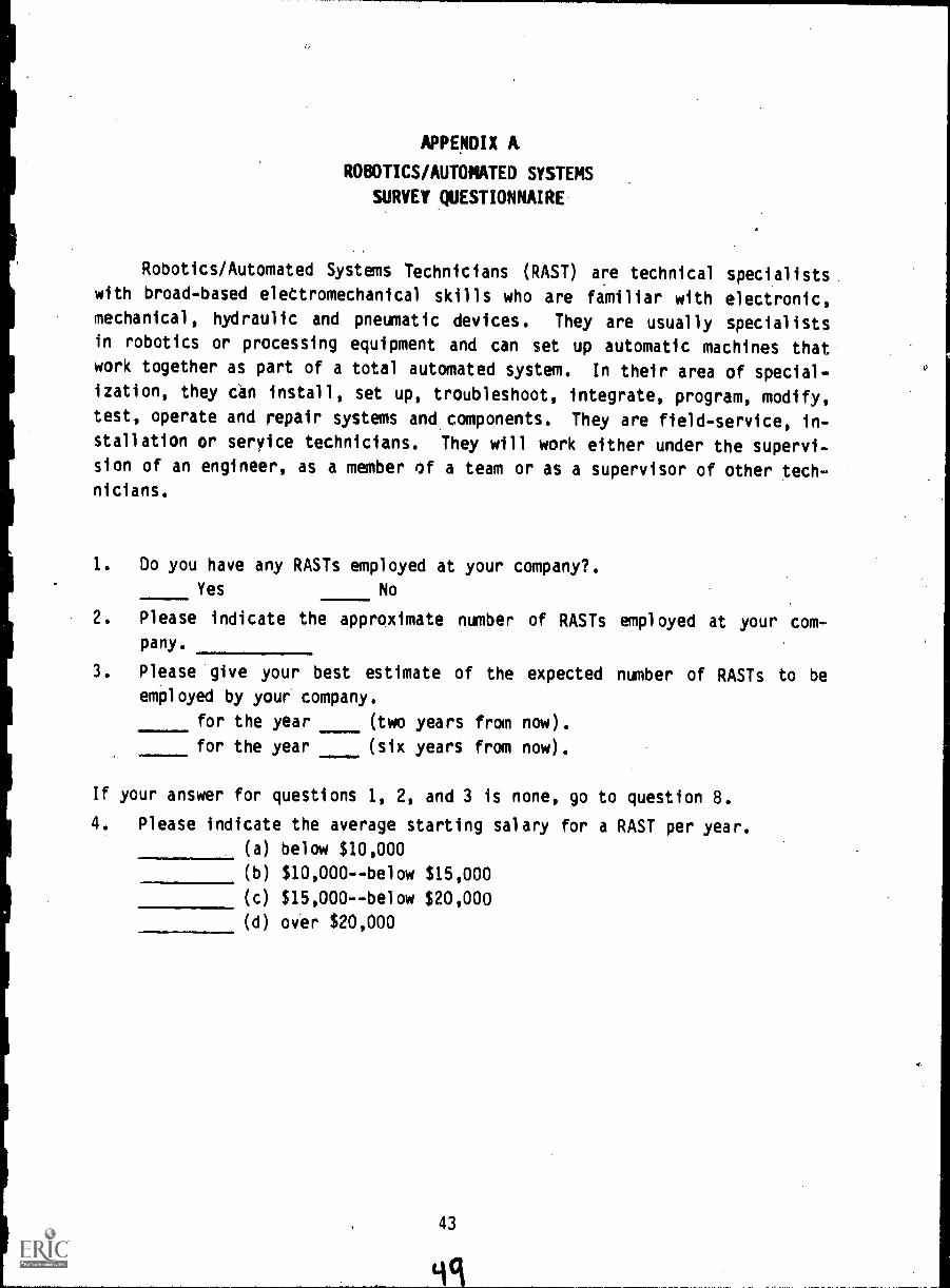
APPENDIX A
ROBOTICS/AUTOMATED SYSTEMS
SURVEY QUESTIONNAIRE
Robotics/Automated Systems Technicians (RAST) are technical specialists
with broad-based eleCtromechanical skills who are familiar with electronic,mechanical, hydraulic and pneumatic devices. They are usually specialistsin robotics or processing equipment and can set up automatic machines thatwork together as part of a total automated system. In their area of special-
ization, they can install, set up, troubleshoot, integrate, program, modify,test, operate and repair systems and components. They are field-service, in-
stallation or service technicians. They will work either under the supervi-
sion of an engineer, as a member of a team or as a supervisor of other tech-nicians.
1. Do you have any RASTs employed at your company?.
Yes No
Please indicate the approximate number of RASTs employed at your com-pany.
3. Please give your best estimate of the expected number of RASTs to beemployed by your company.
for the year (two years from now).
for the year (six years from now).
If your answer for questions 1, 2, and 3 is none, go to question 8.
4. Please indicate the average starting salary for a RAST per year.
(a) below $10,000
(b) $10,000--below $15,000
(c) $15,000--below $20,000
(d) over $20,000
43
yq

Please indicate those areas in which you think a RAST should receive
specialty training.
Computer hardware
Computer software
Conventional optics (geometrical and wave optics)
Electronics
Electra- optical devices
Fiber optics
Hydraulics
Industrial electricity
Lasers
Management
Manufacturing processes
Pneumatics
Programming
Report writing
Safety and OSHA
Sales methods and techniques
Other (please specify)
6. Please give your name and the name and address of your firm.
Your kind assistance in completing and
returning this survey questionnaire is appreciated.
44
50

APPENDIX B
SPECIALTY COURSE OUTLINES
FUNDAMENTALS OF ROBOTICS AND AUTOMATED SYSTEMS
Classroom/Lab hrs/wk 2/3
COURSE DESCRIPTION
This course introduces the student to robotics and automated systemsand their operating characteristics. Topics to be covered include roboticsprinciples of operation and work envelopes. Students will learn the variouscoordinate systems and how hydraulic, pneumatic and electromechanical sys-tems function together as a system. Other subjects to be covered includeservo and nonservo controls, system capabilities and limitations, andsafety. Robot tooling will be investigated including welders, grippers,magnetic pickups, vacuum pickups, compliance devices, adhesive applicators,and paint sprayers.
COURSE OUTLINE
Student Contact HoursClass Laboratory
I. Introduction to Robotics and 2 3Automated SystemsA. Description of a SystemB. Definitions
1. Robots2. Automation
C. Elements of Automation1. CAD (CADD)2. CAM3. CAD/CAM4. CAE5. CIM
D. Robot Components1. Manipulator2. Power supply3. Controller4. Transducers
II. Robotics/Automated Systems Hazards 2
and Safety RequirementsA. Three AxiomsB. Three LawsC. Robot Hazards (risk identification)D. Regulations
1. NFPA2. OSHA3. NEMA4. JIC5. NMTBA6. IEEE
5145

Student Contact HoursClass Laboratory
7. NEC
8. ANSI
E. Mental Attitude1. Cleanliness2. Neatness
III. Robotic Operating Parameters 4 6
A. Interpreting Manufacturer's Specifications1. Accuracy/repeatability2. Coordinate system3. Speed
4. Arm geometryDegrees of Freedom1. Definition2. Robot/arm3. Wrist/tool
C. Payload1. Mass2. Limitations3. Radius (cg distance from mount surface)4. Moment of inertia
IV. Robot Programming Characteristics 4 6
A. Reference Planes of Motion1. Tool control path2. Robot's coordinate system
R. Programming Characteristics1. Language2. High/medium/low technologyPath Control1. Point-to-point2. Controlled path3. Continuous path
V. Robot Structural Systems cp 2 3
A. Mechanical1. Support
2. Structural
3. Arm-motion control
R. End-of-Arm Tooling1. Tooling2. Compliance devices3. Applications
C. Grippers1. Parallel motion2. Angular motion3. Special
46 52

Student Contact HoursClass Laboratory
VI. Robot Drive Systems 2 6A. Electrical
1. Power2. Control3. Servo4. Stepper motors
B. Hydraulic1. Pumps2. Actuators3. Valves
C. Pneumatic1. Pumps2. Actuators3. Valves
VII. Robot Control and Feedback Systems 4A. Control
1. Open loop2. Closed loop
B. Transducers1. Discrete2. Analog
C. Relative and Absolute Positioning
STUDENT LABORATORIES
I. Measure Robot Physical CharacteristicsCoordinate systemsSpeed of operationPayloadsWork envelope
II. Identify Robot's Path Control Characteristics and Reference PlanesPoint-to-point
Control pathContinuous path
III. Program Robots and Automated SystemsTeach pendantLead throughOff linePost processor
IV. Program/Operate End-of-Arm ToolingGrippersVacuum pickupsMagnetic pickups
547
3

V. Describe and Operate Drive SystemMechanical
ElectricalHydraulic/pneumatic
VI. Identify Major Systems
MechanicalElectricalHydraulicPneumaticControlsSensorsServos/nonservosEnd-of-arm tooling
STUDENT COMPETENCIES
Upon completion of this course students will be able to:
1. Measure robot performance (distance, positioning, accuracy and repeat-
ability).2. Specify the robot coordinate system.
3. Operate the following equipment.a. End-of-arm toolingb. Grippersc. Magnetic pickupsd. Vacuum pickups
e. Compliance devices4. Identify major systems of a robot.
5. Describe robot drive system operation.
6. Describe mobility of an industrial robot.
7. Identify a robot's work envelope.
8. Be conversant in robotstechnology.
9. Demonstrate knowledge of safety requirement for working around robots.
10. Specify safety considerations for personnel, work'area, operations and
machines.
48
54

PUTOMATED SYSTEMS AND SUPPORT COMPONENTS
'Classroom/Laboratory hrs/wk 2/6
COURSE DESCRIPTION
Students learn the concepts of productiun--mass production, batch pro-cessing, and job shopping. They also learn how identical support componentsare app'ied to different types of automated manufacturing. Proper orienta-tion of parts will be examined in the laboratory. Also, sensor performance
_
will be compared to manufacture's data.
COURSE OUTLINE
Student Contact HoursClass Laboratory
I. Introduction to Types of Manufacturing 2 0A. Mass Production
1. Large volume2. Hard or fixed. automation3. Single7purpose machines/transfer
linesB. Batch Processing
1. Small volumes2. Job shop3. Flexible automation4. Group technology
C. Job Shopping1. Limited production2. Flexible manufacturing
(if large or expensive items)
II. Parts Movers 4 15A. Parts Feeders
1. Bowl feedersHoppers
3. Gravity feedersB. Material Handlers
1. Conveyors2. Wire-guided vehicles3. Cranes4. Lift, carry, and shuttle-type
transfer devices and systems5. Power-and-free versus synchronous6. Walking beams
III. Jigs and Fixtures 4 12A. Free-Effort FixturesB. Parts OrientationC. Fixture Optimization
49
IV.
V.
PositionersA. ElectricalB. PneumaticC. HydraulicD. . Index tables
Sensors (Direct Reading/Discrete[Single-Function] Devices)A .--- t -Switches.-
B. Position Indicators
C. Level Indicators0. TactileE. PressureF. Temperature'
STUDENT LABORATORIES
I.
Student Contact HoursClass Laboratory
4 15
4 18
Observe and Describe Three Types of ManufacturingTake field trips and write 'reports describing observed manufacturingoperationsSeparate ten parts according to. common manufacturing operations (Group
Technology)
Set Up Part FeedersOperate rotary hopperOperate bowl feedersDetermine parts presentation requirements
III. Operate the Following Types of Material HandlersConveyorsWire-guided vehiclesGravity feeders
Evaluate the Following Types of SensorsLimit switchPhotoelectricTactileProximityTemperaturePressureFlow
V. Operate the Following Positioners and WorkHydraulic
ElectricPneumaticMechanicalIndex tables
IV.
Holders

VI. Set Up and Operate the Following Energy Control DevicesSwitchesRelaysValvesServo
Nonservo
VII. Evaluate Applications of the Following Types of ActuatorsCylindersRotary devices.Stepper motors
. Mechanical
SpringsSolenoids
VIII. Assemble and Study Mechanical Positioners Operated by the followingFour-bar linkagesGeneva mechanismsLinksGears/pulleysCam and followerWalking beams
STUDENT COMPETENCIES
Upon completion of this course, the student should be able to:
1. Program stepper motors.2. Install, adjust, troubleshoot and repair or replace tactile and video
sensors.3. Describe the application of mechanical linkages/gears to a robotic work
cell.4. Perform electrical adjustments on servo power amplifiers.5. Describe the application of hydraulic, electric or pneumatic posi-
tioners and sensors to a flexible cell.
5751

CONTROLLERS FOR ROBOTS AND AUTOMATED SYSTEMS
Classroom/Laboratory hrs/wk 2/6
COURSE DESCRIPTION
Students will learn the principles of control systems and how they areapplied to a production system to achieve automation. Systems included inthe course are drum controllers, stepper motors, programmable logic control-lers, microprocessors, computers, feedback systems and robot controllers.
COURSE OUTLINE
I. Introduction to ControllersA. Purpose/Function of ControllersB Open-Loop ControllersC. Closed-Loop Controllers
Student Contact HoursClass Laboratory
2
II. Fixed Sequence 8 18
A. Ladder DiagramsB. Drum Controllers/TimerC. Stepper Relays
III. Programmable Logic Controllers (PLC) 3 12
A. Sequence ControllerB. Process ControllerC. Components/Architecture of PLC
IV. Feedback Sensors 3 15
A. Discrete Signals/SensorsB. Analog Signals/SensorsC. Contact SensorsO. Noncontact SensorsE. Output Signal Uses
V. Robot Controllers 4 15
A. Definition of a Manufacturing OperationB. Sensing
C. Controller ProgrammingO. OperationE. Robot Controller Programming
--A Case Study
STUDENT LABORATORIES
I. Set Up, Program and Operate Drum Controllers
II. Set Up, Program and Operate Stepper Motors/Relays
III. Set Up, Program and Operate Open- and Closed-Loop Programmable Logic
Controllers
52

IV. Set Up, Calibrate and Operate Feedback Sensors and Control Devices In-cluding Encoders and Resolvers
V. Set Up and Operate Robot Controllers using:Teach pendantsWalk throughOff linePost process
STUDENT COMPETENCIES
Upon completion of this course, the student will be able to:
1. Install, adjust, troubleshoot and repair or replace control devices tomanufacturer's specifications.
2. Program stepper relays.3. Program and/or reprogram PLCs (drum, relay and microprocessor types)
for specific sequence of events.a. Prepare a flow chart for a specific sequence of events in perform-
ing a given application.b. Enter instructions into control unit.c. Run program to see if it executes properly.d. Edit or debug program as necessary.e. Download and upload programs.f. Recognize and resolve hardware/software impedance matching prob-
lems.
4. Draw logic diagrams.5. Read, understand and comply with requirements of service bulletins.6. Use teaching pendant for testing, editing and setup.7. Adjust feedback loops that include:
a. Encodersb. Optical sensorsc. Electronic sensorsd. Microprocessorse. Optoelectronicsf. Hall-effect devicesg. Velocity sensorsh. Position detectors
8. Install a programmable controller and its input/output devices.9. Perform electrical adjustments on servo power amplifiers.
10. Perform zeroing of encoders.11. Define axis control and feedback specifications.

ROBOTICS/AUTOMATED SYSTEMS AT WORK
Classroom/Laboratory hrs/wk 2/6
COURSE DESCRIPTION
This course provides students an opportunity to observe and study theapplication of robots and automated systems applied to manufacturing. Stu-
dents will simulate in the lab several of the systems observed in industry.The laboratory exercises are aimed at evaluating current systems and attempting to improve them.
COURSE OUTLINE Student Contact HoursClass Laboratory
I. Review Two Types of Automation 2 4
A. Fixed (field
B. Flexible trips)
II. Flexible Automation 10 42
A. Case Studies (Class)1. Welding2. Assembly3. Material handling
B. Case Study (Individual)Machine tending
III. Fixed Automation 8 14
A. Case Studies (Class)1. Bottlers2. Transfer line3. Photocopier
B. Case Study (Individual)1. Process control2. Packaging
STUDENT LABORATORIES
I. Set up, Debug, Program, Operate Robots in Two Categories. (Electric,
pneumatic, or hydraulic).a. Point-to-point, continuous path, control path
b. Circular, spherical, cartesian, jointed spherical
c. Drum, PLC, microprocessor, computer
II. Perform an Analysis of an Existing Automated System.
III. Assemble Prototype Systems Similar to Existing Production Systems.
54
GO

STUDENT COMPETENCIES
Upon completion of this course, the student should be able to:
1. Install, adjust, troubleshoot and repair or replace sensors for tactilesensing.
2. Identify and use appropriate lubricant.3. Use manual's troubleshooting charts to aid fault isolation/repair.4. Explain the difference between accuracy, precision and repeatability.5. Install, adjust, troubleshoot, repair or replace:
a. Industrial robotsb. End-of-arm toolingc. Smart actuators
6. Interconnect robots and other equipment.7. Analyze and select appropriate robot sensing requirements for certain
manufacturing operations.8. Start up and debug a robot system.9. Analyze operating difficulties of installed robots; perform necessary
corrective adjustments to return system to normal operation.10. Perform field testing of a robot and check to assure that its perfor-
mance is'in accordance with specifications.11. Specify the robot-to-material interfaces.12. Set up, etc., robot to either remove parts from transfer line and pal-
letize them or to depalletize parts and place then on a transfer line.13. Design a system for counting regular/irregular-shaped objects moving on
an overhead track.14. Operate the following equipment.
a. End-of-arm toolingb. Grippersc. Magnetic pidkupsd. Vacuum pickupse. Compliance devices
15. Adapt the following to robotic application:a. Welderc. Paint sprayersb. Adhesive applicatorsd. s Grinders ---
16. Adapt the following to work with automated systems:a. Conveyorsb. Bulk feeders
55

ROBOTICS AND AUTOMATED SYSTEMS INTERFACES
Classroom/Laboratory hrs/wk 2/6
COURSE DESCRIPTION
Stiients in this course will learn the principles of interconnecting
( interfacing) controllers, sensors and actuators. They will study, set up
and operate simple (discrete, binary) and complex (analog) sensors, tooling,
controllers and network interfacing.
COURSE OUTLINE. Student Contact HoursClass Laboratory
I. Simple Sensor Interfaces (Discrete, Binary) 4 12
A. Sensors
B. Controllers
II. Control Signal Interfacing 4 12
A. Electrical CharacteristicsB. RS-232 Characteristics
C. Data TransmissionD. Terminology
III. Mechanical Interfaces 4 12
A. Interchangeability
B. GrippersC. WeldersD. Applicators
E. GrindersF. Lasers
IV. Electrical Interfaces 4 12
A. InterchangeabilityB. Magnetic Pickups
C. Grippers with Tactile Sensors
D. Welders
V. Networking 4 12
A. Data Exchange
B. Control of Other Computers/Controllers
STUDENT LABORATORIES
I. Interface Signalsa. Measure sensor output and compare to manufacturer's specifica-
tions.
b. Simulate signals input to controller and observe and measure the
response.
c. Compare and analyze RS-232C interconnections and determine re-
quirements for compatibility.
56
62

II. Tooling Interfacesa. Mechanical
1. Interchangeability2. Movements/clearances3. Special hardware/tools of installation
b. Electrical1. Power supplied2. Control signals3. Actuator/sensor sensing4. Disconnects
c. Pneumatic/hydraulic1. Disconnects2. Pressure/volume flow3. Sensing
STUDENT COMPETENCIES
Upon completion of this course, the student should be able to:
1. Use manual's troubleshooting charts to aid fault isolation/repair.2. Use manufacturer's manuals as a guide to troubleshoot; repair, test and
operate a failed machine.3. Use manufacturer's manuals to determine a machine's normal operating
characteristics.4. Using a manual, identify operational/functional systems.5. Disassemble, repair, test and return to service robots that have
failed.6. Install, adjust, troubleshoot, repair or replace:
a. Industrial robotsb. End-of-arm toolingc. Smart actuators
7. Coordinate the operation of several pieces of automatic equipment.8. Adjust machines for accuracy and repeatability.9. Start up and shutdown an automated production system.10. Follow troubleshooting procedures recommended by the manufacturer to
diagnose, isolate and repair a rcbot/automated system.11. Specify the robot-t -material interfaces.
°1
12. Set up, program, tr ubleshoot a system comprised of a minimum of twotransfer lines, one \obot and at least one machining center.
13. Set up, and so forth, robot to either remove parts from a conveyor andpalletize them or to depalletize parts and place them on a conveyor.
14. Configure a system for counting regular/irregular-shaped objects movingon an overhead track.
15. Operate the following equipment:a. End-of-arm toolingb. Grippersc. Magnetic pickupsd. Vacuum pickupse. Compliance devices

16. Adapt the following to robotic application:
a. Welderb. Adhesive applicators
c. Paint sprayers
d. Grinder
17. Adapt the following to work with automated systems:
a. Conveyorsb. Bulk feeders
18. Program a host computer to control several "lower-level" computers thatin turn control portions of an automated system.
19. Interchange different open-loop controllers between systems.
20. Interchange different closed-loop controllers between systems.
58 64
..

AUTOMATED WORK CELL INTEGRATION
Classroom/Laboratory hrs/wk 1/8
COURSE DESCRIPTION
Students, working in teams and under the instructor's supervision, willassemble and operate an automated production system. The students will se-lect equipment, write ,specifications, design fixtures and interconnects, in-tegrate system/pro%lde interfaces, and make the assigned system operational.This is a laboratory class.
COURSE OUTLINE Student Contact HoursClass Laboratcry
The instructor will assign a work cell 10 80project. Students will analyze the require-ments, write specifications and assemble,program, debug and operate a prototype ordemonstration work cell.
STUDENT COMPETENCIES
Upon completion of this course, the student should be able to:
1. Interconnect robots and other equipment.2. Program a host computer that controls the operation of, several pieces
of equipment.3. Set up, operate, troubleshoot, maintain and repair automated systems.4. Use manual's troubleshooting charts to aid fault isolation/repair.5. Disassemble, repair, test and return to service .robots that have
failed.6. Install, adjust, troubleshoot, repair or replace:
a. Industrial robotsb. End-of-arm toolingc. Smart actuators
7. Coordinate the operation of several pieces of automatic equipment.8. Adjust machines for accuracy and repeatability.9. Set up machine vision system.
10. Analyze and select appropriate robot sensing requirements for certainmanufacturing operations.
11. Start up and shutdown an automated production system.12. Follow troubleshooting procedures recommended by the manufacturer to
diagnose, isolate and repair a robot/automated system.13. Perform field testing of a robot and check to assure that its perfor-
mance is in accordance with specifications.14. Develop material handling specifications for a work cell.15. Set up, program, troubleshoot a system comprised of a minimum of two
transfer lines, one robot and at least one machining center.

16. Set up, and so forth, robot to either remove parts from transfer line
and palletize them or to depalletize parts and place them on a transfer
line.
17. Program a host computer to control several "lower-level" computers thatin turn control portions of an automated system.
18. Write material handling specifications for a work cell.
60 66

APPENDIX C
A DESCRIPTION OF UTC PHYSICS
Unified Technical Concepts in Physics--or UTC Physics for short--is a
course of instruction for technicians at the postsecondary level. It is a
carefully selected and organized assembly of text and laboratory course mate-rials. It is intended to organize technical principles in such a manner asto make them readily understood and applicable in different technologies- -
those that Include electrica4 mechanical, fluid, and thermal systems, andcombinations thereof. It is intended to blend useful technical principles
with laboratory practice on realistic devices that technicians use in theireveryday work. It is NOT intended for students who plan to pursue physics asa career, or those who intend to become scientists or engineers. For thosestudents, the traditional texts and courses in physics will continue to servetheir needs.
The traditional format for presentation of technical physics has longbeen the bound textbook, logically divided into chapters that address, in
turn, the separate disciplines of mechanics, heat, sound, wave motion, elec-
tricity, magnetism, and optics. But for technicians who generally take only
one course in physics--as an important foundation course--this format hasseveral inherent weaknesses. First, while mastering physics in the usual
"compartments"--mechanics, heat, sound, etc.--the technician may miss Impor-tant concepts that have analogous relationships that thread through the sepa-
rate disciplines of mechanics, heat, hydraulics, and electricity. For exam-ple, the student may identify the physical concept of rate with speed
(length/time), as it is usually introduced in mechanics, and not identify the
rate analogies calories per second in thermal systems, square feet per secondin hydraulic systems, and coulombs per second in electrical systems. Second,
while spending undue time on formula derivation and proofs--a practice con-
sidered essential in traditional physics courses--the technician may miss the
underlying message contained in important application of technical principles
to useful devices and instruments in the scientific and industrial world.
In content, UTC Physics is similar to a traditional course in technicalphysics. Each course covers the body of kn9wledge called physics. But, in
format, organization and manner of presentation, UTC Physics is significantly
different. UTC Physics is a modular system of instruction. It consists of
concept modules, application modules, and supplementary modules. The thrustof presentation in the concept modules is strongly one of unification of
basic physics concepts in four major disciplines--mechanical, fluid, thermal,
and electrical. And most importantly, through the use of specially
61 6'7

designed laboratory experiments in. application modules, hands-on experience
for the technician is heavily emphasized.
UTC Physics has been compiled into three. books. The textual material- -
the concept modules are presented in a separate text. There are thirteen
concept modules in all, each identified as an important technical base needed
by today's technician., In order of presentation the technical concepts are:
FORCE, WORK, RATE, MOMENTUM, RESISTANCE, POWER, ENERGY, FORCE TRANSFORMERS,
ENERGY CONVERTORS, TRANSDUCERS, 'VIBRATIONS AND WAVES, TIME CONSTANTS, and
RADIATION. While the first seven concepts are easily recognized as basic to
physics, the balance, especially ENERGY CONVERTORS, TRANSDUCERS, and TIME
CONSTANTS-aremot-generally given headline coverage in traditional physics_
courses. But we have found them to be important for technicians.
We strongly advocate one year of UTC rhysics for the technician, with
careful coverage of all thirteen concept modules, complemented by lab experi-
ences from 60 to 90 application modules. However;for programs where only
one-half of a year of physics -- rather than the traditional, full yearis
available, we recommend that a total of seven concept modules and 40.to 60
application ,modules be covered. The concepts, would include; in order:
FORCE, WORK, ?ATE, RESISTANCE, POWER, ENERGY, -and FORCE TRANSFORMERS.
Each of the thirteen concept modules begins with a develOpment of the
basit physics relevant'to the physics concept in question. Then, the basic
physics, concept is identified as alunifying principle that is extended to,a
,ariety of problems in mechanical, thermal, fluid, and electrical systems.
For example, the concept module on FORCE first covers.the basic idea of a
"force." It begins with the traditional definition of enpush or a pull" and
moves on to applications involving Newton's laws of motion. But, in addi-
tion, the idea of force as a unifying concept is introduced and extended to
thermal systems, hydraulic syster6, and electrical systems. The module
shows, for example, that a temperature difference (ST), a pressure difference
(AP), and a voltage difference (a) all behave like forces, even though these
quantities are not forces in tho strict sense of a "push'or a pull"; nor do
they have the usual units of a force, e.g., newtons. In this manner, the
concept of FORCE is extended beyond the simple idea of a push or a pull in
mechanical systems, and shown to be a useful, unifying concept that aids the
student in understanding forces and motion in thermal, hydraulic, and elec-
trical systems: This general pattern of defining and explaining, each con -
cept - -and' then demonstrating its application as a unifying concept in mechan-
ical, fluid, thermal, and electrical systems--is continued throughout the
text for each of the remaining 12 concepts.
A supplement has been developed and is included in the concepts volume
for students who may have a deficiency in elementary mathematics or
62

laboratory skills. These supplementary modules are also useful for self-
study or rapid review with instructor assistance.
There are 170 laboratory exercises available in the form of application
modules, of which 150 of the most. used have been presented in Volumes I and
II, the applications volumes. They have been appropriately designed in the
fields of mechanics, fluids, heat, vibrations, electricity and optics to il-
lustrate real-world applications of the concept modules. Each application
module describes an important application of a physical principle to a common
piece of equipment. For example, to illustrate an important application of a
technical principle, application modules use shock absorbers, prony brakes,
strain gages, venturi meters, and electric motors in place of the traditional
vibrating springs, inclined planes, pith balls, and air tab7es. The modules
are carefully designed to emphasize hands-on laboratory experience.
In summary, UTC Physics is a modular system of instruction designed for
technicians at the postsecondary level. It is built around basic technical
concepts that form the foundation of the course. It offers a wide choice of
application modules that exploit "hands-on" learning to apply the basic prin-
ciples of physics to specialized areas of modern technology.
63

APPENDIX D
TEXTBOOKS AND REFERENCES
TEXTS IDENTIFIED BY BOOKS IN PRINT
1. Asfahl, C.R. Robotics and Manufacturing Automation. New York: JohnWiley and Sons, 1984.
2. Ayres, Robert U., and Miller, Steven 'M., ,Robotics. New York: Harperand Row.
3. . Robotics: Applications and Social Implications. HarvardSquare, MA: Ballinger Publications, 1982.
4. Bolz, R.W. and Tyler, D.F. Robotics Sourcebook and Dictionary. NewYork: Industrial Press, 1983.
5. Bondi and Robino. Robotic Applications for Pneumatics and Hydraulics.
Arlington Heights, IL: Amptronics, 1983.
6. Book, W.V. Editor. Robotics Research and Advanced Applications. NewYork: American societ7771401177ii-Fgrneers, 1982.
7. Brady. Robot Motion. Cambridge, MA: MIT Press, 1983.
8. Brock. Ed. Robot Vision and Sensory Control. New York: Els6ierScientific Publications, 1982.
9. Brown, C.M. and Ballard, D.H. Computer Vision. Englewood Cliffs, NJ:Prentice-Hall, Inc., 1982.
10. Browning, I., and Winklessless, N. Robots on Your Doorstep: A Bookabout Thinking Machines. Beaverton, OR: RoboticsIress.
11. Cassell, D. rsirTrtsdvLM.icrocomutersandf'nControlr.nineerirsi. EnglewoodCliffs, NJ: rentice- a 9 nc., 1983.
12. Chmiekwski, T.; Klatter, R.; Negin, M. Robotics: An Integrated Ap-mach to Technology. New York: John Wiley & Sons, 1984.
13. Coiffet, P. Robot Technolo' Vol. 1: Modellin. and Control. Engle-wood Cliffs, 'rent ce
14. . Robot TechnoloVol. 2. 'Eng ewoo 'rent ce- c., 1983.
15.DiGerormo,=ticMarkets and CompetitorsL. LC80-5462, Cleve-adogpLi6
16. Dorf, R.C. Robots and Automated Manufacturing. Reston, VA: RestonPublishers, On:
17. Dubreuil, H. Robots or Men: French Workmen's Experiment in AmericanIndustry. SaleITIM7W75Y71977.
18. Engleberger, J. Robotics In Practice. AMA COM, 1980.
c.
Interaction with the Environment
19. Flexible Manufacturing Systems.tific Publications, 1982, 1983.
20. Flexible Manufacturing Systems.Engfneers, 1984.
Vol. 1 & 2. New York: Elsevier Scien-
Dearborn, MI: Society of Manufacturing
65 0

21. Flora, P. International Robotics Industry Directory-1983. Conroe, TX:
Technical Da-M7.7073T.taCor
22. Gatland, K., and Jeffries, D. Robots. New York: Watts, 1979.
23. George, F.H., and Humphries, J.D. Robots are Coming.. New York: Inter-
national Publishing Service.
24. Gerduld, H. M., and Gotlesman,,R. Robots Robots Robots. Boston, MA:New York Graphic Society, 1978.
25. Gevarter, W. B. Robotics: An Overview. Sacramento, CA: Solar EnergyInformation, 1984.
26. . Robotics and Artificial IntelliSacramento, CA: o ar nergy n ormat on,
27. Goetsch, D.L. CAD/CAM Workbook. SW Publishers, 1983.
28. Grover, Mikell P. Automation, Production Systems and CAM. Englewood
Cliffs, NJ: Prentice-Hall, Inc., 1980.
29. Hall, D.V. Microprocessor and Digital Systems. New York: McGraw-Hill
Book Co., Inc., 1980.
30. Hartley, J. Robots at Work--A Practical Guide for Engineers and Mana-
gers. New York: Elsevier Scientific ublications, 083.
31. Heath, L. Robotics - Theory and Application of Industrial and Educa-tional Robots. Reston, VA: Reston Publishers, 1984.
32. Neer, E. Robots & Manipulator Systems. Elmsford, NY: Pergamon Press,
1977.
33. Heiserman, D.C. Robot Intelligence...With Experiments. Blue Ridge
Summit, PA: TAB Books, 1981.
34. Henson, H. Robots. New York: Watts, 1982.
35. Holland, V.M. Basic Robotic Concepts. Indianapolis, IN: Howard W.
Sams, 1983.
36. Hunt, V.D. Industrial Robotics Handbook. New York: Industrial Press,
1983.
37. Industrial Robots, Vol. I & II. 2nd ed. Dearborn, MI: Society of
Manufacturing Engineers, 1983.
38. Johnson. Process Control Instrumentation Technology. 2nd ed. New
York: John Wiley & Sons, 19$2.
39. Jones, P. Robotics for Safety and Profit. P-P Publications, 1981.
ence lication Series.
40. Kafrissen & Stephens. Industrial Robots and Robotics.
Cliffs, NJ: Prentice-Hall,Ir
41. Knight, C. Robotics Past Present and Future. New York:
1983.
42. Konopka, E. Robotic Gears,__Orives Lingle!. Utica, MI:
Robotics, 1983.
43. Koren. Computer Control of Manufacturing stems.
66
Englewood
Morrow,
Automation

44. Krasnoff, B. Robots Reel to Real. New York: Arco, 1980.
45. Krouse, J.K. What Ever En ineer Should Know About Com uter-Aided De-TasinandConuteriu actura'n. New 'or : farce nc.,
46. Lab Manual for I/O Controllers. ASCII Marketing Group.
47. Maloney, T.J. Industrial Solid-State Electronics: Devices & S stems.Englewood Cliffs, 'rent ce a nc.,
48. Madtaba, S. The AL Robot & Pro9rammir Language. Reston, VA: RestonPublishers, 11n.
49. Metos, T.H. Robots A Two Z. New York: Messner, 1980.
50. Miller, R.K. Robots in Industr : A lications for Foundries. Madison,GA: Southeast coust cs.
Robots in Industr : Applications for Metal Fabrication.51.
Rulison, GA: Sout east Acoust cs.
52. . Robots in Industr : A..lications for the Plastics Indus-t. outheast coust cs.
53. . Robotics in Industry: General Applications. Madison, GA:Southeast Acoustics.
54. Moravec, H.P. Robot Rover Visual Navigation. Ann Arbor, MI: UMI Re-search Press, 19111.
55. Nesenoff, N. Robotics Interfacial. Farmingdale, NY: CES Industries,Inc, 1983.
56. Osborne, D. Robot's. Midwest Scientific, 1983.
57. Paul, R.C. Robot Mani ulators Mathematics Programming and Control.Cambridge, MA: 'ress,
58. Pugh, A. Robot Vision. New York: Springer-Verlag, 1983.
Systems Approach. Englewood
Robotics. Indianapolis, IN:
59. Rehg, J. Introduction to Robotics, A
Cliffs, NJ: Prentice-Hail, Inc., 1984.
60. Robillard, M.J. Microprocessor-BasedHoward W. Sams, 1983.
61. Rooks, B. Developments in Robotics, 1983 Ed. New York: Elsevier Sci-entific Publications, 1983.
62. Robot Operation and Programming. Farmingdale, NY: CES Industries,Inc., 1982;
63. Robots in Industu. New York: International Publications Service.
64. Robots (Market Reports). Cleveland, OH: Predicasts, 1982.
65. Robotics: A Glossary. Sacramento, CA: Solar Energy Information.
66. Robotics and the Economy. Sacramento, CA: Solar Energy Information.
67. Industry Tomorrow. Englewood Cliffs, NJ:
67

68. Robotics Toda Nineteen 1111Ly:111. Dearborn,. MI: Society of Manufac-
turing Eng neers.
69. Silverstein, Alvin, and Silverstein, Virginia B. The Robots are Here.
Englewood Cliffs, NJ: Prentice-Hall, Inc., 1983.
70. Snyder. Industrial Robots: Interfacing and Control. Englewood Cliffs,
NJ: Prentice-Hall, Inc., 1984.
71. Streitmatter and Fiure. Microprocessor Theory and Applications.
72. Susnjara, Ken. A Manager's Guide to Industrial Robots. Corinthian
Press, 1982.
73. Thring, M. W. Robots and Telechirs. New York: Halsted Press, 1983.
74. Tompkins and White. Facilities Planning. New York: John Wiley & Sons,
1984.
75. Ulrich, R. The Robotics Primer: The What Wh & How of Robots in the
Workplace. Frig ewood s, N 'rent ce-Ha nc., $:3.
76. Understanding Electronic Control of Automation. TI Learning Center.
77. Von Bertalanffy, L. Robots Men and Minds. New York: Braziller, 1969.
78. Zimmerman, H. Robots. New York: Starlog Press, 1979.
PERIODICALS
Design News. Published by Cahners Publishing Co., 270 St. Paul Street,
Denver, CO 80206.
Machine Design. Published by Penton Publications, 1111 Center Ave., Cleve -
1and, OH 44114.
Manufacturin En ineerin . Published by Society of Manufacturing Engineers,
One r ve, . . Box 930, Dearborn, MI 48121.
Robotics Toda . Published by Society of Manufacturing Engineers, One SME
r ve, P O. Box 930, Dearborn, MI 48121.
Robotics Age. Published by Robotics Age, Inc., Strand Building, 174 Concord
Street, Peterborough, NH 03458.
68