Embed Size (px)
Citation preview
ED 254 721
TITLE
INSTITUTIONSPONS AGENCYPUB DATENOTE
PUB TYPE
DOCUMENT RESUME
CE 040 997
Millwright Apprenticeship. Related Training Modules.7.1-7.9 Boilers.Lane Community Coll., Eugene, Oreg.Oregon State Dept. of Education, Salem.[82]440p.; For related documents, see CE 040 991-041 007.Many of the modules are duplicated in CE 040 982.Guides - Classroom Use - Materials (For Learner)(051)
EDRS PRICE MF01/PC18 Plus Postage.DESCRIPTORS *Apprenticeships; Behavioral Objectives; Job Skills;
Job Training; Learning Modules; Machine Tools;Mechanics (Physics); Postsecondary Education; *PowerTechnology; Pressure (Physics); *Trade and IndustrialEducation
IDENTIFIERS *Boilers; *Millwrights
ABSTRACTThis packet, part of the instructional materials for
the Oregon apprenticeship program for millwright training, containsnine modules covering boilers. The modules provide information on thefollowing topics: fire and water tube types of boilers, construction,fittings, operation, cleaning, heat recovery systems, instruments andcontrols, and piping and steam traps. Each module consists of a goal,performance indicators, student study guide, vocabulary,introduction, information sheets illustrated with line drawings andphotographs, an assignment sheet, a job sheet, a self-assessment testwith answers, a post-assessment test with answers for the instructor,and a list of supplementary references. (Copies of supplementaryreferences, which are sections of lectures from a correspondencecourse published by the Southern Alberta Institute of Technology, areincluded in the packets.) (KC)
**********$k***********************************************************
Reproductions supplied by EDRS are the best that can be madefrom the original document.
***********************************************************************
APPRENTICESHIP
_
METRELATED
TRAINING MODULES
74/ 7; 9 130/4.ER5
U.S. DEPARTMENT OF EDUCATIONNATIONAL INSTITUTE OF EDUCATION
EDUCATIONAL RESOURCES INFORMATIONCENTER IERICI
ff<This document has been reproduced asreceived from ne person or organizationoriginating it.
I 1 Minor changes have been made to Improvereproduction quality.
Points of view or opinions stated in this docu,ment do not necessarily represent official NIEposition or policy.
2
"PERMISSION TO REPRODUCE THISMATERIAL HAS BEEN GRANTED BY
01(TO THE EDUCATIONAL RESOURCESINFORMATION CENTER (ERIC)."
1
STATEMENT OF ASSURANCE
IT IS THE POLICY OF THE OREGON DEPARTMENT OF EDUCATION
THAT NO PERSON BE SUBJECTED TO DISCRIMINATION ON THE
BASIS OF RACE, NATIONAL ORIGIN, SEX, AGE, HANDICAP OR
MARITAL STATUS IN ANY PROGRAM, SERVICE OR ACTIVITY FOR
WHICH THE OREGON DEPARTMENT OF EDUCATION IS RESPONSIBLE.
THE DEPARTMENT WILL COMPLY WITH THE REQUIREMENTS OF STATE
AND FEDERAL LAW CONCERNING NON-DISCRIMINATION AND WILL
STRIVE BY ITS ACTIONS TO ENHANCE THE DIGNITY AND WORTH
OF ALL PERSONS.
STATEMENT OF DEVELOPMENT
THIS PROJECT WA3 DEVELOPED AND PRODUCED UNDER A SUB-CONTRACT
FOR THE OREGON DEPARTMENT OF EDUCATION BY LANE COMMUNITY
COLLEGE, APPRENTICESHIP DIVISION, EUGENE, OREGON, .1984,
LANE COMMUNITY COLLEGE IS AN AFFIPMATIVE ACTION/EQUAL
OPPORTUNITY INSTITUTION.
3
APPRENTICESHIP
MILLWRIGHTRELATED TRAINING MODULES
SAFETY
1.1 General Safety1.2 Hand Tbol Safety1.3 Power Tbol Safety1.4 Fire Safety1.5 Hygiene Safety1.6 Safety and Electricity1.7 Fire Types and Prevention1.8 Machine Safeguarding (includes OSHA Handbook)
ELECTRICITY/ELECTRONICS
2.1 Basics of Energy2.2 Atanic Theory2.3 Electrical Conduction2.4 Basics of Direct Current2.5 Introduction to Circuits2.6 Reading Scales2.7 Using a V.O.M.2.8 OHM'S Law2.9 Power and Watt's Law2.10 Kirchoff's Current Law2.11 Kirchoff's Voltage Law2.12 Series Resiscive Circuits2.13 Parallel Resistive Circuits2.14 Series - Parallel Resistive Circuits2.15 Switches and Relays2.16 Basics of Alternating Currents2.17 Magnetism
COMPUTSRS
3.1 Digital Language3.2 Digital Logic3.3 Computer Overview3.4 Computer Software
TOOLS
4.1 Boring and Drilling Tbols4.2 Cutting Tbols, Files and Abrasives4.3 Holding and Fastening Tbols4.4 Fastening Devices4.5 Basic Science - Simple Mechanics4.6 Fasteners
Pagel
IDRAFTING
5.1 Types of Drawing and Views5.2,, Sketching5.3 Blueprint Reading/Working Drawings5.4 Working Drawings for Machines and Welding5.5 Machine and Welding Symbols5.6 Blueprint Reading, Drafting: Basic Print5.7 Blueprint Reading, Drafting: Basic Print5.8 Blueprint Reading, Drafting: Basic Print5.9 Blueprint Reading, Drafting: Basic Print5.10 Blueprint Reading, Drafting: Basic Print5.11 Blueprint Reading, Drafting: Basic Print5.12 Blueprint Reading, Drafting: Basic Print5.13 Blueprint Reading, Drafting: Basic Print5.14 Drafting, Machine Features5.15 Drafting, Measurement5.16 Drafting, Visualization
HUMAN RELATIONS
6.1 Communications Skills6.2 Feedback6.3 Individual Strengths6.4 Interpersonal Conflicts6.5 Group Problem Solving6.6 Goal-setting and Decision-making6.7 Wbrksite Visits6.8 Resumes6.9 Interviews6.10 Expectation6.11 Wider Influences and Responsibilities6.12 Personal Finance
7.1
7.2
7.3
7.4
7.5
7.6
7.77.8
7.9
8.1
8.2
8.3
8.4
8.5
BOILERS
Boilers -Boilers -
Boilers -Boilers -Boilers -Boilers -Boilers -Boilers -Boilers -
TURBINES
Fire 1Vbe TypesWatertube TypesConstructionFittingsOperationCleaningHeat Recovery SystemsInstruments and ControlsPiping and Steam Traps
Steam TurbinesSteam ThrbinesSteam ltirbines
Steam TurbinesGas Ittrbines
- Types- Components- Auxiliaries- Operation and Maintenance
ReadingReadingReadingReadingReadingReadingReadingReading
Page II
Page III
PUMPS
9.1 Pumps - Types and Classification9.2 Pumps - Applications9.3 Pumps - Construction9.4 Pumps - Calculating Heat and Flow9.5 Pumps - Operation9.6 Pumps - Monitoring and Troubleshooting9.7 Pumps - Maintenance
10.110.2
10.3
10.4
10.5
allEUSTTON
CanbustionCanbustionCanbustionCanbustionCombustion
- Process- Types of Fuel- Air and Fuel Gases- Heat Transfer- Wbod
GENERATORS.
11.1 Generators - Types and Construction11.2 Generators - Operation
FEEDWATER
12.1 Feedwater - Types and Equipment12.2 Feedwater - Water Treatments12.3 Feedwater - Testing
AIR COMPRESSORS
13.1 Air Compressors - Types13.2 Air Compressors - Operation and Maintenance
STEAM
14.1 Steam - Formation and Evaporation14.2 Steam - Types14.3 Steam - Transport14.4 Steam - Purification
MISCELLANEOUS
15.1 Installation - Foundations15.2 Installation - Alignment15.3 Circuit Protection15.4 Transformers15.5 Trade 'Irms
TRADE MATH
16.1 Linear - Measure16.2 Whole Numbers16.3 Additional and Subtractidn of Common Fraction and Mixed Numbers16.4 Multiplication and Division of Common Fractions and Whole and
Mixed Numbers
6
Page IV
16.5 Compound Numbers16.6 Percent16.7 Ratio and Proportion16.8 Perimeters, Areas and Volumes16.9 Circumference and Wide Area oc. Circles16.10 Area or Plane, Figures and Volumes of Solid Figures16.11 Metrics
17.117.2
17.317.417.5
17.6
17.717.8
17.917.10
17.1117.1217.13
HYDRAULICS
Hydraulics -Hydraulics -Hydraulics -Hydraulics -Hydraulics -Hydraulics -Hydraulics -Hydraulics -Hydraulics -Hydraulics -Hydraulics -Hydraulics -Hydraulics -
METALLURGY
LeverTransmission of ForceSymbolsBasic SystemsPumpsPressure Relief ValveReservoirsDirectional Control ValveCylindersForces, Area, PressureConductors and ConnectorsTroubleshootingMaintenance
18.1 Included are ILS packets:W 3010W 3011-1W 3011-2MS 9001 (1-3-4-8-9-6-7-5-2-9)MS 9200, 9201
PagER DRIVES
19.1 101. A-B-C-D-E102. C-D-E103. B-C-D-E104. A-C-E-F-G-H-I-J107. A108. A
WELDING
20.1 602. A-8,C -D-G -I -L -M
603. A-B-F-G -I
W. 3011-1 refer to Mettallurgy 18.1
WE. MA-18
MILLWRIGHTSUPPLEMENTARY REFERENCE DIRECTORY
Note: All reference packets are numbered on the upper right-hand corner of the respective cover page.
SupplementaryPacket # Description Related Training Module
1.8 Concepts & Techniques of Machine Safeguarding, U.S.D.L., O.S.H.A. 1.8 Machine Safeguarding
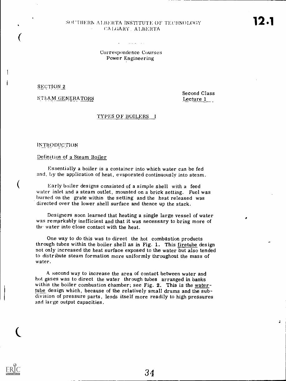
12.1 Correspondence Course, Lecture 1, Sec. 2, Steam Generators, Typesof Boilers I, S.A.I.T., Calgary, Alberta, Canada
7.1 Boilers, Fire Tube Type
12.2 Correspondence Course, Lecture 2, Sec. 2, Steam Generators, Typesof Boikers II, S.A.I.T., Calgary, Alberta, Canada
7.2 Boilers, Water Tube Type
12.3 Correspondence Course, Lecture 2, Sec. 2, Steam Generators, Boiler 7.3 Boilers, Construction
Construction & Erection, S.A.I.T., Calgary, Alberta, Canada
12.4 Correspondence Course, Lecture 4, Sec. 2, Steam Generators, Boiler 7.4 Boilers, Fittings
Fittings II, S.A.I.T., Calgary, Alberta, Canada
12.4 Correspondence Course, Lecture 4, Sec. 2, Steam Generators, Boiler 7.4 Boilers, Fittings
Fitting I, S.A.I.T., Calgary, Alberta, Canada
12.5 Correspondence Course, Lecture 10, Sec. 2, Steam Generation, Boiler 7.5 Boilers, Operation
Operation, Maintenance, Inspection, S.A.I.T., Calgary, Alberta,
Canada
12.7 Correspondence Course, Lecture 3, Sec. 2, Steam Generation, Boiler 7.7 Boilers Heat Recovery
Details, S.A.I.T., Calgary, Alberta, Canada Systems
PUMPS
13.1 Correspondence Course, Lecture 9, Sec. 2, Steam Generator, Power Types & Classifications
13.2 Plant Pumps, S.A.I.T., Calgary, Alberta, Canada 9.2 Applications
13.4 9.4 Calculating Heat & Flow
13.6 9.6 Monitoring & Troubleshooting
13.7 9.7 Maintenance
13.3 Correspondence Course, Lecture 6, Sec. 3, Steam Generators, Pumps, 9.3 Construction
13.5 S.A.I.T., Calgary, Alberta, Canada 9.5 Operation
tEl
MillwrightSupplementary Reference DirectoryPage 2
SupplementaryPacket # Description
14.3 Correspondence Course, Lecture 6, Sec. 3, Steam Generators, Steam
12.8 Generator Controls, S.A.I.T., Calgary, Alberta, Canada
14.4 Correspondence Course, Lecture 11, Sec. 2, Steam Generators,
Piping II, S.A.I.T., Calgary, Alberta, Canada
15.1 Correspondence Course, Lecture 1, Sec. 4, Prime Movers, & Auxil-iaries, Steam Turbines, S.A.I.T., Calgary, Alberta, Canada
15.2 Correspondence Course, Lecture 4, Sec. 3, Prime Movers, SteamTurbines I, S.A.I.T., Calgary, Alberta, Canada
15.3 Correspondence Course, Lecture 2, Sec. 4, Prime Movers & Auxil-iaries, Steam Turbine Auxiliaries, S.A.I.T., Calgary, Alberta,Canada
15.4 Correspondence Course, Lecture 6, Sec. 3, Prime Movers, SteamTurbine Operation & Maintenance, S.A.I.T., Calgary, Alberta,Canada
15.5
16.2
16.2
16.3
1/.1
17.2
1 0
Correspondence Course, Lecture 8, Sec. 3, Prime Movers, GasTurbines, S.A.I.T., Calgary, Alberta, Canada
Boilers Fired with Wood & Bark Residues, D.D. Junge, F.R.L.,0.S.U., 1975
,,,rrespondeuce Course, Lecture 5, Sec. 2, Steam Generators, FuelCombustion, S.A.I.T., Calgary, Alberta, Canada
Correspondence Course, Lecture 5, Sec. 2, Plant Services, Fuel& Combustion, S.A.I.T.,.Calgary, Alberta, Canada
Correspondence Course, Lecture 12, Sec. 3, Steam Generation, WaterTreatment, S.A.I.T., Calgary, Alberta, Canada
Correspondence Course, Lecture 12, Sec. 2, Steam Generation, WaterTreatment, S.A.I.T., Calgary, Alberta, Canada
Related Training Module
14.3 Steam Transport7.8 Boilers, Instruments &
Controls
14.4 Steam Purification
8.1 Steam Turbines, Types
8.2 Steam Turbines, Components
8.3 Steam Turbines, Auxiliaries
8.4 Steam Turbines, Operation& Maintenance
8.5 Gas Turbines
10.2 Combustion Types of Fuel'
10.2 Combustion Types of Fuel
10.3 Combustion Air & Fuel Gases
12.1 Feedwater, Types &Operation
12.2 Feedwater, WaterTreatments
11
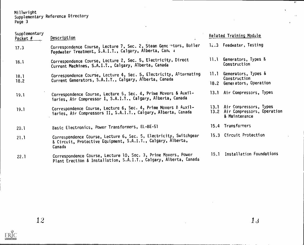
MillwrightSupplementary Reference Directory
Page 3
SupplementaryPacket # Description
Related Training Module
17.3 Correspondence Course, Lecture 7, Sec. 2, Steam Gene -qors, Boiler 14.3 Feedwater, Testing
Feedwater Treatment, S.A.I.T., Calgary, Alberta, Cant 4
18.1 Correspondence Course, Lecture 2, Sec. 5, Electricity, Direct 11.1 Generators, Types &
Current Machines, S.A.I.T., Calgary, Alberta, Canada Construction
18.1 Correspondence Course, Lecture 4, Sec. 5, Electricity, Alternating 11.1 Generators, Types &
18.2 Current Generators, S.A.I.T., Calgary, Alberta, Canada Construction18.2 Generators, Operation
19.1 Correspondence Course, Lecture 5, Sec. 4, Prime Movers & Auxil-
iaries, Air Compressor I, S.A.I.T., Calgary, Alberta, Canada
13.1 Air Compressors, Types
19.1 Correspondence Course, Lecture 6, Sec. 4, Prime Movers t Auxil- 13.1 Air Compressors, Types
iaries, Air Compressors II, S.A.I.T., Calgary, Alberta, Canada 13.2 Air Compressors, Operation& Maintenance
20.1 Basic Electronics, Power Transformers, EL-BE-51 15.4 Transformers
21.1 Correspondence Course, Lecture 6, Sec. 5, Electricity, Switchgear 15.3 Circuit Protection
& Circuit, Protective Equipment, S.A.I.T., Calgary, Alberta,
Canada
22.1 Correspondence Course, Lecture 10, Sec. 3, Prime Movers, Power 15.1 Installation Foundations
Plant Erection & Installation, S.A.I.T., Calgary, Alberta, Canada
1 2
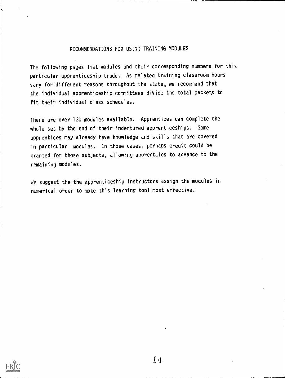
RECOMMENDATIONS FOR USING TRAINING MODULES
The following pages list modules and their corresponding numbers for this
particular apprenticeship trade. As related training classroom hours
vary for different reasons throughout the state, we recommend that
the individual apprenticeship committees divide the total packets to
fit their individual class schedules.
There are over 130 modules available. Apprentices can complete the
whole set by the end of their indentured apprenticeships. Some
apprentices may already have knowledge and skills that are covered
in particular modules. In those cases, perhaps credit could be
granted for those subjects, allow4ng apprentcies to advance to the
remaining modules.
We suggest the the apprenticeship instructors assign the modules in
numerical order to make this learning tool most effective.
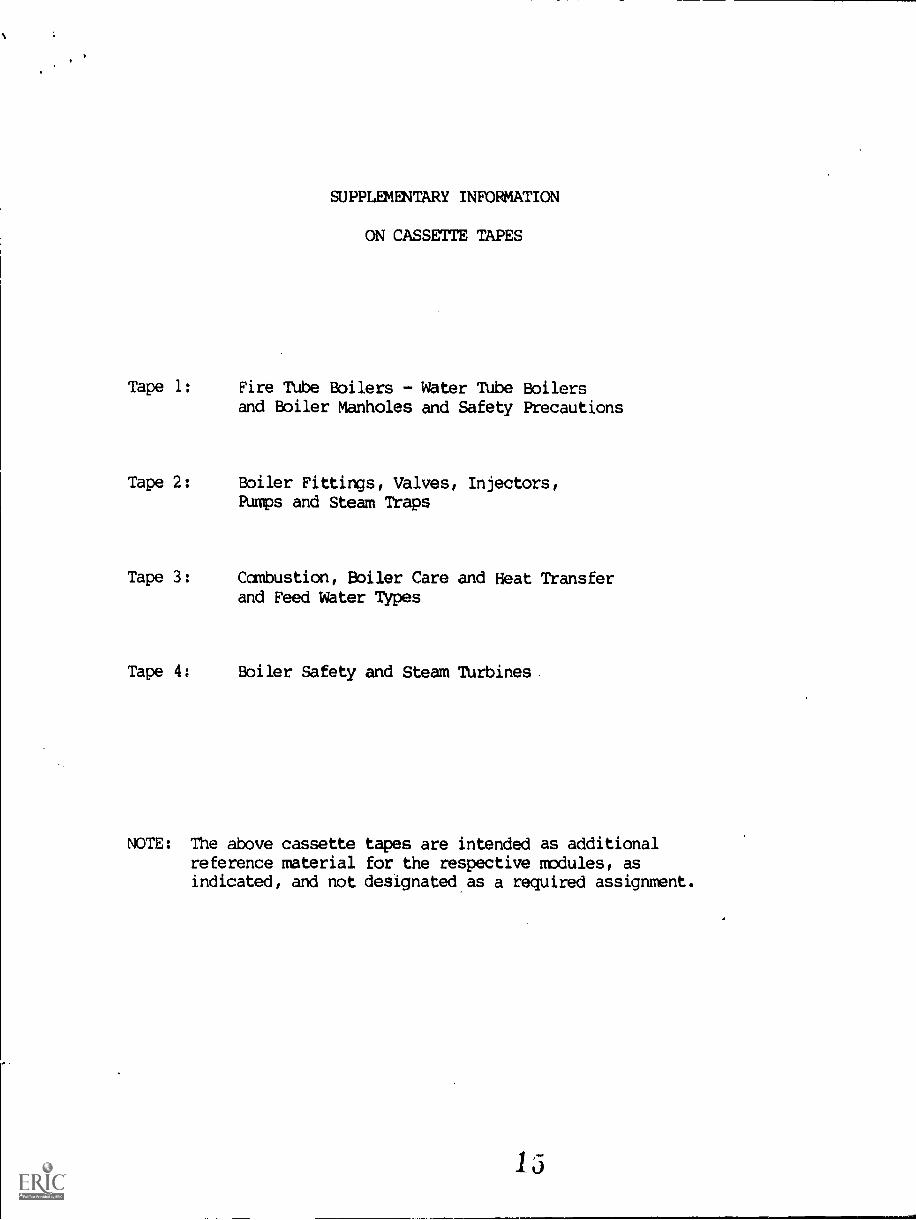
SUPPLEMENTARY INFORMATION
ON CASSETTE TAPES
Tape 1: Fire Tube Boilers - Water Tube Boilersand Boiler Manholes and Safety Precautions
Tape 2: Boiler Fittings, Valves, Injectors,Pumps and Steam Traps
Tape 3: Combustion, Boiler Care and Heat Transferand Feed Water Types
Tape 4: Boiler Safety and Steam Thrbines
NOTE: The above cassettereference materialindicated, and not
tapes are intended as additionalfor the respective modules, asdesignated as a required assignment.
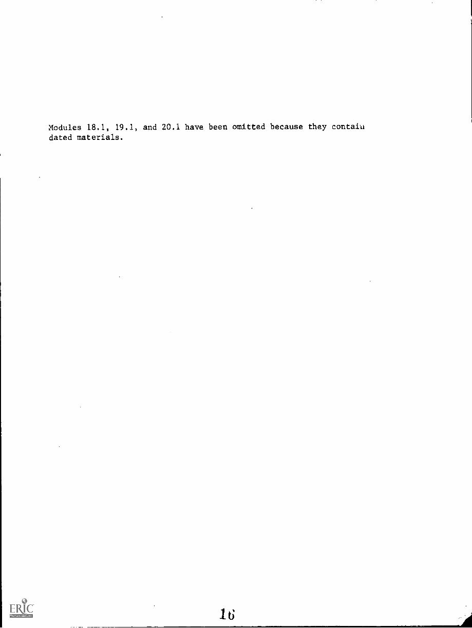
Modules 18.1, 19.1, and 20.1 have been omitted because they containdated materials.
IN=00
NUCRIUM011414 Will
7.1
BOILERS -- FIRE TUBE TYPES
Goal:
The apprentice will be able to describe
types of fire tube boilers.
1
Performance Indicators:
1. Distinguish between fire tube
and water tube boilers.
2. Describe horizontal returnboilers.
3. Describe scotch boilers.4. Describe one and two-pass boilers.
5. Describe dryback and wetbacktypes of boiler.
6. Describe packaged boilers.
7. Describe firebox boilers.
8. Describe internally fired boilers.
9. Describe shell internals of a
boiler.10. Describe safety devices and practices
with fire tube boilers.
17

INSTRUCTIONAL LEARNING SYSTEMS
Study Guide
* Read the goal and performance indicators to determine what is to be learned from
package.
* Read the vocabulary list to find new words that will be used in package.
* Read the introduction and information sheets.
* Complete the job sheet.
* Complete self-assessment.
* Complete post-assessment.
2
18

INSTRUCTIONAL LEARNING SYSTEMS
°Vocabulary* Blow-off connection
* Dryback boiler
-II Firetube boiler
* Horizontal return tube boiler
* Internally fired boilers
* Internal furnace boilers
* One pass boiler
* Packaged firetube boiler
orSafety valves
* Scotch boilers
* Steam dome
* Steam outlet
* Smoke box
* Smoke stack
* Tube plates
* Two-pass boiler
* Water-leg
* Watertube boiler
* Wetback boiler
INSTRUCTIONAL LEARNING SYSTEMS
*IntroductionHigh pressure boilers can be divided into major classifications--firetube aad
watertube. firetuae boiler has tubes that carry flue gases from the fluebox.
The tubes are surrounded with water. ks the gases travel through the firetubes,the surrounding water is heated to produce stewa.
A watertube boiler circulates water through tubes instead of flue gasses. Hot
flue gasses, outside the tubes, heat the water in the tubes and produce steam.
This package will describe the firetube boiler. Another package will describe
watertube boilers.
INSTRUCTIONAL LEARNING SYSTEMS
°InformationA steam boiler is merely a steel container in which water can be heated to
produce steam. The water is heated and evaporated into steam that drives a
prime mover such as the steam turbine.
The firetube boiler uses tubes to carry the heat throughout the water. Closecontact between water and heated tubes makes steam production more efficient.The principle of the firetube boiler is shown in the following diagram.
eFiretube Boiler Watertube Boiler
Firetube boilers are simple in construction and low first costs make them
suitable for many applications in steam generation. Many variations in designhelp to improve the efficiency and ada?tability of the firetube boiler.
Horizontal Return Tube Boiler
A horizontal return tube boiler has firetubes running the length of the boiler
shell. The top portion of the boiler is above water level and allows steam to
collect. Horizontal return tube boilers can use a variety of fuels. A diagram
of the horizontal return tube boiler follows.
001
21
.810mar,..Cenaft,14.
Mi
INSTRUCTIONAL LEARNING SYSTEMS
°InformationpTwo Pass Boilers
Two pass boilers have two sets of firetubes. The gasses pass through a short
set of tubes and return back through a long set of tubes. The long tubes are
smaller than the short tubes.
BEST COPY
22
Dryback Boilers
In dryback type boilers, the furnace opens into a refractory lined chamber which
causes the gasses to flow back through the firetubes. The chamber is dry which
gives it the name "dryback". A brick lining is used for the chamber.
ti-r3Nonditole
Wehtfrati fep
FusiblePlug
mmtmIsmMMI
INSTRUCTIONAL LEARNING SYSTEMS
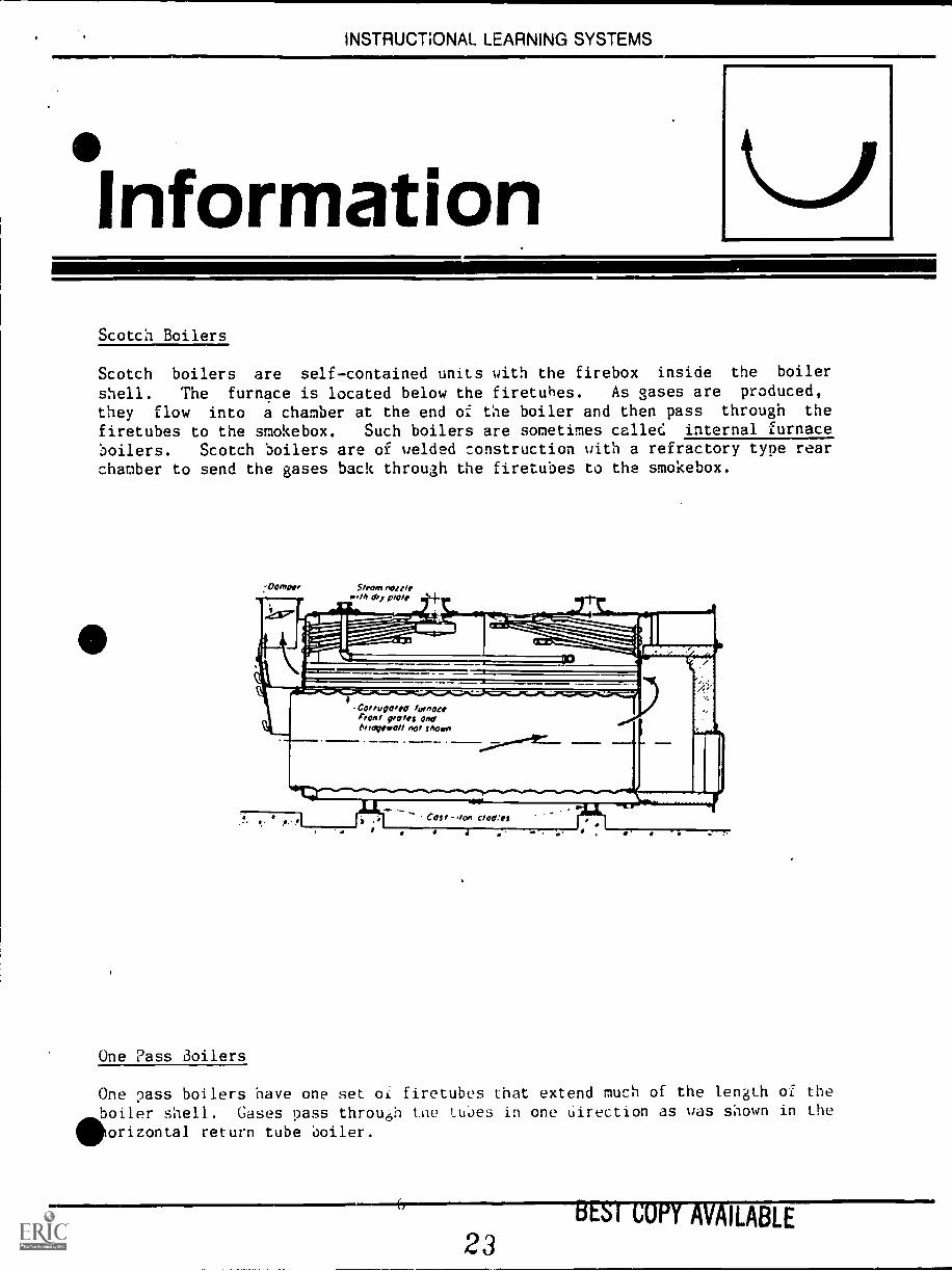
°InformationScotch Boilers
Scotch boilers are selfcontained units with the firebox inside the boiler
shell. The furnace is located below the firetubes. As gases are produced,
they flow into a chamber at the end of the boiler and then pass through the
firetubes to the smokebox. Such boilers are sometimes called internal furnace
boilers. Scotch boilers are of welded construction with a refractory type rearchamber to send the gases back through the firetubes to the smokebox.
9mmnoiv0.'M coy plate
Coin/gotta funoctFront rotes andOilotgeroll not show+
Alf
COSI -,10.1 M'S
One Pass Boilers
One ?ass boilers have one set of firetubes that extend much of the length of theboiler shell. Gases pass through the tubes in one Uirection as was shown in the
orizontal return tube boiler.
ILABLE
23
INSTRUCTIONAL LEARNING SYSTEMS
°InformationMIIINIMOMMIIIIII11111111111111
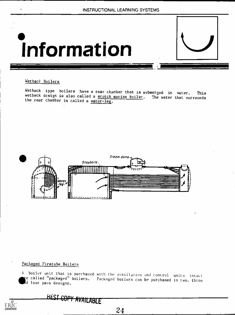
WetbacV Boilers
Wetback type boilers have a rear chamber that is submerged in water. Thiswetback design is also called a scotch marine boiler. The water that surroundsthe rear chamber is called a water-lea.
11`4111111111111111111111111111111111
Packaged Firetube Boilers
A boiler unit that is purchased with the auxiliaries and control units intactWe called "packaged" boilers. Packaged boilers can be purchased in two, threed four pass designs.
24
INSTRUCTIONAL LEARNING SYSTEMS
°Information
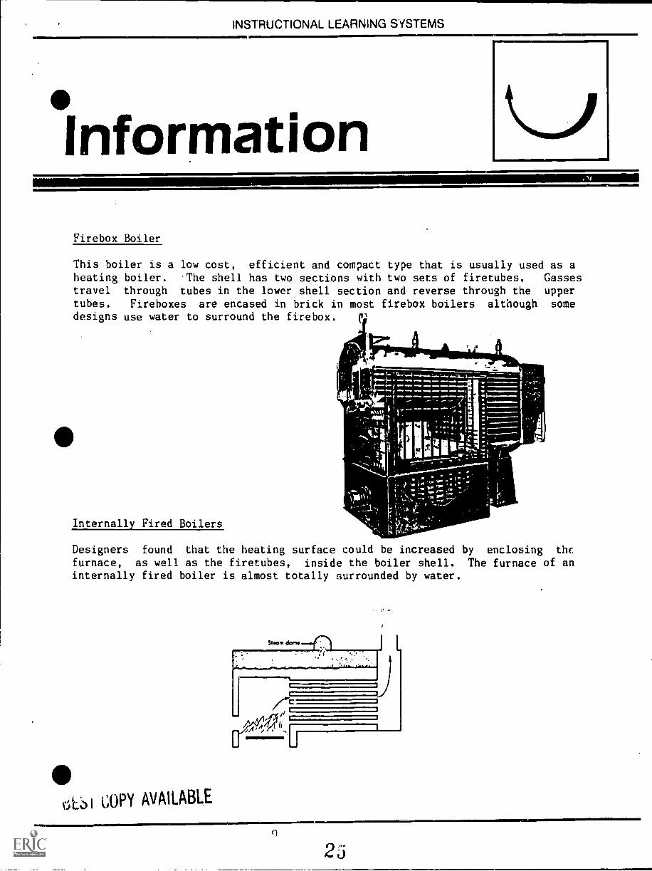
Firebox Boiler
This boiler is a low cost, efficient and compact type that is usually used as aheating boiler. The shell has two sections with two sets of firetubes. Gassestravel through tubes in the lower shell section and reverse through the uppertubes. Fireboxes are encased in brick in most firebox boilers although somedesigns use water to surround the firebox.
r 4--
Internally Fired Boilers
a
Designers found that the heating surface could be increased by enclosing the
furnace, as well as the firetubes, inside the boiler shell. The furnace of aninternally fired boiler is almost totally surrounded by water.
Stearn dome
GOPY AVAILABLE
J

INSTRUCTIONAL LEARNING SYSTEMS
InformationShell Internals
Most boilers have cylindrical Lihells to resist the internal pressure of the
steam. The internal shell is strengthened by the use of the diagonal stays,
through bolts or ti!bes designed as stays. The major internal force is directed
more along the length of the boiler than along its girth. A basic component of
the firetube boiler is the firetubes which carry the heated gases that heat the
water. The firetubes are 76 mm to 102 mm in diameter and expand at each end
into tube plates. The tube plates are supported by diagonal stays or braces
that attach to the boiler shell. A blow-off connection permits cleaning and
draining of the boiler. Internally fired boilers have a firebox inside the shell
that is surrounded by a water -lei or brick. A steam dome contains a
steam' outlet and safey valves. A smokebox receives the ,lases that emerge from
the firetubes and directs them into the smoke stack for discharge from the
system.
411 Safety Devices and Practices
The firetube boiler is much xore dangerous when it exploder,. Where a watertube
boiler explosion is usually limited to a ruptured tube, the firetube boiler
explodes completely. For safe operation of firetube boilers the operator
should:
1. Make sure that the boiler conforms to ASME code in regard to materials,
fabrication methods and installation of fittings.
2. Make sure that controls are responsive to changing conditions.
3. Maintain boiler in a clean condition.
4. Make periodic inspections of boiler parts.
5. Read manufacturers instructions for operation and safety of s7eclfic
boiler that is being operated.
3oilers are fitted with safety valves to prevent explosions. The oderator must
be sure that these safety devices are ainctionin3 and that the controls are
properly registering the pressures within the boilers. Damaged ?arts should be
replaced before the boiler becomes hazardous to overate.
1.0
26
INSTRUCTIONAL LEARNING SYSTEMS
Assignment
Read pages 1-21 in supplementary reference and study diagrams.
Complete job sheet.
Complete self-assessment and check answers.
Complete post-assessment and ask the instructor to check your answers.
2
INSTRUCTIONAL LEARNING SYSTEMS
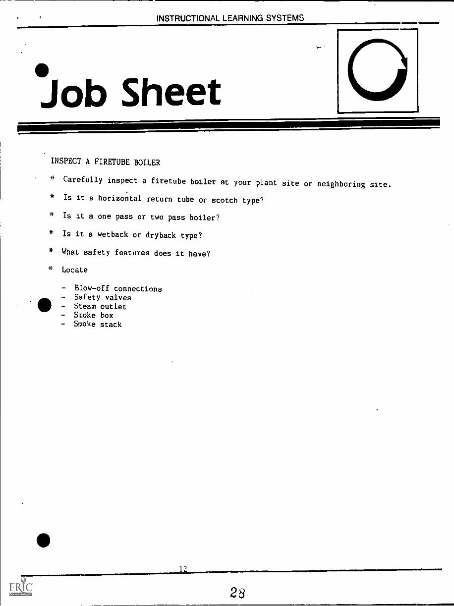
Job SheetINSPECT A FIRETUBE BOILER
* Carefully inspect a firetube boiler at your plant site or neighboring site.
* Is it a horizontal return tube or scotch type?
* Is it a one pass or two pass boiler?
* Is it a wetback or dryback type?
* What safety features does it have?
* Locate
- Blow-off connections- Safety valves- Steam outlet- Smoke box- Smoke stack
4111111
28
INSTRUCTIONAL LEARNING SYSTEMS
.SelfAssessment
1. A boiler that carries heated gases through its tubes is aboiler.
. 2. Boilers with an internal firebox and a refractory type rear chamber are
called boilers or internal furnace boilers.
3. A boiler that produces steam on one trip of gases through the firetubes is aboiler.
4. Boilers that pass gases through a short set of tubes and then reverses theflow back through a longer set of tubes is aboiler.
5. A boiler that has a brick lined rear chamber is a
type.
6. One that has a rear chamber surrounded by a water-leg is a
type.
7. A scotch marine boiler is a type.
8. Boilers that are purchased complete with auxiliaries and controls are calledboilers.
9. A boiler that uses a two-section shell with short tubes in the lower sectionis a boiler.
10. The connection permits the boiler to be cleaned
and drained.

INb I NUL, I SUINIAL LtN11141INIU b Y b I tIVI
Self AssessmentAnswers
1. Firetube
2. Scotch
3. One-pass
4. Two-pass
5. Dryback
6. Wetback
7. Wetback
41, 8. Packaged
9. Fireb
10. Blow-off
INSTRUCTIONAL LEARNING SYSTEMS
*PostAssessment
Match the following boilers and boiler part descriptions with their names:
1. Dry rear chamber lined with brick. A. Blow-off connection
2. Boiler unit purchased complete withcontrols and auxillaries.
B. Internally firedboiler
3. Rear chamber surrounded by water-leg. C. Wetback
4. Receives gases from firetubes anddirects them to smokestack.
D. Packaged
E. Steam dome5. Allows boiler to be cleaned and
drained. F. Dryback
6. Contains a steam outlet andsafety valves.
G. Tube plate
H. Smokebox7. Boiler with both firetube and
furnace enclosed in shell. I. Steam boiler
8. Boiler has a two-section shellthat contains short tubes inone section and long tubes inthe other section.
J. Firebox boiler
9. Expanded ends of a firetube.
10. A container in which water isheated to produce steam.
INSTRUCTIONAL LEARNINU SYS I trob
InstructorPost AssessmentAnswers
F 1.
Ij 2.
C 3.
H 4.
A 5.
E 6.
7.
8.
9.
I 10.
32
p INSTRUCTIONAL LEARNING SYSTEMS
SupplementaryReferences
* Correspondence Course. Lecture 1, Section 2, Second Class Steam Generators.Southern Alberta Institute of Technology. Calgary, Alberta, Canada.
1
33
Smt"Hil.:RN ALBERTA INS'FITUTE 01"I'ECIINOLOGYCALGARY. ALBERTA
SECTION 2
STEAM GENERATORS
Correspondence CoursesPower Engineering
TYPES OF BOILERS I
IN'T'RODUC'T'ION
Definition of a Steam Boiler
Second ClassLecture 1
Essentially a boiler is a container into which water can be fedand, by the application of heat, evaporated continuously into steam.
Early boiler designs consisted of a simple shell with a feedwater inlet and a steam outlet, mounted on a brick setting. Fuel wasburned on the grate within the setting and the heat released wasdirected over the lower shell surface and thence up the stack.
Designers soon learned that heating a single large vessel of waterwas remarkably inefficient and that it was necessary to bring more ofthe water into close contact with the heat.
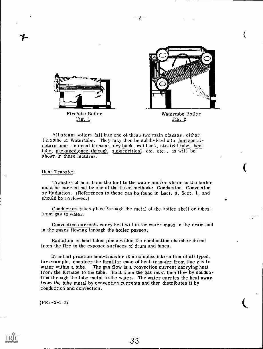
One way to do this was to direct the hot combustion productsthrough tubes within the boiler shell as in Fig. 1. This firetube designnot only increased the heat surface exposed to the water but also tendedto distribute steam formation more uniformly throughout the mass ofwater.
A second way to increase the area of contact between water andhot gases was to direct the water through tubes arranged in bankswithin the boiler combustion chamber; see Fig. 2.. This is the water-tube design which, because of the relatively small drums and the sub-division of pressure parts, lends itself more readily to high pressuresand large output capacities.
34
12.1
- 2
Firetube BoilerFig. 1
Watertube BoilerFig. 2
All steam boilers fall into one of these two main classes, eitherFiretube or Watertubc. They may then be subdivided into horizontal-return tube, internal furnace, dry back, wet back, straight tube, benttube, packaged,once-through, supercritical, etc. etc. , as will beshown in these lectures.
Heat Transfer
Transfer of heat from the fuel to the water and/or steam in the boilermust be carried out by one of the three methods: Conduction, Convectionor Radiation. (References to these can be found in Lect. 8, Sect. 1, andshould be reviewed.)
Conduction takes place through the metal of the boiler shell or tubes,from gas to water.
Convection currents carry heat within the water mass in the drum andin the gases flowing through the boiler passes.
Radiation of heat takes place within the combustion chamber directfrom the fire to the exposed surfaces of drum and tubes.
In actual practice heat-transfer is a complex interaction of all types,for example, consider the familiar case of heat-transfer from flue gas towater within a tube. The gas flow is a convection current carrying heatfrom the furnace to the tube. Heat from the gas must then flow by conduc-tion through the tube metal to the water. The water carries the heat awayfrom the tube metal by convection currents and then distributes it byconduction and convection.
(PE2-2-1-2)
3-
hurler Surface
Since a boiler turns water into steam by the application of heat,the amount and the disposition of its heating surface has a primaryhearing upon its output capacity and its operating efficiency.
Fiii,tubes added to the early shell boiler designs increased theheat-transfer surface: further developments and improvements arediscussed in this lecture.
Watertube boilers have developed from the typical illustrationin Fig. 2 in which almost all of the heat-transfer occurred in convec-tion banks, to the complicated designs shown in later lectures havinghuge radiation surfaces and a full range of heat-saving equipment,superheaters. economizers, air heaters, etc. These boiler aredescribed in Lecture 2 of this Section.
The trend of boiler design. especially for large thermal gener-ating stations. has been towards progressively larger boilers, thatis boilers with greater steam output. At the same time the pressureand temperature of the steam supply required have been increasing.A practical ceiling of about 565°C temperature has been reached andis generally not exceeded. Pressures in common use are more varied,the most popular being about 16 500 kPa.
Use of these higher .team pressures and temperatures in the moreefficient steam power plant cycles has had an important effect uponboiler design.
Low-pressure boilers with small superheaters absorbed much ofthe heat from the combustion products in banks of convection tubes.
At higher pressures, however.. the increase in saturation temper-ature reduces the temperature difference between the steam and thecombustion gases and necessitates a greater superheater surface areato carry out the heat-transfer. Further an increase in boiler sizebrings a disproportionate increase in furnace wall area. The combinedeffect is to reduce the convection section of the boiler practically toelimination so that a modern power boiler consists of furnace, super-heater. economizer and air heater only. The latent heat of vaporiza-tion is added to the boiler water as it passes through the furnace tubes.
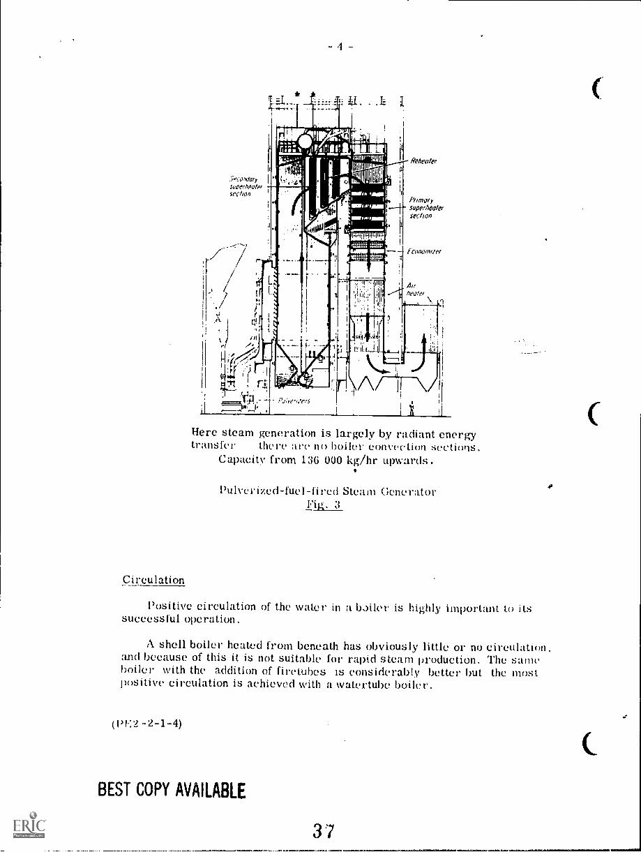
Figure 3 shows the appearance of a modern pulverized-fuel-firedsteam generator with the characteristic tall furnace and no convectionbanks
(13E2-2-13)
- 4
Ptunorysuperheatersection
f-Conofluier
Here steam generation is largely by radiant energytransfer there are no boiler convection sections.
Capacity from 136 000 kg/hr upwards.
Pulverized-fuel-fired Steam GeneratorFig. 3
Circulation
Positive circulation of the water in a boiler is highly important to itssuccessful operation,
A shell boiler heated from beneath has obviously little or no circulation,and because of this it is not suitable for rapid steam production. The sameboiler with the addition of firetubes IS considerably better but the mostpositive circulation is achieved with a vatertube boiler.
(Pl :2 -2-1-4)
BEST COPY AVAILABLE
37
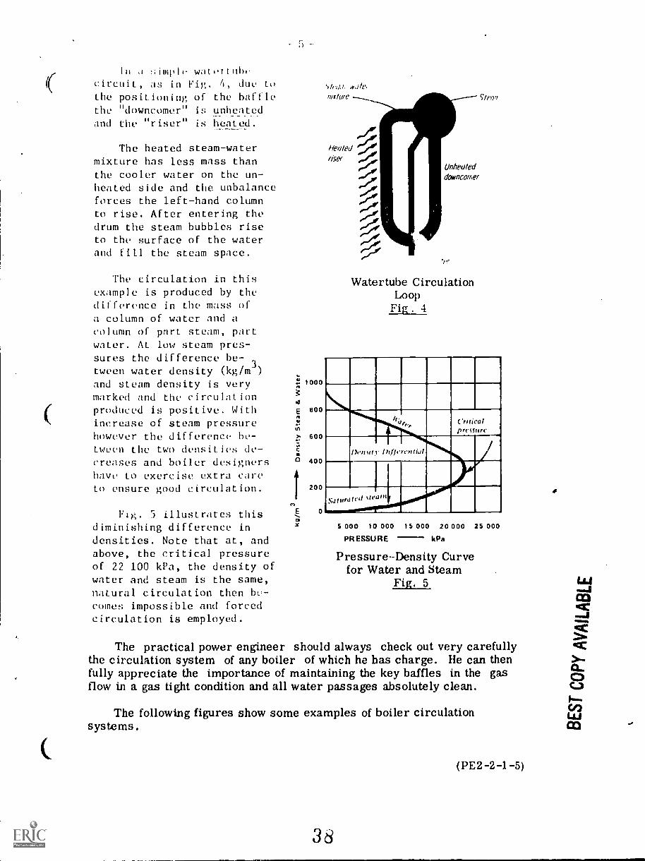
In ,1 !;imph watcilubcircuit, as in Fig, 4, due tothe positioning of the bafflethe "downcomer" is unheatedand the "riser" is heated.
The heated steam-watermixture has less mass thanthe cooler water on the un-heated side and the unbalanceforces the left-hand columnto rise. After entering thedrum the steam bubbles riseto the surface of the waterand fill the steam space.
The circulation in thisexample is produced by thedifference in the mass ofa column of water and acolumn of part steam, partwater. AL low steam pres-sures the difference be-
, 3.tween water density (kg/m )and steam density is verymarked and the circulationproduced is positive. Withincrease of steam pressurehowever the difference be-tween the two densities de-creases and boiler designershave to exercise extra careto ensure good circulation.
Fig. 5 illustrates thisdiminishing difference indensities. Note that at, andabove, the critical pressureof 22 100 kPa, the density ofwater and steam is the same,natural circulation then be-comes impossible and forcedcirculation is employed.
1000
BOO
600
400
200
E 0
w,110
while SIP0,7
Healedriser
-/:0-0-4 Unhealed
erwdowncomer
5:1';
-1111
Watertube CirculationLoop
Fig . 4
If,e.,,_ Critical
pressure
DensdylkfiercuNJ
Na I UN f cif %fed III
5 000 10 000 15 000 20 000 25 000
PRESSURE kPa
PressureDensity Curvefor Water and Steam
Fig. 5
The practical power engineer should always check out very carefullythe circulation system of any boiler of which he has charge. He can thenfully appreciate the importance of maintaining the key baffles in the gasflow in a gas tight condition and all water passages absolutely clean.
The following figures show some examples of boiler circulationsystems.
(PE2 -2-1 -5)
38
6
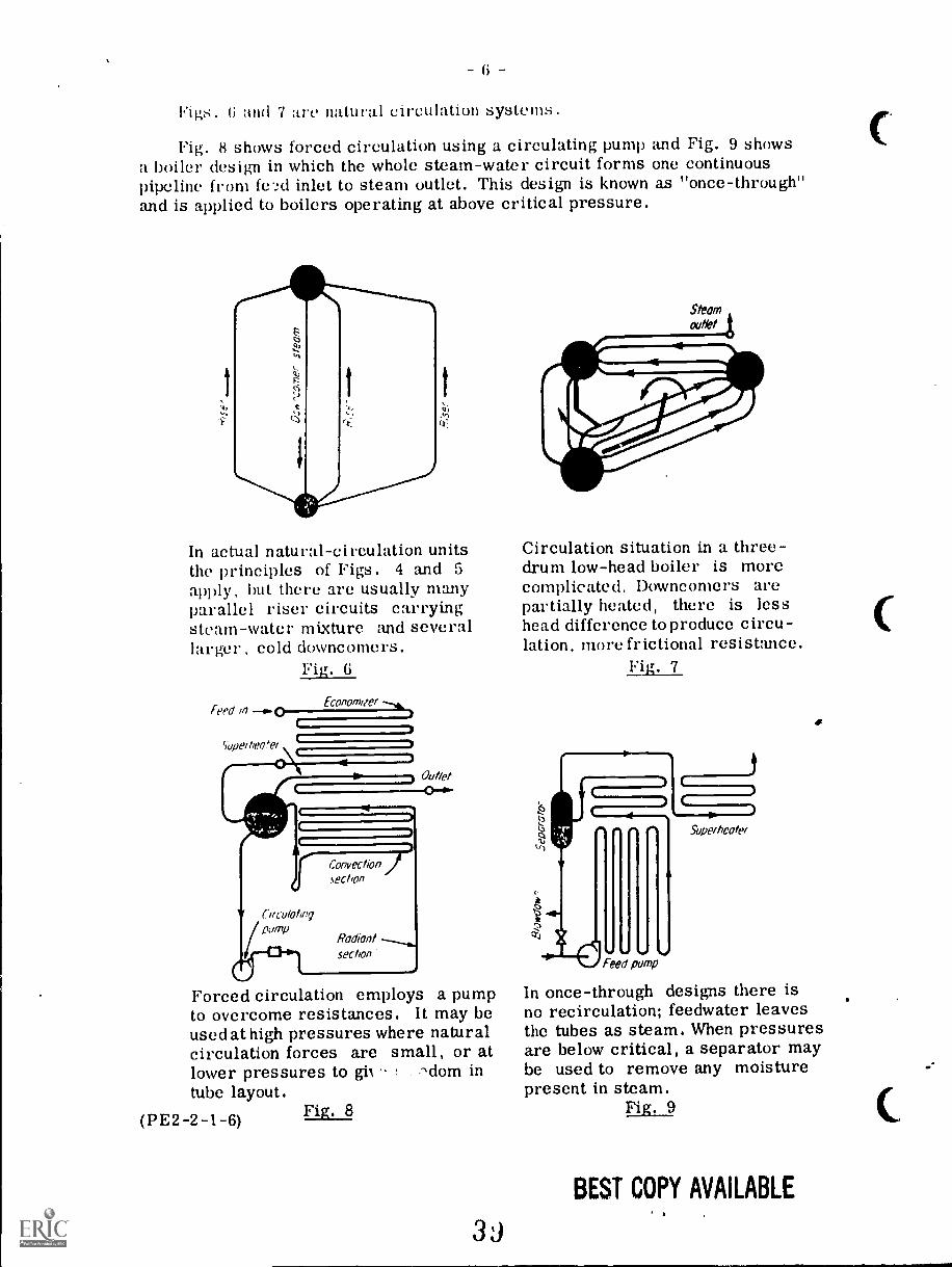
Figs. 6 and 7 are natural circulation systems.
Fig. 8 shows forced circulation using a circulating pump and Fig. 9 showsa boiler design in which the whole steam-water circuit forms one continuouspipeline from feed inlet to steam outlet. This design is known as "once-through"and is applied to boilers operating at above critical pressure.
In actual natural-circulation unitsthe principles of Figs. 4 and 5apply, but there are usually manyparallel riser circuits carryingsteam-water mixture and severallarger cold downcomcrs.
Fig. G
W C/rCutOhr'qpmp
Convectionsection
Radiantsection
Forced circulation employs a pumpto overcome resistances. It may beused at high pressures where naturalcirculation forces are small, or atlower pressures to -dom intube layout.
(PE2 -2 -1-6) Fig. 8
3J
Circulation situation in a three-drum low-head boiler is morecomplicated. Downcomers arepartially heated, there is lesshead difference to produce circu-lation, more frictional resistance.
Fig. 7
ti
crj
(.(( 4Superheater" 41. 0.
Feed pump
In once-through designs there isno recirculation; feedwater leavesthe tubes as steam. When pressuresare below critical, a separator maybe used to remove any moisturepresent in steam.
Fig. 9
BEST COPY AVAILABLE
P II t 1,1 1 1,111 I. II II I';1 III 111011.1 I.
I Ilt I III It II. IIII :111\k1 lilt Illtl \% 011 It lilt. 1/1 I''''1111III.11;-,It\ I., OW driving tort", behind the eirculation; it ha, 1,,
,wereome the re,-,I:-,tanee ttI rimy presented h the tidies and headers 111 the eiretiit.
In ;!,,,,,e1.;i1, the lorce ;iyailable to produce circulation diminishes with increas-ing boiler pressures, because the densities of steam and water approach each other.This is partially offset by the fact that friction losses tend to decrease :S pressurerises.
\s net result, it is possible to design high-pressure steani generators fornatural circulation, but as pressure rises circulation factors demand increasinglycareful consideration. This is one of the reasns some designers have turned toforced circulation, using a pump.
It is apparent that the ,unount (..! water circulated in a boiler usually greatlyexceeds the amount of steam being generated. If I () kg is circulated for each kggenerated, the circulation ratio is I() to I .
The liereentage of steam hy mass in the stearn-w'ate'r mixture at the top ofa riser till', where heating ceases is called top dryness - it varies with designhut normall runs from about 5 to 20`.; . if percentage of the steam in the mixtureheeomes execsSi VC, a condition is reached in which a film of steam exists at theinner surfaces of the boiler tubes. This condition is acceptable in superheaters,hut not in wall tuIR'S, because in this Ca6e the film is more likely to be stagnant.10(1 furthermore these tubes are exposed to higher temperature radiant heat.
Watertuhe holler designs with complex circulation loops waterwalls, screenwalis, radiant platen heaters, superheaters, etc. must be calculated to ensurethat sufficient mass-flow passes through each tube, at every load, to keep thetube metal within a safe temperature limit. Mass -flow refers to the mass ofFluid mixture in kg/hr passing through the tube. It is affected by velocity, density,specific heat, conductivity, fluid viscosity, tube diameter and internal surface.
Designers must he able to make a calculated guess at some of these variablesfor example, the percentage of steam by mass in the steam-water mixture, the"(Iryness-fraction" mentioned before, at various points in the circuit.
()nee that approximation is made, relationship between these variables isgoverned by certain dimensionless numbers which have become the indispenabletool of the hydraulic engineer. Most commonly used among these numbers andapplied to the gas side as well as the steam side of boiler surfaces is the Reynoldsnumber. This brings into the picture massflow, tube diameter, fluid velocity andviscosity all factors in flow resistance.
BEST COPY AVAILABLE
40
(PIE- 2 -1 -7)
In contrast to natural circulation and forced circulation designs in whichmore water is circulated than steam is generated and a drum or drums serve asa collecting and steam-releasing point the once-through design consists intheory, of a single Tube (no drum) into which goes feedwater and out-of whichcomes saturated or superheated steam. In actual units, of course, the theoret-ical single circuit becomes a number of parallel circuits.
Steam Generator Ratings
The oldest measure of steam-generator capacity is the boiler horsepower.This is the amount of steam which was required to generate one horsepower ina typical steam engine at the date when this unit was adopted. In the SI Systemone boiler horsepower is equivalent to 9.809 kW.
It is still used as the common measure of capacity for small boilers. Largerboiler capacity is almost invariably given in the number of kg of steam evapo-rated per hour, with specified steam conditions.
Maximum continuous rating is the hourly evaporation that can be maintainedfor 24 hours. Boilers supplying steam to turbo-alternators are often rated inmegawatts (MW) today, because the kg/h rating at the boiler stop valve does nottake into account the large reheater sections of the boilers.
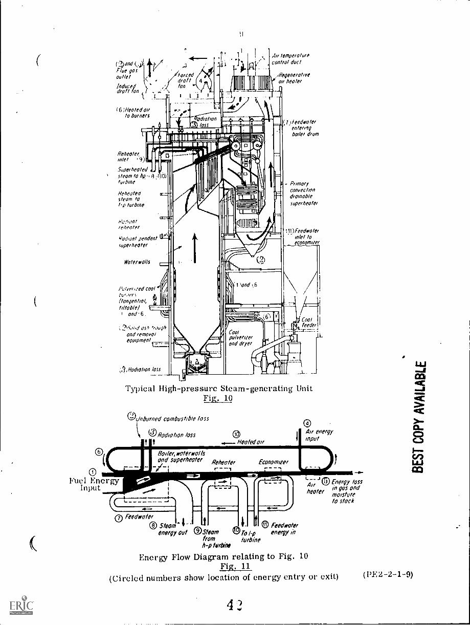
A steam-generating unit coordinates many elements. While the term"boiler" is broadly used, it should apply, strictly speaking, only to the ele-ments in which the change of state from water to steam takes place. Theterm "steam generator" embraces the many combinations of heating surfaces,such as water-walls, superheaters, reheaters, economizers, and air heaters.A "steam-generating unit" consists of a steam generator and its associatedequipment, including fuel burning, ash removal, and draft systems. Such asteam-generating unit is pictured in Fig. 10.
It can be seen that a complete steam-generating unit represents a combin-ation of many elements, all of which must be integrated properly if the unit'soperation is to be efficient.
Expressed another way, performance of the total unit can be affected bylimitations of any of the systems external to the steam generator - inadequatedraft, for example, or fuel-burning equipment that does not supply the heatrelease on which steam-generator design was predicated. Thus, there is anincreasing tendency for the manufacturer of the steam generator to be respons-ible for coordinating the entire unit.
Fig. 10 shows a sectional arrangement of a typical high-pressure, high-temperature steam-generating unit.
Fig. 11 is a diagrammatic illustration of the energy flows which occur inthe unit from the fuel input (1) to the steam outputs Nos. (8) and (10). Thenumbers given on Fig. 10 show the location of these energy flows.
(PE2 -2-1-8)
41
ti/flue qosout/el KforcInducey1droll Ion I _
( 6 ;Heeled oilto burners
I.)
temperaturecontrol duct
/Regenerativeov heater
NUE1111.5.34111111)Mil,ili.lini1 .., , I
ilirali1111111111MMI"w3 7.-7-------"g----:-,i;))
Relwate"
r 17.==. 1111111.111111111111MilliliWINflinif
inlet ,9)1111 reir'-=.--cie..!.1_steam to hp, 8 .10)
tudune1111'41i
Superheated I
Reheatedsteam to
turbine
e hedte/
Yudivnt pendentsuperheater
Wolerrolls
Pclyelieed coolPu,,,e1(tangential,tillable/
and 6.
)feedwolelentetinqbode, drum
P unaryConvectiond'amoblesuperheater
111)Feedwolelinlet toeconomize'
ost) troughand lemovoiequipment
,110tholion loss
Coolteed& I
IL
Typical High-pressure Steam-generating UnitFig. 10
C.:kink/wed combustible toss
ORodio Ws (41Heated oir? ?
0Fuel Energy
Input
woterwo/Isand supetheotef Reheoter
r 1
1
Qtr anewinput
1
0 feedwoler
0 Steam. 4energy out OSteern e To 1p
from turbineh-p turbine
Energy Flow Diagram relating to Fig. 10Fig. 11
(Circled numbers show location of energy entry or exit)
0 Feedvoterenergy in
kl9 Energy loss
healer It? gas andmoistureto stock
(PEZ-2-1-9)
10
111t1 TI'BI
The term "firetube" is derived from the fact that the hot combustion gasesl'al'i(41 in tubes through the water space. Firetube boilers may also be
called "shell" boilers because the whole of the steam-producing elements arehoused within a single outer shell.
Although the ideal shape to resist internal pressure is a sphere, prac-tical consideration leads to the use of hasicall) cylindrical shells. Non-cylin-drical sections and flat surfaces are given added resistance to internal pressureby various means: diagonal stays, through-bolts, or tubes which are themselvesdesigned to he used as stays.
In such a shell the force tending to burst it along the length is twice thattending to burst it around the girth. In the critical longitudinal direction thestrength required to resist bursting is proportional to the product of the pres-sure and the diameter. It can he seen that high pressures and large diametersWould lead to extremely thick shell plates. Hence, there is a definite econom-ical limit on pressure and capacity that can be reached with shell-type boilers.
An operating pressure of 1725 k Pa may he considered the practical ceiling,:mil on this continent, capacity rarely exceeds 11 500 kg/h of steam roughly75W) kW boiler. In Europe, where larger firetube boilers have always beenpopular and economics tuid boiler-code conditions are different, units of 13 500kg /h are not unusual.
As a class, firetuhe boilers feature simple and rugged construction andrelatively low first cost. Their charactistically large water capacity makesthem somewhat slow in coming up to operating pressure but provides someaccumulator action that makes it possible to meet load changes quickly.
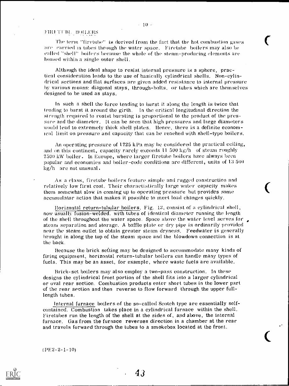
Horizontal return-tubular boilers, Fig. 12, consist of a cylindrical shell,now usually fusion-welded. with tubes of identical diameter running the lengthof the shell throughout the water space. Space above the water level serves forsteam separation and storage. A baffle plate or dry pipe is ordinarily providednear the steam outlet to obtain greater steam dryness. Feedwater is generallybrought in along the top of the steam space and the blowdown connection is atthe back.
Because the brick setting may be designed to accommodate many kinds offiring equipment, horizontal return-tubular boilers can handle many types offuels. This may be an asset, for example, where waste fuels are available,
Brick-set boilers may also employ a two-pass construction. In thesedesigns the cylindrical front portion of the shell fits into a larger cylindricalor oval rear section. Combustion products enter short tubes in the lower partof the rear section and then reverse to flow forward through the upper full-length tubes.
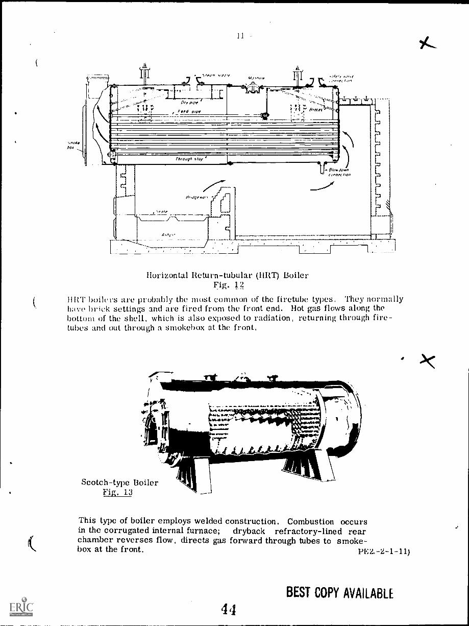
Internal furnace boilers of the so-called Scotch type are essentially self-contained. Combustion takes place in a cylindrical furnace within the shell,Firetubes run the length of the shell at the sides of, and above, the internalfurnace. Gas from the furnace reverses direction in a chamber at the rearand travels forward through the tubes to a smokebox located at the front.
(1'2-2-1-10)
C
boa
11
Horizontal Return-tubular (11RT) BoilerFig. 12
IIRT boilers are probably the must common of the firetube types. They normallyhave brick settings and are fired from the front end. Hot gas flows along thebottom of the shell, which is also exposed to radiation, returning through fire-tubes and out through a smokebox at the front.
Scotch-type BoilerFig. 13
This type of boiler employs welded construction, Combustion occursin the corrugated internal furnace; dryback refractory-lined rearchamber reverses flow, directs gas forward through tubes to smoke-box at the front. PE2.-2-1-11)
BEST COPY AVAILABLE
44
The Scotch holler illustrated in Fig, 1:t (prevlou:, mse) 1 dryb.iekdesign, with a refractory-100qt rear chamber. When the rear chamber issubmerged in the water space wetback design tt is known as the ScotchMiirine boiler.
The internal furnace is subject to compressive forces and so must bedesigned to resist them. Furnaces of relatively small diameter and shortlength may be self-supporting if wall thickness is adequate. For largerfurnaces, one of four methods of support may be employed:
(1) corrugating the furnace walls;
(2) dividing the furnace length into sections with a stiffeningflange (Adamson ring) between sections;
GO using welded stiffening rings, and
(1) installing staybolts between the furnace and the outer shell.
It solid fuel is to be fired, a bridgewall may be built into the furnaceat tne end of the grate section.
Also essentially self-contained are the several firebox boiler types,The firebox is lined on all sides with a water-cooled shell (waterlog)coystructed of flat plate stayed to withstand internal pressure, "Loco-motive" and other firebox boilers are often used as portable units.
Figs. 1.1 to 18 inclusive, on the following pages, show examples ofHorizontal Return-tube, Scotch Marine and Locomotive types of firetubeboilers.
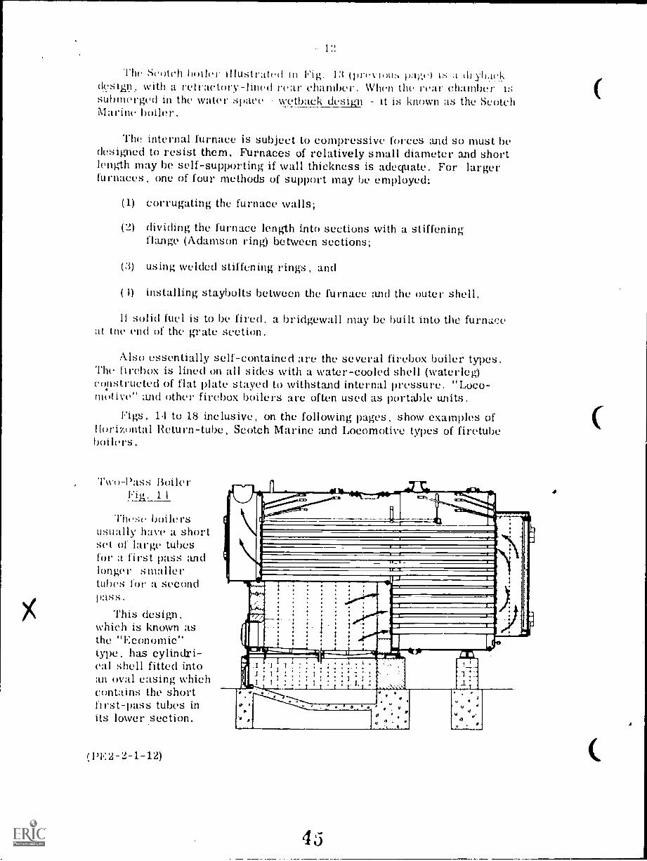
Two-Pass Boiler1'ii2__1 1
These boilersusually have a shortset of large tubesfor a first pass andlonger smallertubes for a secondpass.
This design,which is known asthe "Economic"type, has cylindri-cal shell fitted intoan oval casing whichcontains the shortfirst-pass tubes inits lower section.
tspE.3'2-1-12)
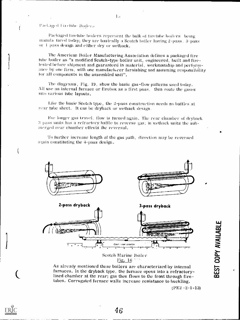
1.;
l'ael.pit'd I II (.ttilm Bode!,
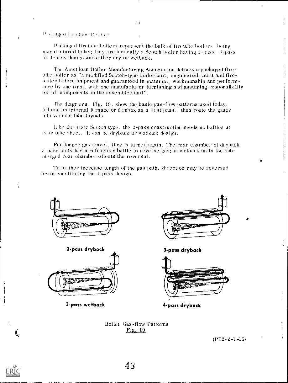
Packaged liretube boilers represent the bulk of liretube boilers beingmanilla- Lured today; they are basically a Scotch boiler having 2-pass, 3-passor 1 pass design and either dry or wetback.
The American Boiler Manufacturing Association defines a packaged fire-tube boiler as "a modified Scotch-type boiler unit, engineered, built and fire-tested before shipment and guaranteed in material, workmanship and perform-ance by one firm, with one manufacturer furnishing and assuming responsibilitytor all components in the assembled unit".
The diagrams, Fig, 19, show the basic gas-flow patterns used today.All use an internal furnace or firebox as a first pass, then route the gasesinto various tube layouts.
Like the basic Scotch type, the 2-pass construction needs no ballk,s atrear tube sheet, It can be dryback or wetback design.
For longer gas travel. flow is turned again. The rear chamber of dryback3-pass units has a refractory baffle to reverse gas; in wetback units the sub-merged rear chamber effects the reversal,
To further increase length of the gas path, direction may be reversed:r.;ain constituting the 4-pass design.
2-pass dryback 3-pass dryback
Scotch Marine BoilerPig. 16
As already mentioned these boilers arc characterized by internalfurnaces. In the dryback type, the furnace opens into a refractory-lined chamber at the rear; gas then flows to the front through fire-tabes. Corrugated furnace walls increase resistance to buckling.
(1)E2. -2-1-13)
46

IP
Locomotive-type BoilerFig. 18
Locomotive-type Boilers have a firebox built into the boiler. Awater leg. or water-cooled surface. completely surrounds thefurnace, and refractory lining is not required. Rugged construc-tion makes this unit suitable for portable service,
(PE2-2-1-14)
47
I I ( .1 (i I I I 11111 w licol 11'1
Packaged liretube boilers represent the bulk of firetube boilers beingnanutactured today; they are basically a Scotch boiler having 2-pass 3-passor 1-pass design and either dry or wetback.
The American Boiler Manufacturing Association defines a packaged fire-tube boiler as "a modified Scotch-type boiler unit, engineered, built and fire-tested before shipment and guaranteed in material. workmanship and perform-ance by one firm. with one manufacturer furnishing and assuming responsibilitytor all components in the assembled unit".
The diagTams, Fig. 19. show the basic gas -flow patterns used today.All use an internal furnace or firebox as a first pass, then route the gasesinto various tube layouts.
Like the basic Scotch type, the 2-pass construction needs no baffles atre:i the sheet. It can be dryback or wetback design.
For longer gas travel. flow is turned again. The rear chamber of dryback3 -pass units has a refractory baffle to 1'0W' rSe gas in wetback units the sub-merged rear chamber effects the reversal.
To further increase length of the gas path, direction may be reverseda'taIn constituting the .1-pass design.
(
2-pass dryback
3-pass wetback
(
3-pass dryback
4-pass dryback
Boiler Gas-flow PatternsFig. 19
48
(PE2-2-1-15)
lti
l'a.ss 1)esigns
These boilers tend to be simplest in design and other things beingequal, may he somewhat lower in first cost. A variety of arrangementsare employed to extract most of the heat from the combustion gas duringthe relatively short travel time between the burner and stack. For onething, designers put great emphasis on maximum heat-transfer from thefurnace tube, usually by imparting a vigorous swirl or turbulence to theflame and the combustion products.
1)esigners also give attention to the number and arrangement of thesecond-pass tubes. While waterside inspection and cleaning are easierwhen tubes are lined up vertically and horizontally, a staggered layouttends to give a more circuitous flow of water around these tubes, prom-oting increased heat-transfer. One builder seeks improved transfer fromgas to water by using slip-in fittings at the tube inlets to impart a swirlto the hot gas.
Figs. 20 and 21 illustrate "2-pass" design boilers.
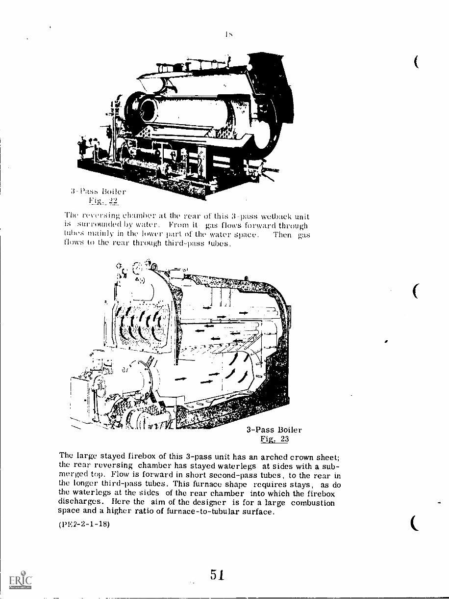
Three-Pass Designs
Judging by the variety of these boilers on the market, the "3-pass"design offers a popular approach. It adds another boiler length to thetravel of the hot as at the cost of some added complexity. In the caseof dryback units,' the rear chamber must be baffled with refractory toseparate the gas being directed into the second-pass tubes, from thegas being discharged out of the third-pass tubes. In wetback units thisis accomplished by the design of the submerged rear chamber, Fig. 22.
Models differ not only in rear chamber construction but in number,size and placing of tubes. Thus, relatively-small-diameter furnacetubes may be surrounded by a multiplicity of firetubes while other unitsfeature large furnace tubes with fewer firetubes. There seems to helittle agreement on the best ratio of primary surface (exposed to fire)and secondary surface (heated by flue gas),
In the "3-pass" category, a number of designs that are basicallyfirebox boilers as distinguished from the internal-furnace type with itscylindrical furnace tube, are to be considered. Typical units have afirebox with a flat bottom and vertical sides going into an arched crownsheet that forms the top, as shown in Fig. 23,
(13E2-2-1-16)
elJ
17
&001--rs '
i1g.0.1MM. ow,u....
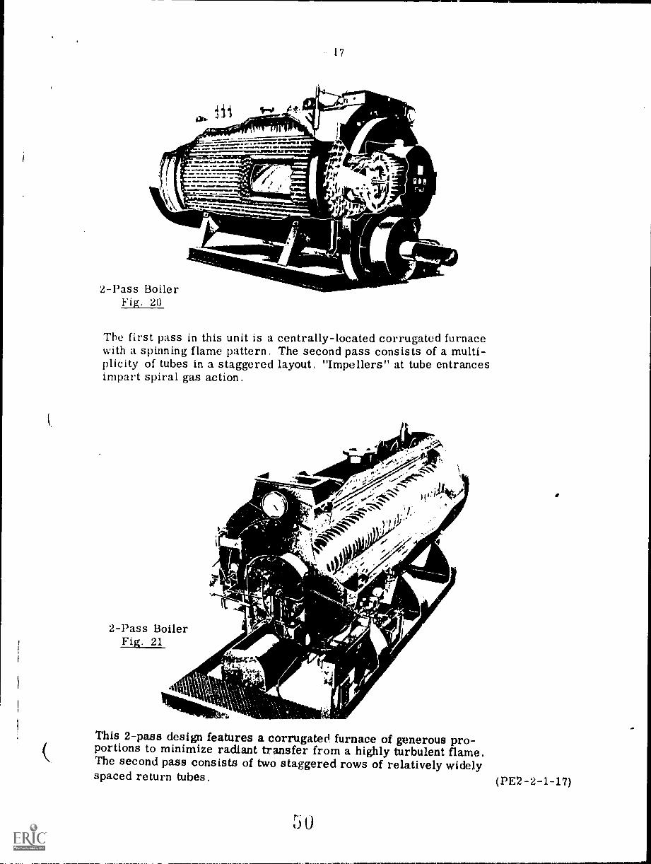
2-Pass BoilerFig. 20
The first pass in this unit is a centrally-located corrugated furnacewith a spinning flame pattern. The second pass consists of a multi-plicity of tubes in a staggered layout. "Impellers" at tube entrancesimpart spiral gas action.
2-Pass BoilerFig. 21
0
ti
74"1/4 +
4
t
4
This 2-pass design features a corrugated furnace of generous pro-portions to minimize radiant transfer from a highly turbulent flame.The second pass consists of two staggered rows of relatively widelyspaced return tubes. (PE2-2-1-17)
0
The reversing chamber at the rear of this 3-pass wetback unitis surrounded by water, From it gas flows forward throughtubes mainly in the lower part of the water space. Then gasflows to the rear through third-pass tubes.
3-Pass BoilerFig. 23
The large stayed firebox of this 3-pass unit has an arched crown sheet;the rear reversing chamber has stayed waterlegs at sides with a sub-merged top. Flow is forward in short second-pass tubes, to the rear inthe longer third-pass tubes. This furnace shape requires stays, as dothe waterlegs at the sides of the rear chamber into which the fireboxdischarges. Here the aim of the designer is for a large combustionspace and a higher ratio of furnace-to-tubular surface.
(PE2-2-1-18)
51
(
19
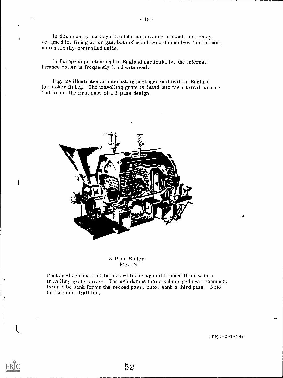
In this country packaged firetube boilers are almost invariablydesigned for firing oil or gas, both of which lend themselves to compact,automatically-controlled units.
In European practice and in England particularly, the internal-furnace boiler is frequently fired with coal.
Fig. 24 illustrates an interesting packaged unit built in Englandfor stoker firing. The travelling grate is fitted into the internal furnacethat forms the first pass of a 3-pass design.
3-Pass BoilerFig. 21
Packaged 3-pass firetube unit with corrugated furnace fitted with atravelling -grate stoker. The ash dumps into a submerged rear chamber.Inner tube bank forms the second pass, outer bank a third pass. Notethe induced-draft fan.
Pa:;: 1,11;,
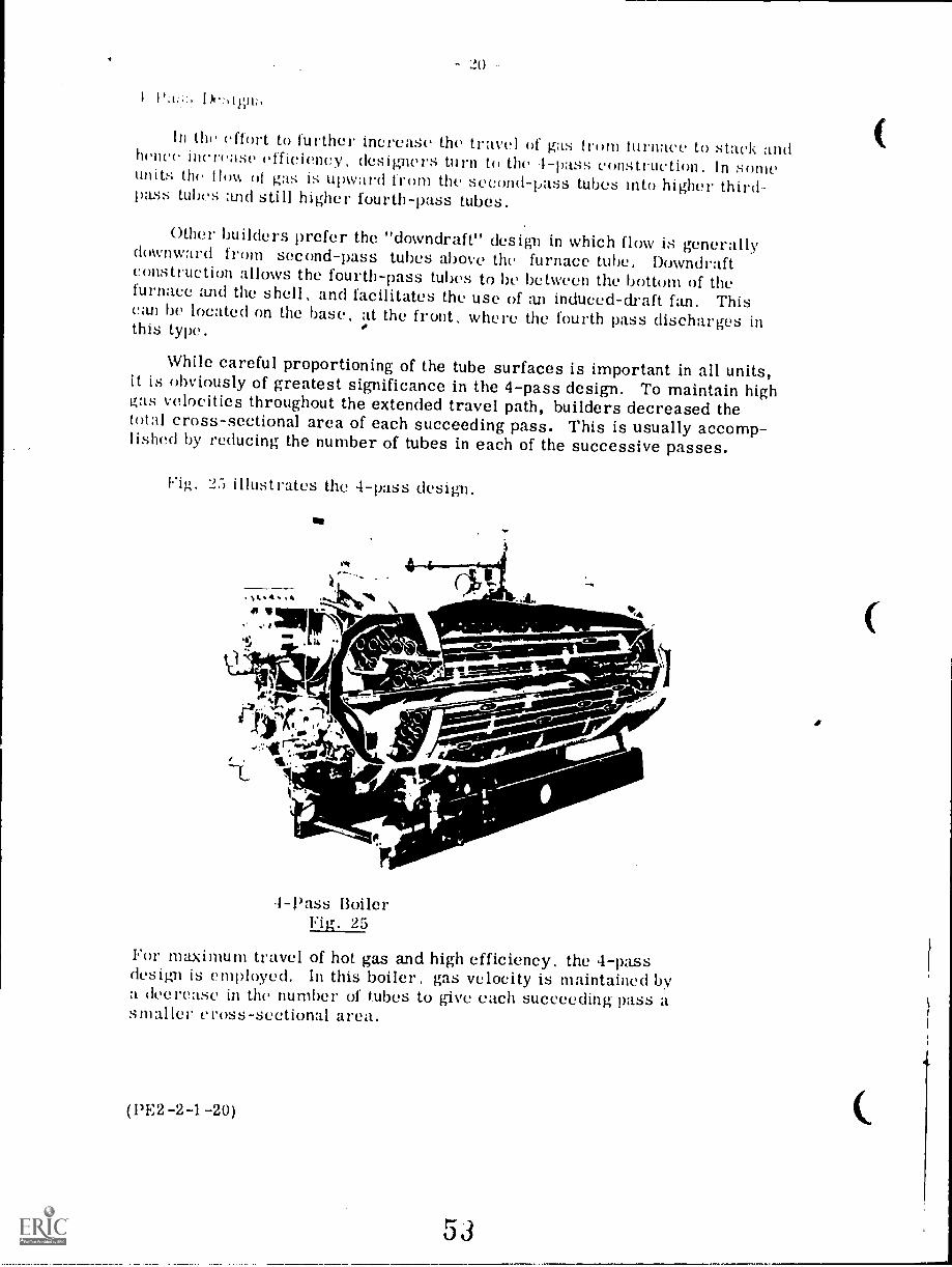
In the effort to further increase the travel of gas from lonace to stack andhence increase efficiency, designers turn to the 4-pass construction. In someunits the How of gas is upward from the second-pass tubes into higher third-pass tubes and still higher fourth-pass tubes.
Other builders prefer the "downdraft" design in which flow is generallydownward from second-pass tubes above the furnace tube. Downdraftconstruction allows the fourth-pass tubes to be betweenJe.ween the bottom of thefurnace turd the shell, and facilitates the use of an induced-draft fan, Thiscan be located on the base, at the front, where the fourth pass discharges inthis type.
While careful proportioning of the tube surfaces is important in all units,it is obviously of greatest significance in the 4-pass design. To maintain highgas velocities throughout the extended travel path, builders decreased thetotal cross-sectional area of each succeeding pass. This is usually accomp-lished by reducing the number of tubes in each of the successive passes.
Fig. 2:3 illustrates the 4-pass design.
-Pass BoilerFig. 25
For maximum travel of hot gas and high efficiency, the 4-passdesign is employed. In this boiler, gas velocity is maintained bya decrease in the number of tubes to give each succeeding pass asmaller cross-sectional area.
(PE2-2-1-20)
53
lls ,.1.11,..tik Hien is notlimr, Icy He% eat !lit addithfiCIIitAlr !hat 11/111 11'1)11:'IW, a 1)1 :Whral !Tent 1111111 an examph. ofthe cunwnic balances that alway:; concrrn the boiler designer. lie must weighHi( need for greater tan power. increased complexity of construction, perhaps alarger shell diameter and hence thicker shell plates against the performanceadvantages to !e gained by going from two to three or to four passes. In likefashion, the boiler purchaser must weigh possible performance gains againstpossible higher first costs and strike the best economic balance for hisconditions
tleneral Features
Thus tar consideration has been given mainly to the boiler propel. and pat-trularly such items as furnace and tube arrangement, gas flow, etc. Now somecharacteristics will he considered which have been developed in recent yearsas applied to packaged firetube boilers.
A number of the construction changes reflect efforts to produce more compactand less costl,, packages. Skillful design has made it possible. however, to achievethese objectives while maintaining desirable performance characteristics. Fore \ample. Ihr general tendency to make shells longer rather than larger indiameter has permitted the use of thinner plate and has made possible otheradvances in fabrication procedures that yielded economies in cost without in anyway jeopardizing safety. Similarly, the use of welded construction has effected111:111%. economies and simplifications and at the same time increased structuralintegrity of t!ie finished product.
More skillful use of heating surface with higher rates of heat-transfer makesit possible to secure more output from a given number of square metres of sur-face. Most of today's Llackaged units, for example, are designed to develop aboiler kW from 0.7 tri- of heating surface.
One inevitable result of working heat exchange surfaces harder has been to*make it imperative to km) both fireside and waterside clean. This puts a greaterpremium on good water treatment and on maintenance. More compact designs,however, tend to make surfaces less accessible for inspection and cleaning. Thus,builders have given increasing attention to improving access by means of largeropenings and by hinging or davit-mounting rear heads and sometimes front headsincludirii*; burners and controls. Modern units are encased and insulated so effect-ively that radiation losses have been reduced to a minimum.
40ine packaged firetube units employ induced-draft fans, but the majorityuse forced draft. either integrated with the burner or mounted separately.Combustion-control equipment has been continuously improved, and an increas-ing number of units employ modulating control, some with plug-in type circuitsfor easy maintenance and replacement of parts, This means that major controlrepairs can he handled by the manufacturer in his shop rather than in the field.
(1'E2 -2 -1 -21)
54
I It :\ :,111.1. I
oldLeek
1,0,'lt EN( I.:ER IN( i
1. Define the following terms:
(a) Firetube boiler(b) Watertube boiler(c) Ilorizontai return tube holler(d) Dry-back and wet-back Scotch boiler(e) Packaged boiler(f) Once-through boiler.
(a) Explain the theory of heat transfer.(1)) Describe the heat transfer in a two-pass firetube boiler.(e) Describe the heat transfer in a three-drum Stirling type
%vatertube boiler.
. (a) Explain, with the aid of a sketch, the natural water circulationin a steam boiler.
(1)) Why is forced circulation a necessity for very high-pressurehoilers.. Explain the following terms applied to water circulation in water-
tube boilers:(a) Circulation ratio(b) Top dr,vness.
5. Sketch and describe an energy flow diagram for a high-pressuresteam generator.
u. Name the different heat transfer surfaces and explain their location ina large high-pressure steam generator.
7. Make front- and side -view sketei., ; of a four-pass firetube boiler,showing position of baffles and tube hanks.
8. Discuss the advantages and disadvantages of modern firetube boilers.
9. Describe in detail your own boiler plant or one with which you arefamiliar, stating manufacturer, type, capacity, and steam conditions.Include auxilliarics such as firing equipment, feed pumps, fans, ashremoval equipment, etc.
(PE2 -2 -1 -Q)
55
1
11.14.UMCNIAL LEARrsnc mawns
7.2
BOILERS -- WATERTUBE TYPE
Goal:
The apprentice will be able to describetypes of watertube boilers.
1
Performance Indicators:
1. Describe straight and bent
tube type boilers.2. Describe horizontal and cross
drum boilers.3. Describe vertical, box and
inclined headers.4. Describe furnace baffles and
refractory furnaces.5. Describe waterwalls,6. Describe stirling type
boilers.7. Describe lower drum/headers,8. Describe drum internals,9. Describe saiety devices and
practices.
.0=161.1.1," AMIwwINIMONI
56
assitalsOnormilin
INSTRUCTIONAL LEARNING SYSTEMS
Study Guide 117
Read the goal and performance indicators to find what is to be learned from
package.
Read the vocabulary list to find new words that will be used in package.
Read the introduction and information sheets.
* Complete the job sheet.
Complete self-assessment.
Complete post-assessment.
2
INSTRUCTIONAL LEARNING SYSTEMS
Vocabulary* Blowoff connection
* Box headers
* Cross baffles
* Cross drum
* Curved baffles
* Downcomers
* Drums
* Feedwater inlet
411* Furnace baffles
* Horizontal drum
* Inclined headers
* Longitudinal baffles
* Lower drums/headers
* Packaged boilers
* Refractory furnace
* Risers
* Steam inlet
* Stirling type
* Straight tube
* Tube nipple
* Vertical headers
* Waterwalk
INSTRUCTIONAL LEARNING SYSTEMS
Introduction
Watertube boilers use their system of tubing to carry water instead of gases.
The hoh gases flow over the tubes and heat the water that is inside the tubes.
DesignePs have improved watertube boilers during the past few years until they
are very competitive with the firetube type. The need for high pressures have
given the watertube boiler an advantage. A second advantage is the safety
factor. Watertube boilers are not as dangerous when exploding. Normally they
rupture a watertube internally rather than blowing out the entire boiler shell.
The watertube boiler has greater flexibility and requires less space than
firetube boilers of the same capacity.
INSTRUCTIONAL LEARNING SYSTEMS
Information
Watertube Boilers
Watertube boilers can be divided into two types:
1. Straight tube
2. Bent tube
Straight 'tube boilers are not widely used in today's steam plants. Some old
boilers of straight tube design are still in operation today but very few new
ones are being made. The bent tube design has advantages that make it the
popular choice. Drums are used to collect and separate water and steam. The
bent tubes connect to the drums.
*Packaged Watertube Boilers
A boiler that is shipped complete with fuel burning and draft equipment and
automatic controls and accessories is a "packaged" boiler.
Horizontal Drum
A horizontal drum boiler is one that has a drum that is located in a horizontal
plane and lies in the same direction as the straight tubes. The tubes and mud
drum are connected by a tube nipple. The drum is located overhead and collects
steam from the tubes.
INSTRUCTIONAL LEARNING SYSTEMS
Information1,11111.
Cross Drum
The cross drum is another configuration for straight tube boilers. The drum
lies at right angles to the tubes.
Bent Tube Boilers
Bent tubes allow more surface exposure to the heat. They can be built in
configurations that give a more desirable size and can usually be built cheaper
thah a straight tube boiler. Older boilers may have four or five drums but new
models use only one or two drums. Improvements in design and fluid handling
have reduced the number of drums needed in a unit. A bent type of structure
shows the tubes and rums arrangement.
"A" Type
-11161144**"..:.
6
1101111MMEM111111111t
61
INSTRUCTIONAL LEARNING SYSTEMS
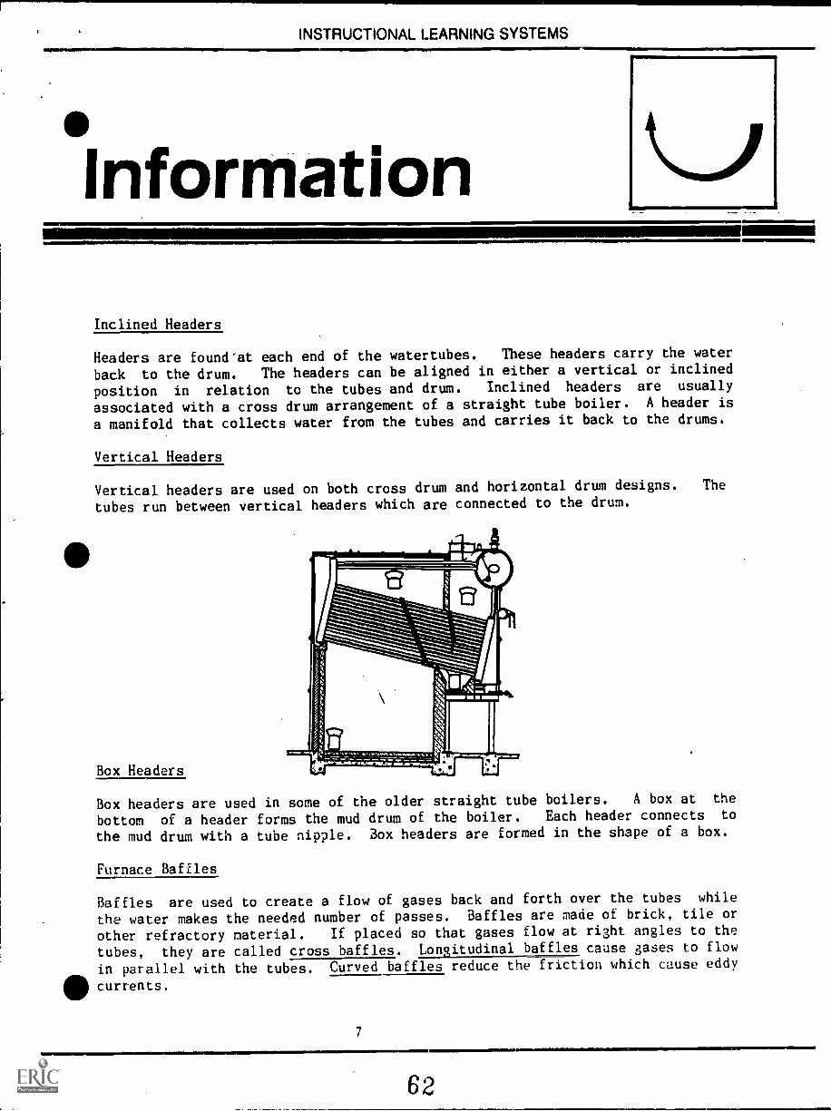
Information
Inclined Headers
Headers are found'at each end of the watertubes. These headers carry the water
back to the drum. The headers can be aligned in either a vertical or inclined
position in relation to the tubes and drum. Inclined headers are usually
associated with a cross drum arrangement of a straight tube boiler. A header is
a manifold that collects water from the tubes and carries it back to the drums.
Vertical Headers
Vertical headers are used on both cross drum and horizontal drum designs. The
tubes run between vertical headers which are connected to the drum.
Box Headers
Box headers are used in some of the older straight tube boilers. A box at the
bottom of a header forms the mud drum of the boiler. Each header connects to
the mud drum with a tube nipple. Box headers are formed in the shape of a box.
Furnace Baffles
Baffles are used to create a flow of gases back and forth over the tubes while
the water makes the needed number of passes. Baffles are made of brick, tile or
other refractory material. If placed so that gases flow at right angles to the
tubes, they are called cross baffles. Longitudinal baffles cause gases to flow
in parallel with the tubes. Curved baffles reduce the friction which cause eddy
41, currents.
7
62
INSTRUCTIONAL LEARNING SYSTEMS
Information
11.
Refractory Furnace
A refractory furnace is one that is lined with brick or other refractory
material.
Waterwalls
Waterwalls or water legs are often used to provide a heat absorbing surface
about the furnace. It serves the same purpose as brick in a refractory furnace.
Almost 50% of the total furnace heat is absorbed by the waterwall. Waterwalls
are also used to surround the tubes and carry steam to the top drum. As water
and steam rise from the mud drum upward to the drum, convection tubes serve
either as risers or downcomers. The risers carry steam upward to the drum.
Downcomers carry water and steam downward to the mud drum and it is
glirecirculated. A waterwall captures much of the furnace heat and uses it in the
II/formation of steam.
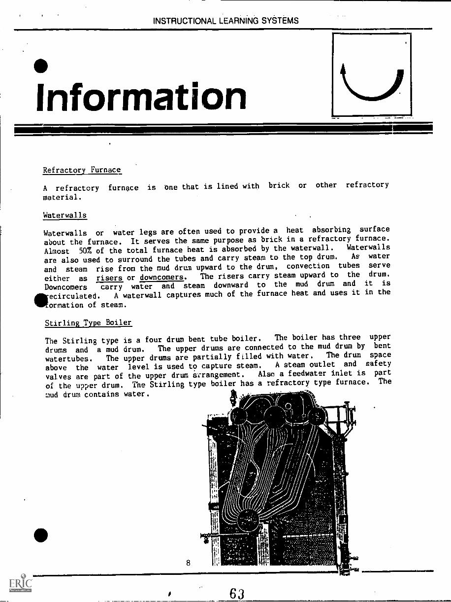
Stirling Type Boiler
The Stirling type is a four drum bent tube boiler. The boiler has three upper
drums and a mud drum. The upper drums are connected to the mud drum by bent
watertubes. The upper drums are partially filled with water. The drum space
above the water level is used to capture steam. A steam outlet and safety
valves are part of the upper drum arrangement. Also a feedwater inlet is part
of the upper drum. The Stirling type boiler has a refractory type furnace. The
mud drum contains water.
I .AL_
11111111111111111111=1.1111SMIEN.1.1.11,1111111111111W
INSTRUCTIONAL LEARNING SYSTEMS{MMINne_n._.
11.111111111=11
InformationAly
.45111111=110
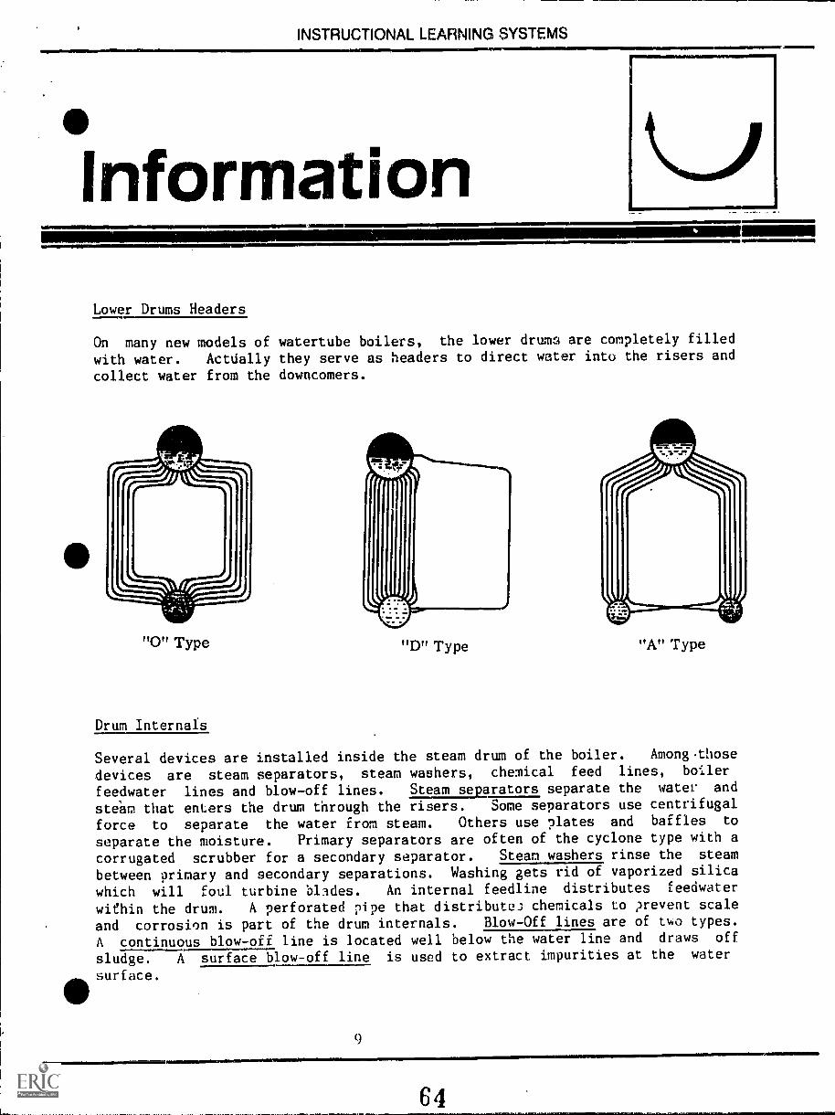
Lower Drums Headers
On many new models of watertube boilers, the lower drum.; are completely filled
with water. Actdally they serve as headers to direct water into the risers and
collect water from the downcomers.
"0" Type "D" Type "A" Type
Drum Internals
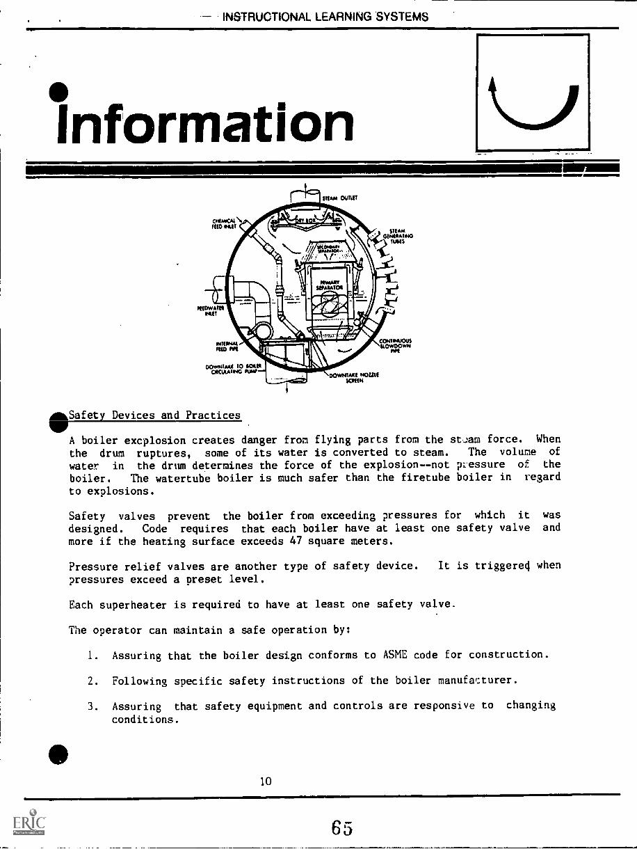
Several devices are installed inside the steam drum of the boiler. Among.those
devices are steam separators, steam washers, chemical feed lines, boiler
feedwater lines and blow-off lines. Steam separators separate the water and
steam that enters the drum through the risers. Some separators use centrifugal
force to separate the water from steam. Others use plates and baffles to
separate the moisture. Primary separators are often of the cyclone type with a
corrugated scrubber for a secondary separator. Steam washers rinse the steam
between primary and secondary separations. Washing gets rid of vaporized silica
which will foul turbine blades. An internal feedline distributes feedwater
within the drum. A perforated pipe that distribute; chemicals to ?revent scale
and corrosion is part of the drum internals. Blow-Off lines are of two types.
A continuous blow-off line is located well below the water line and draws off
sludge. A surface blow-off line is used to extract impurities at the water
surface.
9Ar. 9111MMIIMME
64
INSTRUCTIONAL LEARNING SYSTEMS
Information
AftSafety Devices and PracticesVA boiler excplosion creates danger from flying parts from the st,Jam force. When
the drum ruptures, some of its water is converted to steam. The volume of
water in the drum determines the force of the explosion--not pressure of the
boiler. The watertube boiler is much safer than the firetube boiler in regard
to explosions.
Safety valves prevent the boiler from exceeding pressures for which it was
designed. Code requires that each boiler have at least one safety valve and
more if the heating surface exceeds 47 square meters.
Pressure relief valves are another type of safety device. It is triggered when
pressures exceed a preset level.
Each superheater is required to have at least one safety valve.
The operator can maintain a safe operation by:
1. Assuring that the boiler design conforms to ASME code for construction.
2. Following specific safety instructions of the boiler manufacturer.
3. Assuring that safety equipment and controls are responsive to changing
conditions.
10
INSTRUCTIONAL LEARNING SYSTEMS
AssignmentRead pages 1 - 27 in supplementary reference. Pay close attention to
illustrations.
Complete job sheet.
Complete self-assessment and check answers.
Complete post-assessment and have instructor check answers.
11
66
INSTRUCTIONAL LEARNING SYSTEMS
°Job SheetINSPECT A WATERTUBE BOILER
* Locate and secure permission to inspect a watertube boiler.
* Examine the boiler and its components.
- What is the drum arrangement?- Is it straight or bent tube type?- Does it have headers? What type?- Does it have waterwalls?- Is the furnace lined with refracto. material?- Can you locate the feedwater- Can you locate the steam outlet?- Can you locate the blow-off connection for boiler cleaning?
* Write a short description of the boiler: Manufacturer, type, descriptiveAlfeatures.
* Check description with instructor to make sure that your observations were ontarget.
12 All101.1=
67
INSTRUCTIONAL LEARNING SYSTEMS
*SelfAssessment
MM.
1. Water and steam are collected and separated in the
2. A boiler that comes complete with automatic controls, fuel burning anddraft equipment is called a boiler.
3. A boiler that has a drum lying at right angles to the watertubes is calleda type.
4. A
the watertubes more surface exposure to the heated gasses.boiler allows
5. A is a manifold that collects water from thetubes and carries it back to the drum.
6. are used to divert the flow of gases back towardthe watertubes.
7. A uses water to absorb the heat of thefurnace.
8. tubes carry steam upward to the drum.
9. tubes carry water and steam downward to the muddrum.
10. The Stirling type boiler has a type furnace.
13
68

INSTRUCTIONAL LEARNING SYSTEMS
Self AssessmentAnswers
1. Drum
2. Packaged
3. Cross drum
4. Bent tube
5. Header
6. Baffles
7. Waterwall
8. Risers
III 9.Downcomers
10. Refractory
14
INSTRUCTIONAL LEARNING SYSTEMS
PostAssessmentMatch the following terms and phrases
1. Header A. Collects and separates water and
steam.
B. Lies at right angle to watertubes.
2. WaterwallC. Allows more surface exposyre of tubes
to heat.
3. Cross drum D. Acts as a manifold that collects
water from tubes and returns it to
drums.
E. A waterfilled tube or column that
surrounds the furnace area.
4. Bent tubeF. Fitting in mud drum.
5. Drum G. Fitting in upper drum.
H. Carries water and steam downward.
6. Stirling typeI. A four drum bent-tube boiler with
three upper drums and a mud drum.
7. Riser J. Carries steam upward.
8. Downcomer
9. Blow-off connection
10. Steam outlet
15
INSTRUCTIONAL LEAHNINU SYS I hMb
Instructor'host AssessmentAnswers
D 1.
2.
B 3.
C 4.
A 5.
6.
J 7.
H 8.
F 9.
10.
INSTRUCTIONAL LEARNING SYSTEMS
SupplementaryReferences
~IIMINIIIIINIsioNNIMOIWIN
* Correspondence Course, Lecture 2, Section 2, Second Class. Steam Generators.Southern Alberta Institute of Technology. Calgary, Alberta, Canada.
17
WTHURN A1,111:RTA INSTITUTE('A I , A ',BERTA
Correspondence CoursesPower Engineering
SECIION 2
STEAM GENERATORS
TYPES OF BOILERS
WATERTUBE BOILERS
Second ClassLecture 2
Watertuhe boilers came into extensive use in the 19th century butthe changes in design which have occurred since that time, and moreparticularly in the last 25 years, have left little similarity betweenthose old boilers and the present-day steam generators.
The following pages trace these developments and give illustrationsof some typical boilers.
Advantages of Watertube Boilers
The comparisons given below are between watertube and Scotchtype firetube boilers for equivalent output ratings.
1. Saving in MassThe relative mass of Scotch to watertube boiler install-
ations for equivalent m2 of heating surface with water atworking level is approximately 3 to 1.
2. Use of High PressuresThe demands of steam-driven machinery for ever-higher
pressures and temperature could only be met by the use ofwatertube boilers with their small steam drums. The limit ofworking pressure for Scotch boilers for practical reasons, suchas shell thickness and lack of flexibility, is limited to about1725 to 2070 kPa.
3. Greater Mechanical FlexibilityThe boiler is not so sensitive to fluctuating pressures. The
Scotch boiler. with its poor circulation, especially when raisingsteam, is very prone to mechanical straining and subsequentgrooving in its many flange attachments. These defects do notexist in the watertube boiler with its rapid circulation and struc-tural flexibility.
4. Rapid Steam RaisingThe superior heat-transfer qualities together with positive
circulation reduce the time required for raising steam in a water-tube boiler to a fraction of that required by a Scotch boiler.
5 Saving in SpaceThe good circulation and ability to withstand forcing and
higher pressures enable high outputs to be obtained from water-tube boilers of very small dimensions when compared to theScotch type.
Note that some of the above comparisons are not so biarply defined inthe case of modern packaged firetube boilers.
Safer in the Event of Serious RuptureThe damage done when a boiler explodes is due to the propulsion
of the boiler parts by the issuing steam jet. The steam jet itself isproduced from the body of water in contact with the failed drutr.Collapse of pressure causes a proportion of the water to flash off intosteam.
So it :.an be argued that the potential danger which a steaming boilerpresents is proportional to the quantity of water in any one of its drumsNote that the pressure makes little difference; the vital item is waterquantity. Hence a watertube boiler, even when operating at very highpressures is considerably less hazardous than a shell-type boiler havinga much greater water content at a low pressure.
Types of Watertube Boilers
Watertube boilers at one time could be divided into "straight-tube" and "bent-tube" types. However the bent-tube designs have been so universally adopted that"straight-tube" watertube boilers are very rarely, if ever, built today
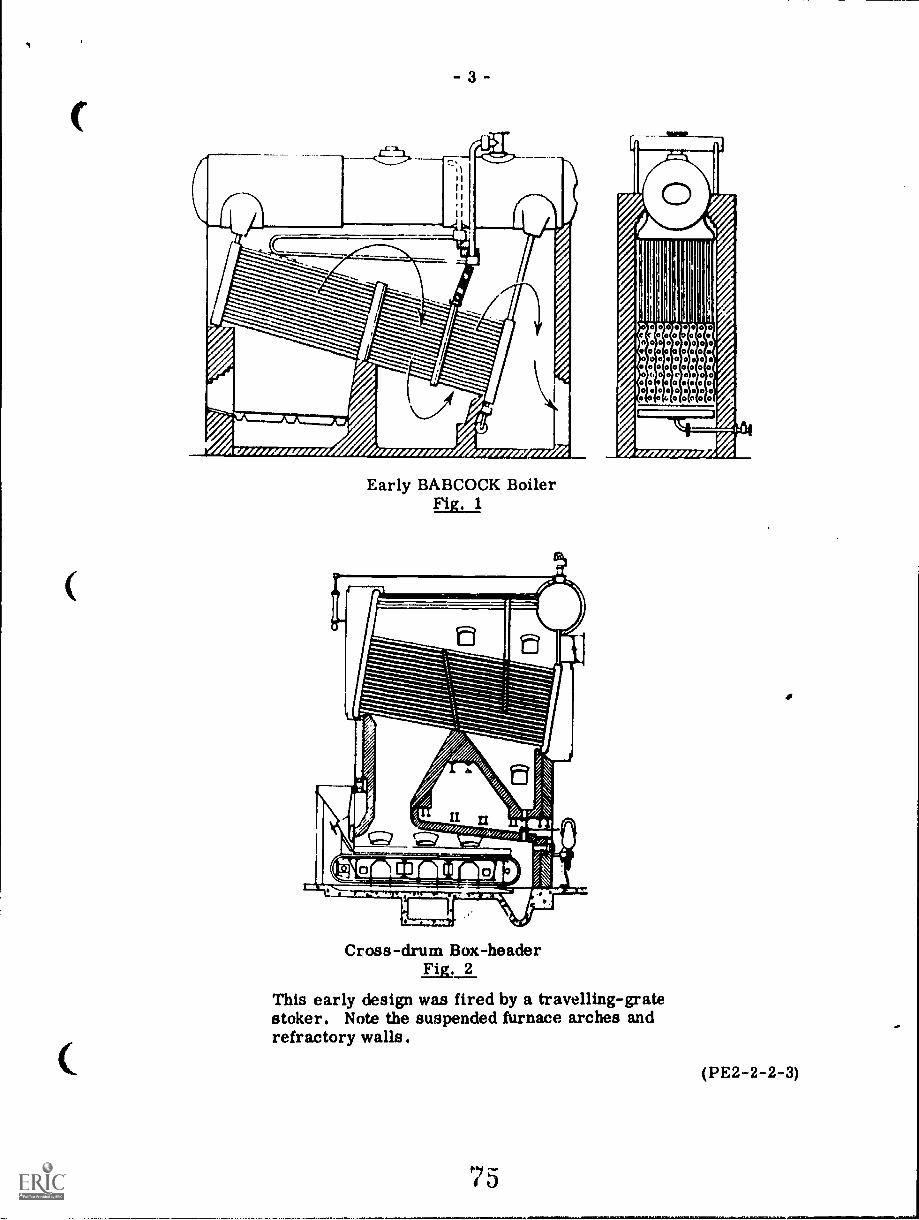
Fig. 1 shows an early watertube boiler design. This is an inclined (straight)tube design, with sectional-cast iron vertical headers. The transverse box atthe bottom of the rear headers forms the mud drum. Each header is connectedto the mud drum by a tube nipple. The vertical headers were usually "sinuous" toallow better tube spacing. This basic watertube boiler design was used extensivelyfor almost a hundred years, many being still in service today.
Fig. 2 shows another old design fired by a travellin;T: grate stoker. In thiscase the steam drum is set at right angles to the axis of the tubes.
(PV2-2-2-2)
-3
IrMININwIN MINIM IV
1W,IIMIWAW /.077,ZeM7, /AVOW
Early BABCOCK BoilerFig. 1
Cross-drum Box-headerFig, 2
r-11
)
Liu
cc 000 oon0000000o o o o 0 0oooo0000000voec0000i,00o 0f000aeo
rzew,,,,,,
This early design was fired by a travelling-gratestoker. Note the suspended furnace arches andrefractory walls.
(PE2-2-2-3)
Bent-tube boilers were found to be more flexible in their design require-ments. Where headroom is limited they can be made wide and low, or narrowand high where floor space is at a premium. Also, bent-tube boilers allow moreof the surface to be exposed to radian heat of the furnace. As a final factor,they can be built at a lower cost.
Drums serve as convenient collecting points in the steam-water circuitaild for separation of steam and water. Thus , boilers with two, three andsometimes four drums were popular up through the mid 1920's. Fig. 3 showsa bent-tube type.
As boilers grew in size, the demand for more active furnace coolinginereased..It was then that waterwalls and other changes in design came intothe picture. A better knowledge of fluid dynamics resulted in improvedmethods for the calculation and monitoring of circulation of waterwall fluids -both on the gas side and the steam side. In short order, it became practicalto eliminate one, sometimes two drums. Two-drum boilers, even boilers withonly one drum at. the top and one or two large headers at the bottom, becamecommon designs; one is shown in Fig. 4.
Thousands of boilers of the vertical-header type and of the multi-drumbent-tube variety are still operating satisfactorily today. Many feel that theaverage life of a well-designed, properly installed and adequately maintainedboiler can be as much as 50 years.
Modern designs have eliminated the rivetting of boiler seams and the useof cast-iron for header boxes. Welding replaced rivetting for boiler construc-tion in the early 1930's. Welding methods have improved significantly; today,covered electrodes are used for continuous automatic metal deposition.
The use of furnace water-wall surfaces has been extended to providemaximum utilization of radiant heat. Exposed refractory surfaces have beenreduced to a minimum and often replaced altogether by either tangent tubewalls or membrane walls.
Boiler casings are being made more air and gas-tight and there is atrend towards pressurized furnaces and elimination of the induced draft fan.There is increasing use being made of hcat recovery equipment, air heaters,,conoinizers. etc. in a continuing endeavour to produce more and moreefficient steam generating units.
Fig. 5 shows a watertube boiler design by Babcock and Wilcox. Max-imum continuous steam capacity 454 000 kg/h at 10 700 kPa and 538°C.This steam generator is fired by a cyclone furnace and designed for pres-surized firing.
Lecture 3 will discuss the separate sections such as furnace firing equip-ment. superheaters, etc. in boilers of this type.
(PE2-2-2-4)
76
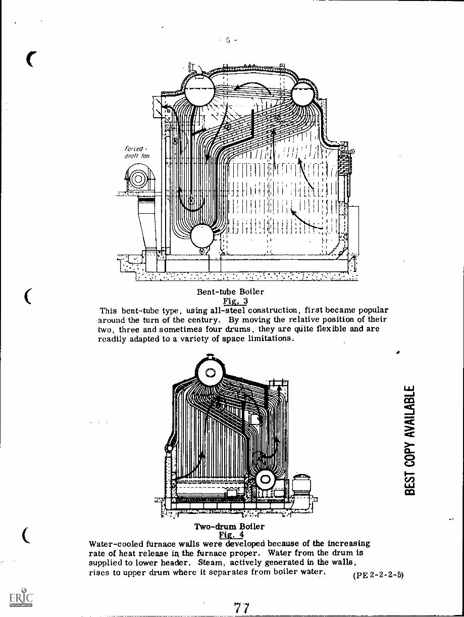
C
Bent-tube BoilerFig. 3
This bent-tube type, using all-steel construction, first became populararound the turn of the century. By moving the relative position of theirtwo, three and sometimes four drums, they are qUite flexible and arereadily adapted to a variety of space limitations.
Two-drum BoilerFig. 4
Water-cooled furnace walls were developed because of the increasingrate of heat release in the furnace proper. Water from the drum issupplied to lower header. Steam, actively generated in the walls,rises to upper drum where it separates from boiler water. (PE 2-2-2-5)
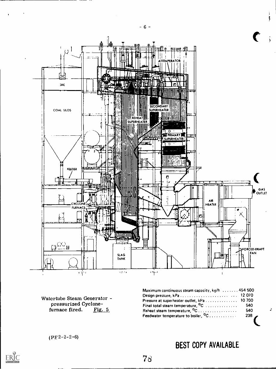
t Egiari1arE;gii=1;0
4 1JI
11111%UMW ............
floc.- .apiroma. ,\. -.... -- -131fri-t1.:7. ..!..!_.... -.:., iiihwtir. III NW , iii411 I
11 1-; 7 I, iiitMiliaZifillfilligrillii0...61,....,, 1,:,..,...,..;,-,...-4., I, -,T {
II1
,,
, .
ti
III ;;1 i;, im 1111111j111111.
mil1 r .1.234mmt-immellr......,,, 1__,.,,,i4
I: 1 il 1. _sawn,
tzt,jai... _ =94
III Ili FltIli.
* li i jimAll 0 1111 a
, I lc
LJ110g. ,to
1 Nam1111.,----
triL1.
10
I I I 1111
Art 2lift Iii c>yi' 1.011.FA A --..:1111.1..
1 Jis
)IIIIIME.I.,a,
1 .i.
il 11
......a.1 m
"
7 4 $. .10111
;IV IIIIIIIM111111P111111111.1,1111,
I)
. .. .
_
.
. .
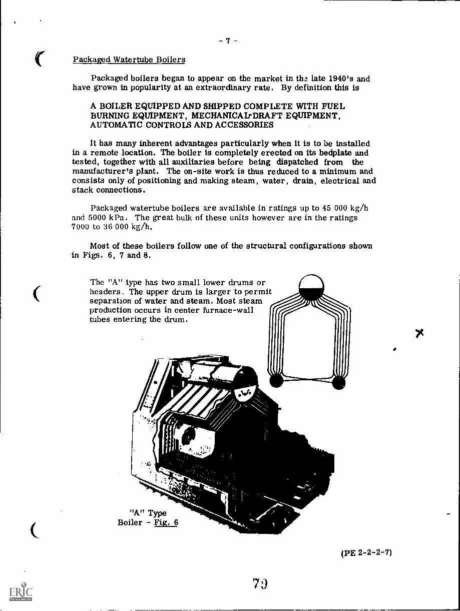
C
7
Packaged Watertube Boilers
Packaged boilers began to appear on the market in th. late 1940's andhave grown in popularity at an extraordinary rate. By definition this is
A BOILER EQUIPPED AND SHIPPED COMPLETE WITH FUELBURNING EQUIPMENT, MECHANICAL-DRAFT EQUIPMENT,AUTOMATIC CONTROLS AND ACCESSORIES
It has many inherent advantages particularly when it is to be installedin a remote location. The boiler is completely erected on its bedplate andtested, together with all auxiliaries before being dispatched from themanufacturer's plant. The on-site work is thus reduced to a minimum andconsists only of positioning and making steam, water, drain, electrical andstack connections.
Packaged watertube boilers are available in ratings up to 45 000 kg/hand 5000 kPa. The great bulk of these units however are in the ratings7000 to 36 000 kg/h.
Most of these boilers follow one of the structural configurations shownin Figs. 6, 7 and 8.
The "A" type has two small lower drums orheaders. The upper drum is larger to permitseparation of water and steam. Most steamproduction occurs in center furnace-walltubes entering the drum.
"A" TypeBoiler - Fig. 6
7J
(PE 2-2-2-7)
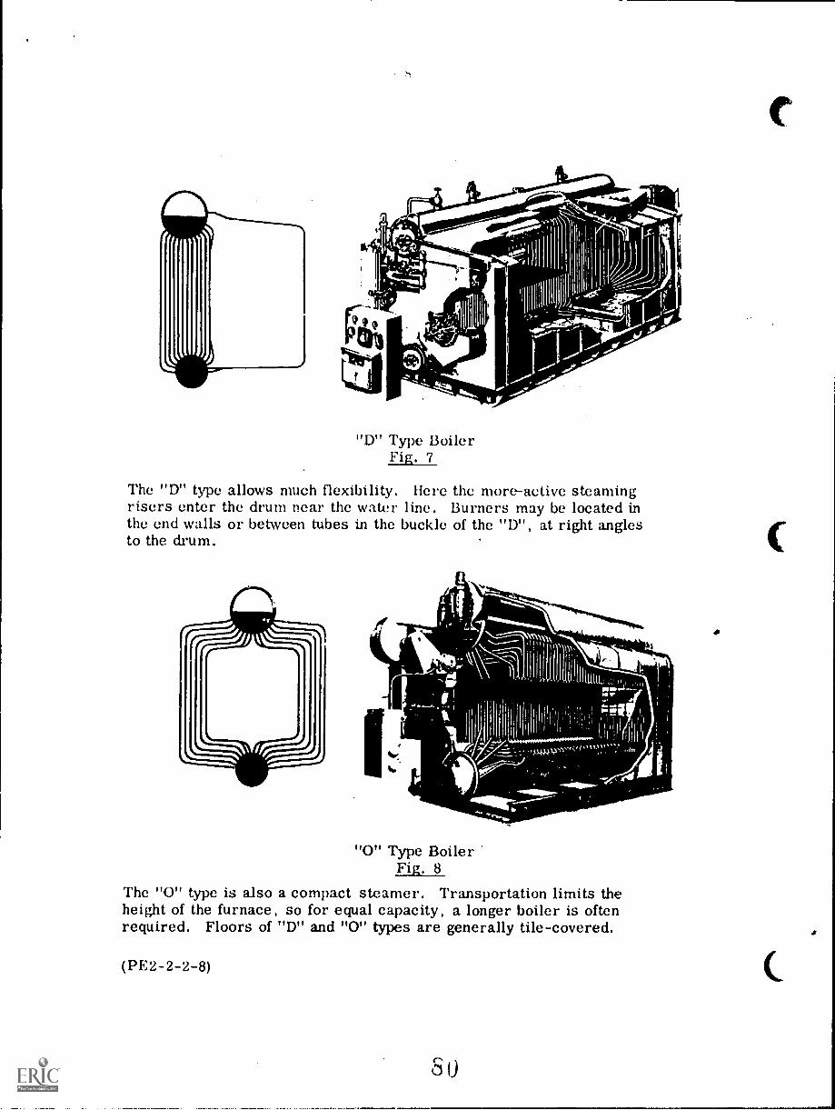
ti
""1111S,P1'
"D" Type BoilerFig. 7
The "D" type allows much flexibility.risers enter the drum near the waterthe end walls or between tubes in theto the drum.
Here the more-active steamingline. Burners may be located inbuckle of the "D", at right angles
I"0" Type Boiler
Fig. 8The "0" type is also a compact steamer. Transportation limits theheight of the furnace, so for equal capacity, a longer boiler is oftenrequired. Floors of "D" and "0" types are generally tile-covered.
(PE2-2-2-8)
The "A" type, Fig. 6, has two small lower drums or headers. Theupper drum is made large to permit separation of water and steam. Mostof the steam production occurs in the centre furnace wall tubes.
The "D" type, Fig. 7, allows much flexibility of design since thecombustion chamber volume can be easily varied. The more activesteaming tubes become risers and enter the drum near the water line.The boiler is fired I etween the outer "D" tubes either at the end or atthe side, the tubes being bent to allow the burner entry. Superheatersand economizers can be added to the "D" type radiant or convection zone withrelative ease.
The "0" type, Fig. 8, has a symmetrical design but exposes the leasttube surface to radiant heat.
Manufacturers tend to standardize package boiler designs withregard to the outside dimensions of width and height and to vary thelength according to the required boiler output rating. This is largelydictated by the size limitations imposed on rail or road transportation.
Shop-assembled Boilers
These are technically the same as packaged units since they arecompletely assembled at the manufacturer's plant together with all oftheir auxiliaries and controls. The name is customarily applied to thebiggest of the packaged boilers where each one is built to a customer spec-ification as regards required output, types of fans, burners, pumps andcontrols etc.
All of the packaged and shop-assembled boilers have the advantageof lower cost compared with field-erected boilers of equivalent rating,some engineers estimating that the. field-erected boilers' cost is doublethat of the packaged unit.
Figs. 9 and 10 are further examples of "D" and "0" type packagedboilers respectively.
Fig. 9 is pressurized, no induced fan is used. A convection super-heater is located in the gas flow and the boiler can be built to give an out-put of up to 45 000 kg of superheated steam/h at up to 400°C.
Circulation pattern of water, steam a.%! gases may be readily tracedon this boiler. From mud drum and lower headers, water and steam rise infinned waterwalls and enter the drum near its water line (note the druminternals). Some of the convection tubes above the mud drum act as downcomers, the rest serve as risers. Gases from the burner at left (not shown)make a 180° turn at the far left end of the furnace, enter the convection zoneof the boiler between nontangent, nonfinned tubes. They leave the boiler atthe front left.
(PE2-2-2-9)
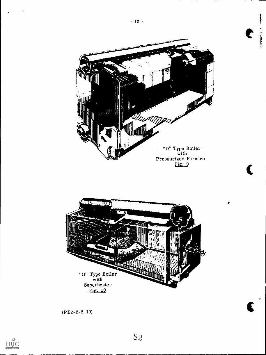
10
F
MI6
"D" Type Boilerwith
Pressurized FurnaceFig. 9
710"grenriftelowuipmmornewurig......_____
s"
"0" Type Boilerwith
SuperheaterFig. 10
(PE2-2-2-10)
4e.
111111!IITP17( lllqii
11
r ..7:67L. IBLIIIIII
', ',.. ' , . iii W4 , ' , ,
.. ' /";.t :4
-14111r
X/
As an alternate in some designs, gases turn into an additional passtoward the rear. This rerouting is accomplished by a baffle made ofrefractory or simply tangent tubes. Superheater and e' 'nomizer can beeasily installed in the convection portion of this unit. Tne furnace floor istiled,
The compact "0" type unit shown in Fig. 10 is skid-mounted. Thispackaged boiler may generate over 45 000 kg/h of superheated steam/hat a maximum of 5350 kPa'and 400°C.
Note the double-steel casing and cyclone-type drum internals toassure drier steam. Convection superheater is located at a poir4 wherethe flow of gases, directed by finned-tube water walls, splits into twoparts. Each turning point of 180° directs the flow toward a flue-gas exitlocated on either side of the upper drum.
A forced-draft fan (not shown) may be located at any convenientplace. The furnace is pressurized and no induced fan is required. Foursoot blowers, two per bank, serve to keep convection banks clean. Thesymmetrically-arranged surface is designed for balanced heat absorp-tion. Tubes are arranged in rows with alternate wide and narrowspacing.
The design trend in packaged or shop-assembled boilers is towardsgreater outputs, using higher heat-release rates, bigger drums and headersto facilitate steam separation and inspection, and the addition of superheaters and economizers.
One BABCOCK and WILCOX design incorporates a cyclone burner foroil or gas. The burner is a fully water-cooled cylinder and is claimed togive stable combustion over a 10 1 load range. Steam purity is attainedthrough the use of cyclone separators and steam scrubbers. Output ratingsup to 90 000 kg /h at 61 200 kPa and 442°C final steam conditions are achieved.
Fig. 11 shows the Babcock and Wilcox "CYCLOPAK" Boiler.
(PE2-2-2-11)
63
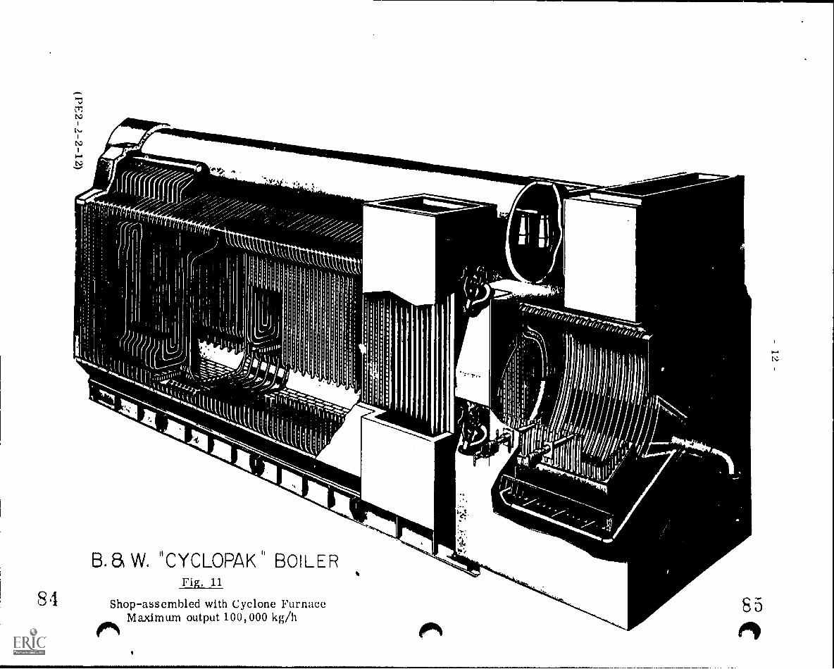
B.81 W. "CYCLOPAK" BOILERFig, 11
Shop-assembled with Cyclone FurnaceMaximum output 100,000 kg/h
85
1.1)
ic
- 13 -
Field - erected Watertube Boilers
Recent developments in boiler design and construction have promoted the saleof packaged boilers to supply the demands of industry, for steam rates up to about45 000 kg/h or even higher in some special cases.
Boilers with steam rates above this figure generally become too large fortransport to site in one piece, and as a result have to be field-erected. Theprinciple of shop assembly or prefabrication of parts is not abandoned altogetherhowever, and it is found that large sections of water wall, superheaters andeconomizers are being completed in the manufacturer's plant and then shippedto Le site for erection.
The great majority of field-erected boilers at the present day are of largeoutput though there still remain a few applications where because of difficulty ofaccess or some other special reason a small field-erected boiler is the bestsolution.
Boiler outputs seem almost to have no limit particularly hi the field of elec-tricity generation. The biggest on record to date is that built to( ConsolidatedEdison Company to supply steam to a 1000 MW turbo-generator in that Company'sRavenswood Station. Steam rate is 2 900 000 kg/h with stop-valve conditions of19 000 kPa and 538°C. This exemplifies the trend which has been followed inpost-war years of matching boiler output to turbo-generator demand and prolucing"unit" electricity generating sets. Boiler outputs are in fact commonly referredto by the MW rating of the turbine set with which they will be "unitized". Thi,;gives truer picture of the boiler size than a rating quoted in kg/h of cill 1
leaving the stop valve because of the large reheat sections included in these boilers.
Boilers designed for use in thermal generating plants have necessarily followedthe preferred standard sizes of steam turbine generators issued by the A.S.M.E.and A.I.E.E. These standards were adopted in post-war years with the object 9fallowing manufacturers to concentrate on a few standard designs and so reduce thecost of production and speed-up delivery dates. The following are some of thesestandard ratings:
22 MW at 5860 kPa and 482°C44 MW at 5860 kPa and 482°C66 MW at 8600 kPa and 510°C
100 MW at 10 000 kPa and 538°C with one reheat to 538°C150 MW at 12 400 kPa and 538°C with one reheat to 538°C
Industrial boilers for use in individual plants are of course designeu to meetthe needs of that particular plant and consequently do not follow any standard sizepattern. The design of these boilers however follows similar lines to the thermalgenerating plant boilers in the tendency towards higher pressure steam, pressur-ized furnaces, increasing use of radiant heat and decreasing convection surfacesand maximum use of heat recovery devices.
There are many boilers designed for special purposes such as the recoveryof waste heat in pulp and paper plants or sulphur recovery plants and these boilershave each to be designed for its particular service.
(PE2-2-2-13)
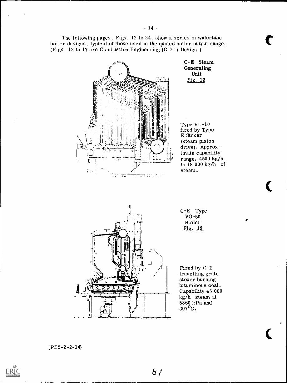
14
The following pages, Figs. 12 to 24, show a series of watertubeboiler designs, typical of those used in the quoted boiler output range.(Figs. 12 to 17 are Combustion Engineering (C -E ) Design.)
(PE2-2-2-14)
8 /
C-E SteamGenerating
UnitFig. 12
Type VU-10fired by TypeE Stoker(steam pistondrive). Approx-imate capabilityrange, 4500 kg/hto 18 000 kg/h ofsteam.
C-E TypeVA -50BoilerFib. 13
Fired by C-Etravelling gratestoker burningbituminous coal.Capability 45 000kg/h steam at5860 kPa and307°C.
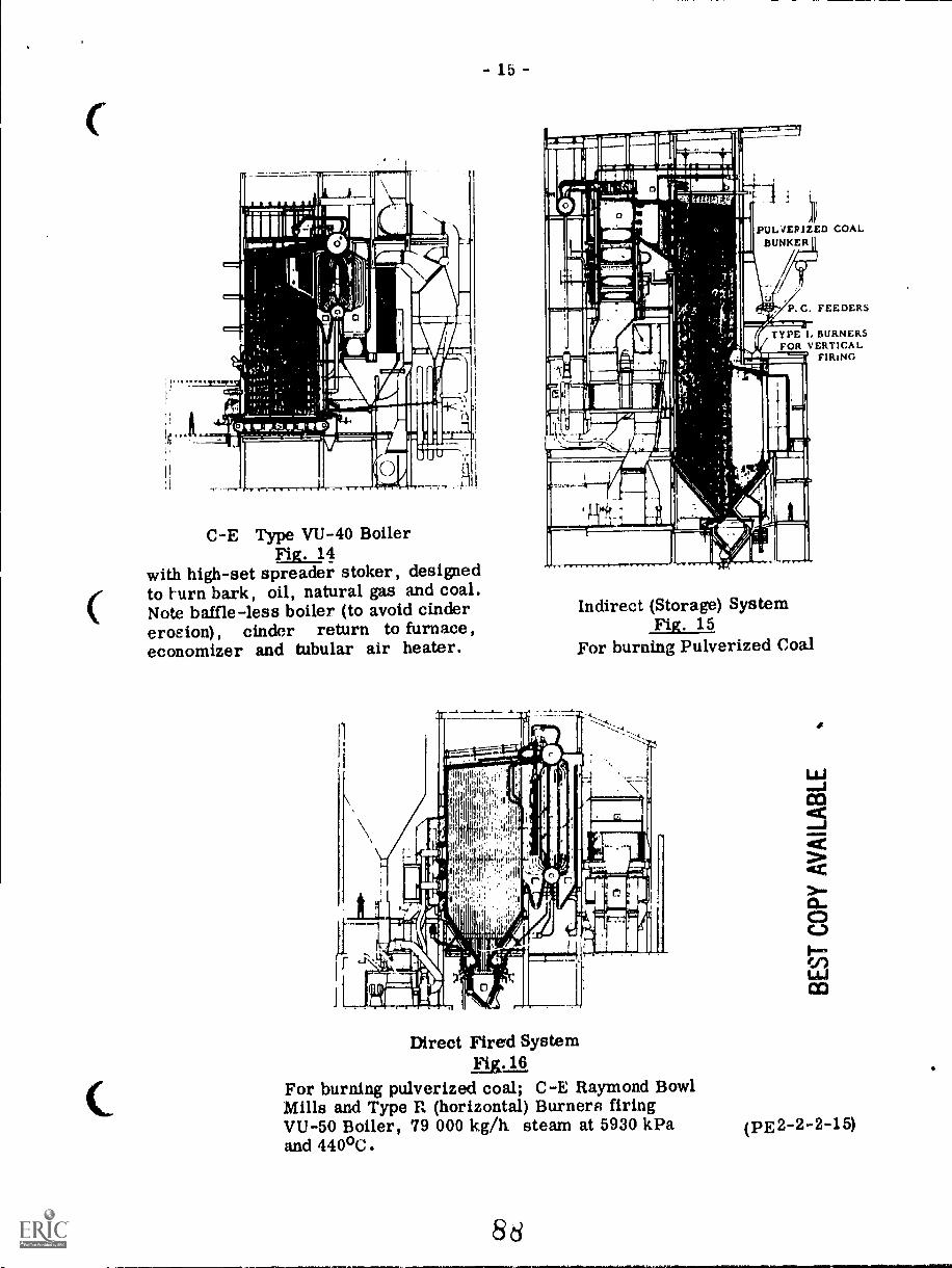
- 15 -
C-E Type VU-40 BoilerFig. 14
with high-set spreader stoker, designedto turn bark, oil, natural gas and coal.Note baffle-less boiler (to avoid cindererosion), cinder return to furnace,economizer and tubular air heater.
PULVERIZED COALBUNKER
TYPE L BURNERSFOR VERTICAL
FIRING
Indirect (Storage) SystemFig. 15
For burning Pulverized Coal
Direct Fired SystemFigt11
For burning pulverized coal; C-E Raymond BowlMills and Type It (horizontal) Burners firingVU-50 Boiler, 79 000 kg/h steam at 5930 kPaand 440°C.
Sd
(PE2-2-2-15)
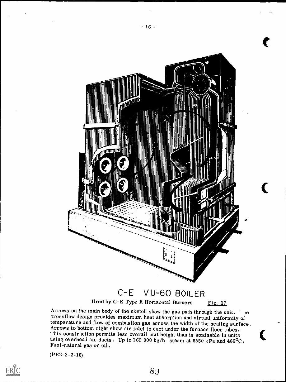
- 16
C-E V U-60 BOILERfired by C-E Type R Horizontal Burners Fig. 17
Arrows on the main body of the sketch show the gas path through the unit. Recrossflow design provides maximum heat absorption and virtual uniformity o:temperature and flow of combustion gas across the width of the heating surface.Arrows to bottom right show air inlet to duct under the furnace floor tubes.This construction permits less overall unit height than is attainable in unitsusing overhead air ducts. Up to 163 000 kg/h steam at 6550 kPa and 480°C.Fuel-natural gas or oil.
(PE2-2-2-16)
C
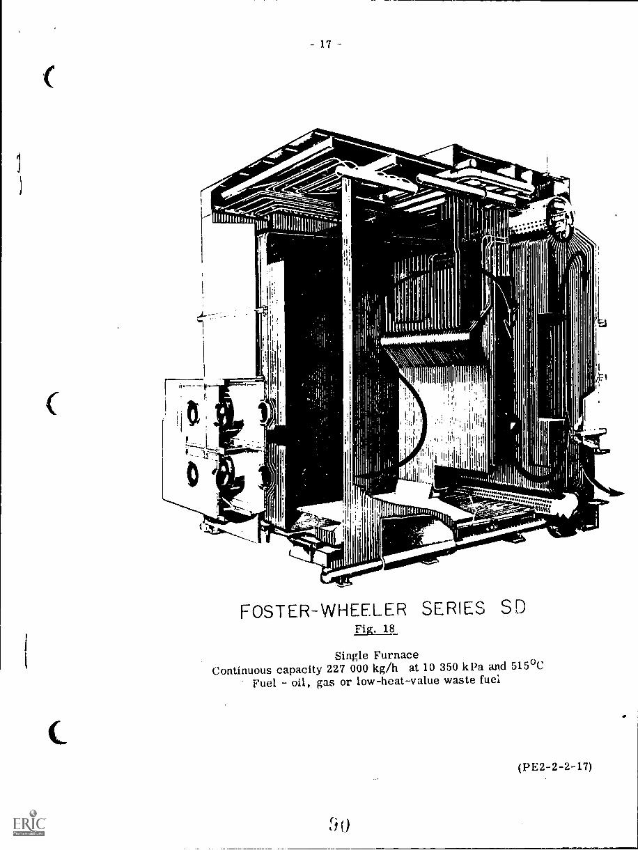
C
r
11110°-
::::::::::::::::::::::::::::::::
171%;.
FOSTER-WHEELER SERIES SDFig. 18
Single FurnaceContinuous capacity 227 000 kg/h at 10 350 kPa and 515°C
Fuel oil, gas or low-heat-value waste fuel
(PE2-2-2-17)
LEGEINII)(referring to Fig. 19)
(I) MEMBRANE WALL FURNACE gas-tight for high efficiencypressure firing. Membrane construction prevents gas-sidecorrosion, Completely water-cooled Integral Furnace givesbalanced heat absorption, eliminates refractory maintenance.
(2) GENERATING TUBE BANK gains optimum heat transfer fromhorizontal cross-flow gas pattern. Arrangement of tubes makespossible effective soot-blower cleaning while the unit is in service.
(3) CYCLONE STEAM SEPARJ.TORS deliver pure, dry steam forhigh turbine and process equipment efficiency. Steam-free waterreturned to boiler provides maximum circulating head, givesbetter control of drum water level during rapid load swings.
(4) SUPERHEATER combines radiant and convection surfaces tohold steam temperature virtually constant over wide load range.Inverted-loop design makes superheater drainable for quick.safe start-ups.
(5) OIL AND GAS BURNERS are centrally located for operator con-venience. Versatile burner design permits single -fuel or(2ombination firing. Easy fuel change-over permits operatorsto take advantage of favorable prices.
(6) INTEGRAL AIR DUCT cuts required boiler space and headroom,minimizes connecting ducts and flues. Full-width "plenum cham-ber" distributes combustion air uniformly to all burners,
(7) SIMPLE FOUNDATION SUPPORTS eliminates external steelwork,
(M) STEEL CASINO AND LAGGING covers the entire boiler and aux-iliary equipment, making this boiler equally suitable fur indooror outdoor installation, Aluminum lagging is also available when
desired,
Fig. 20 shows the circulation system in the "Power for Industry"boiler of Fig. 19, Note the superheater headers below the furnace floor.
(PE2-2-2-18)
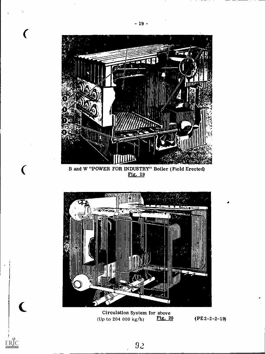
- 19 -
r
.
0 _
B and W "POWER FOR INDUSTRY" Boiler (Field Erected)Fig. 19
Circulation System for above(Up to 204 000 kg/h) (PE2-2-2-19)
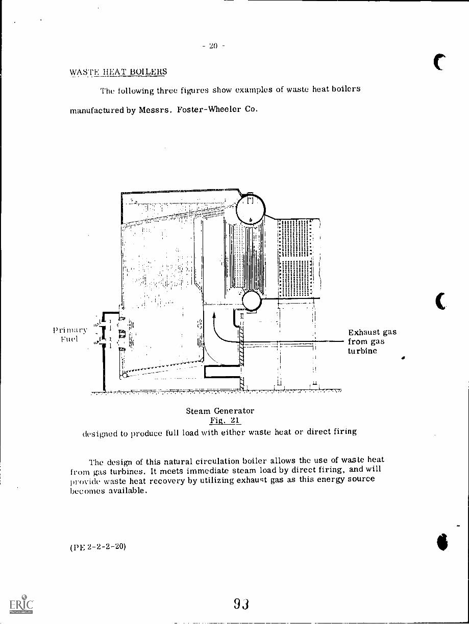
20
WASTE HEAT BOILERS
The following three figures show examples of waste heat boilers
manufactured by Messrs. Foster-Wheeler Co.
I) riFuel
I ''''''' .::1.itt'1..ir
If
r'1::........:,''' .--4:Le%!'.
1,,ii:-4,4...1._,:-.4,-,---
.. ...1. 11, r;01 '''''' ts '''''-of
11;;!1.( 1
Exhaust gasr_ from gas
turbine
Steam GeneratorFig. 21
designed to produce full load with either waste heat or direct firing
The design of this natural circulation boiler allows the use of waste heatfrom gas turbines. It meets immediate steam load by direct firing, and willIn rovide waste heat recovery by utilizing exhaust gas as this energy sourcebecomes available.
(PE 2-2-2-20)
93
C
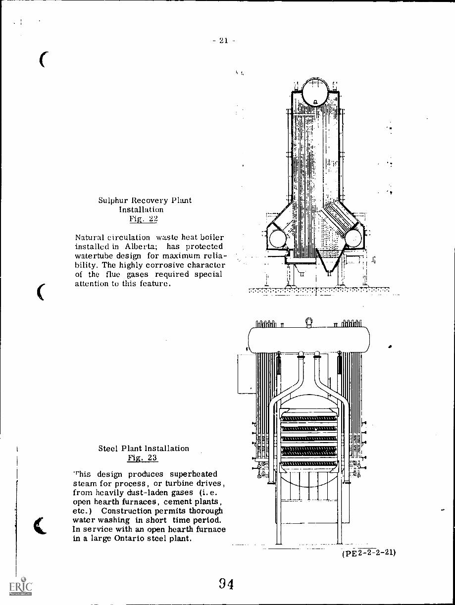
C
21 -
Sulphur Recovery PlantInstallation
Fig. 22
Natural circulation waste heat boilerinstalled in Alberta.; has protectedwatertube design for maximum relia-bility. The highly corrosive characterof the flue gases required specialattention to this feature.
Steel Plant InstallationFig. 23
'phis design produces superheatedsteam for process, or turbine drives,from heavily dust-laden gases (i.e.open hearth furnaces, cement plants,etc.) Construction permits thoroughwater washing in short time period.In service with an open hearth furnacein a large Ontario steel plant.
94
AMA n g
\\\\\N,Nkm,,,, 0,1
IC\ W' \\1
(PE 2-2-2-21)
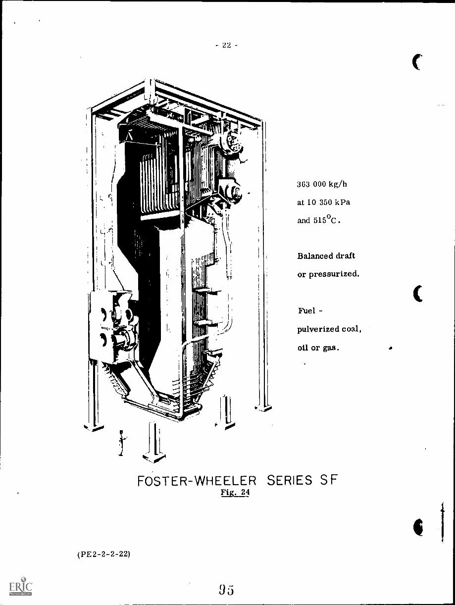
22
ill
363 000 kg/h
at 10 350 kPa
and 515°C.
Balanced draft
or pressurized.
Fuel -
pulverized coal,
oil or gas.
FOSTER-WHEELER SERIES SFFir. 24
23
Forced Circulation Boilers
Natural circulation in a boiler depends upon the difference in densitiesbetween water and steam to produce the circulation head. It was pointed outin Lecture 1 of Section 2 that this difference in density becomes progressivelyless with increased pressure and disappears altogether at critical pressure22 106 kPa.
Boilers designed to operate at high pressures, particularly those withintricate tube paths must be designed with great care in order to ensure goodnatural circulation, or alternatively they can employ a pump in the boiler watersystems to give forced circulation.
Forced circulation in a boiler has the advantage of giving a positive flowin all tubes; further by fitting orifices or nozzles of varying sizes at tube inletsthe flow in the tubes can be regulated.
The disadvantages are the increased cost of equipment, pumps, piping,etc. and the increases in maintenance and running costs. One particulardifficulty lies in effectively sealing the glands of the circulating pump againsta pressure breakdown to atmosphere.
Forced circulation becomes advantageous at pressures of about 12 500to 13 800 kPa upwards, and essential for supercritical steam.
Once-through boilers are a development of forced circulation; in this casethe feedwater is forced through the circuits of die boiler and the change ofstate (water to steam) takes place in its course along the full length of the tube.
Fig. 25 shows a C.E. forced circulation dual-furnace boiler rated at454 500 kg/h with final steam conditions of 14 500 kPa and 565°C. The unitis fired with tilting tangential burners to give superheat temperature control.
Fig. 26 shows a Babcock and Wilcox universal pressure boiler (once-through) designed for both pulverized coal and oil firing, steam conditions are16 500 kPa at 538°C with one reheat to 538°C. The capacity of the unit is1 197 000 kg/h at which the maximum capability of the unit approaches 400 MW.The single furnace is 14.63 metres wide with firing through both front and rearwalls.
(PE2-2-2-23)
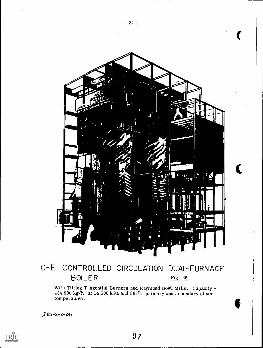
24 -
:qr"-Pri
Mb-
Aog
1.
C-E CONTROLLED CIRCULATION DUAL-FURNACEBOILER Fig. 25
With Tilting Tangential Burners and Raymond Bowl Mills. Capacity454 500 kg/h at 14 500 kPa and 565°C primary and secondary steamtemperature.
(PE2-2-2-24)
9?
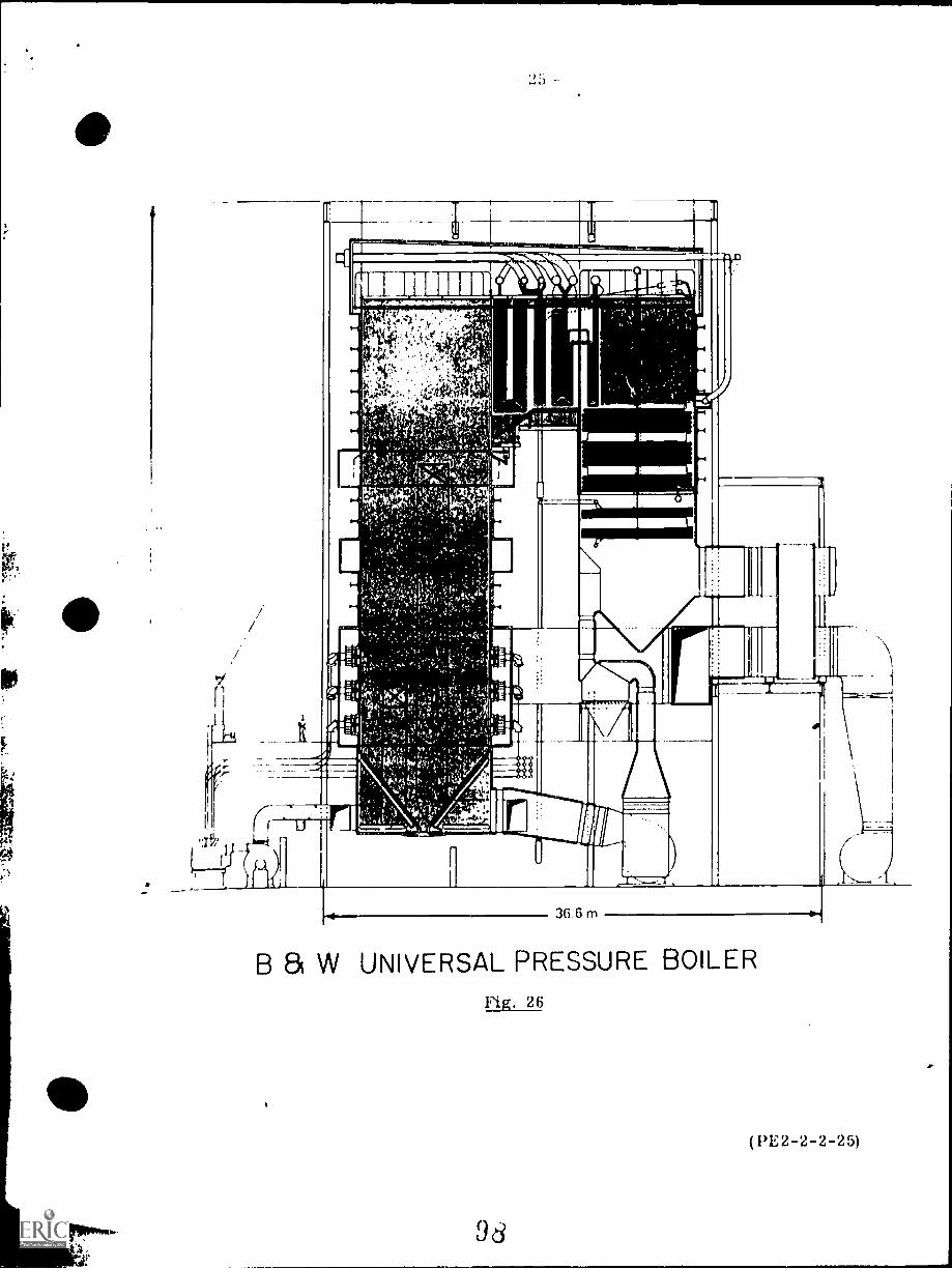
4 ;
11 ro a V I 0 : a I 411 III ID Of
--.
II
11111110.1.=.
AA.t.,..:,, ,.,..i,k. .,.
4111,
i
,9',1r)
I
41, lg. :,,,, 4.,,, i: ,,,,., ,, - ,.,..,.,,,,..,.1.-; l.l. pi
I. (,.,-1.....,,,,,;, (V' A ' ,;K:1:1..; 4 lu
1
. 11
,,;, ' ; 1 i 1 e .17:411: ,s\.1''' t
1
?''''' j il
1, , r.* 4 , t !,;; 4111
MI1-,, .111,41.51°
MI03.--,,.-r..,,:-`' `,; ,...-M
_., , .,,--c.P'0,,,,,'i'"'-i,;^* '414
, 0,.hk-.YtW%:1-41,.,4.
, ,:it 7,. ,.a\ ,,,,,, il 1,:, ); ,,,v. 4 Li
1 - c , '' .
.0 t ''...*-
it I, ..r :!rC i
t:e'f.,:il'ori,
MLA% 10, qi:( t. vl 14j,
ii); k !:1,".11qt tatZig;
i::7771 :*-;'.1clik;1'''17-174:;;i7`,:::.2(1::;:;4::$1";r'f'll
0
i' ' 1
, , , , : .'
, . .. - : : .. . .., p APINKIMIMINPOIEVP e
"WM"
A , . , . ifi 0 i
1:Pi, ,J.
inr.4 t '
Ire 2 .7..7iiiiiit iiik I me. ii. . . 1...--iir d AIN NT,
il
I
a
26
Steam Flooding Boilers
A particular application of the once-through boiler design which has come
into use in recent years is Vie steam flooding boiler. This is a boiler used for
flooding oil wells with steam in order to increase their recovery or for supplying
sulphur-mines with the heat required for sulphur recovery by the Frasch process.
Fig. 27 shows a Struthers Thermo-Flood Corp. boiler (external view).
Fig. 28 shows a similar boiler trailer-mounted.
These boilers are more correctly described as oilfield heaters; they arespecifically designed for use in steam and/or hot water secondary oil recovery
operations. They are basically forced circulation steam generators with a single
pass or once-through coil. They are designed to produce steam of 75 to 80('A
quality depending upon the solids concentration in the feedwater. The effluentsteam, consisting of a steam water mixture is generally injected into the well
without any prior phase separation. The boiler has no steam drum, which sim-
plifies controls. Outputs from these boilers range from 5 million kJ/h to
50 million kJ/h in standard sizes and up to 125 million kJ/h in special caseswith working pressures up to 17 250 kPa.
High-pressure steam injection .has quite recently gained status as an acceptedsuccessful procedure for increasing the recovery of oil from wells which have been
partially depleted. The operation is particularly suited to the recovery of high
viscosity crude oils.
Oil might be recovered by other means such as water-flooding, or solventflooding. Steam injection is more expensive than water-flooding but has proved
to be much more effective; solvent flooding is in experimental stages only.
The reason for the use of steam at such high pressures is to allow the maxi'
imum quantity of heat to be put into the well with the minimum quantity of injected
fluid. This also keeps to a minimum the amount of fluid which must be pumped
out later. Quantity, in the sense used here, means not only mass of steam
(water, after condensation) but also volume of injected steam.
For example steam at 15 000 kPa has specific volume of 10.337 cm3/g and
contains 2610.5 J/g. Steam at 1500 kPa has specific volume of 131.77 cm3/g
and contains 2792.2 J/g.
Their comparative energy contents then, are:
15 000 kPa steam
1500 kPa steam
2610.510.337
2792.2131.77
The high pressure steam contains
= 252.5 J/cm3
252.521.19
times the energy quantity per unit volume.
(PE2-2-2-26)
21.19 J/cm 3
= 11.19
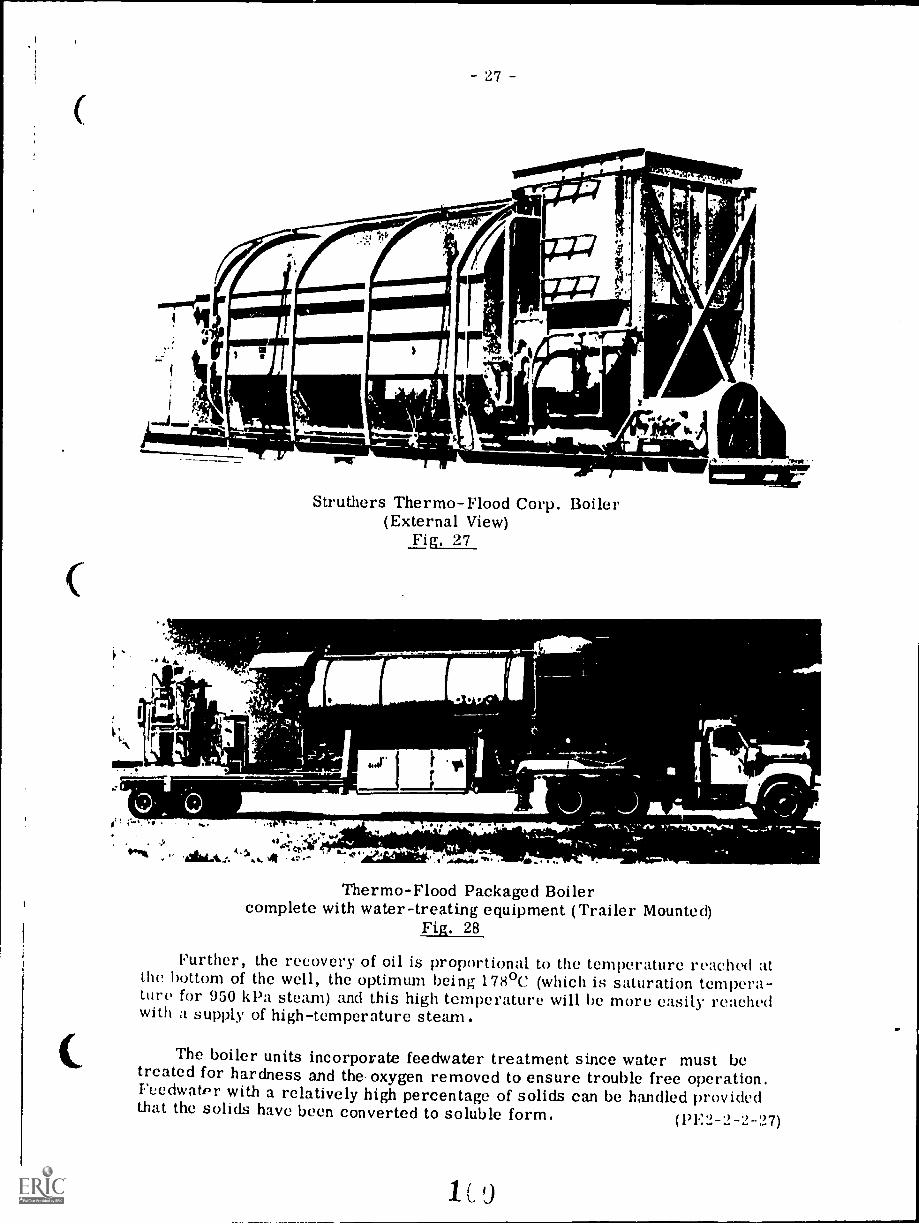
27
Struthers Thermo-Flood Corp. Boiler(External View)
Fig. 27
s' . -s ;.
-
Thermo-Flood Packaged Boilercomplete with water-treating equipment (Trailer Mounted)
Fig. 28
Further, the recovery of oil is proportional to the temperature reached atthe bottom of the well, the optimum being 178°C (which is saturation tempera-ture for 950 kl'a steam) and this high temperature will be more easily reachedwith a supply of high-temperature steam.
The boiler units incorporate feedwater treatment since water must betreated for hardness and the oxygen removed to ensure trouble free operation.Feedwatpr with a relatively high percentage of solids can be handled providedthat the solids have been converted to soluble form. (13E2-2-2-27)
1 C 9
QUESTIoN SHEET
Second ClassPOWER ENGINEERING Sect. 2, Lect. 2
1. Compare watertube and firetube boilers and state the advantagesof the watertube boiler.
a) Sketch and describe a straight-tube boiler.(b) What arc the advantages of a bent-tube boiler compared with
a straight-tube boiler'?
:3. (a) Discuss the advantages of the packaged boiler compared toa field erected boiler.
(h) With the aid of simple sketches describe 'A', '0' and 'I)'type packaged boilers.
(a) Explain the difference between shop-assembled boilers andpackaged boilers.
(b) Explain the difference between field-erected and shop-assembled boilers.
5. Where are 'Waste Heat Boilers' used and how are these boilersheated or fired'?
G. Describe forced-water circulation and discuss the advantagesand disadvantages.
7. (a) What is the purpose of a "Steam Flooding Boiler"?(h) Describe a Steam Flooding boiler.
What preparations must be carried out to make a steam generatorreadv for external and internal inspections.
Mai\ t' a sectional elevation through a watertube boiler of yourchoice showing the positions of the drum, the water walls,economizer, superheaters, and reheaters (if any). Show alsothe firing arrangement, dust collection, fans, and the supportingstee'work. Use single-line sketch method.
1C 1.
(PE2-2-2-Q)
kern, sa 1....1.31atuamagolatna nwildsaaa/C. aVlanin.1.1. u[la aaalo.lallaammaaa
E
7.3
LZA-111111C YINI.M711
BOILERS -- CONSTRUCTION
Goal:
The apprentice will be able to describe
boiler construction.
1
Performance Indicators:
1. Describe naterials used in
boiler construction.
2. Describe processes used in
boiler construction.
102
4=111=11111.MMno-,INSTRUCTIONAL LEARNING SYSTEMS
Study Guide
Read the goal and performance indicators to find what is to be learned from
package.
Read the vocabulary list to find new words that will be used in package.
Read the introduction and information sheets.
Complete the job sheet.
Complete self-assessment.
Complete post-assessment.
2
1C3
INSTRUCTIONAL LEARNING SYSTEMS
°Vocabulary* Capped
IMINIMMI110111111INIPMIIIPININIMI1111
Carbon steel
* Casings
* Extrusion process
* Ductwork
* Fin tubes
* Flat stud tube
* High alloy steel
Hydrastatic testing
* Killed
* Low alloy steel
* Mandrel
* Piercing and rolling
* Rimmed
* Sectionally supported settings
* Semi-killed
* Solid wall settings
* Stays and braces
* Tangent tube
* Tube and brick
* Watercooled settings
0* Welded tube
INSTRUCTIONAL LEARNING SYSTEMS11
Introduction
Modern boilers are expected to operate at high pressures with a life expectancyof 20 years. Good materials must be used in construction of the steam plant andthe fabrication methods must be of high quality.
Since most p, rts will be subjected to high pressure, ferrous materials are
rather standard in boiler construction.
This package will discuss the materials used and fabrication methods for boilerconstruction.
4
105
INS1HULI IUNAL LtAtININla J Y J I CIAO
Information.Types of Steel
Steel is the most common metal used in the manufacture of boilers. Many gradesand types of steel are available:
- Carbon steel (.2 to .3% carbon)- Low alloy steel (up to 5% alloy)- High alloy steel (over 10% alloy)
Steel is often classified according to its manufacturing process and the amountsof carbon monoxide produced as the steel solidified. These classes are:
1. Rimmed--has a rim of pure iron and a core of carbon steel.2. Capped--has a thinner rim and less carbon in the core than rimmed.3. Semi-killed--has silicon and aluminum added to prevent excess gas
bubbles.4. Killed--has all oxygen removed by adding oxygen and aluminum as
deoxydizing agent. Process used in making both carbon steel and alloysteel.
Materials for Boiler Construction
The following chart shows the materials used in boiler construction.
Boiler Parts Type of Material
Drum and Shell Carbon steel or low alloy steel.Rolled while hot and welded seams.
Tubes Carbon steel or alloy steel.
Pipe fittings, valves, watercolumns for pressures under2400 kPa and temperaturesless than 232 C.- Up to 1700 kPa
Malleable iron and cast nodulariron.
Cast iron
5
106
INSTRUCTIONAL LEARNING SYSTEMS--
Information
Boiler Parts Type of Material
Blowoff connections and otherconnections that fit directlyinto the boiler.
Carbon steel or alloy steel.
Processes of Boiler Construction
Foundations
Foundations must be constructed to eliminate movement from settling or othershifting. The foundation size depends upon the weight of the boiler to besupported. Boiler manufacturers will supply the specifications for each boilersold. Large boilers require overhead support from structural steel hangers.Small boilers may be grouted into the cement floor of the power plant.
Settings
A setting is a wall that encloses the furnace and pressure parts of a boiler.Usually a setting is made with firebrick -r plastic fireclay. Solid wall .
settings are independent of the boiler. Sectionally supportedare anchored and supported in sections by external steelwork. Watercooled,settings are used in internally fired,firetube boilers and water tube boilers.A tube and brick setting 'offers both refractory and water cooled furnace walls.A common type of tube and brick wall is constructed with fin tubes. Metalfin bars are welded to tubes to give a continuous wall surface and bricks arelaid against the fin tubes.
6
1C7
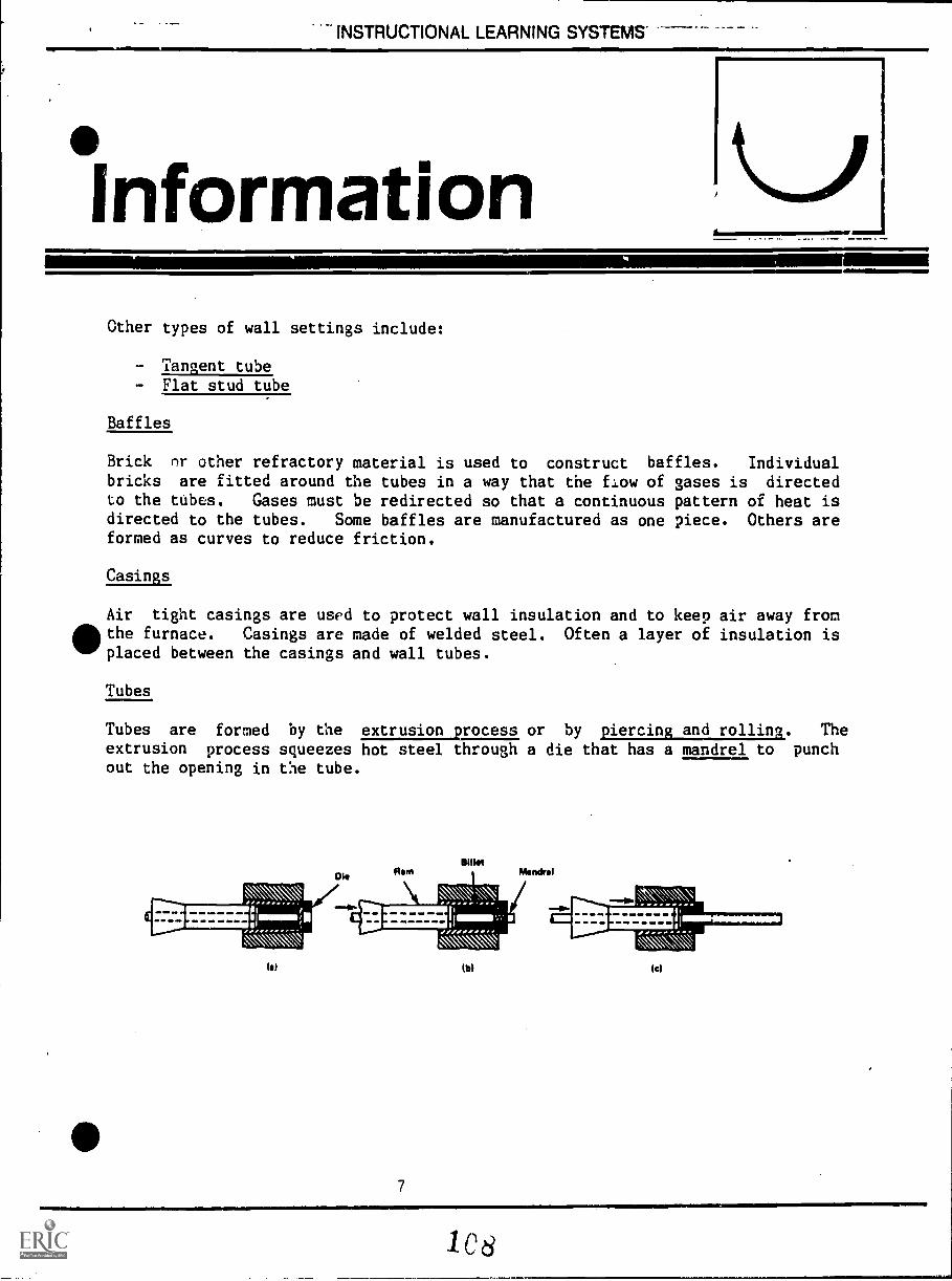
INSTRUCTIONAL LEARNING SYSTEMS-
°InformationOther types of wall settings include:
- Tangent tube- Flat stud tube
Baffles
Brick or other refractory material is used to construct baffles. Individualbricks are fitted around the tubes in a way that the flow of gases is directedto the tubes. Gases must be redirected so that a continuous pattern of heat isdirected to the tubes. Some baffles are manufactured as one piece. Others areformed as curves to reduce friction.
Casings
Air tight casings are used to protect wall insulation and to keep air away from&the furnace. Casings are made of welded steel. Often a layer of insulation isIMF placed between the casings and wall tubes.
Tubes
Tubes are formed by the extrusion process or by piercing and rolling. Theextrusion process squeezes hot steel through a die that has a mandrel to punchout the opening in the tube.
DI.BOW
Ram Mendrel
11153EIES!III':v.
Ibl
MEP111.11111.
(el
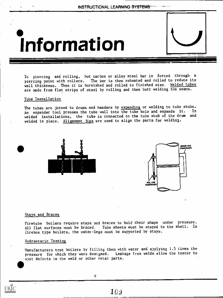
INSTRUCTIONAL LEARNING SYSTEMS--
InformationIn piercing and rolling, hot carbon or alloy steel bar is forced through a
piercing point with rollers. The bar is then reheated and rolled to reduce its
wall thickness. Then it is burnished and rolled to finished size, Welded tubes
are made from flat strips of steel by rolling and then butt welding the seams.
Tube Installation
The tubes are joined to drums and headers by expanding or welding to tube stubs.
An expander tool presses the tube wall into the tube hole and expands it. In
welded installations, the tube is connected to the tube stub of the drum and
welded in place. Alignment jigs are used to align the parts for welding.
Stays and Braces
Firetube boilers require stays and braces to hold their shape under pressure.
All flat surfaces must be braced, Tube sheets must be stayed to the shell. In
firebox type boilers, the water-legs must be supported by stays.
Hydrastatic Testing
Manufacturers test boilers by filling them with water and applying 1.5 times the
pressure for which they were designed. Leakage from welds allow the tester to
spot defects in the weld or other metal parts.
1111111111111=11.
8
1U)
INSTRUCTIONAL-LEARNING SYSTEMS
InformationDuctwork
Metal ducts are .aquired to move combustion air and gases to and from the
furnace. The common ducts required are:
- Main air duct from fan to heater to burner.- Main gas duct from the economizer uutlet to heater to fan to stack.- Air circulating duct from heater outlet to fan inlet.
9
1
INSTRUCTIONAL LEARNING SYSTEMS
Assignment
Read pages 1 - 29 of supplementary reference.
Com ?lete job sheet.
Complete self-assessment and check answers.
* Complete post-assessment and have instructor check answers.
10
111
INSTRUCTIONAL LEARNING SYSTEMS
Job SheetINSPECT CONSTRUCTION OF A BOILER
* Obtain permission to inspect a boiler.
* Observe materials used in construction of:
- Shell or drum- Casing- Blow-off valves- Other valves and fittings- Tubes- Wall setting- Ductwork
* Observe construction features
0 - Which parts are riveted or bolted?- Which parts are welded?
* Ask questions needed to understand the materials used in boiler construction
and processes for construction.
11AIMII.1..
112
INSTRUCTIONAL LEARNING SYSTEMS
,SelfAssessment
1. Low alloy steel has
2.
deoxidizing agent.
3. Drums are made from
4.
percent or less of alloy.
steel has all of the oxygen removed by adding
steel and low alloy steel.
wall settings are independent of the boiler.
5. A setting is a wall that encloses the and pressure
parts of a boiler.
6. Metal bars welded to tubes for construction of a setting are called
7. A setting that uses both brick and tubes is called a and
8. or other refractory material is used to construct
baffles.
9. Casings are made of steel.
10. An tool is used to press tubes into the tube holes of a
drum and lock them in place.
12
111=11M111111
113
1146 I HUe I IUNAL LLAHNINU b Yb I tIVlb
Self AssessmentAnswers
1. 5%
2. Killed
3. Carbon
4. Solid
5. Furnace
6. Fin tube
7. Tube and brick
8. Brick
9. Welded
10. Expander
13
INSTRUCTIONAL LEARNING SYSTEMS
PosetAssessment
111.11. MEMO11111111111111111=11111111MOMI
IMINIM11010111111MIMMI111t
Match the following terms with their descriptive phrase.
ailamaswinowasilk
=11111111111111111111111111011111111/41111111111M1
1 Hydrastatic testing A. Used to align tubes for welding.
2 Stays and, braces B. Made of carbon steel or alloy steel.
3 Ductwork C. Pressure applied at 1.5 times
designed levels.
4 Alignment Jigs D. Has less than .2 to .3 percentcarbon.
5 Baffles E. Helps firetube boilers hold theirshape under pressure.
6 Foundation F. Required to move combustion air andgases to and from furnace.
7 Setting G. Squeezes hot steel through die tomake tube.
8 Tubes H. Constructed from a refractorymaterial.
9 Carbon steel I. Wall that encloses furnace andpressure parts.
10 Extrusion process J. Must be free of seAling andshifting.
14
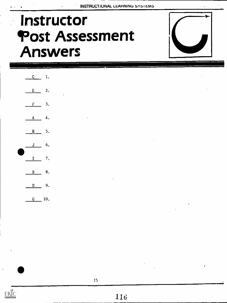
INSTRUM IUNAL LhAHNINU bYbi
InstructorIF'ost AssessmentAnswers
C 1.
E 2.
F 3.
A 4.
H 5.
J 6.
I 7.
B 8.
D 9.
G 10.
15
4 N INSTRUCTIONAL LEARNING SYSTEMS
SupplementaryReferences
* Correspondence Course. Lecture 2, Section 2, First Class. Steam Generation.
Southern Alberta Institute of Technology. Calgary, Alberta, Canada.
16
117
SOUTHERN ALBERTA INSTITUTE OF TECHNOLOGYCALGARY, ALBERTA
Correspondence CoursesPower Engineering
SECTION 2
STEAM GENERATION
BOILER CONSTRUCTION AND ERECTION
First ClassLecture 2
Although modern boilers operate at pressures as high as 35 000 kPa andat temperatures in excess of 550°C they have a life expectancy of 20 years ormore. In order to achieve this 20 year service period, the proper materials andthe proper methods must be used during the fabrication of the boiler. In addition,the proper procedure must be followed during the erection of the boiler whetherit is a field erected or a shop assembled unit.
The selection of the type of material used for the boiler components isgoverned by the ASME Boiler and Pressure Vessel Code. Paragraph PG-6.1lists the specifications of materials to be used for boiler plates, while paragraphPG-9 lists materials for boiler tubes and piping.
In addition to governing the choice of materials used, the ASME Codecontains rules and regulations regarding the design, fabrication, installation,testing and inspection of boilers and related equipment.
In each province, a department of the provincial government makes rulespertaining to the design, fabrication, installation, inspection and operation ofboilers and pressure vessels. These provincial authorities are guided by and'follow, in general, the ASME Codes.
In regard to the materials selected for boiler construction, their strengthand ductility at the various temperatures encountered in service and during fab-rication must be considered as well as their corrosion resistance under operatingconditions. Other important factors are: the behavior of the material under mech-anical and thermal shock, thermal stresses due to temperature changes, andstresses present in the material due to fabrication processes.
Ferrou, materials are used for the pressure parts of the boiler such asdrums, headers and tubes. This is also true for most of the other parts of theboiler and its related equipment including pulverizers, fuel carrying systems, sootblowers, structural supports, economizers, air heaters, casings, ducts, pipingand fittings.
Nonferrous materials are used only to a minor extent in boiler construction,therefore any discussion of materials in this lecture will be confined mainly toferrous materials, in particular the various steels used.
118
12.3
2
MATERIALS USED
Steel
Steel is the most commonly used material of construction in the boiler aadpressure vessel industry. It is basically an alloy of iron and carbon but, dependingupon the proportion of other alloying elements used in its production, it can beclassed into three groups: plain carbon steel which contains from 0.20 to 0.30percent carbon; low alloy steel which contains other alloying elements in additionto carbon up to a total of usually not more than 5.0 percent alloy content; highalloy steel in which the amount of the alloying elements chromium, *lake' ormanganese is le percent or higher.
Steel is also classified according to its method of manufacture. in moststeel making processes the molten metal is saturated with oxygen which tends tocombine with carbon in the metal to form carbon monoxide gas. The amount ofthis gas produced during the solidification of the metal will determine whetherthe steel is classed as rimmed, capped, semikilled or killed.
Rimmed Steel
In this method, the oxygen-rich molten metal is poured into a mold andbegins to solidify by forming a layer of almost pure iron on the walls and bottomof the mold. This tends to concentrate the carbon content in the remaining liquidmetal and this carbon reacts with the oxygen to form carbon monoxide gas. Thisgas, in the form of bubbles, attempts to rise and escape from the metal. Muchdoes escape but some is trapped in the rest of the metal as it solidifies.
Rimmed steel therefore features a rim of nearly pure iron around itsperiphery and a central core of steel which contains carbon and other elementssuch as phosphorus and sulphur..
Rimmed steel is cheaper to manufacture than other types and has a defect -free surface due to the pure iron rim. It is seldom used for pressure vesselconstruction however, due to its lack of homogeneity and also due to its porositycaused by the gas trapped in the metal during its manufacture.
Capped Steel
In the making of capped steel, the molten metal poured into the mold isallowed to rim for a short period of time until a thin skin of pure iron is formed.Then a heavy metal cap or chill plate is locked on top of the mold. The moltenmetal rises due to the formation of gas bubbles and upon reaching the cap thismolten metal chills and solidifies, forming a solid crust of metal which preventsfurther formation of gas bubbles. Sometimes a deoxidizer may be added to themolten metal to give a controlled rimming action.
The difference between capped steel and rimmed steel is that capped steelhas a thinner rim and a somewhat more homogenous core than has rimmed steel.However, like rimmed steel, it has considerable porosity in the ingot.
(PEI-2-2-2)
11d
:3
Semikilled Steel
In the production of semikilled steel a small amount of a deoxidizing agent(silicon, aluminum) is added to the molten metal. This deoxidizing agent combineswith some of the oxygen and prevents the excess production of gas bubbles whichwould otherwise cause rimming. The remain_ 4. oxygen e evolve some gaswhich prevents the shrinkage which would otherwise °cell) solidification ofthe metal in the mold. This also causes some porosity in Lie ingot.
Semikilled steel is often used for thin-walled light duty pressure vesselsas it is the cheapest type of steel suitable for this work.
Killed Steel
Killed steel is made by completely removing the oxygen in the molter'metal before solidification takes place. This means that there is no evolutionof gas and the metal solidifies quietly without effervescence or rimming action,Consequently there is a shrinkage cavity or "pipe" formed in the upper end ofthe ingot. This piped end is discarded leaving a homogenous and non-porousmetal ingot.
The removal of the oxygen is carried out by adding sufficient amounts ofa deoxidizing agent such as silicon or aluminum. This method of steel productionis used for nearly all alloy steels and for carbon steels containing more than0.25 percent carbon. It is used in all thicknesses for pressure vessels intendedfor severe duty and for most seamless piping and boiler tubes.
Steel Types
As mentioned, the three classes of steel according to ingredients usedduring manufacture are plain carbon steel, low alloy steel, and high alloy steel.'
1. Plain Carbon Steel
Plain carbon steels contain on an average of from 0.20 to 0.30 percentcarbon and the amount of carbon present has a great effect on certain mechanicalproperties of the steel such as hardness, strength, ductility, and toughness.Generally speaking, the greater the carbon content the greater will be the strengthand the hardness and the lower will be the ductility and toughness of the steel.
In addition to carbon, plain carbon steel contains varying amounts ofimpurities such as manganese, silicon, sulphur and phosphorus. These impuritiesmay also have an effect on the properties of the steel although this will be muchless than the effect caused by carbon. However, in the selection of a plain carbonsteel both the carbon content and the amount of impurities present must be con-sidered.
(PE1-2-2-3)
1w0
A plain carbon steel listed in ASME PG-6 is SA-285. Grade C of thissteel contains a maximum carbon content of 0.30 percent, a maximum manganesecontent of 0.80 percent, a maximum phosphorus content of 0.04 percent and amaximum sulphur content of 0.04 percent.
2. Low Alloy Steel
A low alloy steel can be considered as a carbon steel to which certainalloying elements are added in order to improve the properties and characteristicsof the steel. In a low alloy steel the total percentage of alloying elements doesnot usually exceed 5.0 percent.
In general, low alloy steels are superior to plain carbon steel in regardto one or more of the following characteristics: Strength at room temperature,strength at high temperature, impact strength at low temperature, corrosionresistance, oxidation resistance at high temperature, creep resistance andmachinabilit.y.
Alloying elements which may be found in low alloy steel, in addition tothe carbon, include manganese, phosphorus, sulphur, silicon, chromium,molybdenum, nickel, aluminum, copper, lead, and vanadium. The purposesof adding these elements are discussed briefly as follows:
Manganese
Manganese is an efficient deoxidizer and its addition improves themechanical properties of the steel such as strength and hardness. It also hasa beneficial effect on the creep properties of the steel. On the other hand, itmakes the steel more difficult to weld properly. The manganese content of low,alloy steel is usually in the range 0.30 to 1.30 percent.
Phosphorus
Phosphorus is found in all steels and in high percentages is consideredan impurity as it has an embrittling effect on the steel and increases weldingdifficulties. When present in small amounts, however, it improves the machin-ability of the steel. The phosphorus content is normally kept below 0.04 percent.
Sulphur
This element is present in all steels and is generally considered animpurity as it reduces the weldability of the steel. For most steels the sulphurcontent, like the phosphorus content, is kept below 0.04 percent.
(PE1-2-2-4)
5
Silicon
Silicon is added, in the case of semikilled and killed steel, to deoxidizethe molten metal. It also has the effect of increasing the strength of the steelalthough amounts in excess of 2.5 percent cause brittleness. A typical low alloysteel may have a silicon content of from 0.15 to 0.30 percent.
Chromium
Chromium is one of the most common alloying elements an,i, in low alloysteel, is present in amounts below 10 percent. It increases the strength, hardnessand toughness of the steel and gives higher resistance to wear or abrasion.
Molybdenum
The addition of molybdenum in low alloy steel increases its strength,hardness and creep resistance. Low alloy steels usually contain from 0.50 to1.0 percent molybdenum.
Nickel
Nickel increases the toughness, strength and hardness of steel and isoften used to provide toughness in steel at low temperatures. Some low alloysteels have nickel contents of from 0.50 to 3.50 percent.
Aluminum
Aluminum is a minor constituent of low alloy steel and is used primarilyas a deoxidizing agent in the production of killed steel.
Copper
Copper is added to steel to increase resistance to atmospheric corrosionand to act as a strengthening agent. The copper content may range from 0.20to 0.50 percent.
Lead
Lead added in the 0,15 to 0.35 range improves the machinability of steelbut does not alter the mechanical properties.
Vanadium
Vanadium is not only a powerful deoxidizes but also increases the strengthand toughness of the steel. Its content in a low alloy steel may range from 0.09to 0.14 percent.
(PE1-2-2-5)
An example of a. low alloy steel which is listed in ASME PG-6 is SA-203.This is a plate steel which has, depending upon the thickness and the grade, acarbon content of from 0.17 to 0.25 percent, a manganese content of 0.70 to0.80 percent, a phosphorus content of 0.035 percent, a sulphur content of 0.04percent, a nickel content of 2.13 to 3.82 percent and a silicon content of 0.13 to0.32 percent.
An example of a low alloy steel used for steam piping is SA-335 P22. Itsalloy content in percentages is as follows:
Carbon -
Manganese -
Phosphorus
Sulphur
Chromium -
Silicon -
Molybdenum
3. High Alloy Steels
0.15 max.
0.30 to 0.600.030 max.
0.030 max.1.90 to 2.60
0.50 max.0.87 to 1.13
A steel is considered to be a high alloy steel if the amount of chromium,nickel or manganese is 10 percent or higher. These steels are used primarilybecause of their corrosion resistance and creep strength at very high temperatures.
They can be divided into two general types: straight chromium steelswhich have a chromium content ranging from 12 to 27 percent and chromium-nickel austenitic steels where the chromium content may range from 18 to 25 *percent and the nickel content from 8 to 20 percent. Special types of chromium-nickel steels have additional alloying elements such as columbium, titanium,molybdenum and copper.
High alloy steels differ from other steels in the following ways:
(PE1-2-2-6)
1. Their thermal conductivity is much lower therefore theyare more susceptible to local overheating and to distortionwhen they are welded.
. Their thermal expansion is higher which tends to increasewelding distortion and to produce higher stresses in thewelds during cooling.
3. They are more corrosion resistant and have higherstrength and oxidation resistance at high temperatures.
123
An example of a chromium nickel austenitie steel which is listed in ASMEPG-9 is SA-376. This is used in the production of seamless piping and its alloycontent for Grade TP 304 is listed as follows in percentages:
Carbon - 0.08 max.
Manganese - 2.00 max.Phosphorus 0.03 max.Sulphur - 0.03 max.Silicon - 0.75 max.Nickel 8.0 to 11.0Chromium 18.0 to 20.0
An example of a straight chromium steel which is listed in PG-9 is SA-268.This is used for both seamless and welded general service tubes. The alloy contentin percentages for Grade TP 430 is as follows:
Carbon - 0.12 max.Manganese - 1.00 max.
Phosphorus 0.04 max.Sulphur - 0.03 max.Silicon 0.75 max.Nickel 0.50 max.Chromium 14.0 to 18.0
Maximum allowable stress values for various temperatures for the materialslisted in PG-6 and PG-9 are contained in the ASME Table PG-23.1.
For example, the chromium - nickel austenitic steel SA-376 Grade TP 304for seamless piping has an allowable stress value of 84.116 MPa for temperaturesfrom 204° to 260°C. The allowable stress value drops to 76.532 MPa for tempera-tures from 343° to 371°C and to 70.326 MPa for temperatures from 454° to 482°C.On the other hand, the straight chromium steel SA-268 Grade TP 430 for seamlesstubing has an allowable stress value of 88.492 MPa for temperatures from 204° to260°C. The allowable stress value drops to 83.427 MPa for temperatures from343° to 371°C and use of this material for temperatures above 371°C is not currentpractice.
8 --
Nonferrous Materials
The ASTVIE Code allows the use of nonferrous pipe or tubes not over 76 mmin diameter for steam lines, feed lines, and drains. The types allowed are listedin PG-9.5 and it is also specified in PG-9.5 that nonferrous pipe or tubes shall notbe used for blow-off piping or any other service where the temperature exceeds208°C.
Maximum allowable stress values for various temperatures for nonferrousmaterials are contained in ASME Table PG-23.2. Referring to this table, it canbe seen that nonferrous pipe or tube SB-42 and SB75 have an allowable stressvalue of only 20 680 kPa at temperatures between 175° and 205°C.
Cast Iron
Cast iron may be used for boiler connections such as pipe fittings, watercolumns, and valves, for pressures up to 1700 kPa providing the steam tempera-ture does not exceed 232°C. The type of cast iron to be used in specified inPG-8.2 .2.
For blow-off valves, however, the limit for which cast iron can be used is1400 kPa and this is discussed in PG-58.1.4 together with the requirements forthe cast iron to be used.
Cast iron shall not be used for nozzles or flanges attached directly to theboiler for any pressure or temperature.
Malleable Iron and Cast Nodular Iron
These materials must not be used for blow-off connections but can be used difor other boiler connections such as pipe fittings, water columns, and valves, forpressures not to exceed 2400 kPa provided the steam temperature does not exceed232°C. Specification numbers for these materials are given in PG-8.3.
Material Selection
The selection of the material used in the pressure parts of the boiler de-pends upon the actual metal temperature to be sustained during operation. Thesteam generation tubes are primarily of carbon steel. Superheater and reheatertubes may also be carbon steel in low temperature areas but as the temperatureincreases the chrome-molybdenum steels are used and for the highest temperatureareas the material is chrome-nickel austenitic steel such as Grade 304, 316, 321or 347.
(PE1-2-2-8)
125
Sit NI) DRUM FABRICATION
The boiler drum is fabricated from plate of the desired material, usuallysome type of carbon steel or low alloy steel. Depending upon the desired serviceconditions and the drum diameter these plates may .be up to ten inches thick.
Usually the plate is bent to the required shape while hot but in some caseswhile cold, the method depending upon the plate material and thickness and thedesired radius to which it is to be bent. The plate may be bent or rolled to thelull circumference or it may be formed into half cylindrical sections which aresubsequently welded together.
tke -410 . oro
tole
llot - Bending Boiler Plate (Foster Wheeler)
Fig. 1 (a)
Contour Checking(Babcock and Wilcox)
1, Fig. 1 (b)
Fig. 3. Checking the contour of a cylindrical section
Fig. 1 (a) shows a section of 180 mm thick boiler plate being bent to therequired shape while hot and Fig. 1 (b) shows contour checking of a heavy platecylindrical section.
(PE1 -2-2-9)
126
10
Cold - Bending Boiler Plate(Foster Wheeler)
Fig. 2
Fig. 2 illustrates the cold - bending process applied to a slightly thinnerplate.
After forming of the plate into full or half shell sections, the plate edgesare machined to form the longitudinal weld grooves.
(PE1-2-2-10)
127
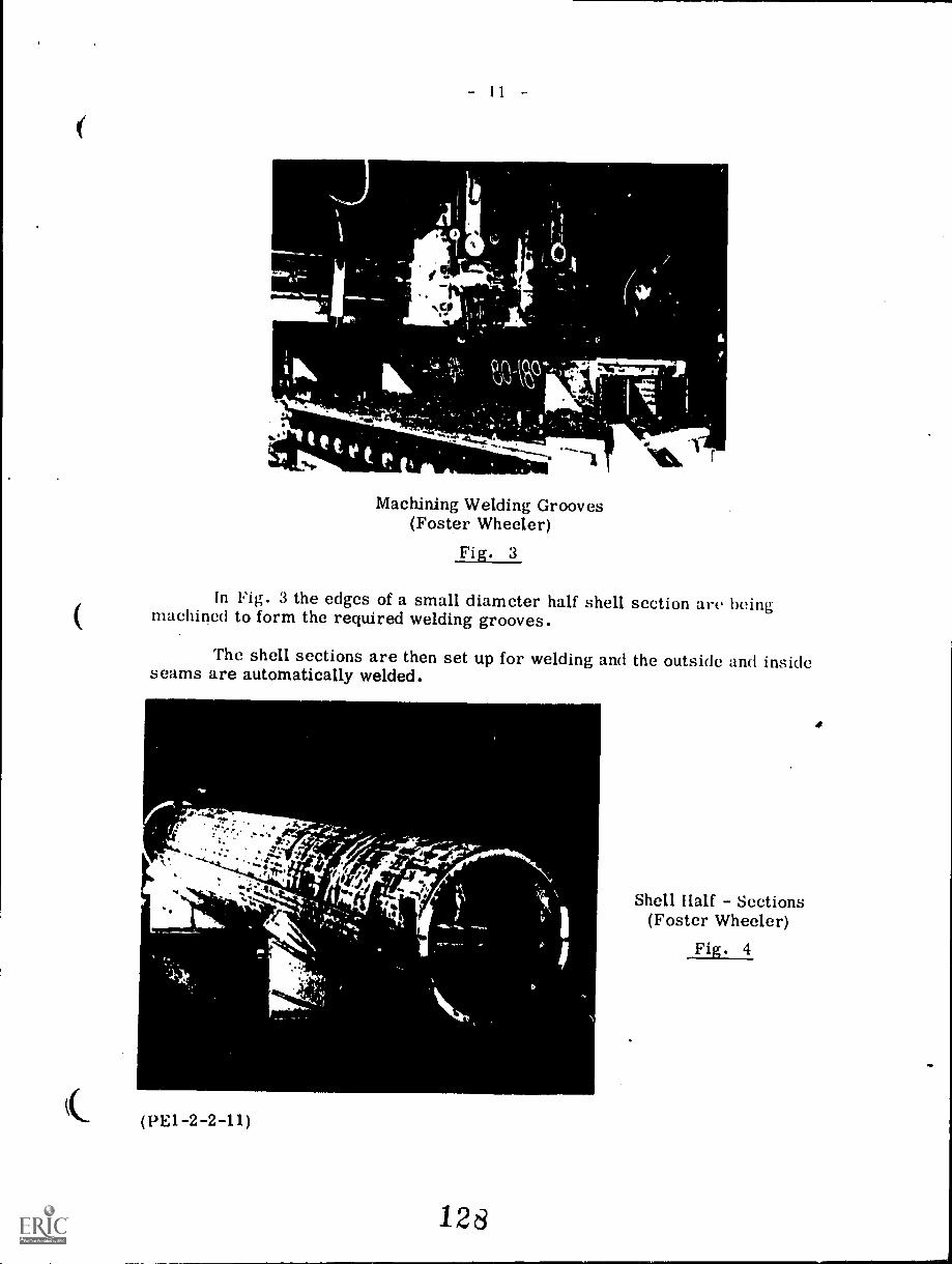
MIJvia.
1
1.
I-tvoraik
0..kr
at
0
..../111111111_
se ww.A..0IN=
Machining Welding Grooves(Foster Wheeler)
Fig. 3
In Fig. 3 the edges of a small diameter half shell section are beingmachined to form the required welding grooves.
The shell sections are then set up for welding and the outside and insideseams are automatically welded.
ire.11*
%.:4'
/1 1%
.4114111111e....
(PE1-2-2-11)
"el
dt,
128
Shell Half Sections(Foster Wheeler)
Fig. 4
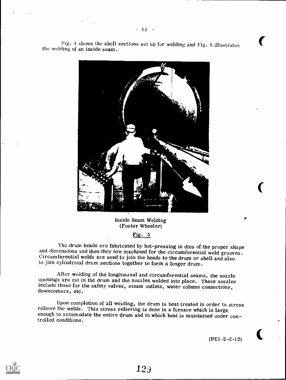
12
Fig. 4 shows the shell sections set up for welding and Fig. 5 illustratesthe welding of an inside seam.
t
nk
S.
Inside Seam Welding(Foster Wheeler)
Fig. 5
The drum heads are fabricated by hot-pressing in dies of the proper shapeand dimensions and then they are machined for the circumferential weld grooves.Circumferential welds are used to join the heads to the drum or shell and alsoto join cylindrical drum sections together to form a longer drum.
After welding of the longitudinal and circumferential seams, the nozzleopenings are cut in the drum and the nozzles welded into place. These nozzlesinclude those for the safety valves, steam outlets, water column connections,downcomers, etc.
Upon completion of all weiding, the drum is heat treated in order to stressrelieve the welds. This stress relieving is done in a furnace which is largeenough to accomodate the entire drum and in which heat is maintained under con-trolled conditions.
(PE1-2-2-12)
123
(ir
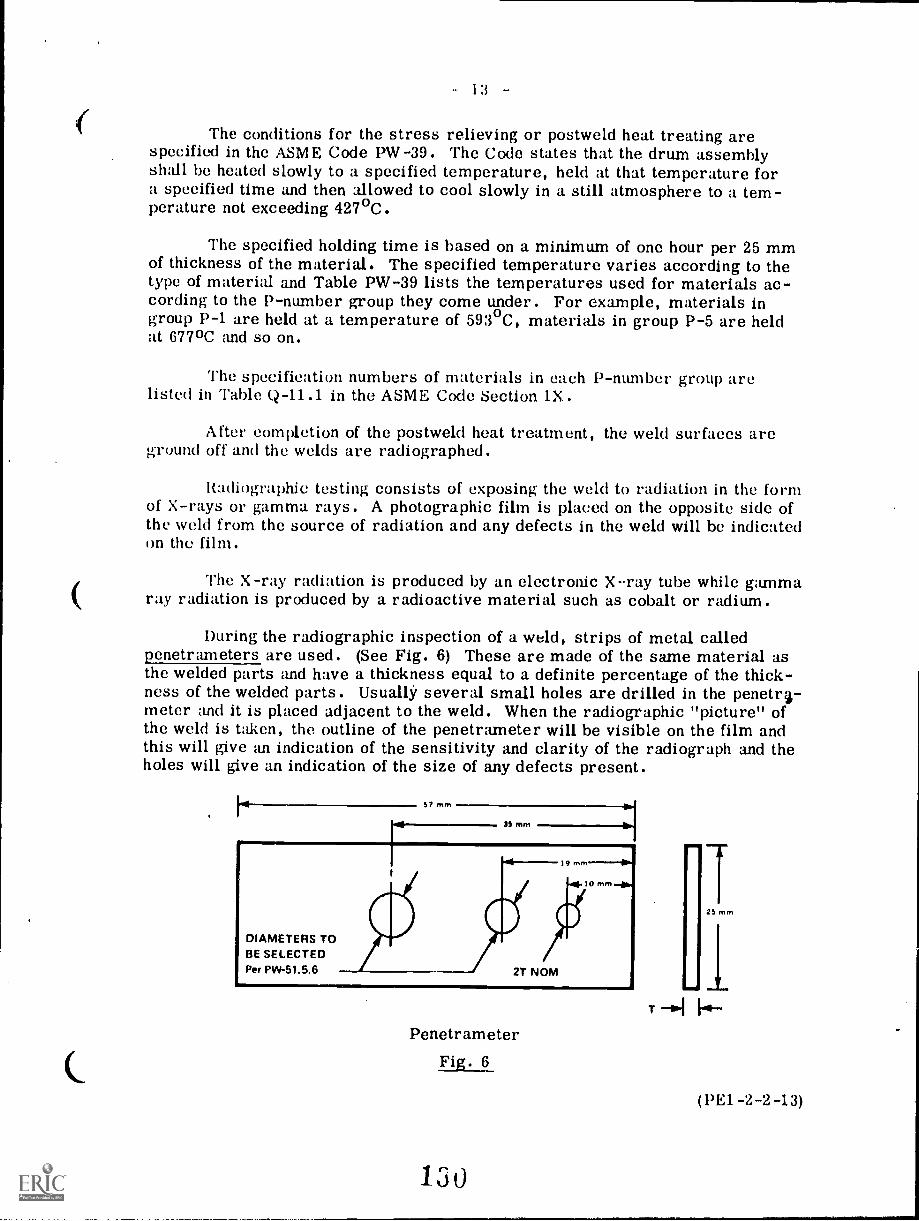
13 -
The conditions for the stress relieving or postweld heat treating arespecified in the ASME Code PW-39. The Code states that the drum assemblyshall be heated slowly to a specified temperature, held at that temperature fora specified time and then allowed to cool slowly in a still atmosphere to a tem-perature not exceeding 427°C.
The specified holding time is based on a minimum of one hour per 25 mmof thickness of the material. The specified temperature varies according to thetype of material and Table PW-39 lists the temperatures used for materials ac-cording to the P-number group they come under. For example, materials ingroup P-1 are held at a temperature of 593°C, materials in group P-5 are heldat 677 °C and so on.
The specification numbers of materials in each P-number group arelisted in Table Q-11.1 in the ASME Code Section 1X.
After completion of the postweld heat treatment, the weld surfaces areground off and the welds are radiographed.
Radiographic testing consists of exposing the weld to radiation in the formof X-rays or gamma rays. A photographic film is placed on the opposite side ofthe weld from the source of radiation and any defects in the weld will be indicatedon the film.
The X-ray radiation is produced by an electronic X-ray tube while gammaray radiation is produced by a radioactive material such as cobalt or radium.
During the radiographic inspection of a weld, strips of metal calledpenetrameters are used. (See Fig. 6) These are made of the same material asthe welded parts and have a thickness equal to a definite percentage of the thick-ness of the welded parts. Usually several small holes are drilled in the penetr3-meter and it is placed adjacent to the weld. When the radiographic "picture" ofthe weld is taken, the outline of the penetrameter will be visible on the film andthis will give an indication of the sensitivity and clarity of the radiograph and theholes will give an indication of the size of any defects present.
1.5/ mm
35 mm
DIAMETERS TOBE SELECTEDPer PW-51.5.6 2T NOM
19 mm
10 mm
PenetrameterFig. 6_
130
25 mm
(Phi -2-2-13)
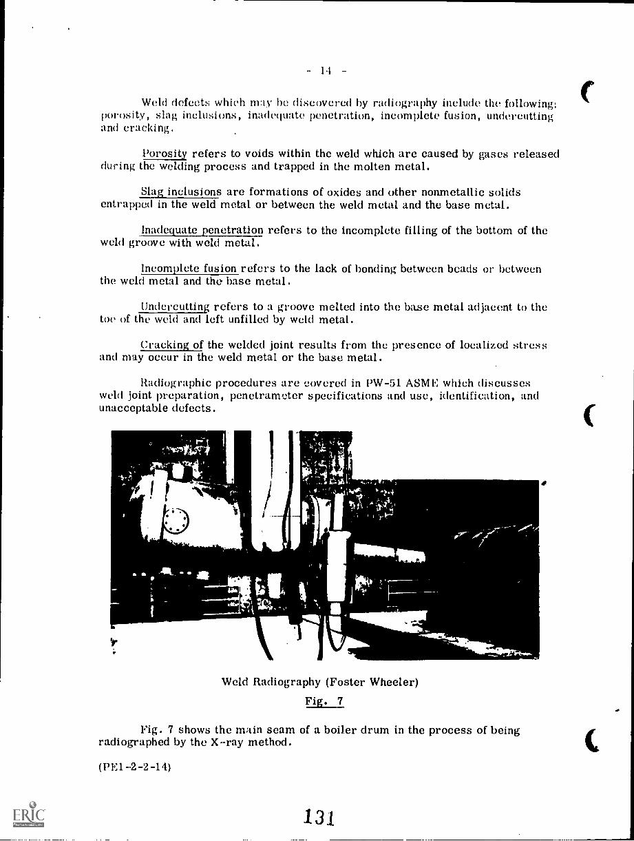
14
Weld defects which may he discovered by radiography include the following:porosity, slag inclusions, inadequate penetration, incomplete fusion, undercuttingand cracking.
Porosity refers to voids within the weld which are caused by gases releasedduring the welding process and trapped in the molten metal.
Slag inclusions are formations of oxides and other nonmetallic solidsentrapped in the weld metal or between the weld metal and the base metal.
Inadequate penetration refers to the incomplete filling of the bottom of theweld groove with weld metal.
Incomplete fusion refers to the lack of bonding between beads or betweenthe weld metal and the base metal.
Undercutting refers to a groove melted into the base metal adjacent to thetoe of the weld and left unfilled by weld metal.
Cracking of the welded joint results from the presence of localized stressand may occur in the weld metal or the base metal.
Radiographic procedures are covered in PW-51 ASME which discussesweld joint preparation, penetrometer specifications and use, identification, andunacceptable defects.
Weld Radiography (Foster Wheeler)
Fig. 7.
Fig. 7 shows the main seam of a boiler drum in the process of beingradiographed by the X-ray method.
(PE12-2-14)
13.1
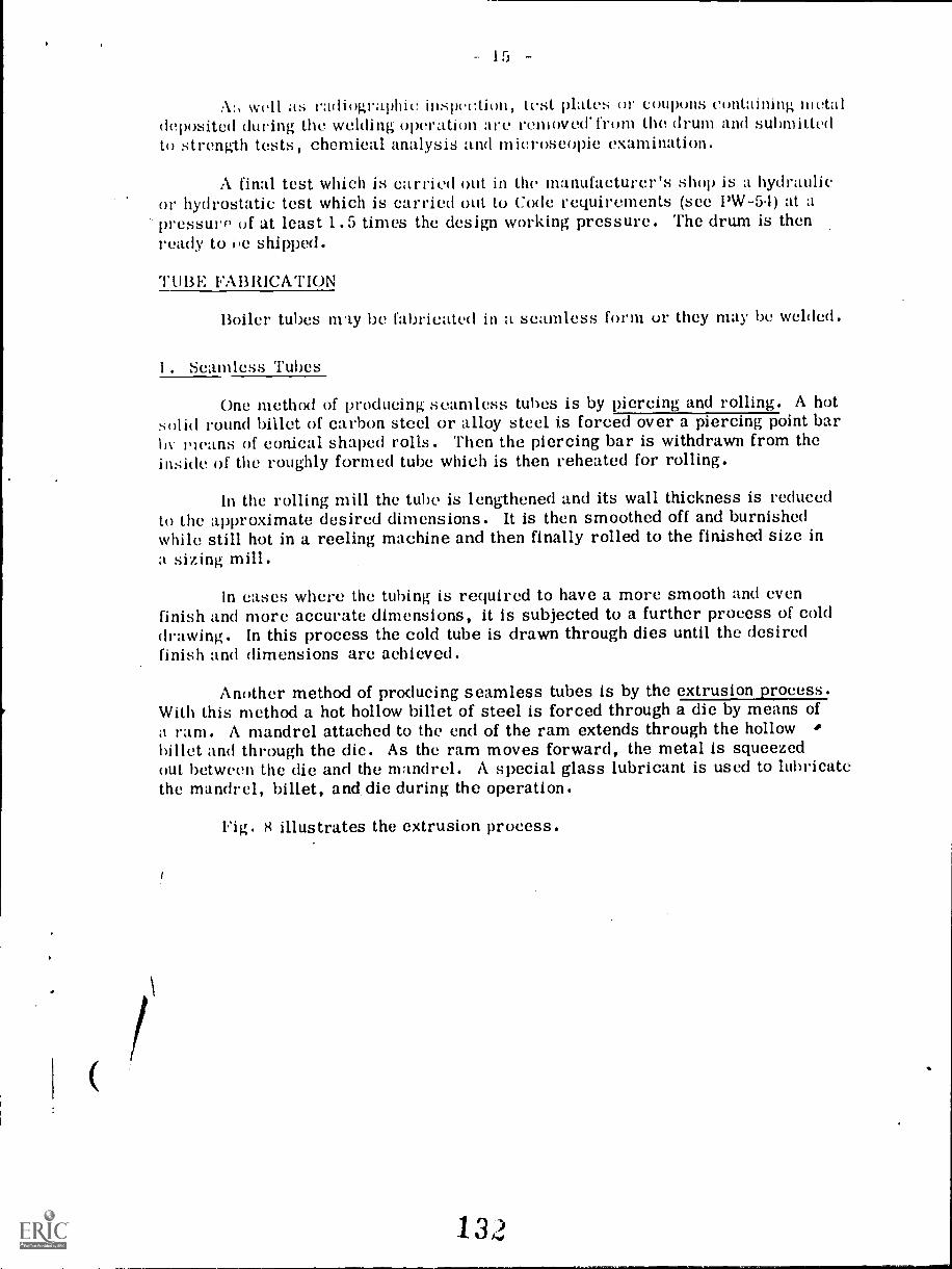
A:, well as radiographic inspec:tion, test plates or coupons containing metaldeposited during the welding operation are removed' from the drum and submittedto strength tests, chemical analysis and microscopic examination.
A final test which is carried out in the manufacturer's shop is a hydraulicor hydrostatic test which is carried out to Code requirements (see PW-5.1) at apressure of at least 1.5 times the design working pressure. The drum is thenready to 1)e shipped.
TUBE FAI3RICATION
Boiler tubes nty be fabricated in a seamless form or they may be welded.
1. Seamless Tubes
One method of producing seamless tubes is by piercing and rolling. A hotsolid round billet of carbon steel or alloy steel is forced over a piercing point barby means of conical shaped rolls. Then the piercing bar is withdrawn from theinside of the roughly formed tube which is then reheated for rolling.
In the rolling mill the tube is lengthened and its wall thickness is reducedto the approximate desired dimensions. It is then smoothed off and burnishedwhile still hot in a reeling machine and then finally rolled to the finished size ina sizing mill.
In cases where the tubing is required to have a more smooth and evenfinish and more accurate dimensions, it is subjected to a further process of colddrawing. In this process the cold tube is drawn through dies until the desiredfinish and dimensions are achieved.
Another method of producing seamless tubes is by the extrusion process.With this method a hot hollow billet of steel is forced through a die by means ofa ram. A mandrel attached to the end of the ram extends through the hollowbillet and through the die. As the ram moves forward, the metal is squeezedout between the die and the mandrel. A special glass lubricant is used to lubricatethe mandrel, billet, and die during the operation.
Fig. 8 illustrates the extrusion process.
1 3 2
- 1 -
In Fig. 8 (a) the hot billet is pushed into a container to which is attachedthe We. In Fig. 8 (b) the ram and mandrel are pushing the billet toward the dieand in Fig. 8 (c) the hot metal is being pushed through the die and around themandrel to form the tube.
After being formed by the extrusion process the tubes are cold drawn tothe desired finished size.
2. Welded Tubes
Welded tubes are formed from a flat strip or skelp which is rolled intotubular form and the edges then butt welded together. Either of two weldingmethods may he used; the furnace butt weld or the electric resistance weld.
To make furnace butt welded tubes, the hot skelp is taken from the furnaceand formed by a series of rolls into a circular tube shape. The hot tube thenpasses through welding rolls which squeeze the edges together and so fuses them.The welded tube then passes to reducing and sizing rolls for final finishing anddimensioning.
To make electric resistance welded tubes, the flat strip is rolled into tubeform by forming rolls. The tube is then welded by a welding roll having two elect-rode halves which straddle the tube joint. The welding current passes betweenthe electrodes through the tube joint thus producing enough heat to fuse the edgestogether.
After welding, the excess metal is trimmed off on the outside and the insideof the weld seam. The tube then is rolled to the correct size.
BOILER ERECTION
In the case of small-sized boiler units, the entire unit is fabricated andassembled in the manufacturer's shop and then shipped as a single package tothe customer. On arrival at the customer's plant the unit is mounted on a suitablefoundation and the necessary piping, ductwork and electrical connections aresupplied thus completing the erection.
*lin rase of larger sized units the usual procedure is to fabricate and
133
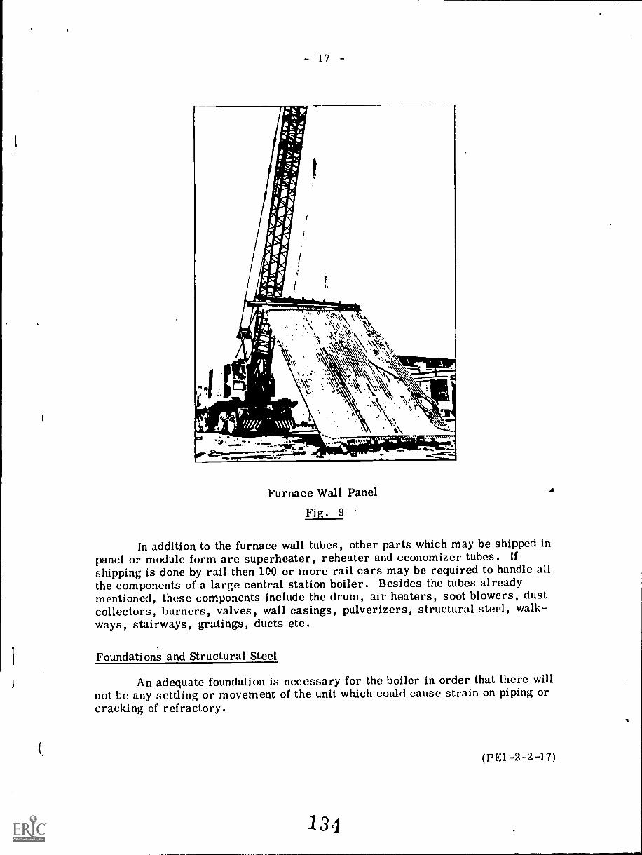
- 17 -
Furnace Wall Panel
Fig. 9
In addition to the furnace wall tubes, other parts which may be shipped inpanel or module form are superheater, reheater and economizer tubes. Ifshipping is done by rail then 100 or more rail cars may be required to handle allthe components of a large central station boiler. Besides the tubes alreadymentioned, these components include the drum, air heaters, soot blowers, dustcollectors, burners, valves, wall casings, pulverizers, structural steel, walk-ways, stairways, gratings, ducts etc.
Foundations and Structural Steel
An adequate foundation is necessary for the boiler in order that there willnot be any settling or movement of the unit which could cause strain on piping orcracking of refractory.
(PE1-2-2-17)
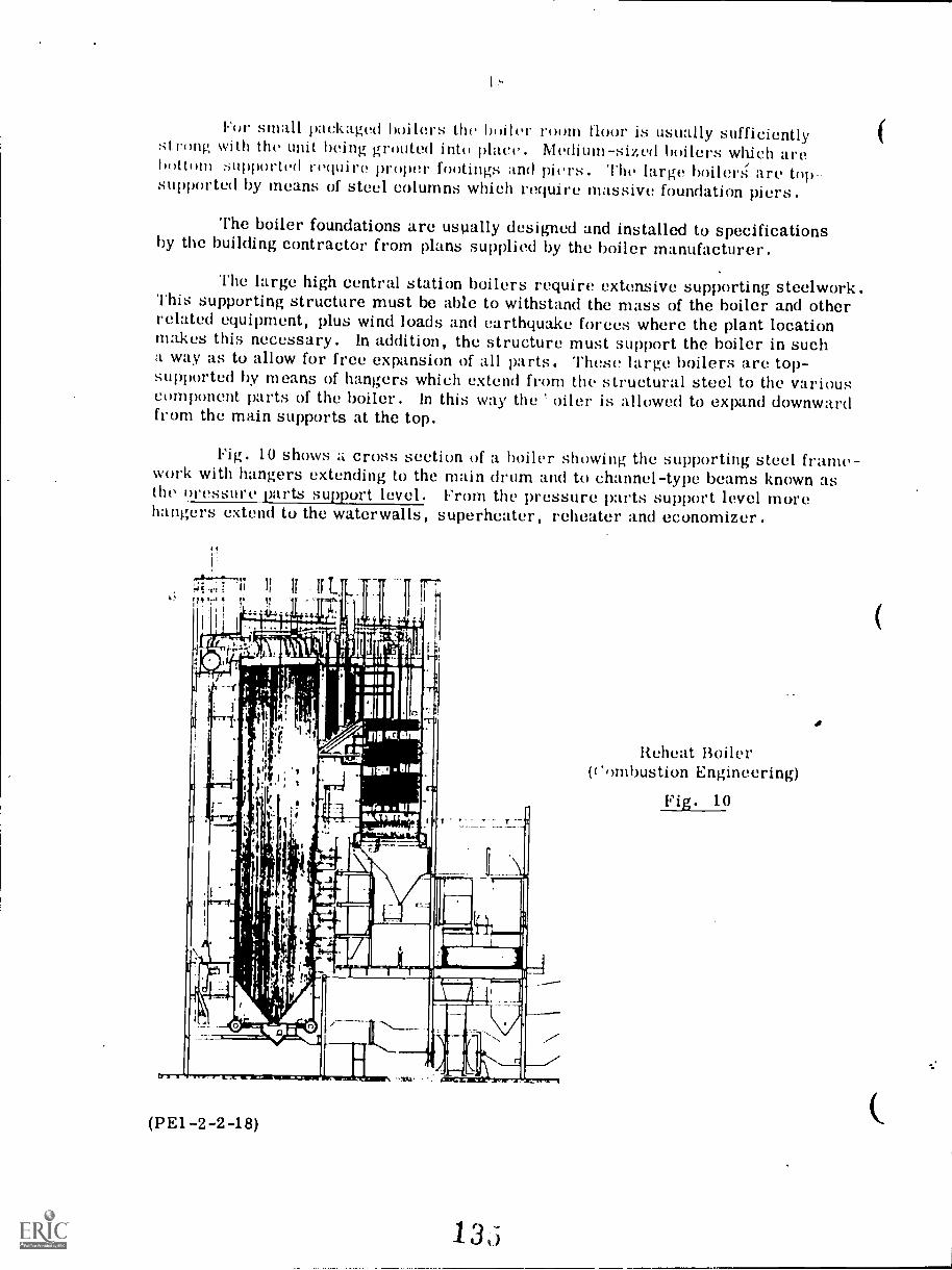
For small pziekaged boilers the boiler room floor is usually sufficientlystrong with the unit being grouted into place. Medium-sized lgiilers which arebottom supported require proper footings and piers. The large boiler:; are top-supported by means of steel columns which require massive foundation piers.
The boiler foundations are usually designed and installed to specificationsby the building contractor from plans supplied by the boiler manufacturer.
The large high central station boilers require extensive supporting steelwork.This supporting structure must be able to withstand the mass of the boiler and otherrelated equipment, plus wind loads and earthquake forces where the plant locationmakes this necessary. In addition, the structure must support the boiler in sucha way as to allow for free expansion of all parts. These large boilers are top-supported by means of hangers which extend from the structural steel to the variouscomponent parts of the boiler. In this way the ' oiler is allowed to expand downwardfrom the main supports at the top.
Fig. 10 shows zi cross section of a boiler showing the supporting steel frame-work with hangers extending to the main drum and to channel-type beams known asthe oressure parts support level. From the pressure parts support level morehangers extend to the waterwalls, superheater, eheater and economizer.
(PE1-2-2-18)
13,5
Reheat Boiler(Combustion Engineering)
Fig. 10
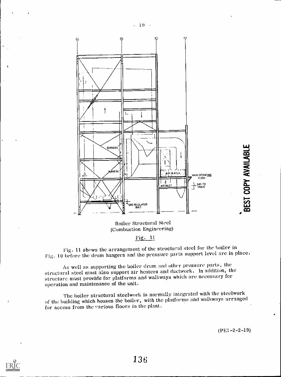
19
BURNERS
RNERS -/
-1)
1-i-s GAS REGULATOR
DUCT
LAIR HEAT EN,!_! 1 !
-tAIR IKE T
Boiler Structural Steel(Combustion Engineering)
Fig. 11
MAIN OPEAATIKFLOOR
A''GAS
TOSTACK
Fig. 11 shows the arrangement of the structural steel for the boiler inFig. 10 before the drum hangers and the pressure parts support level are in place.
As well as supporting the boiler drum and other pressure parts, the
structural steel must also support air heaters and ductwork. In addition, thestructure must provide for platforms and walkways which are necessary foroperation and maintenance of the unit.
The boiler structural steelwork is normally integrated with the steelworkof the building which houses the boiler, with the platforms and walkways arrangedfor access from the various floors in the plant.
(PE1-2-2-19)
136
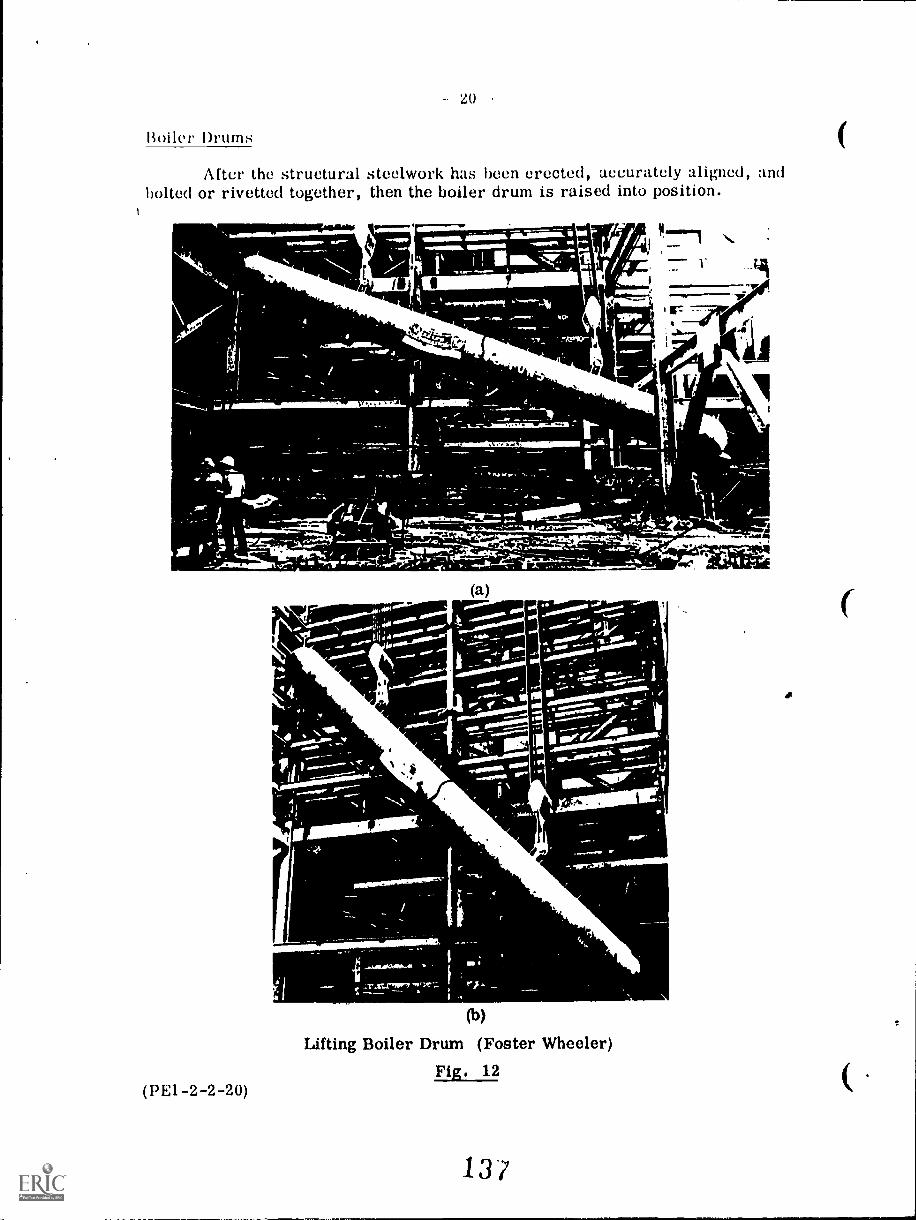
20
Boiler Drums
After the structural steelwork has been erected, accurately aligned, andbolted or rivetted together, then the boiler drum is raised into position.
t,trii 1 _I
44.111.
(a)
(b)
Lifting Boiler Drum (Foster Wheeler)Fig. 12
(1)E1 -2-2-20)
13/
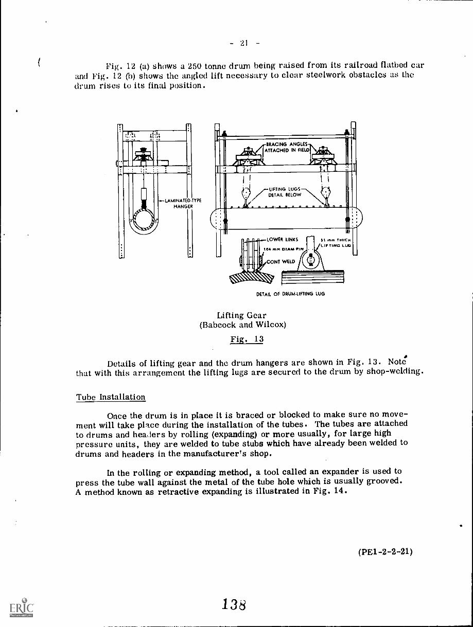
21
Fig. 12 (a) shows a 250 tonne drum being raised from its railroad flatbed carand Fig. 12 (b) shows the angled lift necessary to clear steelwork obstacles as thedrum rises to its final position.
LAMINATEDTYPEHANGER
1--
IIL-I/Phi.
BRACING ANGLESATTACHED IN HELD
..
!44,!
IIMP111111111
JP; 7.41i
12.117 711 l&
I i (
/LIFTING LUGSDETAIL BELOW
A A 41 A II n 11 11 n n n n -,
[
i In.
1111111
I4II1
LOWER LINKS
104 mn1 DIAM PIN
IP CONT WELD/ LO1
III
si mm THICKLIFTING LUG
DETAIL OF DRUMLIFTING LUG
Lifting Gear(Babcock and Wilcox)
Fig. 13
Details of lifting gear and the drum hangers are shown in Fig. 13. Note.that with this arrangement the lifting lugs are secured to the drum by shop-welding.
Tube Installation
Once the drum is in place it is braced or blocked to make sure no move-ment will take place during the installation of the tubes. The tubes are attachedto drums and healers by rolling (expanding) or more usually, for large highpressure units, they are welded to tube stubs which have already been welded todrums and headers in the manufacturer's shop.
In the rolling or expanding method, a tool called an expander is used topress the tube wall against the metal of the tube hole which is usually grooved.A method known as retractive expanding is illustrated in Fig. 14.
(PE1-2-2-21)
138
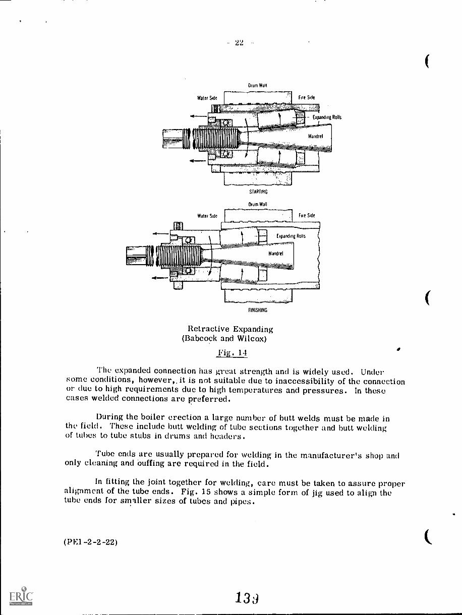
22
Water Side
Drum Wall
Fire Side
Expanding Rolls
Water Side
STARTING
Drum Wall
Fire Side
11111111111.1111FINISHING
Retractive Expanding(Babcock and Wilcox)
Fig. 14
The expanded connection has great strength and is widely used. Undersome conditions, however,, it is not suitable due to inaccessibility of the connectionor clue to high requirements due to high temperatures and pressures. In thesecases welded connections are preferred.
During the boiler erection a large number of butt welds must be made inthe field. These include butt welding of tube sections together and butt weldingof tubes to tube stubs in drums and headers.
Tube ends are usually prepared for welding in the manufacturer's shop andonly cleaning and buffing are required in the field.
In fitting the joint together for welding, care must be taken to assure properalignment of the tube ends. Fig. 15 shows a simple form of jig used to align thetube ends for smaller sizes of tubes and pipes.
(PE1-2-2-22)
13d
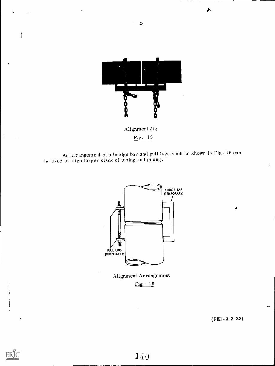
9:i
Alignment Jig
Fig. 15
An arrangement of a bridge bar and pull 11,gs such as shown in Fig. 16 can
be used to align larger sizes of tubing and piping.
gel
PULL LUG(TEMPORARY
BRIDGE BAR
(TEMPORARY)
Alignment Arrangement
Fig. 16
(PE1-2-2-23)
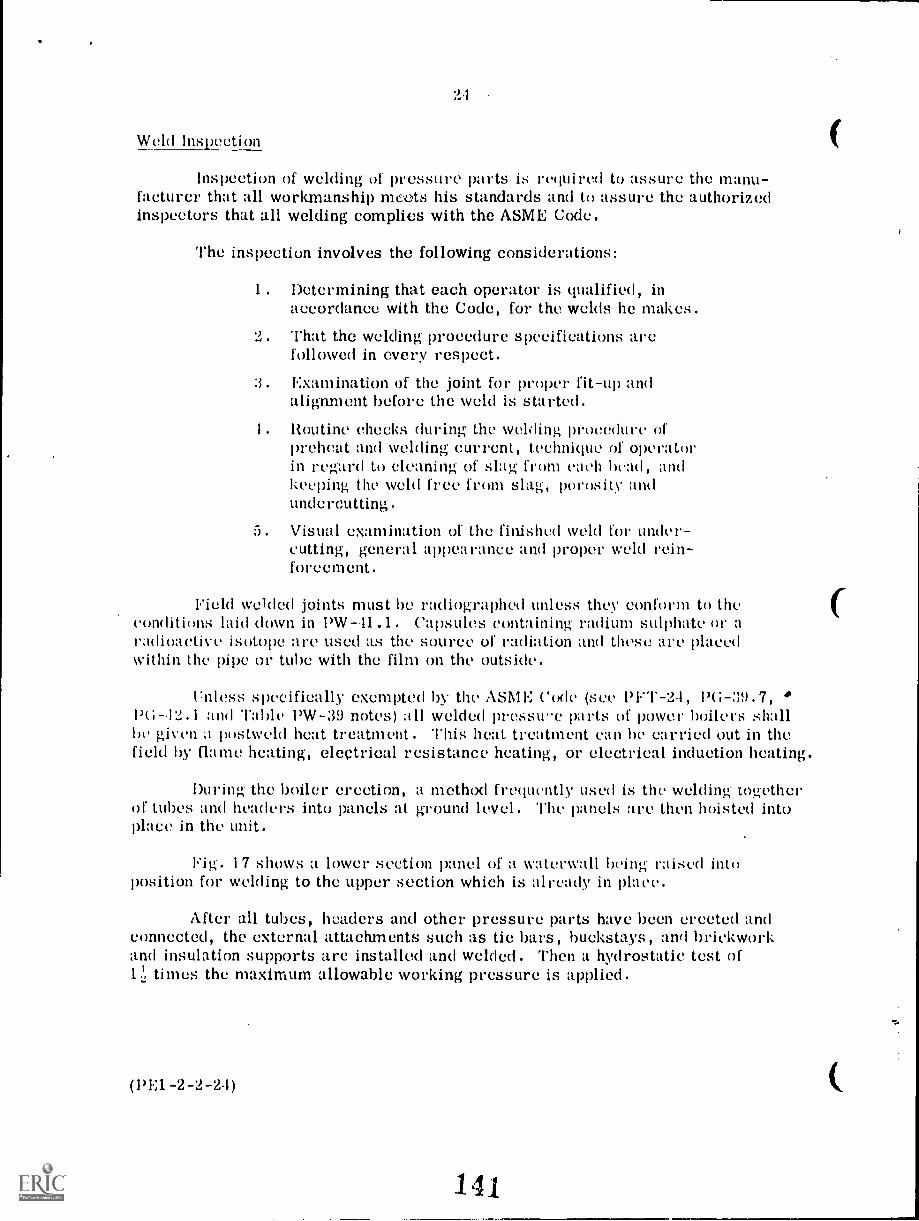
21
Weld Inspection
Inspection of welding of pressure parts is required to assure the manu-facturer that all workmanship moots his standards and to assure the authorizedinspectors that all welding complies with the ASME Code.
The inspection involves the following considerations:
1. Determining that each operator is qualified, inaccordance with the Code, for the welds he makes.
2. That the welding procedure specifications arefollowed in every respect.
3. Examination of the joint for proper fit-up andalignment before the weld is started.
1. Routine checks during the welding procedure ofpreheat and welding current, technique of operatorin regard to cleaning of slag from each be andkeeping the weld free from slag, porosity andundercutting.
5. Visual examination of the finished weld for under-cutting, general appearance and proper weld rein-forcement.
Field welded joints must be radiographed unless they conform to theconditions laid down in PW--11.1. Capsules containing radium sulphate or aradioactive isotope are used as the source of radiation and these are placedwithin the pipe or tube with the film on the outside.
rnless specifically exempted by the ASME Code (see Pl."1.-2.1, PG-39.7,PG-12.1 and Table PW-39 notes) all welded pressure parts of power boilers shallbe given a postweld heat treatment. This heat treatment can he carried out in thefield by flame heating, electrical resistance heating, or electrical induction heating.
During the boiler erection, a method frequently used is the welding togetherof tubes and headers into panels at ground level. The panels are then hoisted intoplace in the unit.
rig. 17 shows a lower section panel of a waterwall being raised intoposition for welding to the upper section which is already in place.
After all tubes, headers and other pressure parts have been erected andconnected, the external attachments such as tie bars, bud:stays, and brickworkand insulation supports are installed and welded. Then a hydrostatic test of1.2i times the maximum allowable working pressure is applied.
(PE1-2-2-2,1)
141
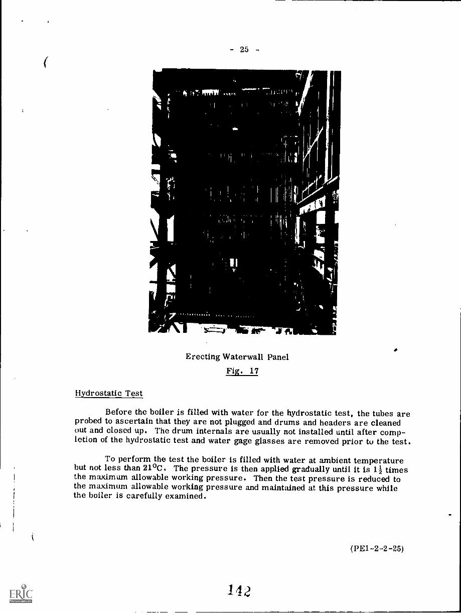
\s:
Hydrostatic Test
- 25 -
111,- al 16
Erecting Waterwall PanelFig. 17
Before the boiler is filled with water for the hydrostatic test, the tubes areprobed to ascertain that they are not plugged and drums and headers are cleanedout and closed up. The drum internals are usually not installed until after comp-letion of the hydrostatic test and water gage glasses are removed prior to the test.
To perform the test the boiler is filled with water at ambient temperaturebut not less than 21°C. The pressure is then applied gradually until it is 1 z timesthe maximum allowable working pressure. Then the test pressure is reduced tothe maximum allowable working pressure and maintained at this pressure whilethe boiler is carefully examined.
(PE1-2-2-25)
142
26
After completion of the hydrostatic test, the gage glasses are installedand checked to see if they read correctly. To do this the water is drained down tojust below the level of the manhole in the drum head and measurements are takento see if the gage glass level corresponds. The boiler is then drained completelyand the drum internals and safety valves are next installed.
Also, after the hydrostatic test is completed and the unit has been provedleakproof, the refractory and insulation is applied.
Casing and Insulation
Plastic chrome ore is often used as the refractory around insd 'Ilion andburner openings. Plastic insulation is applied to the outside of the waterwall tubesand block insulation is frequently applied over the plastic insulation. The cracksbetween the insulation blocks are pointed up with asbestos cement. A finish coatof plastic insulation may then be applied and finally a complete metal casing isinstalled over the installation.
The plastic insulation is made up of mineral wool fibres processed intonodules and then dry-mixed with clay. Before application it is mixed with thecorrect amount of water and then it is applied by throwing against the surface andthen finishing off to the correct thickness with a trowel.
Block insulation may be produced from diatomaceous earth, mineral wool,magnesia, and kaolin clay. The blocks are held in place by galvanized wire criss-crossed from the welded insulation supports.
Expanded metal lath may be used to reinforce the insulation and wire meshis used to reinforce the finish coat.
The metal casing may be supported by the wall structure itself or it maybe supported by external steelwork. The casing may be classified as airtight, *nontight or pressure.
The airtight casing has to be reasonably tight to keep air leakage to aminimum. It is usually constructed of flanged panels which are bolted or weldedtogether.
The nontight casing only serves to protect the insulation and to improve theappearance of the boiler. Air leakage is prevented by the insulation which must bearranged and installed to be quite airtight.
The pressure casing is used for pressurized furnaces and must be completelyairtight against the pressure carried within the furnace. This type of casing istherefore completely welded.
(PE1-2-2-26)
43
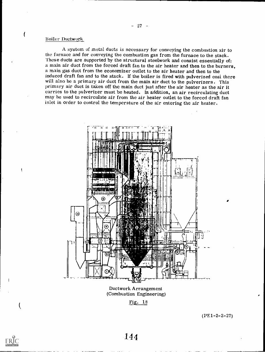
- 27
Boiler Ductwork
A system of metal ducts is necessary for conveying the combustion air tothe furnace and for conveying the combustion gas from the furnace to the stack.These ducts are supported by the structural steelwork and consist essentially of:a main air duct from the forced draft fan to the air heater and then to the burners,a main gas duct from the economizer outlet to the air heater and then to theinduced draft fan and to the stack. If the boiler is fired with pulverized coai therewill also be a primary air duct from the main air duct to the pulverizers. Thisprimary air duct is taken off the main duct just after the air heater as the air itcarries to the pulverizer must be heated. In addition, an air recirculating ductmay be used to recirculate air from the air heater outlet to the forced draft faninlet in order to control the temperature of the air entering the air heater.
-r
IIfp 4
teloviiC 1.1014p401
Ductwork Arrangement(Combustion Engineering)
Fig. 18
144
(13E1-2-2-27)
28
Fig. 18 shows the arrangement of the ductwork in a central station boiler.The circled numburs in the sketch refer to the following items.1. forced draft fan2. air heater3. burner windbox4. primary air take-off5. pulverizer manifold6. pulverizer tempering air7. pulverizers8. forced draft fan discharge9. economizer gas outlet
10. ductwork to stack
Pre-Operation Inspection
After the boiler has been completely erected, a thorough inspection of allparts must be carried out before the boiler can be filled with water and fired.
All trash and debris must be removed from the drum, and tubes should beclosely checked for obstructions. The drum internals must be checked for correctposition and tightness of fastenings. In the case of the chemical feed line, thecontinuous blowdown line, and the feedline itself, those portions which are locatedwithin the drum must be inspected to make sure they are clear. In addition, alldrum connections must be checked for clearness.
An internal inspection of the furnace must be carefully carried out and alltimbers, scaffolding parts, cardboard and other debris removed. Flue gas bafflesare examined for proper location and installation as are the furnace openings forinspection, flue gas sampling, and pressure and temperature instruments.Movement of soot blowers are checked to make sure of proper clearance and toa void the possibility of direct steam impingement on tubes or baffles.
All breeching and duct work must be cleared of dirt and other obstructions.Dampers should be operated to ascertain their freedom of movement and the openand closed positions are marked on the operating mechanism. Pressure andtemperature measuring connections, such as those before and after the air preheater,are checked for location and installation. The air preheater is checked for clean-liness and freedom of movement in the case of the rotary type. If soot blowersare installed for the air heater they must also be checked for proper location andinstallation. Induced draft and forced draft fans must be lined up, lubricated,checked for direction of rotation and operation of control mechanisms.
(PE1-2-2-28)
145
- 29
Dust collectors are usually installed before induced-draft fans in order toreduce wear on fan blades and liners as well as to reduce the amount of dust sent
to the atmosphere. Collectors may be of the mechanical or electrical type or acombination of the two. Before they are placed in operation, a complete finalcheck for internal cleanliness, casing tightness, proper positioning of elements,proper insulation of electrical elements, provisions for expansion, means for dustremoval, and location of draft and test sampling points should be made. Shutoffand bypass dampers if provided should be checked for tightness of closing, pro-vision for expansion under heat, and completeness of travel. Open and closedpositions of dampers should be plainly marked and adequate means for operatingand positioning dampers should be provided.
If a fan is incorporated in the dust-collector assembly, the usual pre-cautionary checks for alignment, lubrication, and cleanliness should be made.
If the collector utilizes electrostatic equipment, a final check of transformers,rectifiers, and auxiliary and control appaeatus should be made before thecollector is placed in service.
All boiler piping must be carefully examined to make sure it is complete.Smaller lines such as drains and blow-off piping are sometimes accidently leftdisconnected. Safety valve discharge piping must be adequately supported withthe proper clearance allowed so that no weight is carried by the safety valve underany conditions. This piping must also be carefully examined to make sure it isclear and free from obstructions. Chemical feed lines, water sampling lines,and water column and gage glass drains are checked for completeness. Valves inmain steam piping and in feedwater piping are checked for proper operation.
Piping to burners is checked for completeness and burner damper vanesand louvres operated to assure freedom of movement.
Upon completion of the overall inspection of the above components theboiler is ready for dry-out and boil-out and these proceedings will be describedin a subsequent lecture.
(PE1-2-2-29)
146
QUESTION SHEET
POWER ENGINEERING First ClassSect. 2, Lect. 2
Discuss the following terms as applied to steel manufacture:
(a) rimmed steel(b) capped steel(e) semikilled steel(d) killed steel
2. Describe the inspection that should be carried out after a boilerhas bees erected and before it is put into operation.
3. (a) List the advantages of low alloy steel compared to plaincarbon steel.
(b) Give as example of a typical low alloy steel and list itsalloy content in percentages.
4. Sketch the basic outline of a large boiler showing the arrangementof the ductwork.
5. List a suitable material for the following boiler parts:
(a) steam drum(b) waterwall headers(c) waterwall tubes(d) radiant superheater tubes
6. Describe the various checks which should be carried out inrelation to the welding of a pressure joint.
7. Discuss the weld defects which could be revealed by radiography.
8. Describe the method and the gear used to raise a large boiler druminto position during erection.
9. Sketch a typical arrangement of the structural steel for a largeboiler including the drum hangers.
I 0 . Describe briefly how the following types of tubes are fabricated:
(a) seamless tubes(b) electric resistance welded tubes(c) furnace butt welded tubes
PE1 -2 -2 -Q
Goal:
illk,UMOnal. amine momal
7.4
BOILERS -- FITTINGS
The apprentice will be able to describe
boiler fittings.
1
Performance Indicators:
1. Describe safety valves2. Describe water columns and
gage glasses.3. Describe pressure gages.4. Describe feedwater connections.5. Describe blow-off valves and
connections.6. Describe slop and check
valves.7. Describe drum intervals.8. Describe soot blowers.9. Describe fusible plugs.
148ME1111111V
INSTRUCTIONAL LEARNING SYSTEMS
'Study Guide
Read the goal and performance indicators to find what is to be learned frompackage.
Read the vocabulary list to find new words that will be used in package.
Read the introduction and information sheets.
* Complete the job sheet.
Complete self-assessment.
Complete post-assessment.
2
14)
INSTRUCTIONAL LEAHNiNU SY5 I tivi
VocabularyMM.
* Angle type valve* Bellows gauge* Bi-color gauge glasses* Bottom blow-off* Bourdon, spring gauge* Combination blow-off valve
* Continuous blow-off* Fireside fusible plug
* Flat gauge glasses* Gauge glasses
* Gate type valve
* Globe type valve* Helix Bourdon gauge
* High pressure gauge glass* Huddling chamber type valves
ill* Jet flow type valves* Long retractable nozzle soot blower
* Main dial gauge* Metallic diaphragm gauge
* Non-return stop valve
* Nozzle reaction type valve
* Outside screw-and-yoke type valve
* Pointer mechanism* Power operated relief valves
* Pressure gauge siphons
* Pressure gauges* Remote gauge glass indicators* Safety valves* Seat and disc blow-off valves
* Seat1(34 sliding plunger and blow-ofl! valve
* Single nozzle retractable soot blower
* Sliding disc blow-off valve
* Solenoid* Spiral Bourdon gauge* Surface blow-off* Torsion bar safety valve
* Tubular gauge glasses* Water column* Waterside fusible plug
3
150
INSTRUCTIONAL LEARNING SYSTEMS
Introduction
Boiler fittings are those items that are directly attached to the boiler. The
fittings are necessary for safe and efficient operation of the boiler.
The apprentices should be concerned with this unit of instruction. Future safety
may depend on the ability to identify each fitting, its function and how it
operates. Steam plant operators must know about fittings and gain experience intheir operation.
Beyond the safety aspects, fittings are part of efficiency. The goal of all
good operators is to run safe and efficient plants.
4
151
INSTHUC 1 IUNAL LLAHNINU b Y tivsz
InformationSafety Valves
Safety valves prevent excess pressures in the boiler. When the pressure exceedssafe levels, the safety valve will trip. There are several types of safety
valves. Some are held shut by steel springs or torsion bars and open by steamwhen the pressure exceeds the setting of the valve. The valve may be opened bynozzle reaction, jet flow or huddling chamber.
Nozzle Reaction Valve
When the valve opens, a baffle and disc are raised upward by the steam. This
closes off the baffle ports and reverses the direction of the steam. Pressure
drops allow the baffle to move downward and steam can flow through the baffle
ports.
Jet Flow Safety Valves
Steam flows from this valve and strikes the piston. The jet stream is deflecteddownward to the nozzle ring. This gives more thrust and the valve opens
further.
1 52
INSTRUCTIONAL. LEARNING SYSTEMS
Information k\JHuddling Chamber Safety Valves
The valve is opened by pressure upon the disc. As it opens the huddling chamberfills with steam and causes a further lift to the disc.
Power Operated Relief Valves
Relief valves can be operated by steam, hydraulics, electricity or remote
control. An element is connected with the pressure vessel or header. When
pressures exceed the limit, this element activates a soleroid which opens the
pilot valve. The excess pressure is relieved from the boiler.
Floating Mohan
Spindle Overtop
Stamm Chamber
eland Holm
Huddling Chamber
Torsion Bar Safety Valve
On high pressure dry steam such as superheaters or reheaters, torsion barp are
used instead of coil springs. Torsion bars are preferred in extreme conditionsof high pressure and high temperature.
Water Columns And Gauge Glasses
Gauge glasses are used to read the water levels in d boiler. A water column
rakes the glass gauge easier to read. The water column allows low and high
level alarms to be installed. Gauge cocks are also installed on water columns.Tubular gauge glasses are used with pressures up to 2800 kPa. Higher pressuresrequire a flat glass gauge.
Bi-Color Gauge Glass
One type of gauge ,,lass uses colored glass (green and red) to make easier
MIMS 41111
153
INSTRUCTIONAL LEARNING SYSI EMS
Informationreading of the gauge. A light is directed through the colored glass strips.
Green light will only shine through when water is in the gauge. Red light
shines through when water is absent.
High Pressure Gauge Glass
High pressure gauge glasses are usually built with ports rather than flat
glass. Individual port assemblies consist of a flat glass, gaskets,.washers,
and a cover and screws.
Remote Gauge Glass Indicators
On large boilers it may be difficult to read the gauge glass from floor level.
A system of mirrors can be used to transmit the indicator to floor level.
Another method of remote indication is achieved by use of a diaphragm. One side
of the diaphragm is connected to the water side and the other to the steam side
of the boiler. The varying levels of water cause the diaphragm to move. Red andblue light indicators show the water levels.
Pressure Gauges
Each boiler has a pressure ,gauge that shows the pressure within the boiler. The
gauge shows a range of 1 1/2 times (or more) the allowable working pressure.
Pressure gauges are classified into three basic types.
1. 9111112111121JULJOlaf..
2. Bellows gauge
3, i.ietallic diaphragm gauge
Bourdon Spring Gauge
The Bourdon spring is a C-shaped tube that is closed at one end and attached to
a pointer mechanism. When pressure is exerted in the tube, the 3ourdon spring
tends to straighten out. This process operates the pointer that shows the
pressure on the dial. Variations of the 3ourdon spring 3auge are the
uiaLlauLELIELand the Helix 3ourdon tube. The C-type Bourdon spring gauge
is used to measure boiler pressure at the main dial gauge. The Helix and spiral
tube gauges are used for recoiling indicators. t. spiral Bourdon tube gauge is
shown as an example of the Bourdon principle.
7
154
INSTRUCTIONAL LEARNING SYSTEMS
°Information
Bellows Gauge
The bellows gauge uses a bellows of elestic metal. When pressure is applied to
the bellows, a pushrod moves the dial indicator according to the level of
pressure. The bellows is used in pneumatic controls and draft measurement
indicators. A bellows type gauge is shown below.
Metallic Diaphragm Gauge
Over-rongetube
p
/r Ten IonZero
o
0010m/rot
cD rinlibrotingsg
Bellows
This type of pressure gauge operates with metallic capsules. The metallic
capsules are connected together. When pressure is exerted inside the capsules,
the capsules expand and move the linkage that operates the indicator. This type
is also used in low pressure applications.
8
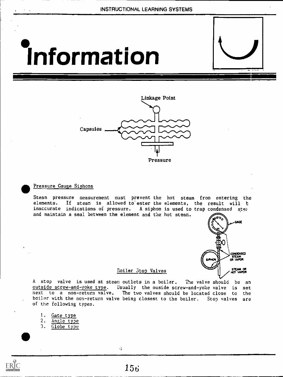
INSTRUCTIONAL LEARNING SYSTEMS
Information
Capsules
Linkage Point
Pressure
40Pressure Gauge Siphons
Steam pressure measurement must prevent the hot steam from entering theelements. If steam is allowed to'enter the elements, the result will t
inaccurate indications of pressure. A siphon is used to trap condensedand maintain a seal between the element and the not steam.
Boiler ;top Valves
A stop valve is used at steam outlets in a boiler. The valve should be anoutside screw -and yoke type. Usually the ouside screw-and-yoke valve is setnext to a non-return valve. The two valves should be located close to theboiler with the non-return valve being closest to the boiler. Stop valves areof the following types.
1. Gate type2. Angle type3. Globe type
I. 5
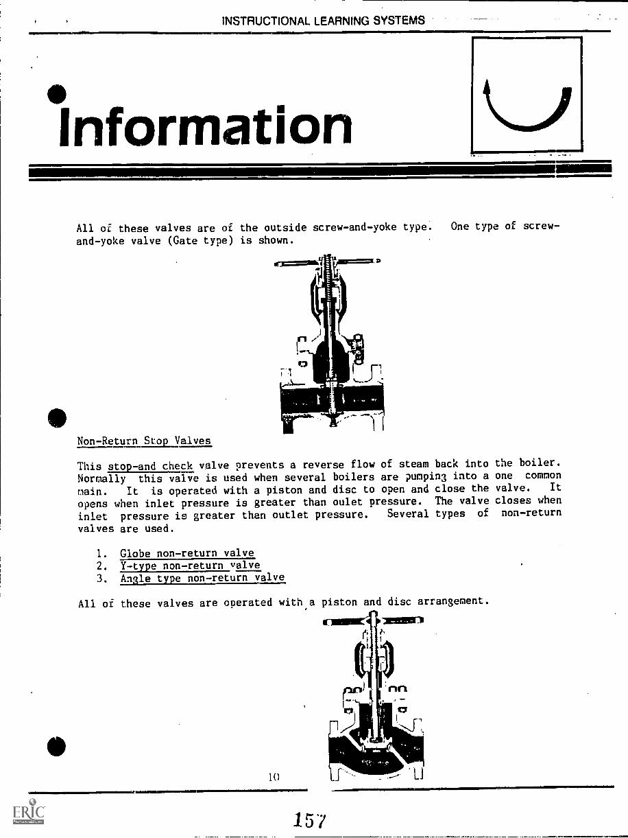
INSTRUCTIONAL LEARNING SYSTEMS
Information .s.
All of these valves are of the outside screw-and-yoke type. One type of screw-
and-yoke valve (Gate type) is shown.
Non-Return Itiokyalves
This stop-and check valve prevents a reverse flow of steam back into the boiler.
Normally this valve is used when several boilers are pumping into a one common
main. It is operated with a piston and disc to open and close the valve. It
opens when inlet pressure is greater than oulet pressure. The valve closes when
inlet pressure is greater than outlet pressure. Several types of non-return
valves are used.
1. Globe non-return valve2. Y-type non-return valve3. Angle type non-return valve
All of these valves are operated with a piston and disc arrangement.
1111111MINIM1b. 11M1.0
10
157
LJ
11 lb 1 HUL., I 1UNAL LEAHNINU 1 I tIVIO
InformationBlow-off Connections
Blow-off connections are used for the following purposes:
1. Removal of sludge from boiler.2. Inject acid cleaning solutions into boiler.3. Lower excess water level in the boiler.
Types of Blow-off
Three major types of blow-off connections are found on boilers.
I. Bottom blow-off are at the bottom of the boiler and used to remove
sludge from the boiler. On firetube boilers, the blow-off connection isto the rear of the boiler. Watertube boilers may have several blow-offconnections to clean sludge out of the mud drums and headers.
2. Continuous blow-off connections are located below the water surface.
Their purpose is to remove water that is heavy with dirt or sludge. A
collecting pipe is located in the heavy water concentrate. A regulatingvalve controls the amounts of water removed by the continuous blow-off.
Most continuous blow-off is part of a heat recovery system that salvages
heat from the blow-off.3. Surface blow-off connections are used to skim off surface sediment from
the boiler water. The blow-off line is located at water level. A
skimming pan moves up and down with variations in the water level. It
scoops off sediment at the water surface.
Blow-off Valve Types
Four types of blow-off valves are used:
1. Sliding disc2. Seatlass slidina212.111E21213. Seat and disc type4. Combination
11111,11
158
INSTRUCTIONAL:LEARNING-SYSTEMS-
°InformationThe sliding disc valve is a quick opening valve that operates by lever action.
\'AI V CO.
us,"
The sliding plunger type is a slow opening valve operated by a handwheel.
NILWirTlalf
=HAM SHUT-0ff
The seat and disc type is also a slow opening vlave with a bottom disc that
closes the valve. It is a handwheel operated valve.
12
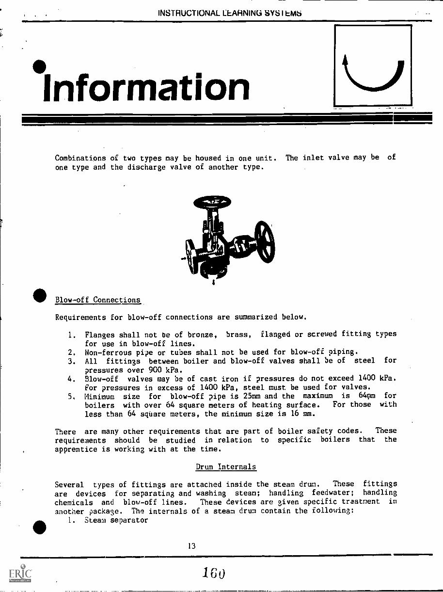
INSTRUCTIONAL LEARNING SYS I OAS
InformationCombinations of two types nay be housed in one unit. The inlet valve may be of
one type and the discharge valve of another type.
111 Blow-off Connections
Requirements for blow-off connections are summarized below.
1. Flanges shall not be of bronze, brass, flanged or screwed fitting types
for use in blow-off lines.2. Non-ferrous pipe or tubes shall not be used for blow-off piping.3. All fittings between boiler and blow-off valves shall be of steel for
pressures over 900 kPa.4. Blow-off valves may be of cast iron if pressures do not exceed 1400 kPa.
For pressures in excess of 1400 kPa, steel must be used for valves.5. Minimum size for blow-off pipe is 25mm and the maximum is 640m for
boilers with over 64 square meters of heating surface. For those with
less than 64 square meters, the minimum size is 16 mm.
There are many other requirements that are part of boiler safety codes. These
requirements should be studied in relation to specific boilers that the
apprentice is working with at the time.
Drum Internals
Several types of fittings are attached inside the steam drum. These fittings
are devices for separating and washing steam; handling feedwater; handling
chemicals and blow-off lines. These devices are given specific traatment in
another package. The internals of a steam drum contain the following:1. Steam separator
13
1 0
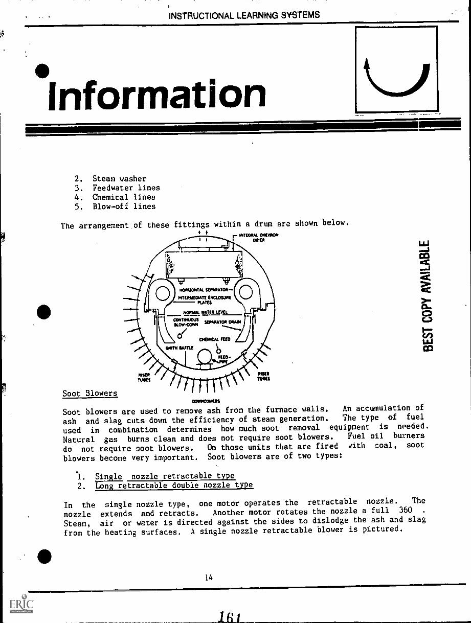
INSTRUCTIONAL LEARNING SYSTEMS
°Information
2. Steam washer
3. Feedwater lines4. Chemical lines5. Blow-off lines
The arrangement of these fittings within a drum are shown below.
Soot Blowers
I r stoteRg..ocro.
MPAIKOKRS
Soot blowers are used to remove ash from the furnace walls. An accumulation of
ash and slag cuts down the efficiency of steam generation. The type of fuel
used in combination determines how much soot removal equipment is needed.
Natural gas burns clean and does not require soot blowers. Fuel oil burners
do not require soot blowers. On those units that are fired iith coal, soot
blowers become very important. Soot blowers are of two types:
1. Single nozzle retractable type
2. Long retractable double nozzle type
In the single nozzle type, one motor operates the retractable nozzle. The
nozzle extends and retracts. Another motor rotates the nozzle a full 360 .
Steam, air or water is directed against the sides to dislodge the ash and slag
from the heating surfaces. A single nozzle retractable blower is pictured.
14
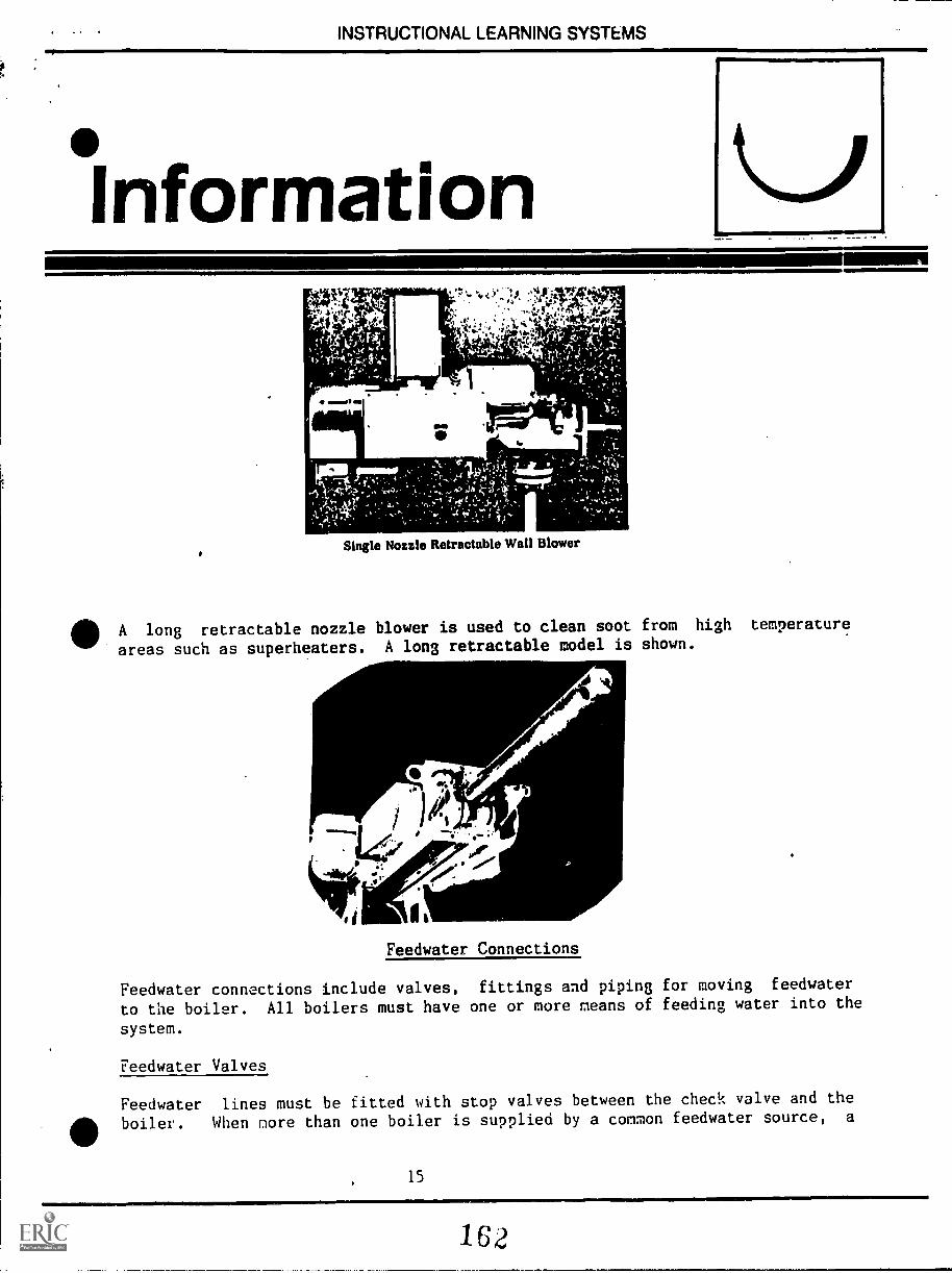
INSTRUCTIONAL LEARNING SYSTEMS
Information
ammoli
1
Single Nozzle Retractable Wall Blower
A long retractable nozzle blower is used to clean soot from high temperature
areas such as superheaters. A long retractable model is shown.
Feedwater Connections
Feedwater connections include valves, fittings and piping for moving feedwater
to the boiler. All boilers must have one or more means of feeding water into the
system.
Feedwater Valves
Feedwater lines must be fitted with stop valves between the check valve and the
boiler. When nore than one boiler is supplied by a common feedwater source, a
15
162
INSTRUCTIONAL LEARNING SYSTEMS
InformationRegulating valve must be installed on branch lines to the individual boilers.
Feedwater Piping
Piping must meet the requirements of the working pressure of the boiler. The
pipe thickness is computed by the following formula:
t= FD + C
2 SE T 2yP
where: t = thickness of pipeP = maximum allowable workin 12essureS = maximum allowable stress valve at operating temperature
(from table)E = efficiency of longitudinal welded joints (From code)C = minimum allowance for threading and structural stability
in m.m. (From code)y = a temperature coefficient (From code)
A list of code tables are needed to compute thicknesses needed for feedwater
piping on specific boilers.
Fusible Plugs
Fusible plugs give warning of low water levels in the boiler. It is a brass
plug with a tin-filled tapered hole drilled through it. It is installed at the
lowest permissable water level in the boiler. When water levels drop below the
plug, the tin will melt and steam will blow out the plug. The operator is
warned so that the boiler can be shut down before damage occurs. ?lugs are
classified as:
1. Fireside plugs which are tapped into holes from the fire side.
2. Waterside plugs which are tapped from the water side of the boiler.
16
163
S. INSTRUCTIONAL LEARNING SYSTEMS
AssignmentRead and study illustrations 11 supplementary references. Read as much of
the references as time will allow.
Complete the job sheet.
Complete the self-assessment and check answers.
Complete the post-assessment and ask the instructor to check your answers.
17
164
INSTRUCTIONAL LEARNING SYSTEMS
ANALYZE THE FITTINGS ON A BOILER
Observe a boiler and closely inspect for the following items. Identify types
of each item.
Safety valvesWater columns and gauge glassesPressure gaugesFeedwater connectionsBlow-off connectionsStop and check valvesDrum internals (if possible)Soot blowers (if possible)Fusible plugs (if possible)
For those items that cannot be readily identified, consult a manufactures
diagram or ask the operator to help.
Learn the identity of every gauge, valve and fitting that is attached to the
boiler and its purpose.
18
165
INSTRUCTIONAL LEARNING SYSTEMS
.SelfAssessment
Indicate what type of fitting is listed below by inserting the proper letter in
the blank beside the number.
1. Single nozzle retractable type A. Safety valve
2. Globe type B. Water column or gauge glass
3. Seatless sliding plunger type valve C. Pressure gauge
4. Bourdon spring gauge D. Fo,dwater connection or valve.
5. Screw and yoke type gauge E. Blow-off connection or valve.
6. Nozzle reaction type F. Stop or check valvewows
7. Steam washer G. Drum internal
8. Flat glass gauge H. Soot blower
9. Fireside type I. Fusible plug
10. Regulating valve J. Non-return stop valve
166
INSTRUCTIONAL LEARNING SYSTEMS
Self AssessmentAnswers
H 1.
J 2.
E 3.
C 4.
F 5.
A 6.
G 7.
B 8.
I 9.
D 10.
INSTRUCTIONAL LEARNING SYSTEMS
PostAssessment
TRUE or FALSE
1. A power operated relief valve is a type of safety valve.
2. Gauge glasses are used to determine the color of boiler water.
3. Tubular gauge glasses are needed on boilers with operating pressures above
2800 kPa.
4. Pressure gauges must show a range of 1 1/2 times the allowable workingpressure to meet code.
5. A bellows gauge is a type of pressure gauge.
6. The Bourdon spring gauge operates from pressure on a C-shaped tube that
causes it to straighten out and open the valve.
7. The outside screw-and-yoke valve is the most common type of safety valve
used on boilers.
8. There are two major kinds of blow-off counnections on boilers.
9. A steam separator is one of the drum internals.
10. natural gas burners require several soot blowers to free the heating
surface of ash.
1110111011111110001e *001111101111.1111MM,
21
168
INS1tRUCTIONAL LEARNING SYSTEMS
Instructorl'ost AssessmentAnswers
1. True
2. False
3, False
4. True
5. True
6. True
7. False
8. False
9. True
10. False
22
16j
INSTRUCTIONAL LEARNING SYSTEMS'
SupplementaryReferences
41111111.1111Mi 411111111=
* Correspondence Courses. Lectures 4 and 5, Section 2, First Class. Steam
Generation. Southern Alberta Institute of Technology. Calgary, Alberta,
Canada.
23
17U
SOUTHERN ALBERTA INSTITUTE OF TECHNOLOGYCALGARY, ALBERTA
SECTION 2
STEAM GENERATION
Correspondence CoursesPower Engineering
BOILER FITTINGS I
First ClassLecture 4
The term "boiler fittings" encompasses all those items directly attachedto or within the boiler proper which are necessary for the safe and efficient oper-ation of the boiler. These fittings include safety valves, water columns and gageglasses, pressure gages, feedwater connections, blowoff valves and connections,main steam valves, drum internals, and soot blowers.
The standards governing the design, fabrication, installation, identifica-tion, testing and inspection of these various fittings are as set forth in the ASMEand CSA Codes. For example, the CSA B51 Code states that drawings and spec-ifications of all fittings* to be used on boilers shall be sent to the Provincial ChiefInspector for approval and registration. The ASME Code contains numerous re-ferences regarding boiler fittings and these will be discussed in this lecture inconjunction with each individual fitting,
SAFETY VALVES
The safety valve is a positive protection device which prevents the boilerpressure from exceeding that for which the vessel was designed.
The ASME Power Boilers Code states that each boiler shall have at leastone safety valve or safety relief valve and if the boiler has more than 47 m2 ofwater heating surface, or if electric it has a power input of more than 500 kW,then it shall have two or more safety valves or safety relief valves. The capacityof the safety valve or valves shall be such as to discharge all the steam that canbe generated by the boiler without allowing the pressure to rise more than 6 per-cent above the highest pressure at which any valve is set and in no case morethan 6 percent above the maximum allowably; working pressure of the boiler.
In the case of a low pressure heating boiler, the ASME Heating BoilersCode states that each steam boiler shall have one or more ,officially rated safetyvalves of the spring pop type adjusted and sealed to discharge at a pressure notto exceed 103 kPa.
171
12.4
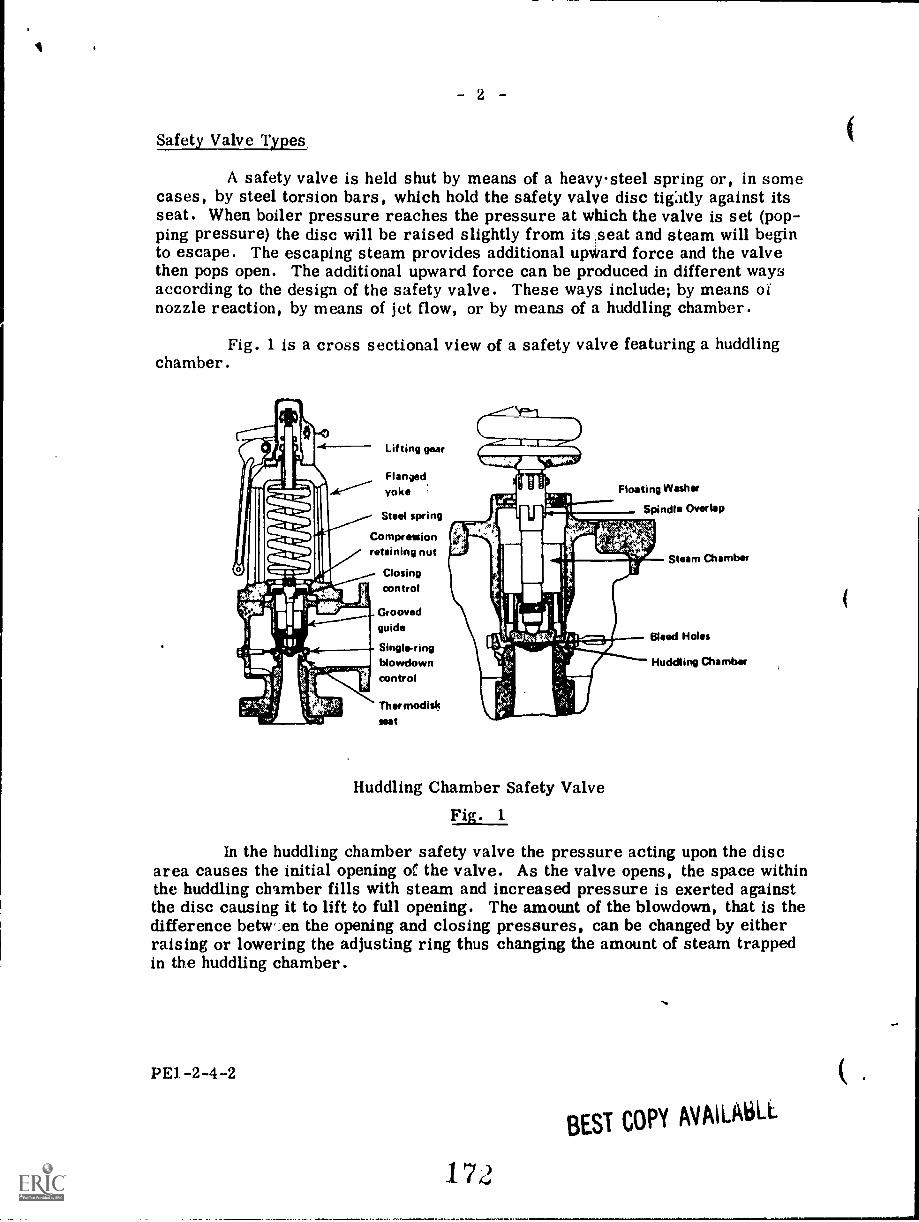
2
Safety Valve Types,
A safety valve is held shut by means of a heavy-steel spring or, in somecases, by steel torsion bars, which hold the safety valve disc tigitly against itsseat. When boiler pressure reaches the pressure at which the valve is set (pop-ping pressure) the disc will be raised slightly from its ,seat and steam will beginto escape. The escaping steam provides additional upward force and the valvethen pops open. The additional upward force can be produced in different waysaccording to the design of the safety valve. These ways include; by means ofnozzle reaction, by means of jet flow, or by means of a huddling chamber.
Fig. 1 is a cross sectional view of a safety valve featuring a huddlingchamber.
Lifting gear
Flanged.yoke
Steel spring
Compressionretaining nut
Closingcontrol
Groovedguide
Single-ringblowdowncontrol
Thermodiskneat
Floating Washer
Spindle Overlap
Huddling Chamber Safety Valve
Fig. 1
In the huddling chamber safety valve the pressure acting upon the discarea causes the initial opening of the valve. As the valve opens, the space withinthe huddling chamber fills with steam and increased pressure is exerted againstthe disc causing it to lift to full opening. The amount of the blowdown, that is thedifference betvt,en the opening and closing pressures, can be changed by eitherraising or lowering the adjusting ring thus changing the amount of steam trappedin the huddling chamber.
PE1 -2-4 -2
172
BEST COPY AVAlLiiiLL
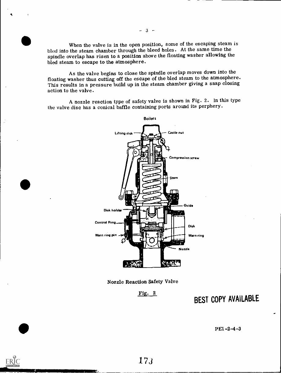
- 3 -
When the valve is in the open position, some of the escaping steam isbled into the steam chamber through the bleed holes. At the same time thespindle overlap has risen to a position above the floating washer allowing thebled steam to escape to the atmosphere.
As the valve begins to close the spindle overlap moves down into thefloating washer thus cutting off the escape of the bled steam to the atmosphere.This results in a pressure build up in the steam chamber giving a snap closingaction to the valve.
A nozzle reaction type of safety valve is shown in Fig. 2. In this typethe valve disc has a conical baffle containing ports around its perphery.
Boilers
,110111IIL.Lifting disk Castle nut
11S410111.
10 1 flakoCompression screw
Stem
Guide
Disk holder
Control Ring
Warn ring pin
Disk
Warn ring
Nozzle
Nozzle Reaction Safety Valve
Fig. 2
173
BEST COPY AVAILABLE
PE1-2-4-3
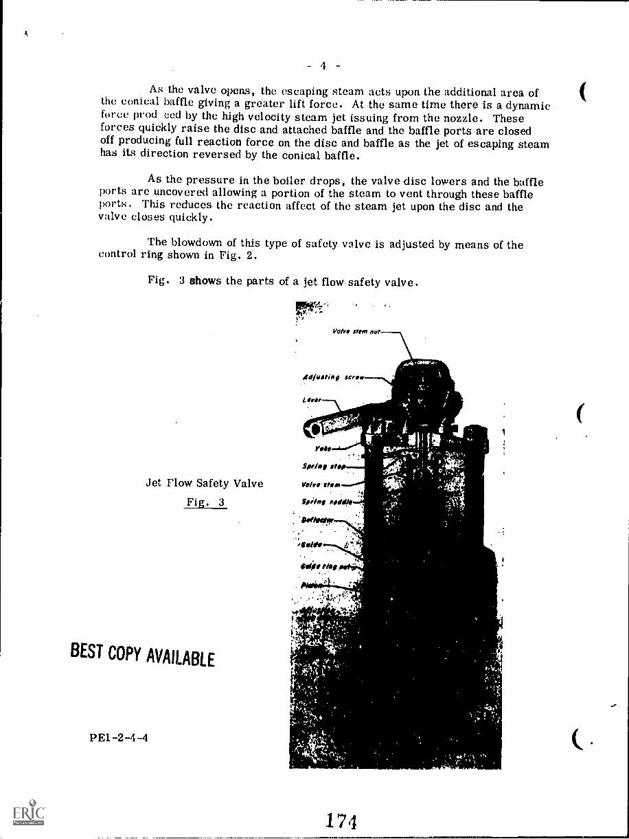
4
As the valve opens, the escaping steam acts upon the additional area ofthe conical baffle giving a greater lift force. At the same time there is a dynamicforce prod ced by the high velocity steam jet issuing from the nozzle. Theseforces quickly raise the disc and attached baffle and the baffle ports are closedoff producing full reaction force on the disc and baffle as the jet of escaping steamhas its direction reversed by the conical baffle.
As the pressure in the boiler drops, the valve disc lowers and the baffleports are uncovered allowing a portion of the steam to vent through these baffleports . This reduces the reaction affect of the steam jet upon the disc and thevalve closes quickly.
The blowdown of this type of safety valve is adjusted by means of thecontrol ring shown in Fig. 2.
Fig. 3 shows the parts of a jet flow safety valve.
Jet Flow Safety Valve
Fig. 3
BEST COPY AVAILABLE
PE1-2-4-4
Valve stem nu,
490 II I/ ft 9 Set
Lfrill
.
SNIP, atop--
Volvo stem
Wine 1400- :
a,
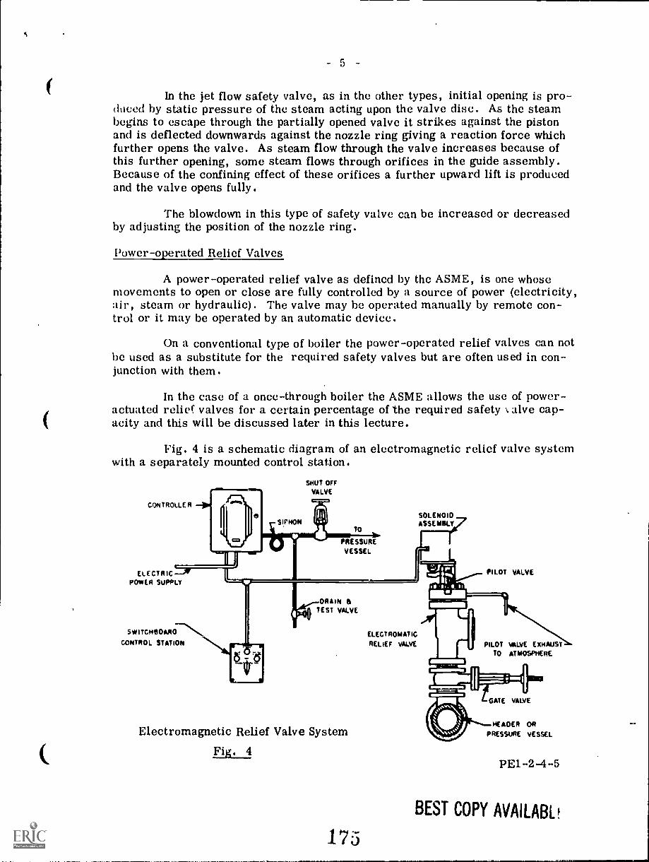
ti
- 5 -
In the jet flow safety valve, as in the other types, initial opening is pro-duced by static pressure of the steam acting upon the valve disc. As the steambegins to escape through the partially opened valve it strikes against the pistonand is deflected downwards against the nozzle ring giving a reaction force whichfurther opens the valve. As steam flow through the valve increases because ofthis further opening, some steam flows through orifices in the guide assembly.Because of the confining effect of these orifices a further upward lift is producedand the valve opens fully.
The blowdown in this type of safety valve can be increased or decreasedby adjusting the position of the nozzle ring.
Power-operated Relief Valves
A power-operated relief valve as defined by the ASME, is one whosemovements to open or close are fully controlled by a source of power (electricity,air, steam or hydraulic). The valve may be operated manually by remote con-trol or it may be operated by an automatic device.
On a conventional type of boiler the power-operated relief valves can notbe used as a substitute for the required safety valves but are often used in con-junction with them.
In the case of a once-through boiler the ASME allows the use of power-actuated relief valves for a certain percentage of the required safety \,alve cap-acity and this will be discussed later in this lecture.
Fig. 4 is a schematic diagram of an electromagnetic relief valve systemwith a separately mounted control station.
CONTROLLER
ELECTRICPOWER SUPPLY
SHUT OFF
VALVE
SIPHONTO
PRESSURE
VESSEL
SOLENOIDASSEMBLY
PILOT VALVE
DRAIN &TEST VALVE
SW I TCHEIOARD-"...%%\
CONTROL STATIONEL ECT ROMATIC
RELIEF VALVE PILOT WYE EXHAUSTTO ATMOSPHERE
Electromagnetic Relief Valve System
Fig. 4
175
GATE VALVE
HEADER ORPRESSURE VESSEL
PE1-2-4-5
BEST COPY AVAILABL
- 6
The operation of the system is basically as follows:
The controller contains a Bourdon tube element which is connectedthrough a siphon to the pressure vessel or header. When the pressure in theheader or vessel reaches a preset value the Bourdon tube element will close acontact switch which energizes the solenoid. The solenoid plunger acts on a leverwhich opens the pilot valve. With the pilot valve open steam pressure is relievedfrom above the relief valve disc and the disc is forced open by the steam pressurefrom the header or pressure vessel.
When the pressure is reduced as a result of the relief valve opening, theBourdon tube element opens the contact switch and the solenoid is de-energized.The pilot valve spring then closes the pilot valve which traps steam above therelief valve disc and the resulting pressure forces the disc into the closed posi-tion.
The control station switch has three positions: manual, off, and auto-matic.
When the switch is in the automatic position the relief valve will operatewhen the preset pressure is reached as just described.
When the switch is placed in the manual position the solenoid is imme-diately energized and the relief valve opens no matter what the pressure is.
When the switch is in the off position the circuit to the solenoid isbroken and the relief valve will remain closed even if the pressure reaches thepreset value.
Fig. 5 shows the details of the relief valve. The inlet to the valve A isconnected to the space C by means of passages not shown which pass upwardaround both sides of the exhaust chamber B. Steam passes from C to E throughthe clearance space 5 around the main valve disc 6. It is the pressure of thesteam in E which holds the main valve disc in the closed position.
When the solenoid is energized, either by means of the manual switchor by the Bourdon tube element, the pilot valve 4 which is held closed by thespring 3 is opened by the solenoid plunger head"1 acing upon the lever 2.
Steam is thus released from E through the port G faster than it canenter through 5. The resulting unbalance of pressures in chambers E and Cproduces a lifting force which lifts the main valve disc from its seat permittingsteam to flow from A through C to the outlet B.
PEI-2-4-6
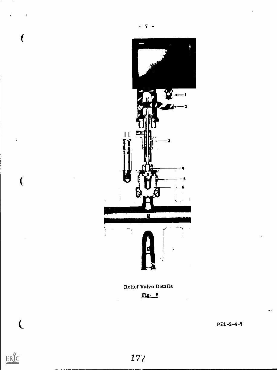
B
Relief Valve DetailsFig. 5
PE1-2-4-7
17/
The advantages of the power-operated relief valve are as listed:
. They can be operated by remote control.
2. They can be repaired while the boiler is in service because theycan be isolated from the boiler by means of the gate valve shownin Fig. 4.
3. They are kept closed by full boiler pressure in comparison tor'zing loaded sviety valves which are kept closed by he differ-ence between steam pressure and spring pressure.
4. They can be set to open before the conventional code-requiredspring loaded safety valves and thus save wear and tear onthese valves.
.1 They can he used to purge pendent type superheaters of waterduring the boiler start up.
6. They can be used to reduce steam pressure when shutting downthe boiler.
Safety Valve Code Requirements
The ASME Code Section I deals with safety valves for power boiiers inparagraphs PG 67 to PG 72 inclusive.
As mentioned on Page 1 of this lecture, each boiler must have at leastone safety valve or safety relief valve and if the boiler is above a certain sizethen it must have two or more safety valves or safety relief valves.
Tie terms "safety valve", relief valve", and safety relief valve" haveoften in the past been used interchangeably with resulting confusion. The follow-ing definitions are therefore offered:
A safety valve is an automatic, direct-pressure-actuated, pressurerelieving valve characterized by pop action and suitable for vapor or gas services.
A relief valve is an automatic, direct-pressure-actuated, pressurerelieving valve with no pop action and usually with no definite blow-down or re-closure point. It is used primarily for liquid service.
A safety-relief valve is an automatic, direct-pressure-actuated, pres-sure relieving valve which can be adjusted for either pop or non-pop action andis suitable for vapor, gas or liquid services.
PE-1-2-48
1 7s
As also mentioned on Page 1 of this lecture the safety valve or safetyrelief valve capacity for each boiler of the conventional drum-type design shallbe such that the valves will discharge all the stcam that can be generated by theboiler without allowing the pressure to rise more than ts, percent above the high-est pressure at which any valve is set and in no case to more than 6 percent abovethe maximum allowable working pressure.
One or more safety valves shall be set at or below the maximum allow-able working pressure and the set point of the other valves if used shall not exceedthe maximum allowable working pressure by more than 3 percent.
The ASME Code, however, allows any one of the following options in thecase of a once-through forced-flow steam generator with no fixed steam and waterline and equipped with automatic controls and protective interlocks responsive tosteam pressure:
1. Spring-loaded safety valves, capable of relieving 100% of the steamingcapacity of the boiler, shall be installed as for conventional drum-type boilers.
2. One or more power operated relief valves, set to open at the maximumallowable working pressure at the superheater outlet, shall be provided havingan aggregate capacity from 10% to 30% of the required relieving capacity for theboiler. The remaining 70% to 90% of relieving capacity shall be provided byspring loaded safety valves which may be set above the maximum allowable work-ing pressure. The set pressures however, shall be such that when all the valvesare operating (spring-loaded plus power-operated) the pressure will not rise morethan 20 percent above the maximum allowable working pressure of any part of theboiler.
3. The capacity of the spring-loaded safety valves in option 2 may be re-duced to not less than 10% of the required relieving capacity providing the follow-ing conditions in addition to those in option 2 are met:
(a) the boiler generates at least 450 000 kg per hourof,steam and is installed in a unit system whereina single boiler supplies a single turbine-generator.
(b) the boiler is provided with automatic devices res-ponsive to variations in steam pressure includingat least:
modulation of firing rate and feedwater flow inproportion to steam output.
- reduction of fuel rate and feedwater flow whensteam pressure exceeds the maximum allowableworking pressure by 10% thus over-riding thefiring rate and feedwater coantrels mentionedabove.
- complete stoppage of fuel and feedwater to boilerbefore pressure reaches 20% above the maximumallowable working pressure.
PE1-2-4-9
1 7
10 -
(e) the spring-loaded safety valves must be atleast two in number and set to open at apressure no higher than 20% above the max-imum allowable working pressure.
(d) a fail-safe circuitry is provided to stop theflow of fuel and feedwater to the boiler whenthe spindle of either of the required two spring-loaded safety valves moves.
(e) the power supply for all controls shall includeat least one source located within the plantwhich will actuate the controls in the event offailure of the other power sources.
An advantage of both options 2 and 3 is the fact that the spring-loadedvalves can be set at an overpressure of up to 20% above the maximum allowableworking pressure. This means that when the steam pressure is at maximumallowable working pressure the spring-loaded valves will not tend to simmer.
Superheater Safety Valves
The ASME Code states that every attached ...uperheater shall have oneor more safety valves near the outlet and the capacity of the valve or valves maybe included in determining the number and size of the safety valves for the boilerproviding there are no intervening valves between the boiler and the superheatersafety valve. In any case the safety valves on the boiler proper must provide atleast 75% of the total required relieving capacity.
The superheater safety valve or valves should be set so as to pop beforethe drum safety valves in the event of loss of the load. In this way overheatingof the superheater is avoided as there will be a flow of steam maintained throughthe superheater until the fires can be shut down.
If a power-operated relief valve is used it is normally set at a loWerpressure than the spring-loaded superheater safety valve and it will always be thefirst valve to operate, in this way reducing wear and tear of the spring-loadedvalve.
If the superheater is separately fired and can be isolated from the boilerthen it shall have one or more safety valves equal in total capacity to 99 kg/m2 ofsuperheater surface and these valves can not be used in determining the numberand size of the safety valves for the boiler.
In the case of a reheater, it shall have one or more safety valves havinga total capacity at least equal to the maximum steam flow for which the reheateris designed. The capacity of these reheater safety valves shall not be included inthe required relieving capacity for the boiler and superheater.
PE1-2-4-10
S 0
Safety Valve Capacity
The capacity of a particular design of safety valve is determined bymeans of tests which are made with steam under conditions similar to actualoperating conditions. Tests under these conditions are also used to determine thelift, popping and blowdown pressures for each safety valve design.
The capacity tests are used to establish a discharge coefficient K whichis then used in the capacity formulae given in PG-69.1.2.
The capacity that is stamped on the safety valve by the manufacturermust not be more than 90 percent of the value as determined by the afore men-tioned tests.
The required safety valve capacity for a boiler is determined on *.he basisof kg of steam generated per hour per m2 of boiler heating surface as given inTable PG-70. In every case, however, the capacity shall be such that all thesteam generated by the boiler can be discharged without the pressure rising morethan 6 percent above the maximum allowable working pressure as specified inPG-67.2.
The safety valve capacity can be checked in any one of the three follow-ing ways:
1. By means of an accumulation test wherein all the steam outlets from theboiler are shut and the fires forced to a maximum. Under these conditions thesafety valve capacity must be sufficient to prevent an excess pressure greaterthan 6 percent above the maximum allowable working pressure. This methodmust not be used on a boiler with a superheater or 'Theater or on a high temper-ature water boiler.
2. By measuring the maximum amount of fuel that can be burned and com-puting the corresponding evaporative capacity based on the heating value of thefuel. The sum of the safety valve capacities marked on the valves shall be equalto or greater than this evaporative capacity.(See Al2 to A17 in Section I ASME).
3. By determining the maximum evaporative capacity by measuring thefeedwater. As in 2. above, the sum of the safety valve capacities marked on thevalves shall be equal to or greater than the maximum evaporative capacity.
PEI-2-4-11
181
12
Safety Valve Installation and Operation
A safety valve or safety relief valve must be connected to the boiler inde-pendent of any other connection and attached as close as possible to the boiler inan upright position with the spindle vertical. No valve of any type shall be placedbetween the safety valve or safety relief valve and the boiler or on the dischargepipe from the safety valve or safety relief valve if such a discharge pipe is used.
If a discharge pipe is used its cross sectional area shall not be less thanthe full area of the valve outset acid the pipe should be as short and straight aspossible. An ample gravity drain must be provided in the discharge pipe at ornear each safety valve or safety relief valve where water of condensation maycollect. In addition, each valve must have an open gravity drain through thecasing below the level of the valve seat.
Fig. 6 shows the discharge piping arrangement and dimensions for atypical safety valve.
The term "blowdown" as used in connection with safety valves refers tothe difference between the opening or set pressure of the valve and its closingpressure. All safety valves on conventional drum type boilers shall close at apressure not lower than 96 percent of their set pressure except that all drumsafety valves on a single boiler may close at a pressure not lower than 96 per-cent of the set pressure of the lowest set drum safety valve. In any case theminimum blowdown shall be 14 kPa. For safety valves for pressures between690 and 210" kPa inclusive, the blowdown shall not be less than 1 percent of theset pressure.
Safety valves used on forced-flow or once-through steam generators withno fixed steam and water line, and safety relief valves used on high temperaturewater boilers may be set to close after blowing down not more than 10 percent ofthe set pressure.
To insure that the valve is not stuck in the closed position, each safetyvalve or safety relief valve 'shall have a lifting device by which the valve discmay be lifted from its seat when there is at least 75 percent of full working pres-sure on the boiler.
PE1-2-4-12
1.82
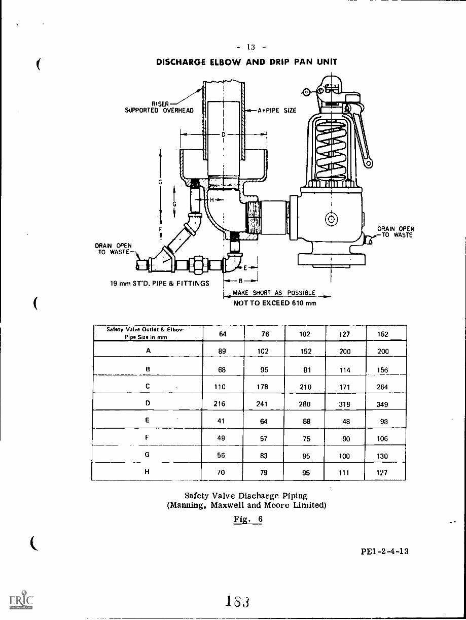
- 1.3
DISCHARGE ELBOW AND DRIP PAN UNIT
RISERSUPPORTED OVERHEAD
DRAIN OPENTO WASTE
DRAIN OPENTO WASTE
19 mm ST'D. PIPE & FITTINGS B
MAKE SHORT AS POSSIBLE
NOT TO EXCEED 610 mm
Safety Valve Outlet & ElbowPipe Size in mm 64 76 102 127 152
A 89 102 152 200 200
B 68 95 81 114 156
C 110 178 210 171 264
D 216 241 280 318 349
E 41 64 88 48 98
F 49 57 75 90 106
G 56 83 95 100 130
H 70 79 95 111 127
Safety Valve Discharge Piping(Manning, Maxwell and Moore Limited)
Fig. 6
PE1 -2 -4 -13
183
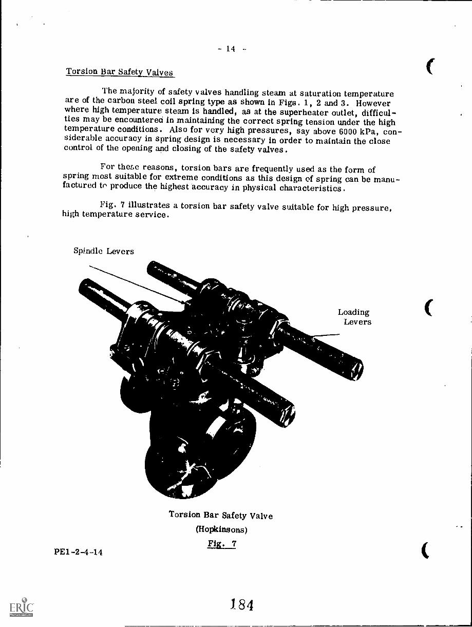
14
Torsion Bar Safety Valves
The majority of safety valves handling steam at saturation temperatureare of the carbon steel coil spring type as shown in Figs. 1, 2 and 3. Howeverwhere high temperature steam is handled, as at the superheater outlet, difficul-ties may be encountered in maintaining the correct spring tension under the hightemperature conditions. Also for very high pressures, say above 6000 kPa, con-siderable accuracy in spring design is necessary in order to maintain the closecontrol of the opening and closing of the safety valves.
For these reasons, torsion bars are frequently used as the form ofspring most suitable for extreme conditions as this design of spring can be manu-factured to produce the highest accuracy in physical characteristics,
Fig. 7 illustrates a torsion bar safety valve suitable for high pressure,high temperature service.
Spindle Levers
PE1-2-4-14
"woRIA,INIP""'
Torsion Bar Safety Valve(Hopkinsons)
184
LoadingLevers
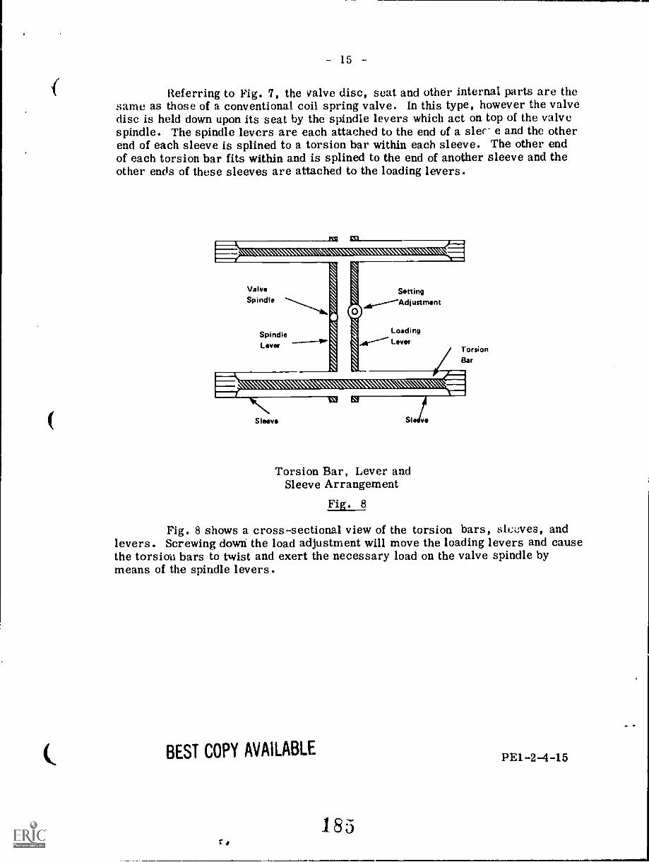
f
- 15
Referring to Fig. 7, the valve disc, seat and other internal parts are thesame as those of a conventional coil spring valve. In this type, however the valvedisc is held down upon its seat by the spindle levers which act on top of the valvespindle. The spindle levers are each attached to the end of a slec e and the otherend of each sleeve is splined to a torsion bar within each sleeve. The other endof each torsion bar fits within and is splined to the end of another sleeve and theother ends of these sleeves are attached to the loading levers.
ValveSpindle
0
\A"1S1
SpindleLever
Setting
LoadingLever
TorsionBar
Sleeve SI ve
Torsion Bar, Lever andSleeve Arrangement
Fig. 8
Fig. 8 shows a cross-sectional view of the torsion bars, sleeves, andlevers. Screwing down the load adjustment will move the loading levers and causethe torsion bars to twist and exert the necessary load on the valve spindle bymeans of the spindle levers.
BEST COPY AVAILABLE
185
PE1 -2-4 -15
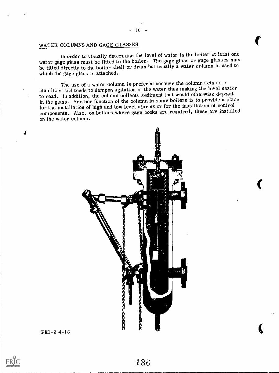
- 16
WATER COLUMNS AND GAGE GLASSES
In order to visually determine the level of water in the boiler at least onewater gage glass must be fitted to the boiler. The gage glass or gage glasses maybe fitted directly to the boiler shell or drum but usually a water column is used towhich the gage glass is attached.
The use of a water column is prefered because the column acts as astabilizer and tends to dampen agitation of the water thus making the level easierto read. In addition, the column collects sediment that would otherwise depositin the glass. Another function of the column in some boilers is to provide a placefor the installation of high and low level alarms or for the installation of controlcomponents. Also, on boilers where gage cocks are required, these are installedon the water column.
PE1-2-4-16
18t
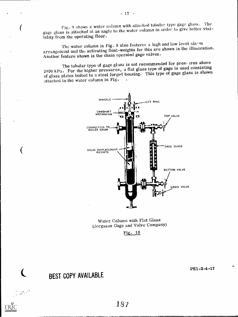
17
Fig. 9 shows a water column with attachtxl tubular type gage glass. The
gage glass is attached at an angle to the water column in order to give better visi-
bility from the operating floor.
The water column in Fig. 9 also features a high and low level itliv-rn
arrangement and the activating float-weights for this are shown in the illustration.
Another feature shown is the chain operated gage valves.
The tubular type of gage glass is not recommended for presiires above2800 kPa. For the higher pressures, a flat glass type of gage is used consisting
of glass plates bolted to a steel forged housing. This type of gage glass is shown
attached to the water column in Fig.
WHISTLE
CAMSHAFTMECHANISM
CONNECTION TOBOILER DRUM
.1 r a
LIFT RING
TOP VALVE
SOLID DISPLACEMENTWEIGHTS
GAGE GLASS
BOTTOM VALVE
DRAIN VALVE
Water Column with Flat Glass(Jerguson Gage and Valve Company)
BEST COPY AVAILABLE
PE1-2-4 -17
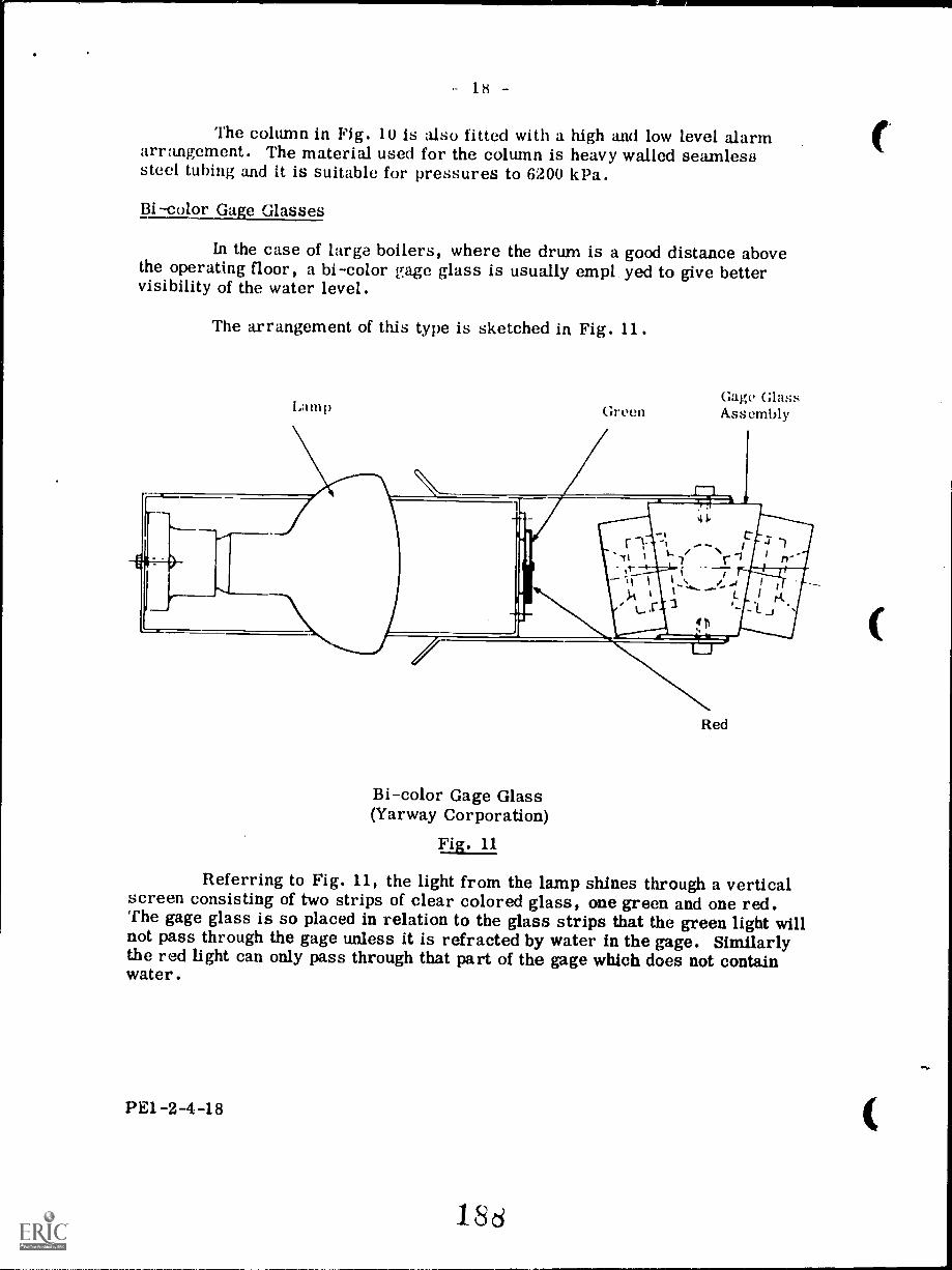
- 18 -
The column in Fig. 10 is also fitted with a high and low level alarmarrangement. The material used for the column is heavy walled seamlesssteel tubing and it is suitable for pressures to 6200 kPa.
Bi-color Gage Glasses
In the case of large boilers, where the drum is a good distance abovethe operating floor, a bi-color gage glass is usually empl yed to give bettervisibility of the water level.
The arrangement of this type is sketched in Fig. 11.
Lamp GreenGage GlassAss embly
Red
Bi-color Gage Glass(Yarway Corporation)
Fig. 11
Referring to Fig. 11, the light from the lamp shines through a verticalscreen consisting of two strips of clear colored glass, one green and one red.The gage glass is so placed in relation to the glass strips that the green light willnot pass through the gage unless it is refracted by water in the gage. Similarlythe red light can only pass through that part of the gage which does not containwater.
PE1-2-4-18
186
- 19
The gage glass assembly is a high pressure design suitable for pressuresup to 20.7 MPa. Rather than using single pieces of flat glass for the back and thefront of the gage, this design uses individual port assemblies. Each port assemblyconsists of a flat glass, washers, gaskets, cover and screws.
Fig. 12 illustrates the port arrangement.
Headon view of cover
WATER (OR STEAM) SPACE
3456
11
tt
7VENT SOLES
Horizontal section through body and covers
9 10
High Pressure Gage Glass(Yarway Corporation)
The numbered parts in Fig. 12 are as
1. stainless steel body2. carbon steel cover3. pyrex round flat glass4. stainless steel spring cones5. stainless steel washer6. asbestos gasket
follows:
7. stainless steel clip rings8. stainless steel retaining rings9. mica shields to prevent erosion
and corrosion of the round flatglasses
10. steel capscrews for cover11. asbestos sealing gaskets
PE12-4-19
20
Fig. 13 shows the arrangement of a bi-color multi-port gage glass. Thegage is attached to a circolating tie-bar instead of to a water column. The tie-barhas top and bottom connector blocks with gage valves plus a bottom connection fora drain line.
TOP SENDMeet p psetln and tntraction.
COLOR SCREENInfinth ***** bit
ler right end Is liddind e*-stratifies,
LIGHTINGNigh filtIntyspotlights provide MIIIbM tneast end molly *ag to/tintCompose design pomade Instal..Note smolt pate.
PE1-2-4-20
FLANGEDCONNECTIONSmtween gage and vIvesnate stuffing boost
AIL
WELBLOCe GAGE VALVESCamped design toduts Installationspate. Wading pads salty ttsiltie.Moe flaw, Imitate...it ea NIL fifilinielltimpattins Ittleventiel.
COVERSIndividual "Mood., ssernbly" henend both pad covets have swingthat apply all petdommined lead enBlau pods. This fealuto else mimeslhooditil Olathe, ponalts fasts. wamadne
COVE, MOLTINGEach teem 41 solidly against body byfeat socket hod tepstomms, tightanod
"...it.. ell Ike way down. ea ..d fw Wavewreath. Each teem wed Its glees maybe lightenet1 at monoveel wIth.md die
oppself* set.
GLASSESindividual timed. .i said*/by special gasket.. Inns. Isit si.
by rnIt.
PORTStwee Iltfneltt pad penings for Intressed visibility.
MIRRORSdefietting admits, Intwasodiatehadetl. transmit ImIghtlyfighted..d-.a view el lets el gage te tia
action/ vytileval on tigemitIng float.
Multi-Port Gage Glass with Tie-Bar(Yarwav Corporation)
BEST COPY AVAILABLE
Fig.
190
21
Remote Indication
In the case of large boilers having the drum and attache(' gage gloss agood distance above the operating floor, it is necessary to transmit the %vote' levelreading to some spot visible to the operator on the operating floor.
One method of accomplishing this is by the use of mirrors as Illustratedin Fig. 14, A and B.
1.).4
0.c.A(.1 WINIlIUMINA101 ON FRONT
N000
ARRANGEMENT A
li11()(1 on gagemay be added iflighting condi-( ions are notfavorable. Inter-mediate mirror on
ruct oral sup-port, lower mirroron floor stand,
INIIRMLDIAILMIAROA
1.011101
ANDFLOOR
SIANG
GAGE WITHALUMSNA104
ARRANGEMENT B
Hooded mirroron gage, lowermirror on floorstand, floodkeeps out objec-tionable lightand cold drafts.
Gage Glass Mirror ArrangementsFig. 14
,1104,111 MJFIN
Another method of remote indication of water level appears in 15.
Referring to Fig. 15, the operating element consis4.s of a lagi:.11.11)hragm, one side being connected to the steam space of the boilor
Ill water space.;awl Ito! other
A condenser at the boiler drum is provided to maintain a fixed hewl ofwater on the steam space side, while the water space side is subjected to ;1 V ry-ing head dependent upon the water level in the boiler. This varying hold 1/4 -a !wed by a spring in the instrument and causes the diaphragm to move in accord-;Ince with the water level. The full boiler pressure, being on both side'', of thediaphragm, is therefore balanced and has no effect on the movement of the diaphrag-m, which is actuated only by the difference in heads.
BEST COPY AVAILABLEIPEI -2 --4.21
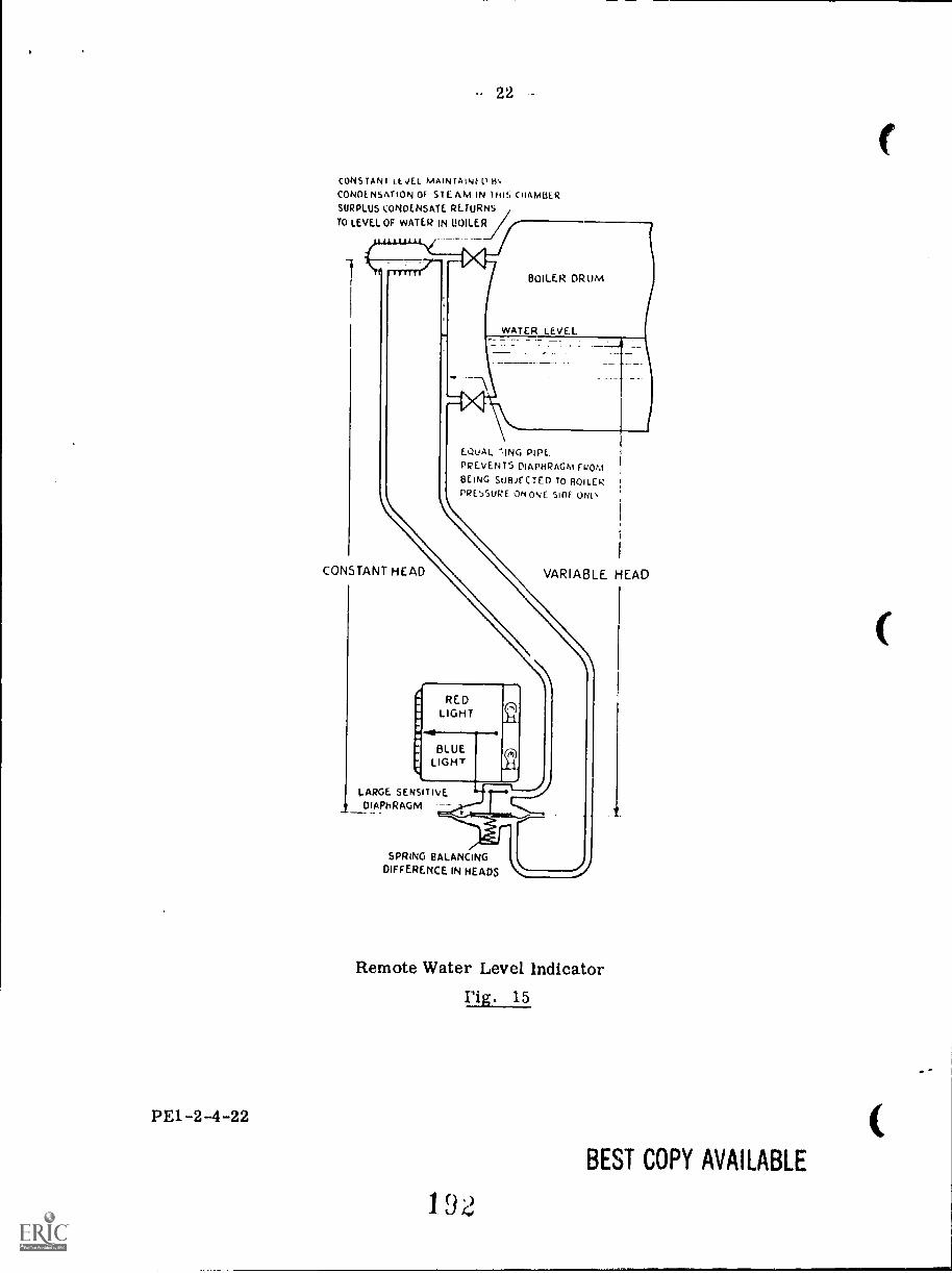
PE1-2-4-22
- 22
CONSTANT LEVEL mAINTAINtoCONOENSATION OF STEAM IN this CHAMBERSURPLUS t:ONDENSATE RETURNS
TO LEVEL OF WATER IN (!OILER
lillilli1
BOILER DRUM
EQUAL -.ING PIPE.
PREVENTS DIAPHRAGM FROto
BEING SUBJECTED TO BOILERPRESSURE 04 ONE SIDE ONO
CONSTANT HEAD VARIABLE HEAD
REDLIGHT
BLUELIGHT
LARGE SENSITIVEDIAPhRAGM
SPRING BALANCING
DIFFERENCE IN HEADS
Remote Water Level Indicator
Fig. 15
192
BEST COPY AVAILABLE
- 23
Ample power is obtained by use of a large diaphragm, a variation of 6 mmin the head on the diaphragm producing an operating force of nearly 1 newton, andthe indicator responds to exceedingly small variations in water level.
A small stainless steel spindle, passing through a self-sealing friction-less gland, transmits the motian of the diaphragm to the outside of the diaphragmchamber, where it actuates a special form of leverage mechanism. This gives astraight line movement of the pointer along the scale, this movement accuratelycorresponding to that of the water in the gauge glass.
There is a red-colored glass screen directly in front of the upper lampand a blue-colored screen directly in front of the lower lamp. A reflecting shutterwhich moves with the pointer divides the two parts and directs red light to the steamspace of the translucent indicator front and blue light to the water space.
Gage Glass Error
During normal boiler operation the gage glass generally indicates a waterlevel lower than the actual level in the boiler drum. This is because the water inthe gage glass and in the water connection from the gage glass to the drum is coolerand denser than the water within the drum.
This error may be quite substantial. For example, in a boiler operatingat 13 800 kPa the level in the gage glass may be 20 percent lower than the actuallevel in the drum. The amount of the error depends upon the temperature differ-ence between the water in the gage and its connection and the water in the drum.This difference in temperature is affected by such factors as the ambient tempera-ture, velocity of the air flowing past the gage, and the amount of gage surface radi-ating heat to the atmosphere.
Code Requirements
The ASME Code Section I states that each boiler, except those with nofixed water and steam line such as the forced flow steam generator or the high-temperature water type, shall have at least one water gage glass. With the ex-ception of electrode type electric boilers, those boilers operating at over 2800 !.Pashall have two water gage glasses.
In the case of power boilers having drum safety valves set at or above6200 kPa, two independent remote level indicators may be used instead of one ofthe required gage glasses. When both these remote indicators are in operationthe gage glass may be shut off provided it is maintained in a serviceable condition.
The lowest visible part of the gage glass shall be at least 51 mm abovethe lowest permissible water level which is the lowest level that the boiler can beoperated at without danger of overheating any part of the boiler.
PE1-2-4-23
193
- 24 -
Boilers of the horizontal firetube type shall have at least 76 mm of waterabove the highest point of the tubes or crown sheet when the water is at the lowestvisible part of the gage glass.
The pipes connecting a water column to a boiler shall be at least 25 mmsize. If the gage glass is connected directly to the boiler without an interveningwater column then the gage glass connecting pipes shall be at least 25 mm size.
The CSA Code B51 states that the water column connecting pipes shall beas short as possible and arranged with crosses having suitable plugs for clean outpurposes. Also shut-off valves shall be fitted in the water and steam connectingpipes to the water column but these are not mandatory in the case of a boiler havinga working pressure of over 5900 kPa or in the case of a low pressure boiler. Fur-thermore these shut-off valves shall be of through flow construction such as theO.S. and Y. with rising spindle, the lever lifting gate type, or a stop-cock withplug held in place by a guard or gland and marked in line with passage.
The foregoing-requirements with others are found in the ASMESection 1 PG-60.1 to 60.4 inclusive.
PRESSURE GAGES
Each boiler must have a pressure gage to indicate the pressure within theboiler and the gage must have a range and dial graduation of at least 1!, times themaximum allowable working pressure. The gage connection must be to the steamspace of the boiler or water column or to the water column steam connection.
Pressure gages may be of three basic types namely: the Bourdon spring,the bellows, or the metallic diaphragm.
1. The Bourdon Spring Gage
The Bourdon spring gage is the type used for the main pressure gage ona boiler. The main components of this gage are shown in Fig. 16.
The main component or heart of the gage is the C shaped Bourdon tubeor spring (3). It is oval in cross section and is closed off at one end (4) and opento pressure at the other end (2) through the socket (1). When pressure is appliedto the inside of the oval tube it tends to assume circular cross section and to par-tially unwind or straighten out. Thus the closed end (4) will move and the move-ment is linked mechanically to a pointer by means of the links (5) and (6).
PE1 -2 -4-24
194
411
4
.11
Bourdon Tube (Spring) Gage
Fig. 16
5
6
25
In addition to the C-type Bourdongage as shown in Fig. 16 there are twovariations of the Bourdon tube; thespiral and the helix and these types areillustrated in Fig. 17.
Spiral Bourdon Tube Helix Bourdon Tube(a)
Fig. 17
(b)
a
PE1-2-4-25
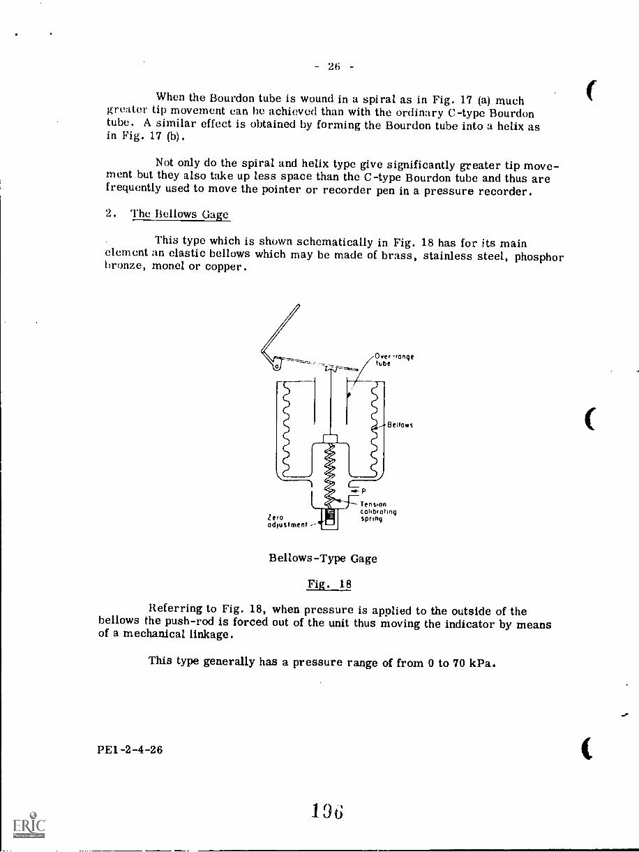
- 26 -
When the Bourdon tube is wound in a spiral as in Fig. 17 (a) muchgreater tip movement can he achieved than with the ordinary C-type Bourdontube. A similar effect is obtained by forming the Bourdon tube into a helix asin Fig. 17 (b).
Not only do the spiral and helix type give significantly greater tip move-ment but they also take up less space than the C-type Bourdon tube and thus arefrequently used to move the pointer or recorder pen in a pressure recorder.
2. The Bellows Gage
This type which is shown schematically in Fig. 18 has for its mainelement an elastic bellows which may be made of brass, stainless steel, phosphorbronze, mon.el or copper.
Over -rangetube
Zeroadjustment ---
p
Bellows
Tensioncalibratingspring
Bellows-Type Gage
Fig. 18
Referring to Fig. 18, when pressure is applied to the outside of thebellows the push-rod is forced out of the unit thus moving the indicator by meansof a mechanical linkage.
This type generally has a pressure range of from 0 to 70 kPa.
PE1-2-4-26
196
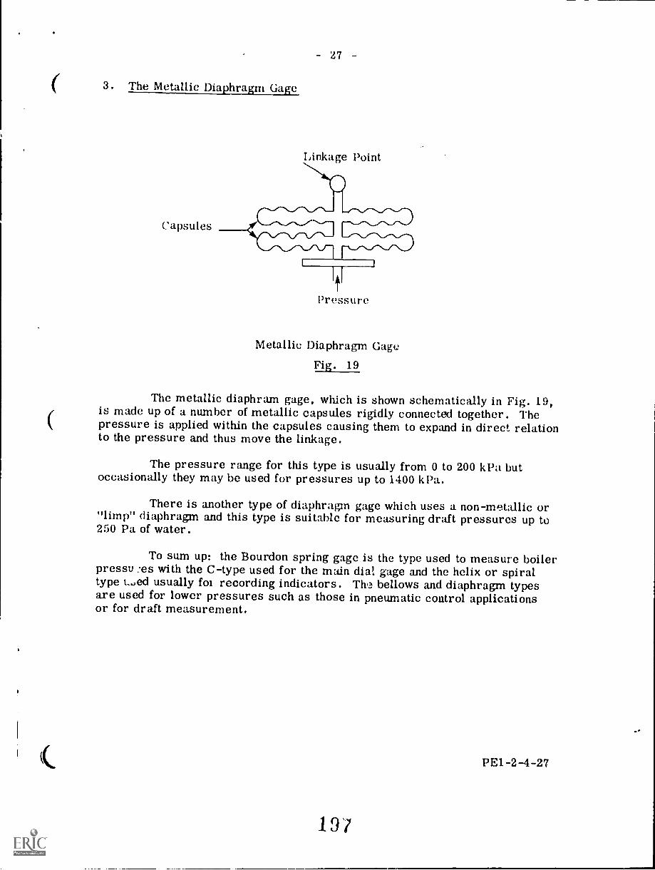
3. The Metallic Diaphragm Gage
Capsules
- 27
Linkage Point
Pressure
Metallic Diaphragm Gage
Fig. 19
The metallic diaphram gage, which is shown schematically in Fig. 19,is made up of a number of metallic capsules rigidly connected together. Thepressure is applied within the capsules causing them to expand in direct relationto the pressure and thus move the linkage.
The pressure range for this type is usually from 0 to 200 kPa butoccasionally they may be used for pressures up to 1400 k Pa.
There is another type of diaphragms gage which uses a non-metallic or"limp" diaphragm and this type is suitable for measuring draft pressures up to250 Pa of water.
To sum up: the Bourdon spring gage is the type used to measure boilerpressu :es with the C-type used for the main dial gage and the helix or spiraltype t...ed usually foi recording indicators. The bellows and diaphragm typesare used for lower pressures such as those in pneumatic control applicationsor for draft measurement.
PE1-2-4-27
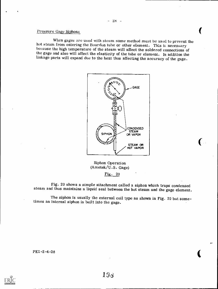
28
Pressure Gage Siphons
When gages are used with steam some method must be used to prevent thehot steam from entering the Bourdon tube or other element. This if, necessarybecause the high temperature of the steam will affect the soldered connections ofthe gage and also will affect the elasticity of the tube or element. In addition thelinkage parts will expand due to the heat thus affecting the accuracy of the gage.
Siphon Operation(Ametek/U.S. Gage)
Fig. 20
Fig. 20 shows a simple attachment called a siphon which traps condensedsteam and thus maintains a liquid seal between the hot steam and the gage element.
The siphon is usually the external coil type as shown in Fig. 20 but some-times an internal siphon is built into the gage.
PE1-2-4-28
196
29
Gage Installation
As mentioned, the gage should be fitted with a siphon to prevent steamfrom entering the gage element. Also the gage case should be sealed to preventdirt or dust from fouling the precision gears of the movement.
When the gage is installed below the point of connection to the boilerdrum, a column of water will exist in the connecting line and it is necessary toadjust for this static head by the zero adjustment of the gage. Also the column ofcondensate above the siphon must be compensated for when the gage is mountedabove the point of connection.
Unless it is of special design the gage should be installed in a verticalupright position. If not, the bearing loads in the linkage will be changed and theweight of the element will affect the movement.
If the gage is mounted in a location where there is excessive vibrationthen there will be more rapid wear of moving parts such as gear teeth, bearingsand hairspring and the pointer may become bent or loose on its spindle.
Code Requirements
The ASME Code requires that each boiler shall have a pressure gageattached to the steam space of the boiler or water column and fitted with a shut-off valve or cock and with the dial graduated to at least 12 times the pressure atwhich the boiler safety valve is set. Also a connection must be provided on theboiler for the sole purpose of attaching a test gage so that the accuracy of theboiler gage can be checked.
In the case of a forced-flow steam generator with no fixed steam or waterline, pressure gages shall be fitted in the following locations: at the boiler orsuperheater outlet after the last section which absorbs heat; at the boiler oreconomizer inlet; upstream of any shut-off valve used between any two sectionswhich absorb heat.
In all cases the material used for pressure gages shall be suitable forpressures, temperatures and fluids encountered.
The above requirements are all discussed in the ASME Code Section IPG-60.6.
PE1-2-4-29
19J
- 30
FEEDWATER CONNECTIONS
Included under this heading are the valves, fittings, and piping requiredto convey feedwater to the boiler.
Feedwater Supply
Boilers having more than 47 m2 of water heating surface shall have atleast two means of feeding water except that boilers using gaseous, liquid, orsolid fuel in suspension where the heat input can be stopped quickly, need onlyhave one means of feeding.
The source of feeding shall be capable of supplying wat. at a pressureof 3 percent higher than the highest setting of any safety valve on the boiler. How-ever if the boiler is a forced flow steam generator with no fixed steam and waterline then the source of feeding need only supply water at a pressure not less thanthat existing at the boiler inlet under maximum operating conditions.
In the case of boilers using solid fuel not in suspension or when the boilersetting is such that overheating could result if the feedwater supply was interruptedthen one of the two required feedwater sources of supply must be steam operated.
Feedwater Valves
The feedwater line to the boiler must be fitted with a check valve nearthe boiler and a stop valve between the check valve and the boiler. A combinationstop-and-check valve or4nonreturn stop valve if used can only be considered as astop valve and a check valve must be installed in addition. When two or moreboilers are supplied from a common source, a globe or regulating valve must beinstalled on the branch line to each boiler and this valve must be located betweenthe check valve and the source of supply. Also when globe valves are used inthe feedwater line the inlet must be under the disc so that if the valve disc becomesseparated from the valve spindle the feedwater supply can still be maintained.
In the case of a forced-flow steam generator having no fixed steam andwater line, a stop valve must be installed in the feed line at the boiler, howeverthe check valve near the boiler need not be installed provided there is a checkvalve at the boiler feed pump discharge or elsewhere in the feed line between thepump and the stop valve at the boiler.
PE1-2-4-30
(
- 31
Feedwater Piping
The feedwater must be introduced into the boiler in such a way that it willnot impinge directly upon surfaces exposed to high temperature gases or directradiation from the fire. Also the feedwater must not discharge dose to any riv-eted joints and, if necessary, a baffle shall be fitted to the discharge end of thefeed pipe in order to divert the flow away from the riveted joints. Furthermorethe feedwater must not be introduced through the blowoff line.
The required thickness of feedwater piping shall be calculated using theformulae given in PG-27.2.2. For example:
PDt2 SE + 2 y P + C
PRSE (1 - y) P + C
or
These formulae involve dimensions, pressures, temperatures, stresses,and constants which, in the latest edition of the code available at the time of writingare given in Imperil.' units. To make calculations in SI units the student must con-vert the formulae symbol dimensions to SI units and use the formula as given inthe code.
minimum required thickness in mm.
maximum allowable working pressure in %Pa.This pressure is always gage pressure inthese formulae unless otherwise specified.
P shall not be taken as less than 690 kPa and also must not be less thanthe pressure required to feed the boiler.
For piping from the boiler to and including the required stop valve and thecheck valve in a conventional type boiler the value of P shall be greater than themaximum allowable working pressure of the boiler by either 25 percent or 1550 kPawhichever is the lesser.
In the case of a forced-flow steam generator having no fixed steam andw. er line the value of P for feedwater piping from the boiler to and including therequired stop valve shall not be less than the expected maximum pressure to whichthat part of the steam generator will be subjected during operation.
When two or more boilers are fed from a common source, for the pipingbetween the required check valve and the globe or regulating valve in the branchline including any bypass piping around the globe or regulating valve up to the shut-off valve in the bypass, the value of P shall be not less than the pressure requiredto feed the boiler.
PE1-2-4-31
201
32
I) outside diameter of cylinder in mm.
inside radius of cylinder in mm.
efficiency of longitudinal welded joints or of ligaments betweenopenings, whichever is lower.The efficiency of a welded joint is the ratio between the strengthof the weld and the strength of the plate itself. The efficiency ofthe ligaments is the ratio of the strength of the metal betweenopenings such as tube holes and the strength of the solid plate.The values allowed for E are listed in the code. See PG-27.4Note 1. As E is a ratio it does not have units to convert.
S maximum allowable stress value at the operating temperature ofthe metal in kPa. These stress values for various materials andtemperatures are listed in Tables PG-23.1 and PG-23.2 in thecode appendix. Both the stress values and the temperatures aregiven in imperial units and must be converted to SI units beforeusing in the formulae.The value of S in the formulae in PG-27.2.2 shall not exceed thatpermitted for the temperature of saturated steam at the maximumallowable working pressure of the boiler except in the case of aforced-flow steam generator having no fixed steam and water linethe value of S shall not exceed that permitted for the maximume::pected temperature at the feedwater inlet.
C = minimum allowance for threading and structural stability, in mm.Values of C are listed in the Code. See PG-27.4 Note 3. Thesevalues are given in inches and must be converted to mm beforeusing in the formula.
a temperature coefficient. Values of y for various temperatureranges are listed in the code. See PG-27.4 Note 6. y is givenno units and therefore no conversion, is involved.
When threaded steel pipe is used for feedwater piping at pressures over690 kPa and temperatures equal to or greater than 104°C it shall be seamless andof a quality at least equal to SA-53 or SA-192 and of a mass at least equal toSchedule 80 in order to provide additional mechanical strength.
When threaded wrought iron, threaded copper or threaded brass pipe isused for feedwater piping it shall have a wall thickness at least equal to that re-quired for steel pipe of a corresponding size and the material used shall be suit-able for the pressure and temperature conditions.
The foregoing requirements for feedwater connections are further explain-ed in the ASME Code Section I PG-27.2.2, PG-58, and PG-59 and in the CSA B51Section 10.7.
PE1-2-4-32
2 r'2
ti
qUESTION SHEET
l'o\V ER ENGINEERINGFirst ClassSect. 2, 1,cct. 1
1 . Describe the operation of the following safety valve types:
(a) jet flow
(b) huddling chamber
(c) nuzzle reaction
2. Sketch an electromagnetic relief valve system and explainthe purpose of each part.
3. Discuss the reasons for using power-operated relief valvesin certain installations.
Describe briefly the safety valve arrangements allowed bythe ASME Code for once-through forced-flow steam generatorswith no fixed steam and water lines.
5. Describe in general how the safety valve capacity would bedetermined for a conventional boiler having a superheaterand a reheatex.
G. Sketch a cross section of a hig ressure gage glass anddescribe its construction.
7. Calculate the required thickness of feedwater piping to beused between the boiler and the feedwater stop valve. Theboiler is a conventional design having a maximum allowableworking pressure of 13.8 M Pa. The piping is 273 mm O.D.and is plain end seamless carbon steel conforming to spec-ification SA-106 B.
8. Discuss the type and the installation of a pressure gagesuitable for the boiler in Q. 7.
9. Sketch and describe a remote water level indicator whichmakes use of a constant head chamber.
PE14.2-4-Q
6
SOUTHERN ALBERTA INSTITUTE OF TECHNOLOGYCALGARY, ALBERTA
Correspondence CoursePower Engineering
SECTION 2
STEAM GENERATION
BOILER FITTINGS II
BLOW-OFF CONNECTIONS
First ClassLecture 5
Boiler blow-off connections have several purposes. These include; removalof sludge or solid material from the boiler, lowering of the dissolved solids con-centration of the boiler water, and draining of the boiler. Also in some cases theblow-off connection may be used to introduce the cleaning solution into the boilerduring acid cleaning and to drain and flush the boiler after acid cleaning. In anemergency the blow-off connection may be used to lower excessively high boilerwater level during operation to prevent carryover of water with the steam leavingthe boiler drum.
Blow-off arrangements may be of three categories: bottom blow-off, con-tinuous blow-off, and surface blow-off.
The bottom blow-off connections are made to the lowest parts of the boilerwhere the greatest concentration of sludge and sediment will form as the mainpurpose of the bottom blow-off is the removal of this sludge. On firetube boilerswith cylindrical shells, the bottom blow-off connection is made at the rear andbottom of the shell. Watertube boilers normally have several bottom blow-offconnections, these being made to the various mud drums and waterwall headers.
Continuous blow-off, or continuous blowdown as it is often called, is thecontinuous removal of concentrated water from the boiler drum. This differsfrom the bottom blow-off which is intermittent rather than continuous. The con-tinuous blow-off arrangement consists of a collecting pipe located within theboiler drum in such a position that it will remove the most heavily concentratedwater. In most boilers this position is several inches below the operating waterlevel.
204
12.4
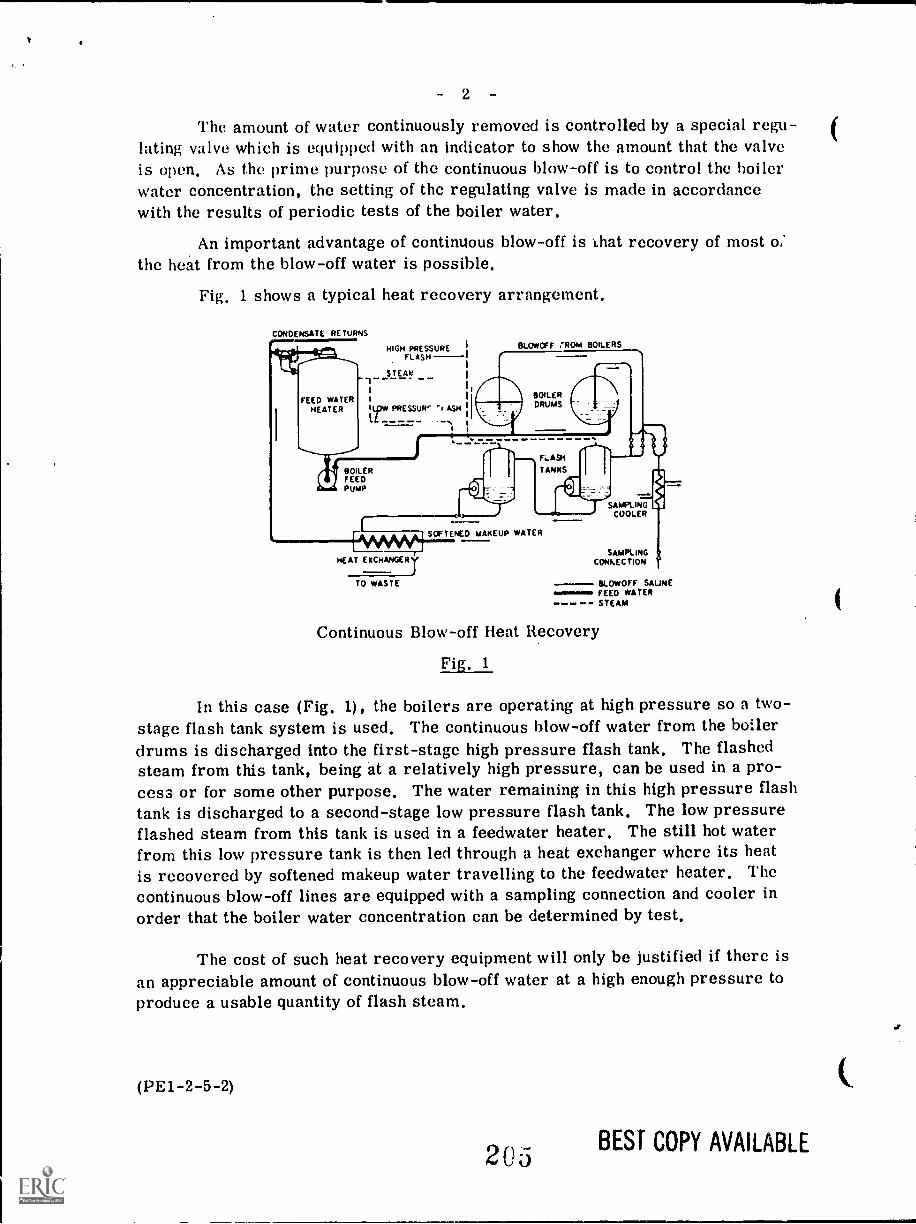
2
The amount of water continuously removed is controlled by a special regu-lating valve which is equipped with an indicator to show the amount that the valveis open. As the prime purpose of the continuous blow-off is to control the boilerwater concentration, the setting of the regulating valve is made in accordancewith the results of periodic tests of the boiler water.
An important advantage of continuous blow-off is Lhat recovery of most o;the heat from the blow-off water is possible.
Fig, 1 shows a typical heat recovery arrangement.
CONDENSATE RETURNS.1HIGH PRESSURE
FLASH
STEAK
FEED WATER I
HEATER It.pw PRESSUR '1 ASH
/I BOILERFEEDPUMP
BLOWOFF 'ROM BOILERS
BOILERDRUMS
FLASH
TANKS
Fovws,00SOFTENED MAKEUP WATER
HEAT EXCHANGER
TO WASTE
-7=ZSAMPLING
COOLER
SAMPLINGCONFECTION
BLOWOFF SAUNEFEED WATERSTEAM
Continuous Blow-off Heat Recovery
Fig. 1
In this case (Fig. 1), the boilers are operating at high pressure so a two-stage flash tank system is used. The continuous blow-off water from the boilerdrums is discharged into the first-stage high pressure flash tank. The flashedsteam from this tank, being at a relatively high pressure, can be used in a pro-cess or for some other purpose. The water remaining in this high pressure flashtank is discharged to a second-stage low pressure flash tank. The low pressureflashed steam from this tank is used in a feedwater heater. The still hot waterfrom this low pressure tank is then led through a heat exchanger where its heatis recovered by softened makeup water travelling to the feedwater heater. Thecontinuous blow-off lines are equipped with a sampling connection and cooler inorder that the boiler water concentration can be determined by test.
The cost of such heat recovery equipment will only be justified if there isan appreciable amount of continuous blow-off water at a high enough pressure toproduce a usable quantity of flash steam.
(PE1-2-5-2)
205 BEST COPY AVAILABLE
3 -
Surface blow-off or blowdown connections are sometimes installed inboilers for the purpose of skimming sediment and oil from the surface of the boilerwater. This type of blow-off is required when the water fed to the boiler foamswhen boiling. This foam contains impurities carried by the water and is drawn offthrough the surface blow-off. The surface blow-off line is located about water levelin the boiler and it frequently has a connection in the form of a pan or scoop whichrises and falls with the water level and thus skims off only the surface of the water.The scoop is held at the surface of the water by means of floats and is connected bymeans of a flexible connection.
Code Requirements
The requirements for blow-off connections as put forth by the ASME and theCSA are summarized in the following paragraphs.
PG-8.4.1. states that brass and bronze flanges and flanged or screwed fit-tings shall not be used in blow-off lines between the boiler and the required blow-off valves. Steel or other material must be used. Screwed fittings shall not beused where flanged types are specified.
PG-9 states that nonferrous pipe or tubes shall not be used for blow-offpiping or any other service where they are exposed to the fire or products of com-bustion.
PG-27.2.2 gives the formulae for calculating the minimum required thick-ness of blow-off piping.
The value of P shall not be less than 900 kPa in any case and if it exceeds900 kPa then the piping thickness shall not be less than Schedule 80. (Par. A-57)
The value of S in the formulae shall not exceed that permitted for thetemperature of saturated steam at the maximum allowable working pressure of theboiler.
All fittings between' the boiler and the blow-off valves shall be of steel forpressures over 900 kPa.
For pressures exceeding 690 kPa but not exceeding 1400 kPa, the blow-offvalves may be of cast iron if equal at least to the requirements of the AmericanNational Standards for 1700 kPa. If steel valves are used they must conform tothe American National Standards. (Par. A-58)
For pressures exceeding 1400 kPa the blow-off valves shall be of steelconstruction equal at least to the requirements of the American National Standardsfor 2100 kPa.
(PE1-2-6-3)
206
For pressures not exceeding 690 kPa the blow-off valves shall be equal atleast to the requirements of the American National Standards for 900 kPa.
PG-59.321 states that for continuous blowdown systems, the pipe connect-ions and all fittings up to and including the first shut -off valve shall be equal atleast to the pressure requirements for the lowest set pressure of any safety valveon the boiler drum and with the corresponding saturated steam temperature.
PG-59.3.2 states that a surface blow-off shall not exceed 64 mm or thepipe size and the internal and external pipes shall form a continuous passage butshall be arranged so that the removal of one does not disturb the other.
Section PG-59.3 also states the following requirements:
Each boiler except forced-flow steam generators having no fixed steam andwater line and high temperature water boilers shall have a bottom blow-off pipefitted with a valve or valves. In addition, all waterwalls and water screens whichdo not drain back into the boiler and all integral economizers shall be equippedwith blow-off valves or drain valves. In this case, drain valves may be usedinstead of blow-off valves if these valves are intended for use only to drain theboiler when it is not under pressure. Under these circumstances a single valvemay be used provided it can be locked in the closed position or alternatively ifthe line is blanked off with a flanged and bolted connection on the downstream sideof the valve.
The minimum size of blow-off pipe and fittings is 25 mm and the maximumsize is 64 mm unless the boiler has 9.3 m2 of heating surface or less in whichcase the minimum size is 19 mm.
If a bottom blow-off pipe is exposed to direct furnace heat it shall be pro-tected by heat resisting material arranged to allow inspection of the pipe and whena blow-off pipe passes through a boiler setting provision for free expansion andcontraction shall be made.
Ordinary globe valves and valves having dams or pockets that may collectsediment should not be used on blow-off connections. Straightway Y-type globevalves or angle valves may be used in vertical pipes. They may also be used inhorizontal pipes providing they have the lowest edge of the seat opening at least25 percent of the inside diameter below the centerline of the valve.
On all boilers, except those used for high-temperature water, tractionand/or portable purposes, when the allowable working pressure exceeds 690 kPa,each bottom blow-off pipe shall have two slow-opening valves, or one slow-openingvalve and a quick-opening valve or a cock.
Further in regard to the use of two blow-off valves, the two valves maybe combined in one body provided the failure of one to operate can not affect theoperation of the other.
(PEI -2-5-4)
20/
5
Blow-off Valve Types
The basic types of blow-off valves commonly used are: the sliding disc,the seatiess htiding plunger, the seat and disc, and the combination.
I& . 411.7.
Shinn
The general arrangement of a sliding disc valve is shown in Fig. 2 (a)
--- - --.-._.*--.L.7.." .1.---' -. ..7. . - . .. -..,...-........-Norom Po t..., ....... ....... ,.111:-..... .4.
- ...a.. ........Z....+41yomINZNY..., .,..-41.3, .N....
When the valve is in the closed position the disc seils a? the ope ng.With the valve in the open position the disc has moved off to one side leaving astraight through passage through the valve.
This valve is classed as a quick opening type and must always be usedin conjunction with a slow-opening valve. It may, however, be converted to aslow-opening valve by means of a handwheel and gear arrangement which canbe used in place of the operating lever.
When used as a quick opening valve it is operated by moving the leverthrough a short arc. This lever movement acts through a simple and directacting mechanism to position the disc in the closed or open position.
(PE1 -2 -5 -5)
:.20d
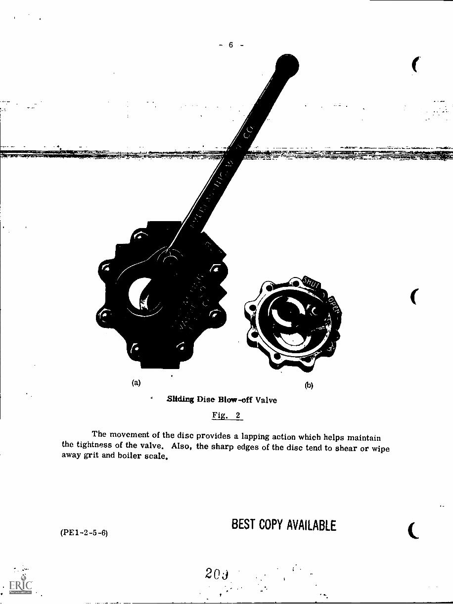
6
AM.
AO.
(a) (b)
Disc Blow-off Valve
Fig. 2
The movement of the disc provides a lapping action which helps maintainthe tightness of the valve. Also, the sharp edges of the disc tend to shear or wipeaway grit and boiler scale.
BEST COPY AVAILABLE(PE 1 -2 -5 -6)
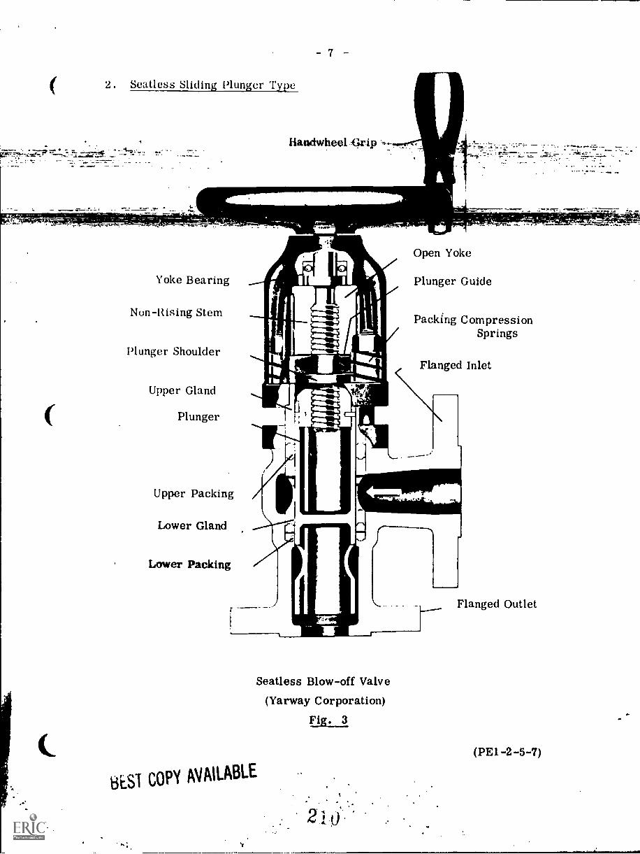
2. Seatless Sliding Plunger Type
7
Handwheel Eirip- _
1
Yoke Bearing
Non-Rising Stem
Plunger Shoulder
Upper Gland
Plunger
Upper Packing
Open Yoke
Plunger Guide
Packing CompressionSprings
Flanged Inlet
Lower Packing
Seatless Blow-off Valve
(Yarway Corporation)
Fig. 3
BEST COPY AVAILABLE
Flanged Outlet
(PE1-2-5-7)
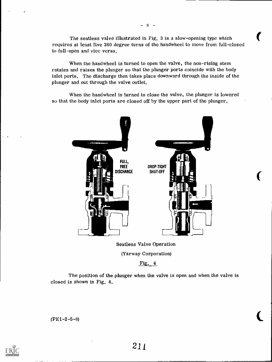
8
The seatless valve illustrated in Fig. 3 is a slow-opening type whichrequires at least five 360 degree turns of the handwheel to move from full-closedto full-open and vice versa.
When the handwheel is turned to open the valve, the non-rising stemrotates and raises the plunger so that the plunger ports coincide with the bodyinlet ports. The discharge then takes place downward through the inside of theplunger and out through the valve outlet.
When the handwheel is turned to close the valve, the plunger is loweredso that the body inlet ports are closed off by the upper part of the plunger.
FULL,
FREE
DISCHARGE
DROPTIGHT
SHUTOFF
Seatless Valve Operation
(Yarway Corporation)
Fig. 4
The position of the plunger when the valve is open and when the valve isclosed is shown in Fig. 4.
(PE1-2-5-8)
21j
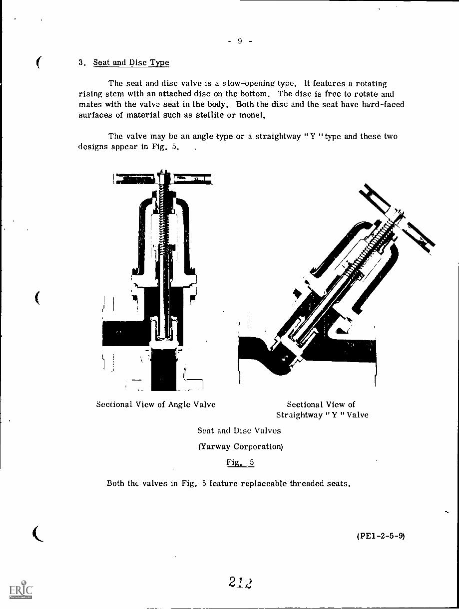
9 -
3, Seat and Disc Type
The seat and disc valve is a slow-opening type, It features a rotatingrising stem with an attached disc on the bottom. The disc is free to rotate andmates with the valvo seat in the body. Both the disc and the seat have hard-facedsurfaces of material such as stellite or monel.
The valve may be an angle type or a straightway "Y "type and these twodesigns appear in Fig. 5,
Sectional View of Angle Valve Sectional View ofStraightway " Y " Valve
Seat and Disc Valves
(Yarway Corporation)
Fig, 5
Both the valves in Fig. 5 feature replaceable threaded seats.
(PE1-2-5-9)
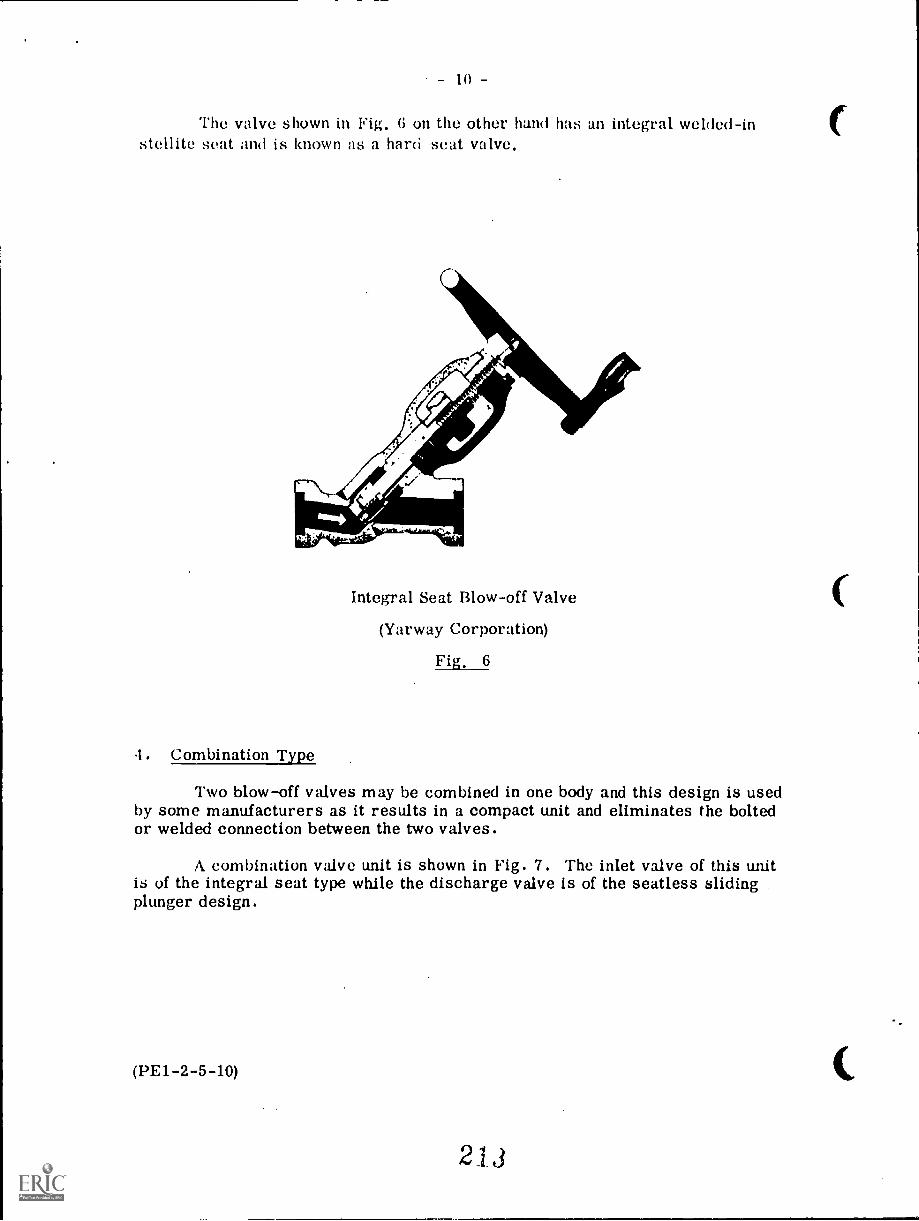
Thu valve shown in Fig. 6 on the other hand has an integral welded-instellite seat and is known as a hard -seat valve.
Integral Seat Blow-off Valve
(Yarway Corporation)
Fig, 6
4. Combination Type
Two blow-off valves may be combined in one body and this design is usedby some manufacturers as it results in a compact unit and eliminates the boltedor welded connection between the two valves.
A combination valve unit is shown in Fig. 7. The inlet valve of this unitis of the integral seat type while the discharge valve is of the seatless slidingplunger design.
(3E1-2-5-10)
213
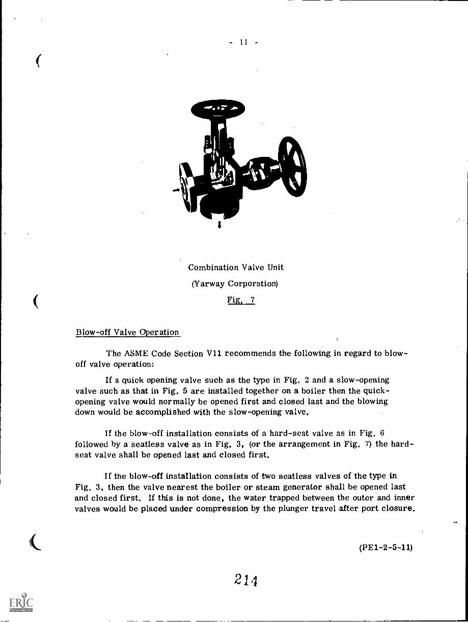
Combination Valve Unit
(Yarway Corporation)
Fig, 7
Blow-off Valve Operation
The ASME Code Section V11 recommends the following in regard to blow-off valve operation:
If a quick opening valve such as the type in Fig. 2 and a slow-openingvalve such as that in Fig. 5 are installed together on a boiler then the quick-opening valve would normally be opened first and closed last and the blowingdown would be accomplished with the slow-opening valve.
If the blow-off installation consists of a hard-seat valve as in Fig. 6followed by a seatless valve as in Fig. 3, (or the arrangement in Fig. 7) the hard-seat valve shall be opened last and closed first.
If the blow-off installation consists of two seatless valves of the type inFig. 3, then the valve nearest the boiler or steam generator shall be opened lastand closed first. If this is not done, the water trapped between the outer and innervalves would be placed under compression by the plunger travel after port closure.
(PE1-2-5-11)
214
- 12 -
If the blow-off installation consists of two identical valves, the sequenceof operation should provide that the same valve is always opened last and closedfirst, so as to save the other valve from erosive throttling service to assuretight closing of the installation.
In order to determine the amount of blow-off, the concentration of solidsin the water should be determined at least daily.
If the amount and frequency of blowing-off is not determined by wateranalysis, then the boiler should be blown-off once every 24 hours by opening theblow-off valve wide and then closing it.
Blowing-off is most effective when performed at periods of low steamoutput.
Boiler waterwalls should not be blown-off except when the boiler is bankedor in accordance with the boiler manufacturer's specific instructions. This isto avoid disruption of the water circulation within the boiler.
When the gage glass is not visible to the operator blowing-off the boiler,another operator should be stationed where he can see the gage glass and signalto the operator blowing-off the steam generator. Never permit an operator atthe blow-off valve to leave it until the operation is completed and the blow-offvalve closed. Never permit an operator to blow-off more than one boiler at atime.
Blow-off Tanks
The CSA Code B51 states that, where the blow-off from any boiler, havinga working pressure exceeding 103 kPa, is discharged into a closed sewer system,an approved blow-off tank or other suitable approved device shall be placed be-tween the boiler and sewer for the purpose of reducing the pressure and tempera-ture of the water entering the sewer.
The arrangement of this required blow-off tank is such that it always re-mains partially full of water. When the hot water from the blow-off enters, thecooler water in the bottom portion of the tank is displaced and overflows to thesewer while the high temperature water remains in the tank. The tank is fittedwith a large open vent to prevent pressurization and is fitted with a siphon breakerto keep the tank from emptying.
The requirements for the design of blow-off tanks are listed in theCSA B51.
(PM. -2-5-12)
21j
1 3
WILE it 5 T01' VALVES
The ASME Code Section 1 A-54 requires that each steam outlet from apower boiler (except safety valve connections) be fitted with a stop valve locatedas close as practicable to the boiler.
If the outlet is over 51 mm pipe size then the valve should be of the outside-screw-and-yoke rising-spindle design. Alternately, a plug cock type valve maybe used provided the plug is held in place by a guard or gland and the valve isequipped with a slow-opening mechanism and equipped to indicate from a distancewhether it is closed or open. In the case of a single boiler and prime mover unitinstallation the required stop valve may be omitted provided the valve at the primemover is equipped to show if it is open or closed and also is designed to withstandthc, required hydrostatic pressure test of the boiler.
When boilers are connected to a common header, the connection fromeach boiler having a manhole opening should be fitted with two stop valves havingan ample free-blow drain between them. The discharge of this drain should bevisible to the operator while manipulating the stop valves. 'The stop valves shouldconsist preferably of one automatic non-return valve (set next to the boiler) anda second valve of the outside-screw-and-yoke type. Alternatively two halves ofthe outside-screw-and-yoke type should be used.
Outside-Screw-and-Yoke Stop Valves
The basic design of a gate type stop valve is shown in Fig. 8.
Yoke
PackingGland
Packing
Seal Weld
Steel Ring
Locking Lugs
StemConnection
WeldingEnd
StraightFlow Design
Ste lliteSurfaces
Seat Rings
(13E1-2-5-14)
Disc
Design illustrated is 10 000 kPaSteel Valve
Gate Type OutsideScrew-and-Yoke Stop Valve(Lunkenheimer)
Fig. 8
BEST COPY AVAILABLE
21 /
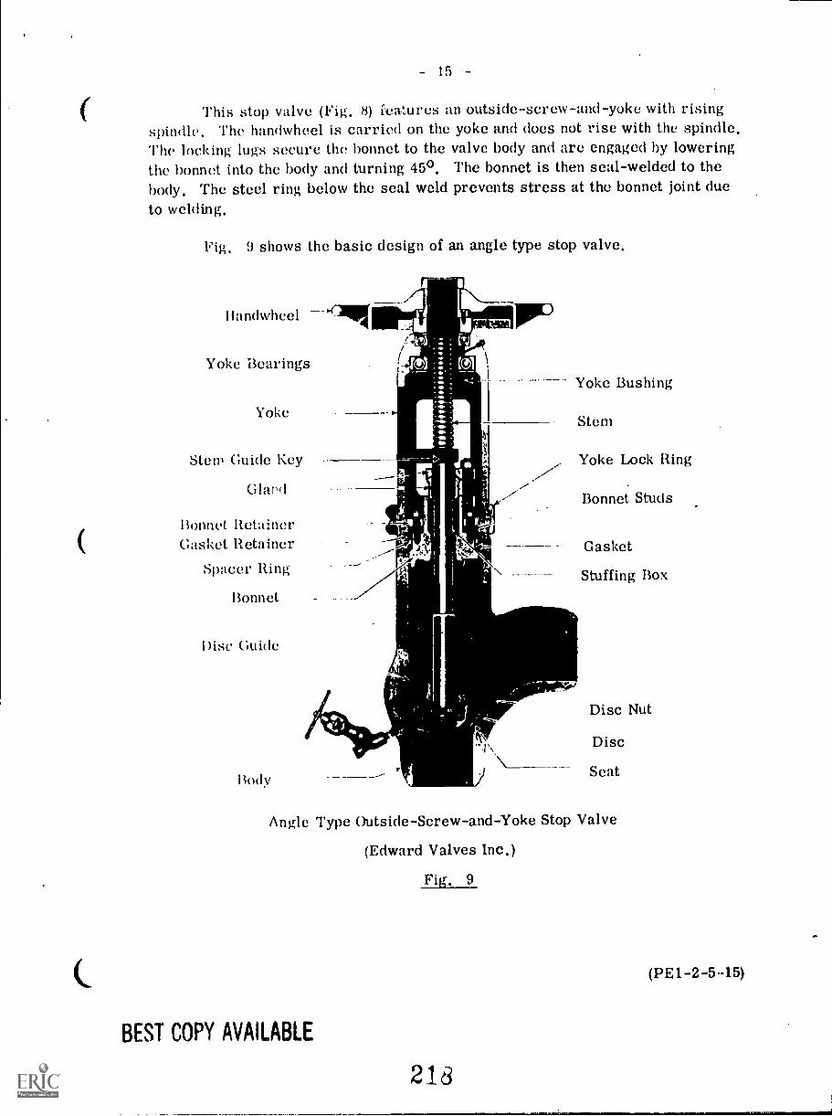
15
This stop valve (Fig. 8) icatures an outside-screw-and-yoke with risingspindle. The handwheel is carried on the yoke and does not rise with the spindle.The locking lugs secure the bonnet to the valve body and are engaged by loweringthe bonnet into the body and turning 450. The bonnet is then seal-welded to thebody. The steel ring below the seal weld prevents stress at the bonnet joint dueto welding.
Fig. 9 shows the basic design of an angle type stop valve.
Ilandwheel
Yoke Bearings
Yoke
Stem Guide Key
Glard
Bonnet RetainerGasket Retainer
Spacer Ring
Bonnet
Disc Guide
Body
Yoke Bushing
Stern
Yoke Lock Ring
Bonnet Studs
Gasket
Stuffing Box
Disc Nut
Disc
Seat
Angle Type Outside-Screw-and-Yoke Stop Valve
(Edward Valves Inc.)
Fig. 9
BEST COPY AVAILABLE
218
(PE1-2-5 15)
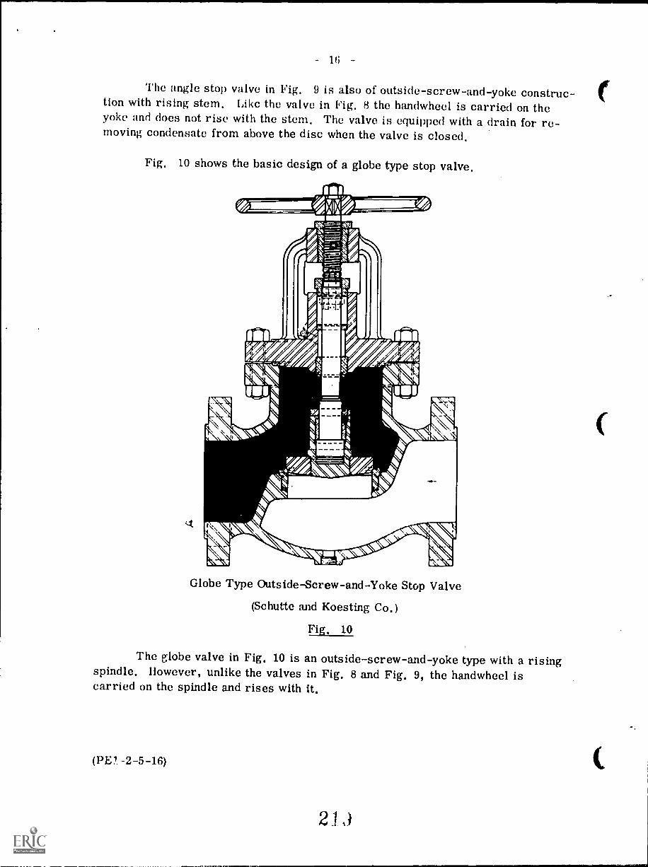
The angle stop valve in Fig. 9 is also of outside-screw-and-yoke construc-tion with rising stem. Like the valve in Fig. H the handwheel is carried on theyoke and does not rise with the stem, The valve is equipped with a drain for re-moving condensate from above the disc when the valve is closed.
Fig. 10 shows the basic design of a globe type stop valve.
Globe Type Outside-Screw-and-Yoke Stop Valve
(Schutte and Koesting Co.)
Fig. 10
The globe valve in Fig. 10 is an outside-screw-and-yoke type with a risingspindle. However, unlike the valves in Fig. 8 and Fig. 9, the handwheel iscarried on the spindle and rises with it.
(PE? -2-5-16)
2 1
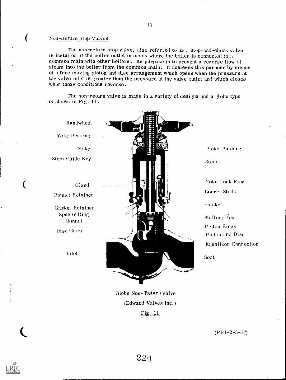
I?
Non-Return Stop Valves
The non-return stop valve, also referred to as a stop-and-cheek valveis installed at the boiler outlet in cases where the boiler is connected to acommon main with other boilers. Its purpose is to prevent a reverse flow ofsteam into the boiler from the common main. It achieves this purpose by meansof a free moving piston and disc arrangement which opens when the pressure atthe valve inlet is greater than the pressure at the valve outlet and which closeswhen these conditions reverse.
The non-return valve is made in a variety of designs and a globe typeis shown in Fig. 11.
llandwheel
Yoke Bearing
Yoke
Stem Guide Key
Gland
Bonnet Retainer
Gasket RetainerSpacer Ring
Bonnet
Disc Guide
Inlet
Globe Non-Return Valve
(Edward Valves Inc.)
Fig, 11
22o
Yoke Bushing
Stem
Yoke Lock Ring
Bonnet Studs
Gasket
Stuffing Box
Piston RingsPiston and Disc
Equalizer Connection
Seat
(PE1-2-5-17)
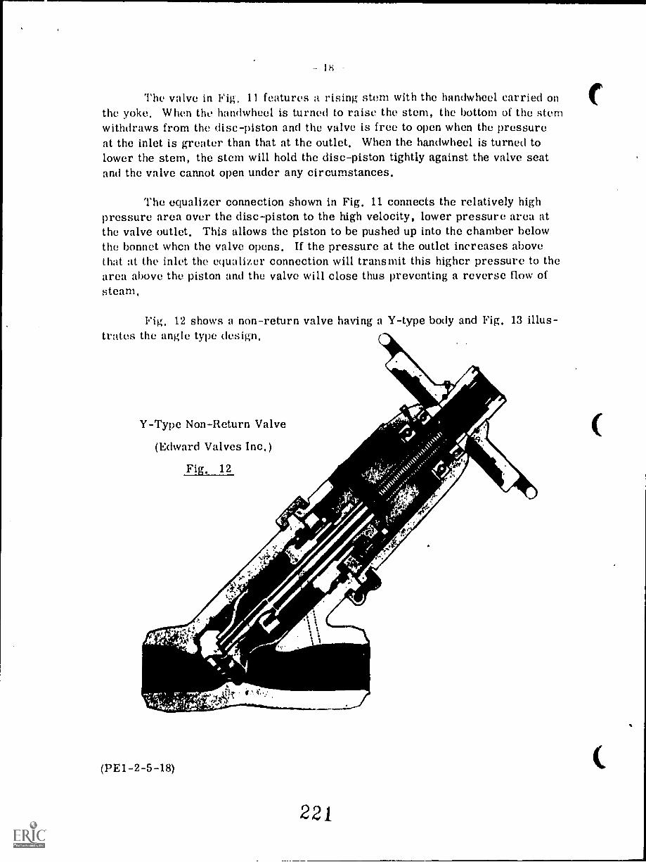
lri
The valve in Fig. 11 features a rising stern with the handwheel carried onthe yoke. When the handwheel is turned to raise the stern, the bottom of the stemwithdraws from the disc-piston and the valve is free to open when the pressureat the inlet is greater than that at the outlet. When the handwheel is turned tolower the stem, the stem will hold the disc-piston tightly against the valve seatand the valve cannot open under any circumstances.
The equalizer connection shown in Fig. 11 connects the relatively highpressure area over the disc-piston to the high velocity, lower pressure area atthe valve outlet. This allows the piston to be pushed up into the chamber belowthe bonnet when the valve opens. If the pressure at the outlet increases abovethat at the inlet the equalizer connection will transmit this higher pressure to thearea above the piston and the valve will close thus preventing a reverse flow ofsteam.
Fig. 12 shows a non-return valve having a Y-type body and Fig. 13 illus-trates the angle type design.
Y-Type Non-Return Valve
(Edward Valves Inc.)
Fig. 12
(PE1-2-5-18)
ZZ1
..11r --riadeum.....
221
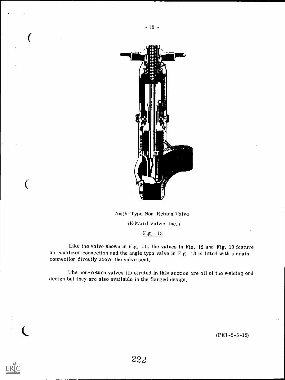
19
Angle Type Non-Return Valve
(Edward Valves Inc.)
Fig. 13
Like the valve shown in Fig. 11, the valves in Fig. 12 and Fig. 13 featurean equalizer connection and the angle type valve in Fig. 13 is fitted with a drainconnection directly above the valve seat.
The non-return valves illustrated in this section are all of the welding enddesign but they are also available in the flanged design,
(PE1-2-5-19)
2(}
DRUM INTERNALS
The term Ilruni internals" is generally taken to mean all the devices in-stalled within the boiler steam drum including various types of steam separators,steam washers, chemical feed lines, boiler feedwater lines, and continuous blowoff and surface blow-off lines.
1. Steam Separators
The separation of the steam from the steam-water mixture discharginginto the drum from the riser tubes is affected by a number of factors. Theseinclude; the difference in density between the water and the steam, the ratio ofwater to steam in the steam-water mixture leaving the risers, the rate of steamgeneration and of water circulation, the concentration of dissolved solids in theboiler water, and the size of the steam drum.
The difference in density between the water and the steam decreases as theboiler operating pressure increases. Therefore the force of gravity available forthe separation of the two will also decrease and at high operating pressures it isnecessary to use quite extensive separating equipment.
A high ratio of water to steam in the mixture leaving the risers will alsoamke the separation process more difficult.
In order to prevent overheating of tubes an adequate circulation of watermust be maintained through the boiler circuit therefore the separating equipmentmust be designed so as not to have too great a pressure drop across it. Thisfactor is not as critical in a forced circulation boiler as in a natural circulationtype.
At high steam generating rates the drum water level will be high due to"swell" and this will make carryover of water with the steam leaving the drummore likely. Also the distance from the water level to the drum steam outletswill depend upon the drum size.
The higher the concentration of dissolved solids in the boiler water thegreater will be the tendency for foaming to occur within the drum with resultingdecrease in separation of water and steam,
As noted previously, at lower operating pressures (up to say 2000 kPa),separation of water and steam can be accomplished by gravity and without theuse of mechanical separators. At higher pressures mechanical equipment isnecessary and this equipment is usually arranged in stages.
(PE 1-2-5-20)
223
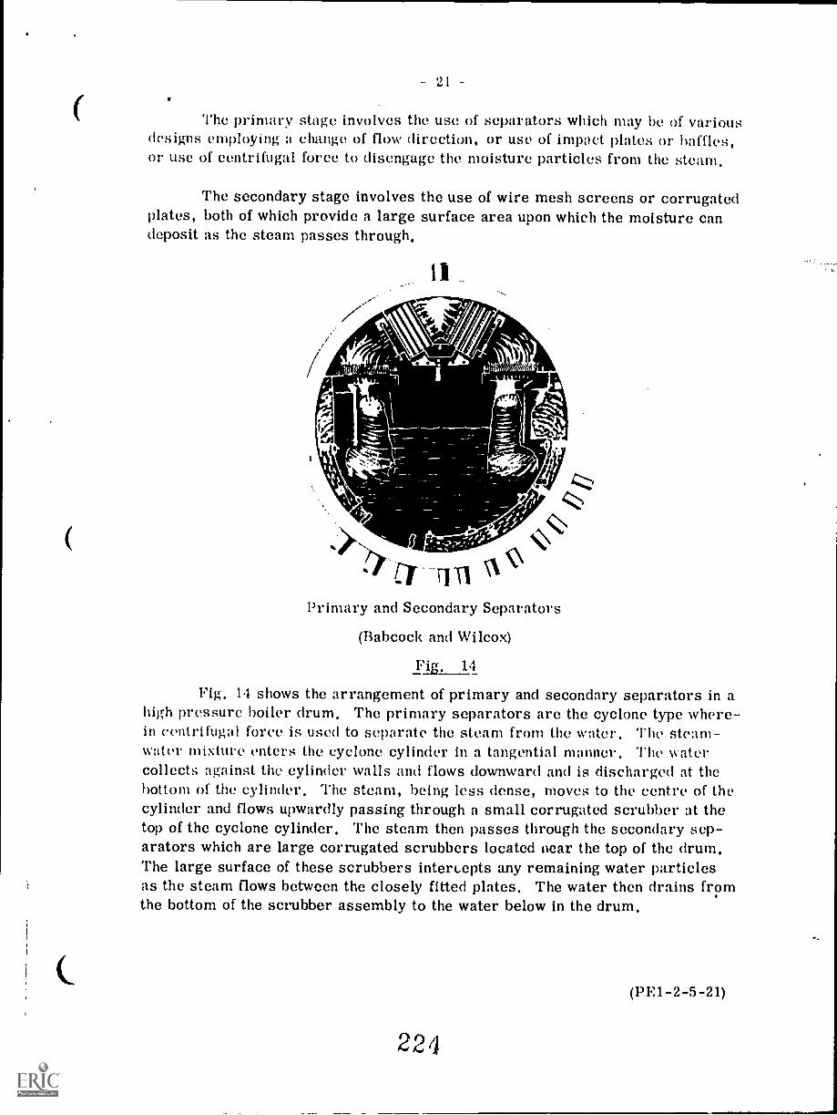
21
The primary stage involves the use of separators which may be Of variousdesigns employing a change of flow direction, or use of impact plates or baffles,or use of centrifugal force to disengage the moisture particles from the steam.
The secondary stage involves the use of wire mesh screens or corrugatedplates, both of which provide a large surface area upon which the moisture candeposit as the steam passes through,
11
ei,7. .,,. %
.:-- i. ,
.>--, I Maga-=/ TIT] \
Primary and Secondary Separators
(Babcock and Wilcox)
Fig, 14
Fig, 14 shows the arrangement of primary and secondary separators in ahigh pressure boiler drum. The primary separators are the cyclone type where-in centrifugal force is used to separate the steam from the water. The steam-water mixture enters the cyclone cylinder in a tangential manner. The watercollects against the cylinder walls and flows downward and is discharged at thebottom of the cylinder. The steam, being less dense, moves to the centre of thecylinder and flows upwardly passing through a small corrugated scrubber at thetop of the cyclone cylinder, The steam then passes through the secondary sep-arators which are large corrugated scrubbers located near the top of the drum,The large surface of these scrubbers intercepts any remaining water particlesas the steam flows between the closely fitted plates, The water then drains fromthe bottom of the scrubber assembly to the water below in the drum,
(P1 :1-2-5-21)
22i
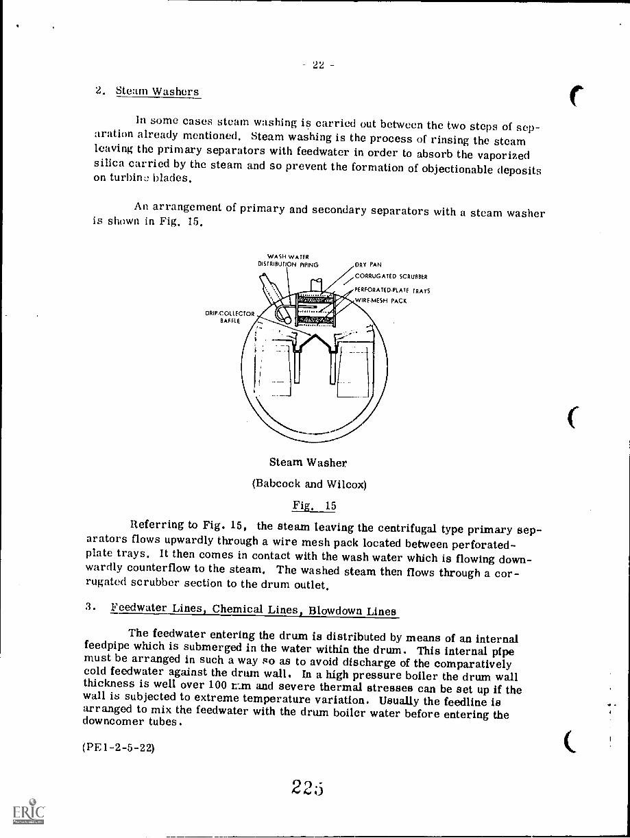
22
2. Steam Washers
In some cases steam washing is carried out between the two steps of sep-aration already mentioned. Steam washing is the process of rinsing the steamleaving the primary separators with feedwater in order to absorb the vaporizedsilica carried by the steam and so prevent the formation of objectionable depositson turbine blades.
An arrangement of primary and secondary separators with a steam washeris shown in Fig. 15.
ORIP.COLLECTORBAFFLE
WASH WATERDISTRIBUTION PIPING
1'
ITEINErdrzOld 4.71);10;;VANTIliropIr
:,..iii,y'f;:;;.,...:".., ,,,,I
DRY PAN
/CORRUGATED SCRUBBER
PERFORATED.PLATE TRAYS
WIR E.MESH PACK
Steam Washer
(Babcock and Wilcox)
Fig. 15
Referring to Fig. 15, the steam leaving the centrifugal type primary sep-arators flows upwardly through a wire mesh pack located between perforated-plate trays. It then comes in contact with the wash water which is flowing down-wardly counterflow to the steam. The washed steam then flows through a cor-rugated scrubber section to the drum outlet.
3. Feedwater Lines, Chemical Lines, Blowdown Lines
The feedwater entering the drum is distributed by means of an internalfeedpipe which is submerged in the water within the drum. This internal pipemust be arranged in such a way so as to avoid discharge of the comparativelycold feedwater against the drum wall. In a high pressure boiler the drum wallthickness is well over 100 r.m and severe thermal stresses can be set up if thewall is subjected to extreme temperature variation. Usually the feedline isarranged to mix the feedwater with the drum boiler water before entering thedowncomer tubes.
(PE1-2-5-22)
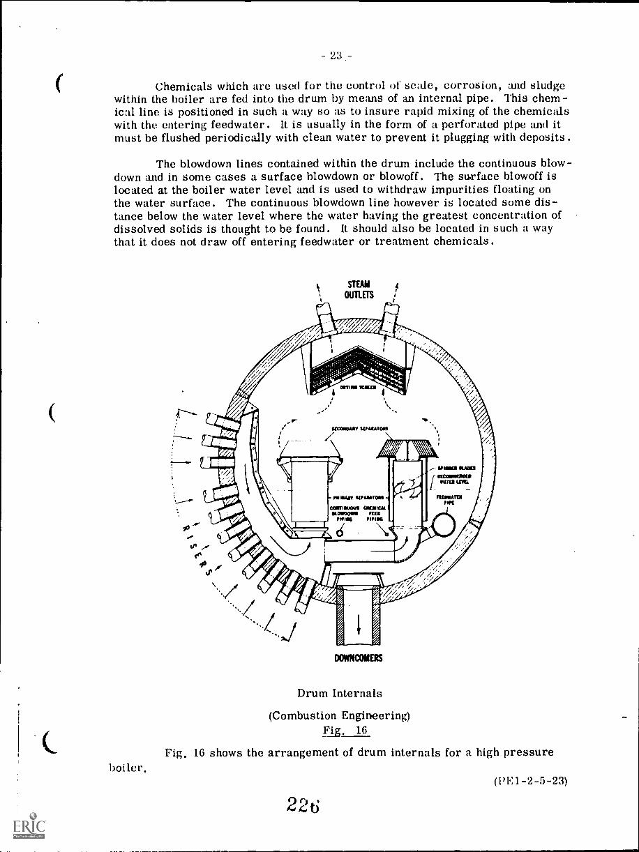
-23-
Chemicals which arc used for the control of scale, corrosion, and sludgewithin the boiler are fed into the drum by means of an internal pipe. This chem-ical line is positioned in such a way so as to insure rapid mixing of the chemicalswith the entering feedwater. It is usually in the form of a perforated pipe and itmust be flushed periodically with clean water to prevent it plugging with deposits.
The blowdown lines contained within the drum include the continuous blow-down and in some cases a surface blowdown or blowoff. The surface blowoff islocated at the boiler water level and is used to withdraw impurities floating onthe water surface. The continuous blowdown line however is located some dis-tance below the water level where the water having the greatest concentration ofdissolved solids is thought to be found. It should also be located in such a waythat it does not draw off entering feedwater or treatment chemicals.
boiler.
DOVOICOMERS
Drum Internals
(Combustion Engineering)Fig. 16
Fig. 16 shows the arrangement of drum internals for a high pressure
226(1)E1-2-5-23)
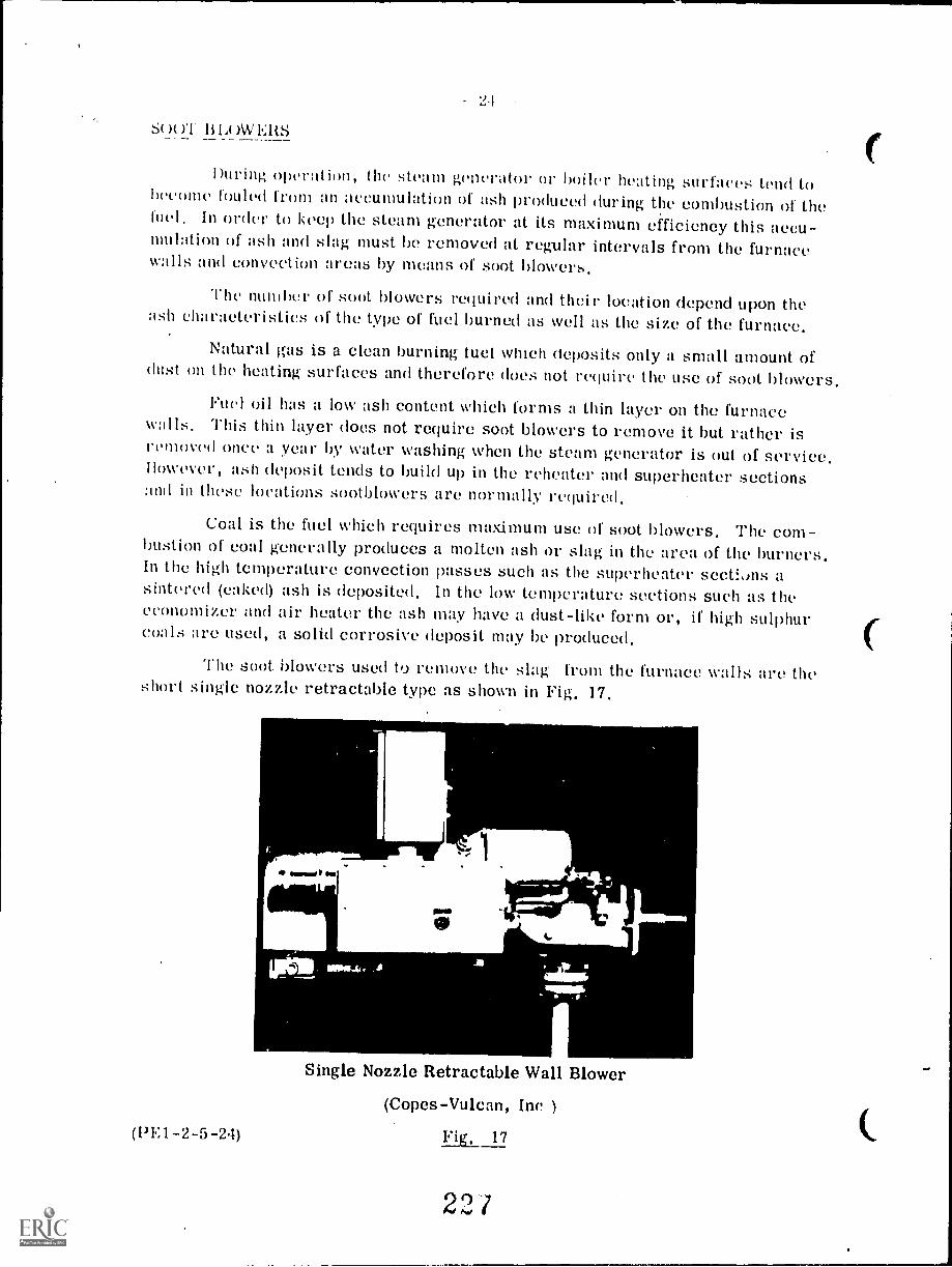
9 1
Sut BIA AVERS
During operation, the steam generator or boiler heating surfaces tend toheeome fooled from an accumulation of ash produced during the combustion of theIuel. In order to keep the steam generator at its maximum efficiency this accu-mulation of ash and slag must be removed at regular intervals from the furnacewalls and collVeCtioil areas by means of soot blowers.
The number of soot blowers required and their location depend upon theash characteristics of the type of fuel burned as well as the size of the furnace.
Natural gas is a clean burning tuel which deposits only a small amount ofdust on the heating surfaces and therefore does not require the use of soot blowers.
Fuel oil has a low ash content which forms a thin layer on the furnacewalls This thin layer does not require soot blowers to remove it but rather isremoved once a year by water washing when the steam generator is out of service.However, ash deposit tends to build up in the reheater and superheater sectionsand in these locations sootbtowers tire normally required.
Coal is the fuel which requires maximum use of soot blowers. The com-bustion of coal generally produces a molten ash or slag in the area of the burners.In the high temperature convection passes such as the superheater sections asintered (caked) ash is deposited. In the low temperature sections such as theeconomizer and air heater the ash may have a dust-like form or, if high sulphurcoals are used, a solid corrosive deposit may he produced.
The soot. blowers used to remove the slag from the furnace walls are theshort single nozzle retractable type as shown in Fig. 17.
(PE1-2-5-24)
stisami I
..fig Irani lag 11,..11L04..
Single Nozzle Retractable Wall Blower
(Copes-Vulcan, Inc )
17
22/
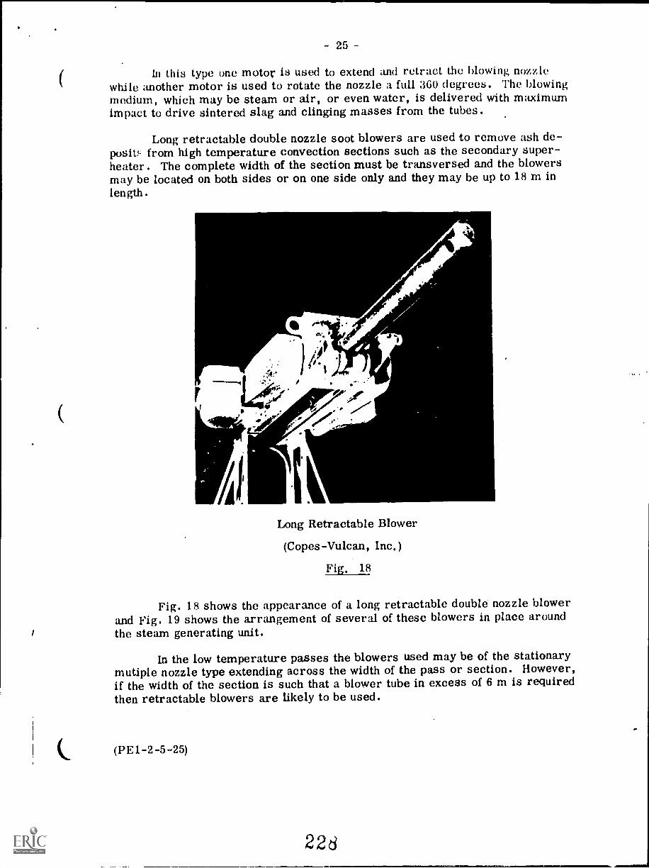
25
In this type one motor is used to extend and retract the blowing nozzlewhile another motor is used to rotate the nozzle a full 360 degrees. The blowingmedium, which may be steam or air, or even water, is delivered with maximumimpact to drive sintered slag and clinging masses from the tubes.
Long retractable double nozzle soot blowers are used to remove ash de-posit from high temperature convection sections such as the secondary super-heater. The complete width of the section must be transversed and the blowersmay be located on both sides or on one side only and they may be up to 18 m inlength.
t A
, -e ..11`
Long Retractable Blower
(Copes-Vulcan, Inc.)
Fig. 18
Fig. 18 shows the appearance of a long retractable double nozzle blowerand Fig. 19 shows the arrangement of several of these blowers in place aroundthe steam generating unit.
In the low temperature passes the blowers used may be of the stationarymutiple nozzle type extending across the width of the pass or section. However,if the width of the section is such that a blower tube in excess of 6 m is requiredthen retractable blowers are likely to be used.
(PE1-2-5-25)
226
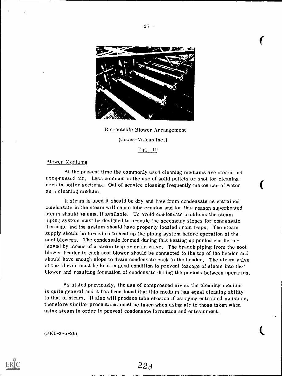
21;
..11811E7
Retractable Blower Arrangement
(Copes-Vulcan Inc.)
Fig. 19
Blower Mediums
At the present time the commonly used cleaning mediums are steam andcompressed air. Less common is the use of solid pellets or shot for cleaningcertain boiler sections. Out of service cleaning frequently makes use of wateras a cleaning medium.
If steam is used it should be dry and free from condensate as entrainedcondensate in the steam will cause tube erosion and for this reason superheatedsteam should be used if available. To avoid condensate problems the steampiping system must be designed to provide the necessary slopes for condensatedrainage and the system should have properly located drain traps. The steamsupply should be turned on to heat up the piping system before operation of thesoot blowers. The condensate formed during this heating up period can be re-moved by means of a steam trap or drain valve. The branch piping from the sootblower header to each soot blower should b'e connected to the top of the header andshould have enough slope to drain condensate back to the header. The steam valveat the blower must be kept in good condition to prevent leakage of steam into the'blower and resulting formation of condensate during the periods between operation.
As stated previously, the use of compressed air as the cleaning mediumis quite general and it has been found that this medium has equal cleaning abilityto that of steam. It also will produce tube erosion if carrying entrained moisture,therefore similar precautions must be taken when using air to those taken whenusing steam in order to prevent condensate formation and entrainment.
(1)E1-2-5-26)
2 2 z)
27
The use of solid pellets or shot. for difficult cleaning problems such asthose found in many types of recovery boilers has gained a certain amount offavor, The method, which is used mostly for air heater and economizer surfaces,consists of allowing the pellets to drop by gravity onto the surfaces and to ricochetfrom one surface to another. A hopper at the bottom of the air heater or econom-izer is used to collect the pellets which are then returned by a pneumatic systemto the distributing chamber at the top for recycling. Most of the ash removed bythe pellets is carried away in the flue gas stream. Large particles fall with thepellets into the collecting hopper and are recirculated with the pellets until theyare broken up into fine particles which can be removed by the flue gas stream.
Advantages for this method of cleaning include 'get that the samequantity of pellets will clean an entire vertical section no tter what the height.In addition, the pellet system does not require platforms wal walkways aroundthe boiler to the same extent as do the steam and air systems and the pelletshave a more positive cleaning action than steam or air.
Soot Blower Control
Depending upon the size and capacity of the boiler unit and the number ofblowers installed, various control methods for soot blower operation may beemployed. For small industrial boilers, hand operated and controlled sootblowers are used. Large industrial and central station boilers use variousdegrees of automatic control ranging from simple push button stations to auto-matic pre-programmed cleaning cycles.
The control panel for an elaborate system used in a central station isshown in Fig. 20. This panel incorporates the boiler diagram with indicatinglights for each blower, alarms and switches.
This system (Fig. 20) can be started manually, by clock, or automaticallyfrom boiler signals. It provides a constant check on such soot blower operatingconditions as: soot blower "blowing ", control power failure, motor overload,low header pressure, no blowing medium, normal time exceeded, low receiverpressure (air only), and no rotary motion.
In general, an automatic system should provide the following:
1. Individual blower selection and remote operation, out of sequence,
Capability of selection of a sequence, interruption of that sequence,and return to normal.
3. Easy identification of the system status, mode of operation, andblower operation.
4. Capability to alarm and identify type and location of any malfunctionplus the ability to provide speedy corrective action.
(PEI-2-5-27)
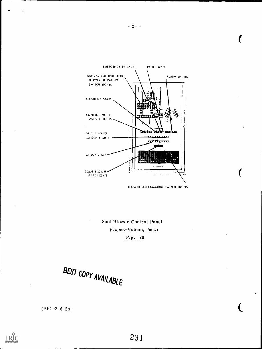
-
EMERGENCY RETRACT
MANUAL CONTROL ANDBLOWER OPERATING
SWITCH LIGHTS
SEOUENCE START
CONTROL MODESWITCH LIGHTS
ROUP }ELECT
;WITCH LIGHTS
GROUP START
SOOT BLOWERSTATE LIGHTS
PANEL RESET
ALARM LIGHTS
BLOWER SELECTMATRIX SWITCH LIGHTS
Soot Blower Control Panel
(Copes-Vulcan, Inc.)Fig. 20
BESTCOPY
AVAILABLE
(PE1-2-5-28)
231
EsTv.)N S i t t.: ET
POWER 1...NG1N RING
First ClassSect, 2, Lect,
Sketch and describe a method of recovering heat from boiler blow-off.
2, Describe the construction and operation of a non-return stop valve.
Sketch an outside-screw-and-yoke stop valve and describe its construction.
I Describe the location and the purpose of each of the following connections:
(a) surface blow-off
(b) bottom blow-off
(c) continuous blow-off
According to the ASME, where are bottom blow-offs required and what arethe maximum and minimum sizes of such connections.
Define the following terms:
(a) sliding disc valve
(b) slow-opening valve
(c) seatless valve
(d) hard-seat valve
(e) blow-off tank
Explain why steam separators are necessary in large high pressuresteam generators.
Sketch and describe a steam separating arrangement for a high pressureboiler, showing the location of riser and downcomer tubes in relation tothe separating equipment.
9. Describe the general construction and the usual location of the followingsootblowers:
(a) single nozzle short retractable type
(b) single nozzle long retractable type
10. Discuss the general requirements of an automatic soot blowing system.
(PE1-2-5-Q)
2302
MCIUM0fLia. YIIM11.1
7.5
BOILERS -- OPERATION
Goal:
The apprentice will be able to describesteps in boiler operation.
S.
Performance Indicators:
1. Describe hydrostatic testing.2. Describe drying out the refractory.3. Describe "boilout".4. Describe setting of safety valves.5. Describe procedures for startup
of boiler.6. Describe procedures for operating
a boiler under normal conditions.7. Describe procedures for operating
boiler under emergent;: conditions.8. Describe types and causes of
boiler explosions.9. Describe procedure for shut
down of boiler.
WWI

INSTRUCTIONAL LEARNING SYSTEMS
°Study GuideRead the goal and performance indicators to find what is to be learned frompackage.
Read the vocabulary list to find new words that will be used in package.
Read the introduction and information sheets.
Complete the job sheet.
Complete self-assessment.
Complete post-assessment.
INSTRUCTIONAL LEARNING SYSTEMS
Vocabulary* Boiling our
* Flame-out
* Foaming
* Forced draft fan
* Furnace explosion
* Hydroset
* Hydrostatic testing
* Induced draft fan
III* Pressure explosion
* Priming
* Purging
* Safety valve compression screw
* Thermocouple
* Turnbuckle
INSTRUCTIONAL LEARNING SYSTEMS
IntroductionA boiler operator must follow a set of prescribed procedures for starting,
operating and shutting down a steam vneration plant. These procedures are
necessary for safe and successful operation of a boiler.
This package discusses the basic practices for operation of boilers. The
material is targeted at those that will be operating and maintaining boilers- -
not boiler mechanics.
4
236
INSTRUCTIONAL LEARNING SYSTEMS
InformationPre - operation Activities
Hydrostatic Testing
Boilers that are new or recently overhauled should be tested under pressure for
leaks. A hydrostatic test places the boiler under 1.5 times as much pressure asit was designed to take. Pinhole leaks and cracks can be detected in the
boiler. High quality water of atmospheric tenperature should be used for the
test.
Drying Out The Refractory
The refractory of a new boiler must be dried out before placing it into full
steam production. A low firing rate that will maintain 95 C water temperaturesis needed for drying the refractory.
Boiling Out The Waterside
The waterside of new boilers should be boiled out to get rid of grease and dirtthat has accumulated during its construction. The boiling out can take place at
the same time the refractory is being dried out. The boiler is filled with
clean water and 25 % of the required "boiling out" chemicals are added. The
boiler manufacturer's recommenmdations must be fcllowed on amounts of chemicals.After the fireside drying is complete, the other 75% of the chemicals are added
and the firing rate is increased. The boiler pressures are raised to one-half
of their working pressures. Blow-off valves are operated every 2-4 hours to
remove the sludge. When the flow-off water becomes clear, the boil out is
complete.
Safety Valve Setting
At the end of boil out, the main steam lines, superheater and reheater should beblown out. Once these have been blown out, the safety valves should be set. A
htdroset unit is attached to the safety valve spindle by means of a turnbuckle.Pressure is put on the safety valve by a hydroset pump until it reaches it
setting. If the valve does not act when its setting is exceeded the value
setting must be adjusted with the safety valve compression screw. A hydroset
unit and safety valve are shown in the following diagram.
5
237
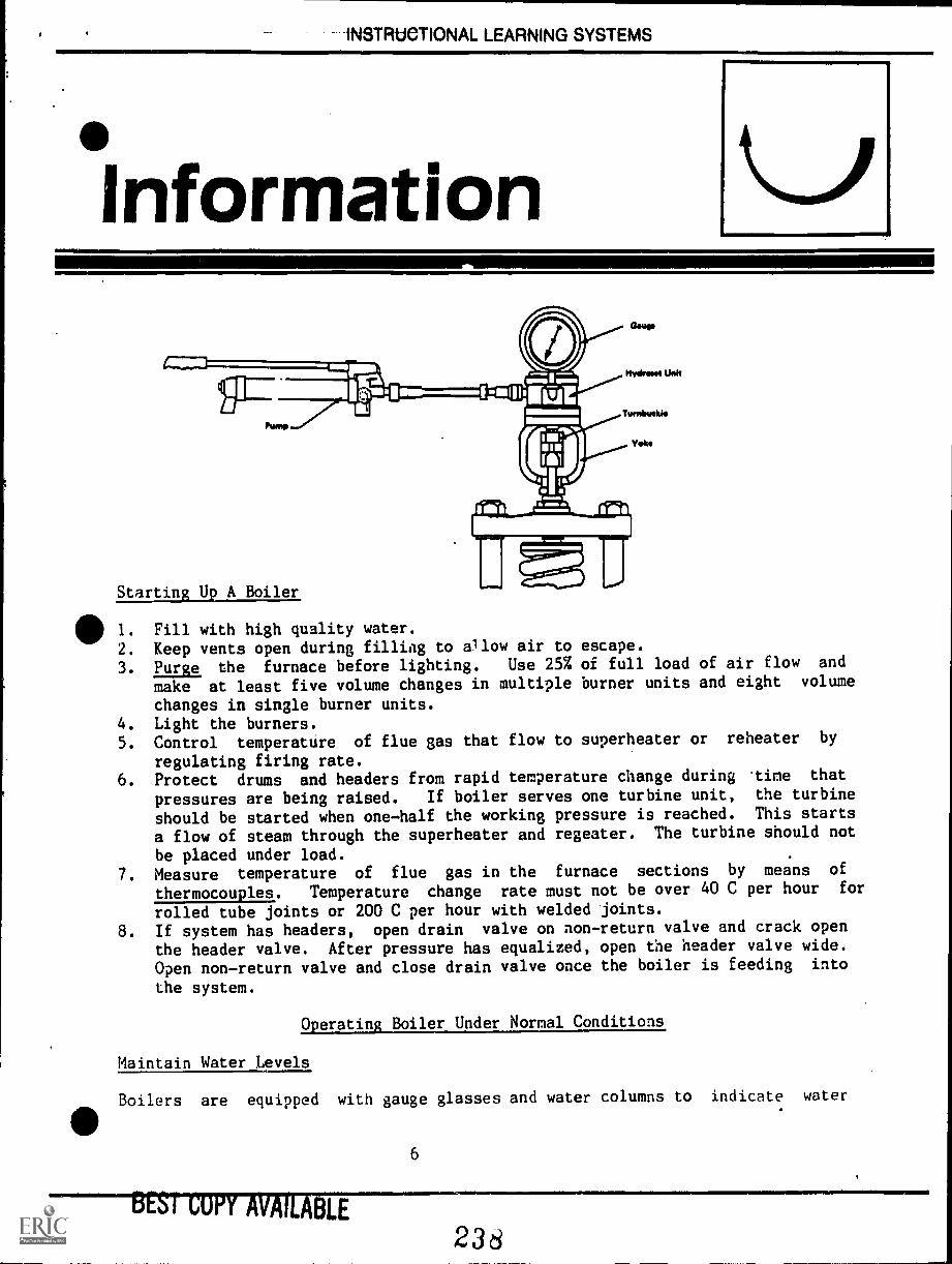
-INSTRtieTIONAL LEARNING SYSTEMS
Information
41.111=
Starting Uv A Boiler
0 1. Fill with high quality water.
2. Keep vents open during filling to allow air to escape.
3. hum the furnace before lighting. Use 25% of full load of air flow and
make at least five volume changes in multiple burner units and eight volume
changes in single burner units.4. Light the burners.5. Control temperature of flue gas that flow to superheater or reheater by
regulating firing rate.6. Protect drums and headers from rapid temperature change during .time that
pressures are being raised. If boiler serves one turbine unit, the turbine
should be started when one-half the working pressure is reached. This starts
a flow of steam through the superheater and regeater. The turbine should not
be placed under load.7. Measure temperature of flue gas in the furnace sections by means of
thermocouples. Temperature change rate must not be over 40 C per hour for
rolled tube joints or 200 C per hour with welded joints.
8. If system has headers, open drain valve on non-return valve and crack open
the header valve. After pressure has equalized, open the header valve wide.
Open non-return valve and close drain valve once the boiler is feeding into
the system.
Operating Boiler Under Normal Conditions
Maintain Water Levels
Boilers are equipped with gauge glasses and water columns to indicate water
stsrrowiLE6
"MNIMICSMIINV
238
111111V
INSTRUCTIONAL LEARNING SYSTEMS
Informationlevels in the boiler. Some boilers have alarms for high and low .,-ter levels.Water columns should be blown down according to the manufacturer'srecommendations. Blow-down shows the operator whether the water column isaccurately measuring the water level. Boiler feed pumps must be checked forbearing temperatures and lubricated when needed. Stand-by feed pumps should bestarted and allow them equal operation time with the regular feed pump. Thewater level control system must be checked regularly.
Water Supply
Feedwater supply must be properly treated. Water testing tells the operator howmany chemicals need to be added to the feedwater. Blow-down requirements canalso be determined by testing. Testing should be done at 24 hour intervals ormore often in some cases.
411 Combustion
Flue gas should be analyzed by recording analyzer or by visual examination offlame color. Fuel burning and draft equipment must be checked and burnerscleaned. Fuel temperature becomes important in oil fired furnaces. Airtemperature must be watched in coal fired furnaces. An operator must maintainthe proper ratio of fuel and air that is fed to the furnace.
Soot Blowing
Soot and ashes clog up the heating surfaces and result in inefficiency of steamproduction. When soot and ashes build up, they must be blown out with the sootblowers. Soot blowers use either steam or air to remove soot and ashes from theheating surfaces. When the temperature of the flue gas becomes high, the sootblower should be turned on. Blowers should only be turned on when the boiler isloaded beyond 50% of its rated output. Furnace draft must be incret.sed duringsoot blowing to prevent blowback of dust through furnace doors.
Dust Collectors
An operator must make sure that dust collector tubes are clear. Dust must becollected from the hoppers regularly to avoid plugging of outlets.
Ash Removal
Ash removal is a chore for operators that fuel with coal. Dumping grates and
7
233
1NSTRUCTIONACLEAHNiMi 4Y-4-tt1tA4-
Informationgrate stokers are used in many coal fired plants. The operator must check on
the type of ash removal equipment to make sure it is working properly.
Boiler Blow-off
Continuous blow-off rates and times are established by manufacturers. Within a
plant, the frequency of blow-off is usually determined by the person in charge
of feedwater treatment. Waterwall blow-off should only be done at times when
the boiler is banked or operating at low levels.
Inspections
Operators should make a general inspection of the boiler plant each shift or
more often if possible. Leaks and problems should be detected as early as
possible. All fittings and gauges should be carefully checked and a written
record made on the findings of that inspection.
Keeping Logs
Routine duties and the time of th,lr performacne should be recorded on a log
sheet, i.e. soot glowing, blow-off. Problems should also be recorded along with
notes or comments on the problem. All entries should show date and time of the
inspection, action or problem.
Operating A Boiler In.Trouble
Emergencies do occur in boiler operation. The operator must know what to do in
case of an emergency.
Low Water Level
There are many conditions that cause a low water level to occur. Actions will
depend somewhat on the nature of the condition that caused the problem. In most
cases, the fire should be cut off as quickly as possible. The gauge glass or
water column should be blown-down to determine if the condition is being
accurately measured. The air supply should be cut off and the boiler steam
outlet closed to avoid rapid pressure changes that might stress and damage the
metal. Where combustion can be stopped immediately, the feedwater should be
shut off. If fueled with coal, it is difficult to stop combustion immediately,
the feedwater should be left on.
8
240
INSTRUCTIONAL LEAHNIMI-SY-b-i-hMb
°InformationHigh Water Levels
High water levels can result in damage to turbine blades and piping failures.
Water is passed on with the steam instead of separating in the drum. In
emergencies created by high water level the operator should:
1. Shut off feedwater2. Shut off fuel3. Shut off air4. Close turbine stop valves or header valves to prevent water
from entering the turbine5. Use blow-off valves to bring water level down to normal
Priming and Foaming
Water is sometimes carried over with steam into the turbine. This condition is
411known as priming. It may be due to a high water level or it may result from
foaming. When large amounts of bubbles form in the drum, it si called foaming.Foaming is controlled by blow-down and addition of feedwater. Sometimes, anti-
foam chemicals are used to prevent foaming.
Fan Failure
Failure of the draft fans allow combustible gases to fill the furnace. The fuel
should be cut off at once. If the induced fan fails, the fuel and
forced draft fan should be shut off.
Flame or Istnition Failure
A flame failure occurs when the flame is extinguished for some reason. It is
often referred to as a flame-out. If fuel continues to flow into the furnace
during a flame-out, combustible gases collect and might cause an explosion.
When a flame-out occurs, the fuel should be shut off immediately. Some boilers
have automatic flame-out devices which shut down the fuel supply, Alarms may be
attached to gas analyzer devices for signalling flame-out conditions. The
furnace should always be purged with a flow of air after a flame failure.
Loss of Load
Sudden loss of load causes a rapid rise in boiler pressure. The safety valves
will open as a result of that pressure. Combusticn controls will react to cut
down the firing rate. The operator must decide whether the shut the boiler down
9
24j
INSTRUCTIONAL-LEARNING-SYSTEMS
Informationor continue operating at a low firing rate.
Boiler Explosions
Boiler explosions may be due to the ignition of combustible gases in thefurnace-7a furnace explosion or too much pressure breaking a boiler part--apressure explosoin. Explosions cause property damage and loss of life to thosein the vicinity. The most common causes of furnace explosions are:
1. Failure to purge the furnace before start-up.2. Fuel added to main burner without pilot flamd.3. Pilot flame is too weak to ignite main burner.4. Loss of main burner flame in a flame-out.5. Lighting a burner from other burners which cause an accumulation of
gases in an area before it is ignited.6. Incomplete conbustion due to improper air supply.7. Insufficient air flow through a banked stoker-fired furnace.8. Improper soot blowing procedures.
Pressure explosions are caused by:
1. Operating boiler at pressures beyond that for which it was designed.2. Weak materials that fail at normal working pressures due to stress,
overheating and erosion.
Shutting Down a Boiler
Boilers are shut down for cleaning, inspection and repair. The basic steps forshut down are:
1. Switch combustion controls from automatic to manual when load is reducedto 25%.
2. Run stoker hoppers and pulverized coal mills empty.3. Cut burners out sequentially.4. Leave burner air registers in firing position.5. Trip main fuel supply valve.6. Purge for 5 minutes.7. Shut down fans and close burner registers.8. Cool slowly and regulate cooling by thermocouples.
10
242
INSTRUCTIONAL LEARNING SYSTEMS
Information
9. Close feedwater valves and header stop valves.
10. Close down non-return valve.11. Ope. drain between header stop valve and non-return stop valve.
12. Open economizer recirculating valve.
13. Open drum vents after pressure drops to 175 kPa.
14. Drain boiler.15. Close, lock and tag valves.
16. Isolate the fuel supply.
11
243
=1,1II
INSTRUCTIONAL LEARNING SYSTEMS
Assignment* Read pages 1 - 21 in supplementary reference.
Complete job sheet.
Complete self-assessment and check answers with answer sheet.
Complete post-assessment and ask the instructor to check your answers.
12
244
INSTRUCTIONAL LEARNING SYSTEMS
°Job SheetOBSERVE START-UP, OPERATION AND SHUT-DOWN PROCEDURES
* Ask an operator to let you observe operational procedures.
* Observe the steps in starting up a boiler.
* Observe the steps in normal operations.
* Observe the steps in shut-down.
It may not be possible to observe all of these procedures but the apprenticeshould take the initiative in learning good operational procedures. Closeobservation of an experienced operator is a good way to learn procedures.
13
245
INSTRUCTIONAL LEARNING SYSTEMS
.SelfAssessmentMatch the following terms with their appropriate description.
I. Boiling out
2. Drying out refractory
A. Passin3 air through boiler toremove combustible gases.
B. Record of actions and
problems in boiler operation.
3. Gauge glasses and, water columns C. Unit used to set safety valves.
4. Hydrostatic testing D. Causes water to pass to the
turbine along with steam.
5. Thermocouples
6. Hydroset
7. Purging
8. Soot blower
9. Log
10. High water level
14
E. Removal of grease and sludgefrom boiler by blow-off untilwater is clean.
F. Removes ash from burner
surf....;es of boiler.
G. Tests boiler pressures to 1.5times rated pressure.
H. Devices used in measuringtemperature of flue gas.
I. A low firing rate and 95 C
water temperature needed.
J. Show water level of boiler.
SOL
246

a INSTRUCTIUNAL LEAHNINU SYSTEMS
Self AssessmentAnswers
E 1.
I 2.
J 3.
4.
Ei 5.
C 6.
A 7.
F 8.
B 9.
D 10.
15
INSTRUCTIONAL LEARNING SYSTEMS
*PostAssessment
1. Operators should make a general inspection of all fittings and gauges atleast once a
2. Water carried over to the turbine with steam is called
3. Large amounts of bubbles in the drum is called
4. Two types of fans are used to move air through the boiler--the forced draftand draft fan.
5. A results when there is a momentary lapse in fuel
supply to the burners and they lose their flame.
6. The two major types of boiler explosions are andexplosions.
7. An operator should switch combustion control equipment from automatic to
manual when the load is reduced to
8. Forcing air through a boiler to remove combustible gases is called
9. A test places the boiler under 1.5 times as muchpressure as its design rating.
10. The accuracy of gauge glasses and water columns can be tested by
16
248
MN.
INSTRUCTIONAL LEARNING SYSTEMS
InstructorPost AssessmentAnswers
1. Shift
2. Priming
3. Foaming
4. Induced
5. Flame-out
6. Furnace and pressure
7. 25
8. Purging
9. Hydrostatic
10. Blow-down
AMII111111MrINSTRUCTIONAL LEARNING SYSTEMS
of, SupplementaryReferences
* Correspondence Course. Lecture 9, Section 3, Third Class. Steam Generation.Southern Alberta Institute of Technology. Calgary, Alberta, Canada.
18
250
12.;SolITHERN ALBERTA INS'IITUT TCHM)Ifx;y
CALGARY, ALBERTA
Correspondence CoursesPower Engineering
SECTION 2
STEAM GENERATION
BOILER OPERATION, MAINTENANCE, INSPECTION
First ClassLecture 10
Successful operation of a boiler is closely related to continuous andadequate maintenance, supplemented by periodic inspections to determine thecondition of the boiler and its auxiliaries. In addition to this, the proper opera-ting techniques must be followed while the boiler is in service.
In the case of a new boiler, thorough inspection, cleaning and testing mustbe carried out after construction and before the boiler is put into operation.
This lecture will deal primarily with natural circulation watertube boilersof modern design but most of the instructions and recommendations containedherein will also apply to other designs of boilers, both large and small. Informa-tion and illustrations contained in the sections on Boiler Start Up, OperatingSafety Precautions, Boiler Cleaning, and Boiler Repair have been abstracted inpart from the volume "Steam, Its Generation and Use "by the kind permission ofBabcock and Wilcox Canada Ltd.
HYDROSTATIC TEST
New boilers or boilers which have undergone majorrepairs or which havebeen out of service for an extended period of time shall be subjected to a hydro-static test of 1.5 times the design pressure. The water used for the test should heat a temperature no less than the surrounding atmosphere and in no case less than21°C. This is necessary to prevent condensation forming on the outside of thetubes and plates which would make the detection of leaks difficult. The watertemperature, however, should not be so high as to prevent touching and closeinspection of the parts.
The water should also be of high quality to avoid corrosion and foulingproblems. Any sections of the boiler which will be drained immediately after thetest can be filled with clear filtered water. Nondrainable parts, on the other hand,should be filled with distilled or demineralized water which has been treated forproper pH and oxygen remc
- 2 -
When filling the various parts of the boiler, care should be taken to vent allair from these parts, otherwise a dangerous condition will develop. Air trappedby the water will compress and, in the event of a leak, will expand producinghazardous high-pressure water jets. A good guide to the effectiveness of the airventing carried out during the filling of the boiler, is the time taken to raise thehydrostatic pressure after the boiler shows full. An excessive time taken to raisepressure indicates that the test pump is compressing air trapped somewhere inthe boiler.
In the case of a new boiler, the hydrostatic test is carried out before therefractory and casing have been installed and the test must be witnessed by anauthorized inspector. In the case of a boiler being returned to service: after amajor repair outage, a hydrostatic test at normal working pressure may be suf-ficient if this is approved by the authorized inspector.
For a hydrostatic test at 1.5 times the design pressure, gags must be usedto prevent safety valves from opening or blank flanges may be used in the case offlanged valves. In order to prevent excessive pressure on the safety valve spindle:Ind to protect the valve seating surfaces, the safety valve gag should not be applieduntil the hydrostatic pressure has reached at least 80% of the valve set pressure.The gags and blank flanges must be removed after completion of the test.
After satisfactory completion of the hydrostatic test, in the case of a newboiler, the refractory, insulation and casing are installed and the boiler is driedout and boiled out.
DRYING AND BOILING OUT
The refractory of a new boiler must be dried out before the boiler is put intoservice and, in addition, the water side of the boiler must be boiled out to removeoil, grease and other contaminants from the internal surfaces.
The drying and boiling out are usually done at the same time. The boiler isfilled with distilled, demineralized or clean raw water until approximately 25 rnmshows in the gage glass and then about 25% of the boiling out chemicals are added.The chemicals used for the boil out may be a combination of several of the following:caustic soda, soda ash, sodium phosphates, sodium nitrate, sodium nitrite, sodiumsulphite, sodium silicate. .; satisfactory mixture is 3 kg caustic soda, 3 kg diso-diurn phosphate and 1 kg sodium nitrate for each 1000 kg of water in the boiler.However, the boiler manufacturer's recommendations regarding this should beadhered to.
PE1-2-10-2
252
Due to the caustic nature of the boil out chemicals, a temporary gage glassshould he used during the drying and boiling out period. The gage should bechecked to see that it correctly registers the boiler water level.
During the drying out operation the firing rate should be such as to maintaina slight vapor leaving the open drum vents. This would indicate a water tempera-ture of about 95°C and in many cases this may be obtained by the use of pilotburners only.
When the refractory is considered to be reasonably dry, the remainder of theboiling out chemicals are added to the boiler. The boiler firing rate is then in-creased to raise the pressure in stages to approximately one half the design work-ing pressure. (Some authorities recommend only 0.2 operating pressure or200 kPa, whichever is lower, for the boiling out procedure). As the pressure israised, the drum vents are closed at about 170 k Pa, and during the pressureraising, the unit should be checked to see that it can expand freely.
During the boiling out period the blow-off valves are operated at intervals offrom two to four hours to blow out sludge :uid sediment from mud drums andheaders. Additional feedwater and chemicals are added as necessary.
The boil out is considered complete when samples from the blow-off show thatthe water is becoming clear: Then the fires are shut down and the boiler pressureallowed to drop with the drum vents being opened before the pressure reaches zero.The boiler is then drained and manhole and handhole covers removed and the boileris flushed out with a high pressure water hose before any deposits can become bakedupon the surfaces.
After the boiling and flushing out are completed there will still be iron oxideand mill scale remaining in the boiler and in the feedwater system. Therefore,in the case of boilers designed for 5500 kPa and over, it is advisable to acid cleanthe unit. This acid cleaning is usually deferred until the boiler has been operatedat high capacity for a sufficient time to ensure that the scale and oxides have beencarried from the feedwater system to the boiler.
The procedure of acid cleaning will be described later in this lecture.
PE1-2-10-3
4
SAFETY VALVE SETTING
The safety valves are usually set at the conclusion of the boil out. How-ever, as the safety valves are susceptible to damage from wet steam or grit,the setting of the valves should be done after the superheater, reheater and mainsteam lines have been blown out thoroughly to rid them of moisture, scale andother foreign material.
Before blowing out the piping it should be checked to make sure it is pro-perly installed and supported, A special connection is usually made to the endof the steam line and carried to a point out of doors where no damage will be doneby the escaping steam and debris. This outside connection must be firmly fas-tened down so that it cannot move under the reaction force of the escaping steam.
Two or three blows of each section of piping are usually done at about50 percent of normal pressure. The valve used to control the steam flow shouldbe gradually opened to the wide position and held for several minutes and thengradually closed again. A motor-operated valve is preferred for this job.
The safety valves are checked for proper operation by raising the steampressure until each valve opens. The other safety valves, if the boiler isequipped with more than one, are held shut by means of a gag or clamp. Thepressure at which each valve opens and closes is recorded and the valve isadjusted until the correct setting is obtained.
Safety valves for very high pressure boilers cannot tolerate even minimalwear to seating surfaces without losing their steam-tightness. Therefore thesevalves are not normally allowed to open and blow-off until closing during thetesting. In other words their closing pressure is not tested. Instead, the safetyvalve set point is checked without allowing the valve to open fully. This can bedone by either of two methods. One method makes use of special gags whichrestrict the lift of the valve and cause it to close immediately after it begins tosimmer. The second method involves the use of a hydraulic jack to open thevalve when boiler pressure is at its normal value.
Fig. 1 shows the hydraulic jack arrangement for testing safety valves.
Referring to Fig. 1, the safety valve lifting gear is removed and thehydraulic jack (hydroset) yoke is set on top of the safety valve compression screw.Then by means of a turnbuckle the safety valve spindle is secured to the hydrosetunit. The safety valve set pressure and the pressure at which the boiler is
PE1-2-10-4
254
- 5
operating are both known and so the hydroset pressure needed to open the valvecan he determined. Then, by means of the pump supplied, the necessary hydro-set pressure is applied and the safety valve should spit or simmer at this pointif the valve is correctly set. If not, then the safety valve compression screwmust be adjusted until the safety valve does simmer when the exact requiredhydroset pressure is applied,
Safety Valve Hydraulic Testing(Dresser Industrial Valve and Instrument Division)
Fig. 1
Gauge
Hydroset Unit
Turnbuckle
Yoke
After the set points of all safety valves have been checked then they aresealed by the Boiler Inspector who has witnessed the tests.
PEI-2-10-5
-6BOILER START UP
When starting up the boiler to put it into service it should be filled with highquality water and the temperature of this water should be such that it does notcause thermal stresses in the boiler metal. The differential between the watertemperature and the metal temperature should not be greater than 40°C.
When filling the boiler the vents should be opened to make sure no air istrapped and that all boiler tubes are filled with water.
Before lighting up the unit it is essential that the furnace be thoroughlypurged. In multiple burner units the purge is done with 25 percent of full-loadair flow until five volume changes are made. Single burner units are usuallypurged with 70 percent air flow until eight volume changes are made.
During the pressure raising period it is normally not necessary to add waterto the boiler therefore there is no flow through the economizer and, dependingupon the economizer location, steam may be generated and trapped within theeconomizer. This may be avoided by allowing boiler water to recirculate throughthe economizer.
Also, during the pressure raising period, there is no steam flow through thesuperheater or the reheater. Therefore the temperature of the flue gas enteringthese sections must be controlled to keep tube temperatures below 480°C in thecase of carbon steel tubes and below 500 to 540°C for alloy tubes. This controlof the flue gas temperature is usually achieved by regulating the firing rate andselecting burners located higher or lower in the furnace wall. Excess air vari-ation and gas recirculation are also methods of control.
The temperature of the flue gas entering the various furnace sections ismeasured by means of retractable thermocouples which can be withdrawn aftersteam flow is established through the tubes.
In addition to the superheater and reheater, the drums and headers must alsobe protected from thermal stresses. In the case of those components which haverolled tube joints, the rate of temperature change must not be greater than 400Cper hour. This temperature change refers to the saturation temperature of thewater which changes as the pressure is being raised. For headers having weldedtube joints, the rate of temperature change should not be greater than 200 °C perhour. In the case of steam drums with welded tube joints, the rate of temperaturechange permissible depends upon the tensile strength of the metal, the drum dia-meter, the wall thickness and the pressure. Therefore the boiler manufacturermust be consulted for data regarding temperature limits for steam drums.
PEI -2-10-6
25t
If the boiler is connected to only one steam using unit, such as a turbine, thenthe turbine may be started when the boiler pressure reaches about one half normalworking pressure. This provides a flow of cooling steam through superheater andreheater. However, the turbine should not be placed under load until the boilerpressure has reached normal working pressure otherwise too great an increasein firing rate may be required resulting in steam temperature control problems.
If the boiler is serving only one unit, as above, then the stop valve at theboiler is usually onitted and only a turbine stop valve is installed. If, however,the boiler is connected to a common header with other boilers, then it must heprovided with a non-return stop valve directly at the boiler and a header stopvalve adjacent to the header with a drain valve between the two stop valves.
To cut a boiler into a pressurized header system, the following procedure isrecommended by the ASME Code Section VII:
Open the drain valve on the non-return valve and crack open the header valve.This will allow steam to flow from the header to the pipe between the header valveand the non-return valve. At the same time any condensate present will be forcedfrom the pipe through the drain valve. When the pressure has equalized on eitherside of the header valve, the header valve is opened wide. When the boiler pres-sure is still a few kPa below the header pressure, the non-return valve spindleis backed off to about the one quarter open position. Then when the boiler pres-sure reaches and just exceeds the header pressure the non-return valve will beopened automatically by the small difference between the boiler and header pres-sures. Once the boiler is feeding into the header, the non-return valve can beopened wide and the drain valve shut.
It should be stressed that before a boiler is put into service, all fittings,auxiliaries, and controls must be checked out for correct operation. The fittingsinclude safety valves, pressure gages, water columns and gage glasses, blow-cffconnections, low water cut-offs, soot blowers, and chemical feed pumps. Theauxiliaries are feed pumps, feedwater heaters, feedwater supply, draft fans,chimney, fuel burning and handling equipment and ash handling equipment. Thecontrols include feedwater level controls, combustion controls, steam tempera-ture controls, and fuel and ash handling controls.
PE1-2-10-7
- 8 -
NORMAL OPERATION
The main concern of the power engineer is to operate the boiler safelyand efficiently. To do this he must maintain the boiler water level at the correctpoint and the steam pressure and temperature at the required values. In additionhe must make sure that the most efficient combustion possible is being carriedout in the boiler furnace at all times and that a maximum of the heat produced inthe furnace is transferred to the water and steam in the boiler.
If the boiler load changes, then the water level will change and the feed-pump output must be changed in order to maintain correct level. Similarly, achange in boiler load will cause a variation in steam pressure, and to compen-sate for this, the amount of fuel and air supplied to the furnace must be adjusted.The temperature of the superheated steam will also tend to vary with loadchanges necessitating alterations to the temperature control system. Changesin the amount of fuel fed to the furnace will tend to alter the efficiency of thecombustion and the air supply must be adjusted in order to maintain this efficiency.
Heating surfaces which become fouled with soot or ashes will reduce theheat transfer to the water and steam in the boiler and to avoid this the sootblowers must be operated when required.
The condition of the water in the boiler is of prime importance. There-fore the correct amount of chemical treatment and blowdown must be maintained.
In order to a: :complish all the above conditions, the auxiliaries, controls,and fittings that are necessary to operate the boiler must be frequently checkedfor proper functioning. These are discussed in the following sections.
Water Level and Supply
For large boilers, two water columns equipped with gage glasses are theusual standard equipment. The columns and conne:...ting lines must be blown downfrequently enough to ensure that they are clear and that the gage glass indicatesthe correct level. If the water gage glasses are the flat-glass or the round-glassmica-protected types, then the manufacturer's instructions regarding blowingshould be followed as excessive blowing will damage the glasses due to erosion.
Remote-operated water level recorders and indicators are often suppliedand used as a supplement to the direct viewed gage glasses. In addition, highand low level alarms are frequently used. These recorders, indicators and
PE1-2-10-8
25d
alarms should be considered solely as operating aids and should not be relied onentirely. The operator should make frequent visual checks of the water columnto compare the level with that shown by the remote recorders and indicators,
Close attention should be paid to the operation of the boiler feed pump withdischarge and suction pressures noted frequently. Bearing temperatures shouldbe checked frequently and proper lubrication of the pump and its driver must beseen to. The boiler operators must be familiar with the procedure for startingup the standby feed pump and stopping the in-service pump. This should be doneat regular intervals in order that both pumps have approximately equal time inoperation. An adequate supply of feedwater at the correct temperature must al-ways be available for the feed pump. Correct operation of the feedwater regula-tor or water level control system must be checked and tested.
In order to avoid scale formation and corrosion in the boiler, the make-up water for the feedwater supply must be properly treated and the operation ofwater softeners, filters, etc. , must b.- ttended to. In addition to this, testingof the boiler water itself must be car i out and this will enable the requiredamount of chemical treatment and bl. .awn to be determined. The boiler wateris usually tested once every 24 hours or in some cases oftener.
2. Combustion of Fuel
The admission of fuel and air to the furnace in conjunction with boilerload changes is normally done by means of an automatic combustion controlsystem. The operator, however, must be able to take over the process from thecontrol system in case of system failure and therefore he must become familiarwith ham: control operation.
Special attention must be paid to the combustion process occurring in thefurnace. An Orsat analysis of the flue gas should be taken regularly and mostplants make continuous analyses for CO2 or 02 content of the flue gas by meansof recording type analyzers. The operation of these recording analyzers shouldbe checked frequently by comparing their results to an Orsat analysis. Visualexamination of the fire in the furnace is also helpful as the flame color and theamount of smoke or haze are indications of the completeness of combustion.
Fuel burning and draft equipment must be checked for proper operation.Burners must be cleaned when necessary and there must be an adequate supply offuel available at all times. When burning heavy oil, the temperature of the fuelmust be maintained at the correct value. If the fuel burned is pulverized coal,
PEI-2-10-9
- 10
then the temperature of the air supplied to the pulverizers must be kept at theproper point. In the case of natural gas, oil fuel or pulverized coal, care mustbe taken at low firing rates to see that a stable flame is maintained at the burners.
In regard to the combustion control system, its function is to control thefiring rate in the furnace in response to the load demand.
Indications of load changes used in combustion control systems may bevariations in steam pressure, variations in steam flow, or variations in megawattoutput in the case of a boiler supplying a turbo-alternator,
The combustion control system must not only vary the input of fuel and airinto the furnace but it must maintain the desired ratio between the amount of fueland the amount of Mr admitted to the furnace.
3. Soot Blowing
In order to ensure that a maximum of the heat produced in the furnacecan be transferred to the water in the boiler, it is necessary that the heating sur-faces be kept free from ashes and soot. This is done by operating the soot blow-ers when required. The frequency of soot blowing will depend upon the type offuel used but usually once a shift is sufficient. The temperature of the flue gasleaving the boiler will indicate when soot blowing is required. If the heating sur-faces are dirty, less heat from the flue gas will be transferred to the boiler waterand the temperature of the leaving flue gas will be hie,
The soot blowers should not be operated unless the boiler load is above 50percent of rated output, This is to ensure that the burner flame will be strongenough to be stable and also to ensure that the fine dust will be carried rapidlyfrom the furnace before an explosive mixture can be formed. The furnace draftshould be increased during soot blowing so that a negative pressure exists withinthe furnace. This will prevent blowback of dust or flame through furnace doorsor inspection openings.
The soot blowing medium, whether steam or air, n of be free of moisturein order to prevent erosion. Alignment of soot blowers should be checked reg-ularly to make sure the blowing medium does not impinge on baffles or on close-by tubes.
The type of fuel used, the boiler load, and the degree of combustion effi-ciency will determine how often soot blowing should be carried out.
PE1-2-10-10
26 9
1.
Soot blowers are usually operated in the same order that the flue gasesfollow as they pass through the unit.
1. Dust Collectors
In the case of mechanical dust collectors, thc main concern of operation isto keep the collector separating tubes cleai so that each one can carry its shareof the flue gas flow.
Collector hoppers must be emptied frequently to avoid plugging of theoutlet ends of the elements. An indication of plugging is an increase in the pres-sure drop across the collector.
In order to avoid corrosion, the temperature of the gases passing throughthe collector should be kept above the dew point.
Sudden increases in boiler load may result in the picking up of largeamounts of ash from low-velocity sections of the boiler and subsequent over-loading of the dust collectors. Therefore, if it is possible, load increases shouldbe gradua' and a close watch should be kept of the level in the collector hoppers.Soot blower operation also tends to overload collectors but frequent blower oper-ation will spread the dust load and reduce the possibility of over-loading.
The above precautions in respect to blower operation, load increases andhopper levels also apply to the electrostatic dust collector. In addition, thevoltage must be kept up to normal and the elements must be properly aligned.Adequate rapping must be ensured either automatically or manually.
5. Ash Removal
If coal is the fuel used in the boiler then removal of ashes will be one ofthe routine duties of the operator. In smaller and medium sized coal burningplants, dumping grates are often used. These are operated intermittently whenrequired as the ash builds up and interferes with air flow, In larger plants, con-tinuous ash discharge is provided by means of travelling grate stokers. Withthis type, the operator must take care that unburned fuel is not discharged fromthe end of the grate together with the ash.
When pulverized coal is burned in the furnace, the furnace may be eitherthe dry-bottom type where the ash is removed without being fused or melted, orthe wet-bottom type where the ash is removed in a melted or liquid state.
26.1
PEI-2-10-11
- 12
In the dry-bottom type the hopper section at the bottom of the furnace mustbe kept cool enough to prevent fusing of the ash. The burners therefore must beadjusted so that the flames do not carry down too far into the ashpits. The ashshould be removed fairly frequently to avoid cakilg together of the ash or aval-anching of large amounts of ash,
In the wet-bottom furnace, the temperature must be maintained highenough to melt the ash and keep it in liquid form. The burners should be adjustedto sweep the lower furnace walls and the furnace floor in order to assist in keep-ing the ash melted. It may be difficult to keep the ash in a molten state duringlow load periods in which case the ash should be allowed to accumulate until higherload conditions will provide for melting of the ash which can then be tapped off,
Boiler Blow-off (Blowdown)
Extreme care must be taken when operating waterwall header blo.' -offvalves. If they are opened when the boiler is steaming at other than low loadsthe circulation in the water wall may be reduced to such an extent that overheat-ing of tube sections may result. Therefore, waterwall blow-off should be doneat periods of low rating or when the boiler is in a banked condition. Undernormal conditions waterwall header blow-off should not be necessary except inthe case of industrial boilers operating with high make-up rates where,with cer-tain types of water treatment,a heavy sludge may be precipitated in the headers.
In regard to the continuous blowdown, which is drawn off the steam drumfrom a point three or four inches below normal water level, written instructionsfor blowdown amounts and times should be issued to the operators by one person,usually the man in charge of feedwater treatment. This same individual shouldbe responsible for specifying to the operators in writing the amount and times forinternal treatment chemicals. If the amount of continuous blowdown is normallyhigh then a heat exchanger arrangement should be used to recover as much heatas possible.
7. Additional Duties
In addition to the items discussed in the previous sections, the operatorshould make a general inspection of the entire plant once each shift. In this way,leaks which have developed in any of the pressure parts will be discovered.Usually the first indication of a leak is the sound of the steam or water escapingand the operator should be alert to any changes in the normal sound of the plant.Trouble in auxiliary machinery is also often indicated by noise or vibration of theparticular piece of machinery.
PE1-2-10-1!
2Gx?
13
All important changes regarding any part of the plant should be entered ina log sheet or log book. Routine duties such as soot blowing, ash removal,changes in continuous blowdown setting, start up and shut down of auxiliaries,etc. , should be noted together with the times involved, Unusual occurrencessuch as failure of machinery, leaks developed, maintenance carried out, etc.,should also be entered in the log.
8. Operating Safety Precautions
(a) Never enter a vessel unless all steam and water valves,including drain and blow-off valves have b( Jn closed, andlocked or tagged. The exception to this is the drain betweenthe boiler non-return stop valve and the header stop valve asthis is an open ended drain and there is no possibility of steamor hot water backing up through it.
(b) Do not enter a confined space until it has been cooled,purged of combustible and dangerous gases, and properlyventilated with precautions taken to keep the entrance open.A responsible person stationed outside the space should bedelegated to maintain contact with those working inside thespace.
(c) Only low voltage lamps should be used when working withina vessel, and extension cords used should be properly grounded.Light bulbs and flashlights should be explosion proof.
(d) Neer use toxic fluids in confined spaces.
(e) Never use volatile fluids in confined spaces unless adequateventilation is provided for.
(I) Never open or enter rotating equipment until it has come to acomplete stop and its circuit breaker has been locked open. Ifthe equipment is such that it can be set in motion with very littleforce then it should be locked with a brake or other device toprevent rotation.
(g) Always secure the drive mechanism of dampers, gates, anddoors before passing through them,
(h) Always wear tinted goggles or a tinted shield when viewingflames or furnace conditions in order to protect the eyes fromharmful light rays and flying ash particles.
PEI-2-10-13
2 C3
(i) Do not stand directly in front of open furnace ports ordoors as pulsation due to firing conditions, sootblower operation,or tube rupture can cause blow-back of hot furnace gases. Inthe case of pressure fired furnaces, where aspirating air is usedon inspection ports and doors, failure of this air supply willallow the escape of hot gases and even particles of ash and slag,
(j) When clearing slag from observation ports or from furnacewalls do not use open-ended pipes as hot gases may blow throughonto the handler.
(k) Make sure personnel are protected from falling slag, dust orother objects when working within the furnace or ashpit.
(1) A-oid contact with accumulations of fly ash. Although cold onthe surface it may remain hot underneath for long periods of time,
(m) When handling a rod or probe in the furnace, be prepared forfalling slag striking the rod and producing a lever action whichmay injure the handler.
(n) Personnel should be made aware that molten slag may washaway refractory and seals and leak out of the furnace causinginjury to personnel or damage to equipment.
(o) When removing manhole and handhole covers, precautionsshould be taken to avoid injury to personnel from hot water whichmay be lying in drums and headers.
Al3NORMAL OPERATION
The engineer in charge of the shift must be prepared for any emergencieswhich may arise. While it is impossible to forecast all possible emergencies,it is possible to plan procedures to be taken if certain abnormal conditions occur.Some of the conditions which may occur are: low water level, high water level,foaming and priming, fan failure, flame or ignition failure and loss of boiler load.
1. Low Water Level
Low water level in the boiler may be due to: malfunction of the water levelcontrol system, feedwater pump failure, feedwater supply failure, leakage fromboiler due to tube rupture or other cause, of it may be due to a combination of theabove. The procedure to be taken will depend in part on which of these is the causeof the low water condition. The primary and most important step is to shut off
PE1-2-10-14
264
15 -
the fire as quickly as possible in order to prevent overheating of any part of theboiler. Small boilers, such as the packaged type which are fired with oil or gasfuel, are normally equipped with a low water fuel cut off device. This deviceusually consists of a float operated switch which shuts the burner fuel valve andair supply when the water drops to a predetermined level, possibly 25 mm abovethe bottom of the glass.
Large boilers, such as industrial and central station types where a shut-down must be avoided as much as possible, generally do not use the automaticlow water fuel cut off device. Instead, an alarm system is used to warn theoperator when the level approaches the bottom of the glass. This usually leavesenough time to remedy the situation before the level becomes dangerously low.
If the water level cannot be seen in the gage glass it may be that the glassis completely full or completely empty. The glass or column should then beblow down to determine if the glass is full or empty.
If the level is below the gage glass then the fuel and air supply should beshut off and the unit allowed to cool. If thermocouples are installed which mea-sure the temperature differential through the drum shell, then feedwater may befed slowly until the level returns to normal, providing allowable temperaturedifferentials are not exceeded. When the unit has cooled down, it should beinspected for damage due to overheating.
In the case of a tube rupture, where the water is escaping rapidly from theboiler, the procedure is to shut off the fuel and to cut down the air supply, leavingonly enough air flowing through the furnace to prevent steam from escaping fromthe furnace to the operating area. The steam outlet from the boiler should beshut to prevent a sudden drop in pressure and temperature within the boiler asthis would cause severe stresses of the metal. If the method of firing is suchthat the combustion can be stopped immediately, as in the case of oil, gas, orpulverized fuel, then the feedwater supply should be shut off as well to preventtemperature shock to the metal from cool feedwater. When the boiler pressurehas gradually dropped to zero then the normal cooling procedure should befollowed. After cooling down, the boiler must be inspected thoroughly forfurther damage and the ruptured tube replaced.
'Where the boiler is stoker fired or fired by any other method that doesnot allow the combustion to be stopped immediately, then the procedure is thesame except that the feedwater supply is not shut off but is increased to the maxi-mum possible. This is done in an attempt to maintain normal water level andthus prevent damage from overheating. At the same time, the burning fuel on the
PE1-2-10-15
- 16
stoker grate must be smothered or dumped in order to stop the combustion asquickly as possible. When this has been done and there is no longer any dangerof overheating any part of the boiler, then the feedwater supply can be shut off.
When the unit has cooled it should be inspected for evidence of overheatingand cracks in drum and headers, If repairs are required they should be approvedby the Boiler Inspector.
2, High Water Level
A high water level in a boiler or steam generator is to be avoided as itwill result in water being carried over with the steam. This water will causedamage to turbine blades and engine cylinders and may result in piping failure dueto water hammer.
One of the first indications of water being carried over from the drum isa sudden drop in superheated steam temperature if the boiler is equipped with asuperheater. If this occurs or if the water level is found to be above the top ofthe gage glass, then the following procedure must be promptly carried out. Feed-water, fuel, and air must be shut off in that order. To protect engines and tur-bines, the flow of the water-carrying steam from the boiler must be stopped. Ifthe boiler is connected to a common header with other boilers, then the headervalve should be shut and all drains opened. If the boiler is supplying a singleturbine only, then the turbine stop valve should be shut and all drains opened.To bring the boiler level down to the normal operating point, the blow-off valvescan be used. When this is accomplished, normal operation of the boiler may beresumed,
3. Priming and Foaming
The term priming refers to the carrying over of water with the steam, Itmay be caused by high water level as described in the previous section or it maybe caused by foaming.
The term foaming refers to the formation of large bubbles or foam in thedrum steam space. This may be due to a high concentration of dissolved solidsin the water, or it may be due to contamination of the water by soap-like mater-ials.
When foaming occurs, there will be rapid fluctuation in the boiler waterlevel and carrying over of water with the steam (priming) may begin. In addition,it will be difficult to detect the true water level in the gage glass.
PE1-2-10-16
26t3
- 17 -
Usually foaming may be checked by blowing down and feeding fresh ed-water. This will reduce the high solids concentration in the boiler. In extremeeases the fuel and air may have to be shut off in addition to the blowing down pro-cedure until conditions return to normal. Special antifoam chemicals which arepumped into the drum are also used to prevent foaming from occurring.
4. Fan Failure
The majority of large boilers use draft fans. Usually a forced draft fanis used to supply combustion air to the furnace and an induced draft fan is used todraw the combustion products from the furnace and discharge them up the stack.
If the forced draft fan fails then the supply of combustion air will be inter-rupted. When this occurs the fuel supply must be shut off immediately as withoutair the fuel will no longer burn and the furnace will fill with combustible gases.
If the induced draft fan fails then the furnace pressure will rapidly risedue to air still being admitted by the forced draft fan. Therefore, the forceddraft fan and the fuel supply must be shut off at once.
It is usual to equip the boiler with an interlock system which will auto-matically trip the forced draft fan and shut off the fuel supply if the induced draftfan fails. It will also shut off the fuel if the forced draft fan fails.
5. Flame or Ignition Failure
When firing with oil, gas, or pulverized coal, the burner flame may beextinguished clue to momentary interruption of fuel supply, low fuel pressure, toohigh air flow, or instability during soot blowing. When this flame failure or" flame-out " occurs, the flow of fuel into the furnace must be stopped immediately.If not, then the furnace will rapidly fill with unburned fuel which could explode.
Some boilers, usually the smaller sizes fired with oil or gas, are equippedwith a flame failure device which will shut off the fuel valve if the burner flamegoes out. Larger boilers normally are not so equipped and it is the operator'sresponsibility to shut off the fuel supply on flame failure. Therefore the operatormust keep a close watch on furnace conditions. Frequently television cameras andmonitors are used to assist the operator in observing flame conditions in the fur-nace. Gas analyzers are often used and may be arranged to sound an alarm whencombustibles appear in the flue gas as would be the case if a flame failure occurred.
PE1-2-10-17
261
- 18
After a flame failure occurs and the fuel has been shut off, it is necessaryto purge the furnace with a flow of air for at least five minutes, This is done toclear the furnace of any combustible gas before relighting the burners. After thepurge period is completed, the burner can be relighted by means of a torch orIgniter.
6. Loss of Load
If a sudden loss of load occurs, the boiler pressure will rise rapidly andthe safety valves will open. The combustion control system is usually arrangedso that it will reduce the firing rate to a minimum value in this event. However,if the load is completely lost, the safety valves will continue to blow even with thereduced firing rate. The operator must then decide whether to shut down theboiler or continue to op',-;rate at the minimum firing rate. His decision will dependupon how long the load is expected to be lost to the boiler. Usually with a smallor medium sized boiler, a shutdown and a subsequent start up will not involve alot of equipment nor will it take a lot of time. However, with a large high pres-sure boiler equipped with superheater and reheater sections a complete shutdownis avoided if possible because of the time involved in putting the unit and its manyauxiliaries back into service again.
BOILER EXPLOSIONS
Boiler explosions may be listed under two general classifications:furnace explosions which occur when an accumulation of combustible gases igniteand explode within the furnace or gas passes of the boiler; and pressure explosionswhich occur when a pressure part of the boiler, such as the drum, bursts due totoo high a steam pressure or a structural weakening of the metal.
In either case the results of an explosion are almost always loss of lifeand extensive damage to property. The power engineer must therefore exerciseconstant vigilance during the operation of the boiler in order to prevent the occur-ance of an explosion.
If an explosion does occur, then the person in charge of the boiler orpressure vessel must notify the proper authorities.
PEI-2-10-18
268
- 19 -
Furnace Explosions
The most common causes of furnace explosions are listed as follows:
1. Failure to purge the furnace adequately before start-up. There may
be an accumulation of combustible gases within the furnace of an idle
boiler and when an attempt is made to light a burner in the furnace this
gas will explode unless the furnace has been thoroughly purged first.
Admission of fuel to main burner before pilot flame or other ignitionsource is established. This will result in a flow of raw fuel into the
furnace which will explode when the ignition is eventually provided.
3, Pilot flame or other ignition source too weak to provide ignition of
main burner. As a result the main burner will not ignite right away
and a flow of raw fuel into the furnace will take place which will even-
tually explode.
4, Loss of main burner flame. This may be caused by momentary inter-ruption of fuel supply or air supply or the burner flame may be blown
out by too great an air supply, particularly if the furnace is still cold.
Another cause of " flame-out "could be water in the fuel in the case of
oil or gas. If the main burner flame fails, the result will be admis-
sion of raw fuel to the furnace and probable explosion.
5. Attempting to light off one burner from other burners in operation.This will result in a concentration of fuel adjacent to the burner in
question which will eventually ignite explosively from the other
burner flames.
6. Incorrect amount of air supplied to the burner resulting in incomplete
combustion, This will also result in an accumulation of combustibles
within the furnace and subsequent explosion.
7. Insufficient air, flow through a stoker fired furnace which has been shut
down and banked. Volatile material will pass off from the banked fuel
due to the heat of the furnace and an accumulation of combustible gases
will result with possibility of explosion.
8, Improper procedure during soot blowing. If soot blowing is done when
the boiler is below 50 percent of full load, the burners which will be
unstable at low load may suffer a flame-out. In addition, at low loads
a combustible mixture of soot and dust will not be swept from the
furnace quickly enough.
2,
PE1-2-10-19
28:j
- 20
Pressure Explosions
A failure of a pressure part of the boiler may be due to any of thefollowing:
1. Pressure in excess of that for which the boiler was designed. Thiswould occur if the safety valves failed to operate and the firing ratewas greater than that required by the boiler load.
2, Weakening of the material to an extent where the pressure part willNil at normal working pressure. This may be due to any or all ofthe following:
(a)
(e)
Overstressing of material due to too rapid heating up ofthe boiler during start-up.
Overheating of the material due to low water level in theboiler.
Overheating of the material due to build up of scale, sludge,or oil on the heating surfaces.
(d) Overheating of the material due to faulty water circulationwithin the boiler.
Weakening of the material due to corrosion.
Weakening of material due to erosion caused by incorrectlyplaced soot blowers or wet steam being used as the blowing
medium.
BOILER SHUT DOWN
Boilers must be taken out of service at regular intervals for cleaning,inspection and repair.
When reducing load during shutdown the combustion controls should beswitched from automatic to manual before the lower limit of the automatic systemis reached, usually at about 25 percent load. Stoker hoppers should be run emptyand the fuel bed burned out. Pulverized coal mills should be run empty. With
oil and gas firing, the burners should be cut out sequentially as the load is reducedand the burner air registers left in the firing position. The main fuel supply valveshould be tripped at the appropriate time.
PE1-2-10-20
270
J
21
After firing has been stopped, the setting should he purged thoroughly withan air flow of 25 percent of full load for at least 5 minutes, Then the fans areshut down and burner registers closed.
The unit should be cooled slowly until the furnace refractory is black andthen moderate amounts of air can be blown through the setting to assist in thecooling process. On large units the use of thermocouples is advised in order toaccurately regulate the rate of cooling.
After the non-return stop valve has closed and feedwater flow to the unitIs no longer required, then the feed valves can be closed and the header stop valve.The stem on the non-return valve is run down to hold the disc upon its seat andthe drain between the header stop and the non-return stop is opened. The econo-mizer recirculating valve if installed is also opened.
When the steam pressure drops to 175 kPa the drum vents should be openedto prevent formation of a vacuum within the unit.
In order to prevent baking on of sludge the unit should not be drained untilit has cooled sufficiently so that personnel can safely enter and remain in thefurnace. When the boiler is one of a battery, make sure that blow-off valves areopened only on the boiler that is to be drained. As soon as the boiler is emptythe blow-off valves including the continuous blow-off valves should be closed andlocked or tagged. This locking shut or tagging should also be done with the feed-water valves, desuperheater injection water valves, chemical feed valves and themain steam valves.
In regard to isolating the fuel supply, oil burners should be disconnectedand removed and on gas burning boilers the gas should be shut off by at least twovalves in series with an open vent valve between them. A spectacle flange in thegas header may also be used to isolate the gas supply.
BOILER CLEANING
In regard to personnel entering the boiler drums, furnace or any otherpart of the setting, the foll wing precautions must be observed:
1. Drum and setting must be cool and well ventilated,
2. Valves must be closed and locked or tagged to prevent any steam,water, fuel or any other undesirable substances from entering theboiler.
27.1
PE1-2-10-21
22
Draft fan motor circuit breakers must be locked out and tagged.
Only low voltage lighting should he used. All portable electricalequipment used in the steam generator should be adequatelygrounded to the steam generator.
A responsible person should be delegated to maintain contact withpersonnel working within the unit.
Overhanging slag and other deposits should be dislodged by bars orrods operated from outside the setting before personnel are allowedto enter the setting.
Cleaners should preferably work in pairs and should be warned ofhazards from hot soot, dust, and slag. They should be providedwith protective clothing, goggles and respirators when necessary.
Cleaning of Furnace and Setting
Many ash deposits are removable by water washing and steam generatorsare often provided with washing facilities either built-in or portable. Thesefacilities must provide for ample drainage of the wash water and sluiced ash. Inmany plants the soot blowing system for the boiler can be used for washing byconnecting the supply of wash water to the blower header system.
The wash water used should be hot and alkaline to prevent acid corrosionwhich could occur when the ash deposits contain sulphur. The wash water dis-charge should be checked periodically to ensure that adequate alkalinity is beingmaintained.
After washing is completed, the surfaces must be dried as thoroughly aspossible. Frequently the water washing is done just before the unit is returnedto service. If the unit is to remain out of service after washing then it should bedried out by firing at a low rate.
Internal Cleaning of Drums, Tubes and headers
Before cleaning of the internal surfaces of drums, tubes, and headers,they should be examined to determine the effectiveness of the feedwater and boilerwater treatment in preventing scale formation, sludge, and corrosion.
PE1-2-10-22
'23
After this examination, a high-pressure hose water stream should be usedto wash down the internal surfaces. This high pressure water will remove loosedeposits and will also remove some of the scale adhering to the surfaces.
During the washing down the blow-off line should be disconnected and thewater allowed to .nin to waste to prevent scale from plugging the blow-off valvesand piping.
Any deposits still adhering to the surfaces after washing down must beremoved by mechanical cleaning or chemical cleaning.
Mechanical Cleaning - The mechanical cleaners used to remove deposits from theinside surfaces of tubes consist of small motors driven by compressed air, orwater. The motors are fitted with cutter heads having a number of cutters madeof very hard steel. The cutter head is rotated at high speed as the cleaner ispassed through the tubes and thus the scale is cut away. If the cutter is driven bycompressed air a stream of water should be introduced into the tube in order tocool the cutters and to wash away the scale as it is removed from the surfaces.The cleaner should be kept moving through the tube as operating it in one spot,even for a short time, will damage the tube. After mechanical cleaning has beencompleted the boiler should be washed out once more with a high pressure hose.
Chemical Cleaning - Many of the internal surfaces of modern boilers cannot becleaned properly by mechanical means. Chemical cleaning has been found to doan adequate job in these cases. In fact this process is now considered to be thequickest, cheapest, and most efficient method of cleaning the internal surfaces ofboilers of all sizes and designs. It has the following advantages compared to themechanical cleaning method:
I. Less time and fewer maintenance personnel are required.Even a large unit can usually be cleaned in less than 36 hours.
2. Inaccessible areas can readily be cleaned and the cleaning ismore thorough than mechanical cleaning.
3. With chemical cleaning in mind, boilers can be designed withoutspecial provisions for mechrnieal cleaning accessibility.
Chemical cleaning involves washing the boiler internal surfaces with anacid solvent and then flushing with clean water. The unit is then treated with aneutralizing solution and then flushed once again with clean water.
PE1-2-10-23
273
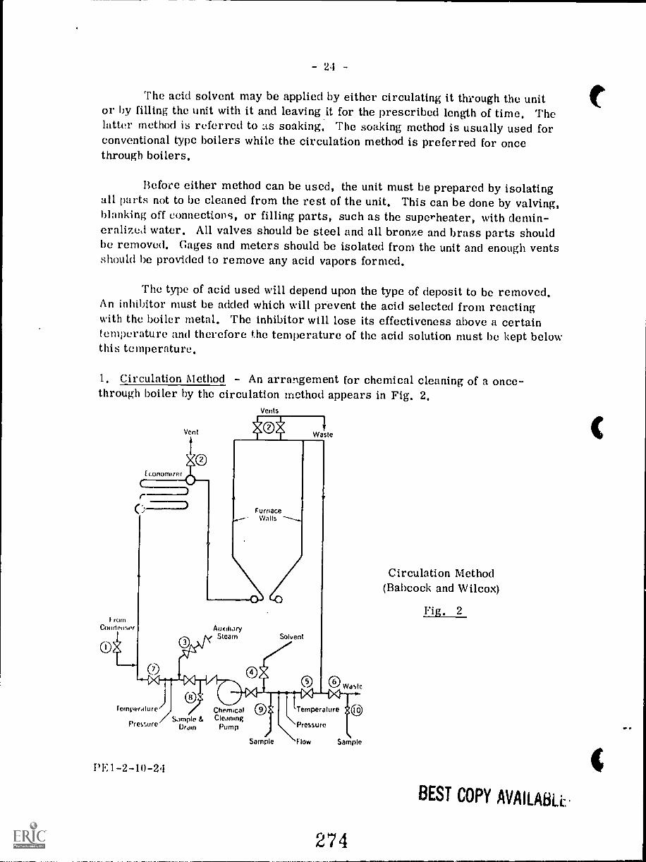
- 24 -
The acid solvent may be applied by either circulating it through the unitor by filling the unit with it and leaving it for the prescribed length of time. Thelatter method is referred to as soaking. The soaking method is usually used forconventional type boilers while the circulation method is preferred for oncethrough boilers.
Before either method can be used, the unit must be prepared by isolatingall parts not to be cleaned from the rest of the unit. This can be done by valving,blanking off connections, or filling parts, such as the superheater, with demin-eralizeJ water. All valves should be steel and all bronze and brass parts shouldbe removed. Gages and meters should be isolated from the unit and enough ventsshould be provided to remove any acid vapors formed.
The type of acid used will depend upon the type of deposit to be removed.An inhibitor must be added which will prevent the acid selected from reactingwith the boiler metal. The inhibitor will lose its effectiveness above a certaintemperature and therefore the temperature of the acid solution must be kept belowthis temperature.
1. Circulation Method - An arrangement for chemical cleaning of a once-through boiler by the circulation method appears in Fig. 2.
Vents
I rumCondenser
Vent
Economizer
(7)
Waste
FurnaceWalls
AuxiliJrySteam Solvent
Temperature
Pressure
PE 1- 2 -10 -24
Sample &Dram
ChemicalCleaning
Pump
O 0 Waste14
Temperature
\ Pressure\Sample Flow Sample
274
Circulation Method(Babcock and Wilcox)
Fig. 2
BEST COPY AVAILAR.L.
- 25 -
After the unit is removed from service, it is cooled and then drained. Thesuperheater 3ection is filled with demineralized water and pressurized with nit-rogen. The boiler proper is then filled with demineralized water through thefilling connection 1. While filling is taking place, r'' air is vented through thevents 2. The water is now circulated through the unit by means of tie chemicalcleaning pump. Low pressure steam is admitted through connection 3 in orderto raise the temperature of the circulating water to 95 °C. The acid solution withthe inhibitor is then admitted through connection 4 to give the desired concen-tration in the circulating water. During the cleaning the temperature must bemaintained at 95°C and the vents must be opened frequently to remove any hydro-gen gas accumulations. Samples of the circulating solution should be taken everyhalf hour and analyzed.
When it has been determined by sample analysis that the ak.id cleaning is com-plete the chemical cleaning pump is stopped and the cleaning solution is removedfrom the unit by closing valve 5 and opening valve 6 while demineralized water isadmitted through valve 1. When the cleaning solution has been displaced, thedemineralized water is circulated by means of the chemical cleaning pump andammonia and hydrazine are added to provide a neutralizing solution which shouldbe heated to 95°C. This neutralizing solution should be circulated for two hoursand all vents, drains, superheater piping and dead-end piping should be flushedout. The neutralizing solution is then displaced by demineralized water.
The final step is to add more ammonia and hydrazine and recirculate thesolution for about one hour.
2. Soaking Method - An arrangement for chemical cleaning of a conventionaltype boiler by the soaking method appears in Fig. 3.
To prepare the unit for soaking, thermocouples should be installed at thesteam drum, at the centre of each furnace wall, and at one of the lower furnacewall headers. The unit is then filled with demineralized water and brought up toa temperature of 77 - 82°C by means of pilot burners or light firing. The firingis then stopped and the uhit is drained and the superheater backfillei with treatedcondensate or demineralized water to prevent acid vapors from entering duringthe cleaning. The drum gage glass is replaced with a plastic tube gage. Then,referring to Fig. 3, the vents 5 and valve 1 are opened and the filling pumpstarted. Heating steam is admitted through valve 6 to keep the water flowing tothe unit at 77 - 82°C and the inhibited acid is admitted through valve 7. Theamount of acid entering is adjusted to give the desired solution strength as sampledat valve 9. When the unit is filled to the normal operating level, the filling pump,heating steam, and acid feed are stopped. Valves 2 and 8 are closed id thedrum vents 5 are left open. The unit is then allowed to soak for the requiredperiod of time.
PE1 -2-10-25
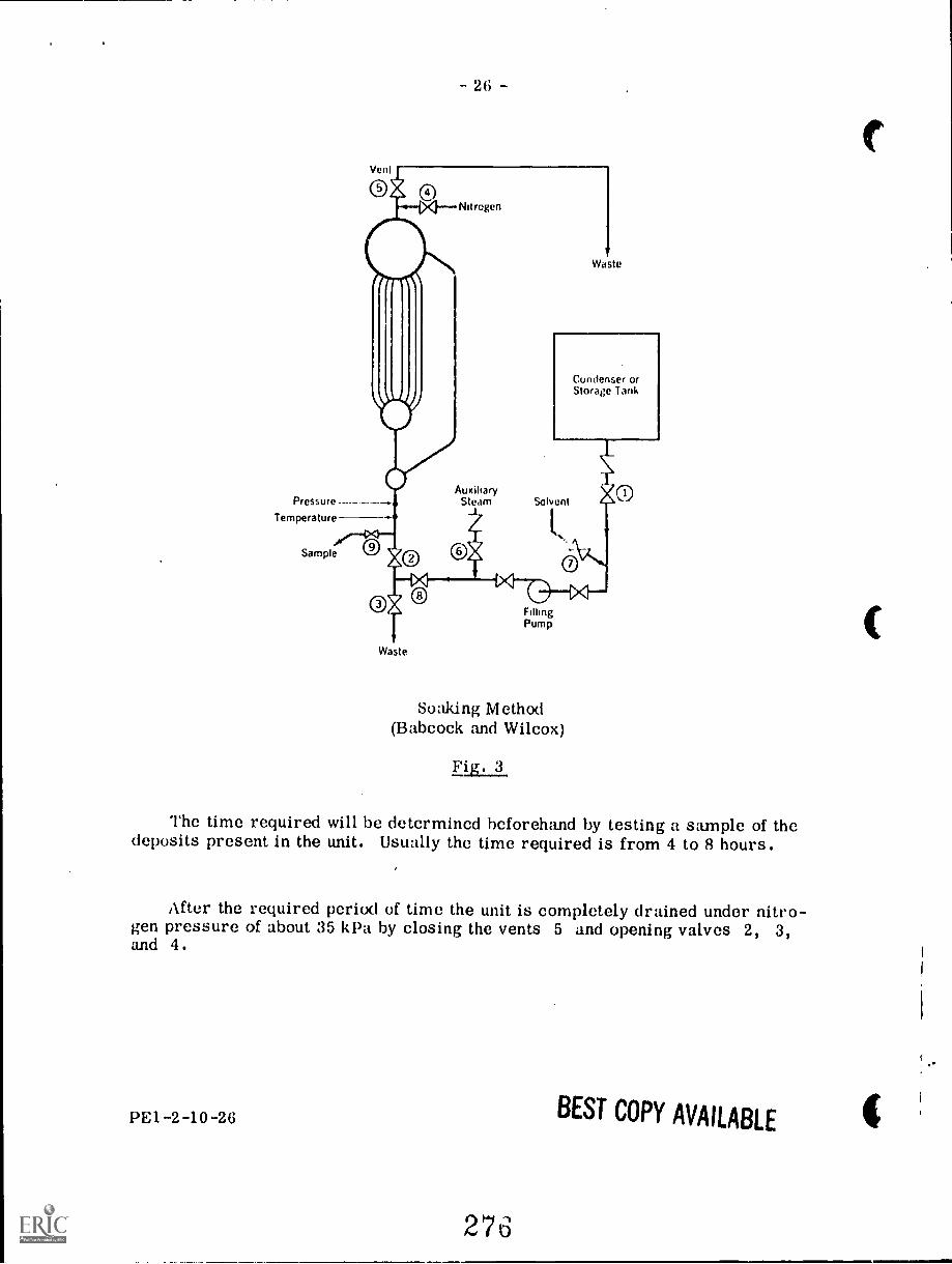
Vent
- 2 fi -
Pressure ---Temperature
leeSample
Nitrogen
Waste
AuxiliarySteam Solvent
FillingPump
Waste
Soaking Method(Babcock and Wilcox)
Fig. 3
The time required will be determined beforehand by testing a sample of thedeposits present in the unit. Usually the time required is from 4 to 8 hours.
After the required period of time the unit is completely drained under nitro-gen pressure of about 35 kPa by closing the vents 5 and opening valves 2, 3,and 4.
PEI -2-10-26
276
BEST COPY AVAILABLE
- 27
After the unit has been drained, valves 3 and 4 are closed and valves 1, 5,and 8 are opened and the unit is filled with demineralized water with the fillingpump until a level appears ir. the water gage. Then more demineralized water isflushed into the unit through the feedwater line until the drum level rises noticeably.This prevents any acid from entering the feedwater system. Similarly, the super-heater should be backflushed with demineralized water until a level increase isobserved in the drum. Then the unit is completely filled using the filling pumpuntil water overflows through the vents 5. This is to ensure the removal of anyacid vapors from the drum.
The unit is now drained under nitrogen pressure and the fill- and -flushingstep is repeated. The unit is again drained under nitrogen pressure and the pHof the rinse water is tested. If the pH is below 5, the fill- and -flushing stepmust be repeated.
If the pH is satisfactory then the next step is to neutralize the surfaces. Thetemporary gage is replaced by the regular drum level gage and the unit is filledto slightly below operating level with a solution of 10 kg of soda ash to 100 kgwater. The unit is then fired and boiled out for 4 to 6 hours. For boilers opera-ting at 1400 kPa or less, the boil-out pressure is operating pressure. For boilersoperating at above 1400 kPa, the boil-out pressure is the higher of 1400 kPa orone half the operating pressure although it is not necessary to exceed 4200 kPa.
After the boil-out the unit is shut down and drained without using nitrogenpressure and while the unit is still hot it is filled with demineralized water con-taining 0.5% sodium nitrite to prevent rusting, until the drum vents overflow. Theunit is drained again after one hour. If there is any evidence of loose depositsremaining in the unit then the headers and tubes should be thoroughly flushed out.
Because of the careful chemical control required and because of the potentialdangers involved in dealing with corrosive solutions and possible explosive andtoxic products of the cleaning process, the chemical cleaning should be supervisedby personnel specially qualified in this highly technical field.
Acid cleaning is usually done by a company specializing in this type of opera-tion. During the procedure, smoking or naked lights must not be permitted in thevicinity due to the possibility of hydrogen gas being produced from the acid reac-tions. Other safety precautions include protective clothing for personnel such asgoggles, gloves and aprons. After opening up of the unit for inspection, air shouldbe circulated through to remove any hydrogen gas which may pass off from themetal. This is done before any personnel are allowed to enter the boiler. Allsolutions whether acid or alkaline must be neutralized before discharging tosewers, rivers, lakes, etc.
PE1 -2-10-27
- 8
BOILER LAYUP
When a boiler is taken out of service, the boiler should be cooled until thewater is below the atmospheric boiling point but not below 85°C, and then theboiler should be emptied and flushed out. An inspection should be made to deter-mine what repair work is necessary and what mechanical and chemical cleaningshould be done. A decision should then he made on whether to employ dry storageor wet storage.
Dry Storage
This procedure is preferable for boilers out of service for extended periodsof time or in locations where freezing temperatures may he expected duringstand-by.
The cleaned boiler should be throughly dried, since any moisture left on themetal surface would cause corrosion to occur on long standing. After drying,precautions should be taken to preclude entry of moisture in any form from steamlines, feed lines, or air.
Moisture- absorbing mate0al, such as quicklime at the rate of 1 kg or silicagel at the rate of 3 kg for 1 m of boiler volume, should be placed on trays insluethe drums to absorb moisture from the air. The manholes should then be closedand all connections on the boiler should be tightly blanked. The effectiveness ofthe materials and need for their renewal may be determined through regular in-ternal boiler inspections.
Wet Storage
A wet procedure may be used for a boiler to be placed in stand-by condition.Wet storage is particularly useful if the stand-by boiler may be required forservice at short notice or if it is impractical to employ a dry storage procedure.The method is not generally employed for reheaters or for boilers which may besubjected to freezing tempei-atures.
Three different methods of wet storage are described as follows.
1. Boiler Completely Filled
The clean empty boiler should be closed and filled to the top with water,conditioned chemically to minimize corrosion during stand-by. Water pressuregreater than atmospheric should he maintained within the boiler during the storageperiod. A head tank may be connected to the highest vent of the boiler to maintainpressure above that of the atmosphere.
PE1 - 2 -10 -28
- 29 -
For a short storage period, condensate or feedwater containing approxi-mately 450 ppm of caustic soda and 200 ppm of sodium sulphite may be used. Ifthe superheater is of the drainable type, it can also be filled with the sametreated water by overflowing from the boiler.
If the superheater is non-drainable, it should be filled only with condensateor demineralized water containing a minimum of dissolved solids, not more thanI ppm. Before introducing the water into the superheater, mix in uniformly about200 ppm of hydrazine and sufficient volatile alkali, such as ammonia, cyclohexyl-amine or morpholine to produce a pll of 10. The treated water may be introducedinto the superheater through an outlet header drain until the water overflows intothe boiler. When the superheater is filled, close the drains and vents.
The boiler can now be filled through the feedwater or other filling line withcondensate, feedwater or clean service water treated as described, with hydrazineand additional volatile alkali. If the storage period is expected to exceed threemonths, the concentration of hydrazine should be doubled.
If preferred, the boiler may be filled using feedwater or condensate treatedwith caustic soda and sodium sulphite after first filling the superheater with con-densate treated with hydrazine and additional volatile alkali.
2, Boiler Partially Filled
As an alternative, the boiler may be stored with water at normal operat-ing level in the drum and nitrogen maintained at greater than atmospheric pres-sure in all vapor spaces. To prevent in-leakage of air, it is necessary to supplynitrogen at the vents before the boiler pressure falls to zero as the boiler is com-ing off the line. If boiler pressure falls to zero, the boiler should be fired to re-establish pressure, and superheaters and reheaters thoroughly vented to removeair before nitrogen is admitted. All partly filled steam drums and superheaterand reheater headers should be connected in parallel to the nitrogen supply. Ifnitrogen is supplied only to the steam drum, nitrogen pressure should be greaterthan the hydrostatic head cf the longest vertical column of condensate that couldbe produced in the superheater.
3 Boile. mpty
Rather than maintain the water in the boiler at norm,1 operating level witha nitrogen cap, it is sometimes preferred to drain the boiler completely, apply-ing nitrogen continuously during the draining operation and maintaining a pressureof nitrogen greater than atmospheric throughout the draining and subsequentstorage.
PE1-2-10-29
27J
- 30 -
BOILER INSPECTION
Boiler inspections are carried out in order to ascertain the condition ofthe boiler. This is necessary to ensure the continuing safe and efficient opera-tion of the boiler.
Inspections by authorized inspectors at regular intervals are required bythe provincial authorities concerned with boilers and pressure vessels, Inaddition, steam plant staff should conduct their own inspections at more frequentintervals.
The ASME "Recommended Rules for the Care of Power Boilers " classi-fies boiler inspections into two categories, namely the external inspection andthe internal inspection,
The external inspection is carried out while the boiler is in service andconsists of a visual examination of the boiler, its fittings, and its auxiliariesincluding checking for misalignment, settling, and clearance for expansion.
The internal inspection, on the other hand, is a thorough examination ofboth the water side and the fire side of the boiler after it has been shut down,cooled, drained, and opened up.
Before the internal inspection, the fire side of the boiler is cleaned ofdust, ashes, and soot,but the water side usually is not cleaned of scale, etc.,until the inspector has had a look at it.
BEFORE AND DURING THE INSPECTION THE SAFETYPRECAUTIONS AS LISTED BELOW MUST BE ADHERED TO,
1. Non-return and header stop valves, feedwater shut off valves, and blow-off valves must be shut, tagged, and preferably padlocked in the shutposition. i.ny other valves through which steam, water, chemicals, etc.could enter the boiler must be handled in the same way. Drain valvesand vent valves must be left open.
2. Similar precautions must be carried out to prevent the entry of fuel,atomizing steam, etc., into the furnace. Oil burners should be dis-connected and removcd and on gas burning boe.lers th gas supply linesshould be blanked oif or a section of pipe removed between the gasshutoff valve and burner,
PEI -2-10-30
2b0
- 31 -
3. The drum and setting must be cool and well ventilated.
Only low voltage lamps of 12 volts or less should be used during theinternal inspection. Extension cords must be grounded mid properlyguarded with waterproof fittings and explosion-proof guarded lightbulbs used.
5. Draft fan motor breakers must be locked out and tagged.
6. A responsible person should be delegated to maintain contact withpersonnel working within the unit.
7. Overhanging slag and other deposits should be dislodged by bars orrods operated from outside the setting before personnel are allowedto enter the setting.
8. Personnel should work in pairs within the boiler and they should bewarned of hazards from hot soot, dust, and slag. They should beprovided with protective clothing, goggles, and respirators whennecessary.
Water Side Inspection
After the inspector has examined the water side surfaces in regard to theamount of scale or sludge present, these surfaces may then be washed down andcleaned. This will leave a clean metal surface which the :nspector can easilyexamine.
When examining the water side surfaces, the inspector will be looking forsigns of corrosion, pitting, and cracking of the metal. Cracks may appear inligaments between tube holes, Stays must be checked for looseness and crackingat the fastened ends. Particular attention is paid to drum connections such assafety valve and steam outlet connections and to manhole and handhole openings.All drum welds are examined close ly.
The plugs in the water column connections should be removed to allowinspection for scale or other deposits.
Drum internals should be closely inspected to see that all baffling andother steam separating equipment are positioned correctly and joints are tight.If baffles, plates, or separators are removed for inspection they should be markedto ensure proper reassembly.
PE1-2-10-31
281
32
In regard to determining the need for cleaning of the internal surfaces, asmentioned in the first paragraph of this section, this can be done by visual inspec-tion in the case of some boiler designs.
However, in the case of the modern high pressure boiler having involvedwater circulation circuits and all-welded construction, adequate visual inspectionmay not be possible. In these cases it may be necessary to cut out a represent-ative tube section in order to determine the amount of deposit present. Alter-natively, a representative tube can be cleaned with a mechanical cleaner and theamount of deposit so removed can be measured by weighing.
After the water side inspection has been completed, the inspector may wishto have the boiler closed up and a hydrostatic test earned out.
Fire Side Inspection
When inspecting the fire side of the boiler the inspector may require re-moval of sections of refractory or insulation in order to facilitate inspection oftube or drum surfaces.
Tube surfaces are examined for bulges or blisters which would indicateoverheating. Ends of fire tubes are checked for signs of leakage and tube sheetligaments for cracking. Tubes adjacent to soot blowers are examined for signsof erosion due to direct impingement of steam from blowers. Refractory andbrickwork of the burners, baffles, and furnace walls are checked for deteriora-tion.
Corrosion of tubes and support brackets may take place in h;gh temper-ature sections such as the superheater ?gpecially if oil containing vanadium isused as the boiler fuel. Corrosion may also ue caused by prolonged contact withash and areas where ash deposits remain should be cleaned and checked. Thealignment of iubes should be checked as misalignment may result from warpageor broken or displaced brackets, hangers, or spacers. If any misalignment isnot corroAed then erosion of tube surfaces by soot blowers may result.
All dampers and air registers should be checked for warpage and froedomof movement. Burners should be examined for signs of carboning or coking andof overheating. Coal handling equipment such as pulverizers and feeders shouldbe inspected for wear and broken parts.
P1-2-10-32
282
- 33 -
Safety valves and related piping, connections, drains, and supports shouldhe examined closely. Blowoff connections should be inspected for cot-gi sion andweakness where they connect with the boiler. These connections must be sup-ported and be able to expand and contract without producing excessive stress onthe boiler. All other piping connecting to the boiler must be similarly checked.
Pressure gages should be tested and calibrated if necessary.
All other boiler fittings shoula be examined for plugged connections andfor proper operation.
BOILER REPAIR
The amount and the nature of the repairs necessary to the boiler can beestablished from indications during the operation of the boiler and from thefindings made during the inspection.
In the case of repairs to the pressure parts, all materials used must meetASME Code requirements and these repairs should be made under the guidance ofthe National Board Inspection Code.
Any repairs to be made by welding must be first approved by an author-ized inspector and the welding carried out by a qualified welder. Following weldrepairs, stress relieving and inspection procedures must be implemented asrequired by the code and the inspection authorities.
Tube Section Replacement
A section of failed tube can be replaced by a qualified welder. The defect-ive section, which should he a minimum length of 300 mm can be cut out withan oxyacetylene torch. During the cutting of the tube care must be taken that noslag enters the tube. After cutting, the tube ends are prepared by grinding andthe new section of tube is welded into place. Backing rings are usually usedexcept where the tube is located in a high heat input zone of a high pressureboiler. Under these latter conditions the space between the tube ends should hea minimum and the first bead of weld metal should be run with a 2.4 mmelectrode. Use of the tungsten-inert-gas process is recommended for the rootpass where an inert gas is used to protect the weld zone from the atmosphere.If the tube to be replaced is of alloy material, the boiler manufacturer should beconsulted regarding welding procedures.
PEI-2-10-33
- 34 -Seal Welding
Seal welds are used under some conditions for fluid tightness. Structuralstrength must be secured by some other means such as an expanded joint.
In new construction the ASME Code permits the eli.mination of the "flare" or"bell" on tubes to be seal welded, provided the throat of the seal weld is not lessthan 4.8 mm nor more than 10 mm. This applies to a seal weld either inside oroutside of the drum or header. For repair work the National Board InspectionCode permits seal welding and differentiates between inside seal welding and out-side seal welding_as follows:
I . Tubes may be seal welded inside provided no single bead has a throatthickness in excess at 4.8 mm., and the throat thickness of a multipassweld does not exceed 10 mm.
2. Tubes may be seal welded outside provided the tube has been expandedand flared to 3.2 mm over the size of the tube hole, and provided thatneither the width or thickness of the weld exceeds 6 mm.
Both codes require that tubes be re-expanded after seal welding. The re-expanding should be done lightly and the seal weld examined for cracks after theexpanding operation is completed.
Tube Removal
Occasionally tubes must be removed and replaced because of damage ordefects or because the boiler is to be dismantled and relocated. There are avariety of ways for removing tubes, depending on whether the tubes are to besalvaged, wholly or in part, or scrapped.
With light-gage tubes it is often possible to cold-crimp both ends of thetubes to loosen them in the seats and then drive or "jack" the tubes out.
When the tubes are too heavy for cold-crimping, the two-stage heatingmethod may be used. The heat is applied to the inside of the tube end with atorch. Heat is first applied for a short period--not long enough for it to betransferred to the tube sheet. When the tube end cools, the joint will haveloosened enough so that the second heat will not be transferred readily to thetube sheet. The tube end can then be heated sufficiently for crimping and thetube can be pushed out of its seat.
PE1 -2 -10-34
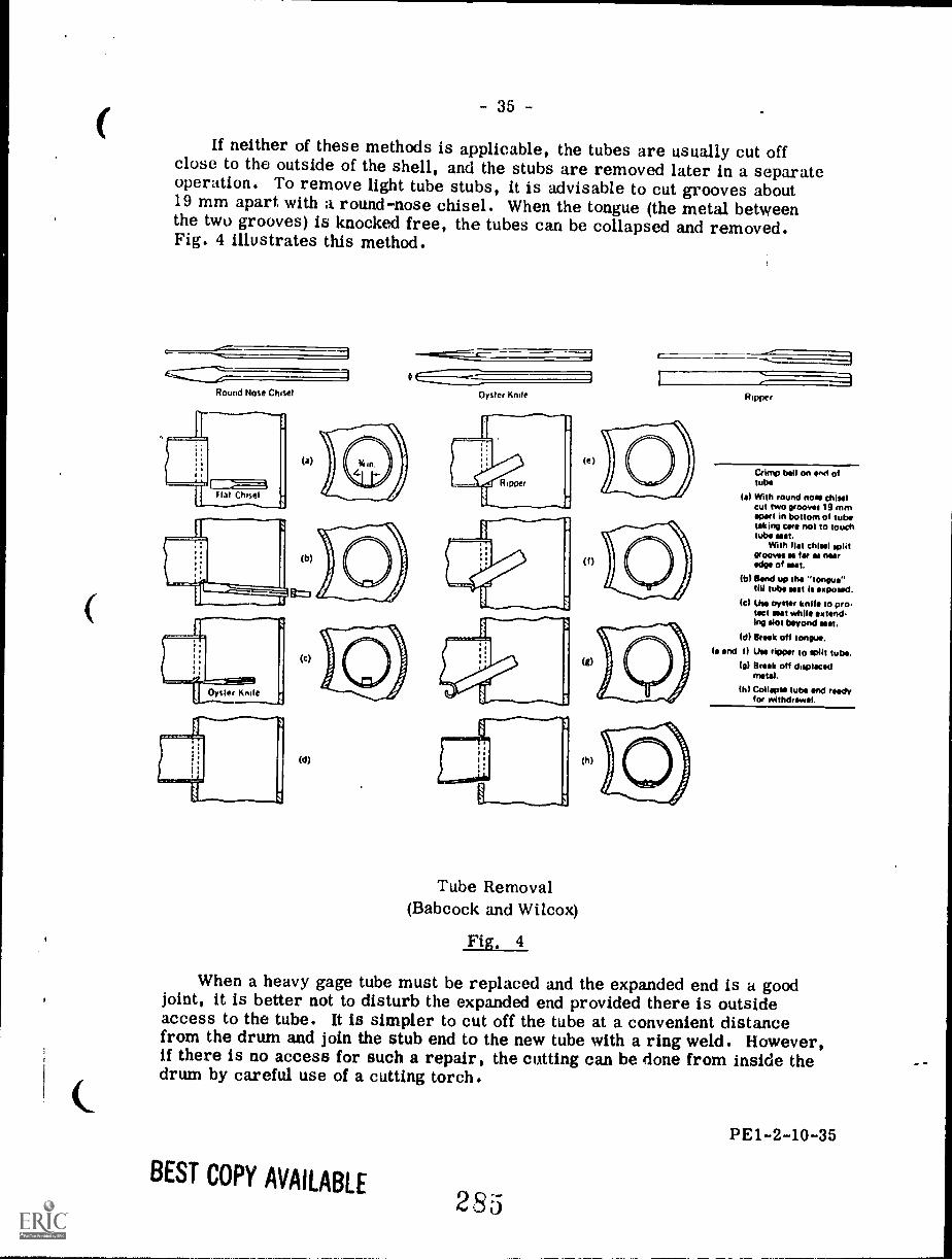
if neither of these methods is applicable, the tubes are usually cut offclose to the outside of the shell, and the stubs are removed later in a separateoperation. To remove light tube stubs, it is advisable to cut grooves about19 mm apart. with a round-nose chisel. When the tongue (the metal betweenthe two grooves) is knocked free, the tubes can be collapsed and removed.Fig. 4 illustrates this method.
1Round Nose Chisel
Flat Chisel
(a)
Oyster Knife Ripper
(e)
Tube Removal(Babcock and Wilcox)
Fig. 4
(0
(g)
(h)
Crimp bell on ins oftube
I.) With round now chiselCut two grooyst 19 mmapart in bottom of tubetaking care not to touchtube mat.
With flat chisel splitgrooves as far es neeredge of wet.
OA Band up the "tongue"till tube wet Is exposed.
Ic/ Use oyster knife to protact wet while extend.Mg Pot beyond wet.
(di Break off tongue.NI and Use ripper to wilt tube.
(g) Brisk off displacedmotel.
(hi Collapse tube end re**for withdraws!.
When a heavy gage tube must be replaced and the expanded end is a goodjoint, it is better not to disturb the expanded end provided there is outsideaccess to the tube. It is simpler to cut off the tube at a convenient distancefrom the drum and join the stub end to the new tube with a ring weld. However,if there is no access for such a repair, the cutting can be done from inside thedrum by careful use of a cutting torch.
BEST COPY AVAILABLE280
PE1-2-10-35
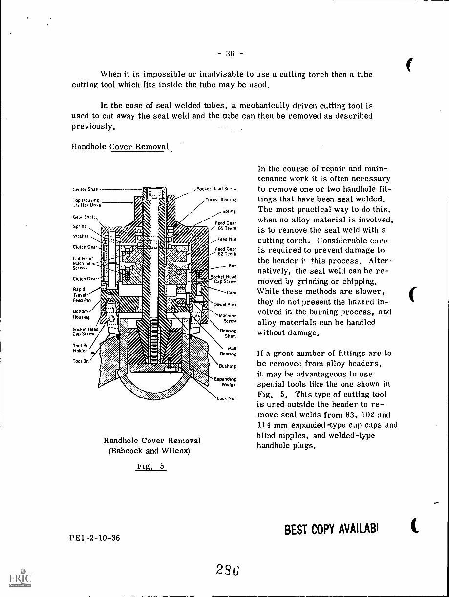
36
When it is impossible or inadvisable to use a cutting torch then a tubecutting tool which fits inside the tube may be used,
In the case of seal welded tubes, a mechanically driven cutting tool isused to cut away the seal weld and the tube can then be removed as describedpreviously,
Handhole Cover Removal
Center Shalt
Top Hou,ing1+2 He Drive
Gear Shalt
Spring
Washer
Clutch Gear
Flat Headfv1.3chineScrews
Clutch Gear
RapidTravelFeed Pin
BottomHousing
Socket HeadCap Screw
Tool BitHolder
Tool Bit
,Socket head Screw
Thrust Bearnig
Spring
Feed Gear7 65 Teem
Feed Nut
Feed Gear62 Teeth
Key
Socket HeadCap Screw
Cam
Dowel Pins
MachineScrew
BearingShaft
BallBearing
Bushing
ExpandingWedge
lock Nut
Handhole Cover Removal(Babcock and Wilcox)
Fig, 5
PE1-2-10-36
2;56
In the course of repair and main-tenance work it is often necessaryto remove one or two handhole fit-tings that have been seal welded,The most practical way to do this,when no alloy material is involved,is to remove the seal weld with acutting torch. Considerable careis required to prevent damage tothe header this process. Alter-natively, the seal weld can be re-moved by grinding or chipping,While these methods are slower,they do not present the hazard in-volved in the burning process, andalloy materials can be handledwithout damage,
If a great number of fittings are tobe removed from alloy headers,it may be advantageous to usespecial tools like the one shown inFig, 5, This type of cutting toolis used outside the header to re-move seal welds from 83, 102 and114 mm expanded-type cup caps andblind nipples, and welded-typehandhole plugs.
BEST COPY AVAILABI
QUESTION SHEET
POWER ENGIN E E RI NG
First ClassSect. 2, Lect. 10
1. Discuss briefly she purpose of and the method of carrying out thefollowing procedures:
(a) hydrostatic test
(b) drying out
(c) boiling out.
2. Sketch and describe a method whereby the set point of a safety valvecan be tested without causing the valve to open fully.
3. In regard to boiler start up discuss the importance of avoiding thermalstresses and explain where these stresses are liable to occur and howthey may be avoided.
4. Summarize the duties of the power engineer in charge of a shift inregard to normal operation. Refer to your own plant if possible.
5. Assume that a furnace tube has ruptured, Summarize the procedureto be followed in shutting down the boiler, repairing it, and returningit to service. Assume that the return to service of the boiler isurgently required.
6. List six precautions to be taken to avoid the occurrence of a furnaceexplosion.
7. List six precautions to be taken to avoid the occurrence of a pressureexplosion.
8. As Chief Engineer you are required to arrange for the chemical cleaningof one of your boilers. Explain how you would arrange for 'his anddescribe the general procedure involved.
9. Discuss the safety aspects involved in regard to boiler inspection andrepairs.
10. Describe a method used for the laying-up of a boiler.Refer to your own plant if possible.
PE1-2-10-Q
=...4
Jift.InUMCMAL 12.A-11111C
7.6
BOILERS -- CLEANING
Goal:
The apprentice will be able to
describe methods for cleaning
a boiler.
1
Performance Indicators:
1. Describe cleaning of air.
2. Describe cleaning of
feedwater.
3. Describe cleaning of steam.
4. Describe cleaning of soot,
ash and scale.
5. Describe cleaning in routine
opreations.
,111111111=111INSTRUCTIONAL LEARNING SYSTEMS
°Study Guide
Read the'soal and performance indicators to find what is to be learned from
package.
Read the vocabulary list to find new words that will be used in package.
Read the introduction and information sheets.
Complete the job sheet.
Complete self-assessment.
Compelte post-assessment.
2
28 :i
INSTRUCTIONAL LEARNING SYSTEMS
Vocabulary* Air washers
* Alkaline boil out
* Ash hoppers
* Ash separators
* Continuous blow-off
* Dust collectors
* Flyash blowers
* Inhibited acid cleaning
* Precipitators
* Purging
* Retractable nozzles
* Sootblowers
* Steam separators
* Steam washers
* Surface blow-off
3
INSTRUCTIONAL LEARNING SYSTEMS
IntroductionEfficiency and safety of boiler operation is highly dependent on keeping the
boiler parts clean and free of grease, combustible gases, ashes and soot.
Purging the boiler with fresh air to rid it of combustible gases is one type of
cleaning operation. Ash and soot removal is a cleaning problem in boiler
systems. Feedwater must be kept clean of impurities. This requires another
cleaning process that involves surface and continuous blow-down systems.
Several packages have dealt with the various cleaning processes. This package
will briefly discuss cleaning and cleaning systems. Each of the systems will be
discussed in greater detail in other packages that relate to draft control,
feedwater and boiler construction and operation.
4
2JI
INSTRUCTIONAL LEARNING SYSTEMS
InformationCleaning the Air
Draft equipment provides a flow of air through the boiler. At the same time
waste gases are moved away from the combustion chamber. An accumulation of
combustion gases can be a safety hazard that causes explosion. Purging is a
strict requirement for all boiler startups. Clean air flows through the boiler
and removes all combustible gases before firing the boiler. The purging
operation must become a habit with boiler operators. Draft equipment must
function properly during operation. The furnace needs air for combustion.
Waste gases must be removed continuously to eliminate hazards of explosion.
Forced draft and induced draft fans are used to move new air into the boiler and
combustion gases out.
Cleaning the Feedwater
Feedwater is cleaned by mechanical and chemical methods. Controlling the
quality of feedwater that enters the boiler is most important. The water may be
treated with chemicals such as softeners and anti-foam materials. Blow-down
connections are designed to help keep the feedwater clean. Surface blow-off
removes impurities of the water line. Continuous blow-off removes water from
well below the surface.. The continuous blow-off is located at a point where
heavy accumulations of solids occur. This continuous removal of feedwater that
is heavy with solids is a cleaning method. Blow-off is used to remove sludge
and scale from the boiler.
Cleaning the Steam
A number of devices are used to clean steam before it enters the turbine. If
the steam contains water, it causes fouling of the turbine blades. Thewater is
actually cleaned from the steam by such devices as steam separators and
steam washers. These devices are part of the drum internals.
Cleaning Out Soot, Ash and Scale
Soot and ash tend to cover the heating surfaces of the boiler. Excess soot and
ash reduce the transfer of heat and efficiency of steam production.
Soot blowers are used to remove soot and ash from the furnace, superheater and
reheater walls. These soot blowers operate on steam, water or air pressure that
is delivered through retractable nozzles. The operator determines the need for
soot blowing and follows prescribed safety procedures in operation of the
blowers. With some fuels, especially coal burning plants, ash handling
equipment becomes very important in boiler operation. Ash handling equipment
5
292
INSTRUCTIONAL LEARNING SYSTEMS
°Informationincludes waterfilled ash hoppers, blowers for handling flyash, ash separators,
air washers, dust collectors and precipitators.
Scale deposits are a major problem in boilers. The control of feedwater quality
determines the amount of scale deposit in the boiler. Scale deposits are
removed by mechanical or chemical cleaning methods. Mechanical cleaning
involves cleaning tools with cutter heads of hard surfaced material. These
tools are powei.ed by steam or air and rotate at high speeds. The tools actually
cut the scale deposits from tubing and drum surfaces. Chemical cleaning is used
to reach surfaces that cannot be cleaned by mechanical methods,
Two methods of chemical cleaning are used. The alkaline boil-out is used to
remove grease and oil. Inhibited acid cleaning uses acid to dissolve scale. A
test should be made of the scale deposit and a chemical strength selected for
each type of deposit. Chemical cleaning is usually accomplished with a low
strength acid (inhibited hydrochloric) that will remove the deposit without
damage to the metal. Experts are usually contracted to do chemical cleaning.
Cleaning in Routine 02erations
Most cleaning oeprations require that the boiler be shut-down and cooled for
internal inspection. The following steps are basic to the cleaning operation.
1. Reduce load on boiler.2. At about 50% load, operate all sootblowers to clean fireside surfaces.
3. rpen drum vents after boiler pressure reduces to 30 kPa.4. isolate boiler by closing and tagging valves and opening - circuit
breakers.5. Open blowdown valves and drain boiler when it has cooled down to 90 C.
6. Remove steam drum manhole cover.7. Remove lower drum manhole cover. This step must be done after step 6 to
avoid steam burns.8. Gpen blowdown valves and flush boiler with high pressure hose.
9. After draining, close and tag blowdown valve.
10. Open fireside access door.11. Inspect drums, drum internals, burners, dampers, sootblowers, tubes and
connections.12. Record condition of parts in the inspection log.
13. Make recommendations on cleaning methods to be used. Outside help may be
needed in analyzing scale deposits and recommending chemical cleaning
method to be used.14. Perform additional cleaning as determined by inspection.
293
INSTRUCTIONAL LEAHNINU SYb I tA4b
AssignmentRead manufacturer instructions on methods for cleaning a specific boiler.
Complete the job sheet.
Complete the self-assessment and check your own answers with the answer
sheet.
Complete the post-assessment and ask the instructor to check your answers.
INSTRUCTIONAL LEARNING SYSTEMS
Job SheetCONDUCT INTERNAL INSPECTION OF BOILER
* Review safety rules for entering a boiler that is shut down.
* Obtain permission from operator to inspect interior or assist operator inmaking routine inspection.
* Keep log on condition of all ?arts inspected.
* Inspect drum, tubes, drum internals, dampers, sootblowers, burners,connections and other parts for deposits, erosion, wear, etc.
* Complete inspection log and show it to instructor for comments.
* Make recommendations for cleaning of the boiler. If possible haveinstructor to verify your recommendations.
8
295
INSTRUCTIONAL LEARNING SYSTEMS
SelfAssessmentMark each of the following pieces of equipment or process accoridn3 to thefollowing code.
(A) -- used in cleaning air(F) -- used in cleaning feedwater(S) -- used in cleaning steam(Q) -- used in cleaning ash, soot and scale
1. Mechanical cleaning
2. Steam separator
3. Induced draft fans
4. Inhibited acid cleaning
5. Surface blow-off
6. Retractable nozzles
7. Dust collector
8. Ash hoppers
9. Purging
10. Alkaline boil-out
9
236
INSTRUCTION/V. LEARNING SYSTEMS11Self AssessmentAnswers
1. Q
2. S
3. A
4. Q
5. F
6. Q
7. Q
8. Q
9. A
10. Q
1 INSTRUCTIONAL LEARNING SYSTEMS
*PostAssessment
0,1
1. List two main methods for cleaning a boiler.
2. List two devices used in cleaning steam.
3. How does soot deposits on heating surfaces reduce the efficiency of steam
production?
4. Which method of chemical cleaning is used for removal of grease and oil
from boiler.
5. What are two types of blow-off?
What device uses retractable nozzles?
7. Flow is sludge normally re-.oved from the boiler?
8. What is the purpose of purging?
9. List two types of fans used in draft control systems.
10. Which type of chemical cleaning is used to dissolve scale deposits?
11
296
INSTRUCTIONAL LEARNING SYSTEMSWIMI =11I
InstructorMost AssessmentAnswers
1. Mechanical and chemical
2. Steam separator and steam washer
3. Reduces heat transfer
4. Alkaline boil-out
5. Surface and continuous
6. Sootblowers
7. By blow-off procedures
8. Removes combustible gases from boilerexplosions from these gases.
or to ignition. Purging prevents
9. Forced draft and induced draft
10. Inhibited acid cleaning
12
"NM
29J
rar
& INSTRUCTIONAL LEARNING SYSTEMS
SupplementaryReferences
* Manufacturer's Instruction Manual on boiler cleaning procedures.
13
3'0
11.14.-41.1Ma )4.54.cal
BOILERS -- IICAT RECOVERY SYSTEMS
Goal:
The apprentice will be able to describe
heat recovery systems.
1
Performance Indicators:
1. Describe types of superheaters
and repeaters.
2. Describe methods of steam
tempterature control.
3. Describe types of economizers.
4. Describe types of air heaters.
301

INSTRUCTIONAL LEARNING SYSTEMS
°Study GuideI"1117
Read the goal and performance indicators to find what is to be learned from
package.
Read the vocabulary list to find new words that will be used in packa3e.
Read the introduction and information sheets.
Complete the job sheet.
Complete self-assessment.
Complete post-assessment.
2
INSTRUCTIONAL LEAHNINLi bYbICIno
°Vocabulary* Attemperation
* Combination superheaters
* Combustion gas by-pass
* Combustion gas recirculation
* Continuous tube
* Convection superheaters
* Desuperheating
* Dry steam
* Economizer
* Extended surface tubes
* Integral economizer
* Integral type
* Plate air heaters
* Radiant superheaters
* Recuperative air heaters
* Regenerative air heaters
* Reheaters
* Rotary regenerative air heater
* Saturated steam
* Separate economizer
* Separately fired type
* Superheaters
3
* Tilting burners
* Tubular air heaters
* Twin furnace
* U-bend tubes
3C3
INSTRUCTIONAL LEARNING SYSTEMS
IntroductionHeat recovery systems improve the efficiency of steam generation. The heat thatis normally lost as combustion gases pass up the smokestack are conserved asheat for making steam.
This package describes the various types of heat recovery systems. With thisbasic understanding, the apprentice can learn more about heat recovery throughon-the-job experience.
4
3
INSTRUCTIONAL LEARNING SYSTEMS
InformationThe boiler has several components that are designed for recovery of heat from
combustion gases. The more heat that can be recovered, the more efficient the
steam generation process becomes.
Heat recovery includes superheaters that remove water from steam to make it more
efficient. Reheaters serve as superheaters for steam that is returned from the
turbine. Economizers absorb heat from the combustion gases into tubes filled
with feedwater. Air heaters absorb the combustion gas heat into the air that
will by returned to the furnace. All of these components are designed to improve
the efficiency of modern boilers.
Superheaters and Reheaters
The superheater and reheater are designed to increase the temperature of steam.
Both are made up of tubes over which the furnace gases can pass. Regular boiler
steam contains moisture and is called saturated steam. If this steam has the
moisture removed by passing it over a superheater, it becomes dry steam with
increased temperature. Dry steam produces more energy than saturated steam.
After steam enters the turbine and expands, it cools and the temperature drops.
The steam is returned to the boiler for reheating. A reheater is actually a
type of superheater.
Superheaters are of two types:
1. Integral type
2. Separately fired type
ntegral Type Superheaters
Integral type superheaters may be further classified into:
1. Convection superheater that is shielded from the radiant heat of the
furnace.
2. Radiant superheater that is exposed to the radiant heat of the
furnace.
3. Combination superheater that is partly exposed and partly shielded.
11111111
5
305
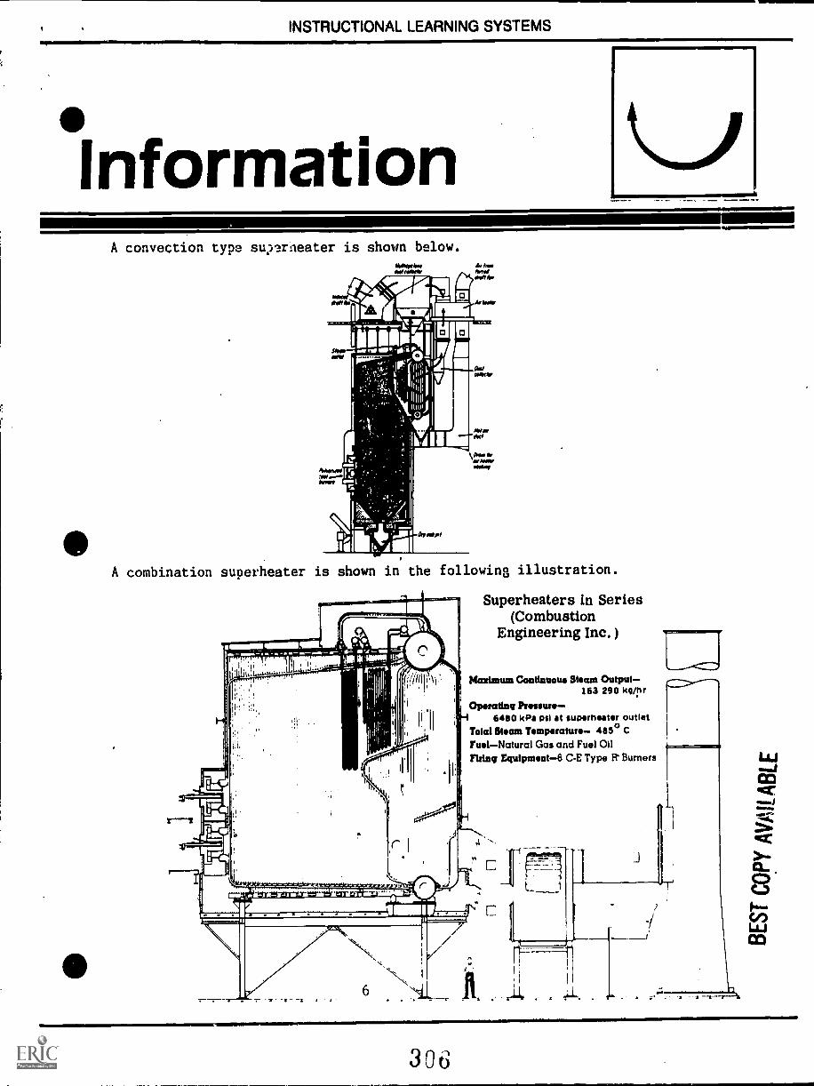
INSTRUCTIONAL LEARNING SYSTEMS
°InformationA convection type suyaraeater is shown below.
A combination superheater is shown in the following illustration.
Superheaters in Series(Combustion
Engineering Inc. )
Maximum Continuous Steam Output-163 290 kg/hr
Operating Pressure-6460 kPa psi at superheater outlet
Total Steam Temperature 465° CFuelNatural Gas and Fuel OilMing Equipment -6 CE Type R Burners
306
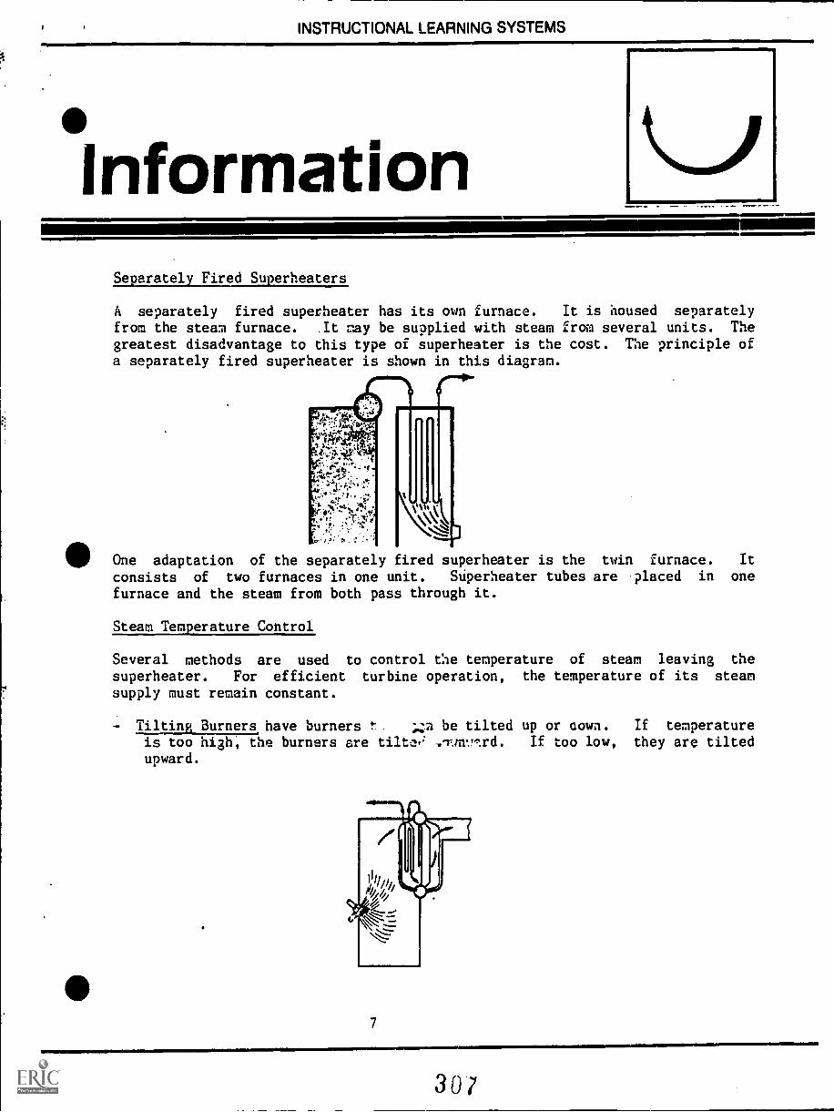
INSTRUCTIONAL LEARNING SYSTEMS
°InformationSeparately Fired Superheaters
A separately fired superheater has its own furnace. It is housed separatelyfrom the steam furnace. .It ray be supplied with steam from several units. Thegreatest disadvantage to this type of superheater is the cost. The principle ofa separately fired superheater is shown in this diagram.
One adaptation of the separately fired superheater is the twin furnace. It
consists of two furnaces in one unit. Superheater tubes are placed in one
furnace and the steam from both pass through it.
Steam Temperature Control
Several methods are used to control the temperature of steam leaving the
superheater. For efficient turbine operation, the temperature of its steam
supply must remain constant.
- Tilting Burners have burners t be tilted up or aown. If temperatureis too high, the burners are tilta, .-rtny.,:rd. If too low, they are tiltedupward.
7
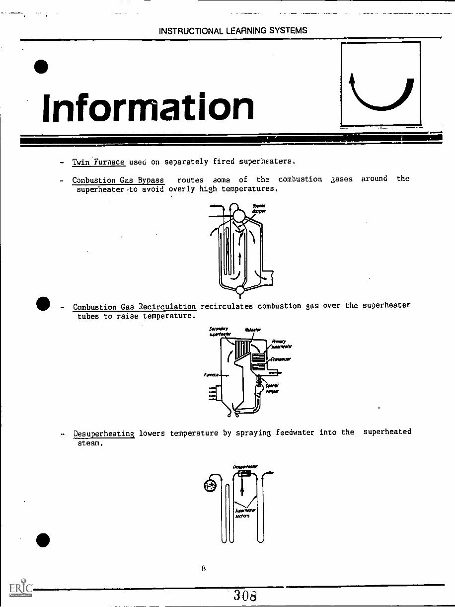
INSTRUCTIONAL LEARNING SYSTEMS
nformation
O'
IIIMMIll==,
- Twin Furnace used on separately fired superheaters.
- Combustion Gas Bypass routes some of the combustion gases around the
superheater to avoid overly high temperatures.
III-Combustion Gas Recirculation recirculates combustion gas over the superheater
tubes to raise temperature.
- Desuperheating lowers temperature by spraying feedwater into the superheated
steam.
8
3081111Mli
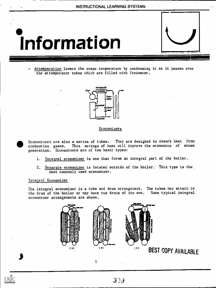
INSTRUCTIONAL LEARNING SYSTEMS
Information- Attemperation lowers the steam temperature by condensing it as it passes over
the attemperator tubes which are filled with feedwater.
onoroffefof
N.
Economizers
EconomizerB are also a series of tubes. They are designed to absorb heat from
combustion gases. This savings of heat will improve the economics of steam
generation. Economizers are of two basic types:
Integral economizer is one that forms an integral part of the boiler.
2. Separate economizer is located outside of the boiler. This type is the
most commonly used economizer.
Intecral Economizer
The integral economizer is a tube and drum arrangement. The tubes may attach to
the drum of the boiler or may have two drums of its own. Some typical integral
economizer arrangements are shown.
( A)
9
( I(c) BEST COPY AVAILABLE
3 '3
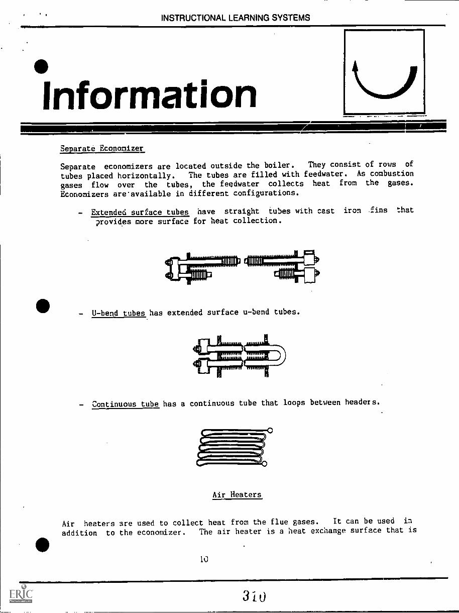
INSTRUCTIONAL LEARNING SYSTEMS
InformationSeparate Economizer
Separate economizers are located outside the boiler. They consist of rows of
tubes placed horizontally. The tubes are filled with feedwater. As combustion
gases flow over the tubes, the feedwater collects heat from the gases.
Economizers are'available in different configurations.
- Extended surface tubes have straight tubes with cast iron fins that
provides more surface for heat collection.
- U-bend tubes has extended surface u-bend tubes.
Continuous tube has a continuous tube that loops between headers.
Air Heaters
Air heaters are used to collect heat from the flue gases. It can be used in
addition to the economizer. The air heater is a heat exchange surface that is
10
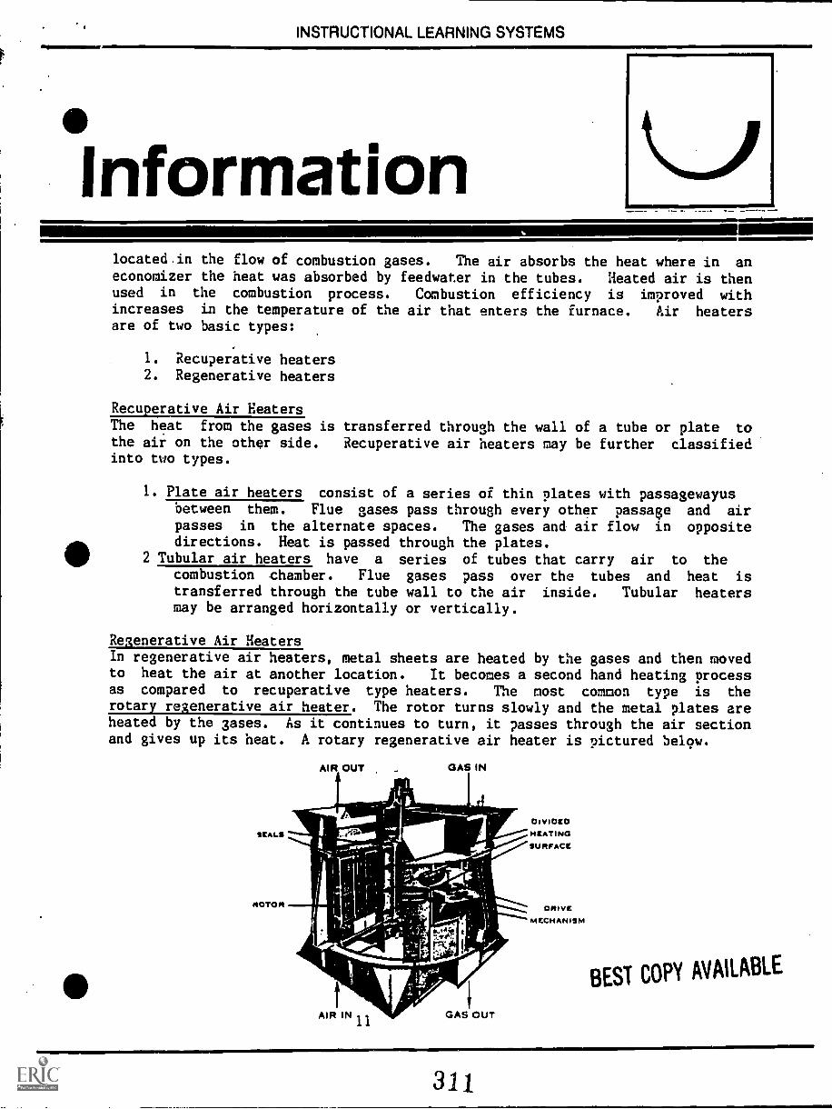
INSTRUCTIONAL LEARNING SYSTEMS
Informationlocated.in the flow of combustion gases. The air absorbs the heat where in aneconomizer the heat was absorbed by feedwater in the tubes. Heated air is thenused in the combustion process. Combustion efficiency is improved withincreases in the temperature of the air that enters the furnace. Air heatersare of two basic types:
1. Recuperative heaters2. Regenerative heaters
Recuperative Air HeatersThe heat from the gases is transferred through the wall of a tube or plate tothe air on the other side. Recuperative air heaters may be further classifiedinto two types.
1. Plate air heaters consist of a series of thin plates with passagewayusbetween them. Flue gases pass through every other passage and airpasses in the alternate spaces. The gases and air flow in oppositedirections. Heat is passed through the plates.
2 Tubular air heaters have a series of tubes that carry air to thecombustion chamber. Flue gases pass over the tubes and heat istransferred through the tube wall to the air inside. Tubular heatersmay be arranged horizontally or vertically.
Regenerative Air HeatersIn regenerative air heaters, metal sheets are heated by the gases and then movedto heat the air at another location. It becomes a second hand heating processas compared to recuperative type heaters. The most common type is therotary regenerative air heater. The rotor turns slowly and the metal plates areheated by the gases. As it continues to turn, it passes through the air sectionand gives up its heat. A rotary regenerative air heater is pictured bel9w.
AIR OUT GAS IN
AIR IN
_JEW---004111MEW
GAS OUT
DIVIDEDHEATINGSUPHrACE
ONIVEMECHANISM
BEST COPY AVAILABLE
111,311

INSTRUCTIONAL LEARNING SYSTEMS
Assignment.1MIMEMW
* Read pages 18-38 in the supplementary reference.
* Complete job sheet.
* Complete self-assessment and check answers.
* Complete post-assessment and ask the instructor to check your answers.
12
312
INSTRUCTIONAL LEARNING SYSTEMS
°Job Sheet11=.
INSPECT A HEAT RECOVERY SYSTEH
Locate a steam generation plant that has a modern heat recovery system.
Ask permission to visit the facility.
Observe the heat recovery system and ask questions of operator.
- Does it have a superheater?
- Is the superheater of the integral type or separately fired?
- Is it a convection, radiant or combination type superheater?
Does it use tilting burners, twin furnaces, combustion gas bypass,combustion gas recirculation, desuperheating, attemperation or other methodsof temperature control?
Is the economizer of the integral or separate type? How is it made?
Are the air heaters recuperative or regenerative types?
13
313
INSTRUCTIONAL LEARNING SYSTEMS
.SelfAssessment
AMINNII=k
Match the following terms with the phrases by writing the proper letters .into
the blanks beside the numbers.
1. Economizers A.
2. Reheaters B.
3. Convection type superheater C.
4. Saturated steam D.
5.. Separately fired
superheater
E.
6. Dry steam F.
7. Radiant superheater G.
H.
8. Tilting burnersI.
9. Combination superheater
10. Recuperative J.
14
Exposed to the radiant heat
of the furnace.
Steam with moisture removedby superheating.
Partially exposed and partiallyshielded from the radiant heat
of the furnace.
Reheats steam that is returnedfrom the turbine.
Absorbs heat from combustiongases into feedwater filled
tubes.
Shielded from radiant heat of
the furnace.
Type of air heater.
Steam that contains moisture.
Method for controlling temper-ature of steam that leaves
the superheater.
Superheater has its own furnaceseparate from the steam gener-
ation furnace.
314
INSTRUCTIONAL LEARNING SYSTEMS
Self AssessmentAnswers
E 1.
D 2.
F 3.
H 4.
J 5.
B 6.
A 7.
I. 8.
C 9.
G 10.
INSTRUCTIONAL LEARNING SYSTEMS
,PostAssessment
1. U-bend tubes are often found in
2, An
3,
plate or tube.
101...1WlN
economizer is formed as a part of the boiler.
air heaters transfer heat through the walls of a
4. air heaters move metal sheets through combustion
gases for collecting heat and then rotate to a fresh air stream to deposit
heat.
5. A rotary air heater is an example of a air heater.
1116, superheaters are shielded from the radiant heat
of the furnace.
7. superheaters are exposed to the radiant heat of the
furnace.
8. One adaptation of the separately fired superheater is the
9. is the spraying of feedwater into superheated steam
to lower its temperature.
10. Extended surface tubes are a type of tube that is found in
15
316
I fo INSTRUCTIONAL LEARNING SYSTEMS
InstructorPost AssessmentAnswers
1. Economizers
2. Integral.
3. Recuperative
4. Regenerative
5. Regenerative
6. Convection
7. Radiant
8. Twin furnace
9. Desuperheating
10. Economizers
17
INSTRUCTIONAL LEARNING SYSTEMS
SupplementaryReferences
* Correspondence Study. Lecture 3, Section 3, Third Class. Steam Generation.
Southern Alberta Institute of Technology. Calgary, Alberta, Canada.
18
318
SOUTHERN ALBERTA INSTITUTE ON' I'ECHNOLOGYCALGARY, ALBERTA
SECTION 3
STEAM GENERATION
Correspondence CoursesPower Engineering
BOILER DETAILS
FOUNDATIONS AND SUPPORTS
Third ClassLecture 3
Every boiler must be supported by a good foundation in order toavoid any movement due to settling which would result in extra stressin the connecting pipework. In addition, if the boiler is of the typewhich requires a brick setting, then any movement usually resultsin cracking of the brickwork. Another undesirable result of boilersettlement is that the gage glass will not give an accurate indicationof water level within the boiler.
In the case of a small boiler of the packaged type, the boilerroom floor is usually strong enough to serve as the boiler foundation.The packaged boiler is supplied already mounted on a steel base whichsupports the entire mass of the unit. This steel base is usually groutedinto place on the boiler room floor. The term "grouted" refers to thepractice of pouring a thin mixture of concrete around and within thebase of the unit.
Fig. 1 shows the structural steel base of a "D" type packagedwatertube boiler being assembled in the manufacturer's shop.
Fig. 2 shows a complete packaged boiler installed in a plant withthe steel base grouted into place.
313
12.';
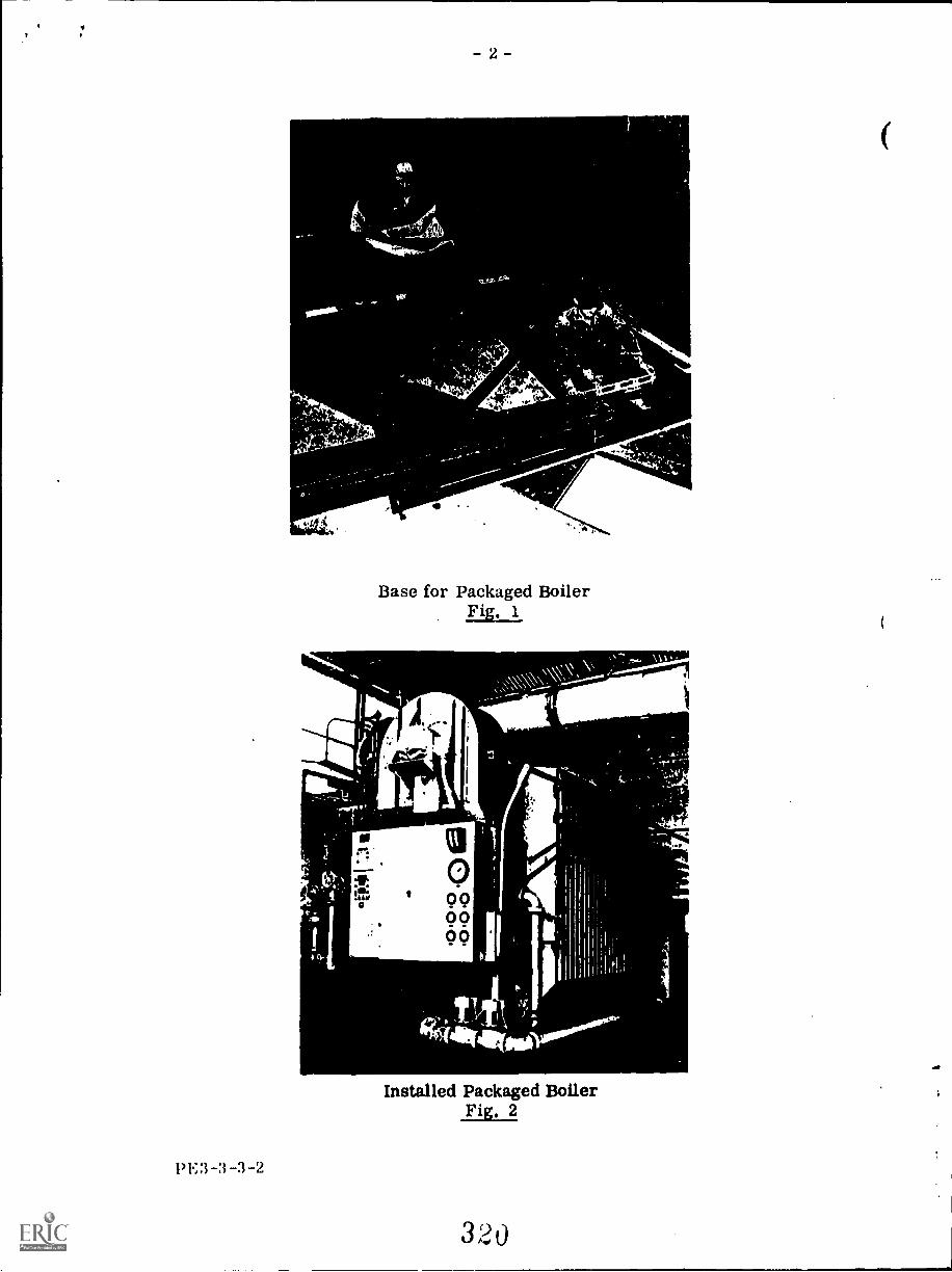
- 2-
oft 4 _lilt
:4tBase for Packaged Boiler
Fig. 1
Installed Packaged BoilerFig. 2
PE3-3-3-2
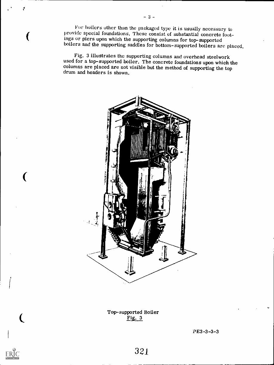
4I
(
(
(
3 -
For boilers other than the packaged type it is usually necessary toprovide special foundations. These consist of substantial concrete foot-ings or piers upon which the supporting columns for top-supportedboilers and the supporting saddles for bottom-supported boilers are placed.
Fig. 3 illustrates the supporting columns and overhead steelworkused for a top-supported boiler. The concrete foundations upon which thecolumns are placed are not visible but the method of supporting the topdrum and headers is shown.
Top-supported BoilerFig. 3
PE3-3-3-3
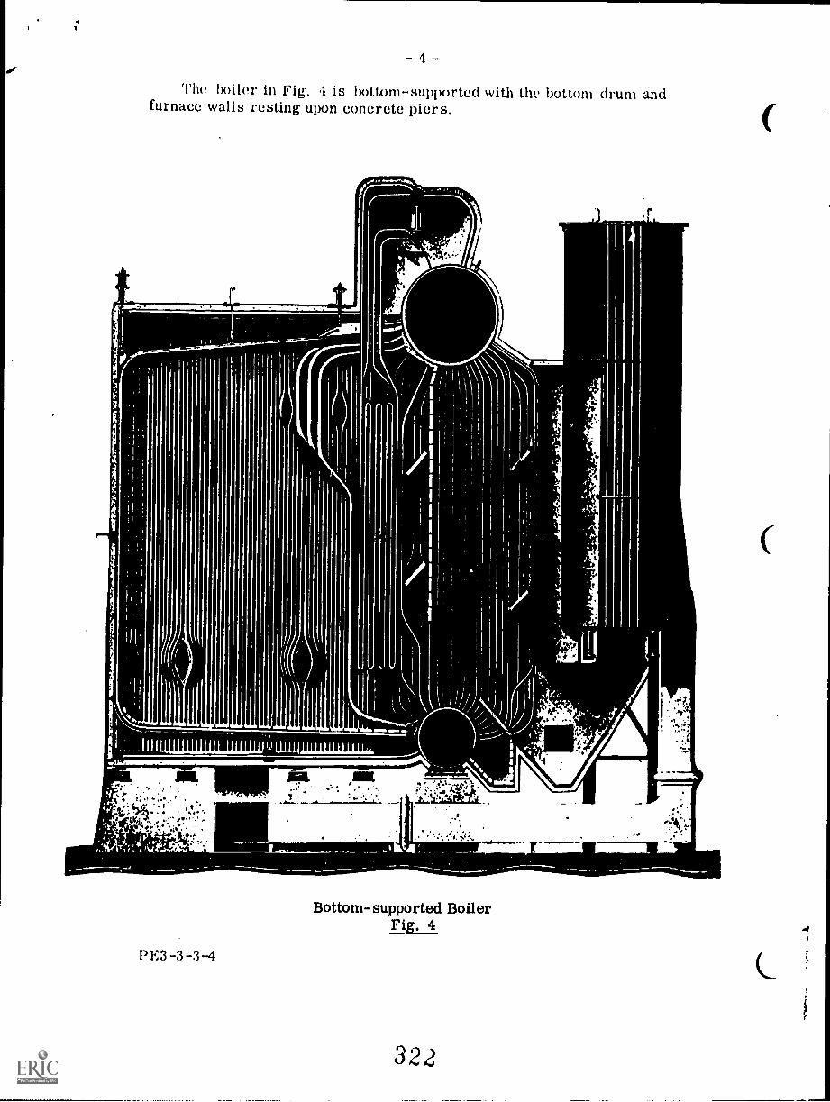
1- 4 -
The boiler in Fig. 4 is bottom-supported with the bottom drum andfurnace walls resting upon concrete piers.
13 F.3 -3 -3-4
Bottom-supported BoilerFig. 4
322
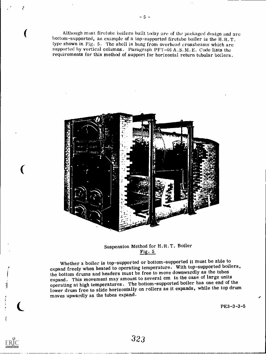
5 -
Although most firetube boilers built today are of the packaged design and arebottom-supported, an example of a top-supported firetube boiler is the 11,R.T.type shown in Fig. 5. The shell is hung from overhead crossbeams which aresupported by vertical columns. Paragraph PFT-46 A.S, M. E. Code lists therequirements for this method of support for horizontal return tubular boilers.
11
t.
T..r" , 4 411
"VA
1.- -2L2.40111111P
Suspension Method for H.R. T. BoilerFig. 5
Whether a boiler is top-supported or bottom-supported it must be able toexpand freely when heated to operating temperature. With top-supported boilers,the bottom drums and headers must be free to move downwardly as the tubesexpand. This movement may amount to several cm in the case of large unitsoperating at high temperatures. The bottom-supported boiler has one end of thelower drum free to slide horizontally on rollers as it expands, while the top drummoves upwardly as the tubes expand.
323
- 6
SETTINGS
The term setting usually is taken to mean the brickwork structure thatencloses the furnace and pressure parts of the boiler and which forms apassage through which the combustion gases flow, It must be able to with-stand high temperatures and prevent the escape of heat from the furnace tothe boiler room. In addition it must prevent the leakage of gas from, andair into, the furnace. As mentioned in the previous section, it occasionallyserves to support some types of boilers.
Internally fired firetube boilers such as the packaged types, locomotivetype, and firebox type, have the furnace contained within the shell or sur-rounded by a water-leg extension of the shell. As a result they do not requirea brickwork setting,
An externally-fired firetube boiler, such as the H. T , has the furnaceexternal to the shell and therefore requires furnace walls of brickwork,
Watertube boilers also require some type of setting around the furnace.Usually these furnace walls are the waterwall type wherein the boiler tubesare arranged to form the enclosure. Sometimes a brick and tube wall isused consisting of brickwork lined with tubes spaced a few inches apart. Somesmall watertube boilers use only brickwork to form the furnace enclosure.
Brickwork Settings
Brickwork settings are of either of two types, namely, the solid walltype or the sectionally-supported wall type .
The solid wall type may be constructed entirely of firebrick, see Fig. 5,or in some cases with only the inner lining of firebrick and the outer part ofred brick. Firebrick is made from clays which have the property of resist-ing high temperatures without fusing. These special clays are known as fireclays and the products from these clays are known by the general termrefractories. The constituents of fire clay are mainly silica and aluminawith small amounts of various oxides and alkalies.
Frequently, instead of using individual firebricks to make up the innerlining of the setting wall, a plastic form of fireclay is used. This is a softputty-like substance and is hammered into place to make a continuous liningwithout joints. Another form of refractory is the castable type which issupplied as a dry powder that can be mixed with water and poured into placelike concrete.
Fig, 6 shows a solid wall type of brickwork setting with the lower partof the inner lining made of plastic refractory (the dotted section). The liningabove the plastic refractory is made of castable refractory.
PE3-3-3-6
324
C
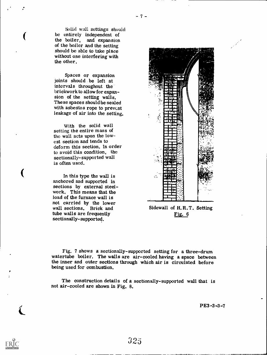
- 7
Solid wall settings shouldbe entirely independent ofthe boiler, and expansionof the boiler and the settingshould be able to take placewithout one interfering withthe other.
Spaces or expansionjoints should be left atintervals throughout thebrickwork to allow for expan-sion of the setting walls.These spaces should be sealedwith asbestos rope to preventleakage of air into the setting.
With the solid wallsetting the entire mass ofthe wall acts upon the low-est section and tends todeform this section. In orderto avoid this condition, thesectionally-supported wallis often used.
In this type the wall isanchored and supported insections by external steel-work. This means that theload of the furnace wall isnot carried by the lowerwall sections. Brick andtube walls are frequentlysectionally-supported.
t c7,3.133
:41 salMAI,MA arraWE MI ENle IL' MIED MP MENM at1111 Ural
IIII miloit
III Ili nuNM 01
IMININMB IN III
NMNOM MIMI MN1191 III sm.
IIIII NMIC IR PMWM WI115 RIM!AMU
min rON UriICStrt 4.1
gialra21MI MIMIEll OS UN
MI in HO..MI MNal MIN
IM
Sidewall of H. R. T. SettingFig. 6
Fig. 7 shows a sectionally-supported setting for a three-drumwatertube boiler. The walls are air-cooled having a space betweenthe inner and outer sections through which air is circulated beforebeing used for combustion.
The construction details of a sectionally-supported wall that isnot air-cooled are shown in Fig. 8.
PE3-3-3-7
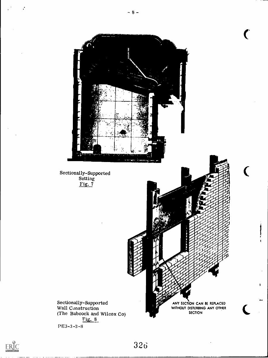
.
yf
e
...
-9
Water-Cooled Settings
Water-cooled settings, wherein the furnace walls are lined withtubes, are more suitable for large steam generators than are brick-work settings, due to the following reasons:
1. Because of the great height of the large steam generator,the mass on the lower portions of a solid brick settingwould be excessive.
2. Furnace temperatures are too high for the brickwork toendure.
3. The brickwork will not stand up to erosion from ashparticles and slagging encountered in pulverized fuelfurnaces.
4. Greater heat absorption is obtained by circulating boilerwater through the furnace wall tubes which are exposed tothe high temperature of the furnace.
5. Relative movement of boiler and setting due to expansionis a serious problem with a brickwork setting.
Water-cooling of the furnace is obtained in firetube boilers ofthe internally-fired type. In the Scotch type packaged boiler thefurnace is contained within the shell and the firebox type of boilerfrequently has the furnace surrounded by a water leg.
In the watertube boiler, water-cooling of the furnace isachieved by arranging tubes to form all or part of the furnacewalls. Various types of construction are used and some of theseare illustrated and described as follows.
PE3-3-3-9
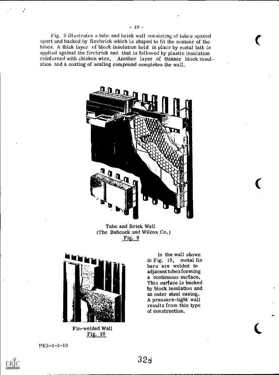
10
Fig. 9 illustrates a tube and brick wall consisting of tubes spacedapart and backed by firebrick which is shaped to fit the contour of thetubes. A thick layer of block insulation held in place by metal lath isapplied against the firebrick and that is followed by plastic insulationreinforced with chicken wire. Another layer of thinner block insul-ation and a coating of sealing compound completes the wall.
ti
Tube and Brick Wall(Th9 Babcock and Wilcox Co.)
Fig. 9
.14111INThanizir... MI
tr.
Fin-welded WallFig. 10
13E3 -3 -3 -10
"lb
11
Ij
In the wall shownin Fig. 10, metal finbars are welded toadjacent tubes forminga continuous surface.This surface is backedby block insulation andan outer steel casing.A pressure-tight wallresults from this typeof construction.
328
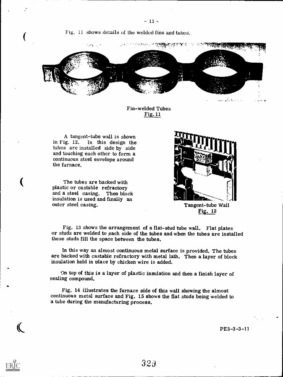
- 11 -
Fig. 11 shows details of the welded fins and tubes.
74- 4&_,
I tri, '!
N144,
ti"
.17 , ,V-1.4111.1"-
Fin-welded TubesFig. 11
A tangent-tube wall is shownin Fig. 12. In this design thetubes are installed side by sideand touching each other to form acontinuous steel envelope aroundthe furnace.
The tubes are backed withplastic or castable refractoryand a steel casing. Then blockinsulation is used and finally anouter steel casing.
. .4 IN
Tangent-tube WallFig. 12
Fig. 13 shows the arrangement of a flat-stud tube wall. Flat platesor studs are welded to each side of the tubes and when the tubes are installedthese studs fill the space between the tubes.
In this way an almost continuous metal surface is provided. The tubesare backed with castable refractory with metal lath. Then a layer of blockinsulation held in place by chicken wire is added.
On top of this is a layer of plastic insulation and then a finish layer ofsealing compound.
Fig. 14 illustrates the furnace side of this wall showing the almostcontinuous metal surface and Fig. 15 shows the flat studs being welded toa tube during the manufacturing process.
PE3-3-3-11
323
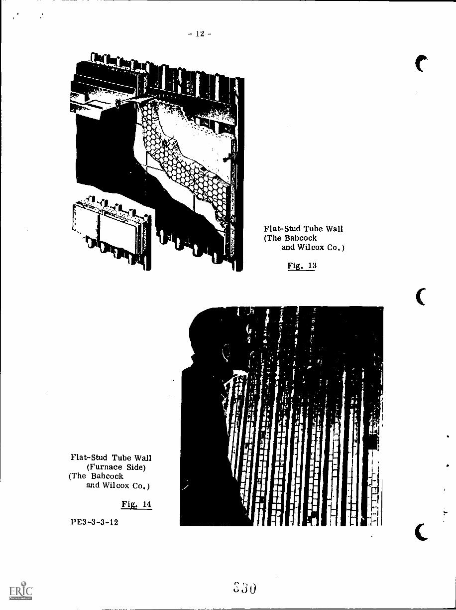
:-
UN
II
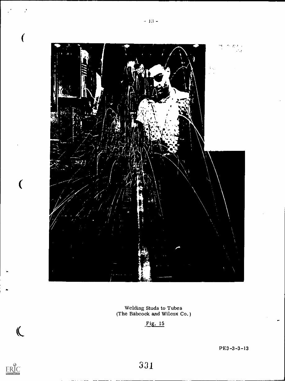
4
*
6
Welding Studs to Tubes(The Babcock and Wilcox Co. )
Fig. 15
331_
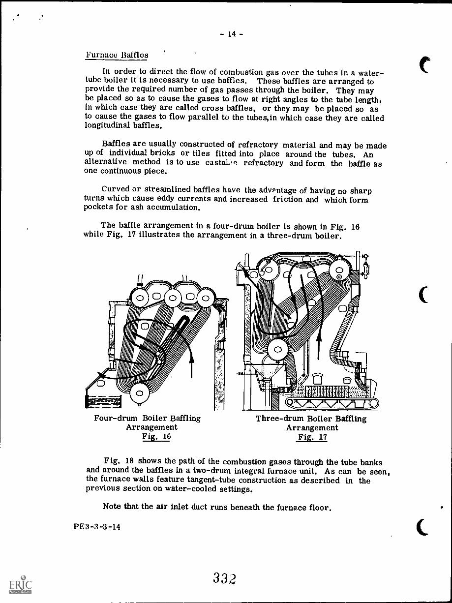
- 14 -
Furnace Baffles
In order to direct the flow of combustion gas over the tubes in a water-tube boiler it is necessary to use baffles. These baffles are arranged toprovide the required number of gas passes through the boiler. They maybe placed so as to cause the gases to flow at right angles to the tube length,in which case they are called cross baffles, or they may be placed so asto cause the gases to flow parallel to the tubes,in which case they are calledlongitudinal baffles.
Baffles are usually constructed of refractory material and may be madeup of individual bricks or tiles fitted into place around the tubes. Analternative method is to use castaL,c; refractory and form the baffle asone continuous piece.
Curved or streamlined baffles have the advantage of having no sharpturns which cause eddy currents and increased friction and which formpockets for ash accumulation.
The baffle arrangement in a four-drum boiler is shown in Fig. 16while Fig. 17 illustrates the arrangement in a three-drum boiler.
Four-drum Boiler BafflingArrangement
Fig. 16
Three-drum Boiler BafflingArrangement
Fig. 17
Fig. 18 shows the path of the combustion gases through the tube banksand around the baffles in a two-drum integral furnace unit. As can be seen,the furnace walls feature tangent-tube construction as described in theprevious section on water-cooled settings.
Note that the air inlet duct runs beneath the furnace floor.
PE3-3-3-14
332
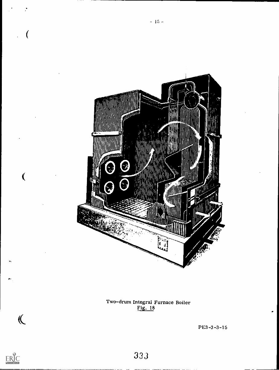
Ir---------------nd -
---
1
\,
a,\
C-
It- ------..,
$f- 11 IL
V 1 k
*,4
..-
I
;Cs
1'1
;}te:*ty
,,
C.II
1_--
k
i
r"----__-Y
'
,..m...,
/
-,-4:--
-
4.-
k'.'c,'.1
MP
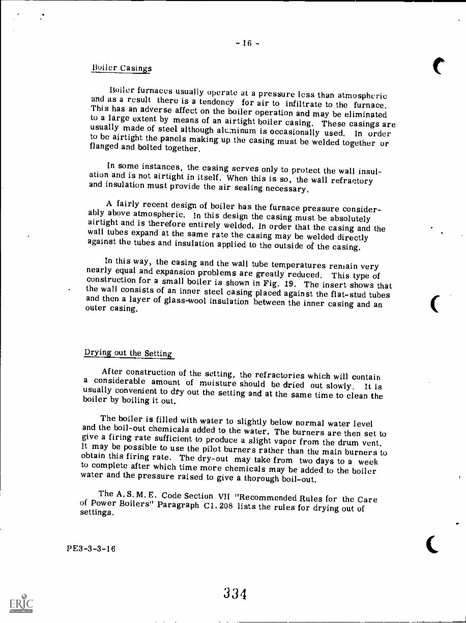
- 16 -
Boiler Casings
Boiler furnaces usually operate at a pressure less than atmosphericand as a result there is a tendency for air to infiltrate to the furnace.This has an adverse affect on the boiler operation and may be eliminatedto a large extent by means of an airtight boiler casing. These casings areusually made of steel although alt:minum is occasionally used, In orderto be airtight the panels making up the casing must be welded together orflanged and bolted together.
In some instances, the casing serves only to protect the wall insul-ation and is not airtight in itself. When this is so, the wall refractoryand insulation must provide the air sealing necessary.
A fairly recent design of boiler has the furnace pressure consider-ably above atmospheric, In this design the casing must be absolutelyairtight and is therefore entirely welded. In order that the casing and thewall tubes expand at the same rate the casing may be welded directlyagainst the tubes and insulation applied to the outside of the casing.
In this way, the casing and the wall tube temperatures remain verynearly equal and expansion problems are greatly reduced, This type ofconstruction for a small boiler is shown in Fig. 19. The insert shows thatthe wall consists of an inner steel casing placed against the flat-stud tubesand then a layer of glass-wool insulation between the inner casing and anouter casing,
Drying out the Setting
After construction of the setting, the refractories which will containa considerable amount of moisture should be dried out slowly. It isusually convenient to dty out the setting and at the same time to clean theboiler by boiling it out.
The boiler is filled with water to slightly below normal water leveland the boil-out chemicals added to the water. The burners are then set togive a firing rate sufficient to produce a slight vapor from the drum vent.It may be possible to use the pilot burners rather than the main burners toobtain this firing rate. The dry-out may take from two days to a weekto complete after which time more chemicals may be added to the boilerwater and the pressure raised to give a thorough boil-out.
The A. S. M. E. Code Section VII "Recommended Rules for the Careof Power Boilers" Paragraph C1.208 lists the rules for drying out ofsettings.
PE3- 3 -3 -16
334
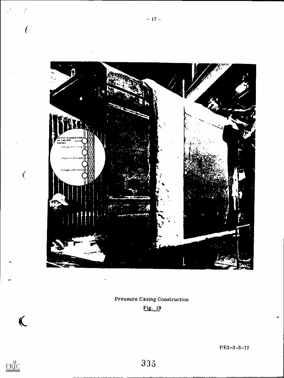
0 MM Iltidded IUMSon 1 00 mmCOMMIS
.10 j v. r 1 '
o. 1 1111.1 *nal
gJgr Jule, 4%01
11S
SSS
rk
17 -
, ti
"
,e1 dne1.1411monnn,-.
4.
C
ir/
Pressure Casing ConstructionFig. 19
335
et
.37,""
S.
Y
S.
.10
PE3-3-3-17
ti
- 18 -
SUPERHEATERS AND REHEATERS
Superheaters and reheaters arc similar both in their generalconstruction and in their purpose, They both are made up of numeroustubes through which steam is passed. Combustion gases from thefurnace pass over the outside of these tubes and the temperature ofthe steam is thus increased. This increase in steam temperature isthe purpose of both the superheater and the reheater.
Steam produced from water in a boiler is at saturation temperatureand usually contains a certain amount of moisture (see Lecture 6,Section 1). If this steam is passed through a superheater, any moisturepresent will be evaporated and then the temperature of the now drysteam will be increased.
The increased temperature of the steam means increased energyper kg of steam and therefore the ability to do more work per kg. Inaudition, the increase in steam temperature means the steam will notcondense as readily and therefore the amount of moisture contained inthe steam after expanding through a turbine is greatly reduced. This isa great advantage as moisture in the steam rapidly erodes turbine bladesand also reduces turbine efficiency.
In a steam generating unit having both a superheater and a reheater,the steam is first superheated in the superheater. The steam is thenled to a turbine where it expands through the high pressure stages andin so doing drops in temperature, It is then brought back to the reheatersection of the steam generating unit and superheated once again. Then itis led back to the turbine and expanded through the remaining turbinestages.
The reheater can be considered as essentially a superheater andtherefore will not be discussed separately in detail in this lecture.
Superheaters may be classed as either the integral type or the sep-arately-fired type. The integral superheater is so called because it iscontained within the boiler setting and is an integral part of the boiler orsteam generator. The separately-fired superheater is located in a furnaceseparate from the main steam generator and is independent of the steamgenerator operating conditions.
Integral Superheaters
Integral superheaters are classed according to their location withinthe boiler setting.
If the superheater is shielded from the radiant heat of the furnace andis located within the path of the hot combustion gases from the furnace thenit is classed as a convection superheater,
PE3-3-3-18
336
1;
Or'
-19 -
If the superheater is exposed to the radiant heat of the furnace thenit is classci as a radiant superheater,
A combination superheater has a section exposed to the radiant heatof the furnace, and a section located away from the radiant heat but inthe hot combustion gas path.
The convection superheater has a rising steam temperature character-istic which means that the superheated steam temperature will rise as thefiring rate or boiler output increases. At low loads the steam temperaturewill be low and at high loads the steam temperature will be high, Thereason for this is that at high loads, although there is an increase insteam flow through the superheater, there is also an increase in combus-tion gas flow and combustion gas temperature due to the higher firingrate and this causes a rise in the steam temperature,
The radiant superheater, on the other hand, has a falling steamtemperature characteristic which means that the superheated steamtemperature will be high at low loads and will drop as the load increases.This is because the furnace temperature does not increase as rapidly asthe steam flow does on a load increase.
The steam gene23 has a pendent typsection located in thcombustion gasesthe radiant heat of tsuperheater tubes.
oerheater combines the characteristics of the. .
BOILER FURNACE
The superheatcdivided into two seadjacent to the relivradiant pendent typsection a horizontatype located just abJom izer.
7
762 mm WATER DRUM
EXHAUSTER
400.1
I FEEDER
ta.3.44 ? ealiVaX4
I I I
IL-
This unit has a capacity ofover 454 000 kg of steam per hourand steam temperature is 566° Creheated to 538° C.
iPULVERIZER../
......-.......o,i
l rECONOMIZER
koe 1/
Reheat Steam GeneratorFig. 23
3 3 7
A
-.1.-.1\ 111
PE3-3-3-21
BEST COPY AVAILABLE
- 20 -
Himl WI1 1 On e
linilliffillUPPHINIMMIMEC1/11110111111/111/111/1
//2gi
--...leimilligiglillill
Mu
;1;111i:1 In: ;;;;CorrdAnauum Type
Ili; ;;l'MIER
ril i i
Ellmit i i':;
: i. i MEiire
ill::ffili::::::11:11:::111/11iiiiiiiiir
E: iliii:iiilliitriiiihhhitiwilimipmpri
.. EiliWilii1111111111111111 IIIIIIIIIiiiii...OA.... aI MP Orive:150r1ITpet :1 i
41 my11401111:::1
.:: : : ;
'f!!
::,, ; :: :
:II: :;:11:1110,1: t.t:
i 1,i : u: ti, 1:-::: :!!...
1OW'SPWife....
I ::;i .e .;; tt:; :;;;:::,
;t:: .11::i:uguhol
14:.., tll. ;
-. r 1
1111
i. ..0.
1111111111 r.:: '
4t.
:!
:: :.1.
MENEM4
...:"
RaAta01
-."."11111L
Type
11111.1.4 t.f. ...4
40 50 60 70 80 90
Steam Output, PercentSuperheater Characteristic Curves
Fig, 20
336
100
21
The steam generator shown inFig. 22 uses a convection superheateronly. The superheater tubes aresuspended (pendent type) in the gaspath from inlet and outlet headers.
With this arrangement the steamtemperature will tend to be high athigh loads and some means of reduc-ing this temperature must beemployed. Various methods maybe used and these will be men-tioned in a later section.
A steam generator employinga reheater may have the reheatersection located in the furnaceproper where it will receive rad-iant heit or it may be located awayfrom the radiant heat of the furnacein which ease it receives itrheat by convection.
The steam gene23 has a pendent tyksection located in thicombustion gases anthe radiant heat of tisuperheater tubes.
The superheatdivided into two se,adjacent to the rehradiant pendent tysection a horizonttype located just. above me econ-omizer.
This unit has a capacity ofover 454 000 kg of steam per hourand steam temperature is 566° Creheated to 538° C.
Reheat Steam GeneratorFig. 23 ,
I 'IFURNACE 1E2ONCMIZER
1/4.
L4
33j
PE3-3-3-21
BEST COPY AVAILABLE
- 22 -
perheat.er section is contained withinthe steam generating furnace. The
)urners and its firing rate may be varied,nds without affecting the steam generating:.ly fired superheater may be suppliedam generating units.
is usually limited to special industrialrolled and very high steam tempera-
)erheater the separately-fired arrange-These are higher first cost, lower
space requirements. It does, however,ature control than the integral type.
rately-fired superheater arrangement
An adaptation of the separately-fired superheater is shown in Fig. 25.This is called a twin furnace unit, differentially fired. It consists of twosteam generating furnaces incorporated into one unit. One of these fur-naces contains superheater tubes in addition to steam generating tubeswhile the other furnace has only steam generating tubes.
By varying the firing rate of each individual furnace the steam temp-erature may be controlled independently of the saturated steam generated.The unit shown has four pulverized coal burners located in the roof of eachfurnace. Each furnace has water-cooled walls made up of steam generatingtubes.
13E3-3-3-22
3 ,h)
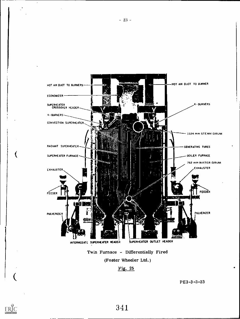
HOT AIR DUCT TO BURNERS
ECONOMIZER
SUPERHE ATERCROSSOVER HEADER
4- BURNERS
HOT AIR DUCT TO BURNER
CONVECTION SUPERHEATER,,,
RADIANT SUPERHEATER
SUPERHEATER FURNACE
EXHAUSTER
cir
FEEDER
PULVERIZER
4 - BURNERS
1524 mm STEAM DRUM
GENERATING TUBES
BOILER FURNACE
762 mm WATER DRUM
INTERMEDIATE SUPERHEATER HEADE4 SUPERHEATER OUTLET HEADER
Twin Furnace - Differentially Fired
(Foster Wheeler Ltd.)
Fig. 25
EXHAUSTER
I I FEEDER
PULVERIZER
I
PE3-3-3-23
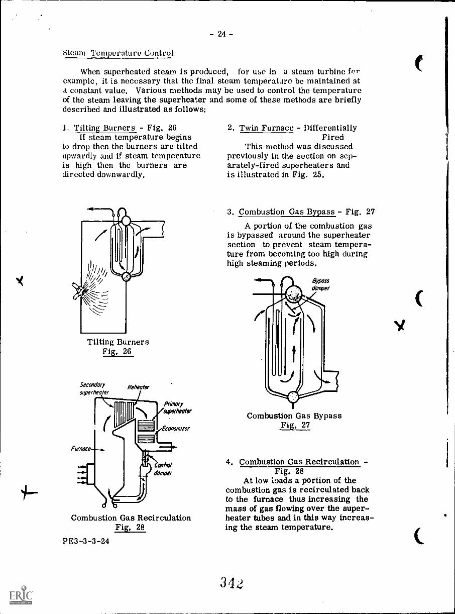
- 24 -
Steam Temperature Control
When superheated steam is produced, for use in a steam turbine fr,rexample, it is necessary that the final steam temperature be maintained ata constant value. Various methods may be used to control the temperatureof the steam leaving the superheater and some of these methods are brieflydescribed and illustrated as follows:
1. Tilting Burners - Fig. 2GIf steam temperature begins
to drop then the burners are tiltedupwardly and if steam temperatureis high then the burners aredirected downwardly.
Tilting BurnersFig. 26
Secondarysuperheater
Furnace
Reheats/
Primarysuperheater
conomaer
Contra/damper
Combustion Gas RecirculationFig. 28
PE3-3-3-24
2. Twin Furnace - DifferentiallyFired
This method was discussedpreviously in the section on sep-arately-fired superheaters andis illustrated in Fig. 25.
3. Combustion Gas Bypass - Fig. 27A portion of the combustion gas
is bypassed around the superheatersection to prevent steam tempera-ture from becoming too high duringhigh steaming periods.
Combustion Gas BypassFig. 27
4. Combustion Gas Recirculation -Fig. 28
At low loads a portion of thecombustion gas is recirculated backto the furnace thus increasing themass of gas flowing over the super-heater tubes and in this way increas-ing the steam temperature.
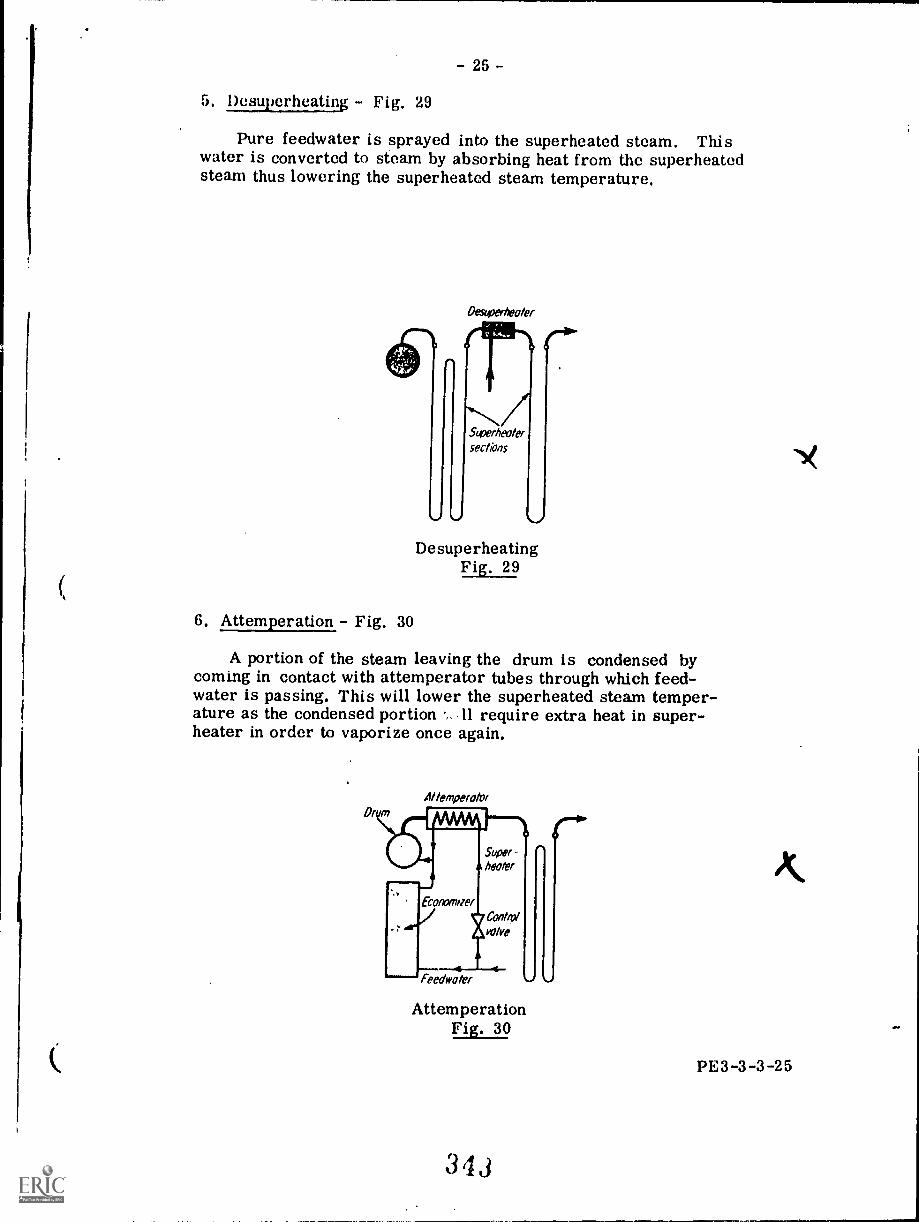
- 25 -
5. Desuperheating - Fig. 29
Pure feedwater is sprayed into the superheated steam. Thiswater is converted to steam by absorbing heat from the superheatedsteam thus lowering the superheated steam temperature.
OesuPerneoler
DesuperheatingFig. 29
6. Attemperation - Fig. 30
A portion of the steam leaving the drum is condensed bycoming in contact with attemperator tubes through which feed-water is passing. This will lower the superheated steam temper-ature as the condensed portion 11 require extra heat in super-heater in order to vaporize once again.
ArlemperotorDim
Super-twofer
ECommmet
Feedweler
Controlverve
AttemperationFig. 30
-
PE3-3-3-25
- 26 -
ECONOMIZERS
In order to obtain maximum economy in steam generator operationit is necessary to absorb the maximum amount of heat from the com-bustion gases, The amount of heat that can be absorbed by the steamgenerating tubes is limited by the temperature of the water within thesetubes,
For example, the temperature of the boiler water in the tubes ofa steam generator operating at 6000 kPa abs. is approximately 276° C(saturation temperature for 6000 kPa abs). Therefore these tubes willabsorb heat from the combustion gas only as long as the combustiongas temperature is above 276° C (heat only travels from the higher tem-perature substance). This means that the combustion gas leaving thesteam generator will be at a temperature greater than 2760 C and as aresult will still contain a great deal of heat.
In order to recover a portion of this heat, the combustion gases mayhe passed over a series of tubes through which feedwater travelling to theboiler is passing, This arrangement of tubes is called an economizer, Asthe temperature of the feedwater entering the economizer is comparativelylow (possibly around 90° C) there will be good heat absorption from thecombustion gases which may be at a temperature of 288° C or more.
Integral Economizers
The integral type is so-called because the economizer forms anintegral part of the boiler. It consists of vertical banks of tubes whichrun either between the boiler steam drum and an economizer water drumor between two economizer water drums. These tubes are usually locatedin the last combustion gas pass of the boiler.
Fig. 31(A) shows an integral economizer having two drums. Feed-water enters one side of the top divided drum and flows downwardly throughone-hail of the economizer tubes to the bottom drum. It then rises up theother half of the tubes to the top drum again and from there to the boilersteam drum.
In the economizer in Fig, 31(13) the water enters a bottom economizerdrum and flows upwardly through the economizer tubes to the boiler steamdrum.
Another two-drum integral economizer with a divided top drum isshown in Fig. 31(C). The feedwater flow in this type is similar to that inFig. 31(A).
PE3-3-3-26
344BEST COPY AVAILABLE
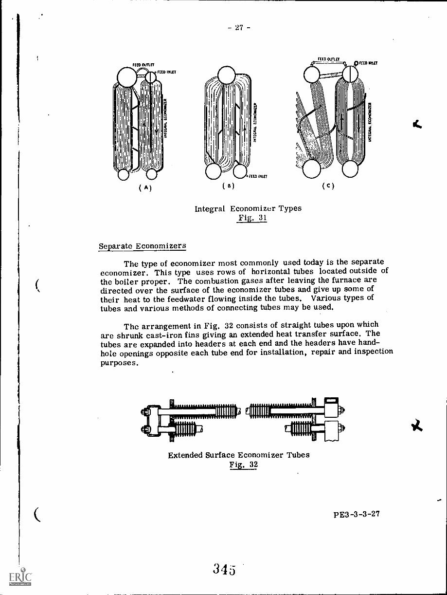
RED Ou
( A )
Separate Economizers
- 27 -
Integral Economizer TypesFig. 31
11(0 Olin ET
C)
MD NUT
The type of economizer most commonly used today is the separateeconomizer. This type uses rows of horizontal tubes located outside ofthe boiler proper. The combustion gases after leaving the furnace aredirected over the surface of the economizer tubes and give up some oftheir heat to the feedwater flowing inside the tubes. Various types oftubes and various methods of connecting tubes may be used.
The arrangement in Fig. 32 consists of straight tubes upon whichare shrunk cast-iron fins giving an extended heat transfer surface. Thetubes are expanded into headers at each end and the headers have hand-hole openings opposite each tube end for installation, repair and inspectionpurposes.
111111111 I a'A 11111111 Mniti
Extended Surface Economizer TubesEizz12
PE3-3-3-27
345
-28--
Fig, 33 illustrates another type of economizer which has extendedsurface U-bend tubes expanded into headers which have handholesprovided for tube installation and maintenance,
dor, ,,, of
VV.1,11 irm
U-bend Economizer TubesFig, 33
An economizer made up of continuous tubes looped between headersis shown in Fig. 34. Plain tubes without extended surfaces are used here.
Continuous Tube EconomizerFig. 34
Fig. 35 shows another continuous tube economizer showing use offinned tubes.
Most modern economizers feature horizontal continuous tube design.
PE3-3-3-28
Fin Tube EconomizerFig. 35
34G
- 29 -
The steam generator in Fig. 36 features a continuous tubeseparate economizer.
Single Drum Steam Generator
Fig. 36
PE3-3-3-29
- 30 -
Economizer Advantagesand Disadvantages
The greatest advantage of the economizer is increased boilerefficiency due to the fact that heat is recovered from the flue gasesthat would otherwise be lost up the stack or chimney, Another advan-tage of using an economizer is that there is less thermal shock to theboiler drum if the entering feedwater has been heated than if coldfeedwater was admitted to the drum.
The disadvantages of an economizer are as follows:
1, It provides increased resistance to flue-gas flow and there-fore increased fan power is required with an economizer.
2, Greater feedwater pumping is required as the economizerprovides increased resistance to feedwater flow,
3. Corrosion of both internal and external surfaces of theeconomizer may be a problem.
4. Both internal and external surfaces of the economizer mustbe kept clean to provide the increased efficiency.
PE3- 3 -3 -30
348
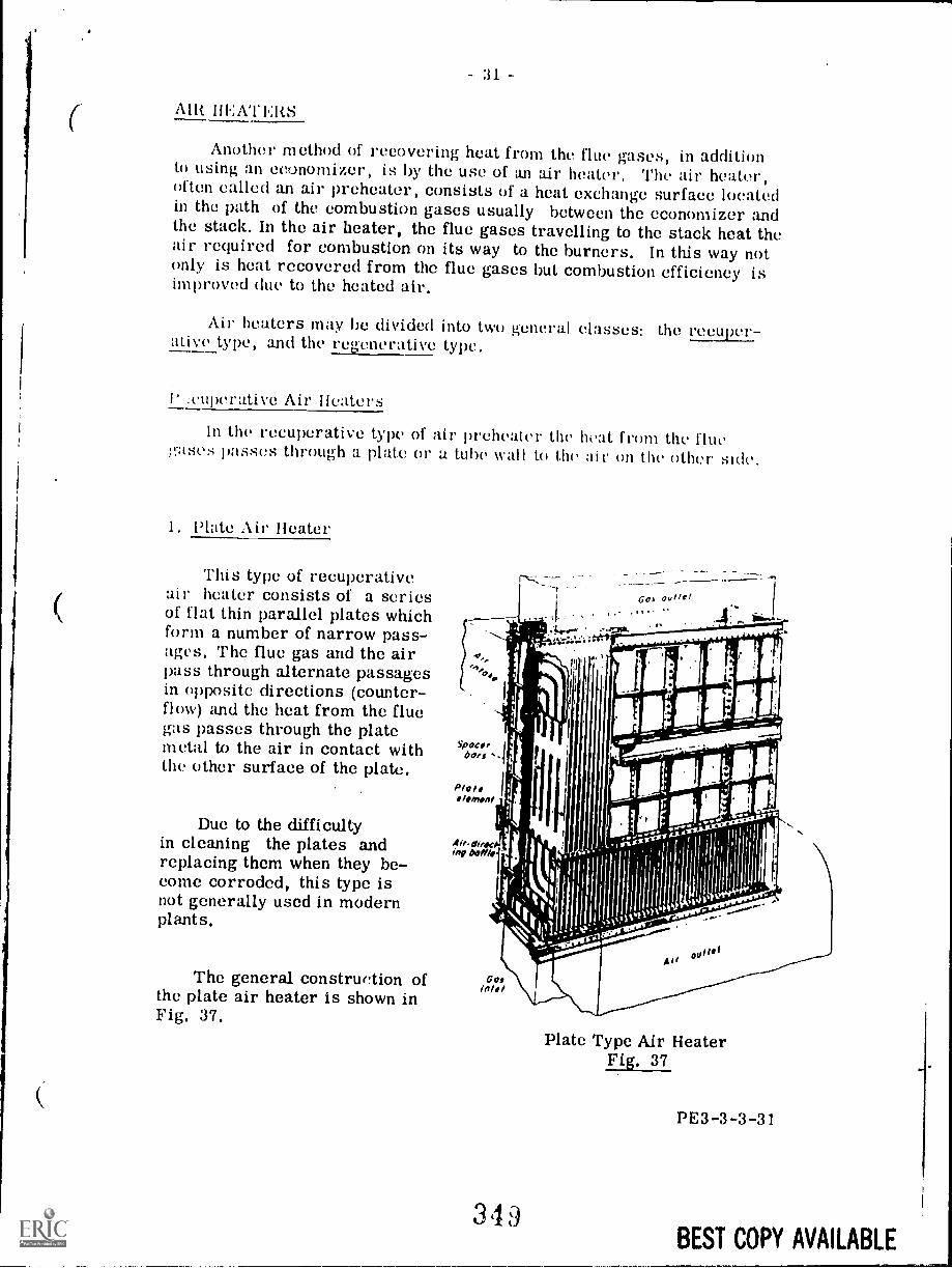
:11
Alit HEAT ERS
Another method of recovering heat from the flue gases, in additionto using an economizer, is by the use of an air heater, The air heater,often called an air preheater, consists of a heat exchange surface locatedin the path of the combustion gases usually between the economizer andthe stack. In the air heater, the flue gases travelling to the stack heat theair required for combustion on its way to the burners. In this way notonly is heat recovered from the flue gases but combustion efficiency isimproved (Inc to the heated air.
Air heaters may be divided into two general classes: the recuper-ative type, and the regenerative type.
I' :roperative Air Heaters
In the recuperative type of air preheater the heat from the flue.:sties passes through 'a plate Or a tube wall to the air on the other side.
1, Plate Air Heater
This type of recuperativeair heater consists of a seriesof flat thin parallel plates whichform a number of narrow pass-ages. The flue gas and the airpass through alternate passagesin opposite directions (counter-flow) and the heat from the fluegas passes through the platemetal to the air in contact withthe other surface of the plate.
Due to the difficultyin cleaning the plates andreplacing them when they be-come corroded, this type isnot generally used in modernplants.
The general construction ofthe plate air heater is shown inFig. 37.
349
Plate Type Air HeaterFig. 37
PE3- 3 -3 -31
BEST COPY AVAILABLE
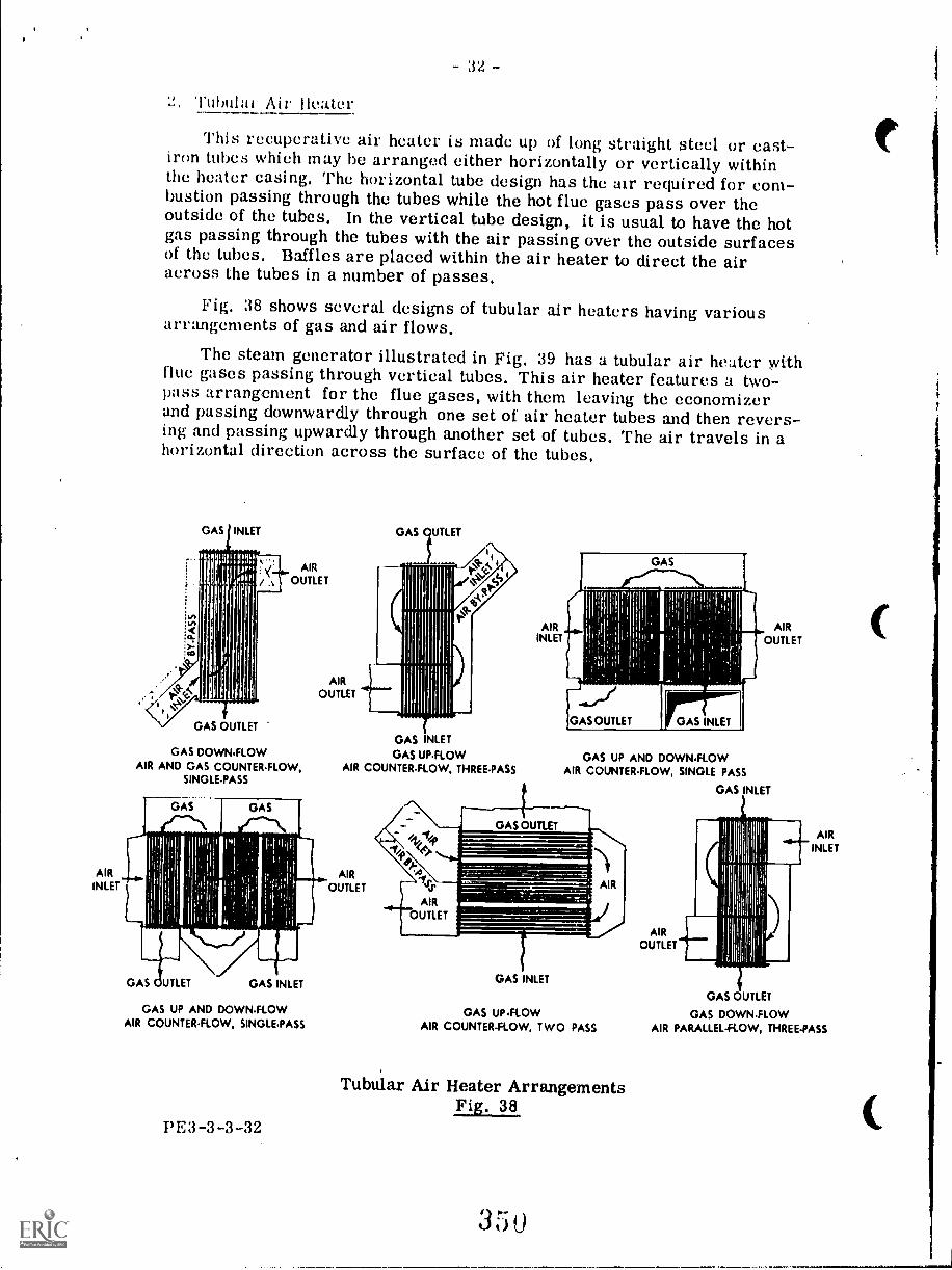
AIRINLET
32 -
!at Air ileater
This recuperative air heater is made up of long straight steel or east-iron tubes which may he arranged either horizontally or vertically withinthe heater casing, The horizontal tube design has the air required for com-bustion passing through the tubes while the hot flue gases pass over theoutside of the tubes. In the vertical tube design, it is usual to have the hotgas passing through the tubes with the air passing over the outside surfacesof the tubes. Baffles are placed within the air heater to direct the airacross the tubes in a number of passes.
Fig. 38 shows several designs of tubular air heaters having variousarrangements of gas and air flows.
The steam generator illustrated in Fig. 39 has a tubular air heater withflue gases passing through vertical tubes. This air heater features a two-pass arrangement for the flue gases, with them leaving the economizerand passing downwardly through one set of air heater tubes and then revers-ing and passing upwardly through another set of tubes. The air travels in ahorizontal direction across the surface of the tubes.
AIR
OUTLET
GAS DOWNFLOWAIR AND GAS COUNTER-FLOW,
SINGLE-PASS
AIROUTLET
GAS UP AND DOWN-FLOWAIR COUNTER-FLOW, SINGLE-PASS
PE:3-3-3-32
GAS UTLET
GAS INLETGAS UP-FLOW
AIR COUNTER-FLOW, THREE-PASS
AIROUTLET
41,1e1/
SAee>
ss
AIROUTLET
AIRINLET
GAS UP AND DOWN-FLOWAIR COUNTER-FLOW, SINGLE PASS
GAS INLET
GAS INLET
GAS UP-FLOWAIR COUNTER-FLOW, TWO PASS
Tubular Air Heater ArrangementsFig. 38
355
AIROUTLET
AIRINLET
GAS OUTLET
GAS DOWN-FLOWAIR PARALLEL - FLOW, THREE-PASS
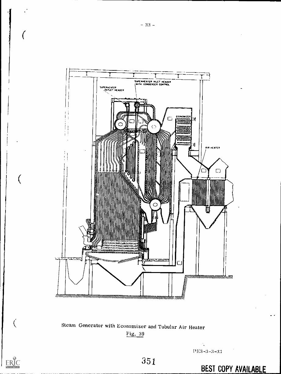
-rSUPERHEATER
,OOTLE T HE ICIER
SUPERHEATER INLET HEADERWITH CONDENSER CONTROL
EU/NOANEER
ease
41.MI 11
AIR NEATER
UI di e m IIII $11 IlIIIII 14 dl Shill
I Nil he NA 111111 I
Steam Generator with Economizer and Tubular Air HeaterFig. 39
35J13E3-3-3-33
BEST COPY AVAILABLE
- 34 -
Regenerative Air Heaters
In a regenerative air heater, a mass of metal or other material isfirst heated by coming in contact with hot gases. The mass, whichusually consists of a number of metal sheets called heating elements,is then removed from contact with the hot gases and brought in contactwith the air to be heated. In this way heat is transmitted from the massto the air.
The type of regenerative air heater used in power plants is a rotaryheater and is described in the following section.
Rotary Regenerative Air Heater
This air heater is made up of a casing within which rotates a rotor.The rotor consists of a number of baskets containing thin corrugatedmetal sheets placed closely together. The casing above and below therotor is divided into two sections. The hot flue gas travels through onesection in one direction and the air to be heated travels through the othersection in the opposite direction.
As the rotor slowly turns, the baskets containing the corrugated'heating elements pass through the hot gas stream and then through thecold air stream alternately. In this way the elements absorb heat fromthe gas and then give up this heat to the air. The elements are arrangedto be edge-on to the flow of both gas and air which allows the flow to takeplace between the closely spaced elements. Leakage of gas and air islargely prevented by means of radial and circumferential seals mountedon the rotor,
The rotor is driven at about 3 rpm by a small electric motor througha gearing arrangement. The power required will not usually exceed 3 hp.
Fig. 40 shows a rotary air heater with the gas and air flows indicated.
In Fig. 41 the insertion of a heating element basket is illustrated andthe closely spaced elements within the basket can be clearly seen.
The rotary regenerative air heater may be arranged in either avertical or horizontal manner. Fig. 42 shows a steam generator withthe air heater arranged so that the flow of gas and air is in a verticaldirection.
The steam generator in Fig. 43 has the air heater arranged so that thegas flows are in a horizontal direction.
PE3-3-3-34
352
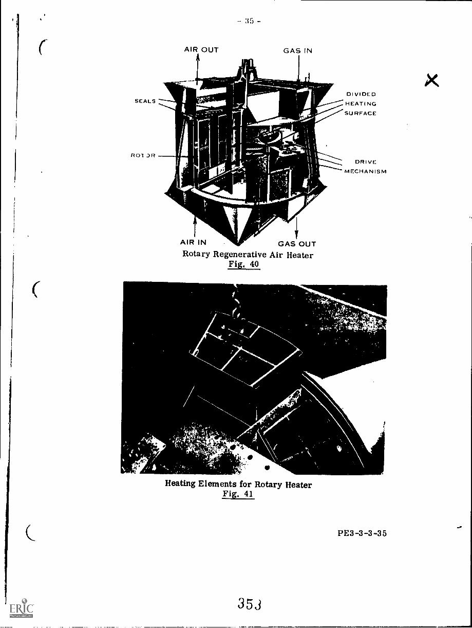
SEALS
ROT .3R
-- 35 -
AIR OUT GAS IN
z
AIR IN GAS OUTRotary Regenerative Air Heater
Fig. 40
AL
4YCFA.4°
Heating Elements for Rotary HeaterFig. 41
DIVIDEDHEATINGSURFACE
DRIVEMECHANISM
PE3-3-3-35
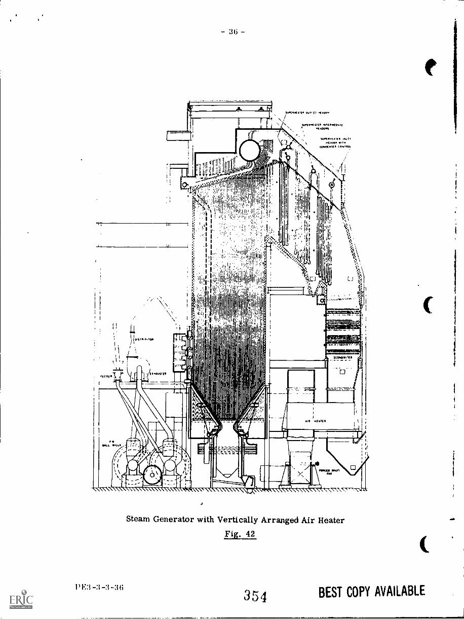
3 -3-36
Steam Generator with Vertically Arranged Air Heater
Fig. 42
354 BEST COPY AVAILABLE
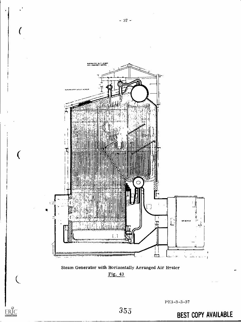
ft
Steam Generator with Horizontally Arranged Air HeaterFig. 43
355I' 1.: 3 -3 -3 -3 7
BEST COPY AVAILABLE
Air Heater Corrosion
Boiler fuels usually contain some amount of sulphur and thereforethe flue gases will contain sulphur compounds. If the temperature of theflue gas is reduced to a certain point (dew point) then sulphuric acid willcondense and form on the air heater surfaces resulting in corrosionof these surfaces, This corrosion will occur at the cold end of the airheater, that is, the gas outlet - air inlet end in a counterflow unit,
Various methods are used to eliminate or reduce this corrosionand these methods usually involve keeping the temperature of the gasleaving the heater above the dew point, A method sometimes used is torecirculate heated air from the heater outlet to the heater inlet. Anothermethod is to bypass a portion of the cool inlet air around the air heaterwith the bypassed air mixing with the heated air at the heater outlet.Several of the arrangements in Fig, 38 feature this method A 1es3common method is to increase the temperature of the air by means ofsteam coils bea)re the air enters the heater,
The rotary regenerative air heater is so designed that the heatingelement baskets in the cold end region of the heater may be quickly andeasily replaced as it is these baskets that are subject to the mostcorrosion,
Air Heater Advantages and Disadvantages
As mentioned previously the advantages of using an air heater areincreased boiler efficiency due to heat recovered from flue gases andincreased combustion efficiency due to the use of heated air,
The air heater, however, has certain disadvantages as well, Fansmust be used to assist the flow of both air and flue gas through the heaterand power is necessary to drive these fans, Maintaining the air heatermay also be a problem due to ash deposits within the passages and corr-osion of the heat transfer surfaces,
13E3-3-3-38
356
BEST COPY AVAILABLE
QUESTION SHEET
Third ClassPOWER ENGINEERING Sect. :1, Lect.
1. Describe the method of support used for any boiler in yourplant or for any boiler with which you are familiar.
2. Describe two different types of construction used tor brick-work settings.
3. List the advantages of a water-cooled setting as compared toa brickwork setting.
4. Sketch and describe one type of tube wall used in a water-cooled setting.
5. (a) Explain the purpose of a superheater and why it is used.
(b) Explain the purpose of a reheater and why it is used.
6. (a) What is meant by the terms radiant superheater, convec-tion superheater and combination superheater?
(b) Describe the steam temperature characteristics of thetypes in (a).
7. What are the advantages and disadvantages of separatelyfired superheaters?
8. Describe three different methods of controlling superheatedsteam temperature.
9. A factor which limits the amount of heat that can be absorbedby steam generating tubes is the temperature of the water withinthe tubes. Explain how this affects the efficiency of a boiler anddescribe a method used to increase the amount of heat absorbedby the boiler water.
10. List the advantages and disadvantages of:(a) economizers,(b) air heaters.
351
PE3-3-3-Q
41.1MOMI. LEA' mine ynmal
7.8
BOILERS -- INSTRUMENTS AND CONTROLS
Ng.. " "
Goal:
The student will be able to describethe instruments and controls forboiler operation.
Performance Indicators:
1. Describe measuring devices.
2. Describe controllers, trans-mitters and actuators.
3. Describe feedwater controlsystems.
4. Describe combustion controlsystems.
5. Describe steam temperaturecontrol systems.
1,Read the goal'and performance indicators to find what is to be learned from
package.
Read the vocabulary list to find new words that will be used in package.
Read the introduction and information sheet.
Complete the job sheet.
Complete self-assessment.
Complete post-assessment.
2
3 5 d
Vocabulary
* Actuator* Bellows gauge* Bi-metallic thermometer
* Bourdon tube* Controller* Diaphragm pressure gauge* Float cage* bat manometer* Float weight device
* Flow nozzle* Flow transmitter* On-off controller* Orifice plate* Positioner
40Pressure transmitterProportional controller
* Proportional plus integral (reset) controller
* Proportional plus reset plus derivative controller
* Remote indicating bulb thermometer
* Single element control* Temperature transmitter* Thermocouple* Thermo-electric pyrometer* Thermo-hydraulic system
* Thermo-expansion regulator
* Transmitter* Two element control* Three element control* Venturi tube
3
36
.0.111MMI
IntroductionThe safe and efficient operation of a steam generation plant is dependent upon
the proper control of temperature, pressure, levels and flow of air, fuel, waterand steam. This can only be accomplished with the help of control equipmentthat shows the operator what is happening inside the boiler.
These vairables must be measured and that measurement must be shown in a dial orgauge that is visible to the operator. This package is designed to acquaint
apprentices with the measuring instruments and how the measurements reach the
dials and gauges.
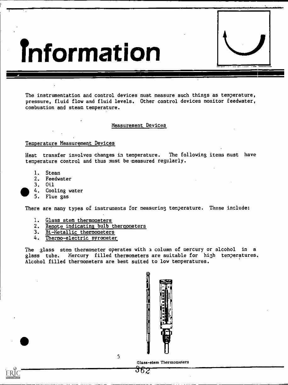
4=111=1.1, IMMIMEMII viabow+1=1.1011msiallatio.
InformationThe instrumentation and control devices must measure such things as temperature,pressure, fluid flow and fluid levels. Other control devices monitor feedwater,
combustion and steam temperature.
Measurement Devices
Temperature Measurement Devices.
Heat transfer involves changes in temperature. The following items must have
temperature control and thus must be-measured regularly.
1. Steam2. Feedwater3. Oil
4. Cooling water5. Flue gas
There are many types of instruments for measuring temperature. These include:
1. Glass stem thermometers2. Remote indicating bulb thermometers3. Bi-Metallic thermometers4. Thermo-electric pyrometer
The glass stem thermometer operates with 3 column of mercury or alcohol in a
glass tube. Mercury filled thermometers are suitable for high temperatures.
Alcohol filled thermometers are best suited to low temperatures.
5
Glass-stem Thermometers
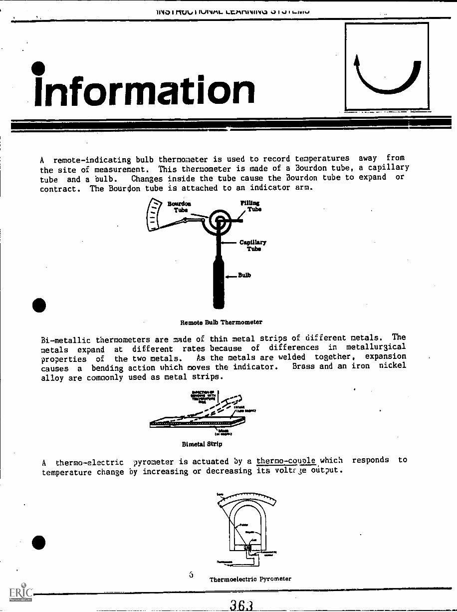
0:prrszlesfammtamsismwirmasair
1140111tAr I IVINitiL. i...LiAniviirma v7 I I 1...lv1%4
ginformationA remote-indicating bulb thermometer is used to record temperatures away from
the site of measurement. This thermometer is made of a Bourdon tube, a capillary
tube and a bulb. Changes inside the tube cause the Bourdon tube to expand or
contract. The Bourdon tube is attached to an indicator arm.
Remote Bulb Thermometer
Bi-metallic thermometers are made of thin metal strips of different metals. The
metals expand at different rates because of differences in metallurgical
properties of the two metals. As the metals are welded together, expansion
causes a bending action which moves the indicator. Brass and an iron nickel
alloy are commonly used as metal strips.
MOW MT*1040110101161001~11
sliPMAme om. % hasliseal
NMItIM MOM,
Bimetal Strip
A thermo-electric pyrometer is actuated by a thermo-couple which responds to
temperature change by increasing or decreasing its voltE3e output.
Thermoelectric Pyrometer
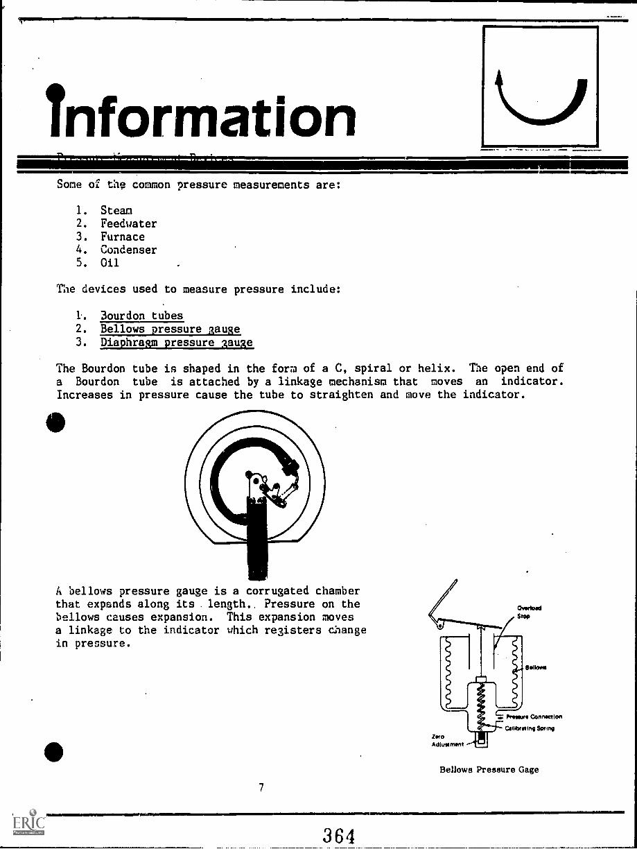
InformationAM, T1
Some of the common pressure measurements are:
1. Steam2. Feedwater3. Furnace4. Condenser5. Oil
The devices used to measure pressure include:
1. 3ourdon tubes2. Bellows pressure gauge3. Diaphragm pressure gauge
The Bourdon tube is shaped in the fora of a C, spiral or helix. The open end ofa Bourdon tube is attached by a linkage mechanism that moves an indicator.Increases in pressure cause the tube to straighten and move the indicator.
A bellows pressure gauge is a corrugated chamberthat expands along its . length.. Pressure on thebellows causes expansion. This expansion movesa linkage to the indicator which registers changein pressure.
11111.1.14
7
1111011011111MINNIMININE111.
364
OverloadStop
UmAdjustment
Bellows
humors Connection
libreting Some
Bellows Pressure Gage
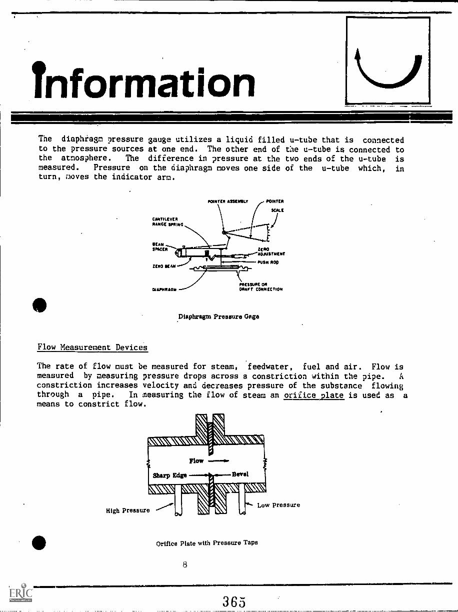
InformationThe diaphragm pressure gauge utilizes a liquid filled u-tube that is connectedto the pressure sources at one end. The other end of the u-tube is connected tothe atmosphere. The difference in pressure at the two ends of the u-tube ismeasured. Pressure on the diaphragm moves one side of the u-tube which, inturn, moves the indicator arm.
CANTILEVERRANGE WIND
SEAMSPACER
ZERO SEAM
DJAPMRAGM
Flow Measurement DeviceS
POINTER ASSEMSLY POINTER
SCALE
ZEROADJUSTMENT
PUSH ROD
PRESSURE ORDRAFT CONNECTION
Diaphragm Pressure Gage
The rate of flow oust be measured for steam, feedwater, fuel and air. Flow ismeasured by measuring pressure drops across a constriction within the pipe. A
constriction increases velocity and decreases pressure of the substance flowingthrough a pipe. In measuring the flow of steam an orifice plate is used as ameans to constrict flow.
High Pressure"""*. Low pressure
Orifice Plate with Pressure Taps
8
365
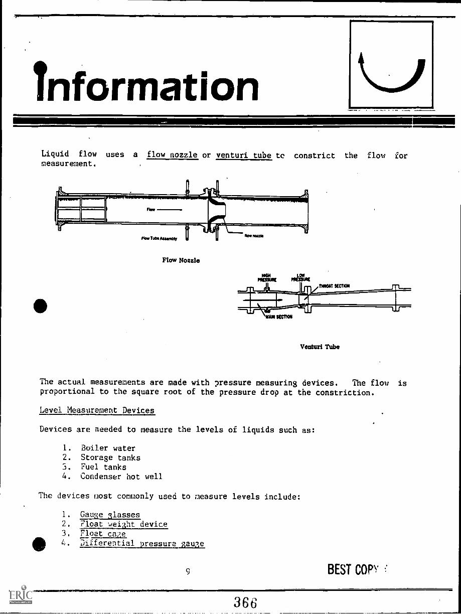
InformationLiquid flow uses a flow nozzle or venturi tube to constrict the flow formeasurement.
Flow Nozzle
HIMPRISM PRESSURE
THROAT SECTICRI
Venturi Tube
The actual measurements are made with pressure measuring devices. The flow isproportional to the square root of the pressure drop at the constriction.
Level Measurement Devices
Devices are needed to measure the levels of liquids such as:
1. Boiler water2. Storage tanks3. Fuel tanks4. Condenser hot well
The devices most commonly used to measure levels include:
1. Gauge glasses2. Float wei,ht device3. Float ca'.,e
4. Differential 9ressura gauge
BEST COPY
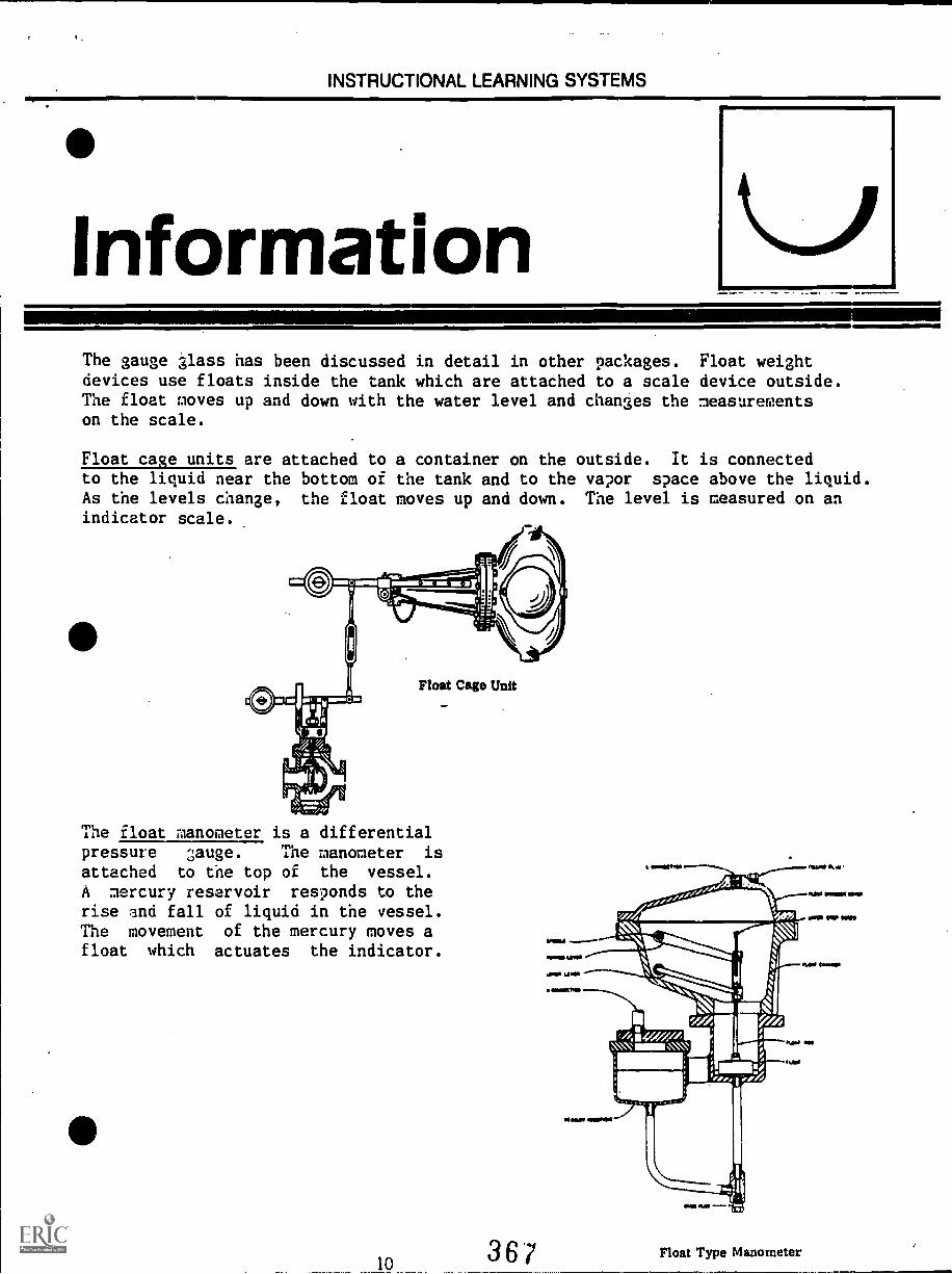
INSTRUCTIONAL LEARNING SYSTEMS
InformationThe gauge glass has been discussed in detail in other packages. Float weightdevices use floats inside the tank which are attached to a scale device outside.The float moves up and down with the water level and changes the measurementson the scale.
Float cage units are attached to a container on the outside. It is connectedto the liquid near the bottom of the tank and to the vapor space above the liquid.As the levels change, the float moves up and down. The level is measured on anindicator scale.
Float Cage Unit
The float manometer is a differentialpressure gauge. The manometer is
attached to the top of the vessel.
A mercury reservoir responds to therise and fall of liquid in the vessel.The movement of the mercury moves afloat which actuates the indicator.
10 36'7 Float Type Manometer
41=111=1..' +111111111111
InformationControllers, Transmitters and Actuators
A control system consists of three main parts:
1. Controller2. Transmitter3. Actuator
Controllers
Controllets sense changes in such things as pressure, temperature and levels andsend the signal on town actuator which can charge dials and open valves. Thecontroller must have a sensing device and a signalling device. The signaldevice may be operated by electrical signal or by pneumatics. Some commoncontrollers are:
1. On-off controller are set to measure above or below a set point. A
flapper is held against a nozzle for maximum settings and away from thenozzle for minimum settings.
2. Proportional controllers measures how much a measurement is above orbelow the set points. These controllers have some problems withoffset. Offset is the difference between new corrected valves and theset point valves.
3. Proportional plus integral (reset) controller offset problems can be avoidedby adding an adjustable restriction and positive feedback bellows to thecontroller. The feedback bellows serves as a reset that bringsmeasurements back to set point.
4. Proportional plus reset plus derivative controller has, in addition tothe reset feature, a controller with a rate action or derivativefeature. This feature consists of a restriction in the airline to thefeedback bellows. A rate action feature causes a quick return to theset point and the final controls move further in the requireddirection.
Transmitters
A transmitter measures the signal produced by the controller and converts thesignal into transmission signals. The transmission signals are sent to thecontroller and indicators. Some transmitters contain sensing device rather
Ilan the controller. Transmitters operate on pneumatic or electronic signals.
4111111MMINIIME1.
11
111111=111M11001111,
368

InformationTransmitters may be classified as:
1. Pressure transmitters2. Flow transmitters3. Level transmitter4. Temperature transmitter
The pressure transmitter uses a sensor of the Bourdon, bellows or diaphragm
types. The transmitter is arranged in a flapper-nozzle assembly. They operate
on pneumatic or electronic signals.
Flow transmitters use the orifice plate to restrict the flow and produce a
pressure drop. A bellows type sensor measures the pressure drop.
A level transmitter uses a float device to move the flapper. A feedback bellows
is used to keep the signal output proportional.
emperature transmitters use a Bourdon tube to move the flapper in relation to
the nozzle.
Actuators
Actuators receive signals from the controller and change them into
mechanical motion. The pneumatic or electronic signals are changed into
mechanical energy for opening valves, dampers,.etc. Actuators may be classified
according to the signals that they receive--pneumatic or electronic. Another
way to classify actuators is by the type of motion they produce--rotary or
linear. A positioner may be used to amplify the control signal at low pressures
and using high pressure air to move the actuator.
Control
Feedwater Controls
Feedwater control systems may be classified as:
1. Thermo-hydraulicThermo-expansion
"..). Single element4. Two element5. Three element
12
363
111111sUr.
InformationThe thermo-hydraulic system has a feedwater regulating valve which is actuated
by a generator. An ou...er tube of the generator is conrected to the feedwater
regulating valve and the bottom. At the top, both inner and outer tubes are
connected to the steam and water. Heat from steam in the inner tube cause the
water in the outer tube to flash into steam. This forces water into the bellows
which controls the opening and closing of the feedwater valve.
Thermo-expansion regulators are a tube mounted on a beam and attached' to the
steam and water space. As water level drops in tube, its temperature is raised
by the steam on its outside. The increased heat expands the tube and actuates
the feedwater regulating valve.
Single element control has a drum level transmitter signal differences between
drum levels and the set point. Th7's system is used where slow changes are made
in the feedwater load. Single element control only responds to teh drum level
variable.
411Two element controls use a hystem that responds to both drum level and steam
flow. The drum level, measurement balances water input with steam output. Steam
flow measurements proportions water according to the "steam flow.
Three element controls measure steam flow, feedwater flow and drum level.
Combustion Control Systems
The flow of fuel and air must be regulated to get good combustion. The ratio of
fuel to air must be maintained for combustion efficiency. There are three
types of combustion controls:
1. On-off controls2. Positioning controls3. Hetering controls
The on-off control system consists of a bellows operated switch which is
activated by boiler pressure. A drop in pressure will start the fans and
burner. This system is inefficient because of the variation of boiler pressurebetween "cut .in" and "cut out" points.
Positioning control involves actuators that position the draft dampers and fuel
valve according to the boiler load. A positioning control is operated by a
master controller that signals the actuators for dampers and full valve.
411111111MallW
13
3 7 o_
InformationMetering control use a master controller to signal the damper and fuel valveactuators. In this case, the signals are based on measured or metered amountsof fuel and air.
Steam Temperature Control
The temperature of superheated steam must be constant for turbine efficiency.Several methods of steam temperature control are discussed in other packages inmore detail. These methods of temperature control are:
1. Combustion gas bypass which routes combustion gases around the
superheater to avoid overly high temperatures.
2. Combustion gas recirculation which recirculates combustion gases over
the superheater tubes to rais temperatures.
3. Desuperheating by spraying feedwater into the superheated steam to
111lower temperature.
4. Tilting burners to vary temperature by tilting burners upward or
downward.
5. Twin furnaces used on separately fired superheaters that allowstemperature control.
6. Attemperation lowers steam temperature by passing it over attemperatortubes and condensing it.
A three element control for steam temperature uses an attemparator with signalsfrom three sources. The signals come from the steam or air flow meter, thethermal element in the attemperator nozzle and a thermal element in the secondstage superheater. The final steam temperature is determined by the thermalelement in the second stage superheater.
14
371
'Assignment111111,
Read pages 1 - 43 in supplementary reference. Study diagrams and
illutrations.
Complete the Job Sheet.
Complete the self-assessment and check answers.
Complete the post- assessment and ask the instructor to check your answers.
15
Job SheetANALYZE MEASUREMENT DEVICES
Obtain devices for measuring temperature, pressure, levels and flow.
Carefully inspect them one at a time.
Do the measuring instruments fit the classificaitons given in this learningpackage?
Do you understand the principle of their operation?
Read manufacturers specifications and diagrams to enhance your understandingof these devices.
SelfAssessmentIndicate what the following devices are used to measure. Show by placing a codeletter in the space at the front of the device. Pressure (P), Temperature (T),Flow (F), Level (L)
IM
11=10.1.1
1. Venturi tube
2. Bourdon tube
Gauge glass
4. Glass stem
5. Float cage
6. Orifice plate
7. Remote indicating bulb
8. Bellows gauge
9. Thermo-electric pyrometer
10. Diaphragm gauge
Self AssessmentAnswers
.
P 2.
L 3.
T 4.
L 5.
F 6.
ST 7.
P 8.
T. 9.
P 10.
Post`Assessment
?lease show these devices as controllers, transmitters or actuators by placing(C) for controller, (T) for transmitter or (A) for actuator in the blank space.
11111.110,
=a
1
1. On-off type
2. Level
3. Proportional plus integral reset
4. Flow
5. Temperature
6. Pressure
7. Rotary
8. Linear
9. Pneumatic
10. Electronic
19
instructorRost AssessmentAnswers
C 1.
T 2.
C 3.
T 4.
T 5.
6.
A 7.
A 8.
A 9.
A 10.
20
ob.,..m..0111111/
377
Supplementary'References
* Correspondence Course. Lecture 11, Section 2, First Class. Steam GeneratorControls. Southern Alberta Institute of Technology. Calgary, Alberta,Canada.
21
MA,MNIMMIIIIIMINO411111MMINEreNT.sosnwataMereSM1010.1"1"""A",""."1"1".."4".".....m.."
378itlanelelorailledilinaMagel
S(WTII ERN ALBERTA INSTITUTE 01, 'U EC IiN0 LOGYCA LGARY, ALBERTA
SECTION 2
STEAM GENERATION
Correspondence CoursesPower Engineering
STEAM GENERATOR CONTROLS
First ClassLecture 11
In order to ensure safe, ecoimmical, and reliable operation of the steamgenerator, instruments and cont. ols are necessary. The boiler outlet conditionssuch as steam flow, pressure, and temperature must be measured and the quan-tities of fuel, air, and water must be adjusted to maintain Ce desired values ofthe outlet steam conditions. This mca,;uring and adjusting must be done contin-uously during the time the boiler is in operation. The subject of the instrument-ation and control necessary to perform the measurement and adjustment is ofnecessity quite complex and extensive and Rs coverage in this course must belimited to not much more than basic concepts.
METHODS OF MEASUREMENT
14.312.8
In measuring the values of the variables involved in the power plant opera-tion, many .ifferent types of instruments may be used, not only to indicate themeasured value, but also to record the value, usually continuously, on a chart.The instruments are also often used to send signals to control certain flows.
The measuring instruments may be located directly at the point where themeasurement is being taken or they may be located remote from the measure-ment point, for example, in a central control room.
Some of the more commonly used designs of measuring instruments aredescribed in the following sections.
PRESSURE NIASUI{ENIENT
Pressure is one of the most commonly measured variables in power plantoi)eration. These pressure measurements include steam pressure, feedwaterpressure, furnace pressure, condenser pressure, lubricating oil pressure andmany others.
37;)
COPY AVAILABLE
The Bourdon tube, the bellows, and the diaphragm are three devices com-monly used to measure pressure. Another device which is sometimes used isthe liquid or mercury filled U-tube used for low pressure work.
The Bourdon tube may be in the form of a C , a spiral, or a helix, In
each case a hollow flattened or oval shaped tube is Usf 1, sealed at one end. Theopen end is fixed and is connected to the source of pressure while the sealed endis free to move. Pressure tends to straighten the tube and the movement of thefree end is a measure of the pressure.
The Bourdon tube types are illustrated in Figs. 1 to 3 inclusive.
C Bourdon Tube
('1.:1 -2-1 1 -2)
Fig, 1
Spiral Bourdon Tube
Fig, 2
7 "78211"61
Helix Bourdon T..be
Fig, 3
3 "J
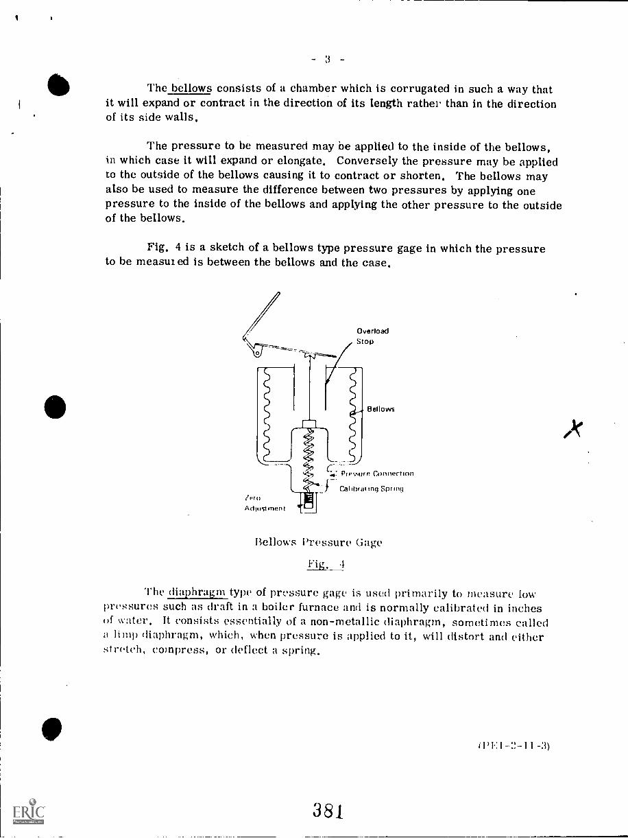
- 3
The bellows consists of a chamber which is corrugated in such a way thatit will expand or contract in the direction of its length rathei than in the directionof its side walls.
The pressure to be measured may be applied to the inside of the bellows,in which case it will expand or elongate. Conversely the pressure may be appliedto the outside of the bellows causing it to contract or shorten. The bellows mayalso be used to measure the difference between two pressures by applying onepressure to the inside of the bellows and applying the other pressure to the outsideof the bellows.
Fig. 4 is a sketch of a bellows type pressure gage in which the pressureto be measui ed is between the bellows and the case.
OverloadStop
len)Adlustment
c---47 Pr #.,:sur e Connection
Bellows
Calibrat mg Spring
Bellows Pressure Gage
Fig. 4
The diaphragm type of pressure gage is used primarily to measure lowpressures such as draft in a boiler furnace and is normally calibrated in inchesof water, It consists essentially of a non-metallic diaphragm, sometimes calleda limp diaphragm, which, when pressure is applied to it, will distort and eitherstretch, compress, or deflect a spring.
(PEI 1 -3)
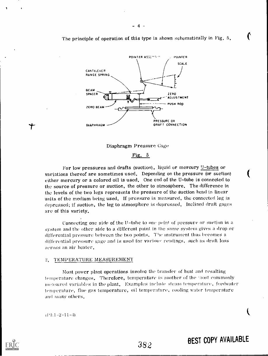
I
- 4
The principle of operation of this type is shown schematically in Pig. 5.
CANTILEVERRANGE SPRING
BEAMSPACER
ZERO BEAM
POINTER POINTER
ZERO"ADJUSTMENT
SCALE
PUSH ROD
PRESSURE OR
DIAPHRAGM DRAFT CONNECTION
Diaphragm Pressure Gage
Fig. 5
For low pressures and drafts (suction), liquid or mercury U-tubes orvariations thereof are sometimes used. Depending on the pressure (or suction)either mercury or a colored oil is used. One end of the U-tube is connected tothe source of pressure or suction, the other to atmosphere. The difference inthe levels of the two legs represents the pressure of the suction head in linearunits of the medium being used. If pressure is measured, the connected leg isdepressed; if suction, the leg to atmosphere is depressed. Inclined draft gagesarc of this variety.
Connecting one side of the U-tube to one point of pressure or suction in asystem and the other side to a different point in the same system gives a drop ordifferential pressure between the two points. The instrument thus becomes adifferential pressure gage and is used for variote- readings, such as draft lossacross an air heater.
2, TEMPERATURE MEASUREMENT
Most power plant operations involve the transfer of heat and resultingtemperature changes. Therefore, temperature is :mother of the lost commonlynie:ured variables in the plant. Examples include steam temperature, feedwatertemperature, flue gas temperature, oil temperature, cooling water temperatureand many others.
P 1 -2-11-.11
382 BEST COPY AVAILABLE
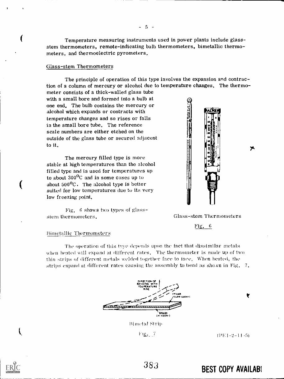
ii
Temperature measuring instruments used in power plants include glass-stem thermometers, remote-indicating bulb thermometers, bimetallic thermo-meters, and thermoelectric pyrometers.
Glass-stem Thermometers
The principle of operation of this type involves the expansion and contrac-tion of a column of mercury or alcohol due to temperature changes. The thermo-meter consists of a thick-walled glass tubewith a small bore and formed into a bulb atone end. The bulb contains the mercury oralcohol which expands or contracts withtemperature changes and so rises or fallsin the small bore tube. The referencescale numbers are either etched on theoutside of the glass tube or secured adjacentto it.
The mercury filled type is morestable at high temperatures than the alcoholfilled type and is used for temperatures upto about 300°C and in some cases up toabout 500°C. The alcohol type is bettersuited for low temperatures due to its verylow freezing point.
Fig. 6 shows two types of glass-stem thermometers.
Bimetallic Thertrometers
Glass-stem Thermometers
Fig. 6
The operation of this tyre depends upon the fact that dissimilar metalswhen heated will expand at different rates. The thermometer is made up of twothin strips of different metals welded together face to lave. When heated, thestrips expand at different rates causing the assembly to bend as shoxn in Fig. 7.
DI H OP
... .1,"TENM°441PATV*4017(11 ...: JO;,.." ,
.../ ,. ''' e' IN VAR.. .7......., Oar* CODP I,......
IAS!(MI COIP
Bimetal Strip
ME.. 7
383
(Pl.: 1 -2-11 -51
BEST COPY AVAILABI
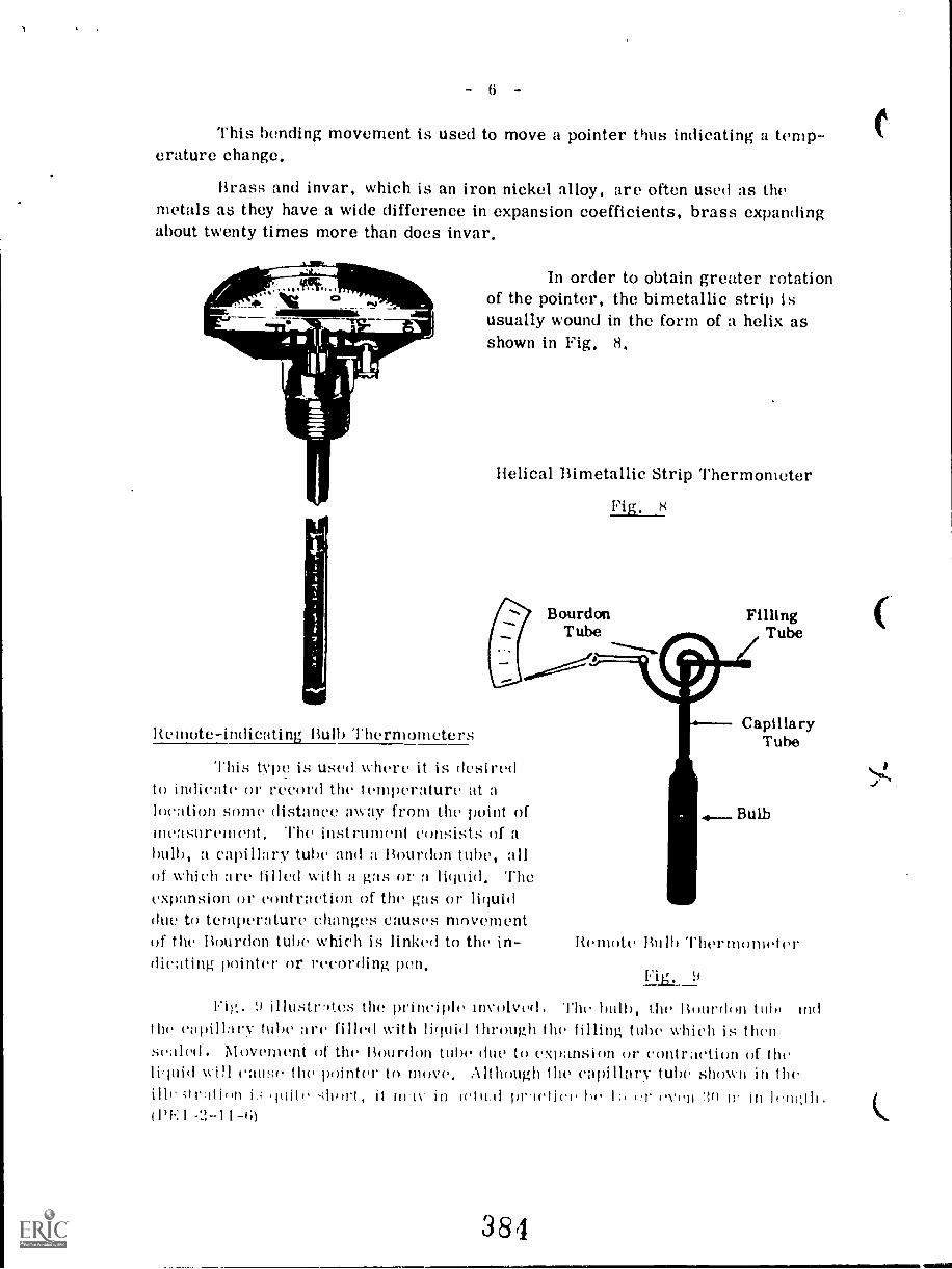
- 6 -
This bending movement is used to move a pointer thus indicating a temp-erature change.
Brass and invar, which is an iron nickel alloy, are often used as themetals as they have a wide difference in expansion coefficients, brass expandingabout twenty times more than does invar.
C3P
In order to obtain greater rotationof the pointer, the bimetallic strip isusually wound in the form of a helix asshown in Fig. 8.
Helical Bimetallic Strip Thermometer
Fig. 8
Bourdon FillingTube Tube
Remote-indicating Bulb Thermometers
This type is used where it is desiredto indicate or record the temperature at alocation some distance away from the point ofmeasurement, The instrument consists of abulb, a capillary tube and a Bourdon tube, allof which cite filled with a gas or liquid. Theexpansion or contraction of the gas or liquiddue to temperature changes causes movementof the Bourdon tube which is linked to the in-dicating pointer or recording pen.
CapillaryTube
4-- Bulb
Itemote Bulb Thermometer
Fig. 9
Fig. 9 illastriteS the principle involved. l'he halt), the limn-dim tuhl tadhe capilla i'v tube a re filled with liriuid t ht'utti.th the tillinj, tube which is then
sealed. Movement of the Bourdon tube due to expansion or contraction of the\vi11 cause the pointer to move Although the capillary tube shmvn in the
illr ;tratiiin is in.11 pricti('i, ;) 11 \'1.11 '211 11' in11)1'.I -2-11-6)
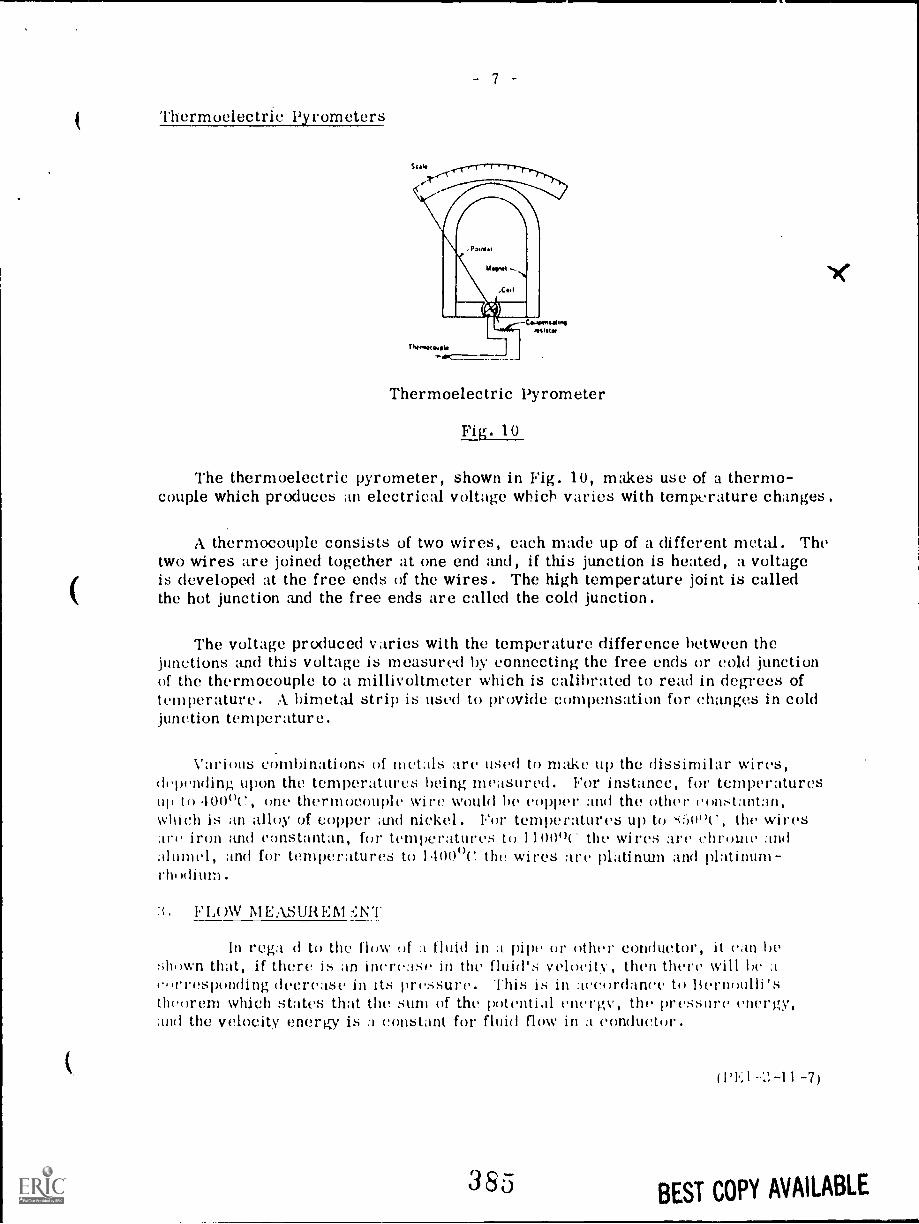
Thermoelectric Pyrometers
Thermoelectric Pyrometer
Fig. 10
The thermoelectric pyrometer, shown in Fig. 10, makes use of a thermo-couple which produces an electrical voltage which varies with temperature changes.
A thermocouple consists of two wires, each made up of a different metal. Thetwo wires are joined together at one end and, if this junction is heated, a voltageis developed at the free ends of the wires. The high temperature joint is calledthe hot junction and the free ends are called the cold junction.
The voltage produced varies with the temperature difference between thejunctions and this voltage is measured by connecting the free ends or cold junctionof the thermocouple to a millivoltmeter which is calibrated to read in degrees oftemperature. A bimetal strip is used to provide compensation for changes in coldjunction temperature.
Various combinations of metals are used to make up the dissimilar wires,depending upon the temperatures being measured. For instance, fur temperaturesup to 400"C, one thermocouple wire would In copper and the other constantan,which is ;in alloy of copper uicl nickel. For temperatures up to itt"c', the wiresare iron ;uid constantan, fur temperatures to 1100"L the wires :ire chrome andalumel, and for temperatures to 1.1000C the wires are platinum and platinum-
ti. FLoW NIEASUI(EM
In rega d to the flow of fluid in a pipe or other conductor, it can hethat, if there is an increase in the fluid's velocity, then there will be a
corresponding decrease in its pressure. This is in :lecordance to Bernoulli'stheorem which states that the sum of the potential energy, the pressure energy,itid the velocity energy is a constant for fluid flow in a conductor.
385
WI.: I -1 1 -7)
BEST COPY AVAILABLE
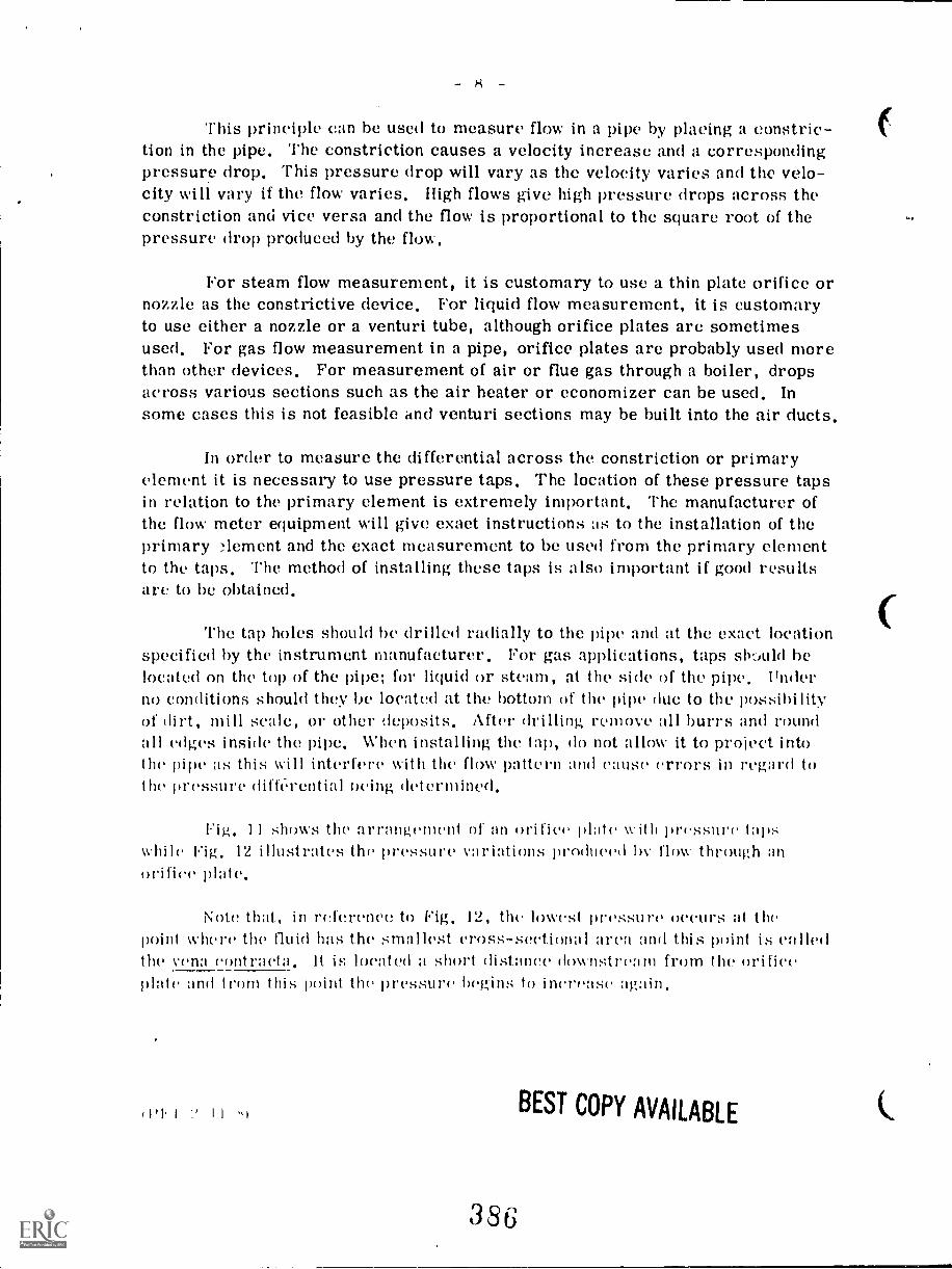
- 8 -
This principle can he used to measure flow in a pipe by placing a constric-tion in the pipe. The constriction causes a velocity increase and a correspondingpressure drop. This pressure drop will vary as the velocity varies and the velo-city will vary if the flow varies. High flows give high pressure drops across theconstriction and vice versa and the flow is proportional to the square root of thepressure drop produced by the flow.
For steam flow measurement, it is customary to use a thin plate orifice ornozzle as the constrictive device. For liquid flow measurement, it is customaryto use either a nozzle or a venturi tube, although orifice plates are sometimesused. For gas flow measurement in a pipe, orifice plates are probably used morethan other devices. For measurement of air or flue gas through a boiler, dropsacross various sections such as the air heater or economizer can be used. Insome cases this is not feasible and venturi sections may be built into the air ducts.
In order to measure the differential across the constriction or primaryelement it is necessary to use pressure taps. The location of these pressure tapsin relation to the primary element is extremely important. The manufacturer ofthe flow meter equipment will give exact instructions as to the installation of theprimary T?,lement and the exact measurement to be used from the primary elementto the taps. The method of installing these taps is also important if good resultsare to be obtained.
The tap holes should be drilled radially to the Ae and at the exact locationspecified by the instrument manufacturer. For gas applications, taps sk,uld helocated on the top of the pipe; for liquid or steam, at the side of the pipe. Underno conditions should they be located at the bottom of the pipe due to the possibilityof dirt, mill scale, or other deposits. After drilling rem OVC a 1 1 burrs and roundall edges inside the pipe. When installing the tap, do not allow it to project intothe pipe as this will interfere with the flow pattern and cause errors in regard tothe pressure diftl.rential oeing determined.
Fig, 11 shows the arrangement Of an orifice plate with pressure tapswhile Fig, 12 illustrates the pressure variations produced by flow through anorifice plate.
Note that, in reference to Fig. 12, the lmvest pressure occurs at thepoint where the fluid has the smallest cross-sectional area and this point is calledthe v('na contract:J. It is located a short distance dowlistream from the orificeplate and from this point the pressure begins to increase again.
(1'I I ' I I
386
BEST COPY AVAILABLE
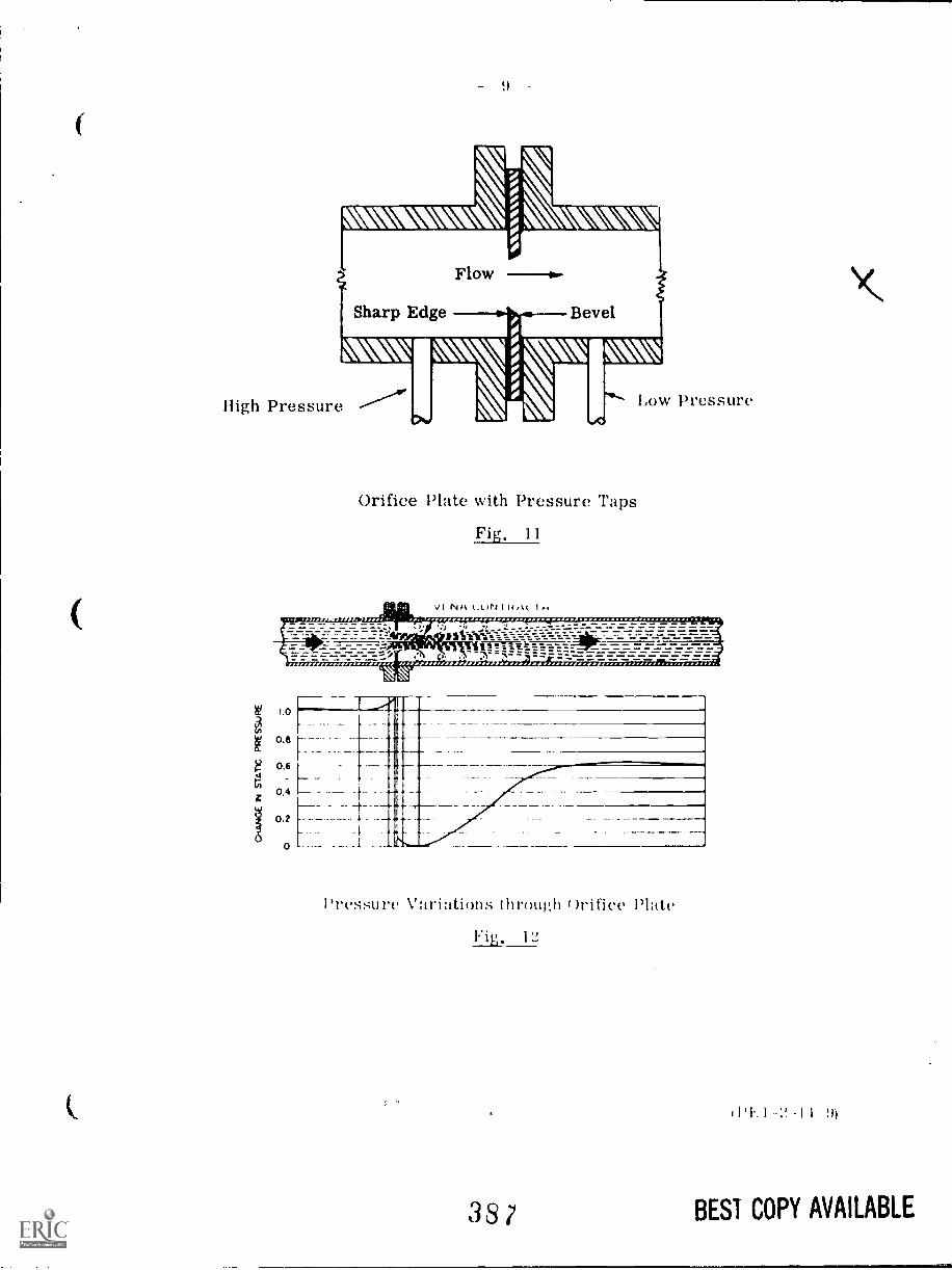
Sharp Edge
Flow
Bevel
High Pressure
Orifice Plate with Pressure Taps
Fig. 11
Low Pressure
1.0
0.6
0.6
0.4
0.2
0
II
III
---1-
Pr essu re \Puri ;mons t h mug h )ri nee Nate
Fig. 1'2
387
11%1 -I!. -I I 9)
BEST COPY AVAILABLE
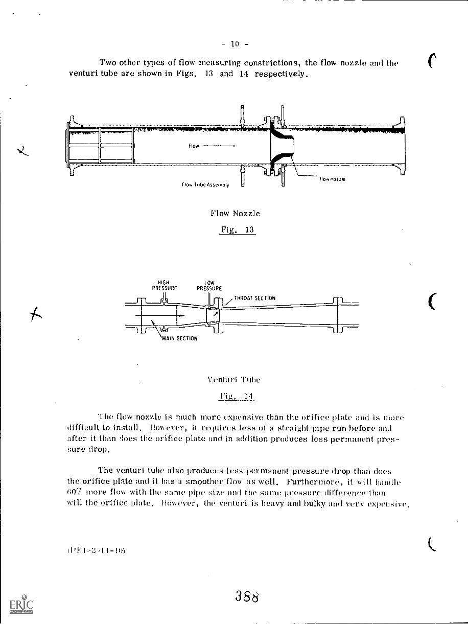
10 -
Two other types of flow measuring constrictions, the flow nozzle and theventuri tube are shown in Figs. 13 and 14 respectively.
HIGHPRESSURE
F low Tube Assembly
Flow Nozzle
Fig. 13
LOWPRESSURE
MAIN SECTION
THROAT SECTION
Venturi 'I'uhe
Fig, 14
The flow nozzle is much more expensive than the orifice plate and is moredifficult to install, However, it requires less of a straight pipe run before andafter it than does the orifice plate and in addition produces less permanent pres-sure drop.
The venturi tube also produces less permanent pressure drop than doesthe orifice plate and it has a smoother flow as well. Furthermore, it will handle007( more flow with the same pipe size and the same pressure difference thanwill the orifice plate, However, the venturi is heavy and bulky and very expensive,
(1)1.,1-2,-11-10)
388
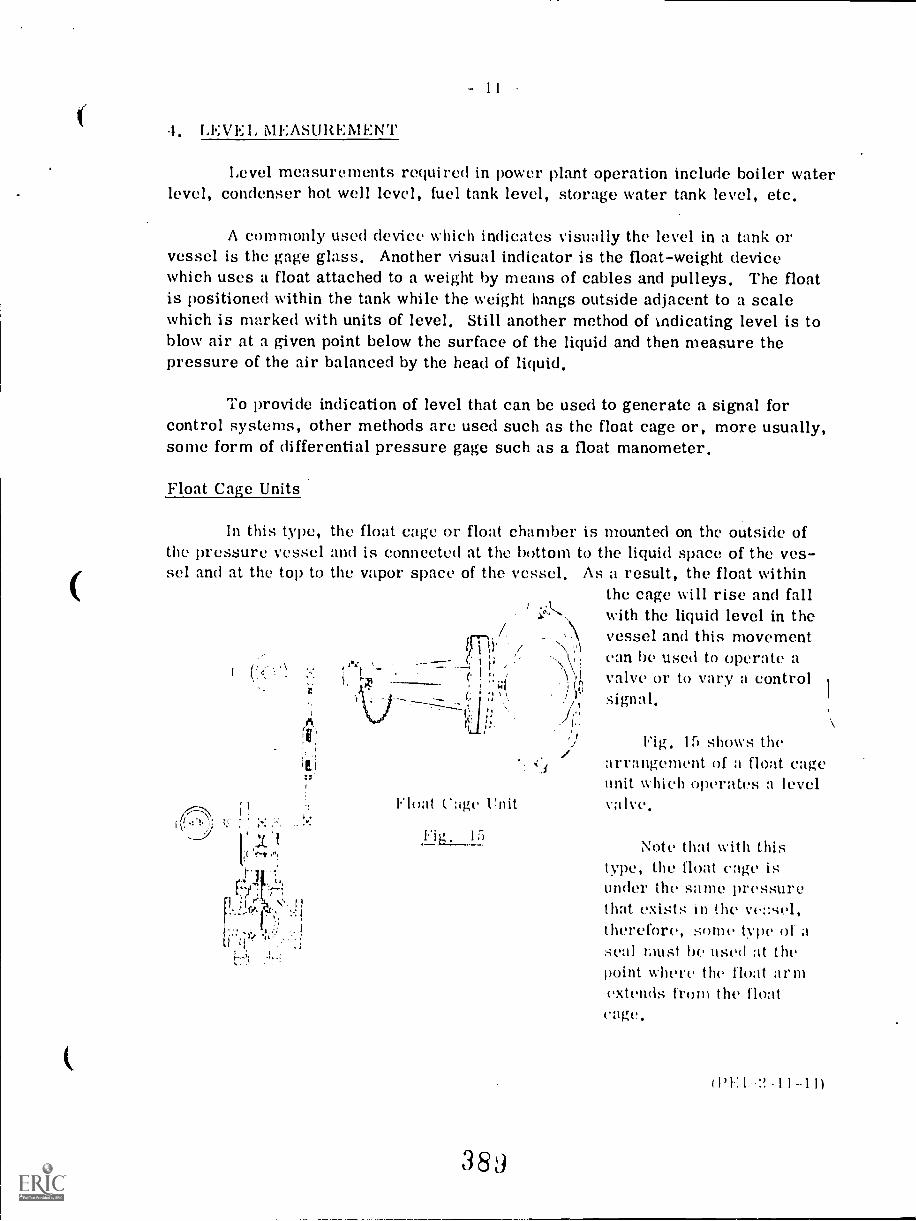
.1. LEVEL MEASUREMENT
Level measurements required in power plant operation include boiler waterlevel, condenser hot well level, fuel tank level, storage water tank level, etc.
A commonly used device which indicates visually the level in a tank orvessel is the gage glass. Another visual indicator is the float-weight devicewhich uses a float attached to a weight by means of cables and pulleys. The floatis positioned within the tank while the weight hangs outside adjacent to a scalewhich is marked with units of level. Still another method of indicating level is toblow air at a given point below the surface of the liquid and then measure thepressure of the air balanced by the head of liquid.
To provide indication of level that can be used to generate a signal forcontrol systems, other methods are used such as the float cage or, more usually,some form of differential pressure gage such as a float manometer.
Float Cage Units
In this type, the float cage or float chamber is mounted on the outside ofthe pressure vessel and is connected at the bottom to the liquid space of the ves-sel and at the top to the vapor space of the vessel, As a result, the float within
the cage will rise and fall1 ..
1.0,-, with the liquid level in the1 vessel and this movementffni
--- (' i i;., can be used to operate a
rArt
'-i. ! h ,1 valve or to vary a control
. '7x -;;Ic :1 signal,i, '..
,';r`: :;,
Float C:igc Unit
389
Fig, 15 shows thearrangement of a float cageunit which operates a levelvalve,
Note that with thistype, the float cage isunder the same pressurethat exists in the ve::sel,therefore, some type ofseal must he used at thepoint where the float armextends from the floatcage,
(1)1:1 '2-11-111
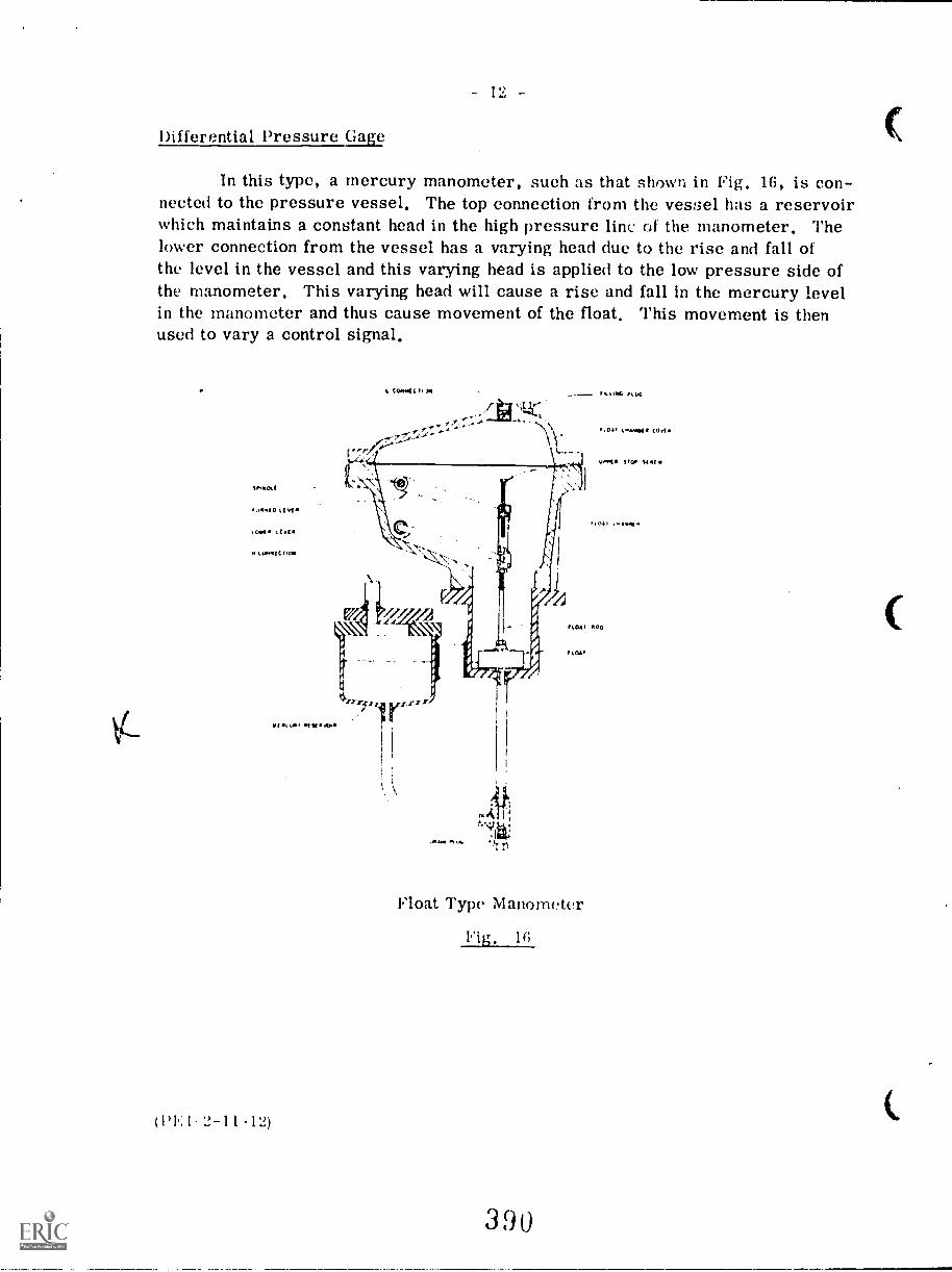
Differential Pressure Gate
In this type, a mercury manometer, such as that shown in Fig, 16, is con-nected to the pressure vessel. The top connection from the vessel has a reservoirwhich maintains a constant head in the high pressure line of the manometer, Thelower connection from the vessel has a varying head due to the rise and fall ofthe level in the vessel and this varying head is applied to the low pressure side ofthe manometer, This varying head will cause a rise and fall in the mercury levelin the manometer and thus cause movement of the float, This movement is thenused to vary a control signal,
(PEI 2-11-12)
f
-Tr
Float Type Manometer
Fig. 16
390
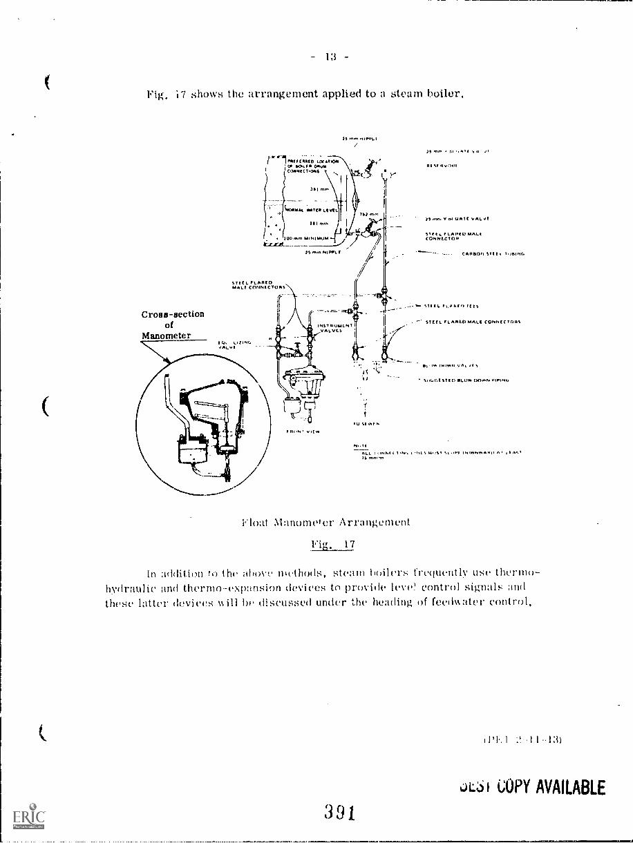
i7 shows the arrangement applied to a steam boiler.
Cross-sectionof
Manometer
ATTIT (-01Ti O LOX AT IOMOT RPIIR 011vCORRECT,ONS
ES ,TvA RRL I
TM:ARAL OSIER NKl
IOR fro. MINIMUM
STEEL FLAREDMALI CONNECTORS',
IQ, LIZINGvALvf
25 mm NIPPLE
-411t
MST AVM( NI IVALVES
VIEW
TU 5EW11.
1, mm 0*
TS Am. V ro GATT VAL...!
Sif I t. ILAREU MALICONNECTOR
CARRON STET
STEEL PLA.IN Ills
STEEL FLARED MALE CONNEC TORS
IN.)* (1411VIN V.
SI.O1iI STE IT OLOve EK,I.P. Pi PI Nu
N., I I
ALL k I.I5 Mo151511I V1 II.IWNWA AO AIS mn.nn
Float ,Manometer Arrangement
Vic, 17
In addition ro the Nhove methods, steam hoilers frequently use thermo-hydraulic and thermoexp:insion devices to provide leve! control sig-nals andthese latter devices \yin I) discussed under the heading of fecd%%ater control.
'2-11-131
LA:61 COPY AVAILABLE
391
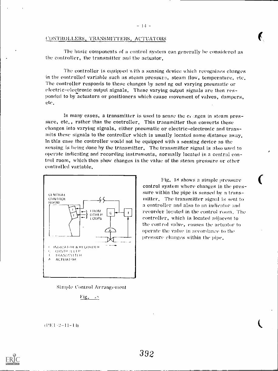
1.1
(.);;.1s1t01,1.,ERS TRANSNIII"I'RS ACTUATORS
The basic components of a control system can generally he considered asthe controller, the transmitter and the actuator.
The controller is equipped %% Oh a sensing device which recognizes changesin the controlled variable such as steam pressure, steam flow, temperature, etc.The controller responds to these changes by send ng out varying pneumatic orelectric-electronic output signals, These varying output signals are then res-ponded to by actuators or positioners which cause movement of valves, dampers,etc.
In many cases, a transmitter is used to sense the einges in steam pres-sure, etc, , rather than the controller. This transmitter then converts thesechanges into varying signals, either pneumatic or electric-electronic and trans-mits these signals to the controller which is usually located some distance away,In this ease the controller would not he equipped with a sensing device as thesensing is hying done by the transmitter. The transmitter signal is also used tooperate indicating and recording instruments, normally located in a central con-trol room, which then show changes in the value of the steam pressure or othercontrolled variable.
FROM°THU.'1 001'S
INIIICA1111{ ?4, HI CO141)114f: 4:0N I /1 11 1114
IliAt',1,,V1 I ItA ACT0A1()F4
Si mple Control Arrangement
1111.: 1 1 I 1,1)
Fig. 18 shows a simple pressurecontrol system where changes in the pres-sure within the pipe is sensed by a trans-nUtter. The transmitter signal is sent toa controller and also to an indicator andrecorder located in the control room, Thecontroller, which is located adjacent tothe control valve, onuses the actuator tooperate the valve in aordanoe to thepressure changes within the pipe.
392
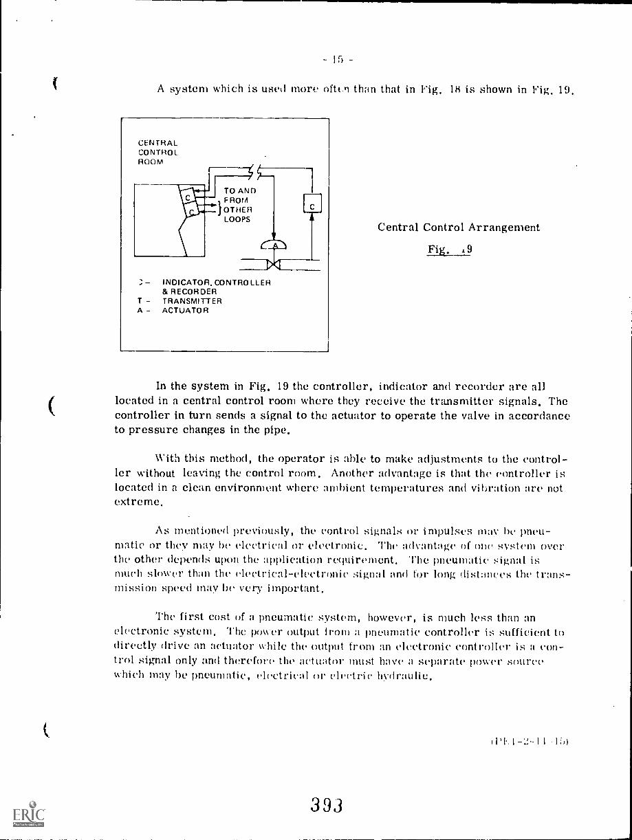
I
A system which is used more often than that in Fig. 1H is shown in Fig. 19,
CENTRALCONTROL.ROOM
TO ANDF ROM
}OTHERLOOPS
INDICATOR, CONTROLLER& RECORDER
T TRANSMITTERA- ACTUATOR
Central Control Arrangement
Fig. .9
In the system in Fig. 19 the controller, indicator and recorder are alllocated in a central control room where they receive the transmitter signals. Thecontroller in turn sends a signal to the actuator to operate the valve in accordanceto pressure changes in the pipe.
With this method, the operator is able to make adjustments to the control-ler without leaving the control room. Another advantage is that the controller itilocated in a clean environment where ambient temperatures and vibration are notextreme.
As mentioned previously, the control signals or impulses mat he pneu-matic or they may be electrical or clectronic. The advantage of one systin overthe other depends upon the application requirement. The pneumatic signal ismuch slower than the electrical- electronic signal and for long distnnces the trnns-nUssion speed may lie very important.
The first cost of a pneumatic system, however, is much less than anelectronic system. The power output Iron) a pneumatic controller is sufficient todirectly drive an actuator while the output from an electronic controller is n con-trol signal only and therefore the actuato must have a sepurnte power sourcewhich may be pneumatic, electricn1 or electric hydraulic.
393
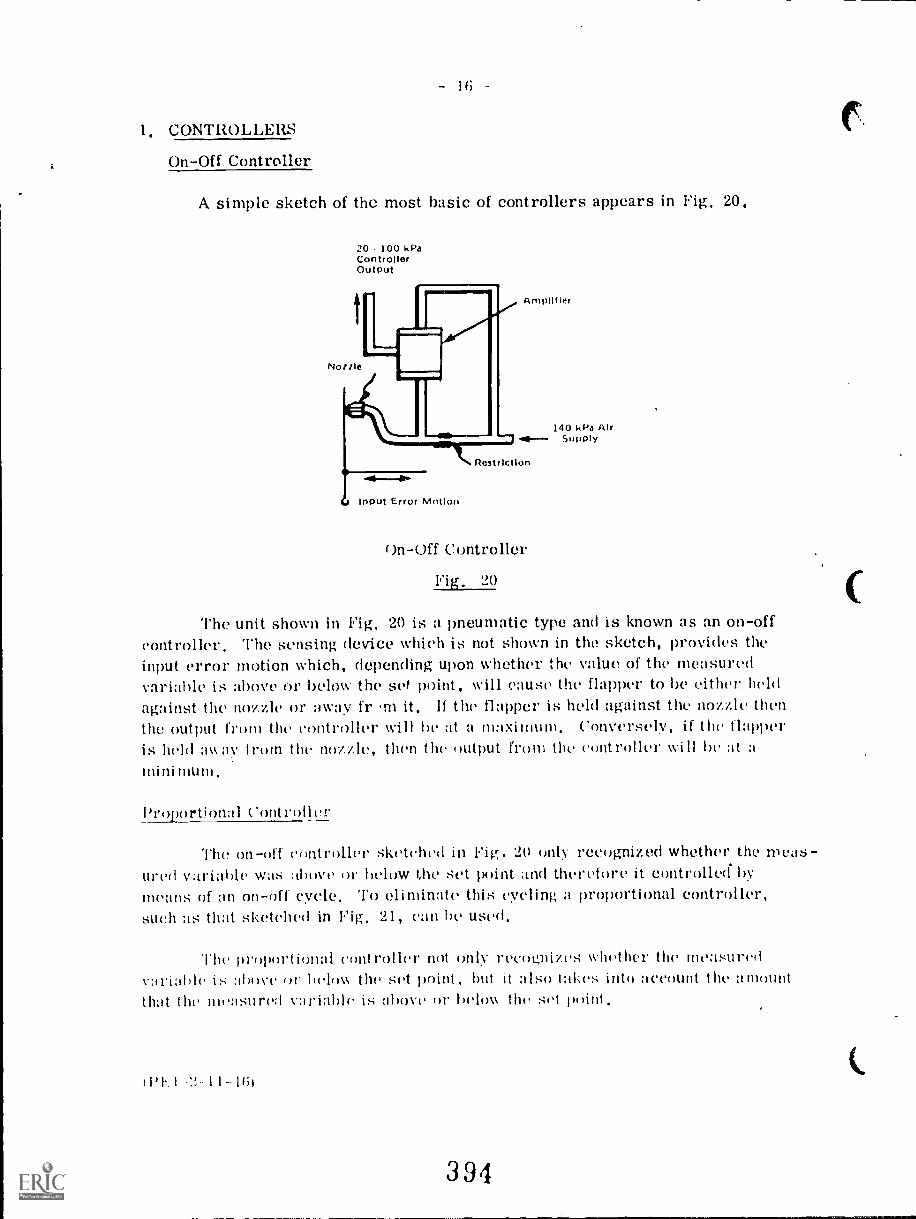
i.
1, CONTROLLERS
On-Off Controller
A simple sketch of the most basic of controllers appears in Fig, 20,
20 100 kPaControllerOutput
Nozzle
Input Error Motion
Amplifier
Restriction
on-Off Controller
Fig, 20
140 kPa AlrSupply
The unit shown in Hg, 20 is a pneumatic type and is known as an on-offcontroller, The sensing device which is not shown in the sketch, provides theinput error motion which, depending upon whether the value of the measuredvariable is above or below the set point, will cause the flapper to be either heldagainst the nozzle or away fr m it, If the flapper is held against the nozzle thenthe output from the controller will he at a maximum, Conversely, if the flapperis held away from the nozzle, than the output from the controller will he at amini mum,
Proportional Controller
The on-off controller sketched in Fig. 20 only recognized whether the nleaSUr ;11' 1 a We WaS above or below the set point ttul therefore it controlled hymeans of an on-off cycle, To eliminate this cycling a proportional controller,such as that sketched in Fig, 21, can be used,
The proportional controller not only recoi..,,nizes whether the measuredarialde ahoy(' helo% the set point, but it also takes into account the amount
that the measured variable is above or below the set point,
WI. I '2. 11-1Gi
394
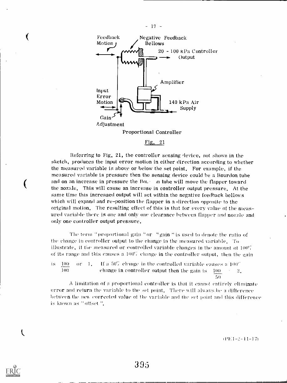
17 -
Feedback Negative FeedbackMotion Bellows
InputErrorMotion
-41-73141Gain
Adjustment
20 100 kPa ControllerOutput
Amplifier
140 kPa AirSupply
Proportional Controller
Fig, 21
Referring to Fig, 21, the controller sensing device, not shown in thesketch, produces the input error motion in either direction according to whetherthe measured variable is above or below the set point, For example, if themeasured variable is pressure then the sensing device could be a Bourdon tubeand on an increase in pressure the not. in tube will move the flapper towardthe nozAe. This will cause an increase in controller output pressure, At thesame time this increased output will act within the negative feedback bellowswhich will expand and re-position the flapper in a direction opposite to theoriginal motion, The resulting effect of this is that for every value of the meas-ured variable there is one and only one clearance between flapper and nozzle andonly one controller output pressure,
The term "proportional gain "or "gain "is used to denote the ratio ofthe change in controller output to the change in the measured variable, Toillustrate, it the measured or controlled variable changes in the amount of 100';of its range and this causes a 100'; change in the controller output, than the i2,ain
is If a 0`,.; clringe in the controlled variable causes a 100'change in controller output then the gain is 100
50
A limitation of a proixirtiona1 controller is that it cannot entirely eliminateerror and return the variable to the set point. There will aNays he a differencebetween the new corrected value of the the sot point and this difforefloois known ;Is "offset ".
100
100
0 I' 1.
WE I-2-11-17)
393
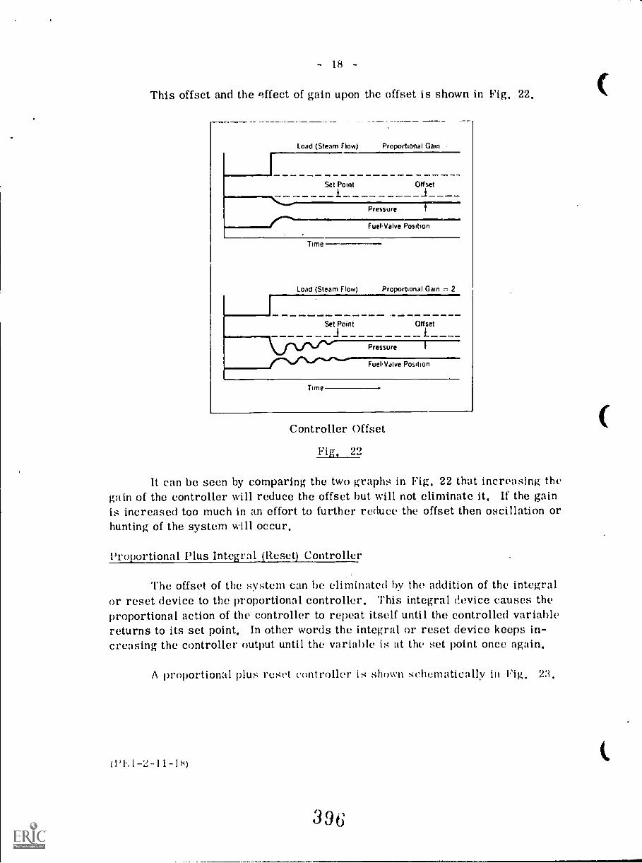
This offset and the effect of gain upon the offset is shown in Fig. 22.
Load (Steam Flow) Proportional Gain
Time
Fuel Valve Position
Load (Steam Flow) Proportional Gain = 2
Set Point OHiset
Pressure
FuelValve Position
Time
Controller Offset
Fig. 22
It can be seen by comparing the two graphs in Fig. 22 that increasing thegain of the controller will reduce the offset but will not eliminate it. If the gainis increased too much in an effort to further reduce the offset then oscillation orhunting of the system will occur.
Proportional Plus Integral (Reset) Controller
The offset of the system can be eliminated by the addition of the integralor reset device to the proportional controller. This integral device causes theproportional action of the controller to repeat itself until the controlled variablereturns to its set point. In other words the integral or reset device keeps in-creasing the controller output until the variable is at the set point once again.
A proportional plus reset controller is shown schematically ilt Hg, 23,
('1.. I-Z-11-18)
336
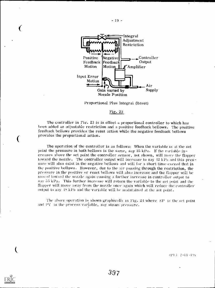
- 19 -
IntegralAdjustmentRestriction
Positive ControllerFeedback Feedback OutputMotion Motion Amplifier
Input ErrorMotion
Gain varied byNozzle Position
AirSupply
Proportional Plus Integral (Reset)
Fig. 23
The controller in F. 23 is in effect a proportional controller to which hasbeen added an adjustable restriction and a positive feedback bellows. The positivefeedback bellows provides the reset action while the negative feedback bellowsprovides the proportional action.
The operation of the controller is as follows: When the variable is at the setpoint the pressure in both bellows is the same, say 35 kpa. If the variable in-creases above the set point the controller sensor, not shown, will move the flappertoward the nozzle. The controller output will increase to say 42 k and this pres-sure will also exist in the negative bellows and will for a short time exceed that inthe positive bellows. However, due to the air passing through the restriction, thepressure in the positive or reset bellows will also increase and the flapper will bemoved toward .the nozzle again causing a further increase in controller output tosay 55 kPa. This further increase will return the variable to the set point and theflapper will move :way from the nozzle once again which will reduce the controlleroutput to say k Pa and the variable will be maintained at the set point.
The above operation i.s shown graphicall.N. in Fig. 24 where SP is the set pointand PV is the process variable, say steam pressure.
0'1%1 2-11 -191
397
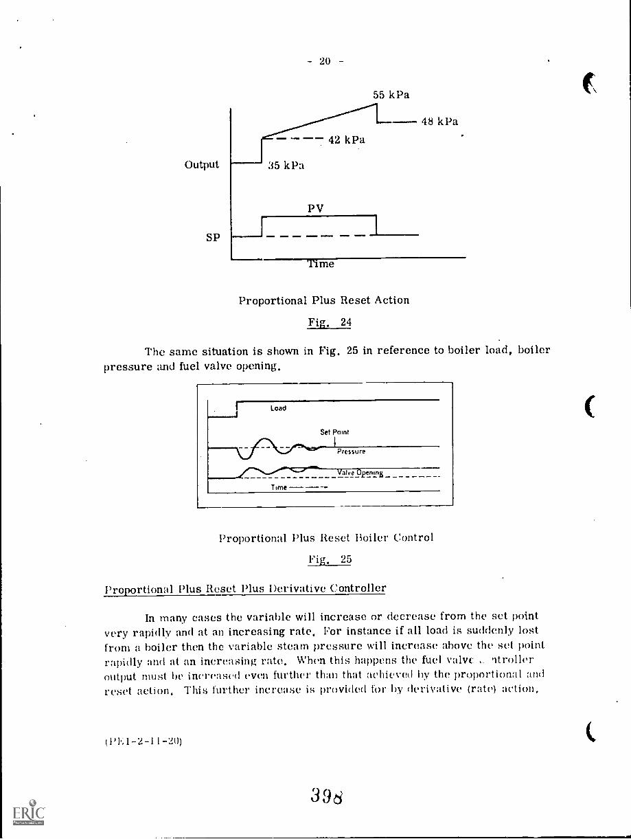
- 20
55 kPa
-- 42 kPa
Output 35 kPa
SP
PV
=MEV 1 OMNI. M.I
Time
Proportional Plus Reset Action
Fig. 24
48 kl3a
The same situation is shown in Fig. 25 in reference to boiler load, boilerpressure and fuel valve opening,
Load
Set Point
Pressure
alve_ penmE
Time
Proportional Plus Reset Boiler Control
Fig, 25
Proportional Plus Reset Plus Derivative Controller
In many cases the variable will increase or decrease from the set pointvery rapidly and at an increasing rate, For instance if all load is suddenly lostfrom a boiler then the variable steam pressure will increase above the set pointrapidly and at an increasing rate, When this happens the fuel valve strolleroutput must be increas(41 even further than that :IChievud by the proportional andreset action, This further increase is provided for by derivative (rate) action,
(PE1-2-11 -2(1)
396
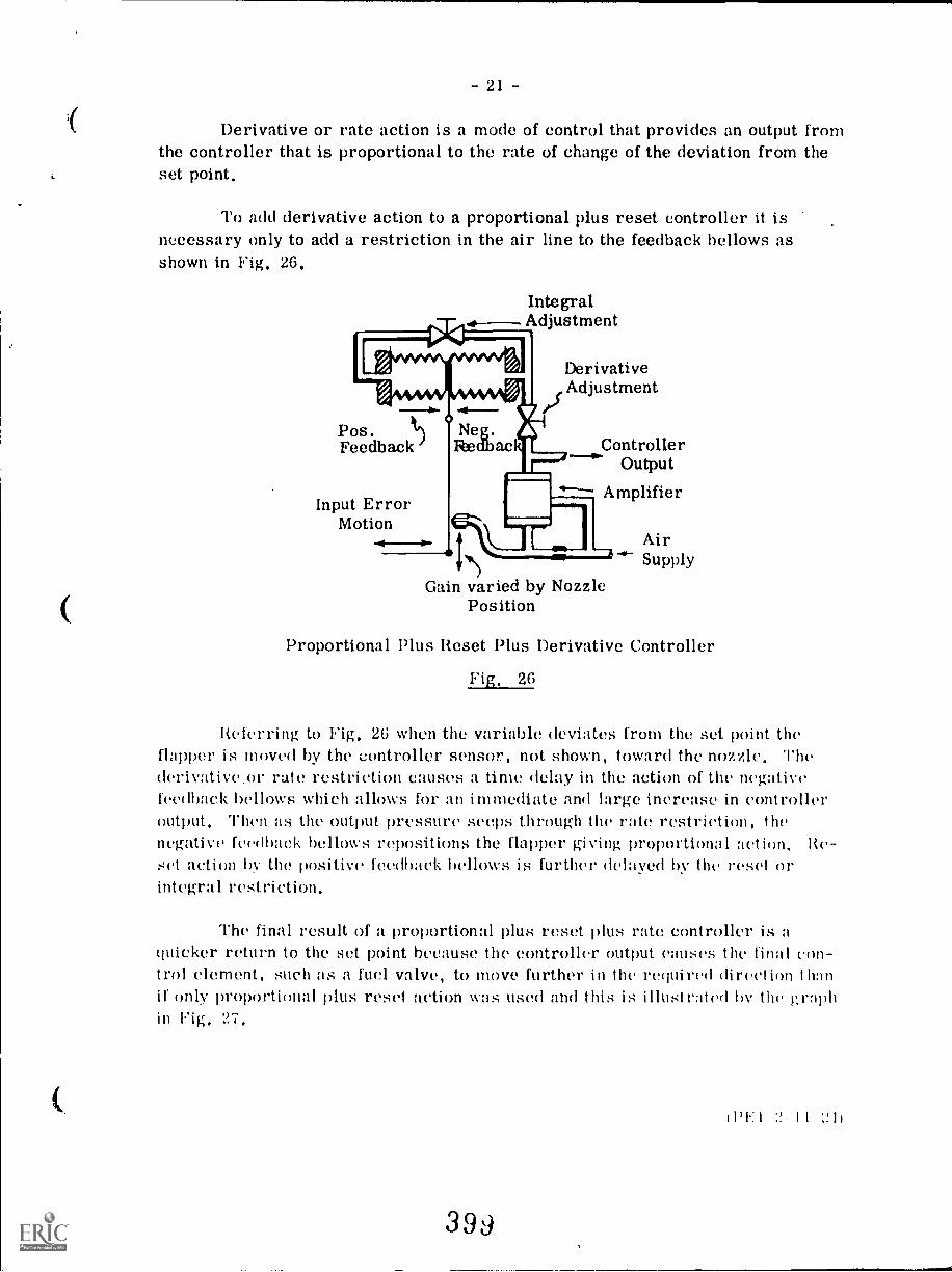
21 -
Derivative or rate action is a mode of control that provides an output fromthe controller that is proportional to the rate of change of the deviation from theset point.
To add derivative action to a proportional plus reset controller it isnecessary only to add a restriction in the air line to the feedback bellows asshown in Fig. 26.
IntegralAdjustment
Pos.Feedback
DerivativeAdjustment
Input ErrorMotion
ControllerOutput
Amplifier
Gain varied by NozzlePosition
AirSupply
Proportional Plus Reset Plus Derivative Controller
Fig, 26
Referring to Fig, 2(; when the variable deviates from the set point theflapper is moved by the controller sensor, not shown, toward the nozzle. Thederivative.or rate restriction causes a time delay in the action of the negativefeedback bellows which allows for an immediate and large increase in controlleroutput. Then as the output pressure seeps through the rate restriction, thenegative feedback bellows repositions the flapper giving proportional adion, Re-set action hV t.110 positive feedback bt'llOWS is further delayed by the reset orintegral restriction.
The final result of a proportional plus reset plus rate controller is aquicker return to the set point because the controller output causes the final on-trol element, such as a fuel valve, to move further in the required direction thanif only proportional plus reset action was used and this is illustrated the graphin Fig. 27,
(1)1.:1 I I :!.1)
399
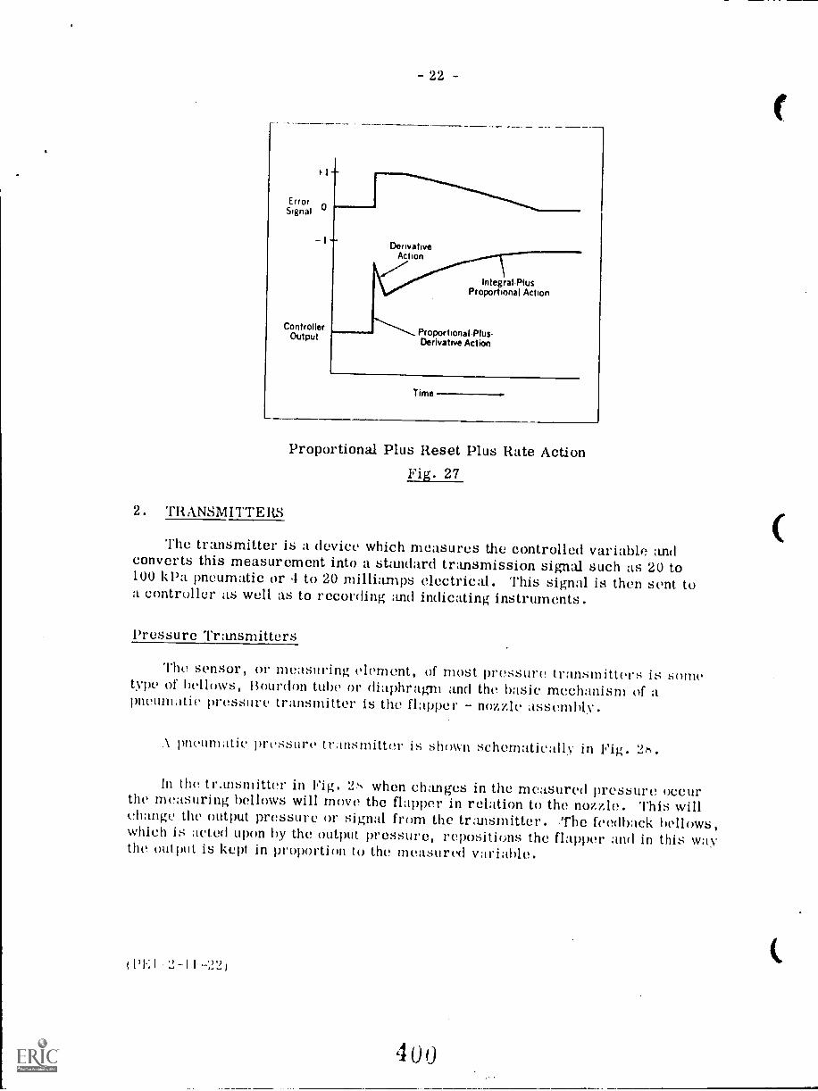
ErrorSignal
ControllerOutput
22 -
DerivativeAction
IntegralPlusProportional Action
ProportionalPlusDerivative Action
Time
Proportional Plus Reset Plus Rate ActionFig. 27
2. TRANSMITTERS
The transmitter is a device which measures the controlled variable andconverts this measurement into a standard transmission signal such as 20 to100 kPa pneumatic or 1 to 20 milliamps electrical. This signal is then sent toa controller as well as to recording and indicating instruments.
Pressure Transmitters
The sensor, or measuring element, of most pressure transmitters is sometype of belhAvs, Bourdon tube or diaphragms and the basic mechanism of apneumatic pressure transmitter is the flapper - nozzle assembly.
.k pneumatic pressure transmitter is shown schematicall.,. in Fig. 2r+.
In the transmitter in Fig. 2s when changes in the measured pressure occurthe measuring bellows will move the flapper in relation to the nozzle. This willchange the output pressure or signal from the transmitter. The feedback bellows,which is acted upon by the output pressure, repositions the flapper and in this waythe output is kept in proportion to the measured variable.
(PEI 2-II -22)
4 00
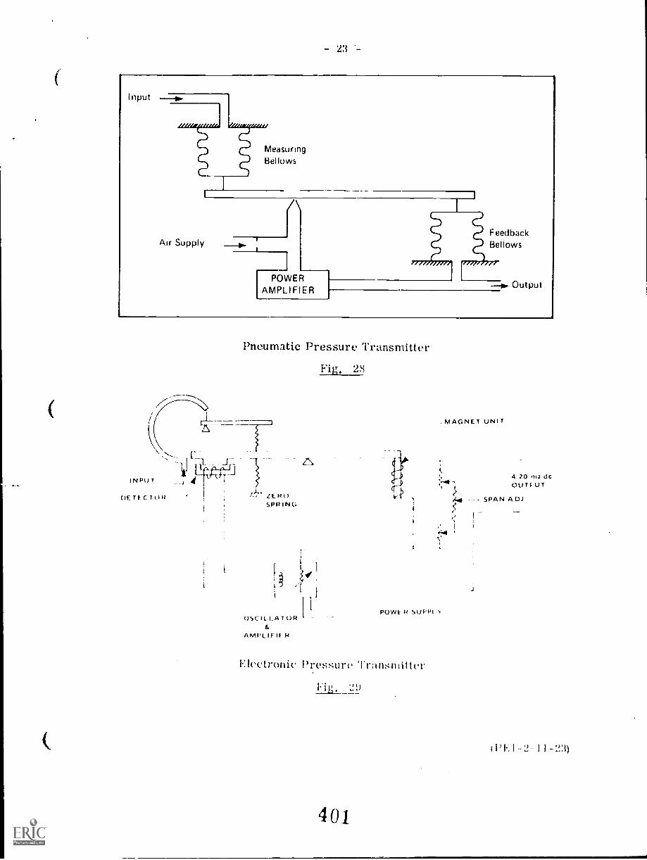
- 23
Input
L / / /l, 4WW., Atemed "Wei,
Air Supply
MeasuringBellows
T
rTOWERAMPLIFIER
FeedbackBellows
1,7", //,
--b. Output
Pneumatic Pressure Transmitter
Fig. 28
OSCILLATOR
AMPLIFIF
POVVE k SUPPI
Electronic Pressure Trnnsmitter
. MAGNET UNIT
4 20 ma 0cOUTI UT
2,4 --- SPAN A DJ
. 1
'241
( l'1.; 1 -?,- 1 1 -'23)
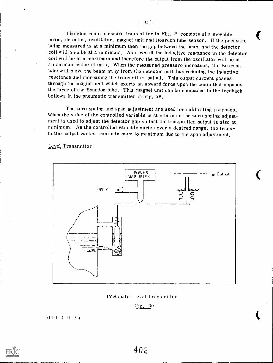
The electronic pressure transmitter in Fig. 29 consists of a movablebeam, detector, oscillator, magnet unit and Bourdon tube sensor. If the pressurebeing measured is at a minimum then the gap between the beam and the detectorcoil will also be at a minimum. As a result the inductive reactance in the detectorcoil will be at a maximum and therefore the output from the oscillator will be ata minimum value (4 ma ). When the measured pressure increases, the Bourdontube will move the beam away from the detector coil thus reducing the inductivereactance and increasing the transmitter output. This output current passesthrough the magnet unit which exerts an upward force upon the beam that opposesthe force of the Bourdon tube, This magnet unit can be compared to the feedbackbellows in the pneumatic transmitter in Fig. 28.
The zero spring and span adjustment are used for calibrating purposes.When the value of the controlled variable is at minimum the zero spring adjust-ment is used to adjust the detector gap so that the transmitter output is also atminimum. As the controlled variable varies over a desired range, the trans-mitter output varies from minimum to maximum due to the span adjustment.
Level Transmitter
Supply
POWERAMPLIFIER
Output
I PI. I -1! -I 1-'2 1)
Pneumatic Level Trati:;mitter
402
:30
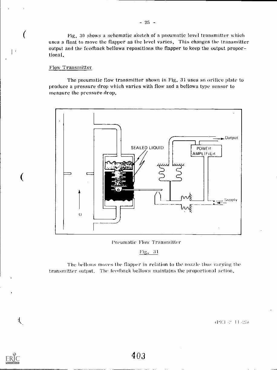
25 -
Fig. 30 shows a schematic sketch of a pneumatic level transmitter whichuses a float to move the flapper as the level varies. This changes the transmitteroutput and the feedback bellows repositions the flapper to keep the output propor-tional.
Flow Transmitter
The pneumatic flow transmitter shown in Fig. 31 uses an orifice plate toproduce a pressure drop which varies with flow and a bellows type sensor tomeasure the pressure drop.
Pneumatic Flow Transmitter
Fig. 3 1
The bellows moves the flapper in relation to the nozzle thus varying thetransmitter output. The feedback bellows maintains the proportional action.
I 'V. 1 I I -:!:»
403
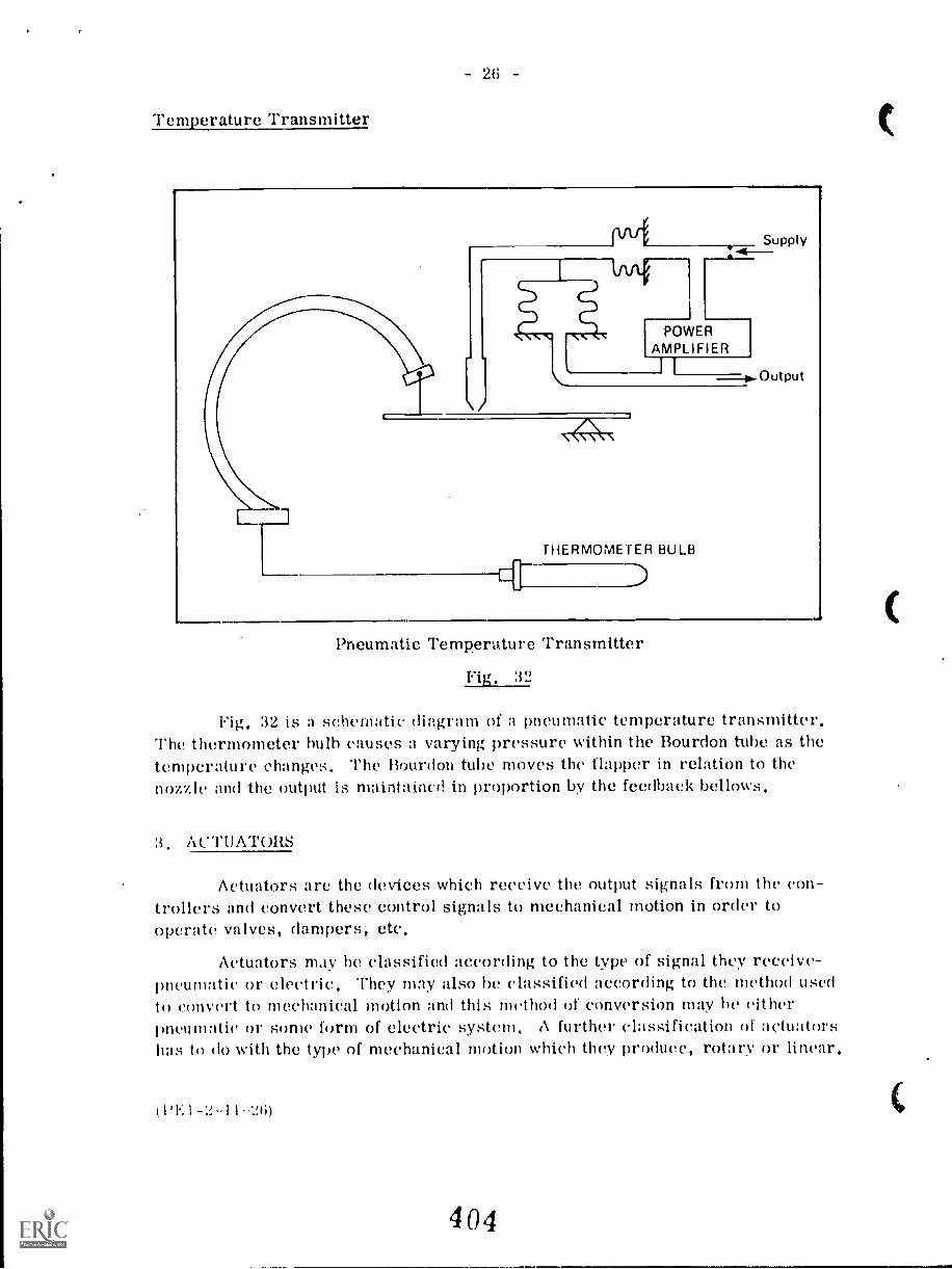
Temperature Transmitter
(".LT_]
26
Supply-4--
POWERAMPLIFIER
THERMOMETER BULB
Output
Pneumatic Temperature Transmitter
Fig. 32
Fig. 32 is a schematic diagram of a pneumatic temperature transmitter.The thermometer bulb causes a varying pressure within the Bourdon tube as thetemperature changes. The Bourdon tube moves the flapper in relation to thenozzle and the output is maintained in proportion by the feedback bellows.
3. ACTUATORS
Actuators are the devices which receive the output signals from the con-trollers and convert these control signals to mechanical motion in order tooperate valves, dampers, etc.
Actuators may he classified according to the type of signal they receive-pneumatic or electric. They may also be classified according to the method usedto convert to mechanical motion and this method of conversion may he eitherpneumatic or some form of electric system. A further classification of actuatorshas to do with the type of mechanical motion which they produce, rotary or linear.
'1.: I -2-1 1 -26)
404
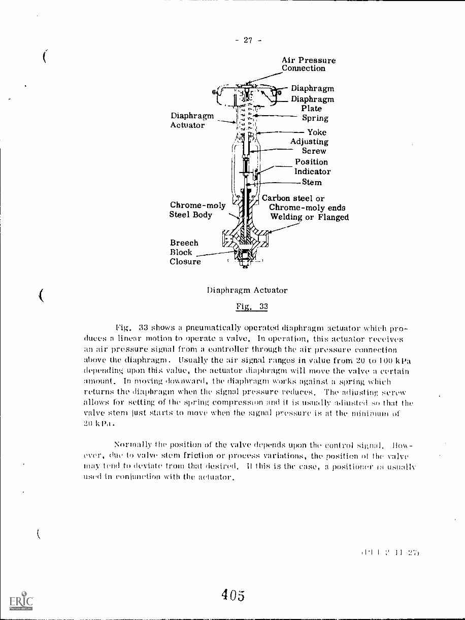
27 -
Air PressureConnection
DiaphragmActuator
DiaphragmDiaphragm
PlateSpring
YokeAdjusting
ScrewPositionIndicator
Stem
Chrome-molySteel Body
BreechBlockClosure
Carbon steel orChrome-moly endsWelding or Flanged
Diaphragm Actuator
Fig. 33
Fig. 33 shows a pneumatically operated diaphragm actuator which pro-duces a linear motion to operate a valve. In operation, this actuator receivesan air pressure signal from a controller through the air pressure connectionabove the diaphragm. Usually the air signal ranges in value from 20 to 100 k Padependin!4 upon this value, the actuator diaphragm will move the valve a certainamount. In moving downwar(I, the diaphragm works against a spring whichreturns the diaphragm when the signal pressure reduces. The adjusting screwallows for setting of the spring compression and it is usimllv adjusted so that thevalve stem just starts to move when the signal pressure is at the minimum of20 kPa.
Normally the position of the valve depends upon the control signal.ever, due to valve stem friction or process variations, the position of the valvemay tend to deviate from that desired. It this is the case, a positioner is usuallyused in conjunction with the actuator.
I I :' I I .._!7)
405
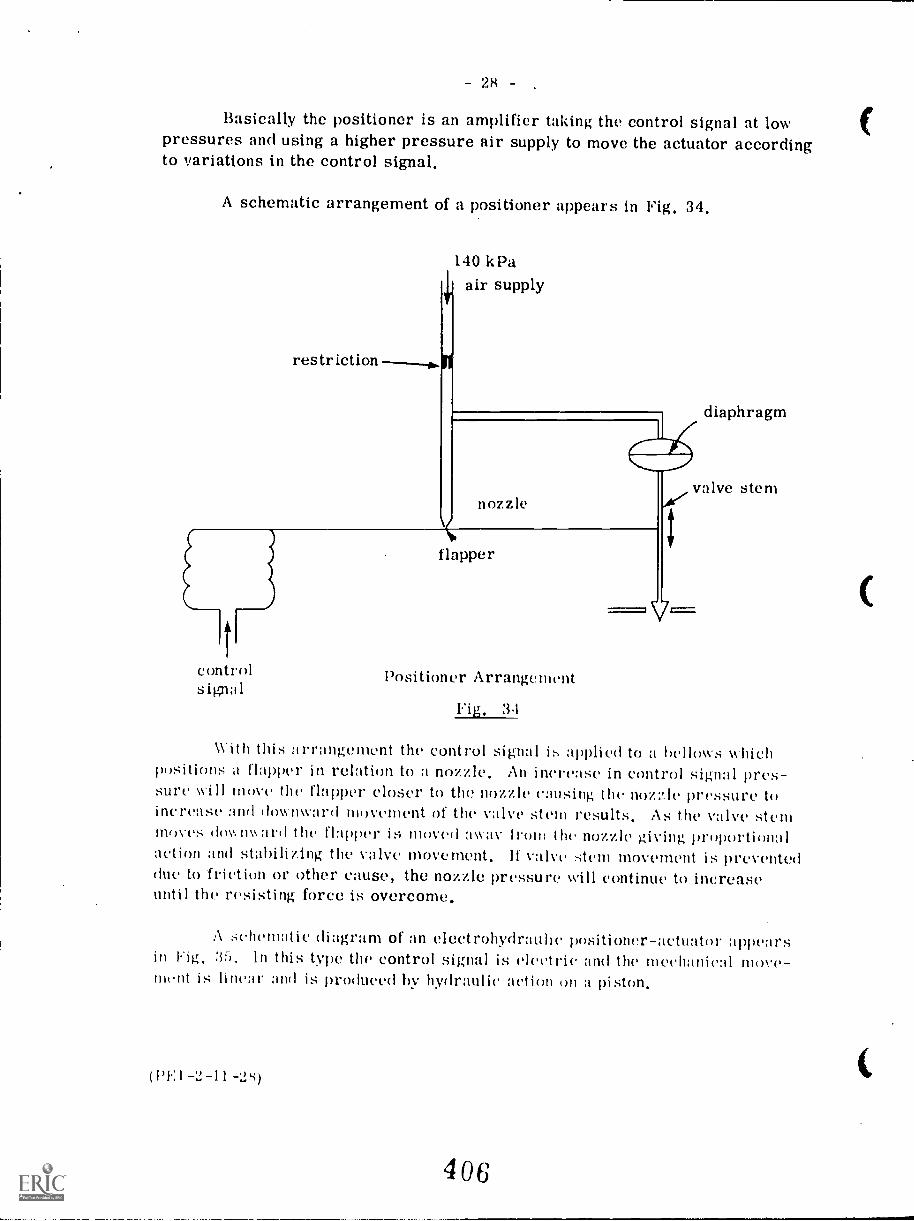
28
Basically the positioner is an amplifier taking the control signal at lowpressures and using a higher pressure air supply to move the actuator accordingto variations in the control signal.
A schematic arrangement of a positioner appears in Fig, 34,
restriction--1.111
140 kPaair supply
nozzle
controlsipal
flapper
Positioner Arrangement
Fig, 34
diaphragm
With thiti arrangement the control signal is applied to a bellows whichpositions a flapper in relation to a nozzle. An increase in control signal pres-sure will move the flapper closer to the nozzle causing the noz:qc pressure toincrease and downward movement of the valve stem results. As the valve stemfrif)ves doy.n\kard the flapper is moved away from the nozzle giving proportionalaction and stabilizing the valve movement. If valve stem movement is preventeddue to -friction or other cause, the nozzle pressure will continue to increaseuntil the resisting force is overcome.
A schematic diagram of an electrohydrauhe positioner-actuator appearsin Hg. 35. In this type the control signal is electric. and the mechanical move-ment is linear and is produced by hydraulic action on a piston.
(1)I.: 1 -2-11-2s)
406
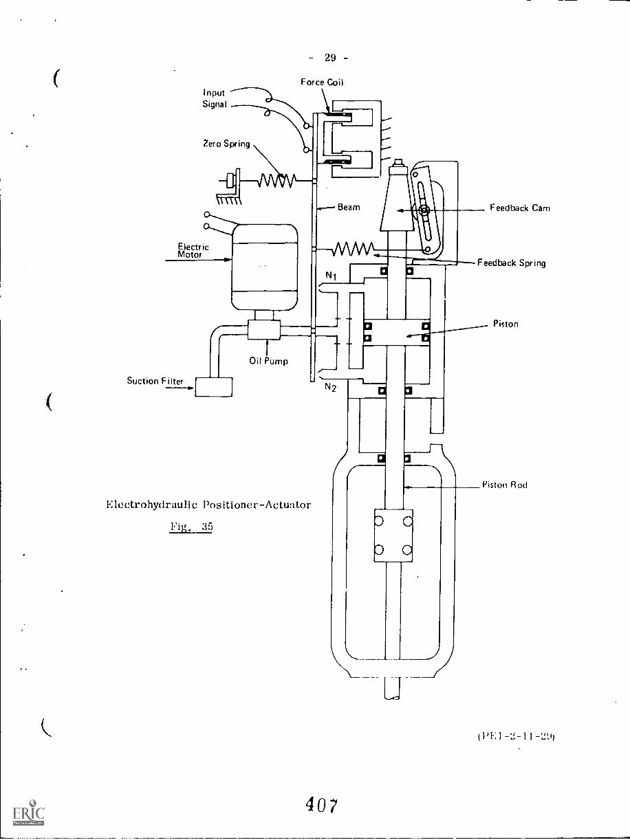
InputSignal
29
Force Coil
Zero Spring
ElectricMotor
Feedback Cam
Feedback Spring
Piston
Suction Filter
Oil Pump
Electrohydraulic Positioner-Actuator
Fig. 35
N2
407
Piston Rod
1 -2- l 1 -29)
30
Referring to Fig. 35, the electric motor runs continuously driving the oilpump which produces a high pressure flow of oil through the nozzles N1 and N2.The control signal is applied to a force coil and on an increase of signal the coilwill move within the core surroundingit. This moves the beam and restrictsnozzle N1 causing a build up of pressure above the piston. As the piston movesdown, the feedback cam allows the bean, to he repo' it,oned. If the signal decreases,nozzle N2 will be restricted and the piston will me ipwardly. The movementof the piston rod can be used to position a valve, damper etc.
FEEDWATER CONTROL SYSTEMS
Most shop-assembled boilers in the lower capacity range and the loweroperating pressure range are equipped with self-contained feedwater systems ofthe thermo-hydraulic or thermo-expansion types. For higher capacity boilersand those operating at higher pressures, a pneumatic or electrically operatedfeedwater control system is used. These may be single, two, or three elementtypes.
Thermo-hydraulic Regulator
This system consists essentially of a feedwater regulating valve which isactuated by a generator. The generator consists of two tubes, one within theother. The ends of the inner tube arc connected to the steam and water spacesof the boiler thus the level of water in the inner tube Nv i 1 1 he the same as theboiler drum level. The outer tube is connected at the bottom to a bellows onthe feedwater regulating valve.
To pu! the regulator into operation the outer tube ani-the bellows are filledwith water and sealed off. In operation the heat from the Meam in the upper por-tion of the inner tube causes the surrounding water in the outer tube to flash tosteam, forcing water down into the bellows until the water levels in the inner andouter tubes are equal. This will cause the bellows to expand and open the feed-water Valve in direct proportion to the water level in the generator.
If the water level in the boiler and therefore in the inner tube rises, someof the steam in the outer tube will condense which will decrease the pressure inthe bellows. As a result the feedwater valve will close in proportion.
Fig. 36 shows the al rangement of the thermo-hydraulic' regulator.
(1'P:1-'2-11-31h
408
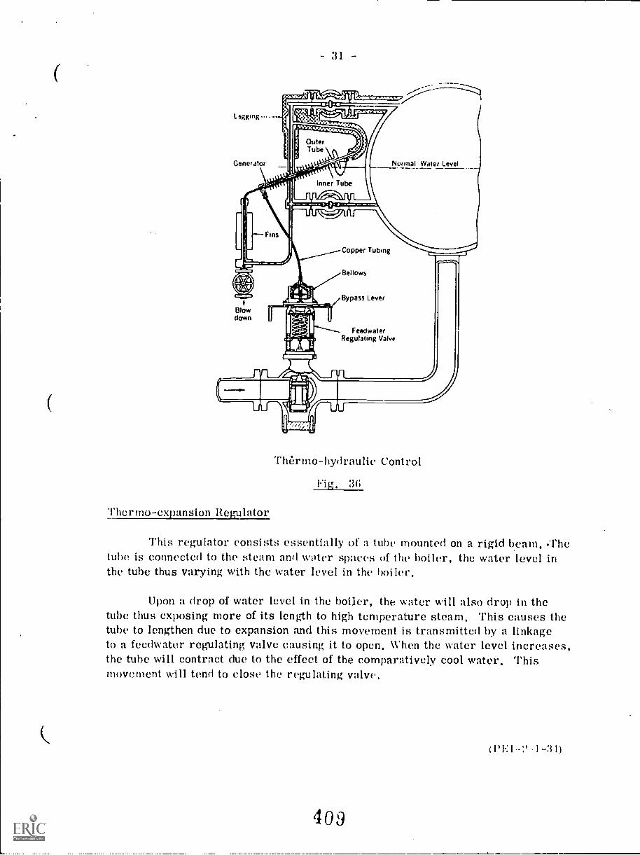
31
Normal Water Level
Thermo-hydraulic Control
Fig, 3E;
hermo- expansion Regulator
This regulator consists essentially of a tube mounted on a rigid beam, .Thetube is connected to the steam and water spaces of the boiler, the water level inthe tube thus varying with the water level in the boiler,
Upon a drop of water level in the boiler, the water will also drop in thetube thus exposing more of its length to high temperature steam, This causes thetube to lengthen due to expansion and this movement is transmitted by a linkageto a feedwater regulating valve causing it to open, When the water level increases,the tube will contract due to the effect of the comparatively cool water, Thismovement will tend to close the regulating valve,
(1)1:1 1-31)
409
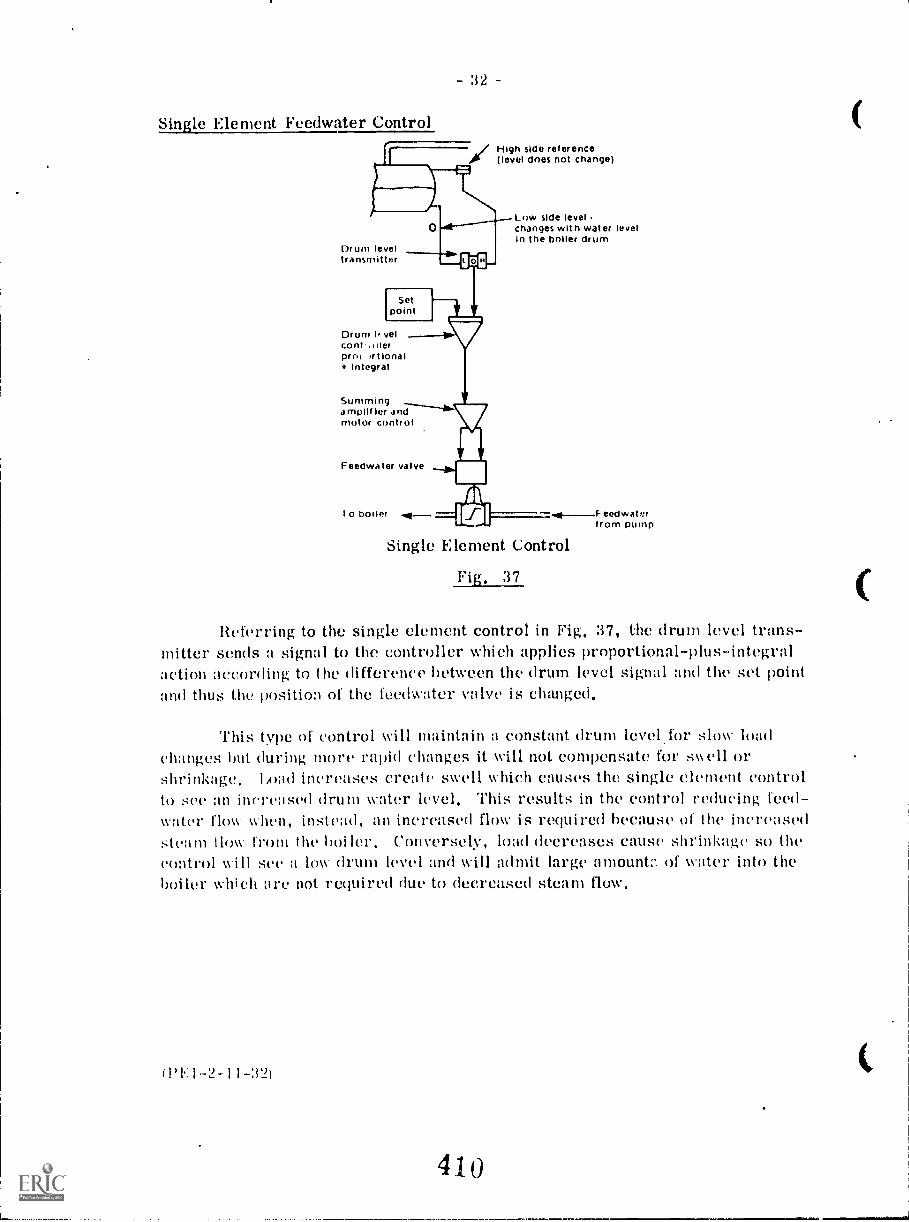
32
Single Element F'eedwater Control/High side reference(level does not change)
0Drum leveltransmitter
Drum I' velcontpros rtlonal+ Integral
Summinga mplif ler andmotor control
Feedwa ter valve
I o boiler Ai-
Low side levelchanges with water levelIn the boiler drum
Single Element Control
Fig. 37
eedwalerfrom pump
Referring to the single element control in Fig, 37, the drum level trans-mitter sends a signal to the controller which applies proportional-plus-integralaction according to the difference between the drum level signal and the set pointand thus the position of the teedwater valve is changed,
This type of control %ill maintain a constant drum level for slow loadchanges but during more rapid changes it will not compensate for swell orshrinkage, Load increases create swell which causes the single element controlto see an increased drum water level, This results in the control reducing feed-water flow when, instead, an increased flow is required because of the increasedsteam (low front the boiler, Conversely, load decreases cause shrinkage so thecontrol will see a low drum level and will admit large amount:: of water into theholler which are not required due to decreased steam flow,
0'11-2-11-32)
410
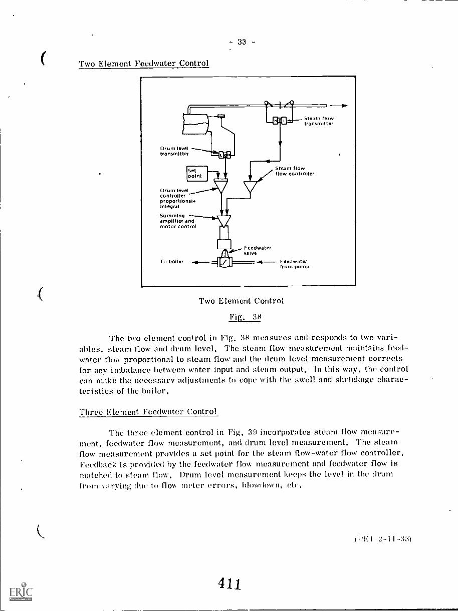
- 33 -
Two Element Feedwater Control
Drum leveltransmitter
Drum levelcontrollerproportional.Integral
Summingamplifier andmotor control
Setpoint
To boiler
Feedwatervalve
Steam flowtransmitter
Steam flowflow controller
Feedwaterfrom pump
Two Element Control
Fig. 38
The two element control in Fig. 38 measures and responds to two vari-ables, steam flow and drum level. The steam flow measurement maintains feed-water flow proportional to steam flow and the drum level measurement correctsfor any imbalance between water input and steam output. In this way, the controlcan make the necessary adjustments to cope with the swell and shrinkage charac-teristics of the boiler.
Three Element Feedwater Control
The three clement control in Fig. 39 incorporates steam flow measure-ment, feedwater flow measurement, and drum level measurement. The steamflow measurement provides a set point for the steam flow-water flow controller.Feedback is provided by the feedwater flow measurement and feedwater flow ismatched to steam flow. Drum level measurement keeps the level in the drumfrom varying due to flow meter errors, blowdown, etc.
1)1.: 1 -2-11-33)
411
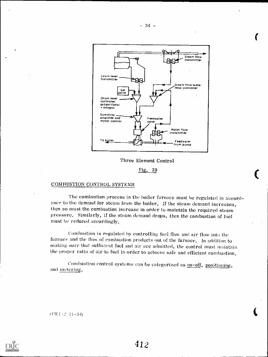
34 -
arum leveltransmitter
Drum levelcontrollerproportional
Integral
Summingamplifier andmotor control
Steam flowtransmitter
Steam flowwaterflow controller
Water flowtransmitter
Feedwaterfrom pump
Three Element Control
Fig, 39
COMBUSTION CONTROL SYSTEMS
The combustion process in the boiler furnace must he regulated in accord-ance to the demand for steam from the boiler. If the steam demand increases,then so must the combustion increase in order to maintain the required steampressure. Similarly, if the steam demand drops, then the combustion of fnelmust be reduced accordingly,
Combustion is regulated by controlling fuel flow and air flow into thefurnace and the flow of combustion products out of the furnace. In addition tomaking sure that sufficient fuel and air arc admitted, the control must maintainthe proper ratio of air to fuel in order to achieve safe and efficient combustion.
Combustion control systems can be categorized as on-off, positioning,and teetering,
(PI -11--34)
412
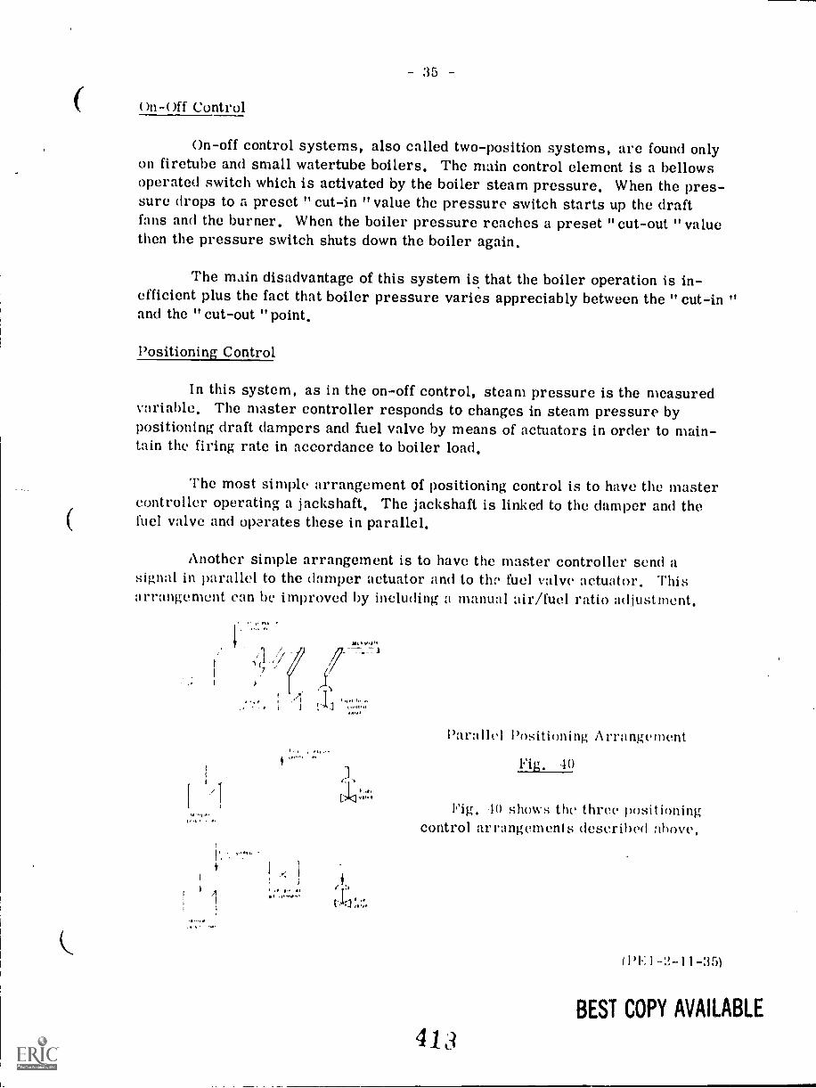
on-off Control
On-off control systems, also called two-position systems, are found onlyon firetube and small watertube boilers, The main control clement is a bellowsoperated switch which is activated by the boiler steam pressure, When the pres-sure drops to a preset " cut-in "value the pressure switch starts up the draftfans and the burner, When the boiler pressure reaches a preset "cut-out "valuethen the pressure switch shuts down the boiler again,
The main disadvantage of this system is that the boiler operation is in-efficient plus the fact that boiler pressure varies appreciably between the " cut-in "and the " cut-out "point,
Positioning Control
In this system, as in the on-off control, steam pressure is the measuredvariable, The master controller responds to changes in steam pressure bypositioning draft dampers and fuel valve by means of actuators in order to main-tain the firing rate in accordance to boiler load,
The most simple arrangement of positioning control is to have the mastercontroller operating a jackshaft, The jackshaft is linked to the damper and thefuel valve and operates these in parallel,
Another simple arrangement is to have the master controller send asignal in parallel to the damper actuator and to thzb fuel valve actuator. Thisarrangement can be improved by including a manual air/fuel ratio adjustment.
1 tI 7
A
f
V,..1
Parallel Positioning' Arrangement
Fig. 40
Pig. to shows the three positioningcontrol arrangements described above.
413
(14:1-2-11-35)
BEST COPY AVAILABLE
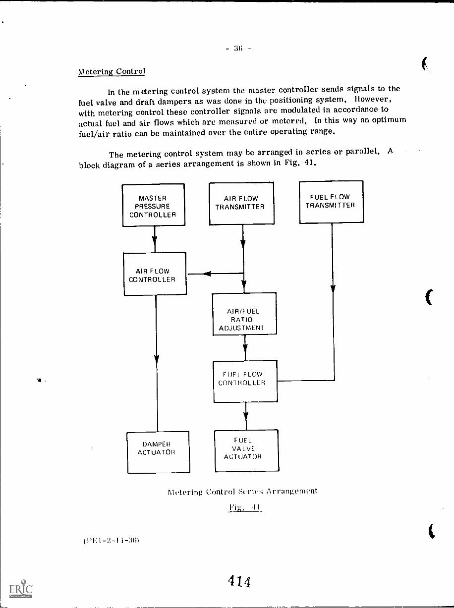
Metering Control
In the mitering control system the master controller sends signals to thefuel valve and draft dampers as was done in the positioning system. However,
with metering control these controller signals are modulated in accordance to
actual fuel and air flows which are measured or metered. In this way an optimumfuel/air ratio can be maintained over the entire operating range,
The metering control system may be arranged in series or parallel. Ablock diagram of a series arrangement is shown in Fig. 41,
MASTERPRESSURE
CONTROLLER
AIR FLOWCONTROLLER
AIR FLOWTRANSMITTER
DAMPERACTUATOR
(PEI-2-11-3(1)
AIR/FUELRATIO
ADJUSTMENT
V
FUEL FLOWCONTROLLER
FUEL FLOWTRANSMITTER
FUELVALVE
ACTUATOR
Metering Control Seriet Arrangement
Fig. 11
414
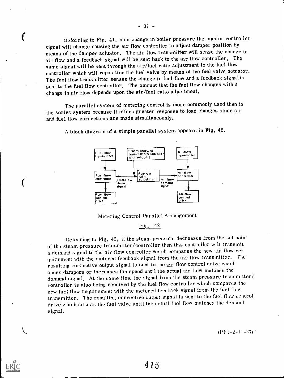
37
Referring to Fig, 41, on a change in boiler pressure the master controllersignal will change causing the air flow controller to adjust damper position bymeans of the damper actuator. The air flow transmitter will sense the change inair flow and a feedback signal will be sent back to the air flow controller, The
same signal will be sent through the air/fuel ratio adjustment to the fuel flowcontroller which will reposition the fuel valve by means of the fuel valve actuator.The fuel flow transmitter senses the change in fuel flow and a feedback signal issent to the fuel flow controller. The amount that the fuel flow changes with achange in air flow depends upon the air/fuel ratio adjustment.
The parallel system of metering control is more commonly used than isthe series system because it offers greater response to load changes since airand fuel flow corrections are made simultaneously.
A block diagram of a simple parallel system appears in Fig. 42.
Fuelflowtransmitter
whi
Steam-pressuretransmitter/controllerwith setpolnt
Alrflowtransmitter
Air-flowdemandsignal
Fuelf owcontroller
Fuel/airratioadjustment
Air-flowcontroller
Fuelflowdemandsignal
Fue11 owcontroldrive
Alrflowcontroldrive
Metering Control Parallel Arrangement
Fig, 42
Referring to Fig. 42, if the steam pressure decreases from the set pointof the steam pressure transmitter/controller then this controller will transmita demand signal to the air flow controller which compares the new air flow re-quirement with the metered feedback signal from the air flow transmitter. The
resulting corrective output signal is sent to the air flow control drive whichopens dampers or increases fan speed until the actual air flow matches the
demand signal. At the same time the signal from the steam pressure transmitter/controller is also being received by the fuel flow controller which compares thenew fuel flow requirement with the metered feedback signal from the fuel flow
transmitter. The resulting corrective output signal is sent to the fuel flow controldrive which adjusts the fuel valve until the actual fuel flow matches the demand
(PE1-2-11-37)
38 -
Combustion Control Arrangements
It is necessary that the amount of combustion air be proportioned to theamount of fuel being burned and this proportioning can be done manually or auto-matically. The amount of air supplied must be over and above that required fortheoretical perfect combustion in order to assure that sufficient oxygen contactsall the fuel. This air is referred to as excess air and it must be kept to a mini-mum otherwise boiler efficiency will decrease. Conversely if insufficient excessair is supplied then incomplete combustion will result giving lower boiler efficien-cy as well as the formation of combustible products that can present an explosionhazard in the boiler furnace and passes.
In order to determine the amount of air required for varying boiler loads,three basic guides are used for control systems. These are steam flow-air flow,fuel flow-air flow, and gas analysis.
1, Steam Flow - Air Flow
As mentioned in the previous section, the proportion of air to fuel(air/fuel ratio) is extremely important as far as boiler efficiency and safety areconcerned. The most direct way to determine whether the air and the fuel arein the correct amounts would be to measure the fuel flow and the air flow and toadjust them when necessary in order to maintain the correct ratio. However,with certain types of fuel, such as coal, it is difficult to measure fuel flow. Inthese cases, the steam flow is measured and is used as an indication of fuel con-sumption or heat absorption, The air flow is also measured and is maintained ina certain ratio with the steam flow, In this way a ratio is indirectly maintainedbetween the air flow and the fuel flow,
A block (littgr;tt of :1 steam flO air flow combustion control system isshown in I'ig.
Control symbols used in Vig, arc defined in Table I,
Referring to rig, .13, upon a change in boiler pressure, the steam pres-sure transmitter will simultaneously signal a change in both fuel flow and airflow through the steam pressure controller and boiler master controller, Thecorrect air /fuel ratio is maintained by the combustion controller which receivessignals from the steam flow transmitter and the air flow transmitter.
416
C
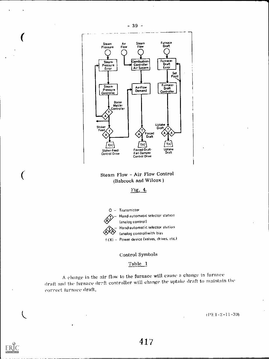
SteamPressure
Stearn.Pressure
Error
Steam-Pressure
Controller
AirFlow
-39-
SteamFlow
9
BoilerMaster
Controller
4StokerFeed 0
Combustion-ControllerAir System
.4iAir-FlowDemand
I 1(x)\
Stoker.Feed-Control Drive
f(x)
Forced-Draft-Fan Damper-Control Drive
ForcedDraft
FurnaceDraft
UptakeDraft
UptakeDraft
Steam Flow - Air Flow Control(Babcock and Wilcox )
Fig. 4.
0 TransmitterHand-automatic selector station
(analog control)
A. Hand-automatic selector station
(analog control)with bias
f (X) Power device (valves, drives, etc.)
Control Symbols
Table 1
A change in the air flow to the furnace will cause a change in furnace
draft and the furnace drift controller will change the uptake draft to maintain the
correct furnace draft.
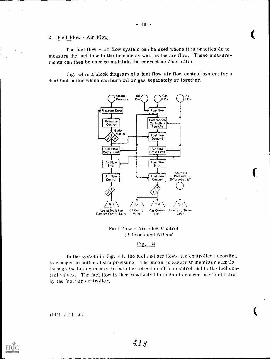
- 40
2. Fuel Flow - Air Flow
The fuel flow - air flow system can be used where it is practicable tomeasure the fuel flow to the furnace as well as the air flow. These measure-ments can then be used to maintain the correct air/fuel ratio.
Fig. 44 is a block diagram of a fuel flow-air flow control system for adual fuel boiler which can burn oil or gas separately or together.
Steam OilPressure Flow
41Pressure Error!
PressureControl
BoilerMaster
CombustionController go
Fuel/Air
4
4Fuel-FlowDemand
Fuel Flow AirFlowCross Limit Cross Limit
Air-Flow Fuel-F lowError Error
Flow
Steam OilAirflow Fuel Flow PressureControl Control Differential, AP
Forced Draft Fan 011 Control Gas ControlOamper-Control Drive Valve Vdive
Atorit...: SteamVala.
Fuel Flow Air Flow Control(Babcock and Wilcox)
Fig, 44
In the system in Fig. 44, the fuel and air flows arc controlled accordingto changes in boiler steam pressure. The steam pressure transmitter signalsthrough the boiler master to both the forced draft fan control and to the fuel con-trol valves, The fuel flow is then readjusted to maintain correct air/fuel ratioby the fuel/air controller.
(1'F:1-2-11-40)
418
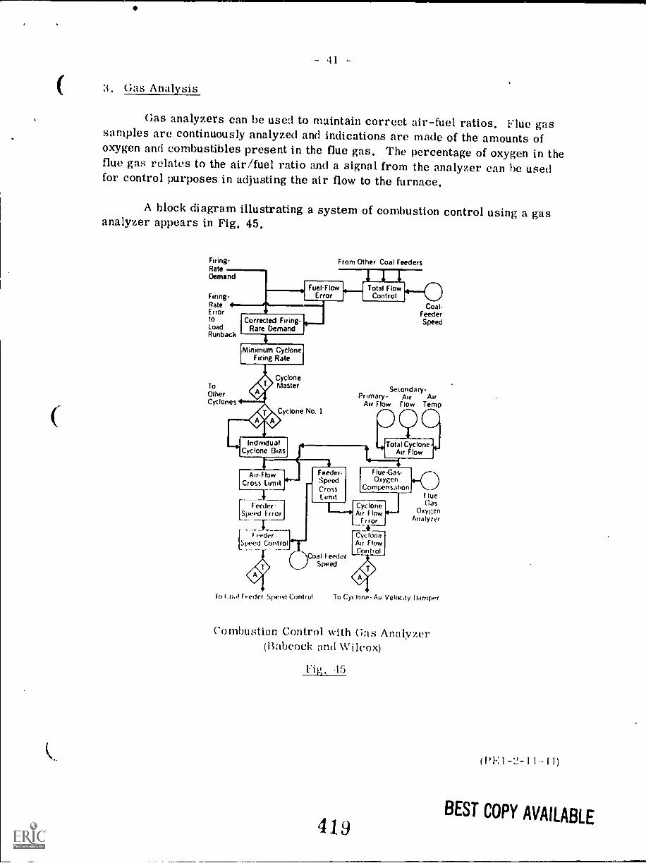
3. Gas Analysis
Gas analyzers can be used to maintain correct air-fuel ratios. Flue gassamples are continuously analyzed and indications are made of the amounts ofoxygen and combustibles present in the flue gas. The percentage of oxygen in theflue gas relates to the air/fuel ratio and a signal from the analyzer can be usedfor control purposes in adjusting the air flow to the furnace.
A block diagram illustrating a system of combustion control using a gasanalyzer appears in Fig. 45.
Firing - From Other Coal FeedersRateDemand
I
Fuel-Flow FlowFiring- Error Control
Coal.Rate *Error Feeder
Corrected Firing-to SpeedLoad Rate DemandRunback
4
ToOtherCyclones
Minimum CycloneFiring Rate
CycloneMaster
Cyclone No. I
IndividualCyclone Bias
Air-FlowCross Limit
4kFeeder
peed Error
r..,,;:,-7-;;pecci Control
Secondary-Primary Air Air
Air Flow flow Temp
0Total Cyclone
Air Flow
4Feeder.SpeedCross
Cyclone
Flue -Gas.Oxygen
Compensation +CDF lueGas
OxygenAnalyzer
F lowError
Air
CyrAirControl
loneFlow
Coal-FeederSpeed
to ( F vette Speed Control To Cyclone- Air -Velncity Darnrwr
Combustion Control with Gas Analyzer(Babcock and Wilcox)
Fig. 15
419
( I F. 1 - 1 1 1 )
BEST COPY AVAILABLE
- 42 -
The system in Fig. 45 is for a cyclone furnace fired boiler. On a changein firing rate demand due to a change in boiler pressure, a signal change is sentto the coal feeder speed control and to the cyclone air damper. The air flow isreadjusted to maintain the correct air/fuel ratio by a signal from the flue gasoxygen analyzer.
A new concept for a combustion control guide is megawatt generation-airflow. The megawatts generated represent a direct index of heat input to the unitand this system is more accurate than the steam flow-air flow system as therelationship of steam flow to heat input can be affected by changes to feedwater orsteam temperature. This is because a variation of either temperature necessi-tates more or less transfer of heat to each pound of steam, The megawatt gener-ation-air flow method is now being applied in new boiler instrumentation and con-trol systems for steam electric generating plants,
STEAM TEMPERATURE CONTROL
In the case of steam generators which produce superheated steam, it isnecessary to maintain the temperature of the superheated steam at a constantvalue. The following reasons make this particularly important when superheatedsteam is used to drive a turbine.
1. Turbines are designed to operate most efficiently under setconditions of temperature.
Steam temperature changes wil, cause differential expansionor contraction between the turbine rotor and the turbine casing.
Excessive rise in steam temperature will cause weakening ofmetals used in both the superheater and the turbine.
Excessive drop in steam temperature will result in condensationtaking place in the turbine low pressure stages with subsequentblade erosion and loss of efficiency,
The main problem in steam temperature control is to maintain the samefinal steam temperature at both high and low loads. One or more of the follow-ing methods may he used to achieve this control.
1, Desuperheating .1, Gas bypass9 Attemperation 5, Twin furnace3. Gas recirculation G. Tilting burners
These methods were all described in Lecture 3, Section 2,
( PE I -2-1 1-.121
420
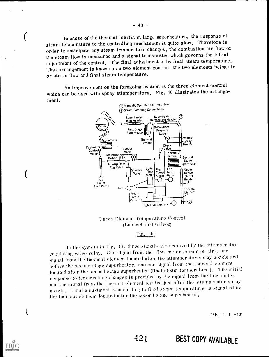
- 4:3
Because of the thermal inertia in large superheaters, the response ofsteam temperature to the controlling mechanism is quite slow. Therefore in
order to anticipate any steam temperature changes, the combustion air flow or
the steam flow is measured and a signal transmitted which governs the initial
adjustment of the control. The final adjustment is by final steam temperature.This arrangement is known as a two element control, the two elements being air
or steam flow and final steam temperature.
An improvement on the foregoing system is the three element controlwhich can be used with spray attemperators. Fig. 46 illustrates the arrange-ment.
1 Manually Operated bhutott Valves
2 Steam Sampling Connections
SuperheaterInlet Header
SuperheaterIntermediate Header
First.StageSuperheater
DifferentialPressure
Gage
Economizer The ma(Element
FeedwaterControlValve
C)Potter
Fee,iPtatM
BypassValve
Metering') 1
ooOrifice 0
I, c
Attemp FloN-Fteg Valve
Retav
Selector Flow-Valve Meter
CV ha el vc ek
Thermal AElement y Second
StageSuperheater
SuperheaterOutletHeader
HirshTempAlarm
SteamTemp --
Recorder _J
Attemp..Spray
Nozzle
LowTempAlarm
High Temp Alarm--
ThermalElement
Three Element Temperature Control(13.,11)coek and Wilcox)
1(i
In the system in Fig, G, three signals art' received by the attemperator
regulating valve relay, One signal from the flov, mater (steam or air) , one
signal front the thermal clement located after the attemperator spray nozzle and
before the second stage superheater, and one signal from the thermal clement
located after the second stage superheater (final steam temperature ) , The initial
response to temperature changes is provided by the signal front the flim meterand the signal from the thermal element located just after the attemperator spray
nozzle, Final adjustment is according to final steam temperature as signalled by
the thermal clement located after the second stage superheater,
421
WEI-2-11-13)
BEST COPY AVAILABLE
QUESTION SHEET
POWER ENGINEERING
First ClassSect. 2, Lect. 11
1. (a) Sketch, describe, and compare the three principle primary flowelements used to create differential pressure in a line.
(b) Explain the relationship between flow and differential pressure.
2. Sketch and describe briefly the arrangement of a float manometer usedfor boiler water level indication.
3. Describe the functions of the following control co. Jonents:
(a) the controller
(b) the transmitter
(c) the actuator
4. With the aid of simple sketches, define and explain:
(a) On off action
(b) proportional action
(c) integral action
(d) derivative action
5. With the aid of sketches, describe the operation of the following:
(a) pneumatic transmitter
(b) electronic transmitter
Explain the purpose of a positioner used in conjunction with an actuator.
7. Describe briefly the basic arrangement of each of the following feedwatercontrol systems:
(a) single element
(b) two element
(c) three element
422
(('ontinued)
(1)E I -2-11 -(1)
-2
8. Describe generally the following combustion control systems:
(a) On Off
(b) positioning
(c) metering
9. Explain the principle of operation of each of the following combustioncontrol arrangements:
(a) steam flow-air flow
(b) fuel flow-air flow
10. Discuss steam temperature control with reference to methods, problems,and necessity.
(1'E] -2-11-Q-2)
423
1 1
1113,711=CNIAL LEAR'1116 W)Witl
7.9
BOILERS -- PIPING AND STEAM TRAPS
Goal:
The apprentice will be able to describethe parts of a boiler piping system.
1
Performance Indicators:
1. Describe piping materials andconnections.
2. Describe types of valves.
3. Describe steam traps.
4. Describe bypass and drain
lines.
5. Describe water hammer.
424

INSTRUCTIONAL LEARNING SYSTEMS
°Study Guide""\
1-7Read the goal and performance indicators co find what is to be learned from
package.
Read the vocabulary list to find new words that will be used in package.
Read the introduction and information sheets.
Complete the job sheet.
Complete self-assessment.
Complete post-assessment.
2
425
INSTRUCTIONAL LEARNING-SYSTEMS
VocabularyAlloy steel pipeBrass pipeBypass and drain lineCarbon steel pipeCheck valveControl chamberCouplingsDrag ValveElbowsFlangesGate valveGlobe valveImpulse trapInverted bucket trapLateralsOutlet orificePlastic pipePlug valveReducersStainless steel pipeSteam trapTeesWater hammer
3
426

INSTRUCTIONAL LEARNING SYSTEMS
IntroductionThe piping for transporting water, steam and condensate through the power plant
is a complex system. These materials are handled at a wide range of
temperatures and .pressures. Each set of conditions require piping with
characteristics for handling the material without becoming corroded or eroded.
The piping system must have valves for controlling the movement of the fluids
through the plant. Steam traps are necessary for removing condensate from the
steam as it travels through the piping.
4
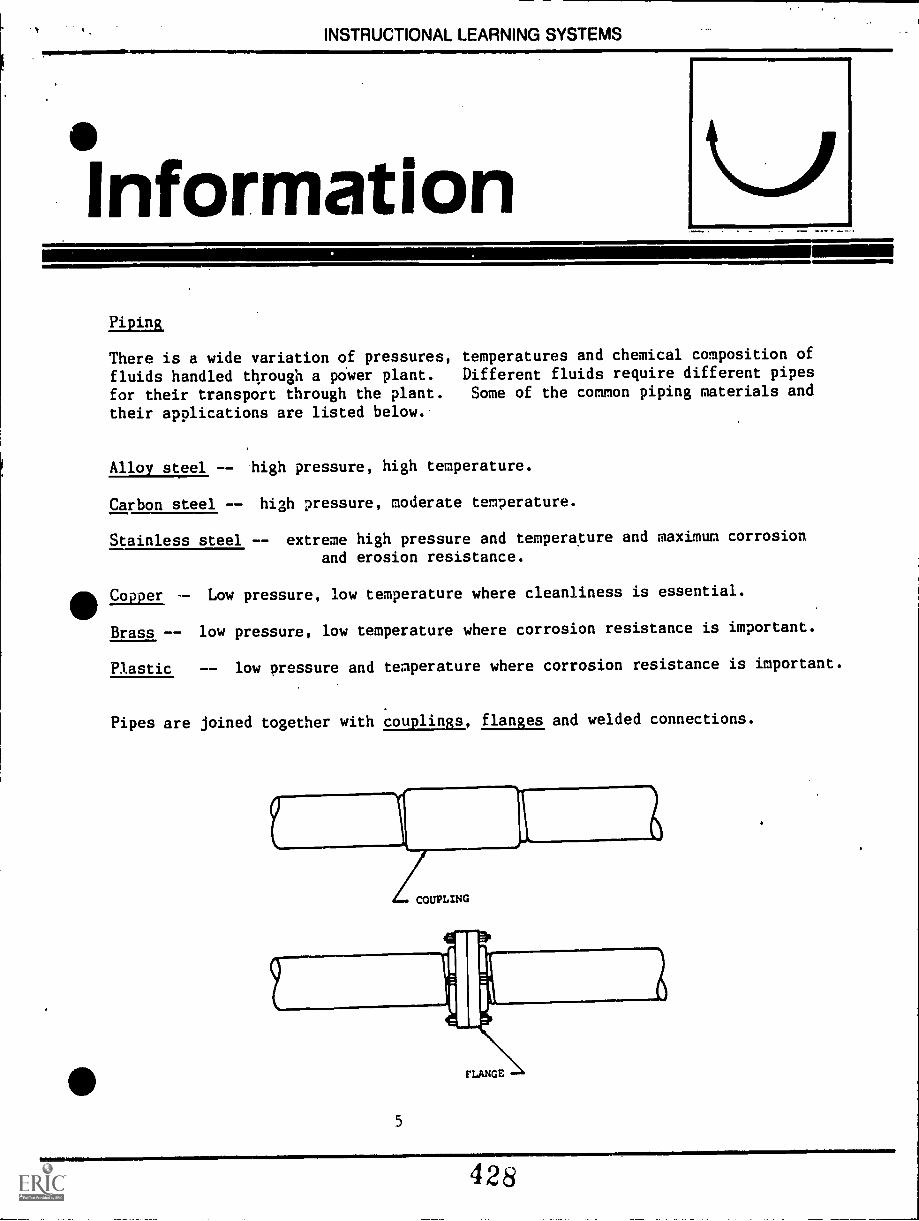
INSTRUCTIONAL LEARNING SYSTEMS.11mmailme
InformationPi in
There is a wide variation of pressures,fluids handled through a po'wer plant.for their transport through the plant.their applications are listed below.
temperatures and chemical composition ofDifferent fluids require different pipesSome of the common piping materials and
Alloy steel -- high pressure, high temperature.
Carbon steel -- high pressure, moderate temperature.
Stainless steel -- extreme high pressure and temperature and maximum corrosion
and erosion resistance.
411Copper -- Low pressure, low temperature where cleanliness is essential.
Brass -- low pressure, low temperature where corrosion resistance is important.
Plastic -- low pressure and temperature where corrosion resistance is important.
Pipes are joined together with couplings, flanges and welded connections.
COUPLINGING
5
428
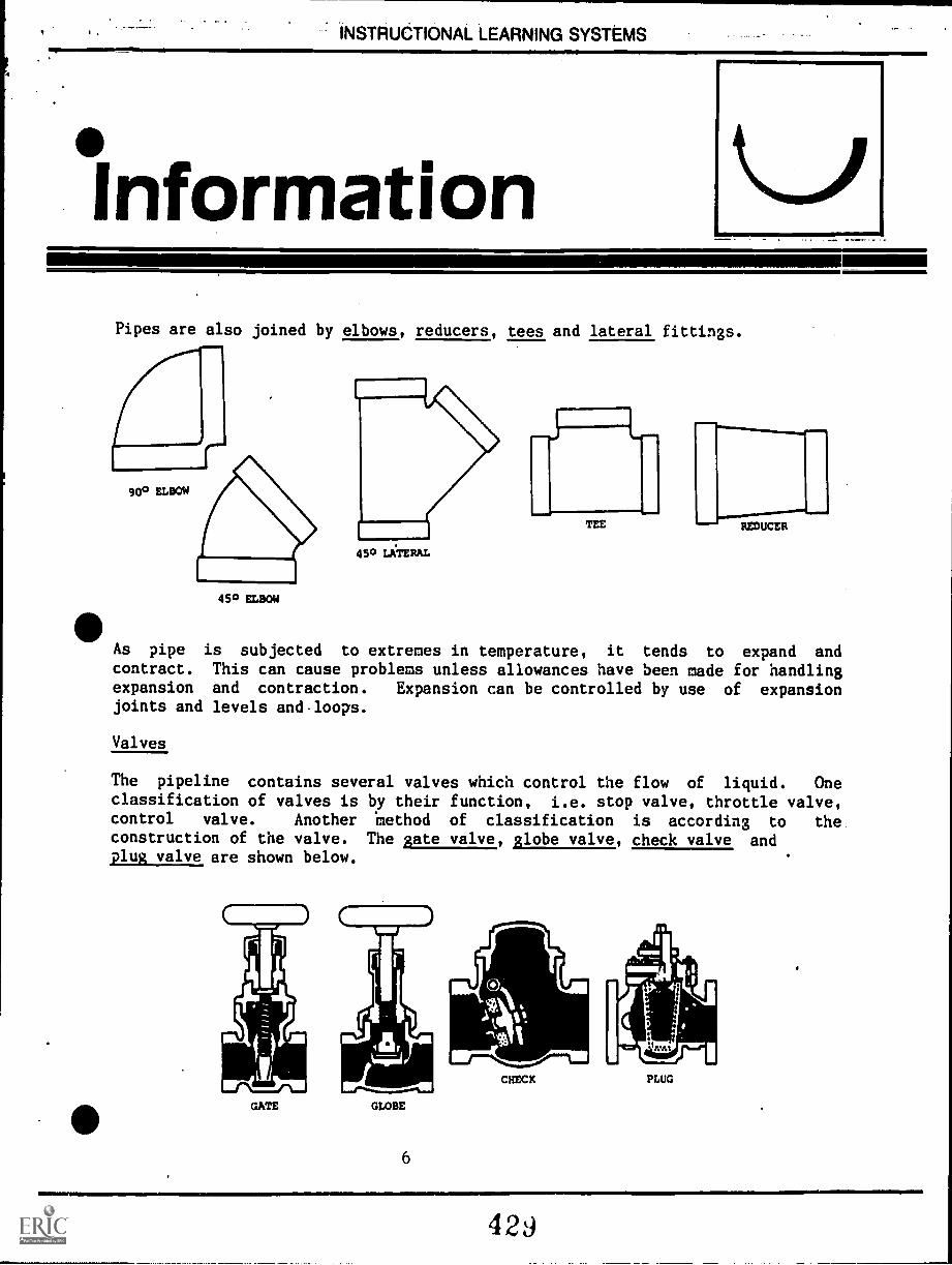
INSTRUCTIONAL LEARNING SYSTEMS
°InformationPipes are also joined by elbows, reducers, tees and lateral fittings.
900 ELBOW
450 ELBOW
450 LATERAL
TEE - REDUCER
As pipe is subjected to extremes in temperature, it tends to expand andcontract. This can cause problems unless allowances have been made for handlingexpansion and contraction. Expansion can be controlled by use of expansionjoints and levels and.loops.
Valves
The pipeline contains several valves which control the flow of liquid. Oneclassification of valves is by their function, i.e. stop valve, throttle valve,control valve. Another 'method of classification is according to theconstruction of the valve. The Bate valve, Alobe valve, check valve andplug valve are shown below.
GATE GLOBE
CHECK PLUG
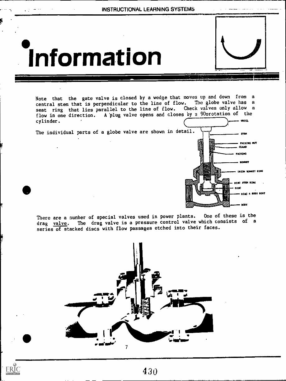
INSTRUCTIONAL LEARNING SYSTEMS
SInformationNAM
- _ --- -INWiMOINIO eleilMMONIMIMMEIMI
Note that the gate valve is closed by a wedge that moves up and down from a
central stem that is perpendicular to the line of flow. The globe valve has a
seat ring that lies parallel to the line of flow. Check valves only allow a
flow in one direction. A 'plug valve opens and closes by a 9Oorotation of the
cylinder. WEL
The individual parts of a globe valve are shown in detail.ST1121
.... PACKING NUT
PACKING
MOW VOMIT M103
DISC 11134 NINA
MSC
DIIC 11 MT SW
INDY
There are a number of special valves used in power plants. One of these is the
drag valve. The drag valve is a pressure control valve which consists of a
series of stacked discs with flow passages etched into their faces.
`NW
430
.1111111111111111010
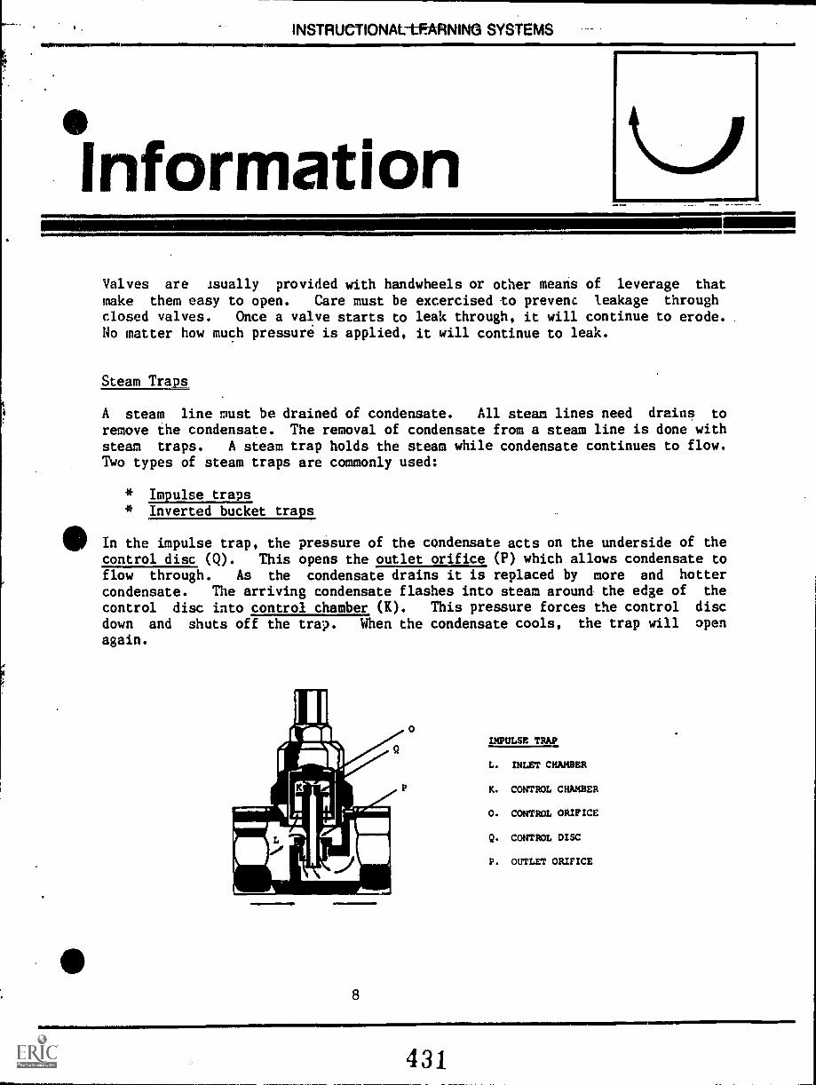
INSTRUCTIONAL LEARNING SYSTEMS4111 41
°InformationValves are isually provided with handwheels or other means of leverage that
make them easy to open. Care must be excercised to prevent leakage throughclosed valves. Once a valve starts to leak through, it will continue to erode. .
No matter how much pressure is applied, it will continue to leak.
Steam Tram.
A steam line must be drained of condensate. All steam lines need drains to
remove the condensate. The removal of condensate from a steam line is done withsteam traps. A steam trap holds the steam while condensate continues to flow.Two types of steam traps are commonly used:
* Impulse traps* Inverted bucket traps
In the impulse trap, the pressure of the condensate acts on the underside of thecontrol disc (Q). This opens the outlet orifice (P) which allows condensate toflow through. As the condensate drains it is replaced by more and hotter
condensate. The arriving condensate flashes into steam around the edge of the
control disc into control chamber (K). This pressure forces the control disc
down and shuts off the trap. When the condensate cools, the trap will open
again.
8
IMPULSE TRAP
L. INLET CHAMBER
K. CONTROL CHAMBER
0. CONTROL ORIFICE
Q. CONTROL DISC
P. OUTLET ORIFICE
11111111111111M101011. .1111r
431
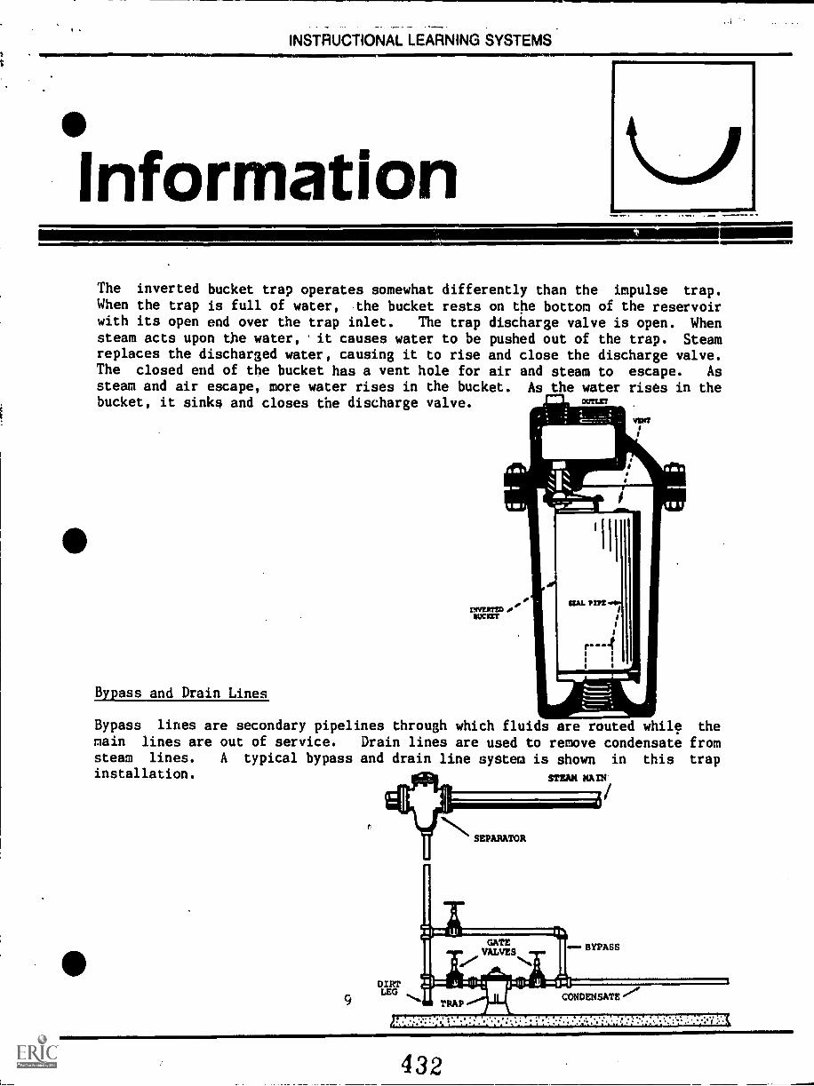
INSTRUCTIONAL LEARNING SYSTEMS
Information
MIPAIIIMMh
NIMMINI
1111MIMM=11
The inverted bucket trap operates somewhat differently than the impulse trap.When the trap is full of water, the bucket rests on the bottom of the reservoirwith its open end over the trap inlet. The trap discharge valve is open. Whensteam acts upon the water,. it causes water to be pushed out of the trap. Steamreplaces the discharged water, causing it to rise and close the discharge valve.The closed end of the bucket has a vent hole for air and steam to escape. Assteam and air escape, more water rises in the bucket. As the water rises in thebucket, it sinks and closes the discharge valve. OUT=
Bypass and Drain Lines
Bypass lines are secondary pipelines through which fluids are routed while themain lines are out of service. Drain lines are used to remove condensate fromsteam lines. A typical bypass and drain line system is shown in this trapinstallation. STEAM MA r11
9
t
432
---- INSTRUCTIONAL LEARNING SYSTEMS--
nformationWater Hammer
When water is confined under high pressure, it can be very dangerous. If the
flow of water is suddenly stopped; it can lead to a condition known as water
hammer. It is a shock force that can cause explosion of the line. Verticalwaterlines are more likely to have water hammer than horizontal lines. Valves
should be opened slowly to avoid waterhammer in either water or steam lines.
Hammers in steam lines can occur when hot water is admitted into a cold line.
Within steam lines, this condition is more likely to happen in long,
horizontal lines. This differs from waterlines which more often occur in
vertical lines.
10
OWInsie=a laWw,
433
-INSTRUCTIONAL LEARNING SYSTEMS
Assignment
* Complete job sheet.
Complete self-assessment.
* Complete post-assessment.
11
434:
INSTRUCTIONAL LEARNING SYSTEMS
!Job SheetINSPECT THE PIPING OF A STEAK PLANT
* Carefully inspect each pipe that enters the boiler.
- Where does the pipe come from?
- What does it carry?
- How are pipes connected? flanges, couplings?
- What type of material? alloy steel, copper?
- What kinds of valves do you see? gate, globe, plug, etc.?
- Can you locate the steam traps?
All- What type of steam trap?
- Is there bypass and drain lines?
- Do you find piping, valves and traps that are different from thedescriptions in the learning package?
* Ask the operator to explain those items that were not described in package.
12
MIMIIMMIEL
435
IIM=MIL
INSTRUCTIONAL LEARNING SYSTEMS
.SelfAssessment
Match the following terms with the most appropriate description.
1. Gate valve
2. Inverted bucket
3. Water hammer in waterlines
4. Alloy steel
5. Copper
6. Stainless steel
7. Couplings
8. Waterhammer in steam lines
9. Globe valve
10. Plastic
13
A. Materials used for high
temperature and high pressure
pipe.
B. Material used for extreme
high pressure and temperaturepipe with maximum corrosion
resistance.
Method of joining sections of
pipe together.
Valve seat ring lies parallelto the line of flow.
Valve wedge lies perpendicularto the line of flow.
A type of steam trap.
More likely to occur in
vertical lines.
More likely to occur in long,horizontal lines.
Material used in low pressure,low temperature piping thatrequires cleanliness.
J. Material used in low temperature,low pressure piping wherecorrosion resistance is
important.
436
INSTRUCTIONAL LEARNING SYSTEMS
Self AssessmentAnswers
E 1.
F 2.
G 3.
A 4.
I 5.
6.
C 7.
H 8.
D 9.
J 10.
14
INSTRUCTIONAL LEARNING SYSTEMS
PostAssessment
1. What causes a water hammer in a waterline?
2. What causes a water hammer in a steam line?
3. What piping material would you select for extreme high temperature andpressures and corrosion resistance?
4. What piping material would you select for high pressure and moderate
temperatures?
5. Which piping material would you select for low temperatures, low pressuresand cleanliness?
6. List two connecting methods for joining pipe.
7. List two fittings used to join pipe together.
8. List two types of steam traps.
9. What kind of valve is a drag valve?
10. Which type of valve allows water to flow in only one direction?
15
438
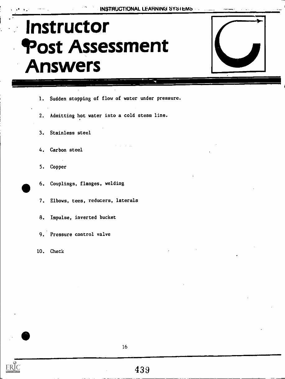
9. -
111111 INSTRUCTIONAL LEARNING SYb I trvib
Instructor"Jost AssessmentAnswers
1. Sudden stopping of flow of water under pressure.
2. Admitting hot water into a cold steam line.
3. Stainless steel
4. Carbon steel
5. Copper
6. Couplings, flanges, welding
7. Elbows, tees, reducers, laterals
8. Impulse, inverted bucket
9. Pressure control valve
10. Check
16
439
INSTRUCTIONAL LEARNING SYSTEMS
SupplementaryReferences
* Instruction Manual. Operator Training Program. Volume I. Pacific Gas and
Electric Company. 1974.
17
440