Embed Size (px)
Citation preview

ED 175 733
AUTHORTITLEINSTITUTIONEPONS AGENCYPUB DATEGRANTNOTE
EDRS PRICEDESCRIPTORS
IDENTIFIERS
DOCUMENT RESUME
SE 029 913
Mckaughan, Stephen V.: A2d OthersBasic Shop Skills in Wool, Metal, Circuits, Glass.Boston Univ., Mass. Physical Science Group.National Science Foundation, Washington, D.C.75NSF-GZ-2892216p.: Photogra . say not reproduce well
mF01/PC09 Plus Postage.Class Autivities: Electro2ics: Glass: HigherEducation: Industrial Arts; InterdisciplinaryApproach: *Laboratories: *Laboratory Equipment:*Laboratory Technology: Science Education; *ScienceLaboratories: Secondary Education: Sheet Metal Work:WoodworkingNational Science Foundation
ABSTRACTThe text seeks to help students reach, through about
90 hours of class instruction, to acquire a level of competencynecessary to repair a piece of laboratory equipment or construct asimple tiece of equipment. Tools are introduced as neede.1 in each ofthree s `.ions of the text: (1) wo3dwork and metalworking: (2)electrc.1 circuits; and (3) glassblowin4. The course is intended forundergrt,..uate, preservice science education majors and graduatestudents in science education. (Author/RE)
***********************************************************************Reproductions supplied by EDES are the best that can be made
from the original document.***********************************************************************

10,
41 ..iNAs .45'(),.( n
Ark
*
.*`.A
-A4- 4 4.
,r. gv 1.4
'
; H
Mar's htkries
IN WOOD METAL CIRCUITS GLASS
I.
YB1CAL SC1E CE GRO P129STON UNIVERSITY

SitC'D EDsms SEP 8 794
BASIC SHOP SKILLS
in
Wood, Metal, Circuits, Glass
PHYSICAL SCIENCE GROUP
Boston University
.- Archives of
BIMMR EDUCAT:N SCIENCE
ATP/SCIPIDS
Property of
THE NATIONAL SCIENCE FOUNDATION
Gzi..zirl*B &fr.% U.Ort 140ie Sctief:*

Copyright ® 1975 by The Trustees of Boston University
Printed in the United States of America

PREFACE
Whether the setting is a science classroom at a high school or
a research laboratory at a university, there are times when it is advan-
tageous to know how to repair a piece of equipment or to construct a
simple piece of apparatus. The job may require only the mastery of a
simple skill such as making a solder joint, bending a piece of glass,
or tapping a hole for a screw. Nevertheless, even the mastery of such
rudimentary skills requires careful instruction and a good deal of
practice. It is the primary aim of this text to help students reach this
essential level of competency.
The text naturally divides into three sections: woodworking and
metalworking, electronic circuits, and glassblowing. Rather than instruct-
ing the students to perform lengthy and often tedious practice operations,
the text is designed around the construction of a carefully plannE- series
of projects. Within each section different tools and operations are
introduced as they are needed, the procedures becoming more complex
for each successive project. By actually building useful pieces of equip-
ment the students gain confidence in knowing that they can use the skills
they are learning.
The recommended time allotment for the entire course is approxi-
mately ninety hours with each work session being at least two hours
long. Approximately half the course consists of the wood and metal
section, with the remainder being divided between circuits and glass.

-iv-
Because the three sections of the text are independent, each can be
used separately.
Orig. ially developed as part of an undergraduate course for the
preparation of physics-chemistry teachers, the text has been revised
and expanded to meet the needs of a wider group of students, including
undergraduate science majors and graduate students in science education.
During its piloting, the course was taught to a variety of students, both
men and women, some of whom had previous experience and others none.
The course best accomplished its goals when each student completed the
projects at a pace that matched his or her ability. By learning a few
skills well, the students gained the confidence to use them again.
The early planning of the shop course was done by Stephen V.
McKaughan, Judson B. Cross James A. Walter, and Uri Haber-Schaim,
Director of the Undergraduate Program for Physics-Chemistry Teachers.
The drawings were done by George V. Frigulietti and Myrna Goldblat,
and R. Paul Larkin took most of the photographs. The text was edited
and produced by Susan J. McMahon. The camera copy was typed by
Caroline E. Russell.
The development of the Undergraduate Program is supported by
a grant from the National Science Foundation.
Stephen V. McKaughanRichard J. DuffyJuly 1975
6

A WORD ON SAFETY
In this course you will learn to use a variety of tools, ranging from
hammers to an oxygen-gas torch, to perform many different operations. If
used improperly, many of these tools can cause physical harm. For this
reason safety in the shop is extremely important. Safety methods, as they
apply to each tool, will be taught along with the use of the tool, but there
are a few general rules to remember.
In the shop the most dangerous clothes to wear are those with long
sleeves, which can get caught in machines, and ties, scarves, or any loose
apparel around the neck. Always wear shoes that give good traction, be-
cause a slip at the wrong time could result in injury. If you have long hair,
be sure to tie it back securely.
The basic safety rule in all shop work is to think ahead, plan each
operation, and anticipate all the possible results of what you are about to do.

CONTENTS
WOOD AND METAL
Project I: A LABORATORY STAND 3
The Handsaw i The Square Shop Sketches a The PlaneFinishing End Grain Layout of Holes Drilling Holeswith a Brace and a Bit Sanding a Joining Pieces of WoodNails The Nail Hammer Gluing and Nailing
1-
Project 2: A DENSITY KIT 29
Files and Filing Dimensions, Tolerance, and LayoutsHackscntits Using a Hacksaw a Precision MeasurementsFinishing the Density Kits,
Project 3: AN ELASTICITY APPARATUS 43
Twist Drills a The Hand Drill The Drill Press Typesof Fiteii Slotting Machine Screw Threads CuttingThreads Drilling Round Stock Counterboring
Project 4;, A WOODEN FRAME
The Tabfe Saw a Circular Saw Blades Making Sawcutswith the Rip Fence Chamfering with a Table Saw Slot-ting with a Table Saw a Making Sawcuts with a Mitre Gauge
Project 5: A TEST-TUBE RACK
PoWer Bits
65
75
Project 6: A' LAB CART 77
Wood Screws
CIRCUITS 84
Project 7: NEON BLINKER 85
Resistors a Capacitors Soldering and ConstructionNeon Bulb Variable Neon Blinker An Analysis of theNeon Blinker

v.
Project 8: ELECTRONIC POWER SUPPLY
Transformers Diode's I Filtering Full-Wave Recti-fication 'A Aipolar Power Supply
Project 9: OPERATIONAL AMI3LIFIER
OperatiOnal Amplifiers A Photometer Other Opera-tional-Amplifier Circuits
GLASS
Project 10: TECHNIQUES USED IN GLASSBLOWING
Types of Glass Torche§ Cutting Glass TubingConstricting Glass Tubing Beni:ling Glass TubingEnd-to-End Seals * T Seals Ring Seals
99
107
116
117
Project 11: A DISTILLING COLUMN 139
Project 12: A COLD TRAP 143
Project 13: A CONDENSER 145
Appendix 1: SHARPENING TOOLS 147
The Bench Grinder * Sharpening a Wood Chisel Sharp-ening Power Bits S Sharpening Twist Drills SharpeningVarious Togls
Appendix 2: OPERATIONS ON A METALWORKING LATHE 159
The Lathe Holding Stock in a Lathe * Cutting ToolsMoving the Tool Facing A Word on Safety TurningTurning a Taper Facing to Length Turning a ShoulderUses of the Tailstock Turning Two Shoulders
Appendix 3: THE CATHODE-RAY OSCILLOSCOPE 187
NOTES TO THE INSTRUCTOR 191a
INDDC 207

WOOD AND METAL
The materials most commonly available for making equipment are
wood and metal. From visits to the local lumberyard and the hardware storeand with a little ingenuity, you will have the material that you need for theconstruction of simple laboratory equipment.
The first section of this text is designed to teach you the skillsneeded to work with these materials. Although the tools used for working
wood are different from those used to work metal, the operations and the
coordination needed to perform the operations are very similar. When you
make a piece of apparatus different parts will be made of different materials.
To work with other materials, which have some of the properties of wood
and some of the properties of metal, you will have to combine woodworking
and metalworking techniques. For these reasons, this section combineswoodworking and metalworking, teaching the skills as they are needed tobuild a project.
Phe projects in this section are simple if they are done consecutivelybecause each project teaches techniques that are used over and over. Theinstructional material contained here will appear difficult or easy dependingmostly on your experience with the tools involved. Even if you think you
know all about certain operations and tools, read the sections through be-cause they may contain information you have forgotten. Most power toolsare introduced later in the section because they are more dangerous to usethan hand tools and should be operated only after you have gained some un-derstanding of the work involved.
Above all else, think before you act. Your thoughtfulness can pre-vent errors and minimize the chance of injury.
I 0

- 3 -
Project 1: A LABORATORY STAND
Your first project is the wooden stand shown in Fig. 1.1(a). For anumber of experiments where equipment must be supported about two feetabove a table top, the stand is clamped as shown. The stand is sturdyenough so that it will not bend, vibrate, or otherwise interfere with the
operation of the apparatus it supports. Clamped to the stand, in Fig. 1.1(b),is a weighted bicycle wheel used for a study of kinetic energy.
4.
Fig. I.1(a) Fig. I.1(b)
,
1.1 The Hanclsaw
Generally, the first operation in any shop project is to bring a pieceof wood or metal (called .stock) to the proper length, width, and thickness.In most cases, this operation is done with a saw of some kind.
00900000Using a handsaw, cut a few short pieces off one
end of a board.
17411

Was it easy to get the saw started? In which di-rection did the saw remove more material, when mov-ing toward you or away from you?
What happened when you neared the end of the cut?Were the sawcuts straight and square (at right
angles) to the adjoining surfaces?What did you find was the easiest position in
which to stand while you were sawing?
0 0 0 0 0 0 0 0
Handsaws are used only to cut wood and other soft materials. Theyare purchased by length of cutting edge (usually 24 or 26 inches) and by thenumber of Points (teeth) per inch. There are two kinds of handsaws: cross-cut saws and ripsaws.
Crosscut saws are used to cut across the grain of the wood. Fig-ure 1..2(a) shows the teeth of a crosscut saw. Observe that the teeth do notIle in a straight line but are bent alternately a little to one side and then tothe other. This is called set. Beciuse of the set, the width of the sawcutis greater than the thickness of the steel of which the saw is made. The setprovides clearance so that the saw blade does not stick and bind in the woodwhile cutting. Notice also that the teeth are sharpened at an angle and areclose together (8 to 12 points per inch) to make it easier to cut across thegrain of the wood. Fig. 1.2(a)
...11711Ripsaws are used to cut with the grain of the wood. Although you
will not use a ripsaw in this course, you should be able to recognize one.Like the set of a crosscut saw, a ripsaw's set also prevents the blade fromsticking in the wood. The difference between a ripsaw and a crosscut sawis that the teeth of a ripsaw are sharpened straight across, as shown inFig, 1.2(b), and are spaced much farther apart (5-1/2 points per inch).
Fig. 1.2(b)

If it is necessary to rip a board and a ripsaw is not available, acrosscut saw ca.1 be used, although it will take more time. However, theopposite is not true: If a ripsaw is used to cut across the grain of the wood,it will splinter the wood.
The proper way to use a handsaw is demonstrated in Fig. 1.3. Notethat the knuckle of the left thumb rests against the blade above the teeth toguide the saw. The initial motion of the saw should be toward you. Notethat the cutting edge of the saw makes ap- 731n,
proximately a 45 degree angle with the
board. Always find a comfortable position
while cutting a board. Usually the boardis placed low and is cut with smooth
strokes using most of the saw blade. Whenyou approach the end of the cut, use veryshort, easy strokes, applying less pressureso that the last bit of wood will not chipaway.
Fig. 1.31.2 The Ssuare
In Section 1.1 you were told to try to cut a piece of stock so that thecut surface was at an angle of 90 degrees to all the other surfaces. Youprobably judged the angle by eye, which was perfectly adequate for the prac-tice operation. However, if greater accuracy is required, a tool called asquare is generally used.
Of the two common types of squares shown in Fig. 1.4, the combi-nation square is the most versatile. Its blade slides in the head to vary the
Try square Fig. 1.4 1 Combination square
3
SCRIBER

- 6
length, and there is a face for drawing or measuring a 45 degree angle.Perhaps the biggest problem that occurs when using a square is in
deciding to which surface another should be square. No problem arises whenall the surfaces of a board are already square to each other. However, whathappens when two edges of a board are not parallel? The ends may be squarewith one edge of the board but not with the other. TI-..Jrefore, you must choose
one surface as a reference from which other surfaces can be compared for
squareness or for size. The reference surfece should be smooth and flat andbe square with as many adjoining surfaces as possible. A reference surfacemust be chosen in each plane to measure the length, the width, and theheight of a board. Since three references may not be available, you will
have to make them. To begin with, you must choose one stirface for cutting
the end of a board square, and this surface will become the reference for allfuture operations.
When using a square to draw a line for a sawcut, place the flat sur.;.face of the head against the surface that is lived as a reference, as shownin Fig. 1.5. Then mark the line. When using it to check the end of a pieceof stock, place the square as in Fig. 1.6 and move it until the blade touchesat one point. By holding the stock and the square up to the light, you willbe able to see if the blade is in contact with the entire edge being measured.
Fig. 1 . 5
1 44
4

0 0 0 0 0 0 0 0Fig . 1 . 6
Draw a line across a board at right angles to itsedge, as shown in Fig. 1.5. An additional line canbe drawn on the front edge of the board (Fig. 1.7) toact as a guide for the vertical alignment of the saw-cut. Cut the end off and practice until you can followthe lines and cut the end square that is, with the re-sulting surface perpendicular to the adjoining surfacesof the board.
Take a close look at the saw you used. How manypoints per inch does it have? What do you think wouldbe the advantages or the disadvantages of using a sawwith more points per inch?
0 0 0 0 0 0 0 0
.1
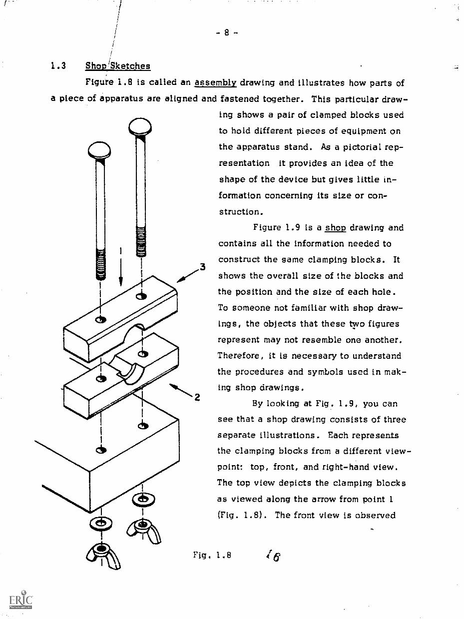
1.3 Shop/Sketches
Figure 1.8 is called an assembly drawing and illustrates how parts ofa piece of apparatus are aligned and fastened together. This particular draw-
ing shows a pair of clamped blocks used
to hold different pieces of equipment on
the apparatus stand. As a pictorial rep-
resentation it provides an idea of the
shape of the device but gives little in-formation concerning its size or con-
struction.
Figure 1.9 is a shop drawing andcontains all the information needed to
construct the same clamping blocks. It
shows the overall size of the blocks and
the position and the size of each hole.To someone not familiar with shop draw-
ings, the objects that these two figuresrepresent may not resemble one another.Therefore, it is necessary to understandthe procedures and symbols used in mak-
2ing shop drawings.
By looking at Fig. 1.9, you cansee that a shop drawing consists of threeseparate illustrations. Each represents
the clamping blocks from a different view-point: top, front, and right-hand view.The top view depicts the clamping blocks
as viewed along the arrow from point 1
(Fig. 1.8). The front view is observed
Fig. 1.8
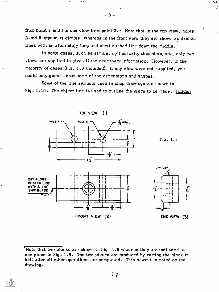
from point 2 and the end view from point 34 * Note that in the top view, holesA and 13 appear as circles, whereas in the front view they are shown as dashedlines with an alternately long and short dashed line down the middle.
In some cases, such as simple, cylindrically shaped objects, only two
views are required to give all the necessary information. However, in themajority of cases (Fig. 1.9 ncluded) , if any view were not supplied, youcould only guess about some of the dimensions and shapes.
Some of the line symbols used in shop drawings are shown inFig. 1.10. The object line is used to outline the piece to be made. Hidden
TOP VIEW (1)
HOLE A HOLE I 5"ii ORILL
I.
CuT ALONGCENTER LINEWITH A Ihs"SAW BLADE
FRONT VIEW (2)
Fig. 1.9
*Note that two blocks are shown in Fig. 1.8 whereas they are indicated asone piece in Fig. 1.9. The two pieces are produced by cutting the block inhalf after all other operations are completed. This sawcut is noted on thedrawing.

- 10 -
lines are edges that cannot he seen from the.point of view of the drawing.These lines can indicate holes, slots in the other side of the piece, hiddenedges of all kinds. Center lines are used to show the center of any piece orhole and to show the axis of the piece. All circular holes or circles are
drawn with center lines through their centers, and dimensions are measuredfrom these center lines. Any center line in the middle of a piece is consid-ered to be its axis if marked with the symbol ç .
A dimension line represents a measurement between the arrow points
on its ends. Often the dimension you want is not shown on a drawing, and
you have to do some addition or subtraction to find it.
Fig. 1.10
ONO= em110 MID
WM Ma OMR MO
AIMED IMINNIM.R!
OBJECT LINE
HIDDEN LINE
CENTER LINE
DIMENSION LINE
In many drawings some lines are made heavier than others for empha-
sis, making the drawing easier to understand. (Dimension lines, for example,
are usually ligliter than object lines.) In general, a good drawing contains
only enough detail to make it understandable. Any additional detail may just
clutter it.
0 0 0 0 0 0 0 0In Fig. 1.9, how far in from each side is hole A?
How far apart are holes A and B? How deep is holeA? How deep is the 11/16-inch-diameter hole?How far in from the left-hand end is the 15/32-inch-diameter hole?
The pieces needed to assemble the apparatusstand are depicted in Fig. 1.11. Get the necessaryboards and cut them approximately 1/16 inch longerthan given in the drawing to allow for finishing.Use a square as shown in Fig. 1.5 to draw the lineson the boards to mark the sawcuts.
A

1911 sillSIDES
MATERIAL I x4 PINE
Fig. 1.11
2 PIECES NEEDED
-4:1C-r out TYPII
r 3*Ni
BOTTOM PIECE TOP PIECE
APPROX
MATERIAL 2 x 4 FIR OR SPRUCE I PIECE NEEDED MA/TRIAL: 2 x 4 FIR OR SPRUCE I PIECE NEEDED
If you wish a board to come out a precise length,where should you make the sawcuts, along the cen-ter of the lines or to one side?
0 0 0 0 0 0 0 0
1.4 The Plane
When a sawcut is not square, or when only a small amount of wood
needs to be removed to make the piece the de3ired dimension, a lane can
be used. There are several different kinds of planes. They all look like the

- 12 -
one shown in Fig. 1.12, although they vary in length from about six inchesto approximatell. 30 inches.
Each plane holds a sharp blade that protrudes through the bottom sur-
face of the plane to slice off material. A Jointer plane is about 22 to 30inches long and is used for planing the edges of long boards. A smoothiuplane is about eight inches long and is used for doing precise work. Ablock plane, about six inches long, looks slightly different from the othersbut is adjusted the same way. Because of its compactness, a block planeis used for small jobs and is ideal for planing the ends of boards. The jackplane is the most common of all. It is between a smoothing plane and a
jointer plane in size, and therefore it can do most of the jobs of all the otherplanes.
The parts of a plane are shown in Fig. 1.12. Part A is the blade that
does the actual cutting. Part B keeps the blade rigid and also breaks off the
thin slices of wood so that they will not jam the plane. Its front edge should
be about 1/16 inch back from the cutting edge of the blade. Part C is used to
adjust the blade so that its cutting edge is parallel to the surface of theboard. Part D is used to control the depth that is cut.
Fig. 1.12
Because the blade is very sham, you should never touch the cuttingedge with your fingers. Keep your fingers away from the bottom of the plane
when using it. Because the cutting edge can be easily chipped or dulled,
always lay the_plane on its side when not in use.
2 0

- 13 -
O 0 0 0 0 0 0 0Disassemble the plane by first lifting the release
lever (part E). Note how the parts fit together andcheck to see how the adjustments work. When re-assembling the plane, be sure that part B (seeFig. 1.12) is adjusted so that its front edge is about1/16 inch back from the cutting edge of the blade.
O 0 0 0 0 0 0 0
Vt. aen both edges are square and flat, planing down a board to aspecified dimension is a simple matter. First choose one edge as a refer-ence. Parallel to the reference edge, draw a line corresponding to the finaldimension. Then clamp the board in a carpenter's vise with the edge to beplaned facing up. Hold the plane as shown in Fig. 1.13 and push it along
A t
'MIME=,
Fig. 1.13
the edge of the board with one smooth stroke. The beginning and the end ofe stroke are shown in Fig. 1.14. Note that the stroke begins with the bladeto the left of the end of the board and that downward pressure is exerted on
Fig. 1.14
PRESSURE PRESSURE
- 14 -
the front of the plane. The stroke ends with the blade beyond the other endof the board and with the pressure on the rear of the plane. This is the onlyway to make sure that the surface remains flat. After every few strokes,check the edge at different points to see if it remains square. If it does,continue the operation until the board is planed to the line you drew earlier.
With the blade adjusted properly (with its cutting edge parallel to
the bottom surface of the plane), nothing can alter the angle of the edge be-ing planed. Therefore, if the edge is square it will remain square as theboard becomes narrower. Likewise, if the edge is not square it will remainuntrue.
,Planing an eel* of a board that is not square to begin with, therefore,
becomes a matter of triil and error. First, check to see which side of theedge is highest. Then take a few strokes with the plane, removing materialfrom th2 high side. By watching the chips that are formed by the blade, you
can see where material is being removed. Looking down on the edge of the
board, if the right side is the higher, the chip should appear on the rightside of the blarie. If it does not, tip the plane clockwise and try again.After a few strokes, removing material from the same place, check to see ifthe surface you have generated is square. If it is, proceed with the opera-tion by using the newly squared edge as a reference. If it is not, find thehigh spot and try again.
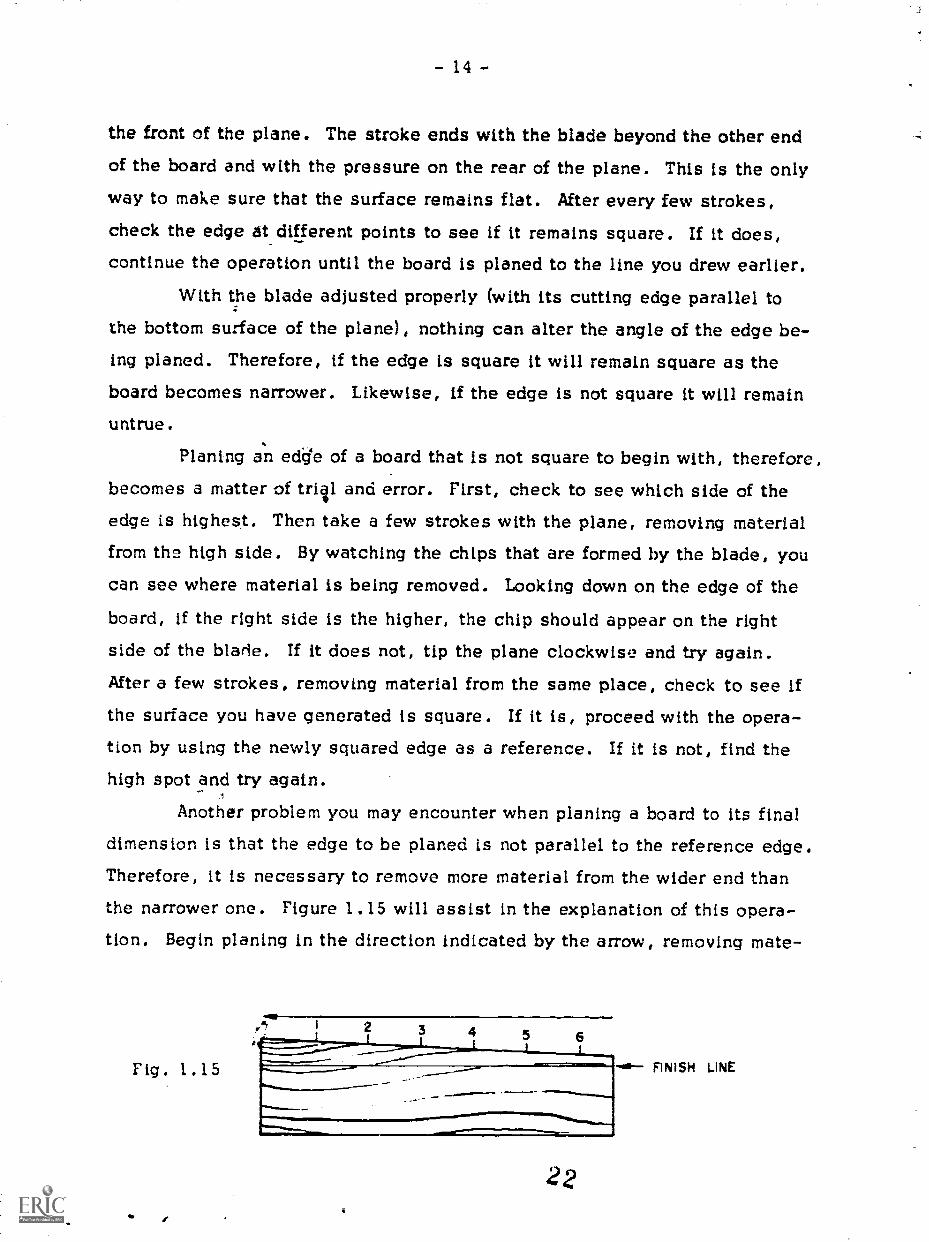
Another problem you may encounter when planing a board to its finaldimension is that the edge to be planed is not parallel to the reference edge.Therefore, it is necessary to remove more material from the wider end thanthe narrower one. Figure 1.15 will assist in the explanation of this opera-tion. Begin planing in the direction indicated by the arrow, removing mate-
Fig. 1.15
22
FINISH LINE

- 15 -
rial beginning at point (1)4 (Two or three strokes should be sufficient.)
Then begin the stroke at point (2); then (3); and so on. After the edge is
flat, mea.3ure the distance from the finish line to the planed edge to see if
the two edges are parallel. Make corrections if needed and proceed to plane
the board to its final width.0 0 0 0 0 0 0 0
Take a piece of stock, adjust the plane for a thincut, and pr4a4r..4,planing the edge of a board. Useone smootY, continvous stroke from one end of theboard to the other. Take several strokes and checkto see that the surface is square and flat.
After practicing for a while, use the plane tosquare one edge of each piece of wood you cut forthe apparatus stand.. This edge can then be used asa reference for planing the opposite edge to its finaldimension (3-1/4 inch, as shown in Fig. 1.11).
1.5 Finishing End Grain
In Section 1.3 you were instructed to cut the boards for the labora-tory stand about 1/16 inch longer than specified to allow for finishing. Asyou may have observed, after the boards were cut with the saw, the result-ing surface was not as smooth as the sides or edges of the board. They maynot have been perfectly flat and square either. In building a house, the end
of a board has to be reasonably square and flat to fit properly, but becausethe end will not been seen, it doesn't have to be perfectly smooth. How-ever, when building furniture or apparatus, not only must the ends be flat
and square but they must also look good.Figure 1.16 depicts a power tool called a belt sander. It has a motor
connected by 1/ belts and pulleys to a druai located at about the middle of
the machine. At the top of the machine there is another drum, which can beadjusted in height and made parallel to the lower drum. A flat cloth belt on
which abrasive material is cemented is placed around the two drums andtightened by adjusting the height of the upper drum. When the motor isswitched on, the belt moves downward and slides over a piece of steel that

- 16 -
keeps the belt flat when wood is pressed against it. Because the belt is flat,It generates a flat surface on the piece of wood.
k,
fele
Fig. 1.16
On the front of the belt sander is a
table with a groove in it. The angle of thetable can be adjusted to sand pieces atdifferent angles. The groove in the top ofthe table is used to index an attachment
called a mitre gause (Fig. 1.17). The sur-face against which the wood is held can beadjusted so that you can sand at differentangles to the side of the board. The mitregauge is calibrated in degrees for easy ad-justment. On some gauges a 90 degree
setting produces a surface at 90 degrees to
the side, whereas on others, it is done witha setting of zero degrees.
To finish the ends of a board,first sand one end square, removing
as little material as possible. To dothis, adjust both the belt sander ta-
t,ble and mitre gauge so that they are
at right angles to the sanding belt.
To check the settings, take a pieceof scrap wood and hold it firmly
against the table and mitre gauge but
with some clearance between the endof the board and the sanding belt.
Switch on the machine and slide the board toward the sanding belt, keeping itin contact with the gauge and table. Press it against the sanding belt until theend is completely sanded. Remove the board from the table and turn off the mo-tor. Check the end of the board with a square, and readjust the table or gauge
Ft . 1.17

- 17 -
if needed. Once you determine that the settings are correct, proceed by sand-ing the one end of your workpiece. Using the sanded surface as a reference,draw a line at the proper length and sand the marked end to the line, complet-ing both ends.
A word of caution: Keep your hands as far away from the moving beltas possible. It is very abrasive and will remove skin more rapidly than itwill remove wood.
0000 o o
Take a piece of scrap wood and saw one end square.00000000
When a belt sander is not available to finish end grain, a plane canbe used to perform the same operation, although the process is much morerigorous. If a plane is used, the ends must be finished before the board isplaned to its specified width. Remember, one edge must be planed squareto be used as a reference for the ends.
The first step in planing end grain is to chamfer (bevel) one corner,as shown in Fig. 1.18, to reduce the possibility of chipping the wood. Thisis done by ciamping the workpiece in a vise at a 45 degree angle and by us-ing the plane as shown in Fig. 1.19. The size of the chamfer is determined
Fig. 1.18
***1"%iftikm6 CHAMFER

- 18 -
by the amount of material to be removed both in the length and the width of
the board. Therefore, it is necessary to draw lines that correspond to thefinal dimensions of the piece. The surface that forms the chamfer is planeduntil it meets the intersection of the dimension lines (see Fig. 1.18).
After the chamfer is made, adjust the plane to as fine a cut as pos-
sible. Proceed to remove material using the plane in the direction indicatedby the arrow in Fig. 1.18.
When both ends are completed, plane the second edge to the linedrawn on the side of the board. After you have finished this operation, thereshould be no indication that any corner was chamfered.
Take a piece of scrap wood and plane the end.Now finish both ends of the pieces for the lab-
oratory stand (by either method) and then plane theboards to their specified widths.
0 0 0 0 0 0 0 0
1.6 Layout of Holes
Now that you have cut and squared all the pieces for the apparatus
stand, it is time to drill the 5/16-inch-diameter holes in the top and bottom
pieces (see Fig. 1.11).Before drilling holes, you must draw intersecting lines to locate their
centers. A square and a marking gauge can be used for this purpose. Thesquare is used to make the line perpendicular to the edge of the board, andthe marking gauae (Fig. 1.20) is used to make the line that is parallel to theedge of the board. The dimension that is requ, ed is set between the point
Fig. 1.20
and the adjustable collar. When you guide the collar along the edge of aboard, the point makes a fine line at the desired distance from the edge of
26

- 19 -
the board. (Figure 1.21 shows how a square and a pencil can be used inplace of the marking gauge.)
WIMP"
Fig. 1.21
In using a scale (ruler) to lay out dimensions, be careful of parallax.Always recheck the dimensions of your lines after you have drawn them. Alittle extra care will save a lot of time and material!
o o o
Lay out all the lines necessary to prepare fordrilling the holes in the top and in the bottom ofthe apparatus stand. Check all of the lines tc,make sure you have made no mistakes. Now thatthe positions are marked, you are ready to drillthe holes.
0 0 0 0 0 0 0 0
1.7 Drilling Holes with a Brace and a Bit
In this course you will use various types of drill bits. They willhave different applications and look different, but all of them remove mate-rill only when rotated in a clockwise direction. Because leverage is neededto do the work, all drill bits require the use of an additional tool to drive them.
The tool that is most commonly used to hold drills for drilling wood
is called a brace (as illustrated in Fig. 1.22). Figure 1.23 shows an augerMI, the type of drill that is used with a brace. Auger bits come in sizesfrom 1/4 inch to 1 inch in diameter. They are made in 1/16-inch steps andare marked accordingly. Thus, a bit with a diameter of 9/16 inch would havea "9" on the tang (square end of the shaft), and a 3/4-inch bit is a No. 12.

- 20 -
Figure 1.24(a) demonstrates
how to insert and tighten the auger
In the chuck of the brace. The jaws
of the chuck are closed when thechuck is rotated in a clockwise di-rection. Only drills that have a tangon the end can be used with a brace.Be sure that the tang is properly
aligned with the triangular grooves
of the Jaws, as shown in Fig. 1.24(b),so that it fits into the braces snuglyand will not slip.
Because of the design of
the auger bit (Fig. 1.25) it is notnecessary to exert a large down-
ward force on the brace. Part C
screws into the wood and pulls the
bit along with it. Part B slices the
wood vertically to provide a neat
outline for the hole, and part A re-
moves the material in the same
way as the blade of a plane. The
drill is helical, and the materialthat is cut away travels up the he-lix and is cleared from the hole.
Fig. 1.23
Fig. 1.24(a)
Fig. i .25
TANG
Fig. 1.24(b)
A CUTTERSB SPURSC SCREW
- 21 -
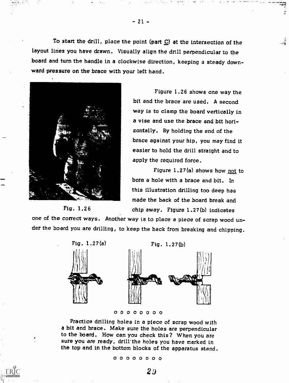
To start the drill, place the point (part C) at the intersection of thelayout lines you have drawn. Visually align the drill perpendicular to theboard and turn the handle in a clockwise direction, keeping a steady down-ward pressure on the brace with your left hand.
Figure 1.26 shows one way thebit and the brace are used. A secondway is to clamp the board vertically ina vise and use the brace and bit hori-
zontally. By holding the end of thebrace against your hip, you may find it
easier to hold the drill straight and toapply the required force.
Figure 1.27(a) shows how not tobore a hole with a brace and bit. In
this illustration drilling too deep hasmade the back of the board break and
Fig . 1.26 chip away. Figure 1.27(b) indicatesone of the correct ways. Another way is to place a piece of scrap wood un-der the board you are drilling, to keep the back from breaking and chipping.
Fig. 1.27(a) Fig. 1.27(b)
0 0 0 0 0 0 0 0Practice drilling holes in a piece of scrap wood with
a bit and brace. Make sure the holes are perpendicularto the board. How can you check this? When you aresure you are ready, drill'the holes you have marked inthe top and in the bottom blocks of the apparatus stand.
0 0 0 0 0 0 0 0
2

22 -
_Sanding,
Before you assemble the apparatus stand, the pieces should be
smoothed with an abrasive to erase dirt and pencil marks and to remove burrsfrom the edges of the pieces. For this purpose there are three kinds of abra-sives: sandpaper, garnet paper, and emery cloth. The least durable kind issandpaper, which is also the cheapest. Garnet paper is more durable, whileemery cloth is very tough and is often used for smoothing metal.
Abrasive papers are sometimes classified according to texturecoarse, medium, fine, or extra-fine. Another classification is by grit num-bers such as 50, 80, 220. These represent the number of grits per unit area.;so that the larger the number the finer the abrasive. For example, coarsegarnet paper is about 50 grit, fine paper about 120 grit, and extra-fine paperabout 220.
When smoothing a surface that is very rough, start with a coarse-gritpaper. After all the rough spots are smoothed, switch to a finer paper forfinish sanding. The easiest way to hold a piece of abrasive paper is to wrapit around a small block of wood. By the application of even pressure, theblock will help to produce a flat surface. Always sand with the grain ratherthan across it. Instead of concentrating on small spots, use a smooth back-and-forth stroke that covers the entire surface. This also will help to keepthe surface flat.
To remove burrs from the corners, sand them lightly (one or twostrokes. should be sufficient). This too will help prevent the pieces fromchipping and splitting.
0 0 0 0 0 0 0 0Sand all the parts for the apparatus stand.
Sanding is hard work, and doing a good Job takesa long time. While sanding, make certain thatyou do not round surfaces you have planed flat.They must remain flat to fit together properly andlook neat.
0 0 0 0 0 0 0 0
3 0

- 23 -
1.9 Joining Pieces of Wood
There are many different methods of joining two pieces of wood to-gether. Nails, glue, wood screws, dowels, and metal fasteners are com-monly used. The strongest is a combination of wood screws and glue, whichis stronger than nails and glue because nails can pull out of wood more easilythan screws. Boards can be joined much faster with nails than with woodscrews. If two parts may need to be disassembled later, wood screws shouldbe used, but no glue.
Using dowels requires precision drilling. Dowels are use ' mostly infurniture so that the means of fastening will not show.
Metal fasteners are employed mostly in situations in which a narrowboard makes screws or nails impractical. They are a poor substitute, how-ever, and should be used only when nothing else will work.
For this project, the use of glue and nails is suggested. If eitherone were used by itself, the joint would not be satisfactory. However, thecombination of the two makes a solid and durable joint. The choice of nailsrather than wood screws is determined by cost (nails are much cheaper) andby time (nails are faster to install).
1.10 Nails
The kinds of nails that are mostoften used are common nails, finishing
nails, and wire nails. Common nailsare used for general construction. Fin-ishing nails, which have small heads,are used where it is desirable to hidethe nail. With a nail set, a finishingnail can be driven so that its head isjust below the surface (Fia. 1.28) andcan then be covered with plastic wood.
31

- 24 -
Common nails and finishing nails are rated for size by the term
"penny," which has the abbreviation "d." This describes not only the
length but also the diameter. Table 1.1 shows the relationship of the penny
size to the length of the nail. Note that from 2 to 10 penny, for every in-
crease of one penny in size the length Increases by 1/4 inch.
Size
TABLE 1.1
Length (in.)
2d 1
3d 1-1/4
4d 1-1/2
5d 1-3/4
6d 2
7d 2-1/4
8d 2-1/2
9d 2-3/4
lOd 3
12d 3-1/4
16d 3-1/2
Wire nails are of two types, brads and flat-head nails. Wire nails
can be purchased by both length and diameter. The diameter is given in
terms of the wire size used to make the nails. As the number of the nail in-
creases, the diameter decreases. For example, a 1-1/4-inch No. 20 brad
has a smaller diameter than does a 1-1/4-inch No. 18 brad. Wire nails
range in lengths from about 1/4 inch to 1-1/2 inch. There are some sizesthat are longer, but they come in one diameter only. A brad is a small ver-
sion of a finishing nail. A flat-head wire nail looks like a common nail.
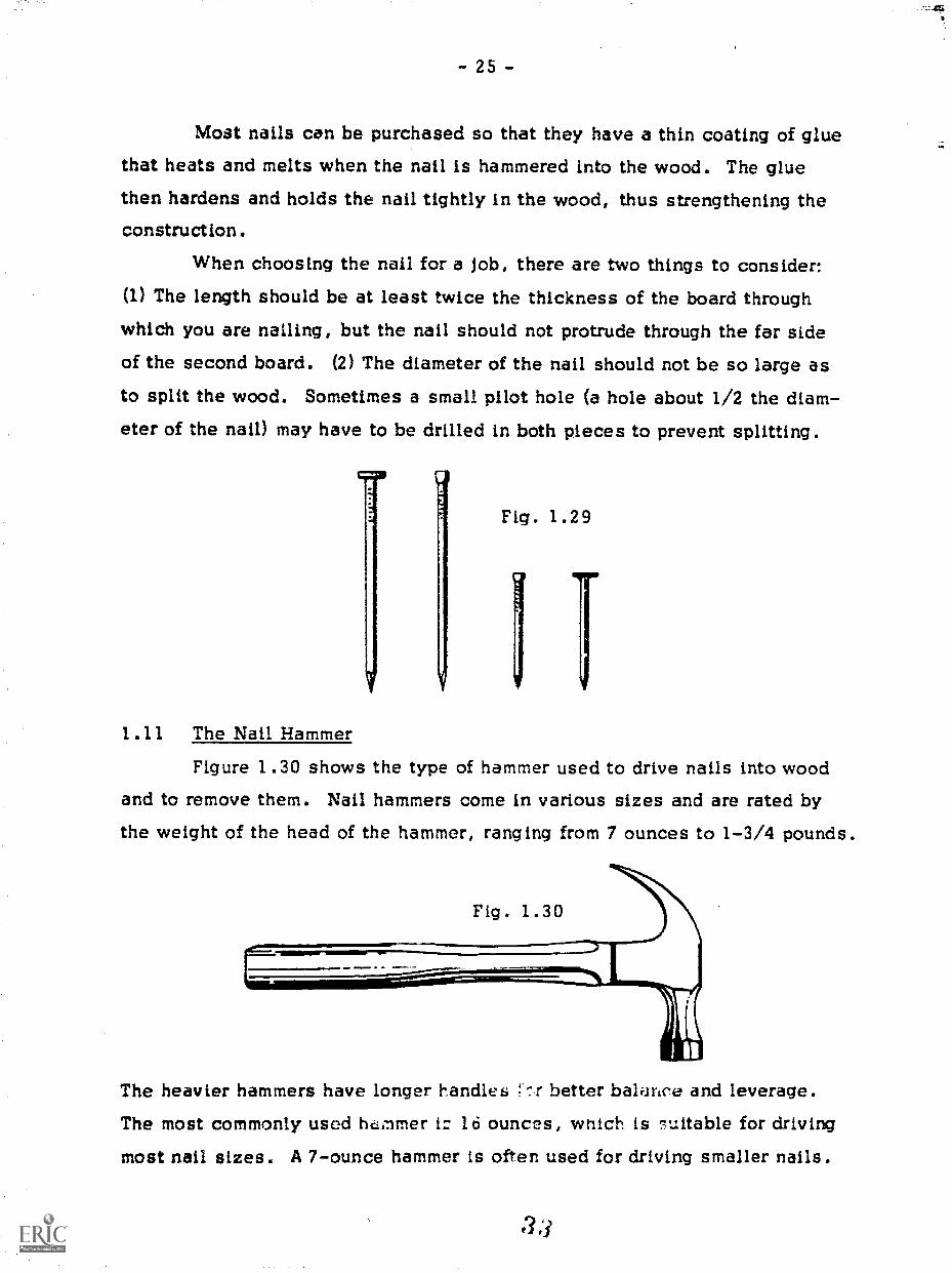
Figure 1.29 illustrates the various kinds of nails we have been discussing.
3 2
- 25 -
Most nails can be purchased so that they have a thin coating of gluethat heats and melts when the nail is hammered into the wood. The gluethen hardens and holds the nail tightly in the wood, thus strengthening theconstruction.
When choosing the nail for a Job, there are two things to consider:
(1) The length should be at least twice the thickness of the board through
which you are nailing, but the nail should not protrude through the far sideof the second board. (2) The diameter of the nail should not be so large asto split the wood. Sometimes a small pilot hole (a hole about 1/2 the diam-eter of the nail) may have to be drilled in both pieces to prevent splitting.
Fig. 1.29
1.11 The Nail Hammer
Figure 1.30 shows the type of hammer used to drive nails into woodand to remove them. Nail hammers come in various sizes and are rated bythe weight of the head of the hammer, ranging from 7 ounces to 1-3/4 pounds.
The heavier hammers have longer handles ;* r better balartoe and leverage.
The most commonly used hcimmer 16 ounces, wnich is 7uitable for driving
most nail sizes. A 7-ounce hammer is often used for driving smaller nails.

- 26 -
In using a nail hammer, always hold it near the end of the handle forbetter leverage. To start a nail, hold it firmly in position with the fingers ofyour left hand and lightly tap the head once or twice. Then take away yourfingers and drive the nail into the wood with firm, smOoth strokes (Fig. 1.31).
iN0-#04,* 4
A*I
Fig. 1.31
Do not watch the hammer; keep your eye on the nail. When the nail is nearlyall the way in, use light blows of the hammer to finish. Just drive the nailuntil the top of the head is flush with the surface of the wood. Do not dentthe wood with the face of the hammer. If you are using finishing nails, youcan then use a nail set to drive the top of the nail just below the surface.
In driving a nail, you may bend it so that it cannot be driven into thewood. Remove the nail and use another. To remove a nail, turn the hammeraround and place the head of the nail between the two claws. Then use thehammer as a lever, as shown in Fig. 1.32. To increase the leverage for pull-ing out long nails, you can place a small block of wood under the head ofthe hammer.
The first step in fastening two boards together with nails is to de-cide where the nails should go and how many to use. If a nail is placed toonear the edge of a board the nail may split it. Not only will a split make thepiece look bad, but the nail will have little holding power. Whenever pos-
at

- 27 -
Bible, position the nail between 1/2 inch and 3/4 inch in from an edge. Thisis close enough to hold the corner securely but not so close that the woodwill split. You should drill a pilot hole if you think the wood might split.
The distance between nailsis determined by the amount of
strength required of the device. Toensure that the piece is sturdy, al-ways use at least two nails. After
that, you must decide how many
nails to use. Experience is the onlyteacher because each item you build
will have different requirements.
O 0 0 0 0 0 0 0Practice driving nails into
a scrap piece of two-by-four.*Watch out for your fingers whenyou start each nail.
O 0 0 0 0 0 0 0111161.11110.....
-a
°
Fig. 1.32
1.12 Gluing and Nailing
Once you have decided where the nails should be placed, drive theminto the top board about three-quarters of the way through. Then apply glueto one of the surfaces to be Joined. Use enough glue to cover the wholesurface, but not so much that it oozes out over the edges when the surfaces
ItA two-by-four (2 )( 4) is the material you used to make the top and bottompieces of the stand. It is called a two-by-four because the original size ofthe board before it is finish-milled is 2 inches by 4 inches. After milling,it is considerably smaller, however. The wood used for the sides of thescand is called a one-by-four because its premilled size was 1 inch by4 inches. All board lumber is referred to in this manner, so remember, ifyou need a board that is 5 inches wide by 3/4 inch thick you must order aone-by-six and cut it to size.
- 28 -
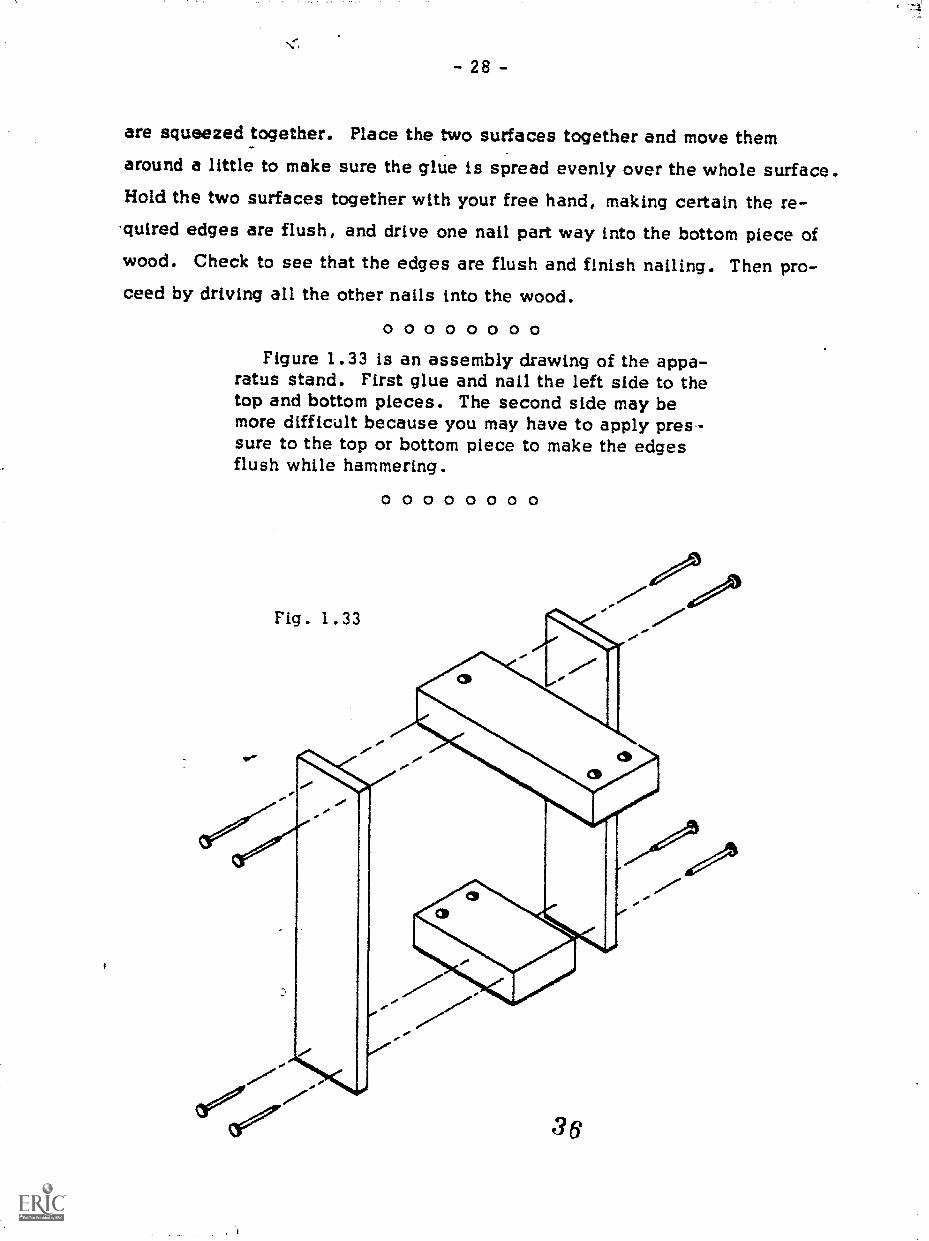
are squeezed together. Place the two surfaces together and move themaround a little to make sure the glue is spread evenly over the whole surface.Hold the two surfaces together with your free hand, making certain the re-quired edges are flush, and drive one nail part way into the bottom piece ofwood. Check to see that the edges are flush and finish nailing. Then pro-ceed by driving all the other nails into the wood.
00000000Figure 1.33 is an assembly drawing of the appa-
ratus stand. First glue and nail the left side to thetop and bottom pieces. The second side may bemore difficult because you may have to apply pres-sure to the top or bottom piece to make the edgesflush while hammering.
0 0 0 0 0 0 0 0

- 29 -
Project 2: A DENSITY KIT
The three rectangular objects shown in Fig. 2.1 are designed for usein an experiment on density. iThe purpose of the experiment is to determine
0
by measurements of size and' ass whether two of the objects are made of thesame material. Because an t ree pieces are painted the same color the stu-dent's decision is based solely on the measurements taken.
Fig. 2.1
In making this project, you will use steel for one of the cubes, alu-minum for the other cube, and aluminum for the long rectangular piece. Fig-ure 2.2 is a shop sketch-of the piecesfor this project. The material alumi-num and steel bar stock has two ofthe dimensions set and must be cut tolength and finished to dimension.
MATERIAL., ALUMINUM
i.00010.003
ke
Fig. 2.2
3.500± 0.005
MATERIAL : I ALUMINUMI STEEL
0.250 ± 0.003

- 30 -
2.1 LIELIrt FitLnAs in Project 1, the first step in making the density kit is to square
one end of the stock so that this surface can be used as a reference for the
length of the piece. In making the laboratory stand you used a belt sanderor a plane to square the end of the piece of wood stock and to bring the piece
to the final dimension. Because metal is much harder than wood you willhave to use different tools to perform the same operations that you did in
Project 1. Instead of a belt sander or a plane, you will use a file.Files can be purchased in nearly any shape, such as flat, square,
round, triangular, and half-round, to name a few. The most common type of
files range in size from about 4 inches to 16 inches in length. They are
used in general work to produce flat surfaces on metal.The rate at which material can be removed from a piece of stock is
determined by the space between the teeth of a file. A coarse file, one withteeth spaced far apart, can remove metal faster than a smooth file. Of thethree grades of coarseness, the bastard-cut file is the coarsest tooth fileand is used to remove :nook quickly, but leaves a very rough finish. A
second-cut file has medium-spaced teeth and is used for general work. A
smooth-cut file, used for doing finish work, has teeth that are close together.Each grade of file can be either a single-cut or a double-cut (see Fig. 2.3).A single-cut file has one set of teeth cut at an angle across the face of the
file. A double-cut file, not to be confused with a second-cut file, has a setof teeth like the single-cut file and another set crossing the first to prcduce
many sharp, pointed teeth. This makes it
possible to remove material faster.The length of a file also determines
the coarseness of the teeth. The longer thefile, the greater the distance between theteeth. For example, a 12-inch second-cutfile will remove material faster than an 8-
inch second-cut file.
Fig. 2.3
3 8

- 31 -
Figure 2.4 demonstrates the proper way to hold the stock and the file.Note that on the end of the file there is a wood handle, which prevents theend of the file from piercing the hand.
Fig. 2.4
4 .44,
The motion and coordination for filing is very similar to that of plan-ing, the main difference is that much less force is required in filing than inplaning. At the beginning of the stroke the pressure is placed on the leadingend of the file, and during the stroke It is gradually transferred to the rearend. The tendency is to place too much pressure on the rear end of the fileat the beginning and on the front end at the end of the stroke. If this mistakeis made, a convex surface rather than a flat one results. You will be morelikely to get a flat surface if you file diagonally from corner to corner andthen change your position so you can file across the opposite corners. Whenyou change the direction in which you are filing, the first stroke will tell youif the surface is flat. The marks made by the file should cover the entiresurface of the metal. If the file marks appear only in the middle, the middleis too high. Only by observing these marks can you make corrections in yourmotion to produce a flat surface. Even though a surface is flat, it might notbe square to the sides of the stock. As you did in the first project, be sureto check the squareness of the surface with a square.
3 3

- 32 -
The file is made to be used in only one direction; therefore, you
should lift it off the stock during the backward stroke. If you do not, you
dull the file without removing any material.Be sure the file is clean before you use it, and clean it every few
strokes. If it is not kept clean, small chips may stick in the teeth and gougethe surface of the stock. To clean the file use a file card, a short wire-bristled brush that cleans out the grooves when pushed along them. Figure2.5 shows a file card being used to clean a file.
. 2 .
"chl
a
1
Figure 2.6 depicts a method of filing called drawfiling, which is
used to remove small amounts of material from the surface or when the sur-
face needs to be smoothed. After using the regular method to remove most of
the material, drawfiling is used to finish the workpiece.
Fig . 2 6
n ,nn, ,4169.WI 11.0.naM
4 0

- 33 -
During drawfiling, a smooth-ma, single-cut file is held flat againstthe surface of the stock and moved back and forth with light pressure. Al-though the cutting motion is forward, the file is not removed from the stockduring the backward stroke as before, but held against it. This will helpyou avoid rocking the file and thereby make it easier to generate a flat sur-face. The reason drawfiling is not used for the entire filing operation is thatit requires more time than regular filing.
After a piece has been brought to dimension with a file, small burrsare usually found on the edges. To remove these, hold the file at about a45 degree angle with the surface (Fig. 2.7). Beginning at the left corner,move the file forward and to the right in one smooth, continuous motion. Itis usually easier to hold the stock in one hand, as shown, rather than in avise.
Fig. 2.7
Another type of file, called a Swiss pattern file, is used to form del-icate shapes and may be purchased in various sizes ranging from 3-1/2inches to about 7 inches in length. Unlike the files previously described,the length of this file does not determine the coarseness of the file. Swisspattern files are supplied in various "cuts" ranging from 00 to 8, with an8 cut being the coarsest. Because they are small and delicate, these filesshould not be used for heavy filing.
dl

- 34 -
2.2 Dimensions, Tolerance, and_Layouts
In Fig. 2.2 you will note that the dimensions are given in decimalsrather than in fractions of an inch. In general, fractional dimensions areused for woodworking, whereas decimal dimensions, in thousandths of aninch, are used for metalworking. Therefore, a piece of metal that is 1-3/4inches long has this dimension written as 1.750 inciler.
Decimal dimensions are commonly described it .nousandths of aninch rather than in a combination of thousandths, hundredths, and tenths.Therefore, the dimension 1.250 would be referred to as "one inch, two hun-dred and fifty thousandths"; and the dimension 0.056 as "fifty-six thousandths."
Most dimensions in Fig'. 2.2 are followed by "+0.003." This gives thethe tolerance to which the piece must he made. That is, the final size mustbe no more than 0.003 inch larger and no more than 0.003 inch less than thedimension given. For a dimension given as 2.250 +0.003 inch, the piecewould be acceptable if it measured hetween 2.247 inches and 2.253 inches.
To lay out the cuts to be made on the boards for the apparatus standyou simply drew the lines on the wood with a pencil. Because pencil marksdo not show very well on smooth metal surfaces, you must now use anothermethod. The metal must be coated with a dye that dries quickly, leaving adark or dull-coated soft substance. Scratching this surface with a sharp-pointed tool called a scriber leaves a shiny line on the metal underneath.The most common of these layout dyes is an inklike, alcohol-based liquid,which, when dry, produces a blue or purple surface that contrasts nicelywith the shiny lines. Light pressure is sufficient in using the scriber. It isnecessary only to scratch through the dye, not to leave a mark on the metal.After the piece is completed, the dye can be removed easily with alcohol.
0 0 0 0 0 0 0 0Take the stock you will use to make the density
kit and square one end with a file.
How can you determine whether the end is squarewithin the tolerances given in Fig. 2.2?
4
- 35 -
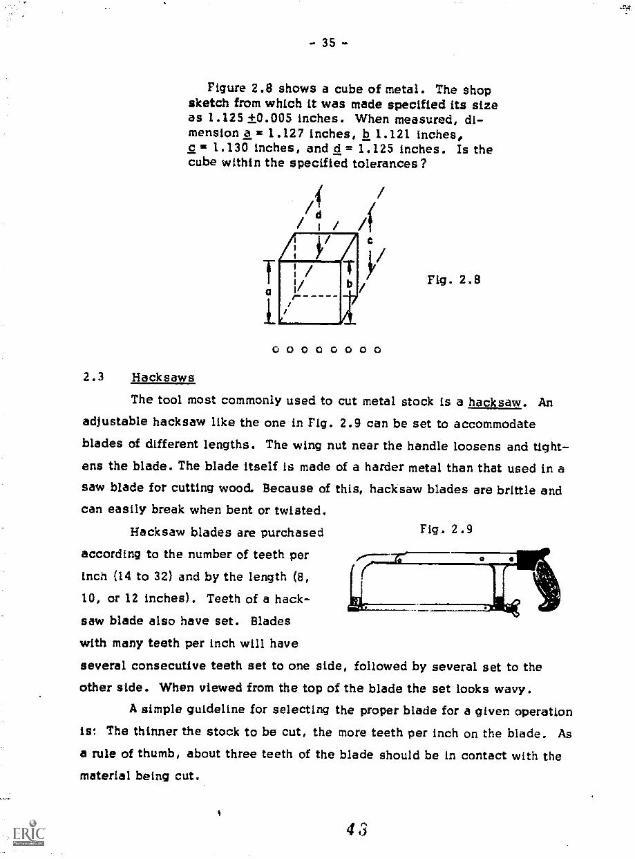
Figure 2.8 shows a cube of metal. The shopsketch from which it was made specified its sizeas 1.125 +0.005 inches. When measured, di-mension a = 1.127 inches, b 1.121 inches,c 1.130 inches, and d = 1.125 inches. Is thecube within the specified tolerances?
Q00000cCo
Fig. 2.8
2.3 Hacksaws
The tool most commonly used to cut metal stock is a hacksaw. Anadjustable hacksaw like the one in Fig. 2.9 can be set to accommodateblades of different lengths. The wing nut near the handle loosens and tight-ens the blade. The blade itself is made of a harder metal than that used in asaw blade for cutting wood. Because of this, hacksaw blades are brittle andcan easily break when bent or twisted.
Hacksaw blades are purchased
according to the number of teeth per
inch (14 to 32) and by the length (8,10, or 12 inches). Teeth of a hack-saw blade also have set. Blades
with many teeth per inch will have
several consecutive teeth set to one side, followed by several set to theother side. When viewed from the top of the blade the set looks wavy.
A simple guideline for selecting the proper blade for a given operationis: The thinner the stock to be cut, the more teeth per inch on the blade. Asa rule of thumb, about three teeth of the blade should be in contact with thematerial being cut.
Fig. 2.9
4 a
-
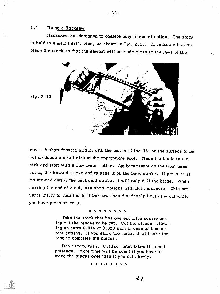
2 .4 Using a Hacksaw
Hacksaws are designed to operate only in one direction. The stockis held in a machinist's vise, as shown in Fig. 2.10. To reduce vibrationplace the stock so that the sawcut will be made close to the jaws of the
Fig. 2.10
Vet
vise. A short forward motion with the corner of the file on the surface to becut produces a small nick at the appropriate spot. Place the blade in thenick and start with a downward motion. Apply pressure on the front handduring the forward stroke and release it on the back stroke. If pressure ismaintained during the backward stroke, it will only dull the blade. Whennearing the end of a cut, use short motions with light pressure. This pre-vents injury to your hands if the saw should suddenly finish the cut whileyou have pressure on it.
0 0 0 0 0 0 0 0Take the stock that has one end filed square and
lay out the pieces to be cut. Cut the pieces, allow-ing an extra 0.015 or 0.020 inch in case of inaccu-rate cutting. If you allow too much, it will take toolong to complete the pieces.
Don't try to rush. Cutting metal takes time andpatience. More time will be spent if you have tomake the pieces over than if you cut slowly.
0 0 0 0 0 0 0 0

- 37 -
2 . 5 Precision MeasurementsBecause the tolerances in metalworking are usually small, the dimen-
sion of a piece must be checked often as filing continues. A scale whosesmallest division is 1/64 inch is unsuitable for measuring to thousandths ofan inch (see Fig. 2.11). For these precise measurements a micrometer isused.
ANVIL
SPINDLE LOCK NUT RATCHET STOP
THIMBLE
SLEEVE
Fig. 2.11
As the thimble is turned clockwise (looking from the thimble towardthe anvil), the distance between the spindle and the anvil decreases by0.025 inch with each revolution. If you examine the thimble, you will noticethat it ie graduated into 25 divisions around its circumference. Therefore,each division is 1/25 of a revolution and represents 0.001 inch of movementof the spindle.
Each division marked along the sleeve (Fig. 2.12) is 0.025 inch(You can check this by rotating the thimble one revolution), and every fourthdivision is marked by a number, 1, 2, 3, 4, etc., which is the distance intenths of an inch. To read the micrometer, each tenth of an inch and eachsmall division exposed by the thimble are added together with the reading on
Fig. 2.12
- 38 -
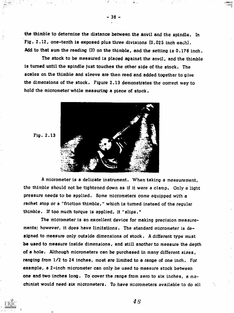
the thimble to determine the distance between the anvil and the spindle. In
Fig. 2.12, one-tenth is exposed plus three divisions (0.025 inch each).Add to that sum the reading (3) on the thimble, and the setting is 0.178 inch.
The stock to be measured is placed against the anvil, and the thimbleis turned until the spindle Just touches the other side of the stock. Thescales on the thimble and sleeve are then read and added together to givethe dimensions of the stock. Figure 2.13 demonstrates the correct way tohold the micrometer while measuring a piece of stock.
Fig. 2.13
« 14,
A micrometer is a delicate instrument. When taking a measurement,
the thimble should not be tightened down as if it were a clamp. Only a lightpressure needs to be applied. Some micrometers come equipped with a
rachet stop or a "friction thimble," which is turned instead of the regularthimble. If too much torque is applied, It "slips.
The micrometer is an excellent device for making precision measure-
ments; however, it does have limitations. The standard micrometer is de-signed to measure only outside dimensions of stock. A different type mustbe used to measure inside dimensions, and still another to measure the depthof a hole. Although micrometers can be purchased in many different sizes,
ranging from 1/2 to 24 inches, most are limited to a range of one inch. For
example, a 2-inch micrometer can only be used to measure stock betweenone and two inches long. To cover the range from zero to six inches, a ma-
chinist would need six micrometers. To have micrometers available to do all

- 39 -
these jobs and cover a reasonable range of sizes would be very expensive.Figure 2.14 is an illustration of a vernier caliper. This instrument
can be used to measure inside or outside dimensions, measure pieces up tosix inches in length, and measure the depth of holes. It is not as preciseas a micrometer because it is more difficult to read, but its versatility morethan compensates for this limitation.
There are two parts to a caliper. The first is an L-shaped piece ofsteel, the short section of which forms one of the jaws of the caliper. The
I I t I I I L 1 1
Trr.v.uarri...ri..1111111111111t1111rTITIlliwilistfillitliV1111111,1
Fig. 2.14
second is the other jaw that slides on the long section of the L. The scaleon the sliding jaw is used with the scale on the first part to determine thedistance between the jaws.
Figure 2.15 is a close-up photograph of the scale of the caliper.
0 2 4 6 8 10 Vzomm
1 iIIIIIIIIIIIIIIIIIIMIIIIIIIII111111)11111111111a 1 2 3 4 5 Fig. 2.153 4 5 6 7 8 9 1 1 2 3 4 5 6 7 8 9 2 1401.114 al ififiy,01111111111111111111,11111111114V11.11111ffilliq
i
3 10 15 20 5 ll000
The upper set of scales is for the metric measurements; the lower set for theEnglish system. Our discussion pertains to the English system, though the

- 40 -
principles of the vernier are the same for both. The large numbers, 1 and 2.,
on scale a represent inches. Each inch is divided into tenths of an inch re-presented by the smaller numbers 1 through 9. And each tenth of an inch issubdivided into four parts, which results in the smallest division on scale abeing equal to 0.025 Inch. Scale a is similar to the scale on the sleeve ofthe micrometer, and both can be considered to be a ruler whose smallest di-vision is equal to twenty-five thousandths of an inch.
The line that corresponds to zero on scale b enables you to readscale a. For the moment, iqnorp all the other divisions and the numbers on
scale b; we shall return to them later. If the zero line on scale b aligns withthe zero on scale a, the distance between the jaws of the caliper is zero.If it lines up with the large 1 on scale a, the distance is one inch, and so on.Figure 2.15 shows that the zero on scale b is between the small 3 and thesmall 4. Consequently, the distance is between three-tenths and four-tenthsof an inch. A closer look at the zero of scale b shows that it is between thethird small divi sion and four-tenths inch. Therefore, the distance betweenthe jaws of the caliper is greater than 0.375 but less than 0.400. You can
estimate that the reading is about halfway between the two, but estimating
is not accurate enough when measuring to a thousandth of an inch.
Scale b is used to read to 0.001 inch. It is divided into twenty-fiveparts and is used in conjunction with scale a to divide each small division ofscale a into twenty-five parts or one thousandth of an inch. We shall notdiscuss yvhy scale b works, but how it works: When one of its divisionslines up with any division on scale a, the number on scale b represents thenumber of thousandths of an inch. For example, in Fig. 2.15 the number 13on scale b lines up with a division on scale a. Therefore, the reading is0.013 plus 0.075 (three small divisions) plus 0.300, or a total of 0.388 inch.
Unlike the micrometer, sometimes it is difficult to determine which of
two lines is lined up with a division on the other scale. When looking atFig. 2.15, it Is difficult to decide whether the reading is 0.388 or 0.389.This is the limitation of the vernier caliper.
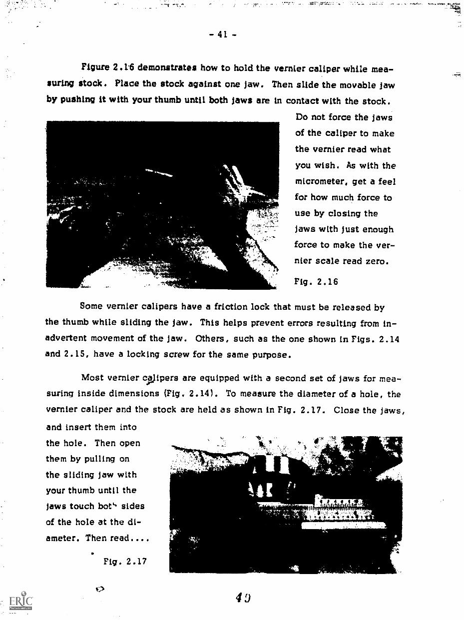
- 41 -
Figure 2.1.6 demonstrates how to hold the vernier caliper while mea-suring Stock. Place the stock against one Jaw. Then slide the movable Jaw
by pushing it with your thumb until both Jaws are in contact with the stock.
Do not force the jaws
of the caliper to make
the vernier read what
you wish. As with themicrometer, get a feel
for how much force to
use by closing the
^ 14110.-
Jaws with Just enough
force to make the ver-,,
nier scale read zero.
Fig. 2.16
Some vernier calipers have a friction lock that must be released bythe thumb while sliding the jaw. This helps prevent errors resulting from in-advertent movement of the jaw. Others, such as the one shown in Figs. 2.14and 2.15, have a locking screw for the same purpose.
Most vernier Vipers are equipped with a second set of jaws for mea-
suring inside dimensions (Fig. 2.14). To measure the diameter of a hole, thevernier caliper and the stock are held as shown in Fig. 2.17. Close the jaws,
and insert them into
the hole. Then openthem by pulling on
the sliding jaw withyour thumb until the
jaws touch botli sidesof the hole at the di-ameter. Then read....
Fig. 2.17
4o
ere IttiLlak 4
t.14.11 tjt
14*

- 42 -
A vernier caliper can also be used as a depth gauge. The sliding jawhas an extension that fits into the back of the caliper. The end of the ex-tension is made so that it is flush with the end of the caliper frame when thevernier is set at zero. As the jaws are opened, the extension protrudes be-yond the end of the caliper and its length is determined by the reading on thevernier scale.
To measure the length of a
shoulder (Fig. 2.18) place the endof the caliper against the end of thesmaller diamete,.. section. Then
slide the moving jaw until the ex-
tension touches the shoulder. Usethe same method for measuring the
depth of holes.
0 0 0 0 0 0 0 0
Fig. 2.18
Take a piece of scrap metal, measure all itsdimensions, and make a shop sketch of thepiece. So that you will become accustomed tousing a micrometer and a vernier caliper, measurethe piece with both instruments.
File the previously cut pieces to their requireddimensions, and remove burrs and finish the edgesuntil they are smooth.
0 0 0 0 0 0 0 0
2.7 Iinishinti the Density Kit/n3.1fta experiment for which the densay kit is designed, it is impor-
4
tent that the studerOoes not see the raw material from which each piece was;)
made. Therefoe'lf it is necessary that each piece be painted the same color.Beforef,plinting metal, rinse each piece with alcohol to remove oil
arid dirt. Thiiiwill provide a clean surface to which the paint can adhere.
5 0
Projecb 3: AN ELASTICITY APPARATUS
In this project you will build a piece of equipment that is used tomeasure the elasticity of different kinds of wire. In the picture of the ap-paratus (Fig. 3.1) you will see that the ivire is fastened to a bolt at one end
Ix
vMt
Fig. 3.1
of the board and at the other end to a drum with a pointer attached. When aweight is hung on the wire, the wire is stretched and the drum and the pointerturn, indicating the amount oX extension.
3.1 Twist Drills
A twist drilt (Fig. 3.2) is made of hardened and temperedsteel and can be used for drilling holes in almost any material.Designed mainly for use on metals, these drills differ from auger
bits. In the figure you will notice that the end of the drill comes
to a point. This point keeps the drill centered while the materialis removed by the cutting edges, which are formed by the spiral
grooves (flutes) in the body of the drill. The flutes also help totake the chips out of the hole. Fig. 3.2
Sizes of twist drills are designated in three ways: fractional, number,and letter. Fractional twist drills come in diameters from 1/64 inch to 3-1/2inches in steps of 1/64 inch. However, the standard set of frar'ional twistdrills contains only the sizes between 1/1 6 and 1/2 inch.

- 44 -
Number, or wire-gauge, drills are designated by numbers ranging
from I to 80, with No. I the lamest and No. 80 the smallest. A standardset of number drills consists of drills from No. 1 through No. 60. Becauseof their small size, drills with numbers higher than 60 are rarely usec A
No. 1 drill is 0.228 inch in diameter, and a No. 60 is 0.040 inch. Y41 cansee that there is quite a selection of drill sizes within this group of drills.Because number drills are made from wire-gauge stock, and are classifiedaccordingly, they do not come in uniform steps.
Letter drills range from A through Z, with A being the smallest.These too are made to supplement the fractional drills and therefore do notchange diameter in regular steps. They cover the range from 0.234 inch,
where number drills leave off, to 0.413 inch in diameter.
TABLE 3.1 SIZES OF TWIST DRILLS
Fractional
Size Drills
Inches
Wire-GaugeDrills
DecimalEquivalent
Inches
Fractional
Size DrillsInches
Wire-GaugeDrills
DecimalEquivalent
Inches
60 0.0400 44 0,086059 0.0410 43 0.089058 0.0420 42 0.093557 0.0430 3/32 0.093756 0.0465 41 0.096055 0.0520 40 0.098054 0.0550 39 0.099553 0.0595 38 0.1015
1/16 0.0625 37 0.104052 0.0635 36 0.1065SI 0.0670 7/64 0.109450 0.0700 35 0.110049 0.0730 34 0.111048 0.0760 33 0.1130
5/64 0.0781 32 0.116047 0.0785 31 0.120046 0.0810 1/8 0.125045 0.0820 30 0.1285

- 45 -
TABLE 3.1. SIZES OF TWIST DRILLS (Cont)
FractionalSize Drills
Inches
Wire-GaugeDrills
DecimalEquivalent
Inches
FractionalSize Drills
Inches
Wire-GaugeDrills
DecimalEquivalent
Inches----.5-.0.0
29 0.1360 D 0.246028 0.1405 1/4 E 0.2500
9/64 0.1406 F 0.257027 0.1440 G 0.261026 0.1470 17/64 0.265625 0.1495 H 0.266024 0.1520 I 0.272023 0.1540 J 0.2770
5/32 0.1562 K 0.281022 0.1570 9/32 0.281221 0.1590 L 0.290020 0.1610 M 0.295019 0.1660 19/64 0.296918 0.1695 N 0.3020
11/64 0.1719 5/16 0.312517 0.1730 0 0.316016 0.1770 P 0.323015 0.1800 21/64 0.328114 0.1820 Q 0.332013 0.1850 R 0.3390
3/16 0.1875 11/32 0.343712 0.1890 S 0.348011 0.1910 T 0.358010 0.1935 23/64 0.35949 0.1960 U 0.36808 0.1990 3/8 0.37507 0.2010 V 0.3770
13/64 0.2031 W 0.38606 0.2040 25/64 0.39065 0.2055 X 0.39704 0.2090
,Y 0.4040
3 0.2130 13/32 0.40627/32 0.2187 Z 0.4130
2 0.2210 27/64 0.42191 0.2280 7/16 0.4375A 0.2340 29/64 0.4531
15/64 0.2344 15/32 0.4687B 0.2380 31/64 0.4844C 0.2420 1/2 0.5000

- 4 6 -
The size of a drill is stamped on the shank, except for some smallerkizes where there is not room. Never use an unmarked drill, or one with thesize mark obliterated, just because it is in the drill index, or holder, in theplace for the correct size. Always check the size of the drill with a microm-eter by measuring the diameter across the cutting edges.
3.2 The Hand Drill
An "eggbeater" hand drill like the one shown in Fig. 3.3 is oftenused with twist drills to make holes in wood. The twist drill is placed in
the chuck, which is hand-tightened by holding the crank and turning thechuck counterclockwise as seen from the handle end. Make certain that the
drill is centered in the three jaws of the chuck and that it is not inserted toofar, making the jaws clamp down on the Mites.
Fig. 3.3
To use the drill, place the point on the intersecting lines of the lay-
out where a hole is indicated. Hold the hand drill perpendicular to the sur-
face and turn the crank clockwise. Because a twist drill's point has no
screw to pull it into the wood, you must apply force directly downward on
the drill. When the hole is nearly through, reduce the pressure so that thedrill will not break through the back side of the wood and chip the material.
To extract the drill from the hole, gently pull the hand drill upward while
turning the crank. If a hole is deep, you may need to withdraw the drill
occasionally to clear chips out of the flutes.
ta; 4

0 0 0 0 0 0 0 0Take the laboratory stand that
you made in Project 1 and drill ahole in each side as shown inFig. 3.4. This hole ts used tosupport a guide arm that you willmike later in this project.
0 0 0 0 0 0 0 0
3.3 The Drill Press
Apart from the chuck, the
tool in Fig. 3.5 does not look atall like a hand drill, but it is madeto do exactly the same job. Asyou begin to use other power tools,
you will notice that they do the
same things as hand tools, butthey do them much faster, more
ac...2rately, and with much less
effort on your part. However,
power tools are more dangerous
than hand tools, for two reasmis:First, the power is provided froman outside source. If anything
goes wrong while you are drilling
a hole with a hand drill, you sim-ply stop turning the handle and
the drill stops. With a power tool,
- 47 -
NO. 11 DRILL
MOM" ININMI [IMOM,
owTr DIA.
-11117Fi.woo dm.mt
SPINDLECHUCK
Fig. 3.4
MOTOR PULLEY
111111W.
FEED HANDLE
TABLE
TABLECLAMPLEVER
Fig. 3.5

- 48 -
however, if something goes wrong, an electric motor must be turned off andthen it must slow down and stop before the operation ceases. The secondreason power tools are more dangerous is the freedom that they allow the
hands. With hand tools, in most cases, both hands are used to perform theoperation; with power tools, one hand is usually free to wander around and
get into trouble. When working with power tools, keep your hands and looseclothing away from moving parts. It is important to develop a respect forpower tools and to use them carefully and thoughtfully.
The drill press is simple to operate but takes skill to use accurately.Figure 3.5 is an illustration of a drill press and has the most important partslabeled. A chuck is fastened to a spindle, which goes up through the headof the machine to a set of pulleys. The spindle can be lowered by rotatingthe top of the feed handle toward the operator. It is usually spring loadedso that it will go up when the pressure is eased on the feed handle. Thechuck operates the same way as the chuck on the hand drill, with one ex-ception: Because the drill press is more powerful and can handle largerdrills, the chuck must be turned much tighter than for that of a hand drill. Achuck key is provided to do thls. Simply insert the geared end of the key intoone of the holes on the side of the chuck and rotate it clockwise until thechuck is tight. Always remember to take the key out of the chuck when you
are through; otherwise when the motor is started the key may be thrown outand strike someone.
There is a limit to the distance the spindle can travel downward, andso it is often necessary to adjust the heic&t of the table to accommodate thelength of the drill and the thickness of th, stock to be drilled. This is ac-complished by loosening the table clamp, lifting or lowering the table, and
retightening the clamp. The table is heavy, so be careful not to let it slipfrom your grasp.
On top of the drill press depicted in Fig. 3.5 there are two sets ofpulleys one connected to the spindle and the other to the motor making
6

- 49 -
it possible to change the speed of the drill press. Some drill presses haveother, more convenient, means of changing speeds by simply turning a dial.
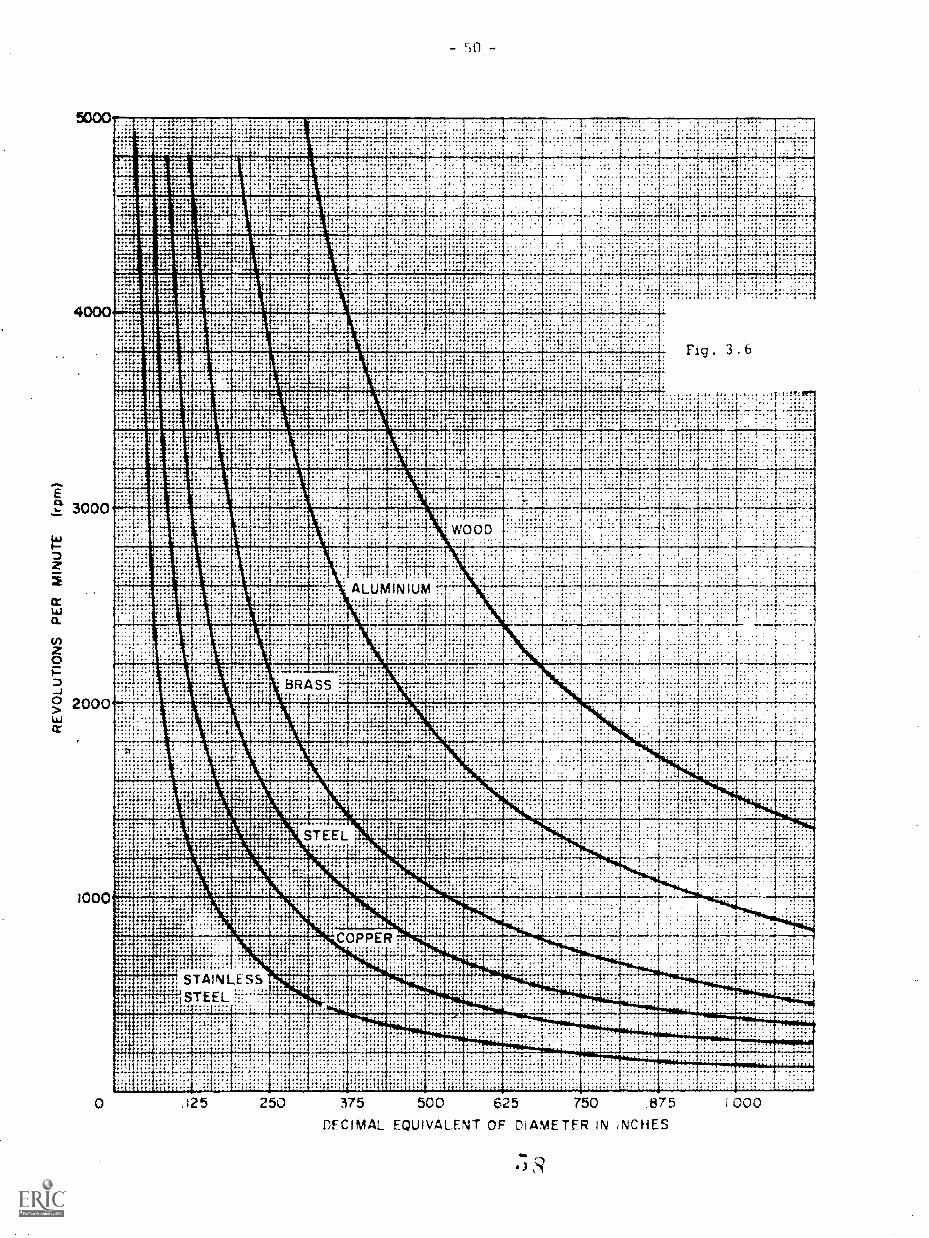
The specd at which a drill is turned is determined by two factors:the diameter of the drill and the material being drilled. In general, a largedrill must be turned more slowly than a small one because the outside edgeis moving faster than that of the small drill turned at the same number ofrevolutions per minute. Because steel is harder than wood there is morefriction between the drill and the workpiece, making it necessary to turn thedrill more slowly. If a drill is run at too high a speed, it will heat up andquickly become dull. However, if it is run too slowly, it may chip or break.
Estimating the proper speed for a given size of drill in drilling a givenmaterial is a complicated process. To simplify the matter, Fig. 3.6 is pro-vided. Do not be concerned if the exact speed shown for a specific materialcannot be obtained on the drill press you are using; simply use the nextslower speed rather than the next higher.
When you drill a hole clear through a piece of stock make certain youdo not drill into the table of the drill press. Position the table so that thedrill will go through the hole in the middle, or place a piece of scrap woodunder the piece you are drilling.
3.4 Types of Fits
There are two types of fits found in shop work. The fit in which twopieces mate but can move against each other is called a clearance fit. An
interference fit is one where two parts mate and, because of their relative
sizes, cannot be moved in relation to each other. For example, a windowthat is designed to open and close by sliding up and down must have a clear-ance fit between the window and the sash. However, if the wood swells be-
cause it absorbs moisture and the window sticks, it could be termed an in-terference fit. In this project you will make use of both of these fits.
4000
F.,` 3000
tz
o..
0
-a° 2000or
1000
INIlanNIP ': "--1.
.':.::::::::
1:
." .-.::,1
.i ... . . -(..I
.
. .
V.I
. :
"..
, ,-.:-:-- ::!7:
., ..,
11 .: 1
IIN
:..;:':*;`._., ...-
. .....,., .
'"
.. - .....:
,REA,IREMI3la
::::L:.
1.1"'
ikm..
,
I., noir .. . .
RR ". ... ,
... .
. ....... .
4i. ".;.;.:.
1 .
, .
IIismStitt
um!mixIC. =It=
--mi,'1X
311. .
... ... ..:' f ,. .........., ..
,
:..
Si Ir . . . ME. ......- .
..-...-......... ...... .
..:.4..
.... .
i;
1:..F.....
131 ::.:
- .. I11 III.::::: i
1.1
.:i:-:..,...:11.:?!.1.ii..::
i :1
,-,
.., :.,..
*. :
,
..
.
.. i :-.:..41,.....::::::=mum
fillammoin..:,...::
Ficj . 3
, , ::, !.. :;.,......... ......... ..-
. 6
: T!!.,-
IIM.
11:
;....1
grllositiumr,11111111valli
.41 U. laa,...
.Emmai
°11.-,t..,igi.
imii.l.i.:..;:#14ffinglinaismai:-..- ,,,,..
. ,.. .
, : I11 l 1.,.:. 1:-.1..
.. 1
..r:...
; .
'I'T 11 -:
Ella RE1.-1011-1 11 ........
:-::*3:1*--' 1* '
.
.: .:....
.
,.
Ent..:tini
.,.
_II
IBISI
1..11
..
i
...i'-*
LwooD.; ....... ......
.....
H. ..,.
ALUMINIUM.. -.
.
..
......
......4.1.. ... .;:.: . I.
.:...
.
..
., .
,.....
..... -::.:-:.,...... .: -1-:,. .
.-. ::: , L.E. .. .
..
:. ilk..... .
_..,..: .1.... ..; ...... ....:.1
...... .
..i::::.
...
BRASS
........-Egg
.. ..... . . .... 111.
.: ' :
... .
; .
.: : .
.......: .; ..
; .... '
. .......' " '.
4
::::1 ... ,
Tv:I.....a a ..
r 'MEEto., .. ...... .... .
,
...: .: ila1 :..:.
.
.:...
.
.
:-.
T
'114 '4 ..
0......
1-:.
.
.. rkg...LiimaMM
III .: .:; 1. :1:
.
..."..I..,. .... ::: ::?... . .... .
' ..
....,....
.....44.4.
'::/::.
..:,;:-...--: . 1 ..- ...
.
i.
".6. VS STEEL....i,: ,..,
:::.ill3
...., 'I.:
ii:;Li:
,,,
:::is .
,,
.. -t. . -: ,. i .......
......;,....
"....
zz Ka,. . -,
- : . ...r
,,.
.
...
. .
.
.
::.
1;:t....
,:44,...4...t.
.": ..... , ,-......
. .
.
,
-, ...... ...... - ....-
.....
II :::.MN'a
:::, 7.1'::.
bill,
........,.:.... .. .....
...
4.
.....
COPPER
khi;
,-: I::::
..... ..... ....
.,... ..............
: .:-......... .. , .
.
. .
INIE...:Thr
''.; itii;lii .11mg . ,, .
::.:....
.
gin
....,..v."
.
.. ...
......... -ilk. .mos
insh......_il.:4'.:: -. :::-
.. um.
...gll STAINLESS:1STEEL:":11.:;`,. ::::
T:. :i.:......
INNIMINORINNums0....jOnaMIWNri
. _
. .
: , . ,::::"
...
mgclaN
Mau.
........
..
,
'
. 1 5 250 375 500 625 750 .875
DECIMAL EQUIVALENT OF DIAMETER IN INCHES
I 00 0
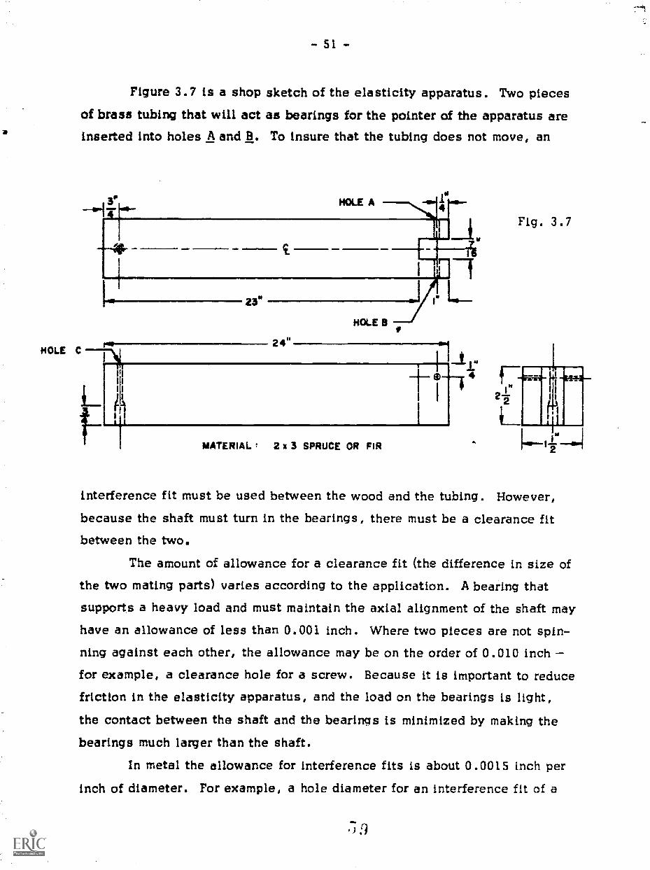
- 51 -
Figure 3.7 is a shop sketch of the elasticity apparatus. Two piecesof brass tubing that will act as bearings for the pointer of the apparatus areinserted into holes A and B. To insure that the tubing does not move, an
1msHOLE C
24"
MATERIAL 2 x 3 SPRUCE OR FIR
Fig. 3.7
interference fit must be used between the wood and the tubing. However,
because the shaft must turn in the bearings, there must be a clearance fitbetween the two.
The amount of allowance for a clearance fit (the difference in size ofthe two mating parts) varies according to the application. A bearing thatsupports a heavy load and must maintain the axial alignment of the shaft may
have an allowance of less than 0.001 inch. Where two pieces are not spin-ning against each other, the allowance may be on the order of 0.010 inchfor example, a clearance hole for a screw. Because it is important to reducefriction in the elasticity apparatus, and the load on the bearings is light,the contact between the shaft and the bearings is minimized by making the
bearings much larger than the shaft.
In metal the allowance for interference fits is about 0.0015 inch per
inch of diameter. For example, a hole diameter for an interference fit of a
.)

- 52 -
1/2-inch shaft would be about 0.499 inch. Since wood is much softer than
metal, the allowance should be at least double that of metal. However, thematerial into which the bearing is pressed may crack if the hole is too small.
The first step when considering an interference fit is to measure the
diameter of the inserted piece. It is only after a precise measurement is ob-tained that the proper drill for the hole can be selected. The hole size is de-termined by using the allowance for the material and size. Once you havedone this, both holes A and B should be drilled together to insure alignment;
in other words, drill one hole clear through the stock. After the end is slot-
ted, the piece will look like the drawing in Fig. 3.7.00000000
After cutting the wood stock to length and fin-ishing both ends, measure the brass tubing ob-tained from your instructor. Select the proper drillfor an interference fit, and drill the hole in the wood.
0 0 0 0 0 0 0 0
3 .5 Slotting
To slot the end of the stock for this project, you will use two hand
tools, a saw and a wood chisel (Fig. 3.8). After the handsaw is used to
make the sawcuts along the edge of the slot, you can use the chisel to re-
Fig . 3.8
move the material between the sawcuts.
If you look at a chisel from the side, you will noticethat it resembles the blade of a plane. In fact, it functionslike a plane in places where a plane cannot be used (for ex-ample, recessing latches in a door jamb). A chisel is either
pushed by hand or struck lightly with a hammer when more
force is needed. Chisels can be purchased in widths rang-
ing from 1/4 inch to 2 inches.To make the sawcuts, lay out the slot on both the top
and the bottom of the stock and place it in a vise (see Fig.3.9). Start the saw, and as the cut is made, gradually
adjust the saw until it is perpendicular to the stock as shown in Fig. 3.10.60

Fig. 3.9
r.
4.
-rat'
Once both sawcuts are made, use the chisel as demonstrated inFig. 3.11 and Fig. 3.12. First drive it into the wood at the base of the slotabout 3/16 inch (Fig. 3. I). Then split out the stock (Fig. 3.12). Do notsplit out a section deeper than the 3/16-inch cut, for this will cause thebottom of the slot to be very rough. Repeat this sequence until the stock isslotted about halfway through. Then turn the stock over in the vise and re-move material from the other side to prevent splitting.
If
Fig. 3.11
ii
Fig. 3.12
t. 44.'-

Fig. 3.13
0 0 0 0 0 0 0 0Slot the end of the stock for the elasticity proj-
ect by cutting the slot undersize and removing thematerial with a chisel. Then smooth the walls andbring them to dimension as illustrated in Fig. 3.13.Use both hands to guide the chisel, making surethe stock is securely clamped.
0 0 0 0 0 0 0 0
3.7 Machine Screw ThreadsDuring this project you will make two metal pieces that require machine
screw threads. The firAt is a guide arm used with the laboratory stand. It is
threaded on one end and 'attthed to the side of the stand with two nuts. The
thread, which is cut on the outside of the rod, is called an external thread.The roller in the elasticity apparatus is the second metal piece you will make.Here, an internal thread is required so that a wire can be attached to the
rolleriby means of a machine screw.*Both internal and external machine screw threads are classified by
the number of grooves per inch and by the diameter of the thread. The thread
diameters are given by numbers starting from very small threads up to a 1/4-
inch diameter. The diameters are then given in fractions of an inch. The
*Unlike wood screws, which taper to a point and form their own threads inthe wood, machine screws are straight with a uniform thread and requiremating threads to be cut in the metal.

- 55 -
smallest of the threads classified in this way is a No. 0, which is 0.060inch in diameter. The diameter then increases by 0.013 inch for each num-
ber of the screw. There are always two numbers given to des.cribe a thread.
The first is the diameter, and the secorid number Ls the threads per inch. Thus,
a 6-32 screw has a No. 6 diameter (0.138 inch) and 32 threads per inch.
Threads come in various
groupings, but the most common are
the National Coarse (NC) and the Na-
tional Fine (NF) series. The Nation-al Coarse series has sizes rangingfrom a No. 1 to as large as 4 inches
in diameter. The National Fine series
ranges from a No. 0 to 1-1/2-inchdiameter. Table 3.2 lists the threadsavailable in these two series. Onlythe commonly used sizes are given.
3.8 Cutting Threads
To cut an external thread, you
use a tool called a die (Fig. 3.14).
The teeth on the inside of the die are
tapered to remove material gradually
until the full threads are formed on the Fig. 3.15rod. Because of the taper (Fig. 3.15),the die must be started from one side only, often marked"Start from this side."
The die is held in a tool called a die stock (Fig. 3.16) by means of a screwin the side of the die stock thatFig. 3.16engages in the side of the dieand is tightened snugly.
TABLE 3.2
National Coarse National Fine
2-56 2-644-40 4-485-40 5-446-32 6-408-32 8-36
10-24 10-32
12-24 12-281/4 -20 1/4 -285/16-18 5/16-243/8 -16 3/8 -297/16-14 7/16-201/2 -13 1/2 -20
Fig. 3.14
63
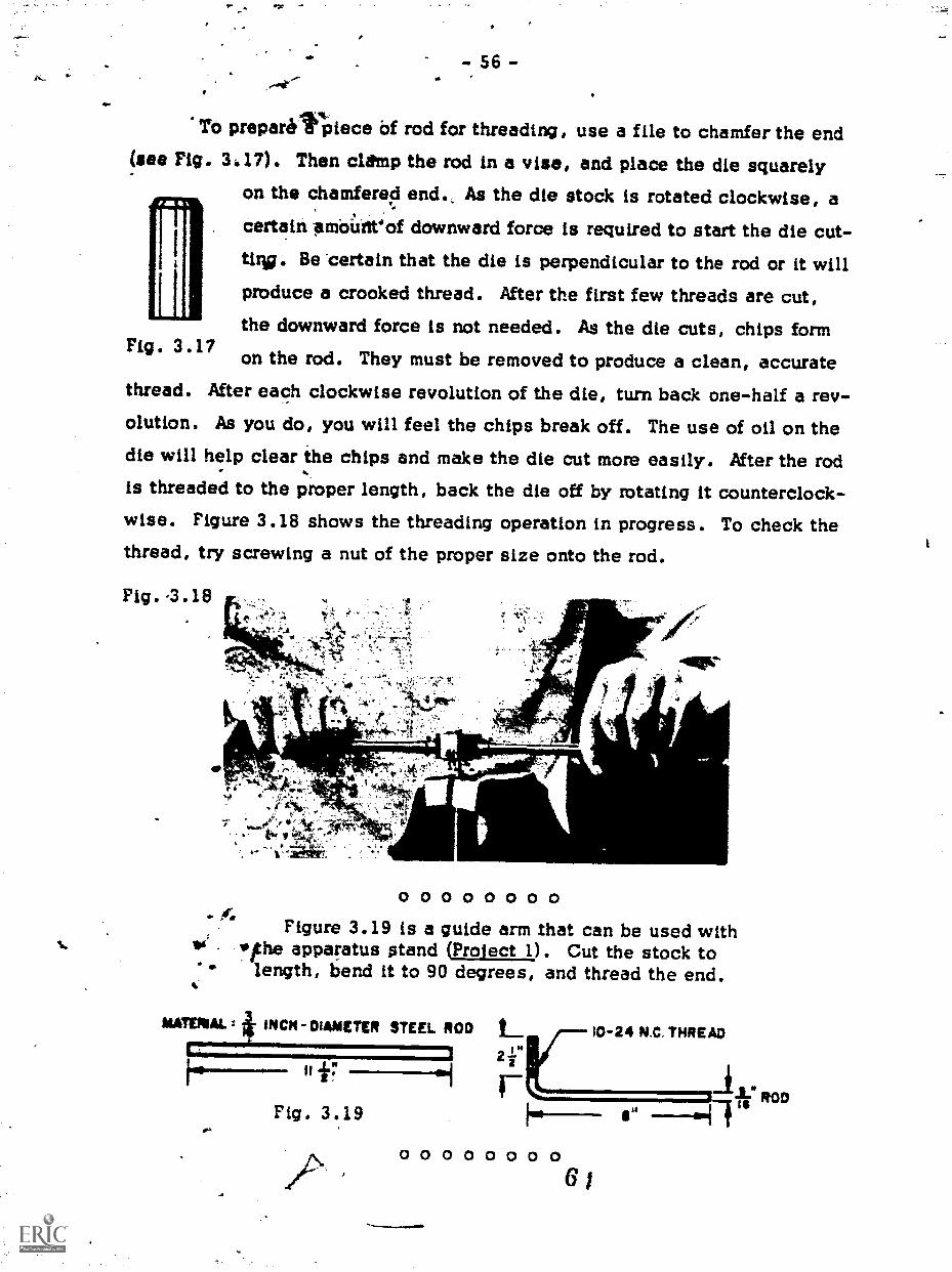
To prepare*Piece Of rod for threading, use a file to chamfer the end(see Fig. 3 17). Then clemp the rod in a vise, and place the die squarely
on the chamfered end., As the die stock is rotated clockwise, a
certain sm'ciUtitof downward force is required to start the die cut-tirkg. Be 'certain that the die is perpendicular to the rod or it willproduce a crooked thread. After the first few threads are cut,the downward force is not needed. As the die cuts, chips form
Fig. 3.17on the rod. They must be removed to produce a clean, accurate
thread. Mter each clockwise revolution of the die, turn back one-half a rev-olution. As you do, you will feel the chips break off. The use of oil on thedie will help clear the chips and make the die cut more easily. After the rodis threaded to the proper length, back the die off by rotating it counterclock-wise. Figure 3.18 shows the threading operation in progress. To check thethread, try screwing a nut of the proper size onto the rod.
Fig. '3.18
0 0 0 0 0 0 0 0
44'
Figure 3.19 is a guide arm that can be used with10 lope appar.atus stand (Project 1). Cut the stock to
length, bend it to 90 degrees, and thread the end.I.
MATERIAL 4. INCH-DIAMETER STEEL NOD
=
Fig. 3.19
L. - 2 4 N.C. THREAD
2 f
0 0 0 0 0 0 0 06 ;
I
sROD
--awl-1111
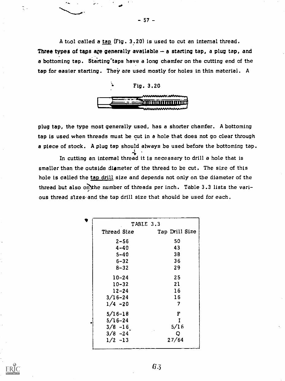
- 57 -
A tool called a (Fig. 3.20) is used to cut an internal thread.Three types of taps are generally available a starting tap, a plug tap, anda bottoming tap. Stirting-taps have a long chamfer on the cutting end of the
tap for easier starting. Their are used mostly for holes in thin material. A
Fig. 3.20,AMMWMMMW
plug tap, the type most generally used, has a shorter chamfer. A bottomingtap is used when threads must be cut in a hole that does not go clear througha piece of stock. A plug tap should always be used before the bottoming tap.
In cutting an internal thread it is necessary to drill a hole that issmaller than the outside dimmeter of the thread to be cut. The size of thishole is called the tap drill size and depends not only on the diameter of thethread but also or..Nhe number of threads per inch. Table 3.3 lists the vari-ous thread slzes-and the tap drill size that should be used for each.
TABLE 3.3Thread Size Tap Drill Size
2-56 504-40 435-40 386-32 368-32 29
10-24 2510-32 2112-24 16
3/16-24 161/4 -20 7
5/16-185/16-243/8 -16_ 5/163/8 -241/2 -13 27/64
6.3

- 58 -
A tap is held in a tool called a tap handle. Figure 3.21 illustratestwo types that are often used. The square end of the tap is placed in thechuck of the tap handle, and the chuck is tightened down on he tap itself.To start the tap, place tne cutting end in the hole, exert downward pressure,and rotate the handle clockwise. Make sure that the tap is perpendicular tothe stock. Proceed as you did In using a die, backing off the tap occasion-ally to break off chips. Use cutting oil on the tap. Figure 3.22 demonstratesa tapping operation in progress.
um as= a( IRA
Fig. 3.21
Fig. 3.22
3.9 Drilling Round Stock
Figure 3.23 is a shop sketch of the drum, or roller, that is used withthe elasticity equipment. Note that two holes are drilled in it one alongthe axis and one perpendicular to it.
MATERIAL: - INCH-DIAMETER ALUMINUM ROD
0.125 0.
-110375!.003
Fig. 3.23
0.750 t .003
TAP DRILL. FOR 5-32 MACHINE SCREW
67

- 59 -
When drilling a hole in metal, a drill 'may wander and start in thewrong place. To prevent this, a small hole is made at the intersection ofthe layout lines on the stock with a tool called a center punch. It looks likea nail set except that the end comes to a point. Because the hole will guidethe drill, the center punch must be used accurately.
Place the point at the intersection of the layout lines and tap the cen-ter punch lightly with a hammer. Check the indentation on the metal to seeif it is correctly positioned. If so, replace the center punch (you will feelthe point drop into the previous indentation) and enlame the hole by tappingthe center punch once again. If the mark is incorrectly placed, tilt the cen-ter punch and tap it with a hammer, moving the Indentation in the direction
you wish. Then straighten it and tap it again with a hammer.To drill the hole accurately through the diameter of the stock, V blocks
are used. When a drill is positioned so that it lines up with the bottom ofthe V, the resulting hole passes through the center of the stock. Two meth-ods used to insure this are depicted in Fig. 3.24 and Fig. 3.25.
In Fig. 3.24, the stock is placed in the V blocks after the hole is
laid out on the side. While the clamps are loose, the hole position is markedwith a center punch. The square is used to referenceethe circumference of the
Fig. 3.24 Fig. 3.25

- 60 -
stock. The stock is rotated in the V blocks until the distance between the
square and the center mark is one-half the diameter of the stock. Then theclamps are tightened and the measurement is checked from both sides of the
stock to make sure that it has not shifted. Then the setup is moved untilthe drill is positioned correctly and the hole drilled. Because the materialis metal, oil is used on the drill and the feed is slower.
Another method is to clamp a V block in a drill vise (see Fig. 3.25).Position the vise so that the drill lines up with the bottom of the V, and clamp
it to the drill press table. This method, however, has two drawbacks. Thestock must be held by h: nd, which is difficult and possibly dangerous. Al-though it is more direct than the first, this method takes more time to set up.
In using either method, be sure that if the drill is to go clear through thestock that it will not go into the V block as it comes out the bottom side.
After squaring one end of the stock used for thedrum in Fig. 3.23, drill the hole along the diam-eter of the stock. Then cut the stock to length andfile to dimension.
00000000To drill the hole along the axis of the drum, it is necessary to find
the center of the stock. Figure 3.26 shows a center head, the tool used tolay out the center of round stock. A diameter line is drawn by placing the
Fig. 3.26
stock in the "V" of the center head and scribing a line along the steel ruleas shown in Fig. 3.27. By scribing any two diameter lines, the center islocated at their intersection. Use a vernier caliper to check the position ofthe center point. Remember that the dimensional tolerances are +0.003 inch,
and so you must drill carefully.6 c

To prevent the stock from tipping when you drill the hole, place apiece of scrap wood under the stock before clamping the piece in a drill vise.
Fig 3.27
0 0 0 0 0 0 0 0
440
Drill the hole along the axis of the roller.Tap the hole along the diameter. Because most
8-32 taps are not long enough, tap from both endsof the hole. In the final assembly of the apparatus,two machine screws are screwed into the drum, oneto hold the wire to the drum and a second to holdthe drum to the pointer. The screw holding the wireis shorter; therefore, the hole does not have to betapped so deeply. However, the hole for the sec-ond screw must be tapped at least halfway throughto allow the screw to tighten on the pointer.
0 0 0 0 0 0 0 0
3.10 CpunterbalmT ie shop sketch of the elasticity apparatus, Fig. 3.7, indicates that
the hole or. the right end (hole C) has two diameters. This hole Is made bydrilling with two separate drills, one the diameter of the smaller section ofthe hole and the second the diameter of the larger. Drilling the second holeis called counterboring.
The most common use of counterboring is to form a hole that will re-ceive both the shaft and the head of a machinc.; .therew without exposing the
6,)

- 62 -
ead of the screw. In the case of the elasticity apparatus, the hole is coun-terbored for two reasons. First, if the head of the screw were to extend be-yond the surface of the wood, the piece would be unstable. Second, becausethe hole is counterbored, a shorter screw can be used.
There are special tools for counterboring. In most cases, a flat-bottomed hole is required. However, it is nct important here, and so a drillis used that results in the bottom of the hole being tapered. The first stepin countel is to drill a clearance hole through the stock for the screw.The second step is to drill a clearance hole for the head of the screw. Thesecond hole does not go clear through the stock; therefore, it is necessaryto stop the feed of the drill press when the drill reaches a specified depth.
Figure 3.28 shows the parts of the drill press that are used to drillto a specified depth. Mark the depth of the second hole on the side of the
Fig. 3.28
(a) SPINDLE LOCK(a) DEFTH STOP(c) DEPTH-ADJUST-
MENT NUT(d) DEPTH SCALE
-sr
(d)
stock. Then lower the spindle until the drill is even with the line. Tightenthe qpindle lock by rotating it toward you. Now release the lock on thedepth-adjustment nut and spin the nut until it rests against the depth stop.Retighten the lock on the depth-adjustment nut to prevent it from moving.
Then release the spindle lock and the setting is completed.

- 63 -
Drill and counterbore hole C (Fig. 3.7).Cut the stock to length for the pointer (Fig. 3.
it to 90 degrees, and file the end to a point as shCut two pieces of brass tubing 1/2 inch long.
ends square, and deburr and bevel the outside of
MATERIAL: - -INCH-DIAMETER STEEL ROD
>
29), bendown.
File thethe ends.
0
Assemble the elasti-city apparatus as shownin Fig. 3.30. A visemay be used to pressthe brass tubing into thewood. Place the tubingover the hole, makingsure that it is squareto the surface of thewood. To reduce thechance of splitting,place a piece of wood,which barely fits, intothe slot behind the hole.Then tighten the vise.
0 0 0 0 0 0 0 0
Fig. 3.30
12"
8- 32 WING NUT
18 BRASSWASHERS
i 8 32 x L.' R H2
MACHINE SCREW1
Fig. 3.29
8 - 3" " R. H.4MACHINE SCREW
ROLLER
POINTER
BRASSTUBING
"8-32x 2- RH2
MACHINE SCREW
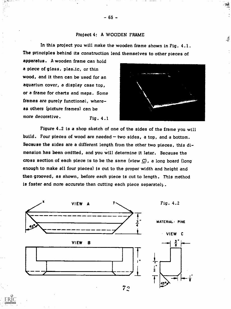
- 65 -
Project 4: A WOODEN FRAME
In this project you will make the wooden frame shown in Fig. 4.1.The principles behind its construction lend themselves to other pieces ofapparatus. A wooden frame can hold
a piece of glass, plasac, or thinwood, and it then can be used for an
aquarium cover, a display case top,or a frame for charts and maps. Some
frames are purely functional, where-as others (picture frames) can bemore decorative. Fig . 4 .1
Figure 4.2 is a shop sketch of one of the sides of the frame you willbuild. Four pieces of wood are needed two sides, a top, and a bottom.Because the sides are a different length from the other two pieces, this di-mension has been omitted, and you will determine it later. Because thecross section of each piece is to be the same (view C), a long board (longenough to make all four pieces) is cut to the proper width and height and
then grooved, as shown, before each piece is cut to length. This methodis faster and more accurate than cutting each piece separately..
VIEW A
a .1110 01.
VIEW 8
7
2
Fig. 4.2
MATERIAL : PINE
VIEW C
H hi

- 66 -
4.1 The Table Saw
The pkble saw depicted in Fig. 4.3 can do the same things as a hand-
saw, but more quickly and easily because the power is supplied by an elec-tric motor connected by pulleys and belts to a circular saw blade. The woodis fed in as the top of the blade rotates toward the operator, forcing the wooddown against the table as it is being cut. The height of the blade can be ad-justed by a crank generally located on the front of the machine. On mosttable saws the angle of the blade also can be adjusted by a crank on theside of the machine.
Two pieces orequipment are required when using the table saw. Thertp fence (Fig. 4.4) is used as a reference when making sawcuts along the
length of a board. The mitre gauge (Fig. 4.6) can be adjusted to make saw-cuts at various angles.
Fig . 4 . 3 4 . 2 Circular Saw Blades
*4.1
Fig. 4.4
filegt-oVekg Ait. -.
A circular saw blade is a flat
disc of steel having saw teeth ground
around the circumference. There are
blades made for ripsawing, and others
for crosscutting. The teeth on theseblades are very similar to those on the
corresponding kinds of handsaws ex-
cept that they are larger.
Fig. 4.5
7 3

- 67 -
So that the blade does not need to be changed, the one most common-
ly used with a table saw is.the combination blade, which combines both ripteeth and crosscut teeth. Around the circumference are several segments,each consisting of a series of small teeth for crosscutting and one largetooth that performs the ripping operation.
Circular saw blades can be purchased with or without set. Blades
with set are used for doing rough work where clearance is needed to reducefriction. Blades without set are used when smooth-finish cuts are required.
Saw blades are cl ssified according to the type of teeth crosscut,rip, and so on. They' are also classified by the diameter of the blade (whichis limited by the capacity of the table saw) and the diameter of the shaft on
which the blade is used.
There are many other types of blades that can be used in table saws.Some blades are made for cutting plastics, others for cutting composition
boards such as chipboard and Masonite, and still others for cutting metal.The blades discussed in this section and also some of the other bladesavailable are shown in Fig. 4 .6.
When it is necessary to change a blade in a table saw, because itis the wrong blade or has become dull, ask someone who is familiar with the
table saw you are using to show you how to do it. Be sure that the blade isinstalled in the proper direction and is tightened snugly. Always unplug thesaw while the blade is being changed. A serious accident could occur ifsomeone should happen to hit the starting switch.
When preparing to make a sawcut, adjust the blade so that the teethare just a little higher than the thickness of the stock. The less the bladeis exposed, the less risk there is of accidents.
4.3 Making Sawcuts with the Rip Fence
The distance between the rip fence and the saw blade can be adjustedto cut a piece of wood to any width by sliding the fence along the front andrear support bars until it is at the proper distance from the blade and then byclamping it in position. Most rip fences have a built-in clamp that can be

RIPSAW
ROTATION
COMBINATION SAW(With SET)
- 68 -
Fig. 4 . 6
CROSSCUT SAW
PLYWOOD SAW
CARBIDE SAW
i

- 69 -
set by turning a knob or pressing a lever.* Always recheck the dimensionbecause the fence will move slightly as the clamp is tightened. The mostaccurate way to set the distance between the fence and the saw blade is to
use a scale or a steel measuring tape to measure the distance from the fenceto the nearest tooth on the blade. Remember that some blades have set teethand others do not. On most table saws the front support bar is graduated in
inches measured from the blade. The proper dimension can be set from thisscale and the fence clamped. This method is not so accurate and should beused only when rough work is being done.
Before making a cut, be certain there is enough room around the table
saw so that the board will not hit 'anything. You may have to turn the saw
around to provide the necessary clearance. Make sure there is nothing nearthe saw blade, and then turn the saw on. Place the stock firmly against thefence and push it into the blade (see Fig. 4.7), always keeping your hands
well clear of the blade. Push the stock through until the back side of theblade is no longer in contact with the wood (Fig. 4.8). Never let the stockstand still while it is being cut. If it does, friction will cause the wood toburn and heat up the blade, which will dull or even warp it. Take care that
Fig . 4 . 7 Fig. 4.8
*Some fences have two clamps on them, one for each end of the rip fence.Be sure to determine which type is used on your saw. If one clamp is nottightened, the fence may move during a cut, which is very dangerous.

- 70 -
the wood does not pull away from the fence, thereby causing the wood to
bind between the blade and the fence. Warped or twisted wood is morelikely to do this than straight wood is.
If the wood should bind for any reason, do not back up or let go of
the wood because it could be thrown by the blade. Hold it firmly againstthe table with one hand and shut off the saw with the other.
In ripping a narrow piece of
stock, do not use your fingers to pushthe stock between the blade and the
fence. Use an awl or some type ofwooden pusher, as shown in Fig. 4.9.
Mter you have finished a cut,turn off the saw before doing anything
else. Then clear any chips of wood
that are near the blade, otherwise theycould vibrate into the blade during the
next cut and be thrown across the room. Never remove scraps while the
blade is rotating and be careful to turn the saw off in such a way that you
are clear of the path of any chips that might be thrown.
Because the table saw is potentially the most dangerous tool you
will ever use, this section contains many warnings and negative instructions.However, since it is also one of.the most useful tools, you must learn to
use it cautiously by thinking ahead and planning for anything that might hap-
pen during the operation. If you approach the table saw in this manner, you
will find it a safe tool to use and have no reason to fear it.
Fig. 4.9
0 0 0 0 0 0 0 0Only after your instructor has demonstrated the
correct way to use the table saw and has watchedyou make some practice cuts should you begin torip the stock for the wooden frame shown inFig. 4.2. Remember, BE CAREFUL!
0 0 0 0 0 0 0 0
77

- 71 -
4.4 Chamfering with a Table Saw
In the description of end planing (Project 1) you were told to use aplane to chamfer the enci-of a board to reduce the chance of splitting. The
wooden frame in Fig. 4.2 requires a chamfer, but for a purely decorative
reason. The frame Ikould function just as well without it. As before, aplane can be used by planing lengthwise along the edge of the board. How-ever, this operatiop is done with more ease, more accuracy, and more speedon a table saw.
.Before the previous sawcut was made, the distance between the bladeand the fence was set with the aid of a scale. However, to chamfer a board
the blade must be tilted at an angle; and because the blade is angled, it iseasier to make a ch"amfer by trial and error than to set the fence to a speci-fic dimension.
First set the blade at 45 degrees by turning the crank on the side ofthe table saw, and check the angle by making a trial cut. Lay out the width
of the chamfer on the edge# the board. Then raise the blade until its ver-tical height is greater than the Ackness-of the board. Position the fence so
,.
lthat the blade aretipve i st a little material and make a sawcut. Measurethe distance beth thle edge of the sawcut and the layout line. Readjust
the fence accordingly and make the final cut.O 0 0 0 0 0 0 0
Chamfer the edges according to Fig. 4.2. Becertain that whatever you use to push the wooddoes not touch the blade during the cut.
O 0 0 0 0 0 0 04.5 Slotting with a Table Saw
Note in view1Qcf Fit. 4.2 that a section of wood has been removed.
-117'"A
When. the frame Is assenibled, tills sec-\.
tion, called a rabbet, forks the recess'
'into IhiclIsthe glass will fit.;; The rab-ENI,
ilttis'the Tesult'of two .sawcuts , as il-lustrated in Fig-. 4.10(a) and 4.10(b).
Fig. 4.10
7s(b)
- 72 -
,The first sawcut is Irsically a rip cut except that the blade does not
cut clear tkirough the wood. The 'height of the blade is the same as the depth
of the slot in Fig. 4.10(a) and is set by using the scale as demonstrated inFig. 4.11. Next, the riNtince is adjusted so that the distance between the
blade and the fence corresponds to that specified in the drawing. Then thesawcut is made.
NZ. The second sawcut removes the material represented by the shaded4-
section in Fig. 4.10()).. The two sawcuts must meet precisely at point Afor the glass to have a proper fit. The method used for this cut is the sameas the previous one.. Hovver,,-more care is required because the piece
will be less stable during the cut. To prevent tipping the wood during thecut, place the awl used,to push the stock between the blade and the
fence. Fig. 4.11
o 0 oMake the r8bbet cut for the wooden frame.
Take care that the board does not lift from thetable at the end of 'the cut and cause the sawcutsnot to meet properly.
0 0 0 0 0 0 0 0
4.6 Making Sawcuts with a Mitre Gauge,41,' 4
A mitre tf auge spirifeTifily used to make crosscuts with the table saw.
It rides back and forthin esfot in the top of the table saw. The mitre gauge
79

- 73 -
you use is the same as the one used with the belt sander in Project 1. For
accurate work you must make a trial cut, measure the angle of the end, andreadjust the mitre gauge if necessary.
Before making a sawcut with a mitre gauge you must mark the board
where it is to be cut. The best place for your layout mark is on the frontedge of the board toward the saw blade. To obtain better control of the pieceduring the operation, always hold the board against the mitre gauge by theend that will be the longest after the sawcut. Remember which end is to bethe finished piece so that you will know on which side of the layout line tosaw.
Before turning on the saw, move the mitre gauge forward until thestock to be cut is very close to the saw blade. Then slide the wood alongthe surface of the mitre gauge until the layout mark lines up with the edgeof the blade. (Don't forget what to do if a blade has set.) As you hold thewood firmly against the mitre gauge, move the gauge toward you until thewood is well clear of the blade. Start the saw and push the stock into theblade, being sure not to slide it along the face of the mitre gauge (Fig. 4 .12).
Fig. 4.12
e-
Jodi
After the cut is through, hold the board against the mitre gauge, move itaway from the saw blade, and slide the mitre gauge back toward you. Thenshut off the saw.

- 74 -
Always be careful to keep your hands away from the saw blade. If
you are cutting a narrow board, use only one hand to hold it against themitre gauge. If the board is wide, you will have to hold the board against
the gauge with one hand and push it with the other.
Eight 45 degree sawcuts are needed for the frame, two on each piece.
Making a crosscut at an angle other than 90 degrees is simple. However, inthe case of the wooden frame, each sawcut must be very accurate becauseevery error is multiplied by the number of sawcuts. If every sawcut were
off by 1/2 degree, when the frame is assembled a gap of 4 degrees would
result at one corner. Thus the setting of the mitre gauge is very critical.The best way to check the setting is to make two cuts on scrap wood and fit
them together, checking with a square that they add to 90 degrees.NEVER use the rip fence with the mitre gauge to make a crosscut.
There is a very good possibility that the stock would bind because there is
not enough wood against the fence to act as a good reference. If many boards
must be cut to the same length, a stop can be clamped on the mitre gaugemaking it possible to cut each board to the same length.
In Fig. 4.2, the length of the piece is not speci-fied. If the frame is to fit around a piece of glassthat is 8 by 10 inches, how long should each piecebe? (Give the distance from point a to point b.)
Make the 45 degree cuts on the long board youhave already chamfered, cutting each piece tolength in the process. To reduce errors, be sureeach cut is made in the correct direction withoutresetting the mitre gauge each time.
Use glue ard small-diameter brads to assemblethe frame. It n,ay be easier to assemble the frameif you clamp one board to the table while you nailthe other to it. Wipe up any excess glue with adamp cloth. Glue prevents stain from being ab-sorbed by the wood if you choose to stain the framea different color.
Sand the frame to remove marks left by the sawblade but do not round any of the corners in theprocess.
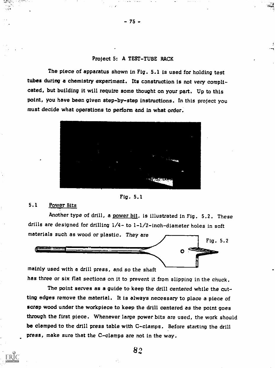
- 75 -
Project 5: A TEST-TUBE RACK
The piece of apparatus shown in Fig. 5.1 is used for holding testtubes during a chemistry experiment. Its construction is not very compli-cated, but building it will require some thought on your part. Up to thispoint, you have been given step-by-step instructions. In this project you
must decide what operations to perform and in what order.
Fig. 5.15.1 Power Bits
Another type of drill, a power bit, is illustrated in Fig. 5.2. Thesedrills are designed for drilling 1/4- to 1-1/2-inch-diameter holes in softmaterials such as wood or plastic. They are
Fig. 5.2
mainly used with a drill press, and so the shafthas three or six flat sections on it to prevent it from slipping in the chuck.
The point serves as a guide to keep the drill centered while the cut-ting edges remove the material. It is always necessary to place a piece ofscrap wood under the workpiece to keep the drill centered as the point goesthrough the first piece. Whenever large power bits are used, the work shouldbe clamped to the drill press table with C-clamps. .Before starting the drillpress, make sure that the C-clamps are not in the way.

ewe, .... /I. M... Ir .5-
- 76 -
0 0 0 0 0 0 0 0All the information you need to make the test-
tube rack is contained in Fig. 5.3. However,because of the natu:.) of the piece, the actualdimensions used for setting the table saw arelot given directly.
On a plece of paper, list in order all the op-erations you must perform to make the test-tuberack. Describe every step in detail as if theperson reading your instructions has seen thetools used but has never used them.
At first, the 45 degree sawcat may appear dif-ficult to make. It will help L: you remember howyou used the height of the blade and the distancebetween the blade and the rip fence to make therabbet cut in Project 1 .
Take the list to your instructor. After you re-ceive approval, proceed t) carry out the projectas you have outlined it.
0 0 0 0 0 0 0 0
83
Fig. 5.3

- 77 -
Project.6: A LAB CART
Your sixth project is to construct the piece of equipment shown inFig. 6.1. This lab cart is used to investigate the relationship betweenforce, mass, and acceleration. It consists of a piece of 2 x 4 with threewheels attached and a spring-loaded piston that can accelerate the cart.The mass of the cart can be changed, usually by stacking bricks on the top.
Fig. 6.1
6.1 WoQd Screws
The only additional information you need to make the lab cart is themethod used to fasten the wheels to the 2 x 4. In Project 1 we briefly dis-cussed different types of wood fasteners. The method that is most appro-priate here is the use of wood screws.
Two styles of wood screws are: round head (R.H.) and flat head(F.H.) (see Fig. 6.2). Their diameters range from a No. 2 up to a No. 24,with a selection of lengths for each diameter. The most commonly used di-ameters are between No. 4 and No. 10, roughly corresponding to the sizes
of machine screws. Because the bottom of the head is flush with the sur-face, the length of a rcund-head screw is measured
from the bottom of the head to the tip of the screw.The top of a flat-head screw is usually flush with thesurface through which it is used; therefore, its length
is measured from the top of the head to the bottom tip
of the screw.Fig. 6.2
- 78 -
There is no set rule for choosing the size of the screw to be used forany particular job. The sturdier a project must be because of the weightor stress it mat bear the larger the diameter of the screw. If you want toattach a large machinist's vise to a bench top, you have to use a screwlarger than a No. 6 or a No. 10. For building .a book cabinet out of I-inchpine, you might use a No. 8 or a No. 10 screw. If you are going to screw
a lid on a box and the only reason for fastening the lid is to hold it in ple-le,you might use a No. 4 or a No. 6.
Once the diameter is chosen, it is a simple matter to select theproper length. It should be equal to the thickness of the stock through whichit passes plus 2-1/2 to 3 times the diameter of the screw. For example, ifyou were fastening a piece of 1 x 4 to the side of a 2 x 4 and used a No. 10screw, the length of the screw should be about 1-3/4 inches. A feeling forselecting the proper size develops with experience. Table 6.1 lists sizesfor wood screws.
To prepare two pieces of wood for fastening with wood screws, you
must drill a hole in each of the boards. A clearance hole must be drilledthrough which the shaft of the screw will pass. An easy way to check whatsize drill to use is to try the screw in the holes of a drill gauge, which hasholes made by drills of various sizes. The second board requires a pilothole for the screw, which makes it easier to start the screw and prevents thewood from splitting. Figure 6..3 shows how to select the pilot-hole size for
soft woods such as pine. Simply estimate the proper diameter by placingthe drill in front of the screw. The drill should be just small enough so thatthe full thread of the screw will be embedded in the wood. For harder woods
the pilot-hole size should
be slightly lamer, because, hard woods have much
more holding power arid a
greater tendency to split.
Fig. 6.3

TABLE 6.1
Diameter of ScrewLength(inches) #2 #3 #4 #5 #6 #7 #8 #9 #10 #11 #12 #14 #16 #18 #20 #24
1/4 x x x ft 0 * 0 II 0 a f
3/8 x x x x x x .. a a If 0 a
1/2 X X X X X X X X X .00 . .401, Odos Mae a se5/8 X X X X X X X X X X X fO. !gm .00 OP1PS OS!3/4 X X X X X X X X X X X X ed14 *Of *fa 000
7/8 a.. X X X X X X X X X X X Oaf fed /10. SO&
1 0 X X X X X X X X X X X X 0 a 0
1 1 /4 X X X X X X X X X X X X 0
1 'W 1 /2 X X X X X X X X X X X X X 4 a
1-3/4 6 6 a a a II x x x x x x x x x x x *
2 000 O00 000 Off X X X X X X X X X X X2-1/4 &Of 000 Off f00 X X X X X X X X X X X ad*
2-1/2 adra odto see *Of X X X X X X X X X X X2-3/4 elps f 00 40 0 X X X X X X X X X off
3 6 a to . If 11 X X X X X X X X X X3-1/2 000 000 sae BON il. Of& .0 000 X X X X X X X x4 a 0 7 . IP X X X X X x4-1/2 . a 4P a It If a a X X X X x5 0 a a a a X X X X X
88 7
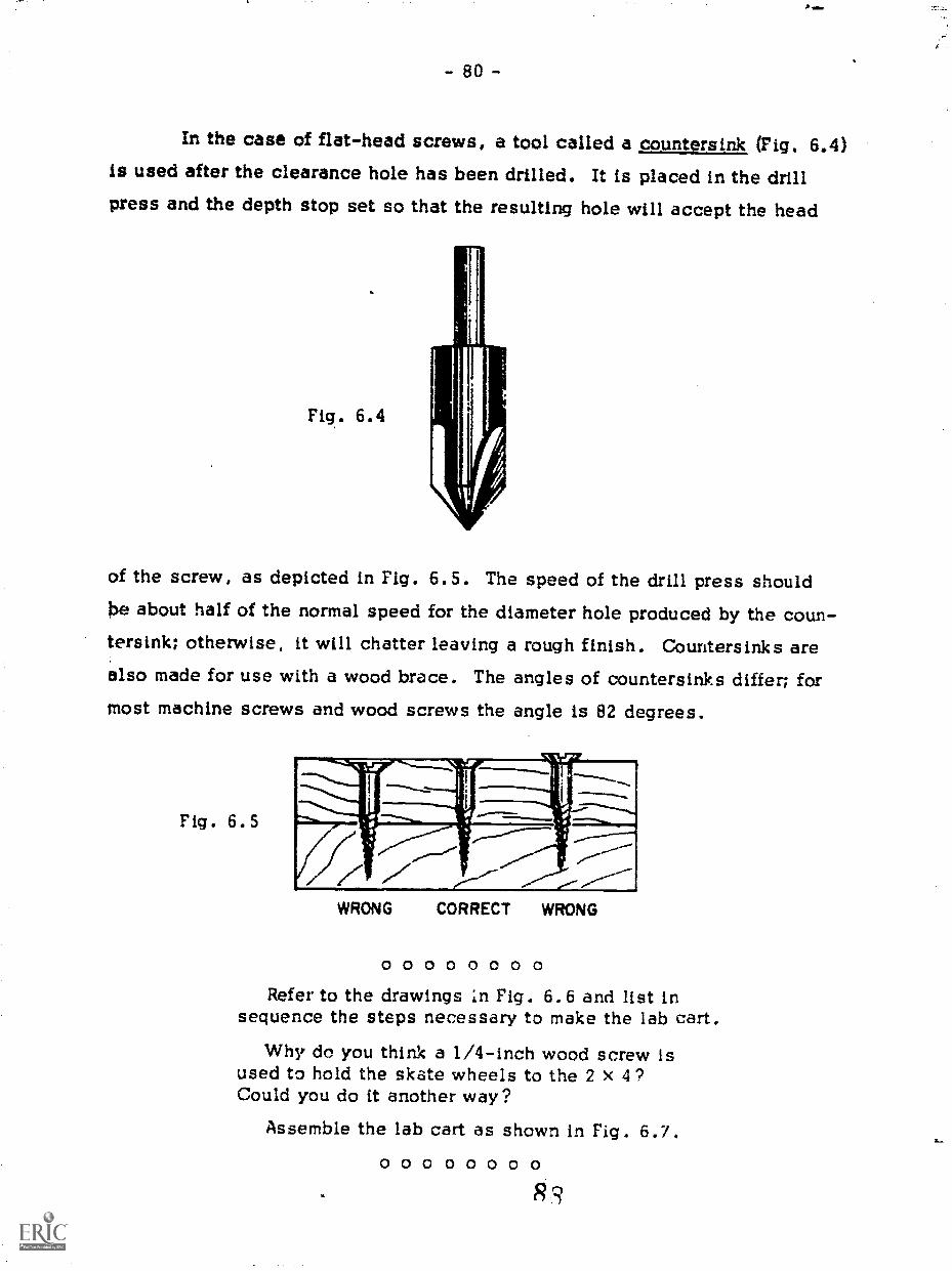
- 80 -
In the case of flat-head screws, a tool called a countersink (Fig. 6.4)is used after the clearance hole has been drilled. It is placed in the drillpress and the depth stop set so that the resulting hole will accept the head
Fig. 6.4
of the screw, as depicted in Fig. 6.5. The speed of the drill press shouldbe about half of the normal speed for the diameter hole produced by the coun-tersink; otherwise, it will chatter leaving a rough finish. Countersinks arealso made for use with a wood brace. The angles of countersinks differ; formost machine screws and wood screws the angle is 82 degrees.
Fig. 6.5
O 0 0 0 0 0 0 0Refer to the drawings in Fig. 6.6 and list in
sequence the steps necessary to make the lab cart.
Why do you think a I/4-inch wood screw isused to hold the skate wheels to the 2 x 4?Could you do it another way?
Assemble the lab cart as shown in Fig. 6.7.O 0 0 o o 0 o 0
. R 3

I DIA . I"DEEP16 9:DIA.
16
16 111
lir min IN onle
F ig 6 . 6
STEEL TUBING
WOOD DOWEL
WOOD DOWEL
.045 WALL THICKNESS
PILOT HOLES FOR
NO.6 WOOD SCREW
12- DEEP2
3" DIA. el DEEP
5" 16DIA
3.4
HOLE
NTERSUNK
3 4
of
ha-
s IN
4
16
4. DI A .PILOT
HOLE FOR PINte
Ns SLOT
9U

- 82 -
Fig. 6.7
6-32 zIFH.MACHINE SCREW
8-32 NUT STEEL TUBE
STEEL SOLT
2" STEEL PATCH PLATE
COMPRESSION SPRING -
rIs
s RH.
MACHINE SCREW TYP.
I"- DIA. PINIS
WOOD DOWEL
6 A it: FH. SCREW-
4+" STEEL WASHER
20 NUT

rEB
- 84 -
CIRCUITS
Until now you may never have built an electronic circuit because
you thought electronics in general to be too complicated. Actually thereP. ;
are many circ4ttith4trequ't'e only a few basic skills in order to build and*test them. ,Maqtering these skills is the principal aim of the next three
projects.8,Uptioie4You come across a useful circuit in a scientific journal, a
magazine', or attbook. First you must be able to read the circuit diagramand to identify the various components. The next step is to lay out the partsand then to poldets them together as indicated in the circuit diagram. The
final step, of course, ,i-s to test to see if th94ircuit works. Each of these1 I
steps, .especially the litst, can become quite complicated for a sophif,Zicatedcircuit; howevirthera are many circuits that you will be capable of build-
ing.In other-parts ofthis book, the quality of your work depends on the
accuracy to which you made a piece of equipment and its appearance to the
eye. In iJuilding an electronic circuit it is nice to have the circuit look neatQbut thi pla3ement of the components is not the crucial factor. The important
point is: Does itew9rk ?
-
6
92

4
- 85 -0).
Project 7: NEON BLINKER
We begin this project with the very simple but practical circuit shownin Fig. 7.1. The cylindrical .glass tube in the right-hand side of the photo-
(
graph is a eon bulb, which pan be made to flash at a steady rate determinedby the otherp components. The two leads on the left are connected to avoltage source. Becatoe the butb_bIinkellEan and off at a constant rate, thiscircuit can be used as a timilig'dele especially for a photographic studyof motion. In an actual apialicAton, of course, the componei.bs are wiredtogether more compactly to suit the experiment.
Fig 7 1
rt,

- 8 6 -
Usually you will not be given a photograph of a circuit; rather, you
must work from a circuit diagram and a list of components (Fig. 7.2). It is
then up to you to assemble the components into a working circuit.
Fig. 7.2 CONNECTTO
VOLTAGESOURCE
Resistor R1 470 kil+10% 1/2-watt carbonCapacitor C1 0.1 microfarad 200 V paperNeon bulb B1 NE-2H 1/4 watt
.The circuit diagram is a schematic and only tells you which compo-
nents are connected to which. Their final placement and how they are in-terconnected are determined by a host of factors, such as the size and theshape of each component, and by the way in which the circuit will be used.
When testing a circuit to see how it works and how it might be improved,the components are spaced far apart and the connections are made so that
they can easily be changed. This construction is referred to by the term
breadboard. After a circuit is ready for use, the final layout ts determinedby considerations of size, mechanical rigidity, and the electrical interaction
of various components.
For tnis project you will use a thin phenolic sheet (see Fig. 7.3).Special metal pins dre inserted in the holes and serve as tie points for wires
and components. Because the
pins can be positioned wherever
you like, this material is idealfor breadboard circuits. In many
cases, the final circuit can laterbe placed in a protective box to
make a finished product.
Fig. 7.39

- 87 -
7.1 Resistors
Probably the most common of all circuit elements is the resistor,which is denoted in circuit diagrams by the symbol .--,yvv-. The voltage
V mea3ured across a resistor is proportional to the current I through .
This is usually written symbolically asV se IR
and is referred to as Ohm's law. The factor R is the resistance of the com-ponent and is given in ohms (CI). It is this linear relationship between thecurrent and the voltage that instinguishes resistors from other components.For many other components, such as diodes and neon bulbs, a direct rela-tionship also exists between the current and voltage; but doubling the cur-rent for these components does not necessarily lead to a doubling of thevoltage. Since this relationship is not linear it cannot be expressed simplybut must be looked at in detail. For commercial resistors the values of re-sistance range from fractional parts of an ohm to several millions of ohms.
For some the resistance value is stamped on the component, whereas thevalue for others is given by a color code.
Several types of resistors are shown in Fig. 7.4. The size variationsare due principally to their power rating; that 6, their ability to dissipateheat. The two resistors on the left are made from resistive wire and are gen-erally used when a high-power rating is needed. Those on the right, by farthe most common and least expensive, are made from a substance containingcarbon. The power ratings for carbon resistors go from 1/10 watt to 2 watts.In contrast, the wire-wound re-sistors in Fig. 7.4 are 25 wattsand 10 watts respectively.
Fig. 7.4
. When the color code is
used to designate the resistance,the value is expressed by twodigits and a decimal multiplier.
9 5
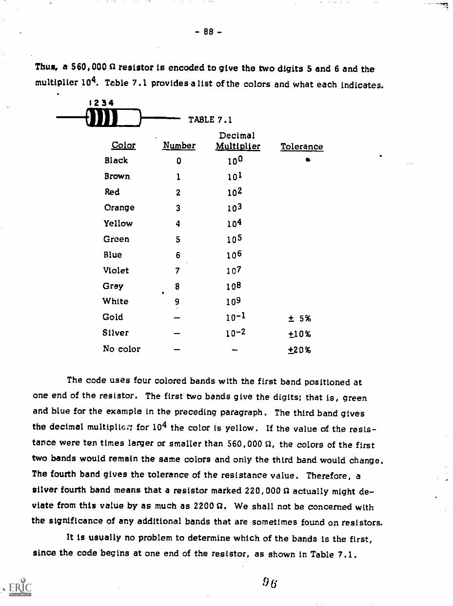
- 88 -
Thus, a 560,000 n resistor is encoded to give the two digits 5 and 6 and themultiplier 104. Table 7.1 provides a list of the colors and what each indicates.
1234
7.1
DecimalMultiplier ToleranceColor
TABLE
Number
Black 0 100
Brown 1 101
Red 2 102
Orange 3 103
Yellow 4 104
Green 5 105
Blue 6 106
Violet 7 107
Gray 8 108
White 9 109
Gold jo-1 ± 5%Silver 10-2 +10%
No color +20%
The code uses four colored bands with the first band positioned atone end of the resistor. The first two bands give the digits; that is, greenand blue for the example in the preceding paragraph. The third band givesthe decimal multiplicr, for 104 the color is yellow. If the value of the resis-tance were ten times larger or smaller than 560,000 Si, the colors of the firsttwo bands would remain the same colors and only the third band would change.The fourth band gives the tolerance of the resistance value. Therefore, asilver fourth band means that a resistor marked 220,000 S2 actually might de-viate from this value by as much as 2200 O. We shall not be concerned withthe significance of any additional bands that are sometimes found on resistors.
It is usually no problem to determine which of the bands is the first,since the code begins at one end of the resistor, as shown in Table 7.1.
96

- 89 -
However, for some resistors that are small in size the colored bands extendfrom one end to the other. Because the tolerance band is always the fourthband and is either silver or gold, you can determine in which direction thecode is read.
oce00000What is the color code for the resistor used in Fig. 7.2?
00000000As you might imagine, resistors are not available in every value.
However, for each power-of-ten there are approximately 25 resistance val-ues; that is, there are 25 resistors with values between 10 CZ and 100 S7, or
between 100 S2 and 1000 S2, and so on. Generally, one does not need a pre-cise value; but for the few applications where it is necessary, you can wiretogether several resistors to give the needed value or you can use a poten-tiometer, a device whose resistance can be varied.
Several types of potentiometers are shown in Fig. 7.5, and the prin-ciple of their construction can be seen in the two on the left: A resistor,which in this case is made of wire, has an additional sliding contact thatcan be positioned anywhere along the resistor. The symbol for a potentiom-
.4wLeter is , the arrowhead denoting the sliding contact. The resis-tance between the sliding contact and either end depends on the position ofthe contact and can be varied from zero ohms to the full resistance of thewire. The resistance from one end to the other remains fixed, of course.
The other potentiometers shown in Fig. 7.5 are variations on thisdesign. Some are made of .carbon or other resistive ma-
terial, and some are minia-ture. The last on the right,called a ten-turn potentiom-
eter, has the resistance wirewrapped in the form of a ten-turn helix. Fig . 7. 5

Because their resistance can be varied, potentiometers are found in
many circuits in which some property must be changed; for example, the
volume control for a radio or a television.Generally, potentiometers are larger in size, and a good dei more
expensive, than carbon resistors. Therefore, they are used only when nec-
essary - not as a replacement for an ordinary carbon resistor.
7.2 CapacitorsCapacitors also come in many sizes, shapes, and types. In their
most elementary form capacitors, symbolized by 11-- , are two conduc-
tors separated by insulating materials such as paper, plastic, mica, or even
air. The conductors - or plates - can be charged, and the capacitance of
each unit is a measure of the amount of charge for a particular charging volt-
age. The larger the capacitance C the larger the charge_a at a fixed voltage
V; that is, Q = CV. The unit of capacitance is a farad (1 farad = 1 coulomb/
volt); but, in practice, a microfarad (10-6 farad) is more commonly used.Most capacitors have a fixed value
of capacitance, but for some the ca-
pacitance can be varied by moving
one set of plates relative to the
other (see Fig. 7.6). Most of these
have low capacitance (10-12 farad
to 10-9 farad) and are used to tune
circuits to particular frequencies.
"t
Fig. 7.6,
For fixed capacitors the available range is from about 10-12 farad
(1 picofarad) to several thousand microfarads. These larger values are usu-
ally attained by using a chemical film as the insulator. They are called
electrolytic capacitors and have the advantage of a large capacitance in a
small volume. There is a disadvantage, however; a voltage can only be ap-
.9 s

91 -
plied to them in one way. The terminal marked "+" (Fig. 7.7) must always beat a higher voltage than the other terminal. If not, the insulation can be ruined.
The information you need to
know is printed on each unit. For an
electrolytic capacitor, in addition toits polarity and capacitance being
noted, a number followed by WVDC
is marked. This number is the max-
imum working DC voltage the unit
can withstand and not be ruined.
Fig. 7.7
7.3 Soldering and Construction
If you are given a circuit diagram and the parts necessary to make it,
there is really only one skill that is absolutely essential to get the circuitworking: You must know how to make a good solder joint. Knowing the theorybehind a particular circuit design is not essential in order to construct cir-cuits. With a few tools and a knowledge of how to solder, you can use some-one else's circuit, get it working, and then gradually come to understand itsdesign. Fortunately, the list of needed tools and supplies is not very long:two types of small pliers (needle- nose and diagonal-cuttIng), a wire stripper,
a small screwdriver, a 40-watt soldering iron and a file to clean it, rosin-core solder (60 percent tin and 40 percent lead), and several spools of hook-
up wire (No. 24 gauge).
After you have decided where to place the components and have in-
serted the pins you will need for the wiring (see Fig. 7.3), you can begin to.solder the components together. As a general rule, solid, insulated wire isused for wiring a circuit, but for cases in which the wire frequently will be
bent or flexed it is advisable to use stranded wire. Solid wire is easier toinstall but cracks if it is bent too often; stranded wire does not. Both types
9 9
-7
- 92 -
are easily cut with diagonal-cutting
pliers. A wire stripper (Fig. 7.8),which can bb set for different wire
diameters, is used to remove the in-sulation without cutting the wire
strands..1
Fig . 7 . 8
The key to making a 000d solder joint is to ensure that all the metalparts are hot enough to melt the solder. If they are not, molten solder will
solidify on the cooler metal without making a good bond. Initially it mayappear to be all right, but sometime in the future the contact may go bad
and will be very difficult to locate. However, there is another considera-tion too much heat can ruin the components.
To guarantee a good solder joint, a light coating of solder is applied
to each of the pieces before they are connected together. This accomplishestwo things: Some of the solder for the joint is already where it is needed;but, more importantly, the solder as it melts helps to conduct the heat sothat the :oint is completed before the components have a chance to heat up.
This coating process, called tinning, is recommended for components and
hookup wires alike but especially for stranded wire, since it holds all the
small strands together. (The pins are pre-tinned by the manufacturer, and
so they can be used as is.)The soldering-iron itself must be tinned before use. The tip is made
of copper, and it will oxidize and become difficult to use unless it is tinned.If the tip is in poor shape, it can be cleaned and reshaped with a file. Theiron is then heated and solder is quickly applied to the tip before an oxide
coating forms.The pins inserted in the perforated breadboard are ideal for making
solder connections. Each wire or component lead is secured to the pin and
then soldered together. (If there are too many wires for a single pin, you can
I k)O

'4
- 93 -
use several pins and interconnectthem.) To make the solder jointplace the hot iron against a pin asshown in Fig. 7.9 and apply a littlesolder where they touch. This serves
to increase the heat flow between the
iron and the pin. (You may also ap-ply an extra bit of solder to the iron
Fig. 7.9 before touching the pin.) Now touchsome solder to the pin and wires, but not at the point where the iron touchesthe pin. When the wires and pin are hot enough, the solder will melt andflow over them. Add a bit more solder, but do not overdo it; you just needenough to coat all the surfaces. When you see that the solder has flowedeverywhere in the Joint remove the iron and let the solder cool. Do not blowon it. With a little practice it is a simple matter to make consistently goodsolder connections.
When breadboarding a circuit you may want to change components or
even remove them later for ase in another circuit. Leave plenty of room be-tween components, and do not cut their leads too short. If wires and leadsare twisted together before soldering, they are very difficult to unsolder.Twisting is unnecessary if you use soldering pins, which are designed tohold the wires securely. Keep in mind that solder Joints are used for elec-trical connections and not for mechanical rigidity, which the soldering pinsprovide.
7.4 Neon Bulb
A neon bulb is a small glass bulb, filledwith neon gas, in which two electrodes are placed
side by side, separated by a distance of about onemillimeter. The dot in a circuit symbol for a neonbulb (see Fig. 7.10) indicates a gas-filled tube. For low voltages across itsterminals, the bulb acts as an open circuit; that is, there is no current through
Fig. 7.10
- 94 -
the bulb. However, when the voltage across the bulb is in the range of 100 V,the neon gas begins to conduct, there is current between the electrodes, andthe bulb glows. If the voltage across the glowing bulb is then lowered, thecurrent c es not stop immediately but continues until a somewhat lower volt-age is reached. For example, a bulb that has a breakdown voltage of 105 V
will stay lit until the applied voltage drops to its turnoff voltage of 85 V. Asyou shall see, it is this property of neon bulbs that maYes a blinker work.
Neon bulbs are commonly used as pilot lights since they require very
little power they range from 1/25 watt to 1/3 watt. The disadvantage, ofcourse, is in the voltage needed to operate one.
One word of caution: A neon bulb, if connected to a high-voltage
source, wilt probably draw too much current and burn out. Use them inseries with a suitable resistor, usually one with a resistance greater than50,0000.
O 0 0 0 0 0 0 0Obtain the circuit components, the breadboard,
the hookup wire, and thc tools required to assemblethe neon flasher shown in Fig. 7.2. When the as-sembly is completed, connect it to a DC voltagesource of about 125 V and see if it operates. Ifpossible,vary the source voltage and note how theoperation of the circuit changes.
O 0 0 0 0 0 0 0
The rate at which the bulb blinks can be varied by changing the val-
ues of both the resistor and the capacitor. To see the effect of each, changeonly one component at a time.
O 0 0 0 0 0 0 0I. Replace,the capacitor with one that has a
capacitance either ten times larger or smaller thanthe present one. What change does this make inthe rate of blinking?

- 95 -
2. For a fixed value of the capacitance, varythe resistance in the circuit by putting a one-meg-ohm (106 CI) potentiometer in series with the 470 kS2resistor now in the circuit. Use an ohmmeter to de-termine which of the three terminals on the potenti-ometer is the sliding contact. By connecting thesliding contact to one end (as shown), you can varythe resistance between points 1 and 2 from zero ohmsto a megohm. How does the rate of blinking vary asthe resistance is increased? Decreased?
2
0 0 0 0 0 0 0 0
7.5 Variable Neon Blinker
A neon blinker with a fixed blinking rate may be adequate for some
applications, but with a few changes the basic circuit can be altered tocover a range of blinking rates. The circuit (Fig. 7.11) incorporates a vari-able resistor and a switch that selects one of three capacitors. The speci-ficacions call for a three-position switch; but most likely you will have toadjust a .1.zh that has many more positions. When the switch is assembled
a small metal stop se the number of possible positions usually anywhere
from one to twelve. If your switch is not properly adjusted, reset the stopfor three positions.
Fig. 7.11
470 )(CZ +10% 1/2-watt carbonR2 1-megohm variable resistorR3 100 S2+10% 1/2-watt carbonCl 1 microfarad 200 V paperC2 0.1 microfarad 200 V paperC3 0.01 microfarad 200 V paperS1-1 Rotary switch 1 section,
I pole, 3 positionB1 NE-2H 1/4 watt neon
Rf R2 ri-/V\AA/
ci T 3C2
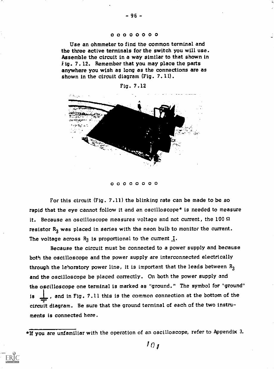
- 96 -
0 0 0 0 0 0 0 0Use an ohmmeter to find the common terminal and
the three active terminals for the switch you will use.Assemble the circuit in a way similar to that shown inFig. 7. 12. Remember that you may place the partsanywhere you wish as long as the connections are asshown in the circuit diagram (Fig. 7.11).
Fig. 7.12
0 0 0 0 0 0 0 0
For this circuit (Fig. 7.11) the blinking rate can be made to be sorapid that the eye cannot follow it and an oscilloscope* is needed to measure
it. Because an oscilloscope measures voltage and not current, the 100 c2
resistor R3 was placed in series with the neon bulb to monitor the current.
The voltage across R3 is proportional to the current I.Because the circuit must be connected to a power supply and because
both the oscilloscope and the power supply are interconnected electricallythrough the lehoratory power line, it is important that the leads between R3
and the oscilloscope be placed correctly. On both the power supply andthe oscilloscope one terminal is marked as "ground." The symbol for "ground"
is , and in Fig. 7.11 this is the common connection at the bottom of the
circuit diagram. Be sure that the ground terminal of each of the two instru-
ments is connected here.
*If you are unfamiliar with the operation of an oscilloscope, refer to Appendix 3.

- 97 -
0 0 0 0 0 0 0 0Use an oscilloscope to monitor the current in the
resistor R3. What does the cu:rent do as the bulbflashes? What is the range of frequencies throughwhich the flasher will operate? Are all frequenciesin this range covered? If not, what changes couldyou make in the circuit to span the range?
0 0 0 0 0 0 0 0
7.6 An Analysis of the Neon Blinker
In its simplest form the blinker circuit consists of a voltage source,a resistor, a capacitor, and a neon bulb in parallel with the capacitor.When the voltage source is connected, charge flows. During this part ofthe cycle, as the capacitor is being charged, the neon bulb has no effectbecause it acts as an open circuit, which is why it was drawn with dashedlines in Fig. 7.13. The voltage across it between points a and b buildsup toward the maximum value 110, the voltage of the source. Of course,
after the capacitor is fully charged the current drops to zero. The timeneeded for charging depends on the values of the capacitance and the resis-
tance. The larger these values, the longer the time needed for changing.
va,
Fig. 7.13
1MAAor
a
T-Now, if Vo is greater than the breakdown voltage V1 of the neon
bulb,* the capacitor will never become fully charged, For, as soon as thevoltage across C reaches VI, the neon bulb conducts, becoming a short cir-cuit, and the capacitor discharges through it. At that point the circuit is
ee Section 7.4.
1615

- 98 -
essentially Just the capacitor and the bulb (see Fig. 7.14). The dischargecontinues until the voltage across the capacitor drops to V2, the turnoffvoltage for the bulb. As long as V2 Ls less then V1 the process will repeatitself charging to V1 and discharging to V2.
.
Fig. 7.14
The cycle repeats itself in a steady fashion as long as the values ofR, C, and Vo remain fixed. If Vo is increased, the blinking rate increasesbecause V1 is reached in a shorter time. On the other hand, increasing thevalue of either R or C will decrease the rate.
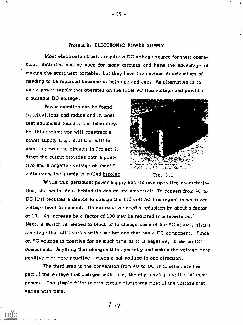
Project 8: ELECTRONIC POWER SUPPLY
Most electronic circuits require a DC voltage source for their opera-tion. Batteries can be used for many circuits and have the advantage ofmaking the equipment portable, but they have the obvious disadvantage ofneeding to be replaced because of both use and age. An alternative is touse a power supply that operates on the local AC line voltage and providesa suitable DC voltage.
Power supplies can be found
in televisions and radios and in mosttest equipment found in the laboratory.
For this project you will construct a
power supply (Pig. 8.1) that will be tused to power the circuits in Project 9. ,,Since the output provides both a posi-
,tive and a negative voltage of about 9volts each, the supply is called bipolar. Fig. 8.1
While this particular power supply has its own operating characteris-tics, the basic ideas behind its design are universal: To convert from AC toDC first requires a device to change the 110 volt AC line signal to whatevervoltage level is needed. (In our case we need a reduction by about a factorof 10. An increase by a factor of 100 may be required in a television.)Next, a switch is needed to block or to change some of the AC signal, giving
a voltage that still varies with time but one that has a DC component. Sincean AC voltage is positive for as much time as it is negative, it has no DCcomponent. Anything that changes this symmetry and makes the voltage more
positive or more negative gives a net voltage in one direction.The third step in the conversion from AC to DC is to eliminate the
part of the voltage that changes with time, thereby leaving just the DC com-ponent. The simple filter in this circuit eliminates most of the voltage thatvaries with time.

- 100 -
8.1 Transformers
The line voltage usually referred to as 110 volts, 60 cycle is analternating voltage that various sinusoidally with time and has a maximum
voltage of approximately 155 V and a frequency of 60 Hz. This voltage, dis-
played as alunction of time, is illustrated in Fig. 8.2. For most applica-
tions a voliage of this magnitude is either too large or too small for use in
a circuit, and a transformer is used to change its level.
VOLTAGE
155-110 -
-155 -
Fig. 8.2
elp. TIME
A number of transformers are shown in Fig. 8.3, but not all of them
are for use at 110 V AC. Basically, a transformer consists of two coils of
wire that are coupled magnetically. As the voltage varies sinusoidally in
one, a voltage is induced in the other. If the coils are identical, the in-
duced voltage will be the same as the applied voltage. However, if a trans-
former has a different number of turns of wire for each coil, the induced volt-
age will be either larger or smaller than the applied voltage and, accordingly,
it is called a step-up transformer or a step-down transformer.
Fig. 8.3
.
168
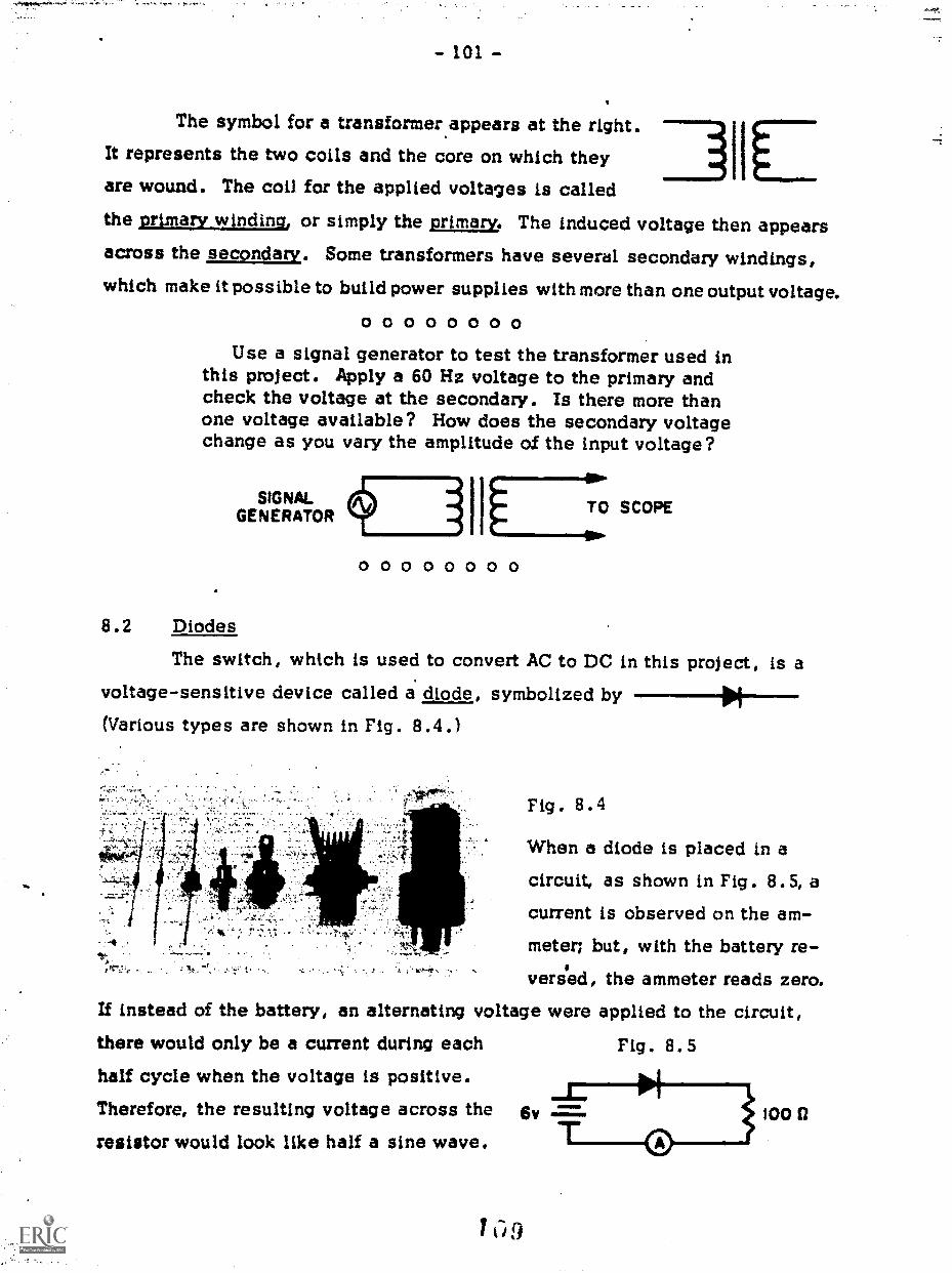
- 101 -
The symbol for a transformer.appears at the right.
41ILIt represents the two coils and the core on which theyare wound. The coil for the applied voltages is called
the prmarywtndtng, or simply the primary. The induced voltage then appearsacross the secondary. Some transformers have several secondary windings,which make it possible to build power supplies with more than one output voltage.
o oUse a signal generator to test the transformer used in
this project. Apply a 60 Hz voltage to the primary andcheck the voltage at the secondary. Is there more thanone voltage available? How does the secondary voltagechange as you vary the amplitude of the input voltage?
SIGNAL (f---1 I SCOPEGENERATOR
0 0 0 0 0 0 0 0
8.2 Diodes
The switch, which is used to convert AC to DC in this project, is avoltage-sensitive device called a. diode, symbolized by --Of-(Various types are shown in Fig. 8.4.)
Fig . 8.4
When a diode is placed in acircuit, as shown in Fig. 8.5, acurrent is observed on the am-meter; but, with the battery re-
versed, the ammeter reads zero.If instead of the battery, an alternating voltage were applied to the circuit,there would only be a current during each
half cycle when the voltage is positive.Therefore, the resulting voltage across the
resistor would look like half a sine wave.
Fig . 8.5
CiD
100

- 102 -
Ca 0 0 0 0 0 0 0Using a signal generator set at
60 Hz, wire up the circuit shown inFig. 8.6 and sketch the voltage ob-served across the resistor. Howdoes it change as you change thevalue of the input voltage?
0 0 0 0 0 0 0 0
'
SIGNALG ENERATOR
Fig. 8 . 6
1
8.3 Filtering
Changing an alternating voltage to one that is only positive or onlynegative is called rectification. The rectified voltage you observed in thelast section is said to be half-wave rectified.
The next step is to smooth out this half-wave signal to give a voltagethat more nearly approximates a steady DC voltage. This is accomplishedmost simply by putting an electrolytic capacitor across the resistor, as shownin Fig. 8.7. As you can see from this sketch of output voltage versus time,
Fig. 8.7
11 \1i / %LOAD VOLTSRESISTOR
// /1/
TIME
the capacitor keeps the voltage quite steady and only permits it to drop
slowly. The rate at which it drops between cycles is determined by the fac-tor RC, and so a larger capacitor means a steadier voltage. The small fluctu-ations in voltage that still remain are called ripple.
Figure 8.8 shows a half-wave
rectifier consisting of a power trans-
former, a diode, a load resistor, anda filter capacitor.
I 1 0
1
Fig. 8.8

- '03 -
8.4 Full-Wave Rectification
By using two diodes it is possible to make a full-wave rectifier that
operates during both halves of the AC cycle. The transformer has a tap atthe center of the secondary winding so that one end of the secondary is pos-itive and the other end is negative with respect to this center tap. The cir-cuit diagram for this full-wave rectifier and both the unfiltered and filteredoutputs are illustrated in Fig. 8.9. In operation the two diodes always passcurrent in the same direction but work alternately. Note that since the time
between voltage "bumps" is half what it was before, there is less fluctuationin the output voltage.
AD
Fig. 8.9
LOADRESISTOR
VOLTS
TIME
8.5 A Bipolar Power Supply
Many electronic devices require both positive and negative voltages,and so the bipolar power supply you will build combines two full-wave recti-
fier circuits as diagramed in Fig. 8.10.* The same transformer can be used
A]
Fig. 8.10
AC-1
[ T1
*When two wires cross in a circuit diagram we must designate whether or notthey are connected. A dot indicates that a connection is made between thetwo wires.

- 104 -
for each supply, and the complete circuit (shown in Fig. 8.11) includes an
on-off switch and a neon pilot light in the primary circuit.
Fig. 8.11
CR4
- 100 K2 10% 1/2-watt carbonR2 , R3 - 10 k2 10% 1/2-watt carbonC1 ,C2 - 1000 id 25 V electrolyticT1 filament, 117 V primary,
12.6 V center-tap secondaryCR1, CR2, CR3, CR4 1N3193 diodeBl NE-21-1 1/4-watt neonSj - single pole-single throw switch
The components for this circuit - especially the transformer - arebulky, and some planning should go into how they will be mounted. A simple
mounting assembly can be made by
using a wooden base with a narrowFig. 8.12
the perforated'board (see Fig. 8.12).Four nibber feet keep the wooden, base
sawcut across it. The size of the
sawcut should provide a snug fit for
from touching the table.Figure 8.13 shows a possible construction of a permanent case for
the power supply. (The top and the side have been removed to show the in-
terior layout.) Solid Masonite, perforated Masonite, and slotted boards are
used for the construction.

- 105 -
Fig. 8.13
0 0 0 0 0 0 0 0Obtain the parts and the circuit board and as-
semble the power supply according to the circuitdiagram shown in Fig. 8.11.
The resistors R2 and R3 discharge the capaci-tors when the circuit is turned off. They arecalled bleeder resistors and have only a small cur-rent in them.
When the power supply is completed, turn it onand measure the output voltages. Arrange a circuit(Fig. 8.14) that will allow you to measure the out-
put voltage and the current. Add some load to thecircuit, and plot output voltage versus current. Byusing a 5 KZ potentiometer you can increase the cur-rent up to 40 ma (milliamperes). Look at the outputvoltage with an oscilloscope and measure the peak-to-peak ripple voltage at 5, 10, 15, and 20 ma out-put current. This voltage is measured between thebottom and the top of the ripple.
0 0 0 0 0 0 0 0

- 107 -
Project 9: OPERATIONAL AMPLIFIER
The small metal device pictured in Fig. 9.1 is an extremely versatileelectronic component called an operational amplifier or "op-amp." Becausean op-amp can be connected in so many different configurations, the project
begins with the construction of the breadboard shown in Fig. 9.2. When a
few resistors are added the circuit becomes an amplifier; with a resistor anda capacitor it is an integrator. Other configurations make the circuit an os-cillator, a square-wave generator, or a circuit that can add or subtract volt-ages. Before these individual circuits can be tested the three leads (seeFig. 9.2) are connected to a bipolar power supply.
The subject of op-amps is extensive and far beyond the scope of thiscourse. The purpose of this project is to teach you how to construct, test,and modify a few simple circuits.
Fig. 9.1 Fig . 9 .2
9.1 Operational Amplifiers
You will use a model 741, general-purpose operational amplifier.
This is an integrated circuit in which the working parts have been formed to-gether on a chip of semiconductor material and function as a single unit. The
circuit contains 20 transistors, 12 resistors, and one capacitor on a surface

- 108 -
only a few millimeters on a side. The 741 comes in various packages so thata designer can make a choice. The T0-99 package (Fig. 9.1), which is aneight-lead metal can, is the most suitable for breadboard work and is the one
you will use.
In circuit diagrams it is customary to draw an op-amp as a trianglewith only three terminals two input terminals marked "+" and "-" and one
output terminal (Fig. 9.3). Because any op-amp you buy has more than threeterminals, your first task is to learn how each is connected.
Fig. 9.3
For a 741 in a TO-99 package the manufacturer supplies an accompany-
ing diagram like that in Fig. 9.4. Pins 2, 3, and 6 correspond to the threeterminals shown in Fig. 9.3, and pins 4 and 7 are connected to the circuit's
power supply (V- will be attached to the negative power terminal and V+ to
Fig. 9.4
OFFSET
INVERTING 2INPUT
TAB8 NC
V+7
NONINVERTING 3INPUT
( TOP VIEW)
OUTPUT
OFFSET
PIN 4 IS CONNECTEDTO CASE
the positive terminal). For the circuits in this project the other terminalsneed not be connected. (Note in the top view of the op-amp shown in
Fig. 9.4 that there is a small metal tab to identify pin 8.)

- 109 -
0 0 0 0 0 0 0 0Figure 9.5 is a top view of the circuit board show-
ing the relative positions of the op-amp and the bind-ing posts. Solder all eIght leads to the soldering pins,even though you will not be making connections to allof them.
Fig. 9.5 _1_,. TO POWER---,' SUPPLY
+
INVERTINGINPUT
GROUND
NONINVERTING
INPUT
Like other semiconductor devices, op-amps can bedamaged by overheating. Make the solder jointsquickly and use a pair of pliers to hold the leads be-tween the soldering pin and the base of the op-amp.The pliers will heat up during soldering and protectthe internal circuits.
After attaching the binding posts to the circuitboard, turn the circuit board over and connect them tothe appropriate terminal of the op-amp. The two groundposts are connected together, as are the two outputposts. Both these terminals are duplicated for conven-ience when breadboarding.
Next add some stranded leads that will be connectedto the power supply. The plus and minus leads are con-nected to V+ and V- on the op-amp, and the ground leadgoes to the ground in the circuit board. Use differentcolors for each of the wires to ensure that the properconnections are made at the power supply. If the powerleads are connected incorrectly you may damage the op-amp.
CAUTION: Do not confuse the "-" and "+" terminals(pins 2 and 3) with the power terminals V- and V+ (pins4 and 7).
0 0 0 0 0 0 0 0

9.2 A Photometer
There are hundreds of circuits that use operational amplifiers similar
to the 741. The few we have selected here will give you an idea of how easyit is to set up a circuit and, then, to modify it to suit experimental conditions.
A simple circuit for a photometer is shown in Fig. 9.6. The sensing
element is a photocell, which produces a current proportional to the intensityoi .he light that strikes it. The photometer circuit converts this current to a
voltage that can be read at the output terminals. For a current I the outputvoltage Vo is given by Vo = -IR. Thus, a positive current as indicated inFig. 9.6 produces a negative voltage at the output.
Fig. 9.6
PHOTOCELL
OUTPUT V out = - IR
CURRENT - TO - VOLTAGE CONVERTOR
0 0 0 0 0 0 0 0Assemble the photometer circuit shown in
Fig. 9.6. (Remember that the connections to thepower supply are not shown.) Use a voltmeterwith a range of 3 V to read the output voltage.
To test the circuit, use a small light source(25-30 watts) and vary the distance between thelight and the detector. How can you distinguishbetween the signal caused by the background roomlight and that which is the result of the test bulb?
0 0 0 0 0 0 0 0
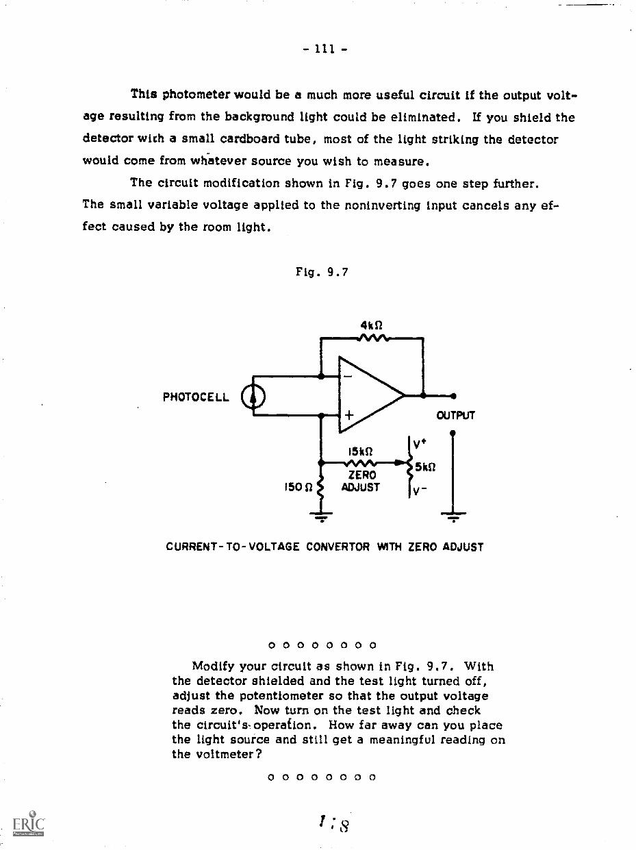
This photometer would be a much more useful circuit if the output volt-age resulting from the background light could be eliminated. If you shield thedetector with a small cardboard tube, most of the light striking the detectorwould come from wh-atever source you wish to measure.
The circuit modification shown in Fig. 9.7 goes one step further.The small variable voltage applied to the noninverting input cancels any ef-fect caused by the room light.
PHOTOCELL
Fig. 9.7
4k1/
CURRENT- TO- VOLTAGE CONVERTOR WITti ZERO ADJUST
0 0 0 0 0 0 0 0Modify your circuit as shown in Fig. 9.7. With
the detector shielded and the test light turned off,adjust the potentiometer so that the output voltagereads zero. Now turn on the test light and checkthe circuit's-operation. How far away can you placethe light source and still get a meaningful reading onthe voltmeter?
0 0 0 0 0 0 0 0

- 112
To increase the photometer's sensitivity a second stage is added to
the circuit (Fig. 9.8). The second op-amp circuit senses the voltage from
the first stage and amplifies it. The output voltmeter is then placed at the
output of the second stage. The voltage gain (Voutputninput) of the second
stage is determined by the values of the two resistors:gain = (R1 + R2)/R2
Therefore, with the resistance values shown in Fig. 9.8 the gain can be
varied from one to about 20.
4 kn
STAGE ONE
Fig. 9.8
51111
RI IMO
Pk S2 Ar-1-6R2
CONTROLGAIN
STAGE TWO
CURRENT-TO-VOLTAGE NONINVERTINGCONVERTOR AMPUFIER
0 0 0 0 0 0 0 0Add the amplification stage to the photometer.
The second breadboard is powered by the samepower supply that you used for the first.
Test the sensitivity of the overall circuit.What is the maximum light-to-detector distancethat is now possible?
How would you calibrate the gain control ofthe amplifier?
0 0 0 0 0 0 0 0
OUTPUT
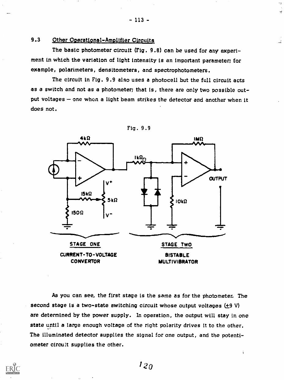
- 113 -
9.3 Other ODerati9nal-Amplifter Circuits
The basic photometer circuit (Fig. 9.8) can be used for any experi-ment in which the variation of light intensity is an important parameter; for
example, polarimeters, densitometers, and spectrophotometers.
The circuit in Fig. 9.9 also uses a photocell but the full circuit actsas a switch and not as a photometer; that is, there are only two possible out-put voltages one when a light beam strikes the detector and another when itdoes not.
STAGE ONE
CURRENT-TO-VOLTAGECONVERTOR
Fig. 9.9
STAGE TWO
BISTABLEMULTIVIBRATOR
As you can see, the first stage is the same as for the photometer. The
second stage is a two-state switching circuit whose output voltages (±9are determined by the power supply. In operation, the output will stay in onestate until a large enough voltage of the right polarity drives it to the other.The illuminated detector supplies the signal for one output, and the potenti-ometer circuit supplies the other.
120

- 114 -
The amplifier you built for the photometer's second stage (Fig. 9.8)is not the only amplifier you can construct. The circuit drawn in Fig. 9.10is called an inverting amplifier and contrasts with the other, which is non-Overting . In the inverting amplifier a positive input voltage results in anegative voltage output and, hence, a minus sign appears in the expressionfor the gain. Both amplifiers can be used for AC as well as DC signals. ForAC applications a small 0.1 pf capacitor is usually put in series with the in-put terminal to block any DC voltage that may be present.
INVERTING AMPLIFIER GAIN
The circuit drawn in
Fig. 9.11 differs from the others
in that an input signal is not
needed to make it work. It is asimple example of a signal gen-erator and, in this case, the out-put is a square wave of +9 V.
The output frequency is control-
led by the values for Ro and Co.MULTIVIBRATOR (SQUARE-WAVE GENERATOR)

- 115
These few circuits may give you some idea of the versatility of opera-tional amplifiers, and because of their low cost, you can use op-amps to dojust about any electronic job you may be faced with. However, they are lim-ited in the amount of power they can handle, and so for high-power applica-
tions transistors can be added to the op-amp circuit.

GLASS
Many experiments involve the use of liquids or gases that are corro-sive to metals such as copper, aluminum, and steel. Therefore, many piecesof equipment require that certain parts be made of glass that is not chemi-cally attacked by most liquids and gases.
Glass is very different from the materials you have previously used.Because it is hard and its surface is smooth, glass is very difficult to cut,drill, or assemble with glues or cements. Therefore, the most common
method of working glass is to heat it with a torch until it turns liquid (likethick molasses) and then perform the appropriate operations.
Two pieces of glass can be joined by forcing them together whilethey are liquid. Holes can be made in glass tubing by heating a small area,blowing the liquid glass into a bubble, and bursting the bubble. Althoughworking glass does not always require blowing, the term glassblowing is
used when describing the operations in which a torch is used to work glass.Earlier in this course power tools were used as substitutes for hand
tools because power tools do a better job. The same is true in glassblow-ing; but because glassblowing power tools are very specialized, they aregenerally available only to the professional glassblower. Therefore, thisportion of the course will cover only the operations that can be done byhand, although the techniques involved are directly applicable to power toolssuch as the glass lathe.

Project 10: TECHNIQUES USED IN GLASSBLOWING
Learning to blow glass requires a considerable amount of patience,
and a "feel" for working glass must be acquired. Seldom will you perform
an operation correctly on the first, second, or third trial; it often takesmuch longer. For this reason, the first project in this section consists ofa series of practice operations that will prepare you for making the projectsthat follow. Do not become discouraged. Practice until you can -2.onsis-
tently perform an operation correctly. You will need the confidence gainedfrom experience when the time comes to incorporate the operations you have
learned into the construction of a piece of scL, itific glassware.
10.1 Types of Glass
The types of glass most commonly found in a laboratory are soda-lime and borosilicate glass. Most laboratory glassware is made of borosil-icate glass, such as Pyrex and Kimex, because this type has a higher resis-tance to thermal shock than soda lime. Glass made of 96 percent silica(Vycor brand) is used in extremely high-temperature applications. All of
these types have different thermal properties and melt at different tempera-tures. Soda-lime glass melts at a relatively low temperature, near 7000C.Pyrex melts at 8200C and Vycor at 15000C. Because of their different ther-mal properties, types of glass cannot be mixed together although they may
flow together when heated. The mixture will crack as it cools and the work
that has been done will be ruined because each type of glass has a differentcoefficient of linear expansion.
Because most laboratory glassware is made from Pyrex, that type of
glass will be used in the projects in this course. Types of glass can bedistinguished by the rate of softening, by the index of refraction, or by acomparison of the coefficients of expansion of a known glass and an unknown.
To compare the expansion coefficients of two pieces of tubing, the pieces

- 118 -
are fused together at one end (Fig. 10.1) by heating both until they becomesoft and then by forcing them together. The fused ends are then heated once
Fig. 10.1
again until they are quite soft. The glass is then removed from the flameand stretched into a thread with a pair of tweezers. If the thread of glass re-
mains straight, the two samples of glass have the same coefficient of ex-
pansion. If the thread bends, the sample on the inside of the bend has the
greater coefficient (Fig. 10.2).
10.2 TorchesMost torches used in glassblowing operate on natural or bottled gas
and another gas that helps it to burn moreefficiently and thus at a higher
temperature. For soda-lime glass, gas and compressed air are used; for
Pyrex, a combination of gas, air, and compressed oxygen; for Vycor, oxygen
and acetylene.The gas-air-oxygen torch comes in two basic types. The first type
mixes all three gases together by means of regulating valves or special ven-
turi mixers. These torches are usually cumbersome and difficult to regulate,
and there is also the possibility of an explosion, called flashback, when
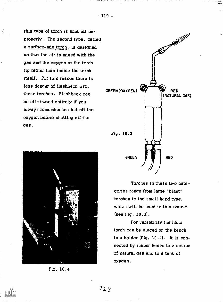
this type of torch is shut off im-properly. The second type, calleda surface-mix torch, is designedso that the air is mixed with the
gas and the oxygen at the torch
tip rather than inside the torchitself. For this reason there isless danger of flashback withthese torches. Flashback canbe eliminated entirely if you
always remember to shut off the
oxygen before shutting off the
gas.
Fig 10.4
119 -
GREEN (OXYGEN)
Fig. 10.3
GREEN
Torches in these two cate-
gories range from large "blast"
torches to the small hand type,which will be used in this course(see Fig . 10.3) .
For versatility the hand
torch can be placed on the bench
in a holder (Fig. 10.4). It is con-nected by rubber hoses to a source
of natural gas and to a tank ofoxygen.

- 120 -
The oxygen tank has a set of gauges and a regulator attached to it.(This tank should always be secured so that it cannot fall over.) One gaugemeasures the pressure inside the tank, and thus the amount of oxygen. Theother gauge measures the pressure as set by the regulator, which controlsthe flow of oxygen to the torch. The regulator is adjusted by turning thehandle on the side until tha gauge shows the proper pressure. For glass-blow.ing, the regulator should be set at 5 to 10 pounds per square inch. Onthe top of the tank is a valve that should always be closed except when thetank is being used.
Before lighting a torch, be sure that the valves on .1-, are turned off.Then turn on the source of natural gas and the oxygen tank, and set the reg-ulator. Open the valves on the torch for 10 to 15 seconds to clear out anyair that may be in the tubing. Shut off the oxygen valve and turn the gasvalve until it is just slightly open. Light the torch with a match, makingcertain that it is not pointed at anything or anyone nearby.
After the torch is lighted, adjust the gas valve until the yellow flameis about 8 inches long. Then open the oxygen valve, and a light blue conewill appear in the center of the flame as the flame shortens overall. Adjust
the center cone until it is 1/2 to 3/4 inch long. This is only an approximateadjustment. The more oxygen you add to the flame, the hotter it will be.You can produce a small, sharp, pointed flame that is very hot, or a relativelycool flame for slow work on small pieces.
When shutting off the torch, gradually close the oxygen valve andshorten up the flame by reducing the gas flow. Then close the oxygen valvecompletely and finally the gas valve. If the torch is not going to be usedagain in a few minutes, be sure to shut off the source of gas, close thevalve on the oxygen tank, open the regulator valve, and drain the gas hosesby opening the valves on the torch until the pressure is released.
Always be careful when using a torch. The flame is extremely hot.Always think about what you are doing before you make any move near alighted torch. Make sure that there are no flammable materials anywherenear the flame.
1 2 7

- 121 -
Whenever a torch is being used, everyone nearby should wear safetyglasses. There is a difference between regular safety glasses and thoseworn by glassblowers. When glass is placed in a high-temperature flame,it is surrounded by a bright yellow sodium flame. This makes it difficult tosee the glass itself, and for this reason, glassblowers use glasses withdidymium lenses to filter out the yellow flame.
10.3 Cutting Glass Tubing
Glass tubing usually com-es in four-foot lengths and has to be cut toshorter lengths for easier handling and to definite lengths to fit apparatus.
Small-diameter tubing, 20 mm or less, can be cut by making a notch
at the desired place with the corner of a file. Only one stroke is needed,but the stroke must be firm so that the notch is deep enough. Wet the notchwith your finger, and grasp the tubing with the notch facing away (Fig. 10.5).
Break the tubing with a swift motion by bending it so that the curve is away
from the notch.

- 122 -
Lamer-diameter tubing can be cut by scribing a notch and then touch-
ing the edge of the notch with a piece of molten glass rod. This should pro-
duce a crack around the tube. If it does not crack, or if the crack does notgo completely around the tubing, repeat the process.
You can also cut large-diameter tubing with the help of a piece of
nichrome wire and a low-voltage power supply. Loop the nichrome wire
amund the glass tubing, taking care that the loops do not touch. Then con-nect the power supply to heat it up. This will heat a small area of the glasstubing. If water is poured over the tubing, the thermal shock should break
it. Be sure the power supply is turned off before you pour on the water.Another technique, called fire-cutting, is used most often when the
end of a piece of tubing has to be sealed off. A torch is used to heat asmall section of the tubing until it is pliable. The tubing is then stretchedalong its axis until it is very thin. This thin section is put back into thehottest portion of the flame, and the tubing separates.
10.4 Constricting Glass Tubing
To constrict a piece of tubing a section of glass is heated until it ispliable and the heated section is stretched by pulling both ends of the tub-
ing. As the tubing is stretched the diameter reduces.
The greatest problem in most glassblowing operations is to heat theglass evenly. When working with tubing, the glass is rotated about its axisat a steady rate as it is heated in the flame. While the glass is hard, it iseasy to coordinate the hands to rotate the glass continuously. However, asthe glass gets hot, it becomes very pliable and less manageable.
The photbgraph in Fig, 10.6 is taken from overhead and depicts the
technique of supporting and rotating glass tubing in a flame. The thumb andindex finger of each hand are used to spin the glass while the other fingers
form a cradle in which the glass rests. The tubing is rotated by alternatelyusing one hand and then the other su : lat the tubing never stops in one place,causing uneven heatiny. With practice you will dev,..lop the coordination
necessary to keep the tubing in line and prevent it from twisting.

- 123 -
t
Fig. 10.6
0 0 0 0 0 0 0 0Take a piece of glass tubing about 8 mm in diam-
eter and 14 inches long, and heat a one-inch sectionin the center. As soon as the tubing becomes quiteflexible, remove it from the flame and pull on it un-til the heated section is approximately one-half theoriginal diameter.
What was the color of the glass when it becamepliable enough to stretch?
Be very careful not to touch the heated section ofthe glass, because you can sustain a severe burn.To check if a section of glass is cool enough, beginby touching the end farthest from the hot section andthen slowly slide your finger along the tube.
After the glass is cooled so that you can handleit, cut it at the middle of the constriction. How doesthe wall thickness there compare with the wall thick-ness of the original tubing? How might this be unde-sirable?
0 0 0 0 0 0 0 0

- 124 -
Because the wall thickness of the constriction you have just made isthin, the tubing is very weak at that point. To strengthen the constrictedpart of the tubing, it is necessary to increase the wall thickness. This isdone by heating the tubing as before but leaving it in the flame after the tub-ing has become pliable enough to stretch. If there is no pull by either handas the tubing is rotated, the wall thickness will increase because of surfacetension (Fig. 10.7). At this point the tubing is removed from the flame andis allowed to cool for a second without any force exerted on it. The thin-walled sections cool and harden, and then, as the tubing is stretched, onlythe thick-walled glass will stretch and become thinner. When the outsidediameter of the constriction becomes one-half the tubing diameter, enoughglass will be available to make the constriction thick walled.
Fig. 10.7
After completing this operation, you will have learned two of the mostimportant factors used in glassblowing. First, when glass is heated until itis soft, it contracts due to surface tension. Second, thinner sections ofglass cool faster than thicker ones. You will make use of these two factorsevery time you work with glass.
Take another piece of tubing and constrict thecenter portion. Practice until you have been ableto make three or four good constrictions. Takeone tube and cut it at the constricted section.How does the wall thickness compare with thatof the previous constriction?
00000000If liquid glass is allowed to cool at its own rate, stresses are set up
in it because one portion cools faster than another. This difference in cool-ing can be the result of variations in thickness or drafts from the surround-
ings. These stresses can cause the glass to crack when it cools or when it3 1

- 125 -
is heated up again. To help alleviate this problem, a process calledannealim brings the glass back down to room temperature at a controlledrate so that all of it cools at the same time.
When the glass was made, it was annealed in large ovens. Using anoven is the best way to anneal a piece of glass, but an oven is not alwaysavailable and often the project may be too large to fit into one. Under theseconditions a section of glass can be annealed by placing it in a soft yellowflame from a torch immediately after completing an operation and allowing it
to cool slowly until a layer of carbon covers it. The carbon only forms at a
low temperature and can be wiped off after the glass is completely cool.When it is necessary to rework a piece of glass, always heat it very
slowly to give the entire area around a seal the chance to warm up. Thiswill help prevent the glass from cracking and the work from being ruined.
10.5 Bending Glass Tubing
Bending small-diameter tubing is easy if the angle of the bend.is ap-proximately 90 degrees or more. The tubing is rotated in the flame while thesection to be bent is heated until it is pliable. Then thetubing is removed from the flame and the heated section is
bent to the proper angle. The length of the section that isheated determines the radius of the bend. The most com-
mon mistake in bending glass is to heat too short a sec-tion. This produces a bend
Fig. 10.8that is too sharp, as illus-trated in Fig. 10.8. A i.ule of thumb is to heat a section of tubing thatis between four and six times the diameter of the tubing (Fig. 10.9).
Fig. 10.94-6 DIA. -0-
Th.-"'"4"-
\k_EAT,ED\S_EpTiO4
1 32

- 126 -
This will produce a smooth bend, as shown in Fig. 10.10.
To make a U bend, the procedure is the same, but
the section of tubing that is heated must be longer. If a
U bend is considered simply as two 90 degree bends, ob-viously almost twice as much tubing should be heated,
producing a bend that is rela-tively uniform but with a fairly Fig. 10.10large radius.
Sometimes it is necessary to make bends with a radius smaller thanthose mentioned earlier. Figure 10.8 depicts the results of a bend that wastoo sharp (small,radius). One way to prevent the collapse of the bend is toblow into the glass tubing while it is still hot, which expands it to its origi-nal diameter. To do this, one end of the piece of tubing must be closed off.If the tubing is very small, a rubber policeman can be used. On medium-size tubing, a piece of snug-fitting rubber hose can be attached to the tube,bent over to pinch off the hose, and tied or taped in position, as shown inFig. 10.11. Larger-diameter tubing can be closed off with a cork or a rubberstopper.
Fig. 10.11
After one end is closed, you have to provide a means by which to
blow into the tube. (Never put the end of a piece of glass tubing in your
mouth to blow into it. The edges may be sharp, or the end may be hot from
a previous operation.) A rubber hose, fitted with a mouthpiece, can be at-tached to the glass tube by means of a swivel, which prevents the hose from
twisting as the glass is rotated. The swivel is attached to the glass tubingby means of a short piece of rubber hose or a cork or a rubber stopper, de-

- 127 -
pending on the diameter of the glass. Figure 10.12 shows the easiest way
of holding a piece of tubing with a blowing hose attached. Much of theweight of the hose is removed from the glass tube by placing the hose aroundthe neck.
Fig. 10.12
-
-
...mmi.111111116.-34.
The next step is to rotate the tubing in the flame and heat it until it
is almost fluid. The tubing is removed from the flame, stretched slightly toremove any irregularities, and bent to the desired angle. Before the glasshas a chance to cool, gently blow into it until the tube returns to its originaldiameter. This must all be done rapidly so that the glass will not cool downtoo much before the bend is completed.

- 128 -
There is another method that produces a usable though often irregularbend. First the area where the bend is to be made is heated up but removedfrom the flame before it becomes pliable. The heat is then concentrated ina small area, and a small bend is made. Then the heat is applied a littlefarther along the tube, and another small bend is made. This is continueduntil the proper curve is obtained. The series of small bends should blendtogether to form a smooth curve. This process takes more time but is quiteeffective, especially when the bend has to fit another piece.
00000000Make a series of right-angle and U bends from
tubing ranging in diameter from 6 to 8 mm. Trymore than one method. What method do you thinkwould be best for bending capillary tubing? Try it.
0 0 0 0 0 0 0 0
10.6 End-to-End Seals
When almost any seal or joint is made, there are two basic areas ofconcern. First, the glass from one piece must flow to the other piece toform a good seal, and second, the joint must be strong. When the two piecesare heated thoroughly, and to a high enough temperature, the glass naturallyflows together. Because glass tubing tends to conEtrict when it is heated,it is often necessary to expand the diameter of the seal after it is made byblowing into one end of the tubing while the other end is closed off. If thewall thickness of the joint is approximately the same as that of the tubing it-self, the seal is sufficiently strong.
To make an end-to-end seal between two pieces of tubing having the
same diameter and wall thickness, one piece is closed off by a rubber police-man or cork stopper, and a blowing hose is attached to the other piece. Thetwo ends to be joined are rotated in the flame in axial alignment, but without
touching. When the ends become soft, they are pushed together, as inFig. 10.13(a), so that they make contact with each other over the entire sur-face to be joined. Then the tubing is removed from the flame and stretched
slightly. The seal is put back into the flame and the tubing is shrunk. The
1 3

- 129 -
tubing is then removed from the flame and blown into by means of the rubber
hose so that the diameter becomes slightly larger than it was before, asshown in Fig. 10.13(b). The tubing is then stretched to bring its outer di-ameter down to its original size. See Fig. 10.13(c). The blowing andstretching may have to be repeated several times to distribute the glassevenly and to make a relatively neat seal.
Fig. 10.13
!MININIMM11011111111PI '414011111111111MIll.
This three-step technique is sometimes difficult to master. Anothermethod can be used, but the results are not quite as neat. The beginning ofthe operation is the same as before: Heat both pieces of glass and pushthem together when they become soft. Now, rather than trying to fuse theentire seal at one time, try fusing it in sections. Hold the seal in the flame
but do not rotate the tubing. Once the glass begins to shrink and flow to-gether, remove the glass from the flame and blow the tubing to its original
diameter. Rotate the gla^s and repeat the process until you have worked
your way around the seal. Because the seal is made in sections it will notbe smooth. However, if made correctly., the seal will be adequate.
0 0 0 0 0 0 0 0Take two 8-inch pieces of 7- or 8-mm-diameter
tubing and make an end-to-end seal. Do not bediscouraged if the seals do not turn out well thefirst time. After practice, making end seals will bea very simple task.
0 0 0 0 0 0 0 0

- 130 -
To make end-to-end seals between regular glass tubing and capillarytubing, the procedure is the same as in the previous exercise except for afew additional steps. First, the end of the capillary is closed by heating itin a flame (Fig. 10.14(a)). Then a bubble is blown in the end, as illustratedin Fig. 10.14(b). The bubble is broken off by tapping it with a file, and theend is fire-polished to eliminate sharp edges. This procedure makes thewall thickness of the capillary tubing approximately the same as the tubingto which it will be joined. At this point, except for one factor, the proce-dure for joining standard tubing and capillary tubing is the same as for join-ing tubing of the same wall thickness. Because the capillary tubing hasthicker walls than standard tubing, it will take longer to heat up as well asto cool down. For this reason, when working the seal, the flame should beconcentrated a little more on the capillary tubing than on the standard tub-
ing. The completed seal is shown in Fig. 10.14(d).
Fig. 10.14
(a)
(b)
(C)
(d)
In making end-to-end seals between pieces of tubing having differ-
ent but relatively close diameters, tne end of the smaller tube is flared untilthe end of the flare is the same diameter as the larger tubing (Fig. 10.15).This can be done by sealing the end, blowing a bubble, striking off the bub-
ble, and flre-polishing it. A flare can also be made by heating the end of
/

- 131 -
Fig. 10.15
=CEIMIMIIIIINI=NIMMIEM===9
wiliMM......piro;n0. Z11111.11111111.111111111.1.11.11..1
the tube until it is molten and forming the end with a pointed carbon rod (seeFig. 10.16). The procedure from this point is tho came as for the previousseal.
If the diameters of two pieces of tubing differ by quite a bit, it isfirst necessary to close off the end of the larger-diameter tubing. This isdone by fire-cutting the larger tubing, sealing the end, and blowing the bot-tom end of the tube into a round bottom like thtit of a test tube.
If you simply stretch the tubing as you fire-cut it, the wall will betoo thin and you will burn a hole in the thin wall as you make the seal. Asyou fire-cut, concentrate the heat on the unused section of the tubing andshrink the tubing as you did in Section 10.4. To round the bottom of thetube, heat the end until it contracts and then blow into the tube forming theround bottom.
The next step is to provide the sealed bottom of the large tube with ahole of the same diameter as the small tube. This is done by heating up asmall area in the center of the end of the tube, blowing a bubble the size ofthe small tube, striking it off, and then fire-polishing to remove sharp edges.The smaller tube is then flared slightly on the end to be sealed. The two sur-faces that are to be joined are rotated in the flame until they are red hot andthen pushed together. The procedure from this point on is the same as in theprevious end-to-end seals. Figure 10.17(a) - (e) illustrates the steps in thisoperation.
I 3 8

(a)
00)
(c)
(d)
(e)
- 132 -
Fig. 10.17
11,4npl)
There are two problems that may arise if some of the steps are not
carried out correctly. The first problem occurs in making sure that the wall
thickness of the end of the large-diameter tubing is consistent. Frequently,
when a piece of tubing is sealed off, there is an excess of glass at the veryend of the tube, as shown in Fig 10.18(a). To remove it, heat the thick-walled portion until it is nearly white. Then, after removing it from theflame, touch a piece of small-diameter cold glass rod to the thick portionand pull (Fig. 10.18(b)). This will remove much of the glass, and all thatis left to do is to burn off the strand of glass, heat up the end of the tube,
and blow to form a round, smooth bottom (Fig. 10.18(c)).
13;)

(a)
(b)
(c)
- 133 -
Fig. 10.18
a
The second problem occurs when very large-diameter tubing is used.
It is almost impossible to heat the entire joint (seal) evenly with a smallhand torch. Therefore, the seal is made by shrinking and blowing sectionsof the joint separately and by gradually working around the entire joint, as
described earlier.
0 0 0 0 0 0 0 0Take two pieces of glass tubing of different di-
ameters and make an end-to-end seal between them.After this, try making seals between tubings of dif-ferent diameter ratios.
0 0 0 0 0 0 0 0
10.7 T Seals
A T seal is any seal in which one piece of tubing is joined to the side
of another at or near right angles to it. Joining a piece of small-diameter
tubing to one of a larger diameter is the most common T seal. Side arms indistilling columns or condensers are good examples. There are also occa-sions when a T seal is made from two pieces of tubing that have the same
diameter.
1 4 o
- 134 -
A T seal is produced by first making a hole in the side of the tubethat is to be the crossbar of the T, using the same technique that was usedin making a hole in the bottom of the large-diameter tubing for the end-to-
end seal. The tube is sealed off at one end by a cork, and a blowing hoseis attached to the other end. A bubble, having the same diameter as the sidetube to be used, is blown in the side of the cross tube. The bubble is blownout or broken off, and the edges of the hole are fire-polished.
The piece of glass tube that is to be used as the side piece is flared.After this has been done, the other end of this tube must be closed off by acork or similar device.
The area around the hole of the crosspiece and the end of the sidetube are heated up at the same time and then pushed together. The joint isthen fused and blown in sections, straightened, and stretched slightly.
(See Fig. 10.19(a)-(f).)For making a T seal, the torch can be held in a stand while the two
pieces of glass are held by hand, or the crossbar can be held by clamps ontwo ring stands while the torch and side arm are held by hand. In the lattercase, updrafts from the torch can burn the hand or make it very uncomfort-
able. To alleviate the problem, a heat shield can be made by putting apiece of sheet asbestos on the side arm and holding the side arm above this
point.
0 0 0 0 0 0 0 0Take an 8-inch-long piece of 10-mm-diameter
tubing and make a T seal ir the side of it using6-mm tubing. After completing two or three Tseals of this type, try making a few using twopieces of tubing that have the same diameter.This is slightly more difficult than T seals madefrom tubing of different diameters because whenthe seal is fused, the entire joint usually be-comes very flexible and hard to control.
0 0 0 0 0 0 0 0
1 4 I
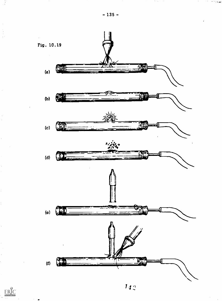
- 135 -
(b)
(c)
(d)
(e)
(f)
le4;4'. 90.41, df

- 136
10.8 R1nqSea1s
A ring seal is used when a piece of glass tubing must extend through
the wall of a larger-diameter tube. In most cases, this seal is made through
the round bottom of a tube similar to a test tube.
Ring seals can be made in two ways. One method, called a triple
seal, is to make an internal seal, blow a hole in the wall of the outer tube,
and make an external seal. One end of the inside tube is flared, and a
blowing hose is attached to the other end. The inside tube is then held so
that the flared end rests against the bottom of the outer tube. It can be held
in axial alignment by wrapping it with asbestos tape so that it fits snugly in-
side the outer tube. The seal is made by heating the bottom of the outer tube
and fusing the tubes together. A bubble.is made in the outer tube by blowing
through the hose attached to the in:3We tube (Fig. 10.20). The bubble is re-
moved, the edges are fire-polished, and a regular end-to-end seal is made,
using the same diameter tubing as the inside tube. Straighten the tubes and
anneal the joint, and the seal is completed.
Another type of ring seal is. made by blowing a hole in the outer tube.
This hole should be slightly larger than the outer diarnete of the inside tube.
A ring is formed on the inner tube at the point where the seal is to be made
to the outer tube (Fig. 10.21). This can be done by closing one end with a
Fig. 10.21
stopper and attaching a blow hose. A narrow band is heated where the ring
should be. When hot, the tube is removed from the flame, blown into so that
/,/

- 137 -
a small bulge is formed, and pushed together to form the ring. The diameterof the ring should be slightly larger than the hole in the outer tube.
The two pieces of tubing are put together so that the ring is on theoutside. The two surfaces to be Joined are heated, pushed together, sealed,and straightened. For this seal, the blowing hose is attached to the smallertube and the larger tube is closed by a stopper.
0 0 0 0 0 0 0 0Practice both procedures by making ring seals
out of medium-diameter tubes. The ratio of thediameters of the tubing should be about 2: 1.
0 0 0 0 0 0 0 0

Project 11: A DISTILLING COLUMN
The apparatus shown inFig. 11.1 is called a Vigreaux distill-
ing column. The combination of bub-
bles and drip-off points makes this type
of column very useful for fractional dis-
tillations. Because the column does notflood as easily as one of the glass-beadtype, it is particularly effective withorganic solvents.
The procedure for constructing
the distilling column is simply a com-
bination of two types of seals that you
have practiced and two other very simple
operations. Since large tubing makes upthe main section of the column, it must
be fire-cut and sealed. In the processof fire-cutting larger diameters, the
tube must be shrunk quite a bit beforeit is pulled so that the wall thicknessat the bottom will not be too thin to
work with. The torch will "burn" through
the thin glass, and the result will be aFig. 11.1
large hole.
If it is necessary to fire-cut and seal a piece of tubing that is tooshort to hold with both hands, attach a piece of glass rod as shown inFig. 11.2. This will provide an easy means of holding the tubing while fire-cutting. Be sure that the rod is straight and in axial alignment before you
begin fire-cutting.

- 140 -
An end-to-end seal is then made between the 25-mm and 12-mm
pieces of tubing. Do not forget to anneal the seal and the surrounding area
after the joint is completed.Occasionally, while making a seal a hole will develop. An easy
technique for closing the hole is to fill it with molten glass. This must bedone before the hole becomes too large. The seal can then be fused to form
a relatively smooth surface.The next step is to make the bubbles on the inside of the column.
The column is held so that the point of the flame heats up the spot wherethe bubble is desired. Once the tubing begins to shrink and the wall startsto thicken, remove the column from the flame and suck on the blow tube until
the bubble is the proper diameter. Make sure that the wall is allowed tothicken before the bubble is formed; otherwise, the wall of the bubble will be
thin and much too delicate. After the first bubble is made, rotate the column
90 degrees and proceed to make the next bubble. No dimensions are given
for the distance between the bubbles. If dimensions were given, they would
be only approximations. Much of glassblowing is done by "eyeball"; and so
just make the next bubble where it "looks like" it should be.The drip-off points are made by heating small spots until they soften,
by removing the column from the flame, and then by placing a small-diamet,..r
carbon rod into the center of the hot spots and pushing until the point is just

- 141 -
above the bubble on the opposite wall. A piece of lead from a pencil canalso be used for this operation. The column is then annealed.
The side arm is a simple T seal that is bent to the proper angle in theprocess of fusing the seal itself.When making the T seal, do not
forget that two other corks as wellas the blow hose are needed to
close the system before blowingcan be done.
At the bottom of the dis-tilling column there is anotherdrip-off point so that fluid can
easily drip back into the boiling
flask. This drip-off point is madeby sealing a piece of small-diam-eter rod to the edge of the tube
70mm
25mm
.0m.
Fig. 11.3
300mand then by fire-cutting the rod.The point should turn in so that a rubber stopper canslide easily over the tube. This must be done rapidlyand with a small flame so that the edge of the tube isnot distorted.
When the whole column is cool, the carbon canbe wiped off with a cloth and the column can be washedand rinsed in alcohol to remove dirt and fingerprints.
0 0 0 0 0 0 0 0Make the side arm and 12-mm tube for the end-
to-end seal as shown in Fig. 11.3. Fire-polishall ends and put corks where needed. Have every-thing you need ready before you fire-cut the largetube. Once the glass is heated up, you will wantto proceed from one operation to the next withoutany delays. Try to make all seals with smoothand uniform walls.
0 0 0 0 0 0 0 0
147
60mm

Project 12: A COLD TRAP
Figure 12.1 shows acold trap that can be placed ina Dewar filled with Dry Ice or
liquid nitrogen to freeze out un-
desirable gases during an ex-periment.
The construction of the
cold trap involves making a ring
seal and a T seal, followed by
fire-cutting and sealing off theoutside tube. The inner tubeand the side arm are prepared
before any work is done on the
main chamber. It is suggestedthat the second type of ringseal be used rather than thetriple seal.
Immediately after the
ring seal is completed, the sidearm is attached. The glassshould not be allowed to cool
completely because it maycrack while being reheated for
the T seal, even if it has beenannealed.
Fig. 12.1
14 S

- 144 -
0 0 0 0 0 0 0 0Figure 12.2 is a dimensional draw-
ing of a cold trap. Make the separatepieces and then assemble the entiretrap. If the inner tube is not in align-ment following the completion of thering seal, It can be straightened by in-serting a tube through the opening inthe bottom of the main chamber whileapplying a gentle flame to keep thering seal soft.
Be sure to anneal the seals as theyare completed.
0 0 0 0 0 0 0 0
Fig. 12.2
12Dmm

Project 13: A CONDENSER
The apparatus shown in Fig. 13.1
is a water-cooled condenser. It is oftenused in conjunction with a distillationcolumn to cool and condense vapors in
the course of a distillation.Again, the piece that you will
build is just a series of seals and otheroperations that have been done before.The condenser consists of a ring seal,two T seals, and a variation of the ringseal. This variation, called a shrinkring seal, is the only operation that isnew. You start by assembling the first
ring seal and the nearby side arm. It isvery important that the inner tube be
aligned properly.
For the shrink ring seal, you mustblow into both the cooling chamber and
the inner tube. A hose is connected from
the side arm to the protruding end of the
inner tube, and the blowing hose is con-nected to the open end of the large tube.
The shrink ring seal is made as
if the tube were to be fire-cut The onlydifference is that the outside tube is
Fig. 13.1

- 146 -
shrunk until it fs fused with the flare on the end of the inside tube (Fig. 13.2).
Care must be taken so that when the tubing is sealed the wall thickness isnot too thin or too thick.After the seal is fused, theend of the cooling chamber
ccn be shaped by blowing.
The inner tube should not
be constricted at the pointof the seal. Blowing takescare of this, too.
Again, the side arm
Is attached before the glasshas a chance to cool toomuch.
Fig. 13.2
SHRINKRINGSEAL
RINGSEAL
0 0 0 0 0 0 0 0
Fig. 13.3
A dimensional drawing of the condenser isshown in Fig. 13.3. Prepare all the parts be-forehand and then proceed with the completeassembly. Do not forget to anneal all seals.
0 0 0 0 0 0 0 0

- 147 -
Appendix 1: SHARPENING TOOLS
The sharpness of a tool is directly reflected in the quality of thework that it can do. A sharp tool cuts easily, smoothly, quickly, and accu-rately. A dull tool requires more force to de the same amount of work, length-
ens the time for an operation because it cuts slower, produces a mugh finishsince the tool is likely to chatter, and makes it difficult to cut within thespecified tolerance. In addition, a dull tool is more dangerous to use thana sharp tool. Consequently, it is important for you to be able to recognizewhen tools are dull and to know what to do when they ne"d to be sharpened.
It is important to remember tho,t in the context of tools "sharp" de-
scribes the condition of the cutting edge rather than the shape of the cuttingtool. The cutting tools shown in Fig. A1.1(a) and (b) are considered sharp
as long as the cutting edges are notFig. A1.1 rounded and not nicked. This is
easily determined by looking at the(a) cutting edge. Nicks and a rounded
cutting edge can be seen becauseof the light that reflects from them.
(b) The shape of the tool is de-termined by the Job for which it is
designed. The angle of the surfacesthat form.the cutting edge is more
acute (see Fig. Al .1(a)) when the material being cut is soft. For example,the tip of a razor blade used to cut , Ar has an angle of about 7 degrees,
whereas the tip of a chisel used for cutting steel has an angle of about 65degrees. There are two reasons for this. The first is the strength requiredof the tool: A broader angle is needed for tougher jobs. The second is thatthe more pointed a tool, the faster it becomes dull. Therefore, as we dis-cuss sharpening cutting tools, you will see that the angles of the cuttingpoint change as the applications change.
5 2

- 148 -
In making the density kit you cut and filed a piece of steel with toolsthat were also made of steel. For this to be possible the tools must havebeen much harder than the steel being worked or the tools would have dulledrapidly. All steel is made by adding carbon to iron. When the carbon con-tent is greater than 0.3 percent the steel can be made much harder thanlower-carbon steel. The amount of carbon does not make the steel much
harder or softer in itself, but allows it to be hardened by a process calledheat treatment. The high-carbon steel (called tool steel) is made harder byheating it until it is red (about 14000F) and by cooling it quickly (quenchingit) in a bath of oil or salt water. In this state the steel is extremely hardbut very brittle. To reduce the chance of cracking, the steel is reheated toa temperature between 3000 and 10000F, depending on how the steel will beused, and quenched as before.
AI.1 The Bench Grinder
A tool that is hardened and tempered cannot be sharpened with a filebecause the tool and the file are of equal hardness. Therefore, a grinder(see Fig. A1.2) is used that consists of a motor with a grinding wheel at-
Fig. A1.2
tached to each end of the shaft. The adjustable rests on the front of thegrinder serve to support the workpiece. A safety shield is also attached,as shown in the figure.

- 149 -
Grinding wheels are made of small pieces of stone that are bonded
together with a glasslike substance. For grinding different materials differ-ent types of stone are used. The size and the spacing of the stone chipsdetermine the coarseness of the grinding wheel. A complicated numbering
system is used to describe the characteristics of each wheel, but to simplifyour discussion we will classify wheels as coarse, medium, fine, and extrafine. Most grinders are equipped with a coarse wheel for rough work and a
fine wheel for finish work. Grinding wheels are available in various sizes(diameter and width) and shapes for specialized applications.
With use, a grinding wheel becomes clogged with metai and the edges
of the stone become dull. Sometimes the face of the wheel becomes irregu-lar and must be smoothed before the grinder can be used. The process ofreconditioning the wheel is called dressing the wheel, and a tool called awheel dresser is tased. For specifics on wheel dressers and how they areused, ask your instructor or refer to a machinist's text.
ALWAYS WEAR SAFETY GOGGLES whenever you use a grinder. The
many pieces of stone and metal thrown by the wheel could go into your eyes.
These pieces are very sharp and can cause severe eye damage.
A1.2 Sharpening a Wood Chisel
The wood chisel is one of the most maligned hand tools, and unjusti-fiably so. The problem is that dull wood chisels are poor tools. However,
when sharpened correctly and not abused, they are one
of the most useful hand tools you will use. In Fig. A1.3
the blade of the chisel is drawn from a side view. The
angle of the two surfaces forming the cutting edge is
about 25 degrees.
Fig. A1.3
SURFACE A
The first step when sharpening a wood chisel is
to remove the nicks and any rounding of the cutting edge.
Begin by adjusting the tool rest so that surface A in
Fig. A1.3 will be ground at 25 degrees. Because thetool rest is not calibrated and there is no room for a

- 150 -
protractor, this must be done by eye. After loosening the bolts on the toolrests hold the chisel on the tool rest and tilt the tool rest until all of surfaceA is in contact with the face of the grinding wheel. Make sure there is about1/16-inch clearance between the tool rest and the grinding wheel and retight-en the bolts. With the grinder switched on, lightly touch the chisel to thegrinding wheel. Look at the grinding marks on the surface of the chisel to de-termine if the rest angle is set correctly, and make readjustments if necessary.Then grind the entire surface of the chisel by moving it laterally across theface of the grinding wheeL Be sure that the blade of the chisel is perpendicu-lar tothe face of the wheel; otherwise the end of the chisel will not be square.
When any metal is being ground, heat is produced by the friction be-tween the metal and the wheel. If too much-heat is developed, the metalturns blue, loosing its hardness quickly. Therefore, after every few sec-onds of grinding,the tool should be dipped into a cup of water and left thereuntil it is cool. This procedure is very important. Many cutting tools havebeen mined because this precaution has not been taken.
After grinding a wood chisel, the cutting edge is still not sharpenough. The grinding wheel leaves burrs and a rough surface on the cuttingedge. Remove the burrs and smooth the edge by hand rubbing the cutting
edge on a very fine stone called an
A 'A oilstone. Oil is used while sharp-ening the chisel to help maintain the
flat surface of the oilstone and toprevent metal buildup in the pores of
the stone. Hold the chisel as shownin Fig. Al .4 and move it back and
forth as indicated. To ensure thatthe surface will be flat, be certainnot to rock the chisel as you moveit. Turn the chisel over and repeat
the procedure holding the entire
Fi . A1.4
*4sr.
>'1

- 151 -
surface of the blade against the stone. For the cutting edge to be sharp, theadJoining surfaces must be yew smooth. When they are smooth, the surfaceswill appear shiny but no light will reflect from the cutting edge itself.
The procedure for sharpening the cutting blade of a plane is the sameas for a wood chisel. Because the blade of the plane is simply a wider ver-sion of a chisel, even the angle of the cutting tip is the same.
A1.3 Sharpening Power Bits
Enlarged views of the cutting end of two types of power bits are de-picted in Fig. A1.5(a) and (b). Both bits are used the same way, but becauseof their shape, one of the sharpening steps is different.
To reduce friction, all cutting toolsare designed so that the minimum surface Fig. Al . 5area is in contact with the workpiece. Thesurfaces that form the cutting edge are al-ways made so that the angle between themis less than 90 degrees, providing clear- (a) (b)ance. In the case of the wood chisel andthe plane cutter, the clearance is providedby the angle at which each was held. Withpower bits and most other cutting tools, theclearance must be ground into the tool as it
is sharpened. The angle between the edge that is ground and the workpieceis called the clearance angle or relief angle (see Fig. A1.6).
Each cutting edge of a power bit must be sharpened to give clearance.
To sharpen the bit, you must grind edges a, b, c, and d. However, you
should not grind edges e and f because this will cause the size of the drillto be reduced.
When a wood chisel is sharpened, the tool rest is tilted and the chiselis held against it to grind the angled surface. But because there are so many
cutting edges on a power bit, it is easier to hold the bit by hand. By looking
13-Li

- 152 -
at Fig. A1.7 you can see that the surface being ground is not at a right angle
to the .power bit. By raising or lowering the tool rest, you can achieve the
desired angle.When sharpening any
cutting tool that rotates, youwill find that the greatest prob-
lem is to grind the tool symmet-
rically. If a drill is not sym-
metrical, the hole it drills willbe too large. For the powerbit, both the length of the cut-ting edges a and d and the dis-tance from the point of the drillto cutting edges a and d must
be the same. If cutting edge
a is longer than cutting edge d
the point of the drill (used tomake a pilot hole and to act as
a guide) will be off center, and
the diameter of the hole will be
twice the distance from thepoint to the edge of the drill
(dimension x). If more materi-
al is removed from edge a than
from edge A only edge d will
cut the wood. The result of
this is that more side pressurewould be applied to the drill, causing the hole to be oversized.
Because of its contour, a power bit is difficult to sharpen symmetri-
cally. It is difficult to take meaningful measurements of the length of cut-
ting edges. Therefore, power bits must be sharpened by eye and with an
acquired "feel."
Fig . Al . 6
11111&;PEIRINIIIIIINCLEARANCE
ANGLES
I 7

- 153 -
To sharpen a power bit, grind away the rounded cutting edge a, re-moving as little material as possible. Be careful that the side of the grind-ing wheel does not touch surface b. Now turn the drill over and repeat the
F A1 process on edge Try to use theig. .7same amount of pressure for the
same.period of time so that you re-move the same amount of material
from edge d as you did when sharp-
ening edge a. Use the side of thegrinding wheel to sharpen edges b
and c in turn, again using the samepressure for the same time period.
Be sure to notate the drill slightlyto produce the proper clearance.
Use a steel rule to see if edges aand d lie in a straight line, and
visually check that the rule is at right angles to the axis of the power bit.To determine if the point of the drill is centered, measure the distance fromthe point to the end of cutting edges a and
The power bit shown in Fig. A1.5(b) is easier to sharpen becauseedges a and h are sharpened simultaneously, as are edges c and d. Simplyhold the drill at an angle to use the side of the wheel to sharpen the point(and provide clearance) while the face of the wheel sharpens the cutting sur-face. As before, take the same precautions to ensure that the drill is sharp-ened symmetrically.
When using a power bit for drilling holes In wood, it is not necessaryto use an oilstone to further sharpen the cutting edges. For use in drillingplastic, however, it is essential to make the drill as sharp as possible.Therefore, you should use an oilstone as you did when sharpening the chiselor plane cutter.
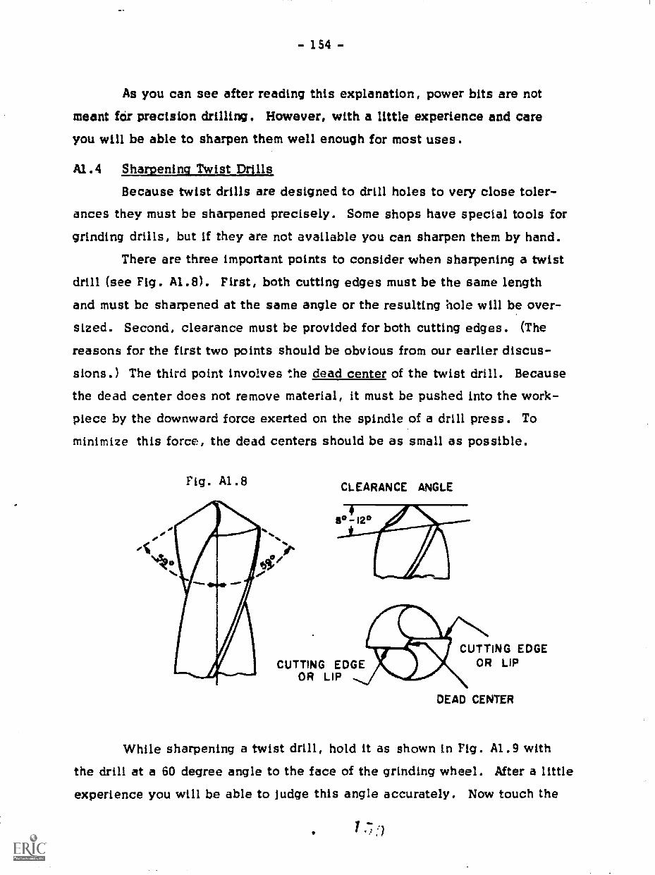
- 154 -
As you can see after reading this explanation, power bits are not
meant for precision drilling. However, with a little experience and careyou will be able to sharpen them well enough for most uses.
A1.4 Sharpening Twist Drills
Because twist drills are designed to drill holes to very close toler-ances they must be sharpened precisely. Some shops have special tools forgrinding drills, but if they are not available you can sharpen them by hand.
There are three important points to consider when sharpening a twist
drill (see Fig. A1.8). First, both cutting edges must be the same lengthand must be sharpened at the same angle or the resulting hole will be over-
sized. Second, clearance must be provided for both cutting edges. (The
reasons for the first two points should be obvious from our earlier discus-
sions.) The third point involves the dead center of the twist drill. Because
the dead center does not remove material, it must be pushed into the work-piece by the downward force exerted on the spindle of a drill press. Tominimize this force, the dead centers should be as small as possible.
Fig. A1.8 CLEARANCE ANGLE
CUTTING EDGECUTTING EDGE OR LIP
OR LIP
DEAD CENTER
While sharpening a twist drill, hold it as shown in rig. A1.9 withthe drill at a 60 degree angle to the face of the grinding wheel. After a littleexperience you will be able to judge this angle accurately. Now touch the

- 155 -
cutting edge to the face of the grinding wheel and pivot the drill over yourrightlorefinger by moving your left hand downward, as indicated by the ar-rows. Never allow the shaft of the drill to be higher than the cutting end
Fig . Al . 9
because the drill will not cut. By keeping the drill in contact with the grind-ing wheel as you pivot it, clearance will be ground for the cutting edge. If
the angle is too small, the drill will not cut. If the clearance angle is toobig, the drill will dull more rapidly. See Fig. A1.8 for the proper angle.
To prevent the drill from overheating, always
keep it moving when it is in contact with the grindingwheel. If the drill is dipped in water after every fewpasses on the grinding wheel, it will not overheat.
After two or three passes over the grinding
wheel, check the angle of the cutting edge with adrill-point gauge, as shown in Fig. A1.10. (A pro-
tractor head for a combination square can be used asa substitute for a drill-point gauge.) Make correc-tions if necessary, and then check the cutting edgeto make certain it is sharp. Repeat the procedure.to sharpen the second cutting edge. At this point Fig.you must check the length of both edges as well as A1.10
1 60

- 156
the angle of both edges. On some drill-point gauges a scale is convenientlyprovided for measuring the length of the edge while measuring its angle.
However, a steel rule or caliper can also be used. The length of the cuttingedge is measured from the circumference of the drill to the point at which the
dead center Joins the cutting edge. Be sure everything is correct because any
error in the measurement of the length of the cutting edge will be reflected in
the size of the hole the drill will make. If you follow the steps correctly thedrill will make the correct size hole and the dead center will be sufficiently
small.
All cutting tools become dull with use. However, because twistdrills are used with power drills to drill hard materials, they receive more
abuse than the other tools discussed here. If a twist drill is used after itbecomes dull, more force is required to make the drill cut. Excessive forcecreates more friction, which causes the drill to heat up and lose its hard-
ness or to chip or crack. If any of these problems should occur the drill
must be ground down far enough to remove the soft steel or until the chip does
not interfere with the cutting edge. (Use a coarse wheel at first and then
switch to a fine wheel.)Always remember to check the drill that you will be using because it
will save time if you sharpen the drill before it is damaged and because prop-
erly sharpened tools produce much better work.
A1.5 Sharvening Various Tools
So far we have discussed only a few tools and how they are sharpened.
Some tools require only a brief description of the sharpening procedures.Several tools require special machinery to ensure the accuracy of the cutter
or take so much time that it is less expensive to send them to a professional
tool grindar. Others cannot be resharpened and must be replaced once they
become dull. In this section we will mention some of the tools you have used
in the course and describe what to do when they become dull.
Auger bits are not made of hardened tool steel. Therefore, they can
be sharpened with a file. Clamp the shaft of the auger bit in a machinist's1 G
- 157 -
vise with the cutting end facing upward. File the cutters (refer to Fig. 1.25)Just as you would grind the cutting edges of a power bit, making sure thatthe file is angled correctly to provide the proper clearance. The edges ofthe spurs are sharpened by filing the inside of the spurs. Remove as littlematerial as possible to prolong the life of the bit. Be careful to avoid filingthe screw. Smaller auger bits will require the use of small delicate files; sogo slowly and be careful.
A center punch is made of hardened tool steel and must be sharpenedon a grinder. Although the center punch is not a cutting tool, the point mustbe sharp to function properly. To sharpen a center punch, simply hold it ata 45 degree angle to the face of the grinding wheel and spin the punch as yougrind it. Make sure that the end comes to a point.
Circular saw blades should be sharpened by a professional. Becausethe circumference of the blade must be true to the shaft of the table saw,circular saw blades must be sharpened on a special machine. A good hard-ware store usually provides this service.
A die for cutting threads cannot be resharpened. Once it becomesdull, a die should be discarded and a new pne purchased.
Files fit into the same category as dies; there is no way to resharpenthem. However, a dull file should not be thrown away because it can beused in many other ways around a shop. Files are made of very good toolsteel, and when they are dull they can be ground to make knives or cuttingtools for a wood lathe.
Hacksaw blades cannot be resharpened; but again they are made ofgood steel and can be used for other purposes.
Handsaws can be sharpened by hand. A special tool can be purchasedto set the teeth of the saw. However, to do a good job takes experience.Hardware stores generally provide this service, and the cost is not prohibi-tive.
Scribers and other layout tools can be sharpened on an oilstone.Simply spin the tool while rubbing it against the oilstone.
1 62

- 158 -
Screwdrivers are not often thought of as being dull or sharP. However,
sometimes the end becomes so rounded that it continually slips out of theslot of a screw. Other t,imes the end of the screwdriver has been chipped.To sharpen a screwdriver, grind the end on the face of the grinding wheel.
Be sure that the end is square to the axis of the screwdriver. If the end hasbeen ground many times, you will have to grind the sides of the screwdriver
as well.Taps cannot be resharpened. Because so much force is required when
using a worn tap, the tap often breaks off in the hole. Therefore, make sure
a tap is sharp before using it; otherwise you may ruin the piece you are making.There are many other tools that require sharpening but have not been
mentioned in this appendix. Most of them require professional sharpening,whereas others do not. After your exposure to this appendix you should be
able to make informed Judgments concerning dull tools you may come across.
The most important things to remember about the general maintainance
of tools are to keep them sharp, to use them only for the operation for which
they were designed, and to keep a light coating of oil on them, which willprevent them from rusting.
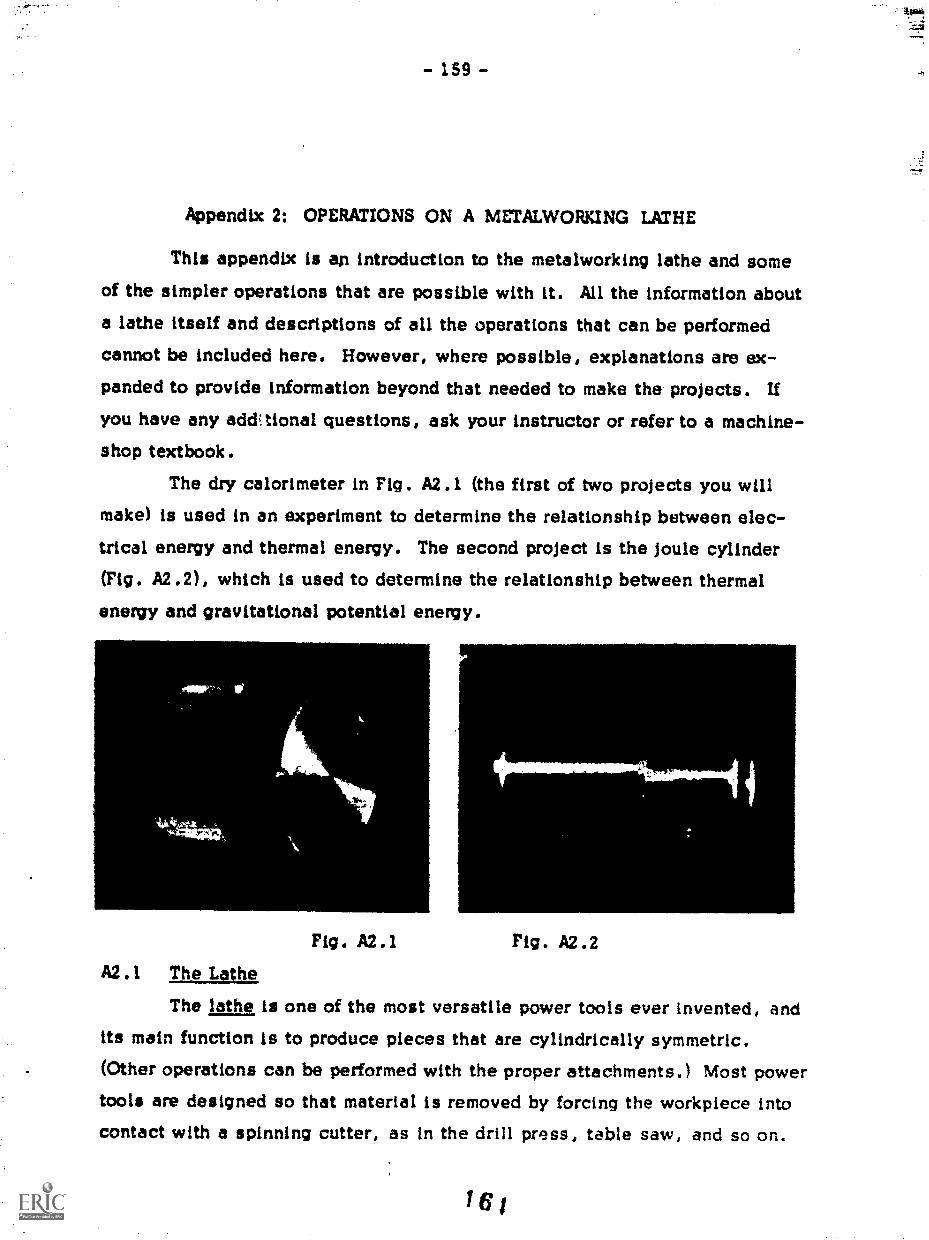
Appendix 2: OPERATIONS ON A METALWORKING LATHE
This appendix is an introduction to the metalworking lathe and some
of the simpler operations that are possible with it. All the information about
a lathe itself and descriptions of all the operations that can be performedcannot be included here. However, where possible, explanations are ex-panded to provide information beyond that needed to make the projects. If
you have any addCtional questions, ask your instructor or refer to a machine-shop textbook.
The dry calorimeter in Fig. A2.1 (the first of two projects you will
make) is used in an experiment to determine the relationship between elec-trical energy and thermal energy. The second project is the joule cylinder(Fig. A2.2), which is used to determine the relationship between thermalenergy and gravitational potential enemy.
Fig. A2.1 Fig. A2.2A2.1 The Lags_
The lathe is one of the most versatile power tools ever invented, andits main function is to produce pieces that are cylindrically symmetric.(Other operations can be performed with the proper attachments.) Most powertools are designed so that material is removed by forcing the workpiece into
contact with a spinning cutter, as in the drill press, table saw, and so on.
161

- 160 -
The lathe removes material by forcing the cutting tool into a rotating work-piece, tfiereby producing the desired shape. The movement of the tool canbe precisely controlled, making it relatively easy to produce pieces to a tol-erance of +0.001 inch. Even greater degrees of accuracy are obtained withhigh-precision lathes.
The drawing in Fig. A2.3 has the most Important parts of a lathelabeled. Because lathes come in many different sizes and types, the loca-tion and the kinds of controls may differ from one lathe to another. Conse-
quently, it is important to know the function of each knob or lever beforeturning on the power.
CHUCK
HEADSTOCK
Fig . A2 . 3
TOOL POST
TOOL HOLDER COMPOUNDFEED
CROSSSLIDE
TA ILSTOCK
COMPOUNDREST
BED
CARRIAGE
LONGITUDINAL FEED CROSS FEED

- 161 -
The basic concept behind the design of all lathes is that a workpiece(the stock being machined) is attached to a shaft rotated by a inctor. The ro-tating shaft and its drive system are located in a casing called the headstock.The drive system, which in turn is connected to the motor, consists of a se-ries of pulleys and belts or gears whose ratio can be changed to vary thespeed of the shaft. Other than the tailstock, the remaining parts of the latheare designed to move the cutting tool in a precise manner.
A2.2 Holding Stock in a Lathe
Of the different methods for holding stock in a lathe the use of achuck is the most common. Although designs may differ, all chucks operateon the same basic principle. Each has movable jaws that can be adjusted tohold stock firmly.
The most common type, and the easiest tosal chuck (Fig. A2.4). Because the threejaws move in unison, this type of chuck isself-centering (within 0.003 iuch) and can
hold circular-, triangular-, or hexagonal-shaped stock. It is equipped with one setof jaws that can hold small pieces from the
outside and larger pieces from the inside,as in Fig. A2.5(a) and (b) . Another set of
jaws, illustrated in Fig. A2.5(c), is used to hold large-diameter stock externally.
use, is a three-Jaw univer-
Fig. A2.4
111reala"`.
(a)
Fig; A2 . 5
(t)
160
(c)

- 162 -
Each jaw of the chuck is marked with a number corresponding to the
slot into which it fits. To change the jaws, open them as wide as possibleby rotating the chuck wrench counterclockwise and remove one jaw at a time.
If you look into one of the slots after the jaw is removed, you will see aspiral gear that rotates as the chuck wrench is turned and meshes with the
teeth on the back of the Jaw. The Jaws must be engaged in the proper order
to maintain the axial alignment. This is done by first rotating the spiral
gear until the leading tooth is Just behind the edge of slot No. 1. The jaw
is then slid into the slot and the chuck wrench is turned clockwise Just
enough to engage the Jaw. Then Jaw No. 2 is placed in its slot and en-
gaged in the same way, and then No. 3.Another type of chuck, called a collet, is illustrated in Fig. A2.6.
The diameter of the hole through the axis of the collet determines the size of
the stock that can be held. The conical end has three or four slots that form
Fig. A2.6the jaws. The other end is threadedand screws into the drawbar. FigureA2.7 is a drawing of the necessaryparts, and Fig. A2.8 is a cutaway ofthe headstock that shows how these
parts are assembled in a lathe. As
the drawbar (a) is rotated clockwise by hand, the collet is pulled into the
headstock, and because of the matching taper in the collet sleeve (c), the
jaws are tightened onto the stock.
Fig. A2.7
(a) DRAWBAR (b) SPINDLE NOSE CAP (c) COLLET SLEEVE (d ) COLLET
(e) SPANNER WRENCH
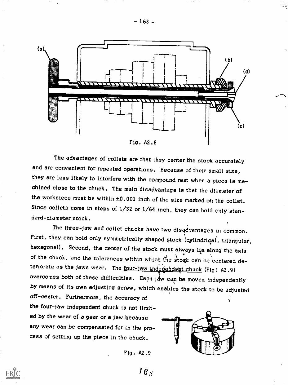
(a)
- 163 -
11L111.1.1101.1111.11MIL1110111U1111.k.r
Arm
111111111r""inkwawill-,iwaiTiliia.-
The advantages of collets are that they center the stock accuratelyand are convenient for repeated operations. Because of their small size,they are less likely to interfere with the compound rest when a piece is ma-chined close to the chuck. The math disadvantage is that the diameter ofthe workpiece must be within +0.001 inch of the size marked on the collet.Since collets come in steps of 1/32 or 1/54 inch, they can hold only stan-dard-diameter stock.
The three-jaw and collet chucks have two disad7antages in common.First, they can hold only symmetrically shaped stock (gylindrical, triangular,hexagonal). Second, the center of the stock must always lie, along the axis
,
of the chuck, and the tolerances within which die stocik call be 'centered de-teriorate as the jaws wear. The four-jaw lndeVildelit.chuck (Fig: A2.9)overcomes both of these difficulties. Each jiw cell be moved independentlyby means of its own adjusting screw, which enables the stock to be adjustedoff-center. Furthermore, the accuracy ofthe four-jaw independent chuck is not limit-ed by the wear of a gear or a jaw because
any wear can be compensated for in the pro-cess of setting up the piece in the chuck.
Fig. A2.9

- 164 -
Figure A2.10 shows three examples of operations that can be per-formed with a four-jaw chuck: (a) ordinary machining to fine tolerances,
(b) drilling a hole off-axis, and (c) machining a plumbing elbow.
Fig. A2.10
(a)
Co)
Cc)

- 165 -
The main disadvantage of a four-jaw chuck is in the amount of timeneeded to set up an operation. Because a three-jaw chuck is suggested forthe projects in this section, the setup procedure for a four-jaw chuck willnot be described. However, it is adequately described in most machine-shop texts.
When using any chuck, be sure that the workpiece is held tightly butnot so that its surface is marred by the jaws. Never leave a chuck wrenchin a chuck at any time. If the lathe is turned on, the wrench will be thrownand someone could bc seriously injured.
A2.3 Cutting Tools
There are different shapes, sizes, and qualities of cutting tools usedwith a lathe. Usually the operator grinds the tool for a specific operation.As with other cutting tools, lathe tools(see Fig. A2.11) are ground with clear-ance for the cutting edge. Because theangles of the surfaces on a lathe' toolvary depending on the use of the tool,
it is impractical to go into a full dis-cussion of lathe tools. However, you
should be able to recognize what operation each shape is designed for.Figure A2.12 shows some of the tools you are likely to see and their uses.
Fig. A2.12
IRIGHT &LEFTCUTTING TOOLS
CUTOFF OR RIGHT 3 LEFTPARTING TOOL FACING TOOLS
ROUND NOSESMOOTH- FINISHCUTTING TOOLS
GROOVINGTOOLS
ROUGHTURNINGTOOL

- 166
The cutting tool is held in a tool holder and is fastened by means ofa bolt (Fig. A2.13). The tool holder, in turn, is held in the tool post. By
loosening the bolt at the top of the tool post, the holder can be pivoted upand down, slid in and out, and rotated sideways. This versatility makes itpossible to adjust the position of the holder for any tool or operation.
Fig. A2.13TOOL POST
COMPOUND REST
CUTTING TOOL
TOOL HOLDER
A2.4 Moving the Tool
Looking back at Fig. A2.3, you will notice that there are three differ-
ent feed controls: the longitudinal feed, the cross feed, and the compoundfeed. They are all part of a mechanism called a carriage. Machined intothe bed of the lathe are a series of tracks, called ways,, that run parallel tothe axis of the main rotating shaft of the lathe. They act as guides andbearings along which the carriage can slide. The motion of the carriage,and therefore of the tool, is controlled by the longitudinal-feed wheel. Byrotating the wheel clockwise the carriage moves away from the headstock.
A couAterclockwise rotation produces the opposite movement.
Mounted on the carriage are two other feed controls. Machined into
the top of the carriage is a guiding track perpendicular to the axis of thelathe. The cioss slide is moved along this track by rotating the cross-feed
knob (Fig. A2.3). n top of the cross slide is the compound rest, which canbe pivoted through 360 degrees and locked at any angle. The base of the
7 7

- 167 -
compound rest is calibrated in degrees for convenient adjustment. When the
compound-feed knob is rotated, the tool moves at the angle at which the restis set. On top of the compound rest is a "T" slot into which the tool postcan be slid and fastened.
In order to move the tool a precise distance, both the compound feedand the cross feed are equipped with dials calibrated in thousandths of aninch. A clockwise rotation of either feed knob will move the tool away fromthe operator. Figure A2.14 will enable you to understand the possible move-ments of the cutting tool.
Fig. A2.14
CROSS SLIDE
COMPOUNDREST
CARRIAGE
0 0 0 0 0 0 0 0With the lathe turned off, move all the feed con-
trols. Use your left hand on the longitudinal feedand your right hand for the others. Try to get the"feel" and coordination of the different feeds.
0 0 0 0 0 0 0 0
1 72

- 168 -
A2.5 Facing
Figure A2.15 is a dimensional drawing of the dry calorimeter. Fig-
ure A2.16 is provided to assist in the discussion of the operations and the
order in which they will be performed. As in every pmject you have made,
0 753
Fig. A2.15
0712
V52 DRILL
NOTES.
I - ONE PIECE 0.125 ALUMINUM1/4 INCH LONG PER UNIT
2- ALL DIMENSIONS t 0.002
3- MASS OF SLUG (WITH PIN)14.0 GRAMS t 0.IGRAMS
4- DEBURR ALL EDGES
MATERIAL. 2011 - T3 ALUMINUM ROD
0151 DRILL FOR PRESS FITOF 0.125 ALUMINUM PIN
(REFER TO NOTE 1 )
the first step is to prepare one or more surfaces that can be used as refer-
ences for future operations. In this apparatus the reference end, labeled
@ in Fig. A2.16, should be michined smooth and at right angles to theworkplece. The operation that does this is called facing. You will use the
facing operation again to finish the workpiece to the proper length.
Before facing the piece, there are three things to be considered in the
proper placement of the cutting tool. First, the tool must protrude far enough

- 169 -
® TURNING A TAPER® DRILLING
DR LLING
FACING()DRILLING
@TURNING
FACING
Fig. A2.16
to prevent the tool holder from touching the surface of the piece to be ma-
chined. This distance is determined by the shape of the tool and is checkedvisually. If the tool extends too far, it is likely to vibrate (chatter), produc-ing a rough finish. Second, because chatter is also caused when too much ofthe cutting edge is in contact with the machined surface, it is necessary tohave a small clearance angle between the
cutting tool and the surface being faced(Fig. A2.17). The third factor to consider
when positioning the tool is the height.The tool must be adjusted so that its point
will intercept the axis of the workpiece. r-If the tool is adjusted too low or too high, CLEARANCE
ANGLE
Fig. A2.17
it will be impossible for it to remove ma-
terial at the center of the stock. The angle and the height of the tool are ad-justed at the same time because the tool-post bolt must be loosened for both.
The clearance angle is set by loosening the bolt and by rotating thetool post until the proper angle is set. The angle is not very critical and canbe set by eye. Adjusting the height of the tool is more difficult, however,because it is done by trial and error. The tool holder is pivoted up or downin the tool post until the tool is approximately at the correct height, and thetool-post bolt is then tightened. A trial cut is taken, and the height of thetool is readjusted if necessary.

- 170 -
Another method for approximate positioning is shown in Fig. A2.18.
A small ruler or a straightedge is placed between the point of the cutting tooland the circumference of the stock. If
the straightedge is vertical, the pointof the tool is at the correct height. If
the toli of the straightedge tilts towardthe operator, the tool is too low. If the
straightedge tilts in the other direction,the opposite is true. A trial cut is
taken and, if necessary, a fine adjust-ment is made.
Fig. A2.18
WARNING: Never adjust the
cutting tool while the lathe is running.
Facing tools are designed to be moved from the circumference to the
center of the stock when making rough cuts and from the center to the circum-
ference when making finish cuts. However, until you have gained experiencewith the lathe, it is safer to perform all facing operations from the center to
the circumference.To face the workplece the lathe is turned on and the cutting tool is
moved so that it barely touches the surface at the center. This is done byrotating the carriage wheel (longitudinal-feed wheel) with the left hand alidadjusting the cross feed with the right hand. Apply a slight pressure with
the longitudinal feed until a chip begins to form on the cutting tool. Remove
your left hand from the longitudinal-feed wheel and begin rotating the cross-
feed knob in a counterclockwise direction. The motion of the tool will be
smooth if you alternate hands while rotating the knob. Go slowly until you
get the "feel" for what can be done on a lathe. In general, a slower feed
gives finish cuts a smoother surface. The process is repeated until the de-
sired finish is produced.i 7.3

- 171 -
As with the drill press, the diameter of the stock determines the speedat which the lathe can be run. For diameters below 1.000 inch, refer toFig. 3.8. For larger diameters, use the formula
RPMcutting speed x 4
diameter
where the cutting speed is 40 FPM (feet per minute) for stainless steel;
65 FPM for copper; 95 FPM for steel; 130 FPM for brass; and 230 FPM for
aluminum. Most lathes do not have continuously variable speed controls;therefore, you should select the closest speed below the one specified.
A2.6 A Word on Safety
When using a lathe always wear safety goggles or glasses and neverwear a necktie, a scarf, or any loose-sleeved clothing. Wear long-sleevedclothing with tight cuffs or roll the sleeves above the elbows. Any loose
clothing can be a hazard because it might get caught on a control. Long hairshould be tied back away from the face.
Always allow the lathe to come to a complete halt before you touch
the chuck or.workpiece and before making a measurement of any kind. When
cleaning the lathe remove the cutting tool and use a brush or rag. Never
handle metal chips. They are very sharp!Be sure to remove the chuck key and make certain that nothing is in
the way of the chuck before starting the lathe. Above all, plan ahead andthink before you do anything. Most operations on a lathe can b.?. done slowly,
and so there is no reason to rush things.
0 0 0 0 0 0 0 0Take a piece of aluminum stock 4 to 6 inches long and 7/8 inch
in diameter. Fasten it in the chuck with about two inches extend-ing beyond the jaws. Set the lathe at the correct speed and adjustthe cutting tool. Before starting the lathe', check to see that thereis enough clearance between the chuck and the cross slide and thetool holder. Start the lathe and make a light cut. Vary the rate atwhich you turn the cross feed and note the results on the surface ofthe aluminum. Continue making cuts until the surface is smooth.The last cut should be made with a very slow but steady feed.
0 0 0 0 0 0 0 0
76
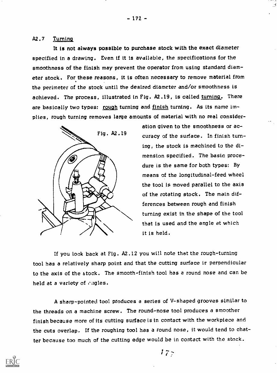
- 172 -
A2.7 Turning
It is not always possible to purchase stock with the exact diameterspecified in a drawing. Even if it is avdilable, the specifications for thesmoothness of the finish may prevent the operator from using standard diam-
eter stock. For these reasons, it is often necessary to remove material from
the perimeter of the stock until the desired diameter and/or smoothness is
achieved. The process, illustrated in Fig. A2.19, is called turning. Thereare basically two types: rough turning and finish turning. As its name im-plies, rough turning removes large amounts of material with no real consider-
ation given to the smoothness or ac-
curacy of the surface. In finish turn-
ing, the stock is machined to the di-mension specified. The basic proce-
dure is the same for both types: Bymeans of the longitudinal-feed wheel
the tool is moved parallel to the axisof the rotating stock. The main dif-ferences between rough and finish
turning exist in the shape of the toolthat is used and the angle at which
it is held.
If you look back at Fig. A2.12 you will note that the rough-turning
tool has a relatively sharp point and that the cutting surface if: perpendicular
to the axis of the stock. The smooth-finish tool has a round nose and can be
held at a variety of eagles.
A sharp-pointed tool produces a series of V-shaped grooves similar to
the threads on a machine screw. The round-nose tool produces a smoother
finish because more of its cutting surface is in contact with the workpiece and
the cuts overlap. If the roughing tool has a round nose, it would tend to chat-
ter because too much of the cutting edge would be in contact with the stock.

- 173 -
As you might imagine, there is a tremendous amount of force exertedon the cutting tool when large amounts of material are removed. This forceis exerted downward because of the rotation of the stock and also laterallybecause of the movement of the carriage and tool. Because the tool post andtool holder are designed to be versatile, they are not as rigid as they mightbe. Therefore, the lateral force exerted on the tool may cause the holder andpost to pivot when heavy cuts are made. If this should happen with the toolholder positioned as shown in Fig. A2.20(a), the surface would be gouged ormachined to an undersized diameter. However, with the holder positioned asshown in Fig. A2.20(b), the pivoting of the tool post does not result in dam-age to the workpiece. To help minimize this problem, be sure the tool postis as tight as possible.
Fig. A2.20
To turn down a piece of stock, place it in the chuck with enough ma-terial extending to allow the cutting tool to be moved the desired distancewithout any part of the carriage being hit by the chuck. If the stock extendstoo far, it may bend or vibrate while being machined. (The tailstock and a
dead or floating center can be used to eliminate these problems.)The carriage is then moved to the right so that the tool is beyond the
end of the stock. Move the MISS feed to the desired setting, and then movethe carriage toward the headstock by rotating the longitudinal-feed wheelcounterclockwise with a slow, smooth motion. When the proper length ismachined, the tool is moved away from the surface it has just cut by turningthe cross feed counterclockwise, and the carriage is moved toward the tail-
1 78

- 174 -
stock to repesition the tool for the next cut. The maximum depth of the cut
is determined by the material being machined, the diameter of the material,
the type of cutting tool, and the size of the lathe. Experience is the only-,!,)v to learn the capacity of the lathe and the size of the cut tt at can be
takea. However, it is not unreasonable to take 0.040- or 0.050-inch cuts.Rough turn to about 0.035 inch over the final diameter before switching to
the finishing tool.
As you can see by Icoking at Fig. A2.15 and Fig. A2.16, the secondoperation of the project requires you to turn down the diameter of the dry cal-
orimeter to 0.750 +0.002 inch. The stock used is 7/8-inch-diameter alumi-
num; therefore, approximately 1/8 inch of aluminum must be removed from
the diameter of the stock. The distance the tool is moved is indicated by
the dial on the cross slide. i'Z the dial is moved from 25 to 75 the tool has
been moved 0.050 inch. nowever, the diameter of the stock will have been
reduced by twice that amount, or 0.100 inch.* Therefore, in the process of
turning down the diameter of the stock for the dry calorimeter from 7/8 inch
to 0.750 inch, the micromete and therefore the tool will be moved
by only 0.062 inch.
You have learned that it is always necessary to have a surface that
can be used as a reference. Because ahe stock used in this project may be
slightly bent or out a; round, the circu lference should not be used as a ref-
erence. The first step in turning is to make a cut that can then be used as
a reference for future cuts. After the first cut is made, the dial reading is
noted, the diameter of the stock is measured with a micrometer, and the next
movement is calcuLated from these two numbers.
This is true for most lathes. However, a few lathes are designed so that thedial reading represents the total amount of material removed. Check the latheyou are using to determine which method is used.

- 175 -
0 0 0 0 0 0 0 0If after the first cut has been made on a 1.000-
inch-diameter aluminum bar, the dial reads 13, andthe diameter measures 0.896 inch, what will thefinal dial reading be to reduce the diameter to 0.784inch?
Take the piece of stock you have faced for the drycalorimeter and set it up in the chuck so that you canturn down the stock for a length of 1-1/2 to 2 inches.Position the cutting tool properly, and check to makesure that nothing will hit the chuck during the opera-tion. Then proceed with the operation.
0 0 0 0 0 0 0 0
A2.8 Turning a Taper
In making the dry calorimeter, the third step is to taper one end. Thistaper must match a mating taper that is in the end of a hard rubber rod. Therod, in turn, is attached to the center of a weighted bicycle wheel that isused with the dry calorimeter to investigate the relationship of thermal andkinetic energies.
Because the compound rest can be rotated through 360 degrees (Fig.A2.14), it can be used to turn tapers. The desired angle is set according tothe scale on the base of the compound rest; and by rotating the feed knob, acut is made at this angle.
To set the compound rest at the required angle, loosen the two bolts,nuts, or screws that hold it secure. The exact position of these fastenerswill vary from lathe to lathe. Rotate the compound rest to the proper angleand retighten. The tool holder is then set in the proper position for turning.
The taper in Fig. A2.15 is given as 3 degrees. To make a cut at thisangle, the compound rest is rotated counterclockwise so that the amle be-
180
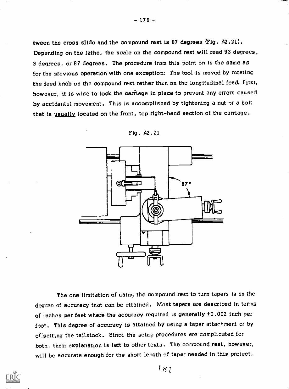
- 176 -
tween the cross slide and the compound rest is 87 degrees (Fig. A2.21).
Depending on the lathe, the scale on the compound rest will read 93 degrees,
3 degrees, or 87 degrees. The procedure from this point on is the same as
for the previous operation with one exception: The tool is moved by rotating
the feed knob on the compound rest rather thz.n on the longitudinal feed. First,
however, it is wise to lock the carkage in place to prevent any errors caused
by accidental movement. This is accomplished by tightening a nut or a bolt
that is usually located on the front, top right-hand section of the carriage.
Fig. A2.21
The one limitation of using the compound rest to turn tapers is in the
degree of accuracy that can be attained. Most tapers are described in terms
of inches per feet where the accuracy required is generally +0.002 inch per
foot. This degree of accuracy is attained by using a taper attac4±ment or by
ofsetting the tailstock. Sinct the setup procedures are complicated for
both, their explanation is left to other texts. The compound rest, however,
will be accurate enough for the short length of taper needed in this project.
IHJ
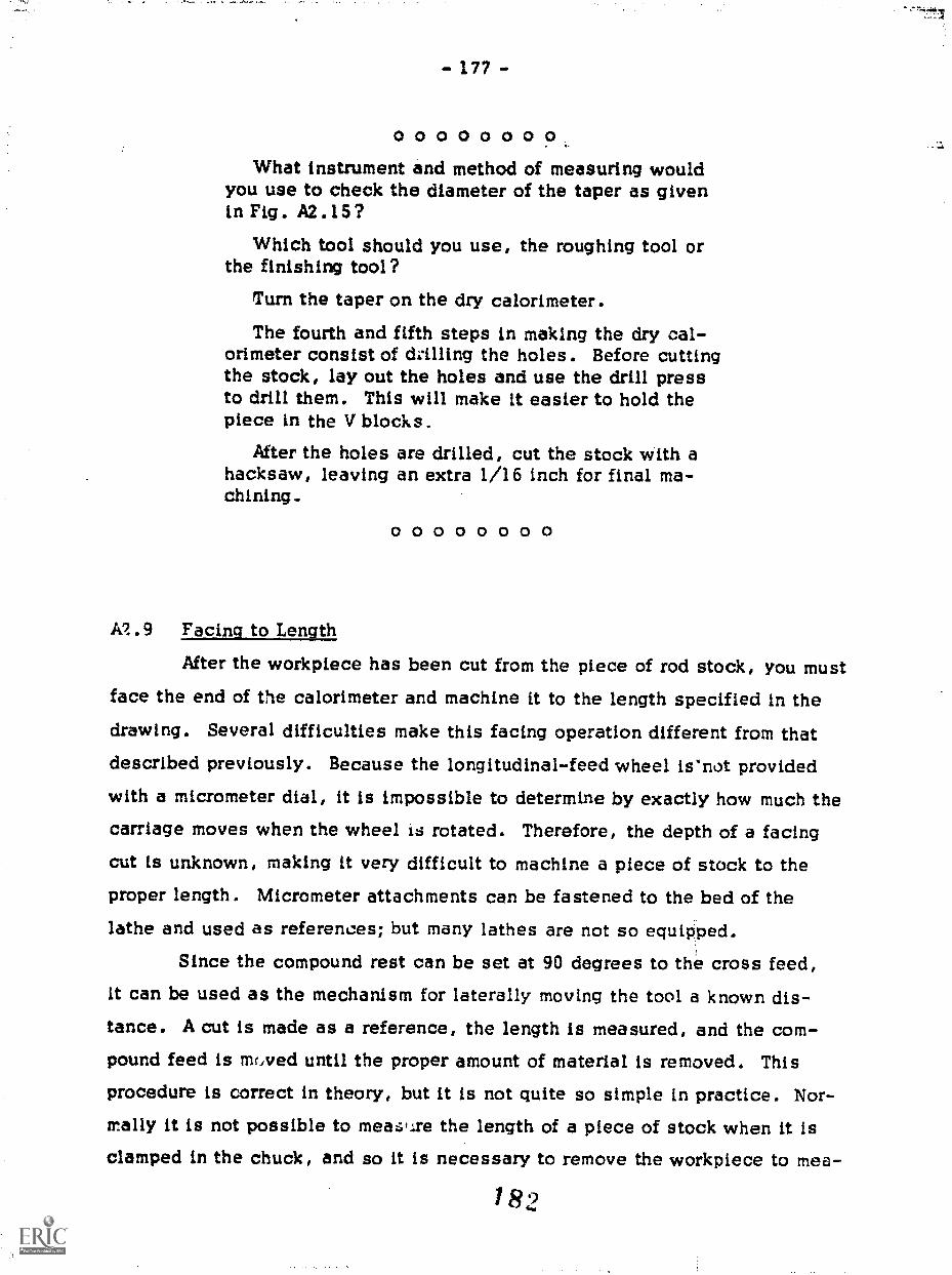
- 177 -
00000000What instrument and method of measuring would
you use to check the diameter of the taper as givenin Fig. A2.15?
Which tool should you use, the roughing tool orthe finishing tool?
Turn the taper on the dry calorimeter.
The fourth and fifth steps in making the dry cal-orimeter consist of drilling the holes. Before cuttingthe stock, lay out the holes and use the drill pressto drill them. This will make it easier to hold thepiece in the V blocks.
After the holes are drilled, cut the stock with ahacksaw, leaving an extra 1/16 inch for final ma-chining.
0 0 0 0 0 0 0 0
A1.9 Facing to Length
After the workpiece has been cut from the piece of rod stock, you mustface the end of the calorimeter and machine it to the length specified in thedrawing. Several difficulties make this facing operation different from that
described previously. Because the longitudinal-feed wheel isInot provided
with a micrometer dial, it is impossible to determine by exactly how much thecarriage moves when the wheel is rotated. Therefore, the depth of a facingcut is unknown, making it very difficult to machine a piece of stock to theproper length. Micrometer attachments can be fastened to the bed of thelathe and used as references; but many lathes are not so equipped.
Since the compound rest can be set at 90 degrees to the cross feed,it can be used as the mechanism for laterally moving the tool a known dis-tance. A cut is made as a reference, the length is measured, and the com-pound feed is mrived until the proper amount of material is removed. This
procedure is correct in theory, but it is not quite so simple in practice. Nor-mally it is not possible to meare the length of a piece of stock when it isclamped in the chuck, and so it is necessary to remove the workpiece to me6-
1 82
- 178 -
sure it. Because it is extremely difficult to reposition the workpiece exactly,
the dial reading on the compound rest is meaningless. To reestablish thefaced surface as a reference, the tool is moved carefully into contact withthe surface, removing as little material as possible. This operation is oftenreferred to as "picking up the edge" and requires a certain amount of experi-ence. Through close observation and/or sensitive hearing it is possible to"pick up an edge" and to remove less than 0.001 inch. Always perform this
operation near the circumference of the stock ratherihan the center, whichis nearly motionless. Move the tool slowly until the smallest chip or parti-cle is removed .1)y the tool. It is sometimes possible to hear the sound of thetool rubbing against the stock even before a chip appears. Once the tool hasbeen set, note the dial reading on the compound-feed dial and determine theamount of feed needed to remove the desired amount of material. The proce-
dure from this point on is the same as that described in Section A2.5with one exception: Instead of the longitudinal feed being used to movtool, the compound feed is used.
Because it is more difficult to make measurements when facing theworkpiece, the operator is often tempted to leave a space between the refer-ence end of the workpiece and the face of the chuck and use a caliper or mi-crometer to measure the piece without removing it from the chuck. This prac-
tice can be unsafe or be the source of error. Always try to position the work-
piece so that the length of material that extends beyond the face of the jaws
is as short as possible. This method is safe and will result in greater accu-
racy.
Each machining operation produces a burr on the corner of the machined
surface. In Project 2, to remove burrs you used a file held at a 45 degree
angle to the surface. A similar procedure is used on the lathe. The sharp
corner i filed off by moving the file perpendicular to the stock with a light,
steady stroke while the workpiece is spun by the lathe. The file shou'd beheld so that the surface that it produces is at 45 degrees to the machined
surfaces. As you can see in Fig. A2.22, care must be taken when deburrinc
with a file. Any loose sleeves or clothing could easily be caught in the chuck

- 179 -
because the left arm passes over the chuck and the headstock. If the strokeof the file Is too long, the right hand could be hit by the spinning jaws.Deburring is one of the most dangerous operations performed on a lathe, andso be very careful, think ahead, and proceed slowly.
To deburr the holes, a countersink can be used, either by hand orwith a drill press.
Fig. A2.22
0 0 0 0 0 0 0 0Face the dry calorimeter to the length shown in
Fig. A2.15. Debur: all corners and holes.Lay out and drill the hole in the back of the dry
calorimeter. DE ..rr the hole to make it easier topress fit the aluminum pin.
Cut a 1/8-inch-diameter aluminum rod to a lengthof 3/16 inch. Face it to length (0.250), bevel (taperwith a file) both ends, and press it into the hol-.1 inthe back of the dry calorimeter. To protect the sur-face, an arbor Dress or a machinist vise egLippedwith soft aluminum jaws may be used.
0 0 0 0 0 0 0
184
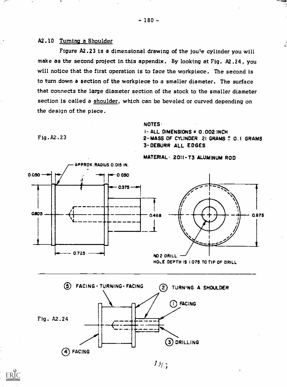
- 180 -
A2.10 Turning a Shoulder
Figure A2.23 is a dimensional drawing of the joule cylinder you will
make as the second project in this appendix. By looking at Fig. A2.241 you
will notice that the first operation is to face the workpiece. The second isto turn down a section of the workpiece to a smaller diameter. The surfacethat connects the large diameter section of the stock to the smaller diametersection is called a shoulder, which can be beveled or curved depending onthe design of the piece.
Fig . A2 .23
APPROX . RADIUS 0.015 IN.
NOTES:
I- ALL DIMENSIONS 2 0.002 INCH2-MASS OF CYLINDER 21 GRAMS t 0.1 GRAMS3- DEBURR ALL EDGES
MATERIAL; 2011-T3 ALUMINUM ROD
1.0-- 0.725NO2 DRILLHOLE DEPTH 15 1.075 TO TIP OF DRILL
® FACING - TURNING- FACING
Fig. A2.24
0 TURNING A SHOULDER
FACING
0 FACING
0 DRILLING
5

- 181 -
There are two methods of producing the shoulder on the joule cylin-der. The first involves the use of the longitudinal feed and the cross feed,and the second substitutes the compound-rest feed for the longitudInal feed.
After facing the end, a mark is made on the stock at the position ofthe shoulder. As the lathe is turning, a line can be drawn around the circum-ference of the stock by holding a pencil or a scriber at the mark. The proce-dure from this point on is similar to the standard turning operation. Material
is removed by moving the tool longitudinally until it reaches the line on thestock. A smooth finish is produced on the shoulder by moving the tool out-ward with the cross feed. The process is repeated until the desired diameteris reached. A vernier caliper or a depth micrometer can be used to measure
the length of the smaller diameter portion and the shoulder can be machined
more if necessary. As you can see, this operation is a combination of twooperations you have already used: turning to reduce the diameter, andfacing to produce a smooth shoulder. If the transition from turning to fac-ing is not immediate the tool will chatter, leaving a rough finish.
The second method is more convenient and faster; however, it is lim-ited for two reasons. First, the compound rest must be set at right angles tothe cross feed. Since this setting cannot be exact, this method is not asprecise as the first. Second, the length of the screw in the compound restlimits the length of the stock that can be turned down.
After the compound rest is set at right angles to the cross feed, setthe dial on the compound rest to zero. Face the stock as you normally would,clamping the carriage on the final cut. Turn down the workpiece by using the
compound-rest feed rather than the longitudinal feed. Because the compound-rest feed is calibrated, Lhe tool can be fed the distance specified in the draw-ing and the shoulder faced using the cross feed as before. When using thisprocedure, allow 0.002 or 0.003 inch for a finish cut. Although the compound-
rest feed is quite precise, you shoul measure the distance to the shoulder tobe sure it is correct.
1 8 6
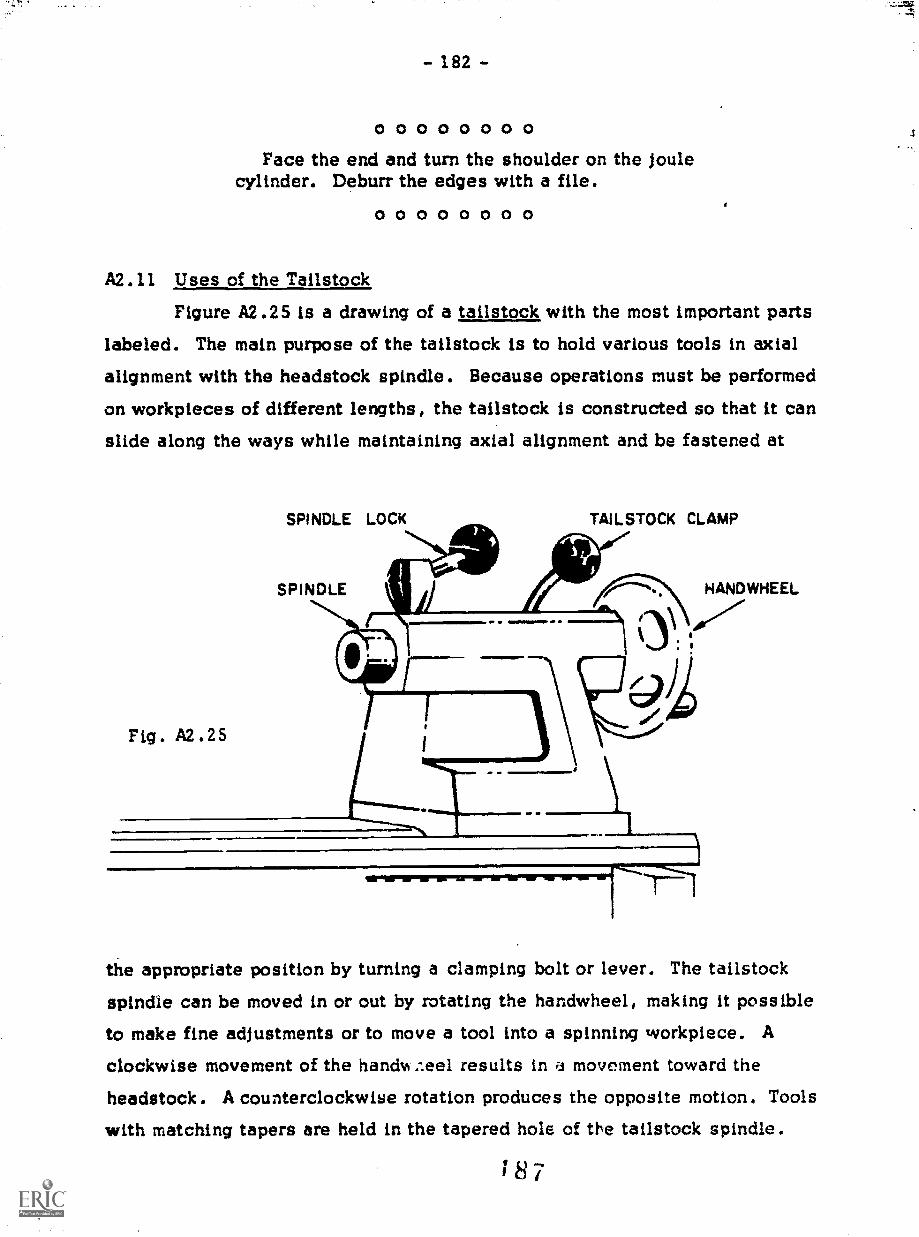
- 182 -
0 0 0 0 0 0 0 0Face the end and turn the shoulder on the joule
cylinder. Deburr the edges with a file.0 0 0 0 0 0 0 0
A2.11 Uses of the TailstockFigure A2.25 is a drawing of a tailstock with the most important parts
labeled. The main purpose of the tailstock is to hold various tools in axialalignment with the headstock spindle. Because operations must be performed
on workpieces of different lengths, the tailstock is constructed so that it canslide along the ways while maintaining axial alignment and be fastened at
Fig. A2.25
SPINDLE LOCK TAILSTOCK CLAMP
SPINDLE HANDWHEEL
o)A
the appropriate position by turning a clamping bolt or lever. The tailstock
spindle can be moved in or out by rotating the handwheel, making it possible
to make fine adjustments or to move a tool into a spinning workpiece. Aclockwise movement of the handm ....eel results in a movement toward the
headstock. A counterclockwise rotation produces the opposite motion. Toolswith matching tapers are held in the tapered hole of the tailstock spindle.
18 7
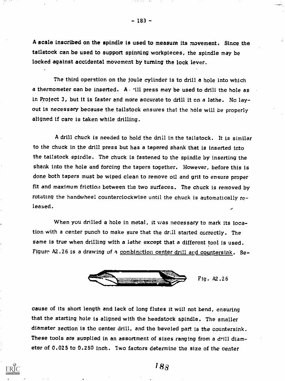
- 183 -
A scale inscribed on the spindle is used to measure its movement. Since thetailstock can be used to support spinning workpieces, the spindle may belocked against accidental movement by turning the lock lever.
The third operation on the joule cylinder is to drill a hole into whicha thermometer can be inserted. A . -ill press may be used to drill the hole asIn Project 3, but it is faster and more accurate to drill it on a lathe. No lay-out is necessary because the tailstock ensures that the hole will be properlyaligned if care is taken while drilling.
A drill chuck is needed to hold the drill in the tailstock. It is similarto the chuck in the drill press but has a tapered shank that is inserted intothe tailstock spindle. The chuck is fastened to the spindle by inserting theshank into the hole and forcing the tapers together. However, before this isdone both tapers must be wiped clean to remove oil and grit to ensure proper
fit and maximum friction between the two surfaces. The chuck is removed by
rotating the handwheel counterclockwise until the chuck is automatically re-leased.
When you drilled a hole in metal, it was necessary to mark its loca-tion with a center punch to make sure that the drAl started correctly. Thesame is true when drilling with a lathe except that a different tool is used.Figure A2.26 is a drawing of a combinetion center drill ard countersink. Be-
;Se ti.Y.V,,":";.:0:7",'
..SN)A1)6Fig. A2.26
cause of its short length and lack of long flutes it will not bend, ensuringthat the starting hole is aligned with the headstock spindle. The smallerdiameter section is the center drill, and the beveled part is the countersink.These tools are supplied in an assortment of sizes ranging from a drill diam-eter of 0.025 to 0.250 inch. Two factors determine the size of the center

- 184 -
drill the diameter of the hole to be drilled and the size of the dead center*of the drill The center drill should be smaller than the diameter of the drill
but larger than the dead center of the drill.Once you determine the proper size, insert the combination center
drill and countersink into the chuck of the tailstock and tighten the chuck
with a chuck key. Then release the tailstock clamp and slide the tailstocktoward the headstock until there is between 1/4 and 1/2 inch clearance 12e-tween the center drill and the workpiece. Tighten the tailstock clamp and,after selecting the proper speed, start the lathe. Feed the center drill intothe stock by turning the handwheel clockwise, but do not drill deeper than
the flutes of the countersink.When drilling blind holes in a workpiece (as in the joule cylinder) use
the scale on the tailstock spindle to determine the de, h of feed. With thespindle set at a major division on the scale (0, 1/2, or 1 inch) slide thetailstock until the point of the drill is flush wIth the end of the workpiece.Tighten the tallstock and feed the drill into the stock the specified amount.Because the smallest division on the scale of the spindle is 1/16 inch, youcannot drill a blind hole with the accuracy that other lathe operations have.To subdivide the 1/16 inch divisions, turn the handwheel a calculated frac
tion of a turn to provide a more precise feed.
0 0 0 0 0 0 0 0Drill the thermometer hole in the joule cylinder.
Deburr the hole with a countersink held in the tail-stock chuck.
0 0 0 0 0 0 0 0
A2.12 Turning Two Shoulders
In the joule experiment, a long piece of nylon line is wrapped around
the cylinder. To keep the line from slipping off, two shoulders are machined
on the cylinder (Step 5). This can be done with either of the grooving tools
shown in Fig. A2.12. One tool has a square nose that produces flat shoulders,
*Refer to Fig. A1.618

- 185 -
and the other has a round nose to produce curved shoulders. Since both toolscut on the side as well as the end, they cain be moved laterally so that tnewidth of the groove is not restricted to the width of the tool. The drawingcalls for a radius in the corners; so therefore a round-nose tool with the prop-ér curve is used.
The onfy difference between this operation and turning one shoulder isthat the cut must begin at a specified position rather than at the end of thestock. The cylinder is held in the chuck by the end that has the small diam-eter, which makes it difficult to perform the operation without the tool holderhitting the chuck. Therefore a specialr utt ing tool is used (Fig. A2.27) that
is really the same as the other groov-ing tools but it is ground at an angleto make the cut easier.
Although you will later measure the shoulders precisely, mark theposition of the shoulders to act as guides for the early cuts. Position thetool as shown in Fig. A2.28. Use the cross feed to move the tool into thework. Allowing a little space for a finish cut, move the tool laterally until its
left edge reaches the line for the sec-ond shoulder. Move the tool towardyou using the cross feed and start theprocedure from the beginning. Contin-
ue turning down the stock until the di-ameter is 0.002 or 0.003 inch over-size. Then measure both shoulders
and face them until they are oversizeby about 0.002 inch. Now make allthree finish cuts at one time by fac-ing the right shoulder to the proper
width, making the finish turning cut,and facing the second shoulder to the proper width. When facing the shoul-ders be careful to remove only the 0.002 or 0.003 inch you have allowed.
Fig. A2.27
Fig. A2.28
1 90

- 186 -
0 0 0 0 0 0 0 0Face the end of the stock to length.
Turn the double shoulders. Since the nylon lineslides on the surface between the shoulders, it mustbe smooth.
Deburr all edges with a file.0 0 0 0 0 0 0 0

Appendix 3: THE CATHODE-RAY OSCILLOSCOPE
The most useful piece of electronic test equipment is the cathode-rayoscilloscope "scope" for short. Whenever a voltage changes too rapidlyto be observed with a DC voltmeter, a scope can show you what is going on.
The principles of its operation are very simple:1. A beam of electrons is fired at a screen that produces
a flash of light whenever an electron strikes it.2. The beam begins at the left side of the screen and
produces a trace as it moves across at a constantrate a rate that can be set over a wide range of val-ues. Therefore, if the beam takes 0.1 sec to crossthe screen, the length of the trace represents 0.1sec. If the sweep time is 1 millisecond, the tracerepresents 1 msec, and so on. (The sweep rates areusually given in time per division because the screenis scribed with a grid.)
3. The voltage being measured causes the beam to be
deflected vertically. Thus the final scope tracegives a picture of the voltage (vertical deflection) asa function of time (horizontal deflection).
Except for special oscilloscopes that can store anddisplay a single trace of the electron beam, whatyou actually observe on the screen is the result ofrepeated traces of the same signal. Thus the voltageto be studied must be periodic and be synchronized
to the sweep of the beam so that each trace will co-incide with the previous one.

- 188 -
Knowing how an oscilloscope functions is hardly sufficient when the
time comes to use one. What you need to know then is which knob controls
which function, and so we wili Icok at the oscilloscope from this point of
1. The Beam
The only external controls over the electron beam itself are theknob that changes the beam's intensity and the one used to adjust the focus.
2. The Time Base
The sweep of the beam is controlled by a group of circuits thatare referred to as the time base. For some scopes the knob that sets thesweep speed is calibrated and reads directly in time per division (roughlyfrom 1 sec/div to 1 psec/div). For other scopes two knobs are used: Onesets the general range of the sweep, and the other is used to make fine, un-calibrated adjustments. To shift the entire pattern to the right or the left ahorizontal positioning knob is provided.
3. The Vertical Input
You connect the scope to an external circuit by means of thevertical input terminals. The ground connection should be clearly indicated.
A range switch is used to match the incoming signal to the input circuitry.
On some scopes the range switch is calibrated in volts per division; onothers the range is set by a continuous, uncalibrated control.
Another knob, in addition to the range selector, is adjusted toposition the trace up or down.
4. Synchronization and Trigering
Basically there are two ways to synchronize the sweep of theelectron beam with the input signal. A trigger circuit is the easiest to ad-just but is expensive to produce. The scope waits for a sigral of a certainsize and a certain polarity before the sweep is initiated, and so you mustadjust the trigger level, the voltage necessary to start the sweep, and theslope, which makes the sweep begin on either positive or negative signals.There may be other adjustments but these are the basic ones.
- 189 -
The sweep speed of the beam is determined by the time base
selector. You can decide whether you want to observe one cycle of the sig-nal, or a fraction of a cycle, or several cycles.
For scopes that do not have a trigger circuit, the beam continu-ally sweeps at a constant rate. Thus the sweep speed must be adjusted until
the pattern appears stationary on the screen. The time base is not calibrated,and so an external signal of known frequency is required when quantitativetime measurements are made.
For both types of LI ..pes, there is another set of terminals marked
"External Sync" or "External Trigger." Using this input the beam sweep issynchronized to the external signal.
00000000Use your oscilloscope to look at the output of a
sine-wave signal generator. Set the generator for1000 Hz, and adjust the oscilloscope controls todisplay approximately five sine-wave cycles. Whatis the period of each cycle?
If the signal generator has a square-wave outputlook at it at UM Hz. How can you tell where zerovolts is?
If your scope accepts DC input voltages, you canuse a flashlight battery to check the calibrations ofthe vertical deflection. With zero input a straic"tline appears across the scope face. Now apply aDC voltage either positive or negative to.the in-put terminals and observe the deflection. How goodis the scope's calibration? What is your estimateof the accuracy of a voltage measurement?
0 0 0 0 0 0 0 0

- 191 -
NOTES TO THE INSTRUCTOR
The text is divided into three sections: woodworking and metalwork-ing, electronic circuits, and glassblowing. Each consists of a series ofprojects that teaches the students to develop the skills needed to performoperations with a variety of tools. Every tool is described as it is used toperform an operation. After a tool and the operation are discussed, a seriesof instructions set off from the text by circles (o 000000 o) areprovided to tell the students how .to apply the information to build the proj-ect. These sections often include questions that encourage them to proceedthoughtfully.
The students' backgrounds will differ enormously depending on theirprevious experience with the materials being discussed. Therefore, the for-mat of the text is designed so that a student can be somewhat independentof the instructor. This allows the instructor to spend more time with the lessexperienced students while the others continue at their own pace.
The entire course can be taught in approximately 90 hours, with eachclass period being at least two hours long. About half the time is needed forwoodworking and metalworking, with the remainder divided equally betweenelectronic circuits and glassblowing.
To assist you in prepthations kr the course, a brief explanation andlists of materials and tools are provided for each project. The sizes of thetools are intended as guidelines Other sizes can be substituted if the toolsare already available.
WOODWORKING AND METALWORKING
Because many of the techniques used in working metal and wood aresimilar, woodworking and metalworking have been combined into one section.kithough some of the projects use only wood or only metal, others requirethat both materials be used.
1 9 5

- 192 -
Most woodworking and metalworking hand tools are used in making
the projects in this part of the text. Because of cost factors, the power toolsthat are used (drill press, belt sander, and table saw) are oriented more forworking wood than for metal.
The facilities should be as spacious as possible with plenty of room
around the power tools, especially the table saw. Workbenches equippedwith machinisc's and woodworking vises should have durable hardwood tops.
Because it is easier to cut a board with a handsaw when the board is belowwaist 'evel, be sure to have sawhorses or low stools available.
The quantities of tools needed to teach the course depend on the sizeof the class and the number of students that perform the same operation at
the same time. Therefore, as projects continue, fewer multiples of tools arerequired. Each student should have access to a handsaw, a plane, and asquare because the operations that use them are very time-consuming. Thedrilling operation, however, takes a very short time, and so only a few braceand bit sets are needed.
Prolect 1
By constructing the laboratory stand the students are introduced to
more than the hand tools used to build it. They acquire a feeling of how to
approach a project and the correct sequence of operations from the way the
text and the instructions are presented.As a substitute for the plane, the belt sander is used in the first proj-
ect to finish end grain of boards. In the past, we found that students became
discouraged because of the amount of time needed to do a good job with a plane.
To help the students better understand shop sketches, make someblocks of wood with two holes drilled in it. (One of the holes can be coun-
terbored.) Give one to each student, and have them make a 3-view sketchthat gives all the information required to build the block. In this exercisethe emphasis should be on the communication of information rather than on
the making of precise mechanical drawings.
- 193 -
Materials needed per student
2 x 4 fir or spruce, approximately 8 ft
1 x 4 common pine, approximately 6 ft
General supplies4d or 6d cement-coated box nails
Sandpalier, medium and fine grit
Wood glue, Elmer's brand or equivalent
Tools needed
Auger bit, 5/16-in. diameterBelt sander
Brace
Crosscut handsaw, 24 in., 10 or 12 pointsHammer, 16 oz
Plane
Square
Steel rule, 6 in.Tape measure
Project 2While working on the densiL,>. kit the students should make two major
observations; Because metal is harder than wood, more time is needed towork it; and metal can be worked to closer tolerances.
To give the students practice in using vernier calipers and microm-eters and in making shop sketches, supply students with pieces of scrapmetal of various shapes and have them make a shop sketch with the dimen-sions they have measured. Check each piece and have the students ri-ned-sure if necessary.
Materials needed per student1/2-in. square 2024-T4 aluminum bar stock, 1 in.1/2-in, square cold-drawn steel bar stock, 1 in.1/4 x 1-in rectangular 2024-T4 aluminum bar stock, 1-1/2 in.
- 194 -
General supplies
Dykem blue or equivalent
Tools needed
Combination square
File, assorted sizesFile card
Hacksaw
Micrometer
Scriber
Vernier caliper
Prolect 3
The elasticity apparatus is the first project in this text that uses
wood and metal. The text for this project also includes a greater amount of
information than any of the projects in this section.If a wire-bending brake is not available, the guide arm for Project 1
and the pointer for the elasticity apparatus can be bent by using a machinist'svise and a hammer. After marking the position of the bend, the shorter endof the stock is placed in the vise with the mark at the edge of the jaws.Pressure is applied to the free end of the rod with the left hand and the bend
is made by striking the rod, close to the jaws, with a hammer.
If you find it difficult to get the 3/16-inch-diameter brass tubing,tension pins having a 3/16-inch diameter and a 0.022- or 0.028-inch wall
thickness can be substituted. Because they can be purchased in 1/2-inch
lengths, tension pins require no additional work.
Materials needed per student2 x 3 spruce or fir, 2 ft3/4-in.-diameter 6061-T6 aluminum rod, 1/2 in.1/8-in.-diameter cold-rolled steel rod, 15 in.3/16-in.-diameter cold-rolled steel rod, 12 in.
8-32 x 1/2-in. R.H. steel machine screw8-32 x 1/4-in. R.H. steel machine screw

- 195 -
8-32 x 2-1/2-in. R.H. steel machine screw8-32 wing nut
4 No. 8 brass washers
3/16-in.-diameter, thin-walled brass tubing, approximately 2 in.
General supplips
Dykem blue
Sandpaper
Tools needed
Belt sander
Center head for combination squareCenter punch
Combination square
Die, 10-24 N.C.Die stockDrill press
Hand drill
Handsaw
Micrometer or vernier caliperPlane
Scriber
Steel rule, 6 in.Tap, 8-32 N.F.Tape measure
Tap handle
mwist drills, number and fraction sizesV blocks
Wood chisel, 1/4 and 3/4 in.
Project 4
In making the wooden frame the students will use the table saw forthe first time. Because of the danger involved, this is one of the few times
1 99
- 196 -
where it is necessary for you to give a demonstration, followed by each stu-dent making a few practice cuts. Be very critical of every student's actions
near the table saw. Note such things as (1) the way they hold the board and
move their hands, (2) where they stand, (3) the rate at whicl, they feed the
stock into the blade, (4) how they switch off the machine, and (5) how they
approach the saw when someone else is using it. All of these points areimportant for safety.
Materials needed per student
1 x 4 select pine, 4 ft
General supplies
Wire nails
Wood glue
Tools needed
C-clamps
Combination square
Hammer
Sandpaper
Steel rule, 6 in.Table saw, with mitre gauge and rip fence
Tape measure
Project 5_
Have each student write a detailed description of the operations used
in making the test-tube rack. Insist that they describe everything, including
such things as which side of the saw blade is used when setting the rip fencefor a sawcut. This description by your students willeassure you and them asto whether or not each one understands the use of the table saw and the drill
press.
Materials needed per student
2 x 4 flr or spruce, 1 ft

- 197 -
Tools needed
Belt sander
Drill press
Power bit, 13/16-in. diameterSandpaper
Steel rule, 6 in.Table saw
,Project
The write-up of the lab cart should be as complete as the descriptionfor the test-tube rack. Some minor details have been deliberately omitted toencourage some thought by the student.
Materials needed per student2 x 4 fir or spruce, 1 ft
1/4-in.-diameter wood dowel!, 6 in.1/2-in.-diameter wood dowell, 7 in.8-32 x 1-3/4-in. F.H. steel machine screw
8-32 steel hex nut2 1/4-20 x R.H. steel machine screws2 1/4-20 steel square or hex nuts3 1/4 x 1-1/4-in. R.H. wood screws2 No. 6 x 1/2-in. R.H. wood screws
2-in. steel mending plate
O.D. steel tubing (electrical conduit), 9 in.3 Roller skate wheels
Compression spring
Tools needed
Belt sander
Countersink
Drill press
Drill sets, fraction and number sizes
2k11

File
File cards
Hacksaw
Pliers or wrench
Screw driver
Steel nile, 6 in.Table saw
Tape measure
V blocks
- 198 -
ELECTRONIC CIRCUITS
4-
The projects in this section are designed to teach the student how to
assemble a circuit from a list of components and a circuit diagram. There-fore, the descriptions of the components and their uses are intended to help
the student recognize the components rather than provide a complete under-
standing of the functions of each. Circuit explanations are included for
those students who are interested.Along with a signal generator, an oscilloscope is used to investigate
some of the components and to check circuits. An appendix is provided to
introduce the oscilloscope as a tool for measuring voltage as a function of
time.
Project 7While building the neon blinker, the students will le irn five skills
that are essential for the construction of any electronic device: (1) to recog-
nize components; (2) to read circuit diagrams; (3) to lay out the components
in a practical arrangement; (4) to make good solder joints; and (5) to test the
circuit and determine if it works correctly. All of these skills are reinforced
by the projects that follow.The students should use an ohmmeter to determine the correct termi-
nals for connecting the switch and potentiometer (Fig. 7.10).

- 199 -
Because the push-in terminals protrude through the perforated bread-board, feet are needed to suspend the board above the table top. We suggestwooden or metal strips that can be fastened to the board by nails or screws.
The mounting brackets for the potentiometer and the switch can bemade from aluminum sheet stock.
Materials needed per student470 K2 10% 1/2-watt carbon resistor100 MI 10% 1/2-watt carbon resistor1 megohm potontiometer. 01 i4f 200 V paper capacitor
. 1 mf 200 V paper capacitor
1 id 200 V paper capacitor
1-pole, 3-position rotary switchNE-2H 1/4-watt neon bulb
2 Mounting brackets
4 X 5 in. piece #64A18 Vectorboard
General supplies
Assorted lead wire
Nuts and screws for mounting brackets
Push-in terminals, Vector ikT9.4
Solder, 60% tin-40% lead
Tools needed
Hammer, small
High-voltage power supply, 100 VDCOscilloscope
Pliers, diagonal-cutting and needle-noseSoldering iron
Wire stripper
23

- 200 -
Project 8
The construction of the electronic power supply introduces new com-
ponents and different uses of components from the previous project. The bi-
polar-power stspply is used for the final project in this section of the course.The design and construction of the case for the power supply, which
should be the responsibility of each student, is an opportunity to put intopractice some of the skills learned in the course.
Materials needed per student
2 10 kg 10% 1/2-watt carbon resistors
100 Id/ 10% 1/2-watt carbon resistor
5 kfl 1/2-watt potentiometer
2 1000 1.4f 25 V electrolytic capacitors
4 1N3193 diodesFilament transformer, 117 V primary, 12.6 V center-tap secondary
NE-2H neon bulb
SPST switch
Line cord
Line plug
Black 3-way binding post
Red 3-way binding post
Blue 3-way binding post
Vectorboard
General supplies
Assorted lead wire
Lumber supplies for the case
Push-in terminals
Solder

- 201 -
Tools needed
Ammeter, 30-50 ma full scaleDrill press
Oscilloscope
Pliers, diagonal-cutting and needle-noseScreWdriver
Signal generator
Soldering iron
Table saw
Voltmeter, 10 V full scale
Wire stripper
Prof ect 9
Since integrated circuits have become widely used, a new dimensionhas been added in the field of electronics. No longer must a person be anengineer to design and to use simple electronic circuits. References nowexist that include hundreds of circuit diagrams that use an integrated circuitas the core of the device.
Perhaps the most useful integrated circuit for the science teacher isthe operational amplifier. Its versatility makes it possible to construct many
different devices with only a few additional components.
The first part of the project is to construct a breadboard for the op-amp that will accept a variety of circuit components and configurations.
Following the construction of the breadboard, we have included a few circuitsas examples of possible uses of the op-amp.
Materials needed per student
150 Jd2 10% 1/2-watt carbon resistor
4 kV 10% 1/2-watt carbon resistor
47 K2 10% 1/2-watt carbon resistor
5 kfl 1/2-watt potentiometer
1 megohm 1/2-watt potentiometer
741 operational amplifier2tiS

- 202 -
Selenium or silicon photocell,Radio Shack #276-115 orInternational Rectifier #S0505E1OPL
4 Red 3-way binding posts
2 Black 3-way binding posts
Vectorboard
General supplies
Push-in terminals
Solder
Tools needed
Drill press or electric hand drillPliers, diagonal-cutting and needle-noseSoldering iron
Wire stripper
GLASSBLOWING
Projects 10-13
The techniques used in glassblowing are more difficult for the student
to master than any of the other techniques taugh !n this course. The key to
glassblowing is learning how to handle a substance whose properties change
as it is being worked. Consequently, students make frequent mistakes whileacquiring the necessary "feel" for.working glass. Because a student's mis-take can ruin a project that has been worked on for some time, the glassblow-ing section begins with a series of practice operations. Students will stillmake frequent mistakes, but hopefully some of the frustratiln can be avoided.
By the time the students begin the projects that follow, they should
have acquired the necessary "feel" and confidence that will enable them to
do a good job.In this section the students are learning scientific rather than artistic
glassblowing, and so we have chosen to teach only the techniques used forworking borosilicate glass. Emphasize slow heating and proper annealing ofglass joints and mention that much more care must be taken in these steps if
the student ever uses soda-lime glass.2 "I ,)

- 203 -
The most important exercise in the glassblowing section is the firstone constricting glass tubing. If students understand what is happeningand can constrict the tubing properly, they have come a long way in learn-ing how to work glass.
A cless of students can work at the same time if you make two mani-folds: One for natural gas and the other for oxygen. One oxygen tank andregulator are able to service many stations, but each station should haveseparate valves to reduce the possibility of accidental leaks.
Quantity of Pyrex glass per student for Projects 10 through 136-mm-diameter tubing, 12 ft
7-mm-diameter tubing, 12 ft
8-mm-diameter tubing, 12 ft
9-mm-diameter tubing, 4 ft
10-mm-diameter tubing, 8 ft
12-mm-diameter tubing, 4 ft
14-mm-diameter tubing, 4 ft
25-mm-diameter tubing , 8 ft
30-mm-diameter tubing, 4 ft
6-mm-capillary tubing, 2 ft3-mm-diameter rod, 2 ft
Luiament needed for ea cljalow in stationAsbestos sheet or Transite, for table top
Asbestos tape, 1 in. wideCarbon block, 1 in. squareCarbon rod,' 1/4-in. diameterCork borer
Corks, assorted sizes for all glass tubfngFile, triangular
Hand torch, with assorted tips
Mouthpiece, for blowing hose
Rubber tubing, assorted sizes
7

- 204 -
Safety glasses, didymium, regular and clip-onSwivel, glassblowing
Torch holder
Twin hose, for oxygen-gas torch
APPENDIX 1: Sharpening Tools
The first appendix is meant to be used for student reference. Stu-dents should be able to recognize dull tools, know which tools can be sharp-ened, and know how to sharpen them. The cutting tools that have been usedin this course are listed, and brief descriptions of sharpening procedures areincluded.
APPENDIX 2: Operations on a Metalworking Lathe
The lathe is a very costly piece of equipment and may not be readily
available. However, because knowledge of operations that can be performed
on a metalworking lathe is invaluable in the construction of any equipment,
we have chosen to include a section on the lathe. This appendix can be usedas a reference for interested students or, if a lathe is available, ar supple-mentary exercises after students have completed the previous projects.
The methods for the precise layout of the holes in the dry calorimeter
have not been described in the text. Therefore, the method the student willuse depends on the tools available in your shop.
We have not mentioned power feeds for the lathe. However, if youfind it convenient you might mention their existence and their uses.
Materials needed per student
7/8-in.-diameter 2011-T3 aluminum rod, 3 in.
1/8-in.-diameter 2011-T3 aluminum rod, 3 in.
General su_pplies
Dykem blue
:"}

- 205 -
Equipment needed
Arbor press (if available)
Center head
Center punch
Combination center drill and countersink
Combination square
Countersink
Drill press
Drill sets, fractional and numberFacing tool
File
Finish-turning tool
Hacksaw
Lathe with 3-jaw chuck
Machinist's viseMicrometer
Rough-turning tool
Scriber
Special-turning tool for joule cylinder
Surface gauge
Surface plate
V blocks
Vernier caliper
APPENDIX 3: The Cathode-Ray Oscilloscoye
One of the instruments used in the electronic circuits section of thetext is the oscilloscope. This appendix is provided as a reference for stu-dents who have no previous experience with a scope.
Because brands of scopes differ, the description in the appendix pro-vides the student with a general understanding of the functions of an oscillo-scope. Later the student will have to learn the specific capabilities of theinstrument that is available in their laboratory.
2449

Abrasives, 22
Aluminum, cutting and filing,30-33, 35-36
Annealingglass, 124-125steel, 148
Assembly drawings, 8elasticity apparatus, 63laboratory cart, 82laboratory stand, 28
Auger bits, 19-20drilling with, 20-21sharpening, 156-157sizes of, 19
Belt sander, 15-16sanding with, 16-17
Bench grinder, 148-149
Bending glass tubing, 125-128
Bevel, defined, 17
Bipolar, defined, 99
Bipolar power supply, 103-104circuit diagram, 104
Bits, lathe tool aga cuttingtool, lathe.)
Bladescircular, 66-68
adjustment of, 67, 71-72hacksaw, 35sharpening of, 157
Block plane, 12
Brace, 19-20drilling with, 19-21
- 207 -
INDEX
Brads, 24sizes of, 24
Breadboard, 86
2
Calipers, vernier, 39-42
Capacitance, 90
Capacitors, 90-91charging of, 90electrolytic, 90filtering with, 102symbol for, 90
Carb ln content of steel, 148
Carpenter's vise, illustrated, 13, 17Capillary tubing, sealing of, 130
Carriage, lathe, 160, 166, 167
Cathode-ray oscilloscope, 187-189
Center punch. 59sharpening of, 157
Center drill, 183
Chamfer, 17
Chamferingwith plane, 17with table saw, 71for threading, 56
Chisel, wood, 52-53sharpening of, 149-151
Chucks, drillingbrace, 20drill press, 48hand drill, 46lathe, 183
0

- 208 -
Chucks, lathe, 161-165moLnting stock in, 161-165four-jaw, 163-1 64universal, 1 61
Circuit diagrams, 86bipolar power supply, 104current-to-voltage converter,
110, 111. 112fixed neon blinker, 86inverting amplifier, 114multivibrator, 114noninverting amplifier, 112photoelectric switch, 113photometer, 110, 111, 112variable neon blinker, 95
Circular saw (age table saw.)Circular saw blades, 66-72
adjustment of, 67, 71, 72sharpening of, 1 57
Clearance angle, defined, 151for lathe tool, 1 69
Clearance fit, 4 9, 51for machine screw, 62for wood screw, 78
Clearance holefor machine screw, 62for wood screw, 78
Cold trap, construction of, 143-144
Collets, lathe, 162-163Color code, resistor, 88
Combination center drill andcountersink, 183
Combination square, 5for layout, 6, 19center head, 60-61
Common nails, 23, 24
Compound feed, lathe, 166
Compound rest, lathe, 160, 166-167
Condenser, construction of, 14 5-146
Constricting glass tubing, 122-124
Construction, circuit, 91-93
Counterboring, with drill press, 61-62Countersink, 80, 183
Crosscut saw, 4
Cross feed; lathe, 166
Cross slide, lathe, 1 66
Cutting glass tubing, 121-122Cutting speeds
for drills, 40-50for lathe, 171
Cutting tools, lathe, 165
Dead center, twist drill, 154Deburring
metal, 33, 178, 179wood, 22
Density kit, construction of, 29-42Didymium goggles, 121
Die stock, 55-56Dies, 55-56
Dimensions, decimal, 34
Diodes, 101-102
Distilling column, construction of, 139-141Drawfiling, 32
Drawings, shop, 8cold trap, 144condenser, 14 6density kit, 29distilling column, 141dry calorimeter, 168elasti.city apparatus, 51, 58, 63frame, 65joule cylinder, 180laboratory cart, 81laboratory stand, 11test-tube rack, 76

Dressing grinding wheels, 149
Drill chuck, lathe, 183
Drill gauge, 78
Drillingwith brace and bit, 19-21with drill press, 47-49
counterboring, 62flat stock, 48-49round stock, 58, 60
with lathe, 183-184
Drill press, 47-49for counterborirtg, 62
Drill-point gauge, 155-156Drills
auger bits, 19-20power bits, 75sharpening of, 151-157twist, 43-46
Drill speeds, 49-50Drill vise, 60-61
Dry calorimeter, construction of,159-179
Elasticity apparatus, constructionof, 43-63
Electrolytic capacitor, 90
Electron beam, oscilloscope, 187
Emery paper, 22
End grain, finishing ofwith belt sander, 16-17with plane, 17-18
End-to-end seals, 128-133, 140External thread, 54-56
- 209 -
Facing, on lathe, 168-171to length, 177-178
Feeds, lathecalibration of, 174types, 160, 166-167
File card, 32
Filescleaning of, 32for cutting glass tubing, 121-122to start hacksaw, 36Swiss pattern, 33types and sizes, 30-31
Filing, 31-33deburring, 33, 178-179drawfiling, 32on lathe, 178-179
Filtering, electronic, 102
Finishing nails, 23, 24, 25Finish turning, lathe, 172
Fire cutting, glass tubing, 122, 139near end of tube, 140
Fitsclearance, 49, 51interference, 49, 51, 52
Flashback, torch, 118, 119
Flat-head nails, 24-25Frame, construction of, 65-74
Full-wave rectifier, 103
Gain, voltage, 112
Garnet paper, 22
Glassdistinguishing types, 118types of, 117

ass tingannekling of, 124-125bending of, 125-128constricting of, 122-124cutting of, 121-122flaring of, 130, 131joining of, 128-137
end-to-end, 128-133inside of, 136-137 .
at right anglvs, 133-135making holes at,' 132, 134, 13P
Gluing wood, 27-28
Goggles, glassblowing, 12i1Grt,i,K0-.4Nbench, 148-149
Grinding wheelsclassificaiion of, 149dressing cif,, 149
it ,
grinding wheels, 149sarlipaper. 22,
9rtaince electrical. 96
,.Hacksaw, 35
bladed! 35
41,
/ cutting with, 16Half-wave rectifier, 102
Hammer, 25-26
Hand drill, 46
Handsaw, 3-5cutting with, 5sharpening, 157for slotting, 52-53
S.
- 210 -
Headstock, lathe, 160, 161
Heat treatment, steel, 148
Horizontal deflection, oscilloscope,187
Independent chuck, lathe 43-164
f 111 '...= 4iLI:..001,
Interference fit, 49, 51-52
Internal threads, 54, 57-58Inverting amplifier, 114
Inverting input, 108
Jack plane, 12mt.Jointer plane, 12
Joule cylinder, construction of, 180-186
Laboratory cart, construction of, 71 litiiLaboratory stand, construction of, 3-28
Lathe, metalworking, 159-186bed, 160carriage, 160, 166, 167chucks, 161-165, 183collets, 162-163compound rest, 160, 166, 167cutting
a shoulde , 180-181speeds, 1 .1a taper, 175-176
cutting tools, 165drilling oii,'183-184facing on, 168-171feeds, 160, 166-167filing on, 178, 179finish turning, 172headstock, 160, 161independent chuck, 163-164mounting workpieces in a chuck, 161-165rough turning, 172safety, 171tailstock, 182-184taper turning, 175-176tool bits, 165tool holder, 166universal chuck, 161
Layoutof holes, 18tn metal, 34
5 f

Line symbols, 9-10
Line voltage, 100
Longitudinal feed, lathe, 166
Lumber, sizes of, 27
Machinist's vfse, illustrated.Machine screws
clearance drill for, 51counterboring for, 61-62sizes, 51-54tap drill for, 57
Marking gauge, 18
Measuring, precision, 37-42depth of holes, 42hole diameter, 41inside dimensions, 41length of shoulder, 42outside dimensions, 38, 41
Micrometer, 37-38
Mitio gauge, 16-17, 66, 72-74
Multivibrator, 114
Nails, 23-25removing of, 26, 27used with hammers, 26-27
Nail set, 23
- 211
Ohm's law, resistance, 87
Oilstone, 150-151
Operational amplifier, 107-115
Oscilloscope, 187-189
31 Perfboard, 86, 104
Photoelectric switch, 113-114
Photometer, construction of, 110-112circuit diagrams
single stage, 110single stage-zero adjust, 111two stage, 112
Pilot holewood screw, 78nail, 25
Pilot light, neon, 94, 104
Plane, 12-14, 17cutting with, 12-14, 17for end grain, 17
Points per inch, defined, 4
Potentiometer, 89-90
Power bits, 75shamening of, 151-154
Power supply, construction of, 99-105circuit diagram, 104
Primary, transformer, 101National Course threads, 54-58National Fine threads, 54-58
Neon blinker, construction of, 85-98circuit diagrams
fixed frequency, 86variable frequency, 95
Neon bulbs, 93-94
Noninverting amplifier, 114Noninverting input, 108, 111
Rabbet cut, 71-72
Rectification, 102
Reference surface, defined, 6
Regulator, oxygen, 120Relief angle, 151
Resistance, Ohm's law, 87

Resistorsas bleeder, 105color code, 88fixed 87-89variable, 89-90
Ring seals, 121, 136,137shrink type, 145-146
Rip fence, table saw, 66-72
Ripple, voltage, 102
Ripsaw, 4
Rough turning, on lathe, 172
Sanding, 22
Sandpaper, 22
Saw bladescircular, 66-68, 71,hacksaw, 35sharpening of, 157
Sawshacksaw, 35handsaw, 35-table saw, 66-74
Schematic, 86
- 212 -
Sharpening tools, 147-158Shoulder
machining ot 180measuring a 42
Shrink ring seal, 145-446
Signal generator, 101, 102, 189
Slottingwith chisel and handsaw, 52-53with table saw, 71-72
Smoothing plane, 12
Solder, 91
Soldering, 91-93semiconductors 109
Soldering iron. 91
Speeds72 chart of, 50
for drill press, 49for lathe, 171
Square, definition, 7
Square (tool), 5-6,19, 59
Square-wave generator, 114
Steel, tool, 148
Stock, definition. 3Swiss-pattern files, 33
Synchronization, oscilloscope, 188
Screwdriversharpening of, 158
Screw threads, machine screw,54-58
Scriber, 34sharpening of, 157
Seals, glass tubingend-to-end, 128-133ring, 136-137
133-135
Secondary, transformer, 101
Setcircular saw, 67hacksaw, 35handsaw, 4
Table saw, 66-74chamfering, 71crosscuts, 72-74rabbet cut, 71-72ripping, 67, 69-70slotting, 71-72
Tailstock lathe, 182-184Tang, auger bit, 19
Taper turning, lathe, 175-176
Tap, thread, 57-58
Tap drill size, 57
Tap handle, 58
Tapping, holes, 57-58
Test-tube rack, construction of,75-76
Threads, machine screw, 54-58external, 54-56internal, 54, 57-58
Time base, oscilloscope, 188
Tinning, solder, 92
Tolerances, 34
Tool bits, lathe(au cutting tools, lathe.)
Tool holder, lathe, 166adjustment of, 166, 168-170
Tool post, lathe, 166
Tools, sharpening of, 147-158Tool steel, 148
Torch, glassblowing, 118-120
Transformer, 100-101
Triggering, oscilloscope, 188
Triple seal (agg Ring seal.)Try square, 5
- 213
seal, 133-135, 141, 143Turning, lathe, 172-176
one shoulder, 180taper, 175-176two shoulders, 184
Twist drills, 43-46sharpening of, 151-154speeds for, 50
Universal chuck, lathe, 161
V blocks, 59-60
Vernier calipers, 39-42
Vertical input oscilloscope, 187Vises
carpenter's, 13, 17drill press, 59, 60
machinist's, 31
Ways, lathe, 166
Wire, hook-up, 91
Wire stripper, 92
Wood chisel, 52-53sharpening of, 149-151
Wood screws, 77-80