Embed Size (px)
Citation preview
DOCUMENT RESUME
ED 092 690 CE 001 419
TITLE; Aircraft Fuel, Hydraulic and Pneumatic Systems(Course Outlines), Aviation Mechanics 3 (Air Frame):9067.01.
INSTITUTION Dade County Public Schools, Miami, Fla.PUB DATE 71NOTE 36p.; An Authorized Course of Instruction for the
Quinmester Program
EDRS PRICE MF-$0.75 HC-$1.85 PLUS POSTAGEDESCRIPTORS *Aviation Mechanics; *Aviation Technology; Course
Content; Course Objectives; *Curriculum Guides;*Equipment Maintenance; Job Skills; PerformanceCriteria; *Technical Education
IDENTIFIERS *Quinmester Program
ABSTRACTThis document presents an outline for a 135-hour
course designed to familiarize the student with the operation,inspection, and repair of aircraft fuel, hydraulic, and pneumaticsystems. It is designed to help the trainee master the knpwledge andskills necessary to become an aviation airframe mechanic. Theaviation airframe maintenance technician must be able to demonstratehis ability to troubleshoot, service, and repair aircraft fuelsystems; his ability to troubleshoot, remove, and install aircraftfuel components; his ability to troubleshoot, service, and repairaircraft hydraulic and pneumatic systems; and Ais ability totroubleshoot, remove, and install aircraft hydraulic and pneumaticsystem components. The behavioral objectives and performancestandards necessary for a person to become an airframe mechanic, or acombined airframe and powerplant mechanic, with a Federal AviationAgency license are specified. A Quinmester posttest sample isincluded. (KP)
AUTHORIZED COURSE OF INSTRUCTION FOR THE
AVIATION MECHANICS 3 (Air Frame)(Aircraft Fuel, Hydraulic and Pneumatic Systems)
a il41cop,4411,
tA)
Department 48 - Course 9067.01
DIVISION OF INSTRUCTION 1971
DADE COUNTY PUBLIC SCHOOLS1 4 1 0 NORTHEAST SECOND ENUE
MIAMI, FLORIDA 33132
Course Outline
AVIATION MECHANICS 3 (Air Frame)(Aircraft Fuel, Hydraulic and Pneumatic Systems)
Department 48 - Course 9067.01
the division of
VOCATIONAL, TECHNICAL AND ADULT EDUCATION
DADE COUNTY SCHOOL BOARD
Mr. William Lehman, ChairmanMr. G. Holmes Braddock, Vice-Chairman
Mrs. Ethel BeckhamMrs. Crutcher Harrison
Mrs. Anna Brenner MeyersDr. Ben Sheppard
Mr. William H. Turner.
Dr. E. L. Whigham, Superintendent of SchoolsDade County Public Schools
Miami, Florida 33132
Published by the Dade County School Board
Copies of this publication may be obtained through
Textbook Services2210 S. W. Third StreetMiami, Florida 33135
Course Description
Aircraft Fuel, Hydraulic9067 48 9067.01 and Pneumatic Systems
State Category County Dept. County Course Course Title
To familiarize the student with the operation, inspectionand repair of aircraft fuel, hydraulic and pneumaticsystems.
Indicators of success: Successful completion of ALLquinmesters of the Aviation Mechanics (Airframe andPowerplant General) course, Number 9073.
PREFACE
The course outline that follows has been prepared as a
guide to help the trainee in the skills and knowledge neces-
sary to become an Aviation Airframe Mechanic.
This is a course composed of knowledge and .kills
necessary should one decide to follow the Airframe Mechanic
or combined Airframe and Powerplant Mechanic Curriculum
leading to a Federal Aviation Agency License.
Trainees desiring to follow this curriculum must first
successfully complete the basic Aviation Mechanic Curriculum
Course which applies equally to both the Airframe and Power-
plant License. This course is composed of two blocks of
several units each, requiring one quinmester or 135 hours.
The several quinmesters of course 9065 must also be success-
fully completed if the student desires to apply for his
license examinations.
Great emphasis will be placed on the use of lecture,
audio-visual aids and instruction sheets of various types.
A listing of the Behavioral Objectives which are to be met
to earn satisfactory grades is included. Following each
unit title will be found, in parentheses, several letters
and numbers designating the time spent in terms of theory
and shop work. EIT designates the estimated instructional
time, T indicates the time spent in theory or classroom work
and 11/S indicates time spent in laboratory or shop work.
The level 1 following a unit denotes that the student
must have knowledge of general principles but no practical
application nor manipulative skills. Instruction is given
by lecture, demonstration and discussion. The level 2 fol-
lowing a unit denotes that the student must have knowledge
of general principles and limited practical application, and
adequate manipulative skill to perform basic operations.
Instruction is given by lecture, demonstration, discussion
and a limited amount of practical application. The level 3
following a unit denotes that the student must have knowledge
of general principles and performance of a high degree of
practical application and sufficient manipulative skill to
accomplish return-to-service operations. Instruction at
this level is given by lecture, demonstration, discussion
and a large amount of practical application.
This outline has been developed through the cooperative
efforts of the instructional and supervisory personnel, the
Quinmester Advisory Committee and the Vocational Teacher
Education Service, and has been approved by the Dade County
Vocational Curriculum Committee.
ii

TABLE OF CONTENTSwith Suggested Hourly Breakdown
Page
PREFACE . . .
GOALS . . iv
BLOCK
I. AIRCRAFT FUEL SYSTEMS (44 hours)Inspect, Service and Repair Fuel Systems . 1
Repair Engine Fuel System Components . . 2
Inspect and Repair Fuel Quantity .
Indicating Systems . . 2
Inspect, Check and Repair PressureFuel Systems . . . , 2
Check and Service Fuel Dump Systems . . 2
Fuel Management, Transfer and Defueling . 2
Fuel Pressure and Temperature WarningSystems . . . . 3
II. HYDRAULIC AND PNEUMATIC POWER SYSTEMS (91 hours)Identify and Select Hydraulic FluidsRepair Hydraulic and Pneumatic PowerSystem Components
Inspect, Check, Service, Troubleshoot andRepair Hydraulic and Pneumatic PowerSystems OO
III. QUINMESTER POST TEST
3
3
BEHAVIORAL OBJECTIVES . 6BIBLIOGRAPHY . . . . . . . 18APPENDIX: QUINMESTER POST TEST SAMPLE 21
iii
GOALS
The aviation airframe maintenance technician must be ableto demonstrate:
1. His ability to troubleshoot, service and repair aircraftfuel systems.
2. His ability to troubleshoot, remove and install aircraftfuel system components.
3. His ability to troubleshoot, service and repair aircrafthydraulic and pneumatic systems.
4. His ability to troubleshoot, remove and install aircrafthydraulic, and pneumatic system components.
iv
Course Outline
AVIATION MECHANICS 3 (Air Frame)(Aircraft Fuel, Hydraulic and Pneumatic Systems)
Department 48 - Course 9067.01
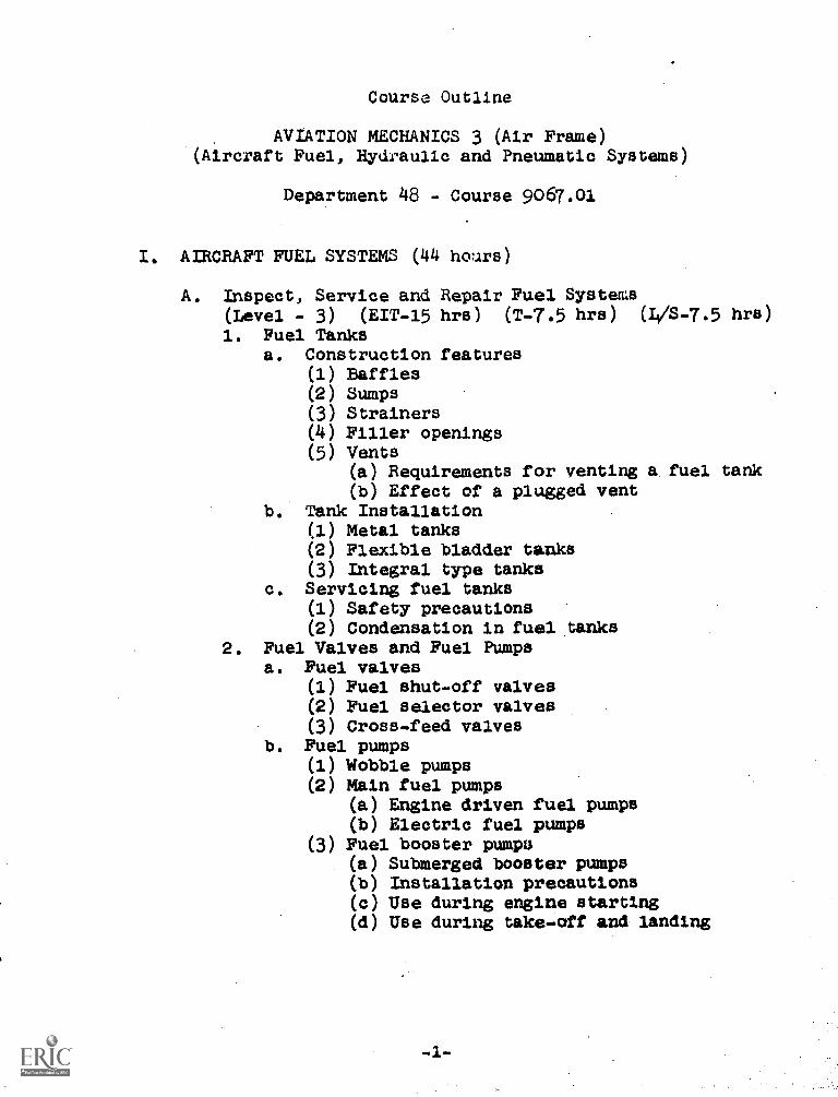
I. AIRCRAFT FUEL SYSTEMS (44 hours)
A. Inspect, Service and Repair Fuel Systems(Level - 3) (EIT-15 hrs) (T-7.5 hrs) (4/8-7.5 hrs)
1. Fuel Tanksa. Construction features
(1) Baffles(2) Sumps(3) Strainers(4) Filler openings(5) Vents
(a) Requirements for venting a. fuel tank(b) Effect of a plugged vent
b. Tank Installation(1) Metal tanks(2) Flexible bladder tanks(3) Integral type tanks
c. Servicing fuel tanks(1) Safety precautions(2) Condensation in fuel tanks
2. Fuel Valves and Fuel Pumpsa. Fuel valves
(1) Fuel shut-off valves(2) Fuel selector valves(3) Cross-feed valves
b. Fuel pumps(1) Wobble pumps(2) Main fuel pumps
(a) Engine driven fuel pumps(b) Electric fuel pumps
(3) Fuel booster pumpu(a) Submerged booster pumps(b) Installation precautions(c) Use during engine starting(d) Use during take-off and landing
-1-
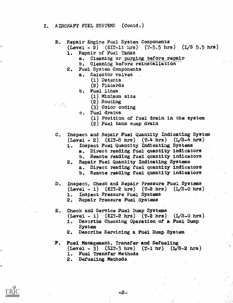
I. AIRCRAFT FUEL SYSTEMS (Contd.)
B. Repair Engine Fuel System Components(Level - 2) (EIT-11 'ars) (T-5.5 hrs) (4/S 5.5 hrs)
1. Repair of Fuel Tanksa. Cleaning or purging before repairb. Cleaning before reinstallation
2. Fuel System Componentsa. Selector valves
(1) Detents(2) Placards
b. Fuel lines(1) Minimum size(2) Routing(3) Color coding
c. Fuel drains(1) Position of fuel drain in the system(2) Fuel tank sump drain
C. Inspect and Repair Fuel Quantity Indicating System(Level - 2) (EIT-8 hrs) (T-4 hrs) (4/S-4 hrs)
1.. Inspect Fuel Quantity Indicating Systemsa. Direct reading fuel quantity indicatorsb. Remote reading fuel quantity indicators
2. Repair Fuel Quantity Indicating Systemsa. Direct reading fuel quantity indicatorsb. Remote reading fuel quantity indicators
D. Inspect, Check and Repair Pressure Fuel Systems(Level - 1) (EIT-2 hrs) (T-2 hrs) (4/8-0 hrs)1. Inspect Pressure Fuel Systems2. Repair Pressure Fuel Systems
E. Check and Service Fuel Dump Systems(Level - 1) (EIT-2 hrs) (T-2 hrs) hrs)1. Describe Checking Operation of a Fuel Dump
System2. Describe Servicing a Fuel Dump System
F. Fuel Management, Transfer and Defueling(Level - 3) (EIT-3 hrs) (T-1 hr) (L/S-2 hrs)1. Fuel Transfer Methods2. Defueling Methods
I. AIRCRAFT FUEL SYSTEMS (Contd.)
G. Fuel Pressure and Temperature Warning Systems(Level - 2) (EIT-3 hrs) (T-1.5 hrs) (L/S -1.5 hrs)
1. Fuel Pressure Warning Systems2.- Fuel Temperature Warning Systems
II. HYDRAULIC AND PNEUMATIC POWER SYSTEMS (91 hours)
A. Identify and Select Hydraulic Fluids(Level - 3) (EIT-2 hrs) (T-1 hr) (L/S-1 hr)1. Identify hydraulic fluid
a. Vegetable base fluidb. Mineral base fluidc. Ester base fluid
2. Select Hydraulic Fluid
B. Repair Hydraulic and Pneumatic Power SystemComponents(Level - 2) (EIT-18-hrs) (T-9 hrs) (L/S-9 hrs)1. Select and Install Seals
a. "0" ring sealsb. Cup sealsc. Chevron seals
2. Hydraulic Selector Valvea. Rotor type selector valveb. Poppet type selector valvec. Piston type selector valve
3. Remove and Install Hydraulic Pressure Regulatorsa. Remove a pressure regulatorb. Install a pressure regulatorc. Test and adjust regulator pressure
4. Operation of a Pneumatic Power Systema. Multistage compressorb. Intercoolerc. Filter/oil separator
C. Inspect, Check, Service, Troubleshoot and RepairHydraulic and Pneumatic Power Systems(Level - 3) (EIT-71 hrs) (T-35.5 hrs) (L/S-35.5 hrs)1. Force, Area and Pressure
a. Simple leversb. Mechanical advantagec. Hydraulic advantaged. Incompressibility of liquidse. Transmission of force
-3-
II. HYDRAULIC AND PNEUMATIC POWER SYSTEMS (Contd.)
2. Operation of a Basic Hydraulica. Hand pumpsb. Actuating cylindersa. Reservoirsd. Check valvese. Selector, valvesf. Relief valvesg. Power pumpsh. Pressure regulator1. AccumulatorJ. Hydraulic fusek. Flap overload valve1. Orifices check valvem. Sequence or timing valven. Shuttle valveo. Pressure gauges and snubbers
3. Constant Pressure and Open Center Hydraulic Systemsa. Constant pressure systemsb. Open center systems
4. Inspect and Service Hydraulic Reservoirsa. Servicing placardb. Filler openingse. Expansion spaced. Fluid quantitye. Filters
5. Hydraulic Pumpsa. Constant displacement pumpsb. Variable displacement pumpsCheck, Inspect, Remove and Install Hydraulic Pumpsa. Engine driven pumpsb. Electrically driven pumps
7. TroUbleshooting Hydraulic Pumps.a. Engine driven pumpsb. Electrically driven pumps
8. Hydraulic Accumulatorsa. Operationb. Servicingc. Inspectiond. Removale. Replacementf. Safety precautions
System
II. HYDRAULIC AND PNEUMATIC POWER SYSTEMS (Contd.)
9. Hydraulic System Pressuresa. Normal system operationb. Low system pressurec. High system pressured. Fluctuating pressuree. Adjustment of pressures
10. Hydraulically Operated Flap Systema. System operationb. Inspection of flap systemc. Flap adjustments
III. QUINMESTER POST TEST.
BEHAVIORAL OBJECTIVES
BLOCK I - AIRCRAFT FUEL SYSTEMS
A, Inspect, Check, Service, Troubleshoot and RepairAircraft Fuel Systems.
1. Inspect and Service Fuel TanksGiven:
Fuel tanks of the separate metal type,flexible bladder and integral types, appro-priate service information and copies of theapplicable Federal Aviation Regulations.
Performance:The student will inspect each of the threedifferent types of tank. Using appropriateservice information, he will describe theconstruction characteristics and installationprecautions for each type of tank.
Standard:The inspection will be performed as specifiedin the service manual. Correct nomenclatureand terminology will be applied to alldescriptions of servicing and installations.
2. Inspect, Check, Service, Troubleshoot and RepairFuel Valves and Fuel Pumps.Given:
An operational fuel system or test benchmock-up, manually operated fuel valves,engine driven fuel pumps, electricallydriven fuel pumps, and service informationpertaining to the operation and trouble-shooting of fuel valves and pumps.
Performance:The student will inspect, check, service,troubleshoot and repair each type of valveand pump.
Standard:Each unit will function within the toleranceprovided and will be free from leaks andother hazards, but need not meet return-to-service standards.
B. Repair Aircraft Fuel System Components
1. Interpret Information Pertaining to the Repairof Fuel Tanks.Given:
Typical aircraft fuel tanks of the separatemetal type, flexible bladder and integraltypes, ten written questions pertaining tothe repair of fuel system tanks, and appro-priate written reference information.
Performance:The student will locate and interpret infor-mation from repair manuals and describe therepair procedures for each type of tank.
Standard:The repair procedures will be interpretedwithout error. Correct nomenclature andterminology will be used in all descriptions.
2. Interpret Information Pertaining to the Repairof Fuel System ComponentsGiven:
Aircraft fuel system strainers, selectorvalves, fuel lines and hoses, and fueldrains, appropriate reference informationand ten written questions pertaining to therepair of fuel system components.
Performance:The student will locate and interpret infor-mation from the manuals and describe therepair procedures for fuel system componentsas specified in the written questions.
Standard:The repair procedures will be interpretedwithout error- Correct nomenclature andterminology will be used as a part of alldescriptions.
C. Inspect and Repair Fuel Quantity Indidating Systems
1. Inspect Fuel Quantity Indicating SystemsGiven:
An operational fuel quantity indicatingsystem of the direct reading (sight4augeor mechanical float) type, and a remoteindicating electrical type, appropriatereference information and ten statementsdescribing malfunction of the systems'.
-7-
Performance:The student will inspect the operating sys-tems, correctly interpret information fromthe manuals and describe the repairs thatwould be undertaken to correct the mal-functions described in the ten statements.
Standard:The repair practices and procedures of themanual will be interpreted without error.Correct nomenclature will be used as a partof all described repairs.
.2. Repair Fuel Quantity Indicating SystemsGiven:
An operational fuel quantity indicatingsystem of the direct reading (sight gauge ormechanical float) type, and a remote indica-ting electrical type, appropriate referenceinformation and ten statements describingmalfunctions of the system.
Performance:The student will inspect the operatingsystems, correctly interpret informationfrom the manuals and describe the repairthat would be undertaken to correct themalfunctions described in the ten statements.
Standard:The repair practices and procedures of themanual will be interpreted without error.Correct nomenclature will be used as a partof all described repairs.
D. Inspect, Check and Repair Pressure Fueling Systems
1. Describe the Inspection of Pressure FuelingSystemsGiven:
Visual aids, mock-ups, and technical dataavailable from the manufacturer's manual.
Performance:The student will describe the procedures tobe followed when inspecting pressure typefueling systems.
standard:Reference publications will be used duringthe descriptions. Correct nomenclature andterminology will be used as a part of alldescriptions.
-8-
2. Describe the Repair of Pressure Fueling SystemsGiven:
Visual aids, mock-ups and technical dataavailable from the manufacturer's servicemanual.
Performance:The student will describe the procedures tobe followed when repairing pressure typefueling-systems.
Standard:Reference publications will be used duringdescriptions. Correct nomenclature andterminology will be used as a part of thedescription.
E. Check and Service Fuel Dump Systems
1. Describe the Checking of a Fuel Dump SystemGiven:
Visual aids and the technical data availablefrom the manufacturer's service publications.
Performance:The student will locate information in thereference publication and describe checkinga fuel dump system.
Standard:Correct nomenclature and terminology will berequired as a part of the description.
2. Describe the Servicing of a Fuel Dump SystemGiven:
Visual aids and the technical data availablefrom the manufacturer's service publications.
Performance:The student will locate information in thereference publication and describe servicinga fuel dump system.
Standard:Correct nomenclature and terminology will berequired as a part of the description.
F. Perform Fuel Management, Transfer and Defueling
1.' Perform Fuel Transfer.Given:
Schematic diagrams or mock-ups of a fuelsystem that incorporate provisions for cross -feed, 'fuel transfer and, the service
-9-
publications that cover the specificsystems.
Performance:The student will locate information in theappropriate technical publications anddescribe the procedure necessary to transferor cross-feed fuel.
Standard:Correr't nomenclature and terminology will beused as a part of the description of opera-tion.
2. Perform DefuelingGiven:
Schematic diagrams or mock-ups of a fuelsystem that incorporates provisions forcross-feed, fuel transfer and the servicepublications that cover the specific systems.
Performance:The student will locate information in theappropriate technical publications anddescribe the procedures necessary to defuelthe system.
Standard:Correct nomenclature and terminology will beused as a part of the description of opera-tion.
G. Troubleshoot, Service and Repair Fuel Pressure andTemperature Warning Systems
1. Fuel Pressure Warning SystemsGiven:
An operating fuel system installed in anairplane or a mock-up, including a pressureand temperature system, a schematic diagramof the system, and service informationapplicable to the specific system..
Performance:The student will operate the system andadjust the pressure sensing devices. He willinterpret information and identify the causeof an instructor-introduced fault in thesystem. He will repair the system as directedin the service manual.
-10-
Standard:All troubleshooting, servicing and repair ofthe fuel pressure warning system will be inaccordance with the service publication.Repair information in the service manual willbe followed without error.
2. Temperature Warning SystemsGiven:
An operating fuel system installed in anairplane or on a mock-up, including apressure and temperature warning system,and service information applicable to thespecific system.
Performance:The student will operate the system andadjust the temperature sensing devices. Hewill interpret information and identify thecause of an instructor-introduced fault inthe system. He will repair the system asdescribed in the service manual.
Standard:All troubleshooting, servicing and repairof the temperature warning system will bein accordance with the service publications.Repair information in the service manual willbe followed without error.
BLOCK II - HYDRAULIC AND PNEUMATIC POWER SYSTEMS
A. Identify and Select Hydraulic Fluids
1. Identify Hydraulic FluidsGiven:
Samples of ester base, petroleum base andvegetable base hydraulic fluids, with writteninformation describing characteristics of thevarious fluids.
Performance:The student will distinguish between thesamples by color, odor and specificationnumber.
Standard:The three types of fluid will be identifiedwithout error.
2. Select Hydraulic FluidGiven:
Placards of the type attached to hydraulicreservoirs', written information describingthe characteristics and uses of hydraulicfluids.
Performance:The student will select the correct type offluid for the system to be serviced.
Standard:Reference information and placards will becorrectly identified and complied with.
B. Repair Hydraulic and Pneumatic Power System Components
1. Select and Install SealsGiven:
Hydraulic components not requiring complexassembly and disassembly, various types andsizes of seals and fluids, and referenceinformation describing the procedures forreplacing and testing seals in a hydraulicunit after replacement.
Performance:The student will use and interpret informa-tion that will assist in identifying andselecting seals for use in ester, petroleumand vegetable base hydraulic fluids. He willinstall seals in one unit in accordance withprocedures specified in the manual, and willtest the unit following reassembly.
Standard:The unit which had seals replaced will func-tion as it was designed to operate, withoutinturnal or external leakage.
2. Identify, Remove and Install a HydraulicSelector ValveGiven:
An operational hydraulic system or a segmentincluding a source of hydraulic pressure, aselector valve, an actuating cylinder, writtenservice instructions, spare selector valve toinstall in the system, line caps and plugs,and a supply of hydraulic fluid.
-12-
Performance:The student will identify, remove and installa selector valve in the system. He willoperationally check the system followingreplacement of the valve.
Standard:The selector valve will be identified, re-gardless of type. The removal and installa-tion procedure will be adhered to withouterror or omission. The system will functionnormally.
3. Remove and Install Hydraulic Pressure RegulatorsGiven:
An operational hydraulic system, writtenreference information, a replacementpressure regulator, line caps and plugs,and hydraulic fluid.
Performance:The student will identify, remove and installa pressure regulator in the hydraulic system.The pressure will be adjusted to within thetolerance specified in the maintenance in-structions.
Standard:The procedures will be fully in accordancewith the written instructioils. The pressurewill be adjusted to within the tolerancespecified in the instructions.
4. Interpret and Describe the Operation of aPneumatic Power SystemGiven:
Diagrams and drawings of a pneumatic powersystem, including a multi-stage compressor,filter, intercooler and/or oil separator,and written reference information describingthe operation of the system.
Performance:The student will interpret information andexplain the principles of pneumatics and theoperation of the specific system.
Standard:Explanations and descriptions will be inaccordance with the technical information pro-vided. Correct nomenclature and terminologywill be a part of all explanations anddescriptions.
-13-
C. Inspect, Check, Service, Troubleshoot and RepairHydraulic and Pneumatic Power Systems
1. Solve Problems Involving Force, Area andPressureGiven:
Ten problems applying the relationship ofapplied force, area of the cylinder orpiston, and pressure per unit area.
Performance:The student will solve the problems whenone of the factors is unknown. He willexplain the hydraulic principles involvedin the solution of the problems.
Standard:At least eight of the ten problems will besolved correctly. Correct nomenclature andterminology will be used in all solutionsand explanations.
2. Interpret Reference Information Pertaining tothe Operation of a Basic Hydraulic SystemGiven:
Reference manuals, drawings, diagrams, mock-ups or components installed in aircrafthydraulic systems, including but not limitedto: reservoir, pumps, check.valves, actuatingcylinders, selector valves, relief valves,pressure regulators, accumulators, fuse,sequence valve and pressure gauges.
Performance:The student will :i.nterpret the reference.Information and diagrama basic hydraulicsystem. He will show and explain therelationship, purpose and fUnction of eachcomponent in the system.
Standard:Reference material will be interpretedwithout error. Correct nomenclature andterminOlOgy will be used in all explana-tions and descriptions.
Compare Constant Pressure and Open Center Typesof Hydraulic SystemGiven:
Charts, manuals, diagrams, mock-ups or coin.plate aircraft hydraulic systems of the con-stant pressure and open center types.
-14-
Performance:The student will identify each type ofsystem and will compare the components andmethod of system pressure regulation.
Standard:All reference information will be inter-preted and comparison made without error.Correct nomenclature and terminology willbe used in the explanations.
4. Inspect and Service Hydraulic ReservoirsGiven:
An operational hydraulic system or mock-up,provided with a vented or pressurized reser-voir; a supply of hydraulic fluid andwritten inspection and servicing instructionsfor the specific aircraft hydraulic system.
Performance:The student will inspect the reservoir andservice it with the correct type of fluid,and will check the filter for contamination.
Standard:The inspection and servicing procedure willbe fully in accordance with servicing in-structions.
5. Identify and Describe the Operation of Constantand Variable Displacement PumpsGiven:
Visual aids, manuals, and samples or cutawaysof constant and variable displacement typehydraulic power pumps.
Performance:The student will identify and describe theoperation of one pump of each type.
Standard:Reference information will be correctlyinterpreted. Nomenclature and terminologywill be correctly used.
6. Check, Inspect, Remove and Install HydraulicPower PumpsGiven:
An operational hydraulic system installationin an aircraft or a mock-up; three enginedriven pumps, at least one of which has aworn or sheared drive shaft, a suitable
-15-
accessory drive pad, and written instructionsdescribing the inspection, installation andremoval of the hydraulic pump.
Performance:The student will inspect the pump driveshafts and will identify the pump with thedefective shaft. He will remove and installa pump on the accessory drive pad, and checkthe operation of the system following pumpinstallation.
Standard:The pump with the defective.shaft will beidentified without error. Maintenanceinformation will be correctly interpreted.Removal, installation and checking will bein accordance with the written instructions.
7. Troubleshoot Hydraulic PumpsGiven:
An operational hydraulic system that may besupplied with pressure from an auxiliarypower source0.and written service instructions.
Performance:The student will troubleshoot the hydraulicsystem after the instructor has introducedair into the pump. The student will primethe pump and purge air from the system.
Standard:The .procedures will be in accordance with thereference information. The pump and systemwill operate, as specified, following correction of the fault.
6. Remove, Install, Inspect, Service and Cheek aHydraulic Accumulator.Given:
An operational constant pressure hydraulicsystem, including one or more pressureaccumulators, line sealing caps, hydraulicfluid, and written service instructions.
Performance:The student will remove, inspect and installan accumulator in the system. Observingproper safety precautions, he will charge itwith air or nitrogen and will check theoperation of the system. He will replace highpressure air valve assemblies as necessary.
-16-
Standard:All tasks will be accomplished in accordancewith the manufacturer's specifications.
9. Troubleshoot and Determine the Cause of Low,High or Fluctuating Hydraulic PressureGiven:
An operational hydraulic system, includingat least a power supply pump, pressure re-gulating devices, accumulators, flow controlvalves, actuators, and written maintenanceinstructions applicable to the specificsystem.
Performance:The student will operate the system, comparethe operating characteristics with thereference information, and detect low, highor fluctuating pressures when faults havebeen.introduced by the instructor. He willadjust and restore the system to normaloperating conditions.
Standard:Operation, adjustments and analysis of faultswill be in accordance with the written infor-mation. Following observations, analysis andadjustments, the system will operate withintolerances specified in the instructions.
10. Inspect, Check and Service a Hydraulically Operated-Flap SystemGiven:
An operational hydraulic flap system installedin an aircraft or mock-up, with the manu-facturer's maintenance and service publica-tions or written reference information.
Performance:The student will inspect, check and servicethe flap system.
Standard:The tasks will be completed in accordancewith the written instructions and will re-sult in a system that operates within thetolerances specified in the instructions.
BIBLIOGRAPHY(Aircraft Fuel, Hydraulic and Pneumatic Systems)
Basic References:
1. Northrup Institute of Technology. Basic Science forAerospace Vehicles. lst ed. New York: McGraw-Hill Book Company, Inc., 1963. Pp 320.
2. Northrup Institute of Technology. Maintenance and4', Repair of Aerospace Vehicles. 3rd Ed. New York:McGraw-Hill Book Company, Inc., 1967. Pp 358.
Federal Aviation Publications:
1. Federal Aviation Administration. Federal AviationRegulations Parts: 1, 23, 25, 27, 29, 33, 35,37, 39, 43, 45, 47, 65, 91 and 145. 1st ed.Washington, D.C.: U.S. Government PrintingOffice. 1968.
2. Federal Aviation Administration. Aircraft TypeCertificate Data Sheets and Specifications.1st ed. Washington, D.C.: U.S. GovernmentPrinting Office. 1967.
3. Federal Aviation Administration. Acceptable Methods,Techniques and Practices - Aircraft Inspectionand Repair, Advisory Circular 43.13-1. 1st ed.Washington, D.C.: U.S, Government Printing Office.1965. Pp 232.
4. Federal Aviation Administration. Acceptable Methods,Techniques and Practices - Aircraft Alterations,Advisory Circular 43.13-2. Washington; D.C.:1U:S;-Government Printing Office. 1965. Pp 74.
5. Federal Aviation 'Administration. Airframe and Power-plant Mechanics Examination Guide, AdvisoryCircular 65-2A. 1st ed. Washington, D.C.: U.S.Government Printing Office. 1969. Pp 63.
-18-
Films:
1. Basic Hydraulics. 16mm. 9 min. Color. Sound. UW.
2. Basic Hydraulics. 16mm. 16 min. Black and White.Sound. U.S. Army Air Forces.
3. Brakes - Hydraulic, Inspection and Adjustment.16mm. 10 min. Black and White. Sound. U.S.Army Air Forces.
4. De-icers - Aircraft. 16mm. 20 min. Black andWhite. Sound. U.S. Army Air Forces.
5. De-icers - Removal and Storage. 16mm. 10 min.Black and White. Sound. U.S. Army Air Forces.
6. Don't Build Hazards into Your Tubing System. 16mm.20 min. Color. Sound. Imperial Eastman.
7. Goodyear-Wheels, Tires and Brakes. 16mm. 22 min.Black and White. Sound. Goodyear Tire andRubber Company.'
-19-
APPENDIXQuinmester Post Test Sample
-20-
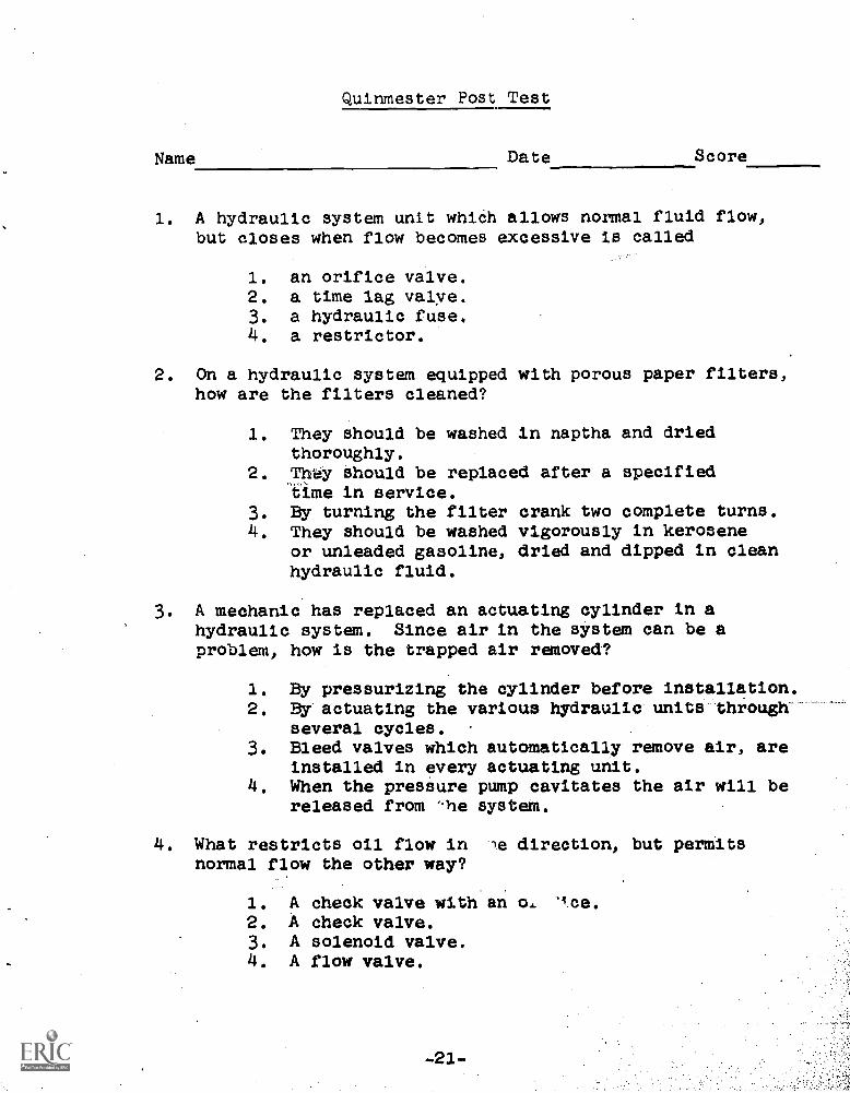
Quinmester Post Test
Name Date Score
1. A hydraulic system unit whiCh allows normal fluid flow,but closes when flow becomes excessive is called
1. an orifice valve.2. a time lag valye.3. a hydraulic fuse.4. a restrictor.
2. On a hydraulic system equipped with porous paper filters,how are the filters cleaned?
1. They should be washed in naptha and driedthoroughly.
2. 71,1y Should be replaced after a specified"time in service.
3. By turning the filter4. They should be washed
or unleaded gasoline,hydraulic fluid.
crank two complete turns.vigorously in kerosenedried and dipped in clean
3. A mechanic has replaced an actuating cylinder in ahydraulic system. Since air in the system can be aproblem, how is the trapped air removed?
1. By pressurizing the cylinder before installation.2. By actuating the various hydraulic units through
several cycles.3. Bleed valves which automatically remove air, are
installed in every actuating unit.4. When the pressure pump cavitates the air will be
released from -he system.
4. What restricts oil flow in le direction, but permitsnormal flow the other way?
1. A check valve with an o.2. A check valve.3. A solenoid valve.4. A flow valve.
-23.-
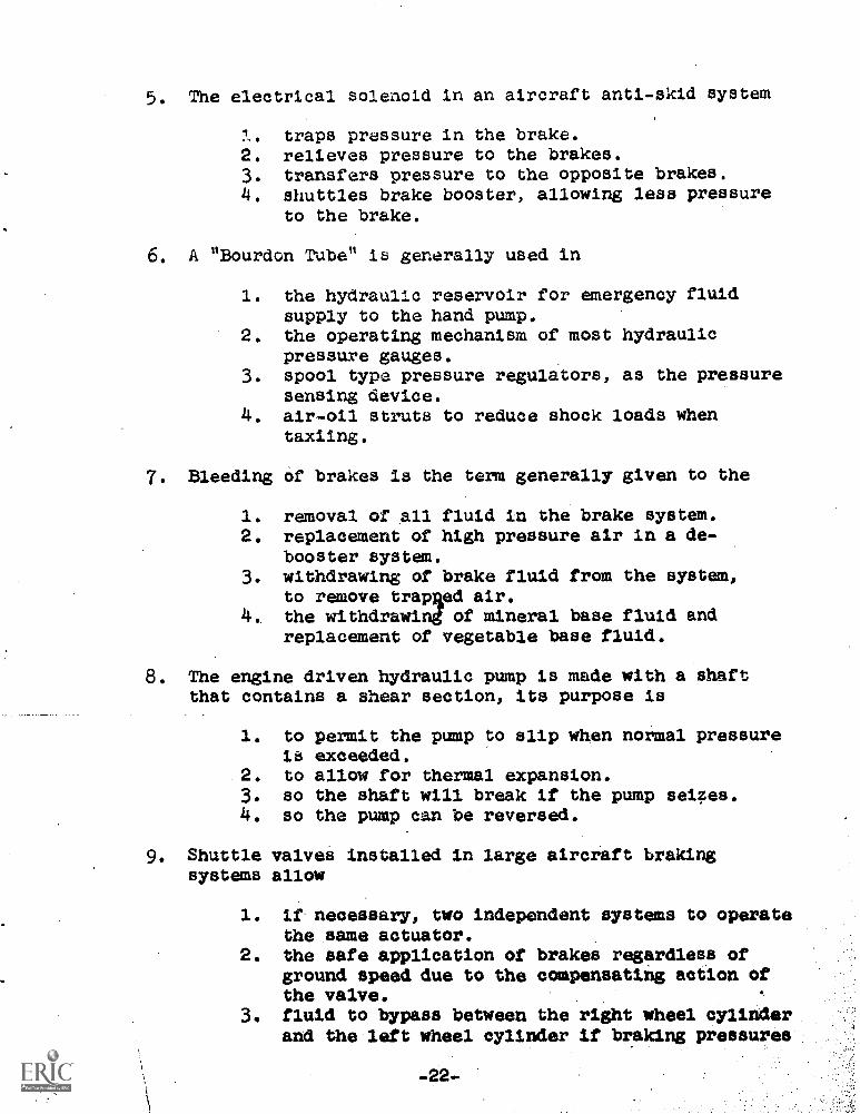
5. The electrical solenoid in an aircraft anti-skid system
:1.. traps pressure in the brake.2. relieves pressure to the brakes.3. transfers pressure to the opposite brakes.4. shuttles brake booster, allowing less pressure
to the brake.
6. A "Bourdon Tube" is generally used in
1. the hydraulic reservoir for emergency fluidsupply to the hand pump.
2. the operating mechanism of most hydraulicpressure gauges.
3. spool type pressure regulators, as the pressuresensing device.
4. air-oil struts to reduce shock loads whentaxiing.
7. Bleeding of brakes is the term generally given to the
1. removal of all2. replacement of
booster system.3. withdrawing of
to remove traps4., the withdrawing
replacement of
fluid in the brake system.high pressure air in a de-
brake fluid from the system,ed air.of mineral base fluid and
vegetable base fluid.
8. The engine driven hydraulic pump is made with a shaftthat contains a shear section, its purpose is
1. to permit the pump to slip when normal pressureis exceeded.
2. to allow for thermal expansion.3. so the shaft will break if the pump seizes.4. so the pump can be reversed.
9. Shuttle valvei installed in large aircraft brakingsystems allow
1. if necessary, two independent systems to operatethe same actuator.
2. the safe application of brakes regardless ofground speed due to the compensating action ofthe valve.
3. fluid to bypass between the right wheel cylinderand the left wheel cylinder if braking pressures
-22-
are different.4. the compensating port, interconnecting both
master cylinders to discharge fluid alternatingfrom one to the other.
10. An aircraft pneumatic system which incorporates an enginedriven multi-stage reciprocating compressor, also requires
1. a moisture separator.2. an oil separator.3. a surge chamber.4. a vacuum relief valve.
11. Severe 'kick back' of the emergency'hand pump duringoperation is caused when the
1. inlet port check valve of hand pump sticksopen.
2. accumulator air side is still charged and handpump cannot overcome pressure.
3. outlet port check valve of hand pump sticksopen.
4. hydraulic reservoir is low on oil.
12. What type seals should be used with skydrol fluid?
1. Solid black neoprene with no color markings.2. Only those having blue bands around the seal.
3. Black synthetic rubber identified by anirregular red dot..
4. Butyl rubber.
13. If you filled the reservoir in a constant pressuresystem while pressure was built up, what would happen?
1. Hydraulic fluid would spew out.2. The hydraulic reservoir fluid level would be
higher than normal after pressure was reduced.3. The sight gauge would still indicate the proper
level after the pressure was reduced.4. This would not assure a reserve oil supply to
operate the hand pump.
14. A de-booster is used to
1. relieve pressure in the system.2. prevent a rapid flow in reverse.
-23-
3. reduce pressure to the brakes.4. is not used.
15. The most common hydraulic selector valve is the
1. four way valve.2. selective valve.3. three way valve.4. two way valve.
16. The type fluid to be used in an aircraft'hydraulicsystem can be determined by
1. a chemical analysis of a sample of fluid fromthe system.
2. the markings on or near the reservoir filleropening.
3. the color code attached to the hydraulic lines.4. mixing a sample of fluid to be added with a
sample of fluid in the system and observing thereaction.
17. Hydraulic systems usually require several differentpressure settings on many of the units in the system.The general rule to follow when setting these valves isto
1. adjust the units with the highest pressuresettings first.
2. always adjust units in the landing gear. systemfirst, then the auxiliary systems.
3. start with the unit with the lowest setting andthen move upward.
4. start with unit that is most distant frompressure pump then work toward the pump.
18. How would you bleed a system pressure if you wished to. remove the pressure relief valve?
1. Tighten the tension on the overload valve.2. Loosen the tension on the overload valve.
Operate the flaps.4. Relieve the pressure by bleeding the brakes.
-24-
19. The purpose of the outlet standpipe in the hydraulicreservoir is
1. for the emergency system at any time.2. for the emergency hand pump use when the normal
system fluid has been exhausted.3. not related to the emergency system.4. to reduce air accumulation in the reservoir.
20. An orifice, valve will .prevent flaps from retracting toofast. It is installed in the
1. flap 'down' line between the selector valve andthe flap actuating cylinder.
2. flap 'ups line between the actuating cylinderand selector valve.
3. return line from the selector valve to thereservoir
4. return line to the accumulator.
21. How can you determine the amount of precharge on anaccumulator?
1. Read off main gauge.2. Actuate some unit and look for a rapid pressure
drop.3. Apply pressure to the system using a hand pump
and when the pressure starts to build, this isthe accumulator precharge pressure.
4. Use hand pump and pressurize the system, thenread the accumulator.
22. If the main hydraulic line breaks,
1. the landing gear can be retracted.,2. the landing gear can be lowered.3. the landing gear cannot be lowered.4. the landing gear can be lowered; however,
it will not lock in the down position.
23. A timing valve in a hydraulic system may also be knownas a
1. check valve.2. reverse-flow valve.3. sequence valve.4. supplementary valve.
-25-
24. There are three basic types of hydraulic pressurepumps, they are
1. gear, gerotor and vane.2. gear, piston and gerotor.3. piston, vane and gerotor.4. gerotor, piston and vacuum.
25. When using Skydrol fluid in the hydraulic system
1. natural rubber seals should be used.2. synthetic (neoprene) rubber seals should be
used.3. either natural rubber or synthetic seals are
compatible with Skydrol.4. seals of a pressed fibre type should be used
because of the deteriorating effect of Skydrolon either natural or synthetic rubber seals.
26. The location of the brake de-booster is
1. between the power brake control valve and thebrakes.
2. in the hydraulic system just ahead of the powerbrake control valve.
3. between the relief valve and the power brakecontrol valve.
4. within the brake control unit since it is anintegral pert of the brakes and brake shoes.
27. What is used to separate the air and oil in a hydraulicaccumulator?
1. A centrifugal separator.2. A flexible separator.3. A metallic diaphragm.4. Air on top and oil on the bottom.
28. Instrument static system leakage can be detected byobserving the rate of change in indication of the
1. altimeter after pressure has been applied tothe static system to cause a prescribed equi-valent altitUde to be indicated.
2. airspeed indicator after pressure has beenapplied to the static system to cause a pre-scribed equivalent airspeed to be.indicated.
-26-
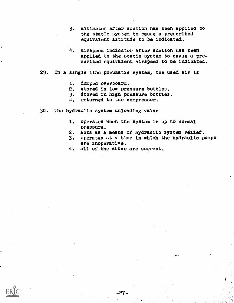
3. altimeter after suction has been applied tothe static system to cause a prescribedequivalent altitude to be indicated.
4. airspeed indicator after suction has beenapplied to the static system to cause a pre-scribed equivalent airspeed to be indicated.
29. On a single line pneumatic system, the used air is
1. dumped overboard.2. stored in low pressure bottles.3. Stored in high pressure bottles.4. returned to the compressor.
30. The hydraulic system unloading valve
1. operates when the system is up to normalpressure.
2. acts as a means of hydraulic system relief.3. operates at a time in which the hydraulic pumps
are inoperative.4. all of the above are correct.
-27-
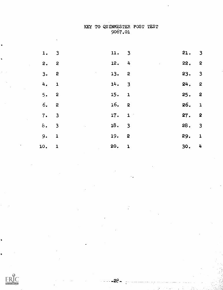
KEY TO QUINMESTER POST TEST9067.01
1. 3 11. 3 21. 3
2. 2 12. 4 22. 2
3. 2 13. 2 23. 3
4. 1 14. 3 24. 2
5. 2 15. 1 25. 2
6. 2 16. 2 26. 1
7. 3 17. 1 27. 2
8. 3 18. 3 28. 3
9. 1 19. 2 29. 1
10. 1 20. 1 30. 4
_28-

![Homepage [dtiaircraftsales.com]dtiaircraftsales.com/uploads/15db9ec8183760c22641f13555d... · AIRCRAFT DENNIS THOMPSON INTERNATIONAL FOR SALE PDC 14 690 Harvard Lane Ardmore Airport,](https://img.pdfslide.us/doc/110x75/60fc4bd25f0bed4fa9669c0b/homepage-aircraft-dennis-thompson-international-for-sale-pdc-14-690-harvard.jpg)


![[Shinobi] Claymore 092](https://img.pdfslide.us/doc/110x75/568bd5b31a28ab2034996af8/shinobi-claymore-092.jpg)