Embed Size (px)
Citation preview

DOCUMENT RESUME
ED 112 257 CE 005 283
TITLE The Tractcr Electrical System. A TeachingReference.
INSTITUTION American Association for Vocational InstructionalMaterials, Athens, Ga.; Farm and Industrial EguipmentInst., Chicago, Ill.
REPORT NO VT-102-067NOTE 61p.; Illustrations have color keying which will not
reproduce
EDRS PRICE MF-$0.76 HC-$3.32 Plus PostageDESCRIPTORS *Agricultural Machinery; Agricultural Machinery
Occupations; *Electrical Systems; Electric Batteries;Electricity; Equipment Maintenance; *Farm Mechanics(Occupation); Machine Repairmen; *Manuals; Trade andIndustrial Education
ABSTRACTThe fundamental principles underlying the application
of electricity to tractors and farm equipment are presented. Anunderstanding of the material in the basic manual will enable theservice man to understand better the service procedures covered inservice manuals on electrical equipment. Topics dealt with arefundamentals of electricity, storage batteries, circuits, andcombination motor and generator. (NJ)
***********************************************************************Documents acquired by ERIC include many informal unpublished
* materials not available from other sources. ERIC makes every effort ** to obtain the best copy available. Nevertheless, items of marginal *
* reproducibility are often encountered and this affects the quality *
* of the microfiche and hardcopy reproductions EPIC makes available *
* via the ERIC Document Reproduction Service (EDRS). EDRS is not* responsible for the quality of the original document. Reproductions ** supplied by EDRS are the best that can be made from the original.***********************************************************************

1
A
A
U S DEPARTMENT OF HEALTH,EDUCATION & WELFARENATIONAL INSTITUTE OF
EDUCATION
THIS DOCUMENT HAS BEEN REPRO.DUCED EXACTLY AS RECEIVED FROMTHE PERSON OR ORGANIZATION ORIGIN.ATING IT POINTS OF VIEW OR OPINIONSSTATED DO NOT NECESSARILY REPRE-SENT OFFICIAL NM IONAL INSTITUTE OFEDUCATION POSITION OR POLICY
to
(VT I c2, o4-0

o
A Teaching ReferenceAvailable through the cooperative efforts of the ...
4.11)A AVIM
FARM and INDUSTRIALEQUIPMENT INSTITUTE and the
AMERICAN ASSOCIATIONFOR VOCATIONALINSTRUCTIONAL MATERIALS

CEOO5 2 8 3
CONTENTS
Introduction 3
Fundamentals of Electricity 3
Definition of Electricity 3
Nature of Electricity 3
Electrical Circuit /1.
Resistance.Factors Affecting Resistance in a CircuitOther Types of Conductors 5
InsulatorsMagnetism 6,
Electromagnetic Fields 7
Combined Magnetic Fields 8
Electromagnets 10
Magnetic Force on a Conductor 11
Electromagnetic induction 13
Types of Circuits 15
Measurement of Voltage, Current and Resistance 16
Measurement of Electric Power 18
Current Flow in Series and Parallel Circuits 19
Storage Batteries 20
Internal Construction 20
Chemical Action 20
Effect of Temperature on Battery Voltage 23
Batteries in Storage 23
Battery Charging Rate 24
Battery Checks .
24
Cranking Motor Circuit 25
Control Switches 25
Cranking Motor 27
Ignition Circuit 30
Induction Coils 30
Primary Circuit 31.
Condenser Action 32
Secondary Circuit 32
Distributor 33
Distributor Point Setting 34
Resistance in a 12 Volt System 34

Charging Circuit 35
Shunt Generator Principles 36Armature Reaction 37
Generator Circuits 38Charging Circuit 38Load Circuit 39Field Circuit 39
Control of Generator Output 40Voltage Regulator y 40Current Regulator 40
Combination Current and Voltage Regulator 41.
Special Generator Circuits 44Third Brush Generators 44
Manual Control of Third Brush Generator Output 46Interpole Generators 47Bucking Field Generator 48Split Field Generator 48
Double Contact Regulators for Generators 49Polarity of a Generator 49
Polarizing Generators 50A.C. Generating Circuit 51
Alternating Current Generator 51
Transistorized Regulators 55
Combination Motor and Generator 57

INTRODUCTION
Since the discovery of electricity, a greatdeal has been learned about it and many wayshave been devised to use it in performingtasks which were formerly done by hand, orother cumbersome methods. Electricity hasmade possible the introduction of many labor-saving devices such as electric light, electricpower for motors, and electric heating units.
Electricity, as it is used to power crankingmotors for engines, makes starting of enginesmuch easier and less hazardous than the pre-vious hand cranking method. The moderngasoline engine could not be run without.electricity to furnish the spark to ignite thefuel in the cylinder. These and many other
applications of electricity are used on ourmodern tractors and farm equipment.
On the following pages is a discussion ofthe fundamental principles behind the appli-cation of electricity to tractors and farm equip-ment. It is the aim of this manual to presentthese fundamentals in a manner which willmake the farm equipment service man betterable to understand the operation of the electri-cal equipment on farm machines. An under-standing of the material covered in this basicmanual will enable the service man to under-stand better the service procedures covered inservice manuals on electrical equipment.
FUNDAMENTALS OF ELECTRICITY
Definition of Electricity
Electricity can be defined briefly as a formof energy. Since energy is the capacity fordoing work, it follows that electricity, ifproperly harnessed. can perform work. This
work can take the form of motion as in thecase of electric motors, or heat as in electricheaters, cigarette lighters. etc. or it canproduce light as in a light bulb.
Nature of Electricity
In order to have a better understanding ofhow electricity can be used to perform work.we need to know something about the natureof this form of energy. No one knows speci-fically what electricity is. Electricity is presentin everything, for example, our body, clothes.paper, furniture etc. The reason that we arenot aware of its presence is because it is notin motion.
3
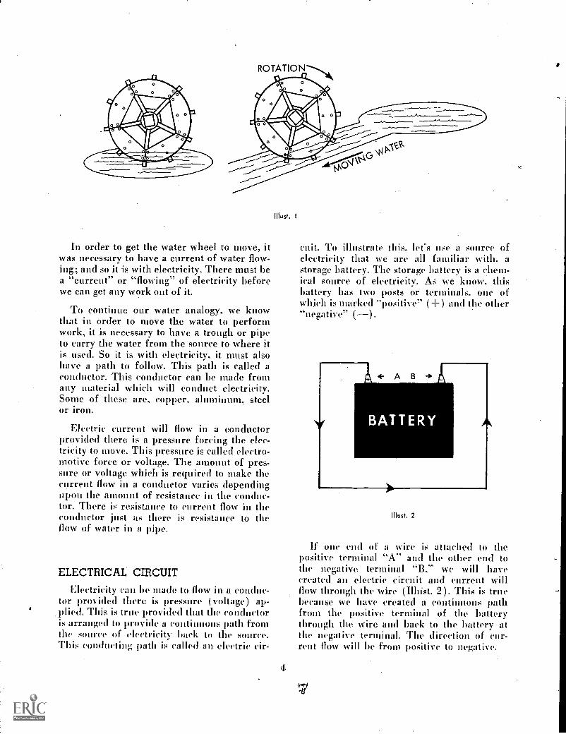
Electricity can be compared with water. Forexample, if we were to place a water wheelin the middle of a pond, the wheel would notturn, but if we place the wheel in a positionwhere water can flow past the blades, thewheel would turn. (II lust. 1.) The motion ofthe water causes the wheel to turn. The sameis trile of electricity, when we put it in motionwe can obtain work from it.
ROTATION
In order to get the water wheel to move, itwas necessary to have a current of water flow-ing; and so it is with electricity. There must bea "current" or "flowing" of electricity beforewe can get any work out of it.
To continue our water analogy, we knowthat in order to move the water to performwork, it is necessary to have a trough or pipeto carry the water from the source to where itis used. So it is with electricity, it must alsohave a path to follow. This path is called aconductor. This conductor can be made fromany material which will conduct electricity.Some of these are, copper, aluminum, steelor iron.
Electric current will flow in a conductorprovided there is a pressure forcing the elec-tricity to move. This pressure is called electro-motive force or voltage. The amount of pres-sure or voltage whielt is required to make thecurrent flow in a conductor varies dependingupon the amount of resistance in the conduc-tor. There is resistance to current flow in theconductor just as there is resistance to theflow of water in a pipe.
ELECTRICAL CIRCUIT
Ehsetricity can be made to flow in a conduc-tor provided there is pressure ( voltage) kip-plied. Tltis is true provided that the conductoris arranged to provide a continuous path fromthe source of electricity back to the source.This conducting path is called an electric cir-
Illust. I
4
mit: To illustrate this. let's use a source ofelectricity that we are all familiar with. astorage battery. The storage battery is a chem-ical source of electricity. As we know. thisbattery has two posts or terminals. one ofwhich is marked "positive" (+) and the other"negative" ().
Akio. 2
If one end of a wire is attached to thepositive terminal "A" and the other end tothe negative terminal "B," we will havecreated an electric circuit and current willflow through the wire (Illtist. 2). This is truebecause we have created a continuous pathfrom the positive terminal of the batterythrough the wire and back to the battery atthe negative terminal. The direction of cur-rent flow will be from positive to negative.

RESISTANCE
Any conductor has resistance to currentflow, so it is necessary to overcome this resist-ance with pressure (voltage) to make the cur-rent flow. With a given pressure (voltage)such as is produced by the battery, the amountof current which will flow will depend uponthe amount of resistance in the circuit. Themore resistance there is in the circuit, theless current will flow and conversely the lessresistance in the circuit, the more current willflow. In order to perform work with electricity.it is necessary to put it in motion (that is)we lutist have current flowing in a suffieientamount to do the work required. Therefore.it is necessary to pay close attention to theamount of resistance present in a circuit.
FACTORS Alt ECTING RESISTANCEIN A CIRCUIT
There are a number of factors which affectthe amount of resistance in a circuit and thesemust all be considered when setting up anelectrical circuit to do a particular job.
For example, the simple circuit in Il lust. 2has only the wire conductor to cause resistanceto current (low. In this case, the factors affect-ing the resistance are:
I. The material from which the wire ismade.
Metallic substances such as copper. alu-minum. steel or iron are good conduc-tors. This is because they have a relative-ly low resistance to current (low. Thesematerials, therefore. are often used asconductors. Copper is by far the mostcommonly used because it has a lowresistance to current (low and is rela-tively cheap. Copper is also desirable forconductors because it is soft and bendseasily without breaking. This simplifiesforming the conductor in the shapedesired to make up a circuit.
Most metallic substances have a relative-ly low resistance to current flow andmay. therefore.be used as conductors.Engine blocks or the frame of a tractorcan be used as conductors and often are
5
used to reduce the amount of wire neces-sary. to complete circuits.
2. Diameter of Conductor.Another factor which affects the amountof resistance present in the wire used inMust. 2 is the diameter of the wire. Ithas been determined that the larger thewire, the less resistance to current flowwill be present. Therefore, if a circuitmust carry a large amount of current, awire of large diameter should be used.
3. Length of the eonductor.The total resistance of a circuit dependsalso on the length of the wire since agiven amount of resistance per unitlength is present. This being the case,the length of the wire becomes an im-portant factor when considering the cur-rent carrying capacity of a circuit.
4. Temperature of the conductor.When the temperature of a conductorincreases, the resistance also increases indirect proportion, that is, for each de-gree rise in temperature of the conduc-tor, there is a corresponding increasein the amount, of resistance. This factmakes it important that the conductorbe of sufficient size to carry the currentrequired without heating.
OTHER TYPES OF CONDUCTORS
We have considered up to this point resist-ance as it exists in a wire conductor such asused in the simple circuit shown in Il lust. 2.However. the conductor need not necessarilybe a wire. It can be the frame of a machine orunit of a machine. It can also be a liquid. Theliquid in a storage battery is a conductor ofelectricity. Even air will conduct electricitybut the resistance is so high that it takes agreat deal of pressure (voltage) to make thecurrent (low.
INSULATORS
We have considered materials with relative-ly low resistance which are used as conduetorsof electricity. kit what about other materialswith high resistance to current flow. Manymaterials has e such a high resistance to cur-rent (low that no current will (low through

them unless the pressure (voltage) is veryhigh. This makes them of little value as con-ductors. Many of them do have a value how-ever, to prevent current from flowing in thewrong path. Electric current will flow throughthe material offering the least resistance.Therefore, it is necessary to use a materialof high resistance around conductors to pre-vent the current from deviating from the pathprovided. This material is called insulation.
Rubber, fabrics, ,,glass, enamel, and air are ex-amples of good insulators and e commonly
mused for that purpose. These materials havesuch a high resistance to current flow that athin layer around a conductor will preventcurrent from straying from its normal path.Air, while it is a good insulator, is not toopractical for insulating wires because it willnot support the wire and keep it away fromother conductors.
Magnetism
Another phenomenon which is closely asso-ciated with electricity is magnetism. Likeelectricity, very little is known about what itactually. is. There is, however, a great dealknown about how it acts. In order to under-stand how electricity is used to do work, it isnecessary to consider magnetism because itworks together with electricity in many eases.
Magnetism may be defined briefly as "thepower to attract." We mean by this that cer-tain materials have the power to attract othersimilar materials. The force which causes thisattraction is 'known as "magnetism." Thereare only a few materials which have thismagnetic property, such as iron, .nickel, co-balt and their alloys. All other materials whichdo not have this property are considered non-magnetic.
!Wheninari etism was first discovered, it wasfound that a magnetized piece of elongatediron ore, in addition to having the power toattract other ferrous material, would alwayspoint toward the North if suspended in air.It was also learned that if two pieces of elong-ated iron ore were placed near each other thatthe ends which pointed to the North pole ofthe earth would not be attracted to each other.but would be repelled. If on the other hand.one of the pieces was reversed, then the pieceswould be attracted to each other. Since oneend of this material always pointed towardthe North pole of the earth when suspendedin air, it was termed the North pole of the ma-terial which was called a "magnet." The op-posite end then. was termed the South pole.This principle became the basis for the firstcompass.
6
Further study of these so-called "naturalmagnets" revealed that the attraction betweentwo of these was limited to. a short distance.This indicated that there was a limited areaaround these magnets in which the attractiveforce was apparent. This then, was called amagnetic field." It was also learned that the
attracting force became stronger the closerthe magnets were placed together. This indi-cated that around a magnet there are invisiblelines of force which are close together nearthe magnet and progressively farther apartaway from it. These invisible lines are repre-sented graphically, as shown in Must. 3. Since
iiiust. 3
the North pole is attracted to the South poleof another magnet, it follows that the unlikepoles of one magnet would he attracted toeach other and the lines of force around themagnet have a direction from the North to theSouth pole, as shown in Illust. 3. As previouslystated. unlike poles of a magnet attract each
9

N
Illust. 4
UNLIKEPOLESATTRACT
LIKEPOLESREPEL
other and like poles repel when placed neareach other. Must. 4 shows the direction of themagnetic lines of force in each case. You willnote that a. large number of lines of forcepass from the North pole to the South polewhen opposite poles are placed near eachother making a strong magnetic field betweenthe poles. When the like poles are near eachother, the lines of force repel each other andno lines of force are traveling between thelike poles. The magnetic field between the twolike poles is, therefore, very weak. These factsare the basis for the fundamental law ofmagnetism. which is, "Unlike, poles attractand like poles repel each other."
Another property of "natural magnets" isthat if a piece of iron which is not a naturalmagnet, such as a nail touching a naturalmagnet, it too becomes magnetized. Whenthis happens, the nail will have a North andSouth pole just like the natural magnet. Theend of the nail touching the natural magnetwill have the opposite polarity to the magnetand is, therefore, attached to it. As soon as thenail is removed from the natural magnet, itloses its magnetism and cannot, therefore, beconsidered a natural or permanent magnet.
It has been found that soft iron becomesmagnetized easily but loses its magnetismquickly when removed from a magnetic field.Hard iron, such as steel alloys are muchharder to magnetizes but will retain magne-tism much longer. Due to this fact, a perman-ent magnet may be produced out of certainhard materials by subjecting them to a strongmagnetic field.
ELECTROMAGNETIC FIELDS
With this basic knowledge. of magnetism.let's return to our basic electric circuit shown
7
e
Illust. 5
in Illust. 2. Using a compass needle, we findthat when the compass is placed near the wirethrough which current is flowing, the needlepoints toward the wire (Illust. 5). Since amagnetic force is the only force that will de-flect a compass needle, it is apparent that amagnetic field is'produced by the current flowin the wire. In the case of the straight conduc-tor, the lines of force form concentric circlesaround the wire. In this respect, the fielddiffers from that of the -permanent magnet.There are no magnetic poles in the conductorat which the lines of force can enter or leave.The strength of this magnetic field is increasedwith an increase in the current flow. The in-crease in the number of lines of force is indirect proportion to the increase in current,and the- field is distributed along the fulllength of the conductor.
As in the case of the magnetic lines of forceset up by the permanent magnet, the lines offorce around a wire travel in a definite direc-tion. The direction of these lines of force isdependent upon the direction of current flowin the wire. If the direction of current flowis known, then the direction of the lines offorce around the conductor can he determinedby what is known as the right hand rule(Mist. 6). If the right hand grasps the con-ductor with the thumb pointing in the direc-tion of current flow, the the fingers will pointin the direction of the lines of force aroundthe conductor. If the direction of current flowis not known, then a compass may be used to

RIGHT HANDRULE
Must. 6
determine the direction of the lines of force.See Il lust. 5. If the compass is placed abovethe wire, the North pole of the needle willpoint in the direction of the lines of force.With this information, the direction of cur-rent flow can be determined by the righthand rule.
CURRECARRCON
1 INCH
Must. 7
BER
LINESAREA
The extent of the magnetic field around aconductor is limited as in the ease of thepermanent magnet and is progressively weakeras the distance from the conductor is in-creased. This is shown graphically in Il st. 7as a series of concentric lines around the con-duetor which are progressively farther apartas the distance from the conductor is in-creased. For example. with a given current
8
travelint, in a conductor, there will be twicethe number of lines of force at a distance of1,4 inch from the conductor as there will be ata distance of 1 inch. The number of lines perunit area is called "density." The density ofthe field being greatest at the conductor meansthat the most useful portion of the magneticfield is near the conductor.
DIRECTION OFCURRENT FLOW
!Rust. 8
If we take a straight current carrying con-ductor and bend it into a loop, the lines offorce are still traveling around the conductorat right angles to it, as shown in Mist. 8. Thelines of force all pass through the inside ofthe coil. This eoneentrates the Ihies in thisarea and, therefore, materially strengthensthe field without increasing the current flow.In addition, note that the polarity on one sideof the loop is opposite to that on the otherside, This can he observed by using a magneticcompass. We see, then. that the magnetic fieldaround the loop is very similar to that pro-duced by a permanent magnet.
COMBINED MAGNETIC FIELDS
We now know that when current flows in astraight conductor, there is a magnetic fieldcreated around the conductor. We have alsolearned that the magnetic lines of force arealways in a plane at right angles to the con-

doctor and the direction of the lines dependsupon the direction of current flow. Now let'sconsider what happens to the magnetic fieldaround two parallel conductors which areadjacent to one another.
order to keep track of the direction ofcurrent flow, we will mark the end of one con-ductor with a (-I-) to indicate current flowingaway from that point and one end of the otherwith a dot () to indicate current flowingtoward that point. See Must. 9.
CURRENTIN
LOAD
RETURN CURRENT
Illust. 9
40
With current flowing in opposite directions.as shown in Il lust. 9, the magnetic lines offorce around the conductors will be in op-posite directions also. You will notice, how-ever, that the lines of force between the con-ductors is traveling in the same direction. Welearned when considering permanent magnetsthat lines of force traveling in opposite direc-tions were repelled v each other. This is alsotrue of the magnetic lines of force aroundparallel conductors. This means that the linesof force around the conductors in Illust. 9will be compressed and forced between theconductors when the conductors are placedclose together. See Must. 10.
Illust. IO
9
12
The total number of lines of force betweenthe conductors will be the same as the totalnumber of lines outside since all the loops arccontinuous. The area between the conduc-tors is very limited, however, as comparedto the area outside. This causes a condition ofunbalanced density. This unbalance causesforces to act on both conductors in a directionwhich will increase the enclosed area andthereby minimize the unbalance. This willcause the conductors in Illust. 10 to try tomove apart. This characteristic of magneticfields around conductors to try to balance thefield by forcing the conductors apart is calledinteraction between current carrying conduc-tors. This principle is the basis for all electricmotors.
.We have seen what the magnetic fieldsaround two parallel current carrying conduc-tors is like when the current is traveling inopposite directions, so now let's consider whathappens if the current is traveling in the samedirection through both ,conductors.
Illust. I I
If we apply the right hand rule, we see thatthe magnetic lines of force will be travelingin the same direction around each conductor.See Illust. 11. You will note in this ease. thelines of force between. the conductors aretraveling in opposite directions. Since the linesof force repel each other. they can't passbetween the conductors and are divertedaround both conductors. as shown in Must. 12.
This again. causes an unbalanced field. butin this ease. the strong field is outside theconductors and so the tendency is to force theconductors closer together to balance thefield. You will notice also that the lines offorce of the two conductors have joined. and
01
11+44,
0.100 41.11
Must. 12
Must. 13
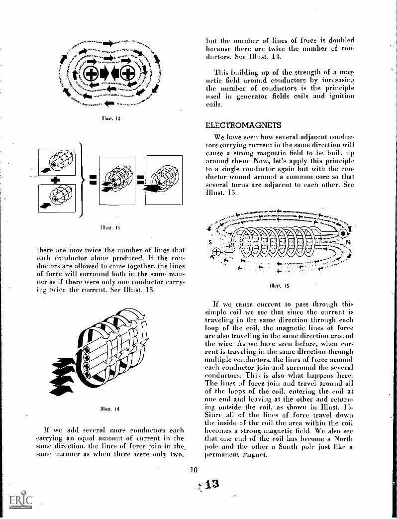
there are now twice the number of lines thateach conductor alone produced. If the con-ductors are allowed to come together, the linesof force will surround both in the same man-ner as if there were only one conductor carry-ing twice the current. See Illust. 13.
Illust. 14
If we acid several more conductors eachcarrying an equal amount of current in thesame direction. the lines of force join in thesame manner as when there were only two,
but the number of lines of force is doubledbecause there are twice the number of con-ductors. See Illust. 14.
This building up of the strength of a mag-netic field around conductors by increasingthe number of conductors is the principleused in generator fields coils and ignitioncoils.
ELECTROMAGNETS
We have seen how several adjacent conduc-tors carrying current in the same direction willcause a strong magnetic field to be built uparound them: Now, let's apply this principleto a single conductor again but with the con-ductor wound around a common core so thatseveral turns are adjacent to each other. SeeIllust. 15.
Must. 15
If we cause current to pass through thissimple coil we see that since the. current istraveling in the same direction through eachloop of the coil, the magnetic lines of forceare also traveling in the same direction aroundthe wire. As we have seen before, when cur-rent is trawling in the same direction throughmultiple conductors, the lines of force aroundeach conductor join and surround the severalconductors. This is also what happens here.The lines of force join and travel around allof the loops of the coil, entering the coil atone end and leaving at the other and return-ing outside the coil, as shown in Illust. 15.Since all of the lines of force travel downthe inside of the coil the area within the coilbecomes a strong magnetic field. We also seethat one end of the coil has become a Northpole and the other a South pole just like apermanent magnet.
a13

RIGHTHANDRULE
FOR COILS
NORTH
TDIRECTION OF CURRENT FLOWING
!Rust. 16
In order to determine which end of the coilis the North pole, all that is needed is to knowthe direction of current flow. With this in-fOrtnation, the Right Hand Rule for coilscan be applied. Place the right hand aroundthe coil so that the fingers are pointing in thedirection the coil is wound and the current isflowing. The thumb will then be pointingtoward the North pole. See Il lust. 16.
As we learned earlier. air is a rather poorconductor for lineS of force so that our coil inIl lust. 15 loses many of the lines of forcearound the coil to the surrounding air. Inorder to strengthen the field within the coil,it is necessary to place a soft iron core withinthe coil replacing the air. The soft iron canhe easily magnetized and will materiallystrengthen the magnetic field, See Must. 17.
II lust, 17
11
4
This then becomes a true electromagnet. Witha given amount of current flowing through acoil, the strength of the electromagnet pro-duced is directly proportional to the numberof turns in the coil. The strength of the elec-tromagnet of a given number of turns is alsodirectly proportional to the amount of currentpassing through the coil. By varying the num-ber of turns in the coil and the amount of cur-rent passing through it, virtually any strengthof electromagnet desired may be obtained.
MAGNETIC FORCE ONA CONDUCTOR
011
!Dust. 18
Vf
We have seen how magnetic fields aroundsingle and multiple conductors act when cur-rent is passing through them. Now, let's seewhat happens when a current carrying con-ductor is placed in a magnetic field created bytwo 'permanent magnets or electromagnetsplaced near each other with opposite polesfacing each other. As we would expect, sinceopposite poles attract each other, the lines offorce travel from the North pole of one mag-net to the South pole of the other across theair gap. Now, if we place a current carryingconductor in this magnetic field, we find thatthe field becomes distorted as shown. in Must,18. This reaction between the two magneticfields is to be expected .since magnetic linesof force traveling in the same direction joinand travel together, while lines traveling inopposite directions repel each other and arediverted around the conductor.

In Il lust. .18 we see, that the field aroundthe conductor has lines of force traveling ina clockwise direction. The field caused by thepermanent magnets has lines of force travel-ing from left to right. Therefore, these linesare,directed around and above the conductor.This creates a strong field above the conduc-tor and a weak field below it. Since lines offorce, being somewhat like stretched rubberbands, don't like this unbalanced condition,they tend to move the conductor into theweaker field to relieve the unbalance.
Must. 19
If the current carrying conductor, shownin Il lust. 1.8, is formed into a loop. as shownin. Illust. 19, and placed in the magnetic field.we see that the same unbalanced field condi-tion is created See Must. 20. The same forceis then applied to move the conductor out ofthe field. You will notice, however, that sincethe current in the loop is traveling in oppositedirections on 'each side, the field createdaround the conductor is also opposite. Thismeans then that each side of the loop will beforced out of the field in opposite directions.If this loop, then, is placed on a shaft sup-ported by bearings, it will rotate.
This force which is moving each side of theloop out of the field, Illust. 20, causes the loop
to rotate until the sides of the loop are as farout of the field as possible. When this pointis reached, these same forces will resist theconductors moving back into the field andthe rotation of the loop will stop. see Must. 21.This point is called the neutral position. In
12
'Dust. 20
4g-
<,.;41ebe
Illust. 21
order to keep the loop turning, it becomesobvious that it will be necessary to changethe direction of current flow through the wireloop at this point. This will reverse the mag-netic field around the wire and restore thecondition shown in Illust. 20. The loop willthen continue to rotate. We see from this thatin order to keep the loop rotating, it will benecessary to reverse the direction of currentflow every half turn of the loop to keep thelines of force acting in the same direction.This can be done by means of a device calleda commutator (Illust. 22). This device con-sists of two brushes sliding on contacts at-tached to each 'end of the wire loop. If thebrushes are properly located, we see that ifthe current comes in at one brush and out atthe other, the direction of current flow willchange at the neutral point and permit con-tinuous rotation.
b

FIELD MAGNETS SPLIT RINGCOMMUTATOR
I.
BRUSHES
Must. 22
CURRENTFLOW (CONSTANT)
This then is the principle which makeselectric motors possible. As we have learned,if we increase the strength of the magneticfields involved, the forces acting will be madestronger. Increasing the number of turns ofwire around a soft iron core will createstronger field magnets (called pole shoes inan electric motor), and increasing the num-ber of loops rotating in the field will cause agreater turning force on the conductors.
ELECTROMAGNETIC INDUCTION
We have learned that when a current carry-ing conductor is placed in a magnetic fieldrotation of the loop results. Now, let's consideranother condition which can be created witha conductor in a magnetic field.
It has been found that if a conductor, whichis not carrying current is passed through amagnetic field, voltage is built up in the con-ductor and if a complete circuit is connected.current will flow. The lines of force tend tobend around the leading edge of the conductorthus distorting the field (Illust. 23). It is thisdistortion of the field which causes voltage tobe built up in the conductor. As we mightexpect. the direction the conductor passesthrough 'the magnetic field determines thedirection the voltage will build up in the con-ductor. To determine the direction of the
13
16
S
DIRECTIONOF CONDUCTOR
MOVEMENT
NSTRETCHED.RUBBER BANDS
Illust. 23
Illust. 24
voltage induced, we can use the right handrule again. If the fingers are wrapped aroundthe conductor in the direction of the lines offorce which are bent mull& it, the thumb willpoint in the direction of the induced voltage.See Illust. 24.
MOVING CONDUCTOR;STATIONARY FIELD
CURRENT IN
11160. 25
CURRENT OUT
Using the right hand rule in Must. 25, wesee that if the conductor is moved to the rightthrough the magnetic field, the voltage in-duced will cause current to flow away fromthe observer. while if it is moved to the left

the voltage will build up in the opposite direc-tion causing the current to flow toward theobserver.
FIELD CIRCUIT
LOAD CIRCUIT
Must. 26
If we place a wire-loop and commutator ina magnetic field again as we did in Il lust. 22,but instead of passing a current through theloop, we merely connect the brushes to anexternal circuit, such as a light bulb, (Must.26), then we will turn the loop so that it cutsthe line of force in the magnetic. field. Wecan see that since one half of the loop is cut-ting the lines in one direction and the otherhalf is cutting them in the opposite direction,the voltage induced is in the same directionthroughout the loop and a current will flowthrough the light bulb causing it-to light. Thisprinciple is called electromagnetic inductionand is used in the design of generators. Welearn from this that any time a conductordistorts a magnetic field in any way, a voltagewill be induced in the conductor.
As we might suspect, the rate that the con-ductor moves through the magnetic field hasa great deal to do with the amount of voltageinduced, The faster the conductor moves, themore it will disturb the magnetic field and thegreater will be the voltage induced. This be-comes an important factor when designingelectric generators.
The principle of 'electromagnetic inductioncan be used to generate voltage in another way
Illust. 27
also, without needing a rotating coil. As wehave said, voltage is produced when a mag-netic field is disturbed or distorted. If we passa current through a coil, there is a magneticfield built up around the coil. Asthe currentstarts to flow, the magnetic field starts expand-ing also. While this field is expanding, a volt-age is being built up in the opposite directionof the voltage from the current source. Thisis known as counter °'voltage. This countervoltage causes an appreciable delay betweenthe time the current starts to flow and whenit reaches its maximum. Now, when the cur-rent is interrupted iirthe coil, the field startsto collapse and since the field is now changing,an induced voltage is again created in theconductor, but in the same direction as thecurrent had been flowing which tends to keepthe current flowing. This induced voltage willbe higher than the original voltage accordingto the number of turns in the coil.
Now, if another coil is wrapped around thefirst coil and current is passed through theinside coil only, we find that the magneticfield is now around both coils (Illust. 27). Inthis case, voltage will be built up in bothcoils when the field ,expands or contracts. Asa retiult of this condition, the voltage buildsnp in both coils when the current is inter-rupted and the field collapses. The amount ofvoltage built up in each coil is proportionalto the number of turns in the coils. For ex-ample, if the second coil has 100 times asmany turns as the inside coil, then the voltagewill also be 100 times as great. This principleis used in the design of ignition coils to createhigh enough voltage to cause a spark to occurat the-spark plug.

From the foregoing discussion, we see thatelectricity and magnetism are so closely re-lated that they are inseparable. We will seeas we apply these fundamentals to electrical
circuits on tractors and other farm equipmentthat both electricity and magnetism are util-ized in many ways.
Types of Circuits
We have learned that an electrical circuit isa continuous path from the source and backto the source. We also know that this pathmust be composed of conductors which willpermit current flow. These conductors may-be copper wire, or the frame of a machine orthe frame of a unit of a machine. As long as aconducting path is provided, current will flow.
As we said before, the simplest circuit is awire connected to a source of electricity suchas .a battery with one end of the wire at-tached to the positive terminal and the otherend attached to the negative terminal (Illust.28). As we know, current will flow throughthe wire. The amount of current which willflow will depend upon the, - amount of resist-ance in the wire. While this is a circuit, ithas no practical value since no work is beingdone.
AAA
BATTERY
710.Must. 28
In order to use electricity for useful work,it is necessary to put into the circuit some de-vice capable of doing some work. Supposethen. that we connect a light bulb into thesimple circuit, as shown in II lust. 29. As we
would expect, the bulb will light. The resist-ance in the bulb is added to the circuit andthere will be less current flowing in the cir-cuit than before. Now there is useful workbeing performed since tire light is burning.
A a
BATTERY
!Dust. 29
As circuits are made more complex due tothe introduction of more devices for doingwork, it becomes necessary to consider thetypes of circuits which can be used. Thereareseries circuits, parallel circuits and seriesparallel circuits.
The series circuit is composed of severalresistances which arc connected in such away that there is only one path in which the
15
8

1111111Iil
SERIES PARALLEL
Illust. 30
current can flow. A parallel circuit is onewhere there is more than one path for currentto flow (Illust. 30). The series parallel circuit,as the name implies, is a combination of theother two wherein some of the devices are
SERIES PARALLEL
connected in series and others in parallel.These three types of circuits are importantand must be understood in order to deal withelectrical equipment.
Measurement of Voltage, Current, and Resistance
In order to properly use electricity and con-trol it for our use, it is necessary to have somemeans of measuring voltage, current and re-sistance of the various components. We havesaid that electricity will flow in a conductor asa current of water flows, provided there ispressure, which we have called voltage, pres-ent to make it move. The unit of measurementfor this is called the "volt." The unit of meas-urement of current is called the "ampere"and the unit of measurement of resistance iscalled the "OHM." The relationship betweenthese three factors is very definite and con-forms to a very definite rule known as "OHMSLAW." This rule states that the electricalcurrent through a conductor equals the pres-sure divided by the resistance. In terms ofthe electrical units of measurement, this mayhe stated as:
VOLTSAMPERES = OHMS
By means of this equation if two of the quan-tities are known, the third can be calculated.
It follows then that we must have some wayof measuring at least two of these factors.
In order to make these measurements, it isnecessary to have instruments which willmeasure volts and amperes. These instrumentsare called voltmeters and ammeters. or a com-bination of both. Most. modern meter. move-ments are of the moving coil type which con-sists of a permanent horse shoe or hoopshaped magnet and a movable coil. Currentflowing through the movable coil reacts withthe permanent magnetic field causing the coilto rotate against a light spring tension. Therelative movement of the coil is in proportionto the amount of current flowing in the wind-ings. A pointer attached to the coil movesacross a calibrated scale indicating the amountof current flowing in the coil. See Illust. 31.
The same meter movement can be used foreither a voltmeter or an ammeter. It becomesa voltmeter when connected in parallel withthe circuit, and an ammeter when connected

AMMETER CIRCUIT VOLTMETER CIRCUIT
VOLTMETERSCONNECTEDIN PARALLEL
Must. 31
TII lust. 32
0AD
in series with the circuit. In order to obtainaccurate readings with these instruments, itis 'important that they do not disturb the cir-cuit when they are connected into it.
A voltmeter for example, being connectedin parallel with the circuit (Il lust. 32) mustbe a high resistance unit so that very littlecurrent can flow through the meter. Theammeter on the other hand must be a verylow resistance unit because it is connectedin series with the circuit (Must. 33) andmust not disturb the circuit when connected.
Some meters arc equipped to measure eithervolts or amperes depending upon how theyare connected. With this type of meter, youwill notice that when used as an ammeter,there is a conductor connected in parallelwith the meter movement( called a shunt)which carries most of the current, and only
a small amount passes through the meter.When it is connected as a voltmeter, a highresistance is in series with the meter to allowonly a very small amount of current to flowthrough the meter.
AMMETERSCONNECTEDIN SERIES
Must. 33
12V
Must. 34
In order to measure the resistance in acircuit, it is necessary to use a third type ofmeter called an OHM meter. We said before,however, that if we could measure two of theunknowns in OHM's law, we could calculatethe third. So, for our purposes, we will con-sider measuring voltage and current and cal-culate the resistance where necessary.
We can measure voltage by connecting avoltmeter across the circuit. This then, meas-ures the pressure or potential difference be-tween the two points. For example. if a volt-
701..an,

meter is connected across a 12 volt battery,there, will be a reading of 12 volts; however,if the meter is connected across one cell ofthe battery, there will be a reading of 2 volts.Because the cells are connected in series, thevoltage is multiplied. In the same manner,voltage measurements may be taken in aportion of a circuit connected to a battery.For example, if a voltmeter is connectedacross any one of the resistances in the cir-cuit shown in Illust. 34, a voltage reading canbe taken. This will be the potential differencebetween one side and the other of the resist-ance. The sum of the readings across eachresistor in the series circuit, shown in Illust.
34, will equal the voltage reading across thebattery terminals. The readings across indi-vidual segments of a circuit are called "Volt-age Drop" and the total voltage drop isequal to the potential at the sonrec. Measuringvoltage drop in a segment of a circuit is a com-mon way of detecting a poor connection in acircuit since a connection which. is poor,will have a high resistance to current flowand, therefore, a large voltage drop.
In a parallel circuit, the voltage drop acrosseach resistor will be equal to the potential ofthe current source since there is a separatepath for current to flow through each resis-tor.
Measurement of Electric Power
We have said that electricity is a form ofenergy and that if properly harnessed can bemade to do work. In order to be able to de-termine. the amount of work that electricityis doing, we need a unit of measurement whichwill indicate this. The amount of work whichis being done is normally considered in termsof rate of work per unit of time. The termused to describe this is power. Power then, isthe rate of doing work. The unit of powercommonly used is the horsepower. One h6rse-power is equal to 33,000 ft. lbs. of work perminute.
When dealing with electricity, the unit ofmeasurement of power is the "Watt." In terms
18
of horsepower, the watt is equal to 1;746 of ahorsepower.
The power that is being used in a circuitcan be readily determined by measuring thevoltage and current in the circuit and multi-plying them together. In other words, Power(Watts) VOLTS X AMPERES. If we sub-stitute values in this equation. we see that 1watt equals the amount of power producedwhen one ampere is flowing under one voltpressure. We can see from this equation thatas the power required increases with the samevoltage present, the current will increase. Thisis a very basic formula which explains whythe current draw in a circuit varies with theload imposed.

Current Flow in Series and Parallel Circuits
4f1
4 f/
1111111N-12V
SERIESA
4f1
111011111
12VPARALLEL
B
Illust. 35
We have learned from OHM's law thatthere is a definite relationship between volt-age, current and resistance in an electrical cir-cuit.' Lets see now how this applies to seriesand parallel circuits with a given resistance.To illustrate this, let's connect 3 four ohmresistors in series, as shown in "A," Il lust. 35.Since there is only one path for the currentto flow, the total resistance in the circuit is
Volts12 ohms. Since current =Ohms
(Ohm's
Law), we filid that one ampere of currentwill flow.
Now we will connect the same three resis-tors in parallel, as shown in "B," -Must. 35.
In this case, we have provided three differentpaths through which current can flow and
12V.SERIES PARALLEL
C
there is 12 volts pressure on each. This meansthat each resistor will draw 3 amperes or atotal of 9 amperes for the circuit.
If we take the same three resistors and makea series-parallel connection, as shown in "C,"Illust. 35, we see that the total resistance willbe 4 ohms plus half of the resistance value ofone of the resistances connected in parallelor 2 ohms which equals 6 ohms. In this case,the current flow will be 2 amperes.
It becomes apparent then, that if a highresistance is required in the circuit, a seriesconnection should be used and when a lowresistance is desired, a parallel connection isnecessary. These facts are of great importancein electrical design and must be understoodbefore electrical circuits can be serviced.

STORAGE BATTERIES
We are familiar with the fact that a bat-tery is a source of electricity and is commonlyused in electrical systems on farm tractors andfarm equipment. We think of a battery asbeing a storage tank of electricity. This is notquite true however, because what is actuallystored is chemical energy. The battery is,therefore, a device for converting chemicalenergy into electrical energy. Active materialswithin the battery react chemically to producea flow of direct current whenever a load suchas lights, cranking motor, or other currentconsuming device is attached at the batteryterminal posts.
BASICBATTERY
PLATEGRID
POSITIVEPLATEPb02
NEGATIVEPLATE
SPONGELEAD
Pb
1.1 L It
I I I' I'11:1
Illust. 36
INTERNAL CONSTRUCTION
The internal construction on the lead-acidstorage battery is relatively simple. The basicnuits are the positive and negative plateswhich are suspended in an electrolyte. Thecharged positive plates contain an active in-gredient called "lead peroxide' (PB0.2) andis a chocolate brown color. The negative plates
are sponge lead (PB) and are grey in color.(Must. 36). Alternate positive and negativeplates are assembled in a battery case withseparators in between to prevent plates con-tacting each other.
TERMINALPOST
NEGATIVEPLATEGROUP
SEPARATOR
POSITIVEPLATEGROUP
PLATE STRAPCASTING
ELEMENT
Must. 37
The positive plates are all connected to-gether and to the positive terminal post. Thenegative plates are also connected togetherand are connected to the negative tcrinimilpost. When these groups Of positive and nega-tive charged plates are assembled into a unitwith separators in between. as in Illust. 37.and electrolyte is added. they become .one cellof a battery. Three such cells are connectedin series to produce a 6 volt battery since eachcell generates about 2 volts. A 12 volt batteryis composed of 6 such cells connected in series.
CHEMICAL ACTION
The electrolyte used in the battery cell isa solution of sulfuric acid (ILS04) and waterOL:0). This solution is composed of 64%water with a specific gravity of 1.000 and 36%
202,3

acid with a specific gravity of 1.835. The spe-cific gravity of the resulting electrolyte is
1.270.
When the electrolyte is added to the batterycell, a chemical action takes place between theplates and the electrolyte, which causes anelectrical pressure (voltage) to build up be-tween the terminals. The voltage is normallyabout 2 volts per cell. When a circuit isattached to a battery, a current will flow. Thisis reasonable since we know that electricity ispresent in virtually all materials and onlyrequires a pressure to get it moving.
The chemical action which takes place ina battery during discharge is a changing fromone compound to another. For example, thelead peroxide (PB02) in the positive platebreaks down into lead (PB) and oxygen (02)and unites with the electrolyte (112SO4) where-in the lead (PB) unites with the sulphate(SO4) portion of the sulfuric acid (H2SO4)and forms lead sulphate (PBSO.t). The oxygenunites with the hydrogen (H2) thus releasedforming water (H20). At the same time, thesponge lead in the negative plate unites withthe sulphate (SOS) to form lead sulphate onthe negative plates also. As the dischargingprogresses, lead sulphate crystals form on boththe positive and negative plates and the watergoes into the electrolyte. Since the positiveand negative plates become more and morealike chemically during the discharge, thepotential of the battery drops and the currentwill finally stop flowing. The battery is thendischarged. Since the sulfuric acid in the elec-trolyte was being used up and water was form-ing during discharge, the specific gravity ofthe electrolyte is reduced also. This explainswhy a discharged battery is subject to freezingduring cold weather.,
Due to the nature of the active materialsused in a lead acid battery, it is possible torecharge the battery by applying an electriccurrent flowing in the opposite direction fromthat produced during discharge. This reversecurrent causes the chemical action in the bat-tery to reverse itself, that is. the lead sulphatein the plates and the water break down againand reform into lead peroxide (PB0) at thepositive plates and sponge lead (PB) at thenegative plates. The hydrogen (Ha) combines
21
with the sulphate (SO4) and forms sulfuricacid (H2SO4) in the electrolyte.
We can see from this chemical action thatduring discharge the electrolyte becomes moredilute since the sulfuric acid is being used upand water is forming. Conversely when thebattery is charged, sulfuric acid is formed andwater is used up. This causes the specificgravity of the electrolyte to go down duringdischarge and rise during charge. For thisreason, it is possible to get an indication of thestate of charge of the battery by taking a read-ing of the specific gravity of the electrolyte.The specific gravity of the electrolyte can bemeasured by the use of a battery hydrometer.
/( fi'll.
i
I11)
-7,--0--.
Must. 38
This device is composed of a tube in whichis placed a float which has a graduated scaleon it. Some of the electrolyte is drawn intothe tube and the level that the float rides atwill permit a reading to be taken at the pointon the scale which is even with the top ofthe liquid. (Must. 38). The top of the liquidcolumn should be held at eye level so thatan accurate reading can be taken.
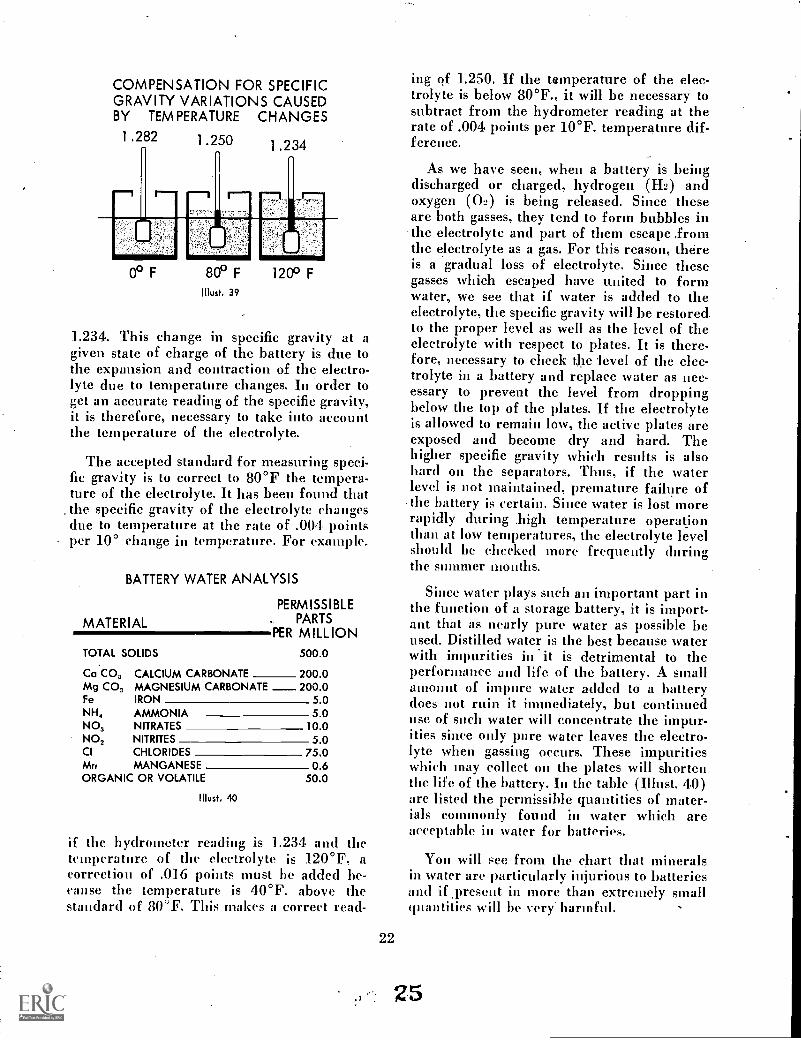
The specific gravity of the electrolyte isaffected not only by the state of charge of thebattery, but also by the temperature of theelectrolyte. As the temperature of the electro-lyte rises. the specific gravity is reduced.(Illust. 39). For example, if the electrolytemeasures a specific gravity of 1.282 at 0°Fand then the temperature is raised to 80°F,the specific gravity will have dropped to 1.250and at 120°F. the gravity reading will be
24
COMPENSATION FOR SPECIFICGRAVITY VARIATIONS CAUSEDBY TEMPERATURE CHANGES
1.282 1.250 1 .234
r-0
0° F
--1 r--
d11116800 F
illust. 39
120° F
1.234. This change in specific gravity at agiven state of charge of the battery is clue tothe expansion and contraction of the electro-lyte due to temperature changes. In order toget an accurate reading of the specific gravity,it is therefore, necessary to take into accountthe temperature of the electrolyte.
The accepted standard for measuring speci-fic gravity is to-correct to 80°F the tempera-ture of the electrolyte. It has been found thatthe specific gravity of the electrolyte changesdue to temperature at the rate of .004 pointsper 10° change in temperature. For example.
BATTERY WATER ANALYSIS
PERMISSIBLEPARTS
PER MILLIONMATERIAL
TOTAL SOLIDS 500.0
Ca CO, CALCIUM CARBONATE 200.0Mg CO, MAGNESIUM CARBONATE 200.0Fe IRON 5 0NH, AMMONIA 5 0NO, NITRATES 10.0NO, NITRITES 5 0CI CHLORIDES 75.0Mrs MANGANESE 0 6ORGANIC OR VOLATILE 50M
Must. 40
if the hydrometer reading is 1.234 and thetemperature of the electrolyte is 120°F, acorrection of .016 points must be added be-cause the temperature is 40°F. above thestandard of 80 °F. This makes a correct read-
22
ing of 1.250. If the temperature of the elec-trolyte is below 80°F., it will be necessary tosubtract from the hydrometer reading at therate of .004 points per 10°F. temperature dif-ference.
As we have seen, when a battery is beingdischarged or charged, hydrogen (IL) andoxygen (0:) is being released. Since theseare both gasses, they tend to form bubbles inthe electrolyte and part of them escape fromthe electrolyte as a gas. For this reason, thereis a gradual loss of electrolyte. Since thesegasses which escaped have united to formwater, we see that if water is added to theelectrolyte, the specific gravity will be restoredto the proper level as well as the level of theelectrolyte with respect to plates. It is there-fore, necessary to check the level of the elec-trolyte in a battery and replace water as nec-essary to prevent the level from droppingbelow the top of the plates. If the electrolyteis allowed to remain low, the active plates areexposed and become dry and hard. Thehigher specific gravity which results is alsohard on the separators. Thus, if the waterlevel is not maintained, premature failure ofthe battery is certain. Since water is lost morerapidly during high temperature operationthan at low temperatures, the electrolyte levelshould be checked more frequently duringthe slimmer months.
Since water plays such an important part inthe function of a storage battery, it is import-ant that as nearly pure water as possible beused. Distilled water is the best because waterwith impurities in *it is detrimental to theperformance and life of the battery. A smallamount of inquire water added to a batterydoes not ruin it immediately, but continueduse of such water will concentrate the impur-ities since only pare water leaves the electro-lyte when gassing occurs. These impuritieswhich may collect on the plates will shortenthe life of the battery. In the table (Illust. 4.0)are listed the permissible quantities of mater-ials commonly found in water which areacceptable in water for batteries.
You will see from the chart that mineralsin water are particularly injurious to batteriesand if ,present in more than extremely smallquantities will be very. harmful.
25

Water containing a high percentage of ironwill permit the iron particles to travel betweenthe positive and negative plates causing theplates to discharge.
Water obtained from volcanic areas usuallycontains a small amount of manganese whichwill combine with sulfuric acid to form astrong oxidizing agent which perforates theseparators. Manganese in the amount of afew parts per million is enough to destroy abattery in six weeks time.
Water for battery use should be stored inglass, rubber, or other non-metallic containersin order to keep the water as pure as Possible.Water stored in a metal container will in timepick up enough minerals from the containerto make it unsuitable for battery use.
EFFECT OF TEMPERATUREON BATTERY VOLTAGE
The voltage produced by a fully chargedstorage battery is normally a little more thantwo volts per cell, but this is affected by thetemperature, of the battery. When the tem-perature of the, electrolyte is cold, the resist-ance in the battery increases.
This means that a cold battery will requirea higher voltage in the charging circuit toovercome this resistance than .if it is warm.Illust. 41 shows a comparison of the batteryterminal voltage at various rates of charge
4
8>.11
NORMAL 3VOLTAGE w2REGULATORSETTING >-
ac
4m.
when the electrolyte is "cold," "warm," or"hot." Voltage regulators incorporate in theirdesign a provision for increasing chargingvoltage during cold weather to overcome thehigher resistance under these conditions.
BATTERIES IN STORAGEWhen a lead acid battery is not being used,
care should be taken to maintain the batteryin good condition until it is again placed inoperation. When a fully charged battery isplaced in storage, it will gradually lose someof its charge because all of the chemical activ-ity does not stop. While this discharge rate isconsiderably slower than when a dischargecurrent is flowing, it still does slowly becomedischarged. This means that the battery shouldbe recharged periodically to keep it in a fullycharged condition.
If a battery is allowed to remain in a dis-charged condition over a period of time, thesulphate crystals which form on the platesbecome hard and will not easily break downduring the charging process. This conditionis commonly called a sulphated battery.Batteries which have been allowed to self-discharge over a long period of time withoutboosting, or which have been discharged andallowed to remain undercharged for a longperiod of time show an increase in internalresistance due to the hard sulphate crystalswhich form on the plates. Such a battery willseldom perform satisfactorily when placed inservice.
112111111""PfirIv .... ... ,..
..'"IdIf . °°°°° -
....P.'...... ..541"..."..."'
I..... .. 4
OOOOOOOO*00_
OOOOOOOO
CHARGING RATE IN AMPERES
Must. 41
23
c*--. 2.6
COLD FULL CHARGE.
COLD 3/4 CHARGE
WARM FULL CHARGE
HOT FULL CHARGE
WARM 3/4 CHARGE
HOT 3A CHARGE

BATTERY CHARGING RATE
We have learned that when a battery isdischarged, the voltage at the terminals isreduced due to the fact that the active mater-ial in the positive and negative plates hasbecome more alike chemically. This meansthat when the battery is being recharged, itwill accept a high rate of charge at a givenvoltage to begin with, but as the battery be-comes recharged, the voltage of the battery in-creases and it will accept only a small current.This is a desirable situation in that if highcharging rates are used on a battery whichis almost fully charged, excessive gassing takesplace and the battery heats up. High chargingrates when a battery is in a discharged con-dition are desirable for rapid recovery, butshould be cut down as the battery nears fullcharge to prevent damage to the battery.
A battery which has become self-dischargedslowly should be recharged slowly to give moretime for the sulphate crystals on the plates tobreak down. This will happen if the sul-phated condition has not existed too long. Asulphated battery will tend to operate at ab-normally high voltages and if placed in anelectrical system with normal regulator set-tings will soon become discharged. Even themaximum allowable setting of the voltage reg-ulator can be ineffectual with such batteriesbecause they tend to heat excessively whencharged at higher rates. If such a battery isslowly recharged on a slow charger until thereis no further increase in specific gravity forthree successive readings taken at hourly in-tervals, the normal charging characteristicsof the battery can often be restored.
BATTERY CHECKS
Whenever electrical trouble is encountered,one of the first considerations should be thebattery. A visual inspection of the battery canoften indicate whether or not the trouble isat the battery. Mechanical damage to the bat-tery case, leakage or heavy corrosion at theterminals are indications of battery trouble.However, any analysis of electrical or chemi-cal conditions within the battery requires theuse of reliable testing instruments.
The basic instruments required for batterytesting are the hydrometer, thermometer and
24
voltmeter. In recent years, the open circuitvoltage tester has been introduced as a sub-stitute for the hydrometer. This tester, whichis essentially a voltmeter with an expandedscale, is especially convenient for checkingbatteries in storage since the vent caps neednot be removed. It will give satisfactory resultsif the instructions of the manufacturer areobserved carefully. For best results, however,use the battery hydrometer and correct fortemperature.
Another check which can be made on abattery is the load test or high rate dischargetest. The load test indicates the battery'scranking ability as well as indicating forms ofdeterioration and internal damage not other-wise detectable. The standard conditions forconducting load tests are as follows:
1. Battery specific gravity should be notless than 1.215 at 80°F.
2. Battery temperature should be between70°F and 90°F.
3. Battery discharge rate should be twicethe ampere hour rating of 6 volt bat-teries and three times the ampere hourrating of 12 volt batteries.
Place the recommended load across thebattery for approximately 15 seconds, thenmeasure the terminal voltage of the battery.If the terminal voltage falls below 4.5 voltson a 6 volt battery or 9.0 volts on a 12 voltbattery, possible trouble is indicated.
Frequently electrical trouble existing at thebattery is caused by poor connections at thebattery terminals. These connections tend tocorrode in time resulting in a high resistance.at this point. Such a condition may cause thecranking motor to fail to operate properly.It is well to keep battery cable connectionsclean and tight to insure against trouble atthis point. A thin coating of a heavy bodiedmineral grease or oil will help to retard cor-rosion.
Keeping the top of the battery clean isimportant especially with 1.2 volt batteries.Wash off the top of the battery with a solutionof baking soda or household ammonia andwater to neutralize the acid and rinse withclear water.
'41

CRANKING MOTOR CIRCUITThe cranking motor circuit consists of a
low resistance cable connection from the stor-age battery, through a control switch, to adirect current cranking motor and returningto the battery through the engine crankcaseand/or frame of the vehicle. A simplified dia-gram of such a circuit is shown in Il lust. 42.The large amount of current used to operatethe motor while cranking the engine requiresthat the cables be large enough and that allconnections be clean and tight to carry the
Illust. 42Cranking motor circuit.
current without undo resistance or voltagedrop. It should be noted that, since volts Xamperes = watts, a six volt system uses twiceas many amperes as a twelve volt system toaccomplish the same amount of work. There-fore, larger conductors are required on thesix volt system. It also should be noted thata twelve volt system will provide twice thenumber of watts (power) as a six volt systemusing the same amount of current (amperes).
CONTROL SWITCHESThe control switch of a cranking circuit may
be any one of a number of commonly usedtypes. It is always a low resistance, highcapacity unit but may be either manually orelectrically operated.
The manually operated switch may bemounted where it is directly accessible to theoperator or it may be mounted on the crank-ing motor frame and made accessible as shownin Must. 43.
25
FEA -64399
Illust. 43Cranking motor with manually operated starting switch.
Illust. 44.
'lo understand the operation of the mag-netic and solenoid switches we should reviewthe basic fundamentals of the electro-magnet.We have seen how a magnetic field is strength-ened by placing a soft iron core within a coiland how the polarity of the magnetic field inthe core is the same as that of the coil. If thecore is free to move and is placed at one endof the coil, as shown in Must. 44, the polarityof the core will be the same as that of the coil.Because the adjacent poles are of oppositepolarity the core will be drawn into the centerof the coil when current flows. When currentis stopped the magnetic field collapses andthe core is free to move again.
The electrically operated switch is alsomounted on the cranking motor frame. It isoperated by a magnetic coil which is energizedthrough a "start" contact in the ignition switchas shown in Must. 45.
The magnetic switch consists of a highresistance winding of many turns of small wirewound around a hollow core. Floating in thiscore is a plunger. one end of which acts as a

Connector Field coil aCoverband
Oiler
Magnetic switch
Thrubolt p Drive housing
Drive spring
krona
_27 a..
'1Ix up
m11111111Vis-3mirms... :ear
Commutator Brush Armature
Comm. end frame
Bronze\ bearing
::rive pinionFEA-64400
!Dust. 45Sectional view of cranking motor with magnetic switch.
contact between the two main switch termi-nals which are connected in series with thecranking motor. Normally a small coil springholds the plunger away from the main termi-nal contacts. When the circuit to the coil isclosed through the control circuit, a strongmagnetic field is created in the core, and theplunger is forced against the spring tensionto make a connection between the terminal-enntacts. This connection completes the maincircuit to the cranking motor, causing, theengine to he cranked. When the control circuitis opened at the ignition key or push buttonswitch, the magnetic field collapses and thespring forces the plunger to its original posi-tion and the cranking motor circuit is opened.
It should be noted that a standard Bendixtype of drive (Must. 45), which automaticallyengages and disengages the cranking motor111111011 with the flywheel ring gear is usedwith both the manual and magnetic switches.
starter switch
linkageshift lever
return spring
!Must. 46
Another type of control now in commonuse, especially on the larger engines, is thesolenoid switch, which is a combination ofthe magnetic switch and a mechanical link-age which shifts the cranking motor pinion
HOLD WINDING PULL WINDINGPLUNGER CONTACT DISC
BATTERY TERMINAL
TO STARTER SWITCH
STARTER
SWITCH
Illust. 47
into mesh with the flywheel ring gear. Seeillust. 46. The solenoid consists of two coils orwindings, wound in the same direction, one,which is of heavy. wire (known as the "pull-in" winding) connected to the motor termi-nal of the switch and through the motor toground, and one, which is of au equal num-ber of turns of fine wire (known as the hold-in winding) connected to ground (Must. 47 ) .The solenoid coils are energized direct fromthe battery through a "start" position op theignition switch or a push button switch.
Must. 48
CIRCUIT ATINSTANTSTARTERSWITCH ISCLOSED &PLUNGER ISSTARTINGTO MOVE
Since these coils are wound in the samedirection, and the current flows in the samedirection, a strong magnetic field is createdwhich pulls the plunger into the field. Thismovement of the plunger causes the motorpillion to engage thellywheel ring gear andat the same time closes the circuit across -thetwo main terminals to the cranking motor.See Blum. 48.
As shown in Illust. 49, the closing of themain -contacts shorts out the heavy or "pull-in" winding leaving only the fine or "hold-in"winding energized during the cranking period.The initial flow of current through the heavy
26
'29

or pull-in winding is of very short durationand cannot be measured with au ammeter.The flow of current through the fine or "hold-in" winding continues as long as the controlcircuit is closed.
It should be noted that, during the crankingperiod, a eircuit to the ignition coil is com-pleted. This circuit shorts out the resistanceunit in the permanent ignition circuit andthus provides a "hotter" spark during thecranking period.
1)L
lust. 49
CIRCUITDURINGCRANKING
II lust, 50
When the control circuit is opened the twowindings become connected in series and areenergized from the motor terminal as shownin 'Must. 50. The current now flows in a re-verse direction in the heavy winding, butcontinues in the same direction as beforethrough the fine winding, as the sameend of the fine winding is grounded.Since the number of turns in the two windingsare equal, and the ampere flow is equal, but
27
the direction of flow is opposite, the magneticfield of one coil nullifies that of the other andthe plunger is returned to its original positionby the spring. This movement opens thecranking motor circuit and the circuit to theignition coil. At the same time the crankingmotor pinion is pulled out of niesh with theflywheel ring gear and returns to its originalposition.
THE CRANKING MOTOR
Basically, the cranking motor is known asa series wound, direct current motor designedto provide high power for a limited time froma low voltage source, such as a storage battery.It consists mainly of two, four or six field poleswith windings, a wound armature with com-mutator two, four or six brushes.
We have learned that a current carryingconductor, formed into a loop and mountedon a shaft, will cause the shaft to rotate whenplaced in a magnetic field. We have furtherlearned that, if the direction of current flow inthe loop is reversed through a commutator asthe loop passes the neutral position, the loopand shaft will continue to rotate. It is obvious,tlubn, that many loops of conductors connectedin series through an equal number of seg-ments of a commutator (as in an armature)will increase the turning ability or power indirect relation to the number of loops. It alsofollows that the strength of the magnetic fieldwill effect the turning ability of the armature,and will be in direct relation to the nnmber offield poles and to the number of ampere-turnsOn each pole.
The design of a cranking motor then, willd(bpend On tine power required to crank theengine on which it will be used. In all casesthe armature windings are in series, through

Must. 51
the brushes, with the field windings. The fieldwindings may consist of two windings on fourpoles, four windings on four poles or six wind-ings on six poles (Illust. 51). Note that ineach case the field windings are wound toprovide alternate North and South poles. Notealso that in the four coil units, half the cur-rent passes through each pair of coils, and in
28
POLEPIECES
FIELD WINDINGS
I ARMATURE
Illust. 52
the six coil units, one third the current passesthrough each pair of coils.
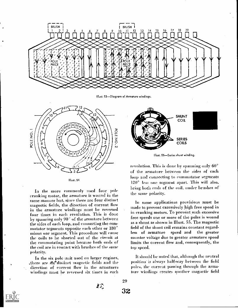
The armature must be wound to conformto the magnetic fields provided by the fieldpoles. In a simple two coil, two pole brushunit as shown in Illust. 52, each armature loopor winding is connected to one segment of thecommutator, passes through a slot in the lam-inated armature core, and returns throughanother armature slot 1800 from the first slot,and is then connected to a commutator seg-ment next adjacent to its starting segment or360' minus one segment. This second segmentis then connected through a second loop to thethird segment, and ,so on until the circuit iscompleted to the first segment (Must 53).Thus it will be seen that all the loops are con-nected in series. Now, if brushes wide enoughto contact two or more segments,. are placedon the commutator 180° apart, and voltage isapplied to the brushes. current will flowthrough all the loops except those shorted outby the two brushes. It will he noted that twodistinct and parallel paths are provided forthe current to follow, and that current flowsin the same direction in all conductors pass-ing before a pole piece. It will also be notedthat the direction of current flow changes atthe neutral position or between the magneticfields.
A more realistic diagram of the windings isshown in Illust. 54. Note that a lead of ap-proximately 90° is provided on either side ofthe brush in order to place the brush midwaybetween the sides of the loop and to effect achange of direction of enrrent flow as the looppasses through the- neutral position.
BRUSH 1
10 11 12 13 .14 15 16 17 18 19
Illust. 53Diagram of Armature windings.
II lust. 54
In the more commonly used four polecranking motor, the armature is wound in thesame manner but, since there are four distinctmagnetic fields, the direction of current flowin the armature windings must be reversedfour times in each revolution. This is cloneby spanning only 90' of the armature betweenthe sides of each loop, and ceecting the com-mutator segments opposite each other or 180°minus one segment. This procedure will causethe coils to be shorted out of the circuit atthe commutating point because both ends ofthe coil are in contact with brushes of the samepolarity.
In the six pole unit used on larger engines,,,there are gtx7distinct magnetic fields and thedirection of current flow in the armatureswindings must be reversed six times in each
29
32
SHUNTCOIL
SERIESCOILS
Illust. 55Series shunt winding.
revolution. This is done by spanning only 60°of the armature between the sides of eachloop and connecting LO commutator segments120° less one segment apart. This will also,bring both ends of the coil. under brushes ofthe same polarity.
In some applications provisions must bemade to prevent excessively high free speed inin cranking motors. To preventsuch excessivefree speeds one or more of the poles is woundas a shunt as shown in Illust. 55. The magneticfield of the shunt coil remains constant regard-less of armature speed and the greatercounter voltage due to greater armature speedlimits the current flow and, consequently, thetop speed.
It should be noted that, although the neutralposition' is always half-way between the fieldpoles, the current passing through the arma-ture windings creates another magnetic field

which distorts the normal field between thepoles as shown in Il lust. 56. For this reasonthe actual neutral position is behind (in thedirection of rotation) the center point oncranking motors and ahead of the center pointon generators. Therefore, the brush locationis set to compensate for this variation and toeliminate excessive sparking at the brushes.
It has been pointed out that crankingmotors are low-resistant and high powered.Therefore, the amount of current used willhe high. The number of amperes will, ofcourse, depend upon the voltage and thepower required, and will vary from 100 to300 amperes or more.
CRANKING MOTOR LOADNEUTRAL
Ignition Circuit
The gasoline engines used in tractors andother farm equipment depends upon electric-ity to ignite the fuel and air mixture in thecomustion chamber. In order for this ignitionto take place, it is necessary to have a sparkoccur in the combustion chamber. This sparktakes place when electricity jumps across thegap between the electrodes of a spark plug.This spark must occur at the proper time inthe combustion chamber so that the burningfuel can exert pressure on the piston to causethe crankshaft to 'rotate.
The electrical circuit which provides thisspark at the spark plug is known as the igni-tion circuit. The ignition circuit is differentfrom the other electrical circuits we have dis-cussed in that there is a permanent opening inthe circuit at the spark plug. This means thatif electricity is to flow past this point, it mustjump this gap to complete this circuit. In orderto understand how this can be done, wemist examine the components of the ignitioncircuit.
30
Illust, 56
We know from Ohms law that the currentflow in a circuit is a function of the voltageand the resistance. Since the air gap betweenthe points at the spark plug is a high resistancein the circuit, we see that if any current is toflow at all, the voltage or pressure will have tohe increased. In fact, the voltage will have tobe increased substantially above that fur-nished by a battery or generator to make aspark jump the gap at the spark plug. It hasbeen found that it takes 20000 volts per centi-meter of air gap between needle points to makea spark jump.
INDUCTION COILSWe learned from our study of electro-
magnetic induction that if we pass a currentthrough a coil we can induce a voltage ina second coil wrapped around the first if weinterrupt the current flow in the first coil. Thevoltage induced in the secondary coil is pro-portional to the relative number of turns ineach coil. We see then that if we have only a
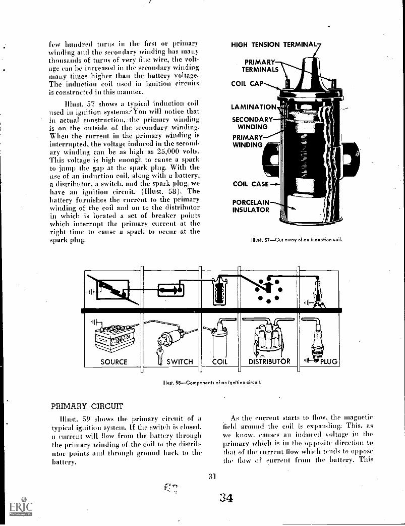
few hundred turns in the first or primarywinding and the secondary winding has manythousands of turns of very fine wire, the volt-age can be increased in the secondary windingmany times higher than the battery voltage.The induction coil used in ignition circuitsis constructed in this manner.
Must. 57 shows a typical induction coilused in ignition systems:'You will notice thatin actual construction,_ the primary windingis on the outside of the secondary winding.When the current in the primary winding isinterrupted, the voltage induced in the second-ary winding can be as high as 25,000 volts.This voltage is high enough to cause a sparkto jump the gap at the spark plug. With theuse of an induction coil, along with a battery,a distributor, a switch, and the spark plug, wehave an ignition circuit. (Must. 58). Thebattery furnishes the current to the primarywinding of the coil and on to the distributorin which is located a set of breaker pointswhich interrupt the primary current at theright time to cause a spark to occur at thespark plug.
HIGH TENSION TERMINAL
PRIMARYTERMINALS
COIL CAP
LAMINATION
SECONDARYWINDING
PRIMARYWINDING
COIL CASE
PORCELAININSULATOR
Must. 57Cut away of an induction coil,
INit,il 3.,
f
a L IV:4J! ----, 1 ...0000
SOURCE
Fil)
SWITCH COIL DISTRIBUTOR
n"II' PLUG
LI
!Must. 58Components of an ignition circuit.
PRIMARY CIRCUIT
'Must. 59 shows the primary circuit of atypical ignition system. If the switch is closed,a current will flow from the battery throughthe primary winding of the coil to the distrib-utor points and through ground hack to thebattery.
31
As the current starts to flow, the magneticfield around the coil is expanding:- This, aswe know. causes an induced voltage in theprimary which is in the opposite direction tothat of the current flow which tends to opposethe flow of current from the battery. This
34

DISTRIBUTOR
.00
0 II.4 PRIMARY
SECONDARY;
IGN ITIONSWITCH
BATTERYLGN IT IO N
COIL
Illust. 59Primary circuit of ignition system.
causes a slight delay in the current flowreaching its maximum. This self-induction be-comes an important factor when an engine isoperating at high speed.
When the points open, the current in theprimary circuit stops and the magnetic fieldcollapses. When this happens, there is a self-induced voltage built up in the primary coilwhich tends to keep the current flowing. Aswe know, the more suddenly the current isinterrupted, the higher will be the inducedvoltage in the secondary winding. Therefore,this self-induced voltage which is built up inthe primary causes a spark to jump across thepoints, blurting them. In addition, the currentflow does riot stop quick enough to induce thehigh voltage needed in the secondary circuit.
Illust. 60Condenser action.
CONDENSER ACTION
In order to overcome this, a device calleda condenser is connected across the points.The function of the condenser is to absorbcurrent flow momentarily to prevent arcing atthe distributor points. (Must. 60). When the
32
STANDARDDUTY
HEAVYDUTY
ADDITIONALINSULATION
Illust. 61Construction of condenser.
points separate, the condenser absorbs thecurrent momentarily, stopping the current flowacross the points. This action builds up ahigher voltage in the secondary. In addi-tion, since the current is absorbed in thecondenser, it prevents arcing at the points.It should be understood that current can-not flow through a condenser but onlyinto it. The condenser is composed oftwo foil sheets which are separated by insula-ting paper and rolled up together. (Illust. 61).One of the foil sheets is grounded to the caseof the condenser and the other is connectedto the insulated lead at the other end of thecondenser. Since the two foil sheets are con-nected only through the .primary circuit, cur-rent cannot pass from one sheet to the otherexcept to go through the primary circuit. Withthis situation, the primary current flows intothe condenser when the points open. Thischarges up the condenser. When the voltagein the condenser gets higher than in the pri-mary of the coil, it discharges back throughthe primary. In effect, there is an oscillatingaction between the condenser and the primarywhich continues until all of the remaining coilenergy is dissipated.
SECONDARY CIRCUITThe induced voltage in the secondary coil
builds up, when the primary circuit is inter-rupted, to whatever level is required to jinupthe gap at the spark plug. This may be any-where from 4,000 - 20,000 volts, dependingnpon the conditions in the engine.
The secondary coil has one end attached toone end of the primary winding,. (Illust. 59),and the other end is connected to the hightension terminal of the coil. A heavily insula-ted wire carries the current to the spark plug.
55

The secondary circuit is completed throughthe battery and primary circuit. Since thesecondary voltage is so high, it is necessaryto have much heavier insulation on the sec-ondary wiring than on wire carrying low volt-age, to prevent short circuits. The heavy por-celain insulator round the center electrode ofthe spark plug is there to prevent short cir-cuits within the spark plug itself.
DISTRIBUTOR
In order for the spark to occur at the rightcylinder at the right thee, the distributor in-cludes a cam which opens and closes thepoints and also a rotor and cap which dis-tributes the spark to the correct cylinder. Thetime when the spark occurs is controlled byhe relationship between the cam and thepoints in the distributor. Adjustment 'of theignition timing is accomplished by changingthe position of the fibre actuating arm on themovable distributor point with respect to thelobes on the cam. This is done by rotatingthe body of the distributor with respect tothe cam. Rotating the distributor body in thedirection of cam rotation will retard the sparkand rotating it in the opposite direction willadvance the timing.
DUST SEALROTOR
CONDENSERL
BREAKER
CAMWEIGHTSPRING
TERMINAL
BREAKER LEVER
ADVANCEWEIGHT
CONTACT SUPPORT
WEIGHT BASEAND SHAFT
BRONZE
COUPLING
'Must. 62Cut away of a distributor,
GREASECUP
FEA-64407
It is also necessary for best operation of anengine to advance the timing as the enginespeeds np. This is done automatically in thedistributor by means of a set of weights.(Must. 62). Centrifugal force causes theseweights to separate as. the engine speeds LLp
which shifts the cam ahead with respect tothe breaker points thus advancing the timing.You will note also in Must. 62 that the con-denser is connected directly across the pointsso that when the points open, the current flowsinto ,the condenser as described above.
C717
101
ROTORSPARKPLUGS
DISTRIBUTOR
33
36
BATTERY IGNITION COIL
Illust. 63Primary and secondary ignition circuit.
We see from our examination of the ignitionsystem that there are actually two circuits.one a low voltage primary circuit and theother a high voltage secondary circuit. Must.63 shows a typical ignition circnit. The pri-mary circnit is shown in red and the secondaryin blue. You will note that the distributorrotor takes the high voltage current from thecenter terminal of the distributor cap anddirects it to the various terminals near theedge of the cap. If the correct leads to thespark plugs are placed in these terminalsaccording to the firing order of the engine.the sparks will occur at each plug in the rightorder.
As we know. the direction of the 'mild upof Nroltage in a coil is dependent upon thedirection the current flows through the pri-mary circuit. The direction the high voltagecurrent will flow in the secondary circuit isdependent ilium how the coil is hooked intothe primary circuit. It is a known fact that a

spark will jump more readily from a hot sur-face to a cool one than it will from a cool toa hot one. Since the center electrode of thespark plug is hotter than the grounded one,it is desirable to place the coil in the -primarycircuit so that the secondary current flow willbe from the center electrode of the sparkplug to ground. It takes about 5.000 volts lessto make the spark jump from the center elec-trode to ground than in the reverse direction.For this reason, the primary terminals on thecoil-are marked (-I-) and (). If the negativeterminal of the battery is grounded. then thenegative terminal of the coil should heattached to the distributor terminal. If thepositive terminal of the battery is grounded,then the positive terminal of the coil shouldbe connected to the distributor.
DIALINDICATORFOR CHECKINGPOINT OPENING
POINTSCLOSE
II lust. 64Checking point opening with dial indicator.
POINTSOPEN
DISTRIBUTOR POINT SETTING
The amonnt that the distributor pointsseparate as the cam opens and doses them isan important consideration which should notbe overlooked. If the point setting is too wide,the points will not only open sooner, but willstay open longer which means that the buildup time for the coil will be shorter. This canbe a disadvantage at high speeds because thecoil may not have time to build np enoughvoltage to fire the spark plug. If the pointopening is too narrow. the points will openlater and dose sooner. While this increasesthe length of time the points are dosed (camangle) it also causes the rubbing block to con-tact the cam at a point where a slow rate ofbreak occurs. The result is more arcing at thecontact points and sometimes missing of theengine. It is, therefore. important that the
34
point gap be set according to specificationsfor the application. When checking thebreaker point opening, a dial indicator shouldhe used, as shown in Mist. 64, to check theopening accurately. This is far better than try-ing to measure with a feeler gauge since the re-sults are much more accurate especially if thecontact surfaces of the points are the least bitpitted or irregular.
RESISTOR
let 0
so-
II lust. 65Showing resistor in primary ignition circuit.
RESISTANCE IN 12 VOLT SYSTEM
When a 12 volt system is used, it is a com-mon practice to use an external resistance Illthe primary ignition circuit to reduce thevoltage to approximately 6 volts. (Illust. 65).This resistance is in the circuit when theengine is running, but is shorted out of thecircuit during starting. The cranking motorsolenoid usually has a switch incorporated init which shorts the resistance out of the igni-tion circuit when the cranking motor switch isclosed. This gives full battery voltage on thecoil for starting and then, when running, theresistance etas the voltage back.
As we know, when the temperature of aresistor rises, its resistance value increases.With this external resistance at low speed. itis hotter because of the longer contact time.This means that its resistance will be higher

at low speed than at high speed. At highspeeds, this resistor then will be cooler clue tothe shorter contact time and will, therefore,permit more current to flow in the coil. Thisfeature stretches out the performance of the
coil and provides higher voltage at top speed.This helps to keep the engine firing at topspeed and reduces danger of burning distribu-tor points at slower speeds when contact timeis the longest.
Charging Circuit
We are familiar with the fact that a batteryis a chemical source of electricity and iscommonly used in electrical circuits on tractorsand other farm equipment. We also know-thatthere is a limit to the amount of electricitywhich can be drawn from a battery, and whenthat limit is reached, it will no longer producecurrent in the quantities needed. It, therefore,becomes necessary to provide another sourceof electricity to supplement and replenish theelectricity furnished by the battery.
A storage battery can be recharged simplyby reversing the flow of current through it.This action reverses the chemical activity inthe battery so that it can again deliver currentto the circuits attached to it. The generator isa device for converting mechanical energyinto electrical energy. The geerator cannotdeliver any electrical energy, however, nnICSit is being driven by the engine so it is nec-essary to have the battery to supply the energy,,-required for starting the engine. The gener-ator can then take over and supply energy tooperate the electrical system on the machineas well 'as recharge the battery.
Whether the energy required for the electri-cal system is supplied by the battery or thegenerator or both depends on the conditionsender which the generator operates.
If the engine is stopped, the battery fur-nishes all of the energy since none can be fur-nished by the generator. Note that in Illust.66. "A" the switch is open., separating thegenerator from the circuit. When the engineis operating at medium speeds, "B", the gen-erator supplies part of the current and thebattery supplies- the rest. When the engine
35
Illust. 66--Showing three conditions of generator circuit withengine stopped, medium speed and high speed.
speed is increased, "C" the generator suppliesall of the energy required for the electricalsystem and also energy to recharge the battery.It can be seen that if the battery is to berecharged, the generator must supply all ofthe energy for the electrical circuits.
We see from Illust. 66 that the generator,a switch, the battery, and the load are all con-nected into a circuit or circuits and operatetogether. The battery furnishes current to theload when the generator cannot, and the gen-erator picks up the load and recharges thebattery when its speed picks up.

SHUNT GENERATOR PRINCIPLESIn order to sec how a generator functions
in the system, let's take a closer look at whatit does. As we learned from the principle ofelectromagnetic induction, a wire loop cuttingthrough a magnetic field causes a voltage tobuild up in the loop and a current to flow ifa circuit is attached to the ends of the loop.We also learned that a commutator must beused with brushes to reverse the current flowin the loop at the neutral point. See Illust.26 under "Fundamentals of Electricity."Since one loop will generate only a very smallvoltage, it will have little value as a generator.However, if we add more loops and morecommutator bars and connect the loops inseries with each other, then the voltage gen-erated would be added and more current canthen flow (Illust. 67). This, then, is the basisof the construction of the rotating member ofthe generator which is called the armature.The armature is wound with a number of coilsof wire on a soft core so that there are a largenumber of conductors to generate voltage.These coils are connected in series to the com-mutator bars in the same manner as the arma-ture for the cranking motor. In the case ofthe generator, the wire used is considerablysmaller because it is not required to carrysuch a high current.
In order to strengthen the field in whichthe armature rotates, an iron frame is placedaround the poles which, as we know, strength-ens the magnetic field by providing a conduct-ing path for magnetic lines of force betweenthe poles. See Il lust. 68.
BRUSH POLE PIECE FIELD COIL
II lust. 67Showing several loops in armature.
AIR GAP IRON FRAME
IRON ARMATURE CORE
IRONPOLE
PIECE
Illust. 68Showing magnetic lines of force traveling in frame.
In addition, the field poles are soft ironwith field coils, wound around them so thatthe strength of the magnetic field can be stillfurther increased. The current for the fieldcoils. is obtained from the armature as itrotates. Must. 69 shows the modern generatorand the electrical diagram of the unit. We see
AROSSSECTIONAL
V EW
ELECTRICALDIAGRAM
II lust. 69Cross Section of Generator.

then that the three basic fundamentals fordeveloping current and voltage are being usedin the construction of the generator, namely,strength of magnetic field, the number of con-ductors on the armature and the speed ofarmature rotation.
We learned that the speed at which a con-ductor cuts lines of force affects the voltagewhich is built up in the conductor. This beingtrue, the faster the armature of the generatorturns the higher the voltage will build up.This means that the voltage developed withinthe generator will climb to any value neces-sary to overcome the resistance in the attachedcircuits, providing the .speed of the armatureis sufficient. If the total resistance in theattached circuits is low, generator voltage willbe low, if the attached circuits total resistanceis high, generator voltage will be high. Sincethe field coils in the generator and many ofthe external loads can be damaged by exces-sively high voltage, some method of voltagecontrol is necessary. This voltage control ishandled by means of an external unit calleda voltage regulator.
Current flow through the generator is theresult of the voltage developed in the arma-ture coils. The amount of current flow in thearmature and in the attached circuits dependsupon the voltage developed and the resistancein these circuits. If the total resistance of theattached circuits is high, the generator voltagev:i!I be as high as the voltage regulator willpermit, and the current flow will he low. Ifthe resistance in the attached circuits is low,the current flow will he high provided thegenerator speed is sufficient. Armature over-heating can result from the high current flow.
Overheating of the armature can damagethe insulation and varnish used to bind theconductors in the armature slots. The solderedconnections at the commutator bars can alsobe melted by excessive heat. To prevent thiscondition, an external unit called a currentregulator is used to limit the current .flow inthe generator.
There is another source of heat in the arma-ture which must be considered and that is"iron loss." The iron tore of the armatureacts as one large conductor which cuts lines offorce. and generates voltage in the tore itself.
3744; 40
The resulting current flow is called "eddy cur-rents." These currents produce heat which isadded to the heat generated by the coils them-selves. To reduce the eddy current in the coreas much as possible the iron core of the arma-ture is laminated. This procedure preventslarge voltages Wilding up and the eddy cur-rents are kept small and less heat is developedin the armature (Must. 70).
EDDY CURRENTS CREATE HEAT
(....-7 ,..,..i.t ,.....c=2._
1....i,e
m A-" ,v-
\...,.,
Illust. 70Eddy currents create heat.
PLACING A FANON THE GENERATORDRIVE PULLEY
Must. 7IGenerator ventilated by fan.
We see from this that one of the limitingfactors in generator output is heat and musthe considered in the design of the generator.Many generators have provisions for passingair through them to help carry the heat away.This is often done by placing a fan on thegenerator drive pulley which draws airthrough the generator (Must. 71). Air mayalso be forced through a generator from anexternal source through a blast tube. This willcool the generator and permit a higher currentrating than if it were not cooled.
ARMATURE REACTION
W. learned when studying electromagneticinduction that when a conductor cuts throughlines of force that these lines of force becomebent causing the neutral point to shift fromthe mechanical neutral point which is half

way between the poles. This shifting of theneutral position is due to what is called"armature reaction."
In the case of the cranking motor, welearned that the "load neutral" point is shiftedahead of the mechanical neutral point because
CRANKING MOTOR LOADNEUTRAL
NEUTRAL 'MECHANICAL/ I NEUTRAL
GENERATOR LOAD NEUTRAL
Illust. 72 Load neutral
the lines of force bend around the trailingedge of the armature conductors. In the caseof the generator, the lines of force are bentaround the leading edge of the armature con-ductors which causes the load neutral pointto shift ahead of the mechanical neutral point.See Il lust. 72.
Inasmuch as the current flow in the arma-ture conductors reduces to 0 at the load neu-tral point, this means that commutation shouldtake place at this point. Since no current isflowing in the coil at this point, the coil canhe shorted out of the circuit without causing
38
arcing at the brush. In view of this, the brushesshould be moved to the load neutral positionfor best operation. The actual position of thisideal commutating point is affected by thespeed of the armature and the load applied.This means that in actual operation, the loadneutral point is constantly changing. For thisreason, a brush location is chosen which willbe the:: best average position and cause theleast arcing under the most usual operatingcondition.
In actual practice the brushes themselvesare not in the load neutral position but thearmature coils are attached to the commutatorsegments which are under the brushes whenthat coil is in the load neutral position.
GENERATOR CIRCUITS
Now that we have seen how a generatorconverts mechanical energy into electricalenergy, let's examine the electrical circuitsin a standard two brush generator to see howthe unit operates. There are actually three cir-cuits which involve the generator directly.One is the charging circuit (Illust. 73) whichstarts at the insulated brush of the generator,out through the battery to ground and backthrough the ground to the grounded brush inthe generator. The second circuit is the loadcircuit which starts at the insulated brushand out to the load and back through theground '(usually the frame of the machine)to the grounded brush in the generator. Thethird circuit starts at the insulated brush andpasses through the field coils, the regulator,and back to ground.
CHARGING CIRCUIT
If we examine the charging circuit shown inIllust. 73 more closely, we see that if thecircuit went directly from the insulated brushin the generator to the battery, a circuit wouldbe complete regardless of whether the genera-tor is running or not. This means that thehat-tery would discharge through the generatorwhenever the generator is stopped. In orderto prevent this happening, an automaticswitch is inserted in the circuit called a cut outrelay. This cult out relay is composed of a setof contact points. one of which is stationaryand is connected to the line to the battery.
tor

CUTOUT RELAY
Must. 73Circuit diagram of two brush generator with cut out.
The other point is movable and is mounded onall arm called an armature which is pivoted.A spring attaehed.to this armature keeps thepoints separated so that current cannot flowunless the points are closed. Just beneath thearmature is a soft iron core. On this core arewound two coils. One is composed of a fewturns of heavy wire which is connected illseries with the charging cirenit and throughwhich all current in charging circuit must (low.The second coil is composed of a large numberof turns of fine wire and is connected as ashunt with one end grounded. See Il hist. 73.
When the generator is stopped, the springtension holds the points open so that the bat-tery cannot discharge through the generator.As the generator picks up speed, voltage buildsup in the cut out coils and current flowsthrough both coils which are now in series toground. This action maonetizes the core which,when the voltage gets high enough, will pullthe points closed and allow current to flowto the battery. The coil with the fine windingnow becomes a shunt roil and carries a smallamount or current which goes directly to
ground without going through the battery.
39
42
When the generator slows down to a pointwhere the voltage of the generator is less thanthat of the battery, the enrrent starts to flowback through the generator. When this hap-pens, the current is reversed in the heavyseries winding. However, sinee the fine shuntwinding still has the same end of the coilgrounded,unded, the current flowing through it willbe in the same direction as before. Since thedirection of current flow in the series windingis reversed, its magnetic field is also reversedand will oppose the field of the shunt coil.This weakens the field to a point where thespring on the armature can separate the pointsand stop the current flow.
The voltage at which the points dose in thecut out relay can be adjusted by changing the
tension of the spring on the armatnre. It is
important that thiS adjustment be made sothat the "cut in" point is tua right at the idlespeed of the engine. The reason for this is thatengines do not idle at a uniform speed there-fore, if the "(lit in" point is right at idle speedthe points will tend to open and close rapidly.causing.buirning of the points in the relay. The"ent in" point should be at least 1 00 rpmabove or below engine idle speed to avoid this.
LO AD CIRCUIT
The load circuit starts' at the insulated brushin the generator, passes out through therelay, through the load, and back throughground Indto the grounded brush in the o. 'era-ntor. This places the load in parallel with thegenerator and the battery. so that current canbe supplied by either the battery or the gen-erator as described on page 35.
FIELD CIRCUIT
The shunt field circuit is the third circuitwhich starts at the insulated brush in the gen-erator, passes through the series field coils andthrough, the regulator to ground. This circuitcauses the field 'strength to increase as thegenerator speed increases and the voltagebuilds up in the generator.

CONTROL OF GENERATOR OUTPUTWe have seen from the foregoing that the
output of the generator depends upon thespeed of the generator and .the amount ofload in the circuit. If there is low resistancein the charging and load circuits, the currentflow from the generator will be high providedthe speed of the generator is great enough.We also know that if the speed of the genera-tor is high enough, the voltage will rise toalmost any height required to overcome highresistance in the circuit. This means that inorder to prevent high voltages from beingimpressed on load and charging circuits, it isnecessary to have some control over the gen-erator voltage.
VOLTAGE REGULATOR
If a generator has a control on the maximumspeed at which it can operate, such as is thecase on tractors which have governed enginespeed, this will serve to protect the generatorfrom becoming overloaded. However, it willnot prevent the voltage from becoming toohigh. In order to prevent high voltage frombuilding up to damaging levels, it is necessaryto provide some means of controlling the volt-age. This is done by an external unit called avoltage regulator.
The function of the voltage regulator is tocontrol the strength of the magnetic field inthe generator which, as we know, will controlthe voltage built up in the generator. The volt-age regulator, like the cut out relay, has avoltage sensitive coil of fine winding on a coreand a set of points which are held closed bya spring. This voltage sensitive shunt coil isconnected acro'ss the generator brushes so thatfull generator voltage is impressed on it at alltimes, (Illust. 74). As the voltage builds upin the generator, the .soft iron core of thevoltage regulator becomes magnetized to apoint where it pulls the points apart. Whenthis happens, the field current cannot go direct=ly to ground, but must pass through a resist-ance first. This reduces the field current, andtherefore, weakens the magnetic field betweenhe field poles. This causes a reduced current
and voltage in the armature circuit. Thisaction also reduces the strength of the mag-netic relay in the regulator and allows thepoints to close. The voltage again starts to
VOLTAGE REG
i 4 J
VEHICLE FRAME
Must. 74Circuit diagram showing voltage regulator only.
-41P"
climb to a point where the points open.In actual operation, the voltage regulatorpoints open and close rapidly and are saidto vibrate. The vibrating action of the pointsis so rapid that a voltm'eter will register onlythe average voltage developed. With the volt-age regulator in the field circuit, the voltageis held down to safe levels and preventsdamage to units in the load circuit and alsoprevents overcharging the battery.
Since the voltage regulator permits high cur-rent to flow as long as the voltage is below thelevel set by the regulator, the battery can becharged at a high rate when the battery is low,and will cut down the rate when the batterybecomes charged and its resistance is high.This will reduce the tendency for the batteryto give off gasses and will, therefore, minimizethe need for adding water to the battery.
CURRENT REGULATOR
The voltage regulator cannot control thecurrent output of the generator if the resist-ance in the load and charging circuits is low.since the generating voltage is below that setby the regulator. If the speed of the generatoris high enough. the current flow may be sogreat as to cause overheating of the generator.In order to protect the generator from suchoverloads, a current regulator is used to limitthe current flow to safe levels.
40 4:3

CURRENT REG
VEHICLE FRAME
Illust. 75Circuit diagram showing current regulator in circuit.,
Illust. 75 shows a current regulator in thecircuit. The current regulator is similar in itsoperation to the voltage regulator, except thecoil which opens the points is in series withthe armature circuit and all current except thefield current must pass through it. This is aheavy coil and it causes the points to openwhich places a resistance in the field circuitand thus rednecs the current output of thegenerator. In this manner, both the voltageand the current can be controlled within safelimits.
In actual practice, the cut out relay. thecurrent regulator, and the voltage regulatorare placed together in one unit. Must. 76shows the circuit diagram of . the so- calledthree unit regulator and how it is connectedinto the circuit. You will notice that thereare three terminals on this regulator, onemarked "F", one marked "Gen" and onemarked "Bat". To connect the regulator intothe circuit, a lead is attached to the field ter-minal on the generator and to the "F" ter-minal on the regulator. The armature terminalis connected to the Generator terminal on theregulator and the lead from the batterythrough the ammeter is connected to the bat-tery terminal of the regulator.
You will note in Illust. 76 that there is afield series winding wound on the core of thevoltage regulator in addition to the shuntwinding. This coil is only a few turns of rela-tively heavy wire which is also voltage sensi-tive and helps to open the points. This coilserves to increase the rate at which the pointsvibrate and thus keeps the voltage more con-stant.
Note that there are two resistances connected in parallel in the field circuit. Whenthe current regulator points open, the fieldcurrent flows through both resistances inparallel to ground. This places less resistancein the field circuit than when the voltage reg-ulator points open. In this case, the field cur-rent must pass through one resistance toground. This is a desirable situation since thefield current needs to be reduced only slightlyto protect the generator from overheating, butneeds to be cult down drastically to preventovercharging a fully charged battery.
COMBINATION CURRENT ANDVOLTAGE REGULATOR
Another type of regulator which is used onmany tractor applications is what is calleda combined current and voltage regulator.This regulator is a two unit type incorporatinga cut out relay and a combined current andvoltage relay which has three windings on onecore, one set of points. and one resistance.See Illust. 77.
You will notice from the circu'it diagramthat there is a series winding (heavy red) onthe regulator core along with a shunt windingof many turns of fine wire (dashed red) plusa third series field winding (solid blue). Thismakes the regulator sensitive to both voltageand current at the same time.
You will notice also that there is a fourthterminal on the regulator which is marked"L". This terminal is connected to the station-ary point on the cut out relay. This extra ter-minal permits current from the generator tobe diverted directly to the load without pass-ing through the regulator. This permits addi-tional load to be placed on the generator with-out affecting the regulation of the charging
41
94

ANCES
BAT. CUTOUTRELAY
Ilaw imo *woo
Sri E
VOLTAGEREG.
CURRENTREG.
A F
AMMETER
BATTERY
GENERATOR
Must. 76--Circuit diagram of three unit regulator.
enrrent to the battery. When the generatoris not in operation, the electrical load is sup-plied by the battery through the series wind-ing of the regulator.
IL is important that all light loads such aslights. ignition, etc. be attached to the "L"terminal in order not to interfere with regu-lation. Any load such as horns which individ-ually 'nay exceed the capacity of the genera-
12
for should be connected directly to the bat-tery side of the ammeter because heavy cur-rents cannot he drawn from the batterythrough the series winding without consider-able loss of voltage.
The field series winding on the regulatormight be considered au accelerator coil inthat it causes the points to vibrate more rap-idly. When the contact points are dosed. the
45

O
CUTOUT RELAY RE. 0.40Yek
BAT.11111111/
_Ilk
414-01AAVAIrRESISTANCE
F
A F
AMMETER
GENERATOR
Must. 77Circuit diagram of combined current and voltageregulator.
magnetic field of this winding aids the othertwo but when the contact points open, itsmagnetic field collapses immediately. As weknow, when a magnetic field collapses, acounter voltage is built up in the coil with areversed magnetic field. This field then bucks
'13
46
that produced by the other windings and rap-idly reduces the attraction for the armature ofthe regulator, This action accelerates thevibration of the armature in opening and clos-ing the points which results in a more accurategenerator control,

SPECIAL GENERATOR CIRCUITSSo far, we have discussed the principles of
operation of the shunt type generator and themethod of developing voltage in these units.There are other types of generators also whichhave been developed for specific applications.These generators use the same basic principlesof operation as the shunt type with only slightvariations or additions made to fit the appli-cation. Examples-af these are the Third Brush,Interpole, Bucking Field and Split Field types.
THIRD BRUSH GENERATORS
The third brush type generator is similarin design to the shunt type except that ituses three brushes instead of two. The twomain brushes are located. at the neutral pointwhere maximum voltage is developed. Thethird brush is located at a point between themain brushes. (Illust. 78). The purpose ofthis third brush is to take current off thecommutator to feed the field coil windings.
1111 1111
FIELD COILS
Lu0 <
ow
Illust. 78Circuit diagram of 3rd brush generator.
Since the armature coils are connected inseries, the maximum voltage will be across themain brushes, since the maximum number ofcoils are in the circuit. When the third brushis added, the voltage will be less between thethird brush and the grounded brush. sincefewer armature coils are in the circuit. Thevoltage which will be present at the thirdbrush will depend upon the position of thethird brush. The closer it is to the main insu-lated brush, the higher the voltage and thusthe higher the field current will be. The far-ther the third brush is moved away from themain insulated brush, the lower will be thevoltage, since fewer armature coils will be inthe circuit. This action is just like the storagebattery. The more cells we place in series witheach other, the higher the voltage is developed.
HIGHER OUTPUTINCREASED VOLTAGE
FIELD' INCREASED CURRENT
I
GREATER MAGNETICSTRENGTH
LOWER OUTPUTREDUCED VOLTAGE
FIELDDECREASED CURRENTLESS MAGNETICSTRENGTH
Must. 79Showing different positions of third brush and resultingoutput.
LOW LOAD
LOW SPEED
MEDIUM LOAD
MEDIUM SPEED
HIGH LOAD
HIGH SPEED
Illust. 80Showing armature reaction at different speed of thirdbrush generator.
Most third brush type generators have thethird brush adjustable so that it can be moved.and thereby adjust the generator field strength,which in turn controls the output of the gen-erator. See Illust. 79.

BAT. CUT-OUTRELAY
AMMETER
BATTERY
4I
... L
Lim p Jaw or wit pro# NM
GEN . VOLTAGE FREG .
F
GENERATOR
Illust. 81Circuit diagram of third brush generator andvibrating regulator.
In the discussion of armature reaction, welearned that the field becomes distorted dueto the armature cutting lines of force. Thiscauses the neutral position to shift. As thespeed and load on the generltor increases,more distortion in the direction of rotationtakes place.
When this happens in a third brush typegenerator, we see from Must. 80 that, as thespeed and load increase, the lines of forcewhich are cut by the conductors between thethird brush and the grounded brush are de-
45
18
creased. This means that the voltage will be de-creased due to the distortion of the magneticfield. This automatically reduces the ontputof the generator.
Therefore, the third brush type generatorcan regulate its own current output without acurrent regulator. A voltage regulator is
needed however, to control the voltage in themain circuit because this voltage is not affectedby the action of the third brush. See Mist. 8].The voltage regulator used with this generatoroperates in a similar manner to those pre-viously described.
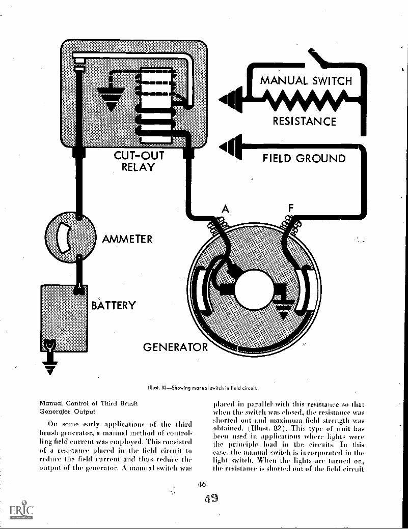
CUT-OUTRELAY
MANUAL SWITCH
RESISTANCE
FIELD GROUND
AMMETER
BATTERY
GENERATOR
Must. 82Showing manual switch in field circuit.
Manual Control of Third BrushGenercgor Output
On some early applications of the thirdbrush generator, a manual method of control-ling field current was employed. This consistedof a resistance placed in the field circuit toreduce the field current and thus reduce theoutput of the generator. A. manual switch was
placed in parallel with this resistance so thatwhen the switch was closed, the resistance wasshorted out and maximum field strength wasobtained. (Must. 82). This type of unit hasbeen used in applications where lights werethe principle load in the circuits. In thiscase, the manual switch is incorporated in thelight switch. When the lights are turned on,the resistance is shorted out of the field circuit
46
19

and maximum output of the generator is ob-tained. When the lights are turned off, theswitch is opened and the resistance is thenback in the field circuit. This reduces the gen-erator output and prevents excessive batteryovercharge and high voltage.
CONCLUSION
The third brush type generator is a lowcapacity generator which has been used exten-sively in the past and is still used in applica-tions where a high current output is not re-quired, This. type of generator is not suitablefor high speed operation because the outputdrops off rapidly at high speed due to arma-ture reaction.
INTERPOLE GENERATORS
The interpole generator is one that has, asthe name implies, a third pole mounted be-tween the other two. (Il lust. 83). The purposeof this interpole is to create another magneticfield which will neutralize the field producedby current flowing in the armature and thusstraighten out the lines of force between thefield poles. In other words, it overcomes theeffect of armature reaction in distorting thefield. This interpole is a narrow pole piecemounted on the generator frame between thetwo regular poles. It is wound with heavybar copper since all the armature current goesthrough this winding. The number of turns inthe interlude coil is calculated to produceenough ampere turns in the opposite directionto offset the magnetic field created by the
A-2
Illust. 83Interpole generator.
current flow through the armature. Since theamount of current flowing through the arma-ture and the interpole is always the same,the right amount of correction is always pres-ent to nullify the armature reaction and allowthe normal magnetic field between the polesto remain in a straight line. See Must. 84.
Because no field distortion exists when theinterpole is used, it becomes necessary for thebrushes to be exactly at the mechanical neu-tral position rather than the advance positionas was found practical with regular generators.
The advantage of the interpole generator isthat the commutation can take place when thecoil in the armature is carrying 110 currentand thus reduce arcing at the brushes. It hasbeen found that where high speeds and highcurrent are a factor, that installation of aninterlude generator can increase brush lifeas nutch as two to eight times over similar gen-erators without interpoles,
ARMATURE MAGNETIZINGFORCE
INTERPOLE MAGNETIZINGFORCE
Must. 84--Showing interpole correction for armature reaction.
47
50

BUCKING FIELD GENERATOR
With some generator applications wherean extremely wide range of speeds is re-quired, it becomes a problem to control thevoltage with normal voltage regulation. Atvery high speeds, only a very weak field cur-rent is required to produce the needed voltage.The residual magnetism of the pole shoes isenough to produce voltage but this voltagecannot be controlled and the voltage in themain circuit will continue to climb eventhough the voltage regulator has the resistancein the fieldeireuit.
BUCKINGFIELD
NORMALFIELD
Illust. 85Bucking field generator circuit diagram.
This type of problem can be overcome bythe use of a bucking field coil. (Must. 85).This is a shunt coil of high resistance woundon one pole piece and connected directly acrossthe brushes. This winding is connected in areverse direction to the normal field windingand has an opposing magnetic effect to it. Atkw speeds, when. the normal field current islarge, the opposing effect of the bucking fieldis not great in proportion to the main field.At higher speeds, when the current in themain. field circuit is, redneed by the voltageregulator, the opposing effect of the buckingfield is greater than the residual magneticfield and practically all of the magnetic linesof force are cancelled. Thus, the current flowthrough the main field coils can be controlledby the regulator and the effects of the residualmagnetism can be controlled by the buckingfield, and normal generator voltage ran he
maintained. The purpose of the bucking field,is therefore, to aid in regulation,
SPLIT FIELD GENERATOR
Under sonic operating conditions, whereslow speed of the
loadprevails for ex-
tended periods, the load circuit may exceed theoutput of the generator. Under these condi-tions, the battery must supply the current andwill soon run clown. In order to increase theoutput of the generator, it is necessary toincrease the field strength. This would requireincreasing the field current in a standard gen-erator. The regulator points cannot stand in-creased current however, because they burnso rapidly when they vibrate.
A
Illust. 86Split field generator.
In order to get around this problem, thesplit field generator was developed. This. asthe name implies, is a generator that has twofield circuits and two sets of brushes. (Must.86). You will also notice that there are fourpole shoes which will give approximatelytwice the field strength. Each field circuit iscontrolled by its own voltage regulator so thatthe field current across the regulator pointsis no higher than normal regulation and thusare not burned.
This type of generator is more costly andtherefore. is not used except in special appli-cations where engine idling periods are longand a standard generator cannot put outenough current to keep the battery charged.
4851.

DOUBLE CONTACT REGULATORSFOR GENERATORS
The vibrating contact points in regulatorshave a very definite limitation as to the amountof field current they can carry. As they openand close many times per second, they makeand break the field circuit of the generator.Each time the points open, an arc occurs. Thisarcing burns the points even though they aremade from the best materials known.
III order to prevent rapid burning of thepoints, it is necessary to keep the field currentdown to safe limits. In general, on six voltsystems, a maximum of two amperes is allowedin the field circuit. On twelve volt systems, amaximum of 11/2 amperes is allowed. On 24volt systems, one ampere is permissible. Thismeans that the regulator is a very definitelimiting factor in the design of generators.
The limitation of the field coil current thatcan be handled by the vibrating points has, toa small degree, been offset by a new voltageregulator design which controls generator volt-age by inserting resistance in series with thefield circuit in two steps. (Illust. 87). In stepone, a resistance of low value is inserted inthe usual manner. When the voltage climbsto a predetermined value, step two shorts outthe entire field circuit so that no current flowsin the field coils.
This decrease in the resistance of the fieldcoil circuit permits slightly higher field cur-rents. Higher field current means that thegenerator will develop regulated voltage at alower speed, and if the design of the genera-tor can stand it. higher output.
POLARITY OF A GENERATOR
The polarity of a generator determines thedirection of current flow from the generatorto the external circuits. As we know from ourstudy of Electromagnetic induction, the direc-tion of current flow in a conductor which iscutting lines of force, is determined by thedirection the conductor is cutting through andthe direction of the flow of magnetic lines offorce between the pole shoes. It can then beseen from Illust. 88 that if the North pole
49
CUTOUT CURRENT VOLTAGERELAY REG. REG.
16air armsrooni
'RESISTANCES
BAT.FUSE 0.-
GEN. FIELD
AMMETER
BATTERY.17°,410.0"11'7- GENERATOR
Illust. 87Circuit diagram of double contact regulator.
shoe is changed from the left to the right side,that the direction of current flow in thearmature circuit is also reversed. We knowthat the magnetism in the field poles is createdby current flow through the field coils. Thedirection the current flows through the coils,determines the polarity of the pole shoes. Theresidual magnetism and the polarity of thepole shoes will remain the same as was in-duced from the magnetism of its field coil, thelast time current was passed through it. Fromthis, we see that generators can build up volt-age Melt will cause current to flow in eitherdirection depending upon the residual magne-tism in the poles. III order for a generator tofunction properly, the polarity of the genera-tor must be the same as that of the battery.Illust. 89 shows what will happen if a gener-ator is operated with reverse polarity in a bat-tery charging circuit. Since current flows frompositive to negative, we see that the generatoris now in series with the battery so that assoon as the generator develops enough voltageto close the cut out points, the voltage of the
52
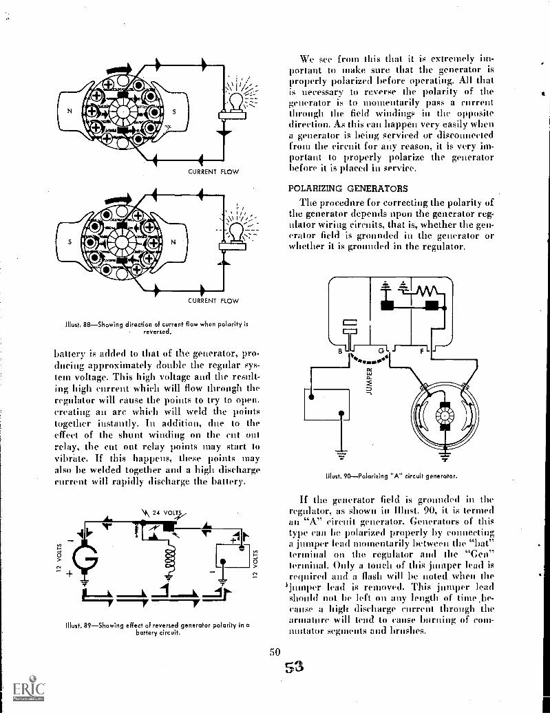
CURRENT FLOW
CURRENT FLOW
Must. 88Showing direction of current flow when polarity isreversed.
battery is added to that of the generator, pro-clueing approximately double the regular sys-tem voltage. This high voltage and the result-ing high current which will flow through theregulator will cause the points to try to open.creating au are which will weld the pointstogether instantly. In addition, clue to theeffect of the shunt winding on the cult outrelay, the cut out relay points may start tovibrate. If this happens, these points mayalso be welded together and a high dischargecurrent will rapidly discharge the battery.
II lust. 89Showing effect of reversed generator polarity in abattery circuit.
We see from this that it is extremely im-portant to make sure that the generator isproperly polarized before operating. All thatis necessary to reverse the polarity of thegenerator is to momentarily pass a currentthrough the. field windings in the oppositedirection. As this can happen very easily whena generator is bein. 1-, serviced or disconnectedfrom the circuit for any reason, it is very im-portant to properly polarize the generatorbefore it is placed in service.
POLARIZING GENERATORS
The procedure for correcting the polarity ofthe generator depends upon the generator reg-ulator wiring circuits, that is, whether the gen-erator field is grounded in the generator orwhether it is grounded in the regulator.
fl
Illust. 90Polarizing "A" circuit generator.
If the generator field is grounded in theregulator, as shown in Illnst. 90, it is termedan "A" circuit generator. Generators of thistype Vail be polarized properly by connectinga jumper lead momentarily between the "bat"terminal on the regulator and the "Gen"terminal. Only a touch of this jumper lead isrequired and a flash will be noted when the
ljumper lead is removed. This jumper leadshould not l left on any length of time .be-cause a high discharge current through thearmature will tend to cause burning of coin-imitator segments and brushes.
50
53

G LF
Illust. 91Polarizing a "B" circuit generator.
If the generator has the field circuitgrounded inside the generator, it is termed a"B" circuit generator and the procedure forpolarizing it is slightly different.
Illust. 91 shows the circuit diagram of a"B" circuit generator. You will notice thatone end of the field coil is grounded at themain brush in the generator. In order to polar-ize this generator, it is necessary to remove thefield lead from the regulator "F" terminal andconnect a jumper between this lead and the"hat" terminal of the regulator.
It is important to remove the field lead fromthe regulator in this case, because failure todo so will cause a high current to flow throughthe regulator points and the armature toground, burning the points in the regulator.
The "B" circuit generator, however, is notused on any tractor or farm equipment appli-cations at the present time. The "A" circuittype is the only one used.
THE A.C. GENERATING CIRCUIT
In the previous section of this manual weDave seen how batteries can he charged andthe voltage and current flow can be regulatedfrom a direct current (DC) generator.
Alternating current (AC) generators arealso used for supplying electrical energy for
51
54
power equipment. Alternating current differs,as the name implies, from direct current inthat the direction of flow completely reversesitself at regular intervals. The "frequency" ofthe reversals will depend on the speed of thegenerator and is given in cycles per second.But since alternating current cannot be usedto recharge a storage battery, it is necessary tochange or "rectify" it to direct current. A com-plete alternating current circuit for automo-tive equipment then will consist of the gener-ator, rectifier, ignition switch, field relay andvoltage regulator, time storage battery and thenecessary connecting conductors.
ALTERNATING CURRENT GENERATOR
The alternating current generator, like thedirect current generator, produces au electri-cal potential or voltage in a conductor whichcuts or passes through magnetic lines of force.As shown in Illust. 92, the (AC) generatordiffers from the (DC) generator in that the(AC) conductor is stationary and the magnetrevolves while the (DC) conductor revolvesand the magnet is stationary.
LOADCIRCUIT
CHANGEDPOLARITY
ROTATINGMAGNETIC
FIELD
Must. 92

MAXIMUM VALUE
270S OF ROTOR ROTATION
Must, 93Graph of potential,
When the magnet is revolved on a shaftbetween the sides of a loop, the magnetic linesof force are cut as they move past the conduc-tor and a potential is created in the conductorwhich forces current through the load in adirection indicated by the right hand rule.As the magnet continues to rotate, the mag-netic lines of force will again be cut by theconductor, but the poles of the magnet havenow been reversed. The lines of force arealso reversed and the right hand rule indicatesthe current will flow in the opposite direction.After a second one-half revolution, the magnetwill be back at the starting point and the cur-rent in the conductor will flow in the originaldirection. Hence, we have two reversals ofpotential for each revolution of the magnet.
This alternating potential is graphicallyshown in Must. 93, It will be noted that theconductor is attached to the inside of thestationary iron frame (now called the stator)and that the poles of the magnet (now called
the rotor) are enlarged at each end to providea wider area for magnetic lines of force.
As seen in the illustration, there is nopotential in the conductor when no lines offorce are being cut (position 1) but as therotor rotates in a clockwise direction, the mag-netic fields cross the conductor in graduallyincreased concentration until maximum poten-tial is created in one direction (position 2).Then, as rotation continues.. the potentialgradually lessens as the fields leave the conduc-tor until at position 3. the fields have passedand no potential is created. Further rotationof the rotor brings the opposite fields of therotor ;,o the conductor and potential is createdin equal amount, but in the opposite direction.
We have learned that the potential or volt-age created will be in direct proportion to thenumber of conductors, the strength of themagnetic field and the speed of the conduc-tors through the field. It follows then that anydesired voltage may be obtained by increasing
55
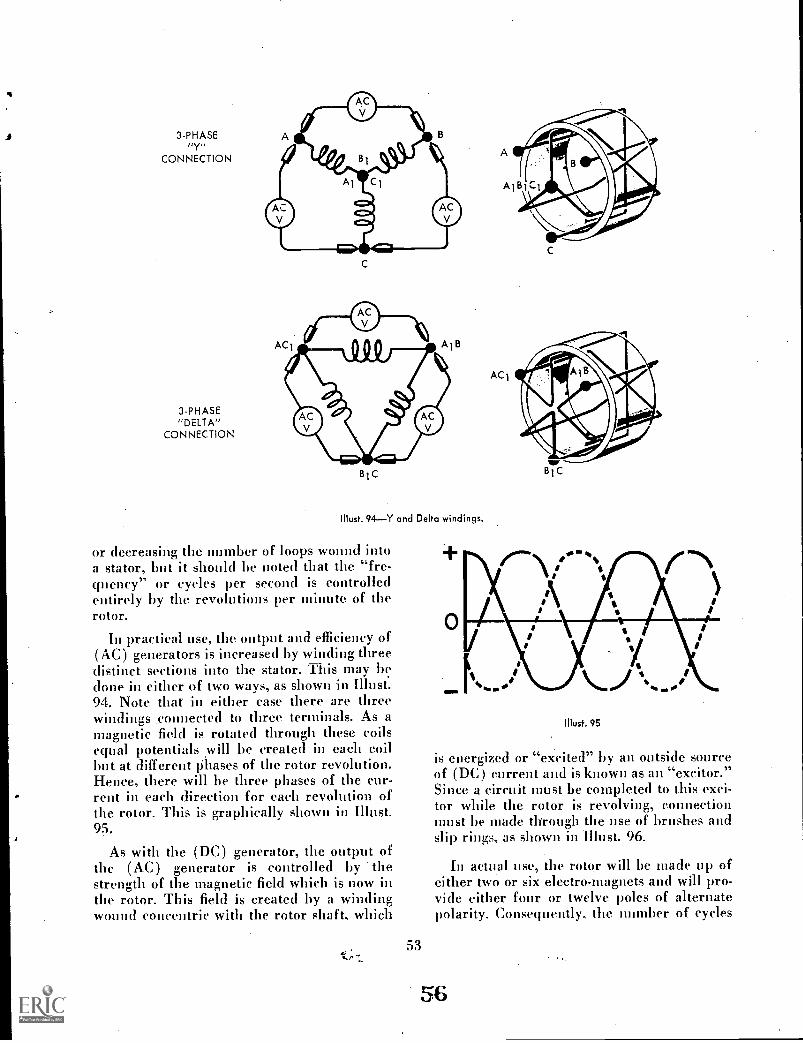
3-PHASElir,CONNECTION
3-PHASE"DELTA"
CONNECTION
BiC
Illust. 94Y and Delta windings.
or decreasing the iminber of loops wound intoa stator, but it should be noted that the "fre-qnency" or cycles per second is controlledentirely by the revolutions per minute of therotor.
In practical use, the (nitwit and efficiency of(AC) generators is increased by winding threedistinct sections into the stator. This may bedone in either of two ways, as shown in Illust..94. Note that in either case there are threewindings .connected to three terminals. As amagnetic field is rotated through these coilsequal potentials will be created in each coilbut at different Phases of the rotor revolution.Hence, there will be three phases of the cur-rent in each direction for each revolution ofthe rotor. This is graphically shown in Illust.95.
As with the (DC) generator, the output ofthe (AC) generator is controlled by thestrength of the magnetic field which is now inthe rotor. This field is created by a windingwound concentric with the rotor shaft, which
53
ACS
Illust. 95
is energized or "excited" by an outside sourceof (DC) current and is known as an "excitor."Since a circuit must be completed to this exci-tor while the rotor is revolving, connectionmust be made through the use of brushes andslip rings, as shown in Illust. 96.
In actual use, the rotor will be made up ofeither two or six electro-magnets and will pro-vide either four or twelve poleS of alternatepolarity. Consequently, the number of cycles
56

LOAD
D. C. FIELD
EXCITATION
per revolution of the rotor will increase totwo or six.
In the battery section of this manual, it waslearned that direct current must be used to re-charge a storage battery. Therefore, alternat-ing current must be "rectified" into a currentwhich will be suitable for battery recharging.This is clone by eliminating all the voltagepotential, on either the positive or negativeside of the neutral line, and using only thatpotential voltage on the other side of the
utral line. The resultant rectified currentis graphically shown in Illust. 97.
RECTIFIED CURRENT
'Host, 97Rectified current
Rectification of (AC) current can be ac-complished in a number of ways, but themodern and most efficient method is by theuse of diodes. The chemical composition of a
-=diode is such that it will allow current to passthrough itself in only one direction. Con-
Illust. 96
54
D. C. FIELDEXCITATION
NCURRENT FLOW
DIODE SYMBOL
Illust. 98Diode symbol.
sequently, when placed in a circuit which isenergized by alternating current, it acts muchlike a check valve in a water or hydraulic sys-tem and allows the current to flow in one direc-tion only. The diode is pictured in circuitdiagrams as Shown in Illust. 98.
In the (AC) generator, a diode is placedin each of the three phases of the generatorcircuit, positive diodes being used with anegative grounded battery. From the threediodes, the three phases are joined together,and to the "BAT" terminal on the generator.Thus, (DC) current which flows in only onedirection, flows to the battery and/or to thelights, etc. connected to the system. However,provision must be made for the completion ofthe circuits to each phase by connection toground. This is done by placing a negativediode (if negative battery terminal isgrounded)) between each phase from the gen-erator and ground. The connections throughthe six diodes are shown in the generator por-tion of the diagram in Illust. 99.

TRANSISTORIZED REGULATORlip_ RELAX, LlaalaLct& VOLTAGE REG.r- J I
II
jBATDIODE
Fl L J F2
IGNITIONSWITCH
AMMETER
BAT
RECTIFIER
BATTERY
STATOR
0z
SELF-RECTIFYING A. C. GENERATOR
!NO. 99Schematic diagram.
TRANSISTORIZED REGULATORS
The four terminal transistorized regulator,used with the (AC) generator when an am-meter is used, accomplishes the same purposeas the (DC) regulators, but in a different way.There is no cutout relay as the diodes preventcurrent flow back through the generator fromthe battery when the generator is idle or oper-ating at slow speeds. The cutout relay is re-placed by a field relay and the voltage regula-tor operates through a transistor.
55
RING
Illust. 100Transistor.
To understand the operation of the voltageregulator, the characteristics of the transistormust be known. The diode, which we havelearned permits the flow of current in onlyone direction, is made of a "P" (positive) ma-terial and a "N" (negative) material. Thetransistor is made up of two sections of "P"material and one section of "N" material or"base" between. The two "P" sections arcknown as the "emitter" and the "collector" asshown in Blush 100.
BASEEMITTER I COLLECTOR
H nigSi
CLOSED
4.5 AMPS
Must. 101
S2OPEN
When connected in a (D(:) circuit, currentwill flow freely through the emitter and basesections, as shown in Must. 101. However, itwill be seen in Must. 102 that no current willflow through the emitter and collector sectionswhen the base section is not connected, Butwhen the base section is connected, then avery small part of the current will flow throughthe base and a large part will flow through thecollector, as shown in Blust. 1.03. Thus, it willbe seen that practically a full flow of currentthrough the emitter and collector may he con-trolled by controlling a much smaller currentflow through the emitter and base sections.

BASEEMITTER i COLLECTOR
I 1111111
51
OPEN
NO CURRENT FLOW
Illust. 102
S2CLOSED
BASEEMITTER s COLLECTOR
4.5 AMPS 4.15 AMPS
Illust. 103
Referring again to Illust. 99 we see that theregulator has two units, a field relay and avoltage control.
The field relay armature is connected in-. series, through the transistor, with the fieldcoils in the generator rotor. When the ignitionkey is turned "on," the magnetic coil in therelay is energized, the relay points are closedand the field circuit is completed through theregulator points and pis() through both thetransistor emitter-base and emitter-collectorcircuits. At the same time, the shunt and ac-celerator windings on the voltage regulatorunit are energized, but the voltage at that timeis not sufficient to open the regulator points.
As the generator speed is increased, thevoltage from the generator will increase andcurrent will flow through the battery, lights,etc. As the speed further increases, the voltageand current flow through the battery will be-come excessive and must be controlled by theregulator. Note that the voltage is impressedupon the shunt and accelerator winding in theregulator. When the voltage has increased tothe desired potential, the combined pull ofthe two windings will open the regulator con-
56
tact points and the emitter-base circuit toground. The opening of the emitter-base cir-cuit then opens the emitter-collector circuitand the field circuit. The generator. voltagethen immediately decreases, the magnetic pullof the two coils is decreased and the points areclosed by the adjustable spring tension. Thisaction completes the emitter-base circuitwhich allows the field current to pass throughthe emitter-collector circuit and the field cir-cuit to ground. This action occurs many timesper second and thereby regulates and controlsthe generator output to the desired voltage.
It should be -noted that the current flowthrough the regulator contact points is onlythat small amount which flows through theemitter-base circuit. The total amount of fieldcurrent which flows through the emitter-collector would cause burning of the contactpoints but the very small flow of emitter-basecurrent can be interrupted many times persecond without burning or pitting the points.
The accelerator winding in the regulatorcoil carries no current when the points areopen. The loss of this magnetic pull, plus thereduced pull of the shunt winding, permitsthe spring to reclose the points in a very shortperiod of time. Once closed, the magnetic pullis restored immediately and the points reopen.This winding, then, speeds up the frequencyof vibration and therefore is called the "ac-celerator" winding.
Note that there is a resistor connected acrossthe emitter and base of the transistor. Thisresistance acts to prevent emitter-collector"leakage" when the regulator points are openunder high temperature conditions.
The resistance in series with the accelerat-ing winding and the contact points is a designfeature permitting the use of a required sizewire for the winding.
The diode is connected directly across thefield coil leads. Its purpose is to prevent anexcessive build-up of voltage in the field coilscaused by the interruption of the field current.This high voltage would cause a failure of thetransistor, and the diode provides an alternatecircuit where the current can flow withoutinducing the high voltage in the windings.
59
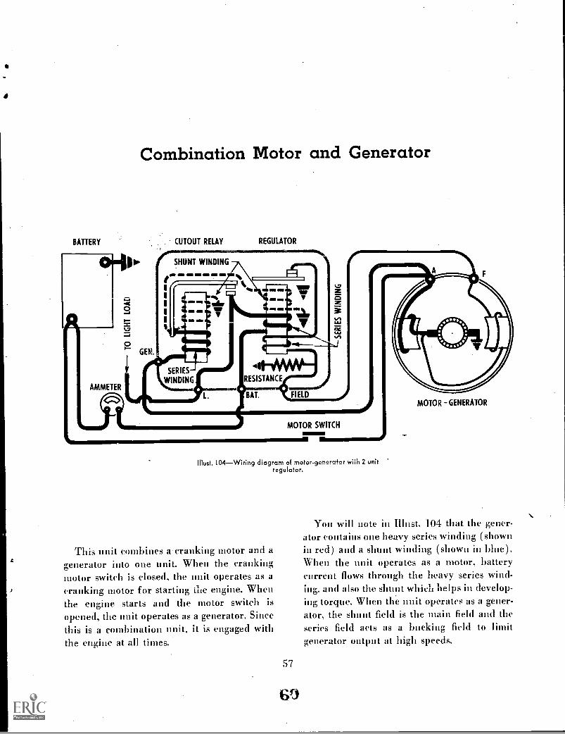
BATTERY
AMMETER
G=0
Combination Motor and Generator
GEN.
CUTOUT RELAY
SHUNT WINDING
V
L-J
REGULATOR
Ce
Vn
111111
SERIES
WINDING
MOTOR SWITCH
IV
Illust. 104 Wiring diagram of motor-generafor wiin 2 unitregulator.
This unit combines a cranking motor and agenerator into one unit. When the crankingmotor switch is dosed, the unit operates as acranking motor for starting ike engine. Whenthe engine starts and the motor switch is
opened, the unit operates as a generator. Sincethis is a combination unit, it is engaged withthe engine at all times.
57
MOTOR -GENERATOR
You will note in Must. 104 that the gener-ator contains one heavy series winding (shownin red) and a shunt winding (shown in bine).When the unit operates as a motor, batterycurrent flows through the heavy series wind-ing, and also the shunt which helps in develop-ing torque. When the unit operates as a gener-ator, the shunt field is the main field and theseries field acts as a bucking field to limitgenerator output at high speeds.

BATTERYCUTOUT
RELAYCURRENT
REGULATORVOLTAGE
REGULATOR
SHUNT WINDING
SERIES WINDING
SHUNT WINDING
AMMETER
RESISTANCES
MOTOR- SWITCH41
Illust. 105Motor-generator with three unit regulator.
The motor-generator may also be used witha three unit regulator as shown in Illust. 105:
You will note that the wiring in the gener-ator is slightly different. when a three unitregulator is used, in that an additional lead isbrought out from the series winding for themotor circuit. When this unit operates as agenerator, the shunt winding is the only wind-ing being used. The series winding is by-passed. With this arrangement, a greater out-put at high and low speed can he obtained be-cause the series field is not acting as a buck-ing field.
58
MOTOR - GENERATOR
The motor-generator is used on small motorswhere cranking loads are not great and elec-trical loads are not excessive. One advantageof this unit for small motors is that due to theseries and shunt field windings, the. free motorspeed will not he excessive. This permits con-necting the motor by means of a belt withoutdanger of the motor overspeeding if the beltshould break or come off during cranking.Regular series wound cranking motors arealways connected directly to the engine toprevent excessive speeds which would occurif allowed to run free.