Embed Size (px)
Citation preview
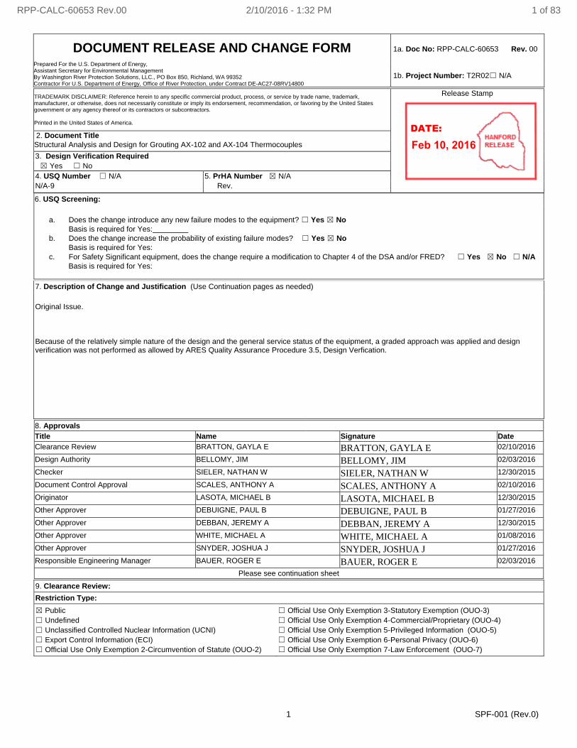
DOCUMENT RELEASE AND CHANGE FORM Prepared For the U.S. Department of Energy, Assistant Secretary for Environmental Management By Washington River Protection Solutions, LLC., PO Box 850, Richland, WA 99352 Contractor For U.S. Department of Energy, Office of River Protection, under Contract DE-AC27-08RV14800
1a. Doc No: RPP-CALC-60653 Rev. 00
1b. Project Number: T2R02☐ N/A
1 SPF-001 (Rev.0)
TRADEMARK DISCLAIMER: Reference herein to any specific commercial product, process, or service by trade name, trademark, manufacturer, or otherwise, does not necessarily constitute or imply its endorsement, recommendation, or favoring by the United States government or any agency thereof or its contractors or subcontractors. Printed in the United States of America.
Release Stamp
2. Document Title
Structural Analysis and Design for Grouting AX-102 and AX-104 Thermocouples
3. Design Verification Required
☒ Yes ☐ No
4. USQ Number ☐ N/A 5. PrHA Number ☒ N/A
N/A-9 Rev.
6. USQ Screening:
a. Does the change introduce any new failure modes to the equipment? ☐ Yes ☒ No
Basis is required for Yes:
b. Does the change increase the probability of existing failure modes? ☐ Yes ☒ No
Basis is required for Yes:
c. For Safety Significant equipment, does the change require a modification to Chapter 4 of the DSA and/or FRED? ☐ Yes ☒ No ☐ N/A
Basis is required for Yes:
7. Description of Change and Justification (Use Continuation pages as needed)
Original Issue. Because of the relatively simple nature of the design and the general service status of the equipment, a graded approach was applied and design verification was not performed as allowed by ARES Quality Assurance Procedure 3.5, Design Verfication.
8. Approvals
Title Name Signature Date
Clearance Review BRATTON, GAYLA E BRATTON, GAYLA E 02/10/2016
Design Authority BELLOMY, JIM BELLOMY, JIM 02/03/2016
Checker SIELER, NATHAN W SIELER, NATHAN W 12/30/2015
Document Control Approval SCALES, ANTHONY A SCALES, ANTHONY A 02/10/2016
Originator LASOTA, MICHAEL B LASOTA, MICHAEL B 12/30/2015
Other Approver DEBUIGNE, PAUL B DEBUIGNE, PAUL B 01/27/2016
Other Approver DEBBAN, JEREMY A DEBBAN, JEREMY A 12/30/2015
Other Approver WHITE, MICHAEL A WHITE, MICHAEL A 01/08/2016
Other Approver SNYDER, JOSHUA J SNYDER, JOSHUA J 01/27/2016
Responsible Engineering Manager BAUER, ROGER E BAUER, ROGER E 02/03/2016
Please see continuation sheet
9. Clearance Review:
Restriction Type:
☒ Public
☐ Undefined
☐ Unclassified Controlled Nuclear Information (UCNI)
☐ Export Control Information (ECI)
☐ Official Use Only Exemption 2-Circumvention of Statute (OUO-2)
☐ Official Use Only Exemption 3-Statutory Exemption (OUO-3)
☐ Official Use Only Exemption 4-Commercial/Proprietary (OUO-4)
☐ Official Use Only Exemption 5-Privileged Information (OUO-5)
☐ Official Use Only Exemption 6-Personal Privacy (OUO-6)
☐ Official Use Only Exemption 7-Law Enforcement (OUO-7)
RPP-CALC-60653 Rev.00 2/10/2016 - 1:32 PM 1 of 83
Feb 10, 2016DATE:
DOCUMENT RELEASE AND CHANGE FORM Doc No: RPP-CALC-60653 Rev. 00
2 SPF-001 (Rev.0)
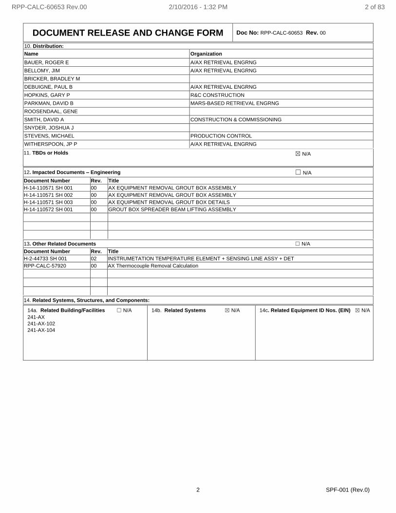
10. Distribution:
Name Organization
BAUER, ROGER E A/AX RETRIEVAL ENGRNG
BELLOMY, JIM A/AX RETRIEVAL ENGRNG
BRICKER, BRADLEY M
DEBUIGNE, PAUL B A/AX RETRIEVAL ENGRNG
HOPKINS, GARY P R&C CONSTRUCTION
PARKMAN, DAVID B MARS-BASED RETRIEVAL ENGRNG
ROOSENDAAL, GENE
SMITH, DAVID A CONSTRUCTION & COMMISSIONING
SNYDER, JOSHUA J
STEVENS, MICHAEL PRODUCTION CONTROL
WITHERSPOON, JP P A/AX RETRIEVAL ENGRNG
11. TBDs or Holds ☒ N/A
12. Impacted Documents – Engineering ☐ N/A
Document Number Rev. Title
H-14-110571 SH 001 00 AX EQUIPMENT REMOVAL GROUT BOX ASSEMBLY
H-14-110571 SH 002 00 AX EQUIPMENT REMOVAL GROUT BOX ASSEMBLY
H-14-110571 SH 003 00 AX EQUIPMENT REMOVAL GROUT BOX DETAILS
H-14-110572 SH 001 00 GROUT BOX SPREADER BEAM LIFTING ASSEMBLY
13. Other Related Documents ☐ N/A
Document Number Rev. Title
H-2-44733 SH 001 02 INSTRUMETATION TEMPERATURE ELEMENT + SENSING LINE ASSY + DET
RPP-CALC-57920 00 AX Thermocouple Removal Calculation
14. Related Systems, Structures, and Components:
14a. Related Building/Facilities ☐ N/A
241-AX
241-AX-102
241-AX-104
14b. Related Systems ☒ N/A
14c. Related Equipment ID Nos. (EIN) ☒ N/A
RPP-CALC-60653 Rev.00 2/10/2016 - 1:32 PM 2 of 83

3 SPF-001 (Rev.0)
DOCUMENT RELEASE AND CHANGE FORM CONTINUATION SHEET
Document No: RPP-CALC-60653 Rev. 00
8. Approvals
Title Name Signature Date
USQ Evaluator KOZLOWSKI, STEPHEN D KOZLOWSKI, STEPHEN D 02/03/2016
[THIS PAGE HAS BEEN INTENTIONALLY LEFT BLANK]
RPP-CALC-60653 Rev.00 2/10/2016 - 1:32 PM 3 of 83
A-6002-767 (REV 3)
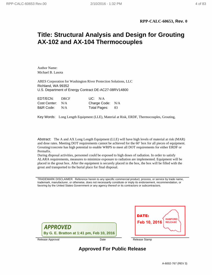
RPP-CALC-60653, Rev. 0
Title: Structural Analysis and Design for Grouting AX-102 and AX-104 Thermocouples
Author Name: Michael B. Lasota ARES Corporation for Washington River Protection Solutions, LLC Richland, WA 99352 U.S. Department of Energy Contract DE-AC27-08RV14800 EDT/ECN: DRCF UC: N/A Cost Center: N/A Charge Code: N/A B&R Code: N/A Total Pages: 83
Key Words: Long Length Equipment (LLE), Material at Risk, ERDF, Thermocouples, Grouting,
Abstract: The A and AX Long Length Equipment (LLE) will have high levels of material at risk (MAR) and dose rates. Meeting DOT requirements cannot be achieved for the 60’ box for all pieces of equipment. Grouting/concrete has high potential to enable WRPS to meet all DOT requirements for either ERDF or Permafix. During disposal activities, personnel could be exposed to high doses of radiation. In order to satisfy ALARA requirements, measures to minimize exposure to radiation are implemented. Equipment will be placed in the grout box. After the equipment is securely placed in the box, the box will be filled with the grout and transported to the burial place for final disposal.
TRADEMARK DISCLAIMER. Reference herein to any specific commercial product, process, or service by trade name, trademark, manufacturer, or otherwise, does not necessarily constitute or imply its endorsement, recommendation, or favoring by the United States Government or any agency thereof or its contractors or subcontractors.
Release Approval Date Release Stamp
Approved For Public Release
RPP-CALC-60653 Rev.00 2/10/2016 - 1:32 PM 4 of 83
By G. E. Bratton at 1:41 pm, Feb 10, 2016
Feb 10, 2016DATE:
Quality Assurance Procedure 3.1 Calculation Cover Sheet (08-15)
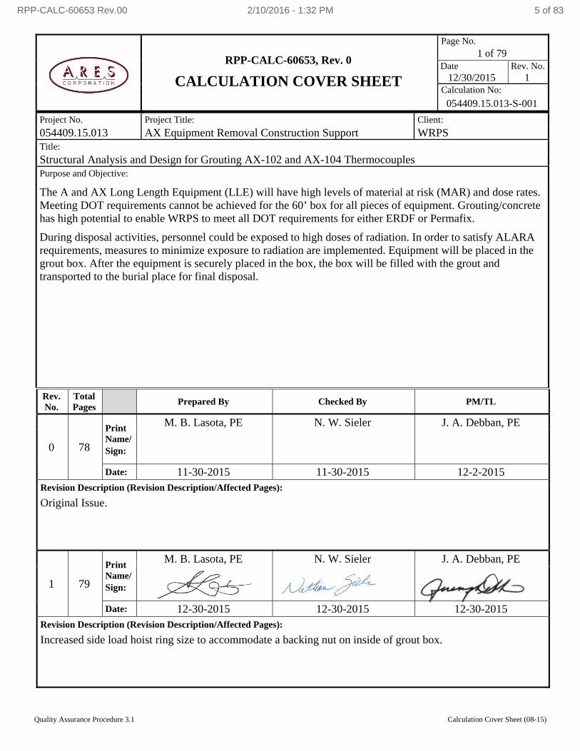
RPP-CALC-60653, Rev. 0
CALCULATION COVER SHEET
Page No.1 of 79
Date Rev. No.12/30/2015 1
Calculation No:
054409.15.013-S-001
Project No. Project Title: Client:
054409.15.013 AX Equipment Removal Construction Support WRPS Title:
Structural Analysis and Design for Grouting AX-102 and AX-104 Thermocouples Purpose and Objective:
The A and AX Long Length Equipment (LLE) will have high levels of material at risk (MAR) and dose rates. Meeting DOT requirements cannot be achieved for the 60’ box for all pieces of equipment. Grouting/concrete has high potential to enable WRPS to meet all DOT requirements for either ERDF or Permafix.
During disposal activities, personnel could be exposed to high doses of radiation. In order to satisfy ALARA requirements, measures to minimize exposure to radiation are implemented. Equipment will be placed in the grout box. After the equipment is securely placed in the box, the box will be filled with the grout and transported to the burial place for final disposal.
Rev. No.
Total Pages
Prepared By Checked By PM/TL
0 78
Print Name/ Sign:
M. B. Lasota, PE N. W. Sieler J. A. Debban, PE
Date: 11-30-2015 11-30-2015 12-2-2015 Revision Description (Revision Description/Affected Pages):
Original Issue.
1 79
Print Name/ Sign:
M. B. Lasota, PE N. W. Sieler J. A. Debban, PE
Date: 12-30-2015 12-30-2015 12-30-2015 Revision Description (Revision Description/Affected Pages):
Increased side load hoist ring size to accommodate a backing nut on inside of grout box.
RPP-CALC-60653 Rev.00 2/10/2016 - 1:32 PM 5 of 83
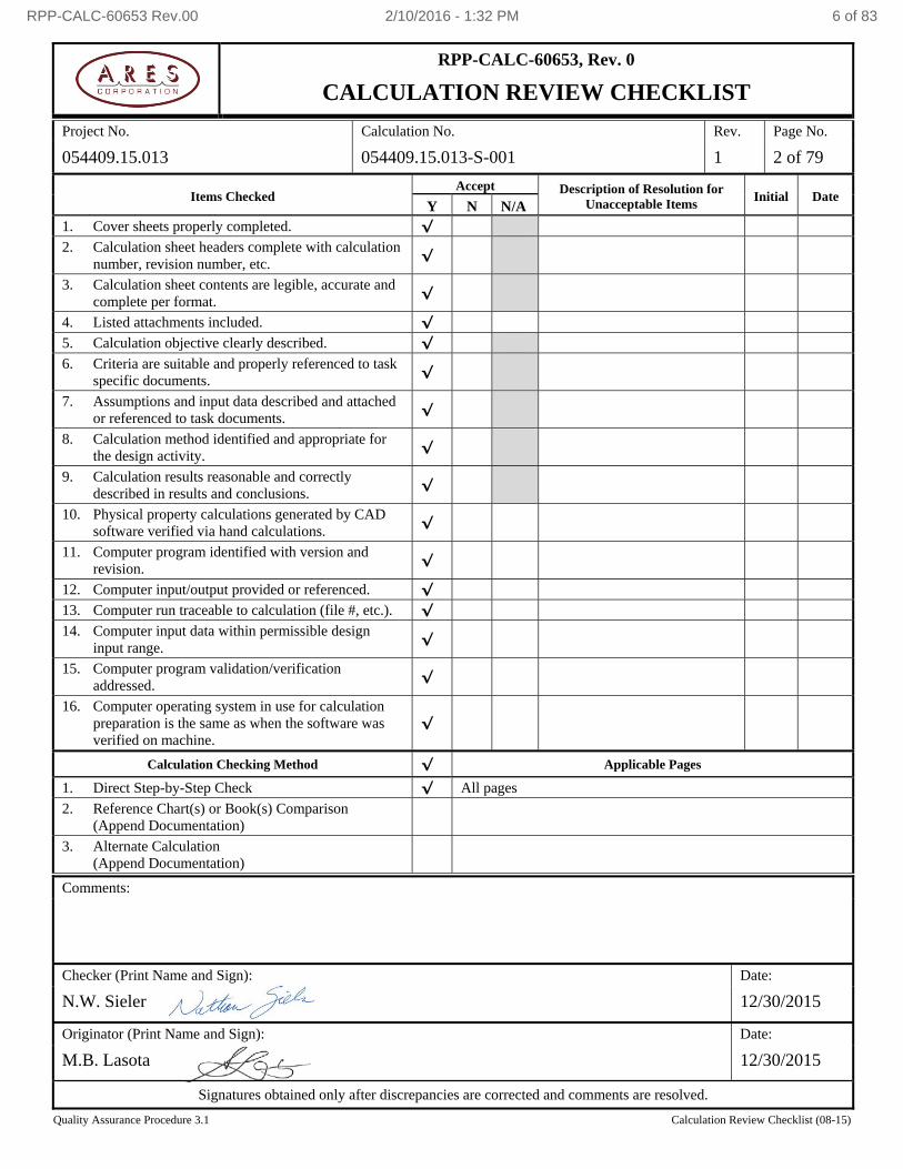
Quality Assurance Procedure 3.1 Calculation Review Checklist (08-15)
RPP-CALC-60653, Rev. 0
CALCULATION REVIEW CHECKLIST
Project No. Calculation No. Rev. Page No.
054409.15.013 054409.15.013-S-001 1 2 of 79
Items Checked Accept Description of Resolution for
Unacceptable Items Initial Date
Y N N/A 1. Cover sheets properly completed. √
2. Calculation sheet headers complete with calculation number, revision number, etc.
√
3. Calculation sheet contents are legible, accurate and complete per format.
√
4. Listed attachments included. √
5. Calculation objective clearly described. √
6. Criteria are suitable and properly referenced to task specific documents.
√
7. Assumptions and input data described and attached or referenced to task documents.
√
8. Calculation method identified and appropriate for the design activity.
√
9. Calculation results reasonable and correctly described in results and conclusions.
√
10. Physical property calculations generated by CAD software verified via hand calculations.
√
11. Computer program identified with version and revision.
√
12. Computer input/output provided or referenced. √
13. Computer run traceable to calculation (file #, etc.). √
14. Computer input data within permissible design input range.
√
15. Computer program validation/verification addressed.
√
16. Computer operating system in use for calculation preparation is the same as when the software was verified on machine.
√
Calculation Checking Method √ Applicable Pages
1. Direct Step-by-Step Check √ All pages
2. Reference Chart(s) or Book(s) Comparison (Append Documentation)
3. Alternate Calculation (Append Documentation)
Comments:
Checker (Print Name and Sign): Date:
N.W. Sieler 12/30/2015
Originator (Print Name and Sign): Date:
M.B. Lasota 12/30/2015
Signatures obtained only after discrepancies are corrected and comments are resolved.
RPP-CALC-60653 Rev.00 2/10/2016 - 1:32 PM 6 of 83
RPP-CALC-60653, Rev. 0
CALCULATION SHEET
Project No. 054409.15.013 Calculation No. 054409.15.013-S-001 Rev. 1 Page No. 3 of 79
Title: Structural Analysis and Design for Grouting AX-102 and AX-104 Thermocouples
Prepared By: MB Lasota Date: 12-30-15 Checked By: NW Sieler Date: 12-30-15
Quality Assurance Procedure 3.1 Calculation Sheet (05-10)
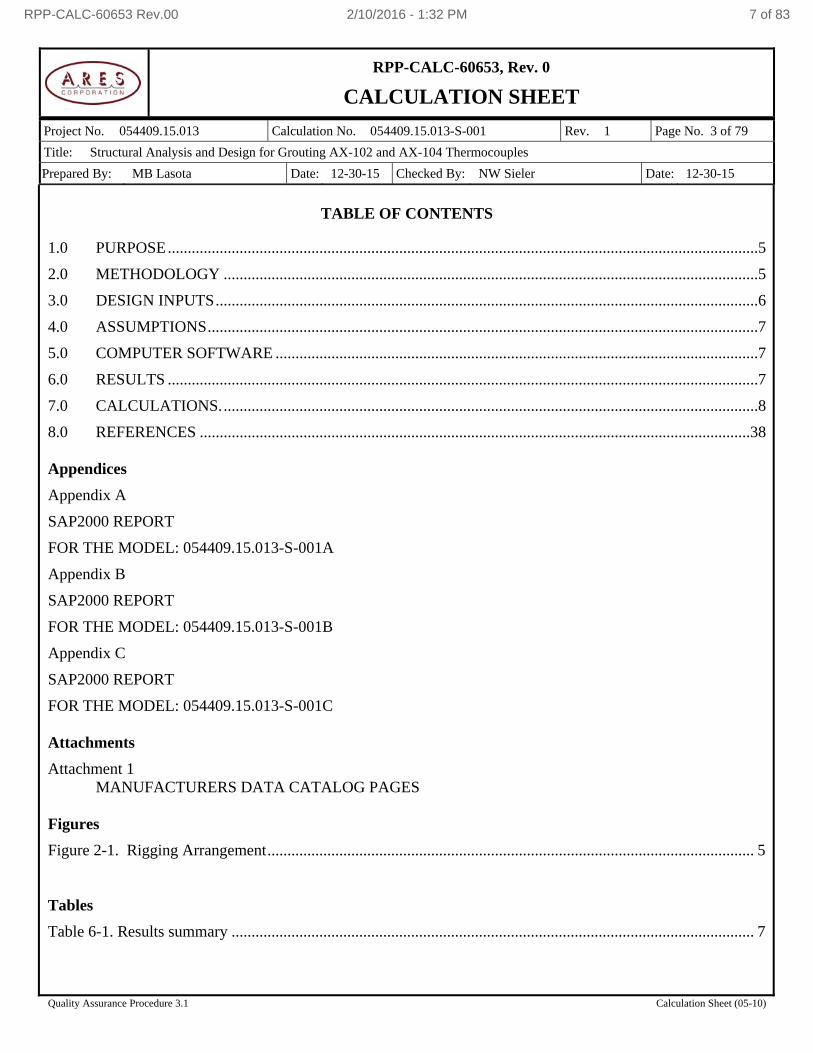
TABLE OF CONTENTS
1.0 PURPOSE ....................................................................................................................................................5
2.0 METHODOLOGY ......................................................................................................................................5
3.0 DESIGN INPUTS ........................................................................................................................................6
4.0 ASSUMPTIONS ..........................................................................................................................................7
5.0 COMPUTER SOFTWARE .........................................................................................................................7
6.0 RESULTS ....................................................................................................................................................7
7.0 CALCULATIONS. ......................................................................................................................................8
8.0 REFERENCES ..........................................................................................................................................38 Appendices
Appendix A
SAP2000 REPORT
FOR THE MODEL: 054409.15.013-S-001A
Appendix B
SAP2000 REPORT
FOR THE MODEL: 054409.15.013-S-001B
Appendix C
SAP2000 REPORT
FOR THE MODEL: 054409.15.013-S-001C
Attachments
Attachment 1 MANUFACTURERS DATA CATALOG PAGES
Figures
Figure 2-1. Rigging Arrangement .......................................................................................................................... 5 Tables
Table 6-1. Results summary ................................................................................................................................... 7
RPP-CALC-60653 Rev.00 2/10/2016 - 1:32 PM 7 of 83
RPP-CALC-60653, Rev. 0
CALCULATION SHEET
Project No. 054409.15.013 Calculation No. 054409.15.013-S-001 Rev. 1 Page No. 4 of 79
Title: Structural Analysis and Design for Grouting AX-102 and AX-104 Thermocouples
Prepared By: MB Lasota Date: 12-30-15 Checked By: NW Sieler Date: 12-30-15
Quality Assurance Procedure 3.1 Calculation Sheet (05-10)
Acronyms
ACI American Concrete Institute
AISC American Institute of Steel Construction
ASME American Society of Mechanical Engineers
ASTM American Society for Testing and Materials
ALARA As Low as Reasonably Achievable
BTH Below the Hook
DOT Department of Transportation
ERDF Environmental Restoration Disposal Facility
LLE Long Length Equipment
MAR Material at Risk
WRPS Washington River Protection Systems
RPP-CALC-60653 Rev.00 2/10/2016 - 1:32 PM 8 of 83
RPP-CALC-60653, Rev. 0
CALCULATION SHEET
Project No. 054409.15.013 Calculation No. 054409.15.013-S-001 Rev. 1 Page No. 5 of 79
Title: Structural Analysis and Design for Grouting AX-102 and AX-104 Thermocouples
Prepared By: MB Lasota Date: 12-30-15 Checked By: NW Sieler Date: 12-30-15
Quality Assurance Procedure 3.1 Calculation Sheet (05-10)
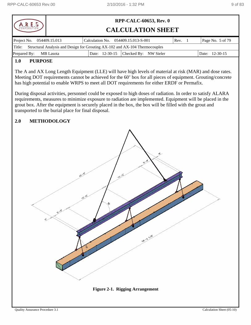
1.0 PURPOSE
The A and AX Long Length Equipment (LLE) will have high levels of material at risk (MAR) and dose rates. Meeting DOT requirements cannot be achieved for the 60’ box for all pieces of equipment. Grouting/concrete has high potential to enable WRPS to meet all DOT requirements for either ERDF or Permafix.
During disposal activities, personnel could be exposed to high doses of radiation. In order to satisfy ALARA requirements, measures to minimize exposure to radiation are implemented. Equipment will be placed in the grout box. After the equipment is securely placed in the box, the box will be filled with the grout and transported to the burial place for final disposal.
2.0 METHODOLOGY
Figure 2-1. Rigging Arrangement
RPP-CALC-60653 Rev.00 2/10/2016 - 1:32 PM 9 of 83
RPP-CALC-60653, Rev. 0
CALCULATION SHEET
Project No. 054409.15.013 Calculation No. 054409.15.013-S-001 Rev. 1 Page No. 6 of 79
Title: Structural Analysis and Design for Grouting AX-102 and AX-104 Thermocouples
Prepared By: MB Lasota Date: 12-30-15 Checked By: NW Sieler Date: 12-30-15
Quality Assurance Procedure 3.1 Calculation Sheet (05-10)
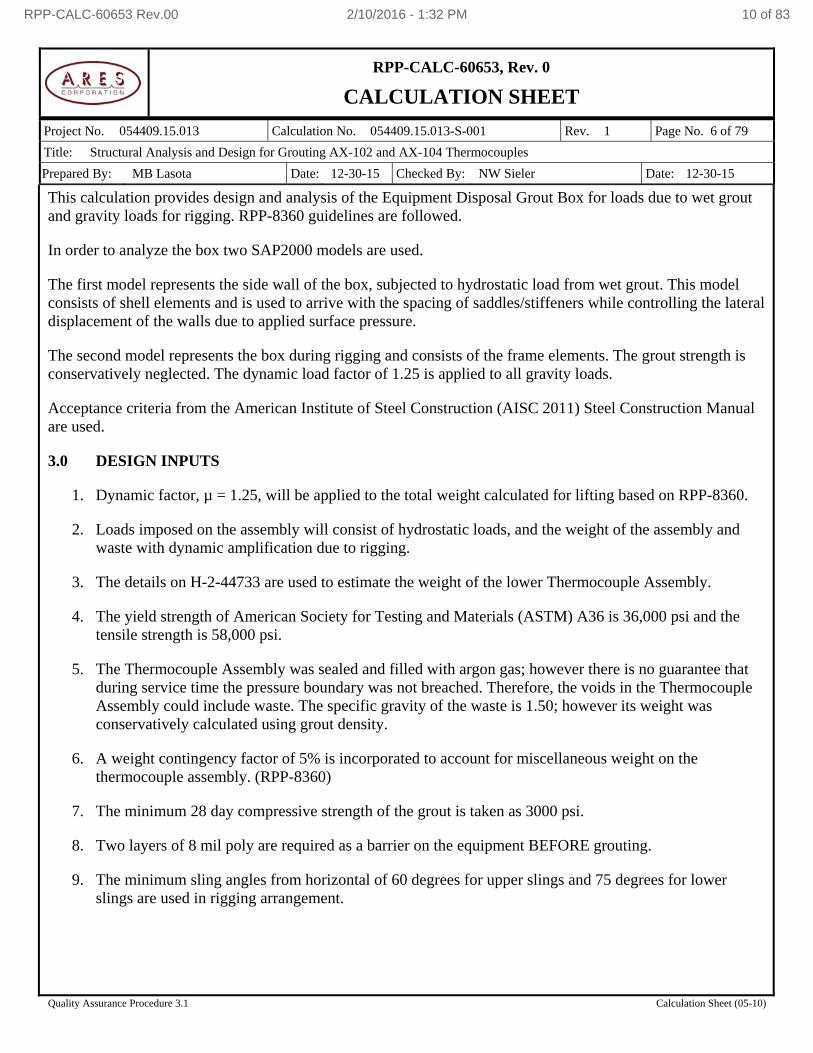
This calculation provides design and analysis of the Equipment Disposal Grout Box for loads due to wet grout and gravity loads for rigging. RPP-8360 guidelines are followed.
In order to analyze the box two SAP2000 models are used.
The first model represents the side wall of the box, subjected to hydrostatic load from wet grout. This model consists of shell elements and is used to arrive with the spacing of saddles/stiffeners while controlling the lateral displacement of the walls due to applied surface pressure.
The second model represents the box during rigging and consists of the frame elements. The grout strength is conservatively neglected. The dynamic load factor of 1.25 is applied to all gravity loads.
Acceptance criteria from the American Institute of Steel Construction (AISC 2011) Steel Construction Manual are used.
3.0 DESIGN INPUTS
1. Dynamic factor, µ = 1.25, will be applied to the total weight calculated for lifting based on RPP-8360.
2. Loads imposed on the assembly will consist of hydrostatic loads, and the weight of the assembly and waste with dynamic amplification due to rigging.
3. The details on H-2-44733 are used to estimate the weight of the lower Thermocouple Assembly.
4. The yield strength of American Society for Testing and Materials (ASTM) A36 is 36,000 psi and the tensile strength is 58,000 psi.
5. The Thermocouple Assembly was sealed and filled with argon gas; however there is no guarantee that during service time the pressure boundary was not breached. Therefore, the voids in the Thermocouple Assembly could include waste. The specific gravity of the waste is 1.50; however its weight was conservatively calculated using grout density.
6. A weight contingency factor of 5% is incorporated to account for miscellaneous weight on the thermocouple assembly. (RPP-8360)
7. The minimum 28 day compressive strength of the grout is taken as 3000 psi.
8. Two layers of 8 mil poly are required as a barrier on the equipment BEFORE grouting.
9. The minimum sling angles from horizontal of 60 degrees for upper slings and 75 degrees for lower slings are used in rigging arrangement.
RPP-CALC-60653 Rev.00 2/10/2016 - 1:32 PM 10 of 83
RPP-CALC-60653, Rev. 0
CALCULATION SHEET
Project No. 054409.15.013 Calculation No. 054409.15.013-S-001 Rev. 1 Page No. 7 of 79
Title: Structural Analysis and Design for Grouting AX-102 and AX-104 Thermocouples
Prepared By: MB Lasota Date: 12-30-15 Checked By: NW Sieler Date: 12-30-15
Quality Assurance Procedure 3.1 Calculation Sheet (05-10)
4.0 ASSUMPTIONS
There are no unverified assumptions in this calculation. Engineering judgments are used and justified in the body of the calculation.
5.0 COMPUTER SOFTWARE
No unverified computer software was used in this analysis.
The following software is used in this calculation:
Computers and Structures Inc. SAP2000® version 17.3.0 distributed by CSI is used to conduct a finite element analysis of the Grout Box and Spreader Beam. The software has been verified per ARES quality assurance procedures and documented in ARES Verification No. VV-15-03-180. The software is run on an ARES computer (Computer ID: 2V4F8P1 which is a DELL Precision T5500 running Microsoft Windows 7 Professional x64 Edition Version 2009 Service Pack 1.
PTC Mathcad1 15.0.0.436 – Mathcad results are verified using hand held calculator.
6.0 RESULTS
Table 6-1. Results summary
Stress in the 1/2 inch box side walls due to hydrostatic pressure 0.13
Stress in weld between walls of the box and the floor plate 0.14
Flexural stresses in the box 0.53
Shear stress in the box. 0.08
Side Load Hoist Ring 0.65
Local stress in side wall due to Hoist Ring action. 0.80
Spreader Beam stress per BTH-1 [2011] 0.46
Top Crane Lifting Bails 0.67
Top Crane Lifting Bails stress in the weld 0.48
Bottom Spreader Beam Lifting Bails 0.83
Bottom Spreader Beam Lifting Bails stress in the weld 0.37
The controlling Demand/Capacity Ratio is for the Bottom Spreader Beam Lifting Bails and is highlighted in the table above.
The Maximum Allowable Rated Capacity is 65715 pounds.
The Not-To-Exceed Lifting Pull is 54341 pounds.
1 Mathcad is a registered trademark of Parametric Technology Corporation, Needham, Massachusetts.
RPP-CALC-60653 Rev.00 2/10/2016 - 1:32 PM 11 of 83
Project No.: 054409.15.013
RPP-CALC-60653, Rev. 0
CALCULATION SHEET
Calculation Title: Structural Analysis and Design for Grouting AX-102 and AX-104
Thermocouples
Calc. No. 054409.15.013-S-001 Rev. 1 Page 8 of 79
Prepared By: MB Lasota Date: 12/30/15 Checked By: NW Sieler Date: 12/30/15
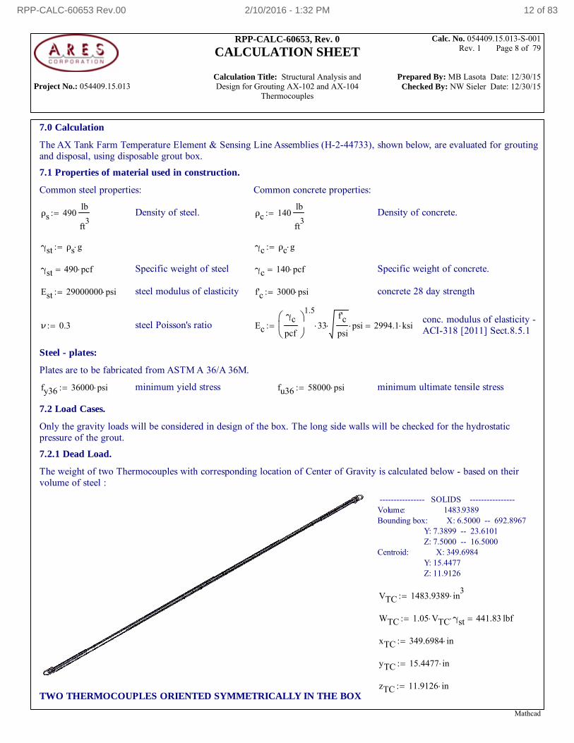
7.0 Calculation
The AX Tank Farm Temperature Element & Sensing Line Assemblies (H-2-44733), shown below, are evaluated for groutingand disposal, using disposable grout box.
7.1 Properties of material used in construction.
Common steel properties: Common concrete properties:
ρs 490lb
ft3
Density of steel. ρc 140lb
ft3
Density of concrete.
γst ρs g γc ρc g
γst 490 pcf Specific weight of steel γc 140 pcf Specific weight of concrete.
Est 29000000 psi steel modulus of elasticity f'c 3000 psi concrete 28 day strength
conc. modulus of elasticity -ACI-318 [2011] Sect.8.5.1ν 0.3 steel Poisson's ratio Ec
γc
pcf
1.5
33f'c
psi psi 2994.1 ksi
Steel - plates:
Plates are to be fabricated from ASTM A 36/A 36M.
fy36 36000 psi minimum yield stress fu36 58000 psi minimum ultimate tensile stress
7.2 Load Cases.
Only the gravity loads will be considered in design of the box. The long side walls will be checked for the hydrostaticpressure of the grout.
7.2.1 Dead Load.
The weight of two Thermocouples with corresponding location of Center of Gravity is calculated below - based on theirvolume of steel :
---------------- SOLIDS ----------------Volume: 1483.9389Bounding box: X: 6.5000 -- 692.8967 Y: 7.3899 -- 23.6101 Z: 7.5000 -- 16.5000Centroid: X: 349.6984 Y: 15.4477 Z: 11.9126
VTC 1483.9389 in3
WTC 1.05 VTC γst 441.83 lbf
xTC 349.6984 in
yTC 15.4477 in
zTC 11.9126 inTWO THERMOCOUPLES ORIENTED SYMMETRICALLY IN THE BOX
Mathcad
RPP-CALC-60653 Rev.00 2/10/2016 - 1:32 PM 12 of 83
Project No.: 054409.15.013
RPP-CALC-60653, Rev. 0
CALCULATION SHEET
Calculation Title: Structural Analysis and Design for Grouting AX-102 and AX-104
Thermocouples
Calc. No. 054409.15.013-S-001 Rev. 1 Page 9 of 79
Prepared By: MB Lasota Date: 12/30/15 Checked By: NW Sieler Date: 12/30/15
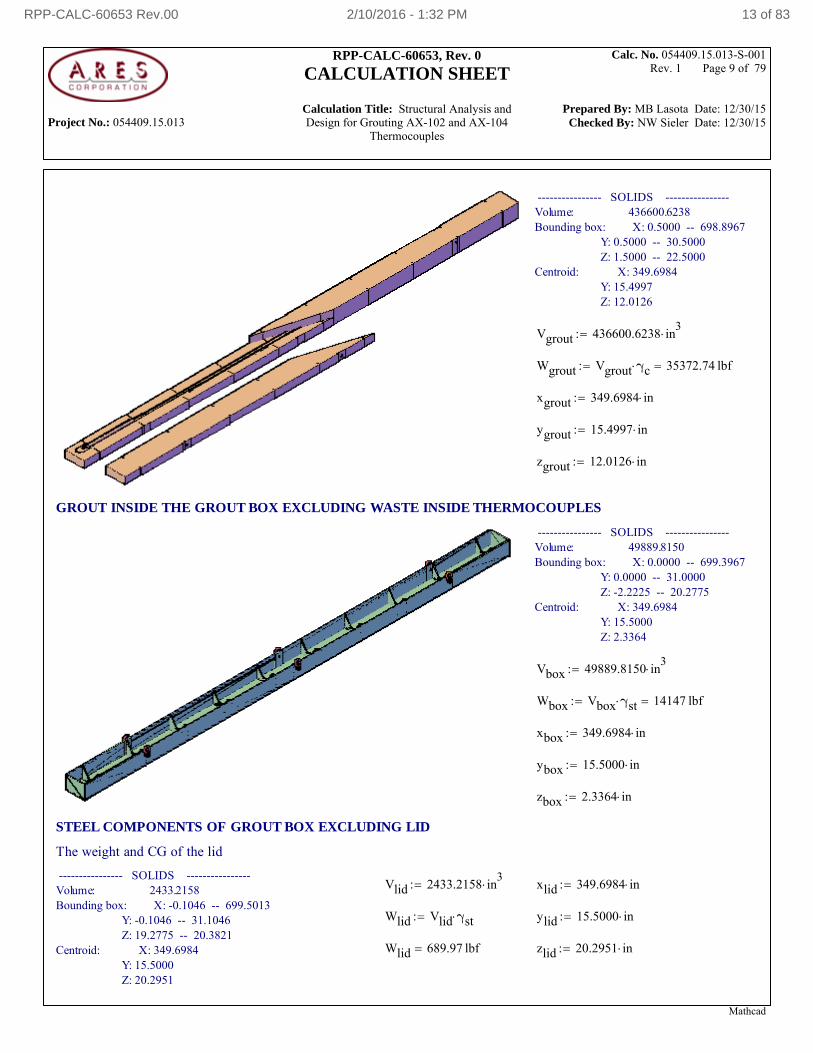
---------------- SOLIDS ----------------Volume: 436600.6238Bounding box: X: 0.5000 -- 698.8967 Y: 0.5000 -- 30.5000 Z: 1.5000 -- 22.5000Centroid: X: 349.6984 Y: 15.4997 Z: 12.0126
Vgrout 436600.6238 in3
Wgrout Vgrout γc 35372.74 lbf
xgrout 349.6984 in
ygrout 15.4997 in
zgrout 12.0126 in
GROUT INSIDE THE GROUT BOX EXCLUDING WASTE INSIDE THERMOCOUPLES
---------------- SOLIDS ----------------Volume: 49889.8150Bounding box: X: 0.0000 -- 699.3967 Y: 0.0000 -- 31.0000 Z: -2.2225 -- 20.2775Centroid: X: 349.6984 Y: 15.5000 Z: 2.3364
Vbox 49889.8150 in3
Wbox Vbox γst 14147 lbf
xbox 349.6984 in
ybox 15.5000 in
zbox 2.3364 in
STEEL COMPONENTS OF GROUT BOX EXCLUDING LID
The weight and CG of the lid
---------------- SOLIDS ----------------Volume: 2433.2158Bounding box: X: -0.1046 -- 699.5013 Y: -0.1046 -- 31.1046 Z: 19.2775 -- 20.3821Centroid: X: 349.6984 Y: 15.5000 Z: 20.2951
Vlid 2433.2158 in3
xlid 349.6984 in
Wlid Vlid γst ylid 15.5000 in
Wlid 689.97 lbf zlid 20.2951 in
Mathcad
RPP-CALC-60653 Rev.00 2/10/2016 - 1:32 PM 13 of 83
Project No.: 054409.15.013
RPP-CALC-60653, Rev. 0
CALCULATION SHEET
Calculation Title: Structural Analysis and Design for Grouting AX-102 and AX-104
Thermocouples
Calc. No. 054409.15.013-S-001 Rev. 1 Page 10 of 79
Prepared By: MB Lasota Date: 12/30/15 Checked By: NW Sieler Date: 12/30/15
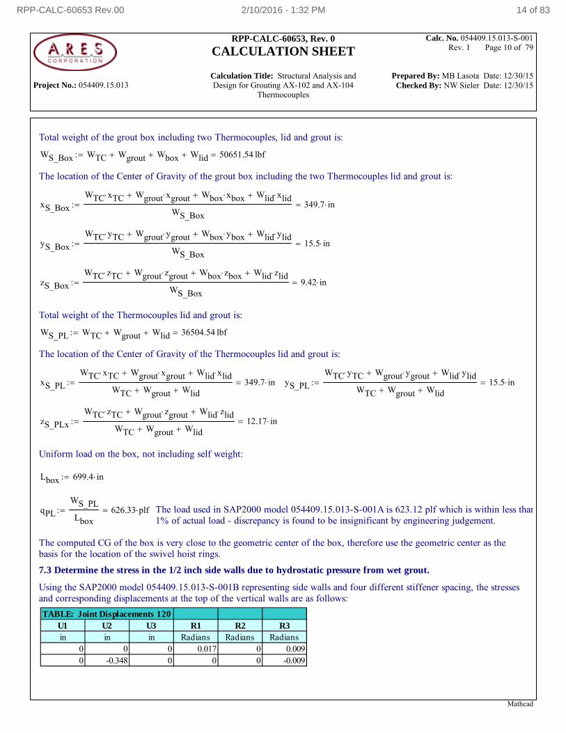
Total weight of the grout box including two Thermocouples, lid and grout is:
WS_Box WTC Wgrout Wbox Wlid 50651.54 lbf
The location of the Center of Gravity of the grout box including the two Thermocouples lid and grout is:
xS_Box
WTC xTC Wgrout xgrout Wbox xbox Wlid xlid
WS_Box349.7 in
yS_Box
WTC yTC Wgrout ygrout Wbox ybox Wlid ylid
WS_Box15.5 in
zS_Box
WTC zTC Wgrout zgrout Wbox zbox Wlid zlid
WS_Box9.42 in
Total weight of the Thermocouples lid and grout is:
WS_PL WTC Wgrout Wlid 36504.54 lbf
The location of the Center of Gravity of the Thermocouples lid and grout is:
xS_PL
WTC xTC Wgrout xgrout Wlid xlid
WTC Wgrout Wlid349.7 in yS_PL
WTC yTC Wgrout ygrout Wlid ylid
WTC Wgrout Wlid15.5 in
zS_PLx
WTC zTC Wgrout zgrout Wlid zlid
WTC Wgrout Wlid12.17 in
Uniform load on the box, not including self weight:
Lbox 699.4 in
qPL
WS_PL
Lbox626.33 plf The load used in SAP2000 model 054409.15.013-S-001A is 623.12 plf which is within less than
1% of actual load - discrepancy is found to be insignificant by engineering judgement.
The computed CG of the box is very close to the geometric center of the box, therefore use the geometric center as thebasis for the location of the swivel hoist rings.
7.3 Determine the stress in the 1/2 inch side walls due to hydrostatic pressure from wet grout.
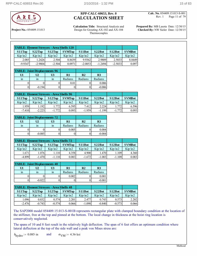
Using the SAP2000 model 054409.15.013-S-001B representing side walls and four different stiffener spacing, the stressesand corresponding displacements at the top of the vertical walls are as follows:
TABLE: Joint Displacements 120U1 U2 U3 R1 R2 R3in in in Radians Radians Radians
0 0 0 0.017 0 0.0090 -0.348 0 0 0 -0.009
Mathcad
RPP-CALC-60653 Rev.00 2/10/2016 - 1:32 PM 14 of 83
Project No.: 054409.15.013
RPP-CALC-60653, Rev. 0
CALCULATION SHEET
Calculation Title: Structural Analysis and Design for Grouting AX-102 and AX-104
Thermocouples
Calc. No. 054409.15.013-S-001 Rev. 1 Page 11 of 79
Prepared By: MB Lasota Date: 12/30/15 Checked By: NW Sieler Date: 12/30/15
TABLE: Element Stresses - Area Shells 120S11Top S22Top S12Top SVMTop S11Bot S22Bot S12Bot SVMBotKip/in2 Kip/in2 Kip/in2 Kip/in2 Kip/in2 Kip/in2 Kip/in2 Kip/in2
2.085 1.2426 2.504 8.8439 9.9362 2.9809 2.5033 8.8449-9.9347 -2.9804 -2.504 0.0971 -2.0853 -1.2494 -2.5033 0.097
TABLE: Joint Displacements 96U1 U2 U3 R1 R2 R3in in in Radians Radians Radians
0 0 0 0.01 0 0.0060 -0.194 0 0 0 -0.006
TABLE: Element Stresses - Area Shells 96S11Top S22Top S12Top SVMTop S11Bot S22Bot S12Bot SVMBotKip/in2 Kip/in2 Kip/in2 Kip/in2 Kip/in2 Kip/in2 Kip/in2 Kip/in2
1.959 1.192 1.772 6.595 7.412 2.224 1.772 6.596-7.410 -2.223 -1.772 0.093 -1.959 -1.199 -1.772 0.093
TABLE: Joint Displacements 72U1 U2 U3 R1 R2 R3in in in Radians Radians Radians
0 0 0 0.005 0 0.0040 -0.085 0 0 0 -0.004
TABLE: Element Stresses - Area Shells 72S11Top S22Top S12Top SVMTop S11Bot S22Bot S12Bot SVMBotKip/in2 Kip/in2 Kip/in2 Kip/in2 Kip/in2 Kip/in2 Kip/in2 Kip/in2
1.671 1.076 1.110 4.358 4.900 1.470 1.109 4.360-4.899 -1.470 -1.110 0.083 -1.672 -1.083 -1.109 0.083
TABLE: Joint Displacements 48U1 U2 U3 R1 R2 R3in in in Radians Radians Radians
0 0 0 0.002 0 0.0010 -0.022 0 0 0 -0.001
TABLE: Element Stresses - Area Shells 48S11Top S22Top S12Top SVMTop S11Bot S22Bot S12Bot SVMBotKip/in2 Kip/in2 Kip/in2 Kip/in2 Kip/in2 Kip/in2 Kip/in2 Kip/in2
1.096 0.832 0.574 2.201 2.477 0.743 0.573 2.202-2.476 -0.743 -0.574 0.066 -1.098 -0.840 -0.573 0.066
The SAP2000 model 054409.15.013-S-001B represents rectangular plate with clamped boundary condition at the location ofthe stiffener, free at the top and pinned at the bottom. The local change in thickness at the hoist ring location isconservatively neglected.
The spans of 10 and 8 feet result in the relatively high deflection. The span of 6 feet offers an optimum condition wherelateral deflection at the top of the side wall and a peak von Mises stress are:
δhydro 0.085 in and σVM 4.36 ksi
Mathcad
RPP-CALC-60653 Rev.00 2/10/2016 - 1:32 PM 15 of 83
Project No.: 054409.15.013
RPP-CALC-60653, Rev. 0
CALCULATION SHEET
Calculation Title: Structural Analysis and Design for Grouting AX-102 and AX-104
Thermocouples
Calc. No. 054409.15.013-S-001 Rev. 1 Page 12 of 79
Prepared By: MB Lasota Date: 12/30/15 Checked By: NW Sieler Date: 12/30/15
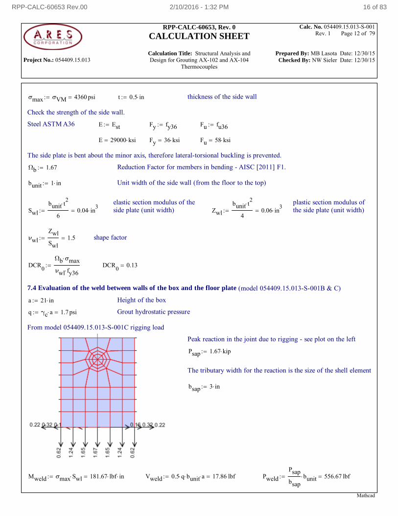
σmax σVM 4360 psi t 0.5 in thickness of the side wall
Check the strength of the side wall.
Steel ASTM A36 E Est Fy fy36 Fu fu36
E 29000 ksi Fy 36 ksi Fu 58 ksi
The side plate is bent about the minor axis, therefore lateral-torsional buckling is prevented.
Ωb 1.67 Reduction Factor for members in bending - AISC [2011] F1.
bunit 1 in Unit width of the side wall (from the floor to the top)
elastic section modulus of theside plate (unit width)
plastic section modulus ofthe side plate (unit width)Swl
bunit t2
60.04 in
3 Zwl
bunit t2
40.06 in
3
νwl
Zwl
Swl1.5 shape factor
DCR0
Ωb σmax
νwl fy36 DCR
00.13
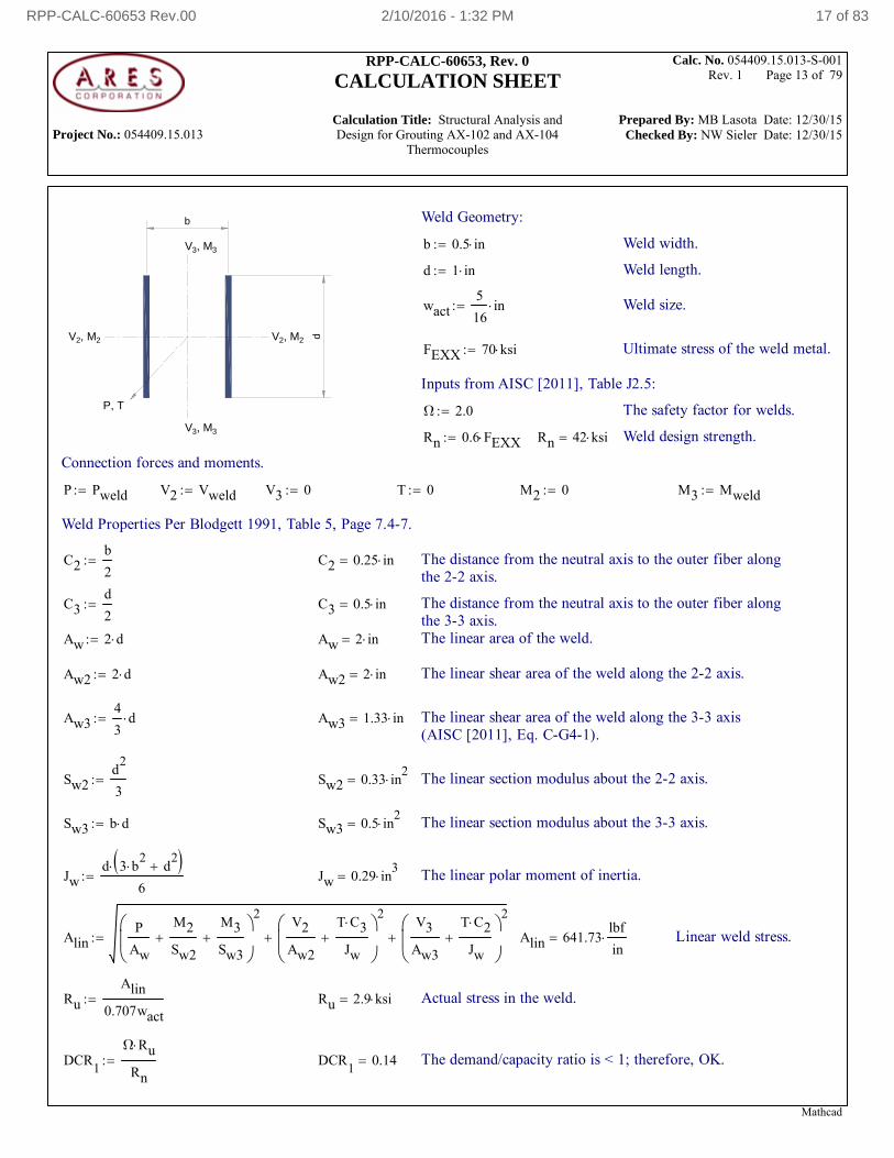
7.4 Evaluation of the weld between walls of the box and the floor plate (model 054409.15.013-S-001B & C)
a 21 in Height of the box
q γc a 1.7 psi Grout hydrostatic pressure
From model 054409.15.013-S-001C rigging load
Peak reaction in the joint due to rigging - see plot on the left
Psap 1.67 kip
The tributary width for the reaction is the size of the shell element
bsap 3 in
Mweld σmax Swl 181.67 lbf in Vweld 0.5 q bunit a 17.86 lbf Pweld
Psap
bsapbunit 556.67 lbf
Mathcad
RPP-CALC-60653 Rev.00 2/10/2016 - 1:32 PM 16 of 83
Project No.: 054409.15.013
RPP-CALC-60653, Rev. 0
CALCULATION SHEET
Calculation Title: Structural Analysis and Design for Grouting AX-102 and AX-104
Thermocouples
Calc. No. 054409.15.013-S-001 Rev. 1 Page 13 of 79
Prepared By: MB Lasota Date: 12/30/15 Checked By: NW Sieler Date: 12/30/15
d
b
V 3, M
3
V 3, M
3
V 2, M
2 V
2, M 2
P, T
Weld Geometry:
b 0.5 in Weld width.
d 1 in Weld length.
wact5
16in Weld size.
FEXX 70 ksi Ultimate stress of the weld metal.
Inputs from AISC [2011], Table J2.5:
Ω 2.0 The safety factor for welds.
Rn 0.6 FEXX Rn 42 ksi Weld design strength.
Connection forces and moments.
P Pweld V2 Vweld V3 0 T 0 M2 0 M3 Mweld
Weld Properties Per Blodgett 1991, Table 5, Page 7.4-7.
C2b
2 C2 0.25 in The distance from the neutral axis to the outer fiber along
the 2-2 axis.
C3d
2 C3 0.5 in The distance from the neutral axis to the outer fiber along
the 3-3 axis.Aw 2 d Aw 2 in The linear area of the weld.
Aw2 2 d Aw2 2 in The linear shear area of the weld along the 2-2 axis.
Aw34
3d Aw3 1.33 in The linear shear area of the weld along the 3-3 axis
(AISC [2011], Eq. C-G4-1).
Sw2d
2
3 Sw2 0.33 in
2 The linear section modulus about the 2-2 axis.
Sw3 b d Sw3 0.5 in2
The linear section modulus about the 3-3 axis.
Jwd 3 b
2 d
2
6 Jw 0.29 in
3 The linear polar moment of inertia.
AlinP
Aw
M2
Sw2
M3
Sw3
2V2
Aw2
T C3
Jw
2
V3
Aw3
T C2
Jw
2
Alin 641.73lbf
in Linear weld stress.
Ru
Alin
0.707wact Ru 2.9 ksi Actual stress in the weld.
DCR1
Ω Ru
Rn DCR
10.14 The demand/capacity ratio is < 1; therefore, OK.
Mathcad
RPP-CALC-60653 Rev.00 2/10/2016 - 1:32 PM 17 of 83
Project No.: 054409.15.013
RPP-CALC-60653, Rev. 0
CALCULATION SHEET
Calculation Title: Structural Analysis and Design for Grouting AX-102 and AX-104
Thermocouples
Calc. No. 054409.15.013-S-001 Rev. 1 Page 14 of 79
Prepared By: MB Lasota Date: 12/30/15 Checked By: NW Sieler Date: 12/30/15
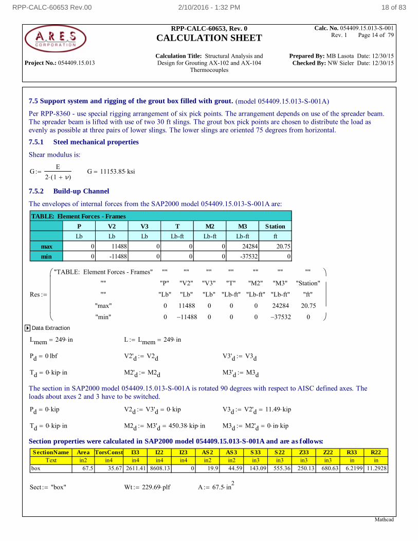
7.5 Support system and rigging of the grout box filled with grout. (model 054409.15.013-S-001A)
Per RPP-8360 - use special rigging arrangement of six pick points. The arrangement depends on use of the spreader beam. The spreader beam is lifted with use of two 30 ft slings. The grout box pick points are chosen to distribute the load asevenly as possible at three pairs of lower slings. The lower slings are oriented 75 degrees from horizontal.
7.5.1 Steel mechanical properties
Shear modulus is:
GE
2 1 ν( ) G 11153.85 ksi
7.5.2 Build-up Channel
The envelopes of internal forces from the SAP2000 model 054409.15.013-S-001A are:
P V2 V3 T M2 M3 Station
Lb Lb Lb Lb-ft Lb-ft Lb-ft ft
max 0 11488 0 0 0 24284 20.75
min 0 -11488 0 0 0 -37532 0
TABLE: Element Forces - Frames
Res
"TABLE: Element Forces - Frames"
""
""
"max"
"min"
""
"P"
"Lb"
0
0
""
"V2"
"Lb"
11488
11488
""
"V3"
"Lb"
0
0
""
"T"
"Lb-ft"
0
0
""
"M2"
"Lb-ft"
0
0
""
"M3"
"Lb-ft"
24284
37532
""
"Station"
"ft"
20.75
0
Data Extraction
Lmem 249 in L Lmem 249 in
Pd 0 lbf V2'd V2d V3'd V3d
Td 0 kip in M2'd M2d M3'd M3d
The section in SAP2000 model 054409.15.013-S-001A is rotated 90 degrees with respect to AISC defined axes. Theloads about axes 2 and 3 have to be switched.
Pd 0 kip V2d V3'd 0 kip V3d V2'd 11.49 kip
Td 0 kip in M2d M3'd 450.38 kip in M3d M2'd 0 in kip
Section properties were calculated in SAP2000 model 054409.15.013-S-001A and are as follows:
SectionName Area TorsConst I33 I22 I23 AS2 AS3 S33 S22 Z33 Z22 R33 R22Text in2 in4 in4 in4 in4 in2 in2 in3 in3 in3 in3 in in
box 67.5 35.67 2611.41 8608.13 0 19.9 44.59 143.09 555.36 250.13 680.63 6.2199 11.2928
Sect "box" Wt 229.69 plf A 67.5 in2
Mathcad
RPP-CALC-60653 Rev.00 2/10/2016 - 1:32 PM 18 of 83
Project No.: 054409.15.013
RPP-CALC-60653, Rev. 0
CALCULATION SHEET
Calculation Title: Structural Analysis and Design for Grouting AX-102 and AX-104
Thermocouples
Calc. No. 054409.15.013-S-001 Rev. 1 Page 15 of 79
Prepared By: MB Lasota Date: 12/30/15 Checked By: NW Sieler Date: 12/30/15
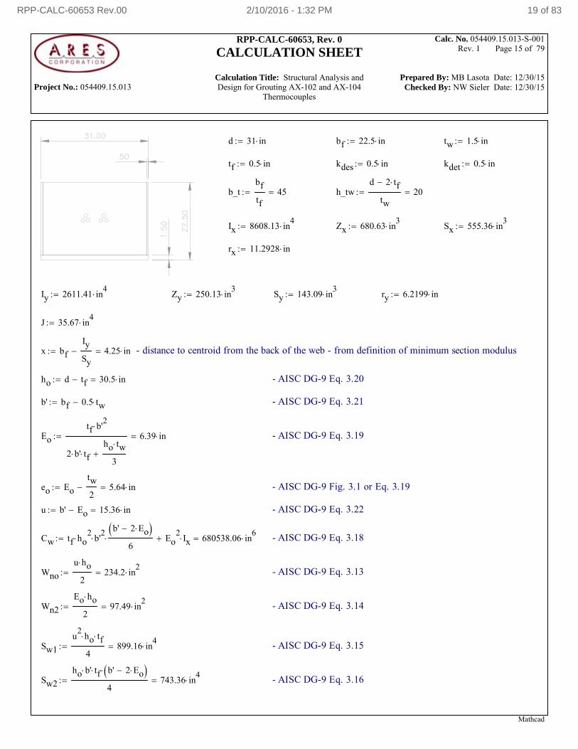
d 31 in bf 22.5 in tw 1.5 in
tf 0.5 in kdes 0.5 in kdet 0.5 in
b_tbf
tf45 h_tw
d 2 tf
tw20
Ix 8608.13 in4
Zx 680.63 in3
Sx 555.36 in3
rx 11.2928 in
Iy 2611.41 in4
Zy 250.13 in3
Sy 143.09 in3
ry 6.2199 in
J 35.67 in4
x bf
Iy
Sy 4.25 in - distance to centroid from the back of the web - from definition of minimum section modulus
ho d tf 30.5 in - AISC DG-9 Eq. 3.20
b' bf 0.5 tw - AISC DG-9 Eq. 3.21
Eo
tf b'2
2 b' tfho tw
3
6.39 in - AISC DG-9 Eq. 3.19
eo Eo
tw
2 5.64 in - AISC DG-9 Fig. 3.1 or Eq. 3.19
u b' Eo 15.36 in - AISC DG-9 Eq. 3.22
Cw tf ho2
b'2
b' 2 Eo
6 Eo
2Ix 680538.06 in
6 - AISC DG-9 Eq. 3.18
Wno
u ho
2234.2 in
2 - AISC DG-9 Eq. 3.13
Wn2
Eo ho
297.49 in
2 - AISC DG-9 Eq. 3.14
Sw1
u2
ho tf
4899.16 in
4 - AISC DG-9 Eq. 3.15
Sw2
ho b' tf b' 2 Eo
4743.36 in
4 - AISC DG-9 Eq. 3.16
Mathcad
RPP-CALC-60653 Rev.00 2/10/2016 - 1:32 PM 19 of 83
Project No.: 054409.15.013
RPP-CALC-60653, Rev. 0
CALCULATION SHEET
Calculation Title: Structural Analysis and Design for Grouting AX-102 and AX-104
Thermocouples
Calc. No. 054409.15.013-S-001 Rev. 1 Page 16 of 79
Prepared By: MB Lasota Date: 12/30/15 Checked By: NW Sieler Date: 12/30/15
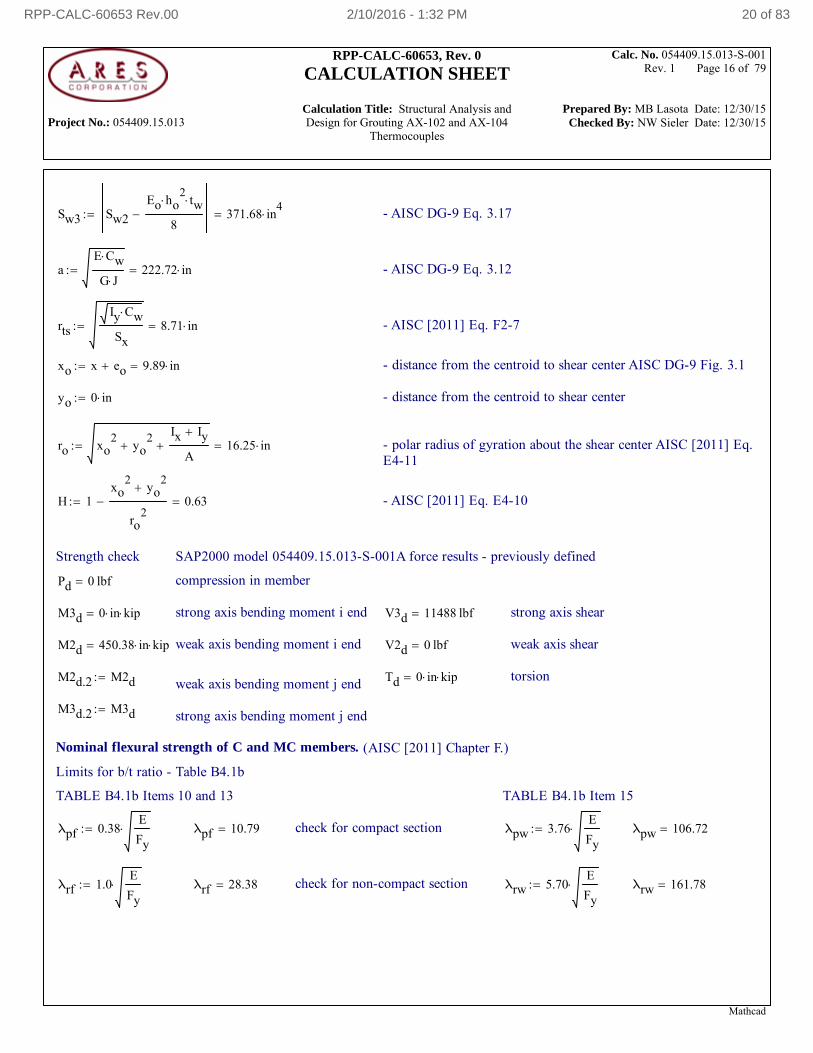
Sw3 Sw2
Eo ho2
tw
8 371.68 in
4 - AISC DG-9 Eq. 3.17
aE Cw
G J222.72 in - AISC DG-9 Eq. 3.12
rts
Iy Cw
Sx8.71 in - AISC [2011] Eq. F2-7
xo x eo 9.89 in - distance from the centroid to shear center AISC DG-9 Fig. 3.1
yo 0 in - distance from the centroid to shear center
ro xo2
yo2
Ix Iy
A 16.25 in - polar radius of gyration about the shear center AISC [2011] Eq.
E4-11
H 1xo
2yo
2
ro2
0.63 - AISC [2011] Eq. E4-10
Strength check SAP2000 model 054409.15.013-S-001A force results - previously defined
Pd 0 lbf compression in member
M3d 0 in kip strong axis bending moment i end V3d 11488 lbf strong axis shear
M2d 450.38 in kip weak axis bending moment i end V2d 0 lbf weak axis shear
M2d.2 M2d Td 0 in kip torsionweak axis bending moment j end
M3d.2 M3d strong axis bending moment j end
Nominal flexural strength of C and MC members. (AISC [2011] Chapter F.)
Limits for b/t ratio - Table B4.1b
TABLE B4.1b Items 10 and 13 TABLE B4.1b Item 15
λpf 0.38E
Fy λpf 10.79 check for compact section λpw 3.76
E
Fy λpw 106.72
λrf 1.0E
Fy λrf 28.38 check for non-compact section λrw 5.70
E
Fy λrw 161.78
Mathcad
RPP-CALC-60653 Rev.00 2/10/2016 - 1:32 PM 20 of 83
Project No.: 054409.15.013
RPP-CALC-60653, Rev. 0
CALCULATION SHEET
Calculation Title: Structural Analysis and Design for Grouting AX-102 and AX-104
Thermocouples
Calc. No. 054409.15.013-S-001 Rev. 1 Page 17 of 79
Prepared By: MB Lasota Date: 12/30/15 Checked By: NW Sieler Date: 12/30/15
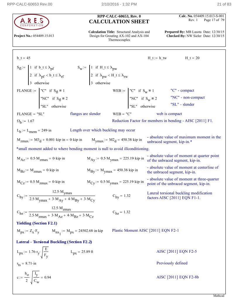
b_t 45 H_t h_tw H_t 20
Sfl 1 b_t λpfif
2 λpf b_t λrfif
3 otherwise
Sw 1 H_t λpwif
2 λpw H_t λrwif
3 otherwise
FLANGE "C" Sfl 1=if
"NC" Sfl 2=if
"SL" otherwise
WEB "C" Sw 1=if
"NC" Sw 2=if
"SL" otherwise
"C" - compact
"NC" - non-compact
"SL" - slender
FLANGE "SL" flanges are slender WEB "C" web is compact
Ωb 1.67 Reduction Factor for members in bending - AISC [2011] F1.
Lb Lmem 249 in Length over which buckling may occur
- absolute value of maximum moment in theunbraced segment, kip-in.*Mzmax M3d 0.001 kip in 0 kip in Mymax M2d 450.38 kip in
*small moment added to where bending moment is null to avoid illconditioning.
- absolute value of moment at quarter pointof the unbraced segment, kip-in.MAz 0.5 Mzmax 0 kip in MAy 0.5 Mymax 225.19 kip in
- absolute value of moment at centerline ofthe unbraced segment, kip-in.MBz Mzmax 0 kip in MBy Mymax 450.38 kip in
- absolute value of moment at three-quarterpoint of the unbraced segment, kip-in.MCz 0.5 Mzmax 0 kip in MCy 0.5 Mymax 225.19 kip in
Lateral torsional buckling modificationfactors AISC [2011] EQN F1-1.Cby
12.5 Mymax
2.5 Mymax 3 MAy 4 MBy 3 MCy Cby 1.32
Cbz
12.5 Mzmax
2.5 Mzmax 3 MAz 4 MBz 3 MCz Cbz 1.32
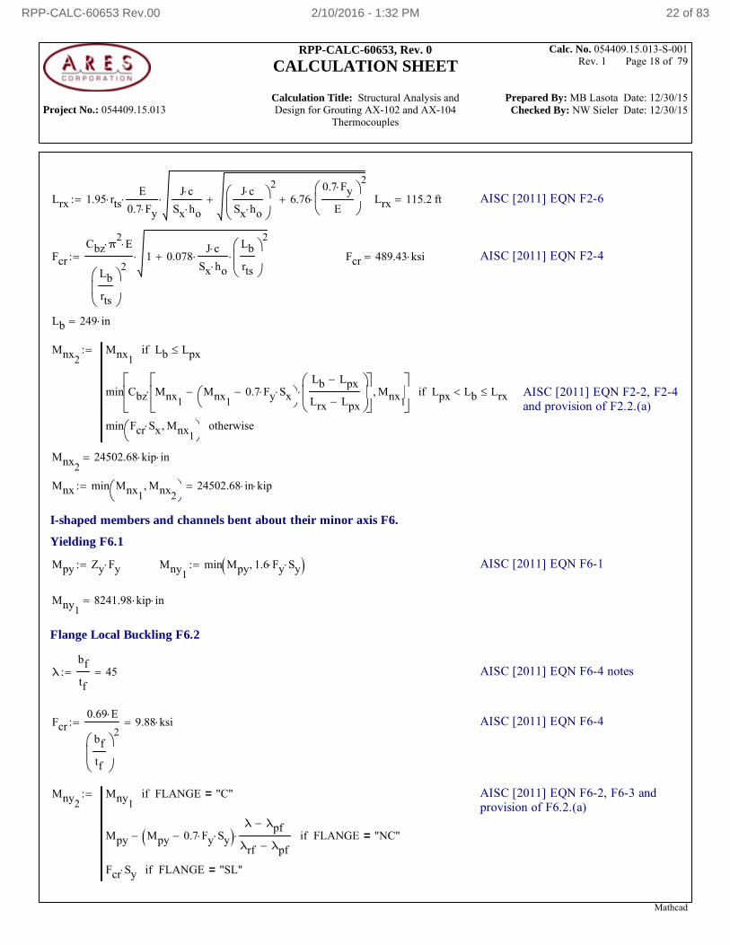
Yielding (Section F2.1)
Mpx Zx Fy Mnx1Mpx 24502.68 in kip Plastic Moment AISC [2011] EQN F2-1
Lateral - Torsional Buckling (Section F2.2)
Lpx 1.76 ryE
Fy Lpx 25.89 ft AISC [2011] EQN F2-5
rts 8.71 in Previously defined
cho
2
Iy
Cw 0.94 AISC [2011] EQN F2-8b
Mathcad
RPP-CALC-60653 Rev.00 2/10/2016 - 1:32 PM 21 of 83
Project No.: 054409.15.013
RPP-CALC-60653, Rev. 0
CALCULATION SHEET
Calculation Title: Structural Analysis and Design for Grouting AX-102 and AX-104
Thermocouples
Calc. No. 054409.15.013-S-001 Rev. 1 Page 18 of 79
Prepared By: MB Lasota Date: 12/30/15 Checked By: NW Sieler Date: 12/30/15
Lrx 1.95 rtsE
0.7 Fy
J c
Sx ho
J c
Sx ho
2
6.760.7 Fy
E
2
Lrx 115.2 ft AISC [2011] EQN F2-6
Fcr
Cbz π2
E
Lb
rts
21 0.078
J c
Sx ho
Lb
rts
2
Fcr 489.43 ksi AISC [2011] EQN F2-4
Lb 249 in
Mnx2Mnx1
Lb Lpxif
min Cbz Mnx1Mnx1
0.7 Fy Sx
Lb Lpx
Lrx Lpx
Mnx1
Lpx Lb Lrxif
min Fcr Sx Mnx1
otherwise
AISC [2011] EQN F2-2, F2-4and provision of F2.2.(a)
Mnx224502.68 kip in
Mnx min Mnx1Mnx2
24502.68 in kip
I-shaped members and channels bent about their minor axis F6.
Yielding F6.1
Mpy Zy Fy Mny1min Mpy 1.6 Fy Sy AISC [2011] EQN F6-1
Mny18241.98 kip in
Flange Local Buckling F6.2
λbf
tf45 AISC [2011] EQN F6-4 notes
Fcr0.69 E
bf
tf
29.88 ksi AISC [2011] EQN F6-4
Mny2Mny1
FLANGE "C"=if
Mpy Mpy 0.7 Fy Sy λ λpf
λrf λpf FLANGE "NC"=if
Fcr Sy FLANGE "SL"=if
AISC [2011] EQN F6-2, F6-3 andprovision of F6.2.(a)
Mathcad
RPP-CALC-60653 Rev.00 2/10/2016 - 1:32 PM 22 of 83
Project No.: 054409.15.013
RPP-CALC-60653, Rev. 0
CALCULATION SHEET
Calculation Title: Structural Analysis and Design for Grouting AX-102 and AX-104
Thermocouples
Calc. No. 054409.15.013-S-001 Rev. 1 Page 19 of 79
Prepared By: MB Lasota Date: 12/30/15 Checked By: NW Sieler Date: 12/30/15
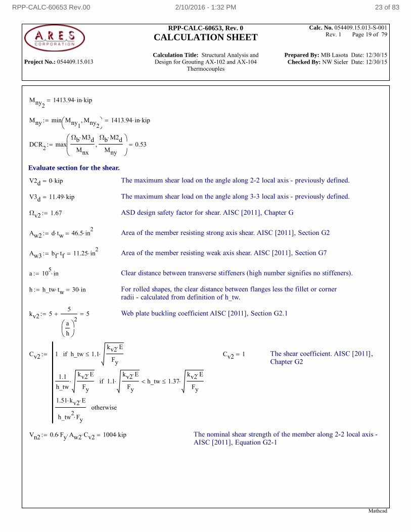
Mny21413.94 in kip
Mny min Mny1Mny2
1413.94 in kip
DCR2
maxΩb M3d
Mnx
Ωb M2d
Mny
0.53
Evaluate section for the shear.
V2d 0 kip The maximum shear load on the angle along 2-2 local axis - previously defined.
V3d 11.49 kip The maximum shear load on the angle along 3-3 local axis - previously defined.
Ωv2 1.67 ASD design safety factor for shear. AISC [2011], Chapter G
Aw2 d tw 46.5 in2
Area of the member resisting strong axis shear. AISC [2011], Section G2
Aw3 bf tf 11.25 in2
Area of the member resisting weak axis shear. AISC [2011], Section G7
a 105
in Clear distance between transverse stiffeners (high number signifies no stiffeners).
h h_tw tw 30 in For rolled shapes, the clear distance between flanges less the fillet or cornerradii - calculated from definition of h_tw.
kv2 55
a
h
2 5 Web plate buckling coefficient AISC [2011], Section G2.1
Cv2 1 h_tw 1.1kv2 E
Fyif
1.1
h_tw
kv2 E
Fy 1.1
kv2 E
Fy h_tw 1.37
kv2 E
Fyif
1.51 kv2 E
h_tw2
Fyotherwise
Cv2 1 The shear coefficient. AISC [2011],Chapter G2
Vn2 0.6 Fy Aw2 Cv2 1004 kip The nominal shear strength of the member along 2-2 local axis -AISC [2011], Equation G2-1
Mathcad
RPP-CALC-60653 Rev.00 2/10/2016 - 1:32 PM 23 of 83
Project No.: 054409.15.013
RPP-CALC-60653, Rev. 0
CALCULATION SHEET
Calculation Title: Structural Analysis and Design for Grouting AX-102 and AX-104
Thermocouples
Calc. No. 054409.15.013-S-001 Rev. 1 Page 20 of 79
Prepared By: MB Lasota Date: 12/30/15 Checked By: NW Sieler Date: 12/30/15
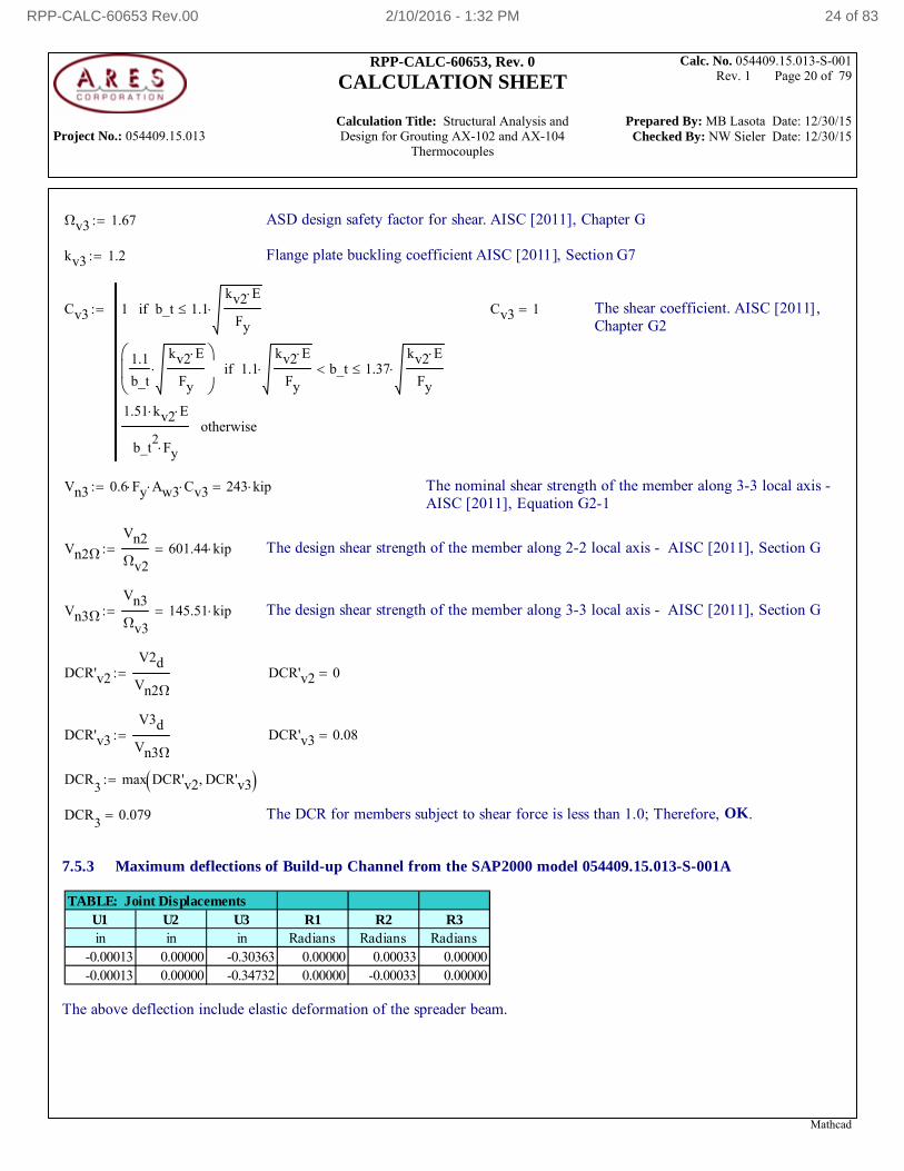
Ωv3 1.67 ASD design safety factor for shear. AISC [2011], Chapter G
kv3 1.2 Flange plate buckling coefficient AISC [2011], Section G7
Cv3 1 b_t 1.1kv2 E
Fyif
1.1
b_t
kv2 E
Fy
1.1kv2 E
Fy b_t 1.37
kv2 E
Fyif
1.51 kv2 E
b_t2
Fyotherwise
Cv3 1 The shear coefficient. AISC [2011],Chapter G2
Vn3 0.6 Fy Aw3 Cv3 243 kip The nominal shear strength of the member along 3-3 local axis -AISC [2011], Equation G2-1
Vn2Ω
Vn2
Ωv2601.44 kip The design shear strength of the member along 2-2 local axis - AISC [2011], Section G
Vn3Ω
Vn3
Ωv3145.51 kip The design shear strength of the member along 3-3 local axis - AISC [2011], Section G
DCR'v2
V2d
Vn2Ω
DCR'v2 0
DCR'v3
V3d
Vn3Ω
DCR'v3 0.08
DCR3
max DCR'v2 DCR'v3
DCR3
0.079 The DCR for members subject to shear force is less than 1.0; Therefore, OK.
7.5.3 Maximum deflections of Build-up Channel from the SAP2000 model 054409.15.013-S-001A
TABLE: Joint DisplacementsU1 U2 U3 R1 R2 R3in in in Radians Radians Radians
-0.00013 0.00000 -0.30363 0.00000 0.00033 0.00000-0.00013 0.00000 -0.34732 0.00000 -0.00033 0.00000
The above deflection include elastic deformation of the spreader beam.
Mathcad
RPP-CALC-60653 Rev.00 2/10/2016 - 1:32 PM 24 of 83
Project No.: 054409.15.013
RPP-CALC-60653, Rev. 0
CALCULATION SHEET
Calculation Title: Structural Analysis and Design for Grouting AX-102 and AX-104
Thermocouples
Calc. No. 054409.15.013-S-001 Rev. 1 Page 21 of 79
Prepared By: MB Lasota Date: 12/30/15 Checked By: NW Sieler Date: 12/30/15
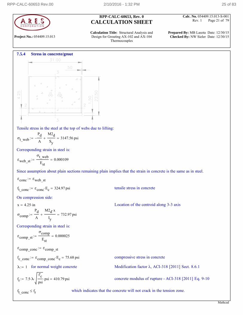
7.5.4 Stress in concrete/grout
Tensile stress in the steel at the top of webs due to lifting:
σt_web
Pd
A
M2d
Sy 3147.56 psi
Corresponding strain in steel is:
εweb_st
σt_web
Est0.000109
Since assumption about plain sections remaining plain implies that the strain in concrete is the same as in steel.
εconc εweb_st
ft_conc εconc Ec 324.97 psi tensile stress in concrete
On compression side:
x 4.25 in Location of the centroid along 3-3 axis
σcomp
Pd
A
M2d x
Iy 732.97 psi
Corresponding strain in steel is:
εcomp_st
σcomp
Est0.000025
εcomp_conc εcomp_st
fc_conc εcomp_conc Ec 75.68 psi compressive stress in concrete
λ 1 for normal weight concrete Modification factor λ, ACI-318 [2011] Sect. 8.6.1
fr 7.5 λf'c
psi psi 410.79 psi concrete modulus of rupture - ACI-318 [2011] Eq. 9-10
ft_conc fr which indicates that the concrete will not crack in the tension zone.
Mathcad
RPP-CALC-60653 Rev.00 2/10/2016 - 1:32 PM 25 of 83
Project No.: 054409.15.013
RPP-CALC-60653, Rev. 0
CALCULATION SHEET
Calculation Title: Structural Analysis and Design for Grouting AX-102 and AX-104
Thermocouples
Calc. No. 054409.15.013-S-001 Rev. 1 Page 22 of 79
Prepared By: MB Lasota Date: 12/30/15 Checked By: NW Sieler Date: 12/30/15
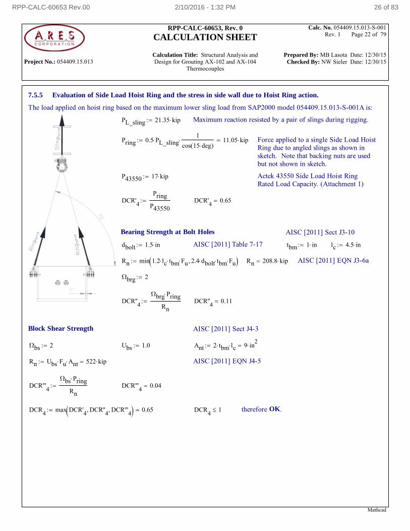
7.5.5 Evaluation of Side Load Hoist Ring and the stress in side wall due to Hoist Ring action.
The load applied on hoist ring based on the maximum lower sling load from SAP2000 model 054409.15.013-S-001A is:
PL_sling 21.35 kip Maximum reaction resisted by a pair of slings during rigging.
Pring 0.5 PL_sling1
cos 15 deg( ) 11.05 kip Force applied to a single Side Load Hoist
Ring due to angled slings as shown insketch. Note that backing nuts are usedbut not shown in sketch.
P43550 17 kip Actek 43550 Side Load Hoist RingRated Load Capacity. (Attachment 1)
DCR'4
Pring
P43550 DCR'
40.65
Bearing Strength at Bolt Holes AISC [2011] Sect J3-10
dbolt 1.5 in AISC [2011] Table 7-17 tbm 1 in lc 4.5 in
Rn min 1.2 lc tbm Fu 2.4 dbolt tbm Fu Rn 208.8 kip AISC [2011] EQN J3-6a
Ωbrg 2
DCR''4
Ωbrg Pring
Rn DCR''
40.11
Block Shear Strength AISC [2011] Sect J4-3
Ωbs 2 Ubs 1.0 Ant 2 tbm lc 9 in2
Rn Ubs Fu Ant 522 kip AISC [2011] EQN J4-5
DCR'''4
Ωbs Pring
Rn DCR'''
40.04
DCR4
max DCR'4
DCR''4
DCR'''4
0.65 DCR4
1 therefore OK.
Mathcad
RPP-CALC-60653 Rev.00 2/10/2016 - 1:32 PM 26 of 83
Project No.: 054409.15.013
RPP-CALC-60653, Rev. 0
CALCULATION SHEET
Calculation Title: Structural Analysis and Design for Grouting AX-102 and AX-104
Thermocouples
Calc. No. 054409.15.013-S-001 Rev. 1 Page 23 of 79
Prepared By: MB Lasota Date: 12/30/15 Checked By: NW Sieler Date: 12/30/15
The following are calculation of spring constants used in modeling the effect of the concrete - compression elements only.The average size of interior shell element is 3in x 3in. The top springs stiffness is 50% of the interior springs. The springs atthe nodes where mesh is refined are adjusted accordingly.
kspring_int
3 in( )2
Ec
30 in898.23
kip
in
kspring_ref
0.5 1.0735 1.4212( ) in2
Ec
30 in124.49
kip
in
kspring_ext
1.5 in 3 in Ec
30 in449.12
kip
in
Von Mises stress as a result of SAP2000 model054409.15.013-S-001C analysis is:
sVM_05 2.729 ksi in 1/2 in thick plate
sVM_1 25.832 ksi in 1 in thick plate
Ωb 1.67 ASD safety factor for bending
νpl 1.5 plate shape factor
DCR5
sVM_1 Ωb
νpl Fy DCR
50.80
Stress SVM Diagram - Visible Face (RIGGING)
7.6 Design of Spreader Beam.
7.6.1 Steel - W, S, M and HP sections:
W, S, M and HP sections shall be fabricated from ASTM A992/A992M.
fy992 50000 psi minimum yield stress
fu992 65000 psi minimum ultimate tensile stress
Fy fy992 50 ksi Fu fu992 65 ksi E Est 29000 ksi ν 0.3
G 11153.85 ksi
Mathcad
RPP-CALC-60653 Rev.00 2/10/2016 - 1:32 PM 27 of 83
Project No.: 054409.15.013
RPP-CALC-60653, Rev. 0
CALCULATION SHEET
Calculation Title: Structural Analysis and Design for Grouting AX-102 and AX-104
Thermocouples
Calc. No. 054409.15.013-S-001 Rev. 1 Page 24 of 79
Prepared By: MB Lasota Date: 12/30/15 Checked By: NW Sieler Date: 12/30/15
Member Properties ref AISC [2011]
7.6.2. Section input table (all sections in Manual of Steel Construction, Fourteenth Edition)
Spreader Beam. Member "W18X86"
Variables in data file
Sect "W18X86" Wt 86 plf A 25.30 in2
d 18.4 in
bf 11.1 in tw 0.48 in tf 0.77 in kdes 1.17 in
kdet 1.63 in k1 1.06 in b_2tf 7.2 h_tw 33.4
Ix 1530 in4
Zx 186 in3
Sx 166 in3
rx 7.77 in
Iy 175 in4
Zy 48.4 in3
Sy 31.6 in3
ry 2.63 in
J 4.1 in4
Cw 13600 in6
Wno 48.9 in2
Sw1 105 in4
Qf 36 in3
Qw 92.4 in3
rts 3.05 in ho 17.6 in
rT 2.97 in Ref. AISC [1989]
7.6.3 Enveloped load combinations from SAP2000 analysis, shape is Sect "W18X86"
The envelopes of internal forces from SAP2000 model 054409.15.013-S-001A analysis are:
P V2 V3 T M2 M3 Station
Lb Lb Lb Lb-ft Lb-ft Lb-ft ft
max 0 21139.1 0 0 0 77152.71 15
min -19493.53 -21139.1 0 0 0 -119770.87 0
TABLE: Element Forces - Frames
Res
"TABLE: Element Forces - Frames"
""
""
"max"
"min"
""
"P"
"Lb"
0
19493.53
""
"V2"
"Lb"
21139.1
21139.1
""
"V3"
"Lb"
0
0
""
"T"
"Lb-ft"
0
0
""
"M2"
"Lb-ft"
0
0
""
"M3"
"Lb-ft"
77152.71
119770.87
""
"Station"
"ft"
15
0
Data Extraction
length between slings L' 2 246 in 492 in total member lengthL 2 Lmem 360 in
Pd 19.49 kip Compression Td 0 kip in
V2d 21.14 kip M2d 0 kip in
V3d 0 kip M3d 1437.25 kip in M3max 925.83 kip in M3min 1437.25 kip in
Mathcad
RPP-CALC-60653 Rev.00 2/10/2016 - 1:32 PM 28 of 83
Project No.: 054409.15.013
RPP-CALC-60653, Rev. 0
CALCULATION SHEET
Calculation Title: Structural Analysis and Design for Grouting AX-102 and AX-104
Thermocouples
Calc. No. 054409.15.013-S-001 Rev. 1 Page 25 of 79
Prepared By: MB Lasota Date: 12/30/15 Checked By: NW Sieler Date: 12/30/15
Unsupported length L 30 ft
Stress check SAP2000 force results from model 054409.15.013-S-001A
P Pd P 19.49 kip
Mz_i M3d Mz_i 1437.25 kip in Mz_j M3d Mz_j 1437.25 kip in
My_i M2d My_i 0 kip in My_j M2d My_j 0 kip in
faP
A fa 0.77 ksi
fby
My_i
Sy fby 0.00 ksi
fbx
Mz_i
Sx fbx 8.66 ksi
Mathcad
RPP-CALC-60653 Rev.00 2/10/2016 - 1:32 PM 29 of 83
Project No.: 054409.15.013
RPP-CALC-60653, Rev. 0
CALCULATION SHEET
Calculation Title: Structural Analysis and Design for Grouting AX-102 and AX-104
Thermocouples
Calc. No. 054409.15.013-S-001 Rev. 1 Page 26 of 79
Prepared By: MB Lasota Date: 12/30/15 Checked By: NW Sieler Date: 12/30/15
7.6.4 Evaluation of the Section according to ASME BTH-1 2011
Use a Category A Lifter per BTH-1-2011, Section 2-2.1
For Category A lifter: Nd 2 BTH-1-2011, Section 3-1.3 Static Design Basis
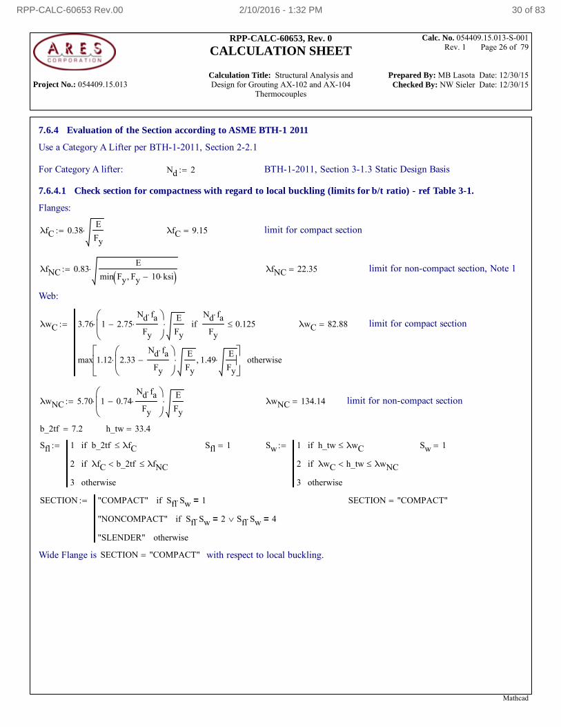
7.6.4.1 Check section for compactness with regard to local buckling (limits for b/t ratio) - ref Table 3-1.
Flanges:
λfC 0.38E
Fy λfC 9.15 limit for compact section
λfNC 0.83E
min Fy Fy 10 ksi λfNC 22.35 limit for non-compact section, Note 1
Web:
λwC 3.76 1 2.75Nd fa
Fy
E
Fy
Nd fa
Fy0.125if
max 1.12 2.33Nd fa
Fy
E
Fy 1.49
E
Fy
otherwise
λwC 82.88 limit for compact section
λwNC 5.70 1 0.74Nd fa
Fy
E
Fy λwNC 134.14 limit for non-compact section
b_2tf 7.2 h_tw 33.4
Sfl 1 b_2tf λfCif
2 λfC b_2tf λfNCif
3 otherwise
Sfl 1 Sw 1 h_tw λwCif
2 λwC h_tw λwNCif
3 otherwise
Sw 1
SECTION "COMPACT" Sfl Sw 1=if
"NONCOMPACT" Sfl Sw 2= Sfl Sw 4=if
"SLENDER" otherwise
SECTION "COMPACT"
Wide Flange is SECTION "COMPACT" with respect to local buckling.
Mathcad
RPP-CALC-60653 Rev.00 2/10/2016 - 1:32 PM 30 of 83
Project No.: 054409.15.013
RPP-CALC-60653, Rev. 0
CALCULATION SHEET
Calculation Title: Structural Analysis and Design for Grouting AX-102 and AX-104
Thermocouples
Calc. No. 054409.15.013-S-001 Rev. 1 Page 27 of 79
Prepared By: MB Lasota Date: 12/30/15 Checked By: NW Sieler Date: 12/30/15
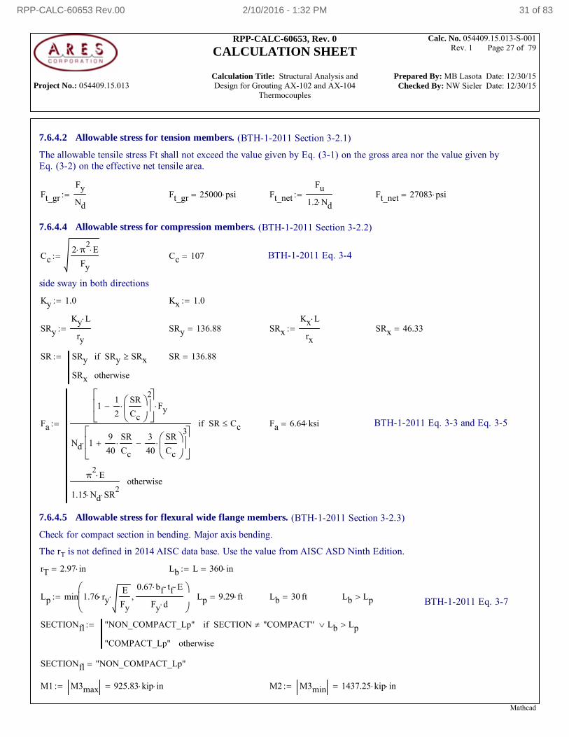
7.6.4.2 Allowable stress for tension members. (BTH-1-2011 Section 3-2.1)
The allowable tensile stress Ft shall not exceed the value given by Eq. (3-1) on the gross area nor the value given byEq. (3-2) on the effective net tensile area.
Ft_gr
Fy
Nd Ft_gr 25000 psi Ft_net
Fu
1.2 Nd Ft_net 27083 psi
7.6.4.4 Allowable stress for compression members. (BTH-1-2011 Section 3-2.2)
Cc2 π
2 E
Fy Cc 107 BTH-1-2011 Eq. 3-4
side sway in both directions
Ky 1.0 Kx 1.0
SRy
Ky L
ry SRy 136.88 SRx
Kx L
rx SRx 46.33
SR SRy SRy SRxif
SRx otherwise
SR 136.88
Fa
11
2
SR
Cc
2
Fy
Nd 19
40
SR
Cc
3
40
SR
Cc
3
SR Ccif
π2
E
1.15 Nd SR2
otherwise
Fa 6.64 ksi BTH-1-2011 Eq. 3-3 and Eq. 3-5
7.6.4.5 Allowable stress for flexural wide flange members. (BTH-1-2011 Section 3-2.3)
Check for compact section in bending. Major axis bending.
The rT is not defined in 2014 AISC data base. Use the value from AISC ASD Ninth Edition.
rT 2.97 in Lb L 360 in
Lp min 1.76 ryE
Fy
0.67 bf tf E
Fy d
Lp 9.29 ft Lb 30 ft Lb Lp BTH-1-2011 Eq. 3-7
SECTIONfl "NON_COMPACT_Lp" SECTION "COMPACT" Lb Lpif
"COMPACT_Lp" otherwise
SECTIONfl "NON_COMPACT_Lp"
M1 M3max 925.83 kip in M2 M3min 1437.25 kip in
Mathcad
RPP-CALC-60653 Rev.00 2/10/2016 - 1:32 PM 31 of 83
Project No.: 054409.15.013
RPP-CALC-60653, Rev. 0
CALCULATION SHEET
Calculation Title: Structural Analysis and Design for Grouting AX-102 and AX-104
Thermocouples
Calc. No. 054409.15.013-S-001 Rev. 1 Page 28 of 79
Prepared By: MB Lasota Date: 12/30/15 Checked By: NW Sieler Date: 12/30/15
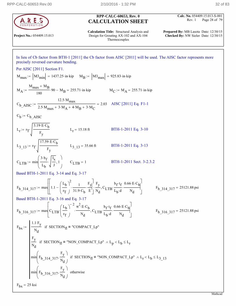
In lieu of Cb factor from BTH-1 [2011] the Cb factor from AISC [2011] will be used. The AISC factor represents moreprecisely reversed curvature bending.
Per AISC [2011] Section F1.
Mmax M3min 1437.25 in kip MB M3max 925.83 in kip
MA
Mmax MB
18090 MB 255.71 in kip MC MA 255.71 in kip
Cb_AISC
12.5 Mmax
2.5 Mmax 3 MA 4 MB 3 MC2.03 AISC [2011] Eq. F1-1
Cb Cb_AISC
Lr rT
3.19 E Cb
Fy Lr 15.18 ft BTH-1-2011 Eq. 3-10
L3_13 rT
17.59 E Cb
Fy L3_13 35.66 ft BTH-1-2011 Eq. 3-13
CLTB min3 bf
Lb
Ix
J 1
CLTB 1 BTH-1-2011 Sect. 3-2.3.2
Based BTH-1-2011 Eq. 3-14 and Eq. 3-17
Fb_314_317 max 1.1Lb
rT
21
31.9 Cb
Fy
E
Fy
Nd CLTB
bf tf
Lb d
0.66 E Cb
Nd
Fb_314_317 25121.88 psi
Based BTH-1-2011 Eq. 3-16 and Eq. 3-17
Fb_316_317 max CLTB
Lb
rT
2
π
2E Cb
Nd CLTB
bf tf
Lb d
0.66 E Cb
Nd
Fb_316_317 25121.88 psi
Fbx
1.1 Fy
NdSECTIONfl "COMPACT_Lp"=if
Fy
NdSECTIONfl "NON_COMPACT_Lp"= Lp Lb Lrif
min Fb_314_317
Fy
Nd
SECTIONfl "NON_COMPACT_Lp"= Lr Lb L3_13if
min Fb_316_317
Fy
Nd
otherwise
Fbx 25 ksi
Mathcad
RPP-CALC-60653 Rev.00 2/10/2016 - 1:32 PM 32 of 83
Project No.: 054409.15.013
RPP-CALC-60653, Rev. 0
CALCULATION SHEET
Calculation Title: Structural Analysis and Design for Grouting AX-102 and AX-104
Thermocouples
Calc. No. 054409.15.013-S-001 Rev. 1 Page 29 of 79
Prepared By: MB Lasota Date: 12/30/15 Checked By: NW Sieler Date: 12/30/15
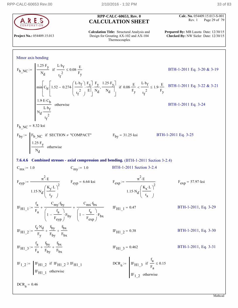
Minor axis bending
Fb_NC
1.25 Fy
Nd
L bf
tf2
0.08E
Fyif
min Cb 1.52 0.274L bf
tf2
Fy
E
Fy
Nd
1.25 Fy
Nd
0.08E
Fy
L bf
tf2
1.9E
Fyif
1.9 E Cb
Nd
L bf
tf2
otherwise
BTH-1-2011 Eq. 3-20 & 3-19
BTH-1-2011 Eq. 3-22 & 3-21
BTH-1-2011 Eq. 3-24
Fb_NC 8.32 ksi
Fby Fb_NC SECTION "COMPACT"if
1.25 Fy
Ndotherwise
Fby 31.25 ksi BTH-1-2011 Eq. 3-25
7.6.4.6 Combined stresses - axial compression and bending. (BTH-1-2011 Section 3-2.4)
Cmx 1.0 Cmy 1.0 BTH-1-2011 Section 3-2.4
Feypπ
2E
1.15 NdKy L
ry
2
Feyp 6.64 ksi Fexpπ
2E
1.15 NdKx L
rx
2
Fexp 57.97 ksi
IFH1_1
fa
Fa
Cmy fby
1fa
Feyp
Fby
Cmx fbx
1fa
Fexp
Fbx
IFH1_1 0.47 BTH-1-2011, Eq. 3-29
IFH1_2
fa Nd
Fy
fby
Fby
fbx
Fbx IFH1_2 0.38 BTH-1-2011, Eq. 3-30
IFH1_3
fa
Fa
fby
Fby
fbx
Fbx IFH1_3 0.462 BTH-1-2011, Eq. 3-31
IF1_2 IFH1_2 IFH1_2 IFH1_1if
IFH1_1 otherwise
DCR6
IFH1_3
fa
Fa0.15if
IF1_2 otherwise
DCR6
0.46
Mathcad
RPP-CALC-60653 Rev.00 2/10/2016 - 1:32 PM 33 of 83
Project No.: 054409.15.013
RPP-CALC-60653, Rev. 0
CALCULATION SHEET
Calculation Title: Structural Analysis and Design for Grouting AX-102 and AX-104
Thermocouples
Calc. No. 054409.15.013-S-001 Rev. 1 Page 30 of 79
Prepared By: MB Lasota Date: 12/30/15 Checked By: NW Sieler Date: 12/30/15
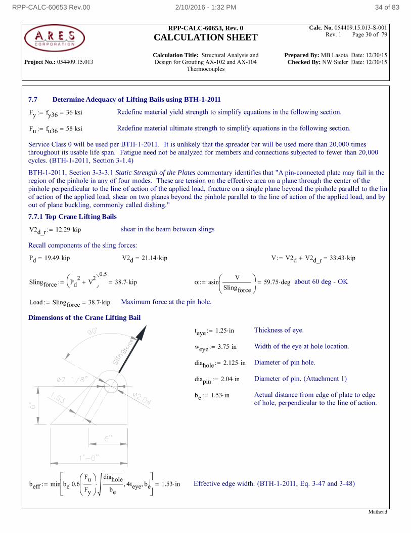
7.7 Determine Adequacy of Lifting Bails using BTH-1-2011
Fy fy36 36 ksi Redefine material yield strength to simplify equations in the following section.
Fu fu36 58 ksi Redefine material ultimate strength to simplify equations in the following section.
Service Class 0 will be used per BTH-1-2011. It is unlikely that the spreader bar will be used more than 20,000 timesthroughout its usable life span. Fatigue need not be analyzed for members and connections subjected to fewer than 20,000cycles. (BTH-1-2011, Section 3-1.4)
BTH-1-2011, Section 3-3-3.1 Static Strength of the Plates commentary identifies that "A pin-connected plate may fail in theregion of the pinhole in any of four modes. These are tension on the effective area on a plane through the center of thepinhole perpendicular to the line of action of the applied load, fracture on a single plane beyond the pinhole parallel to the linof action of the applied load, shear on two planes beyond the pinhole parallel to the line of action of the applied load, and byout of plane buckling, commonly called dishing."
7.7.1 Top Crane Lift ing Bails
V2d_r 12.29 kip shear in the beam between slings
Recall components of the sling forces:
Pd 19.49 kip V2d 21.14 kip V V2d V2d_r 33.43 kip
Slingforce Pd2
V2
0.538.7 kip α asin
V
Slingforce
59.75 deg about 60 deg - OK
Load Slingforce 38.7 kip Maximum force at the pin hole.
Dimensions of the Crane Lifting Bail
teye 1.25 in Thickness of eye.
weye 3.75 in Width of the eye at hole location.
diahole 2.125 in Diameter of pin hole.
diapin 2.04 in Diameter of pin. (Attachment 1)
be 1.53 in Actual distance from edge of plate to edgeof hole, perpendicular to the line of action.
beff min be 0.6Fu
Fy
diahole
be 4teye be
1.53 in Effective edge width. (BTH-1-2011, Eq. 3-47 and 3-48)
Mathcad
RPP-CALC-60653 Rev.00 2/10/2016 - 1:32 PM 34 of 83
Project No.: 054409.15.013
RPP-CALC-60653, Rev. 0
CALCULATION SHEET
Calculation Title: Structural Analysis and Design for Grouting AX-102 and AX-104
Thermocouples
Calc. No. 054409.15.013-S-001 Rev. 1 Page 31 of 79
Prepared By: MB Lasota Date: 12/30/15 Checked By: NW Sieler Date: 12/30/15
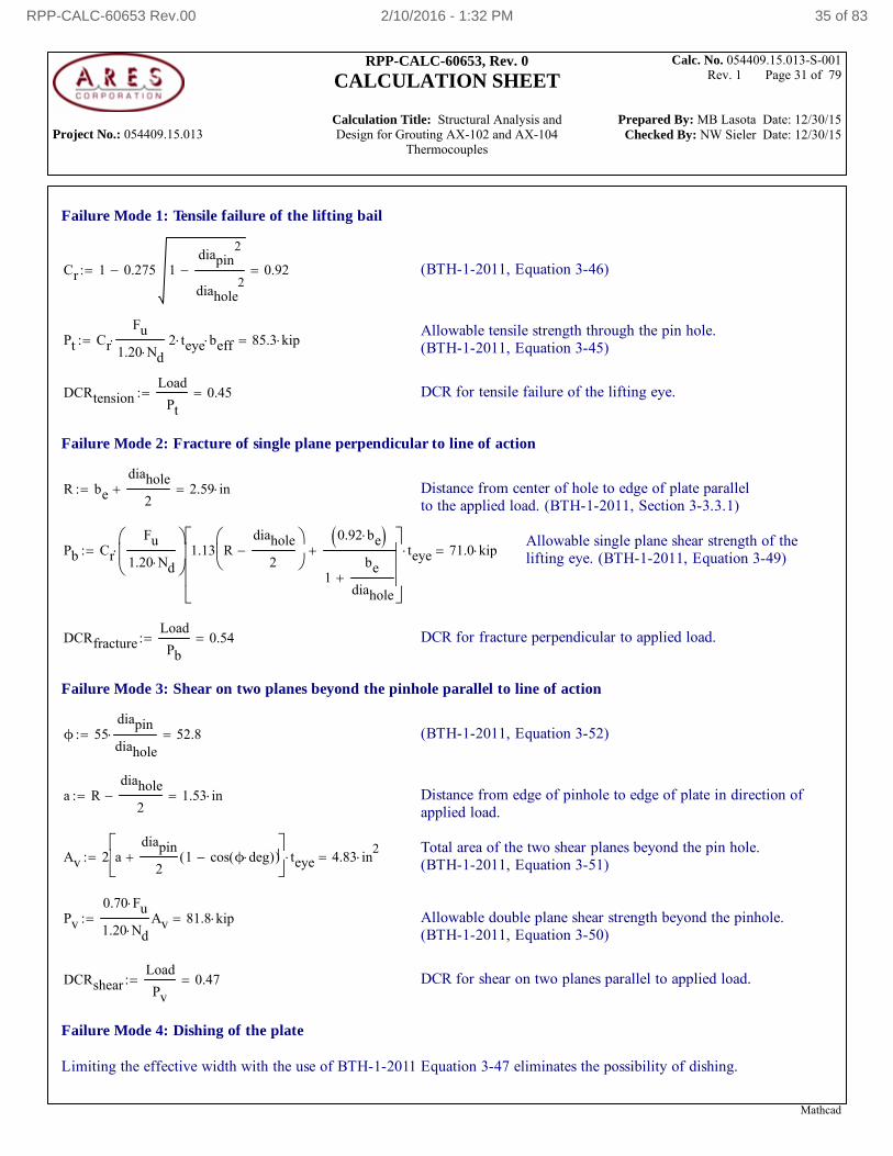
Failure Mode 1: Tensile failure of the lifting bail
Cr 1 0.275 1diapin
2
diahole2
0.92 (BTH-1-2011, Equation 3-46)
Allowable tensile strength through the pin hole.(BTH-1-2011, Equation 3-45)Pt Cr
Fu
1.20 Nd 2 teye beff 85.3 kip
DCRtensionLoad
Pt0.45 DCR for tensile failure of the lifting eye.
Failure Mode 2: Fracture of single plane perpendicular to line of action
R be
diahole
2 2.59 in Distance from center of hole to edge of plate parallel
to the applied load. (BTH-1-2011, Section 3-3.3.1)
Allowable single plane shear strength of thelifting eye. (BTH-1-2011, Equation 3-49)Pb Cr
Fu
1.20 Nd
1.13 Rdiahole
2
0.92 be
1be
diahole
teye 71.0 kip
DCRfractureLoad
Pb0.54 DCR for fracture perpendicular to applied load.
Failure Mode 3: Shear on two planes beyond the pinhole parallel to line of action
ϕ 55diapin
diahole 52.8 (BTH-1-2011, Equation 3-52)
a Rdiahole
2 1.53 in Distance from edge of pinhole to edge of plate in direction of
applied load.
Total area of the two shear planes beyond the pin hole.(BTH-1-2011, Equation 3-51)Av 2 a
diapin
21 cos ϕ deg( )( )
teye 4.83 in2
Pv
0.70 Fu
1.20 NdAv 81.8 kip Allowable double plane shear strength beyond the pinhole.
(BTH-1-2011, Equation 3-50)
DCRshearLoad
Pv0.47 DCR for shear on two planes parallel to applied load.
Failure Mode 4: Dishing of the plate
Limiting the effective width with the use of BTH-1-2011 Equation 3-47 eliminates the possibility of dishing.
Mathcad
RPP-CALC-60653 Rev.00 2/10/2016 - 1:32 PM 35 of 83
Project No.: 054409.15.013
RPP-CALC-60653, Rev. 0
CALCULATION SHEET
Calculation Title: Structural Analysis and Design for Grouting AX-102 and AX-104
Thermocouples
Calc. No. 054409.15.013-S-001 Rev. 1 Page 32 of 79
Prepared By: MB Lasota Date: 12/30/15 Checked By: NW Sieler Date: 12/30/15
Bearing Stress between the pin and the plate
Fp
1.25 Fy
Nd22.5 ksi The allowable bearing stress on the contact area.
(BTH-1-2011, Equation 3-53)
Abear teye diapin 2.55 in2
Projected bearing area.
Pbear Fp Abear 57.4 kip Allowable bearing force.
DCRbearingLoad
Pbear0.67 DCR for bearing of the pin on the lifting eye.
Shear of the pin
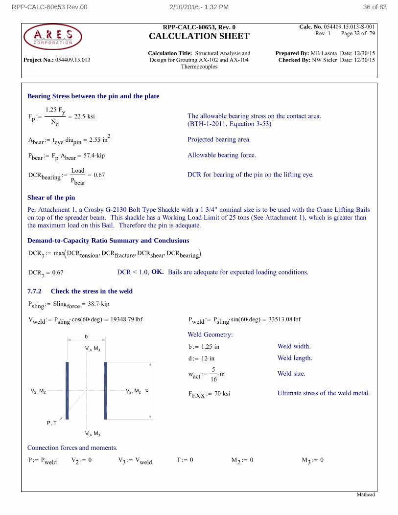
Per Attachment 1, a Crosby G-2130 Bolt Type Shackle with a 1 3/4" nominal size is to be used with the Crane Lifting Bailson top of the spreader beam. This shackle has a Working Load Limit of 25 tons (See Attachment 1), which is greater thanthe maximum load on this Bail. Therefore the pin is adequate.
Demand-to-Capacity Ratio Summary and Conclusions
DCR7
max DCRtension DCRfracture DCRshear DCRbearing
DCR7
0.67 DCR < 1.0, OK. Bails are adequate for expected loading conditions.
7.7.2 Check the stress in the weld
Psling Slingforce 38.7 kip
Vweld Psling cos 60 deg( ) 19348.79 lbf Pweld Psling sin 60 deg( ) 33513.08 lbf
d
b
V 3, M
3
V 3, M
3
V 2, M
2 V
2, M 2
P, T
Weld Geometry:
b 1.25 in Weld width.
d 12 in Weld length.
wact5
16in Weld size.
FEXX 70 ksi Ultimate stress of the weld metal.
Connection forces and moments.
P Pweld V2 0 V3 Vweld T 0 M2 0 M3 0
Mathcad
RPP-CALC-60653 Rev.00 2/10/2016 - 1:32 PM 36 of 83
Project No.: 054409.15.013
RPP-CALC-60653, Rev. 0
CALCULATION SHEET
Calculation Title: Structural Analysis and Design for Grouting AX-102 and AX-104
Thermocouples
Calc. No. 054409.15.013-S-001 Rev. 1 Page 33 of 79
Prepared By: MB Lasota Date: 12/30/15 Checked By: NW Sieler Date: 12/30/15
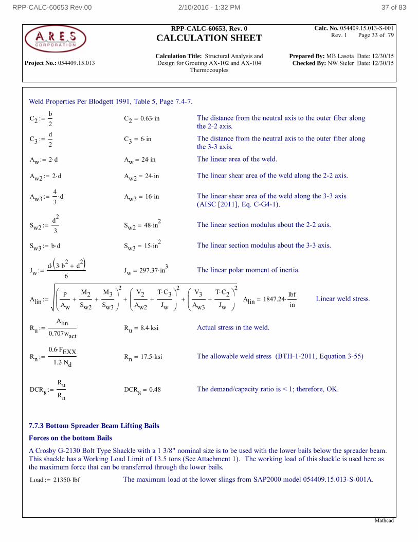
Weld Properties Per Blodgett 1991, Table 5, Page 7.4-7.
C2b
2 C2 0.63 in The distance from the neutral axis to the outer fiber along
the 2-2 axis.
C3d
2 C3 6 in The distance from the neutral axis to the outer fiber along
the 3-3 axis.
Aw 2 d Aw 24 in The linear area of the weld.
Aw2 2 d Aw2 24 in The linear shear area of the weld along the 2-2 axis.
Aw34
3d Aw3 16 in The linear shear area of the weld along the 3-3 axis
(AISC [2011], Eq. C-G4-1).
Sw2d
2
3 Sw2 48 in
2 The linear section modulus about the 2-2 axis.
Sw3 b d Sw3 15 in2
The linear section modulus about the 3-3 axis.
Jwd 3 b
2 d
2
6 Jw 297.37 in
3 The linear polar moment of inertia.
AlinP
Aw
M2
Sw2
M3
Sw3
2V2
Aw2
T C3
Jw
2
V3
Aw3
T C2
Jw
2
Alin 1847.24lbf
in Linear weld stress.
Ru
Alin
0.707wact Ru 8.4 ksi Actual stress in the weld.
Rn
0.6 FEXX
1.2 Nd Rn 17.5 ksi The allowable weld stress (BTH-1-2011, Equation 3-55)
DCR8
Ru
Rn DCR
80.48 The demand/capacity ratio is < 1; therefore, OK.
7.7.3 Bottom Spreader Beam Lifting Bails
Forces on the bottom Bails
A Crosby G-2130 Bolt Type Shackle with a 1 3/8" nominal size is to be used with the lower bails below the spreader beam.This shackle has a Working Load Limit of 13.5 tons (See Attachment 1). The working load of this shackle is used here asthe maximum force that can be transferred through the lower bails.
Load 21350 lbf The maximum load at the lower slings from SAP2000 model 054409.15.013-S-001A.
Mathcad
RPP-CALC-60653 Rev.00 2/10/2016 - 1:32 PM 37 of 83
Project No.: 054409.15.013
RPP-CALC-60653, Rev. 0
CALCULATION SHEET
Calculation Title: Structural Analysis and Design for Grouting AX-102 and AX-104
Thermocouples
Calc. No. 054409.15.013-S-001 Rev. 1 Page 34 of 79
Prepared By: MB Lasota Date: 12/30/15 Checked By: NW Sieler Date: 12/30/15
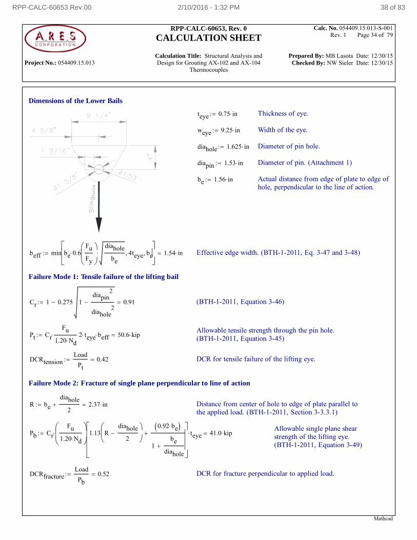
Dimensions of the Lower Bails
teye 0.75 in Thickness of eye.
weye 9.25 in Width of the eye.
diahole 1.625 in Diameter of pin hole.
diapin 1.53 in Diameter of pin. (Attachment 1)
be 1.56 in Actual distance from edge of plate to edge ofhole, perpendicular to the line of action.
beff min be 0.6Fu
Fy
diahole
be 4teye be
1.54 in Effective edge width. (BTH-1-2011, Eq. 3-47 and 3-48)
Failure Mode 1: Tensile failure of the lifting bail
Cr 1 0.275 1diapin
2
diahole2
0.91 (BTH-1-2011, Equation 3-46)
Allowable tensile strength through the pin hole.(BTH-1-2011, Equation 3-45)Pt Cr
Fu
1.20 Nd 2 teye beff 50.6 kip
DCRtensionLoad
Pt0.42 DCR for tensile failure of the lifting eye.
Failure Mode 2: Fracture of single plane perpendicular to line of action
R be
diahole
2 2.37 in Distance from center of hole to edge of plate parallel to
the applied load. (BTH-1-2011, Section 3-3.3.1)
Allowable single plane shearstrength of the lifting eye.(BTH-1-2011, Equation 3-49)
Pb Cr
Fu
1.20 Nd
1.13 Rdiahole
2
0.92 be
1be
diahole
teye 41.0 kip
DCRfractureLoad
Pb0.52 DCR for fracture perpendicular to applied load.
Mathcad
RPP-CALC-60653 Rev.00 2/10/2016 - 1:32 PM 38 of 83
Project No.: 054409.15.013
RPP-CALC-60653, Rev. 0
CALCULATION SHEET
Calculation Title: Structural Analysis and Design for Grouting AX-102 and AX-104
Thermocouples
Calc. No. 054409.15.013-S-001 Rev. 1 Page 35 of 79
Prepared By: MB Lasota Date: 12/30/15 Checked By: NW Sieler Date: 12/30/15
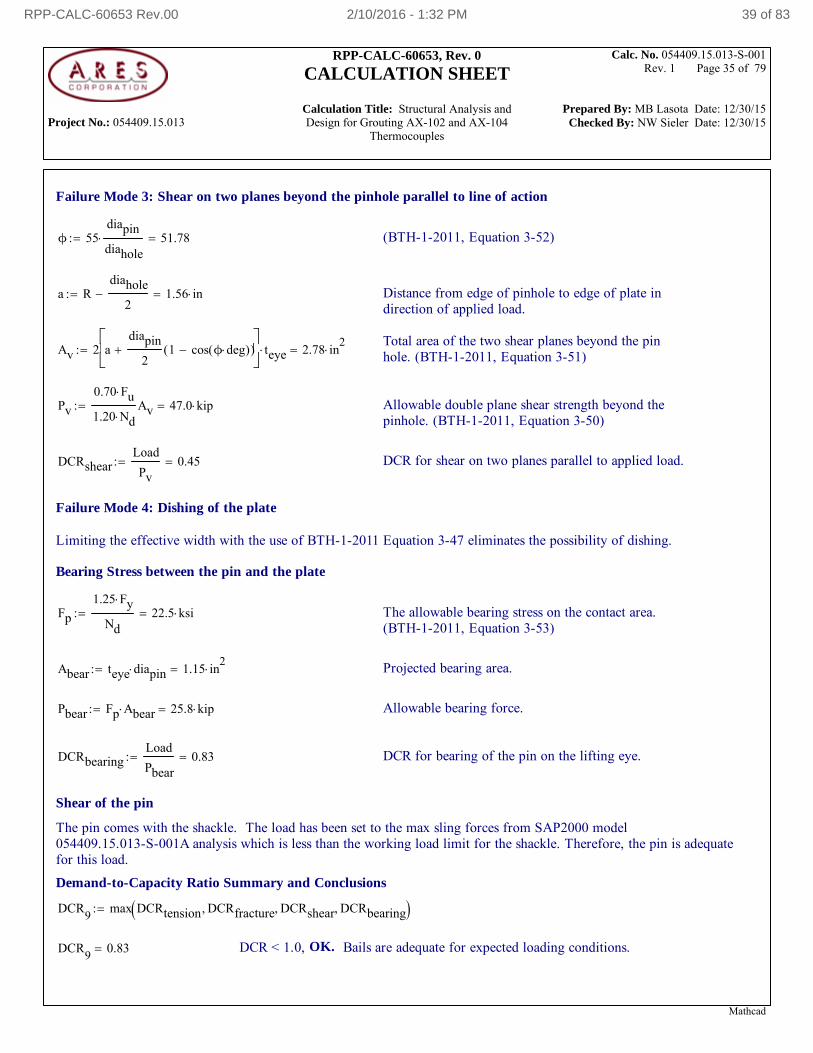
Failure Mode 3: Shear on two planes beyond the pinhole parallel to line of action
ϕ 55diapin
diahole 51.78 (BTH-1-2011, Equation 3-52)
a Rdiahole
2 1.56 in Distance from edge of pinhole to edge of plate in
direction of applied load.
Total area of the two shear planes beyond the pinhole. (BTH-1-2011, Equation 3-51)Av 2 a
diapin
21 cos ϕ deg( )( )
teye 2.78 in2
Pv
0.70 Fu
1.20 NdAv 47.0 kip Allowable double plane shear strength beyond the
pinhole. (BTH-1-2011, Equation 3-50)
DCRshearLoad
Pv0.45 DCR for shear on two planes parallel to applied load.
Failure Mode 4: Dishing of the plate
Limiting the effective width with the use of BTH-1-2011 Equation 3-47 eliminates the possibility of dishing.
Bearing Stress between the pin and the plate
Fp
1.25 Fy
Nd22.5 ksi The allowable bearing stress on the contact area.
(BTH-1-2011, Equation 3-53)
Abear teye diapin 1.15 in2
Projected bearing area.
Pbear Fp Abear 25.8 kip Allowable bearing force.
DCRbearingLoad
Pbear0.83 DCR for bearing of the pin on the lifting eye.
Shear of the pin
The pin comes with the shackle. The load has been set to the max sling forces from SAP2000 model054409.15.013-S-001A analysis which is less than the working load limit for the shackle. Therefore, the pin is adequatefor this load.
Demand-to-Capacity Ratio Summary and Conclusions
DCR9
max DCRtension DCRfracture DCRshear DCRbearing
DCR9
0.83 DCR < 1.0, OK. Bails are adequate for expected loading conditions.
Mathcad
RPP-CALC-60653 Rev.00 2/10/2016 - 1:32 PM 39 of 83
Project No.: 054409.15.013
RPP-CALC-60653, Rev. 0
CALCULATION SHEET
Calculation Title: Structural Analysis and Design for Grouting AX-102 and AX-104
Thermocouples
Calc. No. 054409.15.013-S-001 Rev. 1 Page 36 of 79
Prepared By: MB Lasota Date: 12/30/15 Checked By: NW Sieler Date: 12/30/15
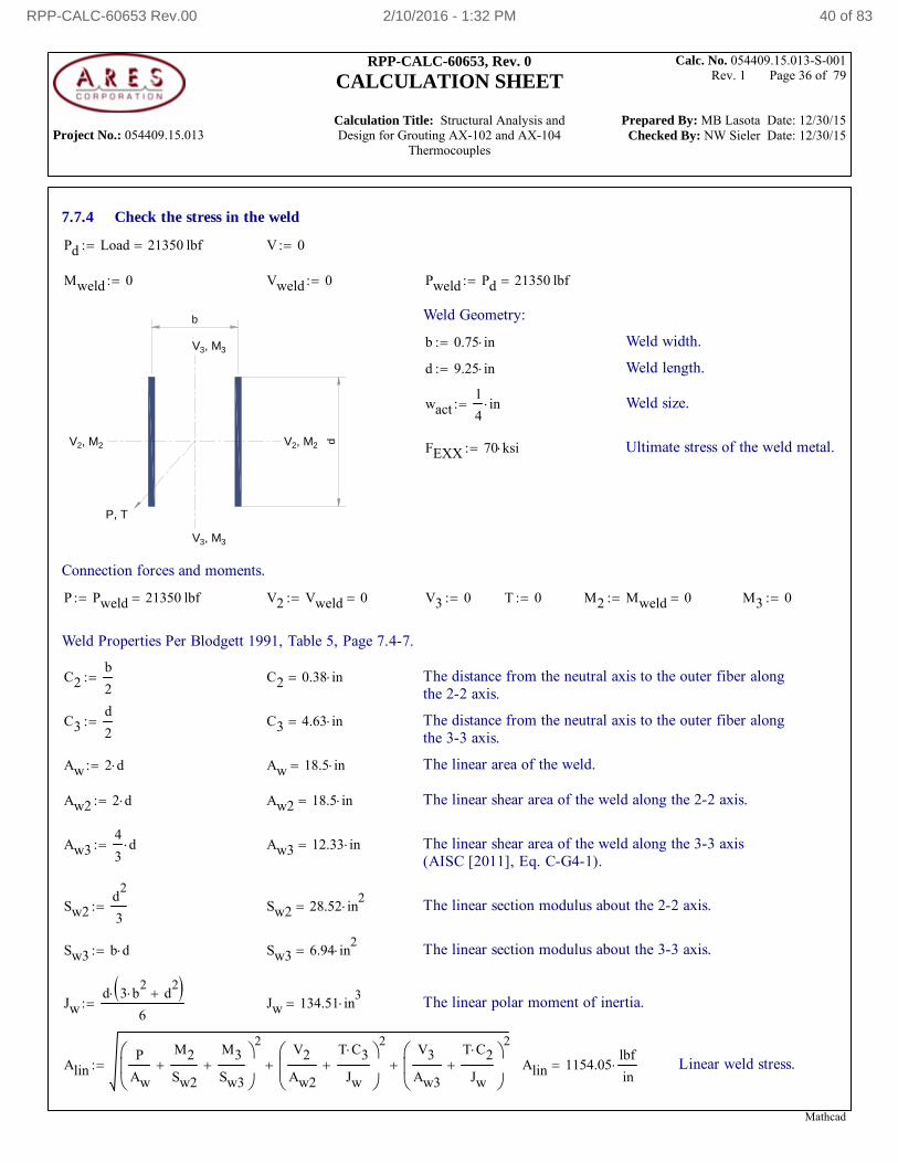
7.7.4 Check the stress in the weld
Pd Load 21350 lbf V 0
Mweld 0 Vweld 0 Pweld Pd 21350 lbf
db
V 3, M
3
V 3, M
3
V 2, M
2 V
2, M 2
P, T
Weld Geometry:
b 0.75 in Weld width.
d 9.25 in Weld length.
wact1
4in Weld size.
FEXX 70 ksi Ultimate stress of the weld metal.
Connection forces and moments.
P Pweld 21350 lbf V2 Vweld 0 V3 0 T 0 M2 Mweld 0 M3 0
Weld Properties Per Blodgett 1991, Table 5, Page 7.4-7.
C2b
2 C2 0.38 in The distance from the neutral axis to the outer fiber along
the 2-2 axis.
C3d
2 C3 4.63 in The distance from the neutral axis to the outer fiber along
the 3-3 axis.
Aw 2 d Aw 18.5 in The linear area of the weld.
Aw2 2 d Aw2 18.5 in The linear shear area of the weld along the 2-2 axis.
Aw34
3d Aw3 12.33 in The linear shear area of the weld along the 3-3 axis
(AISC [2011], Eq. C-G4-1).
Sw2d
2
3 Sw2 28.52 in
2 The linear section modulus about the 2-2 axis.
Sw3 b d Sw3 6.94 in2
The linear section modulus about the 3-3 axis.
Jwd 3 b
2 d
2
6 Jw 134.51 in
3 The linear polar moment of inertia.
AlinP
Aw
M2
Sw2
M3
Sw3
2V2
Aw2
T C3
Jw
2
V3
Aw3
T C2
Jw
2
Alin 1154.05lbf
in Linear weld stress.
Mathcad
RPP-CALC-60653 Rev.00 2/10/2016 - 1:32 PM 40 of 83
Project No.: 054409.15.013
RPP-CALC-60653, Rev. 0
CALCULATION SHEET
Calculation Title: Structural Analysis and Design for Grouting AX-102 and AX-104
Thermocouples
Calc. No. 054409.15.013-S-001 Rev. 1 Page 37 of 79
Prepared By: MB Lasota Date: 12/30/15 Checked By: NW Sieler Date: 12/30/15
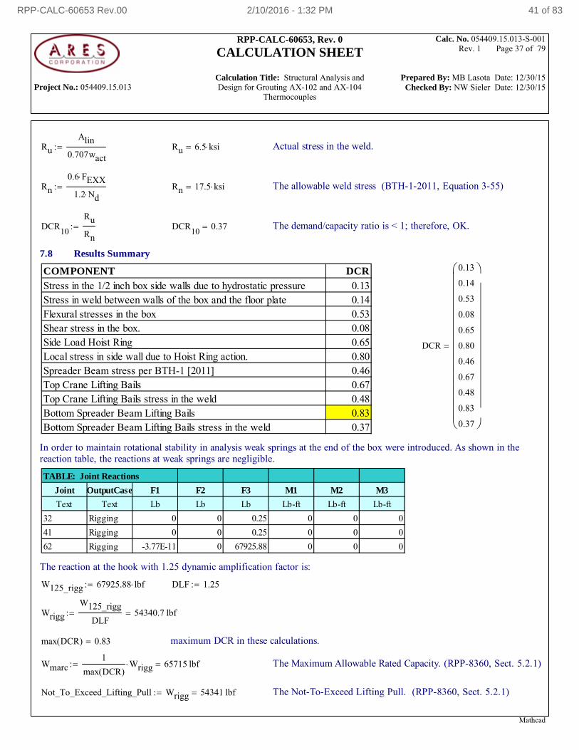
Ru
Alin
0.707wact Ru 6.5 ksi Actual stress in the weld.
Rn
0.6 FEXX
1.2 Nd Rn 17.5 ksi The allowable weld stress (BTH-1-2011, Equation 3-55)
DCR10
Ru
Rn DCR
100.37 The demand/capacity ratio is < 1; therefore, OK.
7.8 Results Summary
COMPONENT DCRStress in the 1/2 inch box side walls due to hydrostatic pressure 0.13Stress in weld between walls of the box and the floor plate 0.14Flexural stresses in the box 0.53Shear stress in the box. 0.08Side Load Hoist Ring 0.65Local stress in side wall due to Hoist Ring action. 0.80Spreader Beam stress per BTH-1 [2011] 0.46Top Crane Lifting Bails 0.67Top Crane Lifting Bails stress in the weld 0.48Bottom Spreader Beam Lifting Bails 0.83Bottom Spreader Beam Lifting Bails stress in the weld 0.37
DCR
0.13
0.14
0.53
0.08
0.65
0.80
0.46
0.67
0.48
0.83
0.37
In order to maintain rotational stability in analysis weak springs at the end of the box were introduced. As shown in thereaction table, the reactions at weak springs are negligible.
TABLE: Joint Reactions
Joint OutputCase F1 F2 F3 M1 M2 M3
Text Text Lb Lb Lb Lb-ft Lb-ft Lb-ft
32 Rigging 0 0 0.25 0 0 0
41 Rigging 0 0 0.25 0 0 0
62 Rigging -3.77E-11 0 67925.88 0 0 0
The reaction at the hook with 1.25 dynamic amplification factor is:
W125_rigg 67925.88 lbf DLF 1.25
Wrigg
W125_rigg
DLF54340.7 lbf
max DCR( ) 0.83 maximum DCR in these calculations.
Wmarc1
max DCR( )Wrigg 65715 lbf The Maximum Allowable Rated Capacity. (RPP-8360, Sect. 5.2.1)
Not_To_Exceed_Lifting_Pull Wrigg 54341 lbf The Not-To-Exceed Lifting Pull. (RPP-8360, Sect. 5.2.1)
Mathcad
RPP-CALC-60653 Rev.00 2/10/2016 - 1:32 PM 41 of 83
RPP-CALC-60653, Rev. 0
CALCULATION SHEET
Project No. 054409.15.013 Calculation No. 054409.15.013-S-001 Rev. 1 Page No. 38 of 79
Title: Structural Analysis and Design for Grouting AX-102 and AX-104 Thermocouples
Prepared By: MB Lasota Date: 12-30-15 Checked By: NW Sieler Date: 12-30-15
Quality Assurance Procedure 3.1 Calculation Sheet (05-10)
8.0 REFERENCES
ACI 318, 2011, Building Code Requirements for Structural Concrete (ACI 318-11), an ACI Standard, American Concrete Institute, Farmington Hills, MI
AISC, 2011, Steel Construction Manual, Fourteenth Edition, American Institute of Steel Construction, Inc., Chicago, IL
AISC, 1989, Steel Construction Manual, Allowable Stress Design, Ninth Edition, American Institute of Steel Construction, Inc., Chicago, IL
AISC, 1997, Torsional Analysis of Structural Steel Members, Design Guide 9, DESIGN GUIDE SERIES, American Institute of Steel Construction, Inc., Chicago, IL
ASME B1.1, 2003, Revision of ASME B1.1-1989 (R2001), Unified Inch Screw Threads (UN and UNR Thread Form), American Society of Mechanical Engineers, New York, NY
ASME BTH-1-2011, Design of Below-the-Hook Lifting Devices, American Society of Mechanical Engineers, New York, NY
ASTM A 36/A 36M - 03a, Standard Specification for Carbon Structural Steel, American Standards for Testing and Materials, West Conshohocken, PA
ASTM A 992/A 992M - 06a, Standard Specification for Structural Steel Shapes, American Standards for Testing and Materials, West Conshohocken, PA
Blodgett, Omer W., 1976, Design of Welded Structures, the James F. Lincoln Arc Welding Foundation, Cleveland, Ohio.
H-2-44733, Instrumentation, Temperature Element & Sensing Line Assemblies & Details, Rev. 2, U.S. Department of Energy, Richland, WA
H-14-110571, AX Equip. Removal, Grout Box Assembly, Rev. A, U.S. Department of Energy, Richland, WA
H-14-110572, Grout Box, Spreader Bar Lifting Assembly, Rev. A, U.S. Department of Energy, Richland, WA
PTC, 2010, Mathcad 15.0 (15.0.0.436 [006041742]), Parametric Technology Corporation, Needham, Massachusetts
RPP-8360, Rev 4, Lifting Point Evaluation Process, U.S. Department of Energy, Richland, WA
SAP2000 Advanced, Version 17.3.0, 2015, Structural Analysis Program, Computers and Structures, Inc., Berkeley, California.
TFC-ENG-STD-06, REV C-8, Design Loads for Tank Farm Facilities, Washington River Protections Solutions, LLC, Richland, Washington.
VV-15-03-180, 2015, Software Verification & Validation, SAP2000, ADVANCED, Release 17.3.0, ARES Corporation, Richland, Washington
RPP-CALC-60653 Rev.00 2/10/2016 - 1:32 PM 42 of 83
RPP-CALC-60653, Rev. 0
CALCULATION SHEET
Project No. 054409.15.013 Calculation No. 054409.15.013-S-001 Rev. 1 Page No. 39 of 79
Title: Structural Analysis and Design for Grouting AX-102 and AX-104 Thermocouples
Prepared By: MB Lasota Date: 12-30-15 Checked By: NW Sieler Date: 12-30-15
Quality Assurance Procedure 3.1 Calculation Sheet (05-10)
APPENDIX A
SAP2000 REPORT
FOR THE MODEL: 054409.15.013-S-001A
RPP-CALC-60653 Rev.00 2/10/2016 - 1:32 PM 43 of 83
RPP-CALC-60653, Rev. 0
CALCULATION SHEET
Project No. 054409.15.013 Calculation No. 054409.15.013-S-001 Rev. 1 Page No. 40 of 79
Title: Structural Analysis and Design for Grouting AX-102 and AX-104 Thermocouples
Prepared By: MB Lasota Date: 12-30-15 Checked By: NW Sieler Date: 12-30-15
Quality Assurance Procedure 3.1 Calculation Sheet (05-10)
License #*1ZL9CYATHW4YNFB
AX Equipment Removal Construction Support.
Project Number: 054409.15.013
Prepared for
WRPS
SAP2000 Analysis Report
Prepared by
ARES Corporation
Model Name: 054409.15.013-S-001A
5 November 2015
RPP-CALC-60653 Rev.00 2/10/2016 - 1:32 PM 44 of 83
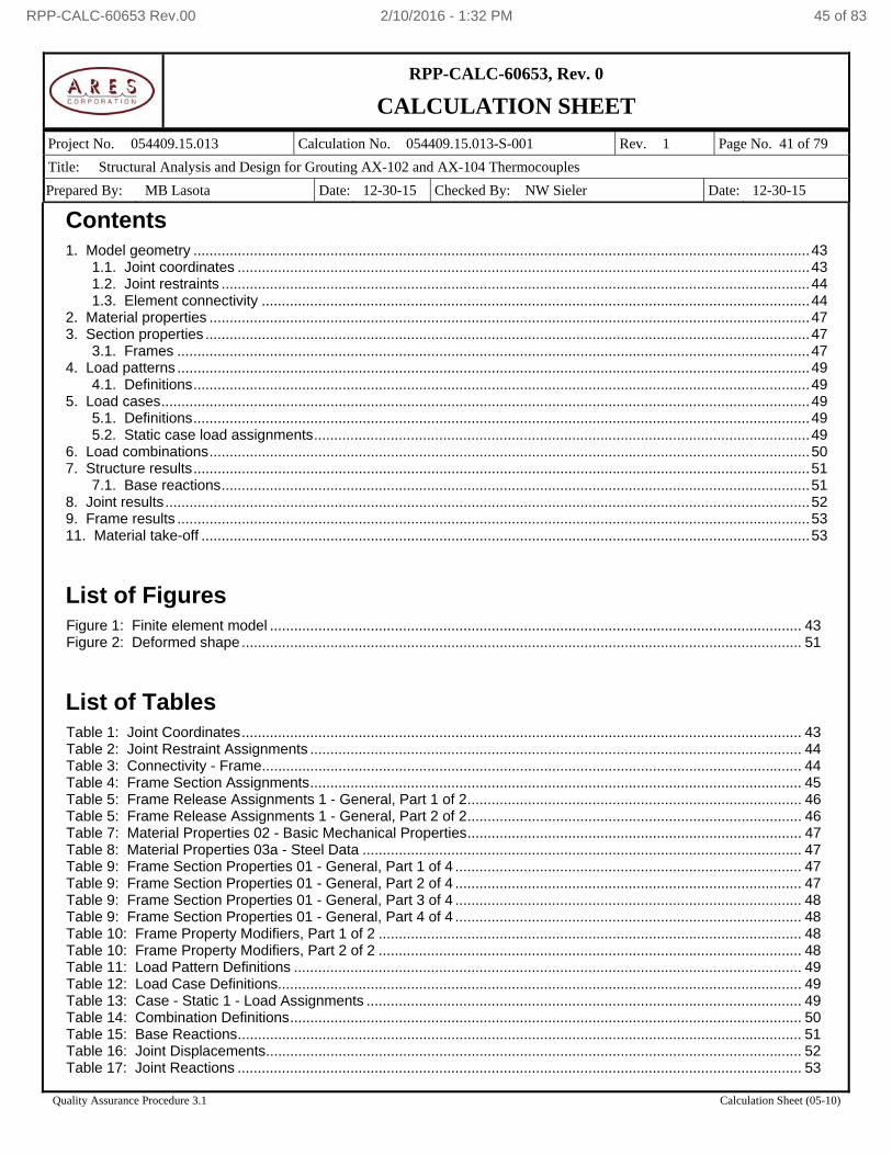
RPP-CALC-60653, Rev. 0
CALCULATION SHEET
Project No. 054409.15.013 Calculation No. 054409.15.013-S-001 Rev. 1 Page No. 41 of 79
Title: Structural Analysis and Design for Grouting AX-102 and AX-104 Thermocouples
Prepared By: MB Lasota Date: 12-30-15 Checked By: NW Sieler Date: 12-30-15
Quality Assurance Procedure 3.1 Calculation Sheet (05-10)
Contents 1. Model geometry ......................................................................................................................................................... 43
1.1. Joint coordinates .............................................................................................................................................. 43 1.2. Joint restraints .................................................................................................................................................. 44 1.3. Element connectivity ........................................................................................................................................ 44
2. Material properties ..................................................................................................................................................... 47 3. Section properties ...................................................................................................................................................... 47
3.1. Frames ............................................................................................................................................................. 47 4. Load patterns ............................................................................................................................................................. 49
4.1. Definitions ......................................................................................................................................................... 49 5. Load cases ................................................................................................................................................................. 49
5.1. Definitions ......................................................................................................................................................... 49 5.2. Static case load assignments ........................................................................................................................... 49
6. Load combinations ..................................................................................................................................................... 50 7. Structure results ......................................................................................................................................................... 51
7.1. Base reactions .................................................................................................................................................. 51 8. Joint results ................................................................................................................................................................ 52 9. Frame results ............................................................................................................................................................. 53 11. Material take-off ....................................................................................................................................................... 53
List of Figures
Figure 1: Finite element model .................................................................................................................................... 43 Figure 2: Deformed shape ........................................................................................................................................... 51
List of Tables Table 1: Joint Coordinates ........................................................................................................................................... 43 Table 2: Joint Restraint Assignments .......................................................................................................................... 44 Table 3: Connectivity - Frame ...................................................................................................................................... 44 Table 4: Frame Section Assignments .......................................................................................................................... 45 Table 5: Frame Release Assignments 1 - General, Part 1 of 2 ................................................................................... 46 Table 5: Frame Release Assignments 1 - General, Part 2 of 2 ................................................................................... 46 Table 7: Material Properties 02 - Basic Mechanical Properties ................................................................................... 47 Table 8: Material Properties 03a - Steel Data ............................................................................................................. 47 Table 9: Frame Section Properties 01 - General, Part 1 of 4 ...................................................................................... 47 Table 9: Frame Section Properties 01 - General, Part 2 of 4 ...................................................................................... 47 Table 9: Frame Section Properties 01 - General, Part 3 of 4 ...................................................................................... 48 Table 9: Frame Section Properties 01 - General, Part 4 of 4 ...................................................................................... 48 Table 10: Frame Property Modifiers, Part 1 of 2 ......................................................................................................... 48 Table 10: Frame Property Modifiers, Part 2 of 2 ......................................................................................................... 48 Table 11: Load Pattern Definitions .............................................................................................................................. 49 Table 12: Load Case Definitions.................................................................................................................................. 49 Table 13: Case - Static 1 - Load Assignments ............................................................................................................ 49 Table 14: Combination Definitions ............................................................................................................................... 50 Table 15: Base Reactions ............................................................................................................................................ 51 Table 16: Joint Displacements ..................................................................................................................................... 52 Table 17: Joint Reactions ............................................................................................................................................ 53
RPP-CALC-60653 Rev.00 2/10/2016 - 1:32 PM 45 of 83
RPP-CALC-60653, Rev. 0
CALCULATION SHEET
Project No. 054409.15.013 Calculation No. 054409.15.013-S-001 Rev. 1 Page No. 42 of 79
Title: Structural Analysis and Design for Grouting AX-102 and AX-104 Thermocouples
Prepared By: MB Lasota Date: 12-30-15 Checked By: NW Sieler Date: 12-30-15
Quality Assurance Procedure 3.1 Calculation Sheet (05-10)
Table 18: Element Forces - Frames, Part 1 of 2 ......................................................................................................... 53 Table 19: Element Forces - Frames, Part 2 of 2 ......................................................................................................... 53 Table 26: Material List 2 - By Section Property ........................................................................................................... 53
RPP-CALC-60653 Rev.00 2/10/2016 - 1:32 PM 46 of 83
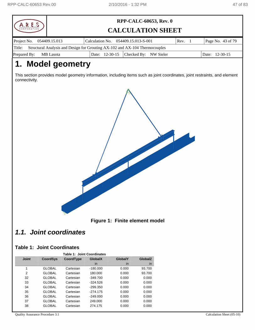
RPP-CALC-60653, Rev. 0
CALCULATION SHEET
Project No. 054409.15.013 Calculation No. 054409.15.013-S-001 Rev. 1 Page No. 43 of 79
Title: Structural Analysis and Design for Grouting AX-102 and AX-104 Thermocouples
Prepared By: MB Lasota Date: 12-30-15 Checked By: NW Sieler Date: 12-30-15
Quality Assurance Procedure 3.1 Calculation Sheet (05-10)
1. Model geometry This section provides model geometry information, including items such as joint coordinates, joint restraints, and element connectivity.
Figure 1: Finite element model
1.1. Joint coordinates Table 1: Joint Coordinates
Table 1: Joint Coordinates
Joint CoordSys CoordType GlobalX GlobalY GlobalZ
in in in
1 GLOBAL Cartesian -180.000 0.000 93.700
2 GLOBAL Cartesian 180.000 0.000 93.700
32 GLOBAL Cartesian -349.700 0.000 0.000
33 GLOBAL Cartesian -324.526 0.000 0.000
34 GLOBAL Cartesian -299.350 0.000 0.000
35 GLOBAL Cartesian -274.175 0.000 0.000
36 GLOBAL Cartesian -249.000 0.000 0.000
37 GLOBAL Cartesian 249.000 0.000 0.000
38 GLOBAL Cartesian 274.175 0.000 0.000
RPP-CALC-60653 Rev.00 2/10/2016 - 1:32 PM 47 of 83
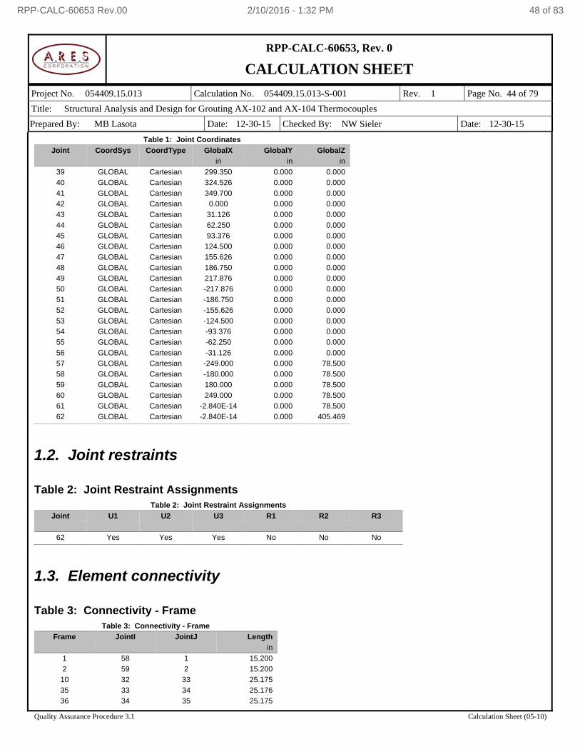
RPP-CALC-60653, Rev. 0
CALCULATION SHEET
Project No. 054409.15.013 Calculation No. 054409.15.013-S-001 Rev. 1 Page No. 44 of 79
Title: Structural Analysis and Design for Grouting AX-102 and AX-104 Thermocouples
Prepared By: MB Lasota Date: 12-30-15 Checked By: NW Sieler Date: 12-30-15
Quality Assurance Procedure 3.1 Calculation Sheet (05-10)
Table 1: Joint Coordinates
Joint CoordSys CoordType GlobalX GlobalY GlobalZ
in in in
39 GLOBAL Cartesian 299.350 0.000 0.000
40 GLOBAL Cartesian 324.526 0.000 0.000
41 GLOBAL Cartesian 349.700 0.000 0.000
42 GLOBAL Cartesian 0.000 0.000 0.000
43 GLOBAL Cartesian 31.126 0.000 0.000
44 GLOBAL Cartesian 62.250 0.000 0.000
45 GLOBAL Cartesian 93.376 0.000 0.000
46 GLOBAL Cartesian 124.500 0.000 0.000
47 GLOBAL Cartesian 155.626 0.000 0.000
48 GLOBAL Cartesian 186.750 0.000 0.000
49 GLOBAL Cartesian 217.876 0.000 0.000
50 GLOBAL Cartesian -217.876 0.000 0.000
51 GLOBAL Cartesian -186.750 0.000 0.000
52 GLOBAL Cartesian -155.626 0.000 0.000
53 GLOBAL Cartesian -124.500 0.000 0.000
54 GLOBAL Cartesian -93.376 0.000 0.000
55 GLOBAL Cartesian -62.250 0.000 0.000
56 GLOBAL Cartesian -31.126 0.000 0.000
57 GLOBAL Cartesian -249.000 0.000 78.500
58 GLOBAL Cartesian -180.000 0.000 78.500
59 GLOBAL Cartesian 180.000 0.000 78.500
60 GLOBAL Cartesian 249.000 0.000 78.500
61 GLOBAL Cartesian -2.840E-14 0.000 78.500
62 GLOBAL Cartesian -2.840E-14 0.000 405.469
1.2. Joint restraints Table 2: Joint Restraint Assignments
Table 2: Joint Restraint Assignments
Joint U1 U2 U3 R1 R2 R3
62 Yes Yes Yes No No No
1.3. Element connectivity Table 3: Connectivity - Frame
Table 3: Connectivity - Frame
Frame JointI JointJ Length
in
1 58 1 15.200
2 59 2 15.200
10 32 33 25.175
35 33 34 25.176
36 34 35 25.175
RPP-CALC-60653 Rev.00 2/10/2016 - 1:32 PM 48 of 83
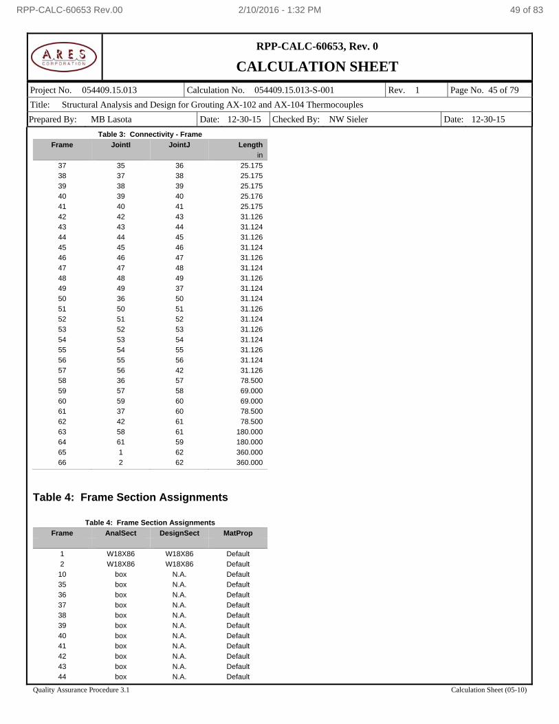
RPP-CALC-60653, Rev. 0
CALCULATION SHEET
Project No. 054409.15.013 Calculation No. 054409.15.013-S-001 Rev. 1 Page No. 45 of 79
Title: Structural Analysis and Design for Grouting AX-102 and AX-104 Thermocouples
Prepared By: MB Lasota Date: 12-30-15 Checked By: NW Sieler Date: 12-30-15
Quality Assurance Procedure 3.1 Calculation Sheet (05-10)
Table 3: Connectivity - Frame
Frame JointI JointJ Length
in
37 35 36 25.175
38 37 38 25.175
39 38 39 25.175
40 39 40 25.176
41 40 41 25.175
42 42 43 31.126
43 43 44 31.124
44 44 45 31.126
45 45 46 31.124
46 46 47 31.126
47 47 48 31.124
48 48 49 31.126
49 49 37 31.124
50 36 50 31.124
51 50 51 31.126
52 51 52 31.124
53 52 53 31.126
54 53 54 31.124
55 54 55 31.126
56 55 56 31.124
57 56 42 31.126
58 36 57 78.500
59 57 58 69.000
60 59 60 69.000
61 37 60 78.500
62 42 61 78.500
63 58 61 180.000
64 61 59 180.000
65 1 62 360.000
66 2 62 360.000
Table 4: Frame Section Assignments
Table 4: Frame Section Assignments
Frame AnalSect DesignSect MatProp
1 W18X86 W18X86 Default
2 W18X86 W18X86 Default
10 box N.A. Default
35 box N.A. Default
36 box N.A. Default
37 box N.A. Default
38 box N.A. Default
39 box N.A. Default
40 box N.A. Default
41 box N.A. Default
42 box N.A. Default
43 box N.A. Default
44 box N.A. Default
RPP-CALC-60653 Rev.00 2/10/2016 - 1:32 PM 49 of 83
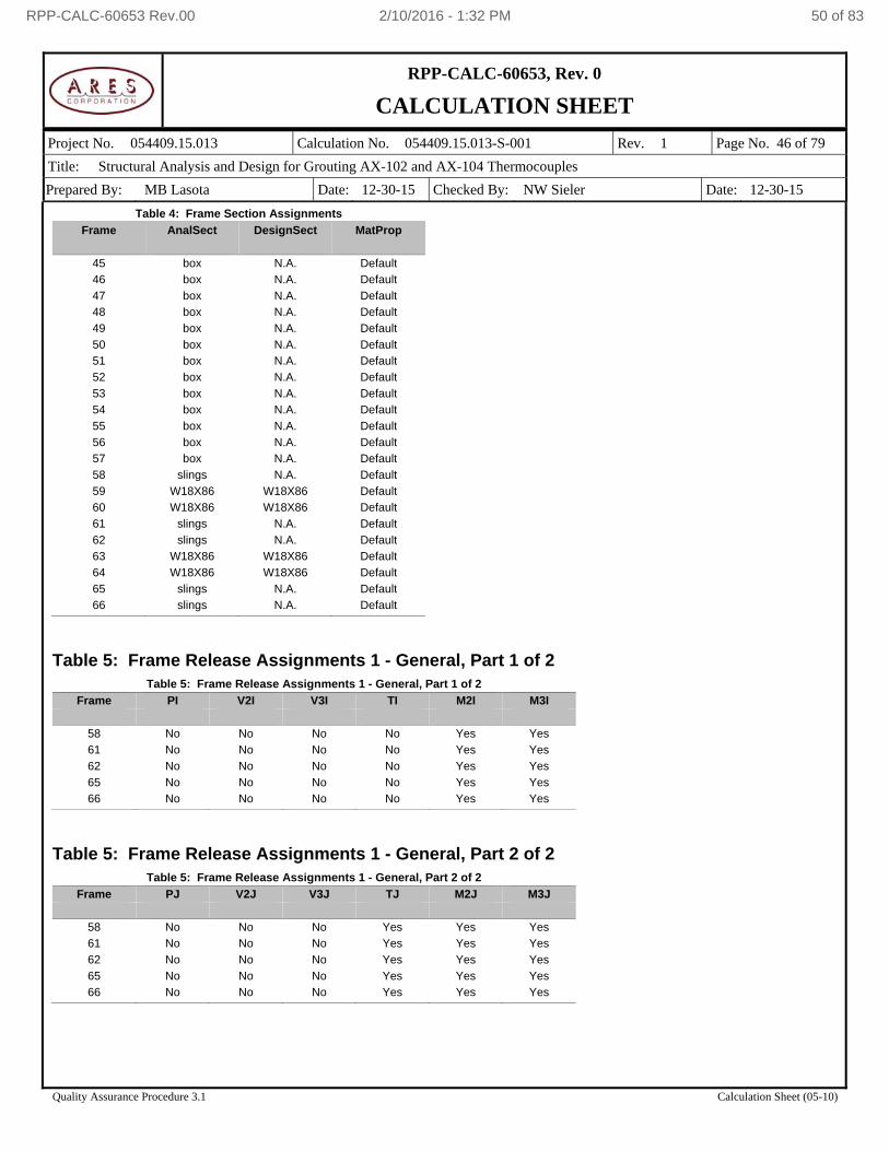
RPP-CALC-60653, Rev. 0
CALCULATION SHEET
Project No. 054409.15.013 Calculation No. 054409.15.013-S-001 Rev. 1 Page No. 46 of 79
Title: Structural Analysis and Design for Grouting AX-102 and AX-104 Thermocouples
Prepared By: MB Lasota Date: 12-30-15 Checked By: NW Sieler Date: 12-30-15
Quality Assurance Procedure 3.1 Calculation Sheet (05-10)
Table 4: Frame Section Assignments
Frame AnalSect DesignSect MatProp
45 box N.A. Default
46 box N.A. Default
47 box N.A. Default
48 box N.A. Default
49 box N.A. Default
50 box N.A. Default
51 box N.A. Default
52 box N.A. Default
53 box N.A. Default
54 box N.A. Default
55 box N.A. Default
56 box N.A. Default
57 box N.A. Default
58 slings N.A. Default
59 W18X86 W18X86 Default
60 W18X86 W18X86 Default
61 slings N.A. Default
62 slings N.A. Default
63 W18X86 W18X86 Default
64 W18X86 W18X86 Default
65 slings N.A. Default
66 slings N.A. Default
Table 5: Frame Release Assignments 1 - General, Part 1 of 2
Table 5: Frame Release Assignments 1 - General, Part 1 of 2
Frame PI V2I V3I TI M2I M3I
58 No No No No Yes Yes
61 No No No No Yes Yes
62 No No No No Yes Yes
65 No No No No Yes Yes
66 No No No No Yes Yes
Table 5: Frame Release Assignments 1 - General, Part 2 of 2
Table 5: Frame Release Assignments 1 - General, Part 2 of 2
Frame PJ V2J V3J TJ M2J M3J
58 No No No Yes Yes Yes
61 No No No Yes Yes Yes
62 No No No Yes Yes Yes
65 No No No Yes Yes Yes
66 No No No Yes Yes Yes
RPP-CALC-60653 Rev.00 2/10/2016 - 1:32 PM 50 of 83
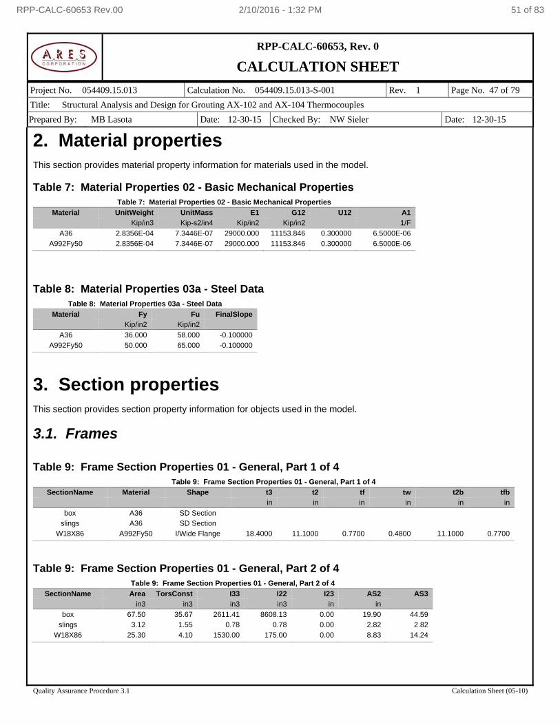
RPP-CALC-60653, Rev. 0
CALCULATION SHEET
Project No. 054409.15.013 Calculation No. 054409.15.013-S-001 Rev. 1 Page No. 47 of 79
Title: Structural Analysis and Design for Grouting AX-102 and AX-104 Thermocouples
Prepared By: MB Lasota Date: 12-30-15 Checked By: NW Sieler Date: 12-30-15
Quality Assurance Procedure 3.1 Calculation Sheet (05-10)
2. Material properties This section provides material property information for materials used in the model. Table 7: Material Properties 02 - Basic Mechanical Properties
Table 7: Material Properties 02 - Basic Mechanical Properties
Material UnitWeight UnitMass E1 G12 U12 A1
Kip/in3 Kip-s2/in4 Kip/in2 Kip/in2 1/F
A36 2.8356E-04 7.3446E-07 29000.000 11153.846 0.300000 6.5000E-06
A992Fy50 2.8356E-04 7.3446E-07 29000.000 11153.846 0.300000 6.5000E-06
Table 8: Material Properties 03a - Steel Data
Table 8: Material Properties 03a - Steel Data
Material Fy Fu FinalSlope
Kip/in2 Kip/in2
A36 36.000 58.000 -0.100000
A992Fy50 50.000 65.000 -0.100000
3. Section properties This section provides section property information for objects used in the model.
3.1. Frames Table 9: Frame Section Properties 01 - General, Part 1 of 4
Table 9: Frame Section Properties 01 - General, Part 1 of 4
SectionName Material Shape t3 t2 tf tw t2b tfb
in in in in in in
box A36 SD Section
slings A36 SD Section
W18X86 A992Fy50 I/Wide Flange 18.4000 11.1000 0.7700 0.4800 11.1000 0.7700
Table 9: Frame Section Properties 01 - General, Part 2 of 4
Table 9: Frame Section Properties 01 - General, Part 2 of 4
SectionName Area TorsConst I33 I22 I23 AS2 AS3
in3 in3 in3 in3 in in
box 67.50 35.67 2611.41 8608.13 0.00 19.90 44.59
slings 3.12 1.55 0.78 0.78 0.00 2.82 2.82
W18X86 25.30 4.10 1530.00 175.00 0.00 8.83 14.24
RPP-CALC-60653 Rev.00 2/10/2016 - 1:32 PM 51 of 83
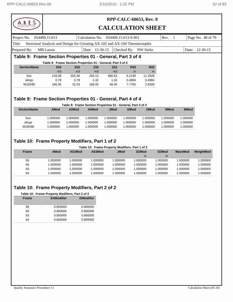
RPP-CALC-60653, Rev. 0
CALCULATION SHEET
Project No. 054409.15.013 Calculation No. 054409.15.013-S-001 Rev. 1 Page No. 48 of 79
Title: Structural Analysis and Design for Grouting AX-102 and AX-104 Thermocouples
Prepared By: MB Lasota Date: 12-30-15 Checked By: NW Sieler Date: 12-30-15
Quality Assurance Procedure 3.1 Calculation Sheet (05-10)
Table 9: Frame Section Properties 01 - General, Part 3 of 4 Table 9: Frame Section Properties 01 - General, Part 3 of 4
SectionName S33 S22 Z33 Z22 R33 R22
in3 in3 in3 in3 in in
box 143.09 555.36 250.13 680.63 6.2199 11.2928
slings 0.78 0.78 1.32 1.32 0.4984 0.4984
W18X86 166.30 31.53 186.00 48.40 7.7765 2.6300
Table 9: Frame Section Properties 01 - General, Part 4 of 4
Table 9: Frame Section Properties 01 - General, Part 4 of 4
SectionName AMod A2Mod A3Mod JMod I2Mod I3Mod MMod WMod
box 1.000000 1.000000 1.000000 1.000000 1.000000 1.000000 1.000000 1.000000
slings 1.000000 1.000000 1.000000 1.000000 1.000000 1.000000 1.000000 1.000000
W18X86 1.000000 1.000000 1.000000 1.000000 1.000000 1.000000 1.000000 1.000000
Table 10: Frame Property Modifiers, Part 1 of 2
Table 10: Frame Property Modifiers, Part 1 of 2
Frame AMod AS2Mod AS3Mod JMod I22Mod I33Mod MassMod WeightMod
in in
59 1.000000 1.000000 1.000000 1.000000 1.000000 1.000000 1.000000 1.000000
60 1.000000 1.000000 1.000000 1.000000 1.000000 1.000000 1.000000 1.000000
63 1.000000 1.000000 1.000000 1.000000 1.000000 1.000000 1.000000 1.000000
64 1.000000 1.000000 1.000000 1.000000 1.000000 1.000000 1.000000 1.000000
Table 10: Frame Property Modifiers, Part 2 of 2
Table 10: Frame Property Modifiers, Part 2 of 2
Frame EAModifier EIModifier
59 0.800000 0.800000
60 0.800000 0.800000
63 0.800000 0.800000
64 0.800000 0.800000
RPP-CALC-60653 Rev.00 2/10/2016 - 1:32 PM 52 of 83
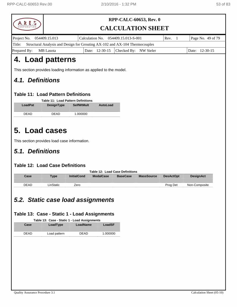
RPP-CALC-60653, Rev. 0
CALCULATION SHEET
Project No. 054409.15.013 Calculation No. 054409.15.013-S-001 Rev. 1 Page No. 49 of 79
Title: Structural Analysis and Design for Grouting AX-102 and AX-104 Thermocouples
Prepared By: MB Lasota Date: 12-30-15 Checked By: NW Sieler Date: 12-30-15
Quality Assurance Procedure 3.1 Calculation Sheet (05-10)
4. Load patterns This section provides loading information as applied to the model.
4.1. Definitions Table 11: Load Pattern Definitions
Table 11: Load Pattern Definitions
LoadPat DesignType SelfWtMult AutoLoad
DEAD DEAD 1.000000
5. Load cases This section provides load case information.
5.1. Definitions Table 12: Load Case Definitions
Table 12: Load Case Definitions
Case Type InitialCond ModalCase BaseCase MassSource DesActOpt DesignAct
DEAD LinStatic Zero Prog Det Non-Composite
5.2. Static case load assignments Table 13: Case - Static 1 - Load Assignments
Table 13: Case - Static 1 - Load Assignments
Case LoadType LoadName LoadSF
DEAD Load pattern DEAD 1.000000
RPP-CALC-60653 Rev.00 2/10/2016 - 1:32 PM 53 of 83
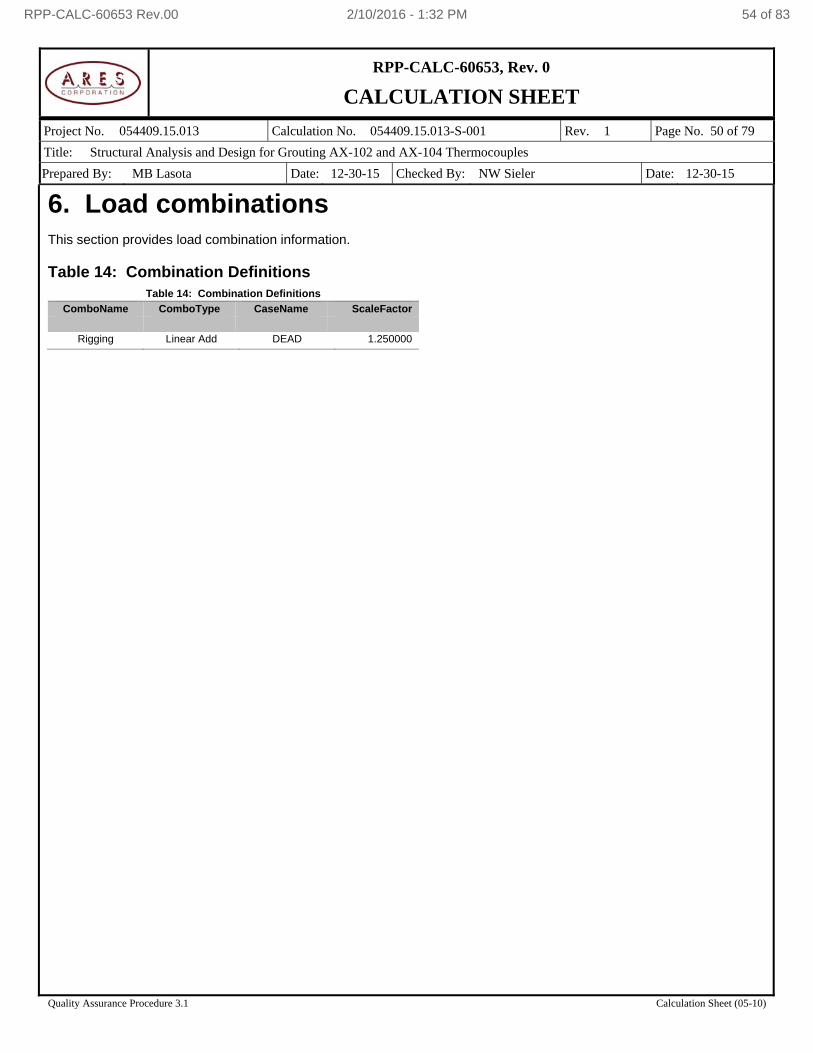
RPP-CALC-60653, Rev. 0
CALCULATION SHEET
Project No. 054409.15.013 Calculation No. 054409.15.013-S-001 Rev. 1 Page No. 50 of 79
Title: Structural Analysis and Design for Grouting AX-102 and AX-104 Thermocouples
Prepared By: MB Lasota Date: 12-30-15 Checked By: NW Sieler Date: 12-30-15
Quality Assurance Procedure 3.1 Calculation Sheet (05-10)
6. Load combinations This section provides load combination information. Table 14: Combination Definitions
Table 14: Combination Definitions
ComboName ComboType CaseName ScaleFactor
Rigging Linear Add DEAD 1.250000
RPP-CALC-60653 Rev.00 2/10/2016 - 1:32 PM 54 of 83
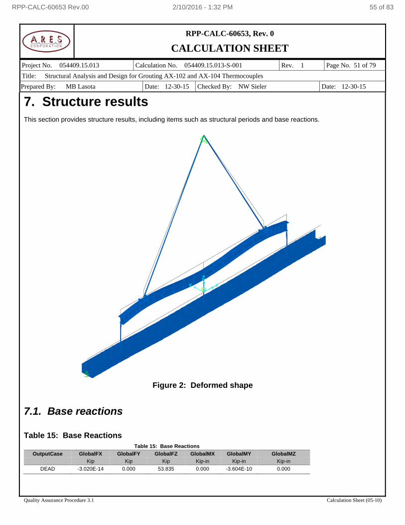
RPP-CALC-60653, Rev. 0
CALCULATION SHEET
Project No. 054409.15.013 Calculation No. 054409.15.013-S-001 Rev. 1 Page No. 51 of 79
Title: Structural Analysis and Design for Grouting AX-102 and AX-104 Thermocouples
Prepared By: MB Lasota Date: 12-30-15 Checked By: NW Sieler Date: 12-30-15
Quality Assurance Procedure 3.1 Calculation Sheet (05-10)
7. Structure results This section provides structure results, including items such as structural periods and base reactions.
Figure 2: Deformed shape
7.1. Base reactions Table 15: Base Reactions
Table 15: Base Reactions
OutputCase GlobalFX GlobalFY GlobalFZ GlobalMX GlobalMY GlobalMZ
Kip Kip Kip Kip-in Kip-in Kip-in
DEAD -3.020E-14 0.000 53.835 0.000 -3.604E-10 0.000
RPP-CALC-60653 Rev.00 2/10/2016 - 1:32 PM 55 of 83
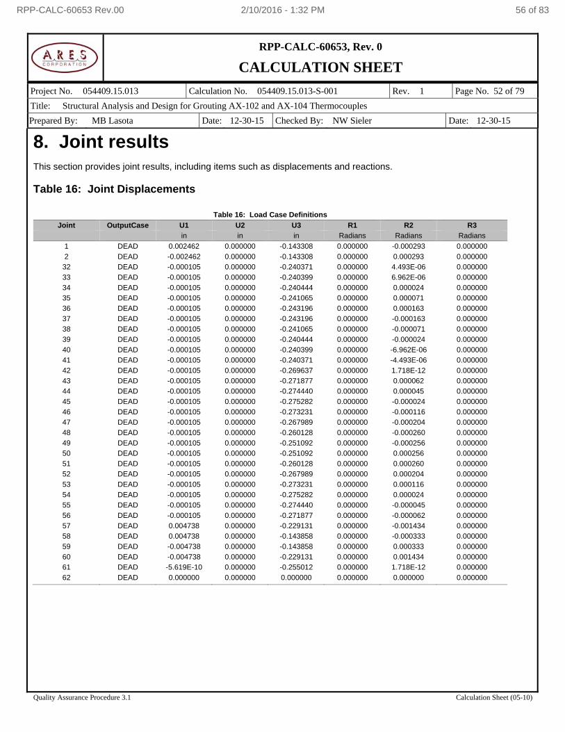
RPP-CALC-60653, Rev. 0
CALCULATION SHEET
Project No. 054409.15.013 Calculation No. 054409.15.013-S-001 Rev. 1 Page No. 52 of 79
Title: Structural Analysis and Design for Grouting AX-102 and AX-104 Thermocouples
Prepared By: MB Lasota Date: 12-30-15 Checked By: NW Sieler Date: 12-30-15
Quality Assurance Procedure 3.1 Calculation Sheet (05-10)
8. Joint results This section provides joint results, including items such as displacements and reactions. Table 16: Joint Displacements
Table 16: Load Case Definitions
Joint OutputCase U1 U2 U3 R1 R2 R3
in in in Radians Radians Radians
1 DEAD 0.002462 0.000000 -0.143308 0.000000 -0.000293 0.000000
2 DEAD -0.002462 0.000000 -0.143308 0.000000 0.000293 0.000000
32 DEAD -0.000105 0.000000 -0.240371 0.000000 4.493E-06 0.000000
33 DEAD -0.000105 0.000000 -0.240399 0.000000 6.962E-06 0.000000
34 DEAD -0.000105 0.000000 -0.240444 0.000000 0.000024 0.000000
35 DEAD -0.000105 0.000000 -0.241065 0.000000 0.000071 0.000000
36 DEAD -0.000105 0.000000 -0.243196 0.000000 0.000163 0.000000
37 DEAD -0.000105 0.000000 -0.243196 0.000000 -0.000163 0.000000
38 DEAD -0.000105 0.000000 -0.241065 0.000000 -0.000071 0.000000
39 DEAD -0.000105 0.000000 -0.240444 0.000000 -0.000024 0.000000
40 DEAD -0.000105 0.000000 -0.240399 0.000000 -6.962E-06 0.000000
41 DEAD -0.000105 0.000000 -0.240371 0.000000 -4.493E-06 0.000000
42 DEAD -0.000105 0.000000 -0.269637 0.000000 1.718E-12 0.000000
43 DEAD -0.000105 0.000000 -0.271877 0.000000 0.000062 0.000000
44 DEAD -0.000105 0.000000 -0.274440 0.000000 0.000045 0.000000
45 DEAD -0.000105 0.000000 -0.275282 0.000000 -0.000024 0.000000
46 DEAD -0.000105 0.000000 -0.273231 0.000000 -0.000116 0.000000
47 DEAD -0.000105 0.000000 -0.267989 0.000000 -0.000204 0.000000
48 DEAD -0.000105 0.000000 -0.260128 0.000000 -0.000260 0.000000
49 DEAD -0.000105 0.000000 -0.251092 0.000000 -0.000256 0.000000
50 DEAD -0.000105 0.000000 -0.251092 0.000000 0.000256 0.000000
51 DEAD -0.000105 0.000000 -0.260128 0.000000 0.000260 0.000000
52 DEAD -0.000105 0.000000 -0.267989 0.000000 0.000204 0.000000
53 DEAD -0.000105 0.000000 -0.273231 0.000000 0.000116 0.000000
54 DEAD -0.000105 0.000000 -0.275282 0.000000 0.000024 0.000000
55 DEAD -0.000105 0.000000 -0.274440 0.000000 -0.000045 0.000000
56 DEAD -0.000105 0.000000 -0.271877 0.000000 -0.000062 0.000000
57 DEAD 0.004738 0.000000 -0.229131 0.000000 -0.001434 0.000000
58 DEAD 0.004738 0.000000 -0.143858 0.000000 -0.000333 0.000000
59 DEAD -0.004738 0.000000 -0.143858 0.000000 0.000333 0.000000
60 DEAD -0.004738 0.000000 -0.229131 0.000000 0.001434 0.000000
61 DEAD -5.619E-10 0.000000 -0.255012 0.000000 1.718E-12 0.000000
62 DEAD 0.000000 0.000000 0.000000 0.000000 0.000000 0.000000
RPP-CALC-60653 Rev.00 2/10/2016 - 1:32 PM 56 of 83
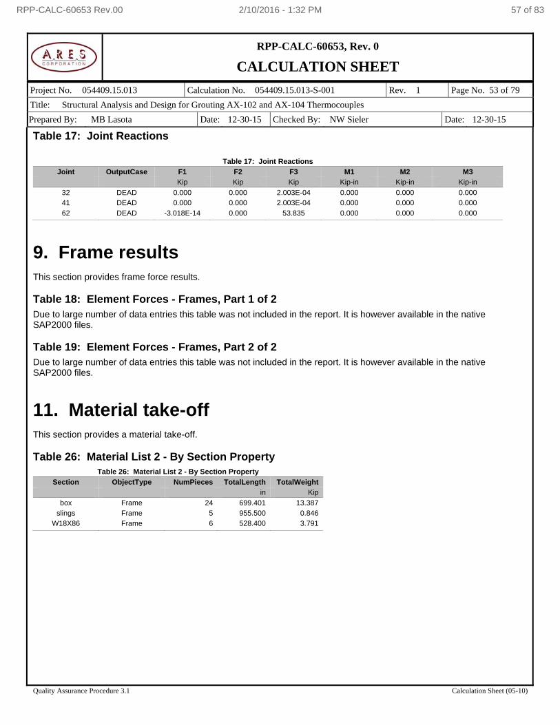
RPP-CALC-60653, Rev. 0
CALCULATION SHEET
Project No. 054409.15.013 Calculation No. 054409.15.013-S-001 Rev. 1 Page No. 53 of 79
Title: Structural Analysis and Design for Grouting AX-102 and AX-104 Thermocouples
Prepared By: MB Lasota Date: 12-30-15 Checked By: NW Sieler Date: 12-30-15
Quality Assurance Procedure 3.1 Calculation Sheet (05-10)
Table 17: Joint Reactions
Table 17: Joint Reactions
Joint OutputCase F1 F2 F3 M1 M2 M3
Kip Kip Kip Kip-in Kip-in Kip-in
32 DEAD 0.000 0.000 2.003E-04 0.000 0.000 0.000
41 DEAD 0.000 0.000 2.003E-04 0.000 0.000 0.000
62 DEAD -3.018E-14 0.000 53.835 0.000 0.000 0.000
9. Frame results This section provides frame force results. Table 18: Element Forces - Frames, Part 1 of 2 Due to large number of data entries this table was not included in the report. It is however available in the native SAP2000 files. Table 19: Element Forces - Frames, Part 2 of 2 Due to large number of data entries this table was not included in the report. It is however available in the native SAP2000 files.
11. Material take-off This section provides a material take-off. Table 26: Material List 2 - By Section Property
Table 26: Material List 2 - By Section Property
Section ObjectType NumPieces TotalLength TotalWeight
in Kip
box Frame 24 699.401 13.387
slings Frame 5 955.500 0.846
W18X86 Frame 6 528.400 3.791
RPP-CALC-60653 Rev.00 2/10/2016 - 1:32 PM 57 of 83

RPP-CALC-60653, Rev. 0
CALCULATION SHEET
Project No. 054409.15.013 Calculation No. 054409.15.013-S-001 Rev. 1 Page No. 54 of 79
Title: Structural Analysis and Design for Grouting AX-102 and AX-104 Thermocouples
Prepared By: MB Lasota Date: 12-30-15 Checked By: NW Sieler Date: 12-30-15
Quality Assurance Procedure 3.1 Calculation Sheet (05-10)
APPENDIX B
SAP2000 REPORT
FOR THE MODEL: 054409.15.013-S-001B
RPP-CALC-60653 Rev.00 2/10/2016 - 1:32 PM 58 of 83
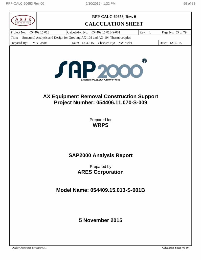
RPP-CALC-60653, Rev. 0
CALCULATION SHEET
Project No. 054409.15.013 Calculation No. 054409.15.013-S-001 Rev. 1 Page No. 55 of 79
Title: Structural Analysis and Design for Grouting AX-102 and AX-104 Thermocouples
Prepared By: MB Lasota Date: 12-30-15 Checked By: NW Sieler Date: 12-30-15
Quality Assurance Procedure 3.1 Calculation Sheet (05-10)
License #*1ZL9CYATHW4YNFB
AX Equipment Removal Construction Support Project Number: 054406.11.070-S-009
Prepared for
WRPS
SAP2000 Analysis Report
Prepared by
ARES Corporation
Model Name: 054409.15.013-S-001B
5 November 2015
RPP-CALC-60653 Rev.00 2/10/2016 - 1:32 PM 59 of 83
RPP-CALC-60653, Rev. 0
CALCULATION SHEET
Project No. 054409.15.013 Calculation No. 054409.15.013-S-001 Rev. 1 Page No. 56 of 79
Title: Structural Analysis and Design for Grouting AX-102 and AX-104 Thermocouples
Prepared By: MB Lasota Date: 12-30-15 Checked By: NW Sieler Date: 12-30-15
Quality Assurance Procedure 3.1 Calculation Sheet (05-10)
Contents 1. Model geometry ...................................................................................................................................................... 58
1.1. Joint coordinates ........................................................................................................................................... 58 1.2. Joint restraints ............................................................................................................................................... 58 1.3. Element connectivity ..................................................................................................................................... 59
2. Material properties .................................................................................................................................................. 59 3. Section properties ................................................................................................................................................... 59
3.1. Areas ............................................................................................................................................................. 59 4. Load patterns .......................................................................................................................................................... 60
4.1. Definitions ...................................................................................................................................................... 60 5. Load cases.............................................................................................................................................................. 60
5.1. Definitions ...................................................................................................................................................... 60 5.2. Static case load assignments ........................................................................................................................ 61
6. Structure results ...................................................................................................................................................... 61 6.1. Mass summary .............................................................................................................................................. 62 6.2. Base reactions ............................................................................................................................................... 62
7. Joint results ............................................................................................................................................................. 62 8. Area results ............................................................................................................................................................. 62 9. Material take-off ...................................................................................................................................................... 63
List of Figures
Figure 1: Finite element model ................................................................................................................................... 58 Figure 2: Deformed shape .......................................................................................................................................... 61
List of Tables Table 1: Joint Coordinates .......................................................................................................................................... 58 Table 2: Joint Restraint Assignments ......................................................................................................................... 58 Table 3: Connectivity - Area ....................................................................................................................................... 59 Table 4: Area Section Assignments ........................................................................................................................... 59 Table 5: Material Properties 02 - Basic Mechanical Properties .................................................................................. 59 Table 6: Material Properties 03a - Steel Data ............................................................................................................ 59 Table 7: Area Section Properties, Part 1 of 3 ............................................................................................................. 59 Table 7: Area Section Properties, Part 2 of 3 ............................................................................................................. 60 Table 7: Area Section Properties, Part 3 of 3 ............................................................................................................. 60 Table 8: Load Pattern Definitions ............................................................................................................................... 60 Table 9: Load Case Definitions, Part 1 of 2 ................................................................................................................ 60 Table 9: Load Case Definitions, Part 2 of 2 ................................................................................................................ 61 Table 10: Case - Static 1 - Load Assignments ........................................................................................................... 61 Table 11: Assembled Joint Masses ............................................................................................................................ 62 Table 12: Base Reactions ........................................................................................................................................... 62 Table 13: Joint Displacements .................................................................................................................................... 62 Table 14: Joint Reactions ........................................................................................................................................... 62 Table 15: Element Forces - Area Shells, Part 1 of 3 .................................................................................................. 62 Table 15: Element Forces - Area Shells, Part 2 of 3 .................................................................................................. 62 Table 15: Element Forces - Area Shells, Part 3 of 3 .................................................................................................. 62 Table 16: Element Stresses - Area Shells, Part 1 of 3 ............................................................................................... 63 Table 16: Element Stresses - Area Shells, Part 2 of 3 ............................................................................................... 63
RPP-CALC-60653 Rev.00 2/10/2016 - 1:32 PM 60 of 83
RPP-CALC-60653, Rev. 0
CALCULATION SHEET
Project No. 054409.15.013 Calculation No. 054409.15.013-S-001 Rev. 1 Page No. 57 of 79
Title: Structural Analysis and Design for Grouting AX-102 and AX-104 Thermocouples
Prepared By: MB Lasota Date: 12-30-15 Checked By: NW Sieler Date: 12-30-15
Quality Assurance Procedure 3.1 Calculation Sheet (05-10)
Table 16: Element Stresses - Area Shells, Part 3 of 3 ............................................................................................... 63 Table 17: Material List 2 - By Section Property .......................................................................................................... 63
RPP-CALC-60653 Rev.00 2/10/2016 - 1:32 PM 61 of 83
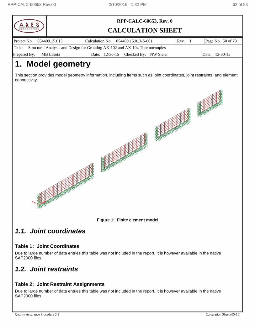
RPP-CALC-60653, Rev. 0
CALCULATION SHEET
Project No. 054409.15.013 Calculation No. 054409.15.013-S-001 Rev. 1 Page No. 58 of 79
Title: Structural Analysis and Design for Grouting AX-102 and AX-104 Thermocouples
Prepared By: MB Lasota Date: 12-30-15 Checked By: NW Sieler Date: 12-30-15
Quality Assurance Procedure 3.1 Calculation Sheet (05-10)
1. Model geometry This section provides model geometry information, including items such as joint coordinates, joint restraints, and element connectivity.
Figure 1: Finite element model
1.1. Joint coordinates Table 1: Joint Coordinates Due to large number of data entries this table was not included in the report. It is however available in the native SAP2000 files.
1.2. Joint restraints Table 2: Joint Restraint Assignments Due to large number of data entries this table was not included in the report. It is however available in the native SAP2000 files.
RPP-CALC-60653 Rev.00 2/10/2016 - 1:32 PM 62 of 83
RPP-CALC-60653, Rev. 0
CALCULATION SHEET
Project No. 054409.15.013 Calculation No. 054409.15.013-S-001 Rev. 1 Page No. 59 of 79
Title: Structural Analysis and Design for Grouting AX-102 and AX-104 Thermocouples
Prepared By: MB Lasota Date: 12-30-15 Checked By: NW Sieler Date: 12-30-15
Quality Assurance Procedure 3.1 Calculation Sheet (05-10)
1.3. Element connectivity Table 3: Connectivity - Area Due to large number of data entries this table was not included in the report. It is however available in the native SAP2000 files. Table 4: Area Section Assignments Due to large number of data entries this table was not included in the report. It is however available in the native SAP2000 files.
2. Material properties This section provides material property information for materials used in the model. Table 5: Material Properties 02 - Basic Mechanical Properties
Table 5: Material Properties 02 - Basic Mechanical Properties
Material UnitWeight UnitMass E1 G12 U12 A1
Kip/in3 Kip-s2/in4 Kip/in2 Kip/in2 1/F
A36 2.8356E-04 7.3446E-07 29000.000 11153.846 0.300000 6.5000E-06
Table 6: Material Properties 03a - Steel Data
Table 6: Material Properties 03a - Steel Data
Material Fy Fu FinalSlope
Kip/in2 Kip/in2
A36 36.000 58.000 -0.100000
3. Section properties This section provides section property information for objects used in the model.
3.1. Areas Table 7: Area Section Properties, Part 1 of 3
Table 7: Area Section Properties, Part 1 of 3
Section Material AreaType Type DrillDOF Thickness BendThick F11Mod
in in
side wall A36 Shell Shell-Thin Yes 0.50000 0.50000 1.000000
RPP-CALC-60653 Rev.00 2/10/2016 - 1:32 PM 63 of 83
RPP-CALC-60653, Rev. 0
CALCULATION SHEET
Project No. 054409.15.013 Calculation No. 054409.15.013-S-001 Rev. 1 Page No. 60 of 79
Title: Structural Analysis and Design for Grouting AX-102 and AX-104 Thermocouples
Prepared By: MB Lasota Date: 12-30-15 Checked By: NW Sieler Date: 12-30-15
Quality Assurance Procedure 3.1 Calculation Sheet (05-10)
Table 7: Area Section Properties, Part 2 of 3 Table 7: Area Section Properties, Part 2 of 3
Section F22Mod F12Mod M11Mod M22Mod M12Mod V13Mod V23Mod MMod
side wall 1.000000 1.000000 1.000000 1.000000 1.000000 1.000000 1.000000 1.000000
Table 7: Area Section Properties, Part 3 of 3
Table 7: Area Section Properties, Part 3 of 3
Section WMod
side wall 1.000000
4. Load patterns This section provides loading information as applied to the model.
4.1. Definitions Table 8: Load Pattern Definitions
Table 8: Load Pattern Definitions
LoadPat DesignType SelfWtMult AutoLoad
DEAD DEAD 1.000000
5. Load cases This section provides load case information.
5.1. Definitions Table 9: Load Case Definitions, Part 1 of 2
Table 9: Load Case Definitions, Part 1 of 2
Case Type InitialCond ModalCase BaseCase MassSource DesActOpt
DEAD LinStatic Zero Prog Det
RPP-CALC-60653 Rev.00 2/10/2016 - 1:32 PM 64 of 83
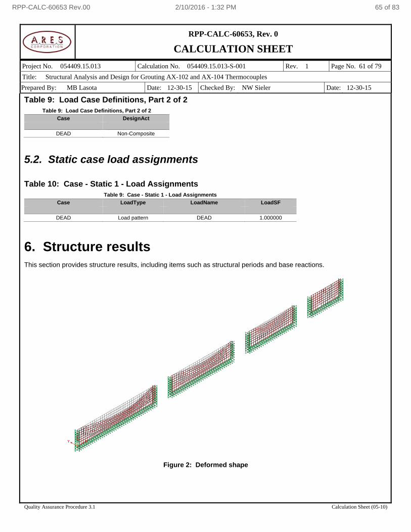
RPP-CALC-60653, Rev. 0
CALCULATION SHEET
Project No. 054409.15.013 Calculation No. 054409.15.013-S-001 Rev. 1 Page No. 61 of 79
Title: Structural Analysis and Design for Grouting AX-102 and AX-104 Thermocouples
Prepared By: MB Lasota Date: 12-30-15 Checked By: NW Sieler Date: 12-30-15
Quality Assurance Procedure 3.1 Calculation Sheet (05-10)
Table 9: Load Case Definitions, Part 2 of 2 Table 9: Load Case Definitions, Part 2 of 2
Case DesignAct
DEAD Non-Composite
5.2. Static case load assignments Table 10: Case - Static 1 - Load Assignments
Table 9: Case - Static 1 - Load Assignments
Case LoadType LoadName LoadSF
DEAD Load pattern DEAD 1.000000
6. Structure results This section provides structure results, including items such as structural periods and base reactions.
Figure 2: Deformed shape
RPP-CALC-60653 Rev.00 2/10/2016 - 1:32 PM 65 of 83
RPP-CALC-60653, Rev. 0
CALCULATION SHEET
Project No. 054409.15.013 Calculation No. 054409.15.013-S-001 Rev. 1 Page No. 62 of 79
Title: Structural Analysis and Design for Grouting AX-102 and AX-104 Thermocouples
Prepared By: MB Lasota Date: 12-30-15 Checked By: NW Sieler Date: 12-30-15
Quality Assurance Procedure 3.1 Calculation Sheet (05-10)
6.1. Mass summary Table 11: Assembled Joint Masses Due to large number of data entries this table was not included in the report. It is however available in the native SAP2000 files.
6.2. Base reactions Table 12: Base Reactions
Table 11: Base Reactions
OutputCase GlobalFX GlobalFY GlobalFZ GlobalMX GlobalMY GlobalMZ
Kip Kip Kip Kip-in Kip-in Kip-in
DEAD 5.306E-15 6.439 -10.959 -46.683 3396.007 1258.368
7. Joint results This section provides joint results, including items such as displacements and reactions. Table 13: Joint Displacements Due to large number of data entries this table was not included in the report. It is however available in the native SAP2000 files. Table 14: Joint Reactions Due to large number of data entries this table was not included in the report. It is however available in the native SAP2000 files.
8. Area results This section provides area results, including items such as forces and stresses. Table 15: Element Forces - Area Shells, Part 1 of 3 Due to large number of data entries this table was not included in the report. It is however available in the native SAP2000 files. Table 15: Element Forces - Area Shells, Part 2 of 3 Due to large number of data entries this table was not included in the report. It is however available in the native SAP2000 files. Table 15: Element Forces - Area Shells, Part 3 of 3 Due to large number of data entries this table was not included in the report. It is however available in the native SAP2000 files.
RPP-CALC-60653 Rev.00 2/10/2016 - 1:32 PM 66 of 83
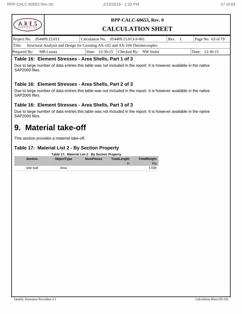
RPP-CALC-60653, Rev. 0
CALCULATION SHEET
Project No. 054409.15.013 Calculation No. 054409.15.013-S-001 Rev. 1 Page No. 63 of 79
Title: Structural Analysis and Design for Grouting AX-102 and AX-104 Thermocouples
Prepared By: MB Lasota Date: 12-30-15 Checked By: NW Sieler Date: 12-30-15
Quality Assurance Procedure 3.1 Calculation Sheet (05-10)
Table 16: Element Stresses - Area Shells, Part 1 of 3 Due to large number of data entries this table was not included in the report. It is however available in the native SAP2000 files. Table 16: Element Stresses - Area Shells, Part 2 of 3 Due to large number of data entries this table was not included in the report. It is however available in the native SAP2000 files. Table 16: Element Stresses - Area Shells, Part 3 of 3 Due to large number of data entries this table was not included in the report. It is however available in the native SAP2000 files.
9. Material take-off This section provides a material take-off. Table 17: Material List 2 - By Section Property
Table 17: Material List 2 - By Section Property
Section ObjectType NumPieces TotalLength TotalWeight
in Kip
side wall Area 1.036
RPP-CALC-60653 Rev.00 2/10/2016 - 1:32 PM 67 of 83
RPP-CALC-60653, Rev. 0
CALCULATION SHEET
Project No. 054409.15.013 Calculation No. 054409.15.013-S-001 Rev. 1 Page No. 64 of 79
Title: Structural Analysis and Design for Grouting AX-102 and AX-104 Thermocouples
Prepared By: MB Lasota Date: 12-30-15 Checked By: NW Sieler Date: 12-30-15
Quality Assurance Procedure 3.1 Calculation Sheet (05-10)
APPENDIX C
SAP2000 REPORT
FOR THE MODEL: 054409.15.013-S-001C
RPP-CALC-60653 Rev.00 2/10/2016 - 1:32 PM 68 of 83
RPP-CALC-60653, Rev. 0
CALCULATION SHEET
Project No. 054409.15.013 Calculation No. 054409.15.013-S-001 Rev. 1 Page No. 65 of 79
Title: Structural Analysis and Design for Grouting AX-102 and AX-104 Thermocouples
Prepared By: MB Lasota Date: 12-30-15 Checked By: NW Sieler Date: 12-30-15
Quality Assurance Procedure 3.1 Calculation Sheet (05-10)
License #*1ZL9CYATHW4YNFB
AX Equipment Removal Construction Support.
Project Number: 054406.11.063-S-011
Prepared for
WRPS
SAP2000 Analysis Report
Prepared by
ARES Corporation
Model Name: 054409.15.013-S-001C
5 November 2015
RPP-CALC-60653 Rev.00 2/10/2016 - 1:32 PM 69 of 83
RPP-CALC-60653, Rev. 0
CALCULATION SHEET
Project No. 054409.15.013 Calculation No. 054409.15.013-S-001 Rev. 1 Page No. 66 of 79
Title: Structural Analysis and Design for Grouting AX-102 and AX-104 Thermocouples
Prepared By: MB Lasota Date: 12-30-15 Checked By: NW Sieler Date: 12-30-15
Quality Assurance Procedure 3.1 Calculation Sheet (05-10)
Contents 1. Model geometry ......................................................................................................................................................... 68
1.1. Joint coordinates .............................................................................................................................................. 68 1.2. Joint restraints .................................................................................................................................................. 68 1.3. Element connectivity ........................................................................................................................................ 69
2. Material properties ..................................................................................................................................................... 69 3. Section properties ...................................................................................................................................................... 70
3.1. Frames ............................................................................................................................................................. 70 3.2. Areas ................................................................................................................................................................ 70
4. Load patterns ............................................................................................................................................................. 72 4.1. Definitions ......................................................................................................................................................... 72
5. Load cases................................................................................................................................................................. 72 5.1. Definitions ......................................................................................................................................................... 72 5.2. Static case load assignments ........................................................................................................................... 72
6. Load combinations ..................................................................................................................................................... 73 7. Structure results ......................................................................................................................................................... 74
7.1. Mass summary ................................................................................................................................................. 74 7.2. Base reactions .................................................................................................................................................. 74
8. Joint results ................................................................................................................................................................ 75 9. Frame results ............................................................................................................................................................. 75 10. Area results .............................................................................................................................................................. 75 11. Material take-off ....................................................................................................................................................... 76
List of Figures
Figure 1: Finite element model .......................................................................................................................................... 68
Figure 2: Deformed shape ................................................................................................................................................ 74
List of Tables Table 1: Joint Coordinates ................................................................................................................................................ 68
Table 2: Joint Restraint Assignments ............................................................................................................................... 68
Table 3: Connectivity - Frame ........................................................................................................................................... 69
Table 4: Frame Section Assignments ............................................................................................................................... 69
Table 5: Connectivity - Area .............................................................................................................................................. 69
Table 6: Area Section Assignments .................................................................................................................................. 69
Table 7: Material Properties 02 - Basic Mechanical Properties ........................................................................................ 69
Table 8: Material Properties 03a - Steel Data ................................................................................................................... 69
Table 9: Frame Section Properties 01 - General, Part 1 of 4 ........................................................................................... 70
Table 9: Frame Section Properties 01 - General, Part 2 of 4 ........................................................................................... 70
Table 9: Frame Section Properties 01 - General, Part 3 of 4 ........................................................................................... 70
Table 9: Frame Section Properties 01 - General, Part 4 of 4 ........................................................................................... 70
Table 10: Area Section Properties, Part 1 of 3 ................................................................................................................. 70
Table 10: Area Section Properties, Part 2 of 3 ................................................................................................................. 71
RPP-CALC-60653 Rev.00 2/10/2016 - 1:32 PM 70 of 83
RPP-CALC-60653, Rev. 0
CALCULATION SHEET
Project No. 054409.15.013 Calculation No. 054409.15.013-S-001 Rev. 1 Page No. 67 of 79
Title: Structural Analysis and Design for Grouting AX-102 and AX-104 Thermocouples
Prepared By: MB Lasota Date: 12-30-15 Checked By: NW Sieler Date: 12-30-15
Quality Assurance Procedure 3.1 Calculation Sheet (05-10)
Table 10: Area Section Properties, Part 3 of 3 ................................................................................................................. 71
Table 11: Load Pattern Definitions .................................................................................................................................... 72
Table 12: Load Case Definitions, Part 1 of 2 .................................................................................................................... 72
Table 12: Load Case Definitions, Part 2 of 2 .................................................................................................................... 72
Table 13: Case - Static 1 - Load Assignments .................................................................................................................. 72
Table 14: Combination Definitions .................................................................................................................................... 73
Table 15: Assembled Joint Masses .................................................................................................................................. 74
Table 16: Base Reactions ................................................................................................................................................. 74
Table 17: Joint Displacements .......................................................................................................................................... 75
Table 18: Joint Reactions .................................................................................................................................................. 75
Table 19: Element Forces - Frames, Part 1 of 2 ............................................................................................................... 75
Table 19: Element Forces - Frames, Part 2 of 2 ............................................................................................................... 75
Table 20: Element Forces - Area Shells, Part 1 of 3 ........................................................................................................ 75
Table 20: Element Forces - Area Shells, Part 2 of 3 ........................................................................................................ 75
Table 20: Element Forces - Area Shells, Part 3 of 3 ........................................................................................................ 75
Table 21: Element Stresses - Area Shells, Part 1 of 3 ..................................................................................................... 75
Table 21: Element Stresses - Area Shells, Part 2 of 3 ..................................................................................................... 76
Table 21: Element Stresses - Area Shells, Part 3 of 3 ..................................................................................................... 76
Table 22: Material List 2 - By Section Property ................................................................................................................. 76
RPP-CALC-60653 Rev.00 2/10/2016 - 1:32 PM 71 of 83
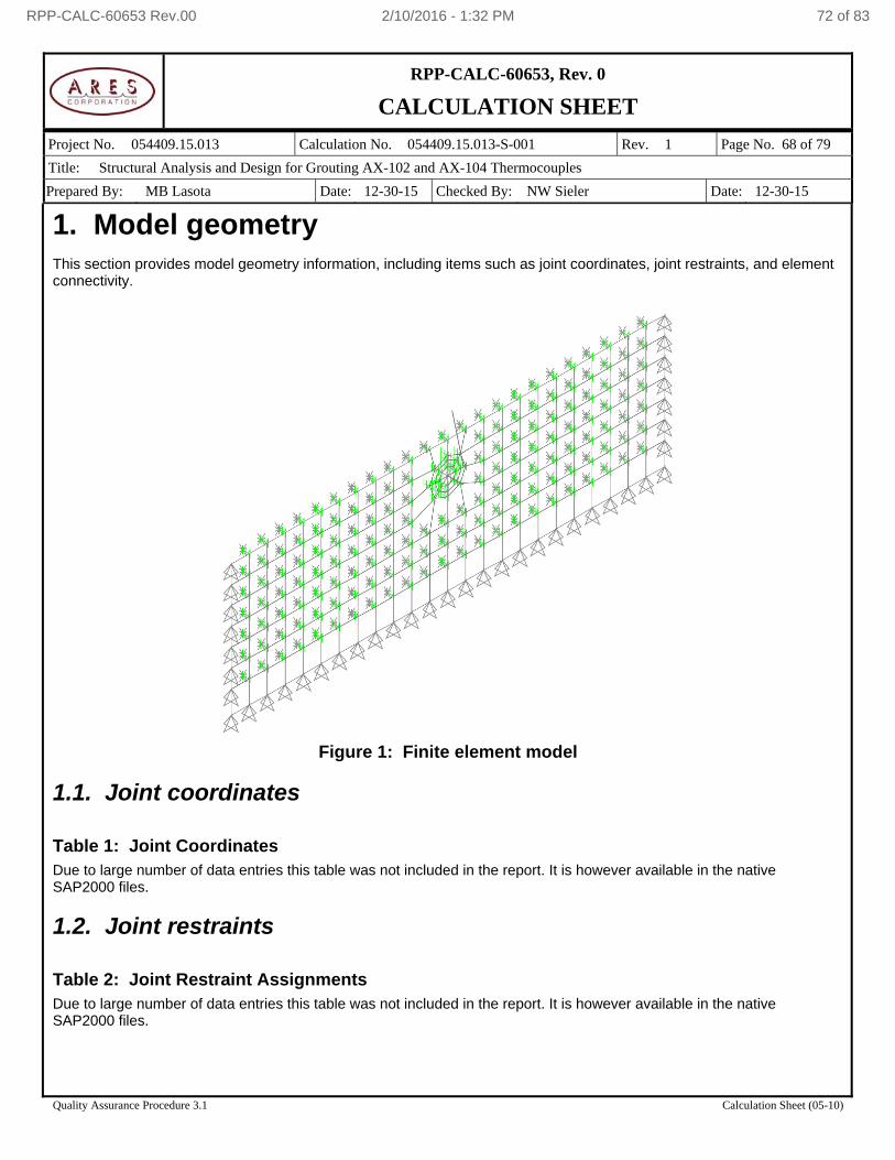
RPP-CALC-60653, Rev. 0
CALCULATION SHEET
Project No. 054409.15.013 Calculation No. 054409.15.013-S-001 Rev. 1 Page No. 68 of 79
Title: Structural Analysis and Design for Grouting AX-102 and AX-104 Thermocouples
Prepared By: MB Lasota Date: 12-30-15 Checked By: NW Sieler Date: 12-30-15
Quality Assurance Procedure 3.1 Calculation Sheet (05-10)
1. Model geometry This section provides model geometry information, including items such as joint coordinates, joint restraints, and element connectivity.
Figure 1: Finite element model
1.1. Joint coordinates Table 1: Joint Coordinates Due to large number of data entries this table was not included in the report. It is however available in the native SAP2000 files.
1.2. Joint restraints Table 2: Joint Restraint Assignments Due to large number of data entries this table was not included in the report. It is however available in the native SAP2000 files.
RPP-CALC-60653 Rev.00 2/10/2016 - 1:32 PM 72 of 83
RPP-CALC-60653, Rev. 0
CALCULATION SHEET
Project No. 054409.15.013 Calculation No. 054409.15.013-S-001 Rev. 1 Page No. 69 of 79
Title: Structural Analysis and Design for Grouting AX-102 and AX-104 Thermocouples
Prepared By: MB Lasota Date: 12-30-15 Checked By: NW Sieler Date: 12-30-15
Quality Assurance Procedure 3.1 Calculation Sheet (05-10)
1.3. Element connectivity Table 3: Connectivity - Frame
Table 3: Connectivity - Frame
Frame JointI JointJ Length
in
1 3375 3376 7.188
2 3377 3378 2.578
3 3376 3378 2.751
Table 4: Frame Section Assignments
Table 4: Frame Section Assignments
Frame AnalSect DesignSect MatProp
1 hoist ring N.A. Default
2 hoist ring N.A. Default
3 hoist ring N.A. Default
Table 5: Connectivity - Area Due to large number of data entries this table was not included in the report. It is however available in the native SAP2000 files. Table 6: Area Section Assignments Due to large number of data entries this table was not included in the report. It is however available in the native SAP2000 files.
2. Material properties This section provides material property information for materials used in the model. Table 7: Material Properties 02 - Basic Mechanical Properties
Table 7: Material Properties 02 - Basic Mechanical Properties
Material UnitWeight UnitMass E1 G12 U12 A1
Kip/in3 Kip-s2/in4 Kip/in2 Kip/in2 1/F
A36 2.8356E-04 7.3446E-07 29000.000 11153.846 0.300000 6.5000E-06
A36-rigid 2.8356E-04 7.3446E-07 2900000.000 1115384.615 0.300000 6.5000E-06
Table 8: Material Properties 03a - Steel Data
Table 8: Material Properties 03a - Steel Data
Material Fy Fu FinalSlope
Kip/in2 Kip/in2
A36 36.000 58.000 -0.100000
A36-rigid 36.000 58.000 -0.100000
RPP-CALC-60653 Rev.00 2/10/2016 - 1:32 PM 73 of 83
RPP-CALC-60653, Rev. 0
CALCULATION SHEET
Project No. 054409.15.013 Calculation No. 054409.15.013-S-001 Rev. 1 Page No. 70 of 79
Title: Structural Analysis and Design for Grouting AX-102 and AX-104 Thermocouples
Prepared By: MB Lasota Date: 12-30-15 Checked By: NW Sieler Date: 12-30-15
Quality Assurance Procedure 3.1 Calculation Sheet (05-10)
3. Section properties This section provides section property information for objects used in the model.
3.1. Frames Table 9: Frame Section Properties 01 - General, Part 1 of 4
Table 9: Frame Section Properties 01 - General, Part 1 of 4
SectionName Material Shape Area TorsConst I33 I22 I23
in2 in4 in4 in4 in4
hoist ring A36 SD Section 3.12 1.55 0.78 0.78 0.00
Table 9: Frame Section Properties 01 - General, Part 2 of 4
Table 9: Frame Section Properties 01 - General, Part 2 of 4
SectionName AS2 AS3
in2 in2
hoist ring 2.82 2.82
Table 9: Frame Section Properties 01 - General, Part 3 of 4
Table 9: Frame Section Properties 01 - General, Part 3 of 4
SectionName S33 S22 Z33 Z22 R33 R22
in3 in3 in3 in3 in in
hoist ring 0.78 0.78 1.32 1.32 0.4984 0.4984
Table 9: Frame Section Properties 01 - General, Part 4 of 4
Table 9: Frame Section Properties 01 - General, Part 4 of 4
SectionName AMod A2Mod A3Mod JMod I2Mod I3Mod MMod WMod
hoist ring 1.000000 1.000000 1.000000 1.000000 1.000000 1.000000 1.000000 1.000000
3.2. Areas Table 10: Area Section Properties, Part 1 of 3
Table 10: Area Section Properties, Part 1 of 3
Section Material AreaType Type DrillDOF Thickness BendThick F11Mod
in in
plate-rigid A36-rigid Shell Shell-Thin Yes 0.7500 0.7500 1.000000
reinforced A36 Shell Shell-Thin Yes 1.0000 1.0000 1.000000
side wall A36 Shell Shell-Thin Yes 0.5000 0.5000 1.000000
RPP-CALC-60653 Rev.00 2/10/2016 - 1:32 PM 74 of 83
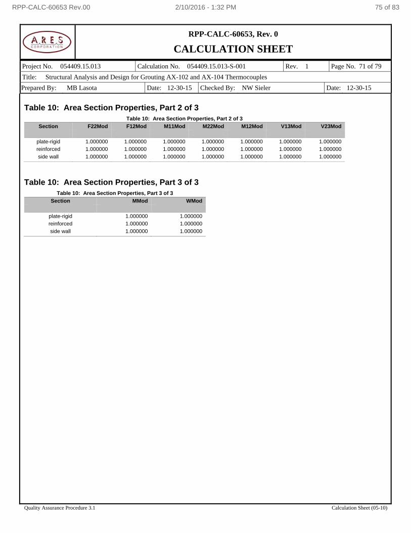
RPP-CALC-60653, Rev. 0
CALCULATION SHEET
Project No. 054409.15.013 Calculation No. 054409.15.013-S-001 Rev. 1 Page No. 71 of 79
Title: Structural Analysis and Design for Grouting AX-102 and AX-104 Thermocouples
Prepared By: MB Lasota Date: 12-30-15 Checked By: NW Sieler Date: 12-30-15
Quality Assurance Procedure 3.1 Calculation Sheet (05-10)
Table 10: Area Section Properties, Part 2 of 3
Table 10: Area Section Properties, Part 2 of 3
Section F22Mod F12Mod M11Mod M22Mod M12Mod V13Mod V23Mod
plate-rigid 1.000000 1.000000 1.000000 1.000000 1.000000 1.000000 1.000000
reinforced 1.000000 1.000000 1.000000 1.000000 1.000000 1.000000 1.000000
side wall 1.000000 1.000000 1.000000 1.000000 1.000000 1.000000 1.000000
Table 10: Area Section Properties, Part 3 of 3
Table 10: Area Section Properties, Part 3 of 3
Section MMod WMod
plate-rigid 1.000000 1.000000
reinforced 1.000000 1.000000
side wall 1.000000 1.000000
RPP-CALC-60653 Rev.00 2/10/2016 - 1:32 PM 75 of 83
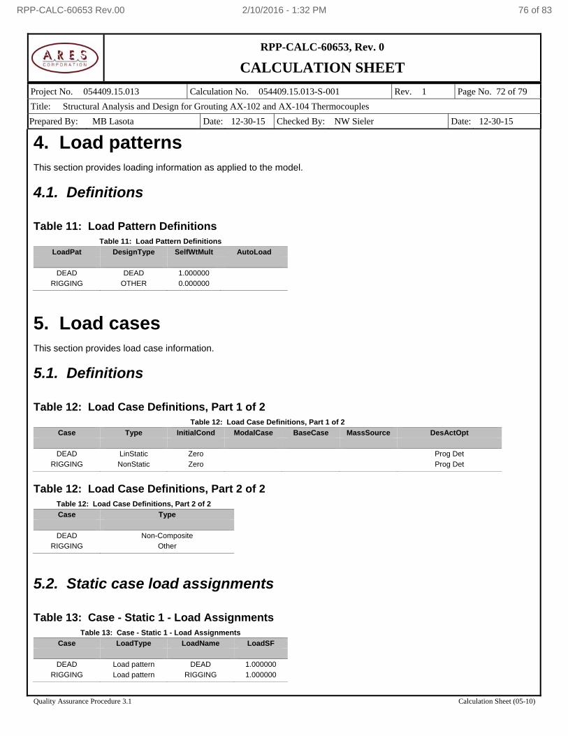
RPP-CALC-60653, Rev. 0
CALCULATION SHEET
Project No. 054409.15.013 Calculation No. 054409.15.013-S-001 Rev. 1 Page No. 72 of 79
Title: Structural Analysis and Design for Grouting AX-102 and AX-104 Thermocouples
Prepared By: MB Lasota Date: 12-30-15 Checked By: NW Sieler Date: 12-30-15
Quality Assurance Procedure 3.1 Calculation Sheet (05-10)
4. Load patterns This section provides loading information as applied to the model.
4.1. Definitions Table 11: Load Pattern Definitions
Table 11: Load Pattern Definitions
LoadPat DesignType SelfWtMult AutoLoad
DEAD DEAD 1.000000
RIGGING OTHER 0.000000
5. Load cases This section provides load case information.
5.1. Definitions Table 12: Load Case Definitions, Part 1 of 2
Table 12: Load Case Definitions, Part 1 of 2
Case Type InitialCond ModalCase BaseCase MassSource DesActOpt
DEAD LinStatic Zero Prog Det
RIGGING NonStatic Zero Prog Det
Table 12: Load Case Definitions, Part 2 of 2
Table 12: Load Case Definitions, Part 2 of 2
Case Type
DEAD Non-Composite
RIGGING Other
5.2. Static case load assignments Table 13: Case - Static 1 - Load Assignments
Table 13: Case - Static 1 - Load Assignments
Case LoadType LoadName LoadSF
DEAD Load pattern DEAD 1.000000
RIGGING Load pattern RIGGING 1.000000
RPP-CALC-60653 Rev.00 2/10/2016 - 1:32 PM 76 of 83

RPP-CALC-60653, Rev. 0
CALCULATION SHEET
Project No. 054409.15.013 Calculation No. 054409.15.013-S-001 Rev. 1 Page No. 73 of 79
Title: Structural Analysis and Design for Grouting AX-102 and AX-104 Thermocouples
Prepared By: MB Lasota Date: 12-30-15 Checked By: NW Sieler Date: 12-30-15
Quality Assurance Procedure 3.1 Calculation Sheet (05-10)
6. Load combinations This section provides load combination information. Table 14: Combination Definitions
Table 14: Combination Definitions
ComboName ComboType CaseName ScaleFactor
COMB1 Linear Add DEAD 1.000000
COMB1 RIGGING 1.000000
RPP-CALC-60653 Rev.00 2/10/2016 - 1:32 PM 77 of 83
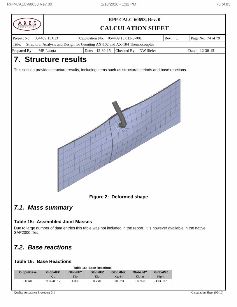
RPP-CALC-60653, Rev. 0
CALCULATION SHEET
Project No. 054409.15.013 Calculation No. 054409.15.013-S-001 Rev. 1 Page No. 74 of 79
Title: Structural Analysis and Design for Grouting AX-102 and AX-104 Thermocouples
Prepared By: MB Lasota Date: 12-30-15 Checked By: NW Sieler Date: 12-30-15
Quality Assurance Procedure 3.1 Calculation Sheet (05-10)
7. Structure results This section provides structure results, including items such as structural periods and base reactions.
Figure 2: Deformed shape
7.1. Mass summary Table 15: Assembled Joint Masses Due to large number of data entries this table was not included in the report. It is however available in the native SAP2000 files.
7.2. Base reactions Table 16: Base Reactions
Table 16: Base Reactions
OutputCase GlobalFX GlobalFY GlobalFZ GlobalMX GlobalMY GlobalMZ
Kip Kip Kip Kip-in Kip-in Kip-in
DEAD -9.324E-17 1.380 0.270 -10.023 -80.923 413.937
RPP-CALC-60653 Rev.00 2/10/2016 - 1:32 PM 78 of 83
RPP-CALC-60653, Rev. 0
CALCULATION SHEET
Project No. 054409.15.013 Calculation No. 054409.15.013-S-001 Rev. 1 Page No. 75 of 79
Title: Structural Analysis and Design for Grouting AX-102 and AX-104 Thermocouples
Prepared By: MB Lasota Date: 12-30-15 Checked By: NW Sieler Date: 12-30-15
Quality Assurance Procedure 3.1 Calculation Sheet (05-10)
8. Joint results This section provides joint results, including items such as displacements and reactions. Table 17: Joint Displacements Due to large number of data entries this table was not included in the report. It is however available in the native SAP2000 files. Table 18: Joint Reactions Due to large number of data entries this table was not included in the report. It is however available in the native SAP2000 files.
9. Frame results This section provides frame force results. Table 19: Element Forces - Frames, Part 1 of 2 Due to large number of data entries this table was not included in the report. It is however available in the native SAP2000 files. Table 19: Element Forces - Frames, Part 2 of 2 Due to large number of data entries this table was not included in the report. It is however available in the native SAP2000 files.
10. Area results This section provides area results, including items such as forces and stresses. Table 20: Element Forces - Area Shells, Part 1 of 3 Due to large number of data entries this table was not included in the report. It is however available in the native SAP2000 files. Table 20: Element Forces - Area Shells, Part 2 of 3 Due to large number of data entries this table was not included in the report. It is however available in the native SAP2000 files. Table 20: Element Forces - Area Shells, Part 3 of 3 Due to large number of data entries this table was not included in the report. It is however available in the native SAP2000 files. Table 21: Element Stresses - Area Shells, Part 1 of 3 Due to large number of data entries this table was not included in the report. It is however available in the native SAP2000 files.
RPP-CALC-60653 Rev.00 2/10/2016 - 1:32 PM 79 of 83
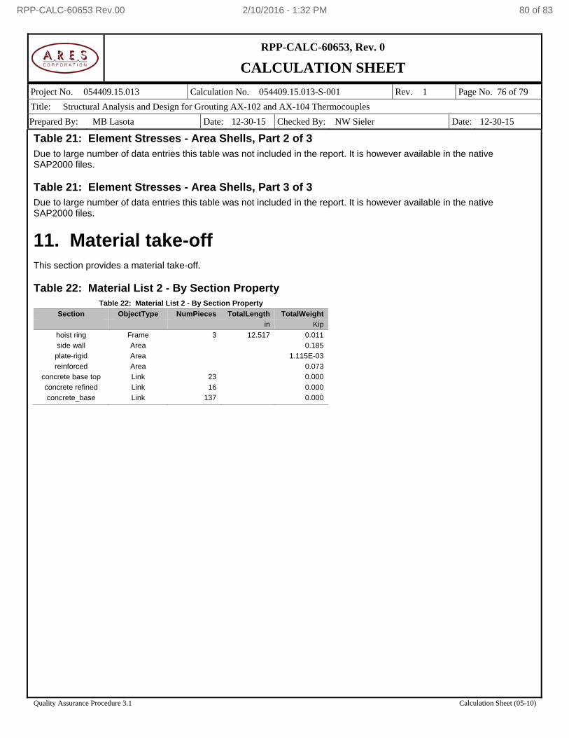
RPP-CALC-60653, Rev. 0
CALCULATION SHEET
Project No. 054409.15.013 Calculation No. 054409.15.013-S-001 Rev. 1 Page No. 76 of 79
Title: Structural Analysis and Design for Grouting AX-102 and AX-104 Thermocouples
Prepared By: MB Lasota Date: 12-30-15 Checked By: NW Sieler Date: 12-30-15
Quality Assurance Procedure 3.1 Calculation Sheet (05-10)
Table 21: Element Stresses - Area Shells, Part 2 of 3 Due to large number of data entries this table was not included in the report. It is however available in the native SAP2000 files. Table 21: Element Stresses - Area Shells, Part 3 of 3 Due to large number of data entries this table was not included in the report. It is however available in the native SAP2000 files.
11. Material take-off This section provides a material take-off. Table 22: Material List 2 - By Section Property
Table 22: Material List 2 - By Section Property
Section ObjectType NumPieces TotalLength TotalWeight
in Kip
hoist ring Frame 3 12.517 0.011
side wall Area 0.185
plate-rigid Area 1.115E-03
reinforced Area 0.073
concrete base top Link 23 0.000
concrete refined Link 16 0.000
concrete_base Link 137 0.000
RPP-CALC-60653 Rev.00 2/10/2016 - 1:32 PM 80 of 83
RPP-CALC-60653, Rev. 0
CALCULATION SHEET
Project No. 054409.15.013 Calculation No. 054409.15.013-S-001 Rev. 1 Page No. 77 of 79
Title: Structural Analysis and Design for Grouting AX-102 and AX-104 Thermocouples
Prepared By: MB Lasota Date: 12-30-15 Checked By: NW Sieler Date: 12-30-15
Quality Assurance Procedure 3.1 Calculation Sheet (05-10)
ATTACHMENT 1
MANUFACTURERS DATA CATALOG PAGES
RPP-CALC-60653 Rev.00 2/10/2016 - 1:32 PM 81 of 83
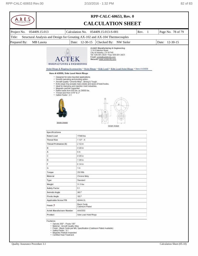
RPP-CALC-60653, Rev. 0
CALCULATION SHEET
Project No. 054409.15.013 Calculation No. 054409.15.013-S-001 Rev. 1 Page No. 78 of 79
Title: Structural Analysis and Design for Grouting AX-102 and AX-104 Thermocouples
Prepared By: MB Lasota Date: 12-30-15 Checked By: NW Sieler Date: 12-30-15
Quality Assurance Procedure 3.1 Calculation Sheet (05-10)
RPP-CALC-60653 Rev.00 2/10/2016 - 1:32 PM 82 of 83
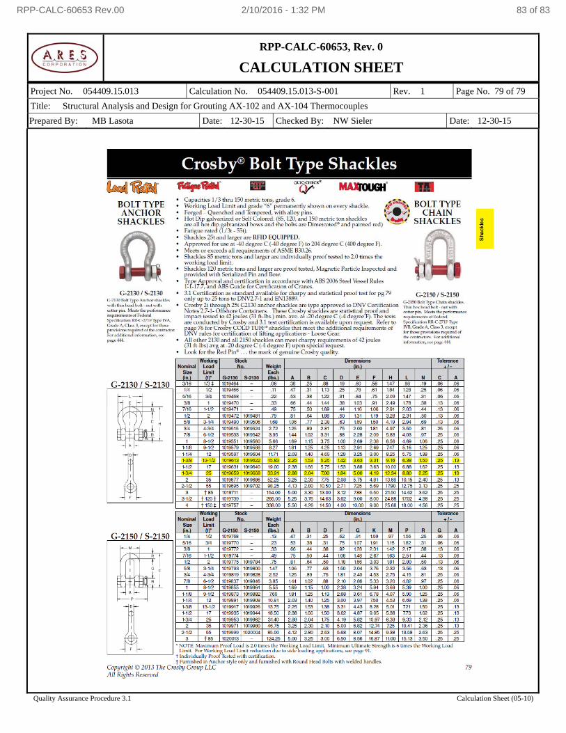
RPP-CALC-60653, Rev. 0
CALCULATION SHEET
Project No. 054409.15.013 Calculation No. 054409.15.013-S-001 Rev. 1 Page No. 79 of 79
Title: Structural Analysis and Design for Grouting AX-102 and AX-104 Thermocouples
Prepared By: MB Lasota Date: 12-30-15 Checked By: NW Sieler Date: 12-30-15
Quality Assurance Procedure 3.1 Calculation Sheet (05-10)
RPP-CALC-60653 Rev.00 2/10/2016 - 1:32 PM 83 of 83