Embed Size (px)
Citation preview

Document number: pe42.45-p-2000-99gh
Document title: Wiring diagram of electronic stability program (ESP)
Code: Designation: Position:
A1 78 AInstrument cluster
A1e17 78 AABS MIL
A1e35 78 AETS MIL
A1e36 79 AETS warning lamp
A1e47 79 ABAS/ESP malfunction indicator lamp
A1e6 77 ABrake pad wear indicator lamp
A1e7 78 ABrake fluid, parking brake and brake distribution warning lamp
A2 70 ERadio
A7/3 16 ETraction system hydraulic unit
A7/3m1 13 FHigh pressure and return pump
A7/3y10 17 FLeft rear axle solenoid valve (hold)
A7/3y11 17 FLeft rear axle solenoid valve (release)
A7/3y12 16 FRight rear axle solenoid valve (hold)
A7/3y13 17 FRight rear axle solenoid valve (release)
A7/3y24 14 FPressure circuit 1 switchover solenoid valve
A7/3y25 15 FPressure circuit 2 switchover solenoid valve
A7/3y26 15 FPressure circuit 1 inlet solenoid valve
A7/3y27 16 FPressure circuit 2 inlet solenoid valve
A7/3y6 19 FLeft front axle solenoid valve (hold)
A7/3y7 18 FLeft front axle solenoid valve (release)
A7/3y8 19 FRight front axle solenoid valve (hold)
A7/3y9 18 FRight front axle solenoid valve (release)
A7/7 24 EBAS brake booster
A7/7 26 EBAS brake booster
A7/7b1 24 EBAS diaphragm travel sensor
A7/7s1 25 FBAS release switch
A7/7y1 27 EBAS solenoid valve
B34/1 21 EESP brake pressure sensor 1
B34/2 22 EESP brake pressure sensor 2
B43 54 FLateral acceleration sensor
B45 52 FESP yaw rate sensor
F1 1 BFuse and relay module
F1 11 CFuse and relay module
F1 21 CFuse and relay module
F1 31 CFuse and relay module
F1 42 CFuse and relay module
F1 52 CFuse and relay module
F1 62 CFuse and relay module
F1 69 CFuse and relay module

Document number: pe42.45-p-2000-99gh
Document title: Wiring diagram of electronic stability program (ESP)
Code: Designation: Position:
F1f13 46 CFuse 13
F1f15 64 DFuse 15
F1f22 44 CFuse 22
F1f27 7 CFuse 27
F1k12 5 DCircuit 15 relay
F1k25 8 DHigh pressure/return pump relay
F1k6 60 DESP stop lamp suppression relay
G1 5 HBattery
L6/1 43 ELeft front wheel speed sensor
L6/1x1 42 HWheel speed sensor connector
L6/2 41 KRight front wheel speed sensor
L6/2x1 40 GWheel speed sensor connector
L6/3 73 CLeft rear wheel speed sensor
L6/3x1 72 FWheel speed sensor connector
L6/4 75 CRight rear wheel speed sensor
L6/4x1 75 FWheel speed sensor connector
N10 1 AAll-activity module
N10 11 AAll-activity module
N10 21 AAll-activity module
N10 31 AAll-activity module
N10 42 AAll-activity module
N10 52 AAll-activity module
N10 62 AAll-activity module
N10 69 AAll-activity module
N15/5 56 KElectronic selector lever module control module
N47 9 LTraction systems control module
N47 19 LTraction systems control module
N47 29 LTraction systems control module
N47 40 LTraction systems control module
N47 50 LTraction systems control module
N47 60 LTraction systems control module
N47 70 LTraction systems control module
N47 78 LTraction systems control module
N49 47 KSteering angle sensor
N71 68 KHeadlamp range adjustment control module
S10/1 31 GLeft front brake pad contact sensor
S10/1 33 GLeft front brake pad contact sensor
S10/2 34 GRight front brake pad contact sensor
S10/3 32 GLeft rear brake pad wear sensor

Document number: pe42.45-p-2000-99gh
Document title: Wiring diagram of electronic stability program (ESP)
Code: Designation: Position:
S10/3 36 GLeft rear brake pad wear sensor
S10/4 35 GRight rear brake pad contact sensor
S11 29 GBrake fluid indicator switch
S12 76 HParking brake indicator switch
S2 3 LStarter switch
S76/6 51 KESP OFF switch
S9 59 KStop lamp switch (4-pin)
U12 70 HValid for left-hand steering
U13 70 GValid for right-hand steering
U151 33 LValid for engine 113
U681 31 LUNBEKANNT
W0 31 EGround location not specified
W0 32 EGround location not specified
W0 34 EGround location not specified
W0 35 EGround location not specified
W0 36 EGround location not specified
W0 37 EGround location not specified
W16/4 5 LGround (output ground - component compartment - right)
W2 29 KGround (at right headlamp unit)
W29/2 77 CGround (right A-pillar)
W9 7 FGround (at left headlamp unit)
W9 12 EGround (at left headlamp unit)
X11/4 67 JData link connector
X12/3 4 ETerminal block (circuit 30, 15, 31, 3-pin)
X18 61 JInterior and taillamp harness connector, cockpit
X18 77 JInterior and taillamp harness connector, cockpit
X18 78 EInterior and taillamp harness connector, cockpit
X18/31 20 JLeft engine compartment/right engine compartment connector
X18/31 34 HLeft engine compartment/right engine compartment connector
X2/4 71 EABS vehicle speed signal connector
X4/37 4 FCircuit 30 terminal block
X88/17 32 HRear brake pad contact sensor connector
X88/17 37 JRear brake pad contact sensor connector
Z50/1 51 ECockpit connector sleeve (circuit 58d)
Z50/11 79 DCAN-L cockpit connector sleeve
Z50/12 78 DCAN-H cockpit connector sleeve
Z50/3 47 ECockpit connector sleeve I (circuit 31, left)
Z50/3 77 ECockpit connector sleeve I (circuit 31, left)
Z50/4 50 ECockpit connector sleeve II (circuit 31, left)

Document number: pe42.45-p-2000-99gh
Document title: Wiring diagram of electronic stability program (ESP)
Code: Designation: Position:
Z50/4 77 DCockpit connector sleeve II (circuit 31, left)
Z50/5 3 GCockpit connector sleeve (circuit 30)
Z50/9 2 GCockpit connector sleeve II (circuit 15)
Z51/1 78 GInterior connector sleeve (CAN-High 1)
Z51/2 79 GInterior connector sleeve (CAN-Low 1)
Z51/3 78 HInterior connector sleeve (CAN-High 2)
Z51/4 79 JInterior connector sleeve (CAN-Low 2)
Z51/5 44 GInterior connector sleeve (circuit 15)
Z52/14 36 HCircuit sleeve in interior, brake wear indicator
Z52/6 64 JInterior connector sleeve (circuit 54)
Z56/1 6 GConnector sleeve in left of engine compartment, circuit 31 (1)
Z56/1 12 GConnector sleeve in left of engine compartment, circuit 31 (1)
Z56/5 6 HConnector sleeve in left of engine compartment, circuit 31 (2)
Z56/6 32 JConnector sleeve in left of engine compartment, brake wear indicator
Z56/6 34 KConnector sleeve in left of engine compartment, brake wear indicator
Z57/1 29 JConnector sleeve in right of engine compartment, circuit 31 (1)
Z57/3 29 HConnector sleeve in right of engine compartment, circuit 31 (2)

© Daimler AG, 11/23/14, G/11/14, pe42.45-p-2000-99gh, Wiring diagram of electronic stability program (ESP) Page 1 of 5MODEL 163 as of 1.12.99 up to 31.8.00 with ENGINE 112, 113, 612 with CODE (472a) Electronic stability program (ESP)
191816 17151413121110987543 621
A
B
C
D
E
191816 17
G
H
J
151413121110987543 6
K
L
21
F
3rs
MM
MV
UB
AT
T
UM
RF
P
MR
U
MR
A
G1
1 2 3
30 15 31
X12/3
Z50/5
5rt
5rt
13rt
W16/4
25sw
8br
313015
15R15 5015X30 P15C
1
3
2
S2
F1
N10
313015
10
N10
5
3
1 2
N47
2
ML/A4 6
24 4823 47
Z56/5
W9
14
13
f27 40
k25
ML/C3 1
12 11
ML/B2
3hbr
30
N47
UB
AT
T
MM
V
m1
31741310691214511
y25y24
y26
y12
y13y27
y9y10
y11
y6
y8y7
2
A7/3
8 15
W9
Z56/1
46 26 27 28 29 30 31
+M
V
US
V1
AS
V1
US
V2
EV
HR
AS
V2
AV
HR 35 36 37 38 39 40
EV
HL
AV
HL
AV
VR
AV
VL
EV
VL
EV
VR
5hbr
2rt
2rt
0,5or
0,5gn
0,5rt
2rt
5hbr
2hbr
2hbr
2hbr
1or
0,5bl
0,5gr
0,5ws
0,5gr
0,5gn
0,5gn
0,5or
0,5or
0,5rs
0,5rs
0,5bl
0,5ws
F1
15
1 2 3 5
k12
27 9
Kl.1
5
C/D6
1 22
Z56/1
Z50/9
rs3
30
rt25
X4/37
▼ Affix page 2 here ▼

© Daimler AG, 11/23/14, G/11/14, pe42.45-p-2000-99gh, Wiring diagram of electronic stability program (ESP) Page 2 of 5MODEL 163 as of 1.12.99 up to 31.8.00 with ENGINE 112, 113, 612 with CODE (472a) Electronic stability program (ESP)
3735 363433323130292726242322 25212019 28
3735 363433323130292726242322 25212019 28
B1A12A11B2A10A9A7A8A6A5A4A3A2
0,5or
A1
X18/31
0,50,5rtgr
0,50,50,50,5 0,5hbrblrsgnws
0,50,50,50,5 0,5rsgrblrsgn
0,5ws
313015
SM
EM
OP
EN
MIDCLO
SE
0,5or
0,5rt
0,5gr
0,5ws
0,5hbr
0,5bl0,5
rs0,5gn
0,5ws
0,5rs
0,5gr
0,5bl
0,5rs
0,5gn
22
MV
1
21
MV
2
4653
GN
D
VS
M
21
GN
D
10
DG
2+5V
9
DG
2 S8
DG
2 M16
DG
1+5V15
DG
1 S14
DG
1 M
P
- +5VS
U
+5VS-
UP
B34/1
1 32 2 31
B34/2
431 5 221 2 31
y1
A7/7
s1
b1
A7/7
SN
7
ML/C11
MR/B8
S11
Z57/3
W2
3hbr
313015
N10 N10
N47 N47
3
y6
y8
39 40
EV
VL
EV
VR
0,5gn
0,5rs
0,5rs
1rs
5hbr
1br
F1 F1
Z57/1
0,5
U681
BB
VV
L
BB
VV
L
U151
4242
or or
Z56/6
X88/17
S10/3
1or
S10/1
X88/17
0,5Z56/6
or0,5
A
X18/31
0,5or
0,50,5or
or
0,51 0,510,5
B12A
or or
Z52/14
or or or
S10/1 S10/2 S10/4 S10/3
W0 W0 W0 W0W0 W0
▼ Affix page 3 here ▼
Cut here

© Daimler AG, 11/23/14, G/11/14, pe42.45-p-2000-99gh, Wiring diagram of electronic stability program (ESP) Page 3 of 5MODEL 163 as of 1.12.99 up to 31.8.00 with ENGINE 112, 113, 612 with CODE (472a) Electronic stability program (ESP)
5654 55535251504948464544434241 47
5654 55535251504948464544434241 47
40393837
40393837
Z51/5
N47
3130
F1
15
3130
F1
15
0,5gr
0,5rs
0,5ws
0,5blrs
0,5ws0,5
17
DR
SM 18
DR
SU 20
DR
SS 22
AY
+5V
23
AY
-S
24
AY
-M
B45
2 3 1 213
B43
N10
18 17 44 43
L6/2
4 2 1 3
12
12
L6/1
0.5ws
0.5bl
0.5bl
0.5ws
0.5bl
0.5ws
N47
DF
VL1
DF
VL0
DF
VR
1
DF
VR
0
x1
x1
N10
ML/C MR/B
UZ
114
0,5bl
14
2bl
P/D C/E
15
f22 15
S76/6N49
OF
FE
SP
LWS
716
Kl.S
igna
l
Kl.3
1
Kl.3
0
Kl.1
53 1 2 4
gngn
A
0,350,5 0,5 0,5rtbl hbr
0,350,5 0,5bl br
F
E
0,350,35wsbl
12311014 5
Z50/3
Z50/4
C/C C/B P/B C/B
Z50/1
30
10f13
0,50,5
13P/D
3
N15/5
BS
11
gn
5Shiftlock
A
rs
X88/17
A
0,5or
0,5or
W0
▼ Affix page 4 here ▼
Cut here

© Daimler AG, 11/23/14, G/11/14, pe42.45-p-2000-99gh, Wiring diagram of electronic stability program (ESP) Page 4 of 5MODEL 163 as of 1.12.99 up to 31.8.00 with ENGINE 112, 113, 612 with CODE (472a) Electronic stability program (ESP)
747372717069686765646362616059585756 66
747372717069686765646362616059585756 66
N47
N10
3130
F1
15
N10
0,5rs
rs0,5
10
M B
LU
10
X18
hbr1
1
253k6
234
BLS
313015
f15 10
2
Z52/6
1or
54
PE 82.10-2000
13
P/B5
C/B14
X11/4
9
PE 54.21-2300
PE 54.15-2000
DIA
G
0,5rs
0,5rs
P/C6
C/C11
15
0,5hbr
0,5 0,50,5 10,50,5
533 212C/D C/E C/F
F1
1
N15/5 S9
gn
5Shiftlock
AA
2 3B
1 1 32
rs rs gn ws gr bl
C/H
0,50,5
N71
DF
A H
L3
6V-Signal
bl bl
110C/D P/D
A1
DF
VR
DF
ST
DF
A V
R
N47
1 2 5
blbl
U120,5 0,5
grblbl0,5 0,50,5
U13
1 2
Navi
X2/4A2
-2000PE 54.22
x1
DF
HL0
DF
HL1
25 26
0.5 0.5rs or
L6/3
1 2
▼ Affix page 5 here ▼
Cut here
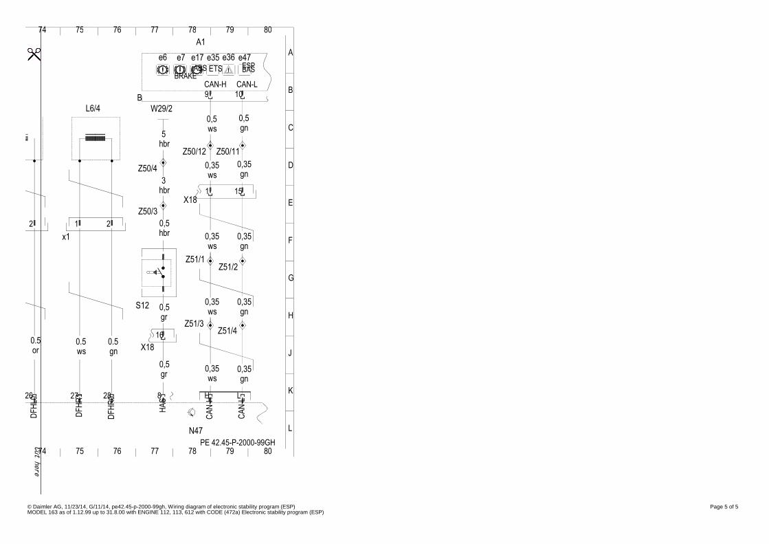
© Daimler AG, 11/23/14, G/11/14, pe42.45-p-2000-99gh, Wiring diagram of electronic stability program (ESP) Page 5 of 5MODEL 163 as of 1.12.99 up to 31.8.00 with ENGINE 112, 113, 612 with CODE (472a) Electronic stability program (ESP)
8079
A
B
7876 777574
C
D
E
G
H
J
K
L
80797876 777574
F
PE 42.45-P-2000-99GH
x1 0,350,35
gnwsgr
CA
N-L
DF
HL0
26
DF
HR
1
HA
S
CA
N-H
DF
HR
0
N47
82827 LH
gn
0,35gn
0,35
wsS12 0,5
0.5or
0.5 0.5gnws X18
0,50,35
16
Z51/3Z51/4
gr
0,35
Z51/1Z51/2
ws
W29/2L6/40,5gn
0,35gn
Z50/4ws
2
Z50/3
1 2 0,5hbr
1hbr 15X18
3
hbrZ50/12 Z50/11
0,35
0,5
5ws
e36
CAN-L
A1
B 9 10CAN-H
BRAKE
e17e7e6 e35ABS ETS
e47ESPBAS
Cut here