Embed Size (px)
Citation preview

NMS User’s GuideDocument No. NMS-A2-GB20-00
June 2005

Copyright 2005 Paradyne Corporation.All rights reserved.Printed in U.S.A.
Notice
This publication is protected by federal copyright law. No part of this publication may be copied or distributed, transmitted, transcribed, stored in a retrieval system, or translated into any human or computer language in any form or by any means, electronic, mechanical, magnetic, manual or otherwise, or disclosed to third parties without the express written permission of Paradyne Corporation, 8545 126th Ave. N., Largo, FL 33773.
Paradyne Corporation makes no representation or warranties with respect to the contents hereof and specifically disclaims any implied warranties of merchantability or fitness for a particular purpose. Further, Paradyne Corporation reserves the right to revise this publication and to make changes from time to time in the contents hereof without obligation of Paradyne Corporation to notify any person of such revision or changes.
Changes and enhancements to the product and to the information herein will be documented and issued as a new release to this manual.
Warranty, Sales, Service, and Training Information
Contact your local sales representative, service representative, or distributor directly for any help needed. For additional information concerning warranty, sales, service, repair, installation, documentation, training, distributor locations, or Paradyne worldwide office locations, use one of the following methods:
Internet: Visit the Paradyne World Wide Web site at www.paradyne.com. (Be sure to register your warranty at www.paradyne.com/warranty.)
Telephone: Call our automated system to receive current information by fax or to speak with a company representative.
— Within the U.S.A., call 1-800-870-2221
— Outside the U.S.A., call 1-727-530-2340
Document Feedback
We welcome your comments and suggestions about this document. Please mail them to Technical Publications, Paradyne Corporation, 8545 126th Ave. N., Largo, FL 33773, or send e-mail to [email protected]. Include the number and title of this document in your correspondence. Please include your name and phone number if you are willing to provide additional clarification.
Trademarks
Acculink, ADSL/R, Bitstorm, Comsphere, DSL the Easy Way, ETC, Etherloop, FrameSaver, GranDSLAM, GrandVIEW, Hotwire, the Hotwire logo, Jetstream, MVL, NextEDGE, Net to Net Technologies, OpenLane, Paradyne, the Paradyne logo, Paradyne Credit Corp., the Paradyne Credit Corp. logo, Performance Wizard, ReachDSL, StormPort, and TruePut are registered trademarks of Paradyne Corporation.
Connect to Success, Hotwire Connected, iMarc, JetFusion, JetVision, MicroBurst, PacketSurfer, Quick Channel, Reverse Gateway, Spectrum Manager, and StormTracker are trademarks of Paradyne Corporation.
All other products or services mentioned herein are the trademarks, service marks, registered trademarks, or registered service marks of their respective owners.
A June 2005 NMS-A2-GB20-00

Contents
About This GuideDocument Purpose and Intended Audience . . . . . . . . . . . . . . . . . . . . v
Document Summary . . . . . . . . . . . . . . . . . . . . . . . . . . . . . . . . . . . . . . v
Product-Related Documents . . . . . . . . . . . . . . . . . . . . . . . . . . . . . . . . vi
1 NMS IntroductionOverview . . . . . . . . . . . . . . . . . . . . . . . . . . . . . . . . . . . . . . . . . . . . . . . 1-1
System Requirements . . . . . . . . . . . . . . . . . . . . . . . . . . . . . . . . . . . . . 1-1
NMS Users. . . . . . . . . . . . . . . . . . . . . . . . . . . . . . . . . . . . . . . . . . . . . . 1-1
Default Settings . . . . . . . . . . . . . . . . . . . . . . . . . . . . . . . . . . . . . . . . . . 1-2
User Access. . . . . . . . . . . . . . . . . . . . . . . . . . . . . . . . . . . . . . . . . . 1-2
System Defaults. . . . . . . . . . . . . . . . . . . . . . . . . . . . . . . . . . . . . . . 1-2
Uplink Interface Defaults . . . . . . . . . . . . . . . . . . . . . . . . . . . . . . . . 1-3
Circuit Defaults . . . . . . . . . . . . . . . . . . . . . . . . . . . . . . . . . . . . . . . 1-4
SNMP Trap Defaults . . . . . . . . . . . . . . . . . . . . . . . . . . . . . . . . . . . 1-4
RAM and NVRAM . . . . . . . . . . . . . . . . . . . . . . . . . . . . . . . . . . . . . . . . 1-5
Local Files . . . . . . . . . . . . . . . . . . . . . . . . . . . . . . . . . . . . . . . . . . . . . . 1-5
Replacing an Interface Module . . . . . . . . . . . . . . . . . . . . . . . . . . . . . . 1-5
Replacing an Uplink Module . . . . . . . . . . . . . . . . . . . . . . . . . . . . . . . . 1-6
Clearing NVRAM . . . . . . . . . . . . . . . . . . . . . . . . . . . . . . . . . . . . . . . . . 1-6
Network Extender . . . . . . . . . . . . . . . . . . . . . . . . . . . . . . . . . . . . . 1-6
Micro DSLAM. . . . . . . . . . . . . . . . . . . . . . . . . . . . . . . . . . . . . . . . . 1-7
Mini DSLAM. . . . . . . . . . . . . . . . . . . . . . . . . . . . . . . . . . . . . . . . . . 1-7
BLC . . . . . . . . . . . . . . . . . . . . . . . . . . . . . . . . . . . . . . . . . . . . . . . . 1-7
2 Initial ConfigurationEstablishing a Connection . . . . . . . . . . . . . . . . . . . . . . . . . . . . . . . . . . 2-1
Configuring Your PC for NMS . . . . . . . . . . . . . . . . . . . . . . . . . . . . . . . 2-1
Connecting your PC to the Management Port . . . . . . . . . . . . . . . . . . . 2-2
Launching a Web Browser and Logging In . . . . . . . . . . . . . . . . . . . . . 2-2
Management Configuration . . . . . . . . . . . . . . . . . . . . . . . . . . . . . . . . . 2-4
Restoring the IP Address and Subnet Mask on Your PC. . . . . . . . . . . 2-6
Restarting the NMS . . . . . . . . . . . . . . . . . . . . . . . . . . . . . . . . . . . . . . . 2-7
NMS-A2-GB20-00 June 2005 i

Contents
3 Navigating the NMSNMS Main Window. . . . . . . . . . . . . . . . . . . . . . . . . . . . . . . . . . . . . . . . 3-1
Network Extender Front View . . . . . . . . . . . . . . . . . . . . . . . . . . . . . . . 3-2
System Reset Button . . . . . . . . . . . . . . . . . . . . . . . . . . . . . . . . . . . 3-2
Ethernet, T1, and E1 Ports and Corresponding LEDs. . . . . . . . . . 3-2
Sub Button . . . . . . . . . . . . . . . . . . . . . . . . . . . . . . . . . . . . . . . . . . . 3-3
Communication Port . . . . . . . . . . . . . . . . . . . . . . . . . . . . . . . . . . . 3-3
Power LED. . . . . . . . . . . . . . . . . . . . . . . . . . . . . . . . . . . . . . . . . . . 3-3
Micro DSLAM Chassis Front View . . . . . . . . . . . . . . . . . . . . . . . . . . . . 3-3
Power LED. . . . . . . . . . . . . . . . . . . . . . . . . . . . . . . . . . . . . . . . . . . 3-3
Management Port and Corresponding LED. . . . . . . . . . . . . . . . . . 3-3
Uplink Ports and Corresponding LEDs . . . . . . . . . . . . . . . . . . . . . 3-4
System Reset Button . . . . . . . . . . . . . . . . . . . . . . . . . . . . . . . . . . . 3-4
Communication Port . . . . . . . . . . . . . . . . . . . . . . . . . . . . . . . . . . . 3-5
SDSL Connection LEDs . . . . . . . . . . . . . . . . . . . . . . . . . . . . . . . . 3-5
Mini DSLAM Chassis Front View . . . . . . . . . . . . . . . . . . . . . . . . . . . . . 3-5
Power LED. . . . . . . . . . . . . . . . . . . . . . . . . . . . . . . . . . . . . . . . . . . 3-5
Fan LED. . . . . . . . . . . . . . . . . . . . . . . . . . . . . . . . . . . . . . . . . . . . . 3-5
Management Port . . . . . . . . . . . . . . . . . . . . . . . . . . . . . . . . . . . . . 3-6
Uplink Interface Modules and Corresponding LEDs . . . . . . . . . . . 3-6
SDSL RJ21 Cable Connector and Corresponding Port LEDs . . . . 3-6
IP DSLAM Chassis Front View . . . . . . . . . . . . . . . . . . . . . . . . . . . . . . 3-7
Uplink Modules and Corresponding LEDs. . . . . . . . . . . . . . . . . . . 3-7
Uplink Interface Modules and Corresponding LEDs . . . . . . . . . . . 3-8
Interface Modules and Corresponding LEDs. . . . . . . . . . . . . . . . . 3-8
4 System Configuration Screens
Overview . . . . . . . . . . . . . . . . . . . . . . . . . . . . . . . . . . . . . . . . . . . . . . . 4-1
Management Configuration . . . . . . . . . . . . . . . . . . . . . . . . . . . . . . . . . 4-2
Advanced Configuration. . . . . . . . . . . . . . . . . . . . . . . . . . . . . . . . . . . . 4-3
HTTP Password . . . . . . . . . . . . . . . . . . . . . . . . . . . . . . . . . . . . . . . . . . 4-4
SNMP Configuration . . . . . . . . . . . . . . . . . . . . . . . . . . . . . . . . . . . . . . 4-5
SNMP Community Administration . . . . . . . . . . . . . . . . . . . . . . . . . . . . 4-6
ii June 2005 NMS-A2-GB20-00

Contents
Global Set . . . . . . . . . . . . . . . . . . . . . . . . . . . . . . . . . . . . . . . . . . . . . . 4-7
Global Circuit Configuration for DSL Ports . . . . . . . . . . . . . . . . . . 4-8
Global Circuit Configuration for T1 or E1 Ports . . . . . . . . . . . . . . . 4-11
Allow Tag or Untag on Ingress Packet Parameter. . . . . . . . . . . . . 4-13
Global DSCP Rules . . . . . . . . . . . . . . . . . . . . . . . . . . . . . . . . . . . . 4-14
Global IP Rules . . . . . . . . . . . . . . . . . . . . . . . . . . . . . . . . . . . . . . . 4-16
Global Layer 2 Set (Micro DSLAMs and Mini DSLAMs) . . . . . . . . 4-18
Global MAC Rules . . . . . . . . . . . . . . . . . . . . . . . . . . . . . . . . . . . . . 4-20
Global Port Set (Micro DSLAMs and Mini DSLAMs) . . . . . . . . . . . 4-22
Global Advanced Configuration . . . . . . . . . . . . . . . . . . . . . . . . . . . 4-23
Global VLAN Rules . . . . . . . . . . . . . . . . . . . . . . . . . . . . . . . . . . . . 4-24
5 System Utilities
Overview . . . . . . . . . . . . . . . . . . . . . . . . . . . . . . . . . . . . . . . . . . . . . . . 5-1
Circuit Summary. . . . . . . . . . . . . . . . . . . . . . . . . . . . . . . . . . . . . . . . . . 5-2
Circuit (Port) Configuration for DSL Ports . . . . . . . . . . . . . . . . . . . 5-3
Circuit Configuration for a T1 or E1 Port . . . . . . . . . . . . . . . . . . . . 5-6
DSCP Rules. . . . . . . . . . . . . . . . . . . . . . . . . . . . . . . . . . . . . . . . . . 5-8
IP Rules . . . . . . . . . . . . . . . . . . . . . . . . . . . . . . . . . . . . . . . . . . . . . 5-10
MAC Rules. . . . . . . . . . . . . . . . . . . . . . . . . . . . . . . . . . . . . . . . . . . 5-12
VLAN Rules . . . . . . . . . . . . . . . . . . . . . . . . . . . . . . . . . . . . . . . . . . 5-14
Backbone VLAN ID . . . . . . . . . . . . . . . . . . . . . . . . . . . . . . . . . . . . 5-17
Port Statistics. . . . . . . . . . . . . . . . . . . . . . . . . . . . . . . . . . . . . . . . . 5-19
Port Copy, Single-Slot Devices . . . . . . . . . . . . . . . . . . . . . . . . . . . 5-21
Port Copy, Multi-Slot Devices . . . . . . . . . . . . . . . . . . . . . . . . . . . . 5-22
SNR Advanced Configuration . . . . . . . . . . . . . . . . . . . . . . . . . . . . 5-23
Circuit Search. . . . . . . . . . . . . . . . . . . . . . . . . . . . . . . . . . . . . . . . . . . . 5-24
DSLAM Users . . . . . . . . . . . . . . . . . . . . . . . . . . . . . . . . . . . . . . . . . . . 5-26
Diagnostics. . . . . . . . . . . . . . . . . . . . . . . . . . . . . . . . . . . . . . . . . . . . . . 5-27
Loop Detect Summary . . . . . . . . . . . . . . . . . . . . . . . . . . . . . . . . . . 5-27
BERT Screen. . . . . . . . . . . . . . . . . . . . . . . . . . . . . . . . . . . . . . . . . 5-29
6 Virtual Front Panel ButtonsOverview . . . . . . . . . . . . . . . . . . . . . . . . . . . . . . . . . . . . . . . . . . . . . . . 6-1
DSLAM Interconnect Configuration (4929 and Micro DSLAM) . . . . . . 6-2
EAPS Button . . . . . . . . . . . . . . . . . . . . . . . . . . . . . . . . . . . . . . . . . . . . 6-4
MAC and IGMP Summary . . . . . . . . . . . . . . . . . . . . . . . . . . . . . . . . . . 6-6
Statistics Button . . . . . . . . . . . . . . . . . . . . . . . . . . . . . . . . . . . . . . . . . . 6-11
Sub Button . . . . . . . . . . . . . . . . . . . . . . . . . . . . . . . . . . . . . . . . . . . . . . 6-13
NMS-A2-GB20-00 June 2005 iii

Contents
7 Troubleshooting the NMSProblems and Solutions . . . . . . . . . . . . . . . . . . . . . . . . . . . . . . . . . . . . 7-1
PC Cannot Locate Web Server . . . . . . . . . . . . . . . . . . . . . . . . . . . 7-1
Lost Web Server Connection. . . . . . . . . . . . . . . . . . . . . . . . . . . . . 7-1
Cannot Establish Web Server Connection From Within Network . 7-2
Web Pages Are Loading Slowly . . . . . . . . . . . . . . . . . . . . . . . . . . 7-2
A Connector Pin Assignments
10/100BaseT MGMT Connector . . . . . . . . . . . . . . . . . . . . . . . . . . . . . A-1
Index
iv June 2005 NMS-A2-GB20-00

About This Guide
Document Purpose and Intended Audience
This guide describes the web-based Network Management System (NMS) used for configuration and management of select Network Extenders, Micro DSLAMs, Mini DSLAMs, the MUM2000-2 Multiplexer Uplink Module, and the BSX8000-5 Broadband Services Switch.
Document Summary
A master glossary of terms and acronyms used in Paradyne documents is available online at www.paradyne.com. Select Support → Technical Manuals → Technical Glossary.
Section Description
Chapter 1, NMS Introduction Describes the system requirements for the NMS, lists primary device defaults, and describes the use of RAM and NVRAM in NMS-managed devices.
Chapter 2, Initial Configuration Explains how to set up a Windows PC for initial access to the NMS.
Chapter 3, Navigating the NMS Describes the main window and menus of the NMS.
Chapter 4, System Configuration Screens
Describes the System Configuration screens.
Chapter 5, System Utilities Describes the System Utilities screens.
Chapter 6, Virtual Front Panel Buttons
Describes the virtual function buttons available on the graphical depictions of the devices in the NMS.
Chapter 7, Troubleshooting the NMS
Lists some typical problems and solutions.
Appendix A, Connector Pin Assignments
Shows the pinouts of the management port used for access to the NMS.
Index Lists key terms, concepts, and sections in alphabetical order.
NMS-A2-GB20-00 June 2005 v

About This Guide
Product-Related Documents
Complete documentation for Paradyne products is available online at www.paradyne.com. Select Support → Technical Manuals. Documents related to this manual include:
To order a paper copy of a Paradyne document, or to speak with a sales representative, please call 1-727-530-2000.
Document Number Document Title
CLI-A2-GB20 Command Line Interface for 4000E and 12000E BACs, Micro DSLAMs, and Network Extenders User's Guide
MTM-A2-GB20 Multimedia Traffic Management User's Guide
SNMP-A2-GB20 SNMP for 12000/4000 BLCs and Micro DSLAMs User's Guide
vi June 2005 NMS-A2-GB20-00
NMS-A2-GB20-00 June 2005
1
NMS IntroductionOverview
Paradyne’s Network Management System (NMS) allows you to access statistical and configuration data through a web server residing within the firmware of select Network Extenders, Micro DSLAMs, Mini DSLAMs, and MUM2000-2 Multiplexer Uplink Modules and BSX8000-5 Broadband Services Switches installed in 4000 and 12000 BLCs.
System Requirements
The following are required for use of the NMS:
A straight-through RJ45 to RJ45 Ethernet Cable
Required for establishing a direct connection from the Network Extender, Micro DSLAM, Mini DSLAM, or BLC management port to your PC for initial configuration.
Web Browser
Required for running NMS. Compatible web browsers include Microsoft Internet Explorer (version 4.0 or higher) and Netscape Navigator (version 4.0 or higher). NMS is optimized for use with Internet Explorer.
Use your browser's default settings when running NMS. JavaScript must be enabled.
Set your screen resolution to 1024 x 768 pixels or higher for optimum viewing of NMS screens.
NMS Users
There are two classes of NMS users: General users and Superusers. General users have read-only access and cannot make any changes. Superusers have full access to make changes and update configurations. The NMS supports up to three Superusers or three General users simultaneously. Only one class of user can log in at the one time, else a "Server Busy..." warning message appears.
See Table 1-1 for the default usernames and passwords.
1-1
1. NMS Introduction
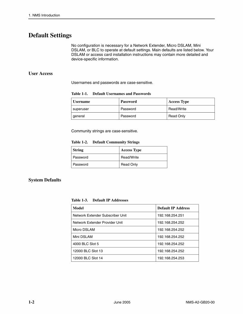
Default Settings
No configuration is necessary for a Network Extender, Micro DSLAM, Mini DSLAM, or BLC to operate at default settings. Main defaults are listed below. Your DSLAM or access card installation instructions may contain more detailed and device-specific information.
User Access
Usernames and passwords are case-sensitive.
Community strings are case-sensitive.
System Defaults
Table 1-1. Default Usernames and Passwords
Username Password Access Type
superuser Password Read/Write
general Password Read Only
Table 1-2. Default Community Strings
String Access Type
Password Read/Write
Password Read Only
Table 1-3. Default IP Addresses
Model Default IP Address
Network Extender Subscriber Unit 192.168.254.251
Network Extender Provider Unit 192.168.254.252
Micro DSLAM 192.168.254.252
Mini DSLAM 192.168.254.252
4000 BLC Slot 5 192.168.254.252
12000 BLC Slot 13 192.168.254.252
12000 BLC Slot 14 192.168.254.253
1-2 June 2005 NMS-A2-GB20-00

1. NMS Introduction
Uplink Interface Defaults
Table 1-4. Default Management Parameters
Parameter Default
Gateway 0.0.0.0
Inband Management disabled
Inband Management VLAN ID 0 (off)
Mgmt (Management) IP Address Filter Range
0.0.0.0 - 255.255.255.255 (all)
Subnet Mask 255.255.255.0
TFTP (Trivial File Transfer Protocol)
on
Uplink DSLAM Interconnection 1 (neither/off)
Table 1-5. Default 10/100BaseT Ethernet Uplink Settings
Parameter Setting
Duplex Mode Auto-Negotiate
Speed Auto-Negotiate
Table 1-6. Default E1 Uplink Parameters
Parameter Default
Frame Type CRC (Cyclic Redundancy Check)
Line Code HDB3 (High Density Bipolar 3)
Table 1-7. Default T1 Uplink Parameters
Parameter Default
Frame Type ESF (Extended Super Frame)
Line Code B8ZS (Bipolar with 8 Zero Substitution)
Line Buildout 0 dB
NMS-A2-GB20-00 June 2005 1-3

1. NMS Introduction
Circuit Defaults
Circuit defaults common to all devices are listed below. For information regarding model specific circuit parameters, refer to the Network Extender, interface module, Micro DSLAM, or Mini DSLAM Installation Instructions specific to the model you are installing.
SNMP Trap Defaults
Table 1-8. Default Circuit Parameters
Parameter Default
Backbone-VLAN 0 (off)
Circ. ID (Circuit Identification) n/a (no default)
Flood Upl (Uplink)
IP Range 1 0.0.0.0 – 255.255.255.255
IP Range 2 0.0.0.0 – 0.0.0.0
Pri (VLAN Priority) 0 (none)
Protocol All (all traffic)
VLAN Range 0–0 (off)
Table 1-9. Default Notification IP Addresses
Parameter Default
IP Address 1 0.0.0.0
IP Address 2 0.0.0.0
IP Address 3 0.0.0.0
IP Address 4 0.0.0.0
Table 1-10. Default SNMP Trap Settings
Parameter Default
Authentication Trap enabled*
* No trap is sent until a notification IP address is defined.
Environment Trap enabled*
Cold Start Trap disabled
Module/Port Trap disabled
1-4 June 2005 NMS-A2-GB20-00

1. NMS Introduction
RAM and NVRAM
Configuration backup is inherent in Paradyne’s Network Extenders, Micro DSLAMs, Mini DSLAMs, and 4000 and 12000 BLCs. Upon intial power up, default parameters will remain in place unless changed through the NMS or SNMP. Once changed, new configurations will automatically be recorded in both Random Access Memory (RAM) and Non-Volatile RAM (NVRAM). Although data stored in RAM will be erased if the unit loses power, data stored within NVRAM will remain intact permanently unless deliberately cleared or reconfigured.
Local Files
Individual port configurations can be saved locally on your PC as a backup and/or for use as a template for future configurations. Once a device has been configured as desired, the settings can be uploaded through a Trivial File Transfer Protocol (TFTP) tool with a GET command and the following information:
Host name: [DSLAM IP Address]Remote filename: NVR_CFG.bin.[superuser password]Local filename: [user preference]
Port configuration files also can be downloaded from a local file to a DSLAM or BLC using a TFTP SET command. Refer to your TFTP user manual for further instructions.
Only individual port configurations can be saved to a local file. Chassis configurations cannot be uploaded or downloaded; they must be manually configured for each unit.
Replacing an Interface Module
Table 1-11, Replacing an Interface Module, shows how configurations are affected by the replacement of an interface module.
A replacement module (of like model) will take on the same configurations as the previous module only if the MUM or BSX remains in the chassis and the chassis retains power during the interim. Otherwise the replacement module will revert to original default settings.
Table 1-11. Replacing an Interface Module
If the replacement interface module is: Then module configurations will revert to:
Same model as previous, new or unconfigured Same configurations as previous module
Same model as previous, already configured Same configurations as previous module
Different model than previous, new or unconfigured Original default settings (see Default Settings on page 1-2)
Different model than previous, already configured Original default settings (Default Settings on page 1-2)
NMS-A2-GB20-00 June 2005 1-5

1. NMS Introduction
Replacing an Uplink Module
Clear the NVRAM of a previously configured MUM or BSX before using it as a replacement in a different chassis. Once NVRAM has been cleared, the MUM or BSX will revert to default settings.
A replacement MUM or BSX will take on the same NMS configurations as the previous MUM or BSX only if there is at least one interface module installed in the BLC and the BLC retains power during the interim. Otherwise, the replacement module will revert to original NMS default settings.
NOTE
SNMP configurations will always revert to original default settings, regardless of whether the replacement MUM is new and unconfigured or power is sustained.
Clearing NVRAM
Clearing NVRAM on a BLC, Micro DSLAM, Mini DSLAM, or Network Extender will restore all chassis and port configurations to original default settings.
CAUTION
Clearing NVRAM to restore original default settings includes restoring the default IP Address, Subnet Mask, and Gateway. Additionally, Inband Management will revert to its original default setting (OFF) and you will be required to establish a direct connection with the Network Extender, Micro DSLAM, Mini DSLAM, or BLC for any subsequent configuration.
Network Extender
The reset button is located behind a small hole on the left side of the faceplate of the Network Extender. Use a straightened paper clip to gently push the button. Wait a few seconds until the Port LEDs flash green. Gently push the reset button again during the time that the LEDs are flashing. NVRAM is cleared, and all configurations on the unit are set to the factory defaults.
Table 1-12. Replacing a MUM or BSX
If the replacement uplink module is: Then the uplink module will revert to:
Same model as previous, new or unconfigured Same configurations as previous uplink module
Different model than previous, new or unconfigured Same configurations as previous uplink module
1-6 June 2005 NMS-A2-GB20-00

1. NMS Introduction
Micro DSLAM
NVRAM on the Micro DSLAM can only be cleared using Command Line Interface (CLI). See the CLI User’s Guide. The Reset Button on the Micro DSLAM will reboot the unit but will not clear NVRAM. To reboot, use a paperclip, mechanical pencil, or similar tool to press and hold the Reset Button on the front of the chassis for 10 seconds, or click the Reset Button depicted in the NMS Micro DSLAM Main Window, then click on Yes and Submit.
Mini DSLAM
Using a paperclip, mechanical pencil or similar tool, press and hold the Reset Button on the front, left-hand side of the chassis for 10 seconds.
BLC
Install the MUM or BSX you wish to clear into a powered 4000 or 12000 BLC devoid of interface modules. (If there are interface modules installed in the BLC, it is not necessary to completely remove them. Slide them out of the chassis far enough to disengage the interface module connector at the back of the chassis and ensure that the power LED on the interface module is no longer illuminated.) Allow a minimum of 40 seconds to pass with the MUM or BSX running in the chassis before reinstalling any of the interface modules.
NMS-A2-GB20-00 June 2005 1-7

1. NMS Introduction
1-8 June 2005 NMS-A2-GB20-00

NMS-A2-GB20-00 June 2005
2
Initial ConfigurationEstablishing a Connection
Connecting to the NMS comprises these steps:
Configuring your PC. See Configuring Your PC for NMS on page 2-1.
Connecting your PC to the device to be configured. See Connecting your PC to the Management Port on page 2-2.
Opening the NMS with your web browser. See Launching a Web Browser and Logging In on page 2-2.
For a Network Extender, you must use the Command Line Interface to establish the Network Extender’s IP address. See the installation instructions for your Network Extender for information.
Configuring Your PC for NMS
To access the NMS directly, your PC must be on the same subnet as the device you connect to. The following instructions are for a Windows XP operating system.
Procedure
To configure a PC for use with the NMS:
1. In the Windows task bar, click on the Start button, and then click on ControlPanel.
2. Double-click on the Network Connections icon.
3. In the LAN or High-Speed Internet window, right-click on the icon corresponding to your network interface card (NIC) and select Properties. (Often this icon is labeled Local Area Connection.) The Local Area Connection dialog box is displayed with a list of currently installed network items.
4. Ensure that the check box to the left of the item labeled Internet Protocol (TCP/IP) is checked, and click on Properties.
5. Write down the current IP Address and Subnet Mask in the Internet Protocol (TCP/IP) Properties dialog box. When you are done using NMS, you will need to reconfigure your PC with these values.
2-1

2. Initial Configuration
6. In the Internet Protocol (TCP/IP) Properties dialog box, click in the radio button labeled “Use the following IP address” and type 192.168.254.x (where x is any number between 3 and 250, inclusive) in the IP Address field.
7. Type 255.255.255.0 in the Subnet Mask field.
8. Click on OK twice to confirm your changes, and close the Control Panel.
Connecting your PC to the Management Port
The MGMT (Management) Port does not have switching capabilities; its main purpose is to allow a direct PC connection for SNMP and NMS access. A direct connection with the MGMT Port may also be used to access the management system with Command Line Interface (CLI) via Telnet (see the CLI User’s Guide).
The 10/100 Ethernet MGMT Port auto-negotiates speed and duplex mode; these configurations cannot be set on the Micro DSLAM, Mini DSLAM, or BLC. For the best configuration results, your PC should be set to auto-negotiate speed and duplex mode as well. If your PC cannot be configured to auto-negotiate, speed may be set at either 10 Mbps or 100 Mbps but duplex mode must be set to Half Duplex; a 10/100BaseT Ethernet MGMT connection cannot be made if your PC is set to Full Duplex.
Using a straight-through Ethernet cable (see 10/100BaseT MGMT Connector in Appendix A, Connector Pin Assignments), connect your PC to the Ethernet RJ45 MGMT Port on the front of the Micro DSLAM, Mini DSLAM, MUM, or BSX faceplate and verify the connection. The MGMT LED will illuminate green or amber (depending on the unit) to indicate an Ethernet connection has been established.
On a Network Extender, which has no management port, you can connect a PC to one of the Ethernet ports. See the installation instructions for your Network Extender for information.
Launching a Web Browser and Logging In
You can now access the NMS via the default IP address.
Procedure
1. Launch a web browser such as Microsoft Internet Explorer or Netscape Navigator.
2. Type the Micro DSLAM, Mini DSLAM, or uplink module's default IP address (see Table 2-1, Default IP Addresses) into the address field at the top of the browser window and press the Enter key.
2-2 June 2005 NMS-A2-GB20-00

2. Initial Configuration
3. The NMS Log In window will pop up. Enter default username (superuser) and password (Password). Both are case-sensitive. You must log in as a superuser to make configuration changes.
4. Click on OK.
Once you have logged into the NMS, use the Tab key or your mouse to move from field to field rather than pressing the Enter key. Internet Explorer equates pressing the Enter key with clicking on the Submit button.
Table 2-1. Default IP Addresses
Default IP Address DSLAM Type or Slot Where Uplink Card Resides
192.168.254.251 Network Extender Subscriber Unit
192.168.254.252 Network Extender Provider Unit, Micro or Mini DSLAM, 4000 BLC Slot 5, or 12000 BLC Slot 13
192.168.254.253 12000 BLC Slot 14
NMS-A2-GB20-00 June 2005 2-3
2. Initial Configuration
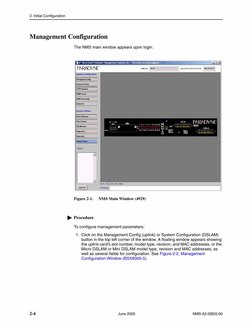
Management Configuration
The NMS main window appears upon login.
Figure 2-1. NMS Main Window (4929)
Procedure
To configure management parameters:
1. Click on the Management Config (uplink) or System Configuration (DSLAM) button in the top left corner of the window. A floating window appears showing the uplink card’s slot number, model type, revision, and MAC addresses, or the Micro DSLAM or Mini DSLAM model type, revision and MAC addresses, as well as several fields for configuration. See Figure 2-2, Management Configuration Window (BSX8000-5).
2-4 June 2005 NMS-A2-GB20-00

2. Initial Configuration
Figure 2-2. Management Configuration Window (BSX8000-5)
2. Select or enter the following parameters. Not all fields are available for all devices.
Table 2-2. Management Configuration Parameters (1 of 2)
Parameter Description
IP Address Specify the management IP address for the DSLAM.
Subnet Mask Specify the subnet mask for the IP address.
Gateway Specify the first-hop gateway address.
EtherType Select the type of packets supported by your router. This is used only for backbone VLAN (Q in Q) traffic.
Inband MGMT Check this box if you will use inband management (that is, you will allow the device to be contacted by ports other than the MGMT port).
For security purposes, disable inband management when it is not in use.
VLAN Id Specify a VLAN identifier for inband management.
Priority Specify a priority (0–7) for inband management traffic.
NMS-A2-GB20-00 June 2005 2-5

2. Initial Configuration
3. Click on Submit and exit your web browser.
NMS connectivity will be lost immediately upon clicking the Submit button; you must close your web browser,
If you have a 12000 BLC with two uplink modules installed (one in slot 13 and one in slot 14), you need to set the system configuration fields for both. Reconfigure the IP Address and Subnet Mask on your PC and then re-launch your web browser.
Restoring the IP Address and Subnet Mask on Your PC
You must now return the IP address and subnet mask of the NIC in your PC back to the original values. The following instructions are for a Windows XP operating system.
Procedure
To return the TCP/IP parameters of your PC back to the original values:
1. In the Windows task bar, click on the Start button, and then click on Control Panel.
2. Double-click on the Network Connections icon.
3. In the LAN or High-Speed Internet window, right-click on the icon corresponding to your network interface card (NIC) and select Properties. (Often this icon is labeled Local Area Connection.) The Local Area Connection dialog box is displayed with a list of currently installed network items.
Flood Configuration Flood refers to the method in which interface modules handle unknown unicasts, unknown broadcasts, and unknown multicasts for each port.
Uplink – Any traffic with VLAN IDs that match a VLAN ID that has been configured to Uplink flood (default) will be allowed to flow from DSL ports to uplinks only (not DSL port to DSL port).
VLAN – Any traffic with VLAN IDs that match a VLAN ID that has been configured to VLAN flood will be allowed to flow from DSL port to uplinks and DSL port to DSL port.
Flood Membership Configuration
Specify the VLAN membership of the uplink ports (four fixed ports and any MIM ports).
By default all uplinks are members of all VLANs. However you can change it such that an uplink port is a member of only a certain set of VLAN IDs. In this case any traffic on an uplink port with a VLAN ID that the uplink port is not a member of, will be dropped.
Table 2-2. Management Configuration Parameters (2 of 2)
Parameter Description
2-6 June 2005 NMS-A2-GB20-00

2. Initial Configuration
4. Ensure that the check box to the left of the item labeled Internet Protocol (TCP/IP) is checked, and click on Properties.
5. In the Internet Protocol (TCP/IP) Properties dialog box, depending upon which option was selected prior to entering the default IP Address and Subnet Mask (as described in Configuring Your PC for NMS on page 2-1), do one of the following:
— Click Obtain an IP Address Automatically
or
— Click Specify an IP Address and then manually enter your local IP Address and Subnet Mask
6. Click on OK twice to confirm your changes, and close the Control Panel.
Restarting the NMS
You may continue to access the NMS using a direct connection to the device. Alternatively, if you enabled inband management, you can access the NMS via a remote network connection.
Procedure
To access the NMS after setting its IP address:
1. Open a web browser. Type the device's new IP Address in the address field at the top of the browser window and press the Enter key.
2. Log in using the default username (superuser) and password (Password).
3. Make additional configuration changes as desired. For security purposes, it is a good idea to immediately change the default passwords and community names.
4. Save port configurations to a local file. Individual port configurations can be saved locally on your PC as a backup, or for use as a template for future configurations. See Local Files in Chapter 1, NMS Introduction.
5. When configuration is complete, log out (close the NMS window). If you forget to log out, the NMS will automatically request a password after five minutes of inactivity.
CAUTION
If you leave your workstation without logging out and another user accesses the NMS before your password expires, the new user will have full access to the management system without being required to log in.
NMS-A2-GB20-00 June 2005 2-7

2. Initial Configuration
2-8 June 2005 NMS-A2-GB20-00

NMS-A2-GB20-00 June 2005
3
Navigating the NMSNMS Main Window
The NMS main window consists of two sections: a chassis front view which provides an at-a-glance illustration of module and port status, and an administration panel with buttons and fields for system management. Views vary among the Network Extenders, Micro DSLAMs, Mini DSLAMs, and BLCs.
Figure 3-1. NMS Main Window
3-1

3. Navigating the NMS
Network Extender Front View
Figure 3-2. Micro DSLAM and its Depiction in the NMS
System Reset Button
Clicking on the System Reset Button on the left side of the faceplate invokes the Network Extender Reset Window. Click on Yes or No, then click on the Submit Button. A system reset will clear NMS statistical data and restart counter values at zero; it will not clear the configuration.
Ethernet, T1, and E1 Ports and Corresponding LEDs
Depending on model, Network Extenders support 10/100BaseT Ethernet and T1 or E1 uplink connections.
Table 3-1. Network Extender Port LEDs
Port LED Color Indication
1–4 10/100
Green 100 Mbps uplink connection established
Amber 10 Mbps uplink connection established
Red No link
Gray Administratively disabled
1–4 or 1–8 T1 or E1
Green Connection established
Red No link
Gray Administratively disable
3-2 June 2005 NMS-A2-GB20-00

3. Navigating the NMS
Sub Button
The Sub button, if present, allows you to select whether the unit is a Provider or Subscriber. Note that the default IP address of the unit changes if the subscriber status changes.
Communication Port
The COM Port is depicted in the middle of the faceplate and has no corresponding LED. There are no configurable elements for the COM Port; it simply allows for a direct connection with your PC for the purpose of system management via Command Line Interface (CLI). See your Network Extender Installation Instructions and the CLI User’s Guide for further information.
Power LED
The Power LED is a solid green LED on the right side of the faceplate.
Micro DSLAM Chassis Front View
Figure 3-3. Micro DSLAM and its Depiction in the NMS
Power LED
The Power LED is a solid green LED on the left-hand side of the chassis faceplate.
Management Port and Corresponding LED
On the SµD6011, the Management Port is the first port on the left, labeled MGMT/1. The corresponding LED is LED 1, to the left of the ports.
NMS-A2-GB20-00 June 2005 3-3

3. Navigating the NMS
The COM port of the AµD8000 has no corresponding LED.
Uplink Ports and Corresponding LEDs
The Micro DSLAMs support 10/100BaseT Ethernet, T1, and E1 uplink connections. The number and placement of uplink ports depends upon the Micro DSLAM model type. If you have a 10/100BaseT Ethernet uplink port, it will be labeled as 10/100 (Port) 2. T1 or E1 uplink ports are (Ports) 2–4 depending on whether or not you have a 10/100BaseT Ethernet uplink and how many uplink ports your Micro DSLAM model has. The corresponding LEDs are LEDs 2–4, located to the left of the MGMT and uplink ports.
System Reset Button
Clicking on the System Reset Button invokes the µDSLAM Reset Window. Click on Yes or No, then click on the Submit Button. A system reset will clear NMS statistical data and restart counter values at zero; it will not clear the configuration.
Table 3-2. Micro DSLAM MGMT Port LED
Port LED Color Indication
1 [MGMT] Green 100 Mbps management connection established
Amber 10 Mbps management connection established
Gray no management connection
Table 3-3. Micro DSLAM Uplink Port LEDs
Port LED Color Indication
1–4 (10/100)
Green 100 Mbps uplink connection established
Amber 10 Mbps uplink connection established
Red No link
Gray Administratively disabled
1–4 or 1–8 (T1)
Green Uplink connection established
Red No link
Gray Administratively disable
1–4 or 1–8 (E1)
Green Uplink connection established
Red No link
Gray Administratively disable
3-4 June 2005 NMS-A2-GB20-00

3. Navigating the NMS
Communication Port
The COM Port is depicted in the middle of the chassis faceplate and has no corresponding LED. There are no configurable elements for the COM Port; it simply allows for a direct connection with your PC for the purpose of system management via Command Line Interface (CLI). See your Micro DSLAM Installation Instructions and the CLI User’s Guide for further information.
SDSL Connection LEDs
SDSL Connection LEDs are depicted on the right of the chassis faceplate. There are either 6 or 12 SDSL LEDs depending upon the Micro DSLAM model type.
Mini DSLAM Chassis Front View
Figure 3-4. Mini DSLAM
Power LED
The Power LED is a solid green LED on the left-hand side of the chassis faceplate.
Fan LED
The Fan LED is on the left side of the chassis faceplate and denotes the status of the four fans inside the Mini DSLAM.
Table 3-4. Micro DSLAM SDSL Connection LEDs
Port LED Color Indication
1-6 or 1-12SDSL Connection
Green SDSL connection established
Red Non-functional SDSL connection
Gray No SDSL connection
Table 3-5. Mini DSLAM Fan LED
LED Color Indication
Fan Green All fans are functioning
Amber At least one fan has failed
Red All four fans have failed
NMS-A2-GB20-00 June 2005 3-5

3. Navigating the NMS
Management Port
The Management (MGMT) Port is depicted on the left side of the chassis faceplate and has no corresponding LED.
Uplink Interface Modules and Corresponding LEDs
Mini DSLAMs support 10/100 Ethernet, T1, E1, DS3 and E3 Uplink Interface Modules (UIMs). The slot on the left is UIM Port 1 and the slot on the right is UIM Port 2. Only one UIM is required for operational purposes; a second UIM may be installed for redundancy.
SDSL RJ21 Cable Connector and Corresponding Port LEDs
The SDSL RJ21 cable connector is depicted on the far right of the chassis faceplate. To the left of the connector are the corresponding SDSL port LEDs: twelve or twenty-four, depending upon the Mini DSLAM model type being installed.
Table 3-6. Mini DSLAM UIM LEDs
UIM LED Color Indication
10/100 Ethernet Green Uplink connection is established
Red No link
Gray Administratively disabled
T1/E1 Green Uplink connection is established
Red No link
Gray Administratively disabled
DS3/E3 Green Uplink connection is established
Red No link
Gray Administratively disabled
Table 3-7. Mini DSLAM SDSL Port LEDs
Port LED Color Indication
1–12 or 1–24SDSL Connection
Green SDSL connection established
Red no SDSL connection
Gray no SDSL connection
3-6 June 2005 NMS-A2-GB20-00

3. Navigating the NMS
IP DSLAM Chassis Front View
Figure 3-5. 4000 BLC and its Depiction in the NMS
Model 12000 BLCs have 14 slots (numbered left to right); slots 1–12 house interface modules and slots 13–14 house Broadband Switches (BSXs) or Multiplexer Uplink Modules (MUMs). Model 4000 BLCs have 5 slots (numbered from bottom to top); slots 1–4 house interface modules and slot 5 houses a BSX or a MUM.
Uplink Modules and Corresponding LEDs
Only one uplink module (a BSX or MUM) is required for operational purposes, although a second uplink module may be installed for redundancy in a 12000 BLC. Uplink modules have two LEDs shown at the top (left in the 4000 BLC) of the module: the Fan LED is on the left (bottom) and the Power LED is on the right (top). On the BSX, there is an OK LED between the other two.
Table 3-8. Uplink Module LEDs (1 of 2)
LED Color Indication
FAN Green All four fans are functioning
Amber At least one fan has failed
Red All fans have failed
NMS-A2-GB20-00 June 2005 3-7

3. Navigating the NMS
Uplink Interface Modules and Corresponding LEDs
MUMs support 10/100BaseT, T1, E1, DS3, and E3 Uplink Interface Modules (UIMs). The top slot (left slot for the 4000 BLC) in a MUM faceplate is UIM Port 1 and the bottom (right) slot is UIM Port 2. Only one UIM is required in a MUM for operational purposes, although a second UIM may be installed for redundancy.
Interface Modules and Corresponding LEDs
Models 4000 and 12000 BLCs support IDSL, SDSL, ADSL, T1, and E1 interface modules. Any interface module may be installed in any slot 1–12 on the 12000 BLC or 1–4 on the 4000 BLC.
OK Green (BSX8000-5 only.) The uplink module is functional.
POWER Green Chassis is powered
Table 3-8. Uplink Module LEDs (2 of 2)
LED Color Indication
Table 3-9. UIM LEDs
UIM LED Color Indication
10/100 Ethernet Green Uplink connection is established
Red No link
Gray Administratively disabled
T1/E1 Green Uplink connection is established
Red No link
Gray Administratively disabled
DS3/E3 Green Uplink connection is established
Red No link
Gray Administratively disabled
Table 3-10. 4000 and 12000 BLC Interface Module LEDs
Port LED Indication
DSL Green DSL connection established
Red No link
Gray Administratively disabled
T1/E1 Green T1/E1 connection established
Red No link
Gray Administratively disabled
3-8 June 2005 NMS-A2-GB20-00

NMS-A2-GB20-00 June 2005
4
System Configuration ScreensOverview
System Configuration screens include:
Management Configuration – Used to set the unit’s IP address. See Management Configuration on page 4-2.
Advanced Configuration – Used to set the system name and communication restrictions. See Advanced Configuration on page 4-3.
HTTP Password – Used to set new passwords. See HTTP Password on page 4-4.
SNMP Configuration – Used to specify SNMP trap notification addresses and enable traps. See SNMP Configuration on page 4-5.
SNMP Community – Used to set community names. See SNMP Community Administration on page 4-6.
Global Set – Used to set global parameters for traffic management. See Global Set on page 4-7.
4-1

4. System Configuration Screens
Management Configuration
Use the Management Configuration screen to set the unit’s IP address and other management parameters.
Procedure
To configure management parameters:
1. From the home screen, click on the Management Config button. The Management Configuration screen appears.
2. Select or enter the following parameters:
3. Click on Submit.
Parameter Description
IP Address Specify the management IP address for the DSLAM.
Subnet Mask Specify the subnet mask for the IP address.
Gateway Specify the first-hop gateway address.
Inband MGMT Check this box if you will use inband management through MIM ports or ADSL ports.
VLAN Id Specify the VLAN to use for inband management.
Priority Specify the 802.1p priority (0–7) to be applied to the VLAN.
4-2 June 2005 NMS-A2-GB20-00

4. System Configuration Screens
Advanced Configuration
Use the Advanced Configuration screen to set the unit’s system name and other parameters.
Procedure
To configure advanced system parameters:
1. From the home screen, click on the Advanced Config button. The Advanced Configuration screen appears.
2. Select or enter the following parameters:
3. Click on Submit.
Parameter Description
System Name Specify a name to identify the DSLAM.
System Location Specify location information to further identify the DSLAM.
IP Range Specify a range of IP addresses from which management traffic is accepted. If your PC’s IP address is outside the range, contact with the DSLAM will be lost when you click on Submit.
Communication Tools Click in the On or Off buttons to enable or disable TFTP and Telnet on this DSLAM.
NMS-A2-GB20-00 June 2005 4-3

4. System Configuration Screens
HTTP Password
Use the HTTP Password screen to set the password for the General and Superuser logins.
Procedure
To configure HTTP passwords:
1. From the home screen, click on the HTTP Password button. The HTTP Password Administration screen appears.
2. Select or enter the following parameters:
3. Click on Submit.
Parameter Description
Old Password Specify the current password for the General or Superuser login. The default setting is Password.
New Password Specify the new password for the General or Superuser login.
Confirm New Type the new password again.
4-4 June 2005 NMS-A2-GB20-00

4. System Configuration Screens
SNMP Configuration
Use the SNMP Configuration screen to enable traps and establish trap managers..
Procedure
To configure SNMP parameters:
1. From the home screen, click on the SNMP Config button. The SNMP Configuration screen appears.
2. Select or enter the following parameters:
3. Click on Submit.
Parameter Description
SNMP Notification IP Specify the IP addresses of hosts that are to receive trap notifications.
SNMP Traps Click in the check boxes to enable or disable SNMP traps:
snmpAuthentication
snmpEnvironment
snmpColdStart
snmpModule/Port
NMS-A2-GB20-00 June 2005 4-5
4. System Configuration Screens
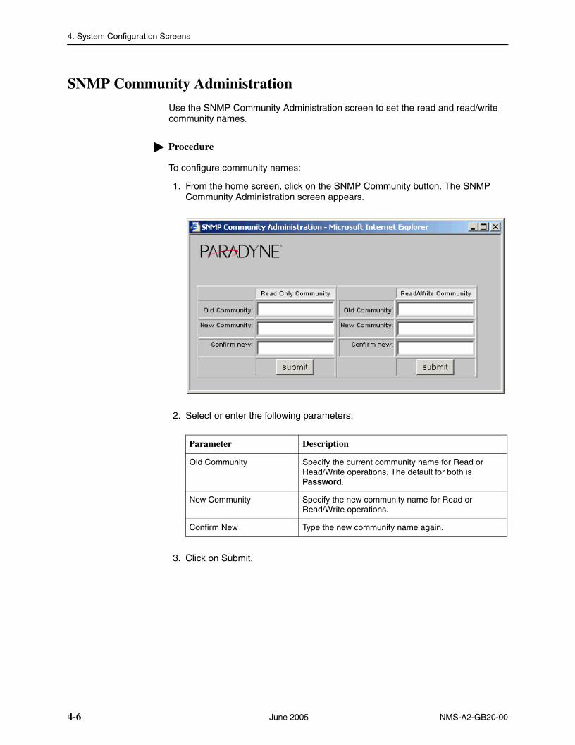
SNMP Community Administration
Use the SNMP Community Administration screen to set the read and read/write community names.
Procedure
To configure community names:
1. From the home screen, click on the SNMP Community button. The SNMP Community Administration screen appears.
2. Select or enter the following parameters:
3. Click on Submit.
Parameter Description
Old Community Specify the current community name for Read or Read/Write operations. The default for both is Password.
New Community Specify the new community name for Read or Read/Write operations.
Confirm New Type the new community name again.
4-6 June 2005 NMS-A2-GB20-00

4. System Configuration Screens
Global Set
Use the Global Set screen to set parameters for all ports or for a group of ports at once. Available Global Set parameters are device-dependent; Table 4-1, Global Set Screens by Device, compares some devices:
Table 4-1. Global Set Screens by Device
Global Set Screen:Network Extender
Micro DSLAM
AIM24000 Line Card
4929 DSLAM
Circuit Config – See Global Circuit Configuration for T1 or E1 Ports on page 4-11
X X
Circuit Config – See Global Circuit Configuration for T1 or E1 Ports on page 4-11
X
DSCP Rules – See Global DSCP Rules on page 4-14
X X X
IP Rules – See Global IP Rules on page 4-16
X X X
Layer 2 Set – See Global Layer 2 Set (Micro DSLAMs and Mini DSLAMs) on page 4-18
X
MAC Rules – See Global MAC Rules on page 4-20
X X X
Port Set – See Global Port Set (Micro DSLAMs and Mini DSLAMs) on page 4-22
X
SNR Settings – See Global Advanced Configuration on page 4-23
X X X
VLAN Rules – See Global VLAN Rules on page 4-24
X X X
NMS-A2-GB20-00 June 2005 4-7

4. System Configuration Screens
Global Circuit Configuration for DSL Ports
Procedure
To configure global parameters for DSL ports:
1. From the home screen, click on the Global Set button. The Global Circuit Configuration screen appears.
2. In the Add Ports drop-down list, select All or a group of ports. To select multiple ports, hold the Ctrl key while clicking on your selections.
3. Select or enter the following parameters:
Parameter Description
Reset Port Statistics Click in this box to reset statistics when the Submit button is clicked on.
Port Mode Setting Specify a port mode:
Fixed – The upstream and downstream rates are fixed at the rates in the Data Rate Setting fields.
Adaptive – The ports will automatically train up to the best possible speed.
Fixed Adaptive – The ports will automatically train up to the best possible speed, up to a user-specified maximum upstream and downstream bandwidth.
4-8 June 2005 NMS-A2-GB20-00

4. System Configuration Screens
VPI/VCI Detect Setting Specify the port behavior with regard to VPI/VCI detection:
On – The DSLAM will monitor the line to determine the VPI and VCI settings of the remote ADSL modem and set itself accordingly. If no ATM cells are detected (at any VPI/VCI setting), the port will default to VPI 0 and VCI 35.
Off – The port will use the default setting of VPI and VCI (0/35 if not changed by the setting of VPI and VCI, below), or lock in the VPI/VCI already discovered while VPI/VCI detection was On.
Data Rate Setting If you have selected a Port Mode of Fixed or Fixed Adaptive, specify the maximum upstream and downstream rates, in bps.
Filter IP Address Settings Specify up to four IP address ranges. Packets are accepted only from source IP addresses in the ranges specified.
Protocol Setting Click in the check box to enable Protocol Setting detection. Select Allow Selected and specify up to four Ethertypes allowed on the ports.
DHCP Option 82 Specify whether DHCP Option 82 is enabled, and if it is, whether packets are identified by IP address or circuit ID. This identifier is added to packets to let your DHCP Server recognize which DSLAM port an IP address request is coming from, thereby allowing the DHCP Server to limit the number of IP addresses assigned per port.
VPI and VCI Specify the VPI and VCI used if VPI/VCI Detect Setting (above) is Off.
Frame Type Specify whether the ports use Logical Link Control (LLC) or Virtual Channel Multiplexing (VCM) bridged encapsulation. These are defined in RFC 1483.
Standard Mode (ADSL) Specify the ports’ line code:
MULTIMODE – Each port uses the line code of its partner modem (default)
T1_413 – DMT modulation as defined in ANSI T1.413
G_Lite – G.992.2 (G.lite) modulation
G_DMT – G.992.1 (G.dmt) modulation
ALCTL – Alcatel modulation
G_DMT_BIS – G.992.3 (ADSL2) modulation
G_DMT_BISplus – G.992.5 (ADSL2+) modulation
READSL2 – Reach Expanded ADSL2 (G.992.3 in Annex L format)
Parameter Description
NMS-A2-GB20-00 June 2005 4-9

4. System Configuration Screens
4. Click on Submit.
Line Code (SHDSL Specify the ports’ line code:
CAP – Carrierless Amplitude and Phase modulation
2B1Q – Two Binary, one quaternary
G.SHDSL – G.991.2
Parameter Description
4-10 June 2005 NMS-A2-GB20-00
4. System Configuration Screens
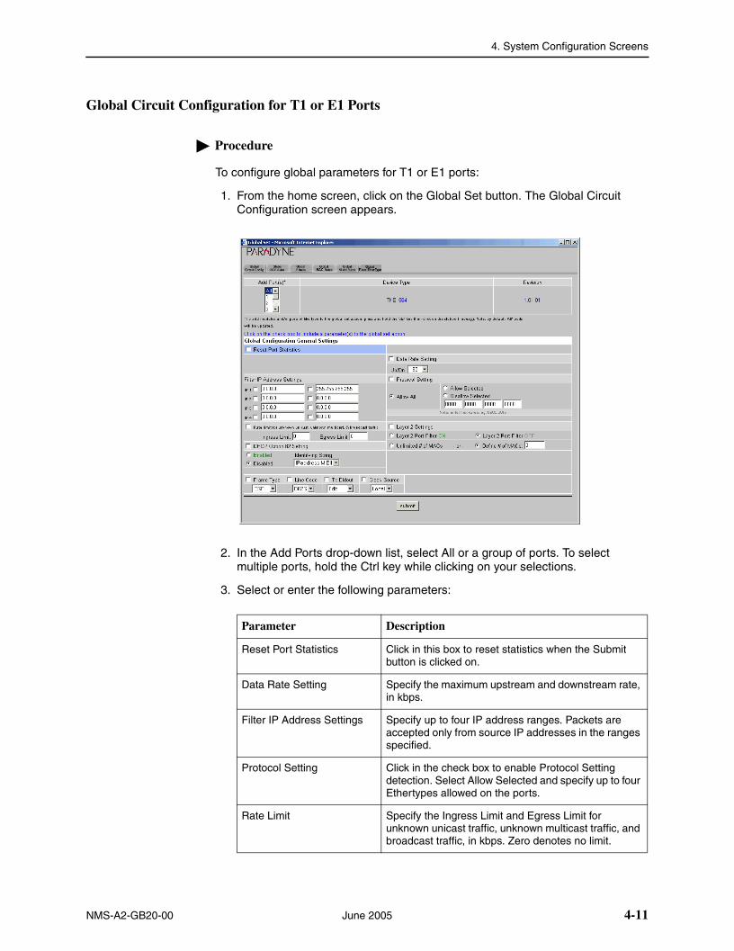
Global Circuit Configuration for T1 or E1 Ports
Procedure
To configure global parameters for T1 or E1 ports:
1. From the home screen, click on the Global Set button. The Global Circuit Configuration screen appears.
2. In the Add Ports drop-down list, select All or a group of ports. To select multiple ports, hold the Ctrl key while clicking on your selections.
3. Select or enter the following parameters:
Parameter Description
Reset Port Statistics Click in this box to reset statistics when the Submit button is clicked on.
Data Rate Setting Specify the maximum upstream and downstream rate, in kbps.
Filter IP Address Settings Specify up to four IP address ranges. Packets are accepted only from source IP addresses in the ranges specified.
Protocol Setting Click in the check box to enable Protocol Setting detection. Select Allow Selected and specify up to four Ethertypes allowed on the ports.
Rate Limit Specify the Ingress Limit and Egress Limit for unknown unicast traffic, unknown multicast traffic, and broadcast traffic, in kbps. Zero denotes no limit.
NMS-A2-GB20-00 June 2005 4-11

4. System Configuration Screens
4. Click on Submit.
Layer 2 Port Filter Specify whether Layer 2 port filtering is enabled or disabled.
# of MACs Specify whether an unlimited number of MAC addresses, or a specified limit number of MAC addresses, is allowed to access the ports. Specify the MAC addresses in MAC 1 through MAC 3.
DHCP Option 82 Specify whether DHCP Option 82 is enabled, and if it is, whether packets are identified by IP address or circuit ID. This identifier is added to packets to let your DHCP Server recognize which DSLAM port an IP address request is coming from, thereby allowing the DHCP Server to limit the number of IP addresses assigned per port.
Frame Type Specify the ports’ frame type.
Line Code Specify the ports’ line code.
Tx Bldout Specify the transmission line buildout.
Clock Source Specify whether the ports receive their clocking from the loop.
Parameter Description
4-12 June 2005 NMS-A2-GB20-00

4. System Configuration Screens
Allow Tag or Untag on Ingress Packet Parameter
The global and single Rules screens include a parameter labeled Allow Tag/Untag on Ingress Pkt. When the tag option is selected, the port acts as an 802.1Q VLAN trunk port; otherwise the port acts as an 802.1Q VLAN access port.
The parameter has the effects shown in Table 4-2, Effects of Allow Tag or Untag on Ingress Packet Parameter.
Table 4-2. Effects of Allow Tag or Untag on Ingress Packet Parameter
Port Type Behavior
VLAN Access Port Allow untagged frames on the upstream DSL ingress and tag it with the specified 802.1q VLAN and 802.1p priority
Allow tagged frames with tags matching the specified 802.1q VLAN on the downstream and strip the tag before sending it to DSL egress
If no configuration is explicitly defined to allow tagged traffic on DSL ingress, then tagged traffic on DSL ingress will be dropped.
VLAN Trunk Port Allow tagged frames with tags matching the specified 802.1q VLAN on the upstream DSL ingress
Allow tagged frames with tags matching the specified 802.1q VLAN on the downstream DSL egress
Any tagged frames with tags not matching the specified 802.1q VLAN(s) or VLAN range(s) for the port will be dropped.
If no configuration is explicitly defined to allow untagged traffic on DSL ingress, untagged traffic will also be dropped.
VLAN Trunk Port with PVID (or native VLAN)
Allow tagged frames with tags matching the specified 802.1q VLAN on the upstream DSL ingress
Allow tagged frames with tags matching the specified 802.1q VLAN on the downstream DSL egress
Allow untagged frames on the upstream DSL ingress and tag it with the specified 802.1q VLAN and 802.1p priority
Allow tagged frames with tags matching the specified untag policy 802.1q VLAN on the downstream and strip the tag before sending it to DSL egress
Any tagged frames with tags not matching the specified 802.1q VLAN(s) or VLAN range(s) for the port will be dropped.
NMS-A2-GB20-00 June 2005 4-13
4. System Configuration Screens
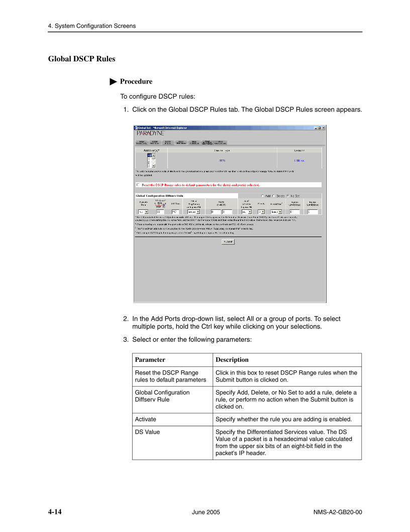
Global DSCP Rules
Procedure
To configure DSCP rules:
1. Click on the Global DSCP Rules tab. The Global DSCP Rules screen appears.
2. In the Add Ports drop-down list, select All or a group of ports. To select multiple ports, hold the Ctrl key while clicking on your selections.
3. Select or enter the following parameters:
Parameter Description
Reset the DSCP Range rules to default parameters
Click in this box to reset DSCP Range rules when the Submit button is clicked on.
Global Configuration Diffserv Rule
Specify Add, Delete, or No Set to add a rule, delete a rule, or perform no action when the Submit button is clicked on.
Activate Specify whether the rule you are adding is enabled.
DS Value Specify the Differentiated Services value. The DS Value of a packet is a hexadecimal value calculated from the upper six bits of an eight-bit field in the packet's IP header.
4-14 June 2005 NMS-A2-GB20-00

4. System Configuration Screens
4. Click on Submit.
DS Mask Specify the DS mask. The DS Mask is a hexadecimal value that indicates which of the DSCP's upper six bits will be utilized in considering a packet's DSCP type. Default is FC, indicating that all of the DSCP's upper six bits will be used in calculating the packet's DS Value.
Allow Tag/Untag on Ingress Pkt.
Specify tag or untag. Tag indicates that ingress packets already matched to the Diffserv Rule must have a VLAN tag to be further considered; packets without a VLAN tag will be dropped. See Allow Tag or Untag on Ingress Packet Parameter on page 4-13.
VLAN Specify a VLAN ID range. For each Global Diffserv Rule, if you selected Tag for Allow Tag/Untag, the VLAN field should specify either an acceptable single VLAN, or an acceptable VLAN Range, for VLAN tags on ingress packets. If you selected Untag, the VLAN field should specify a single VLAN only if you intend to have a VLAN tag added to packets; if you do not intend to have a VLAN tag added to packets, the VLAN field should be left at the 0 - 0 default.
Tag Action on DSL Ingress Pkt.
Specify the action to take with DSL ingress packets:
Add tag
Keep tag
Replace tag
Drop packet
No action
Priority Specify the priority to be used when adding a configured VLAN ID to a packet.
Fixed/Max Specify the handling of VLAN priority (used only if the received packet is already tagged):
Fixed – The packet's original priority will automatically be replaced with the Priority specified above,
Max – The packet's original priority will be replaced with the configured Priority only if the packet's original priority is greater than the configured Priority.
Ingress Limit Specify the ingress limit in kbps for packets matching this rule.
Egress Limit Specify the egress limit in kbps for packets matching this rule.
Parameter Description
NMS-A2-GB20-00 June 2005 4-15

4. System Configuration Screens
Global IP Rules
Procedure
To configure IP rules:
1. Click on the Global IP Rules tab. The Global IP Rules screen appears.
2. In the Add Ports drop-down list, select All or a group of ports. To select multiple ports, hold the Ctrl key while clicking on your selections.
3. Select or enter the following parameters:
Parameter Description
Reset the IP Range rules to default parameters
Click in this box to reset IP Range rules when the Submit button is clicked on.
Global Configuration IP Range Rule
Specify Add, Delete, or No Set to add a rule, delete a rule, or perform no action when the Submit button is clicked on.
Activate Specify whether the rule you are adding is enabled.
IP Range Specify the range of IP addresses that constitutes a match for this rule.
Allow Tag/Untag on Ingress Pkt.
Specify tag or untag. Tag indicates that ingress packets already matched to the IP Rule must have a VLAN tag to be further considered; packets without a VLAN tag will be dropped. See Allow Tag or Untag on Ingress Packet Parameter on page 4-13.
4-16 June 2005 NMS-A2-GB20-00

4. System Configuration Screens
4. Click on Submit.
VLAN Specify a VLAN ID range. For each Global IP Range Rule, if you selected Tag for Allow Tag/Untag, the VLAN field should specify either an acceptable single VLAN, or an acceptable VLAN Range, for VLAN tags on ingress packets. If you selected Untag, the VLAN field should specify a single VLAN only if you intend to have a VLAN tag added to packets; if you do not intend to have a VLAN tag added to packets, the VLAN field should be left at the 0 - 0 default.
Add VLAN to Ingress Pkt. Specify whether the VLAN ID should be added to ingress packets.
Priority Specify the priority to be used when adding a configured VLAN ID to a packet.
Fixed/Max Specify the handling of VLAN priority (used only if the received packet is already tagged):
Fixed – The packet's original priority will automatically be replaced with the Priority specified above,
Max – The packet's original priority will be replaced with the configured Priority only if the packet's original priority is greater than the configured Priority.
Ingress Limit Specify the ingress limit in kbps for packets matching this rule.
Egress Limit Specify the egress limit in kbps for packets matching this rule.
Parameter Description
NMS-A2-GB20-00 June 2005 4-17

4. System Configuration Screens
Global Layer 2 Set (Micro DSLAMs and Mini DSLAMs)
On Micro DSLAMs and Mini DSLAMs, the Global Layer 2 tab is used to set VLAN ranges and other Layer 2 parameters.
Procedure
To configure global Layer 2 parameters:
1. Click on the Layer 2 Set button. The Layer 2 Settings screen appears.
2. Select or enter the following parameters:
Parameter Description
VLAN Ranges Specify up to 10 VLAN ranges from 1 to 4095. A port set with one or more specified VLAN ranges will automatically be designated as an 802.1Q VLAN Trunk Port; only packets tagged within the specified VLAN range(s) will be allowed to communicate across that port.
Priority In compliance with the IEEE 802.1p Standard (a subset of 802.1Q), each port can be set with one of eight levels of prioritization designated numerically from 0 to 7: 0 (the default) denotes no priority and 7 denotes the highest priority. The priority designation is added to Access Port VLAN tags or replaces the priority designation in Trunk Port VLAN tags.
Ethertype Backbone Ethertype is a two-byte code indicating packet type. Use the drop-down menu to select the Ethertype accepted by your router: 8100 (the default) or 9100.
4-18 June 2005 NMS-A2-GB20-00

4. System Configuration Screens
3. Click on Submit.
Backbone VLAN Specify a Backbone VLAN from 0 to 4095. 0 (the default) disables the feature. Also known as QinQ and stacked VLANs, Backbone VLAN is used in conjunction with standard VLAN tags. The single Backbone-VLAN tag will become the primary identifier, allowing a router with backbone capabilities to make smarter decisions in directing unlearned traffic. This helps prevent traffic from being flooded to incorrect networks. Once packets have been directed to the correct network by the Backbone-VLAN tag, standard VLAN tags will then direct the packets to the appropriate ports. Default is zero, meaning the port is not configured to utilize the Backbone-VLAN function.
Note: A Backbone-VLAN tag cannot be used independently; standard VLAN tags must be set. Additionally, the DSLAM uplink connection must run through a router in order for a Backbone-VLAN tag to function.
Flood Flood refers to the method in which interface modules handle unknown unicasts (traffic directed to a single MAC Address), broadcasts (traffic directed to all MAC Addresses), and multicasts (traffic directed to multiple MAC Addresses) for each port. Select from the drop-down list:
Upl (Uplink - Default) – Unknown unicast, broadcast and multicast traffic is flooded only to the Micro DSLAM, Mini DSLAM, or IP DSLAM uplink interface ports. This prevents communication between interface ports without the intervention of an upstream device such as a router. If communication between interface ports is desired, the upstream device must be properly configured to allow it.
Vln (VLAN) – Unknown unicast, broadcast and multicast traffic is flooded to the Micro DSLAM, Mini DSLAM or IP DSLAM access ports (within the sender's VLAN range) in addition to the uplink interface ports.
Parameter Description
NMS-A2-GB20-00 June 2005 4-19

4. System Configuration Screens
Global MAC Rules
Procedure
To configure MAC rules:
1. Click on the Global MAC Rules tab. The Global MAC Rules screen appears.
2. In the Add Ports drop-down list, select All or a group of ports. To select multiple ports, hold the Ctrl key while clicking on your selections.
3. Select or enter the following parameters:
Parameter Description
Reset the MAC rules to default parameters
Click in this box to reset MAC rules when the Submit button is clicked on.
Global Configuration IP Range Rule
Specify Add, Delete, or No Set to add a rule, delete a rule, or perform no action when the Submit button is clicked on.
Activate Specify whether the rule you are adding is enabled.
MAC Range Specify the range of MAC addresses that constitutes a match for this rule. Only packets that have MAC addresses in this range are forwarded.
4-20 June 2005 NMS-A2-GB20-00

4. System Configuration Screens
4. Click on Submit.
Allow Tag/Untag on Ingress Pkt.
Specify tag or untag. Tag indicates that ingress packets already matched to the MAC Rule must have a VLAN tag to be further considered; packets without a VLAN tag will be dropped. See Allow Tag or Untag on Ingress Packet Parameter on page 4-13.
VLAN Specify a VLAN ID range. For each Global MAC Rule, if you selected Tag for Allow Tag/Untag, the VLAN field should specify either an acceptable single VLAN, or an acceptable VLAN Range, for VLAN tags on ingress packets. If you selected Untag, the VLAN field should specify a single VLAN only if you intend to have a VLAN tag added to packets; if you do not intend to have a VLAN tag added to packets, the VLAN field should be left at the 0 - 0 default.
Add VLAN to Ingress Pkt. Specify whether the VLAN ID should be added to ingress packets.
Priority Specify the priority to be used when adding a configured VLAN ID to a packet.
Fixed/Max Specify the handling of VLAN priority (used only if the received packet is already tagged):
Fixed – The packet's original priority will automatically be replaced with the Priority specified above,
Max – The packet's original priority will be replaced with the configured Priority only if the packet's original priority is greater than the configured Priority.
Ingress Limit Specify the ingress limit in kbps for packets matching this rule.
Egress Limit Specify the egress limit in kbps for packets matching this rule.
Parameter Description
NMS-A2-GB20-00 June 2005 4-21

4. System Configuration Screens
Global Port Set (Micro DSLAMs and Mini DSLAMs)
On Micro DSLAMs and Mini DSLAMs, The Global Port Set tab is used to set port parameters.
Procedure
To configure global Port parameters:
1. From the home screen, click on the Global Set button. The Global Port Set screen appears.
2. Select or enter the following parameters:
3. Click on Submit.
Parameter Description
Reset Port Statistics Click in this box to reset statistics when the Submit button is clicked on.
Filter IP Address Settings Specify up to two IP address ranges. Packets are accepted from source IP addresses in the ranges specified.
Data Rate Setting Click in the check box to enable a maximum data rate. Select the maximum data rate in kbps from the drop-down list.
Protocol Click in the check box to enable protocol detection. Select valid protocols from the drop-down list.
4-22 June 2005 NMS-A2-GB20-00
4. System Configuration Screens
Global Advanced Configuration
Procedure
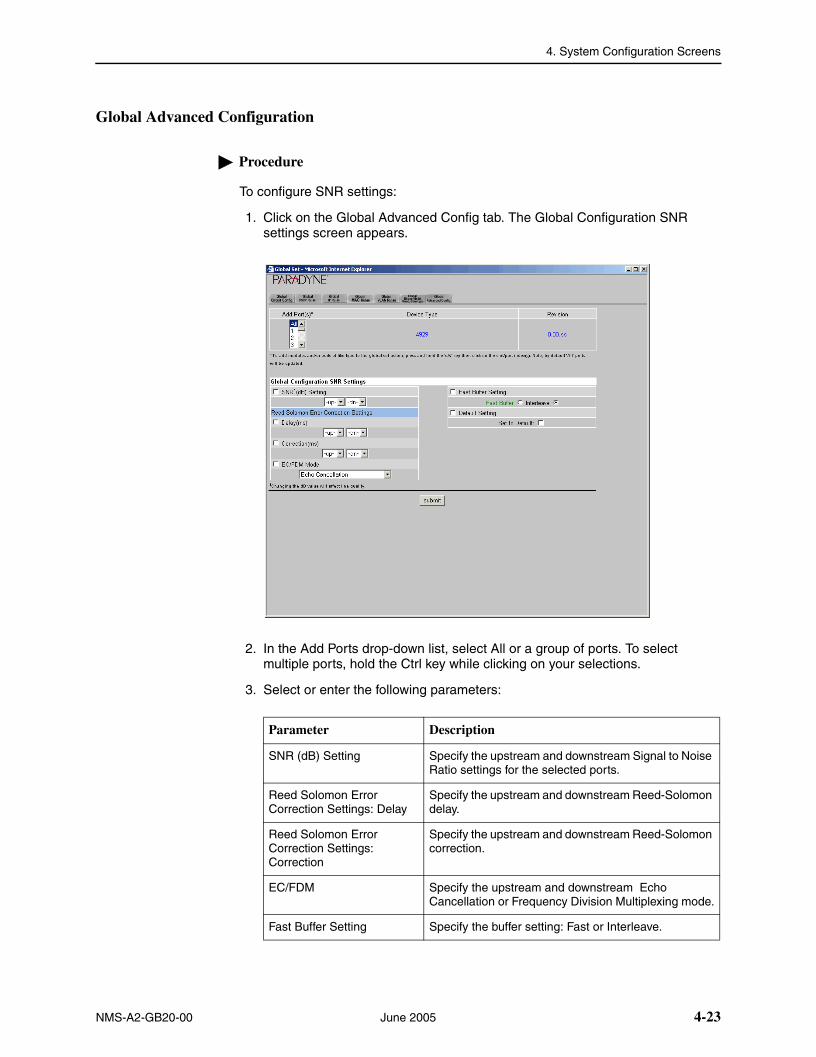
To configure SNR settings:
1. Click on the Global Advanced Config tab. The Global Configuration SNR settings screen appears.
2. In the Add Ports drop-down list, select All or a group of ports. To select multiple ports, hold the Ctrl key while clicking on your selections.
3. Select or enter the following parameters:
Parameter Description
SNR (dB) Setting Specify the upstream and downstream Signal to Noise Ratio settings for the selected ports.
Reed Solomon Error Correction Settings: Delay
Specify the upstream and downstream Reed-Solomon delay.
Reed Solomon Error Correction Settings: Correction
Specify the upstream and downstream Reed-Solomon correction.
EC/FDM Specify the upstream and downstream Echo Cancellation or Frequency Division Multiplexing mode.
Fast Buffer Setting Specify the buffer setting: Fast or Interleave.
NMS-A2-GB20-00 June 2005 4-23

4. System Configuration Screens
4. Click on Submit.
Global VLAN Rules
Procedure
To configure VLAN rules:
1. Click on the Global VLAN Rules tab. The Global VLAN Rules screen appears.
2. In the Add Ports drop-down list, select All or a group of ports. To select multiple ports, hold the Ctrl key while clicking on your selections.
3. Select or enter the following parameters:
Default Setting To return to the default settings when the Submit button is clicked on, click in the Set to Default check box.
Parameter Description
Parameter Description
Reset the VLAN rules to default parameters
Click in this box to reset VLAN rules when the Submit button is clicked on.
Global Configuration VLAN Rule
Specify Add, Delete, or No Set to add a rule, delete a rule, or perform no action when the Submit button is clicked on.
4-24 June 2005 NMS-A2-GB20-00

4. System Configuration Screens
4. Click on Submit.
Activate Specify whether the rule you are adding is enabled.
Allow Tag/Untag on Ingress Pkt.
Specify tag or untag. Tag indicates that ingress packets already matched to the VLAN Rule must have a VLAN tag to be further considered; packets without a VLAN tag will be dropped. See Allow Tag or Untag on Ingress Packet Parameter on page 4-13.
VLAN Specify a VLAN ID range that constitutes a match of this rule.
Add VLAN to Ingress Pkt. Specify whether the VLAN ID should be added to ingress packets.
Priority Specify the priority to be used when adding a configured VLAN ID to a packet.
Fixed/Max Specify the handling of VLAN priority (used only if the received packet is already tagged):
Fixed – The packet's original priority will automatically be replaced with the Priority specified above,
Max – The packet's original priority will be replaced with the configured Priority only if the packet's original priority is greater than the configured Priority.
Ingress Limit Specify the ingress limit in kbps for packets matching this rule.
Egress Limit Specify the egress limit in kbps for packets matching this rule.
Parameter Description
NMS-A2-GB20-00 June 2005 4-25

4. System Configuration Screens
4-26 June 2005 NMS-A2-GB20-00

NMS-A2-GB20-00 June 2005
5
System UtilitiesOverview
What System Utilities screens are available is device dependent. System Utilities screens include:
Circuit Summary – Provides access to the following screens:
— Circuit Configuration. See Circuit (Port) Configuration for DSL Ports on page 5-3.
— DSCP Rules. See DSCP Rules on page 5-8.
— IP Rules. See IP Rules on page 5-10.
— MAC Rules. See MAC Rules on page 5-12.
— VLAN Rules. See VLAN Rules on page 5-14.
— Backbone VLAN, Flood, and Ethertype. See Backbone VLAN ID on page 5-17.
— Port Statistics. See Port Statistics on page 5-19.
— Port Copy. See Port Copy, Single-Slot Devices on page 5-21.
— SNR Advanced Configuration. See SNR Advanced Configuration on page 5-23.
Circuit Search – Lets you search for circuits by their Circuit Identifiers and display their configurations. See Circuit Search on page 5-24.
DSLAM Users – Displays the current users of the web interface. See DSLAM Users on page 5-26.
Diagnostics – Lets you run tests on the device. See Diagnostics on page 5-27.
Show Help – Links to this manual.
Refresh Screen – Refreshes the front panel display.
5-1

5. System Utilities
Circuit Summary
Use the Circuit Summary screen to display information about port configurations.
Procedure
To display the circuit summary:
1. From the home screen, click on the Circuit Summary button. The Circuit Summary screen appears.
Figure 5-1. Circuit Summary Screen
2. Click on Refresh to view current information. Click on a port number in the leftmost column to view the Circuit Configuration screen.
5-2 June 2005 NMS-A2-GB20-00

5. System Utilities
Circuit (Port) Configuration for DSL Ports
Use the Circuit Configuration screen to set the parameters for a single DSL port.
Procedure
To configure circuit parameters for a DSL port:
1. From the home screen, click on one of the DSL port LEDs. Alternatively, click on the Circuit Summary button, then click on a Port number on the left side of the Circuit Summary listing. The Circuit Configuration screen appears.
Figure 5-2. Circuit Configuration Screen
2. Select or enter the following parameters:
Parameter Description
Port Select a port from the drop-down list.
NMS-A2-GB20-00 June 2005 5-3

5. System Utilities
Port Mode Setting Specify a port mode:
Fixed – The upstream and downstream rates are fixed at the Data Rate Setting values.
Adaptive – The ports will automatically train up to the best possible speed supported by the DSLAM, the modem at the remote end, and the copper cable pair connecting the two.
Fixed Adaptive – The ports will automatically train up to the best possible speed, up to the user-specified maximum upstream and downstream rates in Data Rate Setting.
The Data Rate Setting field does not appear if Port Mode is Adaptive. It appears after you change the Port Mode from Fixed to Adaptive or Fixed Adaptive and click on Submit.
VPI/VCI Detect Setting Specify the port behavior with regard to VPI/VCI detection:
On – The port will automatically monitor the line to determine the VPI and VCI settings of the remote ADSL modem to which it is connected and set itself accordingly on PVC 1. If no ATM cells are detected (at any VPI/VCI setting), the port will default to VPI 0 and VCI 35. Thereafter, once it does detect ATM cells from the remote ADSL modem, it will reconfigure VPI and VCI to the same settings at which the ATM cells from the remote ADSL modem were detected.
Off – The port will default to VPI 0 and VCI 35 on PVC 1 unless the port was previously set at VPI/VCI Detect on and had already detected the VPI and VCI settings of the remote ADSL modem. In this case, turning the VPI/VCI function off will lock in the previously detected settings unless the VPI and VCI values are altered manually.
Data Rate Setting If you have selected a Port Mode of Fixed or Fixed Adaptive, specify the maximum upstream and downstream rates, in bps.
Filter IP Address Settings Specify up to four IP address ranges. Packets are accepted from IP addresses in the ranges specified.
Protocol Setting Click in the check box to enable Protocol Setting detection. Select Allow Selected and specify up to four protocol codes allowed on the ports. These codes are 2-byte Ethertypes; for example, 0800 is IPv4 and 0806 is ARP.
See www.iana.org/assignments/ethernet-numbers for a complete list of Ethertypes..
Parameter Description
5-4 June 2005 NMS-A2-GB20-00

5. System Utilities
3. Click on Submit.
DHCP Option 82 Specify whether DHCP Option 82 is enabled, and if it is, whether packets are identified by IP address or circuit ID. This identifier is added to packets to let your DHCP Server recognize which DSLAM port an IP address request is coming from, thereby allowing the DHCP Server to limit the number of IP addresses assigned per port.
Layer 2 Port Filter Settings Click in the check box if you want to filter by MAC address the packets on this port.
MAC 1 – MAC 3 Enter up to three MAC addresses.
Unlimited # of MACs or Define # of MACs
Specify whether the number of MAC addresses with access to the port is to be limited to a certain number (not including MAC 1, MAC 2, and MAC 3, if specified above).
PVC1 – PVC4 Specify the VPI and VCI of up to four PVC indexes. These can be applied to packets coming in through a subscriber connection according to the DSCP, IP, MAC, and VLAN rules you define. Each index must be assigned the same VPI and VCI values as the port on the remote ADSL modem to which that index will be assigned in order for traffic to traverse the line successfully.
Frame Type Specify whether the ports use Logical Link Control (LLC) or Virtual Channel Multiplexing (VCM) bridged encapsulation. These are defined in RFC 1483.
Standard Mode (ADSL) Specify the port’s line code:
MULTIMODE – The port uses the line code of its partner modem (default)
T1_413 – DMT modulation as defined in ANSI T1.413
G_Lite – G.992.2 (G.lite) modulation
G_DMT – G.992.1 (G.dmt) modulation
ALCTL – Alcatel modulation
G_DMT_BIS – G.992.3 (ADSL2) modulation
G_DMT_BISplus – G.992.5 (ADSL2+) modulation
READSL2 – Reach Expanded ADSL2 (G.992.3 in Annex L format)
Line Code (SHDSL Specify the port’s line code:
CAP – Carrierless Amplitude and Phase modulation
2B1Q – Two Binary, one quaternary
G.SHDSL – G.991.2
Parameter Description
NMS-A2-GB20-00 June 2005 5-5

5. System Utilities
Circuit Configuration for a T1 or E1 Port
Use the Circuit Configuration screen to set the parameters for a single T1 or E1 port on a Network Extender.
Procedure
To configure circuit parameters for a T1 or E1 port:
1. From the home screen, click on one of the E1 or T1 port LEDs. Alternatively, click on the Circuit Summary button, then click on a Port number on the left side of the Circuit Summary listing. The Circuit Configuration screen appears.
2. Select or enter the following parameters:
Parameter Description
Reset Port Statistics Click in this box to reset statistics when the Submit button is clicked on.
Data Rate Setting Specify the maximum upstream and downstream rate, in kbps.
Filter IP Address Settings Specify up to four IP address ranges. Packets are accepted only from source IP addresses in the ranges specified.
Protocol Setting Click in the check box to enable Protocol Setting detection. Select Allow Selected and specify up to four Ethertypes allowed on the port.
Rate Limit Specify the Ingress Limit and Egress Limit for unknown unicast traffic, unknown multicast traffic, and broadcast traffic, in kbps. Zero denotes no limit.
5-6 June 2005 NMS-A2-GB20-00

5. System Utilities
3. Click on Submit.
Layer 2 Port Filter Specify whether Layer 2 port filtering is enabled or disabled.
# of MACs Specify whether an unlimited number of MAC addresses, or a specified limit number of MAC addresses, is allowed to access the port. Specify the MAC addresses in MAC 1 through MAC 3.
DHCP Option 82 Specify whether DHCP Option 82 is enabled, and if it is, whether packets are identified by IP address or circuit ID. This identifier is added to packets to let your DHCP Server recognize which DSLAM port an IP address request is coming from, thereby allowing the DHCP Server to limit the number of IP addresses assigned per port.
Frame Type Specify the port’s frame type.
Line Code Specify the port’s line code.
Tx Bldout Specify the transmission line buildout.
Clock Source Specify whether the port receives its clocking from the loop.
Parameter Description
NMS-A2-GB20-00 June 2005 5-7

5. System Utilities
DSCP Rules
Procedure
To configure DSCP rules:
1. Click on the DSCP Rules tab. The DSCP Rules screen appears.
Figure 5-3. DSCP Rules Screen
2. Select or enter the following parameters:
Parameter Description
Port Select a port from the drop-down list.
Reset the DSCP rules to default parameters
Click in this box to reset DSCP rules when the Submit button is clicked on.
Activate Specify whether the rule is active.
DS Value Specify the Differentiated Services value. The DS Value of a packet is a hexadecimal value calculated from the upper six bits of an eight-bit field in the packet's IP header.
DS Mask Specify the DS mask. The DS Mask is a hexadecimal value that indicates which of the DSCP's upper six bits will be utilized in considering a packet's DSCP type. Default is FC, indicating that all of the DSCP's upper six bits will be used in calculating the packet's DS Value.
5-8 June 2005 NMS-A2-GB20-00

5. System Utilities
Allow Tag/Untag on Ingress Pkt.
Specify tag or untag. Tag indicates that ingress packets already matched to the Diffserv Rule must have a VLAN tag to be further considered; packets without a VLAN tag will be dropped. See Allow Tag or Untag on Ingress Packet Parameter in Chapter 4, System Configuration Screens.
VLAN ID Range Specify a VLAN ID range. For each rule, if you selected Tag for Allow Tag/Untag, the VLAN field should specify either an acceptable single VLAN, or an acceptable VLAN Range, for VLAN tags on ingress packets. If you selected Untag, the VLAN field should specify a single VLAN only if you intend to have a VLAN tag added to packets; if you do not intend to have a VLAN tag added to packets, the VLAN field should be left at the 0 - 0 default.
Add VLAN to Ingress Pkt. Specify whether the VLAN ID should be added to ingress packets.
Priority Specify the priority to be used when adding a configured VLAN ID to a packet.
Fixed/Max Specify the handling of VLAN priority (used only if the received packet is already tagged):
Fixed – The packet's original priority will automatically be replaced with the Priority specified above,
Max – The packet's original priority will be replaced with the configured Priority only if the packet's original priority is greater than the configured Priority.
Ingress Limit Specify the ingress limit in kbps for packets matching this rule.
Egress Limit Specify the egress limit in kbps for packets matching this rule.
PVC Select a PVC index (1–4). The PVC Index parameter applies to ADSL ports only.
PVC Indexes will only be applied to packets coming in through a subscriber connection (WAN). They are not applicable to packets coming in through an uplink connection.
Parameter Description
NMS-A2-GB20-00 June 2005 5-9
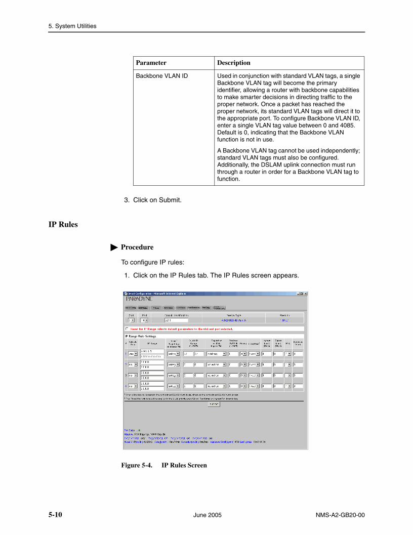
5. System Utilities
3. Click on Submit.
IP Rules
Procedure
To configure IP rules:
1. Click on the IP Rules tab. The IP Rules screen appears.
Figure 5-4. IP Rules Screen
Backbone VLAN ID Used in conjunction with standard VLAN tags, a single Backbone VLAN tag will become the primary identifier, allowing a router with backbone capabilities to make smarter decisions in directing traffic to the proper network. Once a packet has reached the proper network, its standard VLAN tags will direct it to the appropriate port. To configure Backbone VLAN ID, enter a single VLAN tag value between 0 and 4085. Default is 0, indicating that the Backbone VLAN function is not in use.
A Backbone VLAN tag cannot be used independently; standard VLAN tags must also be configured. Additionally, the DSLAM uplink connection must run through a router in order for a Backbone VLAN tag to function.
Parameter Description
5-10 June 2005 NMS-A2-GB20-00

5. System Utilities
2. Select or enter the following parameters:
Parameter Description
Port Select a port from the drop-down list.
Activate Specify whether the rule is active.
IP Range Specify the range of IP addresses that constitutes a match for this rule.
Allow Tag/Untag on Ingress Pkt.
Specify tag or untag. Tag indicates that ingress packets already matched to the IP Rule must have a VLAN tag to be further considered; packets without a VLAN tag will be dropped. See Allow Tag or Untag on Ingress Packet Parameter in Chapter 4, System Configuration Screens.
VLAN ID Range Specify a VLAN ID range. For each IP Range Rule, if you selected Tag for Allow Tag/Untag, the VLAN field should specify either an acceptable single VLAN, or an acceptable VLAN Range, for VLAN tags on ingress packets. If you selected Untag, the VLAN field should specify a single VLAN only if you intend to have a VLAN tag added to packets; if you do not intend to have a VLAN tag added to packets, the VLAN field should be left at the 0 - 0 default.
Add VLAN to Ingress Pkt. Specify whether the VLAN ID should be added to ingress packets.
Priority Specify the priority to be used when adding a configured VLAN ID to a packet.
Fixed/Max Specify the handling of VLAN priority (used only if the received packet is already tagged):
Fixed – The packet's original priority will automatically be replaced with the Priority specified above,
Max – The packet's original priority will be replaced with the configured Priority only if the packet's original priority is greater than the configured Priority.
Ingress Limit Specify the ingress limit in kbps for packets matching this rule.
Egress Limit Specify the egress limit in kbps for packets matching this rule.
PVC Select a PVC index (1–4). The PVC Index parameter applies to ADSL ports only.
PVC Indexes will only be applied to packets coming in through a subscriber connection (WAN). They are not applicable to packets coming in through an uplink connection.
NMS-A2-GB20-00 June 2005 5-11

5. System Utilities
3. Click on Submit.
MAC Rules
Procedure
To configure MAC rules:
1. Click on the MAC Rules tab. The MAC Rules screen appears.
Figure 5-5. MAC Rules Screen
Backbone VLAN ID Used in conjunction with standard VLAN tags, a single Backbone VLAN tag will become the primary identifier, allowing a router with backbone capabilities to make smarter decisions in directing traffic to the proper network. Once a packet has reached the proper network, its standard VLAN tags will direct it to the appropriate port. To configure Backbone VLAN ID, enter a single VLAN tag value between 0 and 4085. Default is 0, indicating that the Backbone VLAN function is not in use.
A Backbone VLAN tag cannot be used independently; standard VLAN tags must also be configured. Additionally, the DSLAM uplink connection must run through a router in order for a Backbone VLAN tag to function.
Parameter Description
5-12 June 2005 NMS-A2-GB20-00

5. System Utilities
2. Select or enter the following parameters:
Parameter Description
Port Select a port from the drop-down list.
Reset the MAC rules to default parameters
Click in this box to reset MAC rules when the Submit button is clicked on.
Activate Specify whether the rule is active.
MAC Range Specify the range of MAC addresses that constitutes a match for this rule.
Allow Tag/Untag on Ingress Pkt.
Specify tag or untag. Tag indicates that ingress packets already matched to the MAC Rule must have a VLAN tag to be further considered; packets without a VLAN tag will be dropped. See Allow Tag or Untag on Ingress Packet Parameter in Chapter 4, System Configuration Screens.
VLAN ID Range Specify a VLAN ID range. For each MAC Rule, if you selected Tag for Allow Tag/Untag, the VLAN field should specify either an acceptable single VLAN, or an acceptable VLAN Range, for VLAN tags on ingress packets. If you selected Untag, the VLAN field should specify a single VLAN only if you intend to have a VLAN tag added to packets; if you do not intend to have a VLAN tag added to packets, the VLAN field should be left at the 0 - 0 default.
Add VLAN to Ingress Pkt. Specify whether the VLAN ID should be added to ingress packets.
Priority Specify the priority to be used when adding a configured VLAN ID to a packet.
Fixed/Max Specify the handling of VLAN priority (used only if the received packet is already tagged):
Fixed – The packet's original priority will automatically be replaced with the Priority specified above,
Max – The packet's original priority will be replaced with the configured Priority only if the packet's original priority is greater than the configured Priority.
Ingress Limit Specify the ingress limit in kbps for packets matching this rule.
Egress Limit Specify the egress limit in kbps for packets matching this rule.
PVC Select a PVC index (1–4). The PVC Index parameter applies to ADSL ports only.
PVC Indexes will only be applied to packets coming in through a subscriber connection (WAN). They are not applicable to packets coming in through an uplink connection.
NMS-A2-GB20-00 June 2005 5-13

5. System Utilities
3. Click on Submit.
VLAN Rules
Procedure
To configure VLAN rules:
1. Click on the VLAN Rules tab. The VLAN Rules screen appears.
Figure 5-6. VLAN Rules Screen
Backbone VLAN ID Used in conjunction with standard VLAN tags, a single Backbone VLAN tag will become the primary identifier, allowing a router with backbone capabilities to make smarter decisions in directing traffic to the proper network. Once a packet has reached the proper network, its standard VLAN tags will direct it to the appropriate port. To configure Backbone VLAN ID, enter a single VLAN tag value between 0 and 4085. Default is 0, indicating that the Backbone VLAN function is not in use.
A Backbone VLAN tag cannot be used independently; standard VLAN tags must also be configured. Additionally, the DSLAM uplink connection must run through a router in order for a Backbone VLAN tag to function.
Parameter Description
5-14 June 2005 NMS-A2-GB20-00

5. System Utilities
2. Select or enter the following parameters:
Parameter Description
Port Select a port from the drop-down list.
Reset the VLAN rules to default parameters
Click in this box to reset VLAN rules when the Submit button is clicked on.
Activate Specify whether the rule is active.
Allow Tag/Untag on Ingress Pkt.
Specify tag or untag.
Tag indicates that ingress packets already matched to the VLAN Rule must have a VLAN tag to be further considered; packets without a VLAN tag will be dropped.
Untag indicates that ingress packets already matched to the VLAN Rule cannot have a VLAN tag to be further considered; packets with a VLAN tag will be dropped. There can be only one untagged rule. The DSLAM tries to match to a VLAN rule traffic that has not matched any other rule type. If the packet is untagged it will match the one and only allowed VLAN rule that indicates Untagged. If the packet has a tag then the DSLAM will try to find a Tagged rule that has a VLAN range defined with the packet’s VLAN ID. If it finds one it will use that rule, and then the packet will be checked for all other criteria. If it does not find a rule to match the packet VLAN ID the packet is dropped.
See Allow Tag or Untag on Ingress Packet Parameter in Chapter 4, System Configuration Screens.
VLAN Specify a VLAN ID range that constitutes a match of this rule. If you selected Untag, the VLAN field should specify a single VLAN only if you intend to have a VLAN tag added to packets; if you do not intend to have a VLAN tag added to packets, the VLAN field should be left at the 0 - 0 default.
Add VLAN to Ingress Pkt. Specify whether the VLAN ID should be added to ingress packets.
Priority Specify the priority to be used when adding a configured VLAN ID to a packet.
Fixed/Max Specify the handling of VLAN priority (used only if the received packet is already tagged):
Fixed – The packet's original priority will automatically be replaced with the Priority specified above,
Max – The packet's original priority will be replaced with the configured Priority only if the packet's original priority is greater than the configured Priority.
Ingress Limit Specify the ingress limit in kbps for packets matching this rule.
NMS-A2-GB20-00 June 2005 5-15

5. System Utilities
3. Click on Submit.
Egress Limit Specify the egress limit in kbps for packets matching this rule.
PVC Select a PVC index (1–4). The PVC Index parameter applies to ADSL ports only.
PVC Indexes will only be applied to packets coming in through a subscriber connection (WAN). They are not applicable to packets coming in through an uplink connection.
Backbone VLAN ID Used in conjunction with standard VLAN tags, a single Backbone VLAN tag will become the primary identifier, allowing a router with backbone capabilities to make smarter decisions in directing traffic to the proper network. Once a packet has reached the proper network, its standard VLAN tags will direct it to the appropriate port. To configure Backbone VLAN ID, enter a single VLAN tag value between 0 and 4085. Default is 0, indicating that the Backbone VLAN function is not in use.
A Backbone VLAN tag cannot be used independently; standard VLAN tags must also be configured. Additionally, the DSLAM uplink connection must run through a router in order for a Backbone VLAN tag to function.
Parameter Description
5-16 June 2005 NMS-A2-GB20-00

5. System Utilities
Backbone VLAN ID
Procedure
To configure the backbone VLAN ID, flood type, and Ethertype:
1. Click on the Bkbone VLAN Id, Flood, Ethertype tab. The Bkbone VLAN Id, Flood, Ethertype screen appears.
Figure 5-7. Backbone VLAN ID, Flood, and Ethertype Screen
2. Select or enter the following parameters:
Parameter Description
Backbone VLAN Id Configuration
Specify the Backbone VLAN ID. Also called QinQ or VLAN stacking, the Backbone VLAN ID is used in conjunction with standard VLAN tags. The single Backbone VLAN tag will become the primary identifier, allowing a router with backbone capabilities to make smarter decisions in directing unlearned traffic. This helps prevent traffic from being flooded to incorrect networks. Once packets have been directed to the correct network by the Backbone VLAN tag, standard VLAN tags will then direct the packets to the appropriate ports. The default is zero, meaning the port is not configured to utilize the Backbone-VLAN function.
A Backbone-VLAN tag cannot be used independently; stardard VLAN tags must be set. Additionally, the DSLAM uplink connection must run through a router in order for a Backbone VLAN tag to function.
NMS-A2-GB20-00 June 2005 5-17

5. System Utilities
3. Click on Submit.
Flood Specify the Flood setting. Flood refers to the method in which interface modules handle unknown unicasts (traffic directed to a single MAC Address), broadcasts (traffic directed to all MAC Addresses) and multicasts (traffic directed to multiple MAC Addresses) for each port.
Upl (Uplink) – Unknown unicast, broadcast and multicast traffic is flooded only to the DSLAM uplink interface ports. This prevents communication between interface ports without the intervention of an upstream device such as a router. If communication between interface ports is desired, the upstream device must be properly configured to allow it.
Vln (VLAN) – Unknown unicast, broadcast and multicast traffic is flooded to the DSLAM’s ADSL ports (within the sender's VLAN range) in addition to the uplink interface ports.
Ethertype Specify the Ethertype of the backbone tag added to traffic if the backbone VLAN ID is configured. Used only in conjunction with backbone VLANs.
Parameter Description
5-18 June 2005 NMS-A2-GB20-00

5. System Utilities
Port Statistics
Procedure
To view port statistics:
1. Click on the Port Statistics tab. The Port Statistics screen appears.
Figure 5-8. Port Statistics Screen
2. Click on Reset Statistics to set all statistics to zero.
At the bottom of the screen, dropped packets are shown:
Dropped Pkts Tx Overflow shows the number of packets dropped due to lack of resources.
Dropped Pkts Count shows the number of packets dropped because they violated the port configuration. A check mark appears next to the violation or
NMS-A2-GB20-00 June 2005 5-19
5. System Utilities
violations encountered. They are listed in Table 5-1, Reasons for Packets Being Dropped.
Table 5-1. Reasons for Packets Being Dropped
Description Meaning
Protocol Filter IngressProtocol Filter Egress
The packet did not have the protocol defined as a requirement for the port.
IP Range (Ingress) The packet’s source IP address matches none of the defined IP address ranges.
QOS VLAN Config IngressQOS VLAN Config Egress
The packet failed to match a rule in any of the MTM categories (DCSP, IP address, MAC address, and VLAN).
Database Trusted/Untrusted Violation
More MAC addresses than configured or different MAC addresses than configured sent a packet to the port.
Database - Layer 2 Filter Static or Dynamic MAC Violation
A statically configured MAC address was seen on a different port than expected.
Other Drop Reason Other possible reasons include:
Packet has a source address of a multicast type (not unicast as it should be)
There are no other ports active or there are no ports that want to see the particular VLAN in the packet
5-20 June 2005 NMS-A2-GB20-00

5. System Utilities
Port Copy, Single-Slot Devices
The Port Copy screen lets you copy a source port configuration to other ports.
Procedure
To copy a port configuration to one or more other ports on a one-slot device:
1. Click on Port Copy. The Port Copy screen appears.
Figure 5-9. Port Copy Screen, Single Slot Device
2. Select a source port, then one or more destination ports.
3. Click on Submit. The configuration of the source port is copied to the destination port or ports.
NMS-A2-GB20-00 June 2005 5-21

5. System Utilities
Port Copy, Multi-Slot Devices
The Port Copy screen lets you copy a source port configuration to other ports, including those on cards in other slots.
Procedure
To copy a port configuration to one or more other ports on a multi-slot device:
1. Click on Port Copy. The Port Copy screen appears.
Figure 5-10. Port Copy Screen, Multi-Slot Device
2. Select a source slot and a source port.
3. For each slot, select the ports to which the source configuration will be copied.
4. Click on Submit. The configuration of the source port is copied to the destination port or ports.
5-22 June 2005 NMS-A2-GB20-00

5. System Utilities
SNR Advanced Configuration
SNR settings may greatly affect ADSL performance. Do not change SNR settings unless so advised by your service provider.
Procedure
To configure SNR settings:
1. Click on the Advanced Config tab. The Configuration SNR settings screen appears.
Figure 5-11. Configuration SNR Settings Screen
2. Select or enter the following parameters:
Parameter Description
Port Select a port from the drop-down list.
SNR (dB) Setting Specify the upstream and downstream Signal to Noise Ratio settings for the selected ports.
Reed Solomon Error Correction Settings: Delay
Specify the upstream and downstream Reed-Solomon delay.
Reed Solomon Error Correction Settings: Correction
Specify the upstream and downstream Reed-Solomon correction.
EC/FDM Specify the upstream and downstream Echo Cancellation or Frequency Division Multiplexing mode.
NMS-A2-GB20-00 June 2005 5-23

5. System Utilities
3. Click on Submit.
Circuit Search
The Circuit Search screen allows you to locate a circuit by circuit ID, then display its Circuit Summary screen.
Procedure
To use the Circuit Search:
1. Click on Circuit Search. The Circuit Search screen appears.
2. Select a Circuit ID from a drop-down list.
Figure 5-12. Circuit Search Screen
Fast Buffer Setting Specify the buffer setting: Fast or Interleave.
Default Setting To return to the default settings when the Submit button is clicked on, click in the Set to Default check box.
Parameter Description
5-24 June 2005 NMS-A2-GB20-00

5. System Utilities
The Circuit Configuration screen for the specified circuit appears.
Figure 5-13. Circuit Configuration Screen
3. Display or modify parameters for the circuit. See Circuit Summary on page 5-2.
NMS-A2-GB20-00 June 2005 5-25

5. System Utilities
DSLAM Users
The DSLAM Users screen shows the users that are using or have used the DSLAM or BLC. Users are identified by IP address.
To display DSLAM users, click on the DSLAM Users button. The DSLAM Users screen appears.
Figure 5-14. DSLAM Users Screen
Current entries show the login time and user status. Historical entries document the time each user logged in and logged out.
5-26 June 2005 NMS-A2-GB20-00

5. System Utilities
Diagnostics
Use the Diagnostics screens to display diagnostic information and run tests.
Loop Detect Summary
Click on Diagnostics to display the Loop Detect Summary screen.
Figure 5-15. Loop Detect Summary Screen
If a loop is detected in the chassis, the Database Trusted/Untrusted Violation box will be checked on the related Port Statistics screen.
NMS-A2-GB20-00 June 2005 5-27

5. System Utilities
Figure 5-16. Port Statistics Showing a Trusted/Untrusted Violation
A packet coming from the network is considered Trusted and traffic coming from a modem is Untrusted. If a trusted MAC address (coming from the network) moves to a DSL port (Untrusted), it will be blocked for a minimum of 5 minutes and will increment the Dropped Packet counter for every packet from that source MAC address. Only the MAC address that is looped will be blocked and not be able to be forwarded to the backplane. A hard loop facing a T1 port in the DSLAM, for example, causes all packets to be dropped on that port.
5-28 June 2005 NMS-A2-GB20-00

5. System Utilities
BERT Screen
A Bit Error Ratio Test (BERT) is available for SDSL ports.
Procedure
To use the BERT screen:
1. Click on Diagnostics. The Loop Detect Summary screen appears.
2. Click on the BERT tab. The Bit Error Rate Test (BERT) screen appears.
Figure 5-17. BERT Screen
3. Select one or more slots and one or more ports on which to conduct a test.
4. Specify a test duration of 15 to 900 seconds, then click on Start.
Upon test completion, results are displayed at the bottom of the screen.
NMS-A2-GB20-00 June 2005 5-29

5. System Utilities
5-30 June 2005 NMS-A2-GB20-00

NMS-A2-GB20-00 June 2005
6
Virtual Front Panel ButtonsOverview
The depiction of the front panel of some devices includes buttons not found on the actual hardware:
DSLAM Interconnect Configuration button – Lets you specify and display the connection to the downstream DSLAM. See DSLAM Interconnect Configuration (4929 and Micro DSLAM) on page 6-2.
EAPS button – Lets you set up an Ethernet Automatic Protection Switching arrangement. See EAPS Button on page 6-4.
MAC and IGMP button – Displays the MAC and IGMP summary and search screens. See MAC and IGMP Summary on page 6-6.
STATS button – Displays backplane statistics. See Statistics Button on page 6-11.
Sub Button – Lets you change the device role from Subscriber to Provider or Provider to Subscriber. See Sub Button on page 6-13.
6-1

6. Virtual Front Panel Buttons
DSLAM Interconnect Configuration (4929 and Micro DSLAM)
Use the DSLAM Interconnect Configuration screen to specify a port connected to a downstream DSLAM. This information is used to configure internal traffic flows. The screen is accessed using the blue button on the faceplate image.
Figure 6-1. DSLAM Interconnect Buttons on 4929 and SµD2011-12T
DSLAM Interconnect Button
DSLAM Interconnect Button
6-2 June 2005 NMS-A2-GB20-00

6. Virtual Front Panel Buttons
Procedure
To specify the port connected to a downstream DSLAM:
1. From the home screen, click on the blue button. The DSLAM Interconnect Configuration screen appears.
Figure 6-2. DSLAM Interconnect Configuration Screen
2. Select Off or a port from the drop-down list. For example, if this DSLAM is connected to a downstream DSLAM over the first MIM port, select MIMp1.
3. Click on Submit.
NMS-A2-GB20-00 June 2005 6-3

6. Virtual Front Panel Buttons
EAPS Button
The EAPS button displays the Ethernet Automatic Protection Switching (EAPS) configuration screen. It allows you to set up an EAPS arrangement as described in RFC 3619.
Figure 6-3. EAPS Button on the BSX8000-5 Faceplate
EAPS Button
6-4 June 2005 NMS-A2-GB20-00

6. Virtual Front Panel Buttons
Procedure
To display and configure EAPS parameters:
1. Click on the EAPS button. The EAPS Configuration screen appears.
Figure 6-4. EAPS Configuration Screen
2. Select or enter the following EAPS Configuration parameters:
Parameter Description
Name Specify a unique name for this configuration.
Enable Specify whether this configuration is enabled for use (y for yes and n for no).
Control VLAN Specify the control VLAN ID. This is used to send link down messages to the master node.
Node Operation Specify whether this is the Master node or the Transit node.
Assign Primary Port Specify the number of the port that normally will be used for the Ethernet connection.
Assign Secondary Port Specify the number of the port that will be used if the primary connection fails.
Fail Time Specify the amount of time, in seconds, the master node awaits a health check frame before declaring a ring-fault state and unblocking its secondary port.
Hello Time Specify the frequency of health check frame transmissions.
NMS-A2-GB20-00 June 2005 6-5
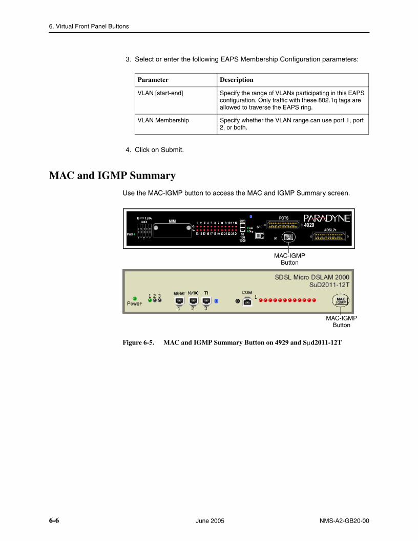
6. Virtual Front Panel Buttons
3. Select or enter the following EAPS Membership Configuration parameters:
4. Click on Submit.
MAC and IGMP Summary
Use the MAC-IGMP button to access the MAC and IGMP Summary screen.
Figure 6-5. MAC and IGMP Summary Button on 4929 and Sµd2011-12T
Parameter Description
VLAN [start-end] Specify the range of VLANs participating in this EAPS configuration. Only traffic with these 802.1q tags are allowed to traverse the EAPS ring.
VLAN Membership Specify whether the VLAN range can use port 1, port 2, or both.
MAC-IGMP Button
MAC-IGMP Button
6-6 June 2005 NMS-A2-GB20-00

6. Virtual Front Panel Buttons
Procedure
To view the MAC and IGMP Summary screens:
1. From the home screen, click on the MAC-IGMP button. The MAC Summary screen appears.
Figure 6-6. MAC Summary Screen
2. Click on a Port or MIM button to see specific entries in the MAC table, or click on MAC Summary to see all entries.
NMS-A2-GB20-00 June 2005 6-7

6. Virtual Front Panel Buttons
3. Click on the IGMP tab to display the IGMP table. Click on a Port or MIM button to see specific entries in the IGMP table, or click on IGMP Summary to see all entries.
Figure 6-7. IGMP Summary Screen
6-8 June 2005 NMS-A2-GB20-00

6. Virtual Front Panel Buttons
4. Click on the IGMP Age tab to set the IGMP age and enable or disable IGMP proxy. The IGMP Age screen appears.
Figure 6-8. IGMP Age Screen
5. Enter or select the following:
Parameter Description
IGMP Age Time Specify an IGMP age interval, in seconds. This should be twice the query rate of your router.
NMS-A2-GB20-00 June 2005 6-9

6. Virtual Front Panel Buttons
6. To search for MAC or IGMP table entries, click on the Search tab. The Search screen appears.
Figure 6-9. MAC and IGMP Search Screen
7. Enter a MAC address to search for a MAC table entry, or an IP address to search for an IGMP table entry.
8. Click on the appropriate Submit button.
6-10 June 2005 NMS-A2-GB20-00

6. Virtual Front Panel Buttons
Statistics Button
The STATS button displays statistics for the device on which the button is provided.
Figure 6-10. STATS Button on the AIM24000-48 Faceplate
Stats Button
NMS-A2-GB20-00 June 2005 6-11

6. Virtual Front Panel Buttons
To display device statistics, click on the STATS button. The Backplane Statistics screen appears.
Figure 6-11. Backplane Statistics Screen
6-12 June 2005 NMS-A2-GB20-00

6. Virtual Front Panel Buttons
Sub Button
The Sub button displays the Subscriber Select screen, from which you can specify whether the device is a Subscriber or a Provider unit.
Figure 6-12. Sub Button on the TNE1584 Faceplate
Procedure
1. To specify the device role, click on the Sub button. The Subscriber Select screen appears.
Figure 6-13. Subscriber Select Screen
2. Click in Provider or Subscriber, then click on Submit.
NOTE:
Because the Provider unit has a different default IP address than a Subscriber unit, when you change device roles you lose connectivity through the web interface.
Sub Button
NMS-A2-GB20-00 June 2005 6-13

6. Virtual Front Panel Buttons
6-14 June 2005 NMS-A2-GB20-00

NMS-A2-GB20-00 June 2005
7
Troubleshooting the NMSProblems and Solutions
The following sections describe problems you may encounter in using the NMS.
PC Cannot Locate Web Server
The PC being used to access NMS keeps a record of IP (Internet Protocol) and MAC (Medium Access Control) addresses in its local ARP (Address Resolution Protocol) cache. If the same computer is used to access NMS through the local management port and then again to access NMS through a network connection, the local ARP cache can prevent the computer from "finding" the embedded web server. Though the ARP cache will eventually clear itself as entries time out, it can also be cleared manually:
1. Click on the Windows Start button.
2. Select Run.
3. Type cmd and click on OK to open a command prompt.
4. At the prompt, type
arp -a
and press the Enter key. This will return a list of all the IP Addresses in the computer's ARP cache.
5. If the IP address of the Micro DSLAM, Mini DSLAM or IP DSLAM MUM you wish to clear is listed, type:
arp -d [the IP Address]
at the prompt and press the Enter key.
Lost Web Server Connection
The web server connection will be lost whenever the Micro DSLAM, Mini DSLAM or IP DSLAM's IP Address is changed.
1. Close all browser windows.
2. Open a new browser window.
7-1
7. Troubleshooting the NMS
3. Enter the new IP address in the address field at the top of the browser window and press the Enter key.
Cannot Establish Web Server Connection From Within Network
The Inband MGMT option (in the System Configuration Window) must be selected in order for NMS to be network accessible. To verify:
1. Connect your PC to the MGMT port on the front of the Micro DSLAM, Mini DSLAM or uplink module.
2. Click the System Configuration button in the administration panel of the NMS Main Window.
3. If the Inband MGMT box is not checked, click it so that a checkmark appears.
4. Click on the Submit button.
Web Pages Are Loading Slowly
If NMS pages are accessible but refreshing slowly, close all browser windows and re-launch the application. If the problem continues, you may be encountering one of the following conditions:
Too Many Users – NMS supports up to three Superusers or three General Users simultaneously. The system may experience a slowdown if there are more than three users at a time. Likewise, both classes of users cannot log in at the same time; attempts at such will result in a "Server Busy..." warning message.
Inband Connection Speed Not Set Appropriately – The speed setting may need to be increased if you are accessing the system via an inband connection from a remote customer site (e.g., through a provisioned DSL connection). As an example, a 128 kbps IDSL connection is generally sufficient for NMS access although it is possible for heavy traffic to cause delays when downloading a web page.
Network Congestion – Extensive network congestion may impact NMS performance due to the fact that the embedded web server powering NMS is a TCP/IP device. Under heavy congestion, you will notice most other network tasks experiencing a slowdown as well.
7-2 June 2005 NMS-A2-GB20-00

NMS-A2-GB20-00 June 2005
A
Connector Pin Assignments10/100BaseT MGMT Connector
The MGMT port is an 8-pin modular jack supporting 10/100BaseT.
Table 1. 10/100BaseT Pinouts
Signal Pin
Transmitted Data + 1
Transmitted Data – 2
Received Data + 3
Unused 4
Unused 5
Received Data – 6
Unused 7
Unused 8
97-15449
Pin 1 Pin 8
A-1

A. Connector Pin Assignments
A-2 June 2005 NMS-A2-GB20-00

Index
Numerics10/100BaseT
LED, 3-2, 3-4, 3-6MGMT Connector, A-1
AADSL mode, 4-9, 5-5Advanced Configuration, 4-3, 4-23
BBackbone VLAN ID, 5-10, 5-12, 5-14, 5-16–5-17BERT Screen, 5-29BLC, 1-7
CCircuit
Configuration, 4-8, 4-11, 5-3, 5-6Configuration, T1 or E1, 5-6Defaults, 1-4Search, 5-24Summary, 5-2
Clearing NVRAM, 1-6COM port, 3-3Communication Port, 3-3, 3-5Community names, 4-6Configuring PC for NMS, 2-1Connecting PC to the Management Port, 2-2Copy Port, 5-21–5-22
DData Rate Setting, 4-9, 4-11, 4-22, 5-6Default Settings, 1-2DHCP Option 82, 4-9, 4-12, 5-5, 5-7Diagnostics, 5-27Document Purpose and Intended Audience, vDocument Summary, vDS Mask, 4-15, 5-8DS Value, 4-14, 5-8DSCP Rules, 4-14, 5-8DSL mode, 4-9, 5-5DSLAM
Front view, 3-7Interconnect Configuration, 6-2Users, 5-26
EE1
defaults, 1-3Global Circuit Configuration, 4-11LEDs, 3-2, 3-4, 3-6port configuration, 5-6
EAPS Button, 6-4EC, 4-23, 5-23Echo Cancellation, 4-23, 5-23Establishing a Connection, 2-1Ethernet
LEDs, 3-2, 3-4, 3-6Ethertype, 2-5, 5-17
FFan LED, 3-5, 3-7Fast Buffer Setting, 4-23FDM, 4-23, 5-23Flood type, 5-17Frame Type, 4-9, 4-12, 5-5, 5-7Frequency Division Multiplexing, 4-23, 5-23
GGateway, 2-5, 4-2Global
Advanced Configuration, 4-23Circuit Configuration, 4-8, 4-11, 5-6DSCP Rules, 4-14IP Rules, 4-16Layer 2 Set, 4-18MAC Rules, 4-20Port Set, 4-22Set, 4-7VLAN Rules, 4-24
HHTTP Password, 4-4
IIGMP
Age Time, 6-9Summary screen, 6-7
Inband Management, 2-5, 4-2Interface Modules, 3-8
LED, 3-8
NMS-A2-GB20-00 June 2005 IN-1

Index
IP Address, 2-5, 4-2Filter settings, 4-9, 4-11, 4-22, 5-4, 5-6
IP Range, 4-3, 4-16, 5-11IP Rules, 4-16, 5-10
LLaunching web browser, 2-2Layer 2 Port Filter Settings, 5-5Layer 2 Set, 4-18LED
10/100BaseT, 3-610/100BaseT Port, 3-2, 3-4DS3, 3-6E1, 3-6E3, 3-6Fan, 3-5, 3-7Interface Module, 3-8MGMT, 2-2, 3-3, 3-6Power, 1-7, 3-3, 3-5SDSL, 3-5–3-6T1, 3-6
Local Files, 1-5Logging in, 2-2Loop Detect Summary, 5-27
MMAC and IGMP Summary, 6-6–6-7MAC Range, 4-20, 5-13MAC Rules, 4-20, 5-12Management
Configuration, 4-2IP address, 2-5, 4-2Port and Corresponding LED, 3-3
MGMT LED, 2-2, 3-3, 3-6Micro DSLAM, 1-7
Chassis Front View, 3-3Mini DSLAM, 1-7
Chassis Front View, 3-5
NNetwork Extender
COM port, 3-3Front View, 3-2port configuration, 5-6Port LEDs, 3-2Power LED, 3-3Reset button, 3-2Sub button, 3-3
NMS Main Window, 3-1NMS Users, 1-1
OOption 82, 4-9, 4-12, 5-5, 5-7Overview, 1-1, 4-1, 5-1, 6-1
PPassword, 4-4PC Cannot Locate Web Server, 7-1Port
Copy, 5-21–5-22Mode Setting, 4-8, 5-4Set, 4-22Statistics, 5-19
Power LED, 1-7, 3-3, 3-5Priority, 2-5, 4-2Problems and Solutions, 7-1Product-Related Documents, viProtocol Setting, 4-9, 4-11, 4-22, 5-4, 5-6Provider, selecting, 6-13PVC, 5-9, 5-11, 5-13, 5-16
QQinQ, 5-17
RRAM and NVRAM, 1-5Reed Solomon Error Correction Settings, 4-23, 5-23Replacing
Interface Module, 1-5Uplink Module, 1-6
Requirements, 1-1Reset Button, 3-3–3-4Restarting the NMS, 2-7Restoring the IP Address and Subnet Mask on Your PC,
2-6RJ21 Cable Connector, 3-6
SSDSL LED, 3-5–3-6SNMP
Community Administration, 4-6Community names, 4-6Configuration, 4-5Trap Defaults, 1-4Traps, 4-5
SNR, 4-23, 5-23Advanced Configuration, 5-23
Statistics Button, 6-11Sub button, 3-3, 6-13Subnet Mask, 2-5, 4-2Subscriber, selecting, 6-13
IN-2 June 2005 NMS-A2-GB20-00

Index
SystemDefaults, 1-2Location, 4-3Name, 4-3Requirements, 1-1Reset Button, 3-3–3-4
TT1
defaults, 1-3Global Circuit Configuration, 4-11LEDs, 3-2, 3-4, 3-6port configuration, 5-6
Telnet, 4-3TFTP, 4-3Trap Defaults, 1-4Trap Managers, 4-5Traps, 4-5
UUplink
Interface Modules, 3-6LED, 3-2, 3-4, 3-6–3-7Modules, 3-7Ports, 3-4
User Access, 1-2
VVLAN ID, 2-5, 4-2VLAN Rules, 4-24, 5-14VLAN stacking, 5-17VPI/VCI Detect Setting, 4-9, 5-4
ZManagement Configuration, 2-4Management Port, 3-6Uplink Interface Defaults, 1-3Uplink Interface Modules, 3-8Web pages loading slowly, 7-2Web server connection, 7-1–7-2
NMS-A2-GB20-00 June 2005 IN-3

Index
IN-4 June 2005 NMS-A2-GB20-00