Embed Size (px)
Citation preview

OpenAir™
Technical InstructionsDocument No. 155-315P25
EA GMAMarch 6, 2018
GMA Series, Spring Return, 62 lb-in,Rotary, Electronic Damper Actuators
Siemens Industry, Inc.
Description The OpenAir direct-coupled spring return electronic actuator is designed formodulating, two-position, and floating control of building HVAC dampers.
Features · Brushless DC motor technology with stall protection
· Bi-directional fail-safe spring return
· Models available with dual, independently adjustable auxiliary switches
· Unique self-centering shaft coupling
· Manual override
· Available in 62 lb-in torque
· 5° preload as shipped from factory
· Mechanical range adjustment capabilities
· UL and cUL listed, CE certified
· 24 Vac/dc compatible
Application Used in constant or variable air volume installations for the control of return air, mixedair, exhaust, and face and bypass dampers requiring up to 62 lb-in (7 Nm) torque.
Designed for applications that require the damper to return to a fail-safe position whenthere is a power failure.
Warning/Caution Notations
WARNING: Personal injury or loss of life may occur if you do not performa procedure as specified.
CAUTION: Equipment damage may occur if you do not perform aprocedure as specified.

Technical Instructions OpenAir GMA Series, Spring Return, 62 lb-in Rotary, Electronic Damper ActuatorsDocument Number 155-315P25March 6, 2018
Page 2 Siemens Industry, Inc.
Product NumbersTable 1.
ProductNumber
OperatingVoltage
Control Cables Built-In ControlOptions
24Va
c±2
0%24
Vdc
±15%
120
Vac
±10%
Mod
ulat
ing
0to
10Vd
c
Mod
ulat
ing
2to
10Vd
c
Floa
ting
2-po
sitio
n
Stan
dard
Plen
um
Posi
tion
Feed
back
Dua
lAux
iliar
ySw
itche
s
Offs
et0
to5
Vdc
Span
2to
30Vd
c
Inpu
tSig
nalI
nver
sion
(Dire
ctor
Inve
rse
Act
ing)
Feed
back
Sign
alIn
vers
ion
GMA121.1U ● ● ●GMA121.1P ● ● ●GMA121.1P/B ● ● ●GMA126.1U ● ● ● ●GMA126.1P ● ● ● ●GMA221.1U ● ● ●GMA226.1U ● ● ● ●GMA131.1U ● ● ●GMA131.1P ● ● ●GMA132.1U ● ● ● ●GMA136.1U ● ● ● ●GMA151.1U ● ● ● ● ● ●
GMA151.1P ● ● ● ● ● ●GMA156.1U ● ● ● ● ● ● ●GMA156.1P ● ● ● ● ● ● ●GMA161.1U ● ● ● ●GMA161.1P ● ● ● ●GMA163.1U ● ● ● ● ●GMA163.1P ● ● ● ● ●GMA164.1U ● ● ● ● ● ●GMA166.1U ● ● ● ● ●GMA166.1P ● ● ● ● ●
Specifications
Power Supply
24 Vac/24 Vdc
Operating voltage 24 Vac ±20%; 24 Vdc ±15%Frequency 50/60 HzPower consumption running (GMA 12x, 13x, 15x, 16x) 5 VA/3.5W holding (GMA 12x, 13x, 15x, 16x) 4 VA/3WEquipment rating Class 2, in accordance with UL/CSA
Class III per EN 60730
Power Supply
120 Vac
Operating voltage 120 Vac ±10%Frequency 50/60 HzPower consumption running and holding (GMA 22x) 7 VA/5W

OpenAir GMA Series Spring Return, 62 lb-in, Rotary, Electronic Damper Actuators Technical InstructionsDocument Number 155-315P25
March 6, 2018
Siemens Industry, Inc. Page 3
Control Signal Input signal (wires 8–2) voltage input signal GMA16x 0 to 10 Vdc (max. 35 Vdc) voltage input signal GMA15x 2 to 10 Vdc (max. 35 Vdc) input resistance >100K ohms
Feedback Signal Position output signal (wires 9–2) voltage output signal GMA16x 0 to 10 Vdc voltage output signal GMA15x 2 to 10 Vdc maximum output current +1 mA, -0.5 mA
Function Running/spring return torque 62 lb-in (7 Nm)Maximum torque 186 lb-in (21 Nm)Runtime for 90° operating with motor 90 seconds closing (on power loss) with spring return 15 seconds typical
(60 seconds max. at -25°F [-32°C])
Mounting Nominal angle of rotation 90°Maximum angular rotation 95°Shaft size 1/4 to 3/4-inch (6.4 to 20.5 mm) dia.
1/4 to 1/2-inch (6.4 to 13 mm) squareMinimum shaft length 3/4-inch (20 mm)
Housing Enclosure NEMA 1IP54 according to EN 60 529 (limitedpositions; see OpenAir™ GMA SeriesInstallation Instructions (129-307)
Material Die-cast aluminum alloyGear lubrication Silicone-free
Ambient Conditions Ambient temperature operation -25°F to 130°F (-32°C to 55°C) storage and transport -40°F to 158°F (-40°C to 70°C)Ambient humidity (non-condensing) 95% rh
Agency Certification UL listed to UL60730 (to replace UL873)cUL certified to Canadian StandardC22.2 No. 24-93Australian ElectromagneticCompatibility (EMC) perAS/NZS 4251.1/2:1999 (C-tick)
Conformity
Low voltage directive (LVD) 2006/95/ECEN 60 730-2-14(Type 1)
Electromagnetic compatibility (EMC) 2004/108/ECImmunity for all models, except GMA132.xx EN61000-6-2Immunity for GMA132.xx EN61000-6-1Emissions for all models EN61000-6-3

Technical Instructions OpenAir GMA Series, Spring Return, 62 lb-in Rotary, Electronic Damper ActuatorsDocument Number 155-315P25March 6, 2018
Page 4 Siemens Industry, Inc.
Auxiliary Features Control signal adjustment Offset (start point) Between 0 to 5 Vdc Span Between 2 to 30 VdcDual auxiliary switches AC rating (standard cable) 24 to 250 Vac
AC 6A resistiveAC 2A general purpose
AC rating (Plenum cable) 24 VacAC 4A resistiveAC 2A general purpose
DC rating (Standard/Plenum cable) 12 to 30 VdcDC 2A
Switch Range Switch A 0° to 90° with 5° intervals Recommended range usage 0° to 45° Factory setting 5° Switch B 0° to 90° with 5° intervals Recommended range usage 45° to 90° Factory setting 85°
Switching hysteresis 2°
WARNING:Apply only AC-line voltage from the same phase or only UL-Class2 voltage (SELV for CE conformance) to the switching outputs ofboth auxiliary switches A and B. Mixed operation is notpermissible.
NOTE: With plenum cables, only UL-Class 2 voltage(SELV for CE) is permitted.
Feedback potentiometer (GMA 132.1U) Sliding contact (P2) 0 to 1000 ohm <10 mA Load <1W Voltage UL-Class 2 (SELV/PELV for CE)
<24 Vac/dc
Miscellaneous Pre-cabled connection 18 AWG (0.75 mm2)
Cable length 3 feet (0.9 m) length
Noise level 40 dBA
Life cycle Designed for over 60,000 full strokecycles and a minimum of 1.5 millionrepositions at rated torque andtemperature
Dimensions 8-3/8-in. H × 3-1/4-in. W × 2-2/3-in. D(212 mm H × 83 mm W × 68 mm D)
Weight 2.9 lbs (1.3 kg)Country of Origin USA

OpenAir GMA Series Spring Return, 62 lb-in, Rotary, Electronic Damper Actuators Technical InstructionsDocument Number 155-315P25
March 6, 2018
Siemens Industry, Inc. Page 5
ActuatorComponents
Figure 1. Components of the GMA SpringReturn Actuator.
Legend1. Actuator housing
2. Positioning scale for angle ofrotation
3. DIP switches and cover
4. Span adjustment
5. Offset (start point) adjustment
6. Mounting bracket
7. Connection cable for power andcontrol signals
8. Connection cable for auxiliaryswitches or feedback potentiometer
9. Gear train lock pin
10. Manual override wrench openingand direction of rotation arrow
11. Auxiliary switches A and B
12. Position indicator
13. Self-centering shaft adapter
14. Shaft adapter locking clip
15. Position indicator adapter
16. Key for manual adjustment
17. Adjustment tool for: auxiliaryswitches (11), offset/span (4 and 5),and lock pin (9)
18. 1/2-inch NSPT conduit connections
Accessories NOTE: The auxiliary switches, control signal adjustment, and feedbackpotentiometer cannot be added in the field. Order the product numberthat includes the option(s).
Figure 2. Floor/Frame Mount Kit.
ASK71.11: For in-the-air streamapplications; anywhere a foot-mountedactuator can be mounted. Can also bedirectly mounted to a damper frame withlouvers and vents and in applicationswhere use of the floor mount is notpossible.Kit contains:
· Crank arm to change theangular rotation into a linearstroke.
· Support bearing ring tominimize side loading on theactuator’s output bearing.
· Mounting bracket, and requiredmounting fasteners.

Technical Instructions OpenAir GMA Series, Spring Return, 62 lb-in Rotary, Electronic Damper ActuatorsDocument Number 155-315P25March 6, 2018
Page 6 Siemens Industry, Inc.
Accessories,Continued
4614
Z16
Figure 3. Rotary to Linear CrankArm Kit.
ASK71.13: Allows a direct-coupledactuator to provide an auxiliary lineardrive. Can be used to simultaneouslydrive a set of opposing or adjacentdampers with a single actuator. Kitcontains:
· Crank arm to attach to thesplined hub of the shaftadapter.
· Mounting fasteners.
Figure 4. Rotary to Linear CrankArm Kit with Mounting Bracket.
ASK71.14: Allows economical mountingof an OpenAir actuator to a variety ofsurfaces. Should be used in applicationswhere the actuator can be rigid-surfacemounted and a linear stroke output isrequired.Kit contains:
· Crank arm to attach to thesplined hub of the shaftadapter.
· Mounting bracket, and otherrequired mounting fasteners.
Figure 5. NEMA 3R WeatherShield.
ASK75.3U: GMA actuators are UL listedto meet NEMA 3R requirements (adegree of protection against rain, sleet,snow, and damage from external iceformation) when installed with ASK75.3UWeather Shield and outdoor-ratedconduit fittings in the vertical position.See Figure 20 for dimensions.
Figure 6. NEMA Type 4XWeather Shield.
ASK75.7U: GMA Actuators are UL listed tomeet NEMA Type 4X requirements (a degreeof protection against falling dirt, rain, sleet,snow, windblown dust, splashing water, hose-directed water, corrosion, and damage fromexternal ice formation) when installed with anASK75.7U Weather Shield and outdoor-ratedconduit fittings. This weather shield may bemounted in any orientation.
For dimensions, see Figure 21.

OpenAir GMA Series Spring Return, 62 lb-in, Rotary, Electronic Damper Actuators Technical InstructionsDocument Number 155-315P25
March 6, 2018
Siemens Industry, Inc. Page 7
Accessories,Continued
Figure 7. Heater/Weather ShieldAssembly.
985-108: Provides protection for 24 Vac/dcOpenAir GMA1xx actuators down totemperatures of -58°F (-50°C).Assembly includes:· Weather Shield· Heater Kit
Service Parts
985-094P10Position indicators (10/pkg.)
985-093Standard shaft
adapter.
985-098Adjustment Tool.
985-092Anti-rotation (mounting)
bracket.
985-124499-ohm resistor assembly kit for
4 to 20 mA applications.Figure 8. GMA Series Service Parts.
Operation GMA16x, GMA15x
Apply a continuous 0 to 10 Vdc, or 2 to 10 Vdc control signal between wire 8 (Y)and wire 2 (G0) to operate the damper actuator. The angle of rotation isproportional to the control signal.
A 0 to 10 Vdc or 2 to 10 Vdc position feedback output signal is available betweenwire 9 (U) and wire 2 (G0) to monitor the position of the damper motor.
In the event of a power failure or when the operating voltage is shut off, theactuator returns to the "0" position.
GMA12x and GMA 22xWhen power is applied, the actuator coupling moves toward the open position"90°". In the event of a power failure or when the operating voltage is shut off, theactuator returns to the "0" position.
GMA13xA floating control signal controls the damper actuator. The actuator’s angle ofrotation is proportional to the length of time the signal is applied. A 24 Vac/dccontrol signal to wire 6 (Y1) causes the actuator coupling to rotate clockwise. A 24Vac/dc control signal to wire 7 (Y2) causes the actuator coupling to rotatecounterclockwise.
With no control voltage, the damper actuator holds its position. In the event of apower failure, the actuator spring returns to the "0" position.

Technical Instructions OpenAir GMA Series, Spring Return, 62 lb-in Rotary, Electronic Damper ActuatorsDocument Number 155-315P25March 6, 2018
Page 8 Siemens Industry, Inc.
Overload Protection In the event of a blockage in the damper, the actuator is overload protected overthe full range to prevent damage to the actuator.
Life Expectancy An improperly tuned loop will cause excessive repositioning that will shorten the lifeof the actuator.
Sizing The type of actuator required depends on several factors:1. Obtain damper torque ratings (lb-in/ft2 or Nm/m2) from the damper
manufacturer.2. Determine the area of the damper.3. Calculate the total torque required to move the damper:
Total Torque =SF
AreaDamperRatingTorque1
´
4. Select a spring return actuator using Table 2.1Safety Factor: When calculating the total torque required, a safety factor should beincluded for unaccountable variables such as slight misalignments, aging of thedamper, etc. A suggested safety factor is 0.80.
NOTE: Mechanically coupled actuators must be of the exact same type exceptfor the dual auxiliary switches and feedback potentiometer options. Usethe correct mounting bracket. See Table 2.
Table 2.DC Power (24 Vdc) AC Power (24 Vac, 120 Vac)
Total Torque Actuator Total Torque Actuator
<62 lb-in (7 Nm) GMA1xx <62 lb-in (7 Nm) GMA
>62 lb-in <160 lb-in(>7 Nm <18 Nm)
GCA12x, GCA13x, GCA15x* >62 lb-in<160 lb-in(>7 Nm <18 Nm)
GCA
>160 lb-in <320 lb-in(>18 Nm <36 Nm)
Use tandem mounting bracketASK73.1 with any combinationof:• GCA12x actuators• GCA13x actuators
Use tandem mounting bracketASK73.2U with anycombination of GCA151 andGCA156 actuators.*
>160 lb-in <320 lb-in(>18 Nm <36 Nm)
Use tandem mounting bracket ASK73.1with any combination of:• GCA12x actuators• GCA22x actuators• GCA13x actuators• Use tandem mounting bracketASK73.2U with any combination of:• GCA151 and GCA156 actuators*• GCA161 and GCA166 actuators

OpenAir GMA Series Spring Return, 62 lb-in, Rotary, Electronic Damper Actuators Technical InstructionsDocument Number 155-315P25
March 6, 2018
Siemens Industry, Inc. Page 9
Mounting and Installation Flip the actuator to select either clockwise or counterclockwise fail-safe rotation ofthe damper shaft. Follow steps 1, 2, and 3 of Table 3 to determine the correctactuator mounting orientation.
Table 3. Actuator Mounting Orientation and Damper Control.
· The shaft adapter and the position indicator can be mounted on either side of the actuator. The actuatormounting orientation and shaft length determine how they will be mounted on the actuator.
· The minimum damper drive shaft length is 3/4-inch (20 mm).
· See Specifications for the minimum and maximum damper shaft dimensions.
· The actuator is shipped from the factory with a 5° preload enabling tight close off of the damper in power-fail-close applications.
· A mounting bracket is included with the actuator.
· The shaft adapter and mounting parts are shipped in a separate container with the actuator.
· See the detailed mounting instructions included with each actuator.
Technical Instructions OpenAir GMA Series, Spring Return, 62 lb-in Rotary, Electronic Damper ActuatorsDocument Number 155-315P25March 6, 2018
Page 10 Siemens Industry, Inc.
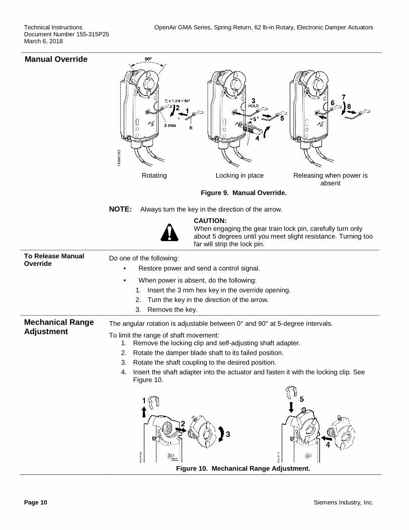
Manual Override
Rotating Locking in place Releasing when power isabsent
Figure 9. Manual Override.
NOTE: Always turn the key in the direction of the arrow.
CAUTION:When engaging the gear train lock pin, carefully turn onlyabout 5 degrees until you meet slight resistance. Turning toofar will strip the lock pin.
To Release ManualOverride
Do one of the following:· Restore power and send a control signal.
· When power is absent, do the following:1. Insert the 3 mm hex key in the override opening.2. Turn the key in the direction of the arrow.3. Remove the key.
Mechanical RangeAdjustment
The angular rotation is adjustable between 0° and 90° at 5-degree intervals.
To limit the range of shaft movement:1. Remove the locking clip and self-adjusting shaft adapter.2. Rotate the damper blade shaft to its failed position.3. Rotate the shaft coupling to the desired position.4. Insert the shaft adapter into the actuator and fasten it with the locking clip. See
Figure 10.
Figure 10. Mechanical Range Adjustment.

OpenAir GMA Series Spring Return, 62 lb-in, Rotary, Electronic Damper Actuators Technical InstructionsDocument Number 155-315P25
March 6, 2018
Siemens Industry, Inc. Page 11
Control SignalAdjustment(Offset and Span)
The offset (start point) and span of the control signal can be adjusted. The offset, Uo, can beadjusted between 0 to 5 Vdc. The span, ∆U, can be adjusted between 2 to 30 Vdc.
GMA163GMA164
Ys Mechanical positioning range (100% = angle of rotation 90°)Yu Control signalUo Offset (start point)DU Span
1. Uo = 0V, DU = 2V The minimum working range for Ys = 100%2. Uo = 5V, DU = 30V The maximum working range for Ys = 100%
3. Uo = 0V, DU » 30V Factory setting
Factory Settingof 30V span
0 offset
Figure 11. The Minimum and Maximum Control Signal Adjustment.
Example:
Open the actuator from 0 to 50% (45°) using a control signal of:
Umin = 2V to Umax = 10V
Calculating the value of DU:
V1650
2)(10 x100%inrotationofangleWorking
min)Umax(U%][100U =
-=
-=D
Settings Uo = 2V; DU = 16V
Umin = minimum control signalUmax = maximum control signal
Figure 12. Example.

Technical Instructions OpenAir GMA Series, Spring Return, 62 lb-in Rotary, Electronic Damper ActuatorsDocument Number 155-315P25March 6, 2018
Page 12 Siemens Industry, Inc.
Dual AuxiliarySwitchGMA126GMA226GMA136GMA156GMA164GMA166
Actuator rotary range with the shaftadapter mounted at position "0".
Setting range for switches A and BSetting interval: 5°Switching hysteresis: 2°
To change the settings of A and B:
· Make sure the actuator is in the "0", fail-safe position. The scale is valid only inthe "0" position.
· Use the adjustment tool provided withthe actuator to turn the switchadjustment dials to the desired setting atwhich a signal is to be given.
Factory setting:Switch A = 5°Switch B = 85°
Figure 13. Adjustable SwitchingValues for the Dual Auxiliary Switches.
NOTE: Use the long arm of the "†" to point to the position of switch A. Use thenarrower tab on the red ring to point to the position of switch B.
DIP SwitchFunctionalityGMA 151GMA 156
Description Label Description Function
Inverse Acting Direct-Acting Input Signal Inversion
Inverse-Acting Feedback Direct-Acting feedback Feedback Signal inversion
Not In Use
Figure 14. DIP Switches.Input Signal Inversion Allows inverting the control input signal
The arrow direction indicates opening or closing (closing or opening)when operating an actuator with a given control signal.
= Direct acting (Factory setting)Input signal 2 Vdc ► fail-safe position
= Inverse actingInput signal 10 Vdc ► fail-safe position
Feedback Signal Inversion Allows inverting the position feedback output signal
= Direct acting feedback (Factory setting)Fail-safe position ► Output signal 2 Vdc
= Inverse acting feedback,Fail-safe position ► Output signal 10 Vdc

OpenAir GMA Series Spring Return, 62 lb-in, Rotary, Electronic Damper Actuators Technical InstructionsDocument Number 155-315P25
March 6, 2018
Siemens Industry, Inc. Page 13
Wiring All wiring must conform to NEC and local codes and regulations.
Use earth ground isolating step-down Class 2 transformers. Do not use autotransformers.
The maximum rating for a Class 2 step-down transformer is 100 VA. Determine the supplytransformer rating by summing the VA ratings of all actuators and all other componentsused. It is recommended that one transformer power no more than 10 actuators (or 80% ofits VA).
WARNING:
Mixed switch operation is not permitted to the switching outputs of both auxiliaryswitches (A and B).Either AC line voltage from the same phase must be applied to all six outputs ofthe dual auxiliary switches, or UL-Class 2 voltage (SELV for CE conformance)must be applied to all six outputs.
NOTE: With Plenum cables only UL-Class 2 voltage (SELV for CEconformance) is permitted.
WARNING:Installations requiring Conformance:
· Except for the auxiliary switches (See Warning above) all wiring for24 Vac/dc actuators must only be safety extra-low voltage (SELV) orprotective extra-low voltage (PELV) per HD384.
· Use safety transformers per EN61558 with double isolation, designed for100% duty-cycle for supplying SELV or PELV circuits.
· Over-current protection for supply lines is maximum 10A.
Wire Designations Each wire has the standard symbol printed on it. See Table 4.
Table 4. Wire Designations.
ApplicableActuator
StandardSymbol Function
TerminalDesignations Color
24 Vac/dc
1 Supply (SP) G Red2 Neutral (SN) G0 Black6 Control signal clockwise Y1 Violet7 Control signal counterclockwise Y2 Orange8 Input signal: 0 to 10 Vdc (GMA16x) or 2 to 10 Vdc (GMA15x) Y Gray9 Position output: 0 to 10 Vdc (GMA16x) or 2 to 10 Vdc (GMA15x) U Pink
120 Vac 3 Line L Black4 Neutral N White
AuxiliarySwitches
S1 Switch A - Common Q11 Gray/redS2 Switch A - N.C. Q12 Gray/blueS3 Switch A - N.O. Q14 Gray/pinkS4 Switch B - Common Q21 Black/redS5 Switch B - N.C. Q22 Black/blueS6 Switch B - N.O. Q24 Black/pink
PositionFeedback
P1 Feedback Potentiometer 0 to 100% P1 - P2 a White/redP2 Feedback Potentiometer Common b White/blueP3 Feedback Potentiometer 100 to 0% P3 – P2 c White/pink

Technical Instructions OpenAir GMA Series, Spring Return, 62 lb-in Rotary, Electronic Damper ActuatorsDocument Number 155-315P25March 6, 2018
Page 14 Siemens Industry, Inc.
Wiring Diagrams
GMA12x
24 Vac/dc2-Position Control
Figure 15.
Class 2
GMA22x
120 Vac2-Position Control
Figure 16.
GMA13x
24 Vac/dcFloating Control
Figure 17.
Class 2
GMA15xGMA16x
24 Vac/dcModulating control
Figure 18.
Class 2
OpenAir GMA Series Spring Return, 62 lb-in, Rotary, Electronic Damper Actuators Technical InstructionsDocument Number 155-315P25
March 6, 2018
Siemens Industry, Inc. Page 15
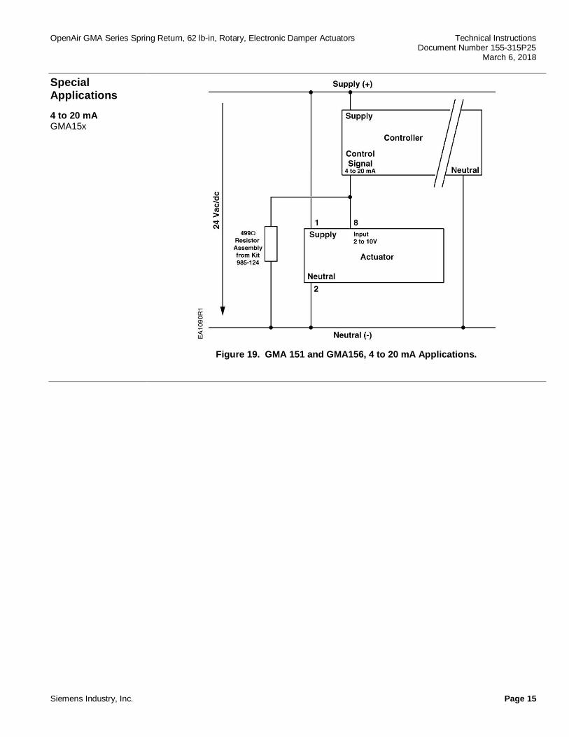
SpecialApplications
4 to 20 mAGMA15x
Figure 19. GMA 151 and GMA156, 4 to 20 mA Applications.
Technical Instructions OpenAir GMA Series, Spring Return, 62 lb-in Rotary, Electronic Damper ActuatorsDocument Number 155-315P25March 6, 2018
Page 16 Siemens Industry, Inc.
Start-Up/Commissioning
GMA16x, GMA15x
Spring ReturnModulating Control24 Vac/dc
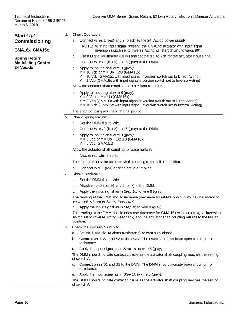
1. Check Operation:a. Connect wires 1 (red) and 2 (black) to the 24 Vac/dc power supply.
NOTE: With no input signal present, the GMA15x actuator with input signal inversion switch set to Inverse Acting will start driving towards 90°.
b. Use a Digital Multimeter (DDM) and set the dial to Vdc for the actuator input signal.c. Connect wires 2 (black) and 8 (gray) to the DMM.d. Apply to input signal wire 8 (gray):
Y = 10 Vdc or Y = Uo + ∆U (GMA16x)Y = 10 Vdc (GMA15x with input signal inversion switch set to Direct Acting)Y = 2 Vdc (GMA15x with input signal inversion switch set to Inverse Acting)
Allow the actuator shaft coupling to rotate from 0° to 90°.
e. Apply to input signal wire 8 (gray): Y = 0 Vdc or Y = Uo (GMA16x) Y = 2 Vdc (GMA15x with input signal inversion switch set to Direct Acting) Y = 10 Vdc (GMA15x with input signal inversion switch set to Inverse Acting)
The shaft coupling returns to the "0" position.2. Check Spring Return:
a. Set the DMM dial to Vdc.b. Connect wires 2 (black) and 8 (gray) to the DMM.
c. Apply to input signal wire 8 (gray): Y = 5 Vdc or Y = Uo + 1/2 ∆U (GMA16x) Y = 6 Vdc (GMA15x)Allow the actuator shaft coupling to rotate halfway.
d. Disconnect wire 1 (red).
The spring returns the actuator shaft coupling to the fail "0" position.
e. Connect wire 1 (red) and the actuator moves.3. Check Feedback:
a. Set the DMM dial to Vdc.b. Attach wires 2 (black) and 9 (pink) to the DMM.c. Apply the input signal as in Step 1d, to wire 8 (gray).The reading at the DMM should increase (decrease for GMA15x with output signal inversionswitch set to Inverse Acting Feedback).d. Apply the input signal as in Step 1f, to wire 8 (gray).The reading at the DMM should decrease (increase for GMA 15x with output signal inversionswitch set to Inverse Acting Feedback) and the actuator shaft coupling returns to the fail "0"position.
4. Check the Auxiliary Switch A:a. Set the DMM dial to ohms (resistance) or continuity check.b. Connect wires S1 and S3 to the DMM. The DMM should indicate open circuit or no
resistance.c. Apply the input signal as in Step 1d, to wire 8 (gray).The DMM should indicate contact closure as the actuator shaft coupling reaches the settingof switch A.d. Connect wires S1 and S2 to the DMM. The DMM should indicate open circuit or no
resistance.e. Apply the input signal as in Step 1f, to wire 8 (gray).The DMM should indicate contact closure as the actuator shaft coupling reaches the settingof switch A.

OpenAir GMA Series Spring Return, 62 lb-in, Rotary, Electronic Damper Actuators Technical InstructionsDocument Number 155-315P25
March 6, 2018
Siemens Industry, Inc. Page 17
Start-Up/Commissioning,Continued
5. Check the Auxiliary Switch B:a. Set the DMM dial to ohms (resistance) or continuity check.b. Connect wires S4 and S6 to the DMM. The DMM should indicate open circuit or no resistance.c. Apply the input signal as in Step 1d, to wire 8 (gray).The DMM should indicate contact closure as the actuator shaft coupling reaches the setting ofswitch B.d. Connect wires S4 and S5 to the DMM. The DMM should indicate open circuit or no resistance.e. Apply the input signal as in Step 1f, to wire 8 (gray).The DMM should indicate contact closure as the actuator shaft coupling reaches the setting ofswitch B.
GMA12x
Spring Return2-Position24 Vac/dc
1. Check Operation:a. Connect wires 1 (red) and 2 (black) to 24 Vac/dc power supply.Allow the actuator shaft coupling to rotate from 0° to 90°.b. Disconnect wire 1 (red) and the actuator shaft coupling returns to the "0" position.
2. Check Spring Return:a. Connect wire 1 (red).Allow the actuator shaft coupling to rotate halfway.b. Disconnect wire 1 (red).
The spring returns the actuator shaft coupling to the fail "0" position.3. Check the Auxiliary Switch A:
a. Set the DMM dial to ohms (resistance) or continuity check.b. Connect wires S1 and S3 to the DMM.
The DMM should indicate open circuit or no resistance.c. Connect wire 1 (red).
The DMM should indicate contact closure as the actuator shaft coupling reaches the setting ofswitch A.
d. Connect wires S1 and S2 to the DMM.The DMM should indicate open circuit or no resistance.
e. Disconnect wire 1 (red).The DMM should indicate contact closure as the actuator shaft coupling reaches the setting ofswitch A.
4. Check the Auxiliary Switch B:a. Set the DMM dial to ohms (resistance) or continuity check.b. Connect wires S4 and S6 to the DMM.
The DMM should indicate open circuit or no resistance.c. Connect wire 1 (red).
The DMM should indicate contact closure as the actuator shaft coupling reaches the setting ofswitch B.
d. Connect wires S4 and S5 to the DMM.The DMM should indicate open circuit or no resistance.
e. Disconnect wire 1 (red).The DMM should indicate contact closure as the actuator shaft coupling reaches the setting ofswitch B.
Technical Instructions OpenAir GMA Series, Spring Return, 62 lb-in Rotary, Electronic Damper ActuatorsDocument Number 155-315P25March 6, 2018
Page 18 Siemens Industry, Inc.
Start-Up/Commissioning,ContinuedGMA22x
Spring Return2-Position120 Vac
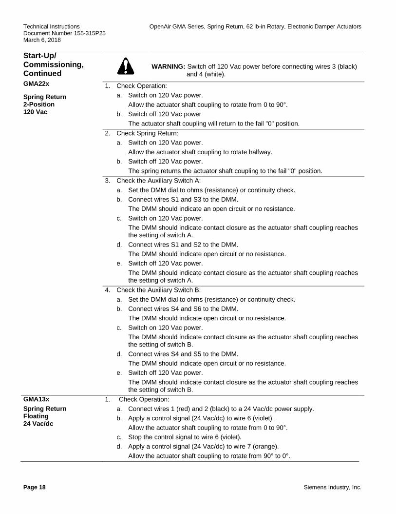
WARNING: Switch off 120 Vac power before connecting wires 3 (black)and 4 (white).
1. Check Operation:a. Switch on 120 Vac power.
Allow the actuator shaft coupling to rotate from 0 to 90°.b. Switch off 120 Vac power
The actuator shaft coupling will return to the fail "0" position.2. Check Spring Return:
a. Switch on 120 Vac power.Allow the actuator shaft coupling to rotate halfway.
b. Switch off 120 Vac power.The spring returns the actuator shaft coupling to the fail "0" position.
3. Check the Auxiliary Switch A:a. Set the DMM dial to ohms (resistance) or continuity check.b. Connect wires S1 and S3 to the DMM.
The DMM should indicate an open circuit or no resistance.c. Switch on 120 Vac power.
The DMM should indicate contact closure as the actuator shaft coupling reachesthe setting of switch A.
d. Connect wires S1 and S2 to the DMM.The DMM should indicate open circuit or no resistance.
e. Switch off 120 Vac power.The DMM should indicate contact closure as the actuator shaft coupling reachesthe setting of switch A.
4. Check the Auxiliary Switch B:a. Set the DMM dial to ohms (resistance) or continuity check.b. Connect wires S4 and S6 to the DMM.
The DMM should indicate open circuit or no resistance.c. Switch on 120 Vac power.
The DMM should indicate contact closure as the actuator shaft coupling reachesthe setting of switch B.
d. Connect wires S4 and S5 to the DMM.The DMM should indicate open circuit or no resistance.
e. Switch off 120 Vac power.The DMM should indicate contact closure as the actuator shaft coupling reachesthe setting of switch B.
GMA13xSpring ReturnFloating24 Vac/dc
1. Check Operation:a. Connect wires 1 (red) and 2 (black) to a 24 Vac/dc power supply.b. Apply a control signal (24 Vac/dc) to wire 6 (violet).
Allow the actuator shaft coupling to rotate from 0 to 90°.c. Stop the control signal to wire 6 (violet).d. Apply a control signal (24 Vac/dc) to wire 7 (orange).
Allow the actuator shaft coupling to rotate from 90° to 0°.

OpenAir GMA Series Spring Return, 62 lb-in, Rotary, Electronic Damper Actuators Technical InstructionsDocument Number 155-315P25
March 6, 2018
Siemens Industry, Inc. Page 19
Start-Up/Commissioning,ContinuedGMA13xSpring ReturnFloating24 Vac/dc
2. Check Spring Return:a. Apply a control signal (24 Vac/dc) to wire 6 (violet).
Allow the actuator shaft coupling to rotate half way.b. Disconnect wire 1 (red).
The spring returns the actuator shaft coupling to the fail "0" position.c. Connect wire 1 (red).
The actuator shaft coupling begins to move.
3. Check Feedback:a. Set the DMM dial to ohms.b. Connect wires P1 and P2 to the DMM.
The DMM should indicate a resistive value.c. Apply a control signal (24 Vac/dc) to wire 6 (violet).
The reading of the DMM should increase.d. Stop the control signal to wire 6 (violet).e. Connect wires P2 and P3 to the DMM.
The DMM should indicate a resistive value.f. Apply a control signal (24 Vac/dc) to wire 7 (orange).
The reading of the DMM should increase.4. Check the Auxiliary Switch A:
a. Set the DMM dial to ohms (resistance) or continuity check.b. Connect wires S1 and S3 to the DMM.
The DMM should indicate an open circuit or no resistance.c. Apply a control signal (24 Vac/dc) to wire 6 (violet).
The DMM should indicate contact closure as the actuator shaft couplingreaches the setting of switch A.
d. Stop the control signal to wire 6 (violet).e. Connect wires S1 and S2 to the DMM.
The DMM should indicate an open circuit or no resistance.f. Apply a control signal (24 Vac/dc) to wire 7 (orange).
The DMM should indicate contact closure as the actuator shaft couplingreaches the setting of switch A.
5. Check the Auxiliary Switch B:a. Set the DMM dial to ohms (resistance) or continuity check.b. Connect wires S4 and S6 to the DMM.
The DMM should indicate an open circuit or no resistance.c. Apply a control signal (24 Vac/dc) to wire 6 (violet).
The DMM should indicate contact closure as the actuator shaft coupling reachesthe setting of switch B.
d. Stop the control signal to wire 6 (violet).e. Connect wires S4 and S5 to the DMM.
The DMM should indicate an open circuit or no resistance.f. Apply a control signal (24 Vac/dc) to wire 7 (orange).
The DMM should indicate contact closure as the actuator shaft coupling reachesthe setting of switch B.

Technical Instructions OpenAir GMA Series, Spring Return, 62 lb-in Rotary, Electric Damper ActuatorsDocument Number 155-315P25March 6, 2018
Page 20 Siemens Industry, Inc.
Service WARNING:Do not open the actuator.If the actuator is inoperative, replace the unit.
Troubleshooting WARNING:To avoid injury or loss of life, pay attention to any hazardous voltage(For example, 120 Vac) when performing checks.
· Check that the wires are connected correctly.
· Check that span/offset (start point) and Dip switches are set correctly, if used.
· Use a Digital Multimeter (DMM) to verify that the operating voltage is within range.
· If the actuator is not working, check the damper for blockage. If blocked, removethe obstacle and cycle the actuator power off and on. The actuator should resumenormal operating mode.
Dimensions
Inches (mm)
Figure 20. ASK75.3U Weather Shield Dimensions.
Figure 21. Dimensions of the ASK75.7U Weather Shield in Inches (Millimeters).

OpenAir Spring Return, GMA Series, 62 lb-in Rotary, Electronic Damper Actuators Technical InstructionsDocument Number 155-315P25
March 6, 2018
Information in this publication is based on current specifications. The company reserves the right to make changes in specifications and models asdesign improvements are introduced. OpenAir is a trademark of Siemens Schweiz, AG. Product or company names mentioned herein may be thetrademarks of their respective owners. © 2018 Siemens Industry, Inc.
Siemens Industry, Inc.Building Technologies Division1000 Deerfield ParkwayBuffalo Grove, IL 60089USA+ 1 847-215-1000
Your feedback is important to us. If you havecomments about this document, please send themto [email protected]
Document No. 155-315P25Printed in the USA
Page 21
Dimensions, Continued
Inches (mm)
Figure 22. GMA Actuator and Mounting Bracket Dimensions.