Embed Size (px)
Citation preview

ED 195 405
TITLE
INSTITUTION
FEPORT NOPUB DATENOTEAVAILABLE FROM
ED FS PRICEDESCRIPTORS
DOCUBENT RESUME
SE 033 253
Aircraft Inspection for the General Aviation AircraftOwner.Federal Aviation Administration (DOT), Washington,D.C. Flight Standards Service.AC-20-106Apr 7893p.: Pho4ographs may not reproduce well.Superinte-ant of Documents, U.S. Government PrintingOffice, Washington, DC 20402 (Stock No.050-007-00449-4: $3.501.
MF01/PC04 Plus Postage.Aerospace Education: *Pviation Mechanics; AviationTechnology: Engines: *E.701.pment Evaluation:*Equipment Standards: Gov :nment Publications;*Inspection: *Maintenance: *Safety; ScienceEducation
ABSTRACTPresented is useful information for owners, pilots,
student mechanics, and others with aviation interests. Part I of thisbooklet outlines aircraft inspection requirements, ownerresponsibilities, inspection time intervals, and sources of basicinformation. Part II is concerned with the general techniques used toinspect an aircraft. (Author /JN)
************************************************************************ Reproductions supplied by EDRS are the best that can be made ** from the original document. *
***********************************************************************
LC\
L.C1
LU
AC 20-106
AIRCRAFT INSPECTION FOR THE GENERALAVIATION AIRCRAFT OWNER
U S. DEPARTMENT OF HEALTH.EDUCATION & WELFARENATIONAL INSTITUTE OF
EDUCATION
4<k4'
x%s'boa;>,
7A
THIS OL.CUMENT HAS BEEN REPRO-DUCED EXACTLY AS RECEIVEO FROMTHE PERSON OR ORGANIZATION ORIGIN-ATING IT POINTS OF VIEW OR OPINIONSSTATED DO NOT NECESSARILY REPRE-SENT OFFICIAL NATIONAL INSTITUTE OFEDUC4TION POSITION OR POLICY
et,STATES 0*
APRIL 1978
U.S. DEPARTMENT OF TRANSPORTATIONFEDERAL AVIATION ADMINISTRATION
cl) Flight Standards Service
t)(1)OLLL(,) For sale by the Superintendent of Documents, U.S. Government Printing Office
Washington, D.C. 20102
Stock Number 050-007-00149-4
PREFACEThe inspections described in this Aircraft Inspection handbook are NOT
intended to replace any required inspection. Rather, they are intended tofamiliarize persons with the techniques generally applicable to aircraft iTspections whether they be owners, pilots, student mechanics, or others withaviation interests.
The services of an appropriately rated certificated repair station, certifi-cated mechanic, or the manufacturer must be utilized for all required inspec-tions and whenever any inspection reveals a questionable condition. Weemphasize the fact that reliable inspection capability comes only with ex-perience, and the use of this handbook does NOT qualify an individual tomake final airworthiness determinations.
PART IINSPECTION FUNDAMENTALSInspection requirements, owner's responsibilities, inspection time inter-
vals, and sources of basic information are discussed in Part. I.
PART IIINSPECTION TECHNIQUESThe general techniques used to inspect an aircraft are discussed in Part
II.To facilitate reference, in the explanation of important inspection pro-
cesses, arrows appear on many of the illustrations. These indicate either theitem or the general area to which the text refers.
Numerous illustrations are used to convey information to the reader inthe most clear, graphic, and PMective manner.
Acknowledgment of cooperation is extended to the following:Beech Aircraft CorporationCessna Aircraft CompanyCessna Aircraft Company
Aircraft Radio and Control DivisionEdo CorporationPiper Aircraft CorporationRockwell International
(Rockwell Commander Aircraft)The Bendix Corporation
Electric/Fluid Power DivisionThe Goodyear Tire and Rubber CompanyThis publication cancels the Personal Aircraft Inspection Handbook, AC
M-9, published in 1964. Suggestions for revision and improvement of thishandbook are encouraged and may be forwarded to Department of Transpor-tation, Federal Aviation Administration, Flight Standards National FieldOffice, AFS-500, P.O. Box 25082, Oklahoma City, Oklahoma 73125.
3
AIRCRAFT INSPECTION FOR THE GENERALAVIATION AIRCRAFT OWNER
ContentsPage
Preface
Part I. Inspection Fundamentals 1
Section 1. The Inspection Process 1
Section 2. Preventive Maintenance 4Section 3. The Forces of Attrition 7Section 4. Inspection Do's and Don'ts 14
Part II. Inspection Techniques 15Section 1. Fuselage 15Section 2. Cabin-Cockpit 21Section 3. Engine-Nacelle 27Section 4. Landing Gear 42Section 5. Wing-Center Section 53Section 6. Empennage 61Section 7. Propeller 66Section 8. Radio 71Section 9. Miscellaneous 75Section 10. Preflight Inspection 77Section 11. After Storage 80
APPENDIX A.APPENDIX B.
APPENDIX C.
APPENDIX D.
FigureI-1.
General Safety Precautions 81
Aviation FuelIdentification and Fueling Proce-dures 83
Certificate of RegistrationAircraft Eligibility andApplication 85
Certificate of AirworthinessGeneral Information 87
List of IllustrationsPART I. Inspection Fundamentals
PageFive stresses acting on aircraft 10
Part II. Inspection TechniquesSection 1.1-1. Inspection chartfuselage 151-2. Cracked fuselage structure 161-3. Cracked former 161-4. Distorted fuselage skin 161-5. Deteriorated fuselage fabric 16
iii
4
Figure Page1.-6. External wing bracing attachment checkpoints 161-7. Proper cable routing 171-8. Improper cable routing 171-9. Proper routing of electrical wiring 171-10. Improper routing of electrical wiring 181-11. Leakage from chafed hydraulic line 181-12. Draining fuel tank sump 181-13. Door lock checkpoints 191-14. Emergency exit checkpoints 191-15. Interior aft fuselage (light twin) 20Section 2.2-1. Inspection chart-cockpit 212-2. Inspection chart-cabin 222-3. Operational check-fuel tank selector valve 222-4. Circuit breaker and fuse panel 232-5. Check quantity hydraulic fluid 232-6. Instrument panel 242-7. Bellcrank checkpoints 242-8. Cable rubbing bulkhead 242-9. Gust lock ...
252-10. Frayed safety belt 252-11. Safety harness 252-12. Inspection items on seat 25Section 3.3-1. Inspection chnrt-engine and nacelle 273-2. Inspection chart-engine 283-3. Fuel strainer checkpoints 293-4. Carburetor inspection points 293-5. Carburetor air filters 303-6. Intake manifold checkpoints 303-7. Oil tank inspection
303-8. Oil quantity check313-9. Satisfactory oil line installation 313-10. Unsatisfactory oil line installation 313-11. Oil-cooler checkpoints 323-12. Checking sparkplug torque 323-13. Unsatisfactory sparkplug cigarette 333-14. Igniter plug-gas turbine engine 333-15. Exhaust manifold checkpoints333-16. Exhaust stack damage343-17. Heat exchanger-shroud removed353-18. Cowl flap checkpoints363-19. Engine baffles373-20. Engine mount checkpoints373-21. Cracked engine mount373-22. Checking starter security383-23. Inspect cowling for damage393-24. Damaged cowling38
iv
Figure Page3-25. Repaired cowling 393-26. Cowling installation checkpoints 403-27. Evidence of chafing 413-28. Battery installation checkpoints 41
Section 4.4-1. Examples of tire defects 424-2. Tire protected by drip pan 424-3. Multiple disc-type brake' 434-4. Shoe and drum-type brake 434-5. Expander block-type brake 434-6. Disc brake inspection points 434-7. Wheel and brake inspection points 444-8. Hydraulic brake line checkpoints 444-9. Simple master cylinder brake systems 444-10. Cockpit-hydraulic brake line checkpoints 444-11. Wheel checkpoints 464-12. Inspection chart-fixed landing gear 454-13. Fixed nose gear checkpoints 464-14. Oleo-type landing gear checkpoints 464-15. Steerable tailwheel inspection points 474-16. Inspection chart-retractable.landing gear 484-17. Retractable main gear checkpoints 474-18. Landing gear retracting 494-19. Retractable nose gear checkpoints 504-20. Retracting mechanism checkpoints 504-21. Typical electrical retraction installation 504-22. Electrical retracting motor and wiring 514-23. Warning microswitch installation 514-24. Gear attachment structure checkpoints 514-25. Float installation inspection points 514-26. Ski installation inspection points 52
Section 5.5-1. Inspection chart-wing-center section 535-2. Indication of defective fabric 545$. Wood structure inspection points 545-4. Metal structure inspection points 555-5. Lighting damage-flap, lower surface 565-6. Control bellcrank checkpoints 555-7. Fuel tank vent 575-8. Fuel cap, vent, and placard 575-9. Pitot mast, airspeed 585-10. Electrical wiring, proper routing 585-11. Satisfactory leading edge of wing 585-12. Dented leading edge of wing 595-13. Damaged landing light lens 605-14. Deicer boot damage 605-15. Block type gust lock 60
Figure PageSection 6.6-1. Inspection chart-empennage 616-2. Oilcanning of metal skin 626-3. External bracing checkpoints 636-4. Rudder checkpoints 636-5. Rudder quadrant 646-6. Stabilizer adjuster checkpoints 656-7. Position light checkpoints 65
Section 7.7-1. Inspection chart-propeller 667-2. Damaged metal blade 667-3. Three-blade propeller checkpoints 677-4. Propeller tip damage 687-5. Wood propeller blade-cracked and separated lamination 687-6. Propeller governor checkpoints 69.7-7. Propeller spinner checkpoints 697-8. Propeller liquid anti-icing system checkpoints 707-9. Propeller electrical deicing system checkpoints 70
Section 8.8-1. Inspection chart-radio 718-2. Communication/navigation equipment installation checkpoints _ 718-3. Bonding radio equipment to shock mount 728-4. Communication/navigation equipment shock mount 728-5. 'Typical communication/navigation equipment. control 728-6. Antenna installations checkpoints 738-7. ADF antenna-internal loop-tail mount. 738-8. ADF antenna-fixed loop 738-9. Bonding wires and trailing edge static wicks 74
Section 9.9-1. Rotating beacon installation 759-2. Autopilot control panel 759-3. Emergency locator transmitter-remote mount 759-4. Emergency locator transmitter-portable mount 76
Section 10.10-1. Inspection chart-preflight 77
Section 11.11-1. Bird's nest 80
Part I. INSPECTION FUNDAMENTALS
Section 1. THE INSPECTION PROCESS
The Required Aircraft Inspections
The Federal Aviation Regulations (FARs)require the inspection of all civil aircraft atspecific intervals, to assure that the aircraft'scondition is equal to its original or properlyaltered condition with regard to aerodynamicfunction, structural strength, and resistance tovibration.
Inspection interval requirements are estab-lished considering the purpose for which theaircraft is used and its operating environment.Some aircraft must be inspected each 100 hoursof time in service while others must be in-spected only once each 12 calendar months.
The 100-hour and annual inspections requirecomplete inspection of the aircraft at one timeand a certification as to its airworthiness.Some airplanes may be inspected in accordancewith a progressive inspection (FAR 91.171) oran approved inspection program (FAR 91.217)wherein portions of the aircraft are inspectedaccording to a predetermined schedule.
The inspection requirements for aircraft, invarious types of operation, are stated in FAR91, Sections 91.169, 91.171, or Subpart D ofFAR 91. The latter prescribes an inspectionprogram for large and turbine-powered multi-engine airplanes (turbojet and turboprop). Ifyou are concerned with the inspection of alarge airplane (over 12,500 pounds) or a turbo-jet or turbopropeller-powered multiengine air-plane, you should determine the inspectionrequirements for that specific airplane.
The information contained in Section I ofthis handbook may not be directly applicableto these larger type airplanes, but the inspec-tion techniques will be similar.
1
FAR 91General Operating and Flight Rules.
Subpart C of Part 91 prescribes rules gov-erning the maintenance, preventive mainte-nance, and alteration of U.S. registered civilaircraft operated within or outside the UnitedStates. (Inspection is part of maintenance.)
FAR 43--Maintenance, Preventive Maintenance,Rebuilding, and Alteration, prescribes rules gov-erning the maintenance, preventive mainte-nance, rebuilding, and alteration of aircraft aswell as standards for their performance.
Inspection.
Inspection is the critical visual examining,testing, measuring, and functional checking re-quired to determine the airworthiness of theitems being inspected.
NOTE: As mentioned in the preface, the serv-ices of a certificated repair station, certificatedmechanic, or the manufacturer must be utilizedfor all required inspections and whenever anyinspection reveals a questionable condition.
Scope of Inspections.
Aircraft inspection may range from a casual"walk-around" to a detailed inspection involv-ing complete disassembly and the use of com-plex inspection aids. The inspections describedin this advisory circular can be made withoutdisturbing the assembly of the aircraft except:for the removal of inspection access covers,fairings, and removable cowlings.
The. Habit of Inspection.
The inspection of your aircraft should be-come a habit. To establish the habit, begin byperforming preflight inspections and work upto detailed inspections. USE the MANUFAC-TURER'S RECOMMENDATIONS and thishandbook as a guide. Develop a system of
inspection and use. an inspection checklist thatcovers the complete aircraft. Once adopted,you should not deviate from the procedure.After completing a-few inspections you will besurprised at how familiar you will be with youraircraft.
Inspection Intervals and Systems.
Federal Aviation Regulations require. inspec-tion of aircraft at specific intervals and thatthey be approved for return to service by cer-tificated and appropriately rated personnel.The purpose of this handbook is to familiarizeinterested persons with general inspection tech-niques and to assist pilots and owners in estab-lishing an inspection program which willsupplement. but NOT replace the requiredinspections.
The interval of your inspection should beadjusted to provide the greatest value to youconsidering your aircraft use and the requiredinspections; e.g., if you are required to have100-hour inspections, you might want to in-spect the aircraft each 25 and 50 hours. If youare required to have only annual inspections,you may wish to inspect the aircraft each 50 to100 hours of operation. The manufacturer'sservice instructions will be valuable in estab-lishing these intervals.
Historically, inspection intervals have beenestablished on the basis of flying hours. How-ever, if utilization is low and flying is doneover the weekends, you may find it advisableto inspect a small group of items each weekend.This will spread your inspection over a periodof time and reduce large demands on yourtime. Here are some examples of types ofinspection intervals:By hours:
Daily preflight inspectionPowerplant (including propeller and engine
controls)every 25 hoursFlight control systemsevery 2.5 hoursLanding gearevery 50 hoursCabin or cockpitevery 75 hoursCovering (fabric or metal)every 100 hoursFuselage interiorevery 100 hours, etc.
2
By calendar weeks (eight-week cycle) :
Daily preflight inspection (including propel-ler and engine controls)
Powerplantfirst and fifth weekendFlight control systemsecond and sixth
weekendLanding gearthird and seventh weekendCabin or cockpitfourth and eighth week-
endCovering (fabric or metal)eighth weekendFuselage interioreighth weekendThis weekly inspection schedule will provide
a complete aircraft inspection every eightweeks. You may wish to extend or shortenthis inspection cycle.
In some cases, it may be convenient to estab-lish a combination of both methods. Regard-less of the method chosen, adhere to itfaithfully. Do not assume that an item is ingood condition. Make a personal inspectioneach time an inspection is due, according toyour plan. There are many inspection items;each of which is essential.
When developing an inspection schedule foryour aircraft, consideration should be given toclimatic conditions, frequency and type offlight operation conducted, contemplated pe-riods of inactivity, and type of storage facili-ties. A thorough review of the aircraftmanufacturer's service instructions will providemany helpful suggestions on inspections. Mostmanufacturers provide an inspection schedulefor their aircraft which can be segmented asyou desire. The information in this handbookwill not tell you WI-LEN to inspect. It willsuggest. WHAT should be inspected and HOWand WHERE to look for possible defects.
Be sure your plans include the time neces-sary to regularly inspect your aircraft. If suchtime cannot be included'in your plans, then youshould have it done by certificated personnel.When you have inspections conducted by aprofessional, whether they are required or sup-plemental in natnre, you should specify exactlywhat inspection is to be accomplished and re-quire the person conducting the inspection tofurnish a written statement, of the results.
9
Aircraft Logs.
"Logs," as commonly used, is an inclusiveterm which applies to the aircraft record"books," and to all supplemental records con-cerning the aircraft. These logs and recordsprovide a history of maintenance and opera-tion, a control for inspection schedules, dataneeded to properly accomplish time replace-ments of components or accessories, and arecord of Airworthiness Directive compliance.Most Airworthiness Directive compliance isbased on aircraft time-in-service, and it is aregulatory requirement that records be keptup-to-date.
Tool: of Inspection.
The tools of inspection are many and varied.They range from a pocket-sized magnifyingglass to a complex X-ray machine. The toolsrequired to make a simple inspection, of thetype which may be performed by the aircraftowner, are inexpensive and readily available.
The following list is typical:eight or ten-power magnifying glassinspection mirrorflashlightsmall wire brushdull-bladed kniferound bristle brush and cleaning fluid (use
caution when selecting cleaning fluids)hydrometersome ragssmall kit of common handtools (screwdriver,
end wrenches, diagonal cutters, etc.)skid-proof stepladder and wheel jacks
REMEMBER
If defects are noted or suspected, have adetailed inspection done by a certificatedrepair station or certificated mechanic.
Section 2. PREVENTIVE MAINTENANCE
Preventive maintenance means simple preser-vation and the replacement of small standardparts not involv ing complex assemblies. It iscorrective action .taken before it becomes neces-sary to make more complex repairs. Thefollowing preventive maintenance may be ac-complished by a certificated pilot, who is theowner or operator of an aircraft, not used inair carrier service.
This list comes from FAR 43, Appendix A,Major Alterations, Major Repairs, and Preven-tive Maintenance, paragraph (c). It reads asfollows:
"(c) Preventive maintenance. Work of thefollowing type is preventive maintenance :
(1) Removal, installation, and repair oflanding gear tires.
(2) Replacing elastic shock absorber cordson landing gear.
Servicing landing gear shock struts byadding oil, air, or both.
(4) Servicing landing gear wheel bearings,such as cleaning and greasing.Replacing defective safety wiring orcotter keys.
(6) Lubrication not requiring disassemblyother than removal of nonstructuralitems such as cover plates, cowlings,and fairings.Making simple fabric patches not re-quiring rib stitching or the removal ofstructural parts or control surfaces.
(8) Replenishing hydraulic fluid in thehydraulic reservoir.Refinishing decorative coating of fuse-lage, wings, tail group surfaces (ex-cluding balanced control surfaces),fairings, cowling, landing gear, cabin,or cockpit interior when removal or dis-
(3)
(5)
(7)
(9)
4
assembly of any primary structure oroperating system is not required.
(10) Applying preservative or protectivematerial to components where no dis-assembly of any primary structure oroperating system is involved and wheresuch coating is not prohibited or is notcontrary to good practices.
(11) Repairing upholstery and decorativefurnishings of the cabin or cockpit in-terior when the repairing does not re-quire disassembly of 'mny primarystructure or operating system or inter-fere with an operating system or affectprimary structure of the aircraft.
(12) Making small simple repairs to fair-ings, nonstructural cover plates, cowl-ings, and small patches and reinforce-ments not changing the contour so asto interfere with proper airflow.
(13) Replacing side windows where ,thatwork does not interfere with the struc-ture or any operating system such ascontrols, electrical equipment, etc.
(14) Replacing safety belts.(15) Replacing seats or seat parts with re-
placement parts approved for the air-craft, not involving disassembly of anyprimary structure or operating system.
(16) Troubleshooting and repairing brokencircuits in landing light wiring circuits.
(17) Replacing bulbs, reflectors, and lensesof position and landing lights.
(18) Replacing wheels and skis where noweight and balance computation is in-volved.
(19) Replacing any cowling not requiringremoval of the propeller or disconnec-tion of flight controls.
(20)
(21)
(22)(23)(24)
(25)
Replacing or cleaning spark plugs andsetting of spark plug gap clearance.Replacing any hose connection excepthydraulic connections.Replacing prefabricated fuel lines.Cleaning fuel ,end oil strainers.Replacing batteries and checking fluidlevel and specific gravity.Removing and installing glider wingsand tail surfaces that are specificallydesigned for quick removal and instal-lation and when such removal and in-stallation can be accomplished by thepilot."
Technical data for use in performing preven-tive maintenance may be found in the manu-facturers' manuals. General data on aircraftmaintenance may be obtained from the follow-ing Advisory Circulars (AC) published by theFAA. All are available from the Superin-tendent of Documents (Supt. Does.) andshould be ordered by the stock numbers (SN)listed after each AC.
AC 65 -9A, Airframe and Powerplant Mechan-ics General Handbook, is designed as a studymanual for persons preparing for a mechaniccertificate with airframe or powerplant ratings.Emphasis in this volume is on theory andmethods of application. It is intended to pro-vide basic information about principles andfundamentals 'common to both the airframeand powerplant ratings. (SN 050-007-00379-0.)
AC 65--12A, Airframe and Powerplant Me-chanics Powerplant Handbook, is designed tofamiliarize student mechanics with the con-struction, theory of repair, operation, andmaintenance of aircraft powerplants and pro-pellers. ( SN 050- 007 -00373 -1.)
AC 65-15A, Airframe and Powerplant Me-chanics Airframe Handbook, is designed to fa-miliarize student mechanics with construction,theory of repair, operations, and maintenanceof airframe and airframe systems. (SN050-007-00391-9.)
5
Advisory circulars are available either freefrom FAA or sold by the Superintendent ofDocuments. The source, ordering instructions,and current prices are listed in the FAA Ad-visory Circular Checklist, AC 00-2. Thechecklist should be consulted for current infor-mation before placing any orders. (A refer-ence copy is available at any FAA office orGPO Bookstore.)
The checklist is published three times a yearand is available free from Department ofTransportation, Publications Section, M-443.1,Washington, D.C. 20590.
The Status of Federal Aviation Regulations,AC 00-14, is issued as changes require and isalso available free from the above address.
Malfunction or Defect Reports (FAA Form8330-2) are provided free of charge and withreturn postage paid by the FAA. They arenormally preaddressed when provided, and area convenient means of ensuring that data, re-quired to make the report meaningful, is in-cluded.
These reports are a means by which theaviation community may interchange serviceinformation since the data received on the re-ports is published in numerous FAA publica-tions, available free or on a subscription basis.
Malfunction or Defect Reports are also adata source used by the FAA. in monitoringthe service reliability of aeronautical products.When trends are noted which indicate possibleproblem areas, the FAA may alert the aviationcommunity or initiate studies to determine theextent and exact nature of the problem.
All aircraft owners, pilots, mechanics, andnon-certificated maintenance facilities are in-vited to participate in the program by submit-ting M or D Reports whenever they becomeaware of items that may be of interest to others.The M or D Reports, FAA Form 8330-2, maybe obtained from most airport managers, main-tenance facilities, or any FAA District Office.
If you haVe had an experience you wish toshare, include in the report all informationavailable; how the occurrence became apparent,describe the malfunction, and include modelnumbers, part numbers, and serial numbers.
12

Parts may be submitted with the report byspecial arrangement. Pictures, sketches, orsnapshots are especially desirable. Includeidentification data such as make, model, andassembly name as an attachment rather thanprinting on the photograph. If you have anyquestions, or need any help, your local FAADistrict Office will gladly assist you.
The success of the program depends entirelyon participation by the aviation public. If youhave comments about the program or have aspecial experience or a "would you believe this"situation, send them to Federal Aviation Ad-ministration, Flight. Standards National FieldOffice, Safety Data Branch, AFS--580, P.O.Box 25082, Oklahoma City, Oklahoma 73125,
13
Section 3. THE FORCES OF ATTRITION
A Definition of Attrition.Attrition, for the purpose of this handbook,
is defined as the general wear and tear of anaircraft during its service life. The five basicsources of attrition are : weather, friction, over-loads, heat, and vibration. These forces assertthemselves in many ways on the entire struc-ture of the aircraft during its life span. Per-sons making inspections should be familiarwith the visible, measurable, or otherwise de-tectable effects of these forces.
Weather.
Much depends on local conditions such asheat, humidity, rain, wind, and snow. Eachelement, or combination of elements, has itsown peculiar effect upon -different parts of theaircraft. These effects are discusSed briefly inthe following paragraphs.
Atmospheric Moisture. The moisture contentof the atmosphere is directly related to theseverity of oxidation found on an aircraft.Aircraft based near large bodies of water or inareas receiving heavy rainfall are more sus-ceptible to oxidation (rusting and corrosion)than those based in.arid areas. Fabric surfacesand wood structures also decay due to at-mospheric conditions.
Oxidation. This condition is caused by thechemical combination of metal and oxygen.Oxidation is called rusting when talking aboutferrous materials; i.e., steel or iron. The oxi-dation of copper, aluminum, and other non-ferrous materials is usually known as corrosion.
Rusting. Rusi usually begins as a reddishdiscoloration on the surface and, if permittedto progress, will result in a reddish browncrustiness on the metal surface. Removal ofthe crust will probably reveal pitting. Ifpitted, the part should be examined by an ex-
7
perienced mechanic qualified to evaluate theextent of the damage and recommend or takecorrective action.
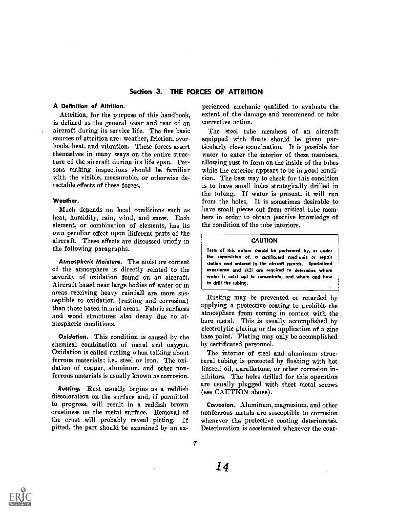
The steel tube members of an aircraftequipped with floats should be given par-ticularly close examination. It is possible forwater to enter the interior of these members,allowing rust to form on the inside of the tubeswhile the exterior appears to be in good condi-tion. The best way to check for this conditionis to have small holes strategically drilled inthe tubing. If water is present, it will runfrom the holes. It is sometimes desirable tohave small pieces cut from critical tube mem-bers in order to obtain positive knowledge ofthe condition of the tube interiors.
CAUTION
Tests of this nature should be performed by, or underthe supervision of, a certificated mechanic or repo:rstation and entered in the aircraft records. Specializedexperience and sk:II are required to determine wherewater is most apt to concentrate, and where and howto drill the tubing.
Rusting may be prevented or retarded byapplying a protective coating to prohibit theatmosphere from coming in contact with thebare metal. This is usually accomplished byelectrolytic plating or the application of a zincbase paint. Plating may only be accomplishedby certificated personnel.
The interior of steel and aluminum struc-tural tubing is protected by flushing with hotlinseed oil, paralketone, or other corrosion in-hibitors. The holes drilled for this operationare usually plugged with sheet metal screws(see CAUTION above).
Corrosion. Aluminum, magnesium, and othernonferrous metals are susceptible to corrosionwhenever the protective coating deteriorate's.Deterioration is accelerated whenever the coat-
4
ing is in contact with an eroding chemical suchas battery acid, insecticide, fertilizer or de-foliants. Contact between two unprotecteddissimilar metals sets the stage for galvanicaction and corrosion, the rate of which in-creases greatly in the presence of moisture,especially saltwater.
Ordinary corrosion of aluminum, magne-sium, or aluminum alloy parts can be detectedby watching for signs of surface flaking, pit-ting, or a white or grayish-white powdering.If pitting is apparent after removing the flakesor powder film, an experienced mechanic shouldbe contacted to evaluate the damage. Onaluminum and magnesium (or their alloys)surfaces that have been painted, watch forpaint bubbles or blisters. These indicate cor-rosion under the paint. The suspected partshould be cleaned to the bare metal, and exam-ined carefully.
Decay of Wood Structure. The protectivecoating on wood structures usually consists ofhigh grade varnish or some type of transparentenamel. An acceptable coating will have ahard glossy appearance. Whenever and wher-ever the protective coating deteriorates, decaywill start.
Healthy wood will splinter if probed with adull knife point. Decayed wood will crumbleor break away in chunks. Weathering of thestructure' is first indicated by a dull appearingsurface, which means that. the protective filmhas broken down. Be especially alert towooden components subject to the collection ofmoisture and/or poor ventilation.
Decay of Fabric. The decay of fabric issomewhat similar to the decay of wood. Ifexposed to the elements, fabric absorbs mois-ture and other harmful substances unless it isprotected by several applications of cellulosenitrate or cellulose acetate, liquids commonlyknown as "dope." When "dope" is applied, itacts to tighten the fabric and produces a hard,smooth, opaque finish. In time, this finish be-comes brittle and develops cracks which exposethe bare fabric to the harmful effects of ultra-violet light, dirt., oil, and mildew. The strengthof the fabric decreases to below minimumstrength and is no longer airworthy.
8
The effect of decay on finished fabric sur-faces can be ascertained only by testing. Todetermine if a test is necessary, examine thefabric surface. If the surface no longer pre-sents a hard flexible glossy finish, is severlyabraded, or cracks are present, testing is ap-propriate.
A manual punch test, performed by a quali-fied repair station or mechanic, will provide anindication of fabric strength. A conclusive testcan only be done by a recognized testing labora-tory, wherein fabric samples are tested underspecified temperature and humidity conditions.If laboratory test facilities are not readilyavailable, contact your local FAA inspector forinformation in their regard.
Since re-covering a surface is usually an ex-pensive process, economics dictates the practiceof good preventive maintenance. Washingfabric-covered surfaces with mild soap andwater, at reasonable intervals, will do much toprolong the life of dope and fabric. Protec-tion from sunlight also prolongs fabric life,since ultraviolet light is a prime factor infabric deterioration.
Friction
Friction is described as the resistance to rela-tive motion between two bodies in contact.Like any machine, the aircraft develops fric-tion in hundreds of moving parts. The effectof friction on the aircraft and its componentsis known as wear. Wear cannot be prevented,but steps can be taken to deter its ultimateeffects on the aircraft's airworthiness by properlubrication, alignment of moving parts, andcleanliness. To better understand inspectiontechniques, the terms used to describe the var-ious conditions of wear, due to friction, mustbe understood. They are as follows:
Abrasion is a form of wear caused by thepresence of an abrasive substance between twomoving parts. In the flight control system,the possibility of abrasion can be detected bya gritty, grinding sensation noticeable duringoperation. Landing gear joints subjected toabrasion may exhibit. an uneven jerky actionwhen in motion. Usually a black gritty sub-stance will be noticed at any joint subjected toabrasion.
15
Burnishing is the polishing of a surface bysliding contact with another smooth, hardermetallic surface. Usually there is no displace-ment or removal of metal. Burnishing is prob-ably the least serious of friction-caused prob-lems; however, it should be very closelymonitored. In can be considered a warningof an impending more serious conditiongall-ing, which is discussed later.
Chafing is the wear between two parts causedby the rubbing, sliding, or bumping of one onthe other. The term is normally used to de-scribe wear between parts not normally incontact.. Chafed fabric, wood, or metal canbe detected easily since chafing usually marksone or both parts involved. Metal parts, whenchafed, show a bright area where contact hasbeen made. Aluminum parts normally displaya black or dark gray residue aroun( 4-he pointof chafing. The simplest method of inspectingfor chafing is to carefully inspect cables, wires,tubes, etc., wherever they are in close proxi-mity to another part or when they are mountedto permit motion.
Cutting results in cuts or grooves in the wornpart. The cause of cutting is similar to chafingexcept that a sharp edge is in contact, insteadof a smooth surface.
Dent is an indentation in a surface producedby an object striking with force. The areassurrounding the indentation will usually beslightly upset. Areas especially susceptible todent damage are the propeller, spinner, nosecontour of engine cowling, nose cone of fuse-lage, and the leading edges of wings, horizontaland vertical stabilizers.
Elongation is the term used to describe theegg-shaped wear of a bearing surface arounda bolt, hinge pin, clevis pin, etc. It results inlooseness in one plane of motion greater thanthat of the other planes. Flight control sur-face hinges, engine control rod ends, flight con-trol push-pull rod ends, bellcrank ends, cableclevis ends, and similar parts are particularlysusceptible to this type of wear.
For example, an elevator may have the con-trol cable rigged so taut that a positive pres-sure is applied on one side of the hinge. Dur-
293-820 0 - 79 - 3
ing normal operation, the hinge .bearing willwear egg-shaped due to the hinge pin rotatingunder a thrust load imposed by the cable.
Erosion is the loss of metal from the surfaceby mechanical action of foreign materials, suchas fine sand or water. The eroded area will berough and may be lined in the direction inwhich the foreign material moved relative tothe surface. Aircraft operated from unim-proved airports are particularly susceptible toerosion, primarily on propellers, landing gear,cowling, and leading edges of wings andstabilizers.
Galling is the breakdown (or buildup) ofmetal surface due to excessive friction betweentwo parts having relative motion. Particles ofthe softer metal are torn loose and "welded"to the harder metal. Galling quite often be-gins as burnishing.
Gouge. A gouge usually involves materialloss but may be largely the displacement ofmaterial and results from contact with foreignmaterial under heavy pressure.
Scratch. A slight tear or break in materialsurface from light momentary contact withforeign material or object.
Score is a deeper (than scratch) tear orbreak in metal surface from contact underpressure. It may show discoloration from thetemperature produced by friction. The termis normally used to describe conditions on partsdesigned to run together; i.e., a worn bearingmight score the shaft.
Tear is a discontinuity which has progressedthrough the full thickness of the material.
Overload.Aircraft. are designed to absorb the loads
imposed during normal operation and accept acertain amount of overload. Excessive loads,however, result in failure or deformation ofthe structure. This deformation may be slightor prominent, but it is usually visible. In anycase, it can be detected and classified by certainappearances peculiar to the type of overloadapplied.
9
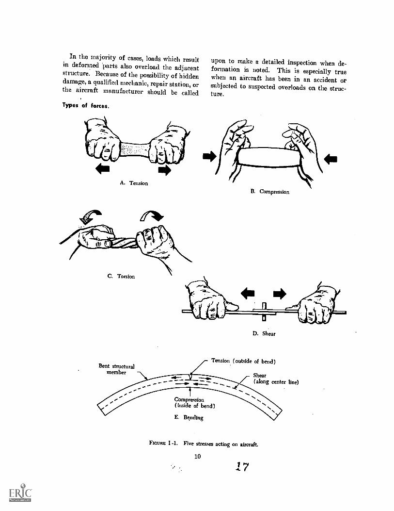
In the majority of cases, loads which resultin deformed parts also overload the adjacentstructure. Because of the possibility of hiddendamage, a qualified mechanic, repair station, orthe aircraft manufacturer should be called
Types of forces.
A. Tension
upon to make a detailed inspection when de-formation is noted. This is especially truewhen an aircraft has been in an accident orsubjected to suspected overloads on the struc-ture.
B. Compression
Bent structuralmember
D. Shear
Tension (outside of bend)
Shear7- (along center line)
Compression(inside of bend)
E. Bending
FIGURE I -1. Five stresses acting on aircraft.
10
17
Tension. When a load is'applied at either orboth ends of an item, tending to pull it apart,it is loaded in tension. Overloads due to ten-sion usually occur after a hard landing, taxiingon a rough field, or during flight in very tur-bulent air. After a hard landing, all attach-ment fittings should be examined for tensionfailures or deformation. Failure is indicated3y attachment fittings which show signs of)ulling away from fuselage structure or failuren a welded area, and bolt holes which areelongated or torn. Welds are particularly sub-ject to failure under tension loads and shouldbe closely inspected.
In aircraft of all metal construction, over-loads are usually evidenced by wrinkling of themetal skin, around wing, stabilizer and landinggear attachment points, and deformed orcracked fittings.
Wing struts are in tension during normalflight conditions and when severe vertical cur-rents or gusts are encountered, they may besubjected to heavy loading. The strut attach-ment points, at the wings and fuselage, shouldbe carefully examined for the indications offailure described for landing gears.
Compression. A part subject to compressionloads tends to fail (bulge) at the weakest pointin overall length or "Pan, at right angles to theapplication of the overload.
Compression failures are usually found aftera hard landing, flight through turbulent air, oran accident, and affects the same areas refer-enced under tension in the previous paragraphs.A bulge is indicative of compression failure;however, it is not always noticeable. In thisevent, a break in protective paint coating maybe present. Sheet metal and extruded mem-bers will show some form of distortion whendamaged by compression. In long memberssuch as wing struts, compression may be firstevidenced by what appears to be a bow or bendin the member.
A compression overload of a wood membercan usually be detected by a slight ridge acrossthe face of the member at right angles to thedirection of the grain.
Torsion is a twisting force that tends to turnone end of a part about a longitudinal axis
11
while the other end is held fast or turned in anopposite direction. Wheels caught in frozenruts during a landing will tend to twist thelanding gear members. Severe air loads im-posed during abnormal flight maneuvers orflight through turbulent air may twist the con-trol surfaces or other components. Improperrigging adjustments to wings and tail surfacesmay also cause twisting of these components.The inspection, in these cases, is similar to thatdescribed for tension and compression over-loads.
Certain landing gears employ a torsionalmember referred to as a "scissor," "nutcracker," or "torque link." Careful inspectionshould be made of this assembly for loose boltsand cracks, especially after landing in a roughor rutted field.
Shear. An action or stress resulting fromforces applied so as to cause a portion of a partto move relatively to another portion in a di-rection parallel to the direction of the force.This action is normally found in tools such asbolt cutters or sheet metal shears which applythe force and shear the material being worked.
When an overload is applied, the part havingthe least resistance to the force will be the firstto fail. For this reason, bolts, rivets, and clevispins should be examined for signs of failure.This is especially important when it is foundthat the overloaded members do not show theusual indications of failure. Failed bolts,clevis pins, and rivets may shear or partiallyshear and yet appear perfectly normal to thecasual observer. To check for this condition,the following hints may prove useful:
1Bolts and Clevis PinsRemoval and in-spection is a positive check for condition.Removal of bolts, clevis pins, etc., is es-pecially difficult if deformed or otherwisedamaged by excessive shear loads.
2RivetsLoose or sheared aluminum rivetsmay be identified by the presence of blackoxide which is caused to form rapidly byworking of the rivet in its hole. Thisoxide will seep out from under the rivethead to stain the surrounding surface.Pressure applied to the skin adjacent tothe rivet. head will help verify the loos-ened condition of a rivet.
s
Bending is 'a force or combination of forcesthat will cause a rigid member to curve or bowaway from a straight line. Overloads whichcause bending are usually the result of ab-normal landing and flight loads, or improperground handling of the aircraft. Bent com-ponents will result from the following prac-tices: stepping or pushing on lift or otherstruts; lifting the aircraft by the stabilizer;jacking or placing supports under longerons;overloading cabin or baggage compartments;or exceeding turn limitations of the nose steer-ing mechanism. On fabric-covered airplanes,a bent member can often be detected by loose-ness or wrinkling of the fabric. Wood ormetal skin may become wrinkled, cracked, ordistorted.
Heat.
The principal source of heat affecting theaircraft is the powerplant. From the stand-point. of inspection, we are interested in twoheating methods. direct and indirect, bothnormally the result of engine operation. Directheat normally originates from leaking exhaustgases. Indirect heat is that radiated from anyhot system or component.
Direct heat. Leaks in components of the ex-haust system may permit carbon monoxide toenter the cabin heating system. More severeleaks or failures of exhaust. system componentsmay allow the escape of flames into surround-ing areas with disastrous results.
To forestall serious hazards, the exhaustpipes, clamps, bolts, braces, and welds shouldbe examined at frequent intervals. Exhaustgaskets must be in good condition. The nutsholding the exhaust pipe, or manifold to thecylinder must be properly torqued and safetied.Loose exhaust pipe bracing allows the pipe tovibrate, causes failure at the welds, and leaksfrom the flange surfaces. Heater muffs orshrouds should be removed to allow inspectionof the exhaust system components.
Indirect Heat. Indirect heat radiated or con-ducted from the engine is carried off by theaction of the air stream passing through the
12
cowling. If the air stream is unable to carrythe heat away, the resulting high temperaturesare harmful to the engine and may cause fail-ure of accessories or other parts of the power-plant assembly. Excessive indirect heat maybe indicated by one or more of the following:
1High oil temperature.2High cylinder head temperature.3Blistering of the paint covering adjacent
parts within the engine compartment.4An odor of burned oil or hot rubber dur-
ing or after engine operation.
5Auto-ignition upon shut down of the en-gine (engine tries to continue function-ing).
If any of the above indications are observed,immediate steps should be taken to trace thetrouble to its source, which is usually loose orleaking engine baffles, improperly fitted cowl-ing, improper rigging of carburetor heat doorcontrol, dirty oil coolers and screens, impropergrade of oil, or oil leaks. In any case, onceindications of excessive heat are found, a de-tailed inspection should be made by an appro-priately rated mechanic or repair station andcorrective action taken immediately.
Vibration
Vibration is the source of many malfunctionsand defects that occur throughout the life ofthe aircraft. Not only will vibration affectparts that are loose or poorly installed, but itwill also accelerate wear and cause the ulthnatefailure of others. There are two types ofvibration in aircraft operation; low frequencyand high frequency.
Low Frequency (usually noticeable vibra-tion). Low frequency vibration is usuallycaused by a malfunctioning powerplant orpropeller, worn engine mounting pads, loose-ness of the aircraft structure, or improper rig-ging. The problem causing vibration shouldbe corrected as soon as discovered since it willcause abnormal wear between moving parts ofthe aircraft and may induce failure in anynumber of other aircraft parts.
19
High Frequency (less noticeable vibration).High frequency vibration is caused by inherentvibration characteristics of the rotating massesin the engine and propeller, can also becaused by aerodynamic forces acting throughthe propeller or by engine firing impulses.High frequency vibrations are usually chartedby special instruments at the time the aircraftis type-certificated by the FAA. When harm-ful vibration frequencies are found, placardsare installed indicating the engine operatingranges which must be avoided.
Factors of Vibration Damage. The factors ofvibration damage can be grouped into threecategories: fatigue, excessive clearance, zindpoor installation. These points should be con-sidered when inspecting for the effects ofvibration.
Fatigue. Fatigue is the weakening and/oreventual failure of a member due to the cumu-lative effects of repetitive loads which cause achange in the molecular structure of the part.Fatigue itself cannot be detected or measuredwhile it is taking place except, possibly, underlaboratory conditions. Its effects are usuallymade known by the ultimate failure of a part.The best prevention against fatigue damage isto maintain a smoothly running powerplant.In addition, control excessive or abnormallooseness in other components of the aircraftby good maintenance practices, particularlyengine mounting pad's which are designed toisolate and absorb vibration.
With the above in mind, it is easily under-stood why the various components must beproperly mounted and secured to resist thedamaging effects of vibration. Copper linesare especially susceptible to fatigue and becomehard and brittle when subjected to vibration.The lines should be periodically replaced orremoved and annealed to restore the originalsoftness.
Excessive Clearance. Excessive clearances ac-celerate the wear rates of all components inwhich they exist and can contribute to theinitiation of flutter. Flutter is an aerodynamic
function, wherein oscillating high loads are im-posed on the affected movable surfaces and canresult. in rapid fatigue failure of critical areas,such as control surface hinge fittings and at-tachments. 'Wear rates are extremely highduring flutter. It is very important to main-tain. clearance within the limit established bythe manufacturer.
Installation.
Installation, as it is used here, is the properarrangement of the various parts in relation toeach other. A fuel, line, for example, may havesufficient clearance relative to another partwhile at rest, yet under vibration, it may moveand make contact. with the other part and be-come chafed or cut.
Ignition or electrical cables in contact witheach other may appear perfectly rigid duringnormal operation, but during periods of vibra-tion they may rub together and wear throughthe protective casings. Every part of the air-craft should be carefully examined for signsof chafing or cutting. If vibration has goneuncorrected for a time, all nuts, bolts, clamps,etc., should be checked for proper security.
Propeller Vibration
Propellers have inherent vibration char-acteristics which are not usually harmful but.can induce fatigue and in time cause failure ofparts essential to the airworthiness of the air-craft, This is one reason why periodic inspec-tion of the aircraft is essential.
A. special word about propellers. Quiteoften a propeller blade becomes nicked, es-pecially at the leading edges. .These nicks be-come points of stress concentration. IT ISIMPORTANT THAT NICKS BE RE-MOVED AS SOON AS POSSIBLE ANDIN A PROPER MANNER. Since the re-moval of nicks requires special skills and toolsand a thorough knowledge of the procedure,such work may be accomplished by certificatedpersonnel only. The importance of correct re-moval of even small nicks AS SOON ASPOSSIBLE after incurring them, cannot beoverstressed.
1320
Section 4. INSPECTION DO'S AND DON'TSDO'S
DO have an assortment of proper tools for in-spection.
DO have an inspection check form and a regu-lar inspection procedure. STICK TO IT.
DO remove all inspection plates and cowlingsin the area to be inspected.
DO clean all items to be inspected. This is es-sential in order to clearly see the parts youare inspecting. Inspect before and aftercleaning.
DO check all moving parts for proper lubrica-tion and check the "jam" or locking nutson push-pull controls or adjustment de-vices for security.
DO familiarize yourself with proper safetyingtechniques and inspect for proper safety-ing. Resafety a part you have unsafetiedbefore inspecting the next item.
DO seek assistance in any questionable area. Acertificated mechanic, an approved repairstation, or your local FAA inspector areyour prime contacts. Use them.
DO the job right the first timesave a lifeit may be your OWN.
14
DON'TS
DON'T be hurriedtake plenty of time toproperly inspect each item. If youdon't know what to do next, ASK.
DON'T move the propeller unless the magnetoswitch reads "OFF," or the ignitionsystem is otherwise rendered inopera-tive.
DON'T presume an item is airworthy until ithas been checked.
DON'T check landing gear by kicking itraise it off the ground.
DON'T perform any complex inspection ormaintenance operation unless you areproperly supervised by a certificatedmechanic.
DON'T take the attitudeit can't happen tome.
21
Part IL INSPECTION TECHNIQUES
Section 1. FUSELAGE
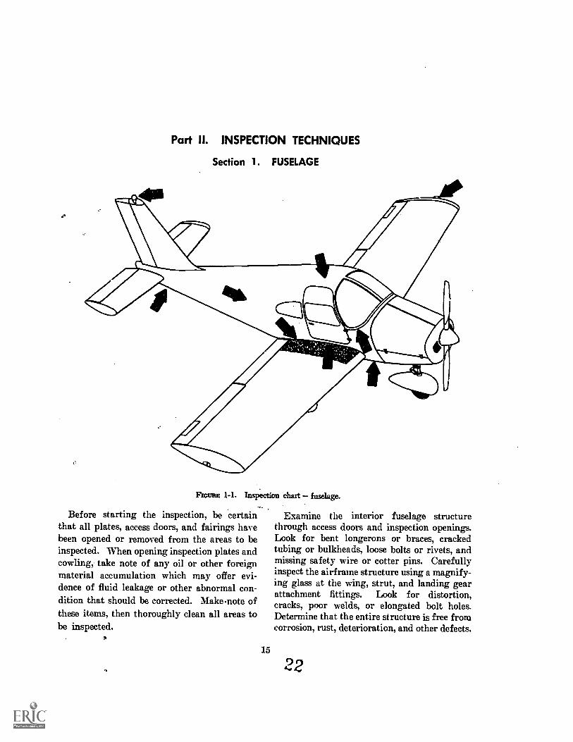
FIGURE 1-1. Inspection chart fuselage._
Before starting the inspection, be certainthat all plates, access doors, and fairings havebeen opened or removed from the areas to beinspected. When opening inspection plates andcowling, take note of any oil or other foreignmaterial accumulation which may offer evi-dence of fluid leakage or other abnormal con-dition that should be corrected. Make .note ofthese items, then thoroughly clean all areas tobe inspected.
Examine the interior fuselage structurethrough access doors and inspection openings.Look for bent longerons or braces, crackedtubing or bulkheads, loose bolts or rivets, andmissing safety wire or cotter pins. Carefullyinspect the airframe structure using a magnify-ing glass at the wing, strut, and landing gearattachment fittings. Look for distortion,cracks, poor welds, or elongated bolt holes.Determine that the entire structure is free fromcorrosion, rust, deterioration, and other defects.
15
22
0 0°0 0 O
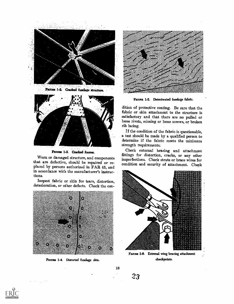
FIGVAZ 1-3. Cracked former.
Worn or damaged structure, and componentsthat are defective, should be repaired or re-placed by persons authorized in FAR 43, andin accordance with the manufacturer's instruc-tions.
Inspect fabric or skin for tears, distortion,deterioration, or other defects. Check the con-
" \-*
ZY y.,`,ti se, \ti" \
Fmuzz 1-4. Distorted fuselage sldn.
16
Rams 1-5. Deteriorated fuselage fabric.
dition of protective coating. Be sure that thefabric or skin attachment to the structure issatisfactory and that there are no pulled orloose rivets, missing or loose screws, or brokenrib lacing.
If the condition of the fabric is questionable,a test should be made by a qualified person todetermine if the fabric meets the minimumstrength requirements.
Check external bracing and attachmentfittings for distortion, cracks, or any otherimperfections. Check struts or brace wires forcondition and security of attachment. Check
Rums 1-8. External wing bracing attachment
checkpoints.
23
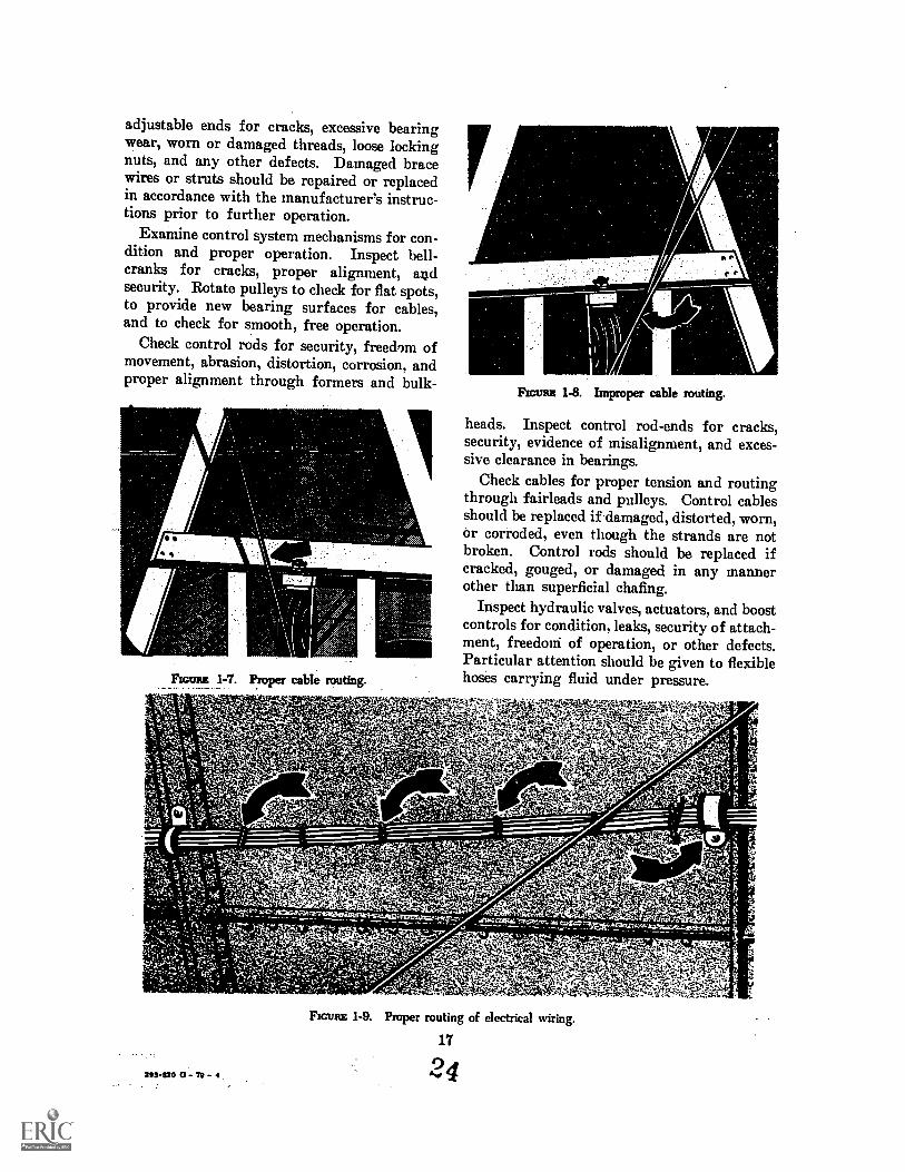
adjustable ends for cracks, excessive bearingwear, worn or damaged threads, loose lockingnuts, and any other defects. Damaged bracewires or struts should be repaired or replacedin accordance with the manufacturer's instruc-tions prior to further operation.
Examine control system mechanisms for con-dition and proper operation. Inspect bell-cranks for cracks, proper alignment, andsecurity. Rotate pulleys to check for flat spots,to provide new bearing surfaces for cables,and to check for smooth, free operation.
Check control rods for security, freedom ofmovement, abrasion, distortion, corrosion, andproper alignment through formers and bulk-
Frnmut 1-7. Proper cable routing.
e r
FM= 1-8. Improper cable routing.
heads. Inspect control rod-ends for cracks,security, evidence of misalignment, and exces-sive clearance in bearings.
Check cables for proper tension and routingthrough fairleads and pulleys. Control cablesshould be replaced if damaged, distorted, worn,or corroded, even though the strands are notbroken. Control rods should be replaced ifcracked, gouged, or damaged in any mannerother than superficial chafing.
Inspect hydraulic valves, actuators, and boostcontrols for condition, leaks, security of attach-ment, freedcari of operation, or other defects.Particular attention should be given to flexiblehoses carrying fluid under pressure.
253420 0 - 72 - 4
FIGURE 1-9. Proper routing of electrical wiring.
17
24
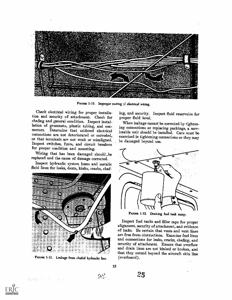
FIGURE 1-10. Improper muting electrical wiring.
Check electrical wiring for proper installa-tion and security of attachment. Check forchafing and general condition. Inspect instal-lation of grommets, plastic tubing, and con-nectors. Determine that soldered electricalconnections are not deteriorated or corroded,or that terminals arP not weak or misaligned.Inspect switches, fuses, and circuit breakersfor proper condition and mounting.
Wiring that has been damaged should .bereplaced and the cause of damage corrected.
Inspect hydraulic system hoses and metalicfluid lines for leaks, dents, kinks, cracks, chaf-
,
wn<
FIGURE 1-11. Leakage from chafed hydraulic line.
18
ing, and security. Inspect fluid reservoirs forproper fluid level.
When leakage cannot be corrected by tighten-ing connections or replacing packings, a serv-iceable unit should be installed. Care must beexercised in tightening connections or they maybe damaged beyond use.
FIGURE 1-12. Draining fuel tank sump.
Inspect fuel tanks and filler caps for properalignment, security of attachment, and evidenceof leaks. Be certain that vents and vent linesare free from obstructions. Examine fuel linesand connections for leaks, cracks, chafing, andsecurity of attachment. Ensure that overflowand drain lines are not kinked or broken, andthat they extend beyond the aircraft skin line(overboard).
25
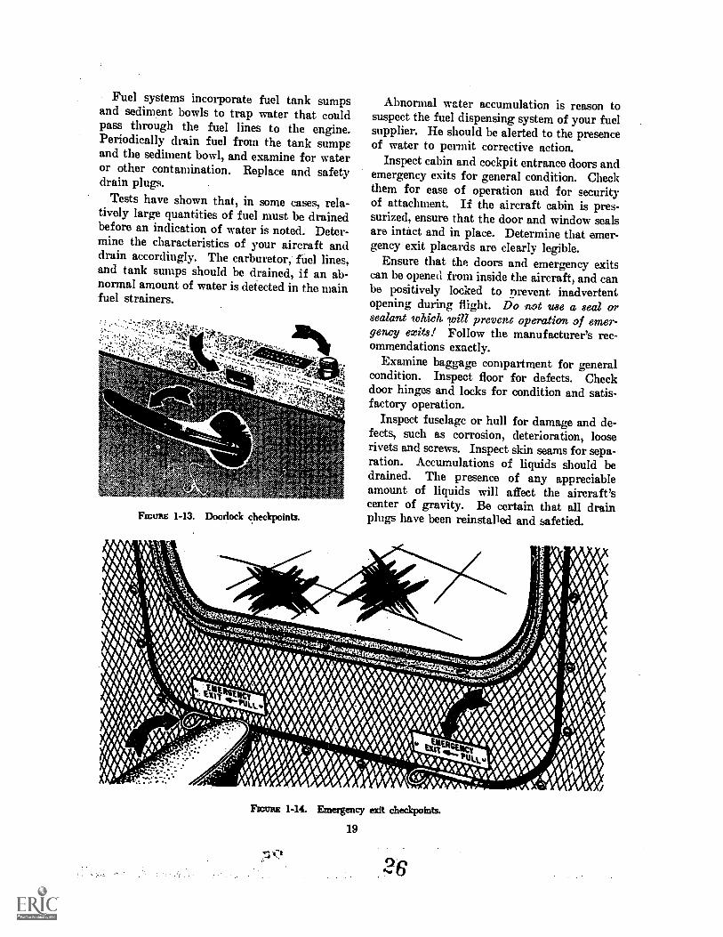
Fuel systems incorporate fuel tank sumpsand sediment bowls to trap water that couldpass through the fuel lines to the engine.Periodically drain fuel from the tank sumpsand the sediment bowl, and examine for wateror other contamination. Replace and safetydrain plugs.
Tests have shown that, in some cases, rela-tively large quantities of fuel must be drainedbefore an indication of water is noted. Deter-mine the characteristics of your aircraft anddrain accordingly. The carburetor, fuel lines,and tank sumps should be drained, if an ab-normal amount of water is detected in the mainfuel strainers.
111.111..
!'' ise. '..0.45, .0.??S
vA'it'cl-V
FWURE 1-13. Doorlock checkpoints.
Abnormal water accumulation is reason tosuspect the fuel dispensing system of your fuelsupplier. He should be alerted to the presenceof water to permit corrective action.
Inspect cabin and cockpit entrance doors andemergency exits for general condition. Checkthem for ease of operation and for securityof attachment. If the aircraft cabin is pres-surized, ensure that the door and window sealsare intact and in place. Determine that emer-gency exit placards are clearly legible.
Ensure that the doors and emergency exitscan be opened from inside the aircraft, and canbe positively locked to nrevent inadvertentopening during flight. Do not use a seal orsealant which rill prevent operation of emer-gency exits! Follow the manufacturer's rec-ommendations exactly.
Examine baggage compartment for generalcondition. Inspect floor for defects. Checkdoor hinges and locks for condition and satis-factory operation.
Inspect fuselage or hull for damage and de-fects, such as corrosion, deterioration, looserivets and screws. Inspect skin seams for sepa-ration. Accumulations of liquids should bedrained. The presence of any appreciableamount of liquids will affect the aircraft'scenter of gravity. Be certain that all drainplugs have been reinstalled and safetied.
FIGURE 1-14. Emergency exit checkpoints.
19
94.s
Whenever a panel is removed for interior in-spection, check the condition of all panelfasteners. Check the opening edges and thepanel for cracks. All accessories should beinspected for security and, if movable parts are
4)
involved, for freedom of movement. Figure1-15 shows the interior of the aft fuselage ofa light twin. Observe the mounting of theemergency locator transmitter, "A," and theyaw damper, "B."
20
27
Section 2. CABIN-COCKPIT
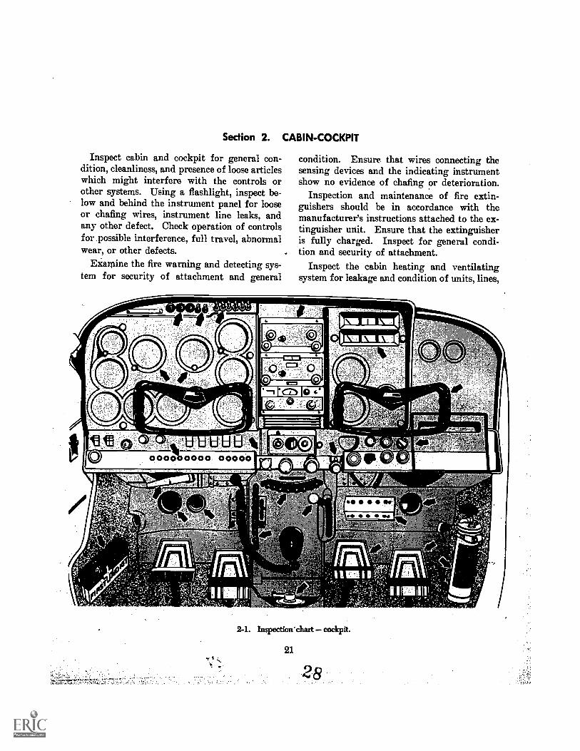
Inspect cabin and cockpit for general con-dition, cleanliness, and presence of loose articleswhich might interfere with the controls orother systems. Using a flashlight, inspect be-low and behind the instrument panel for looseor chafing wires, instrument line leaks, andany other defect, Check operation of controlsfor possible interference, full travel, abnormalwear, or other defects.
Examine the fire warning and detecting sys-tem for security of attachment and general
condition. Ensure that wires connecting thesensing devices and the indicating instrumentshow no evidence of chafing or deterioration.
Inspection and maintenance of fire extin-guishers should be in accordance with themanufacturer's instructions attached to the ex-tinguisher unit. Ensure that the extinguisheris fully charged. Inspect for general condi-tion and security of attachment.
Inspect the cabin heating and ventilatingsystem for leakage and condition of units, lines,
2-1. Inspection' chart cockpit.
21
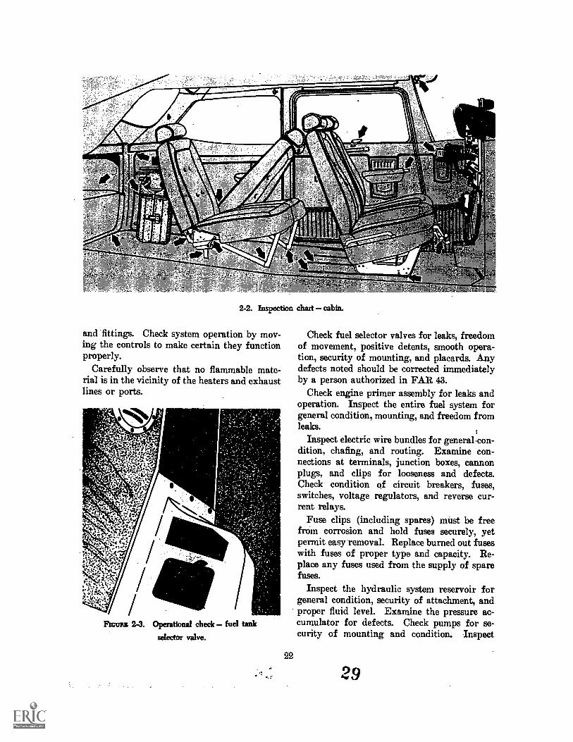
2-2. Inspection chart cabin.
and fittings. Check system operation by mov-ing the controls to make certain they functionproperly.
Carefully observe that no flammable mate-rial is in the vicinity of the heaters and exhaustlines or ports.
FIGURE 2.3. Operational check fuel tank
selector valve.
22
Check fuel selector valves for leaks, freedomof movement, positive detents, smooth opera-tion, security of mounting, and placards. Anydefects noted should be corrected immediatelyby a person authorized in FAR 43.
Check engine primer assembly for leaks andoperation. Inspect the entire fuel system forgeneral condition, mounting, and freedom fromleaks.
Inspect electric wire bundles for general.con-dition, chafing, and routing. Examine con-nections at terminals, junction boxes, cannonplugs, and clips for looseness and defects.Check condition of circuit breakers, fuses,switches, voltage regulators, and reverse cur-rent relays.
Fuse clips (including spares) must be freefrom corrosion and hold fuses securely, yetpermit easy removal. Replace burned out fuseswith fuses of proper type and capacity. Re-place any fuses used from the supply of sparefuses.
Inspect the hydraulic system reservoir forgeneral condition, security of attachment, andproper fluid level. Examine the pressure ac-cumulator for defects. Check pumps for se-curity of mounting and condition. Inspect
29
ti
,1111% 16/
.1.1 14, ,5,5,A,
'CONTROL LOCKRINOVI Wengun, ENGINE
p.1
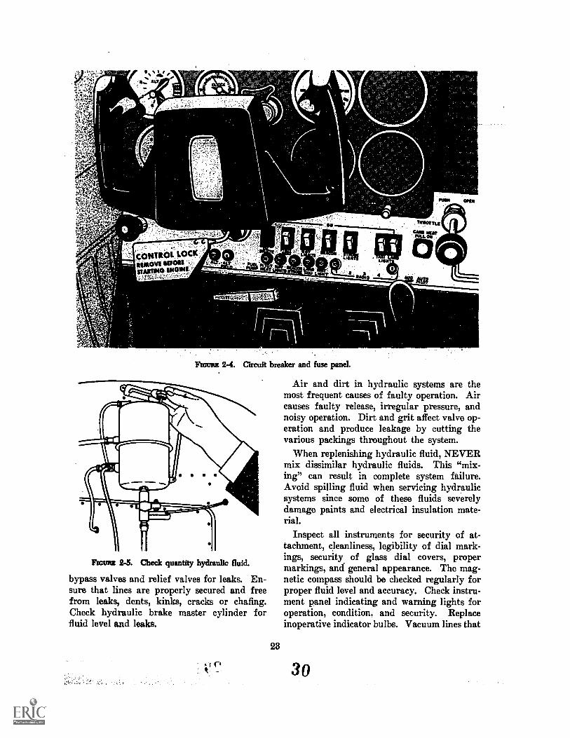
rim= 2-4. Circuit breaker and fuse panel.
Air and dirt in hydraulic systems are themost frequent causes of faulty operation. Aircauses faulty release, irregular pressure, andnoisy operation. Dirt and grit affect valve op-eration and produce leakage by cutting thevarious packings throughout the system.
When replenishing hydraulic fluid, NEVERmix dissimilar hydraulic fluids. This "mix-ing" can result in complete system failure.Avoid spilling fluid when servicing hydraulicsystems since some of these fluids severelydamage paints and electrical insulation mate-rial.
Inspect all instruments for security of at-tachment, cleanliness, legibility of dial mark-ings, security of glass dial covers, propermarkings, and general appearance. The mag-netic compass should be checked regularly forproper fluid level and accuracy. Check instru-ment panel indicating and warning lights foroperation, condition, and security. Replaceinoperative indicator bulbs. Vacuum lines that
Fscunz 2-5. Check quantity hydraulic fluid.
bypass valves and relief valves for leaks. En-sure that lines are properly secured and freefrom leaks, dents, kinks, cracks or chafing.Check hydraulic brake master cylinder forfluid level and leaks.
23
uI
7
3o
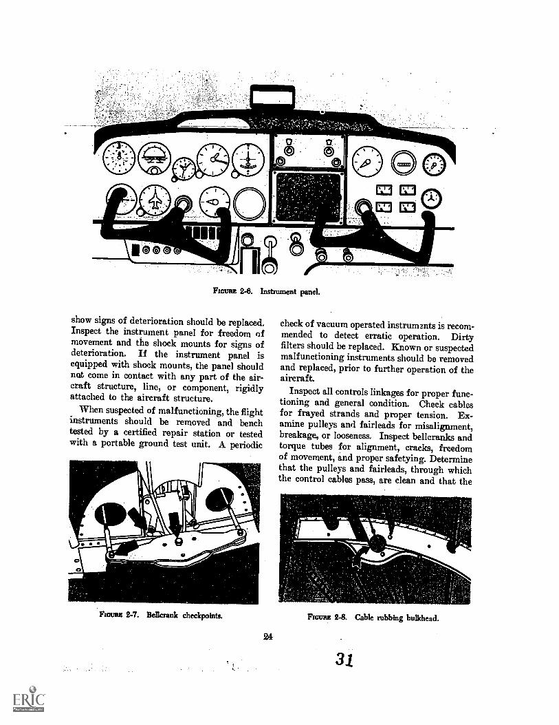
FIGURE 2-8. Instrument panel.
show signs of deterioration should be replaced.Inspect the instrument panel for freedom ofmovement and the shock mounts for signs ofdeterioration. If the instrument panel isequipped with shock mounts, the panel shouldnot come in contact with any part of the air-craft structure, line, or component, rigidlyattached to the aircraft structure.
When suspected of malfunctioning, the flightinstruments should be removed and benchtested by a certified repair station or testedwith a portable ground test unit. A periodic
0
Fscrun BetIcrank checkpoints.
24
check of vacuum operated instruments is recom-mended to detect erratic operation. Dirtyfilters should be replaced. Known or suspectedmalfunctioning instruments should be removedand replaced, prior to further operation of theaircraft.
Inspect all controls linkages for proper func-tioning and general condition. Check cablesfor frayed strands and proper tension. Ex-amine pulleys and fairleads for misalignment,breakage, or looseness. Inspect bellcranks andtorque tubes for alignment, cracks, freedomof movement, and proper safetying. Determinethat the pulleys and fairleads, through whichthe control cables pass, are clean and that the
noun 2-8. Cable rubbing bulkhead.
31
surrounding structure does not interfere withtheir movement. Operate the controls to besure there is no lost motion, binding, or chafing.
If inspection reveals that cables or control_rods have been ehAfing against some portionof the structure, they should be realigned. Iffurther inspection reveals the cables or controlrods to be worn beyond an acceptable limit,they should be replaced.
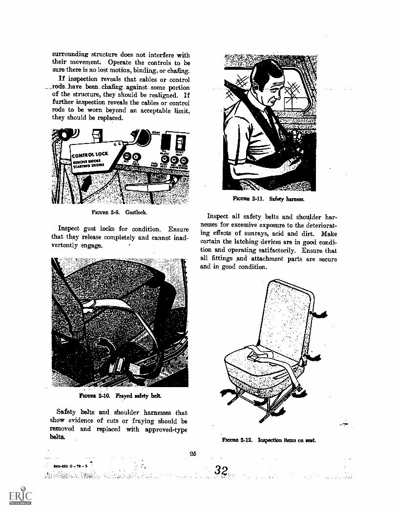
FIGURE 2-9. Custlock.
Inspect gust locks for condition. Ensurethat they release completely and cannot inad-vertently engage.
FIGURIC 240. Frayed safety belt.
Safety belts and shoulder harnesses thatshow evidence of cuts or fraying should beremoved and replaced with approved-typebelts.
25
2115-620 - 79 5
fir- TACAM. ;larks.
FIGURE 2-11. Safety harness.
Inspect all safety belts and shoulder har-nesses for excessive exposure to the deteriorat-ing effects of sunrays, acid and dirt. Makecertain the latching devices are in good condi-tion and operating satifactorily. Ensure thatall fittings and attachment parts are secureand in good condition.
FIGURE 2-12. Inspection items on seat.
32
Inspect all seats and seat tracks for securityof attachment, condition, and function of ad-justing mechanisms. Floor carpets should beremoved-to permit inspection of the floor andassociated structures to which seat and seattracks are attached. This is the appropriatetime to remove floor access covers and inspectfloor substructure, controls, etc., below the floor.
26
Inspect all windows, windshield, and can-opies for cracks, cleanliness, freedom of opera-tion, and general condition. If your aircraftis pressurized, even minor flaws in windows,their attachments, and operating mechanismscan be critical. If there is any question, ac-quire the services of a certificated mechanicor repair station.
33
Section 3. ENGINE NACELLE
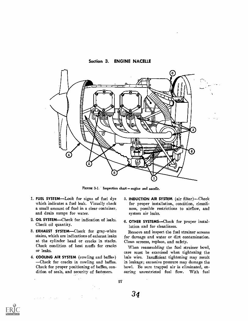
FIGURE 3-1. Inspection chart engine and nacelle.
1. FUEL SYSTEMLook for signs of fuel dyewhich indicates a fuel leak. Visually checka small amount of fuel in a clear container.and drain sumps for water.
2. OIL SYSTEMCheck for indication of leaks.Check oil quantity.
3. EXHAUST SYSTEMCheck for gray-whitestains, which are indications of exhaust leaksat the cylinder head or cracks in stacks.Check condition of heat muffs for cracksor leaks.
4. COOLING AIR SYSTEM (cowling and baffles)Check for cracks in cowling and baffles.Check for proper positioning of baffles, con-dition of seals, and security of fasteners.
27
5. INDUCTION AIR SYSTEM (air filter)Checkfor proper installation, condition, cleanli-ness, possible restrictions to airflow, andsystem air leaks.
6. OTHER SYSTEMSCheck for proper instal-lation and for cleanliness.Remove and inspect the fuel strainer screens
for damage and water or dirt contamination.Clean screens, replace, and safety.
When reassembling the fuel strainer bowl,care must be exercised when tightening thebale wire. Insufficient tightening may resultin leakage; excessive pressure may damage thebowl. Be sure trapped air is eliminated, en-suring unrestricted fuel flow. With fuel
34
A Cylinder hold-down nuts.B. Crankcase thru-bolts.C. Fuel injection distributor.D. Ignition harness.E. Cylinder cooling fins.F. Firewall.
G. Accessory section.H. Magnetos.I. Instrument system pressure filter.
J. Oil lines.K. Cowling seals.
FIGURE 3-2. Inspection chart engine.
28
35
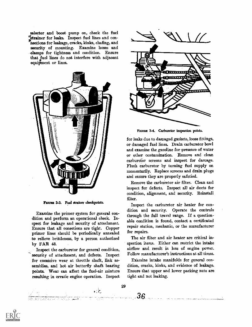
selector and boost pump on, check the fuelstrainer for leaks. Inspect fuel lines and con-nections for leakage, cracks, kinks, chafing, andsecurity of mounting. Examine hoses andclamps for tightness and condition. Ensurethat fluel lines do not interfere with adjacentequipment or lines.
Fun= 3-3. Fuel strainer checkpoints.
Examine the primer system for general con-dition and perform an operational check. In-spect for leakage and security of attachment.Ensure that all conections are tight. Copperprimer lines should be periodically annealedto relieve brittleness, by a person authorizedby FAR 43.
Inspect the carburetor for general condition,security of attachment, and defects. Inspectfor excessive wear at throttle shaft, link as-semblies, and hot air butterfly shaft bearingpoints. Wear can affect the fuel-air mixtureresulting in erratic engine operation. Inspect
29
FIGURE 3-4. Carburetor inspection points.
for leaks due to damaged gaskets, loose fittings,or damaged fuel lines. Drain carburetor bowland examine the gasoline for presence of wateror other contamination. Remove and cleancarburetor screens and inspect for damage.Flush carburetor by turning fuel supply onmomentarily. Replace screens and drain plugsand ensure they are properly safetied.
Remove the carbuietor air filter. Clean andinspect for defects. Inspect all air ducts forcondition, alignment, and security. Reinstallfilter.
Inspect the carburetor air heater for con-dition and security. Operate the controlsthrough the full travel range. If a question-able condition is found, contact a certificatedrepair station, mechanic, or the manufacturerfor repairs.
The air filter and air heater are critical in-spection items. Either can restrict the intakeairflow and, result in loss of engine power.Follow manufacturer's instructions at all times.
Examine intake manifolds for general con-dition, cracks, kinks, and evidence of leakage.Ensure that upper and lower packing nuts aretight and not leaking.
36
.17
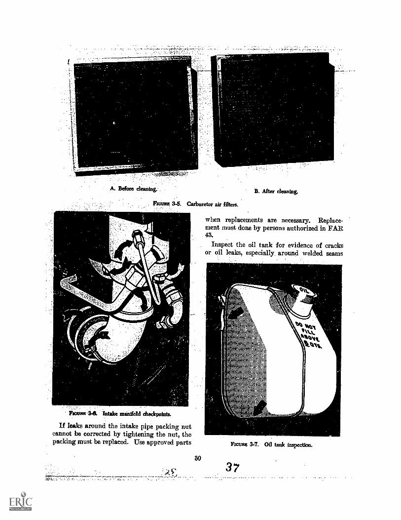
A. Before cleaning.
Pscsnut 3-6. Intake manifold checkpoints.
Carburetor air filters.
If leaks around the intake pipe packing nutcannot be corrected by tightening the nut, thepacking must be replaced. Use approved parts
30
vAr.-
B. After cleaning.
when replacements are necessary. Replace-ment must done by persons authorized in FAR43.
Inspect the oil tank for evidence of cracksor oil leaks, especially, around welded seams
ar
FxcuRE 3-7. Oil tank inspection.
37
and fittings. Leaks should be traced to theirsource and corrected.
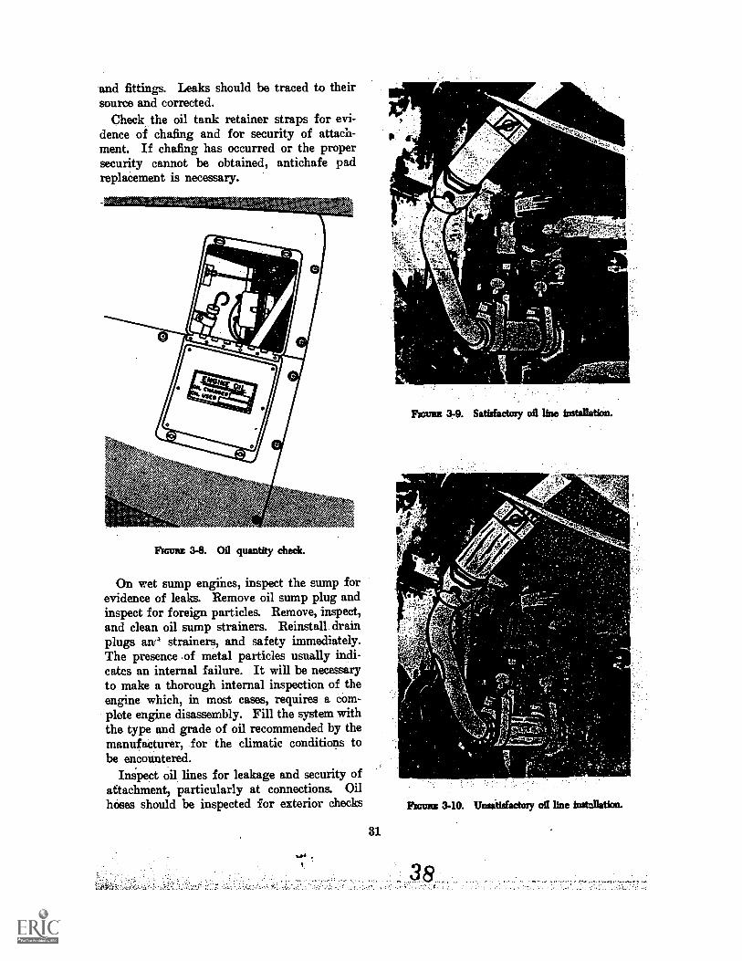
Check the oil tank retainer straps for evi-dence of chafing and for security of attach-ment. If chafing has occurred or the propersecurity cannot be obtained, antichafe padreplacement is necessary.
Flume 3-8. Oil quantity check.
On wet sump engines, inspect the sump forevidence of leaks. Remove oil sump plug andinspect for foreign particles. Remove, inspect,and clean oil sump strainers. Reinstall draMplugs am' strainers, and safety immediately.The presence of metal particles usually indi-cates an internal failure. It will be necessaryto make a thorough internal inspection of theengine which, in most cases, requires a com-plete engine disassembly. Fill the system withthe type and grade of oil recommended by themanufacturer, for the climatic conditions tobe encountered.
Inspect oil lines for leakage and security ofattachment, particularly at connections. Oilhoses should be inspected for exterior checks
31
ii..f4s!..k.:,,eif41
films 3-9. Satisfactory oil line installation.
Rums 3-10. Unsitisfactory oil line installation.
and cracks, and proper tension and location ofclamps. Any leaks must be repaired immedi-ately.
0 0 o
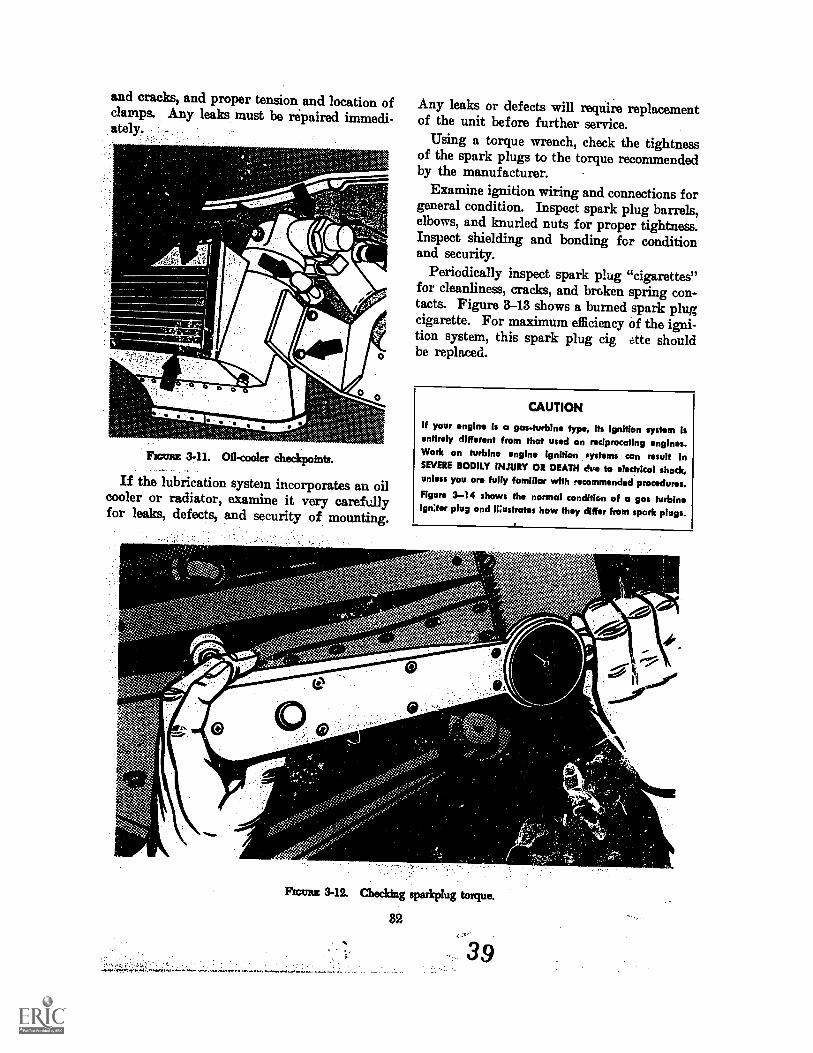
Fawns 3-11. 02-cooler checkpoints.
0
0
0
If the lubrication system incorporates an oilcooler or radiator, examine it very carefxdlyfor leaks, defects, and security of mounting.
.11
$. (:) @wag`s. 10
Ns.
Any leaks or defects will require replacementof the unit before further service.
Using a torque wrench, check the tightnessof the spark plugs to the torque recommendedby the manufacturer.
Examine ignition wiring and connections forgeneral condition. Inspect spark plug barrels,elbows, and knurled nuts for proper tightness.Inspect shielding and bonding for conditionand security.
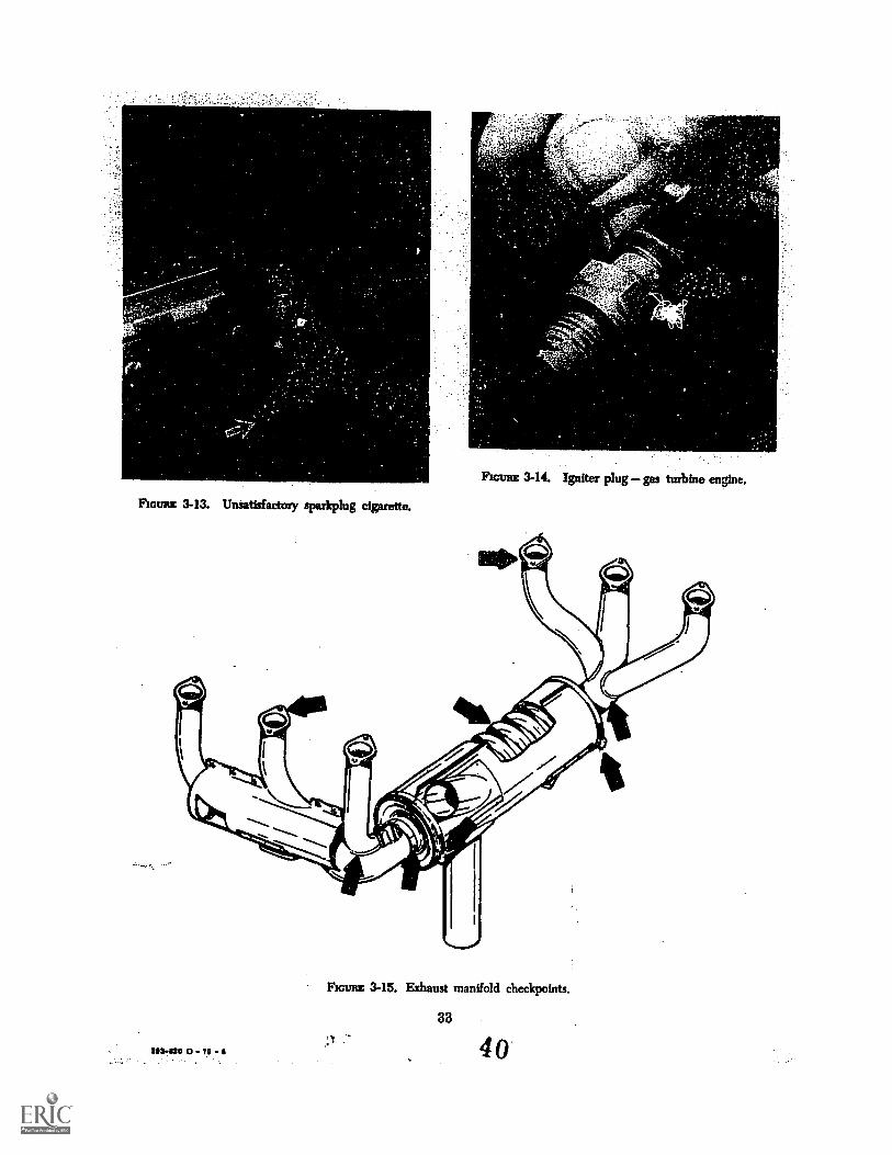
Periodically inspect spark plug "cigarettes"for cleanliness, cracks, and broken spring con-tacts. Figure 3-13 shows a burned spark plugcigarette. For maximum efficiency of the igni-tion system, this spark plug cig Ate shouldbe replaced..
CAUTION
If your engine is a gas-turbine type, Its Ignition system Isentirely different from that used on reciprocating engines.Work on turbine engine ignition systems can result InSEVERE BODILY INJURY OR DEATH due to electrical shock,unless you are fully familiar with recommended procedures.Figure 3-14 shows the normal condition of a gas turbineigniter plug and Wu:trate: how they differ from spark plugs.
v.
-
O
SI''. en47?.V.'41.Svi
91
Rom 3-12. Checking sparkplug torque.
82
39
.s
c.
FIGURE 3-13. Unsatisfactory sparkplug cigarette.
Ficuna 3-14. Igniter plug gas turbine engine.
FIGURE 3-15. Exhaust manifold checkpoints.
88
503.520 0 70 I 40
Be certain that the magneto holddown nutsare tight and properly safetied. If the hold-down nuts are loose, it will be necessary tocheck the magneto timing to make sure it hasnot been disturbed and technical assistanceshould be sought. Inspect magneto and coverscrews for security.
Check magneto ground wires for conditionand proper attachment to the magneto terminaland the ignition switch. If the magneto is notproperly grounded, it is possible for the engineto operate, even though the magneto switchis in the "OFF" position. A check of this"OFF" pnition should be made a regular partof each engine shut down after each flight.BEWARE OF. THE PROPELLER, even
0.
when the switch is "OFF"especially whenthe engine is warm.
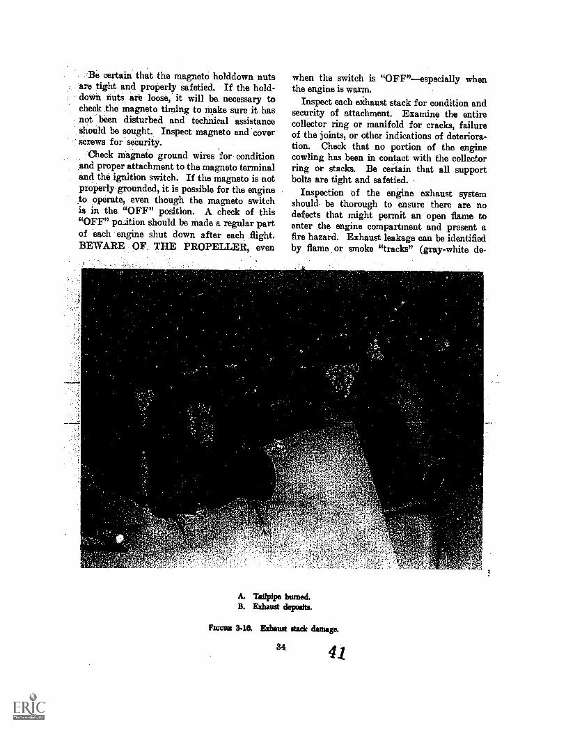
Inspect each exhaust stack for condition andsecurity of attachment. Examine the entirecollector ring or manifold for cracks, failureof the joints, or other indications of deteriora-tion. Check that no portion of the enginecowling has been in contact with the collectorring or stacks. Be certain that all supportbolts are tight and safetied.
Inspection of the engine exhaust systemshould. be thorough to ensure there are nodefects that might permit an open flame toenter the engine compartment and present afire hazard. Exhaust leakage can be identifiedby flame or smoke "tracks" (gray-white de-
A. Tailpipe burned.B. Exhaust deposits.
FIGURE 3-18. Exhaust stack damage.
34 41
posits) at a break in the system or on theadjacent area where exhaust gases impinge.
Figures 8-16 shows an example of exhaustoutlet damage "A" and evidence of exhaustdeposits "B."
On turbine engines, check the tailpipes andtrim devices to see that they are not crackedand are in order. Check the controls for free-dom and alignment. Any binding or malfunc-tioning of an engine control system should betraced to its source and corrected.
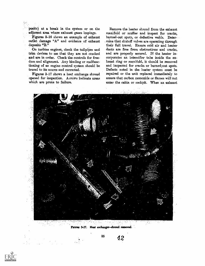
Figures 3-17 shows a heat exchange shroudopened for inspection. Arrows indicate areaswhich are prone to failure.
Remove the heater shroud from the exhaustmanifold or muffler and inspect for cracks,burned-out spots, or defective welds. Deter-mine that shutoff valves are operating throughtheir full travel. Ensure cold air and heaterducts are free from obstructions and cracks,and are properly secured. If the heater in-corporates an intensifier tube inside the ex-haust ring or manifold, it should be removedand inspected for cracks or burned;out spots.Defects noted in the heater system must berepaired or the unit replaced immediately toassure that carbon monoxide or flames will notenter the cabin or cockpit. When an exhaust
Rousts 3-17. Heat exchangershroud removed.
85 42
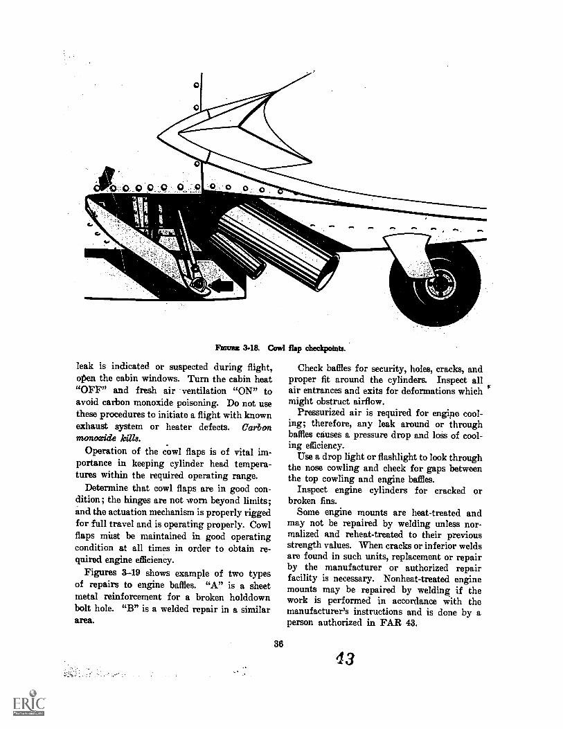
Rom 3-18. Cowl flap checkpoints.
leak is indicated or suspected during flight,open the cabin windows. Turn the cabin heat"OFF" and fresh air ventilation "ON" toavoid carbon monoxide poisoning. Do not usethese procedures to initiate a flight with knownexhaust system or heater defects. Carbonmonoxide kills.
Operation of the cowl flaps is of vital im-portance in keeping cylinder head tempera-tures within the required operating range.
Determine that cowl flaps are in good con-dition; the hinges are not worn beyond limits;and the actuation mechanism is properly riggedfor full travel and is operating properly. Cowlflaps must be maintained in good operatingcondition at all times in order to obtain re-quired engine efficiency.
Figures 3-19 shows example of two typesof repairs to engine baffles. "A" is a sheetmetal reinforcement for a broken holddownbolt hole. "B" is a welded repair in a similararea.
36
Check baffles for security, holes, cracks, andproper fit around the cylinders. Inspect allair entrances and exits for deformations whichmight obstruct airflow.
Pressurized air is required for engine cool-ing; therefore, any leak around or throughbaffles causes a pressure drop and loss of cool-ing efficiency.
Use a drop light or flashlight to look throughthe nose cowling and check for gaps betweenthe top cowling and engine baffles.
Inspect engine cylinders for cracked orbroken fins.
Some engine mounts are heat-treated andmay not be repaired by welding unless nor-malized and reheat-treated to their previousstrength values. When cracks or inferior weldsare found in such units, replacement or repairby the manufacturer or authorized repairfacility is necessary. Nonheat-treated enginemounts may be repaired by welding if thework is performed in accordance with themanufacturer's instructions and is done by aperson authorized in FAR 43.
43
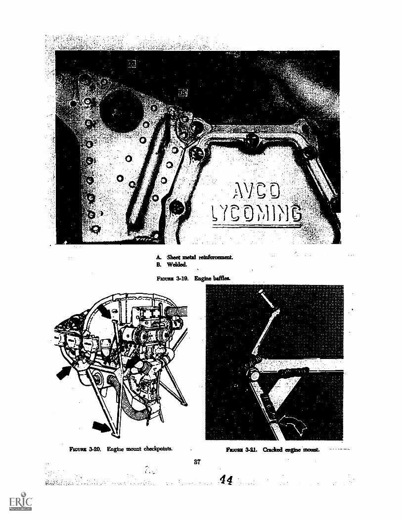
A. Sheet metal reinforcement.B. Welded.
Fromm 3-19. Engine baffles.
Fromm 3-20. Engine mount checkpoints.
87
Frantz 341. Cracked engine
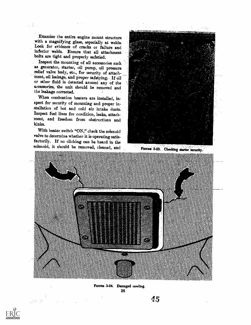
Examine the entire engine mount structurewith a magnifying glass, especially at welds.Look for evidence of cracks or failure andinferior welds. Ensure that all attachmentbolts are tight and properly safetied.
Inspect the mounting of all accessories suchas generator, starter, oil pump, oil pressurerelief valve body, etc., for security of attach-ment, oil leakage, and proper safetying. If oilor other fluid is detected around any of theaccessories, the unit should be removed andthe leakage corrected.
When combustion heaters are installed, in-spect for security of mounting and proper in-stallation of hot and cold air intake ducts.Inspect fuel lines for condition, leaks, attach-ment, and freedom from obstructions andkinks.
With heater switch "ON," check the solenoidvalve to determine whether it is operating satis-factorily. If no clicking can be heard in thesolenoid, it should be removed, cleaned, and FEVRE 3-22. Checking starter securfty.'
::::::***
Flom 3-24. Damaged cowling.88
45
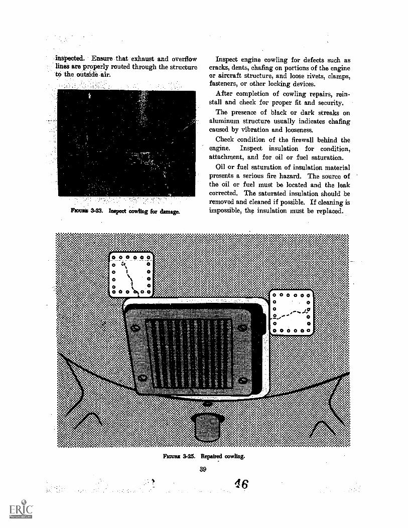
inspected. Ensure that exhaust and overflowlines are properly routed through the structureto the outside air.
Pronto 3-23. Inspect cowling for damage.
Inspect engine cowling for defects such ascracks, dents, chafing on portions of the engineor aircraft structure, and loose rivets, clamps,fasteners, or other locking devices.
After completion of cowling repairs, rein-stall and check for proper fit and security.
The presence of black or dark streaks onaluminum structure usually indicates chafingcaused by vibration and looseness.
Check condition of the firewall behind theengine. Inspect insulation for condition,attachment, and for oil or fuel saturation.
Oil or fuel saturation of insulation materialpresents a serious fire hazard. The source ofthe oil or fuel must be located and the leakcorrected. The saturated insulation should beremoved and cleaned if possible. If cleaning isimpossible, the insulation must be replaced.
:::FB Repaired cowling.A= 345'
39
46
"""
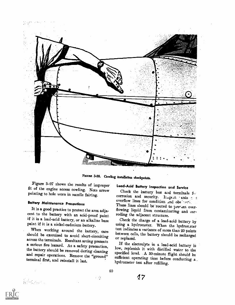
' VM11111m
Ficeez 3-28. Cowling installation checkpoints.
Figure 3-27 shows the results of improperfit of the engine access cowling. Note arrowpointing to hole worn in nacelle fairing.
Battery Maintenance PrecautionsIt is a good practice to protect the area adja-
cent to the battery with an acid-proof paintif it is a lead-acid battery, or an alkaline basepaint if it is a nickel-cadmium battery.
When working around the battery, careshould be exercised to avoid short-circuitingacross the terminals. Resultant arcing presentsa serious fire hazard. As a safety precaution,the battery should be removed during cleaningand repair operations. Remove the "ground"terminal first, and reinstall it last.
40
Lead-Acid Battery Inspection and ServiceCheck the battery box and terminals fi
corrosion and security. 11,..pczt entsoverflow lines for condition ..ind .obsThese lines should be 'routed to prerdnt. over-flowing liquid from contaminating and cor-roding the adjacent structure.
Check the charge of a lead-acid battery byusing a hydrometer. When the hydrometertest indicates a variance of more than 20 pointsbetween cells, the battery should be rechargedor replaced.
If the electrolyte in a lead-acid battery islow, replenish it with distilled water to thespecified level. A 30-minute flight should besufficient operating time before conducting ahydrometer test after refilling.
4
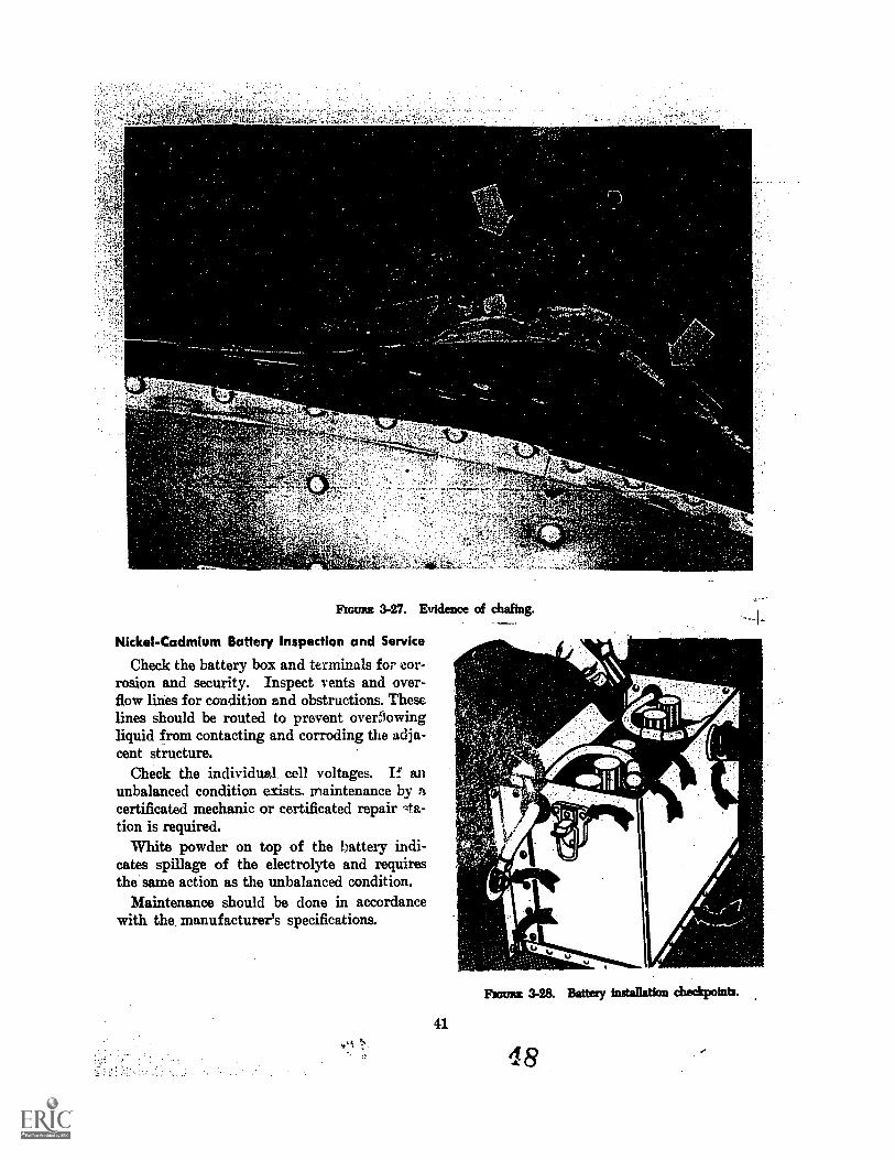
Rome 3-27. Evidence of chafing.
Nickel-Cadmium Battery Inspection and Service
Check the battery box and terminals for cor-rosion and security. Inspect vents and over-flow lines for condition and obstructions. Theselines should be routed to prevent overflowingliquid from contacting and corroding the adja-cent structure.
Check the individual, cell voltages. If anunbalanced condition exists, maintenance by acertificated mechanic or certificated repair gta-tion is required.
White powder on top of the battery indi-cates spillage of the electrolyte and requiresthe same action as the unbalanced condition.
Maintenance should be done in accordancewith the, manufacturer's specifications.
41
:111PN.
Fsouns 3-28. Battery installation chedcpoints.
48
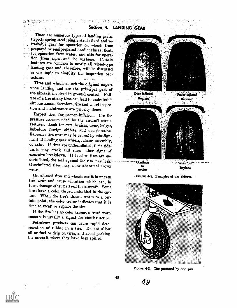
Sedion 4. LANDING
There are numerous types of landing gears :tripod; spring steel; single strut; fixed and re-tractable gear for operation on wheels fromprepared or semiprepared hard surfaces; floatsfor operation-from- water; and. skis for opera-tion from snow and ice surfaces. Certainfeatures are common to nearly all wheel-typelanding gear and, therefore, will be discussedas one topic to simplify the inspection procedures.
Tires and wheels absorb the original impactupon landing and are the principal part ofthe aircraft involved in ground control. Fail-ure of a tire at any time can lead to undesirablecircumstances; therefore, tire and wheel inspec-tion and maintenance are priority items.
Inspect tires for proper inflation. Use thepressure recommended by the aircraft manu-facturer. Look for cuts, bruises, wear, bulges,imbedded foreign objects, and deterioration.Excessive tire wear may be tuuse%1 by misalign-ment of landing gear wheels, z4cissors assembly,or axles. If tires are underinflated, their side-walls may crack and show other signs ofexcessive breakdown. If tubeless tires are un-derinflated, the seal against the rim may leak.Overinflated tires may show abnormal crownwear.
Unbalanced tires and wheels result in uneventire -wear and cause vibration which can, inturn, damage other parts- of the aircraft. Sometires have a color thread imbedded in the car-cass. Whe,i the tire's thread wears to a cer-tain point, the color tracer indicates that it istime to recap or replace the tire.
If the tire has no color tracer, a tread wornsmooth is usually a signal for similar action.
Petroleum products can cause rapid dete-rioration of rubber in a tire. Do not allowoil or fuel to drip on tires, and avoid parkingthe aircraft where they have been spilled.
42
Over-inflited UnderReplace
r'. 1111
oattnue Wom outReplaceservice
Flown 4-1. Examples of tire defects.
,,,,,, .
Room 4-2. Tire protected by drip pan.
19
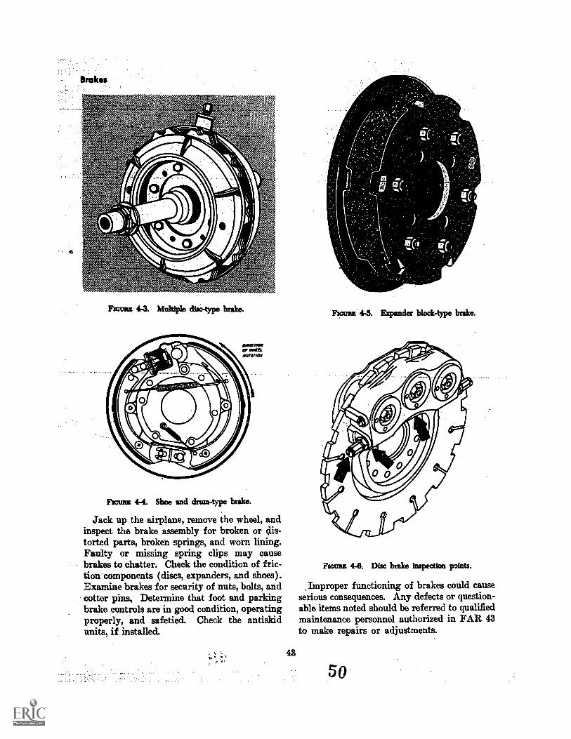
Rooms 4-3. Multiple disc-type brake.
FIGURE 4-4. Shoe and drum-type brake.
Jack up the airplane, remove the wheel, andinspect the brake assembly for broken or dis-torted parts, broken springs, and worn lining.Faulty or missing spring clips may causebrakes to chatter. Check the condition of fric-tion components (discs, expanders, and shoes).Examine brakes for security of nuts, bolts, andcotter pins, Determine that foot and parkingbrake controls are in good condition, operatingproperly, and safetied. Check the antiskidunits, if installed.
Fmums 4-5. Expander block-type brake.
Room 4-0. Disc brake inspection points.
Improper functioning of brakes could causeserious consequences. Any defects or question-able items noted should be referred to qualifiedmaintenance personnel authorized in FAR 43to make repairs or adjustments.
So
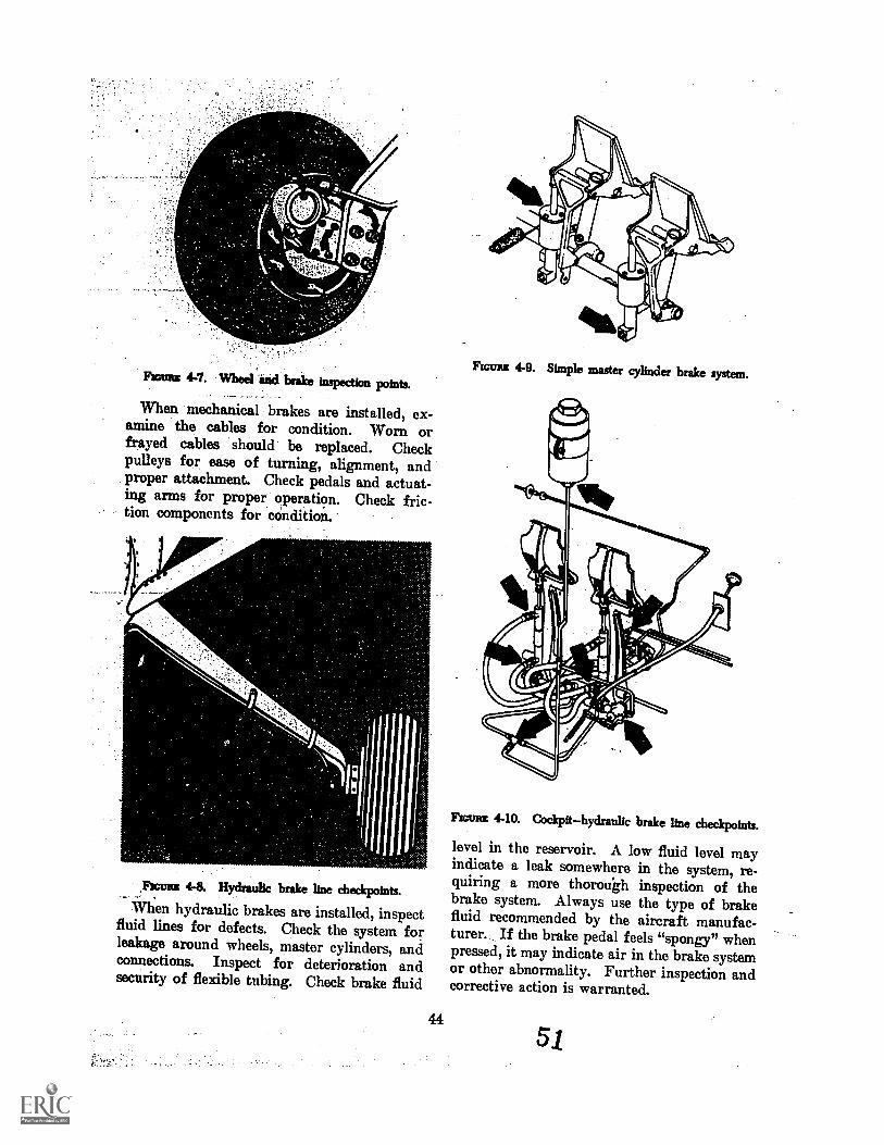
Femme 4-7. Wheel and brake inspection points.
When mechanical brakes are installed, ex-amine the cables for condition. Worn orfrayed cables should be replaced. Checkpulleys for ease of turning, alignment, andproper attachment. Check pedals and actuat-ing arms for proper operation. Check fric-tion components for condition.
Frcuns 4-8. Hydraulic brake line checkpoints.
When hydraulic brakes are installed, inspectfluid lines for defects. Check the system forleakage around wheels, master cylinders, andconnections. Inspect for deterioration andsecurity of flexible tubing. Check brake fluid
Frame 4-9. Simple master cylinder brake system.
Fromm 4-10. Cockpithydraulic brake line checkpoints.
level in the reservoir. A low fluid level mayindicate a leak somewhere in the system, re-quiring a more thorough inspection of thebrake system. Always use the type of brakefluid recommended by the aircraft manufac-turer. If the brake pedal feels "spongy" whenpressed, it may indicate air in the brake systemor other abnormality. Further inspection andcorrective action is warranted.
51
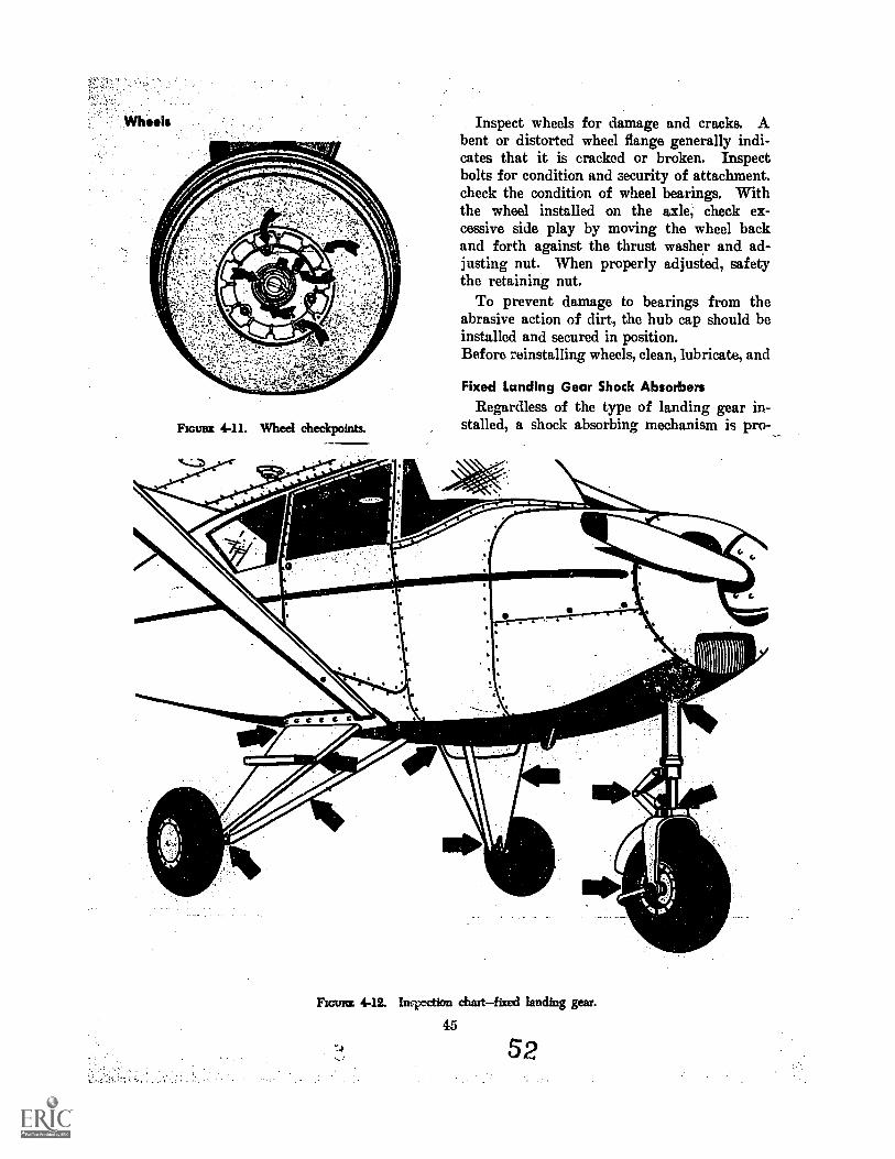
Roues 4-11. Wheel checkpoints.
Inspect wheels for damage and cracks. Abent or distorted wheel flange generally indi-cates that it is cracked or broken. Inspectbolts for condition and security of attachment.check the condition of wheel bearings. Withthe wheel installed on the axle, check ex-cessive side play by moving the wheel backand forth against the thrust washer and ad-justing nut. When properly adjusted, safetythe retaining nut.
To prevent damage to bearings from theabrasive action of dirt, the hub cap should beinstalled and secured in position.Before reinstalling wheels, clean, lubricate, and
Fixed Landing Gear Shock AbsorbersRegardless of the type of landing gear in-
stalled, a shock absorbing mechanism is pro-
Flan= 4-12. Inrixsction chart fixed landing gear.
45
52
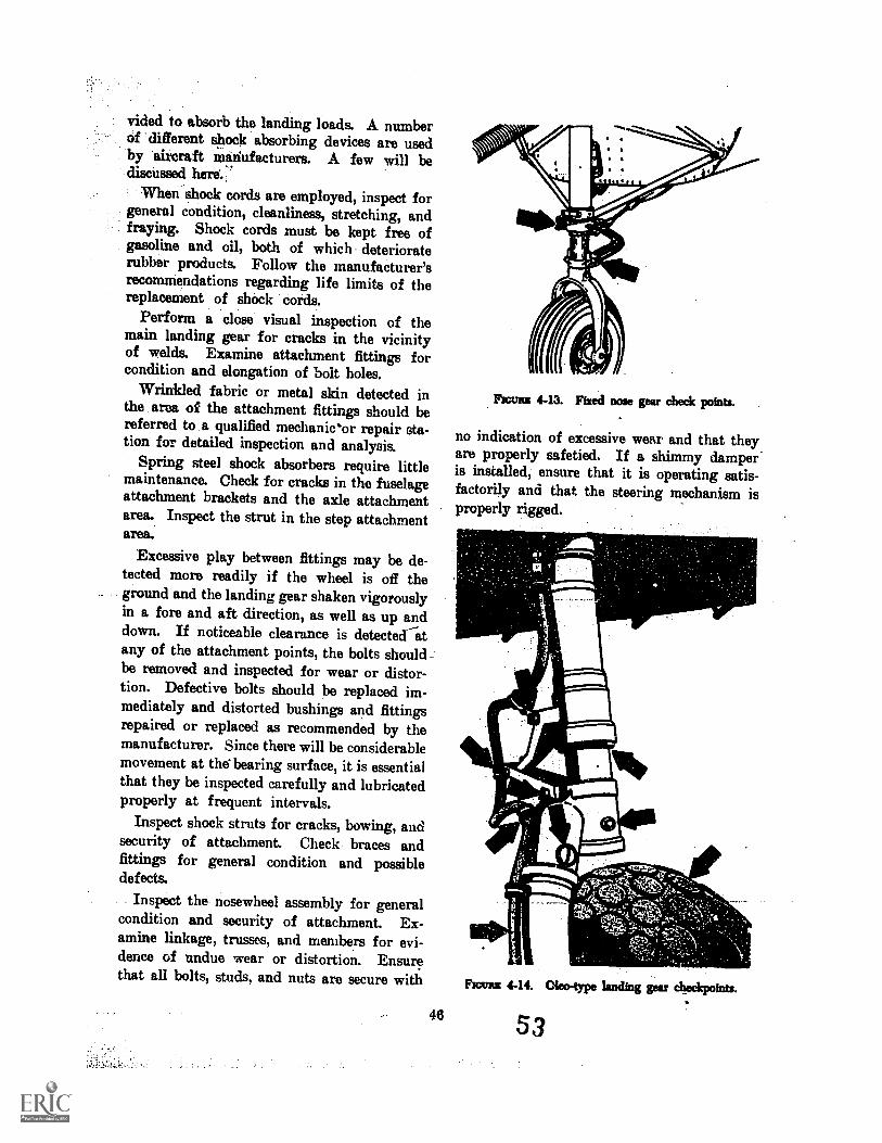
vided to absorb the landing loads. A numberof different shock absorbing devices are usedby aircraft manufacturers. A few will bediscussed here::
When shock cords are employed, inspect forgeneral condition, cleanliness, stretching, andfraying. Shock cords must be kept free ofgasoline and oil, both of which deterioraterubber products. Follow the manufacturer'srecommendations regarding life limits of thereplacement of shock cords.
Perform a close visual inspection of themain landing gear for cracks in the vicinityof welds. Examine attachment fittings forcondition and elongation of bolt holes.
Wrinkled fabric or metal skin detected inthe area of the attachment fittings should bereferred to a qualified mechanieor repair sta-tion for detailed inspection and analysis.
Spring steel shock absorbers require littlemaintenance. Check for cracks in the fuselageattachment brackets and the axle attachmentarea. Inspect the strut in the step attachmentarea.
Excessive play between fittings may be de-tected more readily if the wheel is off theground and the landing gear shaken vigorouslyin a fore and aft direction, as well as up anddown. If noticeable clearance is detected atany of the attachment points, the bolts shouldbe removed and inspected for wear or distor-tion. Defective bolts should be replaced im-mediately and distorted bushings and fittingsrepaired or replaced as recommended by themanufacturer. Since there will be considerablemovement at the bearing surface, it is essentialthat they be inspected carefully and lubricatedproperly at frequent intervals.
Inspect shock struts for cracks, bowing, andsecurity of attachment. Check braces andfittings for general condition and possibledefects.
Inspect the nosewheel assembly for generalcondition and security of attachment. Ex-amine linkage, trusses, and members for evi-dence of undue wear or distortion. Ensurethat all bolts, studs, and nuts are secure with
48
Fromm 4-13. Fixed nose gear check points.
no indication of excessive wear and that theyare properly safetied. If a shimmy damper'is installed, ensure that it is operating satis-factorily and that the steering mechanism isproperly rigged.
Ficants 4-1t Oleo-type landing gear checkpoints.
53
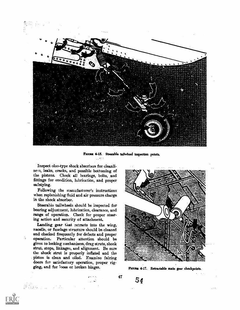
OM.
Flamm 4-15. Steerable tailwbeel inspection points.
Inspect oleo-type shock absorbers for cleanli-ness, leaks, cracks, and possible bottoming ofthe pistons. Check all bearings, bolts, andfittings for condition, lubrication, and propersafetying.
Following the manufacturer's instructionswhen replenishing fluid and air pressure chargein the shock absorber.
Steerable tailwheels should be inspected forbearing adjustment, lubrication, clearance, andrange of operation. Check for proper steer-ing action and security of attachment.
Landing gear gnat retracts into the wing,nacelle, or fuselage structure should be cleanedand checked frequently for defects and properoperation. Particular attention should begiven to locking mechanisms, drag struts, shockstrut, stops, linkages, and alignment. Be surethe shock strut is properly inflated and thepiston is clean and oiled. Examine fairingdoors for satisfactory operation, proper rig-ging, and for loose or broken hinges. Frame 4-11. Retractable main gear checkpoints.
47
0
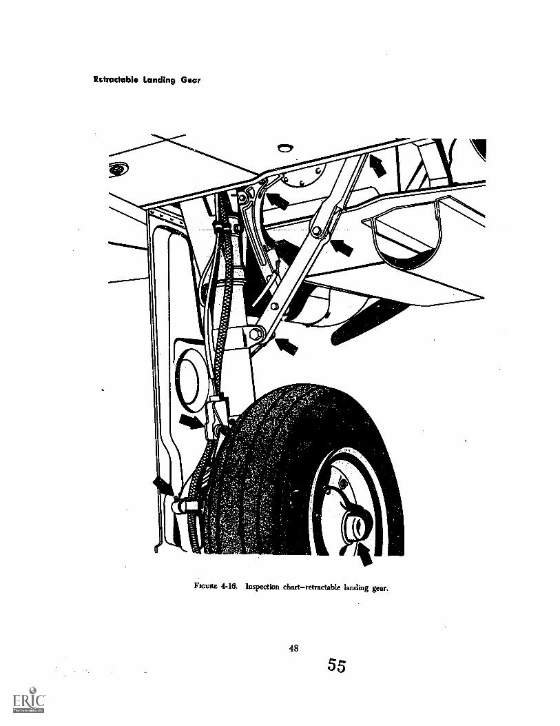
Retractable Landing Gear
k
4-16. Ilispectiort chartiettactable landing tear.Flouts
48
55
Ftcuitz 4-18. Landing gear retracting.
When new or retread tires are installed, alanding gear retraction test should be per-formed to check for proper clearance. Im-proper tire size may cause the gear to hangup in the wheel well.
Check main gear, nose gear, or tail gearuplock and downlock mechanisms for generalcondition and proper operation.
Refer to the manufacturer's service instruc-tions for proper lubrication of retractable land-ing gear.
Inspect the power sources and the retract-ing mechanism of the main gear, nose gear ortail gear for general condition, defects, and
49
security of attachment. Determine that actuat-ing cylinders, sprockets, universals, chains, anddrive gears are in good condition and withinthe manufacturer's tolerance. Clean and lu-bricate using cleaning fluids and lubricants`recommended by the manufacturer of the air-craft.
Inspect the aircraft structure to which thelanding gear is attached for distortion, cracks,and general condition. Be sure that all boltsand rivets are intact and secure.
Any items not within required tolerancesshould be referred to qualified maintenancepersonnel for correction and readjustment.
56
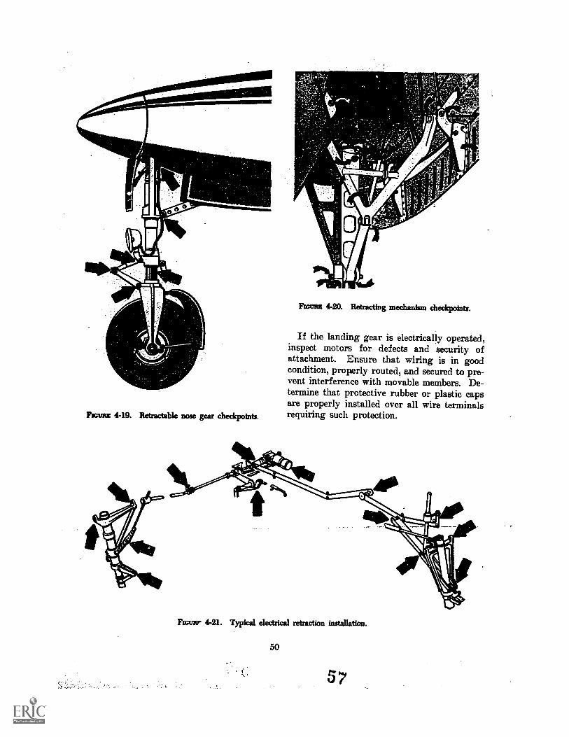
hems 4-19. Retractable nose gear checkpoints.
FIGURE 4-20. Retracting mechanism checkpoints.
If the landing gear is electrically operated,inspect motors for defects and security ofattachment. Ensure that wiring is in goodcondition, properly routed, and secured to pre-vent interference with movable members. De-termine that protective rubber or plastic capsare properly installed over all wire terminalsrequiring such protection.
Raw 4-21. Typical electrical retraction installation.
50
57
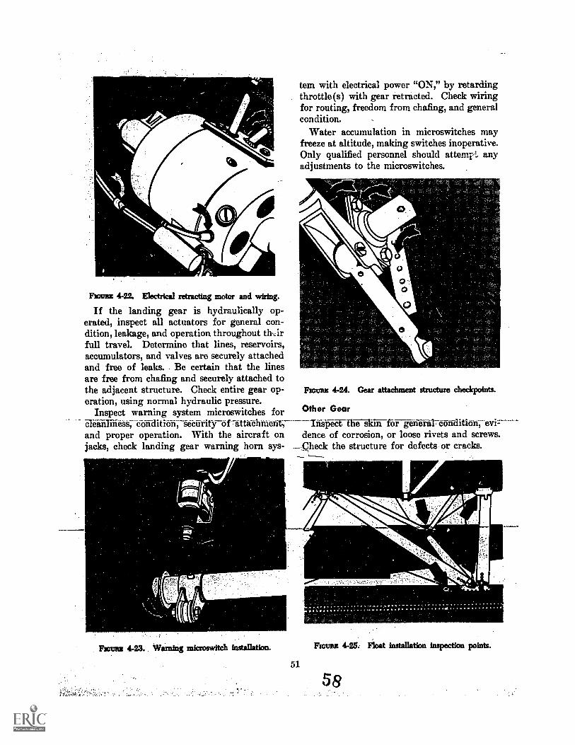
LiintaiFrame 4-22. Electrical retracting motor and wiring.
tem with electrical power "ON," by retardingthrottle(s) with gear retracted. Check wiringfor routing, freedom from chafing, and generalcondition.
Water accumulation in microswitches mayfreeze at altitude, making switches inoperative.Only qualified personnel should atteinr-1. anyadjustments to the microswitches.
O
O
OO
If the landing gear is hydraulically op- 0erated, inspect all actuators for general con-dition, leakage, and operation throughout thirfull travel. Determine that lines, reservoirs,accumulators, and valves are securely attachedand free of leaks.. Be certain that the linesare free from chafing and securely attached tothe adjacent structure. Check entire gear op- FIGURE 4-24. Gear attachment structure checkpoints.
oration, using normal hydraulic pressure.Inspect warning system microswitches for Other Gear
and proper operation. With the aircraft on dente of corrosion, or loose rivets and screws.jacks, check landing gear warning horn sys- .--Check the structure for defects or cracks.
Ficuas 4-23. Warning microswitch installation.
51
FIGURE 4-25: Float installation inspection points.
58
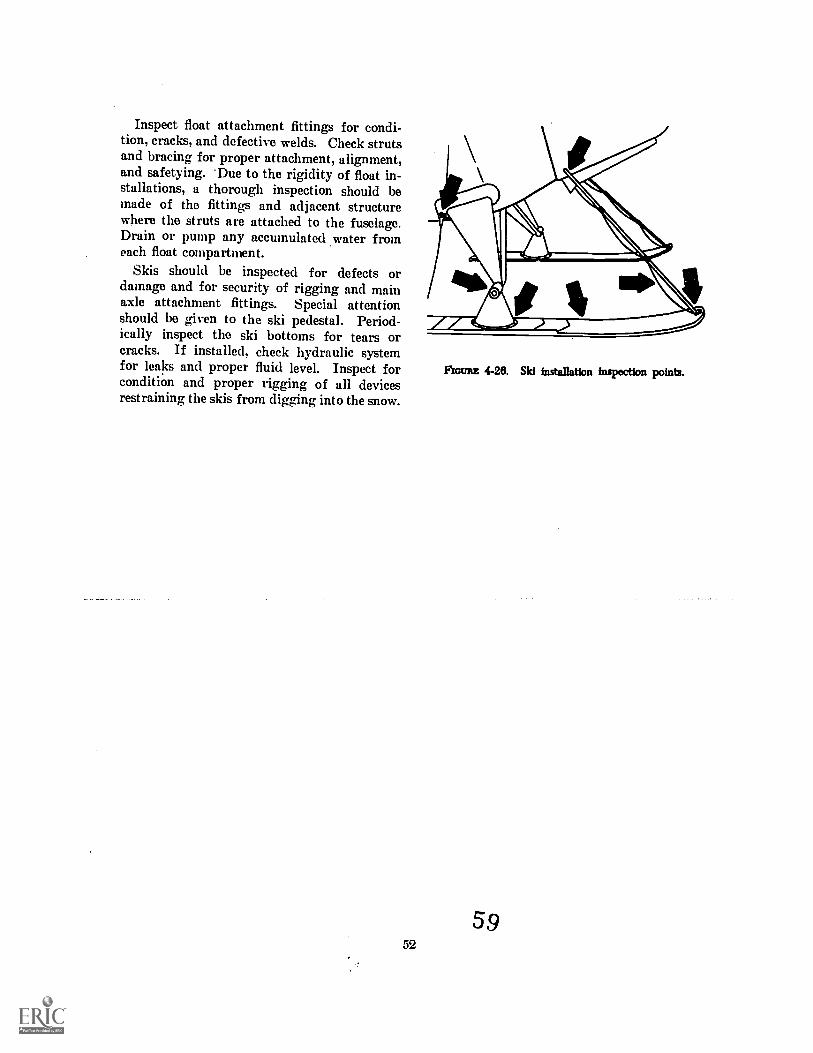
Inspect float attachment fittings for condi-tion, cracks, and defective welds. Check strutsand bracing for proper attachment, alignment,and safetying. *Due to the rigidity of float in-stallations, a thorough inspection should bemade of the fittings and adjacent structurewhere the struts are attached to the fuselage.Drain or pump any accumulated water fromeach float compartment.
Skis should be inspected for defects ordamage and for security of rigging and mainaxle attachment fittings. Special attentionshould be given to the ski pedestal. Period-ically inspect the ski bottoms for tears orcracks. If installed, check hydraulic systemfor leaks and proper fluid level. Inspect forcondition and proper rigging of all devicesrestraining the skis from digging into the snow.
52
FIGURE 4-26. Ski installation inspection points.
59
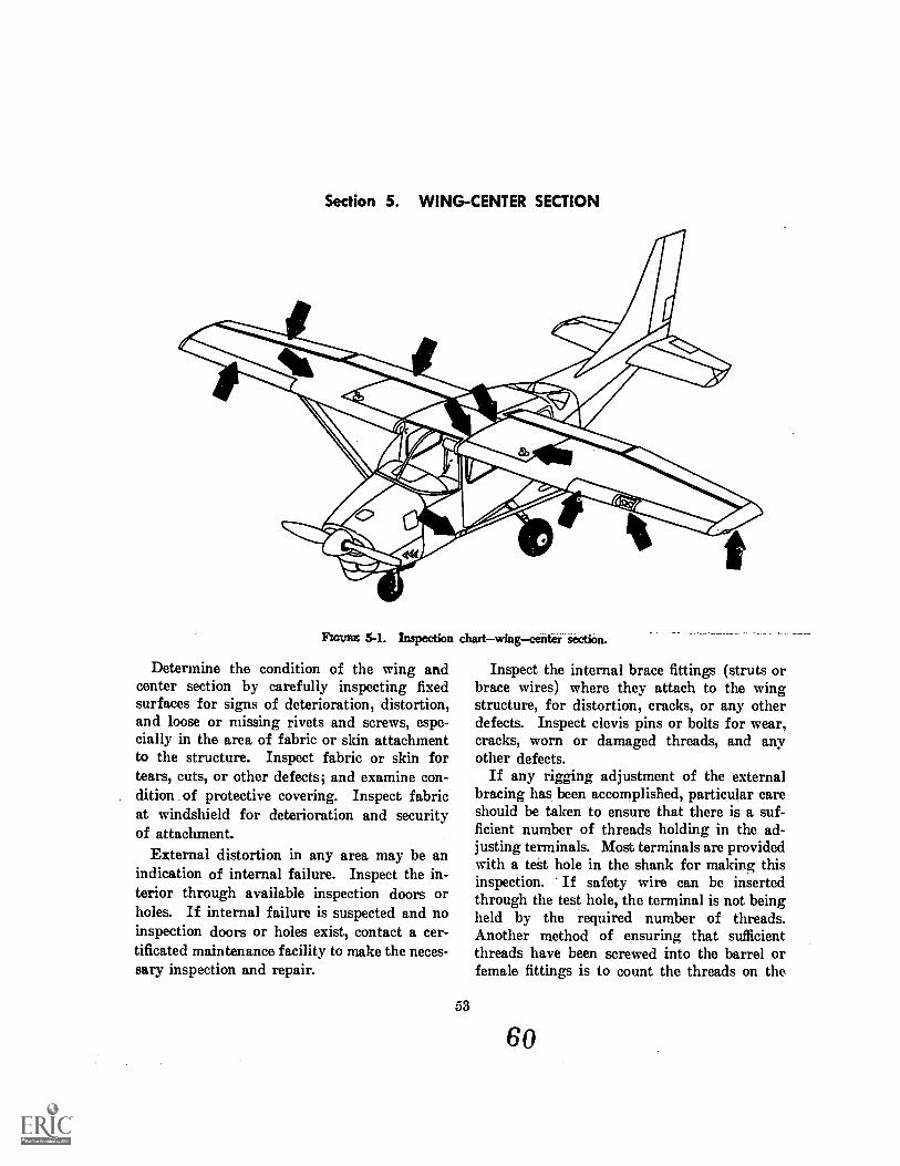
Section 5. WING-CENTER SECTION
Rat= 5-1. Inspection chartwingcenter section.
Determine the condition of the wing andcenter section by carefully inspecting fixedsurfaces for signs of deterioration, distortion,and loose or missing rivets and screws, espe-cially in the area of fabric or skin attachmentto the structure. Inspect fabric or skin fortears, cuts, or other defects; and examine con-dition of protective covering. Inspect fabricat windshield for deterioration and securityof attachment.
External distortion in any area may be anindication of internal failure. Inspect the in-terior through available inspection doors orholes. If internal failure is suspected and noinspection doors or holes exist, contact a cer-tificated maintenance facility to make the neces-sary inspection and repair.
53
Inspect the internal brace fittings (struts orbrace wires) where they attach to the wingstructure, for distortion, cracks, or any otherdefects. Inspect clevis pins or bolts for wear,cracks, worn or damaged threads, and anyother defects.
If any rigging adjustment of the externalbracing has been accomplisfied, particular careshould be taken to ensure that there is a suf-ficient number of threads holding in the ad-justing terminals. Most terminals are providedwith a test hole in the shank for making thisinspection. If safety wire can be insertedthrough the test hole, the terminal is not beingheld by the required number of threads.Another method of ensuring that sufficientthreads have been screwed into the barrel orfemale fittings is to count the threads on the
60
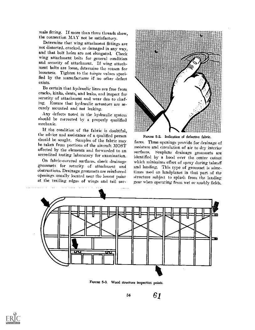
male fitting. If more than three threads show,the connection MAY not be satisfactory.
Determine that wing attachment fittings arenot distorted, cracked, or damaged in any way,and that bolt holes are not elongated. Checkwing attachment bolts for general conditionand security of attachment. If wing attach-ment bolts are loose, determine the reason forlooseness. Tighten to the torque values speci-fied by the manufacturer if no other defectexists.
Be certain that. hydraulic lines are free fromcracks, kinks, dents, and leaks, and inspect forsecurity of attachment and wear due to chaf-ing. Ensure that hydraulic actuators are se-curely mounted and not leaking.
Any defects noted in the hydraulic systemshould be corrected by a properly qualifiedmechanic.
If the condition of the fabric is doubtful,the advice and assistance of a qualified personshould be sought. Samples of the fabric maybe taken from portions of the aircraft. MOSTaffected by the elements and forwarded to anaccredited testing laboratory for extunination.
On fabric-covered surfaces, check drainagegrommets for security of attachment andobstructions. Drainage grommets are reinforcedopenings usually located near the lowest pointat the trailing edges of wings and tail sin.-
ey,.. ~ex...Ay,
it ;
.
FIGURE 5-2. Indication of defective fabric.faces. These openings provide for drainage ofmoisture and circulation of air to dry interiorsurfaces. Seaplane drainage grommets areidentified by a hood over the center cutoutwhich minimizes effect of spray during takeoffand landing. This type of grommet is scime-times used on landplanes in that part. of thestructure subject to splash from the landinggear when operating from wet or muddy fields.
4.
FIGURE 5-3. Wood structure inspection points.
54 61
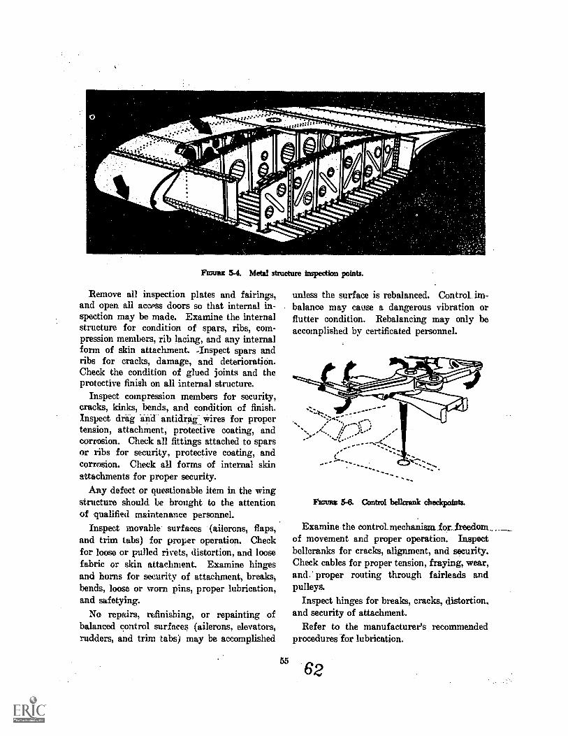
0
O
Fox= 5-4. Metal structure inspection points.
Remove all inspection plates and fairings,and open all access doors so that internal in-spection may be made. Examine the internalstructure for condition of spars, ribs, com-pression members, rib lacing, and any internalform of skin attachment. -Inspect spars andribs for cracks, damage, and deterioration.Check the condition of glued joints and theprotective finish on all internal structure.
Inspect compression members for security,cracks, kinks, bends, and condition of finish.Inspect drag and antidragwires for propertension, attachment, protective coating, andcorrosion. Check all fittings attached to sparsor ribs for security, protective coating, andcorrosion. Check all forms of internal skinattachments for proper security.
Any defect or questionable item in the wingstructure should be brought to the attentionof qualified maintenance personnel.
Inspect movable surfaces (ailerons, flaps,and trim tabs) for proper operation. Checkfor loose or pulled rivets, distortion, and loosefabric or skin attachment. Examine hingesand horns for security of attachment, breaks,bends, loose or worn pins, proper lubrication,and safotying.
No repairs, refinishing, or repainting ofbalanced control surfaces (ailerons, elevators,rudders, and trim tabs) may be accomplished
55
unless the surface is rebalanced. Control im-balance may cause a dangerous vibration orflutter condition. Rebalancing may only beaccomplished by certificated personnel.
From 5-8. Control bellcrank checkpoints.
Examine the control.mechanism_for_freedom. . _of movement and proper operation. Inspectbellcranks for cracks, alignment, and security.Check cables for proper tension, fraying, wear,and.' proper routing through fairleads andpulleys.
Inspect hinges for breaks, cracks, distortion,and security of attachment.
Refer to the manufacturer's recommendedprocedures for lubrication.
62
nouns 5-5. Lightning damageflap, lower surface.
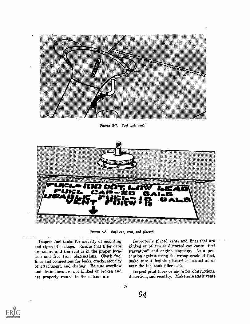
+4
FIGURE 5-7. Fuel tank vent.
ig=eg-ef ^sacitUPIC:Im ezlb.m -Pen 111^...iqualt Bk Ira is "UM
4FEcunz 5.8. Fuel cap, vent, and placard.
Inspect fuel tanks for security of mountingand signs of leakage. Ensure that filler capsare secure and the vent is in the proper loca-tion and free from obstructions. Check fuellines and connections for leaks, cracks, securityof attachment, and chafing. Be sure overflowand drain lines are not kinked or broken arylare properly routed to the outside air.
. 57
"^--T.
Improperly placed vents and lines that arekinked or otherwise distorted can cause "fuelstarvation" and engine stoppage. As a pre-caution against using the wrong grade of fuel,make sure a legible placard is located at ornear the fuel tank filler neck.
Inspect pitot tubes or men's for obstructions,distortion, and security. Make sure static vents
61
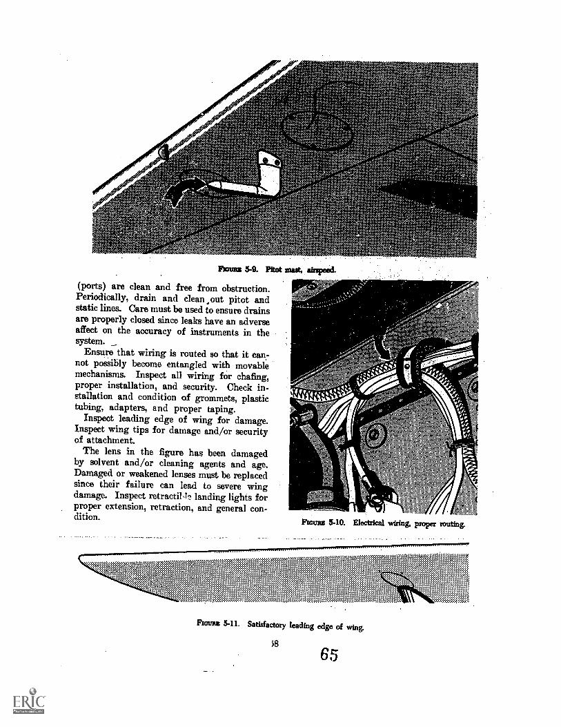
(ports) are clean and free from obstruction.Periodically, drain and clean ,out pitot andstatic lines. Care must be used to ensure drainsare properly closed since leaks have an adverseaffect on the accuracy of instruments in thesystem.
Ensure that wiring is routed so that it can-not possibly become entangled with movablemechanisms. Inspect all wiring for chafing,proper installation, and security. Check in-stallation and condition of grommets, plastictubing, adapters, and proper taping.
Inspect leading edge of wing for damage.Inspect wing tips for damage and/or securityof attachment.
The lens in the figure has been damagedby solvent and/or cleaning agents and age.Damaged or weakened lenses must be replacedsince their failure can lead to severe wingdamage. Inspect retracti1,11 landing lights forproper extension, retraction, and general con-dition. Ram 5-10. Electrical wiring, proper routing.
Room 5-11. Satisfactory leading edge of wing.
$8
65
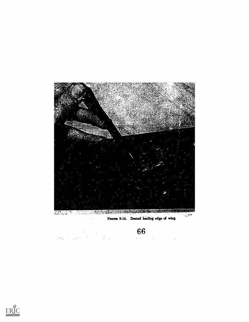
§
Ficmz 5-12. Dented leading edge of wing.
66
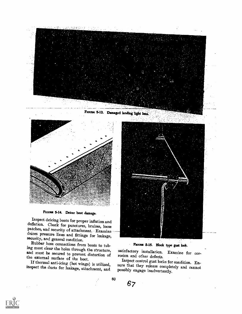
Fromm 5-14. Deicer boot damage.
Inspect deicing boots for proper inflation anddeflation. Check for punctures, bruises, loosepatches, and security of attachment. Examinedeices pressure lines and fittings for leakage,security, and general condition.
Rubber hose connections from boots to tub-ing must clear the holes through the structure,and must be secured to prevent distortion ofthe external surface of the boot.
If thermal anti-icing (hot wings) is utilized,inspect the ducts for leakage, attachment, and
60
FEW= 5-15. Block type gust lock.
satisfactory installation. Examine for cor-rosion and other defects.
Inspect control gust locks for condition. En-sure that they release completely and cannotpossibly engage inadvertently.
67
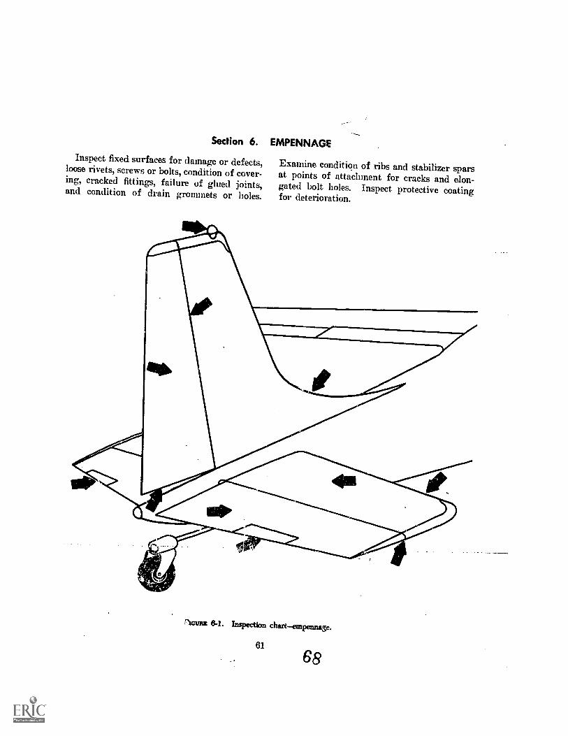
Section 6. EMPENNAGE
Inspect fixed surfaces for damage or defects,loose rivets, screws or bolts, condition of cover-ing, cracked fittings, failure of glued joints,and condition of drain grommets or holes.
Examine condition of ribs and stabilizer sparsat points of attachment for cracks and elon-gated bolt holes. Inspect protective coatingfor deterioration.
Actraz 6-1. Inspection chartempennage.
61
68
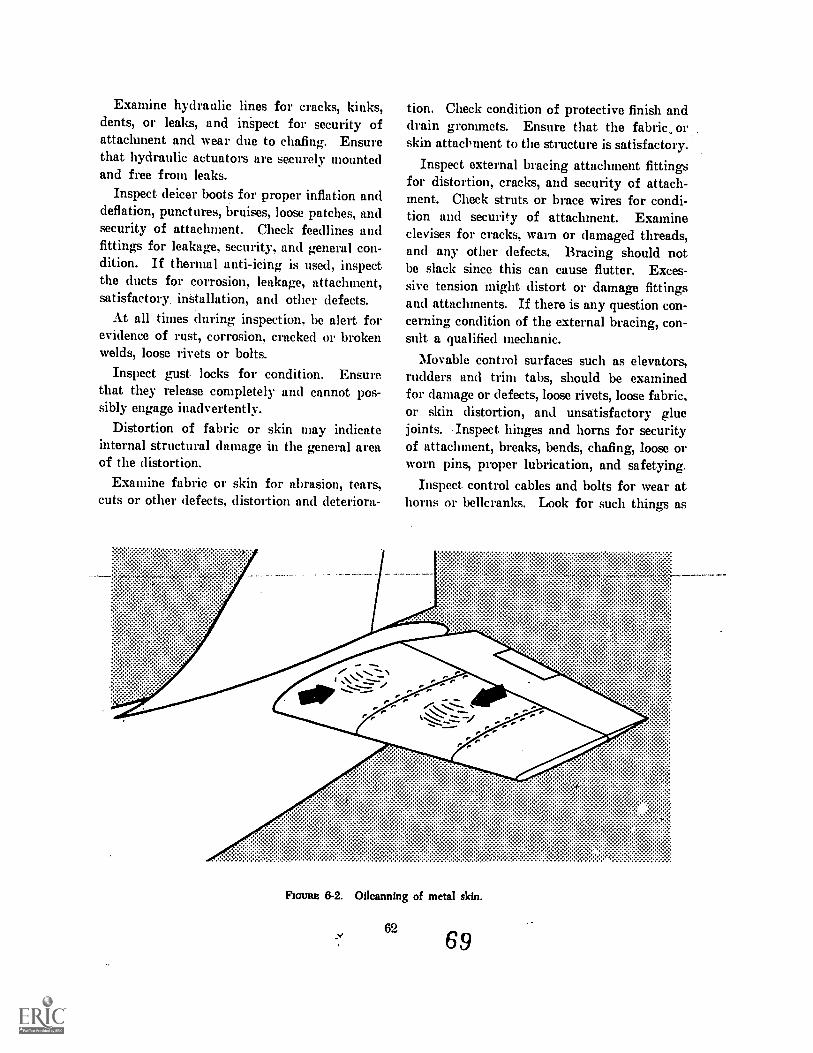
Examine hydraulic lines for cracks, kinks,dents, or leaks, and inspect for security ofattachment and wear due to chafing. Ensurethat hydraulic actuators are securely mountedand free from leaks.
Inspect. deicer boots for proper inflation anddeflation, punctures, bruises, loose patches, andsecurity of attachment. Check feedlines andfittings for leakage, security, and general con-dition. If thermal anti-icing is used, inspectthe ducts for corrosion, leakage, attachment,satisfactory installation, and other defects.
At all times during inspection, be alert forevidence of rust, corrosion, cracked or brokenwelds, loose rivets or bolts.
Inspect gust. locks for condition. Ensure,that they release completely and cannot pos-sibly engage inadvertently.
Distortion of fabric or skin may indicateinternal structural damage in the general areaof the distortion.
Examine fabric or skin for abrasion, tears,cuts or other defects, distortion and deteriora-
tion. Check condition of protective finish anddrain grommets. Ensure that the fabric, orskin attachment to the structure is satisfactory.
Inspect external bracing attachment fittingsfor distortion, cracks, and security of attach-ment. Check struts or brace wires for condi-tion and security of attachment. Examinedevises for cracks, warn or damaged threads,and any other defects. Bracing should notbe slack since this can cause flutter. Exces-sive tension might distort or damage fittingsand attachments. If there is any question con-cerning condition of the external bracing, con-sult. a qualified mechanic.
Movable control surfaces such as elevators,rudders and trim tabs, should be examinedfor damage or defects, loose rivets, loose fabric,or skin distortion, and unsatisfactory gluejoints. Inspect hinges and horns for securityof attachment, breaks, bends, chafing, loose orworn pins, proper lubrication, and safetying.
Inspect. control cables and bolts for wear athorns or bellcranks. Look for such things as
FICWRE 8-2. Oilcanning of metal skin.
6269
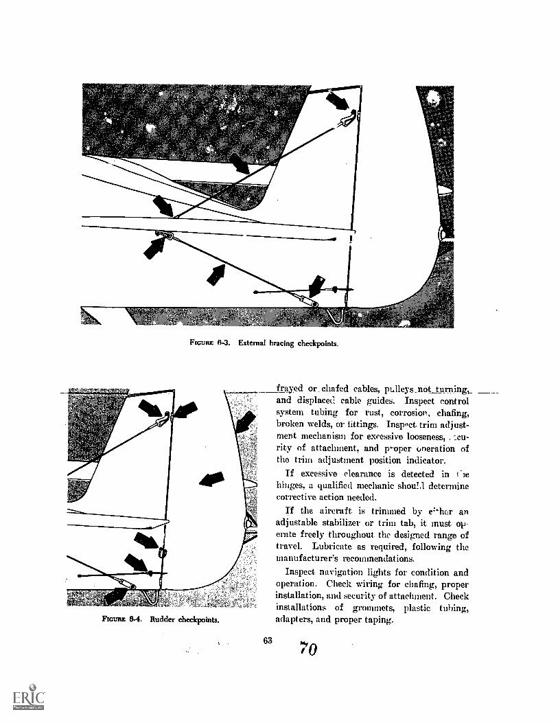
FIGURE 8-3. External bracing checkpoints.
FIGURE 8-4. Rudder checkpoints.
63
frayed or. chafed _cables, pLlleys_not turning,_and displaced cable guides. Inspect controlsystem tubing for rust, corrosion, chafing,broken welds, or fittings. Inspoct trim adjust-ment mechanism for excessive looseness, -..cu-
rity of attachment, and roper oneration ofthe trim adjustment position indicator.
If excessive clearance is detected in liehinges, a qualified mechanic shou!,l determinecorrective action needed.
If the aircraft is trimmed by &lier anadjustable stabilizer or trim tab, it must op-erate freely throughout. the designed range oftravel. Lubricate as required, following themanufacturer's recommendations.
Inspect navigation lights for condition andoperation. Check wiring for chafing, properinstallation, and security of attachment. Checkinstallations of grommets, plastic tubing,adapters, and proper taping.
7fo
'40,44.4g-M
A
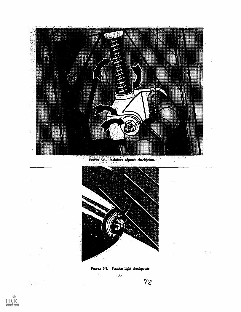
Pict= 8-7. Position light checkpoints.
65
72
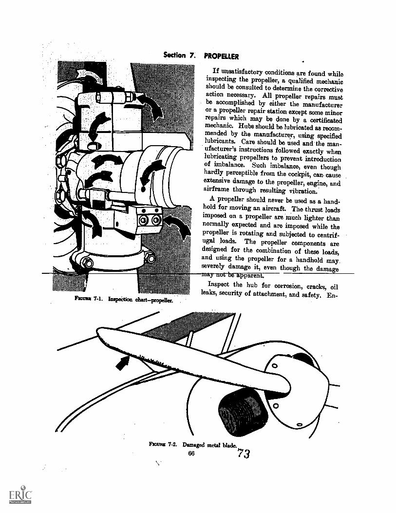
Section 7. PROPELLER
If unsatisfactory conditions are found whileinspecting the propeller, a qualified mechanicshould be consulted to determine the correctiveaction necessary. All propeller repairs mustbe accomplished by either the manufactureror a propeller repair station except some minorrepairs which may be done by a certificatedmechanic. Hubs should be lubricated as recom-mended by the manufacturer, using specifiedlubricants. Care should be used and the man-ufacturer's instructions followed exactly whenlubricating propellers to prevent introductionof imbalance. Such imbalance, even thoughhardly perceptible from the cockpit, can causeextensive damage to the propeller, engine, andairframe through resulting vibration.
A propeller should never be used as a hand-hold for moving an aircraft. The thrust loadsimposed on a propeller are much lighter thannormally expected and are imposed while thepropeller is rotating and subjected to centrif-ugal loads. The propeller components aredesigned for the combination of these loads,and using the propeller for a handhold mayseverely damage it, even though the damage
Fromm 7-1. Inspection chart
parenInspect the hub for corrosion, cracks, oil
leaks, security of attachment, and safety. En-
Fromm 7-2. Damaged metal blade.
66 73

sure-that propeller retainer bolts are tight andproperly safetied.
Inspect metal blades for corrosion, cracks,nicks, and scratches, particularly on the lead-ing edge of each blade from the tip inboard.Even very small nicks and scratches set upstress concentrations which can lead to struc-
,
4`
D01/118.
B. Hub bolts.C. Hub.D. Blade.
tural failures, especially in the-propeller blades.-Propellers should be inspected at preflight andpostflight. This permits repairs to be madeto scratches and nicks before further operationand with less likelihood of delaying a trip.Remember, the longer a scratch or nick existsthe greater the probability of failure.
IrfC'
" 5
Z Counterweight.F. Deicer %totC. Deicer boot leads.H. Spinner bulkhead.
Flamm 7-3. Threezblade propeller checkpntnts.
67
7
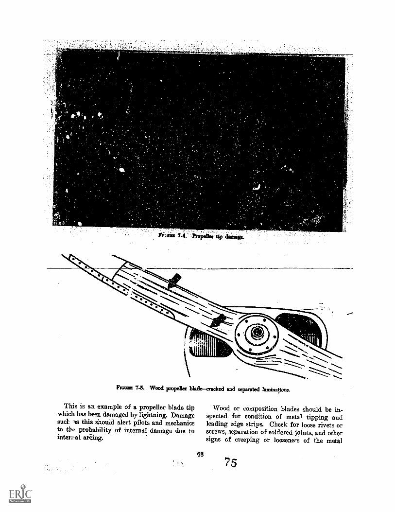
FrAits 7 . 1Piropelle; tip dainage.
4
FIGURE 7-5. Wood propeller bladecracked and separated laminations.
This is an example of a propeller blade tipwhich has been damaged by lightning. Damagesuet As this should alert pilots and mechanicsto probability of internal damage due tointereal arcing.
Wood or composition blades should be in-spected for condition of metal tipping andleading edge strips. Check for loose rivets orscrews, separation of soldered joints, and othersigns of creeping or looseners of the metal
75
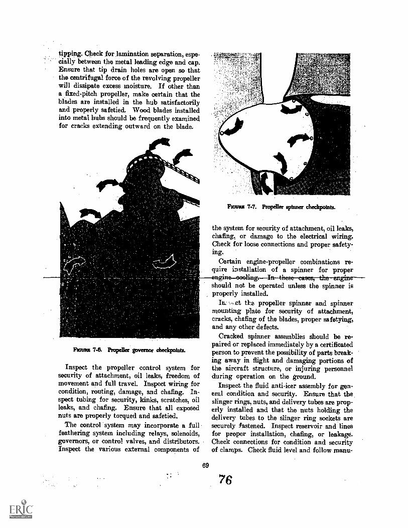
tipping. Check for lamination separation, espe-cially between the metal leading edge and cap.Ensure that tip drain holes are open so thatthe centrifugal force of the revolving propellerwill dissipate excess moisture. If other thana fixed-pitch propeller, make certain that theblades are installed in the hub satisfactorilyand properly safetied. Wood blades installedinto metal hubs should be frequently examinedfor cracks extending outward on the blade.
Frcunst 7-7. Propeller spinner checkpoints.
the system for security of attachment, oil leaks,chafing,. or damage to the electrical wiring.Check for loose connections and proper safety-ing.
Certain engine-propeller combinations re-quire installation of a spinner for proper
should not be operated unless the spinner isproperly installed.
.ct the propeller spinner and spinnermounting plate for security of attachment,cracks, chafing of the blades, proper safetying,and any other defects.
Cracked spinner assemblies should be re-paired or replaced immediately by a certificatedperson to prevent the possibility of parts break-ing away in flight and damaging portions ofthe aircraft structure, or injuring personnelduring operation on the ground.
Inspect the fluid anti-icer assembly for gen-eral condition and security. Ensure that theslinger rings, nuts, and delivery tubes are prop-erly installed and that the nuts holding thedelivery tubes to the slinger ring sockets aresecurely fastened. Inspect reservoir and linesfor proper installation, chafing, or leakage.Check connections for condition and securityof clamps. Check fluid level and follow menu-
Frcraus 7-8. Propeller governor checkpoints.
Inspect the propeller control system forsecurity of attachment, oil leaks, freedom ofmovement and full travel. Inspect wiring forcondition, routing, damage, and chafing. In-spect tubing for security, kinks, scratches, oilleaks, and chafing. Ensure that all exposednuts are properly torqued and safetied.
The control system may incorporate a fullfeathering system including relays, solenoids,governors, or control valves, and distributors.Inspect the various external components of
69
L7. v s
76
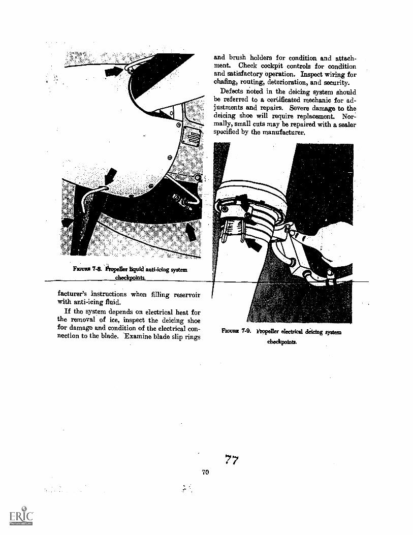
and brush holders for condition and attach-ment. Check cockpit controls for conditionand satisfactory operation. Inspect wiring forchafing, routing, deterioration, and security.
Defects noted in the deicing system shouldbe referred to a certificated mechanic for ad-justments and repairs. Severe damage to thedeicing shoe will require replacement. Nor-mally, small cuts may be repaired with a sealerspecified by the manufacturer.
nY
FIGURE 741. lissopeller liquid anti -icing system
,
facturer's instructions when filling reservoirwith anti-icing fluid.
If the system depends on electrical heat forthe removal of ice, inspect the deicing shoefor damage and condition of the electrical con-nection to the blade. Examine blade slip rings
70
FIGURE 7-9. Propeller electrical deicing system
checkpoints.
77
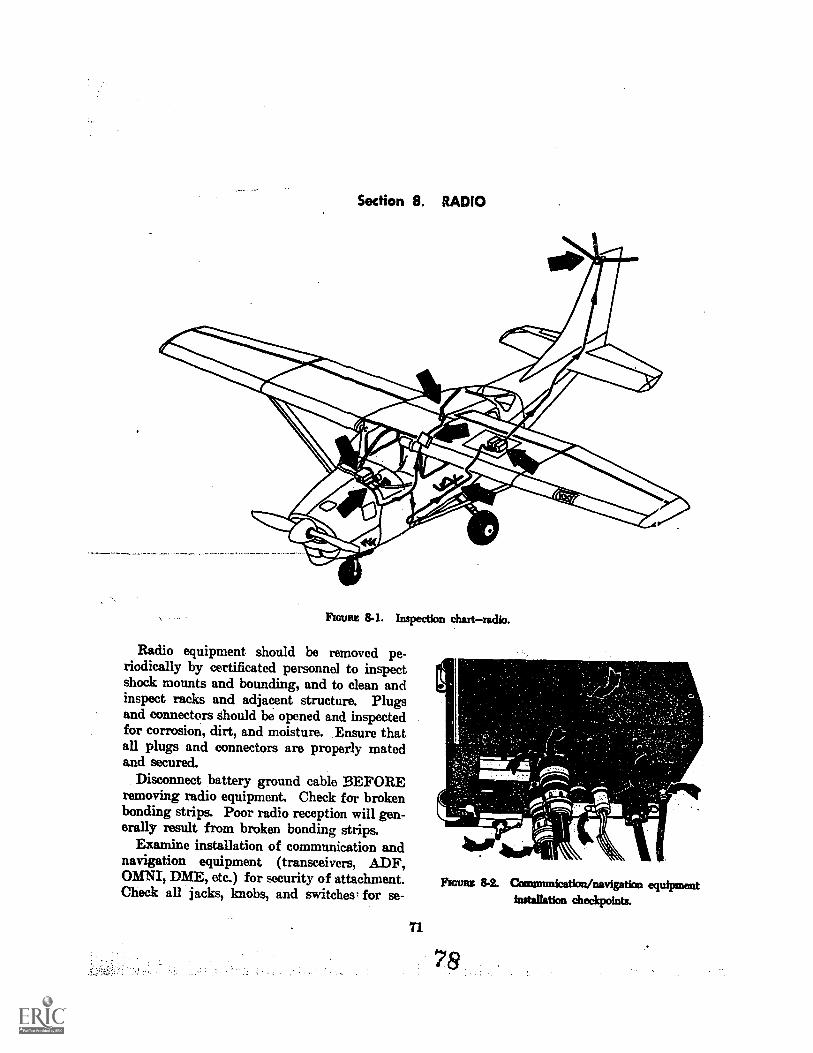
Section 8. RADIO
Flom 8-1. Inspection chartradio.
Radio equipment should be removed pe-riodically by certificated personnel to inspectshock mounts and bounding, and to clean andinspect racks and adjacent structure. Plugsand connectors should be opened and inspectedfor corrosion, dirt, and moisture. Ensure thatall plugs and connectors are properly matedand secured.
Disconnect battery ground cable BEFOREremoving radio equipment. Check for brokenbonding strips. Poor radio reception will gen-erally result from broken bonding strips.
Examine installation of communication andnavigation equipment (transceivers, ADF,OMNI, DME, etc.) for security of attachment.Check all jacks, knobs, and switches. for se-
Rams 8.2. Ounmtmication/navigation equipmentinstallation checkpoints.
71
78
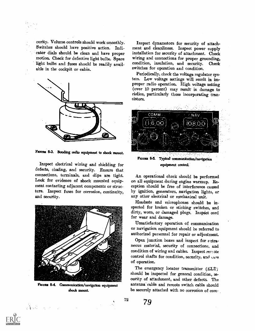
curity. Volume controls should work smoothly.Switches should have positive action. Indi-cator dials should be clean and have propermotion. Check for defective light bulbs. Sparelight bulbs and fuses should be readily avail-able in the cockpit or cabin.
Room 8-3. Bonding radio equipment to shock mount.
Inspect electrical wiring and shielding fordefects, chafing, and security. Ensure thatconnections, terminals, and clips are tight.Look for evidence of shock mounted equip-ment contacting adjacent components or struc-ture. Inspect fuses for corrosion, continuity,and security.
Roma 8-4. Communication/navigation equipmentshock mount.
72
Inspect dynamotors for security of attach-ment and cleanliness. Inspect power supplyinstallation for security of attachment. Checkwiring and connections for proper grounding,condition, insulation, and security. Checkswitches for operation and condition.
Periodically, check the voltage regulator sys-tem. Low voltage settings will result in im-proper radio operation. High voltage setting(over 10 percent) may result in damage toradios, particularly those incorporating tran-sistors.
11
11
11
PICT= 8-5. Typical communication/navigation
equipment control.
11
An operational check should be performedon all equipment during engine warmup. Re-ception should be free of interference causedby ignition, generators, navigation lights, orany other electrical or mechanical unit.
Headsets and microphones should be in-spected for broken or sticking switches, anddirty, worn, or damaged plugs. Inspict cordfor wear and damage.
Unsatisfactory operation of communicationor navigation equipment should be referred toauthorized personnel for repair or adjustment.
Open junction boxes and inspect for a dra-neous material, security of connections, andcondition of wiring and cables. Inspect ren atecontrol shafts for condition, security, and (Acsof operation.
The emergency locator transmitter (ELT)should be inspected for general condition, se-curity of attachment, and other defects. Theantenna' cable and remote switch cable shouldbe securely attached with no corrosion of com-
79
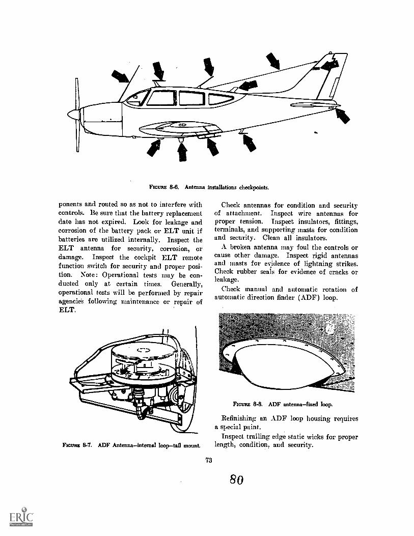
FIGURE 8-8. Antenna installations checkpoints.
ponents and routed so as not to interfere withcontrols. Be sure that the battery replacementdate has not expired. Look for leakage andcorrosion of the battery pack or ELT unit ifbatteries are utilized internally. Inspect theELT antenna for security, corrosion, ordamage. Inspect the cockpit ELT remotefunction switch for security and proper posi-tion. Note: Operational tests may be con-ducted only at certain times. Generally,operational -tests will be performed by repairagencieS following maintenance or repair ofELT.
Flom 8-7. ADF Antennainternal looptail mount.
73
Check antennas for condition and securityof attachment. Inspect wire antennas forproper tension. Inspect insulators, fittings,terminals, and supporting masts for conditionand security. Clean all insulators.
A. broken antenna may foul the controls orcause other damage. Inspect rigid antennasand masts for evidence of lightning strikes.Check rubber seals for evidence of cracks orleakage.
Check manual and automatic rotation ofautomatic direction finder (ADF) loop.
FIGURE 8-8. ADF antennafixed loop.
Refinishing ana special paint.
Inspect, trailinglength, condition,
80
ADF loop housing requires
edge static wicks for properand security.
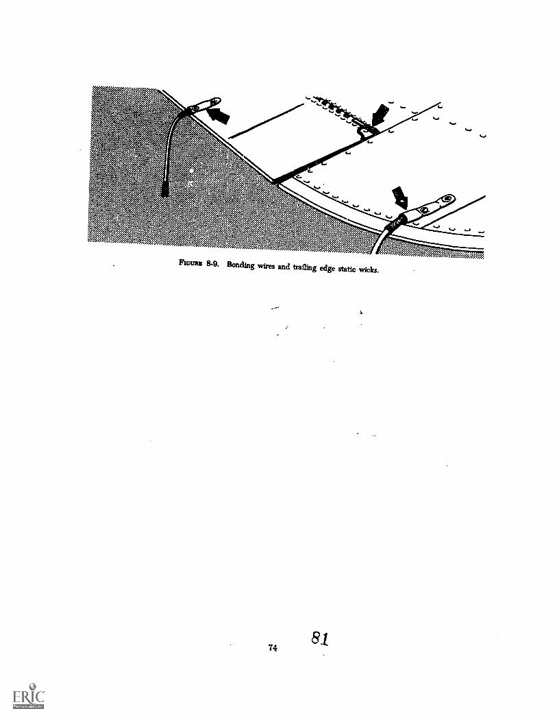
*.z..".. ....t.4.4.**\::::A....,..f...44N......,..
'',:. f*Ik.::::,:x......:..,.
si.44,k 4:::ft.4:00s%:.:0.:7,,txV4: 4::>.::::......:,.. 4.... .' 4.P.: :/:...t...'s...V.sK"*. ".fe.
-::. .,.-4:41t..:3.t. ..k.
.:,...ti:::m:*".::::.," ...4:.4..tVa:u *...<1.::....$4...:x::.k:.....:::::$..
::::::,:?e.44;44.::::::::%:::..:%,.:.:...,::.:;.....:.,.. ...$:04:::4:14::::::::?:::::=A::::::::::::>1:::::::::::.::::§::::::::M
Amax 8-9. Bonding wires and trailing edge static wicks.
7481
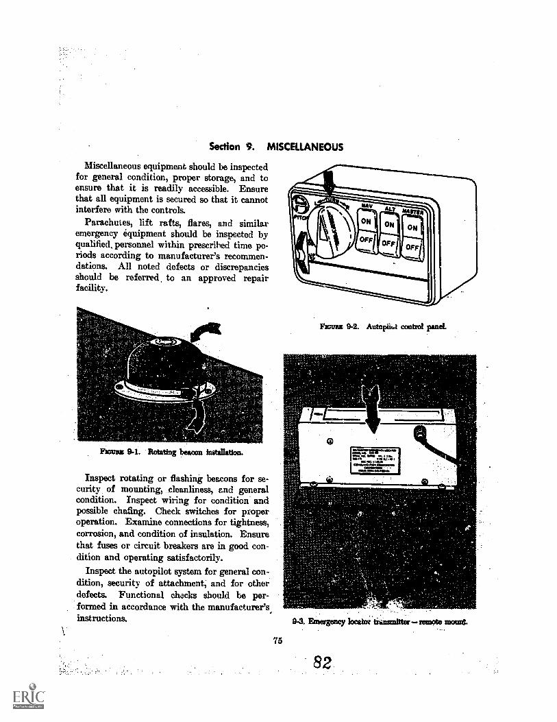
Section 9. MISCELLANEOUS
Miscellaneous equipment should be inspectedfor general condition, proper storage, and toensure that it is readily accessible. Ensurethat all equipment is secured so that it cannotinterfere with the controls.
Parachutes, lift rafts, flares, and similaremergency equipment should be inspected byqualified, personnel within prescrihed time pe-riods according to manufacturer's recommen-dations. All noted defects or discrepanciesshould be referred, to an approved repairfacility.
W."
Emma 9-1. Rotating beacon installation.
Inspect rotating or flashing beacons for se-curity of mounting, cleanliness, and generalcondition. Inspect wiring for condition andpossible chafing. Check switches for properoperation. Examine connections for tightness,corrosion, and condition of insulation. Ensurethat fuses or circuit breakers are in good con-dition and operating satisfactorily.
Inspect the autopilot system for general con-dition, security of attachment, and for otherdefects. Functional checks should be per-formed in accordance with the manufacturer'sinstructions. 9-3. Emergency 1ocatm tunsmitter remote mount.
Fioun 9-2. Autoptiut control panel.
Nem
O=.4.....trirSOCAM
I INM/YMD elk
6110.11.110.011110.1.4OWO.11.110
COW *WO
011110 MINIM
75
82
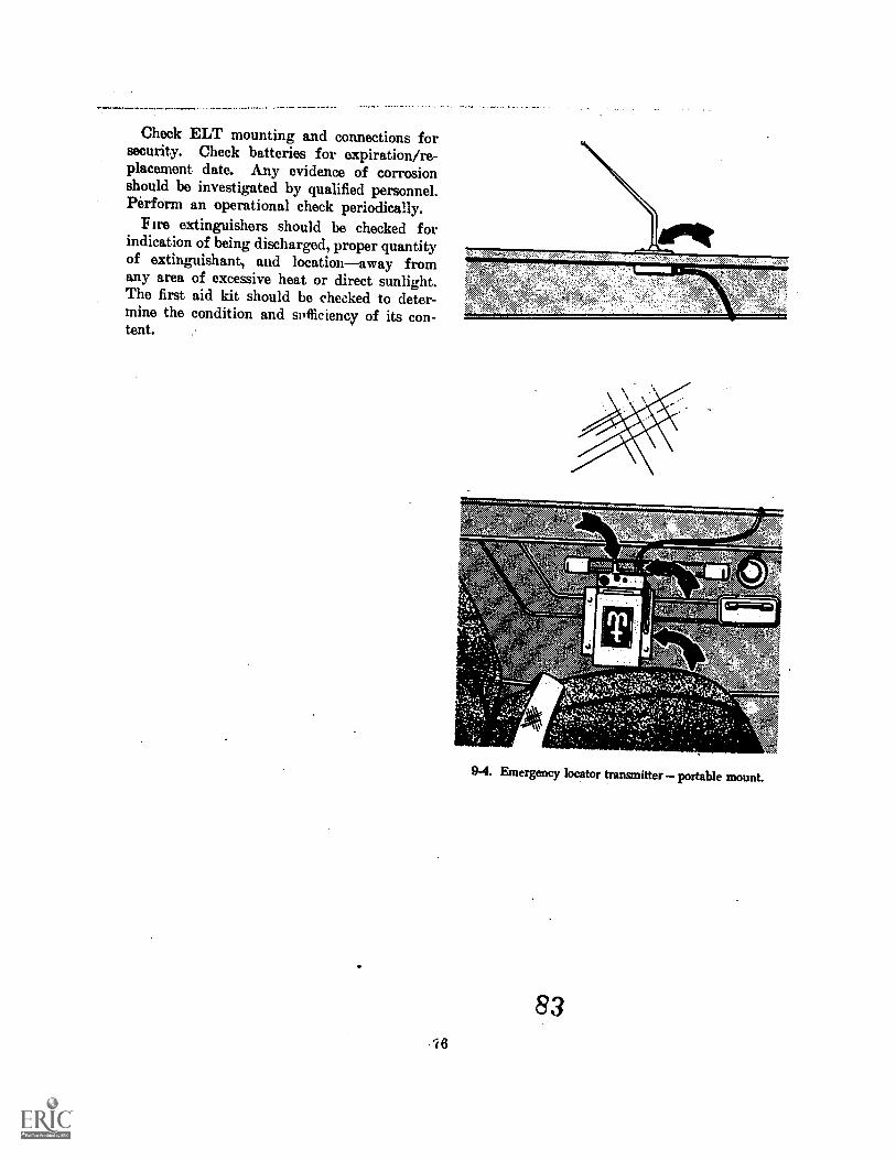
Check ELT mounting and connections forsecurity. Check batteries for expiration/re-placement date. Any evidence of corrosionshould be investigated by qualified personnel.Perform an operational check periodically.
F ire extinguishers should be checked forindication of being discharged, proper quantityof extinguishant, and locationaway fromany area of excessive heat or direct sunlight.The first aid kit should be checked to deter-mine the condition and suflic iency of its con-tent.
76
O
9-4. Emergency locator transmitter portable mount.
83
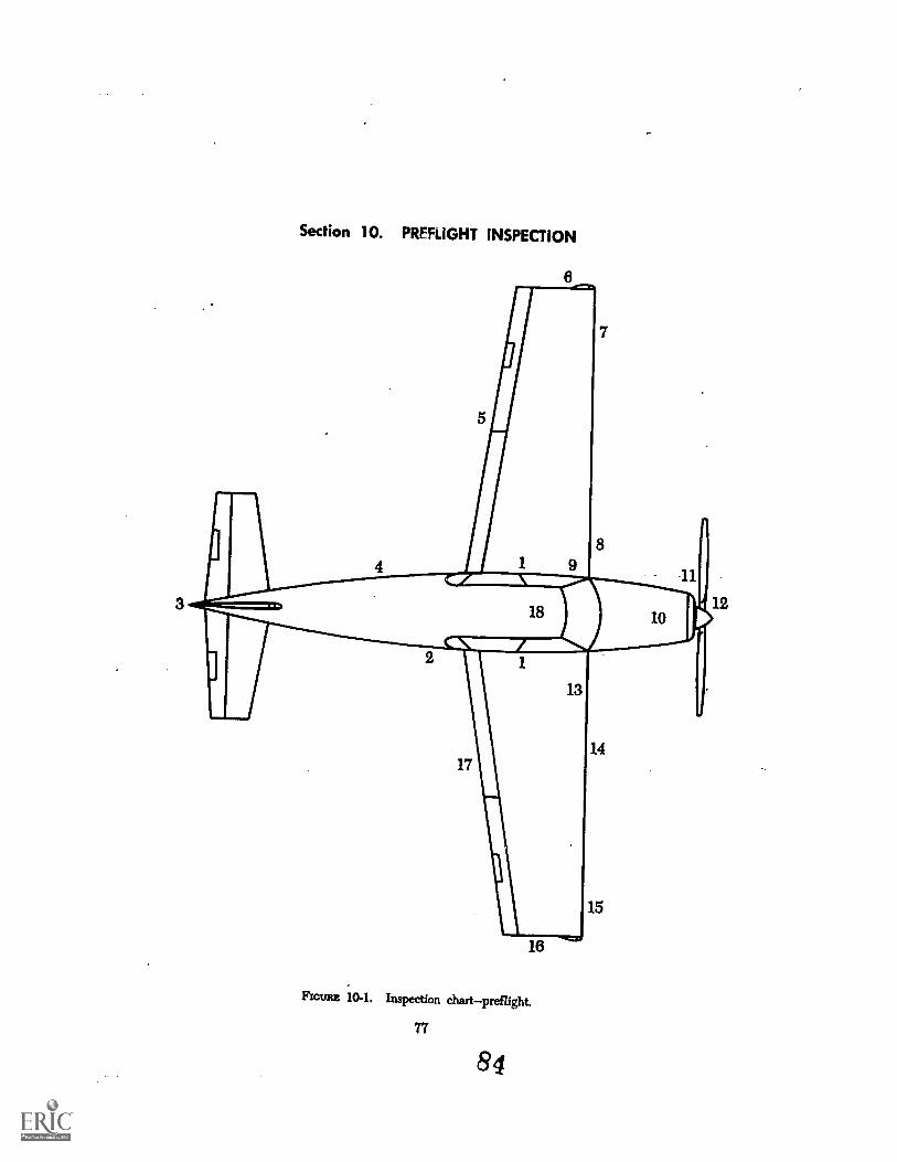
Section 10. PREFLIGHT INSPECTION
5
18
13
18
FIGURE 10-1. Inspection chartpreflight.
77
84
14
15
The following Preflight Inspection Check-list may be used as a guide when developinga preflight checklist for your aircraft. Itshould be modified to suit the aircraft typeand to include the manufacturer's recommenda-tions (normally found i.: the Pilots/OwnersOperation Handbook).
The numbers on the inspection chart cor-respond to the numbers indicated on the item-ized list. By following the numerical route,an effective and organized preflight inspectioncan be accomplished.
1. The first three items to be accomplishedare:Battery and ignition switchesOFFControl locksREMOVEDLanding gear controlGEAR DOWN
AND LOCKED
After completion of item Number 1, proceedwith the preflight inspection.
Carefully observe the general overall ap-pearance of the airplane.
2. Fuselage: Right sideExterior of cockpit doors/passenger
doorcheck for security of hinges andg*latch lock. Check condition of skin
and windows.
Baggage compartmentcontents securedand door locked.
Airspeed static sourcefree from ob-structions.
Condition of coveringmissing or looserivets, cracks, tears in fabric, etc.
3. Empennage:Deicer bootscondition and security.Control surface locks"REMOVE."Fixed and movable control surfaces
dents, cracks, excess play, hinge pinsand bolts for security and movable sur-faces for full travel and freedom ofmovement.
Tailwheelspring, steering arms andchains, tire inflation, and condition.
78
Lightsnavigation and anticollisionlights for condition and security.
4. Fuselage: Left sideSame as item 2.
5. Wing: .
Control surface locks"REMOVE."Control surfaces, including flapsdents,
cracks, excess plt,y, hinge pins andbolts for security and condition, mov-able surfaces for full travel and free-dom of movement.
General condition of wings and cover-ingtorn fabric, bulges or wrinkles,loose or missing rivets, "oil cans," etc.
6. Wing tip and navigation lightcondi-tion and security.
7. Deicer bootsgeneral condition and se-curity.
Landing light--condition, cleanliness,and security.
Stall warning vanefreedom of move-ment. Prior to inspection, turn masterswitch "ON" so that stall warningsignal can be checked when vane isdeflected.
8. Landing gear:Wheels and brakescondition and se-
curity, indications of fluid leakage atfittings, fluid lines, and adjacent area.
Tirescuts, bruises, excessive wear, andproper inflation.
Oleos and shock strutscleanliness andproper inflation.
Shock cordsgeneral condition.Wheel Fairingsgeneral condition and
security. On streamlined wheel fair-ings, look inside for accumulation ofmud, ice, etc.
Limit and position switchessecurity,cleanliness, and condition.
around safety locks"REMOVE."
85
9. Fuel quantity in tank :Fuel tank filler cap and fairing covers
secure.Fuel tank ventsobstructions.When fuel tank is equipped with a quick
or snap-type drain valve, drain a suf-ficient amount of fuel into a containerto check for the presence of water andsediment.
10. Engine :Engine oil quantitysecure filler cap.General condition and evidence of fuel
and oil leaks.Cowling, access doors, and cowl flaps
condition and security.Air inlet screeticleanliness and security.Drain a sufficient quantity of fuel from
the main fuel sump drain to determinethat there is no water or sediment re-maining in the system.
11. Nose landing gear :Wheel and tirecuts, bruises, excessive
wear, and proper inflation.Oleo and shock strutproper inflation
and cleanliness.Wheel well and fairinggeneral condi-
tion and security.Limit and position switchescleanliness,
condition, and security.Ground safety lock"REMOVE."
12. Propeller:Propeller and spinnersecurity, oil
leakage, and condition.Be particularly observant for nicks and
scratches. If the engine runup will beaccomplished at this location, ensurethat ground area under prOpeller isfree of loose stones, cinders, etc.
13. Fuel tank :Same as item 9.
14. Landing gear:Same as item 8.
15. Pitot :Pitot cover"REMOVE."Pitot and static portsfree of obstruc-
tions.General condition and alignment.Deicer boots and landing edge of wing.
16. Same as item 6 (Wing tip and navigationlightcondition and security).
17. Same as item 5 (Wing).
18. Cockpit:Interior of cockpit door/passenger doors
check for security of hinges andlatch or lc "k. ChEek for condition ofdoor linings.
Cleanliness and loose articles.
Windshield and windowsobvious de-fects and cleanliness.
Safety belt and shoulder harnesscon-dition and security.
Check security and adjustment o; pilot'sseat.
Pilot's seatlockedAdjust rudder pedals to ensure full rud-
der travel.
Check all flight coatrol surface -nd trimtabs for full travel, ri7ht or left,or down.
Trim tabs"SET."Parking brake"SET."Landing gear and flap switches or levers
in proper position.
Check all switches and controls.Cabin atmosphere control system.Oxygen system.Communication system.Emergency locator beacon.
With a fireguard' available, start theengine/engines and proceed with en-gine run-up following the engine man-ufacturer's recommendations.
7986
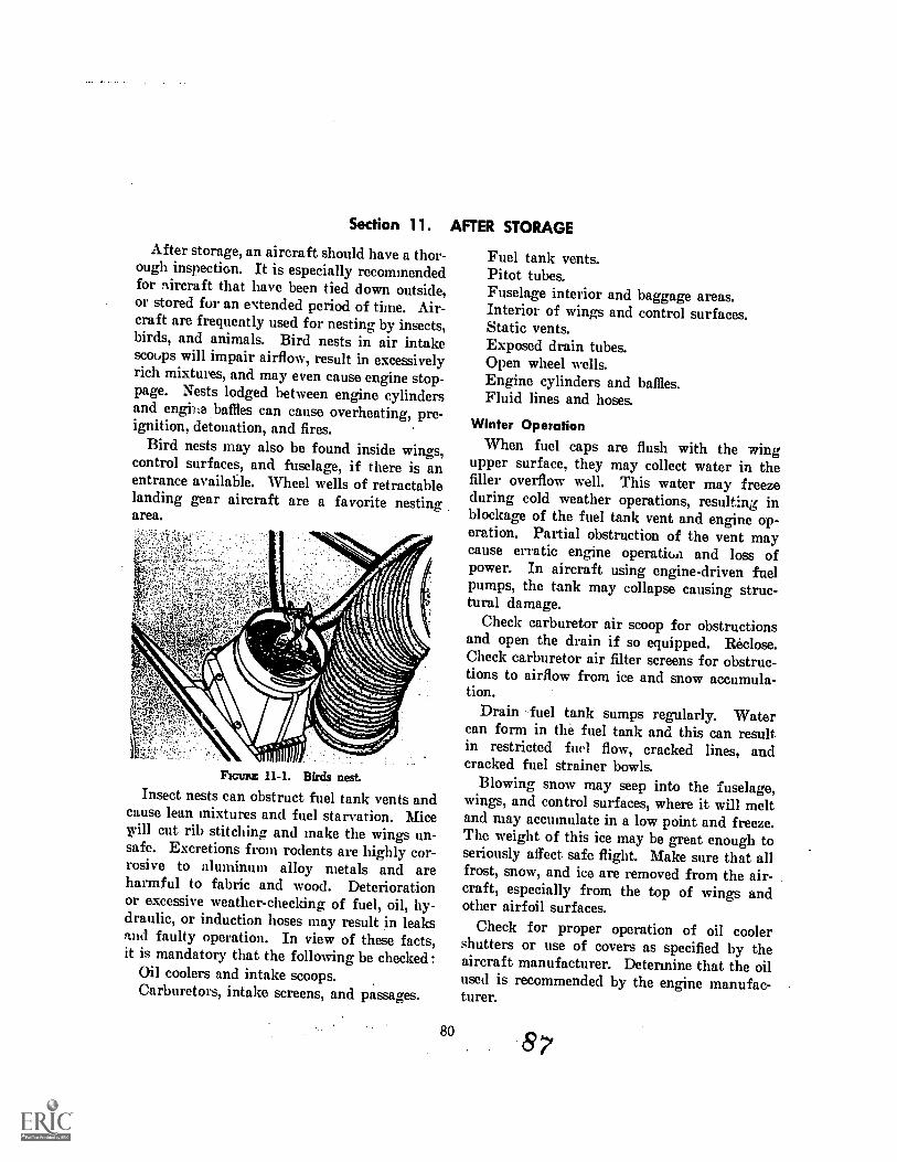
Section 11. AFTER STORAGE
After storage, an aircraft should have a thor-ough inspection. It is especially recommendedfor aircraft that have been tied down outside,or stored for an extended period of time. Air-craft are frequently used for nesting by insects,birds, and animals. Bird nests in air intakescoops will impair airflow, result in excessivelyrich mixtures, and may even cause engine stop-page. Nests lodged between engine cylindersand engiize baffles can cause overheating, pre-ignition, detonation, and fires.
Bird nests may also be found inside wings,control surfaces, and fuselage, if there is anentrance available. Wheel wells of retractablelanding gear aircraft are a favorite nestingarea.
FIGURE 11-1. Birds nest.
Insect nests can obstruct fuel tank vents andcause lean mixtures and fuel starvation. Micewill cut rib stitching and make the wings un-safe. Excretions from rodents are highly cor-rosive to aluminum alloy metals and areharmful to fabric and wood. Deteriorationor excessive weather-checking of fuel, oil, hy-draulic, or induction hoses may result in leaksand faulty operation. In view of these facts,it is mandatory that the following be checked:
Oil coolers and intake scoops.Carburetors, intake screens, and passages.
80
Fuel tank vents.Pitot tubes.Fuselage interior and baggage areas.Interior of wings and control surfaces.Static vents.Exposed drain tubes.Open wheel wells.Engine cylinders and baffles.Fluid lines and hoses.
Winter Operation
When fuel caps are flush with the wingupper surface, they may collect water in thefiller overflow well. This water may freezeduring cold weather operations, resulting inblockage of the fuel tank vent and engine op-eration. Partial obstruction of the vent maycause erratic engine operatioa and loss ofpower. In aircraft using engine-driven fuelpumps, the tank may collapse causing struc-tural damage.
Check carburetor air scoop for obstructionsand open the drain if so equipped. Ric lose.Check carburetor air filter screens for obstruc-tions to airflow from ice and snow accumula-tion.
Drain fuel tank sumps regularly. Watercan form in the fuel tank and this can resultin restricted fuel flow, cracked lines, andcracked fuel strainer bowls.
Blowing snow may seep into the fuselage,wings, and control surfaces, where it will meltand may accumulate in a low point and freeze.The weight of this ice may be great enough toseriously affect safe flight. Make sure that allfrost, snow, and ice are removed from the air-craft, especially from the top of wings andother airfoil surfaces.
Check for proper operation of oil coolershutters or use of covers as specified by theaircraft manufacturer. Determine that the oilused is recommended by the engine manufac-turer.
APPENDIX A
GENERAL SAFETY PRECAUTIONS
Good hot. lc. ng in hangars, shops, andon the flight is essential to safety andefficient main' The highest standardsof orderly %. rents and cleanlinessshould be ,,1;e %:nintaining an air-craft. 711:: ',nor ntt kt," lilt' inspection taskis complete, , and pro?: rly store main-tenance staivfs. noses, electrical cords, hoists,crates, boxes and anythi-eg -alst, used to performthe work.
Pedestrian lanes or ;ire lanes should bemarked and utilized as 9, si-,ety measure toprevent accidents and keep pedestrian trafficout of work areas.
Power cords and air hoses should be straight-ened, coiled, and properly stored when not inuse.
To prevent aircraft damage or personal in-jtcy, the use of wheel or wing jacks on unevenor soft ground, or under windy conditions,should be avoided. Jack or raise the aircraftonly in a closed hangar having a firm ...eve)floor.
Application of aircraft finishes 'lope orlacqueT:, should be accomplished in a coi.trolledenvirmanent (paint room) wheneverNever do this type work the presence, oflights that are not explosion proof or an opL,..flame. Do not permit other work on an air-craft when it is being painted. Keep fire lanesclear and hie exting.,;:liers available. Locateaircraft nit, being pte:',: ad so sl to permit quickremoval from the shop or he% .1%
Oil, gvase, or any slippery substan Pes spilledon hangtt or shop floors should be immediatelymuovel. If spills cannot be .moved, theyshould be covered with an absorbent. materialto prevent fire or personal injury. Drip pansshould be placed beneur.e engines send engineparts whenever dripping exists.
81
To prevent possible personal injury, appro-priate safety devices should be used in mount-ing or removing aircraft tires. When inflatingtires on the wheels, tire gauges should alwaysbe used. Extreme caution and the use of pres-sure regulators is required to avoid overinfla-tion of high-pressure tires. Never use highpressure air bottles to inflate tires.
Welding on aircraft in the hangar shouldnever be permitted except in carefully con-trolled areas. When welding is required, geta rrofebsional to perform the work in con-formance with the manufacturer's approvedprocedure.
Servicing Aircraft Oxygen Systems
Oxygen is a chemically stable, nonflammablegas, however, combustible materials ignite morerapidly, and burn with greater intensity in anoxygen-rich atmosphere. When oxygen com-bines with oil, grease, or any other petroleumproduct, it forms a highly explosive mixture.Petroleum products are extremely sensitive toimpact and spontaneous combustion when ex-posed to oxygen.
Before servicing any aircraft, consult thespecific aircraft maintenance manual to deter-mine the proper type of servicing equipmentto be used. Aircraft should not be .servicedwith oxygen during fueling or other mainte-nance work. Oxygen servicing of aircraftshould be done outside of hangars and byqualified personnel.
Aircraft TiedownAircraft not in use and parked outside
should be tied down at all times. Prevailing.wind and weather conditions will influence theamount of security needed in tying down air-
88
craft. Under normal conditions minimum se-curity is sufficient, but whenever winds orstorms are forecast, additional tiedowns shouldbe added.
Aircraft should be headed, as nearly as pos-sible, into the prevailing wind, depending onthe locations of the parking area's fixed tie-down points. After the aircraft is properlylocated, center the nose wheel or the tailwheelin the fore-and-aft poition. Aircraft whichare not equipped with tielown fittings shouldbe secured in accordance with the manufac-turer's instructions.
Tiedown AnchorsAll parking should provide at least three-
point tiedown (three anchors). Heavy aircrk ft
82
may require five or more. Anchors installedin paved parking areas are adaptable to anysize aircraft. When parking aircraft, spacingshould provide for wing tip clearance.
Control LocksControl locks (blocks) or gust locks should
be installed 3nytime an aircraft is not in use.
General PrecautionThe security and prevention of damage to
aircraft not in use depends upon the owner,pilot, or aircraft operator taking necessaryprecautions. The availability of weather con-dition reports should provide ample time totake additional safety precautions regardingsevere weather.
89
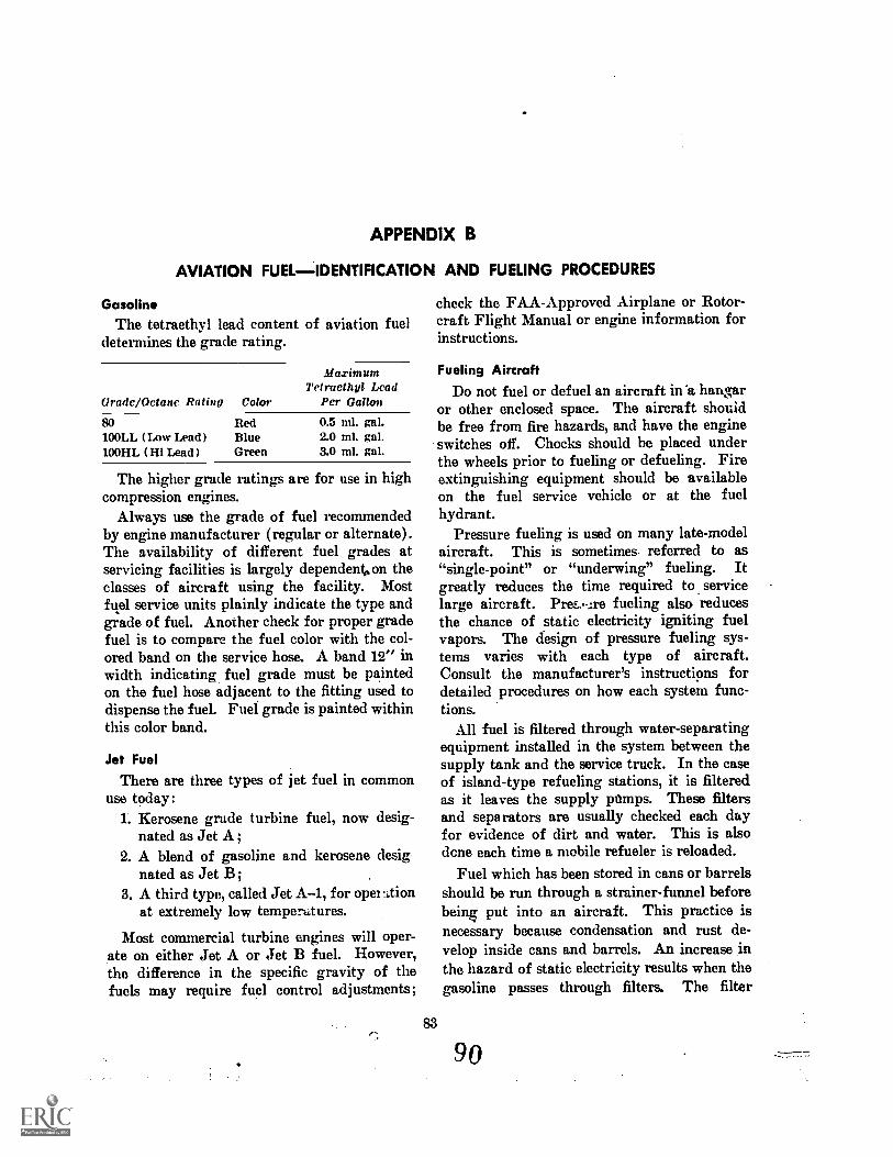
APPENDIX B
AVIATION FUEL IDENTIFICATION AND FUELING PROCEDURES
GasolineThe tetraethyl lead content of aviation fuel
determines the grade rating.
Grade /Octane Rating Color
MaximumTetraethyl Lead
Per Gallon
80100LL (Low Lead)100HL (Hi Lead)
RedBlueGreen
0.5 ml. gal.2.0 ml. gal.3.0 ml. gal.
The higher grade ratings are for use in highcompression engines.
Always use the grade of fuel recommendedby engine manufacturer (regular or alternate).The availability of different fuel grades atservicing facilities is largely dependenon theclasses of aircraft using the facility. Mostfuel service units plainly indicate the type andgrade of fuel. Another check for proper gradefuel is to compare the fuel color with the col-ored band on the service hose. A band 12" inwidth indicating fuel grade must be paintedon the fuel hose adjacent to the fitting used todispense the fuel. Fuel grade is painted withinthis color band.
Jet FuelThere are three types of jet fuel in common
use today:L Kerosene grade turbine fuel, now desig-
nated as Jet A;2. A blend of gasoline and kerosene desig
nated as Jet B;3. A third type, called Jet A-1, for open ltion
at extremely low temperatures.
Most commercial turbine engines will oper-ate on either Jet A or Jet B fuel. However,the difference in the specific gravity of thefuels may require fuel control adjustments;
83
check the FAA-Approved Airplane or Rotor-craft Flight Manual or engine information forinstructions.
Fueling AircraftDo not fuel or defuel an aircraft in'a hangar
or other enclosed space. The aircraft shouldbe free from fire hazards, and have the engineswitches off. Chocks should be placed underthe wheels prior to fueling or defueling. Fireextinguishing equipment should be availableon the fuel service vehicle or at the fuelhydrant.
Pressure fueling is used on many late-modelaircraft. This is sometimes. referred to as"single-point" or "underwing" fueling. Itgreatly reduces the time required to servicelarge aircraft. Pref..--ire fueling also reducesthe chance of static electricity igniting fuelvapors. The design of pressure fueling sys-tems varies with each type of aircraft.Consult the manufacturer's instructions fordetailed procedures on how each system func-tions.
All fuel is filtered through water-separatingequipment installed in the system between thesupply tank and the service truck. In the caseof island-type refueling stations, it is filteredas it leaves the supply pumps. These filtersand separators are usually checked each dayfor evidence of dirt and water. This is alsodone each time a mobile refueler is reloaded.
Fuel which has been stored in cans or barrelsshould be run through a strainer-funnel beforebeing put into an aircraft. This practice isnecessary because condensation and rust de-velop inside cans and barrels. An increase inthe hazard of static electricity results when thegasoline passes through filters. The filter
9p
should be grounded and remain grounded untilall gasoline has drained through it. Never usea plastic funnel, bucket, or similar nonconduc-tive container when servicing from storage cansor barrels.
When fueling aircraft by truck, the aircraftshould be located on the apron or a dispersalsite. The tank truck should hr, ttf. far from theaircraft as the hose will permit, preferably tothe windward or upwind side. Identify theaviation fuel and lubricating oil dispensedfrom each fueling unit before beginning theactual servicing. The fueling techniciansshould be familiar with the various grades ofgasoline so that only the appropriate fuel willbe used.
There should be no lights other than ap-proved explosion-proof lights permitted within100 feet of the fueling operation. Exposedelectric switches, sliprings or commutators,dynamos or motors, and spark-producing elec-trical equipment, should not be operated within100 feet of fueling- operations.
All nonessential circuit switches should be"OFF." Assure that both the aircraft and the
truck are properly grounded to prevent staticelectricity sparks. To accomplish this, a sepa-rate ground wire should be connected fromaircraft to ground, from fuel truck to ground,and the hose nozzle grounded to the aircraft.
If aircraft fuel or other combustible liquidis spilled, it should be immediately removed bywashing with water. It may also be coveredwith a foam blanket or neutralized by othermeans. Tools of nonsparking metal should beused when working on any part of a system orunit which is designed for storing or handlinggasolines. Notify the proper fire authoritiesif the situation so dictates.
Oil
Aircraft oil tanks are normally checked atthe same time the fuel tanks are filled. Thereare a few exceptions to this general rule. Somemanufacturers recommend that the oil level incertain jet engines be checked within a speci-fied time after engine shutdown. In all cases,the manufacturer's instructions should be fol-lowed not only for servicing procedures butalso for type and grade of oil used.
84 91
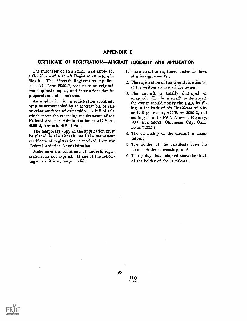
APPENDIX C
CERTIFICATE OF REGISTRATIONAIRCRAFT ELIGIBILITY AND APPLICATION
The purchaser of an aircraft itiust apply fora Certificate of Aircraft Registration before heflies it. The Aircraft Registration Applica-.tion, AC Form 8050-1, consists of an original,two duplicate copies, and instructions for itspreparation and submission.
An application for a registration certificatemust be accompanied by an aircraft bill of saleor other evidence of ownership. A bill of salewhich meets the recording requirements of theFederal Aviation Administration is AC Form8050-2, Aircraft Bill of Sale.
The temporary copy of the application mustbe placed in the aircraft until the permanentcertificate of registration is received from theFederal Aviation Administration.
Make sure the certificate of aircraft regis-tration has not expired. If one of the follow-ing exists, it is no longer valid :
1. The aircraft is registered under the lawsof a foreign country;
2. The registration of the aircraft is canceledat the written request of the owner;
3. The aircraft is totally destroyed orscrapped; (If the aircraft is destroyed,the owner should notify the FAA by fil-ing in the back of his Certificate of Air-craft Registration, AC Form 8050-3, andmailing it to the FAA Aircraft Registry,P.O. Box 25082, Oklahoma City, Okla-homa 73125.)
4. The ownership of theferred;
5. The holder of the certificate loses hisUnited States citizenship; and
6. Thirty days have elapsed since the deathof the holder of the certificate.
aircraft is trans-
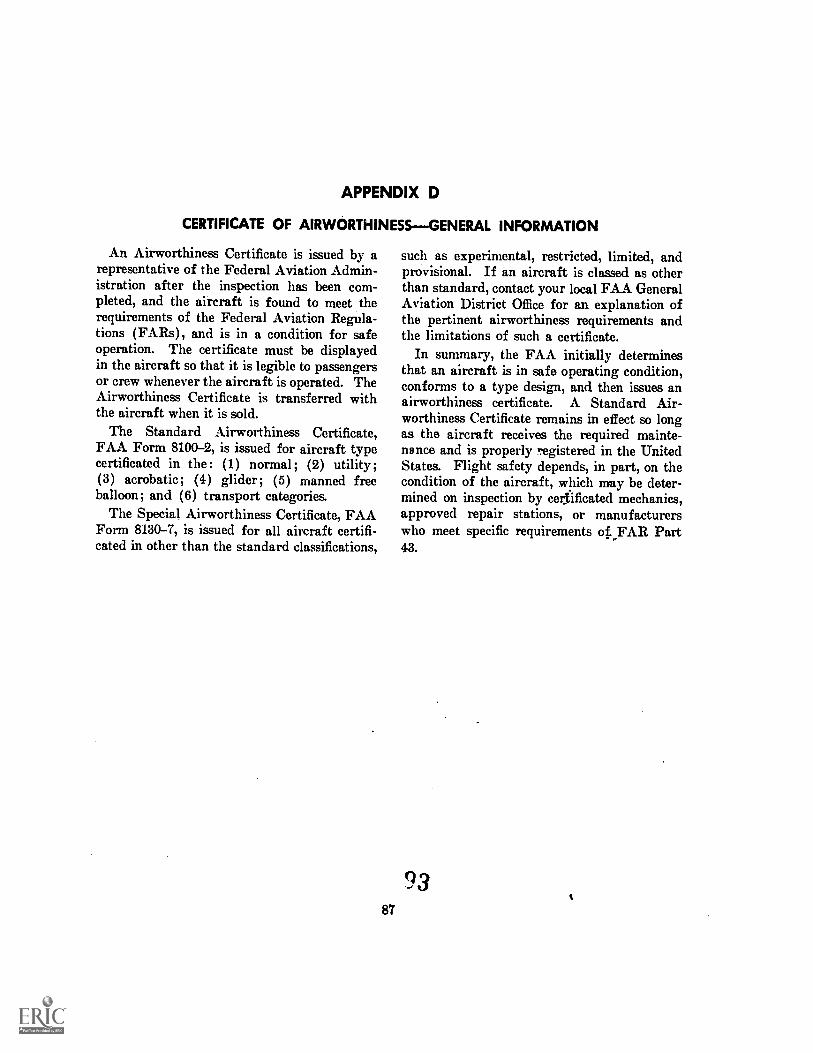
APPENDIX D
CERTIFICATE OF AIRWORTHINESSGENERAL INFORMATION
An Airworthiness Certificate is issued by arepresentative of the Federal Aviation Admin-istration after the inspection has been com-pleted, and the aircraft is found to meet therequirements of the Federal Aviation Regula-tions (FARs), and is in a condition for safeoperation. The certificate must be displayedin the aircraft so that it is legible to passengersor crew whenever the aircraft is operated. TheAirworthiness Certificate is transferred withthe aircraft when it is sold.
The Standard Airworthiness Certificate,FAA Form 8100-2, is issued for aircraft typecertificated in the : (1) normal; (2) utility ;(3) acrobatic; (4) glider; (5) manned freeballoon; and (6) transport categories.
The Special Airworthiness Certificate, FAAForm 8130-7, is issued for all aircraft certifi-cated in other than the standard classifications,
such as experimental, restricted, limited, andprovisional. If an aircraft is classed as otherthan standard, contact your local FAA GeneralAviation District Office for an explanation ofthe pertinent airworthiness requirements andthe limitations of such a certificate.
In summary, the FAA initially determinesthat an aircraft is in safe operating condition,conforms to a type design, and then issues anairworthiness certificate. A Standard Air-worthiness Certificate remains in effect so longas the aircraft receives the required mainte-nance and is properly registered in the UnitedStates. Flight safety depends, in part, on thecondition of the aircraft, which may be deter-mined on inspection by certificated mechanics,approved repair stations, or manufacturerswho meet specific requirements of,FAR Part43.


![DOCUBENT RESUME [A0891544] PAD-77-14. March 3, 1977. 52 pp. · DOCUBENT RESUME 00052 - [A0891544] Need for a Government-Wide Budget Classification Structure for Federal Research and](https://img.pdfslide.us/doc/110x75/5f6d0bceef820312026d8051/docubent-resume-a0891544-pad-77-14-march-3-1977-52-pp-docubent-resume-00052.jpg)