Embed Size (px)
DESCRIPTION
Guide
Citation preview
EMC® VPLEX®
GeoSynchronyRelease 5.4
Administration GuideP/N 302-001-067 REV 02
EMC® VPLEX® Administration Guide2
Copyright © <original pub year> - 2015 EMC Corporation. All rights reserved. Published in the USA.
Published January, 2015
EMC believes the information in this publication is accurate as of its publication date. The information is subject to change without notice.
The information in this publication is provided as is. EMC Corporation makes no representations or warranties of any kind with respect to the information in this publication, and specifically disclaims implied warranties of merchantability or fitness for a particular purpose. Use, copying, and distribution of any EMC software described in this publication requires an applicable software license.
EMC2, EMC, EMC Centera, EMC ControlCenter, EMC LifeLine, EMC OnCourse, EMC Proven, EMC Snap, EMC SourceOne, EMC Storage Administrator, Acartus, Access Logix, AdvantEdge, AlphaStor, ApplicationXtender, ArchiveXtender, Atmos, Authentica, Authentic Problems, Automated Resource Manager, AutoStart, AutoSwap, AVALONidm, Avamar, Captiva, Catalog Solution, C-Clip, Celerra, Celerra Replicator, Centera, CenterStage, CentraStar, ClaimPack, ClaimsEditor, CLARiiON, ClientPak, Codebook Correlation Technology, Common Information Model, Configuration Intelligence, Connectrix, CopyCross, CopyPoint, CX, Dantz, Data Domain, DatabaseXtender, Direct Matrix Architecture, DiskXtender, DiskXtender 2000, Document Sciences, Documentum, elnput, E-Lab, EmailXaminer, EmailXtender, Enginuity, eRoom, Event Explorer, FarPoint, FirstPass, FLARE, FormWare, Geosynchrony, Global File Virtualization, Graphic Visualization, Greenplum, HighRoad, HomeBase, InfoMover, Infoscape, InputAccel, InputAccel Express, Invista, Ionix, ISIS, Max Retriever, MediaStor, MirrorView, Navisphere, NetWorker, OnAlert, OpenScale, PixTools, Powerlink, PowerPath, PowerSnap, QuickScan, Rainfinity, RepliCare, RepliStor, ResourcePak, Retrospect, RSA, SafeLine, SAN Advisor, SAN Copy, SAN Manager, Smarts, SnapImage, SnapSure, SnapView, SRDF, StorageScope, SupportMate, SymmAPI, SymmEnabler, Symmetrix, Symmetrix DMX, Symmetrix VMAX, TimeFinder, UltraFlex, UltraPoint, UltraScale, Unisphere, Viewlets, Virtual Matrix, Virtual Matrix Architecture, Virtual Provisioning, VisualSAN, VisualSRM, VMAX, VNX, VNXe, Voyence, VPLEX, VSAM-Assist, WebXtender, xPression, xPresso, YottaYotta, the EMC logo, and the RSA logo, are registered trademarks or trademarks of EMC Corporation in the United States and other countries. Vblock is a trademark of EMC Corporation in the United States.
VMware is a registered trademark of VMware, Inc. in the United States and/or other jurisdictions.
All other trademarks used herein are the property of their respective owners.
For the most up-to-date regulatory document for your product line, go to the technical documentation and advisories section on the EMC online support website.
CONTENTS
Chapter 1 CLI Workspace and User Accounts
Configure the CLI workspace ............................................................ 9 Managing User Accounts ............................................................... 11
Chapter 2 Meta Volumes
About meta-volumes ..................................................................... 15 Create a meta-volume.................................................................... 16 Back up the meta-volume .............................................................. 18 Move a meta-volume ..................................................................... 21 Rename a meta-volume ................................................................. 22 Delete a meta-volume.................................................................... 22 Display meta-volume ..................................................................... 23 Verify consistency of a meta-volume .............................................. 25 ..................................................................................................... 25
Chapter 3 System Management
SPS battery conditioning ............................................................... 27 Call-home notifications and system reporting ................................ 30 Event log locations ........................................................................ 32 Hardware acceleration with VAAI.................................................... 34 Offload copy overhead with XCOPY ................................................ 39
Chapter 4 Distributed Devices
Additional documentation ............................................................. 41 About distributed devices.............................................................. 41 Logging volumes ........................................................................... 42 Rule-sets ....................................................................................... 45 Configure distributed devices ........................................................ 54 Create a virtual volume on a distributed device.............................. 61 Expose a virtual volume to hosts ................................................... 62 Expose a virtual volume to a remote host....................................... 63 Add a local mirror to distributed device.......................................... 64 Remove a local mirror from a distributed device............................. 65 Create a distributed device from an exported volume..................... 66 Display, enable, or disable automatic device rebuilds .................... 66
EMC® VPLEX® Administration Guide 1
Contents
Configure I/O resumption after a network outage........................... 67 Handling mirror performance degradation ..................................... 70 Storage volume degradation.......................................................... 72 Mirror isolation.............................................................................. 73 Storage volumes health restoration ............................................... 74 Mirror un-isolation......................................................................... 74 Enabling and disabling auto mirror isolation.................................. 76 Enabling and disabling auto mirror un-isolation............................. 76
Chapter 5 Provisioning Storage
Provisioning Overview ................................................................... 77 About VPLEX integrated storage provisioning ................................. 77 Provisioning storage using VIAS..................................................... 78 Provisioning storage using EZ provisioning .................................... 84 Provisioning storage using advanced provisioning ......................... 85
Chapter 6 Volume expansion
Overview ....................................................................................... 87 Determine volume expansion-method ........................................... 87 Expand the virtual volume ............................................................. 89
Chapter 7 Data migration
About data migrations ................................................................... 97 About rebuilds............................................................................... 99 One-time data migrations ............................................................ 100 Batch migrations ......................................................................... 104
Chapter 8 Configure the Network
VPLEX hardware and WAN ports................................................... 113 CLI contexts................................................................................. 114 Modify the network configuration ................................................ 119 LDAP ........................................................................................... 124 About IPv6 addressing................................................................. 126 Implementing IPv6 ...................................................................... 127 ................................................................................................... 130
Chapter 9 Consistency Groups
About VPLEX consistency groups ................................................. 131 Properties of consistency groups ................................................. 138
2 EMC® VPLEX® Administration Guide
Contents
Manage consistency groups......................................................... 148 Operate a consistency group........................................................ 170
Chapter 10 VPLEX Witness
Introduction ................................................................................ 175 Failures in Metro systems ............................................................ 177 Failures in Geo systems ............................................................... 180 Install, enable, and manage VPLEX Witness ................................. 184 VPLEX Witness operation ............................................................. 186
Chapter 11 Cache vaults
About cache vaulting ................................................................... 199 The vaulting process.................................................................... 203 Recovery after vault ..................................................................... 204
Chapter 12 RecoverPoint
RecoverPoint CLI context.............................................................. 207 Configuration/operation guidelines ............................................. 209 Management tools....................................................................... 215
Chapter 13 MetroPoint
Understanding MetroPoint........................................................... 217 MetroPoint topologies ................................................................. 220 Configuring MetroPoint ................................................................ 224 Installing and upgrading MetroPoint ............................................ 226 Failover ....................................................................................... 227 Recover production...................................................................... 230 Failover/disaster scenarios.......................................................... 231
Chapter 14 Performance and Monitoring
About performance...................................................................... 235 About performance monitoring .................................................... 237 Monitor performance using the CLI .............................................. 240 Pre-configured performance monitors .......................................... 249 Statistics ..................................................................................... 255 Statistics tables........................................................................... 257
Appendix A VPLEX with active-passive storage arrays
EMC® VPLEX® Administration Guide 3

Contents
4 EMC® VPLEX® Administration Guide
PREFACE
As part of an effort to improve and enhance the performance and capabilities of its product line, EMC from time to time releases revisions of its hardware and software. Therefore, some functions described in this document may not be supported by all revisions of the software or hardware currently in use. Your product release notes provide the most up-to-date information on product features.
If a product does not function properly or does not function as described in this document, please contact your EMC representative.
About this guide This guide is part of the VPLEX documentation set, and is intended for use by customers and service providers to configure and manage a storage environment.
Related documentation
Related documents (available on EMC Online Support) include:
◆ EMC VPLEX Release Notes for GeoSynchrony Releases
◆ EMC VPLEX Product Guide
◆ EMC VPLEX Site Preparation Guide
◆ EMC VPLEX Hardware Installation Guide
◆ EMC VPLEX Configuration Worksheet
◆ EMC VPLEX Configuration Guide
◆ EMC VPLEX Security Configuration Guide
◆ EMC VPLEX CLI Reference Guide
◆ EMC VPLEX Administration Guide
◆ VPLEX Management Console Help
◆ EMC VPLEX Element Manager API Guide
◆ EMC VPLEX Open-Source Licenses
◆ EMC VPLEX GPL3 Open-Source Licenses
◆ EMC Regulatory Statement for EMC VPLEX
◆ Procedures provided through the Generator
◆ EMC Host Connectivity Guides
Conventions used in this document
EMC uses the following conventions for special notices.
Note: A note presents information that is important, but not hazard-related.
EMC® VPLEX® Administration Guide 5
Preface
A caution contains information essential to avoid data loss or damage to the system or equipment.
IMPORTANT
An important notice contains information essential to operation of the software.
Typographical conventions
EMC uses the following type style conventions in this document:
Where to get help
EMC support and product information can be obtained as follows:
Normal Used in running (nonprocedural) text for:• Names of interface elements (such as names of windows, dialog boxes,
buttons, fields, and menus)• Names of resources, attributes, pools, Boolean expressions, buttons,
DQL statements, keywords, clauses, environment variables, functions, utilities
• URLs, pathnames, filenames, directory names, computer names, filenames, links, groups, service keys, file systems, notifications
Bold Used in running (nonprocedural) text for:• Names of commands, daemons, options, programs, processes,
services, applications, utilities, kernels, notifications, system call, man pages
Used in procedures for:• Names of interface elements (such as names of windows, dialog boxes,
buttons, fields, and menus)• What user specifically selects, clicks, presses, or types
Italic Used in all text (including procedures) for:• Full titles of publications referenced in text• Emphasis (for example a new term)• Variables
Courier Used for:• System output, such as an error message or script • URLs, complete paths, filenames, prompts, and syntax when shown
outside of running text
Courier bold Used for:• Specific user input (such as commands)
Courier italic Used in procedures for:• Variables on command line• User input variables
[ ] Square brackets enclose optional values
| Vertical bar indicates alternate selections - the bar means “or”
{ } Braces indicate content that you must specify (that is, x or y or z)
... Ellipses indicate nonessential information omitted from the example
6 EMC® VPLEX® Administration Guide
Preface
Product information — For documentation, release notes, software updates, or information about EMC products, go to EMC Online Support at:
https://support.emc.com
Technical support — Go to EMC Online Support and click Service Center. You will see several options for contacting EMC Technical Support. Note that to open a service request, you must have a valid support agreement. Contact your EMC sales representative for details about obtaining a valid support agreement or with questions about your account.
Online communities — Visit EMC Community Network at https://community.EMC.com for peer contacts, conversations, and content on product support and solutions. Interactively engage online with customers, partners, and certified professionals for all EMC products.
Your comments
Your suggestions will help to improve the accuracy, organization, and overall quality of the user publications. Send your opinions of this document to:
EMC® VPLEX® Administration Guide 7

Preface
8 EMC® VPLEX® Administration Guide
CHAPTER 1CLI Workspace and User Accounts
This chapter describes how to use the VPLEX command line interface (CLI) to configure the CLI workspace and manage user accounts.
◆ Configure the CLI workspace ..................................................................................... 9◆ Managing User Accounts......................................................................................... 11
Configure the CLI workspaceThe workspace is the appearance and behavior of a CLI session. Use the procedures described in this section to control the output of commands, the level of logging messages sent to the console, and to search the command history of the current CLI session.
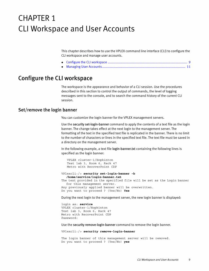
Set/remove the login banner
You can customize the login banner for the VPLEX management servers.
Use the security set-login-banner command to apply the contents of a text file as the login banner. The change takes effect at the next login to the management server. The formatting of the text in the specified text file is replicated in the banner. There is no limit to the number of characters or lines in the specified text file. The text file must be saved in a directory on the management server.
In the following example, a text file login-banner.txt containing the following lines is specified as the login banner:
VPLEX cluster-1/HopkintonTest lab 3, Room 6, Rack 47Metro with RecoverPoint CDP
VPlexcli:/> security set-login-banner -b /home/service/login-banner.txt
The text provided in the specified file will be set as the Login banner for this management server.
Any previously applied banner will be overwritten. Do you want to proceed ? (Yes/No) Yes
During the next login to the management server, the new login banner is displayed:
login as: serviceVPLEX cluster-1/HopkintonTest lab 3, Room 6, Rack 47Metro with RecoverPoint CDPPassword:
Use the security remove-login-banner command to remove the login banner.
VPlexcli:/> security remove-login-banner
The login banner of this management server will be removed.Do you want to proceed ? (Yes/No) yes
CLI Workspace and User Accounts 9
CLI Workspace and User Accounts
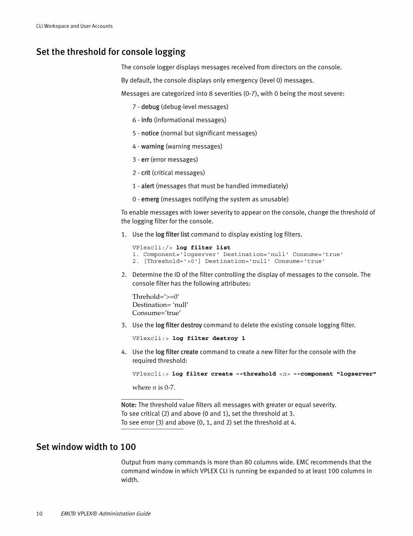
Set the threshold for console logging
The console logger displays messages received from directors on the console.
By default, the console displays only emergency (level 0) messages.
Messages are categorized into 8 severities (0-7), with 0 being the most severe:
7 - debug (debug-level messages)
6 - info (informational messages)
5 - notice (normal but significant messages)
4 - warning (warning messages)
3 - err (error messages)
2 - crit (critical messages)
1 - alert (messages that must be handled immediately)
0 - emerg (messages notifying the system as unusable)
To enable messages with lower severity to appear on the console, change the threshold of the logging filter for the console.
1. Use the log filter list command to display existing log filters.
VPlexcli:/> log filter list1. Component='logserver' Destination='null' Consume='true'2. [Threshold='>0'] Destination='null' Consume='true'
2. Determine the ID of the filter controlling the display of messages to the console. The console filter has the following attributes:
Threhold=’>=0’Destination= ‘null’Consume=’true’
3. Use the log filter destroy command to delete the existing console logging filter.
VPlexcli:> log filter destroy 1
4. Use the log filter create command to create a new filter for the console with the required threshold:
VPlexcli:> log filter create --threshold <n> --component “logserver”
where n is 0-7.
Note: The threshold value filters all messages with greater or equal severity.To see critical (2) and above (0 and 1), set the threshold at 3.To see error (3) and above (0, 1, and 2) set the threshold at 4.
Set window width to 100
Output from many commands is more than 80 columns wide. EMC recommends that the command window in which VPLEX CLI is running be expanded to at least 100 columns in width.
10 EMC® VPLEX® Administration Guide
CLI Workspace and User Accounts
Managing User Accounts
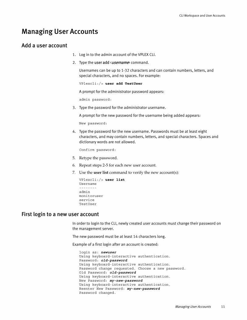
Add a user account
1. Log in to the admin account of the VPLEX CLI.
2. Type the user add <username> command.
Usernames can be up to 1-32 characters and can contain numbers, letters, and special characters, and no spaces. For example:
VPlexcli:/> user add TestUser
A prompt for the administrator password appears:
admin password:
3. Type the password for the administrator username.
A prompt for the new password for the username being added appears:
New password:
4. Type the password for the new username. Passwords must be at least eight characters, and may contain numbers, letters, and special characters. Spaces and dictionary words are not allowed.
Confirm password:
5. Retype the password.
6. Repeat steps 2-5 for each new user account.
7. Use the user list command to verify the new account(s):
VPlexcli:/> user listUsername--------adminmonitoruserserviceTestUser
First login to a new user account
In order to login to the CLI, newly created user accounts must change their password on the management server.
The new password must be at least 14 characters long.
Example of a first login after an account is created:
login as: newuser Using keyboard-interactive authentication. Password: old-passwordUsing keyboard-interactive authentication. Password change requested. Choose a new password. Old Password: old-passwordUsing keyboard-interactive authentication. New Password: my-new-passwordUsing keyboard-interactive authentication. Reenter New Password: my-new-passwordPassword changed.
Managing User Accounts 11
CLI Workspace and User Accounts
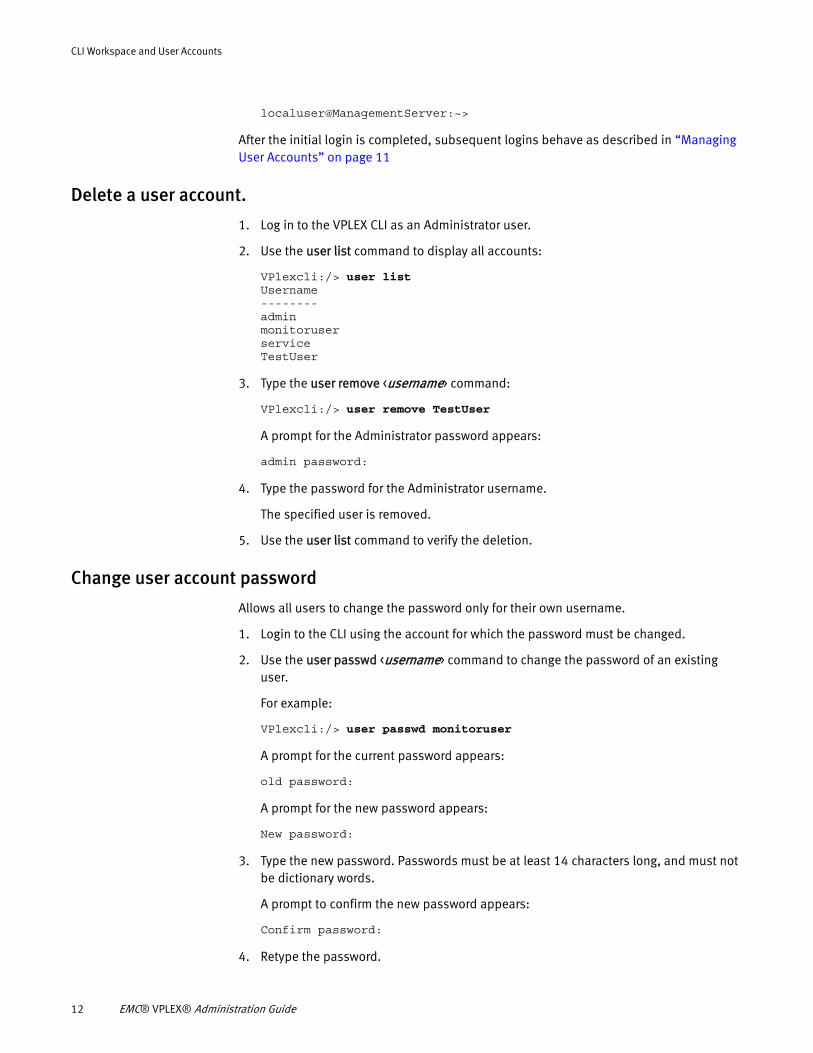
localuser@ManagementServer:~>
After the initial login is completed, subsequent logins behave as described in “Managing User Accounts” on page 11
Delete a user account.
1. Log in to the VPLEX CLI as an Administrator user.
2. Use the user list command to display all accounts:
VPlexcli:/> user listUsername--------adminmonitoruserserviceTestUser
3. Type the user remove <username> command:
VPlexcli:/> user remove TestUser
A prompt for the Administrator password appears:
admin password:
4. Type the password for the Administrator username.
The specified user is removed.
5. Use the user list command to verify the deletion.
Change user account password
Allows all users to change the password only for their own username.
1. Login to the CLI using the account for which the password must be changed.
2. Use the user passwd <username> command to change the password of an existing user.
For example:
VPlexcli:/> user passwd monitoruser
A prompt for the current password appears:
old password:
A prompt for the new password appears:
New password:
3. Type the new password. Passwords must be at least 14 characters long, and must not be dictionary words.
A prompt to confirm the new password appears:
Confirm password:
4. Retype the password.
12 EMC® VPLEX® Administration Guide
CLI Workspace and User Accounts
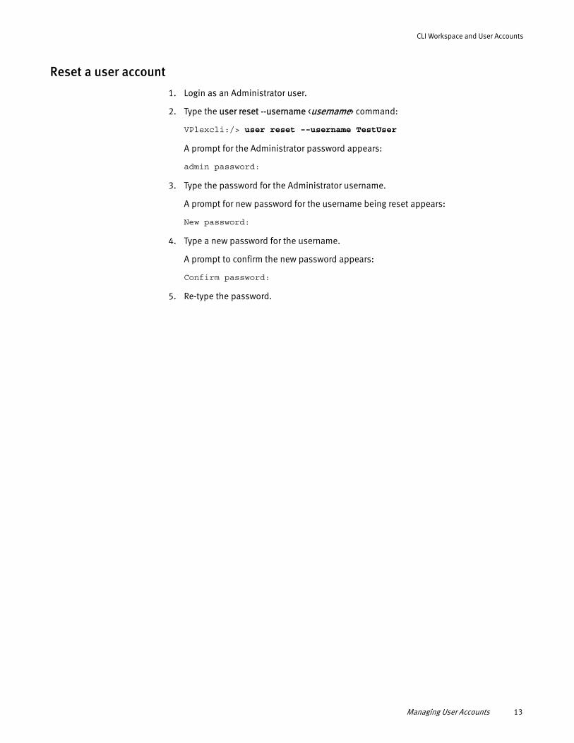
Reset a user account
1. Login as an Administrator user.
2. Type the user reset --username <username> command:
VPlexcli:/> user reset --username TestUser
A prompt for the Administrator password appears:
admin password:
3. Type the password for the Administrator username.
A prompt for new password for the username being reset appears:
New password:
4. Type a new password for the username.
A prompt to confirm the new password appears:
Confirm password:
5. Re-type the password.
Managing User Accounts 13

CLI Workspace and User Accounts
14 EMC® VPLEX® Administration Guide
CHAPTER 2Meta Volumes
This chapter describes the procedures to manage metadata and meta-volumes using the VPLEX CLI:
◆ About meta-volumes............................................................................................... 15◆ Create a meta-volume ............................................................................................. 16◆ Back up the meta-volume: VPLEX Local ................................................................... 18◆ Back up the meta-volume: VPLEX Metro or Geo ....................................................... 19◆ Move a meta-volume............................................................................................... 21◆ Rename a meta-volume........................................................................................... 22◆ Delete a meta-volume ............................................................................................. 22◆ Display meta-volume .............................................................................................. 23
About meta-volumesVPLEX metadata includes virtual to physical mappings, data about devices, virtual volumes, and system configuration settings.
Metadata is stored in cache and backed up on specially designated external volumes called meta-volumes.
Meta-volumes are created during system setup.
When a cluster is initially configured, the meta-volume must be the first storage presented to VPLEX. This prevents the meta-volume from being accidentally overwritten.
After the meta-volume is configured, updates to the metadata are written to both the cache and the meta-volume when the VPLEX configuration is modified.
Backup meta-volumes are point-in-time snapshots of the current metadata, and provide extra protection before major configuration changes, refreshes, or migrations.
Metadata is read from the meta-volume only during the start of each director.
Meta-volume backups are created:
◆ Before migrating to a new array
◆ Before a major update.
Meta-volumes differ from standard storage volumes as mentioned below:
◆ A meta-volume is created without first being claimed
◆ Meta-volumes are created directly on storage volumes, not extents.
Refer to the VPLEX Configuration Guide for more details about the criteria to select storage used for meta-volumes.
If the meta-volume is configured on a CLARiiON array, it must not be placed on the vault drives of the CLARiiON.
Meta Volumes 15
Meta Volumes
Meta-volume performance and availability requirements
Performance is not critical for meta-volumes. The minimum performance allowed is 40 MB/sec and 100 4 K IOP/second.
The physical spindles for meta-volumes should be isolated from application workloads.
EMC recommends the following for meta-volumes:
◆ Read caching must be enabled
◆ A hot spare meta-volume must be pre-configured in case of a catastrophic failure of the active meta-volume.
Availability is critical for meta-volumes. The meta-volume is essential for system recovery. The best practice is to mirror the meta-volume across two or more back end arrays to eliminate the possibility of data loss. Choose the arrays to mirror the meta-volume such that they are not required to migrate at the same time.
Do not create a new meta-volume using volumes from a single storage array. Single array meta-volumes are not a high availability configuration and are a single point of failure.
If VPLEX temporarily loses access to all meta-volumes, the current metadata in cache is automatically written to the meta-volumes when access is restored.
If VPLEX permanently loses access to both meta-volumes, it will continue to operate based on the metadata in memory. Configuration changes are suspended until a new meta-volume is created.
Note: If the VPLEX loses access to all meta-volumes, and all directors either fail or restart, changes made to the meta-data (the VPLEX configuration) after access was lost cannot be recovered.
Create a meta-volumeTo create a meta-volume:
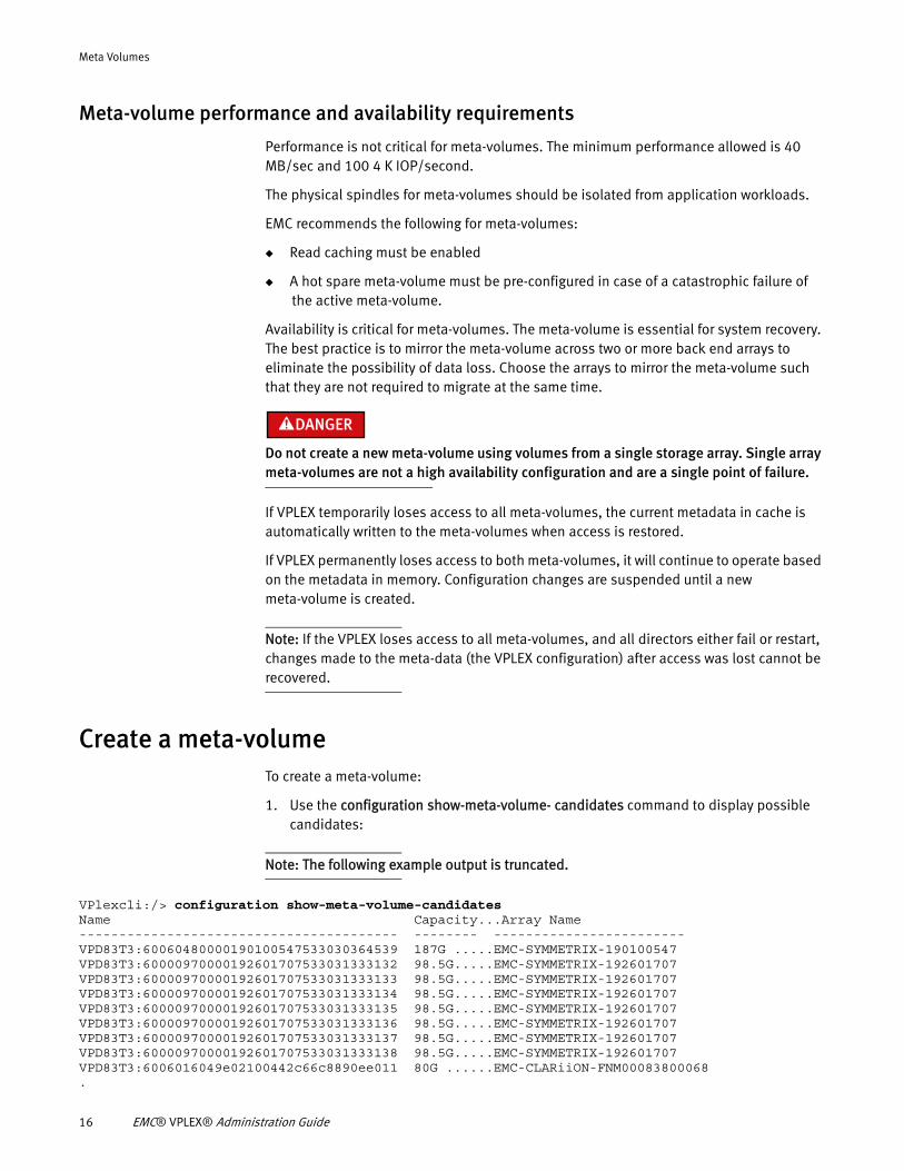
1. Use the configuration show-meta-volume- candidates command to display possible candidates:
Note: The following example output is truncated.
VPlexcli:/> configuration show-meta-volume-candidatesName Capacity...Array Name---------------------------------------- -------- ------------------------VPD83T3:60060480000190100547533030364539 187G .....EMC-SYMMETRIX-190100547VPD83T3:60000970000192601707533031333132 98.5G.....EMC-SYMMETRIX-192601707VPD83T3:60000970000192601707533031333133 98.5G.....EMC-SYMMETRIX-192601707VPD83T3:60000970000192601707533031333134 98.5G.....EMC-SYMMETRIX-192601707VPD83T3:60000970000192601707533031333135 98.5G.....EMC-SYMMETRIX-192601707VPD83T3:60000970000192601707533031333136 98.5G.....EMC-SYMMETRIX-192601707VPD83T3:60000970000192601707533031333137 98.5G.....EMC-SYMMETRIX-192601707VPD83T3:60000970000192601707533031333138 98.5G.....EMC-SYMMETRIX-192601707VPD83T3:6006016049e02100442c66c8890ee011 80G ......EMC-CLARiiON-FNM00083800068.
16 EMC® VPLEX® Administration Guide
Meta Volumes
.
.The log summary for configuration automation has been captured in /var/log/VPlex/cli/VPlexconfig.log
The task summary and the commands executed for each automation task has been captured in /var/log/VPlex/cli/VPlexcommands.txt
The output for configuration automation has been captured in /var/log/VPlex/cli/capture/VPlexconfiguration-session.txt
2. Use the meta-volume create command to create a new meta-volume. The syntax for the command is:
meta-volume create --name meta-volume_name --storage-volumes storage-volume_1,storage-volume_2,storage-volume_3
IMPORTANT
Specify two or more storage volumes. Storage volumes must be:- unclaimed- on different arrays
VPlexcli:meta-volume create --name ICO_META_1_1_Metadata --storage-volumes VPD83T3:60000970000192601707533031333136, VPD83T3:60060480000190300487533030343445
3. Navigate to the system volume context.
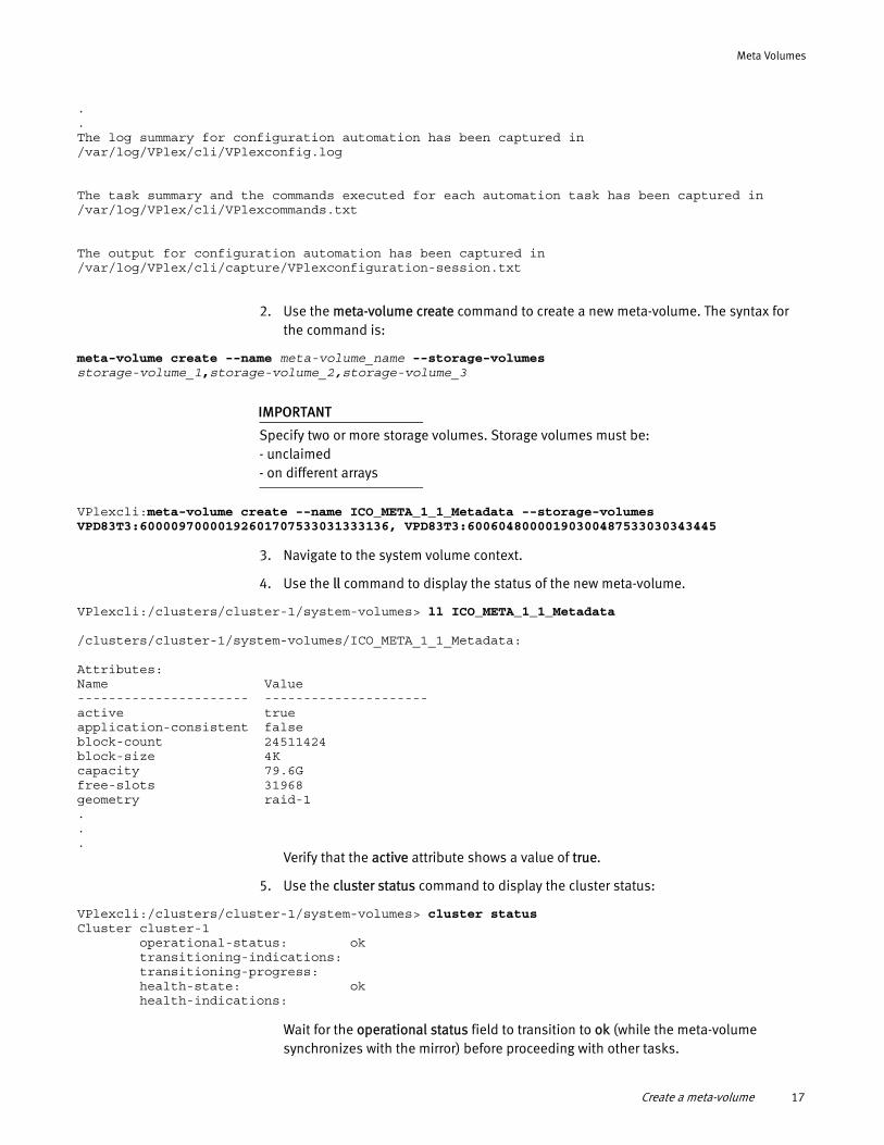
4. Use the ll command to display the status of the new meta-volume.
VPlexcli:/clusters/cluster-1/system-volumes> ll ICO_META_1_1_Metadata
/clusters/cluster-1/system-volumes/ICO_META_1_1_Metadata:
Attributes:Name Value---------------------- ---------------------active trueapplication-consistent falseblock-count 24511424block-size 4Kcapacity 79.6Gfree-slots 31968geometry raid-1...
Verify that the active attribute shows a value of true.
5. Use the cluster status command to display the cluster status:
VPlexcli:/clusters/cluster-1/system-volumes> cluster statusCluster cluster-1 operational-status: ok transitioning-indications: transitioning-progress: health-state: ok health-indications:
Wait for the operational status field to transition to ok (while the meta-volume synchronizes with the mirror) before proceeding with other tasks.
Create a meta-volume 17
Meta Volumes
Back up the meta-volumeBackup creates a point-in-time copy of the current in-memory metadata without activating it. The new meta-volume is named:
current-metadata-namebackup_yyyyMMMdd_HHmms
Create a backup meta-volume:
◆ As part of an overall system health check before a major migration or update.
◆ If VPLEX permanently loses access to both meta-volumes.
◆ After any major migration or update.
Back up the meta-volume: VPLEX Local
Before you begin
Identify two or more storage volumes to backup the metadata. Target storage volumes must be:
◆ Unclaimed
◆ 78 GB or larger
To back up the metadata for a single cluster configuration:
1. Use the ll command in device migration and extent migration contexts to verify that there are no active migrations:
VPlexcli:/data-migrations/device-migrations> ll
VPlexcli:/data-migrations/extent-migrations> ll
If any migrations are in-progress or queued:
• Allow the migrations to complete, and commit them (see “Commit a completed migration”); or
• Cancel the migrations (see “Cancel a migration (optional)”) and remove them (see “Clean a migration”).
2. Use the following commands to verify the overall health of VPLEX:
• validate-system-configuration - Performs a basic system configuration check.
• cluster status - Displays a cluster's operational-status and health-state.
• export storage-view summary -Lists each view, and the number of volumes and initiators that it contains (identifies failed devices).
• connectivity show - Displays the communication protocol endpoints that can see each other.
• export port summary - Summarizes any unhealthy ports.
3. Optionally, use the cluster configdump command to dump the cluster configuration in an XML format.
18 EMC® VPLEX® Administration Guide
Meta Volumes
Using the cluster configdump command to dump a large configuration may take a long time.
The information collected by the cluster configdump command can be useful to identify problems in case of a failure. Administrators must weigh the value of the information collected against the amount of time required to dump a large configuration when deciding whether to perform a configdump.
IMPORTANT
No modifications should be made to VPLEX during the remainder of the backup procedure. Ensure that all other users are notified.
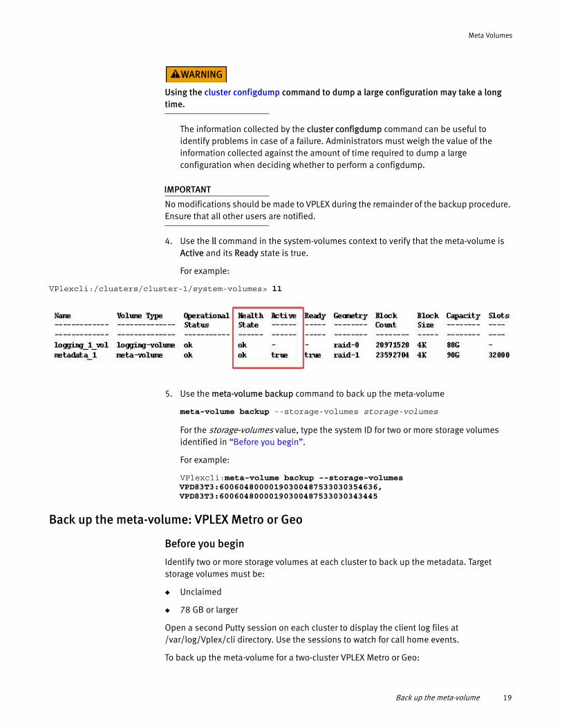
4. Use the ll command in the system-volumes context to verify that the meta-volume is Active and its Ready state is true.
For example:
VPlexcli:/clusters/cluster-1/system-volumes> ll
5. Use the meta-volume backup command to back up the meta-volume
meta-volume backup --storage-volumes storage-volumes
For the storage-volumes value, type the system ID for two or more storage volumes identified in “Before you begin”.
For example:
VPlexcli:meta-volume backup --storage-volumes VPD83T3:60060480000190300487533030354636, VPD83T3:60060480000190300487533030343445
Back up the meta-volume: VPLEX Metro or Geo
Before you begin
Identify two or more storage volumes at each cluster to back up the metadata. Target storage volumes must be:
◆ Unclaimed
◆ 78 GB or larger
Open a second Putty session on each cluster to display the client log files at /var/log/Vplex/cli directory. Use the sessions to watch for call home events.
To back up the meta-volume for a two-cluster VPLEX Metro or Geo:
Back up the meta-volume 19
Meta Volumes
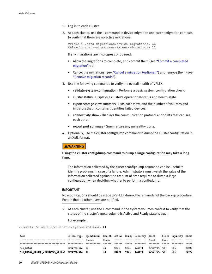
1. Log in to each cluster.
2. At each cluster, use the ll command in device migration and extent migration contexts to verify that there are no active migrations:
VPlexcli:/data-migrations/device-migrations> llVPlexcli:/data-migrations/extent-migrations> ll
If any migrations are in-progress or queued:
• Allow the migrations to complete, and commit them (see “Commit a completed migration”); or
• Cancel the migrations (see “Cancel a migration (optional)”) and remove them (see “Remove migration records”).
3. Use the following commands to verify the overall health of VPLEX:
• validate-system-configuration - Performs a basic system configuration check.
• cluster status - Displays a cluster's operational-status and health-state.
• export storage-view summary -Lists each view, and the number of volumes and initiators that it contains (identifies failed devices).
• connectivity show - Displays the communication protocol endpoints that can see each other.
• export port summary - Summarizes any unhealthy ports.
4. Optionally, use the cluster configdump command to dump the cluster configuration in an XML format.
Using the cluster configdump command to dump a large configuration may take a long time.
The information collected by the cluster configdump command can be useful to identify problems in case of a failure. Administrators must weigh the value of the information collected against the amount of time required to dump a large configuration when deciding whether to perform a configdump.
IMPORTANT
No modifications should be made to VPLEX during the remainder of the backup procedure. Ensure that all other users are notified.
5. At each cluster, use the ll command in the system-volumes context to verify that the status of the cluster’s meta-volume is Active and Ready state is true.
For example:
VPlexcli:/clusters/cluster-1/system-volumes> ll
20 EMC® VPLEX® Administration Guide
Meta Volumes
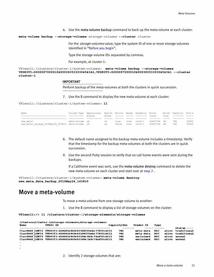
6. Use the meta-volume backup command to back up the meta-volume at each cluster:
meta-volume backup --storage-volumes storage-volumes --cluster cluster
For the storage-volumes value, type the system ID of one or more storage volumes identified in “Before you begin”.
Type the storage volume IDs separated by commas.
For example, at cluster-1:
VPlexcli:/clusters/cluster-1/system-volumes> meta-volume backup --storage-volumes VPD83T3:60000970000194900383533030454342,VPD83T3:60000970000194900383533030454341 --cluster cluster-1
IMPORTANT
Perform backup of the meta-volumes at both the clusters in quick succession.
7. Use the ll command to display the new meta-volume at each cluster:
VPlexcli:/clusters/cluster-1/system-volumes> ll
8. The default name assigned to the backup meta-volume includes a timestamp. Verify that the timestamp for the backup meta-volumes at both the clusters are in quick succession.
9. Use the second Putty session to verify that no call home events were sent during the backups.
If a CallHome event was sent, use the meta-volume destroy command to delete the new meta-volume on each cluster and start over at step 2 .
VPlexcli:/clusters/cluster-1/system-volumes> meta-volume destroy new_meta_data_backup_2010May24_163810
Move a meta-volumeTo move a meta-volume from one storage volume to another:
1. Use the ll command to display a list of storage volumes on the cluster:
VPlexcli:/> ll /clusters/cluster-1/storage-elements/storage-volumes
2. Identify 2 storage volumes that are:
Name Volume Type Operational Health Active Ready Geometry Block Block Capacity Slot s--------------------------------- ----------- Status State ------ ----- -------- Count Size -------- -------------------------------------- ----------- ----------- ------ ------ ----- -------- -------- ----- -------- -----new_meta1 meta-volume ok ok true true raid-1 20447744 4K 78G 32000new_meta1_backup_2010May24_163810 meta-volume ok ok false true raid-1 20447744 4K 78G 32000
Move a meta-volume 21
Meta Volumes
• Unclaimed
• 78 GB or larger
• On different arrays
3. Use the meta-volume create command to create a new meta-volume.
Specify the storage volumes identified in step 2 .
VPlexcli:/engines/engine-1-1/directors> meta-volume create --name meta_dmx --storage-volumes VPD83T3:6006016037202200966da1373865de11,VPD83T3:6006016037202200966da1373865de12
See “Create a meta-volume” on page 16.
4. Use the meta-volume move command to move the existing in-memory metadata to the new meta-volume:
VPlexcli:/engines/engine-1-1/directors> meta-volume move --target-volume meta_dmx
Rename a meta-volumeBy default, meta-volume names are based on a timestamp. To change the name, do the following:
1. Navigate to the /clusters/cluster/system-volumes/context:
VPlexcli:/> cd clusters/cluster-2/system-volumes/
VPlexcli:/clusters/cluster-2/system-volumes>
2. Use the ll command to display the names of the meta-volumes.
3. Navigate to the /clusters/cluster/system-volumes/target-meta-volume context.
For example:
VPlexcli:/clusters/cluster-1/system-volumes> cd new_meta1_backup_2010May24_163810
4. Use the set name new_meta-volume_name command to change the name.
For example:
VPlexcli:/clusters/cluster-1/system-volumes/new_meta1_backup_2010May24_163810> set name backup_May24_pre_refresh
Delete a meta-volume
IMPORTANT
A meta-volume must be inactive to be deleted. Attempts to delete an active meta-volume fail with an error message.
To delete a meta-volume, do the following:
1. Navigate to the target volume’s context.
For example:
22 EMC® VPLEX® Administration Guide
Meta Volumes
cd clusters/cluster-1/system-volumes/metadata_1/
2. Use the ll command to verify that the volume is not active.
For example:
/clusters/cluster-1/system-volumes/metadata_1> ll
Attributes:Name Value---------------------- -----------active falseapplication-consistent falseblock-count 23592704block-size 4K...
3. Use the meta-volume destroy --meta-volume meta-volume command to delete the specified meta-volume.
For example:
meta-volume destroy --meta-volume metadata_1
A warning message appears:
Meta-volume 'metadata_1' will be destroyed. Do you wish to continue? (Yes/No)
4. Type y.
Note: After the deletion of a meta-data volume, it is recommended that the data on the storage volume be deleted through external means to avoid any future confusion.
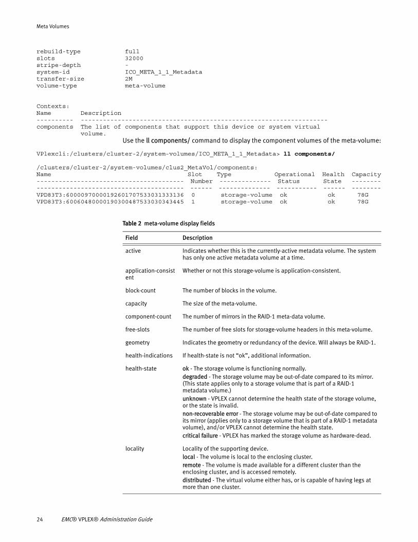
Display meta-volumeUse the ll command to display status for a meta-volume:
VPlexcli:/clusters/cluster-1/system-volumes/ICO_META_1_1_Metadata> ll
/clusters/cluster-1/system-volumes/ICO_META_1_1_Metadata:
Attributes:Name Value---------------------- -------------active trueapplication-consistent falseblock-count 24511424block-size 4Kcapacity 79.5Gcomponent-count 2free-slots 31968geometry raid-1health-indications []health-state oklocality localoperational-status okready truerebuild-allowed truerebuild-eta -rebuild-progress -rebuild-status done
Display meta-volume 23
Meta Volumes
rebuild-type fullslots 32000stripe-depth -system-id ICO_META_1_1_Metadatatransfer-size 2Mvolume-type meta-volume
Contexts:Name Description---------- -------------------------------------------------------------------components The list of components that support this device or system virtual volume.
Use the ll components/ command to display the component volumes of the meta-volume:
VPlexcli:/clusters/cluster-2/system-volumes/ICO_META_1_1_Metadata> ll components/
/clusters/cluster-2/system-volumes/clus2_MetaVol/components:Name Slot Type Operational Health Capacity---------------------------------------- Number -------------- Status State ------------------------------------------------ ------ -------------- ----------- ------ --------VPD83T3:60000970000192601707533031333136 0 storage-volume ok ok 78GVPD83T3:60060480000190300487533030343445 1 storage-volume ok ok 78G
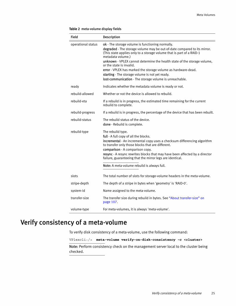
Table 2 meta-volume display fields
Field Description
active Indicates whether this is the currently-active metadata volume. The system has only one active metadata volume at a time.
application-consistent
Whether or not this storage-volume is application-consistent.
block-count The number of blocks in the volume.
capacity The size of the meta-volume.
component-count The number of mirrors in the RAID-1 meta-data volume.
free-slots The number of free slots for storage-volume headers in this meta-volume.
geometry Indicates the geometry or redundancy of the device. Will always be RAID-1.
health-indications If health-state is not “ok”, additional information.
health-state ok - The storage volume is functioning normally.degraded - The storage volume may be out-of-date compared to its mirror. (This state applies only to a storage volume that is part of a RAID-1 metadata volume.)unknown - VPLEX cannot determine the health state of the storage volume, or the state is invalid.non-recoverable error - The storage volume may be out-of-date compared to its mirror (applies only to a storage volume that is part of a RAID-1 metadata volume), and/or VPLEX cannot determine the health state.critical failure - VPLEX has marked the storage volume as hardware-dead.
locality Locality of the supporting device.local - The volume is local to the enclosing cluster. remote - The volume is made available for a different cluster than the enclosing cluster, and is accessed remotely. distributed - The virtual volume either has, or is capable of having legs at more than one cluster.
24 EMC® VPLEX® Administration Guide
Meta Volumes
Verify consistency of a meta-volumeTo verify disk consistency of a meta-volume, use the following command:
VPlexcli:/> meta-volume verify-on-disk-consistency -c <cluster>
Note: Perform consistency check on the management server local to the cluster being checked.
operational status ok - The storage volume is functioning normally.degraded - The storage volume may be out-of-date compared to its mirror. (This state applies only to a storage volume that is part of a RAID-1 metadata volume.)unknown - VPLEX cannot determine the health state of the storage volume, or the state is invalid.error - VPLEX has marked the storage volume as hardware-dead.starting - The storage volume is not yet ready.lost-communication - The storage volume is unreachable.
ready Indicates whether the metadata volume is ready or not.
rebuild-allowed Whether or not the device is allowed to rebuild.
rebuild-eta If a rebuild is in progress, the estimated time remaining for the current rebuild to complete.
rebuild-progress If a rebuild is in progress, the percentage of the device that has been rebuilt.
rebuild-status The rebuild status of the device.done - Rebuild is complete.
rebuild-type The rebuild type.full - A full copy of all the blocks.incremental - An incremental copy uses a checksum differencing algorithm to transfer only those blocks that are different.comparison - A comparison copy.resync - A resync rewrites blocks that may have been affected by a director failure, guaranteeing that the mirror legs are identical.
Note: A meta-volume rebuild is always full.
slots The total number of slots for storage-volume headers in the meta-volume.
stripe-depth The depth of a stripe in bytes when 'geometry' is 'RAID-0'.
system-id Name assigned to the meta-volume.
transfer-size The transfer size during rebuild in bytes. See “About transfer-size” on page 107.
volume-type For meta-volumes, it is always 'meta-volume'.
Table 2 meta-volume display fields
Field Description
Verify consistency of a meta-volume 25

Meta Volumes
26 EMC® VPLEX® Administration Guide
CHAPTER 3System Management
This chapter describes how to use the VPLEX CLI to manage battery conditioning, call-home notifications and system reporting, event log locations, and hardware acceleration with VAAI.
◆ SPS battery conditioning......................................................................................... 27◆ Call-home notifications and system reporting.......................................................... 30◆ Event log locations.................................................................................................. 32◆ Hardware acceleration with VAAI ............................................................................. 34
SPS battery conditioningA Standby Power Supply (SPS) battery conditioning cycle consists of a 5 minute period of on-battery operation followed by 6 hours of recharge.
Battery conditioning verifies the health of the batteries and extends their operational life.
Each SPS battery in a VPLEX system is automatically conditioned once a month.
Battery conditioning is enabled by default, but can be disabled for some activities (maintenance, system upgrades) where both SPS units are required.
In addition to the monthly automatic conditioning cycles, manually requested conditioning cycles can be scheduled and canceled.
Battery conditioning cycle calendar
The conditioning cycle effectively moves the target battery into discharge state. The automatic conditioning cycle is scheduled to not have more than one active battery conditioning cycle (and thus more than one battery in discharge state) at any one time.
In addition to automatic battery conditioning cycles, additional cycles can be manually requested.
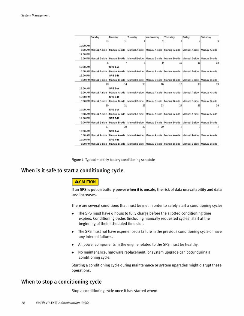
Automatic battery conditioning cycles are "checker boarded" into 6 hour windows:
◆ An SPS on the A side is scheduled to run in the first window, followed by
◆ A window that allows manual tests on the A side, followed by
◆ An SPS on the B side, followed by
◆ A window that allows manual tests on the B side SPS.
Time windows for manual tests allow only one side (A or B) to run conditioning cycles in a given period.
Figure 1 shows the conditioning cycle calendar for a typical month:
System Management 27
System Management
Figure 1 Typical monthly battery conditioning schedule
When is it safe to start a conditioning cycle
If an SPS is put on battery power when it is unsafe, the risk of data unavailability and data loss increases.
There are several conditions that must be met in order to safely start a conditioning cycle:
◆ The SPS must have 6 hours to fully charge before the allotted conditioning time expires. Conditioning cycles (including manually requested cycles) start at the beginning of their scheduled time slot.
◆ The SPS must not have experienced a failure in the previous conditioning cycle or have any internal failures.
◆ All power components in the engine related to the SPS must be healthy.
◆ No maintenance, hardware replacement, or system upgrade can occur during a conditioning cycle.
Starting a conditioning cycle during maintenance or system upgrades might disrupt these operations.
When to stop a conditioning cycle
Stop a conditioning cycle once it has started when:
28 EMC® VPLEX® Administration Guide
System Management
◆ A power component in the associated engine becomes unhealthy.
This could be a hardware fault in one of the engine's director power supplies or a power loss in the peer SPS.
A power disruption automatically aborts any ongoing SPS conditioning.
◆ Manual intervention is required due to unscheduled maintenance or an impending disaster.
If an SPS that is currently being conditioned loses AC power, the engine will behave normally and continue to be powered by the peer SPS.
Additional documentation
Refer to the VPLEX CLI Guide for information about the CLI commands related to battery conditioning:
◆ battery-conditioning set-schedule - Sets the battery conditioning schedule (day of week) for backup battery units on a cluster.
◆ battery-conditioning enable - Enables conditioning on the specified backup battery unit(s).
◆ battery-conditioning disable - Disables battery conditioning on the specified backup battery unit(s).
◆ battery-conditioning manual-cycle request - Manually requests a battery conditioning cycle on the specified backup battery unit.
◆ battery-conditioning manual-cycle cancel-request - Cancels a manually requested battery conditioning cycle on the specified backup battery unit.
◆ battery-conditioning summary - Displays a summary of the battery conditioning schedule for all devices that are grouped by cluster.
Refer to the VPLEX generator for the procedures to:
◆ Set the battery conditioning schedule
◆ Enable battery conditioning
◆ Disable battery conditioning
◆ Manually request an additional conditioning cycle
◆ Cancel a manually requested cycle
SPS battery conditioning 29
System Management
Call-home notifications and system reporting
About call-home notifications
Call-home notifications are messages sent automatically from VPLEX to EMC Customer Service and/or Customer Support Representative when a serious problem occurs. Call-home notifications enable EMC to pro-actively engage the relevant personnel, or use a configured ESRS gateway to resolve the problem.
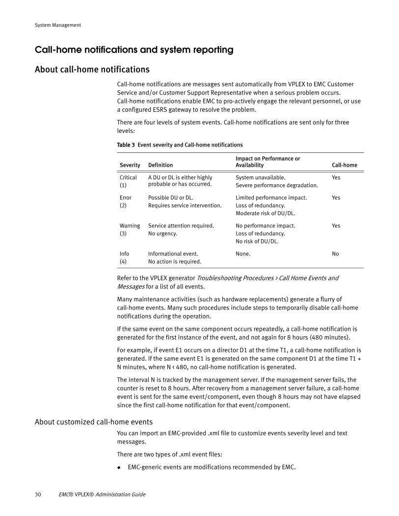
There are four levels of system events. Call-home notifications are sent only for three levels:
Refer to the VPLEX generator Troubleshooting Procedures > Call Home Events and Messages for a list of all events.
Many maintenance activities (such as hardware replacements) generate a flurry of call-home events. Many such procedures include steps to temporarily disable call-home notifications during the operation.
If the same event on the same component occurs repeatedly, a call-home notification is generated for the first instance of the event, and not again for 8 hours (480 minutes).
For example, if event E1 occurs on a director D1 at the time T1, a call-home notification is generated. If the same event E1 is generated on the same component D1 at the time T1 + N minutes, where N < 480, no call-home notification is generated.
The interval N is tracked by the management server. If the management server fails, the counter is reset to 8 hours. After recovery from a management server failure, a call-home event is sent for the same event/component, even though 8 hours may not have elapsed since the first call-home notification for that event/component.
About customized call-home eventsYou can import an EMC-provided .xml file to customize events severity level and text messages.
There are two types of .xml event files:
◆ EMC-generic events are modifications recommended by EMC.
Table 3 Event severity and Call-home notifications
Severity DefinitionImpact on Performance or Availability Call-home
Critical (1)
A DU or DL is either highly probable or has occurred.
System unavailable.Severe performance degradation.
Yes
Error(2)
Possible DU or DL.Requires service intervention.
Limited performance impact.Loss of redundancy.Moderate risk of DU/DL.
Yes
Warning(3)
Service attention required.No urgency.
No performance impact.Loss of redundancy.No risk of DU/DL.
Yes
Info(4)
Informational event.No action is required.
None. No
30 EMC® VPLEX® Administration Guide
System Management
EMC provides an .xml file containing commonly requested modifications to the default call-home events.
◆ Customer-specific events are events modified to meet a specific customer requirement.
EMC provides a custom events file developed by EMC engineering and applied by EMC Technical Support.
◆ Call-home behaviors changes immediately when the modified events file is applied.
◆ If a customized events file is already applied, applying a new file overrides the existing file.
◆ If the same event is modified in the customer-specific and EMC-generic file, the modification specified for that event in the customer-specific file is applied.
◆ If call-home notification is disabled when the custom events file is applied, the modified events are saved and applied when call-home notification is enabled.
About system (SYR) reportingSystem reporting (SYR) collects and transmits two types of information from VPLEX systems to EMC:
◆ System reports - Sent weekly once to the EMC System Reports database. System reports include information about the configuration and state of the system.
◆ System alerts - Sent in real-time through a designated SMTP server to the EMC. Alerts are filtered as to whether a service request should be opened with EMC Customer Service. If a service request is required, it is opened automatically.
SYR is enabled by default, but can be disabled at any time through the GUI or CLI.
Modify call-home and SYRCall-home notifications and SYR settings are typically configured during system set-up.
Use the configuration event-notices-reports-config CLI command to configure the call-home notifications and/or SYR settings if they were not configured during the initial installation.
The command runs an interview script that prompts for the required information. If either call-home notification or SYR is not configured, interview questions to configure the service that is not configured are displayed.
If both call-home notifications and SYR settings are already configured, the current configuration information is displayed.
Before you beginYou need the following information to complete the configuration of call-home notification:
◆ IP address of the primary SMTP server used to forward reports and call-home notifications to EMC. EMC recommends using your ESRS gateway as the primary connection address.
Call-home notifications and system reporting 31
System Management
◆ (Optional) One or more IP addresses of secondary SMTP server(s) used to forward reports and call-home notifications to EMC if the primary server fails. These addresses must be different than the address for the primary SMTP server.
◆ (Optional) One or more e-mail addresses of personnel who should receive e-mail messages when call-home notifications occur.
Additional documentation
Refer to the VPLEX generator for the procedure to configure SYR.
Refer to the VPLEX CLI Guide for information about the CLI commands related to call-home notifications and SYR reporting:
◆ configuration event-notices-reports-config - Configure call-home notifications and SYR settings after the initial configuration of VPLEX,
◆ configuration event-notices-reports-reset - Resets the current call-home notification and reporting configuration.
◆ notification call-home import-event-modification - Imports and applies modified call-home events.
◆ notification call-home remove-event-modifications - Removes customized call-home events files, including customer specific modifications and EMC recommended modifications.
◆ notification call-home view-event-modifications - Displays any customized call-home events.
Event log locationsVPLEX includes services, processes, components, and operating systems that write entries to various logs.
Logs are collected for:
◆ Scheduled activities (SYR collection)
◆ On-demand utilities (collect-diagnostics)
◆ Call-home events
32 EMC® VPLEX® Administration Guide
System Management
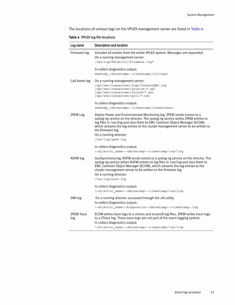
The locations of various logs on the VPLEX management server are listed in Table 4:
Table 4 VPLEX log file locations
Log name Description and location
Firmware log Includes all entries from the entire VPLEX system. Messages are expanded.On a running management server: /var/log/VPlex/cli/firmware.log*
In collect-diagnostics output:smsDump_<datestamp>-<timestamp>\clilogs\
Call home log On a running management server:/opt/emc/connectemc/logs/ConnectEMC.log/opt/emc/connectemc/archive/*.xml/opt/emc/connectemc/failed/*.xml/opt/emc/connectemc/poll/*.xml
In collect-diagnostics output:smsDump_<datestamp>-<timestamp>\connectemc\
ZPEM Log Zephyr Power and Environmental Monitoring log. ZPEM sends events to a syslog-ng service on the director. The syslog-ng service writes ZPEM entries to log files in /var/log and also them to EMC Common Object Manager (ECOM), which streams the log entries to the cluster management server to be written to the firmware log.On a running director: /var/log/zpem.log
In collect-diagnostics output:\<director_name>-<datestamp>-<timestamp>\var\log
NSFW log GeoSynchrony log. NSFW sends events to a syslog-ng service on the director. The syslog-ng service writes NSFW entries to log files in /var/log and also them to EMC Common Object Manager (ECOM), which streams the log entries to the cluster management server to be written to the firmware log.On a running director: /var/log/nsfw.log
In collect-diagnostics output:\<director_name>-<datestamp>-<timestamp>\var\log
DMI log On a running director: accessed through the zdt utilityIn collect-diagnostics output:\<director_name>-diagnostics-<datestamp>-<timestamp>.log
ZPEM Trace log
ECOM writes trace logs to a cimom and ecomofl log files. ZPEM writes trace logs to a ZTrace log. These trace logs are not part of the event logging system.In collect-diagnostics output:\<director_name>-<datestamp>-<timestamp>\var\log
Event log locations 33
System Management
Hardware acceleration with VAAIVMware API for Array Integration (VAAI) allows you to:
◆ Offload storage operations from compute side to storage hardware.
◆ Shift I/O intensive operations of provisioning and snapshotting from hypervisor to VPLEX.
◆ Dedicate hypervisor memory and processing resources to other functions.
VAAI is implemented in VPLEX using three SCSI commands:
◆ “Compare and Write” offloads coordination of powering virtual machines (VMs) on/off, and moving them between hypervisors.
◆ “WriteSame (16)” offloads writing same pattern of data, such as zeroing out blocks for disk initialization.
◆ XCOPY offloads copying data to and from the array through the hypervisor.
“Enabling and disabling XCOPY using CLI” on page 39 provides more information on enabling and disabling XCOPY.
Compare and Write The CompareAndWrite (CAW) SCSI command is used to coordinate VMware operations such as powering-on/off VMs, moving VMs from one ESX to another without halting applications (VMotion), and Distributed Resource Scheduler (DRS) operations.
CAW is used by VMware ESX servers to relieve storage contention, which may be caused by SCSI RESERVATION in distributed VM environments. CAW assists storage hardware acceleration by allowing ESX servers to lock a region of disk instead of an entire disk.
ESX 5.0 servers use this strategy to increase the number of VMs that an ESX servers can host, and to increase the performance of those VMs.
Starting in GeoSynchrony 5.1, VPLEX support for CAW is enabled by default.
Enabling/disabling CAW
CAW can be enabled/disabled on VPLEX only by EMC Customer Support Representative.
VMware servers discover whether the CAW SCSI command is supported:
◆ During initial storage scanning
◆ When the VMFS3.HardwareAcceleratedLocking value on the ESX host is enabled (or toggled if it is enabled)
Note: To toggle the value: In the vSphere client, toggle host > Configuration > Software > Advanced Settings > VMFS3.HardwareAcceleratedLocking value to 0 and then 1.
If CAW is not supported or support is disabled, VPLEX returns CHECK CONDITION, ILLEGAL REQUEST, and INVALID OP-CODE. The ESX server reverts to using SCSI RESERVE and the VM operation continues.
VM operations may experience significant performance degradation if CAW is not enabled.
34 EMC® VPLEX® Administration Guide
System Management
VPLEX enables CAW to be enabled/disabled for all storage associated with VPLEX, using a single command. When CAW is disabled on VPLEX, VPLEX storage volumes, do not include CAW support information in their responses to inquiries from hosts.
To mark storage CAW as disabled:
◆ VMFS3.HardwareAcceleratedLocking must be toggled, or
◆ Hosts may need to rescan their storage.
Enabling/disabling CAW functionality supports exceptional situations such as assisting EMC Technical Support personnel to diagnose a problem. CAW is enabled by default and should be disabled only by EMC Technical Support.
Support for CAW can be enabled or disabled at two levels:
◆ storage-view - Enabled or disabled for all existing storage views. A storage view created after CAW is enabled/disabled at the storage view level inherits the system default setting. EMC recommends maintaining uniform CAW setting on all storage views in VPLEX. If CAW must be disabled for a given storage view, it must be disabled for all existing and future storage views. To enable future storage views to reflect the new setting, change the system default (described below).
◆ system default - Enabled or disabled as a system default. A storage view created after CAW is enabled/disabled at the system default level inherits the system default setting. If the system default is enabled, CAW support for the new storage view is also enabled.
Display CAW settingUse the ls command in /clusters/cluster/exports/storage-views context to display whether CAW is enabled at the storage view level. For example:
VPlexcli:/> ll /clusters/cluster-2/exports/storage-views/*
/clusters/cluster-2/exports/storage-views/FE-Logout-test:Name Value------------------------ -----------------------------------------------------------------caw-enabled false.../clusters/cluster-2/exports/storage-views/default_quirk_view:Name Value------------------------ ------------------------------------------caw-enabled false...
Use the ls command in /clusters/cluster context to display the CAW system default setting:
VPlexcli:/> ls /clusters/cluster-1
/clusters/cluster-1:
Attributes:Name Value---------------------- --------------------------------------------
Hardware acceleration with VAAI 35
System Management
allow-auto-join trueauto-expel-count 0auto-expel-period 0auto-join-delay 0cluster-id 1connected truedefault-cache-mode synchronousdefault-caw-template true...
Enable/disable CAW for a storage viewUse the set command in /clusters/cluster/exports/storage-views/storage-view context to enable or disable CAW for the storage view.
To enable CAW for a storage view:
VPlexcli:/clusters/cluster-1/exports/storage-views/recoverpoint_vols> set caw-enabled true
To disable CAW for a storage view:
VPlexcli:/clusters/cluster-1/exports/storage-views/recoverpoint_vols> set caw-enabled false
Enable/disable CAW as system defaultUse the set command in /clusters/cluster context to enable or disable CAW for the entire cluster.
To enable CAW as the cluster system default:
VPlexcli:/clusters/cluster-1> set default-caw-template true
To disable CAW as the cluster system default:
VPlexcli:/clusters/cluster-1> set default-caw-template false
CAW statisticsCAW performance statistics are included for front-end volume (fe-lu), front-end port (fe-prt), and front-end director (fe-director) targets.
See “Front-end volume (fe-lu) statistics” on page 262, “Front-end port (fe-prt) statistics” on page 263, and “Front-end director (fe-director) statistics” on page 261
Statistics for fe-director targets are collected as a part of the automatically created perpetual monitor.
You can create a monitor to collect CAW statistics, which can be especially useful for fe-lu targets (because there can be very large numbers of volumes involved, these statistics are not always collected). See “Example: Send CAW statistics to the management server” on page 244
WriteSame (16)
The WriteSame (16) SCSI command provides a mechanism to offload initializing virtual disks to VPLEX. WriteSame (16) requests the server to write blocks of data transferred by the application client to consecutive logical blocks multiple times.
WriteSame (16) is used to offload VM provisioning and snapshotting in vSphere to VPLEX.
36 EMC® VPLEX® Administration Guide
System Management
WriteSame (16) enables the array to perform copy operations independently without using host cycles. The array can schedule and execute the copy function much more efficiently.
VPLEX support for WriteSame (16) is enabled by default.
Enabling/disabling WriteSame (16)
WriteSame (16) can be enabled/disabled on VPLEX only by EMC Technical Support personnel.
VMware servers discover whether the WriteSame (16) SCSI command is supported:
◆ During initial storage scanning
◆ When the DataMover.HardwareAcceleratedInit value on the ESX host is enabled (or toggled if it is enabled)
Note: To toggle the value — In the vSphere client, toggle host > Configuration > Software > Advanced Settings > DataMover.HardwareAcceleratedInit value to 0 and then 1.
VM operations may experience significant performance degradation if WriteSame (16) is not enabled.
VPLEX allows WriteSame (16) to be enabled/disabled for all storage associated with VPLEX, using a single command. When WriteSame (16) is disabled on VPLEX, VPLEX storage volumes, do not include WriteSame (16) support information in their responses to inquiries from hosts.
Support for WriteSame (16) can be enabled or disabled at two levels:
◆ storage-view - Enabled or disabled for all existing storage views. A storage view created after WriteSame (16) is enabled/disabled at the storage view level inherits the system default setting. EMC recommends maintaining uniform WriteSame (16) setting on all storage views in VPLEX.
If WriteSame (16) must be disabled for a given storage view, it must be disabled on all existing and future storage views. To make future storage views to reflect the new setting, change the system default (described below).
◆ system default - Enabled or disabled as a system default. A storage view created after WriteSame (16) is enabled/disabled at the system default level inherits the system default setting. If the system default is enabled, WriteSame (16) support for the new storage view is also enabled.
To disable the Write Same 16 default template, you must disable Write Same 16 for all existing views, and disable Write Same 16 template so that all future views will be Write Same 16 disabled. To enable the Write Same 16 default template, you must enable Write Same 16 for all existing views, and enable Write Same 16 template so that all future views will be Write Same 16 enabled.
Hardware acceleration with VAAI 37
System Management
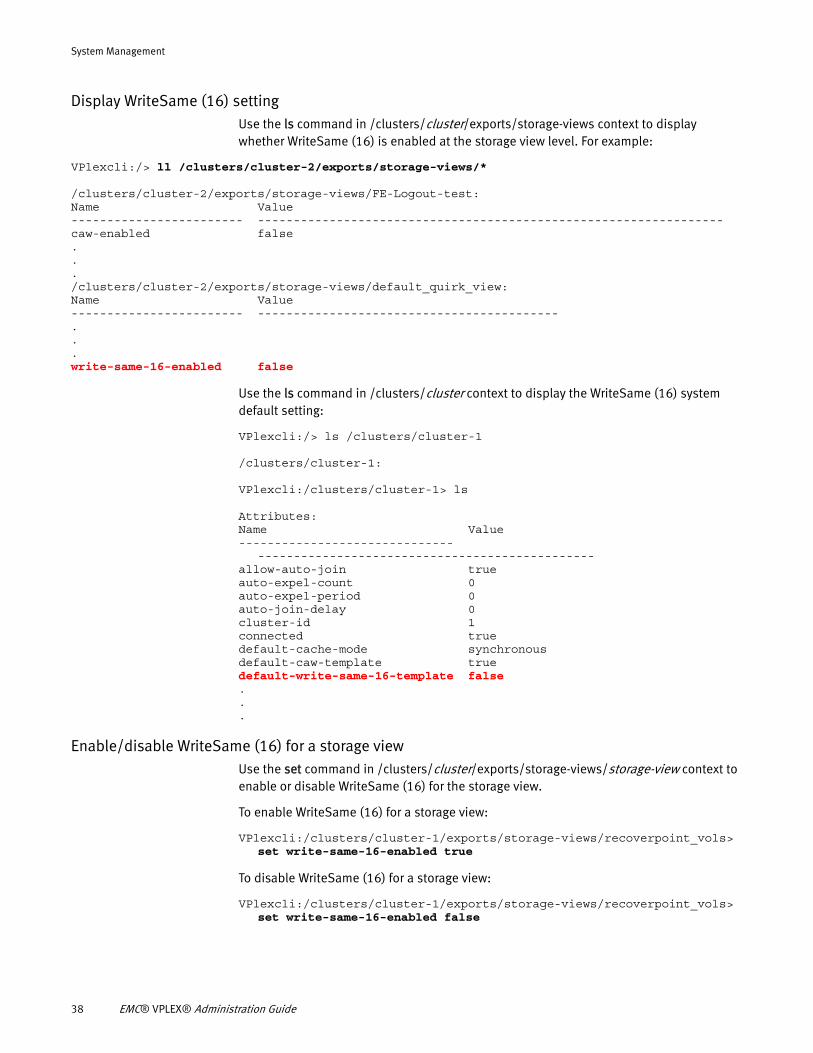
Display WriteSame (16) settingUse the ls command in /clusters/cluster/exports/storage-views context to display whether WriteSame (16) is enabled at the storage view level. For example:
VPlexcli:/> ll /clusters/cluster-2/exports/storage-views/*
/clusters/cluster-2/exports/storage-views/FE-Logout-test:Name Value------------------------ -----------------------------------------------------------------caw-enabled false.../clusters/cluster-2/exports/storage-views/default_quirk_view:Name Value------------------------ ------------------------------------------...write-same-16-enabled false
Use the ls command in /clusters/cluster context to display the WriteSame (16) system default setting:
VPlexcli:/> ls /clusters/cluster-1
/clusters/cluster-1:
VPlexcli:/clusters/cluster-1> ls
Attributes:Name Value------------------------------
-----------------------------------------------allow-auto-join trueauto-expel-count 0auto-expel-period 0auto-join-delay 0cluster-id 1connected truedefault-cache-mode synchronousdefault-caw-template truedefault-write-same-16-template false...
Enable/disable WriteSame (16) for a storage viewUse the set command in /clusters/cluster/exports/storage-views/storage-view context to enable or disable WriteSame (16) for the storage view.
To enable WriteSame (16) for a storage view:
VPlexcli:/clusters/cluster-1/exports/storage-views/recoverpoint_vols> set write-same-16-enabled true
To disable WriteSame (16) for a storage view:
VPlexcli:/clusters/cluster-1/exports/storage-views/recoverpoint_vols> set write-same-16-enabled false
38 EMC® VPLEX® Administration Guide
System Management
Enable/disable WriteSame (16) as system defaultUse the set command in /clusters/cluster context to enable or disable WriteSame(16) for the entire cluster.
To enable WriteSame(16) as the cluster system default:
VPlexcli:/clusters/cluster-1> set default-write-same-16-enabled-template true
To disable WriteSame(16) as the cluster system default:
VPlexcli:/clusters/cluster-1> set default-write-same-16-enabled-template false
Offload copy overhead with XCOPYTo minimize I/O overhead and maximize performance on copy operations, data movement should occur as close to the physical storage layer as possible, rather than at the server layer (as in host-based data copies).
Utilizing VMWare’s XCOPY feature, VPLEX manages data allocation and placement using virtual machines, copying data with minimal performance impact on the host. When XCOPY is enabled, on-disk data copy and move operations occur on the storage-array, not on the host.
Enable XCopy at the cluster or view level using the VPLEX vCenter GUI. See the Management Server Online Help for details.
Enabling and disabling XCOPY using CLI
You can enable or disable XCOPY at the cluster or storage view levels.
XCOPY can be enabled and disabled for all storage views. While it is possible to enable or disable XCOPY for individual views, it is not recommended unless you first consult with EMC Support. The best practice is to always use uniform settings in VPLEX for all storage views.
1. To enable XCOPY, set the xcopy-enabled attribute to true. To disable XCOPY, set the xcopy-enabled attribute to false.
For example, to enable XCOPY for all storage-views, enter the following CLI command:
VPlexcli:/> set /clusters/**/storage-views/*::xcopy-enabled true
2. Verify the status of the xcopy-enabled attribute by listing all attributes for all storage-views as follows:
VPlexcli:/> ll /clusters/cluster-1/exports/storage-views/*
Enabling and disabling XCOPY by defaultXCOPY is enabled by default in VPLEX because the xcopy-enabled attribute is set to true, at manufacturing time, in the cluster context.
To change this behavior, you must alter the default template value of XCOPY.
Offload copy overhead with XCOPY 39
System Management
Changing the default template value of the XCOPY attribute changes the value of the XCOPY attribute in all newly created storage-views. This should be done only in rare instances, usually after consultation from EMC Support. Changing the default template value may have an adverse effect on VMWare host I/O performance.
1. To enable XCOPY by default, set the default-xcopy-template attribute to true as follows:
VPlexcli:/> set /clusters/*::default-xcopy-template true
2. Verify the status of the default-xcopy-template attribute by listing all attributes of the cluster context as follows:
VPlexcli:/clusters/cluster-1> ls
Displaying XCOPY statistics
VPLEX provides statistics that track performance and frequency of XCOPY operations. These statistics are collected at the front-end.
See “XCOPY Statistics” on page 271.
Setting up an XCOPY monitor For all statistics not automatically collected as a part of perpetual monitoring, you can manually create a monitor to gather statistics of XCOPY latency on a particular VPLEX virtual volume.
You create a monitor and configure a file sink so that the stats for the particular fe-lu (VPLEX virtual volume) will be collected in the configured file.
The following example shows how to create a monitor to collect the fe-lu.xcopy-avg-lat statistics for a give volume (VAAI_Vol1_Device_vol) in a file (/tmp/monitors/director-1-1-A-fe-lu-avg-lat):
VPlexcli:/monitoring/directors/director-1-1-A/monitors> monitor create --name fe-lu-xcopy-avg-lat
--director /engines/engine-1-1/directors/director-1-1-A --stats fe-lu.xcopy-avg-lat
--targets /clusters/cluster-1/virtual-volumes/VAAI_Vol1_Device_vol
VPlexcli:/monitoring/directors/director-1-1-A/monitors/fe-lu-ws-avg-lat> monitor add-file-sink
/tmp/monitors/director-1-1-A-fe-lu-avg-lat
40 EMC® VPLEX® Administration Guide
CHAPTER 4Distributed Devices
This chapter provides procedures to manage distributed devices using VPLEX CLI.
◆ Additional documentation....................................................................................... 41◆ About distributed devices ....................................................................................... 41◆ Logging volumes ..................................................................................................... 42◆ Rule-sets................................................................................................................. 45◆ Configure distributed devices.................................................................................. 54◆ Create a virtual volume on a distributed device ....................................................... 61◆ Expose a virtual volume to hosts ............................................................................. 62◆ Expose a virtual volume to a remote host ................................................................ 63◆ Add a local mirror to distributed device ................................................................... 64◆ Remove a local mirror from a distributed device ...................................................... 65◆ Create a distributed device from an exported volume .............................................. 66◆ Display, enable, or disable automatic device rebuilds ............................................. 66◆ Configure I/O resumption after a network outage .................................................... 67◆ Handling mirror performance degradation............................................................... 70◆ Storage volume degradation ................................................................................... 72◆ Mirror isolation ....................................................................................................... 73◆ Storage volumes health restoration......................................................................... 74◆ Mirror un-isolation .................................................................................................. 74◆ Enabling and disabling auto mirror isolation ........................................................... 76◆ Enabling and disabling auto mirror un-isolation ...................................................... 76
Additional documentation◆ Refer to the EMC VPLEX CLI Guide for detailed information about the CLI commands to
create and manage distributed devices.
◆ Refer to the EMC VPLEX Product Guide for general information about distributed devices.
◆ Refer to the VPLEX generator for the following procedures:
• Expand a distributed GeoSynchrony volume
• Move a logging volume
• Convert a local synchronous volume to an asynchronous DR1
About distributed devicesDistributed devices have their underlying storage arrays located at both clusters in a VPLEX Metro or VPLEX Geo.
Distributed devices support virtual volumes, that are presented to a host through a storage view. From the host, the virtual volumes appear as single volumes located on a single array.
Distributed Devices 41
Distributed Devices
You can configure up to 8000 distributed devices in a VPLEX system. That is, the total number of distributed virtual volumes plus the number of top-level local devices must not exceed 8000.
All distributed devices must be associated with a logging volume. During a link outage, the logging volume is used to map the differences between the legs of a DR1.
When the link is restored, the legs are resynchronized using the contents of their logging volumes.
All distributed devices must have a detach rule-set to determine which cluster continues I/O when connectivity between clusters is lost.
Logging volumesThis section describes the following topics:
◆ “About logging volumes” on page 42
◆ “Logging volume size” on page 43
◆ “Create a logging volume” on page 43
◆ “Add a mirror to a logging volume” on page 44
◆ “Delete a logging volume” on page 45
About logging volumes
Logging volumes are required at each cluster before a distributed device can be created.
Logging volumes keep track of blocks that are written during:
◆ An inter-cluster link outage, or
◆ When one leg of a DR1 becomes unreachable and then recovers.
After the inter-cluster link or leg is restored, the VPLEX system uses the information in the logging volumes to synchronize the mirrors by sending only changed blocks across the link.
Logging volumes also track changes during loss of a volume when that volume is one mirror in a distributed device.
Note: Logging volumes are not used to optimize re-synchronizations on local RAID-1s.
Single-cluster systems and systems that do not have distributed devices do not require logging volumes.
During and after link outages, logging volumes are subject to high levels of I/O. Thus, logging volumes must be able to service I/O quickly and efficiently.
EMC recommends:
◆ Place logging volumes on the fastest storage available.
◆ Stripe logging volumes across several disks to accommodate the high level of I/O that occurs during and after link outages.
42 EMC® VPLEX® Administration Guide
Distributed Devices
◆ Mirror the logging volumes across two or more back end arrays, as they are critical to recovery after the link is restored.
Arrays for mirroring logging volumes should be chosen such that they will not need to migrate at the same time.
Logging volume size
Logging volumes must be sized as follows:
Two bits for every 4k page of distributed storage space.
For example, for a VPLEX Metro configuration with 160 TB of distributed devices, the logging volumes at each cluster should be sized at 10 GB approximately.
Create a logging volume
To create a logging volume, first claim the storage volumes that will be used, and create extents from those volumes.
◆ Use the ll /clusters/<cluster-*>/storage-elements/storage-volumes command to display the available storage volumes on the cluster.
◆ Use the storage-volume claim -n storage-volume_name command to claim one or more storage volumes.
◆ Use the extent create -d storage-volume_name, storage-volume_name command to create an extent to use for the logging volume.
Repeat this step for each extent to be used for the logging volume.
Use the logging-volume create command to create a logging volume. The syntax for the command is:
logging-volume create --name name --geometry [raid-0 |raid-1] --extents context-path --stripe-depth
The parameters are:
--name - The name for the new logging volume.
--geometry - The geometry for the new volume. Valid values are raid-0 or raid-1.
--extents - Context paths to one or more extents used to create the logging volume. Target extents must not be empty, and all of them must reside at the specified cluster.
--stripe-depth - Required if --geometry is raid-0. Stripe depth must be:
◆ Greater than zero, but not greater than the number of blocks of the smallest element of the RAID 0 device being created.
◆ A multiple of 4 K bytes.
A depth of 32 means 128 K (32 x 4K) is written to the first disk, and then the next 128 K is written to the next disk.
Concatenated RAID devices are not striped.
Best practice regarding stripe depth is to follow the best practice of the underlying array.
For example:
Logging volumes 43
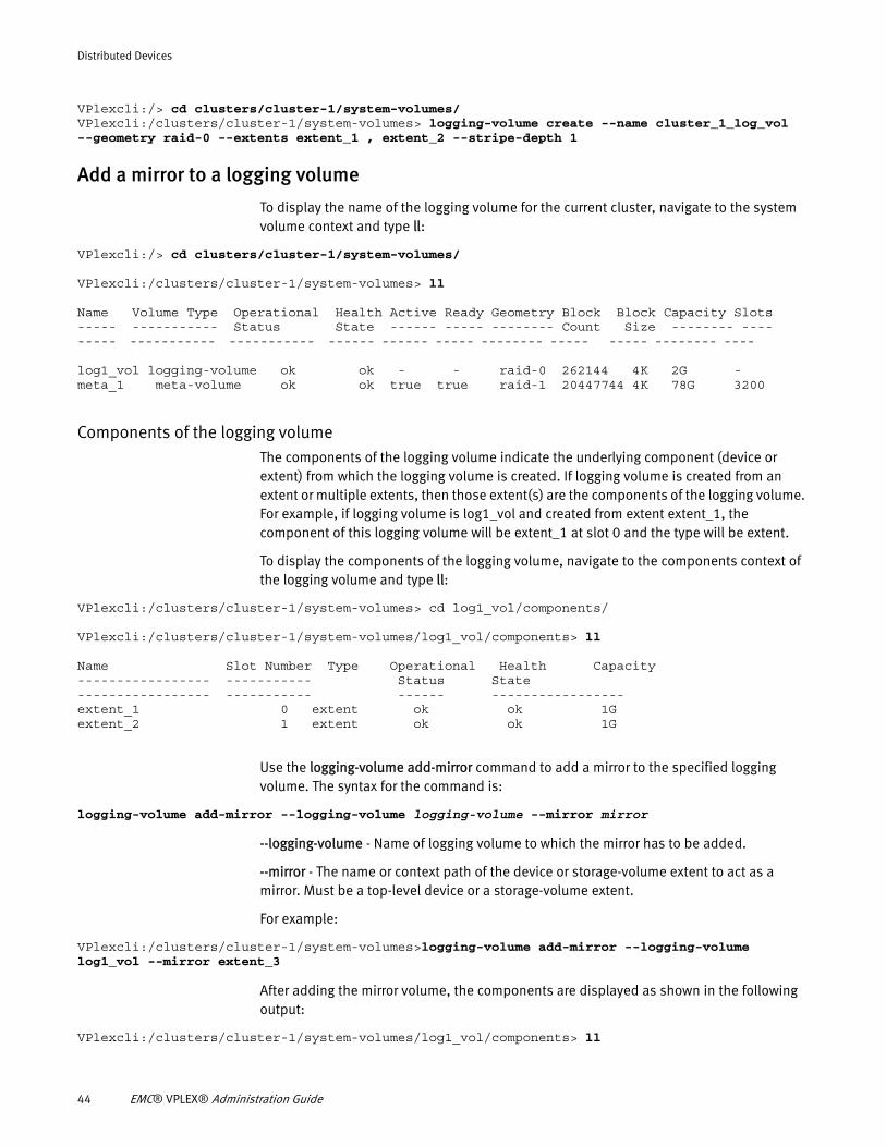
Distributed Devices
VPlexcli:/> cd clusters/cluster-1/system-volumes/ VPlexcli:/clusters/cluster-1/system-volumes> logging-volume create --name cluster_1_log_vol --geometry raid-0 --extents extent_1 , extent_2 --stripe-depth 1
Add a mirror to a logging volume
To display the name of the logging volume for the current cluster, navigate to the system volume context and type ll:
VPlexcli:/> cd clusters/cluster-1/system-volumes/
VPlexcli:/clusters/cluster-1/system-volumes> ll
Name Volume Type Operational Health Active Ready Geometry Block Block Capacity Slots ----- ----------- Status State ------ ----- -------- Count Size -------- --------- ----------- ----------- ------ ------ ----- -------- ----- ----- -------- ----
log1_vol logging-volume ok ok - - raid-0 262144 4K 2G -meta_1 meta-volume ok ok true true raid-1 20447744 4K 78G 3200
Components of the logging volumeThe components of the logging volume indicate the underlying component (device or extent) from which the logging volume is created. If logging volume is created from an extent or multiple extents, then those extent(s) are the components of the logging volume. For example, if logging volume is log1_vol and created from extent extent_1, the component of this logging volume will be extent_1 at slot 0 and the type will be extent.
To display the components of the logging volume, navigate to the components context of the logging volume and type ll:
VPlexcli:/clusters/cluster-1/system-volumes> cd log1_vol/components/
VPlexcli:/clusters/cluster-1/system-volumes/log1_vol/components> ll
Name Slot Number Type Operational Health Capacity----------------- ----------- Status State ----------------- ----------- ------ ----------------- extent_1 0 extent ok ok 1Gextent_2 1 extent ok ok 1G
Use the logging-volume add-mirror command to add a mirror to the specified logging volume. The syntax for the command is:
logging-volume add-mirror --logging-volume logging-volume --mirror mirror
--logging-volume - Name of logging volume to which the mirror has to be added.
--mirror - The name or context path of the device or storage-volume extent to act as a mirror. Must be a top-level device or a storage-volume extent.
For example:
VPlexcli:/clusters/cluster-1/system-volumes>logging-volume add-mirror --logging-volume log1_vol --mirror extent_3
After adding the mirror volume, the components are displayed as shown in the following output:
VPlexcli:/clusters/cluster-1/system-volumes/log1_vol/components> ll
44 EMC® VPLEX® Administration Guide
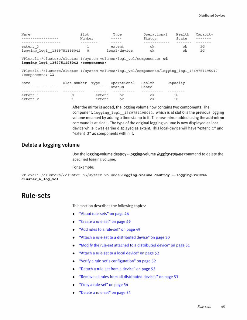
Distributed Devices
Name Slot Type Operational Health Capacity ----------------- Number ----- Status State ------------------------- -------- ----- ------------ ------- -------extent_3 1 extent ok ok 2Glogging_log1__1369751195042 0 local-device ok ok 2G
VPlexcli:/clusters/cluster-1/system-volumes/log1_vol/components> cd logging_log1_1369751195042 /components/
VPlexcli:/clusters/cluster-1/system-volumes/log1_vol/components/logging_log1_1369751195042 /components> ll
Name Slot Number Type Operational Health Capacity----------------- ---------- ------ Status State ------------------------- ---------- ------ ---------- ---------- --------extent_1 0 extent ok ok 1Gextent_2 1 extent ok ok 1G
After the mirror is added, the logging volume now contains two components. The component, logging_log1__1369751195042, which is at slot 0 is the previous logging volume renamed by adding a time stamp to it. The new mirror added using the add-mirror command is at slot 1. The type of the original logging volume is now displayed as local device while it was earlier displayed as extent. This local-device will have “extent_1” and “extent_2” as components within it.
Delete a logging volume
Use the logging-volume destroy --logging-volume logging-volume command to delete the specified logging volume.
For example:
VPlexcli:/clusters/<cluster-n>/system-volumes>logging-volume destroy --logging-volume cluster_6_log_vol
Rule-setsThis section describes the following topics:
◆ “About rule-sets” on page 46
◆ “Create a rule-set” on page 49
◆ “Add rules to a rule-set” on page 49
◆ “Attach a rule-set to a distributed device” on page 50
◆ “Modify the rule-set attached to a distributed device” on page 51
◆ “Attach a rule-set to a local device” on page 52
◆ “Verify a rule-set’s configuration” on page 52
◆ “Detach a rule-set from a device” on page 53
◆ “Remove all rules from all distributed devices” on page 53
◆ “Copy a rule-set” on page 54
◆ “Delete a rule-set” on page 54
Rule-sets 45
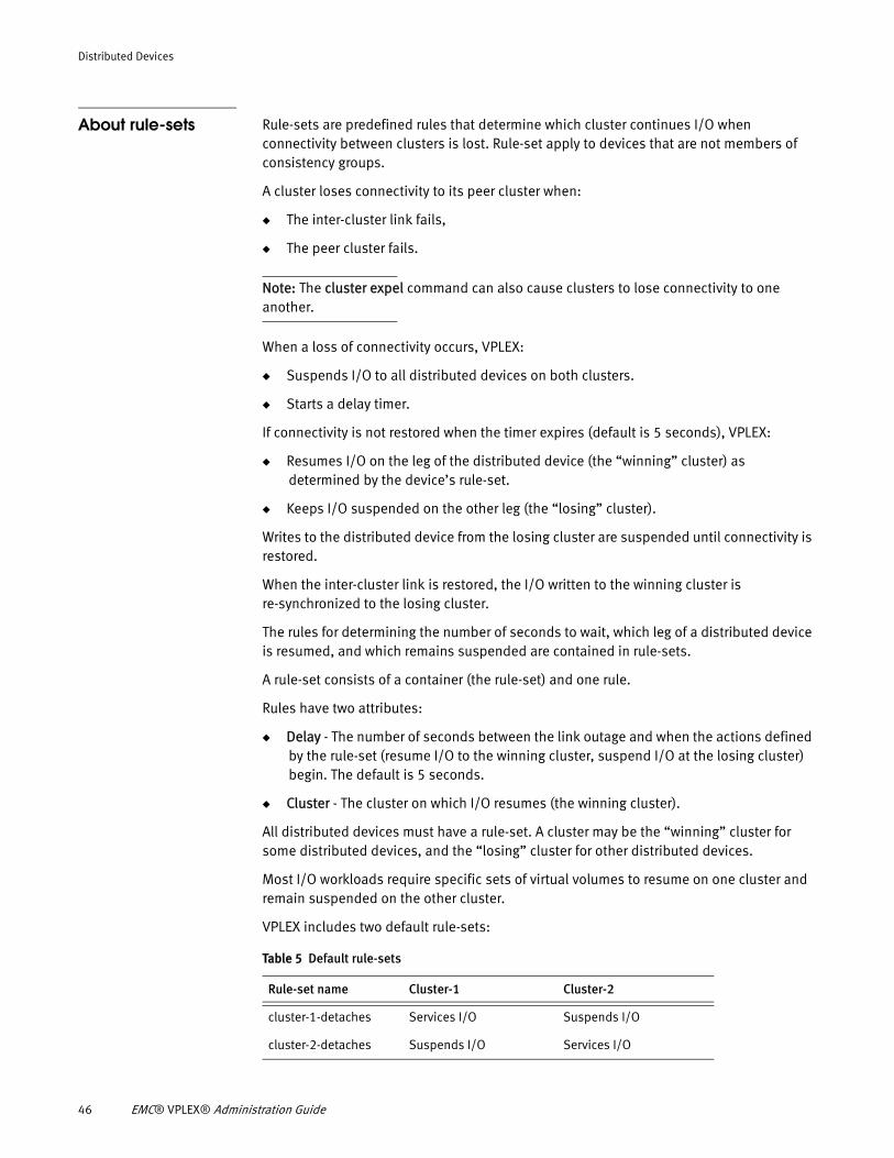
Distributed Devices
About rule-sets Rule-sets are predefined rules that determine which cluster continues I/O when connectivity between clusters is lost. Rule-set apply to devices that are not members of consistency groups.
A cluster loses connectivity to its peer cluster when:
◆ The inter-cluster link fails,
◆ The peer cluster fails.
Note: The cluster expel command can also cause clusters to lose connectivity to one another.
When a loss of connectivity occurs, VPLEX:
◆ Suspends I/O to all distributed devices on both clusters.
◆ Starts a delay timer.
If connectivity is not restored when the timer expires (default is 5 seconds), VPLEX:
◆ Resumes I/O on the leg of the distributed device (the “winning” cluster) as determined by the device’s rule-set.
◆ Keeps I/O suspended on the other leg (the “losing” cluster).
Writes to the distributed device from the losing cluster are suspended until connectivity is restored.
When the inter-cluster link is restored, the I/O written to the winning cluster is re-synchronized to the losing cluster.
The rules for determining the number of seconds to wait, which leg of a distributed device is resumed, and which remains suspended are contained in rule-sets.
A rule-set consists of a container (the rule-set) and one rule.
Rules have two attributes:
◆ Delay - The number of seconds between the link outage and when the actions defined by the rule-set (resume I/O to the winning cluster, suspend I/O at the losing cluster) begin. The default is 5 seconds.
◆ Cluster - The cluster on which I/O resumes (the winning cluster).
All distributed devices must have a rule-set. A cluster may be the “winning” cluster for some distributed devices, and the “losing” cluster for other distributed devices.
Most I/O workloads require specific sets of virtual volumes to resume on one cluster and remain suspended on the other cluster.
VPLEX includes two default rule-sets:
Table 5 Default rule-sets
Rule-set name Cluster-1 Cluster-2
cluster-1-detaches Services I/O Suspends I/O
cluster-2-detaches Suspends I/O Services I/O
46 EMC® VPLEX® Administration Guide
Distributed Devices
EMC recommends that only the two default rule-sets be applied to distributed devices.
The default value of a distributed device’s rule-set is determined by the management server on which the device was created.
If a device is created on the management server for cluster-1, the default rule-set for that device is cluster-1-detaches.
Rule-sets are located in the distributed-storage/rule-sets context.
Rules are located under their rule-set context.
Auto-resume When cluster connectivity is restored, subsequent behavior is determined by the auto-resume attribute for the distributed device.
◆ If auto-resume is set to false, the distributed device on the losing cluster remains suspended until I/O is manually resumed by the system administrator (using the device resume-link-up command).
◆ If auto-resume is set to true, I/O may start immediately after the link is restored.
After I/O is resumed to the mirror leg on the losing cluster, any data written to the device on the winning cluster during the outage is resynchronized from the leg on the winning cluster.
Use the set command to configure auto-resume attribute of a device.
Force I/O to resume on a suspended legTwo commands allow administrators to force I/O to resume on a suspended mirror leg:
◆ device resume-link-down - Used when the inter-cluster link is down. Allows suspended mirror legs to resume I/O immediately.
For example, use this command if the peer cluster is the winning cluster but is known to have failed.
◆ device resume-link-up - Used after the link has been restored.
For example, use this command to the restart I/O to the mirror leg on the losing cluster when the auto-resume attribute is set to false.
Rule-set best practices◆ Use the provided pre-configured rule-sets whenever possible.
◆ For custom rule-sets, leave the detach delay timer at the default value of 5 seconds.
Setting the detach delay lower than 5 seconds can result in unnecessary cluster detaches during periods of network instability. Multiple cluster detaches in a short period of time can result in unnecessary data rebuilds and reduced performance.
Consult EMC Customer Support if a lower detach time is required.
◆ Configure detach rules based on the cluster/site that is expected to continue I/O during an outage.
◆ Avoid conflicting detach configurations. It is important to understand which cluster is configured to automatically detach.
◆ Document how rule sets are applied.
Rule-sets 47
Distributed Devices
It is acceptable for different distributed devices to resume I/O on different clusters during an outage.
If a host application uses more than one distributed device, all distributed devices for that application should have the same rule-set (to resume I/O on the same cluster).
Conflicted detachThe major problem to avoid when creating and using rule-sets is a scenario referred to as a conflicted detach. Conflicted detach happens during a network outage when:
◆ Both legs of a distributed device perform I/O independently.
◆ Both clusters write to the different legs of the same virtual volume.
◆ When connectivity is restored, the administrator picks the winner cluster, meaning that one of the legs is used as the source to rebuild.
◆ Logging synchronizes the losing cluster to match the winning cluster.
◆ Any data written to the losing cluster during the network communication outage is overwritten.
Rule-sets and manual detaches must not result in conflicting detaches. Conflicting detaches result in data loss (on the losing cluster), a full rebuild and degraded performance during the full rebuild.
Rule-sets and local devicesA rule-set can be applied to a local device when the visibility of the device is set to global.
Attaching a rule-set to a local device:
◆ Enables the cluster to detach in the event of a link outage.
◆ Allows I/O to continue at the detached cluster.
VPLEX islands Rule-sets introduce the term “island.” An island is a set of communicating clusters.
A single cluster can be an island by itself.
For 2 clusters, there are 3 possible combinations, each of which can be an island:
◆ cluster-1
◆ cluster-2
◆ cluster-1 and cluster-2
For VPLEX Metro and Geo configurations, islands are mostly synonymous with clusters.
Manage rule-sets
The ds rule-set create command creates custom rule-sets. When a new rule-set is created, the VPLEX system creates a sub-context under the rule-sets context.
Rules themselves are added to these new sub-contexts.
48 EMC® VPLEX® Administration Guide
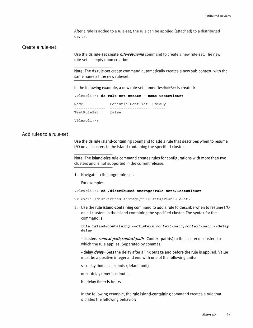
Distributed Devices
After a rule is added to a rule-set, the rule can be applied (attached) to a distributed device.
Create a rule-setUse the ds rule-set create rule-set-name command to create a new rule-set. The new rule-set is empty upon creation.
Note: The ds rule-set create command automatically creates a new sub-context, with the same name as the new rule-set.
In the following example, a new rule-set named TestRuleSet is created:
VPlexcli:/> ds rule-set create --name TestRuleSet
Name PotentialConflict UsedBy-------------- ----------------- ------TestRuleSet false
VPlexcli:/>
Add rules to a rule-setUse the ds rule island-containing command to add a rule that describes when to resume I/O on all clusters in the island containing the specified cluster.
Note: The island-size rule command creates rules for configurations with more than two clusters and is not supported in the current release.
1. Navigate to the target rule-set.
For example:
VPlexcli:/> cd /distributed-storage/rule-sets/TestRuleSet
VPlexcli:/distributed-storage/rule-sets/TestRuleSet>
2. Use the rule island-containing command to add a rule to describe when to resume I/O on all clusters in the island containing the specified cluster. The syntax for the command is:
rule island-containing --clusters context-path,context-path --delay delay
--clusters context-path,context-path - Context path(s) to the cluster or clusters to which the rule applies. Separated by commas.
--delay delay - Sets the delay after a link outage and before the rule is applied. Value must be a positive integer and end with one of the following units:
s - delay timer is seconds (default unit)
min - delay timer is minutes
h - delay timer is hours
In the following example, the rule island-containing command creates a rule that dictates the following behavior:
Rule-sets 49
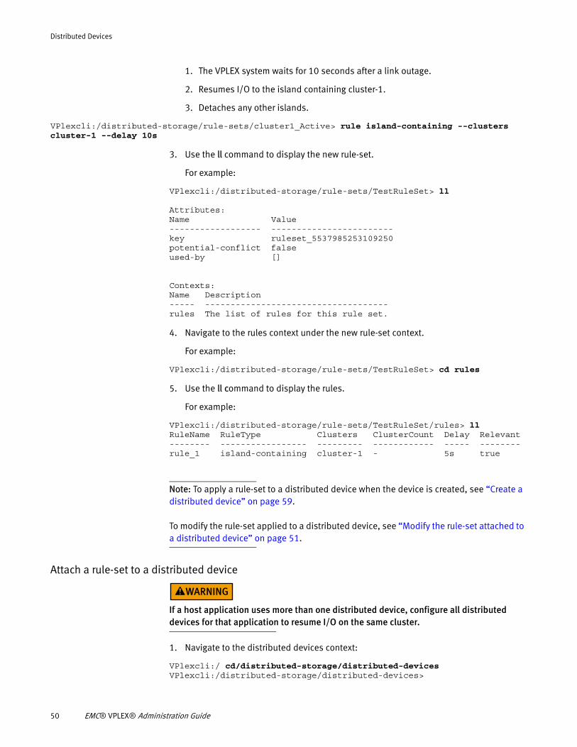
Distributed Devices
1. The VPLEX system waits for 10 seconds after a link outage.
2. Resumes I/O to the island containing cluster-1.
3. Detaches any other islands.
VPlexcli:/distributed-storage/rule-sets/cluster1_Active> rule island-containing --clusters cluster-1 --delay 10s
3. Use the ll command to display the new rule-set.
For example:
VPlexcli:/distributed-storage/rule-sets/TestRuleSet> ll
Attributes:Name Value------------------ ------------------------key ruleset_5537985253109250potential-conflict falseused-by []
Contexts:Name Description----- ------------------------------------rules The list of rules for this rule set.
4. Navigate to the rules context under the new rule-set context.
For example:
VPlexcli:/distributed-storage/rule-sets/TestRuleSet> cd rules
5. Use the ll command to display the rules.
For example:
VPlexcli:/distributed-storage/rule-sets/TestRuleSet/rules> llRuleName RuleType Clusters ClusterCount Delay Relevant-------- ----------------- --------- ------------ ----- --------rule_1 island-containing cluster-1 - 5s true
Note: To apply a rule-set to a distributed device when the device is created, see “Create a distributed device” on page 59.
To modify the rule-set applied to a distributed device, see “Modify the rule-set attached to a distributed device” on page 51.
Attach a rule-set to a distributed device
If a host application uses more than one distributed device, configure all distributed devices for that application to resume I/O on the same cluster.
1. Navigate to the distributed devices context:
VPlexcli:/ cd/distributed-storage/distributed-devicesVPlexcli:/distributed-storage/distributed-devices>
50 EMC® VPLEX® Administration Guide
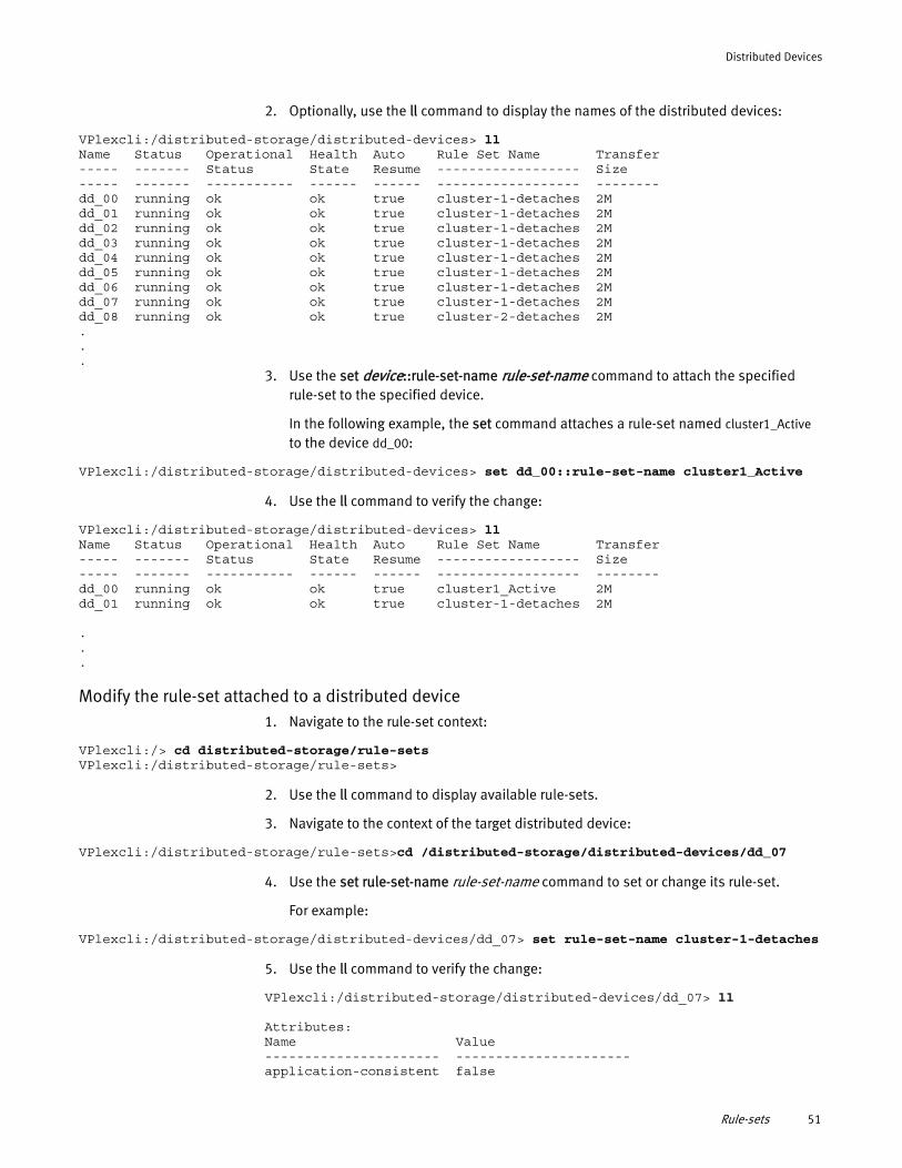
Distributed Devices
2. Optionally, use the ll command to display the names of the distributed devices:
VPlexcli:/distributed-storage/distributed-devices> llName Status Operational Health Auto Rule Set Name Transfer----- ------- Status State Resume ------------------ Size----- ------- ----------- ------ ------ ------------------ --------dd_00 running ok ok true cluster-1-detaches 2Mdd_01 running ok ok true cluster-1-detaches 2Mdd_02 running ok ok true cluster-1-detaches 2Mdd_03 running ok ok true cluster-1-detaches 2Mdd_04 running ok ok true cluster-1-detaches 2Mdd_05 running ok ok true cluster-1-detaches 2Mdd_06 running ok ok true cluster-1-detaches 2Mdd_07 running ok ok true cluster-1-detaches 2Mdd_08 running ok ok true cluster-2-detaches 2M...
3. Use the set device::rule-set-name rule-set-name command to attach the specified rule-set to the specified device.
In the following example, the set command attaches a rule-set named cluster1_Active to the device dd_00:
VPlexcli:/distributed-storage/distributed-devices> set dd_00::rule-set-name cluster1_Active
4. Use the ll command to verify the change:
VPlexcli:/distributed-storage/distributed-devices> llName Status Operational Health Auto Rule Set Name Transfer----- ------- Status State Resume ------------------ Size----- ------- ----------- ------ ------ ------------------ --------dd_00 running ok ok true cluster1_Active 2Mdd_01 running ok ok true cluster-1-detaches 2M
.
.
.
Modify the rule-set attached to a distributed device1. Navigate to the rule-set context:
VPlexcli:/> cd distributed-storage/rule-setsVPlexcli:/distributed-storage/rule-sets>
2. Use the ll command to display available rule-sets.
3. Navigate to the context of the target distributed device:
VPlexcli:/distributed-storage/rule-sets>cd /distributed-storage/distributed-devices/dd_07
4. Use the set rule-set-name rule-set-name command to set or change its rule-set.
For example:
VPlexcli:/distributed-storage/distributed-devices/dd_07> set rule-set-name cluster-1-detaches
5. Use the ll command to verify the change:
VPlexcli:/distributed-storage/distributed-devices/dd_07> ll
Attributes:Name Value---------------------- ----------------------application-consistent false
Rule-sets 51
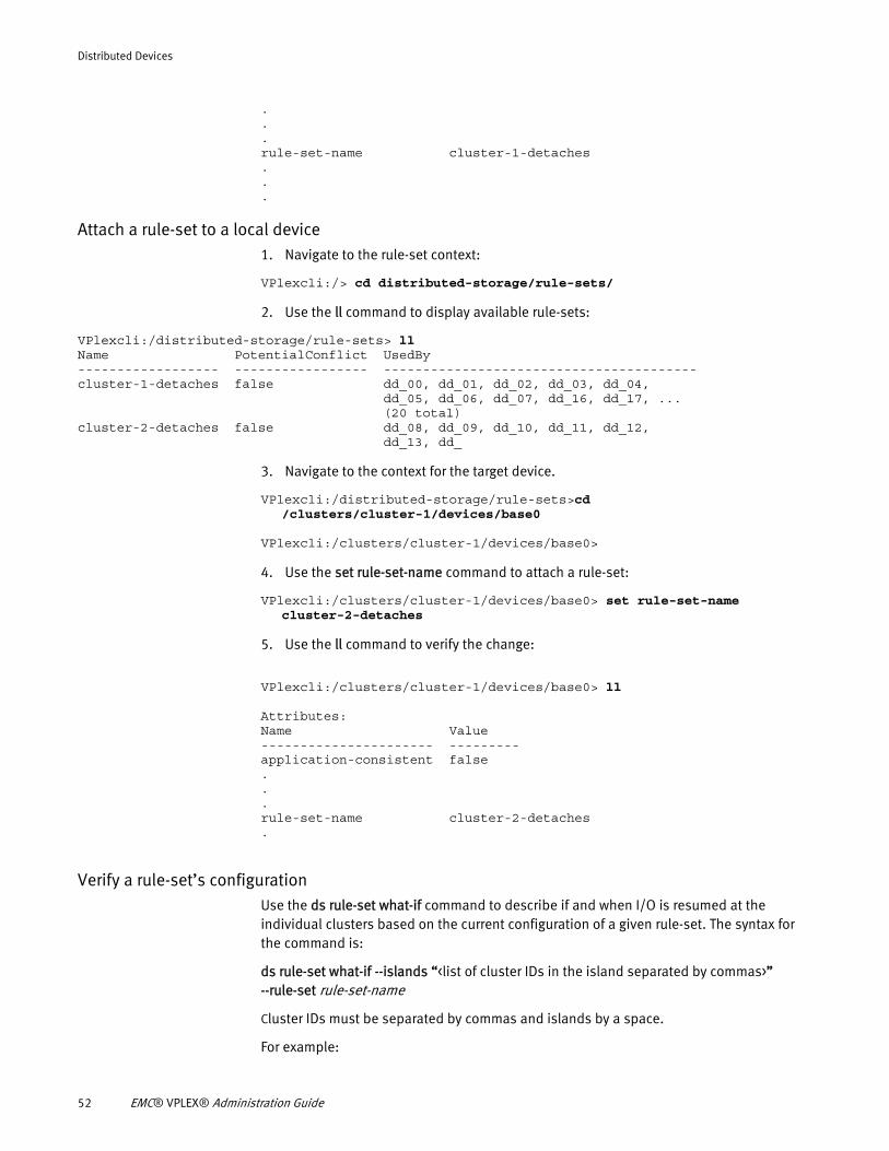
Distributed Devices
.
.
.rule-set-name cluster-1-detaches...
Attach a rule-set to a local device1. Navigate to the rule-set context:
VPlexcli:/> cd distributed-storage/rule-sets/
2. Use the ll command to display available rule-sets:
VPlexcli:/distributed-storage/rule-sets> llName PotentialConflict UsedBy------------------ ----------------- ----------------------------------------cluster-1-detaches false dd_00, dd_01, dd_02, dd_03, dd_04, dd_05, dd_06, dd_07, dd_16, dd_17, ... (20 total)cluster-2-detaches false dd_08, dd_09, dd_10, dd_11, dd_12, dd_13, dd_
3. Navigate to the context for the target device.
VPlexcli:/distributed-storage/rule-sets>cd /clusters/cluster-1/devices/base0
VPlexcli:/clusters/cluster-1/devices/base0>
4. Use the set rule-set-name command to attach a rule-set:
VPlexcli:/clusters/cluster-1/devices/base0> set rule-set-name cluster-2-detaches
5. Use the ll command to verify the change:
VPlexcli:/clusters/cluster-1/devices/base0> ll
Attributes:Name Value---------------------- ---------application-consistent false...rule-set-name cluster-2-detaches.
Verify a rule-set’s configurationUse the ds rule-set what-if command to describe if and when I/O is resumed at the individual clusters based on the current configuration of a given rule-set. The syntax for the command is:
ds rule-set what-if --islands “<list of cluster IDs in the island separated by commas>” --rule-set rule-set-name
Cluster IDs must be separated by commas and islands by a space.
For example:
52 EMC® VPLEX® Administration Guide
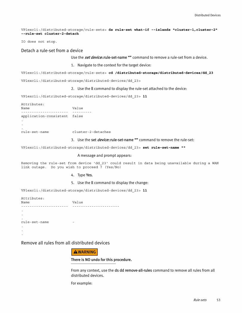
Distributed Devices
VPlexcli:/distributed-storage/rule-sets> ds rule-set what-if --islands "cluster-1,cluster-2" --rule-set cluster-2-detach
IO does not stop.
Detach a rule-set from a deviceUse the set device::rule-set-name “” command to remove a rule-set from a device.
1. Navigate to the context for the target device:
VPlexcli:/distributed-storage/rule-sets> cd /distributed-storage/distributed-devices/dd_23
VPlexcli:/distributed-storage/distributed-devices/dd_23>
2. Use the ll command to display the rule-set attached to the device:
VPlexcli:/distributed-storage/distributed-devices/dd_23> ll
Attributes:Name Value---------------------- ---------application-consistent false...rule-set-name cluster-2-detaches
3. Use the set device::rule-set-name “” command to remove the rule-set:
VPlexcli:/distributed-storage/distributed-devices/dd_23> set rule-set-name ""
A message and prompt appears:
Removing the rule-set from device 'dd_23' could result in data being unavailable during a WAN link outage. Do you wish to proceed ? (Yes/No)
4. Type Yes.
5. Use the ll command to display the change:
VPlexcli:/distributed-storage/distributed-devices/dd_23> ll
Attributes:Name Value---------------------- ----------------------...rule-set-name -...
Remove all rules from all distributed devices
There is NO undo for this procedure.
From any context, use the ds dd remove-all-rules command to remove all rules from all distributed devices.
For example:
Rule-sets 53
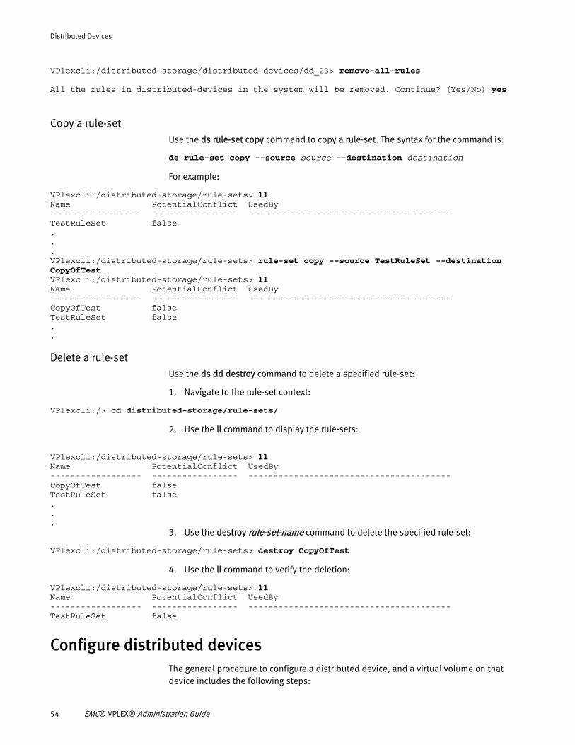
Distributed Devices
VPlexcli:/distributed-storage/distributed-devices/dd_23> remove-all-rules
All the rules in distributed-devices in the system will be removed. Continue? (Yes/No) yes
Copy a rule-setUse the ds rule-set copy command to copy a rule-set. The syntax for the command is:
ds rule-set copy --source source --destination destination
For example:
VPlexcli:/distributed-storage/rule-sets> llName PotentialConflict UsedBy------------------ ----------------- ----------------------------------------TestRuleSet false...VPlexcli:/distributed-storage/rule-sets> rule-set copy --source TestRuleSet --destination CopyOfTest VPlexcli:/distributed-storage/rule-sets> llName PotentialConflict UsedBy------------------ ----------------- ----------------------------------------CopyOfTest falseTestRuleSet false..
Delete a rule-setUse the ds dd destroy command to delete a specified rule-set:
1. Navigate to the rule-set context:
VPlexcli:/> cd distributed-storage/rule-sets/
2. Use the ll command to display the rule-sets:
VPlexcli:/distributed-storage/rule-sets> llName PotentialConflict UsedBy------------------ ----------------- ----------------------------------------CopyOfTest falseTestRuleSet false...
3. Use the destroy rule-set-name command to delete the specified rule-set:
VPlexcli:/distributed-storage/rule-sets> destroy CopyOfTest
4. Use the ll command to verify the deletion:
VPlexcli:/distributed-storage/rule-sets> llName PotentialConflict UsedBy------------------ ----------------- ----------------------------------------TestRuleSet false
Configure distributed devicesThe general procedure to configure a distributed device, and a virtual volume on that device includes the following steps:
54 EMC® VPLEX® Administration Guide
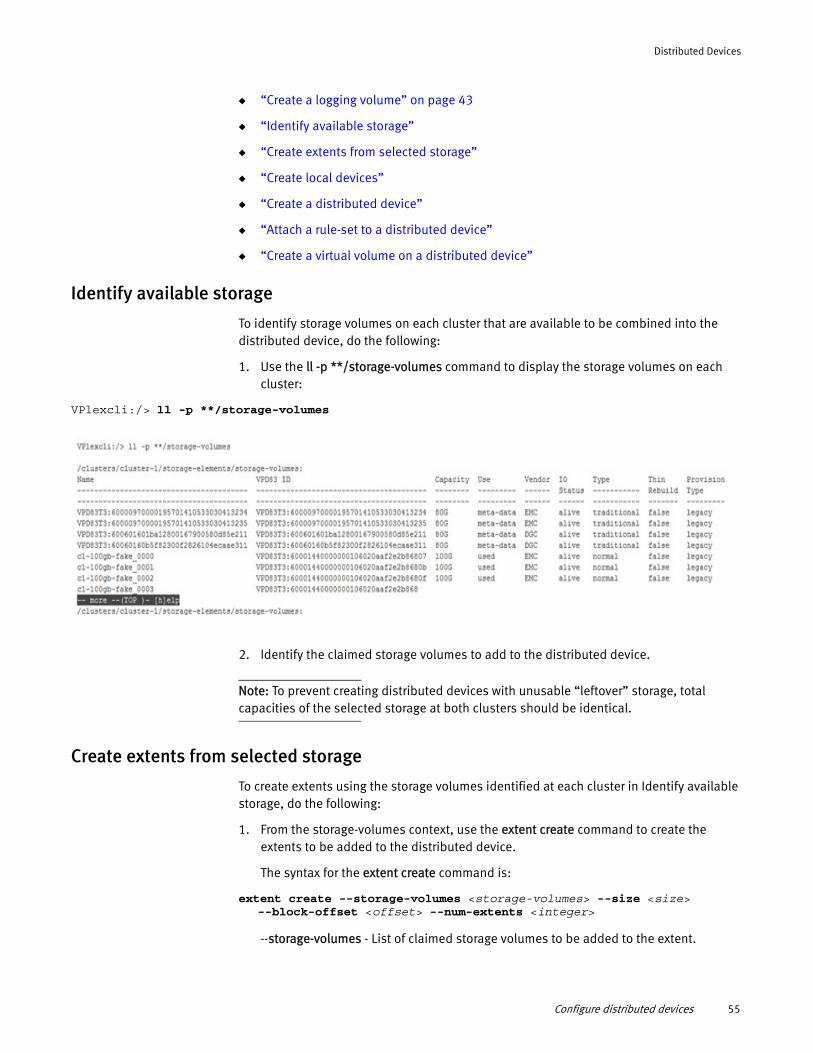
Distributed Devices
◆ “Create a logging volume” on page 43
◆ “Identify available storage”
◆ “Create extents from selected storage”
◆ “Create local devices”
◆ “Create a distributed device”
◆ “Attach a rule-set to a distributed device”
◆ “Create a virtual volume on a distributed device”
Identify available storage
To identify storage volumes on each cluster that are available to be combined into the distributed device, do the following:
1. Use the ll -p **/storage-volumes command to display the storage volumes on each cluster:
VPlexcli:/> ll -p **/storage-volumes
2. Identify the claimed storage volumes to add to the distributed device.
Note: To prevent creating distributed devices with unusable “leftover” storage, total capacities of the selected storage at both clusters should be identical.
Create extents from selected storage
To create extents using the storage volumes identified at each cluster in Identify available storage, do the following:
1. From the storage-volumes context, use the extent create command to create the extents to be added to the distributed device.
The syntax for the extent create command is:
extent create --storage-volumes <storage-volumes> --size <size> --block-offset <offset> --num-extents <integer>
--storage-volumes - List of claimed storage volumes to be added to the extent.
Configure distributed devices 55
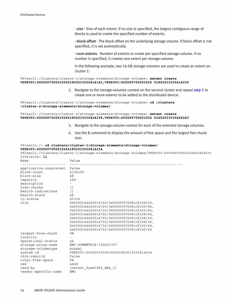
Distributed Devices
--size - Size of each extent. If no size is specified, the largest contiguous range of blocks is used to create the specified number of extents.
--block-offset - The block offset on the underlying storage volume. If block offset is not specified, it is set automatically.
--num-extents - Number of extents to create per specified storage-volume. If no number is specified, it creates one extent per storage-volume.
In the following example, two 16 GB storage volumes are used to create an extent on cluster-1:
VPlexcli:/clusters/cluster-1/storage-elements/storage-volumes> extent create VPD83T3:60000970000192601852533030414143,VPD83T3:600009700001926 01852533030414230
2. Navigate to the storage-volumes context on the second cluster and repeat step 1 to create one or more extents to be added to the distributed device:
VPlexcli:/clusters/cluster-1/storage-elements/storage-volumes> cd /clusters /cluster-2/storage-elements/storage-volumes/
VPlexcli:/clusters/cluster-2/storage-elements/storage-volumes> extent create VPD83T3:60000970000192601852533030424238,VPD83T3:600009700001926 01852533030424243
3. Navigate to the storage-volume context for each of the extented storage volumes.
4. Use the ll command to display the amount of free space and the largest free chunk size:
VPlexcli:/> cd clusters/cluster-1/storage-elements/storage-volumes/ VPD83T3:60000970000192601852533030414234 VPlexcli:/clusters/cluster-1/storage-elements/storage-volumes/VPD83T3:60000970000192601852533030414234> llName Value---------------------- -------------------------------------------------------application-consistent falseblock-count 4195200block-size 4Kcapacity 16Gdescription -free-chunks []health-indications []health-state okio-status aliveitls 0x5000144240014720/0x50000972081cf15d/64, 0x5000144240014720/0x50000972081cf165/64, 0x5000144240014730/0x50000972081cf165/64, 0x5000144240014722/0x50000972081cf158/64, 0x5000144240014732/0x50000972081cf158/64, 0x5000144240014730/0x50000972081cf15d/64, 0x5000144240014732/0x50000972081cf160/64, 0x5000144240014722/0x50000972081cf160/64largest-free-chunk 0Blocality -operational-status okstorage-array-name EMC-SYMMETRIX-192601707storage-volumetype normalsystem-id VPD83T3:60000970000192601852533030414234thin-rebuild falsetotal-free-space 0Buse usedused-by [extent_Symm1852_AB4_1]vendor-specific-name EMC
56 EMC® VPLEX® Administration Guide
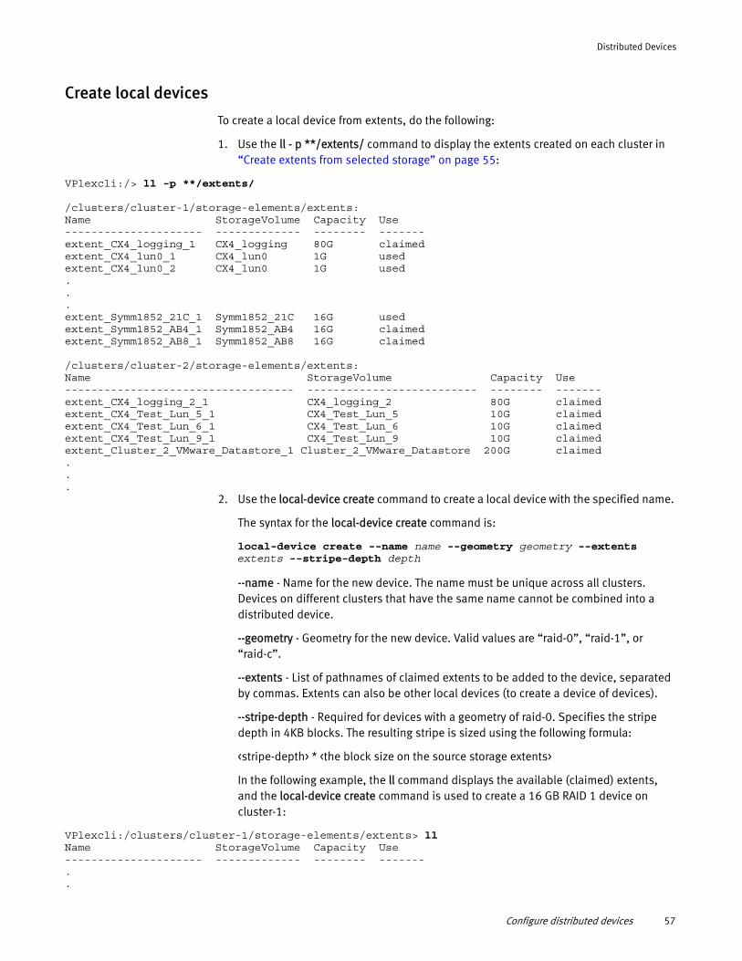
Distributed Devices
Create local devices
To create a local device from extents, do the following:
1. Use the ll - p **/extents/ command to display the extents created on each cluster in “Create extents from selected storage” on page 55:
VPlexcli:/> ll -p **/extents/
/clusters/cluster-1/storage-elements/extents:Name StorageVolume Capacity Use--------------------- ------------- -------- -------extent_CX4_logging_1 CX4_logging 80G claimedextent_CX4_lun0_1 CX4_lun0 1G usedextent_CX4_lun0_2 CX4_lun0 1G used...extent_Symm1852_21C_1 Symm1852_21C 16G usedextent_Symm1852_AB4_1 Symm1852_AB4 16G claimedextent_Symm1852_AB8_1 Symm1852_AB8 16G claimed
/clusters/cluster-2/storage-elements/extents:Name StorageVolume Capacity Use----------------------------------- -------------------------- -------- -------extent_CX4_logging_2_1 CX4_logging_2 80G claimedextent_CX4_Test_Lun_5_1 CX4_Test_Lun_5 10G claimedextent_CX4_Test_Lun_6_1 CX4_Test_Lun_6 10G claimedextent_CX4_Test_Lun_9_1 CX4_Test_Lun_9 10G claimedextent_Cluster_2_VMware_Datastore_1 Cluster_2_VMware_Datastore 200G claimed...
2. Use the local-device create command to create a local device with the specified name.
The syntax for the local-device create command is:
local-device create --name name --geometry geometry --extents extents --stripe-depth depth
--name - Name for the new device. The name must be unique across all clusters. Devices on different clusters that have the same name cannot be combined into a distributed device.
--geometry - Geometry for the new device. Valid values are “raid-0”, “raid-1”, or “raid-c”.
--extents - List of pathnames of claimed extents to be added to the device, separated by commas. Extents can also be other local devices (to create a device of devices).
--stripe-depth - Required for devices with a geometry of raid-0. Specifies the stripe depth in 4KB blocks. The resulting stripe is sized using the following formula:
<stripe-depth> * <the block size on the source storage extents>
In the following example, the ll command displays the available (claimed) extents, and the local-device create command is used to create a 16 GB RAID 1 device on cluster-1:
VPlexcli:/clusters/cluster-1/storage-elements/extents> llName StorageVolume Capacity Use--------------------- ------------- -------- -------..
Configure distributed devices 57
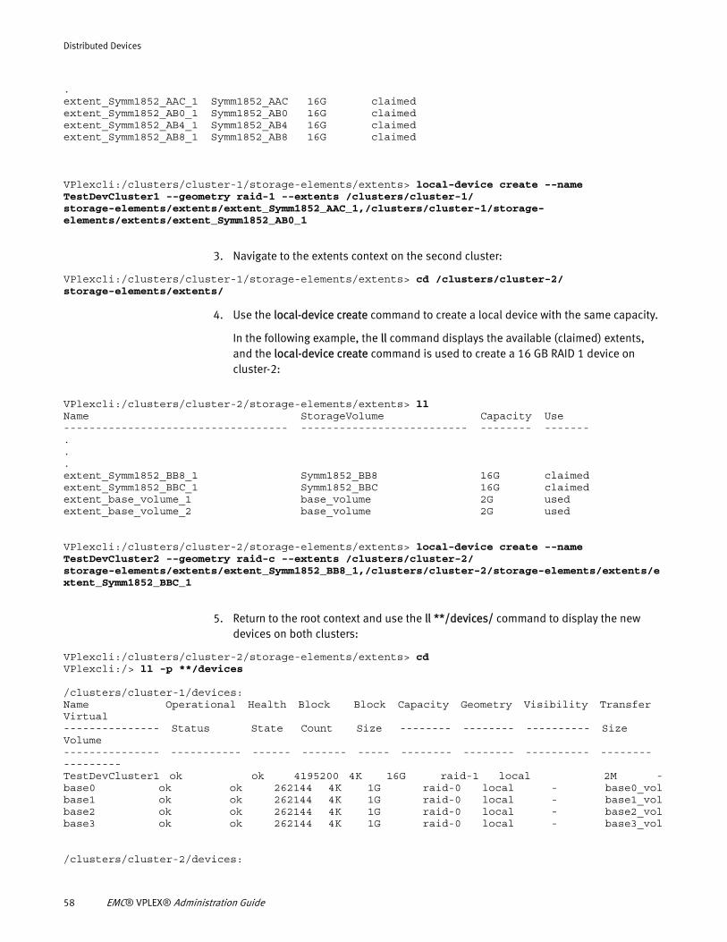
Distributed Devices
.extent_Symm1852_AAC_1 Symm1852_AAC 16G claimedextent_Symm1852_AB0_1 Symm1852_AB0 16G claimedextent_Symm1852_AB4_1 Symm1852_AB4 16G claimedextent_Symm1852_AB8_1 Symm1852_AB8 16G claimed
VPlexcli:/clusters/cluster-1/storage-elements/extents> local-device create --name TestDevCluster1 --geometry raid-1 --extents /clusters/cluster-1/ storage-elements/extents/extent_Symm1852_AAC_1,/clusters/cluster-1/storage- elements/extents/extent_Symm1852_AB0_1
3. Navigate to the extents context on the second cluster:
VPlexcli:/clusters/cluster-1/storage-elements/extents> cd /clusters/cluster-2/ storage-elements/extents/
4. Use the local-device create command to create a local device with the same capacity.
In the following example, the ll command displays the available (claimed) extents, and the local-device create command is used to create a 16 GB RAID 1 device on cluster-2:
VPlexcli:/clusters/cluster-2/storage-elements/extents> llName StorageVolume Capacity Use----------------------------------- -------------------------- -------- -------...extent_Symm1852_BB8_1 Symm1852_BB8 16G claimedextent_Symm1852_BBC_1 Symm1852_BBC 16G claimedextent_base_volume_1 base_volume 2G usedextent_base_volume_2 base_volume 2G used
VPlexcli:/clusters/cluster-2/storage-elements/extents> local-device create --name TestDevCluster2 --geometry raid-c --extents /clusters/cluster-2/ storage-elements/extents/extent_Symm1852_BB8_1,/clusters/cluster-2/storage-elements/extents/extent_Symm1852_BBC_1
5. Return to the root context and use the ll **/devices/ command to display the new devices on both clusters:
VPlexcli:/clusters/cluster-2/storage-elements/extents> cdVPlexcli:/> ll -p **/devices
/clusters/cluster-1/devices:Name Operational Health Block Block Capacity Geometry Visibility Transfer Virtual--------------- Status State Count Size -------- -------- ---------- Size Volume--------------- ----------- ------ ------- ----- -------- -------- ---------- -------- ---------TestDevCluster1 ok ok 4195200 4K 16G raid-1 local 2M -base0 ok ok 262144 4K 1G raid-0 local - base0_volbase1 ok ok 262144 4K 1G raid-0 local - base1_volbase2 ok ok 262144 4K 1G raid-0 local - base2_volbase3 ok ok 262144 4K 1G raid-0 local - base3_vol
/clusters/cluster-2/devices:
58 EMC® VPLEX® Administration Guide
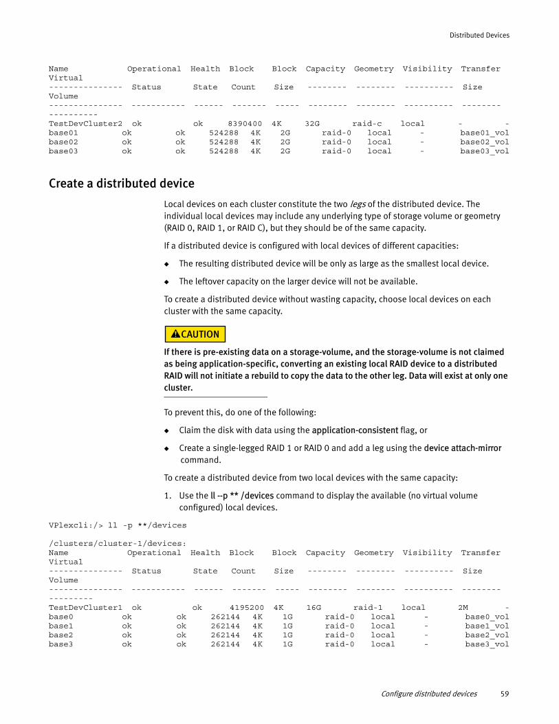
Distributed Devices
Name Operational Health Block Block Capacity Geometry Visibility Transfer Virtual--------------- Status State Count Size -------- -------- ---------- Size Volume--------------- ----------- ------ ------- ----- -------- -------- ---------- -------- ----------TestDevCluster2 ok ok 8390400 4K 32G raid-c local - -base01 ok ok 524288 4K 2G raid-0 local - base01_volbase02 ok ok 524288 4K 2G raid-0 local - base02_volbase03 ok ok 524288 4K 2G raid-0 local - base03_vol
Create a distributed device
Local devices on each cluster constitute the two legs of the distributed device. The individual local devices may include any underlying type of storage volume or geometry (RAID 0, RAID 1, or RAID C), but they should be of the same capacity.
If a distributed device is configured with local devices of different capacities:
◆ The resulting distributed device will be only as large as the smallest local device.
◆ The leftover capacity on the larger device will not be available.
To create a distributed device without wasting capacity, choose local devices on each cluster with the same capacity.
If there is pre-existing data on a storage-volume, and the storage-volume is not claimed as being application-specific, converting an existing local RAID device to a distributed RAID will not initiate a rebuild to copy the data to the other leg. Data will exist at only one cluster.
To prevent this, do one of the following:
◆ Claim the disk with data using the application-consistent flag, or
◆ Create a single-legged RAID 1 or RAID 0 and add a leg using the device attach-mirror command.
To create a distributed device from two local devices with the same capacity:
1. Use the ll --p ** /devices command to display the available (no virtual volume configured) local devices.
VPlexcli:/> ll -p **/devices
/clusters/cluster-1/devices:Name Operational Health Block Block Capacity Geometry Visibility Transfer Virtual--------------- Status State Count Size -------- -------- ---------- Size Volume--------------- ----------- ------ ------- ----- -------- -------- ---------- -------- ---------TestDevCluster1 ok ok 4195200 4K 16G raid-1 local 2M -base0 ok ok 262144 4K 1G raid-0 local - base0_volbase1 ok ok 262144 4K 1G raid-0 local - base1_volbase2 ok ok 262144 4K 1G raid-0 local - base2_volbase3 ok ok 262144 4K 1G raid-0 local - base3_vol
Configure distributed devices 59
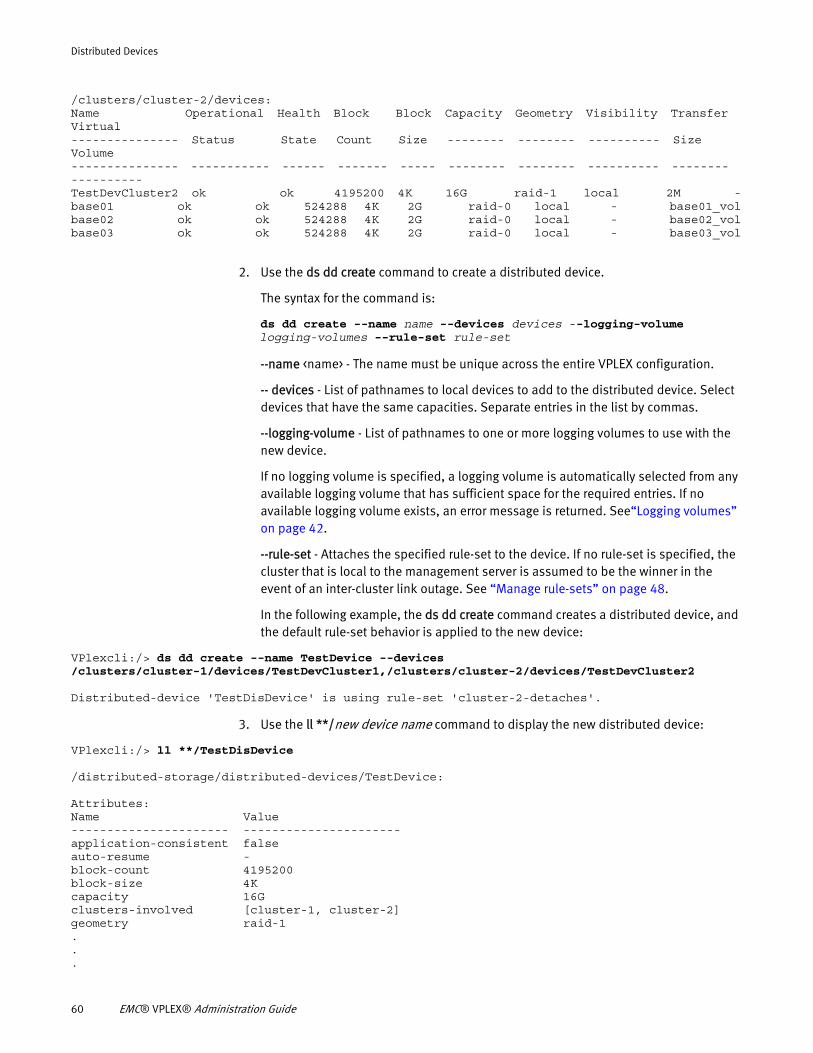
Distributed Devices
/clusters/cluster-2/devices:Name Operational Health Block Block Capacity Geometry Visibility Transfer Virtual--------------- Status State Count Size -------- -------- ---------- Size Volume--------------- ----------- ------ ------- ----- -------- -------- ---------- -------- ----------TestDevCluster2 ok ok 4195200 4K 16G raid-1 local 2M -base01 ok ok 524288 4K 2G raid-0 local - base01_volbase02 ok ok 524288 4K 2G raid-0 local - base02_volbase03 ok ok 524288 4K 2G raid-0 local - base03_vol
2. Use the ds dd create command to create a distributed device.
The syntax for the command is:
ds dd create --name name --devices devices --logging-volume logging-volumes --rule-set rule-set
--name <name> - The name must be unique across the entire VPLEX configuration.
-- devices - List of pathnames to local devices to add to the distributed device. Select devices that have the same capacities. Separate entries in the list by commas.
--logging-volume - List of pathnames to one or more logging volumes to use with the new device.
If no logging volume is specified, a logging volume is automatically selected from any available logging volume that has sufficient space for the required entries. If no available logging volume exists, an error message is returned. See“Logging volumes” on page 42.
--rule-set - Attaches the specified rule-set to the device. If no rule-set is specified, the cluster that is local to the management server is assumed to be the winner in the event of an inter-cluster link outage. See “Manage rule-sets” on page 48.
In the following example, the ds dd create command creates a distributed device, and the default rule-set behavior is applied to the new device:
VPlexcli:/> ds dd create --name TestDevice --devices /clusters/cluster-1/devices/TestDevCluster1,/clusters/cluster-2/devices/TestDevCluster2
Distributed-device 'TestDisDevice' is using rule-set 'cluster-2-detaches'.
3. Use the ll **/new device name command to display the new distributed device:
VPlexcli:/> ll **/TestDisDevice
/distributed-storage/distributed-devices/TestDevice:
Attributes:Name Value---------------------- ----------------------application-consistent falseauto-resume -block-count 4195200block-size 4Kcapacity 16Gclusters-involved [cluster-1, cluster-2]geometry raid-1...
60 EMC® VPLEX® Administration Guide
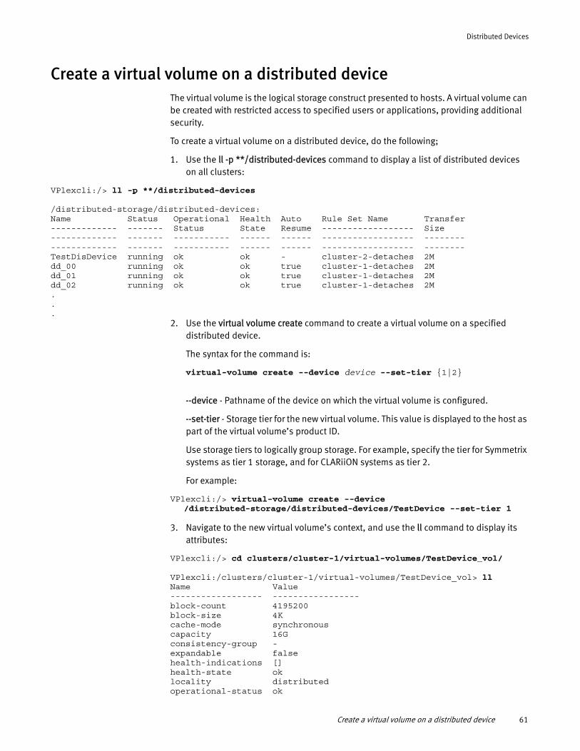
Distributed Devices
Create a virtual volume on a distributed deviceThe virtual volume is the logical storage construct presented to hosts. A virtual volume can be created with restricted access to specified users or applications, providing additional security.
To create a virtual volume on a distributed device, do the following;
1. Use the ll -p **/distributed-devices command to display a list of distributed devices on all clusters:
VPlexcli:/> ll -p **/distributed-devices
/distributed-storage/distributed-devices:Name Status Operational Health Auto Rule Set Name Transfer------------- ------- Status State Resume ------------------ Size------------- ------- ----------- ------ ------ ------------------ --------------------- ------- ----------- ------ ------ ------------------ --------TestDisDevice running ok ok - cluster-2-detaches 2Mdd_00 running ok ok true cluster-1-detaches 2Mdd_01 running ok ok true cluster-1-detaches 2Mdd_02 running ok ok true cluster-1-detaches 2M...
2. Use the virtual volume create command to create a virtual volume on a specified distributed device.
The syntax for the command is:
virtual-volume create --device device --set-tier {1|2}
--device - Pathname of the device on which the virtual volume is configured.
--set-tier - Storage tier for the new virtual volume. This value is displayed to the host as part of the virtual volume’s product ID.
Use storage tiers to logically group storage. For example, specify the tier for Symmetrix systems as tier 1 storage, and for CLARiiON systems as tier 2.
For example:
VPlexcli:/> virtual-volume create --device /distributed-storage/distributed-devices/TestDevice --set-tier 1
3. Navigate to the new virtual volume’s context, and use the ll command to display its attributes:
VPlexcli:/> cd clusters/cluster-1/virtual-volumes/TestDevice_vol/
VPlexcli:/clusters/cluster-1/virtual-volumes/TestDevice_vol> llName Value------------------ -----------------block-count 4195200block-size 4Kcache-mode synchronouscapacity 16Gconsistency-group -expandable falsehealth-indications []health-state oklocality distributedoperational-status ok
Create a virtual volume on a distributed device 61
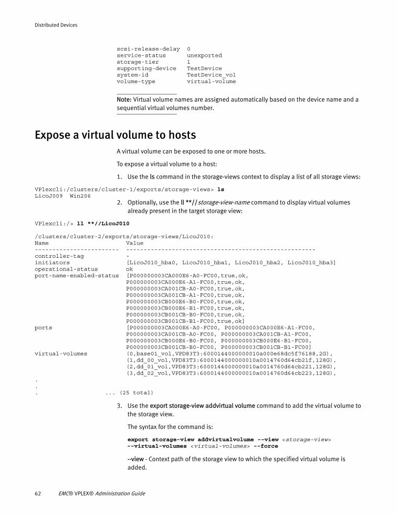
Distributed Devices
scsi-release-delay 0service-status unexportedstorage-tier 1supporting-device TestDevicesystem-id TestDevice_volvolume-type virtual-volume
Note: Virtual volume names are assigned automatically based on the device name and a sequential virtual volumes number.
Expose a virtual volume to hosts A virtual volume can be exposed to one or more hosts.
To expose a virtual volume to a host:
1. Use the ls command in the storage-views context to display a list of all storage views:
VPlexcli:/clusters/cluster-1/exports/storage-views> lsLicoJ009 Win206
2. Optionally, use the ll **//storage-view-name command to display virtual volumes already present in the target storage view:
VPlexcli:/> ll **//LicoJ010
/clusters/cluster-2/exports/storage-views/LicoJ010:Name Value------------------------ ------------------------------------------------------controller-tag -initiators [LicoJ010_hba0, LicoJ010_hba1, LicoJ010_hba2, LicoJ010_hba3]operational-status okport-name-enabled-status [P000000003CA000E6-A0-FC00,true,ok, P000000003CA000E6-A1-FC00,true,ok, P000000003CA001CB-A0-FC00,true,ok, P000000003CA001CB-A1-FC00,true,ok, P000000003CB000E6-B0-FC00,true,ok, P000000003CB000E6-B1-FC00,true,ok, P000000003CB001CB-B0-FC00,true,ok, P000000003CB001CB-B1-FC00,true,ok]ports [P000000003CA000E6-A0-FC00, P000000003CA000E6-A1-FC00, P000000003CA001CB-A0-FC00, P000000003CA001CB-A1-FC00, P000000003CB000E6-B0-FC00, P000000003CB000E6-B1-FC00, P000000003CB001CB-B0-FC00, P000000003CB001CB-B1-FC00]virtual-volumes (0,base01_vol,VPD83T3:6000144000000010a000e68dc5f76188,2G), (1,dd_00_vol,VPD83T3:6000144000000010a0014760d64cb21f,128G), (2,dd_01_vol,VPD83T3:6000144000000010a0014760d64cb221,128G), (3,dd_02_vol,VPD83T3:6000144000000010a0014760d64cb223,128G),... ... (25 total)
3. Use the export storage-view addvirtual volume command to add the virtual volume to the storage view.
The syntax for the command is:
export storage-view addvirtualvolume --view <storage-view> --virtual-volumes <virtual-volumes> --force
--view - Context path of the storage view to which the specified virtual volume is added.
62 EMC® VPLEX® Administration Guide
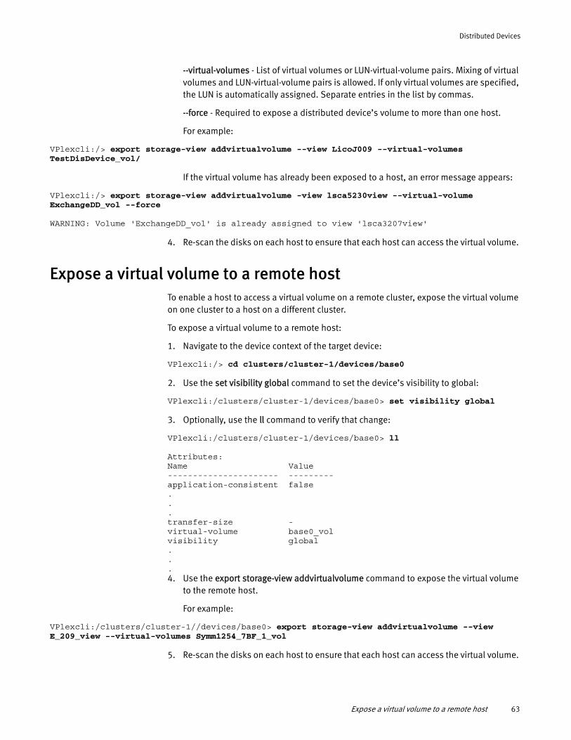
Distributed Devices
--virtual-volumes - List of virtual volumes or LUN-virtual-volume pairs. Mixing of virtual volumes and LUN-virtual-volume pairs is allowed. If only virtual volumes are specified, the LUN is automatically assigned. Separate entries in the list by commas.
--force - Required to expose a distributed device’s volume to more than one host.
For example:
VPlexcli:/> export storage-view addvirtualvolume --view LicoJ009 --virtual-volumes TestDisDevice_vol/
If the virtual volume has already been exposed to a host, an error message appears:
VPlexcli:/> export storage-view addvirtualvolume -view lsca5230view --virtual-volume ExchangeDD_vol --force
WARNING: Volume 'ExchangeDD_vol' is already assigned to view 'lsca3207view'
4. Re-scan the disks on each host to ensure that each host can access the virtual volume.
Expose a virtual volume to a remote hostTo enable a host to access a virtual volume on a remote cluster, expose the virtual volume on one cluster to a host on a different cluster.
To expose a virtual volume to a remote host:
1. Navigate to the device context of the target device:
VPlexcli:/> cd clusters/cluster-1/devices/base0
2. Use the set visibility global command to set the device’s visibility to global:
VPlexcli:/clusters/cluster-1/devices/base0> set visibility global
3. Optionally, use the ll command to verify that change:
VPlexcli:/clusters/cluster-1/devices/base0> ll
Attributes:Name Value---------------------- ---------application-consistent false...transfer-size -virtual-volume base0_volvisibility global...4. Use the export storage-view addvirtualvolume command to expose the virtual volume
to the remote host.
For example:
VPlexcli:/clusters/cluster-1//devices/base0> export storage-view addvirtualvolume --view E_209_view --virtual-volumes Symm1254_7BF_1_vol
5. Re-scan the disks on each host to ensure that each host can access the virtual volume.
Expose a virtual volume to a remote host 63
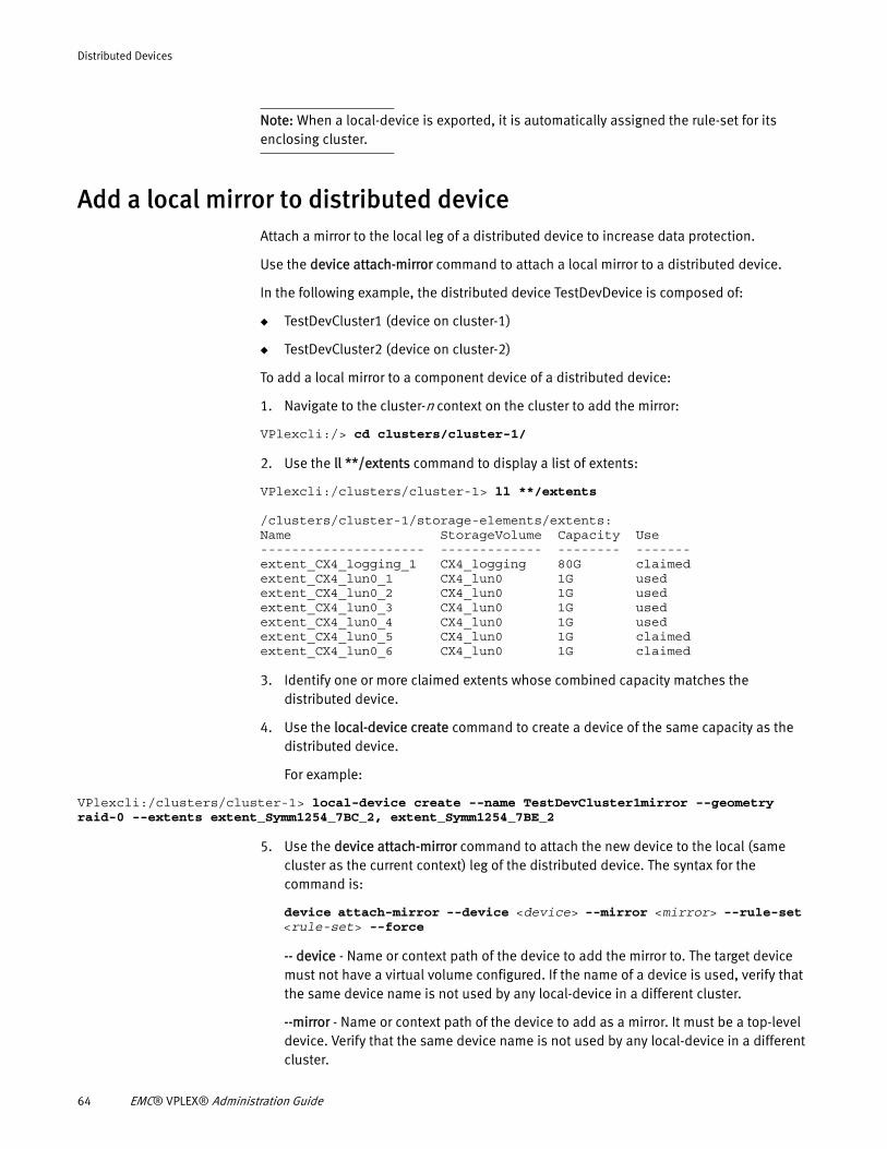
Distributed Devices
Note: When a local-device is exported, it is automatically assigned the rule-set for its enclosing cluster.
Add a local mirror to distributed deviceAttach a mirror to the local leg of a distributed device to increase data protection.
Use the device attach-mirror command to attach a local mirror to a distributed device.
In the following example, the distributed device TestDevDevice is composed of:
◆ TestDevCluster1 (device on cluster-1)
◆ TestDevCluster2 (device on cluster-2)
To add a local mirror to a component device of a distributed device:
1. Navigate to the cluster-n context on the cluster to add the mirror:
VPlexcli:/> cd clusters/cluster-1/
2. Use the ll **/extents command to display a list of extents:
VPlexcli:/clusters/cluster-1> ll **/extents
/clusters/cluster-1/storage-elements/extents:Name StorageVolume Capacity Use--------------------- ------------- -------- -------extent_CX4_logging_1 CX4_logging 80G claimedextent_CX4_lun0_1 CX4_lun0 1G usedextent_CX4_lun0_2 CX4_lun0 1G usedextent_CX4_lun0_3 CX4_lun0 1G usedextent_CX4_lun0_4 CX4_lun0 1G usedextent_CX4_lun0_5 CX4_lun0 1G claimedextent_CX4_lun0_6 CX4_lun0 1G claimed
3. Identify one or more claimed extents whose combined capacity matches the distributed device.
4. Use the local-device create command to create a device of the same capacity as the distributed device.
For example:
VPlexcli:/clusters/cluster-1> local-device create --name TestDevCluster1mirror --geometry raid-0 --extents extent_Symm1254_7BC_2, extent_Symm1254_7BE_2
5. Use the device attach-mirror command to attach the new device to the local (same cluster as the current context) leg of the distributed device. The syntax for the command is:
device attach-mirror --device <device> --mirror <mirror> --rule-set <rule-set> --force
-- device - Name or context path of the device to add the mirror to. The target device must not have a virtual volume configured. If the name of a device is used, verify that the same device name is not used by any local-device in a different cluster.
--mirror - Name or context path of the device to add as a mirror. It must be a top-level device. Verify that the same device name is not used by any local-device in a different cluster.
64 EMC® VPLEX® Administration Guide
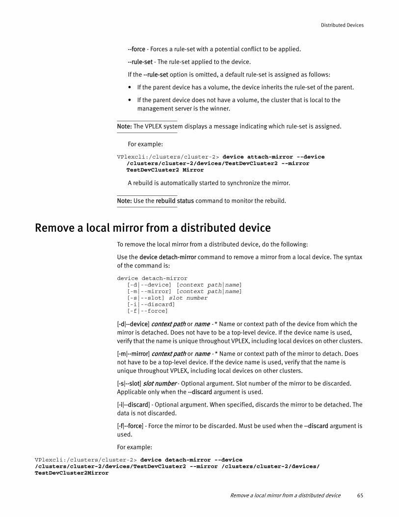
Distributed Devices
--force - Forces a rule-set with a potential conflict to be applied.
--rule-set - The rule-set applied to the device.
If the --rule-set option is omitted, a default rule-set is assigned as follows:
• If the parent device has a volume, the device inherits the rule-set of the parent.
• If the parent device does not have a volume, the cluster that is local to the management server is the winner.
Note: The VPLEX system displays a message indicating which rule-set is assigned.
For example:
VPlexcli:/clusters/cluster-2> device attach-mirror --device /clusters/cluster-2/devices/TestDevCluster2 --mirror TestDevCluster2 Mirror
A rebuild is automatically started to synchronize the mirror.
Note: Use the rebuild status command to monitor the rebuild.
Remove a local mirror from a distributed deviceTo remove the local mirror from a distributed device, do the following:
Use the device detach-mirror command to remove a mirror from a local device. The syntax of the command is:
device detach-mirror [-d|--device] [context path|name][-m|--mirror] [context path|name][-s|--slot] slot number[-i|--discard][-f|--force]
[-d|--device] context path or name - * Name or context path of the device from which the mirror is detached. Does not have to be a top-level device. If the device name is used, verify that the name is unique throughout VPLEX, including local devices on other clusters.
[-m|--mirror] context path or name - * Name or context path of the mirror to detach. Does not have to be a top-level device. If the device name is used, verify that the name is unique throughout VPLEX, including local devices on other clusters.
[-s|--slot] slot number - Optional argument. Slot number of the mirror to be discarded. Applicable only when the --discard argument is used.
[-i|--discard] - Optional argument. When specified, discards the mirror to be detached. The data is not discarded.
[-f|--force] - Force the mirror to be discarded. Must be used when the --discard argument is used.
For example:
VPlexcli:/clusters/cluster-2> device detach-mirror --device /clusters/cluster-2/devices/TestDevCluster2 --mirror /clusters/cluster-2/devices/ TestDevCluster2Mirror
Remove a local mirror from a distributed device 65
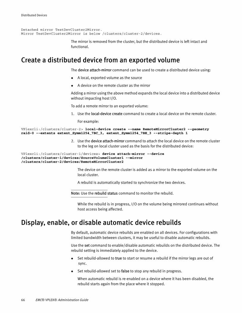
Distributed Devices
Detached mirror TestDevCluster2Mirror.Mirror TestDevCluster2Mirror is below /clusters/cluster-2/devices.
The mirror is removed from the cluster, but the distributed device is left intact and functional.
Create a distributed device from an exported volumeThe device attach-mirror command can be used to create a distributed device using:
◆ A local, exported volume as the source
◆ A device on the remote cluster as the mirror
Adding a mirror using the above method expands the local device into a distributed device without impacting host I/O.
To add a remote mirror to an exported volume:
1. Use the local-device create command to create a local device on the remote cluster.
For example:
VPlexcli:/clusters/cluster-2> local-device create --name RemoteMirrorCluster2 --geometry raid-0 --extents extent_Symm1254_7BC_3, extent_Symm1254_7BE_3 --stripe-depth 1
2. Use the device attach-mirror command to attach the local device on the remote cluster to the leg on local cluster used as the basis for the distributed device:
VPlexcli:/clusters/cluster-1/devices> device attach-mirror --device /clusters/cluster-1/devices/SourceVolumeCluster1 --mirror /clusters/cluster-2/devices/RemoteMirrorCluster2
The device on the remote cluster is added as a mirror to the exported volume on the local cluster.
A rebuild is automatically started to synchronize the two devices.
Note: Use the rebuild status command to monitor the rebuild.
While the rebuild is in progress, I/O on the volume being mirrored continues without host access being affected.
Display, enable, or disable automatic device rebuildsBy default, automatic device rebuilds are enabled on all devices. For configurations with limited bandwidth between clusters, it may be useful to disable automatic rebuilds.
Use the set command to enable/disable automatic rebuilds on the distributed device. The rebuild setting is immediately applied to the device.
◆ Set rebuild-allowed to true to start or resume a rebuild if the mirror legs are out of sync.
◆ Set rebuild-allowed set to false to stop any rebuild in progress.
When automatic rebuild is re-enabled on a device where it has been disabled, the rebuild starts again from the place where it stopped.
66 EMC® VPLEX® Administration Guide
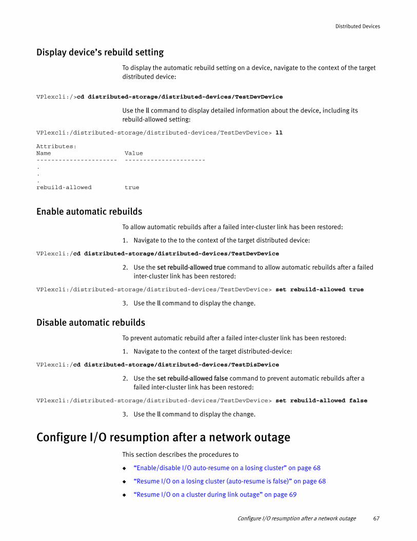
Distributed Devices
Display device’s rebuild setting
To display the automatic rebuild setting on a device, navigate to the context of the target
distributed device:
VPlexcli:/>cd distributed-storage/distributed-devices/TestDevDevice
Use the ll command to display detailed information about the device, including its rebuild-allowed setting:
VPlexcli:/distributed-storage/distributed-devices/TestDevDevice> ll
Attributes:Name Value---------------------- ----------------------...rebuild-allowed true
Enable automatic rebuilds
To allow automatic rebuilds after a failed inter-cluster link has been restored:
1. Navigate to the to the context of the target distributed device:
VPlexcli:/cd distributed-storage/distributed-devices/TestDevDevice
2. Use the set rebuild-allowed true command to allow automatic rebuilds after a failed inter-cluster link has been restored:
VPlexcli:/distributed-storage/distributed-devices/TestDevDevice> set rebuild-allowed true
3. Use the ll command to display the change.
Disable automatic rebuilds
To prevent automatic rebuild after a failed inter-cluster link has been restored:
1. Navigate to the context of the target distributed-device:
VPlexcli:/cd distributed-storage/distributed-devices/TestDisDevice
2. Use the set rebuild-allowed false command to prevent automatic rebuilds after a failed inter-cluster link has been restored:
VPlexcli:/distributed-storage/distributed-devices/TestDevDevice> set rebuild-allowed false
3. Use the ll command to display the change.
Configure I/O resumption after a network outageThis section describes the procedures to
◆ “Enable/disable I/O auto-resume on a losing cluster” on page 68
◆ “Resume I/O on a losing cluster (auto-resume is false)” on page 68
◆ “Resume I/O on a cluster during link outage” on page 69
Configure I/O resumption after a network outage 67
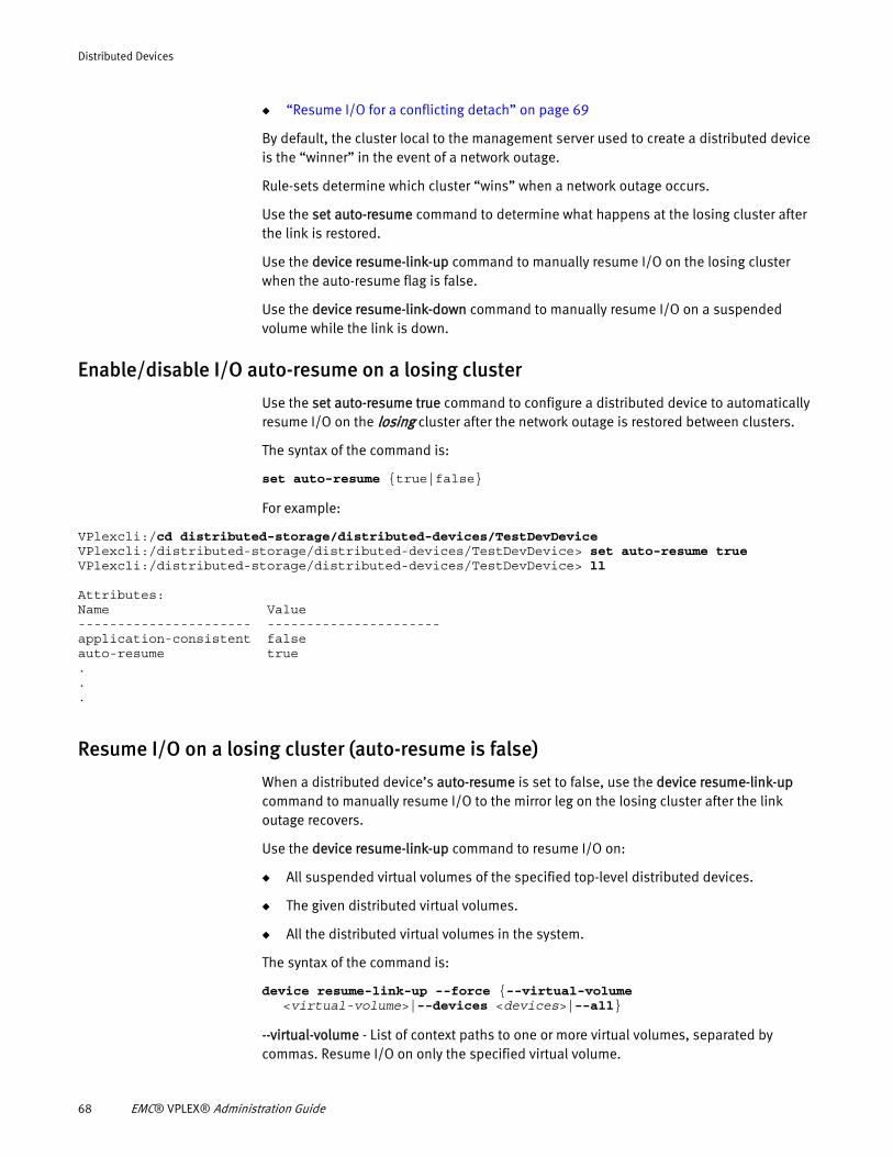
Distributed Devices
◆ “Resume I/O for a conflicting detach” on page 69
By default, the cluster local to the management server used to create a distributed device is the “winner” in the event of a network outage.
Rule-sets determine which cluster “wins” when a network outage occurs.
Use the set auto-resume command to determine what happens at the losing cluster after the link is restored.
Use the device resume-link-up command to manually resume I/O on the losing cluster when the auto-resume flag is false.
Use the device resume-link-down command to manually resume I/O on a suspended volume while the link is down.
Enable/disable I/O auto-resume on a losing cluster
Use the set auto-resume true command to configure a distributed device to automatically resume I/O on the losing cluster after the network outage is restored between clusters.
The syntax of the command is:
set auto-resume {true|false}
For example:
VPlexcli:/cd distributed-storage/distributed-devices/TestDevDeviceVPlexcli:/distributed-storage/distributed-devices/TestDevDevice> set auto-resume trueVPlexcli:/distributed-storage/distributed-devices/TestDevDevice> ll
Attributes:Name Value---------------------- ----------------------application-consistent falseauto-resume true...
Resume I/O on a losing cluster (auto-resume is false)
When a distributed device’s auto-resume is set to false, use the device resume-link-up command to manually resume I/O to the mirror leg on the losing cluster after the link outage recovers.
Use the device resume-link-up command to resume I/O on:
◆ All suspended virtual volumes of the specified top-level distributed devices.
◆ The given distributed virtual volumes.
◆ All the distributed virtual volumes in the system.
The syntax of the command is:
device resume-link-up --force {--virtual-volume <virtual-volume>|--devices <devices>|--all}
--virtual-volume - List of context paths to one or more virtual volumes, separated by commas. Resume I/O on only the specified virtual volume.
68 EMC® VPLEX® Administration Guide
Distributed Devices
--devices - List of context paths to one or more top-level devices, separated by commas. Resume I/O on only the specified top level device.
--all - Resume I/O on all virtual volumes of the losing clusters.
--force - Forces I/O to resume.
For example:
VPlexcli:/distributed-storage/distributed-devices> device resume-link-up --devices DDte_4a –-force
Resume I/O on a cluster during link outage
The device resume-link-down command causes I/O to resume on the local cluster regardless of any rule-sets applied to the device. Verify that rules and any manual detaches do not result in conflicting detaches (cluster-1 detaching cluster-2, and cluster-2 detaching cluster-1). Conflicting detaches will result in data loss on the losing cluster, a full rebuild, and degraded access during the time of the full rebuild.
Use the device resume-link-down command to resume I/O to the mirror leg of distributed devices during a link outage.
Be careful not to introduce a conflicted detach by allowing both legs of distributed devices to independently resume I/O.
The syntax for the command is:
device resume-link-down {--all-at-island|--cluster <context-path>|--devices <context-path,context-path>} --force
--all-at-island - Resumes I/O on all devices on the chosen winning cluster and the clusters with which it is in communication.
--cluster - Context path to a cluster. Resumes I/O on the specified cluster and the clusters it is in communication with during a link outage. Necessary only when the all-at-island flag or distributed devices are specified. Not required for local devices with global visibility.
--devices - List of context paths to one or more top-level devices, separated by commas. Resumes I/O for the specified devices.
--force - Forces I/O to resume.
For example:
VPlexcli:/distributed-storage/distributed-devices> device resume-link-down --all-at-island --cluster --devices DD_5d --force
Resume I/O for a conflicting detach
When a conflicting detach occurs, use the ds dd declare-winner command to manually designate the winning cluster.
Configure I/O resumption after a network outage 69
Distributed Devices
When the link is restored, the leg on the losing cluster is rebuilt from the leg on the winning cluster.
The syntax for the command is:
ds dd declare-winner --distributed-device <distributed-device> --cluster <cluster> --force
--distributed-device - Specifies the distributed-device to which the winning cluster is declared.
--cluster - Specifies the winning cluster.
--force - Forces the 'declare-winner' command to be issued.
For example:
VPlexcli:/distributed-storage/distributed-devices> ds dd declare-winner --distributed-device DDtest_4 –-cluster cluster-2
Handling mirror performance degradation RAID-1 devices provide redundancy by replicating data across a mirror. In write-through mode, this is achieved by persisting all writes to all mirror legs of a RAID-1 (local or distributed) device to the backend storage-volume, before acknowledging to the host.
70 EMC® VPLEX® Administration Guide
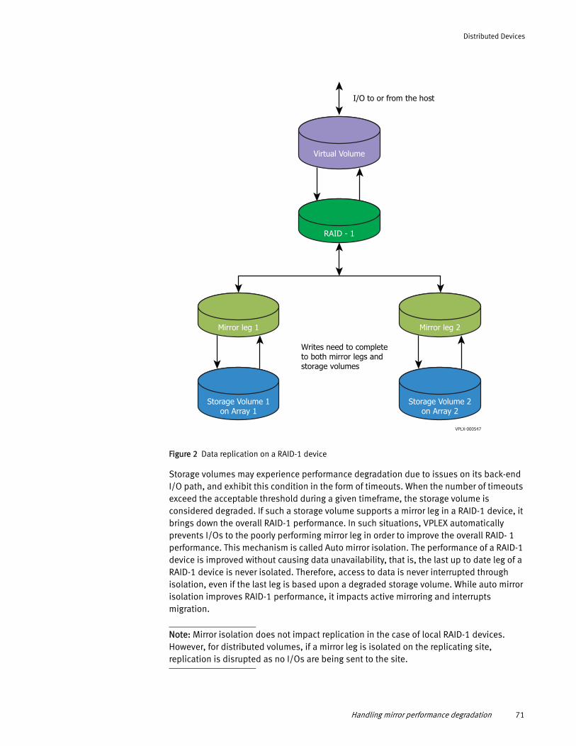
Distributed Devices
Figure 2 Data replication on a RAID-1 device
Storage volumes may experience performance degradation due to issues on its back-end I/O path, and exhibit this condition in the form of timeouts. When the number of timeouts exceed the acceptable threshold during a given timeframe, the storage volume is considered degraded. If such a storage volume supports a mirror leg in a RAID-1 device, it brings down the overall RAID-1 performance. In such situations, VPLEX automatically prevents I/Os to the poorly performing mirror leg in order to improve the overall RAID- 1 performance. This mechanism is called Auto mirror isolation. The performance of a RAID-1 device is improved without causing data unavailability, that is, the last up to date leg of a RAID-1 device is never isolated. Therefore, access to data is never interrupted through isolation, even if the last leg is based upon a degraded storage volume. While auto mirror isolation improves RAID-1 performance, it impacts active mirroring and interrupts migration.
Note: Mirror isolation does not impact replication in the case of local RAID-1 devices. However, for distributed volumes, if a mirror leg is isolated on the replicating site, replication is disrupted as no I/Os are being sent to the site.
I/O to or from the host
Virtual Volume
RAID - 1
Writes need to completeto both mirror legs and storage volumes
Storage Volume 1on Array 1
Mirror leg 1
Storage Volume 2on Array 2
Mirror leg 2
VPLX-000547
Handling mirror performance degradation 71
Distributed Devices
“Storage volume degradation” provides more information on storage volume performance degradation.
Geometries supported
The following geometries are impacted:
◆ Local or Distributed RAID-1s
◆ RAID-1s created from:
• Storage Volumes (System volumes such as meta volumes)
• Extents (Simple RAID-1)
• RAID-0, RAID-1, RAID-C devices (multi-tiered RAID-1)
Note: Logging volumes does not support mirror isolation.
Storage volume degradationVPLEX monitors and tracks the SCSI aborts and timeouts per storage volume per director. A storage volume is declared as degraded when it experiences more than eight abort or timeouts reported on a storage volume during two consecutive 3 minute periods. VPLEX issues a call-home notification and marks the storage volume as “degraded”.
A storage volume can experience performance degradation in the form of timeouts and aborts due to various reasons. The following are some possible scenarios (although not a complete list):
◆ A single degraded storage volume indicating a faulty LUN.
◆ Multiple degraded storage volumes on the same array indicating a possible array issue.
◆ Multiple degraded storage volumes as seen from multiple directors on multiple arrays, which might point to a backend SAN issue.
◆ Multiple degraded storage volumes as seen from a single director, which might point to director's Initiator-Target connection at fault.
72 EMC® VPLEX® Administration Guide
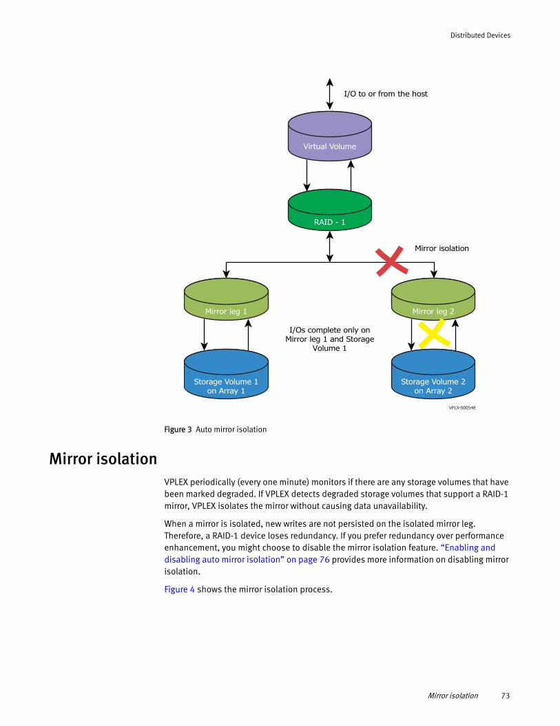
Distributed Devices
Figure 3 Auto mirror isolation
Mirror isolationVPLEX periodically (every one minute) monitors if there are any storage volumes that have been marked degraded. If VPLEX detects degraded storage volumes that support a RAID-1 mirror, VPLEX isolates the mirror without causing data unavailability.
When a mirror is isolated, new writes are not persisted on the isolated mirror leg. Therefore, a RAID-1 device loses redundancy. If you prefer redundancy over performance enhancement, you might choose to disable the mirror isolation feature. “Enabling and disabling auto mirror isolation” on page 76 provides more information on disabling mirror isolation.
Figure 4 shows the mirror isolation process.
I/Os complete only onMirror leg 1 and Storage
Volume 1
I/O to or from the host
Virtual Volume
RAID - 1
Storage Volume 1on Array 1
Mirror leg 1
Storage Volume 2on Array 2
Mirror leg 2
VPLX-000548
Mirror isolation
Mirror isolation 73
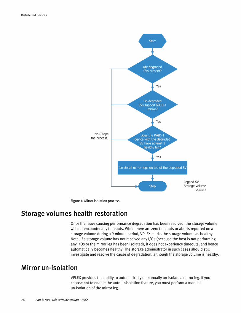
Distributed Devices
Figure 4 Mirror isolation process
Storage volumes health restorationOnce the issue causing performance degradation has been resolved, the storage volume will not encounter any timeouts. When there are zero timeouts or aborts reported on a storage volume during a 9 minute period, VPLEX marks the storage volume as healthy. Note, if a storage volume has not received any I/Os (because the host is not performing any I/Os or the mirror leg has been isolated), it does not experience timeouts, and hence automatically becomes healthy. The storage administrator in such cases should still investigate and resolve the cause of degradation, although the storage volume is healthy.
Mirror un-isolationVPLEX provides the ability to automatically or manually un-isolate a mirror leg. If you choose not to enable the auto-unisolation feature, you must perform a manual un-isolation of the mirror leg.
Start
Do degradedSVs support RAID-1
mirror?
Does the RAID-1device with the degraded
SV have at least 1healthy leg?
Are degradedSVs present?
Isolate all mirror legs on top of the degraded SV
Stop
Yes
Yes
Yes
VPLX-000549
No (Stopsthe process)
Legend SV - Storage Volume
74 EMC® VPLEX® Administration Guide
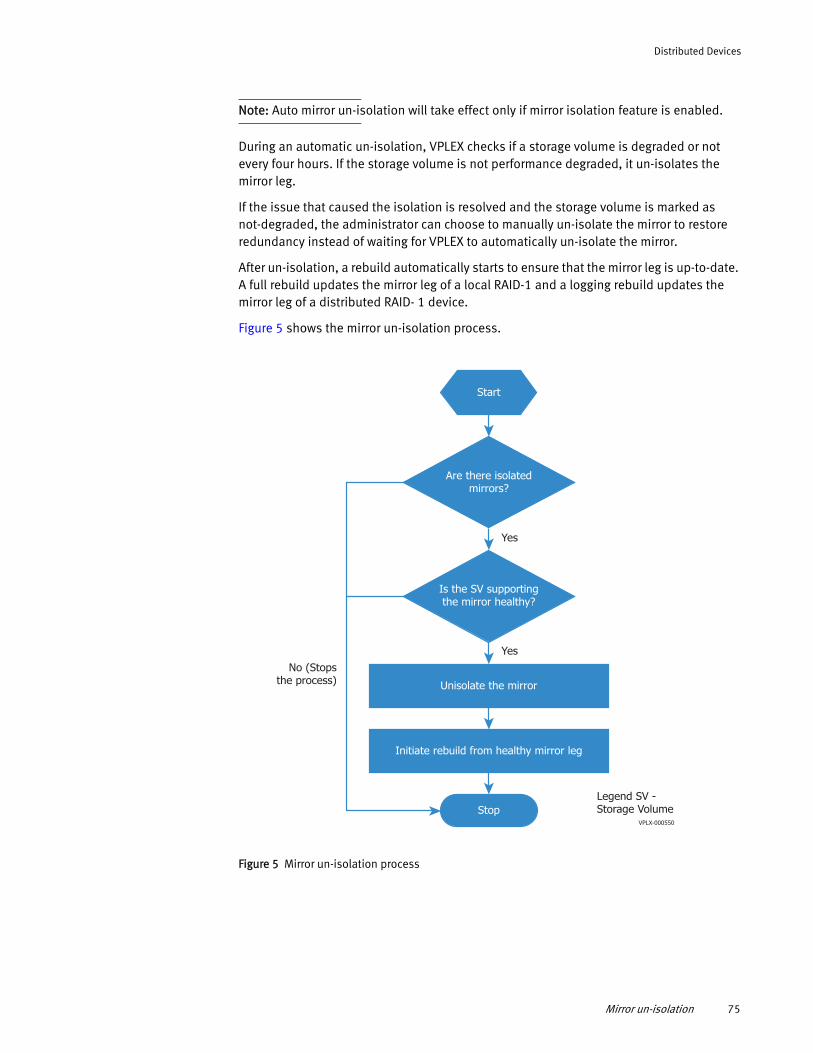
Distributed Devices
Note: Auto mirror un-isolation will take effect only if mirror isolation feature is enabled.
During an automatic un-isolation, VPLEX checks if a storage volume is degraded or not every four hours. If the storage volume is not performance degraded, it un-isolates the mirror leg.
If the issue that caused the isolation is resolved and the storage volume is marked as not-degraded, the administrator can choose to manually un-isolate the mirror to restore redundancy instead of waiting for VPLEX to automatically un-isolate the mirror.
After un-isolation, a rebuild automatically starts to ensure that the mirror leg is up-to-date. A full rebuild updates the mirror leg of a local RAID-1 and a logging rebuild updates the mirror leg of a distributed RAID- 1 device.
Figure 5 shows the mirror un-isolation process.
Figure 5 Mirror un-isolation process
Start
Is the SV supportingthe mirror healthy?
Are there isolatedmirrors?
Initiate rebuild from healthy mirror leg
Unisolate the mirror
Stop
Yes
Yes
VPLX-000550
No (Stopsthe process)
Legend SV - Storage Volume
Mirror un-isolation 75
Distributed Devices
Enabling and disabling auto mirror isolationThe mirror isolation feature is disabled by default, unless explicitly stated otherwise in the release notes. You can decide to enable or disable the mirror isolation feature any time, if you prefer redundancy over performance, or for other reasons, after consulting EMC customer support.
You can enable or disable auto mirror isolation using the VPLEX CLI.
To enable auto mirror isolation, use the device mirror-isolation enable command.
To disable auto mirror isolation, use the device mirror-isolation disable command.
The VPLEX CLI Guide provides information on the commands and their usage.
Enabling and disabling auto mirror un-isolationThe auto mirror un-isolation feature is enabled by default, unless explicitly stated otherwise in the release notes. You can decide to disable this feature any time, if you prefer to always make the manual decision to un-isolate a mirror.
You can enable or disable auto mirror un-isolation using the VPLEX CLI.
To enable auto mirror un-isolation, use the device mirror-isolation auto-unisolation enable command.
To disable auto mirror un-isolation, use the device mirror-isolation auto-unisolation disable command.
The VPLEX CLI Guide provides information on the commands and their usage.
76 EMC® VPLEX® Administration Guide
CHAPTER 5Provisioning Storage
This chapter describes the following topics:
◆ Provisioning Overview............................................................................................. 77◆ About VPLEX integrated storage provisioning .......................................................... 77◆ Provisioning storage using VIAS .............................................................................. 78◆ Provisioning storage using EZ provisioning.............................................................. 84◆ Provisioning storage using advanced provisioning................................................... 85
Provisioning OverviewTo begin using VPLEX, you must provision storage so that hosts can access that storage. There are three ways to provision storage on VPLEX:
◆ Integrated storage provisioning (VPLEX integrated array service based provisioning)
◆ EZ provisioning
◆ Advanced provisioning
Note: EMC recommends using the VPLEX Unisphere GUI to provision storage.
About VPLEX integrated storage provisioningThe VPLEX Integrated Array Service (VIAS) feature provides VPLEX a medium to interact with EMC arrays that support integrated services to enable provisioning storage. VPLEX uses Array Management Providers (AMPs) to streamline provisioning, and allows you to provision a VPLEX virtual volume from a pool on the array.
Note: For supported array information, see EMC Simplified Support Matrix for VPLEX.
The VIAS feature uses the Storage Management Initiative -Specification (SMI-S) provider to communicate with the arrays that support integrated services to enable provisioning. An SMI-S provider must be installed and configured correctly on the same storage area network as VPLEX, and both VPLEX and the SMI-S provider must be configured on the same arrays. After SMI-S is configured, you can register SMI-S as the AMP with VPLEX using the CLI or the Unisphere GUI. After the registration is complete, the managed arrays and pools on the array are visible, and you can provision virtual volumes from those pools. The pools used for provisioning must be created on the array. VIAS does not create the pools for provisioning.
The EMC SMI-S Provider Release Notes provides more information on installing the SMI-S Provider.
Figure 6 illustrates the provisioning and exporting process using VIAS. Provisioning and exporting storage refers to taking storage from a storage array and making it visible to a host.
Provisioning Storage 77
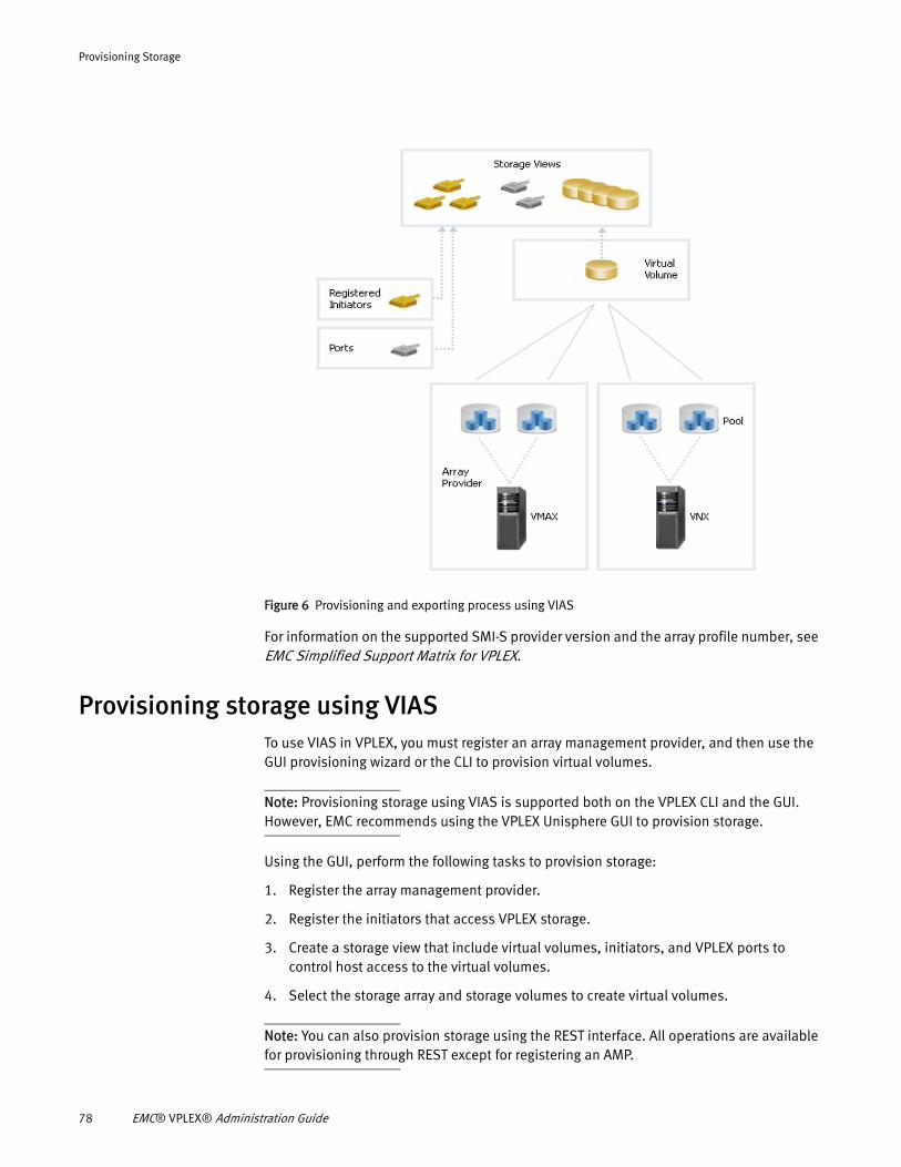
Provisioning Storage
Figure 6 Provisioning and exporting process using VIAS
For information on the supported SMI-S provider version and the array profile number, see EMC Simplified Support Matrix for VPLEX.
Provisioning storage using VIAS To use VIAS in VPLEX, you must register an array management provider, and then use the GUI provisioning wizard or the CLI to provision virtual volumes.
Note: Provisioning storage using VIAS is supported both on the VPLEX CLI and the GUI. However, EMC recommends using the VPLEX Unisphere GUI to provision storage.
Using the GUI, perform the following tasks to provision storage:
1. Register the array management provider.
2. Register the initiators that access VPLEX storage.
3. Create a storage view that include virtual volumes, initiators, and VPLEX ports to control host access to the virtual volumes.
4. Select the storage array and storage volumes to create virtual volumes.
Note: You can also provision storage using the REST interface. All operations are available for provisioning through REST except for registering an AMP.
78 EMC® VPLEX® Administration Guide
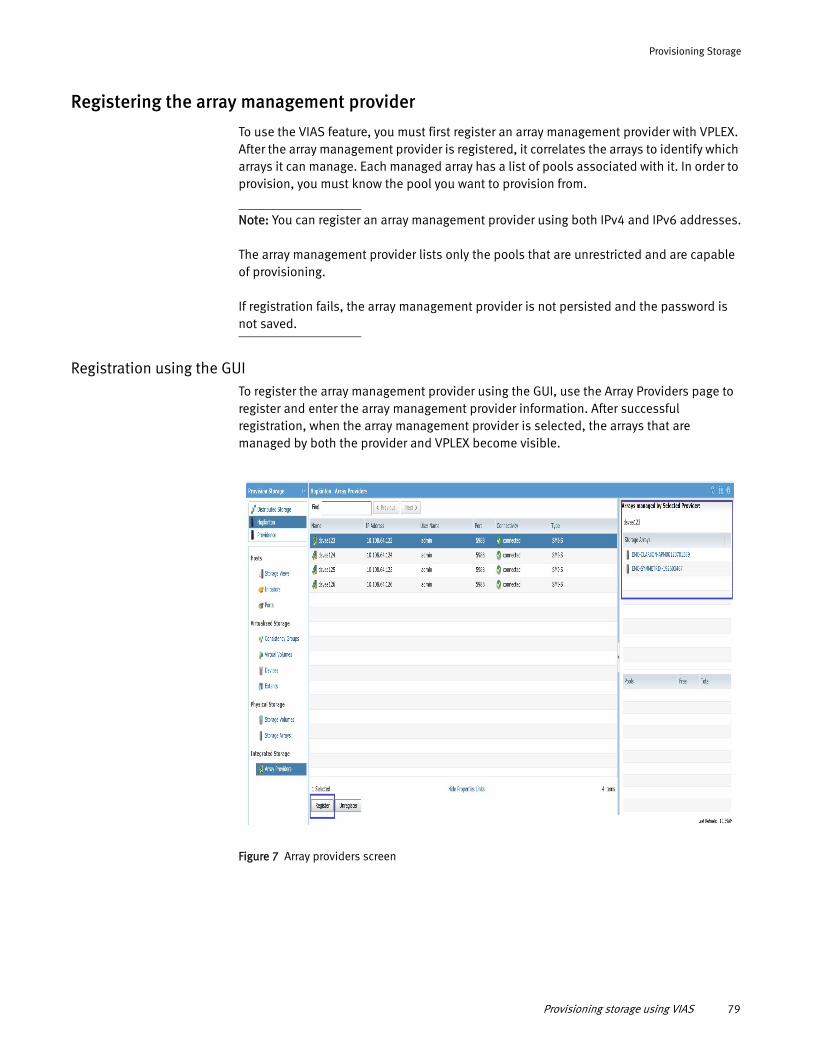
Provisioning Storage
Registering the array management provider
To use the VIAS feature, you must first register an array management provider with VPLEX. After the array management provider is registered, it correlates the arrays to identify which arrays it can manage. Each managed array has a list of pools associated with it. In order to provision, you must know the pool you want to provision from.
Note: You can register an array management provider using both IPv4 and IPv6 addresses.
The array management provider lists only the pools that are unrestricted and are capable of provisioning.
If registration fails, the array management provider is not persisted and the password is not saved.
Registration using the GUITo register the array management provider using the GUI, use the Array Providers page to register and enter the array management provider information. After successful registration, when the array management provider is selected, the arrays that are managed by both the provider and VPLEX become visible.
Figure 7 Array providers screen
Provisioning storage using VIAS 79
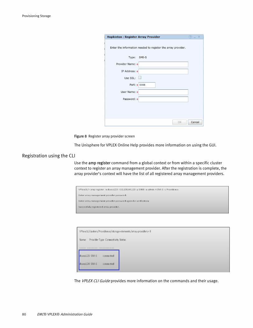
Provisioning Storage
Figure 8 Register array provider screen
The Unisphere for VPLEX Online Help provides more information on using the GUI.
Registration using the CLIUse the amp register command from a global context or from within a specific cluster context to register an array management provider. After the registration is complete, the array provider’s context will have the list of all registered array management providers.
The VPLEX CLI Guide provides more information on the commands and their usage.
80 EMC® VPLEX® Administration Guide
Provisioning Storage
Array correlation and managed arraysAfter an array management provider is registered, the arrays that are managed by both VPLEX and the array management provider are visible. Only the arrays configured to both VPLEX and the array management provider are considered managed. The arrays managed by the array management provider that are not configured to VPLEX are not visible in VPLEX. An array has to be configured correctly for it to be discovered as a managed array. The GUI automatically polls every 3 minutes to correlate new managed arrays. In the CLI, you must manually refresh using the ls –l command in the managed arrays context.
Registering redundant array management providersIt is not a best practice to register multiple array management providers even though the capability to register multiple array management providers exists.
You cannot register the same array management provider on a cluster. However, it is possible to register an array management provider that is managing the same arrays as an array management provider already registered. This means that you must have two array management providers that are managing the same arrays.
VIAS lists the managed arrays for only one of the two array management providers. The managed arrays are listed only under the array management provider registered first. The other provider does not list any arrays under managed arrays.
Unregistering an array management providerBefore unregistering an array management provider, ensure that all arrays associated with the provider are no longer in use and are unregistered. After the array management provider is unregistered, VPLEX removes all references to the array management provider, and it is no longer listed.
Note: An array management provider cannot be unregistered if there is a provisioning or de-provisioning action in progress.
Updating array management provider credentialsIf the array management providers’ credentials change on the back end array, you must unregister and register the array management provider again.
Updating array management provider IP address◆ If the array management providers' IP address changes, you must unregister and
register the array management provider again.
◆ If the array management providers’ IP address is changed from an IPv4 address to an IPv6 address, you must unregister and register the array management provider again.
Pool listingThe array management provider does not list all the pools from an array. Only the pools that are unrestricted and are capable of provisioning LUNs are listed. For example, primordial pools and restricted pools are not listed because they cannot have LUNs directly provisioned from them.
Provisioning storage using VIAS 81
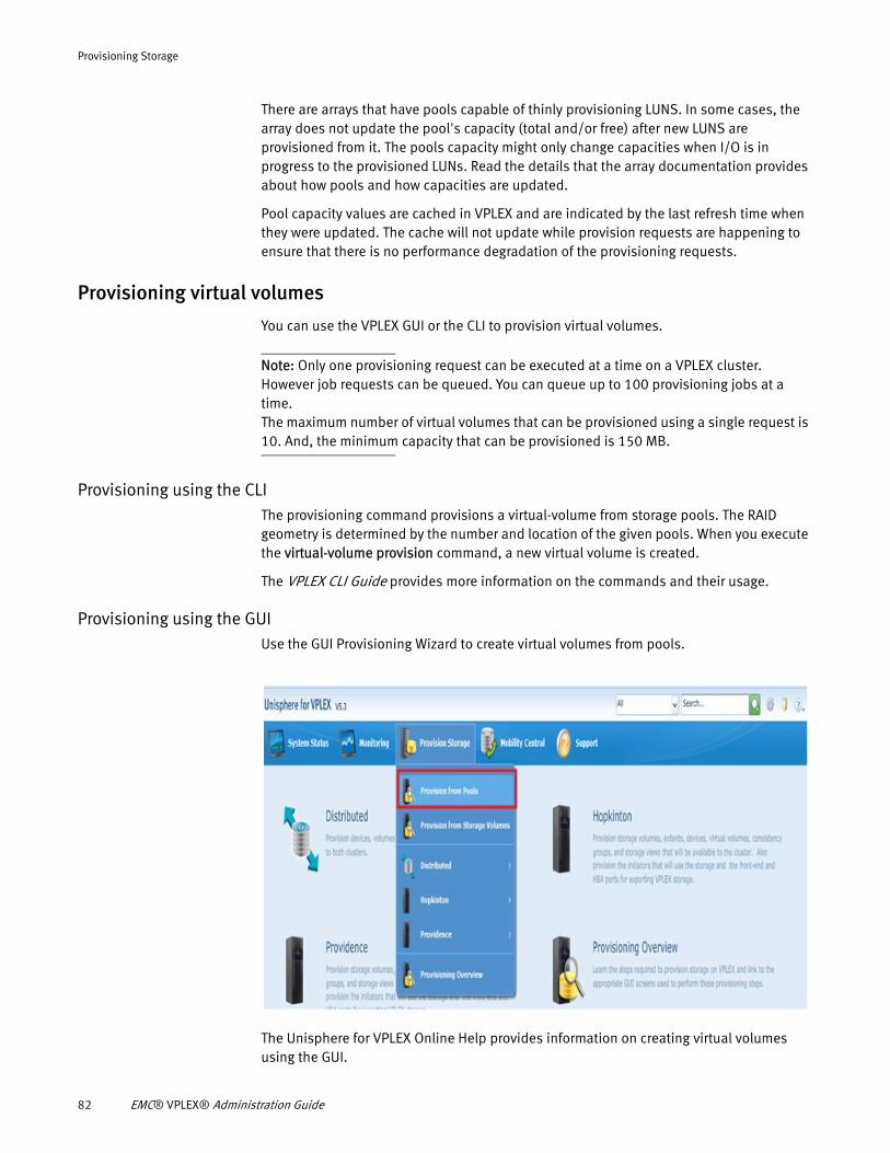
Provisioning Storage
There are arrays that have pools capable of thinly provisioning LUNS. In some cases, the array does not update the pool's capacity (total and/or free) after new LUNS are provisioned from it. The pools capacity might only change capacities when I/O is in progress to the provisioned LUNs. Read the details that the array documentation provides about how pools and how capacities are updated.
Pool capacity values are cached in VPLEX and are indicated by the last refresh time when they were updated. The cache will not update while provision requests are happening to ensure that there is no performance degradation of the provisioning requests.
Provisioning virtual volumes
You can use the VPLEX GUI or the CLI to provision virtual volumes.
Note: Only one provisioning request can be executed at a time on a VPLEX cluster. However job requests can be queued. You can queue up to 100 provisioning jobs at a time.The maximum number of virtual volumes that can be provisioned using a single request is 10. And, the minimum capacity that can be provisioned is 150 MB.
Provisioning using the CLIThe provisioning command provisions a virtual-volume from storage pools. The RAID geometry is determined by the number and location of the given pools. When you execute the virtual-volume provision command, a new virtual volume is created.
The VPLEX CLI Guide provides more information on the commands and their usage.
Provisioning using the GUIUse the GUI Provisioning Wizard to create virtual volumes from pools.
The Unisphere for VPLEX Online Help provides information on creating virtual volumes using the GUI.
82 EMC® VPLEX® Administration Guide
Provisioning Storage
Provisioning jobsProvisioning requests are executed as jobs. In the GUI, the job listings are available under Monitoring > Provision Jobs and in the CLI, under notification/jobs. The Provisioning jobs are queued and can be in the state in-progress, failed, completed, or canceled.
Note the following:
◆ During a provisioning request, it might take several minutes for the job ID to be returned. In the GUI, the provisioning wizard will display an in progress icon until the job ID is ready. The same is applicable for the CLI, it might take several minutes for the job ID to be displayed.
◆ Regardless of the number of LUNs provisioned, the rediscovery of the array happens only once per array after all the LUNs have been provisioned and exposed to VPLEX.
◆ The maximum number of jobs that can be queued are 100. The queue limit of 100 jobs does not include canceled jobs.
◆ The automatic provisioning job deletion only deletes completed and failed jobs. The jobs are deleted after seven days. In- Progress and canceled jobs must be manually deleted.
◆ The local jobs are executed even if the remote cluster fails.
◆ In a scenario where one cluster fails, the DR1 provisioning requests stay queued until the other cluster is reachable.
◆ There are different timers that are executed at each level of a provisioning request. When a cluster fails or an AMP becomes unreachable, a timeout occurs. In the event of a timeout, provisioning requests fail with the message “futures timeout”.
◆ Job status is persisted through SMS failure or reboot.
◆ If a job is in progress and if there is a VPN or SMS failure, the job listing on the remote cluster is not visible. If all jobs are executed on the remote cluster, then the job listing will be empty until the VPN is re-established or the remote cluster is reachable.
◆ You cannot delete or cancel a job that is in progress. You can cancel queued jobs.
◆ You can resubmit canceled and failed jobs.
Table 6 describes the provisioning job status.
Table 6 Provisioning job status
Operation In progress Completed Failure
Pre-check Validating storage array(s) Successfully validated the storage array(s)
Failure validating the storage array(s)
Provision volumes Provisioning X storage volume(s) on storage array(s)
Successfully provisioned X storage volume(s) on the storage array(s).
Failure provisioning the storage volume(s)
Provisioning storage using VIAS 83
Provisioning Storage
Virtual volumes created by VIASWhen a virtual volume is created using the VPLEX integrated array service, the entire encapsulation from storage-volume, extent, and device to virtual volume is performed automatically. The encapsulation is a one-to-one relationship build up from the storage volume.
Storage volumes have an attribute named provision type to indicate that it was created by VIAS.
De-provisioning a VPLEX integrated array service based virtual volume
You can use the storage-volume unclaim command to de-provision a VPLEX integrated array service based virtual volume. However, you must tear down the virtual volume so that it can be unclaimed.
Note: De-provisioning from the array can take several minutes to complete.
The result of the storage-volume unclaim operation depends on how the storage volume is provisioned. When a VPLEX integrated array service is used to provision a virtual volume, a new attribute named vias-based is used to determine whether the storage volume is created from a pool. The vias-based attribute is set to true for VIAS based provisioning.
When the storage-volume unclaim command is executed with a mix of storage volumes, the result is different for VPLEX integrated array service based storage volumes. For instance, a VPLEX integrated array service based storage volume is removed from VPLEX, but other types of storage volumes are only marked as unclaimed and not removed. By default, the storage volume unclaim command only removes the storage from VPLEX view. It does not delete the LUN on the back end array.
Note: When the storage-volume unclaim command is executed with the –r option, the CLI operation might take some time to complete. This is because the storage-volume unclaim –r command waits for the delete action on the array to be complete.
Provisioning storage using EZ provisioningEZ provisioning is a simple method of provisioning that makes provisioning tasks easy. It is available only in the GUI. EZ provisioning automatically creates a virtual volume with a one-to-one mapping to a selected storage volume. Use EZ provisioning to quickly create a
Rediscover arrays Rediscovering newly exposed volume(s) on the storage array(s)
Successfully rediscovered the newly exposed volume(s) on the storage array(s)
Failure during the rediscovery of the newly exposed volume(s) on the storage array(s)
Find and tag Finding and tagging storage volumes.
Successfully found and tagged storage volumes.
Failure finding and tagging storage volumes.
Encapsulate Creating X virtual volume(s).
Successfully created X virtual volume(s)
Failure during the creation of the virtual volume(s)
Table 6 Provisioning job status
Operation In progress Completed Failure
84 EMC® VPLEX® Administration Guide
Provisioning Storage
virtual volume that uses the entire capacity of the storage volume. In EZ provisioning, you select storage arrays and define how you want them to be used, protected, and presented to hosts.
Use the EZ provisioning wizard to provision storage from selected storage volumes. To provision storage using EZ provisioning, do the following:
1. Register initiators that access VPLEX storage.
2. Create storage views that include virtual volumes, initiators, and VPLEX ports to control host access to the virtual volumes.
3. Select the storage array and storage volumes to create virtual volumes.
The Unisphere for VPLEX Online Help provides more information on provisioning storage using EZ provisioning.
Provisioning storage using advanced provisioningAdvanced provisioning allows you to use less than the entire capacity of a storage volume, saving the unused capacity to be used later. When you use less than the total capacity of a storage volume, you create an extent that represents the slice (range of blocks) of the storage volume that is being used. You can then use one or more extents from multiple storage volumes to create a device, and then a virtual volume on top of the device. Use advanced provisioning when you want to slice storage volumes and create complex devices. Use the VPLEX GUI to provision storage using advanced provisioning.
The following steps outlines the tasks involved in provisioning storage using advanced provisioning:
1. View and claim available storage.
2. Create extents from storage volumes.
3. Create RAID-0, RAID-1, RAID-C or 1:1 mapping of extents to devices.
4. Create virtual volumes on the devices.
5. Register initiators that access VPLEX storage.
6. Create storage views that include virtual volumes, initiators, and VPLEX ports to control host access to the virtual volumes.
The Unisphere for VPLEX Online Help provides more information on provisioning storage using advanced provisioning.
Additional documentation
◆ See the VPLEX SolVe Desktop for information on array configuration and best practices, and for provisioning failure and troubleshooting information.
◆ See the Unisphere VPLEX Online Help for information on using the GUI to provision storage.
◆ See the VPLEX CLI Guide for information on provisioning related commands and their usage.
◆ See the EMC Simplified Support Matrix for VPLEX for information on the supported arrays, and AMPs.
Provisioning storage using advanced provisioning 85

Provisioning Storage
86 EMC® VPLEX® Administration Guide
CHAPTER 6Volume expansion
This chapter describes the following topics:
◆ Overview................................................................................................................. 87◆ Determine volume expansion-method..................................................................... 87◆ Expand the virtual volume....................................................................................... 89
OverviewA VPLEX virtual volume is created on a device or a distributed device, and is presented to a host through a storage view. For a number of reasons, you may want to expand the capacity of a virtual volume.
If the volume supports expansion, VPLEX detects the capacity gained by expansion. Then, you determine the available expansion method: either storage-volume (the preferred method) or concatenation (RAID-C expansion). VPLEX can also detect the available expansion method.
Not all virtual volumes can be expanded. See “Determine volume expansion-method” on page 87 for more details.
You perform volume expansion using a simple, non-disruptive procedure:
1. Expand the storage volume associated with the virtual volume on the underlying storage array.
2. Allow VPLEX to rediscover the underlying storage array.
3. Expand the virtual volume using the CLI or GUI.
Additional documentation
◆ EMC VPLEX CLI Guide - Run the virtual-volume expand command.
◆ Unisphere for VPLEX Online Help - Use the GUI to expand the virtual-volume.
◆ The generator - Expand a distributed virtual volume using GeoSynchrony. and configure storage arrays for VPLEX.
Determine volume expansion-methodVPLEX recommends the best expansion method based on the geometry of the underlying device, using the expansion-method attribute.
Possible values for the expansion-method attribute are:
◆ storage-volume - VPLEX expands the underlying storage-volume (the corresponding LUNs on the back-end array).
◆ concatenation (or RAID-C expansion) - The virtual volume is expanded by adding only specified extents or devices, as required.
Volume expansion 87
Volume expansion
◆ not supported - VPLEX cannot expand the virtual volume because the volume did not meet one or more prerequisites. See “Limitations” on page 93 for details.
You can list the expansion-method attribute using the CLI or GUI.
List expansion-method attribute using CLI
In this example, the expansion-method attribute for Test_volume is displayed by listing the virtual-volumes context using the CLI.
VPlexcli:> ll /clusters/cluster-1/virtual-volumes/ Test_volume Name Value ------------------- -------------- ...capacity 0.5G consistency-group - expandable true expandable-capacity 0.0G expansion-method storage-volume expansion-status -
Note that the expansion-method attribute value storage-volume indicates that VPLEX will use the storage-volume method to expand this virtual volume by default.
List expansion-method attribute using GUI
When using the GUI, as shown in Figure 9, click on the virtual volume name to display the properties of the virtual volume you want to expand.
In the example below, the properties for device_BASIC_vnx-1912_LUN146_1_vol indicate that the recommended expansion method is storage-volume. VPLEX will use the storage-volume method to expand this virtual volume by default.
For more information on using the GUI, see the Help available on the VPLEX Management Server.
88 EMC® VPLEX® Administration Guide
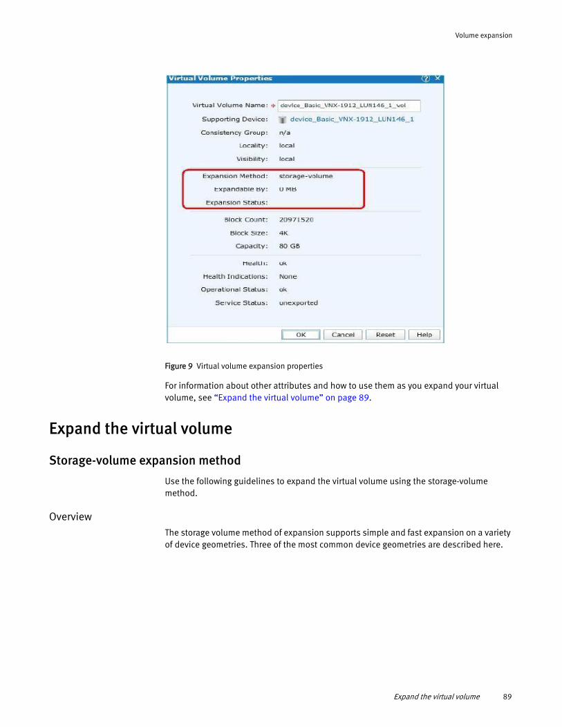
Volume expansion
Figure 9 Virtual volume expansion properties
For information about other attributes and how to use them as you expand your virtual volume, see “Expand the virtual volume” on page 89.
Expand the virtual volume
Storage-volume expansion method
Use the following guidelines to expand the virtual volume using the storage-volume method.
OverviewThe storage volume method of expansion supports simple and fast expansion on a variety of device geometries. Three of the most common device geometries are described here.
Expand the virtual volume 89
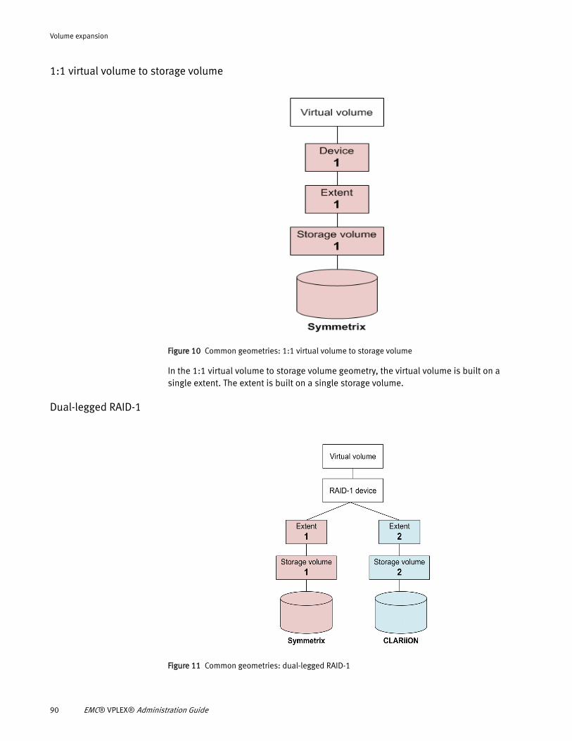
Volume expansion
1:1 virtual volume to storage volume
Figure 10 Common geometries: 1:1 virtual volume to storage volume
In the 1:1 virtual volume to storage volume geometry, the virtual volume is built on a single extent. The extent is built on a single storage volume.
Dual-legged RAID-1
Figure 11 Common geometries: dual-legged RAID-1
90 EMC® VPLEX® Administration Guide
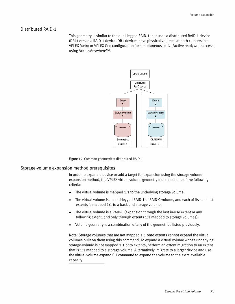
Volume expansion
Distributed RAID-1This geometry is similar to the dual-legged RAID-1, but uses a distributed RAID-1 device (DR1) versus a RAID-1 device. DR1 devices have physical volumes at both clusters in a VPLEX Metro or VPLEX Geo configuration for simultaneous active/active read/write access using AccessAnywhere™.
Figure 12 Common geometries: distributed RAID-1
Storage-volume expansion method prerequisitesIn order to expand a device or add a target for expansion using the storage-volume expansion method, the VPLEX virtual volume geometry must meet one of the following criteria:
◆ The virtual volume is mapped 1:1 to the underlying storage volume.
◆ The virtual volume is a multi-legged RAID-1 or RAID-0 volume, and each of its smallest extents is mapped 1:1 to a back end storage volume.
◆ The virtual volume is a RAID-C (expansion through the last in-use extent or any following extent, and only through extents 1:1 mapped to storage volumes).
◆ Volume geometry is a combination of any of the geometries listed previously.
Note: Storage volumes that are not mapped 1:1 onto extents cannot expand the virtual volumes built on them using this command. To expand a virtual volume whose underlying storage-volume is not mapped 1:1 onto extents, perform an extent migration to an extent that is 1:1 mapped to a storage volume. Alternatively, migrate to a larger device and use the virtual-volume expand CLI command to expand the volume to the extra available capacity.
Expand the virtual volume 91
Volume expansion
Virtual volumes in RecoverPoint consistency groupsIf a virtual volume is a member of a VPLEX RecoverPoint consistency group, then you must perform additional steps in order to use the storage volume expansion method:
◆ Remove the volume from RecoverPoint use.
Refer to the “Manage VPLEX/RecoverPoint” procedure under RecoverPoint Procedures in the generator.
◆ Expand the virtual volume using the storage volume expansion method.
◆ Add the volume back to the RecoverPoint consistency group you removed it from.
For prerequisites specific to expansion using the storage-volume technique, see “Storage-volume expansion method prerequisites” on page 91.
Plan for volume expansionList the expandable-capacity attribute (in the CLI) or the Expandable By field (in the GUI) to plan capacity of your back-end storage devices.
◆ expandable-capacity/Expandable By — For virtual volumes that can be expanded using the storage-volume method of expansion, this value is the capacity added to the back-end storage-volume, but not yet exposed to the host by the virtual volume.
This capacity is available for expanding the VPLEX virtual volume using the storage-volume method of expansion.
• 0 (zero) - A value of zero indicates that there is no expandable-capacity for the volume. Refer the expansion-method attribute to determine if storage-volume based expansion is supported.
• Non-zero value - A non-zero value indicates capacity available to expand the VPLEX virtual volume. Reference the expansion-method attribute to determine if storage-volume based expansion is supported.
Volume ExpansionPerform volume expansion using one of the following techniques:
◆ The virtual-volume expand CLI command. Refer to the EMC VPLEX CLI Guide for detailed information about this command.
◆ Expand a virtual volume using the VPLEX GUI. Refer to the Unisphere for VPLEX Online Help for complete steps.
◆ Refer to the generator for procedures to expand a distributed virtual volume using GeoSynchrony:
During volume expansion, using the storage-volume method, ensure that:
Performing a major host operation (such as a LIP reset, for example) in order to detect a change in volume size presents risk to volumes accessed by the host. It is best to avoid such resource intensive operations during volume expansion.
92 EMC® VPLEX® Administration Guide
Volume expansion
◆ Expansion initialization traffic occurs on disk areas that are not performing host I/O. In addition, the amount of time taken to initialize the newly added capacity depends on the performance of the array that is hosting the storage volumes. However, the expected performance is still faster than the time taken to rebuild a volume.
◆ Across distributed RAID-1 devices, the initialization process does not consume WAN data bandwidth as each cluster performs its initialization locally.
◆ On RAID-1 and distributed RAID-1 devices, VPLEX ensures that all RAID-1 legs have consistent information on the expanded space.
◆ The level of redundancy on RAID-1 and distributed RAID-1 device geometries is maintained through the expansion and initialization process.
◆ The newly expanded virtual volume capacity will be available to use by hosts when the initialization process has finished.
◆ If VPLEX has claimed the storage volumes as thinly provisioned, the initialization process will not affect the underlying provisioning of the additional capacity reported to VPLEX.
Check status of volume expansionQuery the status of your volume expansion by listing the value of the following attributes in the virtual-volumes context using the CLI or GUI.
◆ expansion-status - Status of virtual volume expansion. Indicates whether a virtual volume expansion is underway or has failed.
The attribute will have one of the following values:
• in-progress - Expansion is in progress.
• failed - Most recent in-progress expansion has failed and expansion needs to be retried by the user. If expansion is not retried, then this state persists for up to two days. If two days pass with no fix, the failed state clears and the volume will be assumed fixed.
• unknown - Status cannot be determined. This may be because of a communication error or because of an internal programming error.
• - (dash character) - None of the above states apply.
◆ expansion-summary - If there are no in-progess or failed expansions, and no virtual volumes with a non-zero expandable-capacity, then the virtual volume summary command displays No expansion activity in expansion-summary.
Limitations
The following are general limitations for expanding virtual volumes.
Some virtual volumes cannot be expanded under specific circumstances. Volumes cannot be expanded if any of the following conditions are true:
◆ Migration or rebuilding is occurring - Expansion is blocked during migration or rebuilds.
• If you are rebuilding volumes, wait until the rebuild is complete before attempting expansion.
Expand the virtual volume 93
Volume expansion
• If you are migrating data, wait until the migration is complete. Alternatively, cancel or commit the migration, and then perform the expansion.
◆ Upgrade is occurring - Volume expansion is blocked during Non-Disruptive Upgrade (NDU).
◆ health-check command reports problems - The health-check command returns problems relating to the cluster, storage volumes, or virtual volume being expanded.
◆ Volume to expand belongs to a RecoverPoint-enabled consistency group - A volume cannot be expanded if it belongs to a RecoverPoint-enabled consistency group. See for additional steps you need to take before you can expand a volume that is a member of a RecoverPoint-enabled consistency group.
◆ Volume is a metadata volume - Metadata volumes cannot be expanded.
Limitations with storage-volume expansionThe following limitations apply to the storage volume expansion method:
◆ For virtual volumes built on RAID-1 or distributed RAID-1 devices, a maximum of 1000 initialization processes can run concurrently per cluster. If this limit is reached on a cluster, then no new expansions can be started on virtual volumes with these geometries until some of the previously started initialization processes finish on that cluster.
Virtual volumes that do not contain RAID-1 or distributed RAID-1 devices are not affected by this limitation.
Troubleshooting and health indicationsWhen a volume expansion fails, information as to why it failed is added to the health indications attribute. Note that when an expansion fails it does not degrade overall health, operational status, or service status of a virtual volume.
Note: The VPLEX Troubleshooting section of the SolVe Desktop contains procedures for recovering from an error with volume expansions.
Rediscover the arrayYou may need to rediscover the array after expansion. Depending on the type and configuration of the back-end array, the storage array may not support auto- discovery by VPLEX.
Best practice — If VPLEX does not automatically detect the change in the storage volume, use the array-rediscover command to force VPLEX to recognize the back-end expansion.
If you are performing multiple storage-volume expansions on the array, complete all storage-volume expansions, and re-discover the array only once to force VPLEX to detect all the expansions.
Some arrays need specific system settings to enable support of auto discovery.
Refer to the generator for the procedures to configure storage arrays for VPLEX.
94 EMC® VPLEX® Administration Guide
Volume expansion
Note: Review the applicable best practices for host and array connectivity and configuration in the generator. Some arrays require specific settings for automatic detection.
Array rediscoveries may consume excessive resources and can be disruptive to I/O. Re-discover arrays only when necessary.
Concatenation expansion method
Some devices do not support the storage-volume method of expansion. In this case, use the concatenation method.
Best PracticeBefore selecting extents and local devices to expand a virtual volume using concatenation, ensure the following:
◆ For volumes created on RAID-0 and RAID-C devices:
• Select only one extent or local device. This extent or local device can be the same storage volume from which the virtual volume is created, or it can be a different storage volume.
◆ For volumes created on RAID-1 devices:
• Select two or more extents or local devices.
• Select a number of extents or local devices greater than or equal to the number of components (legs) in the RAID-1 device.
• Create the same redundancy as the original RAID-1 device on which the virtual volume is created.
• Select extents or local devices from different arrays to avoid a single point of failure.
Expand the virtual volume 95

Volume expansion
96 EMC® VPLEX® Administration Guide
CHAPTER 7Data migration
This chapter describes the following topics:
◆ About data migrations............................................................................................. 97◆ About rebuilds ........................................................................................................ 99◆ One-time data migrations...................................................................................... 100◆ Batch migrations................................................................................................... 104
About data migrationsThere are two types of data migrations:
◆ One time migrations - Begin an extent or device migration immediately when the dm migration start command is used.
◆ Batch migrations - Are run as batch jobs using re-usable migration plan files. Multiple device or extent migrations can be executed using a single command.
One time migrations
One time migrations include:
◆ Extent migrations - Extent migrations move data between extents in the same cluster. Use extent migrations to:
• Move extents from a hot storage volume shared by other busy extents.
• Defragment a storage volume to create more contiguous free space.
• Perform migrations where the source and target have the same number of volumes with identical capacities.
◆ Device migrations - Devices are RAID 0, RAID 1, or RAID C devices built on extents or on other devices.
Device migrations move data between devices on the same cluster or between devices on different clusters. Use device migrations to:
• Migrate data between dissimilar arrays.
• Relocate a hot volume to a faster array.
• Relocate devices to new arrays in a different cluster.
Limitations ◆ Device migrations between distributed devices are not supported.
◆ Devices must be removed from consistency groups before they can be migrated between clusters.
◆ Cross cluster migrations of volumes being used with RecoverPoint is not supported. However, migrations within a cluster is supported for volumes being used with RecoverPoint.
Data migration 97
Data migration
Batch migrations Batch migrations migrate multiple extents or devices. Create batch migrations to automate routine tasks:
• Use batched extent migrations to migrate arrays within the same cluster where the source and destination have the same number of LUNs and identical capacities.
• Use batched device migrations to migrate to dissimilar arrays (user must configure the destination’s capacities to match the capacity and tier of the source array), and to migrate devices between clusters in a VPLEX Metro or VPLEX Geo.
Up to 25 local and 25 distributed migrations can be in progress at the same time. Any migrations beyond those limits are queued until an existing migration completes.
Limitations Devices must be removed from consistency groups before they can be migrated between clusters.
General procedure to perform data migration
Use the following general steps to perform extent and device migrations:
1. Create and check a migration plan (batch migrations only).
2. Start the migration.
3. Monitor the migration progress.
4. Pause, resume, or cancel the migration (optional).
5. Commit the migration. Commit transfers the source virtual volume/device/extent to the target.
If the virtual volume on top of a device has a system-assigned default name, committing a device migration renames the virtual volume after the target device.
6. Clean up (optional).
For extent migrations, dismantle the source devices or destroy the source extent and unclaim its storage-volume.
7. Remove the record of the migration.
Prerequisites for targetdevices/extents
The target device or extent must:
◆ Be the same size or larger than the source device or extent.
If the target is larger in size than the source, the extra space can be utilized by using storage volume expansion, if all the prerequisites for storage volume expansion are met. Chapter 6, “Volume expansion,” provides more information on storage volume expansion.
For example, if the source is 200 GB, and the target is 500 GB, only 200 GB of the target can be used after a migration. The remaining 300 GB can be claimed by performing a storage volume expansion, if supported by the virtual volume.
◆ Not have any existing volumes on it.
98 EMC® VPLEX® Administration Guide
Data migration
Device migrations are not recommended between clusters. All device migrations are synchronous. If there is I/O to the devices being migrated, and latency to the target cluster is equal to or greater than 5ms, then significant performance degradation may occur.
About rebuildsRebuilds synchronize data from a source drive to a target drive. When differences arise between legs of a RAID, a rebuild updates the out-of-date leg.
There are two types of rebuild behavior:
◆ A full rebuild copies the entire contents of the source to the target.
◆ A logging rebuild copies only changed blocks from the source to the target.
Local mirrors are updated using a full rebuild (local devices do not use logging volumes).
In VPLEX Metro and Geo configurations, all distributed devices have an associated logging volume. Logging volumes keep track of blocks that are written during an inter-cluster link outage. After a link or leg is restored, the VPLEX system uses the information in logging volumes to synchronize mirrors by sending only changed blocks across the link.
Logging volume rebuilds also occur when a leg of a disaster recovery RAID 1 (DR1) becomes unreachable, but recovers quickly.
If a logging volume is unavailable at the time that a leg is scheduled to be marked out-of-date (via the log), the leg is marked as fully out-of-date, causing a full rebuild.
The unavailability of a logging volume matters both at the time of recovery (when the system reads the logging volume) and at the time that a write fails on one leg and succeeds on another (when the system begins writes to the logging volume).
If no logging volume is available, an inter-cluster link restoration will cause a full rebuild of every distributed device to which there were writes while the link was down.
See “Logging volumes” on page 42.
Rebuilds for thin provisioned storage
Thin provisoning allows storage to migrate onto a thinly provisioned storage volumes while allocating the minimal amount of thin storage pool capacity.
Thinly provisioned storage volumes can be incorporated into RAID 1 mirrors with similar consumption of thin storage pool capacity.
VPLEX preserves the unallocated thin pool space of the target storage volume by detecting zeroed data content before writing, and suppressing the write for cases where it would cause an unnecessary allocation. VPLEX requires the user to specify thin provisoning for each back-end storage volume. If a storage volume is thinly provisioned, the "thin-rebuild" attribute must be to "true" either during or after claiming.
About rebuilds 99
Data migration
If a thinly provisioned storage volume contains non-zero data before being connected to VPLEX, the performance of the migration or initial RAID 1 rebuild is adversely affected. System volumes are supported on thinly provisioned LUNs, but these volumes must have thin storage pool resources available, at maximum capacity. System volumes must not compete for this space with user-data volumes in the same pool. If the thin storage allocation pool runs out of space and this is the last redundant leg of the RAID 1, further writing to a thinly provisioned device causes the volume to lose access to the device, resulting in data unavailability.
Performance considerations
To improve overall VPLEX performance, disable automatic rebuilds or modify the rebuild transfer size:
◆ Disable automatic rebuilds to avoid a flood of activity when re-attaching two clusters. See “Display, enable, or disable automatic device rebuilds” on page 66
Disabling automatic rebuilds prevents DR1s from synchronizing. Child devices will be out of date, increasing the likelihood of remote reads.
◆ Modify the rebuild transfer size. See “About transfer-size” on page 107.
One-time data migrationsA one-time data migration moves data between the specified source and targets as soon as the dm start migration command is used. No reusable migration plan file is created as in “Batch migrations” on page 104.
Start a one-time device or extent data migration
To start a one-time device or extent migration:
1. Use the drill down command to display the components of the source, (including extents) of a view, virtual volume, or device, down to the storage-volume level:
VPlexcli:/clusters/cluster-1> drill-down –o virtual-volumes/Symm1254_7B7_1_vol
virtual-volume: Symm1254_7B7_1_vol (cluster-1) local-device: Symm1254_7B7_1 (cluster-1) extent: extent_Symm1254_7B7_1 storage-volume: Symm1254_7B7
2. Identify the extent or device used by the source storage volume.
3. Use the ll /clusters/<cluster-*>/storage-elements/extents or ll /clusters/<cluster-*>/devices command to display available extents or devices.
4. Identify an unused extent or device as the destination.
5. Navigate to the appropriate migration context.
For device migrations, navigate to device migration context:
VPlexcli:/> cd data-migrations/device-migrations
100 EMC® VPLEX® Administration Guide
Data migration
For extent migrations, navigate to extent migration context:
VPlexcli:/> cd data-migrations/extent-migrations
6. Use the dm migration start command to start a migration. The syntax for the command is:
dm migration start --name name of migration --transfer-size [40 KB-128 MB] --from source extent or device --to destination extent or device
• The --name argument is used to track the migration’s progress, and to manage (cancel, commit, pause, resume) the migration.
• Use the optional --transfer-size argument to specify the size of the area set aside in cache to service the migration. A bigger transfer size means smaller space available for host I/O.
Range: 40K-128M. Default: 128 K. Must be a multiple of 4K.
• Specify the --from device or extent by name if that name is unique in the global namespace. Otherwise, specify a full pathname.
• Specify the --to device or extent by name if that name is unique in the global namespace. Otherwise, specify a full pathname.
For example:
VPlexcli:/data-migrations/device-migrations> dm migration start --name migrate_012 --from device_012 --to device_012a --transfer-size 12M
Setting a large a transfer size may result in data unavailability. Vary from the default only when performance implications are fully understood.
If host I/O activity is high, setting a large transfer size may impact host I/O.
See “About transfer-size” on page 107.
Monitor a migration’s progress
Use the ls command to display the migration’s status.
VPlexcli:/> ls data-migrations/device-migrations/ migrate_012Name Value--------------- ----------------------------from-cluster cluster-1percentage-done 10source device_012source-exported falsestart-time Fri May 28 13:32:23 MDT 2010status in progresstarget device_012atarget-exported falseto-cluster cluster-2transfer-size 12Mtype full
One-time data migrations 101
Data migration
Pause/resume a migration (optional)
Active migrations (a migration that has been started) can be paused and then resumed at a later time.
Pause an active migration to release bandwidth for host I/O during periods of peak traffic.
Use the dm migration pause --migrations migration-name command to pause a migration.
Specify the migration-name by name if that name is unique in the global namespace. Otherwise, specify a full pathname.
For example:
◆ Pause a device migration:
Table 7 Migration status
Field Description
from-cluster Cluster ID of the source extent, device, or devices in the consistency group.
percentage-done Percentage completion of the migration. 100 % if migration is complete or committed.
source Source extent or device.
source-exported Whether the source device was exported during the migration. Applicable if the migration is an inter-cluster device migration and if the device was not already exported. Devices are exported to a remote cluster to make them visible at that cluster and can be used as a leg in a temporary distributed RAID 1 during the migration.false - Source device was not exported.true - Source device was exported.
start-time Date and time migration was started.
status Status of the migration.committed - Migration is committed.complete - Migration is complete (but not committed).error - Error condition, including source or target unreachable.in-progress - Migration is in progress. partially-cancelled - Attempt to cancel the migration failed. Retry the cancel.partially-committed - Attempt to commit the migration failed. Retry the commit. paused - The migration is paused.queued - The migration is in the queue.
target Destination extent or device.
target-exported Whether the target device was exported during the migration. false - Target device was not exported.true - Target device was exported.
to-cluster Cluster ID of the destination extent or device.
transfer-size Size of the region in cache that is used to service the migration. 40 KB-128 MB.
type Type of rebuild.full - Copies the entire contents of the source to the target.logging - Copies only changed blocks from the source to the target.
102 EMC® VPLEX® Administration Guide
Data migration
VPlexcli:/data-migrations/device-migrations> dm migration pause --migrations migrate_012Use the dm migration resume --migrations migration-name command to resume a paused migration.
Specify the migration-name by name if that name is unique in the global namespace. Otherwise, specify a full pathname.
For example:
◆ Resume a paused device migration:
VPlexcli:/data-migrations/device-migrations> dm migration resume --migrations migrate_012
Cancel a migration (optional)
Migrations can be canceled in the following circumstances:
◆ The migration is in progress or paused. The migration is stopped, and any resources it was using are freed.
◆ The migration has not been committed. The source and target devices or extents are returned to their pre-migration state.
Use the dm migration cancel --force --migrations migration-name command to cancel a migration.
Specify the migration-name by name if that name is unique in the global namespace. Otherwise, specify a full pathname.
For example:
VPlexcli:/data-migrations/device-migrations> dm migration cancel --force --migrations migrate_012
Commit a completed migration
The migration process inserts a temporary RAID 1 structure above the source device/extent with the target device/extent as an out-of-date leg of the RAID 1. The migration can be understood as the synchronization of the out-of-date leg (the target).
After the migration is complete, the commit step detaches the source leg of the RAID 1, and removes the RAID 1.
The virtual volume, device, or extent is identical to the one before the migration except that the source device/extent is replaced with the target device/extent.
A migration must be committed to be cleaned.
Verify that the migration has completed successfully before committing the migration.
Use the dm migrations commit --force --migrations migration-name command to commit a migration.
Note: You must use the --force option to commit a migration.
For example:
◆ Commit a device migration:
One-time data migrations 103
Data migration
VPlexcli:/data-migrations/device-migrations> dm migration commit --force --migrations migrate_012
Committed 1 data migration(s) out of 1 requested migration(s).
Clean a migration
Device migrations For device migrations, cleaning dismantles the source device down to its storage volumes. The storage volumes that are no longer in use are unclaimed.
For device migrations only, use the --rename-target argument to rename the target device after the source device. If the target device is renamed, the virtual volume on top of it is also renamed if the virtual volume has a system-assigned default name.
Without renaming, the target devices retain their target names, which can make the relationship between volume and device less evident.
Extent migrations For extent migrations, cleaning destroys the source extent and unclaims the underlying storage-volume if there are no extents on it.
Use the dm migration clean --force --migrations migration-name command to clean a migration.
Specify the migration-name by name if that name is unique in the global namespace. Otherwise, specify a full pathname.
For example:
VPlexcli:/data-migrations/device-migrations> dm migration clean --force --migrations migrate_012
Cleaned 1 data migration(s) out of 1 requested migration(s).
Remove migration records
Note: Migrations must be canceled or committed before they can be removed.
Use the dm migration remove --force --migrations migration-name command to remove the records of the migration.
Specify the migration-name by name if that name is unique in the global namespace. Otherwise, specify a full pathname.
For example:
VPlexcli:/data-migrations/device-migrations> dm migration remove --force --migrations migrate_012
Removed 1 data migration(s) out of 1 requested migration(s).
Batch migrationsBatch migrations are run as batch jobs from reusable batch migration plan files. Migration plan files are created using the create-plan command.
A single batch migration plan can be either for devices or extents, but not both.
104 EMC® VPLEX® Administration Guide
Data migration
Note: Migrations consume cache resources. Running multiple migrations concurrently may impact host I/O.
Use batch migrations to:
◆ Retire storage arrays (off-lease arrays) and bring new ones online.
◆ Migrate devices to a different class of storage array.
The steps to perform a batch migration are generally the same as those described in the “General procedure to perform data migration” on page 98.
There are two additional steps to prepare for a batch migration:
◆ Create a batch migration plan file (using the batch-migrate create-plan command)
◆ Test the batch migration plan file (using the batch-migrate check-plan command)
Prerequisites The following prerequisites are required for batch migrations:
◆ The source and targets are both devices or extents. Migrations between devices and extents are not supported.
◆ Extents must be claimed (extent migrations) or local devices must be configured (device migrations) on the target array.
◆ The structure of the target is the same as the structure of the source.
◆ For extent migrations, both source and target extents must be in the same cluster.
Create a batch migration plan
The batch-migrate create-plan command creates a migration plan using the specified sources and targets. The syntax for the command is:
batch-migrate create-plan --file migration-filename --sources sources --targets targets --force
◆ --file - Specify the migration-filename only if that name is unique in the global namespace. Otherwise, specify a full pathname.
◆ --sources - Pathname(s) of the source extents or devices as a comma-separated list.
Each element may contain wildcards.
For extent migrations, source extents must be in the same cluster.
◆ --targets - Pathname(s) of the target extents or devices as a comma-separated list.
For extent migrations, target extents must be in the same cluster as the source extents.
◆ --force - If a plan file with the same name already exists, this option forces the old plan to be overwritten.
In the following example, the batch--migrate create-plan command creates a batch migration named ‘MigDev-test.txt’ to:
◆ Migrate two devices at cluster-1 to two devices at cluster-2.
◆ Overwrite an existing plan with the same name.
Batch migrations 105
Data migration
VPlexcli:/> batch-migrate create-plan --file MigDev-test.txt --sources /clusters/cluster-1/devices/base0,/clusters/cluster-1/devices/base1 --targets /clusters/cluster-2/devices/dev1723_618, /clusters/cluster-2/devices/dev1723_61C --forceExtents matching source pattern: base0, base1Extents matching target pattern: dev1723_61C, dev1723_618
Creating file /var/log/VPlex/cli/MigDev-test.txt as migration plan file.
Wrote file /var/log/VPlex/cli/MigDev-test.txt. Please review and edit this file, and run this command in the check-plan phase afterward.
In the following example, the batch-migrate create-plan command creates a batch migration to migrate all devices at cluster-1 to cluster-2.
VPlexcli:/> batch-migrate create-plan migrate.txt --sources /clusters/cluster-1/devices/* --targets /clusters/cluster-2/devices/*
Check a batch migration plan
The batch-migrate check-plan --file file-name command checks the specified batch migration plan for the following:
◆ Block-size of source and target extents is equal (4 K bytes)
◆ Capacity of target extent is equal or bigger than the capacity of the source extent.
◆ Device migrations:
• Target device has no volumes on it
• Source device has volumes on it
◆ Extent migrations:
• Target extent is claimed and ready for use
• Source extent is in use
If the migration plan contains errors, a description of the errors is displayed, and the plan check fails. For example:
VPlexcli:/> batch-migrate check-plan --file MigDev-test.txtChecking migration plan file /var/log/VPlex/cli/MigDev-test.txt.
Target device '/clusters/cluster-2/devices/dev1723_61C' has a volume.Target device '/clusters/cluster-2/devices/dev1723_618' has a volume.Plan-check failed, 2 problems.
Use the steps described in “Modify a batch migration file” on page 106 to correct the plan.
Repeat the process of check and modify until the batch migration plan passes the plan check. For example:
VPlexcli:/> batch-migrate check-plan --file migrate.txt
Checking migration plan file /temp/migration_plans/migrate.txt.Plan-check passed.
Modify a batch migration file
To modify a batch migration file, do one of the following:
106 EMC® VPLEX® Administration Guide
Data migration
◆ Use the batch-migrate create-plan command, specify the same filename, and use the --force option to overwrite the old plan with the new one.
◆ Exit from the management server, and navigate to /var/log/VPlex/cli/.
Use a text editor (vi) to edit and save the file.
VPlexcli:/> exitConnection closed by foreign host.service@ManagementServer:~> cd /var/log/VPlex/cli/service@ManagementServer:/var/log/VPlex/cli>
Note: To add comments to the migration plan file, add lines beginning with “/ “.
Start a batch migration
About transfer-sizeTransfer-size is the size of the region in cache that is used to service the migration. The area is globally locked, read at the source, and written at the target.
Transfer-size can be as small 40K, as large as 128 MB, and must be a multiple of 4K. The default value is 128 K.
A larger transfer-size results in higher performance for the migration, but may negatively impact front-end I/O. This is especially true for VPLEX Metro migrations.
If transfer-size is too large, the rebuild read I/O may overwhelm the source device affecting the host I/O.
A smaller transfer-size results in lower performance for migration, but creates less impact on front-end I/O and response times for hosts.
Set a large transfer-size for migrations when the priority is data protection or migration performance.
Set a smaller transfer-size for migrations when the priority is front-end storage response time.
Factors to consider when specifying the transfer-size:
◆ For VPLEX Metro configurations with narrow inter-cluster bandwidth, set the transfer size lower so that the migration does not impact inter-cluster I/O.
◆ The region specified by transfer-size is locked during migration. Host I/O to or from that region is held. Set a smaller transfer-size during periods of high host I/O.
◆ When a region of data is transferred, a broadcast is sent to the system. Smaller transfer-size means more broadcasts, slowing the migration.
Use the batch-migrate start --transfer-size [40K-128M] --file <filename > command to start the specified batch migration:
For example:
VPlexcli:/> batch-migrate start --file migrate.txt --transfer-size 2MStarted 4 of 4 migrations.
Batch migrations 107
Data migration
Pause/resume a batch migration (optional)
Active batch migrations (a migration that has been started) can be paused and resumed.
Pause an active batch migration to release bandwidth for host I/O during periods of peak traffic.
Resume the batch migration during periods of low I/O.
Use the batch-migrate pause --file filename command to pause the specified active migration. For example:
VPlexcli:/data-migrations/device-migrations> batch-migrate pause --file migrate.txt
Use the batch-migrate resume --file filename command to resume the specified paused migration. For example:
VPlexcli:/data-migrations/device-migrations> batch-migrate resume --file migrate.txt
Cancel a batch migration (optional)
Cancel an active batch migration to return the source volumes to their state prior to the start of the migration.
Use the batch-migrate cancel --file filename command to cancel the specified migration. For example:
VPlexcli:/data-migrations/device-migrations> batch-migrate cancel --file migrate.txt
Note: In order to re-run a canceled migration plan, the batch-migrate remove filename command must be used to remove the records of the migration. See “Remove batch migration records” on page 111.
Monitor a batch migration’s progress
Use the batch-migrate summary filename --verbose command to monitor the progress of the specified batch migration:
VPlexcli:/data-migrations/device-migrations> batch-migrate summary filename --verbose
For example:
VPlexcli:/data-migrations/device-migrations> batch-migrate summary --file migrate.txt --verbose
source- source-site target target-cluster migration-name status percentage-complete eta.---------------- ----------- ---------------------- -------- ------------- ------------------- ---R20061115_Symm2264_010 1 R20070107_Symm2A10_1B0 1
migrate.txt 100 -R20061115_Symm2264_011 1 R20070107_Symm2A10_1B1 1
migrate.txt 100 -R20061115_Symm2264_012 1 R20070107_Symm2A10_1B2 1
migrate.txt 100 -
108 EMC® VPLEX® Administration Guide
Data migration
R20061115_Symm2264_0113 1 R20070107_Symm2A10_1B3 1 migrate.txt 27 4.08min
Processed 4 migrations: committed: 0 complete: 3 in-progress: 1 paused: 0 error: 0 cancelled: 0 no-record: 0
View a batch migration’s status
Use the batch-migrate summary filename command to display the status of the specified batch migration.
For example:
VPlexcli:/> batch-migrate summary migrate.txt
Processed 10 migrations from batch migration BR0:committed: 0complete: 10in-progress: 0paused: 0error: 0cancelled: 0no-record: 0
Note: If more than 25 migrations are active at the same time, they are queued, their status is displayed as in-progress, and percentage-complete is displayed as “?”.
Table 8 Batch migration summary
Field Description
Processed.... Of the number of source-target pairs specified in the batch migration plan, the number that have been processed.
committed Of the number of source-target pairs that have been processed, the number that have been committed.
completed Of the number of source-target pairs that have been processed, the number that are complete.
in-progress Of the number of source-target pairs that have been processed, the number that are in progress.
paused Of the number of source-target pairs that have been processed, the number that are paused.
error Jobs that encountered errors during processing.
cancelled Of the number of source-target pairs that have been processed, the number that have been cancelled.
no-record Of the number of source-target pairs that have been processed, the number that have no record in the context tree.
Batch migrations 109
Data migration
Commit a batch migration
The migration process inserts a temporary RAID 1 structure above the source devices/extents with the target devices/extents as an out-of-date leg of the RAID 1. Migration can be understood as the synchronization of the out-of-date leg (the target).
After the migration is complete, the commit step detaches the source leg of the RAID 1 and then removes the RAID.
The virtual volume, device or extent is identical to the one before the migration except that the source device/extent is replaced with the target device/extent.
A migration must be committed in order to be cleaned.
When the batch migration is 100 percent complete, use the batch-migrate commit filename command to replicate the volumes on the target devices and remove the volumes from the source devices.
To commit a batch migration, perform the following:
1. Use the batch-migrate summary command to verify that the migration has completed with no errors.
2. Use the batch-migrate commit --file filename command to commit the migration.
Commit permanently removes the volumes from the source devices.
For example:
VPlexcli:/> batch-migrate commit --file migrate.txt
Clean a batch migration
Device batch migrationFor device migrations, cleaning dismantles the source device down to its storage volumes. The storage volumes that are no longer in use are unclaimed.
For device migrations only, use the optional --rename-target argument to rename the target device after the source device. If the target device is renamed, the virtual volume on top of it is also renamed if the virtual volume has a system-assigned default name.
Without renaming, the target devices retain their target names, which can make the relationship between volume and device less evident.
Extent batch migrationFor extent migrations, cleaning destroys the source extent and unclaims the underlying storage-volume if there are no extents on it.
Use the batch-migrate clean --file filename command to clean the specified batch migration.
110 EMC® VPLEX® Administration Guide
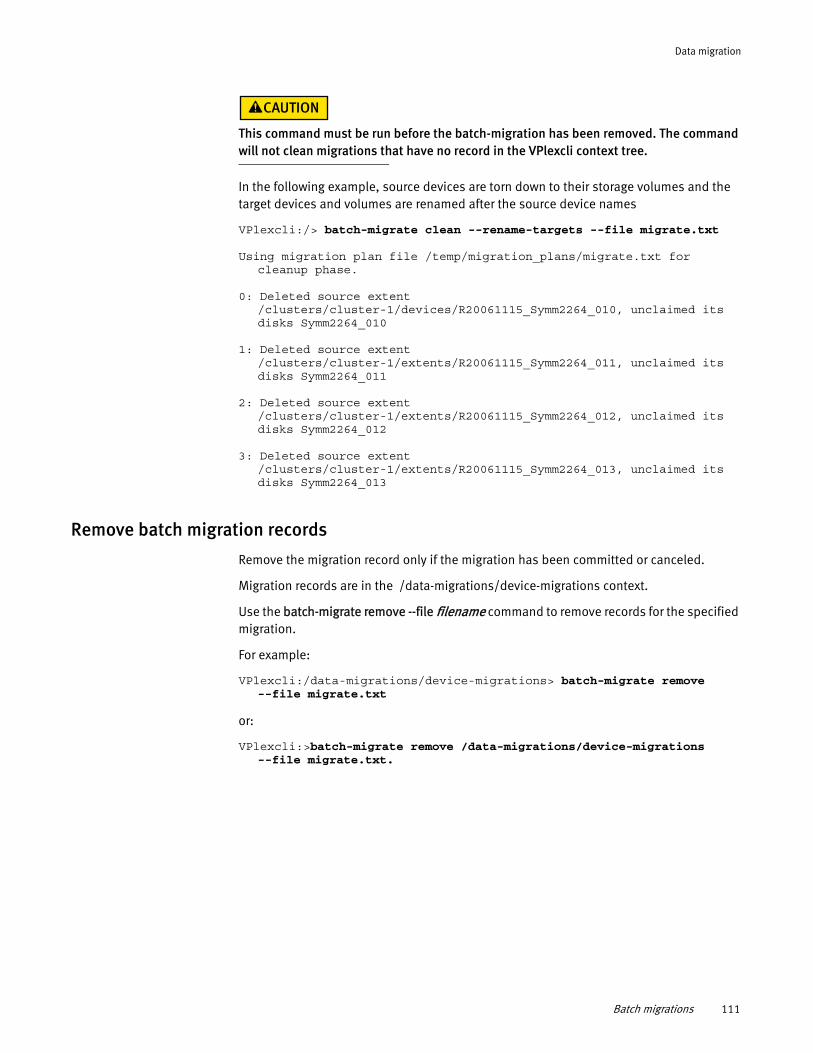
Data migration
This command must be run before the batch-migration has been removed. The command will not clean migrations that have no record in the VPlexcli context tree.
In the following example, source devices are torn down to their storage volumes and the target devices and volumes are renamed after the source device names
VPlexcli:/> batch-migrate clean --rename-targets --file migrate.txt
Using migration plan file /temp/migration_plans/migrate.txt for cleanup phase.
0: Deleted source extent /clusters/cluster-1/devices/R20061115_Symm2264_010, unclaimed its disks Symm2264_010
1: Deleted source extent /clusters/cluster-1/extents/R20061115_Symm2264_011, unclaimed its disks Symm2264_011
2: Deleted source extent /clusters/cluster-1/extents/R20061115_Symm2264_012, unclaimed its disks Symm2264_012
3: Deleted source extent /clusters/cluster-1/extents/R20061115_Symm2264_013, unclaimed its disks Symm2264_013
Remove batch migration records
Remove the migration record only if the migration has been committed or canceled.
Migration records are in the /data-migrations/device-migrations context.
Use the batch-migrate remove --file filename command to remove records for the specified migration.
For example:
VPlexcli:/data-migrations/device-migrations> batch-migrate remove --file migrate.txt
or:
VPlexcli:>batch-migrate remove /data-migrations/device-migrations --file migrate.txt.
Batch migrations 111

Data migration
112 EMC® VPLEX® Administration Guide
CHAPTER 8Configure the Network
The two WAN ports on each VPLEX director support dual Gigabit Ethernet inter-cluster links. The WAN ports are configured as part of the installation of a second cluster. This chapter describes the CLI contexts and procedures to change the configuration created during installation.
◆ VPLEX hardware and WAN ports ............................................................................ 113◆ CLI contexts .......................................................................................................... 114◆ Modify the network configuration.......................................................................... 119◆ About IPv6 addressing .......................................................................................... 126◆ Implementing IPv6 ................................................................................................ 127
VPLEX hardware and WAN portsVPLEX Geo or Metro over IP clusters can include either of the two types of director hardware. The number and speed of the WAN ports on each type of director is as follows:
◆ VS1 - The Wide Area Network (WAN) communication interface card (SLiC) has four 1 Gigabit Ethernet (GbE) ports. Only two ports are used for VPLEX WAN communications.
The ports are named GE00 and GE01.
◆ VS2 - WAN SLiC has two 10 Gigabit Ethernet (10 GbE) ports.
The ports are named XG00 and XG01.
Data carried on WAN ports on both VS1 and VS2 directors and between clusters in VPLEX Metro and Geo configurations is not encrypted.
To prevent DNS attacks, the WAN ports should be routed only on secure and trusted networks.
Refer to the EMC Simple Support Matrix (ESSM) for information about encryption devices supported in VPLEX configurations.
Port groups
All ports named GE00 or XG00 (in a cluster) are collectively referred to as port-group 0.
All ports named GE01 or XG01 (in a cluster) are collectively referred to as port-group 1.
Note: Port group names (port-group-0 and port-group-1) cannot be modified.
Geo or Metro over IP WAN port configuration rules
Geo or Metro over IP WAN ports must conform to the following rules:
Configure the Network 113
Configure the Network
◆ The two WAN ports on a director should be on different physical networks, and must be on different subnets so that port GE00/XG00 (port-group 0) cannot see port GE01/XG01 (port group 1) on any director.
◆ All port GE00/XG00s in the cluster (one from each director) must be in the same subnet and connected to the same LAN. Ports in the same subnet are usually connected to the same Ethernet switch.
◆ All port GE01/XG01s must be in one subnet, which cannot be the same subnet used for ports GE00/XG00.
◆ Each director must have 2 statically assigned IP addresses, one in each subnet.
◆ Each cluster must have an additional statically assigned IP address in each subnet (cluster IP address). This address is used during discovery. The cluster IP address is not tied to a specific physical port. Any director may host the cluster IP address.
◆ The management port subnet cannot be the same as either of the subnet used for the WAN ports.
Sub-contexts
The /clusters/cluster/cluster-connectivity has three sub-contexts:
◆ “subnets context”
◆ “port-groups context”
◆ “option-sets context”
CLI contexts The parent context for configuring Ethernet and WAN connections is:
/clusters/cluster/cluster-connectivity
The /clusters/cluster/cluster-connectivity context includes the following addresses:
◆ discovery-address - The multicast address local directors use to discover the cluster.
Note: Multicast must be enabled on the local switch connecting the Ethernet ports of the director.
◆ discovery-port - The port local directors use (along with the discovery-address) to find other directors in the same cluster.
◆ listening-port - The port local directors use to communicate with the other cluster. The listening port is used when connecting to the directors in the other cluster.
The default values for these three addresses should not be changed. They are used by the local directors to discover each other within the cluster.
IMPORTANT
The listening port must be open through any fire walls between clusters.
Use the set command to change the three addresses.
114 EMC® VPLEX® Administration Guide
Configure the Network
Use the set command with no arguments to display the allowed values for the three addresses:
VPlexcli:/clusters/cluster-1/cluster-connectivity> setattribute input-description------------------------ -----------------------------------------------------discovery-address Takes w.x.y.z where w,x,y,z are in [0..255]
e.g. 10.0.1.125.discovery-port Takes an integer between 1024 and 32767.listening-port Takes an integer between 1024 and 32767.name Read-only.remote-cluster-addresses Read-only.
A second set of addresses directly under the /clusters/cluster/ cluster-connectivity context are as follows:
◆ remote-cluster-addresses - A list of reachable remote cluster addresses.
These are the cluster addresses assigned to the other cluster, both the one in the port-group-0 and the one in port-group-1. There are exactly 2.
To change a remote address, you must first clear the remote address.
Use the remote-clusters clear-addresses and remote-clusters add-addresses commands to add or clear entries in the list.
For example, to change address 42.29.20.214 to 42.29.20.254:
VPlexcli:/clusters/cluster-1/cluster-connectivity> remote-clusters clear-addresses --remote-cluster cluster-2 --addresses 42.29.20.214:11000
VPlexcli:/clusters/cluster-1/cluster-connectivity> remote-clusters add-addresses --remote-cluster cluster-2 --addresses 42.29.20.254:11000
For example, to change an IPv6 address [fd94:10:6:11::251]:11000 to [fd94:10:6:11::255]:11000:
VPlexcli:/clusters/cluster-1/cluster-connectivity> remote-clusters clear-addresses --remote-cluster cluster-2 --addresses [fd94:10:6:11::251]:11000
VPlexcli:/clusters/cluster-1/cluster-connectivity> remote-clusters add-addresses --remote-cluster cluster-2 --addresses [fd94:10:6:11::255]:11000
Alternatively, use the --default argument to create a default list of reachable IP addresses (using the cluster-address attribute of the active subnets of remote clusters) for all remote clusters).
VPlexcli:/clusters/cluster-1/cluster-connectivity> remote-clusters add-addresses --default
Default values are determined by the cluster-address attribute of the active subnets from all remote clusters. For example:
remote-cluster-addresses cluster-2 [192.168.91.252:11000,192.168.101.252:11000]
subnets context
A subnet is a logical subdivision of an IP network. VPLEX IP addresses are logically divided into two fields:
◆ A network or routing prefix.
CLI contexts 115
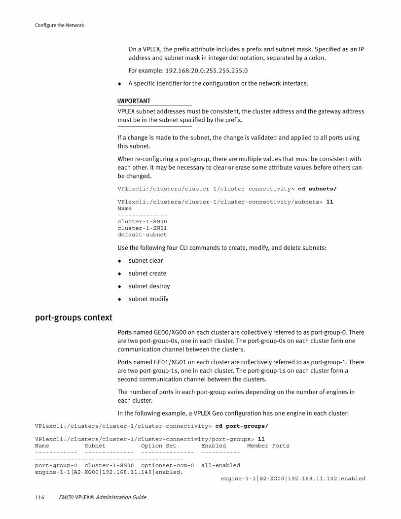
Configure the Network
On a VPLEX, the prefix attribute includes a prefix and subnet mask. Specified as an IP address and subnet mask in integer dot notation, separated by a colon.
For example: 192.168.20.0:255.255.255.0
◆ A specific identifier for the configuration or the network interface.
IMPORTANT
VPLEX subnet addresses must be consistent, the cluster address and the gateway address must be in the subnet specified by the prefix.
If a change is made to the subnet, the change is validated and applied to all ports using this subnet.
When re-configuring a port-group, there are multiple values that must be consistent with each other. It may be necessary to clear or erase some attribute values before others can be changed.
VPlexcli:/clusters/cluster-1/cluster-connectivity> cd subnets/
VPlexcli:/clusters/cluster-1/cluster-connectivity/subnets> llName--------------cluster-1-SN00cluster-1-SN01default-subnet
Use the following four CLI commands to create, modify, and delete subnets:
◆ subnet clear
◆ subnet create
◆ subnet destroy
◆ subnet modify
port-groups context
Ports named GE00/XG00 on each cluster are collectively referred to as port-group-0. There are two port-group-0s, one in each cluster. The port-group-0s on each cluster form one communication channel between the clusters.
Ports named GE01/XG01 on each cluster are collectively referred to as port-group-1. There are two port-group-1s, one in each cluster. The port-group-1s on each cluster form a second communication channel between the clusters.
The number of ports in each port-group varies depending on the number of engines in each cluster.
In the following example, a VPLEX Geo configuration has one engine in each cluster:
VPlexcli:/clusters/cluster-1/cluster-connectivity> cd port-groups/
VPlexcli:/clusters/cluster-1/cluster-connectivity/port-groups> llName Subnet Option Set Enabled Member Ports------------ -------------- --------------- ----------- ------------------------------------------port-group-0 cluster-1-SN00 optionset-com-0 all-enabled engine-1-1|A2-XG00|192.168.11.140|enabled, engine-1-1|B2-XG00|192.168.11.142|enabled
116 EMC® VPLEX® Administration Guide
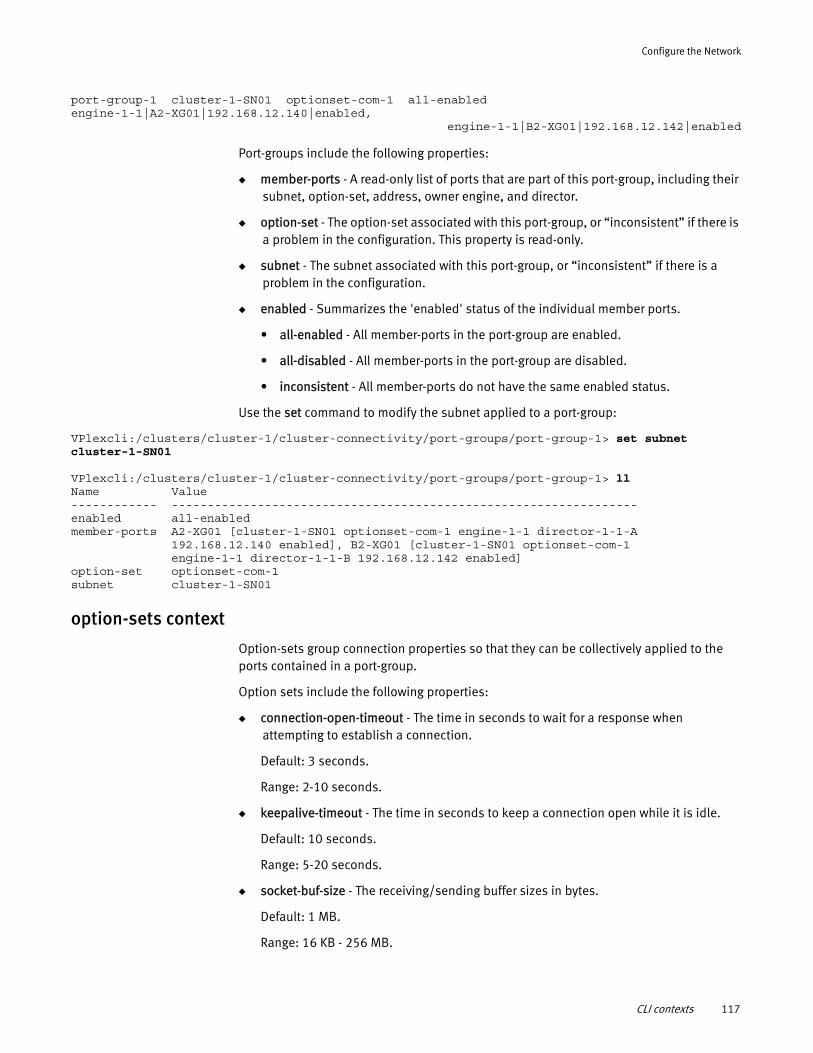
Configure the Network
port-group-1 cluster-1-SN01 optionset-com-1 all-enabled engine-1-1|A2-XG01|192.168.12.140|enabled, engine-1-1|B2-XG01|192.168.12.142|enabled
Port-groups include the following properties:
◆ member-ports - A read-only list of ports that are part of this port-group, including their subnet, option-set, address, owner engine, and director.
◆ option-set - The option-set associated with this port-group, or “inconsistent” if there is a problem in the configuration. This property is read-only.
◆ subnet - The subnet associated with this port-group, or “inconsistent” if there is a problem in the configuration.
◆ enabled - Summarizes the 'enabled' status of the individual member ports.
• all-enabled - All member-ports in the port-group are enabled.
• all-disabled - All member-ports in the port-group are disabled.
• inconsistent - All member-ports do not have the same enabled status.
Use the set command to modify the subnet applied to a port-group:
VPlexcli:/clusters/cluster-1/cluster-connectivity/port-groups/port-group-1> set subnet cluster-1-SN01
VPlexcli:/clusters/cluster-1/cluster-connectivity/port-groups/port-group-1> llName Value------------ -----------------------------------------------------------------enabled all-enabledmember-ports A2-XG01 [cluster-1-SN01 optionset-com-1 engine-1-1 director-1-1-A 192.168.12.140 enabled], B2-XG01 [cluster-1-SN01 optionset-com-1 engine-1-1 director-1-1-B 192.168.12.142 enabled]option-set optionset-com-1subnet cluster-1-SN01
option-sets context
Option-sets group connection properties so that they can be collectively applied to the ports contained in a port-group.
Option sets include the following properties:
◆ connection-open-timeout - The time in seconds to wait for a response when attempting to establish a connection.
Default: 3 seconds.
Range: 2-10 seconds.
◆ keepalive-timeout - The time in seconds to keep a connection open while it is idle.
Default: 10 seconds.
Range: 5-20 seconds.
◆ socket-buf-size - The receiving/sending buffer sizes in bytes.
Default: 1 MB.
Range: 16 KB - 256 MB.
CLI contexts 117
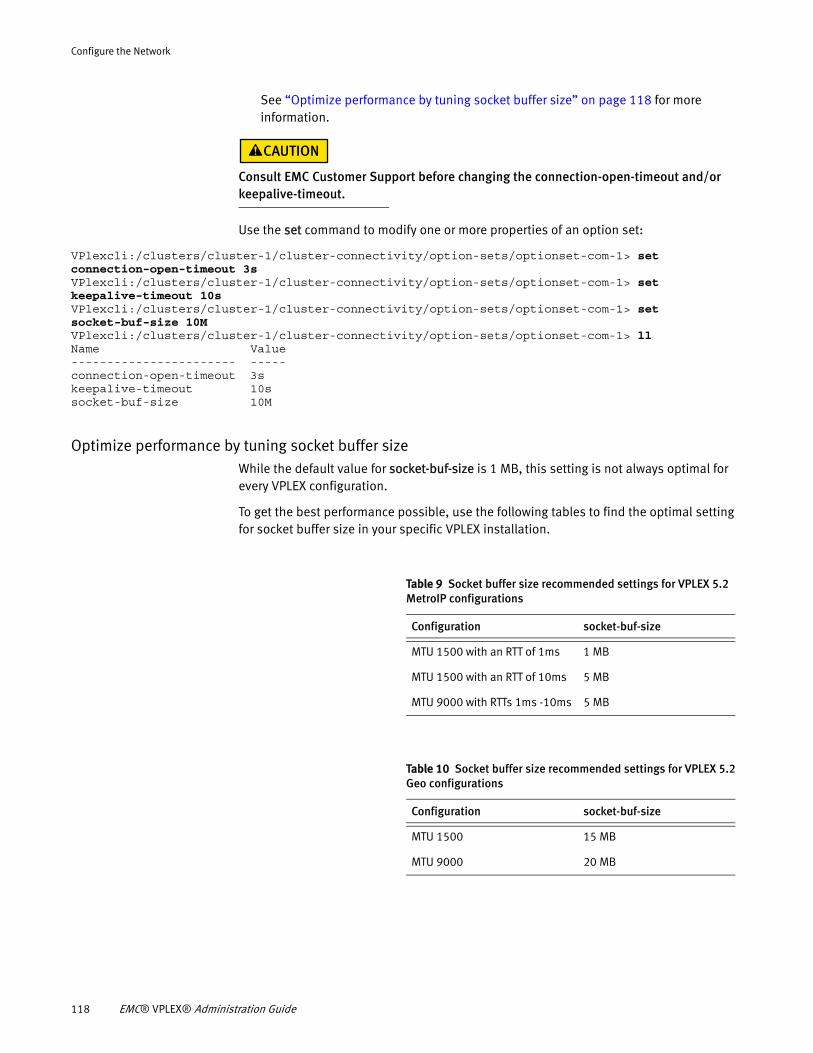
Configure the Network
See “Optimize performance by tuning socket buffer size” on page 118 for more information.
Consult EMC Customer Support before changing the connection-open-timeout and/or keepalive-timeout.
Use the set command to modify one or more properties of an option set:
VPlexcli:/clusters/cluster-1/cluster-connectivity/option-sets/optionset-com-1> set connection-open-timeout 3sVPlexcli:/clusters/cluster-1/cluster-connectivity/option-sets/optionset-com-1> set keepalive-timeout 10sVPlexcli:/clusters/cluster-1/cluster-connectivity/option-sets/optionset-com-1> set socket-buf-size 10MVPlexcli:/clusters/cluster-1/cluster-connectivity/option-sets/optionset-com-1> llName Value----------------------- -----connection-open-timeout 3skeepalive-timeout 10ssocket-buf-size 10M
Optimize performance by tuning socket buffer sizeWhile the default value for socket-buf-size is 1 MB, this setting is not always optimal for every VPLEX configuration.
To get the best performance possible, use the following tables to find the optimal setting for socket buffer size in your specific VPLEX installation.
Table 9 Socket buffer size recommended settings for VPLEX 5.2 MetroIP configurations
Configuration socket-buf-size
MTU 1500 with an RTT of 1ms 1 MB
MTU 1500 with an RTT of 10ms 5 MB
MTU 9000 with RTTs 1ms -10ms 5 MB
Table 10 Socket buffer size recommended settings for VPLEX 5.2 Geo configurations
Configuration socket-buf-size
MTU 1500 15 MB
MTU 9000 20 MB
118 EMC® VPLEX® Administration Guide
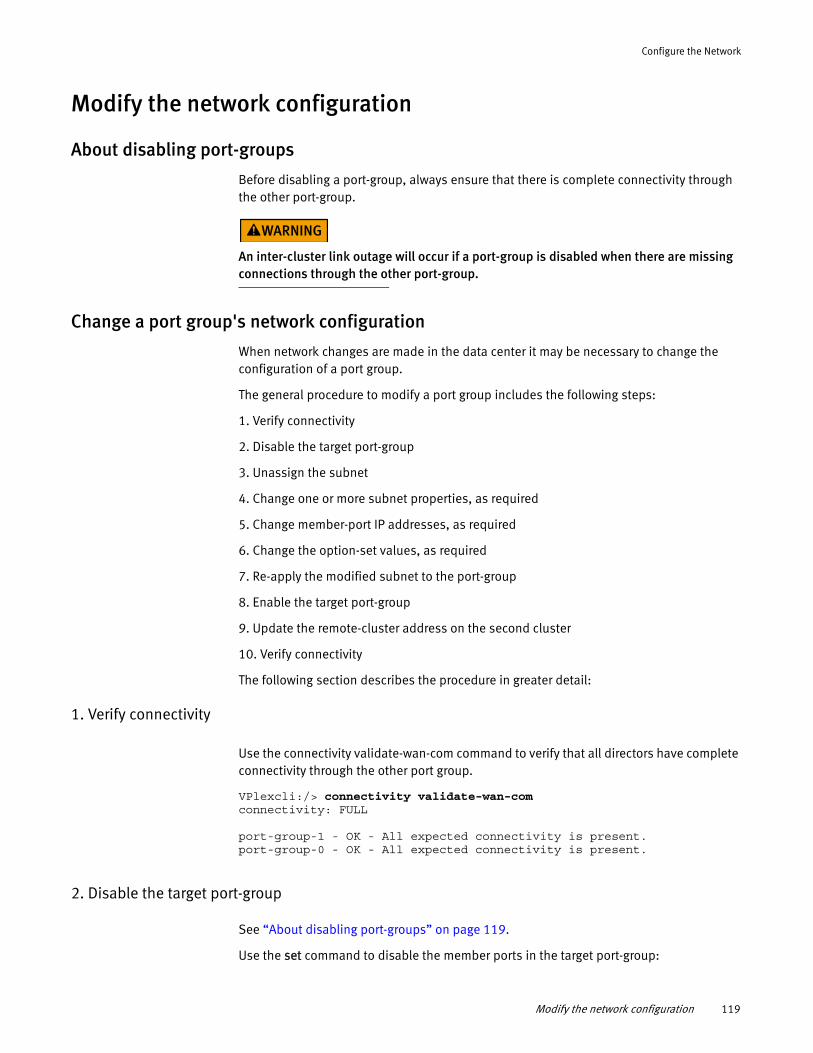
Configure the Network
Modify the network configuration
About disabling port-groups
Before disabling a port-group, always ensure that there is complete connectivity through the other port-group.
An inter-cluster link outage will occur if a port-group is disabled when there are missing connections through the other port-group.
Change a port group's network configuration
When network changes are made in the data center it may be necessary to change the configuration of a port group.
The general procedure to modify a port group includes the following steps:
1. Verify connectivity
2. Disable the target port-group
3. Unassign the subnet
4. Change one or more subnet properties, as required
5. Change member-port IP addresses, as required
6. Change the option-set values, as required
7. Re-apply the modified subnet to the port-group
8. Enable the target port-group
9. Update the remote-cluster address on the second cluster
10. Verify connectivity
The following section describes the procedure in greater detail:
1. Verify connectivity
Use the connectivity validate-wan-com command to verify that all directors have complete connectivity through the other port group.
VPlexcli:/> connectivity validate-wan-com connectivity: FULL port-group-1 - OK - All expected connectivity is present. port-group-0 - OK - All expected connectivity is present.
2. Disable the target port-group
See “About disabling port-groups” on page 119.
Use the set command to disable the member ports in the target port-group:
Modify the network configuration 119
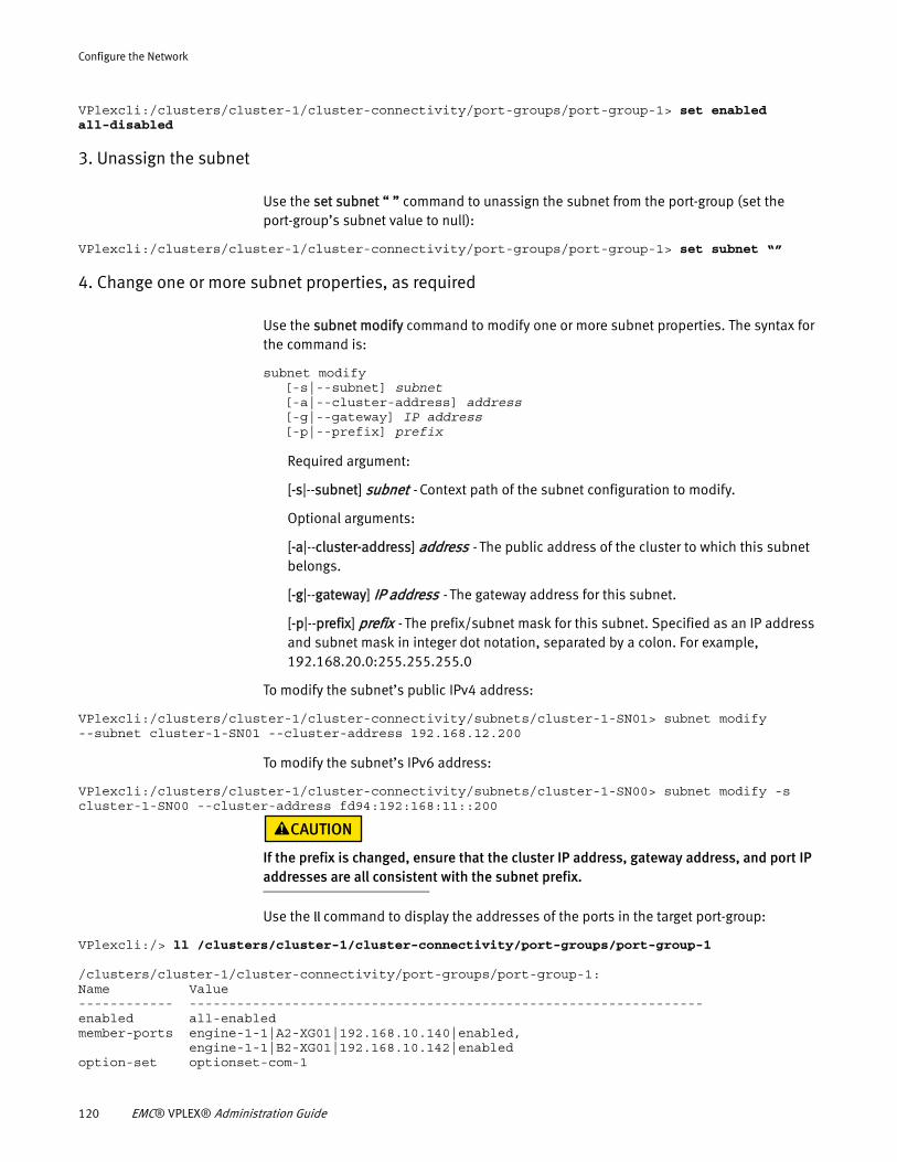
Configure the Network
VPlexcli:/clusters/cluster-1/cluster-connectivity/port-groups/port-group-1> set enabled all-disabled
3. Unassign the subnet
Use the set subnet “ ” command to unassign the subnet from the port-group (set the port-group’s subnet value to null):
VPlexcli:/clusters/cluster-1/cluster-connectivity/port-groups/port-group-1> set subnet “”
4. Change one or more subnet properties, as required
Use the subnet modify command to modify one or more subnet properties. The syntax for the command is:
subnet modify[-s|--subnet] subnet[-a|--cluster-address] address[-g|--gateway] IP address[-p|--prefix] prefix
Required argument:
[-s|--subnet] subnet - Context path of the subnet configuration to modify.
Optional arguments:
[-a|--cluster-address] address - The public address of the cluster to which this subnet belongs.
[-g|--gateway] IP address - The gateway address for this subnet.
[-p|--prefix] prefix - The prefix/subnet mask for this subnet. Specified as an IP address and subnet mask in integer dot notation, separated by a colon. For example, 192.168.20.0:255.255.255.0
To modify the subnet’s public IPv4 address:
VPlexcli:/clusters/cluster-1/cluster-connectivity/subnets/cluster-1-SN01> subnet modify --subnet cluster-1-SN01 --cluster-address 192.168.12.200
To modify the subnet’s IPv6 address:
VPlexcli:/clusters/cluster-1/cluster-connectivity/subnets/cluster-1-SN00> subnet modify -s cluster-1-SN00 --cluster-address fd94:192:168:11::200
If the prefix is changed, ensure that the cluster IP address, gateway address, and port IP addresses are all consistent with the subnet prefix.
Use the ll command to display the addresses of the ports in the target port-group:
VPlexcli:/> ll /clusters/cluster-1/cluster-connectivity/port-groups/port-group-1
/clusters/cluster-1/cluster-connectivity/port-groups/port-group-1:Name Value------------ -----------------------------------------------------------------enabled all-enabledmember-ports engine-1-1|A2-XG01|192.168.10.140|enabled, engine-1-1|B2-XG01|192.168.10.142|enabledoption-set optionset-com-1
120 EMC® VPLEX® Administration Guide
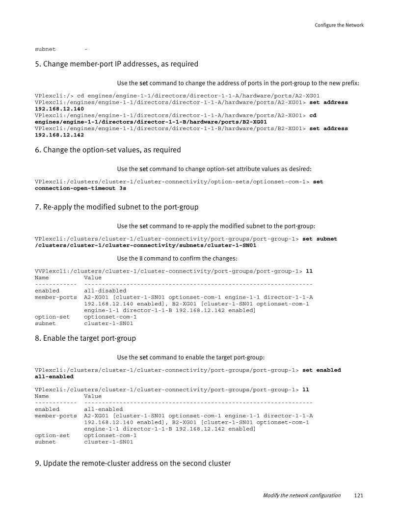
Configure the Network
subnet -
5. Change member-port IP addresses, as required
Use the set command to change the address of ports in the port-group to the new prefix:
VPlexcli:/> cd engines/engine-1-1/directors/director-1-1-A/hardware/ports/A2-XG01VPlexcli:/engines/engine-1-1/directors/director-1-1-A/hardware/ports/A2-XG01> set address 192.168.12.140VPlexcli:/engines/engine-1-1/directors/director-1-1-A/hardware/ports/A2-XG01> cd engines/engine-1-1/directors/director-1-1-B/hardware/ports/B2-XG01VPlexcli:/engines/engine-1-1/directors/director-1-1-B/hardware/ports/B2-XG01> set address 192.168.12.142
6. Change the option-set values, as required
Use the set command to change option-set attribute values as desired:
VPlexcli:/clusters/cluster-1/cluster-connectivity/option-sets/optionset-com-1> set connection-open-timeout 3s
7. Re-apply the modified subnet to the port-group
Use the set command to re-apply the modified subnet to the port-group:
VPlexcli:/clusters/cluster-1/cluster-connectivity/port-groups/port-group-1> set subnet /clusters/cluster-1/cluster-connectivity/subnets/cluster-1-SN01
Use the ll command to confirm the changes:
VVPlexcli:/clusters/cluster-1/cluster-connectivity/port-groups/port-group-1> llName Value------------ -----------------------------------------------------------------enabled all-disabledmember-ports A2-XG01 [cluster-1-SN01 optionset-com-1 engine-1-1 director-1-1-A 192.168.12.140 enabled], B2-XG01 [cluster-1-SN01 optionset-com-1 engine-1-1 director-1-1-B 192.168.12.142 enabled]option-set optionset-com-1subnet cluster-1-SN01
8. Enable the target port-group
Use the set command to enable the target port-group:
VPlexcli:/clusters/cluster-1/cluster-connectivity/port-groups/port-group-1> set enabled all-enabled
VPlexcli:/clusters/cluster-1/cluster-connectivity/port-groups/port-group-1> llName Value------------ -----------------------------------------------------------------enabled all-enabledmember-ports A2-XG01 [cluster-1-SN01 optionset-com-1 engine-1-1 director-1-1-A 192.168.12.140 enabled], B2-XG01 [cluster-1-SN01 optionset-com-1 engine-1-1 director-1-1-B 192.168.12.142 enabled]option-set optionset-com-1subnet cluster-1-SN01
9. Update the remote-cluster address on the second cluster
Modify the network configuration 121
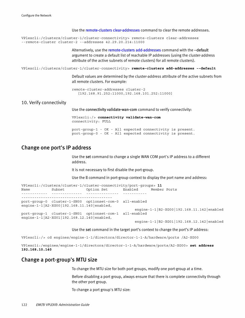
Configure the Network
Use the remote-clusters clear-addresses command to clear the remote addresses.
VPlexcli:/clusters/cluster-1/cluster-connectivity> remote-clusters clear-addresses --remote-cluster cluster-2 --addresses 42.29.20.214:11000
Alternatively, use the remote-clusters add-addresses command with the --default argument to create a default list of reachable IP addresses (using the cluster-address attribute of the active subnets of remote clusters) for all remote clusters).
VPlexcli:/clusters/cluster-1/cluster-connectivity> remote-clusters add-addresses --default
Default values are determined by the cluster-address attribute of the active subnets from all remote clusters. For example:
remote-cluster-addresses cluster-2 [192.168.91.252:11000,192.168.101.252:11000]
10. Verify connectivity Use the connectivity validate-wan-com command to verify connectivity:
VPlexcli:/> connectivity validate-wan-com connectivity: FULL port-group-1 - OK - All expected connectivity is present. port-group-0 - OK - All expected connectivity is present.
Change one port's IP address
Use the set command to change a single WAN COM port's IP address to a different address.
It is not necessary to first disable the port-group.
Use the ll command in port-group context to display the port name and address:
VPlexcli:/clusters/cluster-1/cluster-connectivity/port-groups> llName Subnet Option Set Enabled Member Ports------------ -------------- --------------- ----------- ------------------------------------------port-group-0 cluster-1-SN00 optionset-com-0 all-enabled engine-1-1|A2-XG00|192.168.11.140|enabled, engine-1-1|B2-XG00|192.168.11.142|enabledport-group-1 cluster-1-SN01 optionset-com-1 all-enabled engine-1-1|A2-XG01|192.168.12.140|enabled, engine-1-1|B2-XG01|192.168.12.142|enabled
Use the set command in the target port’s context to change the port’s IP address:
VPlexcli:/> cd engines/engine-1-1/directors/director-1-1-A/hardware/ports /A2-XG00
VPlexcli:/engines/engine-1-1/directors/director-1-1-A/hardware/ports/A2-XG00> set address 192.168.10.140
Change a port-group's MTU size
To change the MTU size for both port groups, modify one port-group at a time.
Before disabling a port group, always ensure that there is complete connectivity through the other port group.
To change a port group's MTU size:
122 EMC® VPLEX® Administration Guide
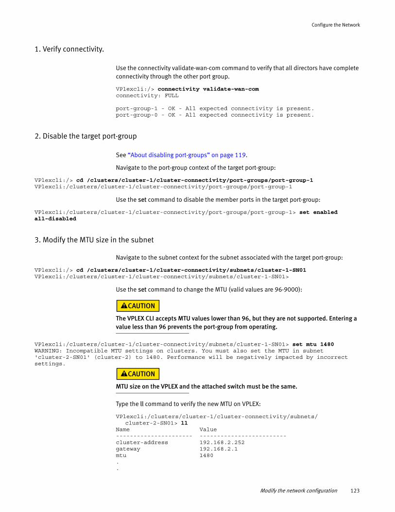
Configure the Network
1. Verify connectivity.
Use the connectivity validate-wan-com command to verify that all directors have complete connectivity through the other port group.
VPlexcli:/> connectivity validate-wan-com connectivity: FULL port-group-1 - OK - All expected connectivity is present. port-group-0 - OK - All expected connectivity is present.
2. Disable the target port-group
See “About disabling port-groups” on page 119.
Navigate to the port-group context of the target port-group:
VPlexcli:/> cd /clusters/cluster-1/cluster-connectivity/port-groups/port-group-1VPlexcli:/clusters/cluster-1/cluster-connectivity/port-groups/port-group-1
Use the set command to disable the member ports in the target port-group:
VPlexcli:/clusters/cluster-1/cluster-connectivity/port-groups/port-group-1> set enabled all-disabled
3. Modify the MTU size in the subnet
Navigate to the subnet context for the subnet associated with the target port-group:
VPlexcli:/> cd /clusters/cluster-1/cluster-connectivity/subnets/cluster-1-SN01VPlexcli:/clusters/cluster-1/cluster-connectivity/subnets/cluster-1-SN01>
Use the set command to change the MTU (valid values are 96-9000):
The VPLEX CLI accepts MTU values lower than 96, but they are not supported. Entering a value less than 96 prevents the port-group from operating.
VPlexcli:/clusters/cluster-1/cluster-connectivity/subnets/cluster-1-SN01> set mtu 1480WARNING: Incompatible MTU settings on clusters. You must also set the MTU in subnet 'cluster-2-SN01' (cluster-2) to 1480. Performance will be negatively impacted by incorrect settings.
MTU size on the VPLEX and the attached switch must be the same.
Type the ll command to verify the new MTU on VPLEX:
VPlexcli:/clusters/cluster-1/cluster-connectivity/subnets/ cluster-2-SN01> ll
Name Value---------------------- -------------------------cluster-address 192.168.2.252gateway 192.168.2.1mtu 1480..
Modify the network configuration 123
Configure the Network
.
Verify that the MTU size on VPLEX matches the MTU on attached switch.
Repeat for the second subnet.
4.Enable the port group
Navigate to the port-group context of the target port-group:
VPlexcli:/> cd /clusters/cluster-1/cluster-connectivity/port-groups/port-group-1VPlexcli:/clusters/cluster-1/cluster-connectivity/port-groups/port-group-1
Use the set command to enable the member ports in the target port-group:
VPlexcli:/clusters/cluster-1/cluster-connectivity/port-groups/port-group-1> set enabled all-enabled
5.Validate connectivity
Use the connectivity validate-wan-com command to verify that the directors have complete connectivity through all port groups.
VPlexcli:/> connectivity validate-wan-com connectivity: FULL port-group-1 - OK - All expected connectivity is present. port-group-0 - OK - All expected connectivity is present.
LDAPThe Lightweight Directory Access Protocol (LDAP) is an application protocol for accessing and maintaining distributed directory information services over an Internet Protocol (IP) network. Directory services provides any organized set of records with a hierarchical structure. LDAP is a client-server model protocol.
Directory structure
The organization of a directory is a tree structure. The top most entry in a directory is known as the root entry. This entry normally represents the organization that owns the directory. Figure 13 illustrates an LDAP tree structure.
124 EMC® VPLEX® Administration Guide
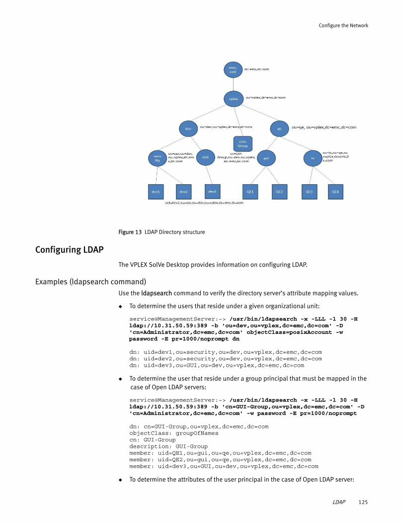
Configure the Network
Figure 13 LDAP Directory structure
Configuring LDAP
The VPLEX SolVe Desktop provides information on configuring LDAP.
Examples (ldapsearch command)Use the ldapsearch command to verify the directory server’s attribute mapping values.
◆ To determine the users that reside under a given organizational unit:
service@ManagementServer:~> /usr/bin/ldapsearch -x -LLL -l 30 -H ldap://10.31.50.59:389 -b 'ou=dev,ou=vplex,dc=emc,dc=com' -D 'cn=Administrator,dc=emc,dc=com' objectClass=posixAccount -w password -E pr=1000/noprompt dn
dn: uid=dev1,ou=security,ou=dev,ou=vplex,dc=emc,dc=comdn: uid=dev2,ou=security,ou=dev,ou=vplex,dc=emc,dc=comdn: uid=dev3,ou=GUI,ou=dev,ou=vplex,dc=emc,dc=com
◆ To determine the user that reside under a group principal that must be mapped in the case of Open LDAP servers:
service@ManagementServer:~> /usr/bin/ldapsearch -x -LLL -l 30 -H ldap://10.31.50.59:389 -b 'cn=GUI-Group,ou=vplex,dc=emc,dc=com' -D 'cn=Administrator,dc=emc,dc=com' -w password -E pr=1000/noprompt
dn: cn=GUI-Group,ou=vplex,dc=emc,dc=comobjectClass: groupOfNamescn: GUI-Groupdescription: GUI-Groupmember: uid=QE1,ou=gui,ou=qe,ou=vplex,dc=emc,dc=commember: uid=QE2,ou=gui,ou=qe,ou=vplex,dc=emc,dc=commember: uid=dev3,ou=GUI,ou=dev,ou=vplex,dc=emc,dc=com
◆ To determine the attributes of the user principal in the case of Open LDAP server:
LDAP 125
Configure the Network
service@ManagementServer:~> /usr/bin/ldapsearch -x -LLL -l 30 -H ldap://10.31.50.59:389 -b 'uid=dev1,ou=security,ou=dev,ou=vplex,dc=emc,dc=com' -D 'cn=Administrator,dc=emc,dc=com' -w zephyr01 -E pr=1000/noprompt
dn: uid=dev1,ou=security,ou=dev,ou=vplex,dc=emc,dc=comsn: devcn: dev1objectClass: topobjectClass: personobjectClass: organizationalPersonobjectClass: posixAccountuid: dev1loginShell: /bin/bashhomeDirectory: /u/v/x/y/dev1uidNumber: 50000gidNumber: 80000
About IPv6 addressingIPv6 is the latest version of IP. IPv6 was proposed to address the inadequacy of the 32-bit addressing scheme of IPv4. IPv6 builds upon the functionality of IPv4, providing improved addressing and security.
IPv6 address representation
IPv6 uses 128-bit addresses. IPv6 addresses use eight sets of four hexadecimal addresses (with 16 bits in each set), separated by a colon (:).
FE80:31AD:C41D::1234 is an example of an IPv6 address.
Note: In an IPv6 address notation, a double colon (::) can be used only once.An IPv6 address is usually specified within square brackets, if the port number is specified.
IPv6 address types
The three types of IPv6 addresses are:
◆ Unicast - An identifier for a single interface. A packet sent to an unicast address is delivered to the interface identified by that address.
There are different types of unicast addresses:
• Link-local address
• Global address
• Site-local address
• Unspecified address
• Loopback address
◆ Anycast - An identifier for a set of interfaces. A packet sent to an anycast address is delivered to any one of the interfaces identified by that address.
◆ Multicast – An identifier for a set of interfaces. A packet sent to a multicast address is delivered to all interfaces identified by that address.
126 EMC® VPLEX® Administration Guide
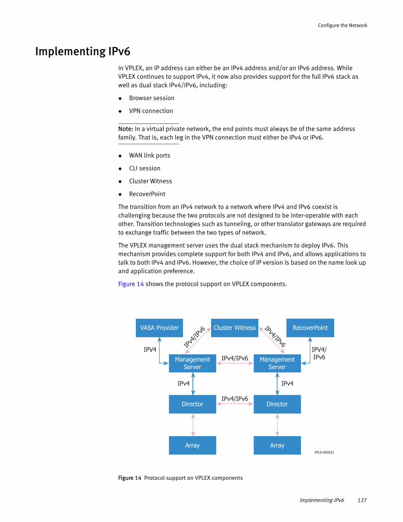
Configure the Network
Implementing IPv6In VPLEX, an IP address can either be an IPv4 address and/or an IPv6 address. While VPLEX continues to support IPv4, it now also provides support for the full IPv6 stack as well as dual stack IPv4/IPv6, including:
◆ Browser session
◆ VPN connection
Note: In a virtual private network, the end points must always be of the same address family. That is, each leg in the VPN connection must either be IPv4 or IPv6.
◆ WAN link ports
◆ CLI session
◆ Cluster Witness
◆ RecoverPoint
The transition from an IPv4 network to a network where IPv4 and IPv6 coexist is challenging because the two protocols are not designed to be inter-operable with each other. Transition technologies such as tunneling, or other translator gateways are required to exchange traffic between the two types of network.
The VPLEX management server uses the dual stack mechanism to deploy IPv6. This mechanism provides complete support for both IPv4 and IPv6, and allows applications to talk to both IPv4 and IPv6. However, the choice of IP version is based on the name look up and application preference.
Figure 14 shows the protocol support on VPLEX components.
Figure 14 Protocol support on VPLEX components
VASA Provider RecoverPointCluster Witness
IPv4
/IPv6
IPv4/IPv6
Array Array
ManagementServer
ManagementServer
IPv4/IPv6
Director DirectorIPv4/IPv6
IPv4 IPv4
IPV4 IPV4/IPv6
VPLX-000551
Implementing IPv6 127
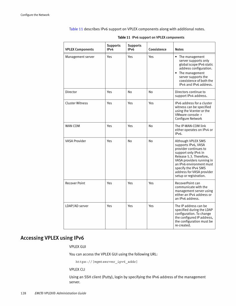
Configure the Network
Table 11 describes IPv6 support on VPLEX components along with additional notes.
Accessing VPLEX using IPv6
VPLEX GUI
You can access the VPLEX GUI using the following URL:
https://[mgmtserver_ipv6_addr]
VPLEX CLI
Using an SSH client (Putty), login by specifying the IPv6 address of the management server.
Table 11 IPv6 support on VPLEX components
VPLEX ComponentsSupports IPv4
Supports IPv6 Coexistence Notes
Management server Yes Yes Yes • The management server supports only global scope IPv6 static address configuration.
• The management server supports the coexistence of both the IPv4 and IPv6 address.
Director Yes No No Directors continue to support IPv4 address.
Cluster Witness Yes Yes Yes IPv6 address for a cluster witness can be specified using the Vcenter or the VMware console -> Configure Network
WAN COM Yes Yes No The IP-WAN-COM link either operates on IPv4 or IPv6.
VASA Provider Yes No No Although VPLEX SMS supports IPv6, VASA provider continues to support only IPv4 in Release 5.3. Therefore, VASA providers running in an IPv6 environment must specify the IPv4 SMS address for VASA provider setup or registration.
Recover Point Yes Yes Yes RecoverPoint can communicate with the management server using either an IPv4 address or an IPv6 address.
LDAP/AD server Yes Yes Yes The IP address can be specified during the LDAP configuration. To change the configured IP address, the configuration must be re-created.
128 EMC® VPLEX® Administration Guide
Configure the Network
Configuring IPv6 on the management server
Use the VPLEX CLI management-server set-ip command to set the IPv6 address and net-mask for port eth3.
The VPLEX CLI Guide provides more information on the commands and their usage.
Implementing IPv6 129

Configure the Network
130 EMC® VPLEX® Administration Guide
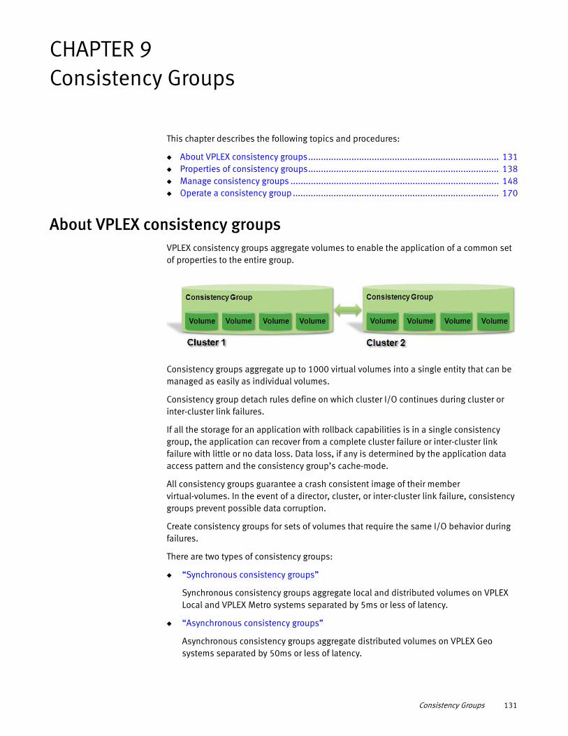
CHAPTER 9Consistency Groups
This chapter describes the following topics and procedures:
◆ About VPLEX consistency groups........................................................................... 131◆ Properties of consistency groups........................................................................... 138◆ Manage consistency groups .................................................................................. 148◆ Operate a consistency group ................................................................................. 170
About VPLEX consistency groupsVPLEX consistency groups aggregate volumes to enable the application of a common set of properties to the entire group.
Consistency groups aggregate up to 1000 virtual volumes into a single entity that can be managed as easily as individual volumes.
Consistency group detach rules define on which cluster I/O continues during cluster or inter-cluster link failures.
If all the storage for an application with rollback capabilities is in a single consistency group, the application can recover from a complete cluster failure or inter-cluster link failure with little or no data loss. Data loss, if any is determined by the application data access pattern and the consistency group’s cache-mode.
All consistency groups guarantee a crash consistent image of their member virtual-volumes. In the event of a director, cluster, or inter-cluster link failure, consistency groups prevent possible data corruption.
Create consistency groups for sets of volumes that require the same I/O behavior during failures.
There are two types of consistency groups:
◆ “Synchronous consistency groups”
Synchronous consistency groups aggregate local and distributed volumes on VPLEX Local and VPLEX Metro systems separated by 5ms or less of latency.
◆ “Asynchronous consistency groups”
Asynchronous consistency groups aggregate distributed volumes on VPLEX Geo systems separated by 50ms or less of latency.
Consistency Groups 131
Consistency Groups
Note: In the current release, asynchronous consistency groups cannot be replicated by RecoverPoint.
A consistency group has either synchronous cache mode or asynchronous cache mode, but not both.
Synchronous consistency groups
Synchronous consistency groups provide a convenient way to apply rule sets and other properties to a group of volumes in a VPLEX Local or VPLEX Metro.
Synchronous consistency groups simplify configuration and administration on large systems.
VPLEX supports up to 1024 synchronous consistency groups.
A synchronous consistency group:
◆ Contains up to 1000 virtual volumes.
◆ Contains either local or distributed volumes, (but not a mixture of both).
◆ Contains volumes with either global or local visibility.
◆ Uses write-through caching (known as synchronous cache mode in the VPLEX user interface).
Write order fidelity is maintained by completing all writes to disk before acknowledging the write to the host.
Figure 15 shows a synchronous consistency group that spans two clusters in a VPLEX Metro configuration.
◆ The hosts at both clusters write to the VPLEX distributed volumes in the consistency group.
◆ VPLEX writes data to the back-end storage on both clusters
◆ An acknowledgment is returned to the host that is issuing the write.
This guarantees that the image on the back end storage is an exact copy on both sides.
Using Consistency Groups with VPLEX WitnessVPLEX Witness failure recovery semantics apply only to volumes in synchronous consistency groups and only if a rule identifying specific preference is configured.
Using Consistency Groups with RecoverPointRecoverPoint protection can only be enabled through volumes in synchronous consistency groups with the recover-point option set.
132 EMC® VPLEX® Administration Guide
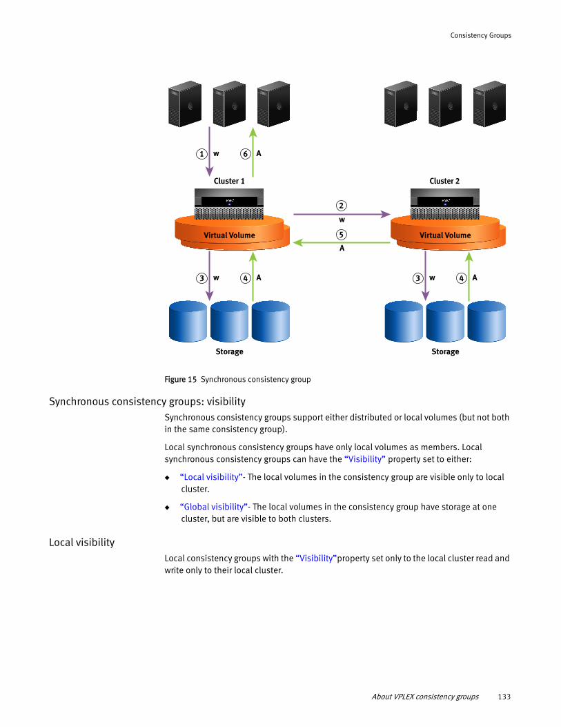
Consistency Groups
Figure 15 Synchronous consistency group
Synchronous consistency groups: visibilitySynchronous consistency groups support either distributed or local volumes (but not both in the same consistency group).
Local synchronous consistency groups have only local volumes as members. Local synchronous consistency groups can have the “Visibility” property set to either:
◆ “Local visibility”- The local volumes in the consistency group are visible only to local cluster.
◆ “Global visibility”- The local volumes in the consistency group have storage at one cluster, but are visible to both clusters.
Local visibilityLocal consistency groups with the “Visibility”property set only to the local cluster read and write only to their local cluster.
Cluster 1
Storage
Virtual Volume
Cluster 2
Storage
Virtual Volume
w
w
A
A61
w A43 w A43
2
5
About VPLEX consistency groups 133
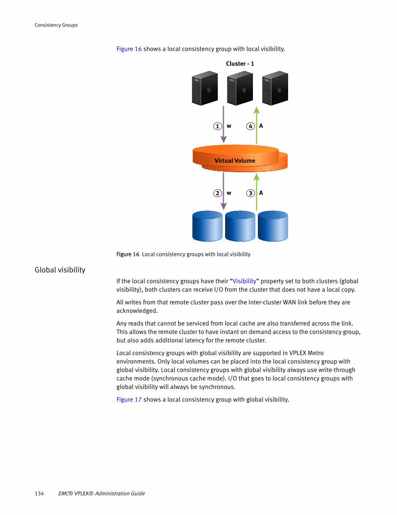
Consistency Groups
Figure 16 shows a local consistency group with local visibility.
Figure 16 Local consistency groups with local visibility
Global visibilityIf the local consistency groups have their “Visibility” property set to both clusters (global visibility), both clusters can receive I/O from the cluster that does not have a local copy.
All writes from that remote cluster pass over the inter-cluster WAN link before they are acknowledged.
Any reads that cannot be serviced from local cache are also transferred across the link. This allows the remote cluster to have instant on demand access to the consistency group, but also adds additional latency for the remote cluster.
Local consistency groups with global visibility are supported in VPLEX Metro environments. Only local volumes can be placed into the local consistency group with global visibility. Local consistency groups with global visibility always use write-through cache mode (synchronous cache mode). I/O that goes to local consistency groups with global visibility will always be synchronous.
Figure 17 shows a local consistency group with global visibility.
Cluster - 1
Virtual Volume
w A32
w A41
134 EMC® VPLEX® Administration Guide
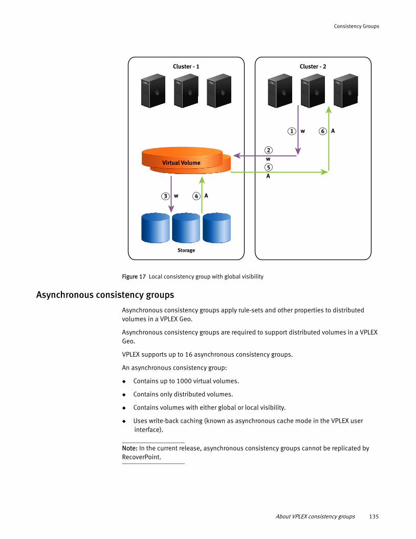
Consistency Groups
Figure 17 Local consistency group with global visibility
Asynchronous consistency groups
Asynchronous consistency groups apply rule-sets and other properties to distributed volumes in a VPLEX Geo.
Asynchronous consistency groups are required to support distributed volumes in a VPLEX Geo.
VPLEX supports up to 16 asynchronous consistency groups.
An asynchronous consistency group:
◆ Contains up to 1000 virtual volumes.
◆ Contains only distributed volumes.
◆ Contains volumes with either global or local visibility.
◆ Uses write-back caching (known as asynchronous cache mode in the VPLEX user interface).
Note: In the current release, asynchronous consistency groups cannot be replicated by RecoverPoint.
Cluster - 1
Virtual Volume
Storage
w A
Cluster - 2
w A
w
A
1 6
2
5
43
About VPLEX consistency groups 135
Consistency Groups
Write-back cachingIn asynchronous cache mode, write order fidelity is maintained by batching I/O between the clusters into packages called deltas that are exchanged between clusters.
Each delta contains a group of writes that were initiated in the same window of time. All writes in one delta are guaranteed to be newer than all writes in the next delta.
Write order consistency is maintained on delta set boundaries, not on individual writes.
Entire deltas are exchanged between clusters and committed to disks as a logical unit.
Each asynchronous consistency group maintains its own queue of deltas in various states:
• open - The delta is accepting new writes.
• closed - The delta is not accepting writes. Deltas are closed when their timer expires or they are full.
• exchanging - The delta's contents are being synchronized between the clusters.
• exchanged - The delta is exchanged with the remote cluster. The delta's contents are the same at all clusters.
• committing- The delta's contents are being written out to the back-end storage.
• committed - The write of the delta’s contents to the back-end storage is complete.
There can be only one delta in each state except closed.
There can be multiple deltas in the closed delta queue.
Before a delta is exchanged between clusters, data within the delta can vary by cluster. After a delta is exchanged and committed, data is exactly the same on both clusters.
If access to the back-end array is lost while the system is writing a delta, the data on disk is no longer consistent and requires automatic recovery when access is restored.
Asynchronous cache mode can deliver better performance, but there is a higher risk that data will be lost if:
◆ Multiple directors fail at the same time.
◆ There is an inter-cluster link partition and both clusters are actively writing and instead of waiting for the link to be restored, the user chooses to accept a data rollback in order to reduce the Real Time Objective (RTO).
◆ The cluster that is actively writing fails.
Asynchronous consistency group: active/passiveIn an asynchronous consistency group, the host receives acknowledgment after the write reaches the VPLEX cache and has been protected to another director in the local cluster.
VPLEX collects writes at the cluster in the form of a delta. At a later point in time, the clusters exchange deltas creating a globally merged delta. The clusters send communication messages back and forth between each other to facilitate the exchange.
Once the exchange is complete, the clusters write a global merged delta to the back-end arrays.
136 EMC® VPLEX® Administration Guide
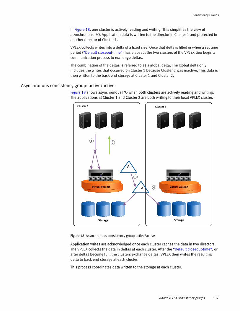
Consistency Groups
In Figure 18, one cluster is actively reading and writing. This simplifies the view of asynchronous I/O. Application data is written to the director in Cluster 1 and protected in another director of Cluster 1.
VPLEX collects writes into a delta of a fixed size. Once that delta is filled or when a set time period (“Default closeout-time”) has elapsed, the two clusters of the VPLEX Geo begin a communication process to exchange deltas.
The combination of the deltas is referred to as a global delta. The global delta only includes the writes that occurred on Cluster 1 because Cluster 2 was inactive. This data is then written to the back-end storage at Cluster 1 and Cluster 2.
Asynchronous consistency group: active/activeFigure 18 shows asynchronous I/O when both clusters are actively reading and writing. The applications at Cluster 1 and Cluster 2 are both writing to their local VPLEX cluster.
Figure 18 Asynchronous consistency group active/active
Application writes are acknowledged once each cluster caches the data in two directors. The VPLEX collects the data in deltas at each cluster. After the “Default closeout-time”, or after deltas become full, the clusters exchange deltas. VPLEX then writes the resulting delta to back end storage at each cluster.
This process coordinates data written to the storage at each cluster.
Cluster 1
Storage
Virtual Volume
Cluster 2
Storage
Virtual Volume
1 2
A
3
4A
About VPLEX consistency groups 137
Consistency Groups
Asynchronous consistency group: RPOThe Recovery Point Objective (RPO) is the maximum acceptable level of data loss resulting from a failure. RPO represents the point in time (prior to the failure) to which lost data can be recovered.
Use the “Maximum-queue-depth” and “Default closeout-time” properties to control the RPO. Refer to “Calculating RPO in VPLEX Geo systems” on page 235.
Note: Both properties must be set sufficiently high to accommodate the latency and usable bandwidth between clusters.
Properties of consistency groupsProperties of a consistency group are applied to all the virtual volumes in the consistency group.
All consistency groups have configurable properties that determine I/O behavior, including:
◆ “Cache mode”
◆ “Visibility”
◆ “Storage-at-clusters”
◆ “Local-read-override”
◆ “Detach-rule”
◆ “Auto-resume-at-loser”
◆ “Virtual-volumes”
◆ “Recoverpoint-enabled”
Additional configurable properties are applicable only to consistency groups with asynchronous cache mode, including:
◆ “Active cluster”
◆ “Default closeout-time”
◆ “Maximum-queue-depth”
IMPORTANT
When RecoverPoint is deployed, it may take up to 2 minutes for the RecoverPoint cluster to take note of the changes made to a VPLEX consistency group. Wait for 2 minutes after making the following changes to a VPLEX consistency group and before creating or changing a RecoverPoint consistency group:- Add/remove virtual volumes to/from a VPLEX consistency group.- Enable/disable the recoverpoint-enabled property of a VPLEX consistency group.- Change the detach rule of a VPLEX consistency group.
138 EMC® VPLEX® Administration Guide
Consistency Groups
Cache mode
Cache mode describes how data is written to storage. Cache mode can be either synchronous or asynchronous:
◆ Synchronous cache mode - Supported on VPLEX Local and VPLEX Metro configurations where clusters are separated by up to 5 ms of latency. In synchronous cache mode, writes to the back-end storage volumes are not acknowledged to the host until the back-end storage volumes acknowledge the write.
Writes to the virtual volumes in a synchronous consistency group are written to disk only if all prior acknowledged writes to all volumes in the consistency group are also present on the disk.
◆ Asynchronous cache mode - Supported on VPLEX Geo configurations where clusters are separated by up to 50 ms of latency. In asynchronous cache mode, host writes to a distributed volume are acknowledged back to the host after the data is protected in the cache of another director in the local cluster. These writes are grouped into deltas.
Writes to the virtual volumes in an asynchronous consistency group are ordered such that all the writes in a given delta are written to disk before writes from the next delta.
A maximum of 16 consistency groups with asynchronous cache mode can be configured.
Each asynchronous consistency group can contain up to 1000 virtual volumes.
Use the set command in /clusters/cluster/consistency-groups/consistency-group context to modify the cache mode property.
Note: Storage-at-clusters must be set to cluster-1 and cluster-2 before cache-mode can be changed to asynchronous (asynchronous mode is supported only for DR volumes).
VPlexcli:/clusters/cluster-1/consistency-groups/TestCG> set cache-mode asynchronous
Changing cache mode for a non-empty consistency group that is receiving host I/O requests may temporarily worsen I/O performance.
Visibility
Visibility controls which clusters know about a consistency group.
Note: Visibility for consistency groups differs from the visibility property for devices. Devices can have visibility set to local (visible only to the local cluster) or global (visible to both clusters). All distributed devices have global visibility.
By default, a consistency groups’s visibility property is set only to the cluster where the consistency group was created. If a consistency group is created on cluster-2, it is initially visible only on cluster-2.
The visibility of the volumes within the consistency group must match the visibility of the consistency group.
Properties of consistency groups 139
Consistency Groups
If the visibility of a volume in a consistency group is set to local, the visibility of the consistency group cannot be set to include other clusters. For example, if volume “LocalVolume” with visibility property set to “local” is added to consistency group “TestCG” the visibility of TestCG cannot be modified to include other clusters.
In general, visibility is set to one of three options:
◆ Configure the consistency group to contain only volumes that are local to the local cluster.
◆ Configure the consistency group to contain only volumes that have storage at one cluster, but have global visibility.
◆ Configure the consistency group to contain only volumes that are distributed with legs at both clusters.
When a consistency group’s visibility is set to a cluster, the consistency group appears below /clusters/cluster-n/consistency-groups context for the cluster.
Note: The context for a specified consistency group appears in a cluster’s consistency group CLI context only if the “Visibility”” property of the consistency group includes that cluster.
Under normal operations, the visibility property can be modified to expand from one cluster to both clusters.
Use the set command in /clusters/cluster/consistency-groups/consistency-group context to modify the visibility property. If consistency group “TestCG” is visible only at cluster-1, use the set command to make it visible to cluster-1 and cluster-2:
VPlexcli:/clusters/cluster-1/consistency-groups/TestCG> set visibility cluster-1,cluster-2
If a consistency group contains virtual volumes with a given visibility (for example, a member volume’s visibility is “local”), the visibility property for the consistency group cannot be changed to conflict with the visibility property of the member virtual volume.
For example, consistency group "TestCG" is visible only at cluster-1, and contains a volume "V" whose device is at cluster-1 and has local visibility. Both the following commands will fail, because the volume V is not visible at cluster-2.
VPlexcli:/clusters/cluster-1/consistency-groups/TestCG> set visibility cluster-1,cluster-2VPlexcli:/clusters/cluster-1/consistency-groups/TestCG> set visibility cluster-2
Storage-at-clusters
Storage-at-clusters tells VPLEX at which cluster the physical storage associated with a consistency group is located.
The storage-at-clusters property of a consistency group must be a non-empty subset of the consistency group’s “visibility” property.
◆ If visibility is set to one cluster, then storage-at-clusters must be exactly the same as visibility.
◆ If visibility is set to two clusters (1 and 2), then storage-at-clusters can be one of:
• cluster-1
• cluster-2
140 EMC® VPLEX® Administration Guide
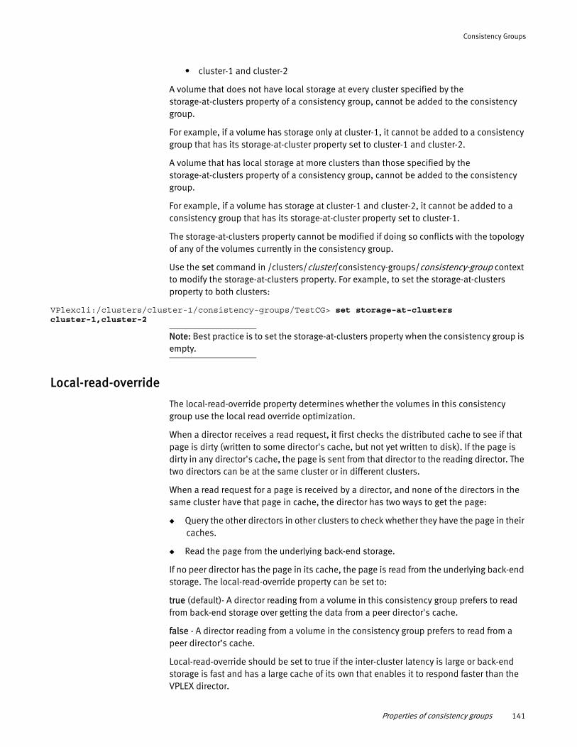
Consistency Groups
• cluster-1 and cluster-2
A volume that does not have local storage at every cluster specified by the storage-at-clusters property of a consistency group, cannot be added to the consistency group.
For example, if a volume has storage only at cluster-1, it cannot be added to a consistency group that has its storage-at-cluster property set to cluster-1 and cluster-2.
A volume that has local storage at more clusters than those specified by the storage-at-clusters property of a consistency group, cannot be added to the consistency group.
For example, if a volume has storage at cluster-1 and cluster-2, it cannot be added to a consistency group that has its storage-at-cluster property set to cluster-1.
The storage-at-clusters property cannot be modified if doing so conflicts with the topology of any of the volumes currently in the consistency group.
Use the set command in /clusters/cluster/consistency-groups/consistency-group context to modify the storage-at-clusters property. For example, to set the storage-at-clusters property to both clusters:
VPlexcli:/clusters/cluster-1/consistency-groups/TestCG> set storage-at-clusters cluster-1,cluster-2
Note: Best practice is to set the storage-at-clusters property when the consistency group is empty.
Local-read-override
The local-read-override property determines whether the volumes in this consistency group use the local read override optimization.
When a director receives a read request, it first checks the distributed cache to see if that page is dirty (written to some director's cache, but not yet written to disk). If the page is dirty in any director's cache, the page is sent from that director to the reading director. The two directors can be at the same cluster or in different clusters.
When a read request for a page is received by a director, and none of the directors in the same cluster have that page in cache, the director has two ways to get the page:
◆ Query the other directors in other clusters to check whether they have the page in their caches.
◆ Read the page from the underlying back-end storage.
If no peer director has the page in its cache, the page is read from the underlying back-end storage. The local-read-override property can be set to:
true (default)- A director reading from a volume in this consistency group prefers to read from back-end storage over getting the data from a peer director's cache.
false - A director reading from a volume in the consistency group prefers to read from a peer director’s cache.
Local-read-override should be set to true if the inter-cluster latency is large or back-end storage is fast and has a large cache of its own that enables it to respond faster than the VPLEX director.
Properties of consistency groups 141
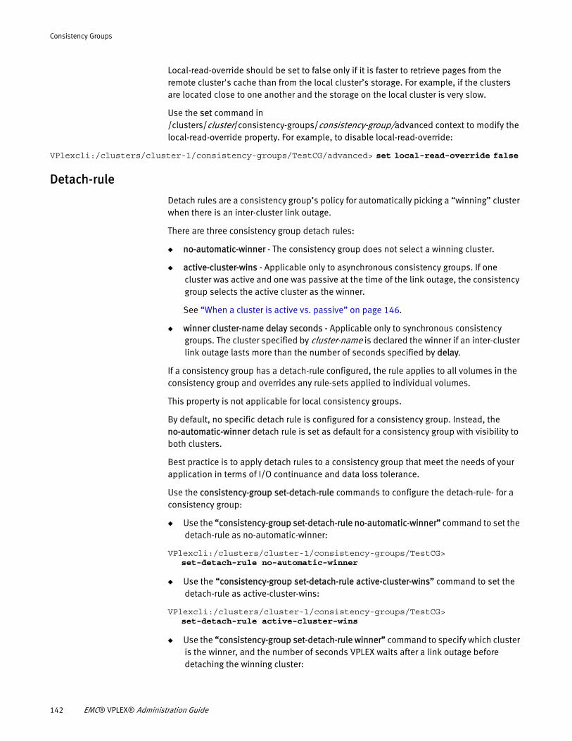
Consistency Groups
Local-read-override should be set to false only if it is faster to retrieve pages from the remote cluster's cache than from the local cluster’s storage. For example, if the clusters are located close to one another and the storage on the local cluster is very slow.
Use the set command in /clusters/cluster/consistency-groups/consistency-group/advanced context to modify the local-read-override property. For example, to disable local-read-override:
VPlexcli:/clusters/cluster-1/consistency-groups/TestCG/advanced> set local-read-override false
Detach-rule
Detach rules are a consistency group’s policy for automatically picking a “winning” cluster when there is an inter-cluster link outage.
There are three consistency group detach rules:
◆ no-automatic-winner - The consistency group does not select a winning cluster.
◆ active-cluster-wins - Applicable only to asynchronous consistency groups. If one cluster was active and one was passive at the time of the link outage, the consistency group selects the active cluster as the winner.
See “When a cluster is active vs. passive” on page 146.
◆ winner cluster-name delay seconds - Applicable only to synchronous consistency groups. The cluster specified by cluster-name is declared the winner if an inter-cluster link outage lasts more than the number of seconds specified by delay.
If a consistency group has a detach-rule configured, the rule applies to all volumes in the consistency group and overrides any rule-sets applied to individual volumes.
This property is not applicable for local consistency groups.
By default, no specific detach rule is configured for a consistency group. Instead, the no-automatic-winner detach rule is set as default for a consistency group with visibility to both clusters.
Best practice is to apply detach rules to a consistency group that meet the needs of your application in terms of I/O continuance and data loss tolerance.
Use the consistency-group set-detach-rule commands to configure the detach-rule- for a consistency group:
◆ Use the “consistency-group set-detach-rule no-automatic-winner” command to set the detach-rule as no-automatic-winner:
VPlexcli:/clusters/cluster-1/consistency-groups/TestCG> set-detach-rule no-automatic-winner
◆ Use the “consistency-group set-detach-rule active-cluster-wins” command to set the detach-rule as active-cluster-wins:
VPlexcli:/clusters/cluster-1/consistency-groups/TestCG> set-detach-rule active-cluster-wins
◆ Use the “consistency-group set-detach-rule winner” command to specify which cluster is the winner, and the number of seconds VPLEX waits after a link outage before detaching the winning cluster:
142 EMC® VPLEX® Administration Guide
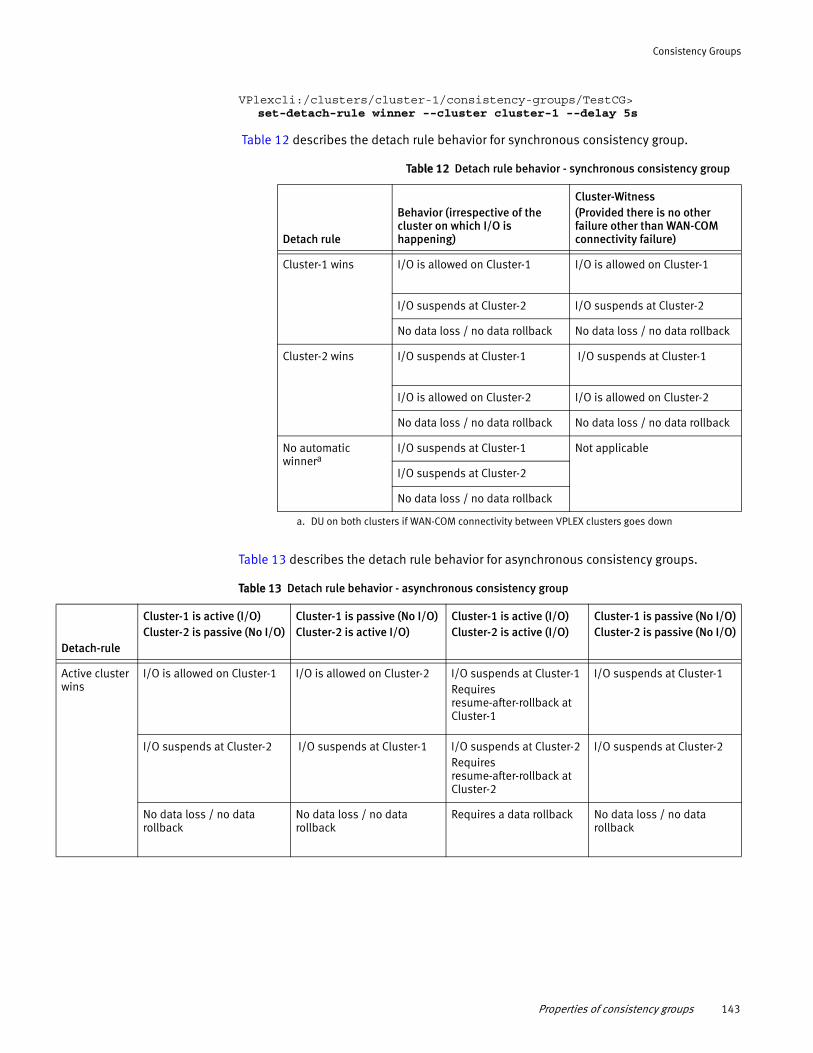
Consistency Groups
VPlexcli:/clusters/cluster-1/consistency-groups/TestCG> set-detach-rule winner --cluster cluster-1 --delay 5s
Table 12 describes the detach rule behavior for synchronous consistency group.
Table 13 describes the detach rule behavior for asynchronous consistency groups.
Table 12 Detach rule behavior - synchronous consistency group
Detach rule
Behavior (irrespective of the cluster on which I/O is happening)
Cluster-Witness(Provided there is no other failure other than WAN-COM connectivity failure)
Cluster-1 wins I/O is allowed on Cluster-1 I/O is allowed on Cluster-1
I/O suspends at Cluster-2 I/O suspends at Cluster-2
No data loss / no data rollback No data loss / no data rollback
Cluster-2 wins I/O suspends at Cluster-1 I/O suspends at Cluster-1
I/O is allowed on Cluster-2 I/O is allowed on Cluster-2
No data loss / no data rollback No data loss / no data rollback
No automatic winnera
a. DU on both clusters if WAN-COM connectivity between VPLEX clusters goes down
I/O suspends at Cluster-1 Not applicable
I/O suspends at Cluster-2
No data loss / no data rollback
Table 13 Detach rule behavior - asynchronous consistency group
Detach-rule
Cluster-1 is active (I/O)Cluster-2 is passive (No I/O)
Cluster-1 is passive (No I/O)Cluster-2 is active I/O)
Cluster-1 is active (I/O)Cluster-2 is active (I/O)
Cluster-1 is passive (No I/O)Cluster-2 is passive (No I/O)
Active cluster wins
I/O is allowed on Cluster-1 I/O is allowed on Cluster-2 I/O suspends at Cluster-1 Requires resume-after-rollback at Cluster-1
I/O suspends at Cluster-1
I/O suspends at Cluster-2 I/O suspends at Cluster-1 I/O suspends at Cluster-2Requires resume-after-rollback at Cluster-2
I/O suspends at Cluster-2
No data loss / no data rollback
No data loss / no data rollback
Requires a data rollback No data loss / no data rollback
Properties of consistency groups 143
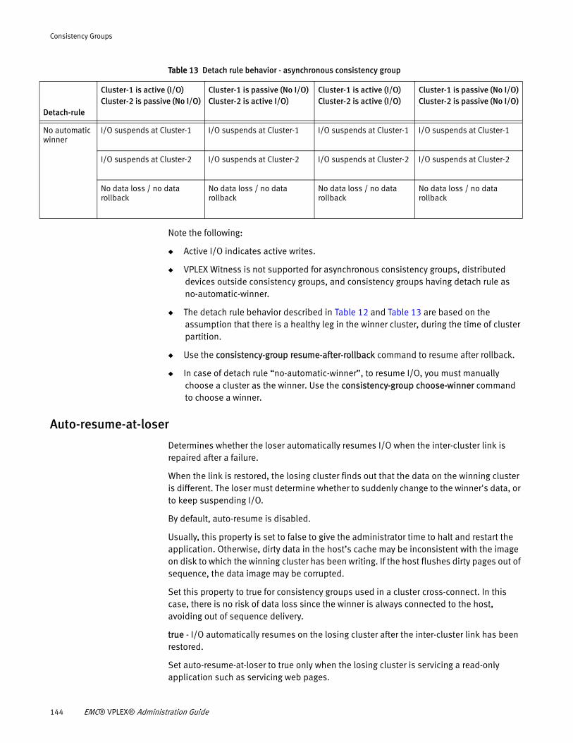
Consistency Groups
Note the following:
◆ Active I/O indicates active writes.
◆ VPLEX Witness is not supported for asynchronous consistency groups, distributed devices outside consistency groups, and consistency groups having detach rule as no-automatic-winner.
◆ The detach rule behavior described in Table 12 and Table 13 are based on the assumption that there is a healthy leg in the winner cluster, during the time of cluster partition.
◆ Use the consistency-group resume-after-rollback command to resume after rollback.
◆ In case of detach rule “no-automatic-winner”, to resume I/O, you must manually choose a cluster as the winner. Use the consistency-group choose-winner command to choose a winner.
Auto-resume-at-loser
Determines whether the loser automatically resumes I/O when the inter-cluster link is repaired after a failure.
When the link is restored, the losing cluster finds out that the data on the winning cluster is different. The loser must determine whether to suddenly change to the winner's data, or to keep suspending I/O.
By default, auto-resume is disabled.
Usually, this property is set to false to give the administrator time to halt and restart the application. Otherwise, dirty data in the host’s cache may be inconsistent with the image on disk to which the winning cluster has been writing. If the host flushes dirty pages out of sequence, the data image may be corrupted.
Set this property to true for consistency groups used in a cluster cross-connect. In this case, there is no risk of data loss since the winner is always connected to the host, avoiding out of sequence delivery.
true - I/O automatically resumes on the losing cluster after the inter-cluster link has been restored.
Set auto-resume-at-loser to true only when the losing cluster is servicing a read-only application such as servicing web pages.
No automatic winner
I/O suspends at Cluster-1 I/O suspends at Cluster-1 I/O suspends at Cluster-1 I/O suspends at Cluster-1
I/O suspends at Cluster-2 I/O suspends at Cluster-2 I/O suspends at Cluster-2 I/O suspends at Cluster-2
No data loss / no data rollback
No data loss / no data rollback
No data loss / no data rollback
No data loss / no data rollback
Table 13 Detach rule behavior - asynchronous consistency group
Detach-rule
Cluster-1 is active (I/O)Cluster-2 is passive (No I/O)
Cluster-1 is passive (No I/O)Cluster-2 is active I/O)
Cluster-1 is active (I/O)Cluster-2 is active (I/O)
Cluster-1 is passive (No I/O)Cluster-2 is passive (No I/O)
144 EMC® VPLEX® Administration Guide
Consistency Groups
false (default) - I/O remains suspended on the losing cluster after the inter-cluster link has been restored. I/O must be manually resumed.
Set auto-resume-at-loser to false for all applications that cannot tolerate a sudden change in data.
Setting auto-resume property to true may cause a spontaneous change of the data view presented to applications at the losing cluster when the inter-cluster link is restored. If the application has not failed, it may not be able to tolerate the sudden change in the data view and this can cause data corruption. Set the property to false except for applications that can tolerate this issue and for cross connected hosts.
Use the set command in the advanced context to configure the auto-resume property for a consistency group:
VPlexcli:/clusters/cluster-1/consistency-groups/TestCG/advanced> set auto-resume-at-loser true
Virtual-volumes
Administrators can add and remove virtual volumes to a consistency group. In order to be added to a consistency group, a virtual volume:
◆ Must not be a logging volume
◆ Must have storage at every cluster in the 'storage-at-clusters' property of the target consistency group
◆ Must not be a member of any other consistency group
◆ Any properties (such as detach rules or auto-resume) that conflict with those of the consistency group are automatically changed to match those of the consistency group
Note: Virtual volumes with different properties are allowed to join a consistency group, but inherit the properties of the consistency group.
Use the “consistency-group list-eligible-virtual-volumes” command to display virtual volumes that are eligible to be added to a consistency group.
Use the “consistency-group add-virtual-volumes” command to add one or more virtual volumes to a consistency group.
Use the ll /clusters/<cluster-*>/consistency-groups/ consistency-group command to display the virtual volumes in the specified consistency group.
Use the “consistency-group remove-virtual-volumes” command to remove one or more virtual volumes from a consistency group.
Recoverpoint-enabled
Starting in Release 5.1, VPLEX includes a RecoverPoint splitter. The splitter “splits” application writes so that the writes are sent to their normally designated storage volumes and a RecoverPoint Appliance (RPA) simultaneously.
To configure a consistency group for use with RecoverPoint:
Properties of consistency groups 145
Consistency Groups
◆ Cache mode must be synchronous.
◆ Consistency groups with the “Visibility” property set to both clusters must also have their “Storage-at-clusters” set to both clusters in order to set the recoverpoint-enable property to true.
◆ All production and replica volumes associated with RecoverPoint must be in a VPLEX consistency group with the recoverpoint-enabled property set to true.
Configure two consistency groups for each set of virtual volumes to be protected by RecoverPoint— one for the production volumes and one for the replica volumes.
RecoverPoint journal volumes are not required to be in a consistency group with this attribute enabled.
In addition to setting this property to true, the VPLEX consistency group must be aligned with the RecoverPoint consistency group.
Use the set command in /clusters/cluster/consistency-groups/consistency-group/ context to configure the recoverpoint-enabled property:
VPlexcli:/clusters/cluster-1/consistency-groups/TestCG> set recoverpoint-enabled true
Properties of asynchronous consistency groups
The following configurable properties are applicable only to consistency groups with asynchronous cache mode.
Active cluster
The active cluster property is not configurable by users. Instead, a configuration changes dynamically between active/passive and active/active depending on the write activity at each cluster.
When a cluster is active vs. passiveFailure behaviors dictated by the active-cluster-wins detach rule vary depending on whether the configuration is active/passive or active/active at the time of the failure.
In asynchronous consistency groups, the process of synchronizing data between the two clusters includes the following phases:
◆ Open - Host writes to distributed volumes are acknowledged back to the host after the data is protected in the cache of another director in the local cluster. Writes from each application are collected into deltas.
◆ Closed - Deltas are closed when their timer expires or when they are full.
◆ Exchanged - The delta is exchanged with the remote cluster.
◆ Commit - The delta's contents are written to back-end storage.
Data that has been protected at another director in the local cluster (but not exchanged with the remote cluster) is known as dirty data.
A configuration is active/passive if hosts at only one cluster were writing at the time of the failure. A configuration is active/active if hosts at both clusters were writing at the time of the failure.
146 EMC® VPLEX® Administration Guide
Consistency Groups
A cluster is marked passive when all dirty data contributed by the cluster has been committed (written to the back end at both clusters). The cluster remains passive as long as no further data is contributed by the time the next delta closes. Specifically when:
◆ Hosts at a cluster stop writing to a consistency group.
◆ The currently open delta closes, either due to a timer (default-closeout-time) or due to the delta becoming full at either cluster.
◆ The closed delta is exchanged and committed the back-end.
◆ The next open (empty at one cluster because the host is not writing) delta is closed.
◆ The closure of the next delta completes without any new data, that cluster is marked passive.
◆ A host writes to a passive cluster (creates dirty data), the cluster is marked as active.
Default closeout-time
Sets the default for the maximum time a delta remains open to accept new writes. Closeout-time can be set as either a positive integer or zero.
Default: 30 seconds.
zero (0) - There is no time limit on closing the open delta. The delta is closed when it is full and cannot accept more data.
A larger value for the default close-out -time unnecessarily exposes dirty data in the open delta if the exchange delta is idle.
The ideal default close-out -time is equal to the time it takes to exchange a full delta set.
The default closeout-time and maximum-queue-depth properties work together to allow administrators to fine-tune the maximum possible data loss in the event of an inter-cluster link outage.
Maximum RPO for the consistency group can be calculated as follows:
RPO = maximum-queue-depth x default closeout-time
Increasing either the default closeout-time or maximum-queue-depth property increases the maximum RPO in the event of a inter-cluster link outage or cluster failure.
Use the set command in /clusters/cluster/consistency-groups/consistency-group/advanced context to configure the closeout-time property for an asynchronous consistency group:
VPlexcli:/clusters/cluster-1/consistency-groups/TestCG/advanced> set closeout-time 12
Maximum-queue-depth
For an asynchronous consistency group, this property configures the maximum possible depth of the delta processing queues.
Each consistency group maintains its own queue of deltas in various states:
• open - The delta is accepting new writes.
• closed - The delta is not accepting writes.
Properties of consistency groups 147
Consistency Groups
• exchanging - The delta's contents are being synchronized between the clusters.
• exchanged - The delta's contents are the same at all clusters.
• committing- The delta's contents are being written out to the back-end storage.
• committed - The write of the delta’s contents to the back-end storage is complete.
All deltas pass through these states, forming a pipeline in the order in which they were received. For applications that generate occasional brief bursts of writes, the rate of incoming writes may (for a short time) be faster than the rate at which deltas are exchanged and committed.
Setting the maximum queue depth allows multiple closed deltas to wait to be exchanged and committed.
The default closeout-time and maximum-queue-depth properties work together to allow administrators to fine-tune the maximum possible data loss in the event of an inter-cluster link outage.
Decrease the maximum-queue-depth to decrease the maximum RPO in the event of a inter-cluster link outage or cluster failure.
Increase the maximum-queue-depth to increase the ability of the system to handle bursts of traffic.
Increasing the maximum-queue-depth also increases the data that must rollback in the case of a cluster failure or a link outage (I/O is resumed when the active cluster became the loser).
Default: 6.
Range: 6-64. The maximum value is platform-specific.
Use the set command in /clusters/cluster/consistency-groups/consistency-group/advanced context to configure the maximum-queue-depth property for an asynchronous consistency group:
VPlexcli:/clusters/cluster-1/consistency-groups/TestCG/advanced>set maximum-queue-depth 8
Manage consistency groups
IMPORTANT
A key best practice for creating and managing consistency groups is to create a 1:1 relationship between consistency groups and applications. All volumes (and only those volumes) required for an application should be in a single consistency group.
Create a consistency group
Before you beginBefore you create a consistency group, consider its usage:
148 EMC® VPLEX® Administration Guide
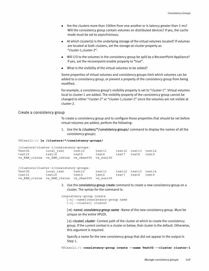
Consistency Groups
◆ Are the clusters more than 100km from one another or is latency greater than 5 ms? Will the consistency group contain volumes on distributed devices? If yes, the cache mode must be set to asynchronous.
◆ At which cluster(s) is the underlying storage of the virtual volumes located? If volumes are located at both clusters, set the storage-at-cluster property as “cluster-1,cluster-2”.
◆ Will I/O to the volumes in the consistency group be split by a RecoverPoint Appliance? If yes, set the recoverpoint-enable property to “true”.
◆ What is the visibility of the virtual volumes to be added?
Some properties of virtual volumes and consistency groups limit which volumes can be added to a consistency group, or prevent a property of the consistency group from being modified.
For example, a consistency group’s visibility property is set to “cluster-1”. Virtual volumes local to cluster-1 are added. The visibility property of the consistency group cannot be changed to either “cluster-2” or “cluster-1,cluster-2” since the volumes are not visible at cluster-2.
Create a consistency groupTo create a consistency group and to configure those properties that should be set before virtual volumes are added, perform the following:
1. Use the ls /clusters/*/consistency-groups/ command to display the names of all the consistency-groups:
VPlexcli:/> ls /clusters/*/consistency-groups/
/clusters/cluster-1/consistency-groups:TestCG local_test test10 test11 test12 test13 test14test15 test16 test5 test6 test7 test8 test9vs_RAM_c1wins vs_RAM_c2wins vs_oban005 vs_sun190
/clusters/cluster-2/consistency-groups:TestCG local_test test10 test11 test12 test13 test14test15 test16 test5 test6 test7 test8 test9vs_RAM_c1wins vs_RAM_c2wins vs_oban005 vs_sun190
2. Use the consistency-group create command to create a new consistency-group on a cluster. The syntax for the command is:
consistency-group create[-n|--name]consistency-group name[-c|--cluster] cluster
[-n|--name] consistency-group name - Name of the new consistency-group. Must be unique on the entire VPLEX.
[-c|--cluster] cluster - Context path of the cluster at which to create the consistency group. If the current context is a cluster or below, that cluster is the default. Otherwise, this argument is required.
Specify a name for the new consistency group that did not appear in the output in Step 1.
VPlexcli:/> consistency-group create --name TestCG --cluster cluster-1
Manage consistency groups 149
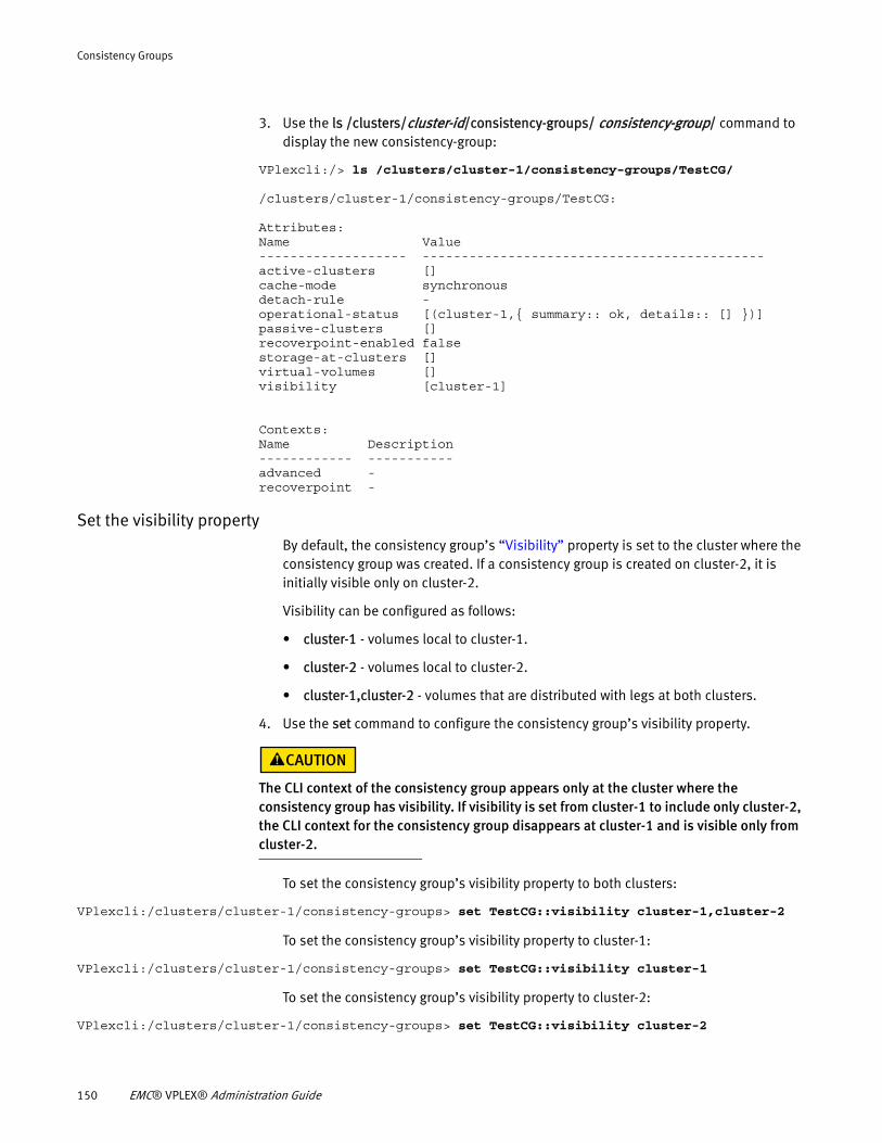
Consistency Groups
3. Use the ls /clusters/cluster-id/consistency-groups/ consistency-group/ command to display the new consistency-group:
VPlexcli:/> ls /clusters/cluster-1/consistency-groups/TestCG/
/clusters/cluster-1/consistency-groups/TestCG:
Attributes:Name Value------------------- --------------------------------------------active-clusters []cache-mode synchronousdetach-rule -operational-status [(cluster-1,{ summary:: ok, details:: [] })]passive-clusters []recoverpoint-enabled falsestorage-at-clusters []virtual-volumes []visibility [cluster-1]
Contexts:Name Description------------ -----------advanced -recoverpoint -
Set the visibility propertyBy default, the consistency group’s “Visibility” property is set to the cluster where the consistency group was created. If a consistency group is created on cluster-2, it is initially visible only on cluster-2.
Visibility can be configured as follows:
• cluster-1 - volumes local to cluster-1.
• cluster-2 - volumes local to cluster-2.
• cluster-1,cluster-2 - volumes that are distributed with legs at both clusters.
4. Use the set command to configure the consistency group’s visibility property.
The CLI context of the consistency group appears only at the cluster where the consistency group has visibility. If visibility is set from cluster-1 to include only cluster-2, the CLI context for the consistency group disappears at cluster-1 and is visible only from cluster-2.
To set the consistency group’s visibility property to both clusters:
VPlexcli:/clusters/cluster-1/consistency-groups> set TestCG::visibility cluster-1,cluster-2
To set the consistency group’s visibility property to cluster-1:
VPlexcli:/clusters/cluster-1/consistency-groups> set TestCG::visibility cluster-1
To set the consistency group’s visibility property to cluster-2:
VPlexcli:/clusters/cluster-1/consistency-groups> set TestCG::visibility cluster-2
150 EMC® VPLEX® Administration Guide
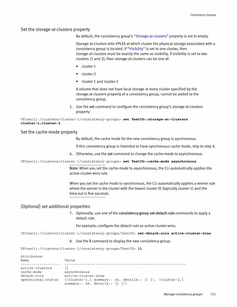
Consistency Groups
Set the storage-at-clusters propertyBy default, the consistency group’s “Storage-at-clusters” property is set to empty.
Storage-at-clusters tells VPLEX at which cluster the physical storage associated with a consistency group is located. If “Visibility” is set to one cluster, then storage-at-clusters must be exactly the same as visibility. If visibility is set to two clusters (1 and 2), then storage-at-clusters can be one of:
• cluster-1
• cluster-2
• cluster-1 and cluster-2
A volume that does not have local storage at every cluster specified by the storage-at-clusters property of a consistency group, cannot be added to the consistency group.
5. Use the set command to configure the consistency group’s storage-at-clusters property
VPlexcli:/clusters/cluster-1/consistency-groups> set TestCG::storage-at-clusters cluster-1,cluster-2
Set the cache-mode propertyBy default, the cache mode for the new consistency group is synchronous.
If this consistency group is intended to have synchronous cache mode, skip to step 8.
6. Otherwise, use the set command to change the cache-mode to asynchronous:
VPlexcli:/clusters/cluster-1/consistency-groups> set TestCG::cache-mode asynchronous
Note: When you set the cache-mode to asynchronous, the CLI automatically applies the active-cluster-wins rule.
When you set the cache mode to synchronous, the CLI automatically applies a winner rule where the winner is the cluster with the lowest cluster ID (typically cluster-1) and the time-out is five seconds.
(Optional) set additional properties7. Optionally, use one of the consistency-group set-detach-rule commands to apply a
detach rule.
For example; configure the detach-rule as active-cluster-wins:
VPlexcli:/clusters/cluster-1/consistency-groups/TestCG> set-detach-rule active-cluster-wins
8. Use the ll command to display the new consistency group:
VPlexcli:/clusters/cluster-1/consistency-groups/TestCG> ll
Attributes:Name Value------------------- ----------------------------------------------------------active-clusters []cache-mode asynchronousdetach-rule active-cluster-winsoperational-status [(cluster-1,{ summary:: ok, details:: [] }), (cluster-2,{ summary:: ok, details:: [] })]
Manage consistency groups 151

Consistency Groups
passive-clusters [cluster-1, cluster-2]recoverpoint-enabled falsestorage-at-clusters [cluster-1, cluster-2]virtual-volumes []visibility [cluster-1, cluster-2]
Contexts:Name Description------------ -----------advanced -recoverpoint -
Refer to Table 15, “Display consistency group field descriptions,” for descriptions of the fields in the display.
Add volumes to a consistency group
A maximum number of 1000 volumes can be added to a consistency group.
All volumes used by the same application should be grouped together in a consistency group.
Only volumes with storage at both clusters (distributed volumes) can be added to asynchronous consistency groups.
Only local volumes can be added to synchronous consistency groups with visibility and storage-at-cluster set to the local cluster.
Remote volumes can be added to synchronous consistency groups with visibility set to both clusters and storage-at-cluster set to one cluster.
To add virtual volumes to an existing consistency group, do the following:
1. Navigate to the target consistency group’s context:
VPlexcli:/> cd clusters/cluster-1/consistency-groups/ TestCG
2. Use the consistency-group list-eligible-virtual-volumes command to display virtual volumes are eligible to be added to the consistency group:
VPlexcli:/clusters/cluster-1/consistency-groups/TestCG> consistency-group list-eligible-virtual-volumes[TestDDevice-1_vol, TestDDevice-2_vol, TestDDevice-3_vol, TestDDevice-4_vol, TestDDevice-5_vol]
3. Use the add-virtual-volumes command to add virtual volumes to the consistency group.
The syntax for the command is:
consistency-group add-virtual-volumes[-v|--virtual-volumes] virtual-volume,virtual-volume,...[-g|--consistency-group] consistency-group
[-v|--virtual-volumes] virtual-volume,virtual-volume,... - List of one or more comma-separated global patterns or context paths of the virtual volume(s) to add.
[-g|--consistency-group] consistency-group - Context path of the consistency group to add the specified virtual volume(s).
To add a single virtual volume:
152 EMC® VPLEX® Administration Guide
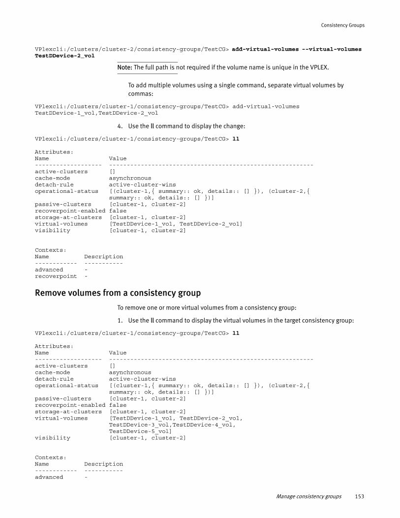
Consistency Groups
VPlexcli:/clusters/cluster-2/consistency-groups/TestCG> add-virtual-volumes --virtual-volumes TestDDevice-2_vol
Note: The full path is not required if the volume name is unique in the VPLEX.
To add multiple volumes using a single command, separate virtual volumes by commas:
VPlexcli:/clusters/cluster-1/consistency-groups/TestCG> add-virtual-volumes TestDDevice-1_vol,TestDDevice-2_vol
4. Use the ll command to display the change:
VPlexcli:/clusters/cluster-1/consistency-groups/TestCG> ll
Attributes:Name Value------------------- ----------------------------------------------------------active-clusters []cache-mode asynchronousdetach-rule active-cluster-winsoperational-status [(cluster-1,{ summary:: ok, details:: [] }), (cluster-2,{ summary:: ok, details:: [] })]passive-clusters [cluster-1, cluster-2]recoverpoint-enabled falsestorage-at-clusters [cluster-1, cluster-2]virtual-volumes [TestDDevice-1_vol, TestDDevice-2_vol]visibility [cluster-1, cluster-2]
Contexts:Name Description------------ -----------advanced -recoverpoint -
Remove volumes from a consistency group
To remove one or more virtual volumes from a consistency group:
1. Use the ll command to display the virtual volumes in the target consistency group:
VPlexcli:/clusters/cluster-1/consistency-groups/TestCG> ll
Attributes:Name Value------------------- ----------------------------------------------------------active-clusters []cache-mode asynchronousdetach-rule active-cluster-winsoperational-status [(cluster-1,{ summary:: ok, details:: [] }), (cluster-2,{ summary:: ok, details:: [] })]passive-clusters [cluster-1, cluster-2]recoverpoint-enabled falsestorage-at-clusters [cluster-1, cluster-2]virtual-volumes [TestDDevice-1_vol, TestDDevice-2_vol,
TestDDevice-3_vol,TestDDevice-4_vol,TestDDevice-5_vol]
visibility [cluster-1, cluster-2]
Contexts:Name Description------------ -----------advanced -
Manage consistency groups 153
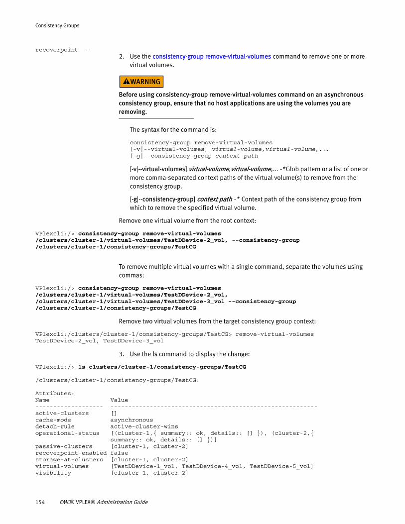
Consistency Groups
recoverpoint -2. Use the consistency-group remove-virtual-volumes command to remove one or more
virtual volumes.
Before using consistency-group remove-virtual-volumes command on an asynchronous consistency group, ensure that no host applications are using the volumes you are removing.
The syntax for the command is:
consistency-group remove-virtual-volumes[-v|--virtual-volumes] virtual-volume,virtual-volume,...[-g|--consistency-group context path
[-v|--virtual-volumes] virtual-volume,virtual-volume,... - *Glob pattern or a list of one or more comma-separated context paths of the virtual volume(s) to remove from the consistency group.
[-g|--consistency-group] context path - * Context path of the consistency group from which to remove the specified virtual volume.
Remove one virtual volume from the root context:
VPlexcli:/> consistency-group remove-virtual-volumes /clusters/cluster-1/virtual-volumes/TestDDevice-2_vol, --consistency-group /clusters/cluster-1/consistency-groups/TestCG
To remove multiple virtual volumes with a single command, separate the volumes using commas:
VPlexcli:/> consistency-group remove-virtual-volumes /clusters/cluster-1/virtual-volumes/TestDDevice-2_vol, /clusters/cluster-1/virtual-volumes/TestDDevice-3_vol --consistency-group /clusters/cluster-1/consistency-groups/TestCG
Remove two virtual volumes from the target consistency group context:
VPlexcli:/clusters/cluster-1/consistency-groups/TestCG> remove-virtual-volumes TestDDevice-2_vol, TestDDevice-3_vol
3. Use the ls command to display the change:
VPlexcli:/> ls clusters/cluster-1/consistency-groups/TestCG
/clusters/cluster-1/consistency-groups/TestCG:
Attributes:Name Value------------------- ----------------------------------------------------------active-clusters []cache-mode asynchronousdetach-rule active-cluster-winsoperational-status [(cluster-1,{ summary:: ok, details:: [] }), (cluster-2,{ summary:: ok, details:: [] })]passive-clusters [cluster-1, cluster-2]recoverpoint-enabled falsestorage-at-clusters [cluster-1, cluster-2]virtual-volumes [TestDDevice-1_vol, TestDDevice-4_vol, TestDDevice-5_vol]visibility [cluster-1, cluster-2]
154 EMC® VPLEX® Administration Guide
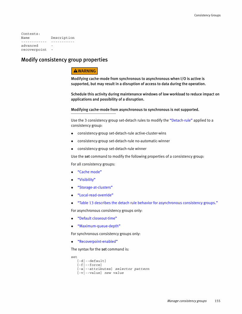
Consistency Groups
Contexts:Name Description------------ -----------advanced -recoverpoint -
Modify consistency group properties
Modifying cache-mode from synchronous to asynchronous when I/O is active is supported, but may result in a disruption of access to data during the operation.
Schedule this activity during maintenance windows of low workload to reduce impact on applications and possibility of a disruption.
Modifying cache-mode from asynchronous to synchronous is not supported.
Use the 3 consistency group set-detach rules to modify the “Detach-rule” applied to a consistency group:
◆ consistency-group set-detach-rule active-cluster-wins
◆ consistency-group set-detach-rule no-automatic-winner
◆ consistency-group set-detach-rule winner
Use the set command to modify the following properties of a consistency group:
For all consistency groups:
◆ “Cache mode”
◆ “Visibility”
◆ “Storage-at-clusters”
◆ “Local-read-override”
◆ “Table 13 describes the detach rule behavior for asynchronous consistency groups.”
For asynchronous consistency groups only:
◆ “Default closeout-time”
◆ “Maximum-queue-depth”
For synchronous consistency groups only:
◆ “Recoverpoint-enabled”
The syntax for the set command is:
set [-d|--default][-f|--force][-a|--attributes] selector pattern[-v|--value] new value
Manage consistency groups 155
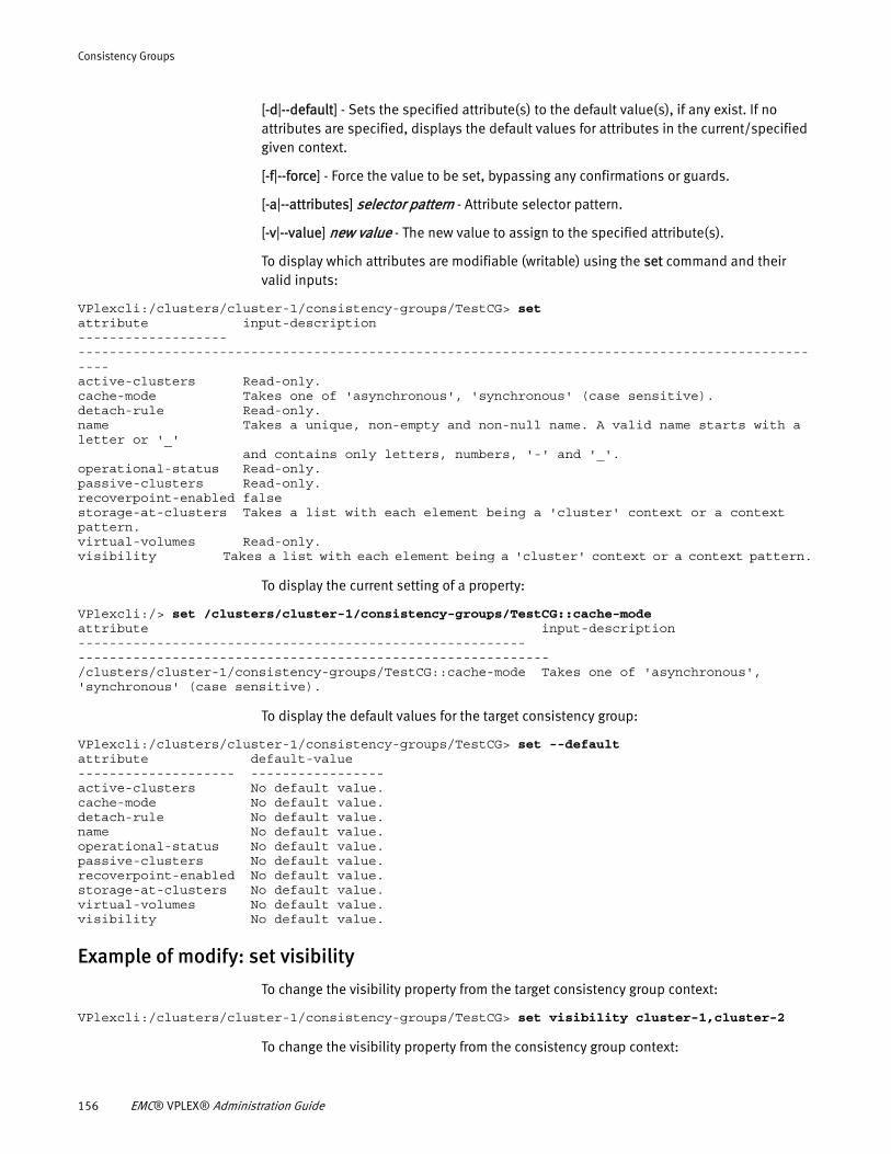
Consistency Groups
[-d|--default] - Sets the specified attribute(s) to the default value(s), if any exist. If no attributes are specified, displays the default values for attributes in the current/specified given context.
[-f|--force] - Force the value to be set, bypassing any confirmations or guards.
[-a|--attributes] selector pattern - Attribute selector pattern.
[-v|--value] new value - The new value to assign to the specified attribute(s).
To display which attributes are modifiable (writable) using the set command and their valid inputs:
VPlexcli:/clusters/cluster-1/consistency-groups/TestCG> setattribute input-description------------------- -------------------------------------------------------------------------------------------------active-clusters Read-only.cache-mode Takes one of 'asynchronous', 'synchronous' (case sensitive).detach-rule Read-only.name Takes a unique, non-empty and non-null name. A valid name starts with a letter or '_'
and contains only letters, numbers, '-' and '_'.operational-status Read-only.passive-clusters Read-only.recoverpoint-enabled falsestorage-at-clusters Takes a list with each element being a 'cluster' context or a context pattern.virtual-volumes Read-only.visibility Takes a list with each element being a 'cluster' context or a context pattern.
To display the current setting of a property:
VPlexcli:/> set /clusters/cluster-1/consistency-groups/TestCG::cache-modeattribute input-description--------------------------------------------------------- ------------------------------------------------------------/clusters/cluster-1/consistency-groups/TestCG::cache-mode Takes one of 'asynchronous', 'synchronous' (case sensitive).
To display the default values for the target consistency group:
VPlexcli:/clusters/cluster-1/consistency-groups/TestCG> set --defaultattribute default-value-------------------- -----------------active-clusters No default value.cache-mode No default value.detach-rule No default value.name No default value.operational-status No default value.passive-clusters No default value.recoverpoint-enabled No default value.storage-at-clusters No default value.virtual-volumes No default value.visibility No default value.
Example of modify: set visibility
To change the visibility property from the target consistency group context:
VPlexcli:/clusters/cluster-1/consistency-groups/TestCG> set visibility cluster-1,cluster-2
To change the visibility property from the consistency group context:
156 EMC® VPLEX® Administration Guide
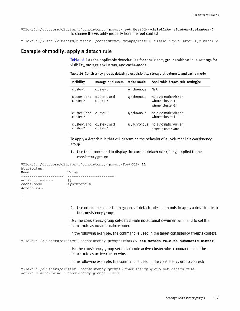
Consistency Groups
VPlexcli:/clusters/cluster-1/consistency-groups> set TestCG::visibility cluster-1,cluster-2To change the visibility property from the root context:
VPlexcli:/> set /clusters/cluster-1/consistency-groups/TestCG::visibility cluster-1,cluster-2
Example of modify: apply a detach rule
Table 14 lists the applicable detach-rules for consistency groups with various settings for visibility, storage-at-clusters, and cache-mode.
To apply a detach rule that will determine the behavior of all volumes in a consistency group:
1. Use the ll command to display the current detach rule (if any) applied to the consistency group:
VPlexcli:/clusters/cluster-1/consistency-groups/TestCG2> llAttributes:Name Value-------------------- ----------------------active-clusters []cache-mode synchronousdetach-rule -...
2. Use one of the consistency-group set-detach-rule commands to apply a detach-rule to the consistency group:
Use the consistency-group set-detach-rule no-automatic-winner command to set the detach-rule as no-automatic-winner.
In the following example, the command is used in the target consistency group’s context:
VPlexcli:/clusters/cluster-1/consistency-groups/TestCG> set-detach-rule no-automatic-winner
Use the consistency-group set-detach-rule active-cluster-wins command to set the detach-rule as active-cluster-wins.
In the following example, the command is used in the consistency group context:
VPlexcli:/clusters/cluster-1/consistency-groups> consistency-group set-detach-rule active-cluster-wins --consistency-groups TestCG
Table 14 Consistency groups detach-rules, visibility, storage-at-volumes, and cache-mode
visibility storage-at-clusters cache-mode Applicable detach-rule setting(s)
cluster-1 cluster-1 synchronous N/A
cluster-1 and cluster-2
cluster-1 and cluster-2
synchronous no-automatic-winnerwinner cluster-1winner cluster-2
cluster-1 and cluster-2
cluster-1 synchronous no-automatic-winnerwinner cluster-1
cluster-1 and cluster-2
cluster-1 and cluster-2
asynchronous no-automatic-winneractive-cluster-wins
Manage consistency groups 157
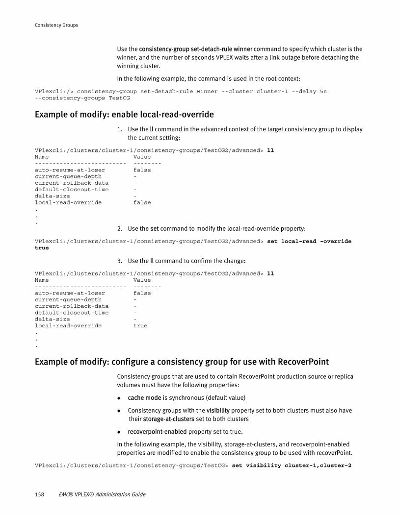
Consistency Groups
Use the consistency-group set-detach-rule winner command to specify which cluster is the winner, and the number of seconds VPLEX waits after a link outage before detaching the winning cluster.
In the following example, the command is used in the root context:
VPlexcli:/> consistency-group set-detach-rule winner --cluster cluster-1 --delay 5s --consistency-groups TestCG
Example of modify: enable local-read-override
1. Use the ll command in the advanced context of the target consistency group to display the current setting:
VPlexcli:/clusters/cluster-1/consistency-groups/TestCG2/advanced> llName Value-------------------------- --------auto-resume-at-loser falsecurrent-queue-depth -current-rollback-data -default-closeout-time -delta-size -local-read-override false...
2. Use the set command to modify the local-read-override property:
VPlexcli:/clusters/cluster-1/consistency-groups/TestCG2/advanced> set local-read -override true
3. Use the ll command to confirm the change:
VPlexcli:/clusters/cluster-1/consistency-groups/TestCG2/advanced> llName Value-------------------------- --------auto-resume-at-loser falsecurrent-queue-depth -current-rollback-data -default-closeout-time -delta-size -local-read-override true...
Example of modify: configure a consistency group for use with RecoverPoint
Consistency groups that are used to contain RecoverPoint production source or replica volumes must have the following properties:
◆ cache mode is synchronous (default value)
◆ Consistency groups with the visibility property set to both clusters must also have their storage-at-clusters set to both clusters
◆ recoverpoint-enabled property set to true.
In the following example, the visibility, storage-at-clusters, and recoverpoint-enabled properties are modified to enable the consistency group to be used with recoverPoint.
VPlexcli:/clusters/cluster-1/consistency-groups/TestCG> set visibility cluster-1,cluster-2
158 EMC® VPLEX® Administration Guide
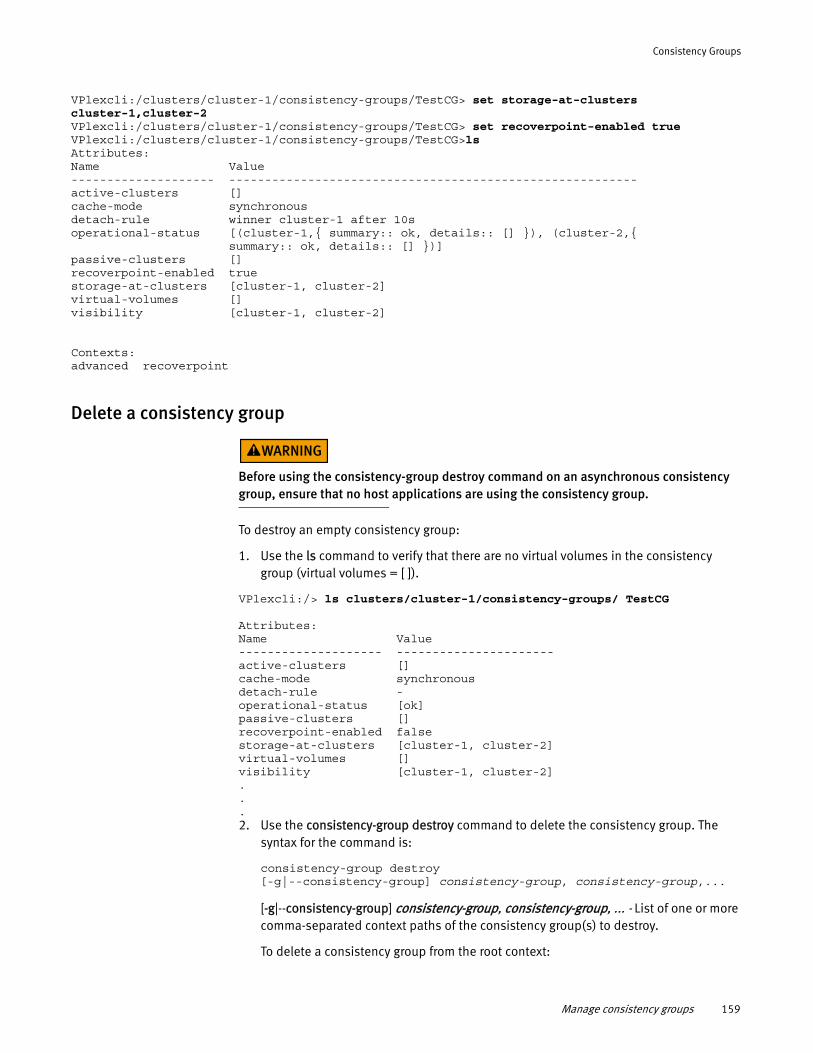
Consistency Groups
VPlexcli:/clusters/cluster-1/consistency-groups/TestCG> set storage-at-clusters cluster-1,cluster-2VPlexcli:/clusters/cluster-1/consistency-groups/TestCG> set recoverpoint-enabled trueVPlexcli:/clusters/cluster-1/consistency-groups/TestCG>lsAttributes:Name Value-------------------- ---------------------------------------------------------active-clusters []cache-mode synchronousdetach-rule winner cluster-1 after 10soperational-status [(cluster-1,{ summary:: ok, details:: [] }), (cluster-2,{ summary:: ok, details:: [] })]passive-clusters []recoverpoint-enabled truestorage-at-clusters [cluster-1, cluster-2]virtual-volumes []visibility [cluster-1, cluster-2]
Contexts:advanced recoverpoint
Delete a consistency group
Before using the consistency-group destroy command on an asynchronous consistency group, ensure that no host applications are using the consistency group.
To destroy an empty consistency group:
1. Use the ls command to verify that there are no virtual volumes in the consistency group (virtual volumes = [ ]).
VPlexcli:/> ls clusters/cluster-1/consistency-groups/ TestCG
Attributes:Name Value-------------------- ----------------------active-clusters []cache-mode synchronousdetach-rule -operational-status [ok]passive-clusters []recoverpoint-enabled falsestorage-at-clusters [cluster-1, cluster-2]virtual-volumes []visibility [cluster-1, cluster-2]...2. Use the consistency-group destroy command to delete the consistency group. The
syntax for the command is:
consistency-group destroy[-g|--consistency-group] consistency-group, consistency-group,...
[-g|--consistency-group] consistency-group, consistency-group, ... - List of one or more comma-separated context paths of the consistency group(s) to destroy.
To delete a consistency group from the root context:
Manage consistency groups 159
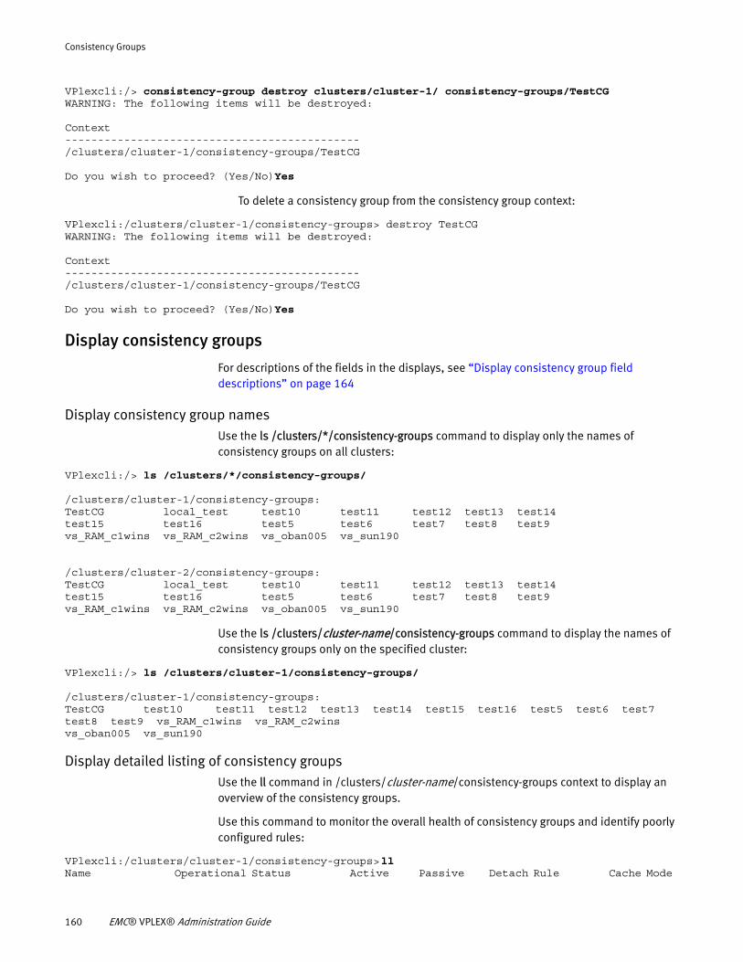
Consistency Groups
VPlexcli:/> consistency-group destroy clusters/cluster-1/ consistency-groups/TestCGWARNING: The following items will be destroyed:
Context---------------------------------------------/clusters/cluster-1/consistency-groups/TestCG
Do you wish to proceed? (Yes/No)Yes
To delete a consistency group from the consistency group context:
VPlexcli:/clusters/cluster-1/consistency-groups> destroy TestCGWARNING: The following items will be destroyed:
Context---------------------------------------------/clusters/cluster-1/consistency-groups/TestCG
Do you wish to proceed? (Yes/No)Yes
Display consistency groups
For descriptions of the fields in the displays, see “Display consistency group field descriptions” on page 164
Display consistency group namesUse the ls /clusters/*/consistency-groups command to display only the names of consistency groups on all clusters:
VPlexcli:/> ls /clusters/*/consistency-groups/
/clusters/cluster-1/consistency-groups:TestCG local_test test10 test11 test12 test13 test14test15 test16 test5 test6 test7 test8 test9vs_RAM_c1wins vs_RAM_c2wins vs_oban005 vs_sun190
/clusters/cluster-2/consistency-groups:TestCG local_test test10 test11 test12 test13 test14test15 test16 test5 test6 test7 test8 test9vs_RAM_c1wins vs_RAM_c2wins vs_oban005 vs_sun190
Use the ls /clusters/cluster-name/consistency-groups command to display the names of consistency groups only on the specified cluster:
VPlexcli:/> ls /clusters/cluster-1/consistency-groups/
/clusters/cluster-1/consistency-groups:TestCG test10 test11 test12 test13 test14 test15 test16 test5 test6 test7 test8 test9 vs_RAM_c1wins vs_RAM_c2winsvs_oban005 vs_sun190
Display detailed listing of consistency groupsUse the ll command in /clusters/cluster-name/consistency-groups context to display an overview of the consistency groups.
Use this command to monitor the overall health of consistency groups and identify poorly configured rules:
VPlexcli:/clusters/cluster-1/consistency-groups> ll Name Operational Status Active Passive Detach Rule Cache Mode
160 EMC® VPLEX® Administration Guide
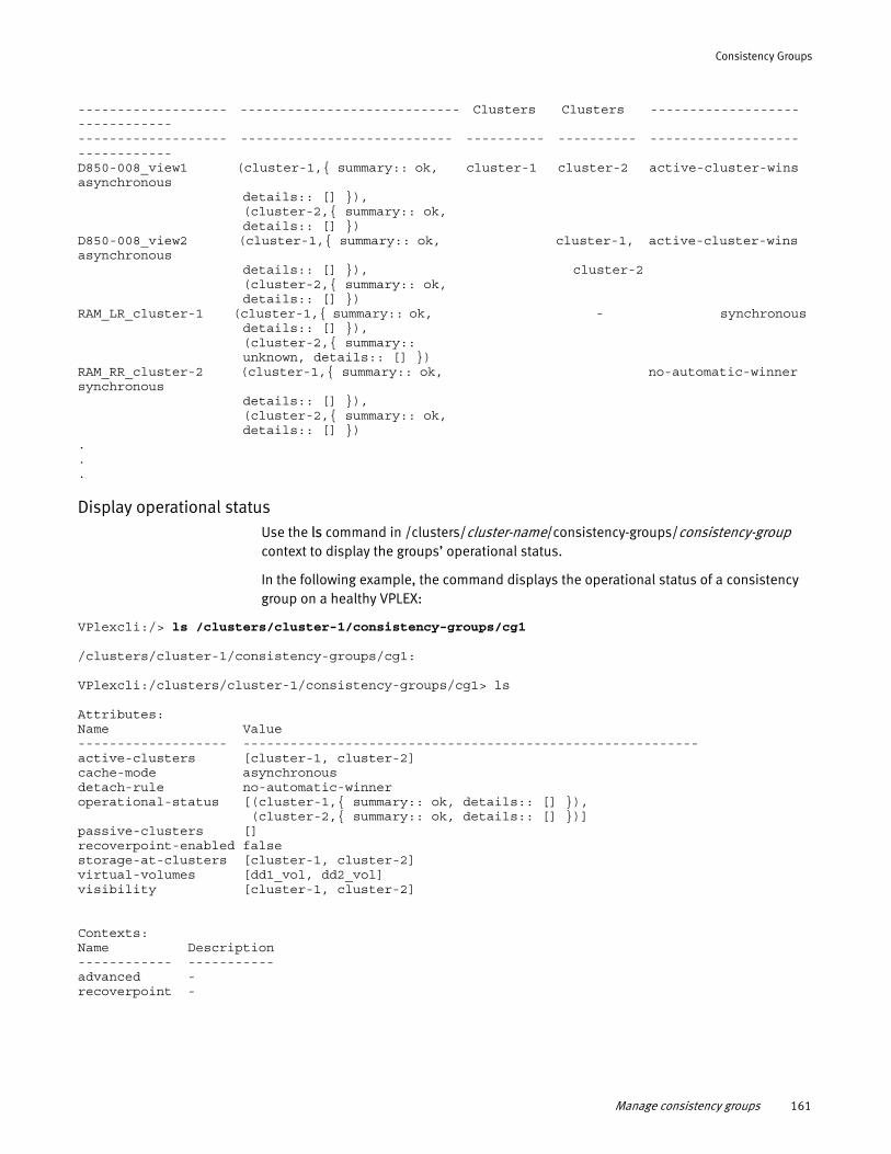
Consistency Groups
------------------- ---------------------------- Clusters Clusters ------------------- ------------ ------------------- --------------------------- ---------- ---------- ------------------- ------------ D850-008_view1 (cluster-1,{ summary:: ok, cluster-1 cluster-2 active-cluster-wins asynchronous details:: [] }), (cluster-2,{ summary:: ok, details:: [] }) D850-008_view2 (cluster-1,{ summary:: ok, cluster-1, active-cluster-wins asynchronous details:: [] }), cluster-2 (cluster-2,{ summary:: ok, details:: [] }) RAM_LR_cluster-1 (cluster-1,{ summary:: ok, - synchronous details:: [] }), (cluster-2,{ summary:: unknown, details:: [] }) RAM_RR_cluster-2 (cluster-1,{ summary:: ok, no-automatic-winner synchronous details:: [] }), (cluster-2,{ summary:: ok, details:: [] }) ...
Display operational statusUse the ls command in /clusters/cluster-name/consistency-groups/consistency-group context to display the groups’ operational status.
In the following example, the command displays the operational status of a consistency group on a healthy VPLEX:
VPlexcli:/> ls /clusters/cluster-1/consistency-groups/cg1
/clusters/cluster-1/consistency-groups/cg1:
VPlexcli:/clusters/cluster-1/consistency-groups/cg1> ls
Attributes: Name Value------------------- ----------------------------------------------------------active-clusters [cluster-1, cluster-2]cache-mode asynchronousdetach-rule no-automatic-winneroperational-status [(cluster-1,{ summary:: ok, details:: [] }), (cluster-2,{ summary:: ok, details:: [] })]passive-clusters []recoverpoint-enabled falsestorage-at-clusters [cluster-1, cluster-2]virtual-volumes [dd1_vol, dd2_vol]visibility [cluster-1, cluster-2]
Contexts:Name Description------------ -----------advanced -recoverpoint -
Manage consistency groups 161
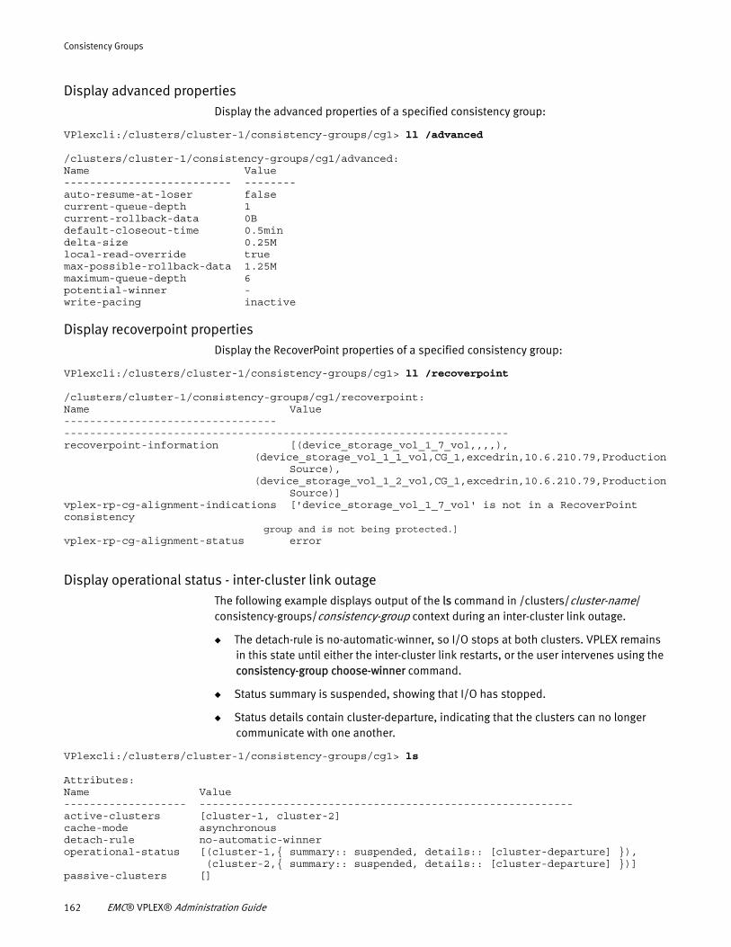
Consistency Groups
Display advanced propertiesDisplay the advanced properties of a specified consistency group:
VPlexcli:/clusters/cluster-1/consistency-groups/cg1> ll /advanced
/clusters/cluster-1/consistency-groups/cg1/advanced:Name Value-------------------------- --------auto-resume-at-loser falsecurrent-queue-depth 1current-rollback-data 0Bdefault-closeout-time 0.5mindelta-size 0.25Mlocal-read-override truemax-possible-rollback-data 1.25Mmaximum-queue-depth 6potential-winner -write-pacing inactive
Display recoverpoint propertiesDisplay the RecoverPoint properties of a specified consistency group:
VPlexcli:/clusters/cluster-1/consistency-groups/cg1> ll /recoverpoint
/clusters/cluster-1/consistency-groups/cg1/recoverpoint:Name Value--------------------------------- ---------------------------------------------------------------------recoverpoint-information [(device_storage_vol_1_7_vol,,,,), (device_storage_vol_1_1_vol,CG_1,excedrin,10.6.210.79,Production Source), (device_storage_vol_1_2_vol,CG_1,excedrin,10.6.210.79,Production Source)]vplex-rp-cg-alignment-indications ['device_storage_vol_1_7_vol' is not in a RecoverPoint consistency
group and is not being protected.]vplex-rp-cg-alignment-status error
Display operational status - inter-cluster link outageThe following example displays output of the ls command in /clusters/cluster-name/ consistency-groups/consistency-group context during an inter-cluster link outage.
◆ The detach-rule is no-automatic-winner, so I/O stops at both clusters. VPLEX remains in this state until either the inter-cluster link restarts, or the user intervenes using the consistency-group choose-winner command.
◆ Status summary is suspended, showing that I/O has stopped.
◆ Status details contain cluster-departure, indicating that the clusters can no longer communicate with one another.
VPlexcli:/clusters/cluster-1/consistency-groups/cg1> ls
Attributes: Name Value------------------- ----------------------------------------------------------active-clusters [cluster-1, cluster-2]cache-mode asynchronousdetach-rule no-automatic-winneroperational-status [(cluster-1,{ summary:: suspended, details:: [cluster-departure] }), (cluster-2,{ summary:: suspended, details:: [cluster-departure] })]passive-clusters []
162 EMC® VPLEX® Administration Guide
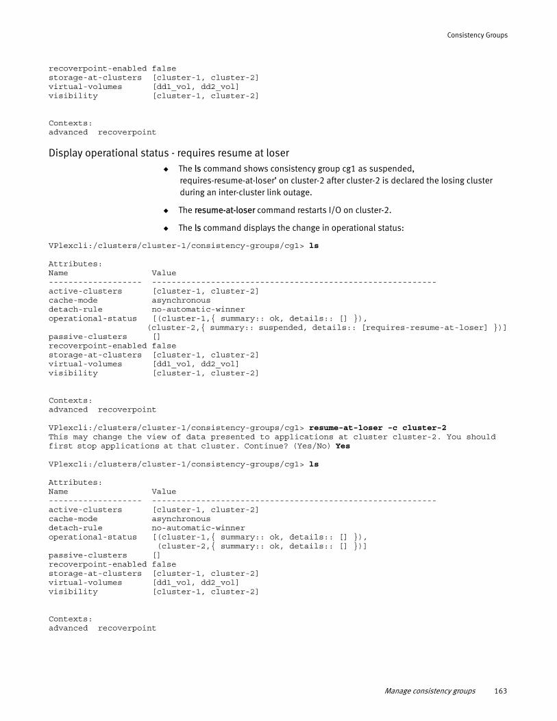
Consistency Groups
recoverpoint-enabled falsestorage-at-clusters [cluster-1, cluster-2]virtual-volumes [dd1_vol, dd2_vol]visibility [cluster-1, cluster-2]
Contexts:advanced recoverpoint
Display operational status - requires resume at loser◆ The ls command shows consistency group cg1 as suspended,
requires-resume-at-loser’ on cluster-2 after cluster-2 is declared the losing cluster during an inter-cluster link outage.
◆ The resume-at-loser command restarts I/O on cluster-2.
◆ The ls command displays the change in operational status:
VPlexcli:/clusters/cluster-1/consistency-groups/cg1> ls
Attributes: Name Value------------------- ----------------------------------------------------------active-clusters [cluster-1, cluster-2]cache-mode asynchronousdetach-rule no-automatic-winneroperational-status [(cluster-1,{ summary:: ok, details:: [] }), (cluster-2,{ summary:: suspended, details:: [requires-resume-at-loser] })]passive-clusters []recoverpoint-enabled falsestorage-at-clusters [cluster-1, cluster-2]virtual-volumes [dd1_vol, dd2_vol]visibility [cluster-1, cluster-2]
Contexts:advanced recoverpoint
VPlexcli:/clusters/cluster-1/consistency-groups/cg1> resume-at-loser -c cluster-2This may change the view of data presented to applications at cluster cluster-2. You should first stop applications at that cluster. Continue? (Yes/No) Yes
VPlexcli:/clusters/cluster-1/consistency-groups/cg1> ls
Attributes: Name Value------------------- ----------------------------------------------------------active-clusters [cluster-1, cluster-2]cache-mode asynchronousdetach-rule no-automatic-winneroperational-status [(cluster-1,{ summary:: ok, details:: [] }), (cluster-2,{ summary:: ok, details:: [] })]passive-clusters []recoverpoint-enabled falsestorage-at-clusters [cluster-1, cluster-2]virtual-volumes [dd1_vol, dd2_vol]visibility [cluster-1, cluster-2]
Contexts:advanced recoverpoint
Manage consistency groups 163
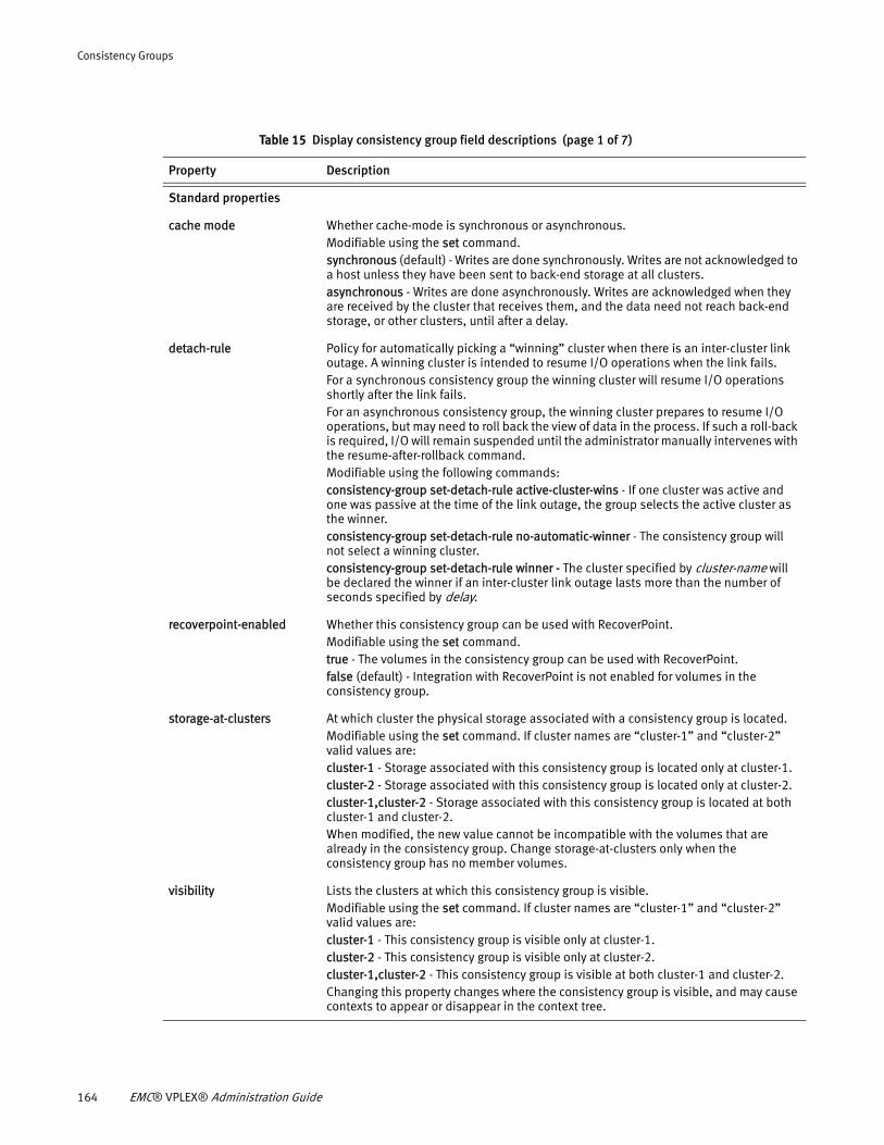
Consistency Groups
Table 15 Display consistency group field descriptions (page 1 of 7)
Property Description
Standard properties
cache mode Whether cache-mode is synchronous or asynchronous.Modifiable using the set command.synchronous (default) - Writes are done synchronously. Writes are not acknowledged to a host unless they have been sent to back-end storage at all clusters. asynchronous - Writes are done asynchronously. Writes are acknowledged when they are received by the cluster that receives them, and the data need not reach back-end storage, or other clusters, until after a delay.
detach-rule Policy for automatically picking a “winning” cluster when there is an inter-cluster link outage. A winning cluster is intended to resume I/O operations when the link fails. For a synchronous consistency group the winning cluster will resume I/O operations shortly after the link fails. For an asynchronous consistency group, the winning cluster prepares to resume I/O operations, but may need to roll back the view of data in the process. If such a roll-back is required, I/O will remain suspended until the administrator manually intervenes with the resume-after-rollback command. Modifiable using the following commands:consistency-group set-detach-rule active-cluster-wins - If one cluster was active and one was passive at the time of the link outage, the group selects the active cluster as the winner.consistency-group set-detach-rule no-automatic-winner - The consistency group will not select a winning cluster.consistency-group set-detach-rule winner - The cluster specified by cluster-name will be declared the winner if an inter-cluster link outage lasts more than the number of seconds specified by delay.
recoverpoint-enabled Whether this consistency group can be used with RecoverPoint.Modifiable using the set command. true - The volumes in the consistency group can be used with RecoverPoint.false (default) - Integration with RecoverPoint is not enabled for volumes in the consistency group.
storage-at-clusters At which cluster the physical storage associated with a consistency group is located.Modifiable using the set command. If cluster names are “cluster-1” and “cluster-2” valid values are:cluster-1 - Storage associated with this consistency group is located only at cluster-1.cluster-2 - Storage associated with this consistency group is located only at cluster-2.cluster-1,cluster-2 - Storage associated with this consistency group is located at both cluster-1 and cluster-2.When modified, the new value cannot be incompatible with the volumes that are already in the consistency group. Change storage-at-clusters only when the consistency group has no member volumes.
visibility Lists the clusters at which this consistency group is visible. Modifiable using the set command. If cluster names are “cluster-1” and “cluster-2” valid values are:cluster-1 - This consistency group is visible only at cluster-1.cluster-2 - This consistency group is visible only at cluster-2.cluster-1,cluster-2 - This consistency group is visible at both cluster-1 and cluster-2.Changing this property changes where the consistency group is visible, and may cause contexts to appear or disappear in the context tree.
164 EMC® VPLEX® Administration Guide
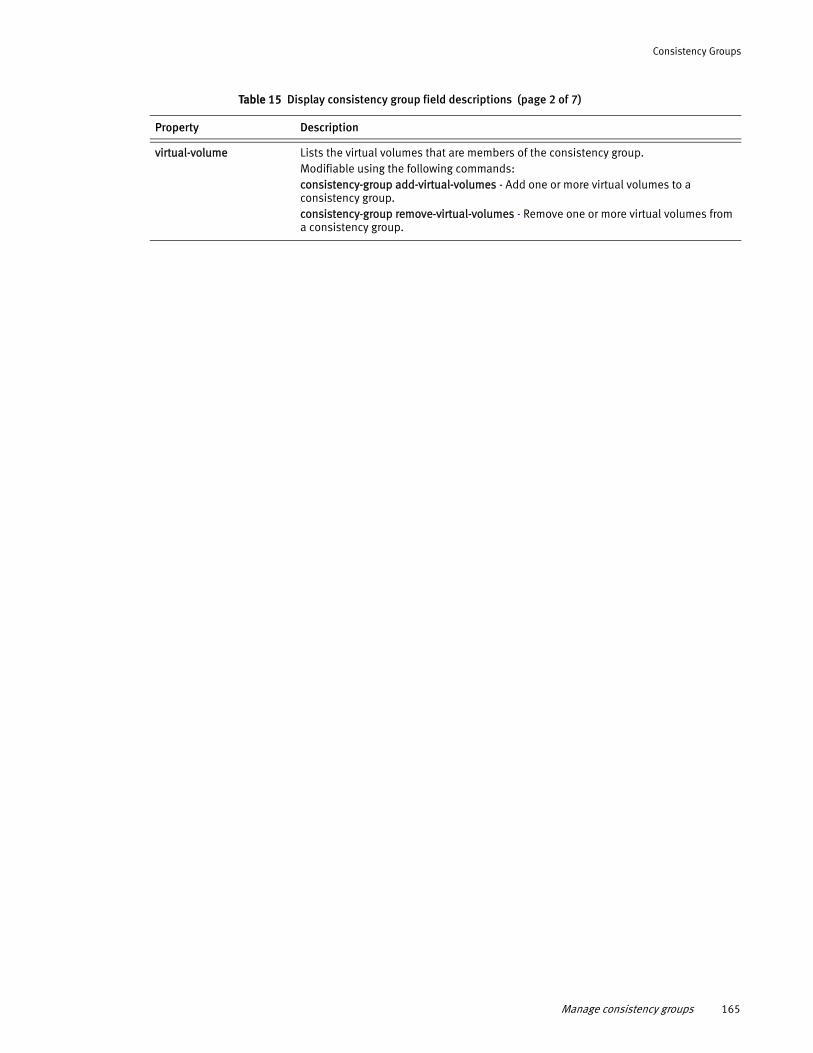
Consistency Groups
virtual-volume Lists the virtual volumes that are members of the consistency group. Modifiable using the following commands: consistency-group add-virtual-volumes - Add one or more virtual volumes to a consistency group.consistency-group remove-virtual-volumes - Remove one or more virtual volumes from a consistency group.
Table 15 Display consistency group field descriptions (page 2 of 7)
Property Description
Manage consistency groups 165
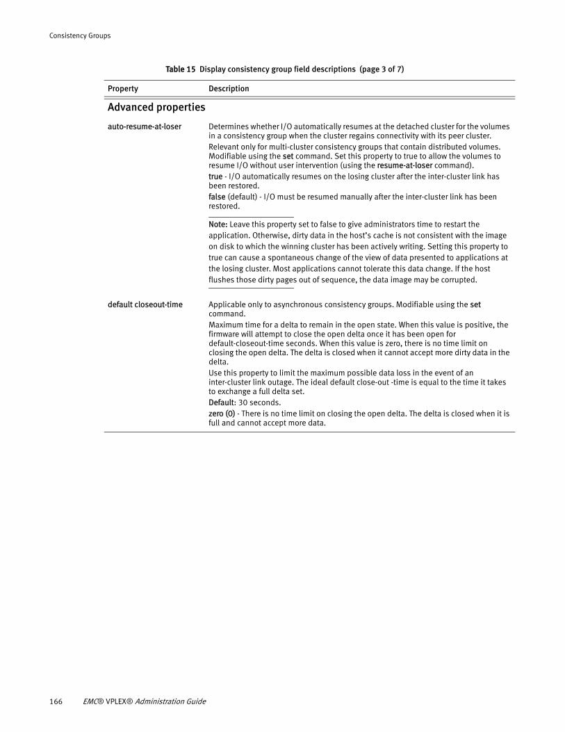
Consistency Groups
Advanced properties
auto-resume-at-loser Determines whether I/O automatically resumes at the detached cluster for the volumes in a consistency group when the cluster regains connectivity with its peer cluster. Relevant only for multi-cluster consistency groups that contain distributed volumes. Modifiable using the set command. Set this property to true to allow the volumes to resume I/O without user intervention (using the resume-at-loser command). true - I/O automatically resumes on the losing cluster after the inter-cluster link has been restored. false (default) - I/O must be resumed manually after the inter-cluster link has been restored.
Note: Leave this property set to false to give administrators time to restart the application. Otherwise, dirty data in the host’s cache is not consistent with the image on disk to which the winning cluster has been actively writing. Setting this property to true can cause a spontaneous change of the view of data presented to applications at the losing cluster. Most applications cannot tolerate this data change. If the host flushes those dirty pages out of sequence, the data image may be corrupted.
default closeout-time Applicable only to asynchronous consistency groups. Modifiable using the set command.Maximum time for a delta to remain in the open state. When this value is positive, the firmware will attempt to close the open delta once it has been open for default-closeout-time seconds. When this value is zero, there is no time limit on closing the open delta. The delta is closed when it cannot accept more dirty data in the delta. Use this property to limit the maximum possible data loss in the event of an inter-cluster link outage. The ideal default close-out -time is equal to the time it takes to exchange a full delta set.Default: 30 seconds.zero (0) - There is no time limit on closing the open delta. The delta is closed when it is full and cannot accept more data.
Table 15 Display consistency group field descriptions (page 3 of 7)
Property Description
166 EMC® VPLEX® Administration Guide
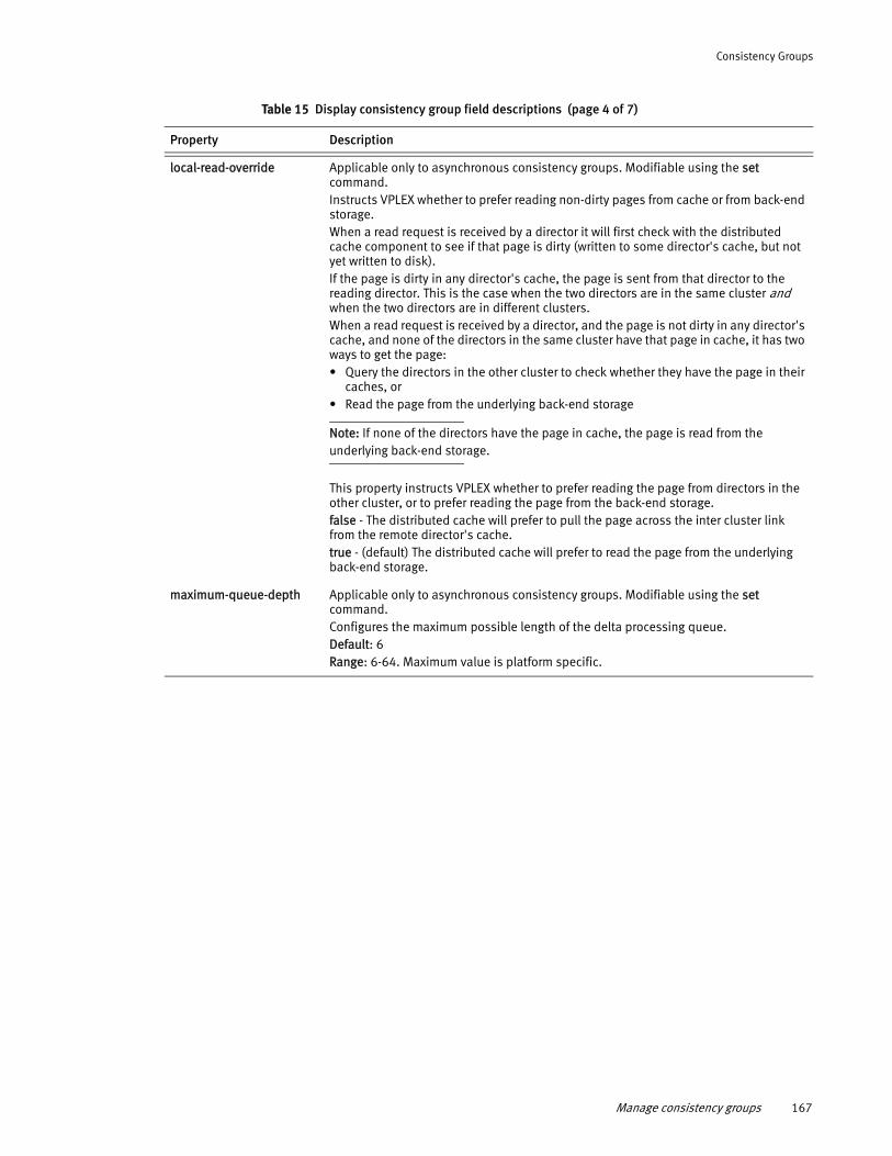
Consistency Groups
local-read-override Applicable only to asynchronous consistency groups. Modifiable using the set command.Instructs VPLEX whether to prefer reading non-dirty pages from cache or from back-end storage.When a read request is received by a director it will first check with the distributed cache component to see if that page is dirty (written to some director's cache, but not yet written to disk). If the page is dirty in any director's cache, the page is sent from that director to the reading director. This is the case when the two directors are in the same cluster and when the two directors are in different clusters. When a read request is received by a director, and the page is not dirty in any director's cache, and none of the directors in the same cluster have that page in cache, it has two ways to get the page: • Query the directors in the other cluster to check whether they have the page in their
caches, or • Read the page from the underlying back-end storage
Note: If none of the directors have the page in cache, the page is read from the underlying back-end storage.
This property instructs VPLEX whether to prefer reading the page from directors in the other cluster, or to prefer reading the page from the back-end storage. false - The distributed cache will prefer to pull the page across the inter cluster link from the remote director's cache. true - (default) The distributed cache will prefer to read the page from the underlying back-end storage.
maximum-queue-depth Applicable only to asynchronous consistency groups. Modifiable using the set command.Configures the maximum possible length of the delta processing queue.Default: 6Range: 6-64. Maximum value is platform specific.
Table 15 Display consistency group field descriptions (page 4 of 7)
Property Description
Manage consistency groups 167
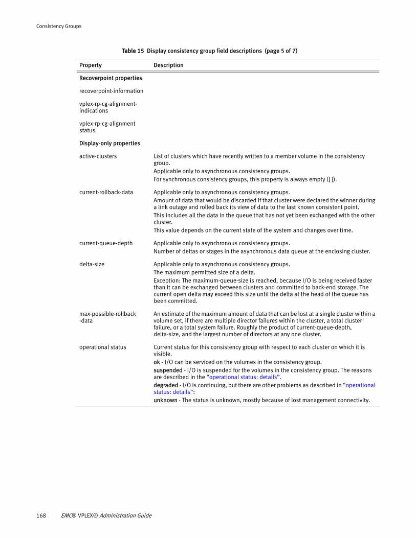
Consistency Groups
Recoverpoint properties
recoverpoint-information
vplex-rp-cg-alignment- indications
vplex-rp-cg-alignment status
Display-only properties
active-clusters List of clusters which have recently written to a member volume in the consistency group. Applicable only to asynchronous consistency groups. For synchronous consistency groups, this property is always empty ([ ]).
current-rollback-data Applicable only to asynchronous consistency groups.Amount of data that would be discarded if that cluster were declared the winner during a link outage and rolled back its view of data to the last known consistent point. This includes all the data in the queue that has not yet been exchanged with the other cluster. This value depends on the current state of the system and changes over time.
current-queue-depth Applicable only to asynchronous consistency groups.Number of deltas or stages in the asynchronous data queue at the enclosing cluster.
delta-size Applicable only to asynchronous consistency groups. The maximum permitted size of a delta. Exception: The maximum-queue-size is reached, because I/O is being received faster than it can be exchanged between clusters and committed to back-end storage. The current open delta may exceed this size until the delta at the head of the queue has been committed.
max-possible-rollback -data
An estimate of the maximum amount of data that can be lost at a single cluster within a volume set, if there are multiple director failures within the cluster, a total cluster failure, or a total system failure. Roughly the product of current-queue-depth, delta-size, and the largest number of directors at any one cluster.
operational status Current status for this consistency group with respect to each cluster on which it is visible.ok - I/O can be serviced on the volumes in the consistency group.suspended - I/O is suspended for the volumes in the consistency group. The reasons are described in the “operational status: details”. degraded - I/O is continuing, but there are other problems as described in “operational status: details”:unknown - The status is unknown, mostly because of lost management connectivity.
Table 15 Display consistency group field descriptions (page 5 of 7)
Property Description
168 EMC® VPLEX® Administration Guide

Consistency Groups
operational status: details If operational status is “ok”, this field is empty: “[ ]”. Otherwise, it displays additional information, which may be any of the following:cluster-departure - Not all the visible clusters are in communication.data-safe-failure - A single director has failed. The volumes are still crash-consistent, and will remain in this state, unless a second failure occurs before the first is recovered. member-volumes-unreachable - This asynchronous consistency group has unreachable volumes. I/O is not suspended but the consistency group is degraded.rebuilding-across-clusters - One or more distributed member volumes is being rebuilt. At least one volume in the group is out of date at that cluster and is resyncing. If the link goes out at this time, the entire consistency group is suspended. Use the rebuild status command to display which volume is out of date at which cluster.rebuilding-within-cluster - One or more local rebuilds is in progress at this cluster. requires-resolve-conflicting-detach - After the inter-cluster link is restored, two clusters have discovered that they have detached from one another and resumed I/O independently. The clusters are continuing to service I/O on their independent versions of the data. The consistency-group resolve-conflicting-detach command must be used to make the view of data consistent again at the clusters. requires-resume-after-data-loss-failure - There have been at least two concurrent failures, and data has been lost. For example, a director fails shortly after the inter-cluster link fails, or when two directors fail at almost the same time. Use the consistency-group resume-after-data-loss-failure command to select a winning cluster and allow I/O to resume. requires-resume-after-rollback - A cluster has detached its peer cluster and rolled back the view of data, but is awaiting the consistency-group resume-after-rollback command before resuming I/O. Displayed:• For an asynchronous consistency group where both clusters have been writing, that
is where both clusters are active.• At the winning side when a detach rule fires, or shortly after the consistency-group
choose-winner command picks a winning cluster. requires-resume-at-loser - Displayed on the losing side when the inter-cluster link heals after an outage. After the inter-cluster link is restored, the losing cluster discovers that its peer was declared the winner and resumed I/O. Use the consistency-group resume-at-loser command to make the view of data consistent with the winner, and to resume I/O at the loser. restore-link-or-choose-winner - I/O is suspended at all clusters because of a cluster departure, and cannot automatically resume. This can happen if:• There is no detach-rule• If the detach-rule is 'no-automatic-winner', or• If the detach-rule cannot fire because its conditions are not met. For example, if more than one cluster is active at the time of an inter-cluster link outage, the 'active-cluster-wins' rule cannot take effect. When this detail is present, I/O will not resume until either the inter-cluster link is restored, or the user intervenes to select a winning cluster with the consistency-group choose-winner command.temporarily-synchronous - This asynchronous consistency group has temporarily switched to 'synchronous' cache mode because of a director failure. unhealthy-devices - I/O has stopped in this consistency group because one or more volumes are unhealthy and cannot perform I/O. will-rollback-on-link-down - If there were a link-down now, the winning cluster would have to roll back the view of data in order to resume I/O.
passive-clusters Applicable only to asynchronous consistency groups.Clusters which have not written to a member volume recently. For synchronous consistency groups, the value of this attribute is always empty [ ].
Table 15 Display consistency group field descriptions (page 6 of 7)
Property Description
Manage consistency groups 169
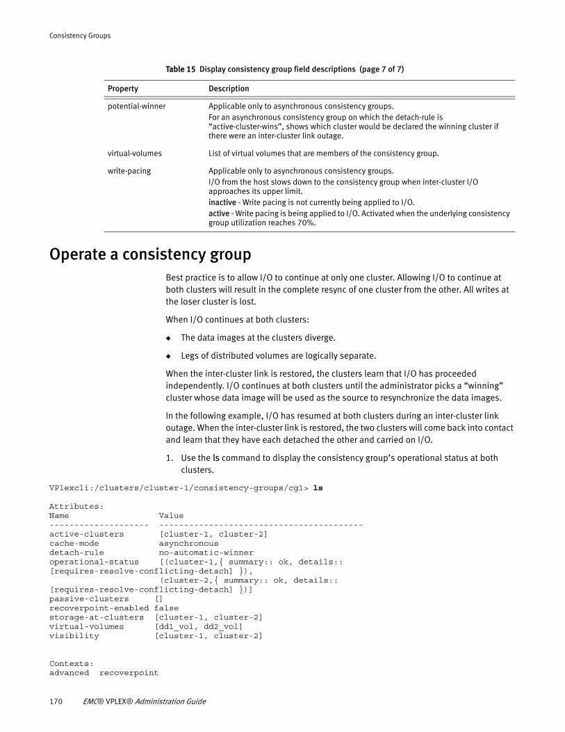
Consistency Groups
Operate a consistency groupBest practice is to allow I/O to continue at only one cluster. Allowing I/O to continue at both clusters will result in the complete resync of one cluster from the other. All writes at the loser cluster is lost.
When I/O continues at both clusters:
◆ The data images at the clusters diverge.
◆ Legs of distributed volumes are logically separate.
When the inter-cluster link is restored, the clusters learn that I/O has proceeded independently. I/O continues at both clusters until the administrator picks a “winning” cluster whose data image will be used as the source to resynchronize the data images.
In the following example, I/O has resumed at both clusters during an inter-cluster link outage. When the inter-cluster link is restored, the two clusters will come back into contact and learn that they have each detached the other and carried on I/O.
1. Use the ls command to display the consistency group’s operational status at both clusters.
VPlexcli:/clusters/cluster-1/consistency-groups/cg1> ls
Attributes: Name Value-------------------- -----------------------------------------active-clusters [cluster-1, cluster-2]cache-mode asynchronousdetach-rule no-automatic-winneroperational-status [(cluster-1,{ summary:: ok, details:: [requires-resolve-conflicting-detach] }),
(cluster-2,{ summary:: ok, details:: [requires-resolve-conflicting-detach] })]passive-clusters []recoverpoint-enabled falsestorage-at-clusters [cluster-1, cluster-2]virtual-volumes [dd1_vol, dd2_vol]visibility [cluster-1, cluster-2]
Contexts:advanced recoverpoint
potential-winner Applicable only to asynchronous consistency groups.For an asynchronous consistency group on which the detach-rule is “active-cluster-wins”, shows which cluster would be declared the winning cluster if there were an inter-cluster link outage.
virtual-volumes List of virtual volumes that are members of the consistency group.
write-pacing Applicable only to asynchronous consistency groups.I/O from the host slows down to the consistency group when inter-cluster I/O approaches its upper limit.inactive - Write pacing is not currently being applied to I/O. active - Write pacing is being applied to I/O. Activated when the underlying consistency group utilization reaches 70%.
Table 15 Display consistency group field descriptions (page 7 of 7)
Property Description
170 EMC® VPLEX® Administration Guide
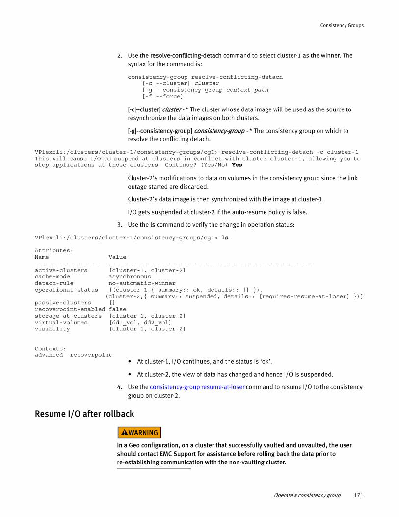
Consistency Groups
2. Use the resolve-conflicting-detach command to select cluster-1 as the winner. The syntax for the command is:
consistency-group resolve-conflicting-detach[-c|--cluster] cluster[-g|--consistency-group context path[-f|--force]
[-c|--cluster] cluster - * The cluster whose data image will be used as the source to resynchronize the data images on both clusters.
[-g|--consistency-group] consistency-group - * The consistency group on which to resolve the conflicting detach.
VPlexcli:/clusters/cluster-1/consistency-groups/cg1> resolve-conflicting-detach -c cluster-1This will cause I/O to suspend at clusters in conflict with cluster cluster-1, allowing you to stop applications at those clusters. Continue? (Yes/No) Yes
Cluster-2’s modifications to data on volumes in the consistency group since the link outage started are discarded.
Cluster-2's data image is then synchronized with the image at cluster-1.
I/O gets suspended at cluster-2 if the auto-resume policy is false.
3. Use the ls command to verify the change in operation status:
VPlexcli:/clusters/cluster-1/consistency-groups/cg1> ls
Attributes: Name Value------------------- ----------------------------------------------------------active-clusters [cluster-1, cluster-2]cache-mode asynchronousdetach-rule no-automatic-winneroperational-status [(cluster-1,{ summary:: ok, details:: [] }), (cluster-2,{ summary:: suspended, details:: [requires-resume-at-loser] })]passive-clusters []recoverpoint-enabled falsestorage-at-clusters [cluster-1, cluster-2]virtual-volumes [dd1_vol, dd2_vol]visibility [cluster-1, cluster-2]
Contexts:advanced recoverpoint
• At cluster-1, I/O continues, and the status is ‘ok’.
• At cluster-2, the view of data has changed and hence I/O is suspended.
4. Use the consistency-group resume-at-loser command to resume I/O to the consistency group on cluster-2.
Resume I/O after rollback
In a Geo configuration, on a cluster that successfully vaulted and unvaulted, the user should contact EMC Support for assistance before rolling back the data prior to re-establishing communication with the non-vaulting cluster.
Operate a consistency group 171
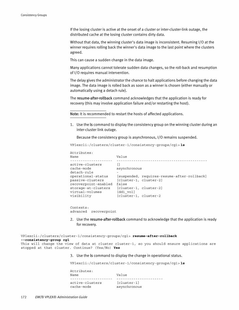
Consistency Groups
If the losing cluster is active at the onset of a cluster or inter-cluster-link outage, the distributed cache at the losing cluster contains dirty data.
Without that data, the winning cluster's data image is inconsistent. Resuming I/O at the winner requires rolling back the winner's data image to the last point where the clusters agreed.
This can cause a sudden change in the data image.
Many applications cannot tolerate sudden data changes, so the roll-back and resumption of I/O requires manual intervention.
The delay gives the administrator the chance to halt applications before changing the data image. The data image is rolled back as soon as a winner is chosen (either manually or automatically using a detach rule).
The resume-after-rollback command acknowledges that the application is ready for recovery (this may involve application failure and/or restarting the host).
Note: It is recommended to restart the hosts of affected applications.
1. Use the ls command to display the consistency group on the winning cluster during an inter-cluster link outage.
Because the consistency group is asynchronous, I/O remains suspended.
VPlexcli:/clusters/cluster-1/consistency-groups/cg1> ls
Attributes: Name Value-------------------- -------------------------------------------active-clusters []cache-mode asynchronousdetach-rule -operational-status [suspended, requires-resume-after-rollback]passive-clusters [cluster-1, cluster-2]recoverpoint-enabled falsestorage-at-clusters [cluster-1, cluster-2]virtual-volumes [dd1_vol]visibility [cluster-1, cluster-2
Contexts:advanced recoverpoint
2. Use the resume-after-rollback command to acknowledge that the application is ready for recovery.
VPlexcli:/clusters/cluster-1/consistency-groups/cg1> resume-after-rollback --consistency-group cg1This will change the view of data at cluster cluster-1, so you should ensure applications are stopped at that cluster. Continue? (Yes/No) Yes
3. Use the ls command to display the change in operational status.
VPlexcli:/clusters/cluster-1/consistency-groups/cg1> ls
Attributes: Name Value-------------------- ----------------------active-clusters [cluster-1]cache-mode asynchronous
172 EMC® VPLEX® Administration Guide
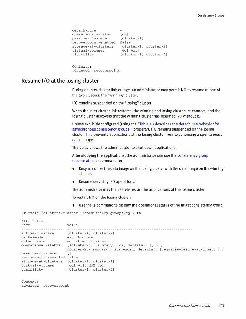
Consistency Groups
detach-rule -operational-status [ok]passive-clusters [cluster-2]recoverpoint-enabled falsestorage-at-clusters [cluster-1, cluster-2]virtual-volumes [dd1_vol]visibility [cluster-1, cluster-2]
Contexts:advanced recoverpoint
Resume I/O at the losing cluster
During an inter-cluster link outage, an administrator may permit I/O to resume at one of the two clusters, the “winning” cluster.
I/O remains suspended on the “losing” cluster.
When the inter-cluster link restores, the winning and losing clusters re-connect, and the losing cluster discovers that the winning cluster has resumed I/O without it.
Unless explicitly configured (using the “Table 13 describes the detach rule behavior for asynchronous consistency groups.” property), I/O remains suspended on the losing cluster. This prevents applications at the losing cluster from experiencing a spontaneous data change.
The delay allows the administrator to shut down applications.
After stopping the applications, the administrator can use the consistency-group resume-at-loser command to:
◆ Resynchronize the data image on the losing cluster with the data image on the winning cluster.
◆ Resume servicing I/O operations.
The administrator may then safely restart the applications at the losing cluster.
To restart I/O on the losing cluster:
1. Use the ls command to display the operational status of the target consistency group.
VPlexcli:/clusters/cluster-1/consistency-groups/cg1> ls
Attributes: Name Value------------------- ----------------------------------------------------------active-clusters [cluster-1, cluster-2]cache-mode asynchronousdetach-rule no-automatic-winneroperational-status [(cluster-1,{ summary:: ok, details:: [] }), (cluster-2,{ summary:: suspended, details:: [requires-resume-at-loser] })]passive-clusters []recoverpoint-enabled falsestorage-at-clusters [cluster-1, cluster-2]virtual-volumes [dd1_vol, dd2_vol]visibility [cluster-1, cluster-2]
Contexts:advanced recoverpoint
Operate a consistency group 173
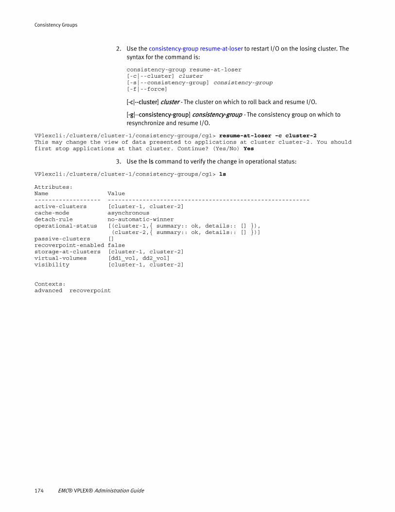
Consistency Groups
2. Use the consistency-group resume-at-loser to restart I/O on the losing cluster. The syntax for the command is:
consistency-group resume-at-loser[-c|--cluster] cluster[-s|--consistency-group] consistency-group[-f|--force]
[-c|--cluster] cluster - The cluster on which to roll back and resume I/O.
[-g|--consistency-group] consistency-group - The consistency group on which to resynchronize and resume I/O.
VPlexcli:/clusters/cluster-1/consistency-groups/cg1> resume-at-loser -c cluster-2This may change the view of data presented to applications at cluster cluster-2. You should first stop applications at that cluster. Continue? (Yes/No) Yes
3. Use the ls command to verify the change in operational status:
VPlexcli:/clusters/cluster-1/consistency-groups/cg1> ls
Attributes: Name Value------------------- ----------------------------------------------------------active-clusters [cluster-1, cluster-2]cache-mode asynchronousdetach-rule no-automatic-winneroperational-status [(cluster-1,{ summary:: ok, details:: [] }), (cluster-2,{ summary:: ok, details:: [] })]passive-clusters []recoverpoint-enabled falsestorage-at-clusters [cluster-1, cluster-2]virtual-volumes [dd1_vol, dd2_vol]visibility [cluster-1, cluster-2]
Contexts:advanced recoverpoint
174 EMC® VPLEX® Administration Guide
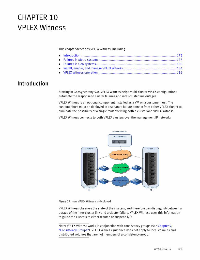
CHAPTER 10VPLEX Witness
This chapter describes VPLEX Witness, including:
◆ Introduction.......................................................................................................... 175◆ Failures in Metro systems...................................................................................... 177◆ Failures in Geo systems......................................................................................... 180◆ Install, enable, and manage VPLEX Witness........................................................... 184◆ VPLEX Witness operation ...................................................................................... 186
IntroductionStarting in GeoSynchrony 5.0, VPLEX Witness helps multi-cluster VPLEX configurations automate the response to cluster failures and inter-cluster link outages.
VPLEX Witness is an optional component installed as a VM on a customer host. The customer host must be deployed in a separate failure domain from either VPLEX cluster to eliminate the possibility of a single fault affecting both a cluster and VPLEX Witness.
VPLEX Witness connects to both VPLEX clusters over the management IP network:
Figure 19 How VPLEX Witness is deployed
VPLEX Witness observes the state of the clusters, and therefore can distinguish between a outage of the inter-cluster link and a cluster failure. VPLEX Witness uses this information to guide the clusters to either resume or suspend I/O.
Note: VPLEX Witness works in conjunction with consistency groups (see Chapter 9, “Consistency Groups”). VPLEX Witness guidance does not apply to local volumes and distributed volumes that are not members of a consistency group.
VPLEX Witness 175
VPLEX Witness
VPLEX Witness capabilities vary depending on whether the VPLEX is a Metro (synchronous consistency groups) or Geo (asynchronous consistency groups).
◆ In Metro systems, VPLEX Witness provides seamless zero RTO fail-over for storage volumes in synchronous consistency groups. See “Failures in Metro Systems: With VPLEX Witness” on page 179.
◆ In Geo systems, VPLEX Witness does not automate failover for asynchronous consistency groups and can only be used for diagnostic purposes.
Related Information Additional information, including procedures to install, configure, enable, and disable VPLEX Witness is published in the following EMC documents:
Handling failures when VPLEX Witness is not deployed: detach rules
When VPLEX Witness is not deployed, detach rules determine at which cluster I/O continues during a cluster failure or inter-cluster link outage.
Note: The cluster on which I/O continues during a failure is called the preferred cluster.
VPLEX uses two levels of detach rules to determine which cluster is preferred, detach rules associated with individual distributed devices, and detach rules associated with consistency groups.
Detach rules associated with distributed devices - Every distributed device must have a detach rule. There are two device-level detach rules:
◆ cluster-1-detaches
Cluster-1 is the preferred cluster. During a cluster failure or inter-cluster link outage, cluster-1 continues I/O and cluster-2 suspends I/O.
◆ cluster-2-detaches
Cluster-2 is the preferred cluster. During a cluster failure or inter-cluster link outage, cluster-2 continues I/O and cluster-1 suspends I/O.
VPLEX Witness does not override device-level detach rules.
Detach rules associated with consistency groups - Every consistency group has a detach rule that applies to all member devices in the consistency group. If a distributed device is a member of a consistency group, the detach rule of the consistency group overrides the detach rule configured for the device.
There are three consistency group detach rules.
Information Reference
Commands to enable/disable/display VPLEX Witness
EMC VPLEX CLI Guide
Consistency groups Chapter 9
Procedures to install/configure VPLEX Witness EMC VPLEX generator
Procedures to troubleshoot VPLEX Witness EMC VPLEX generator
176 EMC® VPLEX® Administration Guide
VPLEX Witness
• active-cluster-wins
This detach rule applies only to asynchronous consistency groups (VPLEX Geo configurations).
If one cluster was active and one was passive at the time of the failure, the active cluster is preferred. See “When a cluster is active vs. passive” on page 146.
The consistency group’s “Table 13 describes the detach rule behavior for asynchronous consistency groups.” property must be set to true for the active-cluster-wins rule to work.
• winner cluster-name delay seconds
This detach rule applies only to synchronous consistency groups (VPLEX Metro configurations).
The cluster specified by cluster-name is declared the preferred cluster if a failure lasts more than the number of seconds specified by seconds.
• no-automatic-winner
Consistency groups with this detach rule are not guided by VPLEX Witness.
The consistency group does not select the preferred cluster. The detach rules of the member devices determine the preferred cluster for that device.
Manual intervention may be required to restart I/O on the suspended cluster.
Failures in Metro systems VPLEX Metro configurations (synchronous consistency groups) have two consistency group level detach rules:
◆ winner cluster-name delay seconds
◆ no-automatic-winner
VPLEX Witness does not guide consistency groups with the “no-automatic-winner” detach rule. The remainder of this discussion applies only to synchronous consistency groups with the “winner cluster-name delay seconds” detach rule.
Synchronous consistency groups use write-through caching. Host writes to a distributed volume are acknowledged back to the host only after the data is written to the back-end storage at both VPLEX clusters.
IMPORTANT
VPLEX Witness does not automate fail-over for distributed volumes outside of consistency groups.
Failures in Metro Systems: Without VPLEX Witness
In Figure 20, the “winner cluster-name delay seconds” detach rule designates cluster-1 as the preferred cluster. That is, during an inter-cluster link outage or a cluster failure, I/O to the device leg at cluster-1 continues, and I/O to the device leg at cluster-2 is suspended.
Failures in Metro systems 177
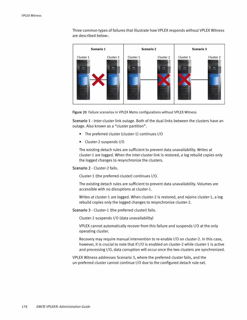
VPLEX Witness
Three common types of failures that illustrate how VPLEX responds without VPLEX Witness are described below:.
Figure 20 Failure scenarios in VPLEX Metro configurations without VPLEX Witness
Scenario 1 - Inter-cluster link outage. Both of the dual links between the clusters have an outage. Also known as a “cluster partition”.
• The preferred cluster (cluster-1) continues I/O
• Cluster-2 suspends I/O
The existing detach rules are sufficient to prevent data unavailability. Writes at cluster-1 are logged. When the inter-cluster link is restored, a log rebuild copies only the logged changes to resynchronize the clusters.
Scenario 2 - Cluster-2 fails.
Cluster-1 (the preferred cluster) continues I/O.
The existing detach rules are sufficient to prevent data unavailability. Volumes are accessible with no disruptions at cluster-1.
Writes at cluster-1 are logged. When cluster-2 is restored, and rejoins cluster-1, a log rebuild copies only the logged changes to resynchronize cluster-2.
Scenario 3 - Cluster-1 (the preferred cluster) fails.
Cluster-2 suspends I/O (data unavailability)
VPLEX cannot automatically recover from this failure and suspends I/O at the only operating cluster.
Recovery may require manual intervention to re-enable I/O on cluster-2. In this case, however, it is crucial to note that if I/O is enabled on cluster-2 while cluster-1 is active and processing I/O, data corruption will occur once the two clusters are synchronized.
VPLEX Witness addresses Scenario 3, where the preferred cluster fails, and the un-preferred cluster cannot continue I/O due to the configured detach rule-set.
Scenario 1
Cluster 1 Cluster 2
Scenario 2 Scenario 3
Cluster 1 Cluster 2 Cluster 1 Cluster 2
178 EMC® VPLEX® Administration Guide
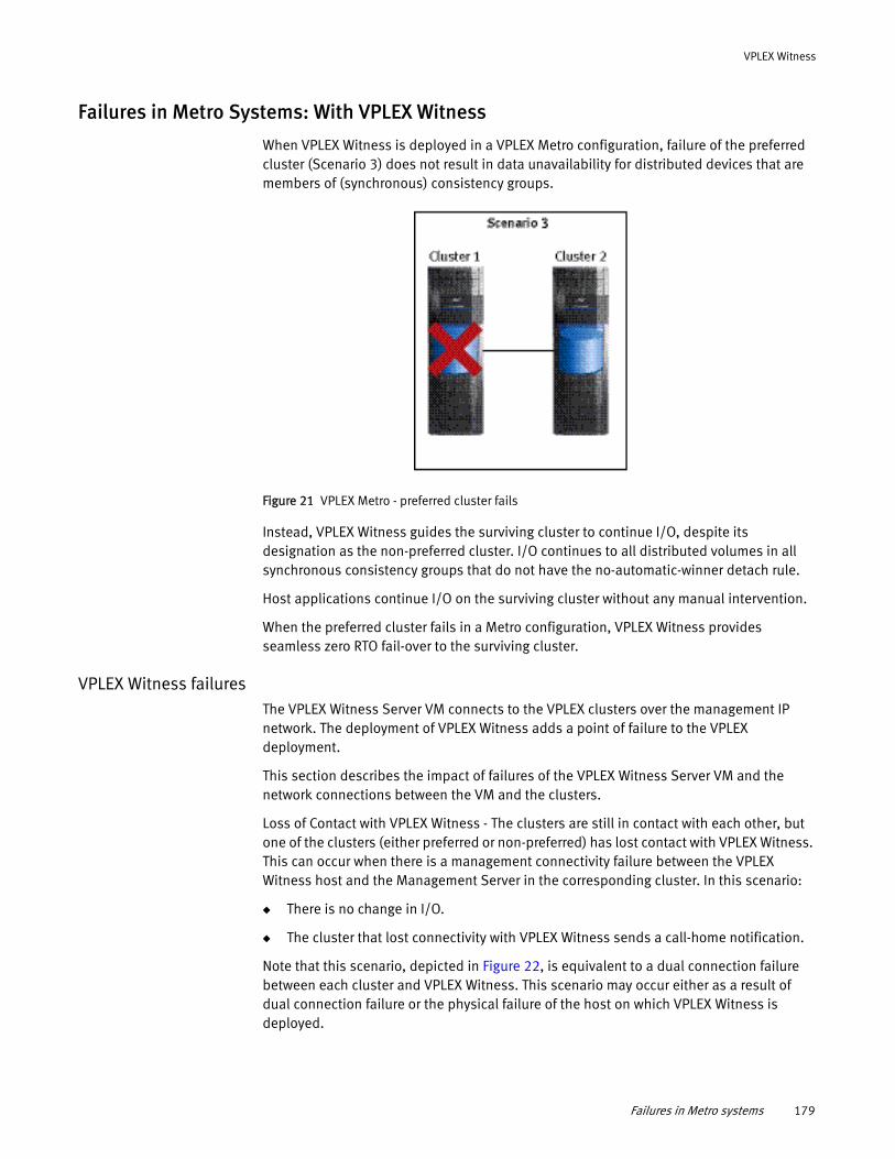
VPLEX Witness
Failures in Metro Systems: With VPLEX Witness
When VPLEX Witness is deployed in a VPLEX Metro configuration, failure of the preferred cluster (Scenario 3) does not result in data unavailability for distributed devices that are members of (synchronous) consistency groups.
Figure 21 VPLEX Metro - preferred cluster fails
Instead, VPLEX Witness guides the surviving cluster to continue I/O, despite its designation as the non-preferred cluster. I/O continues to all distributed volumes in all synchronous consistency groups that do not have the no-automatic-winner detach rule.
Host applications continue I/O on the surviving cluster without any manual intervention.
When the preferred cluster fails in a Metro configuration, VPLEX Witness provides seamless zero RTO fail-over to the surviving cluster.
VPLEX Witness failuresThe VPLEX Witness Server VM connects to the VPLEX clusters over the management IP network. The deployment of VPLEX Witness adds a point of failure to the VPLEX deployment.
This section describes the impact of failures of the VPLEX Witness Server VM and the network connections between the VM and the clusters.
Loss of Contact with VPLEX Witness - The clusters are still in contact with each other, but one of the clusters (either preferred or non-preferred) has lost contact with VPLEX Witness. This can occur when there is a management connectivity failure between the VPLEX Witness host and the Management Server in the corresponding cluster. In this scenario:
◆ There is no change in I/O.
◆ The cluster that lost connectivity with VPLEX Witness sends a call-home notification.
Note that this scenario, depicted in Figure 22, is equivalent to a dual connection failure between each cluster and VPLEX Witness. This scenario may occur either as a result of dual connection failure or the physical failure of the host on which VPLEX Witness is deployed.
Failures in Metro systems 179
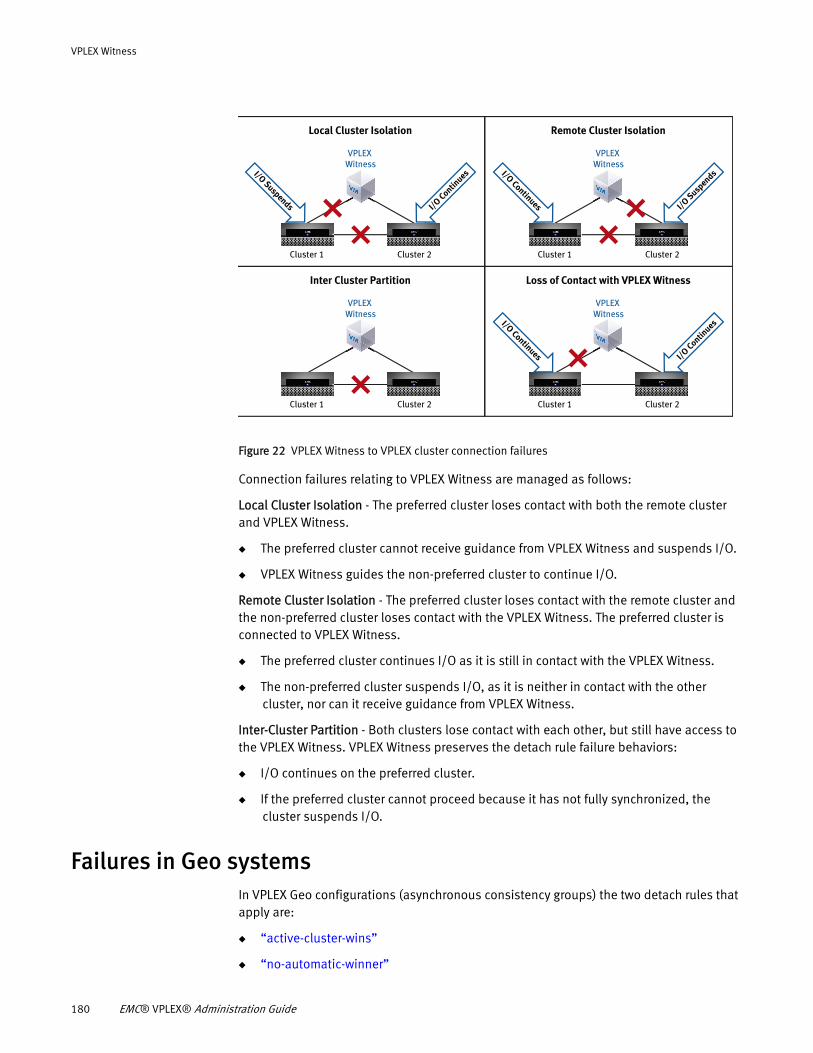
VPLEX Witness
Figure 22 VPLEX Witness to VPLEX cluster connection failures
Connection failures relating to VPLEX Witness are managed as follows:
Local Cluster Isolation - The preferred cluster loses contact with both the remote cluster and VPLEX Witness.
◆ The preferred cluster cannot receive guidance from VPLEX Witness and suspends I/O.
◆ VPLEX Witness guides the non-preferred cluster to continue I/O.
Remote Cluster Isolation - The preferred cluster loses contact with the remote cluster and the non-preferred cluster loses contact with the VPLEX Witness. The preferred cluster is connected to VPLEX Witness.
◆ The preferred cluster continues I/O as it is still in contact with the VPLEX Witness.
◆ The non-preferred cluster suspends I/O, as it is neither in contact with the other cluster, nor can it receive guidance from VPLEX Witness.
Inter-Cluster Partition - Both clusters lose contact with each other, but still have access to the VPLEX Witness. VPLEX Witness preserves the detach rule failure behaviors:
◆ I/O continues on the preferred cluster.
◆ If the preferred cluster cannot proceed because it has not fully synchronized, the cluster suspends I/O.
Failures in Geo systems In VPLEX Geo configurations (asynchronous consistency groups) the two detach rules that apply are:
◆ “active-cluster-wins”
◆ “no-automatic-winner”
I/O Contin
uesI/O Suspends
Local Cluster Isolation
Cluster 2
VPLEX Witness
Cluster 1
I/O SuspendsI/O Continues
Remote Cluster Isolation
Cluster 2
VPLEX Witness
Cluster 1
Inter Cluster Partition
Cluster 2
VPLEX Witness
Cluster 1
I/O Contin
uesI/O Continues
Loss of Contact with VPLEX Witness
Cluster 2
VPLEX Witness
Cluster 1
180 EMC® VPLEX® Administration Guide
VPLEX Witness
This discussion applies only to asynchronous consistency groups with the “active-cluster-wins” detach rule.
Failures in VPLEX Geo systems
Failures in VPLEX Geo configurations vary depending on whether I/O was occurring at one or both legs of a distributed device when the failure occurred.
This section describes a selection of failures when I/O occurs at one leg (active/passive) and when I/O occurs at both legs (active/active). See “When a cluster is active vs. passive” on page 146.
Active/passiveIn an active/passive configuration, hosts at only one cluster write to legs of distributed volumes located at both clusters. Failures in active/passive scenarios are handled as follows:
◆ Entire engine on the passive cluster fails - No loss of data or access. If either director in the failed engine had deltas in “commit” or “exchange”, part of the delta is lost at the passive cluster. These deltas are re-copied across the inter-cluster link from the active cluster.
◆ Entire engine on the active cluster fails - All data available in open, closed, and exchanging deltas is discarded. I/O is suspended at both clusters. Manual intervention is required (resume-after-data-loss-failure command) to roll back the data image to the last committed delta (the last consistent point in time).
◆ Passive cluster fails - No loss of data or access. I/O continues on the active cluster. All writes are logged. When the passive cluster is restored and rejoins, a log rebuild copies only the logged changes to resynchronize the passive cluster.
◆ Active cluster fails - Dirty data is lost, and the volumes are suspended at the passive cluster. Hosts at the active cluster experience a DU.
All writes at the passive cluster are logged. When the active cluster is restored and rejoins VPLEX, a log rebuild copies only changes to the active cluster.
Users can fail-over applications to the passive cluster using the choose-winner and resume-after-rollback commands.
Alternatively, users can wait for the failed cluster to be restored. When the failed cluster is restored and rejoins, VPLEX recognizes that the failed cluster has lost data and rolls back to the last committed delta (last time consistent image). The user must manually re-enable I/O at the recovered cluster (resume-at-loser command).
◆ Inter-cluster link outage - No loss of data or access. I/O continues on the active cluster. All I/O is logged. On the passive cluster, local volumes are accessible to local hosts. When the inter-cluster link is restored, a log rebuild copies only the logged changes to resynchronize the passive cluster.
Active/activeIn an active/active configuration, hosts at both clusters write to legs of distributed volumes at both clusters. Failures in active/active scenarios are handled as follows:
Failures in Geo systems 181
VPLEX Witness
◆ Entire engine on the either cluster fails - All data available in open, closed, and exchanging deltas is discarded. I/O is suspended at both clusters. Manual intervention (resume-after-data-loss-failure command), is required to roll back the data image to the last committed delta, which is the last consistent point in time.
◆ Either cluster fails - All data available in open, closed, and exchanging deltas is discarded. I/O to volumes is suspended at both clusters. All writes are logged at the surviving cluster. When the failed cluster is restored and rejoins, a log rebuild copies only changes to the restored cluster.
Users can fail-over applications to the surviving cluster using the choose-winner and resume-after-rollback commands. VPLEX rolls back the data image to the end of the last committed delta (last consistent point in time). Applications must be restarted or rolled back.
Users can wait for the failed cluster to be restored. When the failed cluster is restored and rejoins, VPLEX recognizes that the failed cluster has lost data and rolls back to the last committed delta (last time consistent image). The user must manually re-enable I/O at the recovered cluster (resume-at-loser command).
◆ Inter-cluster link outage - I/O is suspended at both clusters. I/O at both clusters is logged.
Users can wait for the network outage to resolve. When the inter-cluster link is restored, a log rebuild copies only the logged changes to resynchronize the clusters.
Alternatively, users can manually choose a cluster to continue I/O. Manual intervention (resume-after-data-loss-failure command) rolls back the data image to the last committed delta, which is the last consistent point in time. Applications are then re-started.
Multiple failures in VPLEX Geo systems
During recovery, a failed director's dirty cache is recovered from its protection partner and re-protected. If portions of committed and exchanged deltas have been lost, they are retrieved from the other cluster.
Exchanging deltas are not replicated within the cluster. Thus, a cluster failure can cause a loss of parts of deltas at that cluster. If the surviving cluster remains healthy, a complete copy of the deltas are available at the other cluster.
These recovery operations create scenarios where an additional failure can result in data loss or data unavailability.
This section describes how multiple failures are handled.
◆ Failed director's protection partner also fails - If the failed director's protection partner fails before dirty cache recovery completes, VPLEX has lost data.
This is both a DU and a DL.
Recovery from an external backup is required.
◆ Inter-cluster link outage during director failure recovery - A single director failure followed by an inter-cluster link outage before failure recovery of the missing portions of the commit delta are copied.
182 EMC® VPLEX® Administration Guide
VPLEX Witness
The cluster with the failed director did not complete committing the delta and the image on backend storage is not a time consistent image.
If a detach rule or user command causes the unhealthy cluster to become a winner in this state, the affected consistency groups stay suspended at that cluster.
If the unhealthy cluster (the one at which the original failure occurred) is not detached, the user may:
• Wait for the network to be restored. No data is lost.
• Accept a data rollback and resume I/O at the other, healthy cluster.
◆ Multiple BE storage volume failures after a inter-cluster link outage - This scenario occurs when a cluster is declared preferred during a inter-cluster link outage. When the link recovers, the preferred cluster updates the other cluster (logging rebuild). If the target disks on the cluster being updated fail, the consistency group suspends.
Recovery from an external backup is required.
Data loss failure mode (DLFM)
In some extremely rare system-wide multi-failure scenarios the system may enter Data Loss Failure Mode, including data loss and potential loss of crash consistency on disk in both clusters.
This state applies to individual asynchronous consistency groups; that is, while one asynchronous consistency group may be in Data Loss Failure Mode, others on the same VPLEX Geo system may be unaffected.
Best practices to avoid DLFMTo avoid DLFM, follow these best practices when configuring your system:
◆ Mirror local DR1 legs to two local arrays with a RAID-1. Local mirrors minimize the risk of back-end visibility issues during array failures
◆ Follow best practices for high availability when deploying VPLEX Geo configurations. Refer to the VPLEX Product Guide.
Recover from DLFMRefer to the troubleshooting procedure for recovering from DLFM in the VPLEX generator.
Failures in Geo Systems: With VPLEX Witness
The value of VPLEX Witness is different in VPLEX Geo configurations than it is in VPLEX Metro configurations. In Geo configurations, VPLEX Witness does not automate recovery from any failure scenario.
Clusters in Geo configurations do not comply with VPLEX Witness guidance. Rather, the clusters operate according to the detach rules applied to each asynchronous consistency group.
Information displayed in the VPLEX Witness CLI context can determine the nature of a failure (for example, a cluster failure or inter-cluster link outage). Administrators use this information to make manual fail-over decisions.
Failures in Geo systems 183
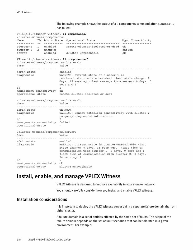
VPLEX Witness
The following example shows the output of a ll components command after cluster-2 has failed:
VPlexcli:/cluster-witness> ll components/ /cluster-witness/components: Name ID Admin State Operational State Mgmt Connectivity---------- -- ----------- ------------------------------- -----------------cluster-1 1 enabled remote-cluster-isolated-or-dead okcluster-2 2 unknown - failedserver - enabled cluster-unreachable ok
VPlexcli:/cluster-witness> ll components/* /cluster-witness/components/cluster-1: Name Value----------------------- ------------------------------------------------------admin-state enableddiagnostic WARNING: Current state of cluster-1 is remote-cluster-isolated-or-dead (last state change: 0 days, 15 secs ago; last message from server: 0 days, 0 secs ago.)id 1management-connectivity okoperational-state remote-cluster-isolated-or-dead
/cluster-witness/components/cluster-2: Name Value----------------------- ------------------------------------------------------admin-state unknowndiagnostic WARNING: Cannot establish connectivity with cluster-2 to query diagnostic information.id 2management-connectivity failedoperational-state -
/cluster-witness/components/server: Name Value----------------------- ------------------------------------------------------admin-state enableddiagnostic WARNING: Current state is cluster-unreachable (last state change: 0 days, 15 secs ago.) (last time of communication with cluster-1: 0 days, 0 secs ago.) (last time of communication with cluster-2: 0 days, 34 secs ago.)id -management-connectivity okoperational-state cluster-unreachable
Install, enable, and manage VPLEX WitnessVPLEX Witness is designed to improve availability in your storage network.
You should carefully consider how you install and enable VPLEX Witness.
Installation considerations
It is important to deploy the VPLEX Witness server VM in a separate failure domain than on either cluster.
A failure domain is a set of entities effected by the same set of faults. The scope of the failure domain depends on the set of fault scenarios that can be tolerated in a given environment. For example:
184 EMC® VPLEX® Administration Guide
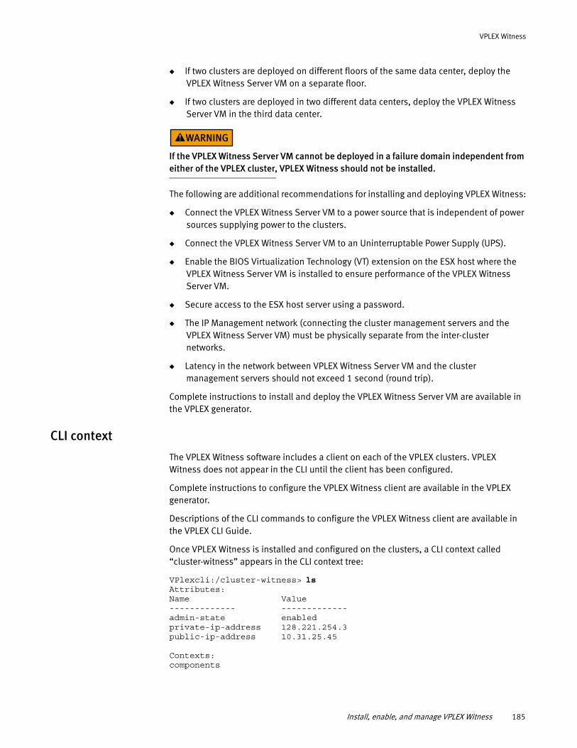
VPLEX Witness
◆ If two clusters are deployed on different floors of the same data center, deploy the VPLEX Witness Server VM on a separate floor.
◆ If two clusters are deployed in two different data centers, deploy the VPLEX Witness Server VM in the third data center.
If the VPLEX Witness Server VM cannot be deployed in a failure domain independent from either of the VPLEX cluster, VPLEX Witness should not be installed.
The following are additional recommendations for installing and deploying VPLEX Witness:
◆ Connect the VPLEX Witness Server VM to a power source that is independent of power sources supplying power to the clusters.
◆ Connect the VPLEX Witness Server VM to an Uninterruptable Power Supply (UPS).
◆ Enable the BIOS Virtualization Technology (VT) extension on the ESX host where the VPLEX Witness Server VM is installed to ensure performance of the VPLEX Witness Server VM.
◆ Secure access to the ESX host server using a password.
◆ The IP Management network (connecting the cluster management servers and the VPLEX Witness Server VM) must be physically separate from the inter-cluster networks.
◆ Latency in the network between VPLEX Witness Server VM and the cluster management servers should not exceed 1 second (round trip).
Complete instructions to install and deploy the VPLEX Witness Server VM are available in the VPLEX generator.
CLI context
The VPLEX Witness software includes a client on each of the VPLEX clusters. VPLEX Witness does not appear in the CLI until the client has been configured.
Complete instructions to configure the VPLEX Witness client are available in the VPLEX generator.
Descriptions of the CLI commands to configure the VPLEX Witness client are available in the VPLEX CLI Guide.
Once VPLEX Witness is installed and configured on the clusters, a CLI context called “cluster-witness” appears in the CLI context tree:
VPlexcli:/cluster-witness> ls Attributes: Name Value------------- -------------admin-state enabledprivate-ip-address 128.221.254.3public-ip-address 10.31.25.45
Contexts: components
Install, enable, and manage VPLEX Witness 185
VPLEX Witness
Enable/disable VPLEX Witness client
Once VPLEX Witness client is configured on the clusters, the cluster-witness context is added to the CLI context tree, and you can enable and disable the client.
Enable the VPLEX Witness client on the clusters to provide guidance.
Disable the VPLEX Witness client on the clusters when:
◆ The VPLEX Witness Server VM fails, and is not expected to be restored quickly.
◆ Connectivity between both clusters and the VPLEX Witness Server VM fails, and is not expected to be restored quickly.
There is no impact on I/O to distributed volumes. Both clusters send a call-home notification to indicate that they have lost connectivity with the VPLEX Witness Server. However, an additional failure (cluster failure or inter-cluster link outage) may result in a Data Unavailability.
When you disable the VPLEX Witness client on the clusters, all distributed volumes in consistency groups use their consistency group-level detach rules to determine which cluster is preferred.
Complete instructions to enable/disable the VPLEX Witness client are available in the VPLEX generator.
Descriptions of the CLI commands to enable/disable the VPLEX Witness client are available in the VPLEX CLI Guide.
Renew the VPLEX Witness security certificate
When VPLEX Witness is installed, a VPLEX Witness host security certificate is created.
All types of security certificates expire and must be periodically renewed. Host certificates (including the VPLEX Witness host security certificate) must be renewed every two years.
Complete instructions to renew the VPLEX Witness security certificate are available in the VPLEX generator.
Descriptions of the CLI commands to renew the VPLEX Witness security certificate are available in the VPLEX CLI Guide.
VPLEX Witness operationThis section describes the output of CLI commands during normal operations and in various failure states:
◆ “Normal operation”
◆ “Single failures (no data unavailability)”
◆ “Dual failures (no data unavailability)”
◆ “Single failures (data unavailability at one cluster)”
◆ “Dual failure (cluster isolation/DU at one cluster)”
186 EMC® VPLEX® Administration Guide
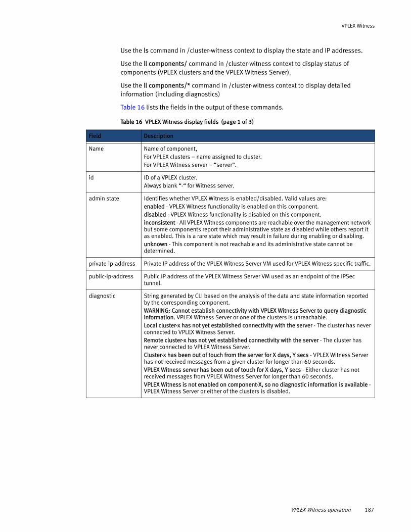
VPLEX Witness
Use the ls command in /cluster-witness context to display the state and IP addresses.
Use the ll components/ command in /cluster-witness context to display status of components (VPLEX clusters and the VPLEX Witness Server).
Use the ll components/* command in /cluster-witness context to display detailed information (including diagnostics)
Table 16 lists the fields in the output of these commands.
Table 16 VPLEX Witness display fields (page 1 of 3)
Field Description
Name Name of component,For VPLEX clusters – name assigned to cluster.For VPLEX Witness server – “server”.
id ID of a VPLEX cluster.Always blank “-“ for Witness server.
admin state Identifies whether VPLEX Witness is enabled/disabled. Valid values are: enabled - VPLEX Witness functionality is enabled on this component.disabled - VPLEX Witness functionality is disabled on this component. inconsistent - All VPLEX Witness components are reachable over the management network but some components report their administrative state as disabled while others report it as enabled. This is a rare state which may result in failure during enabling or disabling. unknown - This component is not reachable and its administrative state cannot be determined.
private-ip-address Private IP address of the VPLEX Witness Server VM used for VPLEX Witness specific traffic.
public-ip-address Public IP address of the VPLEX Witness Server VM used as an endpoint of the IPSec tunnel.
diagnostic String generated by CLI based on the analysis of the data and state information reported by the corresponding component. WARNING: Cannot establish connectivity with VPLEX Witness Server to query diagnostic information. VPLEX Witness Server or one of the clusters is unreachable.Local cluster-x has not yet established connectivity with the server - The cluster has never connected to VPLEX Witness Server.Remote cluster-x has not yet established connectivity with the server - The cluster has never connected to VPLEX Witness Server.Cluster-x has been out of touch from the server for X days, Y secs - VPLEX Witness Server has not received messages from a given cluster for longer than 60 seconds.VPLEX Witness server has been out of touch for X days, Y secs - Either cluster has not received messages from VPLEX Witness Server for longer than 60 seconds.VPLEX Witness is not enabled on component-X, so no diagnostic information is available - VPLEX Witness Server or either of the clusters is disabled.
VPLEX Witness operation 187
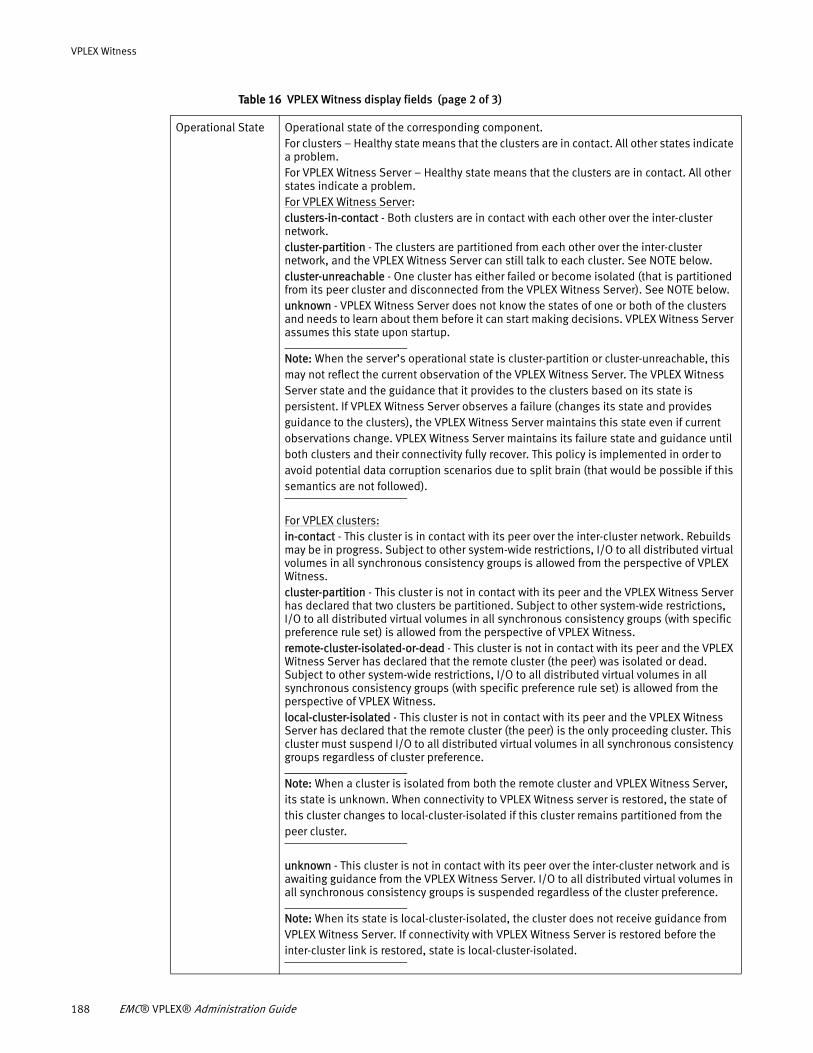
VPLEX Witness
Operational State Operational state of the corresponding component. For clusters – Healthy state means that the clusters are in contact. All other states indicate a problem.For VPLEX Witness Server – Healthy state means that the clusters are in contact. All other states indicate a problem.For VPLEX Witness Server:clusters-in-contact - Both clusters are in contact with each other over the inter-cluster network. cluster-partition - The clusters are partitioned from each other over the inter-cluster network, and the VPLEX Witness Server can still talk to each cluster. See NOTE below.cluster-unreachable - One cluster has either failed or become isolated (that is partitioned from its peer cluster and disconnected from the VPLEX Witness Server). See NOTE below.unknown - VPLEX Witness Server does not know the states of one or both of the clusters and needs to learn about them before it can start making decisions. VPLEX Witness Server assumes this state upon startup.
Note: When the server’s operational state is cluster-partition or cluster-unreachable, this may not reflect the current observation of the VPLEX Witness Server. The VPLEX Witness Server state and the guidance that it provides to the clusters based on its state is persistent. If VPLEX Witness Server observes a failure (changes its state and provides guidance to the clusters), the VPLEX Witness Server maintains this state even if current observations change. VPLEX Witness Server maintains its failure state and guidance until both clusters and their connectivity fully recover. This policy is implemented in order to avoid potential data corruption scenarios due to split brain (that would be possible if this semantics are not followed).
For VPLEX clusters:in-contact - This cluster is in contact with its peer over the inter-cluster network. Rebuilds may be in progress. Subject to other system-wide restrictions, I/O to all distributed virtual volumes in all synchronous consistency groups is allowed from the perspective of VPLEX Witness. cluster-partition - This cluster is not in contact with its peer and the VPLEX Witness Server has declared that two clusters be partitioned. Subject to other system-wide restrictions, I/O to all distributed virtual volumes in all synchronous consistency groups (with specific preference rule set) is allowed from the perspective of VPLEX Witness.remote-cluster-isolated-or-dead - This cluster is not in contact with its peer and the VPLEX Witness Server has declared that the remote cluster (the peer) was isolated or dead. Subject to other system-wide restrictions, I/O to all distributed virtual volumes in all synchronous consistency groups (with specific preference rule set) is allowed from the perspective of VPLEX Witness.local-cluster-isolated - This cluster is not in contact with its peer and the VPLEX Witness Server has declared that the remote cluster (the peer) is the only proceeding cluster. This cluster must suspend I/O to all distributed virtual volumes in all synchronous consistency groups regardless of cluster preference.
Note: When a cluster is isolated from both the remote cluster and VPLEX Witness Server, its state is unknown. When connectivity to VPLEX Witness server is restored, the state of this cluster changes to local-cluster-isolated if this cluster remains partitioned from the peer cluster.
unknown - This cluster is not in contact with its peer over the inter-cluster network and is awaiting guidance from the VPLEX Witness Server. I/O to all distributed virtual volumes in all synchronous consistency groups is suspended regardless of the cluster preference.
Note: When its state is local-cluster-isolated, the cluster does not receive guidance from VPLEX Witness Server. If connectivity with VPLEX Witness Server is restored before the inter-cluster link is restored, state is local-cluster-isolated.
Table 16 VPLEX Witness display fields (page 2 of 3)
188 EMC® VPLEX® Administration Guide
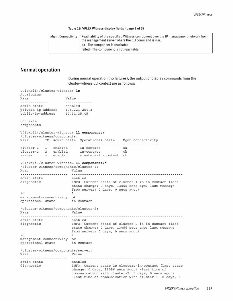
VPLEX Witness
Normal operation
During normal operation (no failures), the output of display commands from the cluster-witness CLI context are as follows:
VPlexcli:/cluster-witness> ls Attributes: Name Value------------- -------------admin-state enabledprivate-ip-address 128.221.254.3public-ip-address 10.31.25.45
Contexts: components
VPlexcli:/cluster-witness> ll components/ /cluster-witness/components: Name ID Admin State Operational State Mgmt Connectivity---------- -- ----------- ------------------- -----------------cluster-1 1 enabled in-contact okcluster-2 2 enabled in-contact okserver - enabled clusters-in-contact ok
VPlexcli:/cluster-witness> ll components/* /cluster-witness/components/cluster-1: Name Value----------------------- ------------------------------------------------------admin-state enableddiagnostic INFO: Current state of cluster-1 is in-contact (last state change: 0 days, 13056 secs ago; last message from server: 0 days, 0 secs ago.)id 1management-connectivity okoperational-state in-contact
/cluster-witness/components/cluster-2: Name Value----------------------- ------------------------------------------------------admin-state enableddiagnostic INFO: Current state of cluster-2 is in-contact (last state change: 0 days, 13056 secs ago; last message from server: 0 days, 0 secs ago.)id 2management-connectivity okoperational-state in-contact
/cluster-witness/components/server: Name Value----------------------- ------------------------------------------------------admin-state enableddiagnostic INFO: Current state is clusters-in-contact (last state change: 0 days, 13056 secs ago.) (last time of communication with cluster-2: 0 days, 0 secs ago.) (last time of communication with cluster-1: 0 days, 0
Mgmt Connectivity Reachability of the specified Witness component over the IP management network from the management server where the CLI command is run. ok - The component is reachable failed - The component is not reachable
Table 16 VPLEX Witness display fields (page 3 of 3)
VPLEX Witness operation 189
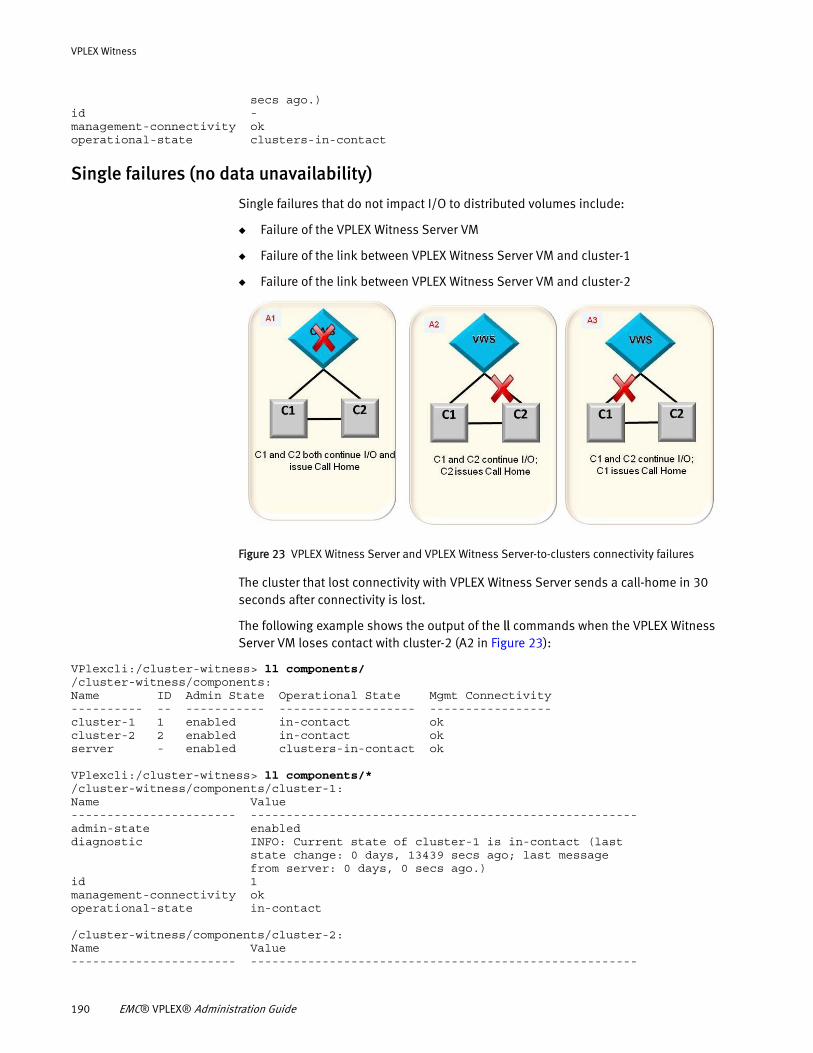
VPLEX Witness
secs ago.)id -management-connectivity okoperational-state clusters-in-contact
Single failures (no data unavailability)
Single failures that do not impact I/O to distributed volumes include:
◆ Failure of the VPLEX Witness Server VM
◆ Failure of the link between VPLEX Witness Server VM and cluster-1
◆ Failure of the link between VPLEX Witness Server VM and cluster-2
Figure 23 VPLEX Witness Server and VPLEX Witness Server-to-clusters connectivity failures
The cluster that lost connectivity with VPLEX Witness Server sends a call-home in 30 seconds after connectivity is lost.
The following example shows the output of the ll commands when the VPLEX Witness Server VM loses contact with cluster-2 (A2 in Figure 23):
VPlexcli:/cluster-witness> ll components/ /cluster-witness/components: Name ID Admin State Operational State Mgmt Connectivity---------- -- ----------- ------------------- -----------------cluster-1 1 enabled in-contact okcluster-2 2 enabled in-contact okserver - enabled clusters-in-contact ok
VPlexcli:/cluster-witness> ll components/* /cluster-witness/components/cluster-1: Name Value----------------------- ------------------------------------------------------admin-state enableddiagnostic INFO: Current state of cluster-1 is in-contact (last state change: 0 days, 13439 secs ago; last message from server: 0 days, 0 secs ago.)id 1management-connectivity okoperational-state in-contact
/cluster-witness/components/cluster-2: Name Value----------------------- ------------------------------------------------------
190 EMC® VPLEX® Administration Guide
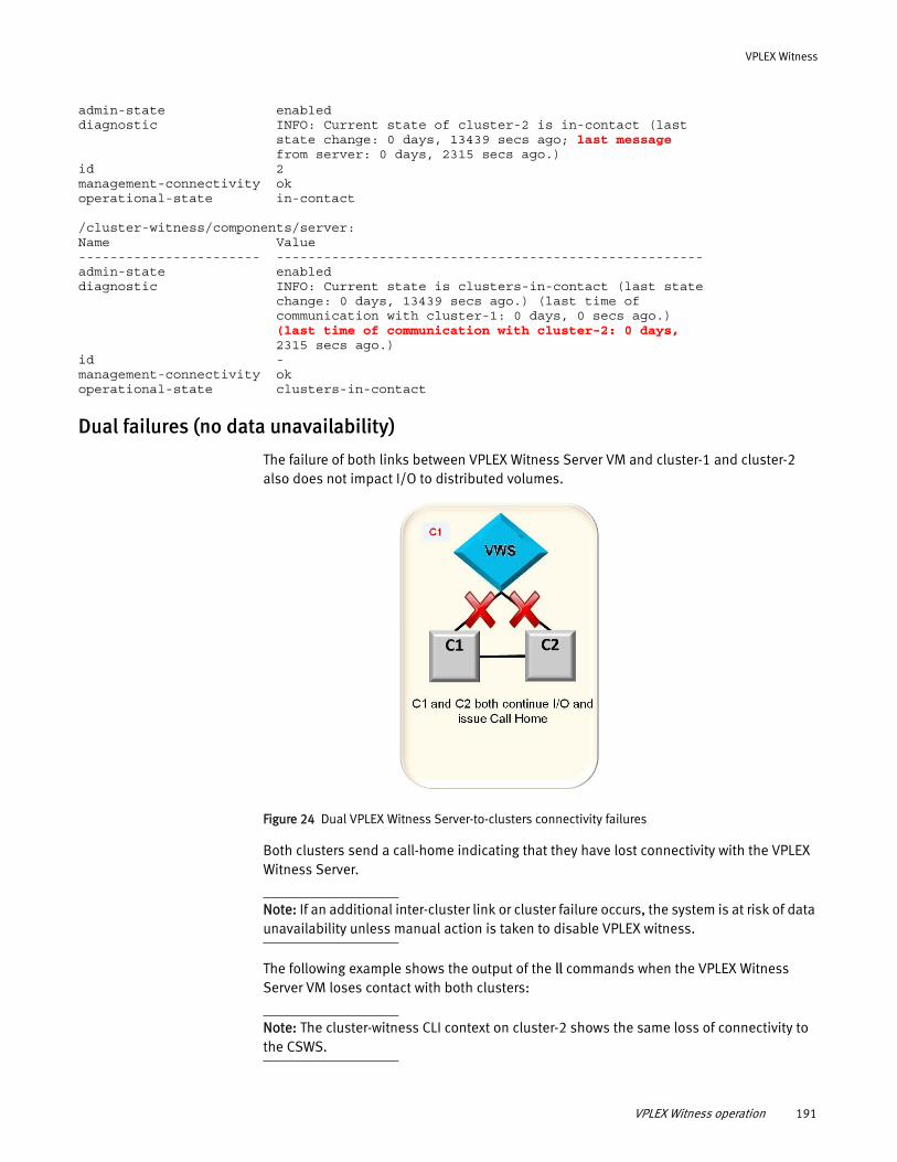
VPLEX Witness
admin-state enableddiagnostic INFO: Current state of cluster-2 is in-contact (last state change: 0 days, 13439 secs ago; last message from server: 0 days, 2315 secs ago.)id 2management-connectivity okoperational-state in-contact
/cluster-witness/components/server: Name Value----------------------- ------------------------------------------------------admin-state enableddiagnostic INFO: Current state is clusters-in-contact (last state change: 0 days, 13439 secs ago.) (last time of communication with cluster-1: 0 days, 0 secs ago.) (last time of communication with cluster-2: 0 days, 2315 secs ago.)id -management-connectivity okoperational-state clusters-in-contact
Dual failures (no data unavailability)
The failure of both links between VPLEX Witness Server VM and cluster-1 and cluster-2 also does not impact I/O to distributed volumes.
Figure 24 Dual VPLEX Witness Server-to-clusters connectivity failures
Both clusters send a call-home indicating that they have lost connectivity with the VPLEX Witness Server.
Note: If an additional inter-cluster link or cluster failure occurs, the system is at risk of data unavailability unless manual action is taken to disable VPLEX witness.
The following example shows the output of the ll commands when the VPLEX Witness Server VM loses contact with both clusters:
Note: The cluster-witness CLI context on cluster-2 shows the same loss of connectivity to the CSWS.
VPLEX Witness operation 191
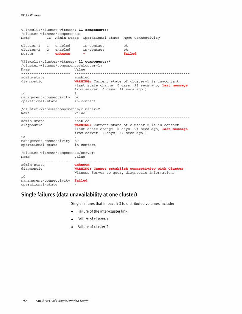
VPLEX Witness
VPlexcli:/cluster-witness> ll components/ /cluster-witness/components: Name ID Admin State Operational State Mgmt Connectivity---------- -- ----------- ----------------- -----------------cluster-1 1 enabled in-contact okcluster-2 2 enabled in-contact okserver - unknown - failed
VPlexcli:/cluster-witness> ll components/* /cluster-witness/components/cluster-1: Name Value----------------------- ------------------------------------------------------admin-state enableddiagnostic WARNING: Current state of cluster-1 is in-contact (last state change: 0 days, 94 secs ago; last message from server: 0 days, 34 secs ago.)id 1management-connectivity okoperational-state in-contact
/cluster-witness/components/cluster-2: Name Value----------------------- ------------------------------------------------------admin-state enableddiagnostic WARNING: Current state of cluster-2 is in-contact (last state change: 0 days, 94 secs ago; last message from server: 0 days, 34 secs ago.)id 2management-connectivity okoperational-state in-contact
/cluster-witness/components/server: Name Value----------------------- ------------------------------------------------------admin-state unknowndiagnostic WARNING: Cannot establish connectivity with Cluster Witness Server to query diagnostic information.id -management-connectivity failedoperational-state -
Single failures (data unavailability at one cluster)
Single failures that impact I/O to distributed volumes include:
◆ Failure of the inter-cluster link
◆ Failure of cluster-1
◆ Failure of cluster-2
192 EMC® VPLEX® Administration Guide
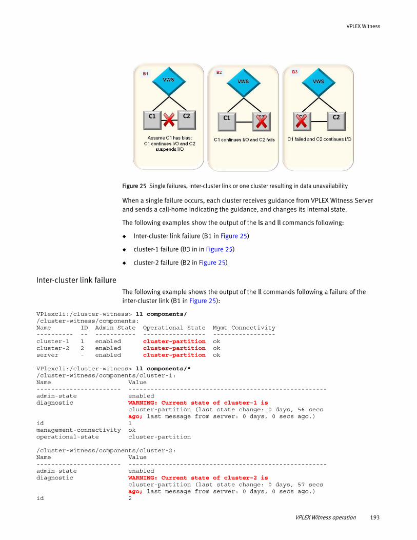
VPLEX Witness
Figure 25 Single failures, inter-cluster link or one cluster resulting in data unavailability
When a single failure occurs, each cluster receives guidance from VPLEX Witness Server and sends a call-home indicating the guidance, and changes its internal state.
The following examples show the output of the ls and ll commands following:
◆ Inter-cluster link failure (B1 in Figure 25)
◆ cluster-1 failure (B3 in in Figure 25)
◆ cluster-2 failure (B2 in Figure 25)
Inter-cluster link failureThe following example shows the output of the ll commands following a failure of the inter-cluster link (B1 in Figure 25):
VPlexcli:/cluster-witness> ll components/ /cluster-witness/components: Name ID Admin State Operational State Mgmt Connectivity---------- -- ----------- ----------------- -----------------cluster-1 1 enabled cluster-partition okcluster-2 2 enabled cluster-partition okserver - enabled cluster-partition ok
VPlexcli:/cluster-witness> ll components/* /cluster-witness/components/cluster-1: Name Value----------------------- ------------------------------------------------------admin-state enableddiagnostic WARNING: Current state of cluster-1 is cluster-partition (last state change: 0 days, 56 secs ago; last message from server: 0 days, 0 secs ago.)id 1management-connectivity okoperational-state cluster-partition
/cluster-witness/components/cluster-2: Name Value----------------------- ------------------------------------------------------admin-state enableddiagnostic WARNING: Current state of cluster-2 is cluster-partition (last state change: 0 days, 57 secs ago; last message from server: 0 days, 0 secs ago.)id 2
VPLEX Witness operation 193
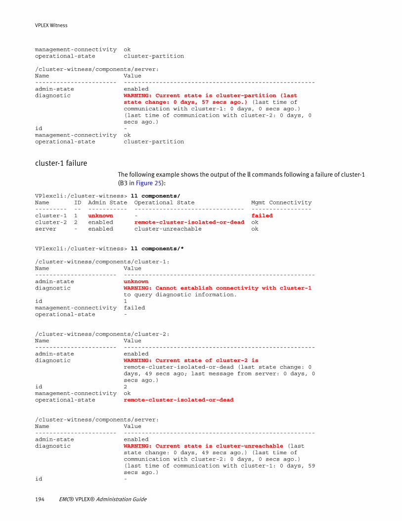
VPLEX Witness
management-connectivity okoperational-state cluster-partition
/cluster-witness/components/server: Name Value----------------------- ------------------------------------------------------admin-state enableddiagnostic WARNING: Current state is cluster-partition (last state change: 0 days, 57 secs ago.) (last time of communication with cluster-1: 0 days, 0 secs ago.) (last time of communication with cluster-2: 0 days, 0 secs ago.)id -management-connectivity okoperational-state cluster-partition
cluster-1 failureThe following example shows the output of the ll commands following a failure of cluster-1 (B3 in Figure 25):
VPlexcli:/cluster-witness> ll components/ Name ID Admin State Operational State Mgmt Connectivity --------- -- ----------- ------------------------------- ----------------- cluster-1 1 unknown - failed cluster-2 2 enabled remote-cluster-isolated-or-dead ok server - enabled cluster-unreachable ok
VPlexcli:/cluster-witness> ll components/* /cluster-witness/components/cluster-1: Name Value ----------------------- ------------------------------------------------------ admin-state unknown diagnostic WARNING: Cannot establish connectivity with cluster-1 to query diagnostic information. id 1 management-connectivity failed operational-state - /cluster-witness/components/cluster-2: Name Value ----------------------- ------------------------------------------------------ admin-state enabled diagnostic WARNING: Current state of cluster-2 is remote-cluster-isolated-or-dead (last state change: 0 days, 49 secs ago; last message from server: 0 days, 0 secs ago.) id 2 management-connectivity ok operational-state remote-cluster-isolated-or-dead /cluster-witness/components/server: Name Value ----------------------- ------------------------------------------------------ admin-state enabled diagnostic WARNING: Current state is cluster-unreachable (last state change: 0 days, 49 secs ago.) (last time of communication with cluster-2: 0 days, 0 secs ago.) (last time of communication with cluster-1: 0 days, 59 secs ago.) id -
194 EMC® VPLEX® Administration Guide
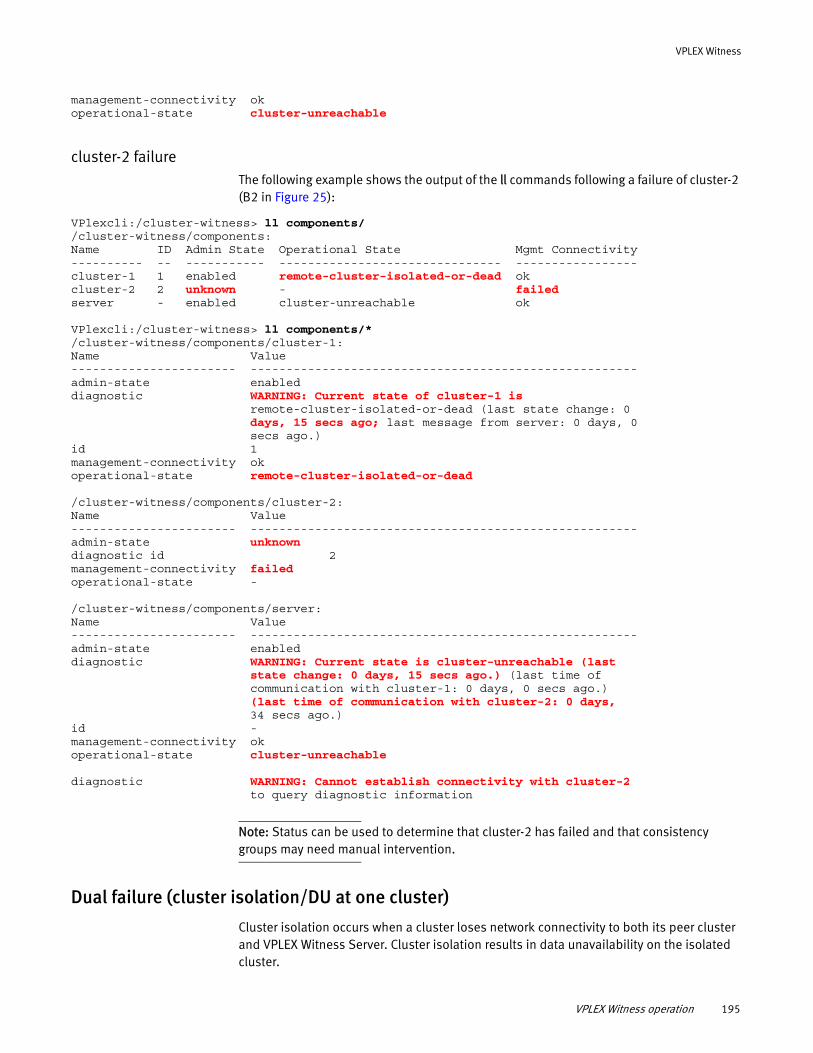
VPLEX Witness
management-connectivity ok operational-state cluster-unreachable
cluster-2 failureThe following example shows the output of the ll commands following a failure of cluster-2 (B2 in Figure 25):
VPlexcli:/cluster-witness> ll components/ /cluster-witness/components: Name ID Admin State Operational State Mgmt Connectivity---------- -- ----------- ------------------------------- -----------------cluster-1 1 enabled remote-cluster-isolated-or-dead okcluster-2 2 unknown - failedserver - enabled cluster-unreachable ok
VPlexcli:/cluster-witness> ll components/* /cluster-witness/components/cluster-1: Name Value----------------------- ------------------------------------------------------admin-state enableddiagnostic WARNING: Current state of cluster-1 is remote-cluster-isolated-or-dead (last state change: 0 days, 15 secs ago; last message from server: 0 days, 0 secs ago.)id 1management-connectivity okoperational-state remote-cluster-isolated-or-dead
/cluster-witness/components/cluster-2: Name Value----------------------- ------------------------------------------------------admin-state unknowndiagnostic id 2management-connectivity failedoperational-state -
/cluster-witness/components/server: Name Value----------------------- ------------------------------------------------------admin-state enableddiagnostic WARNING: Current state is cluster-unreachable (last state change: 0 days, 15 secs ago.) (last time of communication with cluster-1: 0 days, 0 secs ago.) (last time of communication with cluster-2: 0 days, 34 secs ago.)id -management-connectivity okoperational-state cluster-unreachable
diagnostic WARNING: Cannot establish connectivity with cluster-2 to query diagnostic information
Note: Status can be used to determine that cluster-2 has failed and that consistency groups may need manual intervention.
Dual failure (cluster isolation/DU at one cluster)
Cluster isolation occurs when a cluster loses network connectivity to both its peer cluster and VPLEX Witness Server. Cluster isolation results in data unavailability on the isolated cluster.
VPLEX Witness operation 195
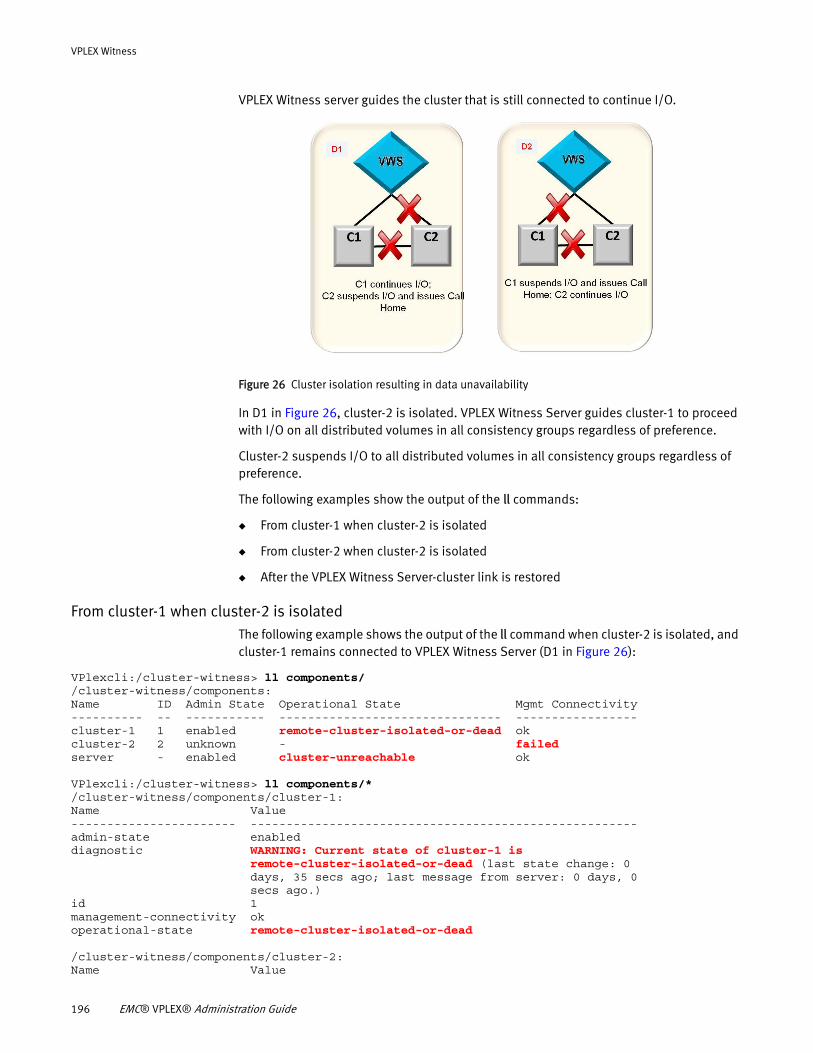
VPLEX Witness
VPLEX Witness server guides the cluster that is still connected to continue I/O.
Figure 26 Cluster isolation resulting in data unavailability
In D1 in Figure 26, cluster-2 is isolated. VPLEX Witness Server guides cluster-1 to proceed with I/O on all distributed volumes in all consistency groups regardless of preference.
Cluster-2 suspends I/O to all distributed volumes in all consistency groups regardless of preference.
The following examples show the output of the ll commands:
◆ From cluster-1 when cluster-2 is isolated
◆ From cluster-2 when cluster-2 is isolated
◆ After the VPLEX Witness Server-cluster link is restored
From cluster-1 when cluster-2 is isolated The following example shows the output of the ll command when cluster-2 is isolated, and cluster-1 remains connected to VPLEX Witness Server (D1 in Figure 26):
VPlexcli:/cluster-witness> ll components/ /cluster-witness/components: Name ID Admin State Operational State Mgmt Connectivity---------- -- ----------- ------------------------------- -----------------cluster-1 1 enabled remote-cluster-isolated-or-dead okcluster-2 2 unknown - failed server - enabled cluster-unreachable ok
VPlexcli:/cluster-witness> ll components/* /cluster-witness/components/cluster-1: Name Value----------------------- ------------------------------------------------------admin-state enableddiagnostic WARNING: Current state of cluster-1 is remote-cluster-isolated-or-dead (last state change: 0 days, 35 secs ago; last message from server: 0 days, 0 secs ago.)id 1management-connectivity okoperational-state remote-cluster-isolated-or-dead
/cluster-witness/components/cluster-2: Name Value
196 EMC® VPLEX® Administration Guide
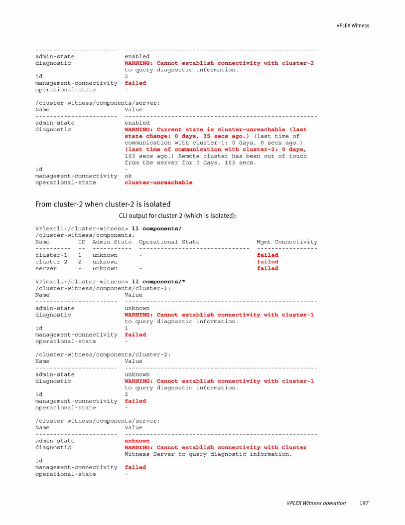
VPLEX Witness
----------------------- ------------------------------------------------------admin-state enableddiagnostic WARNING: Cannot establish connectivity with cluster-2 to query diagnostic information.id 2management-connectivity failedoperational-state -
/cluster-witness/components/server: Name Value----------------------- ------------------------------------------------------admin-state enableddiagnostic WARNING: Current state is cluster-unreachable (last state change: 0 days, 35 secs ago.) (last time of communication with cluster-1: 0 days, 0 secs ago.) (last time of communication with cluster-2: 0 days, 103 secs ago.) Remote cluster has been out of touch from the server for 0 days, 103 secs.id -management-connectivity okoperational-state cluster-unreachable
From cluster-2 when cluster-2 is isolated CLI output for cluster-2 (which is isolated):
VPlexcli:/cluster-witness> ll components/ /cluster-witness/components: Name ID Admin State Operational State Mgmt Connectivity---------- -- ----------- ------------------------------- -----------------cluster-1 1 unknown - failedcluster-2 2 unknown - failedserver - unknown - failed
VPlexcli:/cluster-witness> ll components/* /cluster-witness/components/cluster-1: Name Value----------------------- ------------------------------------------------------admin-state unknown diagnostic WARNING: Cannot establish connectivity with cluster-1 to query diagnostic information.id 1management-connectivity failedoperational-state -
/cluster-witness/components/cluster-2: Name Value----------------------- ------------------------------------------------------admin-state unknown diagnostic WARNING: Cannot establish connectivity with cluster-1 to query diagnostic information.id 2management-connectivity failedoperational-state -
/cluster-witness/components/server: Name Value----------------------- ------------------------------------------------------admin-state unknowndiagnostic WARNING: Cannot establish connectivity with Cluster Witness Server to query diagnostic information.id -management-connectivity failedoperational-state -
VPLEX Witness operation 197
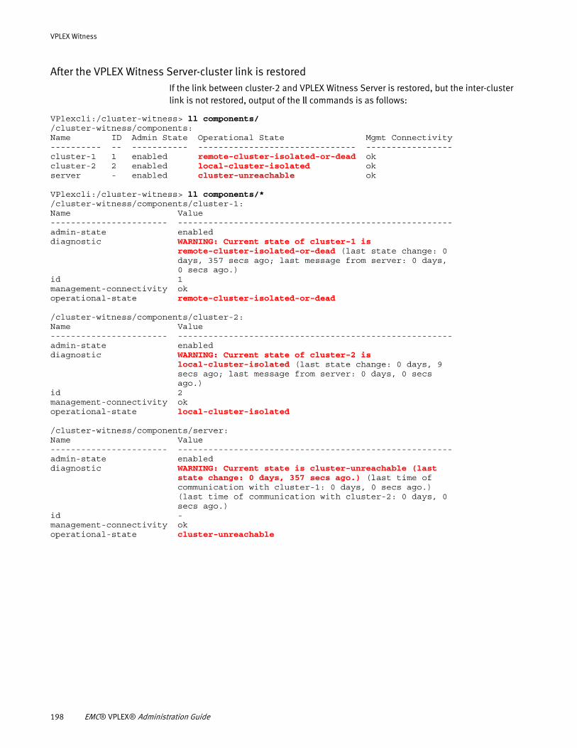
VPLEX Witness
After the VPLEX Witness Server-cluster link is restoredIf the link between cluster-2 and VPLEX Witness Server is restored, but the inter-cluster link is not restored, output of the ll commands is as follows:
VPlexcli:/cluster-witness> ll components/ /cluster-witness/components: Name ID Admin State Operational State Mgmt Connectivity---------- -- ----------- ------------------------------- -----------------cluster-1 1 enabled remote-cluster-isolated-or-dead okcluster-2 2 enabled local-cluster-isolated okserver - enabled cluster-unreachable ok
VPlexcli:/cluster-witness> ll components/* /cluster-witness/components/cluster-1: Name Value----------------------- ------------------------------------------------------admin-state enableddiagnostic WARNING: Current state of cluster-1 is remote-cluster-isolated-or-dead (last state change: 0 days, 357 secs ago; last message from server: 0 days, 0 secs ago.)id 1management-connectivity okoperational-state remote-cluster-isolated-or-dead
/cluster-witness/components/cluster-2: Name Value----------------------- ------------------------------------------------------admin-state enableddiagnostic WARNING: Current state of cluster-2 is local-cluster-isolated (last state change: 0 days, 9 secs ago; last message from server: 0 days, 0 secs ago.)id 2management-connectivity okoperational-state local-cluster-isolated
/cluster-witness/components/server: Name Value----------------------- ------------------------------------------------------admin-state enableddiagnostic WARNING: Current state is cluster-unreachable (last state change: 0 days, 357 secs ago.) (last time of communication with cluster-1: 0 days, 0 secs ago.) (last time of communication with cluster-2: 0 days, 0 secs ago.)id -management-connectivity okoperational-state cluster-unreachable
198 EMC® VPLEX® Administration Guide
CHAPTER 11Cache vaults
This chapter describes cache vaulting on VPLEX and explains how to recover after a cache vault.
◆ About cache vaulting............................................................................................. 199◆ The vaulting process ............................................................................................. 203◆ Recovery after vault............................................................................................... 204
About cache vaultingVPLEX uses the individual director's memory systems to ensure durability of user data and critical system configuration data.
User data is made durable in one of two ways depending on the cache mode used for the data.
◆ Write-through cache mode leverages the durability properties of a back-end array by writing user data to the array and obtaining an acknowledgment for the written data before it acknowledges the write back to the host.
◆ Write-back cache mode ensures data durability by storing user data into the cache memory of the director that received the I/O, then placing a protection copy of this data on another director in the local cluster before acknowledging the write to the host. This ensures that the data is protected in two independent memories. The data is later destaged to back-end storage arrays that provide the physical storage media.
If a power failure on a VPLEX Geo cluster (using write-back cache mode) occurs, the data in cache memory might be at risk. In the event of data at risk from power failure in a VPLEX Geo configuration, each VPLEX director copies its dirty cache data to the local solid state storage devices (SSDs) using a process known as cache vaulting. Dirty cache pages are pages in a director's memory that have not been written to back-end storage but are acknowledged to the host. Dirty cache pages also include the copies protected on a second director in the cluster. After each director vaults its dirty cache pages, VPLEX shuts down the director’s firmware.
Note: Although there is no dirty cache data in VPLEX Local or VPLEX Metro configurations, vaulting is still necessary to quiesce all I/O when data is at risk due to power failure. This is done to minimize the risk of metadata corruption.
Once power is restored, the VPLEX system startup program initializes the hardware and the environmental system, checks the data validity of each vault, and unvaults the data. The process of system recovery and unvault depends largely on the configuration of the system:
◆ In a VPLEX Local or VPLEX Metro configuration, the cluster unvaults without recovering any vault data because there is no data to vault.
Cache vaults 199
Cache vaults
◆ In a VPLEX Geo system, if the remote cluster proceeded on its own (either because it was the only active cluster at the time or because of administrative action), VPLEX discards the vault and does not restore memory. Additionally, the auto-resume-at-loser parameter affects whether the recovering cluster starts processing I/O. By default this parameter is set to false for asynchronous consistency groups. This means that by default the recovering cluster discards its vault and then suspends and waits for manual intervention.
◆ In a VPLEX Geo system, if the remote cluster waits, the vault is recovered, the two clusters get back in touch and continue processing I/O.
When you resume operation of the cluster, if any condition is not safe, the system does not resume normal status and calls home for diagnosis and repair. This allows EMC Customer Support to communicate with the VPLEX system and restore normal system operations.
Vaulting can be used in two scenarios:
◆ Data at risk due to power failure: VPLEX monitors all components that provide power to the VPLEX cluster. If it detects AC power loss in accordance with the specifications in “Power failures that cause vault,” in order to avoid a possible data loss it takes a conservative approach and initiates a cluster wide vault if the power loss exceeds 30 seconds.
◆ Manual emergency cluster shutdown: When unforeseen circumstances require an unplanned and immediate shutdown, it is known as an emergency cluster shutdown. You can use a CLI command to manually start vaulting if an emergency shutdown is required.
When performing maintenance activities on a VPLEX Geo configuration, service personnel must not remove the power in one or more engines unless both directors in those engines have been shutdown and are no longer monitoring power. Failure to do so, leads to data unavailability in the affected cluster. To avoid unintended vaults, always follow official maintenance procedures.
Under normal conditions, the SPS batteries can support two consecutive vaults; this ensures, that the system can resume I/O immediately after the first power failure, and that it can still vault if there is a second power failure.
For information on the redundant and backup power supplies in VPLEX, refer to the Hardware Overview chapter of the EMC VPLEX Product Guide.
Related Information
For additional information on cache vaulting:
Information Reference
Related Commands EMC VPLEX CLI Guide
200 EMC® VPLEX® Administration Guide
Cache vaults
Power failures that cause vault
Note: Vaulting is a mechanism to prevent data loss when an external environmental condition causes a cluster failure. For example, if a power failure lasts longer than 30 seconds in a VPLEX Geo configuration, then each VPLEX director copies its dirty cache data to the local solid state storage devices (SSDs). Known as vaulting, this process protects user data in cache if that data is at risk due to power loss. After each director vaults its dirty cache pages, then VPLEX shuts down the director’s firmware.
Vaulting is evolving rapidly with each release of GeoSynchrony. The events and/or conditions that trigger cache vaulting vary depending on the release and are as follows:
Release 5.0.1:
◆ Vaulting is introduced.
◆ On all configurations, vaulting is triggered if all following conditions are met:
• AC power is lost (due to power failure, faulty hardware, or power supply is not present) in power zone A from engine X.
• AC power is lost (due to power failure, faulty hardware, or power supply is not present) in power zone B from engine Y.
(X and Y would be the same in a single engine configuration but they may or may not be the same in dual or quad engine configurations).
• Both conditions persist for more than 30 seconds.
Release 5.0.1 Patch:
◆ On all configurations, vaulting is triggered if all the following conditions are met:
• AC power is lost (due to power failure or faulty hardware) in power zone A from engine X.
• AC power is lost (due to power failure or faulty hardware) in power zone B from engine Y.
(X and Y would be the same in a single engine configuration but they may or may not be the same in dual or quad engine configurations).
• Both conditions persist for more than 30 seconds.
Release 5.1:
◆ In a VPLEX Geo configuration with asynchronous consistency groups, vaulting is triggered if all the following conditions are met:
Information about consistency groups Chapter 9, “Consistency Groups”
Procedures to shutdown after a cache vault EMC VPLEX generator at EMC Online Support
Procedures to troubleshoot after a cache vault
EMC VPLEX generator at EMC Online Support
Information Reference
About cache vaulting 201
Cache vaults
• AC power is lost (due to power failure or faulty hardware) or becomes “unknown” in a director from engine X.
• AC power is lost (due to power failure or faulty hardware) or becomes “unknown” in director from engine Y.
(X and Y would be the same in a single engine configuration but they may or may not be the same in dual or quad engine configurations).
• Both conditions persist for more than 30 seconds.
◆ In a VPLEX Local or VPLEX Metro configuration, vaulting is triggered if all the following conditions are met:
• AC power is lost (due to power failure or faulty hardware) or becomes “unknown” in the minimum number of directors required for the cluster to be operational.
• Condition persist for more than 30 seconds.
Note: UPS power conditions do not trigger any vaulting.
202 EMC® VPLEX® Administration Guide
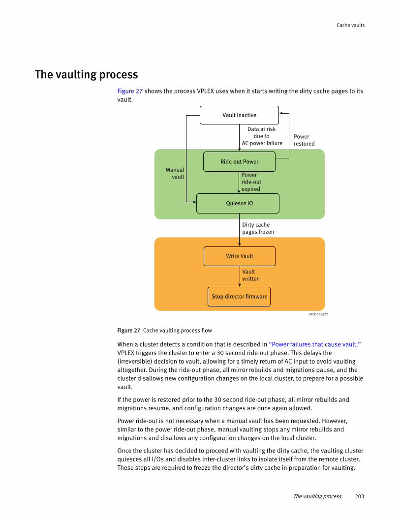
Cache vaults
The vaulting processFigure 27 shows the process VPLEX uses when it starts writing the dirty cache pages to its vault.
Figure 27 Cache vaulting process flow
When a cluster detects a condition that is described in “Power failures that cause vault,” VPLEX triggers the cluster to enter a 30 second ride-out phase. This delays the (irreversible) decision to vault, allowing for a timely return of AC input to avoid vaulting altogether. During the ride-out phase, all mirror rebuilds and migrations pause, and the cluster disallows new configuration changes on the local cluster, to prepare for a possible vault.
If the power is restored prior to the 30 second ride-out phase, all mirror rebuilds and migrations resume, and configuration changes are once again allowed.
Power ride-out is not necessary when a manual vault has been requested. However, similar to the power ride-out phase, manual vaulting stops any mirror rebuilds and migrations and disallows any configuration changes on the local cluster.
Once the cluster has decided to proceed with vaulting the dirty cache, the vaulting cluster quiesces all I/Os and disables inter-cluster links to isolate itself from the remote cluster. These steps are required to freeze the director’s dirty cache in preparation for vaulting.
Vault Inactive
Power restored
Data at risk due to
AC power failure
Manualvault Power
ride-outexpired
Dirty cachepages frozen
Vault written
Write Vault
Quiesce IO
Ride-out Power
Stop director firmware
VPLX-000472
The vaulting process 203
Cache vaults
Once the dirty cache (if any) is frozen, each director in the vaulting cluster isolates itself from the other directors and starts writing. When the director has finished writing to its vault, the director stops its firmware.
This entire process is completed within the time parameters supported by the stand-by power supplies.
It is important to ensure that the cluster is shutdown in an organized fashion to save any remaining battery charge so that recharge completes faster when the cluster is restarted.
Refer to the following procedures (published in the EMC VPLEX generator at EMC Online Support) for the procedures to safely shutdown and restart a VPLEX cluster after a vault:
◆ Startup after a Vault on VPLEX Local
◆ Startup after a Vault on VPLEX Metro or VPLEX Geo System
Recovery after vaultOnce the cluster is ready to recover from the conditions that caused the vault, the cluster is powered up.
Note: If the directors in the cluster come up with degraded power such that it may put the data at risk, the cluster will either shutdown the firmware if vault recovery has not begun (to protect the vaulted data), or initiate vaulting immediately after vault recovery has finished
204 EMC® VPLEX® Administration Guide
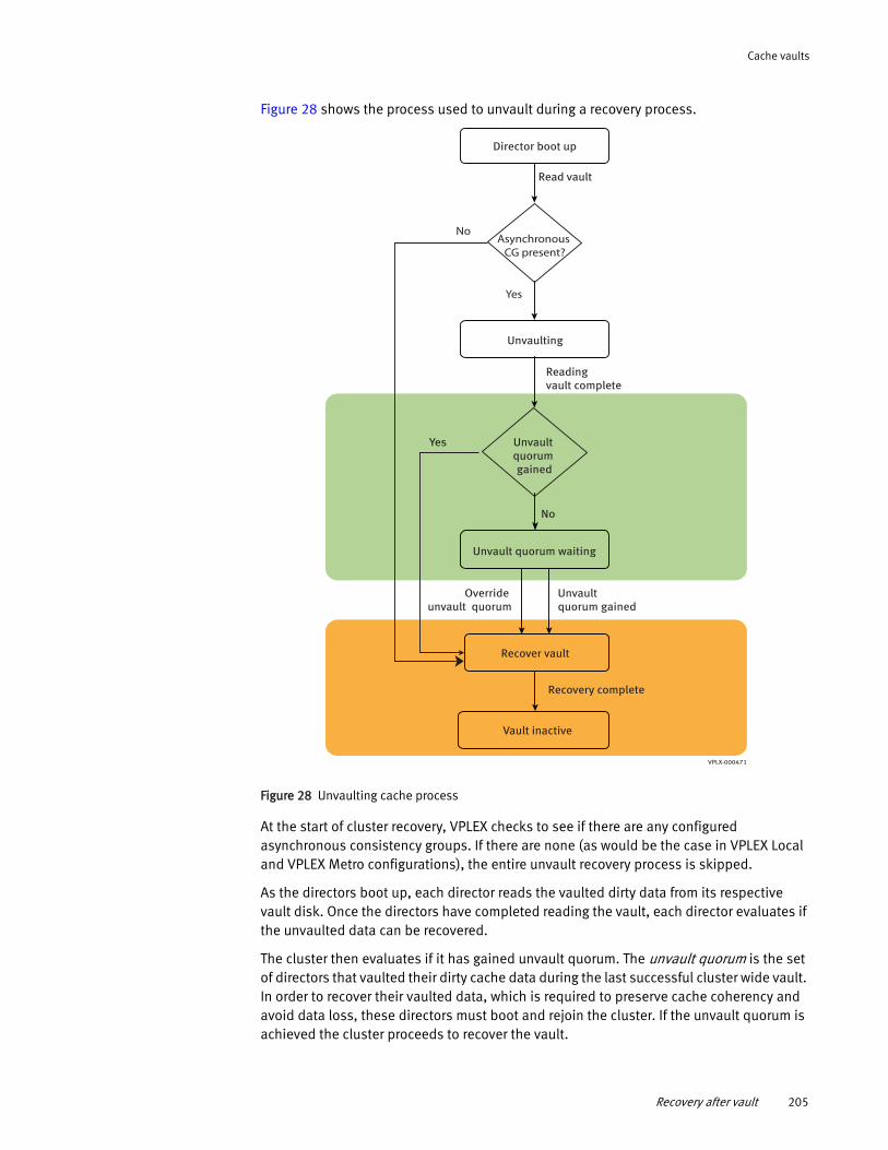
Cache vaults
Figure 28 shows the process used to unvault during a recovery process.
Figure 28 Unvaulting cache process
At the start of cluster recovery, VPLEX checks to see if there are any configured asynchronous consistency groups. If there are none (as would be the case in VPLEX Local and VPLEX Metro configurations), the entire unvault recovery process is skipped.
As the directors boot up, each director reads the vaulted dirty data from its respective vault disk. Once the directors have completed reading the vault, each director evaluates if the unvaulted data can be recovered.
The cluster then evaluates if it has gained unvault quorum. The unvault quorum is the set of directors that vaulted their dirty cache data during the last successful cluster wide vault. In order to recover their vaulted data, which is required to preserve cache coherency and avoid data loss, these directors must boot and rejoin the cluster. If the unvault quorum is achieved the cluster proceeds to recover the vault.
Director boot up
Read vault
Unvaulting
Readingvault complete
Unvault quorum gained
Yes
No
Unvault quorum waiting
Override unvault quorum
Unvault quorum gained
Recover vault
Recovery complete
VPLX-000471
Vault inactive
Asynchronous CG present?
Yes
No
Recovery after vault 205
Cache vaults
If the cluster determines that it has not gained unvault quorum, it waits indefinitely for the required directors to boot up and join the cluster. During the waiting period, the cluster remains in the unvault quorum wait state.
After 30 minutes in the unvault quorum wait state, the cluster generates a call home indicating the current state of the cluster and indicating that manual intervention is needed to allow the cluster to process I/O.
Once the cluster enters the unvault quorum wait state it cannot proceed to the recovery phase until any of the following events happen:
◆ The directors required to gain unvault quorum become available
◆ You issue the override unvault quorum command and agree to accept a possible data loss
Refer to the VPLEX generator troubleshooting procedures for cache vaulting for instructions on how recover in this scenario. See the VPLEX CLI Guide for details on the use of the override unvault quorum command.
Successful Recovery
VPLEX Geo can handle one invalid or missing vault because each director has vaulted a copy of each dirty cache page of its protection partner. The cache can be recovered as long as the original dirty cache vault or its protected copy is available.
An invalid vault can be caused by:
◆ A director not successfully completing write of the vault
◆ A director containing stale (older) vault data
A vault can be missing because:
◆ A director failed during unvault
◆ A director never came up during cluster power up
If the cluster determines it has sufficient valid vaults, it proceeds with recovery of the vaulted data into the distributed cache. In this scenario the unvaulted cluster looks like a cluster that has recovered after an inter-cluster link outage as no data is lost on the vaulting cluster. VPLEX behavior following this recovery process depends on how the detach rules were configured for each asynchronous consistency group.
Refer to Chapter 9, “Consistency Groups.”
Unsuccessful Recovery
If the cluster determines that more than one invalid vault is present, the cluster discards the vault and reports a data loss. In this scenario the unvaulted cluster looks like a cluster that has recovered after a cluster failure. The cluster still waits for all configured directors to boot and rejoin the cluster. The volumes are marked as recovery-error and refuse I/O. If one volume of a consistency group is marked recovery-error, all other volumes of that consistency group must also refuse I/O.
206 EMC® VPLEX® Administration Guide
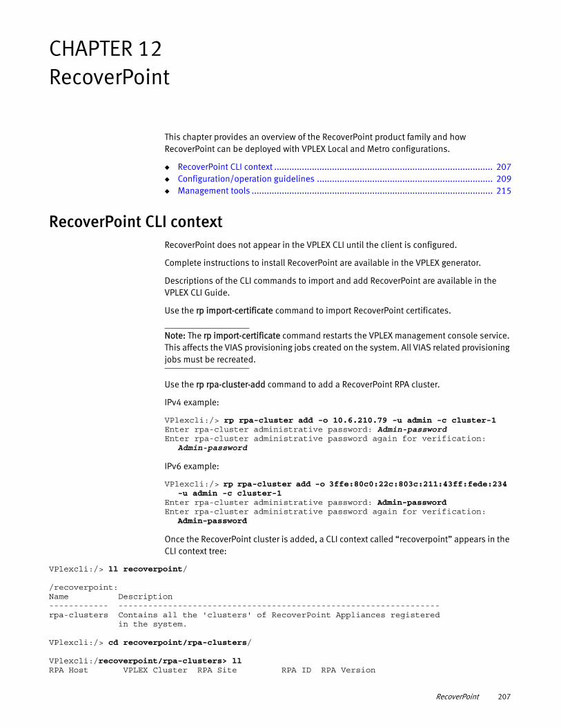
CHAPTER 12RecoverPoint
This chapter provides an overview of the RecoverPoint product family and how RecoverPoint can be deployed with VPLEX Local and Metro configurations.
◆ RecoverPoint CLI context ....................................................................................... 207◆ Configuration/operation guidelines ...................................................................... 209◆ Management tools ................................................................................................ 215
RecoverPoint CLI contextRecoverPoint does not appear in the VPLEX CLI until the client is configured.
Complete instructions to install RecoverPoint are available in the VPLEX generator.
Descriptions of the CLI commands to import and add RecoverPoint are available in the VPLEX CLI Guide.
Use the rp import-certificate command to import RecoverPoint certificates.
Note: The rp import-certificate command restarts the VPLEX management console service. This affects the VIAS provisioning jobs created on the system. All VIAS related provisioning jobs must be recreated.
Use the rp rpa-cluster-add command to add a RecoverPoint RPA cluster.
IPv4 example:
VPlexcli:/> rp rpa-cluster add -o 10.6.210.79 -u admin -c cluster-1Enter rpa-cluster administrative password: Admin-passwordEnter rpa-cluster administrative password again for verification:
Admin-password
IPv6 example:
VPlexcli:/> rp rpa-cluster add -o 3ffe:80c0:22c:803c:211:43ff:fede:234 -u admin -c cluster-1
Enter rpa-cluster administrative password: Admin-passwordEnter rpa-cluster administrative password again for verification:
Admin-password
Once the RecoverPoint cluster is added, a CLI context called “recoverpoint” appears in the CLI context tree:
VPlexcli:/> ll recoverpoint/
/recoverpoint:Name Description------------ -----------------------------------------------------------------rpa-clusters Contains all the 'clusters' of RecoverPoint Appliances registered in the system.
VPlexcli:/> cd recoverpoint/rpa-clusters/
VPlexcli:/recoverpoint/rpa-clusters> llRPA Host VPLEX Cluster RPA Site RPA ID RPA Version
RecoverPoint 207
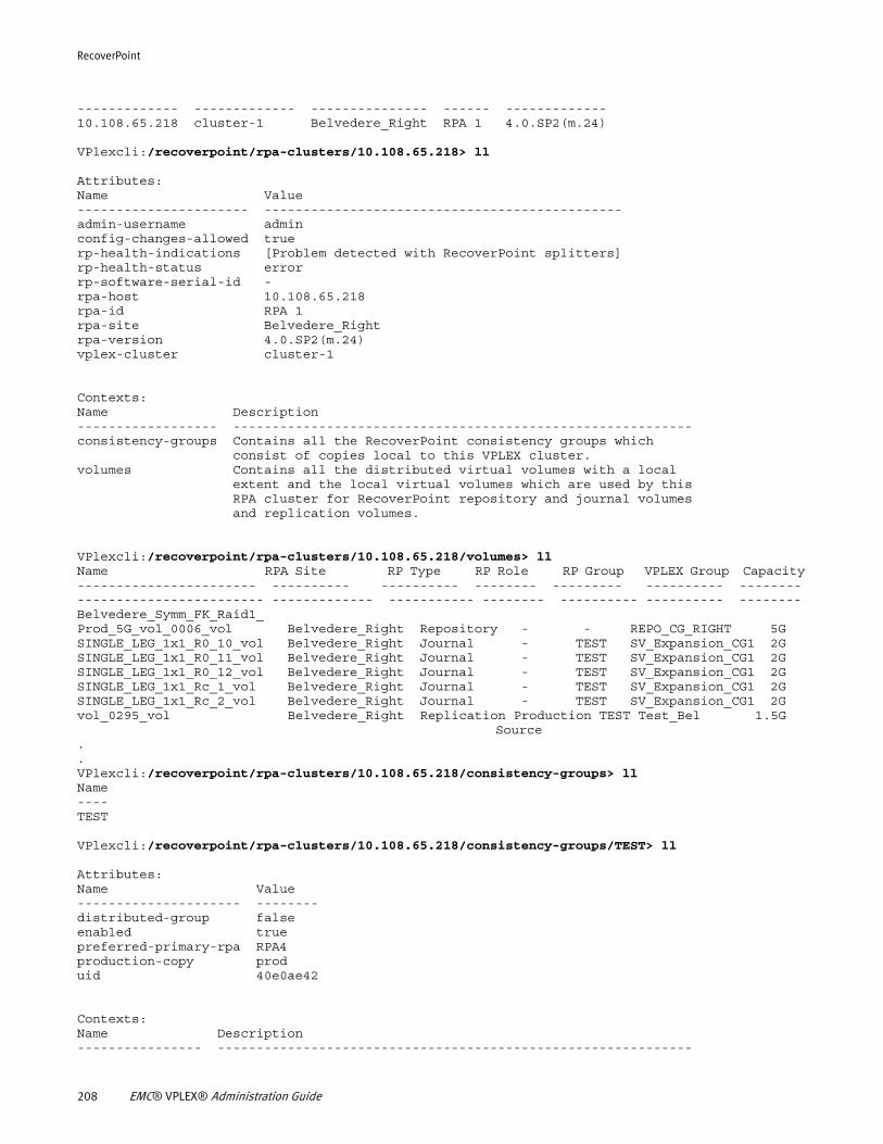
RecoverPoint
------------- ------------- --------------- ------ -------------10.108.65.218 cluster-1 Belvedere_Right RPA 1 4.0.SP2(m.24)
VPlexcli:/recoverpoint/rpa-clusters/10.108.65.218> ll
Attributes:Name Value---------------------- ----------------------------------------------admin-username adminconfig-changes-allowed truerp-health-indications [Problem detected with RecoverPoint splitters]rp-health-status errorrp-software-serial-id -rpa-host 10.108.65.218rpa-id RPA 1rpa-site Belvedere_Rightrpa-version 4.0.SP2(m.24)vplex-cluster cluster-1
Contexts:Name Description------------------ -----------------------------------------------------------consistency-groups Contains all the RecoverPoint consistency groups which consist of copies local to this VPLEX cluster.volumes Contains all the distributed virtual volumes with a local extent and the local virtual volumes which are used by this RPA cluster for RecoverPoint repository and journal volumes and replication volumes.
VPlexcli:/recoverpoint/rpa-clusters/10.108.65.218/volumes> ll Name RPA Site RP Type RP Role RP Group VPLEX Group Capacity----------------------- ---------- ---------- -------- --------- ---------- -------------------------------- ------------- ----------- -------- ---------- ---------- --------Belvedere_Symm_FK_Raid1_Prod_5G_vol_0006_vol Belvedere_Right Repository - - REPO_CG_RIGHT 5GSINGLE_LEG_1x1_R0_10_vol Belvedere_Right Journal - TEST SV_Expansion_CG1 2GSINGLE_LEG_1x1_R0_11_vol Belvedere_Right Journal - TEST SV_Expansion_CG1 2GSINGLE_LEG_1x1_R0_12_vol Belvedere_Right Journal - TEST SV_Expansion_CG1 2GSINGLE_LEG_1x1_Rc_1_vol Belvedere_Right Journal - TEST SV_Expansion_CG1 2GSINGLE_LEG_1x1_Rc_2_vol Belvedere_Right Journal - TEST SV_Expansion_CG1 2Gvol_0295_vol Belvedere_Right Replication Production TEST Test_Bel 1.5G
Source..VPlexcli:/recoverpoint/rpa-clusters/10.108.65.218/consistency-groups> llName----TEST
VPlexcli:/recoverpoint/rpa-clusters/10.108.65.218/consistency-groups/TEST> ll
Attributes:Name Value--------------------- --------distributed-group falseenabled truepreferred-primary-rpa RPA4production-copy produid 40e0ae42
Contexts:Name Description---------------- -------------------------------------------------------------
208 EMC® VPLEX® Administration Guide
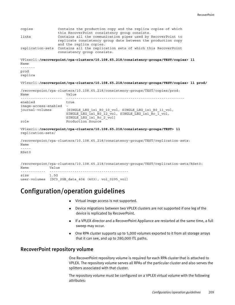
RecoverPoint
copies Contains the production copy and the replica copies of which this RecoverPoint consistency group consists.links Contains all the communication pipes used by RecoverPoint to replicate consistency group date between the production copy and the replica copies.replication-sets Contains all the replication sets of which this RecoverPoint consistency group consists.
VPlexcli:/recoverpoint/rpa-clusters/10.108.65.218/consistency-groups/TEST/copies> llName-------prodreplica
VPlexcli:/recoverpoint/rpa-clusters/10.108.65.218/consistency-groups/TEST/copies> ll prod/
/recoverpoint/rpa-clusters/10.108.65.218/consistency-groups/TEST/copies/prod:Name Value-------------------- ---------------------------------------------------------enabled trueimage-access-enabled -journal-volumes [SINGLE_LEG_1x1_R0_10_vol, SINGLE_LEG_1x1_R0_11_vol, SINGLE_LEG_1x1_R0_12_vol, SINGLE_LEG_1x1_Rc_1_vol, SINGLE_LEG_1x1_Rc_2_vol]role Production Source
VPlexcli:/recoverpoint/rpa-clusters/10.108.65.218/consistency-groups/TEST> ll replication-sets/
/recoverpoint/rpa-clusters/10.108.65.218/consistency-groups/TEST/replication-sets:Name-----RSet0
/recoverpoint/rpa-clusters/10.108.65.218/consistency-groups/TEST/replication-sets/RSet0:Name Value------------ --------------------------------------size 1.5Guser-volumes [DC3_2GB_data_404 (403), vol_0295_vol]
Configuration/operation guidelines◆ Virtual image access is not supported.
◆ Device migrations between two VPLEX clusters are not supported if one leg of the device is replicated by RecoverPoint.
◆ If a VPLEX director and a RecoverPoint Appliance are restarted at the same time, a full sweep may occur.
◆ One RPA cluster supports up to 5,000 volumes exported to it from all storage arrays that it can see, and up to 280,000 ITL paths.
RecoverPoint repository volume
One RecoverPoint repository volume is required for each RPA cluster that is attached to VPLEX. The repository volume serves all RPAs of the particular cluster and also serves the splitters associated with that cluster.
The repository volume must be configured on a VPLEX virtual volume with the following attributes:
Configuration/operation guidelines 209
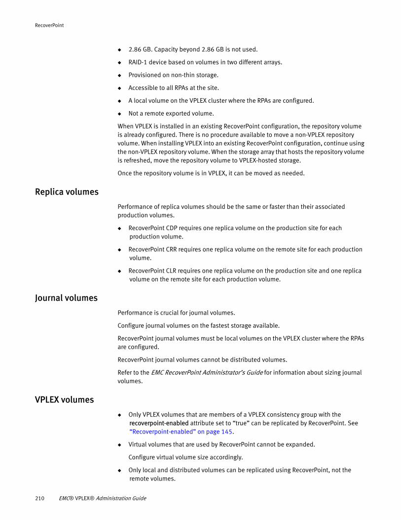
RecoverPoint
◆ 2.86 GB. Capacity beyond 2.86 GB is not used.
◆ RAID-1 device based on volumes in two different arrays.
◆ Provisioned on non-thin storage.
◆ Accessible to all RPAs at the site.
◆ A local volume on the VPLEX cluster where the RPAs are configured.
◆ Not a remote exported volume.
When VPLEX is installed in an existing RecoverPoint configuration, the repository volume is already configured. There is no procedure available to move a non-VPLEX repository volume. When installing VPLEX into an existing RecoverPoint configuration, continue using the non-VPLEX repository volume. When the storage array that hosts the repository volume is refreshed, move the repository volume to VPLEX-hosted storage.
Once the repository volume is in VPLEX, it can be moved as needed.
Replica volumes
Performance of replica volumes should be the same or faster than their associated production volumes.
◆ RecoverPoint CDP requires one replica volume on the production site for each production volume.
◆ RecoverPoint CRR requires one replica volume on the remote site for each production volume.
◆ RecoverPoint CLR requires one replica volume on the production site and one replica volume on the remote site for each production volume.
Journal volumes
Performance is crucial for journal volumes.
Configure journal volumes on the fastest storage available.
RecoverPoint journal volumes must be local volumes on the VPLEX cluster where the RPAs are configured.
RecoverPoint journal volumes cannot be distributed volumes.
Refer to the EMC RecoverPoint Administrator’s Guide for information about sizing journal volumes.
VPLEX volumes
◆ Only VPLEX volumes that are members of a VPLEX consistency group with the recoverpoint-enabled attribute set to “true” can be replicated by RecoverPoint. See “Recoverpoint-enabled” on page 145.
◆ Virtual volumes that are used by RecoverPoint cannot be expanded.
Configure virtual volume size accordingly.
◆ Only local and distributed volumes can be replicated using RecoverPoint, not the remote volumes.
210 EMC® VPLEX® Administration Guide
RecoverPoint
◆ The following volumes may not be added to a VPLEX storage view that is created to support RecoverPoint:
• Remote volumes
• Volumes already in a different RecoverPoint storage view
• Volumes in VPLEX consistency groups whose members are in a different RecoverPoint storage view
Note: A RecoverPoint cluster may take up to 2 minutes to take note of changes to VPLEX consistency groups.
Wait for 2 minutes after making the following changes, before creating or changing a RecoverPoint consistency group:
◆ Adding or removing virtual volumes to or from a VPLEX consistency group.
◆ Enabling or disabling the RecoverPoint-enabled property of a VPLEX consistency group.
◆ Changing the detach rule of a VPLEX consistency group.
VPLEX consistency groups
◆ Only VPLEX volumes that are members of VPLEX consistency groups with the recoverpoint-enabled attribute set to “true” can be replicated by RecoverPoint. See “Recoverpoint-enabled” on page 145.
◆ Changes to VPLEX consistency groups may take up to 2 minutes to register in RecoverPoint.
◆ The cluster at which RPAs are configured must be the preferred cluster as designated by the VPLEX consistency group detach rules. See “Detach-rule” on page 142.
Administrators and VPLEX Witness can override the preferred cluster designation during inter-cluster link outages. See “Failures in Metro Systems: With VPLEX Witness” on page 179.
For production source volumes, this allows normal high availability behavior. Writes to the preferred cluster are logged for the duration of the link outage. When the link is restored, a log rebuild copies only the logged changes to the splitter.
No snapshots are kept during the rebuild.
Note: MetroPoint consistency groups support the detach rule set to either cluster.
◆ All production source volumes for a given RecoverPoint consistency group should be in one VPLEX consistency group. All the replica volumes for a given RecoverPoint consistency group should be in another VPLEX consistency group (not the same VPLEX consistency group as the production source volumes).
If a RecoverPoint consistency group with a production source volume and a replica volume fails over, the replica becomes the production source. Having the replica in a separate VPLEX consistency group assures that the hosts that the replica now services (as the production source volume) is write-order ensured from a VPLEX standpoint.
Configuration/operation guidelines 211
RecoverPoint
◆ Replica volumes and production source volumes may be on non-VPLEX storage, or on a separate VPLEX system.
◆ If a virtual volume is in a RecoverPoint consistency group with the same role as other virtual volumes in the VPLEX consistency group, it should be added to the VPLEX consistency group.
VPLEX NDU
IMPORTANT
Confirm that the new version of VPLEX GeoSynchrony is compatible with the version of RecoverPoint. Refer to the EMC VPLEX Release Notes for the GeoSynchrony release.
When a VPLEX cluster is being upgraded, any RecoverPoint system that the VPLEX cluster can interact with, is put into maintenance mode.
When the upgrade is complete, VPLEX takes the RecoverPoint system out of maintenance mode.
When two VPLEX systems are connected to the same RecoverPoint cluster, the VPLEX systems cannot be upgraded at the same time. Upgrade on the second VPLEX fails until upgrade on the first VPLEX completes.
Note: All RecoverPoint consistency groups must be changed to asynchronous mode during VPLEX NDU.
Do not upgrade VPLEX systems connected to the same RecoverPoint replication environment at the same time.
Storage failures
◆ If a storage volume (at the VPLEX cluster where the RPAs are configured) fails, the host is still writing to the volume, and those writes are not included in the snapshots of the VPLEX consistency group, and will not arrive until the rebuild occurs.
◆ If storage fails at the active production site, there will be active source failover of RecoverPoint replication to the standby production site.
◆ In the case of storage failure of the mirror leg of a replica volume at the RecoverPoint site, there must be a rebuild to correct the data on the replica. This will put the replica volume into tracking mode (overriding fail-all), and rebuild I/O is allowed to proceed.
Logged image access
During logged image access, the user selects a snapshot (PIT). The RecoverPoint system reverts the replica volume to the selected PIT using the following steps:
◆ Stores the current state of the replica storage in the replica journal
◆ Reads historical data from the replica journal
◆ Re-writes the replica storage to reflect the historical data
212 EMC® VPLEX® Administration Guide
RecoverPoint
When logged image access is disabled, the process is reversed.
When logged image access is first enabled, the RecoverPoint GUI displays "Enabling Logged Access". Once logged image access is enabled, the display changes to "Logged access (n% full)".
Click the Journal tab => target copy to display how much data remains to be written and remaining time to complete the writes.
Time to complete the writes depends on the amount of data and on the performance of the journal volume.
For example:
◆ To write 963GB of data;
◆ At a rate of 91MB/sec
The time required to complete the writes can be considered as 3.5 hours approximately.
Zoning
Refer to RecoverPoint Deploying with VPLEX™ Technical Notes for detailed information. The following information is an overview and for guidance only.
Zoning is specific to site and topology. Best practice is to use the RPA Fibre Channel ports as both initiators and targets to achieve maximum performance, redundancy, and optimal use of resource.
Due to Initiator-Target LUN (ITL) limitations or other non-RecoverPoint considerations, if you need to zone RPA Fibre Channel ports in either the initiator zone or the target zone, but not both, there are minor differences in performance and availability.
Initiator-target separation is not supported when:
◆ Multiple splitter types are configured at the same RPA site
◆ Using remote replication over FibreChannel
◆ Using distributed RecoverPoint consistency groups
When using Fibre Channel ports that can be both initiators and targets, best practice is to add all initiator and target ports to the same zone.
About zoning: VPLEX and RecoverPoint upgradesIf you are upgrading a VPLEX system from release 5.0.x or earlier and your RecoverPoint system is at Release 3.4 or earlier, ensure that the VPLEX backend and RecoverPoint systems are not zoned together.
Zone the two systems only after both VPLEX and RecoverPoint are upgraded, VPLEX to 5.1 or later, and RecoverPoint to 3.5 or later.
If a Release 5.1 VPLEX system is zoned to a pre-3.5 RecoverPoint system, the VPLEX system will not recognize when RecoverPoint is upgraded to Release 3.5.
Configuration/operation guidelines 213
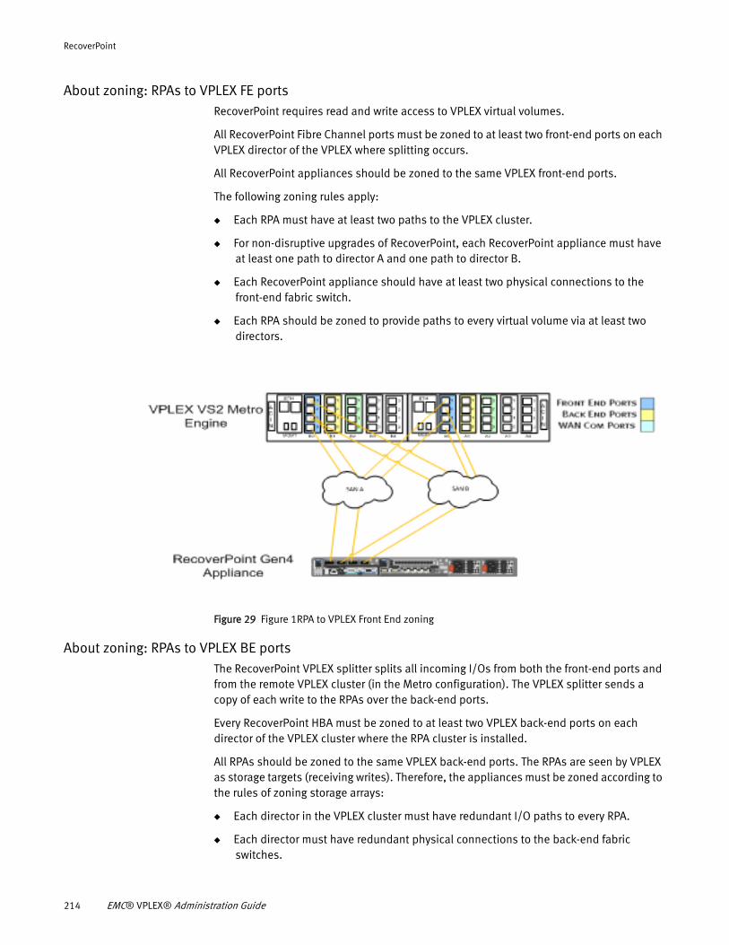
RecoverPoint
About zoning: RPAs to VPLEX FE portsRecoverPoint requires read and write access to VPLEX virtual volumes.
All RecoverPoint Fibre Channel ports must be zoned to at least two front-end ports on each VPLEX director of the VPLEX where splitting occurs.
All RecoverPoint appliances should be zoned to the same VPLEX front-end ports.
The following zoning rules apply:
◆ Each RPA must have at least two paths to the VPLEX cluster.
◆ For non-disruptive upgrades of RecoverPoint, each RecoverPoint appliance must have at least one path to director A and one path to director B.
◆ Each RecoverPoint appliance should have at least two physical connections to the front-end fabric switch.
◆ Each RPA should be zoned to provide paths to every virtual volume via at least two directors.
Figure 29 Figure 1RPA to VPLEX Front End zoning
About zoning: RPAs to VPLEX BE portsThe RecoverPoint VPLEX splitter splits all incoming I/Os from both the front-end ports and from the remote VPLEX cluster (in the Metro configuration). The VPLEX splitter sends a copy of each write to the RPAs over the back-end ports.
Every RecoverPoint HBA must be zoned to at least two VPLEX back-end ports on each director of the VPLEX cluster where the RPA cluster is installed.
All RPAs should be zoned to the same VPLEX back-end ports. The RPAs are seen by VPLEX as storage targets (receiving writes). Therefore, the appliances must be zoned according to the rules of zoning storage arrays:
◆ Each director in the VPLEX cluster must have redundant I/O paths to every RPA.
◆ Each director must have redundant physical connections to the back-end fabric switches.
214 EMC® VPLEX® Administration Guide
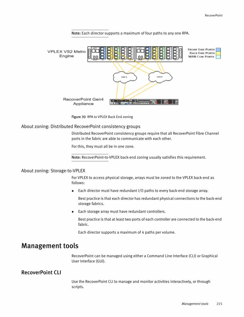
RecoverPoint
Note: Each director supports a maximum of four paths to any one RPA.
Figure 30 RPA to VPLEX Back End zoning
About zoning: Distributed RecoverPoint consistency groupsDistributed RecoverPoint consistency groups require that all RecoverPoint Fibre Channel ports in the fabric are able to communicate with each other.
For this, they must all be in one zone.
Note: RecoverPoint-to-VPLEX back-end zoning usually satisfies this requirement.
About zoning: Storage-to-VPLEXFor VPLEX to access physical storage, arrays must be zoned to the VPLEX back-end as follows:
◆ Each director must have redundant I/O paths to every back-end storage array.
Best practice is that each director has redundant physical connections to the back-end storage fabrics.
◆ Each storage array must have redundant controllers.
Best practice is that at least two ports of each controller are connected to the back-end fabric.
Each director supports a maximum of 4 paths per volume.
Management toolsRecoverPoint can be managed using either a Command Line Interface (CLI) or Graphical User Interface (GUI).
RecoverPoint CLI
Use the RecoverPoint CLI to manage and monitor activities interactively, or through scripts.
Management tools 215
RecoverPoint
There are two main modes of work in a CLI session:
CLI mode - Get help and interact with the system using CLI commands. CLI mode includes:
◆ help mode - Retrieve information regarding each CLI command, its parameters and usage.
◆ interactive mode - Guide the user when running single commands, allowing them to view each command parameter and its possible values while running the command.
◆ expert mode - Input multiple parameters and their values for a single command.
◆ Script mode - Interact with the system using scripts containing CLI commands.
To open a session with a RecoverPoint cluster or RPA and communicate using the CLI, create an SSH connection to either the site management IP (preferred, for a RecoverPoint cluster) or IP address of a specific RPA configured during a RecoverPoint installation.
The tools to work with the RecoverPoint CLI vary depending on which mode is used to access the CLI.
◆ For CLI mode, download, install the free SSH connection utility PuTTY for Linux or Unix.
◆ For Script mode, use the SSH utility that comes with the operating system, to run scripts and commands.
For more information about the command-line interface, see the EMC RecoverPoint Command Line Interface Reference Guide.
RecoverPoint GUI
The RecoverPoint Graphical User Interface (GUI) is a java-based Web application. The GUI enables the user to monitor and manage a single or multiple RecoverPoint cluster connected to each other.
To open a session with a RecoverPoint cluster or RPA:
◆ Open a browser window.
◆ Type the site management IP (to connect to a RecoverPoint cluster) or IP address of a specific RPA configured during a RecoverPoint installation, into the address bar.
◆ Enter your RecoverPoint login credentials.
216 EMC® VPLEX® Administration Guide
CHAPTER 13MetroPoint
This chapter describes the following topics:
◆ Understanding MetroPoint .................................................................................... 217◆ MetroPoint topologies........................................................................................... 220◆ Configuring MetroPoint ......................................................................................... 224◆ Installing and upgrading MetroPoint...................................................................... 226◆ Failover ................................................................................................................. 227◆ Recover production ............................................................................................... 230◆ Failover/disaster scenarios ................................................................................... 231
Understanding MetroPointMetroPoint provides the highest levels of protection and redundancy against full site failures, regional-wide failures, data corruption, and other such events. It combines the full value of VPLEX and RecoverPoint into a 3-site or 4-site topology for continuous availability, disaster recovery, and continuous data protection. The MetroPoint topology provides users full RecoverPoint protection for their VPLEX Metro configuration, maintaining replication even when one site of the Metro is down. MetroPoint also supports a 2-site topology with the ability to expand to a third remote site in the future.
MetroPoint protects customer applications and data from failure scenarios, including:
◆ Any single component failure
◆ A complete site failure
◆ A regional failure that affects two sites
◆ Data unavailability due to user errors
◆ Data corruption from viruses
MetroPoint has the ability to protect a distributed VPLEX virtual volume at both the VPLEX Metro clusters. A RecoverPoint cluster is attached to each VPLEX Metro site. One RecoverPoint cluster is the active production copy and the other RecoverPoint cluster is the standby production copy. The active production copy replicates data to the remote cluster. The standby production cluster does exactly the same thing as the active production cluster except that it does not replicate to the remote cluster. It does, however, maintain an up-to-date journal so that the standby production cluster can instantly become the active production cluster and continue data protection without disruption. In addition, the MetroPoint topology supports a local copy at each side of the distributed volume. The two local copies are independent of each other. The standby production copy is only standby relative to the link to the remote copy. It actively replicates to its local copy, if present.
In a MetroPoint topology, a single consistency group spans across three related sites. The consistency group includes an active production copy and a standby production copy. At all times, only the active production copy replicates to the remote site (there is no communication pipe between the standby production copy and the target). The standby
MetroPoint 217
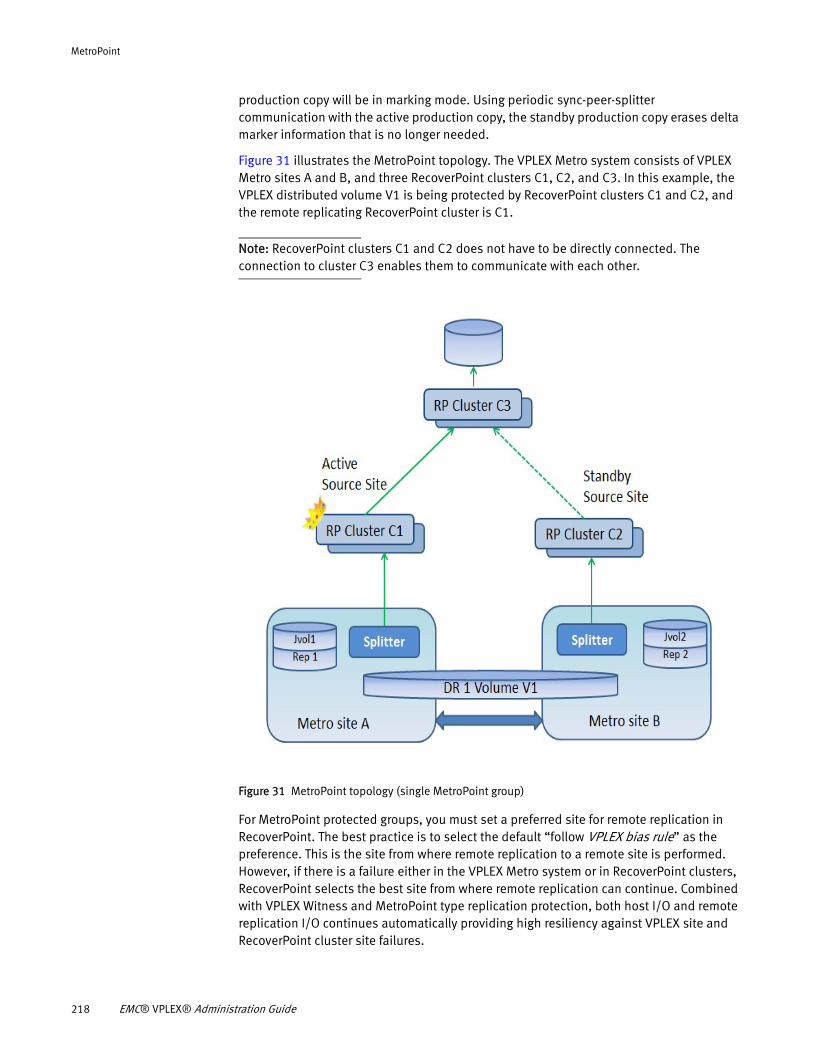
MetroPoint
production copy will be in marking mode. Using periodic sync-peer-splitter communication with the active production copy, the standby production copy erases delta marker information that is no longer needed.
Figure 31 illustrates the MetroPoint topology. The VPLEX Metro system consists of VPLEX Metro sites A and B, and three RecoverPoint clusters C1, C2, and C3. In this example, the VPLEX distributed volume V1 is being protected by RecoverPoint clusters C1 and C2, and the remote replicating RecoverPoint cluster is C1.
Note: RecoverPoint clusters C1 and C2 does not have to be directly connected. The connection to cluster C3 enables them to communicate with each other.
Figure 31 MetroPoint topology (single MetroPoint group)
For MetroPoint protected groups, you must set a preferred site for remote replication in RecoverPoint. The best practice is to select the default “follow VPLEX bias rule” as the preference. This is the site from where remote replication to a remote site is performed. However, if there is a failure either in the VPLEX Metro system or in RecoverPoint clusters, RecoverPoint selects the best site from where remote replication can continue. Combined with VPLEX Witness and MetroPoint type replication protection, both host I/O and remote replication I/O continues automatically providing high resiliency against VPLEX site and RecoverPoint cluster site failures.
218 EMC® VPLEX® Administration Guide
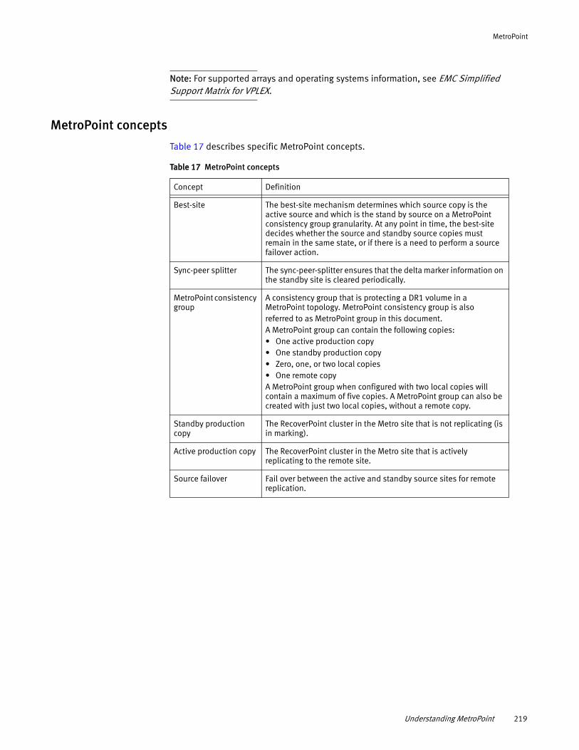
MetroPoint
Note: For supported arrays and operating systems information, see EMC Simplified Support Matrix for VPLEX.
MetroPoint concepts
Table 17 describes specific MetroPoint concepts.
Table 17 MetroPoint concepts
Concept Definition
Best-site The best-site mechanism determines which source copy is the active source and which is the stand by source on a MetroPoint consistency group granularity. At any point in time, the best-site decides whether the source and standby source copies must remain in the same state, or if there is a need to perform a source failover action.
Sync-peer splitter The sync-peer-splitter ensures that the delta marker information on the standby site is cleared periodically.
MetroPoint consistency group
A consistency group that is protecting a DR1 volume in a MetroPoint topology. MetroPoint consistency group is also referred to as MetroPoint group in this document.A MetroPoint group can contain the following copies:• One active production copy• One standby production copy• Zero, one, or two local copies• One remote copyA MetroPoint group when configured with two local copies will contain a maximum of five copies. A MetroPoint group can also be created with just two local copies, without a remote copy.
Standby production copy
The RecoverPoint cluster in the Metro site that is not replicating (is in marking).
Active production copy The RecoverPoint cluster in the Metro site that is actively replicating to the remote site.
Source failover Fail over between the active and standby source sites for remote replication.
Understanding MetroPoint 219
MetroPoint
Related information
MetroPoint topologiesMetroPoint supports 2-site, 3-site, and 4-site topologies.
Note: MetroPoint topologies must adhere to both VPLEX and RecoverPoint best practices for the distances between sites. In a VPLEX Metro, the production copies must be within synchronous distance. For RecoverPoint, the site for the remote copy must be within asynchronous distance.
MetroPoint 2-site topology
RecoverPoint Local Replication can now be added to both sides of a VPLEX Metro to provide redundant operational recovery for the same application. To achieve this, all volumes associated with an application must be placed in a MetroPoint group, even though a third site is not configured.
In a two-site topology, distributed devices are protected with an independent local copy at both Metro sites. This configuration can be upgraded non-disruptively in future by adding a third remote site for full MetroPoint protection and disaster recovery.
Information Reference
MetroPoint commands and their usage
EMC VPLEX CLI Guide
Consistency groups EMC VPLEX Administration Guide
Procedures to install and upgrade MetroPoint
EMC SolVe Desktop
Procedures to manage and troubleshoot MetroPoint
EMC SolVe Desktop
Failover Procedures EMC SolVe Desktop
RecoverPoint EMC RecoverPoint documentation
220 EMC® VPLEX® Administration Guide
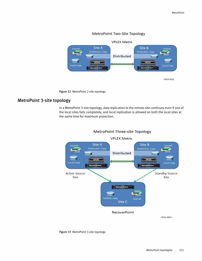
MetroPoint
Figure 32 MetroPoint 2-site topology
MetroPoint 3-site topology
In a MetroPoint 3-site topology, data replication to the remote site continues even if one of the local sites fails completely, and local replication is allowed on both the local sites at the same time for maximum protection.
Figure 33 MetroPoint 3-site topology
MetroPoint topologies 221
MetroPoint
For instance, if Site B fails, the operations will continue seamlessly at Site A, if VPLEX Witness is configured. Replication from Site B will then automatically switch over to replicate from Site A to the remote site (Site C) without losing replication history. All this happens automatically without the need for any operator intervention, specialized tools, or customized scripts. If a regional wide failure or disaster causes both the sites of a Metro to fail, then operations can failover to the DR site.
MetroPoint provides continuous data protection with any-point in time recovery at the remote site (Site C) with RecoverPoint Remote Replication. For ultimate protection, both production sites in a MetroPoint topology (Site A and Site B) can be protected with RecoverPoint Local Replication. This provides the following benefits:
◆ Faster RTO – The local copy is more easily accessible to the administrators and reads from the local copy are faster than reads from the remote copy.
◆ Redundant copies – Protects against the loss of a site(s) or the links between the sites.
RecoverPoint Local Replication can also be added to both sites of a VPLEX Metro to provide redundant operational recovery for the same application. To achieve redundant operational recovery, all the volumes associated with an application must be placed in a MetroPoint group even if there is no third site configured.
Although remote replication is enabled at both local sites, only one copy of the data is sent to the remote site. For each consistency group, the data can be replicated from either side of the Metro. Thus both data paths can be utilized and load can be balanced on a per application basis, that is, on a per consistency group basis.
MetroPoint 4-site topology
MetroPoint can also be configured as a 4- site topology. In a 4-site topology, MetroPoint provides continuous availability for production applications running in two separate regions. Each region provides DR protection for the other region.
Figure 34 illustrates a 4-site topology. The production applications running in Region 1 are replicated to Region 2 for disaster protection. Different applications with volumes in different consistency groups can run in Region 2 and be protected in Region 1.
222 EMC® VPLEX® Administration Guide
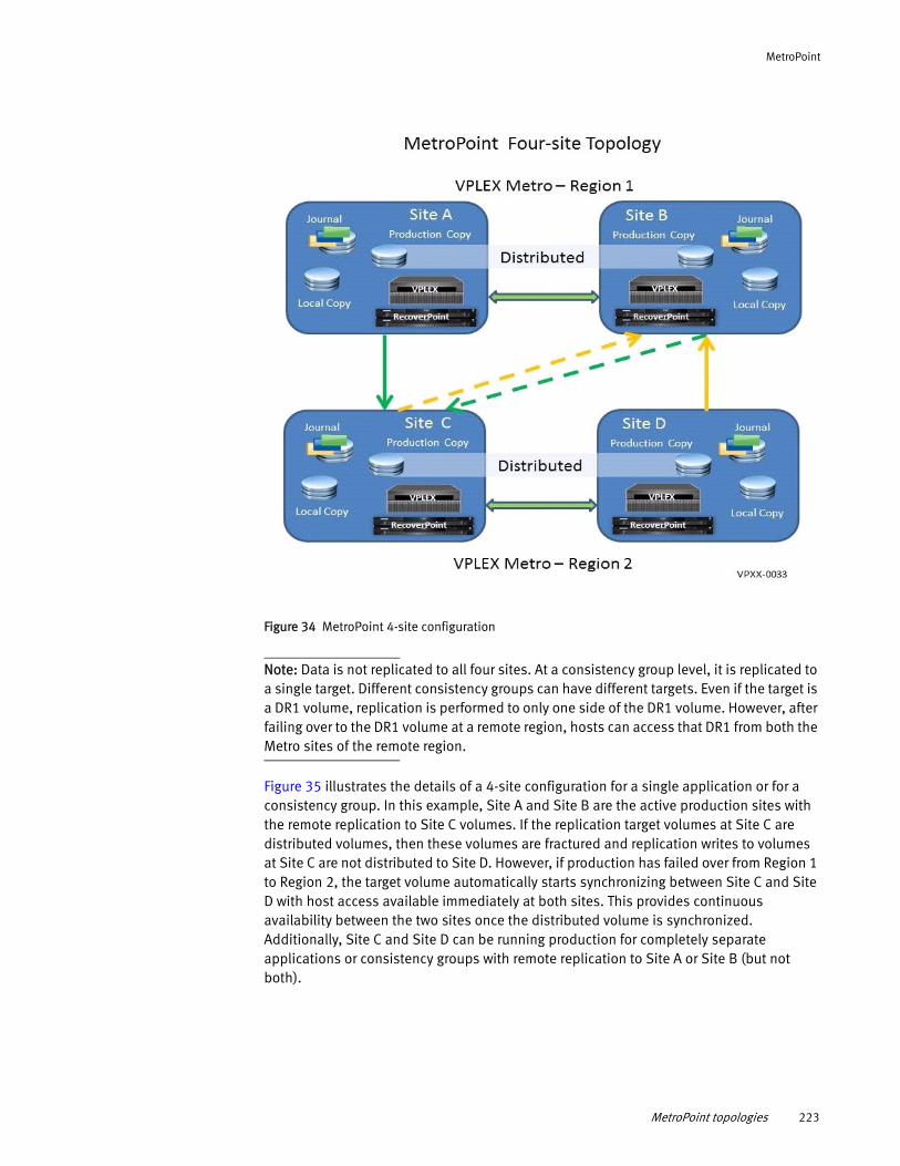
MetroPoint
Figure 34 MetroPoint 4-site configuration
Note: Data is not replicated to all four sites. At a consistency group level, it is replicated to a single target. Different consistency groups can have different targets. Even if the target is a DR1 volume, replication is performed to only one side of the DR1 volume. However, after failing over to the DR1 volume at a remote region, hosts can access that DR1 from both the Metro sites of the remote region.
Figure 35 illustrates the details of a 4-site configuration for a single application or for a consistency group. In this example, Site A and Site B are the active production sites with the remote replication to Site C volumes. If the replication target volumes at Site C are distributed volumes, then these volumes are fractured and replication writes to volumes at Site C are not distributed to Site D. However, if production has failed over from Region 1 to Region 2, the target volume automatically starts synchronizing between Site C and Site D with host access available immediately at both sites. This provides continuous availability between the two sites once the distributed volume is synchronized. Additionally, Site C and Site D can be running production for completely separate applications or consistency groups with remote replication to Site A or Site B (but not both).
MetroPoint topologies 223
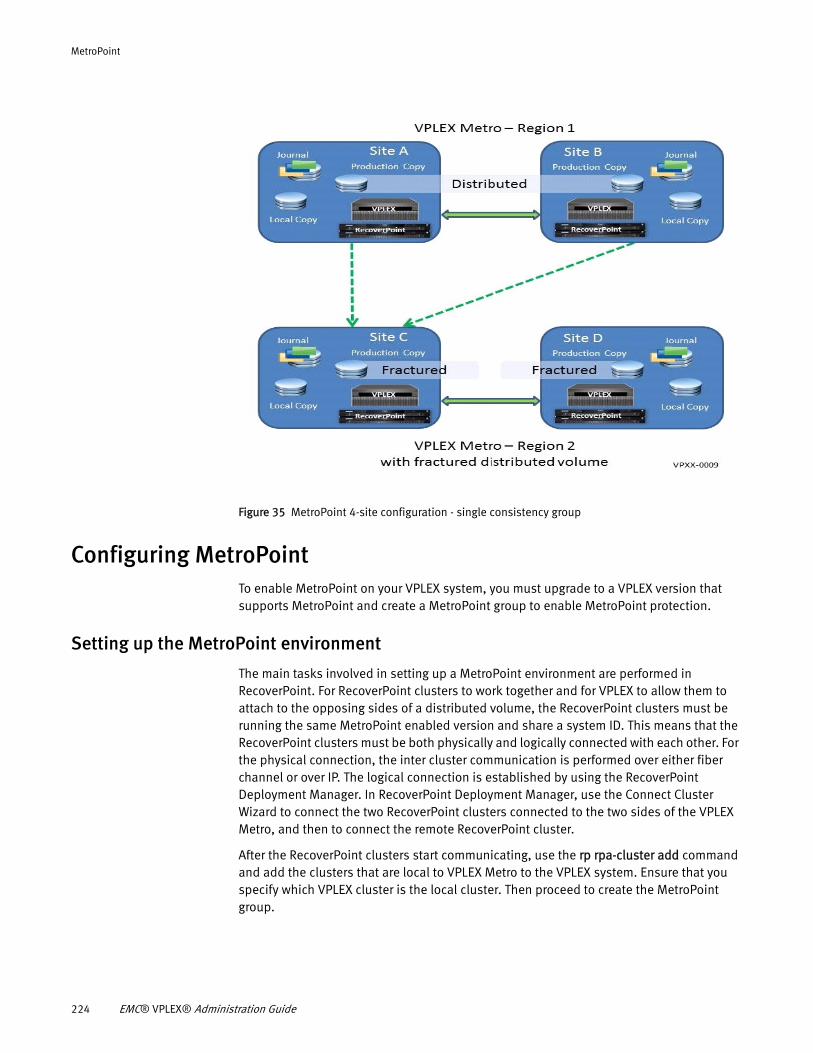
MetroPoint
Figure 35 MetroPoint 4-site configuration - single consistency group
Configuring MetroPointTo enable MetroPoint on your VPLEX system, you must upgrade to a VPLEX version that supports MetroPoint and create a MetroPoint group to enable MetroPoint protection.
Setting up the MetroPoint environment
The main tasks involved in setting up a MetroPoint environment are performed in RecoverPoint. For RecoverPoint clusters to work together and for VPLEX to allow them to attach to the opposing sides of a distributed volume, the RecoverPoint clusters must be running the same MetroPoint enabled version and share a system ID. This means that the RecoverPoint clusters must be both physically and logically connected with each other. For the physical connection, the inter cluster communication is performed over either fiber channel or over IP. The logical connection is established by using the RecoverPoint Deployment Manager. In RecoverPoint Deployment Manager, use the Connect Cluster Wizard to connect the two RecoverPoint clusters connected to the two sides of the VPLEX Metro, and then to connect the remote RecoverPoint cluster.
After the RecoverPoint clusters start communicating, use the rp rpa-cluster add command and add the clusters that are local to VPLEX Metro to the VPLEX system. Ensure that you specify which VPLEX cluster is the local cluster. Then proceed to create the MetroPoint group.
224 EMC® VPLEX® Administration Guide
MetroPoint
Note: You must add both RPA clusters to each of the VPLEX management server. However, ensure that you specify the VPLEX cluster to which the RPA cluster is connected for replication I/O. Use the --cluster argument of the RecoverPoint rpa-cluster add command to specify the VPLEX cluster to which the RPA cluster is connected for replication I/O.
Note: You must not add the remote RPA cluster to the VPLEX management server. Ensure that you add only the RPA clusters local to either side of the VPLEX Metro.
Creating a MetroPoint group
Before you begin, ensure that you have:
◆ Provisioned storage and created the distributed devices for use.
◆ Created RecoverPoint enabled consistency groups.
◆ Exposed the storage in the created consistency groups to RecoverPoint and hosts through storage views.
Note: Ensure that the distributed device is exposed to the RecoverPoint cluster local to each VPLEX Metro cluster and belongs to a storage view on both Metro Site A and Metro Site B. RecoverPoint will see the same volume on both the Metro sites and use it to filter distributed volumes.
In the RecoverPoint GUI, use the Protect Volumes Wizard to create a MetroPoint group.
The EMC RecoverPoint Administrator’s Guide provides information on creating a MetroPoint group.
Upgrading an existing consistency group to a MetroPoint group
If you already have some consistency groups created with replication history, you can non-disruptively upgrade from your current level of protection to MetroPoint protection. It is non-disruptive to the replication history only if the production source volumes are already VPLEX distributed devices. In the case of VPLEX local devices, the VPLEX local devices have to be promoted to distributed devices, and this procedure is currently disruptive to RecoverPoint protection history, requiring a full sweep of the data, and loss of replication history. Both procedures are non-disruptive to host I/O.
Upgrading from VPLEX distributed volumesIf you only have a local copy, you must use the RecoverPoint GUI to add a remote copy at the remote RecoverPoint cluster to the existing RecoverPoint consistency group. If you already have a remote copy and your source volume is a VPLEX distributed device, then you can begin converting your protection to MetroPoint protection.
In the RecoverPoint GUI, use the Manage Protection option to select a consistency group to enable MetroPoint protection.
The following steps outlines the tasks involved in upgrading from VPLEX distributed volumes:
1. Add a secondary production copy to an existing consistency group.
Configuring MetroPoint 225
MetroPoint
2. Select journal volumes for the secondary production source.
3. Review the summary of the replication sets in the RecoverPoint consistency group after adding the standby production source.
4. Select the consistency group you modified to display the MetroPoint configuration.
The EMC RecoverPoint Administrator's Guide provides more information on using the Manage Protection wizard.
Upgrading from VPLEX local volumesThe procedure to upgrade from VPLEX local volumes is disruptive to RecoverPoint replication. The volumes that are to be converted from local devices to distributed devices must be removed from RecoverPoint replication sets and also from VPLEX consistency groups. However, it does not require any halting of host I/O. VPLEX prevents the addition of mirror legs to volumes which are splitting I/O to RecoverPoint, and VPLEX also prevents you from having different volume topologies within a single VPLEX consistency group. Therefore, you cannot mix local and distributed volumes within a single group.
The following steps outlines the tasks involved in upgrading from VPLEX local volumes:
1. Remove the volume from the RecoverPoint replication set and the VPLEX consistency group.
2. Use the device attach-mirror command and add a mirror leg from a VPLEX cluster that is not local to the volume to convert the local volume into a distributed device.
3. Place the volume (now a VPLEX distributed device) back within a RecoverPoint enabled consistency group.
4. Select a detach winner rule for the consistency group, if required.
5. Re-create the original replication sets for the volumes within the RecoverPoint consistency group and then follow the steps to upgrade a VPLEX distributed volume.
Or
Create a new MetroPoint protected consistency group using the Protect VPLEX Volumes Wizard.
Installing and upgrading MetroPointYou can install a new MetroPoint configuration or upgrade to MetroPoint from existing VPLEX, RecoverPoint, or combined VPLEX-RecoverPoint configurations.
Installation and upgrade considerations
◆ Minimum requirement - three sites RPA clusters with one RPA cluster connected to each VPLEX Metro clusters and the third to a remote site.
◆ The three clusters must all share a common RPA system ID to become a part of the same system.
◆ Whenever a RPA system ID must be changed, all replication provisioned in that RecoverPoint cluster must be removed and reconfigured again after the system ID change.
226 EMC® VPLEX® Administration Guide
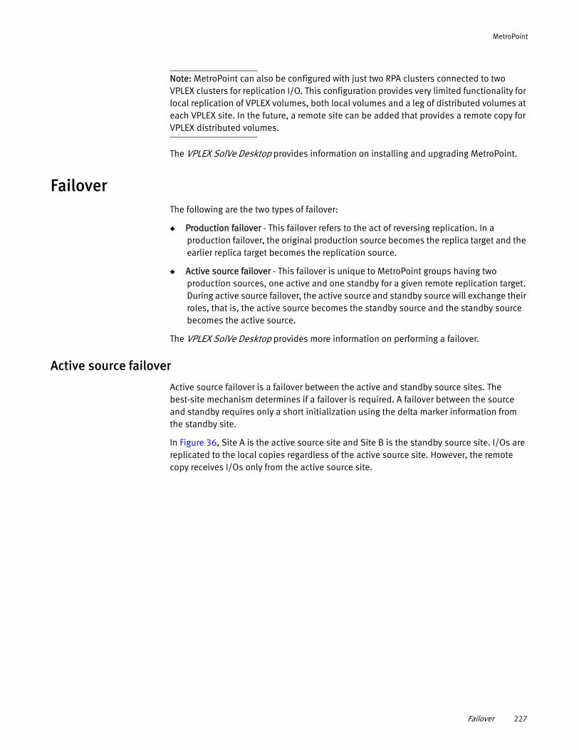
MetroPoint
Note: MetroPoint can also be configured with just two RPA clusters connected to two VPLEX clusters for replication I/O. This configuration provides very limited functionality for local replication of VPLEX volumes, both local volumes and a leg of distributed volumes at each VPLEX site. In the future, a remote site can be added that provides a remote copy for VPLEX distributed volumes.
The VPLEX SolVe Desktop provides information on installing and upgrading MetroPoint.
FailoverThe following are the two types of failover:
◆ Production failover - This failover refers to the act of reversing replication. In a production failover, the original production source becomes the replica target and the earlier replica target becomes the replication source.
◆ Active source failover - This failover is unique to MetroPoint groups having two production sources, one active and one standby for a given remote replication target. During active source failover, the active source and standby source will exchange their roles, that is, the active source becomes the standby source and the standby source becomes the active source.
The VPLEX SolVe Desktop provides more information on performing a failover.
Active source failover
Active source failover is a failover between the active and standby source sites. The best-site mechanism determines if a failover is required. A failover between the source and standby requires only a short initialization using the delta marker information from the standby site.
In Figure 36, Site A is the active source site and Site B is the standby source site. I/Os are replicated to the local copies regardless of the active source site. However, the remote copy receives I/Os only from the active source site.
Failover 227
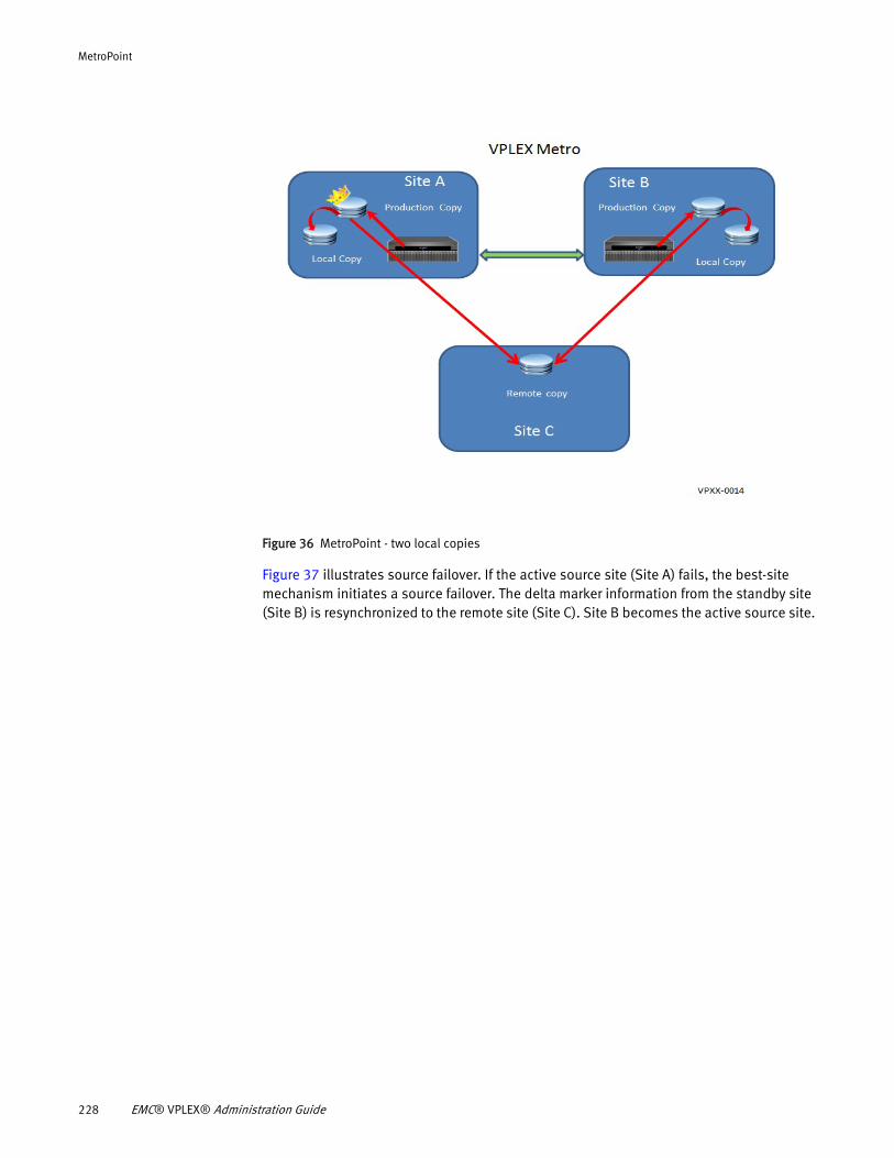
MetroPoint
Figure 36 MetroPoint - two local copies
Figure 37 illustrates source failover. If the active source site (Site A) fails, the best-site mechanism initiates a source failover. The delta marker information from the standby site (Site B) is resynchronized to the remote site (Site C). Site B becomes the active source site.
228 EMC® VPLEX® Administration Guide
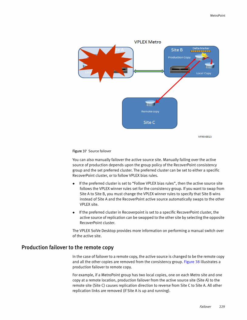
MetroPoint
Figure 37 Source failover
You can also manually failover the active source site. Manually failing over the active source of production depends upon the group policy of the RecoverPoint consistency group and the set preferred cluster. The preferred cluster can be set to either a specific RecoverPoint cluster, or to follow VPLEX bias rules.
◆ If the preferred cluster is set to “Follow VPLEX bias rules”, then the active source site follows the VPLEX winner rules set for the consistency group. If you want to swap from Site A to Site B, you must change the VPLEX winner rules to specify that Site B wins instead of Site A and the RecoverPoint active source automatically swaps to the other VPLEX site.
◆ If the preferred cluster in Recoverpoint is set to a specific RecoverPoint cluster, the active source of replication can be swapped to the other site by selecting the opposite RecoverPoint cluster.
The VPLEX SolVe Desktop provides more information on performing a manual switch over of the active site.
Production failover to the remote copy
In the case of failover to a remote copy, the active source is changed to be the remote copy and all the other copies are removed from the consistency group. Figure 38 illustrates a production failover to remote copy.
For example, if a MetroPoint group has two local copies, one on each Metro site and one copy at a remote location, production failover from the active source site (Site A) to the remote site (Site C) causes replication direction to reverse from Site C to Site A. All other replication links are removed (if Site A is up and running).
Failover 229
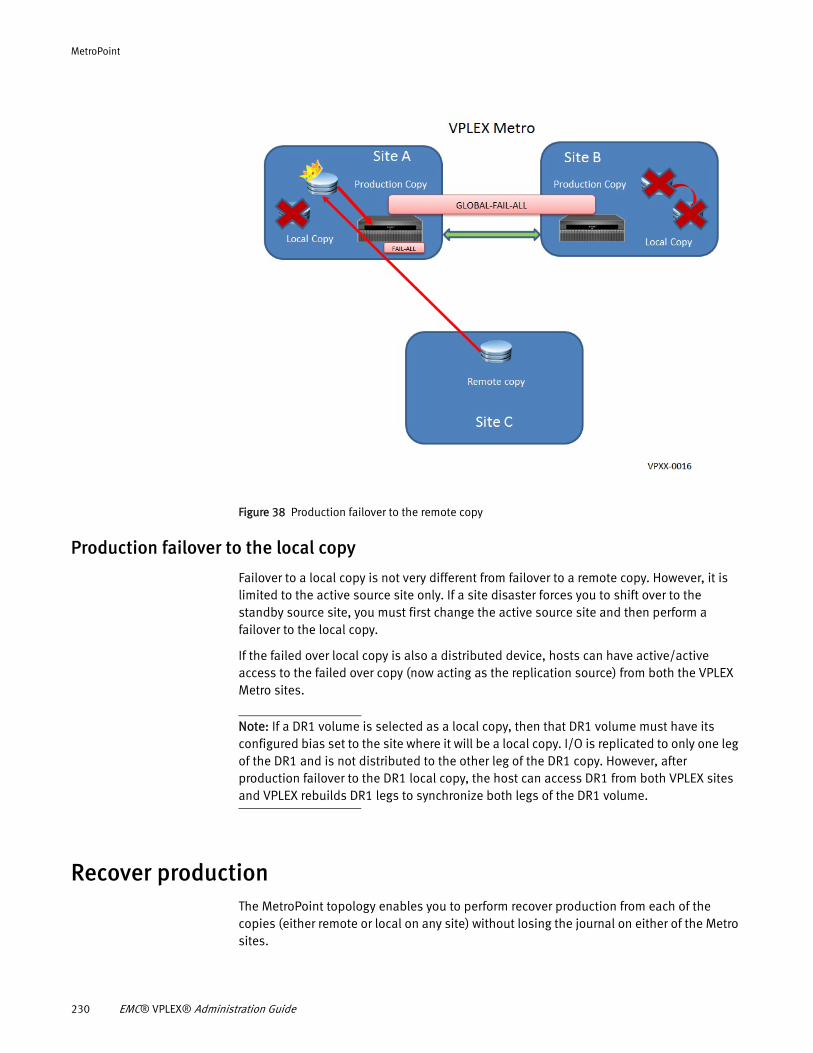
MetroPoint
Figure 38 Production failover to the remote copy
Production failover to the local copy
Failover to a local copy is not very different from failover to a remote copy. However, it is limited to the active source site only. If a site disaster forces you to shift over to the standby source site, you must first change the active source site and then perform a failover to the local copy.
If the failed over local copy is also a distributed device, hosts can have active/active access to the failed over copy (now acting as the replication source) from both the VPLEX Metro sites.
Note: If a DR1 volume is selected as a local copy, then that DR1 volume must have its configured bias set to the site where it will be a local copy. I/O is replicated to only one leg of the DR1 and is not distributed to the other leg of the DR1 copy. However, after production failover to the DR1 local copy, the host can access DR1 from both VPLEX sites and VPLEX rebuilds DR1 legs to synchronize both legs of the DR1 volume.
Recover productionThe MetroPoint topology enables you to perform recover production from each of the copies (either remote or local on any site) without losing the journal on either of the Metro sites.
230 EMC® VPLEX® Administration Guide
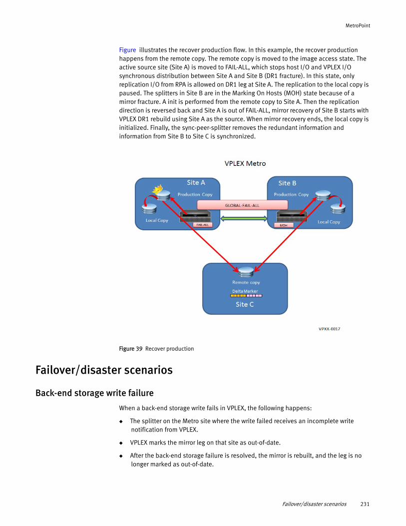
MetroPoint
Figure illustrates the recover production flow. In this example, the recover production happens from the remote copy. The remote copy is moved to the image access state. The active source site (Site A) is moved to FAIL-ALL, which stops host I/O and VPLEX I/O synchronous distribution between Site A and Site B (DR1 fracture). In this state, only replication I/O from RPA is allowed on DR1 leg at Site A. The replication to the local copy is paused. The splitters in Site B are in the Marking On Hosts (MOH) state because of a mirror fracture. A init is performed from the remote copy to Site A. Then the replication direction is reversed back and Site A is out of FAIL-ALL, mirror recovery of Site B starts with VPLEX DR1 rebuild using Site A as the source. When mirror recovery ends, the local copy is initialized. Finally, the sync-peer-splitter removes the redundant information and information from Site B to Site C is synchronized.
Figure 39 Recover production
Failover/disaster scenarios
Back-end storage write failure
When a back-end storage write fails in VPLEX, the following happens:
◆ The splitter on the Metro site where the write failed receives an incomplete write notification from VPLEX.
◆ VPLEX marks the mirror leg on that site as out-of-date.
◆ After the back-end storage failure is resolved, the mirror is rebuilt, and the leg is no longer marked as out-of-date.
Failover/disaster scenarios 231
MetroPoint
For example, if there is a back-end storage write failure of the production source on the active source site (Site A), the host requests are serviced by storage at the standby site (Site B). The DR1 leg of Site A will be out-of-date with the DR1 leg of the standby site (Site B), and replication to the local copy is paused. Because the production source is out-of-date, the active source of remote replication fails over to the standby source site (Site B).
After the production source at Site A recovers from the storage failure, a VPLEX rebuild is initiated using the DR1 leg from Site B as the source of rebuild. After rebuild completes, both DR1 legs are synchronized, the replica copy of Site A is updated with a short initialization and the active source of remote replication fails over from Site B back to Site A.
In the case of a storage failure at Site B, the sequence of actions are very similar except that there is no active source failover.
“Active source failover” on page 227 provides more information on source failover.
VPLEX link failure
In the case of a VPLEX link failure between two Metro sites (Site A and Site B), VPLEX allows host I/O to continue only on the site of configured bias (assuming that the other Metro site is operational and configured to use VPLEX Witness). For example, if Site A is the configured bias, host I/O continues on Site A whereas Site B does not allow host I/O. Site B is marked out-of-date and the mirror leg of Site A collects changes when Site A is detached from Site B in a bit map log. Now, if the source for remote replication is Site A with the “follow VPLEX bias” preference set, replication continues from Site A to the local and remote copy. Replication from Site B to the local copy is paused.
After the VPLEX link is restored, a VPLEX rebuild of Site B is initiated using the bitmap log of Site A as the source of rebuild. After rebuild completes, Site B is synchronized with Site A and a short initialization updates the replica copy at Site B.
In the same example, if Site B has VPLEX configured bias, but the active source of remote replication is Site A because the remote replication preference for MetroPoint group protection is set for Site A, then host I/O continues on Site B. There will be an active source failover to Site B and the replication from Site A to the local and remote copy is paused.
After the VPLEX link is restored, Site A is incrementally rebuilt using Site B's content and bitmap log volume. After Site A is synchronized with Site B, the local copy is updated with a short initialization. The active source of remote replication will failover from Site B to Site A.
RPA cluster inter-site communication failure
RPA cluster inter-site communication failure can occur if:
◆ The remote site is totally down
◆ One local site loses communication to the remote site
When the active source site loses communication to the remote site, a source failover to the other site is performed.
232 EMC® VPLEX® Administration Guide
MetroPoint
For example, consider a communication failure between the RecoverPoint Appliance (RPA) cluster at Site A and the RPA cluster at the remote site (Site C). If Site A is the active source of replication, then the active source of remote replication fails over and Site B becomes the new active source for remote replication. Site A now becomes the standby source site. Site A's write splitter continues to maintain writes in delta markers. Using periodic sync-peer-splitter mechanism, the standby source deletes old delta markers whose writes have been confirmed to be replicated to the remote site (Site C) from Site B.
After the RPA communication from Site A to the RPA cluster at the remote site is restored, the active source fails over from Site B to Site A. After failover, a short initialization from Site A to the replica at Site C copies the delta marker writes present from the last sync-peer-splitter call.
VPLEX site failure
MetroPoint solution provides continuous remote replication protection in the case of VPLEX site failures. VPLEX Witness must be configured for continued access to VPLEX volumes from the surviving VPLEX sites.
When a VPLEX site fails, VPLEX Witness guides the surviving VPLEX to continue I/O on all volumes in the consistency groups irrespective of the configured bias value.
For example, if Site A fails and the consistency group of a DR1 volume has Site A as the winner, host I/O continues on the surviving Site B because of VPLEX Witness guidance. Active source of remote replication fails over to Site B. After Site A recovers, the mirror leg is incrementally rebuilt using Site B's bit-map log content. After rebuild synchronization is complete, the local copy is updated with a short initialization and the active source of remote replication fails back to Site A with the preferred configuration of “follow VPLEX bias”.
Active source site failure - fail-back to the standby site
In a MetroPoint configuration, if you had not failed over production volume(s) to the remote site (Site C) and there was a total cluster disaster involving both VPLEX clusters (Site A and Site B), and later if only one VPLEX site comes back online (Site A or Site B), you can perform a production fail-back to that site irrespective of the VPLEX configured bias and MetroPoint group preference. To achieve this, either VPLEX Witness must allow host I/O, or you must intervene and initiate the consistency-group choose-winner command to allow host I/O on the VPLEX cluster that is up and running. RecoverPoint ignores the configured MetroPoint consistency group preference, in case there is only one working VPLEX cluster.
However, if you had already initiated production failover and then want to fail-back to VPLEX production volume(s), the site from where you failed-over must be up and running. Otherwise, you must use the manual process to fail-back to the stand-by site using newly provisioned storage.
For example, consider Site A and Site B are replicating to the disaster site (Site C). Site A is the active source for MetroPoint replication. A problem is encountered and a production restore from an image copy at Site C to Site A is initiated. This sets Site A's side of DR1 into FAIL-ALL, and Site B's volumes in a given RecoverPoint consistency group are fractured or disconnected. Consider that Site A becomes unavailable when it is the target of a
Failover/disaster scenarios 233
MetroPoint
production restore. Because Site B’s side of the volume is still disabled, you cannot lift FAIL-ALL even though Site A's side of the volume may or may not be splitting. To recover from such a scenario, you must migrate production to a new storage.
The following steps outlines the tasks involved in migrating production to a new storage:
Note: Before migrating production to a new storage, ensure that you have storage available to allocate for the new volumes.
1. Tear down the RecoverPoint consistency group.
2. Provision a new set of local volumes from the new storage at Site B, corresponding to the DR1 volumes that were in the RecoverPoint consistency group.
3. Create a new RecoverPoint consistency group, with Site C as the production and Site B as the replica using the newly created volumes.
This initializes the volumes at Site B based on the data available at Site C.
4. Perform a failover, making Site B as the production volume and Site C as the replica.
At this stage, RecoverPoint protection is available only for local volumes.
During failover, if your hosts are accessing storage at Site C, reconfigure them to use the new Site B volumes. This requires you to create appropriate storage view configurations for the new volumes, so the hosts can access them.
5. Recover Site A.
Site A's VPLEX splitters learns that the old RecoverPoint consistency group is torn down only when they get in touch with Site A's RPAs, and Site A's RPAs are in touch with the rest of the RecoverPoint system where the RecoverPoint consistency group was torn down. In an event where such RPAs never come back, contact EMC support for assistance in cleaning up the stale clusters.
6. To return to full MetroPoint protection:
• Perform the (disruptive-to-RecoverPoint) procedure to upgrade the new local volumes into DR1 volumes
• Perform the procedure to upgrade RecoverPoint protected DR1 volumes to MetroPoint protected DR1 volumes
“Upgrading an existing consistency group to a MetroPoint group” on page 225 provides more information on upgrading VPLEX local and distributed volumes.
Note: Migrating production to a new storage does not affect the old volumes. After the missing or unreliable site becomes available, those volumes and their storage hierarchy can be torn down and reused for other purposes.
234 EMC® VPLEX® Administration Guide
CHAPTER 14Performance and Monitoring
This chapter describes RPO/RTO and the procedures to create and operate performance monitors.
◆ About performance ............................................................................................... 235◆ Monitor performance using the CLI........................................................................ 240◆ Pre-configured performance monitors ................................................................... 249◆ Statistics............................................................................................................... 255
About performanceThis chapter describes the following topics related to performance on VPLEX systems:
◆ Configuration - Modifiable parameters to maximize performance and to manage Recovery Point Objective (RPO) and Recovery Time Objective (RTO) for VPLEX Geo systems.
◆ Monitoring - Tools and techniques to monitor VPLEX’s performance, and to identify and diagnose problems.
RPO and RTO
Recovery Point Objective (RPO): RPO is the time interval between the point of failure of a storage system and the expected point in the past to which the storage system is capable of recovering customer data.
RPO is a maximum amount of data loss that can be tolerated by the application after a failure. The value of the RPO is highly dependent upon the recovery technique used. For example, RPO for backups is typically days; for asynchronous replication minutes; and for mirroring or synchronous replication seconds or instantaneous.
Recovery Time Objective (RTO): RTO is the time duration within which a storage solution is expected to recover from failure and begin servicing application requests.
RTO is the longest tolerable application outage due to a failure of a storage system. RTO is a function of the storage technology. It may measure in hours for backup systems, minutes for a remote replication, and seconds (or less) for a mirroring.
Calculating RPO in VPLEX Geo systems
VPLEX Geo systems, distributed volumes must be members of consistency groups with asynchronous cache-mode.
Two additional parameters specific to asynchronous consistency groups impact the RPO:
◆ “Default closeout-time” on page 147
◆ “Maximum-queue-depth” on page 147
The default closeout-time and maximum-queue-depth properties work together to configure the maximum possible data loss in the event of an inter-cluster link outage.
Performance and Monitoring 235
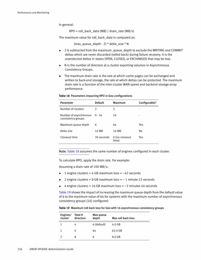
Performance and Monitoring
In general:
RPO = roll_back_data (MB) / drain_rate (MB/s)
The maximum value for roll_back_data is computed as:
(max_queue_depth - 2) * delta_size * N
◆ 2 is subtracted from the maximum_queue_depth to exclude the WRITING and COMMIT deltas which are never discarded (rolled back) during failure recovery. It is the unprotected deltas in states OPEN, CLOSED, or EXCHANGED that may be lost.
◆ N is the number of directors at a cluster exporting volumes in Asynchronous Consistency Groups.
◆ The maximum drain rate is the rate at which cache pages can be exchanged and written to back-end storage, the rate at which deltas can be protected. The maximum drain rate is a function of the inter-cluster WAN speed and backend storage-array performance.
Note: Table 18 assumes the same number of engines configured in each cluster.
To calculate RPO, apply the drain rate. For example:
Assuming a drain rate of 100 MB/s:
◆ 1 engine clusters = 4 GB maximum loss = ~42 seconds
◆ 2 engine clusters = 8 GB maximum loss = ~ 1 minute 22 seconds
◆ 4 engine clusters = 16 GB maximum loss = ~2 minutes 44 seconds
Table 19 shows the impact of increasing the maximum queue depth from the default value of 6 to the maximum value of 64 for systems with the maximum number of asynchronous consistency groups (16) configured:
Table 18 Parameters impacting RPO in Geo configurations
Parameter Default Maximum Configurable?
Number of clusters 2 2 -
Number of asynchronous consistency groups
0 - 16 16 -
Maximum queue depth 6 64 Yes
Delta size 16 MB 16 MB No
Closeout time 30 seconds 0 (no closeout time)
Yes
Table 19 Maximum roll back loss for Geo with 16 asynchronous consistency groups
Engines/ cluster
Total # directors
Max queue depth Max roll back loss
1 4 6 (default) 4.0 GB
1 4 64 62.0 GB
2 8 6 8.0 GB
236 EMC® VPLEX® Administration Guide
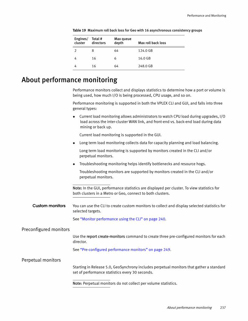
Performance and Monitoring
About performance monitoringPerformance monitors collect and displays statistics to determine how a port or volume is being used, how much I/O is being processed, CPU usage, and so on.
Performance monitoring is supported in both the VPLEX CLI and GUI, and falls into three general types:
◆ Current load monitoring allows administrators to watch CPU load during upgrades, I/O load across the inter-cluster WAN link, and front-end vs. back-end load during data mining or back up.
Current load monitoring is supported in the GUI.
◆ Long term load monitoring collects data for capacity planning and load balancing.
Long term load monitoring is supported by monitors created in the CLI and/or perpetual monitors.
◆ Troubleshooting monitoring helps identify bottlenecks and resource hogs.
Troubleshooting monitors are supported by monitors created in the CLI and/or perpetual monitors.
Note: In the GUI, performance statistics are displayed per cluster. To view statistics for both clusters in a Metro or Geo, connect to both clusters.
Custom monitors You can use the CLI to create custom monitors to collect and display selected statistics for selected targets.
See “Monitor performance using the CLI” on page 240.
Preconfigured monitorsUse the report create-monitors command to create three pre-configured monitors for each director.
See “Pre-configured performance monitors” on page 249.
Perpetual monitorsStarting in Release 5.0, GeoSynchrony includes perpetual monitors that gather a standard set of performance statistics every 30 seconds.
Note: Perpetual monitors do not collect per volume statistics.
2 8 64 124.0 GB
4 16 6 16.0 GB
4 16 64 248.0 GB
Table 19 Maximum roll back loss for Geo with 16 asynchronous consistency groups
Engines/ cluster
Total # directors
Max queue depth Max roll back loss
About performance monitoring 237
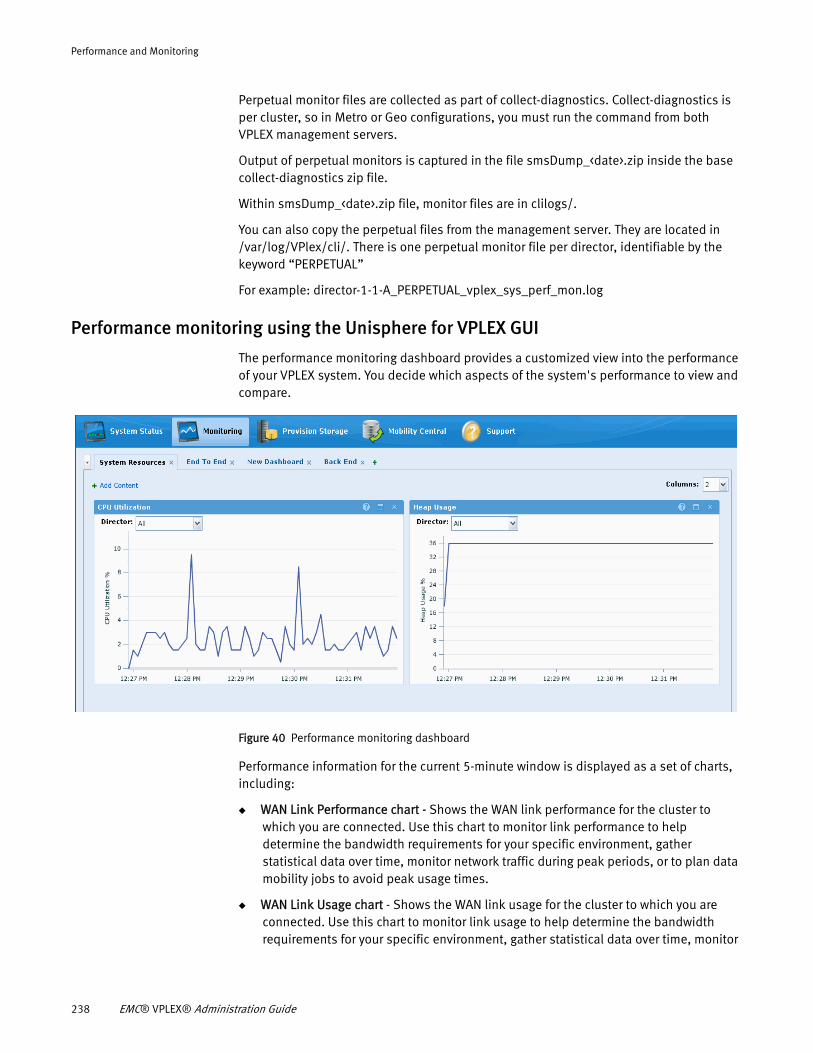
Performance and Monitoring
Perpetual monitor files are collected as part of collect-diagnostics. Collect-diagnostics is per cluster, so in Metro or Geo configurations, you must run the command from both VPLEX management servers.
Output of perpetual monitors is captured in the file smsDump_<date>.zip inside the base collect-diagnostics zip file.
Within smsDump_<date>.zip file, monitor files are in clilogs/.
You can also copy the perpetual files from the management server. They are located in /var/log/VPlex/cli/. There is one perpetual monitor file per director, identifiable by the keyword “PERPETUAL”
For example: director-1-1-A_PERPETUAL_vplex_sys_perf_mon.log
Performance monitoring using the Unisphere for VPLEX GUI
The performance monitoring dashboard provides a customized view into the performance of your VPLEX system. You decide which aspects of the system's performance to view and compare.
Figure 40 Performance monitoring dashboard
Performance information for the current 5-minute window is displayed as a set of charts, including:
◆ WAN Link Performance chart - Shows the WAN link performance for the cluster to which you are connected. Use this chart to monitor link performance to help determine the bandwidth requirements for your specific environment, gather statistical data over time, monitor network traffic during peak periods, or to plan data mobility jobs to avoid peak usage times.
◆ WAN Link Usage chart - Shows the WAN link usage for the cluster to which you are connected. Use this chart to monitor link usage to help determine the bandwidth requirements for your specific environment, gather statistical data over time, monitor
238 EMC® VPLEX® Administration Guide
Performance and Monitoring
network traffic during peak periods, or to plan data mobility jobs to avoid peak usage times. The chart allows you to separately monitor the amount of bandwidth used for normal system operations, writes to distributed volumes, and mobility jobs.
◆ WAN Latency chart - Provides a time-based view of the WAN Latency. The categories avg-lat/min-lat/max-lat each report values observed in the last 5 seconds or less.
◆ WAN Message Size chart - Provides a time-based view of the WAN message sizes. Average sent and received WAN message sizes are the average unit of data that VPLEX communicates between directors.
◆ WAN Packet Drops chart - Provides a time-based view of the WAN Packet Drops. WAN Packet drops are presented as a percentage of total packets, specified by sent or received, that were dropped by the director, or a director port.
◆ WAN Retransmission chart - Provides a time-based view of the WAN Sender Retransmissions. WAN Retransmissions are presented as a percentage of total packets sent that were re-transmitted by the director, or a director port.
◆ Write Latency Delta chart - Provides the delta between Front-end latency and Back-end Latency per director. This is a key metric for Local/Metro – the amount of overhead time VPLEX spends processing a write.
◆ Back-end Errors chart - Displays the back-end I/O errors to and from the storage array. There are three categories of back-end errors: Aborts, timeouts, and resets.
◆ Back-end Throughput chart - Shows the back-end I/Os per second over time for directors. Generally throughput (or more commonly referred to as IOPS) is associated with small block I/O (4KB or 16KB I/O requests.)
◆ Back-End Bandwidth chart - Shows the quantity of back-end reads and writes per second over time for directors. Generally bandwidth (measured in KB/s or MB/s) is associated with large block I/O (64KB or greater I/O requests).
◆ Back-end Latency chart - Provides details of the back-end latency statistics for your VPLEX system in graphical form over time. The chart allows you to view current or historical performance data that you can use to monitor peaks in workload, detect performance issues, or view what was happening in the system when a specific problem occurred.
◆ Rebuild Status chart - Displays the status of any rebuilds or migration operations that are running on your VPLEX system.
◆ CPU Utilization chart - Provides a time-based view of the utilization load on the primary director CPU on your VPLEX system. By default, the chart shows an averaged view of the utilization loads of all the directors in your VPLEX system.
◆ Heap Usage chart - Shows a percentage of the heap memory used by the firmware on a director.
◆ Front-end Aborts chart - Displays the number of aborts per second over time for directors on your VPLEX system. By default, the chart shows averaged front-end aborts for the VPLEX system.
◆ Front-End Bandwidth chart - Displays the quantity of front-end reads and writes per second over time for directors on your VPLEX system. By default, the chart shows the total front-end bandwidth for the VPLEX system.
About performance monitoring 239
Performance and Monitoring
◆ Front-end Latency chart - Provides details of the front-end latency statistics for your VPLEX system in graphical form over time. The chart allows you to view current or historical performance data that you can use to monitor peaks in workload, detect performance issues, or view what was happening in the system when a specific problem occurred.
◆ Front-end Queue Depth chart - Provides the count of front-end operations per director. It describes the number of concurrent outstanding operations active in the system.
◆ Front-End Throughput chart - Displays the front-end I/Os per second over time for directors on your VPLEX system. By default, the chart shows the total front-end throughput for the VPLEX system.
◆ Subpage Writes chart - Displays the percentage of subpage writes over time for directors on your VPLEX system. By default, the chart shows an averaged subpage writes chart for the VPLEX system.
◆ Virtual Volume Throughput chart - Provides a time-based view of the total throughput or IOPS for a virtual volume. Generally throughput, more commonly referred to IOPS, is associated with small block I/O (512B to 16KB I/O requests.
◆ Virtual Volume Latency chart - Provides a time-based view of the IO Latency for a virtual volume broken down by read and write latency. Virtual volume latency is defined as the amount of time an I/O spends within VPLEX for a given virtual volume.
◆ Virtual Volume Bandwidth chart - Provides a time-based view of the total bandwidth (or KB/s or MB/s) in reads and writes for a virtual-volume. Generally bandwidth (also referred to as KB/s or MB/s), is associated with large block I/O (64KB or greater I/O requests)
Performance monitoring using the VPLEX CLI
Use the CLI to create custom monitors to help diagnose performance issues.
Two CLI objects collect and display performance statistics:
◆ monitors - Gather the specified statistic from the specified target at the specified interval.
◆ monitor sinks - Direct the output to the desired destination. Monitor sinks include the console, a file, or a combination of the two.
Note: SNMP statistics do not require a monitor or monitor sink. Use the snmp-agent configure command to configure and start the SNMP agent. Refer to “” on page 271.
Monitor performance using the CLIThis section describes the steps to create a custom monitor using the VPLEX CLI.
About file rotation and timestamps
Starting in Release 5.1, the log files created by a monitor’s file sink are automatically rotated when they reach a size of 10 MB. The 10MB file is saved as filename.csv.n where n is a number 1 - 10, and output is saved in a new file named filename.csv.n+1.
240 EMC® VPLEX® Administration Guide
Performance and Monitoring
The .csv files are rotated up to 10 times.
In the following example, a monitor has exceeded 10MB of output. The initial 10MB are stored in filename.csv.1. Subsequent output is stored in filename.csv.
service@sms-cluster-1:/var/log/VPlex/cli> ll my-data.csv*-rw-r--r-- 1 service users 2910722 2012-03-06 21:23 my-data.csv-rw-r--r-- 1 service users 10566670 2012-03-06 21:10 my-data.csv.1
If the second file exceeds, 10MB:
◆ The previous filename.csv.1 is changed to filename.csv.2
◆ The filename.csv changes to filename.csv.1
◆ Subsequent output is stored in filename.csv
Up to 10 such rotations, and numbered .csv files are supported.
When the file sink is removed or the monitor is destroyed, output to the .csv file stops, and the current .csv file is is timestamped. For example:
service@sms-cluster-1:/var/log/VPlex/cli> ll my-data.csv*-rw-r--r-- 1 service users 10566670 2012-03-06 21:23 my-data.csv.1-rw-r--r-- 1 service users 5637498 2012-03-06 21:26 my-data.csv_20120306092614973
Procedure overview: create a monitor using the CLI
To create and operate a monitor using the CLI, use the following general steps:
1. Determine the type of statistic to collect from the target object.
Use the monitor stat-list category and/or the monitor stat-list * command to display the statistics to include in the monitor.
Refer to the tables in “Statistics” on page 255 for lists of statistics by category.
Note whether the statistic you want to collect requires a target to be specified.
Note: Specify only one type of target per monitor. For example, you cannot create a monitor that includes both port and storage-volumes as targets.
2. Determine how often the monitor should collect statistics.
3. Use the monitor create command to create a monitor.
4. Use the monitor add-sink commands to add one or more sinks to the monitor.
Add a console sink to send performance data to the VPLEX management console.
Add a file sink to send performance data to a specified file.
5. Repeat Steps 3 and 4 for each director.
6. The monitor begins operation (polling and collecting performance data) when the sink is added to the monitor.
To disable automatic polling without deleting the monitor or its sink(s), do one of the following:
• Use the set command to change the monitor’s period attribute to 0.
• Use the set command to change the sink’s enabled attribute to false.
Monitor performance using the CLI 241
Performance and Monitoring
7. Use the monitor collect command to update/collect statistics immediately without waiting for the monitor’s next automatic collection.
8. Monitor output.
Console sinks display monitor output on the console.
For file sinks, navigate to /var/log/VPlex/cli/ on the management server and use the tail -f filename to display the output,
or:
Send output to a csv file, open the file in Microsoft Excel and create a chart.
Do NOT edit the CSV file in Microsoft Excel, and then save the file. Excel removes the seconds field, resulting in duplicate timestamps. Use Excel to look at the CSV files, but don’t save any edits.
9. Use the monitor destroy command to remove the monitor.
Create a monitor
Use the monitor create command to create a monitor and specify the statistics collected by the monitor.
The syntax for the command is:
monitor create [-p|--period] collection-period[-n|--name] monitor-name[-d|--director] context-path,context-path [-s|--stats] stat,stat,stat,stat[-t|--targets] context-path,context-path
Required arguments
--name - Name of the monitor.
--stats stat,stat,stat - One or more statistics to monitor, separated by commas. Examples of statistics (stats) include:
◆ be aborts
◆ be resets
◆ be timeouts
See the Online Help for a complete list of available performance monitor statistics.
Optional arguments
-- period - Frequency at which this monitor collects statistics. Valid arguments are an integer followed by:
ms - milliseconds (period is truncated to the nearest second)s - seconds (Default)min - minutesh - hours0 - Disables automatic polling
242 EMC® VPLEX® Administration Guide
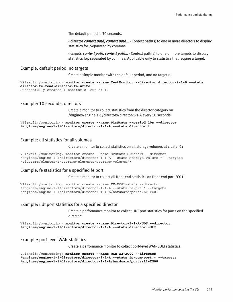
Performance and Monitoring
The default period is 30 seconds.
--director context path, context path... - Context path(s) to one or more directors to display statistics for. Separated by commas.
--targets context path, context path... - Context path(s) to one or more targets to display statistics for, separated by commas. Applicable only to statistics that require a target.
Example: default period, no targetsCreate a simple monitor with the default period, and no targets:
VPlexcli:/monitoring> monitor create --name TestMonitor --director director-2-1-B --stats director.fe-read,director.fe-writeSuccessfully created 1 monitor(s) out of 1.
Example: 10 seconds, directorsCreate a monitor to collect statistics from the director category on /engines/engine-1-1/directors/director-1-1-A every 10 seconds:
VPlexcli:/monitoring> monitor create --name DirStats --period 10s --director /engines/engine-1-1/directors/director-1-1-A --stats director.*
Example: all statistics for all volumesCreate a monitor to collect statistics on all storage volumes at cluster-1:
VPlexcli:/monitoring> monitor create --name SVStats-Cluster1 --director /engines/engine-1-1/directors/director-1-1-A --stats storage-volume.* --targets /clusters/cluster-1/storage-elements/storage-volumes/*
Example: fe statistics for a specified fe portCreate a monitor to collect all front-end statistics on front-end port FC01:
VPlexcli:/monitoring> monitor create --name FE-FC01-stats --director /engines/engine-1-1/directors/director-1-1-A --stats fe-prt.* --targets /engines/engine-1-1/directors/director-1-1-A/hardware/ports/A0-FC01
Example: udt port statistics for a specified directorCreate a performance monitor to collect UDT port statistics for ports on the specified director:
VPlexcli:/monitoring> monitor create --name Director-1-1-A-UDT --director /engines/engine-1-1/directors/director-1-1-A --stats director.udt*
Example: port-level WAN statisticsCreate a performance monitor to collect port-level WAN-COM statistics:
VPlexcli:/monitoring> monitor create --name WAN_A2-XG00 --director /engines/engine-1-1/directors/director-1-1-A --stats ip-com-port.* --targets /engines/engine-1-1/directors/director-1-1-A/hardware/ports/A2-XG00
Monitor performance using the CLI 243
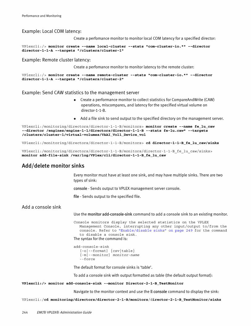
Performance and Monitoring
Example: Local COM latency:Create a perfomance monitor to monitor local COM latency for a specified director:
VPlexcli:/> monitor create --name local-cluster --stats "com-cluster-io.*" --director director-1-1-A --targets "/clusters/cluster-1"
Example: Remote cluster latency:Create a perfomance monitor to monitor latency to the remote cluster:
VPlexcli:/> monitor create --name remote-cluster --stats "com-cluster-io.*" --director director-1-1-A --targets "/clusters/cluster-2"
Example: Send CAW statistics to the management server◆ Create a performance monitor to collect statistics for CompareAndWrite (CAW)
operations, miscompares, and latency for the specified virtual volume on director-1-1-B.
◆ Add a file sink to send output to the specified directory on the management server.
VPlexcli:/monitoring/directors/director-1-1-B/monitors> monitor create --name fe_lu_caw --director /engines/engine-1-1/directors/director-1-1-B --stats fe-lu.caw* --targets /clusters/cluster-1/virtual-volumes/VAAI_Vol1_Device_vol
VPlexcli:/monitoring/directors/director-1-1-B/monitors> cd director-1-1-B_fe_lu_caw/sinks
VPlexcli:/monitoring/directors/director-1-1-B/monitors/director-1-1-B_fe_lu_caw/sinks> monitor add-file-sink /var/log/VPlex/cli/director-1-1-B_fe_lu_caw
Add/delete monitor sinks
Every monitor must have at least one sink, and may have multiple sinks. There are two types of sink:
console - Sends output to VPLEX management server console.
file - Sends output to the specified file.
Add a console sinkUse the monitor add-console-sink command to add a console sink to an existing monitor.
Console monitors display the selected statistics on the VPLEX Management Console, interrupting any other input/output to/from the console. Refer to “Enable/disable sinks” on page 249 for the command to disable a console sink.
The syntax for the command is:
add-console-sink [-o|--format] {csv|table}[-m|--monitor] monitor-name--force
The default format for console sinks is ‘table’.
To add a console sink with output formatted as table (the default output format):
VPlexcli:/> monitor add-console-sink --monitor Director-2-1-B_TestMonitor
Navigate to the monitor context and use the ll console command to display the sink:
VPlexcli:/cd monitoring/directors/director-2-1-B/monitors/director-2-1-B_TestMonitor/sinks
244 EMC® VPLEX® Administration Guide
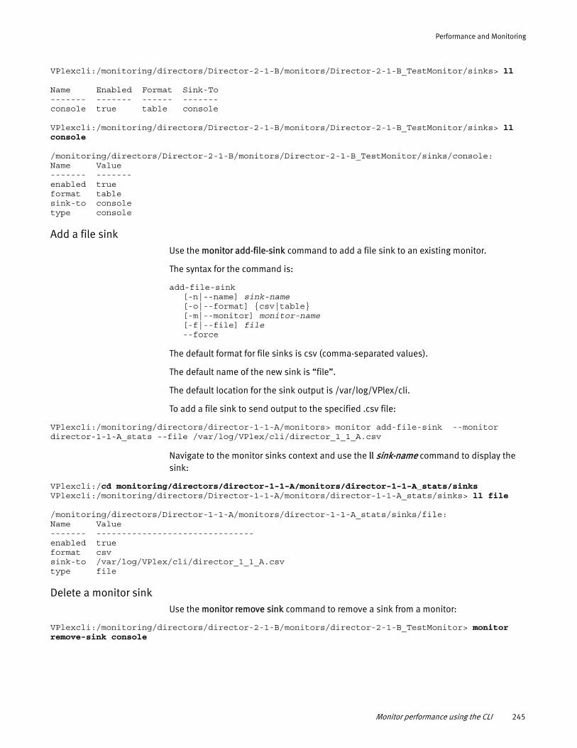
Performance and Monitoring
VPlexcli:/monitoring/directors/Director-2-1-B/monitors/Director-2-1-B_TestMonitor/sinks> ll
Name Enabled Format Sink-To------- ------- ------ -------console true table console
VPlexcli:/monitoring/directors/Director-2-1-B/monitors/Director-2-1-B_TestMonitor/sinks> ll console
/monitoring/directors/Director-2-1-B/monitors/Director-2-1-B_TestMonitor/sinks/console:Name Value------- -------enabled trueformat tablesink-to consoletype console
Add a file sinkUse the monitor add-file-sink command to add a file sink to an existing monitor.
The syntax for the command is:
add-file-sink [-n|--name] sink-name[-o|--format] {csv|table}[-m|--monitor] monitor-name[-f|--file] file--force
The default format for file sinks is csv (comma-separated values).
The default name of the new sink is “file”.
The default location for the sink output is /var/log/VPlex/cli.
To add a file sink to send output to the specified .csv file:
VPlexcli:/monitoring/directors/director-1-1-A/monitors> monitor add-file-sink --monitor director-1-1-A_stats --file /var/log/VPlex/cli/director_1_1_A.csv
Navigate to the monitor sinks context and use the ll sink-name command to display the sink:
VPlexcli:/cd monitoring/directors/director-1-1-A/monitors/director-1-1-A_stats/sinksVPlexcli:/monitoring/directors/Director-1-1-A/monitors/director-1-1-A_stats/sinks> ll file
/monitoring/directors/Director-1-1-A/monitors/director-1-1-A_stats/sinks/file:Name Value------- -------------------------------enabled trueformat csvsink-to /var/log/VPlex/cli/director_1_1_A.csvtype file
Delete a monitor sinkUse the monitor remove sink command to remove a sink from a monitor:
VPlexcli:/monitoring/directors/director-2-1-B/monitors/director-2-1-B_TestMonitor> monitor remove-sink console
Monitor performance using the CLI 245
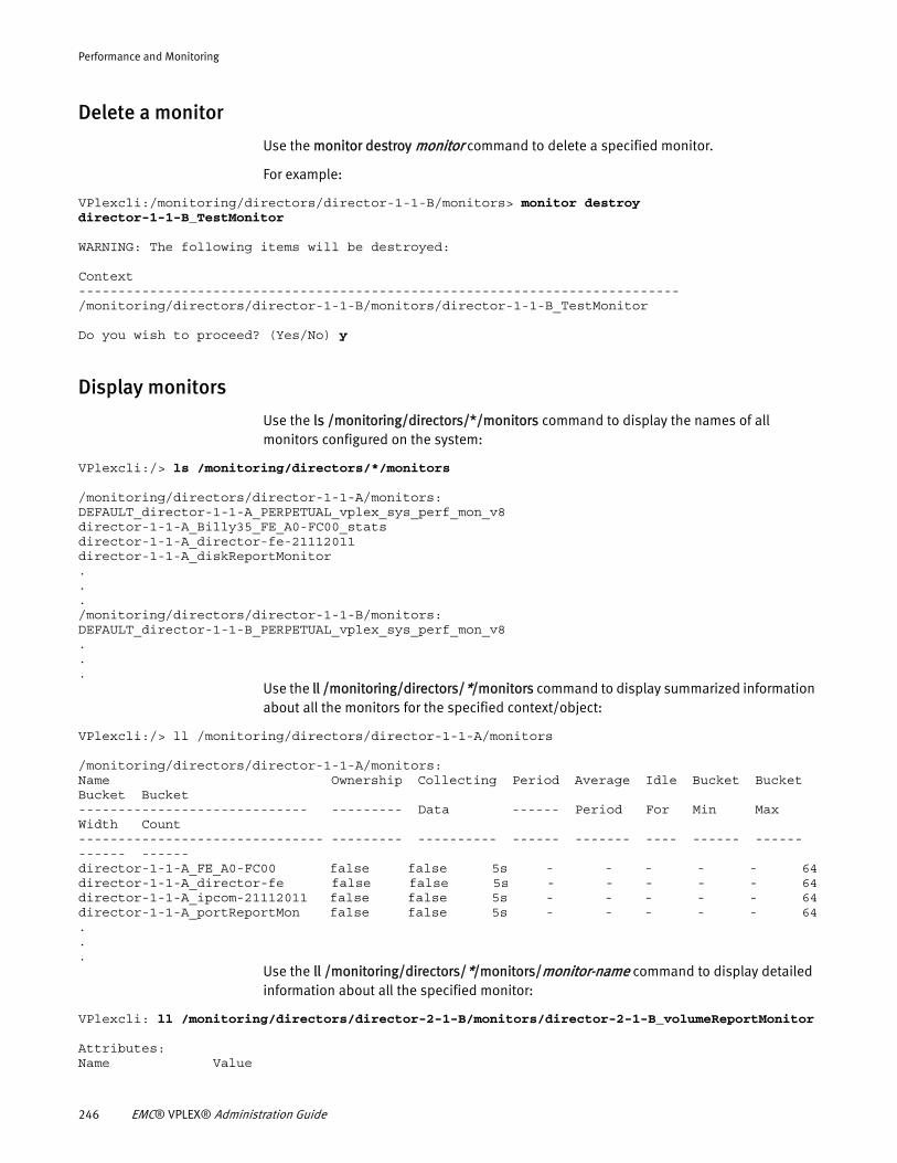
Performance and Monitoring
Delete a monitor
Use the monitor destroy monitor command to delete a specified monitor.
For example:
VPlexcli:/monitoring/directors/director-1-1-B/monitors> monitor destroy director-1-1-B_TestMonitor
WARNING: The following items will be destroyed:
Context----------------------------------------------------------------------------/monitoring/directors/director-1-1-B/monitors/director-1-1-B_TestMonitor
Do you wish to proceed? (Yes/No) y
Display monitors
Use the ls /monitoring/directors/*/monitors command to display the names of all monitors configured on the system:
VPlexcli:/> ls /monitoring/directors/*/monitors
/monitoring/directors/director-1-1-A/monitors:DEFAULT_director-1-1-A_PERPETUAL_vplex_sys_perf_mon_v8director-1-1-A_Billy35_FE_A0-FC00_statsdirector-1-1-A_director-fe-21112011director-1-1-A_diskReportMonitor.../monitoring/directors/director-1-1-B/monitors:DEFAULT_director-1-1-B_PERPETUAL_vplex_sys_perf_mon_v8...
Use the ll /monitoring/directors/*/monitors command to display summarized information about all the monitors for the specified context/object:
VPlexcli:/> ll /monitoring/directors/director-1-1-A/monitors
/monitoring/directors/director-1-1-A/monitors:Name Ownership Collecting Period Average Idle Bucket Bucket Bucket Bucket----------------------------- --------- Data ------ Period For Min Max Width Count------------------------------- --------- ---------- ------ ------- ---- ------ ------ ------ ------director-1-1-A_FE_A0-FC00 false false 5s - - - - - 64director-1-1-A_director-fe false false 5s - - - - - 64director-1-1-A_ipcom-21112011 false false 5s - - - - - 64director-1-1-A_portReportMon false false 5s - - - - - 64...
Use the ll /monitoring/directors/*/monitors/monitor-name command to display detailed information about all the specified monitor:
VPlexcli: ll /monitoring/directors/director-2-1-B/monitors/director-2-1-B_volumeReportMonitor
Attributes:Name Value
246 EMC® VPLEX® Administration Guide
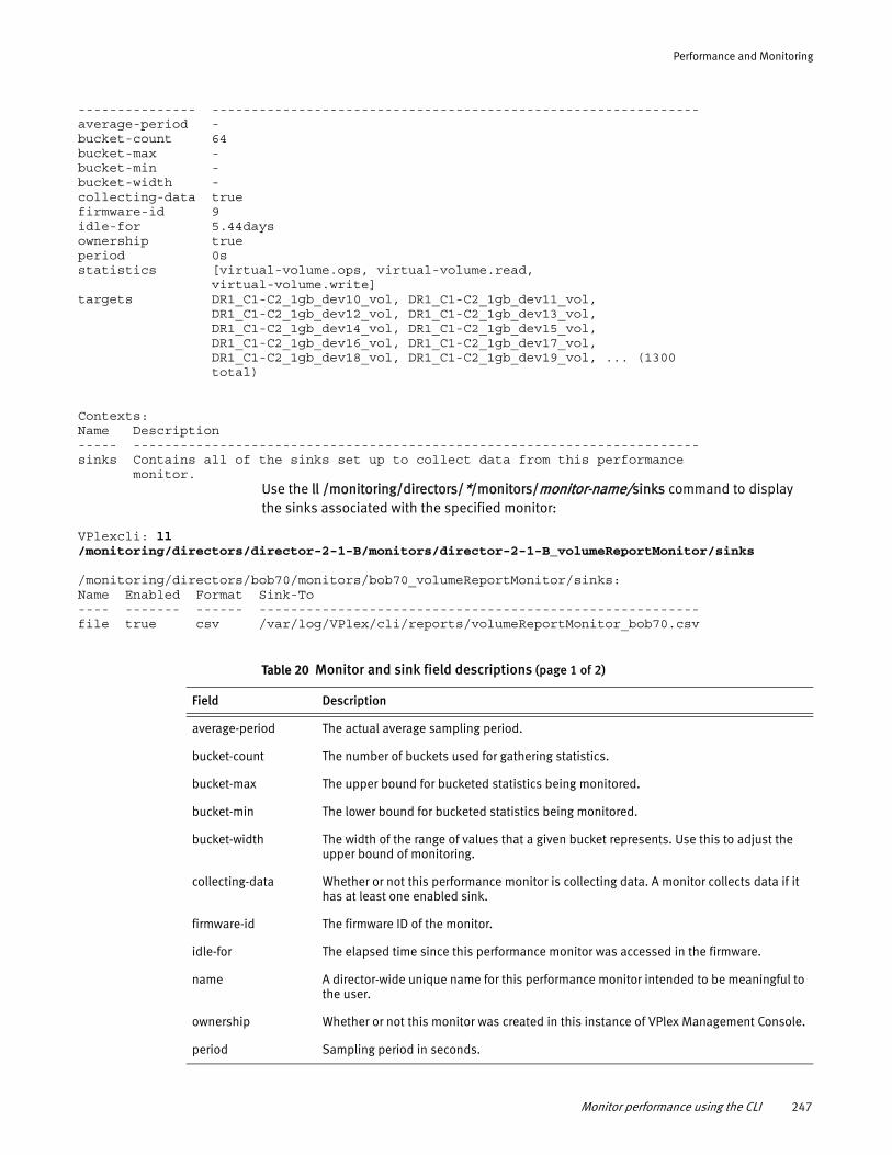
Performance and Monitoring
--------------- --------------------------------------------------------------average-period -bucket-count 64bucket-max -bucket-min -bucket-width -collecting-data truefirmware-id 9idle-for 5.44daysownership trueperiod 0sstatistics [virtual-volume.ops, virtual-volume.read, virtual-volume.write]targets DR1_C1-C2_1gb_dev10_vol, DR1_C1-C2_1gb_dev11_vol, DR1_C1-C2_1gb_dev12_vol, DR1_C1-C2_1gb_dev13_vol, DR1_C1-C2_1gb_dev14_vol, DR1_C1-C2_1gb_dev15_vol, DR1_C1-C2_1gb_dev16_vol, DR1_C1-C2_1gb_dev17_vol, DR1_C1-C2_1gb_dev18_vol, DR1_C1-C2_1gb_dev19_vol, ... (1300 total)
Contexts:Name Description----- ------------------------------------------------------------------------sinks Contains all of the sinks set up to collect data from this performance monitor.
Use the ll /monitoring/directors/*/monitors/monitor-name/sinks command to display the sinks associated with the specified monitor:
VPlexcli: ll /monitoring/directors/director-2-1-B/monitors/director-2-1-B_volumeReportMonitor/sinks
/monitoring/directors/bob70/monitors/bob70_volumeReportMonitor/sinks:Name Enabled Format Sink-To---- ------- ------ --------------------------------------------------------file true csv /var/log/VPlex/cli/reports/volumeReportMonitor_bob70.csv
Table 20 Monitor and sink field descriptions (page 1 of 2)
Field Description
average-period The actual average sampling period.
bucket-count The number of buckets used for gathering statistics.
bucket-max The upper bound for bucketed statistics being monitored.
bucket-min The lower bound for bucketed statistics being monitored.
bucket-width The width of the range of values that a given bucket represents. Use this to adjust the upper bound of monitoring.
collecting-data Whether or not this performance monitor is collecting data. A monitor collects data if it has at least one enabled sink.
firmware-id The firmware ID of the monitor.
idle-for The elapsed time since this performance monitor was accessed in the firmware.
name A director-wide unique name for this performance monitor intended to be meaningful to the user.
ownership Whether or not this monitor was created in this instance of VPlex Management Console.
period Sampling period in seconds.
Monitor performance using the CLI 247
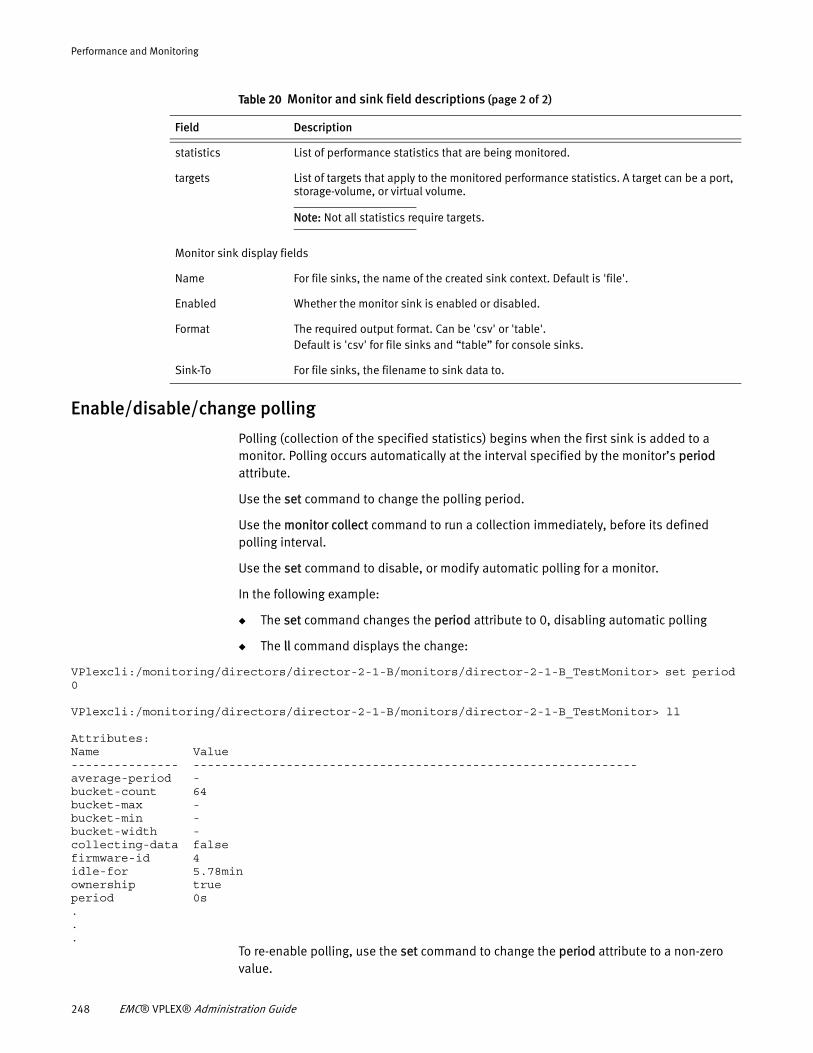
Performance and Monitoring
Enable/disable/change polling
Polling (collection of the specified statistics) begins when the first sink is added to a monitor. Polling occurs automatically at the interval specified by the monitor’s period attribute.
Use the set command to change the polling period.
Use the monitor collect command to run a collection immediately, before its defined polling interval.
Use the set command to disable, or modify automatic polling for a monitor.
In the following example:
◆ The set command changes the period attribute to 0, disabling automatic polling
◆ The ll command displays the change:
VPlexcli:/monitoring/directors/director-2-1-B/monitors/director-2-1-B_TestMonitor> set period 0
VPlexcli:/monitoring/directors/director-2-1-B/monitors/director-2-1-B_TestMonitor> ll
Attributes:Name Value--------------- --------------------------------------------------------------average-period -bucket-count 64bucket-max -bucket-min -bucket-width -collecting-data falsefirmware-id 4idle-for 5.78minownership trueperiod 0s...
To re-enable polling, use the set command to change the period attribute to a non-zero value.
statistics List of performance statistics that are being monitored.
targets List of targets that apply to the monitored performance statistics. A target can be a port, storage-volume, or virtual volume.
Note: Not all statistics require targets.
Monitor sink display fields
Name For file sinks, the name of the created sink context. Default is 'file'.
Enabled Whether the monitor sink is enabled or disabled.
Format The required output format. Can be 'csv' or 'table'. Default is 'csv' for file sinks and “table” for console sinks.
Sink-To For file sinks, the filename to sink data to.
Table 20 Monitor and sink field descriptions (page 2 of 2)
Field Description
248 EMC® VPLEX® Administration Guide
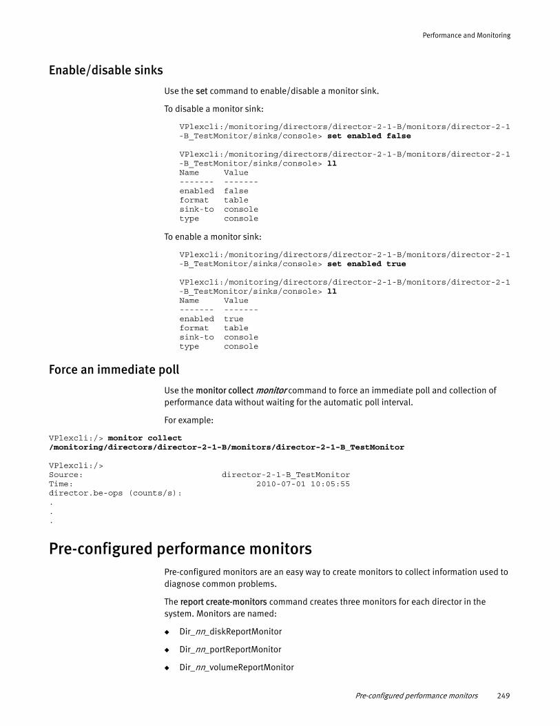
Performance and Monitoring
Enable/disable sinks
Use the set command to enable/disable a monitor sink.
To disable a monitor sink:
VPlexcli:/monitoring/directors/director-2-1-B/monitors/director-2-1-B_TestMonitor/sinks/console> set enabled false
VPlexcli:/monitoring/directors/director-2-1-B/monitors/director-2-1-B_TestMonitor/sinks/console> llName Value------- -------enabled falseformat tablesink-to consoletype console
To enable a monitor sink:
VPlexcli:/monitoring/directors/director-2-1-B/monitors/director-2-1-B_TestMonitor/sinks/console> set enabled true
VPlexcli:/monitoring/directors/director-2-1-B/monitors/director-2-1-B_TestMonitor/sinks/console> llName Value------- -------enabled trueformat tablesink-to consoletype console
Force an immediate poll
Use the monitor collect monitor command to force an immediate poll and collection of performance data without waiting for the automatic poll interval.
For example:
VPlexcli:/> monitor collect /monitoring/directors/director-2-1-B/monitors/director-2-1-B_TestMonitor
VPlexcli:/>Source: director-2-1-B_TestMonitorTime: 2010-07-01 10:05:55director.be-ops (counts/s): ...
Pre-configured performance monitorsPre-configured monitors are an easy way to create monitors to collect information used to diagnose common problems.
The report create-monitors command creates three monitors for each director in the system. Monitors are named:
◆ Dir_nn_diskReportMonitor
◆ Dir_nn_portReportMonitor
◆ Dir_nn_volumeReportMonitor
Pre-configured performance monitors 249
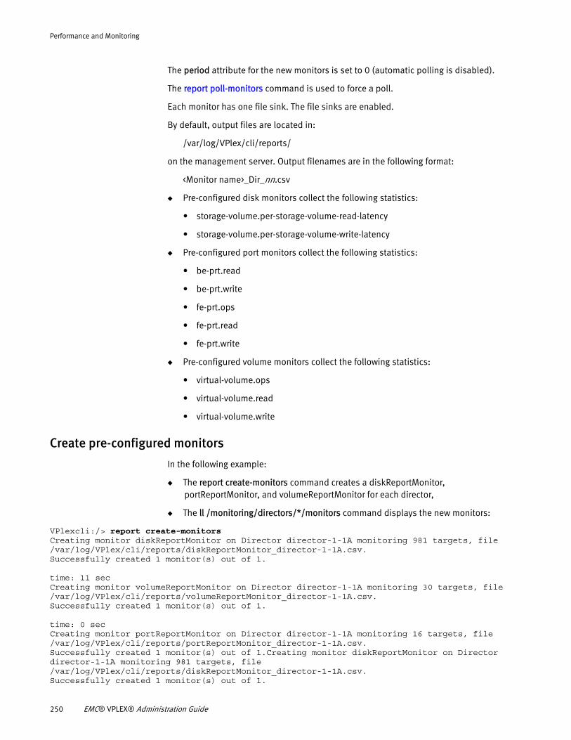
Performance and Monitoring
The period attribute for the new monitors is set to 0 (automatic polling is disabled).
The report poll-monitors command is used to force a poll.
Each monitor has one file sink. The file sinks are enabled.
By default, output files are located in:
/var/log/VPlex/cli/reports/
on the management server. Output filenames are in the following format:
<Monitor name>_Dir_nn.csv
◆ Pre-configured disk monitors collect the following statistics:
• storage-volume.per-storage-volume-read-latency
• storage-volume.per-storage-volume-write-latency
◆ Pre-configured port monitors collect the following statistics:
• be-prt.read
• be-prt.write
• fe-prt.ops
• fe-prt.read
• fe-prt.write
◆ Pre-configured volume monitors collect the following statistics:
• virtual-volume.ops
• virtual-volume.read
• virtual-volume.write
Create pre-configured monitors
In the following example:
◆ The report create-monitors command creates a diskReportMonitor, portReportMonitor, and volumeReportMonitor for each director,
◆ The ll /monitoring/directors/*/monitors command displays the new monitors:
VPlexcli:/> report create-monitorsCreating monitor diskReportMonitor on Director director-1-1A monitoring 981 targets, file /var/log/VPlex/cli/reports/diskReportMonitor_director-1-1A.csv.Successfully created 1 monitor(s) out of 1.
time: 11 secCreating monitor volumeReportMonitor on Director director-1-1A monitoring 30 targets, file /var/log/VPlex/cli/reports/volumeReportMonitor_director-1-1A.csv.Successfully created 1 monitor(s) out of 1.
time: 0 secCreating monitor portReportMonitor on Director director-1-1A monitoring 16 targets, file /var/log/VPlex/cli/reports/portReportMonitor_director-1-1A.csv.Successfully created 1 monitor(s) out of 1.Creating monitor diskReportMonitor on Director director-1-1A monitoring 981 targets, file /var/log/VPlex/cli/reports/diskReportMonitor_director-1-1A.csv.Successfully created 1 monitor(s) out of 1.
250 EMC® VPLEX® Administration Guide
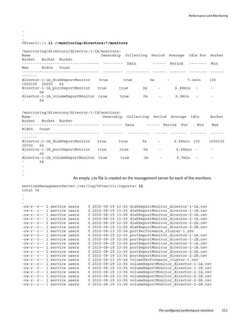
Performance and Monitoring
.
.
.VPlexcli:/> ll //monitoring/directors/*/monitors
/monitoring/directors/director-1-1A/monitors:Name Ownership Collecting Period Average Idle For Bucket Bucket Bucket Bucket----------------------------------- --------- Data ------ Period -------- Min Max Width Count----------------------------------- --------- ---------- ------ ------- -------- ------ ------- director-1-1A_diskReportMonitor true true 0s - 7.1min 100 1600100 25000 64director-1-1A_portReportMonitor true true 0s - 6.88min - - - 64director-1-1A_volumeReportMonitor true true 0s - 6.9min - - - 64
/monitoring/directors/director-1-1B/monitors:Name Ownership Collecting Period Average Idle Bucket Bucket Bucket Bucket----------------------------------- --------- Data ------ Period For Min Max Width Count----------------------------------- --------- ---------- ------ ------- ------- ------ ------- director-1-1B_diskReportMonitor true true 0s - 6.88min 100 1600100 25000 64director-1-1B_portReportMonitor true true 0s - 6.68min - - - 64director-1-1B_volumeReportMonitor true true 0s - 6.7min - - - 64...
An empty .csv file is created on the management server for each of the monitors:
service@ManagementServer:/var/log/VPlex/cli/reports> lltotal 36...-rw-r--r-- 1 service users 0 2010-08-19 13:55 diskReportMonitor_director-1-1A.csv-rw-r--r-- 1 service users 0 2010-08-19 13:55 diskReportMonitor_director-1-1B.csv-rw-r--r-- 1 service users 0 2010-08-19 13:56 diskReportMonitor_director-2-1A.csv-rw-r--r-- 1 service users 0 2010-08-19 13:55 diskReportMonitor_director-2-1B.csv-rw-r--r-- 1 service users 0 2010-08-19 13:55 diskReportMonitor_director-2-2A.csv-rw-r--r-- 1 service users 0 2010-08-19 13:56 diskReportMonitor_director-2-2B.csv-rw-r--r-- 1 service users 5 2010-08-13 15:04 portPerformance_cluster-1.csv-rw-r--r-- 1 service users 0 2010-08-19 13:55 portReportMonitor_director-1-1A.csv-rw-r--r-- 1 service users 0 2010-08-19 13:55 portReportMonitor_director-1-1B.csv-rw-r--r-- 1 service users 0 2010-08-19 13:56 portReportMonitor_director-2-1A.csv-rw-r--r-- 1 service users 0 2010-08-19 13:55 portReportMonitor_director-2-1B.csv-rw-r--r-- 1 service users 0 2010-08-19 13:55 portReportMonitor_director-2-2A.csv-rw-r--r-- 1 service users 0 2010-08-19 13:56 portReportMonitor_director-2-2B.csv-rw-r--r-- 1 service users 5 2010-08-13 15:04 volumePerformance_cluster-1.csv-rw-r--r-- 1 service users 0 2010-08-19 13:55 volumeReportMonitor_director-1-1A.csv-rw-r--r-- 1 service users 0 2010-08-19 13:55 volumeReportMonitor_director-1-1B.csv-rw-r--r-- 1 service users 0 2010-08-19 13:56 volumeReportMonitor_director-2-1A.csv-rw-r--r-- 1 service users 0 2010-08-19 13:55 volumeReportMonitor_director-2-1B.csv-rw-r--r-- 1 service users 0 2010-08-19 13:55 volumeReportMonitor_director-2-2A.csv-rw-r--r-- 1 service users 0 2010-08-19 13:56 volumeReportMonitor_director-2-2B.csv
Pre-configured performance monitors 251
Performance and Monitoring
Operate the pre-configured monitors
The monitors created by the report create-monitors command have their period attribute set to 0 seconds (automatic polling is disabled).
Use the report poll-monitors command to force an immediate poll and collection of performance data for monitors created by the report create-monitors command.
VPlexcli:/> report poll-monitorsCollecting data for director Cluster_2_Dir_1B monitor Cluster_2_Dir_1B_diskReportMonitor.Collecting data for director Cluster_2_Dir_1B monitor Cluster_2_Dir_1B_portReportMonitor.Collecting data for director Cluster_2_Dir_1B monitor Cluster_2_Dir_1B_volumeReportMonitor....
Output is written to the .csv files located in /var/log/VPlex/cli/reports/ on the management server.
Monitoring consistency groups using the CLI
Two groups of statistics are associated with consistency groups:
◆ “Write pacing (wrt-pacing) statistics” monitor write pacing (throttling) of I/O
◆ “Consistency-group (cg) statistics” monitor the performance of asynchronous consistency-groups.
These statistics apply only to consistency groups with cache mode set to asynchronous.
Because these statistics are per-consistency-group, a valid consistency-group must be specified as a target when creating a monitor of this type.
If the target consistency-group is synchronous (either when the monitor is created or if its cache mode is subsequently changed to synchronous), all statistics in this group will read "no data".
If the cache-mode is changed (back) to asynchronous, the monitor will behave as expected and the displayed values will reflect the consistency-group's performance.
Monitoring with SNMP
Simple Network Management Protocol (SNMP) is a protocol for managing and monitoring network-attached devices.
The VPLEX SNMP agent:
◆ Supports retrieval of performance-related statistics as published in the VPLEX-MIB.mib.
◆ Runs on the management server and fetches performance related data from individual directors using a firmware specific interface.
◆ Provides SNMP MIB data for directors for the local cluster only.
◆ Runs on Port 161 of the management server and uses the UDP protocol.
◆ Supports the following SNMP commands:
• SNMP Get
• SNMP Get Next
252 EMC® VPLEX® Administration Guide
Performance and Monitoring
• SNMP get Bulk
VPLEX MIBs are located on the management server in the /opt/emc/VPlex/mibs directory:
service@ManagementServer:/opt/emc/VPlex/mibs> lsVPlex.mib VPLEX-MIB.mib
VPLEX-MIB.mib contains the VPLEX MIB tree:
vplex MODULE-IDENTITY LAST-UPDATED "201008250601Z" -- Aug 25, 2010 6:01:00 AM ORGANIZATION "EMC Corporation" CONTACT-INFO "EMC Corporation 176 South Street Hopkinton, MA 01748 USA Phone: 1-800-424-EMC2 Web : www.emc.com email: [email protected]" DESCRIPTION "EMC VPLEX MIB Tree." REVISION "201008250601Z" -- Aug 25, 2010 6:01:00 AM DESCRIPTION "Initial version." -- 1.3.6.1.4.1.1139.21 ::= { enterprises 1139 21 }
VPlex.mib contains 4 VPLEX notifications:
vplex MODULE-IDENTITY LAST-UPDATED "201002020925Z" ORGANIZATION "EMC Corporation" CONTACT-INFO
"EMC Corporation 176 South Street
Hopkinton, MA 01748 USA phone: 1-800-424-EMC2
web: www.emc.com email: [email protected]" DESCRIPTION "The EMC V-Plex MIB tree." REVISION "201002020925z" DESCRIPTION "Second draft" -- 1.3.6.1.4.1.1139.21 ::= { enterprises 1139 21 }
In order to utilize SNMP, the SNMP agent must be configured and started on the VPLEX cluster.
See “” on page 271 for the VPLEX statistics that can be monitored using SNMP.
Call-home events and SNMP trapWhen a call-home event is generated and sent from VPLEX, a corresponding SNMP trap is also sent from all configured SNMP trap services that have been started on the VPLEX cluster.
The SNMP trap service can be created and started using the snmp-traps create and set started true commands respectively in the /call-home/snmp-traps context in the VPLEX CLI. See “Configure SNMP trap in call-home” on page 254 for details.
Enabling external AMQP clientsAMQP clients that are external to the VPLEX management server can connect to and listen to VPLEX events.
Pre-configured performance monitors 253
Performance and Monitoring
The VPLEX Procedure Generator provides more information on enabling external AMQP clients.
Configure SNMP
Use the snmp-agent configure command to configure and start the SNMP agent:
VPlexcli:/> snmp-agent configureThe community string is already configured to be: private.Choosing to continue will change the existing community string.
Do you want to continue? (yes/no)yes
What community string should the agent use? [private]: public
Use the snmp-agent status command to verify that the SNMP agent is running:
VPlexcli:/> snmp-agent statusSNMP Agent Service status is: Running
Configure SNMP trap in call-homeWhen call-home events are sent, the corresponding SNMP trap can also be sent. The following CLI example shows how to configure the SNMP trap in call-home. Multiple SNMP traps can be configured to send SNMP traps to different remote hosts.
VPlexcli:/> cd notifications/call-home/snmp-traps/ VPlexcli:/notifications/call-home/snmp-traps> create myTrap VPlexcli:/notifications/call-home/snmp-traps> cd myTrap/ VPlexcli:/notifications/call-home/snmp-traps/myTrap> ls Name Value---------------- ------community-string publicremote-host -remote-port 162started false
VPlexcli:/notifications/call-home/snmp-traps/myTrap> set community-string myVplex VPlexcli:/notifications/call-home/snmp-traps/myTrap> set remote-host 1.1.1.1 VPlexcli:/notifications/call-home/snmp-traps/myTrap> set started true VPlexcli:/notifications/call-home/snmp-traps/myTrap> ls Name Value---------------- -------community-string myVplexremote-host 1.1.1.1remote-port 162started true
Stop/start SNMP
Use the snmp-agent stop command to stop the SNMP agent without removing it from VPLEX:
VPlexcli:/> snmp-agent stopSNMP agent has been stopped.
254 EMC® VPLEX® Administration Guide
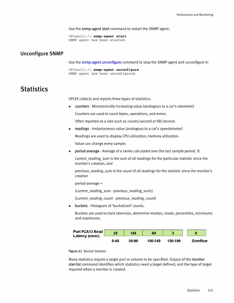
Performance and Monitoring
Use the snmp-agent start command to restart the SNMP agent:
VPlexcli:/> snmp-agent startSNMP agent has been started.
Unconfigure SNMP
Use the snmp-agent unconfigure command to stop the SNMP agent and unconfigure it:
VPlexcli:/> snmp-agent unconfigureSNMP agent has been unconfigured.
StatisticsVPLEX collects and reports three types of statistics:
◆ counters - Monotonically increasing value (analogous to a car’s odometer)
Counters are used to count bytes, operations, and errors.
Often reported as a rate such as counts/second or KB/second.
◆ readings - Instantaneous value (analagous to a car’s speedometer)
Readings are used to display CPU utilization, memory utilization.
Value can change every sample.
◆ period-average - Average of a series calculated over the last sample period. If:
current_reading_sum is the sum of all readings for the particular statistic since the monitor's creation, and
previous_reading_sum is the count of all readings for the statistic since the monitor's creation
period-average =
(current_reading_sum - previous_reading_sum)/
(current_reading_count - previous_reading_count)
◆ buckets - Histogram of ‘bucketized’ counts.
Buckets are used to track latencies, determine median, mode, percentiles, minimums and maximums.
Figure 41 Bucket Statistic
Many statistics require a target port or volume to be specified. Output of the monitor stat-list command identifies which statistics need a target defined, and the type of target required when a monitor is created.
Statistics 255
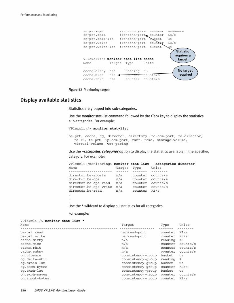
Performance and Monitoring
Figure 42 Monitoring targets
Display available statistics
Statistics are grouped into sub-categories.
Use the monitor stat-list command followed by the <Tab> key to display the statistics sub-categories. For example:
VPlexcli:/> monitor stat-list
be-prt, cache, cg, director, directory, fc-com-port, fe-director, fe-lu, fe-prt, ip-com-port, ramf, rdma, storage-volume, virtual-volume, wrt-pacing
Use the --categories categories option to display the statistics available in the specified category. For example:
VPlexcli:/monitoring> monitor stat-list --categories directorName Target Type Units--------------------- ------ ------- --------director.be-aborts n/a counter counts/sdirector.be-ops n/a counter counts/sdirector.be-ops-read n/a counter counts/sdirector.be-ops-write n/a counter counts/sdirector.be-read n/a counter KB/s...Use the * wildcard to display all statistics for all categories.
For example:
VPlexcli:/> monitor stat-list *Name Target Type Units----------------------------------------------- ----------------- ------- --------be-prt.read backend-port counter KB/sbe-prt.write backend-port counter KB/scache.dirty n/a reading KBcache.miss n/a counter counts/scache.rhit n/a counter counts/scache.subpg n/a counter counts/scg.closure consistency-group bucket uscg.delta-util consistency-group reading %cg.drain-lat consistency-group bucket uscg.exch-bytes consistency-group counter KB/scg.exch-lat consistency-group bucket uscg.exch-pages consistency-group counter counts/scg.input-bytes consistency-group counter KB/s
fe prt.ops frontend port counter counts/sfe-prt.read frontend-port counter KB/sfe-prt.read-lat frontend-port bucket usfe-prt.write frontend-port counter KB/sfe-prt.write-lat frontend-port bucket us
VPlexcli:/> monitor stat-list cacheName Target Type Units----------- ------ ------- --------cache.dirty n/a reading KBcache.miss n/a counter counts/scache.rhit n/a counter counts/s
h b / t t /
Statistic requires a
target
No target required
256 EMC® VPLEX® Administration Guide
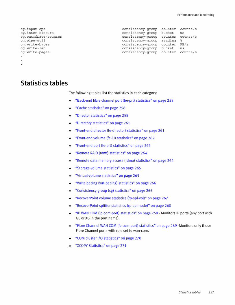
Performance and Monitoring
cg.input-ops consistency-group counter counts/scg.inter-closure consistency-group bucket uscg.outOfDate-counter consistency-group counter counts/scg.pipe-util consistency-group reading %cg.write-bytes consistency-group counter KB/scg.write-lat consistency-group bucket uscg.write-pages consistency-group counter counts/s...
Statistics tablesThe following tables list the statistics in each category:
◆ “Back-end fibre channel port (be-prt) statistics” on page 258
◆ “Cache statistics” on page 258
◆ “Director statistics” on page 258
◆ “Directory statistics” on page 261
◆ “Front-end director (fe-director) statistics” on page 261
◆ “Front-end volume (fe-lu) statistics” on page 262
◆ “Front-end port (fe-prt) statistics” on page 263
◆ “Remote RAID (ramf) statistics” on page 264
◆ “Remote data memory access (rdma) statistics” on page 264
◆ “Storage-volume statistics” on page 265
◆ “Virtual-volume statistics” on page 265
◆ “Write pacing (wrt-pacing) statistics” on page 266
◆ “Consistency-group (cg) statistics” on page 266
◆ “RecoverPoint volume statistics (rp-spl-vol)” on page 267
◆ “RecoverPoint splitter statistics (rp-spl-node)” on page 268
◆ “IP WAN COM (ip-com-port) statistics” on page 268 - Monitors IP ports (any port with GE or XG in the port name).
◆ “Fibre Channel WAN COM (fc-com-port) statistics” on page 269 -Monitors only those Fibre Channel ports with role set to wan-com.
◆ “COM cluster I/O statistics” on page 270
◆ “XCOPY Statistics” on page 271
Statistics tables 257
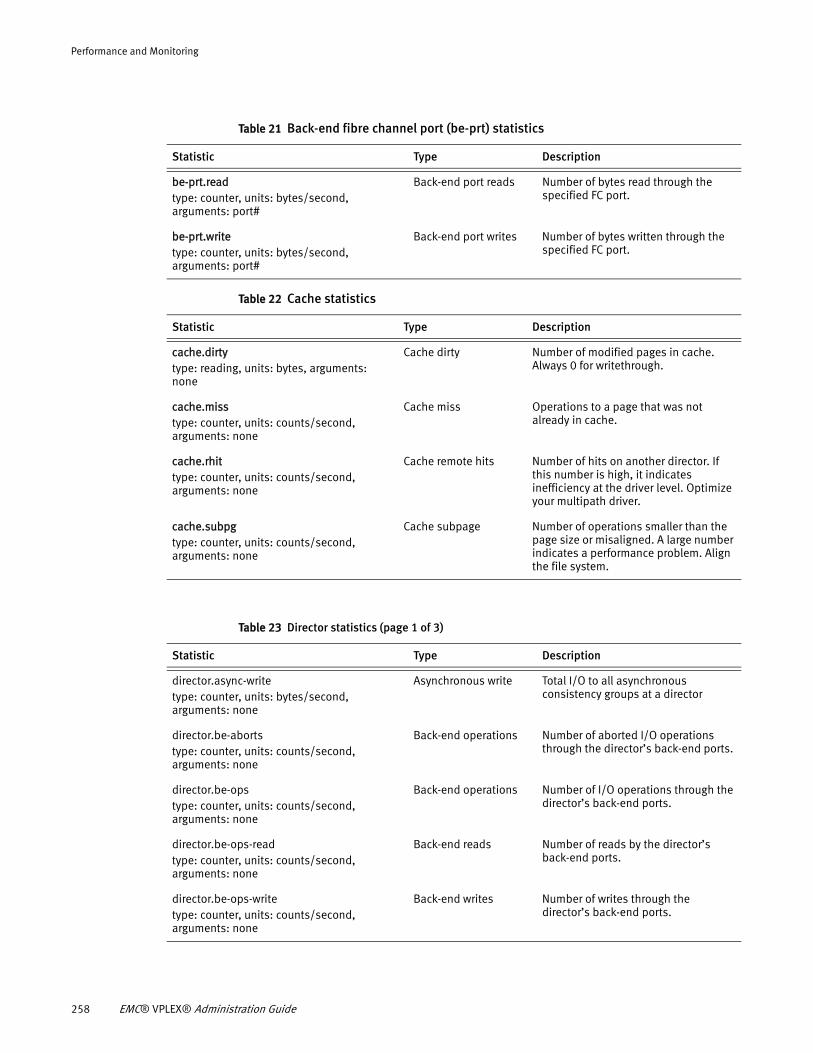
Performance and Monitoring
Table 21 Back-end fibre channel port (be-prt) statistics
Statistic Type Description
be-prt.readtype: counter, units: bytes/second, arguments: port#
Back-end port reads Number of bytes read through the specified FC port.
be-prt.writetype: counter, units: bytes/second, arguments: port#
Back-end port writes Number of bytes written through the specified FC port.
Table 22 Cache statistics
Statistic Type Description
cache.dirtytype: reading, units: bytes, arguments: none
Cache dirty Number of modified pages in cache. Always 0 for writethrough.
cache.misstype: counter, units: counts/second, arguments: none
Cache miss Operations to a page that was not already in cache.
cache.rhittype: counter, units: counts/second, arguments: none
Cache remote hits Number of hits on another director. If this number is high, it indicates inefficiency at the driver level. Optimize your multipath driver.
cache.subpgtype: counter, units: counts/second, arguments: none
Cache subpage Number of operations smaller than the page size or misaligned. A large number indicates a performance problem. Align the file system.
Table 23 Director statistics (page 1 of 3)
Statistic Type Description
director.async-writetype: counter, units: bytes/second, arguments: none
Asynchronous write Total I/O to all asynchronous consistency groups at a director
director.be-abortstype: counter, units: counts/second, arguments: none
Back-end operations Number of aborted I/O operations through the director’s back-end ports.
director.be-opstype: counter, units: counts/second, arguments: none
Back-end operations Number of I/O operations through the director’s back-end ports.
director.be-ops-readtype: counter, units: counts/second, arguments: none
Back-end reads Number of reads by the director’s back-end ports.
director.be-ops-writetype: counter, units: counts/second, arguments: none
Back-end writes Number of writes through the director’s back-end ports.
258 EMC® VPLEX® Administration Guide
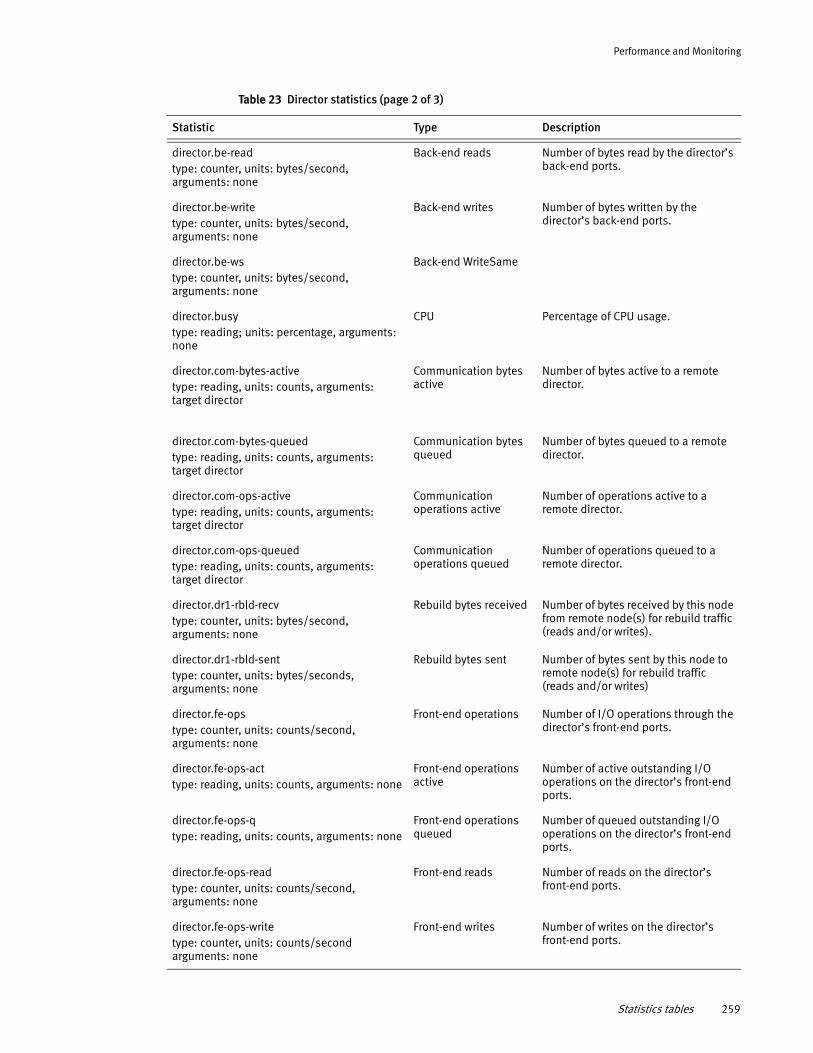
Performance and Monitoring
director.be-readtype: counter, units: bytes/second, arguments: none
Back-end reads Number of bytes read by the director’s back-end ports.
director.be-writetype: counter, units: bytes/second, arguments: none
Back-end writes Number of bytes written by the director’s back-end ports.
director.be-wstype: counter, units: bytes/second, arguments: none
Back-end WriteSame
director.busytype: reading; units: percentage, arguments: none
CPU Percentage of CPU usage.
director.com-bytes-activetype: reading, units: counts, arguments: target director
Communication bytes active
Number of bytes active to a remote director.
director.com-bytes-queuedtype: reading, units: counts, arguments: target director
Communication bytes queued
Number of bytes queued to a remote director.
director.com-ops-activetype: reading, units: counts, arguments: target director
Communication operations active
Number of operations active to a remote director.
director.com-ops-queuedtype: reading, units: counts, arguments: target director
Communication operations queued
Number of operations queued to a remote director.
director.dr1-rbld-recvtype: counter, units: bytes/second, arguments: none
Rebuild bytes received Number of bytes received by this node from remote node(s) for rebuild traffic (reads and/or writes).
director.dr1-rbld-senttype: counter, units: bytes/seconds, arguments: none
Rebuild bytes sent Number of bytes sent by this node to remote node(s) for rebuild traffic (reads and/or writes)
director.fe-opstype: counter, units: counts/second, arguments: none
Front-end operations Number of I/O operations through the director’s front-end ports.
director.fe-ops-acttype: reading, units: counts, arguments: none
Front-end operations active
Number of active outstanding I/O operations on the director’s front-end ports.
director.fe-ops-qtype: reading, units: counts, arguments: none
Front-end operations queued
Number of queued outstanding I/O operations on the director’s front-end ports.
director.fe-ops-readtype: counter, units: counts/second, arguments: none
Front-end reads Number of reads on the director’s front-end ports.
director.fe-ops-writetype: counter, units: counts/second arguments: none
Front-end writes Number of writes on the director’s front-end ports.
Table 23 Director statistics (page 2 of 3)
Statistic Type Description
Statistics tables 259
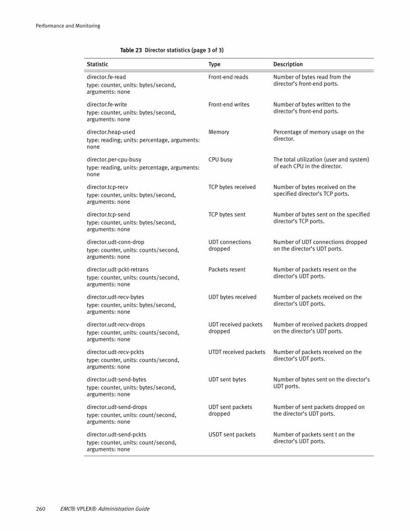
Performance and Monitoring
director.fe-readtype: counter, units: bytes/second, arguments: none
Front-end reads Number of bytes read from the director’s front-end ports.
director.fe-writetype: counter, units: bytes/second, arguments: none
Front-end writes Number of bytes written to the director’s front-end ports.
director.heap-usedtype: reading; units: percentage, arguments: none
Memory Percentage of memory usage on the director.
director.per-cpu-busy type: reading, units: percentage, arguments: none
CPU busy The total utilization (user and system) of each CPU in the director.
director.tcp-recvtype: counter, units: bytes/second, arguments: none
TCP bytes received Number of bytes received on the specified director’s TCP ports.
director.tcp-sendtype: counter, units: bytes/second, arguments: none
TCP bytes sent Number of bytes sent on the specified director’s TCP ports.
director.udt-conn-droptype: counter, units: counts/second, arguments: none
UDT connections dropped
Number of UDT connections dropped on the director’s UDT ports.
director.udt-pckt-retranstype: counter, units: counts/second, arguments: none
Packets resent Number of packets resent on the director’s UDT ports.
director.udt-recv-bytestype: counter, units: bytes/second, arguments: none
UDT bytes received Number of packets received on the director’s UDT ports.
director.udt-recv-drops type: counter, units: counts/second, arguments: none
UDT received packets dropped
Number of received packets dropped on the director’s UDT ports.
director.udt-recv-pcktstype: counter, units: counts/second, arguments: none
UTDT received packets Number of packets received on the director’s UDT ports.
director.udt-send-bytes type: counter, units: bytes/second, arguments: none
UDT sent bytes Number of bytes sent on the director’s UDT ports.
director.udt-send-dropstype: counter, units: count/second, arguments: none
UDT sent packets dropped
Number of sent packets dropped on the director’s UDT ports.
director.udt-send-pcktstype: counter, units: count/second, arguments: none
USDT sent packets Number of packets sent t on the director’s UDT ports.
Table 23 Director statistics (page 3 of 3)
Statistic Type Description
260 EMC® VPLEX® Administration Guide
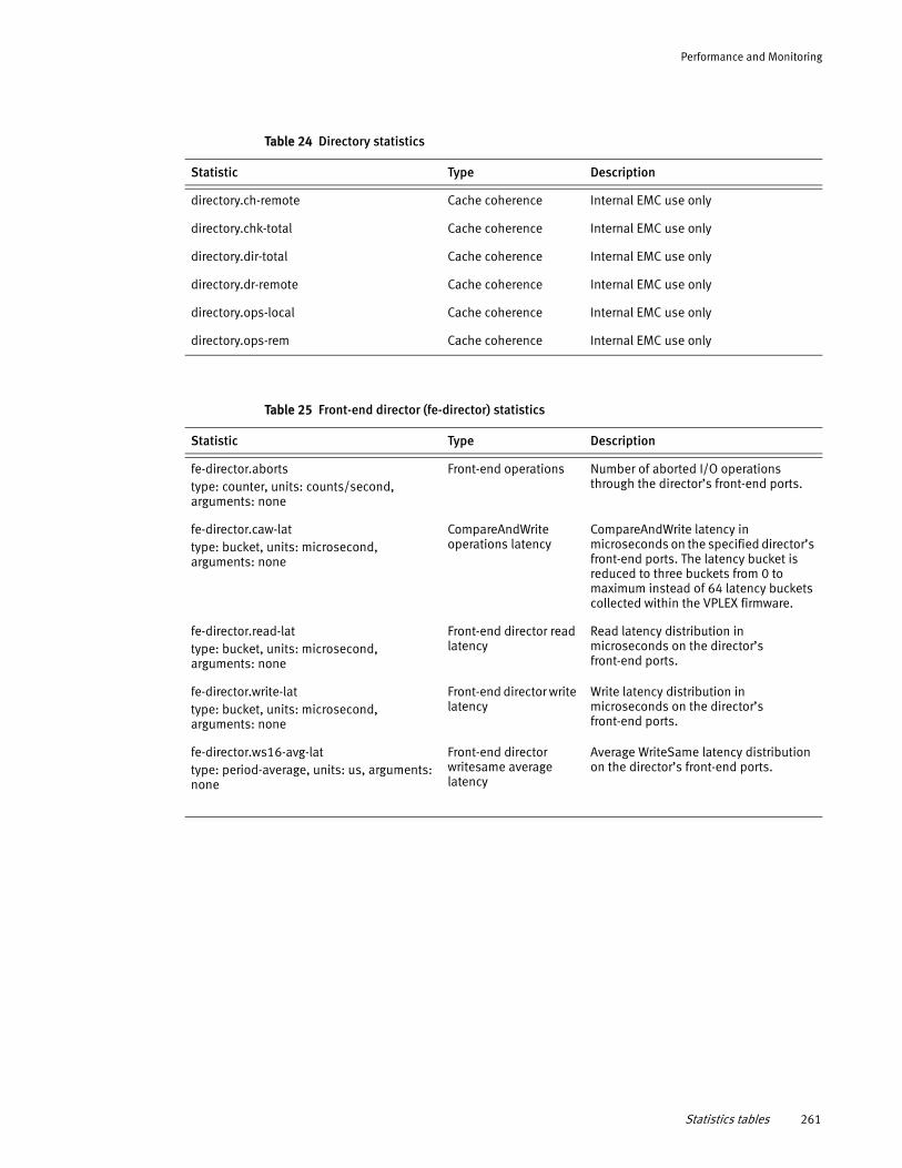
Performance and Monitoring
Table 24 Directory statistics
Statistic Type Description
directory.ch-remote Cache coherence Internal EMC use only
directory.chk-total Cache coherence Internal EMC use only
directory.dir-total Cache coherence Internal EMC use only
directory.dr-remote Cache coherence Internal EMC use only
directory.ops-local Cache coherence Internal EMC use only
directory.ops-rem Cache coherence Internal EMC use only
Table 25 Front-end director (fe-director) statistics
Statistic Type Description
fe-director.aborts type: counter, units: counts/second, arguments: none
Front-end operations Number of aborted I/O operations through the director’s front-end ports.
fe-director.caw-lat type: bucket, units: microsecond, arguments: none
CompareAndWrite operations latency
CompareAndWrite latency in microseconds on the specified director’s front-end ports. The latency bucket is reduced to three buckets from 0 to maximum instead of 64 latency buckets collected within the VPLEX firmware.
fe-director.read-lattype: bucket, units: microsecond, arguments: none
Front-end director read latency
Read latency distribution in microseconds on the director’s front-end ports.
fe-director.write-lattype: bucket, units: microsecond, arguments: none
Front-end director write latency
Write latency distribution in microseconds on the director’s front-end ports.
fe-director.ws16-avg-lattype: period-average, units: us, arguments: none
Front-end director writesame average latency
Average WriteSame latency distribution on the director’s front-end ports.
Statistics tables 261
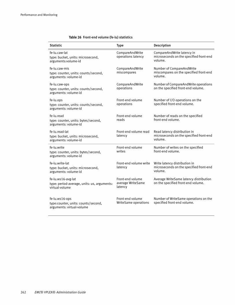
Performance and Monitoring
Table 26 Front-end volume (fe-lu) statistics
Statistic Type Description
fe-lu.caw-lat type: bucket, units: microsecond, arguments:volume-id
CompareAndWrite operations latency
CompareAndWrite latency in microseconds on the specified front-end volume.
fe-lu.caw-mistype: counter, units: counts/second, arguments: volume-id
CompareAndWrite miscompares
Number of CompareAndWrite miscompares on the specified front-end volume.
fe-lu.caw-opstype: counter, units: counts/second, arguments: volume-id
CompareAndWrite operations
Number of CompareAndWrite operations on the specified front-end volume.
fe-lu.opstype: counter, units: counts/second, arguments: volume-id
Front-end volume operations
Number of I/O operations on the specified front-end volume.
fe-lu.read type: counter, units: bytes/second, arguments: volume-id
Front-end volume reads
Number of reads on the specified front-end volume.
fe-lu.read-lattype: bucket, units: microsecond, arguments: volume-id
Front-end volume read latency
Read latency distribution in microseconds on the specified front-end volume.
fe-lu.writetype: counter, units: bytes/second, arguments: volume-id
Front-end volume writes
Number of writes on the specified front-end volume.
fe-lu.write-lattype: bucket, units: microsecond, arguments: volume-id
Front-end volume write latency
Write latency distribution in microseconds on the specified front-end volume.
fe-lu.ws16-avg-lat type: period-average, units: us, arguments: virtual-volume
Front-end volume average WriteSame latency
Average WriteSame latency distribution on the specified front-end volume.
fe-lu.ws16-opstype:counter, units: counts/second, arguments: virtual-volume
Front-end volume WriteSame operations
Number of WriteSame operations on the specified front-end volume.
262 EMC® VPLEX® Administration Guide
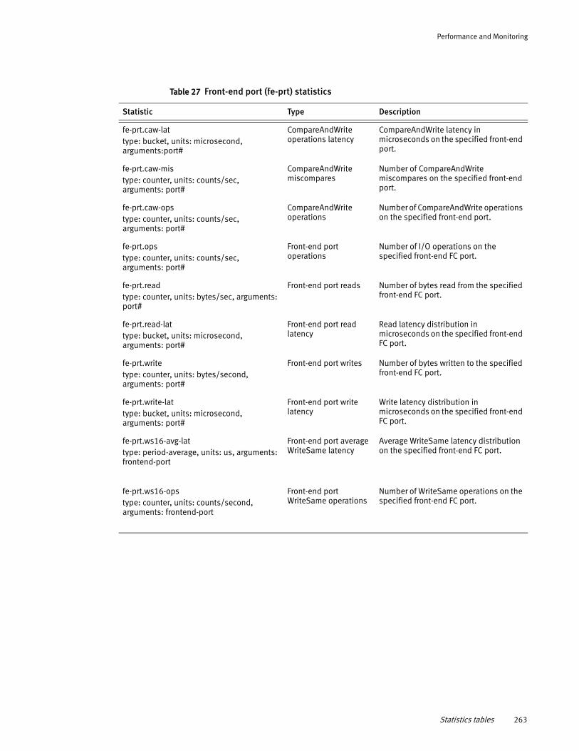
Performance and Monitoring
Table 27 Front-end port (fe-prt) statistics
Statistic Type Description
fe-prt.caw-lat type: bucket, units: microsecond, arguments:port#
CompareAndWrite operations latency
CompareAndWrite latency in microseconds on the specified front-end port.
fe-prt.caw-mistype: counter, units: counts/sec, arguments: port#
CompareAndWrite miscompares
Number of CompareAndWrite miscompares on the specified front-end port.
fe-prt.caw-opstype: counter, units: counts/sec, arguments: port#
CompareAndWrite operations
Number of CompareAndWrite operations on the specified front-end port.
fe-prt.opstype: counter, units: counts/sec, arguments: port#
Front-end port operations
Number of I/O operations on the specified front-end FC port.
fe-prt.readtype: counter, units: bytes/sec, arguments: port#
Front-end port reads Number of bytes read from the specified front-end FC port.
fe-prt.read-lattype: bucket, units: microsecond, arguments: port#
Front-end port read latency
Read latency distribution in microseconds on the specified front-end FC port.
fe-prt.writetype: counter, units: bytes/second, arguments: port#
Front-end port writes Number of bytes written to the specified front-end FC port.
fe-prt.write-lattype: bucket, units: microsecond, arguments: port#
Front-end port write latency
Write latency distribution in microseconds on the specified front-end FC port.
fe-prt.ws16-avg-lattype: period-average, units: us, arguments: frontend-port
Front-end port average WriteSame latency
Average WriteSame latency distribution on the specified front-end FC port.
fe-prt.ws16-ops type: counter, units: counts/second, arguments: frontend-port
Front-end port WriteSame operations
Number of WriteSame operations on the specified front-end FC port.
Statistics tables 263
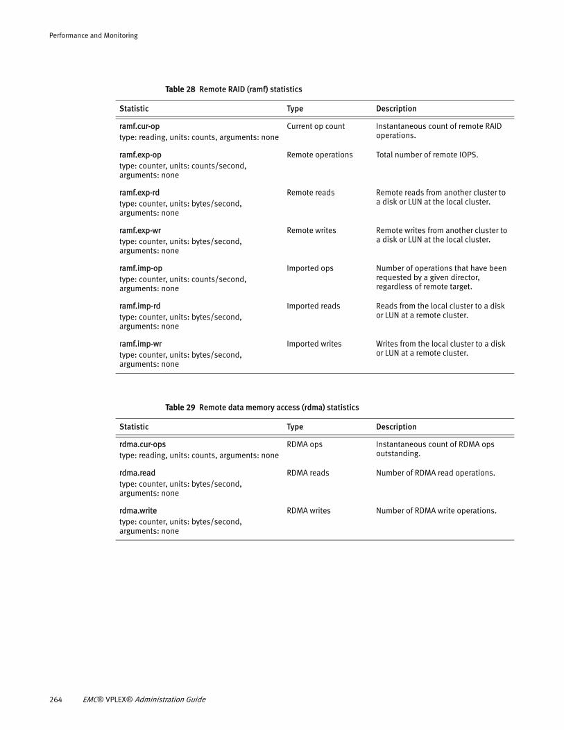
Performance and Monitoring
Table 28 Remote RAID (ramf) statistics
Statistic Type Description
ramf.cur-optype: reading, units: counts, arguments: none
Current op count Instantaneous count of remote RAID operations.
ramf.exp-optype: counter, units: counts/second, arguments: none
Remote operations Total number of remote IOPS.
ramf.exp-rdtype: counter, units: bytes/second, arguments: none
Remote reads Remote reads from another cluster to a disk or LUN at the local cluster.
ramf.exp-wrtype: counter, units: bytes/second, arguments: none
Remote writes Remote writes from another cluster to a disk or LUN at the local cluster.
ramf.imp-optype: counter, units: counts/second, arguments: none
Imported ops Number of operations that have been requested by a given director, regardless of remote target.
ramf.imp-rdtype: counter, units: bytes/second, arguments: none
Imported reads Reads from the local cluster to a disk or LUN at a remote cluster.
ramf.imp-wrtype: counter, units: bytes/second, arguments: none
Imported writes Writes from the local cluster to a disk or LUN at a remote cluster.
Table 29 Remote data memory access (rdma) statistics
Statistic Type Description
rdma.cur-opstype: reading, units: counts, arguments: none
RDMA ops Instantaneous count of RDMA ops outstanding.
rdma.readtype: counter, units: bytes/second, arguments: none
RDMA reads Number of RDMA read operations.
rdma.writetype: counter, units: bytes/second, arguments: none
RDMA writes Number of RDMA write operations.
264 EMC® VPLEX® Administration Guide
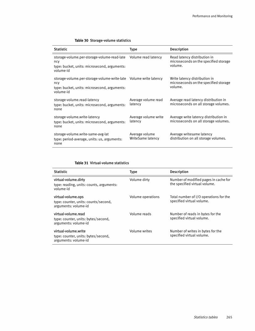
Performance and Monitoring
Table 30 Storage-volume statistics
Statistic Type Description
storage-volume.per-storage-volume-read-latency type: bucket, units: microsecond, arguments: volume-id
Volume read latency Read latency distribution in microseconds on the specified storage volume.
storage-volume.per-storage-volume-write-latency type: bucket, units: microsecond, arguments: volume-id
Volume write latency Write latency distribution in microseconds on the specified storage volume.
storage-volume.read-latencytype: bucket, units: microsecond, arguments: none
Average volume read latency
Average read latency distribution in microseconds on all storage volumes.
storage-volume.write-latency type: bucket, units: microsecond, arguments: none
Average volume write latency
Average write latency distribution in microseconds on all storage volumes.
storage-volume.write-same-avg-lattype: period-average, units: us, arguments: none
Average volume WriteSame latency
Average writesame latency distribution on all storage volumes.
Table 31 Virtual-volume statistics
Statistic Type Description
virtual-volume.dirtytype: reading, units: counts, arguments: volume-id
Volume dirty Number of modified pages in cache for the specified virtual volume.
virtual-volume.opstype: counter, units: counts/second, arguments: volume-id
Volume operations Total number of I/O operations for the specified virtual volume.
virtual-volume.readtype: counter, units: bytes/second, arguments: volume-id
Volume reads Number of reads in bytes for the specified virtual volume.
virtual-volume.writetype: counter, units: bytes/second, arguments: volume-id
Volume writes Number of writes in bytes for the specified virtual volume.
Statistics tables 265
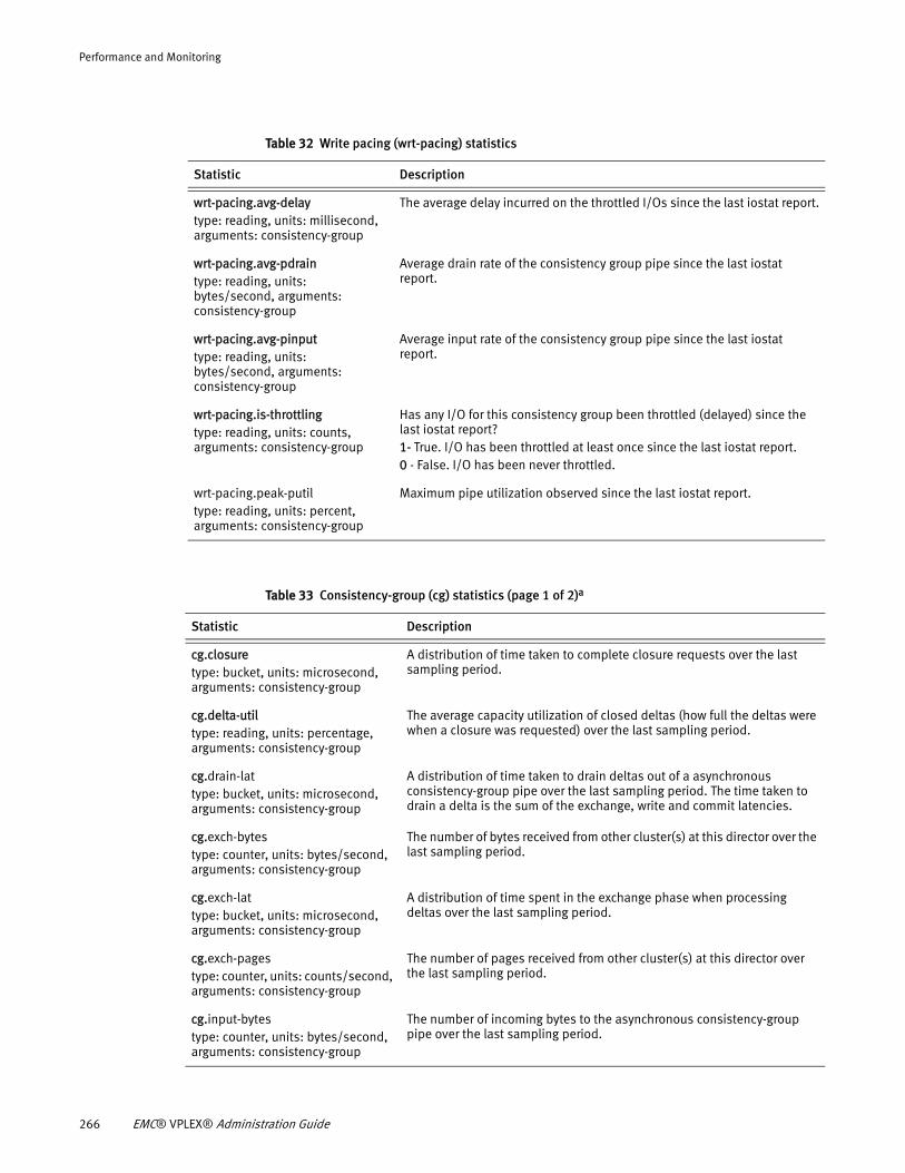
Performance and Monitoring
Table 32 Write pacing (wrt-pacing) statistics
Statistic Description
wrt-pacing.avg-delay type: reading, units: millisecond, arguments: consistency-group
The average delay incurred on the throttled I/Os since the last iostat report.
wrt-pacing.avg-pdrain type: reading, units: bytes/second, arguments: consistency-group
Average drain rate of the consistency group pipe since the last iostat report.
wrt-pacing.avg-pinputtype: reading, units: bytes/second, arguments: consistency-group
Average input rate of the consistency group pipe since the last iostat report.
wrt-pacing.is-throttlingtype: reading, units: counts, arguments: consistency-group
Has any I/O for this consistency group been throttled (delayed) since the last iostat report?1- True. I/O has been throttled at least once since the last iostat report. 0 - False. I/O has been never throttled.
wrt-pacing.peak-putil type: reading, units: percent, arguments: consistency-group
Maximum pipe utilization observed since the last iostat report.
Table 33 Consistency-group (cg) statistics (page 1 of 2)a
Statistic Description
cg.closure type: bucket, units: microsecond, arguments: consistency-group
A distribution of time taken to complete closure requests over the last sampling period.
cg.delta-utiltype: reading, units: percentage, arguments: consistency-group
The average capacity utilization of closed deltas (how full the deltas were when a closure was requested) over the last sampling period.
cg.drain-lat type: bucket, units: microsecond, arguments: consistency-group
A distribution of time taken to drain deltas out of a asynchronous consistency-group pipe over the last sampling period. The time taken to drain a delta is the sum of the exchange, write and commit latencies.
cg.exch-bytestype: counter, units: bytes/second, arguments: consistency-group
The number of bytes received from other cluster(s) at this director over the last sampling period.
cg.exch-lattype: bucket, units: microsecond, arguments: consistency-group
A distribution of time spent in the exchange phase when processing deltas over the last sampling period.
cg.exch-pagestype: counter, units: counts/second, arguments: consistency-group
The number of pages received from other cluster(s) at this director over the last sampling period.
cg.input-bytestype: counter, units: bytes/second, arguments: consistency-group
The number of incoming bytes to the asynchronous consistency-group pipe over the last sampling period.
266 EMC® VPLEX® Administration Guide
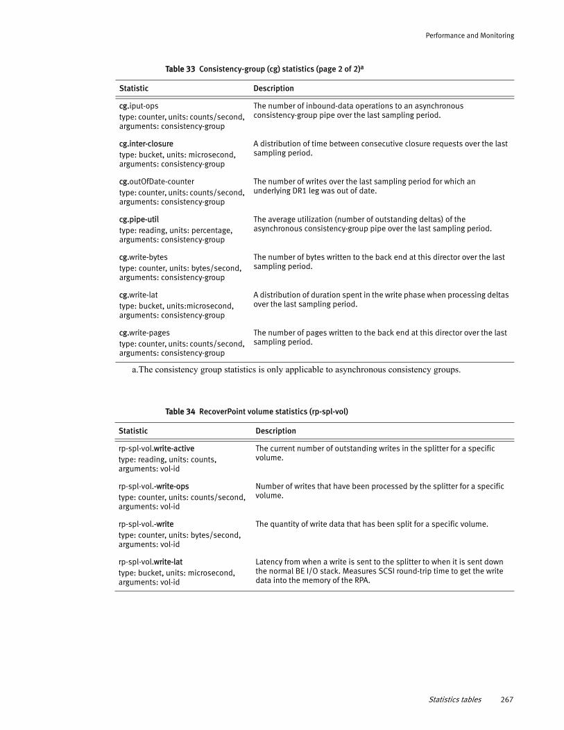
Performance and Monitoring
cg.iput-opstype: counter, units: counts/second, arguments: consistency-group
The number of inbound-data operations to an asynchronous consistency-group pipe over the last sampling period.
cg.inter-closure type: bucket, units: microsecond, arguments: consistency-group
A distribution of time between consecutive closure requests over the last sampling period.
cg.outOfDate-countertype: counter, units: counts/second, arguments: consistency-group
The number of writes over the last sampling period for which an underlying DR1 leg was out of date.
cg.pipe-utiltype: reading, units: percentage, arguments: consistency-group
The average utilization (number of outstanding deltas) of the asynchronous consistency-group pipe over the last sampling period.
cg.write-bytestype: counter, units: bytes/second, arguments: consistency-group
The number of bytes written to the back end at this director over the last sampling period.
cg.write-lattype: bucket, units:microsecond, arguments: consistency-group
A distribution of duration spent in the write phase when processing deltas over the last sampling period.
cg.write-pagestype: counter, units: counts/second, arguments: consistency-group
The number of pages written to the back end at this director over the last sampling period.
a.The consistency group statistics is only applicable to asynchronous consistency groups.
Table 33 Consistency-group (cg) statistics (page 2 of 2)a
Statistic Description
Table 34 RecoverPoint volume statistics (rp-spl-vol)
Statistic Description
rp-spl-vol.write-active type: reading, units: counts, arguments: vol-id
The current number of outstanding writes in the splitter for a specific volume.
rp-spl-vol.-write-opstype: counter, units: counts/second, arguments: vol-id
Number of writes that have been processed by the splitter for a specific volume.
rp-spl-vol.-writetype: counter, units: bytes/second, arguments: vol-id
The quantity of write data that has been split for a specific volume.
rp-spl-vol.write-lattype: bucket, units: microsecond, arguments: vol-id
Latency from when a write is sent to the splitter to when it is sent down the normal BE I/O stack. Measures SCSI round-trip time to get the write data into the memory of the RPA.
Statistics tables 267
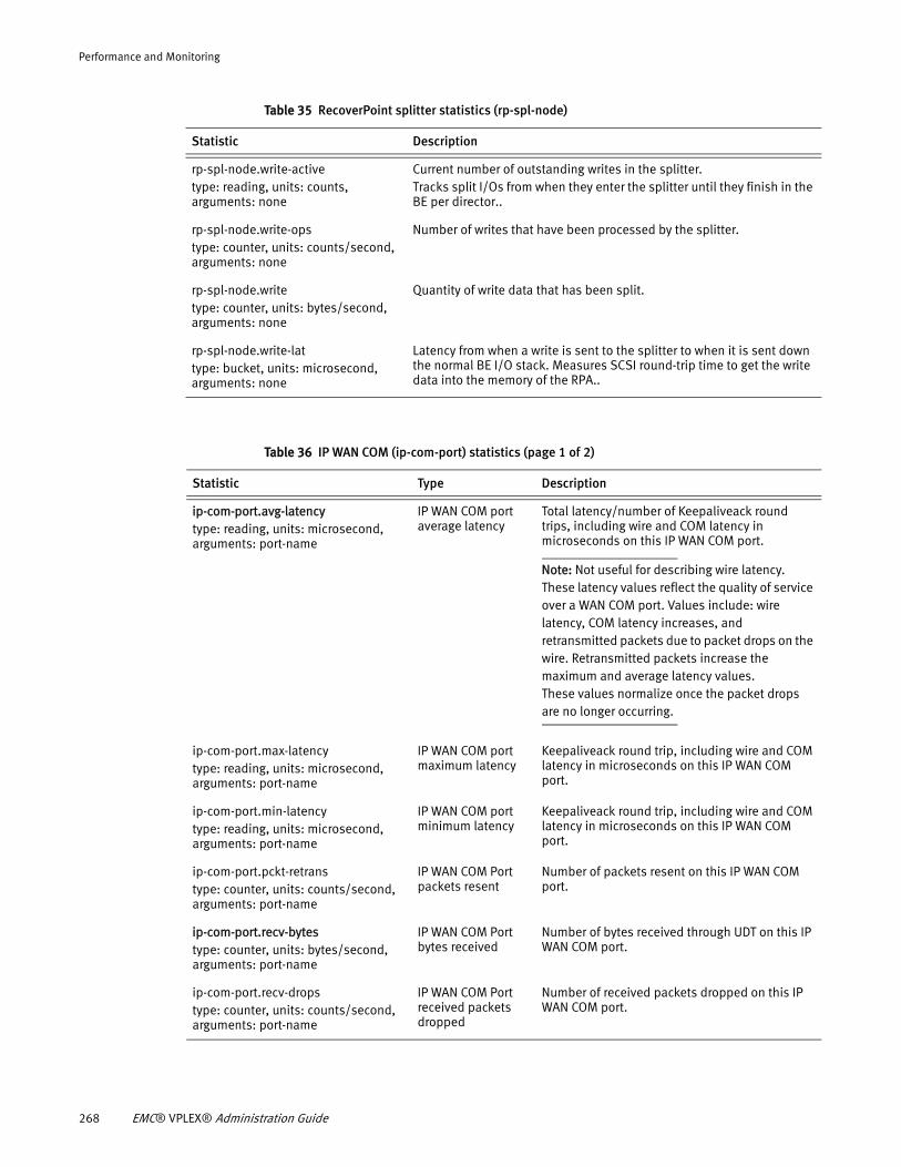
Performance and Monitoring
Table 35 RecoverPoint splitter statistics (rp-spl-node)
Statistic Description
rp-spl-node.write-active type: reading, units: counts, arguments: none
Current number of outstanding writes in the splitter.Tracks split I/Os from when they enter the splitter until they finish in the BE per director..
rp-spl-node.write-ops type: counter, units: counts/second, arguments: none
Number of writes that have been processed by the splitter.
rp-spl-node.write type: counter, units: bytes/second, arguments: none
Quantity of write data that has been split.
rp-spl-node.write-lat type: bucket, units: microsecond, arguments: none
Latency from when a write is sent to the splitter to when it is sent down the normal BE I/O stack. Measures SCSI round-trip time to get the write data into the memory of the RPA..
Table 36 IP WAN COM (ip-com-port) statistics (page 1 of 2)
Statistic Type Description
ip-com-port.avg-latency type: reading, units: microsecond, arguments: port-name
IP WAN COM port average latency
Total latency/number of Keepaliveack round trips, including wire and COM latency in microseconds on this IP WAN COM port.
Note: Not useful for describing wire latency. These latency values reflect the quality of service over a WAN COM port. Values include: wire latency, COM latency increases, and retransmitted packets due to packet drops on the wire. Retransmitted packets increase the maximum and average latency values.These values normalize once the packet drops are no longer occurring.
ip-com-port.max-latency type: reading, units: microsecond, arguments: port-name
IP WAN COM port maximum latency
Keepaliveack round trip, including wire and COM latency in microseconds on this IP WAN COM port.
ip-com-port.min-latency type: reading, units: microsecond, arguments: port-name
IP WAN COM port minimum latency
Keepaliveack round trip, including wire and COM latency in microseconds on this IP WAN COM port.
ip-com-port.pckt-retrans type: counter, units: counts/second, arguments: port-name
IP WAN COM Port packets resent
Number of packets resent on this IP WAN COM port.
ip-com-port.recv-bytes type: counter, units: bytes/second, arguments: port-name
IP WAN COM Port bytes received
Number of bytes received through UDT on this IP WAN COM port.
ip-com-port.recv-drops type: counter, units: counts/second, arguments: port-name
IP WAN COM Port received packets dropped
Number of received packets dropped on this IP WAN COM port.
268 EMC® VPLEX® Administration Guide
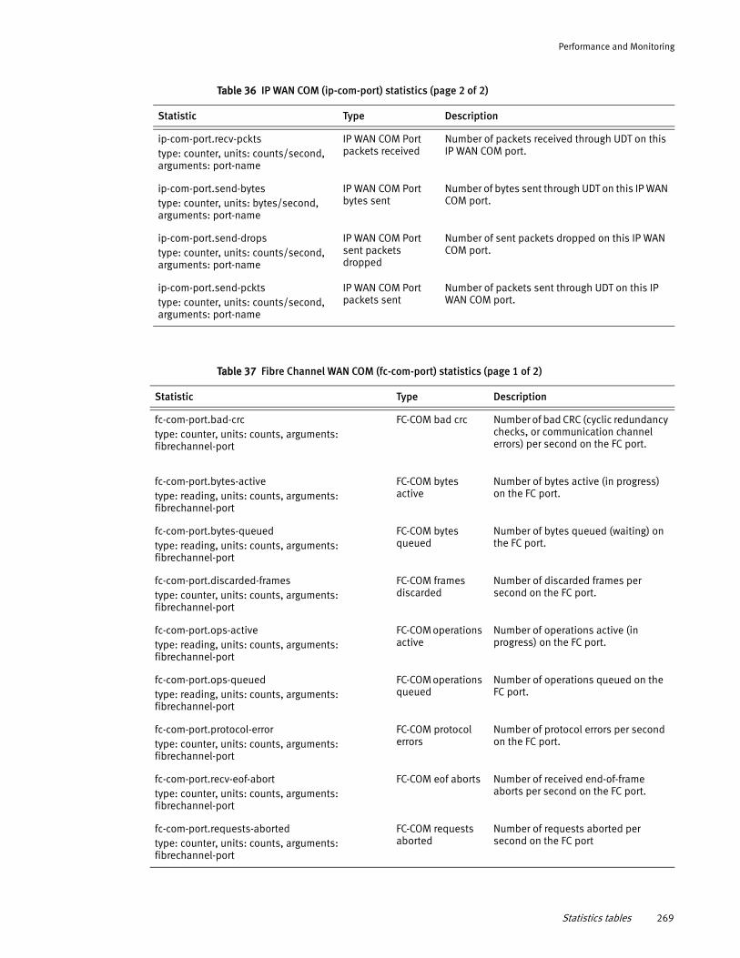
Performance and Monitoring
ip-com-port.recv-pcktstype: counter, units: counts/second, arguments: port-name
IP WAN COM Port packets received
Number of packets received through UDT on this IP WAN COM port.
ip-com-port.send-bytes type: counter, units: bytes/second, arguments: port-name
IP WAN COM Port bytes sent
Number of bytes sent through UDT on this IP WAN COM port.
ip-com-port.send-drops type: counter, units: counts/second, arguments: port-name
IP WAN COM Port sent packets dropped
Number of sent packets dropped on this IP WAN COM port.
ip-com-port.send-pcktstype: counter, units: counts/second, arguments: port-name
IP WAN COM Port packets sent
Number of packets sent through UDT on this IP WAN COM port.
Table 36 IP WAN COM (ip-com-port) statistics (page 2 of 2)
Statistic Type Description
Table 37 Fibre Channel WAN COM (fc-com-port) statistics (page 1 of 2)
Statistic Type Description
fc-com-port.bad-crctype: counter, units: counts, arguments: fibrechannel-port
FC-COM bad crc Number of bad CRC (cyclic redundancy checks, or communication channel errors) per second on the FC port.
fc-com-port.bytes-active type: reading, units: counts, arguments: fibrechannel-port
FC-COM bytes active
Number of bytes active (in progress) on the FC port.
fc-com-port.bytes-queued type: reading, units: counts, arguments: fibrechannel-port
FC-COM bytes queued
Number of bytes queued (waiting) on the FC port.
fc-com-port.discarded-framestype: counter, units: counts, arguments: fibrechannel-port
FC-COM frames discarded
Number of discarded frames per second on the FC port.
fc-com-port.ops-active type: reading, units: counts, arguments: fibrechannel-port
FC-COM operations active
Number of operations active (in progress) on the FC port.
fc-com-port.ops-queued type: reading, units: counts, arguments: fibrechannel-port
FC-COM operations queued
Number of operations queued on the FC port.
fc-com-port.protocol-errortype: counter, units: counts, arguments: fibrechannel-port
FC-COM protocol errors
Number of protocol errors per second on the FC port.
fc-com-port.recv-eof-aborttype: counter, units: counts, arguments: fibrechannel-port
FC-COM eof aborts Number of received end-of-frame aborts per second on the FC port.
fc-com-port.requests-abortedtype: counter, units: counts, arguments: fibrechannel-port
FC-COM requests aborted
Number of requests aborted per second on the FC port
Statistics tables 269
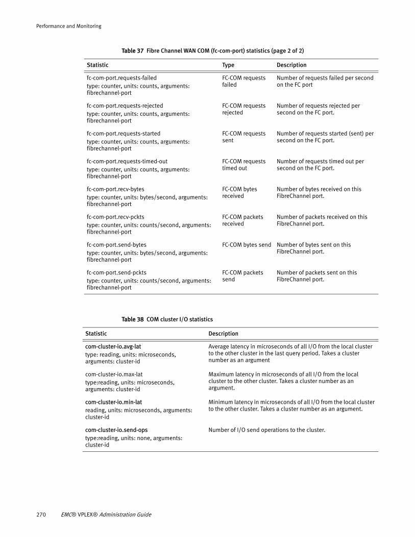
Performance and Monitoring
fc-com-port.requests-failedtype: counter, units: counts, arguments: fibrechannel-port
FC-COM requests failed
Number of requests failed per second on the FC port
fc-com-port.requests-rejected type: counter, units: counts, arguments: fibrechannel-port
FC-COM requests rejected
Number of requests rejected per second on the FC port.
fc-com-port.requests-startedtype: counter, units: counts, arguments: fibrechannel-port
FC-COM requests sent
Number of requests started (sent) per second on the FC port.
fc-com-port.requests-timed-outtype: counter, units: counts, arguments: fibrechannel-port
FC-COM requests timed out
Number of requests timed out per second on the FC port.
fc-com-port.recv-bytes type: counter, units: bytes/second, arguments: fibrechannel-port
FC-COM bytes received
Number of bytes received on this FibreChannel port.
fc-com-port.recv-pckts type: counter, units: counts/second, arguments: fibrechannel-port
FC-COM packets received
Number of packets received on this FibreChannel port.
fc-com-port.send-bytes type: counter, units: bytes/second, arguments: fibrechannel-port
FC-COM bytes send Number of bytes sent on this FibreChannel port.
fc-com-port.send-pckts type: counter, units: counts/second, arguments: fibrechannel-port
FC-COM packets send
Number of packets sent on this FibreChannel port.
Table 37 Fibre Channel WAN COM (fc-com-port) statistics (page 2 of 2)
Statistic Type Description
Table 38 COM cluster I/O statistics
Statistic Description
com-cluster-io.avg-lat type: reading, units: microseconds, arguments: cluster-id
Average latency in microseconds of all I/O from the local cluster to the other cluster in the last query period. Takes a cluster number as an argument
com-cluster-io.max-lat type:reading, units: microseconds, arguments: cluster-id
Maximum latency in microseconds of all I/O from the local cluster to the other cluster. Takes a cluster number as an argument.
com-cluster-io.min-lat reading, units: microseconds, arguments: cluster-id
Minimum latency in microseconds of all I/O from the local cluster to the other cluster. Takes a cluster number as an argument.
com-cluster-io.send-opstype:reading, units: none, arguments: cluster-id
Number of I/O send operations to the cluster.
270 EMC® VPLEX® Administration Guide
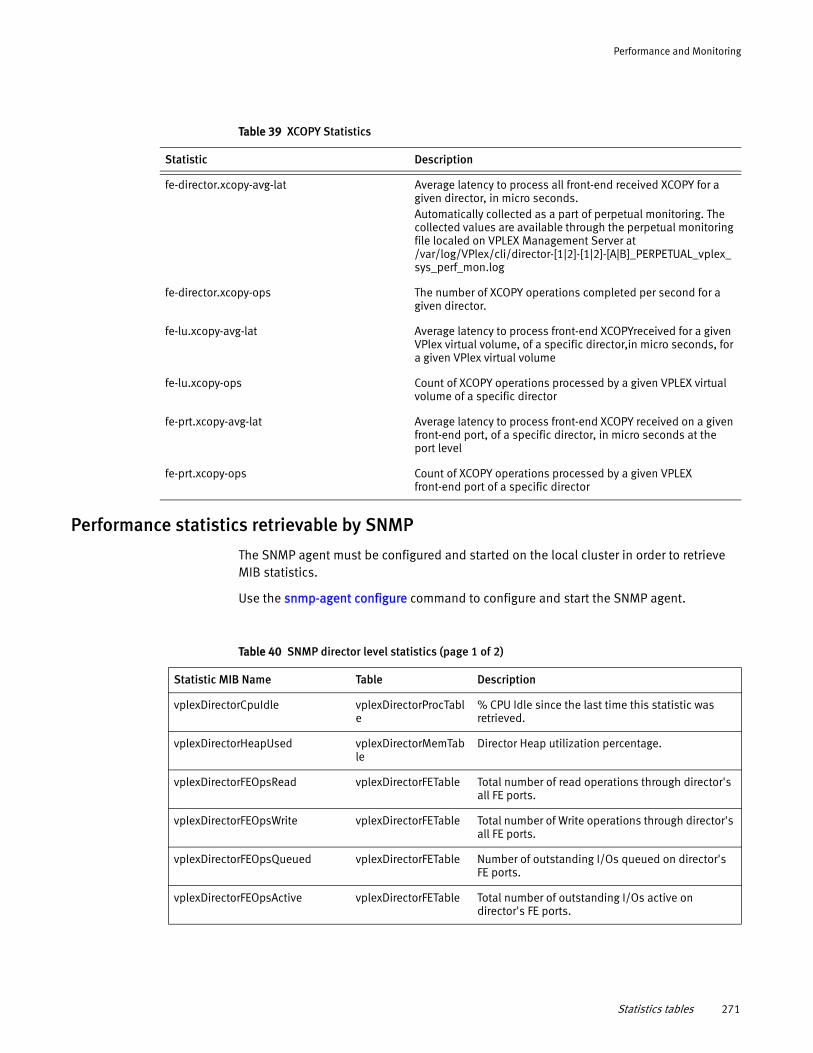
Performance and Monitoring
Performance statistics retrievable by SNMP
The SNMP agent must be configured and started on the local cluster in order to retrieve MIB statistics.
Use the snmp-agent configure command to configure and start the SNMP agent.
Table 39 XCOPY Statistics
Statistic Description
fe-director.xcopy-avg-lat Average latency to process all front-end received XCOPY for a given director, in micro seconds. Automatically collected as a part of perpetual monitoring. The collected values are available through the perpetual monitoring file localed on VPLEX Management Server at /var/log/VPlex/cli/director-[1|2]-[1|2]-[A|B]_PERPETUAL_vplex_sys_perf_mon.log
fe-director.xcopy-ops The number of XCOPY operations completed per second for a given director.
fe-lu.xcopy-avg-lat Average latency to process front-end XCOPYreceived for a given VPlex virtual volume, of a specific director,in micro seconds, for a given VPlex virtual volume
fe-lu.xcopy-ops Count of XCOPY operations processed by a given VPLEX virtual volume of a specific director
fe-prt.xcopy-avg-lat Average latency to process front-end XCOPY received on a given front-end port, of a specific director, in micro seconds at the port level
fe-prt.xcopy-ops Count of XCOPY operations processed by a given VPLEX front-end port of a specific director
Table 40 SNMP director level statistics (page 1 of 2)
Statistic MIB Name Table Description
vplexDirectorCpuIdle vplexDirectorProcTable
% CPU Idle since the last time this statistic was retrieved.
vplexDirectorHeapUsed vplexDirectorMemTable
Director Heap utilization percentage.
vplexDirectorFEOpsRead vplexDirectorFETable Total number of read operations through director's all FE ports.
vplexDirectorFEOpsWrite vplexDirectorFETable Total number of Write operations through director's all FE ports.
vplexDirectorFEOpsQueued vplexDirectorFETable Number of outstanding I/Os queued on director's FE ports.
vplexDirectorFEOpsActive vplexDirectorFETable Total number of outstanding I/Os active on director's FE ports.
Statistics tables 271
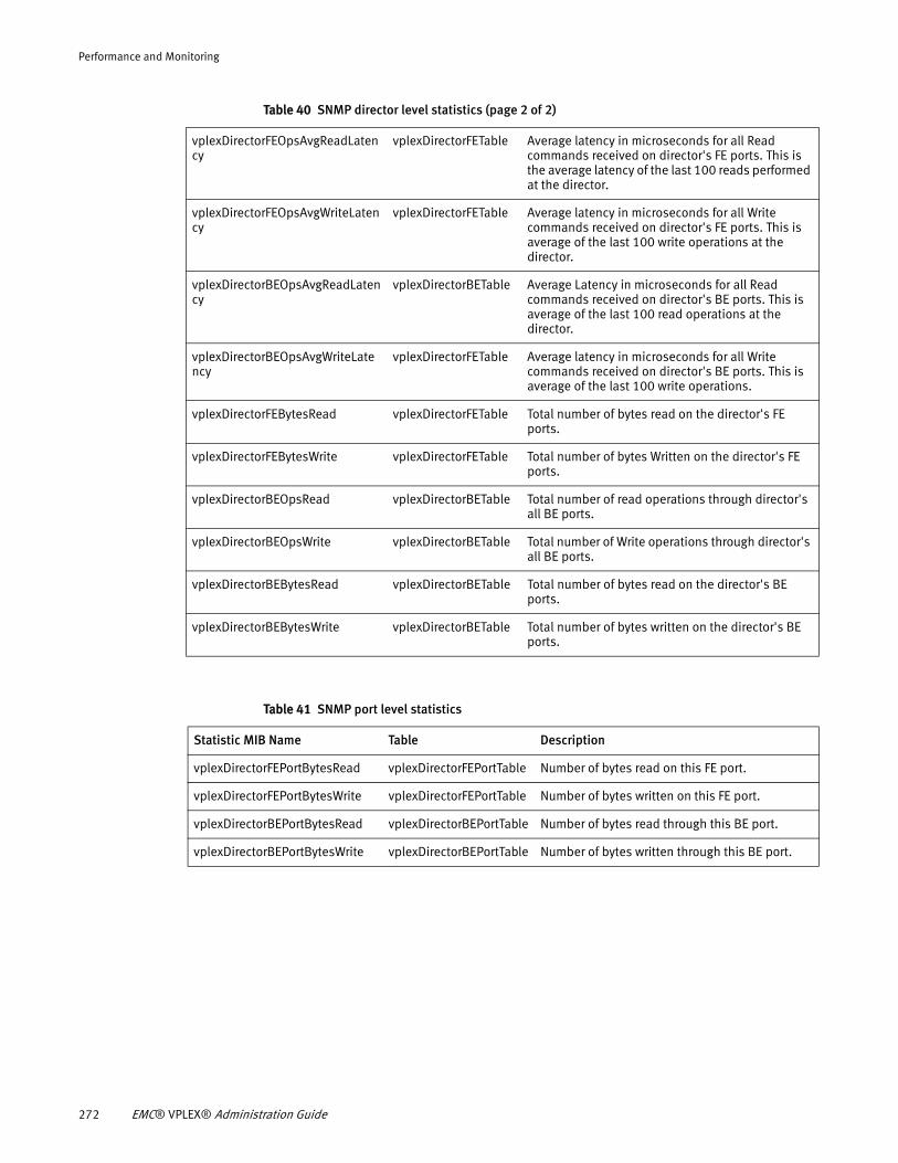
Performance and Monitoring
vplexDirectorFEOpsAvgReadLatency
vplexDirectorFETable Average latency in microseconds for all Read commands received on director's FE ports. This is the average latency of the last 100 reads performed at the director.
vplexDirectorFEOpsAvgWriteLatency
vplexDirectorFETable Average latency in microseconds for all Write commands received on director's FE ports. This is average of the last 100 write operations at the director.
vplexDirectorBEOpsAvgReadLatency
vplexDirectorBETable Average Latency in microseconds for all Read commands received on director's BE ports. This is average of the last 100 read operations at the director.
vplexDirectorBEOpsAvgWriteLatency
vplexDirectorFETable Average latency in microseconds for all Write commands received on director's BE ports. This is average of the last 100 write operations.
vplexDirectorFEBytesRead vplexDirectorFETable Total number of bytes read on the director's FE ports.
vplexDirectorFEBytesWrite vplexDirectorFETable Total number of bytes Written on the director's FE ports.
vplexDirectorBEOpsRead vplexDirectorBETable Total number of read operations through director's all BE ports.
vplexDirectorBEOpsWrite vplexDirectorBETable Total number of Write operations through director's all BE ports.
vplexDirectorBEBytesRead vplexDirectorBETable Total number of bytes read on the director's BE ports.
vplexDirectorBEBytesWrite vplexDirectorBETable Total number of bytes written on the director's BE ports.
Table 40 SNMP director level statistics (page 2 of 2)
Table 41 SNMP port level statistics
Statistic MIB Name Table Description
vplexDirectorFEPortBytesRead vplexDirectorFEPortTable Number of bytes read on this FE port.
vplexDirectorFEPortBytesWrite vplexDirectorFEPortTable Number of bytes written on this FE port.
vplexDirectorBEPortBytesRead vplexDirectorBEPortTable Number of bytes read through this BE port.
vplexDirectorBEPortBytesWrite vplexDirectorBEPortTable Number of bytes written through this BE port.
272 EMC® VPLEX® Administration Guide
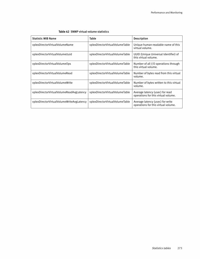
Performance and Monitoring
Table 42 SNMP virtual volume statistics
Statistic MIB Name Table Description
vplexDirectorVirtualVolumeName vplexDirectorVirtualVolumeTable Unique human-readable name of this virtual volume.
vplexDirectorVirtualVolumeUuid vplexDirectorVirtualVolumeTable UUID (Unique Universal Identifier) of this virtual volume.
vplexDirectorVirtualVolumeOps vplexDirectorVirtualVolumeTable Number of all I/O operations through this virtual volume.
vplexDirectorVirtualVolumeRead vplexDirectorVirtualVolumeTable Number of bytes read from this virtual volume.
vplexDirectorVirtualVolumeWrite vplexDirectorVirtualVolumeTable Number of bytes written to this virtual volume.
vplexDirectorVirtualVolumeReadAvgLatency vplexDirectorVirtualVolumeTable Average latency (usec) for read operations for this virtual volume.
vplexDirectorVirtualVolumeWriteAvgLatency vplexDirectorVirtualVolumeTable Average latency (usec) for write operations for this virtual volume.
Statistics tables 273

Performance and Monitoring
274 EMC® VPLEX® Administration Guide
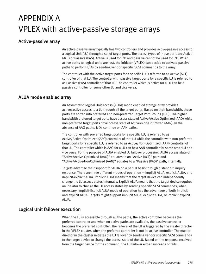
APPENDIX AVPLEX with active-passive storage arraysActive-passive array
An active-passive array typically has two controllers and provides active-passive access to a Logical Unit (LU) through a set of target ports. The access types of these ports are Active (ACT) or Passive (PAS). Active is used for I/O and passive cannot be used for I/O. When active paths to logical units are lost, the initiator (VPLEX) can decide to activate passive paths to perform I/Os by sending vendor specific SCSI commands to the array.
The controller with the active target ports for a specific LU is referred to as Active (ACT) controller of that LU. The controller with passive target ports for a specific LU is referred to as Passive (PAS) controller of that LU. The controller which is active for a LU can be a passive controller for some other LU and vice versa.
ALUA mode enabled array
An Asymmetric Logical Unit Access (ALUA) mode enabled storage array provides active/active access to a LU through all the target ports. Based on their bandwidth, these ports are sorted into preferred and non-preferred Target Port Groups (TPG). The higher bandwidth preferred target ports have access state of Active/Active Optimized (AAO) while non-preferred target ports have access state of Active/Non-Optimized (AAN). In the absence of AAO paths, I/Os continue on AAN paths.
The controller with preferred target ports for a specific LU, is referred to as Active/Active-Optimized (AAO) controller of that LU while the controller with non-preferred target ports for a specific LU, is referred to as Active/Non-Optimized (AAN) controller of that LU. The controller which is AAO for a LU can be a AAN controller for some other LU and vice versa. For the purpose of ALUA enabled LU failover processing, ALUA access state of “Active/Active-Optimized (AAO)” equates to an “Active (ACT)” path and “Active/Active-NonOptimized (AAN)” equates to a “Passive (PAS)” path, internally.
Targets advertise their support for ALUA on a per LU basis through a standard inquiry response. There are three different modes of operation — implicit ALUA, explicit ALUA, and implicit-explicit ALUA. Implicit ALUA means that the target device can independently change the LU access states internally. Explicit ALUA means that the target device requires an initiator to change the LU access states by sending specific SCSI commands, when necessary. Implicit-Explicit ALUA mode of operation has the advantage of both implicit and explicit ALUA. Targets might support implicit ALUA, explicit ALUA, or implicit-explicit ALUA.
Logical Unit failover execution
When the LU is accessible through all the paths, the active controller becomes the preferred controller and when no active paths are available, the passive controller becomes the preferred controller. The failover of the LU is triggered by the master director in the VPLEX cluster, when the preferred controller is not its active controller. The master director in the cluster initiates the LU failover by sending vendor specific SCSI commands to the target device to change the access state of the LU. Based on the response received from the target device for the command, the LU failover either succeeds or fails.
VPLEX with active-passive storage arrays 275
VPLEX with active-passive storage arrays
When failover is initiated for a specific LU on an array to a specific target controller as active, VPLEX firmware event apf/3 is observed. When failover succeeds or fails for a specific LU on an array to specific target controller as active, VPLEX firmware event apf/4 event is generated.
For Example:
apf/3 Failover initiated for logical unit VPD83T3:6006016015a0320061d7f2b300d3e211 on array EMC~CLARiiON~FNM00124500474 to target controller FNM00124500474.SPA as active.
apf/4 Failover succeeded for logical unit VPD83T3:6006016015a0320061d7f2b300d3e211 on array EMC~CLARiiON~FNM00124500474 to target controller FNM00124500474.SPA as active.
apf/4 Failover failed for logical unit VPD83T3:600601606bb72200f01fb4fa1e22e311 on array EMC~CLARiiON~FCNCH072602809 to target controller FCNCH072602809.SPA as active. reason: Scsi mode select command failed
Similar entries can be found in the VPLEX firmware event log /var/log/VPlex/cli/firmware.log* on a running management server.
Logical Unit failback
When the status of the logical unit becomes nominal, VPLEX automatically attempts to fail back the LU to its default controller. This is usually defined as the owner of the LU as determined by the array. The LU failover execution process is started again in order to optimize the performance on the storage array side. This failback occurs only if the array has the “autoswitch” property enabled and the LU is visible through the controller.
Note: The EMC Simple Support Matrix (ESSM) provides more information on the supported EMC storage systems and third party arrays.
276 EMC® VPLEX® Administration Guide
GLOSSARY
This glossary contains terms related to VPLEX federated storage systems. Many of these terms are used in the manuals.
A
AccessAnywhere The breakthrough technology that enables VPLEX clusters to provide access to information between clusters that are separated by distance.
active/active A cluster with no primary or standby servers, because all servers can run applications and interchangeably act as backup for one another.
Active Directory A directory service included in most Windows Server operating systems. AD authenticates and authorizes users and computers in a network of Windows domain type.
active mirror A copy of data that is part of a local or remote mirroring service.
active/passive A powered component that is ready to operate upon the failure of a primary component.
array A collection of disk drives where user data and parity data may be stored. Devices can consist of some or all of the drives within an array.
asynchronous Describes objects or events that are not coordinated in time. A process operates independently of other processes, being initiated and left for another task before being acknowledged.
For example, a host writes data to the blades and then begins other work while the data is transferred to a local disk and across the WAN asynchronously. See also ”synchronous.”
B
bandwidth The range of transmission frequencies a network can accommodate, expressed as the difference between the highest and lowest frequencies of a transmission cycle. High bandwidth allows fast or high-volume transmissions.
backend port VPLEX director port connected to storage arrays (acts as an initiator).
bias When a cluster has the bias for a given DR1, it continues to service I/O to volumes on that cluster if connectivity to the remote cluster is lost (due to cluster partition or cluster failure). The bias for a specific volume is determined by the detach rules for the volume, the detach rules for the consistency group (if the volume is a member of a consistency group) and VPLEX Witness (if VPLEX Witness is deployed).
bit A unit of information that has a binary digit value of either 0 or 1.
block The smallest amount of data that can be transferred following SCSI standards, which is traditionally 512 bytes. Virtual volumes are presented to users as a contiguous lists of blocks.
block size The actual size of a block on a device.
EMC® VPLEX® Administration Guide 277
Glossary
Bookmark A label applied to a snapshot so that the snapshot can be explicitly called (identified) during recovery processes (during image access).
Bookmarks are created through the CLI or GUI and can be created manually, by the user, or automatically, by the system. Bookmarks created automatically can be created at pre-defined intervals or in response to specific system events. Parallel bookmarks are bookmarks that are created simultaneously across multiple consistency groups.
byte Memory space used to store eight bits of data.
C
cache Temporary storage for recent writes and recently accessed data. Disk data is read through the cache so that subsequent read references are found in the cache.
cache coherency Managing the cache so data is not lost, corrupted, or overwritten. With multiple processors, data blocks may have several copies, one in the main memory and one in each of the cache memories. Cache coherency propagates the blocks of multiple users throughout the system in a timely fashion, ensuring the data blocks do not have inconsistent versions in the different processors caches.
cluster Two or more VPLEX directors forming a single fault-tolerant cluster, deployed as one to four engines.
cluster ID The identifier for each cluster in a multi-cluster deployment. The ID is assigned during installation.
cluster deployment ID A numerical cluster identifier, unique within a VPLEX cluster. By default, VPLEX clusters have a cluster deployment ID of 1. For multi-cluster deployments, all but one cluster must be reconfigured to have different cluster deployment IDs.
cluster IP seed The VPLEX IP seed is used to generate the IP addresses used by the internal components of the VPLEX. For more information about components and their IP addresses, refer to EMC VPLEX Installation and Setup Guide. Cluster ID is used by the virtualization software (inter director messaging, cluster identification).
clustering Using two or more computers to function together as a single entity. Benefits include fault tolerance and load balancing, which increases reliability and up time.
COM The intra-cluster communication (Fibre Channel). The communication used for cache coherency and replication traffic.
command line interface(CLI)
Method of operating system or application software by typing commands to perform specific tasks.
consistency group A VPLEX structure that groups together virtual volumes and applies the same detach and failover rules to all member volumes. Consistency groups ensure the common application of a set of properties to the entire group. Create consistency groups for sets of volumes that require the same I/O behavior in the event of a link failure. There are two types of consistency groups:
◆ Synchronous Consistency Groups - Use write-through (synchronous) cache mode to write data to the underlying storage before an acknowledgement is sent to the host. Dependent on latency between clusters and the application's tolerance of the latency
278 EMC® VPLEX® Administration Guide
Glossary
◆ Asynchronous Consistency Groups - Use write-back (asynchronous) cache mode to write protect data by mirroring it to the memory another director in the cluster. Data is destaged asynchronously to the back-end storage arrays. Writes are acknowledged once the data has been committed to disk in write order
continuity of operations(COOP)
The goal of establishing policies and procedures to be used during an emergency, including the ability to process, store, and transmit data before and after.
controller A device that controls the transfer of data to and from a computer and a peripheral device.
D
data sharing The ability to share access to the same data with multiple servers regardless of time and location.
detach rule Predefined rules that determine which cluster continues I/O when connectivity between clusters is lost. A cluster loses connectivity to its peer cluster due to cluster partition or cluster failure.
Detach rules are applied at two levels; to individual volumes, and to consistency groups. If a volume is a member of a consistency group, the group detach rule overrides the rule set for the individual volumes. Note that all detach rules may be overridden by VPLEX Witness, if VPLEX Witness is deployed.
device A combination of one or more extents to which you add specific RAID properties. Local devices use storage from only one cluster. In VPLEX Metro and Geo configurations, distributed devices use storage from both clusters.
director A CPU module that runs GeoSynchrony, the core VPLEX software. There are two directors (A and B) in each engine, and each has dedicated resources and is capable of functioning independently.
dirty data The write-specific data stored in the cache memory that has yet to be written to disk.
disaster recovery (DR) The ability to restart system operations after an error, preventing data loss.
discovered array An array that is connected to the SAN and discovered by VPLEX.
disk cache A section of RAM that provides cache between the disk and the CPU. RAMs access time is significantly faster than disk access time; therefore, a disk-caching program enables the computer to operate faster by placing recently accessed data in the disk cache.
Distributed consistencygroups
The RecoverPoint consistency group is divided into four segments. Each segment runs on one primary RPA and one to three secondary RPAs.
Distributed consistency groups enable a much higher throughput and IOPS rate, regardless of the amount of data being replicated.
distributed device A RAID 1 device whose mirrors are in different VPLEX clusters.
distributed file system(DFS)
Supports the sharing of files and resources in the form of persistent storage over a network.
EMC® VPLEX® Administration Guide
Glossary
distributed RAID1 device(DR1)
Distributed devices have physical volumes at both clusters in a VPLEX Metro or VPLEX Geo configuration for simultaneous active/active read/write access using AccessAnywhere™
E
engine Consists of two directors, management modules, and redundant power. Unit of scale for VPLEX configurations. Single = 1 engine, dual = 2 engines, Quad = 4 engines per cluster.
Ethernet A Local Area Network (LAN) protocol. Ethernet uses a bus topology, meaning all devices are connected to a central cable, and supports data transfer rates of between 10 megabits per second and 10 gigabits per second. For example, 100 Base-T supports data transfer rates of 100 Mb/s.
event A log message that results from a significant action initiated by a user or the system.
extent All or a portion (range of blocks) of a storage volume.
F
failover Automatically switching to a redundant or standby device, system, or data path upon the failure or abnormal termination of the currently active device, system, or data path.
fault domain A set of components that share a single point of failure. For VPLEX, the concept that every component of a Highly Available system is separated, so that if a fault occurs in one domain, it will not result in failure in other domains to which it is connected.
fault tolerance Ability of a system to keep working in the event of hardware or software failure, usually achieved by duplicating key system components.
Fibre Channel (FC) A protocol for transmitting data between computer devices. Longer distance requires the use of optical fiber; however, FC also works using coaxial cable and ordinary telephone twisted pair media. Fibre channel offers point-to-point, switched, and loop interfaces. Used within a SAN to carry SCSI traffic.
Fibre Channel over IP(FCIP)
Combines Fibre Channel and Internet protocol features to connect SANs in geographically distributed systems.
field replaceable unit(FRU)
A unit or component of a system that can be replaced on site as opposed to returning the system to the manufacturer for repair.
firmware Software that is loaded on and runs from the flash ROM on the VPLEX directors.
front end port VPLEX director port connected to host initiators (acts as a target).
G
geographicallydistributed system
A system physically distributed across two or more geographically separated sites. The degree of distribution can vary widely, from different locations on a campus or in a city to different continents.
gigabit (Gb or Gbit) 1,073,741,824 (2^30) bits. Often rounded to 10^9.
gigabit Ethernet The version of Ethernet that supports data transfer rates of 1 Gigabit per second.
280 EMC® VPLEX® Administration Guide
Glossary
gigabyte (GB) 1,073,741,824 (2^30) bytes. Often rounded to 10^9.
global file system (GFS) A shared-storage cluster or distributed file system.
H
hold provisioning An attribute of a registered array that allows you to set the array as unavailable for further provisioning of new storage.
host bus adapter (HBA) An I/O adapter that manages the transfer of information between the host computers bus and memory system. The adapter performs many low-level interface functions automatically or with minimal processor involvement to minimize the impact on the host processors performance.
I
input/output (I/O) Any operation, program, or device that transfers data to or from a computer.
internet Fibre Channelprotocol (iFCP)
Connects Fibre Channel storage devices to SANs or the Internet in geographically distributed systems using TCP.
intranet A network operating like the World Wide Web but with access restricted to a limited group of authorized users.
internet small computersystem interface (iSCSI)
A protocol that allows commands to travel through IP networks, which carries data from storage units to servers anywhere in a computer network.
I/O (input/output) The transfer of data to or from a computer.
J
Journal volumes Volumes that contain data waiting to be distributed to target replica volumes and copies of the data previously distributed to the target volumes. Journal volumes allow convenient rollback to any point in time, enabling instantaneous recovery for application environments.
K
kilobit (Kb) 1,024 (2^10) bits. Often rounded to 10^3.
kilobyte (K or KB) 1,024 (2^10) bytes. Often rounded to 10^3.
L
latency Amount of time it requires to fulfill an I/O request.
LDAP Lightweight Directory Access Protocol, an application protocol that accesses and maintains distributed directory information services over an IP network.
load balancing Distributing the processing and communications activity evenly across a system or network so no single device is overwhelmed. Load balancing is especially important when the number of I/O requests issued is unpredictable.
EMC® VPLEX® Administration Guide
Glossary
local area network (LAN) A group of computers and associated devices that share a common communications line and typically share the resources of a single processor or server within a small geographic area.
local device A combination of one or more extents to which you add specific RAID properties. Local devices use storage from only one cluster.
logical unit number (LUN) Virtual storage to which a given server with a physical connection to the underlying storage device may be granted or denied access. LUNs are used to identify SCSI devices, such as external hard drives, connected to a computer. Each device is assigned a LUN number which serves as the device's unique address.
M
megabit (Mb) 1,048,576 (2^20) bits. Often rounded to 10^6.
megabyte (MB) 1,048,576 (2^20) bytes. Often rounded to 10^6.
metadata Information about data, such as data quality, content, and condition.
metavolume A storage volume used by the system that contains the metadata for all the virtual volumes managed by the system. There is one metadata storage volume per cluster.
MetroPoint consistencygroup (Metro group)
A consistency group that is protecting a DR1 volume in a MetroPoint topology.
Metro-Plex Two VPLEX Metro clusters connected within metro (synchronous) distances, approximately 60 miles or 100 kilometers.
mirroring The writing of data to two or more disks simultaneously. If one of the disk drives fails, the system can instantly switch to one of the other disks without losing data or service. RAID 1 provides mirroring.
mirroring services Mirroring features provided through a storage service profile.
miss An operation where the cache is searched but does not contain the data, so the data instead must be accessed from disk.
move data acrossprofiles
This is a new menu option under "Mobility Central".
N
namespace A set of names recognized by a file system in which all names are unique.
network System of computers, terminals, and databases connected by communication lines.
network architecture Design of a network, including hardware, software, method of connection, and the protocol used.
network-attachedstorage (NAS)
Storage elements connected directly to a network.
network partition When one site loses contact or communication with another site.
282 EMC® VPLEX® Administration Guide
Glossary
Non-distributedconsistency groups
Transfer data through one primary RPA designated by the user during group creation. The policies applied by the consistency group can be modified at any time.
In the event of RPA failure, groups that transfer data through the failed RPA will move to other RPAs in the cluster.
O
Open LDAP Open source implementation of the Lightweight Directory Access Protocol (LDAP).
P
parity checking Checking for errors in binary data. Depending on whether the byte has an even or odd number of bits, an extra 0 or 1 bit, called a parity bit, is added to each byte in a transmission. The sender and receiver agree on odd parity, even parity, or no parity. If they agree on even parity, a parity bit is added that makes each byte even. If they agree on odd parity, a parity bit is added that makes each byte odd. If the data is transmitted incorrectly, the change in parity will reveal the error.
partition A subdivision of a physical or virtual disk, which is a logical entity only visible to the end user, not any of the devices.
Production journalvolumes
Volumes that hold system delta marking information.
Production volumes Volumes that are written to by the host applications. Writes to production volumes are split such that they are sent to both the normally designated volumes and RPAs simultaneously.
Each production volume must be exactly the same size as the replica volume to which it replicates.
point-in-time (PIT) See Snapshot.
R
RAID The use of two or more storage volumes to provide better performance, error recovery, and fault tolerance.
RAID 0 A performance-orientated striped or dispersed data mapping technique. Uniformly sized blocks of storage are assigned in regular sequence to all of the arrays disks. Provides high I/O performance at low inherent cost. No additional disks are required. The advantages of RAID 0 are a very simple design and an ease of implementation.
RAID 1 Also called mirroring, this has been used longer than any other form of RAID. It remains popular because of simplicity and a high level of data availability. A mirrored array consists of two or more disks. Each disk in a mirrored array holds an identical image of the user data. RAID 1 has no striping. Read performance is improved since either disk can be read at the same time. Write performance is lower than single disk storage. Writes must be performed on all disks, or mirrors, in the RAID 1. RAID 1 provides very good data reliability for read-intensive applications.
RAID leg A copy of data, called a mirror, that is located at a user's current location.
EMC® VPLEX® Administration Guide
Glossary
rebuild The process of reconstructing data onto a spare or replacement drive after a drive failure. Data is reconstructed from the data on the surviving disks, assuming mirroring has been employed.
RecoverPoint Appliance(RPA)
Hardware that manages all aspects of data protection for a storage group, including capturing changes, maintaining the images in the journal volumes, and performing image recovery.
RecoverPoint cluster All connected RecoverPoint Appliances on both sides of the replication.
RecoverPointconsistency groups
A logical entity consisting of a collection of replication sets grouped together to ensure write order consistency across all the replication sets' primary volumes.
RecoverPoint consistency groups are used to configure protection policies, and set RPO and RTO policies. Consistency group policies determine behavior during failover and recovery. An operation on a RecoverPoint consistency group applies to all of the replication sets within the consistency group, and their associated production, replica, and journal volumes.
RecoverPoint consistency groups monitor their member volumes to ensure consistency and write-order fidelity. If two data sets are dependent on one another (a database and a database log), they should be part of the same RecoverPoint consistency group.
There are three types of RecoverPoint consistency groups:
◆ Non-distributed consistency groups
◆ Distributed consistency groups
◆ MetroPoint consistency groups
RecoverPoint site All RecoverPoint entities on one side of the replication.
RecoverPoint volumes The volumes used for RecoverPoint Replication.
The following types of volumes are required in all RecoverPoint configurations:
◆ Repository volumes
◆ Production volumes
◆ Replica volumes
◆ Journal volumes
Recovery Point Objective See “RPO” on page 285.
Recovery Time Objective See “RTO” on page 285.
redundancy The duplication of hardware and software components. In a redundant system, if a component fails then a redundant component takes over, allowing operations to continue without interruption.
registered array An array that is registered with VPLEX. Registration is required to make the array available for services-based provisioning. Registration includes connecting to and creating awareness of the array’s intelligent features. Only VMAX and VNX arrays can be registered.
reliability The ability of a system to recover lost data.
284 EMC® VPLEX® Administration Guide
Glossary
remote direct memoryaccess (RDMA)
Allows computers within a network to exchange data using their main memories and without using the processor, cache, or operating system of either computer.
replication set When RecoverPoint is deployed, a production source volume and one or more replica volumes to which it replicates.
Replica journal volumes Volumes that hold:
◆ Snapshots either waiting to be replicated or already distributed to the replica
◆ Metadata for each image
◆ Bookmarks
Each replica journal holds as many snapshots as its capacity allows.
After distribution, the oldest snapshot is discarded to make room for the newest snapshot. The number of snapshots in the journal depends on the size of the snapshots and the capacity of the volumes.
replica volumes Volumes to which production volumes replicate. In prior releases, the replica volume must be exactly the same size as its production volume. In RecoverPoint (RP) 4.0 and GeoSynchrony release 5.2, RP supports a feature called Fake Size, where the replica volume size can be even higher than that of the production volume.
Replication set The production volume and one or more replica volumes to which it replicates.
repository volume A volume dedicated to RecoverPoint for each RPA cluster. The repository volume serves all RPAs of the particular RPA cluster and the splitter associated with that cluster. The repository volume stores configuration information about the RPAs and RecoverPoint consistency groups.
There is one repository volume per RPA cluster.
restore source This operation restores the source consistency group from data on the copy target.
RPO Recovery Point Objective. The time interval between the point of failure of a storage system and the expected point in the past, to which the storage system is capable of recovering customer data. Informally, RPO is a maximum amount of data loss that can be tolerated by the application after a failure. The value of the RPO is highly dependent upon the recovery technique used. For example, RPO for backups is typically days; for asynchronous replication minutes; and for mirroring or synchronous replication seconds or instantaneous.
RTO Recovery Time Objective. Not to be confused with RPO, RTO is the time duration within which a storage solution is expected to recover from failure and begin servicing application requests. Informally, RTO is the longest tolerable application outage due to a failure of a storage system. RTO is a function of the storage technology. It may measure in hours for backup systems, minutes for a remote replication, and seconds (or less) for a mirroring.
S
scalability Ability to easily change a system in size or configuration to suit changing conditions, to grow with your needs.
EMC® VPLEX® Administration Guide
Glossary
services-basedprovisioning
simple networkmanagement protocol
(SNMP)
Monitors systems and devices in a network.
site ID The identifier for each cluster in a multi-cluster plex. By default, in a non-geographically distributed system the ID is 0. In a geographically distributed system, one clusters ID is 1, the next is 2, and so on, each number identifying a physically separate cluster. These identifiers are assigned during installation.
SLES SUSE Linux Enterprise Server is a Linux distribution supplied by SUSE and targeted at the business market.
small computer systeminterface (SCSI)
A set of evolving ANSI standard electronic interfaces that allow personal computers to communicate faster and more flexibly than previous interfaces with peripheral hardware such as disk drives, tape drives, CD-ROM drives, printers, and scanners.
Snapshot/PIT A point-in-time copy that preserves the state of data at an instant in time, by storing only those blocks that are different from an already existing full copy of the data.
Snapshots are also referred to as point-in-time (PIT). Snapshots stored at a replica journal represent the data that has changed on the production storage since the closing of the previous snapshot.
splitter EMC RecoverPoint write-splitting technology built into GeoSynchrony starting in 5.1.
storage area network(SAN)
A high-speed special purpose network or subnetwork that interconnects different kinds of data storage devices with associated data servers on behalf of a larger network of users.
storage view A combination of registered initiators (hosts), front-end ports, and virtual volumes, used to control a hosts access to storage.
storage volume A Logical Unit Number (LUN) or unit of storage presented by the back end array.
stripe depth The number of blocks of data stored contiguously on each storage volume in a RAID 0 device.
striping A technique for spreading data over multiple disk drives. Disk striping can speed up operations that retrieve data from disk storage. Data is divided into units and distributed across the available disks. RAID 0 provides disk striping.
synchronous Describes objects or events that are coordinated in time. A process is initiated and must be completed before another task is allowed to begin.
For example, in banking two withdrawals from a checking account that are started at the same time must not overlap; therefore, they are processed synchronously. See also ”asynchronous.”
T
throughput 1. The number of bits, characters, or blocks passing through a data communication system or portion of that system.
286 EMC® VPLEX® Administration Guide
Glossary
2. The maximum capacity of a communications channel or system.
3. A measure of the amount of work performed by a system over a period of time. For example, the number of I/Os per day.
tool command language(TCL)
A scripting language often used for rapid prototypes and scripted applications.
transfer size The size of the region in cache used to service data migration. The area is globally locked, read at the source, and written at the target. Transfer-size can be as small as 40 K, as large as 128 M, and must be a multiple of 4 K. The default value is 128 K.
A larger transfer-size results in higher performance for the migration, but may negatively impact front-end I/O. This is especially true for VPLEX Metro migrations. Set a large transfer-size for migrations when the priority is data protection or migration performance.
A smaller transfer-size results in lower performance for the migration, but creates less impact on front-end I/O and response times for hosts. Set a smaller transfer-size for migrations when the priority is front-end storage response time.
transmission controlprotocol/Internetprotocol (TCP/IP)
The basic communication language or protocol used for traffic on a private network and the Internet.
U
uninterruptible powersupply (UPS)
A power supply that includes a battery to maintain power in the event of a power failure.
universal uniqueidentifier (UUID)
A 64-bit number used to uniquely identify each VPLEX director. This number is based on the hardware serial number assigned to each director.
V
virtualization A layer of abstraction implemented in software that servers use to divide available physical storage into storage volumes or virtual volumes.
virtual volume Unit of storage presented by the VPLEX front end ports to hosts. A virtual volume looks like a contiguous volume, but can be distributed over two or more storage volumes.
W
wide area network (WAN) A geographically dispersed telecommunications network. This term distinguishes a broader telecommunication structure from a local area network (LAN).
world wide name (WWN) A specific Fibre Channel Name Identifier that is unique worldwide and represented by a 64-bit unsigned binary value.
write-back mode A caching technique where the completion of a write request is communicated as soon as the data is in cache, with writes to disk occurring at different times. Write-back is faster than write-through, but risks a system failure before the data is safely written to disk.
write-through mode A caching technique in which the completion of a write request is communicated only after data is written to disk. This is almost equivalent to non-cached systems, but with data protection.
EMC® VPLEX® Administration Guide

Glossary
288 EMC® VPLEX® Administration Guide
INDEX
AAbout
meta-volumes 15transfer-size 107
Active-passive array 275adding
to a rule set 49addvirtualvolume, export view 62ALUA mode enabled array 275attaching
rule sets, 50rule sets, local RAIDs 52
automatic rebuilds 66
Bbatch migrations 104
cancel 108check migration plan 106clean 110create migration plan 105modify batch migration plan 106monitor 108pause/resume 108prerequisites 105remove 111start 107status 109transfer-size 107
battery conditioning 27typical monthly calendar 27when to stop a cycle 28
Ccache vaulting
about 199recovery after vault 204successful recovery 206unsuccessful recovery 206vaulting process 203
call-home notificationsabout 30customized call-home events 30event severity 30
CAWCompareAndWrite 34display storage view setting 35display system default setting 35enable/disable as default 36enable/disable for storage view 36statistics 36
CLIsetting logging threshold 10
CLI workspace
console logging 10customize the login banner 9remove login banner 9set window width 10
configurationsrule sets, verifying 52
consistency groupsadd volumes 152apply a detach rule 157asynchronous 135
active/active 137active/passive 136RPO 138
create 148delete 159display 160display descriptions 164enable local-read-override 158properties 138
active cluster 146auto-resume-at-loser 143cache mode 139default closeout-time 147detach-rule 142local-read-override 141maximum-queue-depth 147modify properties 155recoverpoint-enabled 145storage-at-clusters 140virtual-volumes 145visibility 139
remove volumes 153resume I/O after rollback 171resume I/O at the losing cluster 173set visibility 156synchronous 132
global visibility 134local visibility 133
using with RecoverPoint 132using with VPLEX Witness 132
console sink 244copying
rule sets 54create a virtual volume 61
Ddata
migration, batching 104migration, multiple RAIDs 104
Data loss failure mode 183data migrations
about 97batch migrations 98general steps 98
EMC® VPLEX® Administration Guide 289
Index
one time migrations 97prerequisites 98
disallowing RAID rebuilds 67Display
consistency-groupsadvanced properties 162names 160operational status 161
monitors 246distributed devices 54
add local mirror 64create from exported volume 66create virtual volume 61enable/disable auto-resume 68enable/disable device rebuilds 66how to create 54remove local mirror 65resume I/O conflicting detach 69resume I/O during outage 69
Eexport
view addvirtualvolume 62
FFailover 227file rotation 240
Llink failure recovery
rule sets, adding 49logging threshold, setting 10logging volumes
add a mirror 44create 43delete 45size 43
Logical Unit failback 276Logical Unit failover 275
Mmeta-volumes
about 15backup
VPLEX Local 18VPLEX Metro or Geo 19
change name 22create 16delete 22display 23display fields 24move 21performance/availability requirements 16
MetroPoint 217MetroPoint topologies 220migrating data
multiple RAIDs 104Mirror isolation 73
Mirror un-isolation 74monitor sink
delate 245monitor sinks 244
Oone-time migration
cancel 103clean 104commit 103monitor 101pause/resume 102remove 104start 100
option-sets context 117
Pperfomance monitor
create 240Perfomance monitoring
Examples10 seconds, directors 243all statistics for all volumes 243default period, no targets 243fe statistics for a specified fe port 243Local COM latency 244port-level WAN statistics 243Remote cluster latency 244Send CAW statistics to the management server 244udt port statistics for a specified director 243
Performance monitoringabout 237add console sink 244add file sink 245add sinks 244configure SNMP 254consistency groups 252create a monitor using the CLI 241create monitor 242custom monitors 237delete monitor sink 245display monitors 246display statistics 256file rotation 240force an immediate poll 249manage sinks 249perpetual monitors 237polling 248preconfigured monitors 237procedure 241SNMP 252statistics 255using the VPLEX CLI 240VPLEX GUI 238
Perpetual monitors 237port groups 113port-group
change MTU size 122port-groups context 116
290 EMC® VPLEX® Administration Guide
IndexIndex
RRAIDs
attaching rule sets 52automatic rebuilds, allowing/disallowing 67migrating (batching) 104
rebuilddisplay 67
RebuildsPerformance 100
rebuilds 99automatic, disallowing 67performance 100thin provisioned storage 99
Recover production 230RecoverPoint
configuration/operation guidelines 209consistency groups 211management tools 215repository volume 209storage failures 212VPLEX NDU 212VPLEX volumes 210zoning 213
removingsingle rule sets 53
rule setsadding rules 49attaching to distributed RAIDs 50attaching to local RAIDs 52attaching to RAIDs 50configuration, verifying 52copying 54removing 53
rule-setsabout 45add a rule 49attach to a device 50auto-resume 47best practices 47copy 54default 46delete 54detach 53local devices 48modify a device’s 51remove all rules 53verify 52
Ssetting
logging threshold for the CLI 10SNMP 271start snmp agent 271statistics 256, 271
back-end fibre channel port 247, 258cache 258consistency group (wof-throttle) 266, 267, 268director 258directory 261
Fibre Channel WAN COM (fc-com-port) 269front-end director 261front-end LU 262front-end port 263IP WAN COM (ip-com-port) 268remote data memory access 264remote RAID 264retrievable by SNMP 271storage-volume 265virtual-volume 265, 266, 267, 268, 269, 270
subnets context 115system (SYR) reporting
about 31
TThin provisioning 99
UUser accounts
add 11change password 12delete 12reset 13
Vverification
rule set configurations 52view
addvirtualvolume 62virtual volume
create 61export to hosts 62export to remote host 63
Volume ExpansionDetermining volume expansion-method 87
Using CLI 88Using GUI 88
Expanding virtual volumesConcatenation expansion method 95Storage-volume expansion method 89
Limitations 87Overview 87
Volume expansionExpanding virtual volumes 88
volume-set add-virtual-volumes 148VPLEX Witness
deploment 175display status
cluster isolation 196cluster link restored 198cluster-1 failure 194cluster-2 failure 195dual failure with DU 195inter-cluster link failure 193
enable/disable 186failures 179
Metro Systems without Witness 177VPLEX Geo
EMC® VPLEX® Administration Guide 291
Index
with VPLEX Witness 183
without VPLEX Witness 181with VPLEX Witness 179
iCLI context 185idisplay status 187
dual failures 191normal operation 189single failures 190single failures with DU 192
installation considerations 184irenew security certificate 186
WWAN ports 113
change a port group configuration 119change a port’s IP address 122change port-group’s MTU 122CLI contexts 114Geo configuration rules 113option-sets context 117port-groups context 116subnets context 115
WriteSameDisplay setting 38display storage view setting 38Enable/disable as system default 39Enable/disable for a storage view 38Enabling/disabling 37statistics 39
WriteSame (16)display default setting 38
292 EMC® VPLEX® Administration Guide