Embed Size (px)
Citation preview
Move the cursor over the lower left corner of the rectangle until the ENDPOINT Symbol appears. Click when the symbol is visible.
Next, move the cursorcorner of the part andENDPOINT Symbol Repeat this process, mtop, left corner of the when the ENDPOINT Then, move the cursoby an arrow in the illuclick when the ENDP
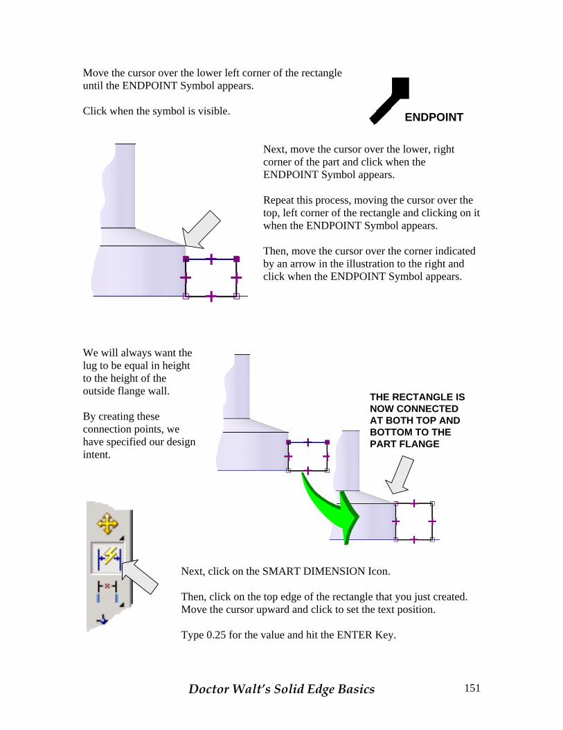
We will always want the lug to be equal in height to the height of the outside flange wall. By creating these connection points, we have specified our design intent.
Next, click on the SMART DIMENSION Then, click on the top edge of the rectanMove the cursor upward and click to set Type 0.25 for the value and hit the ENTE
Doctor Walt’s Solid Edge Bas
ENDPOINT
over the lower, right click when the appears.
oving the cursor over the rectangle and clicking on it Symbol appears.
r over the corner indicated stration to the right and OINT Symbol appears.
THE RECTANGLE ISNOW CONNECTEDAT BOTH TOP ANDBOTTOM TO THEPART FLANGE
Icon.
gle that you just created. the text position.
R Key.
ics 151
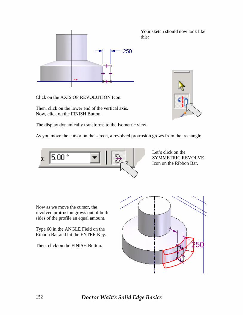
Your sketch should now look like this:
Click on the AXIS OF REVOLUTION Icon. Then, click on the lower end of the vertical axis. Now, click on the FINISH Button. The display dynamically transforms to the Isometric view. As you move the cursor on the screen, a revolved protrusion grows from the rectangle.
Let’s click on the SYMMETRIC REVOLVE Icon on the Ribbon Bar.
Now as we move the cursor, the revolved protrusion grows out of both sides of the profile an equal amount. Type 60 in the ANGLE Field on the Ribbon Bar and hit the ENTER Key. Then, click on the FINISH Button.
Doctor Walt’s Solid Edge Basics 152

Your part should now look like this: Next, we’ll create a duplicate of the lug on the opposite side of the part.
To do this, click on the MIRROR COPY FEATURE Icon.
Notice that the Ribbon Bar is set to FAST copy.
Now, move the cursor over the lug and the feature highlights. Click on it.
Doctor Walt’s Solid Edge Basics 153

Now, click on the green checkmark on the Ribbon Bar.
Notice that the Ribbon Bar is now prompting you to select a Reference Plane for the mirror operation.
Click on the vertical reference plane indicated by an arrow in the illustration to the right. A Dialog Box appears, advising you that the operation has failed. You are advised to try again using the SMART Option. I led you down this road on purpose to illustrate the difference between the smart and fast options. The fast option requires less processing power and will increase throughput when working with large amounts of simple geometry. However, when a feature interacts with overall part topology, such as this external lug does, you must use the smart option. Click on the OK Button in the Warning Dialog Box.
Then, click on the SMART Icon on the Ribbon Bar. Notice that a PREVIEW Button appears on the Ribbon Bar. Click on the PREVIEW Button.
Then, click on the FINISH Button that appears on the Ribbon Bar to complete the operation.
Doctor Walt’s Solid Edge Basics 154
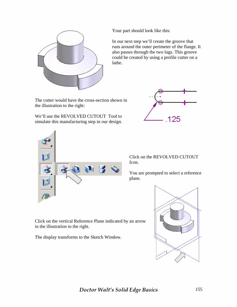
Your part should look like this: In our next step we’ll create the groove that runs around the outer perimeter of the flange. It also passes through the two lugs. This groove could be created by using a profile cutter on a lathe.
The cutter would have the cross-section shown in the illustration to the right: We’ll use the REVOLVED CUTOUT Tool to simulate this manufacturing step in our design.
Click on the REVOLVED CUTOUT Icon. You are prompted to select a reference plane.
Click on the vertical Reference Plane indicated by an arrow in the illustration to the right. The display transforms to the Sketch Window.
Doctor Walt’s Solid Edge Basics 155
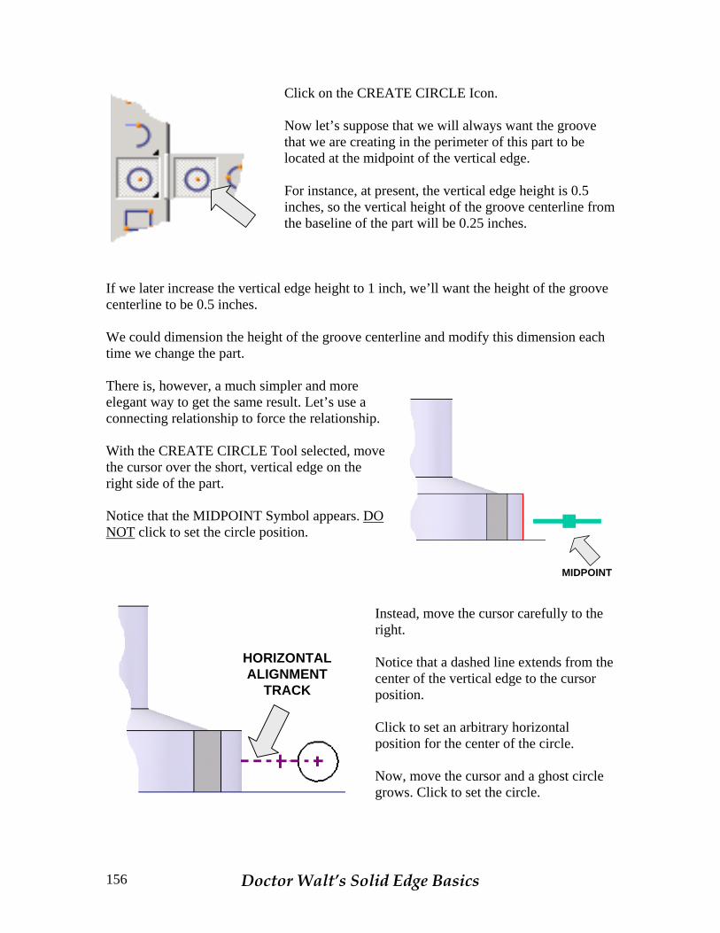
Click on the CREATE CIRCLE Icon.
Now let’s suppose that we will always want the groove that we are creating in the perimeter of this part to be located at the midpoint of the vertical edge. For instance, at present, the vertical edge height is 0.5 inches, so the vertical height of the groove centerline from the baseline of the part will be 0.25 inches.
If we later increase the vertical edge height to 1 inch, we’ll want the height of the groove centerline to be 0.5 inches. We could dimension the height of the groove centerline and modify this dimension each time we change the part. There is, however, a much simpler and more elegant way to get the same result. Let’s use a connecting relationship to force the relationship.
MIDPOINT
With the CREATE CIRCLE Tool selected, move the cursor over the short, vertical edge on the right side of the part. Notice that the MIDPOINT Symbol appears. DO NOT click to set the circle position.
HORIZONTALALIGNMENT
TRACK
Instead, move the cursor carefully to the right. Notice that a dashed line extends from the center of the vertical edge to the cursor position. Click to set an arbitrary horizontal position for the center of the circle. Now, move the cursor and a ghost circle grows. Click to set the circle.
Doctor Walt’s Solid Edge Basics 156
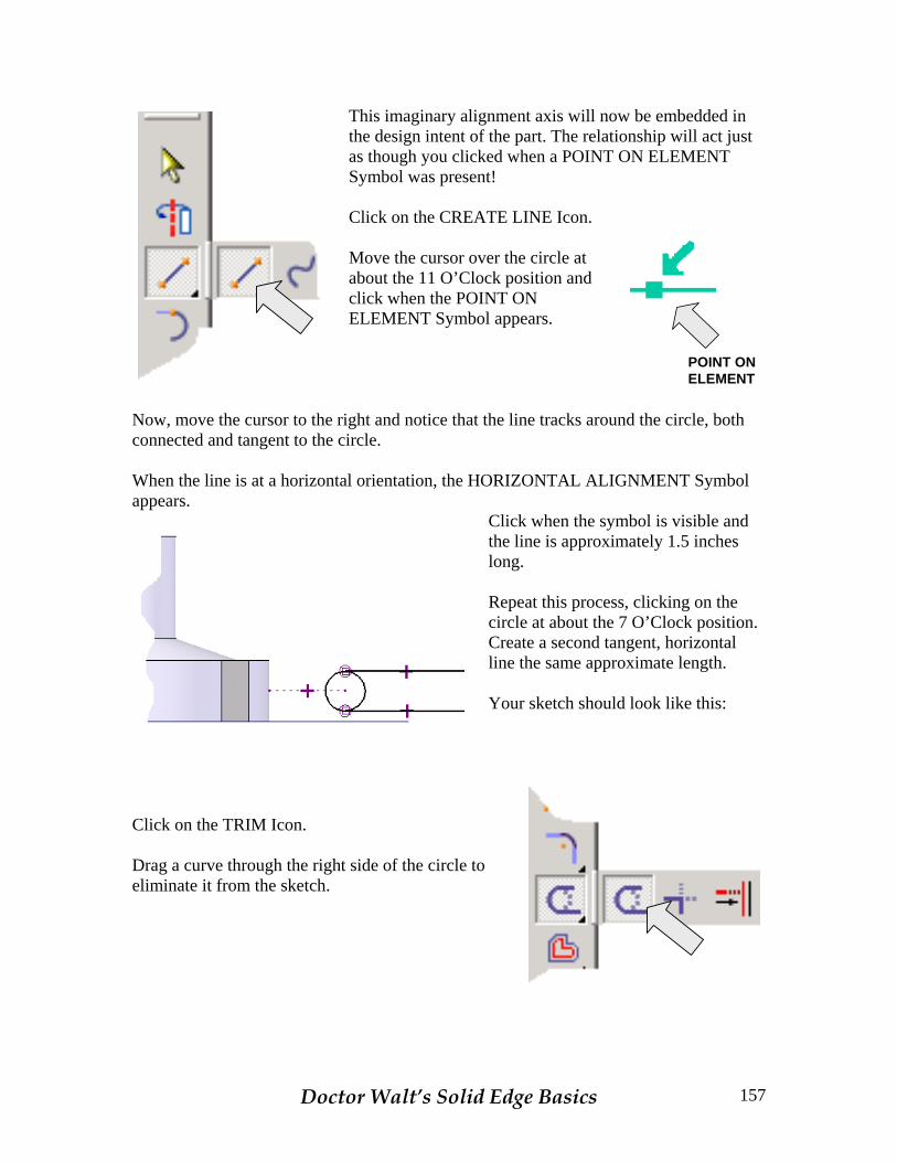
This imaginary alignment axis will now be embedded in the design intent of the part. The relationship will act just as though you clicked when a POINT ON ELEMENT Symbol was present!
Click on the CREATE LINE Icon.
POINT ON ELEMENT
Move the cursor over the circle at about the 11 O’Clock position and click when the POINT ON ELEMENT Symbol appears.
Now, move the cursor to the right and notice that the line tracks around the circle, both connected and tangent to the circle. When the line is at a horizontal orientation, the HORIZONTAL ALIGNMENT Symbol appears.
Click when the symbol is visible and the line is approximately 1.5 inches long. Repeat this process, clicking on the circle at about the 7 O’Clock position. Create a second tangent, horizontal line the same approximate length. Your sketch should look like this:
Click on the TRIM Icon. Drag a curve through the right side of the circle to eliminate it from the sketch.
Doctor Walt’s Solid Edge Basics 157
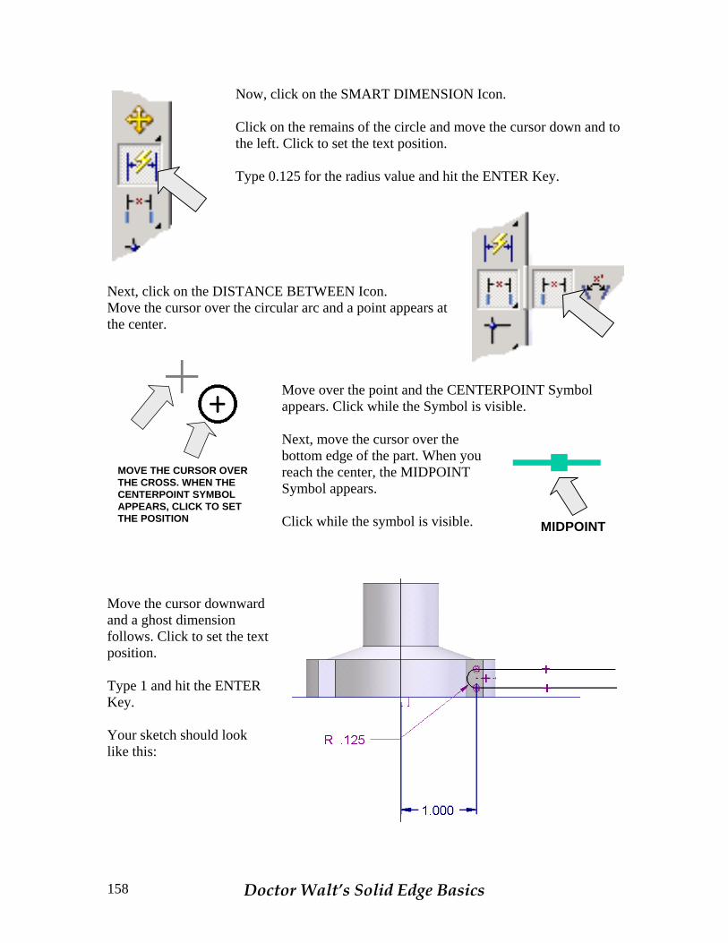
Now, click on the SMART DIMENSION Icon. Click on the remains of the circle and move the cursor down and to the left. Click to set the text position. Type 0.125 for the radius value and hit the ENTER Key.
Next, click on the DISTANCE BETWEEN Icon. Move the cursor over the circular arc and a point appears at the center.
MOVE THE CURSOR OVERTHE CROSS. WHEN THECENTERPOINT SYMBOLAPPEARS, CLICK TO SETTHE POSITION
Move over the point and the CENTERPOINT Symbol appears. Click while the Symbol is visible. Next, move the cursor over the bottom edge of the part. When you reach the center, the MIDPOINT Symbol appears.
MIDPOINT Click while the symbol is visible.
Move the cursor downward and a ghost dimension follows. Click to set the text position. Type 1 and hit the ENTER Key. Your sketch should look like this:
Doctor Walt’s Solid Edge Basics 158
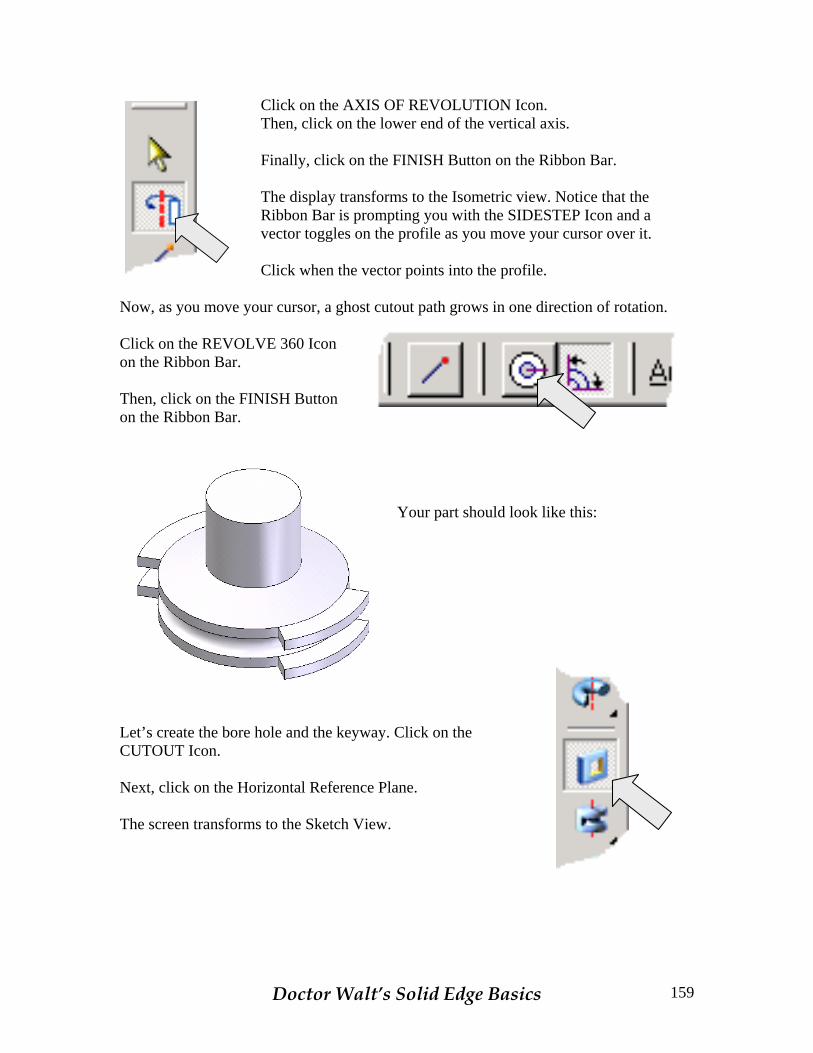
Click on the AXIS OF REVOLUTION Icon.
Then, click on the lower end of the vertical axis. Finally, click on the FINISH Button on the Ribbon Bar. The display transforms to the Isometric view. Notice that the Ribbon Bar is prompting you with the SIDESTEP Icon and a vector toggles on the profile as you move your cursor over it. Click when the vector points into the profile.
Now, as you move your cursor, a ghost cutout path grows in one direction of rotation. Click on the REVOLVE 360 Icon on the Ribbon Bar. Then, click on the FINISH Button on the Ribbon Bar.
Your part should look like this:
Let’s create the bore hole and the keyway. Click on the CUTOUT Icon. Next, click on the Horizontal Reference Plane. The screen transforms to the Sketch View.
Doctor Walt’s Solid Edge Basics 159

Click on the CREATE CIRCLE Icon.
MIDPOINT
Move the cursor over the intersection of the axes until the MIDPOINT Symbol appears. Click while the symbol is visible. Move the cursor and a ghost circle appears. Click to set the circle.
Type 0.5 for the Diameter and hit the ENTER Key. Click on the FINISH Button on the Ribbon Bar. The display transforms to the Isometric view.
THRU ALL
Click on the THROUGH ALL Icon on the Ribbon Bar. Then, move the cursor over the vector on the screen until it becomes a double-headed vector and click on it. Then, click on the FINISH Button on the Ribbon Bar.
Your part should look like this: Now you might wonder why we didn’t create the keyway at the same time that we cut the hole. You could do this by creating a more elaborate cutout sketch but in general, this is not a good idea. First, these are two features that will usually be created by separate operations when the part is made.
Second, more elaborate sketches take more time to create and are easier to mess up!
Doctor Walt’s Solid Edge Basics 160

Let’s once again click on the CUTOUT Icon. Click on the Horizontal Reference Plane. The display transforms to the Sketch View.
Click on the CREATE RECTANGLE Icon.
Drag the cursor across the intersection of the top of the circular bore and the vertical axis to create a small rectangle like the one illustrated to the right.
Click on the CONNECT Icon. Move the cursor over the top of the rectangle until the MIDPOINT Symbol appears.
MIDPOINT Click while the symbol is visible.
POINT ON ELEMENT
Then, move the cursor over the vertical axis until the POINT ON ELEMENT Symbol appears. Click while the symbol is visible. This centers the rectangle on the vertical axis.
Doctor Walt’s Solid Edge Basics 161
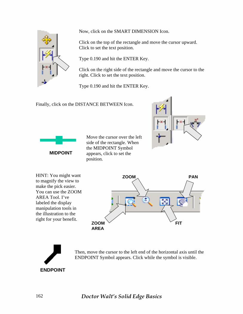
Now, click on the SMART DIMENSION Icon. Click on the top of the rectangle and move the cursor upward. Click to set the text position. Type 0.190 and hit the ENTER Key. Click on the right side of the rectangle and move the cursor to the right. Click to set the text position. Type 0.190 and hit the ENTER Key.
Finally, click on the DISTANCE BETWEEN Icon.
MIDPOINT
Move the cursor over the left side of the rectangle. When the MIDPOINT Symbol appears, click to set the position.
FIT
PANZOOM
ZOOMAREA
HINT: You might want to magnify the view to make the pick easier. You can use the ZOOM AREA Tool. I’ve labeled the display manipulation tools in the illustration to the right for your benefit.
ENDPOINT
Then, move the cursor to the left end of the horizontal axis until the ENDPOINT Symbol appears. Click while the symbol is visible.
Doctor Walt’s Solid Edge Basics 162
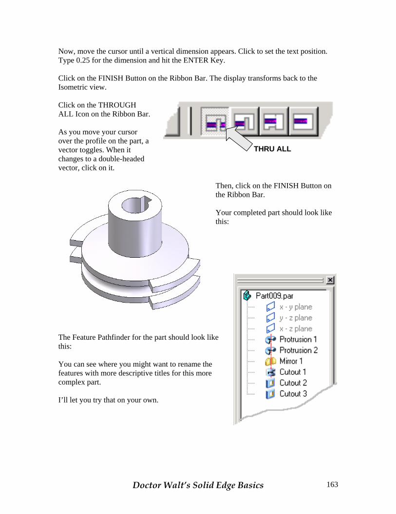
Now, move the cursor until a vertical dimension appears. Click to set the text position. Type 0.25 for the dimension and hit the ENTER Key. Click on the FINISH Button on the Ribbon Bar. The display transforms back to the Isometric view.
THRU ALL
Click on the THROUGH ALL Icon on the Ribbon Bar. As you move your cursor over the profile on the part, a vector toggles. When it changes to a double-headed vector, click on it.
Then, click on the FINISH Button on the Ribbon Bar. Your completed part should look like this:
The Feature Pathfinder for the part should look like this: You can see where you might want to rename the features with more descriptive titles for this more complex part. I’ll let you try that on your own.
Doctor Walt’s Solid Edge Basics 163

Before we leave this exercise, let’s make some changes to the part to reinforce our navigational skills. First, let’s increase the thickness of the lower flange and lugs to 1 inch.
When we do this, we’ll want the edge groove to reposition at the midpoint of the thicker geometry. Because we created design intent in our sketches, this change is extremely simple. RIGHT MOUSE CLICK on the Protrusion1 Feature in the Feature Pathfinder. Then, click on the Edit Dimensions Option in the flyout that appears. The dimensions used in the sketch appear on the screen. Click on the 0.5 flange height dimension and type 1. Hit the ENTER Key.
Doctor Walt’s Solid Edge Basics 164
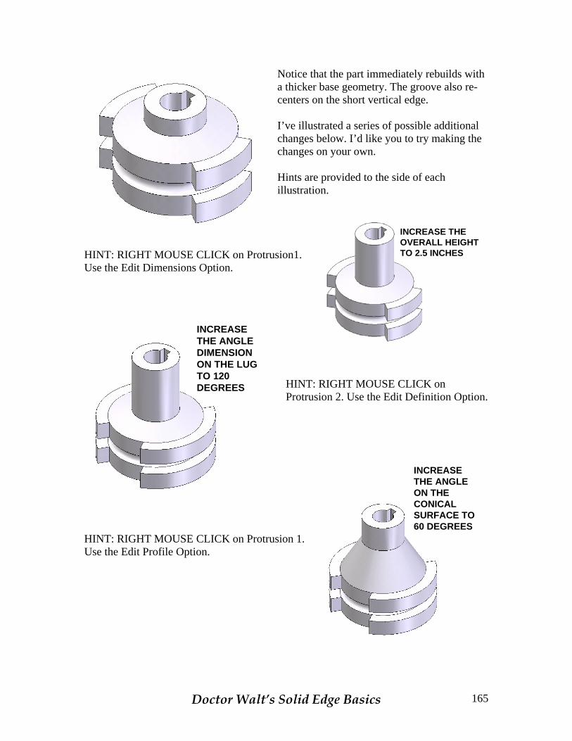
Notice that the part immediately rebuilds with a thicker base geometry. The groove also re-centers on the short vertical edge. I’ve illustrated a series of possible additional changes below. I’d like you to try making the changes on your own. Hints are provided to the side of each illustration.
INCREASE THEOVERALL HEIGHTTO 2.5 INCHES
HINT: RIGHT MOUSE CLICK on Protrusion1. Use the Edit Dimensions Option.
INCREASETHE ANGLEDIMENSIONON THE LUGTO 120DEGREES
HINT: RIGHT MOUSE CLICK on Protrusion 2. Use the Edit Definition Option.
INCREASETHE ANGLEON THECONICALSURFACE TO60 DEGREES
HINT: RIGHT MOUSE CLICK on Protrusion 1. Use the Edit Profile Option.
Doctor Walt’s Solid Edge Basics 165