Embed Size (px)
Citation preview

T E N D E R D O C U M E N T
F O R
THE ORISSA STATE CO-OPERATIVE MILK PRODUCERS’ FEDERATION LTD. BHUBANESWAR
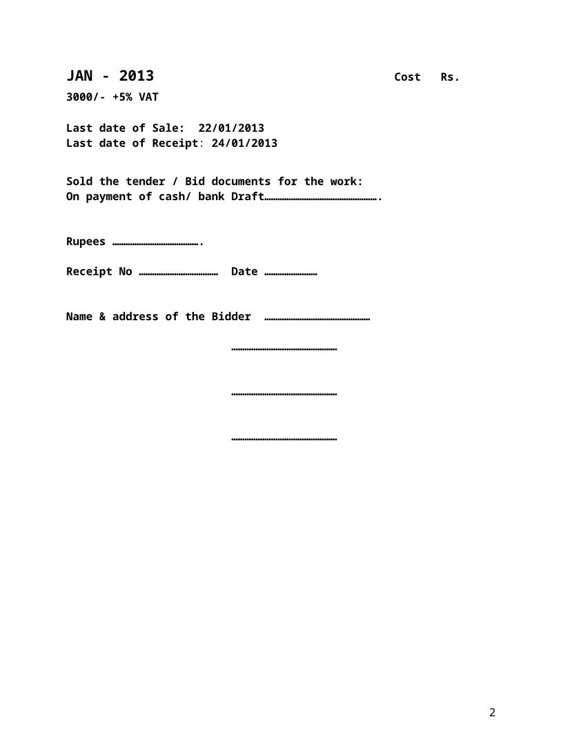
JAN - 2013 Cost Rs. 3000/- +5% VAT
Last date of Sale: 22/01/2013Last date of Receipt: 24/01/2013
“CIVIL STRUCTURAL WORKS FOR CONSTRUCTION OF BOUNDARY WALL, AT SAMBALPUR DAIRY, DIST- SAMBALPUR.”
1
Signature of the Tenderer
Sold the tender / Bid documents for the work:On payment of cash/ bank Draft…………………………………………….
Rupees ………………………………….
Receipt No ……………………………… Date ……………………
Name & address of the Bidder …………………………………………
…………………………………………
…………………………………………
…………………………………………
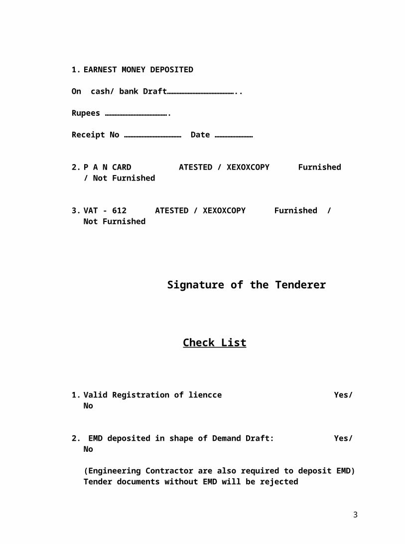
1. EARNEST MONEY DEPOSITED
On cash/ bank Draft……………………………………..
Rupees ………………………………….
Receipt No ……………………………… Date ……………………
2. P A N CARD ATESTED / XEXOXCOPY Furnished / Not Furnished
3. VAT - 612 ATESTED / XEXOXCOPY Furnished / Not Furnished
2
Check List
1. Valid Registration of liencce Yes/ No
2. EMD deposited in shape of Demand Draft: Yes/ No
(Engineering Contractor are also required to deposit EMD) Tender documents without EMD will be rejected
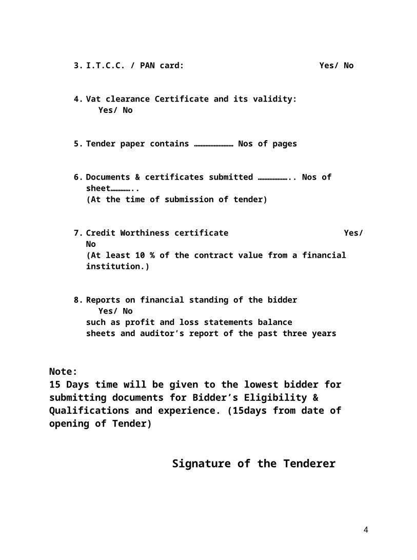
3. I.T.C.C. / PAN card: Yes/ No
4. Vat clearance Certificate and its validity: Yes/ No
5. Tender paper contains …………………… Nos of pages
6. Documents & certificates submitted ……………….. Nos of sheet…………..(At the time of submission of tender)
7. Credit Worthiness certificate Yes/ No(At least 10 % of the contract value from a financial institution.)
8. Reports on financial standing of the bidder Yes/ Nosuch as profit and loss statements balance sheets and auditor’s report of the past three years
Note: 15 Days time will be given to the lowest bidder for submitting documents for Bidder’s Eligibility & Qualifications and experience. (15days from date of opening of Tender)
Signature of the Tenderer
3
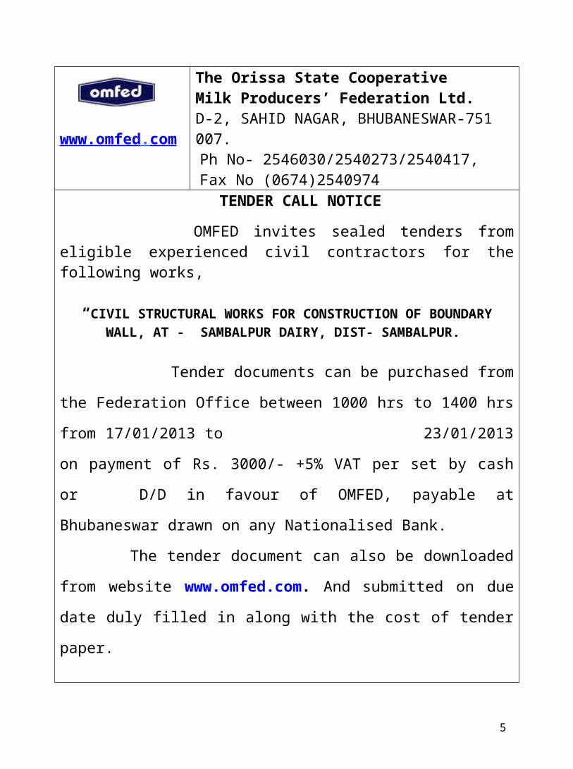
www.omfed . com
The Orissa State CooperativeMilk Producers’ Federation Ltd.D-2, SAHID NAGAR, BHUBANESWAR-751 007.
Ph No- 2546030/2540273/2540417, Fax No (0674)2540974
TENDER CALL NOTICE OMFED invites sealed tenders from eligible experienced civil contractors for the following works,
“CIVIL STRUCTURAL WORKS FOR CONSTRUCTION OF BOUNDARY WALL, AT - SAMBALPUR DAIRY, DIST- SAMBALPUR.”
Tender documents can be purchased from the Federation
Office between 1000 hrs to 1400 hrs from 17/01/2013 to
23/01/2013 on payment of Rs. 3000/- +5% VAT per set by cash or D/D
in favour of OMFED, payable at Bhubaneswar drawn on any
Nationalised Bank.
The tender document can also be downloaded from website
www.omfed.com. And submitted on due date duly filled in along
with the cost of tender paper.
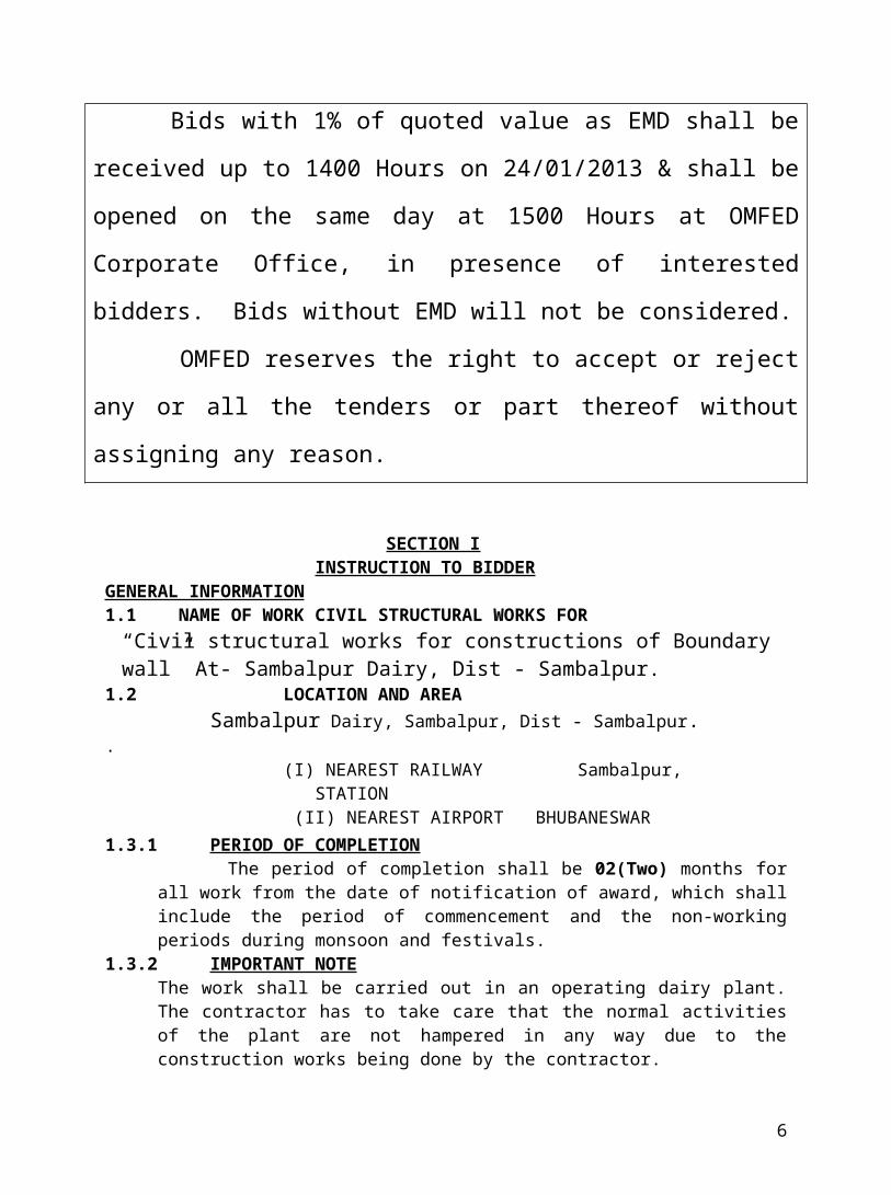
Bids with 1% of quoted value as EMD shall be received up to
1400 Hours on 24/01/2013 & shall be opened on the same day at
1500 Hours at OMFED Corporate Office, in presence of interested
bidders. Bids without EMD will not be considered.
OMFED reserves the right to accept or reject any or all the
tenders or part thereof without assigning any reason.
SECTION I
4
INSTRUCTION TO BIDDERGENERAL INFORMATION1.1 NAME OF WORK CIVIL STRUCTURAL WORKS FOR
1.2 LOCATION AND AREA Sambalpur Dairy, Sambalpur, Dist - Sambalpur.. (I) NEAREST RAILWAY Sambalpur, STATION (II) NEAREST AIRPORT BHUBANESWAR 1.3.1 PERIOD OF COMPLETION The period of completion shall be 02(Two) months for all work from the date of
notification of award, which shall include the period of commencement and the non-working periods during monsoon and festivals.
1.3.2 IMPORTANT NOTE The work shall be carried out in an operating dairy plant. The contractor has to take care that the normal activities of the plant are not hampered in any way due to the construction works being done by the contractor.
2.0 ELIGIBILITY AND QUALIFICATION REQUIREMENTS: -2.1 This invitation to bid is open to all eligible bidders.2.2To be eligible for the award of contract, bidders shall provide evidence satisfactory to
the Orissa State Cooperative Milk Producers ‘Federation Limited of their eligibility and of their capacity and adequacy of resources to carry out the contract effectively. Detailed requirements for this have been specified in clause 12 of the instruction bidders.
3.0 COST OF BIDDING The bidder shall bear all costs associated with the preparation and submission of
his bid and the Orissa State Cooperative Milk Producers’ Federation Limited, hereinafter referred to as “OMFED” will in no case be responsible or liable for these costs, regardless of the conduct or outcome of the bidding process.
4.0 SITE VISIT 4.1 The bidder is advised to visit and examine the site of works and its surroundings
and obtain for himself on his own responsibility all information that may be necessary for preparing the bid and entering into a contract. The costs of visiting the site shall be at bidder’s own expense.
4.2 The bidder and any of his personnel or agent(s) will be granted permission by the OMFED to enter upon the premises and lands for the purpose of such inspection, but only upon the express condition that the bidder, his personnel or agent(s), will release and indemnify the OMFED and his personnel and agent(s) from and against all liabilities in respect thereof and will be responsible for personal injury (whether fatal or otherwise), loss of or damage to property and any other loss or damage, costs and expenses however caused ,which, but for the exercise of such permission would not have arisen.
BIDDING DOCUMENT
“Civil structural works for constructions of Boundary wall” At- Sambalpur Dairy, Dist - Sambalpur.
5
5.0 CONTENTS OF BIDDING DOCUMENTS
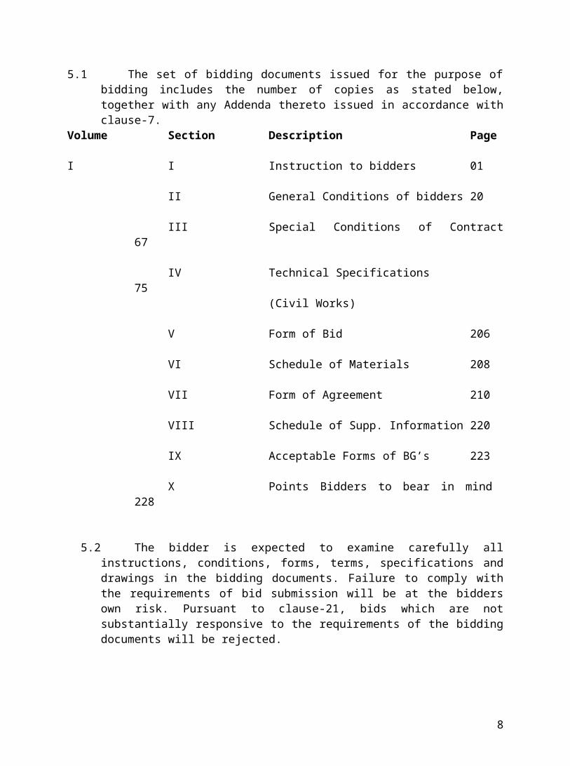
5.1 The set of bidding documents issued for the purpose of bidding includes the number of copies as stated below, together with any Addenda thereto issued in accordance with clause-7.
Volume Section Description Page
I I Instruction to bidders 01
II General Conditions of bidders 20
III Special Conditions of Contract 67
IV Technical Specifications 75(Civil Works)
V Form of Bid 206
VI Schedule of Materials 208
VII Form of Agreement 210
VIII Schedule of Supp. Information 220
IX Acceptable Forms of BG’s 223
X Points Bidders to bear in mind 228
5.2 The bidder is expected to examine carefully all instructions, conditions, forms, terms, specifications and drawings in the bidding documents. Failure to comply with the requirements of bid submission will be at the bidders own risk. Pursuant to clause-21, bids which are not substantially responsive to the requirements of the bidding documents will be rejected.
6.0 CLARIFICATION OF BIDDING DOCUMENTS: A propespective bidder requiring any clarification of the bidding documents may
notify the OMFED in writing or by telegram/ fax at the address of communication indicated in the tender notice. The OMFED will respond in writing or by telegram / fax to any request for the clarification which is required earlier than 10 days prior to the deadline for the submission of the bids. Written copies of the response of the OMFED (including a description of the enquiry without identifying its source) will be sent to all prospective bidders who purchased the bidding documents, and will be attached to the bidding documents sold subsequently.
6
7.0 AMENDMENT OF BIDDING DOCUMENTS7.1 At any time prior to the deadline for the submission of bids, the OMFED may for
any reason whether at its own initiative or in response to a clarification requested by a prospective bidder, modify the bidding document by the issuance of amendment.
7.2 The amendment will be sent in writing or by telegram/ fax to all prospective bidders who have purchased the bidding documents and will be binding upon them. Prospective bidders shall promptly acknowledge receipt thereof by telegram/ fax to the OMFED. The amendment will be attached to the bidding document sold subsequently.
7.3 In order to afford prospective bidders reasonable time in which to take an amendment into account in preparing their bids the OMFED may at its discretion extend the deadline for the submission of bids.
8.0 PRE-BID MEETING:( NOT APPLICABLE)
DELETED
9.0 PREPARATION OF BIDS
9.0 DOCUMENTS COMPRISING THE BID9.1 The bid prepared by the bidder comprise of the following components.(a) The original bidding document purchased by the bidder shall be signed &
stamped in each page as a token of having read & understood the contents therein.
(b) The Bid form completed in accordance with clauses 10 & 11.
(c) Documentary evidence established in accordance with clause 12 that the bidder is eligible to bid and is qualified to perform the contract if its bid is accepted.
(d) Bid security (Earnest Money Deposit) furnished in accordance with Clause 13.
(e) Schedule of Quantities (Vol-II of Bidding Document), completed in accordance to clauses 10 &11.
(f) Schedule of Supplementary information, in separate sheets but as per format provided in Section –VIII of the bidding document (Vol-I) .all the schedules shall be completed & submitted with the bid, without any exception.
10.0 BID FORM
10.1 The Bidder shall complete the Bid form (Section V) and appropriate Schedule of Quantities furnished as part of the Bidding Documents. The Bidder shall submit the bidding documents in original, as issued, after filling in all the appropriate
7
spaces, as required & after signing in all pages of the document as a token of having read and understood the clauses of the bid.
11.0 BID PRICES
11.1 unless stated otherwise in the bidding document, the Contract shall be for the whole works as described in the tender notice based on the Schedule of Unit rates and prices submitted by the bidder.
11.2 The bidder shall fill in the rates and prices for all items of works described in the Schedule of Quantities, whether quantities are stated or not. Items against which no rate is entered by the bidder shall not be paid by OMFED when executed and shall be deemed to have been covered by the other rates in the Schedule of Quantities.
11.3 All duties taxes and other levies shall be payable by the bidder under the Contract or for any other cause, shall be included in the rates and the prices and total bid price submitted y the bidder.
11.4 Fixed Price
a) Prices quoted by the bidder shall be fixed during the Bidder’s performance of the contract and not subject to variation on any account, if the duration of the contract, as stated in clause 1.3, hereof, is less than or up to 12 months. A bid submitted with any price adjustment condition will be treated as non-responsive and rejected.
8
12.0 DOCUMENTS ESTABLISHING BIDDER’S ELIGIBILITY & QUALIFICATIONS
12.0 CIIVIL / STRUCTURAL WORK12.1 Pursuant to clause 9, the Bidder shall furnish, as part of its bids, documents
establishing the Bidder’s eligibility to bid and its qualification to perform the contract if its bid is accepted .The bidder should also give supplementary information in the format attached to the bid document.
12.2 The documentary evidence of the bidder’s qualifications to perform the contract if its bid is accepted, shall establish to the Purchaser’s satisfaction.
(a) That the Bidder has the financial and technical capability necessary to perform the contract .to this end, all bids submitted shall include the following information under section VII:
i) Copies of original documents defining the constitution or legal status, place of registration and principal place of business of the company or firm or partnership etc.
ii) Power of Attorney or a true copy thereof duly attested by a gazetted officer in case an authorized representative ha signed the Bid.
iii) Copies of Income Tax and Sales Tax clearance certificates, valid till the end of bid validity period as prescribed under Clause 14.0,hereof and copy of PAN card.
iv) Details of experience and past performance of the bidder (or each party to a joint venture) on works of similar nature within the past five years, and details of current works in hand and other Contractual commitments shall be submitted as per schedule III and schedule VI given in Section VIII respectively of this bidding document.
v) Major items of constructional plant proposed for use in carrying out the contract in the format prescribed in Schedule VIII and the qualifications and experience of key personnel proposed for the administration and the execution of the contract, both on and off the site, in the format prescribed in schedule II of Section VIII of this bidding document.
Vi) Reports on financial standing of the bidder such as profit and loss statements balance sheets and auditors report of the past three years, an estimate of the financial projections for the next two years as prescribed in schedule - v of section -viii of this bidding document, and an authority from the bidder (or an authorized representative of a joint venture) to seek reference from the bidders bankers; and
vii) Information regarding any current arbitration / dispute in which the bidder is involved, as prescribed in schedule - IV of section - viii of the bidding document.
12.3 For the purpose of this particular contract bidders shall meet the following criteria as minimum:
(a) The bidder’s average turnover in last 3 years should not be less than Rs.30 Lakhs and average profit in last 3 years should not be less than Rs.1 lakhs.
(b) The bidder shall furnish a copy of the latest income tax clearance and sales tax clearance certificates for the previous year in original or certified true copies.
(c) Credit Worthiness certificate at least 10 % of the contract value from a financial institution.
12.4 Bid submitted by a joint venture of two or more firms, as partners shall comply with the following requirements:
9
a. The bid and in case of a successful bid the form of agreement shall be signed so
as to be legally binding on all the partners; b. One of the partners shall be nominated, as being in charge and this authorization
shall be evidenced by submitting a power of attorney signed by legally authorized signatories of all the partners;
c. The partner in-charge shall be authorized to incur liabilities and receive instructions for and on behalf of any and all the partners of the joint venture and the entire execution of the contract including payment shall be done exclusively with the partner in-charges;
d. All the partners of the joint venture shall be liable jointly and severally for the execution of the contract in accordance with the contract terms and a relevant statement to this effect shall be included in the authorization mentioned under (b) above as well as in the form of bid and the form of agreement (in case of the successful bid); and
e. A copy of the agreement entered into by the joint venture partners shall be submitted with the bid.
f. Experience, resources, men and machinery of each party to the joint venture will be taken into account only to the extent of their participation for performing tasks under the joint venture agreement.
10
13.0 BID SECURITY (EARNEST MONEY DEPOSIT)13.1 Pursuant to clause 10, the bidder shall furnish, as part of its bid, bid security for a
value of 1% (one percent) of the bid value.13.2 The bid security is required to protect the purchaser against the risk of bidder’s
conduct, which would warrant the security’s forfeiture, pursuant to Clause 13.8.13.3 The bid security shall be in one of the following forms:
(a) A bank guarantee issued by a Nationalized Indian bank only in the form strictly in accordance to the sample form provided in the bidding documents and valid from the date of bid opening as prescribed in the tender notice till 30 days beyond the validity of the bid.
Or
(b) A demand draft or pay order in favour of Orissa State Cooperative Milk Producers Federation Limited, Payable at Bhubaneswar.
13.4 Any bid not secured in accordance with clause 12, 13.1 And 13.3 will be rejected by OMFED as non-responsive and the 2nd cover shall not be opened at all.
13.5 Unsuccessful bidders bid security will be discharged/ returned as promptly as possible but not later than 30 days after the expiration of the period of bid validity prescribed in the bidding document.
13.6 The successful bidders bid security will be discharged upon the bidders executing the contract pursuant to clause 28, and furnishing the performance security pursuant to clause 29.
13.7 No interest shall be paid b OMFED on the bid security furnished by the bidder.
13.8 The bid security may be forfeited:(a) If a bidder withdraws or modifies his bid during the period of bid validity;
Or(b) In the case of these successful bidder, if the bidder fails: i) To sign the agreement in accordance with clause 28; Or ii) To furnish the required performance security in accordance with clause 29.
14.0 PERIOD OF THE VALIDITY OF BIDS
14.1 Bids shall remain valid for 120 days after the date of bid opening prescribed by the OMFED pursuant to clause 17. A bid valid for a shorter period may be rejected by the OMFED as non-responsive.
14.2 In exceptional circumstance prior to the expiry of the original bid validity period the OMFED may solicit the bidders consent to a specified extension of the period of validity. The request and the response thereof shall be made in writing (or by
11
cable/fax). The bid security provided under clause 13 shall also be suitably extended. A bidder may refuse the request without forfeiting its bid security. A bidder granting the request will not be required nor permitted to modify its bid. The provisions of the clause 13 shall continue to apply during the extended period of bid validity.
15.0 FORMATS AND SIGNING OF BID
15.1 The bidder shall prepare and submit the original bidding document purchased him after having read & understood the contents of the documents.
15.2 Original bid shall be typed or written in indelible ink and all the pages of this bidding document shall be signed by the bidder or a person or persons duly authorized to bind the bidder to the contract. The latter authorizations shall be indicated by written power of attorney accompanying the bid. All pages of the bid shall be signed by the person or persons signing the bid as a token of having read and understood the contents of the document.
15.3 The bid shall contain no alterations interlining, erasures or overwriting except those in accordance with instructions issued by OMFED or as necessary to correct errors made by the bidder, in which case corrections shall be initialed by the person or persons signed the bid.
15.4 The bidder shall quote the rate of each item both in figures and words besides the amount (in figures) based on the estimated quantities mentioned for each item.
15.5 Only one bid may be submitted by each bidder. no bidder shall participate in the bid of another for the same contract in any relation whatsoever.
SUBMISSION OF BIDS
16.0 SEALING AND MARKING OF BIDS
16.1 The bidders shall seal the tender documents duly marking the envelopes as Name of the work with Address.
16.2 The envelope shall:
(a) The cover shall contain all documents as per Volume-I and the Price Bid Volume-II, shall be sealed.
(b) Be addressed to OMFED at the following address: Orissa State Cooperative Milk Producers ‘Federation limited, D-2,
saheednagar, Bhubaneswar- 751007, Orissa.(c) Bear the name of the work, bid reference, and the date of opening as mentioned
in tender notice.
16.3 The envelope shall indicate the name and address of the bidder to enable the bid to be returned unopened in case it is declared “late “
12
16.4 If envelope is not sealed and marked as required by Para. 16.2, the OMFED will assume no responsibility for the bid’s misplacement or premature opening. A bid opened prematurely for this cause will be rejected by OMFED and returned to the bidder.
16.5 Fax facsimile and incomplete bids shall be summarily rejected.
17.0 DEADLINE FOR SUBMISSION OF BIDS
17.1 Bids must be received by the OMFED at the address specified under Para. 16.2 not later than the time and date specified for receipt of the bids as indicated in the tender notice or as extended by OMFED, pursuant to Para 17.2, below.
17.2 The OMFED may, at its discretion, extend this deadline for the submission of bids by amending the bidding documents in accordance with Para 7, above in which case all rights and obligations of the OMFED and bidders previously subject to the deadline will thereafter be subject to the new deadline as extended.
18.0 LATE BIDS
18.1 Any bid received by the OMFED after the deadline for submission of bids prescribed by the OMFED, pursuant to Para 17 will be rejected and/or returned unopened to the bidder.
BID OPENING AND EVALUATION
19.0 OPENING OF BIDS BY OMFED19.1 The OMFED will open bids including submissions, in the presence of bidders’
representatives who choose to attend, at the office of the Orissa State cooperative milk producers, federation limited, Bhubaneswar, Orissa. The bidders’ representatives who are present shall sign the tender opening document evidencing their attendance.
19.2 The bidders’ names, bid prices and the presence or absence of the requisite bid security and such other details as the OMFED, at its discretion, may consider appropriate will be announced at the opening.
19.3 The OMFED will examine the qualification bids to determine the substantial responsiveness of bidder, will examine the bids to determine whether they are complete, whether the requisite bid security have been furnished, whether the documents have been properly signed, and whether the bids are generally in order.
19.4 The OMFED shall prepare, for its own records, the minutes of the bid opening, including the information disclosed to those present in accordance with sub-clause 19.2.
20.0 CLARIFICATION OF BIDS
20.1 To assist in the examination, evaluation and comparison of bids the OMFED may, at its discretion, ask the bidders individually for a clarification of its bid
13
including break down or analysis of the unit rates. The request for clarification and the response shall be in writing.
21.0 PRELIMINARY EXAMINATIONS
21.1 The OMFED will examine the bids to determine whether they are complete, whether they are complete, whether any computational errors have been made, whether required sureties have been furnished, whether the documents have been properly signed, and whether the bids are generally in order.
21.2 Arithmetical errors will be rectified on the following basis. If there is a discrepancy between the unit price and the total price that is obtained by multiplying the unit price and quantity, the unit price shall prevail and the total price shall be accordingly corrected. If there is a Discrepancy between rates and amounts in words and figures, the value in words will prevail. The amount stated in the form of bid will be adjusted by OMFED in accordance with the started procedures, and with the concurrence of the bidder, shall be considered as binding on the bidder. If the bidder does not accept the correction of the errors, its bid will be rejected and the bid security will be forfeited.
21.3 Prior to the detailed evaluation, pursuant to Para 22, the OMFED will determine the substantial responsiveness of each bid to the bidding documents. For purposes of these clauses, a substantially responsive bid is one, which conforms to all the terms and conditions of the bidding documents without material deviations or reservations. A material deviation is one which affects in any substantial way the scope, quality or performance of the works or which limits in any substantial way, inconsistent with the bidding document, the OMFED’s rights or the bidder’s obligations under the Contract, and the rectification of which deviation or reservation would affect unfairly the competitive position of other bidders presenting substantially responsive bids.
21.4 The OMFED at its discretion may waive any minor informality or non-conformity or irregularity in a bid which does not constitute a material deviation, provided such waiver does not prejudice or affect the relative ranking of the bidder.
14
22.0 EVALUATION AND COMPARISON OF BIDS
22.1 The OMFED will evaluate and compare the bids previously determined to be substantially responsive, pursuant to Clause 21.3.
22.2 The OMFED’s evaluation of the bid will exclude and not take into account any allowance for price adjustment during the period of execution of the contract, if provided in the bid.
22.3 In evaluating bids, the OMFED will determine for each bid the evaluated price by adjusting the bid price making any correction for errors pursuant to Clause 21.2.
22.4 The OMFED reserve the right to accept or reject any variation, deviation or alternative offers. Variations, deviations and alternative offers and other factors which are in excess of the requirement of the bidding documents or otherwise result in the accrual of unsolicited benefits to the OMFED shall not be taken into account in bid evaluation.
22.5 If the bid of the successful bidder is seriously unbalanced in relation to the OMFED’s estimate of the real cost of the whole or any part of the work to be performed under the Contract, the OMFED may require that amount of the
Performance security deposit set forth in the clause 29 be increased at the expense of the successful bidder to a level sufficient to protect the OMFED against financial loss in the event of subsequent default of the successful bidder under the Contract.
23.0 CONTACTING THE OMFED
23.1 After the public opening of bids, information relating to the examination, clarification, and comparison of bids and recommendations concerning the award of Contract shall not be disclosed to bidders or other persons not officially concerned with such process until the award of the contract to the successful bidder has been announced.
23.2 Any effort by a bidder to influence the OMFED in the process of bid examination, clarification, evaluation, bid comparison or contract award decisions may result in the rejection of the bidder’s bid.
AWARD OF CONTRACT
24.0 POST-QUALIFICATION
24.1 The determination will take into account the bidder is financial, technical and production capabilities. It will be based upon an examination of the documentary evidence of the bidder’s qualifications submitted by the bidder, pursuant to para 14, as well as such other information as the OMFED deems necessary and appropriate including details of experience and records of past performance.
15
24.2 An affirmative determination will be a prerequisite for award of the contract to the bidder. A negative determination will result in rejection of the bidder’s bid, in which event, the OMFED will proceed to the next lowest evaluated bid to make a similar determination of that bidder’s capabilities to perform satisfactorily.
25.0 AWARD CRITERIA
25.1 Pursuant to Para 26, the OMFED will consider award of contract to the successful bidder whose bid has been determined to be substantially responsive and has been determined as the lowest evaluated bid, provided further that the bidder is determined to be qualified to satisfactorily perform the contract.
26.0 OMFED’S RIGHT TO ACCEPT ANY BID OR REJECT ANY OR ALL BIDS
26.1 The OMFED reserves the right to accept or reject any bid, and to annul the bidding process and reject all bids at any time prior to award of contract, without thereby incurring any liability to the affected bidder or bidders or any obligation to inform the affected bidder or bidders of the grounds for OMFED’s action.
27.0 NOTIFICATION OF AWARD
27.1 Prior to expiry of the period of bid validity, the OMFED will notify the successful bidder in writing by registered letter or by cable or fax, confirmed in writing by registered letter, that its bid has been accepted. This letter (hereinafter and in the Conditions of Contract referred as ‘Letter of Acceptance”) shall name the sum, which OMFED shall pay to the contractor in consideration to the execution, completion and maintenance of the works by the Contractor as prescribed by the Contract (hereinafter and in the Conditions of Contract referred as the “Contract price”).
27.2 The notification of award will constitute the formation of the contract.
27.3 Upon the successful bidder’s furnishing of performance security pursuant to Para 29, the OMFED will promptly notify each unsuccessful bidder and will discharge its bid security, pursuant to Para 13.
28.0 SIGNING OF THE AGREEMENT
28.1 Within 15 days of receipt of the notification of award ,the successful bidder shall prepare and execute the agreement ,strictly in accordance to the sample form provided in the bidding document.
29.0 PERFORMANCE SECURITY
16
29.1 Within 15 days of the receipt of notification of award from the OMFED, the successful bidder shall furnish the performance security for an amount of 5% of the Contract price in accordance with Clause-10 of the Conditions of Contract.
29.2 Failure of the successful bidder to comply with the requirement of Para 28 or Para 29 shall constitute sufficient grounds for the annulment of the award and forfeiture of the bid security, in which event the OMFED may make the award to the next lowest evaluated bidder or call for new bids.
29.3 The performance security may be released during release of running bill on submission of valid Bank qaraneety and conformation of Bank.
30.0 Statutory approvals:
The contractor shall arrange, at his own cost, for inspection of the works and approval of cable layout & schematic drawings from the concerned electrical inspector with necessary test certificates & completion certificates. Any modification suggested by the electrical inspector shall be carried out by contractor without any extra cost. Statutory fees if any shall be reimbursed by Omfed. The approved drawings shall be submitted by the contractor to Omfed, before final payment is released
31.0 Drawing: their Purpose and the custody
31.1 The contractor drawings read together with the contract specifications are intended to show and explain the manner of executing the work and to indicate the type and the class of materials to be used.
31.2 In case any feature of the work is not set forth in the drawings and specifications, the contractor shall forthwith apply to the engineer for further instructions, drawings or specifications.
31.3 he drawings shall remain in the sole custody of the engineer, but two copies shall be issued to the contractor free of charge. One copy of the drawings, furnished to the contractor as afore aid, shall be kept by the contractor on the site and the same shall at all reasonable times be available for inspection and use by the engineer or the engineer’s representative and by any other person authorized by the engineer in writing. At the completion of the authorized by the contractor shall return to the engineer all drawings issued under the contract.
31.4 The contractor shall give written notice to the engineer whenever planning or progress of the works is likely to be delayed unless any further drawing or instruction is issued by the include the detail of the drawing or instruction required and of why and by when it is required and of any delay or disruption likely to be suffered if it is late.
17
31.5 The contractor shall submit the following information, in triplicate, to the engineer for approval within the time stipulated against each item below:
a) General layout plan of construction plant and equipment for the execution of work within fourteen days from the date of notice to proceed with the works; and
b) Drawings or prints show the location of major plants and other facilities which he proposes to put up at the site, including any change in the general layout, at least fourteen days prior to the commencement of the respective work.
31.6 The engineer may also authorizes representative to perform his duties and functions. The contractor shall carryout and be bound by the same. The engineer shall have full powers and authority to supply to the works, such further drawings and instructions as shall be necessary for the proper execution of the project.
18
SECTION II GENERAL CONDITIONS OF CONTRACT
1.0 DEFINITIONS In the Contract, as hereinafter defined, the following words and expressions Shall have the meanings hereby assigned to them, except where the context Otherwise requires:-
1.1 OWNER shall mean the Orissa State Cooperative Milk Producer’s Federation Ltd and shall include his successors and assignees, as well as his authorized representatives.
1.2 PURCHASER shall mean the Orissa State Cooperative Milk Producer’s Federation Ltd. or whomsoever agency inviting the bids.
1.3 CONSULTANT shall mean the Orissa State Cooperative Milk Producer’s Federation Ltd. or the consultants appointed by the Orissa State Cooperative Milk Producer’s Federation Ltd.
1.4 OMFED shall mean the Orissa State Cooperative Milk Producer’s Federation Ltd.
1.5 ENGINEER shall mean the Engineer or any other authorized representative of the OMFED.
1.6 ARCHIECT shall mean the architect appointed by the OMFED/Consultant.
1.7 STRUCTURAL CONSULTANT Shall mean the Structural Consultants appointed by the
OMFED/Consultant.
1.8 BIDDER shall mean the firm/party/individual who submits the bid against the Tender notice.
1.9 CONTRACTOR shall mean the successful bidder whose Bid has been accepted by the OMFED and on whom a work order has been placed and shall include his heirs, legal representatives and assignees.
1.10 SUB-CONTRACTOR Shall mean the person/firm/party named by the Contractor whom a part of the Contract has been sublet with the consent of OMFED and shall include his heirs, successors, legal representatives and assignees.
1.11 CONTRACT PRICE/RATE Shall mean the prices /rates of the accepted Bid.
19
1.12 CONTRACT shall mean the articles of agreement, the conditions, the schedule of quantities, and/or specifications attached herewith.
1.13 “NOTICE IN WRITING “
Shall mean a notice in written ,typed or printed characters sent (unless delivered personally or otherwise prove to have been received ) by registered / ordinary post to the last known address or the registered office of the addressee and shall be deemed to have been received when in the ordinary course of post it would have been delivered.
1.14 SITE shall mean the actual place of the proposed project or any other place where work is to be executed under the Contract. It shall also include any other land allotted by the OMFED for the Contractor’s use.
1.15 MONTH shall mean from the beginning of a given date of a calendar month to the end of the preceding date of the next calendar month.
1.16 WEEK shall mean seven consecutive days.
1.17 DAY shall mean a day from midnight to midnight.
1.18 BUILDING shall mean the proposed building(s), roads, fencing, sanitary, and water supply etc. under the contract.
1.19 AWARD shall mean the written acceptance of Bid by the OMFED given to the successful bidder.
1.20 PERFORMANCE SECURITY Shall mean the amount pledged with the OMFED while
signing the agreement for faithful and satisfactory performance of the Contract.
1.21 CONSTRUCTIONAL PLANT shall mean all appliances or things of
whatsoever nature required in or about the execution and maintenance of the works but does not include the materials or other things required/intended to form or forming part of the works.
1.22 SPECIFICATIONS shall mean the specification referred to in the bid and any modifications thereof or addition thereto as may from time to time be furnished or approved in writing by the OMFED/Engineer.
20
1.23 DRAWINGS shall mean drawings referred to in the specifications and any modification of such drawings approved in writing by the Engineer and such other drawings as may from time to time be furnished or approved in writing by the OMFED/Engineer.
1.24 TEMPORARY WORKS shall mean temporary works of every kind required in or about the execution or maintenance of works.
1.25 PERMANENT WORKS shall mean the permanent works to be executed and maintained in accordance with the Contract.
1.26 WORKS shall mean both temporary works and permanent works.
1.27 APPROVED/APPROVAL shall mean approved in writing, including subsequent written confirmation of previous verbal or written approval.
1.28 I.S.S shall mean Indian Standards Specification
1.29 GOVERNMENT shall mean the Government of India or any other State Government.
1.30 TENDER shall mean the Bid.1.31 Headings and Marginal notes:
All headings of and notes to the clauses of these conditions of Contract or of and to the Specifications or any other bid document are solely for the purpose of giving concise indication and not a summary of the contents thereof, and they shall never be deemed to be the part of the or be used in the interpretation or construction thereof or of the Contract.
1.32 Singular and Plural.
In this contract document unless otherwise stated specifically the singular shall include the plural and vice versa whenever the context so requires.
1.33 Cost
The cost shall be deemed to include overhead costs whether on or off the site.
II. GENERAL
21
2.0 DUTIES AND POWERS OF THE ENGINEER
2.1 The field management shall be the responsibility of the Engineer. The Engineer shall carry out such duties as taking decisions and issuing certificates and orders as specified in the Contract. The Engineer is empowered to take decisions on the following matters after approval of appropriate authority:
(a) Certification of additional sums under sub clause 25.2 hereof;
(b) Determination of an extension of time pursuant to clause 62.0 hereof;
(c) Issuance of a variation order pursuant to clause 24.0 hereof;
(d) Fixing rates or prices for the additional works executed under the Contract pursuant to clause 24.0 hereof;
2.2 If the Contractor shall be dissatisfied by reason of any decision of the Engineer he shall be entitled to refer the matter to the higher authority, who shall there upon confirm, reverse or vary such decision.
2.3Failure of the Engineer to disapprove any work or material shall not prejudice the power of higher authority thereafter to disapprove such work or materials and to order the pulling down, removal or breaking up thereof.
3.0 INSPECTION OF WORKS
3.1 The Owner/OMFED and his representatives shall have full power and authority to inspect the works at any time wherever the work is in progress either on the site or at the Contractor’s premises/workshop wherever situated, the work in connection with the contract may in hand or wherefrom materials are being produced or are to be supplied, and the Contractor shall afford or procure for the Engineer every facility and assistance to carry out such inspection. The Contractor shall at all times during usual working hours and at all other times at which reasonable notice of the intention of the Engineer or the Engineer’s Representative to visit the works shall have been given to the Contractor, either himself be present to receive the orders and instructions, or have a responsible agent/representative duly accredited in writing present for the purpose. Orders given to the Contractor’s agent/representative shall be considered to have the same force as if they had been given to the Contractor himself. The Contractor shall not give less than three days notice in writing to the Engineer’s Representative before covering up or otherwise placing beyond the reach of inspection and measurement any work in order that the same may be inspected and measured. In the event of breach of the above the same shall be uncovered at the Contractor’s expenses for carrying out such measurement of inspection.
3.2 No materials shall be removed from the site before obtaining the approval in writing of the Engineer The Contractor is to provide at all times during the progress of the work and the maintenance period proper means of access with
22
ladders, gangway, etc and the necessary attendance to move and adopt as directed for inspection or measurement of the works by the Engineer’s Representative.
3.3 The contractor shall make available to the Engineer free of cost all necessary instruments and assistance in checking of setting out of works and checking of any works made by the contractor for the purpose of setting out
And taking measurement of works.
CONTRACT DOCUMENTS4.0 LANGUAGE AND LAW OF CONTRACT4.1 i) All written material and correspondence shall be in English. ii) The law to which the contract is to be subjected and according to which the
Contract is construed, shall be the law being in force in India and/or the state where the Contract shall be performed.
4.2 Documents mutually explanatory
Except if and to the extent otherwise provided by the Contract, the provisions of the General Conditions and Special Conditions of the Contract shall prevail over those of any other documents forming part of the Contract. Several documents forming the Contract are to be taken as mutual explanatory. Should there be any discrepancy, inconsistency, error in the Contracts or any of them the matter may be referred to Engineer who shall give his decisions and issue to the Contractor instructions, directing in what manner the work is to be carried out. The decision of the Engineer shall be final and conclusive and the Contractor shall carry out the work in accordance with the decision
4.3 Works shown upon the drawing but not mentioned in the specifications or described in the specifications without being shown on the drawings shall nevertheless be held to be included in the same manner as if they had been specifically shown upon the drawings and described in the specifications.
5.0 DRAWINGS: THEIR PURPOSE AND THE CUSTODY
5.1 The Contract drawings read together with the Contract specifications are intended to show and explain the manner of executing the work and to indicate the type and the class of materials to be used.
5.2 In case any feature of the work is not set forth in the drawings and specifications, the Contractor shall forthwith apply to the Engineer for further instructions, drawings or specifications.
5.3 The drawings shall remain in the sole custody of the Engineer, but two copies shall be issued to the Contractor free of charge. One copy of the drawings, furnished to the Contractor as aforesaid, shall be kept by the Contractor on the site and the same shall at all reasonable times be available for inspection and use by the Engineer or the Engineer’s Representative and by any other person
23
authorized by the Engineer in writing .At the completion of the Contract the Contractor shall return to the Engineer all drawings issued under the Contract.
5.4 The Contractor shall give written notice to the Engineer whenever planning or progress of works is likely to be delayed unless any further drawing or instruction is issued by the Engineer/OMFED within a reasonable time. The notice shall include the detail of the drawing or instruction required and of why and by when it is required and of any delay or disruption likely to be suffered if it is late.
6.0 FURTHER DRAWINGS AND INSTRUCTIONS
6.1 The Engineer may authorize his representatives to perform his duties and functions. The Contractor shall carry out and be bound by the same. The Engineer shall have full powers and authority to supply to the Contractor from time to time, during the progress of the works, such further drawings and instructions as shall be necessary for the proper execution of the project.
GENERAL OBLIGATIONS
7.0 CONTRACTOR’S GENERAL RESPONSIBILITIES
7.1 The Contractor shall, subject to the provisions of the Contract, and with due care and diligence, execute and maintain the works and provide all labour, including the supervision thereof, materials, Construction plant and all other things, whether of a temporary or permanent nature, required in and for such execution and maintenance, so far as the necessity for providing the same is specified in or is reasonably to be inferred from the contract.
7.2 The Contractor shall take full responsibility for the adequate stability and safety of all site operations and methods of construction, provided that the Contractor shall not be responsible, except as may be expressly provided in the Contract, for the design or specification of the Permanent works, or for the design or specification of any temporary works prepared by the Engineer.
8.0 CONTRACT AGREEMENT
8.1 The Contractor shall within 15 days of receipt of notification of award enter into and execute a Contract agreement, in the form provided in section VIII.
9.0 PERFORMANCE SECURITY
9.1 Within 15 days of the receipt of notification of the Award of the contract from the OMFED the successful bidder shall furnish to the OMFED a performance security for an amount of 5% of the Contract value, valid till the end of the defect liability period plus 90 days.
24
9.2 The proceeds of the performance security shall be payable to the OMFED as compensation for any loss resulting from the Contractor’s failure to complete his obligations under the Contract.
9.3 The performance security shall be denominated in Indian Rupees and shall be in any of the following forms: -
a) A Demand draft or Pay Order drawn in favour of the Orissa State Cooperative Milk Producers Federation Ltd. Payable at Bhubaneswar.
b) A Bank guarantee issued by a Nationalized Indian Bank. The acceptable form shall be strictly as provided in section IX of the Bidding documents.
9.4 The bank guarantee shall be valid for the entire period of the Contract including the Period of Maintenance plus 90 days .The validity of the Bank guarantee be suitably extended in the event of extension of time of the Contractor pursuant to clause 68 herein.
9.5 The performance security shall be released by the OMFED not later than 60 days of expiry of validity period.
9.6 In the event of the increase in the Contract value, in actual execution, proportionate additional performance security, shall be paid by the Contractor if called upon to do so.
9.7 In the event of decrease in the Contract value the performance security shall be proportionately adjusted on the completion of the work.
9.8 No interest shall be paid by the OMFED for the amount deposited as performance security with the OMFED.
10.0 SUFFICIENCY OF TENDER
10.1 The Contractor shall be deemed to have satisfied himself before tendering as to the correctness and sufficiency of his tender for the works and of the rates and prices stated in the Price Schedule, if any, which Tender rates and prices shall, except insofar, as it is otherwise provided in the Contract, cover all his obligations under the Contract and all matters and things necessary for the proper execution and maintenance of the Works.
11.0 CONTRACTOR’S SUPERINTENDENCE
11.1 The Contractor shall give or provide all necessary superintendence during the execution of the Works and as long thereafter as the Engineer may consider necessary for the proper fulfilling of the Contractor’s obligations under the Contract. The Contractor, or a competent and authorized agent or representative approved of in writing by the Engineer, which approval may at any time be withdrawn, is to be constantly on the works and shall give his whole time to the superintendence of the same .If such approval shall be withdrawn by the
25
Engineer, the Contractor shall, as soon as is practicable, having regard to the requirement of replacing him as hereinafter mentioned, after receiving written notice of such withdrawal, remove the agent from the Works and shall not thereafter employ him on the Works in any capacity and shall replace him by another agent approved by the Engineer . such authorized agent or representative shall receive, on behalf of the Contractor , directions and instructions from the Engineer.
12.0 CONTRACTOR’S EMPLOYEES12.1 The Contractor shall provide and employ at the site in the connection with the
execution and maintenance of the Works:a) Only such technical assistants as are skilled and experienced in their respective
fields and sub-agents, foremen and leading hands as are competent to give proper supervision to the work they are required to supervise and,
b) Such skilled, semi-skilled and unskilled labour as is necessary for the proper and timely execution and maintenance of the Works.
12.2 It shall be liability of the Contractor to remove forthwith from the works any personnel engaged by the Contractor, in or about the execution or maintenance of the works, who, misconducts or is incompetent or negligent in the proper performance of his duties or whose engagement is otherwise considered to be undesirable and such person shall not be again engaged upon the work. Any person so removed, by the Contractor, from the works shall be replaced by the Contractor, as soon as possible by a competent substitute.
13.0 PATENT RIGHTS AND ROYALTIES
13.1 The Contractor shall save harmless and indemnify the OMFED from and against all claims and proceedings for or on account of infringement of any patent rights, design trademark or name or other protected rights in respect of any Constructional plant, machine work or material and for in connection with the works or any of them and from and against all claims, proceedings, damages, costs, charges and expenses whatsoever in respect thereof or in relation thereto. Except where otherwise specified, the Contractor shall pay all tonnage and other loyalties, rent and other payments or compensation, if any, for getting stone, sand, gravel, clay or other materials required for the works or any of them.
LABOUR
14.0 ENGAGEMENT OF LABOUR
14.1 The Contractor shall make his own arrangements for the engagements of all labour, local or otherwise, and, save insofar as the contract otherwise provides for the transport, housing feeding and payment thereof .The Contractor to the extent possible and reasonable to employ staff and labour with required qualifications and experience from source within India.
14.2 The OMFED may at their own discretion and convenience make available at the site, land for Contractors field office, godowns, workshops and assembly yard
26
required for the execution of the Contract. The Contractor shall at his own cost construct all these temporary buildings and provide suitable water and sanitary arrangement approved by the Engineer.
14.3 The personnel so engaged by the contractor shall be the employees of the contractor and there shall exist no privities of contract between the personnel so engaged and the OMFED.
14.4 On completion of the works undertaken by the Contractor, he shall remove all
temporary building erected by him and have the site cleaned as directed by the Engineer. If the Contractor shall fail to comply with these requirements, the Engineer may at the expense s of the Contractor remove such surplus and rubbish materials and dispose of the same as he deems fit and get the site cleared as foresaid; the Contractor shall forthwith pay the amount of all expenses so incurred and shall have the claim in respect of any such surplus material disposed off as aforesaid. The owner reserves the right to ask the Contractor any time during the tendency of the Contract to vacate the land by giving 7 days notice without giving any reason.
14.5 Land for residential accommodation for staff and labour may be made available at the discretion of the OMFED/Engineer.
14.6 The Contractor shall so far as is reasonably practicable, having regard to local conditions, provide on the site, to the satisfaction of the Engineer at adequate supply of drinking and other water for the use of the Contractor’s staff and the work people.
14.7 The Contractor shall not, otherwise than in accordance with the statutes, Ordinances and Government Regulations or orders for the time being in force, import, sell, give, barter or otherwise dispose of any alcoholic liquor, or drugs or permit any such importation, sale, gift, barter or disposal by his sub-contractors, agents or employees.
14.8 The Contractor shall not give, barter or otherwise dispose of to any person or person, any arms or ammunitions of any kind or permit the same as aforesaid.
14.9 The Contractor shall in all dealings in labour in his employment have due regard to all recognized festivals, days of rests and religious and other customs.
14.10 In the event of any outbreak of illness of an epidemic nature, the contractor shall comply with and carry out such regulations, orders and requirements, as may b made by the Government, or the local medical and sanitary authorities for the purpose of dealing with and overcoming the same.
14.11 The contractor shall at all times take all reasonable precautions to prevent any unlawful, riotous or disorderly conduct by or amongst his employees and for the preservation of peace and protection and property in the neighborhood of the works against the same .The Contractor shall be responsible to comply with the various labour laws such as Contract Labour (R&A) 1970, Payment of wages
27
Act, Minimum Wages Act, Provident fund Act& Rules etc in respect of persons engaged by him.
14.12 The Contractor shall be responsible for observance of his sub-contractors of the foregoing provisions.
15.0 RETURNS OF LABOUR, ETC
15.1 The Contractor shall submit to the OMFED copies of the license under the Contract Labour Act, if required and obtained by the contractor and his Provident Fund number. The Contractor shall if required by the Engineer, also deliver to the Engineer a return in detail in such form and at such intervals as the Engineer may prescribe showing the supervisory staff and the numbers of the several classes of labour from time to time employed by the contractor on the site and such information respecting Constructional Plant as the Engineer may require.
15.2 The Contractor shall not employ in connection with the work any person who has not completed 15 years of age.
15.3 The Contractor shall in respect of labour employed by him comply with or cause to be complied with the provision of the various labour laws and rules and regulations such as Contract Labour act(R&A) Act, 1970, Payment of Wages act, Provident fund Act &Rules etc, applicable to them in regard to all matters provided therein and shall indemnify the OMFED in respect of all claims that may be made against the OMFED for noncompliance thereof by the Contractor.
15.4 Notwithstanding anything contained herein, OMFED may take such actions as may be necessary for the compliance of the various labour laws and recover the costs thereof from the contractor.
15.5 In the event of the Contractor committing a default or breach of any of the provisions of labour laws and rules and regulations are applicable, shall pay penalties as imposed by the statutory authorities and shall indemnify and keep indemnified the OMFED all such penalties and compensations.
MATERIALS AND WORKSMANSHIP
16.0 MATERIALS AND WORKMANSHIP
16.1 All materials and workmanship shall be of the respective kinds described in the Contract and in accordance with the Engineer’s instructions and shall be subjected from time to time to such tests as the Engineer may direct at the place of manufacture or fabrication, or on the site or at such other place or places as may be specified in the contract, or at all or any of such places .The Contractor shall provide such assistance, instruments, machine, labour and materials as are normally required for examining, measuring and testing any work and the quality, weight or quantity of any material used and shall supply samples of materials before incorporation in the works for testing as may be selected and required by the Engineer .
28
16.2 All samples shall be supplied by the Contractor at his own cost if the supply thereof is clearly intended by or provided for in the Contract.
16.3 The cost of conducting any test ordered by the Engineer to ascertain the quality of the material and the workmanship shall be borne by the Contractor.
17.0 INSPECTION OF OPERATIONS
17.1 The Engineer and any person authorized by him shall at all times have access to the Works and to all the workshops and places where work is being prepared or from where materials, manufactured articles or machinery are being obtained for the Works and the Contractor shall afford every facility for and every assistance in or in obtaining the right to such access.
COMMENCEMENT TIME AND DELAYS
18.0 COMMENCEMENT OF WORKS
18.1 The Contractor shall commence the works on site within 30 days of receipt by him of the notification of award and shall proceed with the same with due expedition and without delay, except as may be expressly sanctioned or ordered by the Engineer, or be wholly beyond the Contractor’s control.
19.0 POSSESSION OF SITE
19.1 Save insofar as the Contract may prescribe, the extent of portions of the site of which the Contractor is to be given possession from time to time and the order in which such portions shall be made available to him and, subject to any Requirement in the Contract as to the order in which the Works shall be executed, the OMFED will with the Engineer’s written order to commence the works, give to the Contractor possession of so much of the Site as may be required to enable the Contractor to commence and proceed with the execution of the Works in accordance with the programme referred to in clause 39 hereof, if any, and otherwise in accordance with such reasonable proposals of the Contractor as he shall, by written notice to the Engineer, make and will, from time to time as the work proceed, give to the Contractor possession of such further portions of the Site as may be required to enable the Contractor to proceed with the execution of the Works with due dispatch in accordance with the said programme or proposals, as the case may be. If the Contractor suffers delay from the failure on the part of the OMFED to give possession in accordance with the terms of this clause, the Engineer shall grant an extension of time for the completion of the Works as, in his opinion shall be fair.
19.2 The Contractor shall bear all costs and charges for special or temporary way leaves required by him in connection with access to the site. The Contractor shall also provide at his own cost any additional accommodation outside the Site required by him for the purpose of the Works.
29
20.0 NO NIGHT WORK
20.1 Subject to any provision to the contrary contained in the Contract, none of the permanent Works shall, save as herein after provided, be carried on during the night without the permission in writing of the Engineer except when the work is unavoidable or absolutely necessary for the saving of life or property or for the safety of the Works, in which case the Contractor shall immediately advise the Engineer. Provided always that the Provisions of the clause shall not be applicable in the case of any Work, which it is customary to carry out by rotary or double shifts.
21.0 RATE OF PROGRESS
21.1 If for any reason, which does not entitle the Contractor to an extension of time, the rate of progress of the works or any section is at any time, in the opinion of the Engineer, too slow to ensure completion by the prescribed time or extended time for completion, the Engineer shall so notify the Contractor in writing and the Contractor shall thereupon take such steps as are necessary and the Engineer may approve to expedite progress so as to complete the works or Such section by the prescribed time The Contractor shall not be entitled to any additional payment for taking such steps. If as a result of any notice given by the Engineer under this Clause, the contractor shall seek the Engineer’s permission to do any work at night; such permission shall not be unreasonably refused.
22.0 CERTIFICATION AND COMPLETION OF WORKS
22.1 When the whole of the works have been virtually completed and have satisfactorily passed any final test that may be prescribed by the Contract, the Contractor may give a notice to that effect to the Engineer accompanied by an undertaking to finish any outstanding work during the period of maintenance. Such notice and undertaking shall be in writing and shall be deemed to be a request by the Contractor for the Engineer to issue a certificate of completion in respect of the works. The Engineer shall in receipt of such notice either issue to the Contractor, with a copy to the OMFED, a Certificate of Completion stating the date on which, in his opinion, the Works were virtually completed in accordance with the contract or give instructions in writing to the Contractor specifying all the work which, in the Engineer’s opinion, requires to be done by the Contractor before the issue of such certificate .The Engineer shall also notify the Contractor of any defects in the Works affecting virtual completion that may appear after such instructions and before completion of the works specified therein. The contractor shall be entitled to receive such certificate of Completion, or on the completion to the satisfaction of the Engineer, of the Works so specified and making good any defects so notified.
22.2 Similarly in accordance with the procedure set out in sub Clause 1 of this Clause, the Contractor may request and the Engineer shall issue a Certificate of Completion in respect of: -
30
a) Any section of the Permanent works in respect of which a separate time for completion is provided in the Contract.
And
b) Any substantial part of the Permanent works which has been both completed to the satisfaction of the Engineer and occupied by the OMFED.
22.3 If any part of the permanent works shall have been virtually completed and shall have satisfactorily passed any final test that may be prescribed by the Contract, the Engineer may issue a Certificate of Completion in respect of that part of the Permanent Works before completion of the whole of the works and, upon the issue of such certificate, the Contractor shall be deemed to have undertaken to complete any outstanding work in that part of the works during the Period of Maintenance.
22.4 Provided always that a certificate of Completion given in respect of any section or part of Permanent works before completion of the whole shall not be deemed to certify completion of any ground or surfaces requiring reinstatement, unless such certificate so expressly state.
23.0 CONTRACTOR TO SEARCH
23.1 The Contractor shall if required by the Engineer in writing, search under the direction of the Engineer for the cause of any defect, imperfection or fault appearing during the progress of the works or in the period of maintenance. Unless such defect, imperfection or fault shall be one for which the Contractor is liable under the Contract, the cost of the work carried out by the Contractor in searching as aforesaid shall be borne by the OMFED .If such defect, imperfection or fault shall be one for which the Contractor is liable as aforesaid, the cost of the work carried out in searching as aforesaid shall be borne by the Contractor and he shall in such case repair, rectify and make good such defect, imperfection or fault at his own expense in accordance with the provisions of the Clause 59 hereof .
ALTERTIONS, ADDITIONS AND OMISSIONS
24.0 VARIATIONS
24.1 The Engineer shall make any variations of the form, quality or quantity of the Works or any part thereof that may, in his opinion, be necessary and for that purpose, or if for any other reason it shall, in his opinion be desirable , he shall have power to order the Contractor to do any of the following:-
a) Increase or decrease the quantity of any work included in the Contract,
b) Omit any such work,
c) Change the character, quality or kind of any such work,
31
d) Change the levels, lines, position and dimensions of any part of the Works,
e) Execute additional work of any kind necessary for the completion of the Works,
f) Change any specified sequence, method or timing of construction of any part of the Works,
And no such variation shall in any way vitiate or invalidate the Contract but the value, if any, of all such variations shall be taken into account in ascertaining the amount of Contract price.
24.2 No such variations shall be made by the Contractor without an order in writing of the Engineer, provided that no order in writing shall be required for increase or decrease in the quantity of any work where such increase or decrease is not the result of an order given under this Clause, but is the result of the quantities exceeding or being less than those stated in the Schedule of Quantities. Provided also that if for any reason the Engineer shall consider it desirable to give any such order verbally, the Contractor shall comply with such order and any confirmation in writing of such verbal order given by the Engineer, whether before or after the carrying out of the order, shall be deemed to be an order in writing within the meaning of this Clause.
Provided further that if the contractor shall within seven days confirm in writing to the Engineer and such confirmation shall not be contradicted in writing within 14days by the Engineer, it shall be deemed to be an order in writing by the Engineer.
25.0 VALUATIONS OF VARIATIONS
25.1 All extra or additional work done or work omitted by the order of the Engineer shall be valued at the rates and prices set out in the contract if, in the opinion of the Engineer, the same shall be applicable. If the contract does not contain any rates or prices applicable to the extra or additional work, then suitable rates or prices should be agreed upon between the Engineer and the Contractor. In the event of disagreement the Engineer shall fix such rates or prices, as shall, in his opinion, be reasonable and proper.
25.2 Provided that nature or amount of any omission or addition relative to the nature or the amount of whole of the Works or to any part thereof shall be such that, in the opinion of the Engineer, the rate or price contained in the contract for any item of the works is, by reason of such omission or addition, rendered inapplicable, then a suitable rate or price shall be agreed upon between the Engineer and the Contractor. In case of disagreement the Engineer shall workout and fix the rate or the price.
25.3 In case of any class of work for which there is no such specification supplied by the OMFED as is mentioned in the Tender documents such work shall be carried out in accordance with Indian Standard Specifications and if the I.S.S. do not
32
cover the same the work should be carried out as per the standard Engineering practice subject to approval of the Engineer.
Provided also that no increase or decrease under clause 25.1 or variation of rate or price under clause 25.2 hereof shall be made unless, as soon after the date of the order as is practicable and, in the case of extra or additional work before the commencement of the work or as soon thereafter is practicable, notice shall be given in writing:-
a) By the Contractor to the Engineer of his intention to claim extra payment or a varied rate or price
Orb) By the Engineer to the Contractor of his intention to vary a rate or price.
25.4 If, on certified completion of the whole of the Works it shall be found that a reduction or increase greater than 25 percent of the sum named in the notification of award, results from: -
a) The aggregate effect of all variation orders, and b) All adjustments upon measurement of the estimated quantities set out in the
Schedule of Quantities, But not from any other cause, the amount of the Contract Price shall be adjusted by such sum that may be agreed between the Contractor and the Engineer or, failing agreement, fixed by the Engineer having regard to all material and relevant factors, including the Contractor’s site and general overhead costs of the Contract.
25.5 The Contractor shall send to the Engineer once in every month an account giving particulars, as full and detailed as possible, of all claims for any additional payment to which the Contractor may consider himself entitled and of all extra or additional work ordered by the Engineer which he has executed during the preceding month.
No final or interim claim for payment for any such work or expense will be considered which has not been included in such particulars. Provided always that the Engineer shall be entitled to authorize payment to be made for any such work or expense, not withstanding the Contractor’s failure to comply with this condition, if the Contractor has, at the earliest practicable opportunity, notified the Engineer in writing that he intends to make a claim for such work.
PLANTS, TEMPORARY WORKS AND MATERIALS
26.0 PLANT, ETC., EXCLUSIVE USE OF THE WORKS
26.1 All constructional plant, Temporary works and materials provided by the contractor shall, when brought on to the Site, be deemed to be exclusively intended for the execution of the works and the contractor shall not remove the same or any part thereof, except for the purpose of moving it from one part of the
33
site to another, without the consent in writing, of the Engineer, which shall not be unreasonably withheld.
26.2 Upon completion of the works the Contractor shall remove from the site all the said Constructional plant and Temporary works remaining thereon and any unused materials provided by the contractor with due permission of engineer.
26.3 The OMFED shall not at any time be liable for the loss or damage to any of the said Constructional plant, Temporary works or materials save as mentioned in Clauses 43and 66 hereof.
27.0 APPROVAL OF MATERIALS, ETC., NOT IMPLIED
27.1 The operation of Clause 26 hereof shall not be deemed to imply any approval by the Engineer of the materials or other matters referred to therein nor shall it prevent the rejection of any such materials at any time by the Engineer
28.0 PROGRESS
28.1 The progress of work shall be monitored in accordance with the approved work programme drawn out soon after the award of the Contract shall be reviewed every month and bottlenecks, if any, identified and remedial action planned and the Engineer informed accordingly.
MEASUREMENT
29.0 QUANTITIES
29.1 The quantities set out in the Schedule of Quantities are the estimated quantities of the work, but they are not to be taken as the actual or exact quantities of the works to be executed by the Contractor in fulfillment of his obligations under the Contract.
30.0 WORKS TO BE MEASURED
30.1 The Engineer shall, except as otherwise stated, ascertain and determine by measurement the value in terms of the Contract of work done in accordance with the contract .He shall when he requires any part or part of the works to be measured give notice to contractor’s authorized agent or representative, who shall forthwith attend or send a qualified agent to assist the Engineer in making such measurement, and shall furnish all particulars required by either of them. Should the contractor not attend, or neglect to omit to send such agent, then the measurement made by the Engineer or approved by him shall be taken to be the correct measurement of the work. For the purpose of measuring such permanent work as is to be measured by records or drawings , the Engineer shall prepare records and drawings month by month of such work and the Contractor as and when called upon to do so in writing , shall , within 7 days , attend to examine and agree such records and drawings with the Engineer and shall sign the same when so agreed. If the Contractor does not so attend to examine and agree such records and drawings, they shall be taken to be correct. If after examination of such
34
records and drawings, the Contractor does not agree to the same or does not sign the same as agreed, they shall nevertheless be taken to be correct, unless the Contractor shall, within 7 days of such examination, lodge with the Engineer, for decision by the Engineer, notice in writing of the respects in which such records and drawings are claimed by him to be incorrect.
31.0 METHOD OF MEASUREMENT
31.1 The Works shall be measured net, as prescribed in the specification of the Works, not withstanding any general or local custom, except where otherwise specifically described or prescribed in the Contract , the mode of measurement as in the relevant IS code shall be applicable and finding to the Contractor .The list of IS code of practices which shall be referred to in that event , are mentioned in section IV of Technical Specifications .Only the latest editions of all the codes of practice including all latest official amendments and revisions shall be applicable.
31.2 For measurement of items of work in foundation and plinth & in super structure the criteria shall be the plinth level of the individual buildings covered under this contract.
32.0 APPROVAL ONLY BY MAINTENANCE CERTIFICATE
32.1 No certificate other than Maintenance Certificate referred to in Clause 33 hereof shall be deemed to constitute approval of the Works.
33.0 MAINTENANCE CERTIFICATES
33.1 The Contract shall not be considered as complete until a Maintenance Certificate shall have been signed by the Engineer and delivered to the OMFED stating that the works have been completed and maintained to his satisfaction .The Maintenance Certificate shall be given by the Engineer after the expiry of the Period of Maintenance, or, if different periods of Maintenance shall become applicable to different sections or parts of the Works, the expiry of the latest such period, or as soon thereafter as any works offered during such period , pursuant to Clause 59 and 22 hereof, shall have been completed to the satisfaction of the Engineer and full effect shall be given to this clause , notwithstanding any previous entry on thee Works or the taking possession , working or using thereof or any part thereof by the OMFED.
33.2 The OMFED shall not be liable to the Contractor for any matter or thing arising out of or in connection with the Contract or the execution of the works, unless the contractor shall have made a claim in writing in respect thereof before the issuance of the Maintenance Certificate under this Clause.
33.3 Notwithstanding the issue of Maintenance Certificate the Contractor and, subject to clause 33.2 the OMFED shall remain liable for the fulfillment of any obligation incurred under the provisions of the contract prior to the issue of the Maintenance Certificate which remains unperformed at the time such certificate is issued and
35
for the purposes determining the nature and extent of any of such obligations, the Contract shall be deemed to remain in force between the parties hereto.
REMEDIES AND POWERS
34.0 DEFAULT OF CONTRACTOR
34.1 If the Contractor shall become bankrupt, or have a receiving order made against him, or shall present his petition in execution levied on his goods, or if the Engineer shall certify in writing to the OMFED that in his opinion the Contractor: -
a) Has abandoned the contract, or
b) Without reasonable excuse has failed to commence the work or has suspended the progress of the works for 28 days after receiving from the Engineer written notice to proceed, or
c) Has failed to remove materials from the site or pull down and replace work for 30 days after receiving from the Engineer written notice that the said materials or work had been condemned and rejected by the Engineer under these conditions, or
d) Despite previous warnings by the Engineer, in writing is not executing the works in accordance with the Contract, or is persistently neglecting to carry out his obligations under the Contract, or
e) Has, to the detriment of good workmanship, or in defiance of the Engineer’s instructions to the contrary, sublet any part of the Contract.
Then the OMFED may after 15 days notice in writing to the contractor, enter
upon the site and the works and expel the contractor there from and without thereby voiding the Contract or releasing the Contractor from any of his obligations or liabilities under the Contract, or affecting the rights and powers conferred on the OMFED or the Engineer by the contract and may himself complete the works or may employ any other Contractor/ Agencies to complete the Works. The OMFED or such other Contractor/Agencies may use for such completion so much of the Constructional Plant , temporary works and materials which have deemed to be reserved exclusively for the execution of the works , under the provisions of the Contract ,as he or they may think proper and the OMFED at any time ,sell any of the said Constructional plant , temporary works and unused materials including invocation of bank guarantees and apply the proceeds of sale in or towards the satisfaction of any sum due or which may become due to him for the Contractor under the Contract.
34.2 The Engineer shall, as soon as may be practicable after any such entry and expulsion by the OMFED, fix and determine ex parte, or by or after reference to the parties, or after such investigation or enquiries as he may think fit to make or institute, and shall certify what amount, if any, had at the time of such entry and
36
expulsion been reasonably earned by or would reasonably accrue to the contractor in respect of work than actually done by him under the contract and the value of any of the said unused or partially used materials , any Constructional Plants and any temporary works .
34.3 If the OMFED shall enter and expel the contractor under this clause, it shall not be liable to pay to the Contractor any money on account of the Contract until the expiry of Period of Maintenance and thereafter until the costs of execution and maintenance, damages for delay in completion, if any, and all other expenses incurred by the OMFED have been ascertained and the amount thereof certified by the Engineer. The Contractor shall then be entitled to receive only such sum(s) , if any, as the Engineer may certify would have been payable to him upon due completion by him after deducting the said amount. If such amount shall exceed the sum which would have been payable to the Contractor, on due completion by him, then the Contractor shall, upon demand, pay to the OMFED the amount of such access and it shall be deemed a debt due by Contractor to the OMFED and shall be recoverable accordingly.
34.4 In such event, the OMFED shall charge 15% overhead to cover the departmental charges and the same shall be recovered from the Contractor.
34.5 No credit shall be allowed to the Contractor in case the amount spent by the OMFED for a particular item, which shall be less than the amount payable as per the tender amount.
35.0 URGENT REPAIRS
35.1 If, by reason of any accident, or failure or other event occurring to in or in connection with the works, or any part thereof, either during the execution of the works or during the Period of Maintenance, any remedial or other work or repair shall in the opinion of the Engineer be urgently necessary for the safety of the works and the Contractor is unable or unwilling at once to do such work or repair, the OMFED may employ and pay other persons to carry out such works or repair as the Engineer may consider necessary. If the work or repair so done by the OMFED is work, which, in the opinion of the Engineer, the Contractor was liable to do at his own expense under the contract, all expenses properly incurred by the OMFED in so doing shall be recoverable from the Contractor by the OMFED, or may become due from the Contractor. Provided always that the Engineer, as the case may be, shall, as soon after the occurrence of any such emergency as may be reasonably practicable, notify the Contractor thereof in writing.
SPECIAL RISKS
36.0 NO LIABILITY FOR WAR ETC.SUBJECT TO COVERAGE OF INSURANCE:
36.1 Notwithstanding anything in the Contract contained:-
37
The Contractor shall be under no liability whatsoever whether by way of indemnity or otherwise for or in respect of destruction of or damage to the works, save to work condemned under the provisions of Clause 57 hereof prior to the occurrence of any special risk herein of mentioned, or to property whether of the OMFED or of third parties, or for or in respect of injury or loss of life which is the consequence of any special risk as herein after defined. The OMFED shall indemnify and save harmless the Contractor against and from the same and against and from all claims, proceedings, damages,costs,charges and expenses whatsoever arising there from or in connection there with.
36.2 If the works of any material on the site or any other property of the Contractor used or intended to be used for the purposes of the works, shall sustain destruction or damage by the reason of any of the said special risks the Contractor shall be entitled to payment for: -
a) Any permanent work and for any materials so destroyed or damaged and so far as may be required by the engineer ,or as may be necessary for the completion of the works, on the basis of costs plus such profit as the Engineer may certify to be reasonable.
b) Replacing or making good any such destruction or damage of the works.
c) Replacing or making good such materials or other property of the contractor used or intended to be used for the purpose of works.
36.3 Destruction, damage, injury or loss of life caused by the explosion or impact whenever or wherever occurring of any mine, bomb, shell, grenade or other projectile, missile munitions or explosive of war, shall be deemed to be a consequence of the said special risks.
36.4 The OMFED shall repay the Contractor any increased cost of or incidental to the execution of the work, other than such as may be attributable to the cost of reconstruction work condemned under the provisions of Clause 57 hereof, prior to the occurrence of any special risks, which is however attributable to or consequent on or the result of or in any way whatsoever connected with the said special risks, subject however to the provisions in this Clause herein after contained in regard to outbreak of war ,but Contractor shall as soon as any such increase of cost shall come to his knowledge forthwith notify the Engineer thereof in writing.
36.5 The special risks are unprecedented flood, earthquake or other convulsion of nature, war, hostilities (whether war be declared or not) invasion, act of foreign enemies, the nuclear and the pressure wave risks described in clause 43 hereof, or in so far as it relates to the country in which the works are being or are to be executed or maintained, rebellion, revolution, insurrection, military or usurped power, civil work or unless solely restricted to the employees of the Contractor or his sub-contractors and arising from the conduct of the works ,riots, commotion or disorder.
38
36.6 If, during the currency of the Contract, there shall be an outbreak of war, whether war is declared or not, in any part of the world which, whether financially or otherwise, materially affects the execution of the works the Contractor shall, until and unless the contract is terminated under the provision of this clause continue to use his best endeavors to complete the execution of the works. Provided always that the OMFED shall be entitled at any time after such outbreak of war to terminate the Contract by giving written notice to the contractor and, upon such notice being given this contract shall, except as to the rights of the parties under this Clause and to the operation of Clause 36.8 hereof, terminate, but without prejudice to the right of either party in respect of any antecedent breach thereof.
36.7 If the Contact shall be terminated under the provisions of the last preceding sub-clause the Contractor shall, with all reasonable dispatch, remove from the site all constructional plant and shall give similar facilities to his sub-contractors to do so.
36.8 If the contract shall be terminated as aforesaid, the contractor shall be paid by the OMFED, as in so far as much amount or items shall not have already been covered by payments on account made to the contractor for all works executed prior to the date of termination at the rate and prices provided in the contract and in addition:-
a) The amounts payable in respect of any preliminary terms, so far as the works or service comprised therein has been carried out or performed, and a proper proportion as certified by the engineer of any such items, the work or service comprise in which has been partially carried out or performed.
b) The cost of materials or goods reasonably ordered for the works which shall have been delivered to the Contractor, or of which the Contractor is legally liable to accept delivery, such materials or goods becoming the property of the OMFED upon such payments being made by him.
c) A sum to be certified by the Engineer, being the amount of any expenditure reasonably incurred by the Contractor in the expectation of completing the whole of the works in so far as such expenditure shall not have been covered by the payments in this sub-clause before mentioned.
d) Any additional sum payable under the provision of the clauses 36.1, 36.2& 36.4.
e) The reasonable cost of removal of construction plant under clause 36.7 and if required by the Contractor returned thereof to the contractor’s main plant yard in his country of registration or to any other destination, at no greater cost.
39
f) The reasonable costs of repatriation of all the Contractor’s staff and workmen employed in or in connection with the works at the time of such termination.
Provided always that against any payment due from the OMFED under the
sub- clause, the OMFED shall be entitled to be credited with any outstanding balances due from the Contractor for advances in respect of constructional plant and materials any other sums which at the date of termination were recoverable by the OMFED from the Contractor under the terms of the contract.
CIVIL WORKS
37.0 INSPECTION OF THE SITE
37.1 The contractor shall be deemed to have inspected and examined the site and the surroundings and information available in connection therewith and to have satisfied himself, before submitting his Tender, as to the form and then nature thereof, including the sub-surface conditions, the hydrological and climatic conditions, the extent and nature of work and materials necessary for the completion of the Works, the means of access to the site and accommodation and he may require and, in general ,shall be deemed to have obtained all necessary information ,subject as above mentioned ,as to risks , contingencies and all other circumstances which may influence or affect his Tender .
38.0 WORK TO BE TO THE SATISFACTION OF ENGINEER
38.1 The Contractor shall execute and maintain the Works in strict accordance with the contract to the satisfaction of the Engineer and shall comply with and adhere strictly to the Engineer’s instructions and directions on any matter whether mentioned in the contract or not, touching or concerning the works .The Contractor shall take instructions and directions only from Engineer.
39.0 PROGRAMME TO BE FURNISHED
39.1 The Contractor shall, after the acceptance of his Tender, submit to the Engineer for his approval a programme showing the order of procedure in which he proposes to carry out the works. The Contractor shall whenever required by the Engineer, also provide in writing for his information a general description of the arrangements and methods which the Contractor proposes to adopt for the execution of Works.
39.2 If at any time it should appear to the Engineer that the actual progress of the Works does not confirm to the approved program referred to in sub-clause 39.1 of this Clause, the Contractor shall produce, at the request of the Engineer, a revised program showing the modifications to the approved programme necessary to ensure completion of the works within the time for completion as defined in Clause 61 hereof.
40
39.3 The submission to and approval by the Engineer of such programmers or the furnishing of such particulars shall not relieve the Contractor of any of his duties or responsibilities under the contract.
39.4 The programme shall be reviewed every month, revised and shall include a chart of the principal quantities of work forecast for execution monthly and a schedule of payments expected to be made to the Contractor by the OMFED.
40.0 SETTING-OUT
40.1 The Contractor shall be responsible for the true and proper setting-out of the Works in relation to original points, lines and levels of reference given by the Engineer on site and for the correctness, subject as above mentioned of the position, levels, dimensions and alignments of all parts of the works and for the provision of all necessary instruments, appliances ad labour in connection therewith. If at any time, during the progress of the works, any error shall appear or arise in the position, levels, dimensions or alignment of any part of the works, the Contractor, on being required so to do by the Engineer shall ,at his own cost, rectify such error to the satisfaction of the Engineer unless such error is based on incorrect data supplied in writing by the Engineer in which case the expense of rectifying the same shall be borne by the OMFED. The checking of any setting out or of any line or level by the Engineer shall not in any way relieve the contractor of his responsibility for the correctness thereof and the Contractor shall carefully protect and preserve all bench –marks, sight-rails, pegs and other things used in setting-out the works.
41.0 BOREHOLES AND EXPLORATORY EXCAVATION
41.1 If, at anytime during the execution of the works the Engineer shall require the Contractor to make boreholes or to carry out exploratory excavation, such requirements shall be ordered in writing and shall be deemed to be an addition order under the provision of Clause 24 hereof, unless a provisional sum in respect of such anticipated works shall have been included in Schedule of Quantities.
42.0 WATCHING AND LIGHTING
42.1 The Contractor shall in connection with the works provide and maintain at his own cost all lights, guards, fencing and watching when and where necessary or required by the Engineer, for the protection of the works, or for the safety and convenience of the public or the others.
43.0 CARE OF WORKS
43.1 From the commencement of the works until the date stated in the certificate of completion for the whole of the works pursuant to clause22 hereof the Contractor shall take full responsibility for the care thereof. Provided that if the Engineer
41
shall issue a certificate of completion in respect of any part of permanent works the Contractor shall Cease to be liable for the care of that part of the permanent works from the date stated in the certificate of completion and the responsibility for the care of that part shall pass to the OMFED. Provided further that the Contractor shall take the full responsibility for the care of any outstanding work, which he shall have undertaken to finish during the Period of Maintenance until such outstanding work is completed. In case any damage, loss or injury shall happen to the Works, or to any part thereof, from any cause whatsoever, save and except the excepted risks as defined in Clause 43.3, while the Contractor shall be responsible for the care thereof, the Contractor shall at his own cost, repair and make good the same so that at completion the Permanent Works shall be in good order and condition and in conformity in every respect with the requirements of the Contract and the Engineer’s instructions .In the event of any such damage , loss or injury happening from any of the excepted risks , the Contractor shall , if and to the extent required by the Engineer and subject always to the provision of the Clause 58 hereof , repair and make good the same as aforesaid at the cost of OMFED . The Contractor shall also be liable for any damage to the Works occasioned by him in the course of any operations carried out by him for the purpose of completing any any outstanding work or complying with his obligations under Clause 59 or 23 hereof.
43.2 The Contractor shall not demolish, remove or alter the structures, trees or other facilities on the site without the prior approval of the Engineer.
43.3 Excepted Risks
The “excepted risks “ are war , hostilities (whether war be declared or not ), invasion , act of foreign enemies , rebellion , revolution insurrection or military or usurped power , civil war, or unless solely restricted to employees of the Contractor or of his sub-contractors and arising from the conduct of the Works, riot, commotion or disorder , or a cause solely due to the Engineer’s design of the Works , or ionizing radiations or contamination by radio-activity from any nuclear fuel or from any nuclear waste from the combustion of nuclear fuel , radio-active toxic explosive, or other hazardous properties of any explosive , nuclear assembly or nuclear component thereof, pressure waves caused by aircraft or other aerial devices traveling at sonic or supersonic speeds, or any such operation of the forces of nature as an experienced Contractor could not foresee , or reasonably make provisions for or insure against all of which are herein collectively referred to as “the excepted risks” .
44.0 INSURANCE OF WORKS
44.1 Without limiting his obligation and responsibilities under the clause 43 hereof, the Contractor shall prior to the commencement of the Works insure at its own cost in the joint names of the OMFED and the contractor against all loss or damage from Whatever cause arising, other than the excepted risks, for which he is responsible under the terms of the Contract and in such manner that the OMFED and the Contractor are covered for the period stipulated in clause 43.1 hereof and are also covered during the period of Maintenance for any loss or damage
42
arising from the cause, occurring prior to the commencement of the Period of Maintenance, and for any loss or damage occasioned by the contractor in the course of any operation carried out by him for the purpose of complying with his obligation under Clauses 59 and 23 hereof:-
a) The works for the time being executed to the estimated current contract value thereof plus 10% thereon to allow for any additional costs and professional fees resulting from the loss or damage.
b) The Constructional Plant and other things brought on to the site by the Contractor to the replacement value of such Constructional Plant and other things.
c) It shall be the responsibility of the Contractor to notify the insurer of any change in nature and extent of the Works and to ensure the adequacy of the insurance cover at all times in accordance with the provisions of the clause.
Such insurance shall be effected with an insurer and the Contractor shall, produce to the Engineer / OMFED the policy or policies of insurance and the receipts for payments of the current premiums.
45.0 DAMAGE TO PERSONS AND PROPERTY
45.1 The Contractor shall, except in and so far as the contract provides otherwise, indemnify the OMFED against all losses and claims in respect of injuries or damage to any person or material or physical damage to any property whatsoever which may arise out of in consequence of the execution and maintenance of the Works and against all claims, proceedings, damages, costs, charges and expenses whatsoever in respect of or in relation thereto except any compensation or damages for or with respect to :-
a) The permanent use or occupation of land by the Works or any part thereof.
b) The right of OMFED to execute the works or any part thereof on, over, under, in or through any land.
c) Injuries or damage to persons or property which are the unavoidable result of the execution or maintenance of the Works in accordance with the contract.
d) Injuries or damage to persons or property resulting from any act or neglect of the Engineer or other Contractors, not being employed by the contractor, or for or in respect of any claims, proceedings, damages, costs, charges, and expenses in respect there of or relation thereto or where the injury or damage was contributed to by the contractor, his servants or agents such part of compensation as may be just and equitable having regard to the extent of the responsibility of the Engineer or other Contractors for the damage or injury.
43
45.2 The OMFED shall indemnify the Contractor against all claims, proceedings, damages, costs, charges and expenses in respect of the matters referred to in the provision to sub-clause (1) of this Clause.
46.0 THIRD PARTY INSURANCE
46.1 Before commencing the execution of the Works the Contractor, but without limiting his obligations and responsibilities under clause 45 hereof, shall insure at its own cost against his liability for any material or physical damage, loss or injury which may occur to any property, including that of the OMFED, or to any person, including any employee of the OMFED, or by the arising out of the execution of the Works or in the carrying out of the Contract, otherwise than due to the matters, referred to the provision to Clause 45.1 hereof.
46.2 The Contractor shall, produce to the Engineer /OMFED the policy or policies of insurance and the receipts for payment of the current premiums.
46.3 The term shall include a provision whereby, the event of any claim in respect of which the Contractor would be entitled to receive indemnity under the policy being brought or made against the OMFED, the insurer will indemnify the OMFED against such claims and any costs, charges and expenses in respect thereof.
46.4 Such insurance shall be for an amount not less than Rs.1, 00,000/- per occurrence, with the number of occurrences unlimited.
47.0 ACCIDENT OR INJURY TO WORKMEN
47.1 The OMFED shall not be liable for or in respect of any damages or compensation payable at law in respect or in consequence of any accident or injury to any workman or other person in the employment of the Contractor. The Contractor shall indemnify and keep indemnified the OMFED against all such damages and compensation, Save and except as aforesaid, and against all claims, proceedings, costs, charges and expenses whatsoever in respect thereof or in relation thereto. Where any case is instituted against the OMFED, the Contractor shall imp lead himself as a party as if the case has been instituted against the Contractor.
47.2 The Contractor shall insure against such liability with an insurer and shall continue such insurance during the whole of the time that any persons are employed by him on the Works and shall, produce to the Engineer /OMFED such policy of insurance and the receipt for the payment of the current premium. Provided always that, in respect of any persons employed but any sub-contractor, the Contractor’s obligation to insure as said under this sub-clause shall be satisfied if the sub-contractor shall have insured against the liability in respect of such persons in such manner that the OMFED is indemnified under the policy, but the Contractor shall require such sub-contractor to produce to the
44
Engineer/OMFED such policy of insurance and receipt for the payment of the current premium.
47.3 Employee State Insurance (ESI) Act. The Contractor shall accept full and exclusive liabilities for the compliance with all
obligations imposed by the ESI Act6 1948 , and the contractor shall further defend , indemnify and hold the Owner/OMFED harmless from any liabilities or penalties which may be imposed by the central, state or local authorities by reason of any asserted violation by Contractor or sub-contractor of the ESI Act ,1948 and also from all claims, suits or proceedings that may be brought against the OMFED arising under, growing up or by reason of the work provided for by this Contract whether brought by the employees of the Contractor, by the third parties, or by central or state govt. authorities or by political sub-division thereof. The Contractor shall fill in with the ESI the declaration form and all other forms which may be required in respect of the Contractor’s or sub-contractor’s employees and who are employed by for the works provided for or those covered by ESI from time to time under the agreement. The Contractor shall deduct and secure the agreement of the sub-contractor and deduct the employee's contribution as per the first schedule of the ESI Act from wages and affix the employees’ contribution cards at wages payment intervals. The contractor shall remit and secure that agreement of the sub-contractor to remit, the employees contribution as required by the Act . The Contractor shall maintain all codes and records as required under the Act in respect of the employees and payment and the Contractor shall secure the agreement of the sub-contractor to maintain such records. Any expense incurred for the contribution and maintaining records shall be to the Contractor’s account.
47.4 Provident Fund & Misc. Provision Act
The Contractor shall discharge liabilities under the Employees' Provident Fund & Misc. Provision Act, 1952 and Rules made there under in respect of its' establishment for fulfillment of contractual obligations with OMFED.In the event of failure of the Contractor or to discharge the liabilities under the above said Act, then the Contractor shall defend the proceeding, if any, so brought out against OMFED and consequently bear the cost of such litigation and penalties imposed for such failure by the contractor.
48.0 REMEDY ON CONTRACTOR’S FAILURE TO INSURE
48.1 If the Contractor shall fail to effect and keep in force the insurance referred to in clauses 44, 46 and 47 hereof, or any other insurance which he may be required to effect under the terms of the Contract, than in any such case the OMFED may effect and keep in force any such insurance and pay such premium or premiums as may be necessary for that purpose and from time to time deduct the amount so paid by the OMFED as aforesaid from any payment due or which may become due Contractor, or recover the same as debt to the Contractor , or recover the same as a debt due from the Contractor.
45
49.0 GIVING OF NOTICES AND PAYMENT OF FEES
49.1 The Contractor shall give all notices and pay all fees required to be given or paid by any National or State statute, ordinate, or law, or any regulation or bye-law of any local or other duly constituted authority in relation to the execution of the Works and by the rules and regulations 2.38 of all public bodies and companies whose property and rights are affected or may be affected in any way by the Works.
49.2 The Contractor shall confirm in all respects with the provisions of any such statute, Ordinance or Law as aforesaid and the regulations or bye –laws of any local or other duly constituted authority which may be applicable to the works and with such rules and regulations of public bodies and companies as aforesaid and shall keep the OMFED indemnified against all penalties and liabilities of every kind for breach of any such statute, Ordinance or Law, regulation or bye-law.
49.3 The OMFED will repay or allow to the Contractor all such sums as the Engineer /OMFED shall certify to have been properly payable and paid by the Contractor in respect of such fees.
50.0 FOSSILS, ETC.
50.1 All fossils, coins, articles of value or antiquity and structures and other remains or things of geological or archeological interests discovered on the site of the works shall as between the OMFED and the Contractor be deemed to be the absolute property of the OMFED .The Contractor shall take precautions to prevent his workmen or any other persons from removing or damaging any such article or thing and shall immediately upon discovery thereof and, before removal, acquaint the Engineer of such discovery and carry out the Engineer’s orders as to the disposal of the same .
51.0 INTERFERENCE WITH TRAFFIC AND ADJOINING PROPERTIES
51.1 All operations necessary for the execution of the Works shall, so far as compliance with the requirements of the Contract permits be carried on so as not to interfere unnecessarily or improperly with the convenience of the Public, or the access to, use and occupation of public or private roads and footpaths to or of properties whether in the possession of the OMFED or of any other person .The Contractor shall save harmless and indemnify the OMFED in respect of all claims, proceedings, damages ,costs ,charges and expenses whatsoever arising out of , or in relation to , any such matters in so far as the Contractor is responsible therefore.
52.0 EXTRAORDINARY TRAFFIC
52.1 The Contractor shall use every reasonable means to prevent any of the highways or bridges communicating with or on the routes to the Site from being
46
damaged or injured by any traffic of the Contractor or any of his sub-contractors and, in particular, shall select routes, choose or use vehicles and restrict and distribute loads so that any such extraordinary traffic as will inevitably arise from the moving of plant and material from and to Site shall be limited, as far as reasonably possible , and so that no unnecessary damage or injury may be occasioned to such highways and bridges .
52.2 Should it be found necessary for the Contractor to move one or more loads of Constructional Plant, machinery or preconstructed units or parts of units of work over a part of a highway or bridge, the moving whereof is likely to damage any highway or bridge unless special protection or strengthening is carried out, then the Contractor shall before moving the load on to such highway or bridge give notice to the concerned authority of the weight and other particulars of the load to be moved and his proposals for protecting or strengthening the said highway or bridge and obtain approval from the concerned authority at his own cost .He shall keep the Engineer informed of the action taken .
52.3 If during the execution of the Works or at any time thereafter the Contractor shall receive any claim arising out of the execution of the works in respect of damage or injury to the highways or bridges he shall immediately report the same to the Engineer and thereafter shall negotiate and settlement of and pay all sums due in respect of such claim and shall indemnify the OMFED in respect thereof and in respect of all claims, proceedings, damages, costs, charges and expenses in relation thereto .
52.4 Where the nature of the Works is such as to require the use by the Contractor of water-borne transport the foregoing provisions of this Clause shall be construed the foregoing provisions of this Clause shall be construed as though “highway” included a lock, dock, sea wall or other structure related to a waterway and “vehicle “included craft, and shall have effect accordingly.
53.0 OPPORTUNITIES FOR OTHER CONTRACTORS
53.1 The Contractor shall in accordance with the requirements of the Engineer, afford all reasonable opportunities for carrying out their work to any other Contractors employed by the OMFED and their workmen and to the workmen of the OMFED and of any other duly constituted authorities who may be employed in the execution on or near the Site of any work not included in the contract or of any Contract which the OMFED may enter into the connection with or ancillary to the Works .If, however the Contractor shall , on the written request of the Engineer , make available to any such Contractor , or to the OMFED or any such authority , any roads or ways for the maintenance of which the Contractor is reasonable , or permit the use by any such of the Contractors scaffolding or other plant on the site , or provide any other service of whatsoever nature for any such , the OMFED shall pay to the Contractor in respect of such use or service such sum or sums as shall , in the opinion of the Engineer , be reasonable .
47
54.0 CONTRACTOR TO KEEP SITE CLEAR
54.1 During the progress of the Works the Contractor shall keep the site reasonably free from all unnecessary obstructions and shall store or dispose of any constructional plant and surplus materials and clear away and remove from the site any wreckage, rubbish or Temporary Works no longer required.
55.0 CLEARANCE OF SITE ON COMPLETION
55.1 On the completion of the works the Contractor shall clear away and remove from the site all Constructional plant, surplus materials, rubbish and Temporary Works of every kind, and leave the whole of the Site and Works clean and in a workmen like condition to the satisfaction of the Engineer.
56.0 EXAMINATIONS OF WORK BEFORE COVERING UP
56.1 No Work shall be covered up or put out of view without the approval of the Engineer and the Contractor shall afford full opportunity for the Engineer to examine and measure any work which is about to be covered up or put out of view and to examine foundations before permanent work is placed Thereon. The Contractor shall give due notice to the Engineer whenever such work or foundations is or are ready or about to be ready for examination and the Engineer shall, unless he considers it unnecessary and advises the Contractor accordingly, attend for the purpose of examining and measuring such work or of examining such foundations.
56.2 The Contractor shall uncover any part or parts of the Works, or make openings in or through the same as the Engineer may from time to time direct and shall reinstate and make good such part or parts to the satisfaction of the Engineer. If any such part or parts have been put out of view after compliance with the requirement of clause 56.1 and are found to be executed in accordance with the Contract, the expenses of uncovering, making openings in or through, reinstating and making good the same shall be borne by the OMFED, but in any other case all costs shall be borne by the Contractor.
57.0 REMOVAL OF IMPROPER WORK AND MATERIALS
57.1 The Engineer shall during the progress of the Works have power to order from time to time.
a) The removal from the Site, within such time or times as may be specified in the order of any materials, which, in the opinion of the Engineer, are not in accordance with the Contract.
b) The substitution of proper and suitable materials and
c) The removal and proper re-execution, notwithstanding any previous test thereof or interim payment thereof of any work which in respect of materials or
48
workmanship is not, in the opinion of the Engineer, in accordance with the Contract.
57.2 In case of default on the part of the Contractor in carrying out such order, the OMFED shall be entitled to employ and pay other persons to carry out the same and all expenses consequent thereon or incidental thereto shall be recoverable from the Contractor by the OMFED or may be deducted by the OMFED from any payment due or which may become due to the Contractor.
58.0 SUSPENSION OF WORK
58.1 The Contractor shall, on the order of the Engineer, suspend the progress of the Works or any part thereof for such time or times and shall during such suspension properly protect and secure the work, so far as is necessary in the opinion of the Engineer. The extract cost incurred by the Contractor In giving effect to the Engineer’s instructions under this Clause shall be borne and paid by the OMFED unless such suspension is:
a) Otherwise provided for in the contract,
Or b) Necessary by reasons of some default on the part of the Contractor,
Or
c) Necessary by reason of climatic conditions on the Site, Or
d) Necessary for the proper execution of the Works or for the safety of the Works or any part thereof insofar as such necessity does not arise from any act or default by the Engineer or the OMFED or from any of the excepted risks defined in Clause 43 hereof.
Provided that the Contractor shall not be entitled to recover any such extra cost unless he gives written notice of his intention to claim to the Engineer within 15days of the Engineer’s order .The Engineer shall settle and determine such extra payment and/or extension of time under Clause 62 hereof to be made to the Contractor in respect of such claim as shall, in the opinion of the Engineer, be fair and reasonable.
58.2 If the progress of the Works or any part thereof is suspended on the written order of the Engineer and if permission to resume work is not given by the Engineer within a period of ninety days from the date of suspension then, unless such suspension is within paragraph (a),(b),(C)or (d) of sub-clause 58.1 of this Clause , the Contractor may serve a written notice on the Engineer requiring permission within 28 days from the receipt thereof to proceed with the works , or that part thereof in regard to which progress is suspended and , if such permission is not granted within the time ,the Contractor by further written notice
49
so served may , but is bound to , elect or treat the suspension where it affects only part of the Works as an omission of such part or , where it affects the whole works , as an abandonment of the Contract by the OMFED .
MAINTENANCE AND DEFECTS
(DEFECT LIABILITY)
59.0 DEFINITION OF PERIOD OF MAINTENANCE
59.1 In these conditions the expression “ Period of Maintenance “ shall mean the Period of maintenance of 12 months, calculated from date of the completion of the works, certified by the Engineer in accordance with Clause 22 hereof, or, in the event of more than one certificate having been issued by the Engineer under the said Clause, from the respective dates so certified and in relation to the Period of Maintenance the expression “the works “ shall be construed accordingly.
59.2 To the intent that the Works shall at or as soon as practicable after the expiry of the Period of Maintenance be delivered to the OMFED in the condition required by the Contract, fair wear and tear excepted, to the satisfaction of the Engineer, the contractor shall finish the work, if any, outstanding at the date of completion, as certified under the clause 22 hereof, as soon as practicable after which date and shall execute all such work of repair, amendment, reconstruction, rectification and making good defects , imperfections , shrinkages or other faults as may be required of the Contractor in writing by the Engineer during the Period of Maintenance , or within 15 days after its expiry as a result of an inspection made by or on behalf of the Engineer prior to its expiry.
59.3 All such work shall be carried out by the Contractor at his own expense if the necessity thereof shall, in the opinion of the Engineer, be due to the use of materials or workmanship not in accordance with the Contract, or to neglect or failure on the part of the Contractor to comply with any obligations, expressed or implied, on the Contractor’s part under the Contract.
59.4 If the contract shall fail to do any such work as aforesaid required by the Engineer, the OMFED shall be entitled to employ and other persons to carry out the same and if such work is work which in the opinion of the Engineer, the Contractor was liable to do at his own expense under the Contract, then all expenses consequent thereon or incidental thereto shall be recoverable from the Contractor by the OMFED or may be deducted by the OMFED from any payment due in future or which may become due to the Contractor .
60.0 INSPECTION & TESTS
a. The Owner/OMFED and his representatives shall have full power and authority inspect the works at any time whenever the work is in progress either on the site or at the contractor’s premises / workshop wherever situated,
50
Premises/workshop of any person, firm or corporation where the work in connection with the contract may be in hand or wherefrom materials are being produced or are to be supplied, and the Contractor shall afford or procure for the Engineer every facility and assistance to carry out such inspection. The Contractor shall at all times during usual working hours and at all other times at which reasonable notice of the intention of the Engineer or the Engineer’s Representative to visit the works shall have been given to the Contractor, either himself be present to receive the orders and instructions, or have a responsible agent/representative duly accredited in writing present for the purpose. Orders given to the Contractor’s agent /representative shall be considered to have the same force as if they had been given to the contractor himself. The contractor shall give not less than three days notice in writing to the Engineer’s Representative before covering up or otherwise placing beyond the reach of inspection and measurement any work in order that the same may be inspected and measured. In the event of breach of the above the same shall be uncovered at the Contractor’s expenses for carrying out such measurement or inspection.
b. No materials shall be removed from site before obtaining the approval in writing of the Engineer. The Contractor is to provide at all times during the progress of the work and the maintenance period proper means of access with ladders , gangway,etc . And the necessary attendance to move and adopt as directed for inspection or measurement of the works by the Engineer’s Representative.
c. The Contractor shall make available to the Engineer’s Representative free of cost all necessary instruments and assistance in checking of setting out of works and checking of any works made by the Contractor for the purpose of setting out and taking measurements and works .
61.0 OMFED’S INSTRUCTIONS
The OMFED may in his absolute discretion, issue from time to time drawings and/or instructions, directions and clarifications which are collectively referred to as OMFED’S instruction in regard to:
Any additional drawing and clarifications to exhibit or illustrate details. Variations or modifications of the design, quality or quantity of work or additions
or omissions or substitution of any work.
Any discrepancy in the drawings or between the schedule of quantities and/or specifications.
Removal from the site of any material brought there by the Contractor which are unacceptable to the OMFED and the substitution of any other material thereof.
Removal and/or re-execution of any work erected by the Contractor, which are unacceptable to the OMFED.
51
Dismissal from the work of any persons employed there upon who shall in the opinion of the OMFED, misconduct him, or be incompetent or negligent.
Opening up for inspection of any work covered up.
Amending and making good of any defects.
62.0 RIGHTS OF THE OMFED
62.1 Right to direct works:
The OMFED shall have the right to direct the manner in which all the works under this contract shall be conducted, insofar as it may be necessary to secure the safe and proper progress and specified quality of the works . All the works shall be done and all material shall be furnished to the satisfaction and approval of the OMFED.
Whenever in opinion of the OMFED ,the Contractor has made marked
departures from the schedule of completion or when circumstances or requirement force such a departure from the said schedule, the OMFED , in order to ensure compliance wish the schedule, shall direct the order , pace and method of conducting the work, which shall be adhere to by the Contractor .
If the judgment of the OMFED, it becomes necessary at any time to accelerate the overall pace of the plant erection work , to the Contractor , when directed by the OMFED , shall cease work at any particular point and transfer Contractor’s men to such other point or points and execute such works, as may be directed by the OMFED and at the discretion of the OMFED.
62.2 Right to order modifications of methods and equipment
If at any time the Contractor’s methods, materials or equipment appear to the OMFED to be unsafe, inefficient or inadequate for securing the safety of workmen or the public, the quality of work or the rate of progress required, the OMFED may direct the Contractor to ensure safety, and increase their efficiency and adequacy and the Contractor shall promptly comply with such directives. If at any time the Contractor’s working force and equipments are inadequate in the opinion of the OMFED , for securing the necessary progress as stipulated , the Contractor shall if so directed, increase the working force and equipment to such an extent as to give reasonable assurance of compliance with the schedule of completion .The absence of such demands from the OMFED shall not relieve the Contractor of Contractor’s obligations to secure the quality , the safe conducting of the work and the rate of progress required by the Contract.
The Contractor alone shall be and remain liable and responsible for the safety, efficiency and adequacy of Contractor’s methods, materials, working force and the equipments, irrespective of whether or not the Contractor makes any changes as a result of any order or orders received from the OMFED.
52
62.3 Right to Inspect the Work
The OMFED representative shall be given full assistance in the form of necessary tools , instruments , equipments and qualified operators to facilitate operation .
The OMFED reserves the right to call for the materials used in the erection work.
In the event of OMFED’s inspection reveals poor quality of work/materials, the OMFED shall be at liberty to specify additional inspection procedures if required , to ascertain Contractor’s compliance with the specification of erection work.
Even the inspection is carried out by the OMFED or their representatives, such inspection shall not , however , relieve the contractor of any or all responsibilities as per the Contract , nor prejudice any claim , right or privilege which the OMFED may have because of the of use of defective or unsatisfactory materials or bad workmanship .
63.0 CONTRACTOR’S FUNCTIONS
The Contractor shall provide everything necessary for proper execution of the works, according to the drawings, schedule of quantities and specifications taken together whether the same may or may not be particularly shown or described therein, provided that the same can reasonably be inferred there from and if the Contractor finds any discrepancy therein, he shall immediately refer the same to the OMFED whose decision shall be final and binding on the Contractor.
The Contractor shall proceed with the work to be performed under this Contract in the best and workman like manner by engaging qualified and efficient workers to complete the work in strict conformance with the drawings and specifications and any changes / modifications thereof made by the OMFED.
The work shall be carried out as approved by the OMFED or his authorized representatives from time to time , keeping in view the overall schedule of completion of the project. The Contractor’s job schedule must not disturb or interfere with OMFED’s or the Contractor’s schedules of day to day work. The OMFED will provide all reasonable assistance for carrying out the jobs.
Night work will be permitted only with prior approval of the OMFED. The OMFED may also direct the Contractor to operate extra shifts over and above normal day shift to ensure completion of contract as per schedule .Adequate lighting whenever required should be provided by the Contractor at no extra cost. The Contractor should employ qualified electricians and wiremen for these facilities and personnel; the OMFED has the right to arrange such facilities and personnel and to charge the cost thereof to the Contractor.
In order to enable the OMFED to arrange for insurance of all items received at the site including the items of supply covered under this contract, the Contractor shall furnish necessary details of all the equipment immediately on its receipt at
53
site, to the OMFED. Any default on the part of the Contractor due to which any item does not get covered under the insurance to the OMFED; the consequential losses shall be charged to the Contractor.
The Contractor shall, however, have to arrange for insurance of all the items brought by him to the site for use during the execution of the Contract, till handing over the complete job.
The OMFED shall not be liable for or in respect of any damage or compensation payable in respect or in consequence of any accident or injury to any workman or any other person in the employment of the Contractor or any sub-contractor ,save and except an accident or injury resulting from any act or default of the OMFED, his agents or servants. The Contractor shall indemnify and keep indemnified the OMFED against all such damages and compensation , save and except as aforesaid and against all claims, proceedings , costs , charges and expenses whatsoever in respect thereof or in relation thereto.
The Contractor shall ensure against all such liability with an insurer approved by
the OMFED, which shall not be unreasonably withheld, and shall continue such insurance during the whole of the time that any persons are employed by him on the works shall, when required, produce to the OMFED or OMFED’s representatives such policy of insurance and the receipt for payment of the current premium. Provided always that, in respect of any persons employed by any sub-contractor, the Contractor’s obligation to ensure as foresaid under this sub-clause shall be satisfied if the sub-contractor shall have insured against the liability in respect of such persons in such manner that the OMFED is indemnified under the policy, but the Contractor shall require such sub-contractor to produce to the OMFED or OMFED’s representatives, when required such policy of insurance and the receipt for the payment of the current premium.
Whenever proper execution of the work under the contract depends on the jobs carried out by some other Contractor, in such cases the Contractor should inspect all such erection and installation jobs and report to the OMFED regarding any defects or discrepancies. The Contractor’s failure to do so shall constitute as acceptance of the other Contractor’s installation / jobs as fir\t and proper for reception of Contractor’s works except those defects which may develop after execution.
The Contractor should also report any discrepancy between the executed and the drawings.
The Contractor shall extend all necessary help / co-operation to other Contractor’s working at the site in the interest of the work.
The Contractor shall keep a check on deliveries of the equipment covered in the scope erection work and shall advise the OMFED well in advance regarding possible hold up in Contractor’s work due to the likely delay in delivery of such equipment / components to enable him to take remedial actions.
64.0 DUTIES OF THE CONTRACTOR VIS-À-VIS THE OMFED
The equipment and the items, if any, to be supplied by the OMFED for erection, testing and commissioning by the Contractor, shall be listed in the Contract.
54
65.0 SUPPLY OF TOOLS, TACKLES AND MATERIALS
The Contractor shall, at his own expense, provide all the necessary equipment, tools and tackles, haulage power consumables necessary for effective execution and completion of the works.
66.0 PROTECTION OF PLANT The OMFED shall not be responsible or held liable for any damage to person or
property consequent upon the use , misuse or failure of any erection tools and equipment used by the Contractor or any of his sub-contractor’s even though such tools and equipments may be furnished , rented or loaned to the Contractor or any of his sub-contractors .The acceptance and or use of any such tools and equipments shall be construed to mean that the Contractor accepts all responsibilities for and agrees to indemnify and save the OMFED from any and all claims for said damages resulting from the said use ,misuse or failure of such tools and equipments.
The Contractor or his sub-contractor shall be responsible during the works, for the protection of work which has been complete by other Contractors, Necessary care must be taken to see that no damage to the same is caused by the Contractor‘s men during the course of execution of the work.
All other works completed or in progress as well as machinery and equipment that
are liable to be damaged by the Contractor’s work shall be protected by the Contractor and protection shall remain and be maintained until its removal is directed by the OMFED.
The Contractor shall effectively protect from the effects of weather and from damages or defacement and shall cover appropriately, wherever required, all the works for their complete protection.
55
The work shall be carried out by the Contractor without damage to any work and property adjacent to the area contractor’s work to whomsoever it may belong and without interference with the operation of existing machines or equipment.
Adequate lighting, guarding and watching at and near all the storage handling , fabrication ,pre assembly and erection sites for properly carrying out the work and for safety and security shall be provided by the Contractor at his cost . The Contractor should adequately light the work area during night time also .The Contractor should also engage adequate electricians/ wiremen, helper etc .to carry out and maintain these lighting facilities .If the Contractor fails in this regard , the OMFED may provide lighting facilities as he may deem necessary and charge the cost thereof to the Contractor.
The Contractor shall take full responsibility for the care of the works or any section or portions thereof until the date stated in the taking over certificate issued in respect thereof and in case damage or loss shall happen to any portion of the works not taken over as aforesaid , from any cause whatsoever , the same shall be made good and at the sole cost of the Contractor and to the satisfaction of the OMFED .The Contractor shall also be liable for any loss of or damage to the works occasioned by the Contractor or his sub-contractor in the course of any operations carried out by the contractor or his sub-contractor for the purpose of completing any outstanding work or complying with the contractor’s obligations.
67.0 TIME FOR COMPLETION
Subject to any requirement in the Contract as to completion of the whole, the whole of the work shall be completed, in accordance with the clause 22hereof, within time stated in or such extended time as may be allowed under Clause 68 hereof.
68.0 EXTENSION OF TIME OF COMPLETION
68.1 Should the amount of extra or additional work of any kind or any clause of delay referred to in these conditions, or is exceptional adverse climatic conditions, or other special circumstances of any kind whatsoever which may occur, other than through a default of the Contractor, be such as fairly to entitle the contractor to an extension of time for the completion of the works, the Engineer shall determine the amount of such extension and shall notify the OMFED and the Contractor accordingly . Provided that the Engineer is bound to take into account any extra or additional work or other special circumstances unless the Contractor has within thirty days after the work has been commenced or such circumstances have risen or as soon there after as is practicable, submitted to the Engineer full and detailed particulars of any extension of time to which he may consider himself entitled in order that submission may be investigated at the time.
69.0 LIQUIDATED DAMAGES FOR DELAY
56
69.1 If the Contractor shall fail to achieve completion of the works within the time prescribed in Clause 1.3 of section 1, then the Contractor shall pay to the OMFED the sum at the rate of 0.5%of the contract value as liquidated damages for such default and any such penalty for every week or part of the week which shall elapse between the time prescribed by clause 61 hereof and date of certified completion of the particular works. The OMFED may without prejudice to any other method of recovery, deduct the amount of such damages from any payment in its hands, due or which may become due to the contract. The payment or deduction of such damages shall not relieve the contractor from his obligation to complete the works, or from any other of his obligations and liabilities under the Contract.
69.2 The aggregate maximum of the liquidated damages payable to the OMFED under this clause shall be subject to a maximum of 10% of the contract value.
69.3 If, before the completion of whole of the works any part or section of the work has been certified by the engineer as completed, pursuant to Clause 22hereofand occupied by the OMFED, the liquidation damages for delay shall for any period of delay after such certificate be reduced in the proportion which the value of the part or so section so certified bears to the value- of the whole of the works.
69.4 The criteria for deriving the liquidated damage shall be the actual value of works executed and the amended time of completion.
70.0 BONUS FOR EARLY COMPLETION.
70.1 If the Contractor achieves completion prior to the time prescribed by the clause 61 hereof, the OMFED shall pay to the Contractor the sum at the rate of 0.25% of the Contract value as bonus for early completion for every complete week which shall elapse between the date of certificate of completion of works issued in accordance with clause 61 hereof.
70.2 The aggregate maximum of Bonus payable to the Contractor shall be subject to maximum of 5% of the Contract value.
70.3 The criteria for deriving the award for bonus shall be only the actual value of the works done and the attended time of completion.
CERTIFICATE AND PAYMENT
71.0 INTERIM PAYMENT CERTIFICATE
57
a) The Contractor shall arrange for measurements of permanent work executed, in presence of the Engineer of his Representative & will prepare and submit a bill or shall submit measurement of works executed for the preparation of the bill on computer of OMFED for interim payment in 3 copies to the Engineer, in a form approved by the Engineer. The bill for interim payment shall include the following items, as applicable, which shall be taken into account in the sequence listed:-
i) The estimate Contract value of the Permanent Works executed since the submission of the last bill, obtained by applying the base unit rates and prices in the schedule of Quantities measured by the Engineer pursuant to clause 30;
ii) The estimated Contract value of Permanent Works as obtained above executed upto the previous bill;
iii) The cumulative estimated Contract value at base unit rates and prices of the permanent Works upto the bill in question obtain by adding (i) and (ii);
iv) The cumulative amounts approved in respect of extra items executed upto the bill in question, obtained by applying the rates approved.
v) Any amount to be withheld under the retention provisions of clause 71.3.
vi) Any credit or debit for the period in question in respect of materials on site intended for, but not yet incorporated in, the Permanent Works in the amount and under the conditions set forth in clause 71.2.
vii) Any amount to be deducted on account of the mobilization advance.
viii) Any other sum to which the Contractor may be entitled under the Contract.
ix) Deductions of Income Tax and Orissa Works Contract Sales Tax made on the gross amount of each bill as per the provision of the respective Acts.
x) Any amount to be deducted on amount of water charges and power supply, if any, pursuant to clause 3.40 & 4.20 of section III, Special Conditions of Contract.
xi) Any amount to be deducted on account of materials issued to the Contractor pursuant to Clause 5.1 of section III, Special Conditions of Contract.
b) Within 15 days of receipt of the said bill for interim payment, it shall be approved or amended by the Engineer such that, in the Engineer’s opinion, the certificate reflects the amount due to Contractor in accordance with the Contract. In cases where there is difference in opinion as to the value of an item, the Engineer’s view shall prevail.
71.1 The Contractor shall be entitled to such sum as the Engineer may consider proper in respect of materials intended for but not yet incorporated in the Permanent Works provided that:
58
a) The material is in accordance with the specification for the Permanent Works;
b) Such materials have been delivered to the site, and are properly stored and protected against loss or damage or deterioration to the satisfaction of the Engineer;
c) The Contractor’s records of the requirements, orders, receipts, and the use of materials are kept in the form approved by the Engineer and such records shall be available for inspection by the Engineer.
d) The Contractor shall submit with the interim bill the estimated value of the materials on site together with such documents as may be required by the Engineer for the purpose of valuation of materials and providing evidence of ownership and payment therefore ;
e) The ownership of such materials shall be deemed to vest in the OMFED; and
f) The sum payable for such materials on site shall not exceed 75% of the related exfactory/ exwarehouse/exquarry price of the building materials which shall in any case not be more than the material component of the base unit rates in the
Schedule of Quantities. 71.2 Retention Money
a) A retention amounting to 7.5% of the amount included in any interim payment certificate pursuant to clause 65.1 due to the Contractor on account of the Permanent Works executed by him shall be made by the Engineer in the first and following certificates until such time as cumulative total of such deductions shall amount to 5% of the total actual value of work to be done;
b) One half of the retention money shall be paid to the Contractor within 60 days of issuing of certificate of completion by the Engineer and the balance of the retention money shall be certified with settlement of the final bill. Provided always that, if at such time there shall remain to be executed by the Contractor any works ordered during such period pursuant to clause 61 hereof, the OMFED shall be entitled to withhold payment until the completion of such works of so much of the balance of the retention money as shall, in the opinion of the Engineer, represent the cost of the works so remaining to be executed; and
c) No interest shall be paid by the OMFED to the Contractor for the amount withheld as Retention Money.
71.3 The Engineer may by any Interim Payment Certificate make any corrections or modifications in any previous bills (other than one purporting to be a Final payment certificate) which shall have been issued by him and shall have power to modify or withhold any Interim Payment Certificate if the works or any part thereof are not being carried out to his satisfaction.
59
71.4 All interim payments shall be treated as advance payments. On the completion of the entire work the Contractor shall submit his final bill. After verifying the final bill, the OMFED will issue to the Contractor a statement (herein after called as the final account statement). The Contractor shall return the Final Account statement duly signed as an acknowledgement of full and final settlement of the payment. On receipt of these statements back from the Contractor, the final payment shall be released.
72.0 PAYMENT IN THE EVENT OF FRUSTRATION
72.1 If a war or other circumstances outside the control of both parties arises, after the Contract is made so that either party is prevented from fulfilling his Contractual obligation, or under the law governing the Contract, the parties are released from further performance, then the sum payable by the OMFED to the Contractor in respect of the work executed shall be the same as that which would have been payable under clause36 hereof if the Contract had been terminated under the provisions of clause 36 hereof .
73.0 SETTLEMENT OF DISPUTES
73.1 If the Contractor considers any work demanded of him to be outside the requirements of the contract, or considers any drawings, record or ruling of the Engineer on any matter in connection with or arising out of the Contract or the carrying out of the work to be unacceptable, he shall promptly ask the Engineer in writing, for written instructions of the decision. Thereupon the Engineer shall give his written instructions or decision within a period of 30 days of such requests.
73.2 Upon the receipt of the written instructions or decisions the Contractor shall promptly proceed without delay to comply with such instructions or decisions.
73.3 If the Engineer fails to give his instructions or decisions in writing within a period of 30 days after being requested, or if the Contractor is dissatisfied by the instructions and decision he shall appeal to the OMFED which shall afford an opportunity to the Contractor heard and to offer an evidence in support of his appeal. The OMFED shall give a decision within a period of thirty days after the Contractor has given the said evidence in support of his appeal.
73.4 If the Contractor is dissatisfied with this decision, the Contractor within the period of thirty days from the receipt of the decision shall indicate his intention to refer the dispute to Arbitration, failing which the said decision shall be final and conclusive.
74.0 ARBITRATION
74.1 All disputes or differences in respect of which the decision is not final and conclusive shall, on the initiative of either party, be referred to the adjudication of a sole Arbitrator, to be appointed by OMFED. The appointment of sole Arbitrator so made shall be final and conclusive.
60
74.2 If the Arbitrator so appointed is unable or unwilling to act or resigns his appointment or vacates his office due to any reason whatsoever another Sole Arbitrator shall be appointed as aforesaid.
74.3 The Arbitrator shall be deemed to have entered in the reference on the date he issues notices to both the parties fixing the date of the first hearing.
74.4 The Arbitrator from time to time, with the consent of the parties enlarges the time for making and publishing the award.
74.5 The venue of the Arbitration shall be in Bhubaneswar only and jurisdiction for any matter/dispute arising out of or concerning or connected with such Arbitration shall be of such courts as exercising jurisdiction over Bhubaneswar.
74.6 The fees, if any, of the Arbitration shall, if required to be paid before the award is made and published, be paid at half by each of the parties. The costs of the reference and the award including the fees, if any , of the Arbitrator shall be in the discretion of the Arbitrator who may direct to and by whom and in what manner , such costs or any part thereof shall be paid and may fix and settle the amount of costs to be so paid .
74.7 The award of the Arbitrator shall be final and binding on both the parties.
74.8 The Arbitration proceedings shall be governed by Arbitration and Conciliation Act 1996 and the Rules made there under or any statutory modification thereof for the time being in force. Performance under the Contract, shall, if reasonably possible, continue during the Arbitration proceedings and the payments due to the Contractor by the OMFED shall not be withheld, unless they are the subjects of the Arbitration proceedings.
74.9 Neither party is entitled to bring a claim or dispute to Arbitration after thirty days of expiration of the maintenance period.
75.0 NOTICES
75.1 All certificates, notices or written orders to be given by the OMFED or by the Engineer to the Contractor under the terms of the Contract shall be in writing or by telegram or telex/cable and confirmed in writing to the Contractor’s principal place of business, or such other address as the Contractor shall nominate for this purpose.
75.2 All notices to be given to the OMFED or to the Engineer under the terms of the Contract shall be served by sending by post or delivering the same to the respective addresses nominated for that purpose.
61
75.3 A notice shall be effective when delivered or on the notice’s effective date, whichever is later.
75.4 Either party may change a nominated address to another address in the country where the works are being executed by prior written notice to the other party and the Engineer may do so by prior written notice to both parties.
76.0 DEFAULT OF OMFED
76.1 In the event of the OMFED:-
a) Failing to pay to the Contractor the amount due under any certificate of the Engineer within 60 days after the same shall have become due under the terms of the Contract, subject to any deduction that the OMFED is entitled to make Under the Contract, or
b) Interfering with or obstructing or refusing any required approval to the issue of any such certificate, or
c) Giving to the Contractor a formal notice that for any unforeseen reasons, it is impossible for OMFED to meet its Contractual obligations the Contractor shall be entitled to terminate his employment under the Contract after giving thirty days prior written notice to the OMFED, with a copy to the Engineer.
76.2 Upon the expiry of the thirty days notice referred to in clause 76.1, the Contractor shall, not withstanding the provisions of clause 76.1 hereof, with all reasonable dispatch, remove from the site all constructional plant brought by him thereon.
76.3 In the event of such termination the OMFED shall be under the obligations to the Contractor in regard to payment as if the Contract had been terminated under the provisions of clause 36 hereof, but, in addition to the payments specified in clause 36.8 hereof, the OMFED shall pay to the Contractor the amount of any loss or damage to the Contractor arising out of or in connection with or by consequence of such termination, as are deemed reasonable and fair.
77.0 TAXATION
77.1 The Contractor shall be entirely responsible for all taxes, duties, royalties’ license fees etc.
77.2 The Contractor shall be liable to pay all corporate taxes, income tax and other taxes that shall be levied according to the laws and regulations applicable from time to time in India and the price bid by the Contractor shall include all such taxes. Wherever the laws and regulations require deduction of such taxes at the source of payment, the OMFED shall effect such deductions from the payment due to the Contractor. The remittance of amounts so deducted and issuance of certificate for such deductions shall be made by the OMFED as per the laws and regulations in force. Nothing in the Contract shall relieve the
62
Contractor from his responsibility to pay any tax that may be levied in India on income and profits made by the Contractor in respect of the Contract. The Contractor’s staff, personnel and labour will be liable to pay personal income taxes in India in respect of such of their salaries and wages as are chargeable under the laws and regulations for the time being in force, and the Contractor shall perform such duties in regard to such deductions thereof as may be imposed on him by such laws and regulations.
77.3 The Contractor had to furnish material consumption statement during submission of RA bill. And basis of material consumption OMFED shall deduct the Royalty from RA and final bill or submit the receipt of such taxes paid.
77.4 It is responsibility of the contractor to pay and finalized the service tax in respect to the contract extra claim regency service tax civil not paid by OMFED.
78.0 BRIBERY AND COLLUSION
78.1 The OMFED shall be entitled to terminate the Contract and recover from the Contractor the amount of any loss resulting from such termination if the Contractor shall have offered or given to any person any gift or consideration of any kind as an inducement or reward for doing, or for bearing to do any action in relation to obtaining, or in the execution of Contract or any other Contract with the OMFED, or if any of the like acts shall have been done by any person employed by the Contractor or acting on his behalf(whether with or without the knowledge of the Contractor), or if the Contractor shall have come in to any agreement with another Contractor(s) whereby an agreed quotation or estimate shall be offered as a bid to the OMFED by one or more Contractors.
78.2 In the event of such termination, the Contractor shall:
a) Proceed as provided in sub clause 36.7 hereof, and
b) Be paid by the OMFED as provided in sub clause 36.8 hereof, provided that any loss referred herein shall first be deducted.
79.0 TERMINATION OF CONTRACT FOR OMFED’S CONVENIENCE
79.1 The OMFED shall be entitled to terminate this Contract at any time for its own convenience after giving 60 days prior notice to the Contractor, with a copy to the Engineer.
79.2 In the event of such termination the Contractor:
a) Shall proceed as provided in sub clause 36.7 hereof, and
b) Shall be paid by the OMFED as provided in sub clause 36.8 hereof.
80.0 DELAY IN CONTRACTOR’S PERFORMANCE
63
80.1 An unexcused delay by the Contractor in the performance of his delivery obligations shall render the contractor liable to any or all of the following sanctions: forfeiture of his performance security, imposition of liquidated damages and/or termination of the Contract for default.
80.2 If at any time during the performance of the Contract, the Contractor or his sub-contractor(s) should encounter conditions impending timely performance of Services, the Contractor shall promptly notify the OMFED in writing of the fact of the delay, its likely duration and its cause(s); As soon as practicable after the receipt of the contractor’s notice the OMFED shall evaluate the situation and may at his discretion extend the Contractor’s notice the OMFED shall evaluate the situation And may at his discretion extend the Contractor’s time for performance.
81.0 TERMINATION FOR DEFAULT
81.1 The OMFED may, without prejudice to any other remedy for breach of contract, by written notice of default sent to the Contractor, terminate the contract in whole or part:
(a) If the Contractor fails to complete any or all of the works within the period(s) specified in the Contract, or any extension thereof granted by the OMFED pursuant to Clause 74.0; or
(b) If the Contractor fails to perform any other obligation(s) under the Contract.
81.2 In the event the OMFED terminates the Contract in whole or part, pursuant to para 75.1, the OMFED may at his own discretion engage another competent contractor or take up the works departmentally to complete such portions of works as may have remain uncompleted, and the Contractor shall be liable to the OMFED for any excess costs for such works. However, the Contractor shall continue performance of the Contract to the extent not terminated.
81.3 Consequent to such termination of Contract, the OMFED shall recover the advance paid, if any, to the contractor along with interest @ 18% per annum compounded quarterly for each quarter or part thereof on the advance paid for the entire period for which the advance was retained by the Contractor.
82.0 FORCE MAJEURE
82.1 Notwithstanding the provisions of Clauses 63, 74 & 75 the Contractor shall not be liable for forfeiture of his performance security, liquidated damages or termination for default, if and to the extent that, his delay in performance or other failure to perform his obligations under the Contract is the result of an event of Force Majeure.
82.2 For any purposes of this Clause,”Force Majeure “ means an event beyond the control of the contractor and not involving the Contractor’s fault or negligence and not foreseeable. Such events may include, but are not restricted to , acts of the OMFED either in its sovereign or contractual capacity , wars or revolutions , fires , floods , epidemics , quarantine restrictions and freight embargoes .
64
82.3 If a Force Majeure situation arises, the Contractor shall promptly notify the OMFED in writing of such condition and the cause thereof. Unless otherwise directed by the OMFED in writing, the Contractor shall continue to perform his obligations under the Contract as far as it is reasonably practical and shall seek all reasonable alternative means for performance not prevented by the Force Majeure event.
SECTION III SPECIAL CONDITIONS OF CONTRACT 1.0 The following special conditions of Contracts shall supplement the General
conditions of Contract, given in Section II. Wherever there is a conflict the provision herein shall prevail over those in the General conditions of Contract:
2.0 TAXES
The rates shall include all taxes. The bidder shall include in his rates all types of taxes including sales tax , works tax ,service tax, Royalties and octroi as per the law of the Central & the Govt. of the state where the Contract is to be performed .No claim on account of any type of tax shall be admissible .
3.0 ENGINEERS OFFICE ACCOMODATION
The Contractor shall at his own cost provide a temporary office accommodation of size 3M*4M for the Engineer along with toilet facility and shall provide Electrical connection to the same .The structure shall be removed after the completion of the work, by the Contractor, at his own cost.
65
4.0 STORE
4.1 The Contractor shall at his own cost provide a temporary material store of suitable size for the materials to be issued to him during the work and shall provide electrical connection to the same. The structure shall be removed after the completion of work, by the Contractor, at his own cost.
5.0 WATER FOR CONSTRUCTION AND OTHER USE
5.1 Unless otherwise specified the Contractor shall make his own arrangement for water for the work and nothing extra shall be paid for the same.
5.2 The water used by the Contractor shall be fit for drinking as well as construction purposes to the satisfaction of the Engineer/OMFED.
5.3 The Contractor may be allowed to construct temporary tube wells / wells in the project site for getting water after he has got written consent of the OMFED / Engineer .The Contactor shall be required to provide necessary arrangements to avoid any accident or damage to the buildings, roads, and service lines adjacent to the tube wells /wells sunk .The Contractor shall dismantle the tube well / well on the completion of work and restore the ground to its original condition at his own cost.
5.4 In case the OMFED supplies water, it shall be on the following conditions:
1. Water charges @ 0.5 % shall be recovered from the gross amount of work done from each Interim bill.
2. The water shall be provided at one point in the site at the discretion of the Engineer .The Contractor shall make his own arrangement for water connection and distribution pipe lines in the construction area.
3. The OMFED shall not guarantee the maintenance of uninterrupted water supply. It will be the responsibility of the Contractor to make alternative arrangements for water supply at his own cost in the event of disruptions of supply so that the progress of work is not affected for want of water. No claim or damage or refund of water charges shall be entertained on account of such disruptions.
6.0 POWER (ELECTRICITY) SUPPLY
6.1 Unless otherwise specified the Contractor shall have to make his own arrangements for the power supply at his cost. All the works shall be removed by the Contractor at his cost after the completion of the work or if there is any hindrance, to the other works to the due to the alignment of these lines during the Contract period.
66
6.2 In case the power supply is provided by the OMFED, it shall be on the following conditions:-
1. The supply shall be made at one point in the site at the direction of the Engineer. The Contractor shall make his own arrangement to carry and distribute the power wherever it is required within the site as per IEA rules.
2. A tested Energy meter shall be installed at the site by the Contractor for recording the power consumed by the Contractor and the same shall be recovered at the prevailing rate of supply of electricity by the local electricity Board or other local authorities as the case may be.
3. If at any time during the period of Contract the Energy meter is found to be faulty the electricity charges shall be recovered from the interim bills of the Contractor @ 0.5% of the value of work done during that particular period.
4. The temporary supply lines shall be removed and the site shall be cleared by the Contractor after the completion of the work at his own cost.
7.0 MATERIALS TO BE ISSUED BY THE OMFED
7.1 If the contract provides for the use of any material to be supplied from the OMFED’s stores or is required that the Contractor shall use certain stores to be provided by the Engineer, such materials and stores, and price to be charged therefore, as hereinafter mentioned being as practicable for the convenience of the Contractor , but not so as in any way to control the meaning or the effect of the Contract, the Contractor shall bound to purchase and shall be supplied with such materials and stores as are from time to time required to be used by him for the purpose of the Contract only. The sum due from the Contractor for the value of materials supplied by the OMFED shall be recovered from the interim bill on the basis of the actual consumption of the materials in the works covered and for which the interim bill has been prepared. After the completion of the works, the Contractor shall account for full quantity of the material supplied to him as per relevant clauses herein.
7.2 The value of the materials as may be issued to the Contractor by OMFED shall be debited to the Contractor’s account at the rate shown in the Schedule of material given in Section VI of this bidding document and if they are not entered in the schedule, they will be debited at cost price, which for the purpose of the Contract shall include the cost of carriage and all other expenses whatsoever such as normal storage, supervision charges which shall have been incurred in obtaining the same at the OMFED’s stores. All materials so supplied to the Contractor shall remain the absolute property of the OMFED and shall not be removed on any account from the site of work unless specifically approved by the Engineer and shall be at all times open for inspection to the Engineer. Any such serviceable material remaining unused at the time of the completion or termination of the Contract shall be returned to the OMFED stores or at a place as directed by the Engineer in perfectly good condition.
7.3 Conditions for issue of materials
67
i) The required Construction materials is to be supplied by the bidder.
ii) Materials as specified to be supplied by contractor shall be issued in standard sizes and quantities obtained from the manufacturers.
iii) The Contractor shall construct suitable godown at the site of works for storing the materials safely against damage by rain, campness, fire theft etc. He shall also employ necessary watch and ward establishment for the purpose.
iv) It shall be the duty of the Contractor to inspect material supplied to him at the
time of taking delivery and satisfy himself that they are in good condition. After the materials have been store at site, it shall be the responsibility of the Contractor to keep them in good condition and if the materials are lost or damaged, at any time the value thereof shall be responsibility the Contractor pursuant to clause 7.4 hereof and clause 5.0 of Section VI.
v) The OMFED shall not be liable for delay in supply or non-supply of any material, which the OMFED has undertaken to supply, where such failure or delay is due to natural calamities, act of enemies, transport and procurement difficulties and any circumstances beyond the control of the OMFED. IN no case, the Contractor shall be entitled to claim any compensation or loss by him on this account.
vi) It shall be the responsibility of the Contractor to arrange in time all materials
required for the works other than those supplied by the OMFED. If, however, in the opinion of the Engineer the execution of the works is likely to be delayed due to the Contractor’s inability to make arrangements for supply of such materials which normally he has to arrange for the Engineer shall have the right at his own discretion to issue such material if available with the Owner/OMFED or procure such materials from the market or elsewhere and the Contractor will be bound to take such materials at the rates decided by the Engineer.
This, however, shall not absolve the Contractor from the responsibility of making arrangement for the supply of such materials in part or full, should such situation occur nor shall this constitute a reason for delay in the work.
vii) Unless specifically approved by the Engineer, none of the materials supplied to the Contractor shall be utilized by the Contractor for manufacturing the item, which can be obtained as supplied from standard manufacturer in finished form.
viii) The Contractor shall, if desired by the Engineer, be required to execute an indemnity bond in the prescribed form, for safe custody and accounting all materials issued by the OMFED.
ix) The Contractor shall furnish to the Engineer sufficiently in advance the statement showing his requirement of the quantities of the materials to be supplied by the OMFED and the time when the same will be required by him for the works, so as to enable the Engineer to make necessary arrangement for procurement and supply of the material.
68
x) A day account of the materials issued by the owner shall be maintained by the Contractor indicating the daily receipt, consumption and balance in hand. This account shall be maintained in a manner prescribed by the Engineer along with all connected paper viz. requisition, issues etc. and shall be always available for in the Contractor’s office at site.
xi) The Contractor should see that only the required quantities of the materials are issued. The Contractor shall not be entitled to cartage and incidental charges for returning the surplus materials, if any, to the store wherefrom they were issued or to the place as directed by the Engineer.
xii) Materials supplied by the OMFED shall not be utilized for any other purpose other than issued for.
xiii) Upon the completion of the works and the receipt of unutilized materials issued to the Contractor by the OMFED pursuant to clause 7.3 herein. The Contractor shall submit the reconciliation statement of materials received, utilized in the works and wastage thereon. The wastage of materials so determined shall be accounted for pursuant to clause 5.0 of Section VI, and the value thereof shall be recovered from the Contractor.
7.4 Notwithstanding anything contained to the contrary in any or all clauses of this Contract where any materials for the execution of the Contract are produced with the assistance of the OMFED either by issue from Owner’ stock or purchase made under orders, or permits or licenses issued by the Govt., the Contractor shall hold the said materials as trustee for the owner and use such materials economically and solely for the purpose of the Contract and not dispose them off without the permission of the OMFED and return, if required by the Engineer all surplus or unserviceable materials that may be left with him after the completion of the Contract or at its termination for any reason whatsoever on his being paid or credited such price as Engineer shall determine having due regard to the Contractor, however, shall not exceed the amount charged to him excluding the storage charges, if any, shall be decided by the Engineer. In the event of the breach of the aforesaid condition, the Contractor shall, in terms of the licenses or permits and/or for criminal breach of trust, be liable to compensate OMFED at double the item rate or at double the prevailing market rate if the material was issued free of charge or any higher rate in the event of those materials at that time having higher rate or not being available in the market, than any other rate to be determined by the Engineer.
8.0 TEMPORARY WORKS
8.1 All temporary sheds, godowns, office etc required for storage/safe custody of materials and for Contractor’s supervisory personnel at site shall be accounted for in the bid.
9.0 NOTICES
69
For the purpose of all the notices, the following shall be the address of the OMFED:
ORISSA STATE CO-OP.MILK PRODUCERS’ FEDERATION.LTD, D-2, SAHEED NAGAR, BHUBANESWAR-751007, ORISSA
SECTION IV
TECHNICAL SPECIFICATION
1.0 EARTHWORK
Scope
This section covers the works specification of earthwork in excavation in all kinds of soils including murrum, hard murrum, soft rock (without blasting), hard rock(without blasting), rock(with blasting), filling excavated earth in plinths, sand filling in plinth, rubble soling, and brick on edge soling.
Applicable Codes
The following Indian Standard Codes, unless otherwise specified herein, shall be applicable. In all cases, the latest revision of the codes shall be referred to.
a) IS -4081 Safety code for blasting and related drilling operations
b) IS -1200 Method of measurement of building works.
c) IS -3764 Safety code for excavation work.
d) IS -3385 Code of practice for measurement of Civil Engineering works.
e) IS -2720 Part II Determination of moisture content. Part VIII Determination of moisture content dry density relation using light
compaction.
70
Part XXVIII Determination of dry density of soils, in-place by the sand replacement method.
Part XXIX Determination of dry density of soils, in-place, by the core cutter
method.
Drawings
Engineer will furnish all necessary drawings showing the areas to be excavated, filled, sequence of priorities etc. Contractor shall follow strictly such drawings.
General
Contractor shall provide all tools, plants, instruments, qualified supervisory personnel, labour, materials, and temporary works, consumables, any and everything necessary, whether or not such items are specifically stated herein, for completion of the Work.
Contractor shall carry out the survey of the site before excavation and set properly all lines and establish levels for various works such as earthwork in excavation for leveling, basement, foundations, plinth filling, roads, drains, cable trenches, pipelines etc. Such survey shall be carried out by taking accurate cross sections of the area perpendicular to establish reference/grid lines at 5m intervals or nearer as determined by Engineer based on ground profile. These shall be checked by Engineer and thereafter properly recorded.
The area to be excavated/filled shall be cleared of fences, trees, plants, logs slumps, bush, vegetations, rubbish slush etc. and other objectionable matter. If any roots or stumps of trees are found during excavation, they shall also be burnt or disposed off as directed by Engineer. Where earth fill is intended, the area shall be stripped of all loose/soft patches, top soil containing deleterious matter/materials before fill commences.
Relics, Objects of Antiquity, Etc.
All gold, silver, oil minerals archaeological and other findings of importance, all precious stones, coins, treasures, relics, antiquities and other similar things which may be found in or upon the site shall be the property of owner and Contractor shall dully preserve the same to the satisfaction of Owner/OMFED and from time to time deliver the same to such person or persons as Owner/OMFED may from time to time authorize or appoint to receive the same.
1.01 Earth work in excavation up to 1.50M from existing GL
71
A) Classification
Any earthwork Will be classified under any of the following categories:-
i) All kinds of soils These shall include all kinds containing kankar, sand, slit, moorum and/or shingle,
gravel, clay, loam peat, ash, shale etc. which can generally be excavated by spade, pick-axe and shovel and which is not Classified under soft and decomposed rock, and hard rock defined below. This shall also include embedded rock boulders not bigger than 1 meter in any dimension and not more than 200mm in any one of the other two dimensions.
ii) Soft Rock
This shall include rock, boulders, slag, chalk, slate, hard mica schist, laterite etc. which are to be excavated with or without blasting or could be excavated with picks, hammer, crow bars, wedges. This shall also include excavation in macadam and tarred roads and pavements. This shall also include rock boulders not bigger than 1 metre in any dimension and not more than 500 mm in any one of the other two dimensions Rubble masonry to be dismantled will also be measured under this item.
iii) Hard Rock This shall include rock which cannot be easily excavated with pick-axes,
hammer, crow bars and wedges but has to be either heated where blasting is prohibited or has to be blasted. They shall be stacked separately for measurement.
B) The earthwork in excavation shall be done as per the Architect and structural consultant’s drawings up to required depths and levels and alignments in all sorts of soils. The depth of the foundation will be as per the Engineer’s instructions. The lining work should be cone by the Contractor. Roots or trees met with during the excavation shall be cut and smeared with coal tar. Excavated earth shall be stacked at least 3m away from the trenches or as per the Engineer’s instructions, so that it may not damage the sides of the excavated trenches. The sides of the excavated trenches shall be vertical and in straight line and bottom uniformly leveled watered, consolidated and ready for termite treatment. The maximum lead for stacking the earth shall be 100m, unless otherwise categorically specified in the item description.
C) In firm soil if the excavation is deeper than 2m the sides of the trenches shall be made bigger by allowing steps of 50 cm on either side so as keep the slope 0.25 to 1. In loose soft or slushy soil the width of the step shall be suitably increased or the sides sloped or shoring and strutting may be done as per the Engineer’s instructions.
72
D) For excavation for drain work, the sides and the bottoms should be to the required slope, shape and gradient. The cutting shall be done from top to bottom. Under no circumstances shall undermining or under cutting be allowed. The final surface shall be neatly leveled and well compacted. The earth from the cutting shall be directly used for filling either in plinth or on grounds.
E) For excavation in trenches for pipes nothing extra shall be payable for the lift irrespective of the depth unless specifically mentioned otherwise in the Schedule of Quantities.
F) If the trenches are made deeper than specified level due to oversight or negligence of the Contractor the extra depth shall be filled up by lean concrete of mix 1:5:10(1 cement: 5 coarse sand and 10 coarse aggregate of nominal size 40mm) and if the trench is made wider than shown in the drawings the Contractor has to make good at his own cost. The foundation trenches shall be free from water and muck, while the foundation work is in progress.
G) The trenches, which are ready for concreting, shall be got approved by the Engineer.
H) The excavated stacked earth shall be refilled in the trenches and sides of foundation in 150 mm layers and the balance surplus shall be first filled in layers in plinth and the remaining surplus shall be disposed off by uniform spreading within the site/outside the site as directed by the Engineer.
I) Adequate protective measures shall be taken by the Contractor to see that the excavation for the building foundation does not affect the adjoining structure’s stability and safety. Contractor will be responsible if he has not taken precaution for the safety of the people, property or neighbor’s property caused by his negligence during the constructional operations.
J) To the extent available, selected surplus spoils from excavated materials shall be used as backfill. Fill material shall be free from clods, salts, soleplates, organic & other foreign material. All clods of earth shall be broken or removed. Where excavated material is mostly rock, the boulders shall be broken into pieces not larger than 150 mm size, mixed with properly graded fine material consisting of murum or earth to fill up the voids and the mixture used for filling.
K) As soon as the work in foundation has been accepted and measured, the spaces around the foundations, structures, pits, trenches etc. shall be cleared of all debris and filled with earth in layers 15 cm to 20 cm, each layer being watered, rammed and properly consolidated before the succeeding one is laid. Each layer shall be consolidated to the satisfaction of Engineer.
L) Mode of measurement for Earth work in excavation including back filling
i) Lead
73
Lead for deposition/disposal of excavated material, shall be as specified in the respective item of work. If the lead is not specified in the respective item, a basic lead of 100 m shall be considered for quoting rates. Only leads beyond 100m shall be considered as extra lead and the Contractor shall be compensated for the same. For the purpose of measurement of lead the area to be excavated or filled or area on which excavated material is to be deposited/disposed off shall be divided into suitable blocks and for each of the blocks, the distance between centerlines shall be taken as the lead which shall be measured, as far as practically possible, by the shortest straight line route on the plan and not the actual route taken by Contractor. No extra compensation is admissible on the grounds that the lead including that for borrowed materials had to be transported over marshy or katcha land/route.
ii) All excavation shall be measured net. Dimensions for purpose of payment shall
be reckoned on the horizontal area of the excavation at the base for foundations of the walls, columns, footings, tanks, rafts or other foundations structure to be built, multiplied by the mean depth from the surface of the ground in accordance with the drawings. Excavation inside slopes shall not be paid for. Contractor may make such allowances in his rates to provide for excavation in side slopes keeping in mind the nature of the soil and safety of excavation. In soft/slushy soil or in firm soil if the excavation is deeper than 2m the sides of the trenches shall be made bigger by allowing steps of 50cm on either side so as to keep slope 0.25:1. This shall be paid as per original tender rate. However, if concreting is proposed against the additional/extra excavation made by the Contractor shall be made good by the Contractor with concrete of the same class as in the foundations at his own cost.
iii) Backfilling as per specification the side of foundations of columns, footings, structures, walls, tanks rafts, trenches etc. with excavated materials will not be paid for separately. It shall be clearly understood that the rate quoted for excavation including backfilling shall include stacking of excavated material as directed, excavation/ stacking of selected stacked material, conveying it to the place of final backfill, compaction etc. as specified. As a rule material to be back filled shall be stacked temporarily within the basic lead of 100 meters unless otherwise specified in the item.
iv) The rates quoted shall also include for dumping of excavated materials in regular heaps, bunds, riprap with regular slopes as directed by Engineer within the lead specified and leveling the same so as to provide natural drainage. Rock/soil excavated shall be stacked properly as directed by Engineer. As a rule, softer material shall be laid along the center of the heaps, the harder and more weather resisting materials forming the casing on the sides and the top. Excavated soft rock or hard rock shall be stacked separately.
v) The bailing out of water shall also be executed by the Contractor at his own cost.
1.02 Earth work in excavation for depth exceeding 1.50 M but not exceeding 3.0 M
74
The general specification shall be same as for the item 1.01 given above.
1.03 Earth work in excavation for depth exceeding 3.0 M but not exceeding 4.5 M
The general specification shall be same as for the item 1.01 given above.
1.04 Earth work in excavation in rocks upto 1.50 M from EGL
(A) Unless otherwise stated herein, IS 4081, safety code for blasting and related drilling operations shall be followed. After removal of over burden, if any, excavation shall be continued in rock to such widths, lengths, depths and profiles as are shown on the drawings or such other lines and grades as may be specified by Engineer. AS far as possible all blasting shall be completed prior to commencement of construction. At all stages of excavation, precautions, shall be taken to preserve the rock below and beyond the lines specified for the excavating, in the soundest possible condition. The quantity and strength of explosive used, shall be such as will neither damage nor crack the rock outside the limits of excavation. All precautions, as directed by Engineer shall be taken that no damage is caused to adjoining buildings or structure as a result of blasting operations. In case of damage to permanent or temporary structures, Contractor shall repair the same to the satisfactions of Engineer at his cost. As excavation approaches its final lines and levels, the depth of charge holes and amount of explosives used shall be progressively and suitably reduced.
(B) Specific permission of Engineer will have to be taken by Contractor for blasting rock and he shall also obtain a valid blasting license from the authorities concerned. If permission for blasting is refused by Engineer, the rock shall be removed by wedging, pick barring, heating and quenching or other approved means. All loose/loosened rock in the sides shall be removed by barring wedging, etc. The unit rates for excavation in hard shall include the cost of all these operations.
(C) Contractor shall obtain necessary license for storage of explosive fuses and detonators issued to him from Owner’s stores or from a supplier arranged by the Contractor, from the authorities dealing with explosives. The fees, if any, required for obtaining such license, shall be borne by Contractor. Contractor shall have to make necessary storage facilities, for the explosive etc. as per rules and regulations of local, State and Central Govt. authorities and Statutory bodies. Explosives shall be kept dry and shall not be exposed to direct rays of sun or be stored in the vicinity of fire, stoves, steam pipes or heated metal, etc. No explosive shall be brought near the work in excess of quantity required for a particular amount of firing to be done and surplus left after filling the holes shall be removed to the magazine. The magazine shall be built as possible from the area to be blasted. Engineer’s prior approval shall be taken for the location proposed for the magazine.
(D) In no case shall blasting be allowed closer than 30 meters to any structure or to locations where concrete has just been placed. In the latter case the concrete must be at least 7 days old.
75
(E) For blasting operations, the following points shall be observed:-
i) Contractor shall employ a competent and experienced supervisor and licensed blaster in charge for each set of operation, who shall be held personally responsible to ensure that all safety regulations are carried out.
ii) Before any blasting is carried out, Contractor shall intimate Engineer and obtain his approval in writing for resorting to such operations. He shall intimate the hours of firing charges, the nature of ensuring safety.
iii) Contractor shall ensure that all workmen and the personnel at site are excluded from an area within200M radius from the firing point, at least 15 minutes before firing time by sounding warning siren. The areas shall be encircled by red flags. Clearance signal shall also be given sounding a distinguishing siren.
iv) The blasting of rock near any existing buildings, equipment or any other property shall be done under cover and Contractor has to make all such necessary muffling arrangements. Covering may preferably be done by MS plates with adequate dead weight over them. Blasting shall be done with small charges only and where directed by Engineer; a trench shall have to be cut by chiseling prior to the blasting from the existing structures.
v) The firing shall be supervised by a Supervisor and not more than six (6) holes at a time shall be set off successively. If the blasts do not tally with the number fired, the misfired holes shall be carefully located after half an hour and when located, shall be misfired hole( but not nearer than 600 mm from it) and by exploding a new charge.
vi) A wooden tamping rod with a flat end shall be used to push cartridges home and metal rod or hammer shall not be permitted. The charges shall be placed firmly into place and not rammed or pounded. After a hole is filled to the required depth the balance of the hole shall be filed with stemming, which may consist of sand or stone dust or similar inert material.
vii) Contractor shall preferably detonate the explosives electrically.
viii) The explosive shall be exploded by means of a primer, which shall be fired by detonating a fuse instantaneous detonator (FID) or other approved cables. The detonators with FID shall be connected by special nippers.
ix) In dry weather and normal dry excavation, ordinary low explosive gunpowder may be used. In damp rock, high explosive like gelatin with detonator and fuse may be used. Under water or for excavation in rock with substantial accumulated seepage electric detonation shall be used.
x) Holes for charging explosive shall be drilled with pneumatic drills, the drilling pattern being so planned that rock pieces after blasting will be suitable for handling without secondary blasting.
76
xi) When excavation has almost reached the desired level, hand trimming shall have to be done for dressing the surface to the desired level. Any rock excavation beyond an over break limit of 75mm shall be filled up as instructed by Engineer, with concrete of strength not less than M10. The cost of filling such excess depth shall be borne by Contractor and the excavation carried out beyond the limit specified above will not be paid for. Stepping in rock excavation shall be done by hand trimming.
xii) Contractor shall be responsible for any accident to workmen, public or owner’s property due to blasting operations. Contractor shall also be responsible for strict observance of rules, laid by Inspector of explosives, or any other Authority duly constituted under the state and/or Union Government.
xiii) Mode of Measurement Volume of rock excavated shall be calculating on the basis of length, breath and
depth of excavation indicated on the drawings. No payment will be made for excavations/over break beyond payment line specified, wherever such measurement is not possible, as in case of strata intermixed with soil, excavated rock shall be properly stacked as directed by Engineer and the volume of rock shall be calculated on the basis of stack measurements after making 40% allowance for voids. The measurement of the earthwork shall be paid as per the drawing or the requirements of the site as approved by the Engineer.
xiv) The rate quoted for excavation shall include the following jobs:
a) Refilling of the trenches and consolidating and spreading as per the Engineer’s directions.
b) Shoring and strutting as demanded by the site conditions and as instructed by the Engineer.
1.05 Earth work in excavation in rocks depth exceeding 1.50M but not exceeding 3.0M The general specification is same as item no. 1.04
1.06 Filling in plinth with selected excavated earth
(A) Plinth above in layers 30 cm, watered and compacted with mechanical compaction machines. When filling reaches the finished level, the surface shall be flooded with water, if directed by the Engineer, for at least 24 hours, allowed to dry and then the surface again compacted as specified above to avoid settlements at a later stage. The finished level of the filling shall be trimmed to the level/slope specified.
(B) Where specified in the item description given in the Schedule of Quantities that the compaction of the plinth fill shall be carried out by means of 10/12 tonne rollers smooth wheeled, sheep-foot or wobble wheeled rollers. As rolling
77
proceeds, water sprinkling shall be done to assist consolidation. Water shall not be sprinkled in case of sandy fill.
(C) Mode of Measurement
Payment for filling in plinth with selected excavated material will be made as specified/directed. Payment for this work will be made based on measurement of plinth/dimensions filled. The plinth/ ground levels shall be surveyed beforehand for this purpose. The lead shall be 100 M. It shall be measured in cum.
1.07 Filling in plinth with selected earth for lead exceeding 100 M but not exceeding 300M
The general specification is same as item no. 1.06
1.08 Filling excavated earth in ground for land development
(A) No earthfill shall commence until surface water discharges and streams have been properly intercepted or otherwise dealt with as directed by Engineer.
(B) Filling shall be carried out as indicated in the drawings and as directed by Engineer. If no compaction is called for, the fill may be deposited to the full height in one operation and leveled. If the fill has to be compacted, it shall be placed in layers not exceeding 600 mm and leveled uniformly and compacted before the next layer is deposited.
(C) Field compaction is called for, test shall be carried out at different stages of filling and also after the fill to the entire height has been completed. This shall hold good for embankments as well.
(D) Contractor shall protect the earthfill from being washed away by rain or damaged in any other way. Should any slip occur, Contractor should remove the affected material and make good the slip at his own cost.
(E) The fill shall be carried out to such dimension and levels as indicated on the drawings after the stipulated compaction. The fill shall be considered as incomplete if the desired compaction has not been obtained.
(F) Mode of Measurement It shall be measured in cum.The rate shall include all operations such as lead
and transport, filling and consolidating as directed.
1.09 Filling in plinth and ground with earth brought from outside.
(A) Filling shall be carried out with approved materials as described in 1.01(J). The material and source shall be subject to prior approval of Engineer. The approved area from where the fill material is to be dug, shall be cleared of all bushes, roots, plants, rubbish etc.,top soil containing salts,sulphate and other foreign material
78
shall be removed. The material so removed shall be burnt or disposed off as directed by Engineer. The contractor shall make necessary access roads to those areas and maintain the same, if such access roads do not exist ,at his cost.
(B) If any material is rejected by Engineer, Contractor shall remove the same for with
from the site at no extra cost to the owner.Surplous fill material shall be disposed off by uniform spreading within the site as instructed by the Engineer.
(C) The compaction shall be carried out as specified in the item no. 1.06 for filling in plinth and as per item no.1.08 for filling in plinth in ground for land development.
(D) Mode of Measurement Backfilling, plinth filling etc. with borrowed earth will be paid for under specified
items. The quoted rate shall include all operations such as clearing, excavation, lead and transport fill, compaction etc. as specified. Actual quantity of consolidated filling or actual quantity of excavation in the borrow pits(less such top soil which has been excavated and not used for filling )whichever is less shall be measured and paid for in cubic metres.The lead ,lift etc. shall be as indicated in the schedule of quantities.
1.10 Providing and filling local sand in trenches, plinth and surrounding areas.
(A) At places backfilling shall be carried out with local sand if directed by the Engineer. The sand used shall be kept flooded with water for 24 hours to ensure maximum consolidation. Any temporary work required to contain sand under flooded condition shall be to Contractor’s account. The surface of the consolidated sand shall be dressed to require level or slope.Constructionof floors or other structures on sand fill shall not be started until engineer has inspected and approved the fill.
(B) Mode of Measurement Actual quantity of consolidated sand filling shall be measure and paid in cubic
metres.
1.11 Providing and laying rubble soling (A) Rubble used for packing under floors, foundations etc. shall be hard, durable rock,
free from veins, flaws and other defects The size of the rubble shall be 100mm-150mm unless, otherwise specified in the item description in the Schedule of quantities and the quality has to be got approved by the Engineer.
(B) Rubble shall be laid closely in position on the subgrade.All interstices between the stones shall be wedged in with smaller stones of suitable size well driven to ensure tight packing and complete filling of interstices. Such filling shall be carried out simultaneously with the placing in position of rubble stone and shall not lag behind.
79
(C) Small interstices shall be filled with murrum, well watered and rammed.
(D) Mode of Measurement The unit of measurement shall be sq.m/cum of the work done As per the
drawings and/or as specified in the Schedule of Quantities.
1.12 Brick Soling
(A) Bricks shall be laid on edge or flat as per the item specification .The bricks shall be placed as close as possible. Broken bricks shall not be used except for closing the line. Bricks should not show any efflorescence on drying.
(B) The soling pattern shall be as specified in the item specification; it can be plain, diagonal or herringbone. Suitable slope shall be maintained as specified by the Engineer.
(C) The joints shall be filled with earth or sand as specified. If it is to be filled with cement mortar, the proportion of mortar shall be as specified in the item specification.
(D) Mode of Measurement This item shall be measured in sq.m of work done as per the drawings/directed by
the Engineer. No deduction shall be made for any opening upto 0.1 sqm.
1.13 Providing and laying dry stone pitching
(A) Stone subject to marked deterioration by water or weather will not be accepted. The stone shall be hard, durable and fairly regular in shape and its thickness in any one direction shall not be less than the thickness of the pitching as specified in the Schedule of Quantities.
(B) Before laying the pitching the sides of the sloped surface shall be trimmed to the required slope and profiles. The depressions shall be thoroughly filled and compacted. It shall commence from the bottom. The stones shall be placed normal to the slope and the largest dimension is perpendicular to the face of the slope unless such dimension is more than thickness of the pitching. The largest stones shall be placed at the bottom. The joints between the stones shall be filled with good earth. The earth shall be got approved by the Engineer before filling.
(C) Mode of Measurement
It shall be measured in sq.m.The rate shall include preparation of base, providing and laying of stones and filling up joints with approved good earth.
80
1.14 Providing and laying dry stone pitching with cement pointing (A) The general specification shall be same as the item no. 1.13 but for the joints
between the stones shall be filled with cement and mortar of proportion as specified in the item description in the Schedule of Quantities.
(B) Mode of Measurement Same item 1.13 but in this the rate includes the pointing also.
1.15 Providing and filling dry brickbats at all levels The brickbats shall be of 40-65mm (average) thickness in size. The brickbats
shall be clean and mortar free. They should be washed off dust before it is filled. They shall be filled in places as directed by the Engineer.
Mode of Measurement
The bulk volume of the filling shall be measured in cum.No deduction shall be made for voids.
2.0 CONCRETE AND ALLIED WORKS
I. Applicable codes
The following codes and standards are made a part of the specifications: All standards, codes of practices referred to herein shall be the latest edition
81
including all applicable official amendments and revisions. In case of discrepancy between this specification and those referred to herein, this specification shall prevail.
(a) Materials
1) IS 269 : Specification for ordinary, rapid hardening and low heat Portland cement. 2) IS 455 : Specification for Portland blast furnace slag. 3) IS1489 : Specification for Portland-pozollana cement. 4) IS 4031 : Methods of physical tests for hydraulic cement. 5) IS 650 : Specification for standard sand for testing of Cement. 6) IS 383 : Specification for coarse and fine aggregates from natural sources for concrete. 7) IS 2386 : Methods of test for aggregates for concrete. (Parts I to VIII) 8) IS 516 : Methods of test for strength of concrete. 9) IS 1199 : Methods of sampling and analysis of concrete. 10) IS 2396(I) IS 5640 : Flakiness Index of aggregates. 11) IS 3025 : Methods of sampling and test (physical and chemical Water used in industry). 12) IS 432 : Specification for mild steel and medium tensile (Part I steel bars and hard drawn steel wire for concrete &II) reinforcement. 13) IS 1139 : Specification for hot rolled mild steel and medium tensile steel deformed bars for concrete reinfor- cement.
14) IS 1566 : Specification for plain hard drawn steel wire Febric for concrete reinforcement. 15) IS 1785 : Specification for plain hard drawn (Part I) steel Wire for prestressed concrete.
82
16) IS 1786 : Specification for cold twisted steel bars for Concrete reinforcement. 17) IS 2090 : Specification for high tensile steel bars used in Prestressed concrete. 18) IS 4990 : Specification for plywood for concrete shuttering Work.
19) IS 2645 : Specification for integral cement water proofing Compounds.
(b) Equipment
1) IS 1791 : Specification for batch type concrete mixers. 2) IS 2438 : Specification for roller pan mixture. 3) IS 2505 : Specification for concrete vibrators immersion Type. 4) IS 2514 : Specifications for concrete vibrating tables. 5) IS 3366 : Specification for pan vibrators. 6) IS 4656 : Specification for form vibrators for concrete. 7) IS 2722 : Specification for portable swing-weigh-batchers for concrete (single and double bucket type). 8) IS 2750 : Specification for steel scaffoldings.
(c) Codes of practice
1) IS 456 : Code of practice for plain and reinforced concrete.
2) IS 1343 :33de of practice for prestressed concrete. 3) IS 457 : Code of practice for general construction of Plain and reinforced concrete for dams and Other massive structures. 4) IS 3370 : Code of practice for concrete structures for (Part I to IV) storage of liquids.
83

5) IS 3935 : Code of practice for composite construction. 6) IS 3201 : Criteria for design and construction of precast Concrete trusses. 7) IS 2204 : Code of practice for construction of reinforced concrete shell roof. 8) IS 2210 : Criteria for the design of RC shell structures and folded plates. 9) IS 2751 : Code of practice for welding of mild steel bars Used for reinforced concrete construction. 10) IS 2502 : Code of practice for bending and fixing of bars for concrete reinforcement. 11) IS 3558 : Code of practice for use of immersion vibrators for consolidating concrete. 12) IS 3414 : Code of practice for design and installation of joints in buildings. 13) IS 4014 : Code of practice for steel tubular scaffolding. (Part I& II) 14) IS 2571 : Code of practice for laying in-situ-cement concrete flooring.
(d) Construction safety 1) IS 3696 : Safety code for scaffolds and ladders.
(e) Measurement 1) IS 1200 : Method of measurement of building works. 2) IS 3385 : Code of practice for measurement of civil engineering works.
The above mode of measurements shall be applicable only if it is not given specifically in the tender document.
II General
84
The quality of materials, method and control of manufacture and transportation of all concrete work irrespective of mix ,whether reinforced or otherwise shall conform to the applicable portions of this specification.
Engineer shall have the right to inspect the source/s of material/s the layout and operation of procurement and storage of materials, the concrete batching and mixing equipment, and the quality control system. Such an inspection shall be arranged and engineer’s approval obtained, prior to starting of concrete work.
III Materials
The ingredients to be used in the manufacture of standard concrete shall consist solely of standard type Portland cement, clean sand, natural coarse aggregate, clean water and mixtures.
(A) Cement
a) If the contractor is instructed to supply cement then the following points shall be applicable:
i) Unless otherwise specified the cement shall be ordinary Portland cement in
50kg bags. The use of bulk cement will be permitted only with the approval of the engineer.
ii) A certified report attesting to the conformance of the cement to IS
specification by the cement manufacturer’s chemist shall be furnished to engineer if demanded.
iii) Cement held in storage for a period of ninety (90) days or longer shall be tested.
Should at any time engineer have reasons to consider that any cement is defective, then irrespective of its origin, and/or manufacturers test certificate, such cement shall be tested immediately at contractor’s cost at a National Test Laboratory/approved laboratory and until the results of such tests are found satisfactory, it Shall not be used in any work, Contractor shall not be entitled to any claim of any nature on this account.
b) If the cement is supplied by OMFED i) Contractor will have to make his own arrangements for the storage of minimum
25 MT of cement. If supplies are arranged by OMFED, cement will be issued in quantities to cover work requirements of one month or more, as deemed fit by engineer and it will be the responsibility of the contractor to ensure adequate and proper storage. Cement in bulk may be stored in bins or silos which will provide complete protection from dampness, contamination and minimize caking and false set. Cement bags shall be stored in a dry enclosed shed (storage under tarpaulins will not be permitted),well away from the outer walls and insulated from the floor to avoid contact with moisture from ground and so arranged as to provide ready access damaged or reclaimed or partly set cement will not be permitted to be used and shall be removed from the site.
85
The storage bins and storage arrangements shall be such that there is no dead storage. Not more than 12 bags shall be stacked in any tier. The storage arrangement shall be approved by engineer. Consignments of cement shall be stored as received and shall be consumed in the order of their delivery.
(B) Aggregates
a) Aggregates in general designate both fine and coarse inert materials used in the manufacture of concrete. Fine aggregate is aggregate all of which passes through 4.75mm IS sieve. Coarse aggregate is aggregate most of which is retained on 4.75 mm sieve.
b) All fine and coarse aggregates proposed for use in the work shall be subject to engineer’s approval and after specific materials have been accepted the source of supply of such materials should not be changed without prior approval of engineer.
c) Aggregates shall, except as noted above, consist of natural sands, crushed stone, and gravel from a source known to produce satisfactory aggregate for concrete and shall be chemically inert ,strong,hard,durable against weathering, of limited porosity and free from deleterious materials that may cause) corrosion of the reinforcement or may impair the strength and/or durability of concrete. The grading of aggregates shall be such as to produce a dense concrete of specified strength and consistency that will work readily into position without segregation and shall be based on the mix design and preliminary tests on concrete specified later.
d) Sampling and testing
Samples of the aggregates for mix design and determination of suitability shall be taken under the supervision of engineer and delivered to the laboratory, well in advance of the scheduled placing of concrete. Records of the tests, which have been made on, proposed aggregates and on concrete made from this source of aggregates shall be furnished to engineer in advance of the work for use in determining aggregate suitability. The cost of all such tests, sampling etc. shall be borne by contractor.
e) Storage of aggregates
All coarse and fine aggregates shall be stacked in stock separately in stockpiles in the material yard near the work site in bins properly constructed to avoid intermixing of different aggregates. Contamination with foreign materials and with earth during storage and while heaping the materials shall be avoided. The aggregate must be of
86
specified quality not only at the time of receiving at site but more so at the time of loading into mixer. Rackers shall be used for lifting the coarse aggregates from the bins or stock piles. Coarse aggregate shall be piled in layers not exceeding 1.20metres in height to prevent coning or segregation. Each layer shall cover the entire area of the stock pile before succeeding layers are started. Aggregates that have become segregated shall be rejected.
f) Specific gravity
Aggregate except as noted above, and for other than light weight concrete shall consist of natural or crushed sand shall conform to IS 383.The sand shall be clean sharp,hard,strong,and durable and shall be free from dust, vegetable substances, adherent coating,clay,alkali,organic matter,mica,salt or other deleterious substances which can be injurious to the setting qualities/strength/durability of concrete.
(C) Machine made sand
Machine made sand will be acceptable, provided the constituent rock /gravel composition shall be sound, hard dense, non-organic uncoated and durable against weathering.
i) Screening and washing
Sand shall be prepared for use for such screening or washing, or both, as necessary, to remove all objectionable foreign matter while separating the sand grains to the required size fractions.
ii) Foreign material limitations
The percentage of determine substances in sand delivered to the mixer shall not exceed the following
i) Material finer than 3.00 15.00 75 micron IS sieve ii) Shale 1.00 -- iii) Coal and lignite 1.00 1.00 IV) Clay lumps 1.00 1.00 v) Total of all above substances Including items (i) to (IV) for
87
uncrushed sand and items(iii) and (IV) for crushed sand. 5.00 2.00
iii) Gradation Unless otherwise directed or approved, the grading of sand shall be within the limits
indicated hereunder:
Percentage passing for IS Sieve Grading Grading Grading Designation Zone I Zone II Zone III Zone IV10mm 100 100 100 100
4.75mm 90-100 90-100 90-100 95-100
2.36mm 60-95 75-100 85-100 95-100
1.18mm 30-70 55-90 75-100 90-100
600micron 15-34 35-59 60-79 80-100
300micron 5-20 8-30 12-40 15-50
150micron 0-10 0-10 0-10 0-15
Where the grading falls outside the limits of any particular grading zone of the sieves other than 600micron IS sieve, by total amount not exceeding 5 percent, it shall be regarded as falling within that grading zone. This tolerance shall not be applied to percentage passing the 600micron IS sieve or to percentage passing any other sieve on the coarser limit of grading zone I or the finer limit of grading zone IV.
IV) Fineness modulus
The sand shall have a fineness modulus of not less than 2.2 or more than 3.2. The fineness modulus is determined by adding the cumulative percentages retained on the following IS sieves sizes 4.75mm,2.36mm,1.18mm,600micron,300micron,and 150micron and dividing the sum by 100.
(D) Coarse Aggregate a) Coarse aggregate for concrete, except for as noted above and for other than light
weight concrete shall conform to IS 383.This shall consist of natural or crushed stone and gravel and shall be clean and free from elongated,flaky,or laminated piece adhering coatings, clay lumps, coal residue, clinkers, slag, alkali, mica, organic matter or other deleterious matter.
b) Screening and washing
88
Natural gravel and crushed rock shall be screened and/or washed for the removal of dirt or dust coating, if so demanded by Engineer.
c) Grading
Coarse aggregate shall be graded, in both cases the grading shall be within the following limits:
----------------------------------------------------------------------------------------IS sieve % passing for single sized %passing for gradedDesignation aggregate of nominal aggregate of nominal size mm size mm 40 20 16 12.5 10 40 20 16 12.5
63mm 100 -- -- -- -- 100 -- -- --
40mm 85 100 -- -- -- 95 100 -- --
20mm 0-20 85- 100 -- -- 30- 95- 100 --
16mm -- -- 85- 100 -- -- -- 90 --
12.5mm -- -- 85- 100 -- -- -- -- 90
100 100
10mm 0.5 0- 0- 0- 85- 10- 25- 30- 40-
20 30 45 100 35 55 70 85
89
4.75mm -- 0- 0- 0- 0- 0- 0- 0- 0-
5 5 10 20 5 10 10 10
2.36mm -- -- -- -- 0-5 -- -- -- --
The pieces shall be angular in shape and should have granular or crystalline surfaces, Friable, flaky and laminated prices, mica and shale, if present, shall only be in such quantities that will not is the opinion of the Engineer affect adversely the strength and/or durability of concrete. The maximum size of coarse aggregate shall be 75mm for class a concrete, 40mm for class B concrete, and 20mm for class C concrete. The maximum size of coarse aggregate shall be maximum size specified above, but in no case greater than 1/4 of the minimum thickness of the member provided that the concrete can be placed without difficulty so as to surround all reinforcement thoroughly and fill the corners of the form. Plums above 150 mm and upto any reasonable size can be used in plain mass concrete work of large dimensions of maximum limit of 20% of the volume of concrete when specifically approved by Engineer. For heavily reinforced concrete members the nominal maximum size of the aggregate shall be 5mm less than the minimum clear distance between the reinforcing main bars or 5mm less than the minimum cover to the reinforcement whichever is smaller. The amount of particles occurring in the free state or as loose adherent shall not exceed 1% when determined by laboratory sedimentation tests as per IS 2386. After 24 hours immersion in water, a previously dried sample shall not have gained more than 10% of its oven dry weight in air, as determined by IS 2386.
d) Foreign Material Limitations The percentages of deleterious substance in the coarse aggregate delivered to the
mixer shall not exceed the following:
Percentage by weight Uncrushed Crushed i) Material finer than 75 micron IS sieve. 3.00 3.00
i) Coal and Lignite 1.00 1.00
iii) Clay Lumps 1.00 1.00IV) Soft fragments 3.00 ---
v) Total of all the above substances 5.00 5.00
(E) Water
a) Water used for both mixing and curing shall be free from injurious amounts of deleterious materials. Portable waters are generally satisfactory for mixing and curing concrete.
90
b) In case of doubt, the suitability of water for making concrete shall be ascertained by the compressive strength and initial setting time test specified in IS 456.The sample of water taken for testing shall be typical of the water proposed to be used for concreting, due account being paid to seasonal variation. The sample shall not receive any treatment before testing other than that envisaged in the regular supply of water proposed for use in concrete. The sample shall be stored in clean container previously rinsed out with similar water.
c) Average 28 days compressive strength of at least three 15cm concrete cubes prepared with water proposed to be used shall not be less than 90% of the average strength of three similar concrete cubes prepared with distilled water
d) The initial setting time or the test block made with the appropriate set cement and the water proposed to be used shall not be less than 30 minutes and shall not differ by more than plus minus 30seconds from the initial setting time of the control test block prepared with appropriate test cement and distilled water. The test blocks shall be prepared and tested in accordance with the requirements of IS 4031.
e) Where water can be shown to contain an excess of acid, alkali sugar or salt, engineer may refuse to permit its use. As a guide the following concentrations represent the maximum permissible values:
i) To neutralize 200 ml sample of water , using phenolphthalein as indicator , it should not require more than 2ml of 0.1 normal Noah. The details of the tests shall be as given in IS 3025.
ii) To neutralize 900ml sample of water using methyl orange as an indicator, it should not require more than 10ml of 0.1 normal HCl. The details of the tests shall be given in IS 3025.
iii) Percentage of solids when tested in accordance with the method indicated below shall not exceed the following:
Percent Method of test (Ref. to clause no. in IS 3025-1964)Organic 0.02 10 and 11 (organic solids=total solids minus ignited
residue).
Inorganic
Sulphate (as SO4) 0.30 11(Ignited residue)
Alkali chlorides(as Cl) 0.05 20 0.10 24
(F) Brick aggregates
91
The brickbats shall be of new bricks well burnt, hard, durable and broken into sizes, well graded. It shall be free from dust; the size shall be of 37mm and down. It shall be free from earth and other impurities.
(G) Reinforcement Steel
a) Reinforcement bars, if supplies are arranged by contractor shall be either plain round mild steel bars grade I as per IS 432(Part I) or medium tensile steel bar as per IS432 (PartI) or hot rolled mild steel and medium tensile steel deformed bars as per IS 1139 or cold twisted steel bars as per IS 1786 as shown and specified on the drawings. Wire mesh or fabric shall be in accordance with IS 1566. Substitution of reinforcement will not be permitted except upon written approval from the engineer.
b) Plain round mild steel bars grade II as per IS 432 (part I) may be issued with prior
approval if the engineer in writing and with 10% increase in the reinforcement area but its use shall not be permitted in structures located in earthquake zones subjected to severe damage (as per IS 1895) and for structures subject to dynamic loading (other than wind loading), such as frames supporting rotary or reciprocating machinery etc.
c) All reinforcement shall be clean, free from grease oil, paint, loose mill scale, loose
rust, bituminous material or any other substances that will destroy or reduce the bond. All rods shall be thoroughly cleaned before being fabricated. Pitted and defective rods shall not be used.
2.01 providing and laying Brickbat Cement Concrete 1:4:8 (1 Cement, 4 coarse sand, 8 Brickbats of size 37 mm and down).
The brick bats, sand and cement shall be of quality as described in the materials section above. The materials shall be mixed in volumetric proportions in concrete mixer only. The concrete shall be laid in layers of 150mm thick and well consolidated with rammer of weight 4.5 to 5.5 kg steel rammers of base area 300 sq cm till slurry comes on top before the next layer is laid. Curing shall be done for 7 days. For joints the edge of the concrete shall be finished off with a slope not steeper than 2:1 and well roughened.
Mode of Measurement
This shall be measured in cum and part thereof. The bed concrete provided for flooring shall be paid for under this item. The rate shall include cost of the shuttering to be provided.
2.02 Providing and laying Brickbat Cement Concrete 1:5:10(1 cement, 5 coarse sand, 10 brickbats of size 37mm and down).
The general specification is same as for item no.2.01 but for the volumetric
proportion of the sand and brickbats is 5 and 10 instead of 4 and 8 respectively.
92
2.03 Providing and laying plain cement concrete1:4:8 (1cement:4 coarse sand , 8 graded stone aggregate of nominal size 37 mm and down.
The coarse aggregate, cement and coarse sand shall be of quality as specified in the materials section. The other procedures are same as specified in item no. 2.01
2.04 Providing and laying plain cement concrete 1:3:6( 1 cement: 3 coarse sand, graded stone aggregate of nominal size 37 mm and down.
-Do-same as per item no 2.03 but for the volumetric proportions of the coarse sand and the stone aggregate which shall be 3:6 instead of 4:8.
2.05 Providing and laying RCC of mix M 15 for structures of up to plinth level.
Mix design
a) All concrete in the works shall be of design mix as defined in IS 456, unless it is a nominal mix concrete such as 1:3:6,1:4:8 or 1:5:10. Whether reinforced or otherwise, all design mix concrete works to be carried out under this specifications shall be divided into the following classifications:
MINIMUM COMPRESSIVE STRENGTH OF 15 CM CUBES AT 7 AND 28 DAYS AFTER MIXING, CONDUCTED IN ACCORDANCE WITH IS 516
Class Preliminary Test Work test Max size of Minimum N/SQ.MM N/SQ.MM Aggregate cement
mm. content per ---------------------- ----------------
At 7 at 18 at 7 at 28 days days days days--------------------------------------------------------------------------------------------------------------------- M 42 35.0 54.0 27.0 46.0 20 550 kg
M 35 31.0 45.0 23.5 39.0 20 470 kg
M 30 28.0 42.0 20.0 33.0 20 420 kg
M 25 23.5 35.0 17.0 28.0 20 370 kg
M 20 19.4 29.0 13.5 22.0 20 320 kg
M 15 14.0 17.0 10 16.0 20 300 kg
93
b) It shall be very clearly understood that whenever the class of concrete such as M 20 is specified it shall be the Contractor’s responsibility to ensure that minimum crushing strength stipulated for the respective class of concrete is obtained at works. The maximum total quantity of aggregate by weight per 50 kg of cement shall not exceed 450 kg except when otherwise specifically permitted by Engineer.
c) To fix the grading of aggregates, water cement ratio, workability and the quantity of cement required to give preliminary and works cubes of the minimum strength specified, the proportions of the mix shall be determined by weight/volume. Adjustment of aggregate proportion due to the moisture present in the aggregate shall be made .Mix proportioning shall be carried out according to Indian Standard Specifications.
d) Whenever there is a change either in required strength of concrete or water cement ratio or workability or the source of aggregates and / or cement, preliminary tests shall be repeated to determine the revised proportions , of the mix to suit the altered conditions .
e) While fixing the value for water cement ratio for preliminary mixes , assistance may be derived from the graph (appendix IS 456 showing the relationship between the 28 day compressive strengths of concrete mixes with different water cement ratios and the 7 days compressive strength of cement tested in accordance with IS 269 .
Preliminary tests
a) Test specimens shall be prepared with at least two different water/cement ratios for each class of concrete , consistent with workability required for the nature of the work. The materials and proportions used in making preliminary tests shall be similar in all respects to those to be actually employed in the works as the object of these tests is to determine the proportions of cement, aggregates and water necessary to produce concrete of required consistency and to give the specified strength .It will be the Contractor’s sole responsibility to carry out these tests and he shall therefore furnish to Engineer a statement of proportions proposed to be used for the various concrete mixes .
b) Materials shall be brought to the room temperature and all materials shall be in a dry condition .The quantities of water , cement and aggregates for each mix shall be determined by weight / volume to accuracy of 1 part in 1000 parts .
c) Mixing shall be done by a mixer machine as per IS 516 in such a manner as to avoid loss of water. The cement and fine aggregate shall first be mixed dry until the mixture is uniform in colour. The coarse aggregate shall then be added, mixed and water added and mixed thoroughly for a period not less than 3 minutes until the resulting concrete is uniform in appearance. Each mix of concrete shall be of such quantity as to leave about 10% excess concrete after molding the desired number of test specimens.
94
d) The consistency of each mix of concrete shall be measured immediately after mixing, by the slump test in accordance with IS 1199.If in the slump test care is taken to ensure that no water or other material is lost, the materials used for the slump test may be remixed with the reminder of the concrete for making the specimen test cubes. The period of mixing shall be as short as possible yet sufficient to produce a homogenous mass.
e) Compression tests of concrete cubes shall be made as per IS 516 on 15cm cubes. Each mould shall be provided with a metal base having a plane surface so as to support the mould during filling without leakage. The base plate shall be preferably attached to the mould by springs or screws. The parts of the mould when assembled shall be positively and rigidly held together. Before placing concrete the mould and base plate shall be cleaned and oiled. The dimensions and internal faces of the mould shall be accurate within the following limits:
Height and distance between the opposite faces of the mould shall be of
specified size plus minus 0.2 mm. The angle between the adjacent internal faces and between internal faces and top and bottom planes of mould shall be 90 deg. Plus minus 5 deg. The interior faces of the mould shall be plane surfaces with a permissible variation 0.03mm.
f) Concrete test cubes shall be moulded by placing fresh concrete in the mould and compacted as specified in IS 516.
g) Curing shall be as specified in IS 516.The cubes shall be kept in moist air of at least 90% relative humidity at a temp. of 27 deg. Cent. Plus minus 2 deg. Cent. For 24 hours plus minus half hour from the time of adding water to the dry ingredients. Thereafter they shall be removed from the moulds and Kept immersed in clean, fresh water and kept at 27 deg. Cent. temp until required for test. Curing water shall be renewed every seven days. A record of maximum and minimum temperatures at the place of storage of the cubes shall be maintained during the period they remain in storage.
h) Testing of Specimens
The strength shall be determined based on not less than five cubes tests specimens for each age and each water cement ratio. All these laboratory test results shall be tabulated and furnished to the Engineer. The test result shall be accepted by the Engineer if the average compressive strengths of the specimens are tested subject to the condition that only one out of the five consecutive tests may give a value less than the specified strength for that age. The Engineer may direct the Contractor to repeat the tests if the results are not satisfactory and also to make such changes as he considers necessary to meet the requirements specified. All these preliminary tests shall be conducted by the Contractor at his own cost in an approved laboratory.
Proportioning consistency, batching and mixing of concrete
Proportioning
95
a) Aggregate The proportions which shall be decided by conducting preliminary test shall be
by volume. These proportions of cement, fine and coarse aggregates shall be maintained during subsequent concrete mixing. The supply of properly graded aggregate of uniform quality shall be maintained over the period of work, the grading of aggregates shall be controlled by obtaining the coarse aggregate in different sizes and blending them in right proportions. The different sizes shall be stocked in separate stock piles. The grading of coarse and fine aggregates shall be checked as frequently as possible as determined by the Engineer, to ensure maintaining of grading in accordance with the samples used in preliminary mix design. The material shall be stock piled well in advance of use.
b) Cement The cement shall be measured by volume.
c) Water Only such quantity of water shall be added to the cement and aggregates in the
concrete mix as to ensure dense concrete, specified surface finish, satisfactory workability, consistent with the strength stipulated for each class of concrete. The water added to the mix shall be such as not to cause segregation of material or the collection of excessive free water on the surface of concrete.
The water cement (W/C) ratio is defined as the volume of water in the mix (including the surface moisture of the aggregates) divided by the volume of cement in the mix. The actual water cement ratio to be adopted shall be determined in each instance by the Contractor and approved by the Engineer.
d) Proportioning by water/cement ratio The w/c ratio specified for use by Engineer shall be maintained. The Contractor
shall determine the water content of the aggregate as frequently as directed by Engineer as the work progress and as specified in IS 2386(Part III) and the amount of water added at the mixer shall be adjusted as directed by Engineer so as to maintain the specified W/C ratio. To allow for the variation in volume of aggregates due to variation in their moisture content suitable adjustments in the volume of aggregates shall also be made.
e) Consistency and slump Concrete shall be of a consistency and workability suitable for the conditions of
the job. After the amount of work for the job is determined, the consistency of the mix shall be maintained throughout the progress of the corresponding parts of the work and approved tests e.g. slump tests, compacting factor tests, in accordance with IS 1199 shall be conducted from time to time to ensure the maintenance of such consistency.
96
f) The following tabulation gives a range of slumps, which shall generally be used for various types of construction unless otherwise instructed by the Engineer.
SLUMPS FOR VARIOUS TYPES OF CONSTRUCTION
Only sufficient quantity of water shall be added to concrete dur-ing mixing to produce a mix of sufficient workability to enable it to be well consolidated, to be worked into the corners of the shuttering and around the reinforcement, to give the specified surface finish, and to have the specified surface strength. The following slumps shall be adopted for different kinds of works:-
Name of Work When When Vibrator used Vibrator not used
Mass concrete infoundations, footingsRetaining walls and pavements. 10mm to 25mm 50mm to 75mm
Thin sections of floorsOf less than 75 mmthick. 25mm to 40mm 75mm to100mm For Reinforced cement concrete work:
Mass concreting in foundations, footingsretaining walls and pavements. 10mm to 25mm 80mm Beams, slabs, columns 25mm to 40mm 100mm to 125mm
Thin shells, folded Plates etc. 40mm to 50mm 125mm to150mm
Sampling and testing concrete in the field
a) Facilities required for sampling materials and concrete in the field shall be provided by the Contractor at no extra cost. The following equipment with
97
operator shall be made available at Engineer’s request (all must be in serviceable condition).
i) One concrete cube testing machine suitable for 15cm machine suitable for 15cm cubes of 100 tones capacity with proving calibration ring.
ii) Twelve cast iron cube moulds of 15cm size.
iii) One Lab. balance to weigh up to 5kg with sensitivity of 10gm.
iv) One set of sieves for coarse and fine aggregates.
v) One set of slump cone complete with tamping rod.
vi) A set of measures from 5 litre to 0.1 litre.
vii) One electric oven with thermostat up to 120 Deg.Cent.
viii) One flakiness gauge.
ix) One elongation index gauge.
x) One sedimentation pipette
xi) One pyconometer
xii) Two calibrated glass jars of 1 litre capacity
Arrangement can be made by the contractor to have the cubes tested in an approved laboratory in lieu of a testing machine at site at his expense, with the prior consent of the Engineer.
b) At least 6 test cubes of each class of concrete shall be made for every 15.0 cu.m. of concrete or part thereof. Such samples shall be drawn on each day for each type of concrete. Of each set of 6 cubes three shall be tested at 7 days age at three at 28 days age. The laboratory test results shall be tabulated and furnished to Engineer. Engineer will pass the concrete if average strength of the specimens tested is not less than the strength specified, subject to the condition that only one out of three consecutive tests may give a value less than the specified strength but this shall not be less than 90% of the specified strength. The cubes shall be tested on 7th and 28th day from the day of casting the cubes.
Admixtures
a) Admixtures may be used in concrete only with the approval of Engineer based upon evidence that, with the passage of time, neither the compressive strength nor its durability reduced. Calcium chloride shall not be used for accelerating setting of the cement for any concrete containing reinforcement or embedded steel parts. When Calcium chloride is permitted to be used, such as in mass
98
concrete works, it shall be dissolved in water and added to the mixing water in an amount not to exceed 1.5% of the volume of the cement in concrete. When admixtures are used, the designed concrete mix shall be corrected accordingly. Admixtures shall be used as per manufacturer’s instructions and in the manner and with the control specified by Engineer.
b) Air entraining agents Where specified and approved by Engineer, neutralized vinyl resin or any other
approved air-entraining agent may be used to produce the specified amount of air in the concrete mix and these agents shall conform to the requirements of ASTM standard 6260, air entraining admixtures for concrete. The recommended total air content of the concrete is 4% plus minus 1%. The method of measuring air content shall be a per IS 1199.
c) Water reducing admixtures Where specified and approved by Engineer water reducing lignosulfonate mixture
shall be added in quantities specified by Engineer. The admixtures shall be added in the form of a solution.
d) Retarding admixtures Where specified and approved by Engineer, retarding agents shall be added to
the concrete mix in quantities specified by Engineer.
f) Water proofing agent Where specified and approved by Engineer, water proofing agent conforming to
IS: 2645 shall be added in quantities specified by Engineer.
Optional tests
a) Engineer may order tests to be carried out on cement, sand, coarse aggregate in accordance with the relevant Indian standards. Tests on cement shall include (i) fineness test (ii) test for normal consistency (iii) test for setting time (iv) test for soundness (v) test for tensile strength (vi) test for compressive strength (vii) test for heat of hydration by experiment and by calculations in accordance with IS:269 .Test on sand shall include (i) sieve test (ii) test for organic impurities (iii) decantation test for determining clay and silt content (iv) specific gravity test (v) test for unit weight and bulkage factor . Tests on coarse aggregate shall include (i) test for sieve analysis (ii) specific gravity and unit weight of dry loose and rodded aggregate (iii) soundness and alkali aggregate reactivity (iv) pictographic examination (v) deleterious materials and organic impurities (vi) test for aggregate crushing value. Any or all these tests would normally be ordered to carried out only if Engineer feels the materials are not in accordance with the specifications or if the specified concrete strengths are not obtained and shall be performed by contractor at site or an approved test laboratory. If the tests are
99
successful, OMFED shall pay for all such optional tests otherwise the Contractor shall have to pay for them.
b) If the works cubes do not give the stipulated strengths Engineer reserves the right to ask contactor to dismantle such portions of the work, which in his opinion are unacceptable and redo the work to the standard stipulated at contactor’s cost.
c) Load test on members or any other tests
i) In the event of any work being suspected as faulty material or workmanship or both, Engineer requiring its removal and reconstruction may order the contractor that it should be load tested in accordance with the following provisions.
ii) The test load shall be 125% of the maximum superimposed load for which the structure was designed. Such test load shall not be applied before 56 days after the effective hardening of the concrete. During the tests, struts strong enough to take the load shall be placed in position leaving a gap under the members. The test load shall be maintained for 24 hours before removal.
iii) If within 24 hours of the removal of the load , the structure does not show a recovery of at least 75% of the maximum deflection shown during the 24 hours under load the test loading shall be repeated after a lapse of at least 72 hours. The structure shall be considered to have failed to pass the testify the recovery after the second test is not at least 75% of the maximum deflection shown during the second test. If the structure is certified as failed by Engineer, the cost of the load test shall be borne by the contractor.
iv) Any other tests e.g. taking out in approved manner concrete cores, examination and tests on such cores removed from such part of the structure as directed by the Engineer, sonic testing etc. shall be carried out by contractor if so directed.
v) Should the results of any test prove unsatisfactory, or the structure shows signs of weakness, undue deflection or faulty construction the contractor shall remove and rebuild the member or members involved or carry out such other remedial measures as may be required by Owner/OMFED. The contractor shall bear the cost of so doing, unless the failure of member or members to fulfill the test conditions is proved to be solely due to faulty design.
Concrete in alkali soils and alkaline water Where concrete is liable to attack from alkali salts or alkaline water , special
cements containing low amount of tricalcium aluminates shall be used , if so specified in the drawings . Such concrete shall have a minimum 28 days
100
compressive strength of 250 kg per sq.cm and shall contain not less than 370 kg of cement per cubic meter of concrete in place. If specified, additional protection shall be obtained by the use of a chemically resistant stone facing or a layer of plaster of Paris covered with suitable fabric , such as jute thoroughly impregnated with tar.
Preparation prior to concrete placement
a) Before the concrete is actually placed in position, the insides of the form work shall be inspected to see that they have been cleaned and oiled. Temporary openings shall be provided to facilitate inspection, especially at bottom of columns and walls forms to permit removal of saw dust, wood shavings, binding wire, rubbish dirt etc. Openings shall be placed or holes drilled so that these materials and water can be removed easily. Such openings/holes shall be later suitably plugged.
b) The various agencies shall be permitted ample time to install drainage and plumbing lines in floor and trench drains , conduits , hangers , anchors, inserts, sleeves, bolts ,frames and other miscellaneous embedment to be cast in the concrete as indicated on the drawings or as is necessary far the proper execution of the work . Contractor shall cooperate fully with all such agencies and shall permit the use of scaffolding form work etc. by other agencies at no extra cost
c) All embedded parts, inserts etc. supplied by Owner or Contractor shall be correctly positioned and securely held in the forms to prevent displacement during depositing and vibrating of concrete.
d) Anchor bolts shall be positioned and kept in place with the help of proper manufactured templates. The use of all such templates, fixture etc. shall be deemed to be included in the rates.
e) Slots, openings, holes, pockets etc. shall be provided in the concrete work in the positions indicated in the drawings or as directed by Engineer.
f) Prior to concrete placement all work shall be inspected and approved by Engineer and if found unsatisfactory , concrete shall not be poured until after all defects have been corrected at Contractor’s cost. Cat ladders shall be provided on the reinforcement to facilitate labour movement.
g) Approval by Engineer for all materials and work as required herein shall not relieve contractor from his obligation to produce finished concrete in accordance with the drawings and specifications.
h) No concrete shall be placed in wet weather or on water covered surface. Any concrete that has been washed by heavy rains, the work shall be entirely removed, if there is any sign of cement and sand having been washed from the concrete mixture. To guard against damage, which may be caused by rains, the works shall be covered with tarpaulins immediately after the concrete has been placed and compacted. Any water accumulating on the surface of the newly
101
placed concrete shall be removed by approved means and no further concrete shall be placed thereon until such water is removed. To avoid flow of water over/around freshly placed concrete, suitable drains and sumps shall be provided.
i) Immediately after concrete placement begins, proposed surfaces except framework, which will come in contract with the concrete to be placed , shall be covered with a bonding mortar.
Transportation
a) All buckets, containers or conveyors used for transporting concrete shall be mortar tight. Irrespective of the method of transportation adopted , concrete shall be delivered with required consistency and plasticity without segregation or loss of slump. However chutes shall not be used for transport of concrete without the written permission of Engineer and concrete shall not be rehandled before placing.
b) Concrete must be placed in its final position before it becomes too stiff to work . On no account, water shall be added after the initial mixing concrete which has become stiff or has been contaminated with foreign materials shall be rejected and disposed off as directed by Engineer.
c) All equipment used for mixing, transporting and placing of concrete shall be maintained in clean condition. All pans, buckets, hoppers, chutes, pipelines and other equipment shall be thoroughly cleaned after each period of placement.
Procedure for placing concrete
a) Before any concrete is placed, the entire placing programme, consisting of equipment, layout proposed procedures and methods shall be submitted to engineer for approval if so demanded by Engineer and no concrete shall be placed until Engineer’s approval has been received.
Conveyor for conveying concrete shall be of such size and design as to ensure a practically continuous flow of concrete during depositing without segregation of materials, considering the size of the job and placement location.
b) Concrete shall be placed in its final position before the cement shall normally be
compacted in its final position within thirty minutes of leaving the mixer and once compacted it shall not be disturbed.
c) Concrete, in all cases, be deposited as nearly as practicable directly in its final position, and shall not be rehandled or caused to flow in a manner which will cause segregation, loss of materials, displacement of reinforcement, shuttering or embedded inserts or impair its strength. For location where direct placement is not possible and narrow forms, contractor shall provide suitable drop and elephant trunks to confine the movement of concrete. Special care shall be taken
102
when concrete is dropped from a height especially if reinforcement is in the way, particularly in columns and thin walls.
d) Except when otherwise approved by Engineer, concrete shall be placed in shovels or other approved implements and shall not be dropped from a height more than 1m or handled in a manner, which will cause segregation.
e) The following specification shall apply when placing of concrete by use of mechanical equipment is specifically called for while inviting bids or is warranted considering the nature of work involved. The control of placing shall begin at the mixer discharger, concrete shall be discharged by a vertical drop into the middle of the bucket or hopper and this principle of a vertical discharge of concrete shall be adhered to thoroughly all stages of delivery until the concrete comes to rest in its final position.
f) Central bottom dump buckets of a type that provides for positive regulation of the amount and rate of deposition of concrete in all dumping position, shall be employed.
g) In placing concrete in large open areas, the bucket shall be spotted directly over the position designated and than lowered for dumping. The open bucket shall clear the concrete already in place and the height of drop shall not exceed 1m. The bucket shall be opened slowly to avoid high vertical bounce. Dumping of buckets on the swing or in any manner which results in separation of ingredients or disturbance of previously placed concrete will not be permitted.
h) Concrete placed in restricted form by wheelbarrows, buggies, cars, short chutes or hand shoveling shall be subject to the requirement for vertical delivery of limited height to avoid segregation and shall be deposited as nearly as practicable in its final position.
i) Where it is necessary to use transfer chutes, specific approval of Engineer must be obtained to the type, length, slopes, baffles, vertical terminals and timing of operations, the discharge and without segregation.
To allow for the loss of mortar against the sides of the chutes, the first mix shall have less coarse aggregate. During cleaning of chutes the wastewater shall be kept clear of forms. Concrete shall not be permitted to fall from the end of the chutes by more than 1m.Chutes when approved for use shall have slopes not flatter than 1:3 and steeper than 1:2 chutes shall be of metal or metal lined and of rounded cross section. The slopes of all chutes sections shall be approximately the same. The discharge end of the chutes shall be maintained above the surface of the concrete in the forms.
j) Concrete may be conveyed and placed by mechanically operated equipment e.g. pumps or pneumatic placers only with the written permission of Engineer. The slump shall be held to the minimum, necessary for conveying concrete by this method.
103
k) When pumping is adopted before pumping of concrete is started, the pipeline shall be lubricated with one or two batches of mortar composed of one part cement and two parts sand. The concrete mix shall be specifically designed to suit pumping. Care shall be taken to avoid stoppages in work once pumping has started.
l) When pneumatic placer is used, the manufacturer’s advice on layout of pipeline shall be followed to avoid blockages and excessive wear. Restraint shall be provided at the discharge box to cater for the reaction at this end. Manufacturer’s advice shall be followed regarding concrete quality and all other related matters when pumping or pneumatic placing equipment are used.
m) Concreting once started, shall be continuous until the pour is completed. Concrete shall be placed in successive horizontal layers of uniform thickness ranging from 15 to 90 mm as directed by Engineer. These shall be placed as rapidly practicable to prevent the formation of cold joints planes of weakness between each succeeding layer within the pour. The thickness of each layer shall be such that it can be deposited before the previous layer has stiffened. The bucket loads or other units of deposit shall be spotted progressively along the face of the layer with such overlap as well facilitate spreading the layer to uniform depth and texture with a minimum of shoveling. Any tendency to segregation shall be corrected by shoveling stones into mortar rather than mortar on to stones. Such a condition shall be corrected redesign of mix or other means, as directed by Engineer.
n) The top surface of each pour and bedding planes shall be approximately horizontal unless otherwise instructed.
o) Compact on
i) Concrete shall be compacted during placing the approved vibrating equipment until the concrete has been consolidated to the maximum practicable density, is free of pockets of coarse aggregate and fits tightly against all form surfaces , reinforcement and embedded fixtures. Particular care shall be taken to ensure that all concrete placed against the forms faces and into corners of forms or against hardened concrete at joints is free from voids and cavities. The use of vibrators shall be consistent with the concrete mix and caution exercised not to over-vibrate the concrete to the point that segregation results.
ii) Vibrators shall conform to IS specifications. Type of vibrator to be used shall depend on the structure where concrete is to be placed. Shutter vibrators to be effective, shall be firmly secured to the formwork which is sufficiently rigid to transmit the vibration and strong enough not to be damaged by it. Immersion vibrators shall have no load frequency, amplitude and acceleration as per IS 2505 depending on the size of vibrator. Immersion vibrators in sufficient numbers and each of adequate size shall be used to properly consolidate all concrete. Tapping or external vibrating of forms by hand tools or immersion vibrators will not be permitted.
104
iii) The exact manner of application and the most suitable machines for the purpose must be carefully considered and operated by experienced men. Immersion vibrators shall be inserted vertically at points not more than 450 mm apart and withdrawn when air bubbles cease to come to the surface. Immersion vibrators shall be withdrawn very slowly. In no case shall immersion vibrators be used to transport concrete inside the forms. Particular attention shall be paid to vibration at the top of a lift e.g. in a column or wall.
iv) When placing concrete in layers, which are advancing horizontally as the work progresses, great care shall be exercised to ensure adequate vibration, blending and mixing of the concrete between the succeeding layers.
v) The immersion vibrator shall penetrate the layer being placed and also penetrate the layer below with the under layer is still plastic to ensure good bond and homogeneity between the two layers and prevent the formation of cold joints.
vi) Care shall be taken to prevent contact of immersion vibrators against reinforcement steel. Immersion vibrators shall not be allowed to come in contact with reinforcement steel after start of initial set. They shall not be allowed to come in contact with forms or finished surfaces.
vii) Form attached vibrators shall be used only with specific authorization of Engineer.
viii) The surface vibrators will not be permitted under normal conditions. However for thin slabs vibration by specially designed vibrators may be permitted upon approval of Engineer.
ix) The formation of stone pockets or mortar bondages in corner and against faces of forms shall not be permitted. Should these occur, they shall be dug out, reformed and refilled to sufficient depth and shape for through bonding, as directed by Engineer.
p) Placement interval
Except when placing with slip forms each placement of concrete in multiple lift work, shall be allowed to set for atleast 24 hours after the final set of concrete and before the start of a subsequent placement.
q) Special provision in placing When placing concrete in walls with openings and in floors of integral slabs and beam construction and other similar conditions, the placing shall stop when the concrete reaches the top of the opening in walls and bottom horizontal surface of the slab, as the case may be placing shall be resumed before the concrete in
105
place takes initial set, but not until it has time to settle as determined by Engineer.
r) Placing concrete with reinforcement steel
When placing concrete through reinforced steel, care shall be taken to prevent segregation of the coarse aggregate. When the congestion of steel makes placing difficult it may be necessary to temporarily move the top steel aside to get proper placement and restore reinforcing steel to design position.
s) Bleeding Bleeding of free water, on top of concrete being deposited in to the forms shall be caused to stop the concrete pour. The conditions causing this defect corrected before any further concreting is resumed.
Curing, protecting, repairing and finishing
a) Curing
i) All concrete shall be cured by keeping it continuously damp for the period of time required for complete hydration and hardening to take place. Preference shall be given to the use of continuous sprays or ponded water continuously saturated covering of sacks, canvas, Hessian or other absorbent materials, or approved effective curing compounds applied with spraying equipment capable of producing a smooth, even textured coat. Extra precautions shall be exercised in curing concrete during cold and hot water as outlined hereinafter. The quality of curing water shall be the same as that used for mixing concrete.
ii) Certain types of finish or preparation for overlaying concrete must be done at certain stage of the curing process and special treatment may be required for specific concrete surface finish.
iii) Curing of concrete made of high alumina cement and supersulphated cement
shall be carried out as directed by Engineer.
iv) Fresh concrete shall be kept continuously wet for a minimum period of ten days from the date of placing of concrete following a lapse of 12 to 14 hours after laying of concrete. The curing of horizontal surfaces exposed to the drying winds shall however begin immediately the concrete has hardened. Water shall be applied uniformly to concrete surfaces within 1 hour after concrete has set. Water shall be applied to formed surfaces immediately upon removal of forms quantity of water applied shall be controlled so as to prevent erosion of freshly placed concrete.
v) Curing shall be assured by use of an ample water supply under pressure in pipes with all necessary appliance of hose, sprinklers and spraying devices. Continuous fine mist spraying or sprinkling shall be used, unless otherwise specified or approved by Engineer.
106
vi) Whenever, by the judgment of Engineer, it may be necessary to omit the continuous spray method, a covering of clean sand or other approved means such as wet gunny bags, which will prevent loss of moisture from the concrete, may be used. No type of covering will be approved which would stain or damage the concrete during or after the curing period. Covering shall be kept continuously wet during the curing period.
vii) For curing of concrete in pavements, sidewalks, floors, flat roofs or other level
surfaces, the ponding method of curing is preferred. The method of containing the ponded water shall be approved by Engineer. Special attention shall be given to the edges and corners of the slabs to ensure proper protection to this area. The ponded area shall be kept continuously filled with water during the curing period.
viii) Surface coating type compounds shall be used only by special permission of Engineer, curing compounds shall be liquid type white pigmented. Other curing compounds shall be used on surfaces where future blending with concrete, water or acid proof membrane or painting is specified.
ix) All equipments and materials required for curing shall be on hand and ready for use before concrete is placed.
b) Protecting fresh concrete Fresh concrete shall be protected from defacements and damage due to
construction operation by leaving forms in place for an ample period as specified later in this specification. Newly placed concrete shall be protected by approved means such as tarpaulins from rain, sun and winds. Steps as approved by Engineer shall also be taken to protect immature concrete from damage by debris, excessive loading, vibration, abrasion or contact with other materials etc. that may impair the strength and/or durability of the concrete. Workmen shall be warned against and prevented from disturbing green concrete during its setting period. If it is necessary that workmen enter the area of freshly placed concrete, Engineer may require that bridges be placed over the area.
c) Repair and replacement of unsatisfactory concrete
i) Immediately after the shuttering is removed, the surface of concrete shall be very carefully inspected and all defective areas called to the attention of Engineer who may permit patching of the defective areas or also reject the concrete unit either partially or entirely. Rejected concrete shall be removed and replaced by contractor at no additional expense to owner. Holes left by from bolts etc. shall be filled up and made good with mortar composed of one part of cement to one and half parts of sand passing 2.36mm IS sieve after removing any loose stones
107
adhering to the concrete shall be finished as described under the particular items of work.
ii) Superficial honey combed surfaces and rough patches shall be similarly made good immediately after removal of shuttering in the presence of Engineer and superficial water and air holes shall be filled in. The mortar shall be well worked into the surface with a wooden float. Excess water shall be avoided. Unless instructed otherwise by Engineer the surface of the exposed concrete placed against shuttering shall be rubbed down immediately on removal of shuttering to remove fine or other irregularities and necessary care being taken to avoid damage to the surface. Surface irregularities shall be removed by grinding.
iii) If reinforcement is exposed or the honeycombing occurs at vulnerable positions e.g. ends of beams or columns it may be necessary to cut out the member completely or in part and reconstruct. The decision of Engineer shall be final in this regard. If only patching is necessary, the defective concrete shall be cut out till solid concrete is reached (or to a minimum depth of 25mm) the edges being cut out perpendicular to the affected surface or with small under cut if possible. Anchors, tees or dovetail slots shall be provided whenever necessary to attach the new concrete securely in place in an area extending several centimeters beyond the edges and the surfaces of the prepared voids shall be saturated with water for 24 hours immediately before the patching material is placed.
iv) The use of epoxy for bonding fresh concrete used for repairs will be permitted under approval of Engineer. Epoxy shall be applied in strict accordance with the instructions of the manufacturer.
v) Small size holes having surface dimensions about equal to the depth of the hole, holes left after removal of form bottom, grout insert holes and slots cut for repair of cracks shall be repaired as follows. The hole to be patched shall be roughened and thoroughly soaked with clean water until absorption stops.
A 5mm thick layer of grout of equal parts of cement and sand shall be well
brushed into the surface to be patched, followed immediately by the patching concrete, which shall be well consolidated with a wooden float. The concrete patch shall be built up in 10 mm thick layers. After an hour or more, depending upon weather conditions, it shall be worked of flush with a wooden float and smooth finish obtained by wiping with Hessian, a steel trowel shall be used for this purpose. The mix for patching shall be of same material and in the same proportions as that used in the concrete being repaired, although some reduction in the maximum size of the coarse aggregates may be necessary and the mix shall be kept as dry as possible.
Mortar filling by air pressure (guniting ) shall be used for repairing of areas too large and/or too shallow for patching with mortar. Patched surfaces shall be given a final treatment to match the colour and texture of the surrounding concrete. While cement shall be substituted for ordinary cement, if so directed by Engineer, to match the shade of the patch with original concrete.
108
vi) The patched area shall be covered immediately with an approved non-staining water saturated material such as gunny bag, which shall be kept continuously wet and protected against sun and wind for a period of 24 hours. Thereafter, the patched area shall be kept wet continuously by fine spray of sprinkling for not less than 10 days.
vii) All materials, procedures and operations used in the repairing of concrete and also the finished repair work shall be subject to the approval of Engineer. All fillings shall be tightly bonded to the concrete and shall be sound, free from shrinkage cracks after the fillings have been cured and finished.
d) Finishing
i) The type of finish for formed concrete surface shall be as follows, unless, otherwise specified by the Engineer.
For surfaces against which backfill or concrete is to be placed, no treatment is required except repairing of defective areas.
For surface below grade, which will receive waterproofing treatment, the concrete shall be free of surface irregularities, which would interfere with proper application of the waterproofing material, which is specified for use.
Unless specified, surfaces which will be exposed when the structure is in service shall receive no special finish, except repairing of damage or defective concrete removal of fins and abrupt irregularities, fillings of holes left by form ties and rods and clean up of loose or adhering debris.
ii) Surfaces which will be exposed to the weather and which would normally be level shall be sloped for drainage. Unless the drawing specifies such as stair treads, walls shall be sloped across the width approximately 1 in 30 broader surface such as walkways, roads, parking areas and platforms shall be sloped about 1 in 50. Surfaces that will be covered by backfill or concrete sub floors to be covered either concrete topping, terrazzo or quarry tile and similar surfaces shall be smooth screened and leveled to produce even surfaces. Surface irregularities shall not exceed 6mm. Surfaces which will not be covered by backfill, concrete or tile toppings such as outside decks, floors of galleries and sumps, parapets, gutters, sidewalk floors and slabs shall be consolidated, screened and floated. Excess water and laitance shall be removed before finishing. Floating may be done with hand or power tools and started as the screeded surface has attained a stiffness to permit finishing operation and these shall be the minimum required to produce a surface uniform in texture and free from screed marks or other imperfections. Joint edges panels and forms linings shall be of uniform size and be as large as practicable and installed with closed joints. Upon removal of forms the joint marks shall be smoothed off and all blemishes, projections etc. removed leaving the surfaces reasonably smooth and unmarred.
iii) Integral cement concrete finish
109
When specified on the drawings and integral cement concrete finish of specified thickness for floors and slabs shall be applied either monolithic or bonded as specified on the drawings as per IS 2571. The surface shall be compacted and then floated with a wood float or power-floating machine. The surface shall be tested with a straight edge and any high and low spots eliminated. Floating or toweling of finish shall be permitted only after all surfaces water has evaporated. Dry cement or a mixture of dry cement and sand shall not be sprinkled directly on the surface of the cement finish to absorb moisture or to stiffen the mix.
iv) Exposed concrete finish/Rendering
A rubbed finish shall be provided only on exposed concrete surfaces as specified on the drawings. Upon removal of forms, all fins and other projections on the surfaces shall be carefully removed, off-sets leveled and voids and damaged sections be immediately saturated with water and repaired by filling with a concrete or mortar of the same composition as was used in the surface. Then surface shall be thoroughly wetted and rubbed with carborundum or other abrasive. Cement mortar may be used in the rubbing, but the finished surface shall be brush coated with either cement grout after rubbing. The finished surfaces shall present a uniform and smooth appearance.
Mode of measurement
i) The unit rate for concrete work under various categories shall be all inclusive and no claims for extra payment on account of such item as leaving holes, embedding inserts etc. shall be entertained unless separately provided for in the schedule of quantities. No extra claim shall also be entertained due to change in the number, position end/or dimensions of holes slots or openings sleeves, inserts or on account of any increased lift or scaffolding etc. All these factors should be taken into consideration while quoting the unit rates.
ii) Payments of concrete will be made on the basis of unit quoted for the respective items in the schedule of quantities. No deduction in the concrete quantity will be made for reinforcements, inserts etc. and opening less than 0.05 cu.m. where concrete is measured in cum. Where no such deduction for concrete is made, payment for shuttering work provided for such holes, pockets etc. will not be made.
iii) Payments for beams will be made for the quantity based on the depth being reckoned from the underside of the slabs and length measured as the clear distance between supports. Payments for columns shall be made for the quantity based on height reckoned upto the underside of slabs.
2.06 Providing and laying RCC of M 20 mix for structures up to plinth level The general specification is same as per item no. 2.05 but for the design mix.
2.07 Providing and laying RCC of M 25 mix for structures up to plinth level
110
The general specification is same as per item no. 2.05 but for the design mix.
2.08 Providing and laying of RCC of M 30 mix for structures up to plinth level The general specification is same as per item no. 2.05 but for the design mix.
2.09 Providing and laying M 15 concrete in super structure up to 12 M height from plinth level
The general specification is same as per item no. 2.0
2.10 Providing and laying M 20 concrete in super structure up to 12 M height from plinth level
The general specification is same as per item no. 2.05.
2.11 Providing and laying M 25 concrete in super structure up to 12 M height from plinth level
The general specification is same as per item no. 2.05.
2.12 Providing and laying M 30 concrete in super structure up to 12 M height from plinth level
The general specification is same as per item no. 2.05. 2.13 Providing and laying M 15 concrete in super structure above 12 M height The general specification is same as per item no. 2.05.2.14 Providing and laying M 20 concrete in super structure up to 12 M height The general specification is same as per item no. 2.05.
2.15 Providing and laying M 25 concrete in super structure above 12 M height The general specification is same as per item no. 2.05.
2.16 Providing and laying M 30 concrete in super structure up to 12 M height The general specification is same as per item no. 2.05.
2.17 Providing and laying RCC for equipment/machine foundation
The general specification is same as item no. 2.05 but for the mix of the concrete, which shall be as specified in the item. The rate is exclusive of reinforcement steel but inclusive of centering and shuttering, providing number of holes, pockets (size and as shown in the drawings/directed) and grouting the
111
same after the machine/equipment is erected with concrete of specified mix and finishing the same as specified.
2.18 Precast concrete Precast concrete shall comply with IS 456 and with the following requirements:
viii) All precast units shall be cast on suitable bed or platform with firm foundation and free from wind. Contractor shall be responsible for the accuracy of the level or shape of the bed or platform. A suitable serial number and the date of casting shall be impressed or painted on each unit.
ix) Side shutters shall not be struck in less than 24 hours after depositing concrete and no precast unit shall be lifted until the concrete reaches a strength of atleast twice the stress to which the concrete may be subjected to at the time of lifting.
x) The lifting and removal of precast units shall be undertaken without causing shock, vibration or undue bending stresses to or in the units. Before lifting and removal takes place Contractor shall satisfy Engineer or his representative that the methods he proposes to adopt for these operations shall not over stress or otherwise affect seriously the strength of the precast units. The reinforced side of the units shall be distinctly marked.
xi) All precast work shall be protected from the direct rays of the sun for at least 7 days after casting and during that period each unit shall be kept constantly watered or preferably be completely immersed in water if the size of the unit so permits, otherwise curing practice as given in clause 20 shall be followed.
xii) Slots, openings or holes, pockets etc. shall be provided in the concrete work in the drawings or as directed by Engineer. Any deviation from the approved drawings shall be made good by contractor at his own expense, without damaging any other work sleeves, bolts, inserts, etc. shall also be provided in concrete work where so specified.
Mode of measurement
It shall be measured as per the item schedule. The unit rate for precast concrete members shall include formwork, mouldings, finishing, hoisting and setting in position including mortar, provision of lifting arrangement, exposed concrete finish etc. complete. Only if reinforcement is used, it shall be measured and paid for separately under item rate.
2.19 Providing and erecting Formwork for structures upto plinth level
a) The formwork shall consist of shores, bracing, sides of beams and columns, bottom of slabs etc. including ties anchors, hangers inters etc. complete which shall be properly designed and planned for the work. False work shall be so
112
constructed that necessary adjustment can be made to compensate for take up and settlements. Wedge may be used at the top or bottom of timber shores but not at both ends to facilitate vertical adjustment or dismantling of the formwork.
b) Design of formwork
The design of formwork as well as its construction shall be the responsibility of the contractor. If so the drawings and/or calculation for the design for the formwork shall be submitted to Engineer for approval before proceeding with work, at no extra cost. Engineer’s approval shall not however relieve contractor of the full responsibility for the design and construction of the formwork. The design shall take into account all the load vertical and lateral that the forms will be carrying live and vibration loadings.
c) Type of formwork
Formwork may be of timber, plywood metal, plastic or concrete. For special finishes the formwork may be lined with plywood, steel sheets oil tempered hard board etc. Sliding forms and slip forms may be used with the approval of Engineer.
d) Form work requirements
i) Forms shall conform to the shapes, lines, grades and dimensions including camber of the concrete as called for on the drawings. Ample studs, braces, ties, straps etc. shall be used to hold the forms in proper position without any distortion whatsoever until the concrete is set sufficiently to permit removal of forms. Forms shall be strong enough to permit the use of immersion vibrators. In special cases form vibrators may also be used. The shuttering shall be close boarded. Timber shall be well seasoned, free from sap, shakes, loose knots, wormholes, warps or other surface defects in contact with concrete. Faces coming in contact with the concrete shall be free from adhering grout, plaster, paint, projecting nails, splits or other defects. Joints shall be sufficiently tight to prevent loss of water or any fine material from concrete.
ii) Plywood shall be used for exposed concrete surfaces; where called for. Sawn and wrought timber may be used for unexposed surfaces. Inside faces of forms for concrete surfaces, which are to be rubbed finished, shall be planed to remove irregularities or unevenness in the face. Formwork with linings shall be permitted.
iii) All new and used form timber shall be maintained in a good condition with respect to shape, strength, rigidity, water tightness, smoothness and cleanliness of surfaces. Form timber unsatisfactory in any respect shall not be used and if rejected by Engineer shall be removed from the site.
iv) Shores supporting successive members shall be placed directly over those below or be so designed and placed that the load will be transmitted directly to them.
113
Trussed supports shall be provided for shores that cannot be secured on adequate foundations.
v) Formwork, during any stage of construction showing signs of distortions or distorted to such a degree that the intended concrete work will not conform to the exact contours indicated on the drawings, shall be repositioned and strengthened. Poured concrete affected by the faulty formwork, shall be removed completely and the formwork be corrected prior to placing of new concrete.
vi) Excessive construction camber to compensate for shrinkage, settlement may impair the structural strength of members and shall not be permitted.
vii) Forms shall be so designed that their removal will not damage the concrete. Face formwork shall provide true vertical and horizontal joints, conform to the architectural features of the structure as to location of joints and be as directed by Engineer.
viii) Where exposed smooth or rendered concrete finishes are required the forms shall be constructed with special care so that the resulting concrete surfaces require a minimum finish.
e) Formwork for slope Surfaces
i) Forms for sloped surfaces shall be built so that the formwork can be placed board-by-board immediately ahead of concrete placement so as to enable ready access for placement, vibration inspection and repair of the concrete.
ii) The formwork shall also be built so that the boards can be removed one by one form the bottom up as soon as the concrete has attained sufficient stiffness to prevent sagging. Surfaces of construction joints and finished surfaces with slopes steeper than 4 horizontal: 1 vertical shall be formed as required herein.
f) Formwork for curved surfaces
i) The contractor shall interpolate intermediate sections as necessary and shall construct the forms so that the curvature will be continuous between sections. Where necessary to meet requirements for curvature, the form timber shall be built up of laminated splines cut to make tight, smooth form surfaces.
ii) After the forms have been constructed, all surface imperfections shall be corrected and all surface irregularities at matching faces of form material shall be dressed to the specified curvature.
g) Formwork For Exposed Concrete Surfaces
i) Where it is desired, directed or shown on the drawings to have original hair face finish of concrete surface without any rendering or plastering, form work shall be
114
carried out by using wood planks, ply wood or steel plates of approved quality and as per direction of the Engineer.
ii) The contractor shall use one type of material for all such exposed concrete faces and the forms shall be constructed so as to produce uniform and consistent texture and pattern on the face of the concrete. Patches or forms for these surfaces will not be permitted. The formwork shall be placed so that all horizontal formworks are continuous across the entire surface.
iii) To achieve a finish, which shall be free of board marks, the formwork shall be faced with plywood or equivalent material in large sheets. The sheets shall be arranged in an approved pattern. Wherever possible, joints between sheets shall be arranged to coincide with architectural features, sills, window heads or change in direction of the surface. All joints between shuttering plates or panels shall be vertical or horizontal unless otherwise directed. Suitable joints shall be provided between sheets. The joints shall be arranged and fitted so that no blemish or mark is imparted to the finished surfaces.
iv) To achieve a finish which shall give the rough appearance of concrete cast
against sawn boards, formwork boards unless otherwise stated shall be of 150 mm wide, securely jointed with tong and grooved joints if required to prevent grout loss with tie rods positions and directions of boards carefully controlled. Sawn boards shall be set horizontally, vertically or at an inclination shown in the drawings. All bolt holes shall be accurately aligned horizontally and vertically and shall be filled with matching mortar recessed 5mm back from the surrounding concrete face.
v) Forms for exposed concrete surfaces shall be constructed with grade strips (the underside of which indicated top of pour) at horizontal joints, unless the use of groove strips is specified in drawings. Such forms shall be removed and reset from lift to lift. Sheeting of reset forms shall be tightened against the concrete so that the forms will not be spread and permit abrupting irregularities or loss of mortar. Supplementary form ties shall be used as necessary to hold the reset forms tight against the concrete.
vi) For fair faced concrete, the position of through bolts will be restricted and generally indicated on the drawings.
vii) Chamfer strips shall be placed on the corner of forms for exposed exterior
corners so as to produce 20 mm beveled edges except where otherwise shown in the drawings. Interior corners and edges at formed joints shall not be beveled unless shown on the drgs. Mouldings for grooves, drip courses and bands shall be made in the form itself.
viii) The wood planks, plywood and steel plates used in formwork for obtaining
exposed surfaces shall not be used for more than 3 times in case of wood planks, 6 times for plywood and 10 times for steel plates respectively. However, no forms will be allowed for reuse, if in the opinion of the Engineer it is doubtful to produce desired texture of exposed concrete.
115
ix) In order to obtain exposed concrete work of uniform colour it shall be necessary
to ensure that the sand used for all exposed concrete work shall be of approved uniform colour. Moreover the cement used in the concrete for any complete element shall be from single consignment.
ix) No exposed concrete surfaces shall be rendered or painted with cement or
otherwise. Plastering of defective concrete as means of achieving the required finish shall not be permitted, except in the case of minor porosity on the surface, the Engineer may allow a surface treatment by rubbing down the cement and sand mortar of the same richness and colour as for the concrete. This treatment shall be made immediately after removing the formwork.
xi) The contractor shall also take all precautionary measures to prevent breaking and chipping of corners and edges of complete work until the building is handed over.
h) Bracing struts and props i) Shuttering shall be braced, strutted, propped and so supported that it shall not
deform underweight and pressure of the concrete and also due to the movement of men and other materials. Bamboos shall not be used as props or cross bearers.
ii) The shuttering for beams and slabs shall be so erected that the shuttering on the sides of the beams and under the soffit of slabs can be removed without disturbing the beam bottoms. Repropping of beams shall not be done except when props are to be reinstated to take care of construction loads anticipated to be in excess of the design load. Vertical props shall be supported on wedges or other measures shall be taken whereby the props can be gently lowered vertically while striking the shuttering. If the shuttering for a column is erected for the full height of the column, one side shall be left open and built up in sections as placing of concrete from the sides to limit the drop of concrete to 3M or as directed by Engineer.
j) Mould Oil
Care shall be taken to see that the faces of form work coming in contact with concrete are perfectly cleaned and two coats of mould oil or any other approved material applied before fixing reinforcement and placing concrete. Such coating shall be insoluble in water, non-staining and not injurious to concrete. It shall not become flaky or be removed by rain or wash water. Reinforcement and/or other items to be cast in the concrete shall not be placed until coating of the forms is complete, adjoining concrete surface shall also be protected against contamination from the coating material.
k) Chamfers and fillets
All corner and angles exposed in the finished structure shall be formed with moulding to form chamfers or fillets on the finished concrete. The standard
116
dimension for chamfers and fillets, unless otherwise specified shall be 20 mm* 20 mm. Care shall be exercised to ensure accurate mouldings. The diagonal face of the mouldings shall be planned or surfaced to the same texture as the forms to which it is attached.
l) Wall ties
Wire ties passing through the walls shall not be allowed. In their place bolts through sleeves are used.
m) Reuse of forms
Before reuse, all forms shall be thoroughly scraped, cleaned, nails removed, holes that may leak suitably plugged and joints examined when necessary, repaired and the inside retreated to prevent adhesion, to the satisfaction of Engineer. Warped lumber shall be resized. Contractor shall equip himself with enough shuttering material to complete the job in the stipulated time.
n) Removal of forms
i) Contractor shall record on the drawings and in a special register the date upon which the concrete is placed in each part of the work and the date on which the shuttering is removed therefore. The contractor shall remove the shuttering after obtaining the approval of the Engineer.
ii) In no circumstances shall forms be struck until the concrete reaches strength of atleast twice the stress due to self-weight and any construction/ erection loading to which the concrete may be subjected at the time of striking formwork.
iii) In normal circumstances (generally where temperatures are above 20 Deg. Cent.) forms may be removed after expiry of the following periods :-
Ordinary Portland Rapid hardening Cement Concrete Portland cement Concrete ---------------------------------- ----------------------------
a) Walls columns and 24 to 48 hrs as 24 hrs.Vertical sides of directed by Beams Engineer
b) Slabs left under 3 days 2 days
c) Beam soffits props 7 days 4 days
Left under
d) Removal of props to slabs:
117
i) Spanning upto 7 days 4 days4.5 m
ii) Spanning over 14 days 8 days4.5 m
e) Removal of props to Beams and arches:
i) Spanning upto 14 days 8 days6 m
ii) Spanning over 21 days 12 days 6 m
iv) Striking shall be done with utmost care to avoid damage to arises and projections and without shock or vibration, by gently easing the wedges. If after removing the formwork, it is found that timber has been embedded in the concrete, it shall be removed and made good as specified earlier.
v) Reinforced temporary openings shall be provided as directed by Engineer to facilitate removal of formwork which otherwise may be inaccessible.
vi) Tie rods, clamps, form bolts etc. which must be entirely removed from walls or similar structures shall be loosened not sooner than neither 24 hours nor later than 40 hrs. After the concrete has been deposited. Ties, except those required to hold forms in place, may be removed at the same time. Ties, withdrawn from walls and grade beams shall be pulled towards the inside face cutting ties back from the faces of walls and grade beams will not be permitted.
vii) For liquid retaining structures no sleeves for through bolts shall be used nor shall through bolts be removed as indicated above. The bolts, in this case shall be cut at 25 mm depth from the surface and then the hole shall be made good by sand, cement mortar of the same proportions as the concrete just after striking the formwork.
Mode of measurement
It shall be measured in sq.m. The actually shuttered area shall be measured and paid for. The rate shall include providing and erecting formwork in position as per drawings, applying oil, removal of form after the specified period.
2.20 Providing and erecting Formwork for structures in super structure up to 12 M
height from plinth level. The general specification is same as per item no. 2.15.
2.21 Providing and erecting Formwork for structures in super structure above 12 M height from plinth level.
118
The general specification is same as per item no. 2.15.
2.22 Providing and erecting false staging for formwork The additional height for which it is required shall be as specified in the item
specification. This shall be measured and paid for in sq.m. The plan area of the structure shall measure for all members except RCC walls and gable ends. For RCC walls and gable ends the elevational area shall be measured for payment under this item.
2.23 Providing and Erecting shuttering for exposed RCC work The specification of the nature of shuttering shall be as specified in the item 2.19
under the sub-head shuttering for exposed concrete works. Only the surfaces, which are given such finish, shall be measured in sq.m. and paid for.
2.24 Providing and laying DPC 25-50mm thick This shall be of plain cement concrete of mix as specified in the item
specification. The top surface of the masonry shall be leveled properly before laying the concrete. The side shuttering shall be vertical and strong. There should not be any honey combing. Curing shall be done for 7 days. After the curing period is over the surface shall be cleaned with brush and kerosene shall be applied over it. Then hot bitumen shall be applied @ 1.7 kg/sqm over the surface. It shall be applied uniformly without any blank space.
Mode of Measurement It shall be measured in sqm and paid for. 2.25 Supplying and mixing waterproofing compound The water proofing compound may be Foss, Sika, Cico or of any equivalent
make. It shall be added to cement concrete or cement mortar as instructed by the Engineer. The proportion of the compound to be added shall be as per the Manufacturer’s specifications.
Mode of measurement The quantity of compound added shall be measured and paid for. The unit shall
be as specified in the item specification.
2.26 Providing, fabricating and placing in position Reinforcement steel The quality of the steel shall be as mentioned in the materials section. The bars
shall be fabricated as per the drawings. Laps and splices for reinforcement shall be as shown on the drawings. Splices in adjacent bars shall be approved by
119
Engineer. The bars shall not be lapped unless the length required exceeds the maximum available lengths of bars at site.
Bending
a) Reinforcing bars supplied bent or in coils, shall be straightened before they are cut to size. Straightening of bars shall be done in cold and without damaging the bars. This is considered as part of reinforcement bending fabricating work.
b) All bars shall be accurately bent according to the sizes and shapes shown on the detailed working drawings/bar bending schedules. They shall be bent gradually by machine or approved means. Reinforcing bars shall not be straightened and rebent in a manner that will injure the material, bars containing cracks or splits shall be rejected. They shall be bent cold, except bars of over 32 mm in diameter which may be bent hot if specifically approved by Engineer. Bars bent hot shall not be heated beyond cherry red colour (not exceeding 845 deg. C.) and after bending shall be allowed to cool slowly without quenching. Bars incorrectly bent shall be used only if the means used for straightening and rebending shall not injure the material. No reinforcement shall be bent when in position in the work without approval whether or not it is partially embedded in hardened concrete. Bars having kinks or bends other than those required by design shall not be used.
Fixing
a) Reinforcement shall be accurately fixed by any approved means and maintained in the correct position shown in the drawings by the use of block, spacers and chairs as per IS 2502 to prevent displacement during placing and compaction of concrete. Bars intended to be in contact at crossing points shall be strongly bound together at all such points with two no. 16 gauge unhealed soft iron wire. The vertical distance required between successive layers of bar in beams or other members shall be maintained by providing of mild steel spacer bars at such intervals that the main bars do not perceptibly sag between adjacent spacer bars.
Cover
a) Unless indicated otherwise in the drawings, clear concrete cover for reinforcement ( exclusive of plaster or other decorative finish ) shall be as follows :
i) At each end of reinforcing bar, not less than 25 mm nor less than twice the diameter of the bar which ever is less.
ii) For a longitudinal reinforcing bar in a column, not less than 40 mm, nor less than the diameter of the bar. In case of columns of minimum dimensions of 20 cm or under, with reinforcing bars of 12 mm and less in diameter, a cover of 25 mm may be used.
120
iii) For longitudinal reinforcing bars in a beam of 25 mm nor less than the diameter of the bar.
iv) For tensile, compressive, shear, or other reinforcement in slab or wall not less than 12 mm nor less than the diameter of such reinforcement.
v) For any other reinforcement not less than 12 mm nor less than the diameter of such reinforcement.
vi) For footings and other principal structural members in which the concrete is deposited directly against the ground, cover to the bottom reinforcement shall be 75 mm. If concrete is poured on a layer of lean concrete the bottom cover may be reduced to 50 mm.
vii) For concrete surfaces exposed to the weather or the ground after removal of forms, such as retaining walls, footing sides and top etc. , not less than 50 mm for bars larger than 16 mm dia and not less than 40 mm for bars 16 mm dia or smaller.
viii) Increased cover thickness shall be provided, as indicated on the drawings, for surfaces exposed to the action of harmful chemicals (or exposed to earth contaminated by such chemical, acid, alkali, saline atmosphere, sulphurous smoke, etc.
ix) For reinforced concrete members, totally or periodically immersed in sea water or subject to sea water spray, the cover of concrete cover shall be 50mm more than those specified in (i) to (v) above.
x) For liquid retaining structures the minimum cover to all steel shall be 40 mm or the diameter of the main bars, whichever is greater. In the presence of seawater and soils and waters of a corrosive character the covers shall be increased by 10 mm.
xi) Protection to reinforcement in case of concrete exposed to harmful surroundings may also be given by providing a dense impermeable concrete with approved protective coatings, as specified by the Engineer.
xii) The correct cover shall be maintained by cement porter cover blocks. Reinforcement for footings, beams and slabs on sub-grade shall be supported on precast concrete blocks as approved by Engineer. The use of pebbles or stones shall not be permitted.
Inspection
Erected and secured reinforcement shall be inspected, jointly measured and recorded and approved by Engineer prior to placement of concrete.
Mode of Measurement Lengths of reinforcement steel shall be measured to the nearest centimeter. Spacers and chairs shall be measured and converted to weight using IS coefficients. The actual quantity of steel embedded in concrete as calculated and approved by Engineer,
121
irrespective of the level or the height at which the work is done shall be taken. The unit rate for reinforcement shall include all wastage, binding wire etc. for which no separate payment shall be made. Laps as shown in drawings or as approved by Engineer and minimum number of chairs and spacer bars required to keep the reinforcement in position shall be paid for. The cost of this quantity of steel plus wastage as specified in clause 5.0 of Section VI shall be recovered at issue rate from the contractor. Rolling margin shall be paid as per clause 6.0 of section VI.
2.27 Providing and placing in position bitumen impregnated fibers The bitumen impregnated fiber boards shall be placed in locations before
concreting as instructed by the Engineer. The work shall be done at all levels without any extra cost.
The thickness of the board shall be as specified in the item specification.
Mode of Measurement It shall be measured in sq.m. The rate quoted shall be valid for all levels. 2.28 Providing and laying bituminous mastic
This shall be of approved make and quality. This shall be filled in the expansion joints as directed by the Engineer/shown in the drawings. The joints shall be of uniform width and care shall be taken for proper bonding of the joints.
Mode of Measurement
This shall be measured in RM for specified width and depth as per the item in the Schedule of Quantities.
Clean-up
i) Upon the completion of concrete work, all forms, equipment, construction tools protective coverings and any debris resulting from the work shall be removed from the premises.
ii) All debris, i.e. empty containers, wooden pieces etc. shall be removed.
iii) The finished concrete surfaces shall be left in a clean condition satisfactory to Engineer.
122
3.0 MASONRY WORKS
Applicable codes and specifications
a) The following codes, standards and specifications are made a part of this specification. All standards, tentative specifications, codes of practices referred to herein shall be the latest edition including all applicable official amendments and revisions.
IS: 1077 - Common burnt clay-building bricks
IS: 3102 - Classification of burnt clay bricks
IS: 2180 - Burnt clay building bricks, heavy duty. IS: 3495 - Method of sampling and testing clay building bricks IS: 2691 - Burnt clay facing bricks
IS: 2221 - Code of practice for brick work IS: 2185 - Load bearing hollow concrete blocks
IS: 5498 - Lime-cement-cinder hollow concrete blocks
IS: 3115 - Lime-cement-cinder solid blocks IS: 1597 - Code of practice for construction of stone masonry (Part 1).
3.01 Providing and constructing brick masonry in CM in foundation and up to plinth level
a) Bricks used in works shall be bricks of specified crushing strength as described in the Schedule of Quantities. They shall have the following general properties :
They shall be sound, hard, and homogenous in texture, well burnt in kiln without being vitrified, table moulded, deep red, cherry or copper coloured, of regular shape and size and shall have sharp and square edges and paralleled faces. The bricks shall be free from pores, chips, flaws or humps of any kind. Bricks
123
containing ungrounded particles and which absorb water more than 1/5 th of their weight when soaked in water for twenty-four hours shall be rejected. Overheated or under burnt bricks shall be liable to rejection. These bricks shall give a clear ringing sound when struck.
b) Samples of bricks shall be submitted before starting the brickwork to the Engineer for approval. Bricks supplied shall conform to these approved samples. Brick samples shall be got tested as per IS: 3495 by Contractor at no extra cost. Bricks rejected by Engineer shall be removed from the site of works within 24 hours.
(c) Mortar
i) Mix for cement mortar shall be as specified in the respective items of work. Gauge boxes for sand shall be of such dimensions that one complete bag of cement containing 50. kgs. Of cement forms one unit. The sand shall be free from clay shale, loam, alkali, and organic matter and of sound, hard, clean and durable particles. Sand shall be approved by the engineer. If so directed by the engineer sand shall be thoroughly washed till it is free of any contamination.
ii) For preparing cement mortar the ingredients shall first be mixed thoroughly in dry condition. Water shall then be added and mixing continued to give a uniform mix of required consistency. Cement mortar shall preferably be machine mixed, through mixing in a thorough manner may be allowed. The mortar so mixed shall be used within 30 minutes of mixing. Mortar left unused in the specified period shall be rejected.
iii) The Contractor shall arrange for test on mortar samples if so directed by the engineer retempering of mortar shall not be permitted.
(d) Workmanship
i) All bricks shall be thoroughly soaked in clean water for at least one hour immediately before being laid. The cement mortar for brick masonry work shall be as specified in the respective item of work. Brick work 230 mm thick and over shall be laid in English bond unless otherwise specified. While laying bricks shall be pressed in to the mortar and shoved into final position so as to embed the brick fully in mortar. Bricks shall be laid with frogs uppermost.
ii) All brickwork shall be plumb, square and true to dimensions. Vertical joints in alternate courses shall come directly one over the other and be in line. Horizontal courses shall be levelled. The thickness of brick courses shall be kept uniform. For walls of thickness greater than 230 mm both faces shall be kept in vertical planes. No broken bricks shall be used except as closers. Care shall be taken that the bricks forming the top corners and ends of the wall shall be properly radiated and keyed into position. Holes kept in masonry for scaffolding shall be closed before plastering. All interconnected brickwork shall be carried out at nearly one level (so that there is uniform distribution of pressure on the
124
supporting structure) and no portion of the work shall be left more than one course lower than the adjacent work where this is not possible, the work shall be raked back accordingly to bond (and not saw toothed) at an angle not exceeding 45 deg.
iii) Bricks shall be so laid that all joints are well filled with mortar. The thickness of joints shall not be less than 6mm and not more than 10 mm. The face joint shall be raked to a minimum depth of 12mm by raking tools daily during the progress of work when the mortar is still green so as to provide a proper key for the plaster or pointing to be done. Where plastering or pointing is not required to be done the joints shall be uniform in thickness and be struck flush and finished at the time of laying. The face of brickwork shall be cleaned daily and all mortar droppings removed. The surface of each course shall be thoroughly cleaned of all dirt before another course is laid on top. If the mortar in the lower course has begun to set the joints shall be raked out to a depth of 12 mm before another course is laid.
iv) All brickwork shall be built tightly against columns, floor slabs or other structural member.
v) Where drgs. Indicate that structural steel columns are to be fireproofed with brick work the brick shall be built closely against all flanges and webs with all spaces between the steel and bricks works filled solid with mortar. Steel members partly embedded in brick work and not indicated to be fireproofed with concrete shall be covered with not less than 12mm thick mortar unless directed otherwise by engineer.
vi) The work shall be cured for 15 days.
(e) Miscellaneous inserts in masonry e.g. sleeves, wall, tiles, anchors, conduits, structural sheet, steel lintel etc. shall be installed by the Contractor. furnishing fixing of any of these inserts by the Contractor will be paid for separately under steel work. Openings arches etc. shall be provided as shown on the drawings, chasses, pockets etc. shall be provided as shown on the drawings to receive rain water pipes etc. Wall ties and flashings shall be built into the brickwork in accordance with the drawings and specifications.
(f) Mode of Measurement.
i) Brick work of thickness one brick i.e. 230 mm and above shall be paid in units of cu.m.
In all cases, the quantities measured shall be executed after making necessary deductions for openings etc. as given below:-
No deductions shall be done for openings up to 1000 sqcm, ends of dissimilar materials, drainage holes, window/door holdfasts, concrete lintel
125
bearings, Landing slab bearing. Beam bearing. Chimney flues. Cutouts, iron fixtures, pipes upto 30cm dia.
ii) it shall be clearly understood that the rates quoted by the contractor include leaving opening, cutting chases in brickwork as per drawings/ instructions of the engineer.
iii) The rate includes necessary single or double scaffolding, centering, soaking of bricks, raking out joints and curing the work all complete.
Providing and brick work in CM in super structure at all levels
The general specification is same as per item no.3.02.
3.03 providing and constructing 115 mm brick masonry in partition for superstructure in CM
The bricks shall be laid with stretchers. The proportion of the mortar shall be as specified in the item description. The quality of the bricks shall be as specified in the item 3.01. the bricks shall be well soaked in water before using them. The brick work shall be plumb and square. Two nos. of 6mm dia ms bars or 25mm x 1.2 mm deep iron band kept at every fourth course of 115mm thick brickwork. This shall be provided by the contractor.
Mode of Measurement
The brick work shall be measured in sq.m. the deductions shall be as specified in the item 3.01. the rate includes necessary single or double scaffolding, centering, soaking of bricks, providing and placing of 2 nos of 6mm dia MS bars or 25mm x 1.2 mm deep iron band , raking out joints and curing the work all complete.
3.04 providing and constructing 75mm partition wall in CM
The general specification shall be same as per item 3.03.
3.05 providing and constructing hone comb brick work
The specification for the material and the workmanship shall be as specified in the items 3.10 or 3.03 depending on the thickness of the brick work. The proportion of the CM shall be as specified in the item description in the schedule of quantities.
Mode of Measurement
It shall be measured as a normal brick work. No deductions shall be made for the honeycombing. Also nothing extra shall be made for the honeycombing.
126
3.06 Providing and constructing Facing brickwork
a) Facing bricks of the type specified shall be laid in the positions indicated on the drawings and all facing brickwork shall be well bonded to the backing bricks. No facing brickwork snail at anytime be more than 600 mm above the backing brickwork.
b) Facing work shall be pointed as the work proceeds and internal faces of the brickwork shall be pointed with neat joint to give a fair face.
c) Faced work shall be kept clean and free from damage, discoloration etc. at all times. The Contractor shall carefully plug all holes with bricks similar to the surrounding.
d) For facing brickwork double scaffolding shall be used and no holes in brickwork for scaffolding shall be permitted.
Mode of Measurement.
It hall be measured in sqm. The rate shall include pointing, double scaffolding, curing etc. all complete.
3.06 Providing and constructing Concrete block masonry
Concrete blocks (hollow or Solid) shall generally conform to IS:2135. Blocks shall be regular in size and shape and shall be of specified strength. Blocks shall be properly cured before they are brought to site. Half or three quarter size blocks are to be used wherever required to make up length of wall and broken blocks shall not be used. The texture of the blocks shall be such that plaster will adhere to it. The contractor shall supply samples for approval.
Blocks supplied shall conform to approved samples.
MORTAR
Mortar shall be similar to mortar in brickwork as given 3.3 herein before.
Workmanship
a) All block work shall be plumb, square and properly bonded. The joints shall be broken. The thickness of courses shall be uniform with courses horizontal. All connected work shall be carried out at nearly one level and no portion of the work shall be left more than one course lower than the adjacent work.
b) Blocks shall be so laid that all joints are well filled with mortar. The thickness of joints shall not be Iess than 6mm and not more than 8 mm. The face joints shall be raked to a minimum depth of 10 mm by raking tools daily during the progress of work when the mortar is still green, so as to provide a proper key for the
127
plaster or pointing. When plastering or pointing is not required, the joints shall be struck flush. For pointed masonry without plaster, smooth textured concrete block shall be used. The face of blocks work shall be kept clean at all times.
c) Where block are to be used for load bearing walls, the uppermost layer of block masonry supporting slab or other structured members, shall be solid or treated as directed by the engineer.
Precast concrete screen blocks or Jali work be may used for decorative purposes. The contractor shall furnish samples for approval.
Mode of Measurement
a) Block work of specified thickness shall be paid in units of cu.m. If reinforcing bars are specified in horizontal courses, it shall be measured and paid for separately at quoted rate for reinforcement in all cases, the quantities measured and paid for shall be those actually executed after making necessary deductions for openings etc.
3.08 Providing and constructing Random rubble masonry uncoursed in foundation and up to plinth level
a) Stones for this work shall be hard. durable rock, close or fine grained and uniform in colour free from veins, flaws and other defects and shall conform IS:1597 (Part I). The stores shall be laid in mortar proportions specified or the particular item of work. Stones shall be got approved.
b) For all work below ground level the masonry shall be random rubble uncoursed with ordinary quarry dressed stones or hearting and faced with selected quarry dressed stones.
c) For all work above ground level the masonry shall be random rubble faced with hammer dressed stones with squared quoins at joints and corners.
d) No stones shall tail in to the wall, either with a point or to length less than 1 1/2 times its height. The thickness of the joints shall not exceed 12 mm.
e) Spauls and spinning shall not be allowed to show on the face of the wall. Two bond stones each of minimum area of 500 sq.cm for every 1.0 sq.m. of each wall face shall be provided. These shall be through stones in walls 600 mm thick and under, in walls thicker than 600 mm the length of bond stones shall be 2/3 times the thickness of walls. The stones for hearting of the wall shall not be less than 150 mm in any direction. Chips and spauls shall be wedged into avoid thick mortar beds and joints. The wall faces corners and joints or openings shall be truly vertical the quoins shall be of selected stones, neatly dressed with chisel to form the required angle and laid header and stretcher alternatively.
128
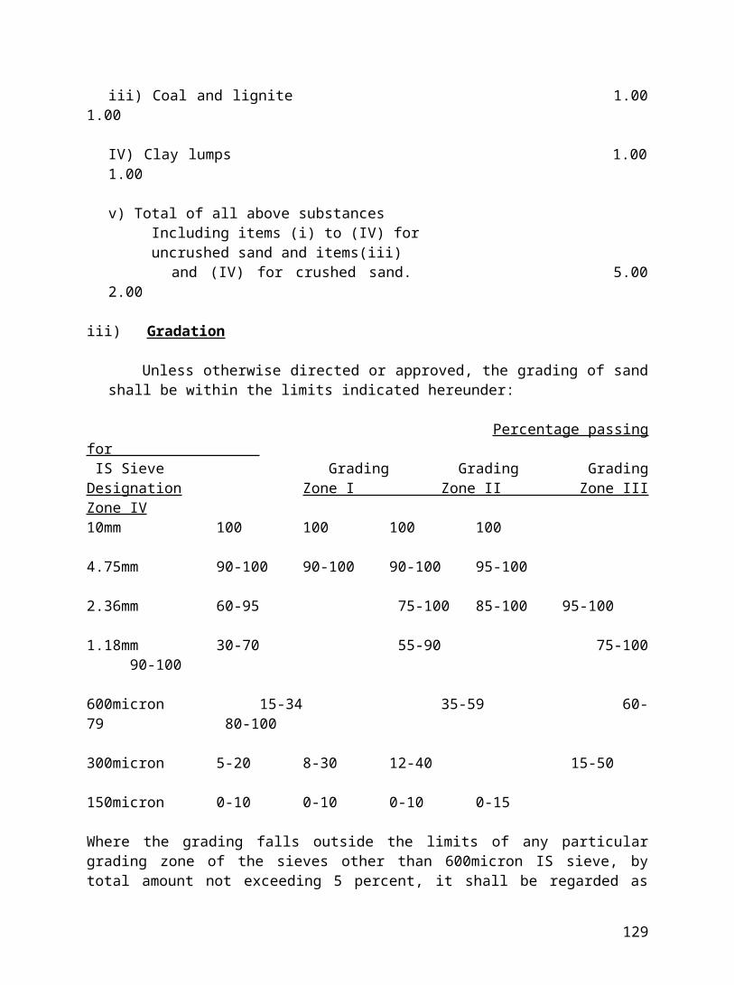
f) The exposed face of the work shall be carefully and neatly pointed with mortar in all joints on the other side the joints shall be neatly struck with trowel while the mortar is fresh.
MORTAR
The mortar for the work shall be as specified in the respective item of work. Curing or masonry shall continue for a minimum of ten days.
Mode of Measurement
The unit of measurement shall be cu.m. or part there of. The actual Quantity of masonry shall be calculated from dimensions shown on the drgs. less opening and shall be paid for. The cost includes providing bond/ through stones.
3.09 Providing and constructing Random rubble masonry uncoursed in superstructure
The specification shall be same item 3.08.
3.10 Providing and constructing coursed rubble masonry in foundation and up to plinth level.
a) The stones used shall be hard, durable rock, free from veins, flaws and other defects and shall conform to IS: 1597 (Part 1). Height of each course in the masonry shall not be 150 mm. The stones in each course shall be of equal height. All courses shall of the same height unless otherwise specified. All stones shall be set in full cement mortar of proportion specified for the respective items of work. Stone shall be got approved by the Engineer.
b) The face stone shall be squared in all joints and beds. The beds being hammer dressed or chisel dressed type and square for at least 75 mm from the face and the joint for at least 40 mm. The face of the stone shall be hammer dressed so that bushings shall not project more than 40 mm
c) No spauls or pinning shall be allowed on the face. All bed joints shall be horizontal and side joints vertical and no joints shall be more than 10 mm in thickness.
d) No face stone shall be less in breadth than in height or shall tail into the work to a length less than the height and at least 1/3rd the number of stones shall tail into the work to at least twice their height, or in walls over 600 mm in thickness 3 times their height.
e) Through stones shall be inserted every 1.5 meters to1.8 meters apart in every case and shall run right through when the wall is not more than 600 mm thick when the wall is more than 600 mm thick a line of two or more headers shall be laid from the face to face which shall overlap each other by at least 150 mm. A
129
header shall have a length of at least thrice its height.
f) Stones shall break joint at least half the height of the course. Quoins shall be formed of stones at least 45 cm long laid stretcher and header alternately. They shall be laid square in their beds, which shall be fair dressed to a depth of at least 100 mm. The corner shall be chisel dressed for a width of 25 mm.
g) The Walk on the interior face shall be precisely the same as on the exterior face unless the work is to be plastered in which case the side joints need not be truly vertical.
h) Hearting shall consist of flat bedded stone carefully laid on their proper beds and solidly bedded in mortar chips and spauls of stone being wedged in wherever necessary so as to avoid thick beds or joints of mortar. Care shall be taken so that no dry work or hollow spaces shall be left anywhere in the masonry. The face and backing shall be brought up every bed. The backing should not be leveled lip at each course by the use of chips.
MORTAR
The mortar for the work shall be as specified in the respective item of work. Curing of masonry shall continue for a minimum of ten days.
MODE OF MEASUREMENT
The unit of measurement shall be cum or part thereof. Actual quantity of masonry shall be calculated from dimensions shown on drawing less openings and shall be paid for. The cost includes the provision of bond or through stones.
4.0 WOOD WORK
Applicable codes
130
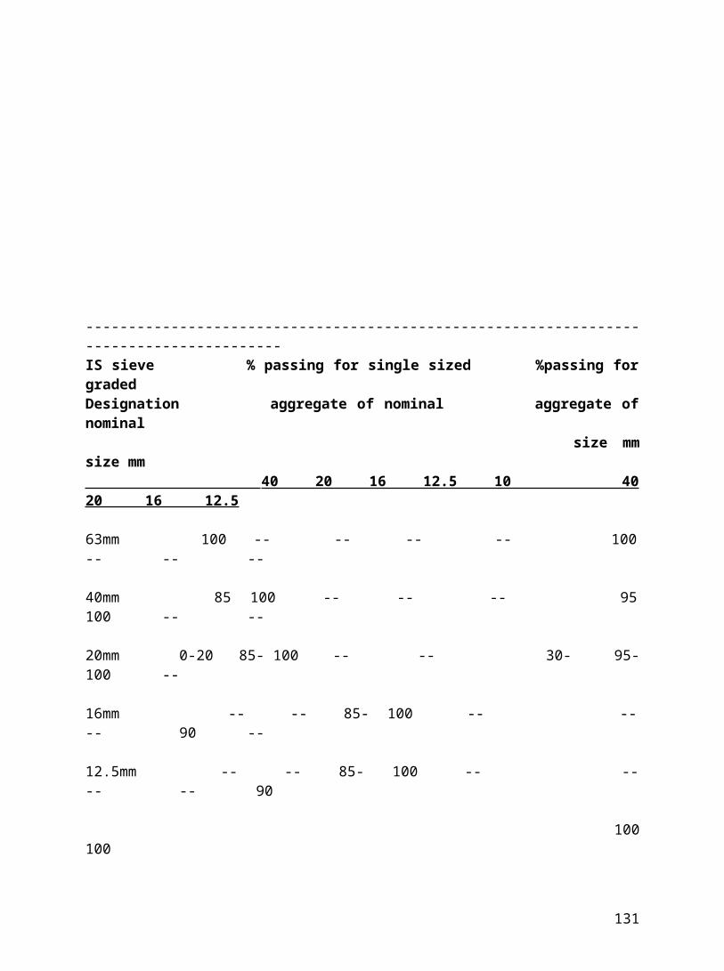
IS: 4021- Timber door, window and ventilator frames
IS: 2202- wooden flush door shutters (solid core type) part I
IS: 1003- Timber paneled and glazed shutter ( part I & II )
IS: 4020- Method of tests for wooden flush doors type tests.
IS: 1761- transparent sheet glass for glazing and framing purposes.
IS: 3097- Specification for veneered particle boards (Exterior Grade).
4.01 Providing & fixing paneled or glazed or partly paneled & partly glazed door shutters of specified thickness with frame of specified size.
a) Wood used for all work shall be the best of the respective class specified, and properly seasoned, suitable for joiner work should be of natural growth, uniform in texture, straight grained, free from sapwood, dead knots, open shakes, rot, decay and any other defects and blemishes.
b) For joints following principles to be observed:- At the joints the weakness of pieces must be minimum as far as possible. To
place each abutting surface in a joint as neatly as possible, perpendicular to pressure. To form and fit accurately every pair of surface those come in contact.
c) All joining shall be wrought on all faces and finish off by hand with sand paper with slightly rounded arises.
d) The joints shall be pinned with hard wood pins and put together with white lead. Joining shall be by means of mortise and ten on or dovetailed joints as approved. For internal joints where there is no chance of moisture the joint shall be glued. Driving of screws with hammer is prohibited. The screws shall be soaked in oil before driving them home. The heads of the screws and nails shall be sunk and puttied.
e) Any joinery work which shall split, fracture, shrink or show flaws or other defects due to unsoundness, inadequate seasoning or bad workmanship, shall be removed and replaced with sound materials at the contractor’s expense.
f) Door frames shall be riveted. All dimensions shall be as per drawings. The verticals of door frames shall project about 50 mm below finished floor, surface coming in contact with brick work shall be painted with bitumen or solignum as directed by the engineer. The door frame shall be provided with 3 nos MS 230x30x3mm flat split hold fasts on each side, respectively. These hold fasts shall be embedded in masonry or concrete work with concrete block of mix 1:2:4 and size 230x300x250. The work shall conform to IS: 4021.
131

g) The door shall be paneled or solid flush doors as described in the item of work. All doors shall be supplied with approved fittings such as hinges, mortise lock of approved make with handles on both sides, oxidized brass tower bolts and latch arrangements door stops, etc., and as shown in drawings. External flush doors shall be made of waterproof plywood as per item description in the schedule of Quantities.
h) The workmanship of all doors and window shutters shall conform to the requirements of IS: 1003 (Parts I & II) and IS: 2202 (Part I). Flush door panels shall be got tested as per IS: 4020 in standard laboratories.
i) Beading and architraves shall conform to the shapes shown on drawings or as approved and fixed by means of screws (counter sunk or otherwise) or bolts.
j) Glass
Sheet glass or plate glass shall be of Indian make as specified in the schedule of Quantities/ as directed. It shall be free from waves and bubbles and all defects. The thickness of the glass shall be as follows:-
2mm thick glass for panes up to 900 sqcm area.
3mm thick glass for panes from 900-5500 sqcm area.
4mm thick glass for panes from 5500-8400 sqcm area.
5.5mm thick glass or plate glass for panes above 8400 sqcm.
It should be clearly understood that glass which does not have uniform refractive index or which is wavy, will be rejected. The glazing shall be fixed with teak wood beading and putty.
It shall conform to IS: 1761.The putty shall be made up of one part of white lead, 3 parts of finely powdered chalk and adding boiled linseed oil to make a stiff elastic paste. No voids shall be left in the putty. Woodwork shall not be painted, oiled or otherwise treated before it has been approved by the engineer.
(k) Mode of Measurement
The doors shall be measured in sq.m. Or part thereof. The outer to outer of the frame shall be measured. The rate for the item shall include the following works:-
132
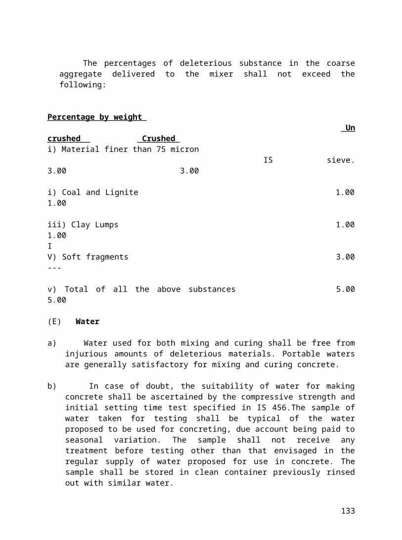
i) Providing and fixing of the frame including the cost of hold fasts and embedding in 1:2:4 concrete blocks.
ii) Providing and fixing of the shutter as specified and instructed by the Engineer
iii) Providing and fixing of architrave as per drawing.
iv) Painting / polishing of the frame, shutter and the architrave/beading
v) Fittings shall be provided as specified in the item /as per the drawings/as directed.
b) Providing and fixing of glass of specified thickness with painted/ polished teak wood beading / putty' etc. all around.
4.02 -Do- same as per item 4.01 but for 19 mm NOVA TEAK panelled or equivalent make board as filler material
The specification shall be same for item 4.01 but for NOVA TEAK or the board shall be of ISI approved make.
4.03 -Do- same item 4.02 but without frame
The specification shall be same as item 4.01 but the measurement of the actual size of the shutter shall be taken.
4.04 Providing and fixing Composite door and window partly openable, partly fixed with frame of specified size.
The specification for the door shutter shall be as per item 4.01. The specifications for the windows shall be as given below:-
The window frame shall be provided with 2 nos MS 230 x 30 x 3 mm flat split holdfasts on each side, respectively. These hold fasts shall be embedded in Masonry or concrete work with concrete block of mix 1:2:4 and size 230x300x250 mm. The type of windows shall be as specified. Each leaf of the shutter shall have one pair of hinges for a width of less than or equal to 2 feet, for width more than 2 feet extra nos of hinges shall be provided as directed by the Engineer at no extra cost. The glazed windows shall be provided with glass of thickness as specified in the item description. Architraves shall be provided as per drawing.
MODE OF MEASUREMENT
Same as item 4.01
4.05 Providing and fixing windows and ventilators Fixed type
133
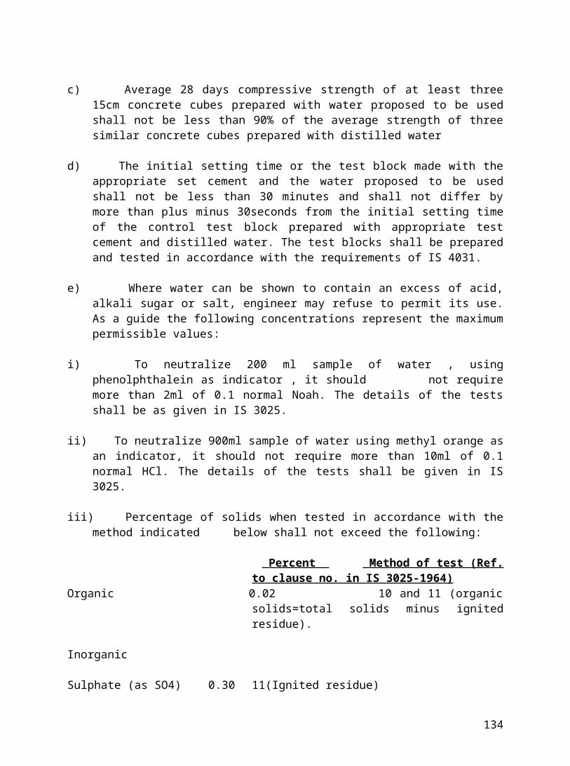
The specification for windows shall be same as given in item 4.04. Ventilators shall have two MS holdfasts. Ventilators shall be provided with glass of thickness as specified in the item description. Architraves for the ventilator shall be provided as per the drawing. Mode of measurement shall be same as item 4.04
4.06 -Do- same as item 4.05 but for fully openable type
The specification shall be same as item 4.05 but with necessary hinges as per item description/drawing. The work shall be carried out as per the drawing/ as instructed by the engineer.
4.07 -Do- same as item 4.05 but for partly openable and partly fixed
The specification shall be same as item 4.05 but with necessary hinges as per item description/ drawing.
4.08 Providing & Fixing mosquito/fly proof shutter
The specification for frames and the shutter shall be same as item 4.05 and for the fly wire mesh the following specification shall be applicable:-
Fly/Mosquito proof netting of 100G or 140G (22 to 23 SWG), rust proof, galvanized as specified in the item description shall be used. Mosquito proof of 100 G (23 SWG), 0.60mm wire dia and 1mm average distance between the wire or fly proof of 140 G (22SWG) , .71mm wire dia and 1.40mm average distance between the wire shall be used.
MODE OF MEASUREMENT
The wire mesh shutter shall be measured in sqm. The wire mesh bent up or turned back shall not be paid, only shutter out to out shall be paid. The rate shall include painting/ polishing of both sides of the shutter and the beading provided all around the wire net as specified in the item description.
4.09 Providing & fixing fixed glass louvers in TW frame of specified size
The frame shall be fixed to the masonry or RCC elements with 2 nos hold fasts. The louvre shall be provided with glass of thickness as specified in the item description. The glass shall be fixed at an angle in the frame as shown in the drawing. The frame shall be painted/polished as specified in the item description.
134
MODE OF MEASUREMENT
It shall be measured in sq.m. The outer to outer of the frame shall be measured. The rate shall include providing of frame, architrave, glass louvers, painting/polishing etc. all complete.
4.10 -Do- same as item 4.09 but with wired glass
The specification shall be same as per item 4.09. The thickness of the wired glass shall be as specified in the item description. -
4.11 Providing & Fixing built in cupboard
These shall be made of block board/particle board as specified in the item description. The shutter shall also be made of 19mm or 2Smm thick block board or particleboard or marine ply as specified in the item. 6mm thick and of suitable width teak wood lipping shall be provided on all edges. Horizontal partitions shall be provided as per the drawings /instructions. The size of the frame shall be as specified in the item description. The inside shall be painted with paint of ISI approved make and exterior shall be painted/polished as specified/directed.
MODE OF MEASUREMENT
It shall be measured in sq.m. The outer to outer of the frame shall be measured. The rate shall include provision of frame, shutter, horizontal and vertical partitions, beading and painting/polishing all complete.
4.12 Providing & fixing meter box cupboard on wall
The frame shall be of specified size and class of wood. It shall be fixed with 2 no. of holdfasts and the same may be grouted with CC 1:2:4 blocks of size 230x230x300. The shutter shall be of 19mm thick Nova teak. A slit shall be provided in the shutter as directed by the Engineer .3mm thick glass shall be fixed in the slit. Architrave shall be provided as directed by the Engineer. Fixtures as specified shall be provided. The shutter, frame and the architrave shall be painted with 3 coats of ISI approved enamel paint.
MODE OF MEASUREMENT
It shall be measured in sq. m. The outer to outer of the frame shall be measured. 4.13 Providing and fixing TW baluster (moulded hand rail)
The handrail shall be of specified quality of teak wood. The size, shape and the design shall be as per the Architect's drawing. The rounding at the landing shall be made up of monolithic one piece. The handrail shall be fixed on HS flats with
135
screws/anchor bolts as specified. It shall be applied with three coats of paint/polish as specified.
MODE OF MEASUREMENT It shall be measured in cum or part there of. Measurement shall be for the
rectangle or square cross-section circumscribing the curve ends and the actual length.
4.14 Extra for making vision panel/Venetian in flush door.
These shall be provided as shown in the drawings. The inside of the opening shall be lipped. The glass shall be braced with beading and putty. The !ipping and the architrave shall be painted with 2 coats of approved paint or polished as directed. Opening upto 0.259 sqmn shall not be deducted from the shutter area for payment.
MODE OF MEASUREMENT
It shall be measured in nos.
4.15 Providing & fixing cupboard below platform
TW frame of specified size and class of wood shall be provided. The shutter shall be of 19mm thick block board/ particle board/ marine ply shutter as specified. The frame and both the sides of shutter shall be duly painted as directed. Architrave shall be provided as specified and the same shall be painted as directed.
MODE OF MEASUREMENT
It shall be measured in sqm .The measurement shall be out to out of the frame.
136
5.0 FINISHING WORK
Applicable Codes
IS: 2394 -Code of practice for application of lime plasters finish.
IS: 1477 -Code of practice for painting of ferrous metals in buildings and allied finishes (part -I &II )
IS: 427 -Distemper, dry colours as required.
IS: 2395 -Code of practice for painting concrete, masonry and plaster surfaces.
IS: 428 -Distemper, oil emulsion, and colour as required.
5.01 Providing & Applying Cement plaster 12 mm thick
The surface to be plastered shall be washed with fresh clean water free from all dirt, loose material grease etc. and thoroughly wetted for 6 hours before plastering work is recommenced. Concrete surfaces to be plastered will how ever be kept dry. The wall should not be too wet but only damp at the time of plastering. The damping shall be uniform to get uniform bond between the plaster
137
and the wall. The junction between the brickwork and RCC should be fixed with chicken wire mesh/PVC strip as directed before plaster.
The proportion of the mortar should be as specified under the respective items of work. Cement shall be mixed thoroughly in dry conditions and then just enough water added to obtain a workable consistency. The quality of water, send and cement shall be as mentioned in the specification for concrete and allied works. The mortar thus mixed shall be used immediately and in no case shall the mortar be allowed to stand for more than 30 minutes after mixing with water. The plaster shall be laid in a single coat. The mortar shall be splashed on the prepared surface with a crewel and finished smooth by toweling. The plastered surface shall be rubbed with iron plate till the surface shows cement paste. The work shall be in the line and level. Curing of plaster shall be started as soon as the applied plaster has hardened so as not to be damaged. Curing shall be done by continuously applying water in a fine spray and shall be carried out for at least 7 days.
The plaster shall be carried out on jambs, lintel and sill faces top and undersides,
etc. as shown in the drawing or directed by the engineer.
Mode of Measurement
a) The quantity of work to be paid for under this item shall be calculated by taking the projected surface of the areas plastered after making necessary deductions for openings, doors, windows etc. as given below :-
i) No deduction shall be made for opening or end steel joints, beams. Post girders etc up to 0.5-sqm areas. No addition shall be made for joints, soffits and sills of such openings. This is applicable to both the sides of the wall.
ii) Where opening exceeds 0.5 sqm but does not exceed 3 sqm and also when only one side of the wall is treated and other side is not treated, deduction shall be made if the width of the reveal on the treated sides is less than that on the untreated side but if the width of the reveal is more then no deduction nor addition shall be made for reveals for jambs, soffits, sills etc.
iii) For openings more than 0.5sqm but not exceeding 3 sqm and also when both the sides of the wall are plastered with the similar plaster, deduction shall be made for one face only. But when both the sides treated with difference plaster, then deduction shall be made from the side on which the reveal is less and no deduction on the other side.
iv) For openings whose respective areas exceed 3 sqm deductions shall be made for the full opening of the wall treatment on both faces while at the same time
138
jambs, sills and soffits shall be measured in sqm for payment. In measuring the jambs deduction shall not be made for the area in contact with the frames of doors, windows etc.
v) If the average thickness of the plaster is more than the specified thickness due to any account nothing extra shall be paid for the same.
vi) Nothing extra shall be paid for double scaffolding and the rate is applicable for work at all levels.
5.02 Providing & Applying Cement plaster 19 mm thick
The general specification is same as item 5.0l but for the thickness of the plaster. The plasterwork shall be carried out in 2 layers, the first layer being 12-14mm thick and the second layer being 6 -7mm thick. The proportions of the mortar for both the layers shall be as specified in the item specification. The first layer shall be splashed against the prepared surface with a trowel to obtain an even surface. The second layer shall then be applied and finished leaving an even and uniform surface, trowel finished unless otherwise directed by the engineer. The plastered surface shall be rubbed with the iron plate till the cement paste comes on the surface.
Mode of Measurement
It is same as specified in item 5.01.
5.03 Providing & Applying lime punning to the plastered surface
The plastered surface shall be finished smooth by trowel ling on the surface with neeru (lime cream). Neeru shall be properly slaked fat lime. The neeru shall be applied at the rate of 2.2 kg per sqm.
Mode of Measurement
As it shall be measured in sq.m. The rate shall include the cost of lime double scaffolding, finishing and curing the work at all levels. The deduction mentioned in the item 5.01 shall be applicable here also.
5.04 Providing and Applying 19mm sand faced plaster
a) This shall be applied in 2 coats. The first coat or the base coat should be approximately 12 mm and shall be continuously carried out without break to the full length of wall or natural breaking points such as doors, window etc. The base coat shall be splashed on to the prepared surface with heavy pressure, brought to true and even surface and then lightly roughened by cross scratch lines, to provide bond for the finishing coat. The mortar proportion for this base coat shall
139

be as specified in the respective item of work. The base coat shall be cured for at least seven days.
b) The second coat shall be 6mm thick. Before application of the second coat, the base coat shall be evenly damped. This coat shall be applied from top to bottom in one operation and without joints, finish shall be straight, true and even. The mortar proportions of this coat shall be as specified under the respective item work. Sand to be used for the second coat and for finishing work shall be as specified in the item description. The second coat shall be finished with sponge. Grooves shall be made as per the drawings.
MODE OF MEASUREMENTIt shall be same as per item 5.01.
5.05 Providing & Applying rough cast plaster
This shall be carried out in two layers. The base plaster shall be of 12 mm thick and of specified proportion of CM. It shall be roughened to receive the top layer the top layer shall be 7mm thick. It shall be of 3 parts cement, 6 parts coarse sand & 4 parts of 6mm to 10mm single or crushed stone aggregate. The plaster shall be cured at least for 7 days.
MODE OF MEASUREMENT
It shall be same as that of item 5.01.
5.06 Providing & Applying waterproof cement plaster
The plaster shall be of specified thickness and of mortar proportions. The contractor shall use approved waterproofing admixture made by reputed manufacturer in the mortar for plasterwork. The quantity to be used shall be in accordance with the manufacturer's instructions, however subjected to the approval of the Engineer. The use of Calcium chloride shall be prohibited unless specifically allowed by engineer and shall conform to IS:2645. The plaster shall be cured at least for 7 days.
MODE OF MEASUREMENT
It shall be measured in sq.m. The rate shall include the double scaffolding, plastering and curing. The amount of water proofing material added shall be measured and paid for separately.
5.07 Providing & Applying neat cement
The specification same as per item 5.03 except that neat cement is applied to the plaster surface in place of neeru.
140
5.08 Providing & Applying cement pointing
a) The dust shall be brushed out of the joints and the wall be washed with water.
b) The mortar shall consist of one part of cement to one part of fine sand. Mortar shall be filled into joints and well pressed with special steel trowels. The joints shall not be touched against after it has once begun to set.
c) The joints of the pointed work shall be neat. The lines of false joints shall be allowed.
d) The work shall be cured for a week after the pointing is complete. Whenever coloured pointing has to be done the colouring pigment of the colour required shall be added to cement in proportion as recommended by the manufacturer and as approved by the engineer.
MODE OF MEASUREMENT
The area pointed shall be calculated in sqm from dimensions shown on drawings less openings as given in the item 5.01 and shall be paid for. The rate quoted shall be applicable for all levels and heights.
5.09 Providing & Applying White washing on new works -3 or more coats
Walls to be thoroughly scrapped with sand paper before white wash is applied. White wash shall be prepared from a good quality fat lime. Lime shall be slaked with water to the consistency of a cream and allowed to remain under water for 2 days .If shall then be strained through a cloth and 2 kg of clean gum of approved make, as specified in the item specification or by the Engineer, shall be added for every cubic metre of lime and indigo up to 3gm per kg of lime dissolved in water shall then be added and stirred well.
Each coat to be applied with a brush. It shall be applied with a stroke of the brush from the top, downwards another from bottom upwards over the first stroke and similarly one stroke from the right and another stroke from left over the first brush, before it dries. Minimum three coats shall be applied on the plastered surface for desired finish. If the desired finish is not obtained extra coats shall be applied without any extra cost.
MODE OF MEASUREMENT
It shall be measured in sqm. Deductions shall be carried out as per item 5.01. The rate shall be applicable for carrying out the work at all heights, double scaffolding etc. all complete. Extra 20% shall be added to the area for AC corrugated sheets and 17% for semi-corrugated sheets, cornices and others.
5.10 Providing & Applying Plastic Emulsion paint
141
Paint to be used for the various items of work should be of approved make viz. British, Asian, Jenson & Nicholson, ICI or Shalimar .The painting work shall be carried out as directed by the engineer, keeping however in view the recommendations of the manufacturer. Where painting with plastic emulsion is specified, all uneven surfaces shall thoroughly cleaned of all dust dirt and sand papered. One primer coat with cement putty and minimum 2 coats of emulsion paint shall be applied. It shall be applied with rollers. Workmanship shall conform to the requirements of IS:2395.
Mode of Measurement
The actual Quantity of work carried out shall be measured in sq metre. Deduction for opening etc. shall be made as in the case of cement plaster.
5.11 Providing & Applying Cement paint
This may be "SNOWCEM" or of equivalent make. The surface shall be prepared as specified in the specification for white wash. This shall be applied with brush on the plastered wall. The strokes shall be even and it shall be cured at least for 7 days. No patch or brush stroke shall be seen. Three coats shall be applied.
MODE OF MEASUREMENT
It shall be measured in sqm. The deductions shall be as specified in the item 5.01
5.12 Providing & applying silicon paint
This shall be applied over the external plaster for rendering it waterproof. This shall be applied with brushes. The paint shall be of approved quality.
MODE OF MEASUREMENT
It shall be measured in sqm.
5.13 Providing & fixing chicken mesh
The wire mesh shall be of 24 gauges and it shall be fixed with nails at the junction of brick masonry and RCC elements. The chicken wire mesh shall not sag in between the nails. This shall be done before the application of plaster.
142
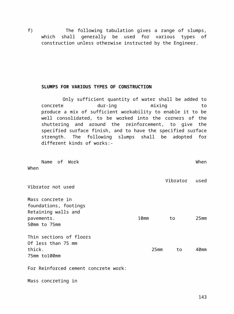
MODE OF MEASUREMENT
It shall be measured in sqm. Measurement shall be taken before the application of the plaster. The rate includes for carrying out the work at all heights.
5.4 Providing & Applying dry distemper
Distemper shall be or approved make. It shall be applied by a broad stiff brush in two coats over a coat: of primer. The first and second coat shall be applied only after the primer coat has thoroughly dried .The first coat shall be of a lighter tint .The shade of the distemper shall De got approved by the Engineer. Water bound and oil bound distemper shall conform to the requirements of IS:427 and IS :428 respectively.
5.5 Providing & Applying Colour Wash
Colour wash shall be applied the same way as white wash. Necessary and approved colouring chemicals shall be added to the white wash which has been strained. Only colour wash required for the day’s work shall be prepared. If the finished surface is powdery and comes off easily or the general appearance is streaky, the work shall be rejected. The contractor has to redo the work at no extra cost.
MODE OF MEASUREMENT
Same as item 5.09
143
6.0 FLOORING
Applicable codes.
IS: l443 -Code of practice for laying and finishing of cement concrete flooring tiles.
IS: 2ll4 -Code of practice for laying in site terrazzo floor -finish.
IS: 777 -Glazed earthenware tiles
6.01 Providing & fixing precast Mosaic tile flooring
The type, quality, size, thickness. colour etc. of the tiles for flooring shall be as per the item description given in the Schedule of Quantities and of best quality .The contractor shall provide the Engineer with necessary sample for approval.
Before the tiling work is commenced, the sub-surface shall be thoroughly cleaned and washed of all loose material, dirt and scum and then shall be wetted without forming water pools on the surface. The tiles shall be laid on cement mortar or lime mortar bedding of thickness and proportion as specified in the item description. The mortar shall be evenly spread on the sub-floor. Over this mortar bed, 4.4 kg of cement per sq.m of floor area shall be spread. The tiles shall be fixed on this bed one after another. Each tile being gently tapped with a wooden mallet till it is properly bedded and in level with the adjoining- tiles. The joints shall be perfectly straight and uniform in thickness. The tiles shall be laid perfectly in level unless otherwise specified by the Engineer. After laying the tiles the joints shall be finished with white cement or ordinary cement as specified.
144
For lime mortar-bedding lime from burnt stone shall be used. It shall be free from ash and impurities and be in the form of lumps and not powder when brought to site, lime which is damaged due to rain, soaking moisture or air slaking shall be rejected.
Floor tiles laid adjoining the wall shall project 12mm or as specified under the plaster, skirting or dado as directed by the Engineer. Half tiles and pieces shall be avoided as far as possible. After laying the tiles, it shall be cured for at least 14 days. About a. week after laying the tiles each and every tile shill be lightly tapped with a small wooden mallet to find out if it gives a hollow sound, if it does, such tiles along with any other cracked or broken tiles shall be removed and replaced with a new title to proper line and level. The same procedure shall be followed again after the tiles are finally polished. For the purpose of ensuring that such replaced tiles match with those earlier laid it is necessary that the contractor order enough extra tiles from the factory to meet this contingency. The tiles shall finally be cleaned and polished by using dilute oxalic acid or any other method recommended by the manufacturer and approved the engineer.
After the joints have attained sufficient strength, the floors shall be machine polished to the desired finish approved by the Engineer. Sufficient quantity of water shall always be used during polishing to prevent scratches.
MODE OF MEASUREMENT
Unit of measurement for floor tiling shall be sq.m or part thereof of the superficial area. Actual quantity of tiling work carried out shall be measured and paid for after making deductions for openings etc. The rate shall include the cost of tiles including wastage laying as per specifications, curing ,polishing etc. all complete.
6.02 Providing & Fixing Precast Mosaic tiles in skirting dado and risers
For dado and skirting work, the vertical surface shall be thoroughly cleaned and wetted. Thereafter it shall be evenly and uniformly covered with about 12 mm thick 1:3 cement mortar. For this work the tiles as obtained from the factory shall be of the size required and practically fully polished. The back of each tile to be fixed shall be covered with a thin layer of neat cement paste and the tile shall then be gently tapped against the wall with a wooden mallet. This shall be done from the bottom of the surface upwards. The joints shall be as close as possible and the work shall be truly vertical and flush. The tiles shall be fixed flush with the plaster of projects as specified by the engineer. The junction of the plaster and the skirting or dado shall be neatly finished. The joints shall be filled with ordinary cement unless otherwise specified. After the tile has set, hand polishing with carborundum stones shall be done so that the surface attains a glossy finish. Corners and junctions be finished true.
145
MODE OF MEASUREMENT
Skirting, dado or risers shall be measured in sqm or part thereof. The rate shall include providing tiles including wastage, laying as per specifications, filling joints, curing, rubbing and polishing etc. all complete.
6.03 Providing & laying cast-in-situ Marble chips flooring
The marble chips shall be of approved size, colour and shade. The cement used may be white cement or cement mixed with coloring pigments as directed by the engineer. The proportion of marble chips to cement shall be as specified in the item description, but in no case it shall be less than 2.5:1. Samples of terrazzo/mosaic work shall be prepared for approval of Engineer. The entire work shall conform to the approved samples. The terrazzo chips shall-be laid after placing the base. The base shall consist of a layer of 28 mm thick 1: 2: 4 cement
concrete (1 cement, 2 coarse sand, 4 19mm and down graded stone aggregate) spread and levelled. While laying the flooring dividing strips of glass/PVC/aluminum of specified thickness shall be inserted in the mortar bed according to the design of the floor. Care being taken to see that no panel exceeds 1.5 sq.m in area. The top of strips shall be 10mm above the surface of the underbed and shall conform to the finished level of the floor. Chips shall be thoroughly mixed dry and then white cement or cement of approved colour shall be added in specified proportion. Chips and cement shall be thoroughly mixed and evenly spread on the platform and not heaped. Water shall then be added to obtain a plastic mix of suitable consistency as directed by the Engineer. Terrazzo layer shall be placed as soon as the screed coat has set sufficiently but in no case than the day thereafter. The thickness of terrazzo topping shall not be less than 10mm. The surface shall be rammed to obtain the consolidation and a levelled surface. Additional chips shall be sprinkled on the surface and rammed in until surplus cement is checked out and chips forced together so that the finished floor will show not less than 70% aggregate. The surface is finally trowelled lightly. The Contractor shall keep the floor moist for not less than seven days. The surfaces shall then be machine polished. Voids shall be filled with neat grouting of same kind and colour as matching. This grouting shall remain at least 72 hours before being removed for final cleaning. The floor shall be refinished wherever necessary to leave the work in first class condition.
MODE OF MEASUREMENT
This shall be measured in sqm. The rate shall include providing and laying marble chips flooring with dividing strips, curing. machine/hand polishing. This item shall be also applicable for flooring in landings, kitchen platform etc.
6.04 Providing & laying cast-in-situ marble chips in skirting and dado
146
The height of the skirting/'dado shall be as per the drawing. The base layer shall be 12mm cement mortar of 1.:3 proportion (1 cement, 3 coarse sand) and top 7 mm thick layer shall be of approved marble chips in proportion 1:2 (1 cement, 2 marble chips) .While laying the skirting/dado glass strips of specified width shall be provided. The skirting/dado shall be flush with the plaster or projected as specified by the Engineer. The junction between the skirting/dado and the plaster shall be finished properly. The skirting/dado shall be hand polished.
MODE OF MEASUREMENT
It shall be measured in sqm. The rate shall include providing and laying marble chips in skirting/dado. Dividing strips, curing, rounding off the corners of the floor and the skirting hand polishing, cleaning etc.
6.05 Providing & laying polished green Kota stone flooring
Stones shall be of approved quality, size and uniform thickness, edges shall be chisel dressed and the top surfaces shall be machine polished with joints running true and parallel from side to side. Stones should be laid on a bed of cement or lime mortar. The pattern of the flooring shall be as per the Architect’s drawing. Thickness of mortar bedding shall be as specified in the item specification. The stone slabs shall be thoroughly wetted with clean water. Neat cement shall be spread over the mortar bed and the slabs shall be placed one by one, keeping in check the level and line of flooring. The slabs are then gently tapped with wooden mallet till it is firmly and properly bedded. There should be no voids left. The joints should not be more than 2 mm thick. The joint should be struck smooth. If specified terrazzo filling of specified thickness shall be done in the joints between the Kota stone slabs. The floor should be kept covered with damp sand or water for a week. Slabs should of sizes as specified. The stone shall be machine polished and then cleaned with oxalic acid. If the contractor is asked to mop the floor with kerosene and water by the engineer, the same shall be done without any extra cost. This shall be carried out daily at least for 10 times for 7 days.
MODE OF MEASUREMENT This shall be measured in sq.m. The rate shall include providing and laying,
curing, machine polishing, cleaning etc. all complete.
6.06 Providing & laying Kota stone in skirting and dado
The Stone shall be of required sizes and the thickness shall be as mentioned in the item specification. The stones shall be pre-polished and machine cut. The stone’s edges shall be dressed fine true, straight and at right angles to each other. The stones shall be fixed over cement mortar bed 1:4 (l cement;4 coarse
147
sand .The joints are filled with ordinary cement and hand and wax polished. The joint between the top of skirting/dado and plaster shall be finished properly. The joints in the flooring shall be continued in the skirting/dado also. The work shall be cured properly.
Mode of Measurement
This shall be measured in sqm. The triangle skirting of staircase shall also be paid under this item. If mopping of the Kota stone is asked to be carried out instead of wax polishing the same shall be carried out with out extra cost.
6.07 Providing & Laying pre-polished, machine cut Kota stone in treads Polished green Kota stone of specified thickness with machine cut edges shall
be fixed for treads of steps in single piece or on the kitchen platform or open shelves and windowsills as directed. The stones shall be hand and wax polished. The laying procedure is same as specified in the item 6.06 above. Curing shall be done properly.
MODE OF MEASUREMENT
. Measurement shall be in sqm of the stones laid. If mopping of the kota stone is asked to be carried out instead of wax polishing the same shall be done continuously for ten days by the Contractor. It shall be done as specified in the item description in the Schedule of Quantities.
6.08 -Do- as above for stones up to 1.5m in length in single piece
Same as per item 6.07.
6.09 Providing & fixing kota stone shelves The stones shall be pre-polished on both the sides and the thickness shall be 25
to 30mm. The stones shall be placed in the brick masonry zarries and the same shall be finished properly.
MODE OF MEASUREMENT This shall be measured in sqm. The rate shall include providing' kota" stones,
cutting zarries, placing the shelves, filling zarries, propping them till the CM sets and curing all complete.
6.10 Providing & Laying rough chiselled kota stone Flooring
The stones shall be of specified thickness and size. The stones shall be placed on 20 thick CM bedding or lime mortar bedding and the joints shall be with CM
148
1:2(1 cement,2 stone dust). The joints shall be finished flush or with "V” grooves of 5 to 8mm wide and 8mm deep. The slope shall be maintained as given in the drawing or as directed.
MODE OF MEASUREMENT
This shall be measured in sqm. The rate shall include providing and laying of stones, finishing of joints etc. all complete.
6.11 Providing & Laying 40mm thick IPS flooring
The mix shall be 1 part cement. 2 parts coarse sand 4 parts graded stone aggregate. The flooring shall be laid in panels of uniform sizes not exceeding 2 sq.m. They shall be laid in alternate panels on alternate days. The edges shall be protected properly. Glass/PVC /aluminium strips shall be provided to separate the panels, as per the item description in the Schedule of Quantities. The slope shall be maintained as directed by the Engineer.
The mix shall be prepared by volumes. Mixing shall be done in mIxers. The concrete shall be placed in position and leveled up with the help of wooden straight edge and trowel and beaten up well till slurry comes on top and holes filled up with concrete.
If IPS has to be laid directly on RCC slab, the surface of the RCC slab shall be roughened up with brushes while the concrete is green. Before laying the floor the laitance, loose materials, cake of mortar dropping shall be removed and the surface of the slab hacked and coat of cement slurry @2.75 kg of cement per sq.m. shall be applied so as to get a good bond between the slab and IPS. IPS has to provided on lean concrete no slurry is required.
The flooring shall be finished with 12mm thick (1:1) cement-sand mortar and cement slurry @2.2kg of cement per sq.m. And water shall be applied on top with wooden float till the voids in the concrete are filled with mortar cream. The surface must be uniform and even in colour. Dry cement or cement sand mixer shall not t sprinkled to absorb excess moisture in the flooring. Colour pigments shall be added to the flooring if instructed by the Engineer. Curing shall be done for seven days. The, edges of the panels shall be protected from damage.
MODE OF MEASUREMENT
The flooring shall be measured in sq.m. The finishing plaster is included in the IPS flooring item and shall not be measured separately. The rate shall include providing and laying IPS flooring, finishing the work, curing, rounding of the edges between the wall and skirting.
6.l2 P & L IPS flooring of 50 thick
-Do- same as item 6.11 but for 50mm thick.
149
6.13 Providing and laying l5-20 mm thick IPS in skirting/dado
The specification shall be same as the item (6.11 but for the work is to be done on vertical surfaces. It is of two layers the base layer shall be of l2mm thick RCC 1:2:4(l cement;2 sand; 4 graded stone aggregate of size 12mm and down). Then it shall be finished with 6mm thick plaster with CM 1:1.
Mode of Measurement
It shall be measured in sqm. The rate shall include the chipping of RCC/brick work, dividing strips, laying the base and the top layer, curing etc. all complete.
6.14 Extra for providing. Mixing and laying of IRONITE
The ironite shall be consisting of uniformly grace iron particles, free from non-ferrous metal particles oil, grease, sand and soluble alkaline compounds. This shall be mixed with cement in proportion of 4 cement and 1. compound by weight. The laying procedure is same as per the specification for IPS flooring.
MODE OF MEASUREMENT The metallic compound added to the IPS flooring shall be measured in Kg.
6.17 Providing & Laying Industrial tile in floorings skirting and dado.
The sizes of the tiles shall be 600mm x 600 mm or as directed, and the thickness shall be 19mm for flooring and 15-20mm for skirting and dado. The stone shall be acid and alkali resistance shall be approved by the Engineer.
The approved quality of acid and alkali preventive primer shall be applied uniformly in two coats over the slab or the concrete surface. The acid-alkali proof powder shall be mixed with the cement in the proportion 2:1 (2 cement: powder) or as per the manufacturer's specification. The cement powder mix and the sand shall be mixed in the ratio 1:3 and the mortar shall be prepared. The stones shall be laid on the mortar bed in level and line with even thickness of 6mm to 10 mm joints all around.
The joints shall be raked to 12-19mm deep and filled with epoxy based resin. The resin is mixed with quick dried and acid alkali proof powder. As the resin is an atmospheric hardening agent, it does not required curing. The work place shall be kept dry for the joint filling operation. The stone shall be either hand polished or machine polished cleaned with oxalic acid and wax combined.
MODE OF MEASUREMENT
The work shall be measured in sqm or part thereof. The rate shall include providing and laying of stones as described above. Nothing extra shall be paid
150
for cutting holes in the stone, machine cutting of edges, stones for steps and raisers, etc.
6.13 P&L Ceramic tiles in flooring. skirting and dado
The ceramic tiles in flooring and dado shall be of first class quality as specified in the item specification and shall be approved by the Engineer. The tiles shall be of standard size with out warp and with straight edges, true and even in shape and size and of uniform colour. The tile surface shall be of fine grain texture, dense and homogenous. The thickness of the tile shall be as per the item specification. The tiles shall be submerge in the water till the bubbles cease.
They should be laid on a base of l2mm thick mortar bed (cement or lime 1:3 sand) and cement (3 kg/sqm) paste. They shall be laid truly vertical on walls and truly horizontal on floors or to slopes as directed. The joint shall be very thin, uniform and perfectly straight. The tiles in dado shall be finished in such a way that, only the tile thickness projects over the finished plaster or as specified otherwise. Where full tiles are not possible the same should be cut or sawn to the required size and their edge rubbed to ensure straight and true joints. After the tiles are laid extra cement grout shall be removed. The joint shall be cleaned with wire brush and then the joint shall be floated with white or gray cement as approved by the Engineer. The tiles shall be cleaned after the work is complete.
MODE OF MEASUREMENT
This shall be measured in sqm. The rate quoted for flooring and dado work shall be inclusive of angles and corner pieces, cutting tiles for water points, such away that the point is in the junction of four tiles, electrical points etc.
6.19 Providing & Laying glazed tiles
-do- same as item 6.19.
6.25 Providing & Applying 115mm thick water proofing treatment
First layer of about 20mm thick in CM 1:3 (1 cement, coarse sand) mixed with waterproofing compound of M/S.lndia Water Proofing Co., Bombay or equivalent shall be laid as instructed by the Engineer. Then brickbats shall be laid over this required slopes and levels as per the drawings and the instructions of the Engineer. The surface of the brickbats shall be finished smooth with another lay of waterproof plaster and the gaps between the brickbats shall also be filled with CM mixed with waterproof plaster. Finally the surface is finished smooth and desired pattern are formed on the surface with thread. All opening sleeves, drains, pipes, etc. shall be specially treated and made sure that they are water tight.
151
MODE OF MEASUREMENT
The item shall be measured in sqm. The wall flashing or the watta shall also be measured in sqm. A guarantee certificate for a period of ten years shall be issued by the Contractor for free maintenance of the treated area.
6.27 Providing & Laying Cast iron tile flooring
The tiles shall be laid over a bed of 37 mm thick 1:2:4; 1 cement; 2 coarse sand; and 4 graded stone aggregate of nominal thickness 12mm and down. The tiles shall be fixed in line and level as per the drawing and as directed by the Engineer. The .joints shall be filled with 1:1 cement mortar, 1 cement and 1 sand. Curing shall be done at least for15 days. 7he tiles shall be hand/machine polished and the entire surface shall be smooth and all joints shall be filled properly.
MODE OF MEASUREMENT
This shall be measured in sqm. Nothing extra shall be paid for cutting tiles around drains and for corner pieces.
7.0 STEEL WORK
Applicable Codes
IS: 4351 - Steel door frames
IS:1038 -Steel door, windows and ventilators.
7.01 Providing & Fixing pressed steel frames for doors They shall be made of hollow metal pressed section of approved make such as
“Perfect Industrial Products", TIL or of equivalent make. They shall be single/double riveted as per the architect’s drawing. It shall be made of CR sheet of size 65x125x1mm thick . It shall be provided with four hinges of 125x2 mm thick of friction type. Four hinges shall be provided per leaf of the door. The frame shall be provided with a hold fast size 150x20x3 mm for each size and the same shall be embedded in brick work with CC 1:2:4 blocks of size 300x23x230 mm. The hollow portion of the frame shall be fitted with CC 1:2:4 before it is fixed.
The frame shall be painted with red oxide primer. There shall be provision in the frame for fixing of tower bolts, aldrop, louvers, mortise lock, etc. The frame shall
152
be painted with two or more coats of approved synthetic enamel paint to get a uniform finish.
Mode of Measurement
It shall be measured in RM. The rate shall include providing and fixing of pressed steel frame as per above specification.
7.02 Providing & Fixing pressed steel section windows for fully openable windows
The frame shall be of size 100x6x1mm thick and it shall be of perfect industrial Products. TIL Senharvic, Agew, or of any approved make. The frames shall be double riveted. The frame shall be provide with 3 holdfasts of 100x15x3 mm.
Long and the same shall be grouted with cc 1:2:4 in the brick work or to RCC member. Shutters shall be made of standard steel sections style f7d, sash bsr of t6 and locking ba4r of f4b section. The hollow portion of the frame shall be filled with cc 1:2:4 before fixing the frame.
Glass of 4mm or 5.5mm shall be fixed with beading as per the architectural drawing the beading shall be of aluminum or GI hollow square pipe of 10 sq mm and wall thickness 1.25mm.
The section shall be provided with arrangement for fixing the ms or aluminum oxidized handless and washers. The window section shall be painted with one coat of primer and two coats of synthetic enamel paint of approved make and shade
Mode of measurement
It shall be measured in sq m. the rate shall be providing and fixing steel windows as per the above specifications.
7.03 -do- same as item 7.02 party open able and partly fixed windows
-Do- same as item 7.01
7.04 -do- same as item 7.01.for fixed windows
-Do- same as per item 7.01
7.05 -do- same as item 7.01 but for louvered ventilators
-Do- same as above but provision shall be given for fixing 4/5.5 mm thick glass
7.06 providing &fixing fly proof shutter
This shall be fixed to the existing pressed steel frame. The wire netting shall be 22 to 23 SWG and galvanized. The beading shall be of MS flat 25x3 mm with screws. The shutter shall be provided with 4 nos. of friction type hinges. The section shall be provided with arrangement for fixing tower bolts and handles. It
153
shall be painted with one coat of primer and 2 coats of approved synthetic enamel paint.
7.07 Providing & Fixing GI BRC fabrics This shall have a GI rectangular or square shape 75, 50, 25 mm size as per
requirement. The gauge of the wire shall be 8X10. The gap size shall be 75X25 mm in general unless be 8X10. The gap size shall be 75X25 mm in general unless specified otherwise. This shall be welded/bolted to the MS Frame made of angle iron 40x 40 x 6 and tee 40 x 40 x 40 x 6 mm with an ms beading of 30 x 3 or 12 x 6 mm or as specified in the item description in the schedule of quantities. This shall be painted with one coat of primer and 2 coats of approved synthetic enamel paint of first quality as specified in the item description.
Mode of measurement This shall be measured in sq m.
7.08 Providing & fixing rolling shutters The rolling shutters shall be of 18 gauge ms solid laths or grill with all the
accessories such as top cover (conform to the size indicated in drawings and shall be of quality specified in the item specification. The rolling slats shall be in one piece and be made of heavy gauge steel sheets minimum 19 SWG in thickness. A cylindrical hood shall be provided on the top to enclose the shutter when it is open. The rolling shutters shall be provided with suitable locking arrangement and deep channel guides. In case galvanized rolling shutters are specified the rolling shutter shall be made of hot dip galvanized slats hood, deep channel guides all preferably in one louse. The channels guides shall be fixed with holding down bolts with pcc 1: 2: 4 (1 cement, 2 sand, 4 coarse aggregate of nominal size 12mm and down).
Incase of hand operated pull and push type rolling shutters and very large than
10 sq m in area, they shall be provided with ball bearing for smooth and efficient operation in case of large rolling Sutherlands depending upon local wind conditions the rolling shutters should be provided with special locking type of wider channel guides or it shall be provided with central wind pressures in the area.
Mode of measurementi) The measurement shall be in sq m the width shall be measured as the width of
the shutter including the portion hidden in the guide channels and the height shall be measured from the bottom of the locking plate to the bottom of lintel and to this 450mm shall be added for the top hood.
ii) The rates quoted shall be inclusive of providing and fixing of rolling shutter with push and pull arrangement two coats of approved paint over 2 coats of approved primer coats (one shop cot and one coat after erection) fixing lugs to be provided to guide channel to suit actual site conditions or as directed by the engineer at no extra cost. The mechanical arrangement provided for the opening and the closing of the shutter shall be paid for separately in sq m of the shutter area as specified in the item description.
7.09 providing &fixing mechanical operated rolling shutters -Do- same item 7.08.
154
7.10 providing & fixing partly grilled rolling shutters -Do- same as items 7.08.7.11 providing & fixing in position grill, railing, steel ladder etc.
This work shall be carried out as per the detailed drawing of the architect. The ms sections shall be of approved quality .the welding shall be perfect and the junctions shall be ground properly. The frames shall be provided with holdfasts. And the same shall be grouted with cc blocks of 1: 2: 4 in brick work. It shall be painted with one coat of prime and 2 coats of approved synthetic enamel paint.Mode of measurement
The dimensions of the members shall be measured in unit length and the same shall be converted in to weights as per the standard steel table. The payment shall be done based or the weight of the item.
7.12 Providing and fixing MS inserts in RCC and brick work
a) Inserts, bolts, etc shall be provided in masonry and concrete works as indicated on the drawing .It is imperative that all Inserts, bolts fixtures and fittings shall be provided in their Position very accurately such inserts and bolts be fixed with necessary templates if due to negligence on the part of contractor the inserts bolts fixtures and fitting etc are out of alignment the contractor shall make arrangements to have the inserts and bolts removed and reaffixed in their proper position as directed by the engineer at no coat of primer and two coats of approved synthetic enamel paint.
b) Mode of measurement It shall be measurement in kg. The measurement at site shall be taken in unit
length and the same shall be converted in to weight using standard steel coefficients/actual weight taken in the presence of the engineer.
7.13 providing & fixing ms gate It shall be as per the drawing . the welding shall be perfect and the junctions shall
be ground properly .the gate shall be provided with locking arrangements hinges and it shall be painted with one coat of primer and two coats of approved synthetic enamel paint.
Mode of measurement All the member of the gate shall be measured in unit lengths and the same shall
be measured in unit lengths and same shall be converted in to weight using standard steel tables. The payment shall be made in kg.
7.14 Providing & fixing GI pipe railing It shall be done with the specified class of GI pipe as per the item in the schedule
of quantities. All necessary specials, bends, elbows tees and holdfasts or clamps shall be provided. If the pipe railing is to be fixed on ground or brick work it shall be done by embedding the holdfasts, as directed b the engineer, in concrete blocks Pcc 1: 2: 4 (1 cement 2 sand, 4 graded coarse aggregate of size 12 mm and down). If it is to be fixed to an Rcc member, the pipe shall be welding to the steel plate by embedding it in the Rcc member.Mode of measurement
155
The running length of the railing shall be measured. The verticals shall not be paid separately fixing ms door frame
7.14(B) Providing & fixing SS pipe railing It shall be done with the specified class of SS pipe as per the item in the
schedule of quantities. All necessary specials, bends, elbows tees and holdfasts or clamps shall be provided. If the pipe railing is to be fixed on ground or brick work it shall be done by embedding the holdfasts, as directed b the engineer, in concrete blocks PCC 1: 2: 4 (1 cement 2 sand, 4 graded coarse aggregate of size 12 mm and down). If it is to be fixed to an RCC member, the pipe shall be welding to the steel plate by embedding it in the RCC member.
Mode of measurement
The running length of the railing shall be measured. The verticals shall not be paid separately fixing ms door frame
7.15 Providing & Fixing MS door Frame.
It shall be fabricated from structural steel as per the details and drawings. All the members shall be free from rust, flakes cracks and other fabrication defects. All holes for hinges, bolts, locking plates etc. shall be provided as per drawings/instructed. The welding shall be smooth. the frame shall be erected and fixed with ms holding 1: 2: 4 (1 cement , 2sand, 4 graded coarse aggregate of nominal size 12 mm and down ) the frame shall be painted with a coat of primer before erection and 3 coats of synthetic enamel paint of specified quality after erection.
Mode of measurement
The length of the members shall be measured and be converted correspondingly in to weight in kg using the standard unit weight coefficient the rate shall include fabrication, erection and painting of the frame.
7.16 Providing & fixing ms sheet door
The frame shall be of ms as specified above. The door shall be as per the architect, s design. The specified gauge ms sheet door shall be welded to the frame. It should have 3 to 6 hinges depending on the shutter size. It shall have fittings as specified in the item/ architect's drawings. The door shall be applied with a coat of primer and 2 coats of synthetic enamel paint of quality as specified.
MODE OF MEASUREMENT
This shall be measured in Sam. If the frames are not included in the item then only then shutter area shall be measured and paid for. The rate shall include fabrication, provision, erection of the door necessary fittings as specified, painting etc. all complete.
156
7.17 PROVIDING & FIXING GI BARBED WIFE FENCING.
This fencing shall be either be made with RCC posts and struts or with MS posts and struts shall be of size and length as specified in the item description in the Schedule of Quantities. It shall be free from cracks, twists and honey combing.
MS posts and struts shall be of size and section as specified in the item description. One end of the angle shall be forked to have grip in the concrete and the other side shall have a hole to receive the fencing wire. It shall be applied with a coat of primer and 2 coats of synthetic enamel paints.
GI WIRE
It shall be 12 to 14 gauge with 4 points barb with two wires twisted together or as specified in the item description and other defects and uniformly galvanized. The type, length and standard weight of the GI wire shall be as specified below.
---------------------------------------------------------------------------------------------------------------------Nominal dia Point wire Nominal distance Length in M/100kgOf wire between two Nominal Min. Max.Line wire barbs---------------------------------------------------------------------------------------------------------------------2.5mm 2.24mm 75mm 1000 934 10662.5 2.24 150 1134 1066 12002.24 2.24 75 1576 1490 16682.24 2.24 150 1890 1778 2000---------------------------------------------------------------------------------------------------------------------
The GI barbed shall be well stretched in number of rows as specified with two diagonals. The spacing shall be equidistant. The posts and struts shall be embedded in PCC 1:2:4 or as specified. It shall be fixed in line. Level and plumb. The grouting concrete shall be cured for 7 days. The Barbed wire shall be held to posts by means of GI staples. U slips or GI binding wire as specified. Turn buckles and straining bolts shall be used at the ends. Two struts shall be provided at the corners and the every 28m. The length of the strut shall be 1.5 times the length of the post.
MODE OF MEASUREMENT.
It shall be measured in RM. The unit rate shall include providing and fixing of posts. Struts, barbed wire painting of MS posts and struts and curing etc. all complete.
8.0 ROOFING
8.01 Providing, Fabricating & Erecting MS Structural steel work for trusses, purling, grinders columns, rafters, struts, wind ties, bracings etc.
157
All structural steel materials such as angles, RS joists flats, tees plants, channels etc. shall conform to the latest edition of IS 226. All structural steel shall be free from twist before fabrication. Cutting of members shall be cone by shearing, cropping sawing or gas cutting contact surfaces of plants and butt joints shall be accurately machined over the whole area so that the parts consecrate shall butt over the entire surface of contact. Welding of pieces shall be done with the approval of the Engineer.
The components parts shall be assembled in such a manner that they are not damaged in any way and specific cambers as snow in the drawing or as directed by the Engineer, shall be provided.
For polted connection, where necessary washers shall be tapered or otherwise suitability to give satisfactory bearing the treated portion of the bolt shall project beyond the nut by at leaser 1.5 threads.
Welding shall be done in accordance with the latest edition of 18 813 and 814, Code of Practice for use of Electric Arc welding for general Construction in mild steel. In welding it must be ensured that the base metal is in fused state when filler metal makes contact with it ; filler metal does not overflow upon any unfused base metal base metal is not cut along the weld edges. Flowing metal floats the slag, oxide and gas bubbles at the surface behind advance pole. For this current shall be adjusted or the electrode size is changes welding shall be free from cracks, discontinuity, under or over size welding thickness.
Surface to be welded shall be free from loose mill scale, rut grease, paints and the any other foreign materials. As far as possible avoid the welding at heights and at difficult positions. Generally fillet welding is preferred. The parts to be welded are brought in as close contact as practicable and rigidly clamped together.
Before erection, steel work shall be thoroughly cleaned of rust, loose scale, dust welding of approved make and one coat of synthetic enamel paint of approved make as specified in the item before erection and final coat of painting after the erection as directed
Steel members shall be hoisted and put in position carefully without any damage to the member and to the building and labour. The trusses shall be lifted at such points that they do not buckle or deform or be unduly stressed. The end of the truss which faces the steel members shall be hoisted and put in position carefully without any damage to the member and to the building and labour. The trusses prevailing wind shall be fixed and the other end may be kept free to move. the steel work shall be securely fastened wherever necessary, temporarily braced ,to provide for all load to be carried by the member during erection for all loads to be carried by the member during erection including the loads due to the erection equipment and its operation . No permanent bolting or welding is done until proper alignment has been obtained. The holes for the rivets shall be determined with the help of templates and drilled. Erection clearance of the cleared ends shall not be more than 1.5mm and without clearing end clearance shall not be more than 3mm. grouting or embedding of structural steel members done after the approval of the alignment level & position of the members by the engineer.
158
Important points
Before the actual execution of the job, the contractor shall prepare fabrication drawing for all structural steel work from the structural drawing s supplied to him and determine the exact cutting b marking out on a level platform to full scale.
Welding plant, electrodes and other equipments sufficient number of spare parts and staff shall be maintained by the contractor at site at his cost.
Mode of measurement
All structural steel members shall be measured in lengths and are converted into weights as per is tables. All rivets bolts shall be measured in kg and paid for . no deduction shall be made for rivet holes and bolts. Nothing extra shall be paid for wastages.
8.02 -do- as per item 8.01 but with ms b class pipes
-Do- same as item 8.01 but with ms b class pipes as per item description given in the schedule of quantities.
8.03 Providing & fixing ms chequered plates
The chequered plates shall be cut to the required shape with arc gas cutting machine. The cut edges shall be ground and finished properly. The plates shall be given a coat of primer and two coats of approved synthetic enamel paint.
MODE OF MEASUREMENT
The cross section of the plates shall be measured and it shall be converted into weight using standard steel table and paid for.
8.04 PROVIDING & FIXING MS HOLDING DOWN BOLTS
The MS holding down bolts of specified dia. Length and shape shall be provided as per the drawings in line & level. These shall be fixed to RCC work of brickwork by grouting it with concrete. The bolt shall be provided with nuts and washers. The grease shall be applied to the thread portion with the help of templates. If the bolts need some adjustment it shall be provided with a wooden piece 75x75mm of 50mm dia GI pipe bolt shall be provided at the time of concreting and shall be removed after initial set.
MODE OF MEASUREMENT
The length of the bolt is measured and according to the dia of the bolt the length shall be converted into weight using standard steel tables.
8.05 PROVIDING & FIXING GI/AC CORRUGATED SHEETS.
159
AC/GI sheet and accessories shall be free from cracks, chipped edges and corners. The fixing shall be done as per the latest edition of IS 459. The spacing of the purlins shall not be more than 1.4m for 6mm sheets. The light shall not visible from the joints of the AC/GI sheets. The AC/GI sheets to be kept on ceiling shall be placed with smooth side upward and the AC/GI sheets to be put in cladding shall be placed with smooth side to side. The AC sheets shall have at sides a lap of half corrugation and an end lap of 150mm minimum. The free over hangs at ends shall not be more than 300mm.
Hole for 8mm dia L or J bolts shall be drilled and not to be punched in the ridge of the corrugation. The diameter of the hole shall not be galvanized J or L hooks with nuts and two nos. of bitumen washers. All AC sheets accessories shall be painted or white washed as specified in the item or directed by the Engineer.
MODE OF MEASUREMENT
The AC/GIGI sheet roofing shall be measured in sq.m. It shall include all rools, ladder, scaffolding, and triangular pieces in cladding or at gable ends or at north light, side laps and ends laps. The work shall be carried out at all height without any extra cost.
8.06 PROVIDING & FIXING AC ACCESSORIES.
-Do- same as above but for Northlighjt curve, AC ridges Curves, Corner pieces, Bargeboards, Eaves board etc.
MODE OF MEASUREMENT
These accessories shall be measured in RM.
8.07 P & F ALIMINIUM FALSHING
This shall be fixed between the RCC facia and the AC sheets with bitumen to prevent leakage. The work shall be carried out as per the item specification.
MODE OF MEASUREMENT
It shall be measured in sq.m unless specified otherwise.
9.0 MISCLLANEOUS WORKS 9.01 Providing and fixing night latch of approved make such as godrej or equivalent as
directed.
This shall be measured in no. The rate shall be quoted for providing night latch of approved quality and make fixing the same in the door shutters and finishing as per item schedule properly in case of damage.
160
9.02 providing & Fixing approved make 6 levers Mort ice lock with pair of brass oxidized/chromium plated handles.
This shall be measured is nos. The rate quoted shall be for providing mort ice lock with handles in doors and finishing as per item schedule.
9.03 Providing and fixing hydraulic door closer or approved size and make such as EVERITE/HYPER/GARNISH or equivalent as directed.
This shall be measured is no. This shall be fixed at places as directed by the Engineer.
9.04 Providing and Fixing PVC hand rail 50mm wide of approved colour to and make such as Caliplast or equivalent, including matching the joints as directed by Engineer.
This shall be measured in RM.
9.05 Filling the electrical zaris 250mm to 150mm wide and 50mm to 100mm deep with cement mortar 1:3 and finishing the same to match with the surrounding white wash or any other finish, etc. complete as directed.
This shall be measured in RM. No patch shall be seen after the zarries are filled up.
9.06 Dismantling brick masonry walls and partitions, paltered or unflustered as per instructions including finishing the broken surface to match with the surrounding. Removing the debris as directed within site cutting the reinforcements if any etc. complete as directed.
The work shall be measured in cum.
9.07 Dismantling the RCC beams, slabs lintel, columns, padre, walls platform etc. including finishing the broken surface to match the surrounding , removing the debris within site, including cutting the reinforcement if any etc. complete as directed.
This shall be measured in cum.
9.08 The zaris 25mm to 150 mm de and 50 to 100mm deep with PCC (1:2:4) and Finishing with plaster to match with surrounding including chiseling, scafolding, curing etc. complete as directed.
9.09 Making holes upto 30cms, in dia or 30 x 30 cms. In size in RCC works and filling the same with PCC (1:2:4) and finishing the same as per surrounding including Scaffolding. Curing etc. complete as directed scaffolding, cutting the reinforcement bars, curing etc. complete as directed.
This shall be measured in nos.
161
9.10 Providing and fixing approved quality and make such as everite or equivalent aluminum hydraulic floor door spring as directed.
This shall be fixed in floor. The floor shall be cut properly for the placing of the spring if necessary. The flooring near the spring location shall be redone matching the existing flooring. Nothing extra shall be paid for this.
This shall be measured no.
9.11 Providing and fixing 24 gauge aluminum kick plates including cutting to size as per details and fixing with aluminum screw etc. all complete as directed.
This shall be measured in sq.m.
9.12 Providing and fixing in RCC side wall or bottom or cover slab of sump the following size GI B class pipes maximum 300mm long with outside flanges/threaded end for connecting the inlet, outlet, washout and overflow pipes for 75 mm dia.
The specification of that GI pipe shall be as per the specification given in Section 11.00 of this Technical specification. It shall be placed during concreting the walls of the sump.
It shall be measured in nos. the rate quoted shall be for the providing and placing of the pipe with flange or threaded in line and level.
9.13 Providing and fixing in RCC side wall or bottom or cover slab of sump the following size GI B class pipes maximum 300mm long with outside flanges/treaded overflow pipes for 50mm dia.
-Do- same as item 9-15
9.14 Providing and fixing in RCC side wall or bottom or cover slab of sump the following size GI B class pipes maximum 300 mm long with outside flanges / threaded end for connecting the inlet, outlet, washout and overflow pipes for 38 mm dia pipe.
-DO- same as item 9.15.
9.15 Providing and fixing in RCC side wall or bottom or cover slab of sump the following size GI B class pipes maximum 300 mm long with outside flanges / treaded end for connecting the inlet, outlet, washout and overflow pipes for 25 mm dia. Pipe.
-Do- same as item 9.15 9.16 Taking the delivery of COLD STORE doors of maximum size 3m x 2.5m. from
the project Authority site store and fixing the same in line and level, cutting the
162
brick work, RCC and fixing with holdfast in cc 1:2:4 blocks including finishing the surface smooth , currying etc, all complete as directed.
This shall be measured in on. 9.20 Providing and fixing removable CI gratings of approved quality for rain water
pipes including painting the same with two coats of approved enamel paint as directed for 1000mm dia.
This shall be measured in on.
9.21 Providing and fixing removable CI gratings of approved quality for rain water pipes including painting the same with two coats of approved enamel paint as directed for 150mm dia.
-Do- same as item 9.20
9.22 Fixing special CI drain in flooring
The taps shall be supplied by the Project Authority. It shall be fixed in position as shown in the drawing as directed. It shall be placed in brick chamber of size 300 x 300mm and 230mm thickness. The chamber shall be finished inside with 12mm thick plaster in CM 1:4 (1 cement, 4 coares sand). The base of the thick PCC 1:4:8 bed. The trap shall be fixed in the chamber and shall fibre as directed. The flooring at the 1:1 and jute fibre as directed. The flooring at the junction of the trap shall be finished properly so that it matches with the existing flooring.
Mode of Measurement
It shall be measured in no. The rate shall include taking delivery of the traps from the Project Authority’s stores, necessary excavation, PCC 1:4:8 bed, brick work chamber in CM 1:6, inside plaster 12mm thick in CM 1:4, IPS flooring, fixing of the trap and finishing the junction of the trap and the flooring to match the existing flooring etc. all complete.
9.23 Providing and fixing vent Cowl
The vent cowl shall be of CI or PVC as specification in the item description. It shall be of approved quality .
Mode of Measurement
It shall be measured in nos.
163
10.0 ROAD WORK
Materials
Murrum
It shall be got from approved quarries. It shall be granular and gritty. It shall be free from dust, all rubbish and any organic materials as well as clods of black cotton soils. The materials shall be got approved prior to its use in road construction.
The materials shall be stacked on a level ground. If the item is only for supplying of murrum, then it shall conveying with the lead and lift and stacking the same at site as directed by the Engineer. The rate shall also include all tools, duties, fees, royalties etc.
SAND
164
The sand shall be from a river or nala or sea. It shall be clear, sound properly grated, free from organic materials slit; clay etc. and it shall be well grated.
METAL
The stone metal be hard, sound, durable, stone of close texture as is locally available and reasonably free from decay and weathering. It shall be angular or cubical, and round elongated or flaky metals shall be rejected. No round or oblong pebbles or angular chips shall be allowed. The size of the metal shall be 40mm to 63mm. All disintegrated stone shall be rejected. The metals shall be tested for Abrasion value, Aggregate Impact value and Flakiness Index in standard laboratories before the materials is put to use and they shall conform to relevant is codes as given in page 4, 16 of this section. Metal shall be stacked at site on fairly level ground.
ROLLING
A power roller shall, as a rule, be not less than 10 tones but if at any time still heavier rollers are required on the works the contractor shall have to bring them as my be directed by the Engineer. A hand roller should not be less than a ton. Rolling shall progress from edges to the center of the road in strips parallel to the centerline of the road. Rolling shall be done by lapping uniformly each preceding near wheel track by at least one half width of the track.
On super elevations. Rolling shall be started at inner edge and shall progress towards outer edge. During and after rolling, the surface shall be checked for grade and camber, with camber plate. The roller shall be started, worked or stopped without jerks. Rolling shall not normally be done length less than 100 M.
10.01 SURFACE DRESSING INCLUDING PREPARATION OF SUBGRADE
The high portion of ground shall be cut down and/or hollows and depression shall be filled upto 500 mm. The gradient and camber / slope should be maintained as per requirement so as to give an even, neat and tidy look to the work. The measurement will be in sq.m. The area requiring cutting or filling more than 300 mm shall be paid separately under relevant items of earth work and surface dressing item will not be applicable. Earth from cutting will be used for filling. The rate for the item shall also include jungle clearing viz plants, shrubs, grass etc. excluding trees.
PREPARATION OF SUBGRADE
The subgrade shall be leveled approximately to the proper level and camber by filling depressions with excavated material and cutting of protuberances. The subgrade shall be made to have as nearly as practicable, a uniform bearing layer and all hard spots therefore be properly excavated and refilled. All soft and spongy parts of the subgrade shall be excavated and refilled with approved materials of 15 cm layers for the same reason. The cost of this excavation will be
165
paid under the item for excavation. The Subgrade shall be watered as directed at least 12 hours before a 10 MI roller is put on it.
Proper accesses should be prepared for the roller to get to the subgrade and all manholes frames and covers should be removed and replaced by plates of adequate strength free of cost whenever they interfere with the free rolling of the subgrade.
After rolling the camber, super elevation and longitudinal slope etc. of the subgrade shall conform in shape to those of the finished road surface. This should be checked with the help of level strings and camber board, if necessary. When subgrade consists of black cotton soil, a thin layer of murrum or coarse sand shall be provided below any base course, watered and rammed and rolled tightly.
Mode of Measurement
The work shall be measured in sq.m. The rate quoted shall include jungle clearing, leveling the surface, dressing to the required shape, grade and camber and rolling.
166
10.02 Providing & Laying base course
65 mm, nominal size or as specified, metal shall be spread over the prepared base to a thickness 0f 130mm in one or two layers as specified, the metal layer dry and wet shall then be rolled and consolidated by a 10 tone power roller. The thickness of the consolidated layer after completing all the operation described below shall be less than 100mm than blinding material like murrum or red bajri shall be laid and watered and rolled. Rolling shall start from edge of road and proceed towards the crown in longitudinal strips overlapping on successive strips by at least one half the width of the rear wheel of the roller. The operation shall continue till no visible settlement of the metal or movement under the roller is observed. The gradient and camber shall be checked from time to time by means of level, stackes, strings camber board etc. any depression or hump shall be corrected by removing completely the metal layer there at the spot and rolling the same satisfactorily.
After the dry rolling is completed, gift, stones, dust, sand etc. shall be spread. Moderate sprinkling of water and rolling shall be continued and stone dust shall again be spread if required till all the voids are completely filled and the movement of metal under the wheel ceases. If there is excess powder the same shall be removed lightly by brooms.
The surface shall be checked for camber etc. the unevenness or undulations shall be rectified as required. The whole surface shall be then watered, extra powder added if required, brushed and rolled to obtain a mosaic surface. This type of surfaces shall be maintained till upper layer is laid.
Mode of Measuremet
The metal spreading and compaction shall be measured, under single item, in sq.m., the thickness of the layer shall be as specified in the item specification or in cum as specified in the schedule of quantities. The rate shall include all the works described above.
10.03 Providing & laying wearing course 50 mm metal shall be spread, in one or two layers, over the prepared base to a
thickness of 100mm consolidated and the prepared base to a thickness of 100mm consolidated and the rate of spreading grit shall not be less than 10 to 15 sq.ft/ 100 sq.ft. the other operations such as rolling watering etc. as item 10.02.
Mode of Measurement
-Do- same as item 10.02.
167
10.04 Providing and laying 20 mm thick layer of hot asphalt & aggregate over the wearing course.
The surface shall then be brushed free of any loose blinding material out of the voids into which it has set. The surface then shall be tested for depression, which shall be made up by remettaling and blinding with aggregate of a size equivalent to the depth of the depression.
Bitumen 80/100 of approved brand, heated to a temperature of 350 deg.F. shall then be applied evenly to the road surfaced by means of a pressure distributor at the rate of 25 kg per 10 sqm.
While the bitumen 80/100 is still hot the surface shall be laid evenly with premix aggregate of 20mm size well mixed with bitumen. The stone aggregate shall be hot and dry and contain not more than 2% moisture before use. It shall be first screened of dust, measured and heated. The rate of application of stone chips shall be 0.20 cum per 10 sqm or as specified in the Schedule of Quantities.
After spreading of the premix carpet the road shall be given a final rolling with 10 tonne power roller. Any soft spot or depression detected at a later date shall be made up as directed by the engineer.
Mode of Measurement
This shall be in sqm.
10.05 Providing and Laying Seal coat with hot bitumen
Seal coat is applied to water proof road, to seal the surface, to prevent oxidation due to air circulation to strengthen bitumen surface or to improve texture, reduce porosity and tendency to disintegration.
Seal coat with hot bitumen: Treatment consists of applying a coat of hot bitumen 2.5 kg/sqm. On prepared surface, binding with stone grit 0.30 cu.m/10m. and consolidating with road roller of 10 tonne.
Mode of Measurement
It shall be measured in sqm. If the quantity of grit and kg. Of asphalt per sqm. Of surface is given in the item specification the same shall be adhered to. The rate shall include covering the surface with sand and removing the sand after 2-3 days as directed by the Engineer.
10.06 Providing & laying seal coat with bitumen emulsion
Seal coat with bitumen emulsion. Other details same as 10.05
10.07 Providing & laying seal coat with pre-mixed sand
168
Seal coat with pre-mixed sand: The type of treatment consists of laying sand coated with bituminous binder on a prepared surface and consolidating with road roller. Bitumen 96 kgs per 0.75 cu.m of coarse sand for 100 sq.m. road area shall be used.
Mode of Measurement
It is same as per item 10.05
10.08 Providing & laying RCC kerb
Road kerbing shall be cast-in-situ/precast cement concrete stone as per the item description in the Schedule of Quantities. In case of pre-cast kerb it shall be laid over Brick bat concrete 1:4:8 150 mm thick or as specified in the ground and the joint between the tow stone shall be filled up with cement mortar (1:6). The stones shall be cast with cement concrete of 1:2:4 proportion within the project premises. The stone shall be cured for at least days. Contractor shall have to make one tank at his own cost for curing the stones.
The whole work shall include excavation, cutting roads if necessary, laying of bed concrete, shuttering, excluding reinforcement, casting, exposed concrete finishing and curing the kerb stones. The item shall be measured in RM.
10.09 Providing & laying RCC pavements
The cement concrete pavement consists of cement concrete(1:2:4) 1 cement, 2 coarse sand, 4 graded stone aggregates, 20 mm nominal size or richer mix as specified laid on the prepared base, compacting and curing. Reinforcement shall be provided in the slabs as per drawings/directed.The surface shall be examined for existing of soft patches and suitably treated to have uniform bearing capacity. The prepared surface shall confirm to the line, cross section shown. The Mixing and placing of concrete and compaction and curing shall be as per RCC specifications. The top surface of the road slab shall be either floated finish or striped finish or brush finish or broom finish as directed.
Mode of Measurement.
The work shall be measured in cum. The rate shall include form work, casting and curing of the slabs. It shall also include the finishing the slab as per the item description.
10.10 Providing & laying RCC roads
169
Mixing and placing of concrete, compacting and curing shall be as per RCC specification. Before concreting the form work should be placed to exact alignment, line and level. The width of the panel shall not be more than 6M. Alternative panels should be cast to avoid cracking and cured. The top surface of the road slab shall be either floated finish or striped finish or brush finish or broom finish as directed. The entire work shall be cured for minimum 15 days.
Mode of Measurement
The work shall be measured in cum. The rate shall include cost of form work, casting and curing of the slabs. It shall also include the finishing the slab as per the item description.
170
11.0 WATER SUPPLY
11.01 Providing & laying underground GI pipeline for 75 mm dia.
The pipes shall be galvanized mild steel welded pipes and screwed and socketed tubes conforming to the requirements of IS: 1239, for medium grade. They shall be of the diameter (normal bore) specified in the description of the item. The sockets shall be designated by the respective nominal bores of the pipes for which they are intended. The pipes and sockets shall be cleanly finished well galvanized in and out and free from cracks surface flaws, laminations and other defects. All screws threads shall be clean and well cut. The ends shall be cut cleanly and square with the axis of the tube.
All screwed tubes and sockets shall have pipe threads conforming to the requirements of IS: 554 screwed tubes shall have taper threads while the sockets shall have parallel threads.
The fittings shall be of malleable cast iron or mild steel tubes complying with all the appropriate requirements as specified for pipes. The fittings shall be designated by the respective nominal bores of the pipes for which they are intended. The fittings shall have screw threads at the ends conforming to the requirements of IS: 554. Female threads on fittings shall be parallel and male threads (except on running nipples and collars of unions) shall be taper.
The pipes and fittings shall be inspected at site before use to ascertain that they conform to the specification. The defective pipes shall be rejected. Where the pipes have to be cut or rethreaded, the ends shall be carefully filed out so that no obstruction to bore is offered. The end of the pipes shall then be threaded conforming to the requirements of IS: 554 with pipe dies and taps carefully in such a manner as will not result in slackness of joints when the two pipes are screwed together. The taps and dies shall be used only for straightening screw threads which have become bent or damaged and shall not be used for turning of the threads so as to make them slack, as the latter procedure may not result in a water tight joint.
The screw threads of pipes and fittings shall be protected from damage until they are fitted.
The pipes shall be cleaned of all foreign matter before being laid in joining the pipes, the inside of the socket and the screwed end of the pipes shall be oiled and rubbed over with white lead and a few turns of spun yarn wrapped round the screwed end of the pipes. The end shall then be screwed in the socket, tee etc. with the pipe wrench. Care Should be taken that all pipes and fittings are properly jointed so as to make the joints completely water tight and pipes are kept at all times free from dust and dirt during fixing. Purr from the joint shall be removed after screwing. After laying, the open ends of the pipes shall be temporarily plugged to prevent access of water, soil or any other foreign matter. Any threads exposed after jointing shall be painted or in the case of underground piping thickly coated with approved anticorrosive paint to prevent corrosion.
171
If the galvanized iron pipes and fittings are laid in trenches, the widths and depths of the trenches for different diameters of the pipes shall be as in the table given below: -
TABLE
Dia of pipe Width of trench Dept of trench15mm to 50mm 30cm 60cm
65mmto100mm 45cm 75cm
At joints the trench width shall be widened where necessary. The work of excavation and refilling shall be done true to line and gradient in accordance with general specifications for each work in trenches. The pipes shall be painted with two coats of anticorrosive bituminastic paint of approved quality. The pipes shall be laid on a layer of 7.5cm sand and filled up to 15cm above the pipes. The remaining portion of the trench shall then be filled with excavated earth. The surplus earth shall be disposed off as directed when excavation is done in rock the bottom shall be cut deep enough to permit the pipes to be laid on a cushion of sand 7.5cm minimum. In case of bigger diameter pipes where the pressure is very high thrust blocks of cement concrete 1:2:4(1 cement: 2 coarse sand: 4 graded stone aggregate of 20mm nominal size) shall be constructed on all bends to transmit the hydraulic thrust without impairing the ground sand spreading it over a sufficient area.
TEST
After laying and jointing, the pipes and fittings shall be inspected under working conditions of pressure and flow. Any joint found leaking shall be redone and all leaking pipes removed and replaced without extra cost. The pipes and fittings after they are laid shall be tested to hydraulic pressure of 6kg/cm2 (60 MWC) the pipes shall be slowly and carefully charged with water allowing all air to escape and avoiding all shock or water hammer. The draw off takes and stop cocks shall then be closed and Specified hydraulic pressure shall be applied gradually. Pressure gauge must be accurate and preferably should have been recalibrated before the test. The test pump having been stopped the test pressure should maintain without loss for at least half an hour. The pipes and fittings shall be tested in the sections as the work of laying proceeds, keeping the joints exposed for inspection during the testing.
172
MODE OF MEASUREMENT
A) The pipe laying shall include all fittings and accessories all proper jointing, painting with anticorrosive paints and testing of pipes shall be paid under this item.
B) Nothing extra shall be paid for the sand bed of 7.5cm thick lay below the pipe and 15cm above for underground pipes.
C) High thrust blocks of cc 1:2:4, if provided shall be paid under relevant concrete item.
11.02 providing and laying underground GI pipeline 50mm dia
-Do- same as item 11.01
11.03 providing and laying underground GI pipeline 38mm dia
-Do- same as item 11.01
11.04 providing and laying underground GI pipeline 25mm dia
-Do- same as item 11.01
11.05 providing and laying underground GI pipeline 20mm dia
-Do- same as item 11.01
11.06 providing and laying underground GI pipeline 12mm dia
-Do- same as item 11.01
11.07 providing and laying GI pipe line 75mm dia for open line work the galvanized iron pipes and fittings shall run on the surface of the walls or ceiling (not in chase) unless otherwise specified. The fixing shall be done by means of standard pattern holder bat clamps. Keeping the pipes about 1.5cm clear of the walls ceiling pipes may be fixed in the ducts or recesses etc. provided there is sufficient space to work on the pipes with the usual tools.
All the pipes and fittings shall be fixed truly vertical and horizontal unless
unavoidable the pipes shall be fixed to walls with standard pattern holders bat clamps of required shape and size so as to fit tightly on the pipes when tightened with screwed bolts. The clamps shall be fixed at short length and near the fittings as directed by the Engineer. The pipeline shall be tested as specified in the item 11.01
MODE OF MEASUREMENT
173
GI pipes with fittings completely fixed in position shall be measured and paid for the finished centerline lengths. The rate shall include providing and laying the pipe line with all necessary specials open, properly fixing it with clamps and testing the line all complete.
11.08 providing and laying open GI pipeline 50mm dia
-Do- same as item 11.07
11.09 providing and laying open GI pipeline 38mm dia
-Do- same as item 11.07
11.10 providing and laying open GI pipeline 25mm dia
-Do- same as item 11.07
11.11 providing and laying open GI pipeline 20mm dia
-Do- same as item 11.07
11.12 providing and laying open GI pipeline 12mm dia
-Do- same as item 11.07
11.13 providing and laying concealed in structure GI line 75mm dia.
For internal work the pipes shall be concealed in the brick masonry. Chasses or zarries shall be cut in the walls and the pipes shall be laid. The pipes shall not ordinarily be buried in the solid floors. Where unavoidable pipes may be buried for short distances provided adequate protection is given against damage, but the joints in the pipes shall not be buried. Where directed by the Engineer MS sleeve shall be fixed at a place where a pipe is passing through a wall or floor for inspection of the pipe and to follow freedom for expansion movements and contraction and other. In case the pipe is embedded walls or floors it should be painted with anticorrosive bituminastic paint of approved quality. The pipe should not come in contact with line mortar or Lime concrete as the pipe shall be laid in layer of sand filling done under concrete floors or as directed by the engineer. The floor and wall shall be finished same as the surrounding surface after the completion of the work. The line shall be measurement.
GI pipes with fittings laid properly shall be measured along the centre line lengths. The rate shall include making zarries in the wall, cutting floor, making holes, painting the pipe line with anticorrosive bituminastic paint all complete.
11.14 providing & laying concealed in structure GI pipe line 50 mm dia
-Do- same as item 11.13.
174
11.15 providing & laying concealed in structure GI pipe line 38 mm dia.
-Do- same item 11.13
11.16 providing & laying concealed in structure GI pipeline 25 mm dia.
-Do- same as item 11.13.
11.17 providing & laying concealed in structure GI pipeline 20 mm dia
-Do- same as item 11.13.
11.18 providing & laying concealed in structure GI pipeline 12 mm dia
-Do- same as item 11.13.
11.19 providing and fixing sluice valve for 75 mm dia pipeline
It shall be of approved quality. It shall be measured in nos.
11.20 providing and fixing sluice valve for 50 mm dia pipeline
-Do- same as item 11.19.
11.21 providing and fixing sluice valve for 38 mm dia pipeline
-Do- same as item 11.19.
11.22 providing and fixing sluice valve for 25 mm dia pipeline
-Do- same as item 11.19.
11.23 providing and fixing sluice valve for 20 mm dia pipeline
-Do- same as item 11.19
11.24 providing and fixing sluice valve for 12 mm dia pipeline
-Do- same as item 11.19.
11.25 providing and fixing of wheel valve of approved quality for 75 mm dia pipe line
It shall be of approved ISI make. It shall be fixed in the pipe line at the place as directed by the engineer.
Mode of measurement
175
It shall be measured in nos. the rate shall include providing and fixing of the valve as directed.
11.26 providing and fixing of wheel valve of approved quality for 50 mm dia pipe line
-Do- same as item 11.25.
11.27 providing and fixing of wheel valve of approved quality for 38 mm dia pipe line
-Do- same as item 11.25.
11.28 providing and fixing of wheel valve of approved quality for 25 mm dia pipe line
-Do- same as item 11.25.
11.29 providing and fixing of wheel valve of approved quality for 20 mm dia pipe line
-Do- same as item 11.25.
11.30 providing and fixing of wheel valve of approved quality for 15 mm dia pipe line
-Do- same as item 11.25
11.31 providing & fixing bib cock for 15 mm dia pipeline
A bibcock (biptap) is a draw off tap with horizontal inlet and free outlet. It shall be of specified size and shall be of the screw down type. The closing device should work by means of a disc carrying a renewable non-metal- seating at right angle to the axis of the threaded spindle, which operates it. The handle shall be either catch of butterfly type security fixed to the spindle. The cocks shall be open in anti- clockwise direction. When the bid cocks are required to be chromium plated the chromium plating shall be of grade b type conforming to IS: 1068. In finish and appearance, the plated articles shall be free from plating defects such as blister, pits, and roughness and shall not be stained or discolored.
Mode of measurement
It shall be measured in nos.
11.32 providing & fixing long body bib cock
-Do- same as item 11.19. The bib cock long body is generally provided for the kitchen sink.
11.33 P & F stop cock for 12 mm dia pipe line
A stopcock (stop tap) is a valve with a suitable means of connections for insertion in a pipe line for controlling or stopping the flow. It shall be specified size and shall be of the screw down type. The closing device should work by
176
means of a disc carrying a renewable non-metallic washer which shuts against water pressure on a seating at right angle to the axis of the threaded spindle which operates it. The handle shall be either catch or butterfly type securely fixed to the spindle. Valve shall be of the loose letter seated pattern. The cocks shall open in anti-clockwise direction. When the stop cocks are required to be chromium plated the chromium plating shall be of grade B type plated articles shall be roughness and shall not be stained or discolored.
Mode of measurement
It shall be measured in nos.
11.34 providing & fixing stop cock for 19 mm dia pipe line
-Do- same as item 11.21.
11.35 providing & fixing angle valve
The brass fittings shall be of heavy quality, CP and approved manufacture and pattern with screwed or flanged ends as specified. The fittings shall in all respects comply with the requirements of is: 781. The standard size of brass fittings shall be designated by the normal bore of the pipe to which the fittings are attached. a sample of each kind of fittings shall be got approved from the engineer and all supplies made according to the approved samples. All cast fittings both internal and external surfaces shall be clean, smooth and free from sand etc. Burring, plugging stopping or patching of the casting shall not be permitted. The or that when assembled the points shall be axial, parallel and cylindrical with surfaces smoothly finished. The area of the water way of the fittings shall not be less than the area of the normal bore. The fittings shall be fully examined and cleared of all foreign matter before being fixed. The fittings shall be fitted in the pipe line in the work man like manner. The joints between fittings and shall be made leak proof. The joints sure kg/sq .cm and the defective fittings and joints shall be replaced or redone.
Mode of measurement
It shall be measured in nos. the rate shall be include providing and fixing of angle valve with the disc all complete.
11.36 providing & fixing shower rose
This shall be of approved make. This shall be properly as directed by the engineer
Mode of measurement
177
It shall be measured in nos.
11.37 providing & fixing 25 mm dia GI hydrant for gardening
The work shall be carried out as per the drawing and as directed. It shall be provided with a wheel valve and a vertical piece of GI pipe to keep the hydrant level above the existing GL at a height as directed by the engineer. The hydrant shall be fixed in the brick chamber of size 450 x 450 mm and depth 230 to 500 mm to suit the site conditions. The bottom of the chamber shall be finished with PCC 1:4:8 100 mm thick and the walls shall be finished with 12 mm thick plaster in CM 1:4. An MS cover shall be provided for the chamber.
Mode of measurement
It shall be measured in no. the rate shall be for providing the hydrant and connecting it to the main line with required specials , providing and fixing wheel valve and GI pipe piece in a chamber a specified above.
11.38 providing & fixing 6 mm thick asbestos string for 25 mm dia line
This shall be wound closely over the GI pipe concealed in structure.
Mode of measurement
This shall be measured in RM of the pipe treated as above.
11.39 providing & fixing 6 mm thick asbestos string for 12 mm dia line
-Do- same as item 11.26
11.40 providing & fixing towel rail
This shall be brass chromium plated or as specified and of approved make. The length shall be between 500 and 800 mm and the rod shall be of 20 mm dia. It shall be fixed as directed by the engineer.
Mode of measurement
It shall be measured in no. s
11.41 providing & fixing CI manhole cover of 40 kg
178
This shall be of approved make. The cover shall be provided on a CI frame. The frame shall be properly fixed in the brick work/ RCC cover slab of the chambers.
Mode of measurement
This shall be measured in no.
11.42 providing & fixing ball cock for 38 mm dia pipe
This shall be of approved class and make. This may be of brass or PVC as specified in the item. It shall be fixed as directed y the engineer.
Mode of measurement
This shall be measured in no.
11.43 providing & fixing ball cock for 25 mm dia pipe
-Do- same as item 11.30.
11.44 providing & fixing ball cock for 12 mm dia pipe
-Do- same as item 11. 30.
11.45 providing & fixing cp brass water spout 12 mm dia
This shall be provided and fixed at places as directed by the engineer. The part of brickwork around the spout shall be finished to match the external finish. No patch shall be seen. The spout shall be of approved quality.
Mode of measurement
This shall be measured in no.
11.46 providing & fixing GI water spout of 75 mm dia
The spout shall be 200 to 450 mm in length as directed by the engineer. One end of the pipe shall be cut diagonally and tack welded at te bottom to facilitate the flow of water. It shall be fixed at places as directed by the engineer. The brickwork after the placement of the spout shall be finished properly to match the external finish. The spout shall e painted with paint of approved shade and make.
Mode of measurement
This shall be measured in no. the rate shall be quoted for providing and fixing water spout in RCC or brick work as specified above.
11.47 P & F GI water spout of 50 mm dia
179
-Do- same as item 11.34
11.48 P & F GI water spout of 38 mm dia
-Do- same as item 11.34
11.49 P & F GI water spout of 25 mm dia
-Do- same as item 11. 34
11.50 Fixing of geyser
The geyser shall be shifted from the site stores to the required place. Then necessary anchor bolts with nuts. CP brass pipes and cp brass angle valves for inlet and outlet.
Mode of measurement
This shall be measured in no. the rate shall be quoted for fixing geyser as specified above
11. 51 fixing of water coolers
The water cooler shall be shifted from the site stores to the required place. Then necessary coach / anchor. Bolts with nuts, CP brass pipes and CP brass angle valves for inlet and GI outlet pipe of 25 mm dia up to drain point shall be provided and fixed.
Mode of measurement
This shall be measured in no. the rate shall be quoted for fixing manufacture as specified above.
11. 52 Fixing PVC water tanks
The tanks shall be shifted from the site stores to the place as shall be fitted to the tanks and the tank shall be properly fixed. Pedestals for the tanks shall be constructed as directed by the engineer.
Mode of measured
This shall be measured in no. the rate shall be quoted for fixing water tank as specified above.
12.0 SANITARY WORKS
180
SCOPE OF WORK
The scope of work includes providing and fixing sanitary fixtures, providing and laying drainage lines and all items of work described in the schedule of quantities.
DRAWINGS
Checked and approved drawings showing location of sanitary and water supply fixtures will be furnished to the Contractor and all drawing so furnished shall form a part of this specification. The Contractor shall refer these drawings for all information contained thereon which pertains to and required for this work.
In the case of variations between the drawings and the specifications, or discrepancies in the information furnished by the Engineer, the Contractor shall refer such discrepancies to the Engineer before proceeding with such work.
All connected works will be measured and paid under respective items of work unless specifically mentioned otherwise.
12.01 Providing & laying 300 mm dia non-pressure Hume pipe
The pipe shall be with or without reinforcement as required and of the class as specified. These shall conform to IS: 458. The reinformeced cement concrete pipes shall be manufactured by centrifugal (or spun) process while unreinforced cement concrete pipes by spun or pressure process. All pipes shall be true to shape, straight, perfectly sound and free from cracks and flaws, the external and internal surface of the pipes shall be smooth and bard. The pipes shall be free form defects resulting from imperfect grading of the aggregate mixing or moulding. The unreinforced pipes (non pressure pipes) shall withstand a test pressure equivalent to 0.7 Kg/Sq. com (7m head) of water.
Concrete used for the manufacture of unreinformced and reinforce3d concrete pipes and collars shall not be leaner than 1:2:4 (1 cement: 2 coarse sand : 4 graded stone aggregate). The max size of aggregate should not exceed one third of the thickness of the pipe or 20 mm whichever is smaller. The reinforcement in the reinforced concrete pipes shall extend throughout the length of the pipe. The circumferential and longitudinal reinforcements shall be adequate to withstand the specified hydrostatic pressure and further bending stresses due to the weight of water when running full across a span equal to the length of pipe plus three times its own weight. The minimum cover for reinforcement of spun pipes and for all other pipes shall be as given below:
------------------------------------------------------------------------------------------------------------ Pipes thickness spun pipes pipes other than
Spun pipe------------------------------------------------------------------------------------------------------------
181
Mm Mm
Less than 30 mm 9 12
30 mm to 75 mm 12 18
75 mm and over 18 18------------------------------------------------------------------------------------------------------------
Where the pipe shall be bedded directly on soil, the bed shall be suitable rounded to fit the lower part of the pipe. The cost of this Operation being included in the rate for ling the pipe.
Loading, transporting, and unloading of concrete pipes shall be done with care handling shall be as to avoid impact. Gradual unloading b inclined plane or b chain block is recommened.all pipe section and connection shall be inspected carefully before being laid. Broken or defective pipes or connections shall not be used pipes shall be lowered in to the trenches carefully. mechanical appliance ma be used. Pipes shall be laid true to the line and grade, as specified.laing of pipe shall proceed upgrade of a slope.
if the pipe have spigot and socket joints, the socket ends shall face up-streem,in
the case of pipes with joints to be made with loose collar ,the collar shall be slipped on before the next pipe is laid. Adequate and proper expansion joints shall be provided where directly in case where the foundation condition are unusual such as in the proximity of trees or holes under existing or proposed tracks manholes etc. the pipe shall be encased all round in 15cm thick cement concrete 1:5:10 (1 cement :5 coarse sand 10 grades stone aggregate 40 mm nominal size)or compacted sand or graval.
In cases where the natural foundation is inadequate the pipes shall be laid either in concrete or cradle supported be laid either in concrete or cradle supported on proper foundation or on any other suitably designed structure. If a concrete cradle bedding is used the depth of concrete below the bottom of the pipe shall be at least 1/4th of the internal dia of the pipe subject to a minimum of 10 cm and a max of 30 cm. The concrete shall extend up the sides of the pipes at least to a distance of 1/4th of the outside diameter for pipes 300 cm and over in diameter. The pipe shall be laid in this concrete bedding before the concrete has set pipes laid in trenches in earth stall be bedded evenly and firmly and as far up the haunches of the pipes as to safely transit the load expected from, the backfill through the pipe to the bed. This shall be done either by excavating the bottom of the trench to fit the curve of the pipe or by compacting the earth under the curve of the pipe to form an even bed. Necessary provision shall be made for joint wherever required. When the pipe is laid in a trench in rock, hard clay, shale or other hard material the space below the pipe shall be excavated and replaced with an equalizing bed of concrete sand or compacted earth. In no case shall pipe be laid directly on such hard material. When the pipes are laid completely above the ground the foundations shall be made even and sufficiently compacted to support the pipeline without any material settlement. Alternatively the pipeline
182
shall be supported on rigid foundations at intervals. Suitable arrangements shall be made to retain the pipeline in the proper alignment such as by shaping the top of the supports to fit the lower part of the pipe. The distance between the supports shall in no case exceed the length of the pipe. The pole shall be supported as far as possible close to the joints. In no case shall the joint come in the center of the span. Care shall be taken to see that superimposed loads greater than the total load equivalent to the weight of the pipe when running full shall not be permitted. Suitably designed anchor blocks at change of directions and grades for pressure lines shall be provided where required.
Jointing of the pipes shall be done as described below:a) Collar shall be space symmetrically over the two pipes and the space between
collar and pipe filled with cement mortar 1:1 thoroughly rammed with caulking tools. The joint shall be finished with a fillet sloping at 45. Joints shall be protected and cured for about 10 days. If specified in the item specification wedge shaped groove in the end of the pipe shall be filled with a special bituminous plastic compound for bitumen soaked spunyarn. The collar shall then be slipped over the end of pipe and next pipe butters well against tee plastic compound by suitable appliances so as to compress the plastic compound in the grooves, care being taken not to disturb concentricity and level of the pipes.
Mode of measurement
a) Providing and laying of pipe links, rounding off the bed to fit the lower part of the pipe, jointing of pipes all shall be paid in RM under this item.
b) The concrete bed and blocks of CC 1:2:4 provided at junction shall be paid under concrete work.
12.02 Providing &laying 230 mm dia non pressure Hume pipe
-DO- same as item 12.01.
12.03 Providing &laying 150 mm dia non pressure Hume pipe
-DO- same as item 12.01.
12.04 Providing & laying stoneware pipe of 300 mm dia
All pipes with spigot and socket ends shall conform to IS 651 and shall be of grade 'A' as specified. These shall be sound free from visible defects such as fire cracks or hair cracks. The glaze of the pipe shall be free from crazing. The pipes shall give a sharp clear sound when struck with a light hammer. There shall be no broken blisters.
The approximate thickness of 60 cm long pipes shall be as given in the table:
183
--------------------------------------------------------------------------------------------------------------------- Internal diameter Thickness of the Weight of of the pipe barrel and socket pipe per M mm mm Kg--------------------------------------------------------------------------------------------------------------------- 100 12 14 150 16 22 200 17 33 230 19 44 250 20 52 300 25 79 350 30 100 400 35 128 450 38 147--------------------------------------------------------------------------------------------------------------------
The length of pipes shall be 60 cm exclusive of the internal depth of the socket. The pipe shall be handled with sufficient care to avoid damage to them.
All pipes shall be laid on a bed of 15 cm cement or lime concrete as specified, projecting on each side of the pipe to the width of the trench which shall be nominal dia of pipe + 400 mm. The pipes with their crown level at 1.20 m depth and less from ground shall be covered with 15 cm thick concrete above the crown of the pipe and sloped off to meet the outer edges of the concrete, to give a minimum thickness of 15 cm around the pipe. Pipes laid at a depth greater than 1.25 m at crown shall be concreted at the side upto the level of the centre of the pipe and sloped off from the edges to meet the pipe tangentially. The concreting shall be done as per specifications for concrete. The pipes shall be carefully laid to the alignment levels and gradients show on the plans and sections great care shall be taken to prevent sand etc. from entering the pipes. The pipes between two manholes shall be laid truly in a straight the without vertical or horizontal undulation. The pipe shall be laid with socket up the gradient. The body of the pipe shall for its entire length rest on an even bed of concrete and places shall be formed in the concrete to receive the socket of the pipe.
Where pipes are not bedded on concrete the trench floor shall be left slightly high and carefully bottomed up as pipe laying proceeds, so that the pipe parrels rest on firm and undisturbed ground. If the excavation has been carried to low the desired levels shall be made up with concrete 1:5:10 (1 cement : 5 coarse sand : 10 graded brick bat of 40 mm nominal size for which no extra payment shall be made.
If the floor of the trench consists of nock very hard ground that cannot easily be excavated to a smooth surface the pipe shall be laid on a leveling course of concrete as desired. When SW pipes are used for strom water drainage, no concreting will normally be necessary. The cement mortar for jointing will be 1:3 (1 cement 3 fine sand) testing of joints will also not be done.
184
Tarred gasket of hemp yarn soaked in thick cement slurry shall first be placed round the spigot of each pipe and the spigot shall then be slipped home well: into the socket of the pipe previously laid. The pipe shall then be adjusted and fixed in the correct position and the gasket caulked tightly home so as to fill not more a 1/4th of the total depth of the socket.
The remainder of the socket shall be filled with stiff mixture of cement mortar in the proportion of 1:1 cement 1 line sand when the socket is filled, a fillet shall be formed round the joint with a trowel forming any angle of 45 with the barrel of the pipe. After a day's work any extraneous material shall be removed from the inside of the pipe. The newly made joints shall be cured.
Water test
a) Stoneware pipes used for sewers shall be subjected to a test pressure of 1.5m head of water at the highest point of the section under test. The test shall be carried out by suitably plugging the low end of the Drain and the ends of the connection if any and filling the system with water. A buckle bend shall be temporarily jointed in at the top end and a sufficient length of vertical pipe jointed to it so as to provide the required test head. Or the top may be plugged with a connection to a hose ending in funnel, which could be raised or lowered till the required head is obtained and fixed suitably for observation. Where leakage will be visible the defective part of the work shall be removed and made good.
In cases where sides are not bedded on concrete special care shall be taken in refilling trenches to prevent the displacement and subsequent settlement at the surface resulting in uneven street surfaces and dangers to foundations etc. The backfilling materials shall be packed by hand under and around the pipe, and rammed with a shovel and light tamper. The method of filling will be continued up to the top of pipe. The refilling shall rise evenly on both sides of the pipe continued up to 60 cm above the top of pipe so as not to disturb the pipe. No tamping should be done within 15 cm of the top of pipe. The remainder of the backfill shall not be done until 7 days have elapsed for brick sewers and 14 days of concrete sewers, unless local conditions or materials are suitable for the earlier placing of load on the pipes. The tamping shall become progressively heavier as the depth of the backfill increases.
In measuring the length of sewer pipes, laid length between faces of manholes shall only be measured omitting lengths of channels between inside faces of walls of manholes or chambers.
Mode of measurement
a) Providing and laying of pipes, the cement concrete bed provided for the pies jointing as per above specifications and testing of pipes which carry waste water and sewage all shall be paid in RM under this item.
b) The concrete provided for haunching shall be paid under the respective concrete
item.
185
12.05 Providing & laying stoneware pipe of 230 mm dia
-Do- same as item 12.04
12.06 Providing & laying stoneware pipe of 150 mm dia
-Do- same as item 12.04.
12.07 Providing & Laying Stoneware pipe of 100mm dia
-Do- same as item 12.04.
12.08 providing & Laying CI WEE line concealed in structure 150 mm dia with cement joint
All cast iron pipes and fittings shall be approved ISI make, shall be of uniform thickness with strong and deep sockets, free from flaws, air holes cracks hand holes and other defects and conform to IS:1729. The pipes and fittings shall be true to shape smooth and cylindrical and shall ring clearly when struck over with a light hand hammer. All pipes and fittings shall be properly cleaned of all foreign materials before being fixed.
The annular space between the sockets and spigot shall be filled with a gasket of hemp or spun year soaked in nearest cement slurry. The joint shall then be filled with stiff cement mortal 1:2 (1cement: 2 fine sand) well pressed with caulking tool and finished smooth on top at an angle of 45 Deg. Cent. The joint shall be kept wet for not less than 7 days by tying a piece of gunny bag and kept moist joints shall be perfectly air and water tight.
The thickness of fittings and their socket and spigot dimensions shall conform to the thickness and dimension specified for the corresponding sizes of straight pipes.
The connection between the main pipe and branch pipes shall be made by using branches and bend with access doors for cleaning. Floor traps shall be provided with 25mm dia puff pipe where the length of the waste is more than 1800 mm or the floor trap is connected to a waste stack through bends.
All cast iron pipes and fittings including joints shall be tested by smoke test to the satisfaction of the Engineer and left in working order after completion. The smoke test shall be carried out as standard under:
a) Smoke shall pumped into the pipe at the lowest end from a smoke machine which consists of the bellow and burner. The materials usually burnet is fresh cotton waste which gives out a clear pungent smoke which is easily detectable sight as well as by smell if there is leaking at any point of the pipeline.
Water test and air test shall be conducted as satisfied in IS 5329
186
MODE MEASUREMENT
a) CI pipes shall be measured along with centerline or pipe in RM including fittings such as plug, bends etc. The rate includes the cost of providing and laying of CI pipe with all fittings such as branches and plug bends, fencil the holding clamps with 1:2:4 CC blocks on to the walls, cement joint in 1:2 (1 cement : 2 fine sand) painting with two coats of bituminastine paint and testing the pipe line.
12.09 Providing & Laying CI waste water line concealed in structure 100mm dia with cement joint.
-Do- same as item 12.08
12.10 Providing & Laying CI waste water line concealed in structure 75mm dia with cement joint.
-Do- same as item 12.08
12.11 Providing &Laying CI waste water line open with cement joint 75mm dia.
The general specification of the pipe shall be as per item 12.08
Pipes shall be fixed to the wall by GI or MS holder back clamps, unless projection with fixing holder are vertical or to the line and slopes as indicated. The clamps shall concrete blocks (1:2:4) 10cm by making necessary holes in the walls at proper places. All holes and breakage shall be made good. The clamps shall be kept 25mm clear of the finished face of the walls to facilities cleaning and painting of pipe. CI pipe and fittings which are exposed shall be first cleaned and then painted with two coats of bitunastic paint.
The pipe shall be tested as specified in item 12.08
MODE OF MEASUREMENT
Same as item 12.08
12.12 Providing & laying CI waste water line open with cement joint 100mm dia.
-Do- same as item 12.1112.13 Providing & laying CI soil pipe line 100mm dia.
The general specification for the pipe shall be as per item 12.08. All plug points drainages pipes shall be provided with inception and cleaning caps. Covers for which shall be fixed nuts and screws.
MODE OF MEASUREMENT
-Do- same as item 12.08
187
12.14 Providing & Laying CI soil pipe line 150mm dia
-Do- same as item 12.13
12.15 Providing & Laying Ci soil pipe 100mm dia with lead joint.
CI pipe with socket and spigot shall be provided with lead caulked joints wherever specified and the joints shall conform to the requirements of IS : 3114
The general specification shall be same as per item 12:13
MODE OF MEASUREMENT
It shall be measured along the centerline of pipeline in RM. For the rate item 12.13 shall be followed.
12.16. Providing & Laying CI soil pipe 150mm dia with lead joint
-Do- same as item 12.15
12.17. Providing & Laying CI soil pipe 100mm dia with cement joint in open The general specification shall be same as item 12.11 and 12.13.
12.18 Providing & Laying CI soil pipe 150mm dia with cement joint in open.
-Do- same as item 12.17
12.19 Providing & laying concealed PVC rain water line 75 mm dia. The strength of the pipe shall be 4kg.Sq.Cm It shall be of approved make. It
shall be provided make. It shall joint with adhesive as per the manufacturers specification.
MODE OF MEASUREMENT
It shall be measured in RM. The rate shall include providing the specification quality of pipe with necessary specials cutting the walls and making them good after the laying jointing with adhesive all complete.
12.20. Providing & laying concealed PVC rain water line 100 mm dia. -Do- same as item 12.19
12.21. Providing & Laying concealed PVC rain water line 150mm dia.
12.22 Providing & Laying CI 100mm dia RW line concealed in the structure.
188
It should be of approved ISI make. It shall be free from pain holes and defects and be neatly finishing form outside and inside, painted with two coats of bitumenastics paint. The joints of the pipe shall be filled with spun yarn soaked with cement slurry and then finished with CM 1:2 (1 cement, 2 coares sand). All necessary bends, plug bends. elbow grating, shoes fixing with holder bat clamps shall be provided pipe shall be cut to require lengths if the site condition demands so. The weight of the pipes of 1.83m long shall be as follows:
Description 75mm dia 100mm dia 150mm dia:
Plain singles socket pipe 14kg/no 19kg/no 34.5 kg/no
Plain double socket 15 20 37.20
Earned singles socket pipe 14.50 19.50 35.40
Eared double socket pipe 15.40 20.40 38.00
Plain short pipes 8.20 kg/m 10.40 kg/m 19.00 kg/m
Plain bend 3.20 kg/no 4.50 kg/no 9.10kg/no
Offsets 55mm projection 2.70 5.00 8.20
75mm projection 3.20 5.50 9.10
115mm Projection 4.10 5.90 9.50
225mm projection 5.00 7.30 11.80
300mm projection 6.00 8.60 12.70
Branches single Y 5.00 7.30 14.50
Branches double Y 6.80 10.00 19.10
Plain shoe 3.20 4.10 8.60
Head 6.40 6.80 11.30
For erosion door fitting 0.90 0.90 1.35
For inspection door 1.80 1.90 2.25
MODE OF MEASUREMENT
189
It shall be measured in RM. This shall include all bends collars etc. The unit rate shall include providing and fixing of CI pipes, jointing cutting of pipe wherever necessary painting with bitunastics paint of joint.
12.23 Providing & Laying CI 150mm dia rainwater line concealed in the structure.
-Do- same as item 12.22
12.24 Providing & Laying CI 100mm dia rain water line in open.
-Do- same as item 12.22 but in open.
12.25 Providing and Laying CI 150mm dia RW line open.
-Do- same as item 12.22 but in open.
12.26 Providing and fixing marble pardi.
It shall be of single piece of marble of approved quality and type and size as specified in the item description. The edges shall be measured cut to the required shape. Both the sides shall be well polished. The pardi shall be properly embedded in the wall with CM 1:2 (minimum 7.5 cm should be embedded)
MODE OF MEASUREMENT
It shall be measured in sqm and only the projected portion shall be measured and paid for.
12.27 Providing & Fixing European WC
Water closets shall be either of white glazed earthward. White glazed vitreous china or white glazed fire clay as specified and shall be of “wash down type”. The closets shall be of one pipe construction. Each water closet fixing have 4 holes having a minimum diameter of 6.5 mm for fixing to floor and shall have integral flushing rim of suitable type. it shall also have an inlet or supply horn for connecting the flush. The flushing rim inlet shall connecting the flush be of the self-draining type. The water closet shall have a weep hole at the flushing Intel. Each water closet shall have an integral trap with either “S” or “P” outlet with least 50mm water seal. Where required the water closets shall have an antisiphonage 50mm dia vent horn on the outset side of the trap. The inside surface of water closets and traps shall be uniform and smooth in order to enable an efficient flush. The narrated part of the outlet shall not be glazed externally. The water closed when sealed at the bottom of the trap in line with the back plate, shall be capable of holding not less than 10 litres of water between the normal water level and the highest possible water level of the water closet as installed.
MODE OF MEASUREMENT
190
It shall be measured in nos. The rate shall include for a heavy duty plastic seat and cover as approved by the Engineer.
12.28 Providing & Fixing Indian type WC/Orissa Pan
This shall be the long pan pattern with fortresses/ Orissa Pattern, as specified made of white glazed vitreous china or of white glazed fire clay. Each pan shall have an integral flushing rim of suitable type. It shall also have an inlet or supply horn or supply horn for connecting the flush pipe. The flushing rim and inlet shall be of the self draining type. It shall have a weep hole at the flushing inlet to the pan. The flushing inlet shall be in the front unless otherwise specified or ordered by the Engineer. The inside of the bottom of pan shall have sufficient slope from the front towards the outlet and the surface shall be uniform and smooth to enable easy and quick disposal while flushing. The exterior surface of the outlet below the flange shall be an unglazed surface which shall have grooves right angles to the axis of the outlet. Pans shall be provided with a trap “P” or “S” type horn etc. complete.
MODE OF MEASURMENET
It shall be measured in nos. The rate shall include the providing and fixing of the footrests also.
12.29 Providing & Fixing lipped urinal.
Urinals basins shall be a flat back of corner wall type lipped in front as specified in the item description in the schedule or Quantities. They shall be of white glazed earthenware, white glazed vitreous china or white glazed fire clay, and of size as specified. The urinals shall be provided with not less than two fixing holes of a minimum dia of 6.5mm on each side. Each urinal shall have an integral flushing rim of suitable type and inlet or supply horn for connecting the flush pipe. It shall have a weep hole at the flushing inlet of the urinal. At the bottom of the urinal, an outlet for connecting to an outlet pipe shall be provided. The exterior of the outlet horn shall not be glazen and the surface be provided with grooves at right angles to the axis of the outlet to facilitate fixing to the outlet pipe. The inside surface of the urinal shall be uniform and smooth throughout to ensure efficient flushing. The bottom of pan shall have sufficient slope from the front, towards the outlet such that there is efficient draining the urinal. The waste fittings shall be chromium plated. Also CP brass spreader and pipe of 100mm dia shall be provided.
Mode of Measurement
191
It shall be measured in nos. The rate shall include CI brackets & screws. CP brass spreader pipe etc., all complete. The bottle trap if asked to be provided, it shall be measured in nos. and paid for separately.
12.30 Providing & Fixing wash basin Wash basins shall be of white glazed earthenware, white glazed vitreous china
or white glazed fire clay as specified. These shall be of the following type and sizes indicated against each type:
Types Sizes
Flat back 530 x 450 mmFlat back 550 x 400 mmFlat back counter top withAntis plash rim 530 x 430 mm
b) Washbasins shall be of one-piece construction, including a combined overflow. All internal angles shall be designed so as to facilitate cleaning. Each basin shall have rim on all sides except sides in contact with the walls and shall have skirting at the back. Basins shall be provided with single or double top holes as specified. The tap holes shall be square. A suitable tap hole button shall be supplied if one top hole is not required in installation. Each basin shall have a circular waste hole to which the interior of basin shall drain. The waste hole shall be either riveted or be beveled internally with diameter of 63 mmaat top and a depth of 10 mm to suit a waste plug having 64 mm diameter. Each basin shall be provided with a non-ferrous 32 mm washer fitting. Stud bolts to receive the brackets on the underside of the wash basins shall be suitable for a bracket with stud not exceeding 13mm diameter 5 mm high and 305 mm from the back of basin to the entire of the stud. The stud slots shall be of depth sufficient to take 5 mm stud every basin shall have an integral soap holder recess or recesses which shall fully drain into the bowl. The position of the chain stay hole shall fully drain into the bowl. The position of the chain stay hole shall not be lower than the over flow slot. A slot type ov3rflow having an area of not less than 5 sq. cm. shall be provided and shall be so designed as to facilitate cleaning of the overflow. The specifications for waste plug, chain and stay shall be the same as given for sinks.
c) All the waste fittings shall be chromium plates bottle trap conform to IS: 5434 the chromium plating shall be of grade B type conforming to IS: 1068. Also CI brackets shall be provided with screws.
It shall be measured in nos. The rate shall be quoted for providing and fixing washbasin as specified above.
12.31 Providing & Fixing Kitchen sinks
a) The sinks shall be of white glazed earthenware, white glazed vitreous china or white glazed fire clay as specified and shall be of the following sizes.
450 x 300 x 150 mm
192
600 x 450 x 250 mm
b) They shall be of one piece construction including a combined overflow; the floor of the sink shall gently slope towards the outlet. The outlet shall in all cases be suitable for waste fittings having flanges of 64mm diameter and the waste hole shall have a minimum diameter of 65mm at the bottom to suit the waste fittings. The waste hole shall be either riveted or beveled having a depth of 10mm. Each sink shall be provided with non-ferrous 40mm dia waste fittings. The sink shall have over flow of the waste type and the inverts shall be 30mm below the top edge. Each sink shall be provided with a waste plug of suitable dia. Chain and stay. The plug shall be of rubber of other equally suitable materials and shall be watertight when fitted plug chains shall be of brass 13mm in length and shall be chromium plated.
c) It shall have an overall length from the collar the stay of not less than 300mm. There shall be a triangular or D shackle at each end, one of which shall be brazed to the plug and the other securely fixed to the stay. The 150mm long shank of the waste shall be threaded conforming to the requirements for IS: 2556 for sinks only. The waste fittings and plug fittings shall be chromium plated. The chromium plating shall be of grade B type conforming to IS: 1068.
Mode of Measurement. It shall be measured in nos.
12.32 Providing & Fixing Stainless Steel sink with drain board.
It shall be of approved make. It shall be provided with fittings and specials like CI brackets, overflow, rubber plugs, CP brass chain, 31mm dia CP brass waste of Synthetic enamel paint.
12.33 PROVIDING & CONSTRUCTING SW 100MM DIA GULLY TRAP
SW gully trap for 100/150mm dia pipe shall be fixed in a chamber of 230 thick wall of size 300 x 300mm, 12mm thick plaster in cm 1:4 inside,100mm thick PCC 1:4:8 bed shall be laid over that 38mm thick IPS flooring shall be provided weight a CI frame and cover.
MODE OF MEASUREMENT
It shall be measured in nos. The unit rate shall include all works necessary for the item as specified above.
12.34 PROVIDING & FIXING FLUSHING CISTERNS
a) The flushing cisterns shall be automatic or manually operated high level or low level as specified. For water closets and urinals high level cistern is intended to operate with minimum height of 125cm and a low level cistern with a maximum
193
height of 30cm between the top of the pan and the underside of the cistern. They shall with the requirements of IS:774
b) The body thickness of a cast iron cistern shall not at any place be less than 0.5 cm and that of an earthenware cistern 1.3 cm. The body of pressed steel cistern shall be of a seamless or welded construction, of thickness not less than 1.6 mm before coating, and shall be porcelain enameled or otherwise protected against corrosion by an equally efficient coating. The cistern shall be free from manufacturing faults and other defects their utility. All working parts shall be designed to operate smoothly and efficiently. Cisterns shall be mosquito proof a cistern shall be considered mosquito proof only if there is no clearance anywhere which would permit a 1.6 mm wire to pass through in the permanent position of the cistern, i.e. in the flushing position of filling position.
c) The breadth of a level cistern, from front to back, shall be such that the cover
or seat, or both of water closets per shall come to rest in a stable position when raised. The cistern shall be supported on two cost iron or mile steel brackets of size as approved by the Engineer, These shall be properly protected by suitable impervious paint. Alternative, the cistern shall have two holes in the back, set above the overflow level, for screwing into the wall, supplemented by two cast iron or mild steel wall supports. A 5 liter cistern, however may be be supported by lugs or brackets cast on the body of the cistern.
d) Manually operated cisterns shall be of the curved siphon type and shall conform to the specifications given in is :2526. The cistern shall have a removable cover, which shall fit closely on it and be secured against displacement. In designs where the operating mechanism is attached to the cover, this may be made in two sections, but the section supporting the mechanism shall be securely bolted or screwed to the body.
e) The outlet fittings of each cistern shall be securely connected to the cistern. In
case of high level cisterns, the outlet shall be of 32 mm nominal bore and in the case of low level cisterns; the outlet shall be of 40 mm nominal bore. Ball cock shall be of screwed type 15 mm in diameter and shall conform to is no. 1703. Ball valves (Horizontal plunger type) including, floats for water supply purposes. In the case of high level manually operated cistern, the level arm of the cistern shall have a suitable hole near the end through which a spilt ring of a (s) hook shall pass. A chain shall be attached to the ring or hook.
f) The chain shall be GTI and strong enough to sustain a suddenly applied pull of 10 KG or a dead load of 50 kg. Without any apartment or permanent deformation of the snipe of the link. The chain shall terminate in a suitable handle of “Pull” which shall be of pottery, galvanized iron non-ferrous metal, or a molding in any heat resisting and non-absorbent plastic.. The finish shall be smooth and free from burrs. In case of law level flushing cisterns, the handle shall be chromium plated.
g) The cast iron cisterns shall be painted with tow coats of black bituminastic
paint of the inside and two coats of synthetic enamel paint on the outside. In the
194
case of manually operated cisterns, the siphonic action of the flushing cistern shall be capable of being rapidly brought into action by the operation of level, but shall not self siphon of leak.
h) The discharge rate of the cistern shall be about 5 liters in 2 seconds when
connected to an appropriate flush pipe, and there shall be no appreciable change in the force of flush during the period of discharge. The cistern shall have a discharge capacity of 5.10 or 12.5 liters as specified.
MODE OF MEASUREMENT
It shall be measured in nos.
12.35 providing & Fixing Flush valve It shall be of approved make
MODE OF MEASUREMENT
It shall be of Measurement in nos.
2.36 Providing & Fixing HCI NAHNI trap The tap shall be painted with anticorrosive paint and fixed in position with PCC
1:2:3 (1 cement, 2 sand, 4 graded coarse aggregate of nominal size 20mm and down. The brass CP shall be placed over the trap, the flooring around the trap shall be properly finished.
MODE OF MEASUREMENT
This shall be measured in nos.
12.37 PROVIDING & FIXING BOTTLE TRAP
It shall be of heavy duty approved quality and make. It shall be provided with necessary connecting pipe, wall flange etc.
MODE OF MEASUREMENT This shall be measured in nos.
12.38 PROVIDING & FIXING PAPER HOLDER
It shall be of approved quality. It shall be glazed with vitreous china recessed type.. It shall have a wooden roller or aluminum or a specified and a roll or paper
MODE OF MEASUREMENT
195
This shall be measured in nos.
12.39 PROVIDING AND CONNECTING MANHOLES
Manholes of different types and sizes as specified shall be constructed in the sewer line at such places and to such levels and dimensions as shown in the drawings or as detected by the Engineer. The sizes indicate the inside dimensions of the manhole.
Excavation and back filling shall; be as per respective specification,.
Manhole shall be built on a bed of brickbat cement concrete 1:4:8: (1 cement 4 sand 6 brickbats of 40 mm nominal size). The thickness of the bed concrete shall be 150 mm unless otherwise specified.
Brick work shall be in cement mortar 1:6 (1 cement: 6 sand). The external joints of the brick masonry shall be finished smooth. The joints of the pipes with the masonry shall be made perfectly leak-proof with cement concerets 1:2:4.
The brick walls of the manholes shall be plastered inside with 12 mm thick cement plaster 1:4 1 ( cement : 4 sand) finished smooth with a floating coat of neat cement.
Channels and benching shall be in cement concrete 1:2:4 (1 cement : 2 snad : 4 graded stone aggregate).
The depth of channels and benching shall be as indicated in the table give below:
---------------------------------------------------------------------------------------------------------------------Size of Top of channel at the Depth of benchingDrain Centre above bed concrete at side walls
Above bed concreteMm cm cm---------------------------------------------------------------------------------------------------------------------100 15 20150 20 30200 25 35250 30 40300 35 45350 40 50400 45 55450 50 60---------------------------------------------------------------------------------------------------------------------
The frame of the manhole cover shall be firmly embedded to correct alignment and levels in plain cement concrete 100 mm thick 1:2:4 (1 cement : 2 sand : 4 graded stone aggregate on top of the brick masonry. After completion of the work, manhole covers shall be seared by means of thick grease.
196
MODE OF MEASUREMENT
It shall be measured in no.
12.40 Providing & Construction Soak Pit
The earth excavation shall be carried out to the exact dimensions as shown in the drawing. The soak pit shall be constructed of honeycomb dry brick work of 250 mm thick in cement mortar 1:6, filled with brick bat upto height as specified. RCC 1:2:4 precast or cast-in-citu slabs 150mm thick for top cover with reinforcement. CI manhole cover
500mm dia of 80 kg. Weight, 150 mm dia sw tee, outlet vent, 75 mm dia CI pipe, 2 m high fixed on masonry pedestal with cowl and bituminastic painting, refilling, watering, consolidating etc., all complete.
Mode of Measurement
All above mentioned works shall be measured under the respective Trades & items as given in the Schedule of Quantities.
12.41 Providing and Construction Drop Connection
In case where branch sewer enters the manhole of main pipe sewer at a higher level than the main sewer, a drop connection should be provided. Pipes; and specials conforming to IS: 1729 shall be of the same size as the branch pipe sewer.
For 150mm and 250 mm main line, if the difference in level between the water line (peak flow level and the invert level of branch line is less than 60 cm, a drop connection may be provided within the manhole by giving a suitable ramp. If the difference in level is more than 60 cm, the drop should be provided externally.
The excavation shall be done for the drop connection at the place where the branch line meets the manhole. The excavation shall be carried up to the bed concrete of the manhole and to the full width; of the branch line excavation and backfilling shall be done as per respective specifications.
All manholes deeper than 1.0 m shall be provided with CI foot rest. These shall be embedded 20 cm deep with 20 x 20 x 10 cm blocks of cement concrete 1:2:4 (1 cement: 2 sand : 4 graded stone aggregate). The block with CI foot rest placed in its center shall be cast-in-situ along with the masonry and the surface finished with 12 mm thick cement plaster 1:4 (1 cement : 4 sand) finished smooth. Foot rests shall be fixed 30 cm apart vertically and staggered laterally and shall project 10 cm beyond the surface of the wall. The top foot rest shall be 45 cm below the manhole cover. Foot rests shall be painted with coal tar, the portion embedded in cement concrete block painted with thick cement slurry before fixing.
197
CI manhole cov3ers and frames shall conform to IS: 1726. The covers and frames shall be cleanly cast and they shall be free from air and sand holes and from cold struts. They shall be neatly dressed and carefully trimmed. All casting shall be free from voids whether due to shrinkage, gas inclusion or other causes. Cover shall have a raised chequered design on the top surfaces to provide an adequate non slip grip. The cover shall be capable of easy opening and closing it shall be fitted in the frame in workmanship like manner. The cover shall be gas tight and Water tight covers and frames shall be coated with a black bituminous paint. It shall not flow when exposed to a temperature of 63 Deg. Cent and shall not be brittle as to chip off at temperature of 0 Deg. Cent.
Manhole cover and frame shall conform to medium duty 500 mm internal diameters and shall weight not less than 75 kg unless otherwise mentioned in the item description (weight of cover 58 kg. And weight of frame 58 kg.).
Manholes shall be measured in numbers. The depth of the manhole shall be reckoned from top level of CI cover to the invert levels of channel. The depth shall be measured correct to centimeters.
Sewers of unequal sectional area shall not be joined at the same invert level in a manhole. The invert of the smaller sewer at its junction with main shall be, at a height at least 2/3 the diameter of the main, above and the invert of the main. The branch sewer should deliver sewage in the manhole in the direction of main flow and the junction must be made with care so that flow in the main is not impeded. No drains from house fittings e.g. GT, soil pipe etc., exceeding a length of 6 m shall be connected unless it is inevitable.
At the end of branch sewer line SCI tee shall be fixed to the line, which shall be extended through the wall of manhole by a horizontal piece of SCI pipe to form an inspection of cleaning eye. The open end shall be provided with chain and lid. The SCI drop pipe shall be connected to the tee at the top and to the SCI bend at the; bottom. The bend shall be extended through the wall of the manhole by a piece of pipe, which shall discharge into the channel. Necessary channel shall be made with cement concrete of grade M-150 and finished smooth to connect the main channel. The joint between SCI pipe and fittings shall be lead caulked. The joint between SCI tee and SW branch line shall be made with cement mortar 1:1 (1 cement: 1 fine sand) as for encased alround with minimum 15 cm thick concrete 1:5:10 (1 cement: 5 coarse sand: 10 graded stone aggregate 40 mm nominal size) and cured. For encasing the concrete around the drop connection, the necessary centering and shuttering shall be provided the holes made in the walls of the manhole shall be made good with brick work in cement mortar 1:5 (1 cement : 5 3 fine sand) on the inside of the manhole wall. The excavated earth shall be back filled in the trench in level with the original ground level.
MODE OF MEASUREMENT
Drop connection shall be measured in numbers.
198
12.42 Providing and Constructing Road gully chambers / Yard gully
The chamber shall be of brick masonry and shall have a CI grating with frame fixed in 150mm thick cement concrete of grade M-150 at the top. The size of the chamber shall be taken as clear internal dimensions of the CI frame. The chamber shall have a SW connection pipe, the length of which between road gully chamber and the point of discharge to drain or to open ground shall be measured separately. The chamber shall be built at the locations indicated in the drawings.
Bed concrete, brickwork, plastering RCC work. Excavation, backfilling etc., shall be as per details given on the drawing and in compliance with the requirements laid down in the specifications for the respective items.
The MS grating cover shall be hinged to the frame to facilitate its openings for cleaning and repairs. The weight of grating shall be 75 kg. Minimum.
After the completion of the work the exposed surfaces of the grating and the frame shall be painted with two coats of synthetic enamel paint.
12.43 Providing and Constructing Septic tank
Septic tanks shall be built as per the drawings. The cost of all works such as excavation backfilling, concrete, reinforcement etc., shall be paid under the respective items included in the specification.
Mode of Measurement
The various works involved shall be measured and paid for in the respective trade as given in the Schedule of Quantities.
199
200
201
202
203
204
SECTION-V
FORM OF BID
Bidders are required to fill up all the blank spaces in this Form of Bid.
Name and address of OMFED :ORISSA STATE CO-OP. MILK PRODUCERS’ FEDERATION LTD., D-2, Saheed Nagar, Bhubaneswar – 751 007, ORISSA.
Description of works :
205
NAME OF WORK CIVIL STRUCTURAL WORKS FOR
“Civil structural works for Boundary Wall at Sambalpur Dairy near Gosala, Dist: Sambalpur.”
Dear Sir,
1.0 Having examined the bidding documents including Drawings, Conditions of Contract, Specifications and Schedule of Quantities for the execution of above mentioned works, we, the undersigned offer to execute, complete and maintain the whole of the said works in conformity with the said conditions of Contract, Specifications and Schedule of quantities ‘for’ the sum of Rs.___________ (Rupees) _______________________________) or such other sum as may be ascertained in accordance with the said conditions.
2.0 We undertake, if our bid is accepted to commence the works within 15 days of receipt of the Notification of Award, and to complete and deliver the whole of the above said works comprised in the Contract within __________* days calculated from the day of the receipt of the Notification of Award.
3.0 If our bid is accepted we will furnish a security in the form of a bank guarantee (to be approved by you) to be jointly and severally bound with us in amount of 10% of the above named sum in accordance with the Conditions of Contract.
4.0 We agree to abide by this bid for the period of 90 days from the date of bid opening, and it shall remain binding upon us and may be accepted at any time before the expiry of that period.
5.0 Unless and until an Agreement is prepared and executed, this Bid, together with your written acceptance thereof, shall constitute a binding Contract between us.
6.0 We understand that you are not bound to accept the lowest or any Bid you may receive.
Dated this ----------day of ------------2----------
Signature ------------------------- In the capacity of ----------------
-----duly authorized to sign the bid for and on behalf of ----------------------------------------------(in capital letters).
206
No. of days should be in confirmation to the period of completion given in Clause 1.3 of Section – I – Instructions to Bidders.
SECTION-VI
MATERIAL TO BE SUPPLIED BY THE BIDDER
207
Bidder will supply required cement and steel for construction work to completion the work.
---------------------------------------------------------------------------------------------------------------------Particulars Unit Rate at which material Make/
Will be supplied Brand By Contractor.
---------------------------------------------------------------------------------------------------------------------
Cement* Per Bag ULTRATECH
ACC
KONARK
PCC GADE
Steel Per Ton TATA
RINL
SAIL
---------------------------------------------------------------------------------------------------------------------
* The empty cement bag will become the property of the Contractor
5.0 Wastage
a) Cement On completion of work, the theoretical consumption shall be worked out. Cost
of cement issued, upto 105% of theoretical consumption shall be recovered at normal issue rate. If the actual consumption of cement exceeds the theoretical consumption by more than 5% shall be recovered at an enhanced rate of 2 times the issue rate or double the prevailing market rate if the material is issued free of charge.
b) Mild or Tor steel Maximum wastage permitted will be 5% of the theoretical consumption. If the
wastage is more than 5% of the steel billed for, then the excess wastage above 5% limit shall be recovered at an enhanced rate of 2 times the issue rate or double the prevailing market rate if the material is issued free of charge.
6.0 ROLLING MARGIN
6.1 Procedure for testing & recording of steel issued random sample, minimum 3 samples per consignment of 10 MT or less shall be taker and the average of these tests shall be taken as governing coefficient for a consignment.
208
6.2 Sample shall be taken jointly & immediately upon the arrival of the consignment and suitably marked and identified samples shall be kept in safe custody of the engineer for future verification if required.
6.3 Records to be maintained clearly, showing consignment date supplier quantity of steel received and the area where the steel is used along with test result.
6.4 Compensation towards the rolling weight difference shall be considered only in case the actual total wastage is considered only in case the actual total wastage is more than 5% of the consumption as per the interim bill for the quantity of the round bar and tor steel used. No compensation shall be considered in individual categories of steel bars, where the wastage is 5% or less.
6.5 The permissible wastage of 5 % is deemed to take in to account the 2.5% difference on account of rolling difference and 2.5% towards the wastage and therefore no compensation shall be considered up to 2.5 % difference in rolling margin.
6.6 The compensation shall be worked out lot wise as under:-
The excess weight on account of the rolling weight difference of more than 2.5% shall be calculated per consignment i.e. if the actual weight per meter length as per the test result is "a" kg/metre as against the Theoretical unit weight "a", kg/m for a consignment of "w" ; then
100 X (a/t) -1) = x% shall be the difference on account of the rolling difference.W X (x - 2.5)/ 100 MT shall be deducted from the gross issue for the purpose of recovery of steel issued.
On no account this difference shall be considered for the payment as per item rates for fabrication of reinforcement steel works.
The above calculation shall be done for each individual lot separately , subject to the clause 6.2& 6.3 hereof and the total for all such lots, where there is more than 2.5% variation in rolling weight, shall be considered.
However, the total quantity to be considered for the reduction towards the rolling margin from the total quantity issued shall be limited to the gross wastage in excess of 5% of the net consumption of steel.
SECTION VII FORM OF AGREEMENT
THIS AGREEMENT is made and executed on the day of -----------19 ------------- between the Orissa State Co-operative Milk Producers' Federation Limited having its registered office at D-2 Saheed Nagar, bhubaneswar-751007, ORISSA (herein after referred to as OMFED which expression shall, unless repugnant to the context or meaning thereof, include the successors and assignees of the
209
OMFED) of the ONE PART and -----------------------------------------------------------------------------------------------(herein after referred to as the contractor, which expression ,shall , unless repugnant to the context or meaning thereof, include the heirs, successors, assignees, executors and administrators of the Contractor) of the OTHER PART.
WHEREAS THE OMFED is desirous that certain works should be-------------------------------------------------------------------------------------------------------------------------------------------------------------------------------------------------------------and has, by letter of acceptance dated---------------------------------accepted a bid by the contractor for the execution, completion and maintence of such works, NOW THIS AGREEMENT WITNESSTH AS FOLLOWS:
1.0 In this agreement, words and expressions shall have the same meanings are respectively assigned to them in the conditions of contract hereinafter referred to.
2.0 The following documents shall be deemed to form and be read and construed as a part agreement, viz
I) this form of agreementii) The notification of awardiii) The said bidiv) The technical specificationsv) The schedule of quantitiesVI) The schedule of supplementary information vii) Special conditions of contractvii) General conditions of contractix) Schedule of materials to be issued by ownerx) Form of bank guarantees
3.0 The aforesaid documents shall be taken as complementary and mutually explanatory of one another but in the case of ambiguities and discrepancies shall take precedence in the order set out above.
4.0 In the consideration of the payment to be made by the OMFED to the contractor as hereinafter mentioned, the contractor hereby covenants with the OMFED to execute, complete and maintain the works in conformity in all respects with the provisions of the contract.
5.0 The OMFED hereby covenants to pay the contractor in consideration of the execution, completion and maintenance of the works the contract price at the times and in the manner prescribed by the contract.
IN WITNESS WHEREOF the parties hereto have caused their respective common seals to be hereunto affixed the month and ear first above written.
Signed, sealed & delivered for and on behalf of the within named OMFED by the hands of its Authorised Signatory.
Authorised signatory
210
Orissa State Co-op. Milk Producers’ Fedn. Ltd.
In the presence of :WITNESS:
1) Signature
Name
Address
2) Signature
Name
Address signed, sealed and delivered for and on behalf of the within named contractor , the other
part.CONTRACTOR
In the presence ofWITNESS
1. Signature
Name
Address
2. Signature
Name
Address
211
SECTION VIII
SCHEDULE OF SUPPLEMENTARY INFORMATION
The bidder shall provide the supplementary information as annexed in the form of schedule mentioned hereunder. All these supplementary information shall be considered for the bid evaluation and same in the contract execution.
Schedule I major items of constructional plant to be deployed by the bidder.
Schedule II key personnel
Schedule III major works successfully completed during the last five years.
Schedule IV statement of arbitration & disputes in the last five years.
Schedule v financial and capability
Schedule VI works in hand.
212
SCHEDULE - I
Major items of constructional plant to be deployed by the bidder.---------------------------------------------------------------------------------------------------------------------Sr.no description of No.s available with no.s Equipment the bidder proposed In working to be Condition. deployed At site.---------------------------------------------------------------------------------------------------------------------
1. Concrete mixers
2. Vibrators a) Needle type b) Surface type
3. Weight batcher
4. Concrete cube Testing equipment
5. Steel scaffolding
6. Shuttering material
7. Water pumps
8. Air compressors
9. Welding equipments
10. Elevators
213
SCHEDULE II
KEY PERSONNEL-------------------------------------------------------------------------------------------------------------------Sr.no. personnel No. of persons Employed to be deployed With the for the project Bidder.-------------------------------------------------------------------------------------------------------------------1. Technical personnel a) Senior engineer b) Site engineer (Degree holder) c) Junior engineer (Degree holder)
2. Supervisory personnel a) supervisor (Diploma holder) b) Foremen c) Technicians
3. Other key staff.
214
SCHEDULE III
Major works successfully completed during the past five years:
---------------------------------------------------------------------------------------------------------------------Sr.no Name of Place Contract Name of Value of Time Date Work reference Client works of of
Comp- comp- letion letion
---------------------------------------------------------------------------------------------------------------------
215
SCHEDULE IV
Statement of Arbitration & Disputes in the last five years.
---------------------------------------------------------------------------------------------------------------------Sr.no. Name of Place Contract Name of value Nature of award Work reference Client of work Dispute of Arbit- ration---------------------------------------------------------------------------------------------------------------------
216
SCHEDULE V
Financial and Business Capabilities
1. Audited annual accounts/ accounts audited under section 44AB of Income Tax Act of past 3 years:
2. Where accounts are not required to be audited following in formation shall be given for last three years duly attested by a chartered Accountant/Manager of nationalized bank.
a. share capital Free reserves Other reserves
b. term loans from financial institutions and Banks.
c. Current liabilities
Bank cash credits
Others (including sundry creditors)
d. Provisions
e. Contingent liabilities including claims not acknowledged.
f. Fixed assets
Gross
Net
g. Cash and bank balances
h. Inventories
217
i. Debtors & Advances considered good more than 6 month. Less than six months
j. Profit before tax.
k. Loss, if any
3. Other information Name of the Bankers
Bank facilities including credit limits
4. Projected turn over for the next two years Year 1 Year 2
218
SCHEDULE VI
WORKS IN HAND
----------------------------------------------------------------------------------------------------------------------
S.no Name Contract Name Place Value Completion of reference of of of period date Work Client Contract Contract
---------------------------------------------------------------------------------------------------------------------
219
SECTION IX ACCEPTABLE FORMS OF BANK GUARANTEES
PROFORMA OF BANK GUARANTEE FOR BID SECURITYON NON-JUDICIAL STAMP PAPER OF RS. 40/-
Bank guarantee no. Date:
This deed of guarantee made this ---------- day of 200__(Two thousand and----------------------------) by -----------------------------------------------------------------------------(name and the address of the bank),hereinafter referred to as the bank, which shall unless repugnant to the context or the meaning thereof includes its legal representatives, successors and assigns and the ORISSA STATE CO-OP. MILK PRODUCERS' OFEDN. LIMITED (hereinafter referred to as the OMFED) which expression shall unless repugnant to the context or meaning thereof include its legal representative, successors or assigns.
Whereas the OMFED has invites bids for
---------------------------------------------------------------------------------------------------------------------------------------------------------------------------------- by the tender reference no.---------------------- .
AND WHEREAS M/S----------------------------------------------------------------------------------------------------------------------------------------------------------------- (Name and the address of the bidders) who having submitted their bids (hereinafter referred to as the tender) and have agreed to deposits to the OMFED an amount indicated in the tender as per the terms and the conditions of bidding documents. AND WHEREAS the OMFED is also willing to accept a bank guarantee in lieu of payment by demand draft of any amount equivalent to the amount of bid security required to be deposited by the bidder to the OMFED which guarantee shall be kept valid for 120 days after the day of the opening of the bids.
In consideration of the OMFED having agreed to consider the bid proposals having submitted by the bidder without depositing the amount of bid security and against this bank guarantee, we (name and the address of the bank ) hereby undertake and guarantee to make payment to the OMFED the amount of bid security or any part thereof not deposited by the bidder to the OMFED at any time( time being the essence of the contract) when the OMFED asks for the same as per the terms and the conditions of the bidding documents within 120 days from the date of opening of the bids.
220
The bank further undertakes not to revoke this guarantee during its currency except with the previous consent of the OMFED in writing and the guarantee shall be continuous and irrevocable guarantee up to a sum of Rs.------------------ (rupees----------------------------------------------------------------- only) provided always that any indulgence or forbearance on the part of the OMFED to the said bidder, with or without the consent of the bank shall not prejudice or restrict remedies against the bank nor shall the same in any event be a ground of defence by the bank against the OMFED.
In case the OMFED puts forth a demand in writing on the bank for the payment of the amount in full or in part against this bank guarantee, the bank will considered that such demand by itself is a conclusive evidence and proof that the bidder has failed in complying with the terms and conditions stipulated by the OMFED without raising any disputes regarding the reasons for such failure on the part of the bidder.
The bank shall not be discharged or released from this guarantee by any
arrangement between the bidder and the OMFED with or without the consent of the bank or any alterations in the obligations of the parties or by an indulgence, forbearance shown by the OMFED to the bidder.
This guarantee shall be in addition to and without prejudice to any other securities or remedies which the OMFED may have or hereafter possess against the bidder and the OMFED shall be under no obligations to marshal in favour of the bank an such securities or fund or assets that the OMFED at its absolute discretion may vary exchange renew modify or refuse to complete or enforce or assign any security or instrument.
The bank agrees that the amount hereby guaranteed shall be due payable to the OMFED on OMFED'S serving with a notice requiring the payment of the amount and such notice shall be served on the bank either by actual delivery thereof to the bank or by dispatching thereof by to the bank by registered post at the address of the said bank. Any notice sent to the bank at its address by registered post shall be deemed to have been duly served on the bank notwithstanding that the notice may not in fact have been delivered to the bank.
In order to give full effect to the provisions of this guarantee the bank thereby waives all rights inconsistent with the above provisions and which the bank might otherwise as a guarantor be entitled to claim and enforce.
The guarantee shall remain in force until ---------------- and unless the guarantee is renewed or a claim is preferred against the bank within three months from the said date all rights of the OMFED under this guarantee shall cease and the bank shall be released and discharged from all liabilities hereunder.
Notwithstanding anything contained here before, our liability under this guarantee
221
is restricted to Rs. ----------------(rupees--------------------------------------------------------only) being the amount of the bid security and it shall remain in force until--------------------------.
Place Signature
Seal
Code no.
Note:
1) Bidders should ensure that the seal and code no. of signatory is put by the bankers, before submission of the bank guarantees.
2) The contractor should ensure that a letter of confirmation is sent by the bank to OMFED directly mentioning the guarantee no. and Date of Issue.
222
Proforma of Bank Guarantee for Retention Money On non-judicial stamp paper of Rs 40/-
Bank guarantee no. Date:
This deed of guarantee made this ----------- day of 200--- (Two thousand and ------------------------------) by (name and the address of the bank), hereinafter referred to as the bank, which shall unless repugnant to the context or the meaning thereof includes its legal representatives, successors and assigns and the ORISSA STATE CO -OP. MILK PRODUCERS' FEDN. LIMITED (hereinafter referred to as the OMFED) which expression shall unless repugnant to the context or meaning thereof include its legal representative, successors or assigns.
WHEREAS THE OMFED has placed its contract order bearing no. --------Dated
-----------on (name and address of the party) hereinafter called the contractor for the construction of----------------------------------------------------------------------------------------------------------------------------------------.
AND WHEREAS the OMFED has agreed to pa to the contractor the retention money i.e. 10% of the value of the contract on submission of a bank guarantee of equal amount which will be kept valid up to.
In consideration of the OMFED having agreed to pay to the contractor Rs. ---------------------- (rupees-------------------------------------------------------only) being the retention money i.e. 10% of the value of the contract, we (the bank), hereby undertake and guarantee to make repayment to the OMFED of the said 10 % amount or any part thereof which does not became payable to the contractor by the OMFED in accordance with and subject to the terms and conditions of the said contract. The bank further undertakes not to revoke this guarantee during its currency except with the previous consent of the OMFED in writing and this guarantee shall be a continuous and irrevocable guarantee up to a sum of Rs.---------------------------(Rupees----------------------only).
The bank shall not be discharged or released from this guarantee by any arrangement between the contractor and the OMFED with or without the consent of the bank or any alterations in the obligations of the parties or by an indulgence, forbearance shown by the OMFED to the contractor and the same shall not prejudice or restrict remedies against the Bank nor shall the same in any event be a ground of defence by the bank against the OMFED. We do hereby undertake to pay an amount equal to.
10% of the contract value being the amount due and payable under this guarantee without any demur ,merely on a demand from the OMFED stating that the amount claimed is due to the OMFED .In case ,the contractor fails to perform or fulfill the contract as per the terms and conditions agreed upon ,the OMFED is entitled to demand an amount equal to 10% of the contract value from the
223
Contractor and the demand made by the OMFED by itself will be conclusive evidence and proof that the supplier has failed to perform or fulfill his obligations and neither the contractor nor the bank salary entitled to raise any dispute regarding the reasons for the failure of performance or fulfillment on any ground.
This guarantee shall be in addition to and without prejudice to any other securities or remedies which the OMFED may have e or hereinafter possess in respect of the works executed or intended to be executed and the OMFED shall be under no obligations to marshal in favor of the bank .any such securities or funds or assets the t the OMFED may be entitled to receive or have a claim upon and the OMFED at its absolute discretion may vary,exchange,renew ,modify or refuse to complete to enforce or assign any security or instrument.
The bank agrees that the amount hereby guaranteed shall be due and payable to the OMFED on OMFED’s servicing with a notice requiring the payment of the amount and such notice shall be served on the Bank or by dispatching thereof by to the bank by registered post at the address of the said bank. Any notice sent to the Bank at its address by registered post shall be deemed to have been duly served on the bank notwithstanding that the notice may not in fact have been deliberate to the bank.
In order to give full effect to the provisions of this guarantee the bank thereby waives all rights inconsistent with the above provisions and which the Bank might otherwise as a guarantor be entitled to claim and enforce.
Notwithstanding anything contained here before, our liability under this guarantee is restricted to Rs. __________________(Rupees _____________only) being the amount of the retention money and it shall remain in force until _____________ and unless it is renewed for a further period or a claim is preferred against the bank within three months from the said date (date of expiry) all rights of the OMFED under the guarantee shall cease and the bank shall be released and discharged from the liabilities hereunder.
Place Signature
Date Seal Code no.
Note:
1) Bidders should ensure that the seal and code no. of signatory is put by the bankers, before submission of the bank guarantees.
2) The contractor should ensure that a letter of confirmation is sent by the bank to OMFED directly, mentioning the guarantee no. and date of issue.
224
PROFORMA OF BANK GURANATEE FOR PERFORMANCE SECURITY On Non-judicial stamp paper of Rs. 40/-
Bank guarantee no. Date:
This deed of guarantee made this ----------- day of 200--- (Two thousand and ------------------------------) by (name and the address of the bank), hereinafter referred to as the bank, which shall unless repugnant to the context or the meaning thereof includes its legal representatives, successors and assigns and the ORISSA STATE CO -OP. MILK PRODUCERS' FEDN. LIMITED (hereinafter referred to as the OMFED) which expression shall unless repugnant to the context or meaning thereof include its legal representative, successors or assigns.
Where as the ORISSA STATE CO.OP MILK PRODUCERS' FEND- LIMITED
has awarded a contract bearing no --------------------------------------------------------------------------------on M/S ----------------------------------------------------------------------------------------------------------------------------------------------------------------------------------------------------------------------
-------------------------------------- (name and the address of the party), hereinafter referred to as the contractor, for the execution, completion and the maintenance of ------------------------------------------------------------------------------------------------------------------------------------------------------------------------------------------------------------------------------------------------------------and whereas, the contractor has agreed to submit a performance security in the form of a bank guarantee to the OMFED as per the terms and conditions of the bidding documents and the contract which will be kept valid up to----------------------calendar months from the date of bank guarantee (the period should be till end of period of maintenance). And whereas the bank and its duly constituted agent and officer has already read and understood the contract made between the OMFED and the contractor.
In consideration of the OMFED having agreed to award the contract on the contractor on the contractor, we ---------------------------------------------------------------------------------------------(the bank), do hereby guarantee, undertake promise and agree with the OMFED its legal representatives, successors and assigns that the within named (the name of the contractor ) their legal representatives and assignees will faithfully perform and fulfill everything within the bidding document and the contract order on their part to be performed or fulfilled , at the time (time being the essence of the contract) and in the manner therein provided do all obligations there under and we further undertake and guarantee to make payment to the OMFED a sum of Rs.--------------------(rupees --------------------------------------------------------------------------------------only) being 10% of the contract
Value, in case the contractor, their legal representatives and assignees donot
225
faithfully performed and fulfill everything within the bidding documents or fulfilled, at the time and in the manner therein provided and donot willfully and promptly do all obligations there under.
In case the contractor fails to perform or fulfill the contract as per the terms and conditions agreed upon, the OMFED is entitled to demand an amount equivalent to 10% of the contract value from the contractor and the demand made by the OMFED itself will be conclusive evidence and proof that the contractor has failed to perform or fulfill his obligations under the contract and neither the contractor nor the bank shall be entitled to raise any dispute regarding the reasons for the failure of performance or fulfillment on any ground whatsoever.
we, ( the name of the bank), do hereby undertake to pay an amount equivalent to 10 % of the contract value , being the amount due and merely on a demand from the OMFED stating that the amount claimed is due by way of non-performance of the contractual obligations as aforesaid by the contractor or by the reason of the contractor's failure to perform the said contractual commitments any such demand made on the bank shall be conclusive as regards the amount due and payable by the bank under this guarantee. However our liability under this guarantee shall be restricted to an amount not exceeding Rs.--------------------------------------- (rupees----------------------------------------------------------------------------------------------------------------------------only) being the amount equal to 10% of the contract value.
we, the bank further agree that the performance security herein contained shall remain in full force and effect for a period of ------------------------ calendar months from the date of the bank guarantee (the period shall be till the end of period of maintenance) which ever is later or till the OMFED certifies that the terms and conditions of the said contract have been fully and properly carried out by the said contractor and accordingly discharge the guarantee, unless a demand or a claim under this guarantee is made on us in writing by the OMFED on or before -------------------------we shall be discharged from all liabilities under this performance hereafter.
we, the bank, further agree with the OMFED that the OMFED shall have the fullest liberty without our consent and without affecting in any manner our obligations hereunder to vary any of the terms and the conditions of the bidding document and the contract or to extend the time of performance by the said contractor from time to time or postpone for any time or from time to time and any of the power exercisable by the OMFED against the contractor and to forbear or enforce any of the terms any of the terms and conditions relating to the said bidding documents and the contract and we shall not be relieved from our liability by reason of any such variation , or extension being granted to the said contractor, or for any forbearance, act or omission on the part of thing whatsoever which under the law relating to sureties would but for this provision have effect of so relieving us.
This guarantee shall be in addition to and without prejudice to any other securities or remedies which the OMFED may have or hereof after possess in
226
respect of the works executed or intended to be executed and the OMFED shall be under no obligation to marshal in favour of the bank any such securities or funds or asset that the OMFED may be entitled to receive or have a claim upon and the OMFED at its absolute discretion may vary, exchange, renew , modify or refuse to complete to enforce or assign any security or instruction.
The bank agrees that the amount hereby guaranteed shall be due and payable to the OMFED on serving us with a notice requiring the payment of the amount and such notice shall be deemed to have been served on the bank either by actual delivery thereof to the bank or by dispatch thereof to the bank by registered post at the address of the bank.
Any notice sent to the bank at its address by registered post shall be deemed to have been duly served on the bank notwithstanding that the notice may not in fact has been delivered to the bank.
In order to give full effects to the provisions of this guarantee the bank hereby waives all rights inconsistent with the above provisions and which the bank might otherwise as a guarantor be entitled to claim and enforce.
we,---------------------------------------------------------, lastly undertake not to revoke
this guarantee during its currency except with the previous consent of the omfed in writing and the guarantee shall be a continuous and irrevocable guarantee up to a sum of Rs.----------------------------------(rupees-------------------------------------).the guarantee shall remain in force until --------------------------and unless the guarantee is renewed or a claim is preferred against the bank within three months from the OMFED under the guarantee shall cease and the bank shall be released and discharged from all liabilities hereunder.
SIGNATURE
PLACE SEAL
DATE
CODE NO.
NOTE:
1) The contractor should ensure that the seal and the code no. of the signatory is put by the bankers, before submission of the bank guarantees.
2) The contractor should ensure that a letter of confirmation is sent by the bank to OMFED directly, mentioning the guarantee No. and date of Issue.
227
SECTION X POINTS BIDDERS SHOULD BEAR IN MIND
1. Bids are invites in accordance with tender procedures.
2. Bids containing deviations from bidding documents terms and other requirements may be rejected.
3. Bids not accompanied by bid security (earnest money deposits) shall be summarily rejected.
4. Non-compliance with even a minor requirement should be specifically stated by the bidders.
5. Bidders should furnish their complete address for the purpose of further correspondence pertaining to bidding document.
6. Corrections in the bid should be noted over and initialed at the place of corrections.
7. Negligence of the bidder in preparing bid confers no right to withdraw the bid after it was opened.
8. Specifications, conditions, and schedule of bidding document constitute an integral part of the bid.
9. All the bids, along with enclosures drawings and technical literature, should be in English only.
10. All the bidders should submit qualification application in the given formats with required documentation
11. Bids should be kept valid for acceptance for a period of 120 days from the days bids are opened.
12. The bidding documents shall be governed any interpreted according to the laws of the union of India.
13. All bidders are urged to submit promptly written requests on matter where Clarifications or additional information are desired, not later than thirty days
before Bids are due for opening. No extension in due date of submission of bids will be Allowed on this ground.
14. All the bidders should quote for the items as per the specifications and details given in this bidding document only.
15. Managing Director, Orissa State Co-op. Milk producers’ Fedn. Ltd. reserves the right to accept or reject any or bids without any explanation to bidders.
228
SCHEDULE OF QUANTITIES FOR CIVIL/STRUCTURAL WORKFOR CONSTRUCTION OF BOUNDARY WALL, AT – SAMBALPUR DAIRY, DIST- SAMBALPUR
Sl.No
Description Unit Qnty. (Rs.)Unit Rate Amount
1 2 3 4 5 61.0 EARTH WORK1.01 Excavation in all types of soil including
morrum, hard soil, gravelly soil or slushy soil for foundation of wall, columns, plinth beams, basement, rail ducts, trenches, under ground sumps, septic tanks etc. including shoring, strutting, bailing out water/pumping out water if required, refilling the trenches / foundation pits in layers of 150mm to 200mm, ramming, watering consolidating removing and stack-ing simultaneously the surplus excavated stuff as directed within the site area upto a lead of 100m and or spreading the same in layers for site development and consoli-dating as directed, including cost of labour tools and plants, taxes etc. complete as per direction of Engineer-In-Charge.a) From exiting ground level upto 1.5 M depth.
Cum 93.0
Unit Rates in word
1.06 Filling in plinth with selected excavated earth available within site (Lead not exceeding 100m) in layers of 15cm to 20cm including watering, consolidating, ramming and compacting etc. complete as directed including cost of excavation, loading, unloading and transportation, T&P, complete as per direction of Engineer-in-charge.
Cum 62.0
Unit Rates in word
1.08 Filling selected excavated earth other than plinth, by mechanical / manual means for land development etc., to required level, within the site (Lead not exceeding 300m) in layers of 15cm to 20cm including watering, consolidating, ramming and compacting etc. complete as directed including cost of excavation, loading, unloading and transportation, T&P, complete as per direction
Cum 31.0
229
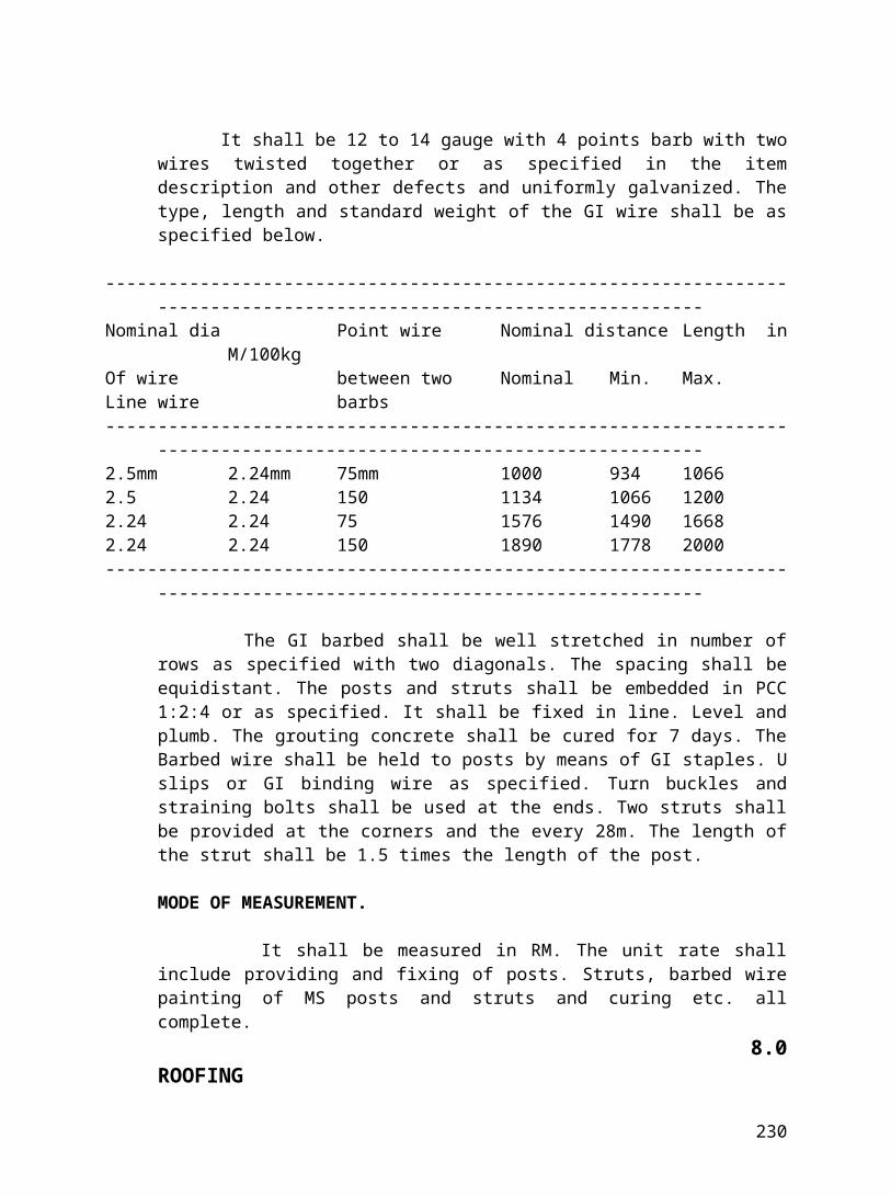
Sl.No
Description Unit Qnty. (Rs.)Unit Rate Amount
1 2 3 4 5 6of Engineer-in-charge.Unit Rates in word
1.10 Providing, supplying and filling approved local sand in foundation, trenches, & plinth foundation areas, and foundation surrounding areas in layers of 150mm to 200mm including watering, ramming and consolidating, transportation, freight, loading, unloading, labour, T&P, taxes, octori, levies, royalties, spreading and compacting etc. complete as per direction of Engineer-in-charge.
Cum 15.0
Unit Rates in word
SUB TOTAL (1)
Sub Total (in Word)
Note:
1) Consolidated measurement of fill shall be paid.
2) The rates shall be inclusive of cost of material, labour, plants, tools, curing, compaction, etc. complete as mentioned.
230
Sl.No
Description Unit Qnty. (Rs.)Unit Rate Amount
1 2 3 4 5 62.0 CONCRETE2.05 Providing, supplying & laying in position
machine mixed plain cement concrete in volumetric proportion (1:3:6) of any thickness for M-15 or volumetric proportion 1: 3: 6 (1:cement, 3 coarse sand: 6 HG stone crusher broken stone aggregates of size 37mm and down) in required thickness, for foundations, below walls, column footings, sunk floor, terraces, rafts, roads at any height above plinth level, at any depth below floors, plinth protection, etc. including centering and shuttering, if required, laying, spreading, ramming, consolidating, as per requirement and curing etc. including cost of all materials, transportation, loading, unloading, labour, T&P, taxes, duties, levies, octori, royalties etc. complete as per direction of Engineer- in-charge.
Cum 6.0
Unit Rates in word
2.06 & 2.20
Providing, supplying & laying in position machine mixed and machine vibrated cement concrete of controlled grades of specified volumetric proportions, for reinforcement cement concrete structural elements, viz. foundation, columns, beams, slabs, precast slab, raft, floor, plinth beam, window sills, coping, walls, parapet, drops, fins, boxes, gutters, folded plates, chajhas, overhead and under ground water tanks, culverts etc. at different levels in any shape as per structural design and as directed in specified compressive strength expressed in N/sqmm at 28 days as per I.S: 456-1978 using 20mm and down size of hard crusher broken black granite aggregates, necessary lift and lead finishing concrete surfaces, and for M-20 or volumetric proportion 1:1 1/2: 3 (1 cement : 1 1/2 : coarse sand: 3 HG stone aggregates of size 20mm )and down concrete in ground and plinth etc.
231
Sl.No
Description Unit Qnty. (Rs.)Unit Rate Amount
1 2 3 4 5 6including cost of centering and shuttering / centering with using M.S., steel plate and M.S. steel frame work including removing the same after specified period or as required and directed or specified in structural drawing and including cost of all material but excluding cost of reinforcement and including cost of curing, transportation, loading, unloading, of all materials and labour, T&P, taxes, duties, levies, octori, royalties etc. complete as per direction of Engineer –In-Charge.
Unit Rates in word
2.10(I)
-Do- as per items no 2.06 &2.20 & 2.21 but for M20 or volumetric proportion 1: 1 1/2: 3 (1cement: 1 1/2 coarse sand: 3 HG crusher broken stone aggregates of size 20mm and down) concrete at all level below plinth level and upto highest plinth level.
Cum 33
2.10 (II)
-Do- as per items no 2.06 &2.20 & 2.21 but for M20 or volumetric proportion 1: 1 1/2: 3 (1cement: 1 1/2 coarse sand: 3 HG crusher broken stone aggregates of size 20mm and down) concrete at all level above plinth level to upto ground floor level.
Cum 10.0
Unit Rates in word
2.26 Providing, fabricating and fixing in position steel reinforcement for RCC structural elements, viz. foundation, columns, beams, slabs, precast slab, raft, floor, plinth beam, window sills, coping, walls, parapet, drops, fins, boxes, gutters, folded plates, chajhas, mullions, overhead and under ground water tanks, road pavement, kerbs, culverts, etc. at different levels in any shape as per structural design and drawing and as Qtl 49.0
232
Sl.No
Description Unit Qnty. (Rs.)Unit Rate Amount
1 2 3 4 5 6directed and specified, as per design at all levels including lift and loading, unloading & transporting steel within site premises from departmental store to the work site, unloading and incidental charges for handling, cutting, bending and binding at all height and floor with 16 gauge GI wire (to be supplied by the contractor at his own cost), welding if necessary etc., labour, T&P complete as per direction of Engineer-in-charge.
Pre-measurement will be made on the length basis and converted into weight by using standard IS co-efficient with Tor steel bars
Unit Rates in word
SUB TOTAL (2)
Notes:
1) The rates shall be inclusive of cost of materials, transportation, loading, unloading, labour, tools & plants, taxes, duties, levies, octori, royalties, compaction, etc. complete.
2) The cost of making cube for testing cube mould will be born by the contractor.
3) The rate of shuttering inclusive of laying polythene of approved quality and removing the same after curing.
233
Sl. Description Unit Qnty. (Rs.)Unit Rate Amount
1 2 3 4 5 63.0 MASONARY WORKS3.01 Providing, supplying and constructing brick
masonry in CM 1:6 (1 cement: 6 coarse sand) with 1st class quality approved KB bricks having minimum crushing strength 70kg/sqcm including soaking the bricks in water vat for 24hoursbefore use in foundation at all levels below and upto highest plinth level, all necessary scaffolding, racking out the joints, in foundation upto plinth level, including cost of all materials, transportation, curing, loading, unloading, labour, T&P taxes, duties, levies, octroi royalties etc. complete as per direction of Engineer in-charge.
Cum 7.0
Unit Rates in word
3.02(A)
-Do- as per items no 3.01 but in superstructure at all height above highest plinth level upto all height for Ground Floor
Cum 97.00
Unit Rates in word
SUB TOTAL (3)
Notes :1) The rates shall be inclusive of cost of material, transportation, loading, unloading, taxes
octroi, and plants, curing compaction etc. complete.2) Holes or pockets in the brick work for rain water pipes and other pipes shall be kept or
the pipes shall be provided at the time of raising the masonary and nothing extra shall be paid for, Septic tanks, compound wall, soak pit, underground sumps, cable trenches of various sizes, chambers having size other than specified above will be measured under relevant items of work and the ground shall be the reference level in case of measurement of brick masonary in super structure.
3) Holes or pockets in the brick work for fixing chaukath window inclusive of rate in relevant item.
4) Holes or pockets in the Brickwork for partition wall shall be kept at the time of raising masonary and nothing extra shall be paid for the grooving.
234
Sl.No
Description Unit Qnty. (Rs.)Unit Rate Amount
1 2 3 4 5 65.0 FINISHING5.01 Providing, supplying and applying 12mm
thick cement plaster in line and level, at all heights above and below plinth level with cement motar 1:4 (1 cement: 4 sand) to walls, beams, ceiling, stair, column, pardis, bends, moulds, pattas, grooves, etc. including scaffolding, curing, finishing smooth (the plaster surface shall be trowelled till the surface shows cement paste), and chipping the concrete at all levels including cost of all materials, transportation, lift, loading, unloading, curing, labour, tools and plants, taxes, duties, levies, octroi, royalties etc. complete as per direction of Engineer – In-Charge
Sqm 914.0
Unit Rates in word
5.09 Providing, supplying & applying two or more coats of 1st quality cement paint of approved make and shade such as “ashian/Berger” Brand on smooth plaster finished surfaces of walls, beams, ceiling, stair, column, pardis, bends, moulds, pattas, grooves etc. at all heights above plinth level over a coat of cement wash and preparation of surface for painting, scaffolding, curing etc., including cost of all materials, transportation, loading, unloading, labour, T&P, taxes, duties levies, octroi, royalties etc. complete as per direction of Engineer - In-Charge
Sqm 914.0
Unit Rates in word
5.11 Providing, supplying & applying two or more coats of 1st quality Enamel paint of approved make and shade such as “ashian/berger” brand on smooth on after scrapping and cleaning the rust over a coat of red oxide primer of MS Grill. at all heights . including cost of all materials, transportation, loading, unloading, labour, T&P, taxes, duties levies, octroi, royalties etc. complete as per direction of Engineer - In-Charge
Sqm 234.0
Unit Rates in word
235
Sl.No
Description Unit Qnty. (Rs.)Unit Rate Amount
1 2 3 4 5 6
SUB TOTAL (5)
Note
1) Groove with cement finish upto 20 mm X 10 mm shall be formed in plaster at the junction of slab and beam and slab and brick work without any extra charge.
2) Similar grooves shall be made in plaster at the junction of masonary and wood or steel door or steel window frames or at bottom of beams as drip moulds without extra charges.
3) Sand used shall be 50% fine and 50% coarse for plaster unless otherwise specified/directed.
236

Sl.No
Description Unit Qnty. (Rs.)Unit Rate Amount
1 2 3 4 5 67.00 STEEL WORK7.11 Providing, fabricating and fixing in
position, grills/MS gate, railing steel ladder etc. of MS sections as per architect’s details including cutting, electrical arc welding, grinding to smooth surface, fixing with holdfast of MS sections of minimum size 25 mm X 3 mm X 10 cm long, embedded in cement concrete 1:2:4 (1 part cement:2 part coarse sand:4 part of HG stone aggregate 12 mm and down), blocks of 15 cm X 15 cm X 23 cm at maximum 1 c/c, anchor bolts etc. including 2 coats of first quality synthetic enamel paint of make J&N / Shalimar / British / Asian and approved shade, over a cost of red oxide primer etc., including cost of materials, transportation, loading, unloading, labour, tools, & plants, taxes, duties, levies, octroi, royalties etc. as per direction of Engineer-in-Charge.
QTL 2.50
Unit Rates in word
SUB TOTAL (7)
237
Sl.No
Description Unit Qnty. (Rs.)Unit Rate Amount
1 2 3 4 5 69.00 MISCELLANEOUS9.06(B)
Dismantling the Brick masonary wall of any thickness & at all height with chisels, hammer etc. removing and stacking the debris as directed within site upto a lead of 100m, including cutting the reinforcement if any, etc. including labour, T&P scaffolding taxes and duties etc. complete as per direction of Engineer-in-charge. Useable brick should be stacked and handed over to store.
Cum 62.0Unit Rates in word
9.06(D)
Dismantling , removing and refixing in position, the existing Ms Grill on Boundary wall as per architect’s details including cutting, electrical arc welding, grinding to smooth surface nut bolt grouting with concrete (1:2:4), including cost of materials, transportation, loading, unloading, labour, tools, & plants, taxes, duties, levies, octroi, royalties etc. as per direction of Engineer-in-Charge.
Sqm 117.0
Unit Rates in word
SUB TOTAL(9)
238
SUMMARY
SL SECTION TOTAL AMOUNTNO (Rs)
01. EARTH WORK 02. CONCRETE
03. MASONARY WORK
05. FINISHING
07. STEEL WORK
09 MISCELLANEOUS
GRAND TOTAL
NET AMOUNT IN WORDSSIGNATURE :DATE :FULL NAME :
ADDRESS :
239