Embed Size (px)
Citation preview
Running Maintenance Contract Technical Specifications of PQA Marine Structures Civil Works
Specification Index
SERIES 100 General Instruction and work descriptionSERIES 200 Engineers FacilitiesSERIES 300 Materials GeneralSERIES 400 Subsoil InvestigationSERIES 500 General Excavation, Earthworks And DewateringSERIES 600 Structural SteelworkSERIES 700 Fenders, Bollards And Safety LaddersSERIES 800 General Piling WorksSERIES 900 Tubular Steel PilesSERIES 1000 Pile TestingSERIES 1100 ConcreteSERIES 1200 Reinforcement steelSERIES 1300 Paint workSERIES 1400 WaterSERIES 1500 FendersSERIES 1600 Navigations AidsSERIES 1700 GroutsSERIES 1800 Tide table & Location Tide of Gauges.
1

Running Maintenance Contract Technical Specifications of PQA Marine Structures Civil Works
SERIES 100
GENERAL REQUIREMENTS
100 GENERAL
100.1 Location of the Works
The works are located at Port Qasim on the Sindh Coast of Pakistan about 28 km East of Karachi. The location of the permanent works extends from the fairway buoy in the Ahsan Channel through Port Qasim and is entirely within the Port Muhammad Bin Qasim Ports Limit.
100.2 General Descriptions of the Works
Annual Running Maintenance Contract of PQA Marine Structures 2015-16.
100.3 Temperature
Data N.A
100.4 Humidity
Data N.A
100.5 Rainfall
Date N.A
100.6 Winds
Except in the winter months between November and March when the most common and strongest winds come from north-east, the predominant wind direction is from south-west to west. From May to September, the wind blows almost exclusively from that sector. Winds from between south and east are extremely rare.
10-25 knots-S.W (From May to September)
5-15 Knots –N.E (From December to February)
100.7 Waves
0.3 to 0.5 Meters during Non-Monsoon.
100.8 TidesPredicted tide of Port Entrance & Pipry enclosed.
2
Running Maintenance Contract Technical Specifications of PQA Marine Structures Civil Works
100.9 Currents
Data N.A
100.10 The General Conditions of Contract Part I & II shall form an integral part of these General Requirements.The Contractor shall notify all sub-contractors of the provisions of the Conditions of Contract and the General Requirement of this Specification.The arrangement and divisions of these Specifications is not to be construed as establishing the limits of responsibility of sub-trades. The Contractor is responsible for delineating the scope of Sub-Contracts and for coordinating all the Works. All works shall be carried out in accordance with the following specifications, supplemented by detailed specifications contained in the following sections. Any inconsistencies or ambiguities shall be brought to the notice of the Engineer for his clarification/decision. Decision and direction of the Engineer, in all such cases, shall be final and binding.The Contractor shall make himself thoroughly familiar with the site conditions, foresee any and all problems likely to the encountered during execution of the works, and shall be able and ready to solve them effectively. Proposals for solutions to the problems shall be submitted to the Engineer for approval before proceeding with the work.
100.11 UNITS OF MEASUREMENTSThe International System of Units (SI) shall be used throughout this Project.
100.12 MANUFACTURER'S RECOMMENDATIONS Installation of manufactured items shall be in accordance with procedures
recommended by the manufacturer or as approved by the Engineer.
100.13 EXISTING CONDITION AT SITE Drawings and information pertaining to existing project conditions are furnished for reference.Neither the Employer nor the Engineer warrants the adequacy or correctness of these.
100.14 PROTECTION AND PRECAUTIONS The Contractor and his sub-contractors shall afford all necessary protection to existing structures and will be required to make good at his own expense any damage done to such structures through his own or his representatives or subcontractors' fault and negligence. The Contractor and his sub-contractors shall afford all necessary protection to existing roads in the area. He will clear and make good at his own expense any damage to or debris on these roads through his own fault and negligence. He must at all time ensure the free and normal flow of traffic and shall not cause obstruction to the traffic system. The Contractor and his sub-contractors shall provide and maintain necessary protection and precautionary measures such as warning signs, warning lamps and barricades etc. to prevent accidents.
3
Running Maintenance Contract Technical Specifications of PQA Marine Structures Civil Works
The Contractor shall promptly correct all such damage to original condition at no additional expense to the Employer. The Contractor shall cooperate with trades performing work under other
Contracts as necessary for completion.
100.15 SETTING OUT OF WORK Establish all boundaries, markers, levelling stakes and bench marks on the site
to adequately set out all work. Verify all data and their relationship to established and Engineer's survey control points and public bench-marks and report discrepancies to the Engineer Permanently mark the necessary controls for distance and elevation sufficient to serve throughout the Contract and protect these control points adequately against damage and displacement. Project setting out is for the use of all trades; each trade is responsible for the layout of its own work.
100.16 SEQUENCE OF CONSTRUCTION The Contractor shall submit his proposal for approval of the Engineer the
sequence of Construction, prior to starting the works. The works shall be executed as per approved sequence of construction.
100.17 LINES AND LEVELS Survey control points will be established by the Engineer. The Contractor shall be responsible for verifying these and shall be responsible for all requirements necessary for the execution of any work to the locations, lines, and levels specified or shown on the drawings, subject to such modifications as the Engineer may require as work progresses.
100.18 PARTIAL POSSESSION Whenever, as determined by the Employer any portion of work performed by the Contractor is in a condition suitable for use, the Employer may take possession of or use such portion. Such use by the Employer shall in no instance be construed as constituting final acceptance, and shall neither relieve the Contractor of any of his responsibilities under the Contract, nor acts a waiver by the Employer of any of the conditions thereof, provided that the Contractor shall not be liable for the cost of repairs, re-work, or renewals which may be required due to ordinary wear and tear resulting from such use. However, if such use increase the cost or delays to the completion of remaining portions of work, the Contractor will be entitled to an equitable adjustment. If, as a result of the Contractor's failure to comply with the provision of the Contract, such use proves to be unsatisfactory, the Employer will have the right to continue such use until such portion of the work can, without injury to the Employer, be taken out of service for correction of defects, errors, omissions, or replacement of unsatisfactory materials or equipment, as necessary for such work to comply with the Contract; provided that the period of such operation or use pending completion of appropriate remedial action shall not exceed twelve months unless otherwise mutually agreed upon in writing between the parties.
100.19 EXISTING SERVICES
4
Running Maintenance Contract Technical Specifications of PQA Marine Structures Civil Works
The Contractor shall search for, find, locate and protect any wiring, cable, duct, pipework, etc., within or immediately adjoining the site area. The Contractor shall take full responsibly for safety of existing service lines, utilities and utility structures uncovered or encountered during excavation and construction operations.The Contractor shall take full responsibility for damaging any such service lines, utility/utility structure and any cost and/or expense that arises or issues from any such damage shall be borne directly by himself. Should any damage to any such service occur the Contractor shall forthwith take remedial action, initiate safety precautions, install temporary services and carryout repair all at his own cost and expense and inform the Engineer and notify all relevant authorities.Existing utilities which are to remain in service for or after the works are to be determined by the Contractor. If any existing service lines, utilities and utility structures which are to remain in service are uncovered or encountered during these operations, they shall be safeguarded, protected from damage, and supported.
100.20 PLANT AND EQUIPMENT The Contractor shall submit a detailed list of plant and equipment which he shall undertake to bring to the site to carry out the work. The list shall satisfy the Engineer as to type, size and quantity. The list shall include for each piece of equipment the type, manufacturer, model, identification number and year of manufacture. The Contractor shall provide on the site of the work at his cost all of the equipment listed and all subsequent equipment required for approval of the detailed programme of work and such equipment which may be directed by the Engineer. The Contractor shall supply all plant and equipment necessary for the construction of each phase of the work and it must be on site, inspected and approved by the Engineer.
100.21 CONSTRUCTION AREA AND ACCESS The Contractor shall confine his operations to the areas that are actually required for the Works and shall fence the area accordingly. Arrangements for access roads, storage areas and routes for haulage of materials are to be made by the Contractor at his own cost, subject to the approval of the Engineer.
100.22 STORAGE & HANDLING FACILITIES The Employer will provide the Contractor possible space within or nearby the area of site of works for the storage of plant, equipment and materials and for Contractor's temporary office, during the currency of the Contract. In case the adjacent area as required by the Contractor is not available within the Project boundary for storage of plant, equipment and machines then the Contractor shall arrange at his own expense possible space for storage of plant, equipment and machines at his own cost and expense. On no account shall such temporary installations conflict/interfere with any of the permanent installations, services and any operational function of Employer. The handling and storage of all plants, equipment and materials at site shall be the sole responsibility of the Contractor and at no risk and cost to the Employer. The Contractor shall protect all material against corrosion, mechanical damage or deterioration during storage and erection on site. The protection methods shall be to the approval of the Engineer.
5
Running Maintenance Contract Technical Specifications of PQA Marine Structures Civil Works
100.23TEST LABORATORY AND TESTING 23.1 Testing, except as otherwise specified herein, shall be performed by an approved testing agency as proposed by the Contractor and at no extra cost to the Employer. The Engineer may require all testing to be carried out under his supervision only.
23.2 If suitable and adequate material testing laboratory is not available in the vicinity, then the Contractor shall provide and maintain a materials testing laboratory in the vicinity of the Contractor's Camp and the laboratory shall have sufficient working area and shall be equipped with all necessary facilities including a suitable store room. 23.3 The Contractor shall supply and maintain to the satisfaction of the Engineer or his representative complete testing equipment, apparatus, tools, gauges, instruments, etc. in sufficient number and adequate for all tests to be carried out as specified in these specifications. Valid calibration certificates of gauges / instruments / equipment shall be provided by the Contractor.
23.4 The Contractor, after the approval by the Engineer for the source of cement and steel shall make available at the site sufficient stock of the materials in advance in order to allow sample testing for quality control prior to use.
23.5 The quality control testing shall be performed by the Contractor's competent personnel in accordance with a site testing and quality control programme to be established by the Contractor and approved by the Engineer or his Representative. The Contractor shall keep a complete record of all quality tests performed on site and submit the same to the Engineer. All quality control and related tests shall be carried out in accordance with applicable standards and codes.
100.24 CONSTRUCTION & CHECKING AT SITE The Contractor shall submit to the Engineer in due time for approval and discussion, his proposals and plans as to the method and procedure to be adopted for the temporary and permanent works involved. The submitting to these suggestions and arrangements, and the approval thereof by the Engineer shall not relieve the Contractor of his responsibilities and duties under the Contract.
The carrying out of all work included in the Contract is to be supervised by a sufficient number of qualified representatives of the Contractor and full facilities and assistance are to be afforded by the Contractor for the Engineer or his Representative to check & examine the execution of the work.
The Engineer reserves the right to inspect all parts of the works but may at his discretion waive inspection on certain items. This shall in no way absolve the Contractor from his responsibilities. This particularly applies to the checking of materials, the accurate setting out of foundations, and to the levelling, setting and
6

Running Maintenance Contract Technical Specifications of PQA Marine Structures Civil Works
aligning of the various parts, and to the proper fitting and adjustment of manufactured and finished materials and fixtures in position.
If the Engineer or his Representative find that the work progress is slow in such a way that the works or parts thereof will not be completed in the time specified, then he shall order the Contractor to work overtime or in shifts and the Contractor shall comply. These arrangements will be free of all financial encumbrances and at no additional costs to the Employer. In the event of night work, the Contractor shall provide sufficient and adequate lighting to the satisfaction of the Engineer or his Representative and shall supply the necessary manpower for satisfactory continuation of the work after normal hours.
100.25 BAR BENDING SCHEDULE Bar bending (reinforcement bars) schedule of all drawings shall be prepared by the Contractor and submitted in triplicate to the Engineer for approval.
100.26 DRAWINGS
26.1 Tender Drawings: The drawings listed in the General Conditions of Contract, Volume I and provided in Volume III are referred to as Tender Drawings and these show the scope of work to be performed by the Contractor. Tender Drawings shall not be used as a basis for fabrication or construction but may be used as a basis for placing preliminary order for materials, subject to corrections based on the future issue of Drawings as provided under sub-clause 19.2 Drawings Issued for Construction. Tender Drawings are subject to be modified and supplemented by additional detail by the Engineer. 26.2 Drawings Issued for Construction: After Award of Contract, Tender Drawings shall be placed by Drawings Issued for Construction including supplementary Specifications as may be necessary. Such drawings and specifications shall be constured to be included in the expression Custody of Drawings under Sub-Clause 6.1 of General Conditions of Contract Part I. Drawings Issued for Construction may include some of the Tender Drawings with or without modification and additional drawings as required to express design intent in greater detail. Such drawings may also be modified from time to time. Drawings Issued for Construction will be the drawings from which shop, fabrication, erection, installation, concrete placing, formwork, or other construction detail drawings shall be prepared by the Contractor. The work shall be executed in conformity with Drawings Issued for Construction. The Contractor shall prepare a schedule of Drawings Issued for Construction of various parts of the Works based on Construction programme approved by the Engineer for issuance to the Contractor from time to time.
26.3 Study of Drawings: The Contractor shall study all Drawings Issued for Construction carefully as soon as practicable after receipt thereof, and any errors discovered shall promptly be brought to the knowledge of the Engineer for his instructions.
7
Running Maintenance Contract Technical Specifications of PQA Marine Structures Civil Works
26.4 Copies of Drawing: Drawings will be issued to the Contractor free of charge as follows: Drawings Issued for Construction - Two copies as specified in sub-clause 6.1 Custody of Drawings, of General Conditions of Contract - Part I Volume I.
26.5 Drawings to be furnished by the Contractor: (a) Shop Drawings. All shop drawings required for the work including all kinds of fabrication, field erection, installation, placement and layout drawings shall be furnished by the Contractor for approval of the Engineer. If additional detail drawings are necessary to complete any part of the work, such including reinforcing steel, drawings shall be prepared by the Contractor and submitted to the Engineer for approval. All drawings shall be complete and shall be submitted in due time and in logical order to facilitate proper coordination.
(b) Lift and placement Drawings. At least thirty calendar days prior to starting construction of any concrete lift or other placement, the Contractor shall submit lift or other placement drawings to the Engineer for approval. Lift or other placement drawings shall be submitted for each lift or other placement of concrete to be placed. These drawings shall be to such scale as to clearly show all recesses, openings, and embedded parts, including embedded structural steel, mechanical and electrical items, reinforcement placement in each lift in sufficient detail for proper execution of the work.
(c) Construction Plant Layout Drawings. Three prints of drawings, showing the layout of construction plant and equipment the Contractor proposes to use on the work, shall be submitted by the Contractor for review to the Engineer. The drawings shall show the locations of the principal components of the construction plant, offices; storage areas and yards which the Contractor proposes to construct or use at the site of the work and elsewhere. The drawings shall also show the unloading facilities for materials and equipment at the work site.
26.6 Submissions and Approvals:
(a) Except as otherwise specified, three copies of each drawing for approval or review shall be furnished to the Engineer. Within thirty calendar days after receipt, the Engineer will send one copy to the Contractor marked Approved, Approved/Except as Noted, or Returned for Correction. The notations Approved and Approved/Except as Noted will authorize the Contractor to proceed with the fabrication of the materials and equipment covered by such drawings subject to the corrections, if any, indicated thereon. Drawings returned for correction will be resubmitted for approval in the same manner as for new drawings. Every revision made during the life of the Contract shall be shown by number, date and subject in a revision block. (b) Upon receipt of prints which have been Approved or Approved Except as
8
Running Maintenance Contract Technical Specifications of PQA Marine Structures Civil Works
Noted, the Contractor shall furnish three prints plus one reproducible of each drawing to the Engineer. If revisions are made after a drawing has been approved, the Contractor shall furnish 3 additional prints and one reproducible subsequent to each approved revision. (c) Shop drawings to be prepared by a Sub-contractor shall be submitted in the same manner as (a) & (b) above but they will be submitted through the Contractor.
(d) All of the applicable requirements of this Clause with reference to drawings to be prepared by the Contractor, including Sub-contractors, shall apply equally to catalogue cuts, illustrations, printed specifications, or other data submitted for approval.
(e) Any work done on Contractor's drawings shall be at the Contractor's risk. The Engineer will have the right to request any additional details and to require the Contractor to make any changes in the drawings which are necessary to conform to the provisions and intent of design and specifications without additional cost to the Employer. The approval of the drawings by the Engineer shall not be construed as a complete check but will indicate only that the general method of construction and detailing is satisfactory. Approval by the Engineer of the Contractor’s drawings shall not be held to relieve the Contractor of his obligation to meet all the requirements of the Specifications or of his responsibility for the correctness of the Contractor's drawings or of his responsibility for correct fit of assembled parts in final position or of his responsibility for the adequacy of method of construction.
100.27 AS-BUILT DRAWINGS
The Contractor shall, at all times, keep on the site one copy of all drawings and approved samples together with copies of all building, mechanical, electrical and public safety codes and relevant standards applicable to the works. All such material shall be made available to the Engineer.In addition, the Contractor shall, at all times, keep on site a separate set of prints on which shall be noted neatly, accurately and promptly as the work progresses all significant changes between the work shown on the drawings and that which is actually constructed. The sub-Contractors shall each keep on site, at all times, a separate set of prints of the drawings showing their parts of the work on which shall be noted, neatly accurately and promptly as work progresses the exact physical location and configuration of the works as actually installed, including any revisions or deviation from the Contract Documents.At the completion of the works, the Contractor shall at his expense, supply to the Engineer six copies and one reproducible copy of all drawings alongwith CD containing all as built drawings amended to comply with the work "As Built". The Contractor shall provide in the same format as the original drawings, any additional drawing required to record the work.
100.28 RESTORATION AND CLEANING
9

Running Maintenance Contract Technical Specifications of PQA Marine Structures Civil Works
The Contractor shall do regular cleaning and clean away all rubbish and excess materials that may accumulate from time to time on completion and before handing over. Upon completion of the works he shall obliterate all signs of temporary construction facilities such as work areas, structures, foundations of temporary structures, stock piles of excess or waste materials, or any other vestiges of construction, unless otherwise directed by the Engineer. The works and site shall be left in a clean and satisfactory state for immediate use and occupation. Care shall be taken not to use any cleaning materials which may cause damage to the surface to be cleaned.
100.29 PROTECTION OF THE WORKS
The Contractor shall whenever necessary cover up and protect the works from weather and damage by his own or other workmen performing subsequent operation. He shall provide all necessary dust sheets, barriers and guard rails and clear away the same at completion. The Contractor shall take all proper steps for protection at all places on or about the works which may be dangerous to his workmen or any other person or to traffic. The Contractor shall provide and maintain warning signs, warning lamps and barricades as necessary.
100.30 PRODUCT DATA
Manufacture’s standard schematic drawings shall be modified or deleted to indicate only information which is applicable to the project. Such standard information shall be supplemented to provide all additional applicable information. Manufacturer's catalogue sheets, brochures, diagrams, schedules, performance charts, illustrations and other standard descriptive literature shall be clearly marked to identify pertinent materials products or models. Dimensions and required clearances shall be indicated. Shop performance characteristics and capacities shall be noted.
100.31 SAMPLES
31.1 The Contractor shall furnish for approval of the Engineer with reasonable promptness all samples as directed by the Engineer or specifically called for in these Specifications. The Engineer shall check and approve such samples with reasonable promptness for compliance with the requirements of Contract Documents. All work shall be in accordance with approved samples.
31.2 Duplicate final approved samples, in addition to any required for the Contractor's use, shall be furnished to the Engineer, one for office use and the other for the Site. 31.3 Samples shall be furnished so as not to delay fabrication, allowing the Engineer reasonable time for consideration of the sample submitted.
10

Running Maintenance Contract Technical Specifications of PQA Marine Structures Civil Works
31.4 Each sample shall be properly labeled with the name and quality of the material, manufacturer's name, name of the project, the Contractor's name and the date of submission, and the Specifications Article number to which the sample refers.
31.5 The manufacturer’s installation directions shall be provided with each sample. The Contractor shall pay all transportation costs and deliver samples to the Engineer’s office, Site or testing laboratory as directed by the Engineer.Samples will not be returned unless return is requested at the time of submission; all packing and transportation costs for the return of samples shall be paid by the Contractor. 31.6 Samples shall be of adequate size and number to permit proper evaluation of the material by the Engineer. Where variations in colour, texture, dimensions or other characteristics are to be expected, the Contractor shall submit samples showing the maximum range of variation. Materials exceeding the range of variation of the approved samples shall not be used on the Work. 31.7 If both Shop Drawings and samples are required for the same item, the Engineer may require both to be submitted before approving either. 31.8 No acceptance or approval of any Shop Drawings or sample, or any indication or directions by the Engineer on any Shop Drawings shall constitute an authorization for any increase in the Contract Sum.
100.32 PRODUCT QUALITY AND HANDLING
Suppliers of local and foreign products and installations specified shall have been regularly engaged in the business of manufacturing, fabricating, installing and / or servicing work required for a period not less than 5 years. In addition, the Engineer may request as appropriate. - list of similar installations that describes project, scope and date of completion.
- complete literature, performance data, and technical data.
- list of services record within Pakistan.
- location of service office from which this installation could be maintained.
For the actual fabrication, installation, and testing of the specified work, use only thoroughly trained and experienced workmen completely familiar with the items required and with the manufacturers recommended methods of installation. In acceptance or rejection, no allowance will be made for the lack of skill on the part of workmen.
Use all means necessary to protect materials before, during and after
11

Running Maintenance Contract Technical Specifications of PQA Marine Structures Civil Works
installation and to protect the installed work and materials of all other trades. In the event of damage, immediately make all repairs and replacement necessary for approval and at no additional cost to the Employer.
100.33 INSPECTION & TESTS REPORTS
All equipment and materials furnished under these specifications and all work performed in connection therewith will be subject to rigid inspection by the Engineer or the Engineer’s Representative. Acceptance of equipment and material or the waiving off inspection thereof shall in no way relieve the Contractor of his responsibility for meeting the requirements of the Contract.The Contractor shall furnish the Engineer with certified true copies of test reports of all materials used in the manufacture and fabrication of all equipment and material including metal work, steel pipes, fire bricks etc. The result of these tests shall be in such form as to show compliance with the applicable Specifications, standards and codes for the material used.
100.34 ACCIDENT PREVENTION, PROTECTIVE EQUIPMENT
The Contractor shall comply and enforce compliance by all his sub-Contractors with the highest standards of safety and accident prevention in accordance with international standards and in compliance with all applicable laws, ordinances and statutory provisions in Pakistan.
All requisite barriers, fences, warning signs, lights and other safety precautions as required for the protection of persons and property on or adjacent to the site shall be provided at the Contractor's cost.
All warning signs shall be in two languages, English and Urdu, and shall at all times be maintained in a clean and legible condition, to the satisfaction of the Engineer.Trash shall be removed at frequent intervals to the satisfaction of the Engineer.
100.35 TEMPORARY FACILITIES
The Contractor shall provide, erect or install, maintain, alter as necessary and remove on completion except as otherwise directed by the Engineer all temporary facilities and services including access roads as described hereinafter and/or in the Contract Document. The Contractor's temporary site office shall be available for use not later than one month after the date of the site handing over. Installation of temporary services at the site shall be given priority over all other construction at the site.
35.1 Temporary Road
The Contractor shall prepare and maintain such temporary roads as may be necessary, from the site to the nearest road and also within the site. Such roads shall be positioned strictly in accordance with the Engineer’s instructions and
12
Running Maintenance Contract Technical Specifications of PQA Marine Structures Civil Works
the Contractor shall reduce or control any dust nuisance by spraying with water as directed. The Contractor shall satisfy himself as to the locations and nature of the proposed access routes to the site and shall be responsible for preventing any damage whatsoever to adjacent property and vegetation and keeping the access road free from debris at all times. 35.2 Temporary Services
35.2.1 Temporary Water Supply The Contractor shall supply in sufficient quantity all necessary potable and other water for construction purposes for all trades at point within a reasonable distance of the work. He shall make arrangements and pay charges for water service installation, maintenance and removal thereof, and pay the costs of water for all trades.
When the permanent water supply and distribution system has been installed, it may be used as the source of water for construction purposes provided that the Contractor obtains the written approval of the Engineer and the Employer and assumes full responsibility for the entire water distribution system and pays all charges/costs for operation and maintenance of the system mutually agreed between the Employer and the Contractor.
Temporary pipe lines and connections from the permanent service line, whether outside or within the area of site of works but necessary for the use of Contractor and his sub-contractor shall be installed, protected and maintained at the expense of the Contractor.
At completion of the work or at such time as the Contractor makes use of the permanent water supply installation, the temporary water services equipment and piping shall be removed by the Contractor at his own expense.
35.2.2 Temporary Electricity The Contractor shall make all the necessary arrangements for a temporary electricity service, pay all expense in connection with the installation, operation and removal thereof and pay the costs of electricity consumed by all trades. In the event that the site can not be connected to a local electricity network or where the available power is insufficient the Contractor has to make his own provision and maintain such installation.
A temporary lighting system shall be furnished, installed and maintained by the Contractor as required to satisfy the minimum requirements for safety and security. The temporary lighting system shall afford adequate general illumination to all building areas. Adequate outdoor lighting shall be provided to illuminate staging trenches and the like to the satisfaction of the Engineer and general illumination throughout adequate for watchmen and emergency personnel. Temporary equipment and wiring for power and lighting shall be in accordance with the applicable provisions of governing codes. Temporary wiring shall be maintained in a safe manner and utilised so as not to constitute a hazard to persons or property. When the permanent electrical power and lighting systems are in an operating
13
Running Maintenance Contract Technical Specifications of PQA Marine Structures Civil Works
condition, they may be used for temporary power and lighting for construction purposes provided that the Contractor obtains the written approval of the Engineer and the Employer and assumes full responsibility for the entire power and lighting system and pays all charges/costs for operation and maintenance of the system mutually agreed between the Employer and the Contractor. Approval, license etc. if required under local laws will be obtained by the Contractor on his own responsibility and cost. At completion of construction work, or at such time as the Contractor makes use of permanent electrical equipment and devices, temporary electricity services shall be removed by the Contractor as his own expense.
35.2.3 Waste Disposal The Contractor shall make such temporary provisions as may be required in order to dispose of any chemicals, fuels, grease, bituminous materials, waste and soil waste and the like without causing pollution to either the site or the environment. Disposal of any materials, wastes, effluents, garbage, oil, grease, chemicals and the like shall be in areas specified by the concerned local authority proposed by the Contractor and subject to the approval of the Engineer. If any waste material is dumped in unauthorized areas the Contractor shall remove the material and restore the area to the condition of the adjacent undisturbed area. If necessary, contaminated ground shall be excavated, disposed off as directed by the Engineer and replaced with suitable fill material compacted and finished with topsoil all at the expense of the Contractor.
35.2.4 Fire Protection The Contractor shall provide and maintain adequate fire protection in the form of barrels of water with buckets, fire bucket tanks, fire extinguishers, or other effective means ready for instant use, distributed around the project and in and about temporary inflammable structures during construction of the works.
Gasoline and other flammable liquids shall be stored in and dispensed from safety containers approved by the Engineer and storage shall not be within building. Torch-cutting and welding operations performed by the Contractor shall have the approval of the Engineer before such work is started and a chemical extinguisher is to be available at the location where such work is in progress. The Contractor shall follow the instructions and specifications of the Civil Defence Department and or other local authority.
35.2.5 Telephone The Contractor shall immediately after receiving the Letter of Acceptance take the necessary steps to obtain a mobile and landline telephone on site. He shall be responsible for all installation and connection charges and periodic mobile and landline telephone accounts. The telephone shall be made available to the Engineer for the due performance of his duties at all times and free of charge during construction and defects liability period.
14

Running Maintenance Contract Technical Specifications of PQA Marine Structures Civil Works
100.36 CONSTRUCTION SCHEDULE A Construction schedule shall be maintained in accordance with the provisions of the General Conditions of Contract. The schedule shall be accompanied with sufficient data and information including all necessary particulars of constructional plant, equipment machinery, temporary Works, arrival of plant, equipment at site and their installation, method of operation, work forces employed, etc., for an activities of the Works. Should the Engineer consider any alteration or addition in the programme and time schedule, the Contractor shall conform thereto without any cost to the Employer. Whenever necessary and wherever the progress of the actual work shows departure, the programme and time schedule shall be undated and submitted to the Engineer for his approval.
100.37 NOTIFICATION TO THE ENGINEER The Engineer’s Representative shall be notified daily in writing of the nature and location of the Works the Contractor intends to perform the next day so as to enable necessary inspection and measurement to be carried out. The Engineer may, if necessary, direct that longer notice be given of certain operations.
100.38 NIGHT WORK When work is done at night the Contractor shall maintain from sunset to sunrise such lights on or about his work and plant as the Engineer may deem necessary for the proper observations of the work and the efficient prosecution hereof.
100.39 WEATHER No work is to be undertaken when, in the opinion of the Engineer, the weather is so unsuitable that proper protection of the work cannot be ensured.
100.40 CO-ORDINATION WITH OTHER CONTRACTORS The Contractor shall make all necessary coordination with other Contractor and shall make sure that all embedding components such as pipes, steel bases etc. (as required for completion of electrical works) are properly, accurately and timely installed.
The Contractor shall inform the other contractor the schedule of any construction activity well in advance giving him sufficient time to finish his part of job, before any compaction/concreting etc. The Contractor shall get the signature of the authorized representation of the other contractor before carrying out any construction activity. If any part of electrical work is damaged or has to be dismantled or redone due to negligence/omissions/incorrect position of the embedding etc. on part of the Contractor, all such losses/expensed shall be borne by the Contractor.
15
Running Maintenance Contract Technical Specifications of PQA Marine Structures Civil Works
All expenses incurred for the above works including coordination are deemed to be covered in his tendered cost and no separate/extra payment shall be paid against such item.
100.41 SUBMISSION REQUIREMENTS
41.1 Schedule submission at least sixty days before the dates when reviewed submittals will be needed.
41.2 Submit Shop Drawings as per provision given in Sub-Clause 19.5 (a) and number of copies of Product Data which the Contractor requires for distribution plus four copies which will be retained by the Engineer. 41.3 Submit three samples unless otherwise specified. 41.4 Accompany submittals with transmittal letter, in duplicate, containing:
- Date - Project title and number - Contractor’s name and address - The number of each Shop Drawing, Product Data and the Sample submitted. - Notification of deviations from Contract Documents. - Other pertinent data.
100.42 RESUBMISSION REQUIREMENTS
Shop Drawings: - Revise initial drawings as required and resubmit as specified for initial submittal. - Indicate on drawings any changes which have been made by the Engineer. - Product Data and Samples: Submit new data and samples as required for initial submittal.
100.43 SURVEY INSTRUMENTS
All the instruments, equipment, stakes and other material necessary to perform all work shall be provided by the Contractor. The survey work shall be carried out by competent staff consistent with the current practices. The Contractor shall maintain on site surveying instruments in perfect working conditions to enable the Engineer to check lines and level at all times.
List of Equipment/Instruments : As required by the Engineer.
16
Running Maintenance Contract Technical Specifications of PQA Marine Structures Civil Works
100.44 WEEKLY PROGRESS REPORT AND PHTOGRAPHS .
44.1 During the continuance of the Contract, the Contractor shall submit weekly progress reports on forms as approved by the Engineer. Such weekly reports shall show the actual progress completed as of date of the report plotted against the schedule as given by the Contractor at the start of work and shall be broken down so as to indicate status of all activities associated with mobilization design, material procurement, manufacture, surveys works, tests with regard to the agreed contract programme.
44.2 The Employer and the Engineer reserve the right to coordinate the schedules of this Contractor and other Contractors working at the Site, and to adjust and/or change any and 0100-14 all such schedules as required during the course of construction in order to achieve a coordinated project in harmony with the Employer's completion date.
44.3 Commencing after the first week of construction, and continuing every week until completion, the Contractor shall take and submit photographs to the Engineer's Representative, to show progress of his work and completion of each structure or major feature.
100.45 CONTRACTOR TO NOTIFY DELAYS ETC.
Any delay which will affect the completion of Works shall be detailed by the Contractor who shall state the action he is taking for effective completion of the Contract programme. The Contractor shall submit a report in respect of the various sections of the Works, the equipment in use or held in readiness, a return of labour and supervisory staff, and details of any matters arising which may generally affect the progress of the work.
The Contractor shall give a summary of the detailed progress report giving the position with regard to the agreed Contract programme.
The progress reports shall be set out in a format to the approval of the Engineer, and forwarded promptly so that on receipt the information contained therein is not more than 21 days out of date.
If during execution of the Contract, the Employer considers the progress position of any section of the work to be unsatisfactory, or for any other reason relating to the Contract, he will be at liberty to convene a meeting and the Contractor’s Representatives are to attend such meeting. The Contractor's Site Office shall prepare and submit 6 copies of a weekly progress report to the Employer and Engineer's Site Office. This report shall summarize site activities and record and details where difficulties in maintaining the agreed programme are being experienced or are likely to cause subsequent delay.
17

Running Maintenance Contract Technical Specifications of PQA Marine Structures Civil Works
The Contractor's Site Office shall also prepare and submit to the Engineer's Site Office 2 copies of Daily Activity Report summarizing the main activities to be undertaken each day, noting special activities such a tests, alignment checks, etc. The Contractor shall be responsible for expediting the delivery of all material and equipment to be provided by him and his subcontractors.
100.46 PHOTOGRAPHS
As soon as work commences on Site, the Contractor shall provide photographs (at least 10 to 12) of the works from positions to be selected by the Engineer. Each photographic print shall not be less than 297mm x 210mm and shall bear a printed description, a serial number and the date when taken.
The negatives of all photographs shall be held at the Contractor’s Site Office, numbered and handed over to the Employer at the completion of the Contract.
100.47 PAYMENT OF WORK
No payment shall be made for the works involved within the scope of this section of specification.
The cost thereof shall be deemed to have been included in the quoted unit rate of other items of the Bills of Quantities.
100.48 Marine Operations
Approvals
The Contractor shall make all arrangements & obtain all necessary approvals for any temporary marine traffic arrangements & control.
At least 14 days before marine works commence, the following shall be submitted to the Engineer.
a) Evidence that the Port Qasim Authority have been notified of the works.b) Licenses, permits etc., to undertake the works and any related conditions of
restrictions. c) Approval of temporary traffic control arrangements.
100.49Floating Equipment
18

Running Maintenance Contract Technical Specifications of PQA Marine Structures Civil Works
The Contractor shall comply with the regulations and shall obey the orders of relevant authority(ies) in respect of navigation or mooring of floating Equipment and boats in the adjacent waterway/harbor and in the vicinity of the site, and shall conduct operations in such a manner that they do not interfere with the use of the waterways, anchorages or wharves jetties, causeways, dolphins etc.
Only classified vessels, fully registered and recently surveyed, shall be used on the works. All crafts and floating Equipments shall be manned at all times with adequate crew to be able to effectively deal with normal emergencies.
100.50Navigation
The Contractor shall conform to any byelaws and regulations concerning navigation and shall obey the orders of any authorized officer in reference thereto. The Contractor is to submit full detail of any operations that may cause any interference to shipping to the Engineer for comment at least 7 days before the event and is to make such modifications as the Engineer may require in order to keep interference to the minimum. Normal movement of craft within the harbor shall be notified to the authorized authorities. All craft shall be fitted with VHF Radios.
100.51Reconfirmation of Marine Operations
Any marine operations to be carried out by the Contractor which involve the suspension of ship movement and which have been agreed with the relevant authorities are to be reconfirm with both the Engineer and those authorities seven days before the agreed date.
When the Contractor does not carry out any operation reconfirmed with the Engineer and the relevant authorities, requiring the authorities to suspend shipping movement for the duration of the operation, then the Contractor shall reschedule the operation to the convenience of the authorities.
Any delays arising from rescheduling the operations to the authorities’ convenience shall deemed to be the Contractor’s responsibility except where it can be shown that cancellation of the reconfirmed operation was due to circumstances outside the Contractor’s control.
100.52Mooring, Buoys, Lights etc.
The Contractor shall provide such buoys, moorings and fastenings as may be required for securing the Contractor floating equipment and craft and also such buoys, warning lights, signs and signals (if any) arising as consequence of
19
Running Maintenance Contract Technical Specifications of PQA Marine Structures Civil Works
undertaking the works as the appropriate authorities may direct as the Engineer may deem necessary to meet the requirements of the authorities.
All moorings shall be agreed by the relevant authorities, and all anchors must be marked by lit-buoys.
100.53Night-time Marketing and Lighting
The Contractor shall during the execution of the works provide & maintain every night from sunset to sunrise; such light or lights, on or near the works as the Appropriate authorities or the Engineer may require.
100.54Removal of Wrecks & Sunken Equipment
The Contractor shall immediately remove all Equipments, Materials and Wrecks which have sunk in connection with the execution of the works from any cause, whatsoever. Until the wrecks or sunken Equipment or Material have been removed, the Contractor shall set all such buoys and display at night such lights and do all such things for the safety of navigation as may be required by the Engineer or the relevant authorities. In the event of the Contractor failing to carry out these obligations the Employer may arrange buoying and lighting and remove the same, and the Contractor shall refund to the Employer all costs incurred in connection therewith.
100.55Radio-Link with Port Authority, Contractor’s Radio Equipment
The Contractor shall maintain radio-telephone link with the port authority. The radio shall be manned at all times during working hours and all radio messages shall be logged.
Radio frequencies used by the Contractor, including those relating to on-board communication equipment, shall be to the approval of any duly constituted authority having jurisdiction. The Contractor shall be responsible for obtaining the necessary licenses and permits.
100.56Security Passes
The Contractor shall, where necessary, arrange for all employees and sub-contractors to have valid Security Passes and identification cards required for access the site.
100.57Visitors
The Contractor shall not allow any unauthorized visitors on the site. Authorised visitors shall sign a Contractors’ Visitor’s Book. The Contractor shall provide safety helmets and any other appropriate protective clothing for such visitors.
20
Running Maintenance Contract Technical Specifications of PQA Marine Structures Civil Works
100.58Diving
All diving operations shall be carried out in accordance with accepted international standards of safety & control e.g. “Diving Operations at Work Regulations 1981” (SI 1981 No. 399) is issued under the Health & Safety at Work Act of the United Kingdom.
Prior to the start of any proposed diving operations, the Contractor shall submit to the Engineer a copy of the diving rules intended for use generally, and also to any hazards peculiar to specific aspects of the Works and to shipping. The Contractor shall also submit to the Engineer a general method statement for diving operation.
The Contractor’s diving team shall have, as a minimum requirement, a competent diving supervisor, two qualified divers and a linesman in attendance at all times when underwater works requiring diving are being carried out.
The diving equipment used by the Contractor shall conform to international diving standards.
100.59 APPLICABLE CODES AND STANDARDS
In the absence of other Standards being required by the Contract Documents, all work and materials shall meet the requirement of the Uniform Building Code of the United States, and/or applicable American Society for Testing Materials (ASTM) American Association of State Highway and Transportation Officials (AASHTO) Specifications and the latest American Concrete Institute Manual of Concrete Practice and American Institute of Steel Construction (AISC) Manual relevant to the Works except in cases where the Pakistan Building Code requires a higher standard. In such cases the Pakistani Code shall govern. Where the abbreviations listed below are used, it refers to the latest code, standards, or publication of the following organizations: AASHTO American Association of State Highway and Transportation Officials. ACI American Concrete Institute AISC American Institute of Steel Construction ANSI American National Standards Institute ASA American Standard Association ASCE American Society of Civil Engineers ASTM American Society for Testing and Material AWS American Welding Society BSI British Standards Institute ICAO International Civil Aviation Organization BSICP British Standard Institute Code of Practice
21

Running Maintenance Contract Technical Specifications of PQA Marine Structures Civil Works
PCA Portland Cement Association PSI Pakistan Standard Institute UBC Uniform Building Code IALA
Should the Contractor, at any time and for any specific reasons, wish to deviate from the above standards or desires to use materials or equipment other than those provided for by the above standards, then he shall state the exact nature of the change giving the reasons for making the change and shall submit complete specifications of the materials and descriptions of the equipment for the Engineer's approval, whose decisions shall be conclusive and binding upon the Contractor.
100.60 CODES, STANDARDS, CERTIFICATESThe Contractor shall supply and have at his site office: Copies of all latest editions of codes and standards referred to in these specifications by number, or equivalent codes and standards approved by the Engineer.Catalogues and published recommendations from manufacturers supplying products and materials for the project.The Contractor shall provide manufacturer's or supplier's certificates to the Engineer for all products and materials which must meet the requirements of a specific code or standard as stated in these Specifications.
22
Running Maintenance Contract Technical Specifications of PQA Marine Structures Civil Works
SERIES 200
FACILITIES FOR THE ENGINEER
200.1 Site Office
The Contractor shall provide and maintain Engineer's Site Office including peon, for the full construction period and Defects Liability Period. A preliminary layout of the site office shall be provided by the Engineer. After receiving letter of award the Contractor will submit to the Engineer detailed shop drawings for review and approval.
The Engineer's site office shall be furnished and equipped with new and unused furniture, equipment, air-conditioners, electrical fittings etc., as per the list given below and as per requirement of site or directed by Engineer.
1.Wooden office table with drawers and side racks 1 (One) No. 2. Office Chairs 1 (One) No. 3. Wooden sitting visitors chairs with arms (standard size) 3 (Three) No. 4. Steel filing cabinet (standard size) 1 (One) No. 5. Electric Kettle 1 (One) No.6. Laptop Hp Core i7 along with all accessories. 1 (One) No. 7. Laser Printer capable of Printing A3/A4 papers.
If any equipment, furniture and installations become unserviceable for any reason whatsoever the Contractor shall promptly replace the same as and when directed by the Engineer. The Engineer’s Site office with fittings, fixtures and all other equipment/accessories shall be maintained and operated for the entire duration of construction period as well as for the duration of subsequent defects liability period.
The Site Office including fittings, fixtures, furniture, furnishing and all other equipment/accessories shall be the property of the Contractor on completion of the Contract.
200.2 Transport
The Contractor shall provide, operate and maintain brand new, Two (2) 800cc Suzuki Mehran VXR AC fitted for the exclusive use of the Engineer’s site supervision team to meet his transportation needs for the entire duration of actual construction period as well as for the duration of subsequent defects liability period. The use of such transport facility shall be under the control of the Engineer, and the Contractor shall be wholly responsible for providing at all times satisfactory operating services for the Engineer. The Contractor shall furnish, supply and provide, as may be necessary without specific direction of the Engineer, all fuels (400 liters/month), lubricants, tires and other supplies,
23
Running Maintenance Contract Technical Specifications of PQA Marine Structures Civil Works
all maintenance, repairs and running costs and suitably qualified drivers at all times.
Prior to Ordering the Vehicle, the Contractor shall furnish to the Engineer for approval, detailed specification, name of manufacturer and model no. of the vehicle to be supplied. These data shall be presented within one week from the date of Engineer's Order to proceed with the works and the vehicle shall be furnished to the Engineer upon approval within two weeks from the date of Engineer's Order to supply the Vehicle.
The vehicle shall be right hand drive, and shall be brand new, properly serviced and ready for use. The Contractor shall provide vehicle to replace any such motor vehicle that is temporarily or permanently rendered unserviceable for any reason or declared to be beyond repair by the Engineer, at no additional cost to the Employer. The vehicle shall become the property of the Contractor on completion of the Contract.
Failure of the Contractor to provide and maintain Engineer’s facilities and transport, shall make him liable to bear actual cost of office, furniture, equipment & vehicle and up to Rs. 2,000/- per day on account of maintenance, which will be deducted from the Contractor’s monthly payment statements for the entire Contract period or till such time that transport as stipulated above is provided by him.
24

Running Maintenance Contract Technical Specifications of PQA Marine Structures Civil Works
SERIES 300
MATERIALS GENERAL
Table of Content
CLAUSE NUMBER PAGE
301 SUBMISSION OF SAMPLES AND TEST CERTIFICATES 26
302 CONCRETE 26
303 AGGREGATES 26
304 CEMENT 27
305 REINFORCEMENT 28
306 WATER FOR USE WITH CEMENT 28
307 CURING COMPOUND 29
308 PIPES FOR WATER SERVICE, SEWERAGE AND DUCTS 29
309 BURIED SERVICES AND DUCTS 30
310 SERVICE DUCTS 30
311 STRUCTURAL STEEL 30
312 STAINLESS STEEL 30
25
Running Maintenance Contract Technical Specifications of PQA Marine Structures Civil Works
301 SUBMISSION OF SAMPLES AND TEST CERTIFICATES1. As soon as possible after the Contract has been awarded the Contractor shall submit
to the Engineer a list of the suppliers from whom he proposes to purchase the materials necessary for the execution of the Works. Each supplier must be willing to admit the Engineer, or his representatives, to his premises during ordinary working hours for the purpose of obtaining samples of the materials in question. Alternatively, if required by the Engineer, the Contractor shall deliver the samples of the materials to the Engineer's office. Samples shall be taken in accordance with the relevant European or other Standard where applicable. Materials subsequently supplied shall conform within any specified tolerances to the quality of samples which have been approved by the Engineer.
2. The information regarding the names of the suppliers may be submitted at different times, as may be convenient, but no sources of supply shall be changed without the Engineer's prior approval.
3. When any material or article is required to comply with a European or other standard such material or article or its container shall bear the stamp of the registered certification trade mark of the Overseeing Institution or other relevant body. Alternatively, the Contractor shall submit to the Engineer test certificates furnished by the supplier or manufacturer of the material or article indicating compliance with the relevant European or other Standard.
302 CONCRETE1. Concrete for structures shall comply with the BS EN 206 if not clearly specified
different in the related Series of Specification or on the drawings.
2. The supplier’s certified mixing records shall be supplied with each delivery to the actually pouring location of concrete and to be checked by the Forman. All record shall be forwarded to the E.R.
3. Such certificates shall clearly state a) Date and time of productionb) The supposed type and standard strength classc) Weight of each added compounds, including free and total waterd) Water – Cement ratio.
303 AGGREGATES1. Aggregates for concrete shall consist of naturally occurring material complying with
the requirements of the BS EN 12620 and the related Series of Specification.
2. All aggregate shall be clean and free from dust and dirt and shall be stored in such a way that they shall be kept free from contact with deleterious matter. Aggregates of different sizes shall be stored separately and in such a way that segregation is maintained.
26

Running Maintenance Contract Technical Specifications of PQA Marine Structures Civil Works
3. Additionally for structural concrete:a) Where the specified compressive strength of concrete is 40 N/mm² or more
at 28 days, the 'ten percent fines' value of the coarse aggregate shall be not less than 100 kN and for other structural concrete not less than 50 kN (related to Aggregate Impact Test, Ten Percent Fines Test and Aggregate Crushing Test).
b) The shell content of the aggregate included as calcium carbonate as determined by the method in BS EN 933 shall not exceed the following amounts:
Nominal size (mm) Percent (%)
40 2
20 5
10 15
fines 30
c) Chloride levels shall be determined daily as agreed by the Engineer.
304 CEMENT
1. Cement shall comply with the requirements of BS EN 197 or ASTM C 150 if not clearly specified different in the related Series of Specification or on the drawings.
2. The manufacturer's test certificate shall be supplied with each consignment of cement. Such certificate shall clearly state the date of manufacture of the cement in the consignment.
3. The Engineer reserves the right to order any consignment of cement which is intended for use in the permanent works to be tested, before delivery onto the Site, for compliance with the appropriate Standard. Any cement which, after testing, in the opinion of the Engineer fails to comply with the Specification through improper storage or for any reason will be rejected.
4. Each consignment of cement shall be kept separate, identified and used in order of delivery. The source of supply of cement for concrete shall be kept constant for each structure.
5. The Contractor shall provide suitable means of storing and protecting the cement against dampness. Bagged or bulk cement which has been stored for more than 60 days or which has become partially set or which contains lumps of caked cement shall be rejected. The use of cement reclaimed from discarded or used bags will not be permitted. If rapid hardening cement is used, it shall at all times be clearly
27
Running Maintenance Contract Technical Specifications of PQA Marine Structures Civil Works
labelled to distinguish it from ordinary cement and shall at all times be stored separately from ordinary cement.
305 REINFORCEMENT
1. Hot-rolled mild steel bars and hot-rolled high yield bars shall comply with the requirements of BS EN 10080:2005 or ASTM A 615 if not stated otherwise in the related Series of Specification or on the drawings.
2. In the case of bars complying with the requirements of BS EN 10080 the Contractor shall provide a certificate confirming that samples, taken from the bars delivered to the Works, pass the rebend test. The frequency of sampling and method of quality control shall be in accordance with this Standard.
3. Reinforcement binding wire shall be either soft annealed iron wire or stainless steel wire if not stated otherwise.
4. The sizes to be used shall be as shown in the Contract or as approved by the Engineer. Where exact equivalent bar sizes are not available (imperial or metric size bar) the specified size bar may be substituted by another size which fulfil the requirements for crack control and other requirements for the serviceability and ultimate limit state.
5. If purchased in small lots from a dealer, reinforcement may be accepted at the discretion of the Engineer upon proof that it meets the requirements of the Specification.
6. Bar reinforcement shall be shipped in Standard bundles, tagged and marked in a manner approved by the Engineer. In all cases the Contractor shall submit manufacturer's test certificate or copies thereof to the Engineer indicating the ultimate strength, yield stress, elongation and result of the cold bend test. If no test data is supplied by the Contractor, the Engineer shall have power to select pieces of steel for testing. Any cost from such tests shall be borne by the Contractor.
306 WATER FOR USE WITH CEMENT
1. If water for the Works is not available from a Public Utility Undertaking supply, the Authority’s and Engineer's approval shall be obtained regarding the source of supply and manner of its use. When required by the Engineer, the Contractor shall arrange for tests of the water. Water from the sea or tidal rivers shall not be used for structural or pavement concrete. Where water is stored it shall be maintained at such a depth and the water shall be drawn in such a manner as to exclude silt, mud, grass or other foreign materials. In general the water has to fulfil the conditions according to BS EN 1008 with special attention to the used cement in combination with sulphate and chloride attack from the seawater.
28

Running Maintenance Contract Technical Specifications of PQA Marine Structures Civil Works
307 CURING COMPOUND
1. Curing compound shall be approved resin based aluminised curing compounds, or polythene sheeting or an approved sprayed plastic film which hardens into a peelable plastic sheet and which shall be removed before opening to traffic.
2. Resin based aluminised curing compound shall contain sufficient flake aluminium in finely divided dispersion to produce a complete coverage of the sprayed surface with a metallic finish. The compound shall become stable and impervious to evaporation of water from the concrete surface within 60 minutes of application and shall have an efficiency index of 90% when tested.
3. Test certificates, prepared by an approved test laboratory, shall be supplied by the contractor to show that the compound complies with a curing efficiency of 90 percent.
4. The curing compound shall not react chemically with the concrete to be cured and shall not crack, peel or disintegrate within 3 weeks after application.
308 PIPES FOR WATER SERVICE, SEWERAGE AND DUCTS
1. All pipes and joints for use in water services and sewerage drains shall comply with the requirements of the related Specification.
2. Where not clearly stated otherwise, pipes shall be in accordance with the following standards:a) Ductile Cast Iron Pipes: BS EN 598b) Clay Pipes: BS EN 295c) Concrete Pipes: BS EN 1916d) Plastic Pipes: BS EN 13244
3. The pipes and fittings supplied shall have stamped on the external side of the pipe the following information:
a) size of pipeb) class of pipe and standard to which manufacturedc) initials of manufacturerd) angle of bend in degrees for bendse) date of manufacturef) serial number
4. All pipes and fittings shall be in all respects sound and good casting. The ends of pipes and specials shall be suitably covered and protected against damage during transit. Each delivery of pipes and fittings shall be accompanied by the Manufacturer's test certificate.
29

Running Maintenance Contract Technical Specifications of PQA Marine Structures Civil Works
5. All items shall be suitable for water works purposes.
6. The Contractor shall supply to the Engineer a certificate from the manufacturer stating each item supplied have been subjected to the tests herein specified and confirm in all respects to this Specification.
7. The Contractor shall provide adequate protection to the materials to guard against damage to the flanges and ingress of foreign material.
8. Joints shall be flexible and watertight sealed by means of a suitably retained rubber gasket.
309 BURIED SERVICES AND DUCTS
1. Where rigid services passing through walls, 1000 mm length rocker pipes shall be laid on each side of the wall.
2. Services shall be bedded, surrounded and covered by using compactable soil or aggregates without any compounds of size or shape which could damage the buried plant.
3. Plant buried within the ground shall receive a plastic marker warning tape laid some 300 mm above the plant. The tape shall be of highly visible colour with an insulated wire. Plastic strip tiles might also be acceptable.
310 SERVICE DUCTS
1. Service ducts shall have a smooth internal bore without any sharp edges to the ends of pipes. Service ducts in structures shall be constructed as described in the Contract. Other service ducts shall be constructed using the following, laid bedded and surrounded as described in the Contract.
311 STRUCTURAL STEEL
1. Structural steel shall comply with the requirements of BS EN 10025 if not stated otherwise in related Series of Specification or on the drawings.
2. In addition, structural steel hot rolled sections and structural steel hot-rolled hollow sections shall comply with the requirements of the specific European Standards.
3. Steel connectors shall comply with the requirements of BS EN ISO 898 unless otherwise described in the related Specification or on the drawings.
312 STAINLESS STEEL
30

Running Maintenance Contract Technical Specifications of PQA Marine Structures Civil Works
1. Stainless steel shall comply with the requirements of BS EN 10088-1, resistance class III (medium) and IV (high), e.g. grade 1.4401, 1.4435 or 1.4439 in accordance with BS EN 10027 if not clearly specified otherwise in the related Series of Specification or on the drawings.
31
Running Maintenance Contract Technical Specifications of PQA Marine Structures Civil Works
SERIES 400
SUBSOIL INVESTIGATION
Table of Content
CLAUSE NUMBER PAGE
401. General.............................................................................................................................33
402. CODES AND STANDARDS.............................................................................................33
403. SCOPE.............................................................................................................................33
404. General Requirements......................................................................................................33
405. Survey Works (Set outs and Survey Records).................................................................35
406. Location of utilities............................................................................................................35
407. Boring...............................................................................................................................36
408. Test/Trial Pits....................................................................................................................38
409. Geological Logs................................................................................................................38
410. Geological logging of boreholes.......................................................................................39
411. Laboratory Testing............................................................................................................40
412. Reports.............................................................................................................................41
413. Schedule...........................................................................................................................42
32

Running Maintenance Contract Technical Specifications of PQA Marine Structures Civil Works
401. General Contractor shall, with due care and diligence, execute the work in compliance with international practice and local laws, by laws, ordinance, regulations, etc. provide all plant, services and labour, inclusive of supervision thereof and provide all equipment, appliances or other articles whatsoever required for the execution and successful accomplishment of the work.
Contractor shall be deemed to have inspected the work areas(s) and their surroundings and to have satisfied himself as to the form and nature thereof, including sub-surface conditions, hydrological and climatic conditions, the extent and nature of the work, the materials necessary for the completion of the works and the means of access to all the work area(s).
402. CODES AND STANDARDSThe latest edition of the internationally accepted standards such as BS EN 1997 shall establish the minimum standards for the works and these standards covers subject of acceptance criteria for subsurface exploration works, site investigation works, testing and reporting etc.
403. SCOPEThis specification covers the geotechnical surveys consisting of the following works.
a) Field Investigation, Testing and Engineering Services.
b) Factual-Interpretive Report for Subsurface Investigation.
404. General Requirements
a) Contractor shall carry out subsurface investigation for the project site to provide the Engineer all the factual and engineering data in a manner consistent with the industry practice for the structure, road and infrastructure projects. The scope of Contractor’s services shall include but not limited to performance of subsurface exploration by borings and sampling, cone penetration tests, test pits/trial pits, field and laboratory testing, geotechnical analysis and the preparation of preliminary and final geotechnical reports. Contractor shall carry out a preliminary subsurface investigation which enables preliminary design to proceed.
b) Prior to proceeding with the subsurface investigation Contractor shall submit detailed plan/schedule of the work and method statement of the works for review and approval of Engineer.
c) The subsurface investigation method statement shall have the content but not limited to the information given in Table 1-1. Each information/stage shall be described in detail how the work will be carried out.
33
Running Maintenance Contract Technical Specifications of PQA Marine Structures Civil Works
Table1-1
Contents of a Typical Subsurface Investigation Method Statement
Investigation Stage Information required
Field works
Boring equipment Staffing and qualification Schedules Boring and Coring techniques Method for excavating pits and trenches including
stability issues Groundwater measurement, including procedures for
installing piezometers. Preservation, labeling, and storage of samples In-situ sampling methods Safety procedures and policies Backfilling
Testing
In-Situ, on-site, and laboratory testing procedures and techniques
Laboratory equipment Schedule Staffing and qualification
Reporting
Forms Log sheets Journals Report formats Standard Description and classification system used
d) The qualification of key personnel and their area of responsibilities and technical tasks shall be included in the method statement. Engineer shall have the right to review and approve the qualifications and performance of all personnel furnished by the Contractor.
e) Contractor shall follow the safety procedure of the project and local safety code in general and shall take full responsibility of the stability and safety of all operations carried out and all methods of work adopted. The Contractor shall also take full responsibility for stability and safety of all existing facilities/utilities/roads/etc. affected by any operation, design and method adopted by Contractor in executing the work. The Contractor shall also be entirely responsible for complying with the requirement of and coordinating with the police traffic department and municipality roads section in relation to all traffic safety measures that may be required for the completion of the works.
f) The locations of boreholes and sampling requirements shown on the drawings are indicative. The exact location to be agreed at site with Engineer before commencing the work at each location. The Contractor shall be responsible for
34
Running Maintenance Contract Technical Specifications of PQA Marine Structures Civil Works
ensuring that all investigation works are set out to within the specified vertical and horizontal tolerances.
g) The method of advancing the bore hole shall include provision for supporting the sides of the borehole in collapsing strata by means of drilling mud, temporary lining casings or other means acceptable to the Engineer, but in no case shall any drilling mud or drilling fluid other than clean water be introduced into the borehole within any section in which permeability testing or a piezometer installation is required. If any borehole cannot be completed in accordance with the specification and /or deviated from the specified location due to drilled off line or tools are jammed in the hole or any other reason the Engineer has right to instruct the Contractor to abandon the hole and new hole to be drilled at nearby location as instructed by Engineer at no extra cost and no extension of time.
h) All borings and test pits and trial pits shall be completely backfilled prior to demobilization.
i)j) Unless otherwise instructed by the Engineer, all boreholes shall be backfilled with
a sand cement grout containing 10 per cent bentonite and sufficiently fluid to ensure complete filling of the hole, or with other mixtures as instructed by the Engineer. The back filling shall be placed in such a manner as ensures the displacement of all water in the borehole.
k) Contractor shall submit a Soil investigation quality plan for Engineer review and approval prior to commence the works. The quality control plan shall detail how Contractor controls and verifications to be put in place to assure quality of the works.
405. Survey Works (Set outs and Survey Records)
a) Based on the locations of the boreholes given in the attached plans and using suitable reference points, boreholes are to be identified by the Contractor within an accuracy of 0.50m from their theoretical intended positions. Upon completion of the boring and before abandoning each borehole a steel peg is to be fixed and identification data recorded there on.
b)c) Once all locations have been pegged, the Contractor should then survey their
actual positions for both location and level. A final list of coordinates and elevations should be submitted for the Engineer’s review and approval. This list is to be used for the final borehole location plans and documented, on final logs that are to be incorporated in the Factual and Engineering reports.
406. Location of utilities
a) The Contractor is required to obtain ‘No Objection Certificate’ from all utility agencies prior to commencing any subsurface investigation works. The Engineer
35

Running Maintenance Contract Technical Specifications of PQA Marine Structures Civil Works
will provide drawings for each structure location showing all available utility information for the use of the Contractor.
b) For any approved borehole and in the absence of clear, definite and undisputed evidence as to the non-existence of subsurface utilities, the Contractor is required to conduct hand excavations in at least two directions centering the proposed borehole location down to sufficient depths to preclude the possibility of the presence of any existing utilities at every proposed boring or excavation location.
c) The confirmation as to the absence of utilities is solely the responsibility of the Contractor for which the Engineer will bear no consequence or undertaking.
407. Boring
General
a) The Contractor shall perform all operations required to make borings, cone penetration tests, field testing and classification of encountered soils. The work shall be performed in accordance with the requirements given in applicable ASTM and BS EN standards and provision given in the following paragraphs and which ever more stringent and appropriate shall be applied.
b) All boring works, boring records and borehole logs should comply with relevant standards/codes and acceptable to the Engineer.
c) Total numbers and locations of bore holes are as shown on the appended bore hole drawing and Schedule of Rates (SOR).
Equipments & Personnel
a) All drilling and sampling equipment to be used shall be inspected and approved by the Engineer before being used on site. All equipment shall be as specified in relevant standard/codes and shall be in good operational condition and maintained serviced. Any equipment abnormalities affecting the quality of boring or samples recovered will result in an instruction to stop the work at once until all equipment are in perfect operating Conditions.
b) Sufficient and comprehensive equipment to maintain project schedule to be provided by the Contractor.
c) Contractor shall assign full-time geotechnical engineer at each rig location to supervise drilling and in-situ testing.
Sampling Testing
36

Running Maintenance Contract Technical Specifications of PQA Marine Structures Civil Works
a) Soil sampling, handling, packaging, labeling and storage of soil samples should be carried out with a high degree of care to recover high quality representative samples.
b) In general sampling in cohesive soil strata shall be undisturbed sampling by thin-walled tube as per ASTM D 1587 and sampling in non-cohesive soil strata shall be by split spoon as per ASTM D 1586.
c) Rock core shall be obtained by rotary drilling using equipment and techniques appropriate to the rock conditions to obtain the maximum core recovery. In accordance with ASTM D 2113 coring shall be extended a minimum of 5 metres into reasonably competent rock. In area where the degree of weathering of the rock makes sample recovery poor using conventional coring techniques, the sampling methods shall be adjusted as required to provide a good sample recovery.
d) For achieving the maximum rate of recovery, the drilling crew must carefully select and adjust several variables: Standard core barrel types, lengths, and sizes. Bit types and sizes. Rotary speed. Axial feed. Core-run lengths. Flush circulation types and rates.
e) The flush medium shall be thoroughly removed from the hole before standpipes are installed for measuring ground water levels. Soil or water samples contaminated with flushing medium are not acceptable. Water flush above the ground water level is not acceptable.
f) The core drilling parameters recorded for ach core run shall be at least the following.
Total Core Recovery (TCR) Solid Core Recovery(SCR) Rock Quality Designation(RQD) Fracture Frequency(FF) Weathering Class(WC) Any other useful parameters.
g) Upon receiving approval of Engineer all rock cores shall be photographed in sufficient clarity. Photographs shall include date, sample identification depth interval, and linear scale and shall be included in the final report.
h) All boreholes shall be drilled to a depth as mentioned in Plan below existing ground level.
37
Running Maintenance Contract Technical Specifications of PQA Marine Structures Civil Works
i) In the borings, standard penetration tests (SPT) shall be carried out with a spacing of 1.0m for depth <5.0m and beyond 5.0m depth intervals between SPT shall be 1.5m.
Contractor shall perform static cone penetration tests and shall measure sleeve friction, cone resistance, friction ratio, estimated soil type. Maximum reaction load shall be at least 20 metric tons.
Length of C.P.T shall be down to the refusal of the C.P.T on the bedrock or 10m. If the density of soil encountered causes refusal at depth less than 8m, pilot holes shall be drilled out using rotary flush boring techniques and the C.P.T shall be continued from the bottom of the pilot holes. If the refusal of the C.P.T occurs beyond 8m depth, the C.P.T shall not be repeated.
A complete and accurate log shall be kept for all borings and C.P.Ts on pre-established forms as approved by Engineer.
408. Test/Trial PitsTest/Trial pits shall be performed by the Contractor as specified. A complete and accurate log shall be kept for all test pits on pre-established forms as approved by Engineer.
409. Geological LogsGeological logging of exploratory excavations shall be carried out by the Contractor and shall be prepared on the appropriate form acceptable to the Engineer.
The geological logs shall include:
1. Name of Contractor, Engineer, Employer and of the Project;2. The information specified for the daily record sheets;3. Coordinates, ground or invert level, orientation, and dimensions of excavation;
4. Detailed geological log of all faces of the excavation. This shall include comprehensive descriptions and a pictorial log of all strata encountered.
In soil strata the description shall include details of the relative density or consistency, structure, colour, soil type and inclusions of each stratum.
In rock strata the description shall include details of the colour weathering, alteration, grain size and compressive strength of the rock material, the fabric, structure, and degree of fracturing of the rock material, the fabric, structure and degree of fracturing of the rock mass, and detailed descriptions of the nature and orientation of the discontinuities with in the rock mass. Point load strength tests shall be carried out one ach rock material as specified or as instructed by the Engineer.
38

Running Maintenance Contract Technical Specifications of PQA Marine Structures Civil Works
The Contractor shall ensure that all features such as sheared, discomposed and open zones which may have some engineering significance are accurately and completely delineated and described.
Logs shall be submitted in the draft to the Engineer within a week of completion of excavation and a final log submitted within three weeks of completion of excavation.
410. Geological logging of boreholesGeological logging of boreholes and C.P.T shall be carried out by the Contractor and shall be prepared on the appropriate form acceptable to the Engineer.
Geological logging shall in all cases be carried out within two days of core being recovered and shall be carried out immediately on recovery in the case of soil cores and cores containing any plastic or altered material. The geological logs shall include:
Contract name and number and reference number of borehole;
Coordinates, ground level or sea bed level, inclination and orientation of boreholes;
Type of drilling machine, core barrel, bit and flush fluid;
Core or hole size;
Standing water level in borehole and total depth of borehole at time of measurement;
The colour and quantity of flush return and variations of both with depth;
Progress of hole and casing on a daily basis;
Values of total sample recovery, solid core recovery and RQD for each core run in rock;
Location and type of all disturbed and undisturbed samples;
Comprehensive description of materials encountered.
In soils this shall include details of relative density or consistency, structure, colour, soil type and inclusions of each stratum. Soil core not required for laboratory testing shall be split longitudinally prior to logging by a method that does not disturb the soil fabric.
In rock strata the description shall include details of the state of alteration or weathering, structure, strength measuring using a point load tester, colou, grain size and rock type, the nature, spacing and infilling or discontinuities, presence of inclusions and shear zones together with any other information considered by the Contractor to be relevant.
The Contractor shall ensure that all features, such as shearing, decomposition and voids which may have some engineering significance are accurately and completely described.
In the event that recovery is the form of abraded fragments or core cuttings this fact shall be reported and the recovered fragments described.
39
Running Maintenance Contract Technical Specifications of PQA Marine Structures Civil Works
results of all in situ tests; details of backfilling; additional information on rate of penetration, loss of core, cavities and any other
information recorded by the driller and considered relevant; Pictorial log of strata encountered; Depths and reduced levels of all geological boundaries, samples, in situ tests and
instrumentation; Name or initials of logger; Name of Contractor, Engineer and Employer
Geological logs prepared solely from driller’s descriptions will not be acceptable as final borehole logs.
The log of each borehole shall be submitted in draft to the Engineer within a week of completion of drilling of the borehole and a final log submitted within two weeks
411. Laboratory Testinga) All equipment and material required for laboratory testing shall be modern, in good
working state, and with valid calibration. All personnel conducting testing work must be qualified based upon education training, and experience in the assigned task.
b) All in-situ, field, and laboratory tests to be conducted shall be pre-scheduled and approved by the Engineer. Specimen selection, sizing, specimen preparation, test procedures, calculations and reporting formats should meet the proper standard requirements. The Contractor shall include in his proposal any additional tests deemed necessary to provide the geotechnical information required for the design of the above mentioned structures.
c) Laboratory tests shall include but not limited to those to define the following parameters:
d) Classification properties of rock and soil including moisture content, grain size distribution, Atterberg Limit, unit weight, specific gravity, Rock Quality Designation (RQD) including grain size, texture, hardness and degree of weathering.
Engineering properties of soil and rock including compressibility, swell potential, shear strength, unconfined compressive strength and compaction characteristics to determine the neutral, passive and active soil pressure and the allowable bearing pressure and anticipated settlement.
Chemical analysis of soils and water shall include determination of pH, sulphate content, chloride content, sulphate reducing bacteria’s and gypsum content.
40

Running Maintenance Contract Technical Specifications of PQA Marine Structures Civil Works
412. ReportsThe following reports are to be submitted by the Contractor:
Factual - Report for Subsurface Investigation (Submittal)This is a documented presentation of all the factual data collected during the investigation stage including all borehole data (logs, sample description, forms), certificates (test sheets) and summaries of all laboratory test results. The report should also include idealized soil profiles at the various locations for analysis. Soil and rock classification systems should be implemented to assign proper soil and rock classes to all strata.
a) Parametric analysis showing correlation of drilling parameters, in-situ test results as well as laboratory test results are also required. Statistical, numerical and graphical methods can be used (if applicable) for such correlations. From these correlations, design parameters are to be assigned and recommended for each stratum of every idealized soil profile generated.
b) Minimum soil or rock mass characteristics required are, but not limited to:
Cohesion (c) (KN/m2)Friction Angle (Φ) (Degrees) Bulk Unit Weight (γ) (KN/m3) Modulus of Elasticity (E) (KN/m2) Poisson’s Ratio (ν) (Ratio) Coefficient of Sub grade Reaction (KS) (KN/m2)/m Permeability (k) (m/s)Relevant Compressibility Parameters Any Other Relevant Parameters
c) Ground water levels should be indicated positively based on at least several days of ground water level measurements in boreholes. An estimate for the high ground water level shall also be provided.
d) In cases where raw data are collected analyses should be conducted on properly corrected data if applicable (e.g. N values should be corrected for ground water level and effective over burden).
e) On each of the idealized soil profiles, depth and elevations of every soil formation boundary (contacts) as well as that of the ground water table should be clearly indicated. An idealized soil profile must be generated for every location to be analyzed. Else the area can be divided into zones of similar subsurface conditions and an idealized soil profile provided for each.
f) The report including all the factual data and results produced during the investigation will be submitted to the Engineer for review comments and approval.
g) The Contractor shall ensure that all investigated sites within public and private properties are maintained to their original status and to ascertain that no potential hazardous conditions created by the investigation are left unattended.
Interpretive Report – Engineering Data
41
Running Maintenance Contract Technical Specifications of PQA Marine Structures Civil Works
a) Based on the foundation engineering, additional testing or refinement of soil parameters may be required for the final foundation design. The Engineering Report shall include any information not present in the Final Factual Report for Subsurface Investigation and required by the Engineer for determining soil characteristics such as, but not limited to:
Bearing Capacity (vertical, lateral, net, ultimate, allowable, shallow foundations, deep foundations, etc.)
Settlements (short term, long term, uniform, differential, etc.) Swell, heave, collapse, shrinkage etc. (Long term, short term, seasonal,
reversals, etc.) Slope stability (excavations, trenches, supported, unsupported, dewatered (total
or partial), fill water pressure, short term, long term; stabilization, materials etc.) Soil erosion (external, internal, scour, solution etc.) Groundwater (seepage, dewatering, ground water level reduction, capillarity,
uplift pressure, chemical properties etc.) Suitability of existing soils for construction material purposes {borrow, rock fill,
filter, aggregate, etc.) Foundation Recommendations which should include but not limited to: Lateral Earth Pressure Parameters to be used for the design of the retaining
walls. Proposed foundation levels for the case of spread, raft foundations and
approximate pile tip elevations for deep foundations. Recommendations for any special surface preparations (soil compaction, soil
replacement, etc.) at the proposed foundation levels Any recommendations to ensure good piling Recommendations for cement type to suit existing ground conditions. Required protective measures to assure the durability of both shallow and deep
foundations. Minimum pile capacities (compression and tension) for diameters 600mm,
800mm,900mm, 1000mm and 1200mm (in form of charts plotted for the pile capacities against the pile lengths)
Recommended minimum spacing between piles Any other issues affecting the design and performance of structural foundations,
retaining walls, temporary shoring system, sheet pile walls and Basements.
a. The report should include all calculations clearly showing the methods and procedures adopted. Calculations should also clearly indicate all input values used in the analysis (soil parameters, specifics of calculations, airy coefficients, safety factors etc.).
413. ScheduleSeparate reports should be submitted for all boreholes within 2 weeks after receipt of N.O.C.
42
Running Maintenance Contract Technical Specifications of PQA Marine Structures Civil Works
SERIES 500
GENERAL EXCAVATION, EARTHWORKS AND DEWATERING
Table of Content
CLAUSE NUMBER PAGE
501 EXCAVATION - GENERAL..............................................................................................44
502 CONTRACTOR'S RESPONSIBILITIES...........................................................................45
503 SCOPE OF WORKS.........................................................................................................45
504 GROUND STABILITY CONSIDERATIONS.....................................................................47
505 EXCAVATION IN TRENCHES.........................................................................................48
506 WATER IN EXCAVATION................................................................................................49
507 BASE OF EXCAVATION..................................................................................................49
508 BACKFILLING..................................................................................................................50
509 COMPACTION OF FILL...................................................................................................50
510 DAMAGE TO EXISTING CONSTRUCTION....................................................................51
511 NOTIFICATION TO ENGINEER.......................................................................................52
512 FINAL FORMATION LEVEL.............................................................................................52
513 CLASSIFICATION OF EXCAVATION MATERIALS.........................................................52
43
Running Maintenance Contract Technical Specifications of PQA Marine Structures Civil Works
501 EXCAVATION - GENERAL1. This specification is to be read in conjunction with the Conditions of Contract and all
other specifications and drawings. Special attention shall be given to additional specifications regarding dredging and reclamation works.
2. The Contractor has to familiarise himself with the soil and ground water condition as given in this Contract. Resulting difficulties for his works to be expected because of foreseeable soil and ground water conditions are to be considered in his rates. No additional claims will be accepted in relation to the soil and ground water conditions.
3. The Contractor shall be responsible for the observance of proper safety measures and good engineering practices, including prototype testing to verify the design. If inexperienced in erecting the necessary temporary structures or in doubt as to the adequacy of its design, the Contractor shall engage suitably qualified competent Professional Engineers with the requisite expertise in these areas to supervise the erection or perform the design of the temporary structures.
4. All methods used for placing, grading, levelling and compaction of materials shall be subject to the prior approval of the Engineer.
5. Excavation shall be of the widths and lengths necessary for the construction of the structure and shall be taken to the depths shown on the drawings or to such depths as directed by the Engineer.
6. Any obstacle encountered during excavation shall be reported to the Engineer and shall be dealt with as instructed. The Contractor shall supply and maintain and remove any timbering, sheet-piling, cofferdams, or other temporary works necessary for the retention of the faces of the excavation, and shall by pumping or other approved means maintain the excavations free from water during the construction of the work therein. The term "timbering" shall mean all planking, strutting, sheet-piling, wedges, traps, bolts, spikes, rails and other fastenings and fittings whatsoever and of any material. Should any slips occur, the cavities shall be filled with concrete, dry stone, or other materials as directed by the Engineer and at the Contractor's expense. Any sumps dug in the bottom of the excavation shall be similarly filled.
7. Excavation shall be left open for as short a period as possible. Immediately, before any work proceeds within an excavation, the sides of latter shall be trimmed if necessary and the last 150 mm of the bottom shall be excavated and approved by the Engineer.
44

Running Maintenance Contract Technical Specifications of PQA Marine Structures Civil Works
8. Earth and other materials taken from the excavation shall be set aside for selection for re-use as filling. Material unsuitable for this purpose or excess material shall be disposed by the Contractor within the site area. Exact location for disposal will be directed by the Engineer.
502 CONTRACTOR'S RESPONSIBILITIES
1. Definition: trenches mean all excavations of soil necessary for construction or installation of all temporary or permanent works to be carried out or parts of it.
2. The Contractor shall allow in his contract price for his compliance with the requirements of this section and for all other things necessary to complete the required earthworks. He shall allow and be responsible for making all necessary temporary works complete and safe for the purpose of supporting the excavation. In this respect, he shall conduct site investigations, prepare adequate designs, make statutory submissions, construct, test, monitor and subsequently remove all necessary temporary works to the satisfaction of both the Engineer and the local Authority. The Contractor's method of construction shall comply with the more severe of either the statutory limits imposed on lateral and vertical ground movements, construction noise, vibration and air pollution levels, or such limits necessary for the adequate protection and proper functioning of neighbouring roadways, buildings and their facilities as agreed with the Engineer. The Contractor's compliance with these limits shall not relieve him of his sole responsibility for all consequential damages to adjoining structures, roads and other properties caused by excavation work.
503 SCOPE OF WORKS1. The Contractor shall allow in the tender for the cost of providing the necessary
design, statutory submission, construction, testing and monitoring of all temporary works, including the subsequent removal of all recoverable temporary structures, for the satisfactory completion of the earthworks. He shall be responsible for the overall adequacy and safety of the temporary works.
2. The Contractor shall be fully responsible for the type of temporary construction that he adopts to ensure the adequate support of the excavation. He shall bear all consequences in time, costs and damages arising from his failure to adhere to adequate safety procedures, sequences of work and standards of workmanship in connection therewith. The method of construction of temporary works shall take into account the following considerations :
3. The scope of temporary construction shall include but not limited to:
45
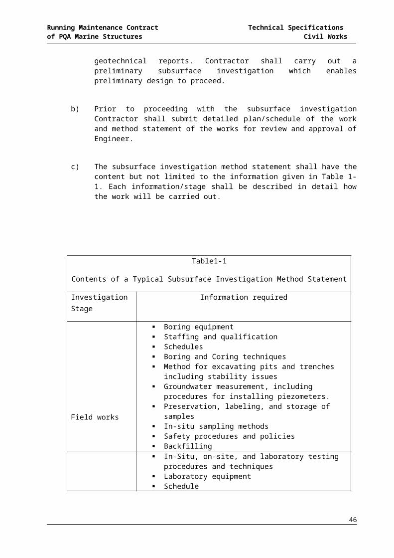
Running Maintenance Contract Technical Specifications of PQA Marine Structures Civil Works
(i) Life safety measures such as hoardings, barricades, nettings, signboards, etc.
(ii) Ground improvement and/or ground water cut-off systems using jet grout piling, etc.
(iii) The geotechnical and geological condition along the length and depth of the cutting.
(iv) The water levels, hydrogeology, strata permeability and natural artesian (if any) along the length and depth.
(v) The settlements that will be expected and the anticipated effect on neighbouring structures.
(vi) The depth of construction required.(vii) Ground water recharging systems, surface and groundwater drainage
system using(viii) Surface or subsoil drains, sumps, chemical grouting, etc.(ix) Recoverable earth retaining system, surface and groundwater drainage
system using surface or subsoil drains, sumps, chemical grouting, etc.(x) Non-recoverable earth retaining structures using contiguous bored piling,
diaphragm wall, etc if not part of the permanent structure(xi) Slope protection systems using concrete lining, soil nail, ground anchors,
etc.(xii) Instrumentation to detect ground and building movement using
inclinometers, piezometers, surface settlement survey, etc.(xiii) Preventive control measures such as daily filling of ground surface cracks
behind temporary retaining structures, conducting regular and systematic visual checks for signs of yielding or disturbance of temporary construction, etc.
(xiv) Any particular difficulties that special plant might meet with respect to access, clearances and working space.
(xv) Control of heave and instability of the base of excavation.(xvi) The adequate support of existing utilities affected by the excavation.(xvii) The operation of heavy equipment, the storage of bulk materials and any
other form of surcharge next to excavation.(xviii) Control of lateral load increase and ground loss induced by water seepage
through ground surface cracks behind temporary retaining structures. (xix) All other measures necessary for the safe performance of the temporary
works, such as maintaining, adding, upgrading, strengthening, adapting, modifying, re-positioning, taking down and refixing from time to time, etc.
4. The Contractor shall employ a Professional Engineer to design and supervise the construction of major temporary works for excavation works. A certified copy of the design calculations and construction drawings for the temporary works shall be
46
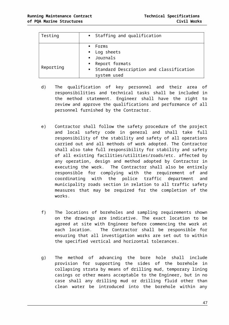
Running Maintenance Contract Technical Specifications of PQA Marine Structures Civil Works
made available to the Engineer for the purpose of record. If the Engineer is of the opinion that the provision of temporary support for the excavation is inadequate in any way, the Engineer will order additional supports or remedial works to be provided entirely at the Contractor's own expense with no additional performance time. Such instruction will not relieve the Contractor of his sole responsibility for the sufficient support of the excavation.
504 GROUND STABILITY CONSIDERATIONS
1. Due regard shall be given to the ground settlements associated with the type or method of temporary construction adopted by the Contractor.(i) Where ground water lowering by pumping will cause soil consolidation and
ground loss, the Contractor shall design and install a groundwater recharging system; the Contractor shall ensure the sediment deposits and precipitation of solutionized minerals are controlled to maintain continued efficiency of the recharge system.
(ii) Where allowed and agreed by the Engineer, timber ground supports which are non-recoverable shall be treated with approved wood preservative before use.
The minimum precautions to be taken by the Contractor for the particular temporary construction that he has adopted include but are not limited to:
Dewatering: Particular attention shall be given to avoid soil consolidation and ground loss next to the excavation caused by fluctuations in the water table level.
Steel Sheet Piling: The Contractor shall ensure that sheet piles are providing proper support to the sides of excavation under the worst combination of lateral earth pressure and groundwater pressure, including the possibility of the water level rising temporarily to the ground surface due to heavy rainfall. Particular attention shall be given to ensuring compliance with permitted noise and vibration levels during the installation and removal of sheet piles.
Timbered Excavation: The Contractor shall ensure that the timber is providing proper support to the sides of excavation. In water-bearing granular soil conditions where water leakage into the excavation will cause significant groundwater drawdown leading to ground loss and/or soil consolidation, particular attention shall be given to the use of a suitable ground water cut-off system such as jet grout piling behind the timbering. Particular attention
47
Running Maintenance Contract Technical Specifications of PQA Marine Structures Civil Works
shall be given to ensure maximum removal of timber on completion of work, but where timber is likely to be left in place, treated timber to prevent rotting is required.
Trench Cutting: Particular attention shall be given when using trench excavation method to control ground movement during the installation of temporary works for braced excavations in close proximity to principal adjacent structures or facilities. Trench cutting requires the sides of excavation to be cut and braced in a pre-selected sequence of alternate panels.Open Cutting:Particular attention shall be given to the stability of side slopes and the prevention of deterioration of the sides of excavation by prolongs weathering. Abrupt changes in soil conditions, such as when a compacted soil layer is underlain by loose soil strata below, will undermine slope stability. Particular attention shall be given to safe work methods and to providing adequate support to the excavation under such conditions.
Ground Anchors: If temporary ground anchors are to be used in this contract, they shall be of recoverable type and ALL these anchors shall be properly removed after use and the Contractor shall be responsible for all consequential costs, time and damages arising from his failure to do so. The Contractor shall also submit a full detailed method statement for the ground anchors to the Engineer for approval prior to work on site. The method statement shall include details of ground anchors systems, materials, construction (including drilling, grouting, stressing, locking off and testing) and removal. Approval of the method statement by the Engineer does not relieve the Contractor of his sole responsibility for the proper construction and removal of the ground anchors. Refer to specification for ground anchors where relevant. No ground anchors shall extend beyond the site boundaries.
505 EXCAVATION IN TRENCHES
1. Definition: trenches mean all excavations of soil necessary for construction or installation of all temporary or permanent works to be carried out or parts of it.
2. The Contractor will be responsible for all shoring of trenches to ensure the safety of his employees. If the opinion of the Engineer the shoring provided by the Contractor is inadequate, additional shoring shall be provided to his satisfaction. In the event of damage occurring to installation from collapse of trench walls the Contractor will be responsible for affecting any remedial works required as directed by the Engineer and at the Contractor's expense.
48

Running Maintenance Contract Technical Specifications of PQA Marine Structures Civil Works
3. Where trenches are excavated along existing structures the Contractor shall similarly ensure that the road formation and pavement is not disturbed due to collapse of the trench walls. Any damage so occurred shall also be required to be repaired to the standard required by the Engineer at the Contractor's expense.
4. Excavated material must be stacked at least 1.2 m clear of the edge of the trench.
5. Where trenches are excavated across roads or drainage channels the Contractor will be required to reinstate the road or channel to its original condition.
506 WATER IN EXCAVATION
1. The Contractor shall not permit water to accumulate or stand in any of the excavations or on any of the areas of filling and he shall take all steps necessary to prevent surface and ground water draining or soaking into the excavations.
2. The Contractor shall take particular care during the placing of the fill to see that the upper surface is at all times left and finished with a smooth well-rolled hard surface to a crossfall such that surface water will drain quickly to the nearest channel or dewatering point.
3. The cost of such measures shall be deemed to be included in the tendered rates for excavations.
507 BASE OF EXCAVATION
1. Immediately after the bottom 150 mm of foundation excavation has been removed as specified, the bottom of the excavation shall be blinded with lean concrete Class 10/20 to a width not less than the foundation to be placed as practicable, and shall be well tamped into the ground. Where plain concrete is to be deposited on the blinding layer the surface of the latter shall be left roughly grooved. Where reinforced concrete is to be constructed thereon the surface of the blinding layer shall be wood-trowel-finished and the specified cover of concrete under the reinforcement shall be provided entirely above the binding layer.
2. The bottom of excavation for other foundations including capping beams, pipe and drain trenches, manholes, etc. shall be formed to correct levels and falls and compacted as required. All soft or defective bottoms shall be cut out and filled in with approved excavated materials as may be directed, well compacted in layers not exceeding 200 mm thickness.
3. For all foundations, all water and sludge shall be removed before laying concrete or pipes. The Contractor shall notify the Engineer when excavations are completed
49

Running Maintenance Contract Technical Specifications of PQA Marine Structures Civil Works
and no concrete or hardcore shall be placed or pipe work or drains laid without his permission.
4. The areas excavated to form finished site levels shall be graded as required.
508 BACKFILLING
1. No backfilling shall be done or trench supports withdrawn until the Engineer has inspected and approved any concrete, anchors, drains, ducts or other permanent structures which are to be covered.
2. Excavation for foundations shall, unless otherwise specified on the drawings, or by the Engineer, be carefully backfilled with the best of the excavated materials, well rammed by mechanical means and compacted in layers not exceeding 200mm thick.
3. Pipe trenches in which the pipes are unprotected by concrete surrounds shall be carefully backfilled with selected fine material, watered and hand rammed to a depth (after compaction) of 300 mm above the crown of the pipe, care being taken too ensure that all joint holes and spaces below the pipes are completely filled. Backfilling of Tie Rod trenches have to be treated in the same way.
4. The remainder of the trench shall unless otherwise specified on the drawings, or directed by the Engineer be backfilled with the best of the excavated materials, well rammed by mechanical means and compacted in 200mm thick layers.
509 COMPACTION OF FILL
1. The Contractor is responsible for taking precautions to prevent damage to existing drains, water and electricity main, any underground works, etc.
2. In general, fill material shall be graded granular soil unless otherwise approved by the Engineer. The Contractor shall allow in the tender for the cost of laboratory tests to determine the optimum moisture content and dry density of the fill material prior to the commencement of filling operations. The compacted fill shall have dry density of not less than 95% (for cohesive material if allowed to be used by the Engineer) and 100% (for cohesionless material) of its maximum dry density.
3. The safety of workmen, ease of placement and compaction are primary considerations when carrying out filling operations in narrow, confined spaces. Under these conditions, only well graded granular soil will be permitted for use as fill material. The use of excavated materials as fill is subject always to the written approval of the Engineer. Notwithstanding any prior approval given in this regard,
50

Running Maintenance Contract Technical Specifications of PQA Marine Structures Civil Works
the Engineer shall bear the right to reject and order the removal of any excavated material that he considers unsuitable for use as fill. The Contractor shall have no claim for extra time or costs in connection therewith.
4. Fill materials shall generally be placed in layers not exceeding 300mm thickness per layer, and uniformly compacted to the satisfaction of the Engineer by approved type rollers before the next layer is applied. In confined work spaces, the use of approved type mechanical rammers or compressed air compactors will be permitted.
5. Where the fill materials are transported by tippers, each load shall be subsequently bulldozed, spread and levelled in layers, and compacted as described above in this section. The Contractor may be permitted to use sheep foot rollers for compaction on condition that the final layer of fill shall be compacted by smooth-wheeled rollers of not less than 10 tonne capacity.
6. The Contractor shall when directed by the Engineer carry out compliance field tests to check the degree of compaction attained on Site. Only tests that meet the minimum compaction requirements of this specification will be acceptable. The Contractor shall have no claim for extra time in connection therewith.
7. Compaction shall not be carried out when the fill is too dry to achieve the satisfactory degree of compaction. In the case of dry fill, the moisture content shall be increased by spraying with water from travelling water tanks or by other approved means as the compaction proceeds.
8. Where the Contractor has failed to obtain sufficient compaction in each layer to the satisfaction of the Engineer, he shall not be allowed to proceed with the next layer without the Engineer's approval, and no claim for time lost or extra time required will be allowed in connection therewith.
9. Where undue movement occurs in the course of compaction due to soft, unstable foundation conditions under the fill, the area affected shall be excavated to such depths and over such dimensions as the Engineer will direct and be run to spoil. The resultant excavation shall be backfilled with suitable and approved materials deposited in layers, each not exceeding 300mm thick in loose form, and compacted as hereinbefore specified, or with suitable compressed air compactors or mechanical rammers where the excavation work is limited. The Contractor shall have no claim on time or cost in connection therewith.
510 DAMAGE TO EXISTING CONSTRUCTION
1. The Contractor is responsible for taking precautions to prevent damage to existing drains, water and electricity main, any underground works, etc. Should any damage
51

Running Maintenance Contract Technical Specifications of PQA Marine Structures Civil Works
occur it shall immediately be reported to the Engineer and rectified as directed by the Engineer at the Contractor's expense.
511 NOTIFICATION TO ENGINEER
1. The Contractor shall notify the Engineer when excavations are ready to receive foundations and the latter shall not be laid until the Engineer's approval is obtained.
512 FINAL FORMATION LEVEL1. The Contractor is required to prepare a final formation level in his directed working
area as shown on the drawings to be handed over to the next contractor as sub-formation for road works.
2. This final formation level shall have a bearing capacity with a minimum surface modulus (Ev2) of 45 MN/m2 when tested with a 300 mm diameter plate bearing test. The Ev2/Ev1-ratio shall be less than 2.6. If the Ev1-value is ≥ 60 % of Ev2, ratios > 2.6 are permitted but have to be agreed with the Engineer.
3. The final formation level tolerances shall be:
a. Maximum deviation from required formation level = 50 mmb. Maximum deviation within 4 m = 20 mm
513 CLASSIFICATION OF EXCAVATION MATERIALS
1. Rates for excavation shall include for excavating in whatever type of soil formation that may be encountered, with the exception of rock which in the opinion of the Engineer is not removable by ordinary tools, bars or ordinary earth moving equipment and requires special methods of removal as defined hereafter.
2. Hard Materials Other Then Rock Materials such as laterite earth, gravel, disintegrated or decomposed masses, geologically semi-formed or weathered “rock” such as very dense cemented sand and other such hard, composite materials that can nevertheless be excavated by standard use of ordinary earth moving machines, shall be deemed as ordinary materials. Excavation of these materials shall be paid for at normal excavation rates.
3. Unsuitable Fill Materials Unsuitable materials shall include:(i) running silt, peat, logs, stumps, perishable or toxic material, slurry or mud, or
(ii) any material- consisting of highly organic clay and silt;
52

Running Maintenance Contract Technical Specifications of PQA Marine Structures Civil Works
- which is clay having a liquid limit exceed 80% and/or a plasticity index exceed 55%;
- which is susceptible to spontaneous combustion;- which has a loss of weight greater than 2.5% on ignition;- containing large amounts of roots, grass and other vegetable matter.
Materials that are soft or unsuitable merely because they are too wet or too dry for effective compaction are not to be classified as unsuitable, unless otherwise defined by the Engineer.
53
Running Maintenance Contract Technical Specifications of PQA Marine Structures Civil Works
SERIES 600
STRUCTURAL STEELWORK
Table of Content
CLAUSE NUMBER PAGE
601 GENERAL.........................................................................................................................55
602 SCOPE OF WORK...........................................................................................................55
603 STANDARDS....................................................................................................................55
604 WORKING DRAWINGS...................................................................................................55
605 TESTING AND INSPECTION...........................................................................................55
606 MATERIALS.....................................................................................................................56
607 GALVANIZED WORK.......................................................................................................56
608 SUPERVISION OF WELDING FLAME CUTTING PROCEDURE TRIALS......................59
609 WELDING.........................................................................................................................61
610 TESTING OF WELDING..................................................................................................63
611 BOLTS FOR STRUCTURAL STEEL WORK....................................................................64
612 FABRICATION - GENERAL.............................................................................................68
613 HANDLING AND TRANSPORTATION TO SITE.............................................................69
614 ERECTION.......................................................................................................................69
54
Running Maintenance Contract Technical Specifications of PQA Marine Structures Civil Works
601 GENERAL
1. The works specified in this chapter comprise the execution of works relating to “Structural Steelwork”. The works include supply, fabrication and installation of materials required and the provision of all labour, plant and equipment and the control for the proper execution and completion of the works.
2. This series shall be read in conjunction with the other series of the specifications and the drawings.
3. The Contractor shall be responsible for executing the works strictly in accordance with the relevant local regulations and by-laws that are current at the date of the tender together with all amendments and addenda which are imposed as statutory requirements in the course of the works.
4. Any standard that can be determined to be substantially equivalent to the standards specified in this document may be used, but it is the Contractor’s responsibility to show the equivalency of the alternate standard and its use must be approved by Engineer.
602 SCOPE OF WORKThe work covered by this section of the Specifications consists of furnishing all plants, labour, equipment, supervision, appliances and materials, and of performing all operations in connection with the fabrication and erection of Structural and Miscellaneous Iron and Steel work together with all anchors, fastenings, hardware, accessories and other supplementary parts necessary to complete the work in strict accordance with this section of the Specification and the applicable drawings and subject to the terms and conditions of the Contract.
603 STANDARDS These Specifications shall be read in conjunction with the Standards in the Appendix which are deemed to form part of these Specifications. In the event of contradiction between these Specifications and Standards, the more stringent requirements shall take precedence. Reference to any standard shall include any amendment thereto.
604 WORKING DRAWINGS Two copies of all detailed working drawings prepared by or on behalf of the Contractor at his own expense shall be submitted to the Engineer for his approval, but this approval shall in no way relieve the Contractor of his responsibilities for the work under the Contract.
605 TESTING AND INSPECTION 1. Whenever required, the Contractor shall satisfy the Engineer by means of
numbers or identification marks on the steel, combined with a manufacturer's
55
Running Maintenance Contract Technical Specifications of PQA Marine Structures Civil Works
certificate that such steel has been tested and complies with all tests and requirements of the relevant British Standards.
2. Notwithstanding the conditions above, the Engineer may direct from time to time as the work proceeds that the whole or part of the steel used in the Works shall be subject to inspection and tests.
3. In case there is a reasonable doubt in the first trial as to the ability of this steel to meet any requirement of this specification, two additional tests shall be made on samples of steel from the same batch, and if failure occurs in either of these tests, the steel shall be rejected. The steel shall be rejected immediately if any sample fails to attain 95% of the characteristic strength.
606 MATERIALS 1. All materials used in the permanent works shall be of first class quality obtained
from an approved manufacturer and shall in all respects comply with the relevant British Standards.
2. All ironwork, both cast and wrought, shall be free from all defects. All castings shall be perfectly true, clean and sharp and be free from air blows and sand pockets.
3. High tensile structural steel shall be Grade 50B to BS 4360 having minimum yield stress of 355 N/mm2.
4. Mild structural steel shall be Grade 43A to BS 4360 having minimum yield stress of 275 N/mm2.
5. High strength Friction Grip Bolt shall be of general grade in accordance with BS 4395.
6. Mild steel Black Bolts shall comply with BS 916: 1953.
7. Electrodes used in welding shall comply with BS EN 499: 1995.
607 GALVANIZED WORK
1. General a) All galvanizing works where specified shall be hot-dip galvanized and shall
conform to the requirements of BS 729 : 1971. b) Hot-dip galvanizing is defined as a coating of zinc and zinc-iron alloy layers,
obtained by dipping prepared iron or steel articles in molten zinc. Under some circumstances the whole coating may consist of zinc-iron alloy layers.
2. Fabrication
56
Running Maintenance Contract Technical Specifications of PQA Marine Structures Civil Works
a) Care shall be taken to avoid fabrication methods which could cause distortions or embrittlement of the iron and steel articles.
b) Unsuitable marking paints, grease, oil and other deleterious materials shall be removed prior to fabrication of steel and iron articles.
c) Holes and/or lifting lugs to facilitate handling, venting and draining during the galvanizing process shall be provided at approved positions.
3. Surface Preparation a) Materials to be galvanized shall be thoroughly cleaned of all scale, dust and
dirt by pickling in a bath of muriative acid. b) All welding slags and burrs, surface contaminants and coatings which
cannot be removed by the normal chemical cleaning process in the galvanizing operation shall be removed by blastcleaning with approved abrasives to Swedish Standard 2 1/2 mechanical cleaning with power operated tools or other suitable methods approved by the Engineer.
4. Galvanizing a) Materials to be galvanized shall be handled with care so as to avoid any
mechanical damage and to minimize distortion. b) The materials shall be dipped in a galvanizing bath of molten zinc containing
not less than 98.5% zinc at suitable galvanizing temperature and shall remain in the bath until all surfaces are evenly coated with firmly adherent shelter and the coating requirements shall comply with Sub-Clause 5.5 of these Specifications.
5. Coating Requirements
57
Material
Minimum Average Coating On Any Individual Test
Area Coating Weight [ g/m² ]
Equivalent Thickness
[ m ] Steel 5 mm thick and over 610 85 Steel under 5 mm thick but not less than 2 mm
460 64
Steel less than 2 mm thick but not less than 1 mm
335 47
Steel articles which are centrifuged 305 42 Grey and malleable iron casting 610 85
Running Maintenance Contract Technical Specifications of PQA Marine Structures Civil Works
a) Coating Weights and Thickness: The weight and thickness of the galvanizing coating shall comply with the minimum values as shown the in Table below.
b) The weight for galvanized coatings for threaded works/fasteners shall not be less than 375g/m2 or the equivalent thickness of the coatings shall not be less than 52 microns.
c) Surface Finish: i) The galvanized coating shall be continuous, adherent, as smooth and
evenly distributed as possible, and free from any defect or imperfections that is detrimental to the usage of the coated article.
ii) Where slip factors are required to enable high strength friction grip bolting, where shown, these shall be obtained after galvanizing by suitable mechanical treatment of the faying surfaces.
iii) Where a protective coating is to be applied the galvanized materials, all spikes shall be removed and all edges shall be free from lumps and runs.
d) Adhesion: The galvanized coating shall be sufficiently adherent to withstand normal handling during transport and erection without peeling or flaking and light blows with a 0.3 kg hammer shall not cause the coating to peel adjacent to the area deformed by hammer blows.
6. Coating Weight a) The weight of coating shall be determined by one or more methods
described in BS 729 : 1971 or other methods approved by the Engineer.
b) Any galvanizing shown to be defective on inspection or by the hammer-blow tests will be rejected. Any work so rejected shall be rectified by the Contractor at his own expense.
7. Uniformity of Coating : Copper sulphate dip test for uniformity of coating described in BS 729 : 1971 shall be followed. The coating shall withstand four one-minute dips in the standard copper sulphate solution without the formation of an adherent red spot of metallic copper upon the basis metal.
8. Transport and Storage a) Galvanized articles, shall, wherever possible, be transported and stored
under dry, well-ventilated conditions to avoid the possibility of wet storage staining.
58

Running Maintenance Contract Technical Specifications of PQA Marine Structures Civil Works
b) Where required, post-treatment of galvanized products such as chromating or phosphating may be applied to reduce the risk of wet storage staining or to assist subsequent painting.
9. Welding
a) Where galvanized steel is to be welded, adequate ventilation shall be provided. If adequate ventilation is not available, supplementary air circulation shall be provided. In confined spaces a respirator shall be used.
b) Grinding of edges prior to welding may be permitted to reduce zinc oxide fumes formed during welding and eliminate weld porosity which may occur.
c) All uncoated weld areas shall be reinstated as per the Coating Reinstatement these Specifications.
10. Coating Reinstatement : Small areas that are uncoated and/or small areas of galvanized coating damaged by welding, cutting or by excessively rough treatment during transit and erection may be reinstated either by the use of low melting point zinc alloy repair rods or powders made specifically for this purpose, or by the use of at least two coats of good quality zinc-rich paint. Sufficient material should be applied to provide a zinc coating at least equal in thickness of the galvanized layer.
608 SUPERVISION OF WELDING FLAME CUTTING PROCEDURE TRIALS 1. When directed by the Engineer and before fabrication is commenced, welding
and flame cutting procedure trials shall be carried out using representative samples of materials to be used in the Works.
2. The samples of materials shall be selected and marked by the Engineer when the materials for the work are inspected at the mills.
3. Trials on material 20 mm thick shall be taken to include all material up to but not exceeding 20 mm thick. Trials on material 40 mm thick shall be taken to include material over 20 mm and up to but not exceeding 40 mm thick. Materials over 40 mm thick shall be tested for every thickness increment of 6 ram.
4. The welding and flame cutting trials shall demonstrate to the satisfaction of the Engineer the procedures to be adopted in the fabrication of the work which shall include:a) Welding procedure in accordance with BS 5135: 1984.
59
Running Maintenance Contract Technical Specifications of PQA Marine Structures Civil Works
b) The heat control techniques required to ensure that the flame cut surfaces of steel are free from cracks, local hardness, and any other defects which would be detrimental to the finished work.
5. The trials shall include specimen weld details representative of the actual construction which shall be welded in a manner simulating the most unfavourable conditions liable to occur in the particular fabrication. Where primers are to be applied to the work prior to fabrication, they shall be applied to the sample material before the procedure trials are made. After welding the specimens shall be held at a temperature not less than 50 degree Fahrenheit for a period not less than 72 hours and shall then be sectioned and examined for cracks and other defects.
6. The following groups of tests to BS 709: 1983 shall be carried out in accordance with Clause a) Butt Welds :
Transverse tensile test. Transverse and longitudinal bend tests. Separate tests shall be performed in each case with the root of the
weld in tension and compression respectively. Charpy V-notch impact tests except for Grades 43A and 50B steels to
BS 4360 : 1986. Macro examination test.
b) Fillet Welds : Fillet weld fracture test. Macro examination test
7. Qualification and Testing of Welders : Only skilled welders shall be employed and shall have previously undertaken selected tests as described in BS 4871.
8. Supervision of Welding : Welding shall be carried out only under the direction of an experienced and competent supervisor. Unless otherwise agreed by the Engineer, a record shall be kept to enable major butt welds to be identified with the welders responsible for the work but finished work shall not be marked by hard stamping for this purpose.
9. Welding Plant : Welding plant, instruments, cables and accessories shall comply with the requirements of the appropriate Parts of BS 638. The contractor shall be responsible for ensuring that the capacity of the welding plant and ancillary
60
Running Maintenance Contract Technical Specifications of PQA Marine Structures Civil Works
equipment is adequate for the welding procedure to be used and for maintaining all welding plant and ancillary equipment in good working order.
10. Welding Consumables : All welding consumables shall be stored and handled with care in accordance with the BS EN 499 : 1995 and manufacturer's recommendations. Electrodes, filler wires and rods and fluxes that show sign of damage or deterioration shall not be used.
609 WELDING 1. Unless otherwise described in the Contract, metal-arc welding shall comply with
BS 5135: 1984 as appropriate except for tack welds and temporary attachments for which the procedures laid down in BS 5135 : 1984 shall be followed.
2. Electrodes and fluxes shall be used in accordance with the manufacturer's instructions. The use of welding processes other than those covered by BS 5135: 1984 shall be subject to the approval of the Engineer.
3. Unless otherwise approved by the Engineer, the welding consumables and procedures used shall be such that the yield and tensile strength of deposited weld metal shall not be less than the respective minimum values of the parent metal being welded.
4. The general welding programme for shop and site weld, including particulars of the preparation of fusion faces, the method of pre-heating and/or post-heating where approved by the Engineer, the methods of making the welds, the number of passes proposed for particular welds and the types of electrodes shall be submitted to the Engineer for his approval before the work is put in hand. No departure from the agreed welding programme or from the details shown on the Drawings shall be made without the agreement of the Engineer. Electrodes and fluxes shall be so chosen that the properties of the deposited metal are not inferior to those of the parent metal. Particular care over choice of welding technique shall be taken to minimise residual weld stresses and deformation of the steel due to welding.
5. The procedures for welding and flame cutting established by the procedure trials under Sub-clause 7.2 shall be strictly followed.
6. Unless otherwise described in the Contract, all butt welds shall be complete penetration welds made between prepared fusion faces.
7. In the fabrication of built-up assemblies, all butt welds in each component part shall be completed, whenever possible, before the final assembly.
8. The position of welds required for temporary attachments shall be agreed by the Engineer before the work commences.
61

Running Maintenance Contract Technical Specifications of PQA Marine Structures Civil Works
9. Where automatic or semi-automatic processes are used, back gouging of the deposited weld will not be required where the Engineer is satisfied that the root run is free from imperfection.
10. Where butt welds are to be ground flush there shall be no loss of parent metal. The final grinding shall be in the direction described in the Contract.
11. In butt joints the root edges or root faces shall not be out of alignment by more than one eighth of the thickness of the thinner material for material up to 12 mm thick or by more than 1.5 mm for thicker material.
12. Requirements for 'run-on' plates and 'run-off' plates shall be as follows :a) One pair of run-on plates and one pair of run-off plates all prepared to the
same thickness and profile as the parent metal shall be attached by clamps to the start and finish respectively of all butt welds.
b) Unless otherwise required by the Engineer, approximately 1 in 5 pairs of run-off plates for butt welds in tension flanges and 1 in 10 pairs for other butt welds shall be production test plates.
c) The combined size of each pair of production test plates shall be either 230 mm, 300 mm or 380 mm wide x 200 mm long, as shown in Table below, the length being measured in the rolling direction of the metal and at right angles to the weld.
Combined Size ( Per Pair ) of Run-Off Production Test PlatesPlate Thickness in [mm] ≤ 30 > 30…≤ 75 > 75Steel of Grades 43A and 50B to BS 4360 : 1986
230 x 200 300 x 200 Sizes to be agreed with the Engineer
Steel of Grades 40C, D and E, 43C, D and E and 50C to BS 4360 : 1986
300 x 200 380 x 200
d) Butt welds shall run the full length of the joint and extend at full weld profile for a minimum distance of 200mm x 275mm and 250mm respectively into the 230mm x 300mm, 300mm x 200mm and 380mm x 200mm run-off production test plates.
e) On completion of the welds the run-off production test plates shall not be removed until they have been marked in a manner agreed by the Engineer to identify them with the joints to which they are attached.
f) When removing the run-on and run-off plates by flame cutting, the cuts shall not be nearer than 6 mm to the sides of the parent metal and the remaining metal shall be removed by grinding or other method agreed by the Engineer.
62

Running Maintenance Contract Technical Specifications of PQA Marine Structures Civil Works
g) Specimens for the following tests to be carried out in accordance with Sub-Clause shall be selected from the run-off production test plates by the Engineer: Transverse tensile test(s). (The number of test piece shall be sufficient
to cover the full thickness of plate). Transverse bend test. Three Charpy V-notch tests except for steel of Grades 43A and 50B to
BS 4360: 1986.
610 TESTING OF WELDING
1. The tests detailed in Sub-Clauses 7.2 and 7.6 shall be carried out by the methods described in BS 709 : 1983.
2. The test results of welded joints shall not be inferior in any respect to the British Standard test requirements for the parent metal.
3. Procedure Trials a) Tensile and Bend Tests : Should any one of the weld joint test pieces
selected for transverse tensile and transverse and longitudinal bend tests fail to comply with the test requirements applicable to the parent metal of the joint represented by the test, 2 additional test pieces shall be taken from the joint material represented by the test. Both shall then comply with the test requirements in order to qualify for acceptance.
b) Charpy V-notch Tests: Should the average impact value obtained from any set of 3 Charpy V-notch specimens fail to comply with the test requirements, 3 additional test pieces from the same sample shall be tested. The average of the 6 test results shall comply with the test requirements in order to qualify for acceptance.
c) Revised Procedures: In the event of failure to meet the test requirements, the Contractor shall carry out further trials using revised procedures and further tests to the satisfaction of the Engineer.
4. Production Tests a) Production Test Plates: The run-off production test plate sizes specified
shall be cut on the instructions of the Engineer in order to enable up to 2 complete sets of test specimens to be obtained.
b) Tensile and Bend Tests : Should any one of the weld joint test pieces selected for transverse tensile and transverse bend tests fail to comply with the test requirements applicable to the parent metal of the joint represented
63
Running Maintenance Contract Technical Specifications of PQA Marine Structures Civil Works
by the test, additional specimens shall be cut from the same production test plates and the tests repeated. Should either of the additional tests fail to comply with the requirements, the joint shall be rejected.
c) Charpy V-notch Tests: Should the average impact value obtained from any set of 3 Charpy v-notch specimens selected fail to comply with the test requirements, 3 additional test pieces from the same production test plates shall be tested.
d) Should the average of the 6 test results fail to comply with the test requirements, the joint shall be rejected.
e) Re-welding and Re-testing : In the event of failure to meet the test requirements the welded joint represented by the tests shall be completely cut out. The joint shall then be rewelded and the tests repeated.
5. Non-Destructive Testing A method of non-destructive testing agreed with the Engineer shall be used for the examination of butt welds in tension members and where otherwise directed by the Engineer.
6. Radiographic Inspection of Welding a) As a further control of weld quality, the Contractor will be requested to
submit for approval radiographs of weld selected by a competent inspector to be approved by the Engineer. The length of weld to be radiographed at any one location shall be determined by the Engineer.
b) Where radiographic inspection reveals defects in the welds, the welds shall be rewelded or the Contractor shall be permitted to carry out repairs and these shall be required to pass the radiographic inspection at the Contractor's expense.
611 BOLTS FOR STRUCTURAL STEEL WORK
1. Holes for Bolts: All holes shall be accurately marked off from templates or corresponding plates, and drilled, except in plates 10 mm thick or under, when they may be punched. Holes should be cleaned or burrs or rough edges and counter-sunk where required. No drifting shall be allowed. Holes for high strength friction grip bolts shall comply with the requirement of BS 4604.
2. Holding Down Bolts: The Contractor shall supply and position holding down bolts as detailed in the drawings including nuts, washers m.s. angles, etc. They shall be fixed accurately and rigidly to the lines and levels as shown in the drawings. It is absolutely
64
Running Maintenance Contract Technical Specifications of PQA Marine Structures Civil Works
necessary to ensure that the bolts are not disturbed once positioned and care shall be taken to ensure that the bolts are not displaced during concreting.
3. High Strength Friction Grip Bolts
a) Bolt System High strength friction grip bolts (H.S.F.G. bolts) to BS 4395 General Grade, Part 1 shall be used in conjunction with an approved Load Indicating Washer (L.I. Washer). The term "H.S.F.G. bolts" in these Specifications shall be deemed to include a H.T. bolt, a H.T. nut, a L.I. washer and one or two H.T. flat or taper washers as appropriate. The LI. washer shall be additional to the normal washer employed and not take the place of a normal flat or taper washer.
b) Design Procedure i) The design procedure of General Grade H.S.F.G. bolts shall comply with
BS 4604, except where this Standard conflicts with the recommendations of the manufacturer of the L.I. washer in respect of tightening H.S.F.G. bolts, when the manufacturer's recommendation shall take precedence but subject to the approval of the Engineer. The Contractor's erection drawings shall clearly indicate the correct size and length of bolt to be fitted.
ii) The H.S.F.G. bolt system shown on the Drawings may be replaced by other system so long as the Contractor submit detailed calculations complying with the requirements of BS 4395 : Part 1 and BS 4604.
c) Bolt Material i) The bolts, nuts and washers shall comply with the requirements of BS
4395, Part 1.
ii) All bolts, nuts, plates, etc when specified shall be hot-dip galvanised.
iii) Materials to be galvanised shall be thoroughly cleaned of all scale, dust and dirt by pickling in a bath of muriative acid. They shall then be dipped in a bath of molten virgin spelter containing not more than 2.5% impurities and shall remain in the bath until all surfaces are evenly coated with firmly adherent spelter and the additional weight must not be less than 2.76 Kg. per square metre.
d) Storage of BoltsThe bolts, nuts and washers shall be stored in a proper dry shed and be adequately protected from inclement weather or contamination so that they
65

Running Maintenance Contract Technical Specifications of PQA Marine Structures Civil Works
will not deteriorate. The bolts are normally supplied by the manufacturers with sufficient residue oil on the threads of the bolt and nut which is not detrimental and should not removed. In this condition they are ready for normal use, and any further treatment at work shop or site is not recommended. If the threads, nuts and washers are dry, rusty or dirty, they must be cleaned and re-lubricated to reduce thread friction during bolt tightening.
e) Bolt Assembly i) Where plane parallel surfaces are involved each H.S.F.G. bolt shall be
assembled with a flat round H.T. washer and a Load Indicating washer under the bolt head or nut whichever is to be rotated during tightening. The rotated bolt head or nut shall always be tightened against a surface normal to the bolt axis.
ii) Where the surfaces are not parallel, tapered H.T. washer are used. Such a washer shall also be used under the non-rotated component except where the angle between bolt axis and contact surface is within 90 degrees centigrade ±3 degree. Tapered H.T. washers shall be correctly positioned.
iii) Generally, the Load Indicating washer is placed under the bolt head with the protrusions bearing against the bolt when the nut is turned during tightening.
iv) If the bolt head is to be turned instead of the nut, then the Load Indicating washer shall be placed at the nut end of the bolt assembly with the protrusions bearing against a nut face H.T. washer between the Load Indicator and the nut. Movement of the washer is acceptable during tightening of the bolt but the gap should, however, be reduced to 0.25 mm for General Grade part 1 and 0.35 mm for Higher Grade Part 2 bolts. Nuts shall be placed in such a manner that their identification marks are clearly visible after tightening. No gasket or other flexible material shall be placed between the steel work. The holes shall be sufficiently well aligned to permit bolts to be freely inserted in position. The bolts shall not be forced in position, i.e. driving of bolts is not permitted.
f) Tightening Procedure i) It is important that all bolts and nuts shall be tightened to the minimum
shank tensions as specified by the Manufacturer and to the approval of the Engineer.
ii) When tightening a group of bolts in a joint, there may be an incremental loss of tension in the first ones when adjacent bolts in the same group
66

Running Maintenance Contract Technical Specifications of PQA Marine Structures Civil Works
are being tightened due to the flexure of the steel members. As such, the bolt may have to be retightened a second time or more to the satisfaction of the Engineer that the required tension has been achieved.
iii) Bolts and nuts shall always be tightened from the centre of the joint outward when tightening a group of bolts. This will help to minimise unwanted gap or loss of tension at the contact surface at the end of the joint splice if the bolts are tightened progressively from one end to the other. Retightening of the bolts shall be done as directed by the Engineer until he is satisfied that the required shank tension has been achieved.
iv) If after final tightening a bolt or nut is slackened off for any reason, the bolt, nut, Load Indicator and washer or washers shall be condemned and discarded.
v) The condemned bolt, nut load indicator and washer or washers shall be removed from site and not reused.
g) Tightening i) Tightening of the bolts and control of bolt tension shall be of the
"Coronet" Load Indicator method. The Load Indicator is a specially hardened washer with protrusions of one face which bear against the underside of the bolt head leaving a gap or bearing against a nut face H.T. washer between the Load Indicator and the nut is placed at the nut end of the bolt assembly.
ii) As the bolt is tightened the protrusions are flattened and the gap reduced until an average gap of 0.40 mm or less is achieved when placed under a head fitting. When the Load Indicator is used with a nut face washer, the gap should be reduced to 0.25 mm for General Grade Part 1 and 0.25 mm for Higher Grade Part 2 bolts. Under no circumstances shall hammer be used to flatten the protrusions of the L.T. washer in order to achieve the minimum required gap.
iii) It is necessary to ensure that the average gap between the Load Indicator and the bolt head or nut face washer has been reached and this can easily be checked with a feeler gauge.
iv) The minimum shank tension of General Grade Part 1 and Higher Grade Part 2 H.S.F.G. bolts are given in Table 2, BS 4604: 1970.
67
Running Maintenance Contract Technical Specifications of PQA Marine Structures Civil Works
612 FABRICATION - GENERAL1. The Works shall be carried in accordance with BS 449.
2. Inspection, etc :
a) All workmanship shall be of first class quality in every respect, the greatest accuracy being observed to ensure that all parts will fit together properly on erection.
b) The Engineer shall have full liberty at all reasonable times to enter the premises of the Contractor for the purpose of inspecting work, and no work shall be taken down or packed until it has been inspected and approved. Any work found defective or which is not in accordance with the drawings or this specification shall be rejected and, if so, shall at once be made good. The Contractor shall supply free of charge all labour, tools, scaffolding, etc required in connection with the inspection of the Works.
3. Templates, Measurements, etc : All templates, jigs and other appliances necessary to ensure the accuracy of the work shall be provided by the Contractor. All measurements shall be made by means of an approved steel tape.
4. Straightening: Before any other work is done on them, all plates shall be checked for flatness and all bars and sections checked for straightness and freedom from twist and any corrective action shall be taken so that, when assembled, adjacent surfaces shall be in close contact throughout. The methods adopted for the above work shall be such as not to injure or mark the material.
5. Unless otherwise specified, steelwork may be cut by shearing, sawing or flame cutting. Surfaces produced by such cutting shall be finished square (unless a bevelled edge is called for), true and smooth to the required dimensions. Finishing of surfaces shall generally be by machining and/or grinding. In the case of flame cutting, surfaces having only slight irregularities may be lightly ground, provided that the finished edges are substantially as straight, true, smooth and regular as those produced by the finishing cut of a planing machine.
6. Shearing will not be permitted for main plates, reinforcing plates, main gussets and splice plates except in a direction perpendicular to the direction of their main stresses.
68

Running Maintenance Contract Technical Specifications of PQA Marine Structures Civil Works
7. The butting ends of compression flanges and compression members, and of girders and other members which are to be spliced by riveted or bolted joints, shall be faced after fabrication so as to be in close contact throughout.
613 HANDLING AND TRANSPORTATION TO SITE
1. Handling : Fabrication parts shall be handled and stacked in such a way that permanent damage is not caused to the components. Means shall be provided to minimise damage to the protective treatment on the steelwork and any damage which does occur shall be made good,
2. Transportation to Site : All works shall be protected from damage in transit. Particular care shall be taken to stiffen free ends and prevent permanent distortion and adequately protect all galvanized surfaces. All bolts, nuts, washers, screws, small plates and small articles generally shall be suitably packed and identified.
614 ERECTION 1. Erection procedure shall be in accordance with proposals submitted by the
Contractor and approved by the Engineer, and no divergence from the approved procedure will be permitted except if agreed to in writing by the Engineer.
2. The Contractor shall inform the Engineer when fabricated sections are ready for inspection prior to erection. No erection shall then be permitted until the Engineer approves the fabrication.
3. During erection care shall be taken to avoid any shock, dynamic or vibrationary loading of the members.
4. No members in the Works shall be finally bolted, welded or otherwise joined until the whole of a major section is approved by the Engineer. Connection shall be made as soon as possible after the Engineer's written approval is received. Care shall be exercised to avoid interference with members already in place.
APPENDIX TO STRUCTURAL STEEL SPECIFICATIONS List of Standards Use in Structural Steel British StandardsBS 4 : Structural Steel Sections BS 449 : Use of Structural Steel in Buildings BS 638 : Arc Welding Power Sources, Equipment and Accessories
69

Running Maintenance Contract Technical Specifications of PQA Marine Structures Civil Works
BS 709 : 1983 Fusion Welded Joints and Weld Metal in Steel BS 729 : 1971 Hot Dip Galvanised Coatings on Iron and Steel Articles BS 916 : 1953 Black Bolts, Screws and Nuts BS 1391 : 1952 Protective Schemes used in the Protection of Light Gauge
Steel and Wrought Iron against corrosionBS 1449 : Steel Plate, Sheet and Strip BS 1453 : 1972 Filler Materials for Gas Welding BS 1494 : Fixing Accessories for Building Purposes BS 2600 : Radiographic Examination of Fusing Welded Butt Joints in
Steel BS 2630 : 1982 Projection of Welding of Low Carbon Steel Sheet and Strip BS 2994 : 1976 Cold Rolled Steel Sections BS 3410 : 1961 Metal Washers for General Engineering Purposes BS 3571 : General Recommendations for Manual Inert-gas Metal-arc
Welding BS 3923 : Ultrasonic Examination of Welds BS 4215 : Spot Welding Electrodes and Electrode Holders BS 4360 : 1986 Weldable Structural Steels BS 4395 : High Strength Friction Grip Bolts And Associated Nuts and
Washers for Structural EngineeringBS 4604 : The Use of High Strength Friction Grip Bolts in Structural
Steelwork BS 4848 : Hot Rolled Structural Steel Sections BS 4870 : Approval Testing of Welding Procedures BS 4871 : Approval Testing of Welders Working To Approved
Welding Procedure BS 4872 : Approval Testing of Welders When Welding Procedure
Approval Is Not RequiredBS 5135 : 1984 Metal-arc Welding of Carbon and Carbon Manganese
Steels BS 5289 : 1976 Visual Inspection of Fusion Welded Joints BS 5950 : Structural Use of Steelwork In Building BS 7079 : 1989 Preparation of Steel Substrates Before Application of Paint
and Related ProductsBS 7613 : 1994 Hot Rolled Quenched and Tampered Weldable Structural
Steel Plates BS 7668 : 1994 Specification for Weldable Structural Steel: Hot Finished
Structural Hollow Sections In Weather Resistant SteelBS EN 499 : 1995 Welding Consumables. Covered Electrodes for Manual
Metal Arc Welding of Non Alloy and Fine Grain Steel. Classification
BS EN 10029 : 1991 Specification For Tolerances on Dimensions, Shape and
70
Running Maintenance Contract Technical Specifications of PQA Marine Structures Civil Works
Mass for Hot Rolled Steel Plates 3mm Thick or AboveBS EN 10113 : 1993 Parts 1 to 3. Hot Rolled Products In Weldable Fine Grain
Structural Steel BS EN 10155 : 1993 Structural Steel With Improved Atmospheric Corrosion
Resistance.
Technical Delivery Conditions Swedish StandardsSIS 055900-1967 Pictoral surface preparation standards for painting steel
surfaces.
71

Running Maintenance Contract Technical Specifications of PQA Marine Structures Civil Works
SERIES 700
SAFETY LADDERS
Table of Content
CLAUSE NUMBER PAGE
701 LADDER GENERAL.........................................................................................................73
702 LADDER DESIGN............................................................................................................73
703 LADDER MATERIAL........................................................................................................74
704 LADDER INSTALLATION.................................................................................................74
72

Running Maintenance Contract Technical Specifications of PQA Marine Structures Civil Works
701 GENERAL
1. The works specified in this chapter comprise the execution of works relating to “Safety Ladders”. The works include supply, fabrication and installation of materials required and the provision of all labour, plant and equipment and the control for the proper execution and completion of the works.
2. This series shall be read in conjunction with the other series of the specifications and the drawings.
3. The Contractor shall be responsible for executing the works strictly in accordance with the relevant local regulations and by-laws that are current at the date of the tender together with all amendments and addenda which are imposed as statutory requirements in the course of the works.
SAFETY LADDERS702 LADDER GENERAL
1. The contractor shall provide ladders as safety ladders installed at a recesses and a fixing frame at the front wall capping beam. The ladders shall be manufactured and installed to the dimensions, materials and locations as specified on the drawings.
2. Rungs shall be 30 x 30 mm and clear length of 450 mm.
3. Rungs shall be in a distance of 300 mm from centre to centre. The upper rug shall be 150 mm below the top of wharf structure capping.
4. The ladders shall be installed with a 40 mm hand grip on the wharf structure as shown on the drawings.
5. The top rung of the Ladder should be 150 mm below the deck of the wharf structure.
6. In order to be accessible from the water at all times, the ladder must extend down to 1.0 m below M.L.L.W., unless otherwise specified on the drawings.
7. Any standard that can be determined to be substantially equivalent to the standards specified in this document may be used, but it is the Contractor’s responsibility to show the equivalency of the alternate standard and its use must be approved by Engineer.
703 LADDER DESIGN1. Design step load is minimum 2 kN. An additional horizontal load at the structural
worst case point of the ladder of 30 kN has to be considered for strokes because of floating debris within the harbour basin from every direction.
2. The fixing frame and its connections shall be designed to resist the forces from the ladder.
73

Running Maintenance Contract Technical Specifications of PQA Marine Structures Civil Works
3. The connection of the ladder to the fixing frame below water table shall be designed as plug-in connection to enable easy replacement of damaged ladders.
704 LADDER MATERIAL1. The ladders, anchor bolts, fixings and the fixing frame shall be manufactured from
mild steel profiles/ members and bolted together on site. Welding and subsequent zinc spray galvanising will not be allowed.
2. All members of the ladder and the fixing frame shall receive a corrosion protection system of
a) Hot dip galvanised in accordance with EN 1461.
b) 130 m primer coat 2-component modified Epoxy-Primer.
c) 120 m topcoat, 2-component PUR. Colour shall be RAL 9005 (black) accordance with the German colour space system of Deutsches Institut für Gütesicherung/ Kennzeichnung or as directed by the Engineer.
3. All fixings as bolts, nuts and washers shall be of stainless steel.
4. An alternative option of the ladder’s material could be plastic if considerable references can be provided to the satisfaction of the Engineer.
705 LADDER INSTALLATION1. The upper 2 to 3 metres of the ladder shall be installed in a recess of
350 x 750 mm within the waterside wharf structure capping beam. The lower 1 metre is to be installed on a fixing frame.
2. The fixing frame shall be fixed to the capping beam as shown on the drawings. The location of the fixing points for the frame in relation to the expected water table in front of the wall has to be considered and all costs shall be included into the relevant bill items.
3. Fixings to the concrete shall be by means of steel anchors.
74

Running Maintenance Contract Technical Specifications of PQA Marine Structures Civil Works
SERIES 800
GENERAL PILING WORKS
Table of Content
CLAUSE NUMBER PAGE
801 GENERAL.........................................................................................................................76
802 LAYOUT, DESIGN AND CONSTRUCTION.....................................................................76
803 MATERIALS.....................................................................................................................77
804 CONSTRUCTION METHOD............................................................................................77
805 ORDERING OF PILES.....................................................................................................77
806 TOLERANCES AND SETTING OUT................................................................................78
807 FORCIBLE CORRECTIONS............................................................................................78
808 FAULTY PILES.................................................................................................................78
809 NUISANCE AND DAMAGE..............................................................................................79
810 HANDLING AND STORAGE OF PILES:..........................................................................79
811 SOCKETING OF PILES...................................................................................................80
812 ANCHORING PILES TO ROCK (TOE PINS)...................................................................82
75
Running Maintenance Contract Technical Specifications of PQA Marine Structures Civil Works
801 GENERAL
1. The works specified in this chapter comprise the execution of piling works. The works include supply, fabrication and installation of material required, the provision of all labour, plant and equipment and the control for the proper execution and completion of the works.
2. This series shall be read in conjunction with the other series of the specifications and the drawings.
3. The Contractor shall be responsible for executing the works strictly in accordance with the relevant local regulations and by-laws that are current at the date of the tender together with all amendments and addenda which are imposed as statutory requirements in the course of the works.
802 LAYOUT, DESIGN AND CONSTRUCTION
1. The Contractor is required to construct elements of the type(s) and dimensions as well as having the qualities of materials and workmanship as specified.
2. Pile installation system shall be approved by local authority.
3. Materials, workmanship and conditions for the manufacture and installation of piled foundations shall be strictly in accordance with the relevant clauses of the contract specification and the latest European Standards. In matters not specifically covered by this specification the Contractor shall comply with EN 1997-1.
4. The Contractor shall be responsible for determining the lengths of piles supported by detailed calculations in accordance with the following:a. The results of the load tests, which shall form the basis for assessing the depth
of penetration required to achieve the vertical pile working capacity.
b. Piles shall not be installed unnecessarily beyond the depths required for them to develop the required vertical load carrying capacity and if required horizontal load carrying capacity. No payment shall be made for extra installation length which the Contractor cannot technically justify.
c. All other relevant requirements of the contract.
5. Spacing of piles shall be not less than 3.0 times the diameter of the pile. The Contractor shall consider the effect of size of the group when determining the number of piles.
76

Running Maintenance Contract Technical Specifications of PQA Marine Structures Civil Works
6. The Contractor may propose a suitable alternative piling system subject to the condition that the assessment of adequacy of any system and its approval shall be at the discretion of the Engineer and the Local Authority. The Contractor shall not be entitled to extra cost or time in the contract should his proposed alternative system be disapproved.
803 MATERIALS
1. The Engineer shall have the right to inspect and test at any stage of the manufacturing processes provided that, once he has been notified of when the materials will be ready for inspection, any delay in his attendance does not cause delay to or disrupt the production processes.
2. The sources of supply of materials shall not be changed until the Contractor has demonstrated that the materials from the new source can meet all the requirements of the Specification.
3. Materials failing to comply with the Specification shall be removed promptly from the site.
804 CONSTRUCTION METHOD
1. The Contractor shall submit with his bid all relevant details of the method of construction of the each pile system and the plant and monitoring equipment he plans to adopt. Alternative methods may be stated provided it is demonstrated that they satisfy the requirements of the Specification.
2. The Contractor shall report immediately to the Engineer any circumstance which indicates that in the Contractor’s opinion the ground conditions differ from those reported in or which could have been inferred from the geotechnical investigation reports. A reason might be a relevant change in driving characteristics compared to the record of the driving resistance of the next nearest available pile.
3. Cutting of piles to cut-off level shall be carried out by the Contractor. Unless otherwise directed, cut-off level shall be 75 mm above the underside of pilecap and all cut-off piles shall be disposed as waste material.
805 ORDERING OF PILES 1. The Contractor shall ensure that the piles are available at the time for incorporation
in the Works.
2. All piles and production facilities shall be made available for inspection at any time.
3. Only new piles shall be used for permanent works.
77
Running Maintenance Contract Technical Specifications of PQA Marine Structures Civil Works
4. Piles shall be carefully examined at the time of delivery and damaged piles repaired or replaced.
806 TOLERANCES AND SETTING OUT 1. Prior to installation of the steel piles, the element positions shall be checked by the
Contractor and confirmed by Engineer.
2. Piles positions shall be set out by the Contractor based on coordinates from execution design and workshop drawings.
3. Adjacent bearing piles shall not have toe levels differing by more than 1 m height in 2 m distance unless agreed with the Engineer.
4. For vertical piles, a deviation from the vertical axis of up to 1 in 50 shall be permitted.
5. For raked piles with a rake of up to 1 in 6, a deviation from the specified rake of up to 1 in 25 shall be permitted.
6. For raked piles with a rake of more than 1 in 6, a deviation from the specified rake of up to 1 in 15 shall be permitted.
7. The maximum deviation of pile’s centre point from specified position shall not exceed 100 mm at specified cut off level.
807 FORCIBLE CORRECTIONS1. Forcible corrections to the as-installed positions of work piles shall not be permitted
in this contract.
808 FAULTY PILES
1. Any piles cracked, deformed or twisted during installation or testing or otherwise damaged in any way, or not installed within the specified position or tolerance, or failed the specified load tests shall be classified as faulty piles.
2. Faulty piles shall be rejected at the discretion of the Engineer and replaced or supplemented with substitute piles by the Contractor at his own expense. At the sole discretion of the Engineer, the pilecaps and any required compensating pile shall be constructed to a modified design proposed by the Contractor to account for the variation in pile position or alignment. The cost and time of replacement, including all direct and consequential costs in modifications required, shall be borne by the Contractor.
78

Running Maintenance Contract Technical Specifications of PQA Marine Structures Civil Works
3. Generally, where substitute or compensating piles are installed within a particular pile group to make good a faulty pile, the Contractor shall be entitled to payment, where application in the contract, on the basis of a hypothetical working pile of the same size as the faulty pile and with a pay lengths equivalent to the average of the pay lengths of the adjacent working piles in the same pile group. Substitute or compensating piles shall not be paid. In the specific case of pile groups with single piles, and if such piles are judged faulty, the hypothetical pay length shall be based on the average of the pay lengths of surrounding piles of the same size as the faulty pile. Computations of hypothetical pay lengths shall be subject to the agreement of the Engineer, whose decision in this regard shall be final.
809 NUISANCE AND DAMAGE 1. Noise and Disturbance:
The Contractor shall carry out the work in such a manner and at such times as to minimize noise, vibration and other disturbance in order to comply with current environmental legislation. Particular restrictions on permissible working hours are stated in regulations of local authorities.
2. Damage to Adjacent Structures a) If in the opinion of the Contractor damage may be caused to other structures or
services by his execution of the Works he shall immediately notify the Engineer and make good at his own cost and time. The Contractor shall submit his plans for making surveys and monitoring movements or vibration before the commencement of the Works at his own cost and time.
b) The Contractor shall determine the positions of all known services and structures before commencing work on site.
3. Damage to Completed Elements a) The Contractor shall ensure that during the course of the work, displacement or
damage which would impair either performance or durability does not occur to completed elements.
b) The Contractor shall submit to the Engineer his planned sequence and timing for installing elements, having regard to the avoidance of damage to adjacent elements and other structures or services.
810 HANDLING AND STORAGE OF PILES:
1. All piles shall be stacked on approved supports. The Contractor shall ensure that the operations of off-loading, handling, transporting, stacking and pitching of the piles are carried out without damage to the piles. Any piles damaged during these operations must be repaired by the Contractor to the satisfaction of the Engineer at the Contractor's expense. The Engineer shall have power to reject any damaged pile and it shall be replaced at the Contractor's expense.
79

Running Maintenance Contract Technical Specifications of PQA Marine Structures Civil Works
2. Holes or openings shall not be burnt or drilled in piles for the purpose of handling without the approval of the Engineer.
3. Any hole or opening made after receiving permission shall be made good to the satisfaction of the Engineer at the Contractor's expense before the hole reaches 1 m above water level.
811 SOCKETING OF PILES
1. General
a) When required within the design, piles shall be socketed into the underlying rock layer. Socketing of piles will generally be required when the length of penetration is not adequate to develop required compression load bearing capacity, resistance against pull-out in tension load, fixity, lateral load resistance, lateral stability etc.
2. Socketing Length a) The required length of socketing will depend on the purpose for which socketing
is required and shall be as agreed with the Engineer.
b) For tubular piles, the socketing length measured from the depth at which driving of the pile is terminated shall not be less than 3 m or 5 times the outer diameter, whichever is the greater.
3. Work Methodology a) Prior to construction of sockets, the Contractor shall submit details of his work
methods and measures to the Engineer for his information, perusal and acceptance. Notwithstanding the Engineer’s acceptance, the Contractor shall solely be responsible for his work methods and for providing the required socketing length.
b) All overburden soil within the pile shall first be removed by augering, jetting, washing or any other method as proposed by the Contractor and acceptable to the Engineer, from within the pile.
4. Drilling of Socket a) The socket length shall be formed by drilling from within the pile by means of
suitable auger or down-hole hammer with eccentric reamer and or whatever appropriate device which is suitable for the type of material being worked in.
b) The diameter of the socket shall be of the same order as that of the outer diameter of the pile.
80
Running Maintenance Contract Technical Specifications of PQA Marine Structures Civil Works
c) During the forming of the socket length, the pile shall be secured against lateral displacement and undue bending. Air, water, foam or any appropriate method for flushing and removal of cuttings from the socket may be used. The method used shall not, however, cause deterioration of the material within which the socket is to be formed.
5. Re-driving of Pile
a) After the required length of socket has been drilled, the pile shall be re-driven to bear at the bottom of the socket.
6. Cleaning and Grouting of Socket Length
a) After the pile has been driven to bear at the bottom of the socket, the pile section which has been in contact with the overburden shall be cleaned along the inside of the pile by means of wire brushing with extending brushes on the drill stem and by high pressure jet hosing, all material being removed by air lifting or other approved method. The pile shall then immediately be filled with non-shrink concrete to socketing depth of minimum 3 m. After completion of sand filling the socket shall then be pressure grouted by injection (permeation grouting) or any other method proposed by the Contractor to ensure that any voids around the outside of the pile are filled. All methods of working shall be agreed with the Engineer prior to commencement of Works.
7. Grout
a) The grout shall be a non-shrink cement grout mix to the approval of the Engineer. Unless otherwise specified or directed by the Engineer, the water-cement ratio of the grout shall be not more than 0.5.
b) The minimum cube strength for a 50 mm cube shall be:
7 days after mixing : 15 N/mm2
28 days after mixing : 25 N/mm2
c) The mix ratio of the grout to be used shall be determined by the Contractor based on trial mixes to be carried out at site and shall be approved by the Engineer before any grouting work is to commence.
d) Grout shall be mixed in specially designed high speed mixers.
81
Running Maintenance Contract Technical Specifications of PQA Marine Structures Civil Works
8. Records
a) In addition to the requirements as specified elsewhere in the Specification for piling works, the following records shall be kept for each socketed pile:
i) equipment used for forming pile socketii) top and bottom elevation of socketiii) driving record together with hammer fall height within the socketiv) depth of overburden removed from within pilev) start and end time of drilling of socket, including time at each stop and re-
start, for whatever reason of stopping, reason/cause of stop to be recorded
vi) downward force applied on drilling equipment, rotation speed, torque etc. at 0.25 m intervals
vii) volume of grout usedviii) elevation of toe socket and top of grouted length within the pileix) any special or abnormal event occurring during socket forming.
812 ANCHORING PILES TO ROCK (TOE PINS)1. If during design of piling works it becomes apparent hard rock will be encountered,
additional uplift resistance of piles might be required by means of drilled-in rock anchors if required.
2. The purpose of the toe pins is to improve the capacity of these piles as tension piles in order to limit lateral movement of the wharf by horizontal forces.
3. The toe pins shall be formed by pressure grouted multiple bar anchor piles (micro piles) as manufactured by Dywidag type GEWI with double corrosion protection or equivalent approved by the Engineer. The piles and their installation shall conform to EN 14199.
4. The piles shall be installed with rake and penetration into competent ground as specified within the shop drawings. The anchor length of the toe pin in the tubular steel section pile shall be minimum 5 m (if not specified different on the drawings) formed by the pressure grouted GEWI bars.
5. Steel bars shall have a minimum yielding strength of 500 N/mm². They shall be manufactured according to EN 14199 or equivalent approved by the Engineer.
6. The cement rich grout to be used shall be in accordance with design requirements and shall take due consideration to the environment where it will be applied.
7. Drilling for the GEWI anchor pile shall be executed through the inside of the tubular steel pile section. Before drilling is commenced, the pile is to be carefully cleaned
82

Running Maintenance Contract Technical Specifications of PQA Marine Structures Civil Works
out from any sand and soil plug which has been formed while driving the pile, and the surface of at least 5 m length have to be wire brushed in order to provide proper bond between the steel pile and the anchor pile forming the toe pin. Then, drilling through a casing is required.
8. Pile holes shall be drilled within 2% of the theoretical centre line as shown on the Drawings.
9. The Contractor shall keep a record of all drilling procedures and times, which shall be made available to the Engineer.
10. For installation of the pile in the borehole, steel or plastic centralizers shall be provided to ensure that the GEWI-pile assembly is centrally located in the hole, providing a minimum grout cover of 15.0 mm.
11. The pile assembly shall be inserted into the full length of the borehole and its top end reach a minimum of 5 m into the tubular steel pile. The Contractor shall take care to provide the proper lengths of pile assemblies in order to avoid unnecessary splicing.
12. For the grouting a cement grout with a water cement ratio of 0.45 and a minimum compressive strength of 20 N/mm² after 7 days shall be used.
13. The grout shall be pumped into the cased hole through a grout tube from the bottom of the hole until the required grout mix reaches the top of the drill casing. The grout shall always be injected at the lowest point of the bond length.
14. The GEWI-pile shall then be pressure grouted through the casing. Grout shall be injected through a top casing cap, while extracting the casing simultaneously. The injection pressure shall be maintained for at least 1.0 MPa during the operation. The grouting shall be continued until the pile assembly is fully encased in grout to above the top end.
15. At the anchoring length of the GEWI pile in the tubular steel pile section; non-shrink concrete class 40/20 shall be used instead of grout for the first grouting stage to form the concrete plug in the spun pile.
16. A multi-stage post grouting system capable of developing grouting pressure of 7 Mpa shall be installed on GEWI-piles in locations directed by the Engineer. Post-grouting shall be performed in accordance with the manufactures recommendations.
17. After each grouting operation, the anchors shall remain in an undisturbed condition until the necessary grout strengths have been achieved. The Contractor shall
83

Running Maintenance Contract Technical Specifications of PQA Marine Structures Civil Works
maintain a record showing the pile number, cement quantity and installation date for each GEWI-pile.
18. This anchoring includes the drilling of an anchor hole into the rock within the tubular steel pile section, provision of anchor bar, compression fittings, cement grout, anchor plate, PVC sleeve etc. as indicative shown on the sketch below.
19. The following sketch shows an example for a toe pin.
Source: M.J. Tomlinsen “Pile Design and Construction Practice”
SERIES 900
84

Running Maintenance Contract Technical Specifications of PQA Marine Structures Civil Works
TUBULAR STEEL PILES
Table of Content
CLAUSE NUMBER PAGE
901 GENERAL.........................................................................................................................86
902 LAYOUT, DESIGN AND CONSTRUCTION.....................................................................86
903 MATERIALS.....................................................................................................................86
904 CONSTRUCTION METHOD............................................................................................87
905 ORDERING OF PILES.....................................................................................................88
906 TOLERANCES AND SETTING OUT................................................................................88
907 RECORDS........................................................................................................................88
908 PILE FABRICATION.........................................................................................................89
909 WELDING OF PILES........................................................................................................91
910 CORROSION PROTECTION AND DURABILITY............................................................93
85

Running Maintenance Contract Technical Specifications of PQA Marine Structures Civil Works
901 GENERAL
4. The works specified in this chapter comprise the execution of steel piling works. The works include supply, fabrication and installation of material required, the provision of all labour, plant and equipment and the control for the proper execution and completion of the works.
5. This series shall be read in conjunction with the other series of the specifications and the drawings.
6. The Contractor shall be responsible for executing the works strictly in accordance with the relevant local regulations and by-laws that are current at the date of the tender together with all amendments and addenda which are imposed as statutory requirements in the course of the works.
902 LAYOUT, DESIGN AND CONSTRUCTION
7. In matters not specifically covered by this specification the Contractor shall comply with EN 12699.
8. When driving tubular steel pile sections there is a risk of the tops bulging. In order to prevent bulging of the pile the head must be stiffened in such cases. All methods for stiffening (e.g. EAU 2004, 11.9) and the removal shall be considered to be included in the Contractor's bid.
903 MATERIALS
4. Piles shall be obtained from an approved manufacturer and the steel is to conform to EN 10204 and EN 10025. Beginning with grade S 355 a certificate according to EN 10204-3.1B is required.
5. Specialised steel (e.g. S 460) according to EN 10113.
6. Tubular pile diameters shall not differ from the theoretical dimensions by more than -1% to +1%.
7. The Contractor shall provide the Engineer with test certificates, analyses and mill sheets. The Contractor shall ensure that adequate notice will be given to the Engineer when the processes can be inspected or tests can be witnessed.
8. The Engineer shall have the right to inspect and test at any stage of the manufacturing processes provided that, once he has been notified of when the
86

Running Maintenance Contract Technical Specifications of PQA Marine Structures Civil Works
materials will be ready for inspection, any delay in his attendance does not cause delay to or disrupt the production processes.
904 CONSTRUCTION METHOD
4. Each pile shall be driven continuously until the specified or approved set and/or toe level has been reached, except that the Engineer may permit suspension of driving if he is satisfied that the rate of penetration prior to the cessation of driving will be substantially re-established on its resumption or if he is satisfied that the suspension of driving is beyond the control of the Contractor. The Contractor shall ensure that the driving hammer used shall have adequate energy to drive the pile to set or toe level.
5. A follower (long dolly) shall not be used for top driving tubular bearing piles unless approved, in which case the Engineer will require the set to be revised to take into account the reduction in the effectiveness of the hammer blow.
6. The Contractor shall give adequate notice and provide all facilities to enable the Engineer to check driving resistance. A set shall be taken only in the presence of the Engineer unless otherwise approved.
a) Each pile shall be clearly marked in white paint with its number and overall length. It shall also be marked with bands painted at 1 m intervals over the visible length of the pile as pitched. Bands at 250 mm intervals shall be painted as required for the purpose of making pile records.
b) When a final set is being measured, the following requirements shall be met:
i. Exposed part of the pile shall be in good condition without damage or distortion.
ii. Dolly and packing, if any, shall be in sound condition.
iii. Hammer blow shall be in line with the pile axis and the impact surfaces shall be flat and at right angles to the pile and hammer axis.
iv. Hammer shall be in good condition and operating correctly.
c) Proof driving shall be carried out by the Contractor. Having reached the agreed final set the pile shall be left for 5 minutes before driving again to check the set. If this set is now reduced the pile shall be redriven and extended if necessary, so that after further proof driving the agreed final set is achieved.
87

Running Maintenance Contract Technical Specifications of PQA Marine Structures Civil Works
d) The cost of complying with these requirements shall be included in the Contractor's rate for piling.
905 ORDERING OF PILES
5. The records of testing of the steel used in the piles shall be submitted prior to commencing the Works.
906 TOLERANCES AND SETTING OUT
8. Piles driven to level shall be driven to a level as specified with tolerance of 20 mm unless otherwise directed by the Engineer.
9. After being driven, the piles might require a temporary bracing to fulfil the tolerance of pile head positioning. This measure shall also protect piles which stand freely in deep water, against excessive bending and damage.
907 RECORDS
1. The Contractor shall keep complete and accurate pile driving records.
2. Such Contractor's records shall be made on an approved standard form and two signed copies of these records shall be submitted to the Engineer.
3. These records shall be submitted to the Engineer not later than noon on the day following the installation for each pile driven.
4. Records shall consist of the following where appropriate to the type of pile being installed. Pile records shall be submitted and approved prior to any piles becoming inaccessible for further pile driving operations.
a) Pile reference number
b) Type or size of pile and type of hammer
c) Inclination of pile
d) Type, weight, drop, mechanical conditions and reference number of hammer and equivalent information for other equipment
e) Number and type of packings used and type, condition and reference number of dolly used during driving the piles, if appropriate
f) Ground level, related to CD(PQ), at start of installation of pile
88

Running Maintenance Contract Technical Specifications of PQA Marine Structures Civil Works
g) If required, temporary compression of ground and pile from time of a marked increase in driving resistance until pile reaches its final level
h) Date of pre-boring, if any
i) Date and time of driving pile
j) Level of pile toe
k) Cut-off level
l) Rate of driving, measured as blows per 250 mm of penetration
m) Final set, measured as blows per 100 mm of penetration together with the time taken for the last 10 blows
n) If required, the sets taken at intervals during the last 3 m of driving
o) Positions of site welds
p) Level of ground inside pile, if appropriate
q) Details of any obstructions encountered and obstruction time, and other interruptions to the sequence of work
5. The final set of each pile shall be recorded as the number of blows required to produce a penetration of 100 mm.
6. Any unexpected driving conditions shall be noted in the records.
7. The Contractor shall submit to the Engineer on the first day of each week a progress report showing the current rate of progress and progress during the previous period on all important items of each section of the Works.
908 PILE FABRICATION
1. The Contractor shall provide a schedule within five weeks of the decision for carrying out piling works giving details of where and how the piles will be fabricated, and the proposed fabrication schedule for the piles. Depending on the location of the pile fabrication yard, the Engineer will decide on the appointment of a suitable inspector. The Contractor shall provide adequate notice for the Engineer to arrange the inspection of the pile weld tests.
89
Running Maintenance Contract Technical Specifications of PQA Marine Structures Civil Works
2. All welds for welded tubular piles shall be full penetration butt welds and, with the exception of the continuous tube-making processes, longitudinal welds shall be made with extension plates at the starting and finishing points of each seam.
3. For welded tubular piles approval shall be obtained if special edge preparation is required for use with automatic welding machines or because of the method of rolling.
4. Prior to forming a spirally welded pile the edges of the strip shall be straight. The forming and welding process shall be approved by the Engineer. Before fabrication commence, tests as required by the Engineer in accordance with the standards for forming and welding shall be made to ensure that the welding procedure is satisfactory.
5. It may be necessary to splice pile sections to form the completed pile and this shall be carried out before driving, if possible. All butt welds shall have a backing plate bent to the pile profile and shall be full penetration welds made between prepared fusion faces. Backing plates shall be cranked or packed as necessary to accommodate the variation in thickness of the piles.
6. For the tubular piles the deviation from straightness shall not exceed 1/600 of a length not exceeding 10 m. When two or more such lengths are joined the deviation from straightness shall not exceed 1/960 of the completed length unless otherwise agreed by the Engineer.
7. Longitudinal seam welds and spiral seam welds of lengths of tubular piles forming a completed pile shall, whenever possible, be evenly staggered but if, in order to obtain a satisfactory match of the ends of piles or the specified straightness, the longitudinal seams or spiral seams are brought closely to one alignment at the joint then they shall be staggered by at least 100 mm.
8. Where a pile is being extended, whether in the site assembly area or after partial driving, the Contractor shall ensure that all steel parts are kept at proper temperatures and that adequate shelter is provided for the work. All installation and welding procedures for such extensions shall be subject to the Engineer’s prior approval.
9. The Contractor should note that, where initial pile driving results indicate that extensions are required to piles yet to be pitched, the Engineer may instruct extensions to be made to piles in the site assembly area, prior to pitching.
10. Fabrication Records : All piles shall be numbered sequentially in the order in which they are welded, and a record of these numbers, the date welded, the name of the
90

Running Maintenance Contract Technical Specifications of PQA Marine Structures Civil Works
operative and the results of testing shall be kept. These records shall be submitted to the Engineer as soon as possible after completion of welding.
909 WELDING OF PILES
1. Generals
b) The Contractor shall submit details of weld preparations and procedures proposed for all longitudinal and circumferential welds for both factory and site fabrication for approval by the Engineer. Welded joints in driven steel piles shall be in accordance to EAU 2004, 8.1.18 (R 99).
c) If and when directed by the Engineer and before fabrication is commenced welding procedure trials shall be carried out using representative samples of materials to be used in the Works. These trials shall be carried out to the approval and in the presence of the Engineer.
d) The approval testing of welding procedures shall be carried out. No variations from the approved procedures will be permitted without the Engineer’s prior approval.
e) After welding, the specimens shall be kept for a period not less than 72 hours and shall then be sectioned and examined for cracks and other defects.
f) The following requirements shall also be met:
i. The test results of welded joints shall not be inferior, in any respect, to the EAU 2004, 8.1.18 "Design of welded joints" requirements.
ii. Should any one of the weld joint test pieces fail to comply with the test requirements applicable to the parent metal, two additional test pieces shall be taken from the joint material represented by the test. Both shall then comply with the test requirements in order to qualify for acceptance.
iii. In the event of failure to meet the test requirements the Contractor shall carry out further trials, using revised procedures and further tests to the approval of the Engineer
g) Production welding shall not commence until the welding procedures have been given partial approval on the basis of non-destructive testing. Production welding may commence prior to final approval of the welding procedures on the basis of destructive testing, at the Contractors risk. The Contractor shall ensure that the destructive tests are carried out without delay and the results promptly
91

Running Maintenance Contract Technical Specifications of PQA Marine Structures Civil Works
forwarded to the Engineer. The cost of all welding procedure trials shall be included in the rates for supply of piles.
2. Welding Plant
The welding plant shall be capable of maintaining at the weld the voltage and current specified by the manufacturer of the electrodes. The Contractor shall supply instruments for verifying voltages and current as and when required by the Engineer.
3. Welding Positions
The assembly of pieces for welding shall be so arranged that, wherever possible, welding is carried out in the down hand or horizontal/vertical position. Welding shall not be carried out in the vertical or overhead positions unless the welder has carried out satisfactory welding tests in these positions.
4. Testing of Production Welds
a) All circumferential butt welds formed in the pile fabrication works will be subject to 90% ultrasonic inspection and 10% radio-graphic inspection. All circumferential butt welds formed at site, either on shore or in-situ over water on a partially driven pile, will be subject to the same inspection. The Engineer will also require radiographs of 10% of longitudinal welds to be produced for inspection.
b) The Contractor shall arrange for the testing of welds to be carried out by personnel qualified for the purpose, and shall provide all personnel, equipment, access and assistance as may be necessary properly to test the welds and to allow the Engineer to inspect the weld testing. The Contractor shall allow for all costs involved in site testing the circumferential welds on the piles, including all delays, craneage, access and interruptions to his working in the items in the relevant Bill of Quantities.
c) The cost of weld testing on circumferential, spiral and longitudinal welds carried out in the fabrication works shall be included in the rates for supply of piling.
d) The Engineer or his appointed inspector will select which welds are to be tested, and will provide qualified personnel to inspect the results of the testing carried out by the Contractor. Should the weld be rejected the cost of all subsequent inspection on the repaired weld, including any cost of bringing specialised personnel and/or equipment to the site or to the works where the welding is being carried out will be charged to the Contractor, and deducted
92

Running Maintenance Contract Technical Specifications of PQA Marine Structures Civil Works
from the payments due in the certificate which relates to the period in which the testing was carried out.
e) The Contractor shall cut out and re-weld or otherwise make good to the approval of the Engineer, all unsatisfactory weld runs or part runs, at no cost to the Contract.
910 CORROSION PROTECTION AND DURABILITY
1. Protective coating shall be applied to steel where specified, following the procedures set out in this Specification.
2. Protective coating system shall be of:
Sa 2 ½ cleaning and decreasing
50 microns (m) Primer
500 microns (m) Top Coating
3. Primer Type
a) Primer shall be epoxy-zinc-rich primer for steel construction, 2-pack, highly pigmented, of low solvent content, which cures very quickly, is resistant to water and weathering, abrasion and barnacles, mechanical wear.
b) Primer colour shall be noticeable different to steel and top coating, e.g. zinc grey.
c) The primer shall be compatible with the specified coating and shall be such that if subsequent welding or cutting is to be carried out it shall not emit noxious fumes or be detrimental to the welding.
d) Primer shall be Friazinc R by
Sika Deutschland GmbHGeschäftsbereich Protective CoatingsRieter TalD - 71665 Vaihingen / EnzFax.: + 49 2845 / 9366826Mobil.: + 49 173 / 677 4959
or equivalent.
4. Coating Type
a) Coating shall be solvent-free epoxy-resin coating (2-component).
93

Running Maintenance Contract Technical Specifications of PQA Marine Structures Civil Works
b) Coating shall be
abrasion resistant
tough hard, abrasion resistant
solvent free
tar-free
suitable for cathodic protection system
applicable in 1 layer up to 1000 microns (m)
c) Coating colour shall be black or red-brown or as agreed with the Employer.
d) Coating shall be compatible with the specified primer.
e) Coating shall be Icosit SW 500 by
Sika Deutschland GmbHGeschäftsbereich Protective CoatingsRieter TalD - 71665 Vaihingen / EnzFax.: + 49 2845 / 9366826Mobil.: + 49 173 / 677 4959
or equivalent.
5. Tubular steel piles shall be coated at the production plant and not on site. Only repairs and weldseams shall be coated on site in accordance with supplier’s recommendations.
6. If pile heads are to be encased in concrete, protective coatings shall be removed from the surfaces of the pile heads down to a level of 100 mm above the soffit of the concrete.
7. Specialist Labour: The preparation of surfaces and the application of the coats to form the coating shall be carried out by specialist labour having experience in the preparation of the surface and the application of the coating specified.
8. Protection During Coating: All work associated with surface preparation and coating shall be undertaken inside a rain-protected housing.
9. Surface Preparation:
a) All surfaces to be coated shall be clean and dry and prepared by one or both of the following methods, as specified.
94

Running Maintenance Contract Technical Specifications of PQA Marine Structures Civil Works
b) Degreasing with detergent wash compatible with the coating shall be carried out where necessary to remove dirt, oil and grease.
c) All surfaces shall be blast cleaned to Sa 2 ½ according to EN ISO 12944, part 4. Blast-cleaning shall be done directly before applying the primer. Unless an instantaneous-recovery blasting machine is used, the cleaned steel surface shall be air-blasted with clean dry air and vacuum-cleaned or otherwise freed from abrasive residues and dust immediately after cleaning.
10. Primer Application:
a) Within 4 hours after surface preparation, before visible deterioration takes place, the surface shall be coated with an appropriate primer or the specified coating. No coating shall be applied to a metal surface which is not thoroughly dry.
11. Control of Humidity During Coating:
a) No coating shall be applied when the surface metal temperature is less than 3°C above the dew-point temperature or when the humidity could have an adverse effect on the coat.
b) When heating or ventilation is used to secure suitable conditions to allow coating to proceed, care shall be taken to ensure the heating or ventilation of a local surface does not have an adverse effect on adjacent surfaces or work already done.
12. Parts to be Welded:
a) The coating within 200 mm of a weld shall be applied after welding. The method of application shall comply with the manufacturer’s recommendations.
13. Inspection of Coatings
a) The nominal thickness of finished and dry coating system shall be 550 microns (mm)
b) The average coat or finished coating thickness shall be equal to or greater than the specified nominal thickness.
c) In no case shall any coat or finished coating be less than 80% of the nominal thickness. Each coat shall be applied after an interval that ensures the proper hardening or curing of the previous coat.
d) The finished coating shall be generally smooth, of dense and uniform texture and free from sharp protuberances or pin-holes. Excessive sags, dimpling or curtaining shall be retreated.
95
Running Maintenance Contract Technical Specifications of PQA Marine Structures Civil Works
e) Any coat damaged by subsequent processes or which has deteriorated to an extent such that proper adhesion of the coating is in doubt shall be removed, and the surface shall be cleaned to the original standard and recoated to provide the specified number of coats.
f) The completed coating shall be checked for thickness by a magnetic thickness gauge. Areas where the thickness is less than that specified shall receive additional treatment.
g) The completed coating shall be checked for adhesion by means of an adhesion test, carried out on 10% of the piles. Areas where the adhesion is defective shall be repaired and re-inspected.
SERIES 1000
PILE TESTING WORKS
96
Running Maintenance Contract Technical Specifications of PQA Marine Structures Civil Works
Table of Content
CLAUSE NUMBER PAGE
1001 GENERAL.....................................................................................................................98
1002 TRIAL PILES.................................................................................................................98
1003 WORKING PILES.........................................................................................................99
1004 STATIC LOAD TEST....................................................................................................99
1005 PREPARATION OF A PILE TO BE TESTED...............................................................99
1006 REACTION SYSTEMS...............................................................................................100
1007 EQUIPMENT FOR APPLYING LOAD........................................................................100
1008 KENTLEDGE..............................................................................................................101
1009 TEST PROCEDURE...................................................................................................101
1010 MEASURING DEVICES..............................................................................................101
1011 PILE TEST RECORDS...............................................................................................102
1012 REINSTATEMENT......................................................................................................103
1013 FAILURE OF WORKING LOAD TEST.......................................................................103
1014 COMPENSATING PILES............................................................................................104
1015 DYNAMIC LOAD TEST AND INTEGRITY TESTING OF PILES................................104
97
Running Maintenance Contract Technical Specifications of PQA Marine Structures Civil Works
1001 GENERAL
1. The works specified in this chapter comprise the execution of pile testing works at raked and vertical piles for tension and compression loading direction. The works include supply, fabrication and installation of material required, the provision of all labour, plant and equipment and the control for the proper execution and completion of the works.
2. This series shall be read in conjunction with the other series of the specifications and the drawings.
3. The Contractor shall be responsible for executing the works strictly in accordance with the relevant local regulations and by-laws that are current at the date of the tender together with all amendments and addenda which are imposed as statutory requirements in the course of the works.
1002 TRIAL PILES
1. The Contractor shall carry out trial piles in advance of the main piling works operation in order to determine the bearing capacity of piles, the required length of piles and the driveability at each location. The locations and the length of the trial piles shall be proposed by the Contractor and approved by the Engineer. All costs in connection with test trial piles shall be borne by the Contractor.
2. Trial piles shall be driven with hydraulic hammer. Trial piles shall be driven with the same equipment that is to be used in the construction of the main piling.
3. Trial piles shall cover all driven pile systems and all main areas.
4. Trial piles shall be preliminary piles and shall not be part of the permanent works.
5. Approved pile records shall be kept for each pile while driving.
6. Dynamic load tests shall be performed.
7. Static load tests shall be performed until failure.
8. Contract working piles are not to be constructed until the test results of the trial piles have been accepted by the Engineer and the Contractor's proposals for the pile lengths and pile combination of the Contract working piles have been reviewed by the Engineer. Such review shall not relieve the Contractor of his responsibility for assessing, ordering and fabricating adequate lengths of piles required for the completion of the works under the Contract.
98

Running Maintenance Contract Technical Specifications of PQA Marine Structures Civil Works
1003 WORKING PILES
1. Working piles shall be taken to mean a pile installed as part of permanent structure.
2. The Contractor shall carry out Load Tests at working piles to ensure that the standards of materials, workmanship and performance are being maintained in accordance with this Specification. All costs in connection with pile testing shall be borne by the Contractor.
3. Dynamic load tests shall be performed.
4. Static load tests shall be performed. The displacement (and recovery) of the pile are determined for a maximum test load equal to twice the working load.
1004 STATIC LOAD TEST
1. Static load tests shall be performed at trial piles and at working piles.
2. Once any load test is carried out, it shall be continued until the whole test load is completed and all measurements of settlements taken and recorded.
1005 PREPARATION OF A PILE TO BE TESTED
1. Inclusive WorksThe works for the load tests shall include the construction and subsequent demolition of all necessary pile caps built in rapid hardening cement to the contractor’s design which shall be subjected to the Engineer’s approval.
2. Notice of ConstructionThe Contractor shall give the Engineer notice of commencement at least 48 hours before testing.
3. Pile Head for Compression TestFor a pile that is tested in compression, the pile head or cap shall be formed to give a plane surface which is normal to the axis of the pile, sufficiently large to accommodate the loading and settlement-measuring equipment and adequately reinforced or protected to prevent damage from the concentrated application of load from the loading equipment.The pilecap shall be concentric with the best pile. The joint between the cap and the pile shall have a strength equivalent to that of the pile.Sufficient clear space shall be made under any part of the cap projecting beyond the section of the pile so that, at maximum expected settlement, load is not transmitted to the ground except through the pile.
99

Running Maintenance Contract Technical Specifications of PQA Marine Structures Civil Works
4. Pile Connection for Tension PileFor a pile that is tested in tension, means shall be provided for transmitting the test load axially to the pile.The connection between the pile and the loading equipment shall be constructed in such a manner as to provide a strength equal to the maximum load which is to be applied to the pile during the test with an appropriated factor of safety on the structural design.
1006 REACTION SYSTEMS
1. Compression TestsCompression tests shall be carried out using kentledge, tension piles, ground anchors or otherwise specially constructed anchorage. Use of kentledge is preferred for load tests on vertical piles; use of tension reaction piles, ground anchors or other tension reaction systems shall be permitted only when use of kentledge proves impractical. Kentledge shall not be used for tests on raking piles.
2. Tension TestsTension tests shall be carried out using compression piles or rafts constructed on the ground. The use of inclined reaction piles, anchors or rafts is not precluded, subject to agreement. In all cases the resultant force of the reaction system shall be co-axial with the test pile.
3. Working PilesWorking piles shall not be used as reaction piles without agreement from the Engineer. Where working piles are used as reaction piles their movement shall be measured to within an accuracy of 0.5 mm.
1007 EQUIPMENT FOR APPLYING LOAD
1. GeneralThe equipment used for applying load shall consist of one or more hydraulic rams or jacks. The rams or jacks shall be arranged in conjunction with the reaction system to deliver an axial load to the test pile. The complete system shall be capable of transferring the maximum load required for the test.
2. Jack CapacityThe total capacity of the jacks shall exceed by 20% or more the required maximum test load, thereby avoiding heavy manual pumping effort when nearing maximum load and minimizing the risks of any leakage of oil through the seals.The loading equipment shall be capable of adjustment throughout the test to obtain a smooth increase of load or to maintain each load constant at the required stages of a maintained load test.
100

Running Maintenance Contract Technical Specifications of PQA Marine Structures Civil Works
1008 KENTLEDGE
1. Where kentledge is to be used, it shall be supported on cribwork, disposed around the pilehead so that its center of gravity is on the axis of the pile. The bearing pressure under supporting cribs shall be such as to ensure stability of the kentledge stack. Kentledge shall not be carried directly on the pile head, except when directed by the Engineer.
2. The kentledge may consist of concrete blocks, steel piles etc, but must be of uniform size so that weight of the kentledge can be easily calculated.
3. The weight of kentledge shall be at least 1.2 times the maximum test load and if the weight is estimated from the density and volume of the constituent materials, an adequate factor of safety against error shall be allowed. The Contractor shall take all reasonable steps to ensure that sufficient excess load capacity is at all times available for the uninterrupted execution of a load test.
1009 TEST PROCEDURE
1. The Contractor shall make his proposals for the test procedure for approval by the Engineer.
1010 MEASURING DEVICES
1. Load measuring devices shall be calibrated before and after each series of tests, whenever adjustments or replacements are made to the devices or at the intervals recommended by the manufacturer of the equipment. Pressure gauges and hydraulic jacks shall be calibrated together. Certificates of calibration from an approved testing house shall be supplied to the Engineer for acceptance.
2. The Contractor's proposed method of measuring the movement of pile heads shall be submitted to the Engineer for approval.
3. For a constant rate of penetration and constant rate of uplift test:
a) The rate of movement of the pile shall be agreed with the Engineer before the start of the test.
b) Each increment of test load shall be measured within an accuracy of 2%. Movements shall be measured within an accuracy of 0.25 mm.
c) Readings of load, movement and time shall be made simultaneously and immediately before and after the application of each load increment or decrement and as directed by the Engineer.
101

Running Maintenance Contract Technical Specifications of PQA Marine Structures Civil Works
d) Loading shall be continued until the test load is reached or the allowed movement is exceeded.
e) The load shall then be reduced in 5 approximately equal to zero load, and movement at each load stage including zero load shall be recorded.
1011 PILE TEST RECORDS
1. The Contractor shall, within 24 hours of the completion of the test, submit to the Engineer for each pile tested graphs showing:
a) Load and movement plotted above and below a common base line of time,
b) Movement and recovery plotted vertically against a base line of load.
2. The Contractor shall, within seven working days of the completion of the test, submit to the Engineer in writing, a complete schedule of data as listed below:
a) Pile Information
i. Pile number
ii. Top of pile to CD(PQ)
iii. Bottom of pile
iv. Top of high pressure grouted body
v. Concrete strength when tested
vi. Date installed
vii. Date tested
viii. Water level
ix. Length of casing if applicable
x. Description of soil for the length of pile.
b) Test layout and equipment including sketches and, if possible, photographs showing:
i. Location and size of reaction and loading equipment
ii. Deflection measuring equipment
iii. Test pile and cap.
iv. Position of reference level marks
102
Running Maintenance Contract Technical Specifications of PQA Marine Structures Civil Works
c) An assessment of the accuracy of the deflection measurement due to variation in loading or temperature.
d) The results of calibration of the load measuring equipment.
e) Test procedure and results including:
i. A tabulation of readings during loading and unloading.
ii. A load settlement curve.
iii. A time settlement curve.
f) These shall include any corrections required for calibration, movement of datum points, etc.
1012 REINSTATEMENT
1. On completion of the testing of trial piles and tests piles, temporary works shall be cut off and removed from the Site and the area reinstated all to the satisfaction of the Engineer.
1013 FAILURE OF WORKING LOAD TEST
1. A pile shall be deemed to have failed the load test if any one of the following observations is recorded:
a. The total settlement under twice the working load exceeds 10% of the least width or diameter of the pile or the ultimate capacity of the pile has been reached in the opinion of the Engineer.
b. The test could not be completed.
c. The scales and/or measuring instrument used are found to have been tampered with.
d. The pile is found to have cracked, crumbled, distorted from its original shape, deflected from its original position and the like.
2. The Contractor shall not be paid for pile test which has failed. The Contractor shall bear the cost for redesign and enlargement of pilecaps or, if necessary, for replacement piles. Successful test will be paid for as specified.
1014 COMPENSATING PILES
1. Any pile which fails under the working load test shall be replaced by one or more piles to be installed as directed by the Engineer, and at no extra cost to the
103
Running Maintenance Contract Technical Specifications of PQA Marine Structures Civil Works
Employer. If, in the opinion of the Engineer, it is impractical or unadvisable to install substitute piles in place of a failed pile, the Contractor shall make his proposals for solving the problem to the Engineer for his consideration and approval. Notwithstanding the Engineer's approval, the Contractor shall be held fully responsible for all costs incurred and any loss to the Employer due to changes in the design of the structure and/or delay to the contract arising from the Contractor's proposal.
2. For each working load test which has failed, the Contractor is required to carry out at no extra cost to the Employer, an additional working load test on a pile selected by the Engineer as a replacement to the working load test on the pile which has failed.
1015 DYNAMIC LOAD TEST AND INTEGRITY TESTING OF PILES
1. Dynamic tests shall be performed at trial piles and at working piles for determination of pile bearing capacity and pile integrity.
2. Dynamic Test shall be conducted on piles to be selected by the Engineer.
3. All tasks require measurement of both axial pile forces and accelerations under at least one hammer blow. A permanent pile set of more than 1.2 mm per blow is recommended for activation of soil resistance. Smaller sets may under-predict static capacity. For integrity, permanent set is not required, but the blow should cause motion of the pile toe.
4. The testing shall be performed by an experienced Civil Engineer in the field of dynamic testing.
5. Analysis of load test results shall be by CAPWAP method.
6. The Contractor shall submit all records of results and any other information to the Engineer within seven days from the completion of the test. The result shall consist of:
a. Static capacity of pile including the toe resistance and shaft friction,
b. Hammer Efficiency,
c. Integrity of Pile,
d. Case Damping Factor Jc,
e. Predicted Load vs. Settlement Plots and
104
Running Maintenance Contract Technical Specifications of PQA Marine Structures Civil Works
f. Whatever information deemed necessary for the report.
SECTION – 1100
CONCRETE
1100 SCOPE OF WORK
The work covered by this section of the Specifications consists of furnishing all plants, labor equipment appliances and materials and in performing all operations in connection
105

Running Maintenance Contract Technical Specifications of PQA Marine Structures Civil Works
wit concrete work complete in strict accordance with the applicable Drawings and the Specifications herein and subject to the terms and conditions of the Contract.
1100.2 GENERAL
Full cooperation shall be extended to other trades to install embedding items, and form ducts and openings etc. Embedded items shall have been inspected and check tested for concrete and other materials or for mechanical operations and approved before concrete is placed.
1100.3 MATERIALS
1100.3.1 Cementicious Material:
i) Portland Blast-Furnace Slag cement type IS (<70)(MS) as per ASTM C595 with slag constituent is between 25% and 75% of the total cementacious material.
ii) Portland cement type II as per ASTM C150.iii) Hydraulic cement type MS (Moderate sulphate resistance) as per ASTM
C1157. iv) Any other recognized cement type subject to approval from the engineer.v) For all types of cements, described in sub-Clauses (i) to (iv) above, the
average compressive strength of three concrete cubes shall not be less than 12OO Lbs/Sq.in(8.2 N/Sq.mm) at three days and not less than 2OOO Lbs/Sq.in(14 N/Sq.mm) at seven days as described in Ps.No.232.1962. Alternatively, the average compressive strength of three mortar cubes prepared with 1:3 cement and standard silica sand mortar shall not be less than 22OO Lbs/Sq.in(15.2 N/Sq.mm) at three days and not less than 34OO Lbs/Sq.in(23.5 N/Sq.mm) at seven days. The initial setting time shall not be less than 45 minutes and final setting time not more than 1O hours.
vi) The supply of cement must be so programmed by the Contractor that at no time the quantity of cement stock shall be less than that required for an average consumption of four weeks. Lorry or truck or other means of transportation, for the conveyance of cement to the site of works, shall be clean, dry, metalled lined and covered from top with water proof sheets, so that cement is sufficiently protected from any deterioration during transit.
vii) The Contractor shall provide at his own cost, on the Site, all necessary sheds, which shall be perfectly dry and watertight for the storing of cement to be delivered to the works, to ensure adequate supplies being available at site of work.
viii) If at any time the Engineer or his Representative considers that any batch of cement may have deteriorated on the site during storage for any reason, he will direct that tests shall be made and that batch of cement on the site shall not be used until it has been shown by test at a laboratory, approved or appointed by the Engineer, to be satisfactory. Contractor
106

Running Maintenance Contract Technical Specifications of PQA Marine Structures Civil Works
shall bear all costs of such testing. Any rejected cement shall be removed from the site by the Contractor without delay. Cement reclaimed from cleaning bags or leaking containers shall not be used.
ix) Cement shall be consumed in the sequence of receipt of shipments unless otherwise directed by the Engineer or his Representative.
1100.3.2 Aggregates
i) All fine and coarse aggregates to be used shall be supplied from approved sources, which shall not be changed without permission in writing from the Engineer. Aggregates shall conform to the test requirements of Pakistan Standard 243:1963 or equivalent.
ii) Fine aggregates, shall be approved sand and shall be clean, sharp, free from clay, earth, vegetable and organic matters, alkaline or acid reactions or other deleterious matter or impurities.
iii) Fine aggregates shall conform to Pakistan Standard Specifications PS No.243:1963 "Natural Aggregates for Concrete" and shall be graded as follows: -
B.S.SIEVE PERCENTAGE (BY WEIGHT) PASSING
NUMBER. ------------------------------
--------- Grading Zone1. Grading Zone 2.
-------------- ---------------
3/8"(9.5 mm) 100 100
3/16"(4.8 mm) 90 - 100 90 - 100
No. 7 60 - 95 75 - 100
No. 14 30 - 70 55 - 90
No. 25 15 - 34 35 - 59
No. 52 5 - 20 08 - 30
No.100 0 - 10 00 - 10
107
Running Maintenance Contract Technical Specifications of PQA Marine Structures Civil Works
iv) Coarse aggregates shall be approved hard crushed stone from a source approved by the Engineer and shall be clean, free from sand, dust, salt, lime, chalk, clay and organic impurities or other deleterious matter.
v) Coarse aggregates shall conform to the relevant Pakistan Standard Specifications PS No.243:1963 Coarse aggregate shall be graded as follows:-
FOR CONCRETE CLASSES A, B & C (Nominal Size of Graded Aggregate 3/4" to 3/16" (19 mm to 4.8 mm).
B.S.SIEVE NUMBER PERCENTAGE (BY WEIGHT) PASSING
--------------------------- -----------------------------------------------
1" (25.4mm) 100
3/4" (19 mm) 090 - 100
3/8" (9.5mm) 020 - 55
3/16"(4.8mm) 000 - 10
FOR CONCRETE CLASSES D & E (Nominal Size of Graded Aggregate 1-1/2" to 3/16" (38 mm to 4.8 mm).
1 1/2" (38 mm) 100
1" (25.4 mm) 95 - 100
3/4" (19 mm) 35 - 70
3/8" (9.5mm) 10 - 33
3/16"(4.8mm) 0 - 5
vi) All aggregates shall be stored on properly constructed paving and in bins and there shall be a physical partition between the stockpiles of coarse and fine aggregate. No mixed up aggregates shall be used in any concrete. Under no circumstances aggregates shall be allowed to be in contact with ground.
vii) If required, aggregates shall be washed and screened to the satisfaction
108
Running Maintenance Contract Technical Specifications of PQA Marine Structures Civil Works
of the Engineer or his Representative before use by processing through proper screening and washing plant. Adequate time is to be allowed therefore, for the moisture content to become substantially uniform before use in works.
viii) Sieve analysis and other necessary tests of all aggregates shall be carried out as and when required by the Engineer or his Representative. Samples for such tests shall be taken in the presence of the Engineer or his Representative. All costs in connection with the tests shall be borne by the Contractor.
ix) All aggregates shall be subject to the approval of the Engineer. Any batch of aggregates not found to the required standard shall be rejected by the Engineer or his Representative and shall have to be removed from site without delay. Concrete structures executed with rejected aggregates shall be dismantled and rebuilt at the Contractor's expense.
x) Special fine gravel of 9 mm (3/8") or 12 mm (1/2") maximum size shall be used if and where called for on the Drawings or as directed by the Engineer.
xi) If suitable gravel meeting with the Specifications is not procured by the Contractor, he will have to arrange suitable crush stone if demanded by the Engineer. No extra payment shall be made to the Contractor to effect this change.
11.3.3 WATER shall be as specified under section on water.
1100.4 CLASSIFICATION OF CONCRETE
Classes of concrete to be used in various parts of the works shall be as indicated on the drawings and mentioned in Bill of Quantities. The concrete of various grades shall be proportioned as set out in Table-I appended hereto.
TABLE-I: Showing minimum required compressive strengths 150 x 150 x 300 mm (6"x6"x12") test cylindrical and minimum quantity of cement required per m3 or per cft of finished concrete for various mixes and under various conditions.
109

Running Maintenance Contract Technical Specifications of PQA Marine Structures Civil Works
Class of Concrete
Min. Cylindrical Strength at 28 Days
Curing
Min. Cement Content
Max.
Water cement
ratio (w/c)N/Sq.mm. Lbs / Sq.in.
Kg / Cu.m.
Lb / Cu.ft.
A 35 5000 500 32 0.4
B 31.5 4500 404 26 0.45
C 21 3000 328 21 0.5
D (Lean) 10 1500 216 14 0.5
1100.5 PROPORTIONING OF CONCRETE MIXES
11.5.1 All concrete shall be proportioned by weight for concrete mixes, unless specifically directed by Engineer to proportion them by volume, when the ratios will also differ. The proportions given above in Table-I are suitable only when the specific gravities of the aggregates are in the region of 2.5. The Contractor shall submit to the Engineer proposed mix designs for concrete to be used, based on preliminary laboratory tests to determine proportion of cement, aggregates and water in the concrete conforming to the quality and strength requirements specified herein. Preliminary test results of at least three different mixes of each class of concrete with varied water cement ratios shall be submitted. The results of 7 days and 28 days cube tests shall be used to establish the ratios between 7 days and 28 days strengths. The Engineer may make adjustments in the ratio of fine to coarse aggregate in the mix for a certain work. Preliminary design of mixes and testing shall be the responsibility of the Contractor. The proportion of voids in the coarse aggregate shall be controlled and if it exceeds 45% than sand and consequently the cement content shall be increased by the Contractor without any charge. If the proposition is less than 4O%, sand shall be decreased but not the cement.
11.5.2 Maximum Allowable Water Content
All concrete specimens shall be made, cured and tested in accordance with British Standard or ASTM Standard. A curve representing the relation between the water content and the average 28 days Compressive Strength or earlier strength at which the concrete is to receive its full working load shall be established for a range of values, including all the compressive strengths shown on the plans, The curve shall be established by at least four points each point
110
Running Maintenance Contract Technical Specifications of PQA Marine Structures Civil Works
representing average values for atlease four specimens. The maximum allowable water content for the concrete shall be as determined from this curve and shall correspond to a strength 15% greater than indicated on the plans. No substitution shall be made in the materials used in the work without additional tests in accordance with this procedure to indicate that the quality of the concrete is satisfactory.
11.5.3 Slump Test
The Slump for concrete, determined in accordance with PS No.422:1964 "Slump Test for Concrete" shall be minimum of 25 mm (1") and a maximum of 75 mm (3") provided the requisite strength is obtained. Corrective additions to remedy deficiencies in aggregate gradations shall be used only with the written approval of the Engineer. When such additions are permitted the materials shall be measured separately for each batch of concrete.
11.5.4 Corrosion Inhibitor Admixture
a) Scope
This work shall consist of procurement and furnishing all labors for mixing of admixture in green concrete in according to this specification and in conformation with the requirements shown on drawing and special provisions or as directed by the engineer.
b) Material
Proprietary type chemicals such as DCI or DCI-S by M/s Grace Construction products, MCI-2005 by Cortec Corporation or equivalent shall be used as corrosion inhibitor admixture in all green concretes as mentioned in drawings and/or specified by the engineer.
The dosage of admixture shall be as per vendor’s recommendation/requirement. Provided appropriate test results shall also be submitted to the engineer for his approval.
c) Workmanship
Addition of admixture and placement of concrete shall be supervised under the admixture vendor representation. All chemicals shall be brought to mixing plant in vendor sealed. Seal shall be open in the presence of engineer.
1100.6 BATCHING AND MIXING
11.6.1 Concrete shall be mixed by a mechanical batch type mixing plant with adequate facilities for accurate measurements and control of each material entering the
111
Running Maintenance Contract Technical Specifications of PQA Marine Structures Civil Works
mixer and for changing the proportions to conform to varying conditions of the work. The mixing plant assembly shall permit ready inspection of operations at all times. The plant and its location shall be subject to approval of the Engineer. However, if approved by the Engineer, Volumetric batching can be adopted, using cement by weight, at 20oC or 70oF according to the following table:
---------------------------------------------------------------------------------------------------
Class Nominal Cement Sand Coarse Aggregate
Mix. Lbs. Kg Cft. Litre Cft. Litre
---------------------------------------------------------------------------------------------------
A 1:1:2 110 50 1 3 35 2 2 70
B 1:1 1/2:3 110 50 1 3/4 50 3 2 106
C 1:2:4 110 50 2 2 70 5 140
D 1:3:6 110 50 3 2 106 7 2 212
E 1:4:8 110 50 5 140 10 280
------------------------------------------------------------------------------------------Water shall be measured for every batch with due allowance made for water already present in aggregates.
11.6.2 Batching units where used shall be supplied with the following items: -
i) Weighing unit shall be provided for each type of material to indicate the scale load at convenient stages of the weighing operations. Weighing units shall be checked at times directed by and in the presence of the Engineer or his Representative and required adjustments shall be made before further use.
ii) Water mechanism shall be tight with the valve interlocked so that the discharge valve cannot be opened before the filling valve is fully closed and shall be fitted with graduated gauge.
iii) Discharge gate shall control the mix to produce a rib boning and mixing of cement with aggregates. Delivery of materials from the batching equipment to the mixer shall be accurate within the following limits:-
112

Running Maintenance Contract Technical Specifications of PQA Marine Structures Civil Works
MATERIAL PERCENTAGE BY WEIGHT
Cement 1/2
Water 1/4
Fine Aggregate 1
Coarse Aggregate 2
1100.6.3 Mixing Unit
i) Operations: Mixers shall not be charged in excess of noted capacity nor be operated in excess of noted speed. Excessive mixing requiring addition of water to preserve required consistency shall not be permitted. The entire batch shall be discharged before re-charging.
ii) Mixing time shall be measured from the instant water is introduced into the mixer drum containing all solids. All mixing water shall be introduced before one-fourth of the mixing time has elapsed. Mixing time for mixers of one cubic meter or less shall be 2 minutes; for larger than one cubic meter capacity mixers time shall be increased 15 seconds for each additional half cubic meter or fraction thereof. If an air-entraining agent is used, additional mixing time shall be allowed such as to provide the specified air-content.
iii) Discharge Lock: Unless waived by the Engineer device to lock the discharge mechanism, until the required mixing time has elapsed, shall be provided on each mixer.
iv) No hand mixing under any circumstances even with extra cement shall be permitted. If during concreting, the mixing plant fails, the concrete already poured shall be removed, unless directed otherwise by the Engineer or his Representative.
1100.7 SAMPLES AND TESTING
11.7.1 General
Test cubes of concrete shall be prepared and stored by the Contractor, in accordance with PS No.56O:1965, as and when directed by the Engineer or his Representative. Test cubes be tested in a laboratory and the Contractor shall bear the charges for the same. Aggregates shall be tested as prescribed.
11.7.2 Cement
Cement shall be tested as prescribed in Pakistan Standard or British Standard or ASTM Standard.
113
Running Maintenance Contract Technical Specifications of PQA Marine Structures Civil Works
11.7.3 Aggregates
Aggregates shall be tested as prescribed in relevant Pakistan Standard or British Standard 812. In addition fine aggregates shall be tested for organic impurities in conformity with B.S. 812 or equal ASTM Standard or Pakistan Standard.
11.7.4 Reinforcement
Reinforcing steel shall be new billet stock of mild steel (Plain bar) hard grade (deformed bar) and Ribbed Tor Steel a specified on the drawings and shall be obtained from the approved manufacturer and shall conform to British Standard Specification or equivalent ASTM or Pakistan Standard. It should comply with BS. 4360 and be of No. 1 quality.
The Contractor, if required shall furnish to Engineer's Representative Manufacturers mills certificates to guarantee that steel meets the standard, specifications, requirements and minimum certified yield stresses as follows:
Mild steel plain bars conforming to B.S.S. 4449 or PS-231-1962, Hard graded deformed bars
conforming to PS-605-1966 and Ribbed Ton Steel conforming to BS-4461.
Tensile Strength: 438 to 517N/mm2 (28 to 33 tons/sq.in).
Yield Strength: 250 N/mm2 (16 Tons/sq.in).
Elongation: 16% to 24% (av. 20%).
Ribbed Tor steel conforming to B.S. 4461.
Tensile Strength: 490 N/mm2 (313 Tons /sq.in).
Yield Strength: 420 N/mm2 (26.8 Tons /sq.in).
Elongation: 14.5%
All steel to be true to the Standard Specifications with regard to bend ability specially the hard grade deformed bars under 19mm (3/4") shall be capable of being bent cold through 90o round a bars of four times its own diameter without fractures or injury of any kind. In case of deformed bars over 19 mm (3/4") and above, round bar of 6 times its own diameter.
18 gauge galvanized wire shall be used for binding the steel reinforcement.
Samples shall be tested for above specification in an approved Laboratory when required by the Engineer or his Representative and all costs of such tests shall be borne by the Contractor. Samples shall be taken from the stocks brought by the Contractor. All under gauge bars shall be rejected. Engineer may allow use of over
114

Running Maintenance Contract Technical Specifications of PQA Marine Structures Civil Works
gauge bars on the condition that only standard weight shall be allowed for such steel bars.
Steel bars for reinforcement of concrete shall comply with the requirements of B.S. 4461 for cold worked steel bars Grade 460/425 and BS 4449 for hot rolled steel bars Grade 250.
1100.7.5 Testing of Concrete
i) The Contractor shall provide for test purposes one set of six cubes taken for each class of concrete poured on each day. The Engineer or his Representative may, however, order for more cube tests if any irregularity is found in the concrete.
ii) All test cubes shall be 15O x 15O x 15O mm (6"x6"x6") size.
iii) All test cubes of the same set shall be made from the same batch of concrete.
iv) Three cubes of the set shall be tested at 7-days and three shall be tested at 28 days or at such ages as directed by the Engineer or his Representative.
v) All test specimens shall be made and cured in accordance with Pakistan Standard PS 56O:1965 or British Standard B.S. 1881 or ASTM C-31.
vi) Specimens shall be cured under laboratory conditions except that the Engineer or his Representative may require curing under field conditions.
vii) ll cube moulds shall be steel moulds perfectly true having all internal and the meeting faces machined to a smooth surface.
viii) If the strength tests of the laboratory controlled specimens for any portion of the work falls below the minimum allowable compressive strength at 28 days required for the class of concrete used in that portion, the Engineer or his Representative shall have the right to order replacement of the effected work.
ix) All test cubes cast at site shall bear distinguishing mark showing serial number, date of casting, quality of concrete and place from where sample was taken and where that batch of concrete was placed in the structure. A proper daily record of test specimens made, test results obtained shall be maintained by the Contractor and weekly test results shall be submitted to the Engineer or his Representative.
x) The Engineer or his Representative may require load tests for the part of the structure from where test specimens have shown unsatisfactory results at the cost of the Contractor. In the event that load tests indicate bad quality of concrete, measures as prescribed by the Engineer shall be taken to correct the deficiency at no additional cost to the Department. The nature, description and details of load test shall be determined by the Engineer and shall be binding on the Contractor.
115

Running Maintenance Contract Technical Specifications of PQA Marine Structures Civil Works
1100.8 TRANSPORTING AND PLACING CONCRETE:
a. Concrete shall be conveyed and deposited as quickly as possible after mixing and shall proceed so that, as far as possible, a complete section of the work is done in one operation.
b. Transport of concrete shall be in a manner approved by the Engineer's Representative and shall be so as to avoid segregation or loss of ingredients of concrete.
c. All foundations and portions of work to be concreted shall be approved by the Engineer's Representative before concrete is poured.
d. All forms and reinforcement shall be completed, cleared inspected and approved before pouring of concrete. No concrete is to be deposited till the Engineer's Representative has inspected and approved in writing all reinforcement, foundations, forms, details, positioning of all fixture and materials to be embedded in concrete, control levels and screeds, etc. and is satisfied with the arrangements the Contractors has made to efficiently proceed with the work such as sufficient labor, materials, plants etc. Such an approval will not relieve the Contractor from any of his obligations under this Contract. Water shall be removed from excavations before concrete is deposited.
e. Placing of concrete shall not be permitted when, in the opinion of the Engineer's Representative, the sun heat, wind, cold, snow or limitations or facilities furnished by the Contractor prevent proper placing, finishing and curing of concrete.
f. All concrete shall be thoroughly compacted and consolidated by means of Pneumatic or mechanical vibrators or other approved compacting method. Care shall be taken to avoid segregation due o excessive vibration. The Contractor shall maintain on site at all times one or more stand-by vibrators. Tapping or other external vibration of forms shall not be allowed, unless so directed by the Engineer's Representative. Compaction shall be done until the whole mass assumes a jelly like appearance and consistency with the water just appearing on the surface. Concrete shall be sufficiently tamped and consolidated around the steel rods, care taken that the vibrator does not touch steel or formwork and into all parts of the moulds in order that no voids or cavities are left. Steel shall not be disturbed during operations of concreting. Concrete shall be brought up in even layers not more than 15O mm (6") thickness and worked against side of forms to give a smooth and uniform surface. No excessive water shall be allowed to come out and lie on the surface of concrete. The concrete must be of such a consistency that after ramming, consolidating and tamping is completed, a thin film of water is just appearing on the surface.
g. Hardened concrete, debris and foreign material shall be removed from interior of forms and from inner surface of mixing and conveying equipments.
116
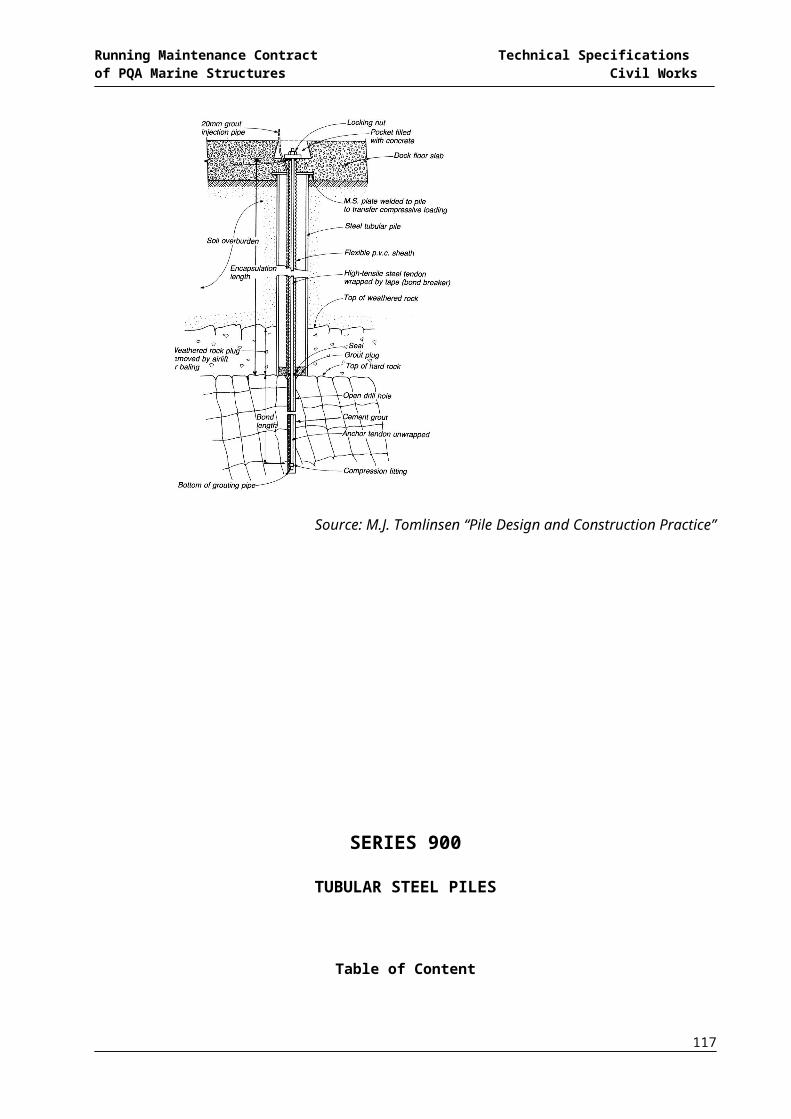
Running Maintenance Contract Technical Specifications of PQA Marine Structures Civil Works
h. Runways shall be provided for wheeled concrete handling equipment, and such equipment shall not be wheeled over reinforcement, nor shall runways be supported on reinforcement.
i. Concrete shall not be dropped freely from a height of more than 3.5 m (12 ft) in columns and 1.5 m (5 ft) elsewhere. Incases where an excessive drop is inevitable the Contractor shall provide spouts, down pipes, chutes, or side parts to forms with pockets which will let concrete stop and flow easily into the form without any risk of segregation. The discharge of the spouts, down pipes or chutes shall be controlled so that the concrete may be effectively compacted into horizontal layers not more than 3OO mm (12") thick.
j. Concrete is to be deposited as quickly as possible after mixing and to proceed continuously. Concrete which has attained its initial set or has contained its mixing water for more than 3O minutes shall not be allowed to be placed in the work.
k. When concrete is laid on hard core, such as subgrade for floor slabs, or other absorbent material, the surface is to be watered, consolidated and, where specified, blinded before the concrete is deposited.
l. Fresh concrete shall not be placed on previously laid concrete or on old concrete surfaces until the latter has been cleaned of dirt, scum and laitance by wire brushes. The clean surface shall then be thoroughly wetted and grouted with cement slurry as approved by the Engineer's Representative.
m. Care shall be taken not to disturb newly placed concrete by vibrator, indirect loading or otherwise. No traffic or loading shall be allowed on the concrete until it has thoroughly set and hardened.
n. Construction joints in concrete shall only be given at locations indicated on the drawings or as approved by the Engineer or his Representative. At the end of the day's work the concrete shall be finished off against a temporary shutter stop, which shall be vertical and securely fixed. Such stops shall be removed within 24 hours of placing of concrete. Construction joints not shown on the drawings shall be reinforced with steel bars or dowels, if deemed necessary by the Engineer or his Representative shall be furnished by the Contractor without any additional payment.
o. No concrete shall be placed during rains or in inclement weather and all fresh concrete shall be suitably protected from rain-fall and excessive heat or cold.
p. Should any part of the exposed surface present a rough uneven or imperfect appearance when the shuttering is removed. It shall be picked out to honeycomb depth and refilled and properly re-surfaced or entirely redone as per directions of Engineer or his Representative at the cost of the Contractor.
q. On removal of the forms and before the skin has had time to harden, all faces of the concrete inside or outside, to be kept exposed shall be rubbed over with carborandum stone, and washed with cement to remove all marks, projections,
117

Running Maintenance Contract Technical Specifications of PQA Marine Structures Civil Works
hollows or any other defect. No extra payment shall be made for this work. All exposed surfaces and lines of the concrete work are to be true and fair without cracks, bends, windings and distortions of all kinds, and if occurring, shall be removed without any extra charges by the Contractor. All un-plastered concrete works is to be fair face, smooth, pleasing and to the entire satisfaction of the Engineer or his Representative.
r. A float or screed is to be worked over the exposed surfaces of all concrete work on the flat or curve, so as to render the surfaces perfectly smooth, clear, and to the necessary slopes or falls or as required to receive the floor or roof finishes, according to the drawings, and as directed by the Engineer or his Representative without any extra charges by the Contractor.
1100.9 PROTECTION AND CURING
All exposed concrete shall be cured. Curing shall be accomplished by preventing loss of moisture, rapid temperature change and mechanical injury or injury from rain or flowing water for a period of at least ten (10) days. Curing shall be started as soon as the concrete has hardened sufficiently for the surface not to be marked. Curing shall be done either by continuous sprinkling of water on the surface or by covering with sand, Hessian, canvas or other approved fabric mats, which shall be kept continually wet. If required and so directed by the Engineer or his Representative, formed surfaces with forms in position shall also be cured by keeping all forms continually wet. As an alternative, curing of concrete, on all exposed surfaces which could not be kept covered, such as sides of the beams, under side of the slabs, may also be done by sealing concrete surfaces with curing compounds like "Paccacure" or equal so as to arrest loss of moisture from concrete, with approval of Engineer or his Representative. The Contractor shall take special care that curing of concrete is satisfactorily carried out and in accordance with methods specified herein and / or as instructed by the Engineer or his Representative. Any negligence in this regard may result in total rejection of such concrete works, which in the opinion of the Engineer or his Representative have not been adequately cured.
Minimum period of curing for any concrete shall be 10 days or more as directed by the Engineer. All concrete components of concreted structures shall be clearly marked with non-washable paints to indicate the date of placing concrete. During hot weather, curing shall be done even at night.
1100.10 FORMWORK
1100.10.1 General
The formwork shall be inclusive of all labor, material, workmanship and alike. All form work and supports thereto shall be designed by the Contractor and relevant drawings shall be submitted to the Engineer and his Representative for approval
118
Running Maintenance Contract Technical Specifications of PQA Marine Structures Civil Works
before the work is put in hand. Such an approval shall not relieve the contractor from all the obligations of the contract or give rise to any claims.
1100.1.2 Making Forms
The formwork for columns, beams, slabs lintels fins, shells, blocks, panels, purdees, surrounds for windows, and all other works whether to be precast or cast in situ shall be made of sound and properly seasoned timber or other approved material and shall be rigidly formed and designed by the Contractor to the shapes and forms as per drawings in accordance with the best of the existing practices so as to be able to withstand, without displacement, deflection or deformation movements of any kind, the pressure of the moist concrete and all other loads. For concrete work to show an even finish the timber forms be properly lined with plywood or steel sheets to give a fair face concrete of a homogenous, perfectly even and smooth appearance in exposed surfaces of all beams, columns, walls, slabs, etc.
1100.10.3 Rigid with Allowance for Camber and Bulges.
It shall be fabricated and erected in position, perfect in alignment, levels and true to plumb and shape and securely braced so as to enable it to stand all weights, live and vibrating to be endured during placing of concrete and its subsequent hardening till the form work is struck. It shall be so sufficiently rigid as not to loose its form and shall be so made for bulging, and deflection as to give the finished concrete to the required lines, plumb, size and shape.
1100.10.4 Exposed Surfaces Left Unplastered
For concrete work covered in this contract where concrete Surface is to be exposed in the finished work and left unplastered, the form-work shall be smoothly faced by using plywood sheets or lining the shuttering with smooth steel sheet or non-absorbent material like formica sheets or in any manner as approved by the Engineer or his Representative, so as to make a perfectly smooth surface of the finished concrete. Where any surface defects on the exposed concrete surfaces occur and which do not impair the structural performance, being in excess of the designed surfaces, and the architectural appearance of the work in the opinion of Engineer or his Representative, such defects may be removed by guniting and grinding with corborandum stone or in any other approved manner, at the cost of the Contractor, otherwise the whole or part of the work may have to be removed and remade good by the Contractor at his own cost. For precast concrete members the forms shall be rigid, exact, smooth and made of steel.
1100.10.5 Materials and Labor
The Contractor shall supply all materials and labor, necessary for a good and speedily erection of form-work such as shuttering, planks, struts, bolts, stays,
119
Running Maintenance Contract Technical Specifications of PQA Marine Structures Civil Works
gangways, boards, fillets etc. and shall do all that is essential in executing the job in a workman like manner to the satisfaction of the Engineer.
1100.10.6 Formwork not to Interfere or Injure Work
The formwork shall be so designed and arranged as not be unduly interfere with concrete, during its placing, and easy to be removed without injuring the finished concrete, wedges, clamps, bolts and the rods shall be used, when permitted and where practicable, in making the form work rigid and in holding it to true position.
1100.10.7 Opening in Formwork
Wherever the Concreting is required to be carried out within forms of considerable depths, temporary openings in the side of the form shall be provided to facilitate the pouring and consolidation of the concrete. Small temporary openings shall be provided at the bottom of all forms to permit the removal of rubbish etc.
1100.10.8 Openings and Other Details
Provision shall be kept in the form-work such as openings, recesses holes, pockets, fillets, etc for housing services and other architectural details in the finished concrete or on its surface and edges as shown on drawings or as directed by the Engineer or his Representative to fix all necessary inserts, dowels pipes, holdfasts etc. as shown on drawings or as directed.
1100.10.9 Joints in Formwork
All joints in the formwork shall be sufficiently closed to prevent undue leakage of mortar for concrete surface not to be exposed in the finished work. The joints in the form-work for all concrete surfaces to be exposed in the finished work shall be close jointed and perfectly smooth so as not to allow any leakage of the mortar from the concrete; and show any appearance of leaking mortar on concrete surface.
1100.10.10Treatment and Inspection of Forms.
All rubbish, particularly chipping, shavings, and sawdust etc. shall be removed from the interior of the forms, immediately before fixing of bars. Forms shall be coated with approved mould oil before reinforcement is placed. Surplus oil on forms and any oil on reinforcing steel shall be removed. Forms surface not exposed to view or normal watering may thoroughly be wetted with soap and water in place of oiling before placing concrete. If the forms are not used within 24 hours, a fresh coat of oil shall be given before placing of concrete.
1100.10.11 Striking Shuttering.
120

Running Maintenance Contract Technical Specifications of PQA Marine Structures Civil Works
No struts or timbering which serve the purpose of supporting the shuttering or centering shall be struck and removed without direct permission from the Engineer or his Authorized Representative in writing and the work of striking and removal after the receipt of such permission shall be conducted under the personal supervision of the competent foreman in the employment of the Contractor and the Contractor shall hold himself fully responsible for any consequences whatsoever. In all cases the Engineer or his Authorized Representative will direct and control the minimum period of time for which the forms, shuttering or centering shall remain in place before being struck; but, for the general guidance of the contractor, when normal Portland Cement has been used in the work, the following are to be considered as the minimum periods in days for the main classes of work:
-----------------------------------------------------------------------------
Removal of 10 oC (50oF) 20 oC (70oF)
Shuttering
-----------------------------------------------------------------------------
Beams sides, walls &
Columns (unloaded) 3 2
Slabs soffits (props left
under) 9 6
Removal of props to slabs 18 14
Beams soffits (props left
under) 18 12
Removal of props to beams,
and shuttering under shells. 24 18
------------------------------------------------------------------------------
The Engineer or his Representative may require, however, that any walings, soldiers, struts or other timbers or supports, the removal of which may cause the transference of load to the finished work, to be kept in place for three weeks after the placing of the concrete.
121
Running Maintenance Contract Technical Specifications of PQA Marine Structures Civil Works
1100.10.12 Injury or Damage.
The Contractor shall be responsible for any injury to the work and any consequential damages caused by or arising from the removal and striking of forms, centering and supports, due to striking too soon, and any advice, permission or approval given by the Engineer or his Authorized Representative, relative to the removal and striking of forms, centering and supports shall not relieve the Contractor from the responsibilities herein defined.
1100.10.13 Treatment after Removal of Forms.
Any minor surface honey-combing or other irregularities are to be properly made good immediately upon the removal of the form-work and the surface made good to the satisfaction of the Engineer and his Representative. Any small voids shall be neatly stopped with cement mortar consisting of one part of cement to two parts of sand and the whole surface rubbed over with corborandum stone and cements wash and bring the whole to a smooth and pleasing finish and uniform color.
No form-work shall be measured and paid for separately and shall be deemed to be included in the unit price of concrete whether cast-in-situ or precast and subsequently fixed in position.
1100.11 FINISHING OF FORMED SURFACES
1100.11.1 Rubbed Finishes
The following finishes shall be produced to concrete with a smooth form finish. Where smooth rubbed finish is to be applied, the forms shall have been removed and necessary patching completed as soon after placement as possible without jeopardizing the structures.
i) Smooth rubbed finish - Smooth rubbed finish shall be produced on newly hardened concrete not later than the day following from removal. Surfaces shall be wetted and rubbed with car texture are produced. No cement grout shall be used other than the cement paste drawn from the concrete itself by rubbing process.
ii) Grout cleaned finish - No cleaning operation shall be permitted until all continuous surfaces to be cleaned are completed. Mix 1 part Portland cement cement and 1 ½ parts fine sand with sufficient water to produce a grout having the consistency of thick paste. White Portland cement shall be substituted for a part of the grey Portland cement in order to produce color matching the color of the surrounding concrete, as determined by a
122

Running Maintenance Contract Technical Specifications of PQA Marine Structures Civil Works
trial patch. Wet the surface of the concrete sufficiently to prevent absorption of water from the grout and apply the grout uniformly with brushes or a spray gun. Immediately after applying the grout, scrub the surface vigorously with a cork flot or stone to the surface and fill all air bubbles and holes. While the grout is still plastic, remove all excess grout by working the surface with rubber float, sack, or other means. After the surface whitens from drying (about thirty minutes at normal temperatures), rub vigorously with clean burlap. The finish shall be kept damp for at least 36 hours after final rubbing.
iii) Cork floated finish - Remove from at an early stage, within 2 to 3 days of placement where possible. Remove ties . Remove all burrs and fins. Mix one part Portland cement and one part fine sand with sufficient water to produce a stiff mortar. Dampen wall surface. Apply mortar with firm rubber float or with trowel filling all surface voids. Compress mortar into voids using a slow - speed grinder or stone. if the mortar surface dries too rapidly to permit proper compaction and finishing, apply a small texture with a cork float using a swirling motion.
1100.11.2 Unspecified Finish
If the finish is not designated and applied finishes are also not indicated the following finishes shall be used as applicable:
i) Rough form finish - For all concrete surface not exposed to public view.
ii) Smooth form finish - For all concrete surfaces exposed to public view.
1100.11.3 Related Unformed Surface
Tops of walls or buttresses, horizontal off-sets, and similar unformed surfaces occurring adjacent to formed surfaces shall be floated to a texture reasonably consistent with that of the formed surfaces. Final treatment on formed surfaces shall continue uniformly across the unformed surfaces.
1100.12CONSTRUCTION JOINTS
Construction joints shall be located as indicated on the drawings and/or as approved or directed by the Engineer or his Representative. For slabs and beams construction joints shall be located at middle third of the span unless a secondary beam intersects a main beam at the centre in which case the joints in the main beam shall be off set a distance equal to twice the width of the beam and provision for shear shall be made by the use of inclined reinforcement at the cost of the Contractor. Joint in columns shall be made at the under side of the deepest beam framing thereto. Beam stems shall be poured
123
Running Maintenance Contract Technical Specifications of PQA Marine Structures Civil Works
monolithically unless directed otherwise by the Engineer. Joints not specified or shown on the drawings shall be so located as to least impair the strength and appearance of the work. Except where indicated on the drawings no jointing shall be made in footings or foundations without written approval of the Engineer or his Representative. Construction jointing shall be at right angles to the member and shall be formed against firm stop boards. The stop boards shall be removed as soon as possible after placing the concrete but without the risk of movement of the concrete and the concrete surface shall be well brushed with a hard brush and washed off with a spray of water, two to four hours after casting, to expose the aggregates and provide a key for the next pour. In all liquid retaining structures and other sub-structures pits and trenches etc. PVC or any other approved water stops shall be provided at the construction joint in the manner shown on the drawings and/or approved by the Engineer or his Representative.
Whenever a section of concrete is left unfinished, for any reasons with the approval of Engineer's Representative, leaving a surface which will be hard set before additional concrete can be joined to it, dovetails, grooves or other bonds with the new work shall be provided at cost of the Contractor. Before depositing fresh concrete upon or against any concrete which has already set, the surface of the set concrete shall be roughened with a cutting tool, any laitance removed, thoroughly cleansed of all foreign matter, well watered and covered with cement grout, and special care shall be taken to ram the fresh concrete thoroughly up and against the set concrete; and, if deemed necessary by the Engineer or his Representative the joints shall be reinforced with steel bars or dowels to be all furnished and done by the Contractor without any additional payment.
1100.13CLEANING AND REMOVAL OF RUBBISH
On completion of works herein the Contractor shall remove all concrete debris, rubbish, shuttering materials, scrapes etc., from the vicinity of the structures completed. All areas shall be cleaned to the satisfaction and approval of the Engineer or his Representative.
1100.14 COORDINATION
The Contractor shall provide chases and openings required for other sections of the work and will co-operate and coordinate with other trades in placing their pipes, ducts, reglets and other built-in-items as the work proceeds.
1100.15EXTERNAL EXPOSED CONCRETE SURFACE
All external exposed un-plastered concrete surfaces of cast in situ or precast units shall be given smooth or pattern finish as shown in the finishing schedule or as directed by the Engineer or his Representative. No separate payment shall be made to the Contractor for this work and it shall be included in the item rates of the respective concrete items in the bill of quantities.
1100.16 PARTICULAR SPECIFICATIONS FOR CONCRETE
124

Running Maintenance Contract Technical Specifications of PQA Marine Structures Civil Works
a) Allowable bearing pressure of soil for foundation is marked on the drawing of the foundation. It is to be checked that no foundation is placed on the soil with a lower bearing capacity. In cases any weaker strata are encountered at any level the matter is to be reported to the Engineer for necessary changes in footings.
b) Level of foundations as indicated on the drawings may be varied at site to reach the suitable strata. This matter is to be decided by the Engineer at site.
c) All concrete is to be thoroughly vibrated mechanically:
i. Any concrete failing to meet the specified strength or not formed as shown on drawings, concrete out of alignment, concrete with surfaces beyond require tolerances or with defective surfaces which cannot be properly repaired or patched in the opinion of Engineer’s Representative shall be removed and replaced at Contractor=s expense. The Engineer’s Representative may reject any defective concrete and order it to be cut out in part or in whole and replaced at the Contractors expense. Only in case of minor surface defects the Engineer=s Representative may approve a surface treatment immediately after from removal.
ii. All ties and bolt holes and all repairable defective area shall be patched immediately after removal.
iii. All honeycombed and other defective concrete shall be remove down to sound concrete. The area to be patched and area at least 150 mm wide surrounding it shall be dampened to prevent absorption of water from the patching mortar. A bonding grout shall be prepared using a mix of approximately 1 part cement to 1 part fine sand passing a No. 25 B.S. Sieve, shall be mixed to the consistency of thick cream and shall then be well brushed into the surface.
iv. The patching mixture shall be made of the same material and of approximately the same proportions as used for the concrete, except that the coarse aggregate shall be omitted and mortar shall consist of not more than 1 part cement to 22 parts sand by damp loose volume. White Portland cement shall be substituted for a part of the grey Portland cement on exposed concrete in order to produce a color matching the color of the surrounding concrete, as determined by a trial patch.
v. The quantity of mixing water shall be not more than necessary for handling and placing. The patching mortar shall be mixed in advance and allowed to stand with frequent manipulation with a trowel, without addition of water, until has reached the stiffest consistency that will permit placing.
vi. After surface water has evaporated from the area to be patched, the bond coat shall be well brushed into the surface. When the bond coat begins to lose the water sheen, the premixed patching mortar shall be applied. The mortar shall be thoroughly consolidated into place and struck off so as to
125

Running Maintenance Contract Technical Specifications of PQA Marine Structures Civil Works
permit initial shrinkage, it shall be left undisturbed for at least 1 hour before being finally finished. The patched area shall be kept damp for 7 days. Metal tools shall not be used in finishing a patch in a formed wall, which will be exposed.
d) For heavy concrete members the form work is to be properly designed and approved by the Engineer.
e) Shuttering should not be struck earlier than the time specified unless otherwise approved by the Engineer.
f) 18 gauge G.I. binding wire to be used for securely binding the reinforcing bars to avoid dislocation or displacement during concreting.
g) All the reinforcing bars are to be properly placed as shown on the working drawings. Steel chairs and concrete spacer blocks are to be used without any extra cost. Concrete spacer blocks are to be properly cured to avoid their damage during concreting, thereby causing displacement of bars. Holes made by bolts etc. introduced for keeping the shuttering in tact should be properly treated after striking the shuttering. No such holes shall be allowed in walls of water retaining structures and earth retaining walls.
h) All bent up bars in slabs are to be properly secured in position. Workers or trollies shall not be allowed in any case over the reinforcement mesh.
i) Special care is to be taken to see that all expansion joints shown on the drawings are made in perfect straight line and treated as specified.
i) Construction joints in beams and slabs shall be located at the centre of the span (such that a proper seat is formed for the next part to be cast); unless otherwise indicated on drawings or approved by the Engineer.
1100.17 MEASUREMENT AND PAYMENT
Measurement of the work acceptably completed and specified herein as concrete will be made on the basis of actual volume in Cu.m. of the respective job including all preparatory work and the cost of all operations without which job cannot be performed to the applicable BSI/ASTM standards complete in all respect as directed by the Engineer. Payment for these items shall be made at the approved tendered rates
The rates for all concrete work shall include for the following:
(i) Concrete testing and testing cost.
(ii) All considerations arising from the specification.
(iii) Mixing, hoisting to any height or lowering to any depth and placing and compacting on the surfaces of any material or on formwork by whatever means necessary.
(iv) Pouring in hot weather conditions in accordance with the Specification.
(v) Compacting by vibrators if required.
126

Running Maintenance Contract Technical Specifications of PQA Marine Structures Civil Works
(vi) Forming any control and construction joints, locations as agreed by the Engineer.
(vii) Shuttering to upper surfaces wherever required/ordered by the Engineer.
(viii) Curing, hacking surfaces for key and protecting concrete surfaces from harmful weather conditions.
(ix) All surface treatment to unset concrete.
(x) Finishing to floor slabs as Specification.
(xi) Expanded metal lathing and angle beads.
(xii)Joint sealing between concrete and plaster.
(xiii) All costs in connection with the construction of “kickers”.
(xiv) Forming and grouting grooves and mortices and making good to holes and mortices.
(xv) Corrosion Inhibitor Admixture where specified, and
(xvi) Water bars and the like etc.
No payment shall be made for any operation and arrangement of any kind without which the job of concreting can not be completed, for which the contractor shall make necessary allowance in his rates for such items.
127

Running Maintenance Contract Technical Specifications of PQA Marine Structures Civil Works
SECTION – 1200
STEEL REINFORCEMENT
12.1 DESCRIPTIONThis work shall consist of furnishing, fabricating and placing of steel reinforcement of the type, size, shape and grade required in accordance with these specifications, and in conformity With the requirements shown on the Drawings and Special Provisions or as directed by the Engineer.
12.2 MATERIAL REQUIREMENTS
All materials shall conform to the requirements hereinafter given. Test reports from approved sources shall be submitted to the Engineer for all steel reinforcement used. These reports shall show the results of chemical and physical tests made:
i) Deformed Billet-Steel Bars (Grades 40 and 60) for Concrete Reinforcement-AASHTO M-31 (ASTM A-615)
ii) Deformed Steel Wire for Concrete Reinforcement-AASHTO M-225 (ASTM A-496)
iii) Welded Steel Wire Fabric for Concrete Reinforcement-AASHTOM-55 (ASTM A-185)
iv) Steel Bar Mats for Concrete Reinforcement-AASHTO M-54 (ASTM A- 184)v) Cold-Drawn Steel Wire for Concrete Reinforcement-AASHTO M-32 (ASTM A-82)vi) Welded Deformed Steel Wire Fabric for Concrete Reinforcement-AASHTO
M-221 (ASTM A-497)vii) Structural Shapes for Concrete Reinforcement ASTM A-36
12.3 CONSTRUCTION REQUIREMENTS
12.3.1 Fabrication of Bent Bars
a) Order Lists
Before materials are ordered all order lists and bending diagrams shall be furnished by the Contractor, for the approval of the Engineer. The approval of order lists and bending diagrams by the Engineer shall in no way relieve the Contractor of responsibility for the correctness of such lists and diagrams. Any expenses incident to the revisions of material furnished in accordance with such lists and diagrams to make it comply with the drawings shall be borne by the Contractor.
b) Storing and Surface Condition of Reinforcement
Steel reinforcement shall be stored above the surface of the ground on platforms, skids, or other supports and shall be protected as far as practicable from mechanical injury and surface deterioration caused by exposure to conditions producing rust. When placed in the work,
128
Running Maintenance Contract Technical Specifications of PQA Marine Structures Civil Works
reinforcement shall be free from dirt, detrimental rust, loose seals, paint, grease, oil, or other foreign materials. Reinforcement shall be free from injurious defects such as cracks and laminations. Surface seams, surface irregularities, or mill scale will not be cause for rejection, provided the minimum dimensions, cross-section area, and tensile properties of a hand-wire brushed specimen meets the physical requirements for the size and grade of steel specified.
c) Fabrication
Bent bar reinforcement shall be cold bent to the shapes shown on the drawings or required by the Engineer. Bars shall be bent around a pin having the following diameters (D) in relation to the diameter of the bar (d)5
Stirrups & column tie bars D = 4xd
Other bars having
d<3.5 cm(l -318")(No. 11 bar) D = 5xd
d>3.5 cm(1~318") D = 10xd
12.3.2 Placing and Fastening
a) Protection of Material
Steel reinforcement shall be protected at all times from injury. When steel, placed in position as shown on the Drawings, has easily removable and detrimental rust, loose scale, or dust, it shall be cleaned by a satisfactory method, approved by the Engineer.
b) Placing and Fastening
Reinforcing steel shall be accurately placed in the position shown on the Drawings and firmly held during the depositing and finishing of the concrete. Cover, the `distance between the external face of the bar and the face of the finished concrete, shall be as indicated on the Drawings. Reinforcing steel bars embedded in concrete shall not be bent after they are in place. Bars shall be tied at all intersections with 16 gauge black annealed wire except that where spacing is less than 1 ft (0.3m) in each direction, alternate intersections need to be tied. All intersections shall be tied in the top mat of reinforcement placed on bridge decks and the top slabs of box culverts. Abrupt bends shall be avoided except where one steel bar is bent around the other.
Stirrups and ties shall always pass around the outside of main bars and be securely attached thereto. All reinforcing steel shall be securely held at
129
Running Maintenance Contract Technical Specifications of PQA Marine Structures Civil Works
the proper distance from steel forms, which remain in place by means of galvanized steel bars or chairs placed on the forms. All reinforcing steel, except as mentioned above, shall be securely held at the proper distance from the forms by means of templates, concrete blocks or galvanized steel chairs. Metal chairs shall not be used against formed surfaces, which will be exposed in the finished structure after the forms are stripped. Blocks for holding reinforcement away from contact with the forms shall be precast concrete blocks of approved shape, and dimensions and shall have 16 gauges black annealed tie wires embedded in them. The precast concrete block shall have a compressive strength equal to that specified for the class of concrete to be placed in the work. Layers of bars shall be separated by approved metal chairs or bolsters.
Any broken or damaged concrete spacer blocks shall be removed before concrete is placed. The use of pebbles, pieces of broken stone or brick, metal pipe or wooden blocks as spacers will not be permitted. Reinforcing steel when placed in the work shall be free from flake rust, dirt and foreign material and before any concrete is placed, any mortar, which may be adhering to the reinforcing steel, shall be removed. No concrete shall be deposited until the Engineer has inspected the placing of the reinforcing steel and given permission to place the concrete. The Contractor shall allow the Engineer four hours time after the reinforcement and forms are in place to conduct the inspection. Any bar of incorrect size, length or shape shall be removed and replaced with correct bars. Any bar located or spaced incorrectly shall be relocated or spaced correctly before permission is given to place concrete and such replacements and corrections shall be at the Contractor's expense. All concrete placed in violation of these provisions shall be rejected and removed.
c) Splicing
All reinforcement shall be furnished in the full lengths indicated on the Drawings unless otherwise permitted. Splicing of bars, except where shown on the drawings, will not be permitted without the written approval of the Engineer. Splices shall be staggered as far as possible and with a minimum separation of not less than forty (40) times bar diameters. Not more than one third (113)of the bars may be spliced in the same cross-section, except where shown on the drawings.
Unless otherwise shown on the Drawings, bars shall be lapped with a minimum overlap of forty (40) times the bar diameter. In lapped splices, the bars shall be placed in contact and wired together. Lapped splices will not be permitted at locations where the concrete section is insufficient to provide a minimum clear distance of one bar diameter or one and one third (1-113) the maximum size of coarse aggregate between the splice and the nearest adjacent bar.. Welding of reinforcing steel shall be done only if detailed on the Drawings or if authorized by the Engineer in writing.
130
Running Maintenance Contract Technical Specifications of PQA Marine Structures Civil Works
Spiral reinforcement shall be spliced by lapping at least one and one half (1-112) turns or by butt welding unless otherwise shown on the Drawings.
d) Lapping of Bar Mat
Sheet of mesh or bar-mat reinforcement shall overlap each other sufficiently to maintain a uniform strength and shall be securely fastened at the ends and edges. The overlap shall not be less than one mesh in width.
e) Covering
The minimum covering, measured from the surface of the concrete to the face of any reinforcement bar shall, unless otherwise shown on the Drawings or directed by the Engineer, be not less than 5 cms except as follows:
In the footings of abutments and retaining walls the minimum covering shall be 7.5 cm. In work exposed to the action of sea water the minimum covering shall be 7.5 cm.
12.4 MEASUREMENT AND PAYMENT
12.4.1 Measurement
The quantity to be paid for shall be the calculated theoretical number of metric tons of reinforcement steel bars, mesh or mats as determined from the approved bar bending diagrams and incorporated in the concrete and accepted, except when reinforcement is paid for under other pay items.
The weight of plain or deformed bars or bar mat will be computed from the theoretical weight of plain round bars of the same nominal size as shown in the following tabulation:
Size
mm
Weight in
Kilograms
Per Meter
Size
mm
Weight in
Kilograms
Per Meter
6 0.222 20 2.466
8 0.395 22 2.984
10 0.616 25 3.853
12 0.888 32 6.313
13 1.042 35 7.553
131
Running Maintenance Contract Technical Specifications of PQA Marine Structures Civil Works
16 1.578 40 9.865
Clips, ties separators, and other material used for positioning and fastening the reinforcement in place and structural steel shall not be included in the weight calculated for payment under this item. If bars are substituted upon the Contractor's request and as a result more steel is used than specified, only the amount specified shall be measured for payment.
When laps are made for splices, other than those shown on the Drawings or required by the Engineer and for convenience of the Contractor, the extra steel shall not be measured nor paid for.
When continuous bars are shown on the Drawings, without the splices being shown the necessary steel in the splices will be paid for on the basis of the individual bars not being shorter than twelve(12)meters.
For bent bars, the length along centre-line of bar will be paid.
12.4.2 Payment
The accepted quantity measured as provided above shall be paid for at the contract unit prices as given in the Bill of Quantities which price and payment shall be full compensation for furnishing materials, labour, equipment and incidentals necessary to complete the item.
132
Running Maintenance Contract Technical Specifications of PQA Marine Structures Civil Works
SECTION – 1300
PAINTING, DISTEMPERING AND WHITE/COLOR WASHING ETC
13.1 SCOPE OF WORK
The work covered by this section of the specifications consists of furnishing all materials, plant, labor, equipment, appliances and performing all operations in connection with surface preparation, mixing, painting concrete works, gates, frames steel works, steel and wooden doors, windows, ventilators, walls ceilings and all such surfaces as shown on the Drawings and/or as directed by the Engineer. The scope of this section of specifications is covered with detailed specifications as laid down herein.
13.2 GENERAL
Except as otherwise specified, all painting shall be applied in conformity with BS CP 231 "Painting of Building as applicable to the work".
The Contractor shall repair at his own expense all damaged or defective areas of shop-painted metal work. Metal surfaces against which concrete are to be placed will be furnished shop-painted and shall be cleaned prior to being embedded in concrete.
Except as otherwise specified, all concrete and plastered surfaces are to be painted.
13.3 MATERIALS
All materials shall be acceptable, proven, top-grade products and shall meet or exceed the minimum standards of reputable manufacturers as approved by the Engineer.
Colors shall be pure, non-fading pigments, mildew-proof, sun-proof, finely ground in approved medium. Colors used on plaster and concrete surfaces shall be lime-proof. All materials shall be subject to Engineer's approval.
All enamel paints and primers for wood and metal work will be the best available of its type and shall be approved by the Engineer prior to its procurement.
Unslaked lime, gum and marine blue shall be used for white washing.
DUROCEM a cement base heavy duty water proof coating manufactured by ICI or any equivalent approved by the Engineer shall be used for painting on the surface specified. The cement base water proof coating for concrete shall conform to ASTM C-109,C-67, D-822 and G-23.
All materials shall be delivered to site in their original unbroken containers or packages and bear the manufacturer's name, label, brand and formula and shall be mixed and applied in accordance with his directions.
133

Running Maintenance Contract Technical Specifications of PQA Marine Structures Civil Works
13.4 SURFACE PREPARATION
All oil, grease, dirt, dust, loose mill, scale and any other foreign substance shall be removed from the surface to be painted, polished and white washed by the use of a solvent and clean wiping material. Following the solvent cleaning, the surfaces shall be cleaned by scraping, chipping, blasting, wire brushing or other effective means as approved by the Engineer.
In the event the surface become otherwise contaminated in the interval between cleaning and painting, recleaning will be done by the Contractor at no additional cost.
Surfaces of stainless steel, aluminum, bronze and machined surfaces adjacent to metal work being cleaned or painted shall be protected by effective masking or other suitable means, during the cleaning and painting operations.
No work in this Section shall be allowed until all surfaces or conditions have been inspected and approved by the Engineer.
13.5 APPLICATION
All paint and coating materials shall be in a thoroughly mixed condition at the time of application. All work shall be done in a workmanlike manner, leaving the finished surface free from drips, ridges, waves, laps and brush marks. All paints shall be applied under dry and dust free conditions. Unless approved by the Engineer paint shall not be applied when the temperature of the surrounding air is below 10 Deg.C. Surfaces shall be free from moisture at the time of painting.
All primary paint shall be applied by brushing. The first coat of paint shall be applied immediately after cleaning. When paint is applied by spraying, suitable measures shall be taken to prevent segregation of the paint in the container during painting operations.
Effective means shall be adopted for removing all free oil and moisture from the air supply lines of the spraying equipment.
Each coat of paint shall be allowed to dry or harden thoroughly before the succeeding coat is applied. Surfaces to be painted that will be inaccessible after installation shall be completely painted prior to installation shall be completely painted prior to installation.
Only as much material should be mixed as can be used up in one hour. Over-thinning will not be permitted. After the first coat, the surfaces will be soaked evenly four or five times and the second coat shall be applied after leaving for at least overnight.
All steel doors, windows and ventilators shall be painted with two coats of approved enamel paint over one coat of a redoxide primer as directed by the Engineer.
Oil bound distemper shall be applied to internal wall surfaces and white wash on ceilings as specified herein after.
134
Running Maintenance Contract Technical Specifications of PQA Marine Structures Civil Works
For applying Durocem the surface shall be dampened with clean water immediately ahead of application. Durocem and clean water shall be mixed as per directions of the manufacturer. A heavy first coat at 20 lbs/100 sft (1 kg per sq.m) shall be applied. This shall be followed by a second brush coat at 10 lbs/100 sft (0.5 kg per sq.m) after the first coat has set. When finish coat has set, it shall be floated to uniform texture with a sponge float. The work shall include cleaning the surface, sand papering and smooth finishing, scaffolding, curing etc. complete as per the approval of the Engineer.
13.6 WHITE AND COLOR WASHING
The surfaces shall be well cleaned and brushed before white washing. The white washing material shall be prepared from un-slaked lime. The lime shall be dissolved in a tub with sufficient quantity of water and then well mixed and strained through a clean cloth. 4 kg clean gum boiled with 12 kg of rice for each cu.m of lime shall be added to the liquid lime along with a small quantity of marine blue as directed by the Engineer.
The mixture shall be in thoroughly mixed condition and shall be applied in three coats with a brush.
Each coat of white wash shall be allowed to dry, so that no sign of cracking shall appear on the surface and also white wash shall not come off readily on fingers when rubbed. The white wash when completed, shall form an opaque coat of uniform white color, through which the old work does not show and shall present a smooth regular surface free from powderly matter. For color washing approved quality of coloring matter shall be added to the liquid and thoroughly mixed by stirring.
13.7 DISTEMPERING
Oil bound distemper of approved quality and shade shall be applied on internal wall surfaces where shown in drawing or directed by the Engineer.
13.8 EXECUTIONS
13.9 SUBMITTALS
Color samples shall be submitted on 6"x6" (150x150 mm) asbestos cement boards, showing each type of paint for Engineer's approval.
13.10 PRODUCT DELIVERY
Deliver materials in manufacturer's original unopened containers with labels intact and legible identifying brand names and contents.
13.11 JOB CONDITION
Observe manufacturer's recommended minimum and maximum temperature but do not apply paint or finish to any surface unless ambient temperature is 10 deg.C or above and less than 43 deg.C. No painting shall be done above 90% relative humidity.
135
Running Maintenance Contract Technical Specifications of PQA Marine Structures Civil Works
Place drop cloths to adequately protect all finished work.
Remove and replace all items of finished hardware, device plates, accessories, including fixtures or other removable items.
The surface shall be prepared first before applying distemper by filling depressions with putty, rubbing, sand papering and cleaning. A priming coat shall first be applied of petrifying liquid of approved manufacture. Distemper shall be applied with broad stiff brush of approved make. Distemper shall be applied quickly and boldly. Each coat of distemper should first be got approved by the Engineer before applying the next coat.
13.13 MEASUREMENT AND PAYMENT
Measurement of the work acceptably completed and specified herein as painting, distempering, and white/color washing etc. will be made on the basis of actual area in square feet of the respective job including all preparatory work like scraping, scratching, sand papering, filling depressions with putty, priming and scaffolding etc. complete in all respect as directed by the Engineer. Payment for these items shall be made at the approved tendered rates. No payment shall be made for painting work on doors, windows, ventilators, steel grills, cabinets and cup boards steel ladders etc. for which the contractor shall make necessary allowance in his rates for such items.
136

Running Maintenance Contract Technical Specifications of PQA Marine Structures Civil Works
SECTION - 1400
WATER
14.1 SCOPE
The work covered by this section of the Specification consists of furnishing all labor, appliances and in performing all operations in connection with obtaining, conveying and storing water at site of work.
14.2 QUALITY OF WATER
The water used for construction shall be free from impurities and fit for drinking purpose.
14.3 TESTING
Water if required, shall be subjected to standard testing at the cost of the Contractor and if found to be unsuitable for construction work then the Contractor shall take such action as directed by the Engineer.
14.4 PAYMENT
No separate payment will be made for the work covered under this section, and all costs in connection therewith shall be deemed to be included in the unit rates.
14.5 TEMPORARY STORAGE TANKS
The Contractor shall provide on site at his own cost temporary storage water tank with all necessary G.I. Pipes and fittings as per instructions of the Engineer. No separate payment will be made for tank, pipes and accessories, etc. These tanks shall be removed or dismantled or demolished and the area shall be cleaned and made good on completion of work as per direction of Engineer.
137

Running Maintenance Contract Technical Specifications of PQA Marine Structures Civil Works
SECTION 1500 FENDERS, BOLLARDS, QUAY FURNITURE & Navigation Aids
1500.1 Quality
Timber used for fenders shall be approved hardwood of mature growth, having a density of at least 1050kg/m3 at 25% moisture content, free from defects & air seasoned. The timber shall be formed or supplied in the sizes & lengths shown on the Drawings and no joints other than those detailed will be permitted. All arises shall be slightly rounded unless shown otherwise on the Drawings.
1500.2 Treatment with preservative Not used.
1500.3 Workmanship, generallyWorkmanship shall be in accordance with BS 5268 Part 2.
1500.4 DimensionsDimensional tolerances shall be in accordance with BS 5450.
1500.5 Connections
The packing of joints & connections in timber members will not be allowed.
The diameter of bolt holes shall be sufficient to permit the bolt to be driven through easily, but not larger than 1.06 times the bolt diameter. Holes shall be drilled in one direction until the lead screw shows through. It shall than completed from the other side.
Bolts and nuts to BS 4190 of the size and grade shown on the Drawings and Galvanized BS 729 shall be used. Galvanized [square] plate washers [75mm x 75mm] x 5 mm shall be provided against timber faces.
All bolt fixings shall be countersunk, the countersinks being filled with approved bituminous mastic. The countersinking shall be of such depth as to provide minimum 50mm cover to the bolt head face.
Screws, where required, shall be countersunk, and of sheradised steel.
Standards and Codes Of Practice
1500.6 Standards
Standards relevant to this section include:
BS 729 Specifications for hot dip galvanized coating on iron and steel articles.
138
Running Maintenance Contract Technical Specifications of PQA Marine Structures Civil Works
BS 4190 Specification for ISO metric black hexagon boltsscrews and nuts.
BS 5268 Structural use of timber.
Part 2 Code of practice for permissible stress design, materials and workmanship.
Part 5 Code of practice for the preservative treatment of structural timber.
BS 5450 Specification for sizes of hardwoods and methods of measurement
BS 5589 Code of practice for preservation of timber
139

Running Maintenance Contract Technical Specifications of PQA Marine Structures Civil Works
SECTION 1600 NAVIGATION AIDS
Table of contents
General1600.1 Scope1600.2 Documentation1600.3 Packing1600.4 Lanterns1600.5 Solar power system for lanterns
140

Running Maintenance Contract Technical Specifications of PQA Marine Structures Civil Works
General
1600.1 Scope
This Section concerns the supply, Manufacture, inspection and testing at the manufacturer’s works, installing and connecting up, testing and putting into operation, painting and completion in full working order of navigation aids.
a) Navigation lights complete with daymarks, rechargeable batteries and solar powered charging systems and radar reflectors.
1600.2 Documentation
The Contractor shall supply the following documents:
a) Manufacturer’s details prior to placing orders of each item including:
(i) Catalogues and descriptive literature (ii) Range (iii) Details of construction(iv) Protective coating (v) Power consumption (vi) Battery consumption (vii) Solar power details(viii) Dimensions(ix) Lloyd’s Register of Shipping manufacturer’s Approval Certificate (x) Name and address of closest certified spare parts stockists
b) Within 8 weeks of placing orders and before dispatch:-
(i) Full dimensioned certified drawings(ii) Operating and maintenance instructions(iii) Lloyd’s Register of Shipping Manufacturer’s Approval Certificate
c) Following installation:-
Commissioning Reports and Test Certificates
1600.3 Packing
All equipment shall be packed suitable for the proposed method of transport.
141

Running Maintenance Contract Technical Specifications of PQA Marine Structures Civil Works
1600.4 Lanterns
a) General
A marine lantern shall be lightweight, of short focal lengths, with wide vertical light divergence. The lantern shall be provided with a polycarbonate plastic flanged base with bottom cable entry. The base shall house a flasher unit to provide a light with characteristics as showing in Appendix 19.1 for buoy mounted lanterns and on the Drawings for beacon mounted lanterns.
The lens shall be acrylic and tinted to the colour shown in Appendix 19.1 and the Drawings. The lens shall be provided with a bird spike and be mounted in a removable weatherproof manner.
Control of the lamp shall be via a sun-switch so that the lantern only operated during the hours of darkness or bad visibility. The range of each lantern shall be in excess of 4 nautical miles over 3600
unless otherwise stated in Appendix 16.1 or on the Drawings.
The lanterns shall operate at 12 volts DC from a rechargeable lead acid battery mounted in a glass reinforced plastic box to be located below the lantern and forming its support. The lantern shall be fitted with a flasher/ lamp charger, with an automatic lamp change. Providing six lamps and over 250 pre-programmed flash characters. The battery shall be recharged using a photovoltaic panel mounted on the same support as the lantern and battery box and shall be provided with its own bird spike. On buoys, the batteries shall be located inside a watertight compartment within the buoy tower section and above the water line.
b) Sector Lights
Additional requirement for sector lights are as follow:
Sectors lights shall be designed to provide a 2.5 degree clear sector for marking the channel and a red and green sector to either side. Total horizontal divergence to be 14 degrees.
Design of optics shall insure a high definition between each colour. The sectors light body should be designed for a marine
142
Running Maintenance Contract Technical Specifications of PQA Marine Structures Civil Works
environment and manufactured from heavy duty marine grade aluminium. All mating surfaces to be fitted with a gasket.
c) Range Lights
Additional requirements for range lights are as follows:
Lantern bodies shall be manufactured from corrosion resistant, marine grade aluminium with built in leveling hardware and a slip ring mounting for ease of adjustment.
A parabolic reflector manufactured from borosilicate glass to focus the light beam shall be provided where necessary. A high durability coating shall ensure a 92% reflectivity or greater in visible light.
The lantern shall be fitted with a spreader lens to the angle specified on the drawing and a flasher/lamp changer, with automatic lamp change, providing six and over 250 pre-programmed flash characters.
1600.5 Solar Power System for Lanterns
The Solar panels and battery shall be sized to suit the prevailing site conditions and the following criteria:
Specified Range Refer to Schedule or drawings
Voltage 12 Volts
Lamp Current To be advised Manufacturer
Character Refer to Schedule
Duty period of Lantern 14 hours per day
Solar panels shall utilize semi-crystalline silicon solar cells laminated between sheets of ethylene vinyl acetate and tempered glass. They shall be fitted with a marine grade aluminium frame and provided with bird spikes.
Solar panels shall be supplied with regulation to protect the batteries from overcharging and with additional capacity to compensate for battery ageing and solar power variations
Batteries shall be maintenance free:
All metallic parts shall be hot dip galvanized. Polycarbonate, acrylic and glass reinforced plastic parts shall be self coloured.
143

Running Maintenance Contract Technical Specifications of PQA Marine Structures Civil Works
Navigation light located onshore shall be mounted on steel supports as shown on the Drawings. The supports shall be fitted and protected against corrosion in accordance with the provision of this Specification.
144

Running Maintenance Contract Technical Specifications of PQA Marine Structures Civil Works
Section 1700 – Grout
General
1700.1 Scope
This Section covers the supply of cement-based grout for:
a) Use alone e.g. to fill fissures, ducts etc.
b) To fill the gaps in aggregate to produce mass concrete in dry or wet
e.g. tremie concrete.
1700.2 Cement Cement shall be ordinary Portland cement to BS 12: or Portland pulverized fuel ash cement BS 6588.
1700.3 Fine AggregateSand shall comply with “Concrete” but shall be graded 5.mm down to Zone 2 of Table 2 BS 882.
1700.004 AdmixturesAdmixtures containing chlorides, sulphates, nitrate or sulphide shall not be used.
1700.5 WaterWater shall be fresh water complying with “Concrete”. Sea water shall not be used except for marine works tremie mass concrete application.
1700.6 Characteristic StrengthThe Characteristic strength of the grout shall be 50 N/mm2 at 28 days
1700.7 Water ContentThe Quantity of water shall be kept to a minimum consistent with the requirements of strength and fluidity.
1700.8 Fluidity of the Grout The fluidity of the grout shall be measured by using a “Concrete” flow meter or equivalent under controlled conditions Flow meter readings shall be between 17000mm and 560mm.
1700.9 Trial MixesTrial mixes shall be prepared and tested in accordance with “Concrete” except that cube size shall be 100mm and information required shall be the expected flow meter reading.
1700.10 Work Testing of Grout Strength
145
Running Maintenance Contract Technical Specifications of PQA Marine Structures Civil Works
Works test shall be in accordance with Section 9 except that cube size shall be 100mm and the samples shall normally be taken for each 10m3 of grout placed or for every grouting operation if the volume involved is less. They shall be cured underwater, or in air, whichever is most appropriate.
1700.011 Compliance with Characteristic Strength
The Compliance requirements of “Concrete” shall apply.
1700.012 Result of Tests
The reports of the tests for strength shall include the information required by BS 1881 : Part 116, and the following additional information:
(i) Flow meter reading of the sample(ii) Identification of mixer (iii) Section of Work represented by the sample(iv) Density of cube (kg/m’)
1700.013 Unsatisfactory Test Results
Should any of specified works tests results be unsatisfactory the Engineer may take any of the actions under Section 9
1700.031 Grouting Records
The following grouting data shall be recorded:
(a) Water/Cement ratio(b) Types of Cement(c) Air Temperature(d) Type and amounts of additives(e) Type of mixing equipment(f) Mixing Time(g) Grouting pressure(h) Sampling Details(i) Amount of grout injected.
1700.032 High Strength Grout
High strength grout shall be Master flow 713 grout manufactured by Master Builders Ltd., UK, or similar approved. The grout shall provide high strength and flow ability with freedom from shrinkage. It shall not contain metallic aggregates, oxidizing catalysts or accelerators. Grout shall be applied strictly in accordance with manufacture’s recommendations.
1700.033 Non-Shrink Grout
146
Running Maintenance Contract Technical Specifications of PQA Marine Structures Civil Works
Non-Shrink grout shall be used for bedding structural steel foundation plates where designated on the drawings. The non-shrink grout shall be Combextra GP manufactured by Fosroc Expandite Ltd. or similar approved. The grout and additive is to be used in accordance with manufacture’s instruction.
British Standards And Codes Of Practice
1700.034 Standards
Standards relevant to this Section are:
BS 12 Ordinary and Rapid-hardening Portland cement.BS 410 Test SievesBS 1881: Part 116 Testing concrete – Method for determination of
compressive strength of concrete BS 6588 Specification for Portland pulverized-fuel ash
cement.
147

Running Maintenance Contract Technical Specifications of PQA Marine Structures Civil Works
Section 1800 – Tide Table & Location of Tide Gauges
3
148
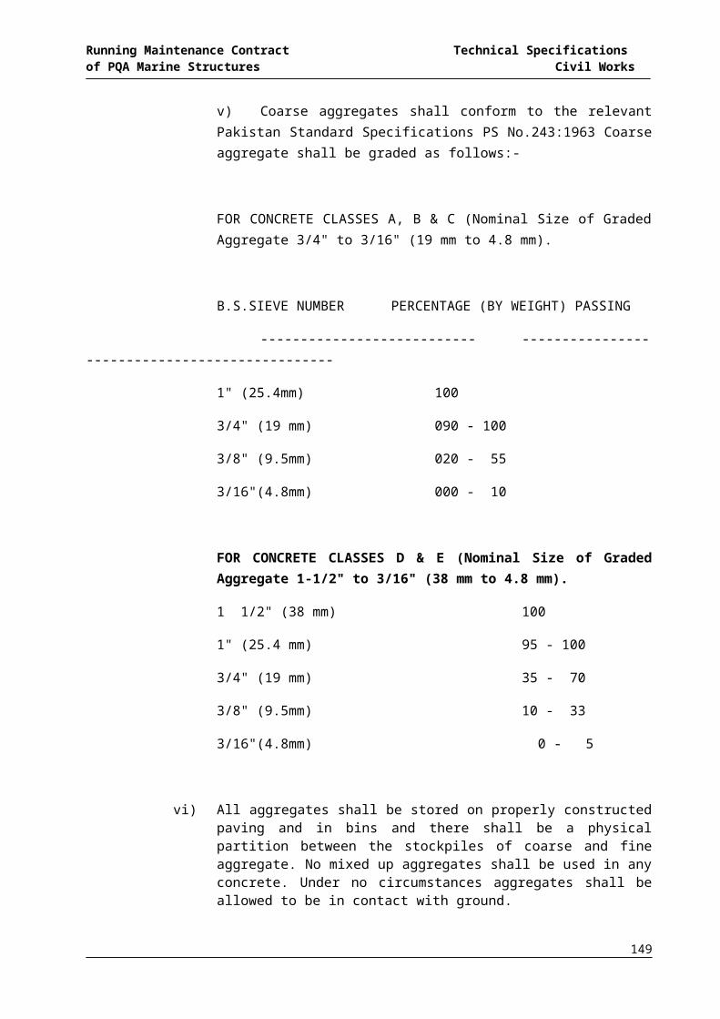
Running Maintenance Contract Technical Specifications of PQA Marine Structures Civil Works
149

Running Maintenance Contract Technical Specifications of PQA Marine Structures Civil Works
150
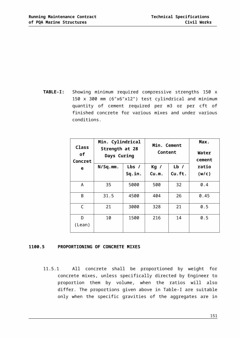
Running Maintenance Contract Technical Specifications of PQA Marine Structures Civil Works
151

Running Maintenance Contract Technical Specifications of PQA Marine Structures Civil Works
152

Running Maintenance Contract Technical Specifications of PQA Marine Structures Civil Works
153