Embed Size (px)
Citation preview
DOCSIS® 3.1 – An Overview
Ron HranacTechnical LeaderCisco Systems
Bruce CurrivanTechnical Director
Broadcom
© 2014 Cisco and/or its affiliates. All rights reserved.Cisco PublicDOCSIS 3.1 Overview 2
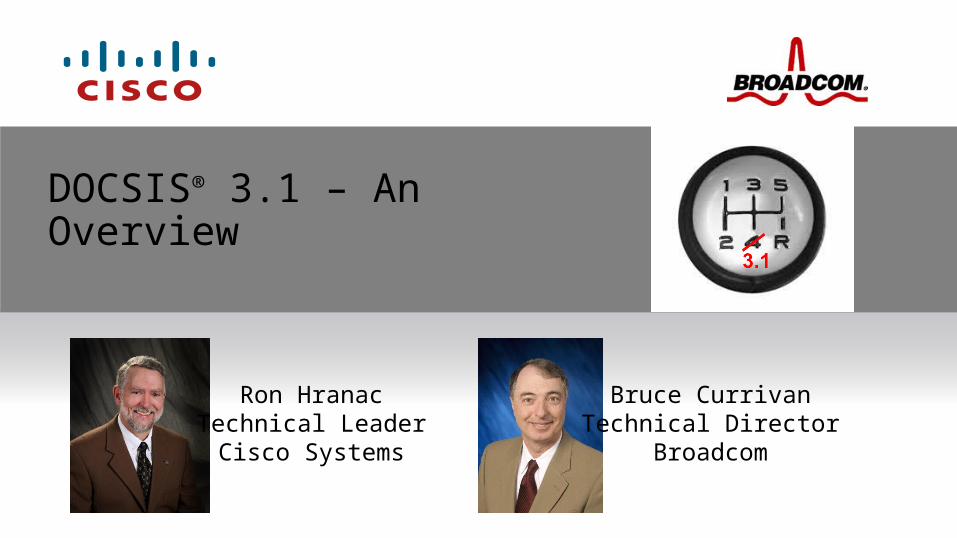
DOCSIS Background
• DOCSIS 1.0 gave us standards-based interoperability, which means “certified” cable modems from multiple vendors work with “qualified” cable modem termination systems (CMTSs) from multiple vendors.
• DOCSIS 1.1 added a number of features, including quality of service (QoS), more robust scheduling, packet classification and other enhancements that facilitate voice and non-best effort data services.
Data-Over-Cable Service Interface Specifications
DOCSIS upstrea
m
DOCSIS downstream
88 MHz 860 MHz 1002 MHz42 MHz5 MHz
One 6 MHz bandwidth downstream channel, 64- or 256-QAM
One upstream channel, typically 1.6 MHz or 3.2 MHz bandwidth

© 2014 Cisco and/or its affiliates. All rights reserved.Cisco PublicDOCSIS 3.1 Overview 3
DOCSIS Background• DOCSIS 1.x supported per-channel downstream data rates of 30.34 Mbps (64-
QAM) and 42.88 Mbps (256-QAM) in a 6 MHz channel bandwidth, and several upstream data rates, ranging from a low of 320 kbps to a high of 10.24 Mbps. It also supported two upstream modulation formats – quadrature phase shift keying (QPSK) and 16-QAM – as well as five upstream RF channel bandwidths.
• DOCSIS 1.1 added some enhancement to upstream transmission robustness, using 8-tap adaptive pre-equalization.
Channel bandwidth, MHz
Symbol rate, ksym/sec
QPSK raw data rate, Mbps
QPSK nominal data rate, Mbps
16-QAM raw data rate, Mbps
16-QAM nominal data rate, Mbps
0.200 160 0.32 ~0.3 0.64 ~0.6
0.400 320 0.64 ~0.6 1.28 ~1.2
0.800 640 1.28 ~1.2 2.56 ~2.4
1.60 1,280 2.56 ~2.3 5.12 ~4.8
3.20 2,560 5.12 ~4.6 10.24 ~9.0
© 2014 Cisco and/or its affiliates. All rights reserved.Cisco PublicDOCSIS 3.1 Overview 4
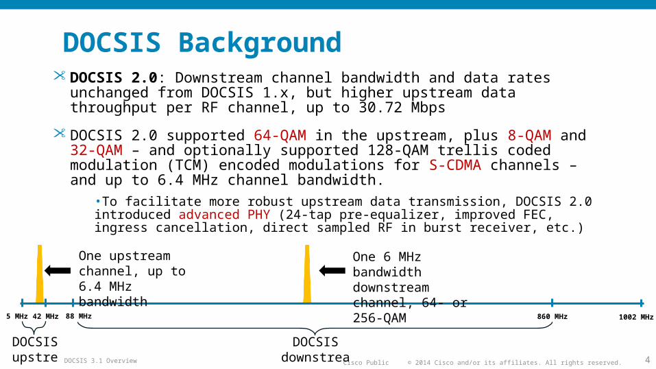
DOCSIS Background• DOCSIS 2.0: Downstream channel bandwidth and data rates unchanged from
DOCSIS 1.x, but higher upstream data throughput per RF channel, up to 30.72 Mbps
• DOCSIS 2.0 supported 64-QAM in the upstream, plus 8-QAM and 32-QAM – and optionally supported 128-QAM trellis coded modulation (TCM) encoded modulations for S-CDMA channels – and up to 6.4 MHz channel bandwidth.
•To facilitate more robust upstream data transmission, DOCSIS 2.0 introduced advanced PHY (24-tap pre-equalizer, improved FEC, ingress cancellation, direct sampled RF in burst receiver, etc.)
DOCSIS upstrea
m
DOCSIS downstream
88 MHz 860 MHz 1002 MHz42 MHz5 MHz
One 6 MHz bandwidth downstream channel, 64- or 256-QAM
One upstream channel, up to 6.4 MHz bandwidth
© 2014 Cisco and/or its affiliates. All rights reserved.Cisco PublicDOCSIS 3.1 Overview 5
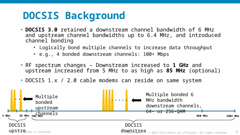
• DOCSIS 3.0 retained a downstream channel bandwidth of 6 MHz and upstream channel bandwidths up to 6.4 MHz, and introduced channel bonding
• Logically bond multiple channels to increase data throughput• e.g., 4 bonded downstream channels: 100+ Mbps
• RF spectrum changes – Downstream increased to 1 GHz and upstream increased from 5 MHz to as high as 85 MHz (optional)
• DOCSIS 1.x / 2.0 cable modems can reside on same system
DOCSIS Background
DOCSIS upstrea
m
DOCSIS downstream
85 MHz 860 MHz 1002 MHz5 MHz
Multiple bonded 6 MHz bandwidth downstream channels, 64- or 256-QAM
Multiple bonded upstream channels
.....
108 MHz
..
© 2014 Cisco and/or its affiliates. All rights reserved.Cisco PublicDOCSIS 3.1 Overview 6
What is DOCSIS 3.1?
Answer: The latest Data Over Cable Service Interface Specifications
DOCSIS 3.1 is the latest Data Over Cable Service Interface Specifications. CableLabs® released version I01 of the new spec in late October, 2013. The latest version is I06, released June, 2015.
All DOCSIS 3.1 specifications including MAC and Upper Layer Protocols Interface Specification (MULPI), Cable Modem Operations Support System Interface Specification (OSSI), Physical Layer Specification (PHY), CCAP™ Operations Support System Interface Specification, and Security Specification have been publicly released.
• (available for download at CableLabs’ web site: http://www.cablelabs.com)
DOCSIS 3.1 specifications became an international standard in early December 2014: ETSI TS 103 311
© 2014 Cisco and/or its affiliates. All rights reserved.Cisco PublicDOCSIS 3.1 Overview 7
Why DOCSIS 3.1? Why not just continue with DOCSIS 3.0?
DOCSIS 3.0 could scale to gigabit-class speeds
DOCSIS 3.1 will scale better, and is more spectrally efficient than today’s single carrier quadrature amplitude modulation (SC-QAM) technology
According to CableLabs:
“DOCSIS 3.1 technology will enable a new generation of cable services and help operators continue to meet consumer demand for high speed connections and sophisticated applications, positioning them to be the providers of choice in their markets.”
© 2014 Cisco and/or its affiliates. All rights reserved.Cisco PublicDOCSIS 3.1 Overview 8
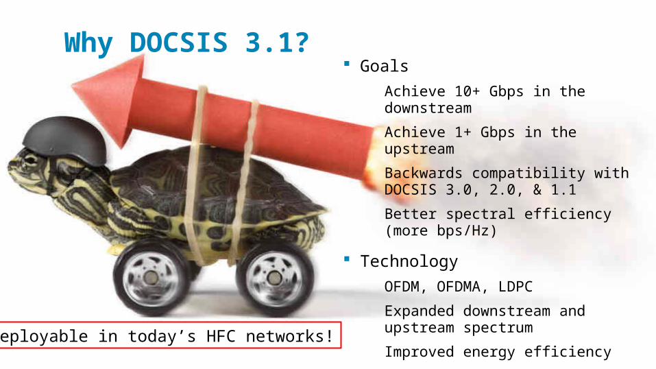
Why DOCSIS 3.1? Goals
Achieve 10+ Gbps in the downstream
Achieve 1+ Gbps in the upstream
Backwards compatibility with DOCSIS 3.0, 2.0, & 1.1
Better spectral efficiency (more bps/Hz)
Technology
OFDM, OFDMA, LDPC
Expanded downstream and upstream spectrum
Improved energy efficiency
This will allow DOCSIS 3.1 to support services competitive with FTTH.
Deployable in today’s HFC networks!
© 2014 Cisco and/or its affiliates. All rights reserved.Cisco PublicDOCSIS 3.1 Overview 9
Improved performance New physical layer (PHY) technology: OFDM (orthogonal frequency division
multiplex) and OFDMA (orthogonal frequency division multiple access)
Better spectral efficiency than SC-QAM
Better forward error correction (FEC): low density parity check (LDPC)
More powerful than the Viterbi/Reed-Solomon FEC used in earlier versions of DOCSIS
Higher modulation orders
Up to 4096-QAM in the downstream and upstream, optional to 16384-QAM in the downstream
Expanded downstream and upstream RF spectrum usage
Downstream: 258 MHz to 1218 MHz, optional to 1794 MHz (and 108 MHz on lower end)
Upstream: 5 MHz to 85 MHz (mandatory), optional to as high as 204 MHz
Multiple modulation profiles
Different modulation orders for different modems
© 2014 Cisco and/or its affiliates. All rights reserved.Cisco PublicDOCSIS 3.1 Overview 10
RF transmit power Downstream RF transmit power
CMTS power is configured by power per CEA channel and number of occupied CEA channels for each OFDM channel. For each OFDM channel, the total power is power per CEA channel + 10log10(number of occupied CEA channels) for that OFDM channel.
Required power per channel for Neq' channels combined onto a single RF port:
Required power in dBmV per channel = 60 – ceil [3.6*log2(N*)] dBmV
Input to the modem
Total input power < 40 dBmV, 54 MHz to 1.794 GHz (negligible input power outside this frequency range)
Level range = -9 dBmV to +21 dBmV (in 24 MHz occupied bandwidth)
(equivalent PSD to -15 dBmV to +15 dBmV per 6 MHz SC-QAM)
© 2014 Cisco and/or its affiliates. All rights reserved.Cisco PublicDOCSIS 3.1 Overview 11
RF transmit power Upstream RF transmit power
All DOCSIS 3.0 requirements still in place for operating DOCSIS 3.0 mode
DOCSIS 3.1 maximum transmit average power (not peak) is required to be at least +65 dBmV
As with DOCSIS 3.0, modem vendors may design their products for higher modem transmit power capability, but all spurious emissions requirements (dBc) must still be met even at higher transmit power levels
DOCSIS 3.1 has minimum transmit power limits related to transmit grant bandwidth
No less than +17 dBmV with 1.6 MHz grant
© 2014 Cisco and/or its affiliates. All rights reserved.Cisco PublicDOCSIS 3.1 Overview 12
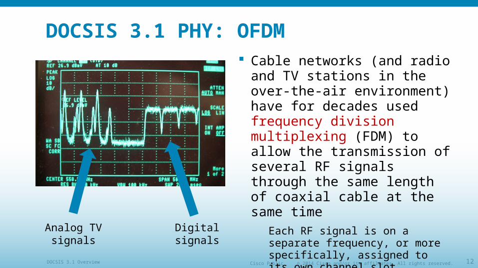
DOCSIS 3.1 PHY: OFDM Cable networks (and radio and
TV stations in the over-the-air environment) have for decades used frequency division multiplexing (FDM) to allow the transmission of several RF signals through the same length of coaxial cable at the same time
Each RF signal is on a separate frequency, or more specifically, assigned to its own channel slot
Digital signalsAnalog TV signals
© 2014 Cisco and/or its affiliates. All rights reserved.Cisco PublicDOCSIS 3.1 Overview 13
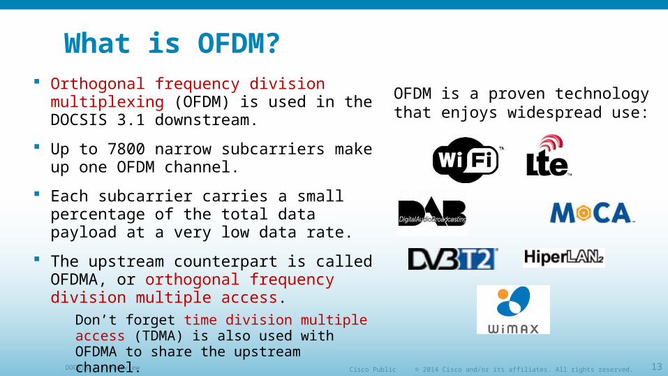
What is OFDM? Orthogonal frequency division multiplexing
(OFDM) is used in the DOCSIS 3.1 downstream.
Up to 7800 narrow subcarriers make up one OFDM channel.
Each subcarrier carries a small percentage of the total data payload at a very low data rate.
The upstream counterpart is called OFDMA, or orthogonal frequency division multiple access.
Don’t forget time division multiple access (TDMA) is also used with OFDMA to share the upstream channel.
OFDM is a proven technology that enjoys widespread use:
© 2014 Cisco and/or its affiliates. All rights reserved.Cisco PublicDOCSIS 3.1 Overview 14
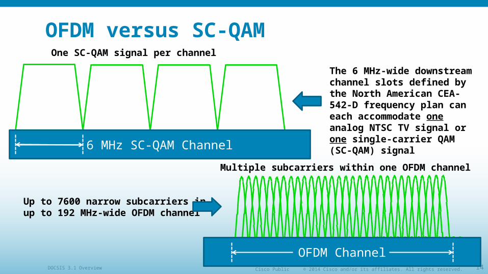
OFDM versus SC-QAMOne SC-QAM signal per channel
OFDM Channel
Multiple subcarriers within one OFDM channel
6 MHz SC-QAM Channel
Up to 7600 narrow subcarriers inup to 192 MHz-wide OFDM channel
The 6 MHz-wide downstream channel slots defined by the North American CEA-542-D frequency plan can each accommodate one analog NTSC TV signal or one single-carrier QAM (SC-QAM) signal
© 2014 Cisco and/or its affiliates. All rights reserved.Cisco PublicDOCSIS 3.1 Overview 15
DOCSIS 3.1 OFDM channel width With OFDM, the concept of a 6 MHz or 8 MHz channel is no longer
necessary.
DOCSIS 3.1 OFDM channel bandwidth is flexible
Downstream channel bandwidth: Minimum of 24 MHz to maximum of 192 MHz
Upstream channel bandwidth: Minimum encompassed spectrum of 6.4 MHz to a maximum encompassed spectrum of 95 MHz
© 2014 Cisco and/or its affiliates. All rights reserved.Cisco PublicDOCSIS 3.1 Overview 16
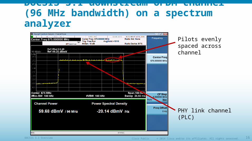
DOCSIS 3.1 downstream OFDM channel (96 MHz bandwidth) on a spectrum analyzer
Pilots evenly spaced across channel
PHY link channel (PLC)
© 2014 Cisco and/or its affiliates. All rights reserved.Cisco PublicDOCSIS 3.1 Overview 17
OFDM: orthogonal subcarriers For improved spectral efficiency, the subcarriers in an OFDM or
OFDMA channel overlap one another.Why don’t they interfere with one another?
The subcarriers are orthogonal.“Orthogonal” in this case means the subcarriers are independent such that there is no interaction between them despite the overlap in frequency.
Orthogonal subcarriers have exactly an integer number of cycles in the symbol interval.
© 2014 Cisco and/or its affiliates. All rights reserved.Cisco PublicDOCSIS 3.1 Overview 18
OFDM: orthogonal subcarriersA
mpl
itude
0
0.2
0.4
0.6
0.8
1.0
- 0.2
- 0.4
Frequency
1/TU
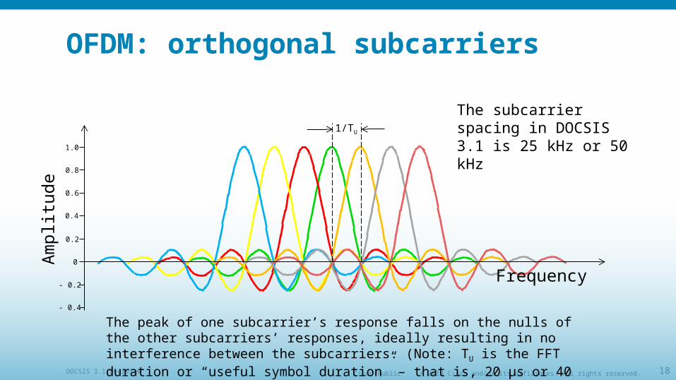
The peak of one subcarrier’s response falls on the nulls of the other subcarriers’ responses, ideally resulting in no interference between the subcarriers. (Note: TU is the FFT duration or “useful symbol duration” – that is, 20 µs or 40 µs in the case of DOCSIS 3.1.)
The subcarrier spacing in DOCSIS 3.1 is 25 kHz or 50 kHz
© 2014 Cisco and/or its affiliates. All rights reserved.Cisco PublicDOCSIS 3.1 Overview 19
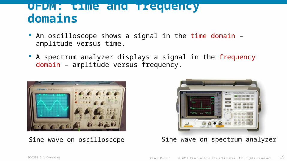
OFDM: time and frequency domains An oscilloscope shows a signal in the time domain – amplitude versus
time.
A spectrum analyzer displays a signal in the frequency domain – amplitude versus frequency.
Sine wave on oscilloscope Sine wave on spectrum analyzer
© 2014 Cisco and/or its affiliates. All rights reserved.Cisco PublicDOCSIS 3.1 Overview 20
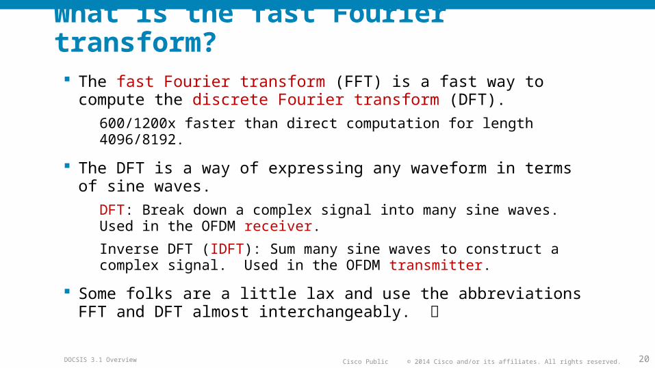
What is the fast Fourier transform? The fast Fourier transform (FFT) is a fast way to compute the
discrete Fourier transform (DFT).
600/1200x faster than direct computation for length 4096/8192.
The DFT is a way of expressing any waveform in terms of sine waves.
DFT: Break down a complex signal into many sine waves. Used in the OFDM receiver.
Inverse DFT (IDFT): Sum many sine waves to construct a complex signal. Used in the OFDM transmitter.
Some folks are a little lax and use the abbreviations FFT and DFT almost interchangeably.
© 2014 Cisco and/or its affiliates. All rights reserved.Cisco PublicDOCSIS 3.1 Overview 21
DFT matrix
To apply the DFT just multiply by a matrix.
Multiplying by this matrix converts between the time and frequency domains, and performs modulation and demodulation.
© 2014 Cisco and/or its affiliates. All rights reserved.Cisco PublicDOCSIS 3.1 Overview 22
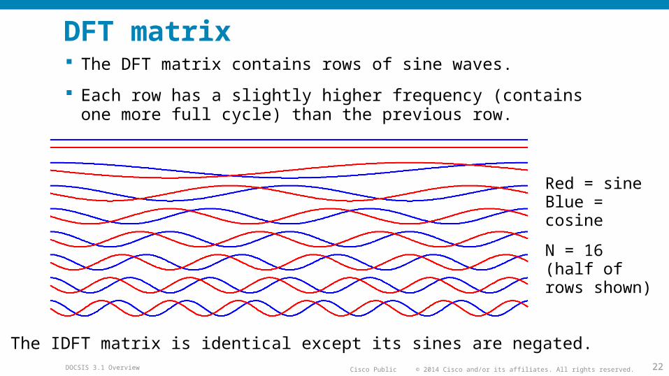
DFT matrix The DFT matrix contains rows of sine waves.
Each row has a slightly higher frequency (contains one more full cycle) than the previous row.
Red = sineBlue = cosine
N = 16(half of rows shown)
The IDFT matrix is identical except its sines are negated.
© 2014 Cisco and/or its affiliates. All rights reserved.Cisco PublicDOCSIS 3.1 Overview 23
Full DFT matrix
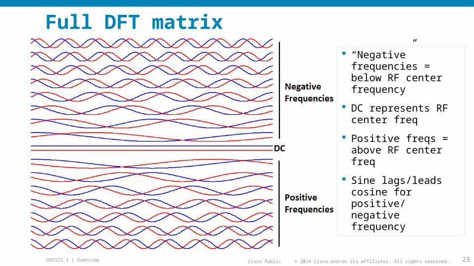
“Negative” frequencies = below RF center frequency
DC represents RF center freq
Positive freqs = above RF center freq
Sine lags/leads cosine for positive/ negative frequency
© 2014 Cisco and/or its affiliates. All rights reserved.Cisco PublicDOCSIS 3.1 Overview 24
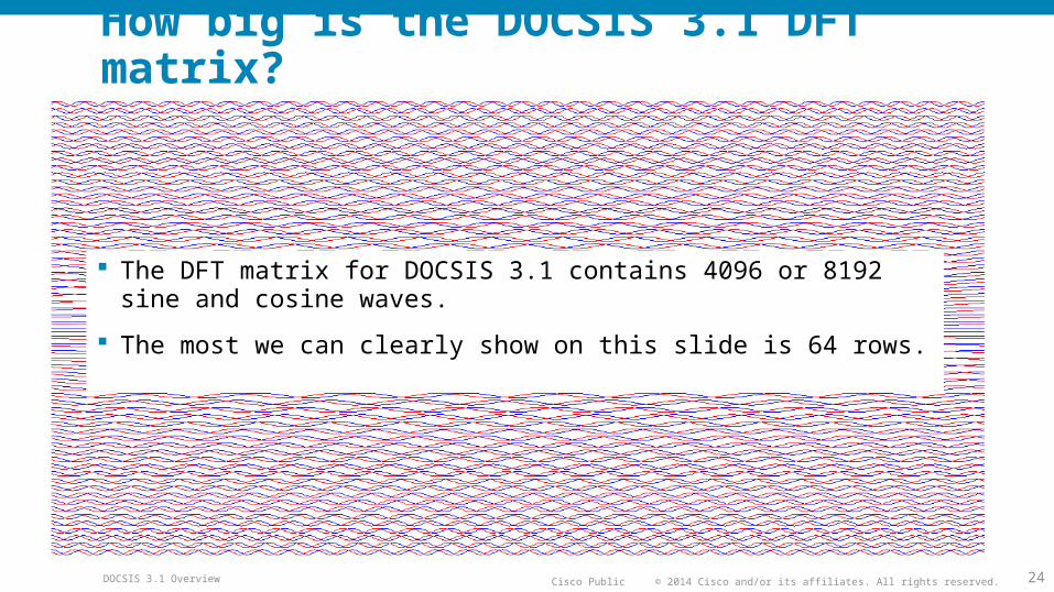
How big is the DOCSIS 3.1 DFT matrix?
The DFT matrix for DOCSIS 3.1 contains 4096 or 8192 sine and cosine waves.
The most we can clearly show on this slide is 64 rows.
© 2014 Cisco and/or its affiliates. All rights reserved.Cisco PublicDOCSIS 3.1 Overview 25
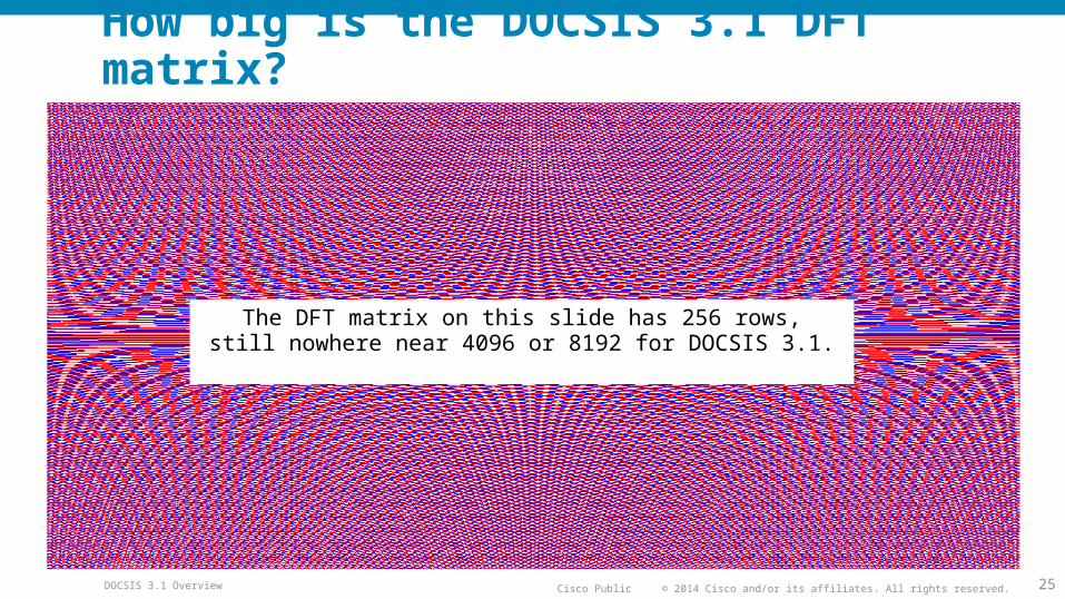
How big is the DOCSIS 3.1 DFT matrix?
The DFT matrix on this slide has 256 rows,still nowhere near 4096 or 8192 for DOCSIS 3.1.
© 2014 Cisco and/or its affiliates. All rights reserved.Cisco PublicDOCSIS 3.1 Overview 26
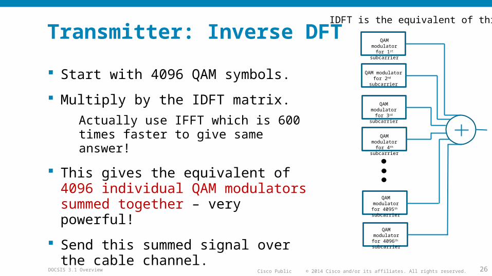
Transmitter: Inverse DFT
Start with 4096 QAM symbols.
Multiply by the IDFT matrix.
Actually use IFFT which is 600 times faster to give same answer!
This gives the equivalent of 4096 individual QAM modulators summed together – very powerful!
Send this summed signal over the cable channel.
QAM modulator for 1st subcarrier
QAM modulator for 2nd subcarrier
QAM modulator for 3rd subcarrier
QAM modulator for 4th subcarrier
QAM modulator for 4095th subcarrier
QAM modulator for 4096th subcarrier
IDFT is the equivalent of this:
© 2014 Cisco and/or its affiliates. All rights reserved.Cisco PublicDOCSIS 3.1 Overview 27
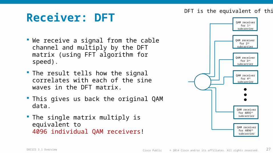
Receiver: DFT
We receive a signal from the cable channel and multiply by the DFT matrix (using FFT algorithm for speed).
The result tells how the signal correlates with each of the sine waves in the DFT matrix.
This gives us back the original QAM data.
The single matrix multiply is equivalent to4096 individual QAM receivers!
DFT is the equivalent of this:
QAM receiver for 1st subcarrier
QAM receiver for 2nd subcarrier
QAM receiver for 3rd subcarrier
QAM receiver for 4th subcarrier
QAM receiver for 4095th subcarrier
QAM receiver for 4096th subcarrier

© 2014 Cisco and/or its affiliates. All rights reserved.Cisco PublicDOCSIS 3.1 Overview 28
Don’t forget receiver synchronization To get the transmitter IFFT and receiver FFT to line up, we need to
synchronize the receiver to the transmitter.
Timing: Adjust symbol timing so the FFT starts at the right time.
Cyclic prefix: To make timing easier, the transmitter repeats part of the signal. This also allows time for channel echoes to die out.
Frequency: Adjust receiver to the correct center frequency.
Continuous pilots: Some subcarriers carry no data, and are used to measure frequency offset.
Equalization: Adjust amplitude and phase of each subcarrier to remove channel effects.
Scattered pilots: Carry no data, visit each subcarrier location once every 128 symbols, used to measure channel response.

© 2014 Cisco and/or its affiliates. All rights reserved.Cisco PublicDOCSIS 3.1 Overview 29
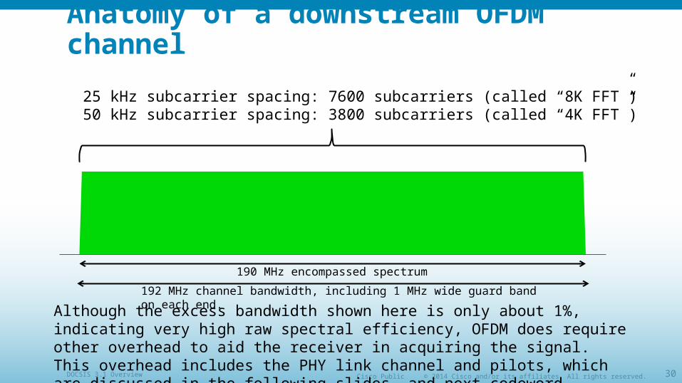
Anatomy of a downstream OFDM channel
192 MHz channel bandwidth, including 1 MHz wide guard band on each end.
190 MHz encompassed spectrum
25 kHz subcarrier spacing: 7600 subcarriers (called “8K FFT”)50 kHz subcarrier spacing: 3800 subcarriers (called “4K FFT”)
Since the guard bands in this example total 2 MHz out of 192 MHz, the equivalent excess bandwidth or “alpha” is (2/192) x 100 ≈ 1%, compared to 12% for DOCSIS 3.0 and earlier 256-QAM SC-QAM.
© 2014 Cisco and/or its affiliates. All rights reserved.Cisco PublicDOCSIS 3.1 Overview 30
Anatomy of a downstream OFDM channel
192 MHz channel bandwidth, including 1 MHz wide guard band on each end.
190 MHz encompassed spectrum
25 kHz subcarrier spacing: 7600 subcarriers (called “8K FFT”)50 kHz subcarrier spacing: 3800 subcarriers (called “4K FFT”)
Although the excess bandwidth shown here is only about 1%, indicating very high raw spectral efficiency, OFDM does require other overhead to aid the receiver in acquiring the signal. This overhead includes the PHY link channel and pilots, which are discussed in the following slides, and next codeword pointer.
© 2014 Cisco and/or its affiliates. All rights reserved.Cisco PublicDOCSIS 3.1 Overview 31
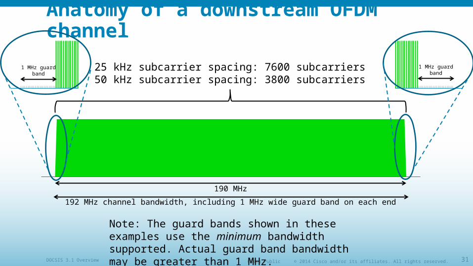
Anatomy of a downstream OFDM channel
192 MHz channel bandwidth, including 1 MHz wide guard band on each end
190 MHz
25 kHz subcarrier spacing: 7600 subcarriers50 kHz subcarrier spacing: 3800 subcarriers
1 MHz guard band
1 MHz guard band
Note: The guard bands shown in these examples use the minimum bandwidth supported. Actual guard band bandwidth may be greater than 1 MHz.
© 2014 Cisco and/or its affiliates. All rights reserved.Cisco PublicDOCSIS 3.1 Overview 32
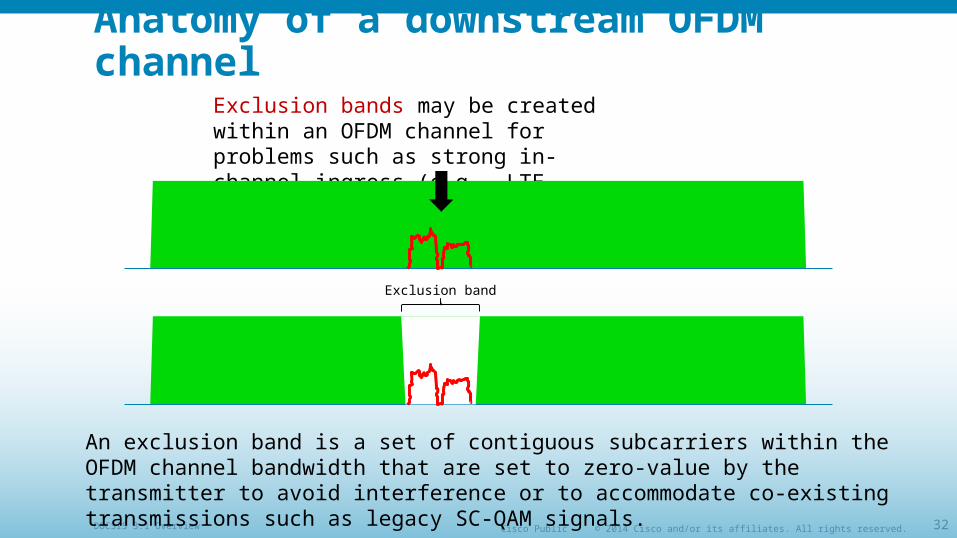
Anatomy of a downstream OFDM channelExclusion bands may be created within an OFDM channel for problems such as strong in-channel ingress (e.g., LTE interference).
An exclusion band is a set of contiguous subcarriers within the OFDM channel bandwidth that are set to zero-value by the transmitter to avoid interference or to accommodate co-existing transmissions such as legacy SC-QAM signals.
Exclusion band
© 2014 Cisco and/or its affiliates. All rights reserved.Cisco PublicDOCSIS 3.1 Overview 33
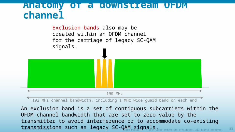
Anatomy of a downstream OFDM channel
192 MHz channel bandwidth, including 1 MHz wide guard band on each end
190 MHz
Exclusion bands also may be created within an OFDM channel for the carriage of legacy SC-QAM signals.
An exclusion band is a set of contiguous subcarriers within the OFDM channel bandwidth that are set to zero-value by the transmitter to avoid interference or to accommodate co-existing transmissions such as legacy SC-QAM signals.
© 2014 Cisco and/or its affiliates. All rights reserved.Cisco PublicDOCSIS 3.1 Overview 34
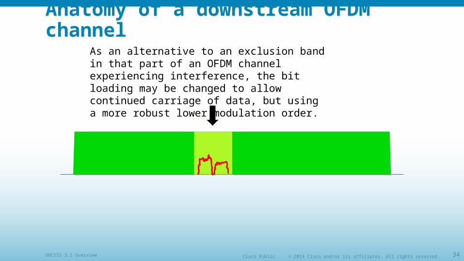
Anatomy of a downstream OFDM channelAs an alternative to an exclusion band in that part of an OFDM channel experiencing interference, the bit loading may be changed to allow continued carriage of data, but using a more robust lower modulation order.
© 2014 Cisco and/or its affiliates. All rights reserved.Cisco PublicDOCSIS 3.1 Overview 35
Anatomy of a downstream OFDM channel
192 MHz channel bandwidth, including 1 MHz wide guard band on each end
190 MHz
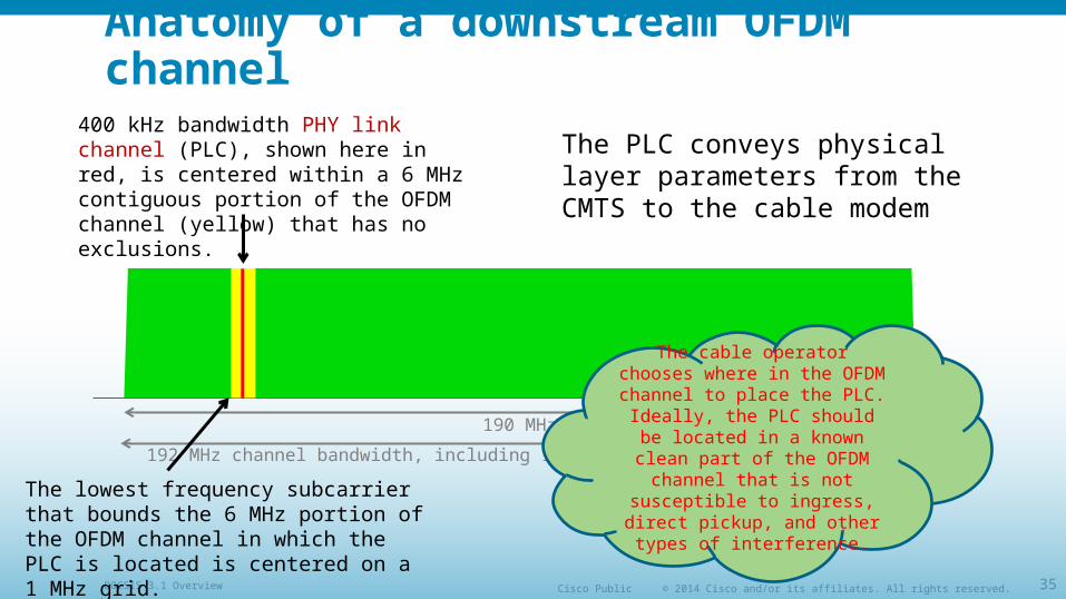
400 kHz bandwidth PHY link channel (PLC), shown here in red, is centered within a 6 MHz contiguous portion of the OFDM channel (yellow) that has no exclusions.
The lowest frequency subcarrier that bounds the 6 MHz portion of the OFDM channel in which the PLC is located is centered on a 1 MHz grid.
The PLC conveys physical layer parameters from the CMTS to the cable modem
The cable operator chooses where in the OFDM channel to place the PLC. Ideally, the PLC should be located in a known
clean part of the OFDM channel that is not susceptible to ingress, direct pickup, and other types of
interference.
© 2014 Cisco and/or its affiliates. All rights reserved.Cisco PublicDOCSIS 3.1 Overview 36
Anatomy of a downstream OFDM channel
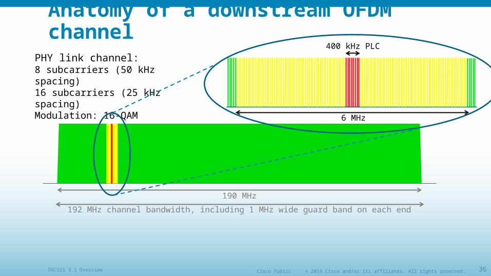
192 MHz channel bandwidth, including 1 MHz wide guard band on each end
190 MHz
PHY link channel:8 subcarriers (50 kHz spacing)16 subcarriers (25 kHz spacing)Modulation: 16-QAM
6 MHz
400 kHz PLC
© 2014 Cisco and/or its affiliates. All rights reserved.Cisco PublicDOCSIS 3.1 Overview 37
Anatomy of a downstream OFDM channel
192 MHz channel bandwidth, including 1 MHz wide guard band on each end
190 MHz
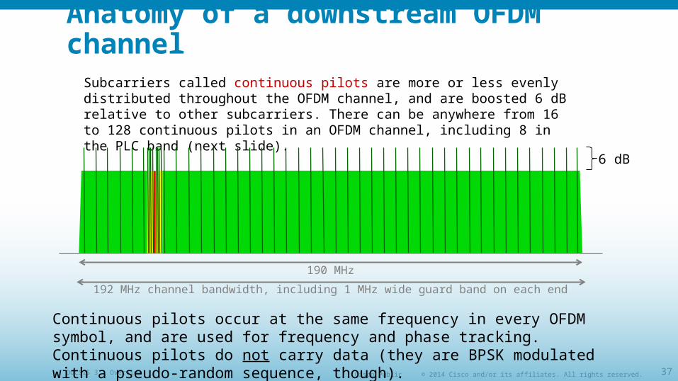
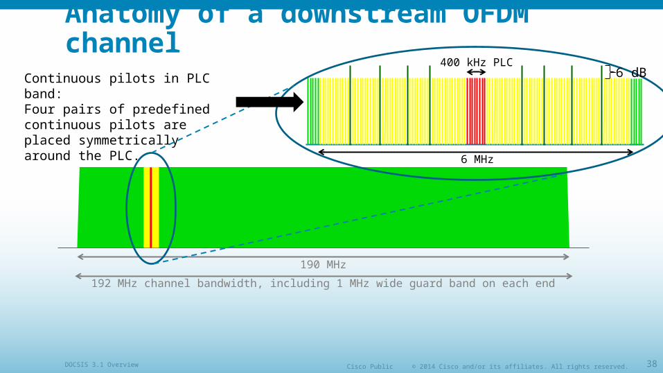
Subcarriers called continuous pilots are more or less evenly distributed throughout the OFDM channel, and are boosted 6 dB relative to other subcarriers. There can be anywhere from 16 to 128 continuous pilots in an OFDM channel, including 8 in the PLC band (next slide).
6 dB
Continuous pilots occur at the same frequency in every OFDM symbol, and are used for frequency and phase tracking. Continuous pilots do not carry data (they are BPSK modulated with a pseudo-random sequence, though).
© 2014 Cisco and/or its affiliates. All rights reserved.Cisco PublicDOCSIS 3.1 Overview 38
Anatomy of a downstream OFDM channel
192 MHz channel bandwidth, including 1 MHz wide guard band on each end
190 MHz
Continuous pilots in PLC band:Four pairs of predefined continuous pilots are placed symmetrically around the PLC.
6 MHz
400 kHz PLC6 dB
© 2014 Cisco and/or its affiliates. All rights reserved.Cisco PublicDOCSIS 3.1 Overview 39
Anatomy of a downstream OFDM channel
192 MHz channel bandwidth, including 1 MHz wide guard band on each end
190 MHz
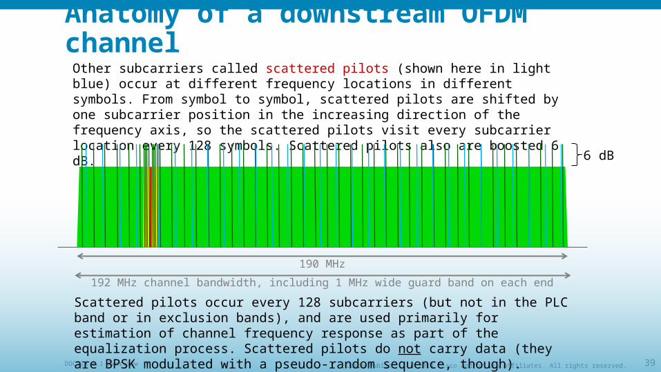
Other subcarriers called scattered pilots (shown here in light blue) occur at different frequency locations in different symbols. From symbol to symbol, scattered pilots are shifted by one subcarrier position in the increasing direction of the frequency axis, so the scattered pilots visit every subcarrier location every 128 symbols. Scattered pilots also are boosted 6 dB.
6 dB
Scattered pilots occur every 128 subcarriers (but not in the PLC band or in exclusion bands), and are used primarily for estimation of channel frequency response as part of the equalization process. Scattered pilots do not carry data (they are BPSK modulated with a pseudo-random sequence, though).
© 2014 Cisco and/or its affiliates. All rights reserved.Cisco PublicDOCSIS 3.1 Overview 40
Anatomy of a downstream OFDM channel
192 MHz channel bandwidth, including 1 MHz wide guard band on each end
190 MHz
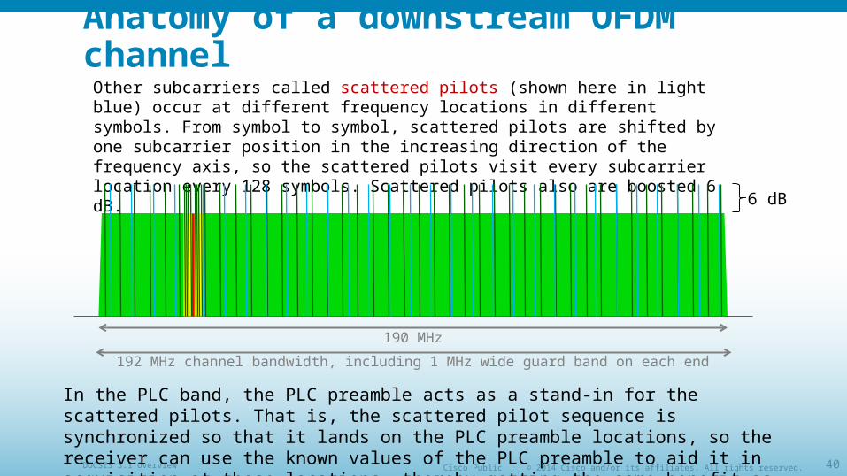
Other subcarriers called scattered pilots (shown here in light blue) occur at different frequency locations in different symbols. From symbol to symbol, scattered pilots are shifted by one subcarrier position in the increasing direction of the frequency axis, so the scattered pilots visit every subcarrier location every 128 symbols. Scattered pilots also are boosted 6 dB.
6 dB
In the PLC band, the PLC preamble acts as a stand-in for the scattered pilots. That is, the scattered pilot sequence is synchronized so that it lands on the PLC preamble locations, so the receiver can use the known values of the PLC preamble to aid it in acquisition at those locations, thereby getting the same benefit as if the scattered pilots had been placed there.
© 2014 Cisco and/or its affiliates. All rights reserved.Cisco PublicDOCSIS 3.1 Overview 41
Anatomy of a downstream OFDM channel
192 MHz channel bandwidth, including 1 MHz wide guard band on each end
190 MHz
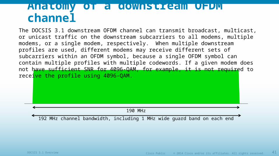
The DOCSIS 3.1 downstream OFDM channel can transmit broadcast, multicast, or unicast traffic on the downstream subcarriers to all modems, multiple modems, or a single modem, respectively. When multiple downstream profiles are used, different modems may receive different sets of subcarriers within an OFDM symbol, because a single OFDM symbol can contain multiple profiles with multiple codewords. If a given modem does not have sufficient SNR for 4096-QAM, for example, it is not required to receive the profile using 4096-QAM.
© 2014 Cisco and/or its affiliates. All rights reserved.Cisco PublicDOCSIS 3.1 Overview 42
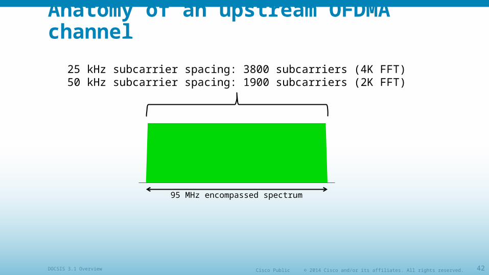
Anatomy of an upstream OFDMA channel
95 MHz encompassed spectrum
25 kHz subcarrier spacing: 3800 subcarriers (4K FFT)50 kHz subcarrier spacing: 1900 subcarriers (2K FFT)
© 2014 Cisco and/or its affiliates. All rights reserved.Cisco PublicDOCSIS 3.1 Overview 43
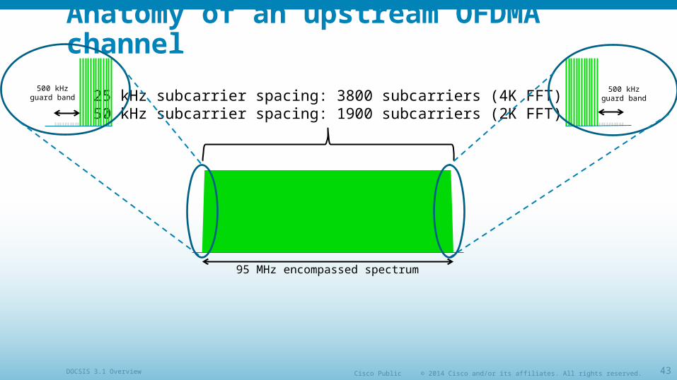
Anatomy of an upstream OFDMA channel
95 MHz encompassed spectrum
25 kHz subcarrier spacing: 3800 subcarriers (4K FFT)50 kHz subcarrier spacing: 1900 subcarriers (2K FFT)
500 kHz guard band
500 kHz guard band

© 2014 Cisco and/or its affiliates. All rights reserved.Cisco PublicDOCSIS 3.1 Overview 44
Anatomy of an upstream OFDMA channel
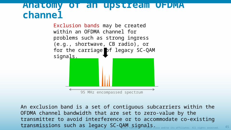
95 MHz encompassed spectrum
Exclusion bands may be created within an OFDMA channel for problems such as strong ingress (e.g., shortwave, CB radio), or for the carriage of legacy SC-QAM signals.
An exclusion band is a set of contiguous subcarriers within the OFDMA channel bandwidth that are set to zero-value by the transmitter to avoid interference or to accommodate co-existing transmissions such as legacy SC-QAM signals.
© 2014 Cisco and/or its affiliates. All rights reserved.Cisco PublicDOCSIS 3.1 Overview 45
Anatomy of an upstream OFDMA channel
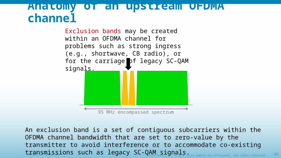
95 MHz encompassed spectrum
Exclusion bands may be created within an OFDMA channel for problems such as strong ingress (e.g., shortwave, CB radio), or for the carriage of legacy SC-QAM signals.
An exclusion band is a set of contiguous subcarriers within the OFDMA channel bandwidth that are set to zero-value by the transmitter to avoid interference or to accommodate co-existing transmissions such as legacy SC-QAM signals.
© 2014 Cisco and/or its affiliates. All rights reserved.Cisco PublicDOCSIS 3.1 Overview 46
Anatomy of an upstream OFDMA channel
95 MHz encompassed spectrum
Exclusion bands may be created within an OFDMA channel for problems such as strong ingress (e.g., shortwave, CB radio), or for the carriage of legacy SC-QAM signals.
An exclusion band is a set of contiguous subcarriers within the OFDMA channel bandwidth that are set to zero-value by the transmitter to avoid interference or to accommodate co-existing transmissions such as legacy SC-QAM signals.
© 2014 Cisco and/or its affiliates. All rights reserved.Cisco PublicDOCSIS 3.1 Overview 47
Anatomy of an upstream OFDMA channel
95 MHz encompassed spectrum
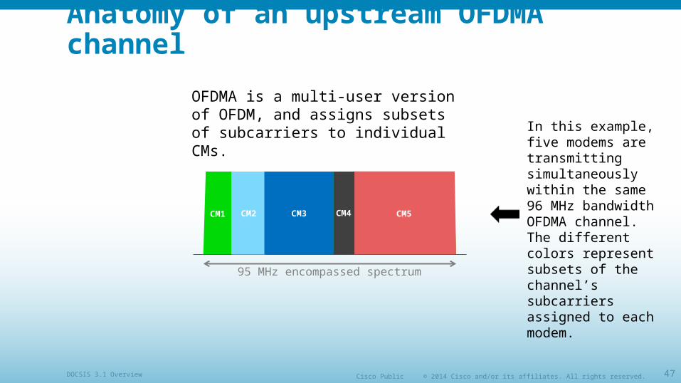
OFDMA is a multi-user version of OFDM, and assigns subsets of subcarriers to individual CMs.
CM2 CM3 CM5CM1 CM4
In this example, five modems are transmitting simultaneously within the same 96 MHz bandwidth OFDMA channel. The different colors represent subsets of the channel’s subcarriers assigned to each modem.
© 2014 Cisco and/or its affiliates. All rights reserved.Cisco PublicDOCSIS 3.1 Overview 48
Anatomy of an upstream OFDMA channel
95 MHz encompassed spectrum
6.4 MHz
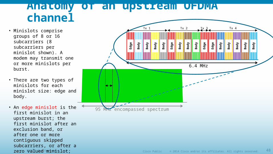
• Minislots comprise groups of 8 or 16 subcarriers (8 subcarriers per minislot shown). A modem may transmit one or more minislots per burst.
• There are two types of minislots for each minislot size: edge and body.
• An edge minislot is the first minislot in an upstream burst; the first minislot after an exclusion band, or after one or more contiguous skipped subcarriers, or after a zero valued minislot; and the first minislot of an OFDMA frame that is not a zero valued minislot.
• All others are body minislots.
Ed
ge
Tx 1 Tx 2 Tx 4Tx 3
Ed
ge
Ed
ge
Ed
ge
Bo
dy
Bo
dy
Bo
dy
Bo
dy
Bo
dy
Bo
dy
Bo
dy
Bo
dy
Bo
dy
Bo
dy
Bo
dy
Bo
dy
© 2014 Cisco and/or its affiliates. All rights reserved.Cisco PublicDOCSIS 3.1 Overview 49
Anatomy of an upstream OFDMA channel
95 MHz encompassed spectrum
6.4 MHz
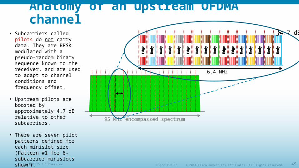
• Subcarriers called pilots do not carry data. They are BPSK modulated with a pseudo-random binary sequence known to the receiver, and are used to adapt to channel conditions and frequency offset.
• Upstream pilots are boosted by approximately 4.7 dB relative to other subcarriers.
• There are seven pilot patterns defined for each minislot size (Pattern #1 for 8-subcarrier minislots shown).
Ed
ge
Ed
ge
Ed
ge
Ed
ge
Bo
dy
Bo
dy
Bo
dy
Bo
dy
Bo
dy
Bo
dy
Bo
dy
Bo
dy
Bo
dy
Bo
dy
Bo
dy
Bo
dy
4.7 dB
© 2014 Cisco and/or its affiliates. All rights reserved.Cisco PublicDOCSIS 3.1 Overview 50
Anatomy of an upstream OFDMA channel
95 MHz encompassed spectrum
6.4 MHz
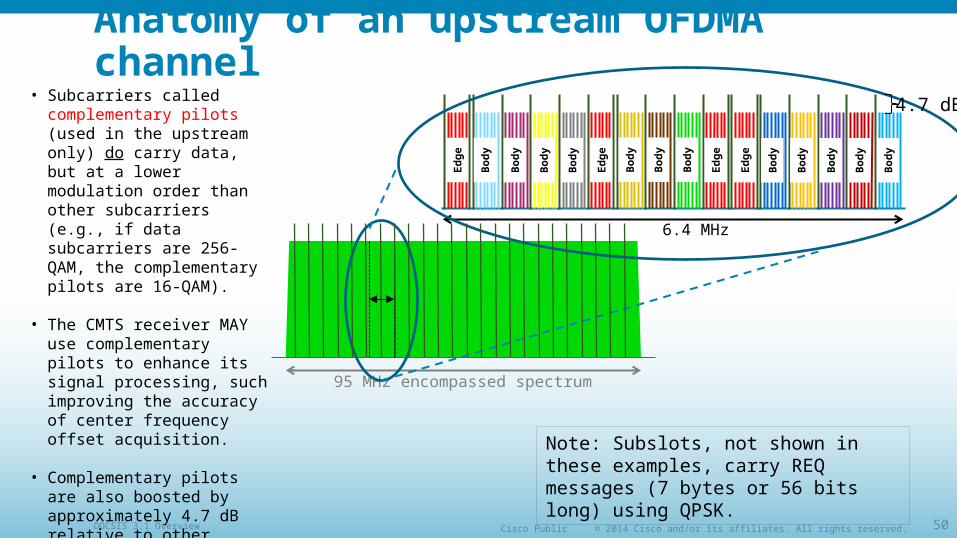
• Subcarriers called complementary pilots (used in the upstream only) do carry data, but at a lower modulation order than other subcarriers (e.g., if data subcarriers are 256-QAM, the complementary pilots are 16-QAM).
• The CMTS receiver MAY use complementary pilots to enhance its signal processing, such improving the accuracy of center frequency offset acquisition.
• Complementary pilots are also boosted by approximately 4.7 dB relative to other upstream subcarriers.
• Pattern #1 for 8-subcarrier minislots shown.
Ed
ge
Ed
ge
Ed
ge
Ed
ge
Bo
dy
Bo
dy
Bo
dy
Bo
dy
Bo
dy
Bo
dy
Bo
dy
Bo
dy
Bo
dy
Bo
dy
Bo
dy
Bo
dy
4.7 dB
Note: Subslots, not shown in these examples, carry REQ messages (7 bytes or 56 bits long) using QPSK.
© 2014 Cisco and/or its affiliates. All rights reserved.Cisco PublicDOCSIS 3.1 Overview 51
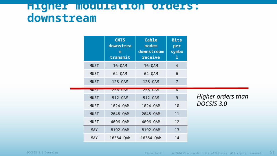
Higher modulation orders: downstream
CMTS downstream
transmit
Cable modem
downstream receive
Bits per
symbol
MUST 16-QAM 16-QAM 4
MUST 64-QAM 64-QAM 6
MUST 128-QAM 128-QAM 7
MUST 256-QAM 256-QAM 8
MUST 512-QAM 512-QAM 9
MUST 1024-QAM 1024-QAM 10
MUST 2048-QAM 2048-QAM 11
MUST 4096-QAM 4096-QAM 12
MAY 8192-QAM 8192-QAM 13
MAY 16384-QAM 16384-QAM 14
Higher orders than DOCSIS 3.0
© 2014 Cisco and/or its affiliates. All rights reserved.Cisco PublicDOCSIS 3.1 Overview 52
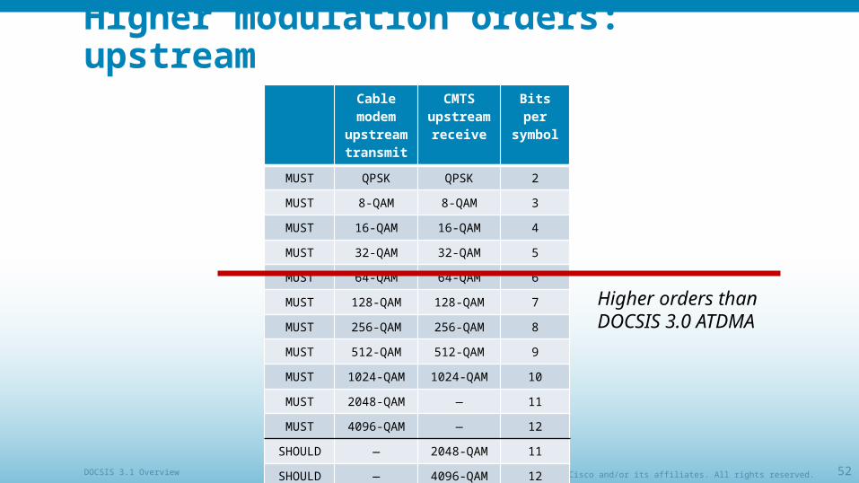
Higher modulation orders: upstreamCable
modem upstream transmit
CMTS upstream receive
Bits per symbol
MUST QPSK QPSK 2
MUST 8-QAM 8-QAM 3
MUST 16-QAM 16-QAM 4
MUST 32-QAM 32-QAM 5
MUST 64-QAM 64-QAM 6
MUST 128-QAM 128-QAM 7
MUST 256-QAM 256-QAM 8
MUST 512-QAM 512-QAM 9
MUST 1024-QAM 1024-QAM 10
MUST 2048-QAM — 11
MUST 4096-QAM — 12
SHOULD — 2048-QAM 11
SHOULD — 4096-QAM 12
Higher orders than DOCSIS 3.0 ATDMA
© 2014 Cisco and/or its affiliates. All rights reserved.Cisco PublicDOCSIS 3.1 Overview 53
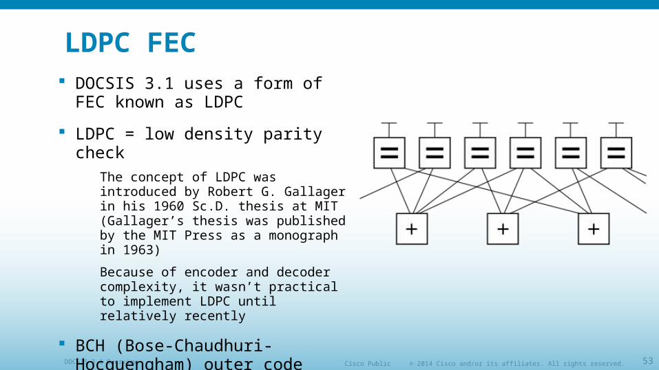
LDPC FEC DOCSIS 3.1 uses a form of FEC
known as LDPC
LDPC = low density parity check
The concept of LDPC was introduced by Robert G. Gallager in his 1960 Sc.D. thesis at MIT (Gallager’s thesis was published by the MIT Press as a monograph in 1963)
Because of encoder and decoder complexity, it wasn’t practical to implement LDPC until relatively recently
BCH (Bose-Chaudhuri-Hocquengham) outer code corrects residual errors in downstream
© 2014 Cisco and/or its affiliates. All rights reserved.Cisco PublicDOCSIS 3.1 Overview 54
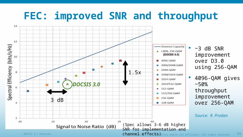
FEC: improved SNR and throughput
~3 dB SNR improvement over D3.0 using 256-QAM
4096-QAM gives ~50% throughput improvement over 256-QAM
3 dB
1.5x
DOCSIS 3.0
Source: R. Prodan
(Spec allows 3-6 dB higher SNR for implementation and channel effects)
© 2014 Cisco and/or its affiliates. All rights reserved.Cisco PublicDOCSIS 3.1 Overview 55
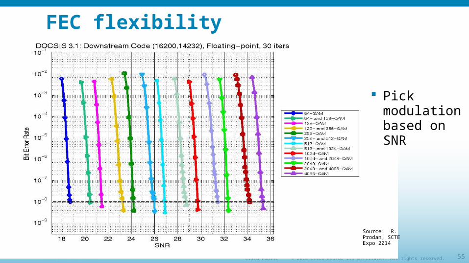
FEC flexibility
Pick modulation based on SNR
Source: R. Prodan, SCTE Expo 2014
© 2014 Cisco and/or its affiliates. All rights reserved.Cisco PublicDOCSIS 3.1 Overview 56
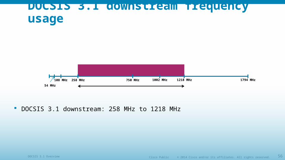
DOCSIS 3.1 downstream frequency usage
DOCSIS 3.1 downstream: 258 MHz to 1218 MHz
1794 MHz1218 MHz258 MHz108 MHz 750 MHz 1002 MHz
54 MHz
© 2014 Cisco and/or its affiliates. All rights reserved.Cisco PublicDOCSIS 3.1 Overview 57
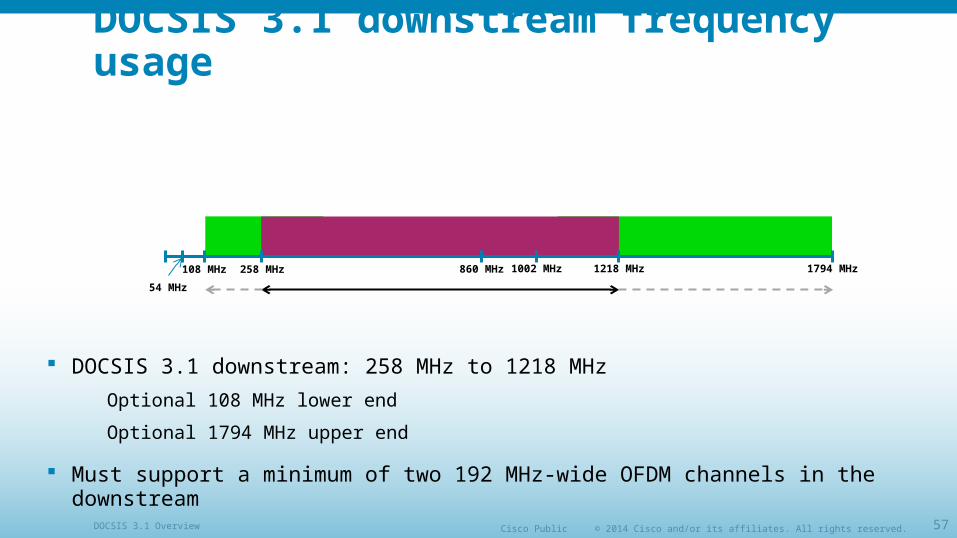
DOCSIS 3.1 downstream frequency usage
DOCSIS 3.1 downstream: 258 MHz to 1218 MHz
Optional 108 MHz lower end
Optional 1794 MHz upper end
Must support a minimum of two 192 MHz-wide OFDM channels in the downstream
1794 MHz1218 MHz258 MHz108 MHz 860 MHz 1002 MHz
54 MHz
© 2014 Cisco and/or its affiliates. All rights reserved.Cisco PublicDOCSIS 3.1 Overview 58
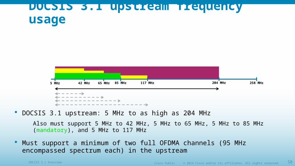
DOCSIS 3.1 upstream frequency usage
DOCSIS 3.1 upstream: 5 MHz to as high as 204 MHz
Also must support 5 MHz to 42 MHz, 5 MHz to 65 MHz, 5 MHz to 85 MHz (mandatory), and 5 MHz to 117 MHz
Must support a minimum of two full OFDMA channels (95 MHz encompassed spectrum each) in the upstream
258 MHz117 MHz42 MHz 65 MHz 85 MHz5 MHz 204 MHz
© 2014 Cisco and/or its affiliates. All rights reserved.Cisco PublicDOCSIS 3.1 Overview 59
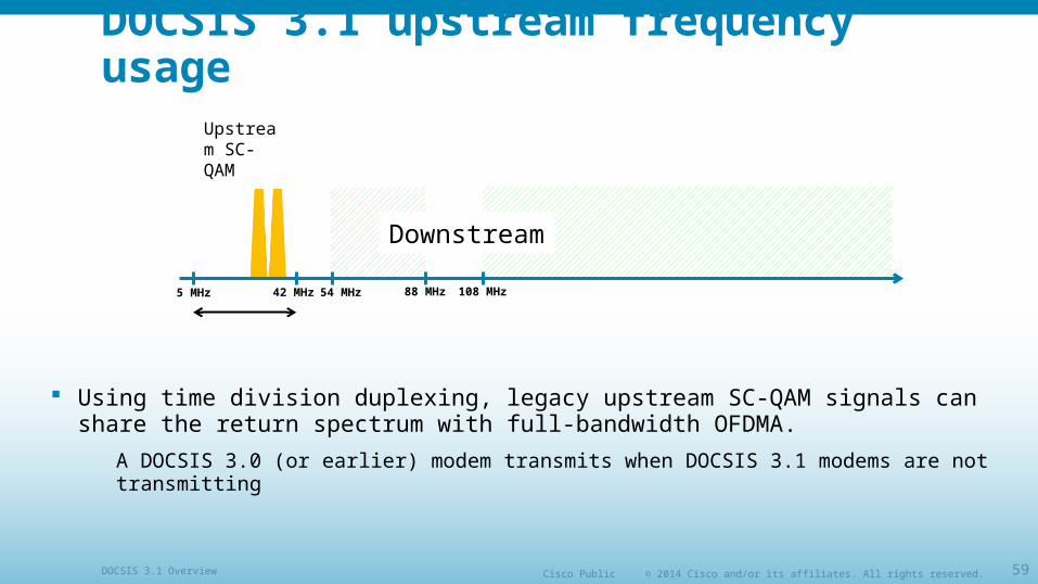
DOCSIS 3.1 upstream frequency usage
Using time division duplexing, legacy upstream SC-QAM signals can share the return spectrum with full-bandwidth OFDMA.
A DOCSIS 3.0 (or earlier) modem transmits when DOCSIS 3.1 modems are not transmitting
108 MHz42 MHz 54 MHz 88 MHz5 MHz
Downstream
Upstream SC-QAM
© 2014 Cisco and/or its affiliates. All rights reserved.Cisco PublicDOCSIS 3.1 Overview 60
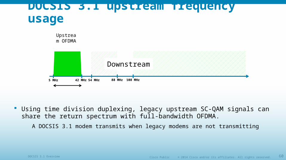
DOCSIS 3.1 upstream frequency usage
Using time division duplexing, legacy upstream SC-QAM signals can share the return spectrum with full-bandwidth OFDMA.
A DOCSIS 3.1 modem transmits when legacy modems are not transmitting
108 MHz42 MHz 54 MHz 88 MHz5 MHz
Downstream
Upstream OFDMA
© 2014 Cisco and/or its affiliates. All rights reserved.Cisco PublicDOCSIS 3.1 Overview 61
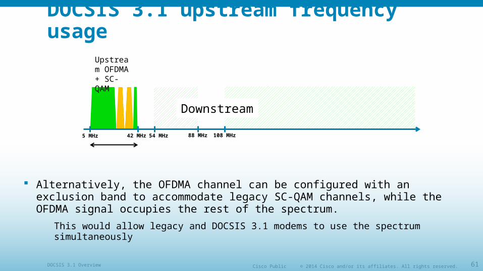
DOCSIS 3.1 upstream frequency usage
Alternatively, the OFDMA channel can be configured with an exclusion band to accommodate legacy SC-QAM channels, while the OFDMA signal occupies the rest of the spectrum.
This would allow legacy and DOCSIS 3.1 modems to use the spectrum simultaneously
108 MHz42 MHz 54 MHz 88 MHz5 MHz
Downstream
Upstream OFDMA + SC-QAM
© 2014 Cisco and/or its affiliates. All rights reserved.Cisco PublicDOCSIS 3.1 Overview 62
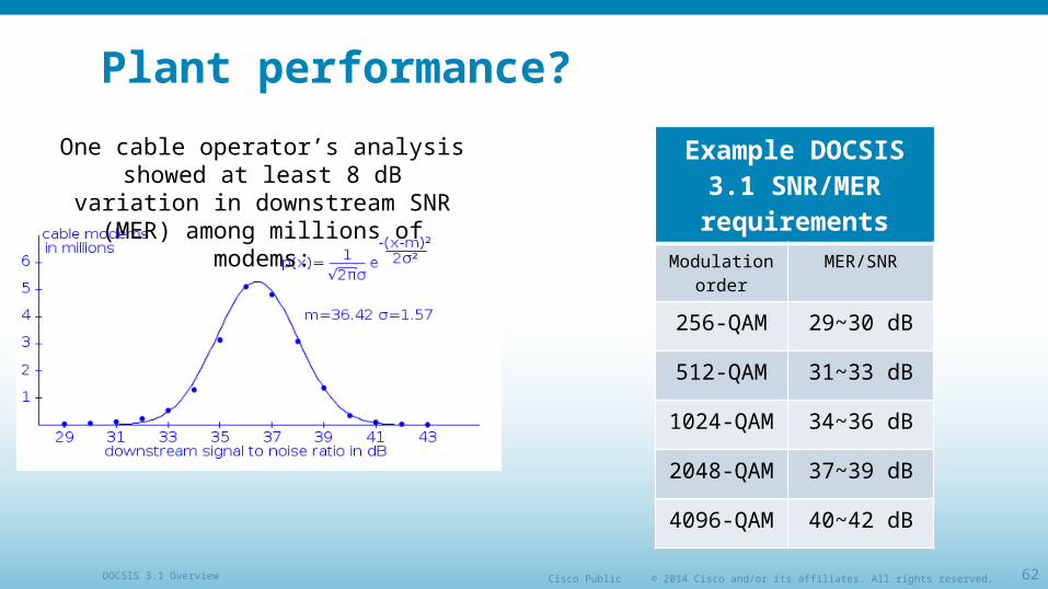
Plant performance?
Example DOCSIS 3.1 SNR/MER requirements
Modulation order
MER/SNR
256-QAM 29~30 dB
512-QAM 31~33 dB
1024-QAM 34~36 dB
2048-QAM 37~39 dB
4096-QAM 40~42 dB
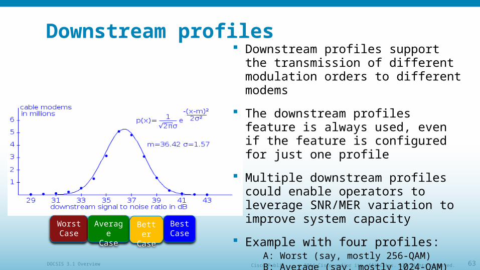
One cable operator’s analysis showed at least 8 dB variation in downstream
SNR (MER) among millions of modems:
© 2014 Cisco and/or its affiliates. All rights reserved.Cisco PublicDOCSIS 3.1 Overview 63
Downstream profiles Downstream profiles support the
transmission of different modulation orders to different modems
The downstream profiles feature is always used, even if the feature is configured for just one profile
Multiple downstream profiles could enable operators to leverage SNR/MER variation to improve system capacity
Example with four profiles:A: Worst (say, mostly 256-QAM) B: Average (say, mostly 1024-QAM)C: Better (say, mostly 2048-QAM)D: Best (say, mostly 4096-QAM)
Worst Case
AverageCase
BestCase
BetterCase
© 2014 Cisco and/or its affiliates. All rights reserved.Cisco PublicDOCSIS 3.1 Overview 64
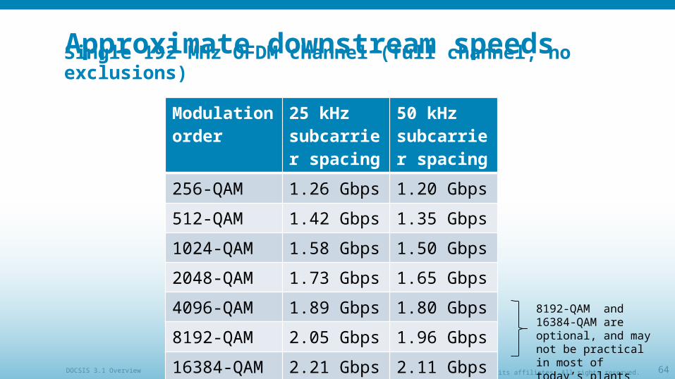
Approximate downstream speeds
Modulation order
25 kHz subcarrier spacing
50 kHz subcarrier spacing
256-QAM 1.26 Gbps 1.20 Gbps
512-QAM 1.42 Gbps 1.35 Gbps
1024-QAM 1.58 Gbps 1.50 Gbps
2048-QAM 1.73 Gbps 1.65 Gbps
4096-QAM 1.89 Gbps 1.80 Gbps
8192-QAM 2.05 Gbps 1.96 Gbps
16384-QAM 2.21 Gbps 2.11 Gbps
Single 192 MHz OFDM channel (full channel, no exclusions)
8192-QAM and 16384-QAM are optional, and may not be practical in most of today’s plants
© 2014 Cisco and/or its affiliates. All rights reserved.Cisco PublicDOCSIS 3.1 Overview 65
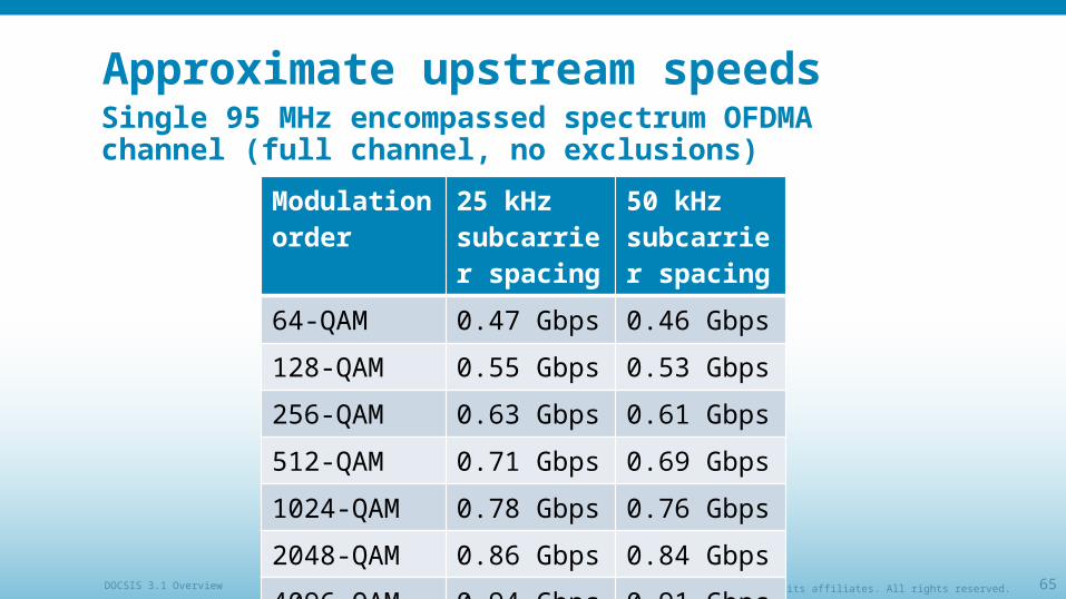
Approximate upstream speeds
Modulation order
25 kHz subcarrier spacing
50 kHz subcarrier spacing
64-QAM 0.47 Gbps 0.46 Gbps
128-QAM 0.55 Gbps 0.53 Gbps
256-QAM 0.63 Gbps 0.61 Gbps
512-QAM 0.71 Gbps 0.69 Gbps
1024-QAM 0.78 Gbps 0.76 Gbps
2048-QAM 0.86 Gbps 0.84 Gbps
4096-QAM 0.94 Gbps 0.91 Gbps
Single 95 MHz encompassed spectrum OFDMA channel (full channel, no exclusions)
© 2014 Cisco and/or its affiliates. All rights reserved.Cisco PublicDOCSIS 3.1 Overview 66
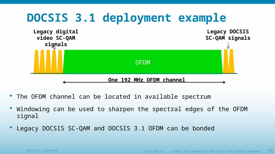
DOCSIS 3.1 deployment example
The OFDM channel can be located in available spectrum
Windowing can be used to sharpen the spectral edges of the OFDM signal
Legacy DOCSIS SC-QAM and DOCSIS 3.1 OFDM can be bonded
OFDM
One 192 MHz OFDM channel
Legacy digital video SC-QAM signals
Legacy DOCSIS SC-QAM signals
© 2014 Cisco and/or its affiliates. All rights reserved.Cisco PublicDOCSIS 3.1 Overview 67
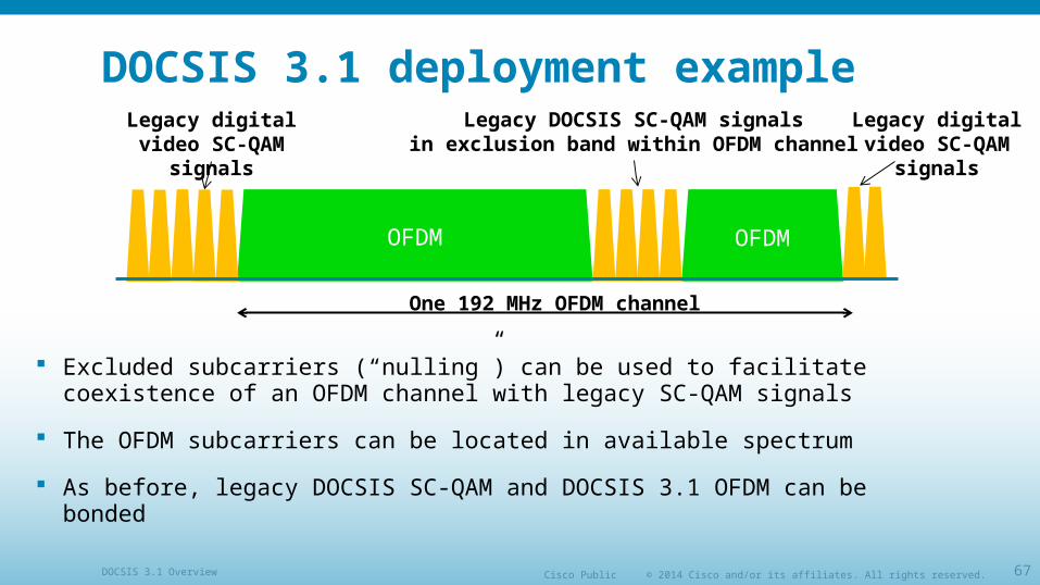
DOCSIS 3.1 deployment example
Excluded subcarriers (“nulling”) can be used to facilitate coexistence of an OFDM channel with legacy SC-QAM signals
The OFDM subcarriers can be located in available spectrum
As before, legacy DOCSIS SC-QAM and DOCSIS 3.1 OFDM can be bonded
OFDM OFDM
One 192 MHz OFDM channel
Legacy DOCSIS SC-QAM signalsin exclusion band within OFDM channel
Legacy digital video SC-QAM signals
Legacy digital video SC-QAM signals
© 2014 Cisco and/or its affiliates. All rights reserved.Cisco PublicDOCSIS 3.1 Overview 68
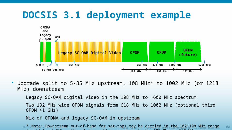
DOCSIS 3.1 deployment example
Upgrade split to 5-85 MHz upstream, 108 MHz* to 1002 MHz (or 1218 MHz) downstream
Legacy SC-QAM digital video in the 108 MHz to ~600 MHz spectrum
Two 192 MHz wide OFDM signals from 618 MHz to 1002 MHz (optional third OFDM >1 GHz)
Mix of OFDMA and legacy SC-QAM in upstream
* Note: Downstream out-of-band for set-tops may be carried in the 102~108 MHz range (avoid local FM), although it could be anywhere in the 102 MHz to 130 MHz range, assuming available spectrum.
OFDM
1218 MHz1002 MHz258 MHz
108 MHz
750 MHz 870 MHz5 MHz
85 MHz
OFDMOFDM(future)
192 MHz 192 MHz 192 MHz
Legacy SC-QAM Digital Video
OFDMA and legacy SC-QAM
OOB
© 2014 Cisco and/or its affiliates. All rights reserved.Cisco PublicDOCSIS 3.1 Overview 69
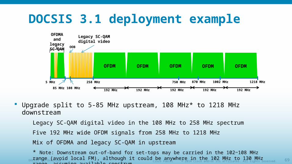
DOCSIS 3.1 deployment example
Upgrade split to 5-85 MHz upstream, 108 MHz* to 1218 MHz downstream
Legacy SC-QAM digital video in the 108 MHz to 258 MHz spectrum
Five 192 MHz wide OFDM signals from 258 MHz to 1218 MHz
Mix of OFDMA and legacy SC-QAM in upstream
* Note: Downstream out-of-band for set-tops may be carried in the 102~108 MHz range (avoid local FM), although it could be anywhere in the 102 MHz to 130 MHz range, assuming available spectrum.
OFDM
1218 MHz1002 MHz258 MHz
108 MHz
750 MHz 870 MHz5 MHz
85 MHz
OFDM
192 MHz 192 MHz 192 MHz
Legacy SC-QAM digital video
OFDMA and legacy SC-QAM
OFDMOFDMOFDM
192 MHz192 MHz
OOB
© 2014 Cisco and/or its affiliates. All rights reserved.Cisco PublicDOCSIS 3.1 Overview 70
OFDM OFDM
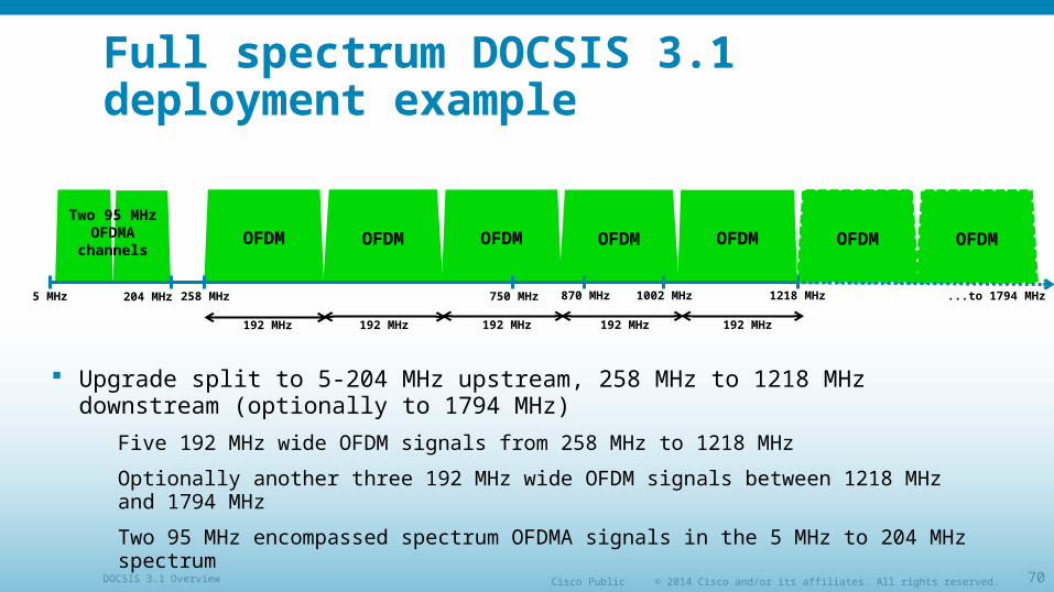
Full spectrum DOCSIS 3.1 deployment example
Upgrade split to 5-204 MHz upstream, 258 MHz to 1218 MHz downstream (optionally to 1794 MHz)
Five 192 MHz wide OFDM signals from 258 MHz to 1218 MHz
Optionally another three 192 MHz wide OFDM signals between 1218 MHz and 1794 MHz
Two 95 MHz encompassed spectrum OFDMA signals in the 5 MHz to 204 MHz spectrum
OFDM
1218 MHz1002 MHz258 MHz204 MHz 750 MHz 870 MHz5 MHz
OFDM
192 MHz 192 MHz 192 MHz
Two 95 MHz OFDMA
channelsOFDMOFDMOFDM
192 MHz192 MHz
...to 1794 MHz
© 2014 Cisco and/or its affiliates. All rights reserved.Cisco PublicDOCSIS 3.1 Overview 71
Backwards compatibility
DOCSIS 3.1 devices will simultaneously support legacy SC-QAM channels and OFDM channels
Devices will support bonding between OFDM and SC-QAM in order to aggregate that capacity and provide an incremental and orderly migration
The time division nature of the existing DOCSIS upstream allows for legacy and OFDMA to be time multiplexed
Allows a gradual and evolutionary introduction of DOCSIS 3.1
© 2014 Cisco and/or its affiliates. All rights reserved.Cisco PublicDOCSIS 3.1 Overview 72
DOCSIS 3.1 proactive network maintenance
• PNM designed for DOCSIS 3.1 from the ground up to provide “test points” in the CMTS and cable modem
Characterize and troubleshoot HFC plant
Support remote proactive troubleshooting of plant faults
Improve reliability and maximize throughput from well-maintained plant
© 2014 Cisco and/or its affiliates. All rights reserved.Cisco PublicDOCSIS 3.1 Overview 73
DOCSIS 3.1 test points for HFC plant
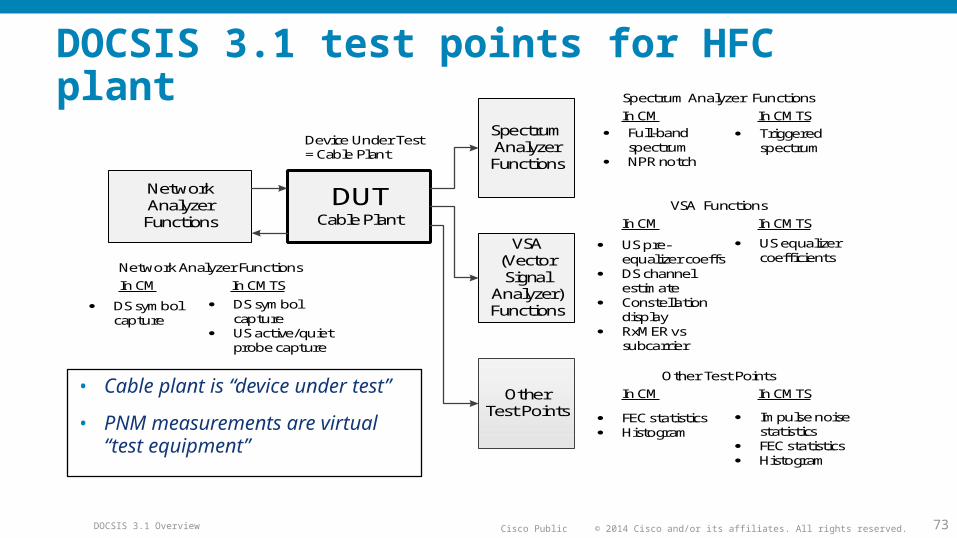
• Cable plant is “device under test”
• PNM measurements are virtual “test equipment”
DUTCable Plant
Spectrum AnalyzerFunctions
VSA(Vector Signal
Analyzer) Functions
Network AnalyzerFunctions
Device Under Test= Cable Plant
OtherTest Points
Spectrum Analyzer FunctionsIn CM In CMTS
Full-band spectrum
NPR notch
Triggered spectrum
VSA FunctionsIn CM In CMTS
US pre-equalizer coeffs
DS channel estimate
Constellation display
RxMER vs subcarrier
US equalizer coefficients
Other Test PointsIn CM In CMTS
FEC statistics Histogram
Impulse noise statistics
FEC statistics Histogram
Network Analyzer FunctionsIn CM In CMTS
DS symbol capture
DS symbol capture
US active/quiet probe capture
© 2014 Cisco and/or its affiliates. All rights reserved.Cisco PublicDOCSIS 3.1 Overview 74
Downstream PNM “hooks” Downstream symbol capture: Capture OFDM symbol at input and output of
plant, solve for plant response
Wideband spectrum analysis: Spectrum analyzer in cable modem
Channel estimate coefficients: Downstream equalizer response
Constellation display: QAM constellation cluster
Receive modulation error ratio (RxMER) per subcarrier: MER (SNR) vs frequency
FEC statistics: Correctable and uncorrectable codewords
Histogram: Signal distribution revealing nonlinearities in plant such as laser clipping
Received power: RF power received at cable modem
© 2014 Cisco and/or its affiliates. All rights reserved.Cisco PublicDOCSIS 3.1 Overview 75
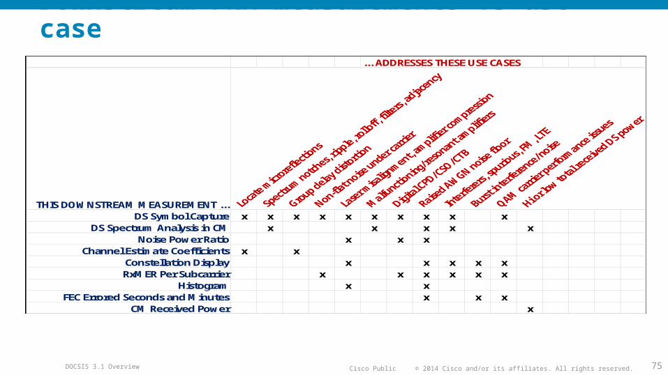
Downstream PNM measurements vs use case... ADDRESSES THESE USE CASES
THIS DOWNSTREAM MEASUREMENT ...DS Symbol Capture x x x x x x x x x x
DS Spectrum Analysis in CM x x x x xNoise Power Ratio x x x
Channel Estimate Coefficients x xConstellation Display x x x x xRxMER Per Subcarrier x x x x x x
Histogram x xFEC Errored Seconds and Minutes x x x
CM Received Power x
© 2014 Cisco and/or its affiliates. All rights reserved.Cisco PublicDOCSIS 3.1 Overview 76
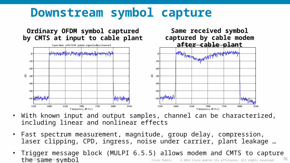
Downstream symbol captureOrdinary OFDM symbol captured by
CMTS at input to cable plantSame received symbol captured by
cable modem after cable plant
• With known input and output samples, channel can be characterized, including linear and nonlinear effects
• Fast spectrum measurement, magnitude, group delay, compression, laser clipping, CPD, ingress, noise under carrier, plant leakage …
• Trigger message block (MULPI 6.5.5) allows modem and CMTS to capture the same symbol
550 600 650 700 750 800 850
-60
-50
-40
-30
-20
-10
0
Spectrum of OFDM probe signal after channel
Frequency (MHz)
dB
550 600 650 700 750 800 850
-60
-50
-40
-30
-20
-10
0
Spectrum of OFDM probe signal after channel
Frequency (MHz)
dB
© 2014 Cisco and/or its affiliates. All rights reserved.Cisco PublicDOCSIS 3.1 Overview 77
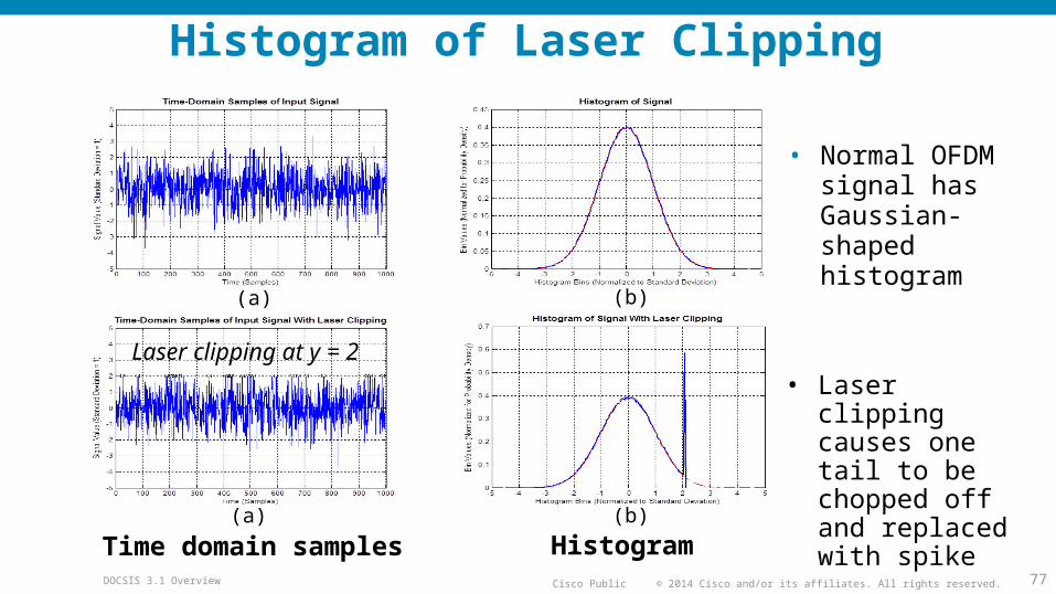
Histogram of Laser Clipping
• Normal OFDM signal has Gaussian-shaped histogram
• Laser clipping causes one tail to be chopped off and replaced with spike
Time domain samples Histogram
Laser clipping at y = 2
(a) (b)
(a) (b)
© 2014 Cisco and/or its affiliates. All rights reserved.Cisco PublicDOCSIS 3.1 Overview 78
Spectrum of upstream band at cable modemExtension to D3.1 PNM
• Problem: Upstream noise funnels to single point at CMTS making it difficult to locate source
• Solution: Measure spectrum of upstream band at each cable modem
Provides noise source location capability
Noise originating in house, drop or plant will have identifiable spectrum signature at cable modems and CMTS
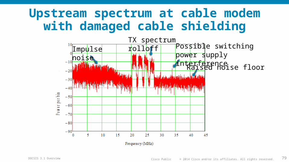
© 2014 Cisco and/or its affiliates. All rights reserved.Cisco PublicDOCSIS 3.1 Overview 79
Upstream spectrum at cable modemwith damaged cable shielding
Impulse noise
TX spectrum rolloff Possible switching power
supply interference
Raised noise floor
© 2014 Cisco and/or its affiliates. All rights reserved.Cisco PublicDOCSIS 3.1 Overview 80
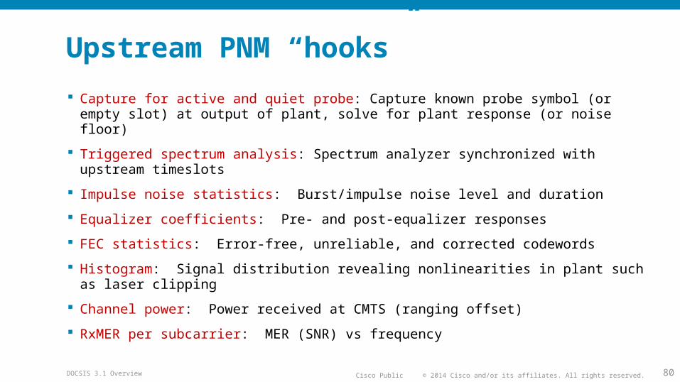
Upstream PNM “hooks”
Capture for active and quiet probe: Capture known probe symbol (or empty slot) at output of plant, solve for plant response (or noise floor)
Triggered spectrum analysis: Spectrum analyzer synchronized with upstream timeslots
Impulse noise statistics: Burst/impulse noise level and duration
Equalizer coefficients: Pre- and post-equalizer responses
FEC statistics: Error-free, unreliable, and corrected codewords
Histogram: Signal distribution revealing nonlinearities in plant such as laser clipping
Channel power: Power received at CMTS (ranging offset)
RxMER per subcarrier: MER (SNR) vs frequency
© 2014 Cisco and/or its affiliates. All rights reserved.Cisco PublicDOCSIS 3.1 Overview 81
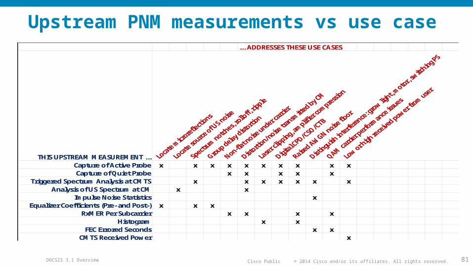
Upstream PNM measurements vs use case... ADDRESSES THESE USE CASES
THIS UPSTREAM MEASUREMENT ...Capture of Active Probe x x x x x x x x x xCapture of Quiet Probe x x x x x
Triggered Spectrum Analysis at CMTS x x x x x x xAnalysis of US Spectrum at CM x x
Impulse Noise Statistics xEqualizer Coefficients (Pre- and Post-) x x x
RxMER Per Subcarrier x x x xHistogram x x
FEC Errored Seconds x xCMTS Received Power x
© 2014 Cisco and/or its affiliates. All rights reserved.Cisco PublicDOCSIS 3.1 Overview 82
Summary
• New PHY layer: OFDM, OFDMA, and LDPC
• Higher modulation orders
• New spectrum usage options
• Takes DOCSIS to full-spectrum capability
• Cost-effectively scales to 10+ Gbps in the downstream, 1+ Gbps in the upstream
• FTTH equivalent at lower price point on an existing HFC plant
• Deployable in today’s HFC networks
© 2014 Cisco and/or its affiliates. All rights reserved.Cisco PublicDOCSIS 3.1 Overview 83
Questions and discussion
Ron HranacTechnical LeaderCisco Systems
Bruce CurrivanTechnical Director
Broadcom
© 2014 Cisco and/or its affiliates. All rights reserved.Cisco PublicDOCSIS 3.1 Overview 84
Useful references
• “What is OFDM?” by Ron Hranac; (November 2012 Communications Technology)
•http://www.scte.org/TechnicalColumns/12-11-30%20what%20is%20ofdm.pdf
• SCTE Rocky Mountain Chapter seminar (April 17, 2014): “Introduction to DOCSIS 3.1”
•http://www.scte-rockymountain.org/information-central/seminar-videos
• DOCSIS 3.1 spec•http://www.cablelabs.com/
© 2014 Cisco and/or its affiliates. All rights reserved.Cisco PublicDOCSIS 3.1 Overview 85
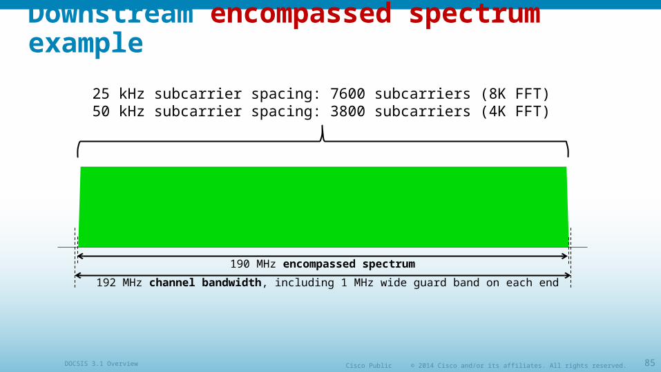
Downstream encompassed spectrum example
192 MHz channel bandwidth, including 1 MHz wide guard band on each end
190 MHz encompassed spectrum
25 kHz subcarrier spacing: 7600 subcarriers (8K FFT)50 kHz subcarrier spacing: 3800 subcarriers (4K FFT)
© 2014 Cisco and/or its affiliates. All rights reserved.Cisco PublicDOCSIS 3.1 Overview 86
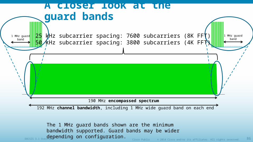
A closer look at the guard bands
192 MHz channel bandwidth, including 1 MHz wide guard band on each end
190 MHz encompassed spectrum
1 MHz guard band
1 MHz guard band
25 kHz subcarrier spacing: 7600 subcarriers (8K FFT)50 kHz subcarrier spacing: 3800 subcarriers (4K FFT)
The 1 MHz guard bands shown are the minimum bandwidth supported. Guard bands may be wider depending on configuration.

© 2014 Cisco and/or its affiliates. All rights reserved.Cisco PublicDOCSIS 3.1 Overview 87
Downstream occupied bandwidth example (1)
OFDM channel aligned with CEA channel grid
192 MHz channel bandwidth, including 1 MHz wide guard band on each end
190 MHz encompassed spectrum
25 kHz subcarrier spacing: 7600 subcarriers (8K FFT)50 kHz subcarrier spacing: 3800 subcarriers (4K FFT)
192 MHz occupied bandwidth(32 CEA ch x 6 MHz = 192 MHz)
© 2014 Cisco and/or its affiliates. All rights reserved.Cisco PublicDOCSIS 3.1 Overview 88
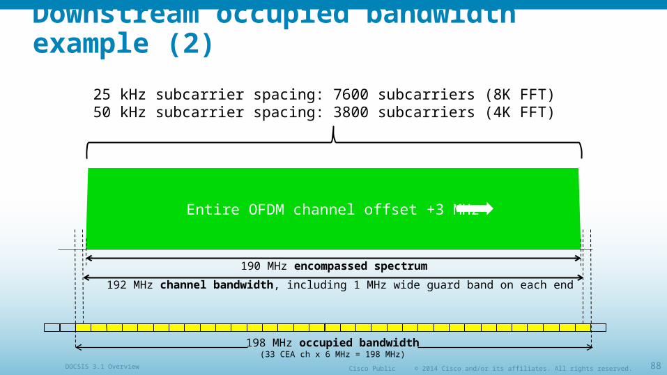
Downstream occupied bandwidth example (2)
Entire OFDM channel offset +3 MHz
192 MHz channel bandwidth, including 1 MHz wide guard band on each end
190 MHz encompassed spectrum
25 kHz subcarrier spacing: 7600 subcarriers (8K FFT)50 kHz subcarrier spacing: 3800 subcarriers (4K FFT)
198 MHz occupied bandwidth(33 CEA ch x 6 MHz = 198 MHz)
© 2014 Cisco and/or its affiliates. All rights reserved.Cisco PublicDOCSIS 3.1 Overview 89
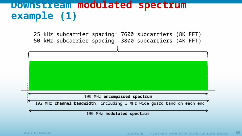
Downstream modulated spectrum example (1)
192 MHz channel bandwidth, including 1 MHz wide guard band on each end
190 MHz encompassed spectrum
25 kHz subcarrier spacing: 7600 subcarriers (8K FFT)50 kHz subcarrier spacing: 3800 subcarriers (4K FFT)
190 MHz modulated spectrum
© 2014 Cisco and/or its affiliates. All rights reserved.Cisco PublicDOCSIS 3.1 Overview 90
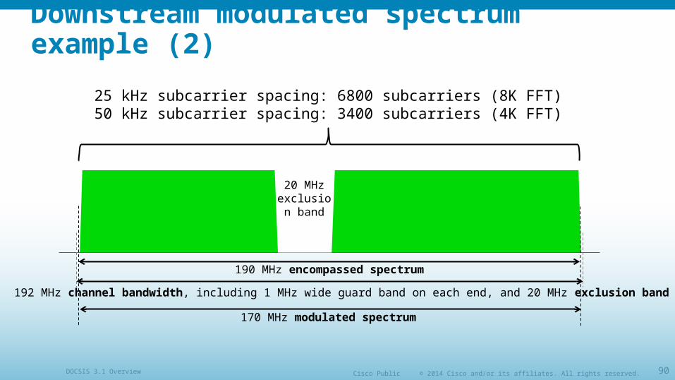
Downstream modulated spectrum example (2)
192 MHz channel bandwidth, including 1 MHz wide guard band on each end, and 20 MHz exclusion band
190 MHz encompassed spectrum
170 MHz modulated spectrum
20 MHz exclusion
band
25 kHz subcarrier spacing: 6800 subcarriers (8K FFT)50 kHz subcarrier spacing: 3400 subcarriers (4K FFT)
© 2014 Cisco and/or its affiliates. All rights reserved.Cisco PublicDOCSIS 3.1 Overview 91
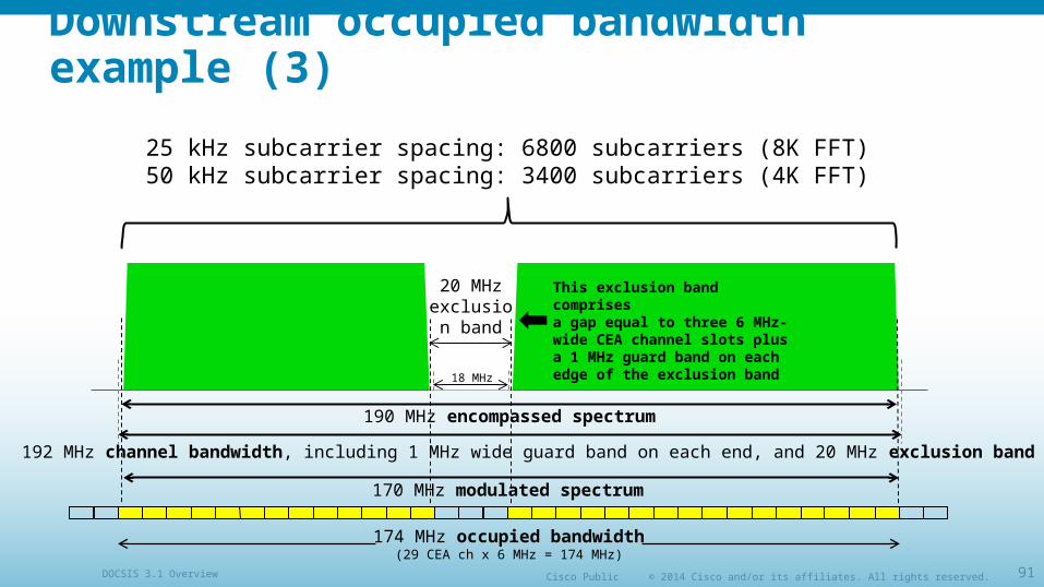
Downstream occupied bandwidth example (3)
192 MHz channel bandwidth, including 1 MHz wide guard band on each end, and 20 MHz exclusion band
190 MHz encompassed spectrum
170 MHz modulated spectrum
20 MHz exclusion
band
25 kHz subcarrier spacing: 6800 subcarriers (8K FFT)50 kHz subcarrier spacing: 3400 subcarriers (4K FFT)
174 MHz occupied bandwidth(29 CEA ch x 6 MHz = 174 MHz)
This exclusion band comprisesa gap equal to three 6 MHz-wide CEA channel slots plus a 1 MHz guard band on each edge of the exclusion band
18 MHz
© 2014 Cisco and/or its affiliates. All rights reserved.Cisco PublicDOCSIS 3.1 Overview 92
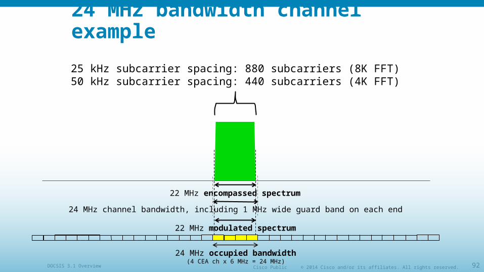
24 MHz bandwidth channel example
24 MHz channel bandwidth, including 1 MHz wide guard band on each end
22 MHz encompassed spectrum
22 MHz modulated spectrum
25 kHz subcarrier spacing: 880 subcarriers (8K FFT)50 kHz subcarrier spacing: 440 subcarriers (4K FFT)
24 MHz occupied bandwidth(4 CEA ch x 6 MHz = 24 MHz)


![ProcessGain Solution BT / Lime Hackathon...[2] UHF Signal Leakage and Ingress - Understanding the Challenges. Ron Hranac, Nick Segura. A Technical Paper prepared for the Society of](https://img.pdfslide.us/doc/110x75/5e8bf0f2dc582e399154cc4b/processgain-solution-bt-lime-hackathon-2-uhf-signal-leakage-and-ingress.jpg)