Embed Size (px)
Citation preview
Subscriber Data Management
Release 9.2
System Configuration User Guide910-6844-001 Revision A
September 2013
Copyright 2013 Tekelec. All Rights Reserved. Printed in USA.Legal Information can be accessed from the Main Menu of the optical disc or on the
Tekelec Customer Support web site in the Legal Information folder of the Product Support tab.
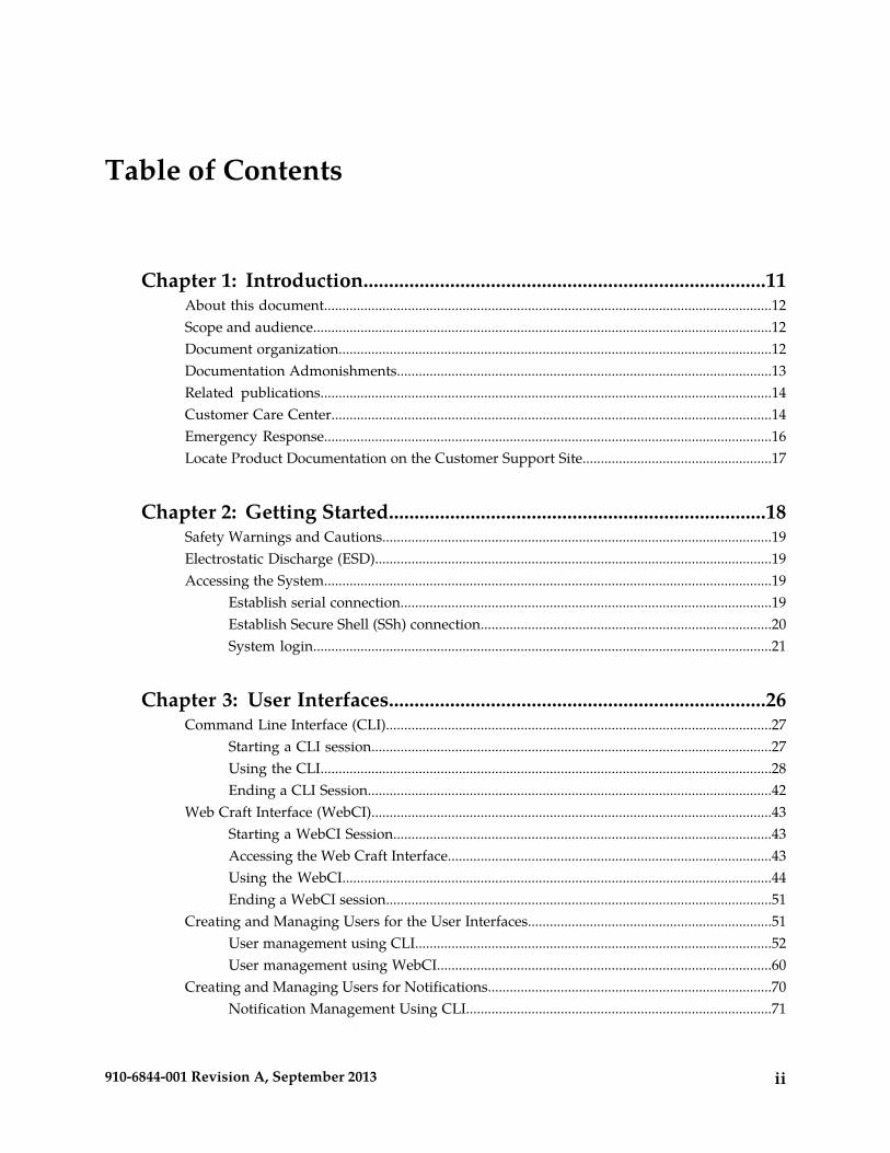
Table of Contents
Chapter 1: Introduction...............................................................................11About this document...........................................................................................................................12Scope and audience..............................................................................................................................12Document organization.......................................................................................................................12Documentation Admonishments.......................................................................................................13Related publications............................................................................................................................14Customer Care Center.........................................................................................................................14Emergency Response...........................................................................................................................16Locate Product Documentation on the Customer Support Site....................................................17
Chapter 2: Getting Started..........................................................................18Safety Warnings and Cautions...........................................................................................................19Electrostatic Discharge (ESD).............................................................................................................19Accessing the System...........................................................................................................................19
Establish serial connection......................................................................................................19Establish Secure Shell (SSh) connection................................................................................20System login..............................................................................................................................21
Chapter 3: User Interfaces..........................................................................26Command Line Interface (CLI)..........................................................................................................27
Starting a CLI session..............................................................................................................27Using the CLI............................................................................................................................28Ending a CLI Session...............................................................................................................42
Web Craft Interface (WebCI)..............................................................................................................43Starting a WebCI Session........................................................................................................43Accessing the Web Craft Interface.........................................................................................43Using the WebCI......................................................................................................................44Ending a WebCI session..........................................................................................................51
Creating and Managing Users for the User Interfaces...................................................................51User management using CLI..................................................................................................52User management using WebCI............................................................................................60
Creating and Managing Users for Notifications..............................................................................70Notification Management Using CLI....................................................................................71
ii910-6844-001 Revision A, September 2013
Notification Management Using WebCI..............................................................................75
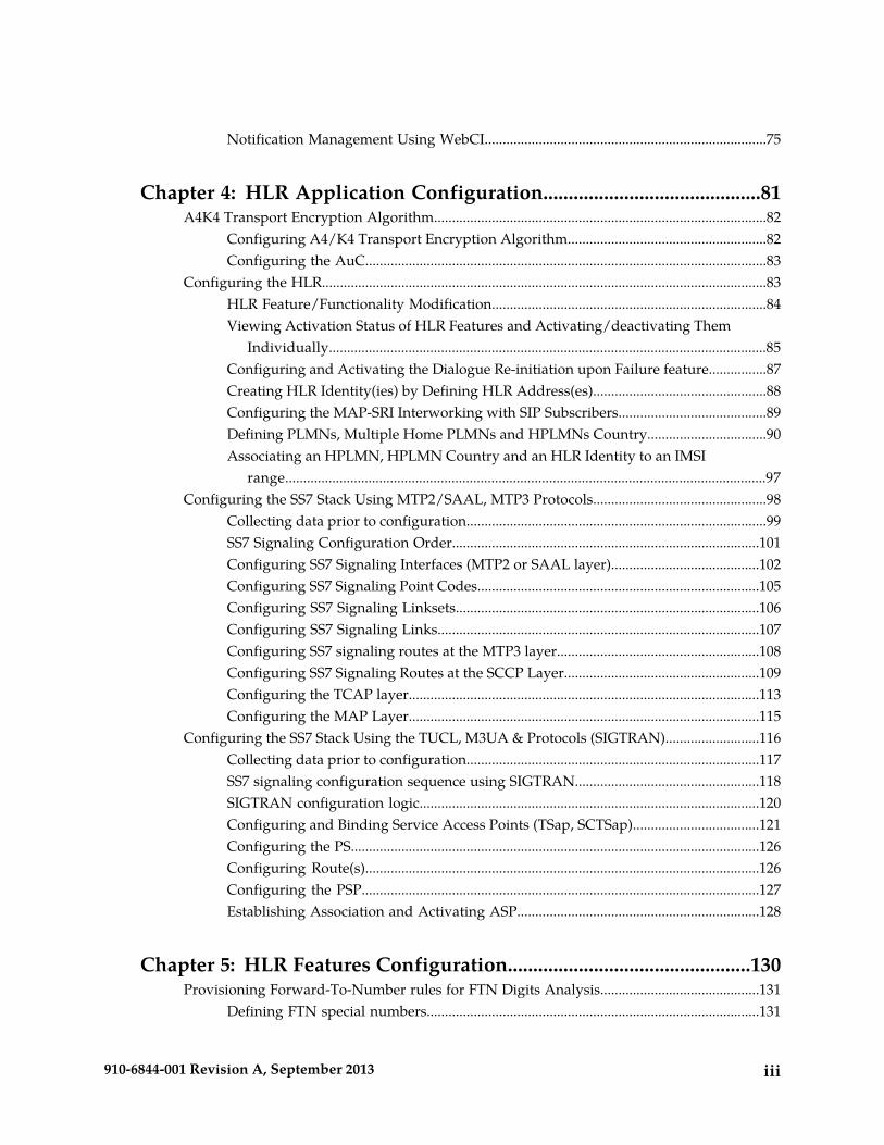
Chapter 4: HLR Application Configuration...........................................81A4K4 Transport Encryption Algorithm............................................................................................82
Configuring A4/K4 Transport Encryption Algorithm.......................................................82Configuring the AuC...............................................................................................................83
Configuring the HLR...........................................................................................................................83HLR Feature/Functionality Modification............................................................................84Viewing Activation Status of HLR Features and Activating/deactivating Them
Individually.........................................................................................................................85Configuring and Activating the Dialogue Re-initiation upon Failure feature................87Creating HLR Identity(ies) by Defining HLR Address(es)................................................88Configuring the MAP-SRI Interworking with SIP Subscribers.........................................89Defining PLMNs, Multiple Home PLMNs and HPLMNs Country.................................90Associating an HPLMN, HPLMN Country and an HLR Identity to an IMSI
range.....................................................................................................................................97Configuring the SS7 Stack Using MTP2/SAAL, MTP3 Protocols................................................98
Collecting data prior to configuration...................................................................................99SS7 Signaling Configuration Order.....................................................................................101Configuring SS7 Signaling Interfaces (MTP2 or SAAL layer).........................................102Configuring SS7 Signaling Point Codes..............................................................................105Configuring SS7 Signaling Linksets....................................................................................106Configuring SS7 Signaling Links.........................................................................................107Configuring SS7 signaling routes at the MTP3 layer........................................................108Configuring SS7 Signaling Routes at the SCCP Layer......................................................109Configuring the TCAP layer.................................................................................................113Configuring the MAP Layer.................................................................................................115
Configuring the SS7 Stack Using the TUCL, M3UA & Protocols (SIGTRAN)..........................116Collecting data prior to configuration.................................................................................117SS7 signaling configuration sequence using SIGTRAN...................................................118SIGTRAN configuration logic..............................................................................................120Configuring and Binding Service Access Points (TSap, SCTSap)...................................121Configuring the PS.................................................................................................................126Configuring Route(s).............................................................................................................126Configuring the PSP..............................................................................................................127Establishing Association and Activating ASP...................................................................128
Chapter 5: HLR Features Configuration................................................130Provisioning Forward-To-Number rules for FTN Digits Analysis............................................131
Defining FTN special numbers............................................................................................131
iii910-6844-001 Revision A, September 2013
Defining FTN short number translation rules on RegSS..................................................132Defining FTN exception rules..............................................................................................133Defining a Global FTN “black-list” (FTN Restrictions) for the ngHLR.........................134Defining FTN Management Rules with FTN “white-list”...............................................135
Provisioning CAMEL........................................................................................................................137Provisioning Roaming Welcome Notifications.............................................................................138
Setting roaming welcome notification exceptions for CCs, CC-NDCs and the NDCextraction rule...................................................................................................................139
Provisioning USSD application nodes for the routing of USSD messages................................143Roaming controls...............................................................................................................................144
Setting Roaming Controls (Operator Controlled PLMN, Roaming Restrictions andService Screening Restrictions).......................................................................................144
Calculating VLR/SGSN Nodes Affected by a Roaming Configuration Change.........149Setting Restrictions on the Version of MAP Messages (MAP Policing) and on the SRI-ack,
ATI-ack and PSI Messages..........................................................................................................152Blocking MAP Transactions Based on the Node Address and the AC..........................153MAP Reset...............................................................................................................................155
Provisioning the Tekelec ngHLR for MT-SMS Routing...............................................................157Other Operations....................................................................................................................159
Provisioning Routing Controls for GSM/IMS Router capabilities.............................................159Provisioning GSM Bearer Capabilities............................................................................................163
Other Operations....................................................................................................................165Provisioning the Subscriber Signaling Router (SSR).....................................................................165
Other Operations....................................................................................................................166Provisioning/Modifying the Enhanced Control Of SCCP Routing Configuration.................167
Other Operations....................................................................................................................168Provisioning PDN Context Templates............................................................................................168
Chapter 6: SIP Application Configuration............................................170Introduction........................................................................................................................................171Configuring SIP Application............................................................................................................171Viewing and editing SIP server configuration...............................................................................171
Other Operations....................................................................................................................174Viewing/Editing SIP Security Configuration................................................................................175Viewing/Editing SIP Registrar Configuration..............................................................................176Viewing/Editing SIP Redirect Configuration................................................................................178Viewing/Editing SIP User Agent (RegClient) Configuration.....................................................179Viewing and editing SIP TAS configuration for 3rd party registration.....................................183Viewing/Editing SIP User Portability configuration...................................................................184
Viewing SIP NP Support for AOR Ranges feature status................................................184
iv910-6844-001 Revision A, September 2013
Configuring SIP NP Support for AOR Ranges feature.....................................................184
Chapter 7: IMS-HSS/SLF Application Configuration........................186Introduction........................................................................................................................................187Configuring the IMS-HSS/SLF........................................................................................................187
Viewing/Editing IMS-HSS/SLF Configuration................................................................187Configuring the IMS-HSS AuC........................................................................................................189
Other Operations....................................................................................................................190Configuring IMS-HSS System Features..........................................................................................191
Other Operations....................................................................................................................192Configuring IMS-HSS Shared Initial Filtering Criterias...............................................................193
Chapter 8: AAA Application Configuration.........................................195Introduction........................................................................................................................................196Configuring the AAA........................................................................................................................196
Viewing/Editing AAA Configuration................................................................................196AAA Provisioning Configuration – Provisioning AAA Address Allocation Policies
and IP Address Pools.......................................................................................................198
Chapter 9: DNS Enum server configuration.........................................203DNS ENUM Server Configuration..................................................................................................204
Chapter 10: HSS/AAA Support for Early IMS SecurityConfiguration..........................................................................................206
Introduction........................................................................................................................................207Other Operations................................................................................................................................208
Chapter 11: LTE-HSS Application Configuration...............................209Introduction........................................................................................................................................210Configuring the LTE-HSS.................................................................................................................210Viewing/Editing LTE-HSS Configuration.....................................................................................210Configuring the LTE HSS PLMN.....................................................................................................212Configuring the LTE-HSS GMLC Node List..................................................................................212Configuring the LTE-HSS Realms...................................................................................................213Introduction to LTE-HSS System Features ....................................................................................214Viewing/Editing LTE-HSS Options................................................................................................214Configure Diameter Relay Agent....................................................................................................215
v910-6844-001 Revision A, September 2013
Chapter 12: EIR Application Configuration.........................................216Introduction........................................................................................................................................217Configure EIR for ECR Message Processing..................................................................................217Configure Global EIR Settings.........................................................................................................218Configure EIR response types..........................................................................................................218Configure EIR IMEI Equipment Status...........................................................................................219Create Unbound IMEI/IMSI Association.......................................................................................219Bind IMEI and IMEI/IMSI Associations to a Subscription..........................................................220Configure EIR Bound IMEI Equipment Status..............................................................................220Create Bound IMEI/IMSI Association............................................................................................220Create EIR IMEI Range......................................................................................................................221
Chapter 13: LTE-EIR Application Configuration................................222Introduction........................................................................................................................................223Configuring LTE-EIR Diameter tables............................................................................................223
Glossary.............................................................................................................................225
vi910-6844-001 Revision A, September 2013
List of Figures
Figure 1: Configure SSh client (PuTTY)...........................................................................................21Figure 2: First CLI prompt.................................................................................................................28Figure 3: CLI subsystems...................................................................................................................29Figure 4: Accessing subsystems through CLI.................................................................................30Figure 5: Entities and operations available from the Hlr subsystem..........................................31Figure 6: Entering an entity in the CLI............................................................................................32Figure 7: Displaying operations and sub-entities from a CLI entity...........................................34Figure 8: User Manager Window.....................................................................................................61Figure 9: User Provisioning Window to Modify a User................................................................62Figure 10: Group Provisioning Window to Modify a Group.......................................................64Figure 11: UserAccessPrivileges provisioning window................................................................67Figure 12: Service Security Provisioning Window.........................................................................69Figure 13: ApplicationIdentity Provisioning Window to Create Applications.........................76Figure 14: AUC A4K4 Window........................................................................................................82Figure 15: AUC Algorithm Window................................................................................................83Figure 16: HLR Configuration Table................................................................................................87Figure 17: Configuring HLR Addresses From The HLR Configuration Window....................89Figure 18: Hlr SipSubscriber Info Table From The HLR Configuration Window314...............90Figure 19: Provisioning PLMN Definitions.....................................................................................91Figure 20: Defining PLMNs...............................................................................................................92Figure 21: Provisioning Home PLMNs............................................................................................93Figure 22: Provisioning Home PLMN Nodes.................................................................................94Figure 23: Provisioning Home PLMN Countries...........................................................................95Figure 24: Defining IMSI Ranges And Associating Them To An HLR Identity, A HPLMN
And A HPLMN Country..............................................................................................................97Figure 25: Provisioning Intra-PLMN IMSI range table.................................................................98Figure 26: SS7 Node Provisioning Order.......................................................................................101Figure 27: SS7 Link Interface...........................................................................................................102Figure 28: MTP2 Window For SS7 Signaling Link Configuration.............................................103Figure 29: SAAL Window For SS7 Signaling Link Configuration.............................................104Figure 30: MTP3 Window................................................................................................................106Figure 31: SCCP Window................................................................................................................111Figure 32: TCAP Window................................................................................................................114Figure 33: Map Window..................................................................................................................115Figure 34: SS7 Configuration Sequence When Using SIGTRAN...............................................119Figure 35: Provisioning Logic For The SIGTRAN (TUCL, M3UA) Protocols..........................121
vii910-6844-001 Revision A, September 2013
Figure 36: TUCL Window................................................................................................................122Figure 37: TUCL Sap Window........................................................................................................122Figure 38: M3UA Window...............................................................................................................124Figure 39: M3UA SCT Sap Window...............................................................................................125Figure 40: M3UA PSP Window.......................................................................................................127Figure 41: Provisioning Special Numbers.....................................................................................131Figure 42: Provisioning Short Number Translation Rules..........................................................132Figure 43: Provisioning FTN Exception Rules..............................................................................134Figure 44: Provisioning The HLR Restricted FTN Table.............................................................135Figure 45: Provisioning FTN Management Rules With Allowed FTNs...................................136Figure 46: Camel GsmScf Provisioning Window.........................................................................138Figure 47: Provisioning A List Of CCs As An Exception To The Roaming Welcome
Notification...................................................................................................................................140Figure 48: Provisioning A List Of CC-NDCs As An Exception To The Roaming Welcome
Notification...................................................................................................................................141Figure 49: Provisioning NDC Extraction Method........................................................................143Figure 50: HLR USSD Routing Table.............................................................................................144Figure 51: Operator Controlled PLMN Definition.......................................................................147Figure 52: Calculating VLR/SGSN Nodes Affected By A Roaming Configuration
Change..........................................................................................................................................151Figure 53: Provisioning MAP Policing...........................................................................................153Figure 54: Displaying Node Number And Node Number AC Mapping Tables For MAP
Policing.........................................................................................................................................154Figure 55: Restore AC Defaults.......................................................................................................154Figure 56: Executing A MAP Reset................................................................................................156Figure 57: Managing Node Number Subset Table For The MAP Reset Feature.....................157Figure 58: Provisioning the MT-SMS Routing functionalities (Redirect and Relay)..............158Figure 59: Provisioning Routing Functionalities..........................................................................160Figure 60: Provisioning Bearer Capabilities..................................................................................164Figure 61: Provisioning/Activating The Subscriber Signaling Router.....................................166Figure 62: Provisioning/Modifying The Enhanced Control Of SCCP Routing......................168Figure 63: Provisioning PDN Context Templates........................................................................169Figure 64: Displaying/Editing The SIP Server Configuration...................................................172Figure 65: Displaying/Editing The SIP Security Configuration................................................176Figure 66: Displaying/Editing The SIP Registrar Configuration..............................................178Figure 67: Displaying/Editing The SIP Redirect Server Configuration...................................179Figure 68: Displaying/Editing The SIP User Agent Configuration..........................................181Figure 69: Displaying/Editing The SIP Tas Configuration........................................................182Figure 70: Displaying/Editing The SIP Tas Configuration........................................................184Figure 71: IMS-HSS Configuration Window................................................................................188Figure 72: SLF Configuration Window..........................................................................................189
viii910-6844-001 Revision A, September 2013
Figure 73: IMS-HSS AUC Window................................................................................................190Figure 74: HSS System Features Window.....................................................................................192Figure 75: HssSPRConfig Table......................................................................................................192Figure 76: IMS-HSS Shared Initial Filtering Criteria Window...................................................193Figure 77: AAA Configuration Window.......................................................................................198Figure 78: Provisioning Address Allocation Policies...................................................................201Figure 79: Clear IP Addresses.........................................................................................................202Figure 80: Configuring The DNS ENUM Server..........................................................................205Figure 81: Configuring The Early IMS Security...........................................................................208Figure 82: LTE-HSS Configuration Window................................................................................211Figure 83: LTE-HSS PLMN Definitions.........................................................................................212Figure 84: Gmlc Node List Definitions..........................................................................................213Figure 85: LTE-HSS Realms Definitions........................................................................................213Figure 86: EirResponseConfig Provisioning Window.................................................................219Figure 87: LTE-EIR Diameter Table Configuration......................................................................223
ix910-6844-001 Revision A, September 2013
List of Tables
Table 1: Pre-defined Users ................................................................................................................22Table 2: Pre-defined users .................................................................................................................27Table 3: Accessing subsystems through CLI...................................................................................29Table 4: CLI commands......................................................................................................................31Table 5: Supported operations .........................................................................................................36Table 6: UNIX shell commands.........................................................................................................36Table 7: CLI characters.......................................................................................................................37Table 8: HLRNumberConfig attributes...........................................................................................38Table 9: Pre-defined users..................................................................................................................43Table 10: Access Privileges................................................................................................................51Table 11: User table operations per user interface.........................................................................52Table 12: Access privileges operations per user interface.............................................................56Table 13: UserApplicationMap table................................................................................................74Table 14: UserApplicationMap table................................................................................................78Table 15: HLR feature or functionality modification types..........................................................84Table 16: SipTasGt permanent entry..............................................................................................182Table 17: SipTasGt permanent entry..............................................................................................183Table 18: IMS-HSS/SLF application procedures..........................................................................187Table 19: Authentication schemas and algorithms......................................................................189Table 20: AAA Configuration Tasks..............................................................................................196Table 21: Association types..............................................................................................................200Table 22: LTE-HSS Configuration Tasks.......................................................................................210Table 23: LTE-HSS Modification Type...........................................................................................214
x910-6844-001 Revision A, September 2013
Chapter
1Introduction
This chapter provides general information aboutmanual organization, the scope of this manual, its
Topics:
• About this document.....12 targeted audience, how to get technical assistance,• Scope and audience.....12 and how to locate customer documentation on the
Customer Support site.• Document organization.....12• Documentation Admonishments.....13• Related publications.....14• Customer Care Center.....14• Emergency Response.....16• Locate Product Documentation on the Customer
Support Site.....17
11910-6844-001 Revision A, September 2013
About this document
This document describes how configure the Subscriber Data Management (SDM) applications usingthe Command Line Interface (CLI) or the Web Craft Interface (WebCI).
Scope and audience
Use this document to locate system configuration procedures. For detailed information about commandsand parameters, refer to the SDM System Configuration Reference Manual.
This document is intended for operators that are responsible and qualified for the subject matter ofthis document.
Document organization
This document is organized into the following chapters:
• Introduction contains general information about this document, how to contact the Tekelec CustomerCare Center, and how to locate the customer documentation on the Customer Support site.
• Getting Started contains information regarding safety precautions and how to begin using theSubscriber Database Management system.
• User Interfaces describes the user interfaces that allow the operator to configure the system orprovision subscribers. The description includes functionalities, command convention, navigationmethod, command execution, and the GUI symbols used in the WebCI.
• HLR Application Configuration contains information pertaining to the configuration of the HLRapplication.
• HLR Features Configuration contains information pertaining to the configuration of HLR Features.• SIP Application Configuration describes the configuration of the SIP application.• IMS-HSS/SLF Application Configuration outlines the procedures to configure the IMS-HSS and SLF.• AAA Application Configuration outlines the procedures to configure the AAA.• DNS Enum server configuration describes the configuration of the DNS Enum server.• HSS/AAA Support for Early IMS Security Configuration describes the configuration of the HSS/AAA
Support for Early IMS Security.• LTE-HSS Application Configuration outlines the procedures to configure the LTE-HSS.• EIR Application Configuration provides the procedures to configure the Equipment Identity Register
(EIR) through the WebCI.• LTE-EIR Application Configuration provides the initial procedures on how to configure the LTE-EIR
through the WebCI.
About links and references
Information within the same document is linked and can be reached by clicking the hyperlink.
To follow references pointing outside of the document, use these guidelines:
12910-6844-001 Revision A, September 2013
IntroductionRelease 9.2 System Configuration User Guide
General:
• Locate the referenced section in the Table of Content of the referenced document.• Locate the same section name in the referenced document.• Place the PDF files in one folder or on a disc and use the powerful Adobe PDF search functions to
locate related information in one or more documents simultaneously.
Alarms
• SDM Alarms Dictionary
Product, features, concepts
• SDM Product Description
Monitoring, maintenance, or troubleshooting:
• Procedures: Monitoring, Maintenance, Troubleshooting User Guide• Entities: Monitoring, Maintenance, Troubleshooting Reference Manual
Subscriber provisioning:
• Procedures: Subscriber Provisioning User Guide• Entities: Subscriber Provisioning Reference Manual
System configuration:
• Procedures: System Configuration User Guide• Entities: System Configuration Reference Manual
User Interfaces:
• User guides
• How to use the user interface• How to set up users (permissions, groups, services)
• Reference manuals
• About user interfaces• Entities for setting up users
To determine the components of the complete documentation set delivered with the software, referto the SDM Documentation Roadmap delivered with each documentation set.
Documentation Admonishments
Admonishments are icons and text throughout this manual that alert the reader to assure personalsafety, to minimize possible service interruptions, and to warn of the potential for equipment damage.
13910-6844-001 Revision A, September 2013
IntroductionRelease 9.2 System Configuration User Guide
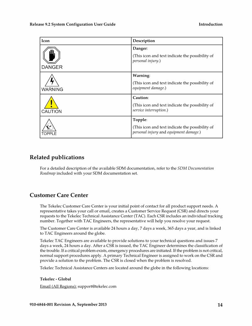
DescriptionIcon
Danger:
(This icon and text indicate the possibility ofpersonal injury.)
Warning:
(This icon and text indicate the possibility ofequipment damage.)
Caution:
(This icon and text indicate the possibility ofservice interruption.)
Topple:
(This icon and text indicate the possibility ofpersonal injury and equipment damage.)
Related publications
For a detailed description of the available SDM documentation, refer to the SDM DocumentationRoadmap included with your SDM documentation set.
Customer Care Center
The Tekelec Customer Care Center is your initial point of contact for all product support needs. Arepresentative takes your call or email, creates a Customer Service Request (CSR) and directs yourrequests to the Tekelec Technical Assistance Center (TAC). Each CSR includes an individual trackingnumber. Together with TAC Engineers, the representative will help you resolve your request.
The Customer Care Center is available 24 hours a day, 7 days a week, 365 days a year, and is linkedto TAC Engineers around the globe.
Tekelec TAC Engineers are available to provide solutions to your technical questions and issues 7days a week, 24 hours a day. After a CSR is issued, the TAC Engineer determines the classification ofthe trouble. If a critical problem exists, emergency procedures are initiated. If the problem is not critical,normal support procedures apply. A primary Technical Engineer is assigned to work on the CSR andprovide a solution to the problem. The CSR is closed when the problem is resolved.
Tekelec Technical Assistance Centers are located around the globe in the following locations:
Tekelec - Global
Email (All Regions): [email protected]
14910-6844-001 Revision A, September 2013
IntroductionRelease 9.2 System Configuration User Guide
• USA and Canada
Phone:
1-888-FOR-TKLC or 1-888-367-8552 (toll-free, within continental USA and Canada)
1-919-460-2150 (outside continental USA and Canada)
TAC Regional Support Office Hours:
8:00 a.m. through 5:00 p.m. (GMT minus 5 hours), Monday through Friday, excluding holidays
• Caribbean and Latin America (CALA)
Phone:
+1-919-460-2150
TAC Regional Support Office Hours (except Brazil):
10:00 a.m. through 7:00 p.m. (GMT minus 6 hours), Monday through Friday, excluding holidays
• Argentina
Phone:
0-800-555-5246 (toll-free)
• Brazil
Phone:
0-800-891-4341 (toll-free)
TAC Regional Support Office Hours:
8:00 a.m. through 5:48 p.m. (GMT minus 3 hours), Monday through Friday, excluding holidays
• Chile
Phone:
1230-020-555-5468
• Colombia
Phone:
01-800-912-0537
• Dominican Republic
Phone:
1-888-367-8552
• Mexico
Phone:
001-888-367-8552
• Peru
Phone:
0800-53-087
15910-6844-001 Revision A, September 2013
IntroductionRelease 9.2 System Configuration User Guide
• Puerto Rico
Phone:
1-888-367-8552 (1-888-FOR-TKLC)
• Venezuela
Phone:
0800-176-6497
• Europe, Middle East, and Africa
Regional Office Hours:
8:30 a.m. through 5:00 p.m. (GMT), Monday through Friday, excluding holidays
• Signaling
Phone:
+44 1784 467 804 (within UK)
• Software Solutions
Phone:
+33 3 89 33 54 00
• Asia
• India
Phone:
+91-124-465-5098 or +1-919-460-2150
TAC Regional Support Office Hours:
10:00 a.m. through 7:00 p.m. (GMT plus 5 1/2 hours), Monday through Saturday, excludingholidays
• Singapore
Phone:
+65 6796 2288
TAC Regional Support Office Hours:
9:00 a.m. through 6:00 p.m. (GMT plus 8 hours), Monday through Friday, excluding holidays
Emergency Response
In the event of a critical service situation, emergency response is offered by the Tekelec Customer CareCenter 24 hours a day, 7 days a week. The emergency response provides immediate coverage, automaticescalation, and other features to ensure that the critical situation is resolved as rapidly as possible.
16910-6844-001 Revision A, September 2013
IntroductionRelease 9.2 System Configuration User Guide
A critical situation is defined as a problem with the installed equipment that severely affects service,traffic, or maintenance capabilities, and requires immediate corrective action. Critical situations affectservice and/or system operation resulting in one or several of these situations:
• A total system failure that results in loss of all transaction processing capability• Significant reduction in system capacity or traffic handling capability• Loss of the system’s ability to perform automatic system reconfiguration• Inability to restart a processor or the system• Corruption of system databases that requires service affecting corrective actions• Loss of access for maintenance or recovery operations• Loss of the system ability to provide any required critical or major trouble notification
Any other problem severely affecting service, capacity/traffic, billing, and maintenance capabilitiesmay be defined as critical by prior discussion and agreement with the Tekelec Customer Care Center.
Locate Product Documentation on the Customer Support Site
Access to Tekelec's Customer Support site is restricted to current Tekelec customers only. This sectiondescribes how to log into the Tekelec Customer Support site and locate a document. Viewing thedocument requires Adobe Acrobat Reader, which can be downloaded at www.adobe.com.
1. Log into the Tekelec Customer Support site.
Note: If you have not registered for this new site, click the Register Here link. Have your customernumber available. The response time for registration requests is 24 to 48 hours.
2. Click the Product Support tab.3. Use the Search field to locate a document by its part number, release number, document name, or
document type. The Search field accepts both full and partial entries.4. Click a subject folder to browse through a list of related files.5. To download a file to your location, right-click the file name and select Save Target As.
17910-6844-001 Revision A, September 2013
IntroductionRelease 9.2 System Configuration User Guide
Chapter
2Getting Started
This chapter contains information regarding safetyprecautions, accessing the system, and logging infor the first time.
Topics:
• Safety Warnings and Cautions.....19• Electrostatic Discharge (ESD).....19• Accessing the System.....19
18910-6844-001 Revision A, September 2013
Safety Warnings and Cautions
It is important to read this section before attempting any of the hardware installation and maintenanceprocedures in this guide.
Only trained and qualified personnel should install, activate, and maintain the systems.
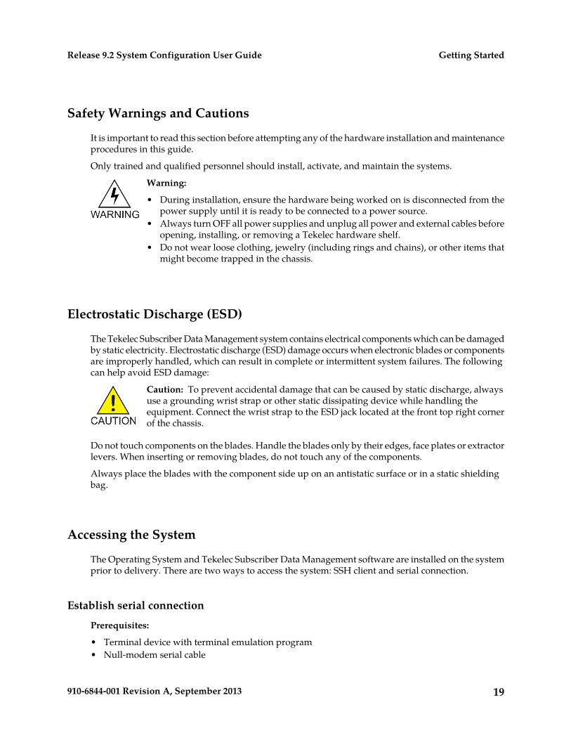
Warning:
• During installation, ensure the hardware being worked on is disconnected from thepower supply until it is ready to be connected to a power source.
• Always turn OFF all power supplies and unplug all power and external cables beforeopening, installing, or removing a Tekelec hardware shelf.
• Do not wear loose clothing, jewelry (including rings and chains), or other items thatmight become trapped in the chassis.
Electrostatic Discharge (ESD)
The Tekelec Subscriber Data Management system contains electrical components which can be damagedby static electricity. Electrostatic discharge (ESD) damage occurs when electronic blades or componentsare improperly handled, which can result in complete or intermittent system failures. The followingcan help avoid ESD damage:
Caution: To prevent accidental damage that can be caused by static discharge, alwaysuse a grounding wrist strap or other static dissipating device while handling theequipment. Connect the wrist strap to the ESD jack located at the front top right cornerof the chassis.
Do not touch components on the blades. Handle the blades only by their edges, face plates or extractorlevers. When inserting or removing blades, do not touch any of the components.
Always place the blades with the component side up on an antistatic surface or in a static shieldingbag.
Accessing the System
The Operating System and Tekelec Subscriber Data Management software are installed on the systemprior to delivery. There are two ways to access the system: SSH client and serial connection.
Establish serial connection
Prerequisites:
• Terminal device with terminal emulation program• Null-modem serial cable
19910-6844-001 Revision A, September 2013
Getting StartedRelease 9.2 System Configuration User Guide
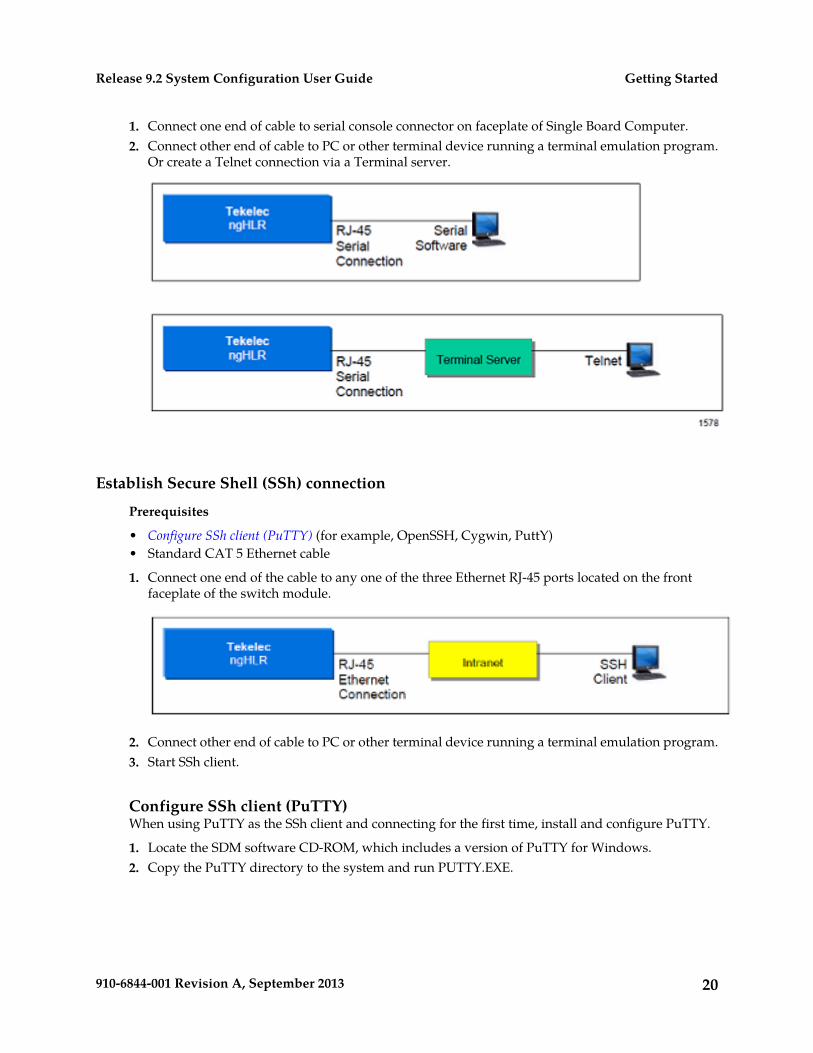
1. Connect one end of cable to serial console connector on faceplate of Single Board Computer.2. Connect other end of cable to PC or other terminal device running a terminal emulation program.
Or create a Telnet connection via a Terminal server.
Establish Secure Shell (SSh) connection
Prerequisites
• Configure SSh client (PuTTY) (for example, OpenSSH, Cygwin, PuttY)• Standard CAT 5 Ethernet cable
1. Connect one end of the cable to any one of the three Ethernet RJ-45 ports located on the frontfaceplate of the switch module.
2. Connect other end of cable to PC or other terminal device running a terminal emulation program.3. Start SSh client.
Configure SSh client (PuTTY)When using PuTTY as the SSh client and connecting for the first time, install and configure PuTTY.
1. Locate the SDM software CD-ROM, which includes a version of PuTTY for Windows.2. Copy the PuTTY directory to the system and run PUTTY.EXE.
20910-6844-001 Revision A, September 2013
Getting StartedRelease 9.2 System Configuration User Guide
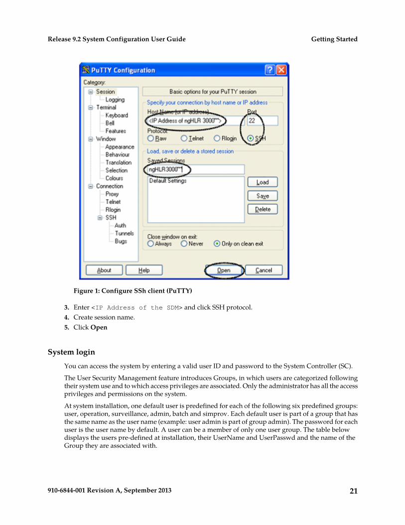
Figure 1: Configure SSh client (PuTTY)
3. Enter <IP Address of the SDM> and click SSH protocol.4. Create session name.5. Click Open
System login
You can access the system by entering a valid user ID and password to the System Controller (SC).
The User Security Management feature introduces Groups, in which users are categorized followingtheir system use and to which access privileges are associated. Only the administrator has all the accessprivileges and permissions on the system.
At system installation, one default user is predefined for each of the following six predefined groups:user, operation, surveillance, admin, batch and simprov. Each default user is part of a group that hasthe same name as the user name (example: user admin is part of group admin). The password for eachuser is the user name by default. A user can be a member of only one user group. The table belowdisplays the users pre-defined at installation, their UserName and UserPasswd and the name of theGroup they are associated with.
21910-6844-001 Revision A, September 2013
Getting StartedRelease 9.2 System Configuration User Guide
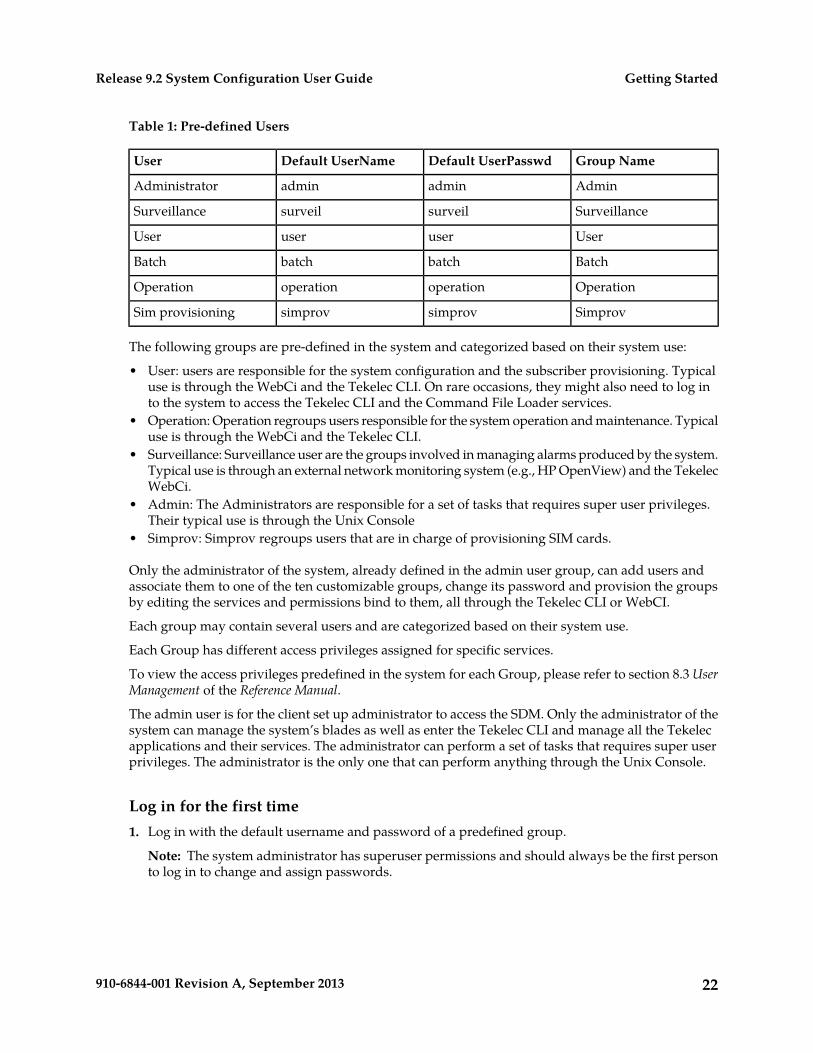
Table 1: Pre-defined Users
Group NameDefault UserPasswdDefault UserNameUser
AdminadminadminAdministrator
SurveillancesurveilsurveilSurveillance
UseruseruserUser
BatchbatchbatchBatch
OperationoperationoperationOperation
SimprovsimprovsimprovSim provisioning
The following groups are pre-defined in the system and categorized based on their system use:
• User: users are responsible for the system configuration and the subscriber provisioning. Typicaluse is through the WebCi and the Tekelec CLI. On rare occasions, they might also need to log into the system to access the Tekelec CLI and the Command File Loader services.
• Operation: Operation regroups users responsible for the system operation and maintenance. Typicaluse is through the WebCi and the Tekelec CLI.
• Surveillance: Surveillance user are the groups involved in managing alarms produced by the system.Typical use is through an external network monitoring system (e.g., HP OpenView) and the TekelecWebCi.
• Admin: The Administrators are responsible for a set of tasks that requires super user privileges.Their typical use is through the Unix Console
• Simprov: Simprov regroups users that are in charge of provisioning SIM cards.
Only the administrator of the system, already defined in the admin user group, can add users andassociate them to one of the ten customizable groups, change its password and provision the groupsby editing the services and permissions bind to them, all through the Tekelec CLI or WebCI.
Each group may contain several users and are categorized based on their system use.
Each Group has different access privileges assigned for specific services.
To view the access privileges predefined in the system for each Group, please refer to section 8.3 UserManagement of the Reference Manual.
The admin user is for the client set up administrator to access the SDM. Only the administrator of thesystem can manage the system’s blades as well as enter the Tekelec CLI and manage all the Tekelecapplications and their services. The administrator can perform a set of tasks that requires super userprivileges. The administrator is the only one that can perform anything through the Unix Console.
Log in for the first time1. Log in with the default username and password of a predefined group.
Note: The system administrator has superuser permissions and should always be the first personto log in to change and assign passwords.
22910-6844-001 Revision A, September 2013
Getting StartedRelease 9.2 System Configuration User Guide
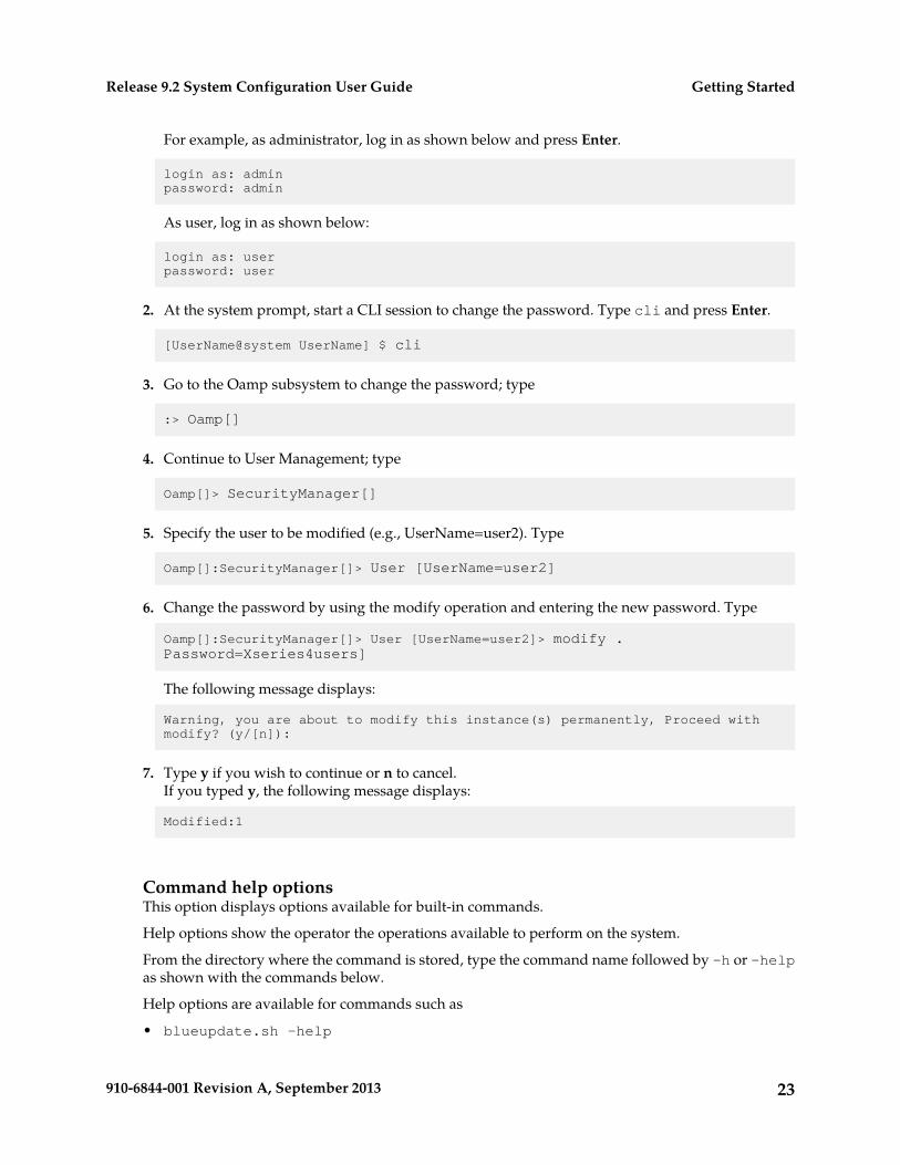
For example, as administrator, log in as shown below and press Enter.
login as: adminpassword: admin
As user, log in as shown below:
login as: userpassword: user
2. At the system prompt, start a CLI session to change the password. Type cli and press Enter.
[UserName@system UserName] $ cli
3. Go to the Oamp subsystem to change the password; type
:> Oamp[]
4. Continue to User Management; type
Oamp[]> SecurityManager[]
5. Specify the user to be modified (e.g., UserName=user2). Type
Oamp[]:SecurityManager[]> User [UserName=user2]
6. Change the password by using the modify operation and entering the new password. Type
Oamp[]:SecurityManager[]> User [UserName=user2]> modify . Password=Xseries4users]
The following message displays:
Warning, you are about to modify this instance(s) permanently, Proceed with modify? (y/[n]):
7. Type y if you wish to continue or n to cancel.If you typed y, the following message displays:
Modified:1
Command help optionsThis option displays options available for built-in commands.
Help options show the operator the operations available to perform on the system.
From the directory where the command is stored, type the command name followed by -h or -helpas shown with the commands below.
Help options are available for commands such as
• blueupdate.sh -help
23910-6844-001 Revision A, September 2013
Getting StartedRelease 9.2 System Configuration User Guide
• cfl -help (Command File Loader)• ctl -h (Command Template Loader)• CmdTemplateViewer -h (Command Template Viewer)
Note: The user must have access privileges to these interfaces and must have logged in successfullybefore these commands become available.
Blueupdatesh help options
/opt/blue/blueupdate.sh –helpblueupdate.sh[-u] [-s] [-k] [-d] [-t dir] [-i interface] [-r release] [-f[<host:>]<filename>>] [<buildId>]
• -u: uninstall only• -s: start software after successful installation• -k: keep current database• d: use debug load• -t: download tarball to given dir but do not install• -i: use specified interface• -r: use specified release• -f: use specified installation file
buildId is ignored if -f is specified
CFL help optionsView the different Command File Loader (CFL) options through this command:
[UserName@system UserName] $ cfl -help
CmdFileLoader options:
• [-c XmlConfigurationFileName] (default: default value)• [-cmd XmlCommand] (i.e., submitted inline)• [-d XmlCommandDirectoryName]
• [-f XmlCommandFileName]
• [-fo XmlOutputFileName] (default: console)
The –fo <XmlOutputFileName.xml> tracks the results of the provisioning request, where<XmlOutputFileName> is the path followed by the name of the XML output file in which youwish the system replies be stored (i.e., /tmp/template/Xmloutfile1.xml).
All system replies are stored in the output file (including error reply codes). Specifying the outputfile is optional and when no output file name is given, the output is sent automatically to the consoleby default.
• [-dbip] (specifies the IP address of the database).• [-ip OampMgrIpAddress]
• [-observer] (i.e., start observer; initiates notifications of changes to the database)• [-p OampManagerPort] (default: 62001)• [-reso] (produce result not encapsulated in xml and no other messages)• [-todb] (i.e., load directly in the database) This is used in bulk provisioning to load subscriber
profile information into the database without performing any validation of the xml requests.• [-trace] (traces for errors)
24910-6844-001 Revision A, September 2013
Getting StartedRelease 9.2 System Configuration User Guide
• [-user] (user name)• [-validate] (validate input against the global schema)
25910-6844-001 Revision A, September 2013
Getting StartedRelease 9.2 System Configuration User Guide
Chapter
3User Interfaces
This chapter describes the user interfaces that allowthe operator to configure the system or provision
Topics:
• Command Line Interface (CLI).....27 subscribers. The description includes functionalities,• Web Craft Interface (WebCI).....43 command convention, navigation method,
command execution, and the GUI symbols used inthe WebCI.
• Creating and Managing Users for the UserInterfaces.....51
• Creating and Managing Users forNotifications.....70
26910-6844-001 Revision A, September 2013
Command Line Interface (CLI)
This section provides step-by-step instructions on how to start a CLI session, how to get around in aCLI session, and how to end a CLI session. Refer to the Command Line Interface chapter in the SDMSystem Configuration – Reference Manual for an overview of the Command Line Interface (CLI)Commands, the command convention, navigation, and command descriptions.
Starting a CLI session
At installation time, five different users are automatically added. One user for each predefined userGroup is added in the system with a default UserName and UserPasswd:
Table 2: Pre-defined users
Group NameDefault UserPasswdDefault UserNameUser
AdminAdminadminAdmin
SurveillanceSurveilsurveilSurveillance
UserUseruserUser
BatchBatchbatchBatch
OperationOperationoperationOperation
All of these users can start a CLI session, but each with limited access and permissions to specificservices. Only the administrator has access to all the services and all the permissions. To view theaccess privileges predefined in the system for each Group, refer to Creating and Managing Users for theUser Interfaces.
To start a CLI session for the first time, the user must log in, as explained in Accessing the system, withits default UserName and UserPasswd. Afterwards, they must enter the following:
[UserName@system UserName] $ cli
After starting a CLI session for the first time, and with the user having changed its own password oras per the operator’s convenience, with the administrator having changed the users’ password, theuser now accesses the system with its UserName and new password. Refer to Creating and ManagingUsers for the User Interfaces to know how to change a user’s password.
The first thing recommended for the administrator to do once he has started a CLI session, is to initiallyprovision users by creating one user name and give them different access privileges by associatingthem to groups following their system use and assigning them the access privileges desired for specificservices.
27910-6844-001 Revision A, September 2013
User InterfacesRelease 9.2 System Configuration User Guide
Using the CLI
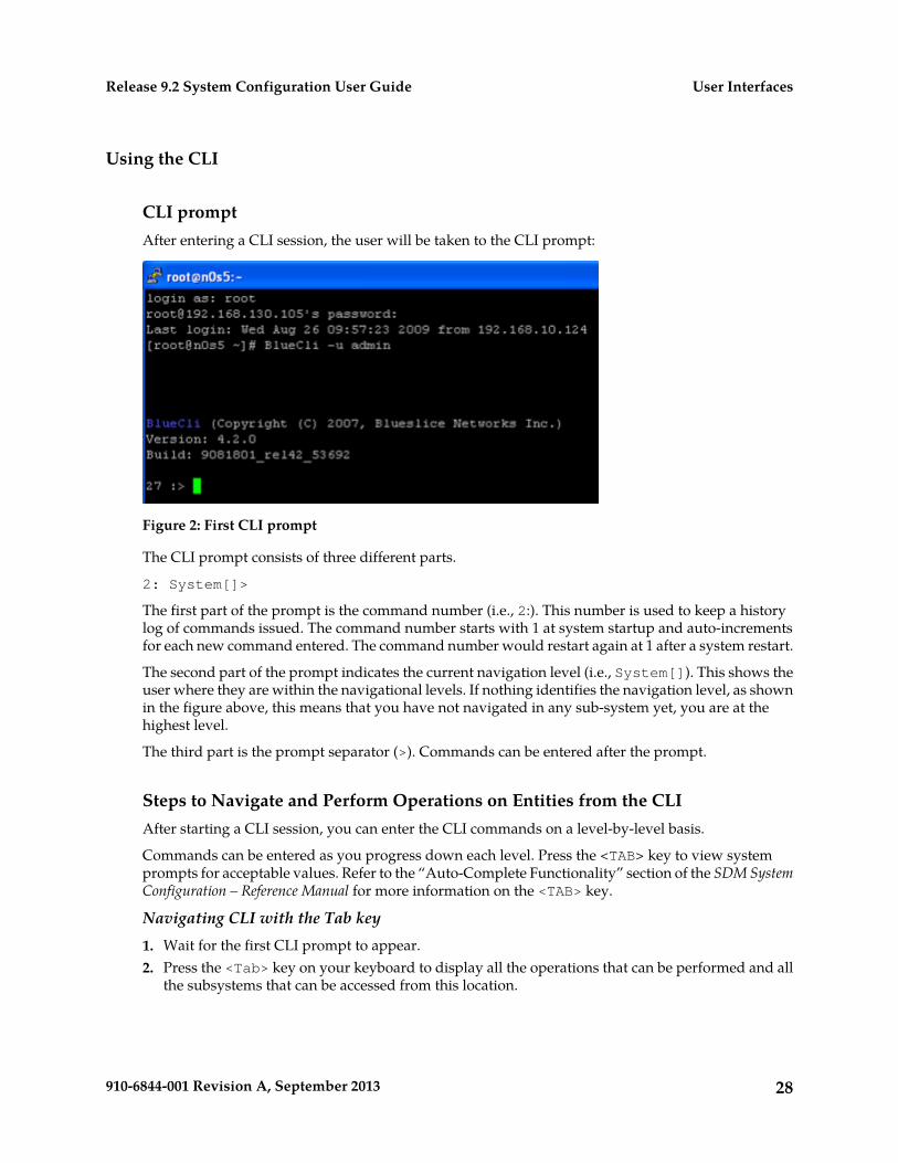
CLI promptAfter entering a CLI session, the user will be taken to the CLI prompt:
Figure 2: First CLI prompt
The CLI prompt consists of three different parts.
2: System[]>
The first part of the prompt is the command number (i.e., 2:). This number is used to keep a historylog of commands issued. The command number starts with 1 at system startup and auto-incrementsfor each new command entered. The command number would restart again at 1 after a system restart.
The second part of the prompt indicates the current navigation level (i.e., System[]). This shows theuser where they are within the navigational levels. If nothing identifies the navigation level, as shownin the figure above, this means that you have not navigated in any sub-system yet, you are at thehighest level.
The third part is the prompt separator (>). Commands can be entered after the prompt.
Steps to Navigate and Perform Operations on Entities from the CLIAfter starting a CLI session, you can enter the CLI commands on a level-by-level basis.
Commands can be entered as you progress down each level. Press the <TAB> key to view systemprompts for acceptable values. Refer to the “Auto-Complete Functionality” section of the SDM SystemConfiguration – Reference Manual for more information on the <TAB> key.
Navigating CLI with the Tab key1. Wait for the first CLI prompt to appear.2. Press the <Tab> key on your keyboard to display all the operations that can be performed and all
the subsystems that can be accessed from this location.
28910-6844-001 Revision A, September 2013
User InterfacesRelease 9.2 System Configuration User Guide
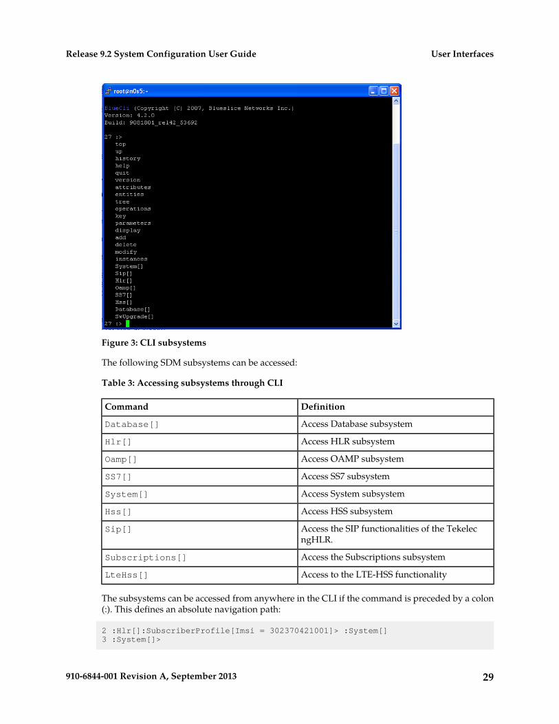
Figure 3: CLI subsystems
The following SDM subsystems can be accessed:
Table 3: Accessing subsystems through CLI
DefinitionCommand
Access Database subsystemDatabase[]
Access HLR subsystemHlr[]
Access OAMP subsystemOamp[]
Access SS7 subsystemSS7[]
Access System subsystemSystem[]
Access HSS subsystemHss[]
Access the SIP functionalities of the TekelecngHLR.
Sip[]
Access the Subscriptions subsystemSubscriptions[]
Access to the LTE-HSS functionalityLteHss[]
The subsystems can be accessed from anywhere in the CLI if the command is preceded by a colon(:). This defines an absolute navigation path:
2 :Hlr[]:SubscriberProfile[Imsi = 302370421001]> :System[]3 :System[]>
29910-6844-001 Revision A, September 2013
User InterfacesRelease 9.2 System Configuration User Guide
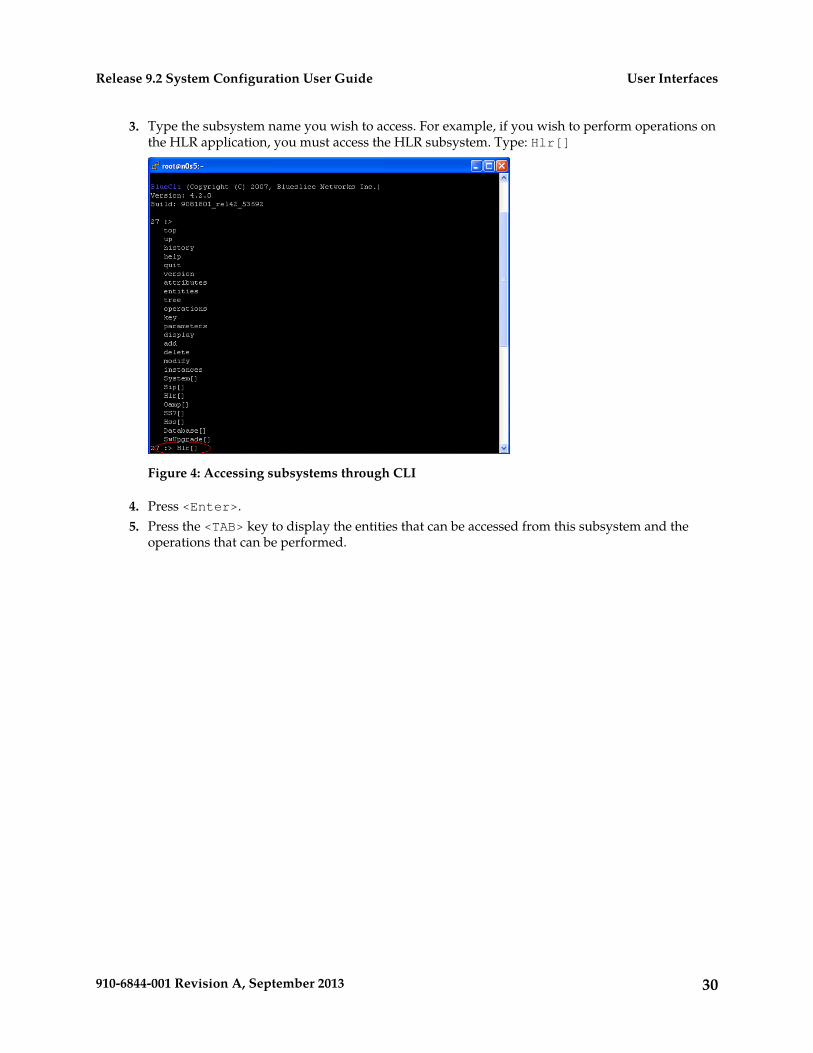
3. Type the subsystem name you wish to access. For example, if you wish to perform operations onthe HLR application, you must access the HLR subsystem. Type: Hlr[]
Figure 4: Accessing subsystems through CLI
4. Press <Enter>.5. Press the <TAB> key to display the entities that can be accessed from this subsystem and the
operations that can be performed.
30910-6844-001 Revision A, September 2013
User InterfacesRelease 9.2 System Configuration User Guide
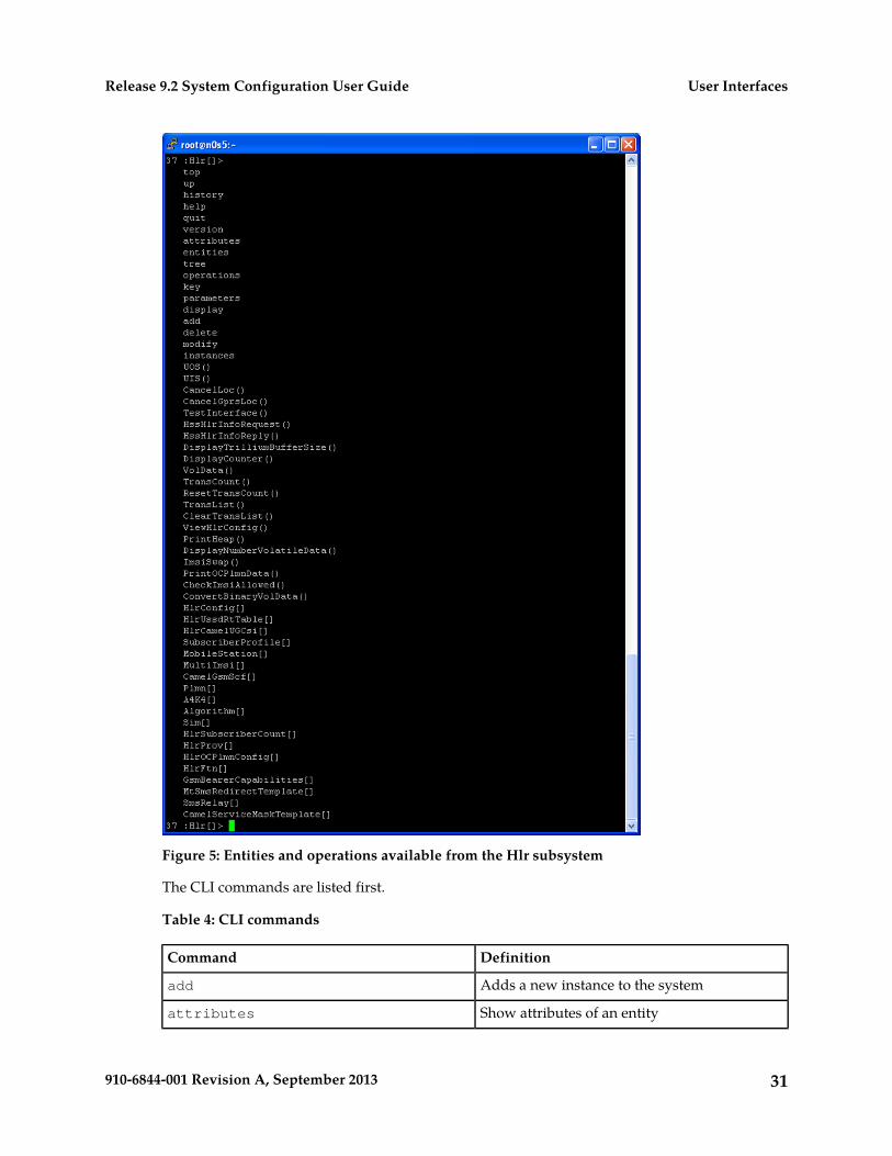
Figure 5: Entities and operations available from the Hlr subsystem
The CLI commands are listed first.
Table 4: CLI commands
DefinitionCommand
Adds a new instance to the systemadd
Show attributes of an entityattributes
31910-6844-001 Revision A, September 2013
User InterfacesRelease 9.2 System Configuration User Guide
DefinitionCommand
Deletes instances from the systemdelete
Display the instancesdisplay
Show sub-entitiesentities
Display help optionshelp
Lists history of commandshistory
Display all instances of an entityinstances
Show navigation key attributeskey
Make changes to instancesmodify
Show operationsoperations
Show parameters of an operationparameters
Exit the CLIquit
Go to top leveltop
View the command treetree
Go up one levelUp
Displays current version of the software load.version
The operations that can be performed on the HLR application are listed next; operations areidentified by the () at the end.
The entities that can be accessed from the HLR subsystem are listed last.
Note: Other entities can only be accessed from these high-level entities.
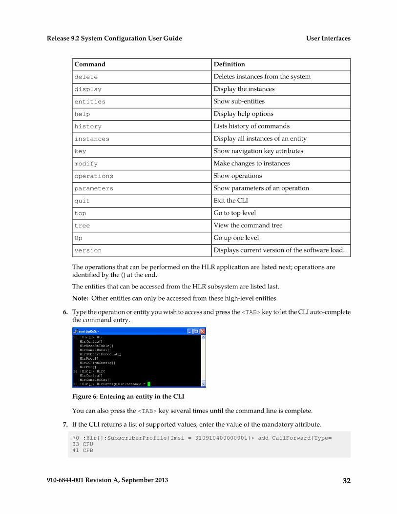
6. Type the operation or entity you wish to access and press the <TAB> key to let the CLI auto-completethe command entry.
Figure 6: Entering an entity in the CLI
You can also press the <TAB> key several times until the command line is complete.
7. If the CLI returns a list of supported values, enter the value of the mandatory attribute.
70 :Hlr[]:SubscriberProfile[Imsi = 310910400000001]> add CallForward[Type=33 CFU41 CFB
32910-6844-001 Revision A, September 2013
User InterfacesRelease 9.2 System Configuration User Guide
42 CFNRY43 CFNRC
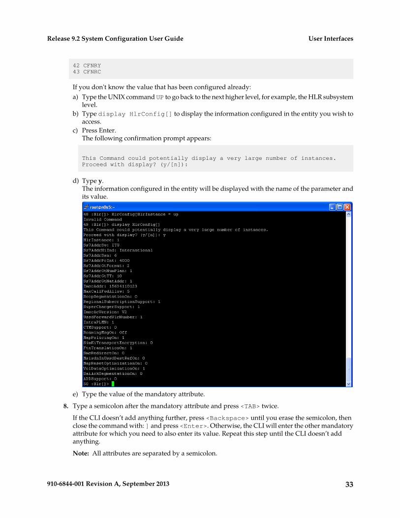
If you don't know the value that has been configured already:a) Type the UNIX command UP to go back to the next higher level, for example, the HLR subsystem
level.b) Type display HlrConfig[] to display the information configured in the entity you wish to
access.c) Press Enter.
The following confirmation prompt appears:
This Command could potentially display a very large number of instances. Proceed with display? (y/[n]):
d) Type y.The information configured in the entity will be displayed with the name of the parameter andits value.
e) Type the value of the mandatory attribute.
8. Type a semicolon after the mandatory attribute and press <TAB> twice.
If the CLI doesn’t add anything further, press <Backspace> until you erase the semicolon, thenclose the command with: ] and press <Enter>. Otherwise, the CLI will enter the other mandatoryattribute for which you need to also enter its value. Repeat this step until the CLI doesn’t addanything.
Note: All attributes are separated by a semicolon.
33910-6844-001 Revision A, September 2013
User InterfacesRelease 9.2 System Configuration User Guide
Refer to the SDM System Configuration – Reference Manual for a description of the entity you aretrying to access and provision to know which attributes are mandatory and for information on theattributes, their value range and default value.
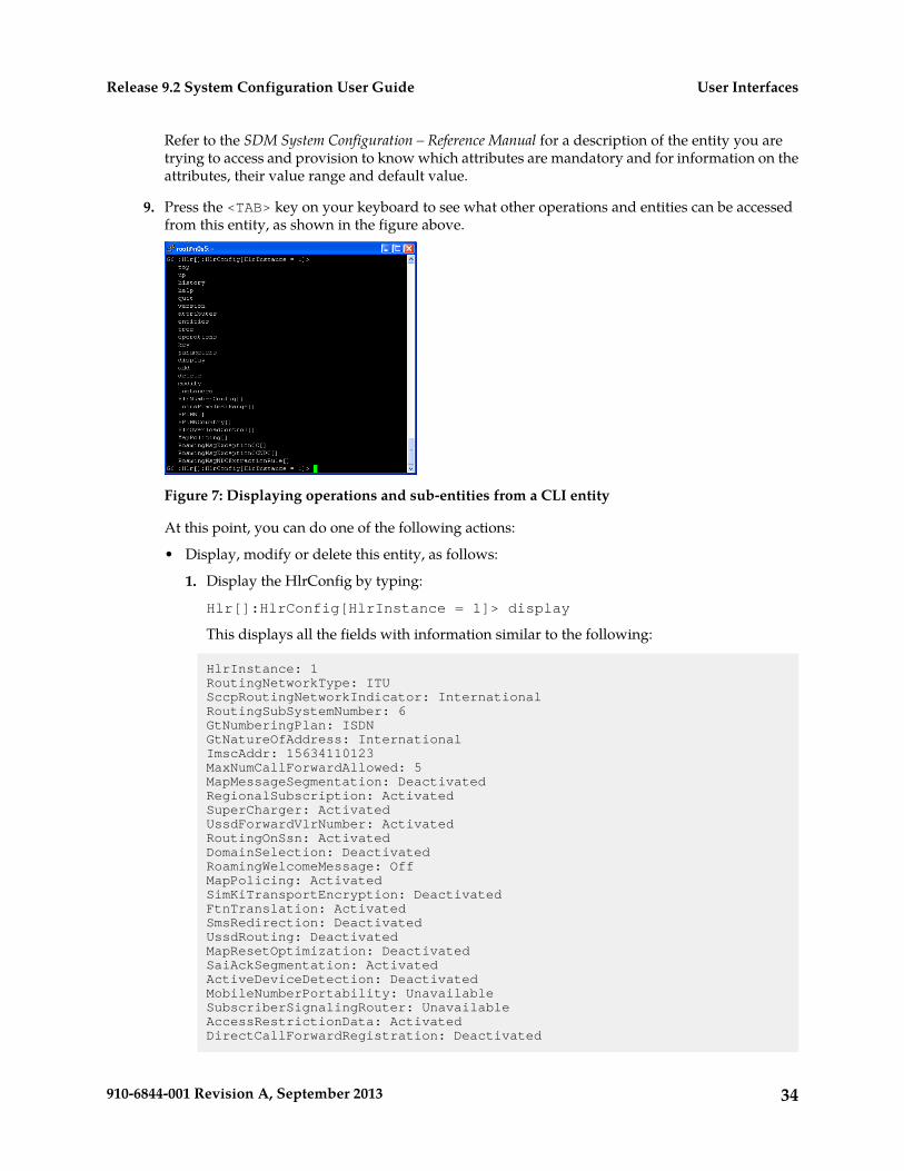
9. Press the <TAB> key on your keyboard to see what other operations and entities can be accessedfrom this entity, as shown in the figure above.
Figure 7: Displaying operations and sub-entities from a CLI entity
At this point, you can do one of the following actions:
• Display, modify or delete this entity, as follows:
1. Display the HlrConfig by typing:
Hlr[]:HlrConfig[HlrInstance = 1]> display
This displays all the fields with information similar to the following:
HlrInstance: 1RoutingNetworkType: ITUSccpRoutingNetworkIndicator: InternationalRoutingSubSystemNumber: 6GtNumberingPlan: ISDNGtNatureOfAddress: InternationalImscAddr: 15634110123MaxNumCallForwardAllowed: 5MapMessageSegmentation: DeactivatedRegionalSubscription: ActivatedSuperCharger: ActivatedUssdForwardVlrNumber: ActivatedRoutingOnSsn: ActivatedDomainSelection: DeactivatedRoamingWelcomeMessage: OffMapPolicing: ActivatedSimKiTransportEncryption: DeactivatedFtnTranslation: ActivatedSmsRedirection: DeactivatedUssdRouting: DeactivatedMapResetOptimization: DeactivatedSaiAckSegmentation: ActivatedActiveDeviceDetection: DeactivatedMobileNumberPortability: UnavailableSubscriberSignalingRouter: UnavailableAccessRestrictionData: ActivatedDirectCallForwardRegistration: Deactivated
34910-6844-001 Revision A, September 2013
User InterfacesRelease 9.2 System Configuration User Guide
VlrMessageNotification: DeactivatedEnhancedControlOfSccpRouting: UnavailableUpdateOfSccpCgAddrOnlyForUL: UnavailableVolDataOptimization: Activated
Note: To view individual fields, specify them (i.e., RoutingNetworkType,MaxNumCallForwardAllowed) when issuing the Display operation.
]> display . RoutingNetworkType; MaxNumCallForwardAllowed
Information similar to the following will be displayed:
RoutingNetworkType: ITU MaxNumCallForwardAllowed: 5
2. Modify HlrConfig by typing
Hlr[]:HlrConfig[HlrInstance = 1]>modify . UssdForwardVlrNumber = 0;SimKiTransportEncryption = 1
The following warning will be displayed:
Warning, you are about to modify this instance(s) permanently, Proceed with modify? (y/[n]):
Type y to proceed.
The following message displays:
Modified: 1
3. Delete HlrConfig by typing
Hlr[]:HlrConfig[HlrInstance = 1]>delete
The following warning displays:
Warning, you are about to delete this instance(s) permanently, Proceed with delete? (y/[n]):
Type y to proceed.
• Add an entry in one of the sub-entities displayed in the list (as shown in figure above). Forexample, type
HlrNumberConfig:
Add the HlrNumberConfig attribute as shown below.
Note: After typing add HlrNumberConfig, press on the <TAB> key to let the CLI complete thecommand line further):
:Hlr[]:HlrConfig[HlrInstance = 1] >add HlrNumberConfig[HlrNumberConfigId= 1; HlrAddrCC = 1; HlrAddrNDC = 123; HlrAddrSN = 1230001; HlrAddrIDD= 001; HlrAddrNDD = 0]
The following message will be displayed.
Added: 1
35910-6844-001 Revision A, September 2013
User InterfacesRelease 9.2 System Configuration User Guide
• Access one of the sub-entities. For this, simply repeat steps 6 to 9 until you have reached theentity on which you wish to perform an action or until the navigation path ends.
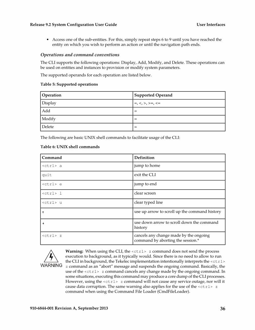
Operations and command conventionsThe CLI supports the following operations: Display, Add, Modify, and Delete. These operations canbe used on entities and instances to provision or modify system parameters.
The supported operands for each operation are listed below.
Table 5: Supported operations
Supported OperandOperation
=, <, >, >=, <=Display
=Add
=Modify
=Delete
The following are basic UNIX shell commands to facilitate usage of the CLI:
Table 6: UNIX shell commands
DefinitionCommand
jump to home<ctrl> a
exit the CLIquit
jump to end<ctrl> e
clear screen<ctrl> l
clear typed line<ctrl> u
use up arrow to scroll up the command history
use down arrow to scroll down the commandhistory
cancels any change made by the ongoingcommand by aborting the session.*
<ctrl> z
Warning: When using the CLI, the <ctrl> z command does not send the processexecution to background, as it typically would. Since there is no need to allow to runthe CLI in background, the Tekelec implementation intentionally interprets the <ctrl>z command as an “abort” message and suspends the ongoing command. Basically, theuse of the <ctrl> z command cancels any change made by the ongoing command. Insome situations, executing this command may produce a core dump of the CLI processes.However, using the <ctrl> z command will not cause any service outage, nor will itcause data corruption. The same warning also applies for the use of the <ctrl> zcommand when using the Command File Loader (CmdFileLoader).
36910-6844-001 Revision A, September 2013
User InterfacesRelease 9.2 System Configuration User Guide
The following provides a description of the characters used in CLI.
Table 7: CLI characters
DefinitionSymbol
Indicates a mandatory item*
Separate multiple attributes or attribute valueswith a semicolon
;
Separate multiple items in a value list with acomma
,
Specifies the current instance.
Separates different levels between entities:
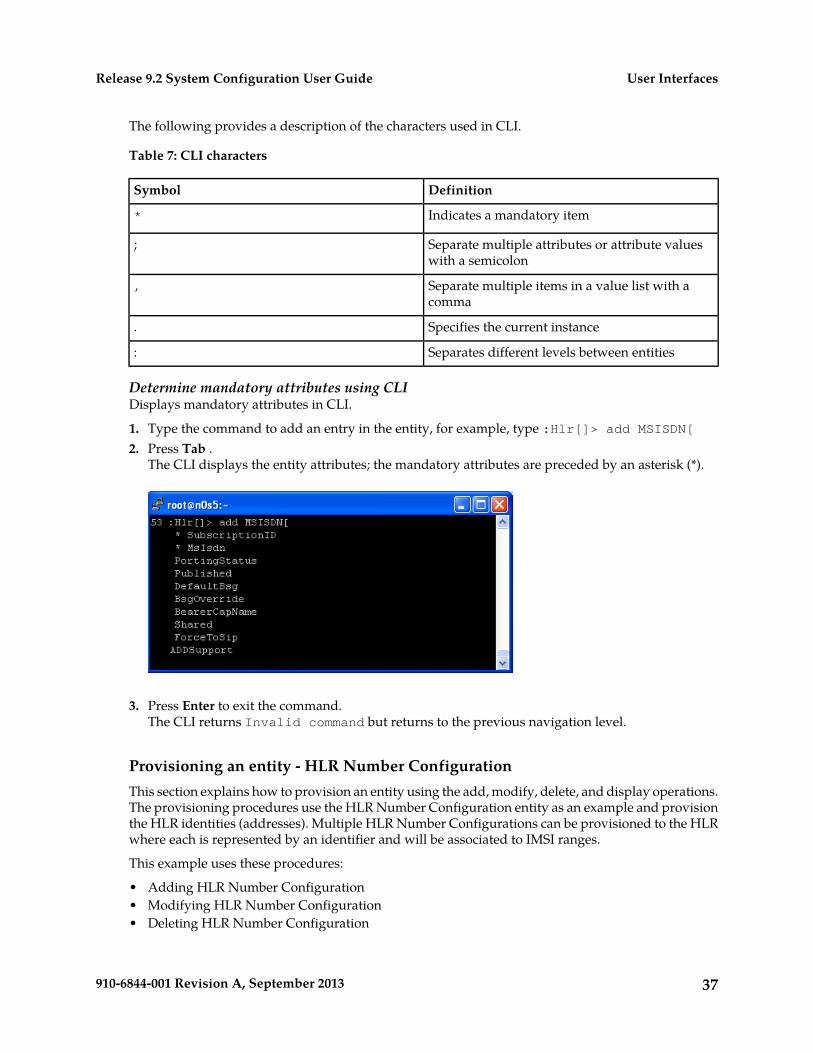
Determine mandatory attributes using CLIDisplays mandatory attributes in CLI.
1. Type the command to add an entry in the entity, for example, type :Hlr[]> add MSISDN[2. Press Tab .
The CLI displays the entity attributes; the mandatory attributes are preceded by an asterisk (*).
3. Press Enter to exit the command.The CLI returns Invalid command but returns to the previous navigation level.
Provisioning an entity - HLR Number ConfigurationThis section explains how to provision an entity using the add, modify, delete, and display operations.The provisioning procedures use the HLR Number Configuration entity as an example and provisionthe HLR identities (addresses). Multiple HLR Number Configurations can be provisioned to the HLRwhere each is represented by an identifier and will be associated to IMSI ranges.
This example uses these procedures:
• Adding HLR Number Configuration• Modifying HLR Number Configuration• Deleting HLR Number Configuration
37910-6844-001 Revision A, September 2013
User InterfacesRelease 9.2 System Configuration User Guide
• Displaying HLR Number Configuration
Adding HLR Number ConfigurationThis procedure describes the steps to add an identity to the HLR by defining a number (address). Youcan add more than one identity (address) to the HLR by repeating this procedure for each HLR identityyou want the HLR to have and by giving it a different identification number (HlrNumberConfigId)each time.
1. Go to the HLR subsystem by typing,:>Hlr[]
2. Go to the HlrConfig by specifying the Instance and typing
:Hlr[]> HlrConfig[HlrInstance = 1]
3. The HlrNumberConfig attributes are listed in the table below.
Table 8: HLRNumberConfig attributes
Value RangeAttribute
integerHlrNumberConfigId
up to 3 digitsHlrAddrCC
1 to 6 digitsHlrAddrNDC
up to 15 digitsHlrAddrSN
Up to 5 digitsHlrAddrIDD
Up to 5 digitsHlrAddrNDD
Add the HlrNumberConfig as shown below:
:Hlr[]:HlrConfig[HlrInstance = 1] > add HlrNumberConfig[HlrNumberConfigId = 1; HlrAddrCC = 1; HlrAddrNDC = 123; HlrAddrSN = 1230001; HlrAddrIDD = 001; HlrAddrNDD = 0]
The following message will be displayed.
Added: 1
Modifying HLR Number ConfigurationThis procedure describes the steps to modify the HLR Number Configuration. For details on the HLRNumber Configuration, refer to the SDM Reference Manual – HLR entities.
1. Go to the Hlr subsystem by typing,
:> Hlr[]
38910-6844-001 Revision A, September 2013
User InterfacesRelease 9.2 System Configuration User Guide
2. Go to the Hlr Config by specifying the Hlr Instance and typing,
:Hlr[]> sHlrConfig[HlrInstance = 1]
3. Go to the HlrNumberConfig by specifying the HlrNumberConfigId and typing,
:Hlr[]:HlrConfig[HlrInstance = 1]> aHlrNumberConfig[HlrNumberConfigId=1]s
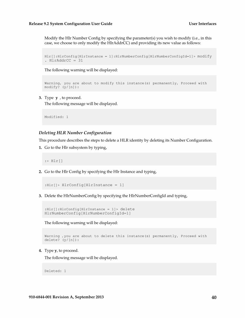
4. The following attributes can be modified: HlrAddrCC, HlrAddrNDC, HlrAddrSN, HlrAddrIDD,HlrAddrNDD.a) Modify the Hlr Number Config by specifying the parameter(s) you wish to modify (i.e., in this
case, swe choose to only modify the HlrAddrCC) and providing its new value as follows:
Hlr[]:HlrConfig[HlrInstance = 1]:HlrNumberConfig[HlrNumberConfigId=1]> modify . HlrAddrCC = 31
The following warning will be displayed:
Warning, you are about to modify this instance(s) permanently, Proceed with modify? (y/[n]):
5. Type y, to proceed.
The following message will be displayed.
Modified: 1
Modifying HLR Number Configuration – Alternate Method1. Go directly to the Hlr Number Config by specifying the HLR instance, HlrNumberConfigId, and
typing,
:> Hlr[]:HlrConfig[HlrInstance=1]:HlrNumberConfig[HlrNumberConfigId=1]
2. The following attributes can be modified: HlrAddrCC, HlrAddrNDC, HlrAddrSN, HlrAddrIDD,HlrAddrNDD.
39910-6844-001 Revision A, September 2013
User InterfacesRelease 9.2 System Configuration User Guide
Modify the Hlr Number Config by specifying the parameter(s) you wish to modify (i.e., in thiscase, we choose to only modify the HlrAddrCC) and providing its new value as follows:
Hlr[]:HlrConfig[HlrInstance = 1]:HlrNumberConfig[HlrNumberConfigId=1]> modify . HlrAddrCC = 31
The following warning will be displayed:
Warning, you are about to modify this instance(s) permanently, Proceed with modify? (y/[n]):
3. Type y , to proceed.The following message will be displayed.
Modified: 1
Deleting HLR Number ConfigurationThis procedure describes the steps to delete a HLR identity by deleting its Number Configuration.
1. Go to the Hlr subsystem by typing,
:> Hlr[]
2. Go to the Hlr Config by specifying the Hlr Instance and typing,
:Hlr[]> HlrConfig[HlrInstance = 1]
3. Delete the HlrNumberConfig by specifying the HlrNumberConfigId and typing,
:Hlr[]:HlrConfig[HlrInstance = 1]> delete HlrNumberConfig[HlrNumberConfigId=1]
The following warning will be displayed:
Warning ,you are about to delete this instance(s) permanently, Proceed with delete? (y/[n]):
4. Type y, to proceed.
The following message will be displayed.
Deleted: 1
40910-6844-001 Revision A, September 2013
User InterfacesRelease 9.2 System Configuration User Guide
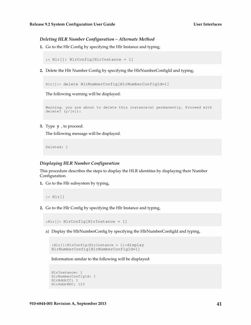
Deleting HLR Number Configuration – Alternate Method1. Go to the Hlr Config by specifying the Hlr Instance and typing,
:> Hlr[]: HlrConfig[HlrInstance = 1]
2. Delete the Hlr Number Config by specifying the HlrNumberConfigId and typing,
Hlr[]:> delete HlrNumberConfig[HlrNumberConfigId=1]
The following warning will be displayed:
Warning, you are about to delete this instance(s) permanently, Proceed with delete? (y/[n]):
3. Type y , to proceed.
The following message will be displayed.
Deleted: 1
Displaying HLR Number ConfigurationThis procedure describes the steps to display the HLR identities by displaying their NumberConfiguration.
1. Go to the Hlr subsystem by typing,
:> Hlr[]
2. Go to the Hlr Config by specifying the Hlr Instance and typing,
:Hlr[]> HlrConfig[HlrInstance = 1]
a) Display the HlrNumberConfig by specifying the HlrNumberConfigId and typing,
:Hlr[]:HlrConfig[HlrInstance = 1]>display HlrNumberConfig[HlrNumberConfigId=1]
Information similar to the following will be displayed:
HlrInstance: 1HlrNumberConfigId: 1HlrAddrCC: 1HlrAddrNDC: 123
41910-6844-001 Revision A, September 2013
User InterfacesRelease 9.2 System Configuration User Guide
HlrAddrSN: 1230001HlrAddrIDD: 001HlrAddrNDD: 0
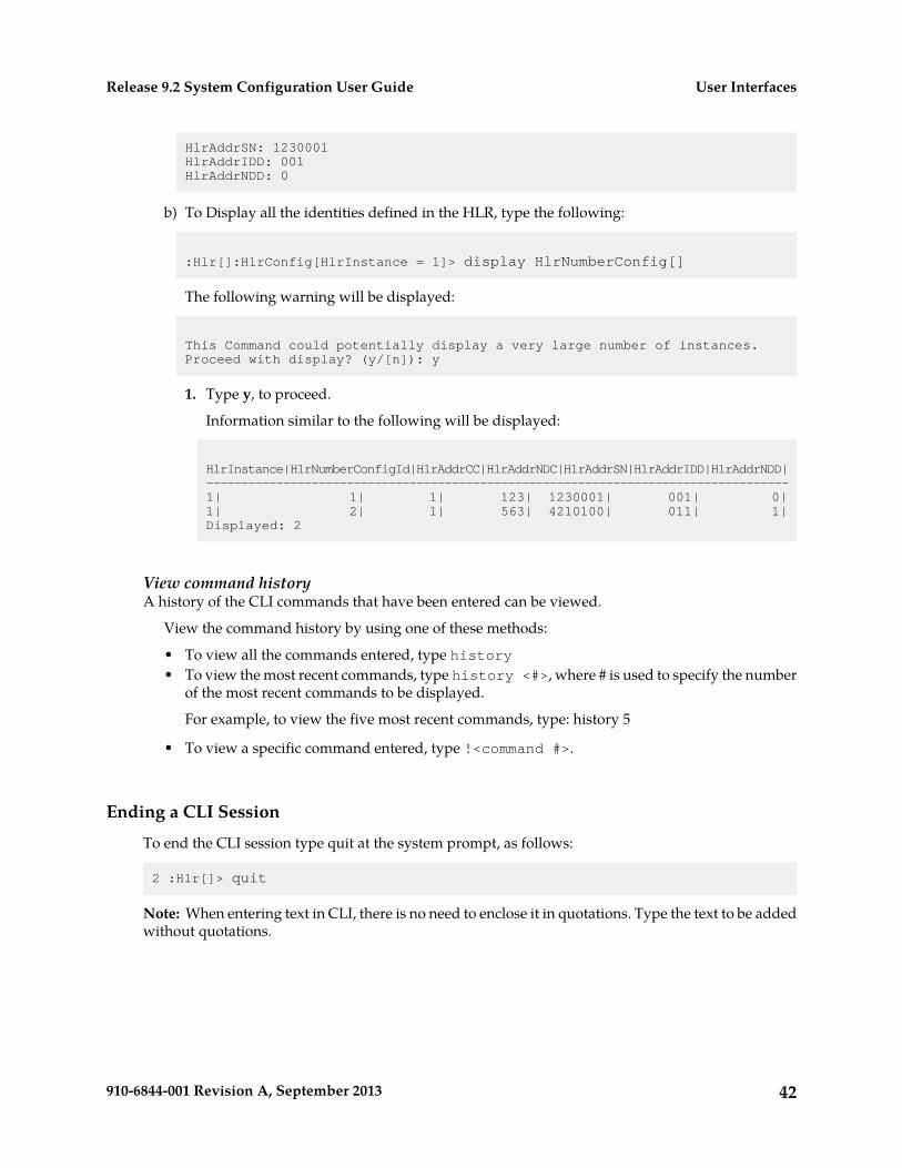
b) To Display all the identities defined in the HLR, type the following:
:Hlr[]:HlrConfig[HlrInstance = 1]> display HlrNumberConfig[]
The following warning will be displayed:
This Command could potentially display a very large number of instances.Proceed with display? (y/[n]): y
1. Type y, to proceed.
Information similar to the following will be displayed:
HlrInstance|HlrNumberConfigId|HlrAddrCC|HlrAddrNDC|HlrAddrSN|HlrAddrIDD|HlrAddrNDD|-----------------------------------------------------------------------------------1| 1| 1| 123| 1230001| 001| 0|1| 2| 1| 563| 4210100| 011| 1|Displayed: 2
View command historyA history of the CLI commands that have been entered can be viewed.
View the command history by using one of these methods:
• To view all the commands entered, type history• To view the most recent commands, type history <#>, where # is used to specify the number
of the most recent commands to be displayed.
For example, to view the five most recent commands, type: history 5
• To view a specific command entered, type !<command #>.
Ending a CLI Session
To end the CLI session type quit at the system prompt, as follows:
2 :Hlr[]> quit
Note: When entering text in CLI, there is no need to enclose it in quotations. Type the text to be addedwithout quotations.
42910-6844-001 Revision A, September 2013
User InterfacesRelease 9.2 System Configuration User Guide
Web Craft Interface (WebCI)
The Web Craft Interface (WebCI) is a web-based application that provides a user-friendly graphicaluser interface (GUI). The WebCI is used to facilitate system configuration, troubleshooting of subscriberprofiles and alarm management.
Starting a WebCI Session
The Web Craft Interface (WebCI) supports the following versions of web browsers:
• Internet Explorer version 8 on Windows.• Mozilla Firefox version 12.0.
Accessing the Web Craft Interface
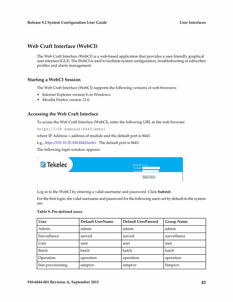
To access the Web Craft Interface (WebCI), enter the following URL in the web browser:
https://<IP Address:8443/webci
where IP Address = address of module and the default port is 8443.
e.g., https://193.10.20.100:8443/webci . The default port is 8443.
The following login window appears:
Log in to the WebCI by entering a valid username and password. Click Submit.
For the first login, the valid username and password for the following users set by default in the systemare:
Table 9: Pre-defined users
Group NameDefault UserPasswdDefault UserNameUser
adminadminadminAdmin
surveillancesurveilsurveilSurveillance
useruseruserUser
batchbatchbatchBatch
operationoperationoperationOperation
SimprovsimprovsimprovSim provisioning
43910-6844-001 Revision A, September 2013
User InterfacesRelease 9.2 System Configuration User Guide
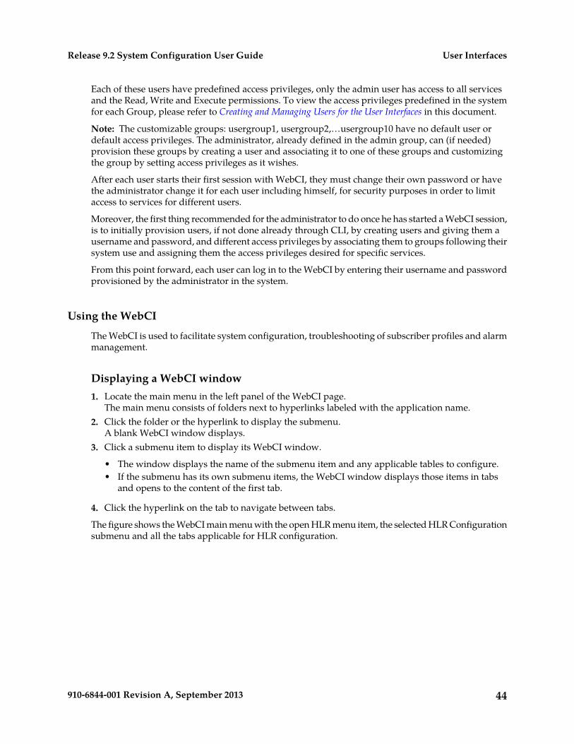
Each of these users have predefined access privileges, only the admin user has access to all servicesand the Read, Write and Execute permissions. To view the access privileges predefined in the systemfor each Group, please refer to Creating and Managing Users for the User Interfaces in this document.
Note: The customizable groups: usergroup1, usergroup2,…usergroup10 have no default user ordefault access privileges. The administrator, already defined in the admin group, can (if needed)provision these groups by creating a user and associating it to one of these groups and customizingthe group by setting access privileges as it wishes.
After each user starts their first session with WebCI, they must change their own password or havethe administrator change it for each user including himself, for security purposes in order to limitaccess to services for different users.
Moreover, the first thing recommended for the administrator to do once he has started a WebCI session,is to initially provision users, if not done already through CLI, by creating users and giving them ausername and password, and different access privileges by associating them to groups following theirsystem use and assigning them the access privileges desired for specific services.
From this point forward, each user can log in to the WebCI by entering their username and passwordprovisioned by the administrator in the system.
Using the WebCI
The WebCI is used to facilitate system configuration, troubleshooting of subscriber profiles and alarmmanagement.
Displaying a WebCI window1. Locate the main menu in the left panel of the WebCI page.
The main menu consists of folders next to hyperlinks labeled with the application name.2. Click the folder or the hyperlink to display the submenu.
A blank WebCI window displays.3. Click a submenu item to display its WebCI window.
• The window displays the name of the submenu item and any applicable tables to configure.• If the submenu has its own submenu items, the WebCI window displays those items in tabs
and opens to the content of the first tab.
4. Click the hyperlink on the tab to navigate between tabs.
The figure shows the WebCI main menu with the open HLR menu item, the selected HLR Configurationsubmenu and all the tabs applicable for HLR configuration.
44910-6844-001 Revision A, September 2013
User InterfacesRelease 9.2 System Configuration User Guide
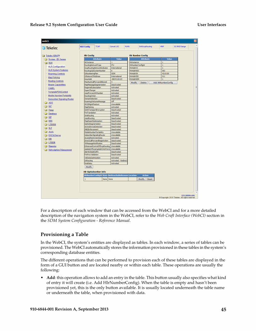
For a description of each window that can be accessed from the WebCI and for a more detaileddescription of the navigation system in the WebCI, refer to the Web Craft Interface (WebCI) section inthe SDM System Configuration - Reference Manual.
Provisioning a TableIn the WebCI, the system’s entities are displayed as tables. In each window, a series of tables can beprovisioned. The WebCI automatically stores the information provisioned in these tables in the system’scorresponding database entities.
The different operations that can be performed to provision each of these tables are displayed in theform of a GUI button and are located nearby or within each table. These operations are usually thefollowing:
• Add: this operation allows to add an entry in the table. This button usually also specifies what kindof entry it will create (i.e. Add HlrNumberConfig). When the table is empty and hasn’t beenprovisioned yet, this is the only button available. It is usually located underneath the table nameor underneath the table, when provisioned with data.
45910-6844-001 Revision A, September 2013
User InterfacesRelease 9.2 System Configuration User Guide
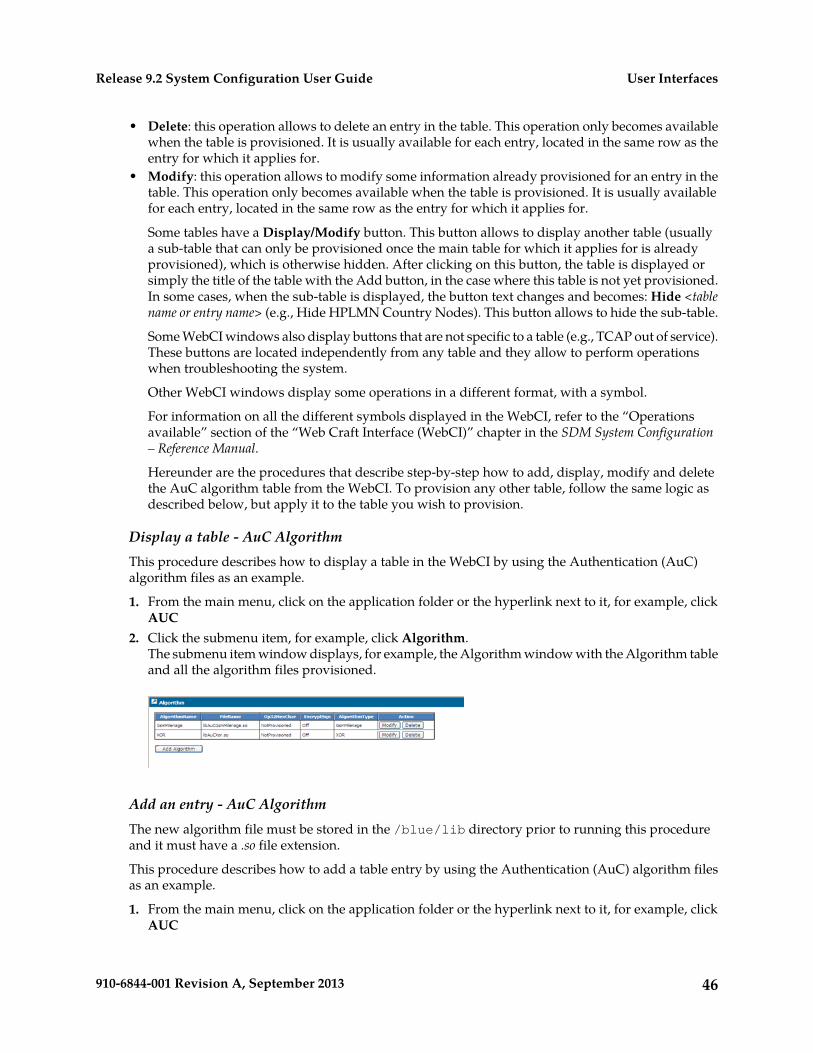
• Delete: this operation allows to delete an entry in the table. This operation only becomes availablewhen the table is provisioned. It is usually available for each entry, located in the same row as theentry for which it applies for.
• Modify: this operation allows to modify some information already provisioned for an entry in thetable. This operation only becomes available when the table is provisioned. It is usually availablefor each entry, located in the same row as the entry for which it applies for.
Some tables have a Display/Modify button. This button allows to display another table (usuallya sub-table that can only be provisioned once the main table for which it applies for is alreadyprovisioned), which is otherwise hidden. After clicking on this button, the table is displayed orsimply the title of the table with the Add button, in the case where this table is not yet provisioned.In some cases, when the sub-table is displayed, the button text changes and becomes: Hide <tablename or entry name> (e.g., Hide HPLMN Country Nodes). This button allows to hide the sub-table.
Some WebCI windows also display buttons that are not specific to a table (e.g., TCAP out of service).These buttons are located independently from any table and they allow to perform operationswhen troubleshooting the system.
Other WebCI windows display some operations in a different format, with a symbol.
For information on all the different symbols displayed in the WebCI, refer to the “Operationsavailable” section of the “Web Craft Interface (WebCI)” chapter in the SDM System Configuration– Reference Manual.
Hereunder are the procedures that describe step-by-step how to add, display, modify and deletethe AuC algorithm table from the WebCI. To provision any other table, follow the same logic asdescribed below, but apply it to the table you wish to provision.
Display a table - AuC AlgorithmThis procedure describes how to display a table in the WebCI by using the Authentication (AuC)algorithm files as an example.
1. From the main menu, click on the application folder or the hyperlink next to it, for example, clickAUC
2. Click the submenu item, for example, click Algorithm.The submenu item window displays, for example, the Algorithm window with the Algorithm tableand all the algorithm files provisioned.
Add an entry - AuC AlgorithmThe new algorithm file must be stored in the /blue/lib directory prior to running this procedureand it must have a .so file extension.
This procedure describes how to add a table entry by using the Authentication (AuC) algorithm filesas an example.
1. From the main menu, click on the application folder or the hyperlink next to it, for example, clickAUC
46910-6844-001 Revision A, September 2013
User InterfacesRelease 9.2 System Configuration User Guide
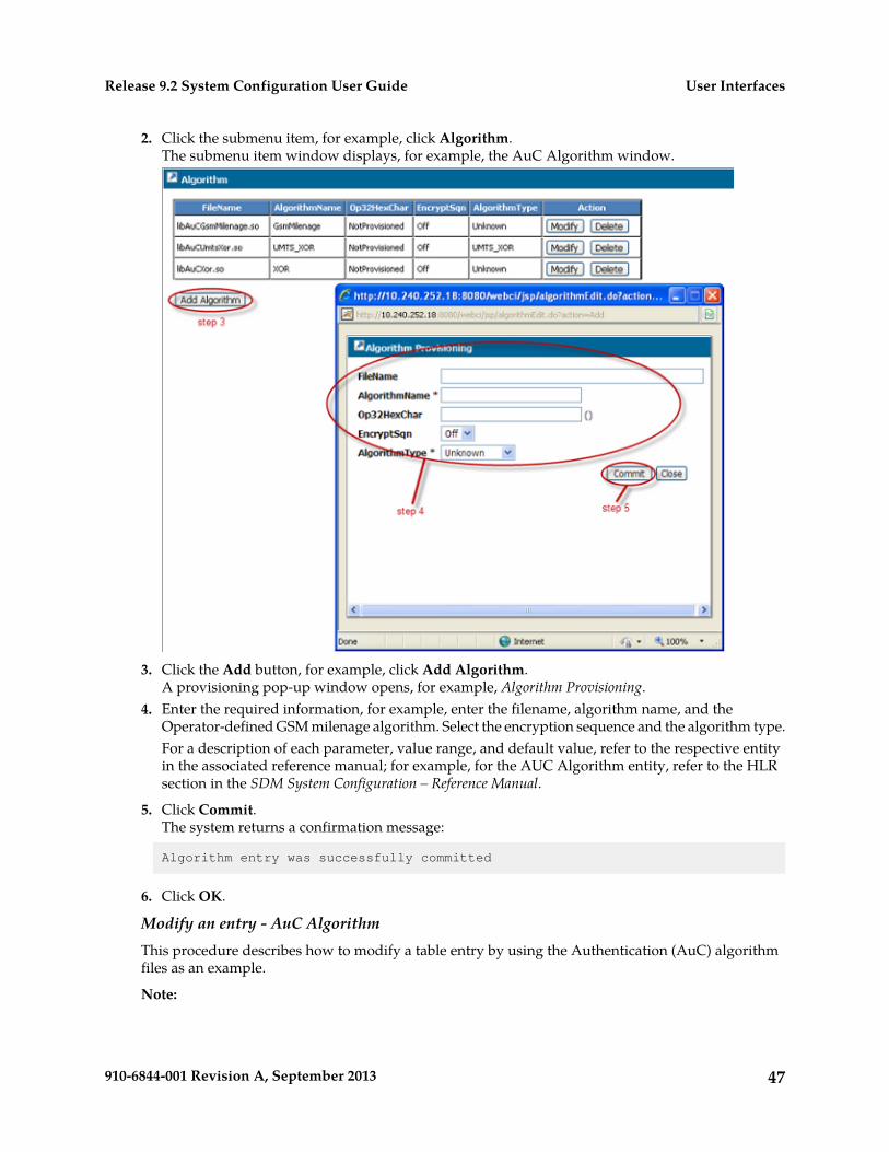
2. Click the submenu item, for example, click Algorithm.The submenu item window displays, for example, the AuC Algorithm window.
3. Click the Add button, for example, click Add Algorithm.A provisioning pop-up window opens, for example, Algorithm Provisioning.
4. Enter the required information, for example, enter the filename, algorithm name, and theOperator-defined GSM milenage algorithm. Select the encryption sequence and the algorithm type.For a description of each parameter, value range, and default value, refer to the respective entityin the associated reference manual; for example, for the AUC Algorithm entity, refer to the HLRsection in the SDM System Configuration – Reference Manual.
5. Click Commit.The system returns a confirmation message:
Algorithm entry was successfully committed
6. Click OK.
Modify an entry - AuC AlgorithmThis procedure describes how to modify a table entry by using the Authentication (AuC) algorithmfiles as an example.
Note:
47910-6844-001 Revision A, September 2013
User InterfacesRelease 9.2 System Configuration User Guide
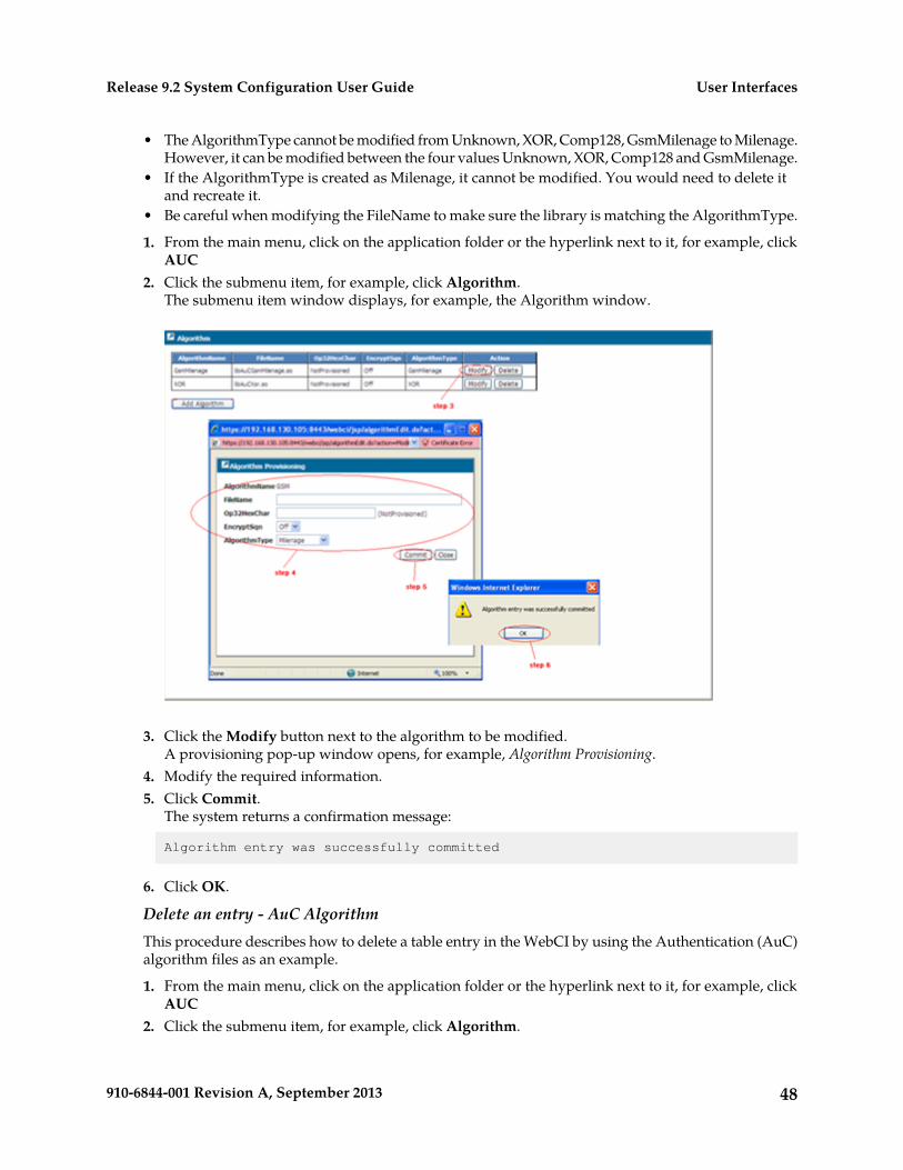
• The AlgorithmType cannot be modified from Unknown, XOR, Comp128, GsmMilenage to Milenage.However, it can be modified between the four values Unknown, XOR, Comp128 and GsmMilenage.
• If the AlgorithmType is created as Milenage, it cannot be modified. You would need to delete itand recreate it.
• Be careful when modifying the FileName to make sure the library is matching the AlgorithmType.
1. From the main menu, click on the application folder or the hyperlink next to it, for example, clickAUC
2. Click the submenu item, for example, click Algorithm.The submenu item window displays, for example, the Algorithm window.
3. Click the Modify button next to the algorithm to be modified.A provisioning pop-up window opens, for example, Algorithm Provisioning.
4. Modify the required information.5. Click Commit.
The system returns a confirmation message:
Algorithm entry was successfully committed
6. Click OK.
Delete an entry - AuC AlgorithmThis procedure describes how to delete a table entry in the WebCI by using the Authentication (AuC)algorithm files as an example.
1. From the main menu, click on the application folder or the hyperlink next to it, for example, clickAUC
2. Click the submenu item, for example, click Algorithm.
48910-6844-001 Revision A, September 2013
User InterfacesRelease 9.2 System Configuration User Guide
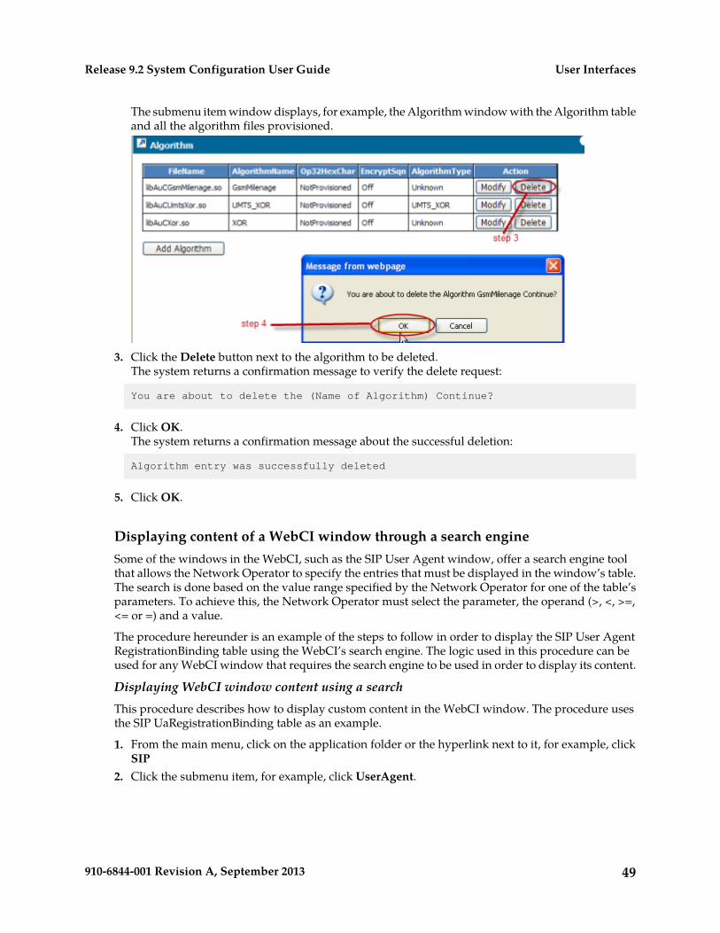
The submenu item window displays, for example, the Algorithm window with the Algorithm tableand all the algorithm files provisioned.
3. Click the Delete button next to the algorithm to be deleted.The system returns a confirmation message to verify the delete request:
You are about to delete the (Name of Algorithm) Continue?
4. Click OK.The system returns a confirmation message about the successful deletion:
Algorithm entry was successfully deleted
5. Click OK.
Displaying content of a WebCI window through a search engineSome of the windows in the WebCI, such as the SIP User Agent window, offer a search engine toolthat allows the Network Operator to specify the entries that must be displayed in the window’s table.The search is done based on the value range specified by the Network Operator for one of the table’sparameters. To achieve this, the Network Operator must select the parameter, the operand (>, <, >=,<= or =) and a value.
The procedure hereunder is an example of the steps to follow in order to display the SIP User AgentRegistrationBinding table using the WebCI’s search engine. The logic used in this procedure can beused for any WebCI window that requires the search engine to be used in order to display its content.
Displaying WebCI window content using a searchThis procedure describes how to display custom content in the WebCI window. The procedure usesthe SIP UaRegistrationBinding table as an example.
1. From the main menu, click on the application folder or the hyperlink next to it, for example, clickSIP
2. Click the submenu item, for example, click UserAgent.
49910-6844-001 Revision A, September 2013
User InterfacesRelease 9.2 System Configuration User Guide
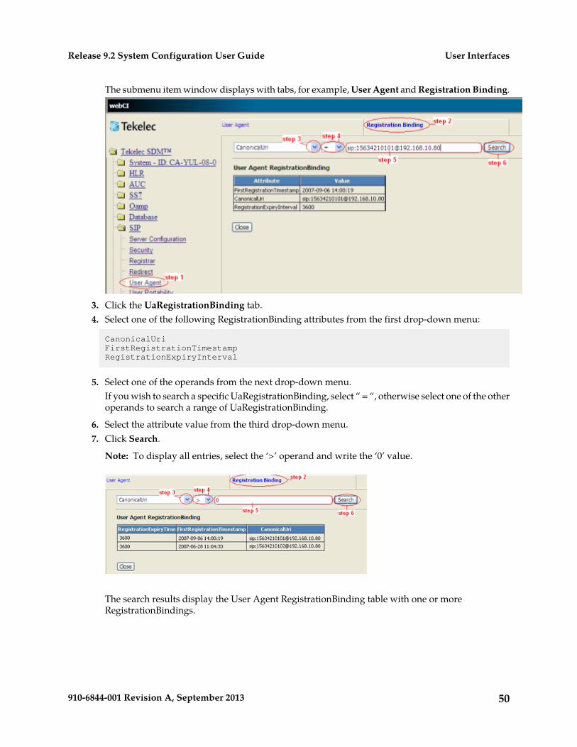
The submenu item window displays with tabs, for example, User Agent and Registration Binding.
3. Click the UaRegistrationBinding tab.4. Select one of the following RegistrationBinding attributes from the first drop-down menu:
CanonicalUriFirstRegistrationTimestampRegistrationExpiryInterval
5. Select one of the operands from the next drop-down menu.If you wish to search a specific UaRegistrationBinding, select “ = “, otherwise select one of the otheroperands to search a range of UaRegistrationBinding.
6. Select the attribute value from the third drop-down menu.7. Click Search.
Note: To display all entries, select the ‘>’ operand and write the ‘0’ value.
The search results display the User Agent RegistrationBinding table with one or moreRegistrationBindings.
50910-6844-001 Revision A, September 2013
User InterfacesRelease 9.2 System Configuration User Guide
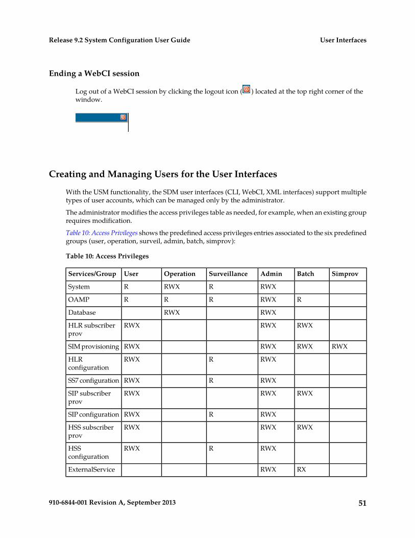
Ending a WebCI session
Log out of a WebCI session by clicking the logout icon ( ) located at the top right corner of thewindow.
Creating and Managing Users for the User Interfaces
With the USM functionality, the SDM user interfaces (CLI, WebCI, XML interfaces) support multipletypes of user accounts, which can be managed only by the administrator.
The administrator modifies the access privileges table as needed, for example, when an existing grouprequires modification.
Table 10: Access Privileges shows the predefined access privileges entries associated to the six predefinedgroups (user, operation, surveil, admin, batch, simprov):
Table 10: Access Privileges
SimprovBatchAdminSurveillanceOperationUserServices/Group
RWXRRWXRSystem
RRWXRRROAMP
RWXRWXDatabase
RWXRWXRWXHLR subscriberprov
RWXRWXRWXRWXSIM provisioning
RWXRRWXHLRconfiguration
RWXRRWXSS7 configuration
RWXRWXRWXSIP subscriberprov
RWXRRWXSIP configuration
RWXRWXRWXHSS subscriberprov
RWXRRWXHSSconfiguration
RXRWXExternalService
51910-6844-001 Revision A, September 2013
User InterfacesRelease 9.2 System Configuration User Guide
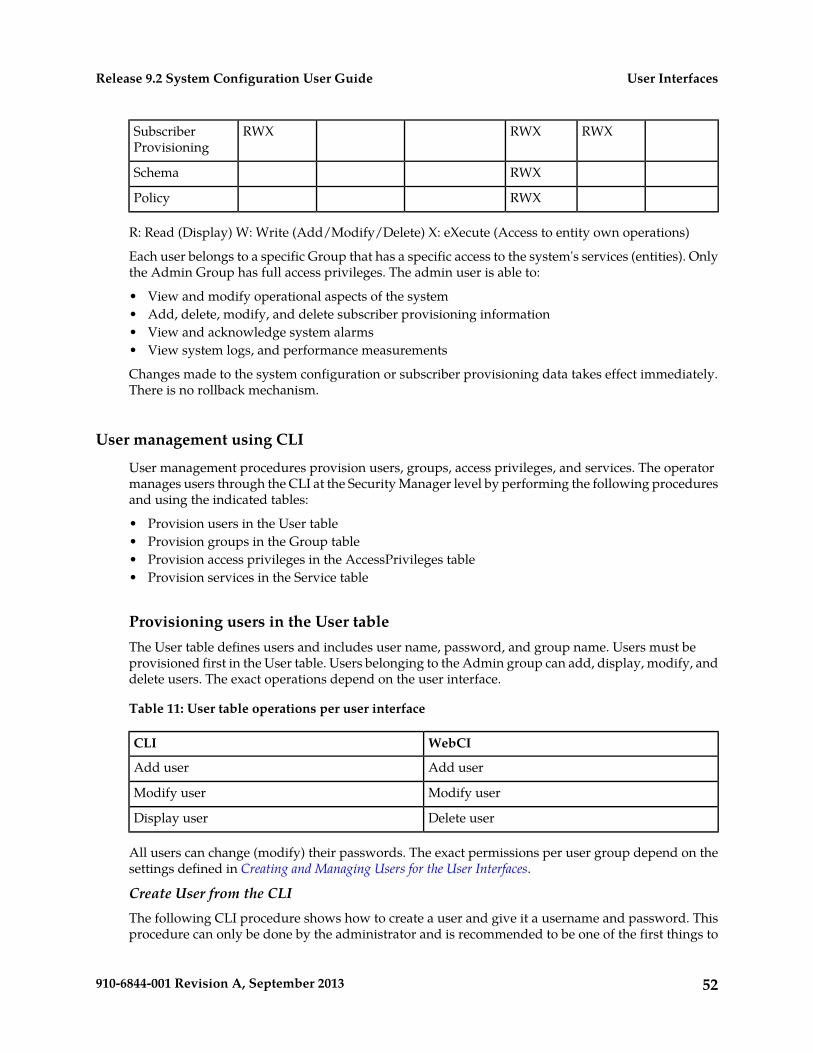
RWXRWXRWXSubscriberProvisioning
RWXSchema
RWXPolicy
R: Read (Display) W: Write (Add/Modify/Delete) X: eXecute (Access to entity own operations)
Each user belongs to a specific Group that has a specific access to the system's services (entities). Onlythe Admin Group has full access privileges. The admin user is able to:
• View and modify operational aspects of the system• Add, delete, modify, and delete subscriber provisioning information• View and acknowledge system alarms• View system logs, and performance measurements
Changes made to the system configuration or subscriber provisioning data takes effect immediately.There is no rollback mechanism.
User management using CLI
User management procedures provision users, groups, access privileges, and services. The operatormanages users through the CLI at the Security Manager level by performing the following proceduresand using the indicated tables:
• Provision users in the User table• Provision groups in the Group table• Provision access privileges in the AccessPrivileges table• Provision services in the Service table
Provisioning users in the User tableThe User table defines users and includes user name, password, and group name. Users must beprovisioned first in the User table. Users belonging to the Admin group can add, display, modify, anddelete users. The exact operations depend on the user interface.
Table 11: User table operations per user interface
WebCICLI
Add userAdd user
Modify userModify user
Delete userDisplay user
All users can change (modify) their passwords. The exact permissions per user group depend on thesettings defined in Creating and Managing Users for the User Interfaces.
Create User from the CLIThe following CLI procedure shows how to create a user and give it a username and password. Thisprocedure can only be done by the administrator and is recommended to be one of the first things to
52910-6844-001 Revision A, September 2013
User InterfacesRelease 9.2 System Configuration User Guide
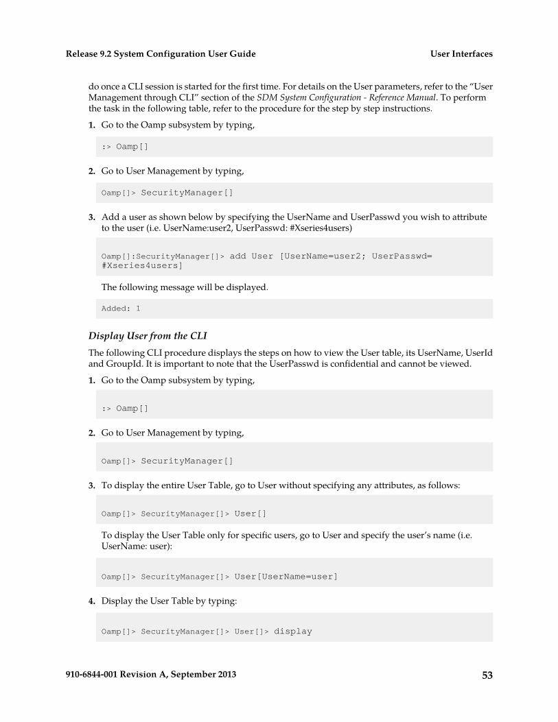
do once a CLI session is started for the first time. For details on the User parameters, refer to the “UserManagement through CLI” section of the SDM System Configuration - Reference Manual. To performthe task in the following table, refer to the procedure for the step by step instructions.
1. Go to the Oamp subsystem by typing,
:> Oamp[]
2. Go to User Management by typing,
Oamp[]> SecurityManager[]
3. Add a user as shown below by specifying the UserName and UserPasswd you wish to attributeto the user (i.e. UserName:user2, UserPasswd: #Xseries4users)
Oamp[]:SecurityManager[]> add User [UserName=user2; UserPasswd= #Xseries4users]
The following message will be displayed.
Added: 1
Display User from the CLIThe following CLI procedure displays the steps on how to view the User table, its UserName, UserIdand GroupId. It is important to note that the UserPasswd is confidential and cannot be viewed.
1. Go to the Oamp subsystem by typing,
:> Oamp[]
2. Go to User Management by typing,
Oamp[]> SecurityManager[]
3. To display the entire User Table, go to User without specifying any attributes, as follows:
Oamp[]> SecurityManager[]> User[]
To display the User Table only for specific users, go to User and specify the user’s name (i.e.UserName: user):
Oamp[]> SecurityManager[]> User[UserName=user]
4. Display the User Table by typing:
Oamp[]> SecurityManager[]> User[]> display
53910-6844-001 Revision A, September 2013
User InterfacesRelease 9.2 System Configuration User Guide
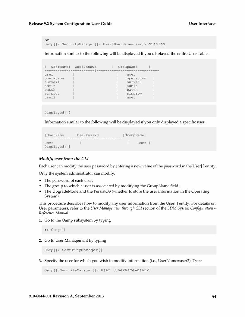
orOamp[]> SecurityManager[]> User[UserName=user]> display
Information similar to the following will be displayed if you displayed the entire User Table:
| UserName| UserPasswd | GroupName |-----------------------|-----------------------------user | | user |operation | | operation |surveil | | surveil |admin | | admin |batch | | batch |simprov | | simprov |user2 | | user |
Displayed: 7
Information similar to the following will be displayed if you only displayed a specific user:
|UserName |UserPasswd |GroupName|------------------------------------user | | user |Displayed: 1
Modify user from the CLIEach user can modify the user password by entering a new value of the password in the User[ ] entity.
Only the system administrator can modify:
• The password of each user.• The group to which a user is associated by modifying the GroupName field.• The UpgradeMode and the PersistOS (whether to store the user information in the Operating
System)
This procedure describes how to modify any user information from the User[ ] entity. For details onUser parameters, refer to the User Management through CLI section of the SDM System Configuration -Reference Manual.
1. Go to the Oamp subsystem by typing
:> Oamp[]
2. Go to User Management by typing
Oamp[]> SecurityManager[]
3. Specify the user for which you wish to modify information (i.e., UserName=user2). Type
Oamp[]:SecurityManager[]> User [UserName=user2]
54910-6844-001 Revision A, September 2013
User InterfacesRelease 9.2 System Configuration User Guide
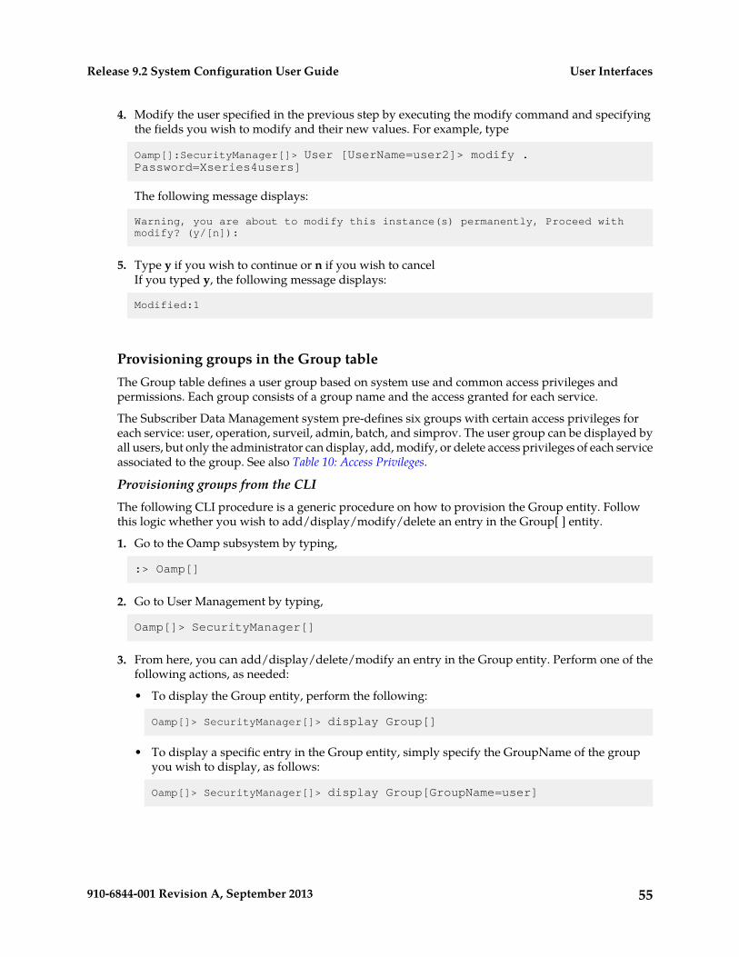
4. Modify the user specified in the previous step by executing the modify command and specifyingthe fields you wish to modify and their new values. For example, type
Oamp[]:SecurityManager[]> User [UserName=user2]> modify . Password=Xseries4users]
The following message displays:
Warning, you are about to modify this instance(s) permanently, Proceed with modify? (y/[n]):
5. Type y if you wish to continue or n if you wish to cancelIf you typed y, the following message displays:
Modified:1
Provisioning groups in the Group tableThe Group table defines a user group based on system use and common access privileges andpermissions. Each group consists of a group name and the access granted for each service.
The Subscriber Data Management system pre-defines six groups with certain access privileges foreach service: user, operation, surveil, admin, batch, and simprov. The user group can be displayed byall users, but only the administrator can display, add, modify, or delete access privileges of each serviceassociated to the group. See also Table 10: Access Privileges.
Provisioning groups from the CLIThe following CLI procedure is a generic procedure on how to provision the Group entity. Followthis logic whether you wish to add/display/modify/delete an entry in the Group[ ] entity.
1. Go to the Oamp subsystem by typing,
:> Oamp[]
2. Go to User Management by typing,
Oamp[]> SecurityManager[]
3. From here, you can add/display/delete/modify an entry in the Group entity. Perform one of thefollowing actions, as needed:
• To display the Group entity, perform the following:
Oamp[]> SecurityManager[]> display Group[]
• To display a specific entry in the Group entity, simply specify the GroupName of the groupyou wish to display, as follows:
Oamp[]> SecurityManager[]> display Group[GroupName=user]
55910-6844-001 Revision A, September 2013
User InterfacesRelease 9.2 System Configuration User Guide
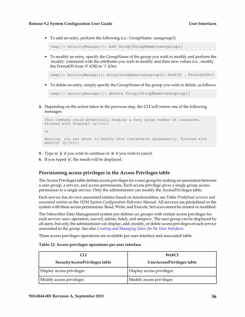
• To add an entry, perform the following (i.e.: GroupName: usergroup1):
Oamp[]> SecurityManager[]> add Group[GroupName=usergroup1]
• To modify an entry, specify the GroupName of the group you wish to modify and perform the'modify' command with the attributes you wish to modify and their new values (i.e.: modifythe PersistOS from '0' (Off) to '1' (On):
Oamp[]> SecurityManager[]> Group[GroupName=usergroup1]> modify . PersistOS=1
• To delete an entry, simply specify the GroupName of the group you wish to delete, as follows:
Oamp[]> SecurityManager[]> delete Group[GroupName=usergroup1]
4. Depending on the action taken in the previous step, the CLI will return one of the followingmessages:
This Command could potentially display a very large number of instances.Proceed with display? (y/[n]):
or
Warning, you are about to modify this instance(s) permanently, Proceed with modify? (y/[n]):
5. Type in 'y' if you wish to continue or 'n' if you wish to cancel.6. If you typed 'y', the result will be displayed.
Provisioning access privileges in the Access Privileges tableThe Access Privileges table defines access privileges for a user group by making an association betweena user group, a service, and access permissions. Each access privilege gives a single group accesspermission to a single service. Only the administrator can modify the AccessPrivileges table.
Each service has its own associated entities based on functionalities; see Table Predefined services andassociated entities in the SDM System Configuration Reference Manual. All services are predefined in thesystem with these access permissions: Read, Write, and Execute. Services cannot be created or modified.
The Subscriber Data Management system pre-defines six groups with certain access privileges foreach service: user, operation, surveil, admin, batch, and simprov. The user group can be displayed byall users, but only the administrator can display, add, modify, or delete access privileges of each serviceassociated to the group. See also Creating and Managing Users for the User Interfaces.
These access privileges operations are available per user interface and associated table:
Table 12: Access privileges operations per user interface
WebCI
UserAccessPrivileges table
CLI
SecurityAccessPrivileges table
Display access privilegesDisplay access privileges
Modify access privilegesModify access privileges
56910-6844-001 Revision A, September 2013
User InterfacesRelease 9.2 System Configuration User Guide
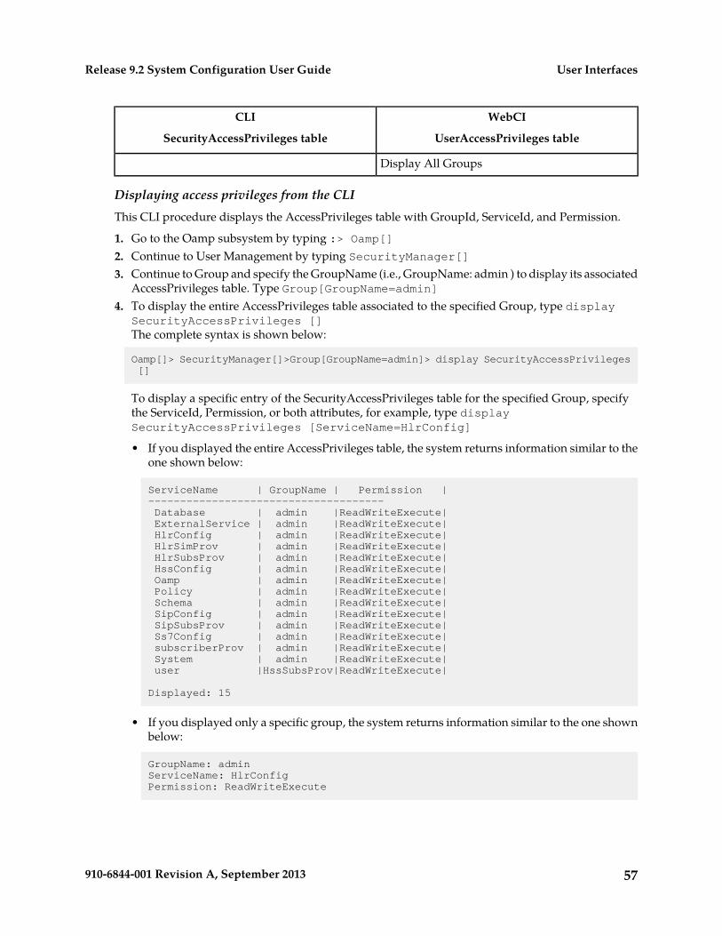
WebCI
UserAccessPrivileges table
CLI
SecurityAccessPrivileges table
Display All Groups
Displaying access privileges from the CLIThis CLI procedure displays the AccessPrivileges table with GroupId, ServiceId, and Permission.
1. Go to the Oamp subsystem by typing :> Oamp[]2. Continue to User Management by typing SecurityManager[]3. Continue to Group and specify the GroupName (i.e., GroupName: admin ) to display its associated
AccessPrivileges table. Type Group[GroupName=admin]4. To display the entire AccessPrivileges table associated to the specified Group, type display
SecurityAccessPrivileges []The complete syntax is shown below:
Oamp[]> SecurityManager[]>Group[GroupName=admin]> display SecurityAccessPrivileges []
To display a specific entry of the SecurityAccessPrivileges table for the specified Group, specifythe ServiceId, Permission, or both attributes, for example, type displaySecurityAccessPrivileges [ServiceName=HlrConfig]
• If you displayed the entire AccessPrivileges table, the system returns information similar to theone shown below:
ServiceName | GroupName | Permission |------------------------------------- Database | admin |ReadWriteExecute| ExternalService | admin |ReadWriteExecute| HlrConfig | admin |ReadWriteExecute| HlrSimProv | admin |ReadWriteExecute| HlrSubsProv | admin |ReadWriteExecute| HssConfig | admin |ReadWriteExecute| Oamp | admin |ReadWriteExecute| Policy | admin |ReadWriteExecute| Schema | admin |ReadWriteExecute| SipConfig | admin |ReadWriteExecute| SipSubsProv | admin |ReadWriteExecute| Ss7Config | admin |ReadWriteExecute| subscriberProv | admin |ReadWriteExecute| System | admin |ReadWriteExecute| user |HssSubsProv|ReadWriteExecute|
Displayed: 15
• If you displayed only a specific group, the system returns information similar to the one shownbelow:
GroupName: adminServiceName: HlrConfigPermission: ReadWriteExecute
57910-6844-001 Revision A, September 2013
User InterfacesRelease 9.2 System Configuration User Guide
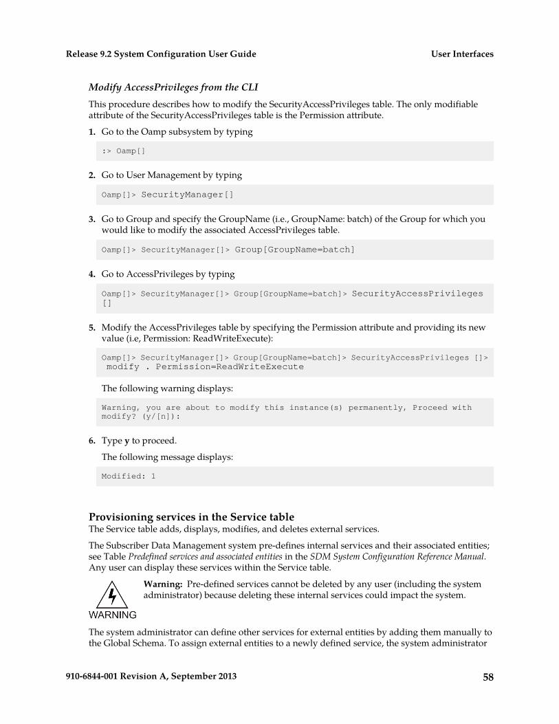
Modify AccessPrivileges from the CLIThis procedure describes how to modify the SecurityAccessPrivileges table. The only modifiableattribute of the SecurityAccessPrivileges table is the Permission attribute.
1. Go to the Oamp subsystem by typing
:> Oamp[]
2. Go to User Management by typing
Oamp[]> SecurityManager[]
3. Go to Group and specify the GroupName (i.e., GroupName: batch) of the Group for which youwould like to modify the associated AccessPrivileges table.
Oamp[]> SecurityManager[]> Group[GroupName=batch]
4. Go to AccessPrivileges by typing
Oamp[]> SecurityManager[]> Group[GroupName=batch]> SecurityAccessPrivileges []
5. Modify the AccessPrivileges table by specifying the Permission attribute and providing its newvalue (i.e, Permission: ReadWriteExecute):
Oamp[]> SecurityManager[]> Group[GroupName=batch]> SecurityAccessPrivileges []>modify . Permission=ReadWriteExecute
The following warning displays:
Warning, you are about to modify this instance(s) permanently, Proceed with modify? (y/[n]):
6. Type y to proceed.
The following message displays:
Modified: 1
Provisioning services in the Service tableThe Service table adds, displays, modifies, and deletes external services.
The Subscriber Data Management system pre-defines internal services and their associated entities;see Table Predefined services and associated entities in the SDM System Configuration Reference Manual.Any user can display these services within the Service table.
Warning: Pre-defined services cannot be deleted by any user (including the systemadministrator) because deleting these internal services could impact the system.
The system administrator can define other services for external entities by adding them manually tothe Global Schema. To assign external entities to a newly defined service, the system administrator
58910-6844-001 Revision A, September 2013
User InterfacesRelease 9.2 System Configuration User Guide
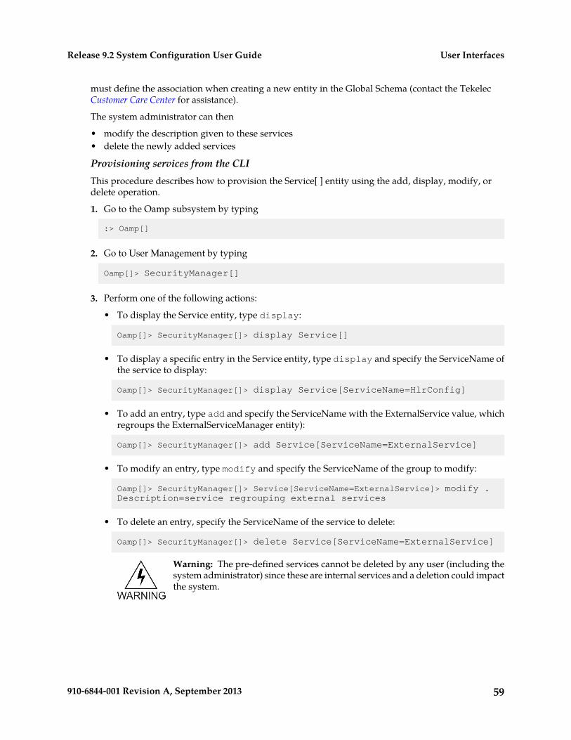
must define the association when creating a new entity in the Global Schema (contact the TekelecCustomer Care Center for assistance).
The system administrator can then
• modify the description given to these services• delete the newly added services
Provisioning services from the CLIThis procedure describes how to provision the Service[ ] entity using the add, display, modify, ordelete operation.
1. Go to the Oamp subsystem by typing
:> Oamp[]
2. Go to User Management by typing
Oamp[]> SecurityManager[]
3. Perform one of the following actions:
• To display the Service entity, type display:
Oamp[]> SecurityManager[]> display Service[]
• To display a specific entry in the Service entity, type display and specify the ServiceName ofthe service to display:
Oamp[]> SecurityManager[]> display Service[ServiceName=HlrConfig]
• To add an entry, type add and specify the ServiceName with the ExternalService value, whichregroups the ExternalServiceManager entity):
Oamp[]> SecurityManager[]> add Service[ServiceName=ExternalService]
• To modify an entry, type modify and specify the ServiceName of the group to modify:
Oamp[]> SecurityManager[]> Service[ServiceName=ExternalService]> modify . Description=service regrouping external services
• To delete an entry, specify the ServiceName of the service to delete:
Oamp[]> SecurityManager[]> delete Service[ServiceName=ExternalService]
Warning: The pre-defined services cannot be deleted by any user (including thesystem administrator) since these are internal services and a deletion could impactthe system.
59910-6844-001 Revision A, September 2013
User InterfacesRelease 9.2 System Configuration User Guide
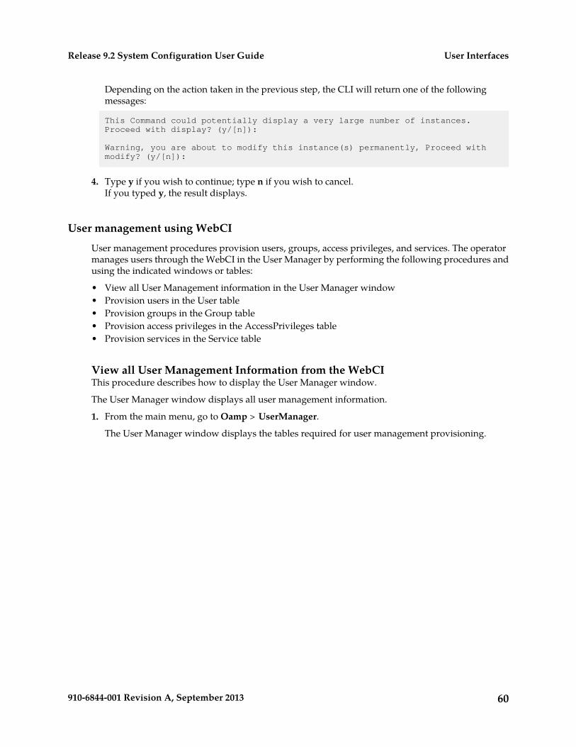
Depending on the action taken in the previous step, the CLI will return one of the followingmessages:
This Command could potentially display a very large number of instances.Proceed with display? (y/[n]):
Warning, you are about to modify this instance(s) permanently, Proceed with modify? (y/[n]):
4. Type y if you wish to continue; type n if you wish to cancel.If you typed y, the result displays.
User management using WebCI
User management procedures provision users, groups, access privileges, and services. The operatormanages users through the WebCI in the User Manager by performing the following procedures andusing the indicated windows or tables:
• View all User Management information in the User Manager window• Provision users in the User table• Provision groups in the Group table• Provision access privileges in the AccessPrivileges table• Provision services in the Service table
View all User Management Information from the WebCIThis procedure describes how to display the User Manager window.
The User Manager window displays all user management information.
1. From the main menu, go to Oamp > UserManager.
The User Manager window displays the tables required for user management provisioning.
60910-6844-001 Revision A, September 2013
User InterfacesRelease 9.2 System Configuration User Guide
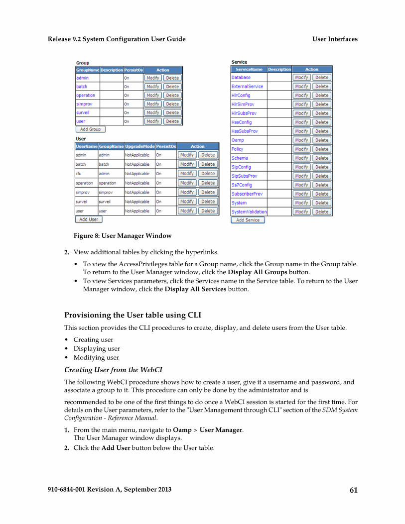
Figure 8: User Manager Window
2. View additional tables by clicking the hyperlinks.
• To view the AccessPrivileges table for a Group name, click the Group name in the Group table.To return to the User Manager window, click the Display All Groups button.
• To view Services parameters, click the Services name in the Service table. To return to the UserManager window, click the Display All Services button.
Provisioning the User table using CLIThis section provides the CLI procedures to create, display, and delete users from the User table.
• Creating user• Displaying user• Modifying user
Creating User from the WebCIThe following WebCI procedure shows how to create a user, give it a username and password, andassociate a group to it. This procedure can only be done by the administrator and is
recommended to be one of the first things to do once a WebCI session is started for the first time. Fordetails on the User parameters, refer to the "User Management through CLI" section of the SDM SystemConfiguration - Reference Manual.
1. From the main menu, navigate to Oamp > User Manager.The User Manager window displays.
2. Click the Add User button below the User table.
61910-6844-001 Revision A, September 2013
User InterfacesRelease 9.2 System Configuration User Guide
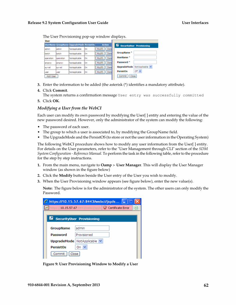
The User Provisioning pop-up window displays.
3. Enter the information to be added (the asterisk (*) identifies a mandatory attribute).4. Click Commit.
The system returns a confirmation message User entry was successfully committed5. Click OK.
Modifying a User from the WebCIEach user can modify its own password by modifying the User[ ] entity and entering the value of thenew password desired. However, only the administrator of the system can modify the following:
• The password of each user.• The group to which a user is associated to, by modifying the GroupName field.• The UpgradeMode and the PersistOS (to store or not the user information in the Operating System)
The following WebCI procedure shows how to modify any user information from the User[ ] entity.For details on the User parameters, refer to the "User Management through CLI" section of the SDMSystem Configuration - Reference Manual. To perform the task in the following table, refer to the procedurefor the step by step instructions.
1. From the main menu, navigate to Oamp > User Manager. This will display the User Managerwindow (as shown in the figure below)
2. Click the Modify button beside the User entry of the User you wish to modify.3. When the User Provisioning window appears (see figure below), enter the new value(s).
Note: The figure below is for the administrator of the system. The other users can only modify thePassword.
Figure 9: User Provisioning Window to Modify a User
62910-6844-001 Revision A, September 2013
User InterfacesRelease 9.2 System Configuration User Guide
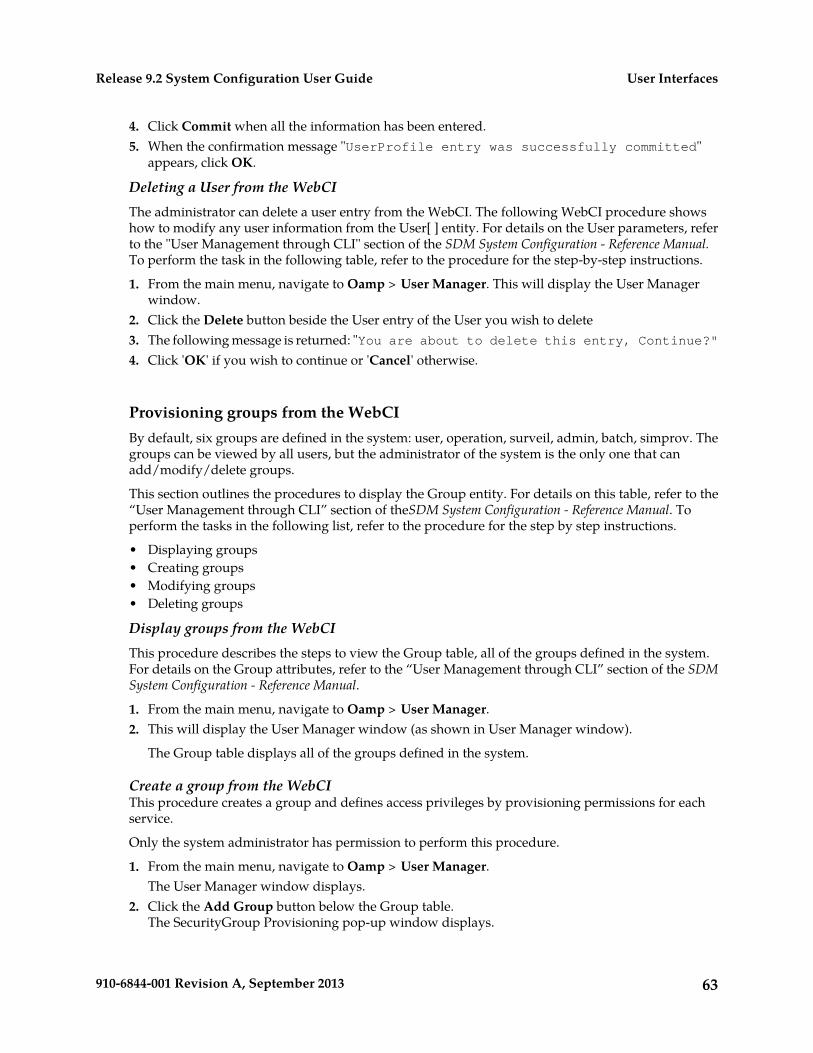
4. Click Commit when all the information has been entered.5. When the confirmation message "UserProfile entry was successfully committed"
appears, click OK.
Deleting a User from the WebCIThe administrator can delete a user entry from the WebCI. The following WebCI procedure showshow to modify any user information from the User[ ] entity. For details on the User parameters, referto the "User Management through CLI" section of the SDM System Configuration - Reference Manual.To perform the task in the following table, refer to the procedure for the step-by-step instructions.
1. From the main menu, navigate to Oamp > User Manager. This will display the User Managerwindow.
2. Click the Delete button beside the User entry of the User you wish to delete3. The following message is returned: "You are about to delete this entry, Continue?"4. Click 'OK' if you wish to continue or 'Cancel' otherwise.
Provisioning groups from the WebCIBy default, six groups are defined in the system: user, operation, surveil, admin, batch, simprov. Thegroups can be viewed by all users, but the administrator of the system is the only one that canadd/modify/delete groups.
This section outlines the procedures to display the Group entity. For details on this table, refer to the“User Management through CLI” section of theSDM System Configuration - Reference Manual. Toperform the tasks in the following list, refer to the procedure for the step by step instructions.
• Displaying groups• Creating groups• Modifying groups• Deleting groups
Display groups from the WebCIThis procedure describes the steps to view the Group table, all of the groups defined in the system.For details on the Group attributes, refer to the “User Management through CLI” section of the SDMSystem Configuration - Reference Manual.
1. From the main menu, navigate to Oamp > User Manager.2. This will display the User Manager window (as shown in User Manager window).
The Group table displays all of the groups defined in the system.
Create a group from the WebCIThis procedure creates a group and defines access privileges by provisioning permissions for eachservice.
Only the system administrator has permission to perform this procedure.
1. From the main menu, navigate to Oamp > User Manager.The User Manager window displays.
2. Click the Add Group button below the Group table.The SecurityGroup Provisioning pop-up window displays.
63910-6844-001 Revision A, September 2013
User InterfacesRelease 9.2 System Configuration User Guide
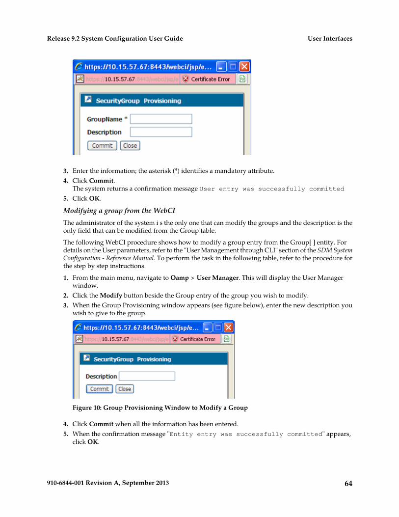
3. Enter the information; the asterisk (*) identifies a mandatory attribute.4. Click Commit.
The system returns a confirmation message User entry was successfully committed5. Click OK.
Modifying a group from the WebCIThe administrator of the system i s the only one that can modify the groups and the description is theonly field that can be modified from the Group table.
The following WebCI procedure shows how to modify a group entry from the Group[ ] entity. Fordetails on the User parameters, refer to the "User Management through CLI" section of the SDM SystemConfiguration - Reference Manual. To perform the task in the following table, refer to the procedure forthe step by step instructions.
1. From the main menu, navigate to Oamp > User Manager. This will display the User Managerwindow.
2. Click the Modify button beside the Group entry of the group you wish to modify.3. When the Group Provisioning window appears (see figure below), enter the new description you
wish to give to the group.
Figure 10: Group Provisioning Window to Modify a Group
4. Click Commit when all the information has been entered.5. When the confirmation message "Entity entry was successfully committed" appears,
click OK.
64910-6844-001 Revision A, September 2013
User InterfacesRelease 9.2 System Configuration User Guide
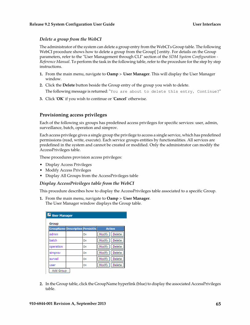
Delete a group from the WebCIThe administrator of the system can delete a group entry from the WebCI's Group table. The followingWebCI procedure shows how to delete a group from the Group[ ] entity. For details on the Groupparameters, refer to the "User Management through CLI" section of the SDM System Configuration -Reference Manual. To perform the task in the following table, refer to the procedure for the step by stepinstructions.
1. From the main menu, navigate to Oamp > User Manager. This will display the User Managerwindow.
2. Click the Delete button beside the Group entry of the group you wish to delete.The following message is returned: "You are about to delete this entry, Continue?"
3. Click 'OK' if you wish to continue or 'Cancel' otherwise.
Provisioning access privilegesEach of the following six groups has predefined access privileges for specific services: user, admin,surveillance, batch, operation and simprov.
Each access privilege gives a single group the privilege to access a single service, which has predefinedpermissions (read, write, execute). Each service groups entities by functionalities. All services arepredefined in the system and cannot be created or modified. Only the administrator can modify theAccessPrivileges table.
These procedures provision access privileges:
• Display Access Privileges• Modify Access Privileges• Display All Groups from the AccessPrivileges table
Display AccessPrivileges table from the WebCIThis procedure describes how to display the AccessPrivileges table associated to a specific Group.
1. From the main menu, navigate to Oamp > User Manager.The User Manager window displays the Group table.
2. In the Group table, click the GroupName hyperlink (blue) to display the associated AccessPrivilegestable.
65910-6844-001 Revision A, September 2013
User InterfacesRelease 9.2 System Configuration User Guide
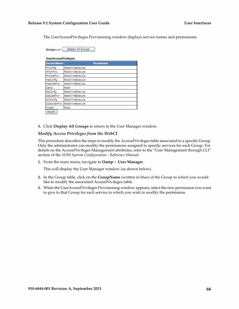
The UserAccessPrivileges Provisioning window displays service names and permissions.
3. Click Display All Groups to return to the User Manager window.
Modify Access Privileges from the WebCIThis procedure describes the steps to modify the AccessPrivileges table associated to a specific Group.Only the administrator can modify the permissions assigned to specific services for each Group. Fordetails on the AccessPrivileges Management attributes, refer to the “User Management through CLI”section of the SDM System Configuration - Reference Manual.
1. From the main menu, navigate to Oamp > User Manager.
This will display the User Manager window (as shown below).
2. In the Group table, click on the GroupName (written in blue) of the Group to which you wouldlike to modify the associated AccessPrivileges table.
3. When the UserAccessPrivileges Provisioning window appears, select the new permission you wantto give to that Group for each service to which you wish to modify the permission.
66910-6844-001 Revision A, September 2013
User InterfacesRelease 9.2 System Configuration User Guide
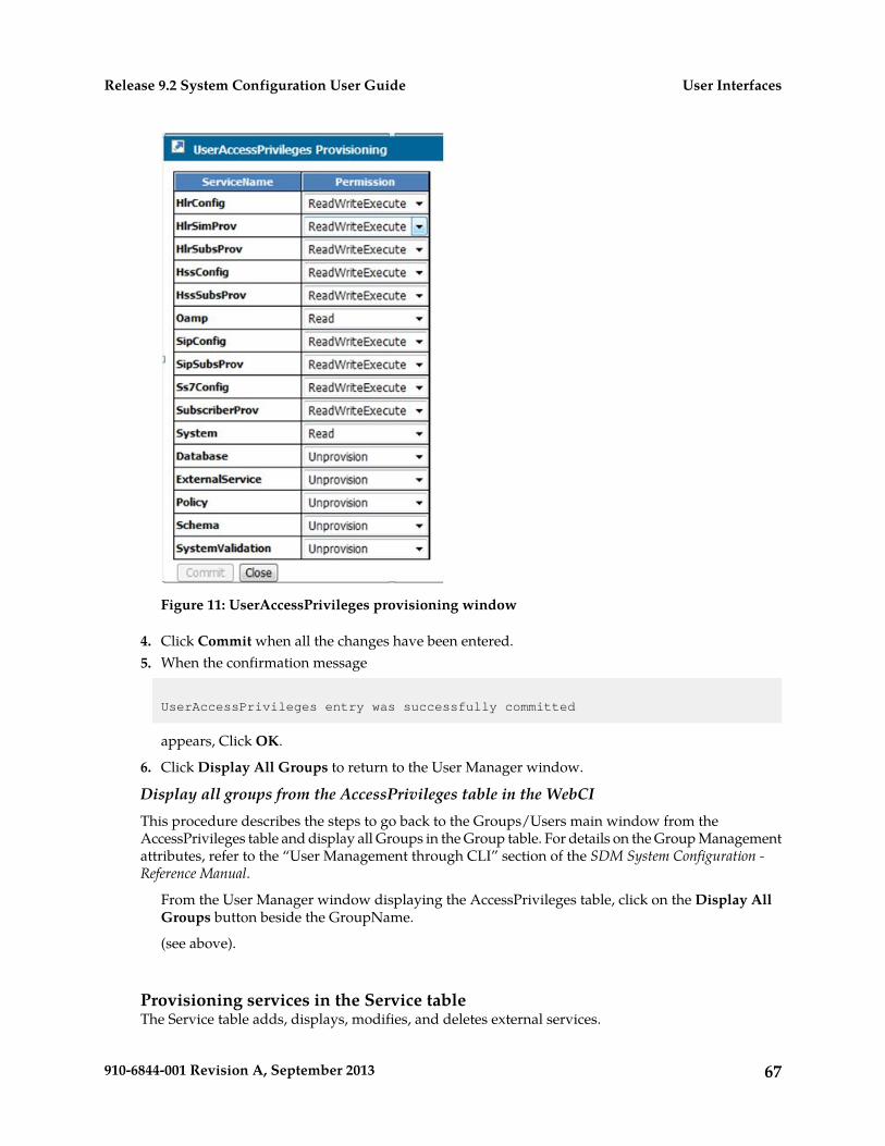
Figure 11: UserAccessPrivileges provisioning window
4. Click Commit when all the changes have been entered.5. When the confirmation message
UserAccessPrivileges entry was successfully committed
appears, Click OK.
6. Click Display All Groups to return to the User Manager window.
Display all groups from the AccessPrivileges table in the WebCIThis procedure describes the steps to go back to the Groups/Users main window from theAccessPrivileges table and display all Groups in the Group table. For details on the Group Managementattributes, refer to the “User Management through CLI” section of the SDM System Configuration -Reference Manual.
From the User Manager window displaying the AccessPrivileges table, click on the Display AllGroups button beside the GroupName.
(see above).
Provisioning services in the Service tableThe Service table adds, displays, modifies, and deletes external services.
67910-6844-001 Revision A, September 2013
User InterfacesRelease 9.2 System Configuration User Guide
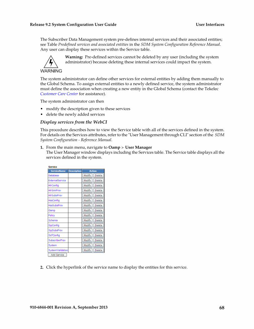
The Subscriber Data Management system pre-defines internal services and their associated entities;see Table Predefined services and associated entities in the SDM System Configuration Reference Manual.Any user can display these services within the Service table.
Warning: Pre-defined services cannot be deleted by any user (including the systemadministrator) because deleting these internal services could impact the system.
The system administrator can define other services for external entities by adding them manually tothe Global Schema. To assign external entities to a newly defined service, the system administratormust define the association when creating a new entity in the Global Schema (contact the TekelecCustomer Care Center for assistance).
The system administrator can then
• modify the description given to these services• delete the newly added services
Display services from the WebCIThis procedure describes how to view the Service table with all of the services defined in the system.For details on the Services attributes, refer to the "User Management through CLI" section of the SDMSystem Configuration - Reference Manual.
1. From the main menu, navigate to Oamp > User ManagerThe User Manager window displays including the Services table. The Service table displays all theservices defined in the system.
2. Click the hyperlink of the service name to display the entities for this service.
68910-6844-001 Revision A, September 2013
User InterfacesRelease 9.2 System Configuration User Guide
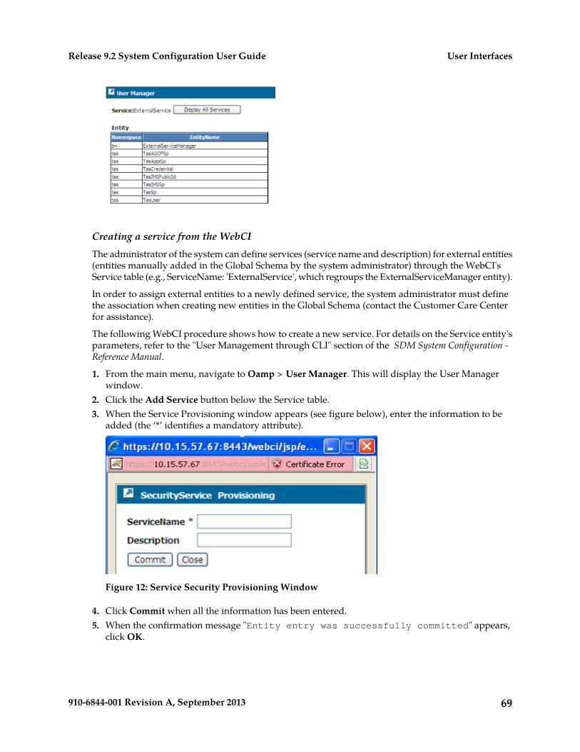
Creating a service from the WebCIThe administrator of the system can define services (service name and description) for external entities(entities manually added in the Global Schema by the system administrator) through the WebCI'sService table (e.g., ServiceName: 'ExternalService', which regroups the ExternalServiceManager entity).
In order to assign external entities to a newly defined service, the system administrator must definethe association when creating new entities in the Global Schema (contact the Customer Care Centerfor assistance).
The following WebCI procedure shows how to create a new service. For details on the Service entity'sparameters, refer to the "User Management through CLI" section of the SDM System Configuration -Reference Manual.
1. From the main menu, navigate to Oamp > User Manager. This will display the User Managerwindow.
2. Click the Add Service button below the Service table.3. When the Service Provisioning window appears (see figure below), enter the information to be
added (the ‘*’ identifies a mandatory attribute).
Figure 12: Service Security Provisioning Window
4. Click Commit when all the information has been entered.5. When the confirmation message "Entity entry was successfully committed" appears,
click OK.
69910-6844-001 Revision A, September 2013
User InterfacesRelease 9.2 System Configuration User Guide
Modifying a service from the WebCIThe administrator of the system can modify the description given to each service.
The following WebCI procedure shows how to modify a service entry from the Service[ ] entity. Fordetails on the Service parameters, refer to the "User Management through CLI" section of the SDMSystem Configuration - Reference Manual.
To perform the task in the following table, refer to the procedure for the step-by-step instructions.
1. From the main menu, navigate to Oamp > User Manager. This will display the User Managerwindow.
2. Click the Modify button beside the Service entry of the service you wish to modify.3. When the Service Provisioning window appears, enter the new description you wish to give to the
service.4. Click Commit when all the information has been entered.5. When the confirmation message "Entity entry was successfully committed" appears,
click OK.
Deleting a service from the WebCIThe pre-defined services cannot be deleted by any user (including the administrator of the system)since these are internal services and a deletion could impact the system. However, the administratorof the system can delete services that he has added himself that regroup external entities (not pre-definedones).
The following WebCI procedure shows how to delete a service from the Service[ ] entity. For detailson the Service parameters, refer to the "User Management through CLI" section of the SDM SystemConfiguration - Reference Manual. To perform the task in the following table, refer to the procedure forthe step by step instructions.
1. From the main menu, navigate to Oamp > User manager. This will display the User Managerwindow.
2. Click the Delete button beside the Service entry of the service you wish to delete.3. The following message is returned: “You are about to delete this entry, Continue?”4. Click OK if you wish to continue or Cancel, otherwise.
Creating and Managing Users for Notifications
The Notification Management functionality allows the management of users with notificationsubscription permissions for specific applications, entities and parameters.
The CLI and WebCI support multiple types of user accounts, which can only be managed by theadministrator. For an external application to be able to subscribe to notifications for specificapplications/entities/attributes, it must have a user account defined by the SDM system administratorwith a username, password and application name. The SDM system administrator must associateapplications to user accounts, by provisioning the UserApplicationMap[ ] entity. The users must firstbe defined in the User[ ] entity and the applications must also be defined with notification subscriptionpermissions for each entity/attribute as well as with notification properties. This can be provisionedin the ApplicationIdentity[ ], NotificationSubscribe[ ] and ApplicationProperty[ ] entities. Take note
70910-6844-001 Revision A, September 2013
User InterfacesRelease 9.2 System Configuration User Guide
that one user can have multiple applications associated to it, which allows the user to subscribenotifications for various applications.
For more details on the system's behavior, refer to the "Security Management" section of the SDMProduct Description. For more details on the entities to provision for Notification Management, referto the "Notification Security Management" section of the SDM System Configuration - Reference Manual.
Take note that changes made to the system configuration or subscriber provisioning data take effectimmediately. There is no rollback mechanism.
Notification Management Using CLI
Notification management requires the provisioning of users, their applications, and notificationsubscriptions/properties. Use these procedures:
• Provision applications• Provision notification subscription permissions• Provision notification properties• Provision users
Requirements: All CLI provisioning procedures require the operator to log into a CLI session with avalid username and password.
Define/Provision applications from the CLIThe following CLI procedure shows how the system's administrator can provision applications in theApplicationIdentity[ ] entity.
1. Go to the Oamp subsystem by typing,
:> Oamp[]
2. Go to Notification Management by typing,
Oamp[]> NotificationManager[]
3. Provision the ApplicationIdentity[ ] entity by performing one of the following commands, asneeded:
• Display the applications provisioned in the ApplicationIdentity[ ] entity by performing thefollowing:
Oamp[]> NotificationManager[]> display ApplicationIdentity[]
• Add an application by performing the following:
Oamp[]:NotificationManager[]> add ApplicationIdentity[ApplName=interface2]
The following message will be displayed:
Added: 1
71910-6844-001 Revision A, September 2013
User InterfacesRelease 9.2 System Configuration User Guide
• Modify an application by performing the following and specifying the new value:
Oamp[]:NotificationManager[]> ApplicationIdentity[ApplName=interface2]> modify . Description=RESTful interface
The following message will be returned:
Warning, you are about to modify this instance(s) permanently, Proceed with modify? (y/[n]):
Type y if you wish to continue or n to cancel.
• Delete an application by performing the following:
Oamp[]:NotificationManager[]> delete ApplicationIdentity[ApplName=interface2
The following message will be returned:
Warning, you are about to delete this instance(s) permanently, Proceed with delete? (y/[n]):
Type y if you wish to continue or n to cancel.
Provision notification subscription permissions from the CLI1. Go to the Oamp subsystem by typing :> Oamp[]2. Go to User Management by typing NotificationManager[]
Oamp[]> NotificationManager[]
3. Provision the NotificationSubscribe[ ] entity by performing one of the following commands:
• Display entities and attributes to which notifications can be subscribed for a specific applicationby typing Oamp[]> NotificationManager[]>ApplicationIdentity[ApplName=BlueCli] >display NotificationSubscribe[]
• Add an entity or attribute to which notifications can be subscribed for a specific application bytyping Oamp[]> NotificationManager[]>ApplicationIdentity[ApplName=BlueCli] > addNotificationSubscribe[Namespace=bn; Entity=MSISDN; Attribute=DefaultBsg]
The following message displays:
Added: 1
• Delete notification properties for an application by typing Oamp[]>NotificationManager[]> ApplicationIdentity[ApplName=BlueCli] > deleteNotificationSubscribe[Namespace=bn; Entity=MSISDN; Attribute=DefaultBsg]
The following message displays:
Warning, you are about to delete this instance(s) permanently, Proceed with delete? (y/[n]):
72910-6844-001 Revision A, September 2013
User InterfacesRelease 9.2 System Configuration User Guide
Type y to continue or n to cancel.
Provisioning notification properties from the CLINotification properties define per application whether the previous value (before update) must beincluded in the notifications in addition to the current value (after update). The administrator definesthese properties in the ApplicationProperty[ ] entity.
1. Go to the Oamp subsystem by typing,
:> Oamp[]
2. Go to Notification Management by typing
Oamp[]> NotificationManager[]
3. Provision the ApplicationProperty[ ] entity by performing one of the following commands, asneeded:
• Display an application's notification properties, by performing the following:
Oamp[]> NotificationManager[]> ApplicationIdentity[ApplName=BlueCli] > display ApplicationProperty[]
• Add notification properties to an application, by performing the following:
Oamp[]> NotificationManager[]> ApplicationIdentity[ApplName=BlueCli] > add ApplicationProperty[Namespace=bn; Entity=MSISDN; isValueBefore=1]
The following message will be displayed:
Added: 1
• Delete notification properties for an application, by performing the following:
Oamp[]> NotificationManager[]> ApplicationIdentity[ApplName=BlueCli] > delete ApplicationProperty[Namespace=bn; Entity=MSISDN; isValueBefore=1]
The following message will be returned:
Warning, you are about to delete this instance(s) permanently, Proceed with delete? (y/[n]):
4. Type y if you wish to continue or n to cancel.
Provisioning user/application combinationsBy default, the system pre-defines users in the User table: user, operation, surveil, admin, batch, andsimprov. Each of these pre-defined users is associated with an application in the UserApplicationMaptable.
73910-6844-001 Revision A, September 2013
User InterfacesRelease 9.2 System Configuration User Guide
Table 13: UserApplicationMap table
Applications associated to each user at installation (pre-defined)User
BlueCli, WebCI, SOAP, CmdFileLoader, LdapDataServerUser
BlueCli, WebCI, LdapDataServerOperation
BlueCli, WebCI, LdapDataServerSurveil (surveillance)
BlueCli, WebCI, SOAP, CmdFileLoader, SNMP, LdapDataServerAdmin
BlueCli, WebCI, SOAP, CmdFileLoader, LdapDataServerBatch
BlueCli, WebCI, SOAP, CmdFileLoader, LdapDataServerSimprov
The administrator can display, add, or delete user/application combinations and modify their loginoptions.
For an external application to subscribe to notifications for specific applications, entities, or attributes,the application must have a user account defined by the SDM system administrator. The user accountdefined in the User[ ] entity contains the username, password, and application name (from theuser/application association defined in the UserApplicationMap[ ] entity.
Note: The application must have been pre-defined in the ApplicationIdentity[ ] entity.
Depending on the user interface used, the following procedures define users and associate them toapplications by provisioning the UserApplicationMap table.
Users can only create and display the User table, modify user passwords, and assign a group to eachuser.
CLIWebCI
Provisioning usersCreating user
Modifying user
Deleting user
Provisioning user/application combinations from the CLIThis CLI procedure shows how to create user/application combinations.
The user must have been defined in the User[ ] entity, and the applications must have been definedin the ApplicationIdentity[ ] entity.
1. Go to the Oamp subsystem by typing :> Oamp[]2. Go to User Management by typing
Oamp[]> NotificationManager[]
3. Provision the UserApplicationMap[ ] entity by performing one of the following commands:
• Display user accounts by typing:
Oamp[]> NotificationManager[]> display UserApplicationMap[]
74910-6844-001 Revision A, September 2013
User InterfacesRelease 9.2 System Configuration User Guide
• Add new users by typing:
Oamp[]> NotificationManager[]> add UserApplicationMap[UserName=user2;ApplName=BlueCli]
The following message displays:
Added: 1
• Delete notification properties for an application by typing:
Oamp[]> NotificationManager[]> delete UserApplicationMap[UserNames=user2; ApplName=WebCI]
The following message displays:
Warning, you are about to delete this instance(s) permanently, Proceed with delete? (y/[n]):
Type y to continue or n to cancel.
• Modify the logging option of user accounts by typing:
Oamp[]>NotificationManager[]>UserApplicationMap[UserName=user2;ApplName=BlueCli]>modify . LogOption=1
The following message displays:
Warning, you are about to modify this instance(s) permanently, Proceed with modify? (y/[n]):
Type y to continue or n to cancel.
If you typed y, the system returns
Modified: 1
Notification Management Using WebCI
This section outlines the WebCI procedures to provision the users, their applications and notificationsubscriptions/properties. To perform the tasks in the following table, refer to the procedures for thestep by step instructions.
Task
View all User Management information
Provision applications
Provision notification subscription permissions
Provision notification properties
Provision users
75910-6844-001 Revision A, September 2013
User InterfacesRelease 9.2 System Configuration User Guide
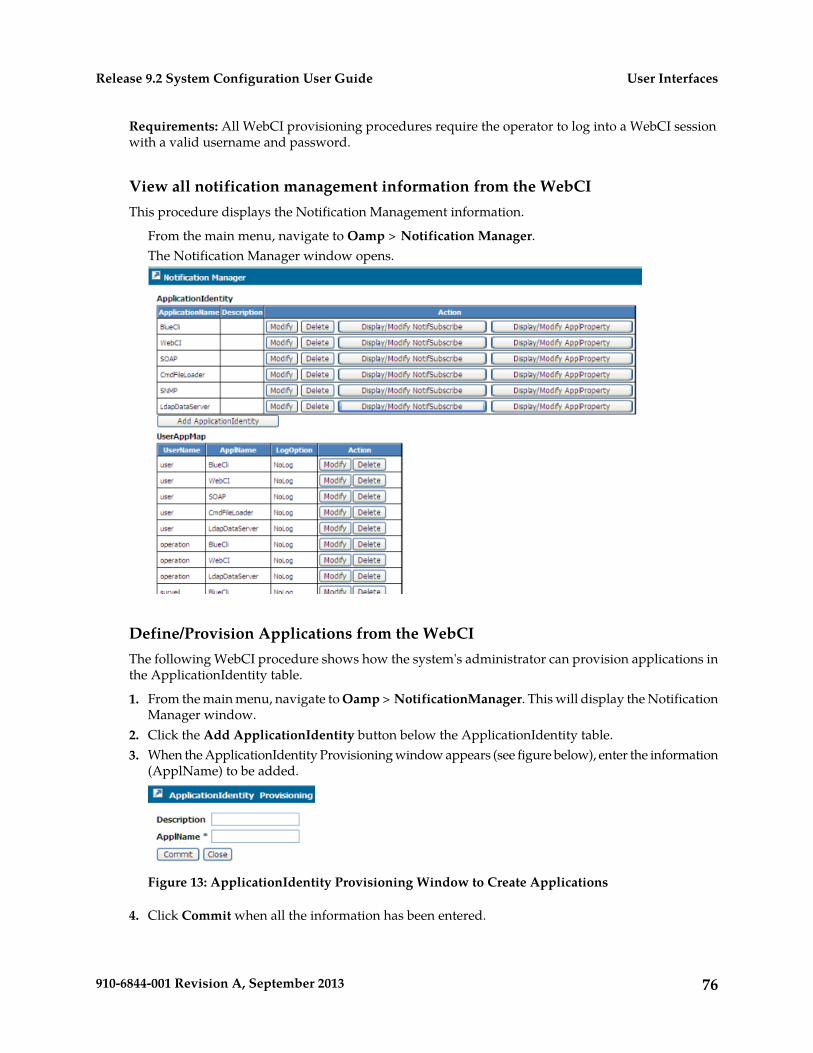
Requirements: All WebCI provisioning procedures require the operator to log into a WebCI sessionwith a valid username and password.
View all notification management information from the WebCIThis procedure displays the Notification Management information.
From the main menu, navigate to Oamp > Notification Manager.The Notification Manager window opens.
Define/Provision Applications from the WebCIThe following WebCI procedure shows how the system's administrator can provision applications inthe ApplicationIdentity table.
1. From the main menu, navigate to Oamp > NotificationManager. This will display the NotificationManager window.
2. Click the Add ApplicationIdentity button below the ApplicationIdentity table.3. When the ApplicationIdentity Provisioning window appears (see figure below), enter the information
(ApplName) to be added.
Figure 13: ApplicationIdentity Provisioning Window to Create Applications
4. Click Commit when all the information has been entered.
76910-6844-001 Revision A, September 2013
User InterfacesRelease 9.2 System Configuration User Guide
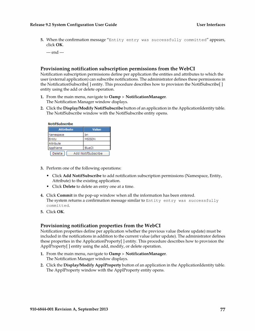
5. When the confirmation message “Entity entry was successfully committed” appears,click OK.
--- end ---
Provisioning notification subscription permissions from the WebCINotification subscription permissions define per application the entities and attributes to which theuser (external application) can subscribe notifications. The administrator defines these permissions inthe NotificationSubscribe[ ] entity. This procedure describes how to provision the NotifSubscribe[ ]entity using the add or delete operation.
1. From the main menu, navigate to Oamp > NotificationManager.The Notification Manager window displays.
2. Click the Display/Modify NotifSubscribe button of an application in the ApplicationIdentity table.The NotifSubscribe window with the NotifSubscribe entity opens.
3. Perform one of the following operations:
• Click Add NotifSubscribe to add notification subscription permissions (Namespace, Entity,Attribute) to the existing application.
• Click Delete to delete an entry one at a time.
4. Click Commit in the pop-up window when all the information has been entered.The system returns a confirmation message similar to Entity entry was successfullycommitted.
5. Click OK.
Provisioning notification properties from the WebCINotification properties define per application whether the previous value (before update) must beincluded in the notifications in addition to the current value (after update). The administrator definesthese properties in the ApplicationProperty[ ] entity. This procedure describes how to provision theApplProperty[ ] entity using the add, modify, or delete operation.
1. From the main menu, navigate to Oamp > NotificationManager.The Notification Manager window displays.
2. Click the Display/Modify ApplProperty button of an application in the ApplicationIdentity table.The ApplProperty window with the ApplProperty entity opens.
77910-6844-001 Revision A, September 2013
User InterfacesRelease 9.2 System Configuration User Guide
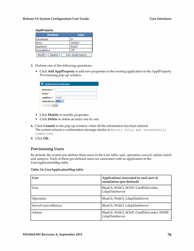
3. Perform one of the following operations:
• Click Add ApplProperty to add new properties to the existing application in the ApplPropertyProvisioning pop-up window.
• Click Modify to modify properties.• Click Delete to delete an entry one by one.
4. Click Commit in the pop-up window when all the information has been entered.The system returns a confirmation message similar to Entity entry was successfullycommitted.
5. Click OK.
Provisioning UsersBy default, the system pre-defines these users in the User table: user, operation, surveil, admin, batchand simprov. Each of these pre-defined users are associated with an application in theUserApplicationMap table.
Table 14: UserApplicationMap table
Applications associated to each user atinstallation (pre-defined)
User
BlueCli, WebCI, SOAP, CmdFileLoader,LdapDataServer
User
BlueCli, WebCI, LdapDataServerOperation
BlueCli, WebCI, LdapDataServerSurveil (surveillance)
BlueCli, WebCI, SOAP, CmdFileLoader, SNMP,LdapDataServer
Admin
78910-6844-001 Revision A, September 2013
User InterfacesRelease 9.2 System Configuration User Guide
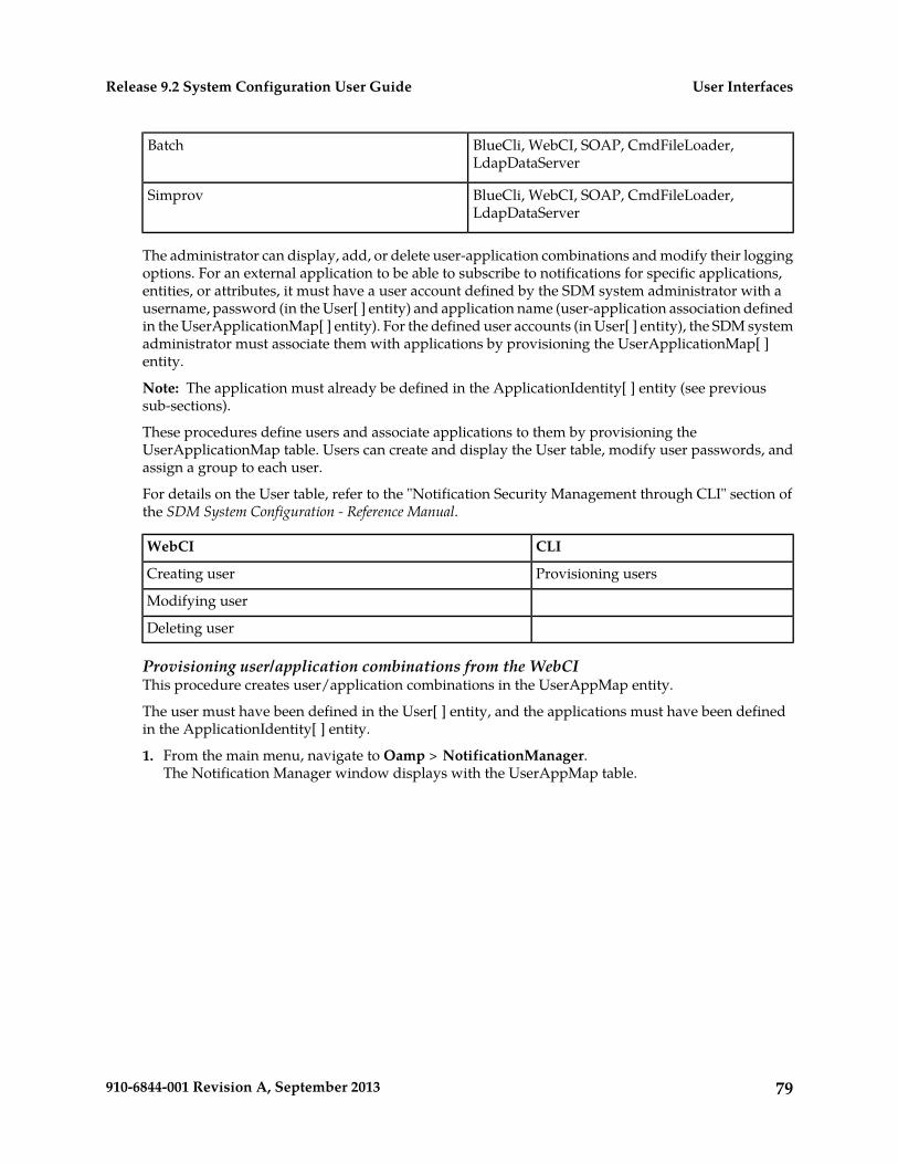
BlueCli, WebCI, SOAP, CmdFileLoader,LdapDataServer
Batch
BlueCli, WebCI, SOAP, CmdFileLoader,LdapDataServer
Simprov
The administrator can display, add, or delete user-application combinations and modify their loggingoptions. For an external application to be able to subscribe to notifications for specific applications,entities, or attributes, it must have a user account defined by the SDM system administrator with ausername, password (in the User[ ] entity) and application name (user-application association definedin the UserApplicationMap[ ] entity). For the defined user accounts (in User[ ] entity), the SDM systemadministrator must associate them with applications by provisioning the UserApplicationMap[ ]entity.
Note: The application must already be defined in the ApplicationIdentity[ ] entity (see previoussub-sections).
These procedures define users and associate applications to them by provisioning theUserApplicationMap table. Users can create and display the User table, modify user passwords, andassign a group to each user.
For details on the User table, refer to the "Notification Security Management through CLI" section ofthe SDM System Configuration - Reference Manual.
CLIWebCI
Provisioning usersCreating user
Modifying user
Deleting user
Provisioning user/application combinations from the WebCIThis procedure creates user/application combinations in the UserAppMap entity.
The user must have been defined in the User[ ] entity, and the applications must have been definedin the ApplicationIdentity[ ] entity.
1. From the main menu, navigate to Oamp > NotificationManager.The Notification Manager window displays with the UserAppMap table.
79910-6844-001 Revision A, September 2013
User InterfacesRelease 9.2 System Configuration User Guide
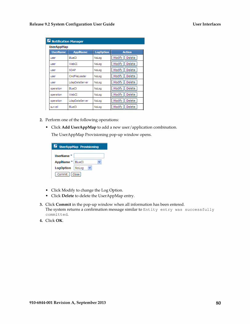
2. Perform one of the following operations:
• Click Add UserAppMap to add a new user/application combination.
The UserAppMap Provisioning pop-up window opens.
• Click Modify to change the Log Option.• Click Delete to delete the UserAppMap entry.
3. Click Commit in the pop-up window when all information has been entered.The system returns a confirmation message similar to Entity entry was successfullycommitted.
4. Click OK.
80910-6844-001 Revision A, September 2013
User InterfacesRelease 9.2 System Configuration User Guide
Chapter
4HLR Application Configuration
This chapter contains information pertaining to theconfiguration of the HLR application.
Topics:
• A4K4 Transport Encryption Algorithm.....82• Configuring the HLR.....83• Configuring the SS7 Stack Using MTP2/SAAL,
MTP3 Protocols.....98• Configuring the SS7 Stack Using the TUCL,
M3UA & Protocols (SIGTRAN).....116
81910-6844-001 Revision A, September 2013
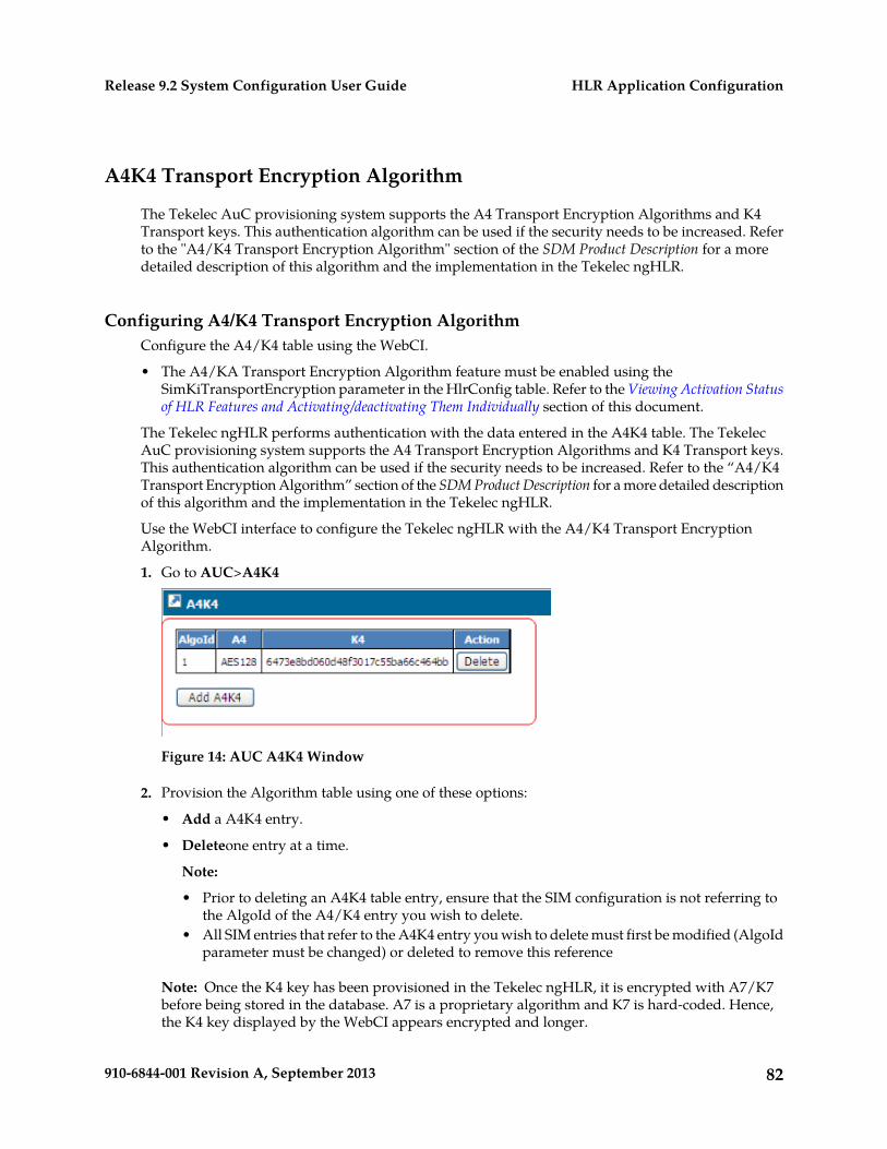
A4K4 Transport Encryption Algorithm
The Tekelec AuC provisioning system supports the A4 Transport Encryption Algorithms and K4Transport keys. This authentication algorithm can be used if the security needs to be increased. Referto the "A4/K4 Transport Encryption Algorithm" section of the SDM Product Description for a moredetailed description of this algorithm and the implementation in the Tekelec ngHLR.
Configuring A4/K4 Transport Encryption AlgorithmConfigure the A4/K4 table using the WebCI.
• The A4/KA Transport Encryption Algorithm feature must be enabled using theSimKiTransportEncryption parameter in the HlrConfig table. Refer to the Viewing Activation Statusof HLR Features and Activating/deactivating Them Individually section of this document.
The Tekelec ngHLR performs authentication with the data entered in the A4K4 table. The TekelecAuC provisioning system supports the A4 Transport Encryption Algorithms and K4 Transport keys.This authentication algorithm can be used if the security needs to be increased. Refer to the “A4/K4Transport Encryption Algorithm” section of the SDM Product Description for a more detailed descriptionof this algorithm and the implementation in the Tekelec ngHLR.
Use the WebCI interface to configure the Tekelec ngHLR with the A4/K4 Transport EncryptionAlgorithm.
1. Go to AUC>A4K4
Figure 14: AUC A4K4 Window
2. Provision the Algorithm table using one of these options:
• Add a A4K4 entry.
• Deleteone entry at a time.
Note:
• Prior to deleting an A4K4 table entry, ensure that the SIM configuration is not referring tothe AlgoId of the A4/K4 entry you wish to delete.
• All SIM entries that refer to the A4K4 entry you wish to delete must first be modified (AlgoIdparameter must be changed) or deleted to remove this reference
Note: Once the K4 key has been provisioned in the Tekelec ngHLR, it is encrypted with A7/K7before being stored in the database. A7 is a proprietary algorithm and K7 is hard-coded. Hence,the K4 key displayed by the WebCI appears encrypted and longer.
82910-6844-001 Revision A, September 2013
HLR Application ConfigurationRelease 9.2 System Configuration User Guide
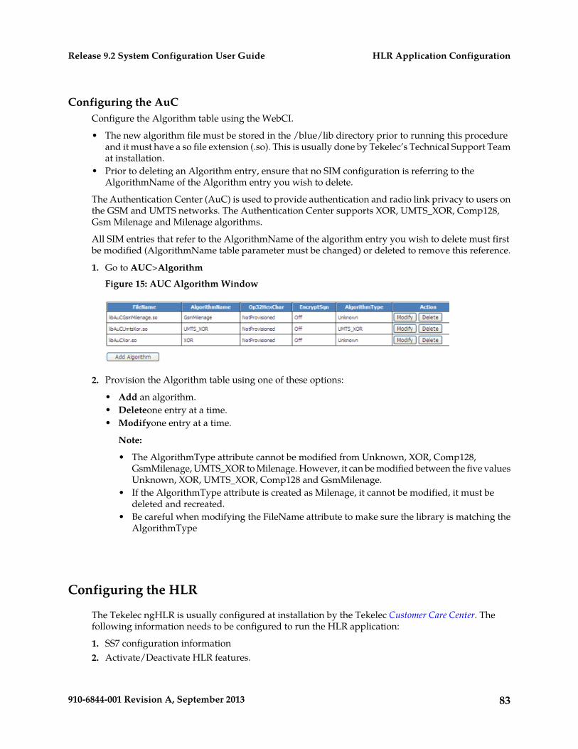
Configuring the AuCConfigure the Algorithm table using the WebCI.
• The new algorithm file must be stored in the /blue/lib directory prior to running this procedureand it must have a so file extension (.so). This is usually done by Tekelec’s Technical Support Teamat installation.
• Prior to deleting an Algorithm entry, ensure that no SIM configuration is referring to theAlgorithmName of the Algorithm entry you wish to delete.
The Authentication Center (AuC) is used to provide authentication and radio link privacy to users onthe GSM and UMTS networks. The Authentication Center supports XOR, UMTS_XOR, Comp128,Gsm Milenage and Milenage algorithms.
All SIM entries that refer to the AlgorithmName of the algorithm entry you wish to delete must firstbe modified (AlgorithmName table parameter must be changed) or deleted to remove this reference.
1. Go to AUC>Algorithm
Figure 15: AUC Algorithm Window
2. Provision the Algorithm table using one of these options:
• Add an algorithm.• Deleteone entry at a time.• Modifyone entry at a time.
Note:
• The AlgorithmType attribute cannot be modified from Unknown, XOR, Comp128,GsmMilenage, UMTS_XOR to Milenage. However, it can be modified between the five valuesUnknown, XOR, UMTS_XOR, Comp128 and GsmMilenage.
• If the AlgorithmType attribute is created as Milenage, it cannot be modified, it must bedeleted and recreated.
• Be careful when modifying the FileName attribute to make sure the library is matching theAlgorithmType
Configuring the HLR
The Tekelec ngHLR is usually configured at installation by the Tekelec Customer Care Center. Thefollowing information needs to be configured to run the HLR application:
1. SS7 configuration information2. Activate/Deactivate HLR features.
83910-6844-001 Revision A, September 2013
HLR Application ConfigurationRelease 9.2 System Configuration User Guide
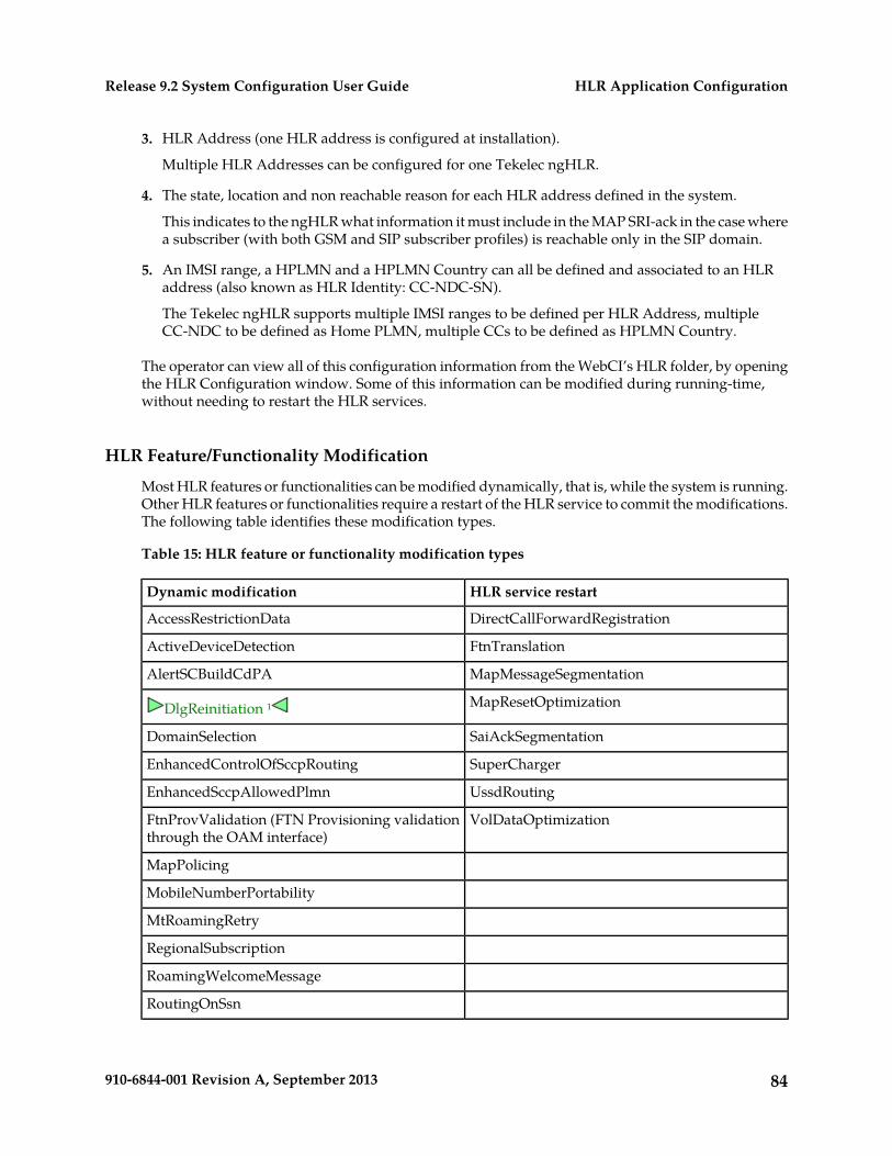
3. HLR Address (one HLR address is configured at installation).
Multiple HLR Addresses can be configured for one Tekelec ngHLR.
4. The state, location and non reachable reason for each HLR address defined in the system.
This indicates to the ngHLR what information it must include in the MAP SRI-ack in the case wherea subscriber (with both GSM and SIP subscriber profiles) is reachable only in the SIP domain.
5. An IMSI range, a HPLMN and a HPLMN Country can all be defined and associated to an HLRaddress (also known as HLR Identity: CC-NDC-SN).
The Tekelec ngHLR supports multiple IMSI ranges to be defined per HLR Address, multipleCC-NDC to be defined as Home PLMN, multiple CCs to be defined as HPLMN Country.
The operator can view all of this configuration information from the WebCI’s HLR folder, by openingthe HLR Configuration window. Some of this information can be modified during running-time,without needing to restart the HLR services.
HLR Feature/Functionality Modification
Most HLR features or functionalities can be modified dynamically, that is, while the system is running.Other HLR features or functionalities require a restart of the HLR service to commit the modifications.The following table identifies these modification types.
Table 15: HLR feature or functionality modification types
HLR service restartDynamic modification
DirectCallForwardRegistrationAccessRestrictionData
FtnTranslationActiveDeviceDetection
MapMessageSegmentationAlertSCBuildCdPA
MapResetOptimizationDlgReinitiation ¹
SaiAckSegmentationDomainSelection
SuperChargerEnhancedControlOfSccpRouting
UssdRoutingEnhancedSccpAllowedPlmn
VolDataOptimizationFtnProvValidation (FTN Provisioning validationthrough the OAM interface)
MapPolicing
MobileNumberPortability
MtRoamingRetry
RegionalSubscription
RoamingWelcomeMessage
RoutingOnSsn
84910-6844-001 Revision A, September 2013
HLR Application ConfigurationRelease 9.2 System Configuration User Guide
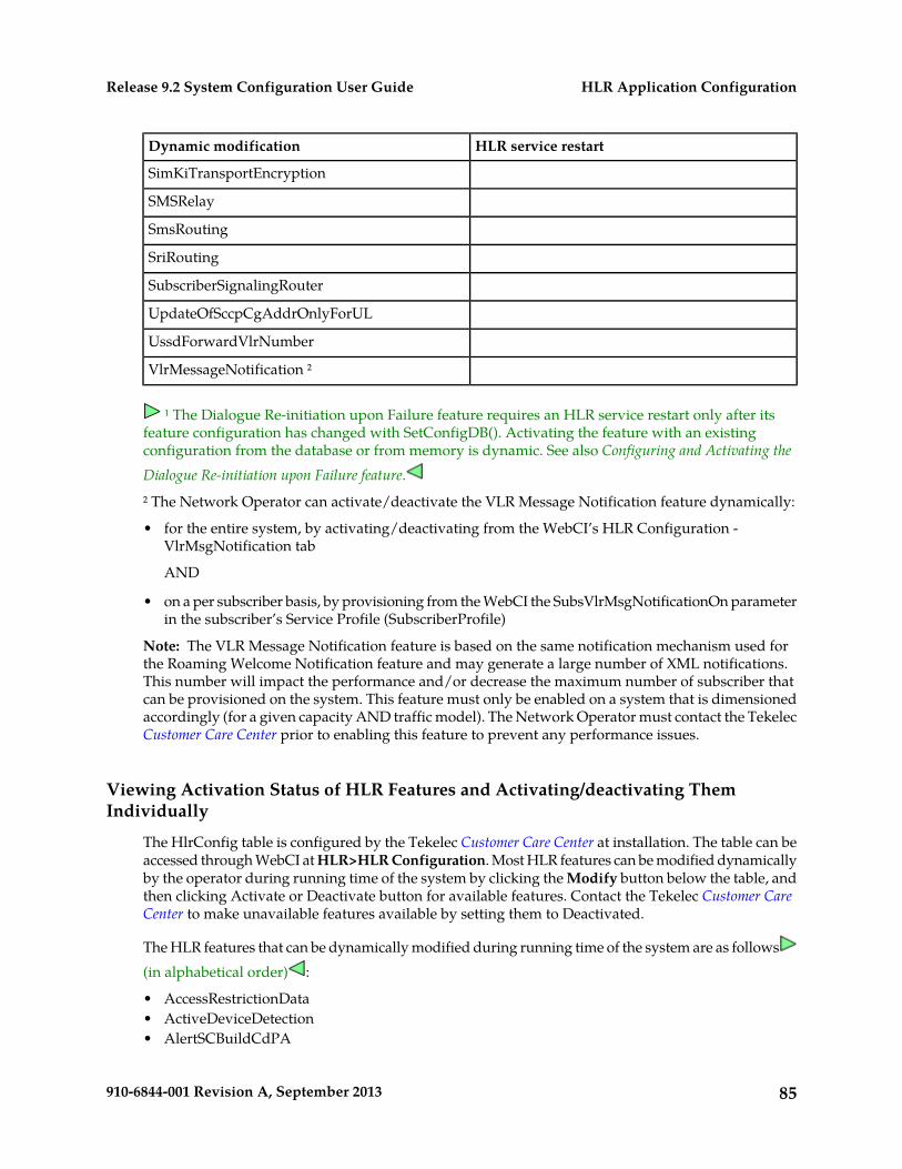
HLR service restartDynamic modification
SimKiTransportEncryption
SMSRelay
SmsRouting
SriRouting
SubscriberSignalingRouter
UpdateOfSccpCgAddrOnlyForUL
UssdForwardVlrNumber
VlrMessageNotification ²
¹ The Dialogue Re-initiation upon Failure feature requires an HLR service restart only after itsfeature configuration has changed with SetConfigDB(). Activating the feature with an existingconfiguration from the database or from memory is dynamic. See also Configuring and Activating theDialogue Re-initiation upon Failure feature.
² The Network Operator can activate/deactivate the VLR Message Notification feature dynamically:
• for the entire system, by activating/deactivating from the WebCI’s HLR Configuration -VlrMsgNotification tab
AND
• on a per subscriber basis, by provisioning from the WebCI the SubsVlrMsgNotificationOn parameterin the subscriber’s Service Profile (SubscriberProfile)
Note: The VLR Message Notification feature is based on the same notification mechanism used forthe Roaming Welcome Notification feature and may generate a large number of XML notifications.This number will impact the performance and/or decrease the maximum number of subscriber thatcan be provisioned on the system. This feature must only be enabled on a system that is dimensionedaccordingly (for a given capacity AND traffic model). The Network Operator must contact the TekelecCustomer Care Center prior to enabling this feature to prevent any performance issues.
Viewing Activation Status of HLR Features and Activating/deactivating ThemIndividually
The HlrConfig table is configured by the Tekelec Customer Care Center at installation. The table can beaccessed through WebCI at HLR>HLR Configuration. Most HLR features can be modified dynamicallyby the operator during running time of the system by clicking the Modify button below the table, andthen clicking Activate or Deactivate button for available features. Contact the Tekelec Customer CareCenter to make unavailable features available by setting them to Deactivated.
The HLR features that can be dynamically modified during running time of the system are as follows(in alphabetical order) :
• AccessRestrictionData• ActiveDeviceDetection• AlertSCBuildCdPA
85910-6844-001 Revision A, September 2013
HLR Application ConfigurationRelease 9.2 System Configuration User Guide
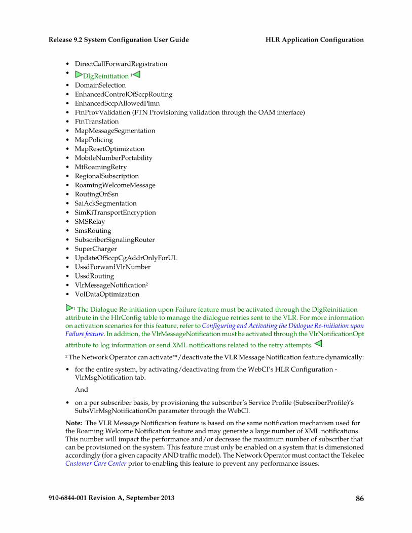
• DirectCallForwardRegistration• DlgReinitiation ¹• DomainSelection• EnhancedControlOfSccpRouting• EnhancedSccpAllowedPlmn• FtnProvValidation (FTN Provisioning validation through the OAM interface)• FtnTranslation• MapMessageSegmentation• MapPolicing• MapResetOptimization• MobileNumberPortability• MtRoamingRetry• RegionalSubscription• RoamingWelcomeMessage• RoutingOnSsn• SaiAckSegmentation• SimKiTransportEncryption• SMSRelay• SmsRouting• SubscriberSignalingRouter• SuperCharger• UpdateOfSccpCgAddrOnlyForUL• UssdForwardVlrNumber• UssdRouting• VlrMessageNotification²• VolDataOptimization
¹ The Dialogue Re-initiation upon Failure feature must be activated through the DlgReinitiationattribute in the HlrConfig table to manage the dialogue retries sent to the VLR. For more informationon activation scenarios for this feature, refer to Configuring and Activating the Dialogue Re-initiation uponFailure feature. In addition, the VlrMessageNotification must be activated through the VlrNotificationOptattribute to log information or send XML notifications related to the retry attempts.
² The Network Operator can activate**/deactivate the VLR Message Notification feature dynamically:
• for the entire system, by activating/deactivating from the WebCI’s HLR Configuration -VlrMsgNotification tab.
And
• on a per subscriber basis, by provisioning the subscriber’s Service Profile (SubscriberProfile)’sSubsVlrMsgNotificationOn parameter through the WebCI.
Note: The VLR Message Notification feature is based on the same notification mechanism used forthe Roaming Welcome Notification feature and may generate a large number of XML notifications.This number will impact the performance and/or decrease the maximum number of subscriber thatcan be provisioned on the system. This feature must only be enabled on a system that is dimensionedaccordingly (for a given capacity AND traffic model). The Network Operator must contact the TekelecCustomer Care Center prior to enabling this feature to prevent any performance issues.
86910-6844-001 Revision A, September 2013
HLR Application ConfigurationRelease 9.2 System Configuration User Guide
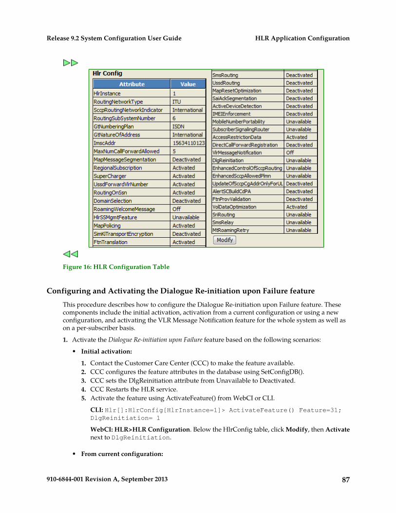
Figure 16: HLR Configuration Table
Configuring and Activating the Dialogue Re-initiation upon Failure feature
This procedure describes how to configure the Dialogue Re-initiation upon Failure feature. Thesecomponents include the initial activation, activation from a current configuration or using a newconfiguration, and activating the VLR Message Notification feature for the whole system as well ason a per-subscriber basis.
1. Activate the Dialogue Re-initiation upon Failure feature based on the following scenarios:
• Initial activation:
1. Contact the Customer Care Center (CCC) to make the feature available.2. CCC configures the feature attributes in the database using SetConfigDB().3. CCC sets the DlgReinitiation attribute from Unavailable to Deactivated.4. CCC Restarts the HLR service.5. Activate the feature using ActivateFeature() from WebCI or CLI.
CLI: Hlr[]:HlrConfig[HlrInstance=1]> ActivateFeature() Feature=31;DlgReinitiation= 1
WebCI: HLR>HLR Configuration. Below the HlrConfig table, click Modify, then Activatenext to DlgReinitiation.
• From current configuration:
87910-6844-001 Revision A, September 2013
HLR Application ConfigurationRelease 9.2 System Configuration User Guide
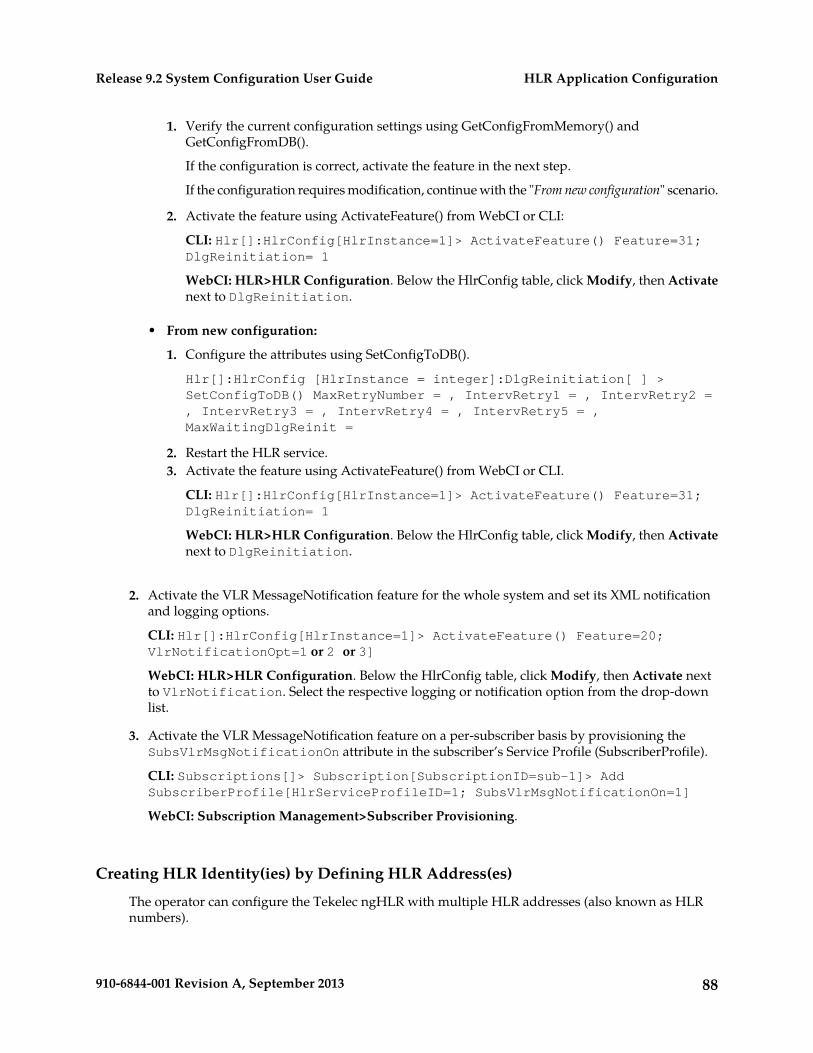
Verify the current configuration settings using GetConfigFromMemory() andGetConfigFromDB().
If the configuration is correct, activate the feature in the next step.
1.
If the configuration requires modification, continue with the "From new configuration" scenario.
2. Activate the feature using ActivateFeature() from WebCI or CLI:
CLI: Hlr[]:HlrConfig[HlrInstance=1]> ActivateFeature() Feature=31;DlgReinitiation= 1
WebCI: HLR>HLR Configuration. Below the HlrConfig table, click Modify, then Activatenext to DlgReinitiation.
• From new configuration:
1. Configure the attributes using SetConfigToDB().
Hlr[]:HlrConfig [HlrInstance = integer]:DlgReinitiation[ ] >SetConfigToDB() MaxRetryNumber = , IntervRetry1 = , IntervRetry2 =, IntervRetry3 = , IntervRetry4 = , IntervRetry5 = ,MaxWaitingDlgReinit =
2. Restart the HLR service.3. Activate the feature using ActivateFeature() from WebCI or CLI.
CLI: Hlr[]:HlrConfig[HlrInstance=1]> ActivateFeature() Feature=31;DlgReinitiation= 1
WebCI: HLR>HLR Configuration. Below the HlrConfig table, click Modify, then Activatenext to DlgReinitiation.
2. Activate the VLR MessageNotification feature for the whole system and set its XML notificationand logging options.
CLI: Hlr[]:HlrConfig[HlrInstance=1]> ActivateFeature() Feature=20;VlrNotificationOpt=1 or 2 or 3]
WebCI: HLR>HLR Configuration. Below the HlrConfig table, click Modify, then Activate nextto VlrNotification. Select the respective logging or notification option from the drop-downlist.
3. Activate the VLR MessageNotification feature on a per-subscriber basis by provisioning theSubsVlrMsgNotificationOn attribute in the subscriber’s Service Profile (SubscriberProfile).
CLI: Subscriptions[]> Subscription[SubscriptionID=sub-1]> AddSubscriberProfile[HlrServiceProfileID=1; SubsVlrMsgNotificationOn=1]
WebCI: Subscription Management>Subscriber Provisioning.
Creating HLR Identity(ies) by Defining HLR Address(es)
The operator can configure the Tekelec ngHLR with multiple HLR addresses (also known as HLRnumbers).
88910-6844-001 Revision A, September 2013
HLR Application ConfigurationRelease 9.2 System Configuration User Guide
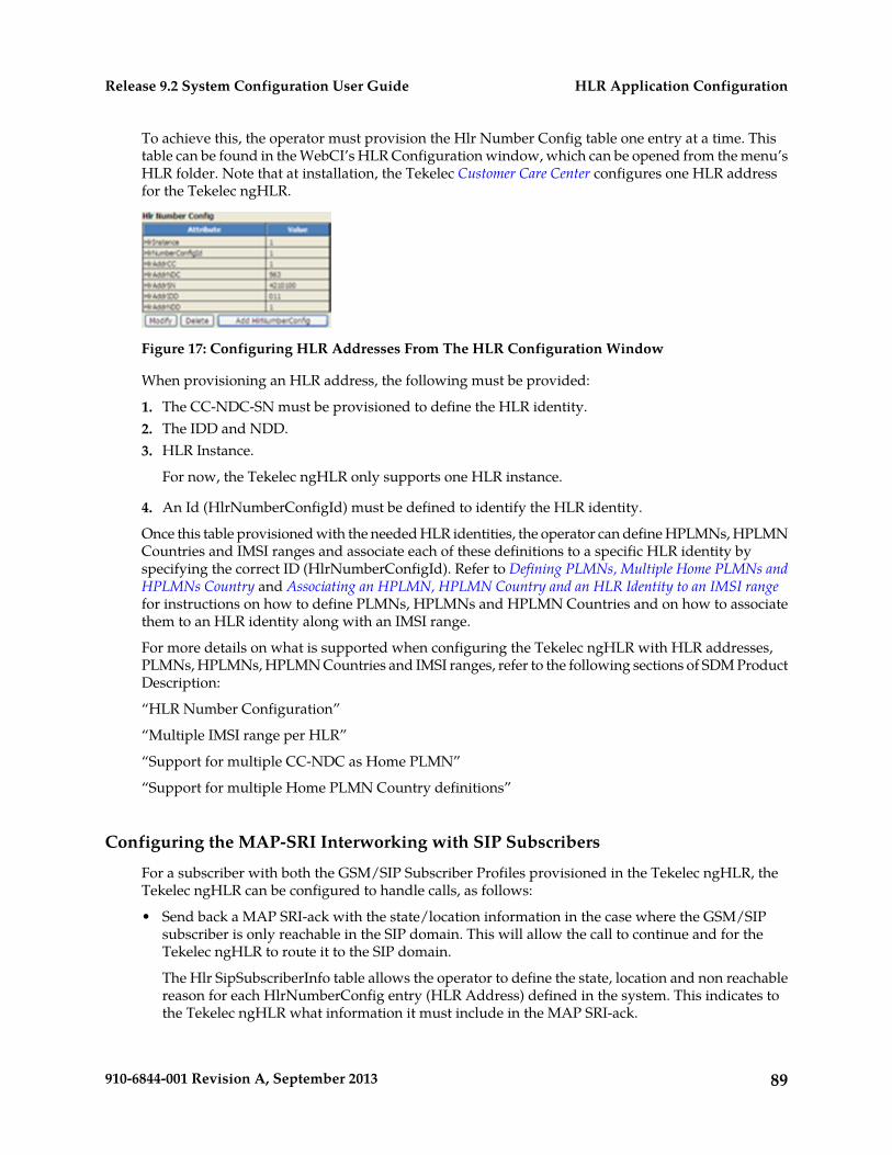
To achieve this, the operator must provision the Hlr Number Config table one entry at a time. Thistable can be found in the WebCI’s HLR Configuration window, which can be opened from the menu’sHLR folder. Note that at installation, the Tekelec Customer Care Center configures one HLR addressfor the Tekelec ngHLR.
Figure 17: Configuring HLR Addresses From The HLR Configuration Window
When provisioning an HLR address, the following must be provided:
1. The CC-NDC-SN must be provisioned to define the HLR identity.2. The IDD and NDD.3. HLR Instance.
For now, the Tekelec ngHLR only supports one HLR instance.
4. An Id (HlrNumberConfigId) must be defined to identify the HLR identity.
Once this table provisioned with the needed HLR identities, the operator can define HPLMNs, HPLMNCountries and IMSI ranges and associate each of these definitions to a specific HLR identity byspecifying the correct ID (HlrNumberConfigId). Refer to Defining PLMNs, Multiple Home PLMNs andHPLMNs Country and Associating an HPLMN, HPLMN Country and an HLR Identity to an IMSI rangefor instructions on how to define PLMNs, HPLMNs and HPLMN Countries and on how to associatethem to an HLR identity along with an IMSI range.
For more details on what is supported when configuring the Tekelec ngHLR with HLR addresses,PLMNs, HPLMNs, HPLMN Countries and IMSI ranges, refer to the following sections of SDM ProductDescription:
“HLR Number Configuration”
“Multiple IMSI range per HLR”
“Support for multiple CC-NDC as Home PLMN”
“Support for multiple Home PLMN Country definitions”
Configuring the MAP-SRI Interworking with SIP Subscribers
For a subscriber with both the GSM/SIP Subscriber Profiles provisioned in the Tekelec ngHLR, theTekelec ngHLR can be configured to handle calls, as follows:
• Send back a MAP SRI-ack with the state/location information in the case where the GSM/SIPsubscriber is only reachable in the SIP domain. This will allow the call to continue and for theTekelec ngHLR to route it to the SIP domain.
The Hlr SipSubscriberInfo table allows the operator to define the state, location and non reachablereason for each HlrNumberConfig entry (HLR Address) defined in the system. This indicates tothe Tekelec ngHLR what information it must include in the MAP SRI-ack.
89910-6844-001 Revision A, September 2013
HLR Application ConfigurationRelease 9.2 System Configuration User Guide
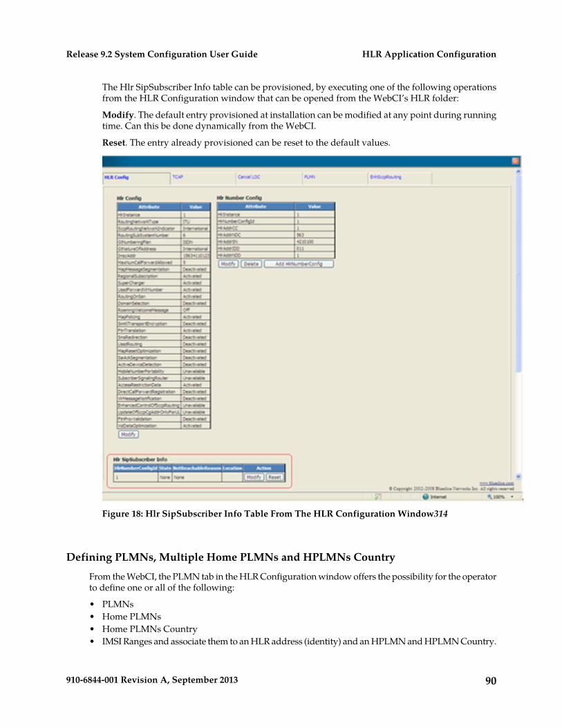
The Hlr SipSubscriber Info table can be provisioned, by executing one of the following operationsfrom the HLR Configuration window that can be opened from the WebCI’s HLR folder:
Modify. The default entry provisioned at installation can be modified at any point during runningtime. Can this be done dynamically from the WebCI.
Reset. The entry already provisioned can be reset to the default values.
Figure 18: Hlr SipSubscriber Info Table From The HLR Configuration Window314
Defining PLMNs, Multiple Home PLMNs and HPLMNs Country
From the WebCI, the PLMN tab in the HLR Configuration window offers the possibility for the operatorto define one or all of the following:
• PLMNs• Home PLMNs• Home PLMNs Country• IMSI Ranges and associate them to an HLR address (identity) and an HPLMN and HPLMN Country.
90910-6844-001 Revision A, September 2013
HLR Application ConfigurationRelease 9.2 System Configuration User Guide
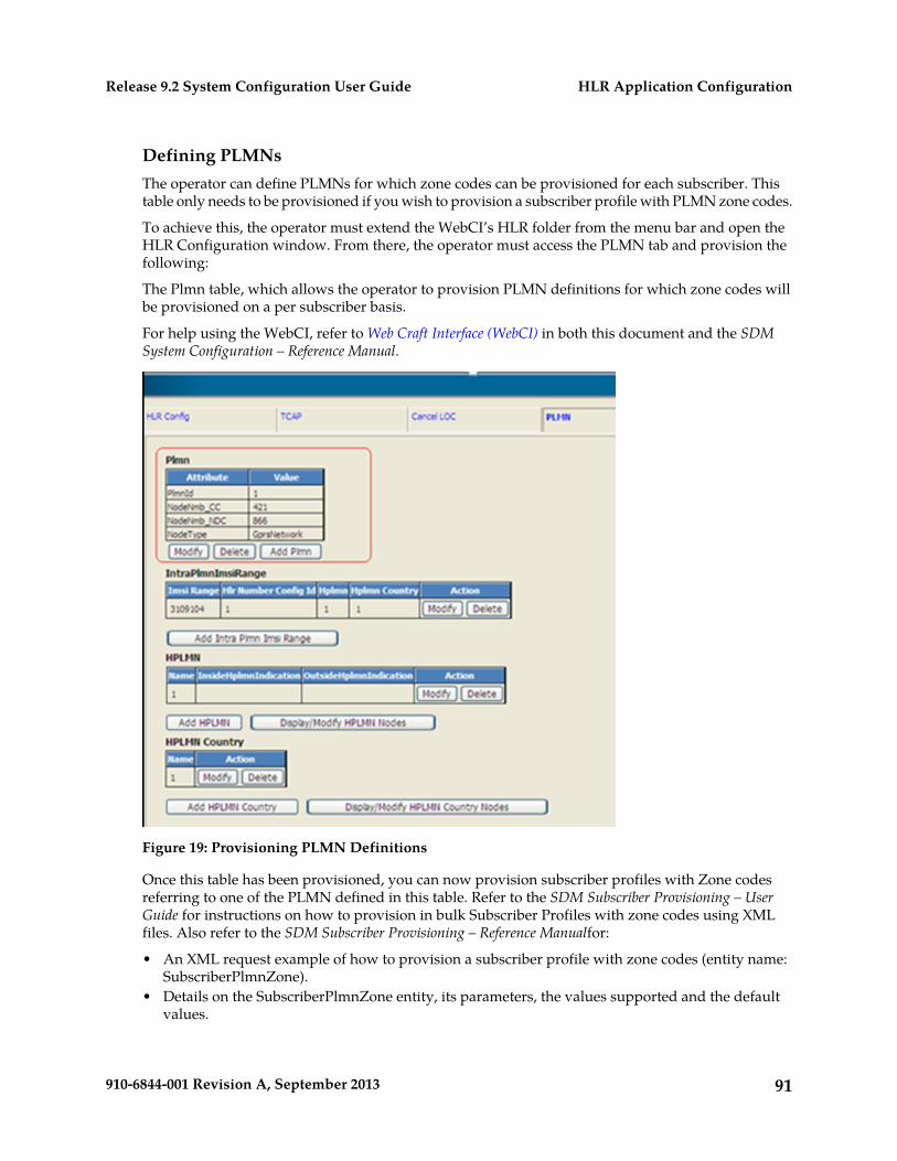
Defining PLMNsThe operator can define PLMNs for which zone codes can be provisioned for each subscriber. Thistable only needs to be provisioned if you wish to provision a subscriber profile with PLMN zone codes.
To achieve this, the operator must extend the WebCI’s HLR folder from the menu bar and open theHLR Configuration window. From there, the operator must access the PLMN tab and provision thefollowing:
The Plmn table, which allows the operator to provision PLMN definitions for which zone codes willbe provisioned on a per subscriber basis.
For help using the WebCI, refer to Web Craft Interface (WebCI) in both this document and the SDMSystem Configuration – Reference Manual.
Figure 19: Provisioning PLMN Definitions
Once this table has been provisioned, you can now provision subscriber profiles with Zone codesreferring to one of the PLMN defined in this table. Refer to the SDM Subscriber Provisioning – UserGuide for instructions on how to provision in bulk Subscriber Profiles with zone codes using XMLfiles. Also refer to the SDM Subscriber Provisioning – Reference Manualfor:
• An XML request example of how to provision a subscriber profile with zone codes (entity name:SubscriberPlmnZone).
• Details on the SubscriberPlmnZone entity, its parameters, the values supported and the defaultvalues.
91910-6844-001 Revision A, September 2013
HLR Application ConfigurationRelease 9.2 System Configuration User Guide
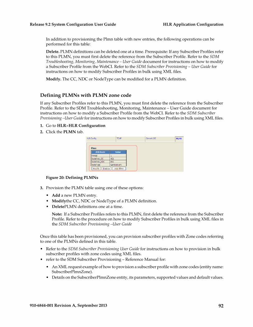
In addition to provisioning the Plmn table with new entries, the following operations can beperformed for this table:
Delete. PLMN definitions can be deleted one at a time. Prerequisite: If any Subscriber Profiles referto this PLMN, you must first delete the reference from the Subscriber Profile. Refer to the SDMTroubleshooting, Monitoring, Maintenance – User Guide document for instructions on how to modifya Subscriber Profile from the WebCI. Refer to the SDM Subscriber Provisioning – User Guide forinstructions on how to modify Subscriber Profiles in bulk using XML files.
Modify. The CC, NDC or NodeType can be modified for a PLMN definition.
Defining PLMNs with PLMN zone codeIf any Subscriber Profiles refer to this PLMN, you must first delete the reference from the SubscriberProfile. Refer to the SDM Troubleshooting, Monitoring, Maintenance – User Guide document forinstructions on how to modify a Subscriber Profile from the WebCI. Refer to the SDM SubscriberProvisioning –User Guide for instructions on how to modify Subscriber Profiles in bulk using XML files.
1. Go to HLR>HLR Configuration2. Click the PLMN tab.
Figure 20: Defining PLMNs
3. Provision the PLMN table using one of these options:
• Add a new PLMN entry.• Modifythe CC, NDC or NodeType of a PLMN definition.• DeletePLMN definitions one at a time.
Note: If a Subscriber Profiles refers to this PLMN, first delete the reference from the SubscriberProfile. Refer to the procedure on how to modify Subscriber Profiles in bulk using XML files inthe SDM Subscriber Provisioning –User Guide
Once this table has been provisioned, you can provision subscriber profiles with Zone codes referringto one of the PLMNs defined in this table.
• Refer to the SDM Subscriber Provisioning User Guide for instructions on how to provision in bulksubscriber profiles with zone codes using XML files.
• refer to the SDM Subscriber Provisioning – Reference Manual for:
• An XML request example of how to provision a subscriber profile with zone codes (entity name:SubscriberPlmnZone).
• Details on the SubscriberPlmnZone entity, its parameters, supported values and default values.
92910-6844-001 Revision A, September 2013
HLR Application ConfigurationRelease 9.2 System Configuration User Guide
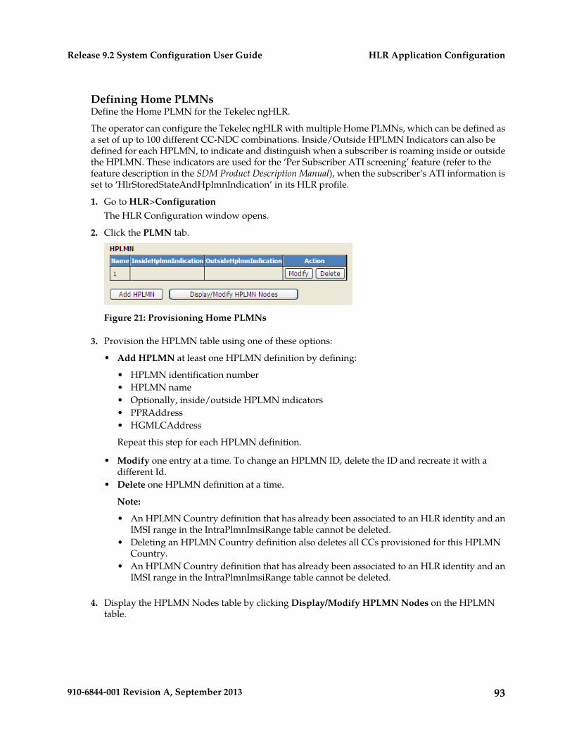
Defining Home PLMNsDefine the Home PLMN for the Tekelec ngHLR.
The operator can configure the Tekelec ngHLR with multiple Home PLMNs, which can be defined asa set of up to 100 different CC-NDC combinations. Inside/Outside HPLMN Indicators can also bedefined for each HPLMN, to indicate and distinguish when a subscriber is roaming inside or outsidethe HPLMN. These indicators are used for the ‘Per Subscriber ATI screening’ feature (refer to thefeature description in the SDM Product Description Manual), when the subscriber’s ATI information isset to ‘HlrStoredStateAndHplmnIndication’ in its HLR profile.
1. Go to HLR>ConfigurationThe HLR Configuration window opens.
2. Click the PLMN tab.
Figure 21: Provisioning Home PLMNs
3. Provision the HPLMN table using one of these options:
• Add HPLMN at least one HPLMN definition by defining:
• HPLMN identification number• HPLMN name• Optionally, inside/outside HPLMN indicators• PPRAddress• HGMLCAddress
Repeat this step for each HPLMN definition.
• Modify one entry at a time. To change an HPLMN ID, delete the ID and recreate it with adifferent Id.
• Delete one HPLMN definition at a time.
Note:
• An HPLMN Country definition that has already been associated to an HLR identity and anIMSI range in the IntraPlmnImsiRange table cannot be deleted.
• Deleting an HPLMN Country definition also deletes all CCs provisioned for this HPLMNCountry.
• An HPLMN Country definition that has already been associated to an HLR identity and anIMSI range in the IntraPlmnImsiRange table cannot be deleted.
4. Display the HPLMN Nodes table by clicking Display/Modify HPLMN Nodes on the HPLMNtable.
93910-6844-001 Revision A, September 2013
HLR Application ConfigurationRelease 9.2 System Configuration User Guide
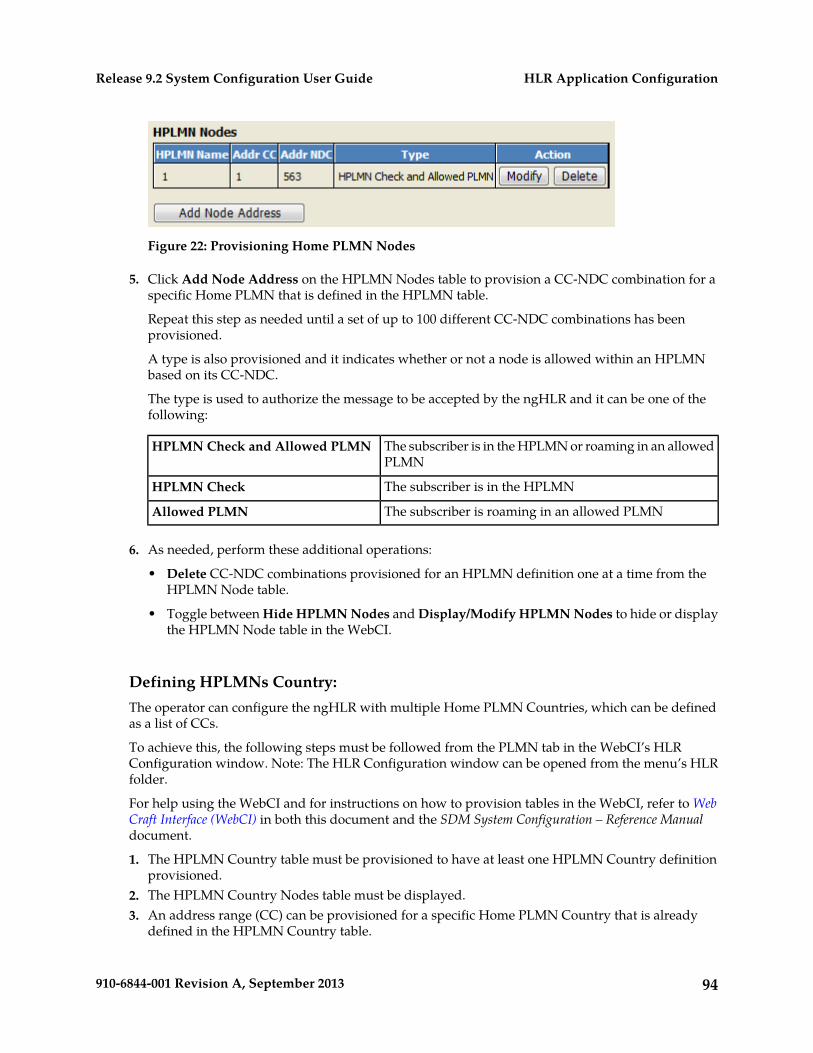
Figure 22: Provisioning Home PLMN Nodes
5. Click Add Node Address on the HPLMN Nodes table to provision a CC-NDC combination for aspecific Home PLMN that is defined in the HPLMN table.
Repeat this step as needed until a set of up to 100 different CC-NDC combinations has beenprovisioned.
A type is also provisioned and it indicates whether or not a node is allowed within an HPLMNbased on its CC-NDC.
The type is used to authorize the message to be accepted by the ngHLR and it can be one of thefollowing:
The subscriber is in the HPLMN or roaming in an allowedPLMN
HPLMN Check and Allowed PLMN
The subscriber is in the HPLMNHPLMN Check
The subscriber is roaming in an allowed PLMNAllowed PLMN
6. As needed, perform these additional operations:
• Delete CC-NDC combinations provisioned for an HPLMN definition one at a time from theHPLMN Node table.
• Toggle between Hide HPLMN Nodes and Display/Modify HPLMN Nodes to hide or displaythe HPLMN Node table in the WebCI.
Defining HPLMNs Country:The operator can configure the ngHLR with multiple Home PLMN Countries, which can be definedas a list of CCs.
To achieve this, the following steps must be followed from the PLMN tab in the WebCI’s HLRConfiguration window. Note: The HLR Configuration window can be opened from the menu’s HLRfolder.
For help using the WebCI and for instructions on how to provision tables in the WebCI, refer to WebCraft Interface (WebCI) in both this document and the SDM System Configuration – Reference Manualdocument.
1. The HPLMN Country table must be provisioned to have at least one HPLMN Country definitionprovisioned.
2. The HPLMN Country Nodes table must be displayed.3. An address range (CC) can be provisioned for a specific Home PLMN Country that is already
defined in the HPLMN Country table.
94910-6844-001 Revision A, September 2013
HLR Application ConfigurationRelease 9.2 System Configuration User Guide
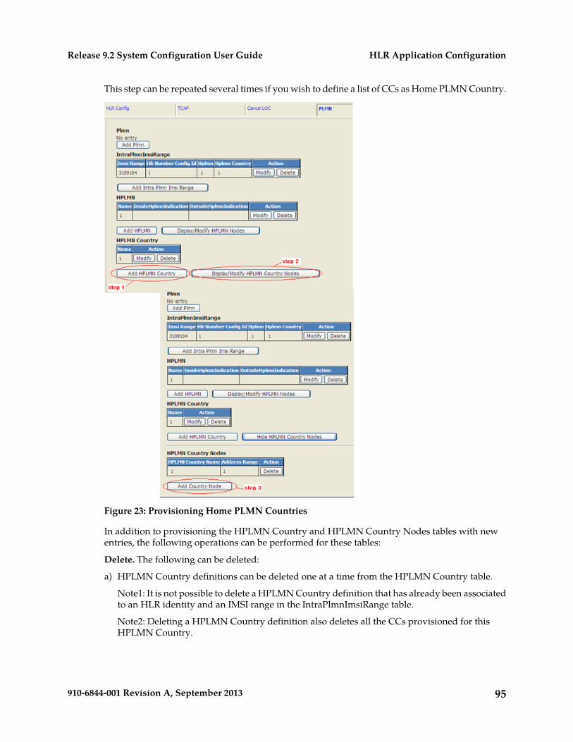
This step can be repeated several times if you wish to define a list of CCs as Home PLMN Country.
Figure 23: Provisioning Home PLMN Countries
In addition to provisioning the HPLMN Country and HPLMN Country Nodes tables with newentries, the following operations can be performed for these tables:
Delete. The following can be deleted:
a) HPLMN Country definitions can be deleted one at a time from the HPLMN Country table.
Note1: It is not possible to delete a HPLMN Country definition that has already been associatedto an HLR identity and an IMSI range in the IntraPlmnImsiRange table.
Note2: Deleting a HPLMN Country definition also deletes all the CCs provisioned for thisHPLMN Country.
95910-6844-001 Revision A, September 2013
HLR Application ConfigurationRelease 9.2 System Configuration User Guide
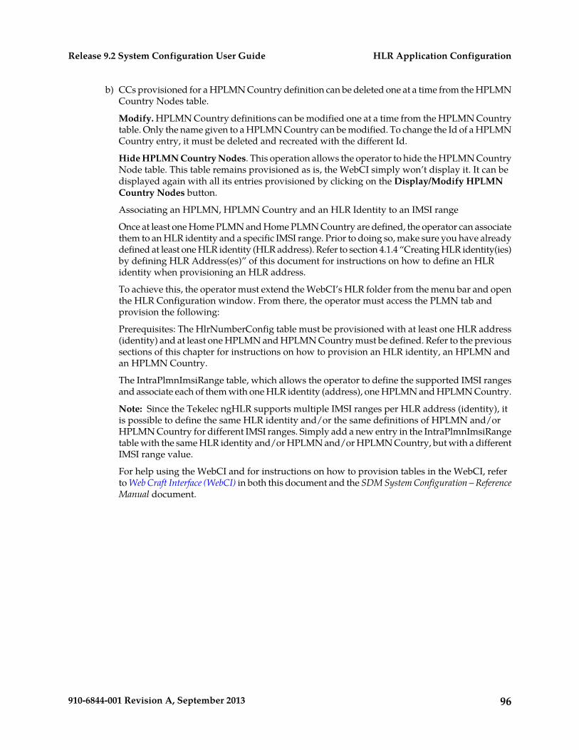
b) CCs provisioned for a HPLMN Country definition can be deleted one at a time from the HPLMNCountry Nodes table.
Modify. HPLMN Country definitions can be modified one at a time from the HPLMN Countrytable. Only the name given to a HPLMN Country can be modified. To change the Id of a HPLMNCountry entry, it must be deleted and recreated with the different Id.
Hide HPLMN Country Nodes. This operation allows the operator to hide the HPLMN CountryNode table. This table remains provisioned as is, the WebCI simply won’t display it. It can bedisplayed again with all its entries provisioned by clicking on the Display/Modify HPLMNCountry Nodes button.
Associating an HPLMN, HPLMN Country and an HLR Identity to an IMSI range
Once at least one Home PLMN and Home PLMN Country are defined, the operator can associatethem to an HLR identity and a specific IMSI range. Prior to doing so, make sure you have alreadydefined at least one HLR identity (HLR address). Refer to section 4.1.4 “Creating HLR identity(ies)by defining HLR Address(es)” of this document for instructions on how to define an HLRidentity when provisioning an HLR address.
To achieve this, the operator must extend the WebCI’s HLR folder from the menu bar and openthe HLR Configuration window. From there, the operator must access the PLMN tab andprovision the following:
Prerequisites: The HlrNumberConfig table must be provisioned with at least one HLR address(identity) and at least one HPLMN and HPLMN Country must be defined. Refer to the previoussections of this chapter for instructions on how to provision an HLR identity, an HPLMN andan HPLMN Country.
The IntraPlmnImsiRange table, which allows the operator to define the supported IMSI rangesand associate each of them with one HLR identity (address), one HPLMN and HPLMN Country.
Note: Since the Tekelec ngHLR supports multiple IMSI ranges per HLR address (identity), itis possible to define the same HLR identity and/or the same definitions of HPLMN and/orHPLMN Country for different IMSI ranges. Simply add a new entry in the IntraPlmnImsiRangetable with the same HLR identity and/or HPLMN and/or HPLMN Country, but with a differentIMSI range value.
For help using the WebCI and for instructions on how to provision tables in the WebCI, referto Web Craft Interface (WebCI) in both this document and the SDM System Configuration – ReferenceManual document.
96910-6844-001 Revision A, September 2013
HLR Application ConfigurationRelease 9.2 System Configuration User Guide
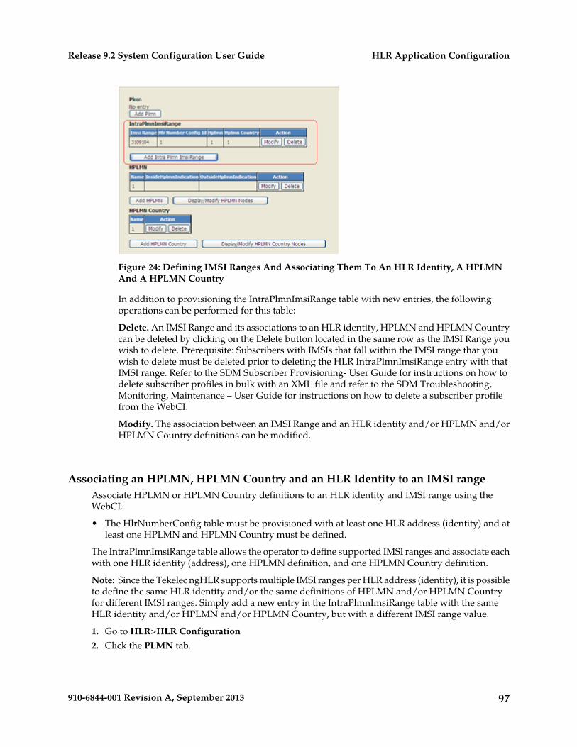
Figure 24: Defining IMSI Ranges And Associating Them To An HLR Identity, A HPLMNAnd A HPLMN Country
In addition to provisioning the IntraPlmnImsiRange table with new entries, the followingoperations can be performed for this table:
Delete. An IMSI Range and its associations to an HLR identity, HPLMN and HPLMN Countrycan be deleted by clicking on the Delete button located in the same row as the IMSI Range youwish to delete. Prerequisite: Subscribers with IMSIs that fall within the IMSI range that youwish to delete must be deleted prior to deleting the HLR IntraPlmnImsiRange entry with thatIMSI range. Refer to the SDM Subscriber Provisioning- User Guide for instructions on how todelete subscriber profiles in bulk with an XML file and refer to the SDM Troubleshooting,Monitoring, Maintenance – User Guide for instructions on how to delete a subscriber profilefrom the WebCI.
Modify. The association between an IMSI Range and an HLR identity and/or HPLMN and/orHPLMN Country definitions can be modified.
Associating an HPLMN, HPLMN Country and an HLR Identity to an IMSI rangeAssociate HPLMN or HPLMN Country definitions to an HLR identity and IMSI range using theWebCI.
• The HlrNumberConfig table must be provisioned with at least one HLR address (identity) and atleast one HPLMN and HPLMN Country must be defined.
The IntraPlmnImsiRange table allows the operator to define supported IMSI ranges and associate eachwith one HLR identity (address), one HPLMN definition, and one HPLMN Country definition.
Note: Since the Tekelec ngHLR supports multiple IMSI ranges per HLR address (identity), it is possibleto define the same HLR identity and/or the same definitions of HPLMN and/or HPLMN Countryfor different IMSI ranges. Simply add a new entry in the IntraPlmnImsiRange table with the sameHLR identity and/or HPLMN and/or HPLMN Country, but with a different IMSI range value.
1. Go to HLR>HLR Configuration2. Click the PLMN tab.
97910-6844-001 Revision A, September 2013
HLR Application ConfigurationRelease 9.2 System Configuration User Guide
Figure 25: Provisioning Intra-PLMN IMSI range table
3. Associate an IMSI range with HLR, HPLMN, and HPLMN Country identities in theIntraPlmnImsiRange table using one of these options:
• Click Add Intra Plmn Imsi Range to add a new IMSI range and associate an
• HLR identity• HPLMN identity• HPLMN Country identity
• Click Delete to delete an IMSI Range and its associations to HLR, HPLMN, and HPLMN Countryidentities.
Note: Subscribers with IMSIs that fall within the IMSI range that you wish to delete must bedeleted prior to deleting the HLR IntraPlmnImsiRange entry with that IMSI range.
• Refer to the SDM Subscriber Provisioning User Guide for instructions on how to delete subscriberprofiles in bulk with an XML file.
• Refer to the SDM Troubleshooting, Monitoring, Maintenance User Guide for instructions on howto delete a subscriber profile from the WebCI
• Click Modify to change the association between and IMSI range and an HLR identity, or HPLMNdefinition or HPLMN Country definition.
Configuring the SS7 Stack Using MTP2/SAAL, MTP3 Protocols
The initial SS7 configuration is loaded into the Single Board Computers at installation (before systemstartup).
The configured SS7 nodes, links, link sets, and subsystem parameters can be modified and new onescan be added from the WebCI.
98910-6844-001 Revision A, September 2013
HLR Application ConfigurationRelease 9.2 System Configuration User Guide
The following section describes how to provision new SS7 components. To achieve this, proceduresdescribe how to define point codes, interfaces, links, link sets, and route sets in order to configure theSS7 Stack.
In order to operate, administer, and manage the components of an SS7 network, a network operatorneeds to set and inspect certain values that characterize the configuration of the network components.
So first, this section lists the prerequisite information necessary prior to configuring the SS7 Stack.
Collecting data prior to configuration
Collect all required information prior to configuration.
Collecting SS7 Point Code DataThe SS7 point codes are SS7 network addresses that uniquely identify every switch, Signal TransferPoint (STP). To communicate with the SS7 network, SS7 point codes must be obtained for the TekelecSDM and for every SS7 network device that it will communicate with. The Tekelec ngHLR onlysupports one originating point code (OPC) and a minimum of one destination point code (DPC), oneDPC per remote SS7 network device.
Collecting CombinedLinkset DataA combinedLinkset must be defined for a group of all linksets that can be used to reach a particulardestination or group of destinations (routes). Each linkset may be associated with up to 16 combinedlinksets. For each combined linkset that a linkset is a member of, it may be assigned a priority relativeto other linksets belonging to that combined linkset.
Collecting Linkset DataA linkset must be defined for each path between the Tekelec ngHLR and the adjacent STP. If there aretwo adjacent STPs, two linksets need to be created. A Linkset can contain from 1 to 16 links. Thefollowing information must be entered about each linkset:
• Destination Point Code• Protocol Type (ANSI or ITU)• CombinedLinkSets• Collecting Link Data
A link corresponds to the linkset that was previously created. A pair of links will be created for eachlinkset in the system, for redundancy purposes. For example, if the system has two linksets, two linkswill be created for each linkset, resulting in the total of four links. The following information must beentered for each link:
• Protocol Variant• Signalling Link Code (SLC)• Priority• Physical Interface• Timeslot• Bit Rate• SlotId
99910-6844-001 Revision A, September 2013
HLR Application ConfigurationRelease 9.2 System Configuration User Guide
Collecting Link DataA link corresponds to the linkset that was previously created. A pair of links will be created for eachlinkset in the system, for redundancy purposes. For example, if the system has two linksets, two linkswill be created for each linkset, resulting in the total of four links. The following information must beentered for each link:
• Protocol Variant• Signalling Link Code (SLC)• Priority• Physical Interface• Timeslot• Bit Rate• SlotId
Collecting SS7 Route DataAn SS7 route must be defined for each Signalling End Point the Tekelec ngHLR wants to reach. Theremust be an SS7 route for each linkset. You must be ready to enter the following information about theSS7 route to be created:
• Destination Point Code (DPC)• Originating Point Code (OPC)• CombinedLinkset
Collecting SS7 Subsystem DataOne route is defined for each destination subsystem that the SCCP layer may be used to access. Theroute defines the destination point code used to reach that subsystem as well as any backup pointcode which replicates the subsystem.
Collecting Concerned Point Code DataEvery remote SignallingPoint interested in knowing about the state changes of the Tekelec ngHLRnode shall be configured. They will receive messages such as SSA (Subsystem Allowed), SSP (SubsystemProhibited), and SSC (Subsystem Congested).
Collecting Global Title DataAll mobile subscriber terminals in a cellular network (e.g. GSM) are usually defined in a specificdatabase, the HLR (i.e., Tekelec ngHLR). The addressing of an HLR node in the telecom network isusually based on the first, most significant half of a mobile subscribe number. When an HLRcommunicates over the SS7 signalling network, this address information has to be translated into aform that allows routing in the SCCP network. Some of the address information based on the globaltitle series is called a Global Title (GT). A GT needs to be translated into a DPC by the SCCP in orderto make it possible for the MTP to route the signalling messages through the SCCP network. Thefollowing information must be entered about the GTT to be created:
• Destination Point Code (DPC)• Subsystem Number (SSN)
100910-6844-001 Revision A, September 2013
HLR Application ConfigurationRelease 9.2 System Configuration User Guide
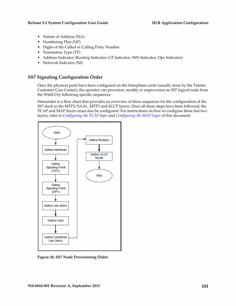
• Nature of Address (NA)• Numbering Plan (NP)• Digits of the Called or Calling Party Number• Translation Type (TT)• Address Indicator (Routing Indicator, GT Indicator, SSN Indicator, Dpc Indicator)• Network Indicator (NI)
SS7 Signaling Configuration Order
Once the physical ports have been configured on the Interphase cards (usually done by the TekelecCustomer Care Center), the operator can provision, modify or unprovision an SS7 logical node fromthe WebCI by following specific sequences.
Hereunder is a flow chart that provides an overview of these sequences for the configuration of theSS7 stack in the MTP2/SAAL, MTP3 and SCCP layers. Once all these steps have been followed, theTCAP and MAP layers must also be configured. For instructions on how to configure these last twolayers, refer to Configuring the TCAP layer and Configuring the MAP Layer of this document.
Figure 26: SS7 Node Provisioning Order
101910-6844-001 Revision A, September 2013
HLR Application ConfigurationRelease 9.2 System Configuration User Guide
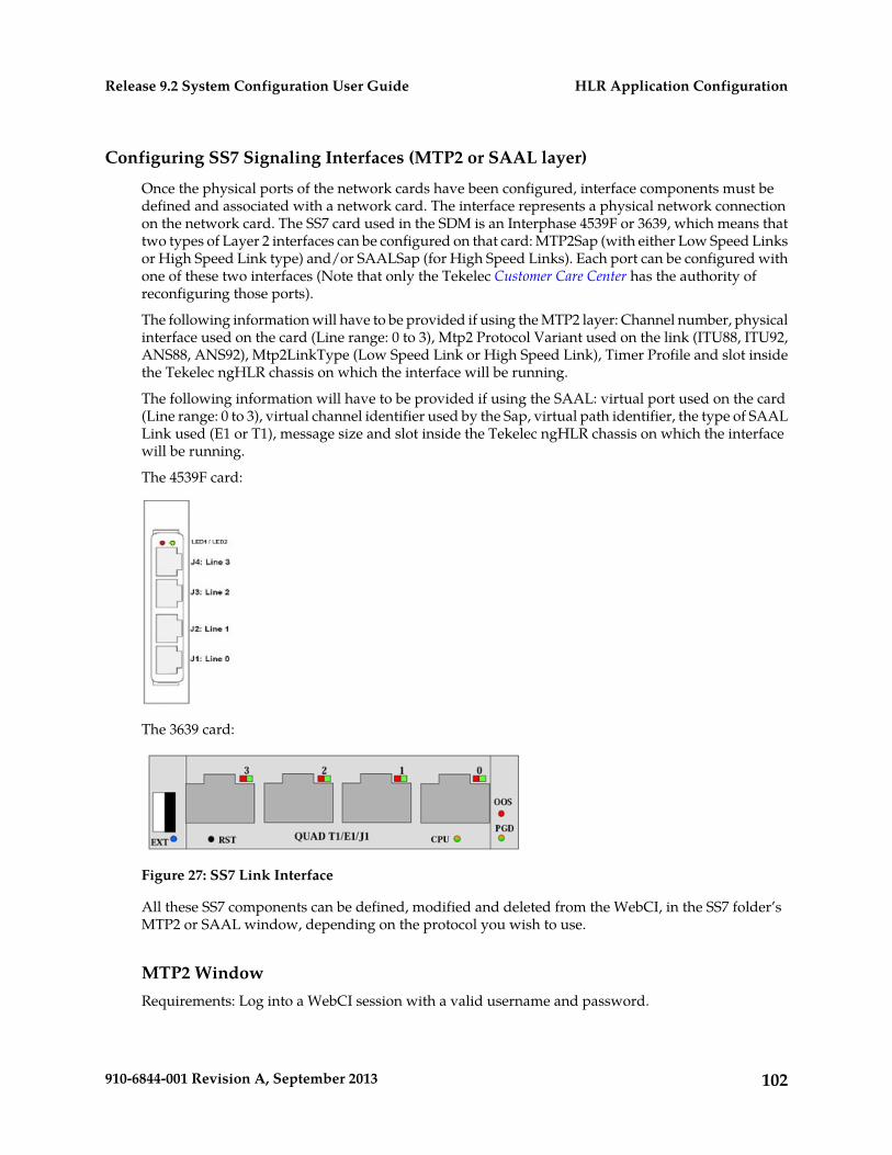
Configuring SS7 Signaling Interfaces (MTP2 or SAAL layer)
Once the physical ports of the network cards have been configured, interface components must bedefined and associated with a network card. The interface represents a physical network connectionon the network card. The SS7 card used in the SDM is an Interphase 4539F or 3639, which means thattwo types of Layer 2 interfaces can be configured on that card: MTP2Sap (with either Low Speed Linksor High Speed Link type) and/or SAALSap (for High Speed Links). Each port can be configured withone of these two interfaces (Note that only the Tekelec Customer Care Center has the authority ofreconfiguring those ports).
The following information will have to be provided if using the MTP2 layer: Channel number, physicalinterface used on the card (Line range: 0 to 3), Mtp2 Protocol Variant used on the link (ITU88, ITU92,ANS88, ANS92), Mtp2LinkType (Low Speed Link or High Speed Link), Timer Profile and slot insidethe Tekelec ngHLR chassis on which the interface will be running.
The following information will have to be provided if using the SAAL: virtual port used on the card(Line range: 0 to 3), virtual channel identifier used by the Sap, virtual path identifier, the type of SAALLink used (E1 or T1), message size and slot inside the Tekelec ngHLR chassis on which the interfacewill be running.
The 4539F card:
The 3639 card:
Figure 27: SS7 Link Interface
All these SS7 components can be defined, modified and deleted from the WebCI, in the SS7 folder’sMTP2 or SAAL window, depending on the protocol you wish to use.
MTP2 WindowRequirements: Log into a WebCI session with a valid username and password.
102910-6844-001 Revision A, September 2013
HLR Application ConfigurationRelease 9.2 System Configuration User Guide
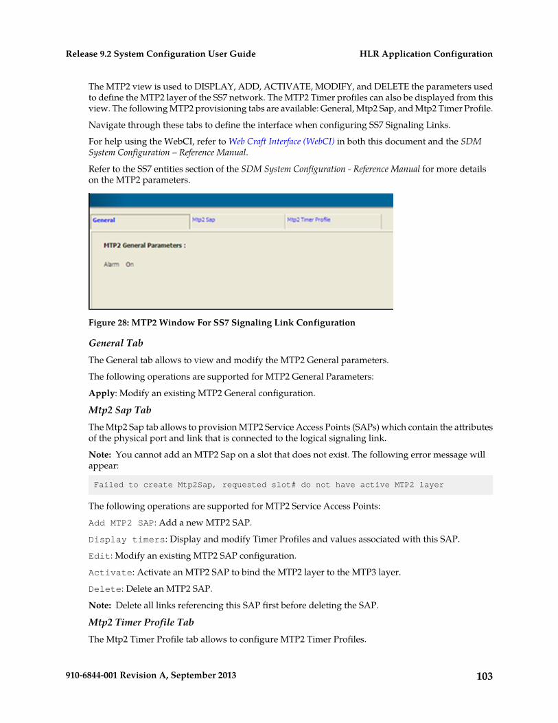
The MTP2 view is used to DISPLAY, ADD, ACTIVATE, MODIFY, and DELETE the parameters usedto define the MTP2 layer of the SS7 network. The MTP2 Timer profiles can also be displayed from thisview. The following MTP2 provisioning tabs are available: General, Mtp2 Sap, and Mtp2 Timer Profile.
Navigate through these tabs to define the interface when configuring SS7 Signaling Links.
For help using the WebCI, refer to Web Craft Interface (WebCI) in both this document and the SDMSystem Configuration – Reference Manual.
Refer to the SS7 entities section of the SDM System Configuration - Reference Manual for more detailson the MTP2 parameters.
Figure 28: MTP2 Window For SS7 Signaling Link Configuration
General TabThe General tab allows to view and modify the MTP2 General parameters.
The following operations are supported for MTP2 General Parameters:
Apply: Modify an existing MTP2 General configuration.
Mtp2 Sap TabThe Mtp2 Sap tab allows to provision MTP2 Service Access Points (SAPs) which contain the attributesof the physical port and link that is connected to the logical signaling link.
Note: You cannot add an MTP2 Sap on a slot that does not exist. The following error message willappear:
Failed to create Mtp2Sap, requested slot# do not have active MTP2 layer
The following operations are supported for MTP2 Service Access Points:
Add MTP2 SAP: Add a new MTP2 SAP.
Display timers: Display and modify Timer Profiles and values associated with this SAP.
Edit: Modify an existing MTP2 SAP configuration.
Activate: Activate an MTP2 SAP to bind the MTP2 layer to the MTP3 layer.
Delete: Delete an MTP2 SAP.
Note: Delete all links referencing this SAP first before deleting the SAP.
Mtp2 Timer Profile TabThe Mtp2 Timer Profile tab allows to configure MTP2 Timer Profiles.
103910-6844-001 Revision A, September 2013
HLR Application ConfigurationRelease 9.2 System Configuration User Guide
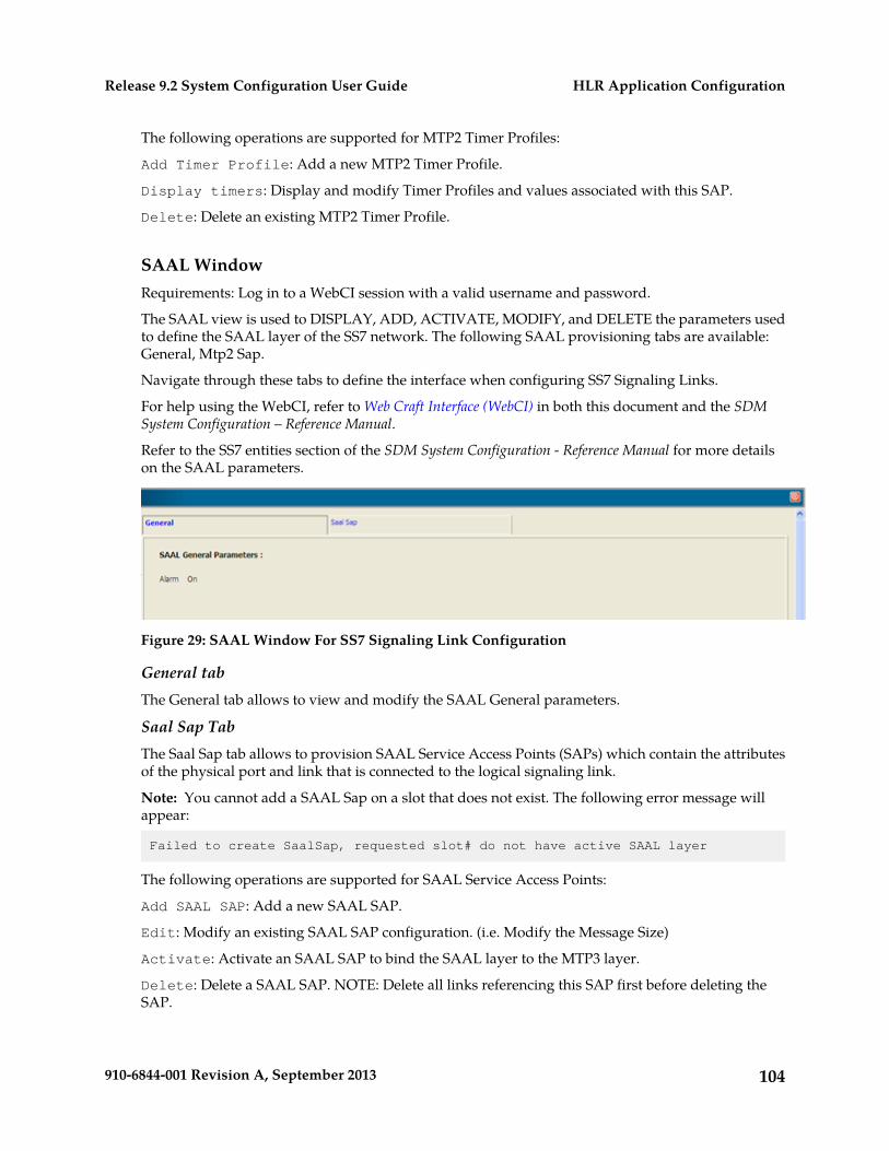
The following operations are supported for MTP2 Timer Profiles:
Add Timer Profile: Add a new MTP2 Timer Profile.
Display timers: Display and modify Timer Profiles and values associated with this SAP.
Delete: Delete an existing MTP2 Timer Profile.
SAAL WindowRequirements: Log in to a WebCI session with a valid username and password.
The SAAL view is used to DISPLAY, ADD, ACTIVATE, MODIFY, and DELETE the parameters usedto define the SAAL layer of the SS7 network. The following SAAL provisioning tabs are available:General, Mtp2 Sap.
Navigate through these tabs to define the interface when configuring SS7 Signaling Links.
For help using the WebCI, refer to Web Craft Interface (WebCI) in both this document and the SDMSystem Configuration – Reference Manual.
Refer to the SS7 entities section of the SDM System Configuration - Reference Manual for more detailson the SAAL parameters.
Figure 29: SAAL Window For SS7 Signaling Link Configuration
General tabThe General tab allows to view and modify the SAAL General parameters.
Saal Sap TabThe Saal Sap tab allows to provision SAAL Service Access Points (SAPs) which contain the attributesof the physical port and link that is connected to the logical signaling link.
Note: You cannot add a SAAL Sap on a slot that does not exist. The following error message willappear:
Failed to create SaalSap, requested slot# do not have active SAAL layer
The following operations are supported for SAAL Service Access Points:
Add SAAL SAP: Add a new SAAL SAP.
Edit: Modify an existing SAAL SAP configuration. (i.e. Modify the Message Size)
Activate: Activate an SAAL SAP to bind the SAAL layer to the MTP3 layer.
Delete: Delete a SAAL SAP. NOTE: Delete all links referencing this SAP first before deleting theSAP.
104910-6844-001 Revision A, September 2013
HLR Application ConfigurationRelease 9.2 System Configuration User Guide
Configuring SS7 Signaling Point Codes
Defining the Signaling Point Codes consists of defining the SS7 network devices that connect theTekelec ngHLR to remote switches. To uniquely identify these network devices, a point code must beassigned to each network device, which serves as SS7 network addresses. The point codes must beunique within the SS7 network. These point codes must be obtained from your SS7 networkadministrator.
Point codes are necessary for the following network devices:
• Tekelec ngHLR• Signalling Transfer Point (STP)• Remote Signaling End Point (SEP)
When configuring a Tekelec ngHLR, a point code address and a point code type must be entered alongwith the protocol type and the network indicator. The PcType is OPC, the SignallingType is SEP, theProtocolVariant is either ANSI or ITU, the NetworkIndicator is either NATIONAL or INTERNATIONALand the point code address is a value in the form x.x.x (for ANSI 8bits.8bits.8bits and for ITU3bits.8bits.3bits).
For configuring point codes for STP, the PcType is DPC, the SignallingType is STP and the point codeaddress is a value in the form x.x.x.
For configuring point codes for Remote SEP, the PcType is DPC, the SignallingType is SEP and thepoint code address is a value in the form x.x.x.
The Signaling Point Codes can be defined, modified and deleted from the WebCI, in the SS7 folder’sMTP3 window.
MTP3 WindowRequirements: Log in to a WebCI session with a valid username and password.
The MTP3 view is used to Display, Add, Modify, Delete, Activate, and Deactivate the parameters usedto define the MTP3 layer of the SS7 network. The following MTP3 provisioning tabs are available:General, Network Sap, Timer Profile, Signalling Point, Combined Linksets, Linksets, Links, and Routes.Navigate through these tabs to configure SS7 Signaling Routes.
For help using the WebCI, refer to Web Craft Interface (WebCI) in both this document and the SDMSystem Configuration – Reference Manual.
Refer to the SS7 entities section of the SDM System Configuration - Reference Manual for more detailson the MTP3 parameters.
105910-6844-001 Revision A, September 2013
HLR Application ConfigurationRelease 9.2 System Configuration User Guide
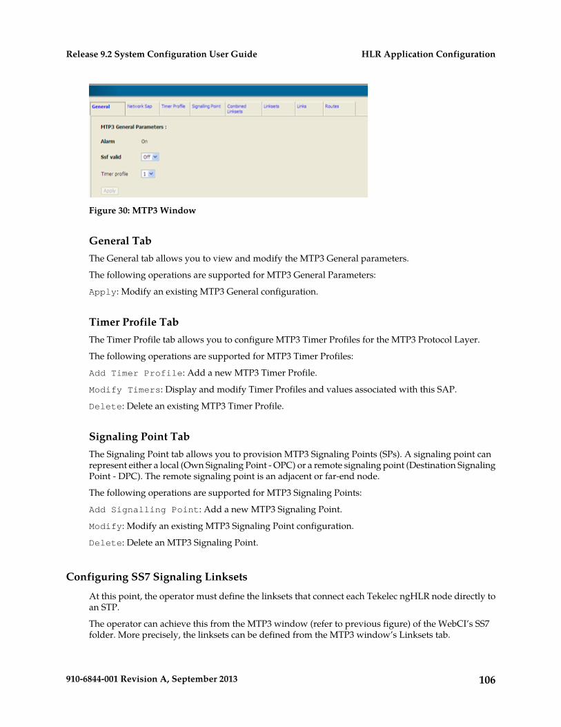
Figure 30: MTP3 Window
General TabThe General tab allows you to view and modify the MTP3 General parameters.
The following operations are supported for MTP3 General Parameters:
Apply: Modify an existing MTP3 General configuration.
Timer Profile TabThe Timer Profile tab allows you to configure MTP3 Timer Profiles for the MTP3 Protocol Layer.
The following operations are supported for MTP3 Timer Profiles:
Add Timer Profile: Add a new MTP3 Timer Profile.
Modify Timers: Display and modify Timer Profiles and values associated with this SAP.
Delete: Delete an existing MTP3 Timer Profile.
Signaling Point TabThe Signaling Point tab allows you to provision MTP3 Signaling Points (SPs). A signaling point canrepresent either a local (Own Signaling Point - OPC) or a remote signaling point (Destination SignalingPoint - DPC). The remote signaling point is an adjacent or far-end node.
The following operations are supported for MTP3 Signaling Points:
Add Signalling Point: Add a new MTP3 Signaling Point.
Modify: Modify an existing MTP3 Signaling Point configuration.
Delete: Delete an MTP3 Signaling Point.
Configuring SS7 Signaling Linksets
At this point, the operator must define the linksets that connect each Tekelec ngHLR node directly toan STP.
The operator can achieve this from the MTP3 window (refer to previous figure) of the WebCI’s SS7folder. More precisely, the linksets can be defined from the MTP3 window’s Linksets tab.
106910-6844-001 Revision A, September 2013
HLR Application ConfigurationRelease 9.2 System Configuration User Guide
Linksets Tab from the WebCI’s MTP3 WindowThe Linksets tab allows you to configure MTP3 Linksets. Linksets define groups of 1 to 16 links thatdirectly connect two signaling points (SPs).
The following operations are supported for MTP3 Linksets:
Add LinkSets: Add a new MTP3 Linkset.
Delete: Delete an MTP3 Linkset.
Display Links: Display all associated linksets that belong to the Linkset.
Activate/Deactivate Linksets: Activate/deactivate all the Links of a LinkSet.
Configuring SS7 Signaling Links
Once the interfaces and Linksets have been defined, the communication links between the TekelecngHLR and SS7 STPs can be defined. While linksets define which Signaling Point a given route uses,it is the links that carry the communications traffic. This section describes how to provision the signalinglink component. Refer to the previous sections if the interfaces and linksets have not been defined yet.
The operator can provision a SS7 Signaling link component from the MTP3 window (refer to previousfigure) of the WebCI’s SS7 folder. More precisely, links can be defined from the MTP3 window’s Linkstab.
To provision a new SS7 link, the operator must open the Link tab from the MTP3 window. For helpusing the WebCI and for instructions on how to provision tables in the WebCI, refer to Web CraftInterface (WebCI) in both this document and the SDM System Configuration – Reference Manual document.
Then, it can provision a SS7 link, as follows:
Prerequisites: Provision the SS7 interfaces and Linksets. Refer to the previous sections.
Provision an entry in the MTP3 Links table, by clicking on the Add button. When defining
the SS7 signaling links, the operator must do the following:
1. Define to which Linkset the link will belong to.2. Specify the following information:3. Which interface to use: (Mtp2Sap or SaalSap).
Each SS7 link in the node must be associated with an interface component, which must be associatedwith a network card.
4. SLC, Adjacent Signaling Points, and Priority.
Links Tab from the WebCI’s MTP3 WindowThe Links tab allows you to configure MTP3 Links. Links define physical signaling links between theSS7 board and the adjacent signaling points. One link configuration must be performed for eachphysical signaling link.
The following operations are supported for MTP3 Links:
Add: Add a new MTP3 Link.
107910-6844-001 Revision A, September 2013
HLR Application ConfigurationRelease 9.2 System Configuration User Guide
Edit: Modify an existing MTP3 Link configuration.
Note: When an SS7 link is up and running, any modification to the link may cause it to go down andresult in signaling failure. The link must be deactivated first before modifying it.
Delete: Delete an MTP3 Link.
Activate: Activate an MTP3 Link to be available to carry MTP3 user traffic.
Deactivate: Remove the link from service and make it unavailable to carry traffic.
Configuring SS7 signaling routes at the MTP3 layer
Once the links have been configured, different routes can be defined between the Tekelec ngHLR anda destination device (STP or SEP).
The routing can be done at two layer levels: MTP3 and SCCP. If you wish to define a route at the SCCPlayer level, you must first have configured it in the MTP3 layer.
Configuring the SS7 Signaling Routes at the MTP3 layer includes defining the following:
1. Combined linkset (CombinedLinkSet)2. The signaling route (Route)3. The Network Sap
Defining Combined Linkset
After determining the point codes for the network devices, define the combined linkset that will grouplinksets together.
The Combined Linkset can be defined, modified and deleted from the WebCI, in the SS7 folder’s MTP3window (refer to the previous figure). More precisely, from the MTP3 window’s Combined Linksetstab.
Combined Linksets Tab from the WebCI’s MTP3 Window:The Combined Linksets tab allows you to configure MTP3 Combined Linksets. It defines a group ofall linksets that can be used to reach a particular destination or group of destinations (routes).
The following operations are supported for MTP3 Combined Linksets:
Add Combined LinkSets: Add a new MTP3 Combined Linkset.
Delete: Delete an MTP3 Combined Linkset.
Display Linksets: Display all associated linksets that belong to the Combined Linkset.
For help using the WebCI and for instructions on how to provision tables in the WebCI, refer to WebCraft Interface (WebCI) in both this document and the SDM System Configuration – Reference Manualdocument.
Defining Routes
The final step in planning SS7 signaling routes is to define the SS7 routes themselves. Routes aredefined in terms of the point codes along the path and the combined linksets that lead from the TekelecngHLR node through the STPs to each DPC.
Items such as the OPC, DPC, and combinedLinksetId will have to be specified.
108910-6844-001 Revision A, September 2013
HLR Application ConfigurationRelease 9.2 System Configuration User Guide
The Routes can be defined, modified and deleted from the WebCI, in the SS7 folder’s MTP3 window(refer to the previous figure). More precisely, from the MTP3 window’s Routes tab.
Routes Tab from the WebCI’s MTP3 WindowThe Routes tab allows you to configure MTP3 Routes to Destination Point Codes.
The following operations are supported for MTP3 Route:
Add Route: Add a new MTP3 Route.
Modify: Modify an existing MTP3 Route configuration.
Delete: Delete an MTP3 Route.
Note: Delete all the links and linksets prior to deleting the route.
For help using the WebCI and for instructions on how to provision tables in the WebCI, refer to WebCraft Interface (WebCI) in both this document and the SDM System Configuration – Reference Manualdocument.
Defining Network Sap
Defining the Network Sap allows you to define the interface between the SCCP and MTP3 layers.
The Network Sap can be defined, modified and deleted from the WebCI, in the SS7 folder’s MTP3window (refer to the previous figure). More precisely, from the MTP3 window’s Network Sap tab.
Network Sap Tab from the WebCI’s MTP3 WindowThe Network Sap tab allows you to provision MTP3 Network Service Access Points (SAPs) and definethe interface between the SCCP and MTP3 layers. One Network SAP is defined for each MTP 3 layerinterface that the SCCP layer uses.
Note: You cannot add a second MTP3 Network SAP. The following error message will appear:
This operation on MTP3NSap is disabled in LDF environment.
The following operations are supported for MTP3 Network Service Access Points:
Add MTP3 Network SAP: Add a new MTP3 Network SAP.
Modify: Modify an existing MTP3 Network SAP configuration.
For help using the WebCI and for instructions on how to provision tables in the WebCI, refer to WebCraft Interface (WebCI) in both this document and the SDM System Configuration – Reference Manualdocument.
Configuring SS7 Signaling Routes at the SCCP Layer
At the SCCP layer, routes can be defined between the Tekelec ngHLR’s signaling stack and thedestination systems or subsystems by using either one of the following routing indicators:
• Global Titles
Or
• Destination Point Codes –SSN
109910-6844-001 Revision A, September 2013
HLR Application ConfigurationRelease 9.2 System Configuration User Guide
The following components must be configured when configuring an SS7 Signaling Route at the SCCPlayer:
1. Define General and Timer Profile information2. Define Network and User Saps3. Define SCCP Route4. Define the DPC-SSN of the destination systems or subsystems (the following only needs to be
defined in the case where the routing indicator is DPC-SSN):5. Define Remote SSN6. Define Concerned Area Point Code7. Define Concerned Point Codes (Optional)8. Define the GTs of the destination systems or subsystems (the following only needs to be defined
in the case where the routing indicator is GT):9. Define Global Title Entries10. Define SCCP Addresses11. Define Concerned Point Codes (Optional)12. Define Concerned Point Codes (Optional)
Configuring SCCP Routes with Global Titles as Routing IndicatorsRequirements: Log in to a WebCI session with a valid username and password.
The SCCP view is used to Display, Add, Modify, Delete, Activate, and Deactivate the parameters usedto define the SCCP layer of the SS7 network. The following SCCP provisioning tabs are available:General, Timer Profile, Network Sap, User Saps, Route, Concerned area, Global title entries and SCCPAddresses.
Note: The tables in the Concerned area tab don’t need to be provisioned when configuring a routewith Global Titles as routing indicators.
For help using the WebCI and for instructions on how to provision tables in the WebCI, refer to WebCraft Interface (WebCI) in both this document and the SDM System Configuration – Reference Manualdocument.
Refer to the SS7 entities section of the SDM System Configuration - Reference Manual for more detailson the SCCP parameters.
110910-6844-001 Revision A, September 2013
HLR Application ConfigurationRelease 9.2 System Configuration User Guide
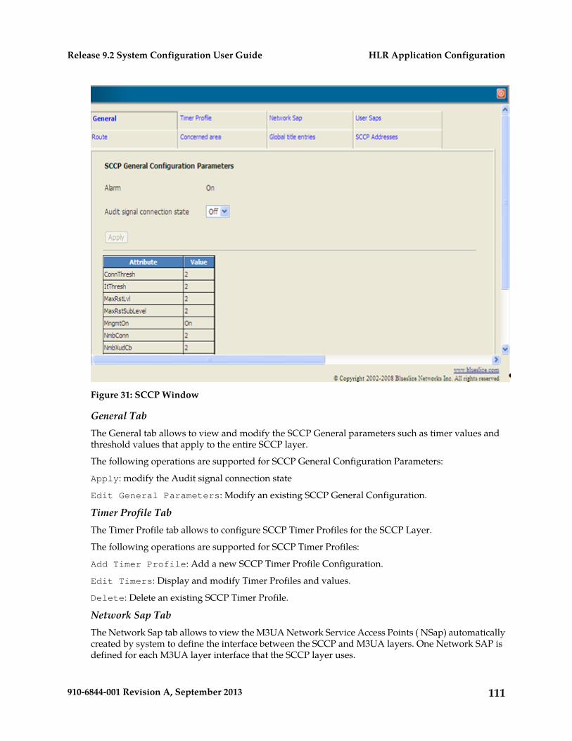
Figure 31: SCCP Window
General TabThe General tab allows to view and modify the SCCP General parameters such as timer values andthreshold values that apply to the entire SCCP layer.
The following operations are supported for SCCP General Configuration Parameters:
Apply: modify the Audit signal connection state
Edit General Parameters: Modify an existing SCCP General Configuration.
Timer Profile TabThe Timer Profile tab allows to configure SCCP Timer Profiles for the SCCP Layer.
The following operations are supported for SCCP Timer Profiles:
Add Timer Profile: Add a new SCCP Timer Profile Configuration.
Edit Timers: Display and modify Timer Profiles and values.
Delete: Delete an existing SCCP Timer Profile.
Network Sap TabThe Network Sap tab allows to view the M3UA Network Service Access Points ( NSap) automaticallycreated by system to define the interface between the SCCP and M3UA layers. One Network SAP isdefined for each M3UA layer interface that the SCCP layer uses.
111910-6844-001 Revision A, September 2013
HLR Application ConfigurationRelease 9.2 System Configuration User Guide
User Saps TabThe User Saps tab allows to provision SCCP User Service Access Points (USAPs) and to define theinterface between the user applications and SCCP layer. One user SAP is defined for each applicationusing the SCCP layer services.
The following operations are supported for SCCP User Service Access Points:
Add SCCP User SAP: Add a new SCCP User SAP configuration.
Edit: Modify an existing SCCP User SAP configuration.
Delete: Delete an SCCP User SAP.
Display Concerned PCs: Display the associated Concerned Point Codes interested in the statuschange of this USAP.
Route TabThe Route tab allows to configure SCCP Routes to Destination Point Codes. One route is defined foreach destination signalling point that the SCCP Layer may route outgoing messages to.
The following operations are supported for SCCP Route:
Add Route: Add a new SCCP Route Configuration.
Modify: Modify an existing SCCP Route configuration.
Delete: Delete an SCCP Route.
Note: First, delete any Concerned Areas still referencing this route.
Global Title Entries TabThe Global title entries tab allows to configure SCCP Global Title Entries. Refer to the SDM SystemConfiguration - Reference Manual for additional details on the Global Title Entries.
The following operations are supported for SCCP Global Title Entry:
Add Global Title Entry: Add a new Global Title Entry configuration.
Delete: Delete a Global Title Entry.
SCCP Addresses TabThe SCCP Addresses tab allows to configure SCCP Addresses. Refer to the SDM System Configuration- Reference Manual for additional details on the SCCP Address parameters.
The following operations are supported for SCCP Address:
Add Address: Add a new SCCP Address configuration.
Delete: Delete an SCCP Address.
Configuring SCCP Routes with DPC-SSNs as Routing IndicatorsRequirements: Log in to a WebCI session with a valid username and password.
For help using the WebCI, refer to Web Craft Interface (WebCI) in both this document and the SDMSystem Configuration – Reference Manual.
The SCCP window (see previous figure) is used to Display, Add, Modify, Delete, Activate, andDeactivate the parameters used to define the SCCP layer of the SS7 network. The following SCCP
112910-6844-001 Revision A, September 2013
HLR Application ConfigurationRelease 9.2 System Configuration User Guide
provisioning tabs are available: General, Timer Profile, Network Sap, User Saps, Route, Concernedarea, Global title entries and SCCP Addresses.
Take note that the tables in the following tabs must be provisioned to define a SCCP Route with theDPC-SSN as the routing indicator:
• General• Timer Profile• Network Sap• User Saps• Route• Concerned area
Refer to Configuring SCCP Routes with Global Titles as Routing Indicators for more information onthe General, Timer Profile, Network Sap, User Saps and Route tabs.
On the other hand, the Global title entries tab does not need to be provisioned when configuringa route using DPC-SSNs.
Refer to the SS7 entities section of the SDM System Configuration - Reference Manual for more detailson the SCCP parameters.
Concerned Area TabOne route is defined for each destination system or subsystem that the SCCP layer may be used toaccess. The route defines the destination point code used to reach that subsystem as well as any backuppoint code which replicates the subsystem.
The Concerned area tab allows to configure SCCP Routes to Destination Point Codes. One route isdefined for each destination signaling point that the SCCP Layer may route outgoing messages to.
The following operations are supported for SCCP Concerned Area:
Add Concerned Area: Add a new SCCP Concerned Area. Maximum of five Concerned Areas perRoute can be added.
Modify: Modify an existing SCCP Concerned Area configuration.
Delete: Delete an SCCP Concerned Area.
Note: First, delete any Concerned Areas still referencing this route.
Get concerned PCs: Add, retrieve and display the Concerned Point Codes for this specificRemoteSSN. All Signalling Points (SPs) interested in knowing about the Tekelec ngHLR state (InService, Out of Service) shall be configured.
Get backup PCs: Add, retrieve and display the list of Backup Point Codes.
Configuring the TCAP layer
Requirements: Log in to a WebCI session with a valid username and password.
For help using the WebCI, refer to Web Craft Interface (WebCI) in both this document and theSDMSystem Configuration – Reference Manual.
The TCAP (Transaction Capability Application Part) window is used to Display, Add, Modify, Delete,Activate, and Deactivate the parameters used to define the TCAP layer of the SS7 network. Thefollowing TCAP provisioning tabs are available: General, Tcap Sap, Tcap Timer Profile. Refer to the
113910-6844-001 Revision A, September 2013
HLR Application ConfigurationRelease 9.2 System Configuration User Guide
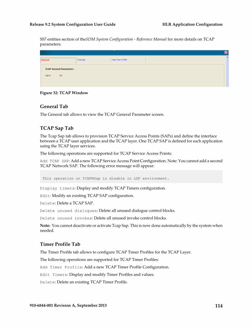
SS7 entities section of theSDM System Configuration - Reference Manual for more details on TCAPparameters.
Figure 32: TCAP Window
General TabThe General tab allows to view the TCAP General Parameter screen.
TCAP Sap TabThe Tcap Sap tab allows to provision TCAP Service Access Points (SAPs) and define the interfacebetween a TCAP user application and the TCAP layer. One TCAP SAP is defined for each applicationusing the TCAP layer services.
The following operations are supported for TCAP Service Access Points:
Add TCAP SAP: Add a new TCAP Service Access Point Configuration. Note: You cannot add a secondTCAP Network SAP. The following error message will appear:
This operation on TCAPNSap is disable in LDF environment.
Display timers: Display and modify TCAP Timers configuration.
Edit: Modify an existing TCAP SAP configuration.
Delete: Delete a TCAP SAP.
Delete unused dialogues: Delete all unused dialogue control blocks.
Delete unused invokes: Delete all unused invoke control blocks.
Note: You cannot deactivate or activate Tcap Sap. This is now done automatically by the system whenneeded.
Timer Profile TabThe Timer Profile tab allows to configure TCAP Timer Profiles for the TCAP Layer.
The following operations are supported for TCAP Timer Profiles:
Add Timer Profile: Add a new TCAP Timer Profile Configuration.
Edit Timers: Display and modify Timer Profiles and values.
Delete: Delete an existing TCAP Timer Profile.
114910-6844-001 Revision A, September 2013
HLR Application ConfigurationRelease 9.2 System Configuration User Guide
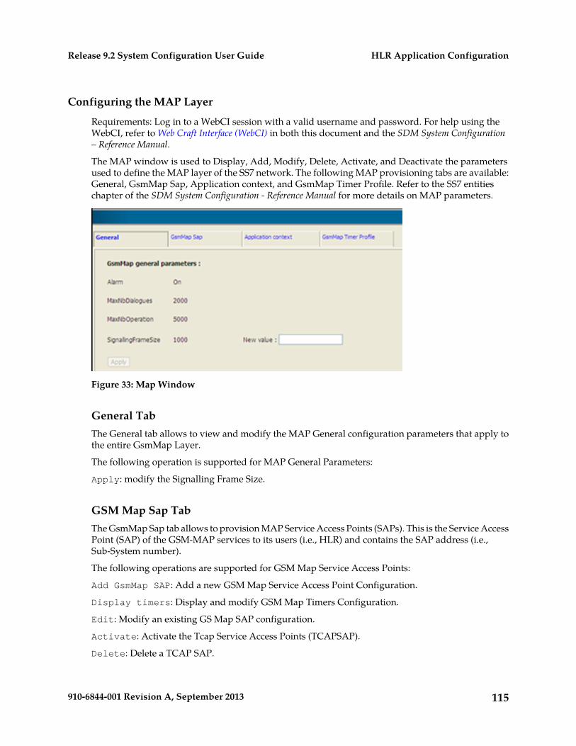
Configuring the MAP Layer
Requirements: Log in to a WebCI session with a valid username and password. For help using theWebCI, refer to Web Craft Interface (WebCI) in both this document and the SDM System Configuration– Reference Manual.
The MAP window is used to Display, Add, Modify, Delete, Activate, and Deactivate the parametersused to define the MAP layer of the SS7 network. The following MAP provisioning tabs are available:General, GsmMap Sap, Application context, and GsmMap Timer Profile. Refer to the SS7 entitieschapter of the SDM System Configuration - Reference Manual for more details on MAP parameters.
Figure 33: Map Window
General TabThe General tab allows to view and modify the MAP General configuration parameters that apply tothe entire GsmMap Layer.
The following operation is supported for MAP General Parameters:
Apply: modify the Signalling Frame Size.
GSM Map Sap TabThe GsmMap Sap tab allows to provision MAP Service Access Points (SAPs). This is the Service AccessPoint (SAP) of the GSM-MAP services to its users (i.e., HLR) and contains the SAP address (i.e.,Sub-System number).
The following operations are supported for GSM Map Service Access Points:
Add GsmMap SAP: Add a new GSM Map Service Access Point Configuration.
Display timers: Display and modify GSM Map Timers Configuration.
Edit: Modify an existing GS Map SAP configuration.
Activate: Activate the Tcap Service Access Points (TCAPSAP).
Delete: Delete a TCAP SAP.
115910-6844-001 Revision A, September 2013
HLR Application ConfigurationRelease 9.2 System Configuration User Guide
Application Context Tab:The Application context tab allows to define the MAP services supported by the HLR, such as mobilitymanagement, location management, call handling etc...
The following operations are supported for GSM Map Application Contexts:
Add application context: Add a new GSM Map Application Context Configuration.
Display timers: Display and modify GSM Map Timers Configuration.
Edit: Modify an existing GSM Map Application Context Configuration.
Delete: Delete a GSM Map Application Context.
Timer Profile TabThe Timer Profile tab allows to configure the GsmMap Timer Profiles.
The following operations are supported for GsmMap Timer Profiles:
Add timer profile: Add a new GsmMap Timer Profile Configuration.
Edit Timers: Display and modify Timer Profiles and values.
Delete: Delete an existing GsmMap Timer Profile.
Configuring the SS7 Stack Using the TUCL, M3UA & Protocols (SIGTRAN)
The ngHLR of the SDM can also use the SIGTRAN feature for SS7 communication via IP. This featureutilizes the TUCL, M3UA protocols and the Linux/SCTP stack (controlled by the OS kernel) to receivethe SS7 messages through IP connections and then transport and route them to upper layers of theSS7: SCCP, TCAP, MAP.
The SDM supports the following for SS7 communication using the SIGTRAN feature:
• The ITU/ANSI networks• The possibility to act as the client or the server (type of Association)• A single local or remote IP address or multiple local or remote IP addresses• Two modes:• ASP – Application Server Process. In this mode, the SDM plays the role of an Application Server
(AS) where the ASP is a process instance of the AS. The ASP contains an SCTP endpoint and isconfigured to process signaling traffic with an external Signalling Gateway node that takes care oftranslating MTP3 services coming from the VLR into services supported by SIGTRAN. This modeis used if the VLR does not support the SIGTRAN feature.
• SGP-Signalling Gateway Process. The SDM supports SIGTRAN communication with a SignallingGateway node. In this mode, the SDM plays the role of a Client and initiates the establishement ofthe association with the external SGP.
• IPSP – IP Server Process. In this mode, the SDM plays the role of an IP Server or IP Client wherethe IPSP is a process instance of an IP-based application. In this context, the SDM uses M3UA in apoint-to-point fashion and does not use the services of a Signalling Gateway node. SS7communication is done over IP directly between the SDM using the SIGTRAN feature and the VLRthat also supports the SIGTRAN feature.
116910-6844-001 Revision A, September 2013
HLR Application ConfigurationRelease 9.2 System Configuration User Guide
The following sections cover all the provisioning information from the prerequisites to the proceduresfor provisioning a new system with new SS7 components using the SIGTRAN feature.
Once the initial SS7 configuration is loaded into the Single Board Computers (before system startup)and once the SIGTRAN feature is enabled within the system (at system installation), the SIGTRANfeature can be provisioned by the operator through the WebCI.
In order to operate, administer, and manage the components of a SIGTRAN network, a networkoperator needs to set and inspect certain values that characterize the configuration of the networkcomponents.
Collecting data prior to configuration
Collect all required information prior to configuration.
Collecting SS7 Point Code DataThe SS7 point codes are SS7 network addresses that uniquely identify every switch, Signal TransferPoint (STP). To communicate with the SS7 network, SS7 point codes must be obtained for the TekelecSDM and for every SS7 network device that it will communicate with. The Tekelec ngHLR onlysupports one originating point code (OPC) and a minimum of one destination point code (DPC), oneDPC per remote SS7 network device.
Collecting IP Addresses and Port NumberLocal and Remote IP addresses must be defined to indicate the IP addresses that will be used by theTekelec ngHLR and its peer nodes to communicate together using SIGTRAN. On the SDM system,two blades run SIGTRAN traffic in High Availability. A local IP address/mask and port number mustbe defined on each of these two blades, and the IP address and port number of the peers node mustalso be defined.
Collecting SS7 Route DataAn SS7 route must be defined for each Signalling End Point the Tekelec ngHLR wants to reach. Theremust be an SS7 route for each linkset. You must be ready to enter the following information about theSS7 route to be created:
• Destination Point Code (DPC)• Originating Point Code (OPC)• CombinedLinkset
Collecting AssociationsAn association refers to an SCTP association. The association provides the transport for the deliveryof MTP3-User protocol data units and M3UA adaptation layer peer messages. An association mustbe created between the Tekelec ngHLR and each of its peer node. Since the Tekelec ngHLR works inHigh Availability, an IP association must be created for each of the system’s blades running SIGTRANtraffic. Finally, in the case where the SDM communicates with one peer node using SIGTRAN, twoSCTP associations must be created. The following information must be entered about each association:
• Remote IP Address(es) and Port
117910-6844-001 Revision A, September 2013
HLR Application ConfigurationRelease 9.2 System Configuration User Guide
• Network (ITU)• SCTSap• PSP Type (SGP, IPsP)• Associtation Type (Client or Server)
Collecting SS7 Subsystem DataOne route is defined for each destination subsystem that the SCCP layer may be used to access. Theroute defines the destination point code used to reach that subsystem as well as any backup pointcode which replicates the subsystem.
Collecting Concerned Point Code DataEvery remote SignallingPoint interested in knowing about the state changes of the Tekelec ngHLRnode shall be configured. They will receive messages such as SSA (Subsystem Allowed), SSP (SubsystemProhibited), and SSC (Subsystem Congested).
Collecting Global Title DataAll mobile subscriber terminals in a cellular network (e.g. GSM) are usually defined in a specificdatabase, the HLR (i.e., Tekelec ngHLR). The addressing of an HLR node in the telecom network isusually based on the first, most significant half of a mobile subscribe number. When an HLRcommunicates over the SS7 signalling network, this address information has to be translated into aform that allows routing in the SCCP network. Some of the address information based on the globaltitle series is called a Global Title (GT). A GT needs to be translated into a DPC by the SCCP in orderto make it possible for the MTP to route the signalling messages through the SCCP network. Thefollowing information must be entered about the GTT to be created:
• Destination Point Code (DPC)• Subsystem Number (SSN)• Nature of Address (NA)• Numbering Plan (NP)• Digits of the Called or Calling Party Number• Translation Type (TT)• Address Indicator (Routing Indicator, GT Indicator, SSN Indicator, Dpc Indicator)• Network Indicator (NI)
SS7 signaling configuration sequence using SIGTRAN
The SS7 logical node must be provisioned, modified or unprovisioned in specific sequences. Hereunderis a flow chart that provides an overview of these sequences for the configuration of the SS7 stack inthe TUCL, M3UA and SCCP layers. Once all these steps have been followed, the TCAP and MAPlayers must also be configured. For instructions on how to configure these last two layers, refer toConfiguring the TCAP layer and Configuring the MAP Layer of this document.
118910-6844-001 Revision A, September 2013
HLR Application ConfigurationRelease 9.2 System Configuration User Guide
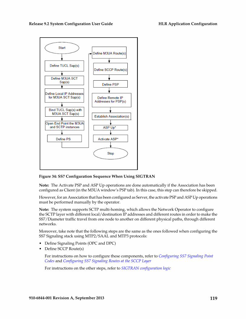
Figure 34: SS7 Configuration Sequence When Using SIGTRAN
Note: The Activate PSP and ASP Up operations are done automatically if the Association has beenconfigured as Client (in the M3UA window’s PSP tab). In this case, this step can therefore be skipped.
However, for an Association that has been configured as Server, the activate PSP and ASP Up operationsmust be performed manually by the operator.
Note: The system supports SCTP multi-homing, which allows the Network Operator to configurethe SCTP layer with different local/destination IP addresses and different routes in order to make theSS7/Diameter traffic travel from one node to another on different physical paths, through differentnetworks.
Moreover, take note that the following steps are the same as the ones followed when configuring theSS7 Signaling stack using MTP2/SAAL and MTP3 protocols:
• Define Signaling Points (OPC and DPC)• Define SCCP Route(s)
For instructions on how to configure these components, refer to Configuring SS7 Signaling PointCodes and Configuring SS7 Signaling Routes at the SCCP Layer
For instructions on the other steps, refer to SIGTRAN configuration logic
119910-6844-001 Revision A, September 2013
HLR Application ConfigurationRelease 9.2 System Configuration User Guide

SIGTRAN configuration logic
The following logic must be followed to provision the Tekelec ngHLR with the SIGTRAN feature:
1. The Service Access Points (Sap) must be configured for each SIGTRAN layer: TUCL and M3UA.2. For the TUCL layer, the Sap provider must be created.3. For the M3UA layer, the SCTSap provider (using the previous TUCL Sap as provider) must be
created.
The list of local IP addresses (IP addresses of the Tekelec ngHLR) must be defined per SCTSap andthe list of remote IP addresses (IP addresses of the peer nodes) that will be used for SIGTRAN mustbe defined per PSP.
4. For SCCP layer, the NSap user (using previous M3UA NSap provider) must be created.5. The M3UA SCTSaps must be bound with the TUCL Saps by executing the Bind() operation and
open-end-point between the M3UA and SCTP protocols must be executed with the OpenEndpoint()operation. Both operations are available in the M3UA layer’s SCTSap.
6. The local and remote PS must be created.7. A local route and remote M3UA route must be created for the PS.8. The PSP (Peer Signalling Process) must be configured in the M3UA layer. When creating the PSP,
the type must be defined (IPsP, SGP) as well as the association type (client or server), the referenceto the Remote PS and the reference to the Remote IP address. Note that when the SGP type isselected, the association type can only be client.
In the case where the association type is configured as “Server” or if it is the first time that the HLRservice is started, the peer that is the client should bring the association up, if it doesn’t, you can:
9. Establish the association by executing the EstablishAssociation() operation found in the PSP entity.10. Set the applications to “ready“ by executing the AspUp() operation found in the PSP entity.11. Activate the applications by executing the ActivateAsp() operation found in the PSP entity.
Note: If you configured the association as being client, the three steps above are done automatically.
The figure below shows the main logic that needs to be followed when provisioning the SIGTRANfeature.
120910-6844-001 Revision A, September 2013
HLR Application ConfigurationRelease 9.2 System Configuration User Guide
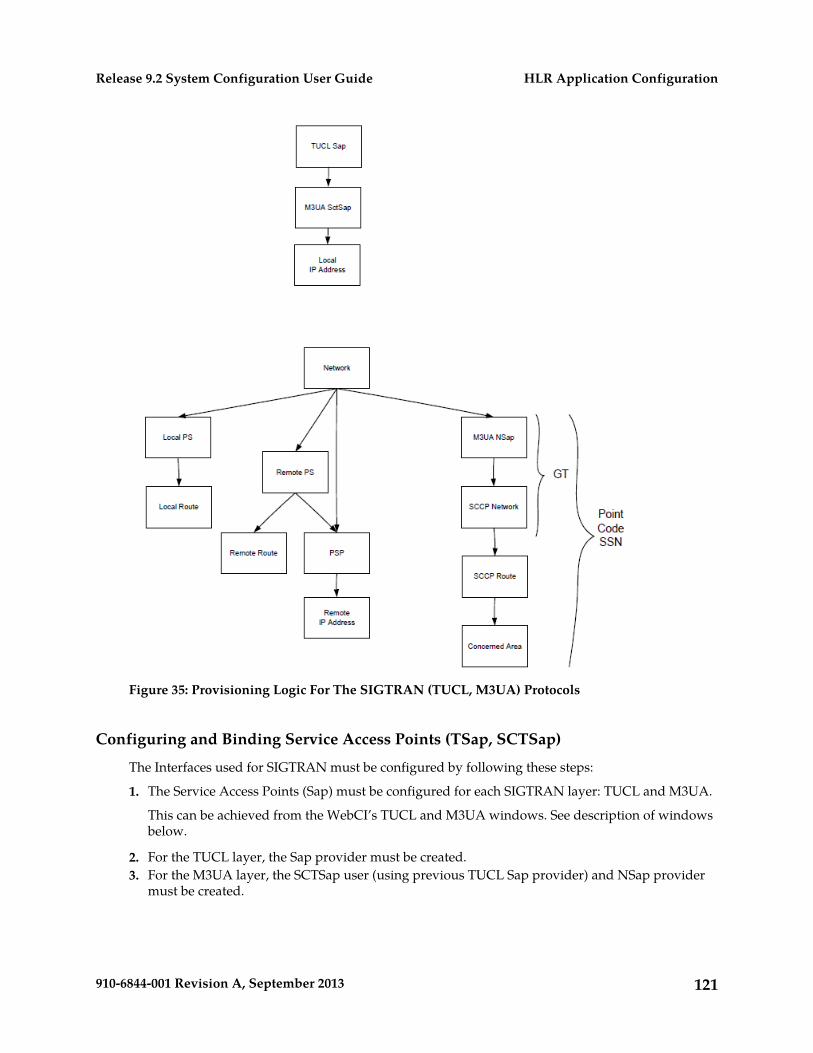
Figure 35: Provisioning Logic For The SIGTRAN (TUCL, M3UA) Protocols
Configuring and Binding Service Access Points (TSap, SCTSap)
The Interfaces used for SIGTRAN must be configured by following these steps:
1. The Service Access Points (Sap) must be configured for each SIGTRAN layer: TUCL and M3UA.
This can be achieved from the WebCI’s TUCL and M3UA windows. See description of windowsbelow.
2. For the TUCL layer, the Sap provider must be created.3. For the M3UA layer, the SCTSap user (using previous TUCL Sap provider) and NSap provider
must be created.
121910-6844-001 Revision A, September 2013
HLR Application ConfigurationRelease 9.2 System Configuration User Guide
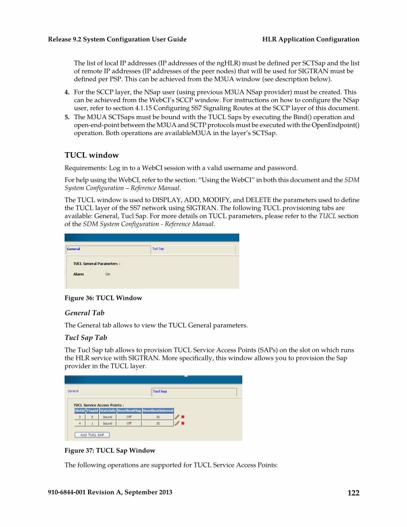
The list of local IP addresses (IP addresses of the ngHLR) must be defined per SCTSap and the listof remote IP addresses (IP addresses of the peer nodes) that will be used for SIGTRAN must bedefined per PSP. This can be achieved from the M3UA window (see description below).
4. For the SCCP layer, the NSap user (using previous M3UA NSap provider) must be created. Thiscan be achieved from the WebCI’s SCCP window. For instructions on how to configure the NSapuser, refer to section 4.1.15 Configuring SS7 Signaling Routes at the SCCP layer of this document.
5. The M3UA SCTSaps must be bound with the TUCL Saps by executing the Bind() operation andopen-end-point between the M3UA and SCTP protocols must be executed with the OpenEndpoint()operation. Both operations are availableM3UA in the layer’s SCTSap.
TUCL windowRequirements: Log in to a WebCI session with a valid username and password.
For help using the WebCI, refer to the section: “Using the WebCI” in both this document and the SDMSystem Configuration – Reference Manual.
The TUCL window is used to DISPLAY, ADD, MODIFY, and DELETE the parameters used to definethe TUCL layer of the SS7 network using SIGTRAN. The following TUCL provisioning tabs areavailable: General, Tucl Sap. For more details on TUCL parameters, please refer to the TUCL sectionof the SDM System Configuration - Reference Manual.
Figure 36: TUCL Window
General TabThe General tab allows to view the TUCL General parameters.
Tucl Sap TabThe Tucl Sap tab allows to provision TUCL Service Access Points (SAPs) on the slot on which runsthe HLR service with SIGTRAN. More specifically, this window allows you to provision the Sapprovider in the TUCL layer.
Figure 37: TUCL Sap Window
The following operations are supported for TUCL Service Access Points:
122910-6844-001 Revision A, September 2013
HLR Application ConfigurationRelease 9.2 System Configuration User Guide
Add TUCL SAP: Add a new TUCL SAP. Note: You cannot add a TUCL Sap on a slot that does notexist. The following error message will appear:
Failed to create TuclSap, requested slot# do not have active TUCL layer
Important: A minimum of two TUCL SAPs should be configured on two different HLRInstances (on two different blades, for different SlotIds) in order to support HighAvailability failure.
Edit: Modify an existing TUCL Sap definition.
Delete: Delete a TUCL SAP. Requirements: Before deleting the configuration of a TSap, the TSapmust not be bound. The operation Unbind() must be executed for this TSap. Moreover, the M3UASCTSap should also be deleted.
M3UA WindowRequirements: Log in to a WebCI session with a valid username and password.
For help using the WebCI, refer to Web Craft Interface (WebCI) in both this document and the SDMSystem Configuration – Reference Manual.
The M3UA window is used to Display, Add, Modify, Delete, Activate, and Deactivate the parametersused to define the M3UA layer of the SS7 network using SIGTRAN. The following M3UA provisioningtabs are available: General, Network, Network Sap, SCT Sap, PS, Route, PSP. For more details onM3UA parameters, refer to the SS7 entities section of the SDM System Configuration - Reference Manual.
123910-6844-001 Revision A, September 2013
HLR Application ConfigurationRelease 9.2 System Configuration User Guide
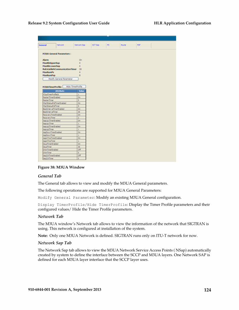
Figure 38: M3UA Window
General TabThe General tab allows to view and modify the M3UA General parameters.
The following operations are supported for M3UA General Parameters:
Modify General Parameter: Modify an existing M3UA General configuration.
Display TimerProfile/Hide TimerProfile: Display the Timer Profile parameters and theirconfigured values/ Hide the Timer Profile parameters.
Network TabThe M3UA window’s Network tab allows to view the information of the network that SIGTRAN isusing. This network is configured at installation of the system.
Note: Only one M3UA Network is defined. SIGTRAN runs only on ITU-T network for now.
Network Sap TabThe Network Sap tab allows to view the M3UA Network Service Access Points ( NSap) automaticallycreated by system to define the interface between the SCCP and M3UA layers. One Network SAP isdefined for each M3UA layer interface that the SCCP layer uses.
124910-6844-001 Revision A, September 2013
HLR Application ConfigurationRelease 9.2 System Configuration User Guide
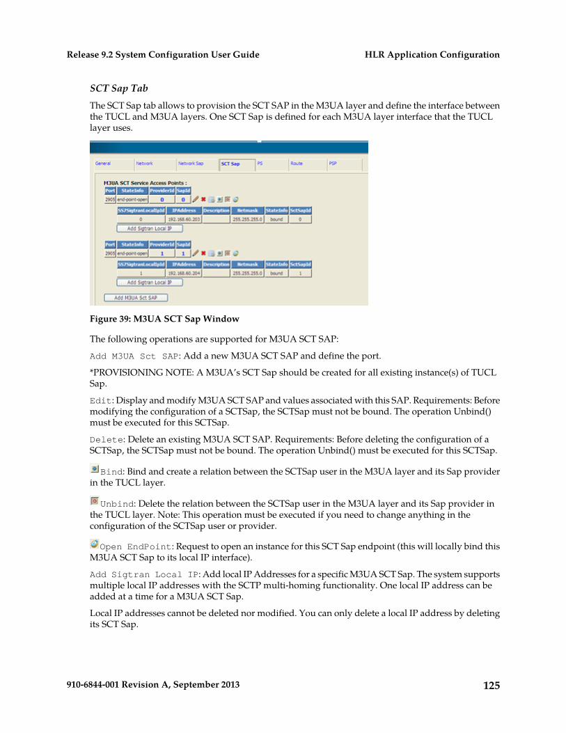
SCT Sap TabThe SCT Sap tab allows to provision the SCT SAP in the M3UA layer and define the interface betweenthe TUCL and M3UA layers. One SCT Sap is defined for each M3UA layer interface that the TUCLlayer uses.
Figure 39: M3UA SCT Sap Window
The following operations are supported for M3UA SCT SAP:
Add M3UA Sct SAP: Add a new M3UA SCT SAP and define the port.
*PROVISIONING NOTE: A M3UA’s SCT Sap should be created for all existing instance(s) of TUCLSap.
Edit: Display and modify M3UA SCT SAP and values associated with this SAP. Requirements: Beforemodifying the configuration of a SCTSap, the SCTSap must not be bound. The operation Unbind()must be executed for this SCTSap.
Delete: Delete an existing M3UA SCT SAP. Requirements: Before deleting the configuration of aSCTSap, the SCTSap must not be bound. The operation Unbind() must be executed for this SCTSap.
Bind: Bind and create a relation between the SCTSap user in the M3UA layer and its Sap providerin the TUCL layer.
Unbind: Delete the relation between the SCTSap user in the M3UA layer and its Sap provider inthe TUCL layer. Note: This operation must be executed if you need to change anything in theconfiguration of the SCTSap user or provider.
Open EndPoint: Request to open an instance for this SCT Sap endpoint (this will locally bind thisM3UA SCT Sap to its local IP interface).
Add Sigtran Local IP: Add local IP Addresses for a specific M3UA SCT Sap. The system supportsmultiple local IP addresses with the SCTP multi-homing functionality. One local IP address can beadded at a time for a M3UA SCT Sap.
Local IP addresses cannot be deleted nor modified. You can only delete a local IP address by deletingits SCT Sap.
125910-6844-001 Revision A, September 2013
HLR Application ConfigurationRelease 9.2 System Configuration User Guide
Configuring the PS
After defining the SAPs, the following must be configured:
The local and remote PS must be created in the M3UA layer.
To achieve this, you can provision the M3UA PS table in the M3UA window’s PS tab.
PS TabThe M3UA window’s PS tab allows to define the PS (Peer Server) local and PS (Peer Server) remotefor a PSP.
The following operations are supported for M3UA PS:
Add M3UA Ps: Add a new M3UA PS.
Note: Only one Local PS should be added. A Remote PS should be created for each destination route.Multiple PSPs can then be assigned to a PS. Multiple non-adjacent point codes and multiple alias pointcodes can also be configured.
Delete: Delete an M3UA PS. Requirements: Before deleting a PS, its associated Route and the PSPsreferring to it must be deleted.
Edit: Modify an M3UA PS. Requirements: Before modifying a PS, you must manually deactivate theApplication Server Process by deactivating the PSP. To do so, you must execute the AspDown()operation for the PSP to which the PS you wish to modify refers to.
Configuring Route(s)
After defining the PS and PSP, the following steps must be followed:
1. The M3UA Routes must be defined by following the steps below:2. The Signaling Point Codes (DPC & OPC) must be defined.
To achieve this, provision the MTP3 Signaling Points table in the MTP3 window’s Signaling Pointstab. Refer to section 0
3. Configuring SS7 Signaling Point Codes of this document.4. A local route and remote route must be created for the PS.
To achieve this, provision the M3UA Route table in the M3UA window’s Route tab.
Route TabThe M3UA window’s Route tab allows to configure the M3UA Route and specify the destinationsignaling points that are accessible from the Signaling Point (SP) being configured. One route is requiredfor each remote signaling point/network/cluster that is to be accessible from the SP being configured(DPC). Routes are used to route outgoing messages to the appropriate signaling IP associations. Eachroute is assigned to one IP association which may be used to reach that destination.
The following operations are supported for M3UA Route:
126910-6844-001 Revision A, September 2013
HLR Application ConfigurationRelease 9.2 System Configuration User Guide
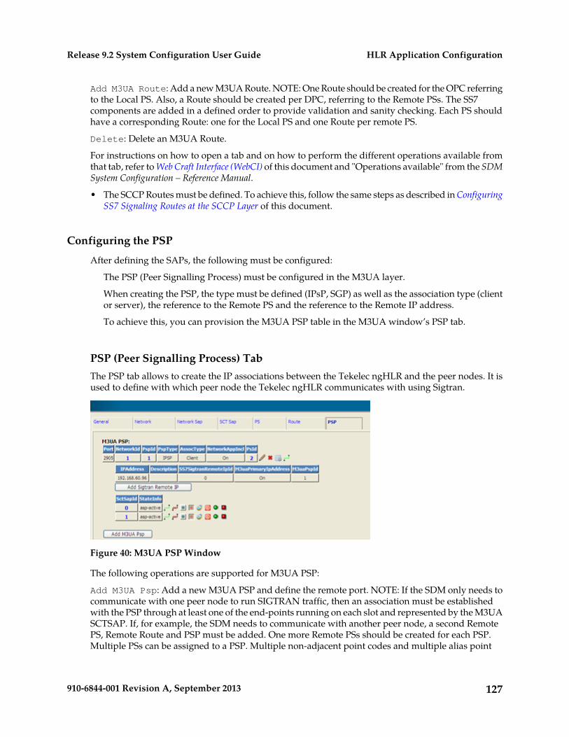
Add M3UA Route: Add a new M3UA Route. NOTE: One Route should be created for the OPC referringto the Local PS. Also, a Route should be created per DPC, referring to the Remote PSs. The SS7components are added in a defined order to provide validation and sanity checking. Each PS shouldhave a corresponding Route: one for the Local PS and one Route per remote PS.
Delete: Delete an M3UA Route.
For instructions on how to open a tab and on how to perform the different operations available fromthat tab, refer to Web Craft Interface (WebCI) of this document and "Operations available" from the SDMSystem Configuration – Reference Manual.
• The SCCP Routes must be defined. To achieve this, follow the same steps as described in ConfiguringSS7 Signaling Routes at the SCCP Layer of this document.
Configuring the PSP
After defining the SAPs, the following must be configured:
The PSP (Peer Signalling Process) must be configured in the M3UA layer.
When creating the PSP, the type must be defined (IPsP, SGP) as well as the association type (clientor server), the reference to the Remote PS and the reference to the Remote IP address.
To achieve this, you can provision the M3UA PSP table in the M3UA window’s PSP tab.
PSP (Peer Signalling Process) TabThe PSP tab allows to create the IP associations between the Tekelec ngHLR and the peer nodes. It isused to define with which peer node the Tekelec ngHLR communicates with using Sigtran.
Figure 40: M3UA PSP Window
The following operations are supported for M3UA PSP:
Add M3UA Psp: Add a new M3UA PSP and define the remote port. NOTE: If the SDM only needs tocommunicate with one peer node to run SIGTRAN traffic, then an association must be establishedwith the PSP through at least one of the end-points running on each slot and represented by the M3UASCTSAP. If, for example, the SDM needs to communicate with another peer node, a second RemotePS, Remote Route and PSP must be added. One more Remote PSs should be created for each PSP.Multiple PSs can be assigned to a PSP. Multiple non-adjacent point codes and multiple alias point
127910-6844-001 Revision A, September 2013
HLR Application ConfigurationRelease 9.2 System Configuration User Guide
codes can be configured. The associations can be established through the same end-points used bythe first PSP. The same logic applies to any scenario with multiple peer nodes running SIGTRANtraffic.
Edit: Modify an existing M3UA PSP. Requirements: Before modifying a PSP (IP association), youmust firstly make sure that the Application Server process is down. You must terminate the associationbetween the Tekelec ngHLR and the remote peer (PSP). To do so, you must execute theTerminateAssociation() operation.
Delete: Delete an M3UA PSP. Requirements: Before deleting a PSP, all its associations with the M3UASCTSAPs must be terminated by executing the TerminateAssociation() operation.
Establish Association: Establish the association between the Tekelec ngHLR and the remote peer(PSP) through an SctSap.
Terminate Association: Terminate the association between the Tekelec ngHLR and the remote peer(PSP).
ASP Up: Indicate to the peer that the Application Server process is up and that the SIGTRANapplications are ready to receive traffic.
ASP Down: Indicate to the peer that the Application Server process is down and that the SIGTRANapplications are no longer ready to receive traffic.
Inhibit Psp: the PSP Association is not available to carry traffic.
Uninhibit Psp: the PSP Association is available to carry traffic.
Activate ASP: The ASP is active and can receive and process traffic.
Deactivate ASP: The ASP is deactivated and cannot receive nor process traffic.
Add Sigtran Remote IP. Add remote IP Addresses for a specific M3UA PSP. The system supportsmultiple remote IP addresses with the SCTP multi-homing functionality. One remote IP address canbe added at a time for a M3UA PSP. When defining multiple remote IP addresses, one and only oneremote IP address must be defined as the ‘Primary’ IP address (only one primary remote IP addressmust be defined for each association). For this, the ‘M3uaPrimaryIpAddress’ parameter has beenimplemented in the Sigtran Remote IP Address table. This indicates to the Tekelec ngHLR which IPaddress to use when connecting with the peer.
Provisioning TIP: The first remote IP Address defined must be the primary address (IP address to usewhen connecting with the peer).
Remote IP addresses cannot be deleted nor modified. You can only delete a remote IP address bydeleting its PSP.
The status of each PSP association is available per M3UA SCT Sap in the PspState table.
Establishing Association and Activating ASP
In the case where the association type is configured as “Server” or if it is the first time that the HLRservice is started, the peer that is the client should bring the association up, if it doesn’t, you can:
• Establish the association by executing the EstablishAssociation() operation found in the PSP entity.• Set the applications to “ready“ by executing the AspUp() operation found in the PSP entity.• Activate the applications by executing the ActivateAsp() operation found in the PSP entity.
128910-6844-001 Revision A, September 2013
HLR Application ConfigurationRelease 9.2 System Configuration User Guide
Note: If you configured the association as being client, the three steps above are done automatically.
129910-6844-001 Revision A, September 2013
HLR Application ConfigurationRelease 9.2 System Configuration User Guide
Chapter
5HLR Features Configuration
This chapter contains information pertaining to theconfiguration of HLR Features.
Topics:
• Provisioning Forward-To-Number rules for FTNDigits Analysis.....131
• Provisioning CAMEL.....137• Provisioning Roaming Welcome Notifications.138• Provisioning USSD application nodes for the
routing of USSD messages.....143• Roaming controls.....144• Setting Restrictions on the Version of MAP
Messages (MAP Policing) and on the SRI-ack,ATI-ack and PSI Messages.....152
• Provisioning the Tekelec ngHLR for MT-SMSRouting.....157
• Provisioning Routing Controls for GSM/IMSRouter capabilities.....159
• Provisioning GSM Bearer Capabilities.....163• Provisioning the Subscriber Signaling Router
(SSR).....165• Provisioning/Modifying the Enhanced Control Of
SCCP Routing Configuration.....167• Provisioning PDN Context Templates.....168
130910-6844-001 Revision A, September 2013
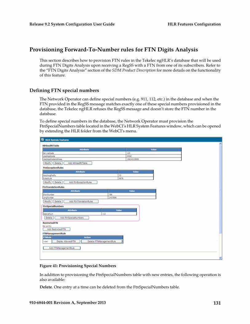
Provisioning Forward-To-Number rules for FTN Digits Analysis
This section describes how to provision FTN rules in the Tekelec ngHLR’s database that will be usedduring FTN Digits Analysis upon receiving a RegSS with a FTN from one of its subscribers. Refer tothe “FTN Digits Analysis” section of the SDM Product Description for more details on the functionalityof this feature.
Defining FTN special numbers
The Network Operator can define special numbers (e.g. 911, 112, etc.) in the database and when theFTN provided in the RegSS message matches exactly one of these special numbers provisioned in thedatabase, the Tekelec ngHLR refuses the RegSS message and doesn’t store the FTN number in thedatabase.
To define special numbers in the database, the Network Operator must provision theFtnSpecialNumbers table located in the WebCI’s HLR System Features window, which can be openedby extending the HLR folder from the WebCI’s menu.
Figure 41: Provisioning Special Numbers
In addition to provisioning the FtnSpecialNumbers table with new entries, the following operation isalso available:
Delete. One entry at a time can be deleted from the FtnSpecialNumbers table.
131910-6844-001 Revision A, September 2013
HLR Features ConfigurationRelease 9.2 System Configuration User Guide
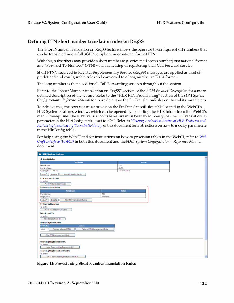
Defining FTN short number translation rules on RegSS
The Short Number Translation on RegSS feature allows the operator to configure short numbers thatcan be translated into a full 3GPP-compliant international format FTN.
With this, subscribers may provide a short number (e.g. voice mail access number) or a national formatas a “Forward-To Number” (FTN) when activating or registering their Call Forward service
Short FTN’s received in Register Supplementary Service (RegSS) messages are applied as a set ofpredefined and configurable rules and converted to a long number in E.164 format.
The long number is then used for all Call Forwarding services throughout the system.
Refer to the “Short Number translation on RegSS” section of the SDM Product Description for a moredetailed description of the feature. Refer to the “HLR FTN Provisioning” section of theSDM SystemConfiguration – Reference Manual for more details on the FtnTranslationRules entity and its parameters.
To achieve this, the operator must provision the FtnTranslationRules table located in the WebCI’sHLR System Features window, which can be opened by extending the HLR folder from the WebCI’smenu. Prerequisite: The FTN Translation Rule feature must be enabled. Verify that the FtnTranslationOnparameter in the HlrConfig table is set to ‘On’. Refer to Viewing Activation Status of HLR Features andActivating/deactivating Them Individually of this document for instructions on how to modify parametersin the HlrConfig table.
For help using the WebCI and for instructions on how to provision tables in the WebCI, refer to WebCraft Interface (WebCI) in both this document and theSDM System Configuration – Reference Manualdocument.
Figure 42: Provisioning Short Number Translation Rules
132910-6844-001 Revision A, September 2013
HLR Features ConfigurationRelease 9.2 System Configuration User Guide
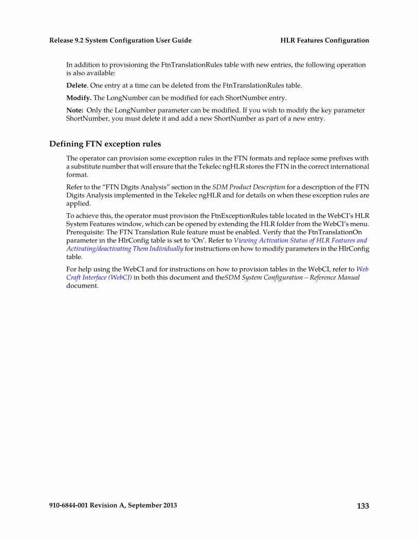
In addition to provisioning the FtnTranslationRules table with new entries, the following operationis also available:
Delete. One entry at a time can be deleted from the FtnTranslationRules table.
Modify. The LongNumber can be modified for each ShortNumber entry.
Note: Only the LongNumber parameter can be modified. If you wish to modify the key parameterShortNumber, you must delete it and add a new ShortNumber as part of a new entry.
Defining FTN exception rules
The operator can provision some exception rules in the FTN formats and replace some prefixes witha substitute number that will ensure that the Tekelec ngHLR stores the FTN in the correct internationalformat.
Refer to the “FTN Digits Analysis” section in the SDM Product Description for a description of the FTNDigits Analysis implemented in the Tekelec ngHLR and for details on when these exception rules areapplied.
To achieve this, the operator must provision the FtnExceptionRules table located in the WebCI’s HLRSystem Features window, which can be opened by extending the HLR folder from the WebCI’s menu.Prerequisite: The FTN Translation Rule feature must be enabled. Verify that the FtnTranslationOnparameter in the HlrConfig table is set to ‘On’. Refer to Viewing Activation Status of HLR Features andActivating/deactivating Them Individually for instructions on how to modify parameters in the HlrConfigtable.
For help using the WebCI and for instructions on how to provision tables in the WebCI, refer to WebCraft Interface (WebCI) in both this document and theSDM System Configuration – Reference Manualdocument.
133910-6844-001 Revision A, September 2013
HLR Features ConfigurationRelease 9.2 System Configuration User Guide
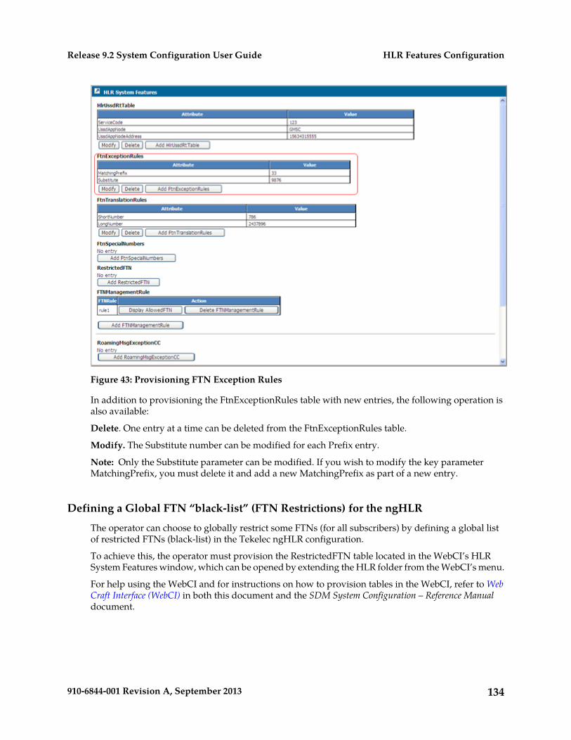
Figure 43: Provisioning FTN Exception Rules
In addition to provisioning the FtnExceptionRules table with new entries, the following operation isalso available:
Delete. One entry at a time can be deleted from the FtnExceptionRules table.
Modify. The Substitute number can be modified for each Prefix entry.
Note: Only the Substitute parameter can be modified. If you wish to modify the key parameterMatchingPrefix, you must delete it and add a new MatchingPrefix as part of a new entry.
Defining a Global FTN “black-list” (FTN Restrictions) for the ngHLR
The operator can choose to globally restrict some FTNs (for all subscribers) by defining a global listof restricted FTNs (black-list) in the Tekelec ngHLR configuration.
To achieve this, the operator must provision the RestrictedFTN table located in the WebCI’s HLRSystem Features window, which can be opened by extending the HLR folder from the WebCI’s menu.
For help using the WebCI and for instructions on how to provision tables in the WebCI, refer to WebCraft Interface (WebCI) in both this document and the SDM System Configuration – Reference Manualdocument.
134910-6844-001 Revision A, September 2013
HLR Features ConfigurationRelease 9.2 System Configuration User Guide
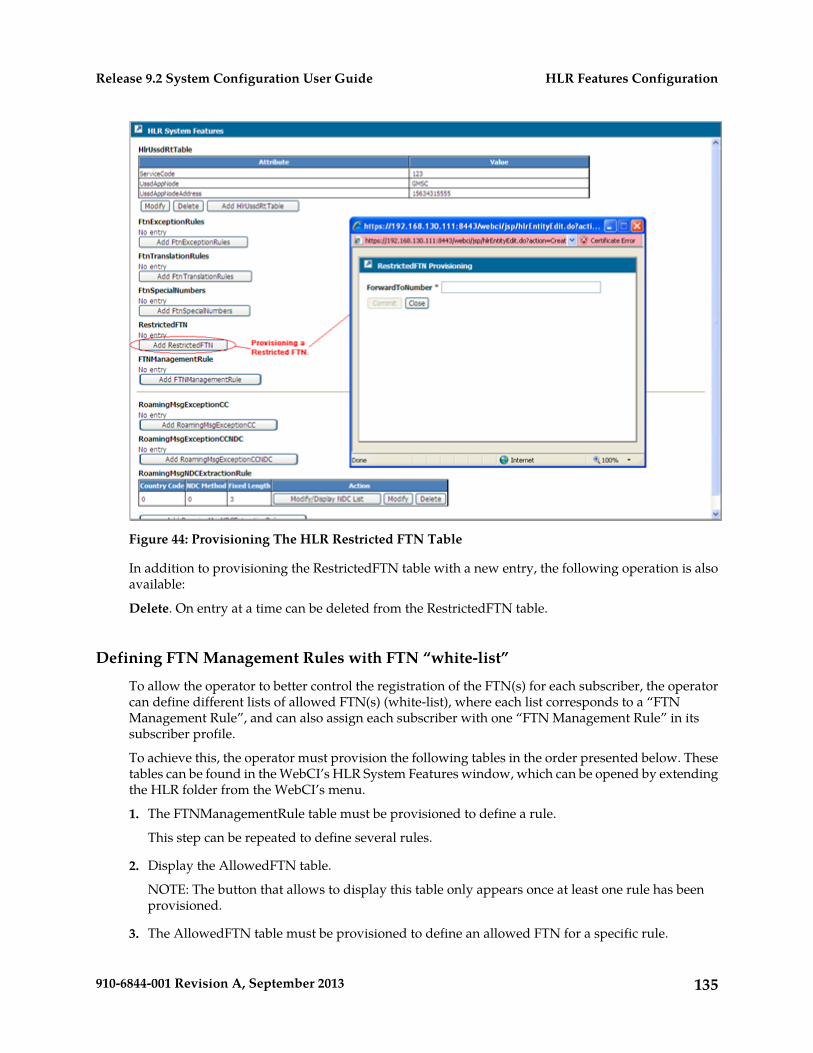
Figure 44: Provisioning The HLR Restricted FTN Table
In addition to provisioning the RestrictedFTN table with a new entry, the following operation is alsoavailable:
Delete. On entry at a time can be deleted from the RestrictedFTN table.
Defining FTN Management Rules with FTN “white-list”
To allow the operator to better control the registration of the FTN(s) for each subscriber, the operatorcan define different lists of allowed FTN(s) (white-list), where each list corresponds to a “FTNManagement Rule”, and can also assign each subscriber with one “FTN Management Rule” in itssubscriber profile.
To achieve this, the operator must provision the following tables in the order presented below. Thesetables can be found in the WebCI’s HLR System Features window, which can be opened by extendingthe HLR folder from the WebCI’s menu.
1. The FTNManagementRule table must be provisioned to define a rule.
This step can be repeated to define several rules.
2. Display the AllowedFTN table.
NOTE: The button that allows to display this table only appears once at least one rule has beenprovisioned.
3. The AllowedFTN table must be provisioned to define an allowed FTN for a specific rule.
135910-6844-001 Revision A, September 2013
HLR Features ConfigurationRelease 9.2 System Configuration User Guide
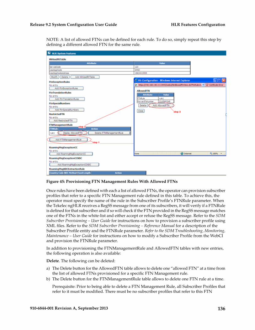
NOTE: A list of allowed FTNs can be defined for each rule. To do so, simply repeat this step bydefining a different allowed FTN for the same rule.
Figure 45: Provisioning FTN Management Rules With Allowed FTNs
Once rules have been defined with each a list of allowed FTNs, the operator can provision subscriberprofiles that refer to a specific FTN Management rule defined in this table. To achieve this, theoperator must specify the name of the rule in the Subscriber Profile’s FTNRule parameter. Whenthe Tekelec ngHLR receives a RegSS message from one of its subscribers, it will verify if a FTNRuleis defined for that subscriber and if so will check if the FTN provided in the RegSS message matchesone of the FTNs in the white-list and either accept or refuse the RegSS message. Refer to the SDMSubscriber Provisioning – User Guide for instructions on how to provision a subscriber profile usingXML files. Refer to the SDM Subscriber Provisioning – Reference Manual for a description of theSubscriber Profile entity and the FTNRule parameter. Refer to the SDM Troubleshooting, Monitoring,Maintenance – User Guide for instructions on how to modify a Subscriber Profile from the WebCIand provision the FTNRule parameter.
In addition to provisioning the FTNManagementRule and AllowedFTN tables with new entries,the following operation is also available:
Delete. The following can be deleted:
a) The Delete button for the AllowedFTN table allows to delete one “allowed FTN” at a time fromthe list of allowed FTNs provisioned for a specific FTN Management rule.
b) The Delete button for the FTNManagementRule table allows to delete one FTN rule at a time.
Prerequisite: Prior to being able to delete a FTN Management Rule, all Subscriber Profiles thatrefer to it must be modified. There must be no subscriber profiles that refer to this FTN
136910-6844-001 Revision A, September 2013
HLR Features ConfigurationRelease 9.2 System Configuration User Guide
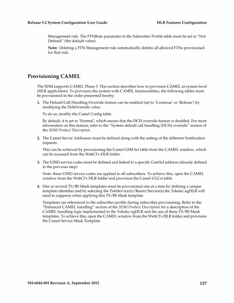
Management rule. The FTNRule parameter in the Subscriber Profile table must be set to “NotDefined” (the default value).
Note: Deleting a FTN Management rule automatically deletes all allowed FTNs provisionedfor that rule.
Provisioning CAMEL
The SDM supports CAMEL Phase 3. This section describes how to provision CAMEL at system level(HLR application). To provision the system with CAMEL functionalities, the following tables mustbe provisioned in the order presented hereby:
1. The Default Call Handling Override feature can be enabled (set to ‘Continue’ or ‘Release’) bymodifying the DchOverride value.
To do so, modify the Camel Config table.
By default, it is set to ‘Normal’, which means that the DCH override feature is disabled. For moreinformation on this feature, refer to the “System default call handling (DCH) override” section ofthe SDM Product Description.
2. The Camel Server Addresses must be defined along with the setting of the different Notificationrequests.
This can be achieved by provisioning the Camel GSM Scf table from the CAMEL window, whichcan be accessed from the WebCI’s HLR folder.
3. The USSD service codes must be defined and linked to a specific GsmScf address (already definedin the previous step).
Note: these USSD service codes are applied to all subscribers. To achieve this, open the CAMELwindow from the WebCI’s HLR folder and provision the Camel UGCsi table.
4. One or several TS/BS Mask templates must be provisioned one at a time by defining a uniquetemplate identifier and by selecting the TeleService(s)/Bearer Service(s) the Tekelec ngHLR willneed to suppress when applying this TS/BS Mask template.
Templates are referenced in the subscriber profile during subscriber provisioning. Refer to the“Enhanced CAMEL handling” section of the SDM Product Description for a description of theCAMEL handling logic implemented in the Tekelec ngHLR and the use of these TS/BS Masktemplates. To achieve this, open the CAMEL window from the WebCI’s HLR folder and provisionthe Camel Service Mask Template.
137910-6844-001 Revision A, September 2013
HLR Features ConfigurationRelease 9.2 System Configuration User Guide
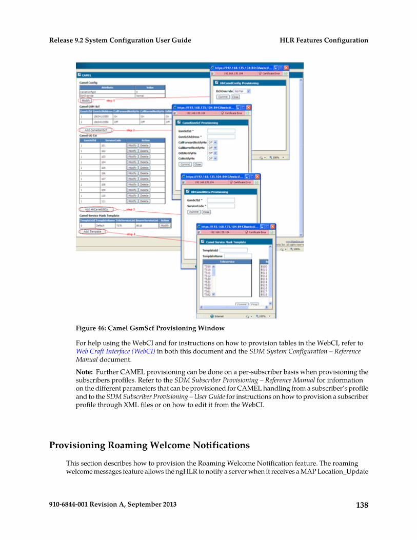
Figure 46: Camel GsmScf Provisioning Window
For help using the WebCI and for instructions on how to provision tables in the WebCI, refer toWeb Craft Interface (WebCI) in both this document and the SDM System Configuration – ReferenceManual document.
Note: Further CAMEL provisioning can be done on a per-subscriber basis when provisioning thesubscribers profiles. Refer to the SDM Subscriber Provisioning – Reference Manual for informationon the different parameters that can be provisioned for CAMEL handling from a subscriber’s profileand to the SDM Subscriber Provisioning – User Guide for instructions on how to provision a subscriberprofile through XML files or on how to edit it from the WebCI.
Provisioning Roaming Welcome Notifications
This section describes how to provision the Roaming Welcome Notification feature. The roamingwelcome messages feature allows the ngHLR to notify a server when it receives a MAP Location_Update
138910-6844-001 Revision A, September 2013
HLR Features ConfigurationRelease 9.2 System Configuration User Guide
or MAP Location_Update_for_GPRS message, with a country code different from the previouslyregistered one.
For a description of the feature and the conditions that need to be met for the Tekelec ngHLR to senda notification to the server, refer to the “Roaming Welcome Notification” section of the SDM ProductDescription.
For more details on the how the Tekelec ngHLR provides an XML interfaces for sending externalnotification when a subscriber is successfully roaming in a different country, please refer to the ID-0020SDM Roaming Welcome Message XML Interface description document.
Setting roaming welcome notification exceptions for CCs, CC-NDCs and the NDCextraction rule
The Tekelec ngHLR notifies a server when it receives a MAP Location_Update or MAPLocation_Update_for_GPRS message with:
• A country code (CC) different from the previously registered one.• A country and National Destination Code (CC-NDC) different from the previously registered one.• An IMSI different from the previously registered one.
Prior to being able to send these notifications, the operator must enable the feature and configure theTekelec ngHLR with the type of change that should trigger a notification. To achieve this, the operatormust provision the “RoamingMsgOn” parameter in the HlrConfig table with one of the followingvalues:
• Off (The Roaming Welcome Notification feature is disabled)• Notify on CC changes or IMSI change (The Roaming Welcome Notification feature is enabled and
notifications are sent when the CC is different from the previously registered one)• Notify on CC-NDC changes or IMSI change (The Roaming Welcome Notification feature is enabled
and notifications are sent when the CC-NDC is different from the previously registered one)
Refer to Viewing Activation Status of HLR Features and Activating/deactivating Them Individually in thisdocument for details on how to set the value (modify) for the “RoamingMsgOn” parameter in theHlrConfig table. Refer to theSDM System Configuration – Reference Manual for more details on theHlrConfig entity and its parameters, values and default values.
Now in the cases where the feature is not disabled, the operator can provision a list of CCs andCC-NDCs that are an exception to the roaming welcome notification service. This means, for example,that when the Tekelec ngHLR is set to “Notify on CC changes” the Tekelec ngHLR will never send anotification for the CCs in this list.
Provisioning a List of CCs as ExceptionTo provision a list of CCs that are an exception to the roaming welcome notification service, you mustprovision the RoamingMsgExceptionCC table located in the WebCI’s HLR System Features window,which can be opened by extending the HLR folder from the WebCI’s menu.
For help using the WebCI and for instructions on how to provision tables in the WebCI, refer to WebCraft Interface (WebCI) in both this document and the SDM System Configuration – Reference Manualdocument.
139910-6844-001 Revision A, September 2013
HLR Features ConfigurationRelease 9.2 System Configuration User Guide
Figure 47: Provisioning A List Of CCs As An Exception To The Roaming Welcome Notification
In addition to provisioning the RoamingMsgExceptionCC table with a new entry, the followingoperation is also available:
Delete. One entry at a time can be deleted from the RoamingMsgExceptionCC table.
Provisioning a list of CC-NDCs as exception
To provision a list of CC-NDCs that are an exception to the roaming welcome notification service, youmust provision the RoamingMsgExceptionCCNDC table located in the WebCI’s HLR System Featureswindow, which can be opened by extending the HLR folder from the WebCI’s menu.
Prerequisite to provision the RoamingMsgExceptionCCNDC table: Prior to adding aRoamingMsgExceptionCCNDC entry, the CC must already be defined in the RoamingMsgExceptionCCtable. Refer to section above to know how to provision the RoamingMsgExceptionCC table.
For help using the WebCI and for instructions on how to provision tables in the WebCI, refer to WebCraft Interface (WebCI) in both this document and the SDM System Configuration – Reference Manualdocument.
140910-6844-001 Revision A, September 2013
HLR Features ConfigurationRelease 9.2 System Configuration User Guide
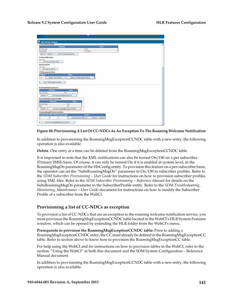
Figure 48: Provisioning A List Of CC-NDCs As An Exception To The Roaming Welcome Notification
In addition to provisioning the RoamingMsgExceptionCCNDC table with a new entry, the followingoperation is also available:
Delete. One entry at a time can be deleted from the RoamingMsgExceptionCCNDC table.
It is important to note that the XML notifications can also be turned On/Off on a per subscriber(Primary IMSI) basis. Of course, it can only be turned On if it is enabled at system level, in theRoamingMsgOn parameter of the HlrConfig entity. To provision this feature on a per-subscriber basis,the operator can set the “SubsRoamingMsgOn” parameter to On/Off in subscriber profiles. Refer tothe SDM Subscriber Provisioning – User Guide for instructions on how to provision subscriber profilesusing XML files. Refer to the SDM Subscriber Provisioning – Reference Manual for details on theSubsRoamingMsgOn parameter in the SubscriberProfile entity. Refer to the SDM Troubleshooting,Monitoring, Maintenance – User Guide document for instructions on how to modify the SubscriberProfile of a subscriber from the WebCI.
Provisioning a list of CC-NDCs as exceptionTo provision a list of CC-NDCs that are an exception to the roaming welcome notification service, youmust provision the RoamingMsgExceptionCCNDC table located in the WebCI’s HLR System Featureswindow, which can be opened by extending the HLR folder from the WebCI’s menu.
Prerequisite to provision the RoamingMsgExceptionCCNDC table: Prior to adding aRoamingMsgExceptionCCNDC entry, the CC must already be defined in the RoamingMsgExceptionCCtable. Refer to section above to know how to provision the RoamingMsgExceptionCC table.
For help using the WebCI and for instructions on how to provision tables in the WebCI, refer to thesection: “Using the WebCI” in both this document and the SDM System Configuration – ReferenceManual document.
In addition to provisioning the RoamingMsgExceptionCCNDC table with a new entry, the followingoperation is also available:
141910-6844-001 Revision A, September 2013
HLR Features ConfigurationRelease 9.2 System Configuration User Guide
Delete. One entry at a time can be deleted from the RoamingMsgExceptionCCNDC table.
It is important to note that the XML notifications can also be turned On/Off on a per subscriber(Primary IMSI) basis. Of course, it can only be turned On if it is enabled at system level, in theRoamingMsgOn parameter of the HlrConfig entity. To provision this feature on a per-subscirber basis,the operator can set the “SubsRoamingMsgOn” parameter to On/Off in subscriber profiles. Refer tothe SDM Subscriber Provisioning – User Guide for instructions on how to provision subscriber profilesusing XML files. Refer to the SDM Subscriber Provisioning – Reference Manual for details on theSubsRoamingMsgOn parameter in the SubscriberProfile entity. Refer to the SDM Troubleshooting,Monitoring, Maintenance – User Guide document for instructions on how to modify the SubscriberProfile of a subscriber from the WebCI.
Provisioning NDC Extraction RuleIn the case where the Tekelec ngHLR is set to “Notify on CC-NDC changes”, the Tekelec ngHLRextracts the CC as per the ITU assignment rules and verifies in the RoamingMsgNDCExtractionRuleentity which method is defined for this CC in order to extract the NDC from the VLR GT (e.164 globaltitle).
The operator can define for a specific CC the method that the Tekelec ngHLR needs to use to extractthe NDC. For a description of the NDC extraction rule and each method that can be used by the TekelecngHLR, refer to the “XML Notifications on NDC change or IMSI change” section of the SDM ProductDescription.
To achieve this, the operator must provision the following from the WebCI’s HLR System Featureswindow, which can be opened by extending the HLR folder from the WebCI’s menu:
1. The RoamingMsgNDCExtractionRule table must be provisioned first to define for a specific CCthe method that the Tekelec ngHLR needs to use to extract the NDC.
2. The RoamingMsgNDCList table must be displayed by clicking on the Modify/Display NDC Listbutton.
3. The RoamingMsgNDCList table must be provisioned to define a list of shared country codes andtheir corresponding NDC list in which roaming welcome messages are sent if the CC-NDC changes.NOTE: This table only needs to be provisioned for the CC for which the roaming message NDCextracting rule is the NDC list method.
For help using the WebCI and for instructions on how to provision tables in the WebCI, refer toWeb Craft Interface (WebCI) in both this document and the SDM System Configuration – ReferenceManual document (this document gives more details on these tables and each of their parametersand values supported).
142910-6844-001 Revision A, September 2013
HLR Features ConfigurationRelease 9.2 System Configuration User Guide
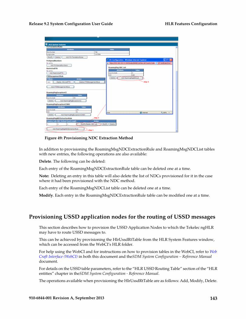
Figure 49: Provisioning NDC Extraction Method
In addition to provisioning the RoamingMsgNDCExtractionRule and RoamingMsgNDCList tableswith new entries, the following operations are also available:
Delete. The following can be deleted:
Each entry of the RoamingMsgNDCExtractionRule table can be deleted one at a time.
Note: Deleting an entry in this table will also delete the list of NDCs provisioned for it in the casewhere it had been provisioned with the NDC method.
Each entry of the RoamingMsgNDCList table can be deleted one at a time.
Modify. Each entry in the RoamingMsgNDCExtractionRule table can be modified one at a time.
Provisioning USSD application nodes for the routing of USSD messages
This section describes how to provision the USSD Application Nodes to which the Tekelec ngHLRmay have to route USSD messages to.
This can be achieved by provisioning the HlrUssdRtTable from the HLR System Features window,which can be accessed from the WebCI’s HLR folder.
For help using the WebCI and for instructions on how to provision tables in the WebCI, refer to WebCraft Interface (WebCI) in both this document and theSDM System Configuration – Reference Manualdocument.
For details on the USSD table parameters, refer to the “HLR USSD Routing Table” section of the “HLRentities” chapter in theSDM System Configuration - Reference Manual.
The operations available when provisioning the HlrUssdRtTable are as follows: Add, Modify, Delete.
143910-6844-001 Revision A, September 2013
HLR Features ConfigurationRelease 9.2 System Configuration User Guide
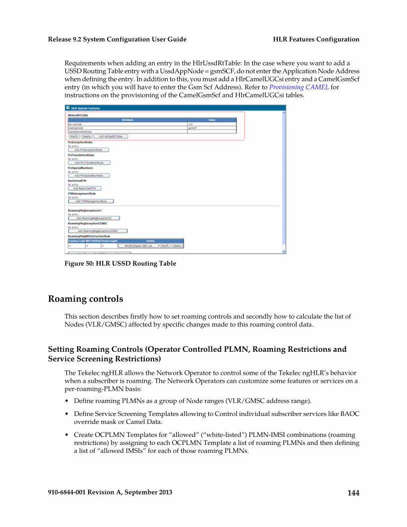
Requirements when adding an entry in the HlrUssdRtTable: In the case where you want to add aUSSD Routing Table entry with a UssdAppNode = gsmSCF, do not enter the Application Node Addresswhen defining the entry. In addition to this, you must add a HlrCamelUGCsi entry and a CamelGsmScfentry (in which you will have to enter the Gsm Scf Address). Refer to Provisioning CAMEL forinstructions on the provisioning of the CamelGsmScf and HlrCamelUGCsi tables.
Figure 50: HLR USSD Routing Table
Roaming controls
This section describes firstly how to set roaming controls and secondly how to calculate the list ofNodes (VLR/GMSC) affected by specific changes made to this roaming control data.
Setting Roaming Controls (Operator Controlled PLMN, Roaming Restrictions andService Screening Restrictions)
The Tekelec ngHLR allows the Network Operator to control some of the Tekelec ngHLR’s behaviorwhen a subscriber is roaming. The Network Operators can customize some features or services on aper-roaming-PLMN basis:
• Define roaming PLMNs as a group of Node ranges (VLR/GMSC address range).
• Define Service Screening Templates allowing to Control individual subscriber services like BAOCoverride mask or Camel Data.
• Create OCPLMN Templates for “allowed” (“white-listed”) PLMN-IMSI combinations (roamingrestrictions) by assigning to each OCPLMN Template a list of roaming PLMNs and then defininga list of “allowed IMSIs” for each of those roaming PLMNs.
144910-6844-001 Revision A, September 2013
HLR Features ConfigurationRelease 9.2 System Configuration User Guide
The Tekelec ngHLR only accepts Update Location (UL) messages coming from one of these“allowed” PLMN-IMSI combinations defined in the system.
• Assign a Service Screening Template to each of the OCPLMN Templates’ roaming PLMN.
By default, the roaming restrictions (PLMN-IMSI selection) and Service Screening restrictions featuresare disabled until purchased. Contact the Tekelec Customer Care Center to purchase one or both ofthese features. Both features can be enabled/disabled dynamically and independently from the WebCIby setting the RoamRestrictEnable or RoamServiceScreeningEnable parameter of the Hlr RoamingControls Configuration table.
When the Roaming Service Screening feature is enabled and the PLMN-IMSI combination is allowedfor the UL message received, the Tekelec ngHLR retrieves the correct Service Screening Templatebased on the OCPLMN Template assigned to the subscriber and the roaming PLMN from which theUL message was received. The Tekelec ngHLR then applies the template against the provisionedSubscriber's services. The UL message continues with the changed Subscriber Profile, as modified bythe service screening rules.
Each subscriber can have a different OCPLMN Template assigned by provisioning the SubscriberProfile with the name of the OCPLMN Template. For more information on the‘OCPLMNTemplateName’ parameter from the Subscriber Profile that can be set to refer to one ofthese templates, refer to the SDM Subscriber Provisioning - Reference Manual. For instructions on howto provision the Subscriber Profile from the WebCI, refer to the SDM Monitoring, Maintaining,Troubleshooting - User Guide.
When receiving a UL message for a subscriber, the Tekelec ngHLR uses the OCPLMN Templateassigned to that subscriber to identify the roaming PLMN and to apply the roaming restrictions andservice screening restrictions defined for that PLMN.
The WebCI Roaming Controls window allows the operator to set all roaming controls such as PLMNDefinitions, Service Screening Templates Definitions, and OCPLMN Templates definitions. To setroaming controls, follow these steps:
1. Define the roaming PLMNs with a list of Node Ranges (VLR/GMSC address ranges). Go toHLR>Roaming Controlsa) Click the Plmn hyperlink.b) Click the Add Plmn button of the Plmn Definitions table.
Add each roaming Plmn to the Definitions table one at a time until they are all defined.
The default PLMN created at system startup must remain undefined, that is, without VLR/GMSCnode associations.
c) Click the Add VLR button of a specific roaming PLMN to define its node range (VLR/GMSCrange).Repeat this step for each node range you wish to define for this PLMN.
2. Optionally, assign a Service Screening Template to the OCPLMN Templates’ roaming PLMNs.
The Service Screening Templates are used by the OCPLMN Templates to customize the SubscriberProfile based on the PLMN where the subscriber is roaming.
a) Click the Service Screening hyperlink.b) Define Service Screening Templates by clicking the Add Service Screening Template button
of the Service Screening Template Definitions table.
145910-6844-001 Revision A, September 2013
HLR Features ConfigurationRelease 9.2 System Configuration User Guide
At system startup, the system creates an undefined Service Screening Template withoutcustomization of any services. This template is used as default for the creation of OCPLMNTemplates and must remain unchanged.
c) Add a service customization to the Service Screening Template one at a time by clicking therespective corresponding service button, for example, Add CSI, Add BSG, Add TS, Add BS,Add SS, or Add ODB.
Customizations may include:
• CSI Key To Suppress from O-CSI,• BAOC per BSG,• Camel – max Camel Version Allowed,• ODB (All Outgoing, All Outgoing Intl, Premium),• TeleServices(TS91, TS92),• BearServices (BS1F, BS17),• Other services - CLIP, CLIR, COLP, COLR, CW, HOLD, MPTY, REGSUBSCRIPTION, CFB,
CRNRc, CFNRy)
d) Set the RemoveIMSAPN parameter to turn on or off the
• removal of IMS APN (Access Point Name) in the Subscriber Data (ISD) message part of theUpdate Location (UL) GPRS request
• VPLMN Address Allowed on the APNs that are returned to a visited network
3. Create OCPLMN Templates by provisioning the OCPLMN Template Definitions table.a) Define an OCPLMN Template by clicking the Add OCPLMN Template button located at the
top of the OCPLMN Templates Definitions table.b) Assign roaming PLMNs to a defined OCPLMN Template. Click the Add Plmn button next to
the OCPLMN Template for which you wish to add a roaming PLMN.
Only the PLMNs that are already defined in the Plmn Definitions table can be assigned to anOCPLMN Template. Assign a list of roaming PLMNs to one single OCPLMN Template byrepeating this step for the same OCPLMN Template.
Optionally, assign for the roaming PLMN:
• A Service Screening Template that is already defined in the Service Screening TemplatesDefinitions table. Only one Service Screening Template can be assigned per roaming PLMN.
• The type of node to which the roaming and service screening restrictions apply.
Note: Roaming PLMNs cannot be assigned to the “Not Defined” OCPLMN Template.
Each OCPLMN Template must have a “Default PLMN” and therefore the first PLMN that is tobe assigned to each OCPLMN Template must be the “Default PLMN”. If a VLR/GMSC is notfound in any of the PLMNs defined for the used OCPLMN Template, it is considered as belongingto the “default PLMN”.
c) Define roaming restrictions (“allowed” PLMN-IMSI combinations) by defining a list of AllowedIMSIs for each roaming PLMN assigned to an OCPLMN Template. Click the Add Imsi buttonnext to the specific roaming PLMN.
One Allowed IMSI range can be defined at a time. Repeat this step as many times as the numberof Allowed IMSIs you wish to define for that roaming PLMN.
146910-6844-001 Revision A, September 2013
HLR Features ConfigurationRelease 9.2 System Configuration User Guide
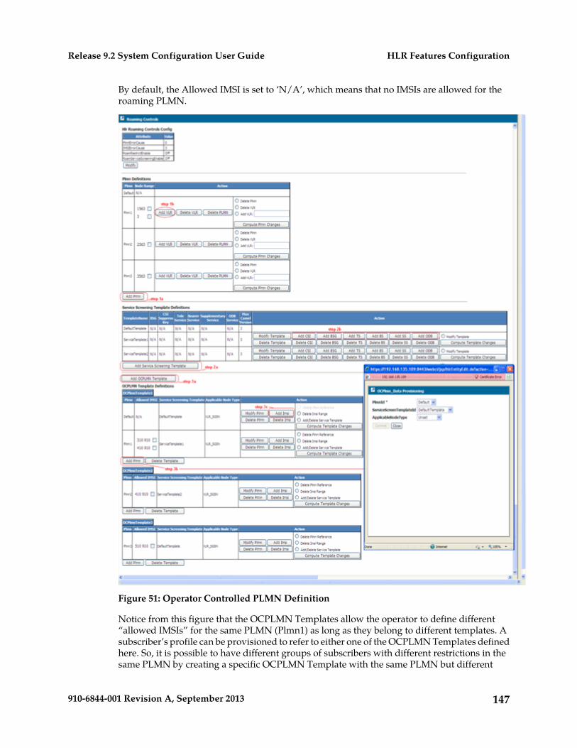
By default, the Allowed IMSI is set to ‘N/A’, which means that no IMSIs are allowed for theroaming PLMN.
Figure 51: Operator Controlled PLMN Definition
Notice from this figure that the OCPLMN Templates allow the operator to define different“allowed IMSIs” for the same PLMN (Plmn1) as long as they belong to different templates. Asubscriber’s profile can be provisioned to refer to either one of the OCPLMN Templates definedhere. So, it is possible to have different groups of subscribers with different restrictions in thesame PLMN by creating a specific OCPLMN Template with the same PLMN but different
147910-6844-001 Revision A, September 2013
HLR Features ConfigurationRelease 9.2 System Configuration User Guide
restrictions and assign them to a specific group of Subscribers. If a subscriber profile does notrefer to any OCPLMN Template (default scenario), then it is always allowed, and there are noPLMN nor service restrictions for that subscriber.
Refer to the SDM Subscriber Provisioning – User Guide for instructions on how to provisionsubscribers in bulk with the OCPlmnTemplateName referring to an OCPLMN template.
Refer to the SDM Subscriber Provisioning – Reference Manual for details on theOCPlmnTemplateName parameter.
Refer to the SDM Troubleshooting, Monitoring, Maintenance – User Guide for instructions on howto modify a subscriber profile and provision the OCPlmnTemplateName.
Tips on provisioning the tables and setting the PLMN-IMSI restrictions:
• The Node Range list may consist of one or more specific node ranges. This list restricts thePLMN to allow only some node ranges. The Node Range list for the Default PLMN must remainempty (N/A), which means that for all Node Ranges, the roaming Allowed/Not Allowedverification will be done based on the Allowed IMSI defined for the ‘Default PLMN’ assignedto the subscriber’s OCPLMN Template.
• The Allowed IMSIs list:
• May be empty (N/A) – this means that the “PLMN is NOT allowed “.
Any calls coming from any node range defined for that PLMN will be blocked.
• May have a list of one or more specific IMSI ranges.
This setting allows only certain subscribers (IMSIs) to make calls from any node range definedfor that PLMN.
• May have an MCC=000 and MNC=000 as IMSI ranges.
This setting allows ALL subscribers (IMSIs) to make calls from any Node Range defined forthat PLMN.
Additional Operations Available:
• The Modify button located beneath the Hlr Roaming Controls Config table allows you toenable/disable the Roaming Restrictions and/or the Service Screening Restrictions and alsoallows you to modify the default PLMN/IMSI error causes configuration.
• The Modify Template button located in the Action column of the Service Screening TemplateDefinitions table for each Service Screening Template, allows you to modify theServiceScreenTemplateName and the MaxCamelVersion.
• The Delete PLMN button located in the Action column of the Plmn Definitions table for eachroaming PLMN, allows you to delete the corresponding roaming PLMN (other than the defaultPLMN).
Note: The Deletion of a PLMN cascades down to the VLR/GMSC address ranges and itun-assigns the roaming PLMN from the OCPLMN Templates to which it had been assigned.
• The Delete Plmn button, located in the Action column for each OCPLMN Template’s roamingPLMN, allows to un-assign a roaming PLMN to an OCPLMN Template.
Note: The deletion of a roaming PLMN also deletes the “Allowed IMSIs” that were defined forit and un-assigns its Service Screening Template.
148910-6844-001 Revision A, September 2013
HLR Features ConfigurationRelease 9.2 System Configuration User Guide
• The Delete VLR button, located in the Action column of the Plmn Definitions table for eachroaming PLMN, allows you to delete one Node range at a time for a specific PLMN.
• The Delete Imsi button, located in the Action column for each OCPLMN Template’s roamingPLMN, allows you to delete one “Allowed IMSI range” at a time for a specific OCPLMNTemplate’s roaming PLMN.
• The Delete Template button, located in the Action column of the Service Screening TemplateDefinitions table for each Service Screening Template, allows you to delete a Service ScreeningTemplate and all of its customized services.
Note: a Service Screening template cannot be deleted if it is assigned to at least one roamingPLMN.
• The Delete Template button, located beneath each OCPLMN Template, allows you to delete aPLMN from the OCPLMN Template.
All the Plmns of an OCPLMN Template, except the “default Plmn”, can be deleted one by oneregardless of whether the OCPLMN Template is assigned to subscribers or not. The “defaultPlmn” of the OCPLMN Template can be deleted, only if the template is not assigned to anysubscriber since the deletion of the “Default Plmn” is equivalent to a deletion of the OCPLMNTemplate as a whole.
The deletion of an OCPLMN Template cascades to its roaming restrictions and service screeningrestrictions.
• Delete TS/Delete BS/Delete BSG/Delete ODB/Delete CSI/Delete SS.
These operations are available for each Service Screening Template and allow to deleteindividually the customized services defined for that template.
Calculating VLR/SGSN Nodes Affected by a Roaming Configuration Change
This section describes how the Network Operator can request for the Tekelec ngHLR to calculate thelist of VLR/SGSN nodes that would be affected by a specific roaming configuration change. TheTekelec ngHLR can calculate the list of affected VLR/SGSN nodes for one roaming configurationchange at a time.
The Network Operator can then use this list of affected VLR/SGSN nodes and include it in theNodeNumberSubset entity’s list of nodes, to which a MAP_RESET message will be sent to whenexecuting the ‘Map Reset’ operation (SendMapReset() Option=Node Number Subset). For furtherinstructions on the ‘Map Reset’ operation, refer to MAP Reset in this document.
In order to request the calculation of the affected VLR/SGSN nodes and then feed that list to theNodeNumberSubset entity’s list of nodes for the MAP Reset, the Roaming Controls window must beaccessed from the WebCI and from there, the following steps must be followed:
Note: For help using the WebCI and for instructions on how to provision tables in the WebCI, referto Web Craft Interface (WebCI) in both this document and the SDM System Configuration – ReferenceManual document.
Prerequisite: The roaming configuration data must be provisioned prior to being able to calculatewhich VLR/SGSN nodes would be affected by a change in the roaming configuration. Refer to theprevious sections for instructions on how to configure roaming data.
1. Select the change for which you wish to have the list of affected VLR/SGSN nodes calculated.
149910-6844-001 Revision A, September 2013
HLR Features ConfigurationRelease 9.2 System Configuration User Guide
Note that only a single change can be evaluated at a time.
The configuration changes are evaluated separately via three operations, which are inserted in thePlmn Definitions, OCPlmn Template Definitions and Service Screening Template tables, as shownin the figure below. Here are the types of roaming configuration changes for which the TekelecngHLR can calculate the list of affected VLR/SGSN nodes and the operation that executes thiscalculation:
Compute Plmn Changes: The user must select one of the actions using the radio buttons.
Delete Plmn: The PlmnId is taken directly from the corresponding row.
Delete Node Range: Select the desired Node Range, using the check boxes in the ‘Node Range’column of the corresponding Plmn row. Only one Node Range can be selected at a time.
Add Node Range: The value of the new Node Range must be entered in the adjacent text box.
Compute OCPlmn Template Changes: The user must select one of the actions using the radiobuttons.
Delete Plmn Reference: The PlmnId is taken directly from the corresponding row.
Delete Imsi: Select the desired Imsi, using the check boxes in the ‘Allowed Imsi’ column of thecorresponding Plmn row. Only one Imsi can be selected at once.
Add/Delete Service Template Reference: The only value required is the action (Add/Delete), theactual value of the service template is irrelevant.
Compute Service Screening Template Changes: The user must select one of the actions using theradio buttons.
Modify Service Template: The ServiceScreenTemplateId is taken directly from the correspondingrow.
2. Click on the compute button that corresponds to the roaming change you selected.
Example: If you select the ‘Delete Plmn’ roaming change, you must click on the ‘Compute PlmnChanges’ button.
3. A pop-up window will appear with the list of affected VLR/SGSN nodes calculated by the TekelecngHLR.
This window offers you the choice to take the following action:
a) ‘Discard’: this operation discards the list of affected nodes.b) ‘Append’: this operation appends the list of affected nodes to the NodeNumberSubset table’s
list of nodes (nodes to which the Tekelec ngHLR will send a MAP_RESET message upon theexecution of the ‘Map Reset’ operation).
c) ‘Replace’: this operation replaces the NodeNumberSubset entity’s list of nodes with the list ofaffected VLR/SGSN nodes calculated by the Tekelec ngHLR.
The steps described above can be repeated as many times as desired for a different roamingconfiguration change. The actions taken in step 3 are cumulative, which means that if you repeatthis procedure multiple times and append each list of affected VLR/SGSN nodes calculated,the NodeNumberSubset entity’s list of nodes will include all of these lists of affected VLR/SGSNnodes calculated.
After performing this procedure, you can display and edit the NodeNumberSubset table’s listof nodes as desired. This list of nodes will be all the nodes to which a MAP_RESET message
150910-6844-001 Revision A, September 2013
HLR Features ConfigurationRelease 9.2 System Configuration User Guide
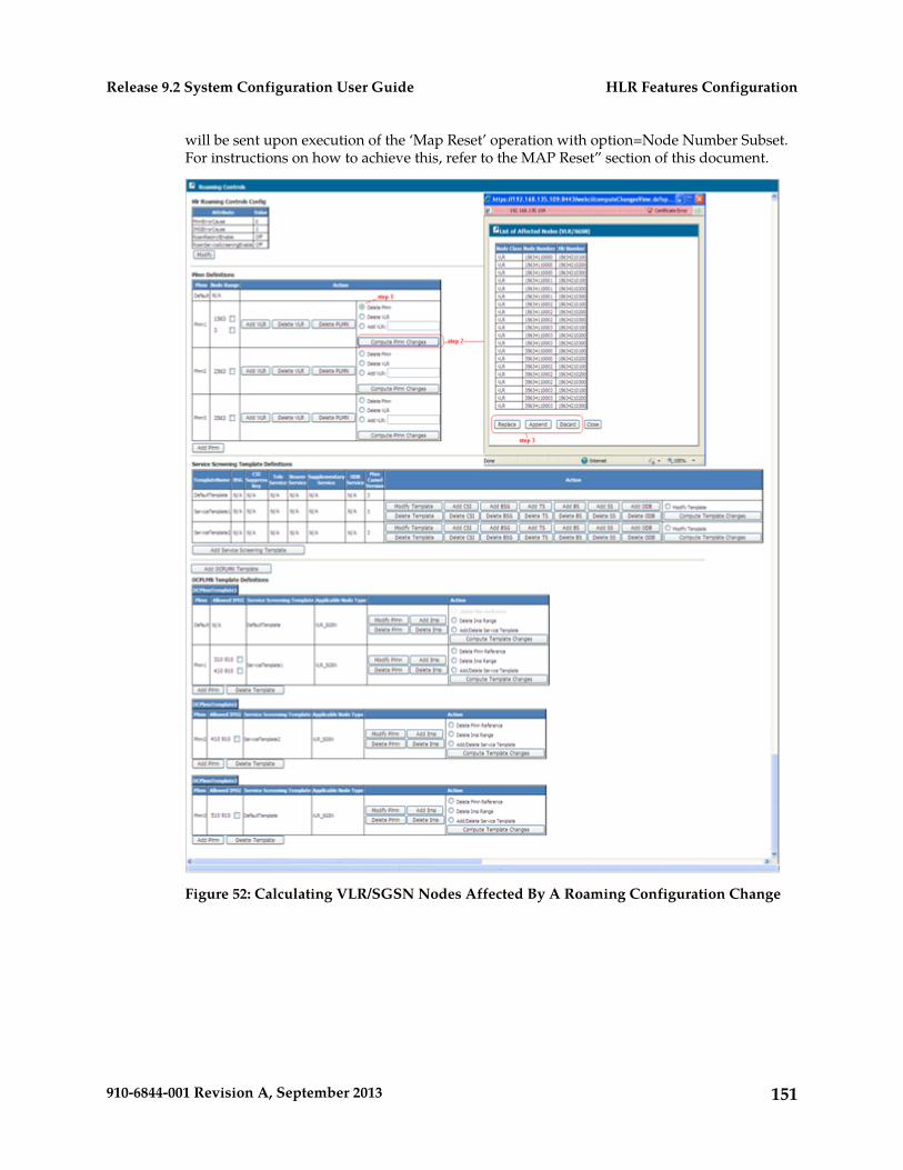
will be sent upon execution of the ‘Map Reset’ operation with option=Node Number Subset.For instructions on how to achieve this, refer to the MAP Reset” section of this document.
Figure 52: Calculating VLR/SGSN Nodes Affected By A Roaming Configuration Change
151910-6844-001 Revision A, September 2013
HLR Features ConfigurationRelease 9.2 System Configuration User Guide
Setting Restrictions on the Version of MAP Messages (MAP Policing) andon the SRI-ack, ATI-ack and PSI Messages
The MAP Policing feature allows the operator to control, on a per-node and per-Application Context(AC) basis, the maximum AC version to be used in any MAP transaction. For a more detailed descriptionof the MAP Policing feature and the Tekelec ngHLR’s behavior, refer to the “Map Policing (ManualConfiguration of Maximum MAP Version)” and “MAP Reset” sections of the SDM Product Description.For a description about the tables to provision, each of their parameters and values supported, referto the “MAP Policing” section of the SDM System Configuration – Reference Manual.
To achieve this, the operator must follow the steps below, from the WebCI’s Map Policing window,which can be opened from the HLR folder.
For help using the WebCI and for instructions on how to provision tables in the WebCI, refer to WebCraft Interface (WebCI) in both this document and the SDM System Configuration – Reference Manualdocument (this document gives more details on these tables and each of their parameters and valuessupported).
Prerequisite: The MAP Policing feature must be enabled. The MapPolicingOn parameter in theHlrConfig table allows to enable/disable this feature. Refer to the Viewing Activation Status of HLRFeatures and Activating/deactivating Them Individually in this document for instructions on how toenable/disable the MAP Policing feature.
1. The Application Context Template table must be provisioned to define a template.
It can also be used to provision the following features for each template definition: ALR Suppression(to include/exclude the ALR information in the reply), Optional PSI (to send or not the PSI message),Addition of GSM-BC and BS in SRI-ack (to include/exclude the GSM-BC and BS information inthe SRI-ack).
2. The AC Template Definition table must be displayed.3. The AC Template Definition table must be provisioned to define a default maximum MAP version,
per Application Context (AC) for a specific template.4. In order to add control of the maximum AC version to be used on a per-node basis, the AC Template
Mapping table must be provisioned to associate a Node Range to the template for which you justdefined a default maximum MAP version for each AC.
152910-6844-001 Revision A, September 2013
HLR Features ConfigurationRelease 9.2 System Configuration User Guide
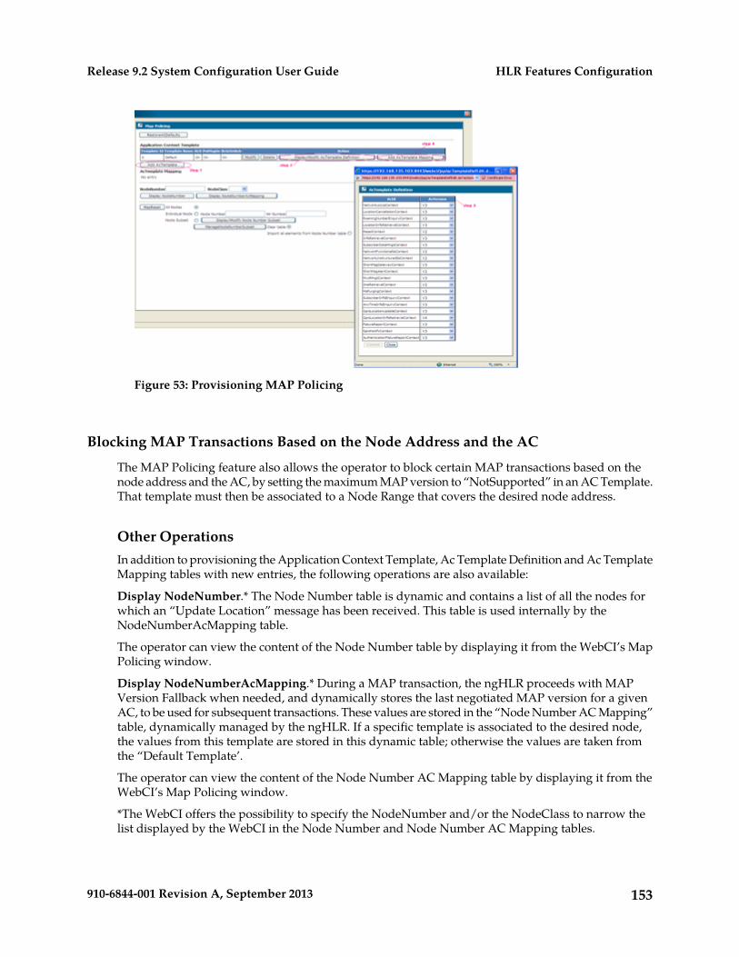
Figure 53: Provisioning MAP Policing
Blocking MAP Transactions Based on the Node Address and the AC
The MAP Policing feature also allows the operator to block certain MAP transactions based on thenode address and the AC, by setting the maximum MAP version to “NotSupported” in an AC Template.That template must then be associated to a Node Range that covers the desired node address.
Other OperationsIn addition to provisioning the Application Context Template, Ac Template Definition and Ac TemplateMapping tables with new entries, the following operations are also available:
Display NodeNumber.* The Node Number table is dynamic and contains a list of all the nodes forwhich an “Update Location” message has been received. This table is used internally by theNodeNumberAcMapping table.
The operator can view the content of the Node Number table by displaying it from the WebCI’s MapPolicing window.
Display NodeNumberAcMapping.* During a MAP transaction, the ngHLR proceeds with MAPVersion Fallback when needed, and dynamically stores the last negotiated MAP version for a givenAC, to be used for subsequent transactions. These values are stored in the “Node Number AC Mapping”table, dynamically managed by the ngHLR. If a specific template is associated to the desired node,the values from this template are stored in this dynamic table; otherwise the values are taken fromthe “Default Template’.
The operator can view the content of the Node Number AC Mapping table by displaying it from theWebCI’s Map Policing window.
*The WebCI offers the possibility to specify the NodeNumber and/or the NodeClass to narrow thelist displayed by the WebCI in the Node Number and Node Number AC Mapping tables.
153910-6844-001 Revision A, September 2013
HLR Features ConfigurationRelease 9.2 System Configuration User Guide
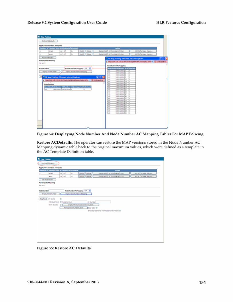
Figure 54: Displaying Node Number And Node Number AC Mapping Tables For MAP Policing
Restore ACDefaults. The operator can restore the MAP versions stored in the Node Number ACMapping dynamic table back to the original maximum values, which were defined as a template inthe AC Template Definition table.
Figure 55: Restore AC Defaults
154910-6844-001 Revision A, September 2013
HLR Features ConfigurationRelease 9.2 System Configuration User Guide
MAP Reset
The operator can force the Tekelec ngHLR to send a MAP_RESET message to VLRs or SGSNs in orderto inform them that a failure occurred. The MAP_RESET message indicates to the remote node thatit should refresh all of the subscriber data previously received by the Tekelec ngHLR. Refer to the“MAP Reset” section of the SDM Product Description for a more detailed description of the MAP Resetservice.
To achieve this, the operator must follow the steps below, from the WebCI’s Map Policing window,which can be opened from the HLR folder.
For help using the WebCI and for instructions on how to provision tables in the WebCI, refer to WebCraft Interface (WebCI) in both this document and the SDM System Configuration – Reference Manualdocument (this document gives more details on these tables and each of their parameters and valuessupported).
Warning: The ‘Map Reset’ operation must only be executed during low traffic periods,otherwise it could affect the performance of the system.
Prerequisite: The MAP Policing feature must be enabled. The MapPolicingOn parameter in theHlrConfig table allows to enable/disable this feature. Refer to the Viewing Activation Status of HLRFeatures and Activating/deactivating Them Individually in this document for instructions on how toenable/disable the MAP Policing feature.
1. Select one of the three options for which you wish the Tekelec ngHLR to send a MAP Reset message:
Option 1: All Nodes. The Tekelec ngHLR sends a MAP Reset message to all nodes from the completelist of nodes stored in the database (in the Node Number entity).
Option 2: An individual node. When selecting this option, you must also specify the Node Numberand Hlr Number.
Option 3: Node Subset. This allows the operator to force the Tekelec ngHLR to send a MAP Resetmessage to a series of specific nodes that can be defined in the Node Number Subset table. Whenselecting this option, you must follow these steps:
Display the Node Number Subset table by clicking on the Display/Modify Node Number Subsetbutton.
Provision the Node Number Subset table to define the Nodes for which you wish the TekelecngHLR to send a MAP Reset message to.
2. Execute the Map Reset operation by clicking on the MapReset button.
This Map Reset operation will be executed as per the option selected previously.
155910-6844-001 Revision A, September 2013
HLR Features ConfigurationRelease 9.2 System Configuration User Guide
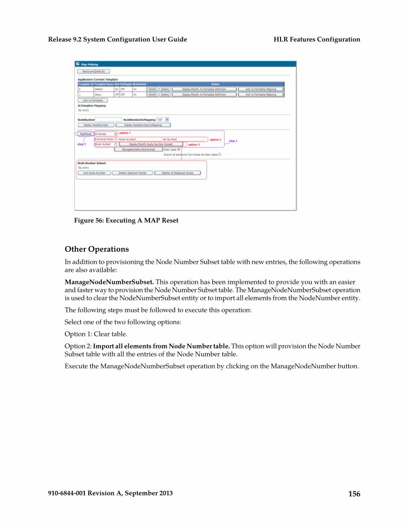
Figure 56: Executing A MAP Reset
Other OperationsIn addition to provisioning the Node Number Subset table with new entries, the following operationsare also available:
ManageNodeNumberSubset. This operation has been implemented to provide you with an easierand faster way to provision the Node Number Subset table. The ManageNodeNumberSubset operationis used to clear the NodeNumberSubset entity or to import all elements from the NodeNumber entity.
The following steps must be followed to execute this operation:
Select one of the two following options:
Option 1: Clear table.
Option 2: Import all elements from Node Number table. This option will provision the Node NumberSubset table with all the entries of the Node Number table.
Execute the ManageNodeNumberSubset operation by clicking on the ManageNodeNumber button.
156910-6844-001 Revision A, September 2013
HLR Features ConfigurationRelease 9.2 System Configuration User Guide
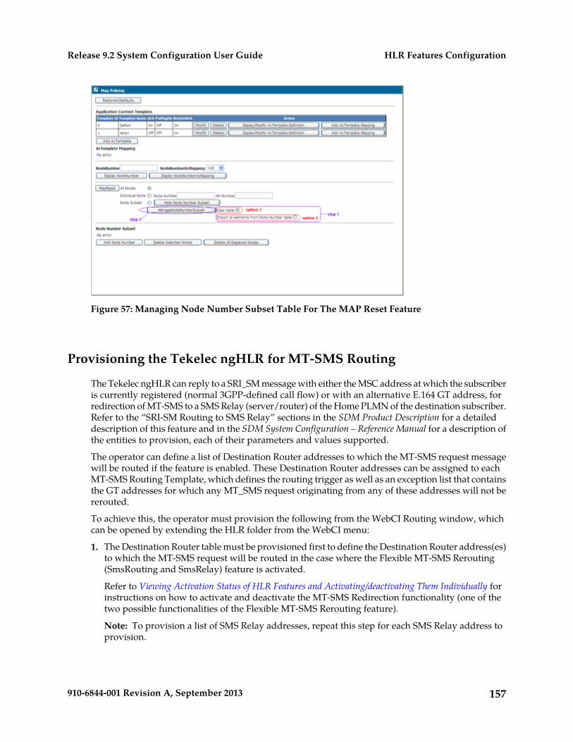
Figure 57: Managing Node Number Subset Table For The MAP Reset Feature
Provisioning the Tekelec ngHLR for MT-SMS Routing
The Tekelec ngHLR can reply to a SRI_SM message with either the MSC address at which the subscriberis currently registered (normal 3GPP-defined call flow) or with an alternative E.164 GT address, forredirection of MT-SMS to a SMS Relay (server/router) of the Home PLMN of the destination subscriber.Refer to the “SRI-SM Routing to SMS Relay” sections in the SDM Product Description for a detaileddescription of this feature and in the SDM System Configuration – Reference Manual for a description ofthe entities to provision, each of their parameters and values supported.
The operator can define a list of Destination Router addresses to which the MT-SMS request messagewill be routed if the feature is enabled. These Destination Router addresses can be assigned to eachMT-SMS Routing Template, which defines the routing trigger as well as an exception list that containsthe GT addresses for which any MT_SMS request originating from any of these addresses will not bererouted.
To achieve this, the operator must provision the following from the WebCI Routing window, whichcan be opened by extending the HLR folder from the WebCI menu:
1. The Destination Router table must be provisioned first to define the Destination Router address(es)to which the MT-SMS request will be routed in the case where the Flexible MT-SMS Rerouting(SmsRouting and SmsRelay) feature is activated.
Refer to Viewing Activation Status of HLR Features and Activating/deactivating Them Individually forinstructions on how to activate and deactivate the MT-SMS Redirection functionality (one of thetwo possible functionalities of the Flexible MT-SMS Rerouting feature).
Note: To provision a list of SMS Relay addresses, repeat this step for each SMS Relay address toprovision.
157910-6844-001 Revision A, September 2013
HLR Features ConfigurationRelease 9.2 System Configuration User Guide
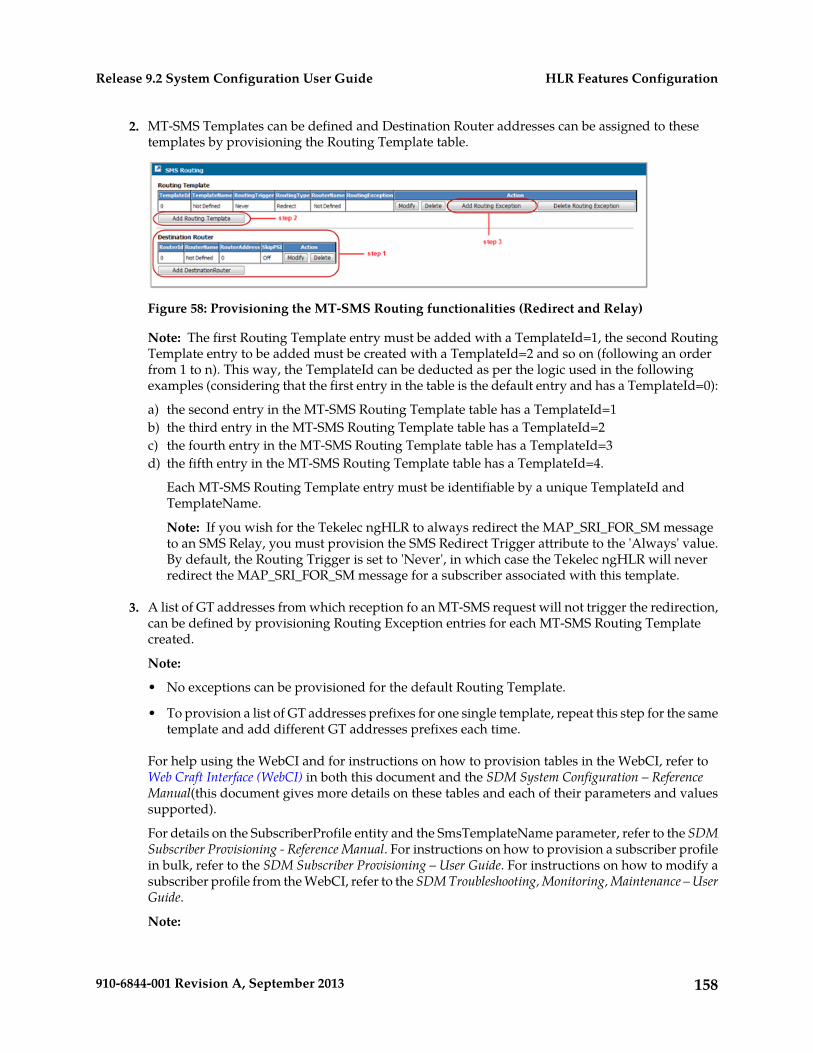
2. MT-SMS Templates can be defined and Destination Router addresses can be assigned to thesetemplates by provisioning the Routing Template table.
Figure 58: Provisioning the MT-SMS Routing functionalities (Redirect and Relay)
Note: The first Routing Template entry must be added with a TemplateId=1, the second RoutingTemplate entry to be added must be created with a TemplateId=2 and so on (following an orderfrom 1 to n). This way, the TemplateId can be deducted as per the logic used in the followingexamples (considering that the first entry in the table is the default entry and has a TemplateId=0):
a) the second entry in the MT-SMS Routing Template table has a TemplateId=1b) the third entry in the MT-SMS Routing Template table has a TemplateId=2c) the fourth entry in the MT-SMS Routing Template table has a TemplateId=3d) the fifth entry in the MT-SMS Routing Template table has a TemplateId=4.
Each MT-SMS Routing Template entry must be identifiable by a unique TemplateId andTemplateName.
Note: If you wish for the Tekelec ngHLR to always redirect the MAP_SRI_FOR_SM messageto an SMS Relay, you must provision the SMS Redirect Trigger attribute to the 'Always' value.By default, the Routing Trigger is set to 'Never', in which case the Tekelec ngHLR will neverredirect the MAP_SRI_FOR_SM message for a subscriber associated with this template.
3. A list of GT addresses from which reception fo an MT-SMS request will not trigger the redirection,can be defined by provisioning Routing Exception entries for each MT-SMS Routing Templatecreated.
Note:
• No exceptions can be provisioned for the default Routing Template.
• To provision a list of GT addresses prefixes for one single template, repeat this step for the sametemplate and add different GT addresses prefixes each time.
For help using the WebCI and for instructions on how to provision tables in the WebCI, refer toWeb Craft Interface (WebCI) in both this document and the SDM System Configuration – ReferenceManual(this document gives more details on these tables and each of their parameters and valuessupported).
For details on the SubscriberProfile entity and the SmsTemplateName parameter, refer to the SDMSubscriber Provisioning - Reference Manual. For instructions on how to provision a subscriber profilein bulk, refer to the SDM Subscriber Provisioning – User Guide. For instructions on how to modify asubscriber profile from the WebCI, refer to the SDM Troubleshooting, Monitoring, Maintenance – UserGuide.
Note:
158910-6844-001 Revision A, September 2013
HLR Features ConfigurationRelease 9.2 System Configuration User Guide
This feature can also be configured for each subscriber by specifying an SmsTemplateName (WebCi)or SmsTemplateId (CLI) in the subscriber profile. This template refers to the corresponding templatedefined in the SMS Redirect Template table.
Other Operations
In addition to provisioning the Destination Router and the Routing Template tables with new entries,the following operations are also available from the WebCI Routing window:
• Delete. The following can be deleted:
• One entry at a time in the Destination Router table. Prerequisite: The Routing templates thatrefer to the Destination Router to delete must first be deleted.
• One MT-SMS Routing template at a time can be deleted in the Routing Template table. NOTE:Deleting a Routing template also deletes any GT addresses provisioned as exceptions for thattemplate.
• One Orig Address can be deleted at a time for a template. Select the address to delete in thescroll down list and then click the Delete Routing Exception button.
• Modify. Each entry in the Destination Router and Routing Template tables can be modified.
Provisioning Routing Controls for GSM/IMS Router capabilities
Use this procedure to provision the Tekelec ngHLR for GSM/IMS routing capabilities.
The Tekelec ngHLR can be configured to behave as a GSM/IMS Router in order to relay SRI, SRI-LCS,ATI and MT-SMS messages or redirect SRI, SRI-LCS and MT-SMS messages to one of the followingnodes:
• Destination Router (in the GSM Network)• External HLR (in the GSM Network)• External TAS (in the IMS Network)
For more information about the Tekelec ngHLR's GSM/IMS Routing capabilities, refer to the GSM/IMSRouter section in the SDM Product Description.
The step-by-step procedure in this section demonstrates how to configure the following RoutingControls from the SDM's WebCI:
• Define a list of Destination Router addresses (used if mobile device is HLR or SIP registered) and/ora list of SIP TAS Gt (used if mobile device is TAS registered).
• Define various Routing Templates, which specify how the Tekelec ngHLR will process the MAPmessages:
• Define Routing Type (Relay or Redirect)• Define Routing Trigger• Define Default Action• Associate one of the Destination Router addresses
159910-6844-001 Revision A, September 2013
HLR Features ConfigurationRelease 9.2 System Configuration User Guide
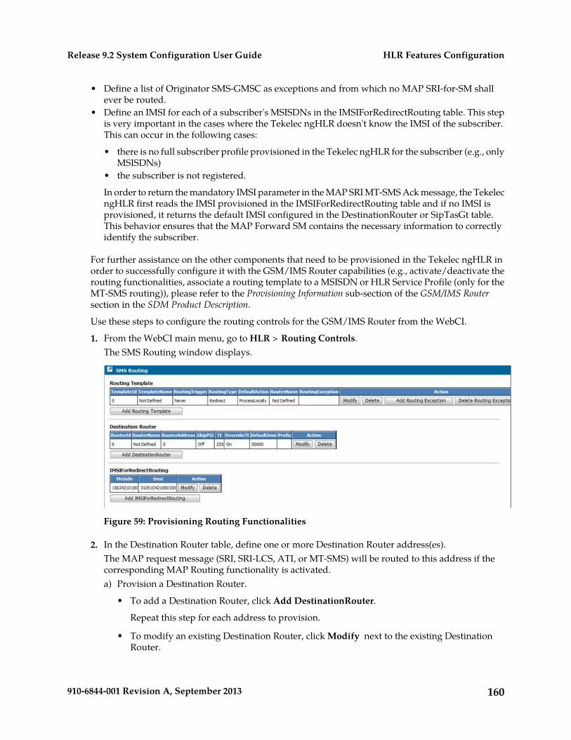
• Define a list of Originator SMS-GMSC as exceptions and from which no MAP SRI-for-SM shallever be routed.
• Define an IMSI for each of a subscriber's MSISDNs in the IMSIForRedirectRouting table. This stepis very important in the cases where the Tekelec ngHLR doesn't know the IMSI of the subscriber.This can occur in the following cases:
• there is no full subscriber profile provisioned in the Tekelec ngHLR for the subscriber (e.g., onlyMSISDNs)
• the subscriber is not registered.
In order to return the mandatory IMSI parameter in the MAP SRI MT-SMS Ack message, the TekelecngHLR first reads the IMSI provisioned in the IMSIForRedirectRouting table and if no IMSI isprovisioned, it returns the default IMSI configured in the DestinationRouter or SipTasGt table.This behavior ensures that the MAP Forward SM contains the necessary information to correctlyidentify the subscriber.
For further assistance on the other components that need to be provisioned in the Tekelec ngHLR inorder to successfully configure it with the GSM/IMS Router capabilities (e.g., activate/deactivate therouting functionalities, associate a routing template to a MSISDN or HLR Service Profile (only for theMT-SMS routing)), please refer to the Provisioning Information sub-section of the GSM/IMS Routersection in the SDM Product Description.
Use these steps to configure the routing controls for the GSM/IMS Router from the WebCI.
1. From the WebCI main menu, go to HLR > Routing Controls.The SMS Routing window displays.
Figure 59: Provisioning Routing Functionalities
2. In the Destination Router table, define one or more Destination Router address(es).The MAP request message (SRI, SRI-LCS, ATI, or MT-SMS) will be routed to this address if thecorresponding MAP Routing functionality is activated.a) Provision a Destination Router.
• To add a Destination Router, click Add DestinationRouter.
Repeat this step for each address to provision.
• To modify an existing Destination Router, click Modify next to the existing DestinationRouter.
160910-6844-001 Revision A, September 2013
HLR Features ConfigurationRelease 9.2 System Configuration User Guide
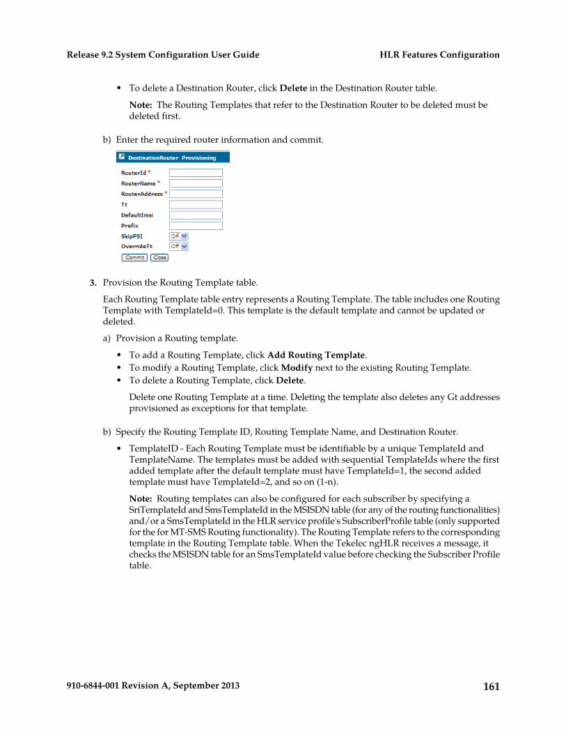
• To delete a Destination Router, click Delete in the Destination Router table.
Note: The Routing Templates that refer to the Destination Router to be deleted must bedeleted first.
b) Enter the required router information and commit.
3. Provision the Routing Template table.
Each Routing Template table entry represents a Routing Template. The table includes one RoutingTemplate with TemplateId=0. This template is the default template and cannot be updated ordeleted.
a) Provision a Routing template.
• To add a Routing Template, click Add Routing Template.• To modify a Routing Template, click Modify next to the existing Routing Template.• To delete a Routing Template, click Delete.
Delete one Routing Template at a time. Deleting the template also deletes any Gt addressesprovisioned as exceptions for that template.
b) Specify the Routing Template ID, Routing Template Name, and Destination Router.
• TemplateID - Each Routing Template must be identifiable by a unique TemplateId andTemplateName. The templates must be added with sequential TemplateIds where the firstadded template after the default template must have TemplateId=1, the second addedtemplate must have TemplateId=2, and so on (1-n).
Note: Routing templates can also be configured for each subscriber by specifying aSriTemplateId and SmsTemplateId in the MSISDN table (for any of the routing functionalities)and/or a SmsTemplateId in the HLR service profile's SubscriberProfile table (only supportedfor the for MT-SMS Routing functionality). The Routing Template refers to the correspondingtemplate in the Routing Template table. When the Tekelec ngHLR receives a message, itchecks the MSISDN table for an SmsTemplateId value before checking the Subscriber Profiletable.
161910-6844-001 Revision A, September 2013
HLR Features ConfigurationRelease 9.2 System Configuration User Guide
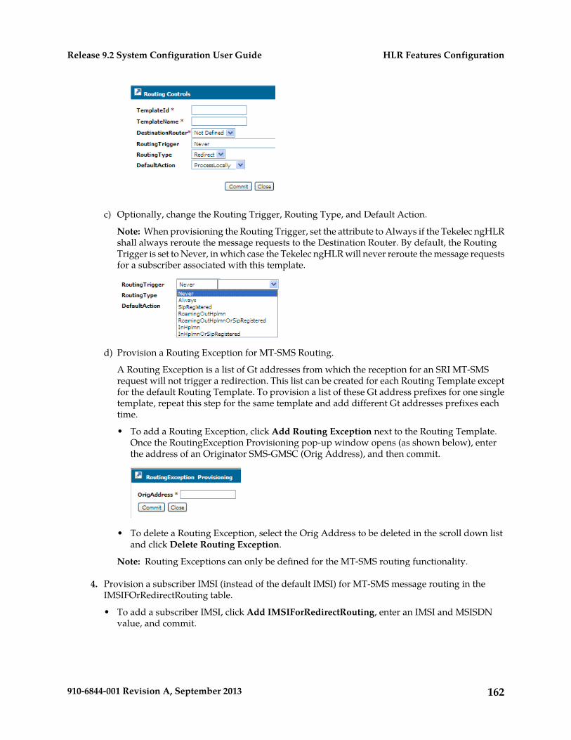
c) Optionally, change the Routing Trigger, Routing Type, and Default Action.
Note: When provisioning the Routing Trigger, set the attribute to Always if the Tekelec ngHLRshall always reroute the message requests to the Destination Router. By default, the RoutingTrigger is set to Never, in which case the Tekelec ngHLR will never reroute the message requestsfor a subscriber associated with this template.
d) Provision a Routing Exception for MT-SMS Routing.
A Routing Exception is a list of Gt addresses from which the reception for an SRI MT-SMSrequest will not trigger a redirection. This list can be created for each Routing Template exceptfor the default Routing Template. To provision a list of these Gt address prefixes for one singletemplate, repeat this step for the same template and add different Gt addresses prefixes eachtime.
• To add a Routing Exception, click Add Routing Exception next to the Routing Template.Once the RoutingException Provisioning pop-up window opens (as shown below), enterthe address of an Originator SMS-GMSC (Orig Address), and then commit.
• To delete a Routing Exception, select the Orig Address to be deleted in the scroll down listand click Delete Routing Exception.
Note: Routing Exceptions can only be defined for the MT-SMS routing functionality.
4. Provision a subscriber IMSI (instead of the default IMSI) for MT-SMS message routing in theIMSIFOrRedirectRouting table.
• To add a subscriber IMSI, click Add IMSIForRedirectRouting, enter an IMSI and MSISDNvalue, and commit.
162910-6844-001 Revision A, September 2013
HLR Features ConfigurationRelease 9.2 System Configuration User Guide
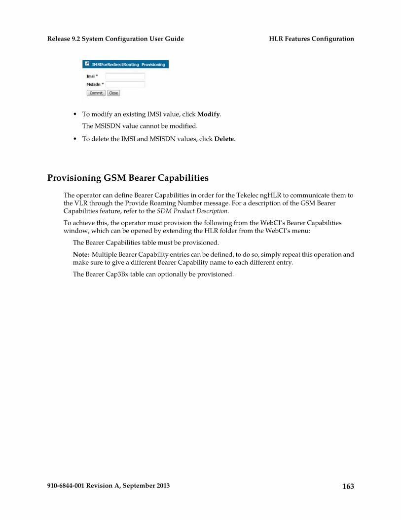
• To modify an existing IMSI value, click Modify.
The MSISDN value cannot be modified.
• To delete the IMSI and MSISDN values, click Delete.
Provisioning GSM Bearer Capabilities
The operator can define Bearer Capabilities in order for the Tekelec ngHLR to communicate them tothe VLR through the Provide Roaming Number message. For a description of the GSM BearerCapabilities feature, refer to the SDM Product Description.
To achieve this, the operator must provision the following from the WebCI’s Bearer Capabilitieswindow, which can be opened by extending the HLR folder from the WebCI’s menu:
The Bearer Capabilities table must be provisioned.
Note: Multiple Bearer Capability entries can be defined, to do so, simply repeat this operation andmake sure to give a different Bearer Capability name to each different entry.
The Bearer Cap3Bx table can optionally be provisioned.
163910-6844-001 Revision A, September 2013
HLR Features ConfigurationRelease 9.2 System Configuration User Guide
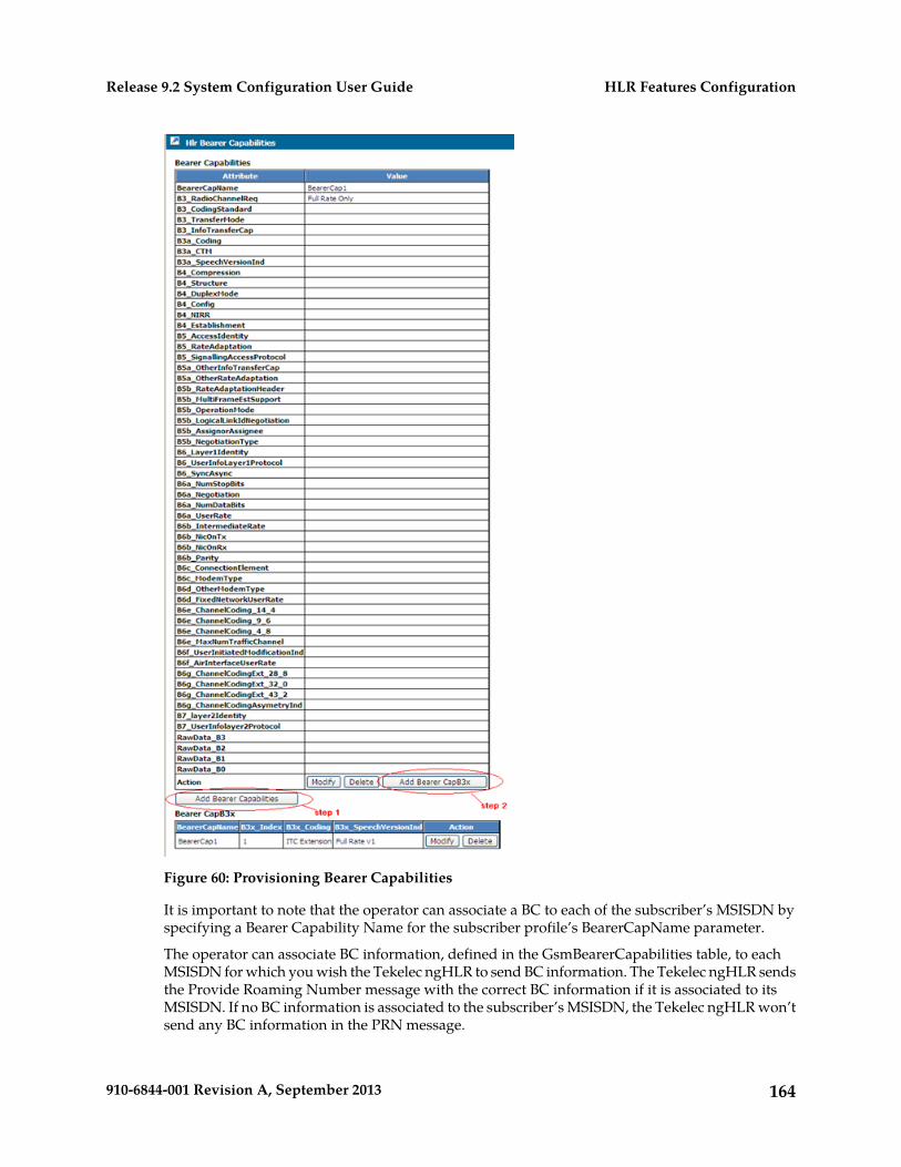
Figure 60: Provisioning Bearer Capabilities
It is important to note that the operator can associate a BC to each of the subscriber’s MSISDN byspecifying a Bearer Capability Name for the subscriber profile’s BearerCapName parameter.
The operator can associate BC information, defined in the GsmBearerCapabilities table, to eachMSISDN for which you wish the Tekelec ngHLR to send BC information. The Tekelec ngHLR sendsthe Provide Roaming Number message with the correct BC information if it is associated to itsMSISDN. If no BC information is associated to the subscriber’s MSISDN, the Tekelec ngHLR won’tsend any BC information in the PRN message.
164910-6844-001 Revision A, September 2013
HLR Features ConfigurationRelease 9.2 System Configuration User Guide
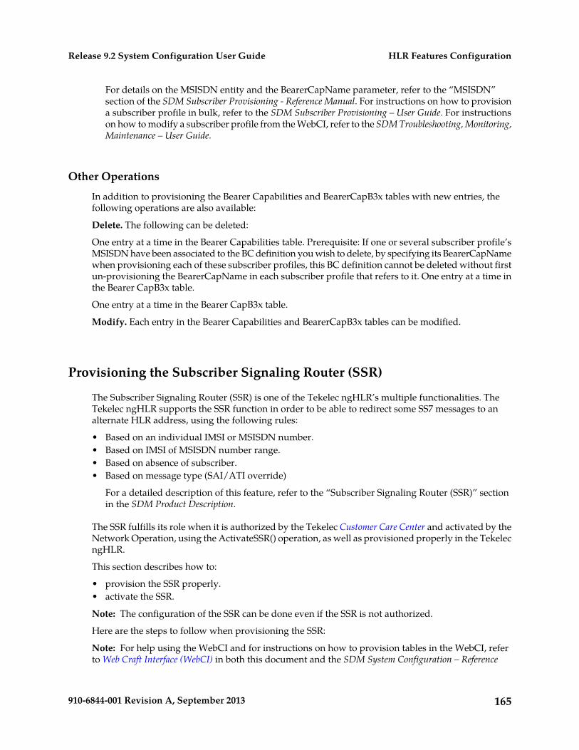
For details on the MSISDN entity and the BearerCapName parameter, refer to the “MSISDN”section of the SDM Subscriber Provisioning - Reference Manual. For instructions on how to provisiona subscriber profile in bulk, refer to the SDM Subscriber Provisioning – User Guide. For instructionson how to modify a subscriber profile from the WebCI, refer to the SDM Troubleshooting, Monitoring,Maintenance – User Guide.
Other Operations
In addition to provisioning the Bearer Capabilities and BearerCapB3x tables with new entries, thefollowing operations are also available:
Delete. The following can be deleted:
One entry at a time in the Bearer Capabilities table. Prerequisite: If one or several subscriber profile’sMSISDN have been associated to the BC definition you wish to delete, by specifying its BearerCapNamewhen provisioning each of these subscriber profiles, this BC definition cannot be deleted without firstun-provisioning the BearerCapName in each subscriber profile that refers to it. One entry at a time inthe Bearer CapB3x table.
One entry at a time in the Bearer CapB3x table.
Modify. Each entry in the Bearer Capabilities and BearerCapB3x tables can be modified.
Provisioning the Subscriber Signaling Router (SSR)
The Subscriber Signaling Router (SSR) is one of the Tekelec ngHLR’s multiple functionalities. TheTekelec ngHLR supports the SSR function in order to be able to redirect some SS7 messages to analternate HLR address, using the following rules:
• Based on an individual IMSI or MSISDN number.• Based on IMSI of MSISDN number range.• Based on absence of subscriber.• Based on message type (SAI/ATI override)
For a detailed description of this feature, refer to the “Subscriber Signaling Router (SSR)” sectionin the SDM Product Description.
The SSR fulfills its role when it is authorized by the Tekelec Customer Care Center and activated by theNetwork Operation, using the ActivateSSR() operation, as well as provisioned properly in the TekelecngHLR.
This section describes how to:
• provision the SSR properly.• activate the SSR.
Note: The configuration of the SSR can be done even if the SSR is not authorized.
Here are the steps to follow when provisioning the SSR:
Note: For help using the WebCI and for instructions on how to provision tables in the WebCI, referto Web Craft Interface (WebCI) in both this document and the SDM System Configuration – Reference
165910-6844-001 Revision A, September 2013
HLR Features ConfigurationRelease 9.2 System Configuration User Guide
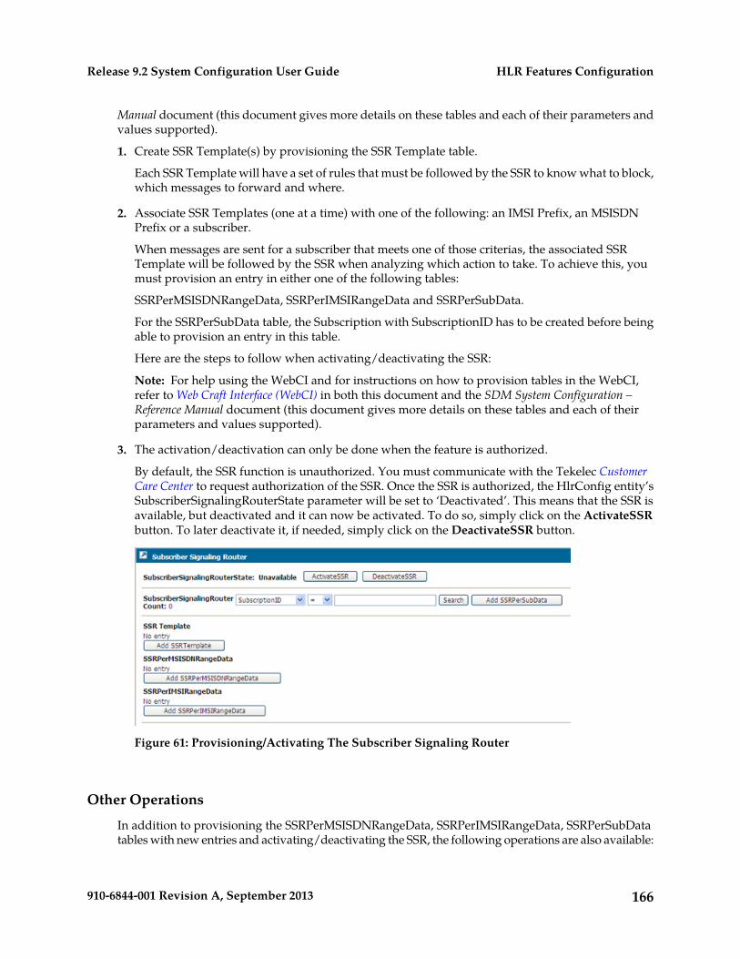
Manual document (this document gives more details on these tables and each of their parameters andvalues supported).
1. Create SSR Template(s) by provisioning the SSR Template table.
Each SSR Template will have a set of rules that must be followed by the SSR to know what to block,which messages to forward and where.
2. Associate SSR Templates (one at a time) with one of the following: an IMSI Prefix, an MSISDNPrefix or a subscriber.
When messages are sent for a subscriber that meets one of those criterias, the associated SSRTemplate will be followed by the SSR when analyzing which action to take. To achieve this, youmust provision an entry in either one of the following tables:
SSRPerMSISDNRangeData, SSRPerIMSIRangeData and SSRPerSubData.
For the SSRPerSubData table, the Subscription with SubscriptionID has to be created before beingable to provision an entry in this table.
Here are the steps to follow when activating/deactivating the SSR:
Note: For help using the WebCI and for instructions on how to provision tables in the WebCI,refer to Web Craft Interface (WebCI) in both this document and the SDM System Configuration –Reference Manual document (this document gives more details on these tables and each of theirparameters and values supported).
3. The activation/deactivation can only be done when the feature is authorized.
By default, the SSR function is unauthorized. You must communicate with the Tekelec CustomerCare Center to request authorization of the SSR. Once the SSR is authorized, the HlrConfig entity’sSubscriberSignalingRouterState parameter will be set to ‘Deactivated’. This means that the SSR isavailable, but deactivated and it can now be activated. To do so, simply click on the ActivateSSRbutton. To later deactivate it, if needed, simply click on the DeactivateSSR button.
Figure 61: Provisioning/Activating The Subscriber Signaling Router
Other Operations
In addition to provisioning the SSRPerMSISDNRangeData, SSRPerIMSIRangeData, SSRPerSubDatatables with new entries and activating/deactivating the SSR, the following operations are also available:
166910-6844-001 Revision A, September 2013
HLR Features ConfigurationRelease 9.2 System Configuration User Guide
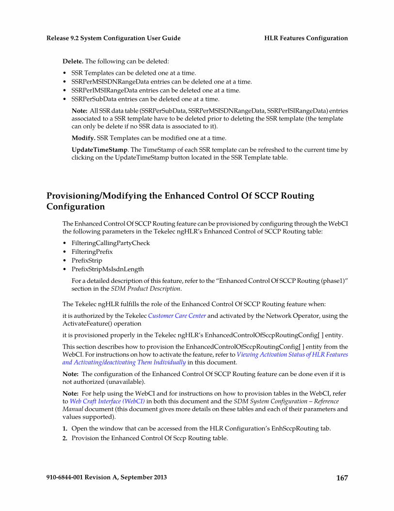
Delete. The following can be deleted:
• SSR Templates can be deleted one at a time.• SSRPerMSISDNRangeData entries can be deleted one at a time.• SSRPerIMSIRangeData entries can be deleted one at a time.• SSRPerSubData entries can be deleted one at a time.
Note: All SSR data table (SSRPerSubData, SSRPerMSISDNRangeData, SSRPerISIRangeData) entriesassociated to a SSR template have to be deleted prior to deleting the SSR template (the templatecan only be delete if no SSR data is associated to it).
Modify. SSR Templates can be modified one at a time.
UpdateTimeStamp. The TimeStamp of each SSR template can be refreshed to the current time byclicking on the UpdateTimeStamp button located in the SSR Template table.
Provisioning/Modifying the Enhanced Control Of SCCP RoutingConfiguration
The Enhanced Control Of SCCP Routing feature can be provisioned by configuring through the WebCIthe following parameters in the Tekelec ngHLR’s Enhanced Control of SCCP Routing table:
• FilteringCallingPartyCheck• FilteringPrefix• PrefixStrip• PrefixStripMsIsdnLength
For a detailed description of this feature, refer to the “Enhanced Control Of SCCP Routing (phase1)”section in the SDM Product Description.
The Tekelec ngHLR fulfills the role of the Enhanced Control Of SCCP Routing feature when:
it is authorized by the Tekelec Customer Care Center and activated by the Network Operator, using theActivateFeature() operation
it is provisioned properly in the Tekelec ngHLR’s EnhancedControlOfSccpRoutingConfig[ ] entity.
This section describes how to provision the EnhancedControlOfSccpRoutingConfig[ ] entity from theWebCI. For instructions on how to activate the feature, refer to Viewing Activation Status of HLR Featuresand Activating/deactivating Them Individually in this document.
Note: The configuration of the Enhanced Control Of SCCP Routing feature can be done even if it isnot authorized (unavailable).
Note: For help using the WebCI and for instructions on how to provision tables in the WebCI, referto Web Craft Interface (WebCI) in both this document and the SDM System Configuration – ReferenceManual document (this document gives more details on these tables and each of their parameters andvalues supported).
1. Open the window that can be accessed from the HLR Configuration’s EnhSccpRouting tab.2. Provision the Enhanced Control Of Sccp Routing table.
167910-6844-001 Revision A, September 2013
HLR Features ConfigurationRelease 9.2 System Configuration User Guide
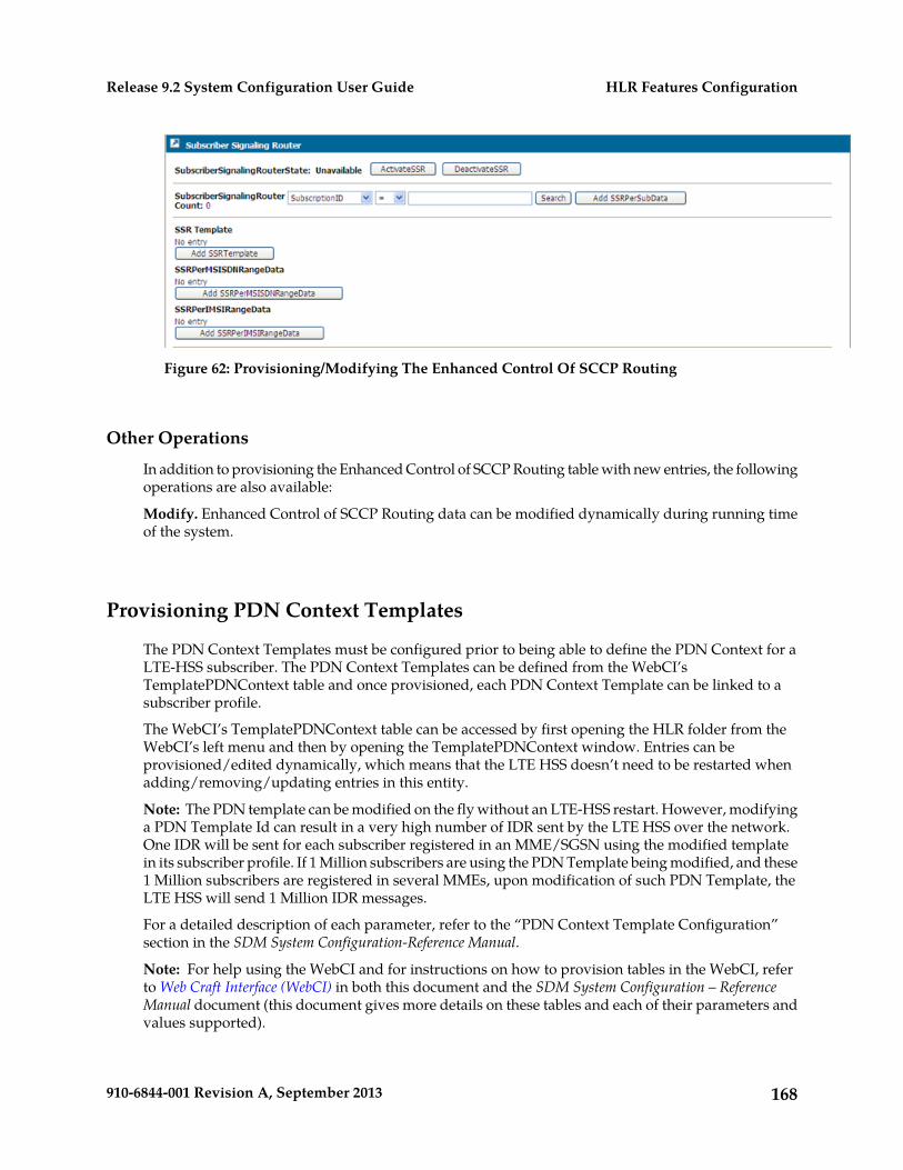
Figure 62: Provisioning/Modifying The Enhanced Control Of SCCP Routing
Other Operations
In addition to provisioning the Enhanced Control of SCCP Routing table with new entries, the followingoperations are also available:
Modify. Enhanced Control of SCCP Routing data can be modified dynamically during running timeof the system.
Provisioning PDN Context Templates
The PDN Context Templates must be configured prior to being able to define the PDN Context for aLTE-HSS subscriber. The PDN Context Templates can be defined from the WebCI’sTemplatePDNContext table and once provisioned, each PDN Context Template can be linked to asubscriber profile.
The WebCI’s TemplatePDNContext table can be accessed by first opening the HLR folder from theWebCI’s left menu and then by opening the TemplatePDNContext window. Entries can beprovisioned/edited dynamically, which means that the LTE HSS doesn’t need to be restarted whenadding/removing/updating entries in this entity.
Note: The PDN template can be modified on the fly without an LTE-HSS restart. However, modifyinga PDN Template Id can result in a very high number of IDR sent by the LTE HSS over the network.One IDR will be sent for each subscriber registered in an MME/SGSN using the modified templatein its subscriber profile. If 1 Million subscribers are using the PDN Template being modified, and these1 Million subscribers are registered in several MMEs, upon modification of such PDN Template, theLTE HSS will send 1 Million IDR messages.
For a detailed description of each parameter, refer to the “PDN Context Template Configuration”section in the SDM System Configuration-Reference Manual.
Note: For help using the WebCI and for instructions on how to provision tables in the WebCI, referto Web Craft Interface (WebCI) in both this document and the SDM System Configuration – ReferenceManual document (this document gives more details on these tables and each of their parameters andvalues supported).
168910-6844-001 Revision A, September 2013
HLR Features ConfigurationRelease 9.2 System Configuration User Guide
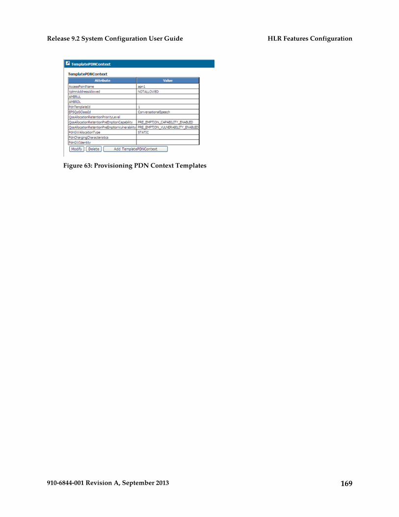
Figure 63: Provisioning PDN Context Templates
169910-6844-001 Revision A, September 2013
HLR Features ConfigurationRelease 9.2 System Configuration User Guide
Chapter
6SIP Application Configuration
This chapter describes the configuration of the SIPapplication.
Topics:
• Introduction.....171• Configuring SIP Application.....171• Viewing and editing SIP server configuration.171• Viewing/Editing SIP Security Configuration..175• Viewing/Editing SIP Registrar Configuration.176• Viewing/Editing SIP Redirect Configuration..178• Viewing/Editing SIP User Agent (RegClient)
Configuration.....179• Viewing and editing SIP TAS configuration for
3rd party registration.....183• Viewing/Editing SIP User Portability
configuration.....184
170910-6844-001 Revision A, September 2013
Introduction
Depending on the Fixed Mobile Convergence (FMC) deployment used by the Network Operator, theSIP Server and only some or all of the following SIP functionalities need to be configured:
• SIP Registrar• SIP Redirect Server• SIP User Agent (RegClient)
Configuring SIP Application
The SIP application is usually configured at installation by the Tekelec Customer Care Center. The SIPfunctionalities are independent from each other, which means that they can be enabled/disabledindividually at installation. During running-time of the system, the Network Operator can view theSIP configuration information and edit some SIP configuration parameters.
The WebCI allows you to view/edit the Server Configuration, Sip Security, Sip Registrar, Sip Redirectand Sip User Agent configuration tables and their attributes. This chapter describes how to view/editthis information from the WebCI.
For details on the parameters used to configure the SIP application, refer to the “SIP Entities” sectionin theSDM System Configuration - Reference Manual.
The operator can view all of the SIP configuration information from the WebCI’s SIP folder, by openingone of the following windows, depending on the SIP functionality’s configuration information desired:
• Server Configuration• Security• Registrar• Redirect• User Agent (RegClient)• User Portability• SIP Tas
Some of the SIP configuration information can be edited, by clicking on the Modify buttons. Tomodify some SIP configuration data that cannot be edited by clicking on the Modify buttons, contactthe Tekelec Customer Care Center.
Viewing and editing SIP server configuration
The WebCI’s Server Configuration window displays the Sip Configuration, Sip IP Configuration,Domain tables, Sip Server TLS Configuration and corresponding LoadPEMFiles() andDisplayCertificate() operations as well as the EnableSipServerStack/DisableSipServerStack operations.
171910-6844-001 Revision A, September 2013
SIP Application ConfigurationRelease 9.2 System Configuration User Guide
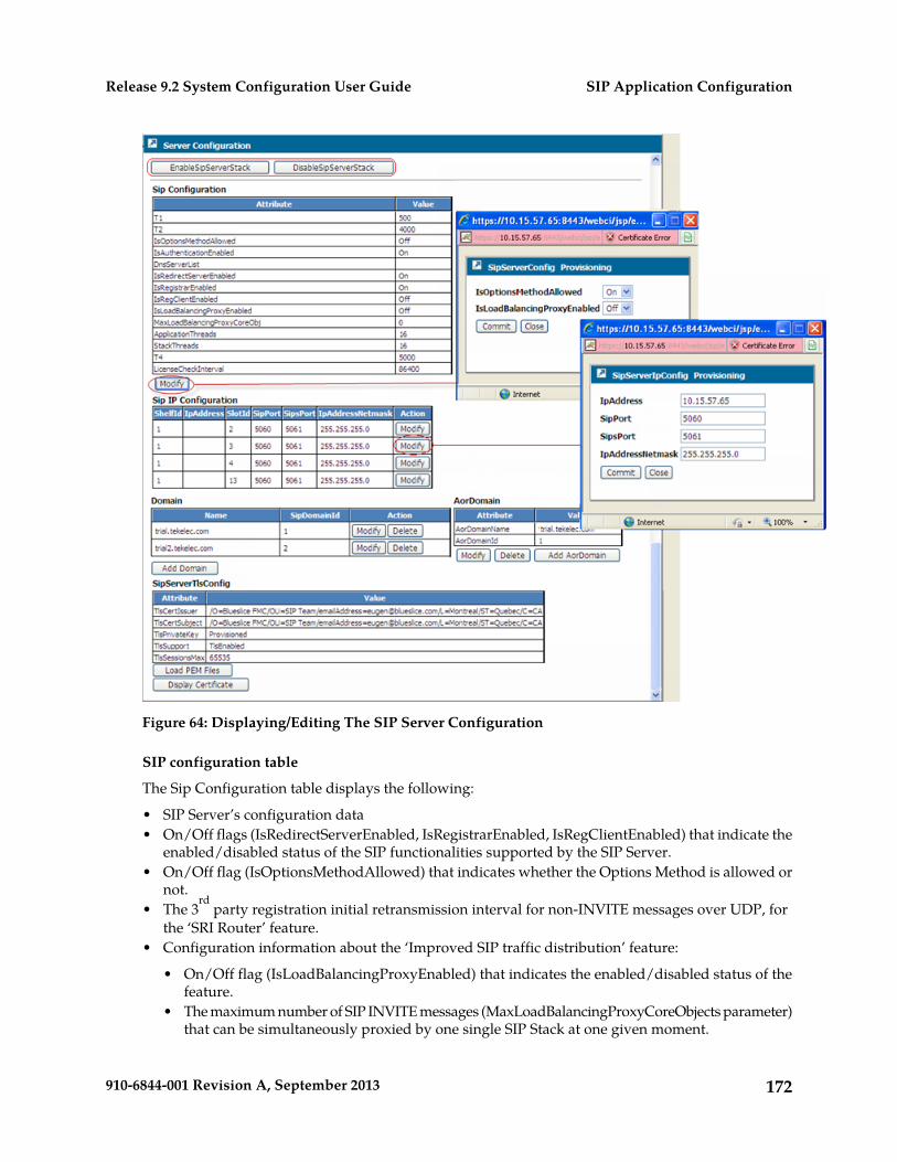
Figure 64: Displaying/Editing The SIP Server Configuration
SIP configuration table
The Sip Configuration table displays the following:
• SIP Server’s configuration data• On/Off flags (IsRedirectServerEnabled, IsRegistrarEnabled, IsRegClientEnabled) that indicate the
enabled/disabled status of the SIP functionalities supported by the SIP Server.• On/Off flag (IsOptionsMethodAllowed) that indicates whether the Options Method is allowed or
not.• The 3
rd party registration initial retransmission interval for non-INVITE messages over UDP, for
the ‘SRI Router’ feature.• Configuration information about the ‘Improved SIP traffic distribution’ feature:
• On/Off flag (IsLoadBalancingProxyEnabled) that indicates the enabled/disabled status of thefeature.
• The maximum number of SIP INVITE messages (MaxLoadBalancingProxyCoreObjects parameter)that can be simultaneously proxied by one single SIP Stack at one given moment.
172910-6844-001 Revision A, September 2013
SIP Application ConfigurationRelease 9.2 System Configuration User Guide
For more details on this feature, refer to the “Improved SIP traffic distribution” section of the SDMProduct Description manual.
The following data can be modified by the Network Operator during running-time of the system,which means that no system restart is required:
• On/Off flag (IsOptionsMethodAllowed) that indicates whether the Options Method is allowed ornot.
• On/Off flag (IsLoadBalancingProxyEnabled) that indicates the enabled/disabled status of thefeature.
SIP IP configuration table
The Sip IP Configuration table displays the following traffic access data of the blades on which runeach SIP Server (integrated in HLR service):
• IP address• Port• IP address netmask• Shelf and slot location of the blade
The following data can be modified by the Network Operator during running time of the system,which means that no system restart is required:
• IpAddress• SipPort• SipsPort• IpAddressNetmask
Domain table
The Domain table displays the Domain Name of the SIP Server. The data can be modified by theNetwork Operator but cannot be edited during the system’s running-time without the need to restartthe HLR services*:
Note: *IMPORTANT: Take note that when editing this information, in order for the new value to becommitted and used by the HLR, the Network Operator must manually perform the following:
1. Stop all the HLR services that run the SIP Server.2. Start all the HLR services that run the SIP Server.
Stopping and starting the HLR services will affect traffic, so make sure to perform this during downtime if necessary. Refer to section “Starting and Stopping Services on a blade” of the SDM Monitoring,Maintaining, Troubleshooting – User Guide for more information on how to stop a service.
For the ‘SRI Router’ feature to work correctly, the following SIP domains must be provisioned in the“Domain” entity before the Hlr service is started:
1. Request-URI domain2. TO URI domain
To allow this, multiple entries can be provisioned in this table. Simply add an entry (by clicking onthe ‘Add Domain’ button beneath the Domain table) with the ‘Request-URI domain’ and then separatelyadd another entry with the ‘TO URI domain’.
If the SIP domain list is changed by the user, the Hlr service needs to be restarted.
173910-6844-001 Revision A, September 2013
SIP Application ConfigurationRelease 9.2 System Configuration User Guide
AorDomain table
The AorDomain table displays the following:
• Domain Name of the AoR.• ID of the AoR Domain Name
The following data can be modified by the Network Operator during running-time of the systemwithout the need to restart the HLR services:
• Domain Name of the AoR
SIP Server TLS table
The Sip Server TLS Configuration table displays the following TLS configuration data:
• TLS Certificate Issuer• TLS Certificate Subject• TLS Certificate PEM• TLS Private Key PEM• TLS Private Key• TLS Support (TLS encryption over SIP enabled or disabled)• Maximum number of sessions opened simultaneously
Call the Tekelec Customer Care Center to edit TLS configuration and enable the TLS Support.
Other Operations
In addition to viewing/editing the Server Configuration, SIP IP Configuration and Domain tables,the following operations are also available:
DisableSipServerStack
This operation can be executed when the system is part of a Geo-redundant deployment and in thecase where it has failed and you wish the system to respond with “503 Service Unavailable” in orderto indicate to the SIP Client Application that it needs to route all the SIP transactions from the troubledsite to the healthy site. When this operation is executed, the SIP Server performs the following:
EnableSipServerStack
Raises the Sip Server Stack Disabled critical alarm (alarmId: 8044) with the following description:SipServer - stack is Disabled, by OAM request received (manual operation)"
Answers to INVITE, OPTIONS and REGISTER valid SIP messages with “503 Service Unavailable”.
Note that the state established by this operations is not persistent.
This operation can be executed after the DisableSipServerStack () operation. When this operation isexecuted, the SIP Server performs the following:
Clears the SipServerStackDisabled alarm (alarmed:8044).
Answers to SIP INVITE, OPTIONS and REGISTER messages as per the usual (it no longer sends a 503error code).
174910-6844-001 Revision A, September 2013
SIP Application ConfigurationRelease 9.2 System Configuration User Guide
For details on these operations, refer to the section that describes the Handling of SS7 and SIP abnormalfailure cases feature in the SDM Product Description.
Load PEM Files
This operation can be executed to load a TLS certificate and private key from the following knownPEM files onto the database: /tmp/cacert.pem and /tmp/cakey.pem.Take note that in thisrelease, multiple certificates are not supported, only one certificate and private key can be loaded.
At system startup, a certificate & a private key are provisioned and stored by default in the/tmp/cacert.pem and /tmp/cakey.pem files.
If the Network Operator chooses to use them, he must simply load them onto the system by performingthe LoadPEMFiles() operation (see instructions below).
Otherwise, if the Network Operator chooses to use another certificate/private key, he must followthese steps:
1. Connect to the system’s active System Controller blade and store the certificate/private key ontothe database’s PEM files: /tmp/cacert.pem and /tmp/cakey.pem.
2. Load the certificate/private key by performing the LoadPEMFiles() operation
In order to perform the LoadPEMFiles() operation, simply follow these steps from the WebCI’s ServerConfiguration window (refer to the previous figure):
Prerequisite: Store the TLS certificate and private key into the database in the following well knownPEM files: /tmp/cacert.pem and /tmp/cakey.pem
1. Click on the Load PEM Files button located underneath the SipServerTlsConfig table.2. The following message will appear: “You are about to perform LoadPEMFiles, Continue?”. Click
on Ok to continue or Cancel if you wish to abort.3. The PEM files will be invoked and loaded on the system. The following message will appear to
inform you that the operation was successfully completed: “
The SIP TLS pem files have been successfully installed.
Display Certificate
This operation can be executed to display the details of the Certificate. Simply click on the DisplayCertificate button located underneath the SipServerTlsConfig table in the WebCI’s ServerConfiguration window (refer to the previous figure). When the Display Certificate window opens, itwill display the TLS Certificate and Private Key. Click on the Close button to exit.
If you wish to delete or modify the TLS Certificate and Private key, you must contact the TekelecCustomer Care Center and the Hlr service will need to be restarted.
Viewing/Editing SIP Security Configuration
The WebCI’s Security window displays the SIP Security Configuration data.
The following data can be modified by the Network Operator:
• NonceValidityDuration
175910-6844-001 Revision A, September 2013
SIP Application ConfigurationRelease 9.2 System Configuration User Guide
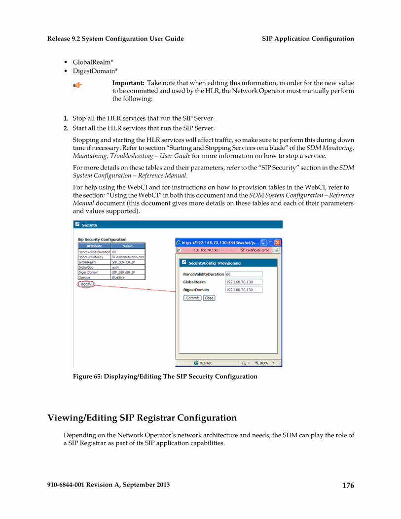
• GlobalRealm*• DigestDomain*
Important: Take note that when editing this information, in order for the new valueto be committed and used by the HLR, the Network Operator must manually performthe following:
1. Stop all the HLR services that run the SIP Server.2. Start all the HLR services that run the SIP Server.
Stopping and starting the HLR services will affect traffic, so make sure to perform this during downtime if necessary. Refer to section “Starting and Stopping Services on a blade” of the SDM Monitoring,Maintaining, Troubleshooting – User Guide for more information on how to stop a service.
For more details on these tables and their parameters, refer to the “SIP Security” section in the SDMSystem Configuration – Reference Manual.
For help using the WebCI and for instructions on how to provision tables in the WebCI, refer tothe section: “Using the WebCI” in both this document and the SDM System Configuration – ReferenceManual document (this document gives more details on these tables and each of their parametersand values supported).
Figure 65: Displaying/Editing The SIP Security Configuration
Viewing/Editing SIP Registrar Configuration
Depending on the Network Operator’s network architecture and needs, the SDM can play the role ofa SIP Registrar as part of its SIP application capabilities.
176910-6844-001 Revision A, September 2013
SIP Application ConfigurationRelease 9.2 System Configuration User Guide
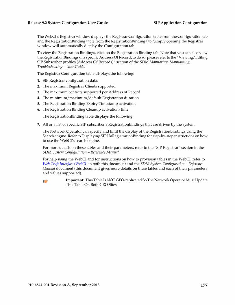
The WebCI’s Registrar window displays the Registrar Configuration table from the Configuration taband the RegistrationBinding table from the RegistrationBinding tab. Simply opening the Registrarwindow will automatically display the Configuration tab.
To view the Registration Bindings, click on the Registration Binding tab. Note that you can also viewthe RegistrationBindings of a specific Address Of Record, to do so, please refer to the “Viewing/EditingSIP Subscriber profiles (Address Of Records)” section of the SDM Monitoring, Maintaining,Troubleshooting – User Guide.
The Registrar Configuration table displays the following:
1. SIP Registrar configuration data:2. The maximum Registrar Clients supported3. The maximum contacts supported per Address of Record.4. The minimum/maximum/default Registration duration5. The Registration Binding Expiry Timestamp activation6. The Registration Binding Cleanup activation/time
The RegistrationBinding table displays the following:
7. All or a list of specific SIP subscriber’s RegistrationBindings that are driven by the system.
The Network Operator can specify and limit the display of the RegistrationBindings using theSearch engine. Refer to Displaying SIP UaRegistrationBinding for step-by-step instructions on howto use the WebCI’s search engine.
For more details on these tables and their parameters, refer to the “SIP Registrar” section in theSDM System Configuration – Reference Manual.
For help using the WebCI and for instructions on how to provision tables in the WebCI, refer toWeb Craft Interface (WebCI) in both this document and the SDM System Configuration – ReferenceManual document (this document gives more details on these tables and each of their parametersand values supported).
Important: This Table Is NOT GEO-replicated So The Network Operator Must UpdateThis Table On Both GEO Sites
177910-6844-001 Revision A, September 2013
SIP Application ConfigurationRelease 9.2 System Configuration User Guide
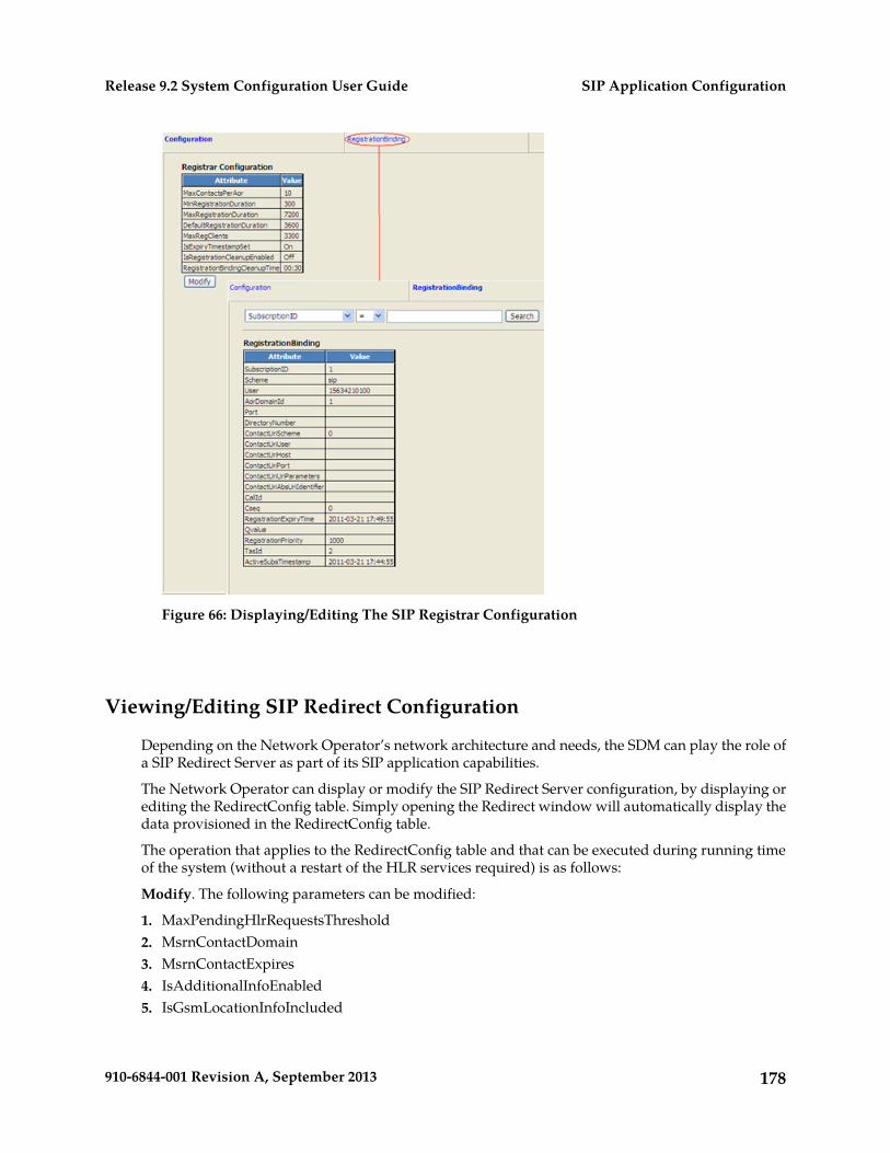
Figure 66: Displaying/Editing The SIP Registrar Configuration
Viewing/Editing SIP Redirect Configuration
Depending on the Network Operator’s network architecture and needs, the SDM can play the role ofa SIP Redirect Server as part of its SIP application capabilities.
The Network Operator can display or modify the SIP Redirect Server configuration, by displaying orediting the RedirectConfig table. Simply opening the Redirect window will automatically display thedata provisioned in the RedirectConfig table.
The operation that applies to the RedirectConfig table and that can be executed during running timeof the system (without a restart of the HLR services required) is as follows:
Modify. The following parameters can be modified:
1. MaxPendingHlrRequestsThreshold2. MsrnContactDomain3. MsrnContactExpires4. IsAdditionalInfoEnabled5. IsGsmLocationInfoIncluded
178910-6844-001 Revision A, September 2013
SIP Application ConfigurationRelease 9.2 System Configuration User Guide
6. IsCamelInfoIncluded7. IsDiversionHeaderIncluded8. IsVoipDnReverseSearchEnabled
Refer to the “SIP Redirect Server section” of the SDM System Configuration - Reference Manual formore detailed information on these parameters and their value range.
For help using the WebCI and for instructions on how to provision tables in the WebCI, refer toWeb Craft Interface (WebCI) in both this document and the SDM System Configuration – ReferenceManual document (this document gives more details on these tables and each of their parametersand values supported).
Figure 67: Displaying/Editing The SIP Redirect Server Configuration
Viewing/Editing SIP User Agent (RegClient) Configuration
Depending on the Network Operator’s network architecture and needs, the SDM can play the role ofa SIP User Agent (RegClient) as part of its SIP application capabilities.
The WebCI’s User Agent window displays the User Agent Configuration, User Agent RegisterConfiguration and User Agent Persistent Contact tables from the User Agent tab and the User AgentRegistrationBinding table from the Registration Binding tab.
The Network Operator can display or modify the SIP User Agent configuration, by displaying orediting these tables. Simply opening the User Agent window will automatically display the User Agenttab.
179910-6844-001 Revision A, September 2013
SIP Application ConfigurationRelease 9.2 System Configuration User Guide
To view the User Agent Registration Bindings, simply click on the Registration Binding tab. Refer toDisplaying WebCI window content using a search for step-by-step instructions on how to use the WebCI’ssearch engine.
Note: The SipUa registration bindings are not persistent across a system restart. Therefore, after arestart the SipUa registration bindings are reset and the table is empty. You can also view theRegistrationBindings of a specific Address Of Record, to do so, please refer to the “Viewing/EditingSIP Subscriber profiles (Address Of Records)” section of theSDM Monitoring, Maintaining, Troubleshooting– User Guide.
The other operation that can be executed during running time of the system (without a restart of theHLR services required) is as follows:
Modify. This operation is available for the User Agent Configuration and User Agent RegisterConfiguration tables.
The User Agent Configuration table’s following parameters can be modified:
• IsImsHeaderRequired• IsUsernameSetInContactHeader• IsUsernamePhoneNumber• IsPathHeaderRequired• OutboundProxyTransport
The User Agent Register Configuration table’s following parameters can be modified:
• RequestUriHost• FromUser• FromHost• OtherHeaderValue• IsThirdPartyRegistrationEnabled
Refer to the “User Agent” section of the SDM System Configuration-Reference Manual for moredetailed information on these parameters and their value range.
For help using the WebCI and for instructions on how to provision tables in the WebCI, refer toWeb Craft Interface (WebCI) in both this document and the SDM System Configuration – ReferenceManual document (this document gives more details on these tables and each of their parametersand values supported).
180910-6844-001 Revision A, September 2013
SIP Application ConfigurationRelease 9.2 System Configuration User Guide
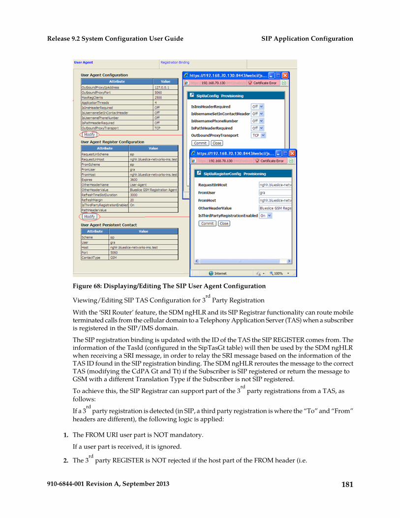
Figure 68: Displaying/Editing The SIP User Agent Configuration
Viewing/Editing SIP TAS Configuration for 3rd
Party Registration
With the ‘SRI Router’ feature, the SDM ngHLR and its SIP Registrar functionality can route mobileterminated calls from the cellular domain to a Telephony Application Server (TAS) when a subscriberis registered in the SIP/IMS domain.
The SIP registration binding is updated with the ID of the TAS the SIP REGISTER comes from. Theinformation of the TasId (configured in the SipTasGt table) will then be used by the SDM ngHLRwhen receiving a SRI message, in order to relay the SRI message based on the information of theTAS ID found in the SIP registration binding. The SDM ngHLR reroutes the message to the correctTAS (modifying the CdPA Gt and Tt) if the Subscriber is SIP registered or return the message toGSM with a different Translation Type if the Subscriber is not SIP registered.
To achieve this, the SIP Registrar can support part of the 3rd
party registrations from a TAS, asfollows:
If a 3rd
party registration is detected (in SIP, a third party registration is where the “To” and “From”headers are different), the following logic is applied:
1. The FROM URI user part is NOT mandatory.
If a user part is received, it is ignored.
2. The 3rd
party REGISTER is NOT rejected if the host part of the FROM header (i.e.
181910-6844-001 Revision A, September 2013
SIP Application ConfigurationRelease 9.2 System Configuration User Guide
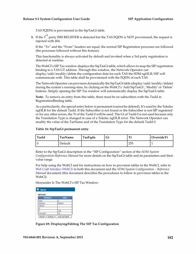
TAS FQDN) is provisioned in the SipTasGt table.
3. If the 3rd
party IMS REGISTER is detected but the TAS FQDN is NOT provisioned, the request isrejected with 404.
If the “To” and the “From” headers are equal, the normal SIP Registration processes are followed(the processes followed without this feature).
This functionality is always activated by default and invoked when a 3rd party registration isdetected at runtime.
The WebCI’s SIP Tas window displays the SipTasGt table, which allows to map the SIP registrationbinding to a TAS GT address. Through this window, the Network Operator candisplay/add/modify/delete the configuration data for each TAS the SDM ngHLR/SIP willcommunicate with. This table shall be provisioned with the FQDN of each TAS.
The Network Operator can provision dynamically the SipTasGt table (display/add/modify/delete)during the system’s running-time, by clicking on the WebCI’s ‘Add SipTasGt’, ‘Modify’ or ‘Delete’buttons. Simply opening the SIP Tas window will automatically display the SipTasGt table.
Note: To remove an entry from this table, there must be no subscribers with the TasId inRegistrationBinding table.
As a particularity, the special entry below is permanent (cannot be deleted). It’s used by the TekelecngHLR for the default TasId. If the Subscriber is not found or the Subscriber is not SIP registeredor for any other errors, the Tt of the TasId 0 will be used. The Gt of TasId 0 is not used because onlythe Translation Type is changed in case of a Tekelec ngHLR error. The Network Operator canmodify the value of the TasName and of the Translation Type for the default TasId 0.
Table 16: SipTasGt permanent entry
OverrideTtTtGtTasFqdnTasNameTasId
1255Default0
Refer to the SipTasGt description in the “SIP Configuration” section of the SDM SystemConfiguration-Reference Manual for more details on the SipTasGt table and its parameters and theirvalue range.
For help using the WebCI and for instructions on how to provision tables in the WebCI, refer toWeb Craft Interface (WebCI) in both this document and the SDM System Configuration – ReferenceManual document (this document describes the procedures to follow to provision tables in theWebCI).
Hereunder Is The WebCI’s SIP Tas Window:
Figure 69: Displaying/Editing The SIP Tas Configuration
182910-6844-001 Revision A, September 2013
SIP Application ConfigurationRelease 9.2 System Configuration User Guide
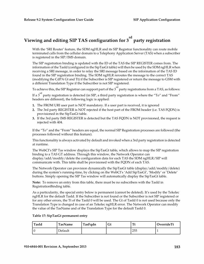
Viewing and editing SIP TAS configuration for 3rd
party registration
With the ‘SRI Router’ feature, the SDM ngHLR and its SIP Registrar functionality can route mobileterminated calls from the cellular domain to a Telephony Application Server (TAS) when a subscriberis registered in the SIP/IMS domain.
The SIP registration binding is updated with the ID of the TAS the SIP REGISTER comes from. Theinformation of the TasId (configured in the SipTasGt table) will then be used by the SDM ngHLR whenreceiving a SRI message, in order to relay the SRI message based on the information of the TAS IDfound in the SIP registration binding. The SDM ngHLR reroutes the message to the correct TAS(modifying the CdPA Gt and Tt) if the Subscriber is SIP registered or return the message to GSM witha different Translation Type if the Subscriber is not SIP registered.
To achieve this, the SIP Registrar can support part of the 3rd
party registrations from a TAS, as follows:
If a 3rd
party registration is detected (in SIP, a third party registration is where the “To” and “From”headers are different), the following logic is applied:
1. The FROM URI user part is NOT mandatory. If a user part is received, it is ignored2. The 3rd party REGISTER is NOT rejected if the host part of the FROM header (i.e. TAS FQDN) is
provisioned in the SipTasGt table.3. If the 3rd party IMS REGISTER is detected but the TAS FQDN is NOT provisioned, the request is
rejected with 404.
If the “To” and the “From” headers are equal, the normal SIP Registration processes are followed (theprocesses followed without this feature).
This functionality is always activated by default and invoked when a 3rd party registration is detectedat runtime.
The WebCI’s SIP Tas window displays the SipTasGt table, which allows to map the SIP registrationbinding to a TAS GT address. Through this window, the Network Operator candisplay/add/modify/delete the configuration data for each TAS the SDM ngHLR/SIP willcommunicate with. This table shall be provisioned with the FQDN of each TAS.
The Network Operator can provision dynamically the SipTasGt table (display/add/modify/delete)during the system’s running-time, by clicking on the WebCI’s ‘Add SipTasGt’, ‘Modify’ or ‘Delete’buttons. Simply opening the SIP Tas window will automatically display the SipTasGt table.
Note: To remove an entry from this table, there must be no subscribers with the TasId inRegistrationBinding table.
As a particularity, the special entry below is permanent (cannot be deleted). It’s used by the TekelecngHLR for the default TasId. If the Subscriber is not found or the Subscriber is not SIP registered orfor any other errors, the Tt of the TasId 0 will be used. The Gt of TasId 0 is not used because only theTranslation Type is changed in case of an Tekelec ngHLR error. The Network Operator can modifythe value of the TasName and of the Translation Type for the default TasId 0.
Table 17: SipTasGt permanent entry
OverrideTtTtGtTasFqdnTasNameTasId
1255Default0
183910-6844-001 Revision A, September 2013
SIP Application ConfigurationRelease 9.2 System Configuration User Guide
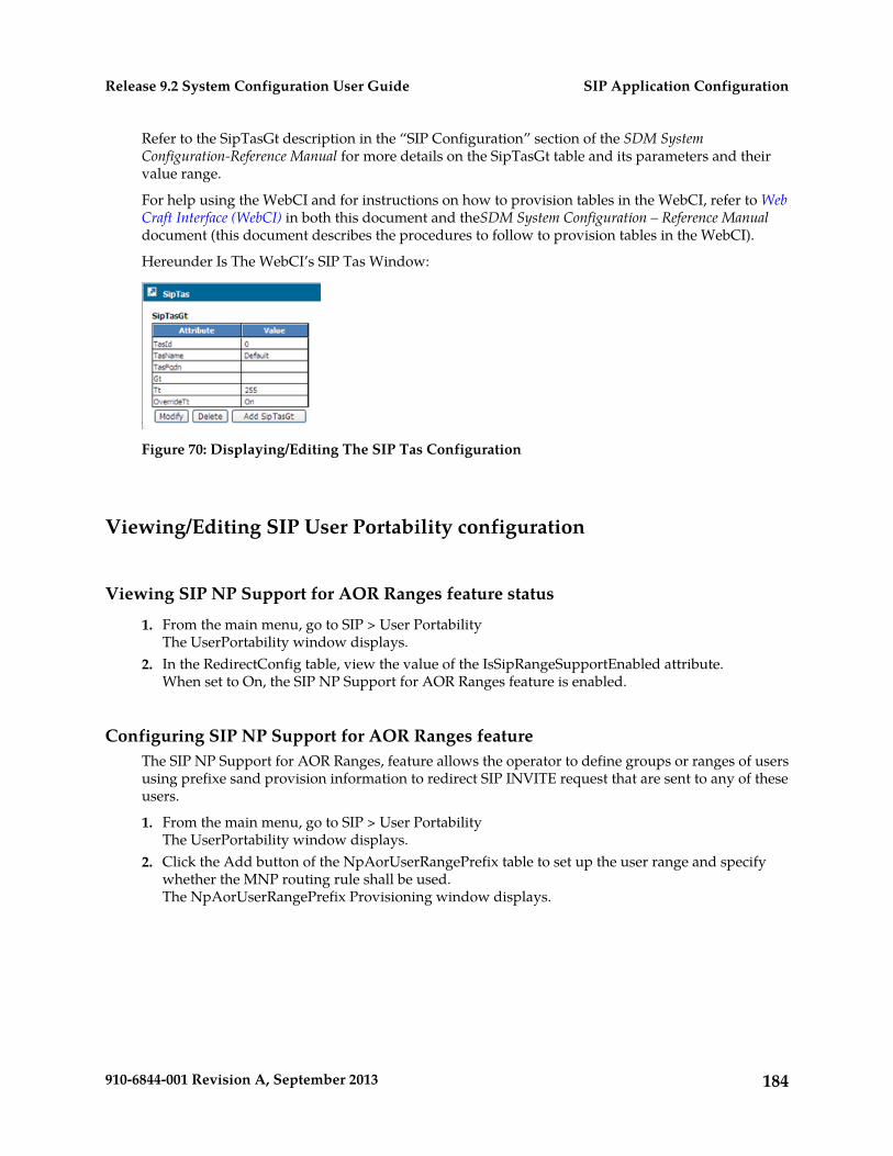
Refer to the SipTasGt description in the “SIP Configuration” section of the SDM SystemConfiguration-Reference Manual for more details on the SipTasGt table and its parameters and theirvalue range.
For help using the WebCI and for instructions on how to provision tables in the WebCI, refer to WebCraft Interface (WebCI) in both this document and theSDM System Configuration – Reference Manualdocument (this document describes the procedures to follow to provision tables in the WebCI).
Hereunder Is The WebCI’s SIP Tas Window:
Figure 70: Displaying/Editing The SIP Tas Configuration
Viewing/Editing SIP User Portability configuration
Viewing SIP NP Support for AOR Ranges feature status
1. From the main menu, go to SIP > User PortabilityThe UserPortability window displays.
2. In the RedirectConfig table, view the value of the IsSipRangeSupportEnabled attribute.When set to On, the SIP NP Support for AOR Ranges feature is enabled.
Configuring SIP NP Support for AOR Ranges featureThe SIP NP Support for AOR Ranges, feature allows the operator to define groups or ranges of usersusing prefixe sand provision information to redirect SIP INVITE request that are sent to any of theseusers.
1. From the main menu, go to SIP > User PortabilityThe UserPortability window displays.
2. Click the Add button of the NpAorUserRangePrefix table to set up the user range and specifywhether the MNP routing rule shall be used.The NpAorUserRangePrefix Provisioning window displays.
184910-6844-001 Revision A, September 2013
SIP Application ConfigurationRelease 9.2 System Configuration User Guide
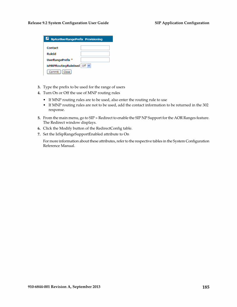
3. Type the prefix to be used for the range of users4. Turn On or Off the use of MNP routing rules
• If MNP routing rules are to be used, also enter the routing rule to use• If MNP routing rules are not to be used, add the contact information to be returned in the 302
response.
5. From the main menu, go to SIP > Redirect to enable the SIP NP Support for the AOR Ranges feature.The Redirect window displays.
6. Click the Modify button of the RedirectConfig table.7. Set the IsSipRangeSupportEnabled attribute to On
For more information about these attributes, refer to the respective tables in the System ConfigurationReference Manual.
185910-6844-001 Revision A, September 2013
SIP Application ConfigurationRelease 9.2 System Configuration User Guide
Chapter
7IMS-HSS/SLF Application Configuration
This chapter outlines the procedures to configurethe IMS-HSS and SLF.
Topics:
• Introduction.....187• Configuring the IMS-HSS/SLF.....187• Configuring the IMS-HSS AuC.....189• Configuring IMS-HSS System Features.....191• Configuring IMS-HSS Shared Initial Filtering
Criterias.....193
186910-6844-001 Revision A, September 2013
Introduction
The procedures in this chapter show you how to view/modify the IMS-HSS and SLFconfiguration,configure the IMS-HSS AuC, configure the IMS-HSS System Features and the Shared Initial FilteringCriterias. To perform the tasks in the following table, refer to the corresponding section within thischapter.
Requirements: Log in to a WebCI session with a username and password.
Table 18: IMS-HSS/SLF application procedures
Task
Viewing/Editing IMS-HSS and SLF Configuration
Configuring the IMS-HSS AuC
Configuring the IMS-HSS System Features
Configuring Shared Initial Filtering Criterias
For details on the parameters used to configure the IMS-HSS/SLF, the IMS-HSS AuC, IMS-HSS SystemFeatures and Shared Initial Filtering Criterias, refer to the “IMS-HSS Entities” section in the SDMSystem Configuration - Reference Manual.
Configuring the IMS-HSS/SLF
The IMS-HSS and SLF are usually configured at installation by the Tekelec Customer Care Center. Theyare both independent from each other, but they are presented together here since they follow similarconfiguration logic.
The following information needs to be configured at installation in order to run the IMS-HSS and/orSLF applications:
• IMS-HSS and/or SLF configuration information• On/Off flags to enable/disable independently the IMS-HSS and SLF applications.• The network information (Local FQDN, LocalSTCPPort, LocalTCPPort, OriginatingRealm,
SCTPTransport, TCPTransport, TCP Listen Address, SCTP Listen Address, Destination Realms,Destination Hosts, etc.) needed for the IMS-HSS/SLF to communicate with the peer servers.
Viewing/Editing IMS-HSS/SLF Configuration
The operator can view all of the IMS-HSS and SLF configuration information from the WebCI’s IMS-HSSfolder and SLF folder respectively, by opening the IMS-HSS Configuration window or the SLFConfiguration window. Some of this information can be modified and network information can bedeleted/added.
Note: Prior to making any changes (adding, modifying, deleting) to the IMS-HSS/SLF Configurationdata during running-time, the IMS-HSS service must first be stopped. Once the changes are made, the
187910-6844-001 Revision A, September 2013
IMS-HSS/SLF Application ConfigurationRelease 9.2 System Configuration User Guide
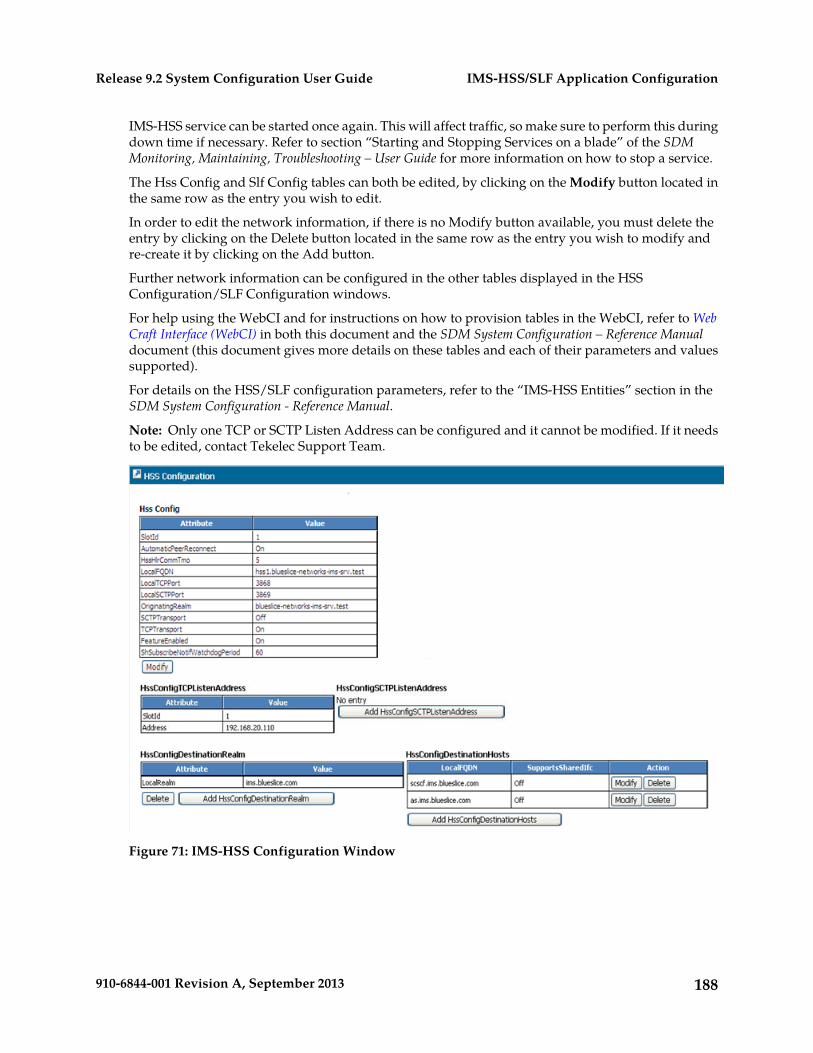
IMS-HSS service can be started once again. This will affect traffic, so make sure to perform this duringdown time if necessary. Refer to section “Starting and Stopping Services on a blade” of the SDMMonitoring, Maintaining, Troubleshooting – User Guide for more information on how to stop a service.
The Hss Config and Slf Config tables can both be edited, by clicking on the Modify button located inthe same row as the entry you wish to edit.
In order to edit the network information, if there is no Modify button available, you must delete theentry by clicking on the Delete button located in the same row as the entry you wish to modify andre-create it by clicking on the Add button.
Further network information can be configured in the other tables displayed in the HSSConfiguration/SLF Configuration windows.
For help using the WebCI and for instructions on how to provision tables in the WebCI, refer to WebCraft Interface (WebCI) in both this document and the SDM System Configuration – Reference Manualdocument (this document gives more details on these tables and each of their parameters and valuessupported).
For details on the HSS/SLF configuration parameters, refer to the “IMS-HSS Entities” section in theSDM System Configuration - Reference Manual.
Note: Only one TCP or SCTP Listen Address can be configured and it cannot be modified. If it needsto be edited, contact Tekelec Support Team.
Figure 71: IMS-HSS Configuration Window
188910-6844-001 Revision A, September 2013
IMS-HSS/SLF Application ConfigurationRelease 9.2 System Configuration User Guide
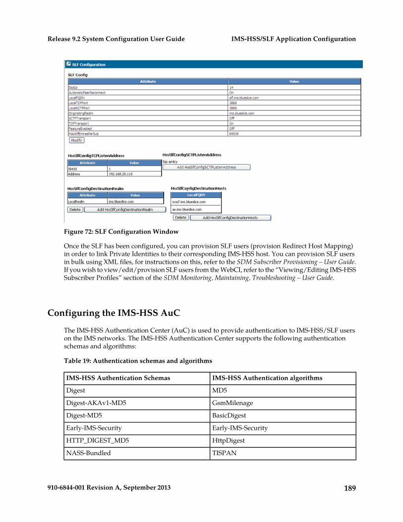
Figure 72: SLF Configuration Window
Once the SLF has been configured, you can provision SLF users (provision Redirect Host Mapping)in order to link Private Identities to their corresponding IMS-HSS host. You can provision SLF usersin bulk using XML files, for instructions on this, refer to the SDM Subscriber Provisioning – User Guide.If you wish to view/edit/provision SLF users from the WebCI, refer to the “Viewing/Editing IMS-HSSSubscriber Profiles” section of the SDM Monitoring, Maintaining, Troubleshooting – User Guide.
Configuring the IMS-HSS AuC
The IMS-HSS Authentication Center (AuC) is used to provide authentication to IMS-HSS/SLF userson the IMS networks. The IMS-HSS Authentication Center supports the following authenticationschemas and algorithms:
Table 19: Authentication schemas and algorithms
IMS-HSS Authentication algorithmsIMS-HSS Authentication Schemas
MD5Digest
GsmMilenageDigest-AKAv1-MD5
BasicDigestDigest-MD5
Early-IMS-SecurityEarly-IMS-Security
HttpDigestHTTP_DIGEST_MD5
TISPANNASS-Bundled
189910-6844-001 Revision A, September 2013
IMS-HSS/SLF Application ConfigurationRelease 9.2 System Configuration User Guide
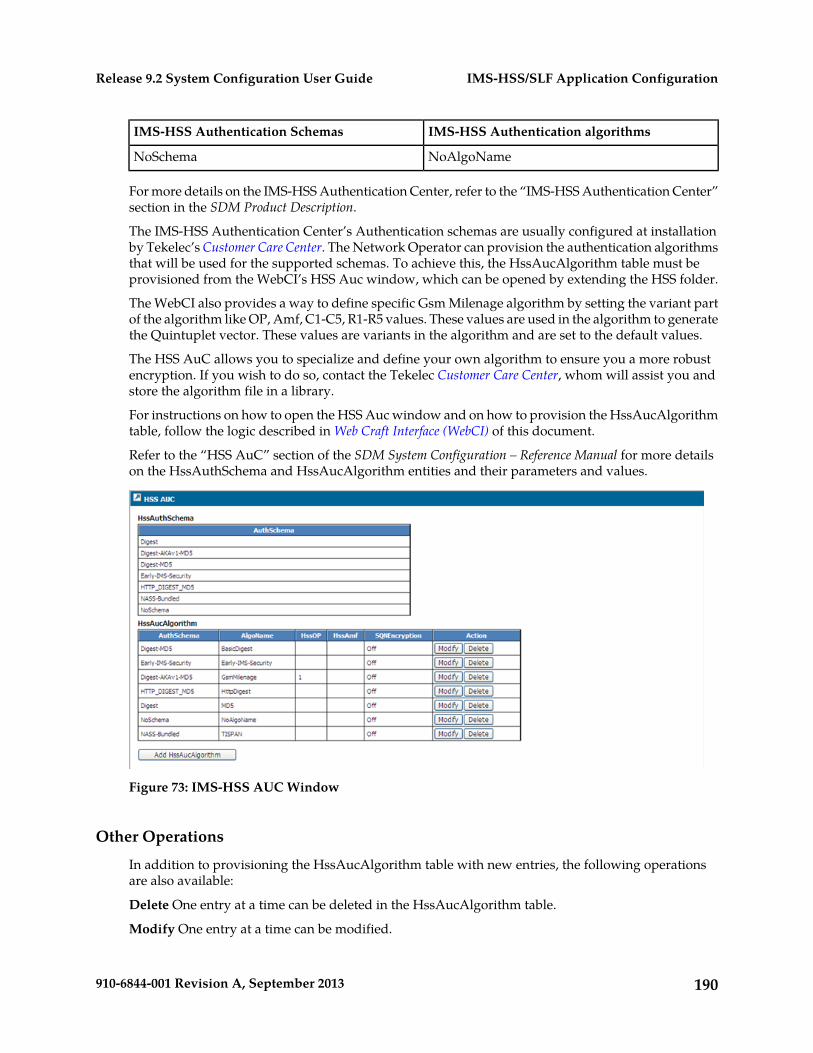
IMS-HSS Authentication algorithmsIMS-HSS Authentication Schemas
NoAlgoNameNoSchema
For more details on the IMS-HSS Authentication Center, refer to the “IMS-HSS Authentication Center”section in the SDM Product Description.
The IMS-HSS Authentication Center’s Authentication schemas are usually configured at installationby Tekelec’s Customer Care Center. The Network Operator can provision the authentication algorithmsthat will be used for the supported schemas. To achieve this, the HssAucAlgorithm table must beprovisioned from the WebCI’s HSS Auc window, which can be opened by extending the HSS folder.
The WebCI also provides a way to define specific Gsm Milenage algorithm by setting the variant partof the algorithm like OP, Amf, C1-C5, R1-R5 values. These values are used in the algorithm to generatethe Quintuplet vector. These values are variants in the algorithm and are set to the default values.
The HSS AuC allows you to specialize and define your own algorithm to ensure you a more robustencryption. If you wish to do so, contact the Tekelec Customer Care Center, whom will assist you andstore the algorithm file in a library.
For instructions on how to open the HSS Auc window and on how to provision the HssAucAlgorithmtable, follow the logic described in Web Craft Interface (WebCI) of this document.
Refer to the “HSS AuC” section of the SDM System Configuration – Reference Manual for more detailson the HssAuthSchema and HssAucAlgorithm entities and their parameters and values.
Figure 73: IMS-HSS AUC Window
Other Operations
In addition to provisioning the HssAucAlgorithm table with new entries, the following operationsare also available:
Delete One entry at a time can be deleted in the HssAucAlgorithm table.
Modify One entry at a time can be modified.
190910-6844-001 Revision A, September 2013
IMS-HSS/SLF Application ConfigurationRelease 9.2 System Configuration User Guide
Configuring IMS-HSS System Features
The following information needs to be defined in order to configure IMS-HSS System Features:
1. Charging Information2. S-CSCF Servers3. Authorized Visited Networks4. AS Permission List
Each of these definitions is identified by a unique ID and can be used by multiple Private Identities.This allows to provision Private Identities (IMPIs) with whichever one of these definitions by simplyreferring to the desired IDs. Refer to the “Viewing/Editing IMS-HSS Subscriber Profiles” sectionof the SDM Monitoring, Maintaining, Troubleshooting – User Guide, for instructions on how toview/edit/provision Private Identities from the WebCI. For instructions on how to provisionPrivate Identities in bulk using XML files, refer to the SDM Subscriber Provisioning – User Guide.
In order to configure these definitions, the HssChargingInfo, HssScscfServer,HssAuthorizedVisitedNetworks, and ASPermList tables must be provisioned from the WebCI’s HSSSystem Features window that can be accessed from the menu’s HSS folder.
Note: These tables must be provisioned prior to being able to provision IMS-HSS Subscriber profiles.
The following operations are also available:
Delete This button is available for each table and only one entry at a time can be deleted.
Note: It is not possible to delete an entry that is still referred by Private Identities (IMS-HSS Subscriberprofiles). Edit those Private Identities and refer to another definition by changing it to the ID of anentry that will remain configured.
Modify This button is available for each table and only one entry at a time can be modified.
191910-6844-001 Revision A, September 2013
IMS-HSS/SLF Application ConfigurationRelease 9.2 System Configuration User Guide
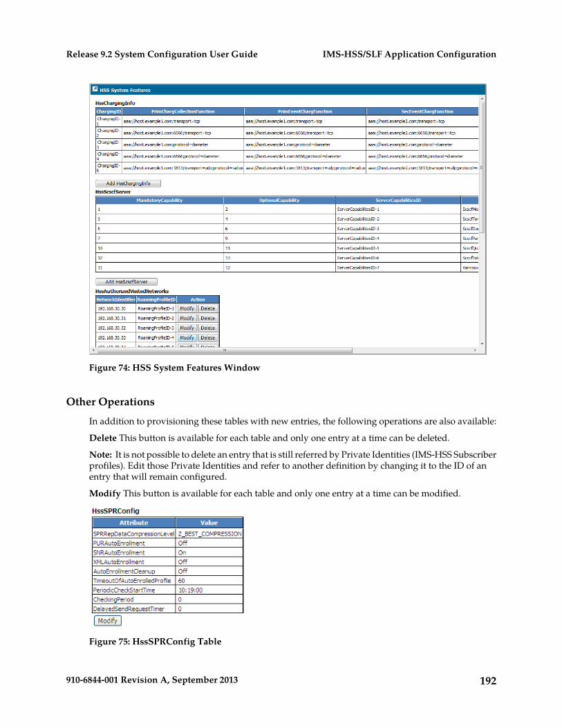
Figure 74: HSS System Features Window
Other Operations
In addition to provisioning these tables with new entries, the following operations are also available:
Delete This button is available for each table and only one entry at a time can be deleted.
Note: It is not possible to delete an entry that is still referred by Private Identities (IMS-HSS Subscriberprofiles). Edit those Private Identities and refer to another definition by changing it to the ID of anentry that will remain configured.
Modify This button is available for each table and only one entry at a time can be modified.
Figure 75: HssSPRConfig Table
192910-6844-001 Revision A, September 2013
IMS-HSS/SLF Application ConfigurationRelease 9.2 System Configuration User Guide
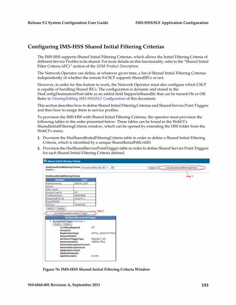
Configuring IMS-HSS Shared Initial Filtering Criterias
The IMS-HSS supports Shared Initial Filtering Criterias, which allows the Initial Filtering Criteria ofdifferent Service Profiles to be shared. For more details on this functionality, refer to the “Shared InitialFilter Criteria (iFC)” section of the SDM Product Description.
The Network Operator can define, at whatever given time, a list of Shared Initial Filtering Criteriasindependently of whether the remote S-CSCF supports SharedIFCs or not.
However, in order for this feature to work, the Network Operator must also configure which CSCFis capable of handling Shared IFCs. The configuration is dynamic and stored in theHssConfigDestinationHost table as an added field SupportsSharedIfc that can be turned On or Off.Refer to Viewing/Editing IMS-HSS/SLF Configuration of this document.
This section describes how to define Shared Initial Filtering Criterias and Shared Service Point Triggersand then how to assign them to service profiles.
To provision the IMS-HSS with Shared Initial Filtering Criterias, the operator must provision thefollowing tables in the order presented below. These tables can be found in the WebCI’sSharedInitialFilteringCriteria window, which can be opened by extending the HSS folder from theWebCI’s menu.
1. Provision the HssSharedInitialFilteringCriteria table in order to define a Shared Initial FilteringCriteria, which is identified by a unique SharedInitialFiltCritID.
2. Provision the HssSharedServicePointTrigger table in order to define Shared Service Point Triggersfor each Shared Initial Filtering Criteria defined.
Figure 76: IMS-HSS Shared Initial Filtering Criteria Window
193910-6844-001 Revision A, September 2013
IMS-HSS/SLF Application ConfigurationRelease 9.2 System Configuration User Guide
Once Shared IFCs have been defined, they can be assigned to IMS-HSS Service Profiles by linkingthe identifier of a Shared IFC to a IMS-HSS Service Profile. The Network Operator can achieve thisby entering a SharedInitialFiltCritID as the value of the HssServiceProfile’s InitialFilterCriteriaattribute when provisioning a IMS-HSS service profile. For instructions on how to provision/editIMS-HSS service profiles from the WebCI, refer to the “Viewing/Editing IMS-HSS SubscriberProfiles” section of the SDM Monitoring, Maintaining, Troubleshooting – User Guide. For instructionson how to provision IMS-HSS Subscriber Profiles in bulk using XML files, refer to the SDM SubscriberProvisioning – User Guide.
194910-6844-001 Revision A, September 2013
IMS-HSS/SLF Application ConfigurationRelease 9.2 System Configuration User Guide
Chapter
8AAA Application Configuration
This chapter outlines the procedures to configurethe AAA.
Topics:
• Introduction.....196• Configuring the AAA.....196
195910-6844-001 Revision A, September 2013
Introduction
This chapter outlines the procedures to configure the AAA. The procedures in this chapter show youhow to view/modify the AAA configuration, provision the Dynamic Address Allocation Policies andIP Address pools. To perform the tasks in the following table, refer to the corresponding section withinthis chapter.
Table 20: AAA Configuration Tasks
Task
View/Editing AAA Configuration
Configuring System and NAS Accounting Servers, Network Access Servers, System and NASAuthentication Servers
Provision Address Allocation Policies (AAA Provisioning Configuration)
Requirements: Log in to a WebCI session with a username and password.
For details on AAA Configuration and Dynamic Address Allocation Policies refer to the “AAA”chapter in the SDM System Configuration - Reference Manual.
Configuring the AAA
The AAA is usually configured at installation by Tekelec’s Customer Care Center. The followinginformation needs to be configured at installation in order to run the AAA application:
• AAA configuration information• On/Off flags to enable/disable the AAA application and the Accounting and Authentication Proxy
Modes.• The network information (Server port, AAA Listen Port, Server IP Address, AAA Listen IP Address,
etc.) needed for the AAA to communicate with the peer servers: Network Access Servers, SystemAccounting Servers, NAS Accounting Servers, System Authentication Servers, NAS AuthenticationServers.
• AAA Address Allocation Policies and IP Address pools.
Viewing/Editing AAA Configuration
The operator can view all of the AAA configuration information from the WebCI’s AAA folder, byopening the AAA Configuration window. Some of this information can be modified and networkinformation can be deleted/added.
IMPORTANT: Take note that prior to making any changes (adding, modifying, deleting) to the AAAConfiguration data during running-time, the IMS-HSS service must first be stopped. Once the changesare made, the IMS-HSS service can be started once again. This will affect traffic, so make sure toperform this during down time if necessary. Refer to section “Starting and Stopping Services on a
196910-6844-001 Revision A, September 2013
AAA Application ConfigurationRelease 9.2 System Configuration User Guide
blade” of the SDM Monitoring, Maintaining, Troubleshooting – User Guide for more information on howto stop a service.
The AAA Config table can be edited, by clicking on the Modify button located underneath it.
In order to edit the network information, you must delete the entry by clicking on the Delete buttonlocated in the same row as the entry you wish to modify and re-create it by clicking on the Add button.
Add AAA Network Access ServersThe following rules need to be followed when configuring the AAA Network Access Servers table:
1. To use two different ports, two entries must be provisioned in the AAA Network Access Serverstable for one single NAS.
Both of these entries can have the same NASIPAddress and the same AAAListenIPAddress.
2. To use one single port, only one entry needs to be configured in the AAA Network Access Serverstable for one single NAS, but the NAS must be able to send both Access-Request andAccounting-Request messages to the same port.
197910-6844-001 Revision A, September 2013
AAA Application ConfigurationRelease 9.2 System Configuration User Guide
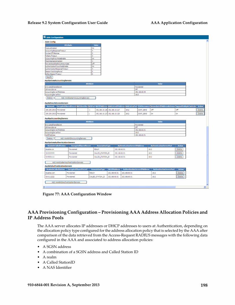
Figure 77: AAA Configuration Window
AAA Provisioning Configuration – Provisioning AAA Address Allocation Policies andIP Address Pools
The AAA server allocates IP addresses or DHCP addresses to users at Authentication, depending onthe allocation policy type configured for the address allocation policy that is selected by the AAA aftercomparison of the data retrieved from the Access-Request RADIUS messages with the following dataconfigured in the AAA and associated to address allocation policies:
• A SGSN address• A combination of a SGSN address and Called Station ID• A realm• A Called StationID• A NAS Identifier
198910-6844-001 Revision A, September 2013
AAA Application ConfigurationRelease 9.2 System Configuration User Guide
For more details on the allocation of IP addresses/DHCP addresses, refer to the “AAA AddressAllocation” section in the SDM Product Description document.
By default, the AAA server provides dynamic address allocations to users upon reception ofAccess-Request messages. However, the AAA’s address allocation functionality can also be donestatically, by allowing the Network Operator to provision a AAA user with static IP addresses for aspecific Called Station (APN) or Realm. Moreover, if desired, a static IP address can also be assignedto a Calling Station (MSISDN). This allows the operator to assign an IP address per Calling Station(MSISDN) for a specific Called Station (APN). This can be achieved by executing the AssignIPAddress()operation. The ReleaseIPAddress() operation is also available to allow the Network Operator to releasea static IP Address. For more details on these two operations, refer to the “AAA Operations” sectionof the SDM System Configuration – Reference Manual. For instructions on how to execute these operationsfrom the WebCI, refer to the “Viewing/Editing AAA Subscriber Profiles” section in the SDM Monitoring,Maintaining, Troubleshooting – User Guide.
To configure the AAA’s dynamic address allocation functionality, the operator must provision thefollowing tables in the order presented below. These tables can be found in the WebCI’s AAAProvisioning Configuration window, which can be opened by extending the AAA folder from theWebCI’s menu.
1. Provision the AAAAddressAllocationPolicy table in order to define Address Allocation Policies:a) Allocation Policy Nameb) Allocation Policy Type:
• ADDRESS_POOL: The AAA allocates an IP address by sending it back in the Access-Acceptmessage. An allocation policy of this type is an IP address pool, for which IP address rangesmust be provisioned. In this case, step 2 must be followed.
• DHCP_IDENT: The AAA sends back a DHCP address instead of an IP address in theAccess-Accept message.
• NO_IP_ALLOC: The AAA doesn’t allocate an IP address.
c) Use Full Address Pool (On/Off): this indicates whether or not the AAA must continuouslyre-use evenly the whole IP address range or not for this address allocation policy, in order toachieve even allocation of IP Addresses.
For more details on this, refer to the “Even allocation of IP Addresses” section in the SDMProduct Description document.
d) Audit Logging Enabled (On/Off): The AAA can generate logs each time it allocates andde-allocates IP addresses for selected address pools.
The AuditLoggingEnabled parameter allows the Network Operator to enable/disable thegeneration of audit loggings. These logs are stored in audit files, which can be managed andconfigured by the Network Operator through the CLI or WebCI. For instructions on how tomanage audit files, refer to the “Configuring and Enabling/Disabling Audit logging” in theSDM Monitoring, Maintaining, Troubleshooting – User Guide.
2. Provision the AAAAddressAllocationRanges table in order to define IP Address ranges for eachIP address pool defined (address allocation policy defined with Allocation Policy Type:‘ADDRESS_POOL’).
Note that it is possible to have many range entries for an IP address pool. IP Address ranges onlyneed to be defined for address allocation policies of type ‘ADDRESS_POOL’ and the WebCI rejectsthe provisioning of IP Address ranges for address allocation policies of any other type(NO_IP_ALLOC and DHCP_IDENT).
199910-6844-001 Revision A, September 2013
AAA Application ConfigurationRelease 9.2 System Configuration User Guide
3. Provision the AAAAddressAllocationAssociation table in order to associate each address allocationpolicy to one of the following association value and type:
Table 21: Association types
Association TypeAuxiliary valueAssociation value
SGSN Address---------------------------<SGSN address>
SGSN and Called Station<Called Station Id><SGSN address>
REALM---------------------------<Realm>
CALLED_STATION-ID---------------------------<Called-Station_id>
NAS Identifier---------------------------<NAS Identifier>
SYSTEM-----------------------------------------------------------------
One entry must absolutely be provisioned to associate an address allocation policy with the defaultAssociationType ‘SYSTEM’. The address allocation policy associated to this association type is thedefault allocation policy.
In order to make an address allocation policy selection, the AAA compares the data received inthe Access-Request with the association values defined in this table. When a match is found, theAAA uses the address allocation policy associated to the matching association value.
When a match is not found, the AAA uses the address allocation policy that is associated to theAssociationType: ‘SYSTEM’.
Note: An allocation policy may be associated with one or more Called Station Ids or one or moreRealms but may not be associated with a combination of Realms and Called Station Ids.
Provisioning this table also allows you to associate each address allocation policy with an AccessLevel, which indicates whether the address allocation policy can only be used for users who passauthentication or whether it can be used for users who don’t pass authentication. For more detailson this, refer to the “Extension to handle Restricted Access for Unauthorized Users” section of theSDM Product Description.
For more information on the tables to be provisioned and their parameter values, refer to the “AAAProvisioning Configuration” section of the SDM System Configuration - Reference Manual.
200910-6844-001 Revision A, September 2013
AAA Application ConfigurationRelease 9.2 System Configuration User Guide
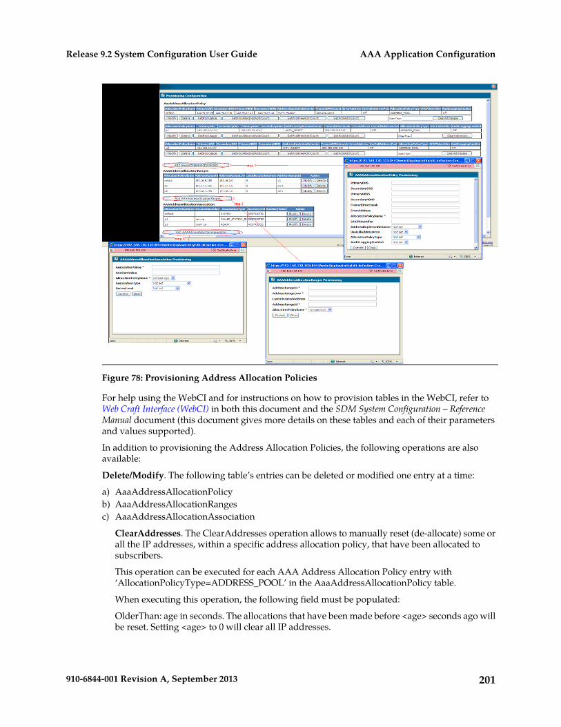
Figure 78: Provisioning Address Allocation Policies
For help using the WebCI and for instructions on how to provision tables in the WebCI, refer toWeb Craft Interface (WebCI) in both this document and the SDM System Configuration – ReferenceManual document (this document gives more details on these tables and each of their parametersand values supported).
In addition to provisioning the Address Allocation Policies, the following operations are alsoavailable:
Delete/Modify. The following table’s entries can be deleted or modified one entry at a time:
a) AaaAddressAllocationPolicyb) AaaAddressAllocationRangesc) AaaAddressAllocationAssociation
ClearAddresses. The ClearAddresses operation allows to manually reset (de-allocate) some orall the IP addresses, within a specific address allocation policy, that have been allocated tosubscribers.
This operation can be executed for each AAA Address Allocation Policy entry with‘AllocationPolicyType=ADDRESS_POOL’ in the AaaAddressAllocationPolicy table.
When executing this operation, the following field must be populated:
OlderThan: age in seconds. The allocations that have been made before <age> seconds ago willbe reset. Setting <age> to 0 will clear all IP addresses.
201910-6844-001 Revision A, September 2013
AAA Application ConfigurationRelease 9.2 System Configuration User Guide
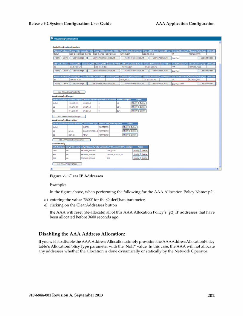
Figure 79: Clear IP Addresses
Example:
In the figure above, when performing the following for the AAA Allocation Policy Name: p2:
d) entering the value ‘3600’ for the OlderThan parametere) clicking on the ClearAddresses button
the AAA will reset (de-allocate) all of this AAA Allocation Policy’s (p2) IP addresses that havebeen allocated before 3600 seconds ago.
Disabling the AAA Address Allocation:If you wish to disable the AAA Address Allocation, simply provision the AAAAddressAllocationPolicytable’s AllocationPolicyType parameter with the ‘NoIP’ value. In this case, the AAA will not allocateany addresses whether the allocation is done dynamically or statically by the Network Operator.
202910-6844-001 Revision A, September 2013
AAA Application ConfigurationRelease 9.2 System Configuration User Guide
Chapter
9DNS Enum server configuration
This chapter describes the configuration of the DNSEnum server.
Topics:
• DNS ENUM Server Configuration.....204
203910-6844-001 Revision A, September 2013
DNS ENUM Server Configuration
The DNS ENUM Server is usually configured at installation by Tekelec’s Customer Care Center whenthe functionality has already been purchased. The following information needs to be configured torun the DNS ENUM Server:
• The maximum number of users that can be provisioned per Subscription (SubscriptionID).• On/Off flags to enable/disable the feature that supports the ENUM Server.• The DNS ENUM Listen Address and Port.• The Domain Name List configuration.
The operator can view all of this configuration information from the WebCI’s ENUM Server folder,by opening the ENUM Server Configuration window and the Provisioning Configuration window.Some of this information can be modified and even added and deleted.
Important: Take note that prior to changing the activation status of the ENUM Serverfunctionality (enable/disable) during running-time, the HSS service must first be stopped.Once the changes are made, the HSS service can be started once again. This will affecttraffic, so make sure to perform this during low traffic periods.
To view, edit, add or delete some DNS ENUM Server configuration parameters, you must access thefollowing windows:
• ENUM Server Configuration window, which displays the ENUM Server configuration table andthe DNS Listen Addresses Configuration table.
• The Provisioning Configuration window, which displays the Domain Name List Configurationtable and the DNS ENUM User Template table. The DNSEnumUserTemplate table allows to definetemplates that can be used by multiple ENUM profiles. Each ENUM profile can be provisioned torefer to a template defined in this table.
These windows can be accessed by extending the ENUM Server folder in the WebCI’s menu.
For help using the WebCI and for instructions on how to provision tables in the WebCI, refer toWeb Craft Interface (WebCI) in this document.
For more details on the parameters of each one of these windows, refer to the “ENUM” chapter ofthe SDM System Configuration – Reference Manual.
Once the DNS ENUM Server has been configured properly, ENUM Users can be provisioned inthe system. To achieve this from the WebCI, refer to the “Viewing/Editing DNS ENUM Users”section of the SDM Monitoring, Maintenance, Troubleshooting – User Guide document. To provisionDNS ENUM Users in bulk, refer to the IMS-HSS Subscriber provisioning XML scripts in the SDMSubscriber Provisioning – User Guide.
204910-6844-001 Revision A, September 2013
DNS Enum server configurationRelease 9.2 System Configuration User Guide
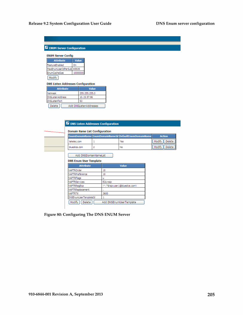
Figure 80: Configuring The DNS ENUM Server
205910-6844-001 Revision A, September 2013
DNS Enum server configurationRelease 9.2 System Configuration User Guide
Chapter
10HSS/AAA Support for Early IMS Security Configuration
This chapter describes the configuration of theHSS/AAA Support for Early IMS Security.
Topics:
• Introduction.....207• Other Operations.....208
206910-6844-001 Revision A, September 2013
Introduction
The Tekelec HSS/AAA support the security mechanisms for early IMS implementations, as per theTR33.978 standard.
This means that upon receiving, from an Early-IMS Configured APN, a RADIUS Accounting RequestSTART message, the HSS/AAA can send back to the GGSN an Accounting-Response. For more detailson the SDM’s behavior when receiving messages from the Early IMS APN, refer to the “HSS/AAASupport for IMS Security” section in the SDM Product Description.
In order to configure the HSS/AAA’s Early IMS Security capability, the Network Operator mustprovision the AaaAPNConfig table, by opening the AAA Provisioning Configuration window fromthe WebCI’s AAA folder.
The AaaAPNConfig table allows the operator to configure the following for a Called Station ID:
• Set the Early IMS Security feature ON/OFF. By default, it is set to ‘Off’.• Select the action the AAA must take in case of Early IMS Security failure.• Set the attribute (CallingStationId, IMSI, User Name) for which the HSS must find an IMPI that
matches.
For more details on the AaaAPNConfig table’s attributes and their values, refer to the “AAAProvisioning Configuration” section in the SDM System Configuration - Reference Manual.
In addition, the Network Operator must provision the Private Identities (IMPIs), for which theAAA may receive messages from the Early IMS Network, with the following values:
• ‘Early-IMS-Security’ value for the AlgoName parameter• ‘On’ value for the Early-IMS-Security flag
For instructions on how to provision a HSS Private Identity (IMPI), refer to the “Viewing/EditingHSS Subscriber Profiles” section in the SDM Monitoring, Maintaining, Troubleshooting – User Guide.
The figure hereunder shows the AaaAPNConfig table from the WebCI.
207910-6844-001 Revision A, September 2013
HSS/AAA Support for Early IMS SecurityConfiguration
Release 9.2 System Configuration User Guide
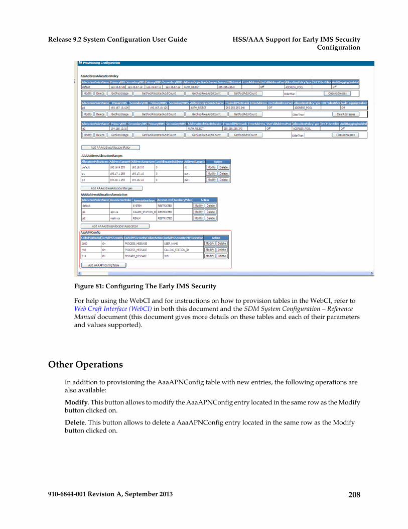
Figure 81: Configuring The Early IMS Security
For help using the WebCI and for instructions on how to provision tables in the WebCI, refer toWeb Craft Interface (WebCI) in both this document and the SDM System Configuration – ReferenceManual document (this document gives more details on these tables and each of their parametersand values supported).
Other Operations
In addition to provisioning the AaaAPNConfig table with new entries, the following operations arealso available:
Modify. This button allows to modify the AaaAPNConfig entry located in the same row as the Modifybutton clicked on.
Delete. This button allows to delete a AaaAPNConfig entry located in the same row as the Modifybutton clicked on.
208910-6844-001 Revision A, September 2013
HSS/AAA Support for Early IMS SecurityConfiguration
Release 9.2 System Configuration User Guide
Chapter
11LTE-HSS Application Configuration
This chapter outlines the procedures to configurethe LTE-HSS.
Topics:
• Introduction.....210• Configuring the LTE-HSS.....210• Viewing/Editing LTE-HSS Configuration.....210• Configuring the LTE HSS PLMN.....212• Configuring the LTE-HSS GMLC Node List...212• Configuring the LTE-HSS Realms.....213• Introduction to LTE-HSS System Features .....214• Viewing/Editing LTE-HSS Options.....214• Configure Diameter Relay Agent.....215
209910-6844-001 Revision A, September 2013
Introduction
The procedures in this chapter show you how to view/add/modify the LTE-HSS configuration, andconfigure the HSS PLMN for roaming purposes. To perform the tasks in the following table, refer tothe corresponding section within this chapter.
Table 22: LTE-HSS Configuration Tasks
Task
Viewing/Editing LTE HSS Configuration
Configuring the LTE HSS PLMN
Configuring the LTE HSS GMLC Node List
Configuring the LTE HSS Realms
Requirements: Log in to a WebCI session with a username and password.
For details on the parameters used to configure the LTE-HSS, HSS PLMN, GMLC Node List andLTE-HSS Realms refer to the “LTE-HSS” section in the SDM System Configuration - Reference Manual.
Configuring the LTE-HSS
The LTE-HSS is usually configured at installation by Tekelec’s Customer Care Center.
The following information needs to be configured at installation in order to run the LTE-HSS application:
1. LTE-HSS configuration information.
The LTE-HSS configuration data can be displayed/edited from the WebCI, as described below.
2. The network information (Local FQDN, LocalSTCPPort, LocalTCPPort, OriginatingRealm,SCTPTransport, TCPTransport, TCP Listen Address, SCTP Listen Address, Destination Realms,Destination Hosts, etc.) needed for the LTE-HSS to communicate with the peer servers.
The LTE-HSS network configuration data can be displayed/edited/added from the WebCI, asdescribed below.
Viewing/Editing LTE-HSS Configuration
The operator can view all of the HSS configuration information from the WebCI’s LTEHSS folder, byopening the LTEHSS Configuration window. Some of this information can be modified and networkinformation can be deleted/added.
Important: Prior to making any changes (modifying) to the LTE-HSS Options dataduring running-time, the LTE-HSS service must first be stopped. Once the changes are
210910-6844-001 Revision A, September 2013
LTE-HSS Application ConfigurationRelease 9.2 System Configuration User Guide
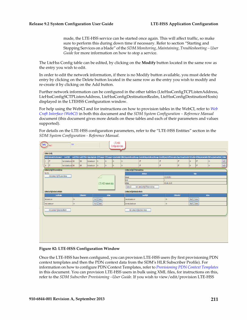
made, the LTE-HSS service can be started once again. This will affect traffic, so makesure to perform this during down time if necessary. Refer to section “Starting andStopping Services on a blade” of the SDM Monitoring, Maintaining, Troubleshooting – UserGuide for more information on how to stop a service.
The LteHss Config table can be edited, by clicking on the Modify button located in the same row asthe entry you wish to edit.
In order to edit the network information, if there is no Modify button available, you must delete theentry by clicking on the Delete button located in the same row as the entry you wish to modify andre-create it by clicking on the Add button.
Further network information can be configured in the other tables (LteHssConfigTCPListenAddress,LteHssConfigSCTPListenAddress, LteHssConfigDestinationRealm, LteHssConfigDestinationHosts)displayed in the LTEHSS Configuration window.
For help using the WebCI and for instructions on how to provision tables in the WebCI, refer to WebCraft Interface (WebCI) in both this document and the SDM System Configuration – Reference Manualdocument (this document gives more details on these tables and each of their parameters and valuessupported).
For details on the LTE-HSS configuration parameters, refer to the “LTE-HSS Entities” section in theSDM System Configuration - Reference Manual.
Figure 82: LTE-HSS Configuration Window
Once the LTE-HSS has been configured, you can provision LTE-HSS users (by first provisioning PDNcontext templates and then the PDN context data from the SDM’s HLR Subscriber Profile). Forinformation on how to configure PDN Context Templates, refer to Provisioning PDN Context Templatesin this document. You can provision LTE-HSS users in bulk using XML files, for instructions on this,refer to the SDM Subscriber Provisioning –User Guide. If you wish to view/edit/provision LTE-HSS
211910-6844-001 Revision A, September 2013
LTE-HSS Application ConfigurationRelease 9.2 System Configuration User Guide
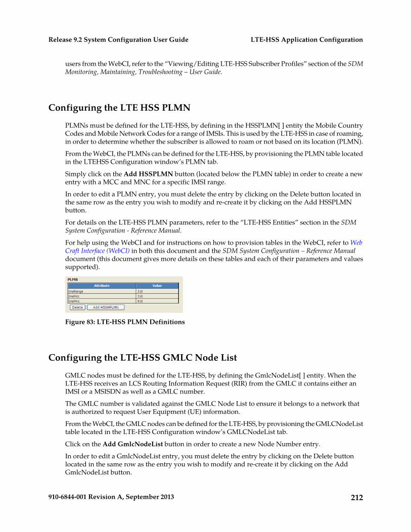
users from the WebCI, refer to the “Viewing/Editing LTE-HSS Subscriber Profiles” section of the SDMMonitoring, Maintaining, Troubleshooting – User Guide.
Configuring the LTE HSS PLMN
PLMNs must be defined for the LTE-HSS, by defining in the HSSPLMN[ ] entity the Mobile CountryCodes and Mobile Network Codes for a range of IMSIs. This is used by the LTE-HSS in case of roaming,in order to determine whether the subscriber is allowed to roam or not based on its location (PLMN).
From the WebCI, the PLMNs can be defined for the LTE-HSS, by provisioning the PLMN table locatedin the LTEHSS Configuration window’s PLMN tab.
Simply click on the Add HSSPLMN button (located below the PLMN table) in order to create a newentry with a MCC and MNC for a specific IMSI range.
In order to edit a PLMN entry, you must delete the entry by clicking on the Delete button located inthe same row as the entry you wish to modify and re-create it by clicking on the Add HSSPLMNbutton.
For details on the LTE-HSS PLMN parameters, refer to the “LTE-HSS Entities” section in the SDMSystem Configuration - Reference Manual.
For help using the WebCI and for instructions on how to provision tables in the WebCI, refer to WebCraft Interface (WebCI) in both this document and the SDM System Configuration – Reference Manualdocument (this document gives more details on these tables and each of their parameters and valuessupported).
Figure 83: LTE-HSS PLMN Definitions
Configuring the LTE-HSS GMLC Node List
GMLC nodes must be defined for the LTE-HSS, by defining the GmlcNodeList[ ] entity. When theLTE-HSS receives an LCS Routing Information Request (RIR) from the GMLC it contains either anIMSI or a MSISDN as well as a GMLC number.
The GMLC number is validated against the GMLC Node List to ensure it belongs to a network thatis authorized to request User Equipment (UE) information.
From the WebCI, the GMLC nodes can be defined for the LTE-HSS, by provisioning the GMLCNodeListtable located in the LTE-HSS Configuration window’s GMLCNodeList tab.
Click on the Add GmlcNodeList button in order to create a new Node Number entry.
In order to edit a GmlcNodeList entry, you must delete the entry by clicking on the Delete buttonlocated in the same row as the entry you wish to modify and re-create it by clicking on the AddGmlcNodeList button.
212910-6844-001 Revision A, September 2013
LTE-HSS Application ConfigurationRelease 9.2 System Configuration User Guide
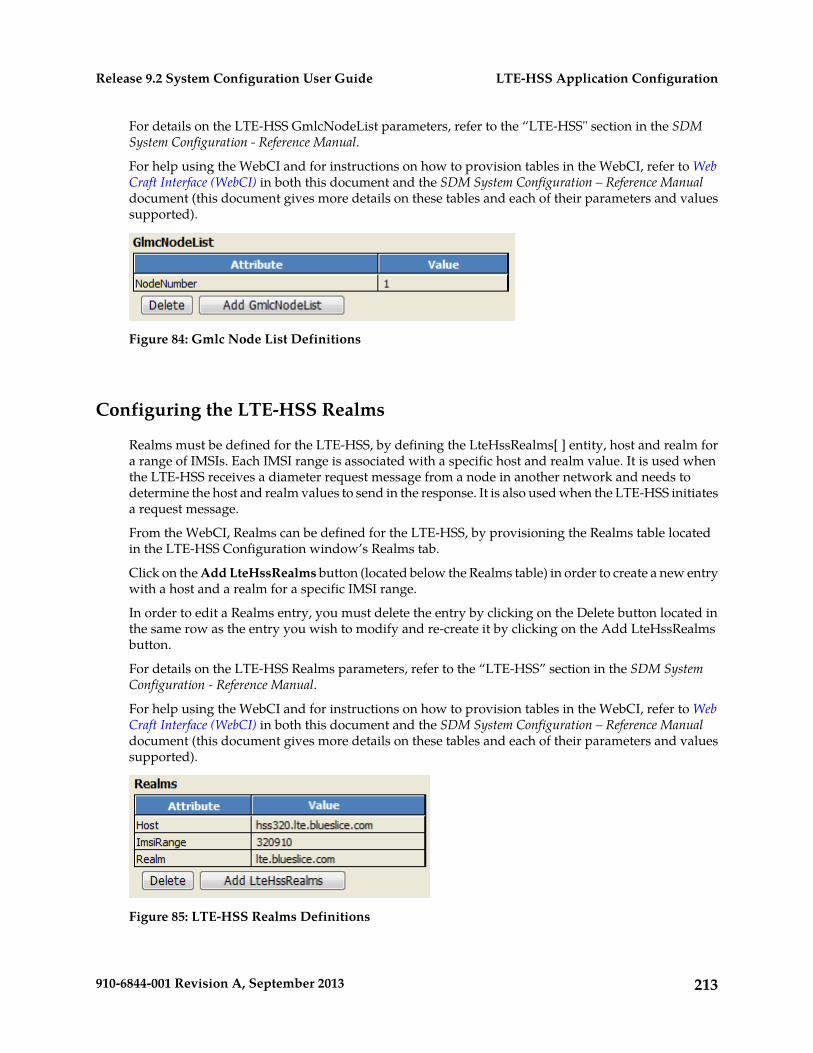
For details on the LTE-HSS GmlcNodeList parameters, refer to the “LTE-HSS" section in the SDMSystem Configuration - Reference Manual.
For help using the WebCI and for instructions on how to provision tables in the WebCI, refer to WebCraft Interface (WebCI) in both this document and the SDM System Configuration – Reference Manualdocument (this document gives more details on these tables and each of their parameters and valuessupported).
Figure 84: Gmlc Node List Definitions
Configuring the LTE-HSS Realms
Realms must be defined for the LTE-HSS, by defining the LteHssRealms[ ] entity, host and realm fora range of IMSIs. Each IMSI range is associated with a specific host and realm value. It is used whenthe LTE-HSS receives a diameter request message from a node in another network and needs todetermine the host and realm values to send in the response. It is also used when the LTE-HSS initiatesa request message.
From the WebCI, Realms can be defined for the LTE-HSS, by provisioning the Realms table locatedin the LTE-HSS Configuration window’s Realms tab.
Click on the Add LteHssRealms button (located below the Realms table) in order to create a new entrywith a host and a realm for a specific IMSI range.
In order to edit a Realms entry, you must delete the entry by clicking on the Delete button located inthe same row as the entry you wish to modify and re-create it by clicking on the Add LteHssRealmsbutton.
For details on the LTE-HSS Realms parameters, refer to the “LTE-HSS” section in the SDM SystemConfiguration - Reference Manual.
For help using the WebCI and for instructions on how to provision tables in the WebCI, refer to WebCraft Interface (WebCI) in both this document and the SDM System Configuration – Reference Manualdocument (this document gives more details on these tables and each of their parameters and valuessupported).
Figure 85: LTE-HSS Realms Definitions
213910-6844-001 Revision A, September 2013
LTE-HSS Application ConfigurationRelease 9.2 System Configuration User Guide
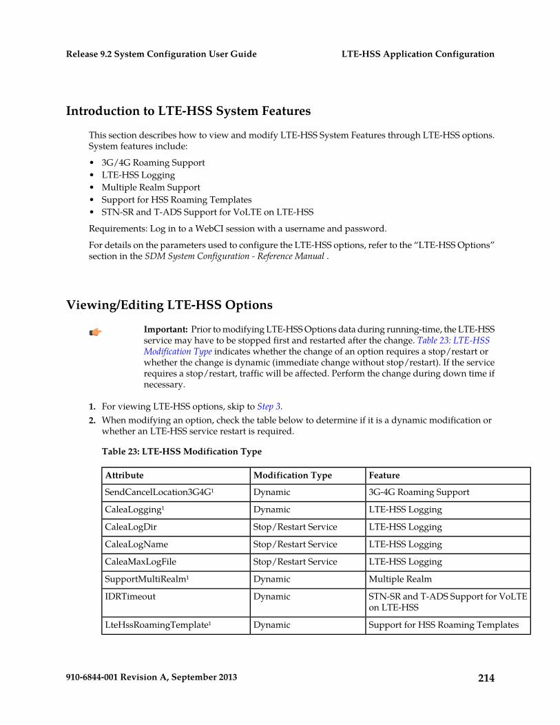
Introduction to LTE-HSS System Features
This section describes how to view and modify LTE-HSS System Features through LTE-HSS options.System features include:
• 3G/4G Roaming Support• LTE-HSS Logging• Multiple Realm Support• Support for HSS Roaming Templates• STN-SR and T-ADS Support for VoLTE on LTE-HSS
Requirements: Log in to a WebCI session with a username and password.
For details on the parameters used to configure the LTE-HSS options, refer to the “LTE-HSS Options”section in the SDM System Configuration - Reference Manual .
Viewing/Editing LTE-HSS Options
Important: Prior to modifying LTE-HSS Options data during running-time, the LTE-HSSservice may have to be stopped first and restarted after the change. Table 23: LTE-HSSModification Type indicates whether the change of an option requires a stop/restart orwhether the change is dynamic (immediate change without stop/restart). If the servicerequires a stop/restart, traffic will be affected. Perform the change during down time ifnecessary.
1. For viewing LTE-HSS options, skip to Step 3.2. When modifying an option, check the table below to determine if it is a dynamic modification or
whether an LTE-HSS service restart is required.
Table 23: LTE-HSS Modification Type
FeatureModification TypeAttribute
3G-4G Roaming SupportDynamicSendCancelLocation3G4G¹
LTE-HSS LoggingDynamicCaleaLogging¹
LTE-HSS LoggingStop/Restart ServiceCaleaLogDir
LTE-HSS LoggingStop/Restart ServiceCaleaLogName
LTE-HSS LoggingStop/Restart ServiceCaleaMaxLogFile
Multiple RealmDynamicSupportMultiRealm¹
STN-SR and T-ADS Support for VoLTEon LTE-HSS
DynamicIDRTimeout
Support for HSS Roaming TemplatesDynamicLteHssRoamingTemplate¹
214910-6844-001 Revision A, September 2013
LTE-HSS Application ConfigurationRelease 9.2 System Configuration User Guide
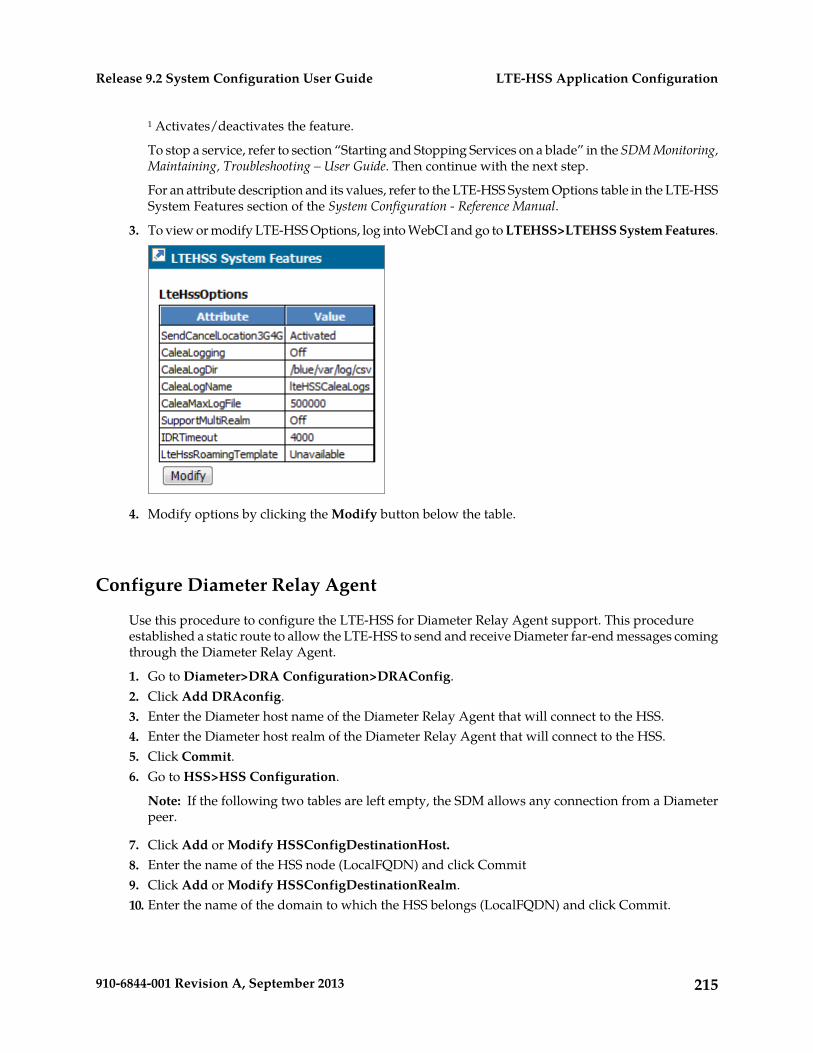
¹ Activates/deactivates the feature.
To stop a service, refer to section “Starting and Stopping Services on a blade” in the SDM Monitoring,Maintaining, Troubleshooting – User Guide. Then continue with the next step.
For an attribute description and its values, refer to the LTE-HSS System Options table in the LTE-HSSSystem Features section of the System Configuration - Reference Manual.
3. To view or modify LTE-HSS Options, log into WebCI and go to LTEHSS>LTEHSS System Features.
4. Modify options by clicking the Modify button below the table.
Configure Diameter Relay Agent
Use this procedure to configure the LTE-HSS for Diameter Relay Agent support. This procedureestablished a static route to allow the LTE-HSS to send and receive Diameter far-end messages comingthrough the Diameter Relay Agent.
1. Go to Diameter>DRA Configuration>DRAConfig.2. Click Add DRAconfig.3. Enter the Diameter host name of the Diameter Relay Agent that will connect to the HSS.4. Enter the Diameter host realm of the Diameter Relay Agent that will connect to the HSS.5. Click Commit.6. Go to HSS>HSS Configuration.
Note: If the following two tables are left empty, the SDM allows any connection from a Diameterpeer.
7. Click Add or Modify HSSConfigDestinationHost.8. Enter the name of the HSS node (LocalFQDN) and click Commit9. Click Add or Modify HSSConfigDestinationRealm.10. Enter the name of the domain to which the HSS belongs (LocalFQDN) and click Commit.
215910-6844-001 Revision A, September 2013
LTE-HSS Application ConfigurationRelease 9.2 System Configuration User Guide
Chapter
12EIR Application Configuration
This chapter provides the procedures to configurethe Equipment Identity Register (EIR) through theWebCI.
Topics:
• Introduction.....217• Configure EIR for ECR Message Processing....217• Configure Global EIR Settings.....218• Configure EIR response types.....218• Configure EIR IMEI Equipment Status.....219• Create Unbound IMEI/IMSI Association.....219• Bind IMEI and IMEI/IMSI Associations to a
Subscription.....220• Configure EIR Bound IMEI Equipment
Status.....220• Create Bound IMEI/IMSI Association.....220• Create EIR IMEI Range.....221
216910-6844-001 Revision A, September 2013
Introduction
Note: Some configurations require the stop of all processes on the blade and a restart of the blade toimplement the changes. Read the procedure carefully prior to starting the configuration.
• For help using the WebCI and for instructions on how to provision tables in the WebCI, refer toWeb Craft Interface (WebCI)
• To stop and restart a process, refer to section "Starting and Stopping Services on a blade" in theSDM Monitoring, Maintaining, Troubleshooting User Guide.
• For table descriptions, configuration values, rules, and all other operations, refer to the indicatedentity table in the SDM System Configuration Reference Manual.
Configure EIR for ECR Message Processing
Use this procedure for set up EIR for ECR Message Processing.
1. Stop the LTE-HSS service that is running on the same blade as the EIR service before configuringthe EirGlobalConfig table. Refer to the "Stop/Start one single service on a blade" procedure in theSDM Monitoring, Maintaining, Troubleshooting User Guide.
2. Configure global EIR settings to define the common EIR configuration that will be used by all EIRapplications belonging to the same platform.
3. Restart the LTE-HSS service. Refer to the "Stop/Start one single service on a blade" procedure inthe SDM Monitoring, Maintaining, Troubleshooting User Guide.
4. Configure EIR response types to define which equipment status will be returned in theMECheck-Identity answer if an IMEI has been configured in more than one list (White/Grey/Black).
5. Configure EIR IMEI equipment status to define new unbound IMEIs and to associate them withtheir equipment status. Use this procedure also to modify an IMEI‘s equipment status or softwareversion, or to delete an IMEI from the EirImeiEquipStatus table.
6. Create unbound IMEI/IMSI association to associate an unbound mobile equipment IMEI (fromthe EirImeiEquipStatus table) with a subscriber‘s IMSI. This procedure can also associate severalIMEIs to the same IMSI, and several IMSIs to the same IMEI.
7. Bind IMEI and IMEI/IMSI associations to a subscription to link other front-end profiles to thesubscription.
8. Configure EIR IMEI equipment status to define new bound IMEIs and to associate them with theirequipment status. Use this procedure also to modify a bound IMEI‘s equipment status or softwareversion, or to delete a bound IMEI from the EirBoundImeiEquipStatus table.
9. Create bound IMEI/IMSI association to associate a bound mobile equipment IMEI (from theEirBoundImeiEquipStatus table) with a subscriber‘s IMSI. This procedure can also associate severalbound IMEIs to the same IMSI, and several IMSIs to the same bound IMEI.
10. Create EIR IMEI range to define an IMEI range for an associated equipment status. The range canoverlap with another range, which can have a different equipment status configuration.
217910-6844-001 Revision A, September 2013
EIR Application ConfigurationRelease 9.2 System Configuration User Guide
Configure Global EIR Settings
Use this procedure to define the common EIR settings in The EirGlobalConfig table. These settingswill be used by all EIR applications belonging to the same platform.
Requirements:
• The LTE-HSS service that is running on the same blade as the EIR service must be stopped priorto configuring the EirGlobalConfig table.
• The LTE-HSS service must be restarted before the EIR changes can take effect.• For both procedures, refer to procedure Stop/Start one single service on a blade in the Monitoring,
Maintaining, Troubleshooting User Guide• The EirGlobalConfig table must have exactly one entry at service startup.
1. Go to EIR>EIR Configuration>EirGlobalConfig.2. Click Modify in the EIRGlobalConfig table.
The EirGlobalConfig Provisioning pop-up window opens.3. Enter or select the information for each field:
• Enter the system-wide default mobile network code (MNC)• Enter the system-wide default mobile country code (MCC)• Select the system-wide EIR response type to be returned for IMEIs that are on more than one
list.• Select the global response option for searching IMEIs in the database as a response to an
ME-Identity-Check-Request.• Turn on or off whether the IMSI shall be checked and the result to be included in an
MECheck-Identity Answer.• Turn on or off whether an IMSI shall be dynamically created when an unknown IMEI associated
with a non-blacklisted result is found.
4. Click Commit.
Configure EIR response types
Use this procedure to modify the response types, which will return a global ME-Check-Identity answerfor unbound IMEIs that have been configured in more than one list, for example, in the white, grey,and black lists This table can be modified dynamically while the LTE-HSS service is running.
Note: The EquipmentStatus attribute of this table is predefined to exactly eight values, which are readat startup. If the EIR feature is turned on and this table does not contain exactly these eight values,the EIR process will not start.
1. Go to EIR>EIR Configuration>EirResponseConfig.2. Click Modify button for the equipment status attribute to be modified.
The EirResponseConfig Provisioning pop-up window opens.
218910-6844-001 Revision A, September 2013
EIR Application ConfigurationRelease 9.2 System Configuration User Guide
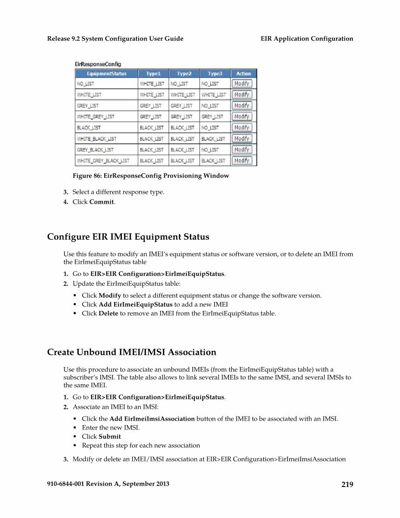
Figure 86: EirResponseConfig Provisioning Window
3. Select a different response type.4. Click Commit.
Configure EIR IMEI Equipment Status
Use this feature to modify an IMEI‘s equipment status or software version, or to delete an IMEI fromthe EirImeiEquipStatus table
1. Go to EIR>EIR Configuration>EirImeiEquipStatus.2. Update the EirImeiEquipStatus table:
• Click Modify to select a different equipment status or change the software version.• Click Add EirImeiEquipStatus to add a new IMEI• Click Delete to remove an IMEI from the EirImeiEquipStatus table.
Create Unbound IMEI/IMSI Association
Use this procedure to associate an unbound IMEIs (from the EirImeiEquipStatus table) with asubscriber‘s IMSI. The table also allows to link several IMEIs to the same IMSI, and several IMSIs tothe same IMEI.
1. Go to EIR>EIR Configuration>EirImeiEquipStatus.2. Associate an IMEI to an IMSI:
• Click the Add EirImeiImsiAssociation button of the IMEI to be associated with an IMSI.• Enter the new IMSI.• Click Submit• Repeat this step for each new association
3. Modify or delete an IMEI/IMSI association at EIR>EIR Configuration>EirImeiImsiAssociation
219910-6844-001 Revision A, September 2013
EIR Application ConfigurationRelease 9.2 System Configuration User Guide
• Click the IMEI Modify button to change the association; or• Click the IMEI Delete button to delete the association
Bind IMEI and IMEI/IMSI Associations to a Subscription
Use this procedure to bind an unbound IMEI or IMEI/IMSI associations to a subscription ID. Theoperator can then link another front-end profile to the subscription ID.
1. Go to EIR>EIR Configuration>EirImeiEquipStatus.2. Enter the subscription ID to be associated with the IMEI.
Note: The mandatory IMEI must have a subscription ID already assigned before other IMEIs canbe bound.
3. Click BindIMEI
This step creates a new entry in the EirBoundImeiEquipStatus table. The new entry includes thespecified SubscriptionID and the data from the corresponding EirImeiEquipStatus entry (which issubsequently removed).
In addition, all EirImeiImsiAssociation entries that have the given IMEI are moved to theEirBoundImeiImsiAssociation table.
Note: If a SubscriptionID is removed from the SDM Subscription table, a cascade operation willresult in the deletion of all EirBoundImeiEquipStatus entries that specify that SubscriptionID.
Configure EIR Bound IMEI Equipment Status
Use this feature to modify a bound IMEI‘s equipment status or software version, or to delete an IMEIfrom the EirBoundImeiEquipStatus table
1. Go to SubscriptionID>EIR>display/modify>Add EirBoundImeiEquipStatus.2. Update the EirBoundImeiEquipStatus table:
• Click Modify to select a different equipment status or change the software version.• Click Add EirBoundImeiEquipStatus to add a new bound IMEI.• Click Delete to remove a bound IMEI from the EirBoundImeiEquipStatus table.
Create Bound IMEI/IMSI Association
Use this procedure to associate a bound IMEI (from the EirBoundImeiEquipStatus table) with asubscriber‘s IMSI. The table also allows to link several IMEIs to the same IMSI, and several IMSIs tothe same IMEI.
1. Go to SubscriptionID>EIR>display/modify>Add EirBoundImeiEquipStatus.
220910-6844-001 Revision A, September 2013
EIR Application ConfigurationRelease 9.2 System Configuration User Guide
2. Associate a bound IMEI to an IMSI:
1. Click the Add EirBoundImeiImsiAssociation button of the bound IMEI to be associated withan IMSI.
2. Enter the new IMSI.3. Click Commit.4. Repeat this step for each new association
3. Modify or delete a bound IMEI/IMSI association atSubscriptionID>EIR>display/modify>AddEirBoundImeiEquipStatus.
• Click the IMEI Modify button to change the association; or• Click the IMEI Delete button to delete the association
Create EIR IMEI Range
Use this procedure to associate a bound IMEI (from the EirBoundImeiEquipStatus table) with asubscriber‘s IMSI. The table also allows to link several IMEIs to the same IMSI, and several IMSIs tothe same IMEI.
1. Go to EIR>EIR Configuration>EirImeiRange.2. Click the EirIMEIRange button to define the Start IMEI, End IMEI, and equipment status for the
range.3. Click Commit.
221910-6844-001 Revision A, September 2013
EIR Application ConfigurationRelease 9.2 System Configuration User Guide
Chapter
13LTE-EIR Application Configuration
This chapter provides the initial procedures on howto configure the LTE-EIR through the WebCI.
Topics:
• Introduction.....223• Configuring LTE-EIR Diameter tables.....223
222910-6844-001 Revision A, September 2013
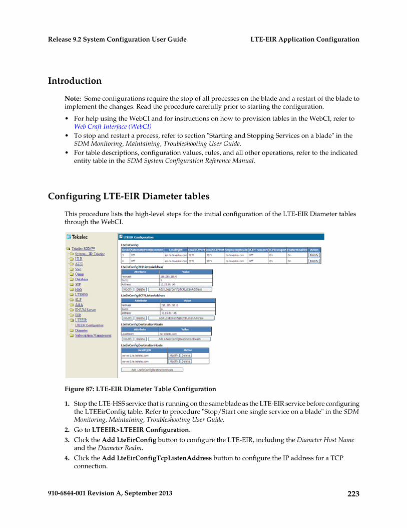
Introduction
Note: Some configurations require the stop of all processes on the blade and a restart of the blade toimplement the changes. Read the procedure carefully prior to starting the configuration.
• For help using the WebCI and for instructions on how to provision tables in the WebCI, refer toWeb Craft Interface (WebCI)
• To stop and restart a process, refer to section "Starting and Stopping Services on a blade" in theSDM Monitoring, Maintaining, Troubleshooting User Guide.
• For table descriptions, configuration values, rules, and all other operations, refer to the indicatedentity table in the SDM System Configuration Reference Manual.
Configuring LTE-EIR Diameter tables
This procedure lists the high-level steps for the initial configuration of the LTE-EIR Diameter tablesthrough the WebCI.
Figure 87: LTE-EIR Diameter Table Configuration
1. Stop the LTE-HSS service that is running on the same blade as the LTE-EIR service before configuringthe LTEEirConfig table. Refer to procedure "Stop/Start one single service on a blade" in the SDMMonitoring, Maintaining, Troubleshooting User Guide.
2. Go to LTEEIR>LTEEIR Configuration.3. Click the Add LteEirConfig button to configure the LTE-EIR, including the Diameter Host Name
and the Diameter Realm.4. Click the Add LteEirConfigTcpListenAddress button to configure the IP address for a TCP
connection.
223910-6844-001 Revision A, September 2013
LTE-EIR Application ConfigurationRelease 9.2 System Configuration User Guide
5. Click the Add LteEirConfigSctpListenAddress button to configure the IP address for an SCTPconnection.
6. Restart the LTE-HSS service. Refer to procedure "Stop/Start one single service on a blade" in theSDM Monitoring, Maintaining, Troubleshooting User Guide.
7. Go to LTEEIR>LTEEIR Configuration.8. Click the Add LteEirConfigDestinationHosts button to define the Diameter host authorized to
establish a new Diameter connection with the EIR application.Add, modify, and delete operations can be performed while the LTE process is running.
9. Click the Add LteEirConfigDestinationRealm button to restrict the Diameter Realm that will beauthorized to connect with it.Add, modify, and delete operations can be performed while the LTE process is running.
224910-6844-001 Revision A, September 2013
LTE-EIR Application ConfigurationRelease 9.2 System Configuration User Guide
Glossary
A
Authentication, Authorization, andAccounting (Rx Diametercommand)
AAA
Application ContextAC
Abstract Service PrimitiveASP
Application Server Process
A process instance of anApplication Server. An ApplicationServer Process serves as an activeor standby process of anApplication Server (e.g., part of adistributed virtual switch ordatabase). Examples of ASPs areprocesses (or process instances of)MGCs, IP SCPs or IP HLRs. AnASP contains an SCTP end-point,and may be configured to processsignaling traffic within more thanone Application Server.
Application Service PartApplication Server Process
Authentication CenterAuC
C
Connection ConfirmedCC
Country Code
Composite Clock
Command-line interfaceCLI
225910-6844-001 Revision A, September 2013
C
Call Session Control FunctionCSCF
D
Protocol that provides anAuthentication, Authorization, and
Diameter
Accounting (AAA) framework forapplications such as network accessor IP mobility. Diameter works inboth local and roaming AAAsituations.
Diameter can also be used as asignaling protocol for mobilitymanagement which is typicallyassociated with an IMS or wirelesstype of environment. Diameter isthe successor to the RADIUSprotocol. The MPE device supportsa range of Diameter interfaces,including Rx, Gx, Gy, and Ty.
Domain Name ServicesDNS
Domain Name System
A system for converting Internethost and domain names into IPaddresses.
Destination Point CodeDPC
DPC refers to the scheme in SS7signaling to identify the receivingsignaling point. In the SS7 network,the point codes are numericaddresses which uniquely identifyeach signaling point. This pointcode can be adjacent to the EAGLE5 ISS, but does not have to be.
E
Equipment Identity RegisterEIR
A network entity used in GSMnetworks, as defined in the 3GPPSpecifications for mobile networks.
226910-6844-001 Revision A, September 2013
GlossaryRelease 9.2 System Configuration User Guide
E
The entity stores lists ofInternational Mobile EquipmentIdentity (IMEI) numbers, whichcorrespond to physical handsets(not subscribers). Use of the EIRcan prevent the use of stolenhandsets because the networkoperator can enter the IMEI of thesehandsets into a 'blacklist' andprevent them from being registeredon the network, thus making themuseless.
TElephone NUmber MappingENUM
A technology for unifying variouscommunications and telephoneaddresses for private and businessnumbers, facsimile and mobilephone numbers, SMS services,Instant Messaging and email.ENUM integrates legacy phonenumbers with the Domain NameSystem (DNS). Users can accessand maintain a directory thatsupports all forms of wiredcommunication, mobilecommunications networks, and theInternet. ENUM allows for an enduser to be reached on multipledevices via one phone number andallows the end user to determinewhich device to contact first ormultiple devices simultaneously.
Electro-Static DischargeESD
F
Fixed-Mobile ConvergenceFMC
G
Gateway GPRS Support NodeGGSN
An edge router that acts as agateway between a GPRS wireless
227910-6844-001 Revision A, September 2013
GlossaryRelease 9.2 System Configuration User Guide
G
data network and other networks.The MPE supports GGSN nodes asnetwork elements. See also GPRS,PGW, and SGW.
Global Title Routing IndicatorGT
Global Title TranslationGTT
A feature of the signalingconnection control part (SCCP) ofthe SS7 protocol that the EAGLE 5ISS uses to determine which servicedatabase to send the query messagewhen an MSU enters the EAGLE 5ISS and more information is neededto route the MSU. These servicedatabases also verify calling cardnumbers and credit card numbers.The service databases are identifiedin the SS7 network by a point codeand a subsystem number.
Graphical User InterfaceGUI
The term given to that set of itemsand facilities which provide theuser with a graphic means formanipulating screen data ratherthan being limited to characterbased commands.
H
Home Location RegisterHLR
A component within the SwitchingSubsystem of a GSM network. TheHLR database is the centraldatabase within the GSMarchitecture. This is whereinformation about the mobilecommunications subscribers whoare assigned to a specific locationarea is stored. The subscriber datais used to establish connections and
228910-6844-001 Revision A, September 2013
GlossaryRelease 9.2 System Configuration User Guide
H
control services. Depending on thenetwork size, the number ofsubscribers and the networkorganization, a number of HLRscan exist within a GSM network.
Home Public Land MobileNetwork
HPLMN
Home Subscriber ServerHSS
A central database for subscriberinformation.
I
International Mobile EquipmentIdentifier
IMEI
International Mobile SubscriberIdentity
IMSI
A unique internal network IDidentifying a mobile subscriber.International Mobile StationIdentity
IP Server ProcessIPSP
A process instance of an IP-basedapplication. An IPSP is essentiallythe same as an ASP, except that ituses MU3A in a peer-to-peerfashion. Conceptually, an IPSPdoes not use the services of asignaling gateway.
International TelecommunicationsUnion
ITU
An organization that operatesworldwide to allow governmentsand the privatetelecommunications sector to
229910-6844-001 Revision A, September 2013
GlossaryRelease 9.2 System Configuration User Guide
I
coordinate the deployment andoperating of telecommunicationsnetworks and services. The ITU isresponsible for regulating,coordinating and developinginternational telecommunications,and for harmonizing nationalpolitical interests.
M
SS7 MTP3-User Adaptation LayerM3UA
M3UA enables an MTP3 User Partto be connected to a remote MTP3via a reliable IP transport.
Mated Application PartMAP
Mobile Application Part
An application part in SS7signaling for mobilecommunications systems.
Mobile Country CodeMCC
A three-digit number that uniquelyidentifies a country served bywireless telephone networks. TheMCC is part of the InternationalMobile Subscriber Identity (IMSI)number, which uniquely identifiesa particular subscriber. See alsoMNC, IMSI.
Mobile Network CodeMNC
A number that identifies a mobilephone carrier. Used in combinationwith a Mobile Country Code(MCC) to uniquely identify amobile phone operator/carrier. Seealso MCC.
230910-6844-001 Revision A, September 2013
GlossaryRelease 9.2 System Configuration User Guide
N
Nature of AddressNA
Network destination codeNDC
Network Data Collection
Network IndicatorNI
Number PlanNP
Numbering PlanNumber PortabilityA capability that permitstelecommunications users tomaintain the same telephone accessnumber as they changetelecommunication suppliers.
O
Operations, Administration andMaintenance Part
OAMP
Originating Point CodeOPC
Within an SS7 network, the pointcodes are numeric addresses whichuniquely identify each signalingpoint. The OPC identifies thesending signaling point.
P
Packet Data NetworkPDN
A digital network technology thatdivides a message into packets fortransmission.
Power Entry ModulePEM
There are two pluggable redundantPower Entry Modules (PEMs) thatare located at the rear bottom side
231910-6844-001 Revision A, September 2013
GlossaryRelease 9.2 System Configuration User Guide
P
of each shelf. Each PEM providespower terminals for four 30 amppower feeds.
Public Land Mobile NetworkPLMN
S
Service Access PointSAP
System ControllerSC
Signaling Connection Control PartSCCP
The signaling connection controlpart with additional functions forthe Message Transfer Part (MTP)in SS7 signaling. Messages can betransmitted between arbitrarynodes in the signaling networkusing a connection-oriented orconnectionless approach.
Serving - Call Session ControlFunction
S-CSCF
Provides user and serviceauthentication and authorization,client registration, SIP-routingcapabilities, service integration,data management, FW/NATtraversal, multi-networkintegration and an interface tothird-party applications.
Stream Control TransmissionProtocol
SCTP
An IETF transport layer protocol,similar to TCP that sends a messagein one operation.
The transport layer for all standardIETF-SIGTRAN protocols.
232910-6844-001 Revision A, September 2013
GlossaryRelease 9.2 System Configuration User Guide
S
SCTP is a reliable transportprotocol that operates on top of aconnectionless packet network suchas IP and is functionally equivalentto TCP. It establishes a connectionbetween two endpoints (called anassociation; in TCP, these aresockets) for transmission of usermessages.
Subscriber Data ManagementSDM
Signaling End PointSEP
A node in an SS7 network thatoriginates or terminates signalingmessages. One example is a centraloffice switch.
Serving GPRS Support NodeSGSN
See SP.Signaling Point
Subscriber Identity ModuleSIM
An ID card the size of a credit cardfor GSM network subscribers, andis typically referred to as a chipcard or smartcard.
Session Initiation ProtocolSIP
A peer-to-peer protocol used forvoice and video communications.
Signaling Link CodeSLC
Subscription Locator FunctionSLF
Simple Object Access ProtocolSOAP
233910-6844-001 Revision A, September 2013
GlossaryRelease 9.2 System Configuration User Guide
S
Service ProviderSP
Signaling Point
A set of signaling equipmentrepresented by a unique point codewithin an SS7 domain.
Signaling System #7SS7
A communications protocol thatallows signaling points in anetwork to send messages to eachother so that voice and dataconnections can be set up betweenthese signaling points. Thesemessages are sent over its ownnetwork and not over the revenueproducing voice and data paths.The EAGLE 5 ISS is an STP, whichis a device that routes thesemessages through the network.
Subsystem AllowedSSA
Secure ShellSSH
A protocol for secure remote loginand other network services over aninsecure network. SSH encryptsand authenticates all EAGLE 5 ISSIPUI and MCP traffic, incomingand outgoing (includingpasswords) to effectively eliminateeavesdropping, connectionhijacking, and other network-levelattacks.
Subsystem NumberSSN
A value of the routing indicatorportion of the global titletranslation data commandsindicating that no further globaltitle translation is required for thespecified entry.
234910-6844-001 Revision A, September 2013
GlossaryRelease 9.2 System Configuration User Guide
S
Subsystem Prohibited networkmanagement message.
SSP
SIP Signaling RouterSSR
Function responsible for queryinga redirection server and proxyingrequests to other SSR servers,redirect servers, SSR Service Points,and Gateways. It helps in evolvinga Flat NGN network into ahierarchical network.
Signal Transfer PointSTP
The STP is a special high-speedswitch for signaling messages inSS7 networks. The STP routes coreINAP communication between theService Switching Point (SSP) andthe Service Control Point (SCP)over the network.
Spanning Tree Protocol
See SDM.Subscriber Data Management
See SSN.Subsystem Number
T
Transaction CapabilitiesApplication Part
TCAP
A protocol in the SS7 protocol suitethat enables the deployment ofadvanced intelligent networkservices by supporting non-circuitrelated information exchangebetween signaling points using theSignaling Connection Control Partconnectionless service. TCAP alsosupports remote control - ability toinvoke features in another remotenetwork switch.
235910-6844-001 Revision A, September 2013
GlossaryRelease 9.2 System Configuration User Guide
T
See TT.Translation Type
Translation TypeTT
Resides in the Called Party Address(CdPA) field of the MSU anddetermines which service databaseis to receive query messages. Thetranslation type indicates whichGlobal Title Translation tabledetermines the routing to aparticular service database.
U
Universal MobileTelecommunications System
UMTS
The standard for 3G used by GSMservice providers. UMTS includesvoice and audio services, for fastdata, graphic and texttransmissions, along withtransmission of moving images andvideo.
User Security ManagementUSM
Unstructured SupplementaryService Data
USSD
V
Visitor Location RegisterVLR
A component of the switchingsubsystem, within a GSM network.The switching subsystem includesvarious databases which storeindividual subscriber data. One ofthese databases is the HLRdatabase or Home LocationRegister; and the VLR is another.
Virtual Location Register
W
236910-6844-001 Revision A, September 2013
GlossaryRelease 9.2 System Configuration User Guide
W
Web Craft InterfaceWebCI
X
eXtensible Markup LanguageXML
A version of the StandardGeneralized Markup Language(SGML) that allows Webdevelopers to create customizedtags for additional functionality.
237910-6844-001 Revision A, September 2013
GlossaryRelease 9.2 System Configuration User Guide