Embed Size (px)
Citation preview
DOCOUNT MORE
10 190 004,._ Cl 026 504
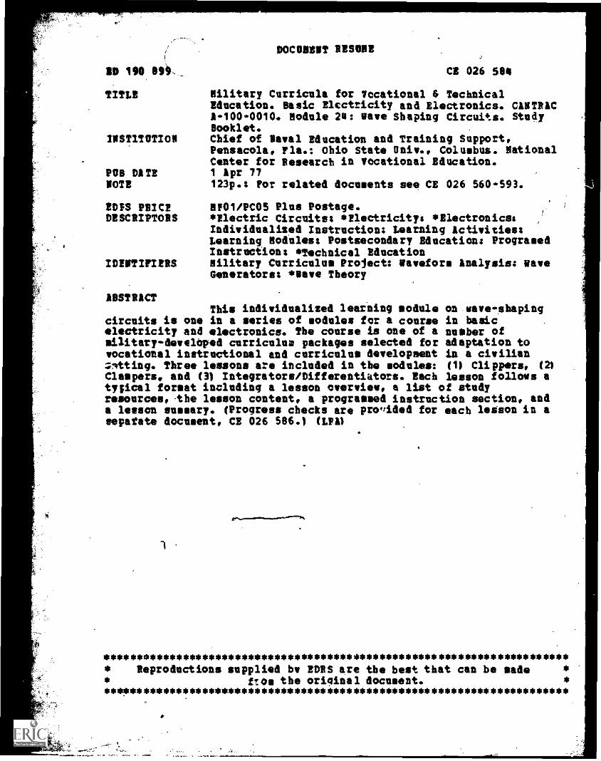
TITLE Nilitary Curricula for Vocational & TechnicalEducation. Basic Electricity and Electronics. CANTRIC1-100-0010. Nodule 24: wave Shaping Circuits. StudyBooklet.
/NSTITOTION Chief of Naval Education and Training Support,Pensacola, Fla.: Ohio State Univ., Columbus. NationalCenter for Research in Vocational Education.
PCB D1TE 1 Apr 77NOTE 123p.: Por related documents see CE 026 560-593.
EDIS P2/C2 11101/PC05 Plus Postage.DESCRIPTORS *Electric Circuits: *Electricity: *Electronics:
Individualized Instruction: Learning Activities:Learning Nodules: Postsecondary Education: ProgramedInstruction: *Technical Education
IDENTIFIERS Military Curriculum Project: Wavefors Analysis: waveGenerators: *neve Theory
ABSTRACTThis individualized learning module on- wave - shaping
circuits is one in a series of modules for a course in basicelectricity mm4 electronics. The course is one of a number ofsilitary-develOped curriculum packages selected for adaptation tovocational instructional and curriculum development in a civilianzmtting. Three lessons are included in the modules: op Clippers, (21
Clampers. and (3) Integrators/Differentiators. Each lesson follows atypical format including a lesson overview, a list of studyresources,-the lesson content, a programmed instruction section, anda lesson summary. (Progress checks are proffided for each lesson in aespatate document, CE 026 506.) (LPA)
1
*************************************************** ********************* Reproductions supplied by 202S are the best that can be made ** ftom the original document. ** **!o******************************i************************************
I
0 ,
0
O
o'I
;, it y , . .4-?r:1' Pt: .
CHIEF OF NAVAL EDUCATION AND TRAINING
1 APRIL 1977
-;
NS. ISCPANTIONS OP NOIONnor.ATIONI WILMS*NATIONAL
O INICATION
nut DOCUMENT SUN OPMOMS ONACTLy As ECM.° POONTHE INIOSON 00 onOmutatiON 04001,MIND IT 'Orlon 00 '490004 OPINIONSSTATED 00 NOT INICISSANILv 011114.SON °FP ICIAL NATIONAL INSTITUTE OFEINICATIos OSITION ON MAY
L
#
.0
J1 OP'
ec nic" I.
I
.;1. Si6.14' a
.. i 0.%
t.
", I ; .....; 1.4.41111
BASIC ELECTRICITY AND ELECTRONICS..
MODULE 24. WAVE SHAPING CIRCUITS.
STUDY BOOKLET .
,9,-,10014 o;
11E WINK CENTERFOR RESEARCH N VOCAllONAL
THE ONO STATE 1.140111154Y
Military .
Curriculum Materials What Materials How Can TheseDiSsemination Is . . Are Available? Materials Be Obtained?1.........._........._j
. an activity to increase the accessibility ofmilitary-developed curriculum materials tovocational and technical educators.
This project, funded by the U.S. Office ofEducation, includes the identification andacquisition of curriculum materials in printfore from the Coast Guard, Air Force.Army, Marine Corps and Navy.
Access to military curriculum materials isprovided through a "Joint Memorandum ofUnderstanding" between the U.S. Office ofEducation and the Department of Defense.
The acquired materials are reviewed by staffand subject matter sPeciilists, and coursesdeemed applicable to vocational and tech-nical education are selected for dissemination.
The National Center for Research inVocational Education is the U.S. Office ofEducation's designated representative toacquire the materials and conduct the projectactivities.
Project Staff:
Watley E. Budke, Ph.D.. DirectorNationil Center Clearinghouse
Shirley'A. Chase. Ph.D.ProjecteDirector
to 4
One hundred twenty courses, on microfiche(thirteen in paper form) and descriptions ofeach have been provided to the vocationalCurriculum Coordination Centers and otherinstructional materials agencies for dissemi-nation.
Course materials include programmedinstruction, curriculUrmoutlines, instructorguides, student workbooks and technicalmanuals.
The 120 ,courses represenethe followingsixteen vocational subject areas:
AgricultureAviationBuilding &ConstructionTrades
ClericalOccupations
CommunicationsDraftingElectronicsEngine Mechanics
Food ServiceHealthHeating & Air
ConditioningMachine ShopManagement &
SupervisionMeteorology &
NavigationPhotographyPublic Service
The number of courses and the subject areasrepresented will expand as additional mate-rials with application to vocational andtechnic education are identified and selectedfor dieseminatiOn.
Contact the Curriculum Coordination Centerin your region for information on obtainingmaterials (e.g., availability and cost). Theywill respond to your request directly or refer
9 you to an instructional materials agencycloser to you.
CURRICULUM COORDINATION CENTERS
EAST CENTRALRebecca S. DouglasDirector100 North First StreetSpringfield, IL 62777217/782-0759
MIDWESTRobert PattonDirector -1515 West Sixth Ave.Stillwater, OK 74704405/377-2000
NORTHEASTJoseph F. Kelly, PhD.Director225 West State StreetTrenton, NJ 08625609/292-6562
NORTHWESTWilliam DanielsDirectorBuilding 17Airdustrial ParkOlYroPie, WA 98504206/7510879
SOUTHEASTJames F Shill, PhD.DirectorMississippi State University
Drawer DXMississippi State, MS 39762
601/325-2510
WESTERNLawrence F. H. Zane, PhD.Director1776 University Ave.Honolulu, HI 98822808/948-7834
t t.. 5
The National CenterMission Statement
The National Center for Research inVocational, Education's mission is to increasethe ability of diverse Agencies, institu dons,and organizations to solve educational prob-Isms relating to individual career planning;preparation, and progression. The NationalCenter fulfills its misfion by:
Generating knowledge through research
Developing educational programs andproduLts
Evaluating individual program needsand outcomes
Installing educational programs andproducts
Operating information systems andservices
Conducting leadership development andtraining programs
FOR FURTHER INFORMATION ABOUT e
Military Curriculum MaterialsWRITE OR CALL
Program Information OfficeThe National ranter for Research in Vocational
EducationThe Ohio State University
61980 Kenny Road. Columbus. Ohio 43210Telephone: or Toll Free 800/
8484815 within' the ntinental U.S.(except Ohio)
Military CurriculumMaterials for
Vocational andTechnical Education
lorqmr',Irn and Fieldniries Division
The Pnlict,,, Center for flesforchin Vetritinpm Education
0
PREPARED FOR
BASIC ELECTRICITY AND ELECTRONICS
CANTRAC A-100-0010
MODULE TWENTY FOUR
WAVE SHAPING CIRCUITS
PREPARED' BY
INDIVIDUALIZED LEARNING DEVELOPMENT GROUP
SERVICE SCHOOL COMMAND, NTC, SAN DIEGO, CA 92133
STUDY BOOKLET
1 APRIL 1977
1
Overview
PCP
Twenty Four
OVERVIEW
BASIC ELECTRICITY ANO ELECTRONICS
NODULF TWENTY FOUR
Wave Shaping Circuits
In the last two modules, we've seen how to generate sineweves and squarewaves with electronli circuits. This module is designed to show you howwe can modify these two basic waveforms into countless other waveforms.
You will find that the circuits used for wave shaping are not complexand that you already have all the basic theory needed to solve them.
This module has been divided into the following three lesions: .
Lesson I ClippersLesson II ClampersLesson III Integrators/Oifferentiators
2
9
BASIC ELECTRICITY AND ELECTRONICS
MODUVE TWENTY FOUR
LESSON I
CLIPPERS
I APRIL 1977
3 .10.
Overview Twenty four-1
OVERVIEW
LESSON 1
tellers.
This lesson will show you the functional operation of a clipper, how torecognize the schematic diagram and the actual circuit, and how you willput this theory and practical information to use by troubleshooting theclipper circuits.
The learning objectives of this lesson are as follows:
TERMINAL OBJECTIVE(S):
24.1.46 When the student completes this course he will be able toIDENTIFY wive shaping circuits and their effects on input -
waveforms by matching an output waveform a +Ave shaping, circuit and its input waveform given input and output wave-
form illustrations and wave shaping circuit schematic diagrams.
ENASL1NO OBJECTIVE(S):9
When the student completes this lesson, he will be able to:
210.46.1 IDENTIFY the function of a clipper circuit by selecting thecorrect statement from a list of four aatemants. 100!accuracy is required.
24.1.46.2 IDENTIFY the schematic diagrams for each of the five basicclipper circuits (series positive, series negative, parallelpositive, parallel negative, and parallel positive and nega-tive), given a set of five schematic diagrams, be selectingthe schematic that matches the name given for each type ofclipper circuit. 100* accuracy is required.
24.1.46.2.1 IDENTIFY by selecting, the schematic diagrams of series/parallel clipper configurations given a set of schematic die-grams which includes one of each of the configurationi. 100!accuracy if required.
24e1.46.1 IDERO/FY by selecting, the output w form for each of thefollowing three clipper circuits (positive, negative, endparallel negative and positive), given input and output weve-shapes and schematic diagrams. 100% accuracy is required.
.
11
4
Overview
OVERVIEW
Twenty Four1
24.1.46.4 IDENTIFY by selecting, output waveforms showing bias effectson series and paralled clipper circuits given a choice offive schematic diagrams and their respective output waveforms..100R accuracy is required.'
24.1.46.5 OBSERVE and INTERPRET clipper output waveforms (normal andabnormal) by varying the bias voltage on a series or parallelclipper cirdait, given an oscilloscope, a job program, and atraining device circuit. 100% accuracy is required.
24.1.## I IDENTIFY the input section, conversic: section, and the outputsection in each of the five basic clipper circuits (-Aries,positive, and parallel positive and negative) by locating allof thircomponents in each section, given a training device orcircuit boards cpntaining clipper circuits, a job program, andthe applicable/ schematic diagrams or technical manuals. 100%accuracy is required.
M
3BEFORE YOU STARTXBIS LESSOP READ THE LESSON LEARNINS'OBJECTIVES ANDPkEVIEH.THE LIST' OF STUDY P. VICES ON THE NEXT. PAGE.
5
/2.?
#
Study Resources Twenty Four-I
ILIST OF STUDY RESOURCES
LESSON I
Clippers,
To learn the material in this lesson, youhave the option of choosing,according to your experience and preferences, any or all of the follow-ing study resources;
Written Lesson presentation in:
Nodule Booklet:
Suimery * flProgramed InstructionNarrative
Student's Guide:
Job Program Twenty Four-I-1 "CLIPPERS"Job Program Twenty Four-I-2 "CLIPPERS"Progress Check
Add, t °eel Material 1 (s
Audlo/Visual Program Twenty Four-I
Enrichment Material(s):
"Introduction to ClippJts"
Electronics Installation and Maintenance Book, Electronic Circuits,NAVSHIPS 0967-000-0120 (EIMII)
YOU MAY USE ANY,. ORAALL, RESOURCES
SUPERVISOR; HOWEVER, SILL MATEIIIALSTO ACHIEVE LESSON OBJECTIVES. JOETOW. .;
. ,
LISTED ABOVE, INCLUDING THE LEARNING
LISTED ARE NOT NECESSARILY REQUIREDpROGRESS CHECK MAY OE TAKEN AT ANY
613. .
Summery Twenty Four-I
SUM ARY
.LESSON
Introduction to Clippers
A clipper or limiter (both terms mean the same thing) is little more than
a half wave rectifier. Using a diode, resistor, and sometimes a DC po-tential, a clipper/limiter can be used to eliminate the positive ornegative alternation of an input waveform or can clip a"desired amountfrom either alternation. in a circuit where the voltage limits are
extremely critical,*a clipper may be aeoloyed as a safety device. in
this lesson you will be introduced to five typeb o clippers: (see
illustration on next page) series positive; series negative, parallelpositIve,.parallei negative; and parallel positive and negative clippers.
Since the diode is actually the limiting component. its location withrespect to the signal flow and its polarity are the factors that deter -' 4mine circuit configuration. -76 the series clipper, the diode is inseries with the input in parallel clippers, the diode Is in parallelwith the output.
Jlemembering hat a diode will pass current in only one direction, and-that the anoee (arrow) of the diode must be less negative (more positive)with respect to the cathode (vertical line) to make the diode conduct,you can loot at the waveform as applied to the diode and determine whatthe output will be.
In a series clipper the diode must be forward biased in order to obtain
an output. In a parallel clipper whose diode is forward biased theSignal will be shorted to the reference voltage. So in order to obtainan output the diode must be reverse biased.
To clip only a portion of either alternation a DC potential is placedIn parallel with the output. This potential, depending upon its polarity,will keep the diode conducting or cut-off until the input waveform exceedsthe DC potential.
VO
7.14
Watery Twenty Four-1
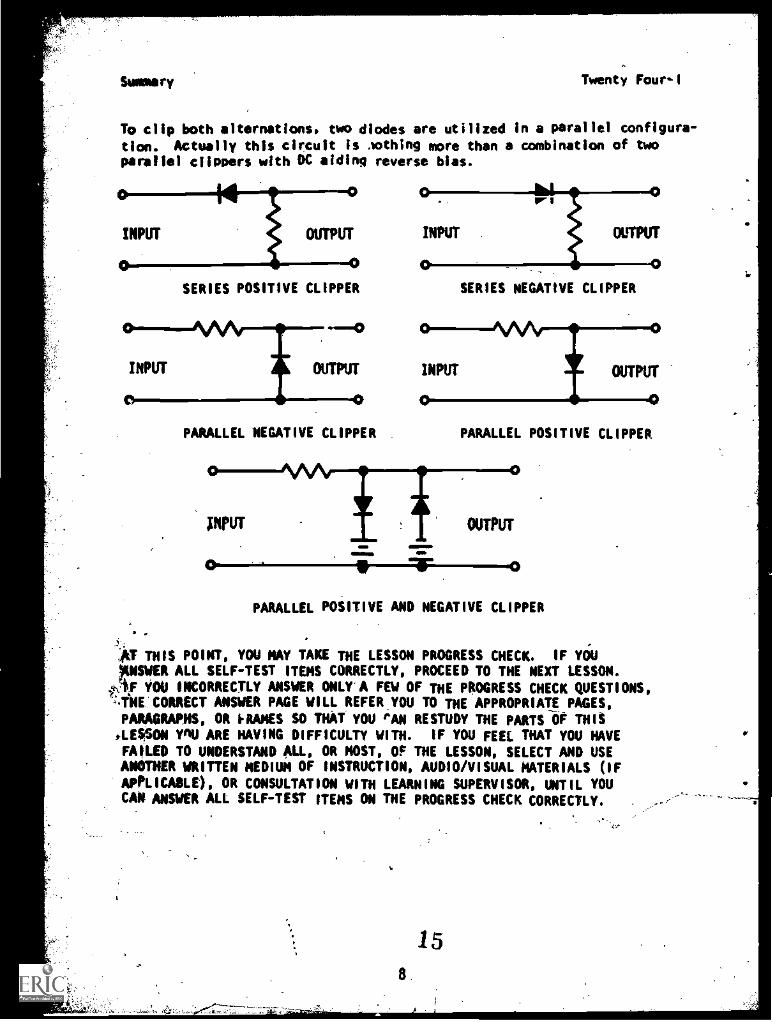
To clip both alternations, two diodes are utilized in a parallel configura-
tion. Actually this circuit is .nothing more than a combination of twoparallel clippers with DC aiding reverse bias.
SERIES POSITIVE CLIPPER
PARALLEL NEGATIVE CLIPPER
SERIES NEGATIVE CLIPPER
PARALLEL POSITIVE CLIPPER
PARALLEL POSITIVE AND NEGATIVE CLIPPER
la THIS POINT, YOU MAY TAKE THE LESSON PROGRESS CHECK. IF YOUrISINit ALL SELF-TEST ITEMS CORRECTLY, PROCEED TO THE NEXT LESSON.
§A.F YOU INCORRECTLY ANSWER ONLY A FEW OF THE PROGRESS CHECK QUESTIONS,'INE CORRECT ANSWER PAGE WILL REFER YOU TO THE APPROPRIATE PAGES,PARAGRAPHS, OR RAMES SO THAT YOU PAN RESTUDY THE PARTS OF THIS,LESSON Y'IU ARE HAVING DIFFICULTY WITH. IF YOU FEEL THAT YOU HAVEFAILED TO UNDERSTAND ALL, OR MOST, OF THE LESSON, SELECT AND USEANOTHER WRITTEN MEDIUM OF INSTRUCTION, AUDIO/VISUAL MATERIALS (IF
APPLICABLE), OR CONSULTATION WITH LEARNING SUPERVISOR, UNTIL YOUCAN ANSWER ALL SELF-TEST ITEMS ON THE PROGRESS CHECK CORRECTLY.
15
P.1. ;Twenty Four-I
PROGRAMMED INSTRUCTIONLESSON I
Introduction to Clippers
TESTS FRAMES ARE 9, 12, 15, i7. TRY FRAME 9 FIRST AND THEN FOLLOW THE
INSTRUCTIONS AT THE END OF THE FRAME.
1. Perhaps the title should read "Introduction to Halfwave_Rectifiers".A clipper (or limiter) circuit is essentially a diode and a resistor,
sometimes used with a DC potential. In the power supply module, youlearned that a diode will pass current in only one direction. 4hen a
waveform having positive and negative alternations is applied to a diode,only the positive or, ,(444gative alternation, depending upon the diode's
insertion in the circuit, is passed. A simple 4. Ipper/limiter circuiteliminates either the positive or the negative alternation which is what
a halfwave rectifier does. Now do you tell which alternation is to be
eliminated? Since the circuits contain the same components, only thedirection of the diode determines which alternation (the positive ornegative) is to be clipped (limited):,
When a waveform is applied to a diode either the.positive or the nega-tive alternation will be passed depending on the
direction of the diode as it is connected into the circuit {or wordsto that effect)
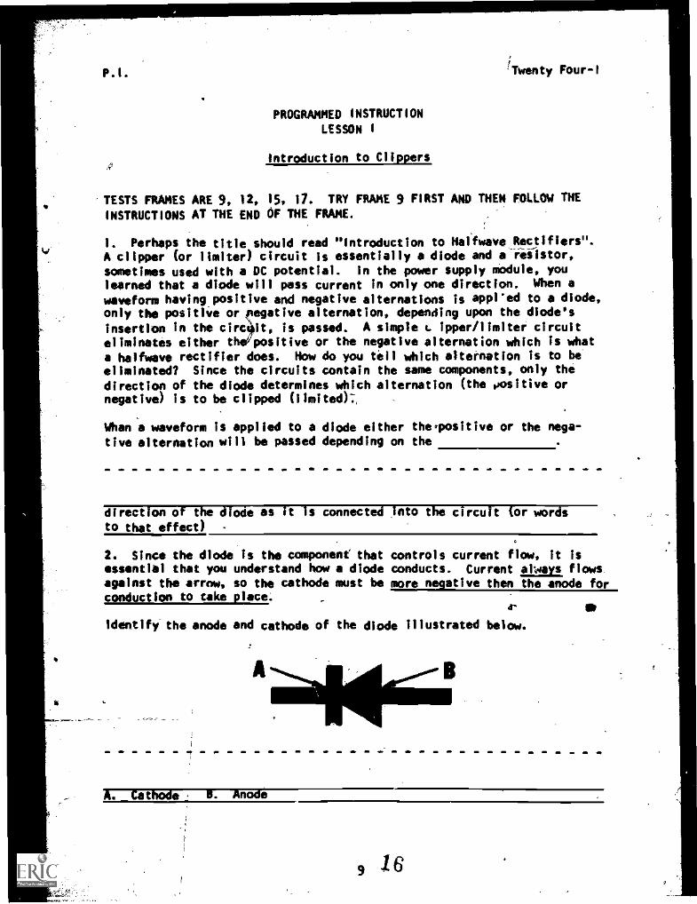
2. Since the diode is the component that controls current flow, it isessential that you understand how a diode conducts. Current always, flowsagainst the arrow, so the cathode must be more negative then the anode forconduction to take place.
4- Sr
identify the anode and cathode of the diode Illustrated below.
A. _Cathode F. -Anode
9 /6
P.I. Twenty Four-I
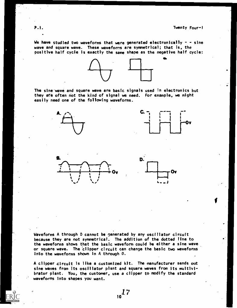
We have studied two waveforms that were generated electronically - - sinewave and square wave. These waveforms are symmetrical; that is, thepositive half cycle is exactly the same shape as the negative half cycle:
m
The sine^weve and square wave are basic signals used in electronics butthey are often not the kind of signal we need. For example, we mighteasily need one of the following waveforms.
B.
IC\1=7/49'.rI I I
I I OV
%4,
i
Ov
Waveforms A through 0 cannot be generated by any oscillator circuitbecause they are not symmetrical. The addition of the dotted line tothe waveforms shows that the basic waveform could be either a sine waveor square wave. The 'clipper circuit can change the basic two waveformsinto the waveforms shown In A through 0.
A clipper circuit is like a customized kit. The manufacturer sends out
sine waves from its oscillator plant and square waves from its multivi-brator plant. You, the customer, use a clipper to modify the standard
waveforms into shapes you want.
1710
P.1. Twenty Four-1
Depending on how you want to customize a waveform, one of the followingclipper circuits dould be ufbd:
1. Series positive or negative clipper.
2. Parallel positive or negative clipper.
3. Parallel positive add negative clipper.
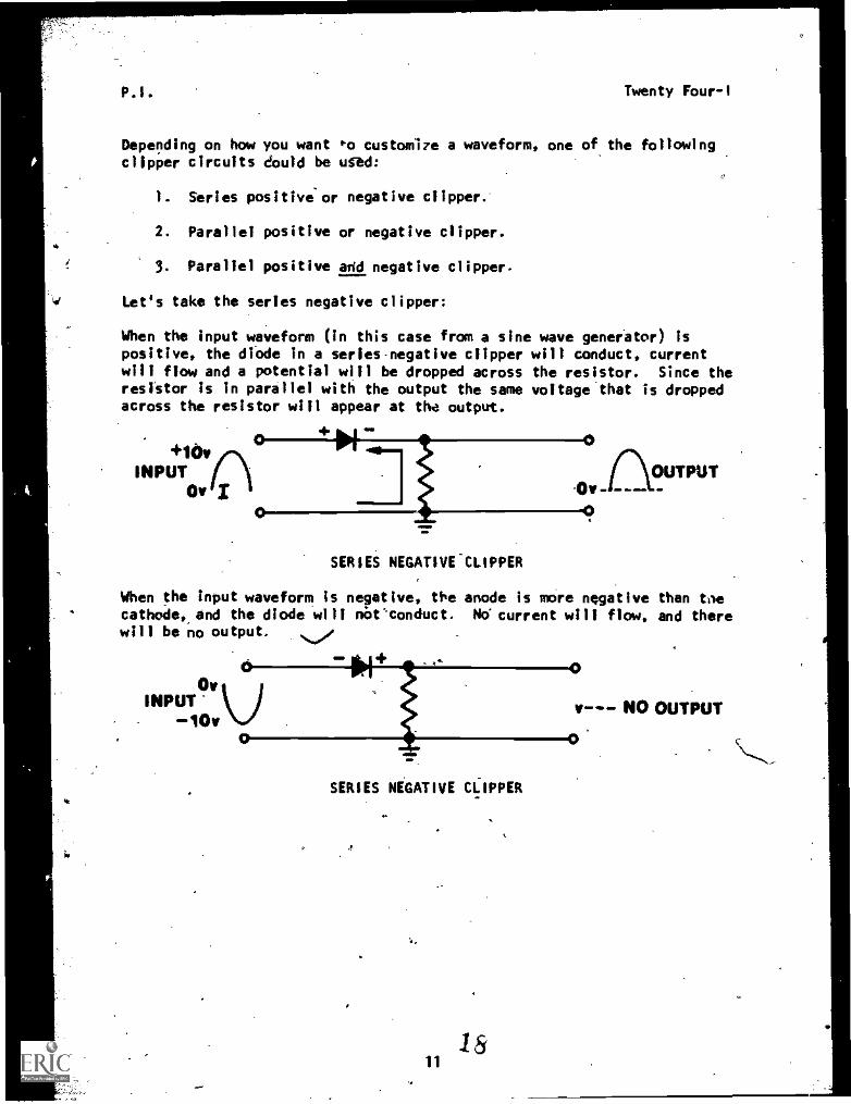
Let's take the series negative clipper:
When the input waveform (in this case from a sine wave generator) ispositive, the diode in a series negative clipper will conduct, currentwill flow and a potential will be dropped across the resistor. Since theresistor is in parallel with the output the same voltage that is droppedacross the resistor will appear at the output.
+10v nINPUT
Or
0
UTPUT.0v -
SERIES NEGATIVE-CLIPPER
When the input waveform is negative, the anode is mere negative than taecathode,_and the diode will robt.'conduct. No current will flow, and therewill be no output.
NPUT 9v I10v
0
*I+
SERIES NEGATIVE CLIPPER
0
i
V4momp.=
0
NO OUTPUT
ee
P.I. Twenty Fou'r -I
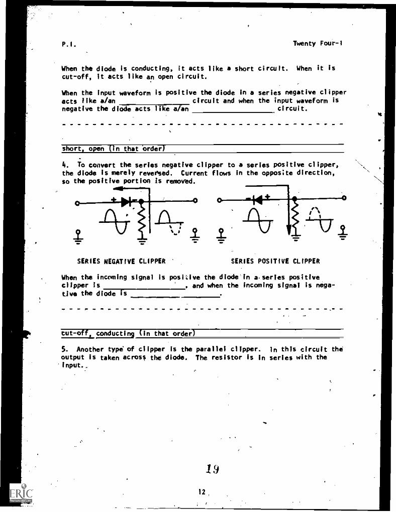
When the diode is conducting, it acts like a short circuit. When it is
cut-off, it acts like an open circuit.
When the input waveform is positive the diode in a series negative clipper
acts like a/an circuit and when the input waveform isnegative the diode acts like a/an circuit.
short, open (in that order,-
4. To convert the series negative clipper to a series positive clipper,the diode is merely reversed. Current flows in the opposite direction,so the positive portion Is removed.
SERIES NEGATIVE CLIPPER SERIES POSITIVE CLIPPER
When the incoming signal is positive the diode In aseries positiveclipper Is , and when the incoming signal is nega-
tive the diode is
tut-off conducting (in that order)
5. Another type of clipper is the parallel clipper. In this circuit theoutput is taken across the diode. The resistor is in series with theinput.,
19
12
p. 1. Twenty Four-1
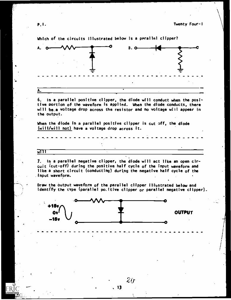
Which of the circuits illustrated below is a parallel clipper?
A. B.
A.
6. In a parallel positive clipper, the diode will conduct when the posi-tive portion of the waveform is applied. When the diode conducts, therewill be_a voltage drop across the resistor and no voltage will appear inthe output.
When the diode in a parallel positive clipper is cut off, the diodeSwill/will not) have a voltage drop across it.
will
7. in a parallel negative clipperi the diode will act like an open cir-cuit (cut-off) during the positive half cycle of the input waveform andlike a short circuit (conducting) during the negative half cycle of the
.input waveform.
Draw the output waveform of the parallel clipper illustrated below andidentify the cope (parallel po.ltIve clipper or parallel negative clipper).
Ov
-.15v
0101NAA,111
2(r
13
OUTPUT
P.I. Twenty Four-1
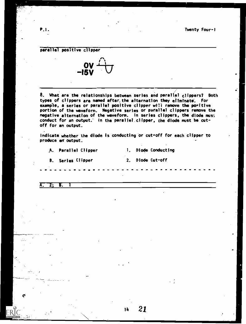
paw 10 positive copper
it
15V
8. What are the relationships between series and paraltel clippers? Both
types of clippers are named after, the alternation they eliminate. Forexample, a series or parallel positive clipper will remove the pomitiveportion of the waveform. Negative series or parallel clippers remove thenegative alternation of the waveform. In series clippers, the diode mustconduct for an output; In the parallel clipper, the diode must be cut-off for an output.
Indicate whether the diode is conducting 'or cut-off for each clipper toproduce art Output.
B.
Parallel Clipper
Series Clipper
1. Diode Conducting
2. Diode Cut-off
A. 2; L 1
lb 21
Twenty Four1
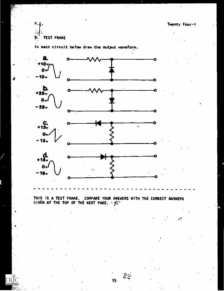
9!. TEST FRAME
tn each circuit below draw the output waveform.
b.+25v
Ow
-25.%
0 O
d.+15v
Ov%15v
THIS iS A TEST FRAME. ,COMPARE YOUR ANSWERS WITH THE CORRECT ANSWERS(IIVEN AT THE TOP OF THE NEXT PAGE. 16-
ii
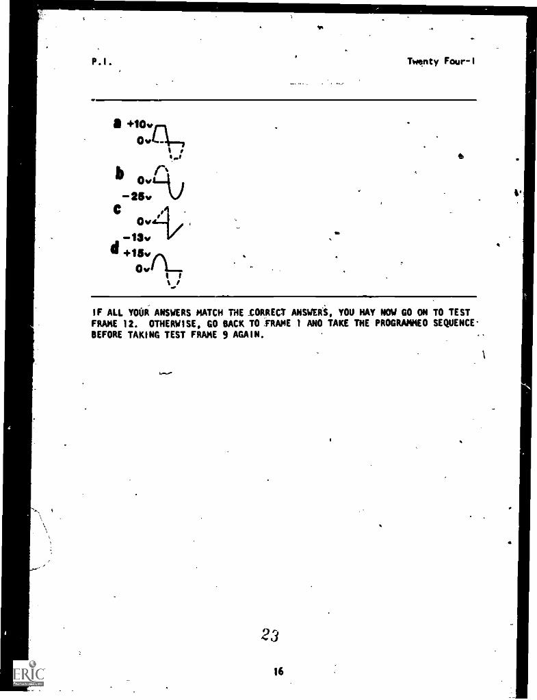
a +10.rt
%we 6I 8
111 ov%-25.
ovIz-1$v .
II +15v . .
OvnI i
IF ALL YOUR ANSWERS MATCH THE _CORRECT ANSWERS, YOU MAY NOW GO ON TO TEST
FRAME 12. OTHERWISE, CO BACK TO ,FRAME 1 ANO TAKE THE PROGRAMMED SEQUENCE.
BEFORE TAKING TEST FRAME 9 AGAIN. N
%
Twenty Four-1
lib
4+0.
23
i6
.
4:
P.I. Twenty Four-I
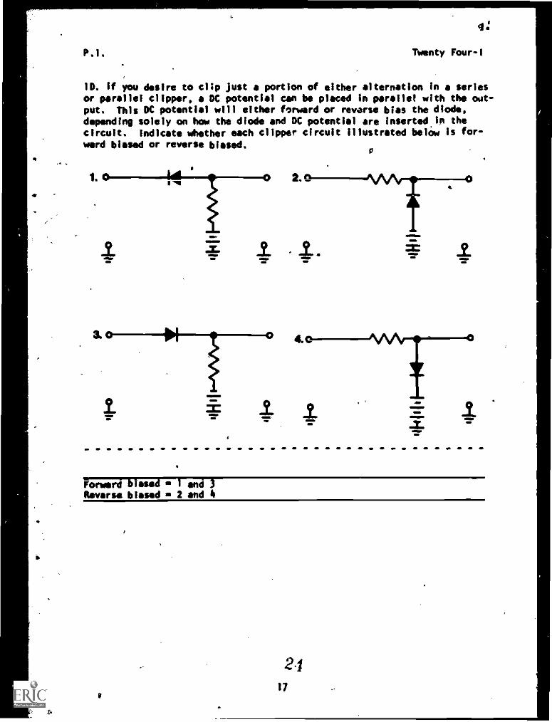
10. if you desire to clip just a portion of either alternation in a seriesor parallel clipper, a DC potential can be placed in parallel with the oat -put. This DC potential will either forward or reverse bias the diode,depending solely on how the diode and DC potential are inserted in thecircuit. indicate whether each clipper circuit illustrated belOw Is for-ward biased or reverse biased.
1.
I
Forward rse and
Reverse biased 2 and 4
ft
2.1
17
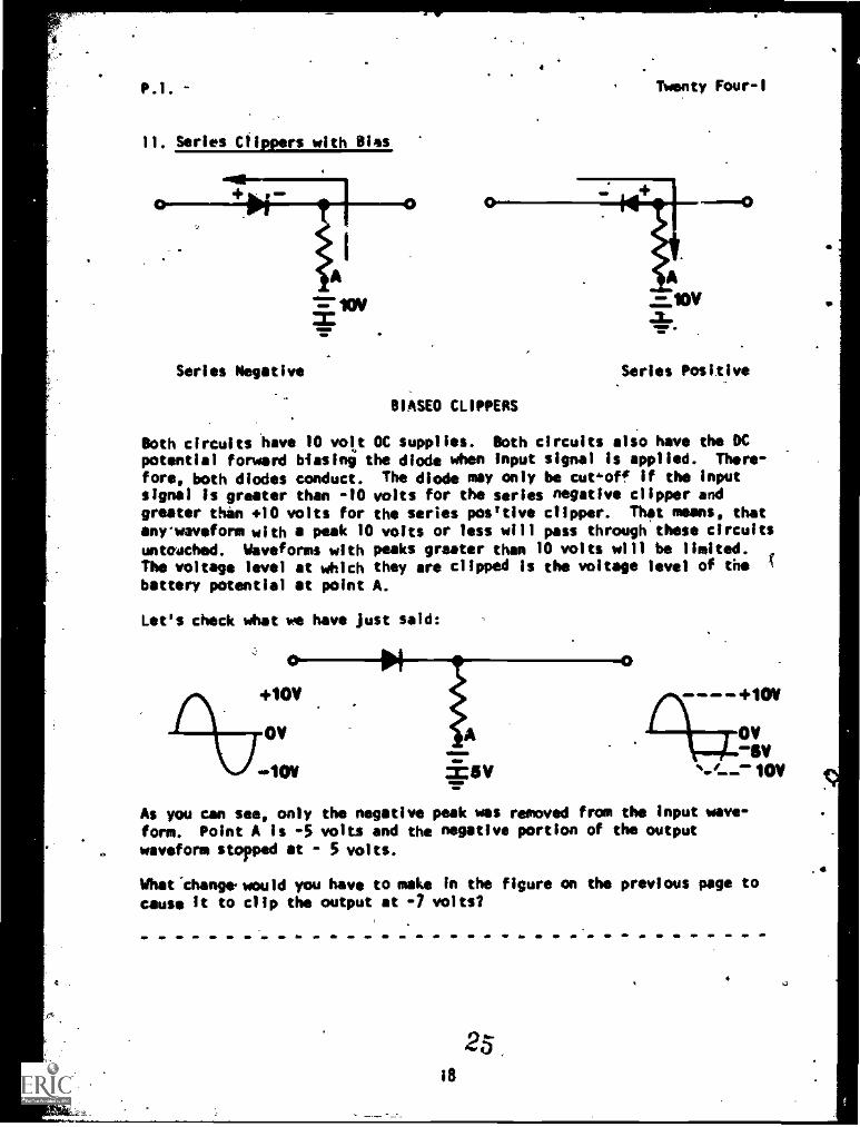
11. Series Clippers with Bias
Series Negative
a
Twenty Four-1
BIASED CLIPPERS
A=10V
Series Positive
Both circuits have 10 volt OC supplies. Both circuits also have the DCpotential forward biasing the diode when input signal is applied. There-
fore, both diodes conduct. The diode may only be cut,off if the inputsignal Is greater than -10 volts for the series negative clipper andgreater thin +10 volts for the series posttive clipper. That means, that
any waveform with a peak 10 volts or less will pass through these circuitsuntouched. Waveforms with peaks greater than 10 volts will be limited.The voltage level at which they are clipped is the voltage level of thebattery potential at point A.
Let's check what we have just said:
0
+10V
ov
.+1011
01
±5V
As you can see, only the negative peak was removed from the input wave-form. Point A is -5 volts and the negative portion of the output
waveform stopped at - 5 volts.
What.changer would you have to make In the figure on the previous page tocause it to clip the output at -7 volts/
0
25i8
4
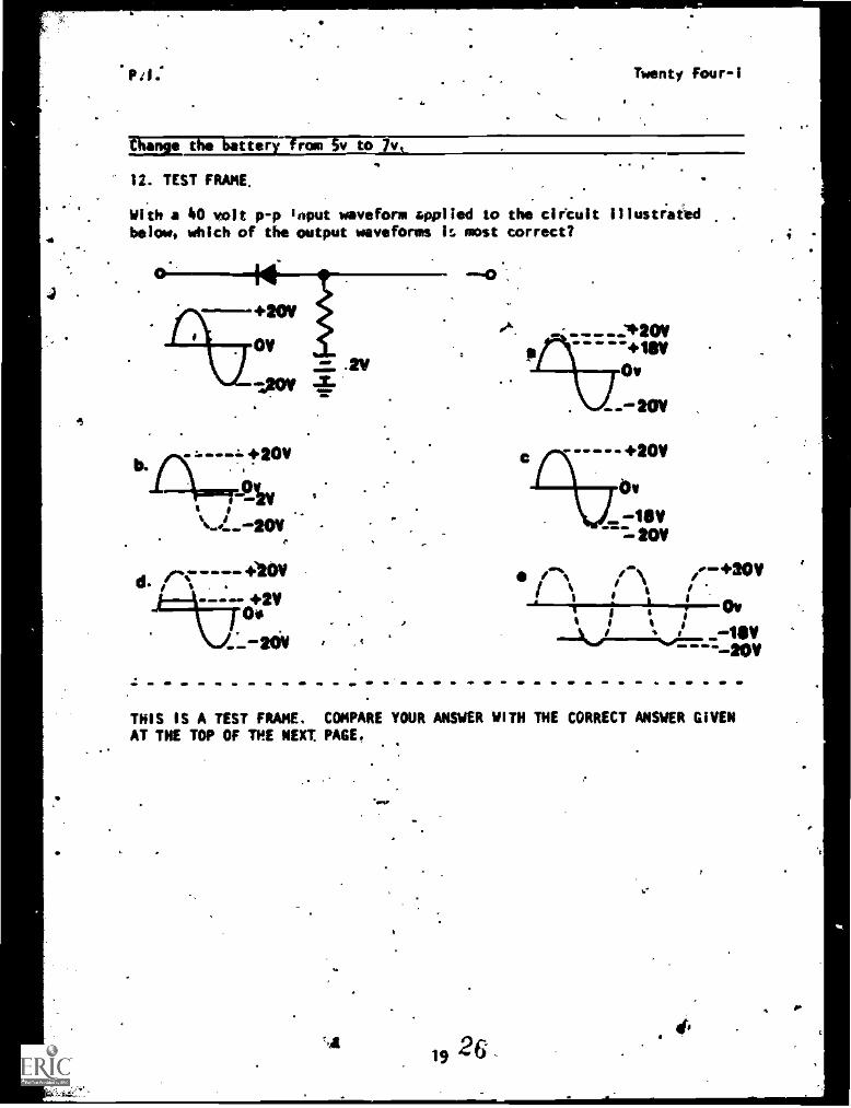
;haw the rota v to
.
12. TEST FRAME.
Twenty Four-1
With a 40 volt p-p Input waveform applied to the circuit illustiaiedbelow, which of the output waveforms U. most correct?
+20v
:!y
d.+20V
O.+2V
__-a00
+111V
Ov
WV
----- +20V
Ov
10V
r-; L. 0.
THIS IS A TEST FRAME. COMPARE YOUR ANSWER WITH THE CORRECT ANSWER GIVENAT THE TOP OF THE NEXT PAGE.
19 26
P.I. Twenty Four-1
d.
IF YOURANSWER HATCHES THE CORRECT MASWER; GO TO TEST FRAME 15. OTHER-
WISE GO PAC TO FRAME 10 AND TAKE THE PROGRAMMED SEQUENCE.
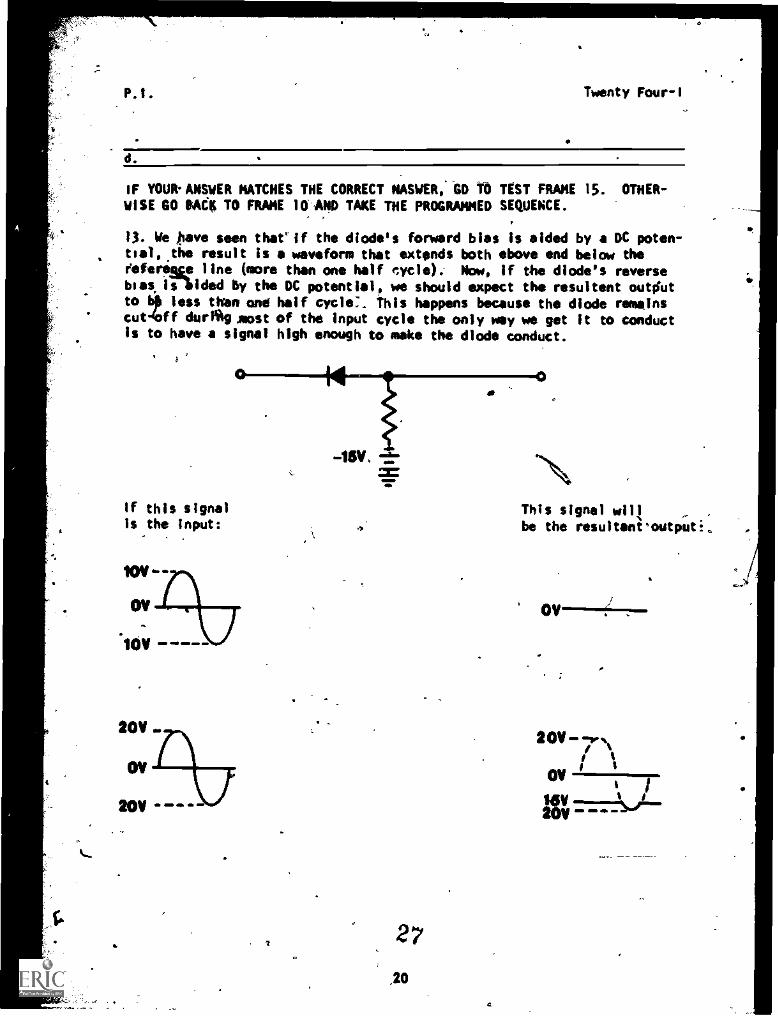
13. We gave seen tharif the diode's forward bias is aided by a DC poten-tial, the result is a waveform that extends both above and below theeeferime line (more than one half cycle).- How, if the diode's reversebias hided by the DC potential, we should expect the resultant outiutto b) less then and half cycle:. This happens because the diode remains
4ofcutf during aost of the input cycle the only way we get it to conductis to have a signal high enough to make the diode conduct.
a
If this signalIs the input:
20V«.
OV
20V -
-15V, -a-
2
,20
This signal will
be the resultanioutpati,,
OV
20V-7Nr
IOV
20V
PA. Twenty Four-I
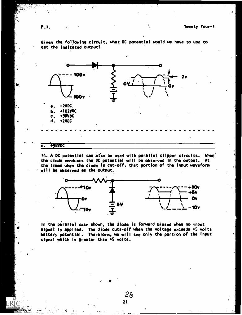
Given the following circuit, what DC potential would we have to use to
get the indicated output?
a. -2VDC.
b. +102VOCc. +98vDCd. +2VDC
O
I - * 1,t.in..0V
=.1 i I i' 0 i.7. i%I1 %
2v
c. +311VOC
14. A DC potential' can also be used with parallel clipper circuits. When'
the diode conducts the' DC potential will be observed in the output. At
the times when the diode is cut-oft, that portion of the Input waveformwill be observed as the output.
+10v
Ov5V
_T
OMVP 4. +10V
+Iv,Ov
In the parallel use shown, the diode Is forward biased when no inputsignal is applied. The diode cuts-off when the voltage exceeds +5 voltsbattery potential. Therefore, we will see only the portion of the inputsignal which is greeter than +5 volts.
4.
2821
4
PO, Twenty FourI
In either the series or parallel clipper, the following general rules
apply.
1. Negative clippers remove the negative alternation either totally
or in part.
,2. Positive clippers remove the positive alternation either totallyor in part.
v.
3. Output in series clippers occurs when the diode conducts. Out-put in parallel clippers.occurs when the diode is cut-off.
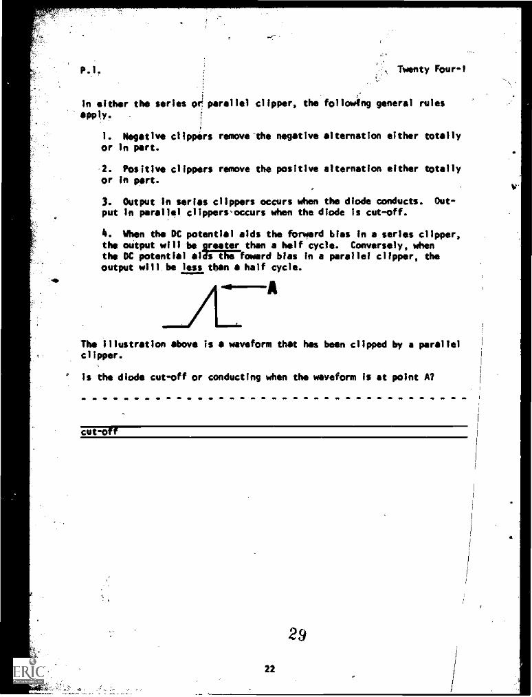
4. When the DC potential aids the forward bias in a series clipper,the output will be rooter than a half cycle. Conversely, whenthe DC potential at s the foward bias in a parallel clipper, theoutput will. be less than a half cycle.
The illustration above is a waveform that has been clipped by a parallelclipper.
Is the diode cut-off or conducting when the waveform is at point A?
cut-off
29
22
P.I. Twenty Four-t
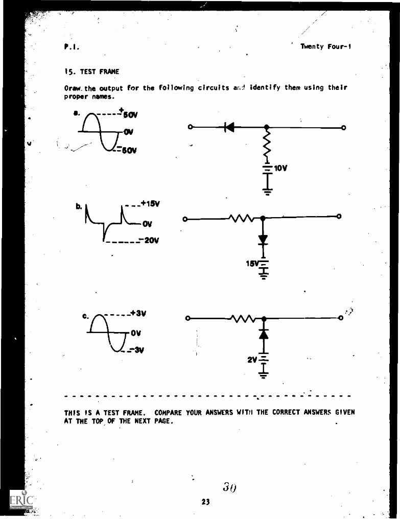
15. TEST FRAME
Draw. the output for the following circuits and identify them using their
proper names.
--504
OW
-GOV
OV
0- 0
=WV
I
o --11//\/-0
THIS IS A TEST FRAME. COMPARE YOUR ANSWERS WITH THE CORRECT ANSWERS GIVEN
AT THE TOP OF THE NEXT PAGE.
3 023
P.i Twenty Four-1
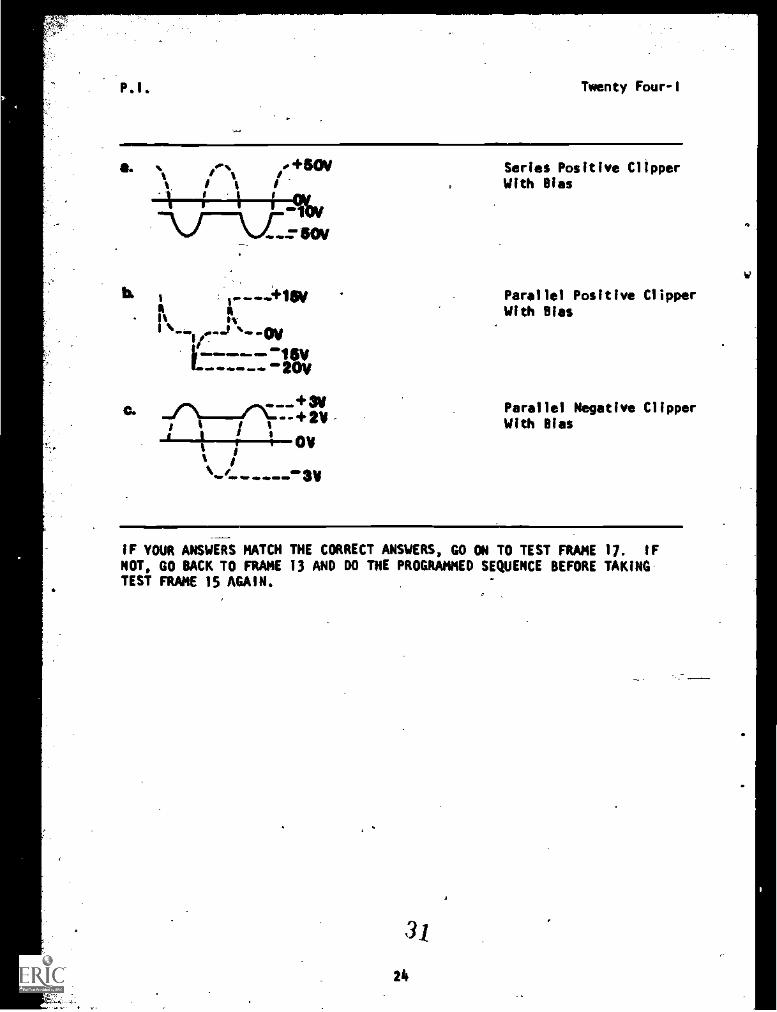
Series Positive ClipperWith Bias
Parallel Positive ClipperWith Bias
Parallel Negative ClipperWith Bias
IF YOUR ANSWERS MATCH THE CORRECT ANSWERS, GO ON TO TEST FRAME 17. IF
NOT, GO BACK TO FRAME 13 AND DO THE PROGRAMMED SEQUENCE BEFORE TAKINGTEST FRAME 15 AGAIN.
3/
21.
P.I. Twenty Four-I
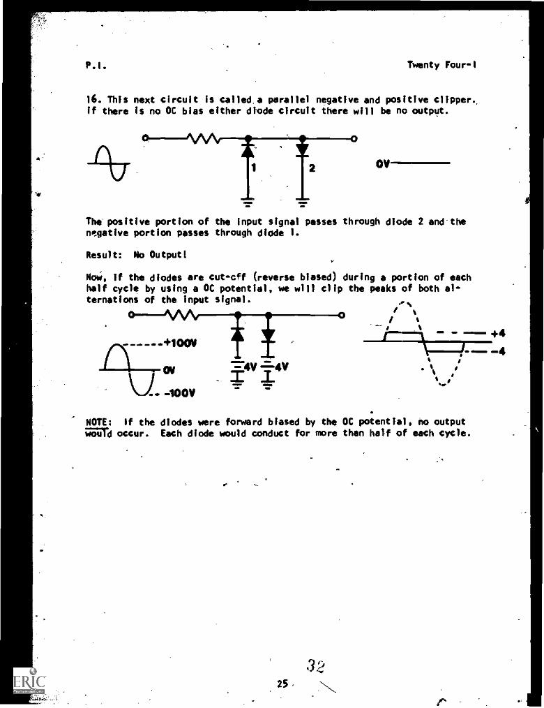
16. This next circuit is called.a parallel negative and positive clipper,if there is no OC bias either diode circuit there will be no output.
2
0
OV-
The'positive portion of the input signal passes through diode 2 and-thenegative portion passes through diode 1.
Result: No Output!
NoW, if the diodes are cut-cff (reverse biased) during a portion of eachhalf cycle by using a OC potential, we will clip the peaks of both al-ternations of the input signal. or %
0
+100v
-10011
=-4V 4V:I: .I.
- -4
NOTE: if the diodes were forward biased by the OC potential, no output;an occur. Each diode would conduct for more than half of each cycle.
3225
P.I. Twenty Four-I
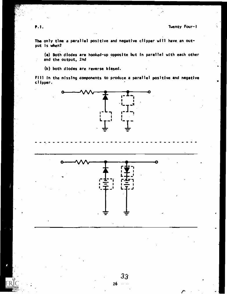
The only time a parallel positive and negative clipper will have, an out-put is when?
(a) Both diodes are hooked-up opposite but in parallel with each otherand the output, 2nd
(b) both diodes are reverse biased.
Fill in the missing components to produce a parallel positive and negativeclipper.
01..
e
_L _L
4=,=1.11M11.
L
gmb
0
3326
el
P.I. Twenty Four-I
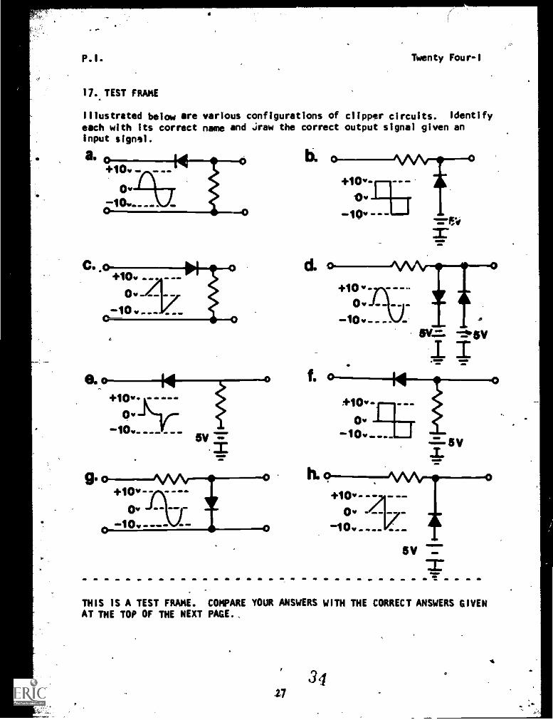
17. TEST FRAME
Illustrated below are various configurations of clipper circuits. Identify
each with its correct name and draw the correct output signal given anInput signal.
a.
0.o+10v-
5v
0
b.
IL4. 1 0 ' . O. M. .011, . . .
`.1 0W . . . O. - --
5V
THIS IS A TEST FRAME. COMPARE YOUR ANSWERS WITH THE CORRECT ANSWERS GIVENAT THE TOP OF THE NEXT PAGE..
3427
4
PI. Twenty Four-1
''`.+10 IN
$
a. 0
10
+10
0. 0
10 ILmJ
+10 A.e.
10 1/
+10
d. 0
10
+10
e. 0
10
0.40
+10
+10
h. 01 0
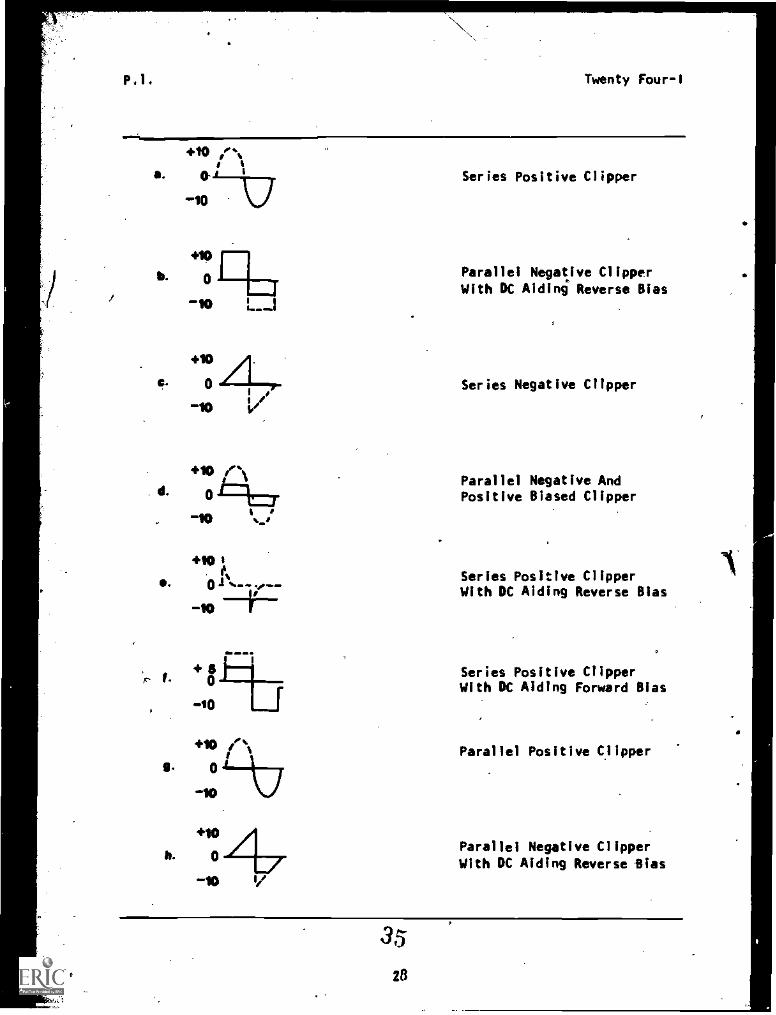
Series Positive Clipper
Parallel Negative Clipper
With DC Aiding Reverse Bias
Series Negative Clipper
Parallel Negative AndPositive Biased Clipper
Series Positive ClipperWith DC Aiding Reverse Bias
Series Positive ClipperWith DC Aiding Forward Bias
Parallel Positive Clipper
Parallel Negative ClipperWith DC Aiding Reverse Sias
35
Twenty Four-I
IF YOUR ANSWERS MATCH THE CORRECT ANSWERS, YOU HAVE COMPLETED THEPROGRAMMED INSTRUCTION FOR LESSON I. OTHERWISE, GO BACK TO FRAME IANO TAKE THE PROGRAMMED SEQUENCE BEFORE TAKING TEST FRAME 17 AGAIN.
AT THIS POINT, YOU MAY TAKE THE LESSON PROGRESS CHECK. IF YOU
ANSWER ALL SELF-TEST ITEMS CORRECTLY, PROCEEO TO THE NEXT LESSON.IF YOU INCORRECTLY ANSWER ONLY A FEW OF THE PROGRESS CHECK QUESTIONS,THE CORRECT ANSWER PAGE WILL REFER YOU TO THE APPROPRIATE PAGE:),PARAGRAPHS,. OR FRAMES SO THAT YOU CAN RESTUOY THE PARTS OF THISLESSON YOU ARE. RAVING DIFFICULTY WITH. IF YOU FEEL THAT YOU NAVEFAILEO TO UNOERSTANO ALL, OR OF THE LESSON, SELECT ANO uSEANOTHER WRITTEN MEOIUM OF INSTRUCTION, AUDIO /VISUAL MATERIALS (IFAPPLICABLE), OR CONSULTATION WITH LEARNING SUPERVISOR, UNTIL YOUCAN ANSWER ALL SELF-TEST ITEMS ON THE PROGRESS CHECK CORRECTLY.
3629
(
Narrative' Twenty Four-I
NARRATIVELESSON I
Clippers
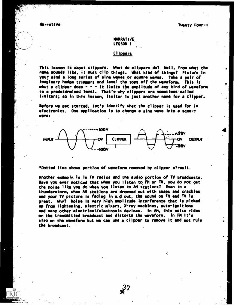
This lesson is about clippers. Whet do clippers do? Weil, from what thename sounds like, it must clip things. that kind of things? Picture inyour mind a long series of sine ways* or square waves. Take a pair ofimaginary hedge trimmers and level the tops off the waveform. This iswhat is.ctippor does - - it limits the amplitude of any kind of waveformto s predetermined level. That's why clippers are solatime calledlimiters; so in this lesson, limiter is just another name for a clipper.
Oefore we get started, let's identify what the clipper is used for inelectronics. Ons application Is to change a sine wave into a squaremope:
INPUT
.1001,
CLIPPER
_---A25V
OV OliPPUT
=WV'I
*Dotted line shows portion of waveform removed by, clipper circuit.
Another example is in FM radios and the audio portion of TV broadcasts.Nave you ever noticed that when you listen to FM or TV, you do not getthe noise like you do when you listen to AM stations? Even in athunderstorm, when AM stations are drowned out with snaps and cracklesand your TV picture is fading in a.od out, the sound on FM and TV isgreet. Why? Noise is very high amplitude interference that is pickedup from lightening, electric mixers, X-ray machines, uto-ignitionsand many other electrical/electronic devices. In AM, this noise rideson the transmitted broadcast and distorts the waveform. In FM it's
also on the waveform but we can use a clipper to remove it and not ruinthe broadcast.
3W7
4.
Narrative
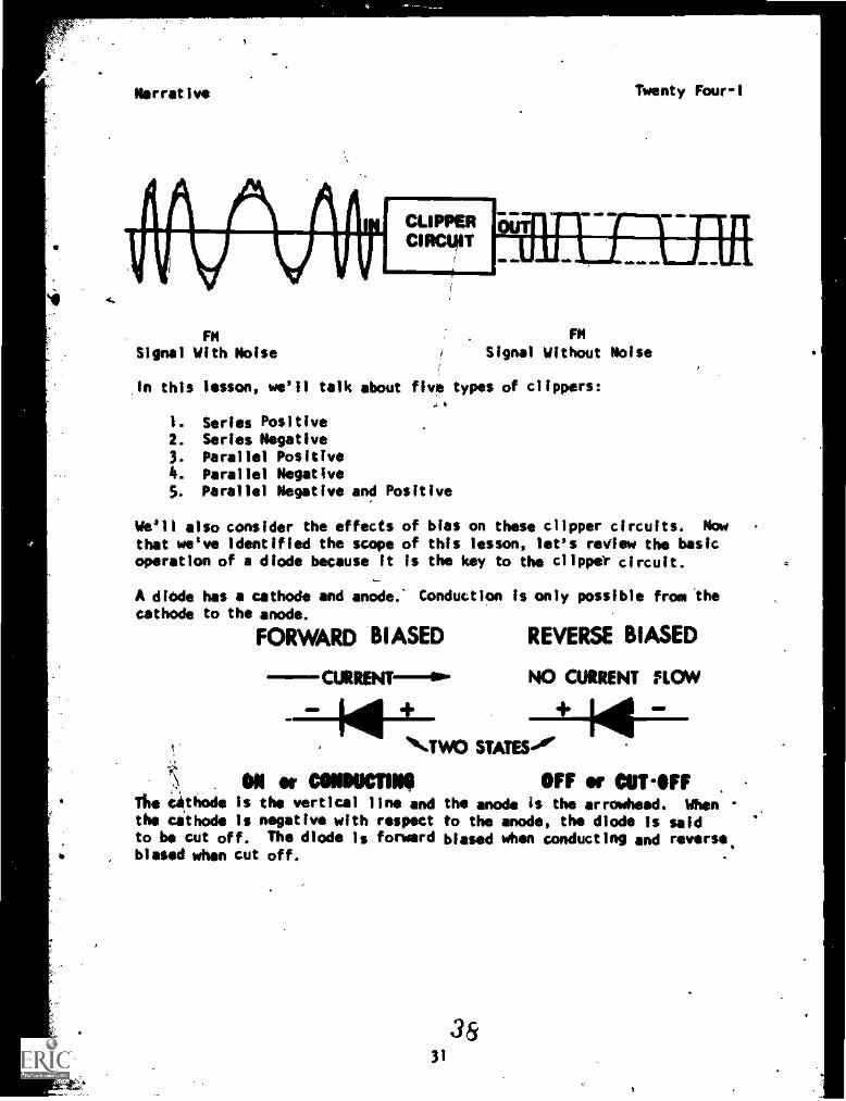
FMSignal With Noise
CLIPPERCIRCUIT
Twenty Four -I
FM
Signal Without Noise
In this lesson, we'll talk about five types of clippers:*
1. Series Positive2. Series Negative3. Parallel Positive4. Parallel Negative5. Parallel Negative and Positive
We'll also consider the effects of bias on these clipper circuits. Nowthat we've identified the scope of this lesson, let's review the basicoperation of a diode because it is the key to the clipper circuit.
A diodecathode
has a cathode and anode.- Conduction is only possible from theto the anode.
FORWARD 'BIASED REVERSE BIASED
CURRENT- NO CURRENT FLOW
TWO STATES-
ON or CONINICTINOThe Cdthode is the vertical line andthe cathode is negative with respectto be cut off. The diode 1s forwardbiased when cut off.
OFF or CUT -OFFthe anode is the arrowhead. Whento the anode, the diode is saidbiased when conducting and reverse.
31
38
Narrative Twenty Four-1
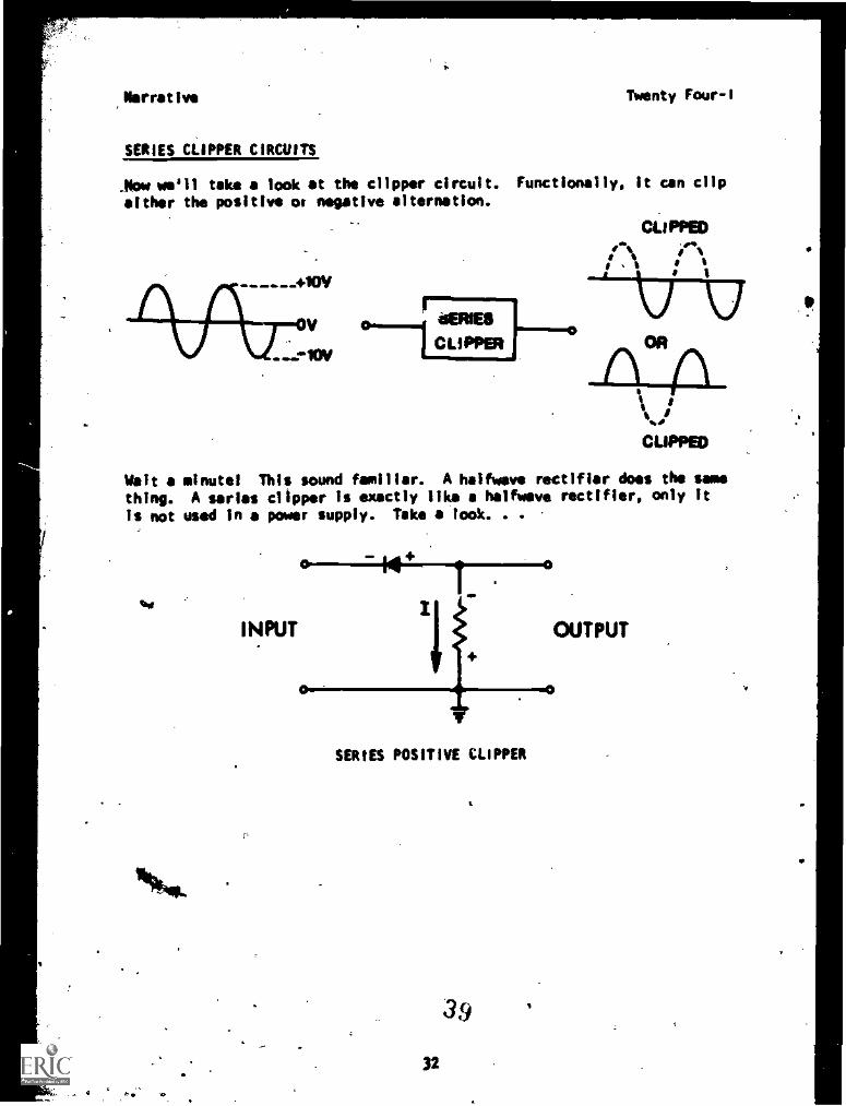
SERIES CLIPPER CIRCUITS
_flow we'll take a look at the clipper circuit. Functionally, it can clip
either the positive 04 negative alternation.
CE11941111LIPPERI--e
CLIPPEDsest. ,»
s sI
CUPPED
Wait a minute! This sound familiar. A halfweve rectifier does the same
thing. A series clipper is exactly like a halfwaye rectifier, only it
is not used in a power supply. Take a look. . .
%I
INPUT
0
T.0
SERIES POSITIVE CLIPPER
32
39
OUTPUT
V
Narrative Twenty four-I
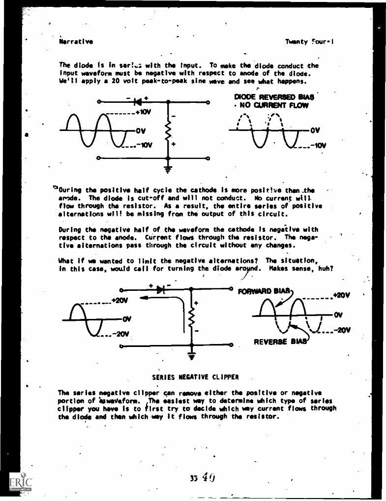
The diode is in sera..: with the input. To make the diode conduct theinput waveform must be negative with respect to anode of the diode.We'll apply a 20 volt peek-to-peek sine wave and see what happens.
P
0100E REVERSED 111A8NO CURFINT FLOW
,+10V
OV OV
130uring the positive half cycle the cathode is more positive than.thertde. The diode is cut-off and will not conduct. No current will.flow through the resistor. As result, the entire series of pOsitivealternations will be missing from the output of this circuit.
During the negative half of the waveform the cathode is negative withrespect to the anode. Current flows through the resistor. The nega-
tive alternations pass through the circuit without any changes.
What if we wanted to limit the negative alternations? The situation,in this case, would calf for turning the diode rynd. Makes sense, huh?
SERIES NEGATIVE CLIPPER
The series negative clipper can remove either the positive or negativeportion of , waveform.
first
easiest way to determine which type of seriesclipper you have is to first try to-decide which way current flows throughthe diode and then whichey it flaws through the resistor.
3340
Narrative Twe*ty Four-3
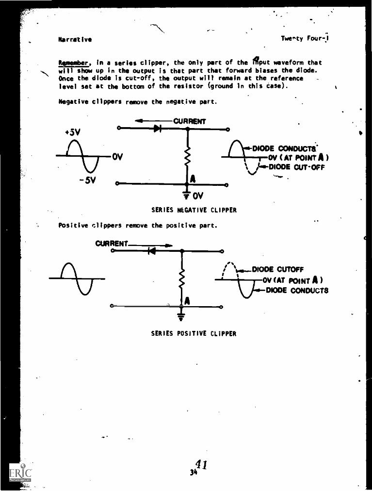
r, In a series clipper, the only part of the Olput waveform that
'di show up in the output is that part that forward biases the diode.Once the diode is cut-off, the output will remain at the referencelevel sat at the bottom of the resistor (ground in this case).
Negative clippers remove the negative part.
-5V
DIODE CONDUCTS'OV (AT POINT A )DIODE CUTOFF
lr CPI
SERIES NEGATIVE CLIPPER
Positive Clippers remove the positive part.
CURRENT r ,
II b.....-DIODE CUTOFF
uo_OV CAT POINT A)DIODE CONDUCTS
SERIES POSITIVE CLIPPER
3441
t
'
Nerrative
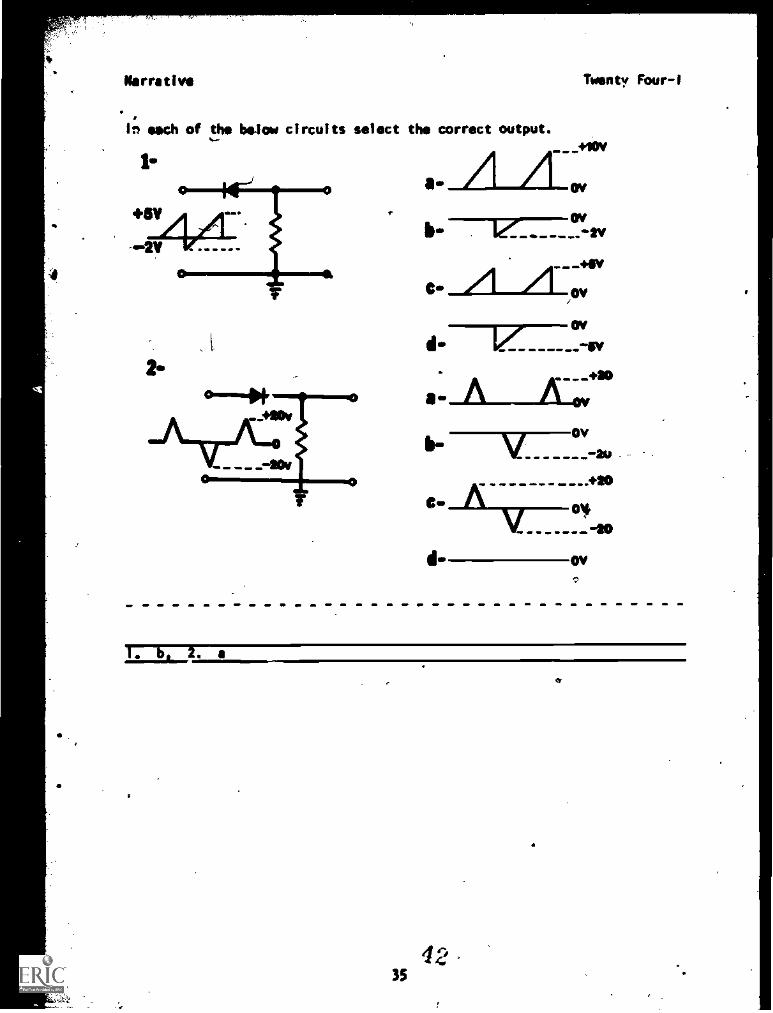
In each of the below circuits select the correct output.
Meaty Four-I
_tow
ow
777---cr.-2v
A- +so
VOV
1 2. a
35
'Narrative Twenty Four-1
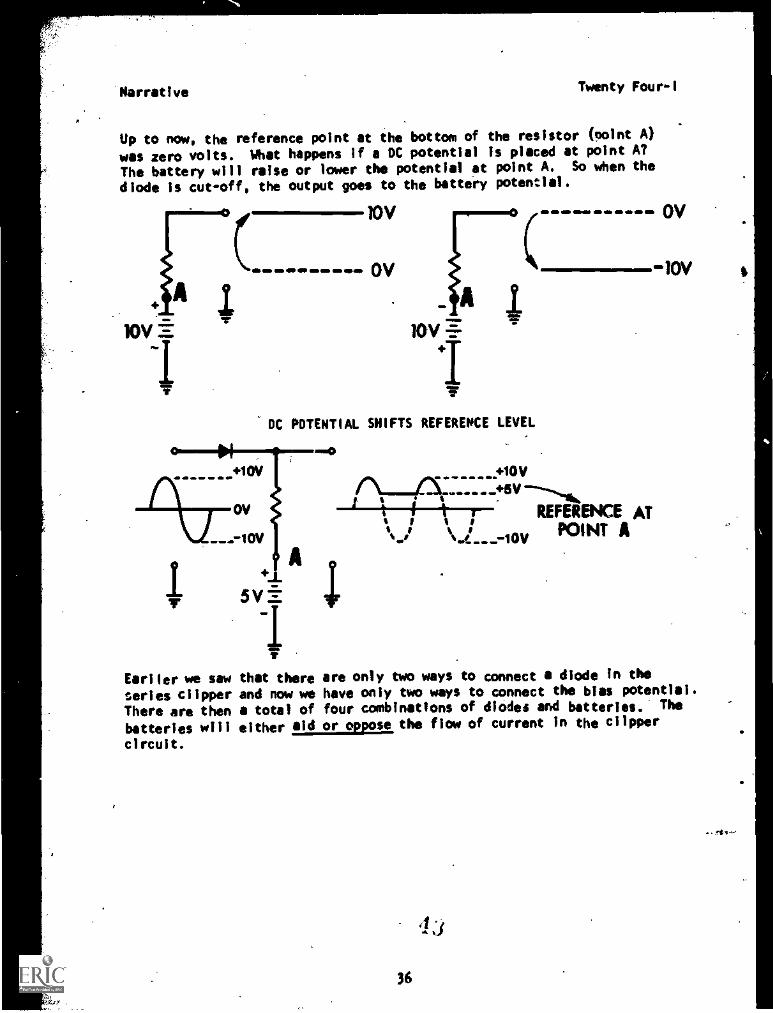
Up to now, the reference point at the bottom of the resistor (point A)
was zero volts. What happens if a DC potential is placed at point A?
The battery will raise or lower the potential at point A. So when the
diode is cut-off, the output goes to the battery potential.
10y
OV
10
DC POTENTIAL SHIFTS REFERENCE LEVEL
Earlier we sawseries clipperThere are then
batteries willcircuit.
5 V
1F
that thereand now wea total of
either aid
w.0
- OV
-10V
0Vr\--A +5V
REFERENCE ATPOINT A
A,
are only two ways to connect a diode in the
have only two ways to connect the bias potential.
four combinations of diodes and batteries.' The
se the flow of current In the clipper
la
36
Narrative
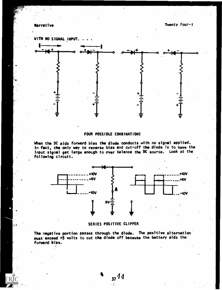
WITH NO SIGNAL INPUT. . . .
I
Twenty Four-I
FOUR POSSIBLE COMBINATIONS
When the DC aids forward bias the diode condUcts with no signal applied.In fact, the only way to reverse bias and cut-off the diode is to have theinput signal get large enough to over balance the DC source. Look at the
following circuit.
0. SERIES POSITIVE CLIPPER
The negative portion passes through the diode. The positive alternation
must exceed +5 volts to cut the diode off because the battery aids the.
forward MO.
437
4 4
NarrativeTwenty Four-I
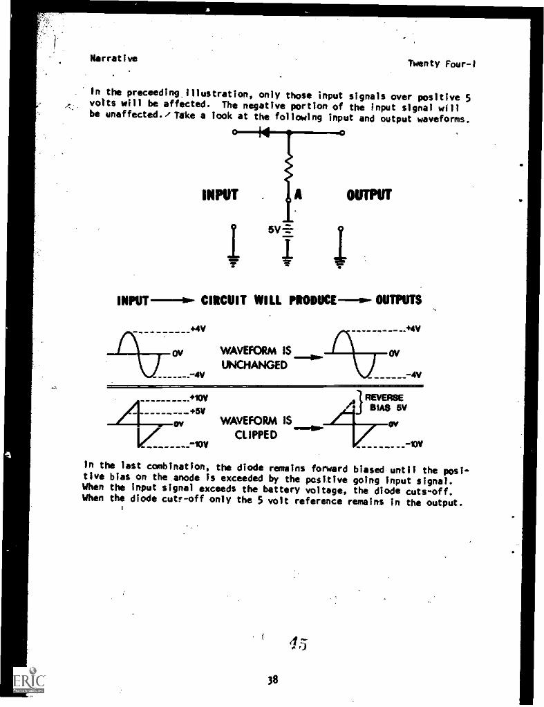
In the proceeding. illustration, only those input signals over positive 5volts will be affected. The negative portion of the input signal willbe unaffected./ Take a look at the following input and output waveforms.
INPUT
INPUT-- CIRCUIT WILL PRODUCEw- OUTPUTS
+4V .44V
4V
WAVEFORM IS ovUNCHANGED
-4V
- Ov
+8VWAVEFORM IS
CLIPPED
l'I;IAs 5V
to
In the last combination, the diode remains forward biased until the posi-tive bias on the anode is exceeded by the positive going input signal.When the input signal exceeds the battery voltage, the diode cuts-off.When the diode cute -off only the 5 volt reference remains in the output.
1
45
38
Narrative Twenty Four-I
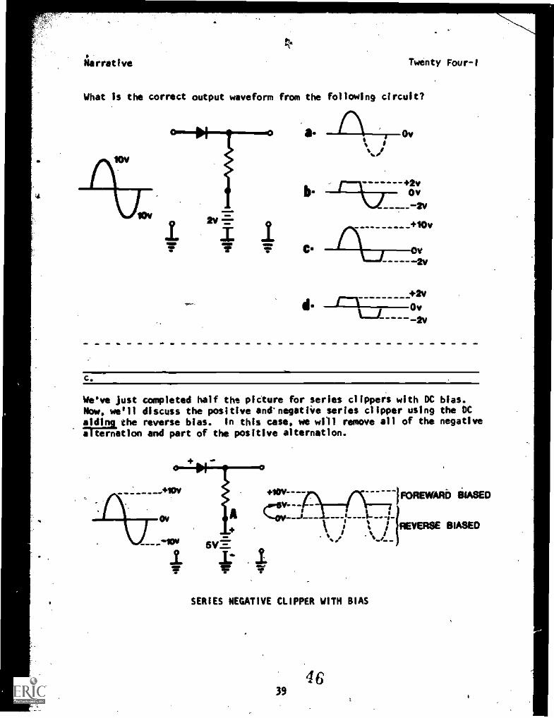
What is the correct output waveform from the following circuit?
2v
Ov
+2vOv
..._....2v
10v
Ov-2v
+2vov
-----2v
c.
We've just completed half the picture for series clippers with DC bias.Now. we'll discuss the positive and'negative series clipper using the DC
Idsliuthe reverse bias. In this case, we will remove all of the negative
a ation and part of the positive alternation.
1:
FOREWARb AIMED
.wwtw
k ; % / REVERSE BIASED
8
SERIES NEGATIVE CLIPPER WITH BIAS
4639
Narrative- Twenty Four-I
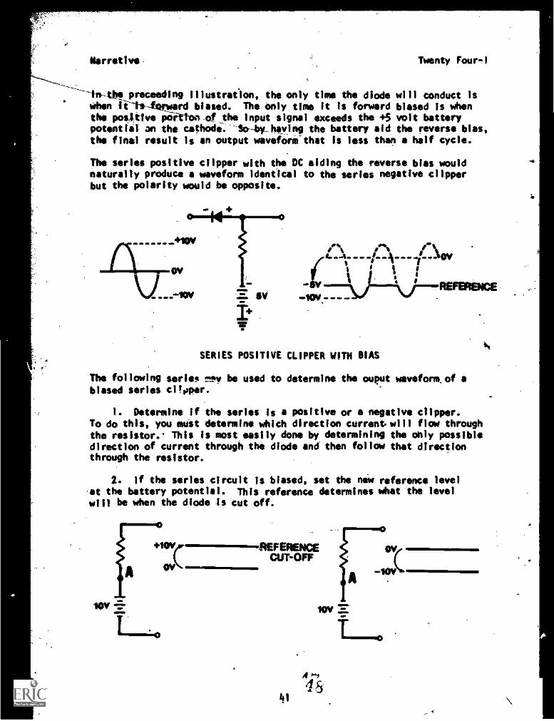
-in-tbe proceeding illustration, the only time the diode will conduct iswhen fi-ts-forword biased. The only time it is forward biased is whenthe positive poittoaof the input signal exceeds the +5 volt batterypotential; an the cathode.--So-bv_haying the battery aid the reverse bias,
the final result is an output waveform-that is less than a half cycle.
The series positive clipper with the DC aiding the reverse bias wouldnaturally produce a waveform identical to the series negative clipperbut the polarity would be opposite.
1\ ov
gy
_+10W
0
111=110100,-
19. lte."11I
SERIES POSITIVE CLIPPER WITH BIAS
REFERENCE
The following series MPV be used to determine the ouput waveforniof abiased series clioper.
I. Determine if the series is a positive or a negative clipper.To do this, you must determine which direction current. will flow throughthe resistor.' This is most easily done by determining the ohiy possibledirection of current through the diode and then follow that directionthrough the resistor.
2. If the series circuit Is biased, set the new reference levelat the battery potential. This reference determines what the levelwill be when the diode is cut off.
tov
+10vFEREAKECUT-OFF
Otik
iov
A0.4
4541
Narrative Twenty Four-1
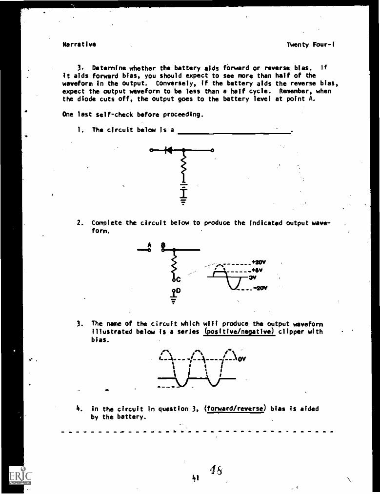
3. Determine whether the battery aids forward or reverse bias. if
It aids forward bias, you should expect to see more than half of thewaveform in the output. Conversely, If the battery aids the reverse bias,expect the output waveform to be less than a half cycle. Remember, whenthe diode cuts off, the output goes to the battery level at point A.
One last self-check before proceeding.
1. The circuit below is a
M 0
2. Complete the circuit below to produce the indicated output wave-form.
A 8
pC
+20V+evov
3. The name of the circuit which will produce the output waveformIllustrated below Is a series (positive/negative) clipper withbias.
\ _Am ___ ov.
4. In the circuit In question 3, (forward/reverse) bias Is aidedby the battery.
1.1
Narrative Twenty Four-I
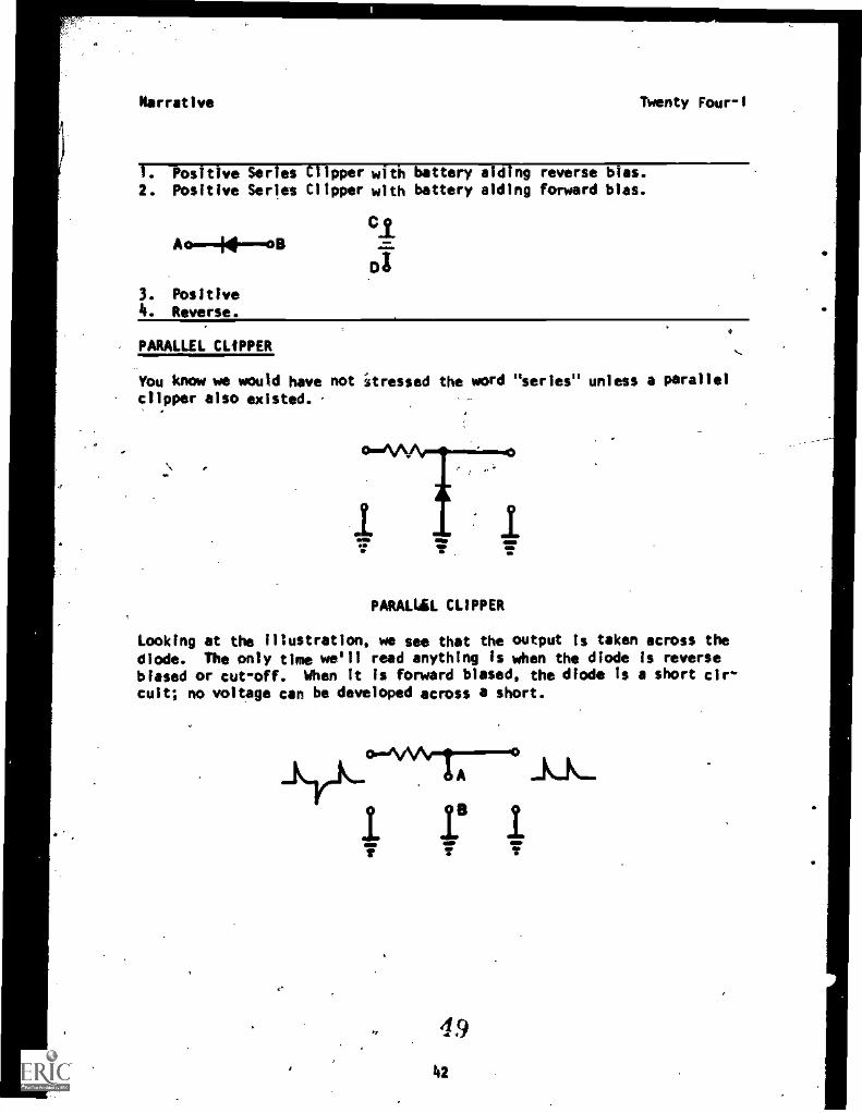
1. Positive Series Clipper with battery aiding reverse bias.2. Positive Series Clipper with battery aiding forward bias.
Cl
3. Positive4. Reverse.
oa
PARALLEL CLIPPER
You know we would have not 1tressed the word "series" unless a parallelclipper also existed.
PARALLEL CLIPPER
ID
Looking at the illustration, we see that the output is taken across the
diode. The only time we'll read anything is when the diode is reversebiased or cut-off. When It is forward biased, the diode Is a short cir-
cuit; no voltage can be developed across a short.
-Lrk-°V\A-1A
ILL
49
Narrative Twenty F"--1
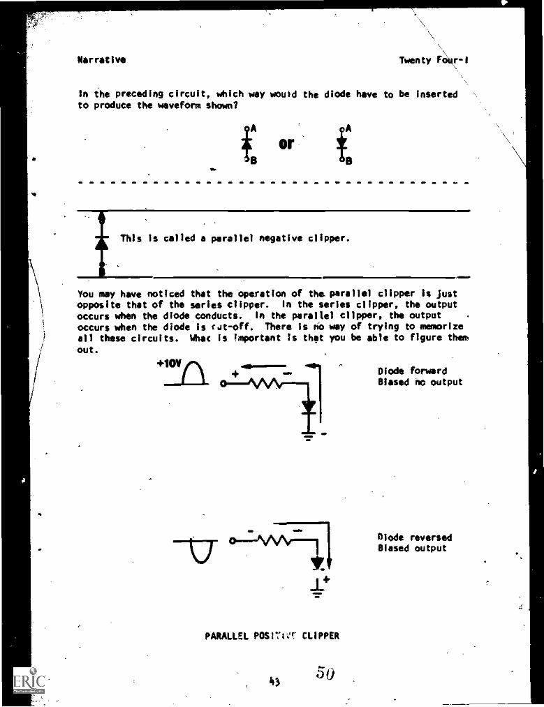
In the preceding circuit, which way would the diode have to be insertedto produce the waveform shown?
or
This is called a parallel negative clipper.
You may have noticed that the 'operation of the parallel clipper is justopposite that of the series clipper. In the series clipper, the outputoccurs when the diodeconducts. In the parallel clipper, the output
occurs when the diode is cut-off. There is no way of trying to memorize
all these circuits. What is important is that you be able to figure them
out.
PARALLEL 11°Sr:1ff CLIPPER
43 0
Diode forwardBiased no output
Olode reversedBiased output
Narrative Twenty Four-I
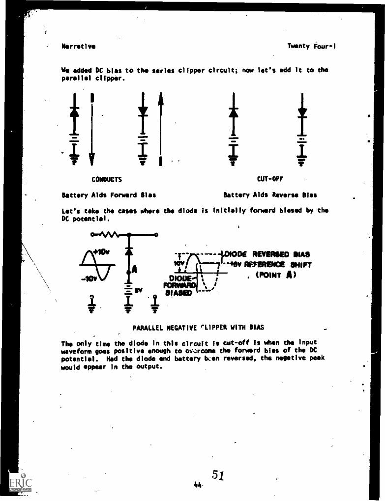
We added DC bias to the series clipper circuit; now let's add it to theparallel clipper.
I
f fT
CONDUCTS CUT-OFF
Battery Aids Forward Bias Battery Aids Reverse Bias
Let's take the cases whore the diode is initially forward biased by theDC potential.
Asv
-----1.01006 REVERSED SIAS40v AFFIRMS SHIFT
O 6(POINT )
BIASED#I 0
m. WO. -
PARALLEL NEGATIVE 'SLIPPER WITH BIAS 4.0
The only time the diode in this circuit is cut-off is when the inputwaveform goes positive enough to owrcome the forward bias of the DCpotential. Had the diode and battery ben reversed, the negative peakwould appear in the output.
5j44,
4
Narrative TWentyFour -I
OUTPUT r%
11V7-1/4/-
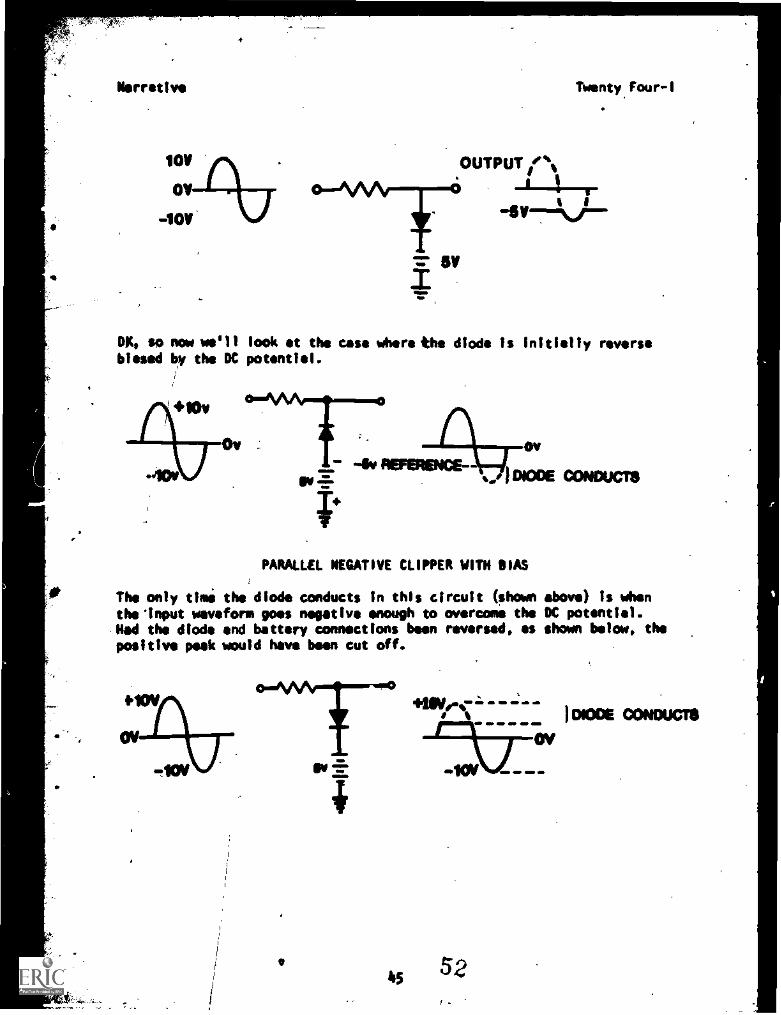
0$4 so now we'll look at the use Otero the diode is initially reversebiased by the OC potential.
PARALLEL NEGATIVE CLIPPER WITH BIAS
The only timi the diode conducts in this circuit (shown above) Is whenthe 'input waveform goes negative enough to overcome the OC potential.Ned the diode and battery connections been reversed, as shown below, thepositive peek would have been cut off.
4552
I woe CONDUCTS
OV
Narrative
1'
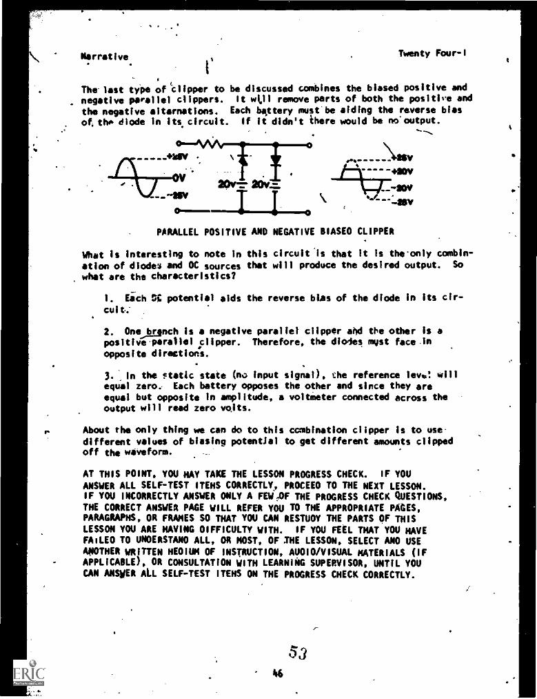
The last type of clipper to. negative parallel clippers.
the negative alternations.of the diode in its circuit.
Twenty Four-1
be discussed combines the biased positive andIt All remove parts of both the positive and
Each bqttery must be aiding the reverse biasIf it didn't there would be no.output.
0
PARALLEL POSITIVE AND NEGATIVE BIASEO CLIPPER
What is interesting to note in this circuit is that it is theonly combin-
ation of diodes and OC sources that will produce the desired output. So
what are the characteristics?
1. Each 0,7, potential aids the reverse bias of the diode in its cir-
cuit:
2. Onejganch is a negative parallel clipper aId the other is apositive parallel clipper. Therefore, the diodes myst face in
opposite directions.
3 .In the $tetic state (no input signal), the reference ley*: willequal tero Each battery opposes the other and since they areequal but opposite In amplitude, a voltmeter connected across theoutput will read zero volts.
About the only thing we can do to this combination clipper Is to usedifferent values of biasing potential to get different amounts clippedoff the weVeform.
AT THIS POINT, YOU NAY TAKE THE LESSON PROGRESS CHECK. IF YOU
ANSWER ALL SELF-TEST ITEMS CORRECTLY, PROCEEO TO THE NEXT LESSON.IF YOU INCORRECTLY ANSWER ONLY A FEW,OF THE PROGRESS CHECK QUESTIONS,THE CORRECT ANSWER PAGE WILL REFER YOU TO THE APPROPRIATE PAGES,PARAGRAPHS, OR FRAMES SO THAT YOU CAN RESTUOY THE PARTS OF THISLESSON YOU ARE HAVING OIFFICULTY WITH. IF YOU FEEL THAT YOU HAVEFAILED TO UNOERSTANO ALL OR MOST, OF 'HE LESSON, SELECT ANO USEANOTHER WRITTEN MEOIUM OF INSTRUCTION, AU010/VISUAL MATERIALS (IFAPPLICABLE), OR CONSULTATION WITH LEARNING SUPERVISOR, UNTIL YOUCAN ANSWER ALL SELF-TEST ITEMS ON THE PROGRESS CHECK CORRECTLY.
5346
3
Si
oiS
BASIC ELECTRICITY AND ELECTRONICS
NODULE TWENTY FOUR
LESSON II
CLANPERS
I APRIL 1977
5447
to
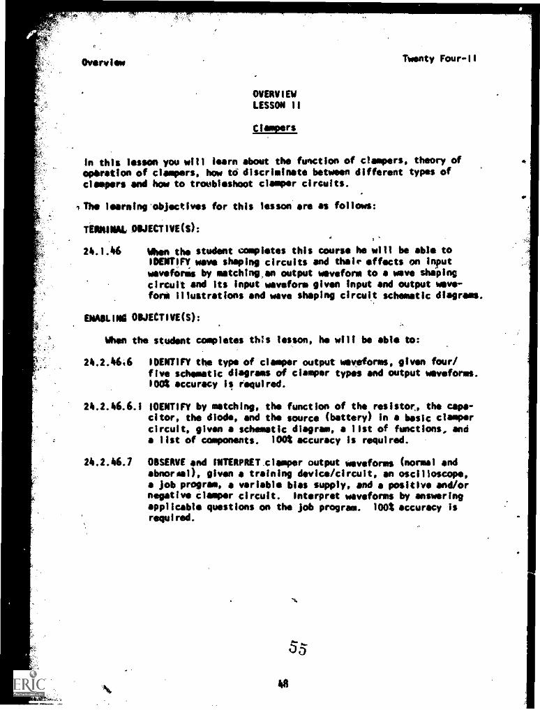
OVERVIEWLESSON 11
In this lesson you will learn about the function of dampers, theory ofoperation of dampers, how to discriminate between different types ofclampers and how to troubleshoot damper circuits.
The learning objectives for this lesson are as follows:
TERMINAL OBJECTIVE(S):
24.1.46 When the student completes this course he will be able toIDENTIFY wave shaping circuits and their effects on inputwevefOris by metchtng,an output waveform to a wave shapingcircuit and its input waveform given input and output wave -for* illustrations and wave shaping circuit schematic diagrams.
DUBLIN OBJECTIVE(S):
When the student completes this lesson, he will be able to:
24.2.46,6 IDENTIFY the type of clasper output waveforms, given four/five schematic diagrams of damper types and output waveforms.1001 accuracy 11 required.
24.2.46.6.1 IDENTIFY by matching, the function of the resistor, the capa-citor, the diode, and the source (battery) in a basic claspercircuit, given a schematic diagram, a list of functions, anda list of components. 100% accuracy is required.
24.2.46.7 OBSERVE and mumunrclamper output waveforms (normal andabnormal), given a training device/circuit, an oscilloscope,a job program, a variable bias supply, and a positive and/ornegative Clasper circuit. Interpret waveforms by answeringapplicable questions on the Job program. 100% accuracy isrequired.
8
55
Overview Twenty Four11
OVERVIEW
. 24.2.46.7.1 LOCATE all of the compoughts in each input section, outputsection, and conversion section of the two basic types ofdamper circuits (positive and negative), given a treningdevice or circuit boards containing damper circuits, a Jobprogram, and the applicable schematic diagreAs or technicalmanuals. 100% accuracy is required.
24.2.46.7.2 IDENTIFY the type of clasper and the amount and polarity ofbias, given a training device, a Job program, an oscillo-scope and the applicable schematic diagram. Either theoscilloscope waveform or schematic diagram, or both, may beused in analyzing for type and/or biasing. 100% accuracy isrequired.
BEFORE YOU START THIS LESSON, READ THE LESSON LEARNING OBJECTIVES ANDPREVIEW THE LIST OF STUDY RESOURCES ON THE NEXT PAGE.
"9
56
I
Stinly Resources
LIST OF STUDY RESOURCES'
LESSON II
-Clampers
Twenty Four-II
To learn the material in this lesson, you have the option of choosing,according to your experience and preferences, any or all of the follow-ing study resources:
Written Lesson presentation in:
Module Booklet:
Summary
Programmed instructionNarrative
Student's Guide:
Job Program Twenty Four-II "Clampers"Progress Check
Additional Material(s):
Audio/Visual Program Twenty Four-II "Introduction to Clampers"
Enrichment Material (s):
Markus, J., Electronic & Nucleonics DictionaryNew York, McGraw Hill Book Co., 1960
Basic Electronics, Vol. 2, NAVPERS 10087-CFundamentals of Electrdnics, Vol. 5, NAVPERS 93400A-5
YOU NAY USE ANY, OR ALL, RESOURCES LISTED ABOVE, INCLUDING THE LEARNINGSUPERVISOR; HOWEVER, ALL MATERIALS LISTED ARE NOT NECESSARILY REQUIREDTO ACHIEVE LESSON OBJECTIVES. THE PROGRESS CHECK MAY BE TAKEN AT ANYTIME.
50.57
Summary Twenty Four -II
SUMMARYLESSON II
pampers
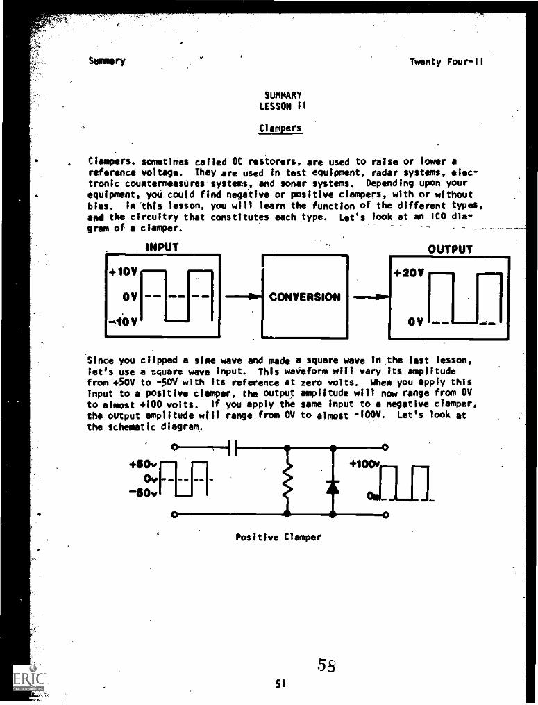
Clampers, sometimes called OC restorers, are used to raise or lower areference voltage. They are used in test equipment, radar systems, elec-tronic countermeasures-systems, and sonar systems. Depending upon yourequipment, you could find negative or positive dampers, with or withoutbias. In this lesson, you will learn the function of the different types,and the circuitry that-constitutes each type. Let's look at an ICO die-gram of a ciamper.
INPUT
+10V
0V
-40V
=,
F
CONVERSION
OUTPUT
+20V
0V
1a- amj
Since you clipped a sine wave and made a square wave in the lest lesson,
let's use a square wave input. This waveform will vary its amplitudefrom +50V to -50V with its reference at zero volts. When you apply thisinput to a positive damper, the output amplitude will now range from OVto almost +100 volts. If you apply the same input to-a negative damper,the output amplitude will range from OV to almost aloov. Let's look at
the schematic diagram.
Positive Clamper
5851
Summery Twenty Four:-11
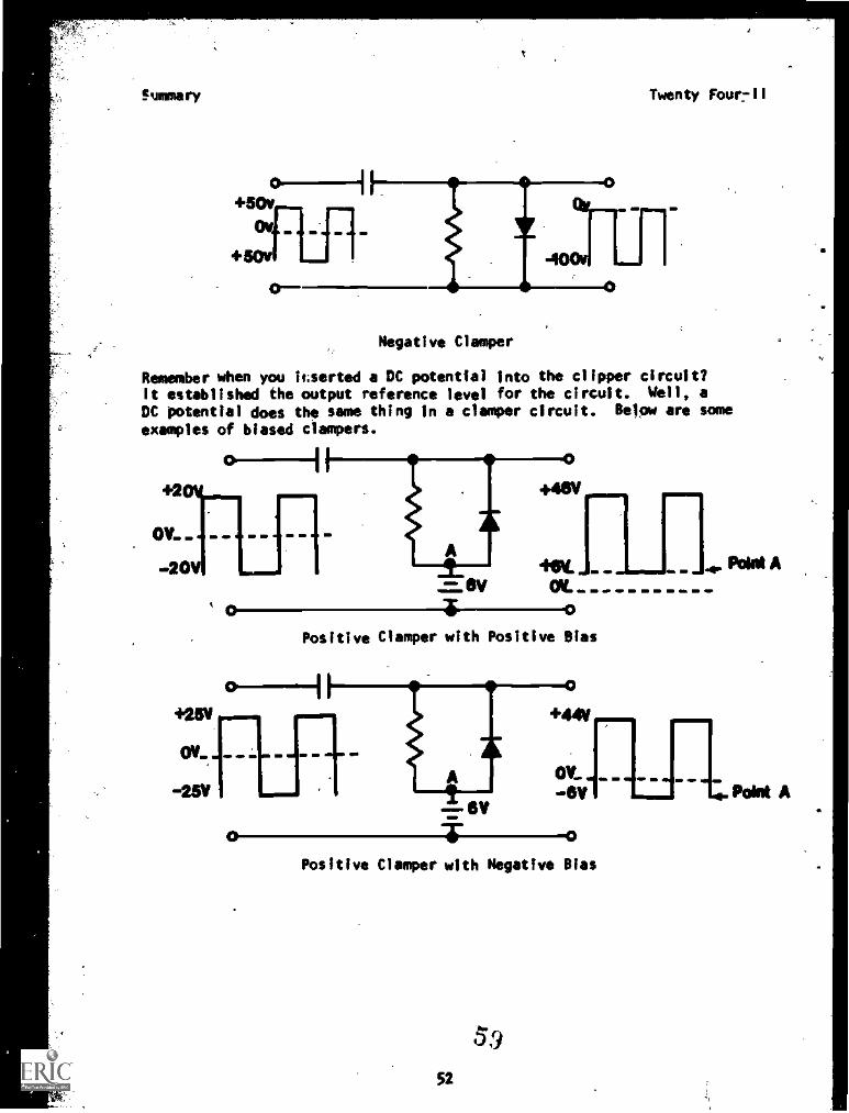
Negative Clamper
Remember when you icsorted a DC potential into the clipper circuit?It established the output reference level for the circuit. Well, a
DC potential does the same thing in a damper circuit. Below are some
examples of biased clamors.
0
JOE .millm M.
Positive Clover with Positive Bias
0
+44V
OV-611Iv
Positive Clamper with Negative Bias
52
59
4. Paint A
Ai. Point A
Summary Twenty Four-fl
At this time you may be asking yourself "Now do these circuits work?"' It's all in the time constants. The diode (forward biased) and capacitor
produce a very, short time constant. When the diode is reverse biased theresistor and capacitor produce a very long time constant. This action
of short and long time constants keeps the voltage acres the capacitorconstant. Keeping the voltage level almost.constant across the capacitorraises or lowers the output voltage reference level. This can be provenby the apllication of Kirchoff's voltage law.
AT THIS POINT, YOWMAY TAKE THE LESSON PROGRESS CHECK. fF YOU
ANSWER ALL SELF-TEST ITEMS CORRECTLY, PROCEED TO ThE NEXT LESSON.IF YOU.INCORRECTLY ANSWER ONLY A FEW OF THE PROGRESS CHECK QUESTIONS,THE CORRECT ANSWER PAGE WILL REFER YOU TO THE APPROPRIATE PAGES,PARAGRAPHS, OR FRAMES SO THAT YOU CAN RESTUDY THE PARTS OF THISLESSON YOU ARE HAVING DIFFICULTY WITH. IF YOU FEEL THAT YOU HAVEFAILED TO UNDERSTAND ALL, OR MOST, OF THE LESSON, SELECT AND USEANOTHER WRITTEN MEDIUM OF INSTRUCTION, AUDIO/VISUAL MATERIALS (IFAPPLICABLE), OR CONSULTATION WITH LEARNING SUPERVISOR, UNTIL YOU.CAN ANSWER ALL SELF-TEST ITEMS ON THE PROGRESS CHECK,CORRECTLY.
53
Tima.waits for no man.. .
ACCIDENTS
WAIT
FOR
EVERYONE.
COMPLACENCY KILLS!
61
54
P.I. TWenty Four -II
PROGRAMMED. INSTRUCTIONLESSON II
Clampers
TEST FRAMES ARE II AND 14. AS BEFORE, GO FIRST TO TEST FRAME Ii AND SEEIF YOU CAN ANSWER ALL THE QUESTIONS THERE. FOLLOW THE DIRECTIONS GIVENAFTER THE TEST FRAME.
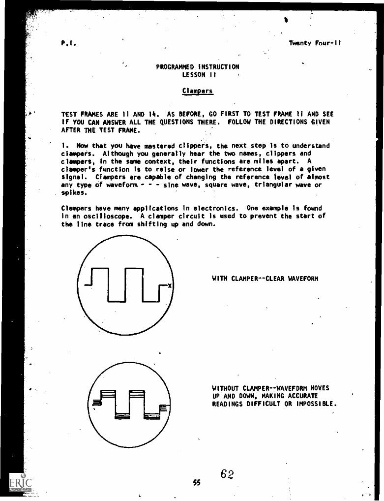
1. Now that you have mastered clippers, the next step is to understanddampers. Although you generally hear the two names, clippers anddampers, in the same context, their functions are miles apart. Adamper's function is to raise or lower the reference level of a givensignal. Ciampers are capable of changing the reference level of almostany type of waveform.- - - sine wave, square wave, triangular wave or
. spikes.
Clampers have many applications in electronics. One example is foundin an oscilloscope. A damper circuit is used to prevent the start ofthe line trace from shifting up and down.
55
WITH CLAMPER--CLEAR WAVEFORM
WITHOUT CLAMPER--WAVEFORM HOVESUP AND DOWN, MAKING ACCURATEREADINGS DIFFICULT OR IMPOSSIBLE.
6`)
P.I. Twenty Four-11
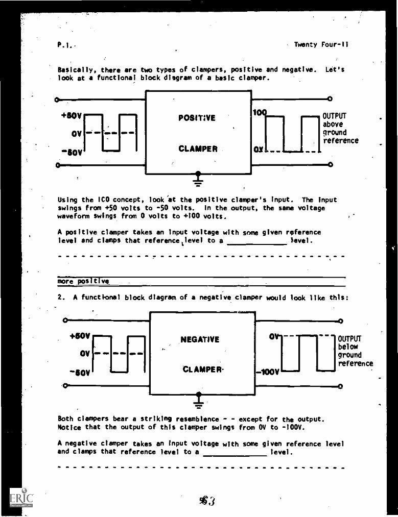
Basically, there are two types of dampers, positive and negative. Let'slook at a functional block diagram of a basic damper.01.+NVu-
OV
110V =1.
POSITIVE
4)
OUTPUTabovegroundreference
CLAMPER
MM.
Using the IC0 concept, look'at the positive damper's input. The Inputswings from +50 volts to -50 volts. In the output, the same voltagewaveform swings from 0 volts to +100 volts.
A positive damper takes an input voltage with some given referencelevel and clamps that referencetievel to a Level.
more positive.
2. A functional block diagram of a negative damper would look like this:
CONmr...=mmi+10VNii
OV
50V
m,
NEGATIVE
CLAMPER-
=410014,011MCO
OM*
1001I ffill,
Both clampers bear a striking resemblence - except for the output.Notice that the output of this damper swings from OV to -100V.
OUTPUTbelowgroundreference
A negative damper takes en input voltage with some given reference leveland clamps that reference level to a level.
P.I. Twenty Four-II
more negative
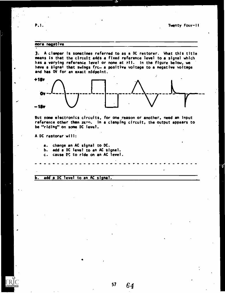
3. A clamper is sometimes referred to as a DC restorer. What this titlemeans Is that the circuit adds a fixed reference level to a signal whichhas a varying reference level or none at Al. In the figure below, wehave a iignal that swings f.rc... a positive voltage to a negative voltageand has OV for an exact midpoint.
+15v
0V-
-is,
M MP 410 MI OW WO . . MM M MO MO .. MM ... ..
But some electronics circuits, for one,reason or another, need an inputreference other than urn. In a clamping circuit, the output appears tobe "riding" on some DC level.
A DC restorer will:
a. change an AC signal to DC.b. add a DC level to an AC signal.
c. cause P' to ride on an AC level.
b. add a DC level to an AC signal.
57 64
Twenty 'Our
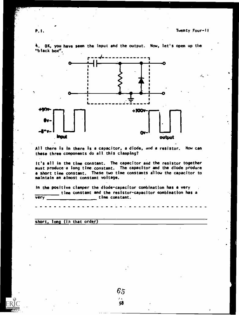
4. OK, you have seen the input and the output. Now, let's open up the"black box".
I. J
ON-1output
All there is in there is a capacitor, a diode, and a resistor. Now can
these three components do all, this clamping?
It's all in the time constant. The capacitor and the resistor togethermust producea long time. constant. The capacitor and the diode produce
a short time constant. These two time constants ilioW the capacitor tomaintain an almost constant voltage.
In the positive damper the diode-capacitor combination has a verytime constant and the resistor-capacitor combination has a
very time constant.
short, long (in that order)
.
58
P.1. Twenty Four-Il
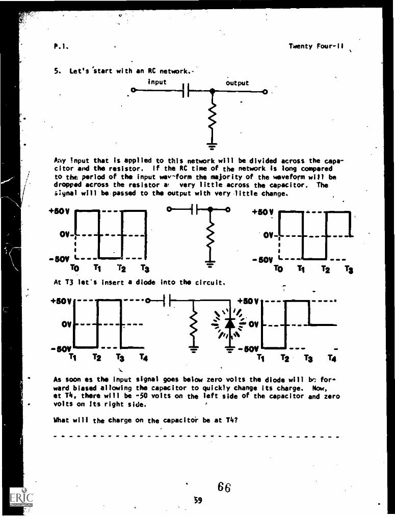
S. Let's 'start with an RC network.-
input output
Any Input that is applied to ttis network will be divided across the capa-citor and the resistor. If the RC time of the network is long comperedto the period of the input way-form the majority of the waveform will bedropped across the resistor at very little across the capacitor. TheiNnal will be possed to the output with very little change.
+50
8
-SOY " --TO Tj 12 T3
At T3 let's insert a diode into the circuit.
+50 - --
OV - --
-SOY -
+50 V
011-117
I
-50VTo Ti TZ 13
,4==
oH +so v'"/.pi A
OV VD 4Ib
sov13 1413 14
M
As soon as the input signal goes below zero volts the diode will be for-ward biased allowing the capacitor to quickly change its charge. Now,at T4, there will be -50 volts on the left side of the capacitor and zerovolts on its right side.
What will the charge on the capacitor be at T4?
66S9
Twenty Four- I I
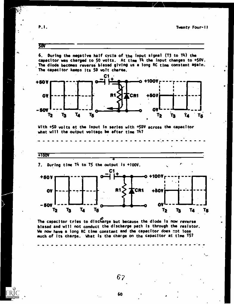
6. During the negative half cycle of the Input signal (T3 to T4) thecapacitor was charged to SO volts. At time T4 the input changes to +W.The diode becomes reverse biased giving us a long RC time constant again.The capacitor keeps its SO volt charge.
Cl
4"17:14+50V
OV
wmadomP 11111M
I= .1 IMO
goy - -T2 T3 14 Tg
- --,
Al CR1
+100v r
+ape .0, M. 411
OV =1/.12 T3 14 Tg
With +SO volts at the input in series with +SOW across the capacitorwhat will the output voltage be after time Tlei
+100Y
7. During time T4 to TS the output Is +100V.
+5011
OV
- 50VT2 T3 T4 Tg
000v r- - - T---'I . is 1
n-...CR1 +60V " 4 4. 4. 4
ov - .J12 13 T4 Tg
The capacitor tries to discharge but because the diode Is now reversebiased and will not conduct the discharge path is through the resistor.
We now have a long RC time constant and the capacitor does n*t losemuch of its charge. What is the charge on the capacitor at time TS?
6?
Twenty Four -II
/ha charge on the capacitor_1:. still
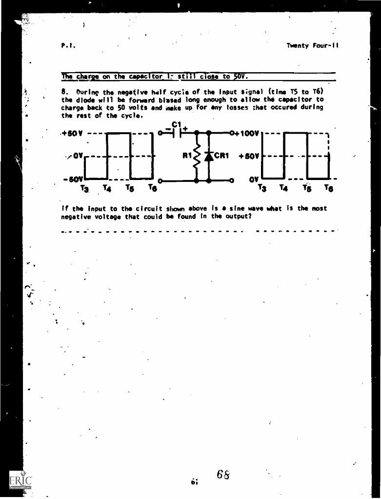
6. Ouring the negative 11.11f cycle of the input signal (time T5 to T6)the diode will be forward biased long enough to allow the capacitor to,charge back to 50 volts and make up for any losses :hat occured duringthe rest of the cycle.
OV
soy 0 0 0 011==.0.1.
Ts. 14 Ts Ts
+100V
RI j Citi +50V
01,
Ts 14 Ts 16
0 0
0 0 de
If the input to the circuit shown above Is a sine wave what is the mostnegative voltage that could be found in the output?
Twenty Four -II
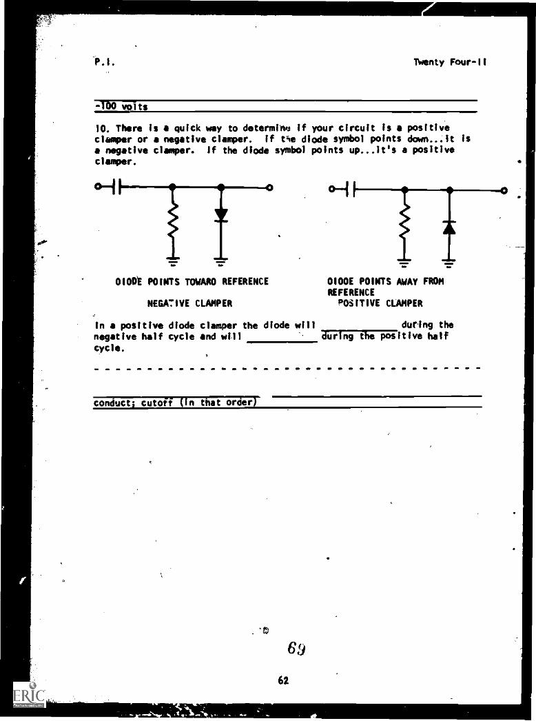
=TOO volts
10. There is a quick way to determine if your circuit Is a positiveclasper or a negative clasper. If tie diode symbol points down...it isa negative clasper. If the diode symbol points up...it's a positiveclasper.
0100E POINTS TOWARO REFERENCE
NEGA7IVE CLAMPER
OIODE POINTS AWAY FROMREFERENCEPOSITIVE CLAMPER
In a positive diode clasper the diode will during the
negative half cycle and will orging The positive half
cycle.
conducts cutoff (in that order)
62
Twenty Four-II
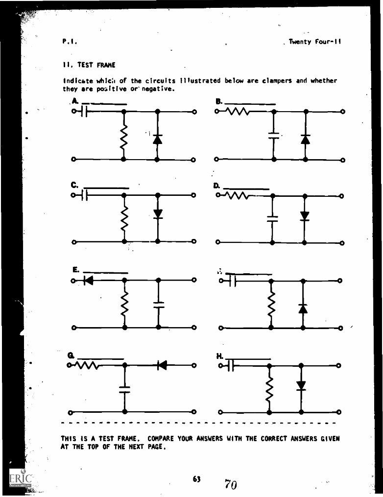
II. TEST FRAME
Indicate whic:, of the circuits illustrated below are dampers and whetherthey are positive ornegative.
Ai
E.
-0
THIS IS A TEST FRAME. COMPARE YOUR ANSWERS WITH THE CORRECT ANSWERS GIVENAT THE TOP OF THE NEXT PAGE.
" 70
(PSI. Twenty Four-il
A. Positive.C. NegativeF. PositiveH. Mostly*
IF ALL YOUR ANSWERS MATCH THE CORRECT ANSWERS, YOU MAY GO ON TO TESTFRAME 14. OTHERWISE, GO BACK TO FRAME 1 AND TAKE THE PROGRAMMEDSEQUENCE BEFORE TAKING TEST FRAME 11 AGAIN.
12. Remember what happened when you placed a DC potential in a clippercircuit? You can do the same thing in a damper. These dampers arecalled biased clam rs. The amount of DC potential will always be .41eoutput reference eve , just like the clipper circuits.
Each type of cleaver (negative and positive) can be biased with either
a positive or a negative potential.
What would be the output reference level of a negative damper with abias potential of -5 volts and an.input voltage swing from +50V to -50V.
-5 volts
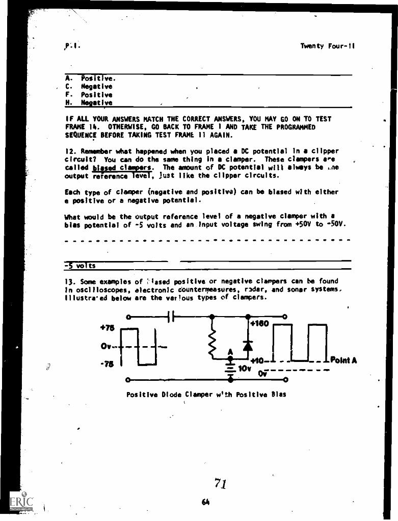
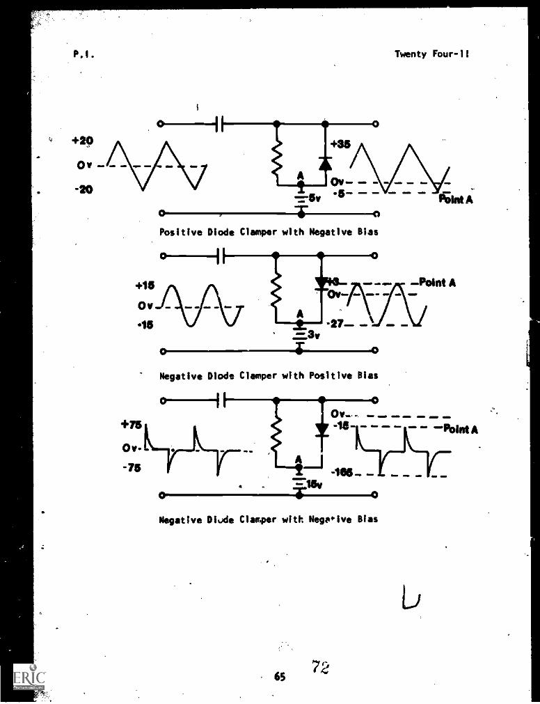
13. Some examples of used positive or negative dampers can be foundin oscilloscopes, electronic dOunterTeasures, ruler, and sonar systems.Illustraed below are the vasIous types of dampers.
+1410
+10 - --Point A.751Chr
Positive Diode Clasper woth Positive Bias
64
P1. Twenty Four-11
+20
0 v
-20
Positive Diode Ciamper with Negative Bias
+75
0 tr.
-75
Negative Diode Ciamper with Positive Bias
Ora
A
Ow-. e PM.
.10 a a a 11%IntA
-165 -.=leygM
O
Negative DI.Jde Ciamper with Negeive Bias
6572
,m ma
Twenty Four -ii
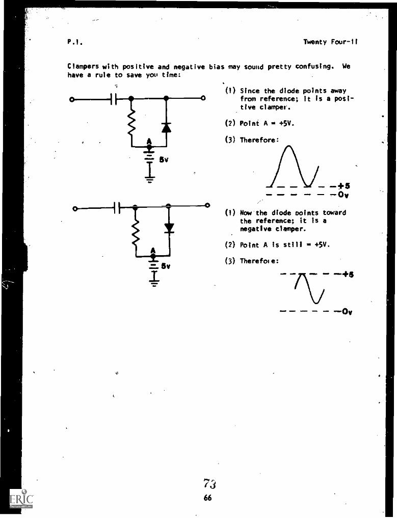
Clampers with positive and negative bias may sound pretty confusing. We
have a rule to save you time
66
(1) Since the diode points awayfrom reference; it Is a posi-tive clamper.
(2) Point A = +5V.
(3) Therefore:
+50,
(1) Mow the diode ooints towardthe reference; it is anegative clemper.
(2) Point A is still = +5V.
(3) Therefore:
111.011 411. aimm, m/Mr
+6
0,
67, 74
Twenty Four-II
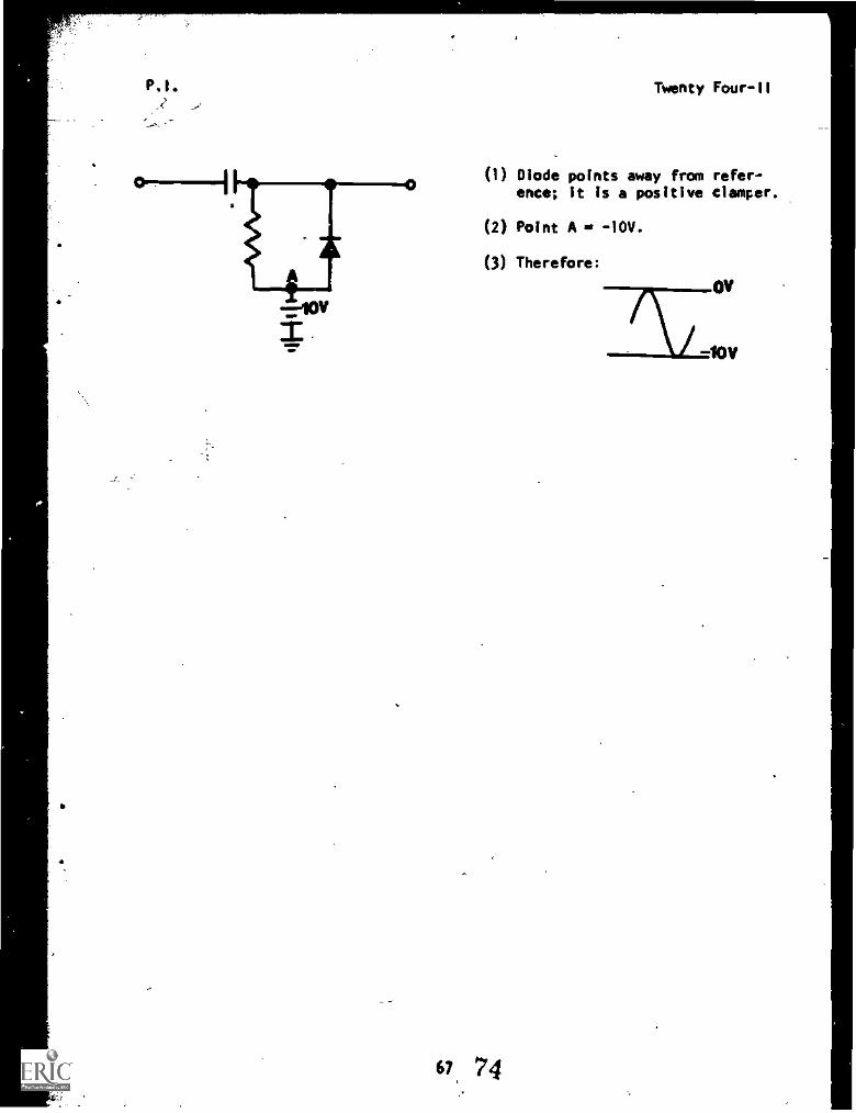
(1) Diode points away from refer-ence; It is a positive damper.
(2) Point A s, -I0V.
(3) Therefore:
Twenty Four-II
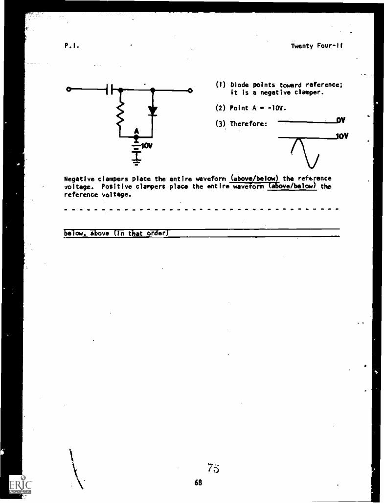
(I) Diode points toward reference;it is a negative damper.
(2) Point A se -10V.
(3) Therefore:
Negative clampers place the entire waveform (above/below) the referencevoltage. Positive clampers place the entire waveform (above/below) the
reference voltage.
Below above Cln that order]
68
Twenty Four-11
14. TEST FRAME
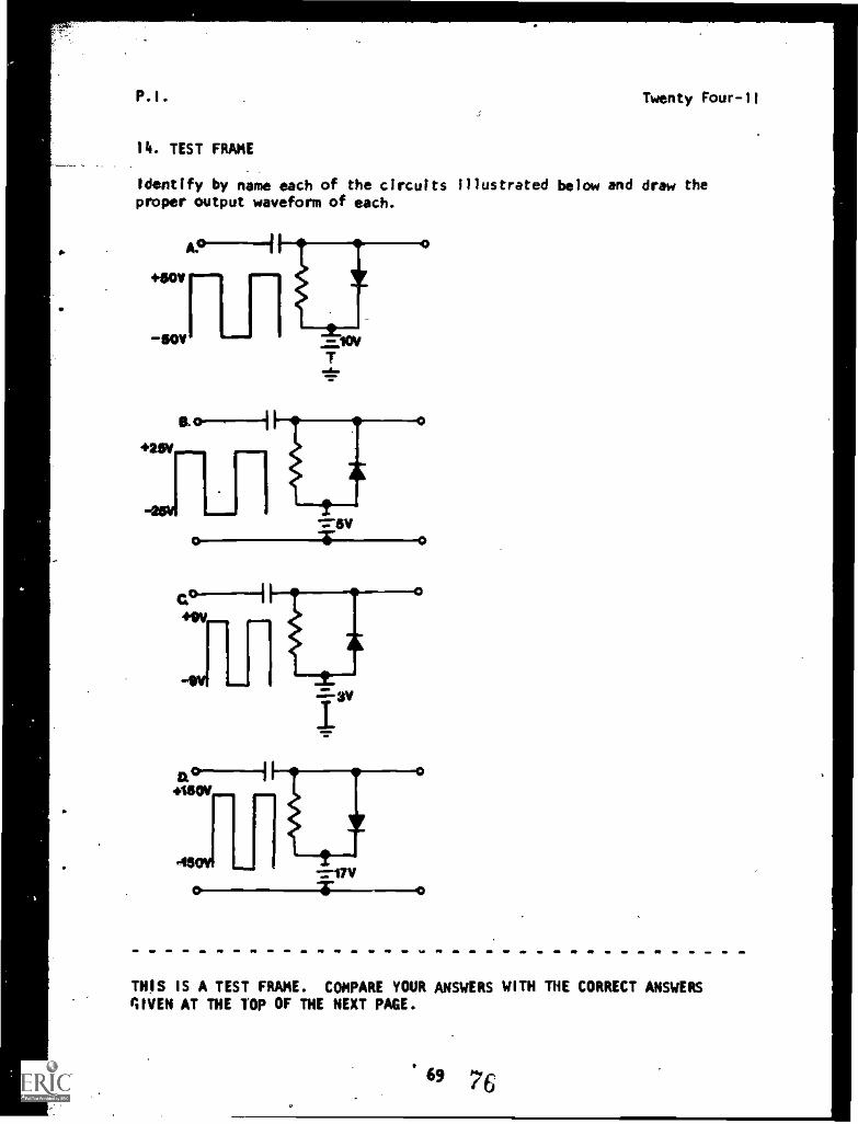
Identify by name each of the circuits illustrated below and draw theproper output waveform of each.
0- -0
Iry
=171/"F--0
THIS IS A TEST FRAME. COMPARE YOUR ANSWERS WITH THE CORRECT ANSWERSGIVEN AT THE TOP OF THE NEXT PAGE.
69 76
Twenty Four -II
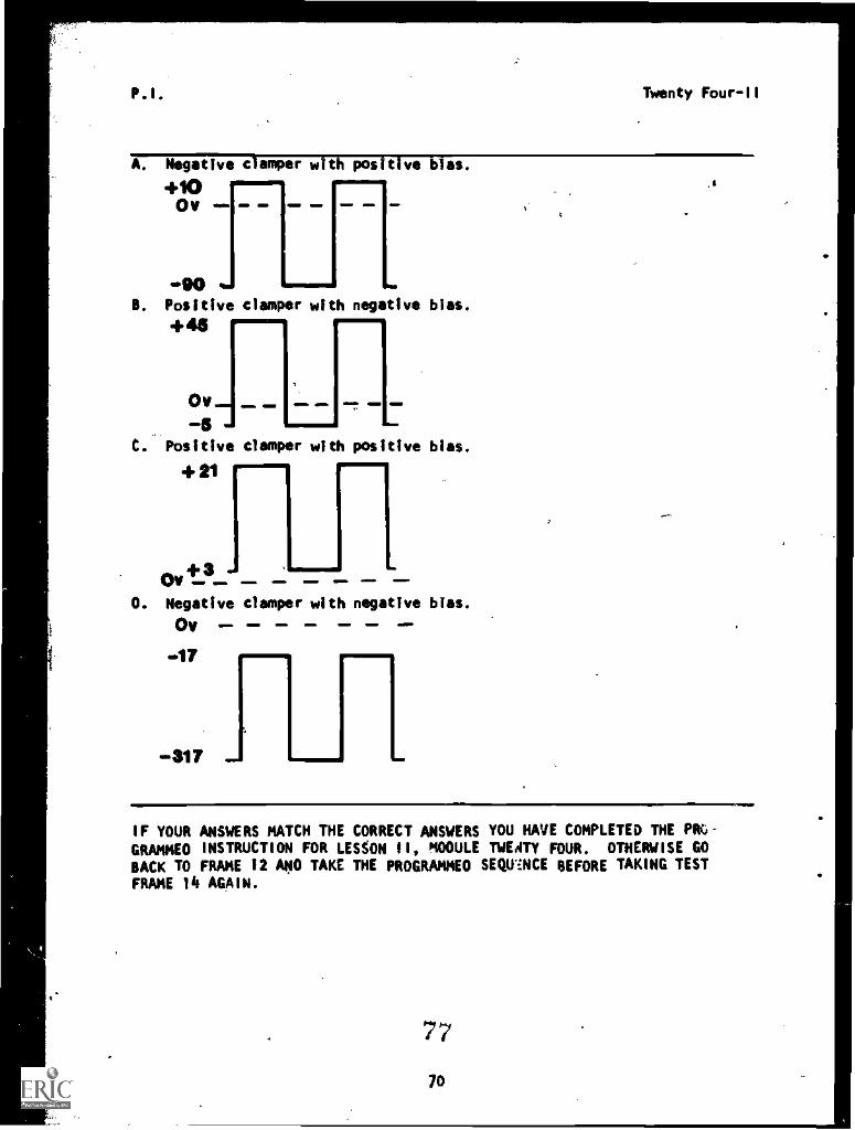
A. Negative damper with positive bias.+10 IM
011
APO
41M
B. Positive damper with negative bias.
+45
Ov411 =16
5. Positive damper with positive bias.
Ov +3"e
D. Negative damper with negative bias.
Ov
.317
mM 11. 11.
IF YOUR ANSWERS MATCH THE CORRECT ANSWERS YOU HAVE COMPLETED THE PMGRAMMED INSTRUCTION FOR LESSON II, MODULE TWEATY FOUR. OTHERWISE GO
BACK TO FRAME 12 AND TAKE THE PROGRAMMED SEQUENCE BEFORE TAKING TESTFRAME 14 AGAIN.
77
70
P. I. Twenty Four-II
THIS COMPLETES THE PROGRAMMED INSTRUCTION FOR LESSDN II, MODULE TWENTY
FOUR.
AT THIS POINT, YOU MAY TAKE THE LESSON PROGRESS CHECK. IF YOU
ANSWER ALL SELF-TEST ITEMS CORRECTLY, PROCEED TO THE NEXT LESSON.IF YOU INCORRECTLY ANSWER ONLY A FEW OF THE PROGRESS CHECK QUESTIONS,THE CORRECT ANSWER PAGE WILL REFER YDU TO THE APPROPRIATE PAGES,PARAGRAPHS, OR FRAMES SO THAT YOU CAN RESTUDY THE PARTS OF THISLESSON YOU ARE HAVING DIFFICULTY WITH. IF YOU FEEL THAT YOU HAVEFAILED TO UNDERSTAND ALL, OR MOST, OF THE LESSON, SELECT AND USEANOTHER WRITTEN MEDIUM OF INSTRUCTION, AUDIO/VISUAL MATERIALS (IFAPPLICABLE), OR CONSULTATION WITH LEARNING SUPERVISOR, UNTIL YOUCAN ANSWER ALL SELF-TEST ITEMS ON THE PROGRESS CHECK CGOECTLY.
7S
71
Narrative
NARRATIVELESSON 11
Ciampers
This lesson deali with:
Twenty Four-II
1. OC Restorer Circuits2. Baseline Stabilizer Circuits3. ,Ciamper Circuits
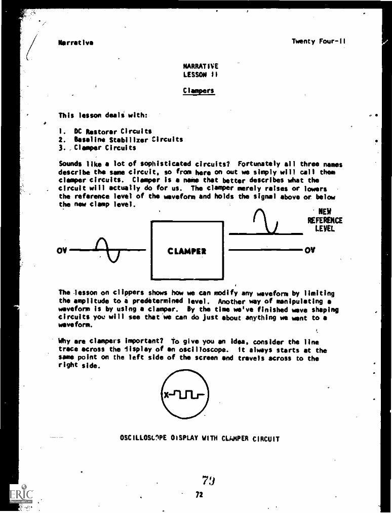
Sounds like a lot of sophisticated circuits? Fortunately all three namesdescribe the same circuit. so from here on out we simply will call themciamper circuits. Clamper is a name that better describes what the
, circuit will actually do for us. The damper merely raises or lowersthe reference level of the waveform and holds the signal above or, belowthe new clamp level.
OV CLAMMED
NEWREFERENCELEVEL
OV
The lesson on clippers shows how we can modify any waveform by limitingthe amplitude to i predetermined level. Another way of manipulating awaveform is by using a clamper. By the time we've finished wave shapingcircuits you will see that.we can do just about anything we went towaveform.
Why are ciampers important? To give you an idea. consider the linetrace across the lisplay of an oscilloscope. It always starts at thesame point on the left side of the screen and travels across to theright side.
OSCILLOSOPE DISPLAY WITH CLI$PER CIRCUIT
7972
Narrative Twenty Four-II
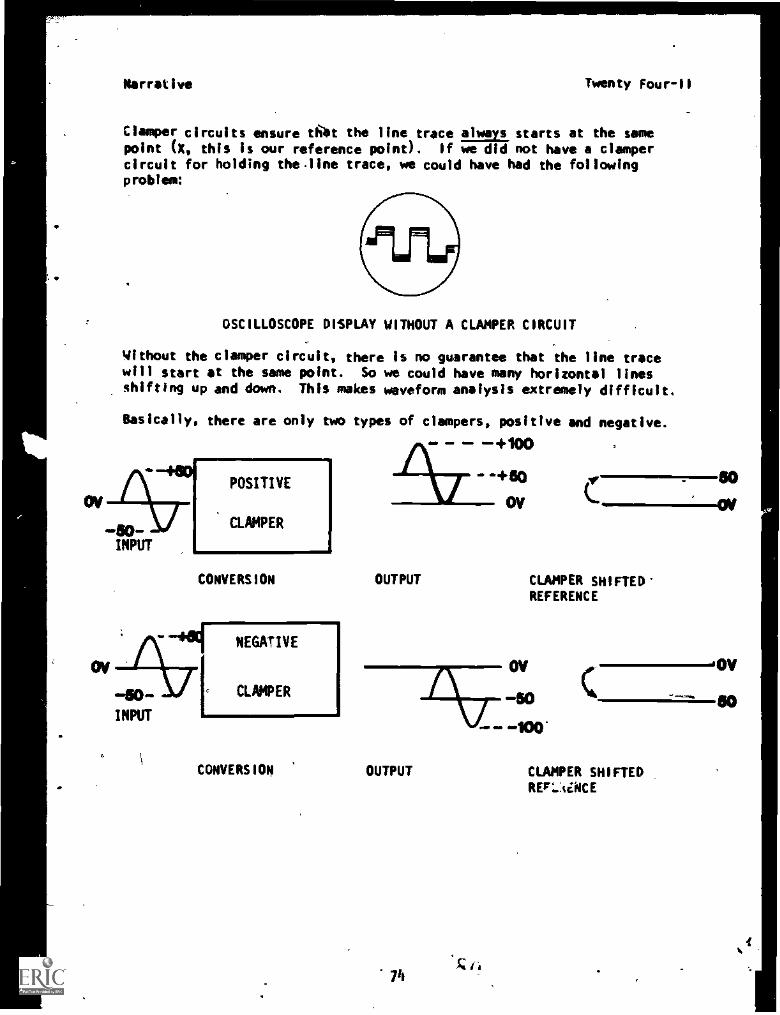
Clamper circuits ensure tibt the line trace always starts at the samepoint (X, this is our reference point). If we did not have a dampercircuit for holding theline trace, we could have had the followingproblem:
OSCILLOSCOPE DISPLAY WITHOUT A CLAMPER CIRCUIT
Without the damper circuit, there is no guarantee that the line tracewill start at the same point. So we could have many horizontal linesshifting up and down. This makes waveform analysis extremely difficult.
Basically, there are only two types of dampers, positive and negative.
POSITIVE
CLAMPER
CONVERSION
1
OUTPUT CLAMPER SHIFTED'REFERENCE
CONVERSION OUTPUT
7"bra
CLAMPER SHIFTEDREr'..siNCE
ov
so
Narrative Twenty Four-11
looking at the illustrations, you can readily see that a positive damperconverts a waveform ranging from 50V to +50V to a waveform which variesfrom OV t) +100V. The same Trip into a negative damper changes thesignal which varies from -50V +50V Into a signal that varies from OVto -100V. Both positive and negative dampers do not change the shape oramplitude of the waveform, they simply put the waveform either above(positive) or below (negative) 0 volts. A damper's input could be al-most anything - - - square wave, sine wave, triangular wave or pulsed in-put - only the output reference will be shifted. Some students.con
fuse clippers and.clampers, but you won't, as long as you remember thatdampers only shift reference levels while clippers change the waveform.
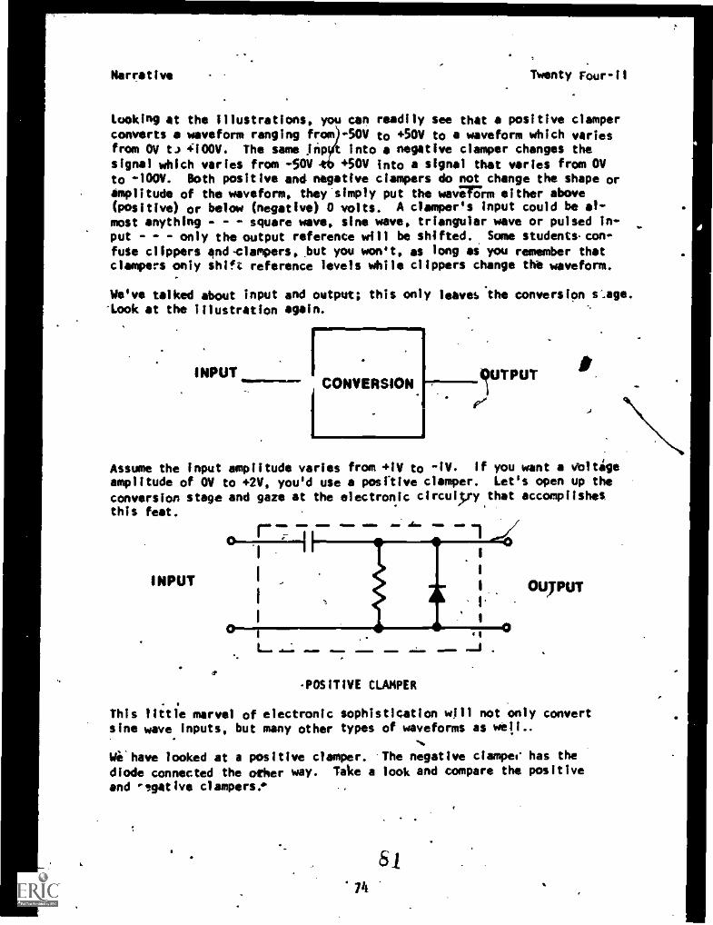
We've talked about input and output; this only leavesthe conversion stage.-Look at the illustration again.
INPUT__CONVERSION
I .1
IUTPUT
e'
Assume the input amplitude varies from +1V to -IV. If you want a voltige
amplitude of OV to +2V, you'd use a positive damper. Let's open up the
conversion stage and gaze at the electronic circulyy that accomplishesthis feat.
INPUT
1 aMa dm IM
I'INM 1 111610
POSITIVE CLANPER
. .
This little marvel of electronic sophistication will not only convertsine wave inputs, but many other types of waveforms as well..
Vi have looked at a positive damper. The negative ciampec has the
diode connected the other way. Take a look and compare the positive
and ',witty. dampers.
8
Narrative
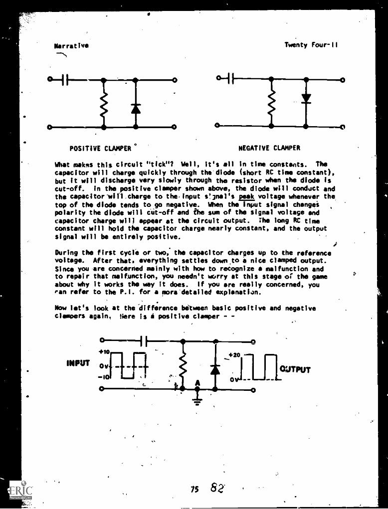
POSITIVE CLAMPER
Twenty Four-II
NEGATIVE CLAMPER
What makes this circuit "tick"? Well, its all in time constants. Thecapacitor will charge quickly through the'diode (short RC time constant),but it will discharge very slowly through the resistor when the diode is
cut-off. In the positive damper shown above, the diode will conduct andthe capacitorvirl.charge to the. input ejnal's gegk voltage whenever thetop of the diode tends toll) negative. When the input signal changeipolarity the diode will cut -off and the sum of the signal voltage and
capacitor charge will appear at the circuit output. The long RC timeconstant will hold the capacitor charge nearly constant, and the outputsignal will be entirely positive.
During the first cycle or two, the capacitor charges up to the referencevoltage. After that, everything settles down,to a nice clamped output.Since you are concerned mainly with how to recognize a malfunction andto repair that malfunction, you needn't worry at this stage of the gameabout why it works the way it does. If you are really concerned, youan refer to the P.I. for a more'detalled explanation.
Now let's look at the 'difference between basic positive and negativeclampers again, Here is A positive damper -
Thy
INPUT oviatp-io
....+20 ---
j0 -- --I - -
15 82-
,41TPUT
1e,
Narrative Twenty four -fi
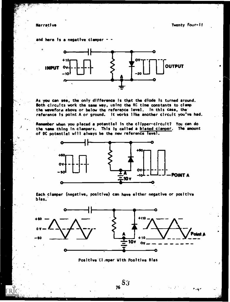
and here is a negative ciamper -
+10
INPUT ov - -
_10
As you can see, the only difference is that the diode is turned around.Both clrcu!ts work the some way, using the RC time constants to clampthe waveform above or below the reference level. In this case, the
reference is point A or ground. It works like another circuit you've had.
Remember when you placed a potential in the clipper circuit? You can do
the same thing in dampers. This is called a biased clamper. the' amount
of DC potential will always be the new reference level.
POINT A
Each damper (negative, positive) can have either negative or positivebias."
O 0
Posltive'C1mper With Positive Bias
7683
Narrative
OV
z-isoy -10v!
Qv-10v OD OD MO
Negative Clamper with Negative Bias
Twenty Four-II
POW A
-410V
-7-1.10V
Negative Clamper with Positive Bias
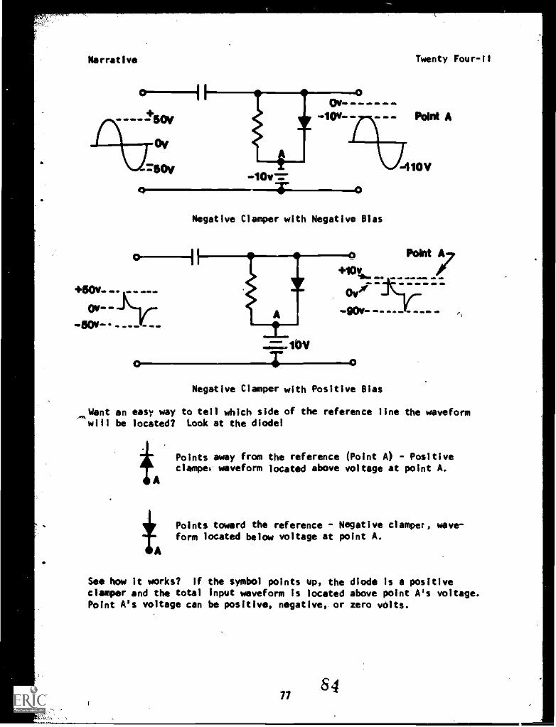
Want an easy way to tell which side of the reference line the waveform4.1w
will be located? Look at the diode!
Points away from the reference (Point A) - Positiveclampel waveform located above voltage at point A.
Points toward the reference - Negative damper, wave-form located below voltage at point A.
See how it works? If the symbol points up, the diode is a positivedamper and the total input waveform Is located above point A's voltage.Point A's voltage can be positive, negative, or zero volts.
877
84
O
Narrative Twenty Four
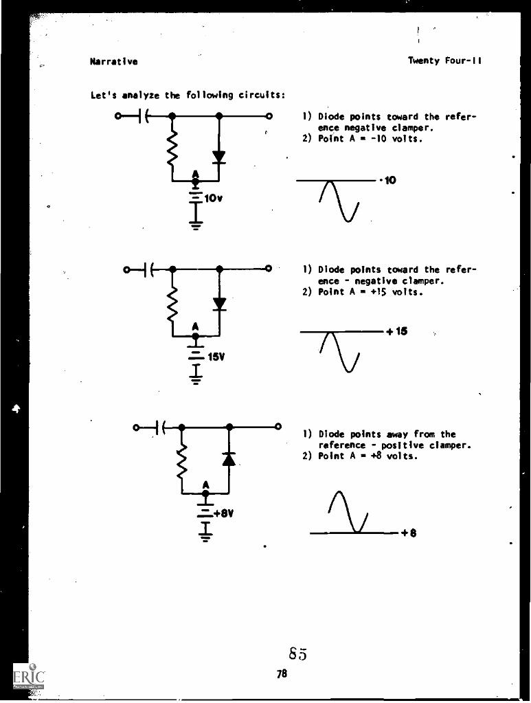
Let's analyze the following circuits:
1) Diode points toward the refer-ence negative clamper.
2) Point A = -10 volts.
15V
78
10
1) Diode points toward the refer-ence - negative clamper.
2) Point A = +15 volts.
+ 15
1) Diode points away from thereference - positive damper.
2) Point A = +8 volts.
65
+8
Narrative Twenty Four-11
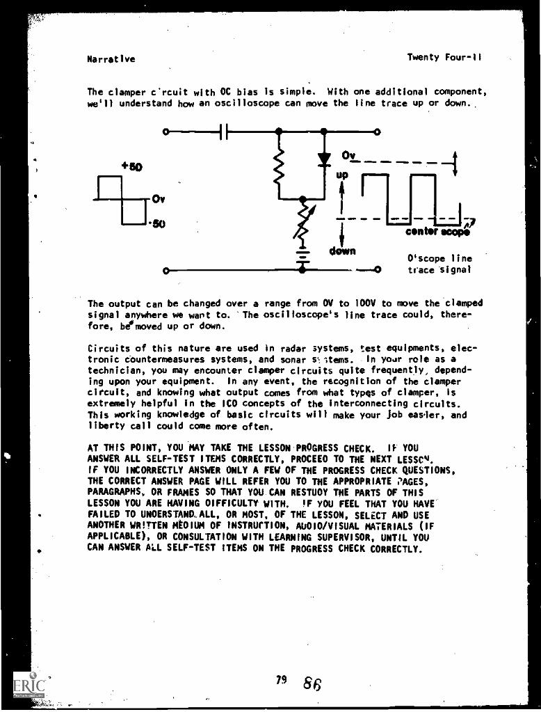
The ciamper circuit with OC bias is simple. With one additional component,we'll understand how an oscilloscope can move the line trace up or down..
11.,
rup ....
1116 11=1.
trace
f
A7scope
line"s 1 gna
V..Mln MID
down
A.150center
O'scope4)
The output can be changed over a range from OV to 100V to move the clampedsignal anywhere we wart to. 'The oscilloscope's line trace could, there-fore, be moved up or down.
Circuits of this nature are used in radar systems, test equipments, elec-tronic countermeasures systems, and sonar st.ltems. In 'mar role as atechnician, you may encounter clamper circuits quite frequently, depend-ing upon your equipment. In any event, the recognition of the clampercircuit, and knowing what output comes from what typqs of clamper, isextremely helpful in the ICO concepts of the interconnecting circuits.This working knowledge of basic circuits will make your Job easier, andliberty call could come more often.
AT THIS POINT, YOU MAY TAKE THE LESSON PROGRESS CHECK. IF YOU
ANSWER ALL SELF-TEST ITEMS CORRECTLY, PROCEED TO THE NEXT LESSeq.IF YOU INCORRECTLY ANSWER ONLY A FEW OF THE PROGRESS CHECK QUESTIONS,THE CORRECT ANSWER PAGE WILL REFER YOU TO THE APPROPRIATE ;'AGES,PARAGRAPHS, OR FRAMES SO THAT YOU CAN RESTUDY THE PARTS OF THISLESSON YOU ARE HAVING DIFFICULTY WITH. !F YOU FEEL THAT YOU HAVEFAILED TO UNDERSTANIL ALL, OR MOST, OF THE LESSON, SELECT AND USEANOTHER WRITTEN ADIUM OF INSTRUCTION, AU010/VISUAL MATERIALS (IFAPPLICABLE), OR CONSULTATION WITH LEARNING SUPERVISOR, UNTIL YOUCAN ANSWER ALL SELF-TEST ITEMS ON THE PROGRESS CHECK CORRECTLY.
79 66
tSCORE WITH SAFETY!
.
ACCIDENTS COST MORE MORE THAN MONEY
87. so
BASIC ELECTRICITY AND ELECTRONICS
NODULE TWENTY FC'$R
LESSON III
INTEGRATORS/D1FFERENTIATORS
1 APRIL 1977
88si
Dverview Twenty Four-III
OVERVIEWLESSON III
Integrators/Differentiators
This lesson deals with square wave shaping circuits. Although integratorsand differentiators only contain two components, the relatively short orlong time constant of these components produce completely different out-put waveforms. These new waveforms add to our growing list of possible'creations" from our basic sine wave and square wave.
The learning objectives of this lesson are as follows:
TERMINAL OBJECTIVE(S):
24.3.46 When the student completes this course, he will be able toIDENTIFY wave shaping circuits and their effects on inputwaveforms by matching an output waveform to a wave shapingcircuit and its input waveform given input and output wave-form illustrations and wave shaping circuit schematic diagrams.
ENABLING OBJECTIVE(S):
When NB student completes this lesson, he will be able to:
24.3.46.8 IDENTIFY by selecting, the schematics for RL and RC Integra-tor and differentlator circuits, given a set of schematicdiagrams. 100% accuracy is required.
24.3.46.9 ANALYZE the conversion action in RL and RC differentiator/integrator circuits, by matching given input and outputwaveforms to the correct schematic diagram, with 100%accuracy.
24.3.46.10 DIFFERENTIATE "long" and "short" time constants of RI. and RCcircuits used as integrators differentiators, given fivetime statements, an PC circuit and an RL circuit, and select-ing the best statement of relative time constant length. 100%accuracy is required.
69.
82
4
Overview Twenty Four-III
OVERVIEW
24.3.46.11 OBSERVE, INTERPRET, and RECORD the effects of varying thetime constant or an RC differentiator circuit, given atraining device/circuit, an oscilloscope, and a job pro-gram. Recorded observations to fall within tolerancesstated in the job program.
24.3.46.11.1 LOCATE and IDENTIFY integrator at ' differennator componentsinstalled in equipment, given a :raining device or circuitboards containing integrator/differentiator circuits anddircult schematic diagrams or technical manuals and a jobprogram. 100% accuracy is required.
BEFORE YOU START THIS LESSON, READ THE LESSON LEARNING OBJECTIVES ANDPREVIEW THE LIST OF STUDY RESOURCES ON THE NEXT PAGE.
8390
4
Study Resources
LIST OF STUDY RESOURCESLESSON III
Integrators/Differentiators
Twenty.Four -III
To learn the malwiai in this lesson, you have the option of choosing,according to your experience and preferences, any or all of the follow-ing study resources:
Writee Lesso4 twesentation in:
Module Booklet:
SummaryProgrammed Instruction
Narrative
Student's Guide:
Job Program Twenty Four-III-1 "Introduction to integrators"Job Program Twenty Four-III-2 "Introduction to Differentiators"Progress Check
Additional Migterial(s):
Audio/Visual Program Twenty Four -III "Introduction to Integratorsand Differentlators"
Enrichme'nt Material(s):
Electronics Installation and Maintenance Book, Electronic Circuits,,IAVPERS 0967-'000-0120
you MAY USE ANY, OR ALL RESOURCESSUPERVISOR; HOWEVER, ALL MATERIALSTO ACHIEVE LESSON OBJECTIVES. THE
TINE.
L:STEO ABOVE, INCLUDING THE LEARNINGLISTED ARE NOT NECESSARILY REQUIREDPROGRESS CHECK MAY BE TAKEN AT ANY
84 91
Summary Twenty Four-III
SUMMARYLESSON III
Integrators and Differentio
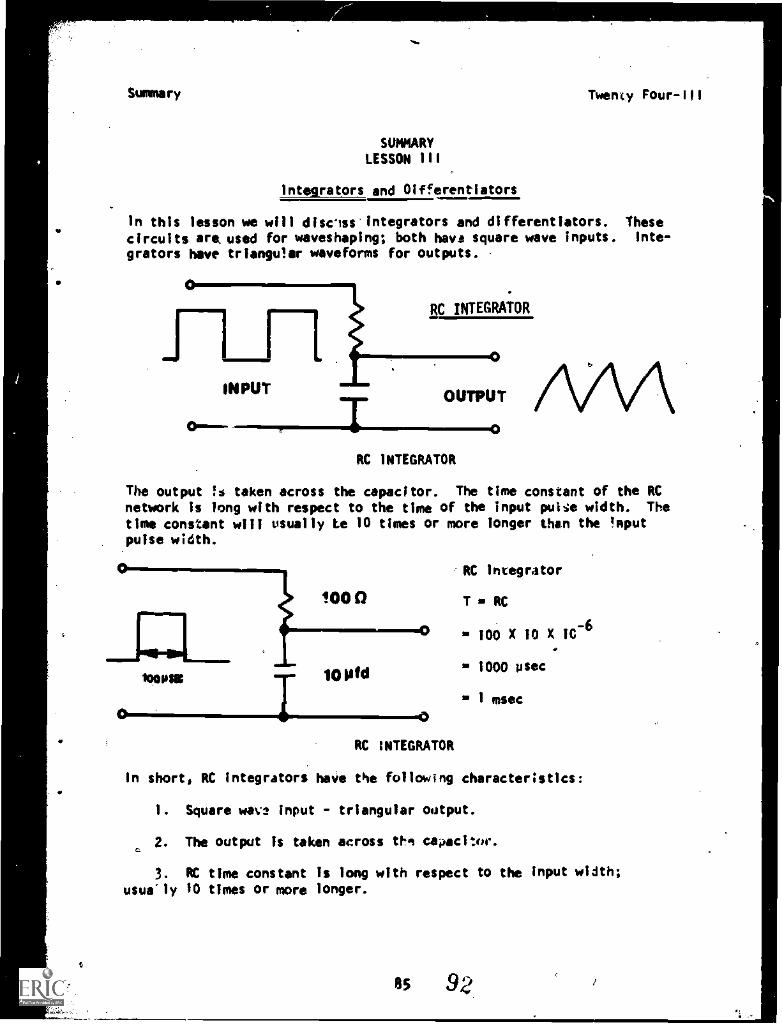
In this lesson we will disciscintegrators and differentiators. Thesecircuits are, used for waveshaping; both hays square wave inputs. inte-
grators have triangular waveforms for outputs.
RC INTEGRATOR
The output is taken across the capacitor. The time constant of the RCnetwork is long with respect to the time of the input pult;e width. Thetime constant will usually Le 10 times or more longer than the Inputpulse width.
0
100081 10 Pfd
'RC Integrator
T sA RC
0 100 X 10 X 104
= 1000 psec
= 1 cosec
RC INTEGRATOR
In short, RC integrators have the following characteristics:
1. Square wave input - triangular output.
2. The output is taken across thn caoac1w.
3. RC time constant is long with respect to the input width;usua'ly 10 times or more longer.
85 92
Summary Twenty Four-III
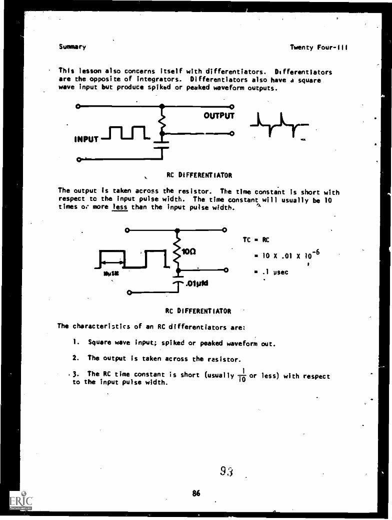
This lesson also concerns itself with differentiators. Differentlatorsare the opposite of integrators. Differentlators also have a squarewave input but produce spiked or peeked waveform outputs.
0
INPUT"Ln.0
OUTPUT
RC DIFFERENTIATOR
The output is taken across the resistor. The time constant is short withrespect tc the input pulse width. The time constant will usually be 10times or more less than the input pulse width.
TC = RC
= 10 X .01 X 10-6
' .1 usec
RC DIFFERENTIATOR
The characteristics of an RC differentiators are
1. Square wave input; spiked or peaked waveform out.
2. The output is taken across the resistor.
.3. The RC time constant is short (usually l0 or less) with respectto the input pulse width.
86
9 3
Seigniory twenty Four -Ill
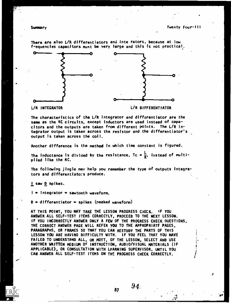
There are also L/R differentiators and inte rators, because at lowf-equencies capacitors must be very large and this is not practical.01.
L/R INTEGRATOR L/R DIFFERENTIATOR
The characteristics of the L/R Integrator and difforentiator are thesame as the RC circuits, except inductors are used instead of capa-citors and the outputs are taken from different points. The L/R in-tegrator output is taken across the resistor and the differentiator'soutput is taken across the coll.
Another difference is the method in which time constant is figured.
The inductance is divided by the resistance, Tc = R, instead of muiti-plied like the RC.
The following jingle may help you remember the type of outputs integra-
tors and differentiatos produce.
I saw 0 spikes.
I integrator sawtooth waveform.
0 differentiator = spikes (peaked waveform)
AT THIS POINT, YOU HAY TAKE THE LESSON PROGRESS CWECK. IF YOUANSWER ALL SELF-TEST ITEMS CORRECTLY, PROCEED TO THE NEXT LESSON.IF YOU INCORRECTLY ANSWER ONLY A FEW OF THE PROGRESS CHECK OUESTIONS,THE CORRECT ANSWER PAGE WILL REFER YOU TO THE APPROPRIATF PAGES,PARAGRAPHS, OR FRAMES SO THAT YOU CAN RESTUDY THE PARTS OF THISLESSON YOU ARE HAVING DIFFICULTY WITH. IF YOU FEEL THAT YOU HAVEFAILED TO UNDERSTAND ALL, OR MOST, OF THE LESSON, SELECT AND USEANOTHER WRITTEN MEDIUM OF INSTRUCTION, AUDIO/VISUAL MATERIALS (IFAPPLICABLE), OR CONSULTATION WITH LFARNING SUPERVISOR, UNTIL YOUCAN ANSWER ALL SELF-TEST ITEMS ON TH! PROGRESS CHECK CORRECTLY.
8794.
-
ea
a
The Only ThingBetween Touand The beep SW
a
. i88
95
4
a.
Twenty Four-111
PROGRAMMED INSTRUCTIONLESSON III
Integrators and Olfferentiators
TEST FRAMES ARE 8 AND 11. GO TO FRAME 8 AND SEE IF YOU CAN.ANSWER THEQUESTIONS'. FOLLOW THE DIRECTIONS AT THE ENO OF FRAME 8.
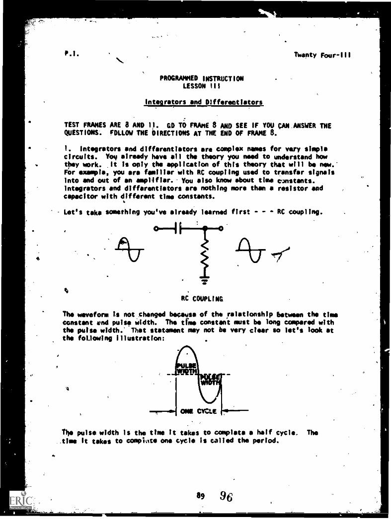
1. Integrators and differentiators are complex names for very simplecircuits. Yoy already have all the theory you need to understand howthey work. It is °ply the application of this theory that will be new.-For example, you are familiar with RC coupling used to transfer signalsInto and out of an amplifier.. You also know about time cwistants.Integrators end differentiators are nothing more than a resistor andcapacitor with different time constants.
Let's take something you've already learned first - - RC coupling.
RC COUPLING
The waveform is not changed because of the relationship between the timeconstant and pulse width. The time constant must be long compared withthe pulse width.' That statement may not be very clear so let's look atthe following illustration:
4
The pulse width is the time it takes to complete a half cycle. The.time It takes to complete one cycle is called the period.
89 96
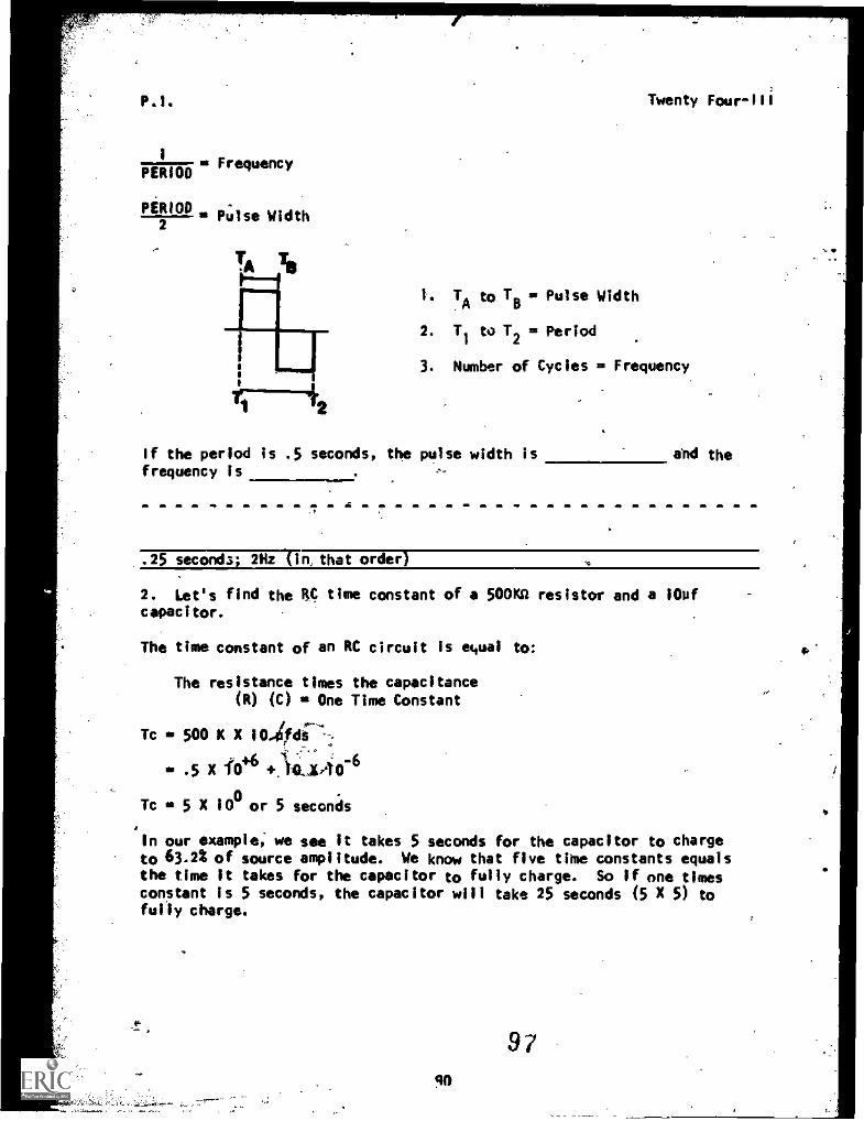
P.!. Twenty Four -II!
1
PERIOD= Frequency
PERIODPulse Width
2
1. TA to Ts . Pulse Width
2. T1
to T2= Period
3. Number of Cycles = Frequency
If the period Is .5 seconds, the pulse width is and thefrequency is
.25 seconds; 2Hz lin, that order)
2. Let's find the RC time constant of a 500K0 resistor and a 10ufcapacitor.
The time constant of an RC circuit is equal to:
The resistance times the capacitance
(R) (C) sB One Time Constant
Tc = 500 K X 104di---:
= .5 X lb +.1Lvto-
Tc = 5 X 100 or 5 seconds
In our example, we see it takes 5 seconds for the capacitor to chargeto 63.2% of source amplitude. We know that five time constants equalsthe time it takes for the capacitor to fully charge. So if one timesconstant is 5 seconds, the capacitor will take 25 seconds (5 X 5) tofully charge.
97
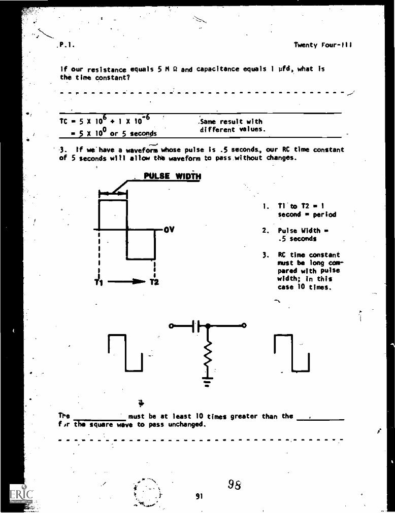
Twenty Four-Ili
If our resistance equals 5 M 0 and capacitance equals 1 ofd, what isthe time constant?
Tc 4. 5 x 10 + 1 X 10-6
S X 100 or 5 seconds
.Same result withdifferent values.
3. if ueltave a waveform whose pulse is .5 seconds. our RC time constant
of 5 seconds will all the waveform to pass without changes.
PULSE Mill
1.0.441. Tl'to T2 1
second period
OV 2. Pulse Width
I 1 1 .5 seconds
3. RC time constantmust be long com-pared with pulse
--Now 12 width; In thiscase 10 times.
41'
The must be at least 10 times greater than thetscpgTheivwave to pass unchanged.
91
98
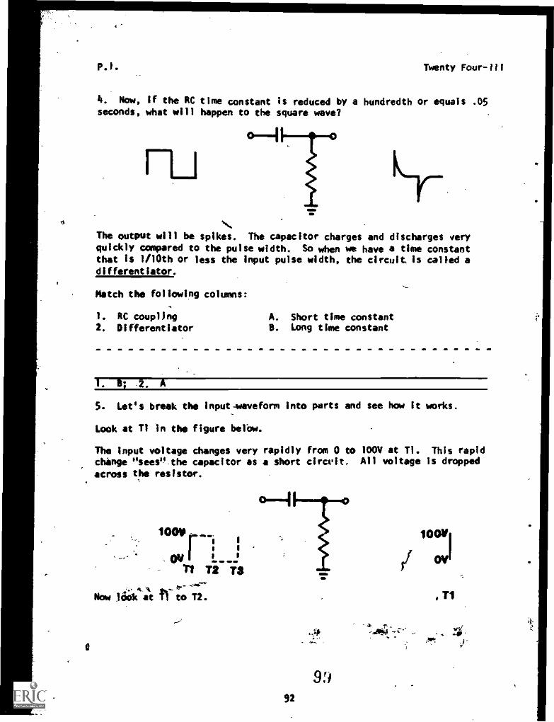
0
P.1. Twenty Four-ill
4. Now, if the RC time constant is reduced by a hundredth or equals .05seconds, what will happen to the square wave?
0-1
ELI
The output will be spikes. The capacitor charges and discharges veryquickly compared to the pulse width. So when we have a time constantthat is 1/10th or less the input pulse width, the circuit is called adifferentiator.
Match the following columns:
1. RC coupling A. Short time constant2. Oifferentiator B. Long time constant
ti
1. B; .2. A
5. Let's break the Input-waveform into parts and see how it works.
Look at T1 In the figure belbw.
The input voltage changes very rapidly from 0 to 100V at Ti. This rapidchange usee0_the capacitor as a short circuit. All voltage is dropped
across the resistor.
10010
. ov r $
T1 T2 TS
Now lioSICIA 11 to T2.
9992
, T1
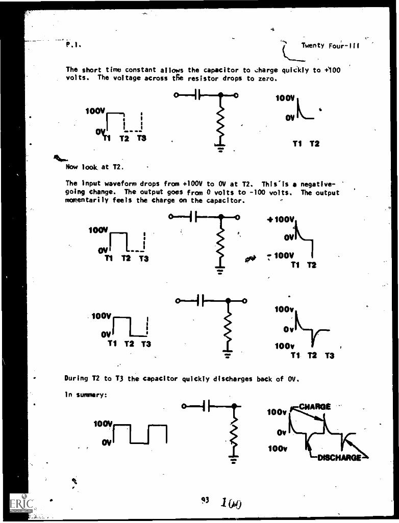
P.1. Fou'r-111
The short time constant allows the capacitor to charge quickly to +100volts. The voltage across tfe resistor drops to zero.
boyn(In T2 T3
Now look at T2.
OV
T1 T2
The input waveform drops from +100V to OW at T2. Thls'Is a negative-going change. The output goes from 0 volts to -100 volts. The outputmomentarily feels the charge on the capacitor.
o--Iboovr_i
ovlT1 T2 1-3
-100V
CNT1 T2 T3
OV
7100VT1 T2
100v
0vky-
100vT1 -T2 T3
During T2 to T3 the capacitor quickly discharges bock of Ov.
In summery:
100v
Ov
100v
CHARGE
DISCHARGE
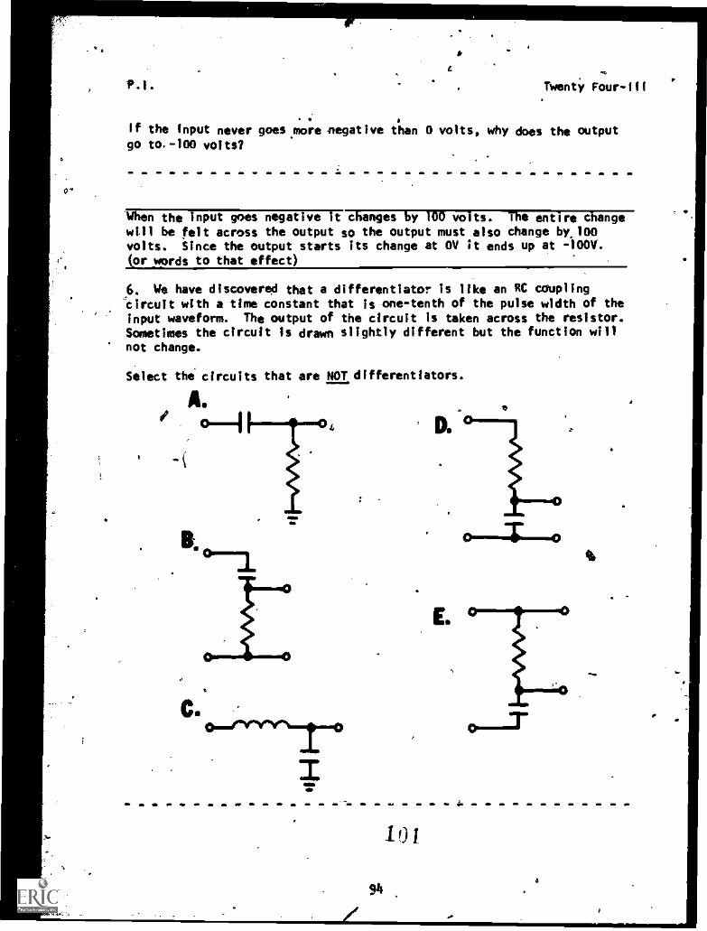
0
p.i. Twenty Fourill
If the input never goes more negative than 0 volts, why does the outputgo to.-100 volts?
When the input goes negative it changes by 100 volts. The entire changewill be felt across the output so the output must also change by,100volts. Since the output starts its change at OV it ends up at -100V.or words to that effect)
6. We have discovered that a differentiator is like an RC coupling-circuit with a time constant that is one-tenth of the pulse width of the
input waveform. The output of the circuit is taken across the resistor.Sometimes the circuit is drawn slightly different but the function willnot change.
Select the. circuits that are NOT differentiators.
A.
616
D.e
10 1
946
Fr
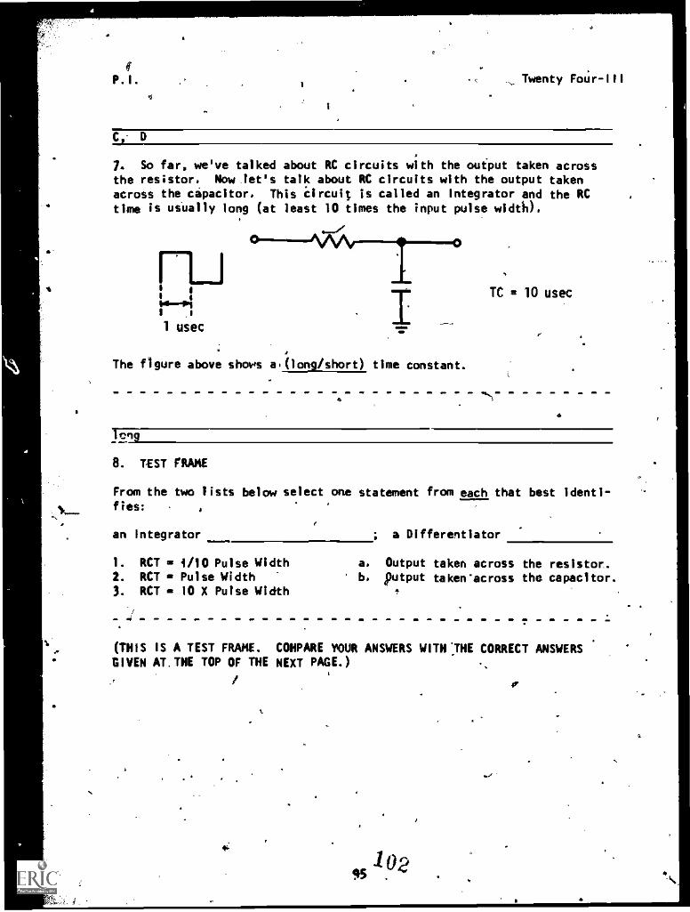
Twenty Fo6r-111
C, D
7. So far, we've talked about RC circuits with the output taken acrossthe resistor. Now let's talk about RC circuits with the output takenacross the capacitor. This Circuit is called an integrator and the RCtime is usually long (at least 10 times the input pulse wid6).
The figure above shows a(long/short) time constant.
TC a 10 usec
8. TEST FRAME
From the two lists below select one statement from each that best identi-fies:
an Integrator ; a Differentiator
1. RCT = 1/10 Pulse Width a. Output taken across the resistor..2. RCT = Pulse Width b. putout taken-across the capacitor.3. RCT = 10 X Pulse Width
(THIS IS A TEST FRAME. COHPARE YOUR ANSWERS WITH ;THE CORRECT ANSWERSGIVEN AT. THE TOP OF THE NEXT PAGE.)
4'
45
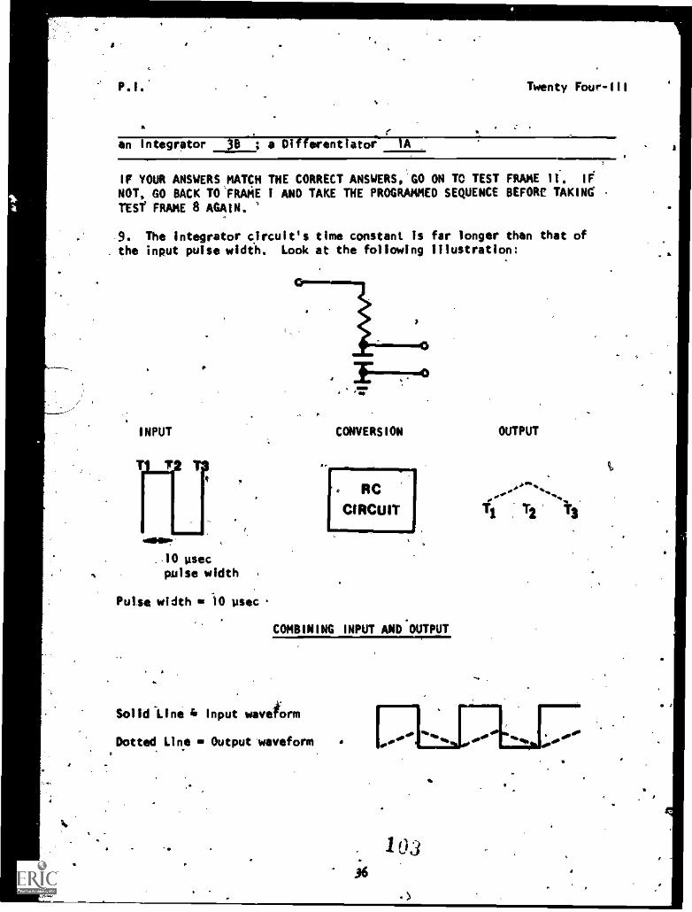
. RCCIRCUIT
P.I. Twenty Four-III
.
an Integrator rr'--Rior'A;aMe---1.-----. .
IF YOUR ANSWERS MATCH THE CORRECT ANSWERS,'GO ON TO TEST FRAME II. IF
NOT, GO BACK TO'FRAME i AND TAKE THE PROGRAMMED SEQUENCE BEFORE TAKINGTESY FRAME 8 AGAIN. '
9. The integrator circuit's time constant is far longer than that ofthe input pulse width. Look at the following illustration:
INPUT
401Mo?
.10 usecpulse width
Pulse width 10 usec
CONVERSION OUTPUT
COMBINING INPUT AND'OUTPUT
Solid-Line 4 Input waveform
Dotted Line Output waveform
T2
10336
A
O
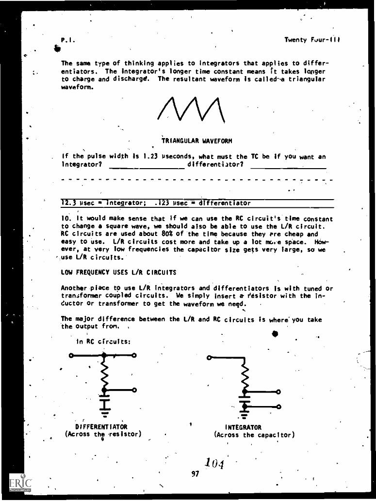
P. I .
bTwenty Fvur-111
The same type of thinking applies to integrators that applies to differ-
entiators. The integrator's longer time constant means it takes lorsgerto charge and discharge. The resultant waveform is calleda triangularwaveform.
TRIANGULAR WAVEFORM
. If the pulse width is 1.23 useconds, what must the TC be if you want anIntegrator? differentiator?
12.3 osec *--integrator; .123 UseCiraifferentiator
10. It would make sense that if we can use the RC circuit's time constantto change a square wave, we should also be able to use the L/R circuit.RC circuits are used about 602 of the time because they pre cheap andeasy to use. L/R circuits cost more and take up a lot mce space. How-ever, at very low frequencies the capacitor size gets very large, so weuse L/R circuits.'
LOW FREQUENCY USES L/R CIRCUITS
Another place to use L/R integrators and differentiators is with tuned ortransformer coupled circuits. We simply insert a- resistor with the in-ductor or transformer to get the waveform we nerd.
The major difference between the L/R and RC circuits is where'you takethe output from. ,
0In RC circuits:
rOIFFERENTIATOR
(Across the fesistor)4 0
INTEGRATOR(Across the capacitor)
10497
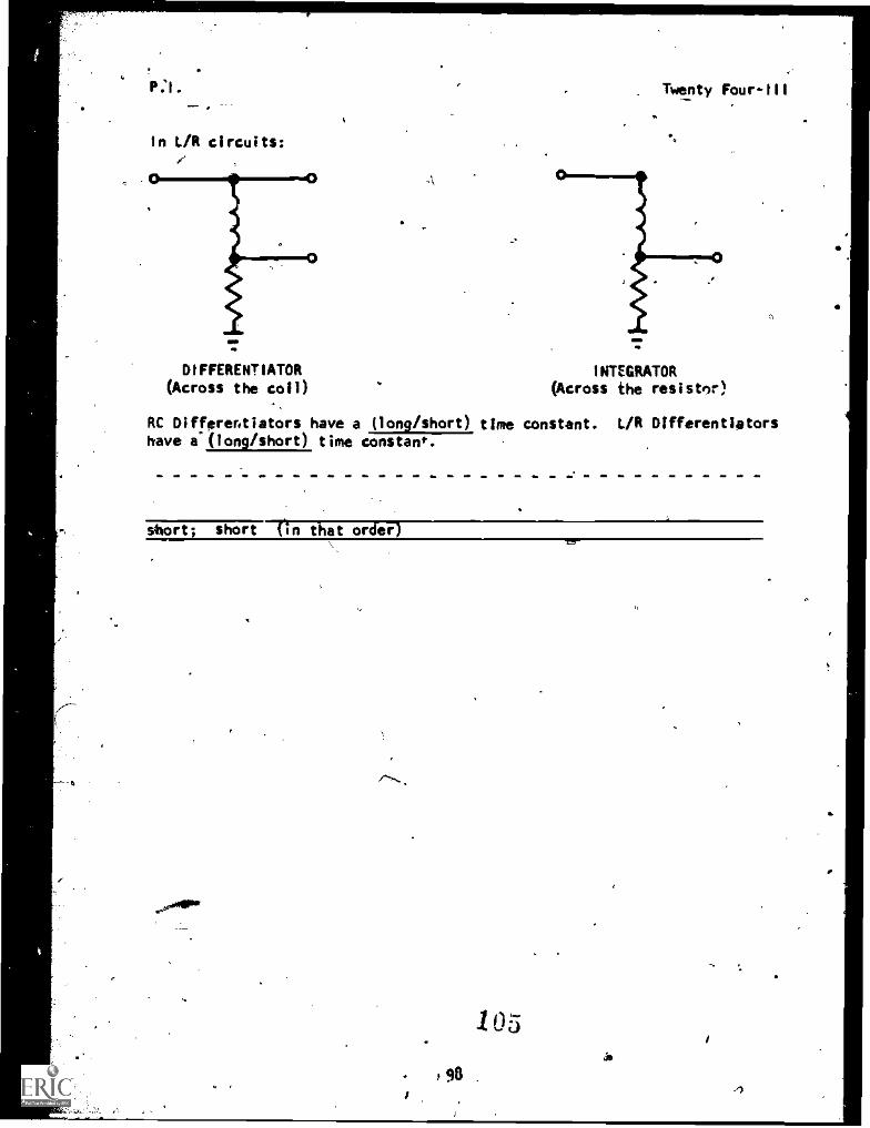
1,
In L/R circuits:
DIFFERENTIATOR
(Across the coil)
RC Differentiators have a (long/short), timehave a (long/short) time constant.
Twenty Four-III
INTEGRATOR(Across the resistor)
constant. L/R Differentlators
short; short (in that order)
s9
1 0 5
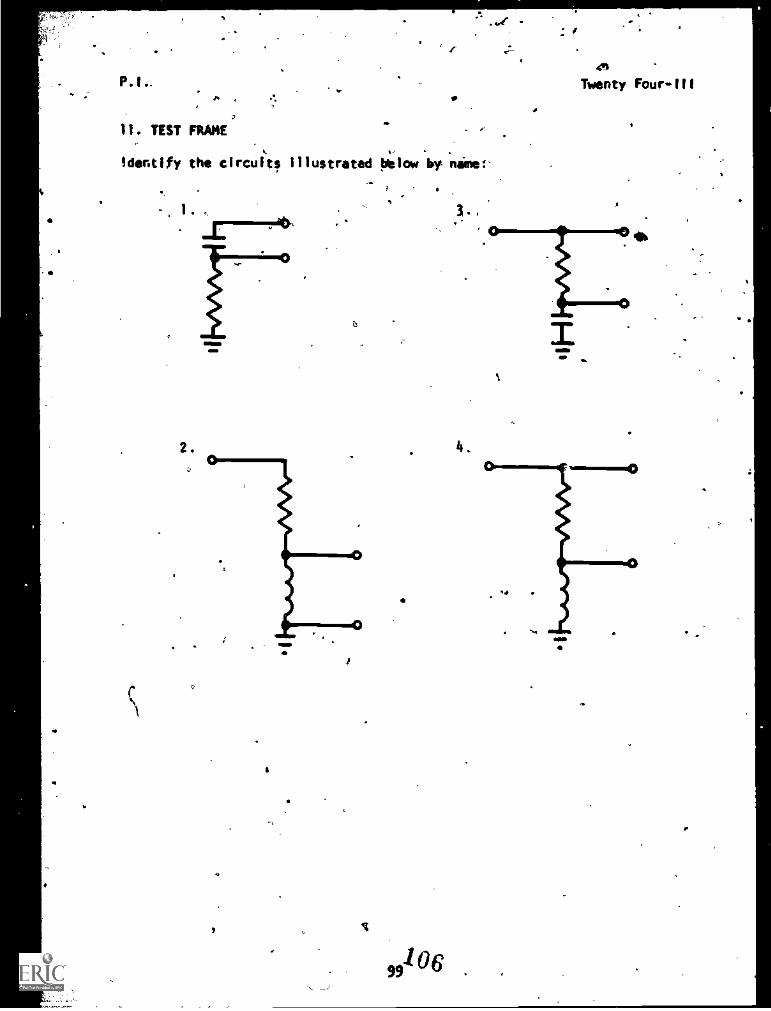
P.I. Twenty Four-Ill
TEST FRAME
identify the circuits illustrated below by nine:-
2.
6
106
3.,
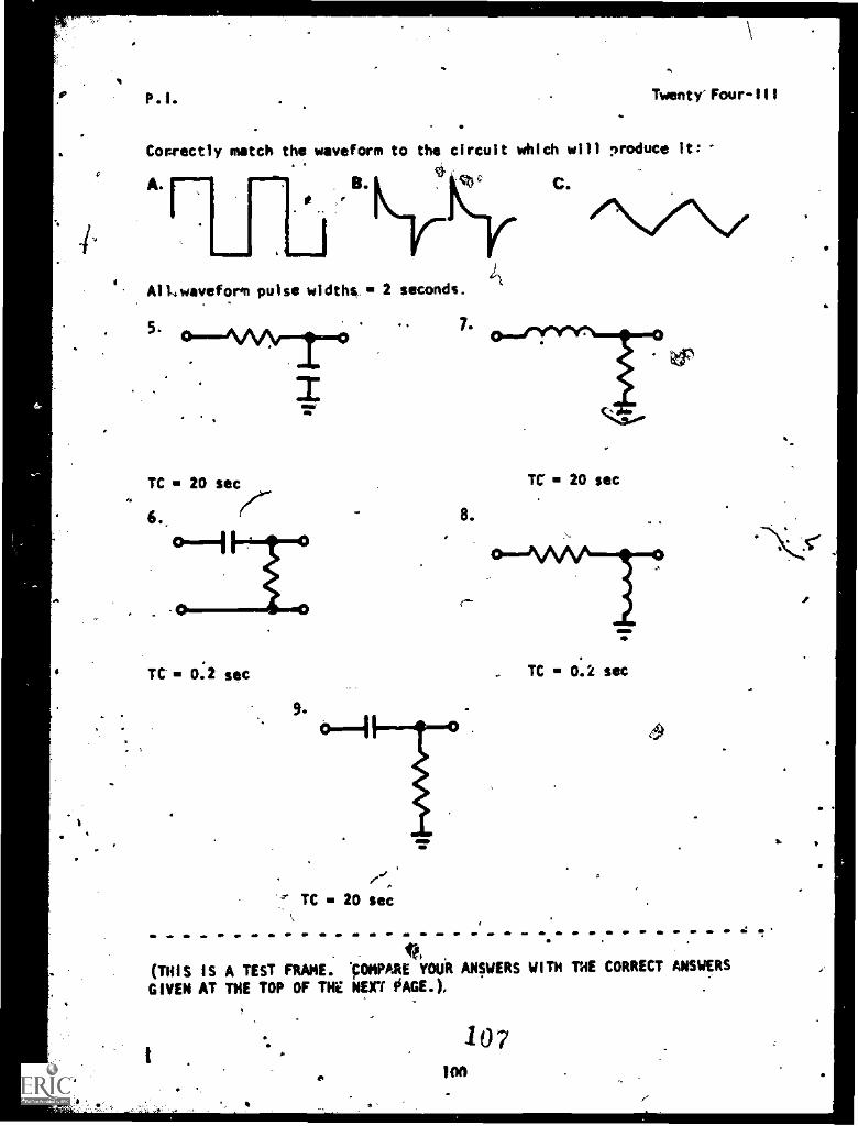
A
P.1. Twenty- Four-111
Correctly match the waveform to the circuit which will produce it:
4=M11/
AlLowaveform pulse widths 2 seconds.
5-
TC 20 sec
6.
0
TC' 0:2 sec
TC 20 sec
7.
8.
TC 20 sec
TC Olk sec
(49
r,trios IS A TEST FRAME. 'COMPARE YOUR ANSWERS WITH THE CORRECT ANSWERS
GIVEN AT THE TOP OF THE NEXT PAGE.).
107100
/o
P.11 Twenty Foui
1. Integrator2. 0Ifferentletor
3. 0Ifferentletor.4. Integrator
5. C
6. e
7. C
8. B
k A
IF YOUR ANSWERS MATCH THE CORRECT ANUERS, YOU HAVE COMPLETED THE PRO-GRAMMED INSTRUCTION FOR LESSON III. MODULE TWENTY PNR. GOBACK TO FRAME 9 ANO TAKE THE PROGRAMMED SEQUENCE BfFORE TAXI G TESTFRAME 11 AGAIN. PAT THIS POINT, YOU MAY TAKE THE LESSON PROGRESS CHECK. IF YOU
ANSWER ALL SELF-TEST ITEMS CORRECTLY:PROCEE0 TO THE NEXT LESSON.IF YOU INCORRECTLY ANSWER ONLY A FEW OF THE PROGRESS CHECK QUESTIONS,THE CORRECT ANSWER PAGE WILL REFER YOU TO THE APPROPRIA PAGES,PARAGRAPHS, OR FRAMES SO THAT YOU CAN RESTUOY THE PARTS O THISLESSON YOU IRE HAVING DIFFICULTY WITH. IF YOU FEEL THAT OU NAVEFAILEO TO UNOERSTANO AL . OR MOST, OF THE LESSON, SELECT ANO USE
MileANOTHER WRITTEN ME° OF INSTRUCTION, AUDIO/VISUAL MATERIALS (IFAPPyCADLE), OR CO ,471,10N WITH LEARNING SUPERVISOR, UNTIL YOUCAN ANSWER ALL SELF -TEST '114115 ON THEtROGRESS CHECK CORRECTLY.
'Pot.
J.
10
101
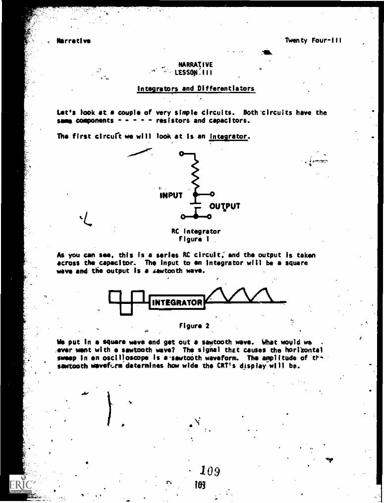
. Narrative Twenty Four-III
NARRA3IVE-.:11S5011-111
Integrators and Differentiators
Let's look at.a couple of very simple circuits. Doth.circuits have thesame components - - - resistors and capacitors.
The first circuriive will look at is an integrator.
0.00".r7
%L.
INPUT
OUVUT
RC IntegratorFigure 1
As you can see, this is a series RC circuit, and the output is takenacross the capacitor. The input to an integrator will be a squarewave and die output is a sawtooth wave.
aRP INTEGRATOR
Figure 2th
Ws put in a square wave and get out a sawtooth wave. What would we .
:ever want with sawtooth wave? The signal thet causes the Noriiontalsweep in an oscilloscope is acsawtoOth waveform. The amplitude oft!'sawtooth weve&rm determines how wide the CRT's display will be.
109103
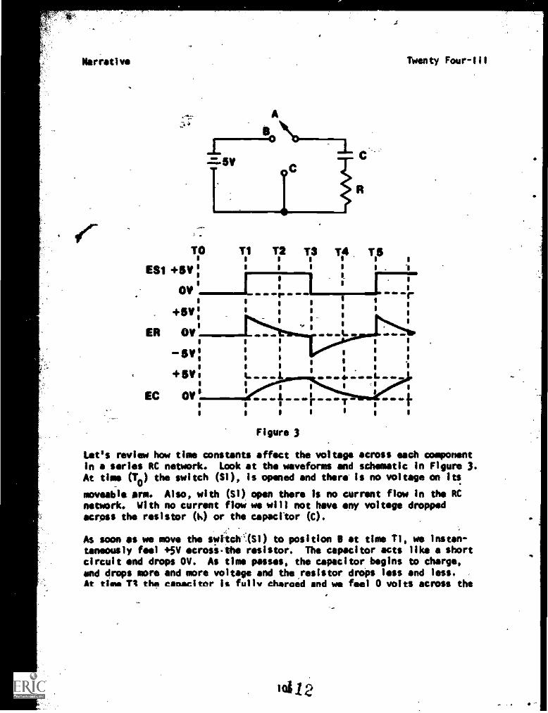
Narrative Twenty four -iii
TO T1 T2 T3 Te Titie e e e
ES1 .011V: e e e e
e_
e e
OVe e
p eI I
+5e
e111 s e
e e
p
ee
, 1 e
ER OVo 40 MI .116 L UP I0 0 0 0
0 o e5V: o
o
o
o
0 e
o s e po . 0
1
+filto 1. MP ID ........., I.0 0 c 0
e p
EC OV 0
10 0111 IND E 411 IND TI
INDMI.140 e
p e I pe p
Figure 3
Let's review how time constants affect the voltage across each componentin a series RC network. Look at the waveforms and schematic In Figure 3.At time (T0) the switch (SI), is opened and there is no voltage on its
moveable arm. Also, with (Si) open there is no current flow in the RC
network. With no current flow we will not have any voltage droppedacross the resistor (k) or the capacitor (C).
As soon as we move the switchqS1) to position B at time TI, we instan-taneously feel +5V acrosi.the resistor. The capacitor acts like a shortcircuit and drops OV. As time passes, the capacitor begins to charge,and drops more and more voltage and the resistor drops less and less.At time TA the capacitor is fully charged and we feel 0 volts across the
101.12.
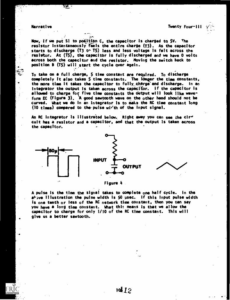
Narrative Twenty Four-111
Now,-if we put SI to pot ton C, the capacitor is charged to 5V. Theresistor instantaneously -feels the entire charge (T3). As the capacitorstarts to discharfe (T3 to T5) less and less voltage is felt across theresistor. At (T5), the capacitor is fully discharged and we have 0 voltsacross both the capacitor and the resistor. Moving the switch back toposition B (T5) will start the cycle over again.
To take on a full.charge, 5 time constant are r uired. To dischargecompletely It also takes 5 time constants. The 1 er the time constants,the more time it takes the capacitor to fully_charge and discharge. In an
integrator the output is taken across the capacitor. If the capacitor isallowedto charge foc five time constants the output will look like Waft -
'Aform EC (Figure 3). good sawtooth wave on the other hand should not becurved. What we do in an integrator is to Make the RC time constant long(10 times) compared to thepuise with of the input signal.
An RC Integrator is illustrated below.. Right away you can see the circult has a resistor and a capacitor, and that the output is taken acrossthe capacitor.
INPUT
OUTPUT
Figure 4 .
,
A pulse is the time the signal takes to complete one half cycle. In the
Opve illustration the pulse width is 50 psec. If this input pulse widthis one tenth or less of the RC network time constant, then you can sayyou have a long time constant. What this means is that we allow thecapacitor to charge for only 1/10 of the RC time constant. This will
give us a better sawtooth.
10,412.
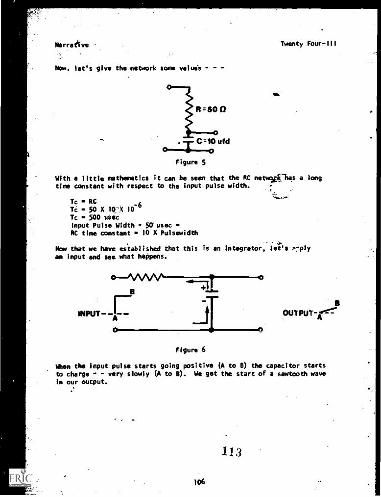
Narrative
-...
Now, let's give the network some values
lR:500
C=10 yid
OFigure 5
Twenty Four-111
With a little mathematics it can be seen that the RC netwitk7has a longtime constant with respect to the input pulse width.
Tc s RCTc 50 X 10 k 10
-6
Tc - 500 IdeeInput Pulse Width - 50 lace sRC time constant 10 X Pulsewidth
- 4-
Now that we have established that this is an integrator, let's Prplyan input and see what happens.
INPUTA--
0
0
OUTPUT-ir
Figure 6
When the input pulse starts going positive OA to B) the capacitor starts
to charge - - very slowly 6A to B). We get the start of a sawtooth wavein our output.
106
113
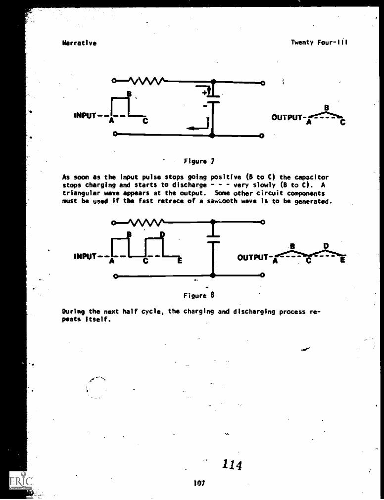
Narrative Twenty Four-Ill
BOUTPUT-Ate-:.-A
Figure 7
As soon as the input pulse stops going positive (B to C) the capacitorstops charging and starts to discharge - - very slowly (B to C). Atriangular wave appears at the output. Some other circuit componentsmust be used if the fast retrace of a saw.00th wave is to be generated.
INPUT -A- W NEP
-r B DOUTPUT-c
0 IMo111110 MCO
Figure 8
During the next half cycle, the charging and discharging process re-peats itself.
'41
114107
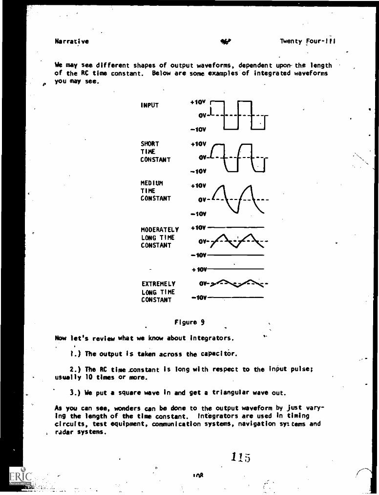
r.
Narrative AlbP Twenty Four-Ill
We may see different shapes of output waveforms, dependent upon-the lengthof the RC time constant. Below are some examples of integrated waveformsyou may see.
INPUT
SHORTTIMECONSTANT
MEDIUMTIMECONSTANT
MODERATELYLONG TIMECONSTANT
EXTREMELY
LONG TIMECONSTANT
lov r--, rovl--------
-10y
10V
OV
-boy
i0V
10V
UN
10V011116 4. WO .11.
10y
Figure 9
Now let's review what we know about Integrators.
1.) The output is taken across the capacitor.
2.) The RC timexonstant is long with respect to the input pulse;usually 10 times or more.
3.) We put a square wave in and get a triangular wave out.
As you can see, wonders can be done to the output waveform by just vary-ing the length of the time constant. Intbgrators are used in timing
circuits, test equipment, communication systems, navigation systems and, radar systems.
imA
115
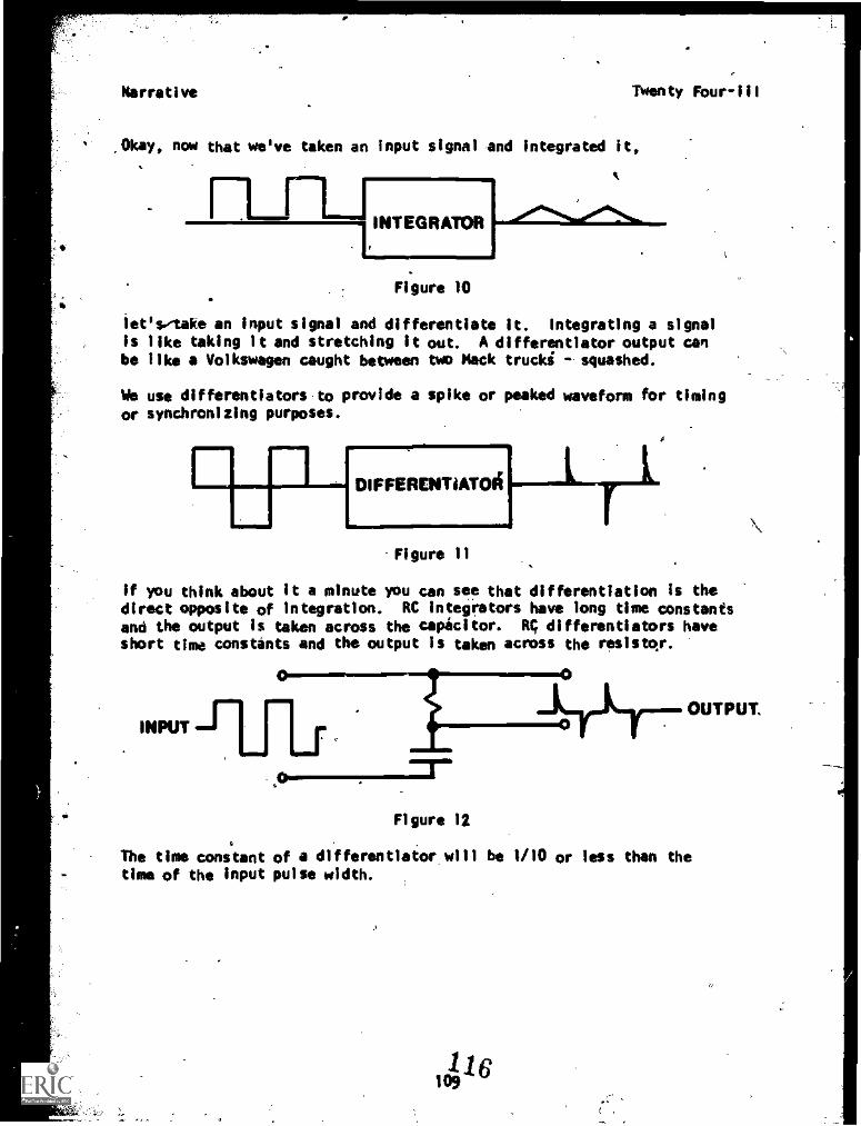
Narrative Twenty Four-III
,Okay, now that we've taken an input signal and integrated it,
Figure 10
let's take an input signal and differentiate it. Integrating a signalis like taking it and stretching it out. A differentiator output canbe like a Volkswagen caught between two Mack trucki -squashed.
We use differentiators-to provide a spike or peaked waveform for timing
or synchronizing purposes.
DIFFERENTIATOli
-Figure 11
If you think about it a minute you can see that differentiation is thedirect opposite of integration. RC integrators have long time constantsand the output is taken across the capacitor. R1 differentiators haveshort time constants and the output is taken across the resistor.
INPUT
Figure 12
The time constant of a differentiator.will be 1/10 or less than thetime of the input pulse width.
116109
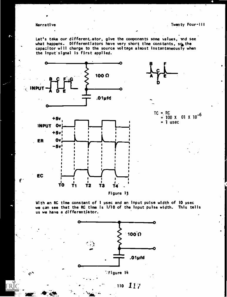
r-.
41.
Is
Narrative . Twenty Four-111
Let's take our different.ator, give the components some values, Ind seewhat happens. Differentiators have very short time constants, sqb the
capacitor will charge to the source voltage almost instantaneously whenthe input-signal is first applied.
43.1nIMP+5v1
INPUT Ov 1+5v:
ER Ov 1
5v 11
1
i1
s
1
V
EC s
I s I 1
TO T1 T2 4-T3 T .I I j
Figure 13
.01pfd
I i j
s 1 s
s it s
I1
1
1
I1
i I
sa.
TC =,RC= 100 X 01 X 10
-6
= 1 usec
With an RC time constant of 1 psec and an input pulse width of 10 psecwe can see that the RC time is 1/10 of the input pulse width. This tellsus we have a differentjator.
riT
"=Figure li
.01 ofd
- no 117
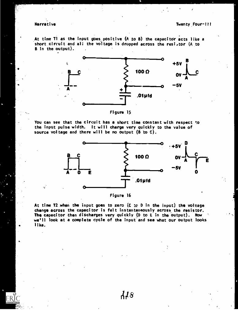
Narrative Twenty Four-III
At time T1 as the input goes positive (A to B) the capacitor acts like ashort circuit and all the voltage is dropped across the resistor (A toB in the output).
Figure 15
You can see that the circuit has a short time constant with respect tothe input pulse width. It will charge very quickly to the value ofsource voltage and there will be no output (B to C).
+5V.
ADD
O C 100 0 OVAi.E
E*.5V
6 T .° "'dFigure 16
At time T2 when the input goes to zero (C ?x, D in the input) the voltagechange across the capacitor is felt instantaneously across, the resistor.The capacitor then discharges very quickly (D to E in the output). Nowwe'll look at a complete cycle of the input-and see what our output lookslike.
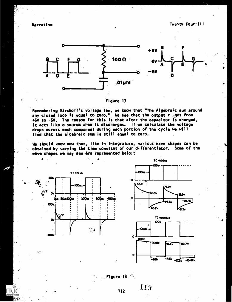
Narrative
.°1111d0
Figure 17
Remembering Kirchoff's voltage law, we know that "The Algebraic sum aroundany closed loop is equal to zero." We see that the output r lies from
+5V to -SV. The reason for this is that after the capacitor is charged,it acts like a source when it discharges. if we calculate the voltagedrops across each component during each portion of the cycle we willfirid that the algebraic sum is still equal to zero.
We should know now that, like in integrators, various wave shapes can be
- obtained by varying the time constant of our differentiator. Some of the
wave- shapes we may seed -represented bola!:
+5V
OV
Twenty Four-Ill
C 0
TCB 10 us
_Figure 111,'
112
.-1001/1-.
TCB100es
AOC*.
s
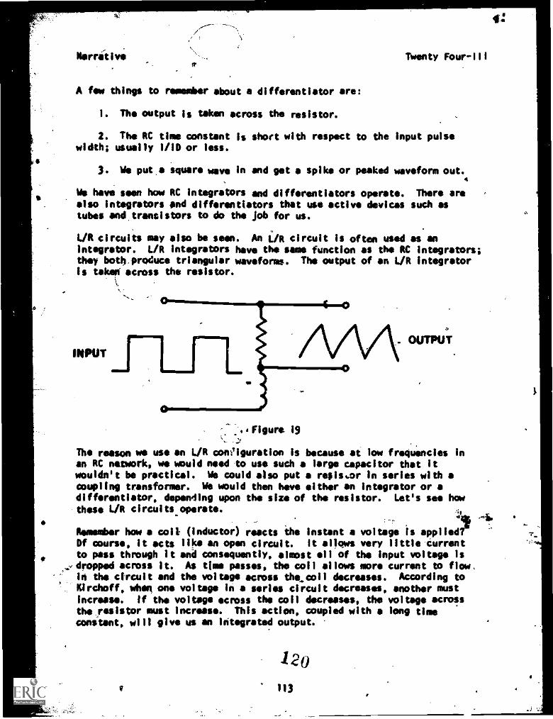
Nerrit I ve Twenty Four111
A few things to remember about a differentiator are:
1. The output is taken across the resistor.
2. The RC time constant is short with respect to the input pulsewidth; usually 1/10 or less.
3. Sle put .a square wave in and get a spike or peaked waveform out.4
Wis have seen how RC integrators and differentiators operate. There arealso integrators and differentlators that use active devices such astubes aftettrantistors to do the job for us.
L/R circuits may also be seen. An 1./R circuit is often used as anintegrator. L/R integrators have the same function as the RC integrators;they both.produce triangular waveforms. The output of an L/R integratoris take0 across the resistor.
1.
INPUT
:..Figurt 19--)
The reason we use an L/R coniguration is because at low frequencies inan RC network, we would need to use such a large capacitor that itwouldn't be practical. We could also put a resisuor in series with acoupling transformer. We would then have either an integrator or adifferentiator, depending upon the size of the resistor. Let's see howthese L/R circuits operate.
Remember how a colt (inductor) reacts the instant a voltage is appliedOf course, it acts like an open circuit. It allows very little-turrentto pass through It and consequently, almost all of the input voltage Is
,;,41ropped across It. As time passes, the coil allows more current to flow,in the circuit and the voltage across the,coll decreases. According to
ACIrchoff, when one voltage in a series circuit decreases, another mustincrease. If the voltage across the coil decreases, the voltage acrossthe ,resistor must increase. This action, coupled with a long timeconstant, will give us an integrated output.
120V 113
#:
1
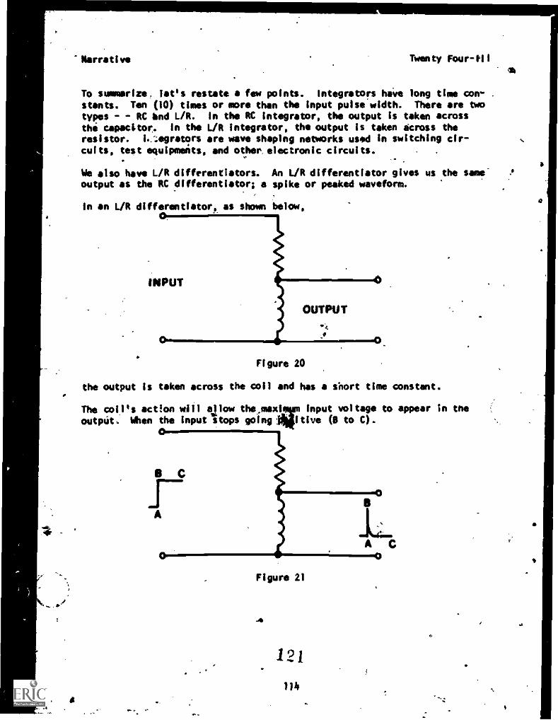
Narrative Twenty Four-illa
To summarize, let's restate a few points. Integrators have long time con- .
stants. Ten (10) times or more than the input pulse width. There are twotypes - - RC bnd L/R. In the RC integrator, the output is taken across
the capacitor, in the L/R integrator, the output is taken across theresistor. I,:egretors are wave shaping networks used in switching cir-cuits, test equipmeits, and other. electronic circuits.
We also have L/R diffrrentiators. An L/R differentiator gives us the same-output as the RC differentiator; a spike or peaked waveform.
in an L/R differentiator, as shown below,
INPUT
OUTPUT
Figure 20
the output is taken across the coil and has a short time constant.
The coil's actIon will allow input voltage to appear in the
outptit. When the input stops going tive (0 to 0.
C
A C
figure 21
121
lib
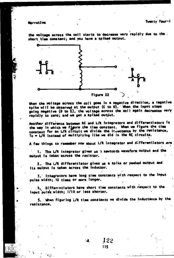
Nerrative TWenty'FOur-1
the voltage across the coil starts to decrease very rapidly due to the
short time constant; and. you have a spiked output.
Figure 22
When the voltage across the coil goes in a negative direction, a negative
spike will be observed at the output (C to 0). Whekthe input stops
going negative (D to I), the voltage across the coil again decreases very
rapidly to zero; and we get a spiked output.
Another diffeience between RC and L/R integrators and differentiators is
the way in which we flours the time constant. When we figure the time
constant for an L/R crOcult we divide the ir..;uctence by the resistance,
Tc L/R instead of multiplying like we did in the R; circuits.
A few things to remember now about L/R integrator and differentiators,are
is The L/R integrator gives us 3 sawtooth waveform output and the
output is taken-across the resistor.
2., The L/R differentiator gives us a spike or peaked output and
its output is taken across the inductor.
3.' integrators have long time constants with respect to the input
pulse width; 10 times or more longer.
DIfferrntlators have short time constants with respect to the
input pul4 width; 1/10 or less shorter.
5. When figuring L/R time constants we divide the inductance by the
resistance.
122115
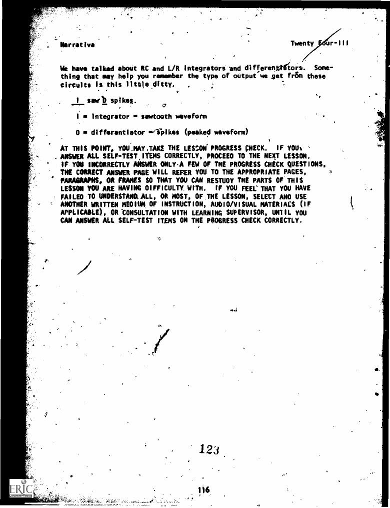
.L
Narrative Twenty r III
We have talked abaft RC and L/R integrators end differepOilort, Some-thing that may help you remember the type of output we Net fr&n these
circuits is this little ditty. .
1 wdb spikes.0
integtator sawtoath waveform
D differentiator 014,1kes (peaked waveform)
a
AT THIS POINT, YOU.NAY.TAKE THE LESSON PROGRESS ;HECK. IF YOUb
. ANSWER ALL SELF-TEST.ITEMS CORRECTLY, PROCEED TO THE NEXT LESSON.
IF YON INCORRECTLY ANSWER ONLYA FEW OF THE PROGRESS CHECK QUESTIONS,THE CORRECT ANSWER PAGE WILL REFER YOU TO THE APPROPRIATE PAGES,PARAGRAPHS, OR FRAMES SO THAT YOU CAN RESTUDY THE PARTS OF. THISLESSON YOU ARE HAYING DIFFICULTY. WITH. IF YOU FEEL'THAT YOU HAVEFAILED TO UNDERSTAND., LL, OR MOST, OF,THE LESSON, SELECT ANO USEANOTHER WRITTEN MEDIUM, OF INSTRUCTION, AUDIO/VISUAL MATERIACS (IFAPPLICABLE), OR 'CONSULTATION WITH LEARNING SUPERVISOR, UNIIL YOUCAN ANSWER ALL SELF-TEST ITEMS ON THE PROGRESS CHECK CORRECTLY.
,4
ri
.6
123


![S-band Planar Antennas for a CubeSat - ijeeiijeei.org/docs-21222827525684f82c93c43.pdf2. Shorted Patch Antenna The simulation model of the shorted patch antenna [9] on 2U CubeSat body](https://img.pdfslide.us/doc/110x75/609a3472c380df5c1e050aaa/s-band-planar-antennas-for-a-cubesat-2-shorted-patch-antenna-the-simulation-model.jpg)


![Digital Logic LAB Manual KL-300 [Shorted]](https://img.pdfslide.us/doc/110x75/55cf93ef550346f57b9ed2c2/digital-logic-lab-manual-kl-300-shorted.jpg)