Embed Size (px)
Citation preview
DOCOBENT RESUME
EU 207 796 SE 033 657
. AUTHOR Craig, Jerry; Stapleton, JerryTITLE Science and Engineering Graphics I. A Study Guide of
the Science and Engineering Tcchnician Curriculum.INSTITUTION Saint Louis Community Coll. P.4 Florissant Valley,
Mo.SPONS AGENCY. National Science Foundation, Washington, D.C.PUB DATE 76GRANT NSF-GZ-3378; NSF-HES74;-22284-A01; NSF-Sa77-17935Nolt 144p.; For related documents, see SE 033 647-656. Not
available in paper copy due to copyrightrestrictions. Contains numerous light and brokentype.
.AVAILABLE FROM National Science Teachers Association, '742Connecticut Ave., N.W., Washington, DC 20009 (writefor correct price).
EDRS PRICE MF01 Plus Postage. PC Not Available from EDRS.DESCRIPTORS Associate Degrees; Charts; *College Science;
Diagrams; *Engineering Drawing; Engineering Graphics;Graphic Arts; Graphs; *Instructional Materials;Interdisciplinary Approach; Orthographic Projection;*Postsecondary Education; Science Course ImprovementProjects; *Technical Education; TechnicalIllustration
IDENTIFIERS *Science and Engineering Technician Curriculum
ABSTRACTThis study guide is part of 'program of studies
entitled Science and Engineering Technician (SET) eurriculua. The SETCurriculum was developed for the purpose of training technicians in
the use of electronic instruments and their applications. Itintegrates elements fromthe disciplines of chemistry, phySics,mathematics, mechanical technology, and electronic technology. Thisguide provides basic information relc.ted to the following topics: (1)lettering and use of equipment; (2) geometrical construction; (3)
sketching and shape description; (4) lultiview projection; (5)auxiliary views; (6) sectional views; (7) drawing; and (a) charts and
graphs. (Author/SK)
***********************************************************************Reproductions supplied by EDRS are the best that can be made
from the original document.***********************************************************************

US MENT Of "REALMEDLECTiON & WELFARENATIONAL INSTITUTE OF
EDUCATION
THIS DOCUMENT HAS KEEN REPSDUCED ExACTL Y AS RECEIVED FR(THE PERSON OR ORGANIZATIONORIGAT/NO IT POINTS OF VIEW OR OPINIOSTATED DO NOT NECESSARILY REPSSENT OFFICIAL NATIONAL INSTITUTEEDUCATION POSITION OR POLICY

1111111.._
-"\tibC_

404
1 Award NumberSEDRDATAFORMAT
SED77-179352. Award DateSeptember 28, 1977
3. Termination DateJuly 31, 1979
6. TitleScience and Engineering Graphics I:A Study Guide of the Science and Engineering Technician Curriculum
4. Amount of Award$70,400 (Cum. Amt.)
S. TypeFinal Technical Report
7. Performing OrganizationSET ProjectSt. Louis Community College at Florissant Valley
St. Louis, MO 63135
8. Pagination131 pages
9. Accession Number
00319
11. Principal Investigator. Field or Specialty
Donald R. Mowery
12. NSF Program Manager
Gene D'Amour
10. Performing OrganizationReport Number
13. SEDR Program
DISE
14. SEDR Subprogram
1S. Abstract
This study guide is part of a program of studies entitled the Science and Engineering_
Technician Curriculum. The SET curriculum was developed for the purpose of training technician;
in the use of electronic instruments and their applications. It integrates elements from the
disciplines of chemistry, physics, mathematics, mechanical technology, and electronic technol-
ogy.Science and Engineering Graphics I provides basic information related to the following
topics: (1) lettering and use of equipment; (2) geometrical construction; (3) sketching and
Shape description; (4) multiview projection; (5) auxiliary views; (6) sectional views; (7)
basic dimensions; (8) electrical and electronic drafting; (9) welding drawing; (1C) pipe
drawing; and (11) charts and graphs.
16. Descriptors
Study GuidesInstructional MaterialsAssociate DegreesScience Curriculum
Engineering TechniciansEngineering GraphicsDraftingEngineering Drawing
17. Identifiers
Science and Engineering Technician Curriculum (SET)
16. Field
Engineering Education
20. AvailabilityLimited number of copies available from St.Louis Community College at Florissant Valley,
St. Louis, MO 63135
19. Target Audience
Two-Year College Students
21. Supplemental Notes
One copy
4,

SCIENCE AND ENGINEERING
GRAM ICS I
A STUDY GUIDE
OF
THE SCIENCE AND ENGINEERING TECHNICIAN
CURRICULUM
Puthors: Jerry CraigSt. Louis Community College at Forest Park
Addi-ess:
Jerry StapletonSt. Louis Community College (IL Flori,;-;ant Valley
Project Directors: 1;111 G. AldridgeDonald Mowery1.awrence J. Wolr
Study Guide Editor: Peggy DixonMontgomery College, Takoma "ark, MD
SET ProjectSt. Louis Community College at, Florissant ValleySt. Louis, Missouri 63135
Copyright c 1976 by St. Louis Community Coil 4. at Florissant Valley.
Printed in e United States of Amerira. All riqhts reqetw,d. This book
or parts thereof may not be reproduced in any without permission.
The materials contained herein were devulopen under Grant NumbersHES74 -222A4 AOle GZ-3378, and SED77-l7,35.
uEc, 19a
q=m1.or

TABLE OF CONTENTS
Page
CHAPTER I INTRODUCTORY TOPICS
:,,-?ction 1.1 Lettering;,oction 1.2 - U-,e of Equipment 4
:HAPTE R *II- ,EOMFTRICAL CONSTRUCTION 11
Sectinn .'.1 - basic Applied Geometry % 11
cinrri-i, III SKETCHING AND SHAPE DESCRIPTION 17
ti n i.1 iketching Materials and Lines Technique 17
tion - Isometric Sketching 19
cHAPrER IV MULTIVIEW PROJECTION 25
;ection 4.1 - Theory of Piojection 25
1-ection 4.2 - Instrument Drawing 29
CHAPFER V AUXILIARY VIEWS 34
.;f.ctic)ri .1 Primary Auxiliary Views 34
CHAPTER VI SECTIONAL VIEWS 39
:t.cticul 6.1 - Cutting P lanes, Section Lining, Full and
Half Sections 39
.ection b.2 - Other Types of Sectioned Views 42
,IA: TER VII BASIC DIME1..IONING 54
- Means for Specifying Dimensions 54
:ectLur, 1.2 - Standard Methods of Dimensioning Features-;faction 7.3 - Special Dimensioning Notes and Symbols 6.]
oction 1.4 - Tolerancinq 65
CHAtTER VIII ELECTRICAL AND ELECTRONIC DRAFTING 78
Section 8.1 - Block Diagrams 78
section 8.2 - Connection Diagrams and Interconnection Diagrams HO
Section 8.1 - Sc'lematic Diagrams H6
Section H.4 - Logic Diagrams, Integrated Circuits, PrintedCircuits H9

.TABLE OF CONTENTS (Cont)
CHAPTER IX WELDING DRAWING
Section 9.1 - Processes, Joints, and Symbols
Page
104
1C4
CHAPTER X - PIPE DRAWING 108
Section 10.1 Joints, Fittings, and Valves 108Section 10.2 - Single-Line and Double-Line Drawing 110
CHAPTER XI - CHARTS AND GRAPHS 112
Section 11.1 Rectangular Line Graphs 112
Section 11.2 Semi-Logarithmic Line Chart or Graph 114
TABLES 125
l
0
CHAPTER I
Introductory lopic;
SECTION 1-1 LETTERING
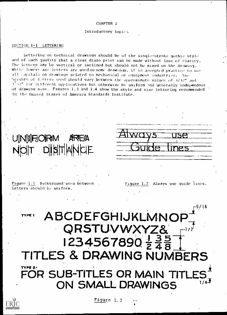
Lettering on technical drawings should be of the single-stroke gothic styleand of such quality that a clear diazo print can be made without loss of clarity.The letters 'may be vertical or inclined but should not be mixed on the drawing.While lower--ase letters are used on some drawings, it is accepted practice to useall ,apitals on drawings related to mechanical or equipment industries. lithqight- of 1,,tters used should vary between the approximate values of 3/32" and9,12" for different -applications but otherwise be uniform -41d generally independentof drawing size. Figures 1.3 and 1.4 show the style and size lettering recommendedby the United States of America Standards Institute.
UNI1OHOIRIM /RSA
ticirr 01151T
Figure .1 Background'area between Figure 1.2 Always use guide lines.letters should b2 uniform.
45/16TYPg ABCDEFGHIJKLMNOR,
QRSTUVWXYZ&1234567890. Lit
TITLES & DRAWING NUMBERS
FOR SUB-TITLES OR MAIN TITLE;ON SMALL DRAWINGS 114
Figure 1.3 I -1

_
.0/32TY" 3 ABCDEFGHIJKLMNOPQRSTUVWXYZ&T1234567890 -2i I9/32
FOR HEADINGS AND PROMINENT NOTES
TY Pt )t"- F^ .7V It ..1
1%147561E5510FOR BILLS OF MATERIAL, (DIMENSIONS & GENERAL NOTESTYPE 5
OPTIONAL. TYPE M-SAIYIE AS TYPE. 4 BUT USINO TYPE 3 FOR RRSTLETTER OF PRINCIPAL WORDS. MAY BE USED FOR SUB-TITLEe.
AND NOTES ON ME BODY OF DRAWINGS.
TYPE 6 abcdefghijklmnopqrstuvwxyzType 6 may be used in place ofType 4 with capitols of Type 3.
Figure 1.3 (cont.)
TYPE 1 ABCDEFGHAJKLMNOPI5
QRSTUVWXYZ& 2
1234567890 I dTO BE USED FOR MAIN TITLES
& DRAWING NUMBERSTYPE 2 ABCDEFGHIJKLMNOPQR
STUVWXYZ&/234567890 ag-i
TO BE USED FOP SUB-TITLESI'i gurt 1 4

TYPE 3
rert 4
ABCDEF:GHIJKLMNOPQRSTUVWXYZa.1234567890 43
FOR HEADINGS AND PROMINENT NOTES
ABCDEFGH&IKLMNOPORSTUVWXYZ411234567890
FOR 811..I.S OFMATERL4L, DIMENSIONS & GENERAL NOTES
TYPE 5ai770A1.41.. TYPE .SAME AS TI-PE 4 BUT USING TYPE 3 FOR FIRST
LETTER OF PRINCJPAL WORDS. MAY BE USED FOR SUB-TITLES
MOTES ON THE BODY OF DRAWINGS.
TYPE 6
LABk RATt)RY
sabcdefghilk/rnnopqrstuvwxyzType 6 may be used in place ofType 4 will, capitals of Type 3
Figure 1. 4 (cont. )
(EXTRACTED FROM AMERICAN STANDARD DRAFTING MANUAL,
LINE CONVENTIONS, SECTIONING AND LETTERING
(ASA Y14-2-1957), WITH PERMISSION O1' THE PUBLISHER)
1. The student should be able to do pencil lettering on tracing paper using
single- stroke gothic style. The work should include capitals, lower
case, whole numbers, and fractions. A diazo reproduction should be
clear with no loss of clarity.
,ECTL)N
STUM ;UESTICNS
1. How much space should be left between words?
What is thP angle of slant on an inclined letter?
When lettering a fractional number, what is the height of the fraction
relative to the height of the whole number?

EXERCISES .
-4-1. Lay out sheet, add guide lin9s (vertical or inclined), and fill in
letters as indicated.
SECTION 1.2 USE OF EQUIPMENT
Proper use of equipment is one of the determining factors in producing aquality technical drawing. Same of-thoseinstruments most difficult to mistergave been listed.
1. Drafting machine - Th<t proper use of a drafting machine can savemany hours of drawing; time. Its use is not covered here due tothe different models .available. Manuals giving detailed instructions-on the use and care of th*drafting machine are available through .
the manufacturers.
2. Drafting pencil - Good Line technique begins with the selection ofthe correct grade of leadand the proper sharpness an the point.
GH 5H 4H 3H
2H H F I-113
PENCIL GRADES
Figure 1.6PENCIL POINTS
vigure 1.7
4

-5-
Figure 1.8 Drawing Horizontal Line.
Draw pencil along straight edge;
Rotate pencil to maintain uniform point.
J
Drawing a Vertical Line
Figure 1.9
3. Scale - Some scales in .common use today are the mechanicalengineers scale, civil engineers scale, architects scale,and to a lesser extent in this country, the metric scale.It is not uncommon to find triangular scales which in-corporate several different types into one .multi- purposescale.
4. Dividers Dividers are used,for transferring measure-ments and occasionally for dividing lines or arcs intoequal parts. Care must be taken when using- the dividersso that the legs do not'moVe between taking the 'Measure-ment and laying it off.
5. Compass - The compass is probably the_most important single item ofall the drafting instruments other than the pencil and straight edge.The correct choice of lead an& proper sharpening technique is essen-tial to the successful use of a compass. Avoid those compasses whichdo riot have a center wheel for adjustment.
(a) (b) ( c )
Figure 1.10 Three different methods of sharpening a compass lead.
1;

iv NCIL LINES
THICK
MEDIUM2
3THIN
-6- INK INES
THICKVISIBLE LINE
MEDIUM1IDDEN LINE 2----------
THINSECTION LINE 3
4
5
6
7
THINCENTER LINE
DIMENSIONLINE
EXTENSIONLINE
AND LEADERS
A
Leader_,t,--- Extension Line
7-Dimension Line1 THIN
I32 THIN
8
9L
10
12
THICK
THICK
TH ICK
ATHIN
HiN
CUTTING E
LINES
9.-TH CK
THIN4
5
ey"Lieader
Extension LineDimension Line
THIN-441 32
2-32 THIN
THICK
BREAK LINES
) 1.11
PHANTOM LINE 12
-A.WIDTH AND CHARACTER OF LINES
Figure 1.11
THICK
THIN
THIN
(EXTRACTED FROM AMERICAN STANDARD DRAFTING MANUAL,
LINE CONVENTIONS, SECTIONING AND LETTERING
(ASA Y14-2-1957), WITH PERMISSION OF THE PUBLISHER)
IL:

-7-
Fraser and eraser shield These are relatively inexpensive items
by comparison but improper use can result in dark smudges on a
vellum drawing. Make sure that the eraser is soft (not artgum)
and the eraser shield is metal (plastic is too thick).
7. Irregular curve - These curves are used for the mechanical drawing
of free curves and require some practice to use effectively.
8. Circle template - The circle template is particularly useful in
drawing small circles (1" diameter or less) whe'r^ a large bow compass
would be difficult to use. When drawing concent ,c circles with a
cle template it's best to lay out first with a small compass.
,E.AlitIRATGRY
1. Tho student should be able to draw object lines, hidden lines, and
r.unter lines using graphite lead for both straight lines' and arcs.
These lines should be sharp, blac' -, and capable of being reproduced
mnco a diazo copy without appreciable loss of line density and sharpness.
3 The student should be able to draw a layout line to an accuracy of
1/32" and to measure a previously drawn line to an accurac,, of
1/32".
3. The student should be able to take angular measurewchts within ± 10
minutes using the drafting machine.
SECTION ITEMS
flUESTIONS
1. What grades of leas. are best suited for technical drawing?
2. Should a compass lead be sha 3ened into a conical point?
3. given the following lead grades; 2B, 2H, F, and 4H,
which is the hardest? Which is the softest?
EXERCISES
1. Measure the following lines'to t 1/32" on length and 410' on angles.
Use full scale
i--
-----------
length
Am..wers
angle
horizontal line (0'))

t
(a)
M,sa:.,ure tit, t(dloWIng
(I) -----------
(c)
t
lines to ' .0i" on length and F10' on angle,,.
length
An
angle.
Use full scale
Oo line
M.,a,ure the following lines to 4.80 mm on length and 410' on angles.
Use full scale
N..(.1,)
---, ((-) ------\N,
,.
length
Answers
angle

4. Make a full scale pencil instrument drawing of the GuSSET in Fig. 1.12.
Draw on a q" x 12" Sheet of vellum with a 1/4" border and use title block
shown -n Fig. 3.14. Make a diazo print of the finished drawing.tyn
._i!APTER ITEM
EXERCISES
c5
I 5o
Figure 1.12
Make a full scal- pencil instrument drawing of the plate in Fig. 1.13.
Draw on a 9" x 12" sheet of vellum with a 1/4" border and use title block
as shown in Fig. 3.14. Make a diazo print of the finished drawing.
ffaure 1.13
[

ANSWER: 1.1 -10-
A Eu.ii t,, tht i. ,,t t it, let
Twr. height of wholo number.
SE:T1ON 1.2
.,TUDY (MF,,,TIONS
1.- 6H - JIB. Many factors such as drafting media, hulidity,drawing surface, and individual technique will play apart in lead selection but -generally the following isrecommended: 6H - 5H for layout work. 4H - 2H for thinlines (center lines, etc.), H - HB for thick lines andlettering
2. No. Compass leads should be sharpened intc a chisel point or anelliptical point.
3. Of that given group of leads the hardest is 4H and soft-est icJ., 2B.
EXEPCISES
length angle 2. length an leJ.
(a) 2 3/32 29° 35' (a) 1.26 28° 40'
(b) 2 9/16 25° 40' (b) 2.37 21° 05'
(c) 2 3/32 5° 00' (c) 2.56, 4° 05'
(d) 2 1/2 12° 15' (d) 3.16 5° 05'
(c') 1 5/32 19° 15' (e) 1.88 26° 15'
3. length an le
(a) 47.50 340 15'
(J) 93.30 15° 55'
(c) 76.20 3o 15'
(d) 79.20 21° 55' 1,'I /
(e) 82.80 31° 00'

CHAPTER II
Geometrical Construction
SECTION 2-1 BASIC APPLIED GEOMETRY
AppIP.,1 Tom(Ar/ 1,, the basis for layout and construction in instrument
Lt i not necessary to write geometric proofs to solve problems
qppli-d Tometry, tt is imprtant to have a general understanding of the
"principles of plane geometry. The practice of pure geometric construction is
rime consuming and does not utilize the many accurate instruments available to
the,drafrsman. The illustrations in this section will use the most expedient
fnethods where accuracy permits.
360'
t
COMPLETECIRCLE
180*
STRAIGHT ANGLE
/LESSTHAN 90'
1
RIGHT ANGLE ACUTE ANGLE
EGUIL AT E RM. TRIANGLE
VERTEX
SUPPLEMENTARY ANGLES
04 +0 =180°
MORETHAN 90'
OBTUSE ANGLE
Fipre 2.1 Angles
ISOSCELES' TRIANGLE SCALENE TRIANGLE
Figure 2.2 Triangles
7*-I, 1
COMPLIMENTARYANGLES
c4 +CD =90
RIGHT TRIANGLE

'RiANLAt ,u0AR1
-12-
',WAGON
Figure 2.3 The Regular Polygons
90'
11111 111 A1001111
GuADRANT
SEINENT
SECTOR
Figure 2.4 Elements of the Circle
(a) (b)
r.r
C
N
I
I GIVEN LINEA ,
CENTEROA Al
N
X 'AGON
Figure 2.5 To Bisect a Line
(c)
Figure 2.6 To Bisect an Angle
(d)

GIVEN LINE
ANY ANGLE(
(a)
rjur4, 2./ I VI de
angle from one end of given I
of equal spaces. Draw from
(c) Draw parallel lines from
(b)
4 EQUAL DIVISIONS
(c )
ltne into equal parts. (a) Draw a line at any
tne. (b) Divide angled line into required number
last mark on angled line to end of given line.
each mark dividing given line into equal parts.
Circumscribing Circle -Distance across corners given.
Insciibed Circle-Distance across flats given.
Figure 2.8 To Draw A Hexagon
Figure 2.9 To draw a circle
through three given points.
CENTER
-DRAFTING
WWRKPINt
Figure 2.10 To draw a tangent
and a circle

CIRCLE
-14-
ELLIPSEPARABOLA
Figure 2.11 The Conic Sections
HYPERBOLA
For all conic sections, a cutting-plane passes through a rightcircular cone in such a manner that one of the following is formed by theintersection of the surface of the cone and the cutting-plane. The anglebetween the center axis of the cone and the cutting-plane determines thecurve.
Circle - Cutting-plane is 900 to ax)s of cone.
Ellipse - Cutting -plane is inclined to axis of cone. The angleformed is greater than that between the axis of thecone and its elements.
Parabola - Cutting-plane makes the same angle with the axis ofthe cone as do the elements; of the cone.
Hyperbola - Cutting-plane makes an angle with the axis of the coneless than that formed between the elements -and the axis.
LABORATORY
1. ThE student should be able to perform basic geometric construction suchas b'secting angles and lines, drawings tangents, dividing lines intoequal spaces, etc.
SECTION ITEMS
STUDY QUESTIONS
I. How many degrees are in d hexagc)ri?
2. What are complementary angles?
3. What conic section can be drawn with a compass?
4. What is the general term for a plane four-sided figure?
4-1
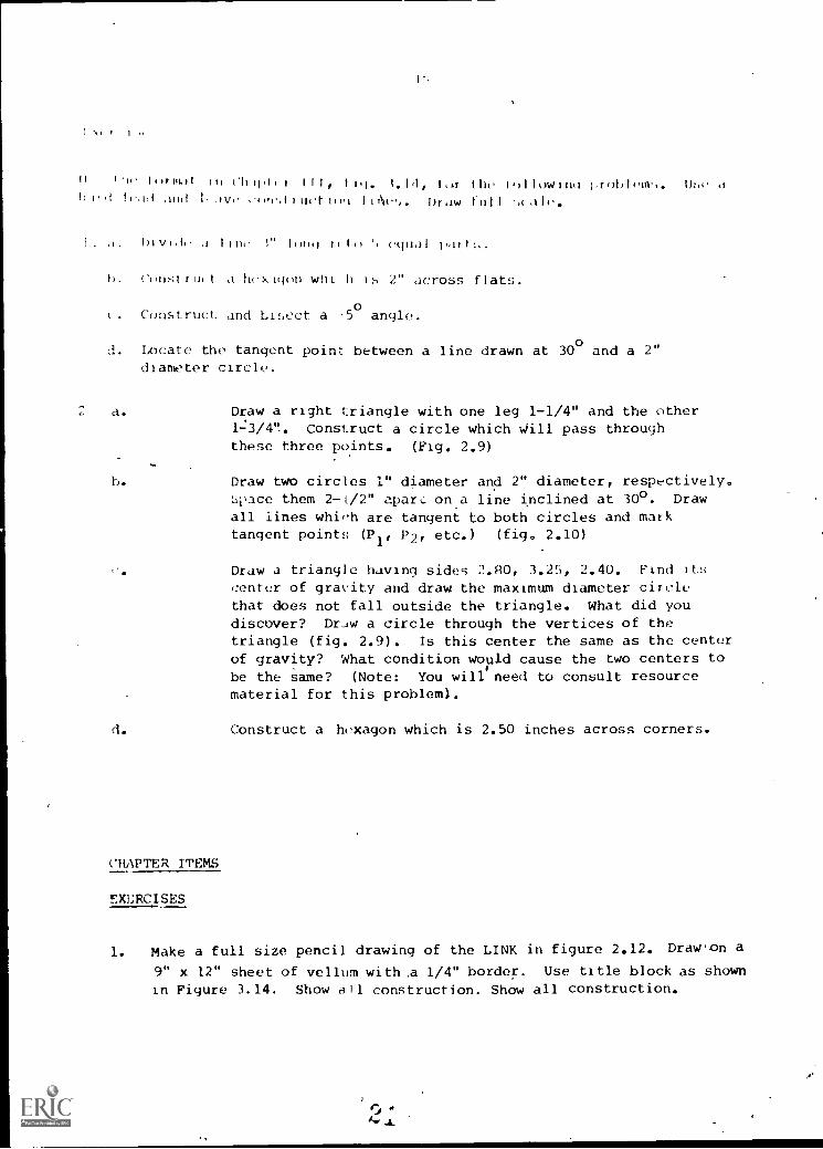
h thrmal Sri Ch rf,l r III, lig. the hrIlhwing hrohlem,.!it'd lead and h Ave e,),I.drherteh Draw thll < ale.
I. a. Divide a line i" Ihng eghal part!..
h. Chnstru(t a hexighn wh t h r 2" across flats.
. Construct and bisect a -5o
angle.
d. Locate the tangent point between a line drawn at 30° and a 2"diameter circle.
2 a. Draw a right triangle with one leg 1-1/4" and the other1-3/4". Construct a circle which pass throughthese three points. (Fig. 2.9)
h. Draw two circles 1" diameter and 2" diameter, respt,ctively.L)pace them 2-L/2" apart on a line inclined at 30°. Draw
all lines which are tangent to both circles and marktangent points (P P2, etc.) (fig. 2.10)
Draw a triangle having sides 2.80, 3.25, 2.40. Find its
center of gravity and draw the maximum diameter circlethat does not fall outside the triangle. What did youdiscover? Draw a circle through the vertices of thetriangle (fig. 2.9). Is this center the same as the centerof gravity? What condition would cause the two centers tobe the same? (Note: You will need to consult resourcematerial for this problem).
d. Construct a hexagon which is 2.50 inches across corners.
CHAPTER ITEMS
EXERCISES
1. Make a full size pencil drawing of the LINK in figure 2.12. Drawon a
9" x 12" sheet of vellum with ,a 1/4" border. Use title block as shown
in Figure 3.14. Show all construction. Show all construction.

-16-88 OA NOSE
75 DIA HOLE
Figure 2.12 LINK
ANSWERSSECTION 2 -1
OJESTIONS
720o
0z. Two adjacent angles whose sum is 9(i. A circle4. Quadrilateral
EXERCISES

-i 7-
:.tec t 1 Yr:1'H 111 '<l S \ND ilS 1.(1
t If rlt hnport ince in
:3rodu .011, ;I -,tttHI. Once the miterkal; lave been ,,electee, theo) e-ta.):1,Ited i,VCtI 0,,t1ods and III te(hnignt-t LS es-)enttal
t oI Ike tin1-1,ed
FIG. 3.1 Selection of innierialsis important
.111
o b j e c t 1 int
irAolcien inc
enter 1 Inc
t II I I 111. t I till I It id III t . It I t ",n,tp" t I it.
, - I ii I M 1 r,. I
2,;
(d)

-18-
LABORATORY
1. The student should be able to demonstrate the proper line techniquefor sketching object lines, hidden lines, and center lines.
2. The student should be able to make a one view pencil sketch on gridpaper showing a border, title block, and proper line techniques.This sketch may be trom a model or another drawini
itIN I n
STULy QUI,SIIONS
1. Does a renter tin. take precedence over a hidden line?
2. What type eraser is use&to remove layout lines from a sketch?
3. How is a pencil sharpened to produce a sketch center line?
4. What grades of pencil lead are best suited for sketching?
5.. Where should you be looking when sketching a layout line betweentwo points?
6. Does a visible line take precedence over a hidden line?
7. How is a pencil sharpened to produce a layout line?
8. Where should you he looking when sketching; an object line betweentwo points?
9. Is a sketch usually made to a specified scale?
10. Are "measuring aids" ever used to help keep a sketch proportional?
EXERCISES
1. Sketch the line technique exercise in Fig 3.5. Use 9 x 12 paper with1/4" grid.
2. Sketch the two gaskets shown in Use 9 x 12 paper with1/4" grid and saint format .as given.

-i9-
Fig.: 3.5 Fig. 3.6
Section 1.2 ISOMETRIC SKETCHING
Pictorial skqtching is an excellent way of conveying an idea to eithertechnical or non-technical personnel. Isometric views have the advantageof a uniform foreshortening factor on all axes thereby simplifying thetransition from orthographic drawing to pictorial. Isometric axes are120° apart with one axis in the vertical position. Any two of these axesdefine a plane which can be used as a reference in locating points on thesketched object.
Fig. 3.7 Isometric Axes
*SQe chaptor IV
Fla. 3.8 Isometric sketchof 1" cube.

,,\
\\A
(a) (b)
Fig. 3.9 Reference planes defined by two isometric axes include
(a) frontal, (b) profile, and (c) horizontal.
LABORATORY
1
i
I
(c)
1. The student should be able to make an isometric sketch on grid papercomplete with border, title block, and proper line technique. The
sketch may be made from a model or a drawing.
(a)
(b)
s-s
(c)
Fig. 3.10 Shows the stepsin making an isometric sketch.The object to be sketched at(a) reference box to exactsize at (b) and finishedat (c).
r.A., C.,
-21-
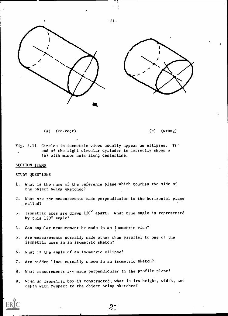
(a) (co,rect) (b) (wrong)
Fig. 3.11 Circles in isometric views usually appear as ellipses. T1-,
end of the right circular cylinder is correctly shown a(a) with minor axis along centerline.
SECTION ITEMS
STUDY QUES"'IONS
1. What is the name of the reference plane which touches the side ofthe object being sketched?
2. What are the measurements made perpendicular to the horizontal planecalled?
3. isometric axes are drawn 120 0 apart. What true angle is represented
by this 120° angle?
4. Can angular measurement be made in an isometric vita?
5. Are measurements normally made other than parallel to one of theisometric axes in an isometric sketch?
6. What is the angle of an isometric ellipse?
7. Are hidden lines normally sliown in an isometric sketch?
8. What measurements are made perpendicular to the profile plane?
9. Wtin an isometric box is constructed, what is its height, width, anddepth with respect to the object being sk0-ched?
2-

EXERCISES
1. On a sheet of 9 x 12 isometric grid paper sketch an isometric view
of the object shown in Fig. 3.12. The numbers represent units on the
isometric grid. Border and title block will be as in Fij. 3.6.
26
Fig. 3.12
CHAPTER ITEMS
1. Sketch the isometric view of Fig. 3.13 on grid paper. Show border
and title block as in Fig. 3.6.
2. Divide a sheet of rectangular grid paper into four equal areas and
add bo4rder and title block as shown in Fig. 3.14.
(a) In space I, sketch the view that you would see if lookingperpendicular to the hozlzontal face of the reference box used
to sketch the isometric of Fig. 3.13.
(b) In space III, sketch the view you would see if looking perpen-dicular to the frontal face of the reference box.
(c) In space IV, sketch the view you would see if looking perpen-dicular to the right profile face of the reference box.
0 rA

-23-
Fig. 3.13
I L
4 1/2 --,.1
1'V
3/8
1/9 -0.,
1.0-1±1.-0...
3R " IOM IOR NO
Fig. 3.14
ANSWERS
SECTION ITEMS
SECTION 3.1
1. No. Order of precedence is visible line, hir'.en line, center line.
2. Artgum.
3. Sharp conical point.
4. F, HB, and B.
5. At the point to which the line is being drawn.
6. Yes. (See answer No. 1)
7. Dull, blunt point.
8. At point of pencil.
9. No. Sketches are made to proportion.
10. Yes. A pencil or a strip of paper may De used to keep sketches
propor:ion:"1.
SECTION 3.2
I. Profile reference plane.
2. Height measurement.
3. 900
4. No. Angular measurements do not appear as true angic:: in an iso-
metric view.

-2_4-
5. No. The only measurements which can be made true length are along
the isometric axis.
6. 35°16'
7. No. Hidden lines are usually omitted from isometric views since
three surfaces are visible.
8. Width measurements.
9. The isometric "reference box" should have the same height, width,
and depth measurements as the object.
EXERCISES
1.
CHAPTER ITEMS
EXERCISES
1.
r-
111(1 11, I 1111101111111111M
L___..
2.
RI
II
r./
TR It"
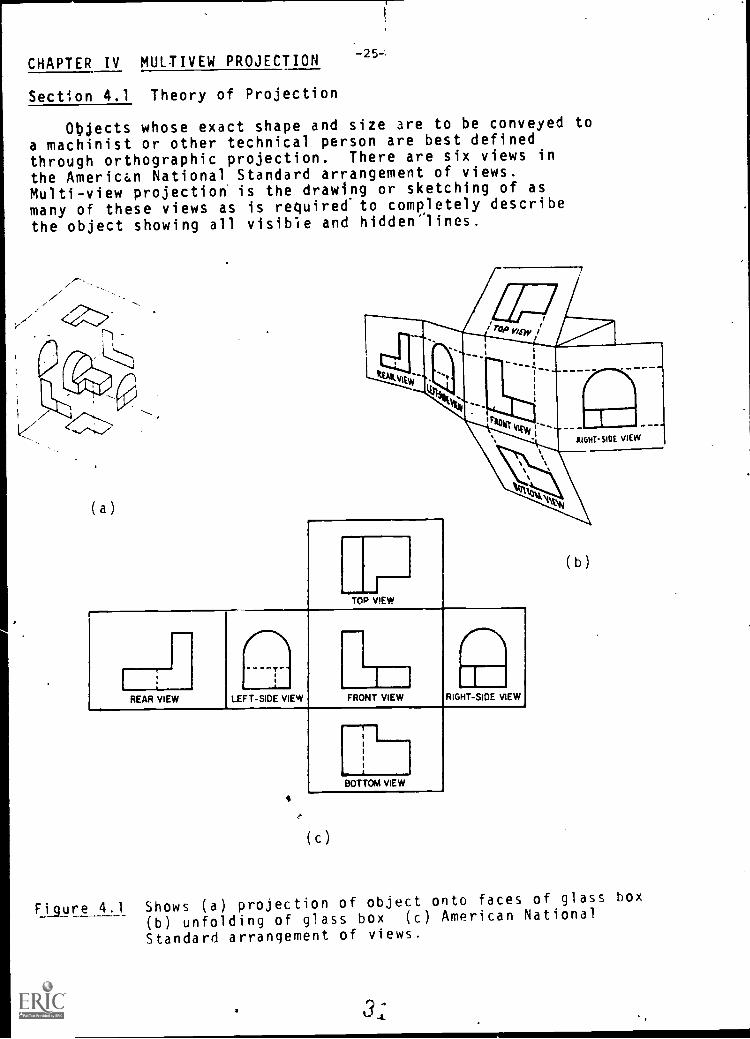
CHAPTER IV MULTIVEW PROJECTION
Section 4.1 Theory of Projection
Objects whose exact shape and size are to be conveyed to
a machinist or other technical person are best definedthrough orthographic projection. There are six views in
the American National Standard arrangement of views.Multi-view projection is the drawing or sketching of as
many of these views as is required to completely describe
the object showing all visible and hidden'lines.
-25-;
1 /1,(7 --.".../:'''''-...../
(a)
TOP VIEW
IREAR VIEW LEFT-SIDE VIEW FRONT VIEW RIGHT-SIDE VIEW
4
iii
1
BOTTOM VIEW
(c)
(b)
Figure 4.1 Shows (a) projection of object onto faces of glass box
(b) unfolding of glass box (c) American National
Standard arrangement of views.
31

F'qure. 4.2 Normally three views are sufficient to, describe the. shape of an object.
,
I
r,
,...
,
r-;1 1
A- L-LLJi 1
IL.,1
I I,
I.I ; I 1
I 1,
I
------
Figure 4.3 Hidden lines are used to describe features that wouldotherwise not b2 seen.

-27-
SECTION ITEMS
Study Questions
1. What is meant by orthographic dimension?
2. What orthographic dimensions can be seen in the frontview?
3. What are adjacent views?
41 In the American National Standard arrangement of views, ------------
what views are adjacent to the front view and what ortho-graphic dimension do they have in common?
EXERCISES:
1. Sketch the two given views and add the top view of theobjects in Figure 4.4. Use the same format and title blockas Shown. Sheet size 9 x 12
I
Figure 4.4
(a)
,3;
(b)
/

LABORATORY
1. Student should be able to sketch three principal ortho-
graphic views showing all visible and hidden lines from
model or isometric view.
2. Student should be able to sketch third view from two
given orthographic views.
SAMPLE PROBLEMS
1. Orthographic view drawn from isometric.
2. Orthographic views drawn from two oiven views.
Figure 4.6(a) Given views
I r L411=Figure 4.6 (b) Completed third view

-29-
ECTION 4.2 Instrument Drawing
Views should be well balanced on the sheet with border lines and complete
tle block. After the /lumber of required views has been determined, thenrtant center lines and outlines are drawn with a sharp 6H pencil. 'If
ee or more views are required, one of the methods in Figures 4.8-4.10
uld be used to transfer measurements. Once the views are accurately drawn,
e finish line work is added with an H or 2H lead.
Figure 4.7 Layout balanced
drawing with 6H lead.
Figure 4.9 Use of dividers todraw top view.
Figure 4.8 Use of mitre lineto draw right side View.
Figure 4.104.10 Drawing front viewfrom given top andright'side view.

LABORATORY
1. Student should be able to make an instrument drawingcomplete with border lines and title block from a model,pictorial view, or given orthographic views. Drawingshould be made on tracing paper and of such qualitythat a clear diazo printcan be made with no appreciablebackground color.
-30--
SECTION ITEMS
Study Questions
1. Are instrument dr. ings usually drawn to a specified scale?
2. Are three views always required in an instrument drawing?
3. What is the proper contrast between visible lines andcenter lines?
4. At what angle is a mitre line drawn?
5. Are hidden lines always shown?
EXERCISE:
1. Reuraw the given views in Fig. 4.11 on9" x 12"tracing paneand add missing view and isometric view. Use format andtitle block shown in Fig. 3.14 . Make a diazocopy of the finished drawing.
Figure 4.11

-31-
CHAPTER ITEMS
1. On a sheet of 9" x 12" vellum, draw the front, top, and right-side viewsof the obiect in Fig. 4.L2. Use border and title block as shown in Fig. 3.14.
Figure 4.12
ANSWERS
SECTION 4.1
Study Questions
1. Height, width, and depth are orthographic dimensions.They are made perpendicular to the horizontal, profile,
and frontal planes, respectively.
2. Height and width.
3. Views which are separated by a folding line; i.e., front
and top views.
4. Views adjacent to the front view are the top front, left
and right side views. They all show the orthographicdimension of depth.

EXERCISES (sclution)
(a)
-32-
Figure 4.13
(b)
SECTION 4.2
Study Questions
1. Yes. Some example are full size, 1/2 size, ;size, etc.
2. No. Drawings require only those views necessary to describethe object. That may be as few as one or more than threeviews.
3. Visible lines should be drawn twice as thick as center lines.
4. Mitre lines are always drawn at 450.
5. No. When clarity is not lost by doing so, hidden linesmay be omitted.
3,.,

-33-
EXERCISES (solution)
ro,IL
CHAPTER ITEMS
EXERCISES
Figure 4.14
Figure 4.15
3,r)

-34-
CHAPTER V
Auxiliary Views
SECTION 5-1. PRMARY AUXILIARY VIEW)
All objects cannot be completely described through the six regular views.In such cases it becomes necessary to "take another direction of sight" in orderto describe the object more fully. Orthographic views which are not principalviews are auxiliary views.'''When these auxiliaries are projected from principalviews they are primary auxiliary views. Primary auxiliaries show a true ortho-graphic dimension of height, width, or depth depending on the view from which,they were projected. _Figure 5.1 shows the modified "glass box" used in projecting ,
an auxiliary view. The steps in projecting a primary,. auxiliary view are as followsl
1. Establish a direction of sight.2. Project all points on the object parallel to the direction of sight.3. Construct a folding line perpendimlar to the direction of sight.4. From a view which shows the same orthographic dimension aS the
auxiliary being drawn, transfer the measurement into the neweuxIliary view.
5. Connect points and determine visibility.
Figt_e 5.1 ModIfiedGlasz. Box
TAL NAMEPLANE

Figure 5.2 Establish a direction
of sight
Finure 5.4 Construct folding lineperpendicular to direct ion of
Figure 5.6 Determine_
and connect. points.
-35-
r
Figure 5,3 Project all pointsparallel to direction of si
Figure 5.5 Transfer measvfements
-r _4_F
(b)
4
Figure 5.7 Visibility can be determined byInspecting adjacent view,. (a) Nearest
edge is visible. (b) Farthest edge or
corner is hidden.
4

- 36-
LAWMATORY
I. The ',tudent ,,hould be able to sketch a primary auxiliary view with vi thility whh q)ven any two principal views.
E57
I
SECTION ITEMS
STUDY QUESTIONS
1. From what view projected?
6
is the auxiliary which shows the true dimension of height
2. What is the angular relationshilp between the projectors and their re- spective folding line?
3. What is the angular relationship between the directions of sight for
any two adjacent views?
4. How is the true shape of a plane projected?
5. how is the true length of a line projected?
EXERCISES
1. Sketch a primary auxiliary view of the entire object shown in Figure 5.8 which shows the true shape of plane A.
42

-37-
2. Sketch a primary auxiliary view of the cables in Figure 5.9 which
show their true lengths.
I
F
Figure 5.8
CHAPTER ITEMS
EXERCISES
Figure 5.9
1. Sketch the indicated auxiliary views showing all visible and hidden,
lines with correct visibility.
1. 2.
I
4

-38-IINS.:WFRS Section 5.1
STUDY cUESTIONS
I. Top view.
?. They are perpendicular.
I. The directions of sight rare mut1.4117 perpendicular.
4. By taking a directidn of sight )!rpendicvlar to
5. By taxing a direction of sight Ile,pendicular to the linev
EXERCISES
CHAPTER ITEMS
2.
J
F P
4
.4
r/4
I

:Ii'AFT.:1 VI ..;;L:CTICI4A1,
-39-
..;ection LLAN-S, FULL AN.) HALF f2CPIONS
Tectional view:, arc often used on engineering drawings. rhe cover sheet ona set of working drawings might be an "assembly section" view or cutaway showinghow the parts of a device fit together. Reading a drawing of a part with many1.iJ,en internal features complicatei by the hidden 14nec in the views. ,Bysectioning or opening the part, the internal design of the part is more clearlyseen.
t'.1 Assembly ,3ection. viewhfrknw: the assembly of isartL, more clearly.
)uttint, plane. he bi:i-lor showing a section view i toimagine the part being cat :0
interior can be seen.
.4?ctio-
A few of the
materials areshown. Arect-ion of liningshould changeon adjacentpmts.
60. Full section views. The f all_ection i- the mo:,t commonly usLd.
F ,tire view "fully -(ctioned".plane locatiol. alone- tie
cent.r line of tc.
4.
SECTION LINING ON ASSEMBLY DRAWINGS

-40-
.calf section. This typeof view is particularly useful wherethe part is symmetrical and bothexterior and interior features needto he shown.
If AL)) 1J,
i. he stud-nt should be able to draw or :,ketch full half 3,-,ction viewsand lse the correct section lining repre,,entatiori.
lEms
Z7UDY .U..;ZPIONS
1. r:hat type of object is best shown in section view ?
2. hen should a half section be shown in preference to a full section ?
3. Is the spacing for cast iron rection lining always 1/8 inches ?
4. ,,re cutting plane lines always shown in full and half sections ?
,ketcn the answerh to tne following problem:,.
i. BASE BLOCK
IMIC OAK. C I.
1
11
4 Ur'
WV101- TOP - StetANS PICTORIAL
Slav PROST VIII INPOLL SECTION.

2. OPERATING LEVER
OPIMOTIOO Urals ar'''. COS
1. PLUNGER RETAINER
PILNIIR RETAINER ar't CRS
A
41
...".. '
..,.......,
f0 s
sI
%'1'...
4
4
.
.......,
emu. TOP AM IOW11111 Vita
MOO PI/MT Vow toPOLL IICT1011.
PliToillos. IIMIA ICTION
EISEN TO, AND FRONT VIEV
ONE* NIIIINT UN VIES INMAW, SECTION
SOCTONIAL IN mat,SECTION

:L',( ' t%C:h..1.;::C21Ci4..;:) V I 'anT;
snecial tyres of sectioned views have been accepted A, =A -lean.; of showiv
nart features more cieariy. lather than draw an entire virw in .7ection, it is
os.lble to break out, partial section, or pull_ out -reciai area: of a part.
ii-. n.5 offset section. :iere, *_se
cuttint plane is bent or offset to
'!setter .how rant features.
,11,:ne section. 'he
,as LI an ,71e-1 through the part. Co
_now tne section view, lt is necesarytc revolve the loints alorv, the section
cut hack to the direction of projection.
,:emoted section. Phe
71.-_,.ne lin. indi,:ite, where the section
.:'d 1, cat. 21.e viewz; are shown w''ero-
%er convienient on the pve. Views at
::.ratified by A ...A, B, C - C etc.
.evolved section. If rrlic.P
a- tie part drawin_,.la
,2ctIpn can te revolv_d ihto
t-e view. :rd:- aids the reading, of
drawin4 by adding a third
!ir.,-nsiJn to the view.
QUILT SECTION
ALIGNED SECTION
LT-A_12.4I.
SECTION A A
1
RE MOVE D
SECTION B B SECTION C-C
1 A
r I
L_ JA
REVOLVED SECTIONS

-4 3-
ihantom -cotton. view
-how- both internal and external narturfd.ces. -potion Lining is shown asia-hed line: And material typ not
ind4.cated.
Fig. 6.10 .hat not to section.
Center shafts, bolts, pins, balls,keys etc. should not be sectioned.
ANJ al-LS
t
SEC TION A A
PNANTONSECT.ONING
sictioN se
MACHINE CLEMENTS NOT SECTIONED
KEY COT TER BALL PIN
1: The Etudent Jhodid be abl to draw or sketch section views similar to those
showd.
:he student :should be abl to choose the best type of section view to
show a particular part.
S-CTION
STUDY ,UESTIONS41. ,hat tyre of p; -t is best shown with the phantom L,oction?
2. Aro the point.: alohgthe alizned section cut projected directly to the
adjacent view?
.Y hat determines whether to use a revolved section :jew or a removed
section view?
4. "hat do the arrows on the cuttinz lane 0hy use lctters
at the end of each arrow?
raw or 'Iketcrl thc answer:, to the followlni-r, problems.

1. GUIDE :;HOE
NNW, NONE - NAT'L C I
1.
T T.4.
-44-
rSECTION SECTION A-A
2. BRACKETORAtINI T NAT'L CRS
ALL NOSES TINONINI
Kh:
\4G IVEN COSTPLEt FRONT,
!OP AND MAT SIDE
D RAW NNW FRONT IN PHANTOMNATION 111-
DRAW MONT SIDE INMANTON SECTION -A
SIVE,. TOP AND RIIIINT IDE
DRAW FRONT VIEW INSECTION TO INCLUDEFEATURES A. S AND CSNOW CUTTINS
Br- C r,1
- J
1
1
-
ii
; 1 I
I
It
L I
1
1
i
was
A I,- CILr
-457
CHAPTER ITEMS
QUESTIONS
1. When ohould .sectioned views be ubed?A
.that the importance of section lining?
3. When would an offset section be preferable to a full section:
4. Li:A the types of :_,ection views requiring cutting plane lines.
5. Why are arrows needed for cutting plane lines?
EXERCISES
Solve the following problems.
5

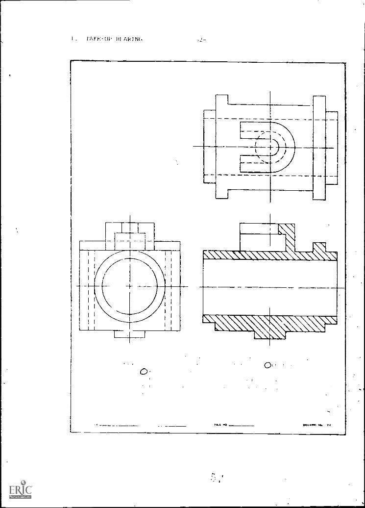
. TAKE-UP BEARING
T r T-L _
-46-
( AD I t I ( TOY AND I CI, I SIDE VIEWS OF A TAKE-UP HEARING
I) I . 2 BRUNEI. I SO ARBON Si EEL 4 SAE IRO S. I AST IRON
s 1 W 'Jr VIEW IN SI LL SECTION
Eltil% f YIE %V IN HALF SEC LION (Mum IfidtlAn I Ines In Upper Half)8 (In '. I VIEW IN HALF SF( TION MINN 111,1dnn Linc In I oe Heir)
NI '.I LIEN IN PHAN EOM SE, 2105
ti

2.-47-
I II
I
,
1 I 1
-
1 t 1
Given: Front and left side views
Draw: Top view in full section
Material Steel

IC Iv
1. erection views are beA for Darts t.it hi' e mln7 internai foaturcfwould otherwi:f- have to 1,c .;hown y h)-!,ion Li
half ection sho'il, be Iced when an rhject :irl-ot-,cal and hat> both
1n1 external fentu-e, that n,_(.1 to he -sown.
3. No. aciri f section lines ib broportional to the overallsizc of time irawing. rna1J rawdaFr on lines
c2d closer.
No. .:uttin4 ;lane 17:nes are oft'n not shown in fill and half section views.
EXFACTSES
1. TIME
Block emu sum - c_S.
.....
2. OPERATING LEVERemnmaws Lift* Natl. CRII
INVOI - 10P -MONT *IOCANN eicramm..
DRAW' FRONT VW, SW$tCUON.
ORA. FRONT VIEW INPOLL 111111111.
PICTORIAL INMILL SIOTION.

3. Plunger Retainer
-50-
SIVIIN TOP ANO FRONT VIEWS
DRAW MONT 3301 VIER INHALF SECTION.
PICTORIAL in MALTSECTIOIL
1. Tne plantom secion is best for objects wit'i large uncomplicated intornalcavatr_es.
2. No. :he intersections along the angled pot Lion of the section cut mistfirst be revolved until perpendicular to tl? line of signt between tke
_22. :,pace availalae on the part drawing. removed section %new shoula be ,13edwhen too crowded.
arrows on the cutting plane lines indic tc the direction of view.-etters are used to distinguish the various section cats.
EXERCISES
1. _GUIDE SHOE RNIE MIS - NAT'S C I
SOCTEES10-0
r#'7 ".7-"1,74r' /
STCTION A-A
SIVEN CONPLETE FRONT,TOP AND PRINT ME
DRAW DRAW FRONT IN IRIANTONSECTION I'S
)RAW PRINT SIDE INPHAETON SECTION A -

2. BRACKET
3. RACK
11111111111 WIL GSM
ALL MOOS TISIMPOSI-51-
A r--
-1
LI
I I
7-1-77-Cr.
-AcotiB,
TS
1111--.41-4.1.4
IIIIVEN TOP ANO InenT SIDE
DRAW POOMT VIEW INSECTION To (Melon(1111110111 11,11, 111) C
1110111 CuTTINO PLANE
----- r-T=44,-r=
7-1
I
1-1
C
8
C
1(:,1 f- 5 SF C T I C,N C CF
c !;71(t : ", f V!F
JD
VIEW D -flDot 1E-Y,
1. Sectioned view_ shouLd be ised when an object hz,s many internal featuresthat would otherwi.-,e have to be shown by hidden
-ection lining, defines the solid area on a part. Var'ous materials can be,mown and ',he direction of section linint c-n be varied to make parts inan assembly section stand out more clearly.
4. ,n off,iet section ailow. more part features to be shown than thesection view.
2,
.d1 section views lo not rP,,uire plane lines to be shown. .ome
companys do riot ',how cuttin.7 p,lane lines on the full ,inu half e ection
rrows on cuttiaj wanes inlicot- the direction . view.
.1 VOW 2204` 200 424 2-'0
1
.141,

.t.r P
OM,
41===.=111
=la
.- am. NM, //

CHAPTER VII BASIC DIMENSIONING -54-
Section MEAYS FCR SFECIFYIrG DIMErSICI:S
Tr.e part ..:rawirx shows the shape of the pert. Dimensions must
ce srecif 1 ed to show the size of the Dart. Dimensions should conform
to accented standards such as U.S. A.S. I. Y14.5 for style and place-
ment. Too many dimensions can ilead to errors in production.Too
few dimensions can lead to lost time. Froper form, location and
ezif ication are essential for quick interpretation of the drawing.
1g. 7.1 Fxtension lines,,-'171enion lines, leaderline-, arrowhead F. Ar?1,rienFlOnerl part is shown.'ote the size, r)lacernent,sracing and form for the
1_6. 7.2 Aligned andudirect-Lonal dimension
placement. The uni-irectional system' is
wererally pref erred .
4.
c ,,' :1
gal ,t1mensioning may besiecif i e,-] so both inch and
metric 'snits can be shown.
DIMENSIONING CONVENTIONS
LEADER
POINT TO CENTER
.0- 7 -44 i 1 1*-0,4
-1APPRO X
y
,16 GAP 7-117=-4.
4'11
UR 4
t_2
4--wo 1.
ALIGNED
*1,41
1
372 - DRILL -2 HOLES
45°'1117.15!
fi f
375.0054 -7 -1
136571136 Q8j
DIMENSION LINE
EXTENSION LINE
3 ft.,-irAPPROX4
8 4
_TA F-
rt 2 .4
-MINIMUM SPACES
UNIDIRECTIONAL
I111 I
I" 11 "-r2 z MOLES7
45
L2i
/IA 1:L.0025 L063.71
.25± C1660]
DIM. IN ; ARE MILLIMETERS.

CU. /,..11.Placement of dimensions.
In adlittjon to proper size and
spacing, a dimension should be
located in the correct view.
Place the dimension where the
shape shows best. Avoiddimensioning to hidden lines.
Place the shortest dimensionsclosest to the part.
-55-
A (*TAU WOMILING DAAvitNu
Standard sizes. Many Items_ used in producing parts and assem-blies are available in standard sizes. Examples are: screws, nutsand bolts, bearings, pins. Machining stock is available in manymaterials preformed to accurate size in many shapes like: round,square, hexagon, rectangular etc. Thin metals are specified ingage thicknesses.
LABORATORY
1.. The student should be able to demonstrate the proper line
technique in adilng extension, dimensior, leader and lettering
guide lines to a drawing for dimensioning. Form arrowheads.
2. The students should be able to choose the best placement of
dimensions based on shape of part features.
3. The student should be able to convert dimensions between the
fractional inch, decimal inch and metric systems maintaining
Cie same relative accuracy.
4. The student should be able to locate tables specifing standard
sizes for hardware items, formed stock shapes and sheetmetal
gages.
SECTION ITEMS
STUDY QUESTIONS
1. e..hAt is t±-.^ lor it tt rlt. on a ,ruwin,:i
2. It. 1.1:,,ini; fractic,n,t.1 dirtchrdon.;/,,:, what the for t./.0 tot-tfraction':
!). N1i t it 'he correct lire thic't,nrt-,:, for extem,ion line.,?
tip correct density for k:kt .131;u n':
it t!n, :te!owItcso-ts l'e ti.t- t.Itrtitj in?
5. di-at_th,_,),)r.:, bk. f.laccd within 1.1, it:tf
6. if a di...onsi,Jn ;'1cified .7471 f .0' pit-A in ti. citric
-56-
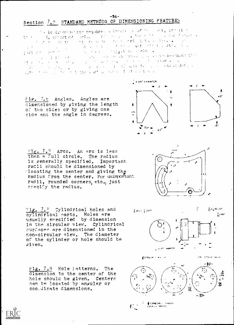
Section 7.7 STANDARD METHODS OF DIMENSIONING FEATURES
is ,1i I( Jr,- rog1:-
X 4S CHAMFER
:1w. 7.c Angles. Angles arelimensioned by giving the length 4
of two sides or by giving oneside ar the angle in degrees.
t
7.7 Arcs. An arc is lessthan a full circle. The radiusIs generally specified. Importantradii should be dimensioned by'locating the center and giving th;radius f rom the center. For unimportantradii, rounded corners) etc.) justsnecify the radius.
71g, 7,P Cylindrical holes andcylindrical narts. Holes areusually srecified by dimensionIn the circular view. Cylindricalsurfaces Are dimensioned in thenon-circular view. The diameterof the cylinder or hole should begiven.
7.9 Hole latterns. Thedimension to the center of thehole should be given. Centerscan be located by angular orcoo.dinate dimensions.
I
t,111 .
0. 2 a. maw 2
'
2 4P.60
2
I
32 K6 F
t
x 4." -HAW
IS 411.
-- 4
/
1754 ORR , SWAP",Movif

Fig. 7.10 Arrowlessdimensioning. Com-plicated hole patternsin_parts can sometimesbe dimensioned bydistances from a fixedlocation (datum).Hole sizes can betabulated.
Fig. 7.11. Reliefs.Reliefs are undercutareas used to facilitatemachining or assemblyof parts.
312 r 32 RELIEF
1VDTg I %' CERT..
Fig. 7.12 Chamfers and roundedcorners. These featurs aredesigned on parts to break sharpdangerous corners or to facilitateassembly or fabrication of parts.
Fig. 7.13 Slots. Machinedslots should be dimensioned tocenter line locations.
L
CI r

Fig. 7.14 Irregular curves.Coordinate dimensions arelocated along the curve.
LAZORATORYC
-58-
1. The student should be able to place dimensions on part featuresaccording to the examples listed.
SECTION ITEMS
STUDY QUESTIONS
%-tch r,th-Fi.' of' -
2. Under what conditions should the center of an arc be located.r.j. ,101( :toah' be riHrdr_icit.-.1
4. Lkctch Pr-t..1,1:- of :Ii',' n-:5011j;1 cylinAcrs.
_). . tfG.. 1.,):; c-b c--)rifer.
EXERCISES
}lace dimensions on the following part drawings.

IP"
7).T.M.iNS:OAIN(3 7:40;LEY #1
Fully dimerv:io.1 the part using
fractional inch dimensions.Use dividers and the scale atthe bottom of the sheet todetermine lengths.
ADD ALL MISSING LINES
0
BRACKET
TiT7 7 11
0I I i
I 2 3
SCALE

DI:LiSILIN,'? PRC314...M #2
Fully dimension the part usingdecimal inch dimensions.Scale = 1/2 size.
(naasure to center of lines toget lengths.)
/ \
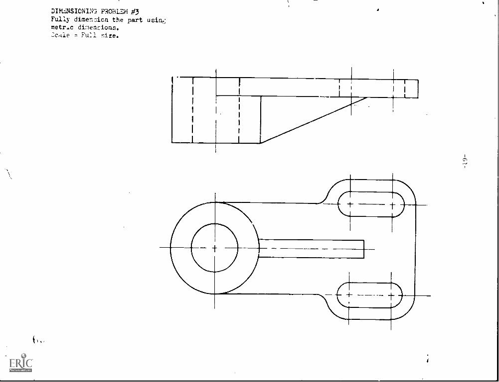
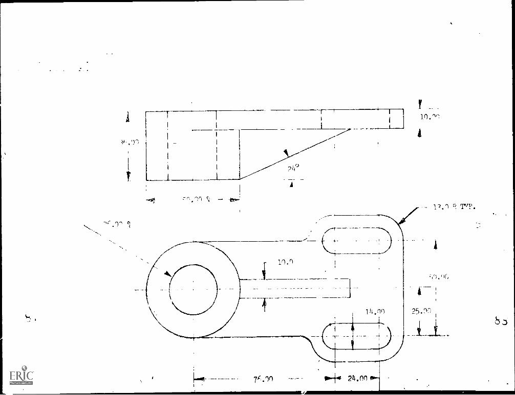
DIKINSIONING PROBLEM #3Fully dimen=ion the part usine;metric dimensions.cafe --,- Full size.

1( . Y. 1.1. :41
r,:Orflat. Ion r,..at lrl, t--) , I ()rails ,icis 1,, .n Jonth ; proof . etr. IL, or ten ,..-ren an note form.e not, ritt conci. tr. :raving in area:,
,4ay '.ror* ilmen. ion ext,m1sion ."0 Lml) le-, ha t, a standard orm:or e notes. i'ollowinc 1r example- ,how' .1p7 the urual note form and standardyTt-_,o1 .
rill, 'Ore, .(e.aM.
shown 4here the act'zt,.macunia,-, iroce 1, named. ._;ome
L, prefer Showing tne =; zeaneter) only w:th no
tc, tne Froce, .
L.. -2,14-,
for 4itr, hea I
tyl-L on varioi-3, tyre _
of fa.
:1:. ::.r<:arlei holes.
:.never tnreais muat be out :na:ieA role, the informatlor, for the
.1ze tnreal note ma5t befrom -tan-'ari table:.
ere,' are11. el wnere ail
JocKin,- , or -elf rtall-114,7 of : art,
r 21r
L
4
500 REAM
430Aut DRILL 3 DRILL
DEEP 11- SPOTFACE iCBORE DEEP .4
82 CSK
if
__J
THROUGH HOLE
TAPPED HOLES
A Of PTA O. Go,,
NOT THROUGH HOLE
AM TA11-
AND NE AM FoR MOTA.4 VIN A ASSI.AelY0

Fig. 7.19 ,Critical diameters. Limit -63-limensionr may be opecified to theallowablt ran.z,e of size_ for a nha'tOr hol,.
F2 ". 7.20 Jriil and counterbore,learance must be allowed for the bodyand heal sizes for common fastener s.:,o.rrect liarleters and del the can he
obtained from taties or by lookin; ip
tne fa -tener head te an i a king J.
clearance.
././1 -xternal tnread. :hrerel
dia:n.ter aal number of threads per inchied Information on standard
turead Ind hun-.b a thr Ter:ro:1 table'.,.
r.eya Jai keyways areuc,ed to revent sli:yage betweenand mating part. ;tandard types a .i.-nze are obtained frxr, tables.
rnurls. -traint and dinmonjsha:Ife- ore comnon. ca. areclfy
meii,Im or coar e.
/. Symbols. ,,c1J, ymbol:are ure4 to avoid loni2,- notes.
'-
DRILL AND COUNTERSORE SIZES DRILL AND COUNTERSINK SIZES
" IN , A
c.1- o.
DrAMOND
r-L
,P1
ti J.1) FIJI h

LAJCI-G,TC11Y
1. ...Le student should be able to use standard notes and yri'nols on a dimensioned
:he student should be able to write standard threat notes from informationin tables for internal and external threads.
3. :he :tadent shout b.? able to calculate ,-,1.ea...ance hole sizes for fasteners.
..;TUDY A1ESTIONS
1. hen a drill depth is specifiediis it the entire depth of the hole to thefrill point?
3- ..cw deep is a spotface? ..'hat is it used for?
3. e: at in the advantage of a woodruff key?
ry is a taper pin used in preference to straiht dowel nin
5. ;:an a "blind" hole be threaded all the wav to the bottom?
1. .rite a thread note for an external thread on a shaft. dameter = 3/8 in.-Lenth of thread , 2 1/4 in.
4rite a thread note for an internal threaded hole. Threads to mate with 1above, nole is threaded all the way throu:;h.
ogrit" a :r]11 an', couhtn.rbore not- for a lf?H
pia hexagon socket heart ca:'
ll';.-1-1tc !rill ind counterink note for a countersunk he id cap srr.?w.
-6s-
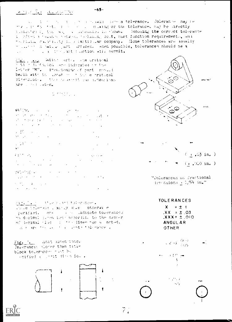
141% 1,1' a to1ranc. Oieran may. e
t . ,A1:47, or tht. tc1eraLc* he irectly
e c , lown. noo:_an.e.: the corr.:ct toleran':e
' 4-en ot, rart ±uiCtion requiremert.,, ifl1. a: -ar col'pahy tpleranceb are .leotally
t. rt crt ice'. Inor. pohIe, tolerances should De acaz t : ..1ct ion nil.. nermit.
ca t r t . r t al
In]inate..1 t
-r "M". f nartwit- t e -rit
it -nc,
e . t r-
V.; ,,,
;
I t r
: 1 . . 7 4 - - 1- : toi-r
other«.. e
tcifi-'i. or the! Ica t e to .1
d- ci1 io :tn. to thr nu-ch-er
nf .-c I - -limer on a nct.--1,.
, anc:F, .
117.,-rc -1;11S.
2olerance ,. than tt*.If-
block to Ant,
clfie! 1 . -it fl in- .
gct-tkE"
-
Sy.
c).3 in. )
+ in. )
".'olerances or :'zac- tional
Tr nsioni; + 1/64 la."
TOLE RAN CES
X = -t 1
.XX ±O3
.XX X = .010ANGUL AROTHER

LI MIT DIMENSIONS
NOMINAL SIZEA DESIGNATION GIVEN TO THE SUBDIVISION of
THE WWI OF LENGTH HAVING NO SPECIFIED LIMITS OfACCURACY BUT INDICATING A CLOSE APPROXIMATIONTO A STANDARD SIZE. A SHAFT Z. IN DIAMETER.
BASIC SIZETHE EXACT THEORETICAL SIZE FROM WHICH
ALL LIMITING VARIATIONS ARE MADE. -2.000-1N DIA.
ALLOWANCE
AN INTENT DIFFERENCE IN THE DIMENSIONSOF MATING PARTS.
TOLERANCE
THE AMOUNT OF VARIATION PERMITTED IN THESIZE OF A PART.
,
.1,,!,., r
'''') 0 01-, 00 , J 0 , t (,0., , , ( 00'1 (-Yr,#,'I , r# # 1,i)': 4 , I 00 4 ( 't )( , VII CI, , i (), ' (X/l)
i C" I fr,:,', 0,, .r 0L, (". 0 I-, (11)-, 02.2 7, - 00',,- ( , ", ,.. ,, ,,,,3 C..,-,1', ,,, , , I. 0 , 0104 4 .4 0 t.)3 0-_, , r t ,:, 0..12 cr" (),)-3 (," nr 012
I ,, , t.. t",..1 ,- 0-1 c] :, 2 1 (,p,(1,0
7.)i ,aciane tolerance:;.
If the machining procesz, is known,tn- tolerance can he zTecificiba,ed on the capability of acrtain machine.
0.

err
7.2<4 tdlerancetot'let;. :hese tu/eran,:e:, an-lected to .fit a ,ertain partfinctlon Zolerance.: are
re card to nowT.art feat,:'', -racnined.
.;alonlate t:.e hole an; :haft(nominal :Lt.!' using nn 4 it.
..00k table unler^eiween 114 and 1.97 incher...00k across to find the plus an:sire. :+otace that these numbersan inch.
lown '_he nominal Size twicetwice for t,,e Moir- calcdlations.
-4,7-
tbe
_
Lnlj a s.'riali ,firt ion of o-e table is,Mown.
dimes -ions for a 1 in.
:ne 1 /-" its nv %inal Si 7,E fall F
-ins variation from the nominalare exi-reF:,ed in thousandths of
tor the ',haft ca1culat.ions. and
all or :-ubtract the lLmit:' fromt table to :et the full limit !amen:ions.
TRUE POSITIONPostarraITotemic's
symmE T RY ("(
COPICZN1 RIC1T Y444
hef-,-
tLe toshow toirhn,:-- between vatt
5HAFT
1.3730
(:taxlimit)
1.3750- .0056
1.3714
limit)
GEOMETRIC CHANACTER1ST IC SYMBOLS
CharactettWic
FLATNESS
TR AIGHTNE SS
POUNONESSICIRCUL A RilYI
CYL INORICIT Y
PROFILE OF ANY LINE
PROFILE CF ANY WRFACI
,RALLLListA 121
e-Reeved (Stith AFIVF SS)Features
PEr'PCNOICLIL A R1T Y
ANGLLAR1 TY
RUI IOU T(31

Y
bi
/ 2 52/ 12 400
/.38 :35 05!
4 00 418,f)%f.
?2 fiG2
Hod
oo!:
THIRD A NA_F l'ROJE(.
-c]

-69-
STUDY ,U1ISTIONS
1. what is a unilateral tolerance? A bilateral tolerance?
2. Using tne title block tolerance block in fig. 7.26 what is the impliedtolerance on a dimension of 2.,38 inches?
Rewrite this as a limit dimension.
:orlinc to 4h it 1
.c.t 1:,, , ,
t t,tr It t tn. nr, t Vc,
, re-- n: in or a t.:la 0! r,I4c).
5. Calculate the limit dimensions or a 1 /2'dia shaft using a RC-5 fit.
6. :_:onvert the answer to prob. 5 into metric equivalents. Be sure to maintainthe same relative accuracy.
CHAPT_IZ
STUff tUE.;TICNS
1. Which dimensions are selected f..rst?
2. Can dimensions be placed on the object:
3. 4hich dimensions aro placed clobest to the object:
4. n hole should be dimensioned in which view?
5. Are aligned or unidirectional cimensions prefered?
EXERCIZi:S
Fully dimension thefollowing drawin;:. Use decimal inch dimensions.
7

ilm rod pivot freely on 1
1-1-1ilthi,
NOT TG
-A.L * a
n
-Tr i-r11
II ii
p
1111
r ti
III

0
-71-
7.1
1. :'or ..ott,ering on engineering drawings is Ifi in.
_no total hei-ht for a fract,aal dimension ahouli be at least 1/1,4 in.
Line thlckher for -xten...ion corre.spond to "thin" on a 1-ne gage
for exten aholl(i be, riLACh.
.;ome corpanys prefer arrowhe&i:, 0 blackened in especda-ly where the'irawin:sire to bo ric:rofiimed.
1
3.477 , .03 in. = c5.19 .76 mm rounded off to consistent degree of accuracy.
1. ,rigl.es c,in be dirensiehed by ,ivinc- the length of one leg and the includedant71e or by givin- the length of two le--7s of the angle.
:'he center of an arc .,nould b slecifiod when the radi).s a critical locationfrom the center.
olos are usually dimensioned in the circular view.
4. imensioninz shaft and cylin,erF:
x OR
JiLencicnir a c..:amter:
x CFP
Dia.x
iimensiohirv: a rounded concr:
x3-c R.TYP.

' r-
A
;
%
t.--1 1,12 1*1 1 7/`-i
I
2 I "S
I I ;--
32
SCALE

1. 37j 37 2.70
3001.50
9 26
S
if
7
.7--(-) )n c,)
A
I I
Y
10 .1n
4
12.1 T TvP .
7F,.ln
...
ow-tit 24.00 01 .

t
r it-
j.
A t
t
ort . .
- t t tot '
.t ,c, i
:y
r.
t t. ,t r-

r
, : r "e, l' i , tt. 4, ,I ' II .
4,_.' '1, 1 " , / /- . , 1 1 . ,1 t , c, !, jr
. ,., t ,I)t t.l. t1 t t I r 1.', r ... It'1,7 .
-,-, cr, pr, .,_ I r,,_:.
1

NOTE: Rocker arm should pivot freely on'Ti
0 r .68°14.4144r _4(37
.05x.06SAW
1
1
.4987 1,
1
1
1
, 1 ;i
4594 I ii il.,
1-----
'1
1 -18UNC16
1
ILL a HOLES
1.15
k.2.995.z989
.03 K45°C FRBOTH ENDS
IC 4
Rocker Armassembly drawing.all parts to scaleexcept as noted
2 HOLES 64-,...J
r-7.75
T
1"°- 1.000+'
26_,..1
1 Li1
1 i- .1 1 li
1
'U"(.368) DRILL 1 -I4 UNC16
1.48
.500
4 : I j4 1 I INC
\ t V I 1105
(

VIR..nAP 1:::.
:Any electrica ,'x-n erilgh -,tarr_ng ,,,Lt-n a .-Ilock1a a. Ti s type rf :LactIon 9i Lualor olrts of the
iesiga and i]nows flow throuh t .em. (-ce ma or functions of4.,1,c11 Ire s,-eci..1.-,.dl_neh t.L.f
Olagram8 ,re also inc-uded la a <t- working draw-ngs, often asrIrst aneet in tse -et cf OrawiLgs, ano la instruction repair manuals.l'.agrams combine blocks with schematic or pictorial elemnts to give agraphic impression of the circuit.
Most block liagrams are drive) aescor:!3n7 to :,heLe baL,Ic ru-e;Only two cr tar dafferent size 'boxes".
J. Space boxes ao areas are rCeep boxes in ros..s or columns...3now signal flow with arrowl%.
-abei function of eac:1 bloc..O n the left. Main circuit in the middle. Outputs on theright. AuxiAary circuits on tn.-! bottom.
to.rte,3;41_ 6. IC.101_)
....._,3_ _j1 A
5 LL 1 -- -,..-7. ......... ,,..-IA- d Avt,,,,f --,, -, LI ,A4. IF a, Nwil;
,4.
-,Mt
-a40,411 L . __.....,
yot r t i c-, .c..,r---.,: = ,.,-.-, i,, , 1+4 I..., ,
/F1
- - - 4.
vF.4,
ial loc(< dia,rram. Heatn 1C-12 Oscilloscope dimram is shown.of bio6c, 'xhematic and -;-1torial elements.
-- r-
v.!. 1
'
r ectr tOr C.Dr.-trOl

- LA5ORA:C.:/.Y -79-
1. The student Jhould 1,c., able to layout a block diagram from a rough cketch.The 117out s3hou7i reflect the nroper bLock eizes, spacing and function
1. .,hat i. tn- alvanta7e of a block diagram over aychematic dia7-am:
blocks always be rectangular in Lhape:
5. ht 7cci-_!e- the size of a block:
.iow do you dete,-mine how many blocks to
w wouli a feedbar'K circ,iit be shodn on a block diagram:
:onvert tr -cne7lticdiA.,--ram to olock diagram. 'se ti:e fuctioL:- rr:ntednext tc the tr-lasi,tor.-. )e hare to show tne innut and out-ut levlces anrowt-r
4.
)t Ft
if 1---i I
/
1, ,
; `.-'4, ,
"',
4 i} ' 1 ", 1 . ,,, .,1 "4 i' .i. ,..,,,
,----I-,, -, -,fn. (",7N573
rk ,
c,...., , ,
t- r-, '' (",,A a] '''.'1 \
1-. 1.. - , : va J
......4 .A ' d - A 01 A
'1
-r-
r,
-xerpted ..I-0m :JAMS iOTCY, Vol. :4.
, .
INTI-kNATION /-11.0/1411/ viODEL 37MI
-Ketch .1 'lock diagram for a "-rerim .11-F1
14II, 4

-BO-CCNNECTION DIAGRAYS AND INTERCONNECTION JIAGRAMS
.,;oanection diagrams chow the wiring between parts of an assembly. These
drawings show the acts 1 wiring inside a particular unit. They are often
used to instruct assemblers on how to wire a device and how the wires should
be routed.Interconnection diagrams show the external wiring used to connect a series
of individual units. These drawings are often used for field assembly and
installation purposes.
Fig. 8.3 Wire coding. Wires Color Abbreviation Number
used in connection work areusually color coded. The color Black BK 0
is either abbreviated on the Brown BR 1
drawing or shown by code numbers. '\ Red R 2
',vireo may also use a base color \--Orange 0 3
and one or more color stripes. Yellow Y 14
Green GN 5
Blue BL 6Note: A wire coded 2/3 is red with Violet 1k
Gray GY 8
White W 9
an orange stripe.
1.1. 0
rs se' (CrIP
,..____ ....,±4...L t'_____J
s,[i}
41
1
::/ ,---,
I
1.4
i
-1iir4
4,_:_ri ,r_i__rwr 1now)
C f l W.' r E 4 ti ---1.-
; j:17)1 11
1 I a i1 S. 0 a .."'
.......... L_..... _____fi, --- ...:.]
, I
L....._.J 1
( A
Fig. 8.4 Typical
connection drawing.All compdnents arehoused in the sameenclosure or chas-si s.

.
Ii. 3.5 ,'ictorlal typeconnection irawini-,
-81-
-_ - - --... ________,----
1,-...r----- 4,-,[---- L'----1,
c,41,,,IR -II s'o'r,--r- . z.,.? PAli4 1......ii.IZY ',AL ', fr. ' T-,;"-f; ' f,.,-..._414
t3
er
CAZ
CAZ
r A2
CA/
Cat
AI
Al
CAL
C I
A
,
t
Al
A
Al
AlAlAlAj
Al
lAi
AlA?
12
)1
01o..
4 3
I, I
It
0/I
41.
S
1C
t
I t
It:1
"15 (:,'N Of U)i PDf- Ill 7,4F
+ rr:N \L TO f;cf4TS.
T; Of,:f .
P I TI(1!'..
315
r-P
'1
Al
Al
1
1
5 %1
1
Al
32
ri
I '1 I
1{
r
oil I
A I
, .
A'I I
131
;4
I"
'IC
I 1
_A1
1,4
3
'S
,s
S Cr' Al ,1(.:A0
"
)',1", I HI P
, .1 ; U f It
t.6 Tabular connection Ytrirt. ,ompare thi:, *viri:q: table with the connection

lP
1
H
'3()
3,
R
-82-
i
-- 7----
) I YR-N
R 2P - PI o
131.1
Y 6
C.) R
L
.2_K; --KO,. --')
, Ni r
-,... _
,
t P{
I 7)4
--r4-- I
1
V
I
I'
(
0. 2
4
to
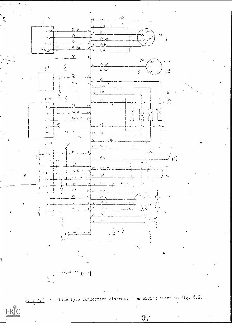
cline t!,:-e conction wirint; cnart in fig.

-83-
FG,A4
C AM
51-3 F 5:-2
E6
F51 -1
UA AS A7
AV,3 F
Fig. 8.3 Feed line connection diagram. Wire destinations are given. This
type of liaFram avoids a maze of crorsin7 lines.
Fig. 8.9 !aug, Jack, terminal
board etc. pin identification
system.
Fig. 8.10 Wire destinations arealon,: with wire code. '92"
(ri, #22 ga. ? ,-- r'd)
Letter identification per chartsomewhere on the; Irawing.
Q
P/T
JZ-F
TB8T814/4 42-0RI40 /h84T814/3 -8
T818/2-84
T814/2-88R145/3-87
R101 /2-89
RI49
ASA IDENTIFICATIONSYSTEM

LABORATORY. -84-
1. she .:tudent should be able to !raw or :>1.(ctch a connection irawirw:.
?. ztudent ',hould be rurle to re:11 .ii rs wrlb, or chart:,
-s:7,7DY
1. :iow are wire colors icnoted?
Is there a general ruLc regurdinc the color w'_re tc use haed cu the
circuit/fltriction of the connection?
3. ::1-.2t is the correct identification for terminal 7 on terminal board .5?
4. :, color coding the only method user! for markirv;
..hat is tne difference in the feed line, base line and point to point type
connection diaFrams?
EAE.:),2.1.3ES
1. ..rite a wiring list for parts 5 and 6 on the following drawing.(.;ot a.:1 pin numbers can be shown due to drawing size limitation)
Note: :artial, simplified tablt. is shown.
IT
NC.
FROh 20 wits:.
;c LC`'
GAGE
COMP. PIN :OMP. PIN
/S ET 4/ 2 R-131- 22
/6
I
t
r1
z2

REFEPENCEr'S CINATIOC
t!
C:LORECP,;TAIL
w.P.f ASSOCk, Ts L7::T.NATIO-L:::"
( 7Ii
CEITiN0f:A-L5CATION0F,m5FR3
Po-TO r:Fr.
_IsESc:TED
SURFACE IN':
(w)
0
BATE _j/LI1
t1-')
f-P2rA,P.7
FTZWIRING
.7. '7
CtI° %I
P13-AILPART
I
(''P.
t'15 kr,AP)
/--SLEEVE Nv..SER
Ann PART r1-:
INr7 Clj
- WIRING
OFSHIELDED
/ CCFDUCTOP
V
P
N %
-r4
,
CAME :;CCP: ST4E0L--'
,wIRE
/ ry=::_TEN
I
/0) fa,- FUT
Fig. 8.11 Drawing for exercise no. 1.
4:t
55
/273
0
.48-- A 4.
SECON:ARYCABLEINDICATION
ti
//-577``.--9ST° STITCH
As/
LETTER SUFFIXUSED wHENADDITICNALFEED LILI:
w, IDENTIFI:ATIONIS REN'RE:
PAIRED VIES
4
TERMINALDESIGNATION
coto

ZCTION SCHMATIC DIAG:GAS
jchematic' diagrams use symbols to Jenict4 tie eiectri.a, connvctionz. to everypart in a device. .Afferent tecnnique--, are ase-1 to draw .;chematics in variousfields; electronic, electrical and arcnitectural. v:oricirk*, with schematics ineach field involves knowinG the symbols used and tht, conventional methods of:thowing the connections.
1ADJUSTAbLE1 ELECTPLY. T(it,E. FlAti(f4( I D(01( (c01,:inteed,
CONTINUOUS( Y Tube component .-4,111c,I., Oto..1? t.. set Tern; ...rat,''e depend -r 'let\,..1..)
ADRISTAKE i Neater ,,, INUJC1C.4. WINOft, orlt di ide(V,trorie) -.02tk 14._
FiLACIUR or CC,0 1.4F-.-. _____CP'-c.rdr Photodtxtr. -!-!t}-AMP:1FIER i Genera' nrCold Len:re, P eft. ttPr c, \'...--'' , air , '..),t -tar N region or basePh,t.r.ittt,,,r
ti Fool c..ittltrOt. F:Jertet, Eort j N emitter on
1ANTENNAP ff ,,J,1 or bhe',(V
General1 G.4,:i Thep, 0 Co' ,. clot cei d,i Dettutini, Of -trolt-..., Ar, wmtlar re.: c ifdd,,..ilr _Dipolet
or pairs;P7iF' Ver,stwI Ar.ode or ii'ate'.o, IL ;1 Tarpet
A.s.-.0 Crt'F,ProfI L'rrrr:fr:tr,
__ _ _ _ _ ...BA"Ti r-:,I. co i: ! , e .,_, , ,
r---: ' c t,,,, ,), .., .,n i. De V," _0'..,1
CAPA'
Curt-] .-.-,ent n, e
. `,,P'Cr
F emat.. r , jM3 e cc 7 ,,, ; ;-.
Fit.g J o 1,A,..t
Switcht)on,d tr,...c
JACK
Co.,' 1 0;1
t.ciitin,L6lya 1 .stoOle
_ .
r E Y
Ti L I Cotwriir NP':--fro-,sster ..0
)1
Unt,w c(orl trar,...., LAMP-,-.. ,P,idast
1 N type b,,se CT-rr..
sitor with(-- , EluoreccerL
1 Fte'd erred trap/) 2 terminal
-: I sd,,Inr *IN (4:-.)_ _Ire lndr e en:T
,
P typr t -se/ tr-PslEr.E.; Ar -P
, F.....er cool . tt r triode 1--' Ptvri ,p, - ILti L1.:, i
`
ItiC E,01-'EI sH-tr
-
5i-41E , oiNG
r'r.!
1, " Ert,
.,,etr '
u-tro .
t,0 ar
t,ttped tbe,ter ,
r.f.!rtf IFc'r_
, A r ALT,'(
I
r
/, f t ,t 'o.,, 4-\ i
i Caf h. -.1., rd., .0" ,! with tiee. Ti r. 1,..i) 'i
^0
.1tt. IL, 0
t frr11,1
'
5) J - ret,itY
,1 0' "r rtect)
TR; N' !ORM' E.'
Ct: *.nArf (ydlottle)
ten r I. c
sr MI: ,..,.',_ TOP rLV,CE,T"A;.,.. ',TO(13,Lyte 14
Fott Fri. -1,-,pr a.in t, orrottooi 7.`1.., il I,,, r0,,0 onto,
"" ''''fY results :̀,". iX , int. *04,n rrt 1,7 ,,_,". 0; F1 cd.'r OF I 'ar ,( nrari
( I lk l 4 flindr!'," 4t F.: (44 s-:.,..t.,, - f
, ,:,,,,,.I
i..,0., 'Dr) tr ir.r.lo_t. .r, (up r 2 1- ........!C.......(dnd loro.ri.ded sniei,1 Ele-e ,-,..^ -iet-
AN(.,1
1
; C eel ct,ortot
//0
l,)1
Gene,-11
(-1 ryd--t,
,tic Core0. Omn
t
uI,,tt -,nstpr (net
ado,' bit
scnematic tiried in electronic:; diagrams.
exercise in nection for typical electronic ...chemotic diagram.

-87-
Fig. 8.13 Typical Indus'
schematic. A.C. motorcontroller is shown.
M
F--1
M I
STARTOL
It--,)1,--1,st%yj
IR
FT. OSP
(c)
Switch
S3 = Three-way switch
Duplex convenience outlet (plug-in)
= 220 v outlet (plug-in range, etc.)
A = Relay
0 = Outlet (light)
= Telephone
O = Other outlets -- letter inside means type, as fan, heater, etc.
Any letter by a symbol means something, as R = range, Dim = dimmer,
wp = weather proof.
L
Fig;. r.14 ArchitPctural 3ymhols and :;ketch of a floorpLan with :_,ymbol.

LAORATORY
1. The student should be ableor pictorial layout.
2. The student should be able
3. The student should be ableschematic.
-88-
to sketch a schematic diagram from a prototype
to draw a schematic diagram from a rough sketch.
to read, sketch and/or draw an architectural
=ION ITEMS
STUDY ,,,UESTICNS
1. dhat is the basis for spacing symbols on schematic diagrams.
gust schematic symbols always be placed vertically or horizontally?
what is meant by part "identity" on a schematic diagram.rules.?
'What are the
4. in what ways are industrial schematics slightly different from electroniczchematics?
In architectural schematics how are 220V circuits shown differently fromstandard 115Y citcuits?
0
EXERCISES
Sketch the schematic diagram of the unit shown.
/ )4,4 4 I
exst,et,
C)
Nn 1 Niel( Ai(1 1 1Zt s1.4,;1, 219 1 ;;ii.', j itc-;IStol V) ;11;,1Iii i 12, 4,1.-d. 22 I. J',.,R) I 1..!(..-1.-tui : ,ii_;I) ,!1!.10; 1 Po .-;.,101, 2'10" td,n,.11, 2, :), -I 4 J.1,1,-
2. Sketch tne floorclan for a classroom, labratory or shop area and snow thearchitectural electrical schematic for the wiring.

-89-
-,CTION 8.4 LOJTC DIAGRAMS, INTDGRATED CIRCUITS, PRINTED CIRCUITS.
Micro-circuits are fast becoming a standard item in industry. They can bedesigned with many components inside a common case. These components are wiredinternally to perform a pre-determined function. Design of complex logic andelectronics circuits is greatly simplified since the designer must only pickthe proper buildlng blocks. Charts, diagrams and drawings are needed to assurethe correct connections, power inputs etc.
Most micro-circuits are wired and mounted to printed circuit hoards. Specialdrawings are needed to produce printed circuits.
Fig. :i.15 Typical symbols used inlogic diagrams.
Fig. 8.16 Integrated circuit.This has four separate circuitsin one case. Note the input,output and power connections.
A
Oft
O.D
( D
FYCtwoo(,
!
AMPOlgE
RE11111." II 'ItSYMt GLS
8
A
Fig 6.17 Internal logic inside the package. Note the four separate circuitsinput output notations. ro the right is a "Truth Table" showing how
the circuit reacts to various inputs. "1" = yes or on, "0" no or off.,7hir notation can change for Lome tyces of logic argument.)

AMERICANSWITCHCramST seamsSUMIONIATINIE
TOSELI SWITCHES
ACTUAL IliTOGGLE SWITCHES molimauMIDI Simi bur chowso1001 NOS
Polo 1040041MIIIrrad is vitally Sown, ONO awns Gen
INWS1111111111111Sal 01w10NM Onoes sonCam saw winos
mum Istown0 losonal lion.'F ' -41 IA. 1-1 .1
!41 IN I..t:7
gr!.-run
44.041.11 MY. SI 14114144 151a
*N O
4111N t 01044111 11111te:
IN .1 11441
-90-CIFIc A IIONS
brWlori
ELECTRICALS gaggign r 13$ VAC IoSse SO3 Noss es 110 VAC (nsefts MOO1 moms 30 VOC 1 /NNW/ 14 10170.006 crow aluwww .1 nom Woo
(ITT -1 -02414 sog 00000 CON WasouNhowl CNN hoslawow. 3 owlicsse samos 413 VOC 01 Aso12411011asnce CNN. Saw 1900 Ouo nosohss Mhos
teeNsie and Car wound01080 $5505.15 012 INN 000 VAC wo 1 single Whams
lowelwel awe can anwowl 1.1 ass Ines)
MECKANICAL & ENVIRONMENTALTaillralen -WV 1-Org r 310.1111CC1nog NosAmono; I. ow 50 MVP percivomos. mat es. w or MIN mona
2t40 111
Twirl 151555.4TPJNO. 1110010 WA. Ow AAO"; milloolsolle. VI WIDOn asllo 801100 411 Isms RI.15.11.NOM OM 0151 1011504 0NT
10011011,0401001 son as 1111-4
OWN
NNW,
4144gag
Vf021.1$134sod
$71-4
TORUS LEVER POSITIONS AND CIRCUITS
POLIOI NOOKTIMM WO.
NIT MIMI 00010411.1
NC.
000001010 w 1101001002
KO NINO, oslomme 0010 woe10 wwwwths nownwa NNW owlkot Wor mwwww Wwwwwww-ow tit 011/ 1gs sass a1-QOM If 0 55S nornwp nNig ~NO (AC «0151
nolayan so= NMI onIS ENIO slaNse 11100 001Cgs bast li aloweg1 tfrr wooIc YAW dry 00 e amino
I
ETimimAL MM
15 41441.55 INN NOEIWO,* 4155
Fpurr's) 11510Lt
w 555 alterm w MOM OP *NON
TINNOION=IN zie
WOW
mnn
114n
1 IS141I 11 411 41
I II1 IIIII
". 1 11
I 5517 .
C411101441*
A00 ON4111
- Searis NONino
14A1 I
0a
IX
01/0Ct
MIS, up11701 4101
1. 01 411 010101.5 1.7 0,1
ot 104 WW1XII Swains namely suosioni waymay NNW soowl000.80.0 156 0~0 howos INgswilgool s WO ION
AMERICANIMAMOI !Inn 0043740 24 IN use Arksolcs Mega 01174 I .(14041 40 CONON *NOW r *WIr..WO ws orm-sonna
1
IMP
44
1,CC f
COLON GNP A10VOW NOON
seta.
az
W or X0, v." St *WI
41144 1.511 01. 111 4514414imoCC 1 c,1 M 455554
Iff 414 0114I4 NWI IMO 1444 4 II15505555 4 155 smog
"4.00 le ISsgg
roam an C , 1
MO A117Cannwt Pomo ems
.
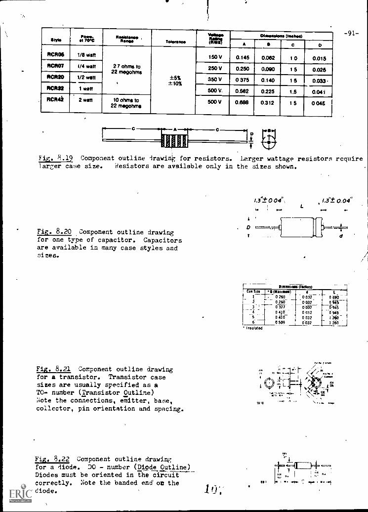
F4-. 8.18 Component outline drawing. The designer must know the electricaland physical charactoristics of every part. Parts manufacturers supply drawingssimilar to this one for desiga and purchasing purposes. rig. 8.16 shows anoutline drawing for an integrated circuit.
SMANmo.
el 70*C111WWWwww7
,Asnew Tolerant*two*AI
(witialIllwenslene (Inches)
A 5 c o
RCR06 1/8 Watt
2 7 ohms to22 megohms
±5%±10%
150 V 0.145 0.062 1 0 0.015RCROT 1/4 watt 250 V 0.250 0.090 1 5 0.025RCR20 1/2 watt 350 V 0 375 0.140 1 5 0.033.RCR32 1 watt 500 V. 0.582 0.225 1.5 0.041
RCR42 2 watt 10 ohms to22 megohms
500 V 0.688 0.312 1 5 0 046
-91-
Fig. 8.19 Component outline irawing for resistors. Larger wattage resistors requirelamer case size. Resistors are available only in the sizes shown.
Fig. 8.20 Component outline drawingfor one type of capacitor. Capacitorsare available in many case styles andsizes.
Fig. 8.21 Component outline drawingfor a transistor. Transistor casesizes are usually specified as aTO- number (Transistor Outline)Note the connections, emitter, base,collector, pin orientation and spacing.
Fig. 8.22 Component outline drawingfor a diode. DO - number (Diode Outline)Diodes must be oriented in the circuit
correctly. Note the banded end on thediode. 10;
1.3"± 0 04",1.
. t
r
Mmeauww0whOCan Sin OMumw0 I
1 . 0 260 0 0322 0 260 0 032_
0 327_ oofff0 410 0 032
5 0 410 130326 1 0 509 0 032
Insulated
701>1
MI5
1.3"± 0.04"
d
0 9451 260 1
1 260 i
n77
ID:! I
001
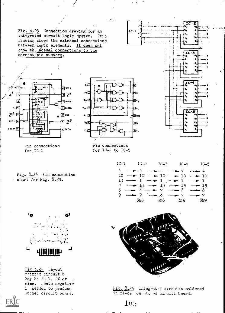
FLT. 8.P3 :or*tion drawing for anintegrated circuit logic system. Phisdrawing showS the external connectionsbetween loxic elements. It does notshow the Actual connections to thecorrect/bin numbers.
,
Fe--11.13MTA
/ gym
eSA
ti 11
st, aMBEr--1"11
SETO*ESE' *
rin connectionsfor,IC-1
8.24 :in connectionchart for Fig. 8.23.
L
-92-
Pin connectionsfor IC-? to 1-0-5
ICA a
As I
** AzA y --.3Ft
S so
IC -3s, A
A I ,
i0 A
F/
S2
IC-4So Ao----111st At
Fc, A
F,
51
Ic-5so Ao
s 4 AI
r* E
As
Sz
IC-1
4
IC 4
4
IC-5
a.- 4
10 10 10 10 1013 1 "W. 1 1 1
13 -- 13 ,----0 13 135 7 HP**. 8 8
9 7 41. 7 7
3&6 3 &6 3 &6 3&9
ig 7).(?4 LayoutTrinted circuit b,:lay be fu.1, ?X orBite,. :hot() negativei needed to )ro.:ucetlhed circuit board.
Fle;, 8.PA5 Integrat'sd circuits solderedin place on etched circuit board.

..1ECTION ITEMS
TT2LgESTIONS
-93-
1. Explain the logic functions of; or, nor, and.
What can be done on a printed circuit board to avoid crossovers of circuitpaths?
3. Where car you find information on the size and pin functions for integratedcircuits'.
4. Explain the proce.3s used in making a etched circuit board.
j. Look up the prices on some of the 7400 series integrated circuits. Wouldyou classify them as expensive or inexpensive?
EX..1.2C I SFS
i. From the connection diagram and pin connection information given, preparea pin connection chart slmilar to fig. 8.24.
4 1 CL
NI VW C,
C45
Cpl
A
el:4- 11160
CI.,2
G
A
IG rI
0261C
C g
F. 14
A
r,G,e2Ge3
am 4 C Fs
r14e2Ge3NNcm .4
Cvg
v1j 111b.1
8260lo
8261
V1.4: 1u 4
Note: Connect all-V CC pins.
Connect all gndpins.

p
-94-
2. 'doing the data and component outlines in this section, sketch a 2X layoutfor a printed circuit board for the circuit shown.
Note: Use 1/2 watt resistors and can size 1 capacitors.Use 1)10-18 size transistor case.
11
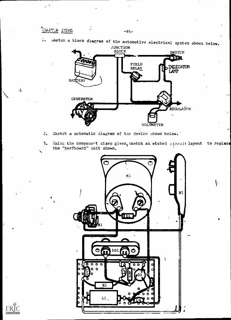
CHAPTER ITEMS -95-
I. sketch a block diagram of the automotive electrical system shown below.JUNCTIONBLOCK SWITCH
INWCATORLAMP
BA
GENERATOR
REGULATOR
VOLTMETER
2. Sketch a schematic diagram of tne device shown below.
3. Using the componert sizes given sketch an etched circuit layoutthe "perfboard" unit shown.
1
YE,

4. write a pin connt-ction chart for th.. connoctiion diagram Jlown below.
e,?66
Draw or sketch fig. 3.8 as a point to point wiring diagram.
8260

-97-
ANSWERS
SECTION ITEMS
SECTION 8.1
1. The block diagram gives an overall picture of the device without regard tothe exact components or wiring. It allows much quicker interpretation thanthe schematic diagram particularly for persons not trained in electricalor electronic circuits.
?. No. blocks sometimes take on the shape of schematic elements.
3. 3lock size is determined by the wording that must be placed in the block.
4. There is no real answer for this question: Block diagrams can be as simpleor complex as needed. Every electronic part has a function so the blockdiagram could be as complex as the schematic diagram.
5. The feedback circuit would usually be shown in the lower middle of the1)1 :k diagram and the arrows would point to the left toward the inputs.
EXERCISES
1.
ANTENNA- -a. R.F. AMP
(Optional)
CONVERTER
POWER SUPPLY
I.F. AMP JRIVER
(Optional)
OUTPUT
SPEAKER
2. Inputs could include: F.M. Tuner, A.M. Tuner; Tape decks for 8 track,Cassette, Reel to Reel; T.V. Tuner, Record player etc.
Pre- Amplifier, Video monitor
Power nmplifier
Speaker systems and headphonefi.

-98-
'SECTION 8.2
1. Wire cplors are denoted by a one or two letter abbreviation or by colorcode numbers.
2. Yes. High voltage for example is usually red. 115V mains are usually gray.
3. TB3/7
No. Wites may be marked by adhesive labels, paint, and sometimes by hotetamping.
5. Feed line shows wire stubs with destination symbols.Base line shows all wires in aconemon single line.Point to'point shows exact connection of wires.
EXERCISES
NOTE: PARTIAL, SIMPLIFIED TABLE IS SHOWN.
ITEM NO.F ROM TO
WIRE COLOR GAGECOMP. PIN COMP. PIN
15 5 1 4 2 R-S, 227
16 5 2 16 . - R-EL
17 5 2 6 RA(
18 5 3 6 6 14-411
19 5 4 26 - RF.0
20 6 1 10 2 R41
21 2 5-1 2 Ba
R-2 6 3 6 5 ---
22 6 4 11 1
23 6 4 6 5 BUB
24. 6 6 10 1 Y
25 6 7 5-1 1
6 8 a 2, Y
HC
V

-99--
SECTION 3.3
1. equal area concept.
?. Yes. Only in a few circuits (=ridge, delta, "Y" etc) are m.hemAtic Nod.oleplaced on an angle.
3. Parts must be identified on a schematic diagram. These identifications arerelated back to the parts list. Basic identifications are: R - 1, C,- 15D - 7 etc. In addition the value, voltage, device numberletc.Imay bt'shownto make schematic interpretation easier.
4. Industrial schematics use the block format and variations on some of thesymbols.
5. Different plug symbol and three wires instead of two wires.
EXERCISES
1.J-4 . J-3 J-2 J-1
2. To be answered locally.

SECTICN 8.4-100-
1. These symbols refer to the output conditions of a device based on the inputconditions. One explanation might be: (positive logic)
OR . . . . if input A or B is on, output is on.
NOR . . if neither input is on, output is on.
- AND . . . . if input A and input B is on, output is on.
2. Circuit paths can be routed under components - uaing the component as a"bridge", double sided boards can be used, jumpers are sometimes needed.
3. No standard reference isienerally available. Usually the individual part_manufacturer's catalog must be used.
4. 'Artwork, photo-negative, circuit board exposure, develop circuit imp', etch,drill holes.
5. Very inexpensive.
EXERCISES
1. Connection diagram may vary depending on the IC-1, IC -2 etc. notation chosen.
1.
I C - I IC - 2. IC - 3 lc - 4 IC 5 IC -6 IC -7 IC -8 IC -924 -- 24 --v. 2412 12 --- 12
311.41154,6Ar7
14 315 4
13314
15 --II. 4
Cu,
nu cosal
IC-2
---a 24 24 24 24 AI. 2412 12 -- 7 --- 7
U.- 12 __...
13 413 -- 131 1 1
13 4 4 43 54 8
1314 6 33
13 6
go
C't 7 Ins
14
I C 3
CNI7 OMt
IC-4
IN. 24
an 58 4
I
11 Ptg
C-11Cfl
Irh soh
se1C-7
sts
C I g ;
Co 2 11741
Cd
IC-5
IIIIIt. P711,114,1 4
i IC-1 4
1C-9
'N

a
-101-
L. 11:in,7 the di.to. :'._d col,:nc.i.'., OU711:!, in thin 30C4i0:1 ::fetch a 2X layout
for a printea e.trc:uit 11(,acd fnr t:i:, circuit shown.
Note: Use Iii: wutt 1-0;:i.:tors nnd can site 1 capacitors.
Use TO-l'r, 1-.A. trauLi4tor cacx.
,

ANSWERS
CHAPTER ITEMS CHAPTER.VIII
1,
2.
TYPICAL
3
-102-
R71
C-1 C-2 R-2
Uri
111
- R-1 -ell "-3
L-1
TO SO -1/
-C-4-00 -TO SO -1/2
NOTE: VIEW FROM TOP OF BOARD
USE REVERSE NEGATIVE

-103-
3. Diagram may vary according to how IC's are labeled.
4.
IC - 1 IC-2 IC - 3 IC - 4 (Ic -1, IC - 2 =8266)
16 16 24 24
8 & 7 8 8, 7 12 12 (IC - 3, IC - 4 =
9 9 3 & 4 8260)
1&2 1&25&6 5&6
10&11 108,11
148,15 148,15
3 174 19
12 21
13 23
5 46°2°
0
3 174 19
12 21
13 23
C UA
2
5 4
6°2°0
F
5 1
6°2°
wanwalms

I
CHAPTER IX -104 -
WELDING DRAWING
'SECTION 9-1 PROCESSES, JOINTS, AND SYMBOLS
The joining of two pieces of metal by gas, arc, or resistance welding is
an economical means of fabrication especially in the early stages of design.
A knowledge of *he common welding procesSes, basic welded joints, and symbols
used.to represent various welds is a necessity for the technician involved in
preliminary design.
I
BUTT CORNER TEE
1 1
LAP
Figure 9-1 Basic types of welded joints.
CZABACK
OR BACKINGFILLET
EDGE
11 1
PLUGOR SLOT
1 1 1-r- i
V VBEVEL "u"
SQUARE
I r I
Figure 9-2 Fundamental arc and gas welds with related symbols.
TYPE OF WELD
Spot Projection SeamFlashor
Upset
(2) l& 11
Figure 9-3 Resistance weld symbols.
SUPPLEMENTARY SYMBOLS
Weld AllAround
FieldWeld
Melt-Thru Contour
Flush Convex Concave
.&° '.-- NW.........
Figure 9-4 Supplementary symbols.

FINISH SIMMIKCONTOUR SYMBOLROOT OPENING; DEPTH OF FILLINGFOR PLUS 11110 SLOT WILDSSIZE; SITE OR STRINGYFOR RESISTANCE WELDSREFERENCE LIRE
-105- GROOVE ANGLE; INCLUDEDANGLE OF COUNTERSINKFOR PLUG WELDSLENGTH OF WELDPITCN(CENTER -TO-CENTERSPACING) OF WELDSARROW CONNECTING REF-ERENCE LINE T9 ARROWSIDE OP JOiNT.,TO GROOVEDMENDER, OR BOTH
o
SPECIFICATION. PROCESS,OR OTHER REFERENCETAILBASK WILD SYMBOLOR DETAIL REFERENCE
(N)FIELD WELD SYMBOLWELD ALL AROUND SYMBOLNUMBER OF SPOT ORPROJECTION WELDS
Figure 9-5 Standard location of the elements of a welding symbol.
Due to the standardization of welding symbols, precise information canbe placed on a drawing regarding the exact type, size, and number of welds re-quired. The following illustrations show typical examples of various welds.
DESIREDWELD (a )
DESIREDWELD
SYMBOL
SYMBOL(c)
32
DESIRED SYMBOLWELD ' (b)
DESIREDWELD (d)
Figure 9-6 Examples of welds.
SYMBOL

:ABORAT',RY -106-
1. The student should be able to translate ANSI* welding symbols froma typical cross section into a clear and complete statement describingthe required weld.
2. The student should be able to draw the correct ANSI welding symbolsand apt)ly them to a typical joint cross section from a word description.
A:CTION
What :loes a fild weld symbol ind)cate?
Ts edge preparation usually shown on a working symbol?
Why welding usually Ireferred over casting or forging in proto-ype fabrication?
EXERCISESI
1. Draw the symbol for a 1/2" weld on the other side of the jointat (a) and both sides at (b).
DESIREDWELD
(a)
2. Describe the following weld.
DESIREDWELD
(b)
* American Nationdl Standards Insdtqe

-/37-
CHAPTER ITEMS
1. Make a weld assembly drawing on an A sizesheet of
vellum using proper ANSI SYMBOLS.
ANSWERS
Section Items
1. Welds made after the initial fabrication.
2. No. With proper weld symbols and notation a picture
of the edge preparation is not required.
3. Weldir is usually preferred in prototype fabrication
becauge it is cheaper and faster.
EXERCISES (solutions)
(a)
DESIREDWELD
(b)
2. Field weld all around with 3/8" fillet weld.

-108 -
CHAPTER X
PIPE DRAWING
SECTION 10-1 JOINTS, FITTINGS, AND VALVES
Pipes which carry a fluid must be joined together and routed in variousdirections to get the fluid from one point to Another. The joints and fittingswhich are required must form a leak proof seal and, in the case of high pressurelines, must be structurally sound. The flow of the fluid usually requires somecontrol and this is achieved through the use of valves. Pipes are made fromferrous and nonferrous materials with various applications. The material fromwhich the pipe is made and the condition of the fluid being transported aredetermining factors in the selection of fittings and joints.
Pipe Material
Pipe is available in steer., wrought-iron, cast-iron, seamless brass andcopper, or plastic. Their -selection depends to a large extent on their appli-cation.
*Pipe Joints and Fittings
Fittings may be used to join pipes together, change size or direction, orallow for branching. The type of joint and-fitting may be screwed, welded,flanged, or soldered depending upon material and application.
Valves
Valves are used to control the flow of fluids in a pipe. The more commontypes are gate valve, globe valve, and check valve.
LABORATORY
1. The student should be able to select the correct fittings and jointswhen given a pipe material, size, and application.
SECTION ITEMS
STUDY QUESTIONS
1. What is the purpose of a check valve?
2. Name one kind of joint that can be used in a high pressure steel line?
3. Of the two, which offers the most resistance to flow; a gate valveor globe valve?
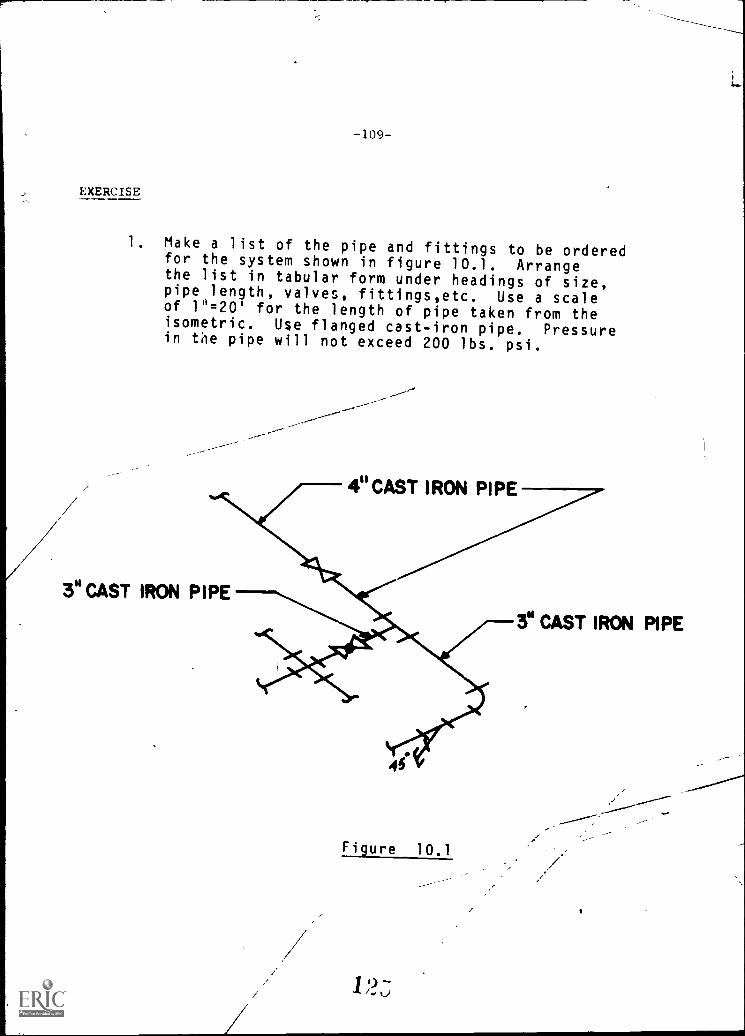
-109-
.1 EXERCISE
1. Make a list of the pipe and fittings to be orderedfor the system shown in figure 10.1. Arrangethe list in tabular form under headings of size,pipe,length, valves, fittings,etc. Use a scaleof 1".20' for the length of pipe taken from theisometric. Use flanged cast-iron pipe. Pressurein the pipe will not exceed 200 lbs. psi.
4" CAST IRON PIPE
Figure 10.1

SECTION 10-2 SINGLE-LINE AND DOUBLE-LINE DRAWINGS
Pipe drawings are made to show the size and locationof pipes, fittings, and valves. A single-line draw-ing showing ANSI symbols is a fast and convenient wayof making a drawing using orthographic or axonometricdrawing. Double-line drawings ale used when moredetail is required in the drawing.
arm 9
UMW OMB GAM
/OS
* 6 .12A1 0 1%
MA .4
OQJIOw
OWN SAT! VALVE WWUNIS(JOINT)
COUNINMOM CHEC1C VALVE TEE
ELBOW
Figure 10.2 Single Line Drawing
re ': -'e _-e
ELBOW
1')

LABORATORY
1. The student should be able to make a single-lineorthographic or isometric drawing from eitherword description or double-line drawing.
2. The student should be able to make an orthographicor isometric double-line drawing from a single-linedrawing.
SECTION ITEMS
EXERCISES
1. Make a single-line isometric drawing of figure 10.3.
CHAPTER ITEMS
EXERCISES
Make a double-line isometric drawing of figure 10.2.
ANSWERS
SECTION 10.1
1. The purpose of a check valve is to allow flow in onlyone direction.
2. Welded joints.3. Globe valve. The fluid must go thrdIrgh the valve
at right angle to the flow direction.

-112-
CHAPTER XI GRAPHS
SECTION 11.1 LINE GLAPHS
Line graphs are commonly used in the engineering field because of theirvisual appeal and ease of interpretation. Some of the more common line graphsare the Rectangular Coordinate Graph, Semilogarithmic Graph, Logarithmic Graph,and the Polar Graph.
s.1".. , I 'I' I J i ,.t',thee Jrlittette ,e-Ale.1 Litt le 0 E L t, et e PipittiSI,
\;ENte,INrFiAlVe rei-1,7{S. I- `', ...ONFERR-d 1
-, ALL U.- I NSTITLT le.A., I'f'-, ,- 1 1(4,1 ,
1 IL
'i
f-t ]
elk tiLlAle '-.
-- i- 4 __,_ , ., . -...,4.- --.1. II I
rRr NDL
-.... ,fen it t ...re- t fielta
- f
MASTER',ei- _ _ + - 4- - 411- + 4- a-
L1 it=
54 SC 4 .)
EARL a
Fig. 11.1 Typical Line Graph
The manner in which a curve is drawn on a graph will depend upon its deriva-tion. If the graph represents discrete values such as temperature or dates it willbe made up of straight line segments and pass tiirough all data points as in Fig.11.2 (a). For a curve that can be easily defined mathematically, it will be 1
smooth and pass through all data points as in Fig. 11.2 (b). A graph representingexperimental data may be straight or curved and will take a mean path through thedistribution of data points as in Fig. 11.2 (c).
(a) (b)
Fig. 11.2
(c)
4

-113-
When constructing a line graph, the following suggestions should be con-sidered:
1. The horizontal scale should usually read from left to right and the verticalscale from bottom to top.
2. All lettering on the graph should read from the bottom or from the left-handside.
3. The zero line should always be shown except for logarithmic graphs. The
diagram should be broken if the scale is such that the zero line would notnormally appear on the graph.
4. Important numerical data and formulas should be included on the graph.
5. The title should completely define the graph and be placed so that it iseasily found.
LABORATORY
The student should be able to annotate a graph when given the grid, curve, andpert1inent data.
SECTION ITEMS
QUESTIONS
1. What four line graphs are most commonly used in the engineering field?
2. On which side of the vertical axis is the label usually placed?
3. Why does the zero line never appear on a logarithmic graph?
4. On which side of the horizontal axis should the label be placed?
EXERCISES
1. Complete the graph in Fig. 11.3 by adding the given information.
Title:STRESS-STRAIN DIAGRAM Soft Steel
Horizontal axis label: Strain, in inches per inch
Vertical axis label: Stress in pounds per sq. inch
Scale on vertical axis: each sq, equals 1000 psi
Scale on horizontal axis: each sq. equals .001 in.
d) 'cij

-114-
MOOSIOSISOOMMOU
MOMOSIOOSUOUSMSOWOOD
SOUSIMOMUMOOMOM MESSMOSOOS OMWOO WOOMMIONOil!MOOMOO Me
OSIMMOOMOMMOOSOMMUs
OSOII us
II MONOOMSOMOSOM
OOSOUSUMOOMMOsommusammemOm mossommimmumm
muminsimmissommome mosimmsumumill mil slesesmessu
Um mu--iL
11+_- - N
tf
1",----4-, ++ i :,_
,
r , 4..-i- .4 -4-....-4-1 t -4-4. -4-.' t "t-^1.- 1.-e-4-44-4-4 1 --+-t .-- 4.- +-..- .--r----. - .--...-.1I-. -4---4- 4-1.-- 4 4 ..--t- -4, -4-4-- 4- -4-- 4-4--.. .4, 4. 4-4 +.-1.. 4- 4 -4- 4 + --4--
,--.- ..._ ,__, ,.-1, 1_,.. ..__, Li ..., . _....._ .
Fig. 11.3SECTION 11.2 RECTANGULAR LINE GRAPHS
Rectangular line graphs are usually drawn on preprinted grid paper whosehorizontal and vertical lines form small rectangles which range in sizes of 1 mm,1/10", or 1/20" on a side. The horizontal and vertical axes of the graph on whichthe independent and dependent variables are plotted, respectively, are drawn about1" inside the grid to allow for lettering.
LA RORATORY
200
180
160
0 140
120
100
80
Ail:COST OF LIVING1941-1953 MEIN
511 IIIMAI1935-'39 = 100
1941 '44 '47
YEAR'50 '53
Fig. 11.4 Typical Rectangular Line Graph
1. The student should be able to pick correct values from a rt.ctanqulargraph.
2. The student should be able to construct a rectangular line graph when givenAe a set of data.

arTION I'I M4
EXERCISES
1. PLOTTING GRAPHS
Look at the examples of plotted graphs.related to the line graphs of examples 1how data jos plotted to form a line graphdata tables and locate additional points
Notice how certain circled data areand 2. Now that you have observedchoose other given data from theon the graph.
Typical curves with written notations for you to compare. See if you canfollow the writteninformation on the graphs.
1.0
0.9
o.
O.
O.
0.
o.
Ill 11111111111111111 MIRMIIIIIM11111111111u111 nn _l_ MI; II
Elirialillimam.MINum
411111
EN
rowrii
Is' delRum_.7.
wallowMIMI
pitstour,69111_1111111111
UMMIMI I lialplAradirrIrlillittliNEM
ofKO
ILA sr...41_, 1 9 1 gi NamPld UM MUM1111111111W11111111111111111111111 NM RIM
11111,4111111111111111pip2d
MUMSNI MEM 11110111MI MN 11111111111/11
MIIIIIIIRIIIIIIMIRMPRIIIIIIIIIUNIMIll ptire1111Will111ir II 11111111111111111 III Mt 1111 Il..1711
go v1 50 200 -,'sVII
AntennaC
0.1 0.2 0.3tuvent
PlateVolts 40 75 102
Plate Volts
.5 0.6 0.7 0.8 0.9 1.0 (Apperes)
160 190 220 252 283 320
Pig. 11.5
1,31
sr
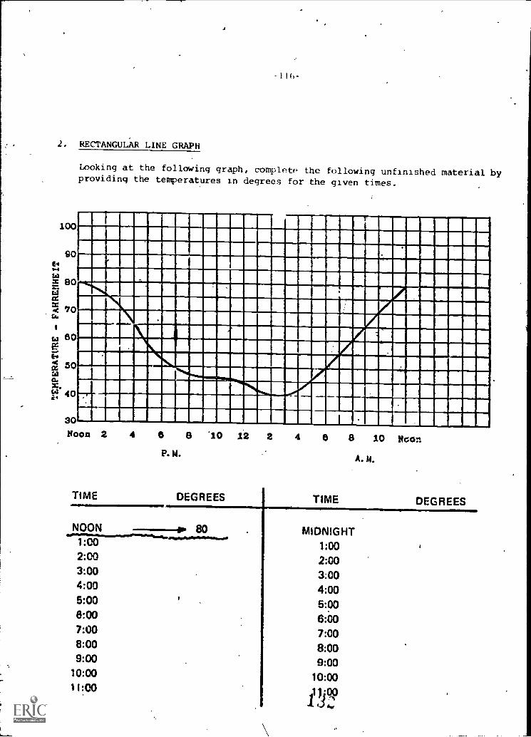
2. RECTANGULAR LINE GRAPH
Looking at the following graph, complete the following unfinished material byproviding the temperatures in degrees for the given times.
100
90
!-44
80
ta 80
V
cd 50slx.te 40
4.
30Noon 2 4 6 8 '10 12 2 4 8 8 10 NoOr.
P.M.
TIME DEGREES
A.11.
TIME DEGREES
NOON 801:002:003:004:005:006:007:008:009:00
10:0011:00
MIDNIGHT1:002:003:004:005:006:007:008:009:00
10:00
IY°
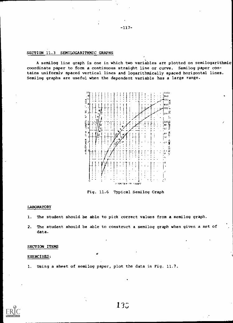
-117-
SECTION 11.3 SEMILOGARITHMIC GRAPHS
A semilog line graph is one in which two variables are plotted on semilogarithmicoordinate paper to form a continuous straight line or curve. Semilog paper con-tains uniformly spaced vertical lines and logarithmically spaced horizontal lines.Semilog graphs are useful when the dependent variable has a large range.
100080000 <
4008.
300
)0E
-100- 130
-16(1
40 t
2,1
141
1)Z24--)
4
/Vim N ,.HAFT
Fig. 11.6 Typical Semilog Graph
LABORATORY
1. The student should be able to pick correct values from a semilog graph.
2. The student should be able to construct a semilog graph when given a set ofdata.
SECTION ITEMS
EXERCISES:
1. Using a sheet of semilog paper, plot the data in Fig. 11.7.
1. 3 3

I I H
TEMPERATURE STRESST, °F S, lb. per sq. in.
1,100 2,700
1,200 1,250
1,300 570
1,400 270
Fig. 11.7
SECTION 11.4 LOGARITHMIC GRAPHS
A logarithmic line graph has two variables plotted on logarithmic coordinategrid paper to form a continuous line or "smooth curve". Log grid paper containslogaritmically spaced divisions on both the vertical and horizontal axes. Logand samilog graph paper can be obtained having as many as five cycles on an axis.Log graphs are used for comparison of large numbers of plotted values in a compactspace and for comparing relative trends of several plotted curves on the samechart or graph. Log graphs are not the best form to present relatively few plottedvalues or for displaying absolute amounts -- but are very good for displaying anextensive range of values used in empirical equations.
5040
300
aJoa ....
Electricat Generotors-:.* Hydraulic Pumps.. ,,
: ., '1, a ..III II 111 t" itt 60 1if .., - - ,4 as al al ttellellitlialtitistK I. muutumulailitUit
:27z" ":: .. 7 ... :w I
OG
:8::;:.::. ,...... .. t.
::::ii:::...,4111...:1:: , 11111111 MUM. ... : - - lima usaiIintelwastualsnuolnill
illini , , itIloi. U. !I. All 1 III 101
NUMMI
O to illli1W, 1,. , 111!.1illifili liN1Igl..,. if ni
iiiii!!::.' ' : gliikAlfilillihR7iii., 111 NV Ilito 30 -.,,I. ,1!!;111:$1111111111114',41 11111151 NIA
0 2.0 ;Iiiiii Mitimbia..11111MUNIN
O :, , iai iiiniii .11411g 1146.:11111111
k.::::::::-"
! ',IEig ::a1i1it i :i1"u:ffl::ir.l.wii1i
ai9i1 ir11sOIkIIii f,.. ,;:iiirm.... : i.... . ._
....I 1..111..Z1311t11U1:1 L. ZVIIM..nn
ln
iltuill
uus:s:.. ....1
ir.-uw..:8:.qgsautcmna.r:uan mnusv necossw.w.....rmumgmliacusi-ui:geesensum.insimonaNatuittli:'!! .41 WIIIIIMIIIIiiiii1J067111141IVITIMIII1199411111
.4.41441111
SPECIFIC WEIGHTVS II
HORSEPOWER
62 3 4 5 6 5 10 20 30 40 5060 eo too
HORSEPOWER-Fig. 11.8 Typical Log Graph

-11q-
LABORATORY
1. The student should be able to pick correct values from a log graph.
2. The stjident should be able to construct a log graph when given a set of data.
SECTION ITEMS
EXERCISES
1. Plot the given dateon log paper. Choosethe number of cycleseach way to use mostof the paper.
SPEED CAPACITYRPM CU. Fr. PER HE.
1.5
2.54
6
10
15
19
34
6090
46
4 577690
117143170220280
355
SECTION 11.5 POLAR GRAPHS
Polar graphs are often used when data is to be examined with respect to various
angular pos_lons. The polar graph is different from the previous graphs in thatthe independent variables are marked off in degrees around the border of the graphand the dependent variables are marked off on the horizontal or vertical radial
lines.
Fig. 11.10 Typical Polar Graph

LABORATORY
1. The gtudert should be,able to pick correct values from a polar graph.
2. The student should be-able to construct a polar graph when given a set of data.
SECTION ITEMS
EXERCISES
1. Construct a polar graph using the data in Fig. 11.11..
Orientation, degrees Candle Power
0
10
20
30 ,- .
40-
/' - 50_,-- 60
70
8090
100
110
120
130
140150160
170180
130
20030 0.
3103300
290280270
2402002
2802
22852902
3 05
3203
333033403303
Fig. 11.11 Candle Power Distributionin a Vertical Plane of an IncandescentLamp Suspended froAr the Ceiling.
CHAPTER ITEMS
2UESTIO416
1.. Why is a curve sometimes drawn between plotted points on a graph rather thanthrough them?
2. What are the two axes of a graph called?
13

121-
3. How are the values plotted on the X and Y axes?
4. What are the two variables on a graph called?
5. In reading a graph, how accurate must one estimate?
6. Why are graphs used by scientists and engineers?
7. What is the difference betw common rectangular graph paper and semilog graph
paper?
8. Why is graph paper printed in various colors; i:e., black,'orange, green,
purple?
EXERCISES
I. RECTANGULAR LINE GRAPH
- This is the frequency of the output of device "Y" as the temperature of
the device is changed.
Fre uenc (MHz)
0 100.0500
2.5 100.0?30
5.0 100.0200
7.5 100.0100
10.0 100.0060
12.5 99.9980
15.0 99.9970
/-7.5 99.9920
20.0 99.9930
22.5 99.9910
25.0 99.9900
27.5 99.9910
30.0 99.9915
32.5 99.9960
35.0 99.9965
37.5 100.0000
40.0 99.9980
42.5 99.9930
45.0 99.9875
47.5 99.9840
50.0 99.9820
52.5 99.9760
55.0 99.9765
57.5 99.9750
60.0 99.9740
62.5 99973065.0 99.9720
13

2. LOG GRAPH
Graph this data:
y x
2.0
5.2
9.013.0
22.030.0
50.072.0
-122-
y x
.1 95.0 3.0
.2 130.0 5.0
.3 150.0 7.0
.4 170.0 10.0
.6 230.0 20.0
.8 260.0 30.01.3 280.0 40.02.0 300.0 50.0
3. SEMILOG GRAPH
response
Gain
of an amplifier:
Fr -. (Hz) Gain Free. (Hz)
Here is some
Gain (dB)
data on frequency
Free. (Hz)
20 1 40 200 40 20K25 2 40 300 38 30K27 3 40 400 36 40K29 4 40 500 35 50K30 5 40 600 32 60K
6 40 700 30 70K7 40 800 25 80K
33 8 41 900 20 90K34 0 42 1000 10 100K35 10 41 2K37 20 40 3K39 30 40 4K40 40 41 5K40 50 42 6K41 60 43 7K40 70 44 9K41 80 43 9K40 90 40 10K39 100
Notice that there are five general groups of frequencies; 1-10, 10-100,100-1000, 1000-10,000, and 10,000-100,000 These are the 5 cycles andthe reason you were toneed 2 or 3 cycles.
get 5 cycle paper. At other times, you may only
1'3
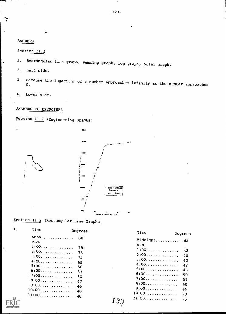
-123-
ANSWERS
Section 11.1
1. Rectangular line graph, semilog graph, log graph, polar graph.
2. Left side.
3. Because the logarithm of a number approaches infinity as the number approaches0.
4. Lower side.
ANSWERS TO EXERCISES
Section 11.1 (Engineering Graphs)
1.
STRESS -1111tiini
MAMMAwit Sravl
km. to, MM. IM kwh
Section 11.2 (Rectangular Line Graphs)
1. Time Degrees
Noon 80P.M.
1:00 782:00 753:00 724:00 655:00 586:00 537:00 508:00 479:00 46
10:00 4611:00 46
13
Time Degrees
Midnight 4AA.M.
1:00 422:00 403:00 404:00 425:00 466:00 507:00 558:00 609:00 65
10:00 7011:00 75

11 1
I II
I_11
11 I
1 II
1110
1111
1111
111
1111
1111
AI 1
1111
1111
1111
i1
nii0
1111
10 "
unio
mm
ilin
umm
omm
ouro
pmm
our
1i .
IIif
I11
1
11
I11
1111
1111
111
U1
I MIN
1111
1119
1111
1111
11ill
011
1111
1111
1111
11I
I
1111
0111
1111
1
TIII
IIIM
PIII
II111
1111
1111
111k
1111
1111
1111
B11
111
in In
inm
mill
1111
1110
111t
hntja
n011
0111
1011
0011
1I a
imN
I11
1111
1111
1111
1111
11
1111
1111
1110
11.1
1111
MIN
UIP
MM
1111
1111
1111
1011
1111
1111
1111
1111
..1 N
IIIIII
Ifti1
II 11
1111
1111
1n11
1
1111
1111
1111
1111
1111
1111
1111
1111
1111
1111
111
IMM
O P
1111
nin
num
man
nm
min
mnn
umun
linno
mm
onm
IIM
I,T
aann
ornu
mm
urou
nova
nm
ainu
mro
mtp
aiin
q 1
Imm
o 11
1111
1111
1111
111
1:I I
I 1O
MN
I NM
I 1111
1
1111
111
11
mom
lunn
urgi
iiii
III 1
1111
1111
1111
1111
11ifi
l
1111
1111
11
1111
0111
I
1111
1111
1111
1111
/111
11
111
1A
m in
nput
11
Im
omm
ennu
mp
:T
oprr
milp
Pr
mi
INIM
IIIIII
IIII ill
pill
111
1I1
Im
iuid
i"
"11
19",
m1
r1
I UN
Hi
glirl
i 111
1111
01 1
i11
111
MU
111
1011
1
1111
1111
1 M
PH
I II
1111
I
I,In
gm n
o ou
na
a fi
now
niup
II-
11M
IN11
1 M
NM
IH
I
111
1111
1110
1111
NI 1
1111
1111
1111
111
1111
1
npun
orno
m
mill
nT
win
=iri
nI
film
u nu
mm
aim
mul
n1
It
7ar
m=
ii
r1
ME
INIII
IIIIII
IIIM
M 1
1111
1111
1111
MIII
IIIIII
III 1
1111
11N
1111
1111
1111
1111
11II
I 1M
IMI 1
1111
11
riffli
ng!
NI
mu
ma
ima n
unno
pmm
an
11
wow
I o
wn
1111
1111
17
IIII
11 P
ill11
1111
11,1
1111
1111
1111
1 I
1011
1111
1111
1111
1111
1111
1111
1111
111
1111
1111
1111
111
1111
1111
1111
$111
1111
1111
1111
1111
1111
111
1111
1 11
11M
1111
1111
111
1111
0111
1111
1111
1111
1111
1111
1111
1111
1111
1111
1111
1111
1111
NN
Iili
nlIM
IIIM
I111
0111
1111
1111
1111
1fill
IMM
IM11
1111
1111
1111
11M
IUM
UM
UM
1111
1111
1111
11 1
1111
111
--
--
1111
1111
1111
1111
1111
1111
1111
1111
1111
1111
1111
1111
1111
11M
1111
111M
1111
111
1101
111
111M
1111
1111
1111
1111
111M
1111
1111
1111
11
...in
konn
inui
mun
nuom
nipu
li in
umm
omm
unin
nuni
mm
ou11
111

Section 11.4 (Log Graph)
1. 10
5040
$4 20
a
10
9 54
1
-125-
1 1 --2,- .-rtiz- ! -fir 1-
, ' T-4---11_ - Capacity of --4 iii 1Screw conveyor-
, 1 --i. -A !11110111alliMMINIMMININ MINIM , i -1:17-_: 1, , i I' ,
= 161111111111111=11111
Malirra=1111 1-t-
t
1
IIIIIP I I 11174-
.I I-, .
-- t1
Jr"' ! !li.
.111111111111111151111111111111111151110511111=1111PfeffilMIIIIMMIMESIN111111111112111EMENUMLII111111111111111111111111111111111MP"-011111011111111121111111111111111111=um.= rrmamoull::=11
MIS.
sommalommowIIIIMIIIIIK-WMMERE111111111111=78=Imensn_w_-gcsgmlnizemmusualamil
Ft SPUMONI!
__ _
'-----.--'3-1ENCIERINISIMICEIMINI)
--'-',=1-g--g-`174.7-74714111011111,11111111111111
==.,.__-a -------1----5_,L-A
crew:8 ixas-_ = = = A CRi )_:- 1 :FT" 1
t -I....../BEgatEmni
=-.....= :-4=-.--======-Eil...........MOMMIMIIYMAIO.-2 3 4 5 6 7 . 10 20 30 0 50 70 11Section 11.5 (Polar Graph)
1.
SPEED IN RPM
,r4off
.1;
74,
11. ,r, .7° t Pk,mef
r
01111. Pear Illartributirn rart1-*1 pl.* 1! ar
loot ',rpm,
rb
pn
N
1
1m
I
SSId
0
14i

-12E-
CHAPTER ITEMS
ANSWERS TO Q(iSTIONS
1. Experimental data will always have some variation from the "true" values dueto errors in reading instruments, slight changes in conditions, etc.
2. The vertical axis is called the Y-axis or ordinate and the horizontal axis
is called the X-axis or abscissa.
3. Values along the X and .Y axes are positive up and to the right and negative
down and to the left.
4. Most physical systems with two variables have one which can be varied, bythe experimenter and a second variable which depends on the first. The first
is called the independent variable and the second is called the dependentvariable.
5. To the nearest half of the smallest scale division.
6. They are very descriptive and can be used to clearly show the results of anexperiment, how a circuit or device behaves, to present data, and to show therelationship between variables in mathematical equations.
7. Rectangular graph paper has equally spaced linear divisions along the verticaland horizontal axes. Semilog graph paper has equally Spaced linear divisionson the short axis and non-linear logarithmic spacing on the long axis.
8. Certain reproduction processes require special colors and sometimes the gridlines are intended to not print script lightly or to print out strong when
reproduced for an engineering report.

ANSWERS TO EXERCISES
1. Rectangular Line Graph
FREQUENCY OUTPUT OF DEVICE V VS. TEMPERATURE
10003 etr----
4.4
U
a:CC
$1.100.04.
;
1
41,:
-127-
;--- i a. A.-A..0i
99.9310--
999,°0
I1 -
4
1
10 20
.143
40TEMPERATURE- °C
1t
iI
1 4_......_
I .I
Mr. It 1=111
-

X
50
ICOM
,
*. I". ... t . . . ..,, ..V. ..0; . , 01, ,4:4I ::: It.' :1Y..:" I
II,
II
'
:
; I '.1 : ;:e"Or. ..!!! 1::: ....ieI 0. .sti 11... 1,1%.: :::: , 1 !11 Xi it
. ::: ;.:.r. 1, -I. 4.;: 1 . . .::
...1
: L
i ..
i i I,1 'i fli
.1.
ild II
r .
:.
....I a
i ::' ..
:: 1 : 1 :i 41. .:.:
' : : 7- j" :-: "t: r
: - i .. .:.. . I : iA 1: !. r ::1. *
: ; i
..._.
*'. . . ..
III11.1. I11121=nini..1MleIll MI ... I Iif.. owml No ..,, . me_,,,... al
----. aim ...,.... Nonmilii: , .1 II 4
t '
I . . ..
-- --- -4-4 -
. . . I ' 4
". .
.
4 . . I . .
. . . 4 .. ... .... ..
. . . .ri
1 . :
:: il I i 1.1I""---*...
-. I i t, '
,11;1*....,.1.4......
1,......--..- _........
. .
..-
. . .
... .......*....,
IMI
II...--.L.._ ......if-,..--..... i I
. MO= NICMUM
: IMMOWell
.1 I .1 , 6 . I
I . . I i 1 .
. ".
..
1.. ,
.
.*
'tto.I I.! r?:.*
I I . I. 1 .. ..
. I ...1...... : .
I i i ........... I . t I..1: .
6. t .
.. i.hI
...:
I
.... ? ? : ! .I ? I I
I* '
..I . i i I .i;t :. ..:
:.
....I. I: i
. 1
: . I . i . : ".L. 1: : : :1: :.I. .
: 1 ;I* '1: '! 1. £* Li]:.1.11.
: :
...,.IN II lir 111
.,,,,,1,,, .. 0: .:i: me itnin... igill....... usa.grzimmigriggma,00,, Ci WC= 13" u
.
ma= 1. 1l44,:...
......... . .mr. ..:1. .. .
11111%11111111F111 moan Mr.... 4,..... no sine n sousuu gar . am a auMIMI in 11=11 . _ I ... .


![PHARMACYBOARD[657] ARC3509C](https://img.pdfslide.us/doc/110x75/61c52ab32485610a611accce/pharmacyboard657-arc3509c.jpg)