Embed Size (px)
Citation preview
Trelleborg MArINe SYSTeMS
Docking &Mooring
Product Brochure
1
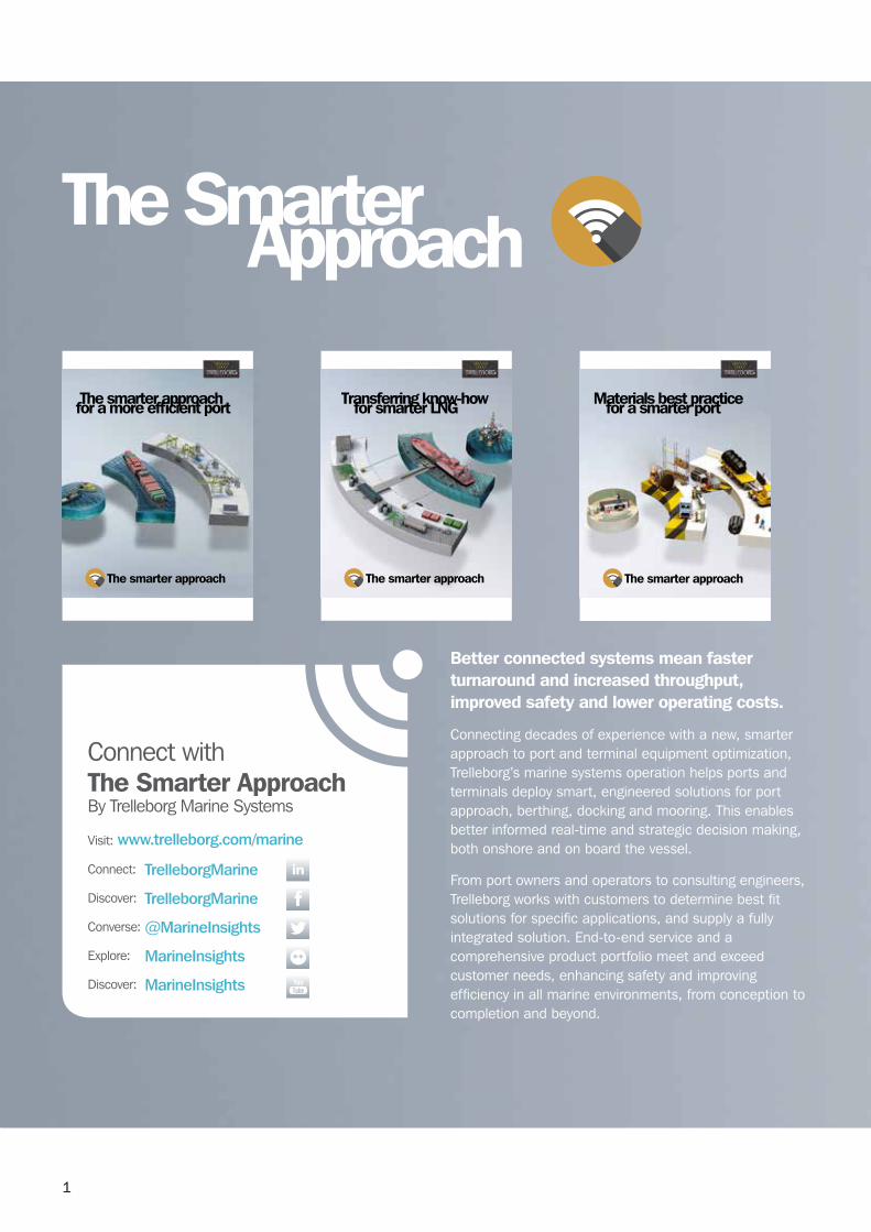
ApproachThe Smarter
Better connected systems mean faster turnaround and increased throughput, improved safety and lower operating costs.
connecting decades of experience with a new, smarter approach to port and terminal equipment optimization, Trelleborg’s marine systems operation helps ports and terminals deploy smart, engineered solutions for port approach, berthing, docking and mooring. This enables better informed real-time and strategic decision making, both onshore and on board the vessel.
From port owners and operators to consulting engineers, Trelleborg works with customers to determine best fit solutions for specific applications, and supply a fully integrated solution. End-to-end service and a comprehensive product portfolio meet and exceed customer needs, enhancing safety and improving efficiency in all marine environments, from conception to completion and beyond.
Transferring know-howfor smarter LNG
The smarter approachThe smarter approach
The smarter approachfor a more efficient port Materials best practice for a smarter port
The smarter approach
connect with The Smarter Approach by Trelleborg Marine Systems
Visit: www.trelleborg.com/marine
connect: TrelleborgMarine
Discover: TrelleborgMarine
converse: @MarineInsights
Explore: MarineInsights
Discover: MarineInsights
2
Whatever bollard type your application requires, trelleborg has a range of seven high-performance styles to suit you.
Trelleborg bollards are precision engineered and manufactured in a variety of metals including premium grade Sg ductile iron and cast steel to offer unprecedented levels of service life and resistance to corrosion and impact. we understand that safety is your number one priority. That’s why Trelleborg Marine Systems provides bespoke safety critical bollard, anchoring and fixing solutions quickly, to our customers’ exact specifications.
This guide will provide you with detailed and specific information of our full range of bollard solutions including installation, maintenance and specification advice, plus much more.
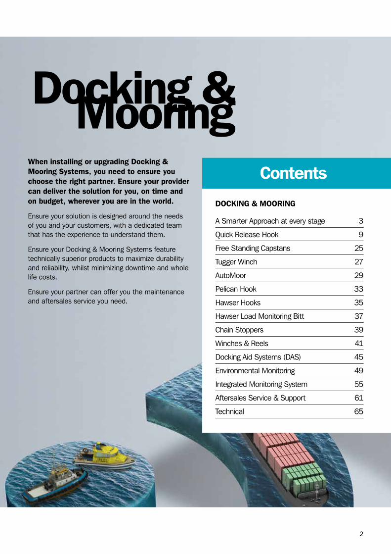
Docking &Mooring
Docking & Mooring
A Smarter Approach at every stage 3
Quick release Hook 9
Free Standing capstans 25
Tugger winch 27
AutoMoor 29
Pelican Hook 33
Hawser Hooks 35
Hawser Load Monitoring bitt 37
chain Stoppers 39
winches & reels 41
Docking Aid Systems (DAS) 45
Environmental Monitoring 49
Integrated Monitoring System 55
Aftersales Service & Support 61
Technical 65
contentsWhen installing or upgrading docking & Mooring Systems, you need to ensure you choose the right partner. ensure your provider can deliver the solution for you, on time and on budget, wherever you are in the world.
Ensure your solution is designed around the needs of you and your customers, with a dedicated team that has the experience to understand them.
Ensure your Docking & Mooring Systems feature technically superior products to maximize durability and reliability, whilst minimizing downtime and whole life costs.
Ensure your partner can offer you the maintenance and aftersales service you need.

3
A Smarter Approachat every stageConsultation
conceptual design in your local office – with full
knowledge of local standards and regulations, delivered in your language – for optimized
port and vessel solutions.
ConCepts
concepts are taken to our Engineering center of
Excellence where our team generates 3D cAD designs,
application-engineering drawings, a bill of materials, finite engineering analysis
and calculations for both our fender systems and marine
technology solutions.
DesiGn
our entire product range is manufactured in-house,
meaning we have full control over the design and quality of everything we produce. our strategically located, state-of-the-art facilities ensure our global, industry leading manufacturing capability.
ManufaCture
A smarter approach to…
consultation from the earliest project phase to ensure the optimum fender, mooring,
navigation and transfer solutions are specified, with full technical support from
our global offices.
4
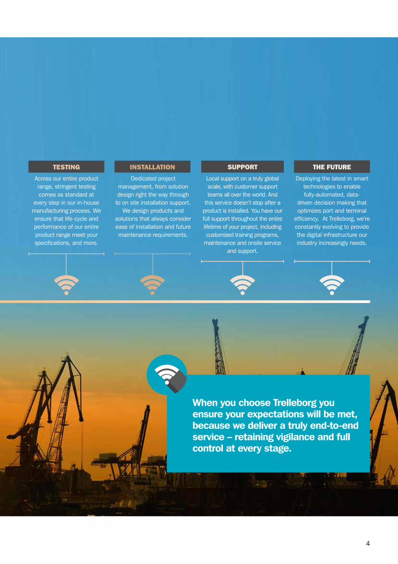
When you choose Trelleborg you ensure your expectations will be met, because we deliver a truly end-to-end service – retaining vigilance and full control at every stage.
Dedicated project management, from solution design right the way through
to on site installation support. we design products and
solutions that always consider ease of installation and future maintenance requirements.
installation
Across our entire product range, stringent testing comes as standard at
every step in our in-house manufacturing process. we ensure that life-cycle and performance of our entire product range meet your specifications, and more.
testinG
Local support on a truly global scale, with customer support teams all over the world. And
this service doesn’t stop after a product is installed. You have our full support throughout the entire lifetime of your project, including customized training programs,
maintenance and onsite service and support.
support
Deploying the latest in smart technologies to enable fully-automated, data-
driven decision making that optimizes port and terminal
efficiency. At Trelleborg, we’re constantly evolving to provide the digital infrastructure our industry increasingly needs.
the future

5
FAcTorS ThAT negATively iMpAcT The coST oF oWnerShip
❙ Exposed berths having to slow or stop transfer operations when metocean conditions or passing ships result in vessel motions outside the guidelines for safe or efficient transfer.
❙ Inefficient mooring operations extending facility downtime and adding overheads for mooring crews, pilotage and tugs.
❙ Unbalanced mooring loads, parting lines and having to stop transfer to tend moorings.
❙ Using tugs to supplement mooring systems during extreme events – passing ship or environmental.
hoW TrelleBorg SolUTionS cAn MiniMiZe ToTAl coST oF oWnerShip AnD iMprove proFiTABiliTy oF porT AnD TerMinAl operATionS
❙ Automated mooring solutions that can dampen vessel motion and extend the range of metocean conditions in which efficient transfer can take place or combat effects from passing ships.
❙ SmartPort turnkey solutions integrating multiple port and terminal subsystems.
❙ confidence that equipment complies with local regulatory requirements, design codes and standards.
❙ class leading structural design to accommodate worst case loading conditions and provide superior integrity for dynamic loading.
❙ global aftersales support network offering total lifecycle management packages, extending asset life and minimizing downtime.
❙ Accredited and best practice quality systems that ensure mooring solutions reliability.
Total CostOf Ownershipwhen considering the selection of docking and mooring equipment, a holistic review of port and terminal operations should be undertaken. This should focus on how docking and mooring solutions can impact or improve facilities ability to transfer product or personnel. A docking and mooring system is far more than just a means to berth and moor a vessel. Like with any business case for investment, when reviewing Total cost of ownership (Tco) of a docking and mooring system, return on investment should be first and foremost in the decision making process.
Proper selection of docking and mooring equipment can greatly reduce facility downtime and improve operational efficiency, safety and ultimately profitability.
Some of the key points that often get overlooked in this review are factors that can negatively impact operations and the solutions that are available. while the initial investment may be higher with a premium solution, the case for return on investment is overwhelming.
6
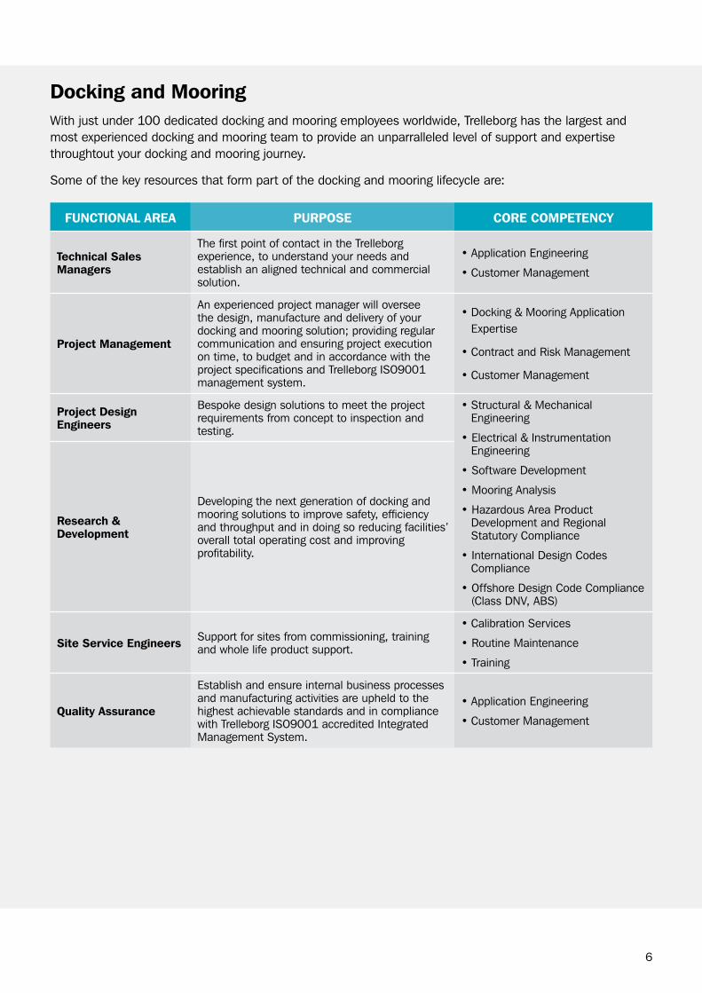
Docking and Mooringwith just under 100 dedicated docking and mooring employees worldwide, Trelleborg has the largest and most experienced docking and mooring team to provide an unparralleled level of support and expertise throughtout your docking and mooring journey.
Some of the key resources that form part of the docking and mooring lifecycle are:
FUncTionAl AreA pUrpoSe core coMpeTency
Technical Sales Managers
The first point of contact in the Trelleborg experience, to understand your needs and establish an aligned technical and commercial solution.
•ApplicationEngineering
•CustomerManagement
project Management
An experienced project manager will oversee the design, manufacture and delivery of your docking and mooring solution; providing regular communication and ensuring project execution on time, to budget and in accordance with the project specifications and Trelleborg ISo9001 management system.
•Docking&MooringApplicationExpertise
•ContractandRiskManagement
•CustomerManagement
project Design engineers
bespoke design solutions to meet the project requirements from concept to inspection and testing.
•Structural&MechanicalEngineering
•Electrical&InstrumentationEngineering
•SoftwareDevelopment
•MooringAnalysis
•HazardousAreaProductDevelopment and regional Statutory compliance
•InternationalDesignCodescompliance
•OffshoreDesignCodeCompliance(class DNV, AbS)
research & Development
Developing the next generation of docking and mooring solutions to improve safety, efficiency and throughput and in doing so reducing facilities’ overall total operating cost and improving profitability.
Site Service engineers Support for sites from commissioning, training and whole life product support.
•CalibrationServices
•RoutineMaintenance
•Training
Quality Assurance
Establish and ensure internal business processes and manufacturing activities are upheld to the highest achievable standards and in compliance with Trelleborg ISo9001 accredited Integrated Management System.
•ApplicationEngineering
•CustomerManagement

7
SummaryApplications
ApplicATion
proDUcT
Qui
ck r
elea
se H
ook
ons
hore
Qui
ck r
elea
se H
ook
off
shor
e
Qui
ck r
elea
se H
ook
Load
mon
itorin
g
Qui
ck r
elea
se H
ook
rem
ote
rele
ase
Free
Sta
ndin
g c
apst
ans
Tugg
er w
inch
es
Auto
Moo
r
Pelic
an (
buo
y) H
ooks
Haw
ser
Hoo
ks
Haw
ser
Load
Mon
itorin
g b
it
cha
in S
topp
ers
Tand
em M
oorin
g w
inch
Doc
king
Sys
tem
s
Envi
ro M
onito
ring
Inte
grat
ed S
yste
ms
LNg carrier berths
oil berths
LPg berths
bulk liquids berths
bulk materials berths
Smale scale mooring
commercial (roro, ferry, container)
cruise terminals
buoy moorings
Tandem Mooring
bow to a Single Point Mooring (SPM)
Spread mooring
(F)LNg and FSrU vessels
offshore berths
Ship-to-ship
bunkering
8
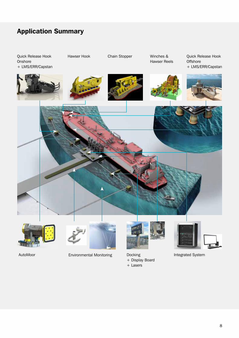
Quick release Hook onshore+ LMS/Err/capstan
AutoMoor Environmental Monitoring Integrated SystemDocking+ Display board+ Lasers
Quick release Hook offshore+ LMS/Err/capstan
Hawser Hook chain Stopper winches & Hawser reels
Application Summary
9
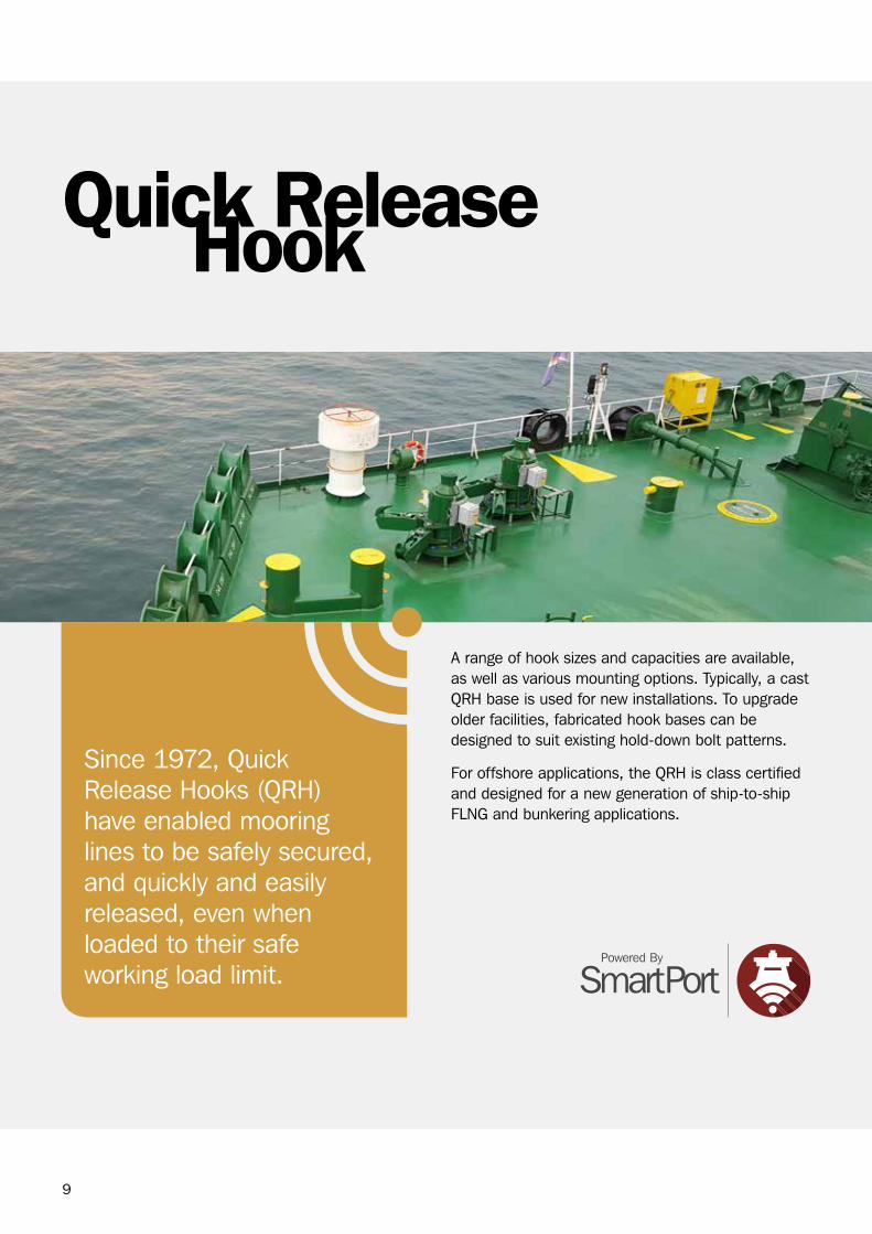
A range of hook sizes and capacities are available, as well as various mounting options. Typically, a cast QrH base is used for new installations. To upgrade older facilities, fabricated hook bases can be designed to suit existing hold-down bolt patterns.
For offshore applications, the QrH is class certified and designed for a new generation of ship-to-ship FLNg and bunkering applications.
HookQuick Release
Since 1972, Quick release Hooks (QrH) have enabled mooring lines to be safely secured, and quickly and easily released, even when loaded to their safe working load limit.

10
FeATUreS
Safe, efficient and reliable mooring operations
options to suit all types of mooring ropes, loading conditions and foundations
Low maintenance option available
Integrated capstan available with speed and power options
Low profile and compact footprint
All hooks individually tested
All hooks can be safely released, even at the hook safe working load (SwL)
compliant with international standards
ApplicATionS
LNg carrier berths
oil berths
LPg berths
bulk liquids berths
bulk materials berths
Small scale mooring
ADD-onS
❙ Low maintenance, dual lock, safety keeper bars and grit guards (refer to page 17)
❙ capstan (refer to page 20)
❙ Load monitoring (refer to page 21)
❙ Hook release (refer to page 23)
❙ Tugger winch (refer to page 27)
❙ Integration with the central monitoring system (refer to page 55)
Qrh onshore Qrh offshoreFeATUreS
Safe, efficient and reliable mooring operations
Low maintenance option available
Integrated capstan available with speed and power options
Low profile, compact footprint and efficient integration with ship deck super structure
All hooks individually tested
All hooks can be safely released, even at the hook safe working load (SwL)
class certificate including DNV, AbS, Lloyds or bV
Stowing place for capstan foot switch to avoid damage due to ship movement
ApplicATionS
Ship-to-ship mooring
Import LNg terminals
Export LNg terminals
offshore ship-to-ship mooring on FLNg bunkering
11
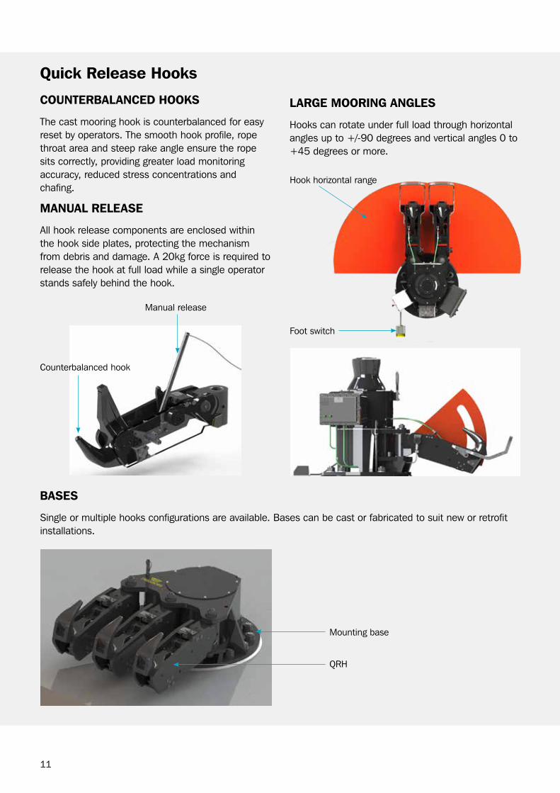
coUnTerBAlAnceD hookS
The cast mooring hook is counterbalanced for easy reset by operators. The smooth hook profile, rope throat area and steep rake angle ensure the rope sits correctly, providing greater load monitoring accuracy, reduced stress concentrations and chafing.
MAnUAl releASe
All hook release components are enclosed within the hook side plates, protecting the mechanism from debris and damage. A 20kg force is required to release the hook at full load while a single operator stands safely behind the hook.
BASeS
Single or multiple hooks configurations are available. bases can be cast or fabricated to suit new or retrofit installations.
Mounting base
QrH
Manual release
counterbalanced hook
Quick release hooks
lArge Mooring AngleS
Hooks can rotate under full load through horizontalangles up to +/-90 degrees and vertical angles 0 to+45 degrees or more.
Foot switch
Hook horizontal range
12
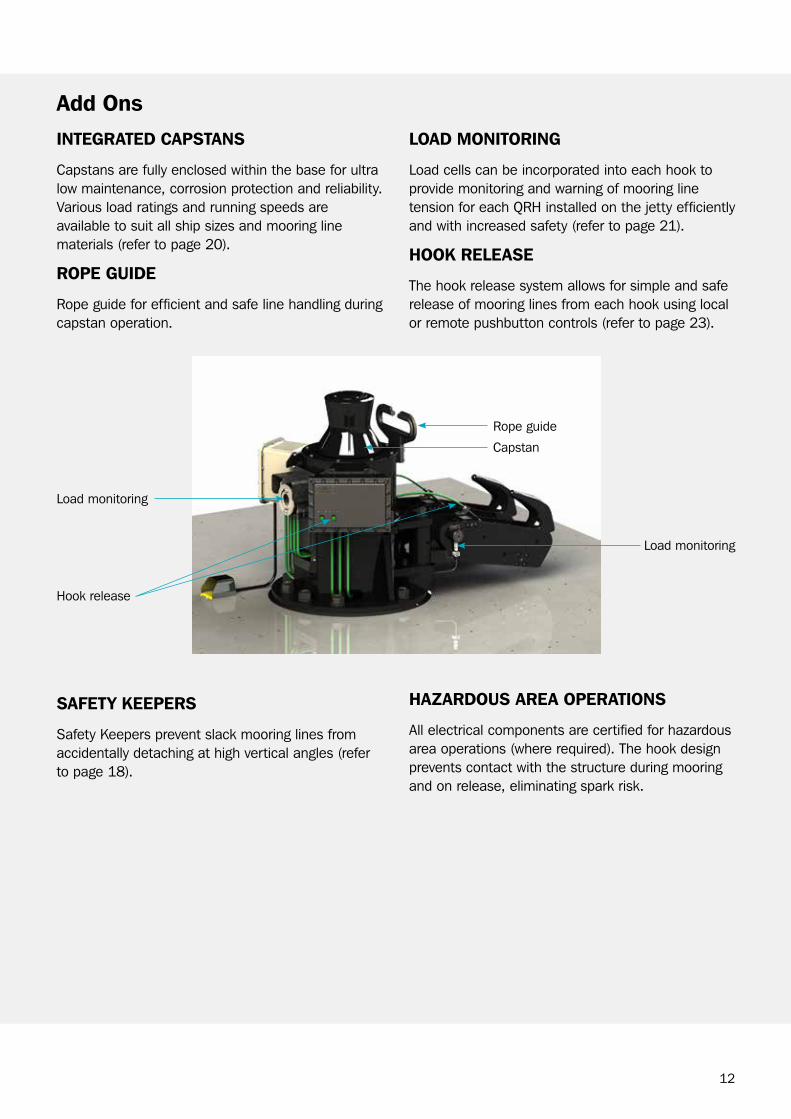
SAFeTy keeperS
Safety Keepers prevent slack mooring lines from accidentally detaching at high vertical angles (refer to page 18).
Add ons
loAD MoniToring
Load cells can be incorporated into each hook to provide monitoring and warning of mooring line tension for each QrH installed on the jetty efficiently and with increased safety (refer to page 21).
hook releASe
The hook release system allows for simple and safe release of mooring lines from each hook using local or remote pushbutton controls (refer to page 23).
capstan
rope guide
Load monitoring
Load monitoring
Hook release
inTegrATeD cApSTAnS
capstans are fully enclosed within the base for ultra low maintenance, corrosion protection and reliability. Various load ratings and running speeds are available to suit all ship sizes and mooring line materials (refer to page 20).
rope gUiDe
rope guide for efficient and safe line handling during capstan operation.
hAZArDoUS AreA operATionS
All electrical components are certified for hazardous area operations (where required). The hook design prevents contact with the structure during mooring and on release, eliminating spark risk.

13
Quick release hook - onshore options
Qrh 50 Series
QUick releASe hook & BASe opTionS SWl (T) inTegrAl cApSTAn
50 Series 50 N/A
60 Series 60 Available
75 Series 75 Available
100 Series 100 Available
125 Series 125 Available
150 Series 150 Available24
035
0
45°
90°90°
45°45°
45°45°
90°90°
350
350
90°90°
45°45°
45°45°
45°45°
45°45°
90°90°
DoUbLE HooK TrIPLE HooK

14
Qrh 60-150 Series
DoUbLE HooKSINgLE HooK
TrIPLE HooK QUADrUPLE HooK

15
Model numbers & Dimensions
MoDel nUMBer
QTyQrh A B c D e F g h i J k l
hDBolTQTy
ShippingMASS
kg
cB45 (SAFe Working loAD = 45 T)
cP45-01 Single 1100 900 2016 530 936 – 1445 246 305 380 1045 1140 4 1450
cP45-02 Double 1100 900 1921 435 936 510 1445 756 305 380 1045 1140 5 1500
cP45-03 Triple 1300 1100 1956 370 936 510 1445 1266 305 380 1045 1140 6 2130
cP45-04 Quad. 1500 1300 2126 430 936 510 1445 1776 305 380 1045 1140 10 2870
cB60 (SAFe Working loAD = 60 T)
cP60-01 Single 1100 900 2016 530 936 – 1445 246 305 380 1045 1140 4 1450
cP60-02 Double 1100 900 1921 435 936 510 1445 756 305 380 1045 1140 5 1500
cP60-03 Triple 1300 1100 1956 370 936 510 1445 1266 305 380 1045 1140 8 2130
cP60-04 Quad. 1500 1300 2126 430 936 510 1445 1776 305 380 1045 1140 10 2870
cB75 (SAFe Working loAD = 75 T)
cP75-01 Single 1100 900 2016 530 936 – 1445 246 305 380 1045 1140 4 1450
cP75-02 Double 1100 900 1921 435 936 510 1445 756 305 380 1045 1140 5 1500
cP75-03 Triple 1300 1100 1956 370 936 510 1445 1266 305 380 1045 1140 8 2130
cP75-04 Quad. 1500 1300 2126 430 936 510 1445 1776 305 380 1045 1140 10 2870
cB100 (SAFe Working loAD = 100 T)
cP100-01 Single 1100 900 2127 530 1047 – 1445 262 305 385 1045 1260 4 1530
cP100-02 Double 1100 900 2032 435 1047 510 1445 772 305 385 1045 1260 7 1600
cP100-03 Triple 1300 1100 2067 370 1047 510 1445 1282 305 385 1045 1260 10 2280
cP100-04 Quad. 1500 1300 2237 430 1047 510 1445 1792 305 385 1045 1260 14 3070
cB125 (SAFe Working loAD = 125 T)
cP125-01 Single 1100 900 2126 530 1046 – 1445 262 305 385 1045 1260 7 1700
cP125-02 Double 1200 1000 2081 435 1046 510 1445 772 305 385 1045 1260 11 1840
cP125-03 Triple 1300 1100 2066 370 1046 510 1445 1282 305 385 1045 1260 14 2460
cP125-04 Quad. 1650 1450 2324 440 1046 510 1445 1792 305 385 1045 1260 14 3370
cB150r (SAFe Working loAD = 150 T)
cP150r-01 Single 1100 900 2126 530 1046 – 1445 262 305 385 1045 1260 7 1700
cP150r-02 Double 1200 1000 2081 435 1046 510 1445 772 305 385 1045 1260 11 1840
cP150r-03 Triple 1300 1100 2066 370 1046 510 1445 1282 305 385 1045 1260 14 2460
cP150r-04 Quad. 1650 1450 2324 440 1046 510 1445 1792 305 385 1045 1260 14 3370
cp200 (SAFe Working loAD = 200 T)
Dimensions available upon request
note 1 : Dimensions are in mm.note 2 : Dimensions are typical. Always request a certified hook/base drawing before starting construction.note 3 : customized bases to suit bolt patterns are available upon request.note 4 : Shipping mass includes base, capstan, hold down bolts and packing. Mass is for indication only.

16
note 1 : closed chock height set to ensure mooring rope eye passes through at 0º.note 2 : M56 Studs grade 8.8 full screw thread into foundation plate and seal welded. Foundation plate flatness to be 1 to 500 ratio.note 3 : Set back of QrH to ensure mooring rope eye is fully clear & inboard of closed chock.note 4 : consider deck camber & ensure foundation plate is installed level.
Quick release hook - offshore options
G
N
H
I
L
YARD SUPPLYU.O.N
TRELLEBORGSUPPLY
VERTICALFLEET ANGLE CLOSED CHOCK
BY OTHERSU.O.N
F
A
D E
B
C
M
HORIZONTALFLEET ANGLE
M
G
H
N
I
L
YARD SUPPLYU.O.N
TRELLEBORGSUPPLY
CLOSED CHOCKBY OTHERS
U.O.N
VERTICAL FLEET ANGLE
F
A F
B
E D C
HORIZONTALFLEET ANGLE
M
G
N
H
I
L
VERTICALFLEET ANGLE CLOSED CHOCK
BY OTHERSU.O.N
D E
A
B
C
M
YARD SUPPLYU.O.N
TRELLEBORGSUPPLY
HORIZONTALFLEET ANGLE
DoUbLE HooK
SINgLE HooK
TrIPLE HooK
BASe ØAØB
pcDc D e F g h Øi J l M n
hD BolT (QTy)
ApproX MASS
STS137F-01 1120 940 2080 470 1060 NA 1515 40 305 380
See Note
1
See Note
2
See Note
3
4 1385
STS137F-02 1100 920 2025 415 1060 430 1515 40 305 380 6 1860
STS137F-03 1250 1080 2190 540 1060 420 1515 40 305 380 10 2535
STS150F-01 1120 940 2116 470 1060 NA 1515 40 305 380 4 1440
STS150F-02 1280 1100 2062 415 1060 430 1515 40 305 380 10 2135
STS150F-03 1400 1220 2247 600 1060 420 1515 40 305 380 12 3020
17
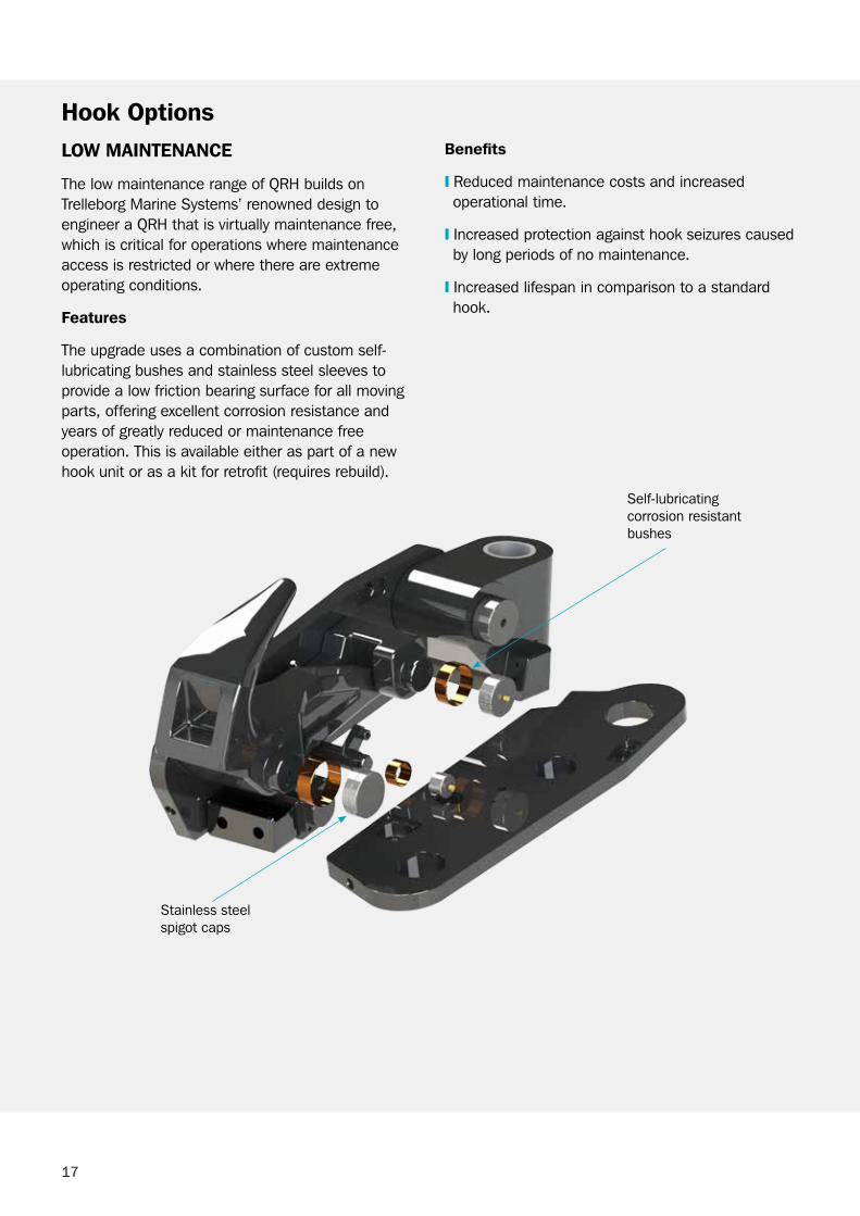
hook optionsloW MAinTenAnce
The low maintenance range of QrH builds on Trelleborg Marine Systems’ renowned design to engineer a QrH that is virtually maintenance free, which is critical for operations where maintenance access is restricted or where there are extreme operating conditions.
Features
The upgrade uses a combination of custom self-lubricating bushes and stainless steel sleeves to provide a low friction bearing surface for all moving parts, offering excellent corrosion resistance and years of greatly reduced or maintenance free operation. This is available either as part of a new hook unit or as a kit for retrofit (requires rebuild).
Self-lubricating corrosion resistant bushes
Stainless steel spigot caps
Benefits
❙ reduced maintenance costs and increased operational time.
❙ Increased protection against hook seizures caused by long periods of no maintenance.
❙ Increased lifespan in comparison to a standard hook.
18
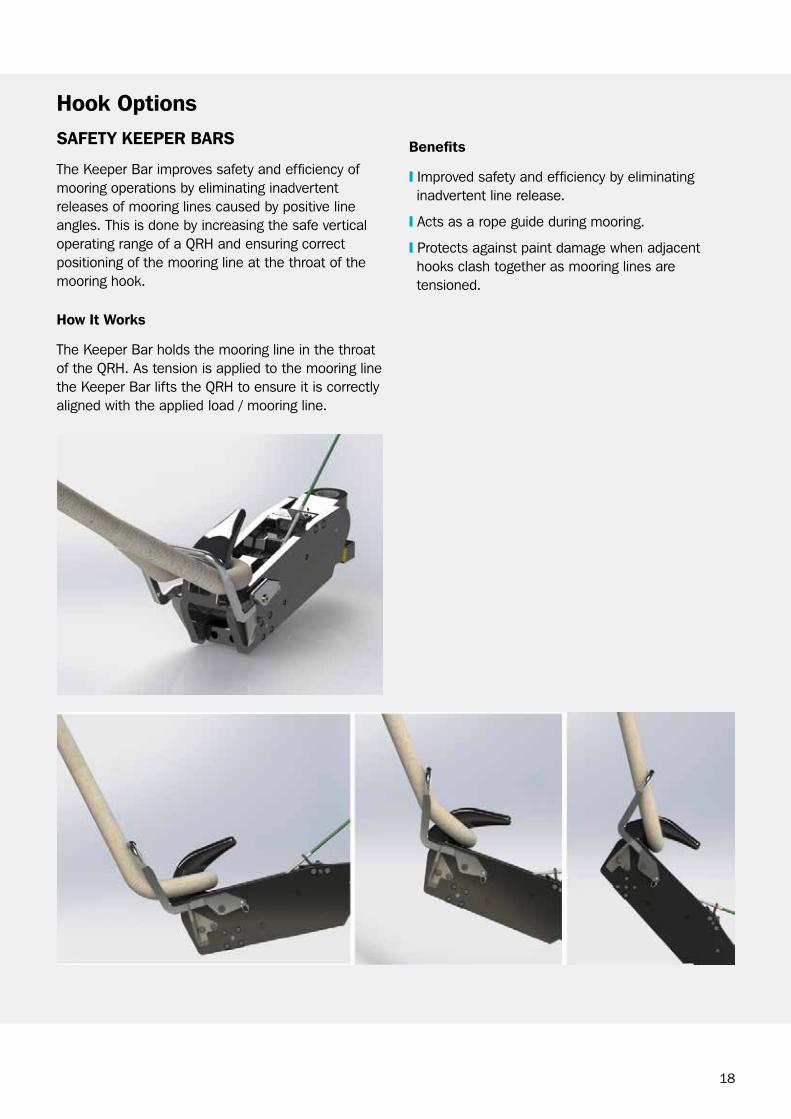
hook optionsSAFeTy keeper BArS
The Keeper bar improves safety and efficiency of mooring operations by eliminating inadvertent releases of mooring lines caused by positive line angles. This is done by increasing the safe vertical operating range of a QrH and ensuring correct positioning of the mooring line at the throat of the mooring hook.
Benefits
❙ Improved safety and efficiency by eliminating inadvertent line release.
❙ Acts as a rope guide during mooring.
❙ Protects against paint damage when adjacent hooks clash together as mooring lines are tensioned.
how it Works
The Keeper bar holds the mooring line in the throat of the QrH. As tension is applied to the mooring line the Keeper bar lifts the QrH to ensure it is correctly aligned with the applied load / mooring line.

19
DUAl lock
The dual lock QrH provides a robust solution to increase plant safety for bulk material terminals. These terminals are subject to an environment with airbourne particulate matter which can deposit on the locking mechanism of a conventional QrH, jeopardizing safety.
without regular maintenance and careful operational checks, such deposits can result in a QrH being set in a “hair trigger” position. often, busy shipping schedules leave little time for maintenance and correct operation of the hook is reliant on the training and diligence of the operator.
The dual lock QrH utilizes a secondary locking latch that engages with the primary locking mechanism of the QrH. The system can be provided as a manual only option or fully integrated into Trelleborg Electric remote release System. An upgrade kit can also be provided for retrofit to existing hooks.
griT gUArD
In bulk material terminals, especially iron ore, dirt may accumulate over the QrH mechanism which requires more frequent maintenance.
The grit guard is fitted on the hook to prevent dirt build up and reduce the maintenance frequency without obstruction to normal operation.
hook options
Secondary locking mechanism
Failsafe visual “Locked” indication
Manual override feature in case of loss of power
Electric actuator for integration with remote release
20
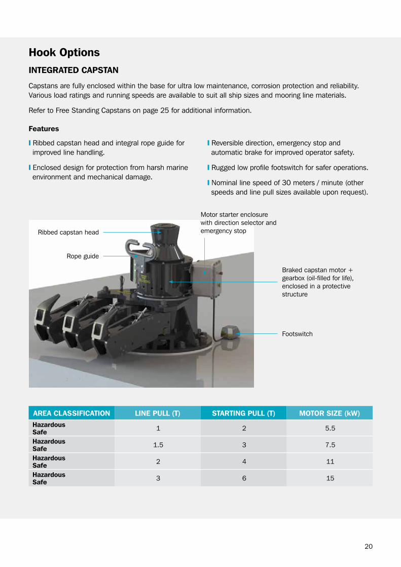
inTegrATeD cApSTAn
capstans are fully enclosed within the base for ultra low maintenance, corrosion protection and reliability. Various load ratings and running speeds are available to suit all ship sizes and mooring line materials.
refer to Free Standing capstans on page 25 for additional information.
hook options
Features
❙ ribbed capstan head and integral rope guide for improved line handling.
❙ Enclosed design for protection from harsh marine environment and mechanical damage.
❙ reversible direction, emergency stop and automatic brake for improved operator safety.
❙ rugged low profile footswitch for safer operations.
❙ Nominal line speed of 30 meters / minute (other speeds and line pull sizes available upon request).
AreA clASSiFicATion line pUll (T) STArTing pUll (T) MoTor SiZe (kW)hazardous Safe 1 2 5.5
hazardous Safe 1.5 3 7.5
hazardous Safe 2 4 11
hazardous Safe 3 6 15
Footswitch
rope guide
Motor starter enclosure with direction selector and emergency stop
braked capstan motor + gearbox (oil-filled for life), enclosed in a protective structure
ribbed capstan head

21
load Monitoring Systemsoperating autonomously, or integrated with a central monitoring system, the Trelleborg SmartHook load monitoring system enables safe mooring and efficient line handling by providing real-time mooring line tension and alarm warning.
The Trelleborg load cell located in the QrH integrates seamlessly with the SmartHook on the QrH base. Local processing is then done before this data is sent to the central monitoring system; this also enables control of warning lights and sirens on the dolphin without a connection to a central monitoring system.
SMArThook
The SmartHook reads the calibration data stored in the load cell and uses this to calculate the mooring tension. A local display allows the mooring crew to quickly and easily see the current tension on the mooring rope. Alarms are also generated from the SmartHook and this can be connected to a warning light and siren to alert the ship’s crew.
Load cells Max of 4 load cells connected per SmartHook
communications output rS 485 Modbus rTU
LcD Display Information Hook load, error information and alarm status
Area classification Hazardous or non-hazardous
IP rating IP66
FeATUreS
❙ real-time monitoring of mooring tension
❙ Local processing and calculation of loads
❙ Autonomous operation
❙ calibration data stored in load cell
❙ Logging of mooring tension (if connected to a central monitoring system)
SmartHook
Load cell

22
load Monitoring SystemsloAD cell
Each load cell is manufactured from high quality stainless steel and load tested up to 150% of the safe working load (SwL). calibration data is stored inside the load cell enabling load cells to be placed in any hook anywhere on the jetty.
WArning lighT AnD Siren
The warning light and siren can be connected to the SmartHook to allow audible and visual indication of an alarm condition.
calibrated range 0 to SwL (T)
Accuracy ±2%
Material grade 431 or 630 stainless steel
Area classification
Hazardous or non-hazardous
IP rating IP66
23
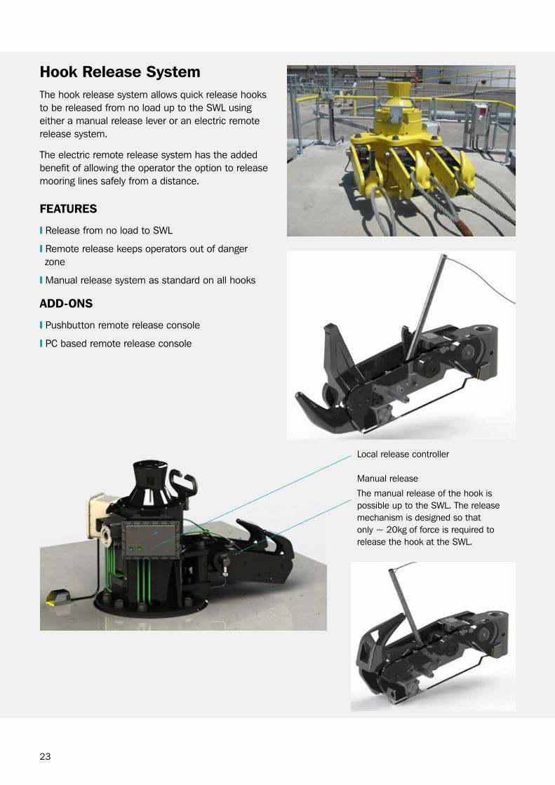
hook release SystemThe hook release system allows quick release hooks to be released from no load up to the SwL using either a manual release lever or an electric remote release system.
The electric remote release system has the added benefit of allowing the operator the option to release mooring lines safely from a distance.
FeATUreS
❙ release from no load to SwL
❙ remote release keeps operators out of danger zone
❙ Manual release system as standard on all hooks
ADD-onS
❙ Pushbutton remote release console
❙ Pc based remote release console
Local release controller
Manual release
The manual release of the hook is possible up to the SwL. The release mechanism is designed so that only ~ 20kg of force is required to release the hook at the SwL.
24
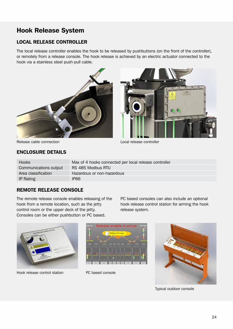
locAl releASe conTroller
The local release controller enables the hook to be released by pushbuttons (on the front of the controller), or remotely from a release console. The hook release is achieved by an electric actuator connected to the hook via a stainless steel push-pull cable.
hook release System
encloSUre DeTAilS
Hooks Max of 4 hooks connected per local release controllercommunications output rS 485 Modbus rTUArea classification Hazardous or non-hazardousIP rating IP66
release cable connection Local release controller
The remote release console enables releasing of the hook from a remote location, such as the jetty control room or the upper deck of the jetty. consoles can be either pushbutton or Pc based.
Typical outdoor console
Pc based consoleHook release control station
Pc based consoles can also include an optional hook release control station for arming the hook release system.
reMoTe releASe conSole

25
FeATUreSribbed capstan head and integral rope guide for improved line handling
Enclosed design for protection from harsh marine environment and mechanical damage
reversible direction, Emergency Stop and automatic brake for improved operator safety
rugged low profile footswitch for safer operations
ApplicATionSLNg carrier berths
oil berths
LPg berths
bulk liquids berths
bulk materials berths
commercial (roro, ferry, container)
CapstansFree Standing
Trelleborg’s free standing capstans provide a field proven, safe and reliable method of hauling in the mooring line alleviating the need for mooring crews to haul in the lines manually.
26
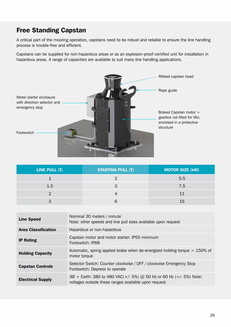
A critical part of the mooring operation, capstans need to be robust and reliable to ensure the line handling process is trouble-free and efficient.
capstans can be supplied for non-hazardous areas or as an explosion-proof certified unit for installation in hazardous areas. A range of capacities are available to suit many line handling applications.
line pUll (T) STArTing pUll (T) MoTor SiZe (kW)
1 2 5.5
1.5 3 7.5
2 4 11
3 6 15
line SpeedNominal 30 meters / minute Note: other speeds and line pull sizes available upon request
Area classification Hazardous or non-hazardous
ip ratingcapstan motor and motor starter: IP55 minimumFootswitch: IP68
holding capacityAutomatic, spring applied brake when de-energized holding torque > 150% of motor torque
capstan controlsSelector Switch: counter clockwise / oFF / clockwise Emergency Stop Footswitch: Depress to operate
electrical Supply3Ø + Earth: 380 to 480 VAc(+/- 5%) @ 50 Hz or 60 Hz (+/- 5%) Note: voltages outside these ranges available upon request
Free Standing capstan
rope guide
braked capstan motor + gearbox (oil-filled for life), enclosed in a protective structure
Footswitch
Motor starter enclosure with direction selector and emergency stop
ribbed capstan head
27
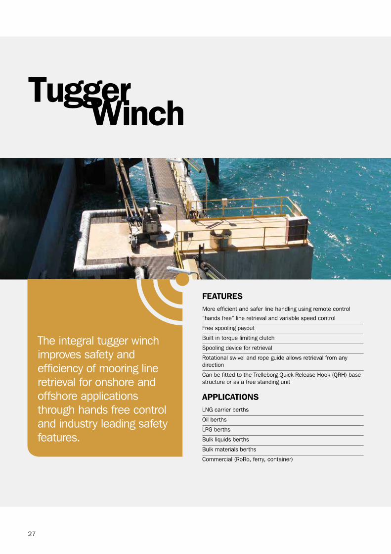
The integral tugger winch improves safety and efficiency of mooring line retrieval for onshore and offshore applications through hands free control and industry leading safety features.
WinchTugger
FeATUreSMore efficient and safer line handling using remote control
“hands free” line retrieval and variable speed control
Free spooling payout
built in torque limiting clutch
Spooling device for retrieval
rotational swivel and rope guide allows retrieval from any direction
can be fitted to the Trelleborg Quick release Hook (QrH) base structure or as a free standing unit
ApplicATionSLNg carrier berths
oil berths
LPg berths
bulk liquids berths
bulk materials berths
commercial (roro, ferry, container)

28
line pull Typically 1000kg (Torque limited)
line SpeedPay out : Free spooling to match ship’s winch or line boat Pay In : Variable speed from 10 - 45m/min
Area classification Hazardous or non-hazardous
ip rating IP 66
holding capacityAutomatic, spring applied brake when de-energized holding torque > 150% of motor torque
Drum capacity 120m of 14mm Dyneema (HMPE) rope
Tugger Winch controls Joystick Direction and Speed – payout / off / retrieve, Emergency Stop
electrical Supply3Ø + Earth: 380 to 480 VAc(+/- 5%) @ 50 Hz or 60 Hz (+/- 5%) Note: voltages outside these ranges available upon request
Tugger Winch
rope guide
Local control stand
capstan head
Spooling device

29
Make your berthing operations smarter, safer and more efficient with AutoMoor from Trelleborg.Many ports and terminals are looking towards automated technologies to cope with increased demand and to compete safely and effectively.
AutoMoor is a rope-free, automated mooring system designed to improve operational efficiency and safety using the latest vacuum and passive damping technologies to rapidly attach to and secure a vessel at berth, optimizing the window for product transfer in a broader range of environmental conditions.
AutoMoor
FeATUreSrope-free vacuum mooring
Faster berthing operations
Patent-pending, passive damping system to reduce vessel motions
Patent-pending electro-mechanical drive system for pad extension and retraction
operates with low power consumption and duty cycle
Delivers greater control by displaying mooring loads and unit operating conditions continuously
SmartPort enabled to allow integration with other port control systems
Three control interfaces provided: ❙ wireless Handheld ❙ Port control Pc ❙ Mooring Machine Pc
Suitable for hazardous area operations
rotating base allows all maintenance to be undertaken onshore
Self-contained units, with all motors, mechanisms and control systems located within – no external auxiliary items
ApplicATionScontainer Terminals
bulk Liquids berths
bulk Materials berths
Ferry / roro Terminals
cruise Terminals

30
ADD-onS❙ Hybrid Mooring - combinations of AutoMoor with conventional mooring equipment
❙ Adaptive Mooring - Using SmartPort to connect assets such as environmental monitoring or vessel traffic systems to AutoMoor to enable adaptive mooring decisions to be made
❙ cold climate version available
❙ SafePilot piloting systems, for navigation of the ship into the berth and information from the AutoMoor units
AutoMoor
Drive motor to dynamically adjust the pad position to provide greater reach
comparison of vessel movement moored with conventional equipment versus AutoMoor using cFD mooring analysis software
Passive damping to restrain ship movement
Vacuum systemVacuum pad for ship connection
control system
SUrge
heAve
AutoMoor off AutoMoor on
Translation
Met
er
5
4
3
2
1
0
-1
-2
-3
-4
0 200 400 600 800 1000 1200 1400 1600 Physical Time (s)
Translation – Y Monitor: Translation – Y Monitor (m)
Translation – Z Monitor: Translation – Z Monitor (m)Translation – X Monitor: Translation – X Monitor (m)
31
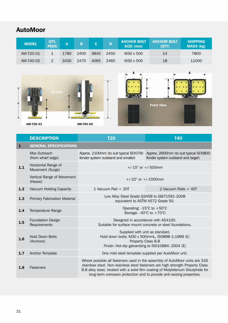
AutoMoor
MoDel QTy. pADS A B c D Anchor BolT
SiZe (mm)Anchor BolT
(QTy)Shipping MASS (kg)
AM-T20-01 1 1780 2400 3845 2450 M30 x 500 14 7800
AM-T40-02 2 3430 2470 4065 2465 M30 x 500 18 11000
DeScripTion T20 T40
1 generAl SpeciFicATionS
1.1
Max outreach(from wharf edge)
Approx. 2100mm (to suit typical ScN700 fender system outstand and smaller)
Approx. 2600mm (to suit typical ScN800 fender system outstand and larger)
Horizontal range of Movement (Surge) +/-15° or +/-500mm
Vertical range of Movement (Heave) +/-22° or +/-1000mm
1.2 Vacuum Holding capacity 1 Vacuum Pad = 20T 2 Vacuum Pads = 40T
1.3 Primary Fabrication Material Low Alloy Steel grade Q345b to gb/T1591-2008 equivalent to ASTM A572 grade 50.
1.4 Temperature range operating: -15°c to +50°cStorage: -40°c to +70°c
1.5Foundation Design requirements
Designed in accordance with AS4100.Suitable for surface mount concrete or steel foundations.
1.6Hold Down bolts(Anchors)
Supplied with unit as standard.Hold down bolts: M30 x 500mmL, ISo898-1:1999 (E)
Property class 8.8Finish: Hot-dip galvanizing to ISo10684: 2004 (E)
1.7 Anchor Template one mild steel template supplied per AutoMoor unit.
1.8 Fasteners
where possible all fasteners used in the assembly of AutoMoor units are 316 stainless steel. Non-stainless steel fasteners are high strength Property class 8.8 alloy steel, treated with a solid-film coating of Molybdenum Disulphide for
long-term corrosion protection and to provide anti-seizing properties.
c
D
BB
D
c
AM-Tv20-01 AM-Tv40-02
Top view
Front view
AM-T20-01 AM-T40-02
32
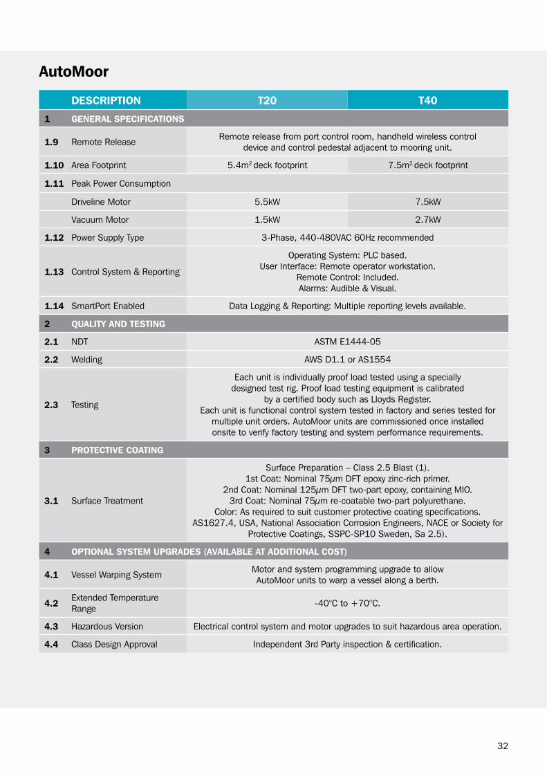
AutoMoor
Description t20 t40
1 GenerAl specificAtions
1.9 Remote Release Remote release from port control room, handheld wireless control device and control pedestal adjacent to mooring unit.
1.10 Area Footprint 5.4m2 deck footprint 7.5m2 deck footprint
1.11 Peak Power Consumption
Driveline Motor 5.5kW 7.5kW
Vacuum Motor 1.5kW 2.7kW
1.12 Power Supply Type 3-Phase, 440-480VAC 60Hz recommended
1.13 Control System & Reporting
Operating System: PLC based.User Interface: Remote operator workstation.
Remote Control: Included.Alarms: Audible & Visual.
1.14 SmartPort Enabled Data Logging & Reporting: Multiple reporting levels available.
2 QuAlity AnD testinG
2.1 NDT ASTM E1444-05
2.2 Welding AWS D1.1 or AS1554
2.3 Testing
Each unit is individually proof load tested using a specially designed test rig. Proof load testing equipment is calibrated
by a certified body such as Lloyds Register.Each unit is functional control system tested in factory and series tested for
multiple unit orders. AutoMoor units are commissioned once installed onsite to verify factory testing and system performance requirements.
3 protective coAtinG
3.1 Surface Treatment
Surface Preparation – Class 2.5 Blast (1).1st Coat: Nominal 75μm DFT epoxy zinc-rich primer.
2nd Coat: Nominal 125μm DFT two-part epoxy, containing MIO.3rd Coat: Nominal 75μm re-coatable two-part polyurethane.
Color: As required to suit customer protective coating specifications.AS1627.4, USA, National Association Corrosion Engineers, NACE or Society for
Protective Coatings, SSPC-SP10 Sweden, Sa 2.5).
4 optionAl systeM upGrADes (AvAilAble At ADDitionAl cost)
4.1 Vessel Warping System Motor and system programming upgrade to allow AutoMoor units to warp a vessel along a berth.
4.2Extended Temperature Range -40°C to +70°C.
4.3 Hazardous Version Electrical control system and motor upgrades to suit hazardous area operation.
4.4 Class Design Approval Independent 3rd Party inspection & certification.

33
FeATUreSSafe working Load (SwL) up to 120 T
Accommodates a wide range of mooring rope sizes and types (nylon and steel rope)
Simple single pin connection to buoy
Able to release hawser, under no load, alongside the buoy
ApplicATionSbuoy Moorings
HookPelican
Trelleborg’s Pelican Hook is a universal buoy hook used to moor vessels to single point mooring buoys.

34
MoDel nUMBer
lengTh (l) mm
WiDTh (W) mm
heighT(h) mm
MoUnTing pin DiA (A)
mm
MAX. SWl (T) MAX. pl (T) Shipping
MASS (kg)
bH120-89 1200 210 580 89 120 120 215
bH120-115 1200 210 580 115 120 120 215
pelican hook
Mooring rope - suitable for sizes upto Ø100mm
Manual release – use a lanyard when the hook is under no load
Mounting - connected to buoy with single pin (Ø89 or Ø115).
L 1200 mm
H 580 mm
w
Ø A

35
Trelleborg’s Hawser Hooks have been installed in over 100 FPSo facilities for tandem mooring or bow mooring during offloading.
FeATUreSSafe, efficient and reliable mooring operations
Low profile and compact footprint
Load monitoring & high load warning system designed for ship board operation
Emergency release, local or remote release from the cargo control room (ccr) panel
Designed in accordance with ocIMF recommendations for Equipment Employed in the bow Mooring of conventional Tankers at Single Point Moorings 4th Edition and ocIMF Tandem Mooring and offloading guidelines for conventional Tankers at F(P)So Facilities 1st Edition
class Approval to DNV, AbS, bV, Lloyds or rINA as applicable
ApplicATionSTandem mooring
bow mooring to a Single Point Mooring (SPM)
HooksHawser

36
ADD-onS
❙ Hawser roller fairlead
❙ bedding plate
MoDel nUMBer
lengTh (l) mm
WiDTh (W) mm
heighT(h) mm
heighTTo chAin
cenTreline(A) mm
MAX. SAFeWorking loAD (T)
MAX. prooF
loAD (T)
hD BolTQTy
Shipping MASS (kg)
H580 1560 560 540 440 250 313 14 x M42 950
H850 1790 680 540 580 350 550 14 x M56 1650
chain Angles between chock and hook
Horizontal Plane: +/- 5º of centreline Vertical Plane: 0 to + 5º above centreline.
Mooring connectionThe Hawser Hooks will accept an ocIMF standard (open) end link of 76mm chafe chain. Type A or b as per ocIMF MEg3.
Area classification Hazardous
ip rating IP66
local control UnitDisplay of hook load, error information & alarm status.Pushbutton control to release the hawser unit.
hydraulic power pack For release system, located below deck in safe area.
❙ Load monitoring and remote release system located in the ccr (refer to page 21)
❙ Trelleborg’s horizontal or vertical drum hawser winches (refer to page 41)
hawser hooks
Integrated load cellImpact blocks to prevent sparking during release
Integrated bedding plate
l
W
hA
37
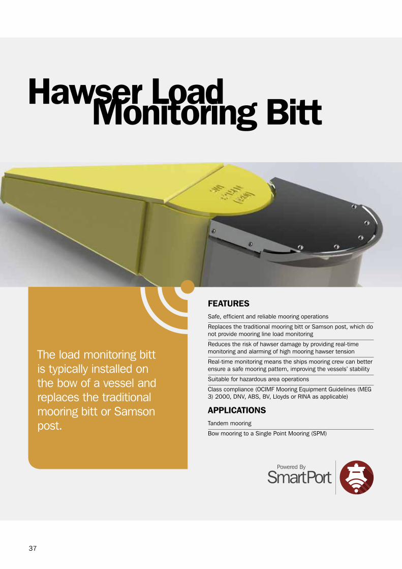
Monitoring BittHawser Load
FeATUreSSafe, efficient and reliable mooring operations
replaces the traditional mooring bitt or Samson post, which do not provide mooring line load monitoring
reduces the risk of hawser damage by providing real-time monitoring and alarming of high mooring hawser tension
real-time monitoring means the ships mooring crew can better ensure a safe mooring pattern, improving the vessels’ stability
Suitable for hazardous area operations
class compliance (ocIMF Mooring Equipment guidelines (MEg 3) 2000, DNV, AbS, bV, Lloyds or rINA as applicable)
ApplicATionSTandem mooring
bow mooring to a Single Point Mooring (SPM)
The load monitoring bitt is typically installed on the bow of a vessel and replaces the traditional mooring bitt or Samson post.
38
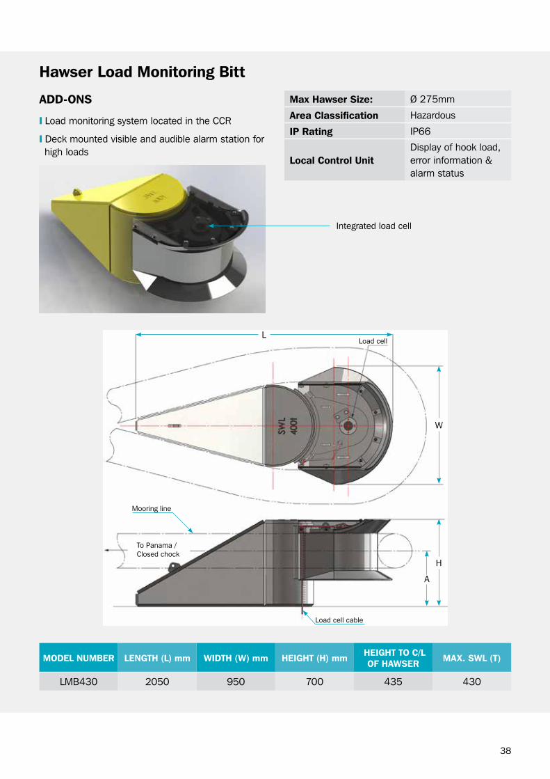
Integrated load cell
L
w
H
A
Load cell
Load cell cable
Mooring line
To Panama / closed chock
ADD-onS
❙ Load monitoring system located in the ccr
❙ Deck mounted visible and audible alarm station for high loads
Max hawser Size: Ø 275mm
Area classification Hazardous
ip rating IP66
local control UnitDisplay of hook load, error information & alarm status
hawser load Monitoring Bitt
MoDel nUMBer lengTh (l) mm WiDTh (W) mm heighT (h) mm heighT To c/l oF hAWSer MAX. SWl (T)
LMb430 2050 950 700 435 430

39
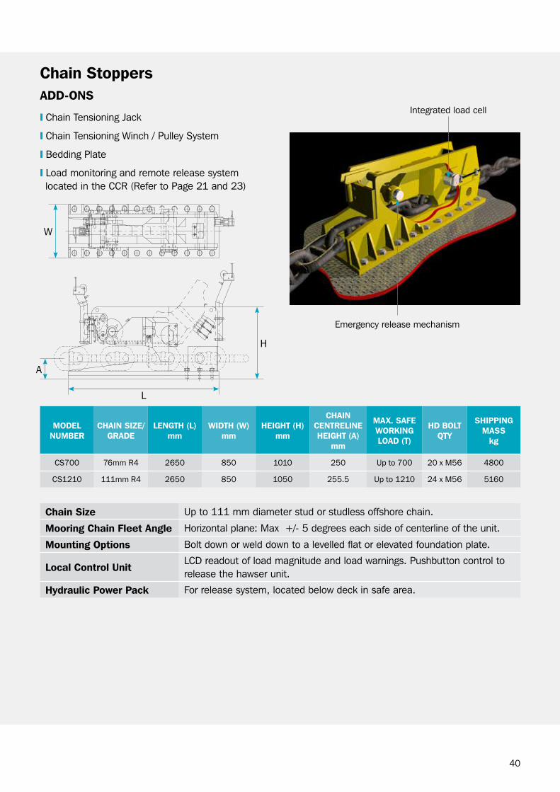
StoppersChain
FeATUreSSafe, efficient and reliable mooring operations
Low profile and compact footprint
releaseable from zero and up to the Safe working Load (SwL)
Load monitoring & high load warning system designed for ship board operation
Emergency release, local or remote release from the cargo control room (ccr) panel
Designed in accordance with ocIMF recommendations for Equipment Employed in the bow Mooring of conventional Tankers at Single Point Moorings 4th Edition and ocIMF Tandem Mooring and offloading guidelines for conventional Tankers at F(P)So Facilities 1st Edition
class Approval to DNV, AbS, bV, Lloyds or rINA as applicable
ApplicATionSbow mooring
Single point mooring
Spread mooring
Deck mounted chain stoppers to 1,210 T for bow or spread mooring applications where emergency release under load and load monitoring functionality is required.
40
chain Size Up to 111 mm diameter stud or studless offshore chain.
Mooring chain Fleet Angle Horizontal plane: Max +/- 5 degrees each side of centerline of the unit.
Mounting options bolt down or weld down to a levelled flat or elevated foundation plate.
local control UnitLcD readout of load magnitude and load warnings. Pushbutton control to release the hawser unit.
hydraulic power pack For release system, located below deck in safe area.
chain StoppersADD-onS
❙ chain Tensioning Jack
❙ chain Tensioning winch / Pulley System
❙ bedding Plate
❙ Load monitoring and remote release system located in the ccr (refer to Page 21 and 23)
MoDelnUMBer
chAin SiZe/grADe
lengTh (l)mm
WiDTh (W)mm
heighT (h)mm
chAincenTrelineheighT (A)
mm
MAX. SAFeWorkingloAD (T)
hD BolTQTy
ShippingMASS
kg
CS700 76mm R4 2650 850 1010 250 Up to 700 20 x M56 4800
CS1210 111mm R4 2650 850 1050 255.5 Up to 1210 24 x M56 5160
Integrated load cell
Emergency release mechanism
w
H
L
A
41
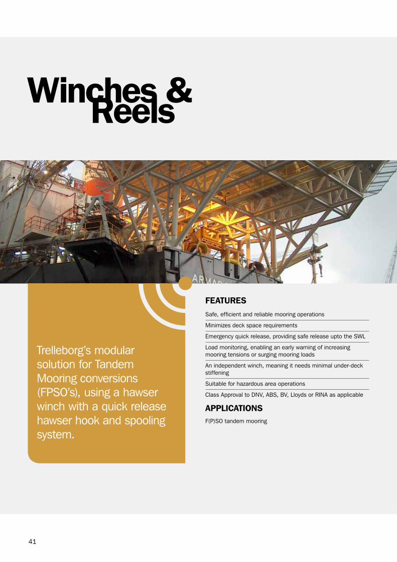
ReelsWinches &
FeATUreSSafe, efficient and reliable mooring operations
Minimizes deck space requirements
Emergency quick release, providing safe release upto the SwL
Load monitoring, enabling an early warning of increasing mooring tensions or surging mooring loads
An independent winch, meaning it needs minimal under-deck stiffening
Suitable for hazardous area operations
class Approval to DNV, AbS, bV, Lloyds or rINA as applicable
ApplicATionSF(P)So tandem mooring
Trelleborg’s modular solution for Tandem Mooring conversions (FPSo’s), using a hawser winch with a quick release hawser hook and spooling system.

42
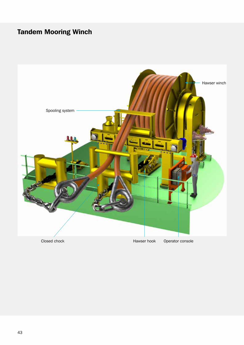
Tandem Mooring Winch
43
Tandem Mooring Winch
closed chock Hawser hook operator console
Hawser winch
Spooling system
44
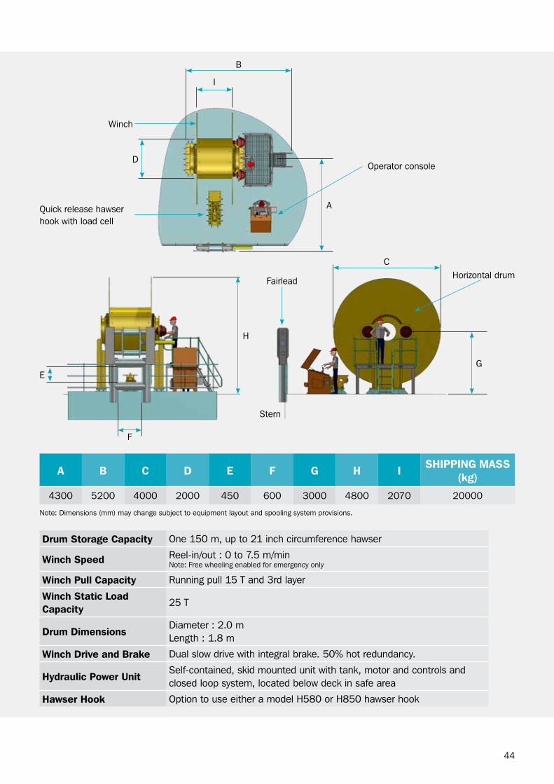
Drum Storage capacity one 150 m, up to 21 inch circumference hawser
Winch Speed reel-in/out : 0 to 7.5 m/minNote: Free wheeling enabled for emergency only
Winch pull capacity running pull 15 T and 3rd layer
Winch Static load capacity
25 T
Drum DimensionsDiameter : 2.0 mLength : 1.8 m
Winch Drive and Brake Dual slow drive with integral brake. 50% hot redundancy.
hydraulic power UnitSelf-contained, skid mounted unit with tank, motor and controls and closed loop system, located below deck in safe area
hawser hook option to use either a model H580 or H850 hawser hook
operator console
Horizontal drumFairlead
Stern
winch
Quick release hawser hook with load cell
Note: Dimensions (mm) may change subject to equipment layout and spooling system provisions.
A B c D e F g h i Shipping MASS (kg)
4300 5200 4000 2000 450 600 3000 4800 2070 20000
I
b
c
D
A
H
g
F
E
45
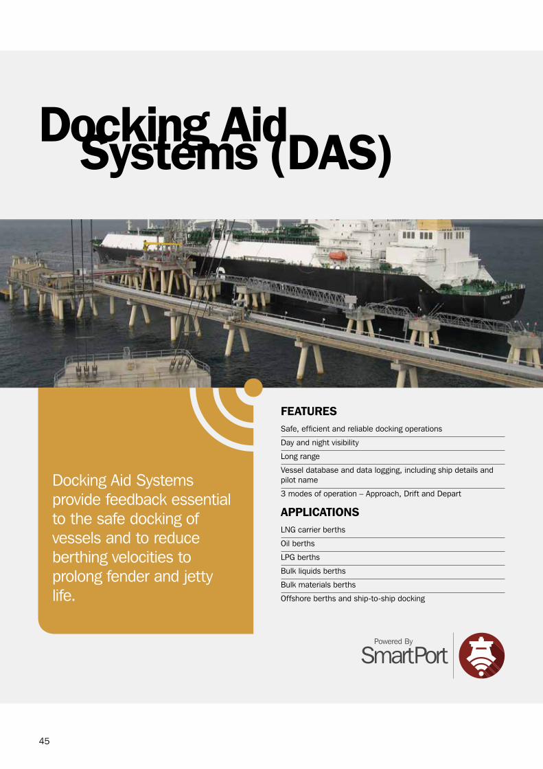
FeATUreSSafe, efficient and reliable docking operations
Day and night visibility
Long range
Vessel database and data logging, including ship details and pilot name
3 modes of operation – Approach, Drift and Depart
ApplicATionSLNg carrier berths
oil berths
LPg berths
bulk liquids berths
bulk materials berths
offshore berths and ship-to-ship docking
Systems (DAS)Docking Aid
Docking Aid Systems provide feedback essential to the safe docking of vessels and to reduce berthing velocities to prolong fender and jetty life.
46
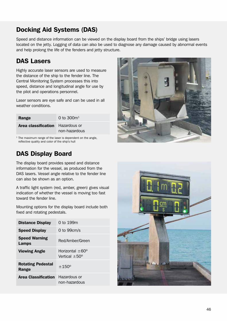
Speed and distance information can be viewed on the display board from the ships’ bridge using lasers located on the jetty. Logging of data can also be used to diagnose any damage caused by abnormal events and help prolong the life of the fenders and jetty structure.
Docking Aid Systems (DAS)
DAS lasersHighly accurate laser sensors are used to measure the distance of the ship to the fender line. The central Monitoring System processes this into speed, distance and longitudinal angle for use by the pilot and operations personnel.
Laser sensors are eye safe and can be used in all weather conditions.
DAS Display BoardThe display board provides speed and distance information for the vessel, as produced from the DAS lasers. Vessel angle relative to the fender line can also be shown as an option.
A traffic light system (red, amber, green) gives visual indication of whether the vessel is moving too fast toward the fender line.
Mounting options for the display board include both fixed and rotating pedestals.
range 0 to 300m1
Area classification Hazardous or non-hazardous
Distance Display 0 to 199m
Speed Display 0 to 99cm/s
Speed Warning lamps
red/Amber/green
viewing Angle Horizontal ±60ºVertical ±50º
rotating pedestal range
±150º
Area classification Hazardous or non-hazardous
1 The maximum range of the laser is dependent on the angle, reflective quality and color of the ship’s hull
47
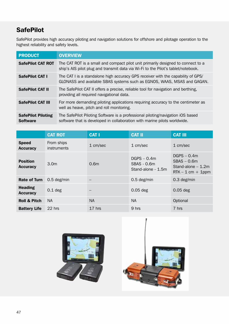
SafepilotSafePilot provides high accuracy piloting and navigation solutions for offshore and pilotage operation to the highest reliability and safety levels.
proDUcT overvieW
Safepilot cAT roT The cAT roT is a small and compact pilot unit primarily designed to connect to a ship’s AIS pilot plug and transmit data via wi-Fi to the Pilot’s tablet/notebook.
Safepilot cAT i The cAT I is a standalone high accuracy gPS receiver with the capability of gPS/gLoNASS and available SbAS systems such as EgNoS, wAAS, MSAS and gAgAN.
Safepilot cAT ii The SafePilot cAT II offers a precise, reliable tool for navigation and berthing, providing all required navigational data.
Safepilot cAT iii For more demanding piloting applications requiring accuracy to the centimeter as well as heave, pitch and roll monitoring.
Safepilot piloting Software
The SafePilot Piloting Software is a professional piloting/navigation ioS based software that is developed in collaboration with marine pilots worldwide.
cAT roT cAT i cAT ii cAT iii
Speed Accuracy
From ships instruments
1 cm/sec 1 cm/sec 1 cm/sec
position Accuracy
3.0m 0.6mDgPS – 0.4mSbAS - 0.6mStand-alone - 1.5m
DgPS – 0.4mSbAS – 0.6mStand-alone – 1.2m rTK – 1 cm + 1ppm
rate of Turn 0.5 deg/min – 0.5 deg/min 0.3 deg/min
heading Accuracy
0.1 deg – 0.05 deg 0.05 deg
roll & pitch NA NA NA optional
Battery life 22 hrs 17 hrs 9 hrs 7 hrs
48

49
FeATUreSMeteorological monitoring options
oceanographic monitoring options (Metocean)
Deployment and retrieval systems
Safe and efficient docking and mooring operations
Accurate, real-time data
Integrated with mooring and docking systems or as a standalone system
can be installed remotely with solar power and telemetry options available
ApplicATionSLNg carrier berths
oil berths
LPg berths
bulk liquids berths
bulk materials berths
buoys
commercial (roro, ferry, container)
MonitoringEnvironmental
Accurate real-time environmental and Metocean monitoring is vital to the safe docking and mooring of vessels, as well as prolonging the life of the fender and jetty assets.
50
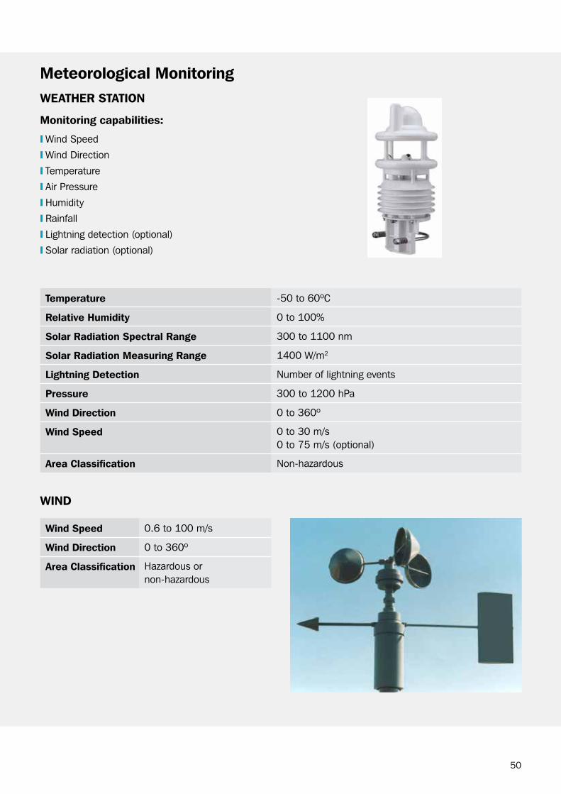
Meteorological MonitoringWeATher STATion
Monitoring capabilities:
❙ wind Speed
❙ wind Direction
❙ Temperature
❙ Air Pressure
❙ Humidity
❙ rainfall
❙ Lightning detection (optional)
❙ Solar radiation (optional)
Temperature -50 to 60ºc
relative humidity 0 to 100%
Solar radiation Spectral range 300 to 1100 nm
Solar radiation Measuring range 1400 w/m2
lightning Detection Number of lightning events
pressure 300 to 1200 hPa
Wind Direction 0 to 360º
Wind Speed 0 to 30 m/s0 to 75 m/s (optional)
Area classification Non-hazardous
Wind Speed 0.6 to 100 m/s
Wind Direction 0 to 360º
Area classification Hazardous or non-hazardous
WinD

51
viSiBiliTy
lighTning DeTecTion
Meteorological Monitoring
Measuring range 10 to 20,000 m
Area classification Non-hazardous
Detection range 30 nautical miles
Detection Bearing 0 to 360º
Area classification Non-hazardous

52
Single poinT cUrrenT MeTer
❙ current speed
❙ current direction
❙ water temperature (optional)
❙ Salinity (optional)
oceanographic monitoringWAve TiDe lASer❙ Significant wave height
❙ Long wave height
❙ Short wave height
❙ Period of significant waves
❙ water level
Measuring range 2.5 to 30 m
Area classification Hazardous or non-hazardous
current Speed 0 to 300 cm/s
current Direction 0 to 360º
Water Temperature -4 to +36ºc
conductivity range 0 to 7.5 S/m
Depth rating 2000 m
SAliniTy
❙ conductivity
❙ water temperature
conductivity 0 to 70 mS/cm
Water Temperature -5 to +35ºc
Depth rating 250 m

53
SiDe looking cUrrenT proFiler
❙ Multiple cells for readings at different distances
❙ current speed
❙ current direction
❙ water temperature
❙ Tide level
oceangraphic Monitoring
current Speed 0 to 6 m/s
current Direction 0 to 360º
Tide level 0.2 to 18 m
Water Temperature -5 to +40ºc
Depth rating 30 m
BoTToM MoUnT cUrrenT proFiler
❙ Multiple cells for current readings at different depths
❙ current speed
❙ current direction
❙ water temperature
❙ Max wave height
❙ Mean wave period
❙ Significant wave frequency (long and short)
❙ Significant wave height (long and short)
❙ Peak wave period (long and short)
❙ wave direction (optional)
❙ Tide level
current Speed 0 to 5 m/s
current Direction 0 to 360º
Water Temperature -5 to +45ºc
conductivity range 1 s
Depth rating 200 m
54

55
Monitoring SystemIntegrated
Integration is the key to maximum safety and optimum productivity.
Trelleborg Marine Systems operation can combine the Docking, Mooring and Environmental systems into a logical and easy to operate IMS (Integrated Monitoring System). Key information and statuses are then distributed to the right people at the right time whether they are on board the vessel, at the control room or on the jetty.
The IMS is built into either a small or large 19” equipment rack or a compact wall mount enclosure.
56
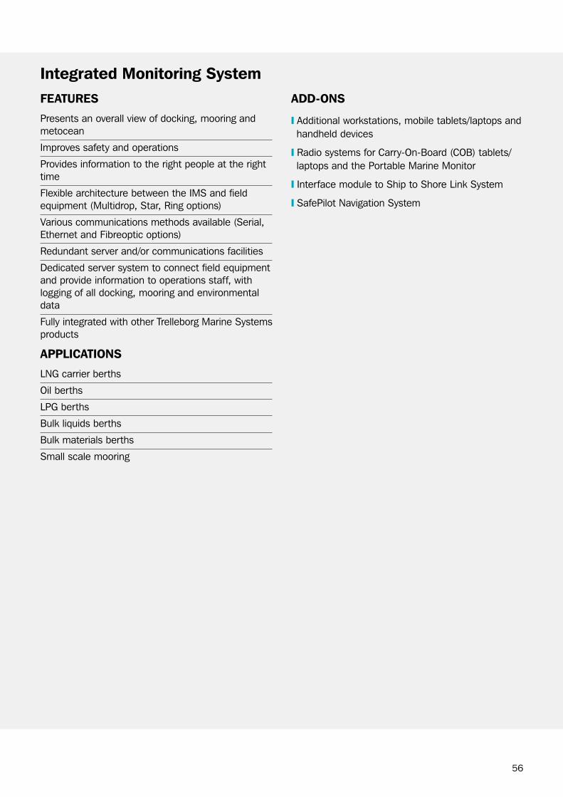
FeATUreS
Presents an overall view of docking, mooring and metocean
Improves safety and operations
Provides information to the right people at the right time
Flexible architecture between the IMS and field equipment (Multidrop, Star, ring options)
Various communications methods available (Serial, Ethernet and Fibreoptic options)
redundant server and/or communications facilities
Dedicated server system to connect field equipment and provide information to operations staff, with logging of all docking, mooring and environmental data
Fully integrated with other Trelleborg Marine Systems products
ApplicATionS
LNg carrier berths
oil berths
LPg berths
bulk liquids berths
bulk materials berths
Small scale mooring
ADD-onS
❙ Additional workstations, mobile tablets/laptops and handheld devices
❙ radio systems for carry-on-board (cob) tablets/laptops and the Portable Marine Monitor
❙ Interface module to Ship to Shore Link System
❙ SafePilot Navigation System
integrated Monitoring System

57
LMS controller communicates with equipment and logs all docking, mooring and environmental data, and provides alarms and generates reports.
other modules that may be included in the rack for field equipment include:
❙ SmartDock controller (JcU replacement)❙ SSL Interface module to goto the Ship to Shore System
❙ Telemetry Interface Module for mobile communications devices
❙ Hook release Interface Module for QrH units
SySTeM ArchiTecTUre key coMponenTS
integrated Monitoring System (iMS)
iMS eQUipMenT rAck opTionS❙ Small or large 19” racks❙ wall mount enclosures
The lMS controller connects and communicates with:
workstations, tablets, laptops using Ethernet, wiFi, 3g/4g to display docking, mooring and environmental information, and VHF/UHF to pagers
Field equipment using serial, Ethernet and/or fibre optic systemsLMS controller
workstations
MoBileDeviceS
cenTrAlSySTeM
FielDeQUipMenT

58
Typical user interface displayed on the workstation:❙ Docking
❙ Mooring
❙ Environmental
WorkSTATionS
integrated Monitoring System (iMS)
Desktop Pc

59
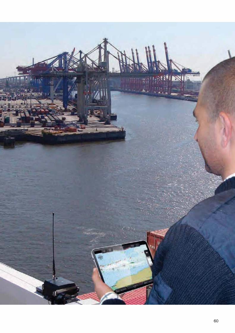
MoBile DeviceS
Mobile tablets and laptops (using one of wiFi, 3g/4g, VHF or UHF)
Handheld devices (using one of wiFi, 3g/4g)
Portable marine monitor – pagers (using one of VHF or UHF)
integrated Monitoring System
60

61
Service & SupportAftersales
Australia china europe Japan Middle east Singapore South
America USA
❙ Sales❙ Service
Engineering❙ Production
Facility❙ Project
Management❙ Project
Engineering❙ research &
Development
❙ Production Facility
❙ Sales❙ Service
Engineering
❙ Sales❙ Service
Engineering
❙ Sales ❙ Sales❙ Service
Engineering
❙ Sales❙ Service
Engineering
❙ Sales ❙ Sales❙ Service
Engineering
by their very nature, marine terminals and installations are located in hostile environments. Industry bodies such as SIgTTo and ocIMF recognize how critical it is for mooring and monitoring equipment to function correctly to ensure safety.
To help meet the challenge in these demanding environments Trelleborg Marine Systems offers clients a full range of Aftersales Services across the Docking and Mooring range.
Trelleborg also recognizes that the maritime industry is inherently a global business and is uniquely positioned to provide rapid response through our global Service Network.
62
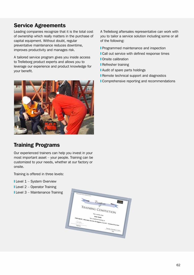
Leading companies recognize that it is the total cost of ownership which really matters in the purchase of capital equipment. without doubt, regular preventative maintenance reduces downtime, improves productivity and manages risk.
A tailored service program gives you inside access to Trelleborg product experts and allows you to leverage our experience and product knowledge for your benefit.
A Trelleborg aftersales representative can work with you to tailor a service solution including some or all of the following:
❙ Programmed maintenance and inspection
❙ call out service with defined response times
❙ onsite calibration
❙ refresher training
❙ Audit of spare parts holdings
❙ remote technical support and diagnostics
❙ comprehensive reporting and recommendations
Service Agreements
Training programsour experienced trainers can help you invest in your most important asset – your people. Training can be customized to your needs, whether at our factory or onsite.
Training is offered in three levels:
❙ Level 1 – System overview
❙ Level 2 – operator Training
❙ Level 3 – Maintenance Training
This certifies thatJohn Smithhas completed training in
TMS D&M | Aftersales Service & Support | Level 1 - System OverviewSignature
Date
Thursday, December 14, 2017
Trelleborg Marine Systems Melbourne Pty Ltd
63
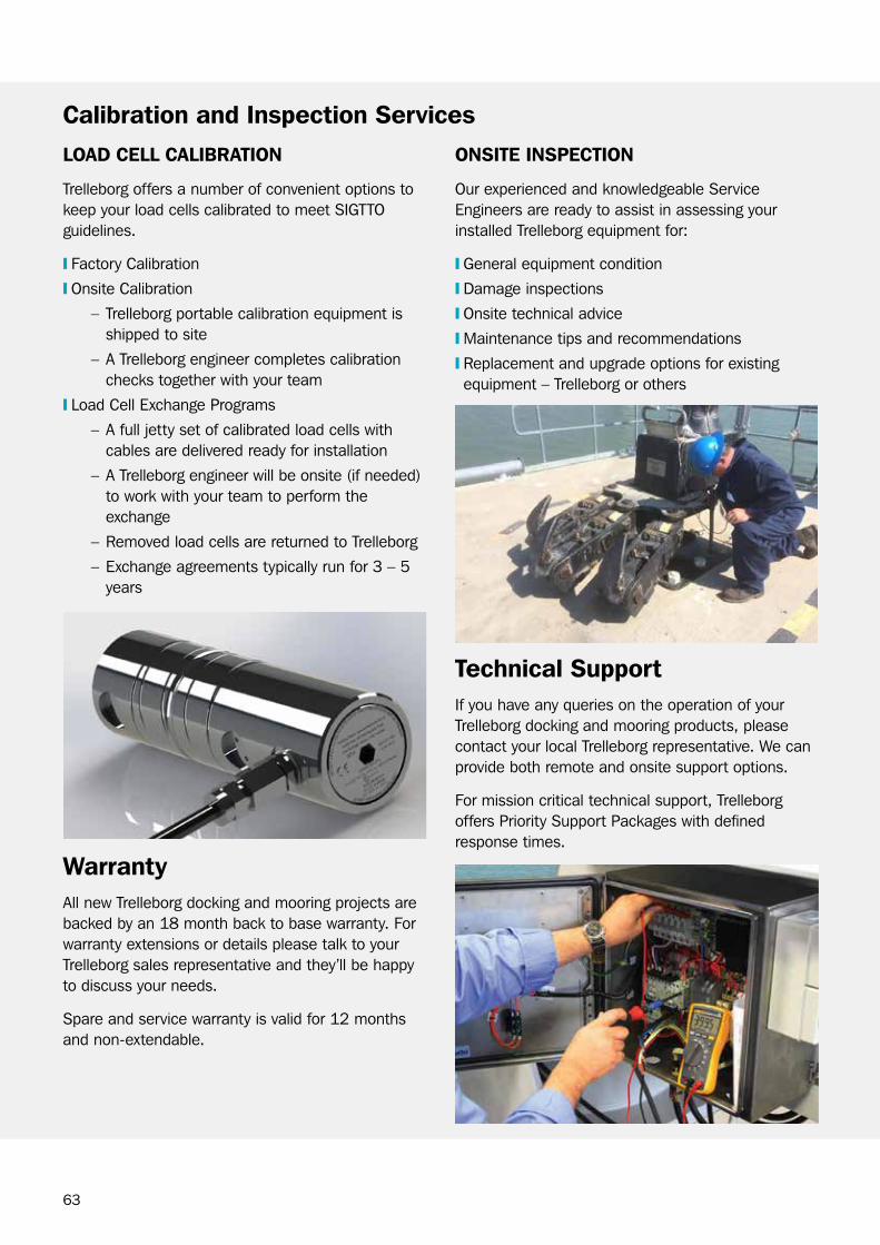
loAD cell cAliBrATion
Trelleborg offers a number of convenient options to keep your load cells calibrated to meet SIgTTo guidelines.
❙ Factory calibration
❙ onsite calibration
– Trelleborg portable calibration equipment is shipped to site
– A Trelleborg engineer completes calibration checks together with your team
❙ Load cell Exchange Programs
– A full jetty set of calibrated load cells with cables are delivered ready for installation
– A Trelleborg engineer will be onsite (if needed) to work with your team to perform the exchange
– removed load cells are returned to Trelleborg
– Exchange agreements typically run for 3 – 5 years
onSiTe inSpecTion
our experienced and knowledgeable Service Engineers are ready to assist in assessing your installed Trelleborg equipment for:
❙ general equipment condition
❙ Damage inspections
❙ onsite technical advice
❙ Maintenance tips and recommendations
❙ replacement and upgrade options for existing equipment – Trelleborg or others
calibration and inspection Services
WarrantyAll new Trelleborg docking and mooring projects are backed by an 18 month back to base warranty. For warranty extensions or details please talk to your Trelleborg sales representative and they’ll be happy to discuss your needs.
Spare and service warranty is valid for 12 months and non-extendable.
Technical SupportIf you have any queries on the operation of your Trelleborg docking and mooring products, please contact your local Trelleborg representative. we can provide both remote and onsite support options.
For mission critical technical support, Trelleborg offers Priority Support Packages with defined response times.

64
Trelleborg recognizes the decision to upgrade equipment requires more than just a set of equipment specifications. what’s needed is a deeper understanding of port operating parameters and the condition and functionality of existing equipment.
whether you’re upgrading equipment which is worn out, superseded or adding functionality, our broad industry knowledge and extensive experience means we can tailor a solution to meet your operational needs and budget.
Spare parts, equipment overhaul & repairLeveraging our extensive experience across our customer base, we are able to make recommendations for consumable, operation and capital spares holdings across multiyear time periods, e.g., 1, 2 or 3 years, to help ensure maximum equipment availability.
we also offer a number of options to support and extend the life of your existing equipment through factory repair and overhaul. Services include:
❙ QrH hook refurbishment and testing
❙ capstan motor / gearbox refurbishment and testing
❙ Load cell repairs and overhaul
❙ general equipment repairs
UpgradesFrom upgrading footswitches to entire jetty equipment replacements, some examples of upgrades we can provide include:
❙ Adding functionality to existing Quick release Hooks (QrH) and bases
– Load monitoring
– remote release
– capstans
– Increased operating line angles
– Fitting safety keeper bars
❙ replacing obsolete or worn QrH utilizing existing bases or bolt patterns
❙ replacing bollards with QrH
❙ Low maintenance QrH for jetties with limited maintenance windows
❙ Upgrading obsolete computer software / hardware
❙ Upgrading or replacing environmental monitoring systems
❙ replacing capstans with tugger winches
65
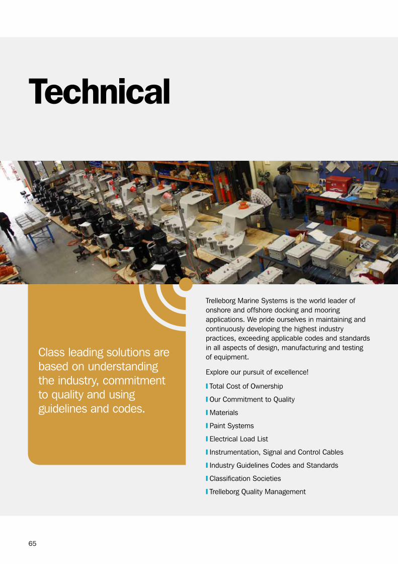
Technical
Trelleborg Marine Systems is the world leader of onshore and offshore docking and mooring applications. we pride ourselves in maintaining and continuously developing the highest industry practices, exceeding applicable codes and standards in all aspects of design, manufacturing and testing of equipment.
Explore our pursuit of excellence!
❙ Total cost of ownership
❙ our commitment to Quality
❙ Materials
❙ Paint Systems
❙ Electrical Load List
❙ Instrumentation, Signal and control cables
❙ Industry guidelines codes and Standards
❙ classification Societies
❙ Trelleborg Quality Management
class leading solutions are based on understanding the industry, commitment to quality and using guidelines and codes.

66
Total cost of ownership❙ what to look for to ensure class leading solutions
❙ comparing bollards with QrH
❙ Supplier selection criteria for customers
WhAT To look For To enSUre clASS leADing SolUTionS
❙ cast bases and hooks provide superior corrosion resistance and higher strength.
❙ weld free hooks and bases offer extended design life and excellent fatigue resistance.
❙ cast hooks with optimal throat size minimizes rope wear.
❙ compact and strong cast hook design offers double the yield strength of forged mild steel hooks by others.
❙ Unobtrusive release mechanism (no protruding components outside the hook body which could act as rope catching points).
❙ Enclosed capstan design offers significantly increased protection from harsh marine environment and mechanical damage during operation, maximizing service life.
❙ compact footprint with an all-in-one design minimizes deck space usage and installation costs.
❙ Standard capstan design has reversible control with automatic brake, enabling operator to take in or let out the line while tension and control is maintained.
❙ Superior insulation design insulates hooks and capstans from the base, as opposed to “under the base” insulation pads by others which are susceptible to cracking due to movement under load over a period of time.
❙ High quality three-coat paint specification offers industry best protective coating.
coMpAring BollArDS WiTh Qrh
❙ Mooring lines on a bollard cannot be released under tension whereas a QrH is designed to release the lines up to full SwL.
❙ Multiple lines on a bollard can cause departure delays if entangled. one line per QrH is the normal practice to assist with accurate line load monitoring.
❙ No facility to upgrade bollards with integral capstans, load monitoring and electric release.
❙ bollards are normally installed closer to edge of the dock which increases the risk of mooring crew falling in to water while handling heavy mooring lines. QrH units require minimal line handling when compared to bollards.
❙ Mooring crews are at risk in close proximity of mooring lines that may be under high tension and/or are prone to failure due to their bad condition. The port often has little control over the condition of the mooring lines which are the property of the visiting vessel. The associated risks can be mitigated by using a QrH with remote release fitted.
❙ The number of personnel required to release a vessel can be minimized on facilities with QrH and remote release systems fitted. This also ensures that mooring personnel are not required to be in the “risk zone” in case of an emergency situation i.e., fire.
67
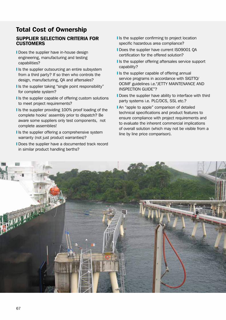
Total cost of ownershipSUpplier SelecTion criTeriA For cUSToMerS
❙ Does the supplier have in-house design engineering, manufacturing and testing capabilities?
❙ Is the supplier outsourcing an entire subsystem from a third party? If so then who controls the design, manufacturing, QA and aftersales?
❙ Is the supplier taking “single point responsibility” for complete system?
❙ Is the supplier capable of offering custom solutions to meet project requirements?
❙ Is the supplier providing 100% proof loading of the complete hooks’ assembly prior to dispatch? be aware some suppliers only test components, not complete assemblies!
❙ Is the supplier offering a comprehensive system warranty (not just product warranties)?
❙ Does the supplier have a documented track record in similar product handling berths?
❙ Is the supplier confirming to project location specific hazardous area compliance?
❙ Does the supplier have current ISo9001 QA certification for the offered solution?
❙ Is the supplier offering aftersales service support capability?
❙ Is the supplier capable of offering annual service programs in accordance with SIgTTo/ocIMF guidelines i.e.“JETTY MAINTENANcE AND INSPEcTIoN gUIDE”?
❙ Does the supplier have ability to interface with third party systems i.e. PLc/DcS, SSL etc.?
❙ An “apple to apple” comparison of detailed technical specifications and product features to ensure compliance with project requirements and to evaluate the inherent commercial implications of overall solution (which may not be visible from a line by line price comparison).
3

68
our commitment to QualityTrelleborg’s commitment to quality drives the way we work and operate and includes:
❙ global commitment to customers around the world with almost 100 dedicated docking and mooring employees worldwide, to provide an unparalleled level of support and expertise.
❙ business processes developed and regularly audited and validated through the ISo9001 quality process.
❙ Key products and associated manufacturing processes audited through certification bodies such as Simtars/cSA for hazardous area products and DNV gL/AbS/bV/Lloyds for classified equipment for use on vessels including FPSos/FSos, FLNg and FSrUs/FSUs.
❙ A proven track record of hazardous area product design and manufacturing capabilities, with numerous products manufactured under the IEcEx and ATEX hazardous schemes. certificates are available upon request.
❙ bringing manufacturing and certification of critical products into the Trelleborg business to ensure total control over the design, sourcing, manufacturing and testing of products such as QrH, load cells, hook release systems and docking displays.
3 4 5
1. SUrFAcE roUgHNESS cHEcK
2. cNc IN oPErATIoN
3. DMg HNc 6300 cNc
4 & 5. LoAD cELL gAUgINg cLEAN rooM.
1 2
69
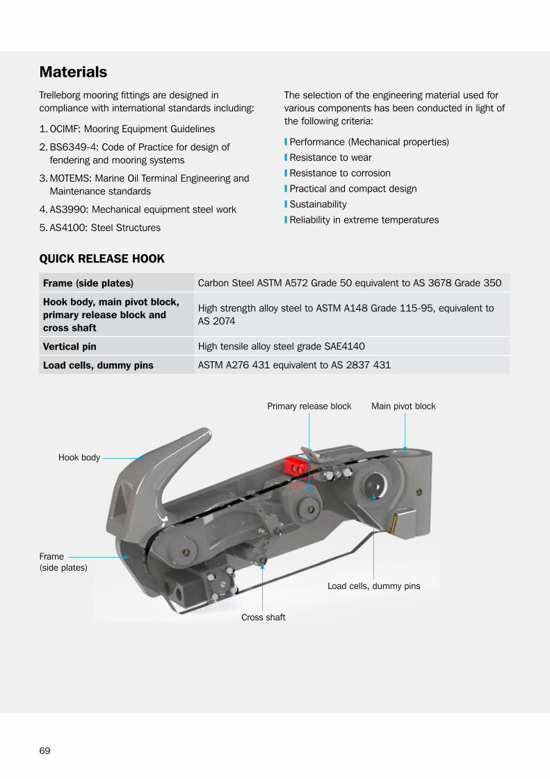
Hook body
Frame (side plates)
Main pivot blockPrimary release block
cross shaft
Load cells, dummy pins
MaterialsThe selection of the engineering material used for various components has been conducted in light of the following criteria:
❙ Performance (Mechanical properties)
❙ resistance to wear
❙ resistance to corrosion
❙ Practical and compact design
❙ Sustainability
❙ reliability in extreme temperatures
Trelleborg mooring fittings are designed in compliance with international standards including:
1. ocIMF: Mooring Equipment guidelines
2. bS6349-4: code of Practice for design of fendering and mooring systems
3. MoTEMS: Marine oil Terminal Engineering and Maintenance standards
4. AS3990: Mechanical equipment steel work
5. AS4100: Steel Structures
QUick releASe hook
Frame (side plates) carbon Steel ASTM A572 grade 50 equivalent to AS 3678 grade 350
hook body, main pivot block, primary release block and cross shaft
High strength alloy steel to ASTM A148 grade 115-95, equivalent to AS 2074
vertical pin High tensile alloy steel grade SAE4140
load cells, dummy pins ASTM A276 431 equivalent to AS 2837 431

70
Holding down bolts
Hook base
MaterialsonShore BASe
hook baseSpheroidal graphite cast iron, ASTM A536 65-45-12 equivalent to 400-12 to AS1831
holding down boltsbS4190 equivalent to ISo898. Property class 8.8Finish: Hot-dip galvanizing to ISo 10684:2004 (E) or Xylan coated
hook base Fabricated steel plate AS 3678 / ASTM A572
holding down boltsbS4190 equivalent to ISo898. Property class 8.8Finish: Hot-dip galvanizing to ISo 10684:2004 (E) or Xylan coated
Ship-To-Ship hook BASe (oFFShore)

71
MaterialshAWSer hook
Structural carbon steel grade 350 to Australian standard AS / NZS 3678:1996 or equivalent ASTM A572
chAin STopper
Structural carbon steel grade 350 to Australian standard AS / NZS 3678:1996 or equivalent ASTM A572
casting Alloy Steel AS2074:2003 or equivalent to ASTM A148
Welding American welding Society AwS D1.1
load cell Stainless steel grade 630
holding down boltsbS4190 equivalent to ISo898. Property class 8.8Finish: Hot-dip galvanizing to ISo 10684:2004 (E) or Xylan coated
casting Alloy Steel AS2074:2003 or equivalent to ASTM A148
Welding American welding Society AwS D1.1
holding down boltsbS4190 equivalent to ISo898. Property class 8.8Finish: Hot-dip galvanizing to ISo 10684:2004 (E) or Xylan coated

72
MaterialsWincheS AnD reelS
AUToMoor
Low Alloy Steel grade Q345b to gb/T1591-2008 equivalent to ASTM A572 grade 50.
Structure & drum Fabricated structural carbon steel to ASTM A 572
Welding American welding Society AwS D1.1

73
paint Systemhigh corroSiviTy reSiSTAnT pAinT SySTeM
Trelleborg Marine Systems produces various mooring systems, which operate in harsh marine environments. These systems are expected to operate for many years and it is therefore crucial that a high standard corrosion protection system is applied.
Trelleborg designed a paint system in conformance with ISo 12944-5 category c5-M which is the highest atmospheric-corrosivity category according to ISo 12944. The system also conforms to ISo 12340 and NorSoK M-501.
carbon steel surfaces are painted to the following system:
Each surface is sandblasted to class 2.5 to SSPc-SP10.
A three coat system is then applied:
❙ 60 - 80 μm DFT Zinc-rich epoxy primer
❙ 160 - 280 μm DFT two part epoxy, containing MIo
❙ 60 - 80 μm DFT re-coatable two-part polyeurethane
Standard color is gloss black but other colors are also available as required.
TrelleBorg QUAliTy
❙ All equipment used for application of the painting system are maintained, calibrated and inspected in accordance with Trelleborg inspection and test plan
❙ All environmental conditions are recorded at various stages of the paint process.
❙ Dry film thickness is measured after each coat and verified statistically according to applicable standards.
❙ A paint report is generated that covers all the steps of surface preparation and paint application.
❙ Two test reference panels are prepared for each batch of painted items. one reference panel is used for testing during surface preparation and paint application and the second is retained for future reference. To ensure traceability, each panel is stamped with a unique identifier traced back to the relevant batch.
❙ Trelleborg engages only qualified and experienced paint applicators and third party paint inspectors qualified to NAcE Level II or III as required.
TeST ApplicABle STAnDArD
pre-cleaning of Surfaces SSPc-SP1
Surface preparation ISo 8501-1
Surface profile Determination ISo 8503-5
Dry Film Thickness Measurement ISo 19840
Adhesion ISo 16276-1
TeSTS conDUcTeD
74
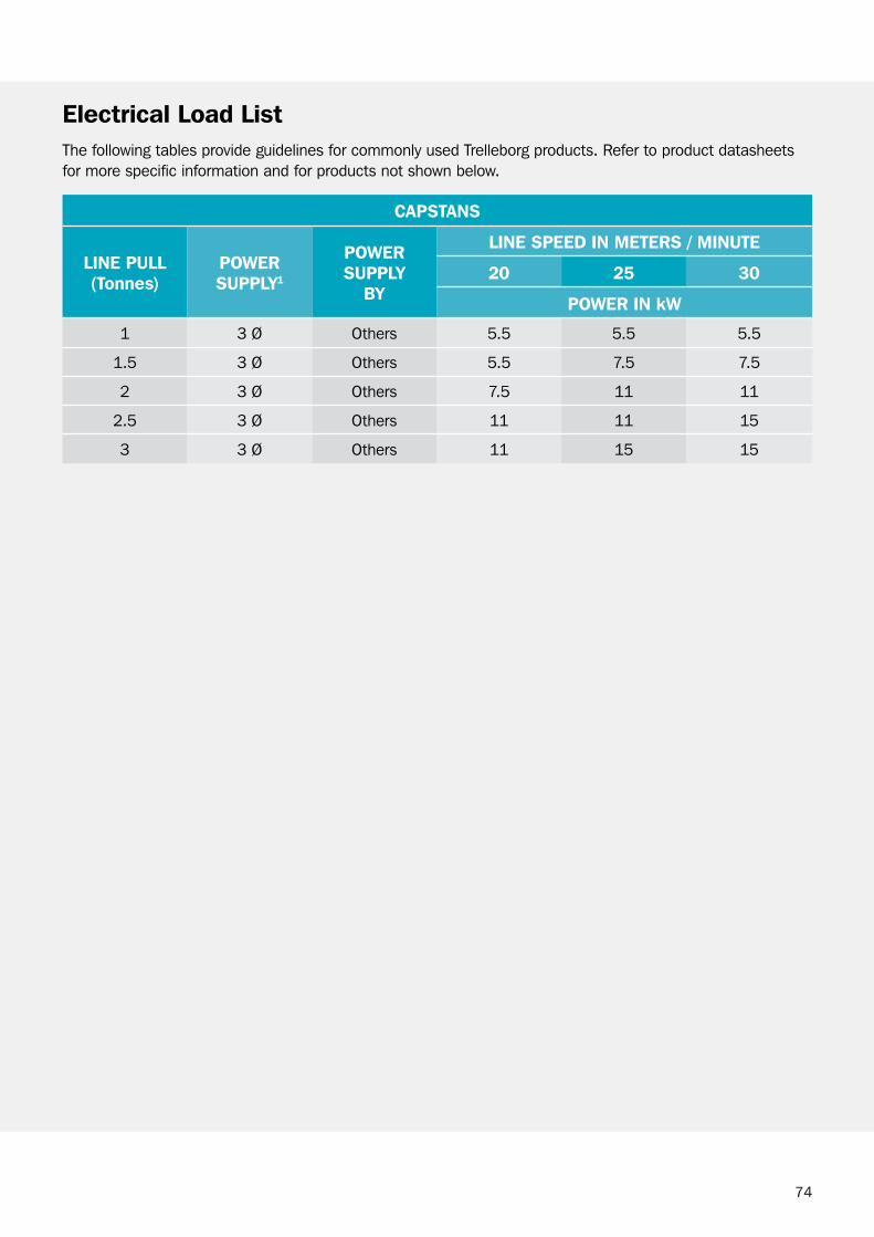
electrical load listThe following tables provide guidelines for commonly used Trelleborg products. refer to product datasheets for more specific information and for products not shown below.
cApSTAnS
line pUll(Tonnes)
poWerSUpply1
poWer SUpply
By
line SpeeD in MeTerS / MinUTe
20 25 30
poWer in kW
1 3 Ø others 5.5 5.5 5.5
1.5 3 Ø others 5.5 7.5 7.5
2 3 Ø others 7.5 11 11
2.5 3 Ø others 11 11 15
3 3 Ø others 11 15 15

75
DeScripTion poWerSUpply1
poWer SUpply
By
poWer inkW
reMoTe releASe
Local releaseSingle to Quadruple Hook arrangement
1 Ø TMS2 0.2
remote release Push button console16-32 Hooks33-48 Hooks
1 Ø1 Ø
othersothers
0.30.3
Virtual release console (Pc workstation) 1 Ø others 0.3
loAD MoniToring - SMArThook®
controller Unit with Load cells(Single to Quadruple Hook Arrangement)
24 VDc TMS2 0.1
warning Light & Siren (optional) 1 Ø TMS2 0.1
loAD MoniToring & reMoTe releASe
Load Monitoring & remote releaseSingle to Quadruple Hook Arrangements
24 VAc TMS2 0.3
Docking AiD SySTeMS - SMArTDock®
Lasers 24 VDc TMS 0.02
Main Display board 1 Ø others 0.2
Electric rotator 3 Ø others 0.5
environMenTAl SySTeMS
Standard weather Station - wind, Temperature, Pressure, Humidity
24 VDc TMS 0.1
current Meter (Doppler) 1 Ø others 0.1
Non-contact wave Tide Laser 1 Ø others 0.1
environMenTAl SySTeMS
Integrated Docking, Load Monitoring, remote release, Environmental, complete with Portable Monitor transmitter, Server Pc Monitor
1 Ø others 0.5
Pc workstation, Monitor, Printer 1 Ø others 0.3
Note1: 1 Ø = Single Phase Power Supply, 3 Ø = Three Phase Power Supply.Note2: In the standard arrangement, the power supply is taken from the capstan suppy. If there is no
capstan, or if client requires independent power, then ‘others’ to provide a single-phase power supply into each Hook release controller.
electrical load list

76
instrumentation Signal and control cablesThe following table indicates the acronyms used in Trelleborg drawings as well as the cable types and maximum recommended distances.
no. Type cABle conFigUrATion
MAXiMUM recoMMenDeD DiSTAnce
cAb1 communications 4 twisted pair, 1.5 mm2 shielded, 13.6 ohm / K
600 m with communications only.500 m typical for QrH, remote release and Laser Sensor.
cAb2 communications 2 twisted pair, 0.5 mm2 shielded, 13.6 ohm / K
600 m
cAb3M Fibre optic Multimode 50/125 uM 4 cores with Sc connectorsorMultimode 62.5/125 uM 4 cores with Sc connectors
2 km
cAb3S Fibre optic Single Mode 9/125 uM 4 cores with Sc connectors
Upto 20 km
cAb4 control Xc + Esize, construction and armoring dependant on installation rquirements.
Distance dependant on power demand and conductor cross sectional area.
cAb5 Network cAT5 100 m
cAb6 Printer USb 3 m
cAb7 control 1.5 mm2 shielded, number of cores to suit.
20 m
cAb8 Antenna VHF, UHF or gPS rg213 / cNT400 30 m
cAb9 Single Phase Power 2c + E Distance dependant on power demand and conductor cross sectional area.
cAb10 Three Phase Power 3c + E Distance dependant on power demand and conductor cross sectional area.
noTeS:
1. Please confirm distance limitations with Trelleborg engineers as actual configurations can affect maximum distances.
2. construction and armoring of cable dependant on regional installation requirements.3. Trelleborg to be notified where neutral can not be provided with three phase power.
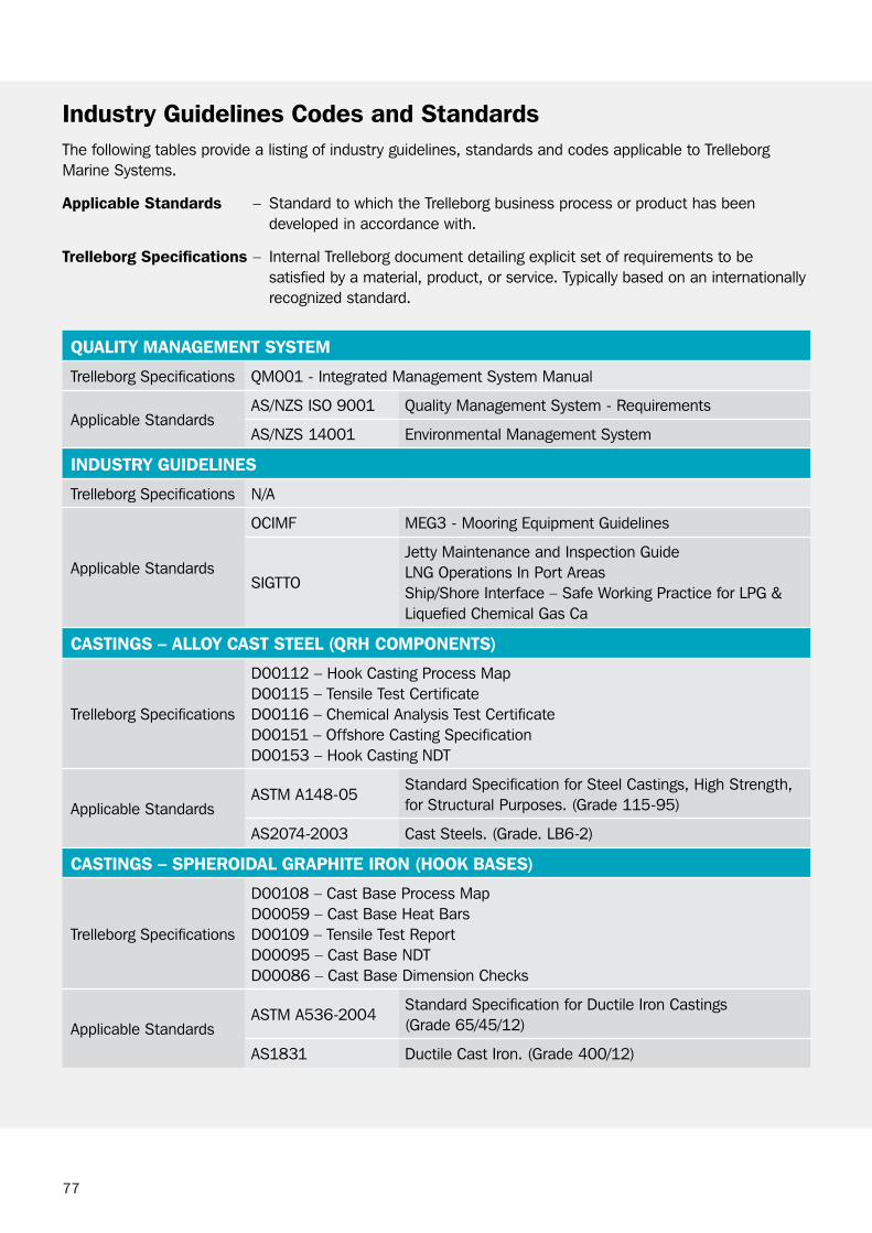
77
industry guidelines codes and StandardsThe following tables provide a listing of industry guidelines, standards and codes applicable to Trelleborg Marine Systems.
Applicable Standards – Standard to which the Trelleborg business process or product has been developed in accordance with.
Trelleborg Specifications – Internal Trelleborg document detailing explicit set of requirements to be satisfied by a material, product, or service. Typically based on an internationally recognized standard.
QUAliTy MAnAgeMenT SySTeM
Trelleborg Specifications QM001 - Integrated Management System Manual
Applicable StandardsAS/NZS ISo 9001 Quality Management System - requirements
AS/NZS 14001 Environmental Management System
inDUSTry gUiDelineS
Trelleborg Specifications N/A
Applicable Standards
ocIMF MEg3 - Mooring Equipment guidelines
SIgTTo
Jetty Maintenance and Inspection guideLNg operations In Port AreasShip/Shore Interface – Safe working Practice for LPg & Liquefied chemical gas ca
cASTingS – Alloy cAST STeel (Qrh coMponenTS)
Trelleborg Specifications
D00112 – Hook casting Process MapD00115 – Tensile Test certificateD00116 – chemical Analysis Test certificateD00151 – offshore casting SpecificationD00153 – Hook casting NDT
Applicable StandardsASTM A148-05
Standard Specification for Steel castings, High Strength, for Structural Purposes. (grade 115-95)
AS2074-2003 cast Steels. (grade. Lb6-2)
cASTingS – SpheroiDAl grAphiTe iron (hook BASeS)
Trelleborg Specifications
D00108 – cast base Process MapD00059 – cast base Heat barsD00109 – Tensile Test reportD00095 – cast base NDTD00086 – cast base Dimension checks
Applicable StandardsASTM A536-2004
Standard Specification for Ductile Iron castings (grade 65/45/12)
AS1831 Ductile cast Iron. (grade 400/12)

78
industry guidelines codes and Standards
MilD STeel plATe (hook FrAMe)
Trelleborg Specifications D00113 – Hook Machining Process MapD00118 – Hook Steel Traceability
Applicable Standards
ASTM A572Standard Specification for High-Strength Low-Alloy columbium-Vanadium Structural Steel. (grade 50)
AS3678-2011Structural steel - Hot-rolled plates, floor plates and slabs.(grade 350)
pinS AnD ShAFTS
Trelleborg Specifications N/A
Applicable Standards
ASTM A56/A564MStandard Specification for Hot-rolled and cold-Finished Age-Hardening Stainless Steel bars and Shapes. (grade 630)
AS2837-1986wrought alloy steels - Stainless steel bars and semi-finished products. (grade 630)
ASTM A29/29MStandard Specification for Steel bars, carbon and Alloy, Hot-wrought, general requirements. (grade 4140)
AS1444-1996 4140wrought alloy steels - Standard, hardenability (H) series and hardened and tempered to designated mechanical properties. (grade 4140)
non-DeSTrUcTive TeSTing oF cASTingS
Trelleborg SpecificationsD00153 - Hook casting component Non-Destructive TestingD00095 - cast base Non-Destructive Testing
Applicable Standards
ASTM A609M-91Standard Practice for castings, carbon, Low-Alloy, and Martensitic Stainless Steel, Ultrasonic Examination Thereof.
ASTM E1444-05 Standard Practice for Magnetic Particle Testing
ASTM A903M-99Standard Specification for Steel castings, Surface Acceptance Standards, Magnetic Particle and Liquid Penetrant Inspection.
ASTM A370-07aStandard Test Methods and Definitions for Mechanical Testing of Steel Products.
AS3998Non-destructive testing - Qualification and certification of personnel.

79
industry guidelines codes and Standards
FABricATion conSTrUcTion & TeSTing oF STeel STrUcTUreS
Trelleborg Specifications D00128 - Fabrication construction Testing
Applicable Standards
AS 1554.1Structural steel welding – Part 1: welding of steel structures.
AwS D1.1/D1.1M Structural welding code – Steel.
AS 2207Non-destructive testing - Ultrasonic testing of fusion welded joints in carbon and low alloy steel.
AS 1171Non-destructive testing - Magnetic particle testing of ferromagnetic products, components and structures.
ASTM E 709 Standard guide for Magnetic Particle Testing.
proTecTive coATingS - STeel & iron
Trelleborg Specifications D00135 - Standard Paint Specification for Steel & Iron
Applicable Standards
AS 1627.4Preparation and pretreatment of surfaces - Abrasive blast cleaning of steel.
ASTM D1005-95Standard Test Method for Measurement of Dry-Film Thickness of organic coatings Using Micrometers.
ASTM D7091-05
Standard Practice for Nondestructive Measurement of Dry Film Thickness of Nonmagnetic coatings Applied to Ferrous Metals and Nonmagnetic, Nonconductive coatings Applied to Non-Ferrous Metals.
AS 3894.3Site testing of protective coatings - Determination of dry film thickness.
STrUcTUrAl DeSign
Trelleborg Specifications N/A
Applicable Standards
AS4100 Steel Structures.
AS3990 Mechanical Equipment Steelwork.
DSc/04-1994Australian Institute of Steel constructions. Design of Structural connections.
FASTenerS
Trelleborg Specifications D00094 – Anchor bolt Manufacturing and Traceability
Applicable Standards
bS4190ISo metric black hexagon bolts, screws and nuts. Specification. (grade 8.8)
ISo 3506Mechanical properties of corrosion resistant stainless steel fasteners.

80
industry guidelines codes and Standards
elecTricAl eQUipMenT For eXploSive ATMoSphereS
Applicable Standards
IEc60079/EN60079
Parts 1 - 28 Explosive Atmospheres.
AS/NZS 2381Design, selection and installation of Electrical Equipment for Explosive Atmospheres.
pAckAgeD elecTricAl eQUipMenT
Applicable Standards
AS/NZS 3000 Electrical installations.
AS/NZS 3008.1.1Electrical installations - Selection of cables - cables for alternating voltages up to and including 0.6/1 kV - Typical Australian installation conditions.
IEc60529 Degrees of Protection Provided by Enclosures.
environMenTAl MoniToring SySTeMS
Applicable Standards wMo - No. 8guide to Meteorological Instruments & Methods of observation.
WireleSS coMMUnicATion
Applicable Standards IEc 60945Maritime navigation and radio communication equipment and systems – general requirements – Methods of testing and required test results.
SATelliTe nAvigATion SySTeMS
Applicable Standards IEc 61108Maritime navigation and radio communication equipment and systems – global navigation satellite systems (gNSS).

81
classification SocietiesQrH and other mooring fittings used on board of vessels for offshore applications in tandem, spread or ship-to-ship mooring are required to comply with stringent design and quality requirements to ensure the structur-al integrity of the ship is met. These are applicable for FPSos/FSos, FLNg and FSrUs/FSUs and any offshore facility.
Trelleborg mooring fittings for offshore applications are designed in compliance with:
1. ocIMF Mooring Equipment guidelines MEg-3
2. IMo MSc / 1175 (guidance on Ship Towing and Mooring)
3. classification Societies rules as applicable including:
The mooring system will be provided with a “product certificate” issued by the relevant classification society as assigned by the ship owner. The Product certificate covers the following compliance requirements:
a. DNV-gL
b. American bureau of Shipping (AbS)
c. bureau Veritas (bV)
d. registro Italiano Navale (rINA)
e. Lloyds
SUrvey coMpliAnce reQUireMenTS
Design survey conducted
The mooring fitting, its support structure holding down bolts and foundation plate must satisfy the design rules of the classification society. See picture on the right.
The design is then assessed by the classification society. when approved, a “Design verification” document is issued to demonstrate compliance.
Manufacturing survey
A surveyor deputed by the classification society inspects each manufacturing step to ensure compliance with class rules from a material testing and traceability points of view. These inspection activities are:
a. witness plate cuttingb. Sample stampingc. witness sample testingd. welding qualificatione. witness welding testingf. casting or forgings process witness and sample cuttingg. witness sample testing for castings or forgings
Each inspection activity is documented by a “Statement of Fact” issued by the surveyor. At the conclusion of this step, a “Manufacturing Survey” document is issued detailing the inspection activities in accordance with class rules and as specified in the design verification document.
Hook proof load and calibration witness
A surveyor deputed by the classification society witnesses the proof load of each mooring fitting to the nominated proof load and the calibration process to the safe working load. A “proof load and calibration certificate” is then issued to document this step. The proof load and calibration certificate is also a statement of fact.
Manufacturing Documentation records (MDr) review
In this step, all documents issued above are compiled and reviewed by the classification society to ensure full compliance. Any of the documents issued in the previous steps does not demonstrate compliance on its own. only a “product certificate” does that once all records have been checked by the surveyor.

82
Image courtesy of oLT offshore LNg Toscana
Foundation plate
Support structure
Mooring fitting
83
Trelleborg Quality ManagementMooring fittings are critical for the operation of a terminal. Failure of any component can have a significant impact on the safety of the personnel, port infrastructure and vessels. The cost to human life and assets is catastrophic. Therefore, the selection of reliable mooring equipment is crucial
Trelleborg has a global supply chain to deliver to our customer the best quality product at a competitive price. Trelleborg’s quality system exceeds the requirements of international standards and includes many tests and check points before the final product is delivered to site.
To ensure the quality of supplied products, the following steps are taken:
proDUcT QUAliTy
while ISo 9001 accreditation provides a certain level of confidence in accredited suppliers, practical experience shows that this alone does not guarantee purchasing a quality product.
Trelleborg has put in place a quality system that ensures the quality of its products, focusing on the following aspects:
1. Material specification: The material mechanical properties and chemical composition is in line with specifications.
2. Material integrity: Depending on the manufacturing method - whether the material is machined, formed, cast or fabricated, correct manufacturing procedures complying with international standards must be followed.
3. Size: The product dimensions and weight are an important factor of conformance. checkpoints are put in place to ensure any non-conformance is picked up and rectified in a timely manner.
4. Functionality: The product must be fit for the purpose for which it’s intended to be used.
Traceability of samples and product material is ensured throughout the manufacturing process.
SUpplier evAlUATion
Every supplier must be evaluated according to a set of corporate rules including a review of their quality accreditation, track record and ability to sustain and support their product and ethical responsibility.
These aspects are reviewed in rigorous processes following strict procedures by our purchasing and quality personnel.
ongoing SUpplier evAlUATion
All suppliers are reviewed on periodic basis against a number of criteria including compliance with specifications, on time delivery, quality control procedures and quality documentation.

84
Trelleborg Quality ManagementMATeriAl TrAceABiliTy
To maintain traceability, Trelleborg goes above and beyond the requirements of international standards and codes and industry practices. To ensure full traceability, Trelleborg uses its own employee or an internationally recognized third party (e.g. Lloyds, SgS, bV … ) to witness the cutting of test samples. Major structural components such as hooks and bases include a built-in test sample that is extracted from the finished product and is available to our customer for testing purposes.
MATeriAl SpeciFicATion
To ensure compliance with material specifications, the following tests are conducted for structural components:
❙ Mechanical and chemical testing of samples by manufacturer
❙ Mechanical and chemical testing of samples by internationally recognized third party
❙ random mechanical and chemical testing of samples by Trelleborg
built-in test sample
MATeriAl inTegriTy
To ensure the integrity of the material produced, the following tests are put in place:
❙ Non-destructive testing of 100% of cast components (MPI and/or Ultrasonic)
❙ random radiographic testing for a full scan on selected batches
❙ For all QrH:
• Proofloadtestingofassembledhooksto125% or 150% of its safe working load three times
• Releasingtheassembledhookatthenominated safe working load
SiZe
All products are dimension checked by Trelleborg to ensure compliance with the requirements.
FUncTionAliTy
A range of tests and checks is conducted in accordance with our inspection and test plan specially designed for each project.
85
diSclaiMer
Trelleborg Ab has made every effort to ensure that the technical specifications and product descriptions in this catalog are correct.
The responsibility or liability for errors and omissions cannot be accepted for any reason whatsoever. customers are advised to request a detailed specification and certified drawing prior to construction and manufacture. In the interests of improving the quality and performance of our products and systems, we reserve the right to make specification changes without prior notice. All dimensions, material properties and performance values quoted are subject to normal production and testing tolerances. This catalog supersedes the information provided in all previous editions. If in doubt, please check with Trelleborg Marine Systems.
© Trelleborg Ab, Po box 153, 231 22 Trelleborg, Sweden.
This catalog is the copyright of Trelleborg Ab and may not be reproduced, copied or distributed to third parties without the prior consent of Trelleborg Ab in each case.
bc-DAM-v1.0-EN, 2018

Trelleborg Marine SystemsEmail: [email protected]
Fender Systems | Docking & Mooring | Ship-Shore Links | Ship Perfornance Monitoring | Navigation & Piloting
www.TrELLEborg.coM/MArINE
facebook: TrelleborgMarinetwitter: @MarineInsights
youtube.com/user/TrelleborgMarineflickr.com/photos/MarineInsights
linkedin.com/MarineInsights MarineInsightsblog.Trelleborg.com
Trelleborg is a world leader in engineered polymer solutions that seal, damp and protect critical applications in demanding environments. Its innovative solutions accelerate performance for customers in a sustainable way.