Embed Size (px)
Citation preview

Docket No. 50-286 IPN-99-056 Attachment II
STRUCTURAL INTEGRITY EVALUATION FOR SERVICE WATER LINE NUMBER 411
(IP3-CALC-SWS-03010 Rev. 0)
NEW YORK POWER AUTHORITY INDIAN POINT 3 NUCLEAR POWER PLANT
DOCKET NO. 50-286 DPR-64
99052602126 9905-17PDR ADOCK 05000286 P PDR

PAGE 1 OF 2
CALC. NO.IPREVISION .
C.LCULATION IS: PRELIMINARY __FINAL V"
NAME IGNATU DAT
PREPARER: 1. /
CHECKER: A::zpc (DESIGN) VERIFIED/NA &. . F /W APPROVED: ORIGINATOR: NYPA OR OTH R 0
SYSTEM NO. /NAME F '4' - -/-- ge/"0C- I,'4" ,.-.
TITLE: ~ /~2 /~.<1,A6-7~4A'
QA CATEGORY: / DISCIPLINE: r7UA'"'9L STRUCTURE:
MODIFICATION NO./TASK NO. k!/A. DBD REF. NO. -3/
PROBLEM / OBJECTIVE / METHOD
6ee Xh. / 4-". C.
DESIGN BASIS / ASSUMPTION
d~W C E S-7 a£.,. W, e: ep Rr, *9'ur027
SUMMARY / CONCLUSIONS "%"e--/LS" a/--',e 0,44
THIS CALC SUPERSEDES OR VOIDS CALC. NO. '-/_&' A
DISTRIBUTION: C = CONTROLLED I= INFO
NAME DEPT LOC C ,R. Xe- /AE,,9: - 2-4. _ v"
i'I
DCM-2 Rev. No. 8
Preparation and Control of Manual Calculations and Analyses (IP3)
ATTACHMENT 4.1 Page 16of 20
II
ItL
I DM-
i
.
Nuclear Engineering CALCULATION CONTROL SHEET
~*
Nuclear Engineering CALCULATION CONTROL SHEET
IPAGE 2 OF 2
COMPONENTS MAJOR P ENO
EQUIPMENT PIPE NO. VALVE NO. SUPT. NO. INST. NO. PENE. NO.
RELATED DOCUMENTS
REFERENCES
-(f9orr d 77,c'.r'/'rM' ) Z,~ ~ ~ ~ ~ ~ / Cj57 0el pioo v o . 3 11.3-C - .)A/-o00 .6-.
To
SECURITY: (Y/N) N COMPUTER PRINTOUT: (Y/N) N
NYPA FORM DCM-2, ATTACHMENT 4.1
(., , A 409;7 4 11/ ftAkL7i t%'Al (4L k C1/ "' IVLIf. J
3 /PR3 -C4C-~J os 6 01 rbeO P.7
)f'.
*gg'rzs7Tc'.7l
I
=-I=

New York Power LE Authority
Verificatiion of:
Document Title:
Document Number:
Subject:
Modification/Task
Number (if applicable):
QA Category:
DESIGN VERIFICATION COVERSHEET Page 1 of I
Service Water Line 411 Wall Thinning Evaluation
IP3-CALC-SWS-03010 Rev. 0
Calculation
DESIGN VERIFICATION
7RM '4 REV. No. 3
ATTACHMENT 4.1
Page 8 of 21
Review Review Completed
Require Discipline (initial of reviewer)
ELECTRICAL
MECHANICAL
INSTRUMENT & CONTROL
X CIVIL/ K.Lo STRUCTURAL
FIRE PROTECTION
SIMULATOR
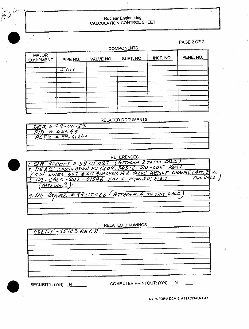
r- New York Power DESIGN VERIFICATION CHECKLIST
I Authority Page 1 of 4
IDENTIFICATION: DISCIPLINE:
Dbcume.nt Title: Service Water Line 411 Wall Thinning [ ] ELEC [ ] I&C (print title) Evaluation [ ] MECH [ ] Fire Protection
[X] C/S [ ] Simulator
Doc. Number: IP3-CALC-SWS-03010 Doc. Revision: 0 ] Other (specified)
QA Category: I
METHOD OF VERIFICATION:
[X] Design Review [ ] Alternate Calculations [ ] Qualification Test
Selected Verifier: Kai Lo/IDEM/2052
(print name \ department \ phone ext.) # Design Verification Questionnaire
All questions shall be explained in the space provided.
1 . Were the inputs correct and incorporated into the design?
Explanation: Yes. Calculation inputs such as 3/8" original wall thickness, as measured 0.14" wall thickness, 1.5" flaw length,18" pipe O.D., 150 psi pressure, 160 degree F design temperature, A53 Gr B pipe
Material, pipe stress from stress output.
I) 2. 1 Are the physical and functional characteristics of the proposed design within the approved design basis of the
x Ip system(s) structure(s) or components(s)?
xplanation: N/A
3. 1 Does the proposed design incorporate license Commitments?
Explanation: N/A
4. Are assumptions necessary to perform the design activity adequately described and reasonable: Where
necessary, are the assumptions identified for subsequent reverifications when the detailed design activities are
completed?
Explanation: Yes. All assumptions are as per original ESM-CES-7.
5. 1 Are the appropriate quality assurance requirements specified? e.g., safety classification?
Explanation: Yes. QA cat I.
6. Are the applicable codes, standards and regulatory requirements including issue and addends properly
I dentified and are their requirements for design met?
Explanation: Yes. ASME Code case N-480.
RCM-4 DESIGN VERIFICATION ATTACHMENT 4.2 REV. No. 3 Page 9 of 21

_ D New York Power D Authority
DESIGN VERIFICATION CHECKLIST Page 2 of 4
Design Verification Questionnaire All questions shall be explained in the space provided.
)licable construction and operating experience been considered?
Explanation:
8. Have the design interface requirements for mechanical, electrical/l&C, and civil/structural engineering been I satisfied?
Explanation: Yes. QA department and QA reports.
9. 1 Was the appropriate design method used?
Explanation: Yes. ESM-CES-7.
10. 1 Is the output reasonable compared to inputs?
Explanation: N/A. No computer output.
11. 1 Are the specified parts, equipment and processes properly suited for the fire protection Ap pendix R, QA, and
IEQ classifications required for the application?
Explanation: N/A
12.1 Are the specified materials compatible with each other and the design environmental conditions to which the material will be exposed?
Explanation: N/A
13.1 Have personnel requirements and limitations for maintenance, testing, and inspection been satisfied?
Explanation: N/A
14.1 Are accessibility, maintenance, repair, and inservice inspection requirements for the pl ant including the plant
cnations under which these will be performed been considered?
Explanation: N/A
15.1 Has adequate accessibility been provided to perform the in-service inspection expected to be required during
Ithe plant life?
Explanation: N/A
I._DESIGN VERIFICATIONI CM-4
I REV. No. 3ATTACHMENT 4.2
Page 10 of 21

F1New York Power LiAuthority
DESIGN VERIFICATION CHECKLIST Page 3 of 4
h #1 . Design Verification Questionnaire
All questions shall be explained in the space provided.
16.1 Has the design properly considered radiation exposure to the public and plant personnel? (ALARA/cobalt
reduction) Explanation: N/A
17.1j Are the acceptance criteria incorporated in the design documents sufficient to allow verification that design requirements have satisfactorily accomplished?
Explanation: Yes. Wall thickness must be at least 30% of original nominal pipe thickness; expected future corroded thickness is less than the required minimum thickness; wall thickness must be structurally adequate to with stand expected loading, i.e. pressure, dead weight and seismic.
18.1 Have adequate pre-operational and subsequent periodic test requirements been appropriately specified?
Explanation: N/A
19. 1Are adequate handling, storage, cleaning and shipping requirements specified?
Explanation: N/A
20.1 Are adequate identification requirements specified?
I Explanation: N/A
21. 1Are the conclusions drawn in the Safety Evaluation fully supported by adequate discussion in the test or Safety
Explanation: N/A
22.1 Are necessary procedu .ral changes specified, and are responsibilities for such changes clearly delineated?
Explanation: N/A
23.1 Are requirements for record preparation, review, approval, retention, etc., adequately specified?
Explanation: Yes. See related document section of DCM-2, sheet 2
Explanation: N/A
25.1 Have the drawings, sketches, calculations, etc., included in the integrated design package been reviewed?
Explanation: Yes. QA report 99UT027 and 99UT028, 9321 -F-55163 Rev. 8.
DESIGN VERIFICATIONDCM-4
ATTACHMENT 4.2 Page 11 of 21
,REV. No.

-- New York Power - Authority
DESIGN VERIFICATION CHECKLIST Page 4 of 4
I # j
Desig n Verification Question naire
• All questions shall be explained in the space provided.
26. Have reviews been performed to identify any effect on the Check Valve Maintenance Program?
Explanation: N/A
27. 1 Does the design check Valves meet the intents of INPO SOER 86-03?
Explanation: N/A
28. Is the plant reference simulator physical and function fidelity affected and it's design change been factored into the cost?
Explanation: N/A
29. Are all references listed (including design calculations/analysis) that were used as part of the design review?
Explanation: Yes. See DCM-2 sheet 2.
REMARKS/COMMENTS:
hIone
Design Verification Complete: Kai K. Lo 4/19/99 ,'j C
(pnnt name signature date)
DESIGN VERIFICATION ATTA(.HMLNI 4.d
I REV. N.Pg 12of2
ATTACHMENT 4.2
Page 12 of 21i
..........

,-NewYorkPower ° A u th o rity ~ ~ ~~~~~~~~~ ~~cak ,u ,,ono. .. . , .. - . . ... - .- -. ./10 .- ........................... ,o....O ....................... ..........
Project Pag /............. .0...
Subjlct - Computed b ~ Date
Ala ......... ...... Checked by 6L1a te ~/'7,
Pe '/ / /
A/b
675R) t/z-3z) ,i-.
7 CU-ts 7tH67 ,
r ? Rpcvcled .aoer

CAlAMWAI"C "Ds VXV S - ~ I M
EvMAJATION OF PIPE WALL I/
Piping System : le "e4 ZT)A6 Description : A W 1WAIA16, 6VDate
:7 5 C)
Prepared By
D
Checked By Date
S£TEP 1 : SCREENING EVALUATIOn[
a. Evlato of Minimuma Predicted Thickness : t, in 7S- 4,,.
ra..in.
- Pipe Wall Nominal Thickness, t..
- Latest Measured Minimum Wall Thickness, t. - A. '
- Previous Measured Minimun Wall Thickness, t'* =
(If wall has not measured before, t' -=1. 1 25* t ,,o.)
- TIME Between Two inspections,
(If wall has not measured before,
TIME = service years of the pipe up to first inspection.)
- Erosion/Corrosion Rate, C
C= TIME
- Years between Latest and Next Inspections, Y -- /-
- c * Y 0/40
- Acceptable Limit = 0.875 *t..
.-1 table Limit = 0.3 * t .
C. haa ~ailIM-of the Thinning Wall:
_[ ] Accept As Is
1-/3 Step 2 Evaluation Required
in. in.
in/yr
- yrs.
in.
. T = I.
= 1in.
for t8 > 0.875"t. o.5-z > 0./2/>0//1 -7 f or 0.875*. > tr ) 0.3*t,.
I ] Repair or Replacement fr V. -Dos
WM s CO-1 ZvYlL21 rcm &W. L392)
90"*s I%"* nValuartIa lors Oo~ be us"t a * .ow~t fcw rpop tkinaiUq Ona~luutlon but tho mw~catla
sha&i rollow tba roquIrOUt at BT
A. - 4
,1 : . ,4:
0 -Z-
"- yr.

/Pk2 po ,"94w A
JALUATION OF PIPE WAN~LTIJN
piping System Se#'e W
Description prepared By Date :
checked By Date : L
SALL THiCKNESS EVLUATION
pipe outside Diameter, D
Design Pressure, P Design Temperature, Td pipe Material Allowable Stress at Design Temperature, S
Longitudinal Weld Effective Coefficient, E
An Additional Thickness for Erosion/Corrosion, A
18z .c - in. . Io psi
= /.Lo °
= ____, o __ psi
= -- in.
b. pite Minimum Wall Thickness Reuired by IS 2
P*D - t'. 1 . = _+ A
2(S*E+O.4P)
c. /6gg ?407
- Axial Stress due to Design Cond.(P+DW),I/6ee,#4 o7S. = S' psi
Axial Stress due to Upset Cond.(P+DW+OBE),,-+10Y3 psi
Axial Stress due to Faulted Cond.(P+DW+DBE), S,. = 3- 6 psi
fS,,-o7.4,Iio$ 0 052 3- in. - t = ( 0,S)*t3 1 5t7Y5- in. - = (S,./1.2S)*t... - 0_0-5- in.
- t,. = Largest of (t 1 ,t,,t,) " k __ ---in
d. •Acctbility bsdal hcns iei.
(X/] Accept But Monitor for
3 [ Step 3 Evaluation Required for j Repair or Replacement
for
___ =aCM7 rvumLw. 1m (W". S."31
t > P .I
tu.,. > tp tv2~
1 2 )0-5y
. O, < q6 in.
/I

VaAA -- PLAM
ION OF PIPE WALL TIINN XG/
piping System 4VI
Description Dae : / q
Prepared By :I q
Checked By Date
a.
=in., tL = i= ni., - " in. "
b. :gDizcko (see Figure 7.2)
L = in.., L. - in., Lin..__- in W-= - jn.
Case 1 : Applicable f L(t) - .so , . f }rom",j. c -ur"ve r i. n Fiur 7.3 _,- ..
.../__L_ __*__ __ i n
Case 2 :sAp licable if L 2. R*t.. & 1.13 t. ,
5 ATE;; t.__1._]_____ in.
t= ( in.
(j/j from a2inFgr7. in.
,:, € '-'//_.__._______. \in.
= nimua of ( tit 2 ,ts) ____ in.
[3Accept But Monitor for t, : tj
S[ 3 Repair or Replacement for t. < t.,.
e. pe Wall Remainla Service Life (RSL): 0-.1 , 0. 0oq6 ; ' > O.05Y
- t = Larger of (t'._, t'.,.) if t 0 tb" & t..
t-3if tu > t,)tu a6 in.
> 0.3,t.. 6
- RSL (where C- pipe thinning rate) =yrs
C
Ims c- rumI~nn (. W")
"a3 S

NewYorkPower A thority //: ~ fl- 3 . &- - 3/C
Project '- ... .....
subject 5e?~ 4/Ce ..............~/ ......... ..-.. ......
Revision .
Page of
Compued b ... Date
Checked by .. 4 / Date Ff
//67y41am a 00
b/4)'J LiAv6 ~Qkt..
.se
i s I~/rA
1/ 7- / a1.4 40, /r/
6J
1
K IA ?'l
MfClf
~ kE3
Recycled paper
&te ve, 4
r44a,S pa, elag
v .

New York P ower - Ultrasonic Examination Report
Authority
;-c2301/O A"e CK
Report No.: 99UT027 Page J oi 3.
Sys. ; Comp. 10: Service Water I SWN - 34 -1 Exam Item: Line 411 Piping
DWG No.or Sketch: 9321-F-27223
QA Category: Cat I ASMS XI Class: II
WRMod: 99-00044-03 Cat: NIA Procedure: NOEP 9.4-12 (I)
Component Configuration: CCW Piping Orientation: 0 Degree Type of Materil'i Carbon Steel
Angle. 0 Mode: Longitudinal. Szi"twa Tckes, 0 .375.
Eauipment Instrument: 213110 Kroutkramer Branson USL 48 Due-, 07t/3/99
Vertical LInearlty C ek Attenuatgr LinatCheck
Signal I F ! I IIo I 1 _0% I a/ CID '_ 5_ I_ 1e % _ I Signal 2 014 4 O1 VT 04 01 0
(Silgnal 2 shall equal 50% of signal 1 5% of full scale.) (32 to 48) (16 to 24) (64-M) (64-05)
Transducer: 0030HO KBA 6 Mhz .25" RND AOP DUAL I GAMMA Wedge: NIA
Search Unit Cable: 6' Self-Cont Wedge Meas. Angle: 0 0 Fxit Point-Front: NA
Couplant: 97120 Sonotech I Soundsafe Thermometer: QS.18 Due: 815/2000 Temperature
Calibration Block: IP3 E/C # 3 Step Wedge To .5" -. 5" Material: Carbon Steel 68 OF
Simulator Block; N/A N/A OF
Reference Block: N/A NA O
Entry Surface: OD Component: 70 OF
Distance Amplitude Cuyrv Each Major Screen Division 0. % Ilnstrument Settings
100-- 1 Reflector Orient FSH Poe. dB Range (in.): 0.5" r " 05fBR stp T-0"1 i Sweep Length. 8.08
0-,11 . Rl .. Stp o-:21 /A Sweep Delay: 8.26
70 71 6-.600 Step* s 1 0I .061 Sensitivity (dB): 58
60 ..-.. f, I Frequency (mHz); 6
so . . . ... I - Reject: Off . I .Filter: NEG
301 Damping: Min " L"aIb : Ti.... 1 ... ' Mode Select: Duel
2lot i i ibat on_ -. Rep. Rate: Fixed o.. .. . .... _ ... -DEC/Gatr On
1 2 3 4 5 6 7 8 9 t0 Jacks: T&R
Acceptance Standard: As per IP3-CAL-SW$-1 596 Recordable Indication(s): Yes Recording Level, N/A% DAC Evaluation Level: NIA% DAC
100 % Complete Limitations: Surface painted at most locations, average D.F.T. = 0.009"
Remarks: UT Examination of Line 411 was performed to evaluate wall thinning of 18" dia. pipe Downstream of
SWN-34-1. the pipe has leak at grid location "J" discovered by OPs during Walkdown.
F.__,inner- Siral H. Memon Lev l: 111 Date. 11&
Examiner: NIA Date; 419/91
Reviewed by: ._ 0L._el
ANII Review: Data:
Tfl4 .fP'N 66,6 F.T NdH 92. .S8922.:Gi£dI-S
Rev.; I
. p2 e /oF.5 _
2dI-HoTn'A 7nn'ON vn:F;

AteChMOM 2
P g I af I
New York Power Report No: 99UT027
Authority Page 2 of 3
Sys. / Comp. ID: Service Water) SWN - 34 - 1 Materiai: Carbon Steel Higrh Reading: 0.551" Exam tem: Line 411 piping
Size: 18" Daimeter Low Reading: 0.058"
DWG No.: 932-F-27223 Thickness: 0.375" (Nomninal) Grid Size: V x 2" WR I Mod: 99-00044-03
Configuratjon: CCW Piping Datum Point Al Top o POO QA Category: 1 ASME XI Class: Ill Cat N/A
Aceptance Standard: As per JP-3 -CAL-SWS-1596 Procedure: NDEP 9.4-12 (I) Rev.: 1
UNCORRECTED FOR PAINT D.F.T No. A B C D I E F H I J K IL M N 0 P R S T
1 -441 .433 .413 .428 .454 .437 .433 .433 .379 .281 .451 .485 .399 .418 .424 .430 .428 .427 .407 .422
2 .511 .492 .498 .516 .493 .535 .552 .537 .530 .112 .185 .161 .140 .523 .531 .498 .520 .551 .530 -479
3 .402 .398 '365 .372 .381 .327 .381 .393 .340 .393 .389 .292 .284 .327 .394 .364 .387 .393 .374 .377
4 .417 .404 .384 .386 .381 382 .380 .381 .371 .383 .378.379 .390 .383 .389 .384 .390 375 .381 .381
NO. u v w hx Y Z AA BBD 1 .419 .421 .467 -398 .426 .427 .432 .408 2 .513 .493 .480 .46J.9 43 .5 479 3 .391 .388 .364 .382 .39L3 .390 .392 .396 4 .374 .379 .378 ., 384 379 .382 387 391. . . , . . .. ,
.... CORRECTED FOR PAINT D.F.T'(uncoected~ thickness macKn -0.05Aa
to. A C D E F G H I n.J K L M 'N n P R S 1 0.441 0.433 0.359 0.374 0.,400 0.38,3 M0.3790.379 7:325 0.227. 0.397 0.411 .350340.370 0.376 0.374 0.373 0. 3 W 0-36,
2 0.511 OA.92 0.498 0.516 0.493 0.535' 0521 0.537 0.534 T9_'15 0.161 ' O.S 0523'0.531 jOASS 0.M' 0551 0.3 = OATS
rev 1.34 0.310ap 803 0-2
'3_0.348 0.344 0.311 0.318 0.327 0.273 0.327 0_339 0.286 033_0.335 0.238 0 _.2 . _ o.3_330 . 4 7363 0.350 0.330 0.332 0.327 0.328 0.326 0.327 0.317 0.329 0.324 0.325 t0.3 0.329 0.336 0.330T 5.3 .321 0.32Z' 0-327
No. IUL V W X< Y Z AA'I BB Ur.d 1,j 774,. CA-..,,
1 10.3651 0.367 0 A67 0398 0A26 0.427 0.432 0.408
2 0513 0.9 A00 60.489 0.493 DA58 0A79 3t 0.337 0.334 0.310 0.328 0339 0336 0.338 0.344, '" 3
4 0. 320 T.3 5 -034 0.3 773-25 =.328i 0.333 0.337 .(/ "
Remarks: ....
AJI thickness readings above are in thousands of an inch. ,,,Examinr. Sia ennLevelt III_._ Date: 4/19M9
Data In SOLD are at locations of no paint Examiner NWA Level: Date
Data corrected forpaint D.F.T. as per NDEP 9.4-121, Revie a by: , __'- "_ Level: Date:
rey. 1. parag:raph 8.6.3. 1. ANIIl Review., Date:
N

tySketclvAttachmeflt Rtepaq! No.: OIUT027 Pogo S. Of
Syo. HonMp. 10: Service Water I SW14 -34 .1
OWO No. or Sketch: 9321-F-27223
QA Category: Cat I ASME XI Claus: III
Exam Item: Uno 411 Piping
WRMod:
Cot WA Procedure:
09.0044-03 NDEP 0.4-12 (I)
t.~e .....o,"0.O
z~4 TP~~
(I~
upc"MR4
Q
Qi
ITAPbAL .A~ h~ Gogkim L,c-&tP4
N (\ ' % _ . .. ... .
Examiner: Siral H. Memon Level: III Date: 4119199
Examiner~ NIA ate:.J4III2A.
Reviewed by: Lov ____Date:
ANII Review; Date:
c~~(- ~~9; rwfk 0 r, RT N A H q)P.q899i:GI £I
Rev.: I
2dl-uoelO ' J 700, nki or) - c
18>A. Pipe.
' ~ we C)Tv, WE ) ~ ~

PR .C. TITLE 7 P -J. , , .
STRUCTURE OF SYSTEM S.f P A6 ESION CLASSM:iCAT ION t'~2L ~~
COMAPL;TEO BY LLAOA, 1'
.
BYS nEi'EO AOOE O.
CHIMKIEL DAT
L,.DATE
POEM STATEMSENT: NIA.
PFAFOA PIPlJ6-TRE55 A4VAL-If5t5 -A' 7-#F S670V..vC wu'A7 I 1,1A.Jo 4o'7 A-JD 411 DUE 'M -r-V~4ZE4ScP CV16A'r OA-; VA4LVES: 5ci.'- 31 S c.AJ- 32, -SW V- 33- 1. S WQ- '3 W sAJ -34 -1 AUJD S WA -34-2Z (,EF. 7 ).TWF q"Lt-'L51S O~-s F PgSS~uE . A~wv-414r
U~SED TO '4LAtulE P'Ptlv64 sr OAPS a-'- 3v-PPO~TS AXIA uof2L{E L-CIAPS. F01Z A0DYT?oQAC- DT.41LS S55
SUMMARY CONCLUSIONS: .-.
"BAMT) 0A-) ?H4 A"AL-ISES P ;-15E e""'. VIC CozvlcE &WATER
4jAE!; 407/4 I / Y (-., A-mt'- H', E BE 'J:'i)?IPIAv4 £t-PESS ^6'~Er 7~E C# CODE 8'-S13/ . )p 5wP (,pYgqkT ,...l ,, -: _', MCuLA'lED ,A.D ', 4:m
s. P4 w'o4 f ,'rN S' L I
•FA --e.4"6-A . o .., ,,j I'> "0, 3
- .- ,, A "S - - -," - - 4 :c .. . " .- U * .- AA.A~-~'5 ~ - ~ '~'~R.t
"IPR -ECT TIT -.-
'.4 4 -
- -.CONTROL SHEET--..
... .- ,.! ; @. 'I00
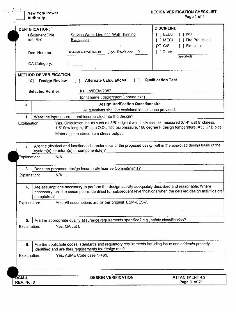
UNVERIFIED ASSUMPTIONSOPEN ITEMS:
i REFERENCES: SPECIFICATIONS. DRAWINGS. CCOES. CALCULATIONS. TEXTS. REPORTS. COMPUTER DATA. FSAR. ETC.) SOy~F r ST2A)
C-PITEZ'A FoP- VES/4:" OFP Cc-A 5^ pp.1ol'f0 FogP-.3 8rwPIqC(6, 5,73) 3 . W~s~t :Zf l RESPONSE SPEC ,, - 2'-. " /,,71 , ,,,, ...... ,.,g-;
4. AYPAsx~~q3?-F-~!63~.. 'O4- 93 L 'A.'E 4'~
AIVIEi QA) ^L TO 2.3 SGSA7r 'C' r8 T 2uP 9s"9//u/, /.-? " "--: . . 8; t% T opj>O. .t t. ... -.... .-. ' -/ . , . '
.- : ~ ~ ~ ~ ~ ~ ~ ~ ~ 1 ?3. . .. _: :, ..... ,_, REV. o ;-::'::

I.
0-~
"u'sin~ug' Nf CAOA-NS
COMPUTATION PA ;' SHEET o
PROJCT L-YPA 7P 3 WT O
SUBJCT W. ./ I 07/#,/ 4l Yr/ L odd
S. s-rftIEC. S. rk AAtJ,
3 . $EAT F-C > ,vW6E P. sO*7tLF auALIP'CA-r/oA)J
A. jAtJ AL-T1C -AL M'-o PEL f- C-aA cA);
I ~ r $A2 F-~A 40 7)
Foo
C.,a~ ThL oP'- 77)~- Z. IS.71r.S Fi Z014
vrr/2. A-'-U.Ig fW1 D7-ALICPk). p,--74-8L

-' '-,
____ ~ ~
* .,:---.*j*~ ,
L~ e~t
GENERAL I -OMPUTA-1ioN__
SHEET N V. 0*
P, s- F- E rzF
____________~ Ac, I ~ / j
12, &-i-J !YAgYKk3Oh $k .AE EVA~~~~ WO T OA Q 75lii 3O S
-7Q
TOTAL IJ~,F13.1? ~FSAI~TS A ThI ISSUE"
7, ~T~i r, ~ T
S ~
- .- , I'-. ,~, ~
- ., - - -
A,
1A
7 7-

.- -.- ~ ~ - . - S. ~ -~ -.. ,-~-.i>;.4- A-
-~ 'I.
'r0 - T;LE
CALCULJ.T-ON q. SUV-AP..,Y . CONTROL S!'ET
Pacg I of 2
sTaUc R E 0c SYSTEM ,. , .. ,PI,4JG DE" cLAssFIc,.O, Ai cJ, / .
SLID3JECT 5,V, ZLMCS '107s4i1 Ak/,.Y.IS FO, ' t. g/, ,.:.-"..
CHSC:- : ..zS ~T~s$~ 1 i A TT.
SC ~ E OFMO O STAP7i- i, ".'
A *O, F.5",o ', ;5 ,,,, TOTAL '. :E- .' .:'-"
1TP:'.:
?2C2EM SATEENT: - _-,-
JO :- ':- ' £ -'<
, ,, ~ T C V m n N 5-, ".m cr", p xC ., ,-- : . .- l-i t --e M .

£ *
V...-, C>. .' ~.
)JECT a'/PA TP-"
3-c 7
AT THEU RE:JE5T oF X-YPA (rASK AULrHOtr?-/O&) IUP-? 4C U UeLaAR fP$SEA J7S TA i A,)JAL-15S r-OR 7yFE
.SegpeE WA"' CScA LAjE 4 0 ALJJ) 4 1 c. Ir "CVE ,# Pr&Eu."IE, .*ALV.SjE i I . 7). -r- AAt,L-/S/
.41E LOA'IAJ-S AIE E,(UCtjTE.lD 13-y UT7.. -lj'VS r,'6
406:t"7 PA04, o, ,'. M ,V6 AEU-rS "F/'/ -f 7',*r e,.ifo[7 W)" L'L-VSIS af* 3 t c-'E~D -rO EVLU41TE PIPE £TMES
C4 PA try 3 -Y c- , /~4R i QC -L/, 7 -./Ev F- D oI
rt+E SC,. LAJES ,rATAN oo L6 AF MA5El O"- ' rSE
"T7E 7' o06L HA.S aeExJ QPcA'ED To /dJVCLL)CE -ryr LJTEsr A s 15E D PIA-(- &9- S L/ P. 4 4~)A.' A CO?IP-,,f4 TP--/
4 E -ALL'/, P7OZP..l'yA,. C qU4,/ ,LY5 /S 'r(.0 Coo. p0'SjZ 9., ).
4, egE *tADE R E P. l# 0, oE I UJ "I-C -,O KTH - 5 OUTrH 4" [
VfPL."cAL A&Ac7a,)J ,DO TP#E e,-P. IA) T' +E E4$r-wE5T
A.'P VEATIC.A1. i-oTo'fS. -oWEL'ER) To Arrjo'J ,.-IE
C, SC 7' 0 DE-P-11 =9i, 5 -::fyt 0~*-''
*.EC'T/OA,),S OF 5E/S-/ 6.sA- . i/.6 A4 S,5
1400-, ZESPOMSE E ...... 2- Afca.WAAJCLE WO ".'/:: ; .. A &) 6: rz 6WITH "c
"4.'
.,. .. ;-
:fkx +++ i+

'1...
* ~ -.
c.~ --- I..-.-,
*/~
- -GENERAL - COMPUTATION
P P O &Q E C T
, ~cr -P i2_c~.______
c~~ 2CT ~FA..ArrK ________
C-. -:T.: 5 .. AT v.r, -.
t.. 2 _dA --1.3 io
Co /- T" b
C- "6- ,/?S R1Z - "T-,', . ~ 7.7.: . ,.-";-.!_,
S7 ~)T 7.
/ ,.L -31-I I ,;-7
./4 - 3-2 -
.A d_. TA-E.
P~6 ~" .
- /. -.-- A"T-'-' ', .R- ' : . '- , -, ,;:.
' :-'!
V...
-*11 *1
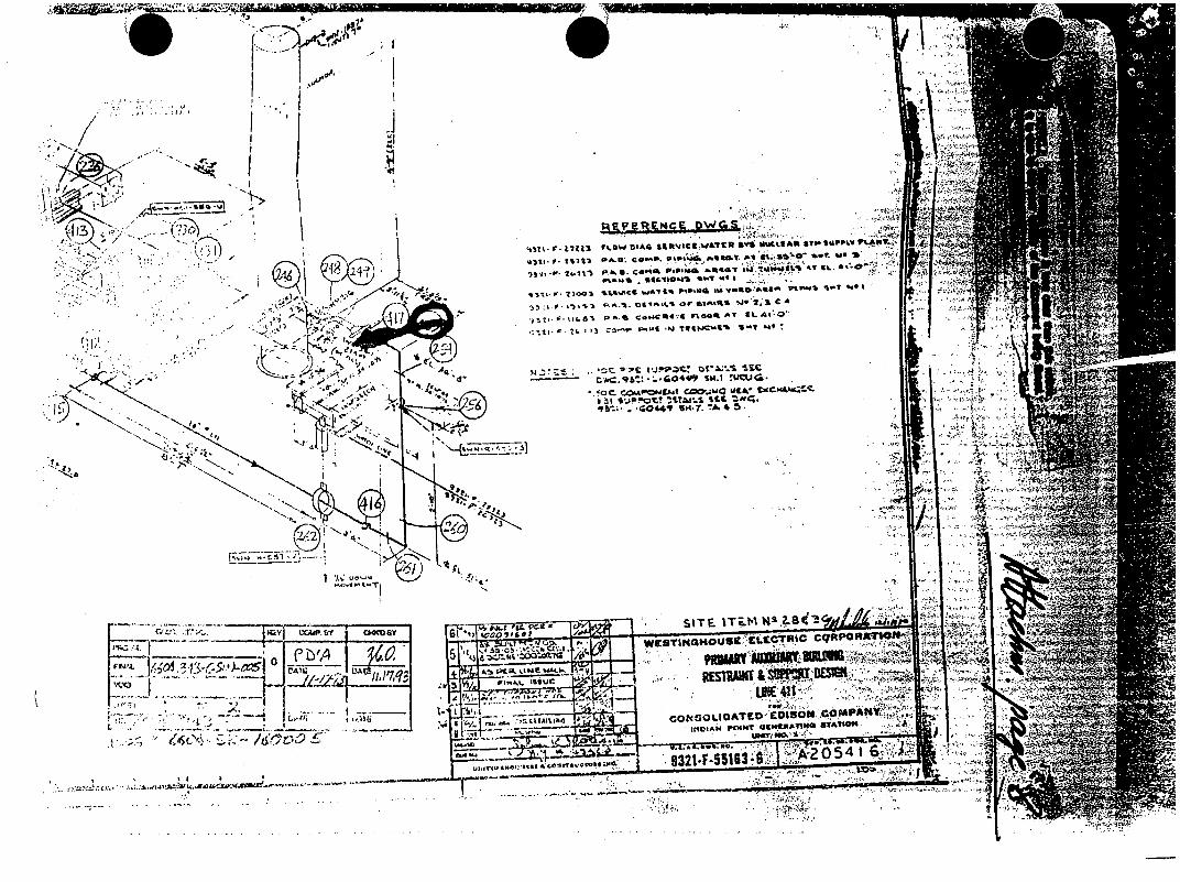
Slk r- 17M1 OJUA $jjlttCg W&TCU Z6 1WCIAft STP SUPPLV P'.AUT
Is~ -41 l.11 r- U C6140% . M ma sil -7-." AT 9L 40
931W 7003 LSW"Ce wJAI& CkP,MC. mi VftWAQ5 9 1- ~
%.'a p .. -0 caScmO'a n@os ^T CL 4.0,
it-- I >.GO4 SM. w cuZ' T.4
OCAPOMIM COO0.Juc Ul . Yme"&o
~itsi01 S..'v -1 SE iLm' qb-' -. .4044r -SH.7&. 4 5.
C/2~~~~~S T ITEM. Ws'.B 2-8 0~ Al /"..cia"-,
1/'2A~fFVcjJ~.~-5 L45~ cSatOHUSCLC~l~ cqPOA1@N #
'j,,
n p..Am ~~~~~~~~~~~L 41o:I* r m ~ 921F513A 5
* '77 "A CO a-.*A ED -0 5
A'-
I-j

I )IS/'A). PIPE ADLPIPE SfRI'SS ANALYSIS 3: .143, 11,PA-I03. S IlVICE WA r PIPIw sYSIEM
I. Lt(- 40) :0,E .LI,'. . 12 (1-051 43i E3V OL6:C D1(3 :11 "132 .I:-6 163, R3EV. ;, AN!) 9321-F-551L22. I1EV. 1O _.. 1 :1,o !- 6 (I Lu I r . . . .. .. . .
". H;t5: Ih ' " ([.[AW . IN)
'."
!.IEMl iI) P(S TYP.
21;0 l'l'l II
26.1 LFG;[) 1.
! coH Irmo r i.,
5 22 BEG 4 / 9 .ID
uw 1. "16) :,b
I ) '50 BEG.( III) 219 ElO UIJ
12 24) 110 I.
2,13 E l .L
O 1:3 2,4t P E( RUi 2,16 VNO L Q u
266 I1:11 9(7
.. ' . .. .. ..
IORSIUN -20. II
...... .. . .
21 .1I
4 1 0
41 9
1111.4 I Ill,4
.1O. 0 ........ .{ ...... "'0. 6
SiCNO I NG 13311.5 272 . 0
18.2
86.3
6G;. 1
40. (3
:0.
263.8
362.
i'). 1
:37. .3.O4
1:.') 4'1. I
COMB I (f0 1339. 2
84.6
92. 1 92. 4
d6. 2 Wi,. 11
.... " .......
2011,.0 1021.2
35!;,.g
1.. u. (3
56. 6 )26
-OC 3EIA 11 9A/11/ 043 17 20 47.
IN INSI r (CAI I ON F AC IOR' ('RIE S I" . IN PL. ANE I WANSVERSE
16818.1 3:500 23.500 I6(d.3 3.50 3.500)
16188. 3 1 ,000 1.000 ... ....... G , : ...... ... ... .i i 6 .......... .... i : 5 .... . .-... ..... .......... ............ ..
638 .1 (000 I 01)
16 801. 3 1.0)00 1.000 1611. 3 3. O1O I. O
1611.3 3 oo 3 100
1618 . 1 .00 I. OCK) 1616. 3 1 00- I.00')
JIr ," .
"1i:',, I
1118. 2
I F'(L1. 2
130(4l . .3
I 68 i3 1(1(.3
78 .
731. I
"t)19. 1
1.3(:)0
I Of,)
3. 7GG
1 00
I. 0.00 I. 000
I . 000 1.000
I. 000 1.0('2
I : (X.)
3. 166 3.766
. 00
I , '0
I ',() "
,-.........!~-...--.'*..-.*.*.......
.4'
'I
I J';;'N', [3:1I1I. I j'.; I C S" Q I 1 0 R Tl

(I S-. -I -
DIS/AOLPIPE ADLPIPE STRESS ANALYSIS .9 .' 4, NYPA-IP3. SERVICE WATER PIPING SYSTEM
.I .1 AND LINE 411 (PROB 416&432) th.C DWG NO 9321-F-55163. REV.G. AND 9321-F-55123, REV. 10 ,41 ,L. XtY+Z lOBE I
I..
COC 3EtA 0
..OND I TION 2 1
.....IN.. . ... ... . . .. . .. .. ..... .. .--.. .. ......... ...... ... .
STRES UNTS(L/SOIN)
..O DAL STRESS SUMMARY. TOTAL NUMBER OF MOOES 47 RENDING MOMENTS ARE SQUARE ROOT SUM OF THE SQUARE. USAS 831.1 STRESS REPORT
9.9)
1l)RSION BENDiNG COMBINED
35.4 1499.3 158l.8 258.5 1499.3 1585.9
INTENSIFICATION FACTORS PRESSURE IN PLANE TRANSVERSE
.0 3.500 3.do
.0 3.500 3.500
428d J., -. O.D. 6:3 2 4 8 16. 8 .0 1.000
, bB .5 632.4 391 . 7
i6,8 785.7
.6 1.000
.0 1.000
... ............. i-' : - . ...... ........ -... . ............ ...... '.000 ' 1.000
1.000
9.251 5 7C., 2 2 13A-7. 251 ~.t .0 3.500 3.500
,3 253 U(G pSl -313.8 237.9 67 1.2, .0 1 2.. Ewl 9. -313.8 240.8 672.2 .0 ,.000 1. ..0
417 END PU -1
250 ENO 1.d
67. I 67. 1
•I 67. I -167. 1
t28. 2
152.0 200. 1
19 2 250 8EG RI -2S2.G 302 4 249 ENO Rl3 -252.6 327.5
19 249 BEG EL -22.0- 1.233.
248 E140 EL -325.U 1423.2
266 r~t:r 1:u 2 2 206 1;2:. sd ]:7.$ ~ ~ ~ ~ ~ ~ ; .... .... i"UF-"i .........
41H IEND I
- uta T i) ...
351.o ,367.5
.:389,.5
.0 1.0-00
.0 1 .000
.6 i.66
.03 1 .000
1.000 1.000
1.000
6 2 .0 ...................... ' ....... . .. .... ... f...... . ....
602.0 .0 1 .GOO 1.0()o
1565.3 .0 3.766 3.766
-325.8 .'/?.) 75-3 .2. I O '7-
325. d 318e.2 753.3 .0 1.000 1.000
37.d 2iso.u 337.6 1748. 1
1 . 8 ............ ... .
21 1.8 847.
2i1.16 211 .8 771.2
2292.9 .0 1 " . .000 1.000.. 1.000 1,00
" '.. ........... ............ .i':o .. .. . 947.5 .0 1 000 1.000
947.5.. "0 1.000 1.000 A79. 9 .0 1 000 1,000
T. 9
.:. .,,
9.?. ~

-J.,
•~___ _ _____ --- - .- .: -.
* / /1'"- !-- .
" -*------- -----.- '.'
F 7
IND !I?: PO N NUCLEA -p STACI. ; - tby:T 3 I ; ; _
cL'ss: :I.N sC:R-Ess " :--. SF'T 4 OF"/r
O'NT
gor n 10.72 p e x., 7 ir-l ....
Sc.~ No.
9gZ2 -F --_5.3 K2
101, TD" - . .:- -.
~xfor allur C(PSI) -Z
- -I '"
M.t o o po•..No
i , r-- / :
- ~7
T _- --- : . for all Cc .) S :-z1.e- .- ,--' I > l ]
J -p--_- -___u_ ,._-
.. : '-.,f.-a.'.-kC C0Bdn,) -<~ ~4~~7 .-0 . . .... _ _. - ,, ....... it
"" <"tu': :e S ____________
7. i + L o d z ,-r,: , -;, j-7_ .. . .. ... ..
S " -" : . P < . S.... .-} ~ :\ ....... . .. .
T 1 p' . " . .1
- . ' M 2- -"o- -_

AVA
2. STA rssS UAWA1~ A.-/ 'C&OT'b vw 'sor1
0Pz 10.7
I .IOoetric Drawing o.. 1 2 .Co0m pu t er Pr i -t -0t '~t~ o, ~ a: C 11
L[S- s ±4-- X-+41,z .3.Llot Of Loads o. Th-'-- ermal: i-.
Dated: '~ i~
I ~
I I
H
I I
ii
I
N

I " , .,'?
, ,f;: " - , t , : .
.,: ,
-li lii-.i.
6GENERAL
COMPUTATION. SHEET
PROJECT p-fP r~3 SUBJECT 1.4. 1-.,E. 4?/ 1/ .4A.ML-9JS
9uIE4ET '.YC44AA4F O. I. ',,
4QUALiFrtcArioA OF COc'LJAI,6 ATFJR HF4T XCAJ5JlU O . "S I A , l D A le , 2 2 <'"/P -V.- 2 9 . / o / 7-7/'E vEA"'Do/Z-~O'6
E5ur"PrI " .P. 24 22 , q 4 ,, ,EEv L'S"
FOA r /# E 4 E/,.FITo A - /4LS, 1-.HsEs ,$L AAE 7-,0~ 7- A C () OF M X 41-,p/ 7-,A1 VEA"001Z 44-4041e -9?L5-s
'V
4P L JA t . I j ., ,,IT / 6 .-( j o .

2 -'
~ :r I - - ;~Tv~.
.3-' -
I GENER COMPUTA
I 'g W SHEE
AL lTION T
PROJECT APIPA p- 3
SUBJECT .. . 4 0 7,, AAAL1/ IS
CA~.OLMAT~ ~? NO ~'psY
ae4. 343-c- w,-"s PAELOA FML I VOID
way 7 op 19
jo 164 4. 34 3
cV.0AtALF.CAT1.-/J -Or C,,00-11 . WI .,,, X
C...'In TH6rM VbA"(-S)o ,4L(-OWOAO-ES
OATE
/DATEY
I ATE
31
____________ I I
ALLOWvAYLI t e>4-D ( . '9
CAL //.0
____ _________I- I
40o0 .03 /
.144 .0 .
PE*I'IAVZIK S
, 2433 _- -,x 3_7_5 ._ _ 1__0
IL
.56 4.t 0
_1 - .23 . 1 1 %j 3438 F- 7000 .492 1.0
_ _ _'' '' •
4500 1,0
I-- - - 1
14/6*7 .!-7 4 /.________ 4 1
*-:,- .:7
/ 3 o1 5I - - ---- ----- -tI
________ I -~ _____ I 3-. - S.
63 <
1
*1
-1.70 - I.o
A y
- A4'~.
.' I :.-~
LEVELL OAD)
P j l7 7 I& 1 4000 1 41 1 .I
134:
3 g67/
/22
8201
q 7 47
.x. ./~--.
-7
I

:j$~ &4~2
r S
.cMu M -~ll hurl I
* @onsrualo a GENERAL COMPUTATION SHEET
PROJECT AVYPA .P- 3
SUBJECT 5. U. iUAES 4,u.A1 L/AY .
CALOAATrJ( WT No
rWLu F?4AL "
sW 8 oF1
Jo_ 64~. 313
0V couA vy
0O AT
11-03!!DATE
/ HE-,4- T , AV 6 "Er ,, LE @ )AL; tCT/,/-) . e rl >
(POALWIICAT/oA0 -OF ccOOc- W,4TEa 94X vo. 31 b
L~v LCAL UATr- ) LL WaF -!AL 4101P -L OAb1 0e4 D ALLOW
-/ 2344 F; 0- o .29 4 1.0 _ R -/ 4-74 F1 L5-O 04 /-0
l2 3969 Fz .01 4. I_ _
+ Y3~ /-o~____jf~t /7/g , 8333 .13 K /.0_
/1- '1' 22S IA$' 17754 /6-&1.o ,
/ez112 V/A 2 1 7 7 0 71 <' - _- _ _ _
• P2 !,
%j_ _ _ _ _ _ _ _
l~IMzI I ~-, 1 ______ _________ I I
LylE ~-'e'rE F~ - RA~;A..
I-
043(0 By
DA'E
4-,.
polm WI Kv "I

77~-CkAI1?A'T SNew York Power
Autorft Calculation No.: IP3-CALC-SWS-01596
Project : IP3
Subject: Mnirnum Pipe Wall Thickness end Maximum Through-Wall
Raw Size for Seismic Class I SW Lines
Revson : 0 Page 20 of 26
Computed by O . DateX.f
Chocked by AU Date LI5/0
3 .0 0 .. " ........ ... ....... -........ ............. ........... ............ .............." ............ ........ . ... .. ....... .." 3.00 . - -. . . -
Oor C. S. with tmtn , 0.3
• . ...... ............ .......... .................... -- --------- ------ ........... ---- -- .............-
~2.50 .... ***
2oo .
-(NPS)
* 1
... ....... ... .......... ---............. .--------- .............. ............. ,..............
1 .0 0 . ............ -.. .... ..... ..... ----. .. .. .. .. ....------- ------ -------.. .... ..... .. .. ... ... .
E -I:
0 5 . . .. ... .. . .... .......... .. . ...... .. ........... ........ ..-- .. ...... -- ... . . ..... .... ... 1.50
0.0 II I I o U) O 0 0 0 ULO 0 0n 10 0
r% 0i (N 1. r: 0 C4 1.6 P 0 - - 4 (N CN (N (4 (V
Maximum Axial Stress (kei)
Figure 7 : Maximum Through-Wall Circumferential Flaws for C. S. SW Lnes (NPS 12. to 24")
77 /P3- !C-J S/ - .o/o9 ~o2
(),7.a / .6, /I w

New York Power - ultrasonic Examination Report ....... . - Authority P .agooUT2
Sys. Comp. ID: Service Water I SWN - 34 - 1 Exam Item: Line 411 piping Dow7tream of 8WN34-
DWO No. or Sketch: 9321-F-27223 QA Category: Cat 1 ASME XI Class: III
WRJMod: 99-00044-43
Cat: N/A Procedure: NDEP 9.4-12 (i)
Component Configuration: CCW Piping
Orientation: 0 Degree Type of Material: Carbon Stel
Angle: 0 * Mode: Longitudinal Size: 18" Std. wall Thicknevs: 0.375"
Eauloment Instrument 213110 Krautkramer Branaon USL 48 Due: 07113/190
VertjcAl Linearity Check AttenuatorLinegrity Check Signal t 40ll _ 1 4 130 1_20 I_ _0".-_ I _"_-_d_ 4o% ;- Signal 2 @ 1 40 1 Zo I I
(Signal 2 shall equal 60% of signal 1 - 6% of full (2alt.) to) (1.to 24) (Wee) t-g)
Transducer: 0030HD KBA 5 Mhz .25" RND ADP DUAL / GAMMA Wedge: NIA
Search Unit Cable: 6 SelfCont. Wedge Meat. Angle: 0 o Exit Polnt-Front NA Couplant: 97120 Sonotech I Soundoafe Thermometer. QS-1a Due: 8/5/2000 Temperature
Calibration Block: IP3 E/C # 3 Step Wedge To .15"' .5" Material: Carbon Steel 68 *F
Simulator Block: N/A N/A OF
Reference Block: N/A /. OF
Entry Surface. OD ".;,. Component: 65 OF
Distance Amplitude Cut. . Each Major Screen Division I 0.1 % Instrument Settings 100 Reflector Orient FSH Poe. dB Range (In.): 0.5"
90 --- ,,-151 BR .. -I 1, -A Sweep Length: 8.06
so "A. Step 80 yx -NW Sweep Delay; 8.26
70 .... tep0... . $ p 80 Sensitivity (dB); 58
6 0 . . . .. .. . . . . . . .. - . . . . F r e q u e r c y ( m H z ) : 5 - Reject: Off
Filter: NEG 40 .Pulse Length; Fixed 30 ..... . . .. ....... .1.7
. ......... Damping: Min 20 C -- Mode Select: Duel 20Calibration Tie. Rep. Rate: Fixed
j.... . - 12560"31- . J DEC/Gate: On 1 2 3 4 5 6 7 8 10 Jacks: T&R
Acceptance Standard: As per IP3-CAL4WS-1596 Recordable Indication(s): Yes Recording Level: N/A% DAC Evaluation Level: NIA % DAC 100 % Complete Limitations: Surface painted at most locations, average D.F.T. M 0.009" Remarks: UT Examination of Line 411 was performed to evaluate wall thinning of 18" dia. pipe Downstream of
SWN-34-1. the pipe has leak at grid location "J. Further evaluation was required to perform UT exam.above ad lw "J" grid location to determine the length of corroded area.
Examiner. -..... ,ral H. Mmon Level: III Date: 4/t9199
Examiner: N/A _Date: 41,19199
Reviewed by: Level Date:
ANII Review: Date:
_( * I .... T c z iT IJ - . . . . .. . . I II .... --
Rev.: I
7n' J cr)n * nki r-7 - OT aa C T ',%IJW 0))CQQ0)!(TT A T -Hn

, Authority .. ..Report No.; 09UT028 Page .r of 2.
Sye. I ComiC; I0: Service Water I SWN - 34 -1 Exam Item: Line 411 piping Downstream of SWN34-1
DWO No, or Sketch. 032t-F-27223 QA Category: Cat I ASME XI Class: III
WR/Mod: 99-00044.03
Cat: NIA Procedure: NDEP 9.4.12 (I) Rev.: 1
LIO;w7..
~~?ca S4 O~~
.. .. ... "- . '0I L
"70 i79 - ,o. e _ , II=
AK~CLUt5E. ~J,.x-r ~c~C)OE~E3
3A7
. ,j o (z) 1"
Z'5S .,,I1 (4)
cr7)
Examiner A:.. f, SrJ H. Memon Level.,III Date. 4t._jq .. _
Examiner IA Date: 4119/99
Reviewed by: Level Date:
ANtI Review- Date!
66,61 IdU 9 S892I:dl
0 A, M&Axeq /,-/ M,4 3-cwews -able'l&e
2O'.d SOO'ON 02:2T 2dl-U0
SketcfINAttachment

4-. - Page 1 ofi1 '-
. A ;
- 4-3W? 4 A
I4 ~ ~ '
'4i
- - .- ~ ____
file://C:\WINDOWS\TEMPMvc-001 x.jpg 4/19/99