Embed Size (px)
Citation preview

Revised - July. 2014
Rubber Dock Hose care, Use & Maintenance
Prepared by: Thomas J. Wise
VP Corporate Development
Contents

Revised - July. 2014 2
1. Novaflex Rubber Dock Hose Testing & Inspection Program 1.1 Introduction - This instruction booklet is intended solely for the use of The Novaflex Group customers as a guide for
hose Care, Use & Maintenance of Dock Hoses. This booklet is not intended for distribution to the general public. In all cases readers are instructed to follow local, state and federal guidelines, requirements and laws regarding safety and environmental issues. This booklet is not intended for use in the selection of a particular hose product or coupling.
All tests performed on hoses involved in this instruction manual are non-destructive. Non-destructive tests are conducted on a length of hose or hose assembly and are for the purpose of showing defects which cannot be seen by visual examination. 1.2 PRESSURE TEST WARNING Before conducting any pressure test on hose, provision must be made to insure the safety of the personnel performing the test and to prevent any possible damage to property. Only trained personnel using proper tools and equipment should conduct the tests and must follow established test procedures.
1. Personnel must wear all appropriate personal safety equipment – not limited to hard hat, eye protection, protective clothing, gloves, safety shoes, breathing equipment, etc.
2. Air or any other compressible gas must never be used as the test media because of the explosive action of the hose should a failure occur. Such a failure could result in damage to property and serious bodily injury.
3. All air should be removed from the hose by bleeding it through an outlet valve while the hose is being filled with the test media. Novaflex will only use water as the test media.
4. Hoses to be pressure tested must be restrained by the placing of sandbags on top of the hose at each end of the hose. On long lengths of hose sandbags can be placed alongside of the hose to prevent whipping in the event of a failure.
5. The outlet end of the hose is to be backed up with piled sandbags to prevent an ejected fitting from propelling any distance.
6. Provision must be made to protect testing personnel from the forces of the pressure media if a failure occurs. All personnel should be clear of the hose testing area to prevent the effects of the pressurized water from causing bodily injury.
7. Testing personnel must never stand in front of, in back of, or on top of the hose being pressure tested. 8. When testing is in process, adequate alarms and signs should be placed in the general area to advise all
nonessential personnel to avoid the test area. 2. Personnel Training Program for Novaflex Hose Coupling and Testing
2.1 Personnel Requirements - It is important in any hose-testing program that the human factor is taken into consideration. The individuals responsible for the inspection and testing of our hose products must be properly trained and competent. The minimum requirements should include:
a. Ability to read and write Basic English. b. Possess basic math skills so that they can read and understand:
i. Pressure gauges ii. Test procedures iii. Acceptance charts iv. Label and test products v. Measuring equipment and coupling data sheets
2.2 Hose Inspection – All hose and hose assemblies should be inspected before each and every use to prevent spills.
2.1 Rubber Dock Hose - The rubber Dock Hose inspection procedure consists of four main elements (some of the
elements are more applicable to hose that has previously been in service).
2.1.1 External inspection (no pressure)

Revised - July. 2014 3
The external portion of the hose or its "cover" serves the primary function of protecting the reinforcement members of the hose from physical or chemical damage. The cover should be carefully examined in order to detect areas where possible reinforcement damage may have occurred. Any cuts, abrasions or cracks in the cover that result in exposing the reinforcement, whether it be wire or textile, must result in the hose being rejected and taken out of service immediately. It must be remembered that the rubber hose cover may show signs of surface cracking due to prolonged exposure to sunlight, ozone, and/or chemicals, but this by itself does not require the hose to be removed from service unless it completely penetrates the cover down to the hose reinforcement. If in the event a used hose has become extremely soft or has visible stress areas behind the coupling stem evident on the cover, this is cause for removal from service. Some used hoses may display bubbles* in the cover or loose spots under the cover. This phenomenon requires the hose to be removed from service. In some cases a cover blister (separation of the cover from the underling carcass) may be discovered. In this case if the hose is in service, carefully slice (personal safety equipment must be worn) this area to see if any of the product conveyed is under the blister. If oil or the chemical conveyed material is found the hose must be pulled from service. If air is found in the blister, the hose can be used to finish the loading process and then removed from service. If a hose is kinked (a kink is where the hose is dented greater than 20% of its diameter) or flattened it must be removed from service. If a hose has a kink less than 20% of it diameter the hose can be used to finished the load/unload process and then removed from service.
Blister with air
Kink in Hose

Revised - July. 2014 4
2.1.2 Internal Inspection
This inspection mainly applies to used product but should be performed on all hoses during the coupling process. The internal inspection must be performed through the use of back lighting or a flashlight shown down through the tube. It is recommended that a 20HG vacuum be applied to the hose and observation of the hose interior be done through a clear Plexiglas plate. Observe as much of the inside diameter of the hose as possible.
Cause for rejection of hose during the internal inspection is usually a result of the tube being subjected to product it was not designed to handle. The following phenomena, if observed must result in the entire hose length being retired from service.
� Loose tube � Cracks in the tube � Soft or gummy texture of the tube � Blisters in the tube � Tube worn excessively � Tube swelling (resulting in the inside diameter being reduced to a smaller dimension than
original
2.1.3 Coupling Inspection
Each style of fitting must be inspected based upon its own merits and requirements. This process involves the wiping of the inside of the coupling and the outside of the coupling with a rag prior to inspection.* If the following phenomena are observed remove the hose from service:
a. Any worn parts that prevent the fitting from performing its designed function. b. Damage to any safety devices, which result in them not working correctly. c. Threads worn or damaged d. Excessive corrosion or rust e. Any cracks observed in any part of the fitting f. Flange face damage – scratched or nicked
Used hose must be inspected closely in the area just behind the fitting to make sure there is no evidence of stress on the hose caused by pulling and/or hanging of the hose against the coupling shank. If this is observed the hose must be removed from service.
All couplings must be inspected for evidence of coupling movement. If movement has taken place there will be marks or scuffed areas just behind the coupling ferrule. If this is observed, the hose must be removed from service.
Kink in Hose at end of coupling

Revised - July. 2014 5
2.1.4 Method of Attachment
Dock hose generally utilizes a crimped/swage type or a built in nipple. It is important that the dock hose staff be familiar with the main types of attachments as mentioned earlier in the program. The type of attachment refers to the method with which the coupling is attached to the hose. Hose should never be installed so that the installation causes torque or stress on the hose assembly. Novaflex recommends the use of a floating flange (ANSI Lap Joint Flange) on one end of the hose to facilitate ease of installation and the eliminate torque from the misalignment of the flange bolt holes.
Crimped on / Swage Type Hose Coupling
Built in Nipple Type
Once the hose assembly has passed this inspection procedure, it must then be hydrostatically pressure tested in accordance with local, state & federal requirements.
2.2 HYDROSTATIC TEST PROCEDURES To obtain maximum efficiency and safety in using hose, hose couplings and other fittings must be of the proper type and be installed in a manner recommended by the manufacturer. Based on the specific type hose & Coupling involved used the appropriate testing criteria per NAHAD, USCG, BS-EN, ISO and others.
� Connect test pump to water source. � Connect manifold to test pump (if required). � Lay the hose(s) out straight. Dock hose should be tested on hose dollies so that the hose can move freely during
the test. NOTE: These hoses should have been previously inspected per prior instructions. � Attach hose to the manifold. � Install test flanges with new gaskets, complete with valves on the ends. NOTE: the end of the hose that is not
attached to the manifold should be elevated to allow any trapped air to escape through the open valve. Tighten all connections.
Flange can rotate in either direction.

Revised - July. 2014 6
� Begin to fill hose with water. Be sure ball valve is open to allow trapped air to escape. � After all the air has been purged, close the valve on the elevated end of the hose and allow the test pump to build
pressure to levels outlined by RMA procedures. � While at working pressure (do not exceed working pressure), examine each length for leaks (especially near the
couplings). Also inspect for any noticeable bulging or swollen areas. Finally, inspect for any coupling movement. � Any hose that leaks or shows signs of wear, bulging, swelling or cracking should be retired from service. � Test time should be in accordance with RMA, or local, state or federal requirements. Tests should never be
shorter than 15 minutes. � During the test, all ends should be secured and protected should a coupling come off. � Upon completion turn off the test pump. � Open the valve and drain water. � All used couplings, if required, should be buffed, oiled, and all gaskets replaced.
2.3 Proper records should be kept showing the date of the test. The hose assembly should be appropriately tagged
with the test date and all pertinent data 2.4 If elongation testing is required, follow the NAHAD guidelines for this requirement.
Once all the inspections and testing have been completed a Dock Hose can be placed into service. This testing should be repeated at least every 6 months. Remember, each hose should be visually inspected before each use for signs of external damage.
3. Dock Hose Handling – This section is a guide line presented to assist the customer in obtaining maximum service life. Every installation has different requirements and different equipment to handle Dock Hose. Below are basic suggestions to facilitate hose handling and to prevent hose damage.
4. Typical correct & incorrect handling situations

Revised - July. 2014 7
a. Novaflex recommends the use of lifting slings (min. 12” wide), lifting buns and cradles designed to reduce stress on the hoses.
i. Hose slings – woven strapping that includes a center portion with a wide support area.

Revised - July. 2014 8
ii. Hose buns are excellent for lifting and provides superior support of the hose.
iii. Hose dollies – for moving hoses on a hard surface
iv. Supporting cradles – custom devices/supports made for a specific application.
b. All of the above devices should be used so that the hose is installed at 1.5 times (or greater) the min. bend diameter to provide maximum service life. Never bend the hose tighter than the minimum bend radius. The handling devices should be designed to accommodate a variety of hose sizes where possible.
c. Dock hose can be installed in a variety of positions. It is important to support all dock hose as shown
in para. 3 a. In addition, hoses may come into contact with sharp edges or the edge of a ship or dock. In these cases the use of protective matting can prevent damage to the hose cover from movement

Revised - July. 2014 9
or vibration. It is also important to ensure that the end of the hose is supported so that the bend begins behind point where the rigid steel part of the coupling meets the rubber hose.
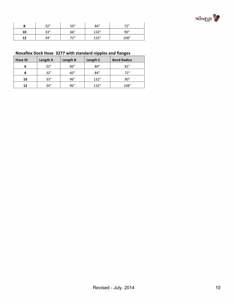
d. In an effort to assist customers with the correct installation of a dock hose, Novaflex has listed
suggested support areas that incorporate the bend radius of the hose. It is common to build a curved support to prevent over bending at the coupling area.
Novaflex Dock Hose 3261 and 3265 with standard nipples & flanges Hose ID Length A Length B Length C Bend Radius
4 31" 40" 84" 36" 6 32" 45" 84" 54" 8 32" 50" 84" 72" 10 33" 66" 132" 90" 12 34" 72" 132" 108"
Novaflex Dock Hose 3267 and 3268 with standard nipples & flanges Hose ID Length A Length B Length C Bend Radius
4 31" 40" 84" 36" 6 32" 45" 84" 54"
Rigid Portion A Start flexing at this point
Revised - July. 2014 10
8 32" 50" 84" 72" 10 33" 66" 132" 90" 12 34" 72" 132" 108"
Novaflex Dock Hose 3277 with standard nipples and flanges Hose ID Length A Length B Length C Bend Radius
6 32" 60" 84" 81" 8 32" 60" 84" 72" 10 33" 96" 132" 90" 12 34" 96" 132" 108"