Embed Size (px)
Citation preview

Heat Transfer to a Fluid in a Stirred Tank University of Illinois
Heat Transfer to a Fluid in a Stirred Tank
The heat transfer coefficient of the wall of a tank of water and a jacket of steam is found in this laboratory. Heat
Transfer is measured in two sections. The first section is at steady state, when the temperature inside is time
independent. The second section is at unsteady state and the temperature is increasing.
1Unit Operations ChE 382 Group 5 Spring 2011 3/1/2011Damo, Duffy, Guerrero, Hsu, Kosak, Qamar, Tyska

Heat Transfer to a Fluid in a Stirred Tank University of Illinois
Lab Prep Report
Unit Operations II Lab 2
March 1, 2011
Group 5
Andrew Duffy
Daniyal Qamar
Jeff Tyska
Bernard Hsu
Ryan Kosak
Tomi Damo
Alex Guerrero
2Unit Operations ChE 382 Group 5 Spring 2011 3/1/2011Damo, Duffy, Guerrero, Hsu, Kosak, Qamar, Tyska
Heat Transfer to a Fluid in a Stirred Tank University of Illinois
Contents1. Introduction.........................................................................................................................................4
2. Literature Review/Theory....................................................................................................................5
3. Experimental.....................................................................................................................................13
3.1. Apparatus..................................................................................................................................13
3.2. Materials and Supplies...............................................................................................................18
3.3. Experimental Procedure............................................................................................................19
4. Anticipated Results............................................................................................................................20
5. References.........................................................................................................................................21
6. Appendix I: Job Safety Analysis..........................................................................................................22
3Unit Operations ChE 382 Group 5 Spring 2011 3/1/2011Damo, Duffy, Guerrero, Hsu, Kosak, Qamar, Tyska

Heat Transfer to a Fluid in a Stirred Tank University of Illinois
1. Introduction
Stirred tanks are probably one of the most used pieces of chemical engineering
equipment that come is a wide variety for chemical processing applications. No two tanks are
alike and have to be designed specifically for the proper application. This involves looking into
the materials and operating parameters to ensure that the desired results occur in the safest and
most efficient way possible. The most common uses are for chemical reactions, leaching,
blending, and dispersing. Typically when looking into the system from a theoretical point of
view the tank is assumed to have perfect mixing or constant bulk properties. This is done to
make the calculations around the tank more manageable.
The main purpose of this lab is to determine the effects of heating and cooling on a
continuously stirred tank with multiple processes. Heating is performed by a steam jacket which
allows heat to be transferred to the internal liquid and as for the case of cooling the tank there is
an internal cooling coil system which uses cold water to remove the heat. There is also a
secondary system to cool the tank which directly pumps the liquid out of the bottom through a
heat exchanger that is also fed with cold water and then sends the cooled liquid back to the top of
the tank. Another aspect to this experiment is the use of baffles on the effect of mixing which are
implemented to enhance it.
The heat transfer coefficient between the fluid and the walls of the vessel will be the main
focus for calculations in this experiment based on its dependence of the impeller speed, fluid
properties, and the baffles. Heat transfer coefficient values are functions of the fluid flow field
and molecular transport properties of the fluid. Since a mixing tank has a very intricate flow 4
Unit Operations ChE 382 Group 5 Spring 2011 3/1/2011Damo, Duffy, Guerrero, Hsu, Kosak, Qamar, Tyska

Heat Transfer to a Fluid in a Stirred Tank University of Illinois
pattern the heat transfer coefficient would be too complex to determine. Therefore the coefficient
must be determined experimentally by correlating it with dimensionless groups. In convective
flow the Reyonlds number (Re), Prandtl number (Pr), and geometric factors are needed to do so.
Four cases will be studied in this experiment. The first is a steady state case and the second is
also at steady state with the baffles placed in the tank. The third and fourth cases are both
unsteady state cases with increasing temperature where one is with the baffles.
2. Literature Review/Theory
Constant stirred tank reactors (CSTR) are widely used reactors in the industry. They are used
to carry out reactions that require intense agitation, such as the addition of gaseous reactants in a
liquid, a solid reactant in a liquid, or polymerization reactions. (Rawlings 5) Heat exchange in
CSTR reactors is a very important and well-studied division. A highly exothermic reaction or a
highly endothermic reaction both require that heat be taken out or put into the reactor
respectively.
Heat is the transfer of energy from one substance to another. There are three types of heat
transfers; conduction, convection, and radiation. Heat conduction is the energy transfer at the
molecular level. As molecules collide and bounce off of each other they exchange energy, the
high energy particles loose energy to the low energy ones. Heat convection is the energy transfer
as the bulk fluid moves and radiation is the transfer of energy without a medium, it does not
required molecules or a bulk fluid to be transferred. In this lab we will be mainly studying
conduction and convection. (Bird 266)
5Unit Operations ChE 382 Group 5 Spring 2011 3/1/2011Damo, Duffy, Guerrero, Hsu, Kosak, Qamar, Tyska

Heat Transfer to a Fluid in a Stirred Tank University of Illinois
The rate of heat conducted depends on the thermal conductivity (k) of a substance. This
constant is a measure of a substance’s resistance to heat conduction. The higher the k value the
easier it is to transfer heat through this substance. Temperature is the measure of energy a
substance holds and heat always transfers from a high temperature region to a low temperature
region. Heat is transferred according to the following law, known as Fourier’s Law (Bird 266-
332).
Q / A=k dTdx (1)
Q is the Heat transferred
A is the area this heat transfers through
K is the thermal conductivity
T is temperature
x is the distance this heat is transferred through
This law states that the heat flow per unit area is proportional to the temperature decrease dT
over a distance dx. The heat transfer, at a boundary, that takes place between a fluid and a solid
goes through a thin film. This heat transfer is not defined directly by the Fouriers law but is
defined by the Newton’s Law of cooling which is defined as follows: (Bird 266-332)
6Unit Operations ChE 382 Group 5 Spring 2011 3/1/2011Damo, Duffy, Guerrero, Hsu, Kosak, Qamar, Tyska

Heat Transfer to a Fluid in a Stirred Tank University of Illinois
Q13=hA (T0−T b ) A (1a)
Q13 is the heat transferred
h is the heat transfer coefficient
T0 is the temperature of the surface
Tb is the temperature of the bulk fluid
A is the area of heat transfer
In this lab we will be studying the heat transfer through three different regions.
1) Heat transfer across the internal fluid to the wall of the stirred tank
2) Heat transfer across the tank wall
3) Heat transfer from the condensing steam to the tank wall
Since these three regions include the heat transfer through several different mediums a collective
heat transfer coefficients (U) can be derived. U is defined as the following for this lab:
U= 11hi
+ 1ho
(2)
hi is the heat transfers coefficient from the fluid in the CSTR to the tank wall. (W/m2−K ¿
ho is the heat transfer coefficient from the tank wall to the surrounding steam. (W/m2−K ¿
With the overall heat transfer coefficient, Newton’s law of cooling becomes:
Q13=U (T 1−T 3 ) A (1b)
7Unit Operations ChE 382 Group 5 Spring 2011 3/1/2011Damo, Duffy, Guerrero, Hsu, Kosak, Qamar, Tyska

Heat Transfer to a Fluid in a Stirred Tank University of Illinois
U is the overall heat transfer coefficient (accounting for heat resistance of all three boundaries
listed above and described by equation 2) (W/m2−K ¿
T 1 is the temperature of the steam surrounding the CSTR (K)
T 3 is the temperature of the fluid in the CSTR (K)
A is the heat transfer area (m2)
Some assumptions that are needed to simplify the heat transfer are that the wall thickness is thin
compared to the tank so area is same for both values and that the tank wall has a very high k
value so it has no resistance to heat transfer.
The following picture can help to understand the derivation of the overall heat transfer
coefficient:
Figure 1: Temperature profile
As the heat transfer from the right to the left it first goes through a thin film with heat transfer
coefficient h0 then it flows through the solid with heat transfer coefficients kscale and kwall finally
8Unit Operations ChE 382 Group 5 Spring 2011 3/1/2011Damo, Duffy, Guerrero, Hsu, Kosak, Qamar, Tyska
QQQQQQQQQQQQQQQQQ

Heat Transfer to a Fluid in a Stirred Tank University of Illinois
comes out on the left side where the heat transfer coefficient is hi. The heat transfer through in
the solid-fluid interface is described the equations:
Q = hiAi(t4 – t5) = h0A0(t1 – t2) (3)
h0 is the heat transfer coefficient across the solid-fluid boundary where temperature difference is
t1 – t2
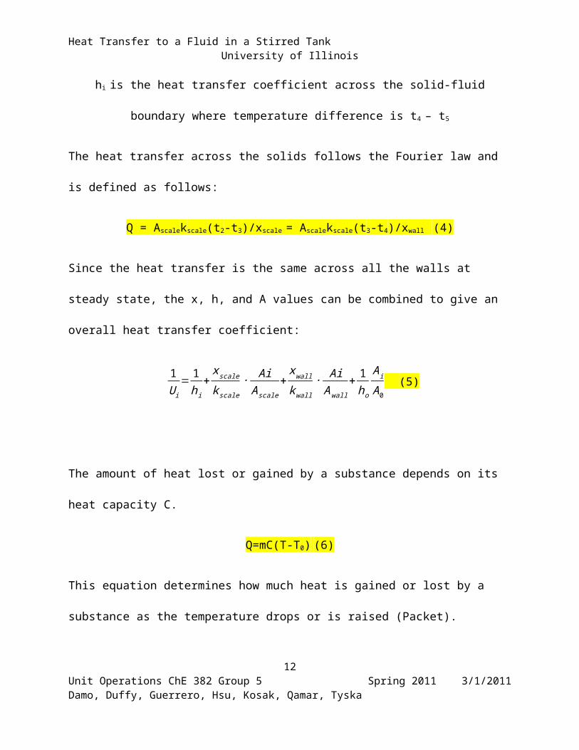
hi is the heat transfer coefficient across the solid-fluid boundary where temperature difference is
t4 – t5
The heat transfer across the solids follows the Fourier law and is defined as follows:
Q = Ascalekscale(t2-t3)/xscale = Ascalekscale(t3-t4)/xwall (4)
Since the heat transfer is the same across all the walls at steady state, the x, h, and A values can
be combined to give an overall heat transfer coefficient:
1U i
= 1h i
+xscale
k scale∙ Ai
A scale+
xwall
k wall∙ Ai
Awall+ 1
ho
A i
A0 (5)
The amount of heat lost or gained by a substance depends on its heat capacity C.
Q=mC(T-T0) (6)
This equation determines how much heat is gained or lost by a substance as the temperature
drops or is raised (Packet).
9Unit Operations ChE 382 Group 5 Spring 2011 3/1/2011Damo, Duffy, Guerrero, Hsu, Kosak, Qamar, Tyska

Heat Transfer to a Fluid in a Stirred Tank University of Illinois
Heat transfer coefficients can be theoretically estimated using the following correlations:
Outer Wall Heat Transfer Coefficient Estimation
This estimates the h value on the outside of the vessel wall where steam condensation takes
place.
ho LT
k=0.925( L3 ρ2 g
μM )1/3
(6)
Where:
ho is the heat transfer coefficient through film of condensing steam. (W/m2−K )
LT is the vertical length of the tank. (m)
k is the thermal conductivity of the fluid. (W/K-m)
ρ is the density of the fluid. (kg/m3)
g is the gravitational constant. (m/s2)
μ is the viscosity of the fluid. (kg/s-m)
M is the mass rate of steam condensed per wetted perimeter described by:
M=mst
π D¿(6a)
mst is the mass rate of steam condensation. (kg/s)
10Unit Operations ChE 382 Group 5 Spring 2011 3/1/2011Damo, Duffy, Guerrero, Hsu, Kosak, Qamar, Tyska

Heat Transfer to a Fluid in a Stirred Tank University of Illinois
Saturated Steam Heat Transfer Coefficient
ho=2960 ( D¿ /mst )1/3 (7)
Estimation Inner Wall Heat Transfer Coefficient Estimation
This system falls into the category of an unbaffled CSTR with Newtonian fluid. The heat transfer correlation can be estimated using the following correlations.
hi DT
k=0.36(C p µ
k )1 /3( Di
2 nρµ )
2/3
(3)
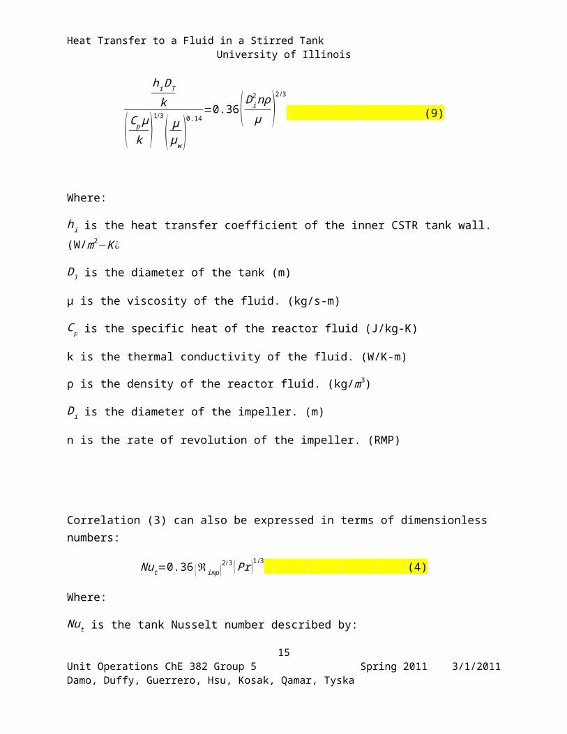
hi DT
k
(C p µk )
1 /3
( μμw )
0.14=0.36 ( Di
2nρµ )
2/3
(9)
Where:
hi is the heat transfer coefficient of the inner CSTR tank wall. (W/m2−K ¿
DT is the diameter of the tank (m)
μ is the viscosity of the fluid. (kg/s-m)
C p is the specific heat of the reactor fluid (J/kg-K)
k is the thermal conductivity of the fluid. (W/K-m)
ρ is the density of the reactor fluid. (kg/m3)
Di is the diameter of the impeller. (m)
11Unit Operations ChE 382 Group 5 Spring 2011 3/1/2011Damo, Duffy, Guerrero, Hsu, Kosak, Qamar, Tyska
Heat Transfer to a Fluid in a Stirred Tank University of Illinois
n is the rate of revolution of the impeller. (RMP)
Correlation (3) can also be expressed in terms of dimensionless numbers:
Nut=0.36 (ℜimp )2 /3 ( Pr )1/3 (4)
Where:
Nut is the tank Nusselt number described by:
Nut=h DT
k(4a)
ℜimp is the impeller Reynolds number described by:
ℜimp=D I
2 nρμ
(4b)
Pr is the fluid Prandtl number described by:
Pr=C p µ
k(4c)
In this lab the convective heat transfer coefficient at the inner surface of the tank will be
experimentally determined. This value will then be compared with theoretically calculated values
using the equations listed above.
12Unit Operations ChE 382 Group 5 Spring 2011 3/1/2011Damo, Duffy, Guerrero, Hsu, Kosak, Qamar, Tyska

Heat Transfer to a Fluid in a Stirred Tank University of Illinois
3. Experimental
3.1.Apparatus
Figure 2: Top Half of CSTR Apparatus
13Unit Operations ChE 382 Group 5 Spring 2011 3/1/2011Damo, Duffy, Guerrero, Hsu, Kosak, Qamar, Tyska
23
6
7
8
9
5
4
17
1

Heat Transfer to a Fluid in a Stirred Tank University of Illinois
Figure 3: Bottom Half of CSTR Apparatus
The figures above depict the “Heat Transfer in a Stirred Tank” lab apparatus. It consists
of a constantly stirred tank that is equipped with a cooling coil and lined with a steam jacket.
After filling the tank with water, the pump located underneath continuously pumps water
out of the tank and into the shell side of a heat exchanger where cooling water removes heat.
The cooled tank water flows through the flowrator to display its flow rate and then re-enters
14Unit Operations ChE 382 Group 5 Spring 2011 3/1/2011Damo, Duffy, Guerrero, Hsu, Kosak, Qamar, Tyska
10
11
12
13
14
15
16
Heat Transfer to a Fluid in a Stirred Tank University of Illinois
the tank. Dial thermometers are located at the inlet and outlet of the heat exchanger. The
cooling coils within the tank are fed with incoming cooling water. The flow rate of the
cooling water can be set and adjusted using a flowrator. The temperature of the cooling
water is displayed on dial thermometers located near the inlet and outlet of the cooling coils.
Steam is fed into the steam jacket of the tank to allow heat transfer into the system. Steam
condensate exits the steam jacket and enters a condenser, where cooling water flows through
it. The impeller, which stirs the water in the tank, is controlled using a variable power
supply. A strobotac is used to measure and display the speed of the impeller. The impeller
speed and the flowrate of water through the external heat exchanger will be studied in three
different experiments: 1) unbaffled stirred tank, 2) baffled stirred tank, and 3) unsteady-state
heat transfer in an unbaffled tank.
# Equipment Description Manufacturer Operating Range
1 Strobotac Displays rotational
speed (RPM) of
motor which powers
the impeller.
N/AN/A
2 Electric Motor Powers the impeller. Eastern Industries 1/4 HP
3 Variable Transformer Controls the speed of
the electric motor.Powerstat
0-140 V
4 Cooling Coil Inlet
Flowrator Tube
Displays the flow
rate of the cooling
coil water.
F & P CO. 0-100% Max of
0.810 GPM
15Unit Operations ChE 382 Group 5 Spring 2011 3/1/2011Damo, Duffy, Guerrero, Hsu, Kosak, Qamar, Tyska

Heat Transfer to a Fluid in a Stirred Tank University of Illinois
5 Cooling Water Inlet
Valve
Controls the flow rate
of the cooling coil
water.
Crane CO. N/A
6 Recycle Water
Flowrator
Displays the flow
rate of the recycle
water.
F & P CO.
0-100% Max of
0.810 GPM
7 Recycle Water
Thermometer
Displays the
temperature of the
recycle water.
MFG CO. 15-105 oC
8 Cooling Water Inlet
Thermometer
Displays the
temperature of the
cooling coil water at
the inlet.
Moeller Instrument CO.0-250 oF
9 Tank Thermometer Displays the
temperature of the
fluid in the tank.
Trend Instruments INC.
50-300 oF
10 Tank Contains the fluid, as
well as the impeller
and steam jacket.
N/A N/A
11 Tank Outlet
Thermometer
Displays the
temperature of the
condensate exiting
Trend Instruments INC.
16Unit Operations ChE 382 Group 5 Spring 2011 3/1/2011Damo, Duffy, Guerrero, Hsu, Kosak, Qamar, Tyska

Heat Transfer to a Fluid in a Stirred Tank University of Illinois
the steam jacket
before it enters the
condenser.
0-200 oF
12 Condenser Cools the steam
condensate.N/A
N/A
13 Pump Continually re-
circulates water
through the tank.
Dayton Electric MFG
CO.1/3 Hp
14 Condenser
Thermometer
Displays the
temperature of the
cooling water
entering the
condenser
Trend Instruments INC. 0-200 oF
15 Recycle thermometer Displays the
temperature of the
water that exits the
tank before it enters
the heat exchanger.
MFG CO.
15-105 oF
16 Heat Exchanger Cools the recycled
water before it re-
enters the tank.
N/A
N/A
17 Pump Power Switch Turns on the pump. Appleton Electric
17Unit Operations ChE 382 Group 5 Spring 2011 3/1/2011Damo, Duffy, Guerrero, Hsu, Kosak, Qamar, Tyska

Heat Transfer to a Fluid in a Stirred Tank University of Illinois
Products N/A
3.2.Materials and Supplies
Material/Supply Description
Water Used throughout the system where
measurements will be taken from.
Graduated Cylinder Used to measure amount of water
collected from the condenser.
Baffles Directs the flow of fluids for maximum
efficiency in stir tank.
Mop Used to clean up any liquid spills.
Stop Watch Time the amount of fluid exiting the
condenser.
3.3.Experimental Procedure
18Unit Operations ChE 382 Group 5 Spring 2011 3/1/2011Damo, Duffy, Guerrero, Hsu, Kosak, Qamar, Tyska

Heat Transfer to a Fluid in a Stirred Tank University of Illinois
Begin the steady state experiment -
1. Open the main water valve
2. Open the valve to the tank, and fill it up to around 2 inches from the top of the tank.
3. Measure the height of the water in the tank.
4. Turn on the impellor, and try to adjust it’s speed to 100 rpm, +- 50 rpm
5. Turn on the cooling water to the heat exchanger and the cooling coils inside the tank.
Note the flowrate of cooling water.
6. Make sure the pump bypass valve and pump suction valve is on, and turn on the pump.
7. Open the valve so that the cooling water goes to the steam condenser.
8. Open the steam inlet valve, and wait for the process to reach steady state.
9. Measure the temperatures, flow rates, and impellor speed.
10. Increase the impellor speed to a different rpm
11. Measure the same variables as in part 9
12. Increase the temperature inside the tank
13. Measure the same variables as in part 9
14. Turn off the impellor, and put baffles inside the tank, being careful not to get burnt.
15. Repeat steps 9 through 13.
16. Turn off the cooling water and steam
17. Drain the tank
Note – This ends the steady state portion of the experiment, the unsteady state procedure
is now started.
18. Add fresh water, whose temperature should be less than 40 degrees C.
19Unit Operations ChE 382 Group 5 Spring 2011 3/1/2011Damo, Duffy, Guerrero, Hsu, Kosak, Qamar, Tyska

Heat Transfer to a Fluid in a Stirred Tank University of Illinois
19. Run cooling water through the steam condenser.
20. Open the condenser water valve
21. Partially open the steam valve.
22. Turn the impellor on, and adjust it’s speed to 100 rpm.
23. Open the steam valve completely
24. Measure the temperature around every 20 seconds (time intervals must be constant, but
intervals need not be 20 seconds)
25. Record this data until the water reaches 85 degrees Celsius
26. Turn off the steam, and record the temperature of the water as it cools down with the
same time intervals.
27. Repeat steps 22-26 with different impellor speeds (same ones as used in step 10).
4. Anticipated Results
The objective of this lab is to measure the heat transfer coefficient of the wall of a tank of
water and a jacket of steam. The heat transfers will be measured in two sections: first as steady
state, when the temperature inside has leveled off, and second during unsteady state, when the
temperature is still increasing.
The first section will measure the heat transfer coefficient with baffles and without
baffles. These baffles are anticipated to increase the transfer of heat between the walls because
the area of tank water exposed to the hot steam is increase therefore more of the water will pick
up the heat as it is exposed to the heat. The baffles do this by increasing the agitation in the tank
20Unit Operations ChE 382 Group 5 Spring 2011 3/1/2011Damo, Duffy, Guerrero, Hsu, Kosak, Qamar, Tyska

Heat Transfer to a Fluid in a Stirred Tank University of Illinois
without the need for increasing the impeller speed. It is anticipated that the heat transfer
coefficient for the baffle runs will be larger than the one without. All the temperatures and flow
rates will be collected in order to do an energy balance and use equation 8 and 1a to figure out
the overall heat transfer coefficient. As high as possible transfer coefficient is desired in order to
transfer heat more rapidly but one thing that will slow this down is fouling. The wall inside the
tank is lined will water build up than will inhibit heat transfer this will lower the transfer
coefficient and make the tank take longer to heat.
During the unsteady state the tanks temperatures are measure when the heating begins not
when it has reached the desired value. In this section the goal is to determine the relationship
between temperature and the heat transfer coefficient. It is anticipated that initially this will be
high due to the larger temperature gradient (sink) between the two streams.
5. References
Bird, R. B., Warren E. Stewart, and Edwin N. Lightfoot. Transport Phenomena. 2nd ed. New York, NY: Jonh Wiley & Sons, Inc., 2002
Packet, Heat transfer to a Fluid in a Stirred Tank
6. Appendix I: Job Safety Analysis
21Unit Operations ChE 382 Group 5 Spring 2011 3/1/2011Damo, Duffy, Guerrero, Hsu, Kosak, Qamar, Tyska

Heat Transfer to a Fluid in a Stirred Tank University of Illinois
What is the purpose of this experiment?
The purpose of this experiment is to determine the effects of mixing with and without baffles on
a stirred tank system. Four cases will be studied: steady state without baffles, steady state with
baffles, unsteady state without baffles, and unsteady state with baffles.
What are the hazards associated with the experiment?
Since high temperature steam is used to heat the tank it is necessary to be aware of which pieces
of the equipment will be at high temperatures. Another hazard is the impeller which should be
avoided when in use. Water is continuously passed through the system therefore there is a
spilling and slipping hazard.
How will the experiment be conducted in a safe manner?
The experiment will be constantly monitored to ensure that everything is running properly and
safety. When filling the tank it will be necessary to be sure that it doesn’t overflow and cause
slipping hazard. It will also be necessary to ensure that all the cooling water is draining properly
and not spilling on the floor. Since electricity is used around a system that uses a lot of water it
will be necessary to be aware this to avoid any electric shocks. As always, close-toed shoes and
safety goggles will be worn at all times in the experiment area to decrease the chance of potential
hazards.
What safety controls are in place?
22Unit Operations ChE 382 Group 5 Spring 2011 3/1/2011Damo, Duffy, Guerrero, Hsu, Kosak, Qamar, Tyska

Heat Transfer to a Fluid in a Stirred Tank University of Illinois
The stirred tank is warped with insulation to ensure no one gets burned by accidently touching
the side when moving around the apparatus. There is a recycle system for the pump. Most
importantly, the laboratory area around the experiment will be kept dry using paper towels and a
mop to clean any spilled liquid promptly to avoid wet working conditions. The water levels will
be monitored to ensure that the water does not overflow and cause a spill in the laboratory.
Safety goggles will be worn at all times to ensure eye protection.
Describe safe and unsafe ranges of operations.
Since steam is used it would be unsafe to run the system at very high temperatures so the vessel
should be kept below 85°C at all times. The impeller should not exceed 200 rpm during the
duration of the experiment. Never run the pump dry.
I have read relevant background material for the Unit Operations Laboratory entitled:
“Heat Transfer to a Fluid in a Stirred Tank” and understand the hazards associated with
conducting this experiment. I have planned out my experimental work in accordance to
standards and acceptable safety practices and will conduct all of my experimental work in a
careful and safe manner. I will also be aware of my surroundings, my group members, and other
lab students, and will look out for their safety as well.
Electronic Signatures:
23Unit Operations ChE 382 Group 5 Spring 2011 3/1/2011Damo, Duffy, Guerrero, Hsu, Kosak, Qamar, Tyska

Heat Transfer to a Fluid in a Stirred Tank University of Illinois
Bernard Hsu
Daniya l Qamar
Jeff Tyska
Alex Guerrero
Tomi Damo
Ryan Kosak
Andrew Duffy
24Unit Operations ChE 382 Group 5 Spring 2011 3/1/2011Damo, Duffy, Guerrero, Hsu, Kosak, Qamar, Tyska