Embed Size (px)
Citation preview
Com'X 510User Manual
DOCA0098EN-0304/2016

Safety Information
Important InformationRead these instructions carefully and look at the equipment to become familiar withthe device before trying to install, operate, service or maintain it. The following specialmessages may appear throughout this bulletin or on the equipment to warn ofpotential hazards or to call attention to information that clarifies or simplifies aprocedure.
The addition of either symbol to a "Danger" or "Warning" safety labelindicates that an electrical hazard exists which will result in personalinjury if the instructions are not followed.This is the safety alert symbol. It is used to alert you to potential personalinjury hazards. Obey all safety messages that follow this symbol to avoidpossible injury or death.
DANGERDANGER indicates a hazardous situation which, if not avoided, will result in death orserious injury.
WARNINGWARNING indicates a hazardous situation which, if not avoided, could result in death orserious injury.
CAUTIONCAUTION indicates a hazardous situation which, if not avoided, could result inminor ormoderate injury.
NOTICENOTICE is used to address practices not related to physical injury.
Please NoteElectrical equipment should be installed, operated, serviced andmaintained only by qualifiedpersonnel. No responsibility is assumed by Schneider Electric for any consequences arisingout of the use of this material.
A qualified person is one who has skills and knowledge related to the construction, installation,and operation of electrical equipment and has received safety training to recognize and avoidthe hazards involved.
© 2016 Schneider Electric. All rights reserved. 3
Com'X 510 User Manual Safety Information
NoticesFCC Part 15 Notice
This equipment has been tested and found to comply with the limits for a Class B digitaldevice, pursuant to part 15 of the FCC Rules. These limits are designed to provide reasonableprotection against harmful interference in a residential installation. This equipment generates,uses, and can radiate radio frequency energy and, if not installed and used in accordance withthe instructions, may cause harmful interference to radio communications. However, there isno guarantee that interference will not occur in a particular installation. If this equipment doescause harmful interference to radio or television reception, which can be determined by turningthe equipment off and on, the user is encouraged to try to correct the interference by one ormore of the followingmeasures.
l Reorient or relocate the receiving antenna.
l Increase the separation between the equipment and receiver.
l Connect the equipment to an outlet on a circuit different from that to which the receiver isconnected.
l Consult the dealer or an experienced radio/TV technician for help.
This Class B digital apparatus complies with Canadian ICES-003.
4 © 2016 Schneider Electric. All rights reserved.
Notices Com'X 510 User Manual
Legal InformationThe Schneider Electric brand and any registered trademarks of Schneider Electric IndustriesSAS referred to in this guide are the sole property of Schneider Electric SA and its subsidiaries.They may not be used for any purpose without the owner's permission, given in writing. Thisguide and its content are protected, within themeaning of the French intellectual property code(Code de la propriété intellectuelle français, referred to hereafter as "the Code"), under the lawsof copyright covering texts, drawings andmodels, as well as by trademark law. You agree notto reproduce, other than for your own personal, noncommercial use as defined in the Code, allor part of this guide on any medium whatsoever without Schneider Electric's permission, givenin writing. You also agree not to establish any hypertext links to this guide or its content.Schneider Electric does not grant any right or license for the personal and noncommercial useof the guide or its content, except for a non-exclusive license to consult it on an "as is" basis, atyour own risk. All other rights are reserved.
Electrical equipment should be installed, operated, serviced andmaintained only by qualifiedpersonnel. No responsibility is assumed by Schneider Electric for any consequences arisingout of the use of this material.
As standards, specifications and designs change from time to time, please ask for confirmationof the information given in this publication.
© 2016 Schneider Electric. All rights reserved. 5
Com'X 510 User Manual Legal Information
Contents Com'X 510 User Manual
6 © 2016 Schneider Electric. All rights reserved.
Contents
Safety Information 3Notices 4Legal Information 5Contents 6Safety Precautions 11Introduction 13Architecture 13Main Features 14Com'X 510 for Entry-level Energy Management 14Schneider Electric Remote Service Platform 15Facility Insights 15PowerMonitoring Expert 15Additional Resources 15
Access the Com'X 510 User Interface 17SupportedWeb Browsers 17Start Up Your Com'X 510 17Reboot Cases 17
Accessing Through the Ethernet Port 18Accessing ThroughWi-Fi Access Point Mode 19Logging In 20Logging In for the First Time 21Changing the Password 21User Session Timeout 22
Com'X 510 User Interface Overview 22Com'X 510 Features 24
Quickstart Guides for Com'X 510 27Quickstart: Setting Up and Starting Data Logging 27Quickstart: Viewing On-board Data 27Quickstart: Setting Up Publication 28
Settings 29General Settings 29Date and Time Settings 29Network Settings 30Proxy Settings 39Publication 41Wi-Fi Access Point Settings 48
Site Settings 49Site Information 49Data Logging 50
Communication Settings 50Modbus TCP Access 50Modbus TCP/IP Filtering 53Modbus Serial Port 53Advanced Ethernet Settings 55ZigBee Network Settings 56
Security 58Firewall Management 58
Certificates 60HTTPS Redirection 60
User Management 60Group Settings 61Users 63
Events 64Predefined Events 65Custom Events 65Creating a Custom Event 66Editing or Deleting a Custom Event 67Copying an Event 67
Links 68Configuring Links 68Viewing Links 68
Custom PageManagement 68Adding a CustomWeb Page 69Deleting CustomWeb Pages 69Downloading a Custom Page 70Viewing a CustomWeb Page 70
Device Settings 71Device Settings Overview 71Common Properties 73General Properties 74Monitored Area 75
Manage Devices 76Adding a Downstream Device 77Modifying a Device 77Disconnecting a Device 78Reconnecting a Device 78Replacing a Device 78Deleting a Device 79
Measurement andMetadata Exported Per Hosted Platform 79SelectingMeasurements to Log or Publish 80
Devices That Can Connect to Digital Inputs 81Built-In PulseMeters 81Custom PulseMeter 82
Devices That Can Connect to Analog Inputs 82Resistance Temperature Detectors 83Custom Analog Devices 83
Modbus Devices 83Discovering Connected Devices 83Adding aModbus DeviceManually 85Connecting Devices to Acti 9 Smartlink 86
Ethernet Devices 87Built-in Ethernet Devices 87Ethernet Device Configuration Parameters 87Custom Ethernet Devices 88
ZigBee Device Discovery 88Discovering Devices 88
Measurements Table 89Viewing theMeasurements Table 89
Commissioning 91
Com'X 510 User Manual Contents
© 2016 Schneider Electric. All rights reserved. 7
Contents Com'X 510 User Manual
8 © 2016 Schneider Electric. All rights reserved.
Commissioning Interface 91Starting the Data Logging 92Starting the Publication 93
Monitoring 95Real TimeData 95Single Device View 95Summary Device View 96Real Time Trending 97
Dashboards 98Viewing a Dashboard Graph or Table 98Saving Dashboard Data Points or Graph 99Saving a Dashboard Link 99Using the Dashboard Kiosk 100
Historical Data Export 100Exporting Historical Data 100
CustomWeb Pages 101Control 103Device Resets 103Resetting Device Parameters 103Setting Time on Devices 103
Diagnostics 105Statistics 105Viewing Statistics 105Resetting Statistics 105Interpreting Statistics 105
Read Device Registers 108Reading Device Registers 109
Communications Check 109Executing aManual Communications Check 109Defining the Out of Service Time 110
Custom Library 111CustomModels 111Creating a CustomModel 111
CustomModbus Devices 112Creating aModbus Custom Slave 112Defining aModbus Custom Slave 113Modbus Custom Slave Register Examples 113Creating aModbus Frame 114CreatingModbus Variables 115Adding a CustomModbus Device 117
Custom PulseMeter Model 117Creating a Custom PulseMeter 117
Custom KYZ PulseMeter Model 119CustomMainMeter Model 120Creating a CustomMainMeter 120MainMeter Measure and Signal Properties 121Adding a CustomMainMeter 123Connecting a StandardMainMeter 124
Custom Contactor or Impulse Relay 125Creating a Custom Contactor or Impulse Relay 125
Creating a Custom Analog Sensor Model 126Creating a Custom Analog Sensor 127
Working with CustomModels 129Modifying a CustomModel 129Deleting a CustomModel 130Exporting One orMore CustomModels 130Importing One orMore CustomModels 130
Maintenance 133Logs 133System Settings 134Save the Configuration 134Restore the Configuration 136Upgrade Firmware 139Enabling Remote Access 141
Com'X 510 Replacement 141Replacing a Com'X 510 in RSP 141
Resets 142Resetting the Password Locally 143Resetting Password Through RSP 143Resetting to Factory Settings 143
Checklist Before Leaving Customer Site 145Troubleshooting 147Metering Device Troubleshooting 147Digital Input Troubleshooting 147Analog Input Troubleshooting 147
Modbus Device Troubleshooting 148Network Troubleshooting 149Ethernet Troubleshooting 149GPRS/3G Troubleshooting 150Wi-Fi Troubleshooting 150
Com'X 510 Troubleshooting 150Com'X 510 Access 150Web Pages 151Remote Service Platform Selection 151Data Publishing 152Firmware Upgrade 152Events 152
Appendices 153Appendix A: Publish Data to Energy Operation 154Quick Start Overview 154Define the Initial and Site Settings 156Define the Network Settings to Publish Data 158Define theMetering Devices 159Visualize the Data to Publish 164Publishing the Data to Energy Operation 164
Appendix B: Replacing the SD Card 166Appendix C: List of Supported Devices 167Appendix D: List of Certificate Authorities 168Appendix E: IPv4 Address Settings 174Static IP Settings 174DHCP Client 174DHCP Server Over Ethernet Port 175DHCP Server OverWi-Fi 175Remote Access withWindows Operating Systems 176
Com'X 510 User Manual Contents
© 2016 Schneider Electric. All rights reserved. 9

Contents Com'X 510 User Manual
10 © 2016 Schneider Electric. All rights reserved.
Appendix F: Modbus Register Mapping 177Discovery Feature 177Com'X 510 Register Mapping 177EM4300 Register Mapping 179
Index 182

Safety PrecautionsDANGER
HAZARD OF ELECTRIC SHOCK, EXPLOSION, OR ARC FLASH
• Apply appropriate personal protective equipment (PPE) and follow safe electrical workpractices. See NFPA 70E in the USA, CSA Z462 or applicable local standards.
• Turn off all power supplying this device and the equipment in which it is installed beforeworking on the device or equipment.
• Always use a properly rated voltage sensing device to confirm that all power is off.• Treat communications and I/O wiring connected tomultiple devices as hazardous liveuntil determined otherwise.
• Do not exceed the device's ratings for maximum limits.• Replace all devices, doors and covers before turning on power to this equipment.
Failure to follow these instructions will result in death or serious injury.
WARNINGUNINTENDED EQUIPMENT OPERATION
• Do not use the software for critical control or protection applications where human orequipment safety relies on the operation of the control action.
• Do not use the software to control time-critical functions because communicationdelays can occur between the time a control is initiated and when that action is applied.
• Do not use the software to control remote equipment without securing it with anauthorized access level, and without including a status object to provide feedbackabout the status of the control operation.
Failure to follow these instructions can result in death, serious injury, orequipment damage.
Com'X 510 User Manual SafetyPrecautions
© 2016 Schneider Electric. All rights reserved. 11
SafetyPrecautions Com'X 510 User Manual
12 © 2016 Schneider Electric. All rights reserved.
WARNINGINACCURATE DATA RESULTS
• Do not incorrectly configure the software, as this can lead to inaccurate reports and/ordata results.
• Do not base your maintenance or service actions solely onmessages and informationdisplayed by the software.
• Do not rely solely on data displayed in the software reports to determine if the system isfunctioning correctly or meeting all applicable standards and requirements.
• Do not use data displayed in the software as a substitute for proper workplace practicesor equipment maintenance.
Failure to follow these instructions can result in death, serious injury, equipmentdamage, or permanent loss of data.
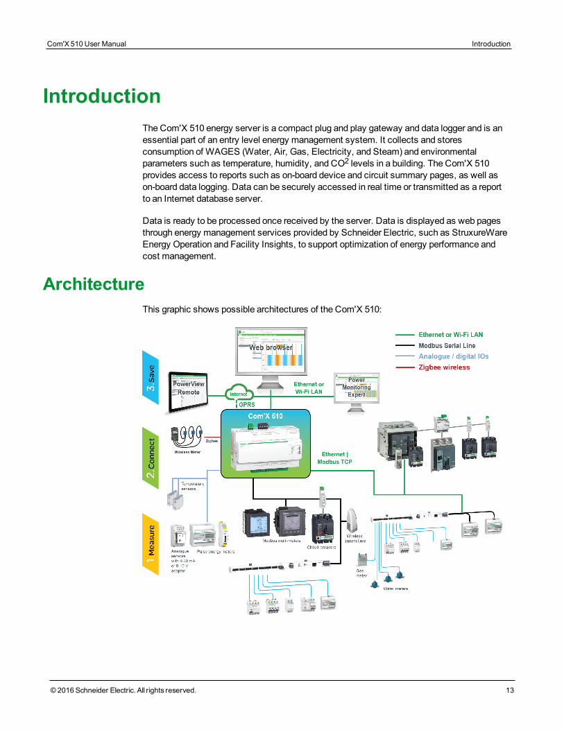
IntroductionThe Com'X 510 energy server is a compact plug and play gateway and data logger and is anessential part of an entry level energy management system. It collects and storesconsumption of WAGES (Water, Air, Gas, Electricity, and Steam) and environmentalparameters such as temperature, humidity, and CO2 levels in a building. The Com'X 510provides access to reports such as on-board device and circuit summary pages, as well ason-board data logging. Data can be securely accessed in real time or transmitted as a reportto an Internet database server.
Data is ready to be processed once received by the server. Data is displayed as web pagesthrough energy management services provided by Schneider Electric, such as StruxureWareEnergy Operation and Facility Insights, to support optimization of energy performance andcost management.
ArchitectureThis graphic shows possible architectures of the Com'X 510:
Com'X 510 User Manual Introduction
© 2016 Schneider Electric. All rights reserved. 13

Introduction Com'X 510 User Manual
14 © 2016 Schneider Electric. All rights reserved.
From a simplemetering installation with one device to largemetering systems, the Com'X510 collects data from any Modbus TCP/Modbus serial line gateways, pulsemeters,actuators, and analog sensors.
Main FeaturesThemain features of the Com'X 510 are:
l real-time data in easy to understand views
l dashboard view for historical reporting
l automatic discovery of connectedModbus devices
l connectivity to the cloud through threemedia: GPRS/3G, wired Ethernet, orWi-Fi Eth-ernet
l two Ethernet ports to separate upstream cloud connection from field device network
l four supported transfer protocols: HTTP, HTTPS, FTP, and SMTP with proxy man-agement
l data logging
l data export with native connection to Schneider Electric service platforms (such asEnergy Operation) and with .csv file for other database servers
l gateway functionality Modbus TCP to Modbus RTU orModbus ASCII
l setup through on-board web pages
l compliant with electrical switchboard environment (temperature, electromagnetic com-patibility)
l local backup of configuration parameters
l ZigBee Pro with EM4300 sensors
Com'X 510 for Entry-level Energy ManagementThe Com'X 510 supports real-time data views frommany common device types, providingseveral device-specific features. Additional energy management capabilities include:
l View real-time and historical information frommultiple locations through a supported webbrowser.
l Select the logging intervals and topics you want logged.
l Automatically export selected logged data to your PC for additional analysis.
l Provide data and system security through password protection and controlled access toindividual web pages, as well as through Com'X 510 firewall management.
l Perform simple control reset commands for supported devices (for example, min/max andaccumulated energy).
l Set date and time for connected devices that support set time commands.

Schneider Electric Remote Service PlatformThe energy server Com'X 510 can be associated with Schneider Electric Remote ServicePlatform. This platform allows you to:
l Remotely manage firmware upgrade, configuration backup on the cloud, troubleshooting,and parameter settings.
l Provide a SIM card with worldwide coverage, by using the EBXA-GRPS-SIM option.
l Publish collected data to Schneider Electric energy management services.
Facility InsightsFacility Insights allows you to outsource energy management andmaintenance, reducingyour energy costs and increasing operating efficiency in buildings.
Facility Insights is a cloud-based software application from Schneider Electric to improveenergy efficiency, andmanage assets andmaintenance. Facility Insights is used for smallandmedium buildings in industry, retail, public, and healthcaremarkets.
Facility Insights provides the following features:
l Support for data acquisition hardware: meters, gateways, and sensors.
l Cloud platform for data displays.
l Consulting service from Schneider Electric expert teams.
l A network of local partners to implement solutions.
Power Monitoring ExpertThe Com'X 510 can send data in comma-separated value (CSV) files to supervision softwaresuch as PowerMonitoring Expert (PME) or third-party supervision software.
PME is a complete, interoperable, and scalable software package for powermanagementapplications. The software collects and organizes data gathered from the electrical networkand presents it as meaningful, actionable information through an intuitiveWeb interface.Share information with key stakeholders or across your entire operation to influencebehavioral changes that can save youmoney.
Additional ResourcesDocument Reference Number(s)
Com'X 510 Instruction Sheet5406AD0025406AD0055406AD006
EBXA-GPRS/EBXA-GPRS-SIM Instruction Sheet 253537613
Com'X 510 User Manual Introduction
© 2016 Schneider Electric. All rights reserved. 15
Introduction Com'X 510 User Manual
16 © 2016 Schneider Electric. All rights reserved.
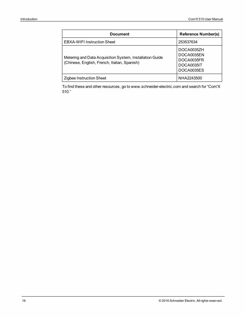
Document Reference Number(s)
EBXA-WIFI Instruction Sheet 253537634
Metering and Data Acquisition System, Installation Guide(Chinese, English, French, Italian, Spanish)
DOCA0035ZHDOCA0035ENDOCA0035FRDOCA0035ITDOCA0035ES
Zigbee Instruction Sheet NHA2243500
To find these and other resources, go to www.schneider-electric.com and search for “Com'X510.”
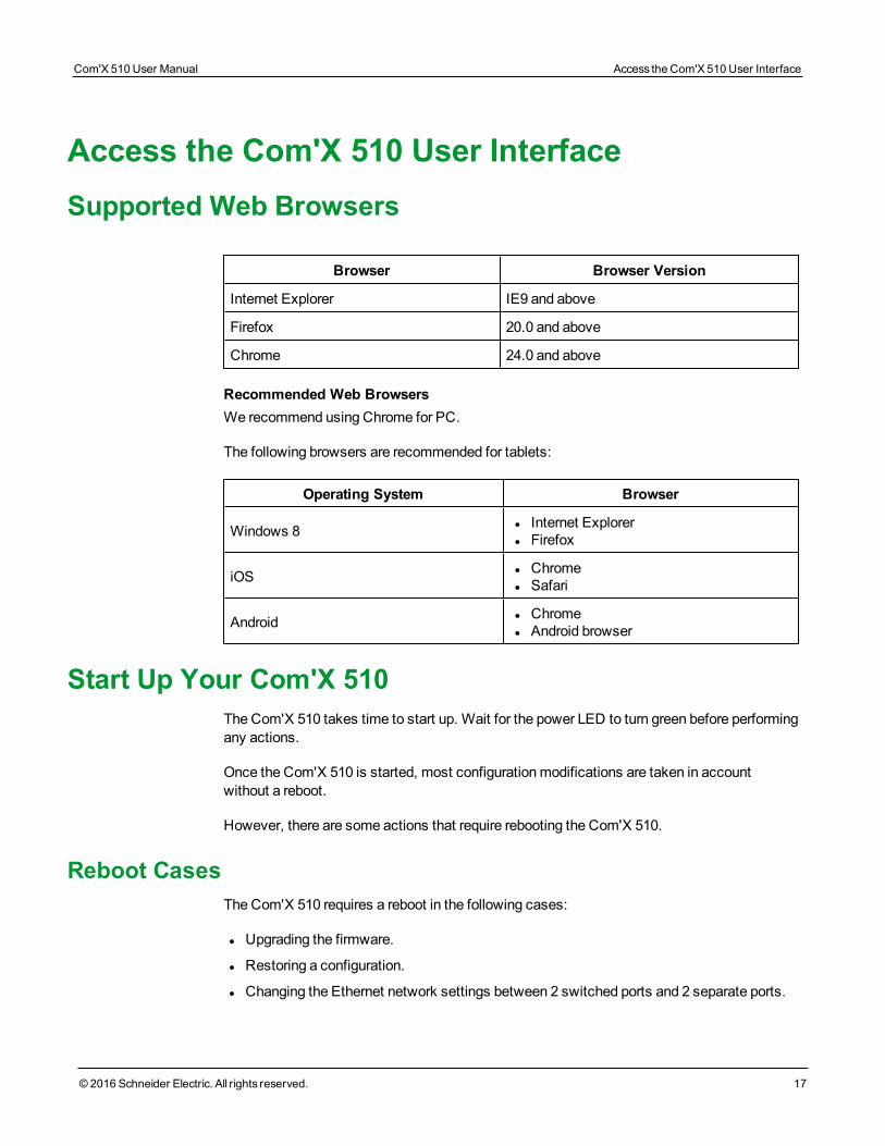
Access the Com'X 510 User InterfaceSupported Web Browsers
Browser Browser Version
Internet Explorer IE9 and above
Firefox 20.0 and above
Chrome 24.0 and above
Recommended Web BrowsersWe recommend using Chrome for PC.
The following browsers are recommended for tablets:
Operating System Browser
Windows 8 l Internet Explorerl Firefox
iOS l Chromel Safari
Android l Chromel Android browser
Start Up Your Com'X 510The Com'X 510 takes time to start up. Wait for the power LED to turn green before performingany actions.
Once the Com'X 510 is started, most configurationmodifications are taken in accountwithout a reboot.
However, there are some actions that require rebooting the Com'X 510.
Reboot CasesThe Com'X 510 requires a reboot in the following cases:
l Upgrading the firmware.
l Restoring a configuration.
l Changing the Ethernet network settings between 2 switched ports and 2 separate ports.
Com'X 510 User Manual Access the Com'X 510 User Interface
© 2016 Schneider Electric. All rights reserved. 17
Access the Com'X 510 User Interface Com'X 510 User Manual
18 © 2016 Schneider Electric. All rights reserved.
l Inserting aGPRS or 3G modem.
l Installing a Zigbee key.
Accessing Through the Ethernet Port
DANGERHAZARD OF ELECTRIC SHOCK, EXPLOSION, OR ARC FLASH
• This equipment must only be installed and serviced by qualified personnel.• Apply appropriate personal protective equipment (PPE) and follow safe electrical workpractices. See NFPA 70E in the USA, CSA Z462 or applicable local standards.
Failure to follow these instructions will result in death or serious injury.
Follow one of the procedures below to access the Com'X 510 user interface for initial setup.
With Windows 7/Vista
1. Disconnect your local computer from all networks.
2. Connect an Ethernet cable from your local computer to the Ethernet port 2 of the Com'X510.
3. OpenWindows Explorer on your local computer and click Network.
The Com'X 510 appears in the list of devices. Refer to Troubleshooting on page 147 if theCom'X 510 does not appear.
4. Double-click the Com'X 510. The login page is opened automatically on your default webbrowser.
NOTE: HTTPS is enabled by default on the Com'X 510 configuration. The Com'X 510has an autosigned security certificate. Therefore, connecting to the Com'X 510 interfacedisplays a security message. Before accepting, confirm that communication with theCom'X 510 has been established. To install a new certificate, seeSecurity on page 58.
5. Type the username (default: admin) and the password (default: admin).
NOTE: The username and password are case-sensitive.
6. Click Ok.
With Other Operating Systems
1. Disconnect your local computer from all networks.
2. Connect an Ethernet cable from your local computer to the Ethernet port 2 of the Com'X510.
3. Open your web browser.
4. Type [10.25.1.1] in the address field and press Enter.
NOTE: HTTPS is enabled by default on the Com'X 510 configuration. The Com'X 510has an autosigned security certificate. Therefore, connecting to the Com'X 510 interfacedisplays a security message. Before accepting, confirm that communication with theCom'X 510 has been established. To install a new certificate, seeSecurity on page 58.
5. Type the username (default: admin) and the password (default: admin).
NOTE: The username and password are case-sensitive.
6. Click Ok.
Accessing Through Wi-Fi Access Point Mode
DANGERHAZARD OF ELECTRIC SHOCK, EXPLOSION, OR ARC FLASH
• This equipment must only be installed and serviced by qualified personnel.• Apply appropriate personal protective equipment (PPE) and follow safe electrical workpractices. See NFPA 70E in the USA, CSA Z462 or applicable local standards.
Failure to follow these instructions will result in death or serious injury.
NOTICEUNINTENDED EQUIPMENT OPERATION
Do not close the door of ametallic enclosure while using theWi-Fi USB key.
Failure to follow these instructions can result in equipment damage.
Follow one of the procedures below to access the Com'X 510 user interface.
With Windows 7/Vista
1. Connect theWi-Fi USB key to a USB port on the Com'X 510.
2. Press theWi-Fi button on the Com'X 510. TheWi-Fi button LED flashes green.
3. On your local computer, connect to the Com'X 510 wireless network using theWindowsWireless Network configuration window.
4. OpenWindows Explorer on your local computer and click Network. The Com'X 510appears in the list of devices. Refer to Troubleshooting on page 147 if the Com'X 510does not appear.
5. Double-click the Com'X 510 and the login page opens automatically in your defaultbrowser.
Com'X 510 User Manual Access the Com'X 510 User Interface
© 2016 Schneider Electric. All rights reserved. 19
Access the Com'X 510 User Interface Com'X 510 User Manual
20 © 2016 Schneider Electric. All rights reserved.
NOTE: HTTPS is enabled by default on the Com'X 510 configuration. The Com'X 510has an autosigned security certificate. Therefore, connecting to the Com'X 510 interfacedisplays a security message. Before accepting, confirm that communication with theCom'X 510 has been established. To install a new certificate, seeSecurity on page 58.
6. Type the username (default: admin) and the password (default: admin).
NOTE: The username and password are case-sensitive.
7. Click Ok.
With Other Operating Systems
1. Connect theWi-Fi USB key to a USB port on the Com'X 510.
2. Press theWi-Fi button on the Com'X 510. TheWi-Fi button LED flashes green.
3. On your local computer, connect to the Com'X 510 wireless network using theWindowsWireless Network configuration window.
4. Open your browser.
5. Type [10.25.2.1] in the address field and press Enter.
NOTE: HTTPS is enabled by default on the Com'X 510 configuration. The Com'X 510has an autosigned security certificate. Therefore, connecting to the Com'X 510 interfacedisplays a security message. Before accepting, confirm that communication with theCom'X 510 has been established. To install a new certificate, seeSecurity on page 58.
6. Type the username (default: admin) and the password (default: admin).
NOTE: The username and password are case-sensitive.
7. Click Ok.
Logging InIf multiple sessions are opened, only the first session can be used to edit parameters.Sessions opened after the first session are read-only.
To log in to the user interface:
1. Select your language.
2. Type the username and the password.
NOTE: The username and password are case-sensitive.
3. Click Connect to be logged in to the configuration web page.
NOTE: HTTPS is enabled by default on the Com'X 510 configuration. The Com'X 510 has anautosigned security certificate. Therefore, connecting to the Com'X 510 interface displays asecurity message. Before accepting, confirm that communication with the Com'X 510 hasbeen established. To install a new certificate, seeSecurity on page 58.
Logging In for the First TimeThe web server is a tool for reading and writing data. It controls the state of the system, withfull access to all data in your application. You will be prompted to change your password thefirst time you log in to prevent unauthorized access to the application.
NOTICEUNAUTHORIZED DATA ACCESS
• Immediately change the default password to a new, secure password.• Do not distribute the password to unauthorized or otherwise unqualified personnel.
Failure to follow these instructions can result in equipment damage.
NOTE: A secure password should not be shared or distributed to unauthorized personnel.The password should not contain any personal or obvious information.
Follow these instructions to log in to the user interface for the first time:
1. Log in using the default password.
2. Read the License Agreement completely.
NOTE: TheAccept button will remain grayed until you scroll to the bottom of the UserLicense Agreement.
3. Accept the License Agreement.
4. Enter a new password. It must contain:
l 8 characters
l 1 uppercase letter
l 1 numeric digit
l 1 special character
Changing the PasswordTo change the password after the first login:
1. Click the username/admin link in the banner.
2. Enter the current password.
3. Enter a new password.
4. Confirm the new password.
5. Click OK.
Com'X 510 User Manual Access the Com'X 510 User Interface
© 2016 Schneider Electric. All rights reserved. 21
Access the Com'X 510 User Interface Com'X 510 User Manual
22 © 2016 Schneider Electric. All rights reserved.
NOTE: An administrator cannot modify the username or password after the user is created. Ifyou forget your username or password, contact an administrator to delete the account andcreate a new one.
User Session TimeoutThe login session terminates after the configuredSession Inactivity Time-out interval forthe user group (seeGroup Settings on page 61).
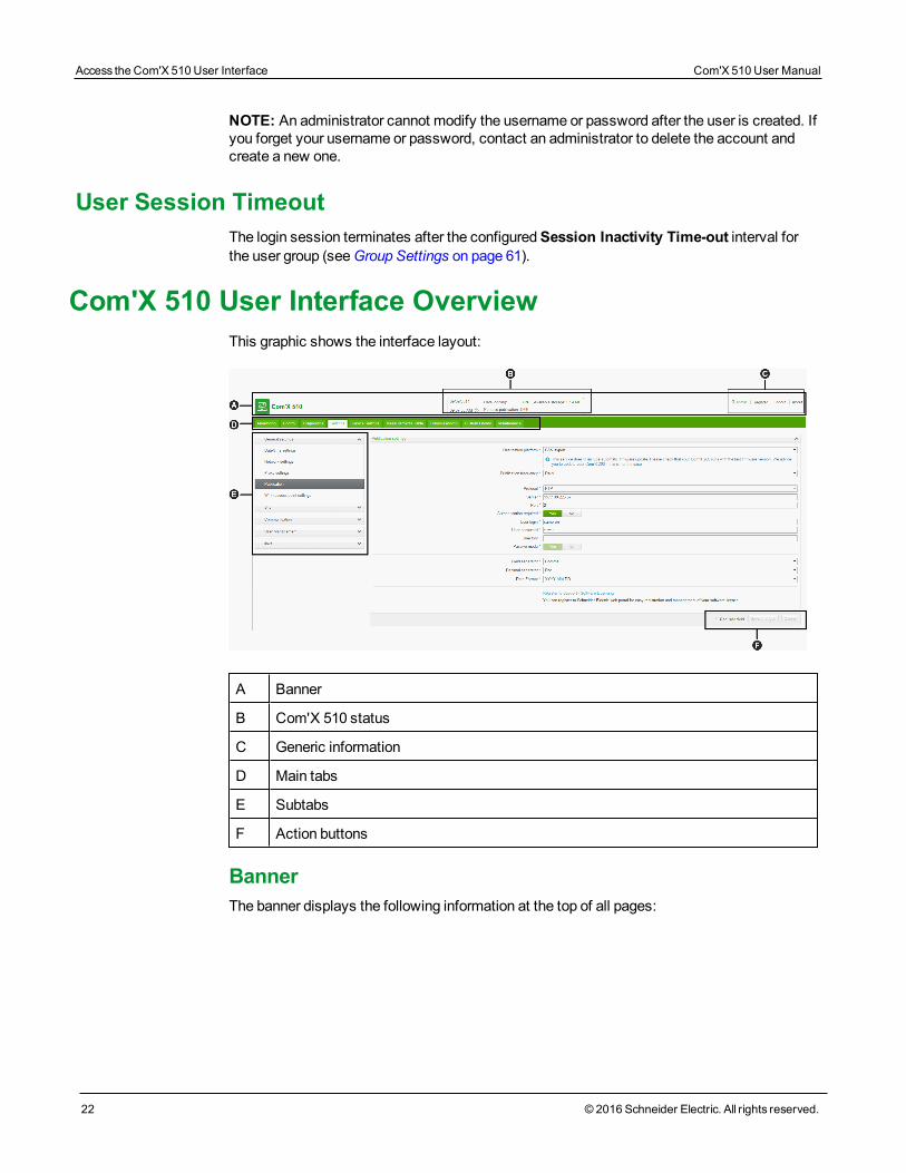
Com'X 510 User Interface OverviewThis graphic shows the interface layout:
A Banner
B Com'X 510 status
C Generic information
D Main tabs
E Subtabs
F Action buttons
BannerThe banner displays the following information at the top of all pages:
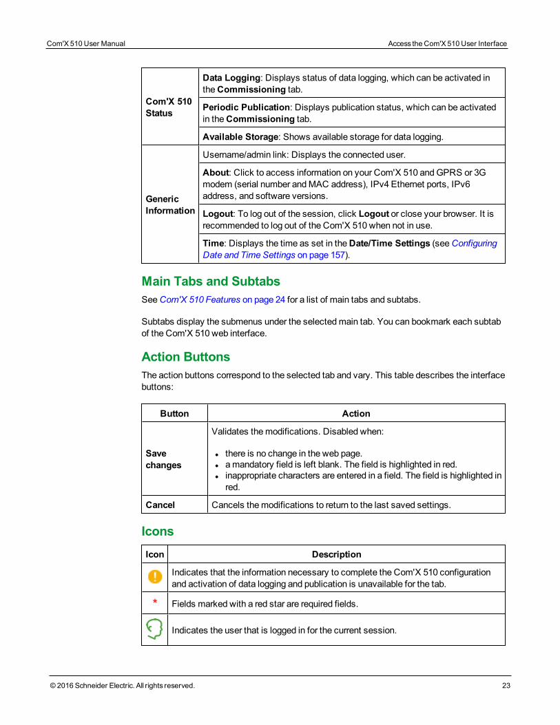
Com'X 510Status
Data Logging: Displays status of data logging, which can be activated intheCommissioning tab.
Periodic Publication: Displays publication status, which can be activatedin theCommissioning tab.
Available Storage: Shows available storage for data logging.
GenericInformation
Username/admin link: Displays the connected user.
About: Click to access information on your Com'X 510 andGPRS or 3Gmodem (serial number andMAC address), IPv4 Ethernet ports, IPv6address, and software versions.
Logout: To log out of the session, click Logout or close your browser. It isrecommended to log out of the Com'X 510 when not in use.
Time: Displays the time as set in theDate/Time Settings (seeConfiguringDate and Time Settings on page 157).
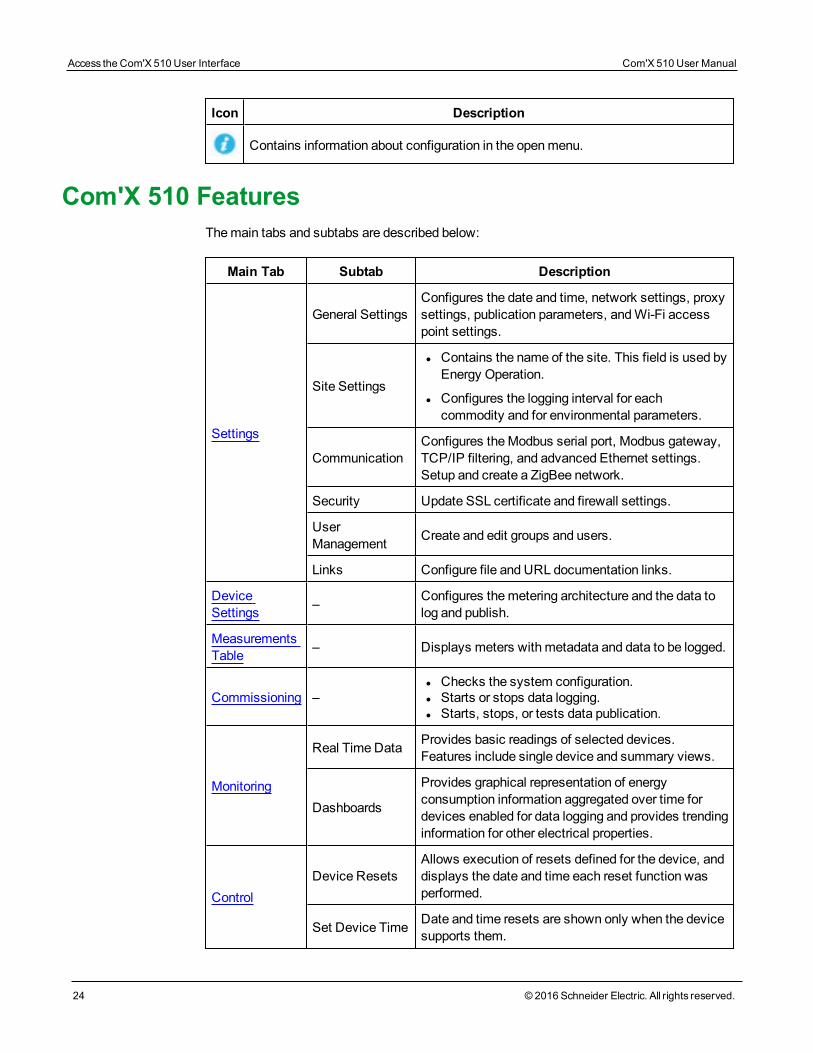
Main Tabs and SubtabsSeeCom'X 510 Features on page 24 for a list of main tabs and subtabs.
Subtabs display the submenus under the selectedmain tab. You can bookmark each subtabof the Com'X 510 web interface.
Action ButtonsThe action buttons correspond to the selected tab and vary. This table describes the interfacebuttons:
Button Action
Savechanges
Validates themodifications. Disabled when:
l there is no change in the web page.l amandatory field is left blank. The field is highlighted in red.l inappropriate characters are entered in a field. The field is highlighted inred.
Cancel Cancels themodifications to return to the last saved settings.
IconsIcon Description
Indicates that the information necessary to complete the Com'X 510 configurationand activation of data logging and publication is unavailable for the tab.
* Fields marked with a red star are required fields.
Indicates the user that is logged in for the current session.
Com'X 510 User Manual Access the Com'X 510 User Interface
© 2016 Schneider Electric. All rights reserved. 23
Access the Com'X 510 User Interface Com'X 510 User Manual
24 © 2016 Schneider Electric. All rights reserved.
Icon Description
Contains information about configuration in the openmenu.
Com'X 510 FeaturesThemain tabs and subtabs are described below:
Main Tab Subtab Description
Settings
General SettingsConfigures the date and time, network settings, proxysettings, publication parameters, andWi-Fi accesspoint settings.
Site Settings
l Contains the name of the site. This field is used byEnergy Operation.
l Configures the logging interval for eachcommodity and for environmental parameters.
CommunicationConfigures theModbus serial port, Modbus gateway,TCP/IP filtering, and advanced Ethernet settings.Setup and create a ZigBee network.
Security Update SSL certificate and firewall settings.
UserManagement Create and edit groups and users.
Links Configure file and URL documentation links.
DeviceSettings – Configures themetering architecture and the data to
log and publish.
MeasurementsTable – Displays meters with metadata and data to be logged.
Commissioning –l Checks the system configuration.l Starts or stops data logging.l Starts, stops, or tests data publication.
Monitoring
Real TimeData Provides basic readings of selected devices.Features include single device and summary views.
Dashboards
Provides graphical representation of energyconsumption information aggregated over time fordevices enabled for data logging and provides trendinginformation for other electrical properties.
ControlDevice Resets
Allows execution of resets defined for the device, anddisplays the date and time each reset function wasperformed.
Set Device Time Date and time resets are shown only when the devicesupports them.
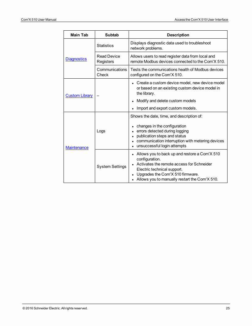
Main Tab Subtab Description
Diagnostics
Statistics Displays diagnostic data used to troubleshootnetwork problems.
Read DeviceRegisters
Allows users to read register data from local andremoteModbus devices connected to the Com'X 510.
CommunicationsCheck
Tests the communications health of Modbus devicesconfigured on the Com'X 510.
Custom Library –
l Create a custom devicemodel, new devicemodelor based on an existing custom devicemodel inthe library.
l Modify and delete custommodels
l Import and export custommodels.
Maintenance
Logs
Shows the date, time, and description of:
l changes in the configurationl errors detected during loggingl publication steps and statusl communication interruption with metering devicesl unsuccessful login attempts
System Settings
l Allows you to back up and restore a Com'X 510configuration.
l Activates the remote access for SchneiderElectric technical support.
l Upgrades the Com'X 510 firmware.l Allows you tomanually restart the Com'X 510.
Com'X 510 User Manual Access the Com'X 510 User Interface
© 2016 Schneider Electric. All rights reserved. 25

Access the Com'X 510 User Interface Com'X 510 User Manual
26 © 2016 Schneider Electric. All rights reserved.
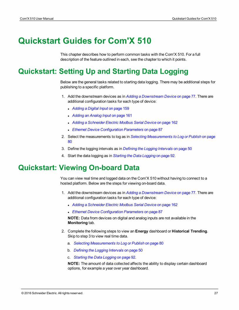
Quickstart Guides for Com'X 510This chapter describes how to perform common tasks with the Com'X 510. For a fulldescription of the feature outlined in each, see the chapter to which it points.
Quickstart: Setting Up and Starting Data LoggingBelow are the general tasks related to starting data logging. Theremay be additional steps forpublishing to a specific platform.
1. Add the downstream devices as inAdding a Downstream Device on page 77. There areadditional configuration tasks for each type of device:
l Adding a Digital Input on page 159
l Adding an Analog Input on page 161
l Adding a Schneider Electric Modbus Serial Device on page 162
l Ethernet Device Configuration Parameters on page 87
2. Select themeasurements to log as inSelectingMeasurements to Log or Publish on page80
3. Define the logging intervals as inDefining the Logging Intervals on page 50
4. Start the data logging as inStarting the Data Logging on page 92.
Quickstart: Viewing On-board DataYou can view real time and logged data on the Com'X 510 without having to connect to ahosted platform. Below are the steps for viewing on-board data.
1. Add the downstream devices as inAdding a Downstream Device on page 77. There areadditional configuration tasks for each type of device:
l Adding a Schneider Electric Modbus Serial Device on page 162
l Ethernet Device Configuration Parameters on page 87NOTE: Data from devices on digital and analog inputs are not available in theMonitoring tab.
2. Complete the following steps to view anEnergy dashboard orHistorical Trending.Skip to step 3 to view real time data.
a. SelectingMeasurements to Log or Publish on page 80
b. Defining the Logging Intervals on page 50
c. Starting the Data Logging on page 92.NOTE: The amount of data collected affects the ability to display certain dashboardoptions, for example a year over year dashboard.
Com'X 510 User Manual Quickstart Guides for Com'X 510
© 2016 Schneider Electric. All rights reserved. 27
Quickstart Guides for Com'X 510 Com'X 510 User Manual
28 © 2016 Schneider Electric. All rights reserved.
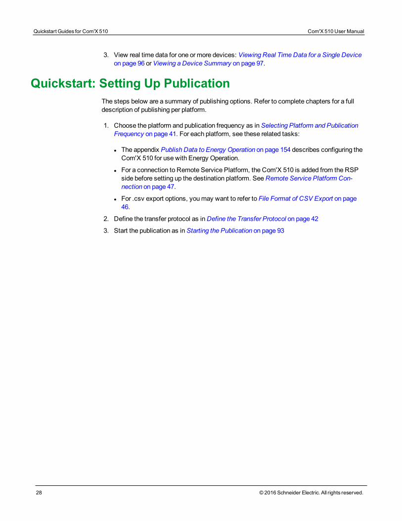
3. View real time data for one or more devices: Viewing Real TimeData for a Single Deviceon page 96 orViewing a Device Summary on page 97.
Quickstart: Setting Up PublicationThe steps below are a summary of publishing options. Refer to complete chapters for a fulldescription of publishing per platform.
1. Choose the platform and publication frequency as inSelecting Platform and PublicationFrequency on page 41. For each platform, see these related tasks:
l The appendix Publish Data to Energy Operation on page 154 describes configuring theCom'X 510 for use with Energy Operation.
l For a connection to Remote Service Platform, the Com'X 510 is added from the RSPside before setting up the destination platform. SeeRemote Service Platform Con-nection on page 47.
l For .csv export options, youmay want to refer to File Format of CSV Export on page46.
2. Define the transfer protocol as inDefine the Transfer Protocol on page 42
3. Start the publication as inStarting the Publication on page 93
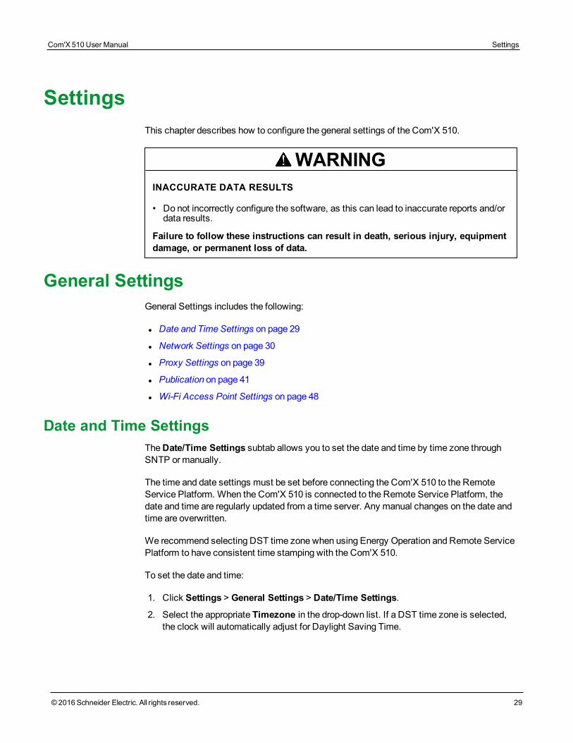
SettingsThis chapter describes how to configure the general settings of the Com'X 510.
WARNINGINACCURATE DATA RESULTS
• Do not incorrectly configure the software, as this can lead to inaccurate reports and/ordata results.
Failure to follow these instructions can result in death, serious injury, equipmentdamage, or permanent loss of data.
General SettingsGeneral Settings includes the following:
l Date and Time Settings on page 29
l Network Settings on page 30
l Proxy Settings on page 39
l Publication on page 41
l Wi-Fi Access Point Settings on page 48
Date and Time SettingsTheDate/Time Settings subtab allows you to set the date and time by time zone throughSNTP ormanually.
The time and date settings must be set before connecting the Com'X 510 to the RemoteService Platform. When the Com'X 510 is connected to the Remote Service Platform, thedate and time are regularly updated from a time server. Any manual changes on the date andtime are overwritten.
We recommend selecting DST time zone when using Energy Operation and Remote ServicePlatform to have consistent time stamping with the Com'X 510.
To set the date and time:
1. Click Settings > General Settings > Date/Time Settings.
2. Select the appropriate Timezone in the drop-down list. If a DST time zone is selected,the clock will automatically adjust for Daylight Saving Time.
Com'X 510 User Manual Settings
© 2016 Schneider Electric. All rights reserved. 29
Settings Com'X 510 User Manual
30 © 2016 Schneider Electric. All rights reserved.
3. Choose one of the following:
a. Click the Today button to set the date and time automatically with the date and timeof your computer.
b. Manually enter the date and time in the date and time fields.
c. Select Yes forSNTP support, then enter an SNTP server address.(Default: pool.ntp.org)
4. Click Save changes.
NOTE: After selecting RSP publication inSettings > General Settings > Publication, donot change date and time settings until the association is complete.
Network SettingsThe Com'X 510 offers several connection interfaces:
l Ethernet with two ports
l Wi-Fi
l GPRS or 3G for isolated sites or sites where the IT administrator does not allow access tothe network infrastructure.
The available interfaces are determined by the accessories connected to the Com'X510: GPRS or 3Gmodem orWi-Fi USB key.
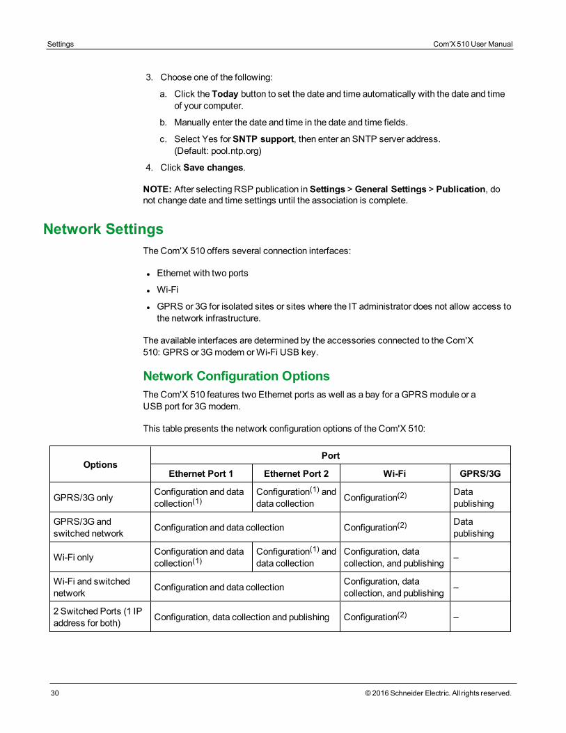
Network Configuration OptionsThe Com'X 510 features two Ethernet ports as well as a bay for a GPRS module or aUSB port for 3Gmodem.
This table presents the network configuration options of the Com'X 510:
OptionsPort
Ethernet Port 1 Ethernet Port 2 Wi-Fi GPRS/3G
GPRS/3G only Configuration and datacollection(1)
Configuration(1) anddata collection Configuration(2) Data
publishing
GPRS/3G andswitched network Configuration and data collection Configuration(2) Data
publishing
Wi-Fi only Configuration and datacollection(1)
Configuration(1) anddata collection
Configuration, datacollection, and publishing –
Wi-Fi and switchednetwork Configuration and data collection Configuration, data
collection, and publishing –
2 Switched Ports (1 IPaddress for both) Configuration, data collection and publishing Configuration(2) –
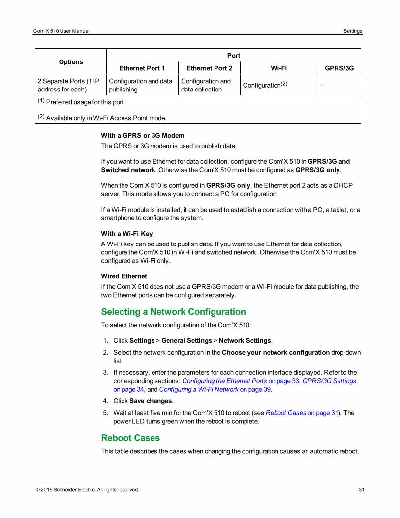
OptionsPort
Ethernet Port 1 Ethernet Port 2 Wi-Fi GPRS/3G
2 Separate Ports (1 IPaddress for each)
Configuration and datapublishing
Configuration anddata collection Configuration(2) –
(1) Preferred usage for this port.
(2) Available only inWi-Fi Access Point mode.
With a GPRS or 3G ModemTheGPRS or 3G modem is used to publish data.
If you want to use Ethernet for data collection, configure the Com'X 510 inGPRS/3G andSwitched network. Otherwise the Com'X 510must be configured as GPRS/3G only.
When the Com'X 510 is configured inGPRS/3G only, the Ethernet port 2 acts as a DHCPserver. This mode allows you to connect a PC for configuration.
If aWi-Fi module is installed, it can be used to establish a connection with a PC, a tablet, or asmartphone to configure the system.
With a Wi-Fi KeyAWi-Fi key can be used to publish data. If you want to use Ethernet for data collection,configure the Com'X 510 inWi-Fi and switched network. Otherwise the Com'X 510must beconfigured as Wi-Fi only.
Wired EthernetIf the Com'X 510 does not use aGPRS/3G modem or aWi-Fi module for data publishing, thetwo Ethernet ports can be configured separately.
Selecting a Network ConfigurationTo select the network configuration of the Com'X 510:
1. Click Settings > General Settings > Network Settings.
2. Select the network configuration in theChoose your network configuration drop-downlist.
3. If necessary, enter the parameters for each connection interface displayed. Refer to thecorresponding sections: Configuring the Ethernet Ports on page 33, GPRS/3G Settingson page 34, andConfiguring aWi-Fi Network on page 39.
4. Click Save changes.
5. Wait at least five min for the Com'X 510 to reboot (seeReboot Cases on page 31). Thepower LED turns green when the reboot is complete.
Reboot CasesThis table describes the cases when changing the configuration causes an automatic reboot.
Com'X 510 User Manual Settings
© 2016 Schneider Electric. All rights reserved. 31
Settings Com'X 510 User Manual
32 © 2016 Schneider Electric. All rights reserved.
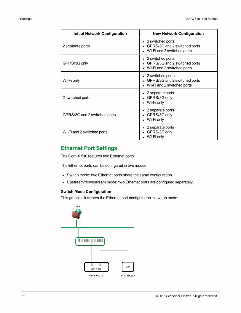
Initial Network Configuration New Network Configuration
2 separate portsl 2 switched portsl GPRS/3G and 2 switched portsl Wi-Fi and 2 switched ports
GPRS/3G onlyl 2 switched portsl GPRS/3G and 2 switched portsl Wi-Fi and 2 switched ports
Wi-Fi onlyl 2 switched portsl GPRS/3G and 2 switched portsl Wi-Fi and 2 switched ports
2 switched portsl 2 separate portsl GPRS/3G onlyl Wi-Fi only
GPRS/3G and 2 switched portsl 2 separate portsl GPRS/3G onlyl Wi-Fi only
Wi-Fi and 2 switched portsl 2 separate portsl GPRS/3G onlyl Wi-Fi only
Ethernet Port SettingsThe Com'X 510 features two Ethernet ports.
The Ethernet ports can be configured in twomodes:
l Switchmode: two Ethernet ports share the same configuration.
l Upstream/downstreammode: two Ethernet ports are configured separately.
Switch Mode ConfigurationThis graphic illustrates the Ethernet port configuration in switchmode:
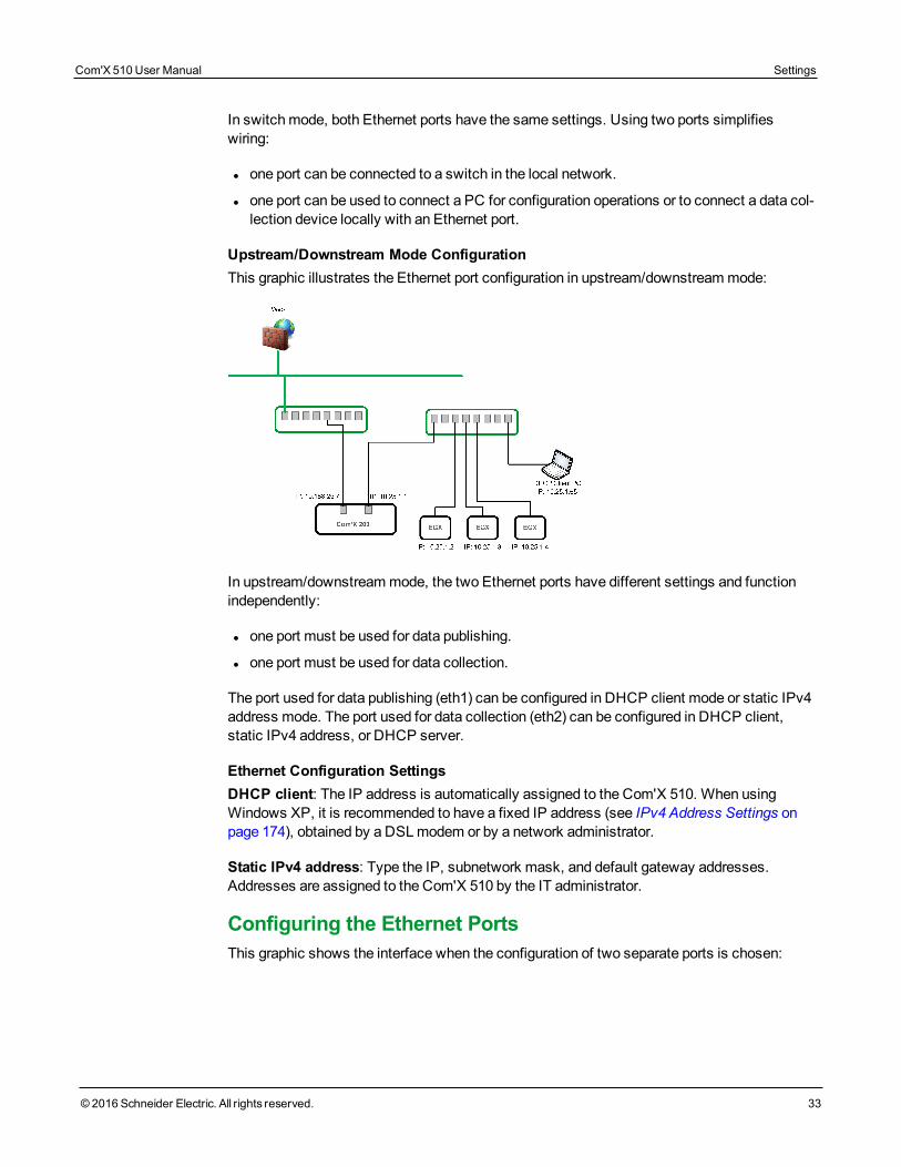
In switchmode, both Ethernet ports have the same settings. Using two ports simplifieswiring:
l one port can be connected to a switch in the local network.
l one port can be used to connect a PC for configuration operations or to connect a data col-lection device locally with an Ethernet port.
Upstream/Downstream Mode ConfigurationThis graphic illustrates the Ethernet port configuration in upstream/downstreammode:
In upstream/downstreammode, the two Ethernet ports have different settings and functionindependently:
l one port must be used for data publishing.
l one port must be used for data collection.
The port used for data publishing (eth1) can be configured in DHCP client mode or static IPv4address mode. The port used for data collection (eth2) can be configured in DHCP client,static IPv4 address, or DHCP server.
Ethernet Configuration SettingsDHCP client: The IP address is automatically assigned to the Com'X 510. When usingWindows XP, it is recommended to have a fixed IP address (see IPv4 Address Settings onpage 174), obtained by a DSLmodem or by a network administrator.
Static IPv4 address: Type the IP, subnetwork mask, and default gateway addresses.Addresses are assigned to the Com'X 510 by the IT administrator.
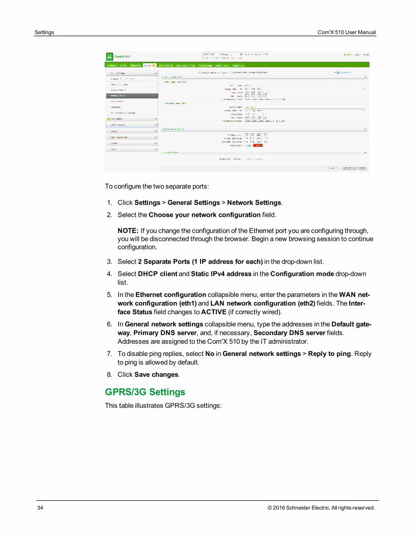
Configuring the Ethernet PortsThis graphic shows the interface when the configuration of two separate ports is chosen:
Com'X 510 User Manual Settings
© 2016 Schneider Electric. All rights reserved. 33
Settings Com'X 510 User Manual
34 © 2016 Schneider Electric. All rights reserved.
To configure the two separate ports:
1. Click Settings > General Settings > Network Settings.
2. Select theChoose your network configuration field.
NOTE: If you change the configuration of the Ethernet port you are configuring through,you will be disconnected through the browser. Begin a new browsing session to continueconfiguration.
3. Select 2 Separate Ports (1 IP address for each) in the drop-down list.
4. Select DHCP client andStatic IPv4 address in theConfiguration mode drop-downlist.
5. In theEthernet configuration collapsible menu, enter the parameters in theWAN net-work configuration (eth1) and LAN network configuration (eth2) fields. The Inter-face Status field changes toACTIVE (if correctly wired).
6. InGeneral network settings collapsible menu, type the addresses in theDefault gate-way, Primary DNS server, and, if necessary, Secondary DNS server fields.Addresses are assigned to the Com'X 510 by the IT administrator.
7. To disable ping replies, select No inGeneral network settings > Reply to ping. Replyto ping is allowed by default.
8. Click Save changes.
GPRS/3G SettingsThis table illustrates GPRS/3G settings:
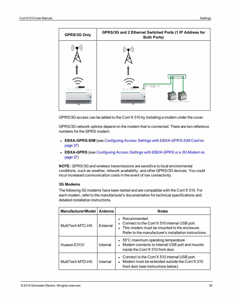
GPRS/3G Only GPRS/3G and 2 Ethernet Switched Ports (1 IP Address forBoth Ports)
GPRS/3G access can be added to the Com'X 510 by installing amodem under the cover.
GPRS/3G network options depend on themodem that is connected. There are two referencenumbers for the GPRS modem:
l EBXA-GPRS-SIM (seeConfiguring Access Settings with EBXA-GPRS-SIM Card onpage 37)
l EBXA-GPRS (seeConfiguring Access Settings with EBXA-GPRS or a 3G Modem onpage 37)
NOTE: GPRS/3G and wireless transmissions are sensitive to local environmentalconditions, such as weather, network availability, and other GPRS/3G devices. You couldincur increased communication costs in the event of low connectivity.
3G ModemsThe following 3Gmodems have been tested and are compatible with the Com'X 510. Foreachmodem, refer to themanufacturer's documentation for technical specifications anddetailed installation instructions.
Manufacturer/Model Antenna Notes
MultiTechMTC-H5 External
l Recommendedl Connect to the Com'X 510 internal USB port.l This modemmust bemounted to the enclosure.Refer to themanufacturer's installation instructions.
Huawei E3131 Internall 55°C maximum operating temperaturel Modem connects to internal USB port andmountsinside the Com'X 510 front door.
MultiTechMTD-H5 Internall Connect to the Com'X 510 internal USB port.l Modemmust be extended outside the Com'X 510front door (see instructions below).
Com'X 510 User Manual Settings
© 2016 Schneider Electric. All rights reserved. 35
Settings Com'X 510 User Manual
36 © 2016 Schneider Electric. All rights reserved.
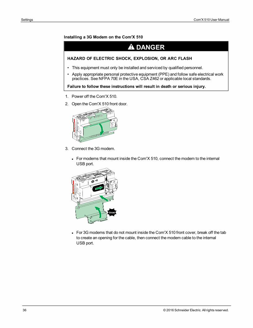
Installing a 3G Modem on the Com'X 510
DANGERHAZARD OF ELECTRIC SHOCK, EXPLOSION, OR ARC FLASH
• This equipment must only be installed and serviced by qualified personnel.• Apply appropriate personal protective equipment (PPE) and follow safe electrical workpractices. See NFPA 70E in the USA, CSA Z462 or applicable local standards.
Failure to follow these instructions will result in death or serious injury.
1. Power off the Com'X 510.
2. Open the Com'X 510 front door.
3. Connect the 3Gmodem.
l Formodems that mount inside the Com'X 510, connect themodem to the internalUSB port.
l For 3Gmodems that do not mount inside the Com'X 510 front cover, break off the tabto create an opening for the cable, then connect themodem cable to the internalUSB port.
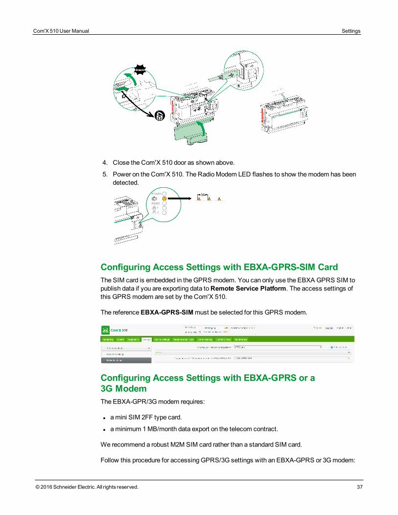
4. Close the Com'X 510 door as shown above.
5. Power on the Com'X 510. The RadioModem LED flashes to show themodem has beendetected.
Configuring Access Settings with EBXA-GPRS-SIM CardThe SIM card is embedded in the GPRS modem. You can only use the EBXA GPRS SIM topublish data if you are exporting data toRemote Service Platform. The access settings ofthis GPRS modem are set by the Com'X 510.
The referenceEBXA-GPRS-SIMmust be selected for this GPRS modem.
Configuring Access Settings with EBXA-GPRS or a3G ModemThe EBXA-GPR/3G modem requires:
l amini SIM 2FF type card.
l aminimum 1 MB/month data export on the telecom contract.
We recommend a robust M2M SIM card rather than a standard SIM card.
Follow this procedure for accessing GPRS/3G settings with an EBXA-GPRS or 3G modem:
Com'X 510 User Manual Settings
© 2016 Schneider Electric. All rights reserved. 37
Settings Com'X 510 User Manual
38 © 2016 Schneider Electric. All rights reserved.
1. Click Settings > General Settings > Network Settings.
2. Install the SIM card into the GPRS modem as described in the EBXA-GPRS/EBXA-GPRS-SIM Instruction Sheet, reference 253537613. For 3G, install the SIM card into the3G modem as described in themanufacturer's installation instructions.
3. Type theAPN, Username, Password, andPIN Code provided by the access provider.
4. Click Save changes.
NOTE: The PIN code and the password of the SIM card cannot be changed by the Com'X510.
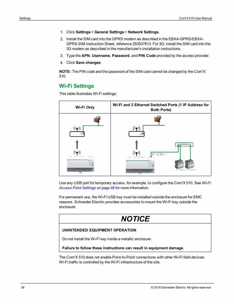
Wi-Fi SettingsThis table illustrates Wi-Fi settings:
Wi-Fi Only Wi-Fi and 2 Ethernet Switched Ports (1 IP Address forBoth Ports)
Use any USB port for temporary access, for example, to configure the Com'X 510. SeeWi-FiAccess Point Settings on page 48 for more information.
For permanent use, theWi-Fi USB key must be installed outside the enclosure for EMCreasons. Schneider Electric provides accessories tomount theWi-Fi key outside theenclosure.
NOTICEUNINTENDED EQUIPMENT OPERATION
Do not install theWi-Fi key inside ametallic enclosure.
Failure to follow these instructions can result in equipment damage.
The Com'X 510 does not enable Point-to-Point connections with otherWi-Fi field devices.Wi-Fi traffic is controlled by theWi-Fi infrastructure of the site.
Configuring a Wi-Fi Network1. Click Settings > General Settings > Network Settings.
2. SelectWiFi only orWiFi and 2 Switched Ports (1 IP address network) in theChoose your network configuration dropdown list.
NOTE: Schneider Electric recommends usingWPA2.
3. Click Select aWi-Fi network in theWi-Fi settings collapsible menu.
4. Click Refresh network list to scan all theWi-Fi networks available.
5. Select theWi-Fi network required. Type the key in the Secure key field if the key doesnot appear automatically.
6. Select Other if the requiredWi-Fi network does not automatically appear in the list of Wi-Fi networks. Type the SSID and the key in the Secure key field.
7. Click Save changes.
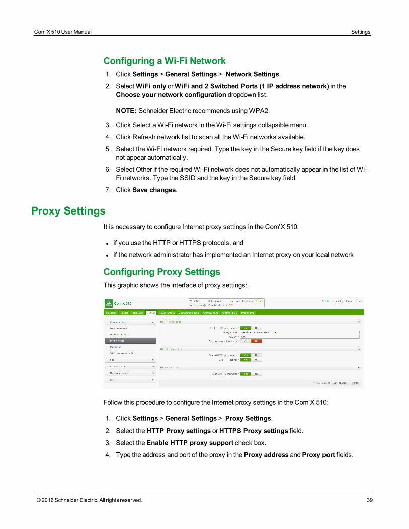
Proxy SettingsIt is necessary to configure Internet proxy settings in the Com'X 510:
l if you use the HTTP or HTTPS protocols, and
l if the network administrator has implemented an Internet proxy on your local network
Configuring Proxy SettingsThis graphic shows the interface of proxy settings:
Follow this procedure to configure the Internet proxy settings in the Com'X 510:
1. Click Settings > General Settings > Proxy Settings.
2. Select theHTTP Proxy settings orHTTPS Proxy settings field.
3. Select theEnable HTTP proxy support check box.
4. Type the address and port of the proxy in theProxy address andProxy port fields.
Com'X 510 User Manual Settings
© 2016 Schneider Electric. All rights reserved. 39
Settings Com'X 510 User Manual
40 © 2016 Schneider Electric. All rights reserved.
5. If proxy authentication is required, select Yes forProxy requires authentication, andenter the login and password to the proxy.
6. Click Save changes.
The proxy address and port number are provided by your network administrator, or you canretrieve these values in the Internet Options of a PC connected to the LAN.
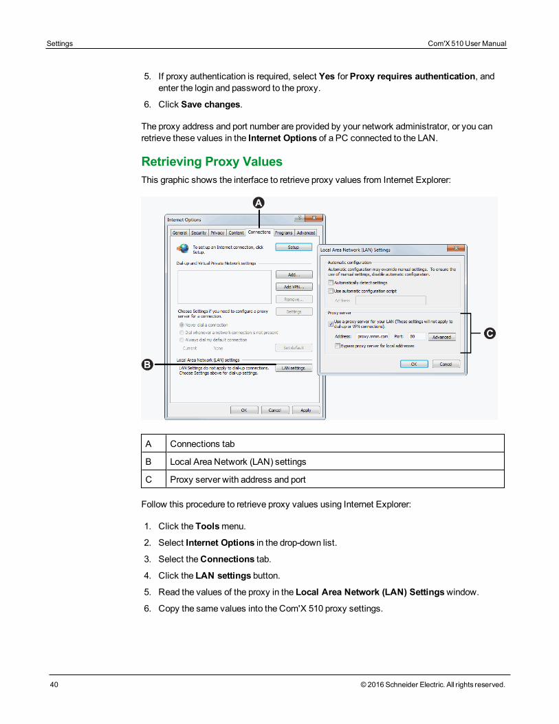
Retrieving Proxy ValuesThis graphic shows the interface to retrieve proxy values from Internet Explorer:
A Connections tab
B Local Area Network (LAN) settings
C Proxy server with address and port
Follow this procedure to retrieve proxy values using Internet Explorer:
1. Click the Toolsmenu.
2. Select Internet Options in the drop-down list.
3. Select theConnections tab.
4. Click the LAN settings button.
5. Read the values of the proxy in the Local Area Network (LAN) Settingswindow.
6. Copy the same values into the Com'X 510 proxy settings.
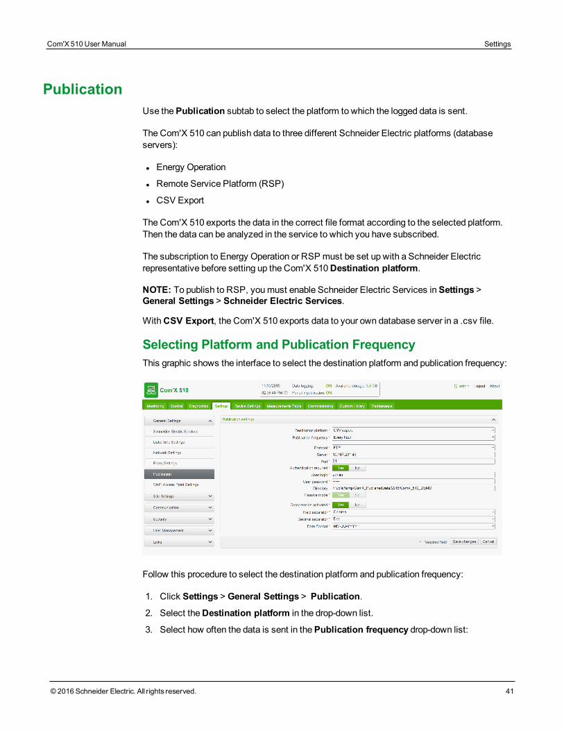
PublicationUse thePublication subtab to select the platform to which the logged data is sent.
The Com'X 510 can publish data to three different Schneider Electric platforms (databaseservers):
l Energy Operation
l Remote Service Platform (RSP)
l CSV Export
The Com'X 510 exports the data in the correct file format according to the selected platform.Then the data can be analyzed in the service to which you have subscribed.
The subscription to Energy Operation or RSP must be set up with a Schneider Electricrepresentative before setting up the Com'X 510Destination platform.
NOTE: To publish to RSP, youmust enable Schneider Electric Services inSettings >General Settings > Schneider Electric Services.
WithCSV Export, the Com'X 510 exports data to your own database server in a .csv file.
Selecting Platform and Publication FrequencyThis graphic shows the interface to select the destination platform and publication frequency:
Follow this procedure to select the destination platform and publication frequency:
1. Click Settings > General Settings > Publication.
2. Select theDestination platform in the drop-down list.
3. Select how often the data is sent in thePublication frequency drop-down list:
Com'X 510 User Manual Settings
© 2016 Schneider Electric. All rights reserved. 41
Settings Com'X 510 User Manual
42 © 2016 Schneider Electric. All rights reserved.
l Weekly: select the day of the week.
l Daily: the data is sent at 1:00 a.m. local time.
l For higher frequencies, publication times are calculated starting at 0:00 a.m. Forexample, if Every 2 hours is selected, data is sent at 0:00 a.m., 2:00 a.m., 4:00 a.m.,and so on. If Every 3 hours is selected, data is sent at 0:00 a.m., 3:00 a.m.,6:00 a.m., and so on.
4. Click Save changes.
NOTE: The first publication occurs on the first hour that matches the selected frequency aftertheStart publication task inCommissioning on page 91. For example, if Every 2 hours isselected and the publication starts at 9:45 a.m., the first publication is at 10:00 a.m.
NOTE:When publication with RSP is activated, it is not possible to change to a differentpublication platform. To change platform, youmust perform a factory reset (Resetting toFactory Settings on page 143). Contact your local Schneider Electric technical support forthis action.
NOTE: After selecting RSP as the destination platform in Publication, do not start publicationuntil the association is complete (SeeRemote Service Platform Connection on page 47)
Define the Transfer ProtocolThere are different ways to export the data. The protocols in theProtocol drop-down list varydepending on the selected platform, as shown in this table:
Platforms Supported Transfer Protocols File Format
Energy Operationl FTP
l HTTP and HTTPSXML
Remote Service Platform Automatically defined by the Com'X 510 EWS
CSV export
l FTP
l HTTP and HTTPS
l SMTP
CSV
NOTICEHAZARD OF UNAUTHORIZED ACCESS
Use the HTTPS transfer protocol.
Failure to follow these instructions can result in equipment damage.
To define the transfer protocol for publication, see one of the following:
l Configuring FTP Transfer Protocol on page 43
l Configuring HTTP and HTTPS Transfer Protocols on page 43
l Configuring SMTP Transfer Protocol on page 45
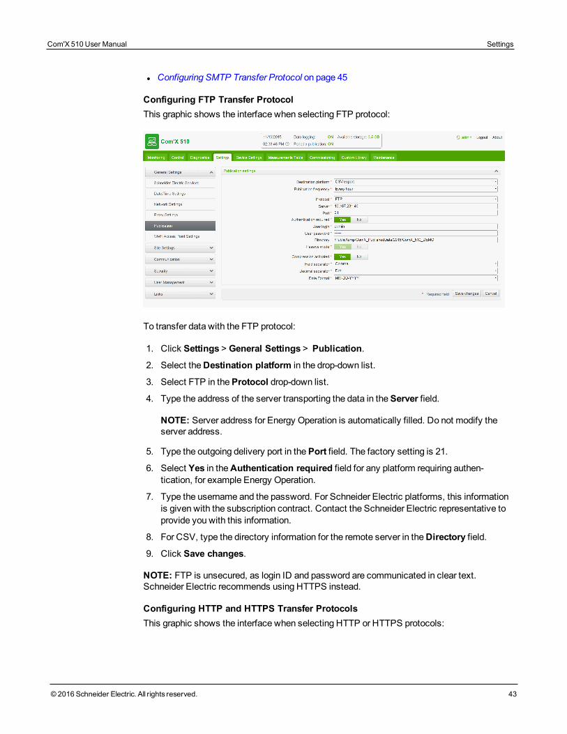
Configuring FTP Transfer ProtocolThis graphic shows the interface when selecting FTP protocol:
To transfer data with the FTP protocol:
1. Click Settings > General Settings > Publication.
2. Select theDestination platform in the drop-down list.
3. Select FTP in theProtocol drop-down list.
4. Type the address of the server transporting the data in theServer field.
NOTE: Server address for Energy Operation is automatically filled. Do not modify theserver address.
5. Type the outgoing delivery port in thePort field. The factory setting is 21.
6. Select Yes in theAuthentication required field for any platform requiring authen-tication, for example Energy Operation.
7. Type the username and the password. For Schneider Electric platforms, this informationis given with the subscription contract. Contact the Schneider Electric representative toprovide you with this information.
8. For CSV, type the directory information for the remote server in theDirectory field.
9. Click Save changes.
NOTE: FTP is unsecured, as login ID and password are communicated in clear text.Schneider Electric recommends using HTTPS instead.
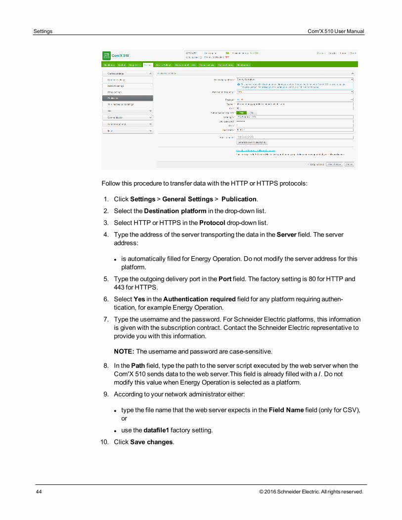
Configuring HTTP and HTTPS Transfer ProtocolsThis graphic shows the interface when selecting HTTP or HTTPS protocols:
Com'X 510 User Manual Settings
© 2016 Schneider Electric. All rights reserved. 43
Settings Com'X 510 User Manual
44 © 2016 Schneider Electric. All rights reserved.
Follow this procedure to transfer data with the HTTP or HTTPS protocols:
1. Click Settings > General Settings > Publication.
2. Select theDestination platform in the drop-down list.
3. Select HTTP or HTTPS in theProtocol drop-down list.
4. Type the address of the server transporting the data in theServer field. The serveraddress:
l is automatically filled for Energy Operation. Do not modify the server address for thisplatform.
5. Type the outgoing delivery port in thePort field. The factory setting is 80 for HTTP and443 for HTTPS.
6. Select Yes in theAuthentication required field for any platform requiring authen-tication, for example Energy Operation.
7. Type the username and the password. For Schneider Electric platforms, this informationis given with the subscription contract. Contact the Schneider Electric representative toprovide you with this information.
NOTE: The username and password are case-sensitive.
8. In thePath field, type the path to the server script executed by the web server when theCom'X 510 sends data to the web server.This field is already filled with a /. Do notmodify this value when Energy Operation is selected as a platform.
9. According to your network administrator either:
l type the file name that the web server expects in the Field Name field (only for CSV),or
l use the datafile1 factory setting.
10. Click Save changes.
NOTE: HTTP is unsecured, as login ID and password are communicated in clear text.Schneider Electric recommends using HTTPS instead.
Certificate considerations for HTTPSYou can secure the HTTP connection to your server with TLS/SSL technology.
As with a web browser, the box is preloaded with all themajor certificate authorities as of thetime of the firmware release. See List of Certificate Authorities on page 168. SchneiderElectric offers an update of the list of certificate authorities with the firmware updates.
This means that your HTTPS server certificates must have been issued by one of the box'strusted certificate authorities. Check with your IT department to know if your HTTPS servercertificate complies with this rule. If not, you can select HTTP.
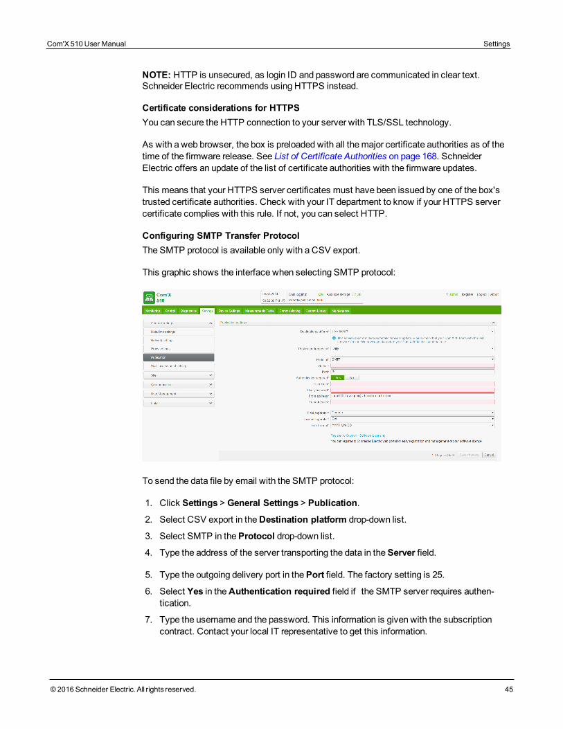
Configuring SMTP Transfer ProtocolThe SMTP protocol is available only with a CSV export.
This graphic shows the interface when selecting SMTP protocol:
To send the data file by email with the SMTP protocol:
1. Click Settings > General Settings > Publication.
2. Select CSV export in theDestination platform drop-down list.
3. Select SMTP in theProtocol drop-down list.
4. Type the address of the server transporting the data in theServer field.
5. Type the outgoing delivery port in thePort field. The factory setting is 25.
6. Select Yes in theAuthentication required field if the SMTP server requires authen-tication.
7. Type the username and the password. This information is given with the subscriptioncontract. Contact your local IT representative to get this information.
Com'X 510 User Manual Settings
© 2016 Schneider Electric. All rights reserved. 45
Settings Com'X 510 User Manual
46 © 2016 Schneider Electric. All rights reserved.
NOTE: The username and password are case-sensitive.
8. Type the address of the email sender in the From address field. The factory setting is inthe format: [email protected].
NOTE: Most SMTP servers require a From address.
9. Type the addresses of the recipients in the To addresses field. Separate the addresseswith a semicolon (;). Exported files are zipped to reduce the size of attached documentsin the email.
10. Click Save changes.
NOTE: SMTP is unsecured, as login ID and password are communicated in clear text.Schneider Electric recommends using HTTPS instead.
Publication Identification SettingsThis table describes the publication identification settings for Energy Operation:
Field/Button Description
Publication ID
This number is a unique identifier of the site for the Energy Operationdatabase. It is used to create a site in Energy Operation.
This ID is automatically generated by the Com'X 510.
Generate newpublication ID
This button generates a new publication ID number. Use this buttonwhenever you reuse:
l the Com'X 510 for a new site.
l the current Com'X 510 configuration on a different site.
File Format of CSV ExportThere is one file exported for each device.
Exported files are in the following naming format: Device Name_Date&time.csv whereDevice Name is the name given to the slave device. The date and time are appended to thefile name in the following format: _yyyymmddhhmmss.
For example:
l Device name: Building 1 Utility Entrance
l Date/time: 20130218115216
The exported file is named Building 1 Utility Entrance_20130218115216.csvand was exported on February 18, 2013 at 11:52:16 a.m.
The following table provides the details of each line of a CSV file, with sample data:
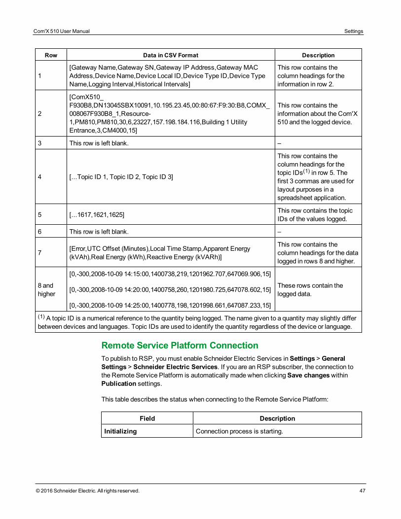
Row Data in CSV Format Description
1[Gateway Name,Gateway SN,Gateway IP Address,Gateway MACAddress,Device Name,Device Local ID,Device Type ID,Device TypeName,Logging Interval,Historical Intervals]
This row contains thecolumn headings for theinformation in row 2.
2
[ComX510_F930B8,DN13045SBX10091,10.195.23.45,00:80:67:F9:30:B8,COMX_008067F930B8_1,Resource-1,PM810,PM810,30,6,23227,157.198.184.116,Building 1 UtilityEntrance,3,CM4000,15]
This row contains theinformation about the Com'X510 and the logged device.
3 This row is left blank. –
4 [...Topic ID 1, Topic ID 2, Topic ID 3]
This row contains thecolumn headings for thetopic IDs(1) in row 5. Thefirst 3 commas are used forlayout purposes in aspreadsheet application.
5 [...1617,1621,1625] This row contains the topicIDs of the values logged.
6 This row is left blank. –
7 [Error,UTC Offset (Minutes),Local Time Stamp,Apparent Energy(kVAh),Real Energy (kWh),Reactive Energy (kVARh)]
This row contains thecolumn headings for the datalogged in rows 8 and higher.
8 andhigher
[0,-300,2008-10-09 14:15:00,1400738,219,1201962.707,647069.906,15]
[0,-300,2008-10-09 14:20:00,1400758,260,1201980.725,647078.602,15]
[0,-300,2008-10-09 14:25:00,1400778,198,1201998.661,647087.233,15]
These rows contain thelogged data.
(1) A topic ID is a numerical reference to the quantity being logged. The name given to a quantity may slightly differbetween devices and languages. Topic IDs are used to identify the quantity regardless of the device or language.
Remote Service Platform ConnectionTo publish to RSP, youmust enable Schneider Electric Services inSettings > GeneralSettings > Schneider Electric Services. If you are an RSP subscriber, the connection tothe Remote Service Platform is automatically made when clickingSave changeswithinPublication settings.
This table describes the status when connecting to the Remote Service Platform:
Field Description
Initializing Connection process is starting.
Com'X 510 User Manual Settings
© 2016 Schneider Electric. All rights reserved. 47
Settings Com'X 510 User Manual
48 © 2016 Schneider Electric. All rights reserved.
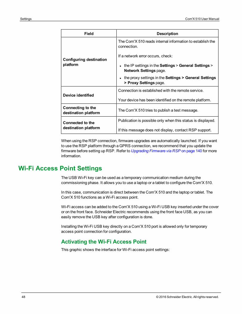
Field Description
Configuring destinationplatform
The Com'X 510 reads internal information to establish theconnection.
If a network error occurs, check:
l the IP settings in theSettings > General Settings >Network Settings page.
l the proxy settings in theSettings > General Settings> Proxy Settings page.
Device identifiedConnection is established with the remote service.
Your device has been identified on the remote platform.
Connecting to thedestination platform The Com'X 510 tries to publish a test message.
Connected to thedestination platform
Publication is possible only when this status is displayed.
If this message does not display, contact RSP support.
When using the RSP connection, firmware upgrades are automatically launched. If you wantto use the RSP platform through aGPRS connection, we recommend that you update thefirmware before setting up RSP. Refer toUpgrading Firmware via RSP on page 140 for moreinformation.
Wi-Fi Access Point SettingsThe USBWi-Fi key can be used as a temporary communicationmedium during thecommissioning phase. It allows you to use a laptop or a tablet to configure the Com'X 510.
In this case, communication is direct between the Com'X 510 and the laptop or tablet. TheCom'X 510 functions as aWi-Fi access point.
Wi-Fi access can be added to the Com'X 510 using aWi-Fi USB key inserted under the coveror on the front face. Schneider Electric recommends using the front face USB, as you caneasily remove the USB key after configuration is done.
Installing theWi-Fi USB key directly on a Com'X 510 port is allowed only for temporaryaccess point connection for configuration.
Activating the Wi-Fi Access PointThis graphic shows the interface forWi-Fi access point settings:
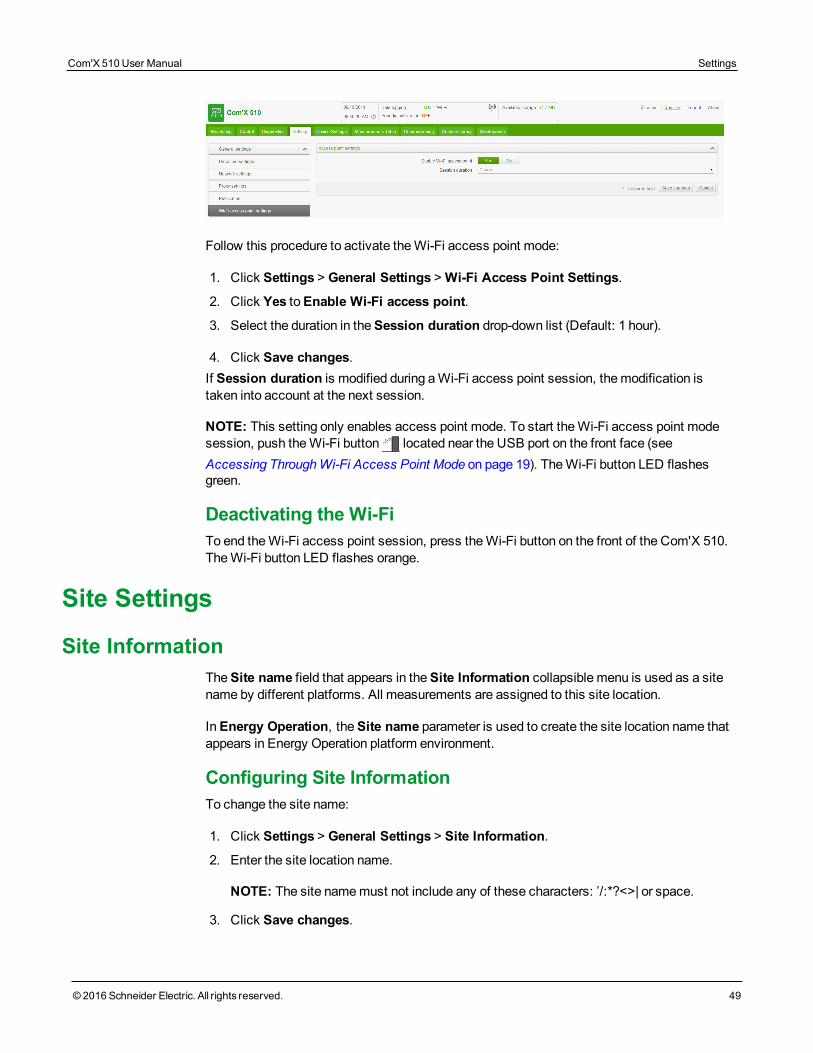
Follow this procedure to activate theWi-Fi access point mode:
1. Click Settings > General Settings >Wi-Fi Access Point Settings.
2. Click Yes toEnable Wi-Fi access point.
3. Select the duration in theSession duration drop-down list (Default: 1 hour).
4. Click Save changes.If Session duration is modified during aWi-Fi access point session, themodification istaken into account at the next session.
NOTE: This setting only enables access point mode. To start theWi-Fi access point modesession, push theWi-Fi button located near the USB port on the front face (seeAccessing ThroughWi-Fi Access Point Mode on page 19). TheWi-Fi button LED flashesgreen.
Deactivating the Wi-FiTo end theWi-Fi access point session, press theWi-Fi button on the front of the Com'X 510.TheWi-Fi button LED flashes orange.
Site Settings
Site InformationTheSite name field that appears in theSite Information collapsible menu is used as a sitename by different platforms. All measurements are assigned to this site location.
InEnergy Operation, theSite name parameter is used to create the site location name thatappears in Energy Operation platform environment.
Configuring Site InformationTo change the site name:
1. Click Settings > General Settings > Site Information.
2. Enter the site location name.
NOTE: The site namemust not include any of these characters: ’/:*?<>| or space.
3. Click Save changes.
Com'X 510 User Manual Settings
© 2016 Schneider Electric. All rights reserved. 49
Settings Com'X 510 User Manual
50 © 2016 Schneider Electric. All rights reserved.
Data LoggingThe Com'X 510 can log data at pre-defined intervals. The logging interval can be set for eachtype of commodity, for example, electricity, water, or gas. Each device can report only onetype of commodity.
Defining the Logging IntervalsIt is important to consider how much data is being logged across all devices when selectingthe logging interval and number of topics to log. Logging toomany topics per interval mayaffect Com'X 510 performance, including degraded web page response andmissed loggingintervals.
For example, for a logging interval of less than fiveminutes, we recommend that you log nomore than 8 devices with 50 total topics.
To define the logging intervals:
1. Click Settings > Site Settings > Data Logging.
2. Select your country.
NOTE: This will automatically set the logging intervals of data for different commoditiesin the country. You can also edit these intervals individually.
3. Click Save changes.
Communication SettingsThis section describes how to configure the communication settings of the Com'X 510.
Modbus TCP AccessThe Com'X 510 is both aModbus TCP gateway and, using the internal Modbus TCP server,a Modbus device.
Modbus TCP GatewayThe Com'X 510 acts as aModbus gateway for wired or wireless Ethernet communicationsfrom an upstream PC to Ethernet devices and field instruments on the downstream network.This capability allows the user of local or cloud-basedmonitoring software to accessinformation from devices for data collection, historical trending, analysis, and other functions.
Accessing the Internal Modbus Slave DeviceThe internal Modbus TCP server allows reading the digital input and analog input values ofthe Com'X 510 via various Modbus registers (seeModbus Register Mapping on page 177.These registers can be read usingModbus slave ID 255.
After you configure the Com'X 510 inputs inDevice Settings, values are accessible throughthe gateway. The register values can also be viewed in theMeasurements Table tab formeasurements selected for logging (seeSelectingMeasurements to Log or Publish on page80).
The internal Modbus TCP server is active whenModbus TCP/IP communications is enabledvia Firewall Management on page 58.
Companion Software Modbus TCP/IP Server FunctionDownstreamModbus devices can be accessed from an upstream PC running a softwareapplication. Recommended software applications offered by Schneider Electric include:
l Remote Setting Utility software for Masterpact and Compact NSX
l StruxureWare PowerMonitoring Expert software.
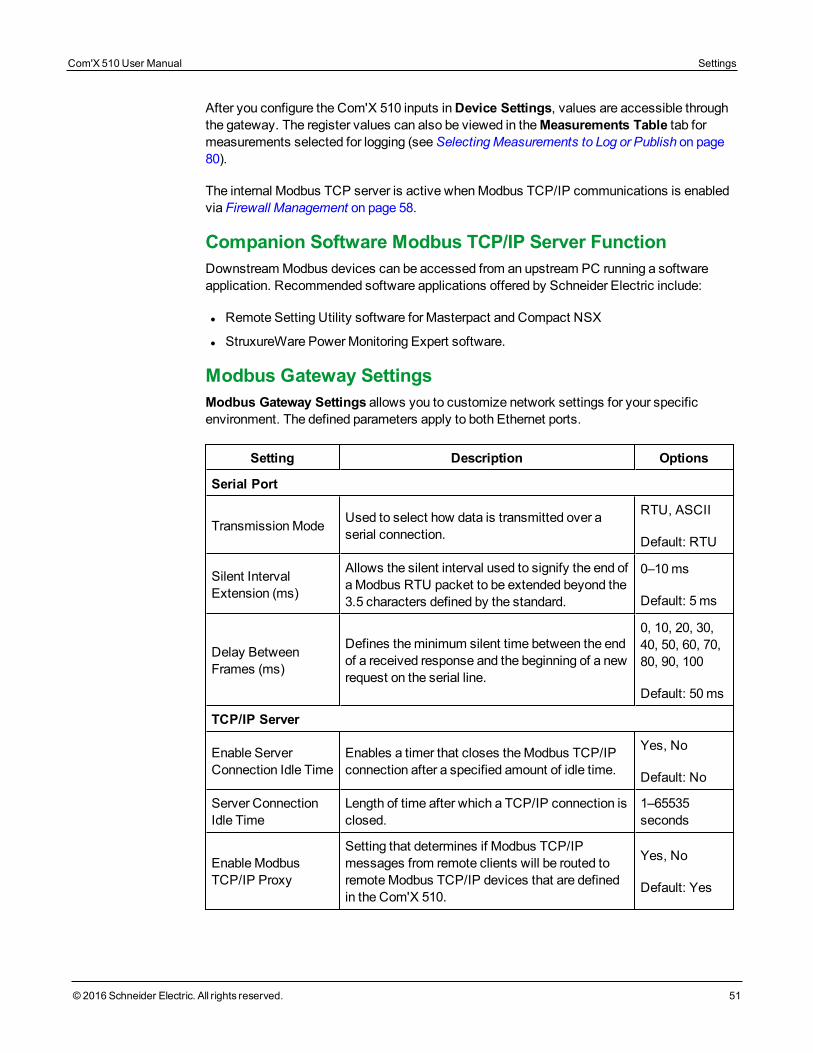
Modbus Gateway SettingsModbus Gateway Settings allows you to customize network settings for your specificenvironment. The defined parameters apply to both Ethernet ports.
Setting Description Options
Serial Port
TransmissionMode Used to select how data is transmitted over aserial connection.
RTU, ASCII
Default: RTU
Silent IntervalExtension (ms)
Allows the silent interval used to signify the end ofaModbus RTU packet to be extended beyond the3.5 characters defined by the standard.
0–10ms
Default: 5 ms
Delay BetweenFrames (ms)
Defines theminimum silent time between the endof a received response and the beginning of a newrequest on the serial line.
0, 10, 20, 30,40, 50, 60, 70,80, 90, 100
Default: 50ms
TCP/IP Server
Enable ServerConnection Idle Time
Enables a timer that closes theModbus TCP/IPconnection after a specified amount of idle time.
Yes, No
Default: No
Server ConnectionIdle Time
Length of time after which a TCP/IP connection isclosed.
1–65535seconds
EnableModbusTCP/IP Proxy
Setting that determines if Modbus TCP/IPmessages from remote clients will be routed toremoteModbus TCP/IP devices that are definedin the Com'X 510.
Yes, No
Default: Yes
Com'X 510 User Manual Settings
© 2016 Schneider Electric. All rights reserved. 51
Settings Com'X 510 User Manual
52 © 2016 Schneider Electric. All rights reserved.
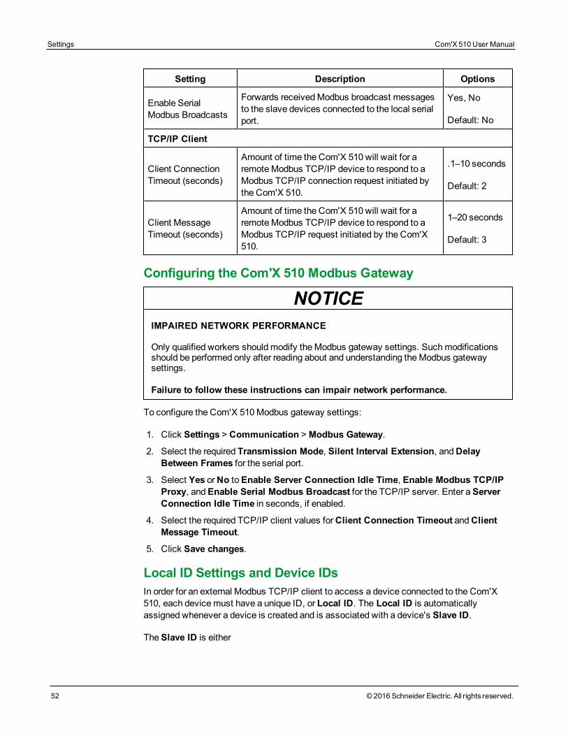
Setting Description Options
Enable SerialModbus Broadcasts
Forwards receivedModbus broadcast messagesto the slave devices connected to the local serialport.
Yes, No
Default: No
TCP/IP Client
Client ConnectionTimeout (seconds)
Amount of time the Com'X 510 will wait for aremoteModbus TCP/IP device to respond to aModbus TCP/IP connection request initiated bythe Com'X 510.
.1–10 seconds
Default: 2
Client MessageTimeout (seconds)
Amount of time the Com'X 510 will wait for aremoteModbus TCP/IP device to respond to aModbus TCP/IP request initiated by the Com'X510.
1–20 seconds
Default: 3
Configuring the Com'X 510 Modbus Gateway
NOTICEIMPAIRED NETWORK PERFORMANCE
Only qualified workers shouldmodify theModbus gateway settings. Suchmodificationsshould be performed only after reading about and understanding theModbus gatewaysettings.
Failure to follow these instructions can impair network performance.
To configure the Com'X 510Modbus gateway settings:
1. Click Settings > Communication >Modbus Gateway.
2. Select the required Transmission Mode, Silent Interval Extension, andDelayBetween Frames for the serial port.
3. Select Yes orNo toEnable Server Connection Idle Time, Enable Modbus TCP/IPProxy, andEnable Serial Modbus Broadcast for the TCP/IP server. Enter aServerConnection Idle Time in seconds, if enabled.
4. Select the required TCP/IP client values forClient Connection Timeout andClientMessage Timeout.
5. Click Save changes.
Local ID Settings and Device IDsIn order for an external Modbus TCP/IP client to access a device connected to the Com'X510, each devicemust have a unique ID, or Local ID. The Local ID is automaticallyassigned whenever a device is created and is associated with a device's Slave ID.
TheSlave ID is either
l the configuredModbus ID of any device connected to the RS485 serial port,
l the configuredModbus ID of a connectedModbus TCP/IP device, or
l the ID used by aModbus TCP/IP gateway that connects a device to an Ethernet network.
You can change the Local ID inSettings > Communication >Modbus Gateway > DeviceIDs. The Local ID must be unique and can only be changed if data logging is disabled for thedevice being updated. SeeStarting the Data Logging on page 92
TheDevices page also provides the following information for each device:
l Slave ID
l Connection: "Serial Port," IP address for remote devices, or Zigbee ID
l Device Type as defined inDevice Settings
Modbus TCP/IP FilteringThis function allows the administrator to create a whitelist and assign the level of access IPaddresses have to the Com'X 510 and its downstream devices.
When enabled, the default access level is Read for any Modbus TCP/IP client not in thefiltered list. Setting theDefault Access field toNone blocks all Modbus TCP/IP clients not inthe filtered list.
To create a filter:
1. Click Settings > Communication >Modbus TCP/IP Filtering.
2. Click Yes to enable filtering.
3. In theWhitelist column, enter the IP address you want to filter on.
NOTE: An empty octet field is treated as a wildcard. Empty fields must begin with theleast significant octet and be contiguous. Themost restrictive filter is applied in cases ofcontradiction.
4. Select the access level: None, Read, or Full.
5. Optionally, you can edit theDefault Access: Read orNone.
6. Click Save changes.
Modbus Serial PortThe RS-485 serial line standard is an industrial standard. If configured correctly, it canpotentially reduce transmission errors even in an environment with electrical disturbances.
This section describes the serial line properties of the local Modbus/RS-485 networkcontrolled by the Com'X 510.
Com'X 510 User Manual Settings
© 2016 Schneider Electric. All rights reserved. 53
Settings Com'X 510 User Manual
54 © 2016 Schneider Electric. All rights reserved.
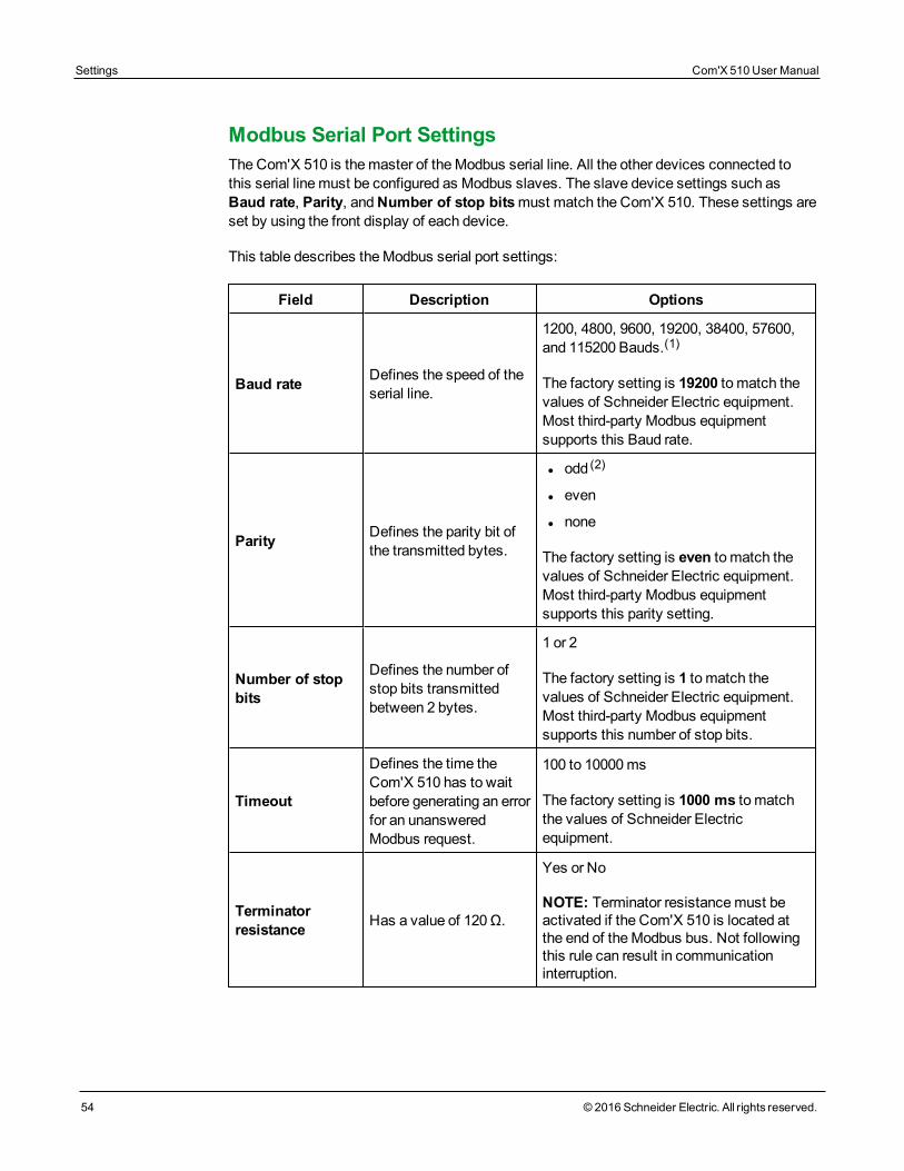
Modbus Serial Port SettingsThe Com'X 510 is themaster of theModbus serial line. All the other devices connected tothis serial linemust be configured as Modbus slaves. The slave device settings such asBaud rate, Parity, andNumber of stop bitsmust match the Com'X 510. These settings areset by using the front display of each device.
This table describes theModbus serial port settings:
Field Description Options
Baud rate Defines the speed of theserial line.
1200, 4800, 9600, 19200, 38400, 57600,and 115200 Bauds.(1)
The factory setting is 19200 to match thevalues of Schneider Electric equipment.Most third-party Modbus equipmentsupports this Baud rate.
Parity Defines the parity bit ofthe transmitted bytes.
l odd (2)
l even
l none
The factory setting is even to match thevalues of Schneider Electric equipment.Most third-party Modbus equipmentsupports this parity setting.
Number of stopbits
Defines the number ofstop bits transmittedbetween 2 bytes.
1 or 2
The factory setting is 1 to match thevalues of Schneider Electric equipment.Most third-party Modbus equipmentsupports this number of stop bits.
Timeout
Defines the time theCom'X 510 has to waitbefore generating an errorfor an unansweredModbus request.
100 to 10000 ms
The factory setting is 1000 ms to matchthe values of Schneider Electricequipment.
Terminatorresistance Has a value of 120 Ω.
Yes or No
NOTE: Terminator resistancemust beactivated if the Com'X 510 is located atthe end of theModbus bus. Not followingthis rule can result in communicationinterruption.
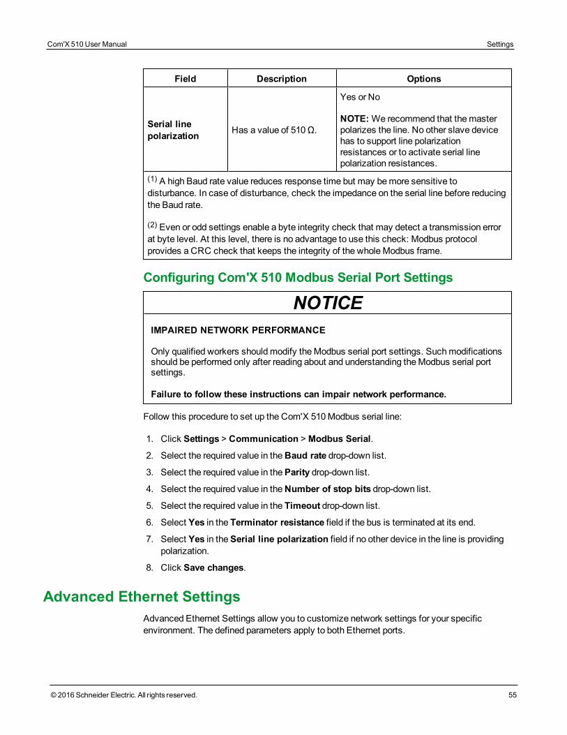
Field Description Options
Serial linepolarization Has a value of 510 Ω.
Yes or No
NOTE:We recommend that themasterpolarizes the line. No other slave devicehas to support line polarizationresistances or to activate serial linepolarization resistances.
(1) A high Baud rate value reduces response time but may bemore sensitive todisturbance. In case of disturbance, check the impedance on the serial line before reducingthe Baud rate.
(2) Even or odd settings enable a byte integrity check that may detect a transmission errorat byte level. At this level, there is no advantage to use this check: Modbus protocolprovides a CRC check that keeps the integrity of the wholeModbus frame.
Configuring Com'X 510 Modbus Serial Port Settings
NOTICEIMPAIRED NETWORK PERFORMANCE
Only qualified workers shouldmodify theModbus serial port settings. Suchmodificationsshould be performed only after reading about and understanding theModbus serial portsettings.
Failure to follow these instructions can impair network performance.
Follow this procedure to set up the Com'X 510Modbus serial line:
1. Click Settings > Communication >Modbus Serial.
2. Select the required value in theBaud rate drop-down list.
3. Select the required value in theParity drop-down list.
4. Select the required value in theNumber of stop bits drop-down list.
5. Select the required value in the Timeout drop-down list.
6. Select Yes in the Terminator resistance field if the bus is terminated at its end.
7. Select Yes in theSerial line polarization field if no other device in the line is providingpolarization.
8. Click Save changes.
Advanced Ethernet SettingsAdvanced Ethernet Settings allow you to customize network settings for your specificenvironment. The defined parameters apply to both Ethernet ports.
Com'X 510 User Manual Settings
© 2016 Schneider Electric. All rights reserved. 55
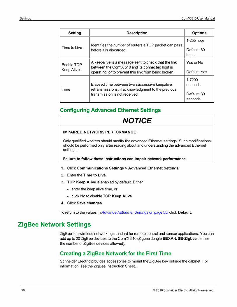
Settings Com'X 510 User Manual
56 © 2016 Schneider Electric. All rights reserved.
Setting Description Options
Time to Live Identifies the number of routers a TCP packet can passbefore it is discarded.
1-255 hops
Default: 60hops
Enable TCPKeep Alive
A keepalive is amessage sent to check that the linkbetween the Com'X 510 and its connected host isoperating, or to prevent this link from being broken.
Yes or No
Default: Yes
TimeElapsed time between two successive keepaliveretransmissions, if acknowledgment to the previoustransmission is not received.
1-7200seconds
Default: 30seconds
Configuring Advanced Ethernet Settings
NOTICEIMPAIRED NETWORK PERFORMANCE
Only qualified workers shouldmodify the advanced Ethernet settings. Suchmodificationsshould be performed only after reading about and understanding the advanced Ethernetsettings.
Failure to follow these instructions can impair network performance.
1. Click Communications Settings > Advanced Ethernet Settings.
2. Enter the Time to Live.
3. TCP Keep Alive is enabled by default. Either
l enter the keep alive time, or
l click No to disable TCP Keep Alive.
4. Click Save changes.
To return to the values inAdvanced Ethernet Settings on page 55, click Default.
ZigBee Network SettingsZigBee is a wireless networking standard for remote control and sensor applications. You canadd up to 20 ZigBee devices to the Com'X 510 (Zigbee dongleEBXA-USB-Zigbee definesthe number of ZigBee devices allowed).
Creating a ZigBee Network for the First TimeSchneider Electric provides accessories tomount the ZigBee key outside the cabinet. Forinformation, see the ZigBee Instruction Sheet.
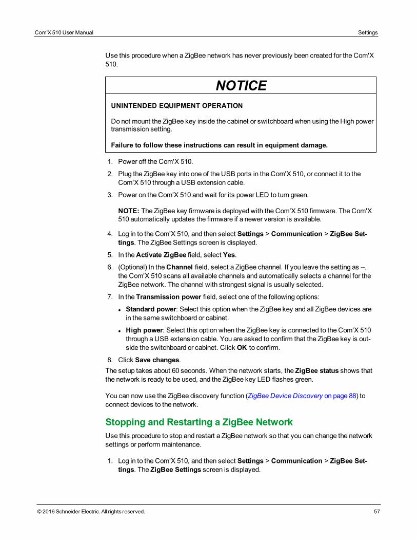
Use this procedure when a ZigBee network has never previously been created for the Com'X510.
NOTICEUNINTENDED EQUIPMENT OPERATION
Do not mount the ZigBee key inside the cabinet or switchboard when using the High powertransmission setting.
Failure to follow these instructions can result in equipment damage.
1. Power off the Com'X 510.
2. Plug the ZigBee key into one of the USB ports in the Com'X 510, or connect it to theCom'X 510 through a USB extension cable.
3. Power on the Com'X 510 and wait for its power LED to turn green.
NOTE: The ZigBee key firmware is deployed with the Com'X 510 firmware. The Com'X510 automatically updates the firmware if a newer version is available.
4. Log in to the Com'X 510, and then select Settings > Communication > ZigBee Set-tings. The ZigBee Settings screen is displayed.
5. In theActivate ZigBee field, select Yes.
6. (Optional) In theChannel field, select a ZigBee channel. If you leave the setting as --,the Com'X 510 scans all available channels and automatically selects a channel for theZigBee network. The channel with strongest signal is usually selected.
7. In the Transmission power field, select one of the following options:
l Standard power: Select this option when the ZigBee key and all ZigBee devices arein the same switchboard or cabinet.
l High power: Select this option when the ZigBee key is connected to the Com'X 510through a USB extension cable. You are asked to confirm that the ZigBee key is out-side the switchboard or cabinet. Click OK to confirm.
8. Click Save changes.The setup takes about 60 seconds. When the network starts, the ZigBee status shows thatthe network is ready to be used, and the ZigBee key LED flashes green.
You can now use the ZigBee discovery function (ZigBee Device Discovery on page 88) toconnect devices to the network.
Stopping and Restarting a ZigBee NetworkUse this procedure to stop and restart a ZigBee network so that you can change the networksettings or perform maintenance.
1. Log in to the Com'X 510, and then select Settings > Communication > ZigBee Set-tings. The ZigBee Settings screen is displayed.
Com'X 510 User Manual Settings
© 2016 Schneider Electric. All rights reserved. 57
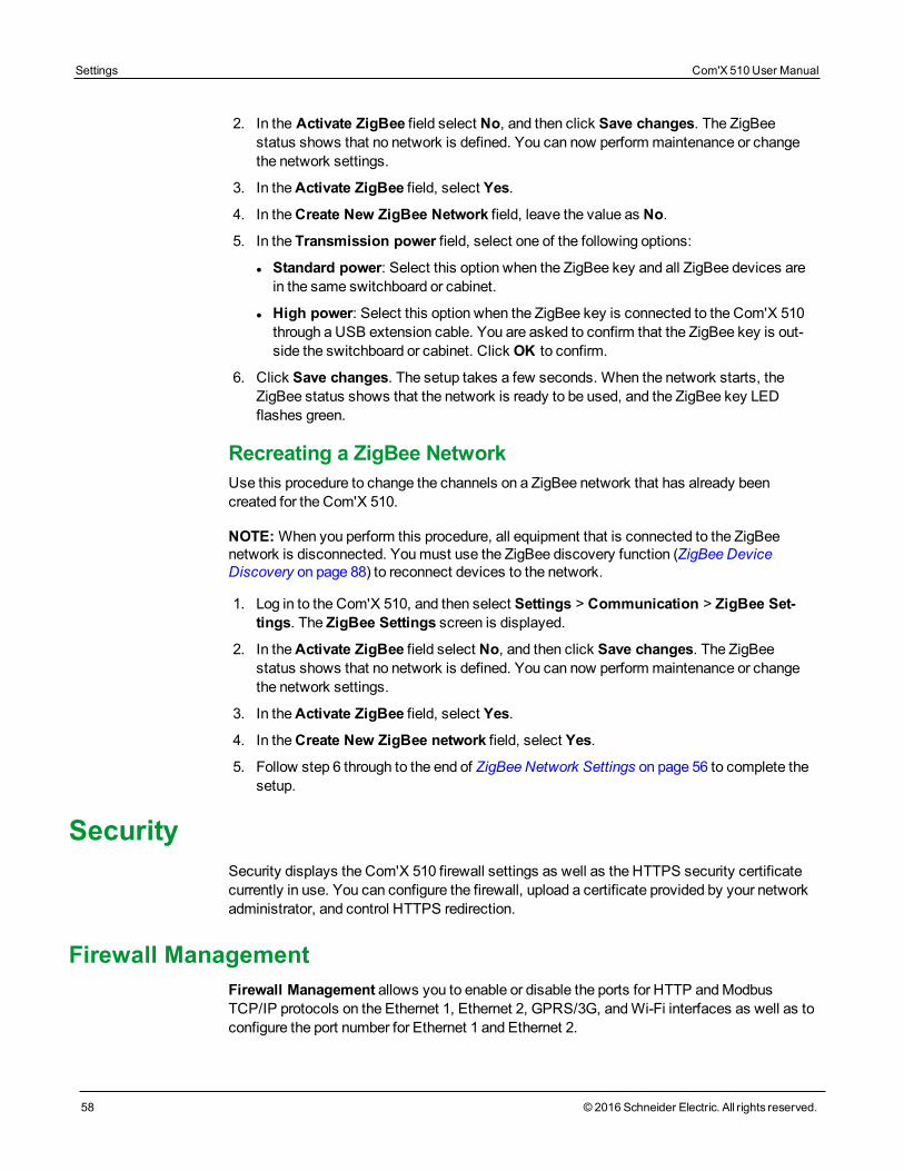
Settings Com'X 510 User Manual
58 © 2016 Schneider Electric. All rights reserved.
2. In the Activate ZigBee field select No, and then click Save changes. The ZigBeestatus shows that no network is defined. You can now perform maintenance or changethe network settings.
3. In theActivate ZigBee field, select Yes.
4. In theCreate New ZigBee Network field, leave the value as No.
5. In the Transmission power field, select one of the following options:
l Standard power: Select this option when the ZigBee key and all ZigBee devices arein the same switchboard or cabinet.
l High power: Select this option when the ZigBee key is connected to the Com'X 510through a USB extension cable. You are asked to confirm that the ZigBee key is out-side the switchboard or cabinet. Click OK to confirm.
6. Click Save changes. The setup takes a few seconds. When the network starts, theZigBee status shows that the network is ready to be used, and the ZigBee key LEDflashes green.
Recreating a ZigBee NetworkUse this procedure to change the channels on a ZigBee network that has already beencreated for the Com'X 510.
NOTE:When you perform this procedure, all equipment that is connected to the ZigBeenetwork is disconnected. Youmust use the ZigBee discovery function (ZigBee DeviceDiscovery on page 88) to reconnect devices to the network.
1. Log in to the Com'X 510, and then select Settings > Communication > ZigBee Set-tings. The ZigBee Settings screen is displayed.
2. In theActivate ZigBee field select No, and then click Save changes. The ZigBeestatus shows that no network is defined. You can now perform maintenance or changethe network settings.
3. In theActivate ZigBee field, select Yes.
4. In theCreate New ZigBee network field, select Yes.
5. Follow step 6 through to the end of ZigBee Network Settings on page 56 to complete thesetup.
SecuritySecurity displays the Com'X 510 firewall settings as well as the HTTPS security certificatecurrently in use. You can configure the firewall, upload a certificate provided by your networkadministrator, and control HTTPS redirection.
Firewall ManagementFirewall Management allows you to enable or disable the ports for HTTP andModbusTCP/IP protocols on the Ethernet 1, Ethernet 2, GPRS/3G, andWi-Fi interfaces as well as toconfigure the port number for Ethernet 1 and Ethernet 2.
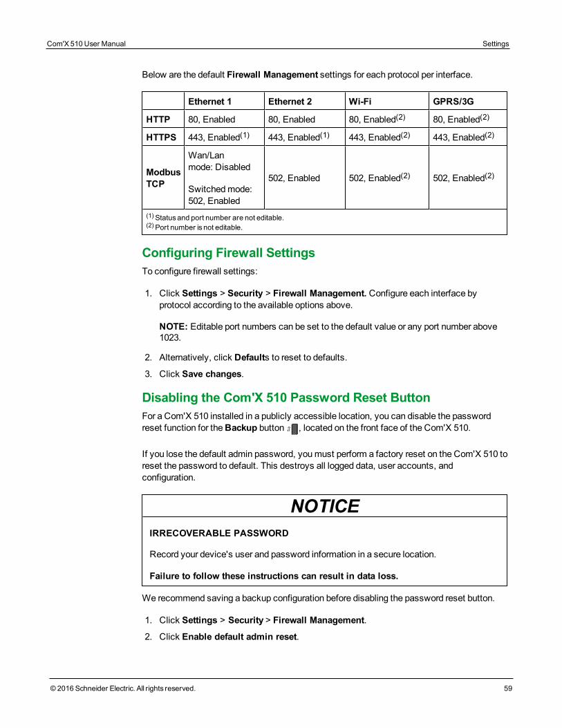
Below are the default Firewall Management settings for each protocol per interface.
Ethernet 1 Ethernet 2 Wi-Fi GPRS/3G
HTTP 80, Enabled 80, Enabled 80, Enabled(2) 80, Enabled(2)
HTTPS 443, Enabled(1) 443, Enabled(1) 443, Enabled(2) 443, Enabled(2)
ModbusTCP
Wan/Lanmode: Disabled
Switchedmode:502, Enabled
502, Enabled 502, Enabled(2) 502, Enabled(2)
(1)Statusand port number are not editable.(2)Port number is not editable.
Configuring Firewall SettingsTo configure firewall settings:
1. Click Settings > Security > Firewall Management. Configure each interface byprotocol according to the available options above.
NOTE: Editable port numbers can be set to the default value or any port number above1023.
2. Alternatively, click Defaults to reset to defaults.
3. Click Save changes.
Disabling the Com'X 510 Password Reset ButtonFor a Com'X 510 installed in a publicly accessible location, you can disable the passwordreset function for theBackup button , located on the front face of the Com'X 510.
If you lose the default admin password, youmust perform a factory reset on the Com'X 510 toreset the password to default. This destroys all logged data, user accounts, andconfiguration.
NOTICEIRRECOVERABLE PASSWORD
Record your device's user and password information in a secure location.
Failure to follow these instructions can result in data loss.
We recommend saving a backup configuration before disabling the password reset button.
1. Click Settings > Security > Firewall Management.
2. Click Enable default admin reset.
Com'X 510 User Manual Settings
© 2016 Schneider Electric. All rights reserved. 59
Settings Com'X 510 User Manual
60 © 2016 Schneider Electric. All rights reserved.
3. Click No to disable the password reset button.
4. Click Save changes.
CertificatesYou can view the current HTTPS security certificate, upload a certificate provided by yournetwork administrator to the Com'X 510, and reset to factory default from this page.
Uploading a New CertificateWe recommend creating a backup of your configuration before installing a new certificate. Toupdate the HTTPS certificate:
1. Click inside the text box Install a new certificate.
2. In the browser, select your *.pem file, then click Open.
3. Click Install. The Installed certificate details update to display the new certificate.
To remove the current certificate and set the Com'X 510 back to the factory defaultcertificate, click Reset.
HTTPS Redirection
NOTICEUNAUTHORIZED ACCESS
Do not disable HTTPS redirection if there is sensitive or private information on your localnetwork.
Failure to follow these instructions can result in equipment damage.
HTTPS redirection allows you to secure the communication between PC and Com'X 510 andis enabled by default.
Schneider Electric recommends usingHTTPS Redirection. Disabling the HTTPSredirection disables your browser security check and compromises the security of your localnetwork.
User ManagementUser Management allows you to create user groups with configurable permissions forCom'X 510 features. Then you can create individual user accounts and assign each user to agroup, based on the desired permissions.
Only an administrator can add, modify, or remove users and groups. SeeGroup Settings toconfigure user groups. SeeUsers to add users.
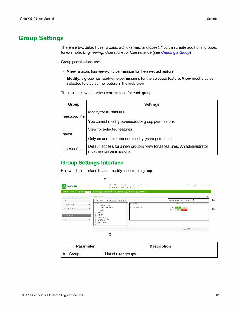
Group SettingsThere are two default user groups: administrator and guest. You can create additional groups,for example, Engineering, Operations, orMaintenance (seeCreating aGroup).
Group permissions are:
l View: a group has view-only permission for the selected feature.
l Modify: a group has read/write permissions for the selected feature. View must also beselected to display the feature in the web view.
The table below describes permissions for each group.
Group Settings
administratorModify for all features.
You cannot modify administrator group permissions.
guestView for selected features.
Only an administrator canmodify guest permissions.
User-defined Default access for a new group is view for all features. An administratormust assign permissions.
Group Settings InterfaceBelow is the interface to add, modify, or delete a group.
Parameter Description
A Group List of user groups
Com'X 510 User Manual Settings
© 2016 Schneider Electric. All rights reserved. 61
Settings Com'X 510 User Manual
62 © 2016 Schneider Electric. All rights reserved.
Parameter Description
B Session InactivityTime-out
Period of inactivity (in minutes) after which a user is logged out.Allowable range is 15–240.
Default: 15
C Featuremenu tree List of Com'X 510 features for which you can set permissions
D Permissions Determines the level of access users have to eachfeature: modify, view, or none
Creating a GroupOnly an administrator can create a new group. To create a group:
1. Click Settings > User Management > Group Settings.
2. Click Add Group. A new window opens.
3. Enter the group name, then click Confirm. The group is added to theGroup list.
NOTE: You cannot modify the group name after you create the group.
Default access for a new group is view for all features. SeeModifying Group Settings toconfigure permissions.
Modifying Group SettingsYou cannot modify a group name or the administrator group permissions. Tomodify any othergroup settings:
1. Click Settings > User Management > Group Settings.
2. Select the group you want to modify from theGroup drop-downmenu.
3. Enter theSession Inactivity Time-out interval (in minutes).
4. Select a feature from the featuremenu tree to view permissions for that feature.
5. Select Yes orNo forView orModify to set permissions.
NOTE: Access to a feature is denied if No is selected forView.
6. Repeat steps 5 and 6 for each feature.
7. Click Save changes to apply the new permissions.
Deleting a GroupYou cannot delete a user group if there are any users assigned to that group. Remove usersfrom the group, then follow the steps below.
1. Click Settings > User Management > Group Settings.
2. Select the group you want to delete from theGroup drop-downmenu.
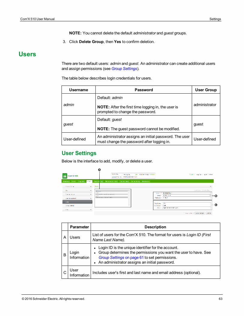
NOTE: You cannot delete the default administrator and guest groups.
3. Click Delete Group, thenYes to confirm deletion.
UsersThere are two default users: admin and guest. An administrator can create additional usersand assign permissions (seeGroup Settings).
The table below describes login credentials for users.
Username Password User Group
admin
Default: admin
NOTE: After the first time logging in, the user isprompted to change the password.
administrator
guestDefault: guest
NOTE: The guest password cannot bemodified.guest
User-defined An administrator assigns an initial password. The usermust change the password after logging in. User-defined
User SettingsBelow is the interface to add, modify, or delete a user.
Parameter Description
A Users List of users for the Com'X 510. The format for users is Login ID (FirstName Last Name).
B LoginInformation
l Login ID is the unique identifier for the account.l Group determines the permissions you want the user to have. SeeGroup Settings on page 61 to set permissions.
l An administrator assigns an initial password.
C UserInformation Includes user's first and last name and email address (optional).
Com'X 510 User Manual Settings
© 2016 Schneider Electric. All rights reserved. 63
Settings Com'X 510 User Manual
64 © 2016 Schneider Electric. All rights reserved.
Creating a User1. Click Settings > User Management > Users.
2. Click New User.
3. Enter the username and password.
NOTE: An administrator cannot modify the username or password after the user iscreated.
4. Select a user group from theGroup drop-down list (seeGroup Settings).
5. Enter the user's first name, last name, and email address.
6. Click Save changes.
Modifying a UserAn administrator cannot modify the username or password after the user is created. If youforget your username or password, contact an administrator to delete the account and createa new one.
Tomodify any other user settings:
1. Click Settings > User Management > Users.
2. Select the user you want to modify.
3. Modify the fields you want to change, then click Save changes.
The user must change the password after logging in for the first time. SeeChanging thePassword on page 21.
Deleting a UserIf a user is logged in when you delete the account, the user receives a session timeoutnotification. Any unsaved changes made by the user are lost.
To delete a user:
1. Click Settings > User Management > Users.
2. Select the name of the user you want to delete.
NOTE: You cannot remove the default admin and guest users.
3. Click Delete User, thenYes to confirm removal.
EventsEvents include predefined and custom events that can be sent to Facility Insights. Beforeconfiguring events, contact Schneider Electric Facility Insights support to confirm availabilityof events.
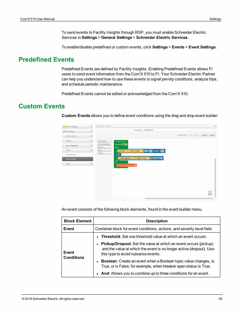
To send events to Facility Insights through RSP, youmust enable Schneider ElectricServices inSettings > General Settings > Schneider Electric Services.
To enable/disable predefined or custom events, click Settings > Events > Event Settings.
Predefined EventsPredefined Events are defined by Facility Insights. Enabling Predefined Events allows FIusers to send event information from the Com'X 510 to FI. Your Schneider Electric Partnercan help you understand how to use these events to signal pre-trip conditions, analyze trips,and schedule periodic maintenance.
Predefined Events cannot be edited or acknowledged from the Com'X 510.
Custom EventsCustom Events allows you to define event conditions using the drag and drop event builder:
An event consists of the following block elements, found in the event builder menu.
Block Element Description
Event Container block for event conditions, actions, and severity level field.
EventConditions
l Threshold: Set one threshold value at which an event occurs.
l Pickup/Dropout: Set the value at which an event occurs (pickup) and the value at which the event is no longer active (dropout). Usethis type to avoid nuisance events.
l Boolean: Create an event when a Boolean topic value changes, isTrue, or is False, for example, when breaker open status is True.
l And: Allows you to combine up to three conditions for an event.
Com'X 510 User Manual Settings
© 2016 Schneider Electric. All rights reserved. 65
Settings Com'X 510 User Manual
66 © 2016 Schneider Electric. All rights reserved.
Block Element Description
Devices
Select the device and topic that trigger an event. For example, receive anotification when the Temperature on a Temperature Probe Pt100exceeds 26°C.
The devicemust be connected to the Com'X 510 inDevice Settings.
Value Threshold value for the selected topic.
Actions
Choose an action for the Com'X 510 to perform when the eventconditions aremet, for example, "Send to Facility Insights."
You can enter text in the Action block, for example, the eventdescription. We recommend using the same or similar text as the EventName field in the Com'X 510.
Creating a Custom EventBefore creating an event, you should be familiar with the device register lists and values.
WARNINGINACCURATE DATA RESULTS
• Do not incorrectly configure the software, as this can lead to inaccurate reports and/ordata results.
• Do not base your maintenance or service actions solely onmessages and informationdisplayed by the software.
• Do not rely solely on data displayed in the software reports to determine if the system isfunctioning correctly or meeting all applicable standards and requirements.
• Do not use data displayed in the software as a substitute for proper workplace practicesor equipment maintenance.
Failure to follow these instructions can result in death, serious injury, equipmentdamage, or permanent loss of data.
To create a new event:
1. Click Settings > Events > Custom Events, then click New Custom Event. The eventbuilder dislays.
2. Click Event Types in the event builder menu, then drag a green event block onto theworkspace.
3. Select the event's Severity: None, Low (alert), or High (Error).
NOTE: For Facility Insights users, this field corresponds to the severity level in FacilityInsights.
4. Click Event Conditions in the event builder menu, and drag a conditions block into the
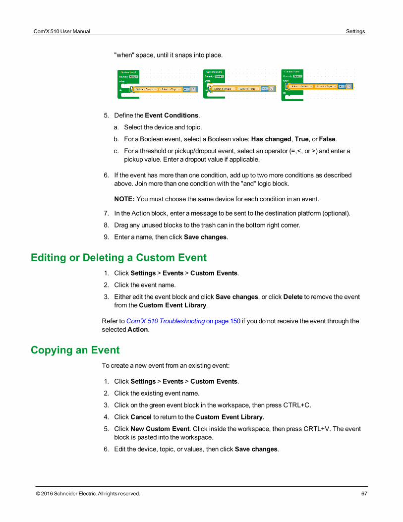
"when" space, until it snaps into place.
5. Define theEvent Conditions.
a. Select the device and topic.
b. For a Boolean event, select a Boolean value: Has changed, True, or False.
c. For a threshold or pickup/dropout event, select an operator (=,<, or >) and enter apickup value. Enter a dropout value if applicable.
6. If the event has more than one condition, add up to twomore conditions as describedabove. Join more than one condition with the "and" logic block.
NOTE: Youmust choose the same device for each condition in an event.
7. In the Action block, enter amessage to be sent to the destination platform (optional).
8. Drag any unused blocks to the trash can in the bottom right corner.
9. Enter a name, then click Save changes.
Editing or Deleting a Custom Event1. Click Settings > Events > Custom Events.
2. Click the event name.
3. Either edit the event block and click Save changes, or click Delete to remove the eventfrom theCustom Event Library.
Refer toCom'X 510 Troubleshooting on page 150 if you do not receive the event through theselectedAction.
Copying an EventTo create a new event from an existing event:
1. Click Settings > Events > Custom Events.
2. Click the existing event name.
3. Click on the green event block in the workspace, then press CTRL+C.
4. Click Cancel to return to theCustom Event Library.
5. Click New Custom Event. Click inside the workspace, then press CRTL+V. The eventblock is pasted into the workspace.
6. Edit the device, topic, or values, then click Save changes.
Com'X 510 User Manual Settings
© 2016 Schneider Electric. All rights reserved. 67
Settings Com'X 510 User Manual
68 © 2016 Schneider Electric. All rights reserved.
LinksThe Com'X 510 supports two types of documentation links:
l Local file access (stored on the Com'X 510)
l External URL access.
The Com'X 510 includes built-in links. These items cannot be edited but can be deleted.
Configuring LinksTo add links to the Com'X 510:
1. Click Settings > Links > Setup Links. The Links page opens.
2. Enter a name and description for the link.
3. Enter a number 1 to 100 in thePriority field.
NOTE: Negative priority is reserved for built-in links. Links display in ascending order ofpriority.
4. Click the type of link, then:
a. For Link to File, click the to browse for the file.
b. For Link to URL, enter the URL
5. Click Add. The link is added to the setup list andView Links (seeViewing Links onpage 68)
You can change the type of link after it has been created. To edit a link, click Edit, make thedesired changes, then click Update.
To delete a link, click the check box beside the link name, then click Remove.
Viewing LinksTo view links, click Settings > Links > View Links. Click the link to open the file or webpage.
You can click Setup Links in the bottom right corner to return to the links configuration page.
Custom Page ManagementYou can create and add custom web pages to the Com'X 510 to provide building overviews,for example.
This section discusses how to add custom pages to the Com'X 510.
WARNINGINACCURATE DATA RESULTS
• Do not incorrectly configure the software, as this can lead to inaccurate reports and/ordata results.
• Do not base your maintenance or service actions solely onmessages and informationdisplayed by the software.
• Do not rely solely on data displayed in the software to determine if the device isfunctioning correctly or meeting all applicable standards and requirements.
• Do not use data displayed in the software as a substitute for proper workplace practicesor equipment maintenance.
Failure to follow these instructions can result in death, serious injury, equipmentdamage, or permanent loss of data.
Adding a Custom Web PageThe init.js file is required for each web page. Any file referenced by init.js is also required forthe page to be valid and viewable.
Before uploading any files, compare the size of the custom page file set with theAvailableStorage.
NOTICEIMPAIRED COM'X PERFORMANCE
Do not addmore than 10MB of files to Custom PageManagement.
Failure to follow these instructions can impair Com'X performance.
1. Click Settings > Custom Page Management.
2. Click Create, then enter the name you want to display on the web page.
3. Click OK. The web page container displays in the list of custom web pages with a val-idation error.
4. Click Edit to add the web page files.
5. Click Upload, then select the custom page files from your computer.
6. Click OK. The Com'X 510 validates that files called by init.js are present.
To view the newly added web page, youmust log out and log in again.
Deleting Custom Web PagesYou can select pages to delete, or you can delete individual files for each page. Werecommend removing unused pages.
Com'X 510 User Manual Settings
© 2016 Schneider Electric. All rights reserved. 69
Settings Com'X 510 User Manual
70 © 2016 Schneider Electric. All rights reserved.
1. Click Settings > Custom Page Management.
2. Select the pages you want to delete, then click Delete andYes to confirm.
3. Alternatively, click Edit to delete files for a single web page. Select the files you want todelete, then click Delete andYes to confirm.
Downloading a Custom PageYou can save a custom web page for use on another Com'X 510 .
1. Click Settings > Custom Page Management.
2. Click Edit to view the web page files.
3. Select the files you want to download, then click Download. Follow your browser'sprompts for saving and viewing downloaded files.
Viewing a Custom Web PageYoumust be in a user group that has permission to view custom pages. SeeUserManagement on page 60 for more information on page permissions.
After you add, edit, or delete custom page content, youmust log out and log in again to viewthe updates.An invalid page is not viewable in Monitoring.
To view a custom page, click Monitoring > Custom Pages, then click the name of the pageyou want to view.
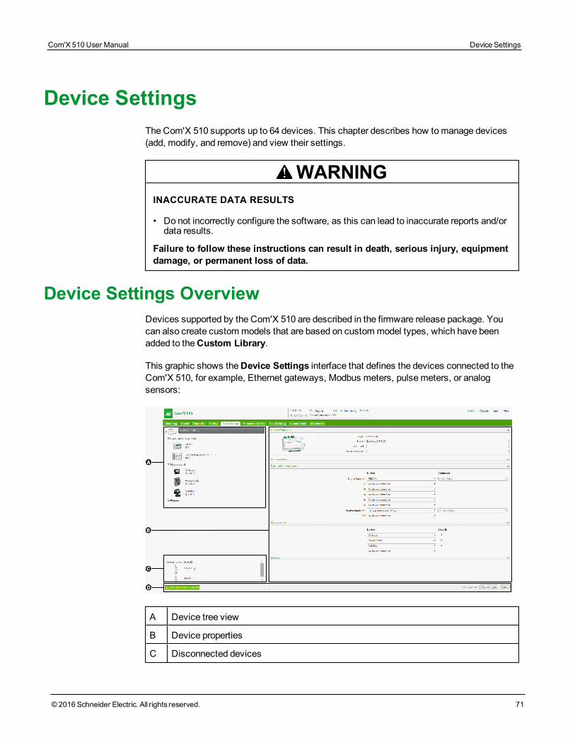
Device SettingsThe Com'X 510 supports up to 64 devices. This chapter describes how tomanage devices(add, modify, and remove) and view their settings.
WARNINGINACCURATE DATA RESULTS
• Do not incorrectly configure the software, as this can lead to inaccurate reports and/ordata results.
Failure to follow these instructions can result in death, serious injury, equipmentdamage, or permanent loss of data.
Device Settings OverviewDevices supported by the Com'X 510 are described in the firmware release package. Youcan also create custommodels that are based on custommodel types, which have beenadded to theCustom Library.
This graphic shows theDevice Settings interface that defines the devices connected to theCom'X 510, for example, Ethernet gateways, Modbus meters, pulsemeters, or analogsensors:
A Device tree view
B Device properties
C Disconnected devices
Com'X 510 User Manual Device Settings
© 2016 Schneider Electric. All rights reserved. 71
Device Settings Com'X 510 User Manual
72 © 2016 Schneider Electric. All rights reserved.
D Action buttons
Device Tree ViewThe device tree view represents the communication architecture of the installation. TheCom'X 510 is always at the top of the tree. Devices are grouped by their connectioninterfaces: Ethernet ports, Modbus port, digital inputs, and analog inputs.
For digital and analog inputs, each device appears with its Name and the input number towhich it is connected.
NOTE: Themultiple outputs of amainmeter (for example, kWh, kVArh pulses) can beconnected to several digital inputs.
For Modbus TCP/Modbus serial line gateway, each device appears with its Name and itsSlave ID.
Click a device to display its properties inGeneral Properties.
Disconnected DevicesThis area displays the devices that are not connected to the installation. Measurements fromthese devices are not logged.
Device PropertiesFor a selected device, this zone allows you to:
l define somemetadata such as the name, the physical location and, for ameter, the com-modity, the energy usage, and the area in the building that is beingmonitored.
l set up or modify settings such as: the pulse weight for a pulsemeter, the slave ID for aModbus meter, the IP address for a gateway, and themeasurements to be logged and pub-lished to the selected hosted platform.
l connect and disconnect downstream devices in the drop-down lists when the selecteddevice allows it. Each connection type has its own area. Only devices that can be con-nected to this type are listed.
This graphic shows the interface of device properties:
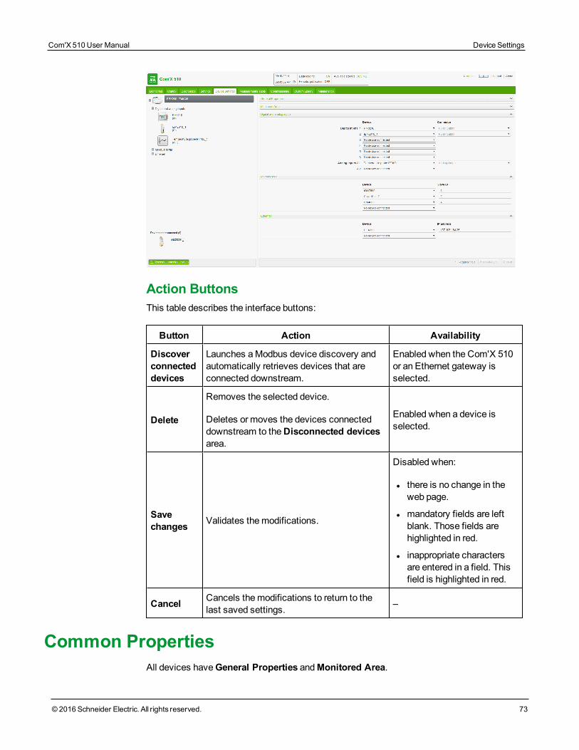
Action ButtonsThis table describes the interface buttons:
Button Action Availability
Discoverconnecteddevices
Launches aModbus device discovery andautomatically retrieves devices that areconnected downstream.
Enabled when the Com'X 510or an Ethernet gateway isselected.
Delete
Removes the selected device.
Deletes or moves the devices connecteddownstream to theDisconnected devicesarea.
Enabled when a device isselected.
Savechanges Validates themodifications.
Disabled when:
l there is no change in theweb page.
l mandatory fields are leftblank. Those fields arehighlighted in red.
l inappropriate charactersare entered in a field. Thisfield is highlighted in red.
Cancel Cancels themodifications to return to thelast saved settings. –
Common PropertiesAll devices haveGeneral Properties andMonitored Area.
Com'X 510 User Manual Device Settings
© 2016 Schneider Electric. All rights reserved. 73
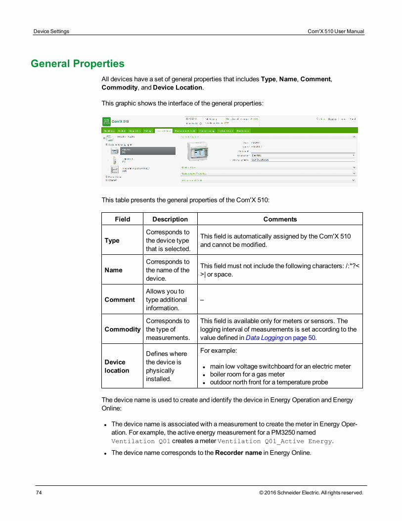
Device Settings Com'X 510 User Manual
74 © 2016 Schneider Electric. All rights reserved.
General PropertiesAll devices have a set of general properties that includes Type, Name, Comment,Commodity, andDevice Location.
This graphic shows the interface of the general properties:
This table presents the general properties of the Com'X 510:
Field Description Comments
TypeCorresponds tothe device typethat is selected.
This field is automatically assigned by the Com'X 510and cannot bemodified.
NameCorresponds tothe name of thedevice.
This field must not include the following characters: /:*?<>| or space.
CommentAllows you totype additionalinformation.
–
CommodityCorresponds tothe type ofmeasurements.
This field is available only for meters or sensors. Thelogging interval of measurements is set according to thevalue defined inData Logging on page 50.
Devicelocation
Defines wherethe device isphysicallyinstalled.
For example:
l main low voltage switchboard for an electric meterl boiler room for a gas meterl outdoor north front for a temperature probe
The device name is used to create and identify the device in Energy Operation and EnergyOnline:
l The device name is associated with ameasurement to create themeter in Energy Oper-ation. For example, the active energy measurement for a PM3250 namedVentilation Q01 creates ameter Ventilation Q01_Active Energy.
l The device name corresponds to theRecorder name in Energy Online.
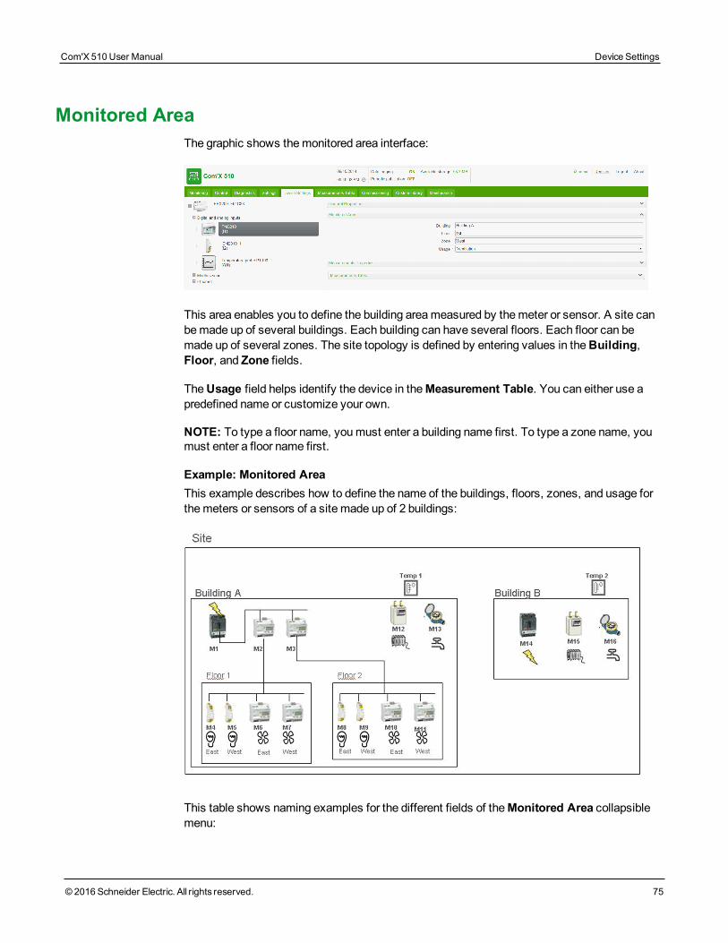
Monitored AreaThe graphic shows themonitored area interface:
This area enables you to define the building areameasured by themeter or sensor. A site canbemade up of several buildings. Each building can have several floors. Each floor can bemade up of several zones. The site topology is defined by entering values in theBuilding,Floor, and Zone fields.
TheUsage field helps identify the device in theMeasurement Table. You can either use apredefined name or customize your own.
NOTE: To type a floor name, youmust enter a building name first. To type a zone name, youmust enter a floor name first.
Example: Monitored AreaThis example describes how to define the name of the buildings, floors, zones, and usage forthemeters or sensors of a site made up of 2 buildings:
This table shows naming examples for the different fields of theMonitored Area collapsiblemenu:
Com'X 510 User Manual Device Settings
© 2016 Schneider Electric. All rights reserved. 75
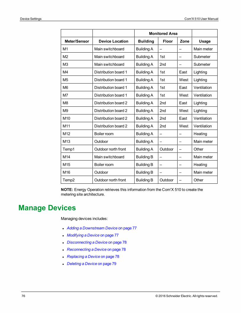
Device Settings Com'X 510 User Manual
76 © 2016 Schneider Electric. All rights reserved.
Monitored Area
Meter/Sensor Device Location Building Floor Zone Usage
M1 Main switchboard Building A – – Mainmeter
M2 Main switchboard Building A 1st – Submeter
M3 Main switchboard Building A 2nd – Submeter
M4 Distribution board 1 Building A 1st East Lighting
M5 Distribution board 1 Building A 1st West Lighting
M6 Distribution board 1 Building A 1st East Ventilation
M7 Distribution board 1 Building A 1st West Ventilation
M8 Distribution board 2 Building A 2nd East Lighting
M9 Distribution board 2 Building A 2nd West Lighting
M10 Distribution board 2 Building A 2nd East Ventilation
M11 Distribution board 2 Building A 2nd West Ventilation
M12 Boiler room Building A – – Heating
M13 Outdoor Building A – – Mainmeter
Temp1 Outdoor north front Building A Outdoor – Other
M14 Main switchboard Building B – – Mainmeter
M15 Boiler room Building B – – Heating
M16 Outdoor Building B – – Mainmeter
Temp2 Outdoor north front Building B Outdoor – Other
NOTE: Energy Operation retrieves this information from the Com'X 510 to create themetering site architecture.
Manage DevicesManaging devices includes:
l Adding a Downstream Device on page 77
l Modifying a Device on page 77
l Disconnecting a Device on page 78
l Reconnecting a Device on page 78
l Replacing a Device on page 78
l Deleting a Device on page 79
Adding a Downstream DeviceFollow this procedure to add a downstream device:
1. Click theDevice Settingsmain tab.
2. In the device tree view, click the upstream device to which the downstream device is con-nected. For example, select the Com'X 510 to connect a device to the Com'X 510.
3. Click the collapsible menu that corresponds to the type of device to be connected:
l Digital and analog inputs collapsible menu for devices connected to the Com'X 510digital and analog inputs, for example, pulsemeters or analog sensors.
l Modbus Serial collapsible menu for aModbus device. Modbus can also be auto-matically discovered with theDiscover connected devices button (seeDiscoveringConnected Devices on page 162).
l Ethernet collapsible menu for aModbus TCP/Modbus serial line gateway or IP-enabled device.
4. Select Create a new device in theDevice drop-down list.
5. Select the type of device to be created in theDevice Type drop-down list.
NOTE: Only the devices that can be connected to this interface are listed. You cannotmodify the device type after the device has been created.
6. Configure the device. Refer to the sections that correspond to the device category:
l Adding a Digital Input on page 159
l Adding an Analog Input on page 161
l Adding a Schneider Electric Modbus Serial Device on page 162
l Ethernet Device Configuration Parameters on page 87
7. Click Create and the device appears in the device tree view.
Modifying a DeviceFollow this procedure tomodify a device setting:
1. Click theDevice Settingsmain tab.
2. Click the device in the device tree view.
3. Modify the settings in the required collapsible menu.
4. Click Save changes.
NOTE: The device type cannot bemodified. If a device is incorrectly configured, delete thedevice and create a new one.
Com'X 510 User Manual Device Settings
© 2016 Schneider Electric. All rights reserved. 77
Device Settings Com'X 510 User Manual
78 © 2016 Schneider Electric. All rights reserved.
Disconnecting a DeviceFollow this procedure to disconnect a device from an upstream device:
1. Click theDevice Settingsmain tab.
2. Click the parent device in the device tree view.
3. Select No device connected in theConnected to drop-down list. The device appears intheDevices not connected collapsible menu under the device tree view.
4. Click Save changes.
NOTE: The device does not appear in theMeasurements Table. Nomeasurement from thisdevice is sent to the hosted platform. The device is still available in Real TimeData.
Reconnecting a DeviceFollow this procedure to reconnect a device from an upstream device:
1. Click theDevice Settingsmain tab.
2. In the device tree view, click the upstream device to which the downstream devicemustbe connected. For example, select the Com'X 510 to reconnect a device to the Com'X510.
3. In theDigital and analog input collapsible menu, select the device to be reconnectedon the required digital input.
4. Click Save changes.
Replacing a DeviceFollow this procedure to replace an existing device with another device of a similar type. Thisprocedure can be used to replace a standard device with a custom device without losing theproperties of the original device.
1. Click theDevice Settingsmain tab.
2. In the device tree view, click the upstream device to which the device to be replaced isconnected. For example, select the Com'X 510 to replace a device connected to theCom'X 510.
3. Click the collapsible menu that corresponds to the type of device to be replaced:
l Digital and analog inputs collapsible menu for devices connected to the Com'X 510digital and analog inputs (for example, pulsemeters or analog sensors).
l Modbus Serial collapsible menu for aModbus device. Modbus can also be auto-matically discovered with theDiscover connected devices button (Discovering Con-nected Devices on page 83).
l Ethernet collapsible menu for aModbus TCP/Modbus device.
l ZigBee: Replacing a ZigBee device launches the ZigBee Devices discovery function
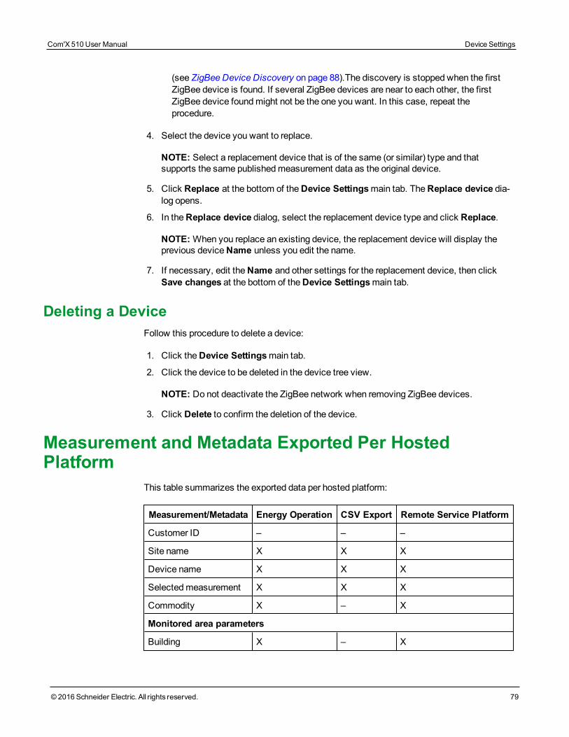
(see ZigBee Device Discovery on page 88).The discovery is stopped when the firstZigBee device is found. If several ZigBee devices are near to each other, the firstZigBee device foundmight not be the one you want. In this case, repeat theprocedure.
4. Select the device you want to replace.
NOTE: Select a replacement device that is of the same (or similar) type and thatsupports the same publishedmeasurement data as the original device.
5. Click Replace at the bottom of theDevice Settingsmain tab. TheReplace device dia-log opens.
6. In theReplace device dialog, select the replacement device type and click Replace.
NOTE:When you replace an existing device, the replacement device will display theprevious deviceName unless you edit the name.
7. If necessary, edit theName and other settings for the replacement device, then clickSave changes at the bottom of theDevice Settingsmain tab.
Deleting a DeviceFollow this procedure to delete a device:
1. Click theDevice Settingsmain tab.
2. Click the device to be deleted in the device tree view.
NOTE: Do not deactivate the ZigBee network when removing ZigBee devices.
3. Click Delete to confirm the deletion of the device.
Measurement and Metadata Exported Per HostedPlatform
This table summarizes the exported data per hosted platform:
Measurement/Metadata Energy Operation CSV Export Remote Service Platform
Customer ID – – –
Site name X X X
Device name X X X
Selectedmeasurement X X X
Commodity X – X
Monitored area parameters
Building X – X
Com'X 510 User Manual Device Settings
© 2016 Schneider Electric. All rights reserved. 79
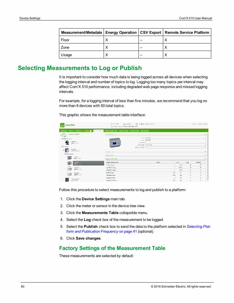
Device Settings Com'X 510 User Manual
80 © 2016 Schneider Electric. All rights reserved.
Measurement/Metadata Energy Operation CSV Export Remote Service Platform
Floor X – X
Zone X – X
Usage X – X
Selecting Measurements to Log or PublishIt is important to consider how much data is being logged across all devices when selectingthe logging interval and number of topics to log. Logging toomany topics per interval mayaffect Com'X 510 performance, including degraded web page response andmissed loggingintervals.
For example, for a logging interval of less than fiveminutes, we recommend that you log nomore than 8 devices with 50 total topics.
This graphic shows themeasurement table interface:
Follow this procedure to select measurements to log and publish to a platform:
1. Click theDevice Settingsmain tab.
2. Click themeter or sensor in the device tree view.
3. Click theMeasurements Table collapsible menu.
4. Select the Log check box of themeasurement to be logged.
5. Select thePublish check box to send the data to the platform selected inSelecting Plat-form and Publication Frequency on page 41 (optional).
6. Click Save changes.
Factory Settings of the Measurement TableThesemeasurements are selected by default:
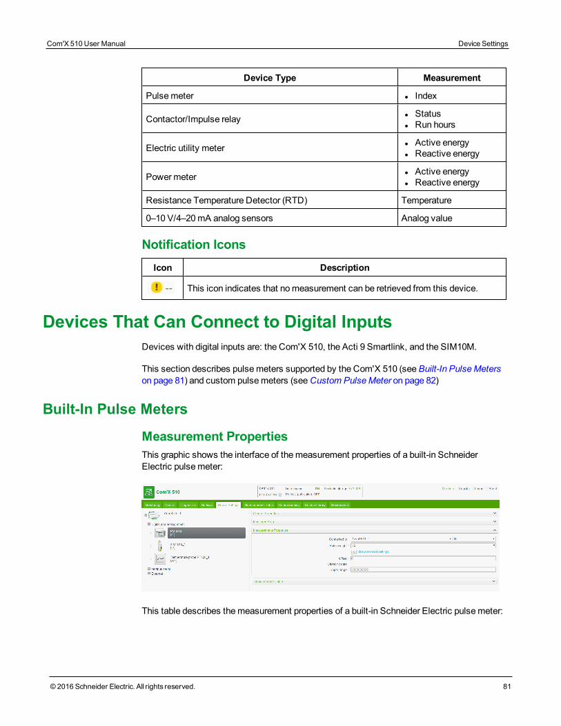
Device Type Measurement
Pulsemeter l Index
Contactor/Impulse relay l Statusl Run hours
Electric utility meter l Active energyl Reactive energy
Powermeter l Active energyl Reactive energy
Resistance Temperature Detector (RTD) Temperature
0–10 V/4–20 mA analog sensors Analog value
Notification IconsIcon Description
This icon indicates that nomeasurement can be retrieved from this device.
Devices That Can Connect to Digital InputsDevices with digital inputs are: the Com'X 510, the Acti 9 Smartlink, and the SIM10M.
This section describes pulsemeters supported by the Com'X 510 (seeBuilt-In PulseMeterson page 81) and custom pulsemeters (seeCustom PulseMeter on page 82)
Built-In Pulse Meters
Measurement PropertiesThis graphic shows the interface of themeasurement properties of a built-in SchneiderElectric pulsemeter:
This table describes themeasurement properties of a built-in Schneider Electric pulsemeter:
Com'X 510 User Manual Device Settings
© 2016 Schneider Electric. All rights reserved. 81
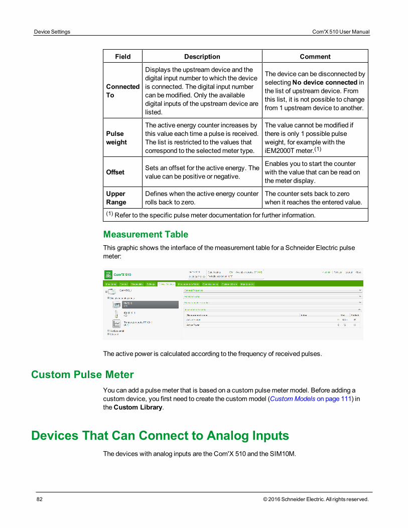
Device Settings Com'X 510 User Manual
82 © 2016 Schneider Electric. All rights reserved.
Field Description Comment
ConnectedTo
Displays the upstream device and thedigital input number to which the deviceis connected. The digital input numbercan bemodified. Only the availabledigital inputs of the upstream device arelisted.
The device can be disconnected byselectingNo device connected inthe list of upstream device. Fromthis list, it is not possible to changefrom 1 upstream device to another.
Pulseweight
The active energy counter increases bythis value each time a pulse is received.The list is restricted to the values thatcorrespond to the selectedmeter type.
The value cannot bemodified ifthere is only 1 possible pulseweight, for example with theiEM2000T meter.(1)
Offset Sets an offset for the active energy. Thevalue can be positive or negative.
Enables you to start the counterwith the value that can be read onthemeter display.
UpperRange
Defines when the active energy counterrolls back to zero.
The counter sets back to zerowhen it reaches the entered value.
(1) Refer to the specific pulsemeter documentation for further information.
Measurement TableThis graphic shows the interface of themeasurement table for a Schneider Electric pulsemeter:
The active power is calculated according to the frequency of received pulses.
Custom Pulse MeterYou can add a pulsemeter that is based on a custom pulsemeter model. Before adding acustom device, you first need to create the custommodel (CustomModels on page 111) intheCustom Library.
Devices That Can Connect to Analog InputsThe devices with analog inputs are the Com'X 510 and the SIM10M.
This section describes resistance temperature detectors supported by the Com'X 510 (seeResistance Temperature Detectors on page 83) and custom analog devices (seeCustomAnalog Devices on page 83)
Resistance Temperature Detectors
Measurement PropertiesThe Pt100/Pt1000 Resistance Temperature Detectors (RTD) are sensors used tomeasuretemperature by correlating the resistance of the RTD element with temperature.
The RTD can only be connected to the analog inputs of the Com'X 510.
The temperature range is from –50 °C (–58 °F) to +104 °C (219 °F).
When connecting an RTD probe to the Com'X 510, there are no specific parameters toconfigure.
Measurement TableBy default, the temperature is logged and published to the selected platform.
Custom Analog DevicesYou can add an analog device that is based on a custom analog devicemodel. Before addinga custom device you first need to create the custommodel (CustomModels on page 111) intheCustom Library.
Modbus DevicesThis section includes:
l Discovering Connected Devices on page 83
l Adding aModbus DeviceManually on page 85
l Connecting Devices to Acti 9 Smartlink on page 86
l Smart InterfaceModule on page 1
Discovering Connected DevicesWith theModbus discovery function, the Com'X 510 can discover the devices that arelocally connected to their Modbus serial port and downstreamModbus TCP/Modbus serialline gateways.
This graphic shows theModbus Discovery interface:
Com'X 510 User Manual Device Settings
© 2016 Schneider Electric. All rights reserved. 83
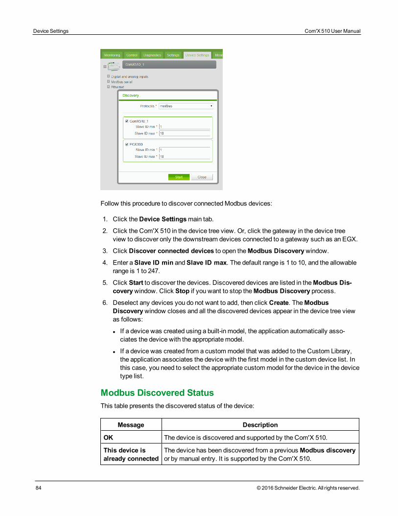
Device Settings Com'X 510 User Manual
84 © 2016 Schneider Electric. All rights reserved.
Follow this procedure to discover connectedModbus devices:
1. Click theDevice Settingsmain tab.
2. Click the Com'X 510 in the device tree view. Or, click the gateway in the device treeview to discover only the downstream devices connected to a gateway such as an EGX.
3. Click Discover connected devices to open theModbus Discoverywindow.
4. Enter aSlave ID min andSlave ID max. The default range is 1 to 10, and the allowablerange is 1 to 247.
5. Click Start to discover the devices. Discovered devices are listed in theModbus Dis-coverywindow. Click Stop if you want to stop theModbus Discovery process.
6. Deselect any devices you do not want to add, then click Create. TheModbusDiscoverywindow closes and all the discovered devices appear in the device tree viewas follows:
l If a device was created using a built-in model, the application automatically asso-ciates the device with the appropriate model.
l If a device was created from a custommodel that was added to the Custom Library,the application associates the device with the first model in the custom device list. Inthis case, you need to select the appropriate custommodel for the device in the devicetype list.
Modbus Discovered StatusThis table presents the discovered status of the device:
Message Description
OK The device is discovered and supported by the Com'X 510.
This device isalready connected
The device has been discovered from a previous Modbus discoveryor by manual entry. It is supported by the Com'X 510.
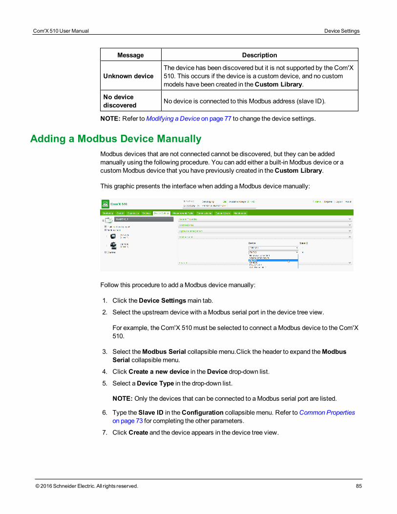
Message Description
Unknown deviceThe device has been discovered but it is not supported by the Com'X510. This occurs if the device is a custom device, and no custommodels have been created in theCustom Library.
No devicediscovered No device is connected to this Modbus address (slave ID).
NOTE: Refer toModifying a Device on page 77 to change the device settings.
Adding a Modbus Device ManuallyModbus devices that are not connected cannot be discovered, but they can be addedmanually using the following procedure. You can add either a built-in Modbus device or acustomModbus device that you have previously created in theCustom Library.
This graphic presents the interface when adding aModbus devicemanually:
Follow this procedure to add aModbus devicemanually:
1. Click theDevice Settingsmain tab.
2. Select the upstream device with aModbus serial port in the device tree view.
For example, the Com'X 510must be selected to connect aModbus device to the Com'X510.
3. Select theModbus Serial collapsible menu.Click the header to expand theModbusSerial collapsible menu.
4. Click Create a new device in theDevice drop-down list.
5. Select aDevice Type in the drop-down list.
NOTE: Only the devices that can be connected to aModbus serial port are listed.
6. Type theSlave ID in theConfiguration collapsible menu. Refer toCommon Propertieson page 73 for completing the other parameters.
7. Click Create and the device appears in the device tree view.
Com'X 510 User Manual Device Settings
© 2016 Schneider Electric. All rights reserved. 85
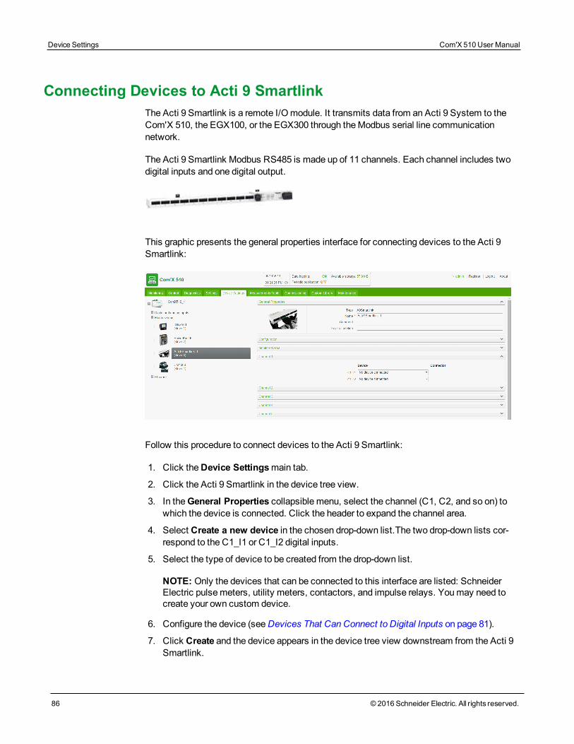
Device Settings Com'X 510 User Manual
86 © 2016 Schneider Electric. All rights reserved.
Connecting Devices to Acti 9 SmartlinkThe Acti 9 Smartlink is a remote I/Omodule. It transmits data from an Acti 9 System to theCom'X 510, the EGX100, or the EGX300 through theModbus serial line communicationnetwork.
The Acti 9 Smartlink Modbus RS485 is made up of 11 channels. Each channel includes twodigital inputs and one digital output.
This graphic presents the general properties interface for connecting devices to the Acti 9Smartlink:
Follow this procedure to connect devices to the Acti 9 Smartlink:
1. Click theDevice Settingsmain tab.
2. Click the Acti 9 Smartlink in the device tree view.
3. In theGeneral Properties collapsible menu, select the channel (C1, C2, and so on) towhich the device is connected. Click the header to expand the channel area.
4. Select Create a new device in the chosen drop-down list.The two drop-down lists cor-respond to the C1_I1 or C1_I2 digital inputs.
5. Select the type of device to be created from the drop-down list.
NOTE: Only the devices that can be connected to this interface are listed: SchneiderElectric pulsemeters, utility meters, contactors, and impulse relays. Youmay need tocreate your own custom device.
6. Configure the device (seeDevices That Can Connect to Digital Inputs on page 81).
7. Click Create and the device appears in the device tree view downstream from the Acti 9Smartlink.
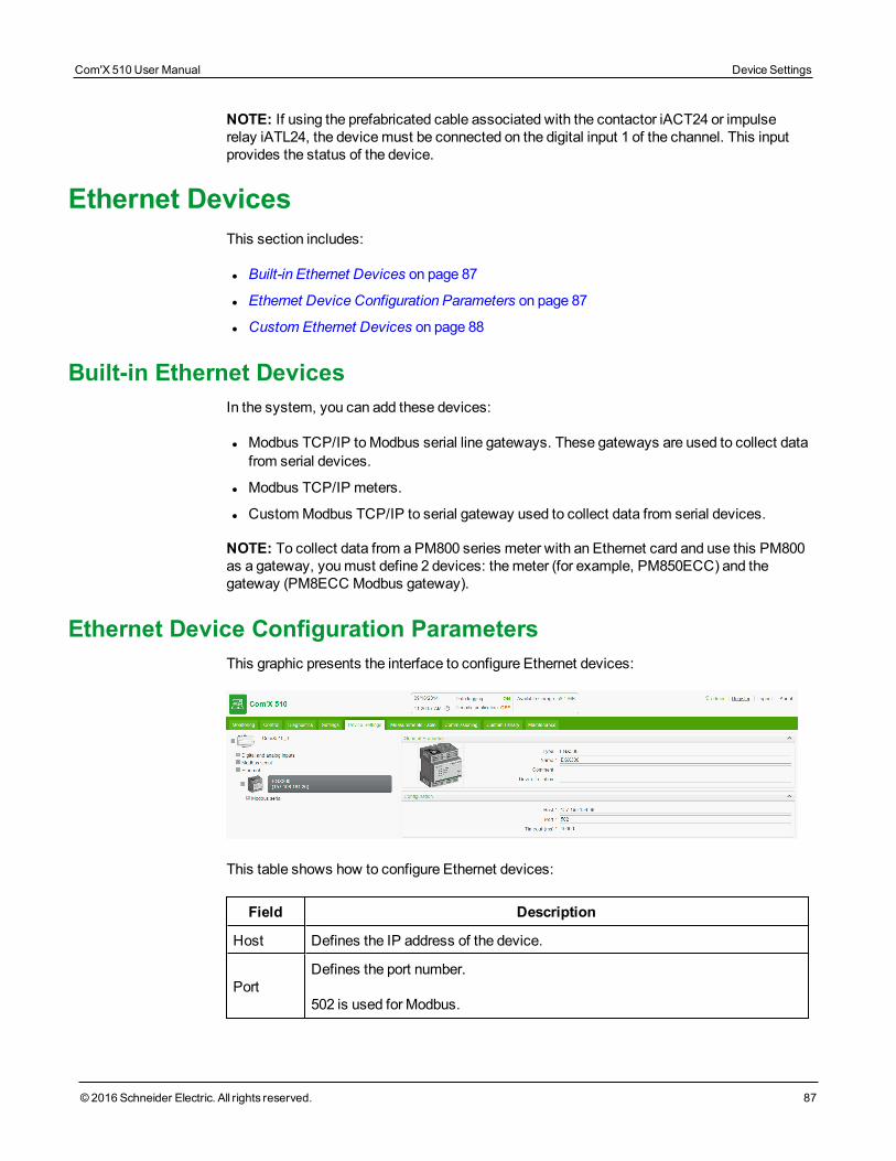
NOTE: If using the prefabricated cable associated with the contactor iACT24 or impulserelay iATL24, the devicemust be connected on the digital input 1 of the channel. This inputprovides the status of the device.
Ethernet DevicesThis section includes:
l Built-in Ethernet Devices on page 87
l Ethernet Device Configuration Parameters on page 87
l Custom Ethernet Devices on page 88
Built-in Ethernet DevicesIn the system, you can add these devices:
l Modbus TCP/IP toModbus serial line gateways. These gateways are used to collect datafrom serial devices.
l Modbus TCP/IP meters.
l CustomModbus TCP/IP to serial gateway used to collect data from serial devices.
NOTE: To collect data from a PM800 series meter with an Ethernet card and use this PM800as a gateway, youmust define 2 devices: themeter (for example, PM850ECC) and thegateway (PM8ECC Modbus gateway).
Ethernet Device Configuration ParametersThis graphic presents the interface to configure Ethernet devices:
This table shows how to configure Ethernet devices:
Field Description
Host Defines the IP address of the device.
PortDefines the port number.
502 is used for Modbus.
Com'X 510 User Manual Device Settings
© 2016 Schneider Electric. All rights reserved. 87
Device Settings Com'X 510 User Manual
88 © 2016 Schneider Electric. All rights reserved.
Field Description
Slave ID Gives the address only for Modbus TCP meters or devices.
Local ID
The address to use when accessing data from a device by an external client.The Local ID must be unique.
This configuration parameter can only be changed if data logging is disabled forthe device being updated. SeeStarting the Data Logging on page 92.
Custom Ethernet DevicesYou can add an Ethernet device that is based on a custom Ethernet model. Before adding acustom device, you first need to create the custommodel (Creating a CustomModel on page111) in theCustom Library.
ZigBee Device DiscoveryWith the ZigBee discovery function, the Com'X 510 can discover ZigBee devices that arewithin range.
Discovering DevicesDo not launch the ZigBee discovery mode of several Com'X 510 simultaneously. If you havetwo or more ZigBee networks in discovery mode, the ZigBee devices are installed randomlyon these networks.
Follow this procedure to discover connected ZigBee devices:
1. Click the Com'X 510 in the device tree view.
2. Click Discover devices to open the Discovery window.
3. Select the communication protocol ZigBee.
4. Enter the Timeout time (in minutes).
5. Click Start to discover the devices. Discovered devices are listed in the ZigBeeDiscovery window. Click Stop if you want to stop the ZigBee Discovery process.
NOTE: In order to detect the ZigBee devices, you also need to activate the discoverymode on the different devices.
6. Close the ZigBee Discovery window. All the discovered devices appear in the devicetree view.
A Local ID is automatically assigned whenever a device is created. You can change theLocal ID inSettings > Communication >Modbus Gateway > Device IDs.
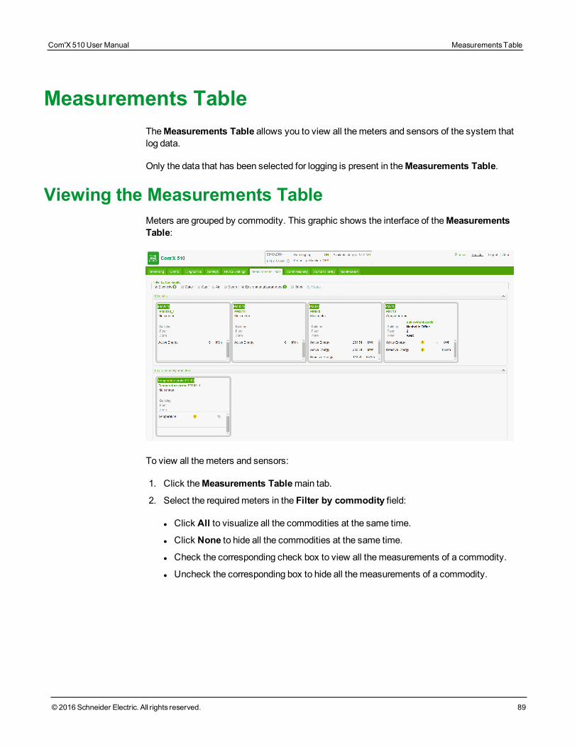
Measurements TableTheMeasurements Table allows you to view all themeters and sensors of the system thatlog data.
Only the data that has been selected for logging is present in theMeasurements Table.
Viewing the Measurements TableMeters are grouped by commodity. This graphic shows the interface of theMeasurementsTable:
To view all themeters and sensors:
1. Click theMeasurements Tablemain tab.
2. Select the requiredmeters in the Filter by commodity field:
l Click All to visualize all the commodities at the same time.
l Click None to hide all the commodities at the same time.
l Check the corresponding check box to view all themeasurements of a commodity.
l Uncheck the corresponding box to hide all themeasurements of a commodity.
Com'X 510 User Manual MeasurementsTable
© 2016 Schneider Electric. All rights reserved. 89

MeasurementsTable Com'X 510 User Manual
90 © 2016 Schneider Electric. All rights reserved.
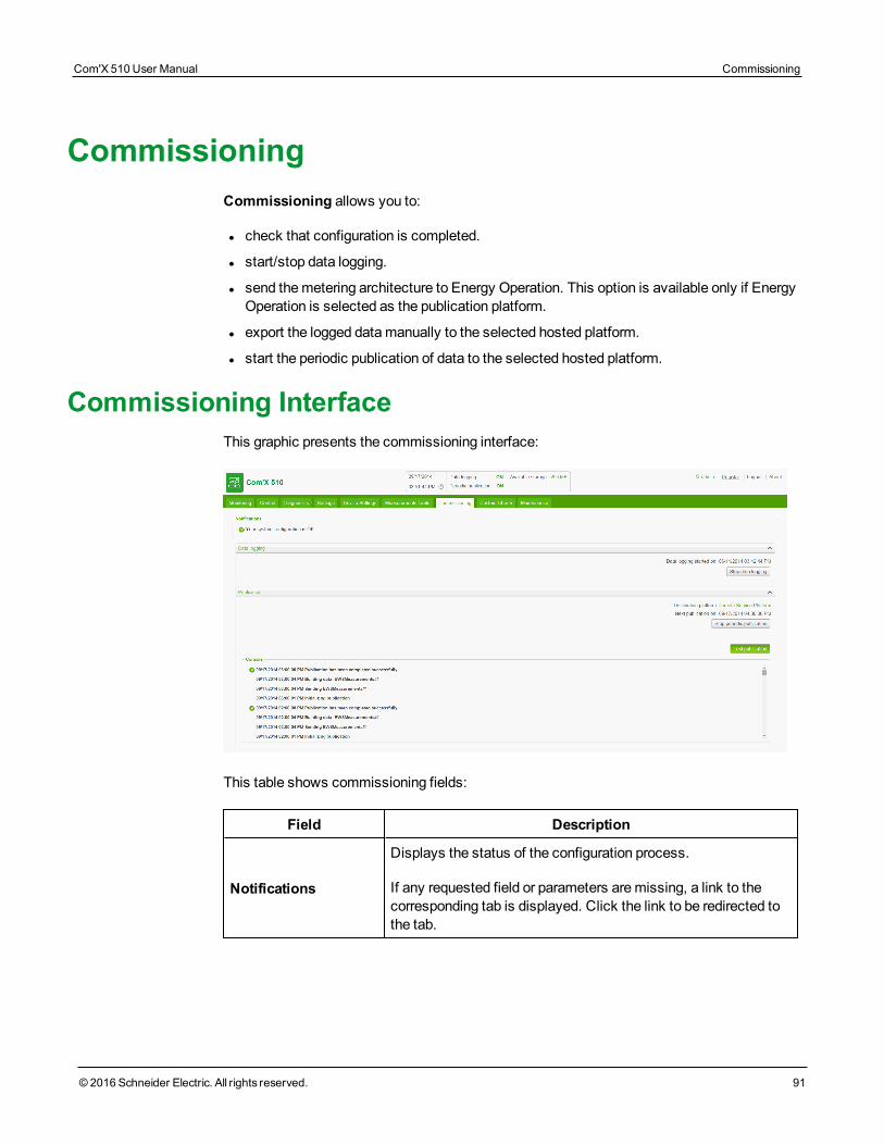
CommissioningCommissioning allows you to:
l check that configuration is completed.
l start/stop data logging.
l send themetering architecture to Energy Operation. This option is available only if EnergyOperation is selected as the publication platform.
l export the logged datamanually to the selected hosted platform.
l start the periodic publication of data to the selected hosted platform.
Commissioning InterfaceThis graphic presents the commissioning interface:
This table shows commissioning fields:
Field Description
Notifications
Displays the status of the configuration process.
If any requested field or parameters aremissing, a link to thecorresponding tab is displayed. Click the link to be redirected tothe tab.
Com'X 510 User Manual Commissioning
© 2016 Schneider Electric. All rights reserved. 91
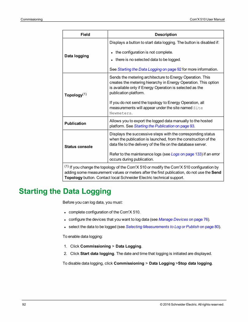
Commissioning Com'X 510 User Manual
92 © 2016 Schneider Electric. All rights reserved.
Field Description
Data logging
Displays a button to start data logging. The button is disabled if:
l the configuration is not complete.
l there is no selected data to be logged.
SeeStarting the Data Logging on page 92 for more information.
Topology(1)
Sends themetering architecture to Energy Operation. Thiscreates themetering hierarchy in Energy Operation. This optionis available only if Energy Operation is selected as thepublication platform.
If you do not send the topology to Energy Operation, allmeasurements will appear under the site named SiteNewmeters.
Publication Allows you to export the logged datamanually to the hostedplatform. SeeStarting the Publication on page 93.
Status console
Displays the successive steps with the corresponding statuswhen the publication is launched, from the construction of thedata file to the delivery of the file on the database server.
Refer to themaintenance logs (see Logs on page 133) if an erroroccurs during publication.
(1) If you change the topology of the Com'X 510 or modify the Com'X 510 configuration byadding somemeasurement values or meters after the first publication, do not use theSendTopology button. Contact local Schneider Electric technical support.
Starting the Data LoggingBefore you can log data, youmust:
l complete configuration of the Com'X 510.
l configure the devices that you want to log data (seeManage Devices on page 76).
l select the data to be logged (seeSelectingMeasurements to Log or Publish on page 80).
To enable data logging:
1. Click Commissioning > Data Logging.
2. Click Start data logging. The date and time that logging is initiated are displayed.
To disable data logging, click Commissioning > Data Logging >Stop data logging.
Starting the PublicationIf you are publishing data to Energy Operation, youmust send the topology to EnergyOperation as inPublishing the Data to Energy Operation on page 164
After you have configured devices for publishing:
1. Click the Test publication button to send data to the hosted platform.
NOTE:When using RSP, do not start the publication until you receive the "Connected tothe destination platform" status from RSP platform in the publicationmenu.
2. Click theStart periodic publication button to send data to the hosted platform accord-ing to the frequency set inPublication settings.
Com'X 510 User Manual Commissioning
© 2016 Schneider Electric. All rights reserved. 93

Commissioning Com'X 510 User Manual
94 © 2016 Schneider Electric. All rights reserved.
MonitoringThe Com'X 510 provides views of real-time data and trends along with historical data logtrends and dashboards. Data from devices on digital and analog inputs are not available in theMonitoring tab.
Real Time DataReal TimeData provides basic readings of selected devices in real time, as well as devicesummaries.
Single Device ViewSingle Device View displays the following information for the selected device.
Menu Description
MonitoredArea
Parameters describing the location and use of the device as defined inCommon Properties on page 73
GaugesAnalog view of device readings.
Options are Load Current (A), Power, Voltage LL, andVoltage LN.
Basic Most common readings for the selected device.
Energy Table view of energy data.
Demand Table view of power demand data.
PowerQuality Table view of power quality data.
Below is the user interface for theSingle Device View:
Com'X 510 User Manual Monitoring
© 2016 Schneider Electric. All rights reserved. 95
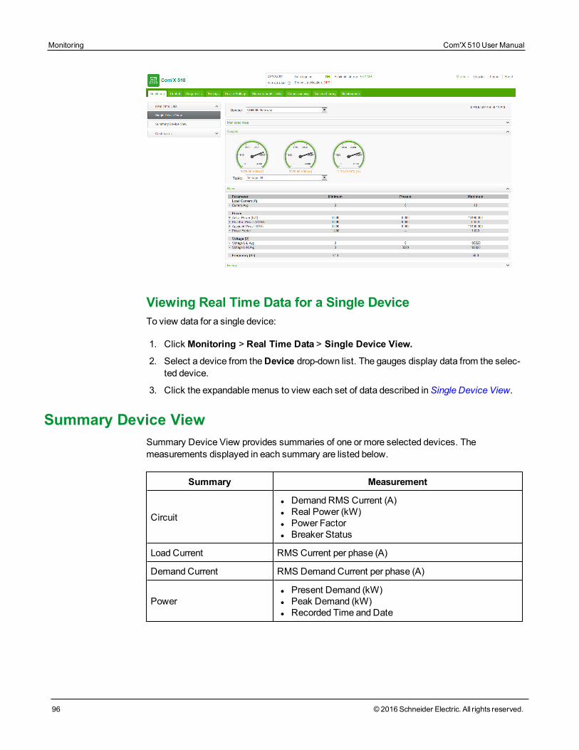
Monitoring Com'X 510 User Manual
96 © 2016 Schneider Electric. All rights reserved.
Viewing Real Time Data for a Single DeviceTo view data for a single device:
1. Click Monitoring > Real Time Data > Single Device View.
2. Select a device from theDevice drop-down list. The gauges display data from the selec-ted device.
3. Click the expandablemenus to view each set of data described inSingle Device View.
Summary Device ViewSummary Device View provides summaries of one or more selected devices. Themeasurements displayed in each summary are listed below.
Summary Measurement
Circuit
l DemandRMS Current (A)l Real Power (kW)l Power Factorl Breaker Status
Load Current RMS Current per phase (A)
Demand Current RMS Demand Current per phase (A)
Powerl Present Demand (kW)l Peak Demand (kW)l Recorded Time and Date
Summary Measurement
Energy Delivered
l Real Energy Delivered (kWh)l Reactive Energy Delivered (kVARh)l Real Energy Total (kWh)l Reactive Energy Total (kVARh)
Energy Received
l Real Energy Received (kWh)l Reactive Energy Received (kVARh)l Real Energy Total (kWh)l Reactive Energy Total (kVARh)
Power Quality
l Power Factor Totall Frequency (Hz)l THDVLL (V)l THDVLN (V)
Viewing a Device SummaryTo view a device summary table:
1. Click Monitoring > Real Time Data > Summary Device View.
2. Select the summary you want to view.
3. Select the device(s) from theDevice Selection list. The requested data displays.
For the current session, the selected settings aremaintained if you navigate away fromSummary Device View.
Real Time TrendingReal Time Trending allows you to view and save (image or .csv file) data points frommultiple devices and/or topics in real time.
Viewing a Real Time Trending Graph or TableTo view a real time trend of multiple devices and topics:
1. Click Monitoring > Real Time Data > Real Time Trending.
2. Select devices from theAvailable Devices list, then select a topic(s) from theAvailable Topics list.
NOTE: Only topics common to all selected devices are available for trending. Themaximum number of topics to trend is dependent on the number of devices selected. Theproduct of the selected devices and topics must be 9 or less.
3. Select the axis updatemethod:
l Fixed adds data points left to right and the x-axis stays constant.
l Auto re-plots data points and redraws the x-axis after each sample.
4. Choose a trend duration of 1 to 15minutes.
Com'X 510 User Manual Monitoring
© 2016 Schneider Electric. All rights reserved. 97
Monitoring Com'X 510 User Manual
98 © 2016 Schneider Electric. All rights reserved.
NOTE: Data samples are taken at a one-second rate but may take longer depending onthe communications load on the serial sub-net and/or remote devices.
5. Click Start Sampling. The graph begins to update.
6. You can stop trending before reaching the trend time by clickingStop Sampling. If youpress Start Sampling again, a new trend is started.
7. Click VIEW POINTS to see the data in a table format.
During the sampling, you can change the axis and line type, as well as navigate away fromReal Time Trending.The session inactivity time-out interval begins after the sample iscomplete or stopped.
Saving Real Time Trending Data Points or GraphAfter the trending interval is complete or you have stopped sampling, you can export the datato a .csv file or save the graph as an image.
1. Click EXPORT DATA, then follow your browser's prompts for saving the file. Altern-atively, click VIEW POINTS, then click Export Data.
2. To save the graph as an image, right-click the graph, then click Save image as. Followyour browser's prompts for saving the file.
DashboardsThere are two types of dashboards: Energy andHistorical Trending.
Energy dashboards display energy consumption information aggregated over time.
The Com'X 510 supports the four periods for energy dashboards described below.
Period Description
Day over Day By default, displays previous day over current day by hours.
Week overWeek By default, displays previous week over current week by days.
4Weeks over 4Weeks
By default, displays previous four-week period over current four-week period.
NOTE: Months are aligned by day of the week, not day of themonth.
Year over Year By default, displays previous calendar year over current year bymonths.
Historical Trending displays each data point collected for the devices/topics and timelinechosen.
Viewing a Dashboard Graph or TableTo view a dashboard:
1. Click Monitoring > Dashboards.
2. Click a dashboard category: Energy orHistorical Trending.
3. Select a device from Available Devices, then select a topic from Available Topics.
NOTE: ForHistorical Trending, you can choose a single device with multiple topics(max 12) or multiple devices (max 4) with a single topic.
4. Select the dashboardPeriod (Energy only). The requested graph displays.
5. Optionally, you can refine the dashboard:
a. Click the calendar icon to select a new start date for thePeriod. ForHistoricalTrending, you can also select an end date to display up to 92 days.
b. Select the type of graph.
c. Click the divider between the device list and the graph to collapse the selection areaand increase the dashboard's display area.
6. Click VIEW POINTS to see the data in a table format.
You can hover over a data point to view the value, date, and time. See Using the DashboardKiosk on page 100 for a full-screen dashboard view.
NOTE: The graph updates only if thePeriod includes the current day. Otherwise, thedashboard remains static.
Saving Dashboard Data Points or GraphYou can save data from a dashboard (Energy or Historical Trending) as a .csv file or as animage, as shown in the steps below.
1. View the dashboard as inViewing a Dashboard Graph or Table on page 98.
2. Click EXPORT DATA, then follow your browser's prompts for saving the file. Altern-atively, click VIEW POINTS to preview the data, then click Export Data.
3. To save the graph as an image, right-click the graph, then click Save image as. Followyour browser's prompts for saving the file.
Saving a Dashboard LinkYou can save a dashboard link to avoid having to select from themainmenu each time youaccess the dashboard. This table describes themethods for saving a dashboard link.
Option Description
BrowserBookmark
Allows users to access the saved dashboard on the computer where thebookmark is created.
Follow instructions for setting a bookmark in your preferred browser.
Com'X 510 User Manual Monitoring
© 2016 Schneider Electric. All rights reserved. 99

Monitoring Com'X 510 User Manual
100 © 2016 Schneider Electric. All rights reserved.
Option Description
DocumentationLink
Allows all users to access a saved dashboard from the Links page.
See Links on page 68 for setting URL access.
Messaging
Allows users to paste a dashboard URL in the body of an email, SMS, orother messagingmedium.
Email recipient must have a user account with at least View access forDashboard. SeeUserManagement on page 60
Using the Dashboard KioskA user in a group with any modify permissions is subject to theSession Inactivity Timeout,configured inGroup Settings.
To display a dashboard in kiosk mode with no session timeout, we recommend logging in asa user in the default guest group. Alternatively, you can create a kiosk user group with view-only permissions forDashboards and no other view ormodify permissions (seeGroupSettings on page 61).
To view the dashboard kiosk:
1. View the dashboard as inViewing a Dashboard Graph or Table on page 98.
2. Click Kiosk.The dashboard opens in full screenmode.
NOTE: The graph updates only if thePeriod includes the current day. Otherwise, thedashboard remains static.
Historical Data ExportHistorical Data Export allows you to define device topics to download and export a .csv filefor each device. The historical data log format and file naming format is the same as aCSVExport publication. (See File Format of CSV Export on page 46
Available topics only include topics configured for logging (seeSelectingMeasurements toLog or Publish on page 80).
Exporting Historical Data1. Click Monitoring > Dashboards > Historical Data Export.
2. Select a device, then select one or moreAvailable Topics.
3. Click to move the devices/topics to the queue.
4. Repeat these steps for each device, then click Download. A .zip file with the formatCom'X Name_Date&time.zip is added to your default download location.
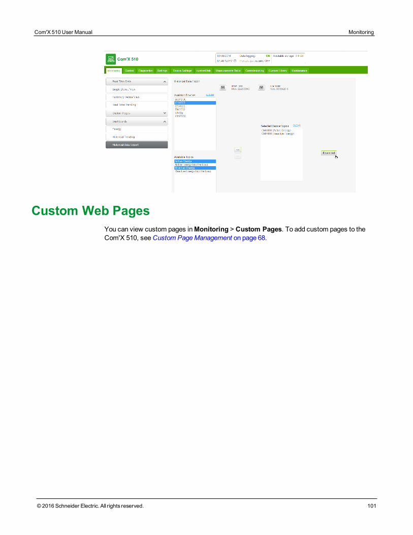
Custom Web PagesYou can view custom pages inMonitoring > Custom Pages. To add custom pages to theCom'X 510, seeCustom PageManagement on page 68.
Com'X 510 User Manual Monitoring
© 2016 Schneider Electric. All rights reserved. 101

Monitoring Com'X 510 User Manual
102 © 2016 Schneider Electric. All rights reserved.
ControlDevice Resets
The Com'X 510 canmanually execute one or more predefined reset commands per devicetype. For a list of parameters available for reset on your device, follow the steps inResettingDevice Parameters on page 103.
Resetting Device ParametersTo reset device parameters:
1. Click Control > Resets > Device Resets.
2. Select the devices you want to reset from theDevice Selection list.
3. Select the reset operation from Reset Options.
4. Enter the password for each device requiring a password. TheReset button becomesavailable.
NOTE: The default password check box is populated by the default password providedby the device and is selected by default.You can deselect the default password checkbox and enter another password.
5. Click Reset.
The selected device parameters are reset and the status displays as "ok."
NOTE: Date/Time values are reported only when the device supports them. For example, if adevice does not support theMin/Max value for "Date/Time Last Reset," the "Min/Max" valuewill not be populated here.
Setting Time on DevicesThe Localized Time is the current date and time on the selected device, adjusted to reflectthe time zone selected in the Com'X 510 Date/Time Settings.
To reset the time on a device:
1. Click Control > Set Device Time.
2. Select the devices you want to reset from theDevice Selection list.
3. Click Get Time to display the Localized Time for the device.
4. Click Set Time to send the Com'X 510 date/time (UTC) to the device. The status dis-plays as eitherSuccessful orUnsuccessful.
Com'X 510 User Manual Control
© 2016 Schneider Electric. All rights reserved. 103

Control Com'X 510 User Manual
104 © 2016 Schneider Electric. All rights reserved.
DiagnosticsDiagnostics provides statistical data about the Com'X 510 and connected devices. It alsoallows you to perform manual register reads and check communications status of connecteddevices.
StatisticsStatistics shows accumulated readings since the Com'X 510 was last reset.
If power to the Com'X 510 is lost or the device is reset due to a configuration change or otherevent, all cumulative values reset to zero.
Viewing Statistics1. Click Diagnostics > Statistics.
2. Click one of the following categories: Network orModbus.
3. Click the expandablemenu for the group of statistics you want to view.
4. Click Refresh if you want to update the data.
NOTE: Network statistics update approximately every 10 seconds.
See Interpreting Statistics on page 105 for a list of available parameters.
Resetting StatisticsTo reset a category of statistics:
1. Click Diagnostics > Statistics.
2. Click one of the following categories: Network orModbus.
3. Click Reset, then click Yes to confirm the reset. Parameters in all expandablemenus arereset.
Interpreting StatisticsThis section describes the statistics available for the Com'X 510 and connected devices.
l Modbus Statistics on page 106
l Network Statistics on page 107
Com'X 510 User Manual Diagnostics
© 2016 Schneider Electric. All rights reserved. 105
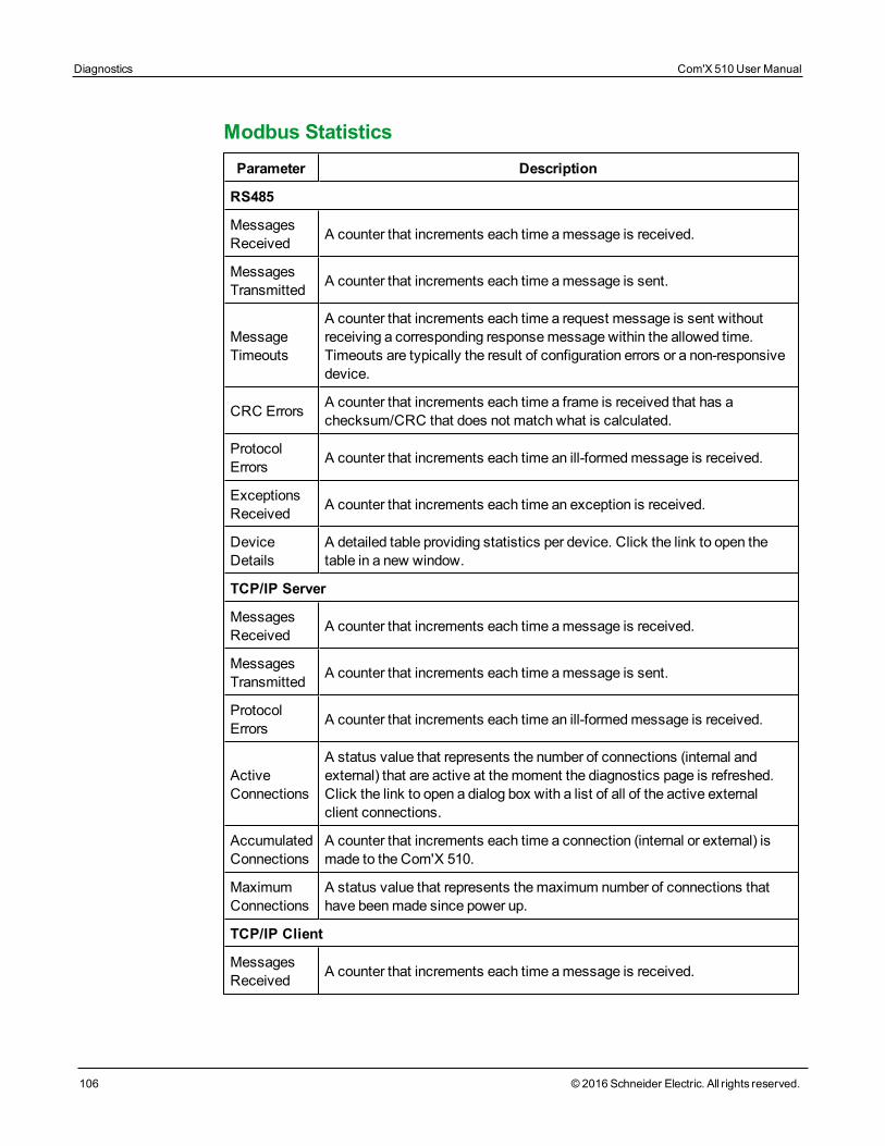
Diagnostics Com'X 510 User Manual
106 © 2016 Schneider Electric. All rights reserved.
Modbus StatisticsParameter Description
RS485
MessagesReceived A counter that increments each time amessage is received.
MessagesTransmitted A counter that increments each time amessage is sent.
MessageTimeouts
A counter that increments each time a request message is sent withoutreceiving a corresponding responsemessage within the allowed time.Timeouts are typically the result of configuration errors or a non-responsivedevice.
CRC Errors A counter that increments each time a frame is received that has achecksum/CRC that does not match what is calculated.
ProtocolErrors A counter that increments each time an ill-formedmessage is received.
ExceptionsReceived A counter that increments each time an exception is received.
DeviceDetails
A detailed table providing statistics per device. Click the link to open thetable in a new window.
TCP/IP Server
MessagesReceived A counter that increments each time amessage is received.
MessagesTransmitted A counter that increments each time amessage is sent.
ProtocolErrors A counter that increments each time an ill-formedmessage is received.
ActiveConnections
A status value that represents the number of connections (internal andexternal) that are active at themoment the diagnostics page is refreshed.Click the link to open a dialog box with a list of all of the active externalclient connections.
AccumulatedConnections
A counter that increments each time a connection (internal or external) ismade to the Com'X 510.
MaximumConnections
A status value that represents themaximum number of connections thathave beenmade since power up.
TCP/IP Client
MessagesReceived A counter that increments each time amessage is received.
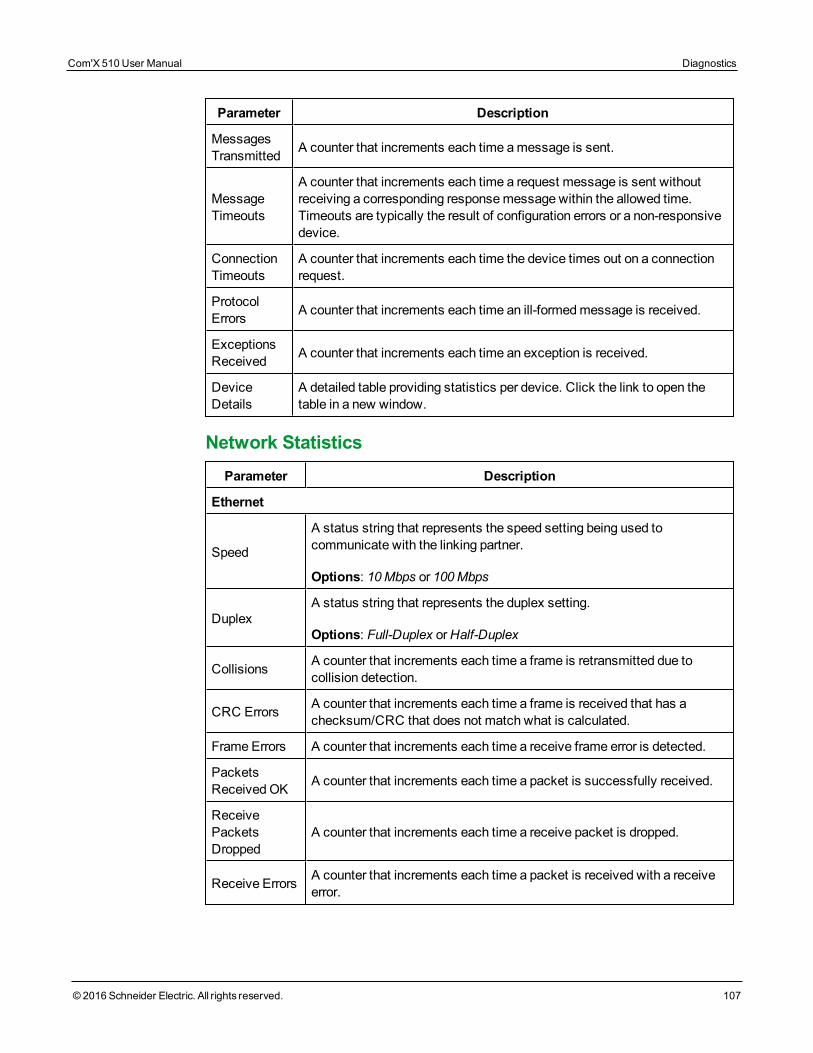
Parameter Description
MessagesTransmitted A counter that increments each time amessage is sent.
MessageTimeouts
A counter that increments each time a request message is sent withoutreceiving a corresponding responsemessage within the allowed time.Timeouts are typically the result of configuration errors or a non-responsivedevice.
ConnectionTimeouts
A counter that increments each time the device times out on a connectionrequest.
ProtocolErrors A counter that increments each time an ill-formedmessage is received.
ExceptionsReceived A counter that increments each time an exception is received.
DeviceDetails
A detailed table providing statistics per device. Click the link to open thetable in a new window.
Network StatisticsParameter Description
Ethernet
Speed
A status string that represents the speed setting being used tocommunicate with the linking partner.
Options: 10Mbps or 100Mbps
DuplexA status string that represents the duplex setting.
Options: Full-Duplex orHalf-Duplex
Collisions A counter that increments each time a frame is retransmitted due tocollision detection.
CRC Errors A counter that increments each time a frame is received that has achecksum/CRC that does not match what is calculated.
Frame Errors A counter that increments each time a receive frame error is detected.
PacketsReceivedOK A counter that increments each time a packet is successfully received.
ReceivePacketsDropped
A counter that increments each time a receive packet is dropped.
Receive Errors A counter that increments each time a packet is received with a receiveerror.
Com'X 510 User Manual Diagnostics
© 2016 Schneider Electric. All rights reserved. 107
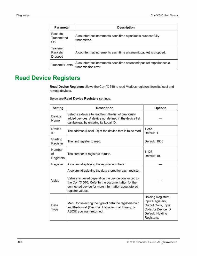
Diagnostics Com'X 510 User Manual
108 © 2016 Schneider Electric. All rights reserved.
Parameter Description
PacketsTransmittedOK
A counter that increments each time a packet is successfullytransmitted.
TransmitPacketsDropped
A counter that increments each time a transmit packet is dropped.
Transmit Errors A counter that increments each time a transmit packet experiences atransmission error.
Read Device RegistersRead Device Registers allows the Com'X 510 to readModbus registers from its local andremote devices.
Below areRead Device Registers settings.
Setting Description Options
DeviceName
Selects a device to read from the list of previouslyadded devices. A device not defined in the device listcan be read by entering its Local ID.
—
DeviceID The address (Local ID) of the device that is to be read. 1-255
Default: 1
StartingRegister The first register to read. Default: 1000
NumberofRegisters
The number of registers to read. 1-125Default: 10
Register A column displaying the register numbers. —
Value
A column displaying the data stored for each register.
Values retrieved depend on the device connected tothe Com'X 510. Refer to the documentation for theconnected device for more information about storedregister values.
—
DataType
Menu for selecting the type of data the registers holdand the format (Decimal, Hexadecimal, Binary, orASCII) you want returned.
Holding Registers,Input Registers,Output Coils, InputCoils, or Device IDDefault: HoldingRegisters.
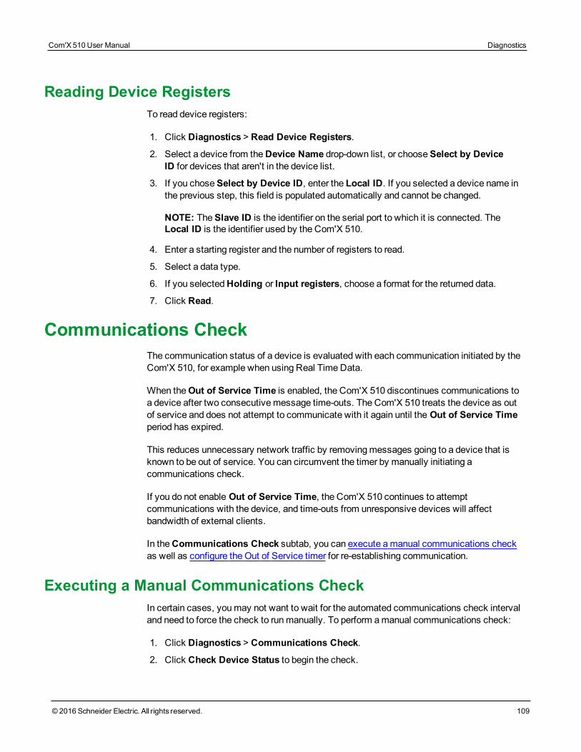
Reading Device RegistersTo read device registers:
1. Click Diagnostics > Read Device Registers.
2. Select a device from theDevice Name drop-down list, or chooseSelect by DeviceID for devices that aren't in the device list.
3. If you choseSelect by Device ID, enter the Local ID. If you selected a device name inthe previous step, this field is populated automatically and cannot be changed.
NOTE: TheSlave ID is the identifier on the serial port to which it is connected. TheLocal ID is the identifier used by the Com'X 510.
4. Enter a starting register and the number of registers to read.
5. Select a data type.
6. If you selectedHolding or Input registers, choose a format for the returned data.
7. Click Read.
Communications CheckThe communication status of a device is evaluated with each communication initiated by theCom'X 510, for example when using Real TimeData.
When theOut of Service Time is enabled, the Com'X 510 discontinues communications toa device after two consecutivemessage time-outs. The Com'X 510 treats the device as outof service and does not attempt to communicate with it again until the Out of Service Timeperiod has expired.
This reduces unnecessary network traffic by removingmessages going to a device that isknown to be out of service. You can circumvent the timer by manually initiating acommunications check.
If you do not enable Out of Service Time, the Com'X 510 continues to attemptcommunications with the device, and time-outs from unresponsive devices will affectbandwidth of external clients.
In theCommunications Check subtab, you can execute amanual communications checkas well as configure the Out of Service timer for re-establishing communication.
Executing a Manual Communications CheckIn certain cases, youmay not want to wait for the automated communications check intervaland need to force the check to runmanually. To perform amanual communications check:
1. Click Diagnostics > Communications Check.
2. Click Check Device Status to begin the check.
Com'X 510 User Manual Diagnostics
© 2016 Schneider Electric. All rights reserved. 109
Diagnostics Com'X 510 User Manual
110 © 2016 Schneider Electric. All rights reserved.
3. Optionally, you can click Stop Status Check to stop the check.
The Status column displays In Service orOut of Service.
Defining the Out of Service TimeTo define theOut of Service Time:
1. Click Diagnostics > Communications Check.
2. Select Yes forEnable Out of Service Time.
3. Select theOut of Service Time. Options are 1, 2, 3, 4, 5, 10, 15, 30 and 60minutes(default: 15).
4. Click Save changes.
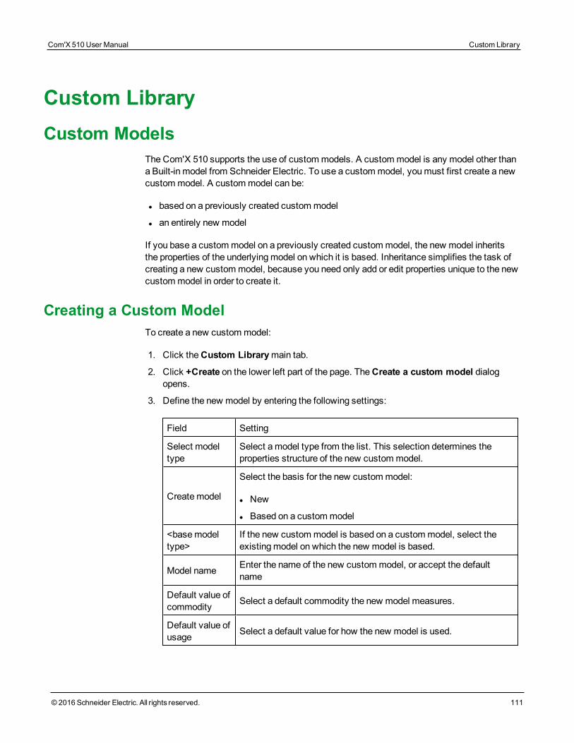
Custom LibraryCustom Models
The Com'X 510 supports the use of custommodels. A custommodel is any model other thana Built-in model from Schneider Electric. To use a custommodel, youmust first create a newcustommodel. A custommodel can be:
l based on a previously created custommodel
l an entirely new model
If you base a custommodel on a previously created custommodel, the new model inheritsthe properties of the underlyingmodel on which it is based. Inheritance simplifies the task ofcreating a new custommodel, because you need only add or edit properties unique to the newcustommodel in order to create it.
Creating a Custom ModelTo create a new custommodel:
1. Click theCustom Librarymain tab.
2. Click +Create on the lower left part of the page. TheCreate a custom model dialogopens.
3. Define the new model by entering the following settings:
Field Setting
Select modeltype
Select amodel type from the list. This selection determines theproperties structure of the new custommodel.
Createmodel
Select the basis for the new custommodel:
l New
l Based on a custommodel
<basemodeltype>
If the new custommodel is based on a custommodel, select theexistingmodel on which the new model is based.
Model name Enter the name of the new custommodel, or accept the defaultname
Default value ofcommodity Select a default commodity the new model measures.
Default value ofusage Select a default value for how the new model is used.
Com'X 510 User Manual Custom Library
© 2016 Schneider Electric. All rights reserved. 111
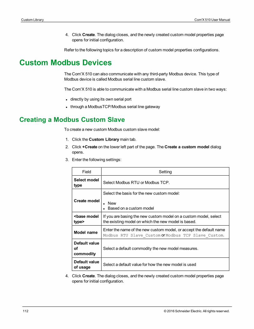
Custom Library Com'X 510 User Manual
112 © 2016 Schneider Electric. All rights reserved.
4. Click Create. The dialog closes, and the newly created custommodel properties pageopens for initial configuration.
Refer to the following topics for a description of custommodel properties configurations.
Custom Modbus DevicesThe Com'X 510 can also communicate with any third-party Modbus device. This type ofModbus device is calledModbus serial line custom slave.
The Com'X 510 is able to communicate with aModbus serial line custom slave in two ways:
l directly by using its own serial port
l through aModbusTCP/Modbus serial line gateway
Creating a Modbus Custom SlaveTo create a new customModbus custom slavemodel:
1. Click theCustom Librarymain tab.
2. Click +Create on the lower left part of the page. TheCreate a custom model dialogopens.
3. Enter the following settings:
Field Setting
Select modeltype Select Modbus RTU orModbus TCP.
Create model
Select the basis for the new custommodel:
l Newl Based on a custommodel
<base modeltype>
If you are basing the new custommodel on a custommodel, selectthe existingmodel on which the new model is based.
Model name Enter the name of the new custommodel, or accept the default nameModbus RTU Slave_Custom or Modbus TCP Slave_Custom.
Default valueofcommodity
Select a default commodity the new model measures.
Default valueof usage Select a default value for how the new model is used
4. Click Create. The dialog closes, and the newly created custommodel properties pageopens for initial configuration.
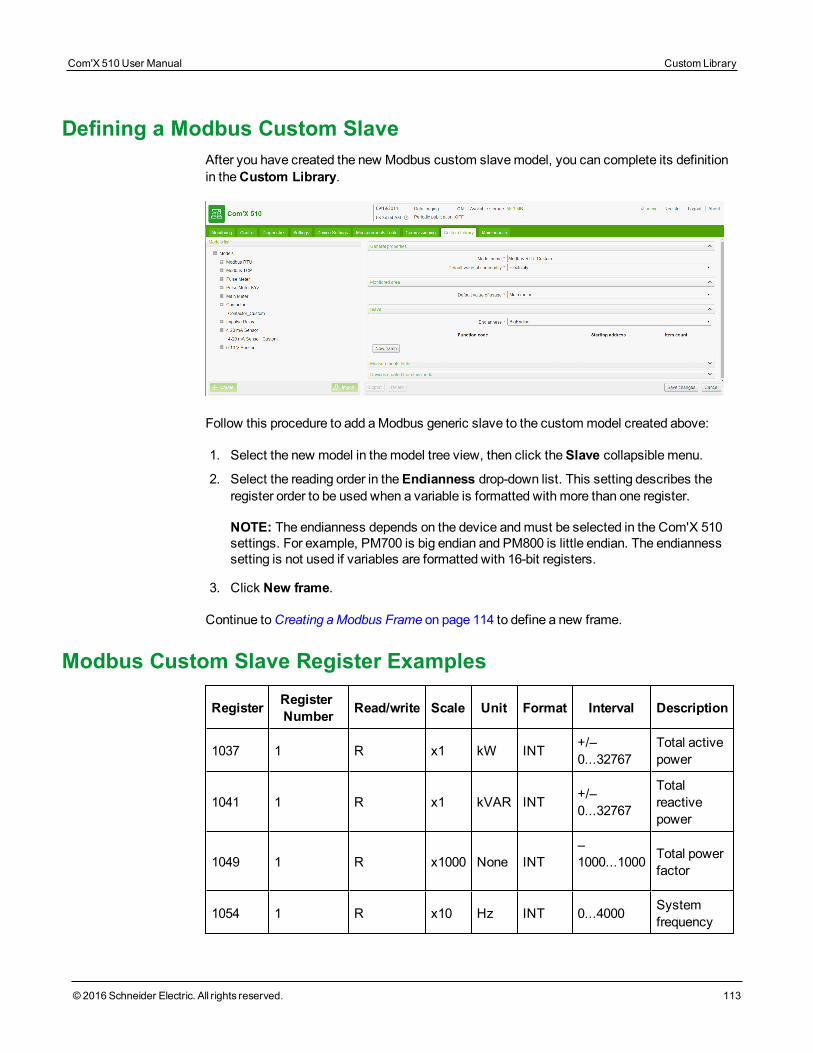
Defining a Modbus Custom SlaveAfter you have created the new Modbus custom slavemodel, you can complete its definitionin theCustom Library.
Follow this procedure to add aModbus generic slave to the custommodel created above:
1. Select the new model in themodel tree view, then click theSlave collapsible menu.
2. Select the reading order in theEndianness drop-down list. This setting describes theregister order to be used when a variable is formatted with more than one register.
NOTE: The endianness depends on the device andmust be selected in the Com'X 510settings. For example, PM700 is big endian and PM800 is little endian. The endiannesssetting is not used if variables are formatted with 16-bit registers.
3. Click New frame.
Continue toCreating aModbus Frame on page 114 to define a new frame.
Modbus Custom Slave Register Examples
Register RegisterNumber Read/write Scale Unit Format Interval Description
1037 1 R x1 kW INT +/–0...32767
Total activepower
1041 1 R x1 kVAR INT +/–0...32767
Totalreactivepower
1049 1 R x1000 None INT–1000...1000 Total power
factor
1054 1 R x10 Hz INT 0...4000 Systemfrequency
Com'X 510 User Manual Custom Library
© 2016 Schneider Electric. All rights reserved. 113
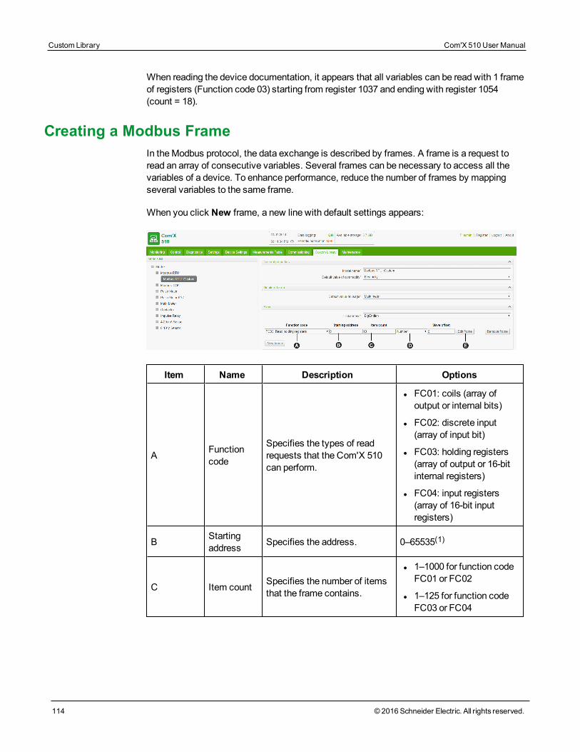
Custom Library Com'X 510 User Manual
114 © 2016 Schneider Electric. All rights reserved.
When reading the device documentation, it appears that all variables can be read with 1 frameof registers (Function code 03) starting from register 1037 and ending with register 1054(count = 18).
Creating a Modbus FrameIn theModbus protocol, the data exchange is described by frames. A frame is a request toread an array of consecutive variables. Several frames can be necessary to access all thevariables of a device. To enhance performance, reduce the number of frames by mappingseveral variables to the same frame.
When you click New frame, a new line with default settings appears:
Item Name Description Options
A Functioncode
Specifies the types of readrequests that the Com'X 510can perform.
l FC01: coils (array ofoutput or internal bits)
l FC02: discrete input(array of input bit)
l FC03: holding registers(array of output or 16-bitinternal registers)
l FC04: input registers(array of 16-bit inputregisters)
B Startingaddress Specifies the address. 0–65535(1)
C Item count Specifies the number of itemsthat the frame contains.
l 1–1000 for function codeFC01 or FC02
l 1–125 for function codeFC03 or FC04
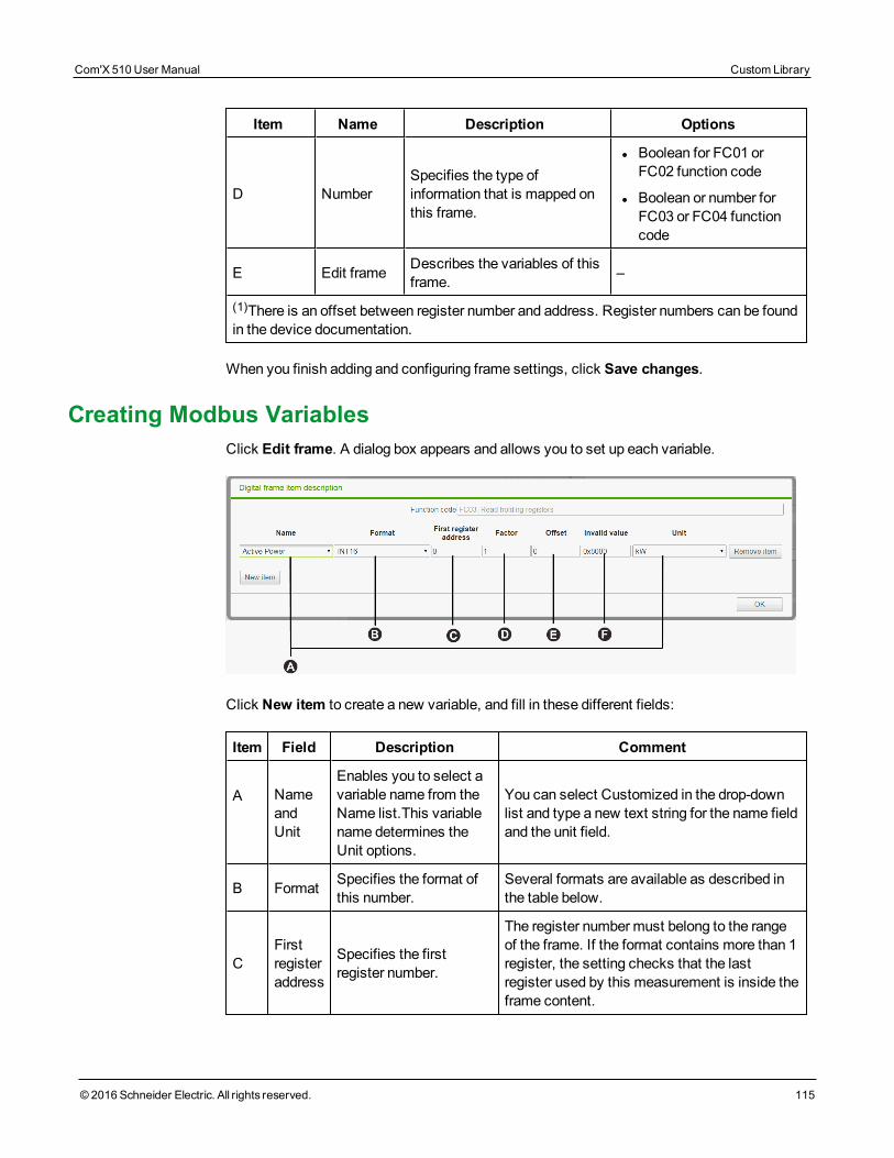
Item Name Description Options
D NumberSpecifies the type ofinformation that is mapped onthis frame.
l Boolean for FC01 orFC02 function code
l Boolean or number forFC03 or FC04 functioncode
E Edit frame Describes the variables of thisframe. –
(1)There is an offset between register number and address. Register numbers can be foundin the device documentation.
When you finish adding and configuring frame settings, click Save changes.
Creating Modbus VariablesClick Edit frame. A dialog box appears and allows you to set up each variable.
Click New item to create a new variable, and fill in these different fields:
Item Field Description Comment
A NameandUnit
Enables you to select avariable name from theName list.This variablename determines theUnit options.
You can select Customized in the drop-downlist and type a new text string for the name fieldand the unit field.
B Format Specifies the format ofthis number.
Several formats are available as described inthe table below.
CFirstregisteraddress
Specifies the firstregister number.
The register numbermust belong to the rangeof the frame. If the format contains more than 1register, the setting checks that the lastregister used by this measurement is inside theframe content.
Com'X 510 User Manual Custom Library
© 2016 Schneider Electric. All rights reserved. 115
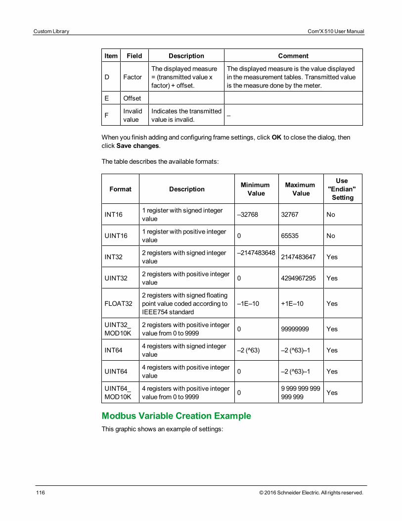
Custom Library Com'X 510 User Manual
116 © 2016 Schneider Electric. All rights reserved.
Item Field Description Comment
D FactorThe displayedmeasure= (transmitted value xfactor) + offset.
The displayedmeasure is the value displayedin themeasurement tables. Transmitted valueis themeasure done by themeter.
E Offset
F Invalidvalue
Indicates the transmittedvalue is invalid. –
When you finish adding and configuring frame settings, click OK to close the dialog, thenclick Save changes.
The table describes the available formats:
Format Description MinimumValue
MaximumValue
Use"Endian"Setting
INT16 1 register with signed integervalue –32768 32767 No
UINT16 1 register with positive integervalue 0 65535 No
INT32 2 registers with signed integervalue
–2147483648 2147483647 Yes
UINT32 2 registers with positive integervalue 0 4294967295 Yes
FLOAT322 registers with signed floatingpoint value coded according toIEEE754 standard
–1E–10 +1E–10 Yes
UINT32_MOD10K
2 registers with positive integervalue from 0 to 9999 0 99999999 Yes
INT64 4 registers with signed integervalue –2 (^63) –2 (^63)–1 Yes
UINT64 4 registers with positive integervalue 0 –2 (^63)–1 Yes
UINT64_MOD10K
4 registers with positive integervalue from 0 to 9999 0 9 999 999 999
999 999 Yes
Modbus Variable Creation ExampleThis graphic shows an example of settings:
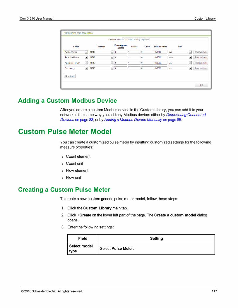
Adding a Custom Modbus DeviceAfter you create a customModbus device in the Custom Library, you can add it to yournetwork in the sameway you add any Modbus device: either by Discovering ConnectedDevices on page 83, or by Adding aModbus DeviceManually on page 85.
Custom Pulse Meter ModelYou can create a customized pulsemeter by inputting customized settings for the followingmeasure properties:
l Count element
l Count unit
l Flow element
l Flow unit
Creating a Custom Pulse MeterTo create a new custom generic pulsemeter model, follow these steps:
1. Click theCustom Librarymain tab.
2. Click +Create on the lower left part of the page. TheCreate a custom model dialogopens.
3. Enter the following settings:
Field Setting
Select modeltype Select Pulse Meter.
Com'X 510 User Manual Custom Library
© 2016 Schneider Electric. All rights reserved. 117
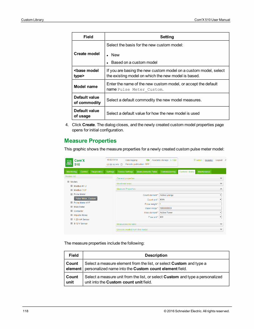
Custom Library Com'X 510 User Manual
118 © 2016 Schneider Electric. All rights reserved.
Field Setting
Create model
Select the basis for the new custommodel:
l New
l Based on a custommodel
<base modeltype>
If you are basing the new custommodel on a custommodel, selectthe existingmodel on which the new model is based.
Model name Enter the name of the new custommodel, or accept the defaultname Pulse Meter_Custom.
Default valueof commodity Select a default commodity the new model measures.
Default valueof usage Select a default value for how the new model is used
4. Click Create. The dialog closes, and the newly created custommodel properties pageopens for initial configuration.
Measure PropertiesThis graphic shows themeasure properties for a newly created custom pulsemeter model:
Themeasure properties include the following:
Field Description
Countelement
Select ameasure element from the list, or select Custom and type apersonalized name into theCustom count element field.
Countunit
Select ameasure unit from the list, or select Custom and type a personalizedunit into theCustom count unit field.
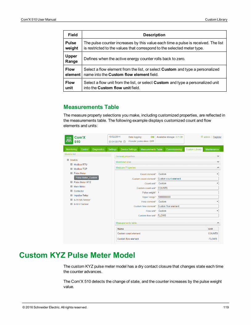
Field Description
Pulseweight
The pulse counter increases by this value each time a pulse is received. The listis restricted to the values that correspond to the selectedmeter type.
UpperRange Defines when the active energy counter rolls back to zero.
Flowelement
Select a flow element from the list, or select Custom and type a personalizedname into theCustom flow element field.
Flowunit
Select a flow unit from the list, or select Custom and type a personalized unitinto theCustom flow unit field.
Measurements TableThemeasure property selections youmake, including customized properties, are reflected inthemeasurements table. The following example displays customized count and flowelements and units:
Custom KYZ Pulse Meter ModelThe custom KYZ pulsemeter model has a dry contact closure that changes state each timethe counter advances.
The Com'X 510 detects the change of state, and the counter increases by the pulse weightvalue.
Com'X 510 User Manual Custom Library
© 2016 Schneider Electric. All rights reserved. 119
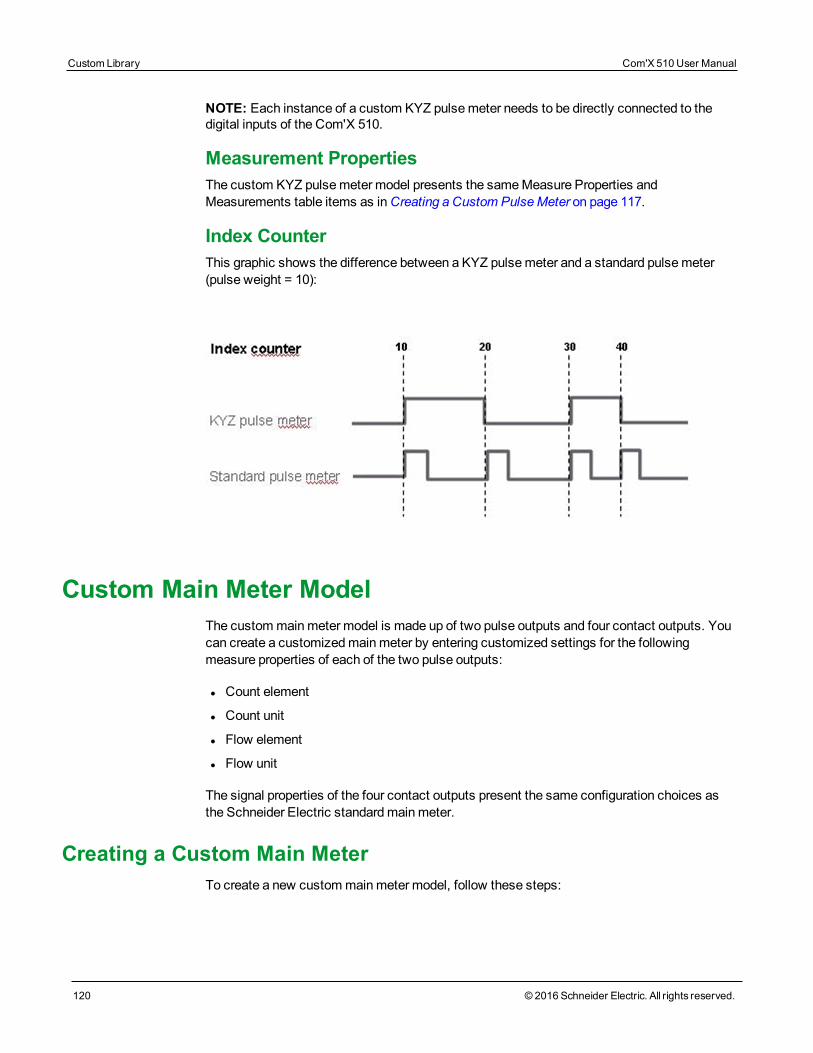
Custom Library Com'X 510 User Manual
120 © 2016 Schneider Electric. All rights reserved.
NOTE: Each instance of a custom KYZ pulsemeter needs to be directly connected to thedigital inputs of the Com'X 510.
Measurement PropertiesThe custom KYZ pulsemeter model presents the sameMeasure Properties andMeasurements table items as inCreating a Custom PulseMeter on page 117.
Index CounterThis graphic shows the difference between a KYZ pulsemeter and a standard pulsemeter(pulse weight = 10):
Custom Main Meter ModelThe custommainmeter model is made up of two pulse outputs and four contact outputs. Youcan create a customizedmainmeter by entering customized settings for the followingmeasure properties of each of the two pulse outputs:
l Count element
l Count unit
l Flow element
l Flow unit
The signal properties of the four contact outputs present the same configuration choices asthe Schneider Electric standardmainmeter.
Creating a Custom Main MeterTo create a new custommainmeter model, follow these steps:
1. Click theCustom Librarymain tab.
2. Click +Create on the lower left part of the page. TheCreate a custom model dialogopens.
3. Enter the following settings:
Field Setting
Select modeltype SelectMain Meter.
Create model
Select the basis for the new custommodel:
l New
l Based on a custommodel
<base modeltype>
If you are basing the new custommodel on a custommodel, selectthe existingmodel on which the new model is based.
Model name Enter the name of the new custommodel, or accept the defaultname Main Meter_Custom.
Default valueof commodity Select a default commodity the new model measures.
Default valueof usage Select a default value for how the new model is used
4. Click Create. The dialog closes, and the newly created custommodel properties pageopens for initial configuration.
Main Meter Measure and Signal PropertiesThis graphic shows themeasure and signal properties for a newly created custommainmetermodel:
Com'X 510 User Manual Custom Library
© 2016 Schneider Electric. All rights reserved. 121
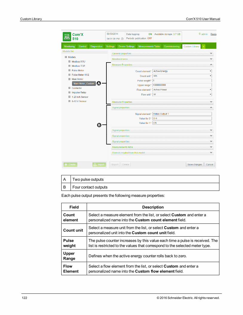
Custom Library Com'X 510 User Manual
122 © 2016 Schneider Electric. All rights reserved.
A Two pulse outputs
B Four contact outputs
Each pulse output presents the followingmeasure properties:
Field Description
Countelement
Select ameasure element from the list, or select Custom and enter apersonalized name into theCustom count element field.
Count unit Select ameasure unit from the list, or select Custom and enter apersonalized unit into theCustom count unit field.
Pulseweight
The pulse counter increases by this value each time a pulse is received. Thelist is restricted to the values that correspond to the selectedmeter type.
UpperRange Defines when the active energy counter rolls back to zero.
FlowElement
Select a flow element from the list, or select Custom and enter apersonalized name into theCustom flow element field.
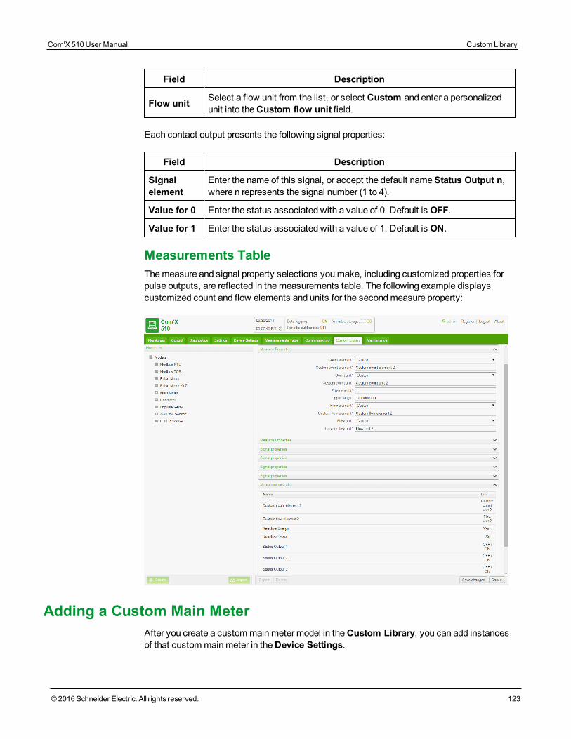
Field Description
Flow unit Select a flow unit from the list, or select Custom and enter a personalizedunit into theCustom flow unit field.
Each contact output presents the following signal properties:
Field Description
Signalelement
Enter the name of this signal, or accept the default nameStatus Output n,where n represents the signal number (1 to 4).
Value for 0 Enter the status associated with a value of 0. Default is OFF.
Value for 1 Enter the status associated with a value of 1. Default is ON.
Measurements TableThemeasure and signal property selections youmake, including customized properties forpulse outputs, are reflected in themeasurements table. The following example displayscustomized count and flow elements and units for the secondmeasure property:
Adding a Custom Main MeterAfter you create a custommainmeter model in theCustom Library, you can add instancesof that custommainmeter in theDevice Settings.
Com'X 510 User Manual Custom Library
© 2016 Schneider Electric. All rights reserved. 123
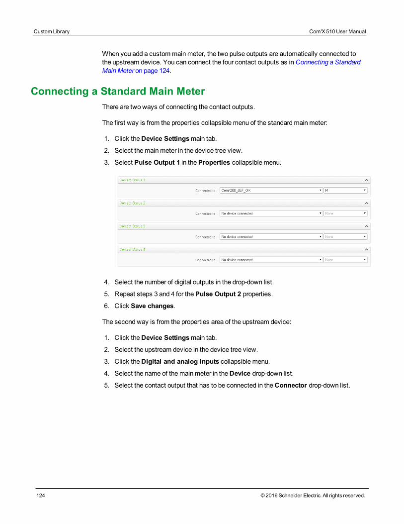
Custom Library Com'X 510 User Manual
124 © 2016 Schneider Electric. All rights reserved.
When you add a custommainmeter, the two pulse outputs are automatically connected tothe upstream device. You can connect the four contact outputs as inConnecting a StandardMainMeter on page 124.
Connecting a Standard Main MeterThere are two ways of connecting the contact outputs.
The first way is from the properties collapsible menu of the standardmainmeter:
1. Click theDevice Settingsmain tab.
2. Select themainmeter in the device tree view.
3. Select Pulse Output 1 in theProperties collapsible menu.
4. Select the number of digital outputs in the drop-down list.
5. Repeat steps 3 and 4 for thePulse Output 2 properties.
6. Click Save changes.
The second way is from the properties area of the upstream device:
1. Click theDevice Settingsmain tab.
2. Select the upstream device in the device tree view.
3. Click theDigital and analog inputs collapsible menu.
4. Select the name of themainmeter in theDevice drop-down list.
5. Select the contact output that has to be connected in theConnector drop-down list.
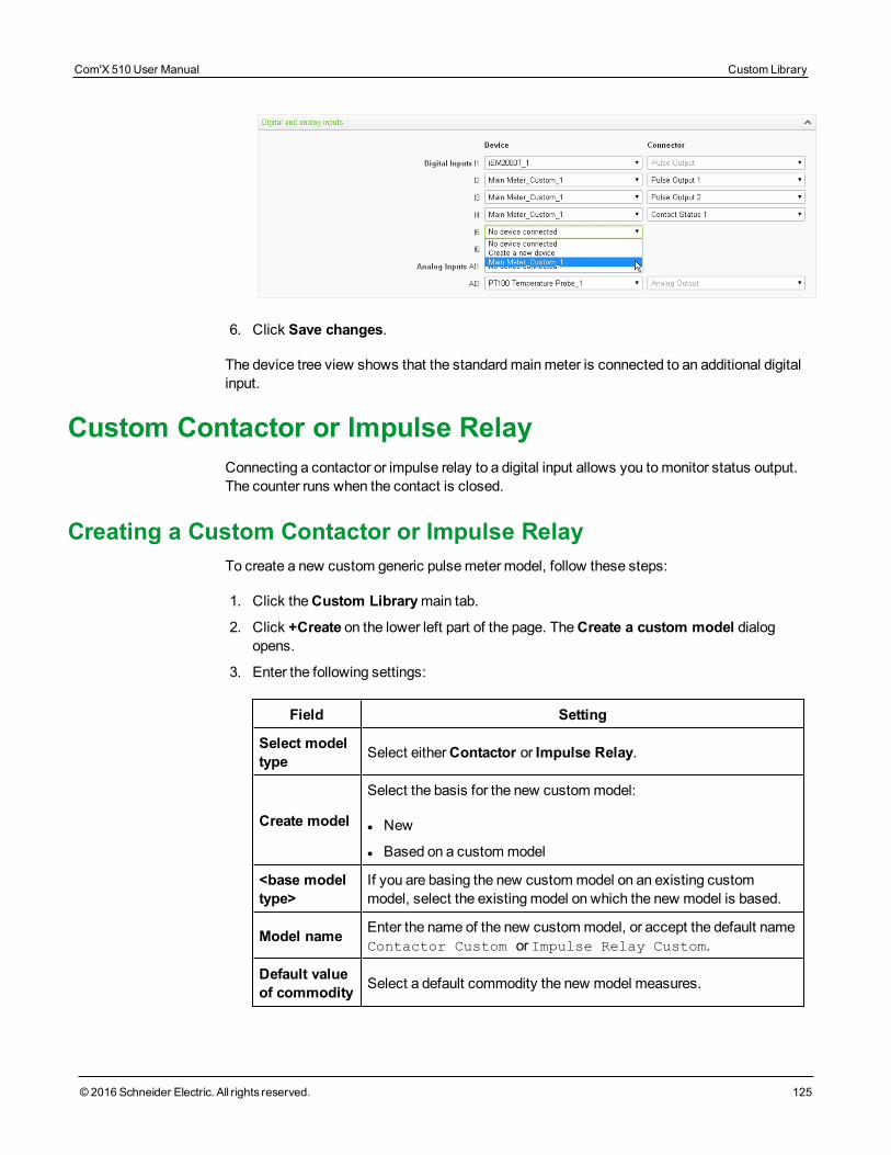
6. Click Save changes.
The device tree view shows that the standardmainmeter is connected to an additional digitalinput.
Custom Contactor or Impulse RelayConnecting a contactor or impulse relay to a digital input allows you tomonitor status output.The counter runs when the contact is closed.
Creating a Custom Contactor or Impulse RelayTo create a new custom generic pulsemeter model, follow these steps:
1. Click theCustom Librarymain tab.
2. Click +Create on the lower left part of the page. TheCreate a custom model dialogopens.
3. Enter the following settings:
Field Setting
Select modeltype Select eitherContactor or Impulse Relay.
Create model
Select the basis for the new custommodel:
l New
l Based on a custommodel
<base modeltype>
If you are basing the new custommodel on an existing custommodel, select the existingmodel on which the new model is based.
Model name Enter the name of the new custommodel, or accept the default nameContactor Custom or Impulse Relay Custom.
Default valueof commodity Select a default commodity the new model measures.
Com'X 510 User Manual Custom Library
© 2016 Schneider Electric. All rights reserved. 125
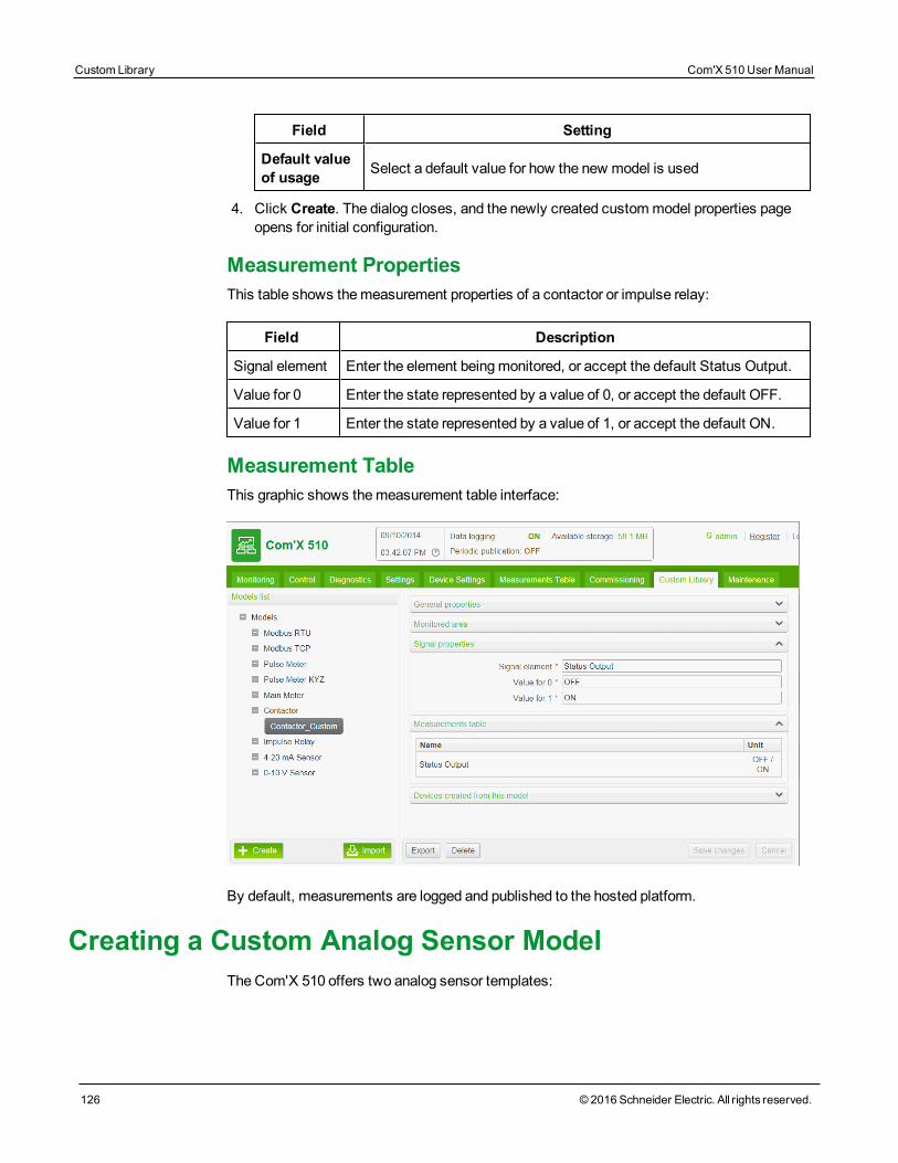
Custom Library Com'X 510 User Manual
126 © 2016 Schneider Electric. All rights reserved.
Field Setting
Default valueof usage Select a default value for how the new model is used
4. Click Create. The dialog closes, and the newly created custommodel properties pageopens for initial configuration.
Measurement PropertiesThis table shows themeasurement properties of a contactor or impulse relay:
Field Description
Signal element Enter the element beingmonitored, or accept the default Status Output.
Value for 0 Enter the state represented by a value of 0, or accept the default OFF.
Value for 1 Enter the state represented by a value of 1, or accept the default ON.
Measurement TableThis graphic shows themeasurement table interface:
By default, measurements are logged and published to the hosted platform.
Creating a Custom Analog Sensor ModelThe Com'X 510 offers two analog sensor templates:
l 4...20mA
l 0...10 V
Each custom analog sensor model monitors a single point. You can create a customizedanalog sensor model by entering customized settings for the following properties:
l Count element
l Count unit
Creating a Custom Analog SensorTo create a new custom analog sensor model, follow these steps:
1. Click theCustom Librarymain tab.
2. Click +Create on the lower left part of the page. TheCreate a custom model dialogopens.
3. Enter the following settings:
Field Setting
Selectmodel type Select either 4-20 mA Sensor or 0-10 V Sensor.
Createmodel
Select the basis for the new custommodel:
l New
TypeEnter the name of the new custommodel, or accept the default name,either Sensor 4-20mA_Custom or Sensor 0-10V_Custom,depending on the selectedmodel type.
Defaultvalue ofcommodity
Select a default commodity the new model measures.
Defaultvalue ofusage
Select a default value for how the new model is used
4. Click Create. The dialog closes, and the newly created custommodel properties pageopens for initial configuration.
Measure and Signal PropertiesThis graphic shows themonitored area properties for a new custom 4...20mA analog sensormodel:
Com'X 510 User Manual Custom Library
© 2016 Schneider Electric. All rights reserved. 127
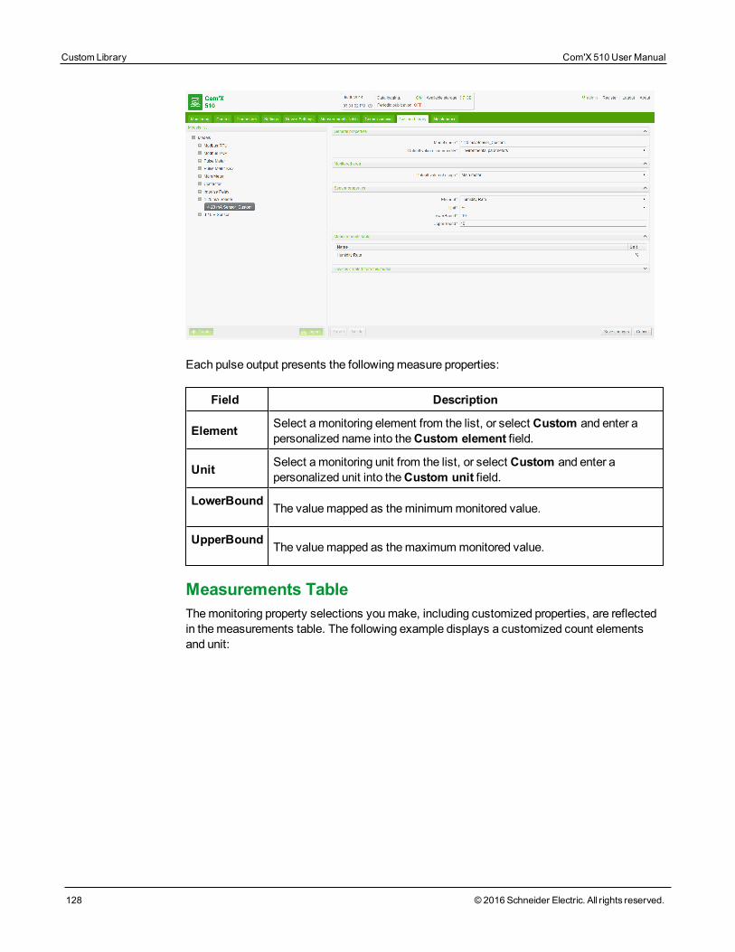
Custom Library Com'X 510 User Manual
128 © 2016 Schneider Electric. All rights reserved.
Each pulse output presents the followingmeasure properties:
Field Description
Element Select amonitoring element from the list, or select Custom and enter apersonalized name into theCustom element field.
Unit Select amonitoring unit from the list, or select Custom and enter apersonalized unit into theCustom unit field.
LowerBound The valuemapped as theminimummonitored value.
UpperBound The valuemapped as themaximummonitored value.
Measurements TableThemonitoring property selections youmake, including customized properties, are reflectedin themeasurements table. The following example displays a customized count elementsand unit:
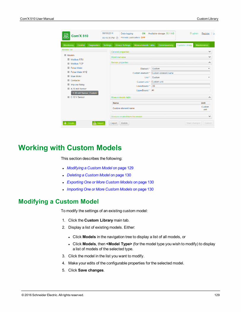
Working with Custom ModelsThis section describes the following:
l Modifying a CustomModel on page 129
l Deleting a CustomModel on page 130
l Exporting One orMore CustomModels on page 130
l Importing One orMore CustomModels on page 130
Modifying a Custom ModelTomodify the settings of an existing custommodel:
1. Click theCustom Librarymain tab.
2. Display a list of existingmodels. Either:
l Click Models in the navigation tree to display a list of all models, or
l Click Models, then <Model Type> (for themodel type you wish tomodify) to displaya list of models of the selected type.
3. Click themodel in the list you want to modify.
4. Make your edits of the configurable properties for the selectedmodel.
5. Click Save changes.
Com'X 510 User Manual Custom Library
© 2016 Schneider Electric. All rights reserved. 129
Custom Library Com'X 510 User Manual
130 © 2016 Schneider Electric. All rights reserved.
Deleting a Custom ModelYou can only delete amodel if no devices have been created from themodel. To delete anexisting custommodel:
1. Click theCustom Librarymain tab.
2. Display a list of existingmodels. Either:
l Click Models in the navigation tree to display a list of all models, or
l Click Models, then <Model Type> (for themodel type you wish to delete) to display alist of models of the selected type.
3. Do one of the following. Either:
l To delete a single model, click the delete icon ( ) in the row for themodel you want
to delete, or
l To deletemultiple models, place a check mark next to themodels you want to delete,then click Delete.
NOTE: A model is deleted when you issue the delete command. Nomessage box appearsand asks you to confirm the delete command.
Exporting One or More Custom ModelsTo export one or more custommodels:
1. Click theCustom Librarymain tab.
2. Navigate to themodel you want to export. Either:
l Click Models in the navigation tree to display a list of all models, or
l Click Models, then <Model Type> (for themodel type you wish to export).
3. Do one of the following. Either:
l To export a single model, click theExport icon ( ) in the row for themodel you want
to export, or
l To export multiple models, place a check mark next to themodels you want to export,then click Export.
The exportedmodel is wrapped in a .zip file and sent to the default download location of yourbrowser.
Importing One or More Custom ModelsTo import one or more custommodels:
1. Click theCustom Librarymain tab.
2. Click Import. The Import models dialog opens.

3. Click Browse. TheOpen dialog appears.
4. In theOpen dialog, navigate to and select the custommodel or models to import, thenclick Open.
5. In the Import models dialog, click Import.
6. After the import process is complete, click Close. The importedmodel or models appearin theCustom Library beneath the appropriate device type.
Com'X 510 User Manual Custom Library
© 2016 Schneider Electric. All rights reserved. 131

Custom Library Com'X 510 User Manual
132 © 2016 Schneider Electric. All rights reserved.
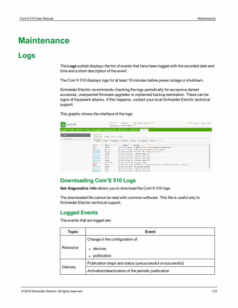
MaintenanceLogs
The Logs subtab displays the list of events that have been logged with the recorded date andtime and a short description of the event.
The Com'X 510 displays logs for at least 10 minutes before power outage or shutdown.
Schneider Electric recommends checking the logs periodically for excessive deniedaccesses, unexpected firmware upgrades or unplanned backup restoration. These can besigns of fraudulent attacks. If this happens, contact your local Schneider Electric technicalsupport.
This graphic shows the interface of the logs:
Downloading Com'X 510 LogsGet diagnostics info allows you to download the Com'X 510 logs.
The downloaded file cannot be read with common software. This file is useful only toSchneider Electric technical support.
Logged EventsThe events that are logged are:
Topic Event
Resource
Change in the configuration of:
l devices
l publication
DeliveryPublication steps and status (unsuccessful or successful)
Activation/deactivation of the periodic publication
Com'X 510 User Manual Maintenance
© 2016 Schneider Electric. All rights reserved. 133
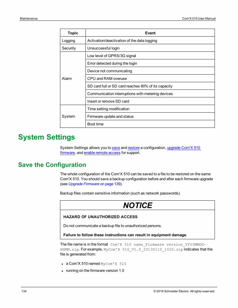
Maintenance Com'X 510 User Manual
134 © 2016 Schneider Electric. All rights reserved.
Topic Event
Logging Activation/deactivation of the data logging
Security Unsuccessful login
Alarm
Low level of GPRS/3G signal
Error detected during the login
Device not communicating
CPU and RAM overuse
SD card full or SD card reaches 80% of its capacity
Communication interruptions with metering devices
Insert or remove SD card
System
Time settingmodification
Firmware update and status
Boot time
System SettingsSystem Settings allows you to save and restore a configuration, upgrade Com'X 510firmware, and enable remote access for support.
Save the ConfigurationThe whole configuration of the Com'X 510 can be saved to a file to be restored on the sameCom'X 510. You should save a backup configuration before and after each firmware upgrade(seeUpgrade Firmware on page 139).
Backup files contain sensitive information (such as network passwords).
NOTICEHAZARD OF UNAUTHORIZED ACCESS
Do not communicate a backup file to unauthorized persons.
Failure to follow these instructions can result in equipment damage.
The file name is in the format Com'X 510 name_Firmware version_YYYYMMDD-HHMM.zip. For example, MyCom'X 510_V1.0_20130110_1020.zip indicates that thefile is generated from:
l a Com'X 510 named MyCom'X 510
l running on the firmware version 1.0
l on January 10th 2013 at 10:20 a.m.
The configuration can be saved only after the initial configuration or updating is completed.
NOTE: This feature is not available on the iPad.
Saving the Configuration LocallyTo save the configuration locally:
1. Click Maintenance > System Settings.
2. Click Save Configuration in theConfiguration Management collapsible menu.According to the web browser used, a dialog box appears to open, save, or cancel theconfiguration file.
3. Select the option to save the file in the dialog box. The date and time of the lastconfiguration backup are displayed under theSave Configuration button.
4. In theChoose File field, select the location on the computer to save the file and save theconfiguration.
Saving the Configuration with Remote Service PlatformTo save the configuration with the Remote Service Platform:
1. Click Maintenance > System Settings.
2. Click Save Configuration to RSP in theRemote Service Platform backupcollapsible menu. The status of the connection follows these steps:
l Contacting the server...
l Saving in progress...
l Configuration uploaded successfullyNOTE: If you cannot connect to the RSP server to upload the backup, retry or contactSchneider Electric technical support.
3. Select the option to save the file in the dialog box. The date and time of the last save aredisplayed under theSave Configuration to RSP button in the format: [Last con-figuration backup done on mm/dd/yyyy hh:mm:ss].
Saving the Configuration for Duplication on Another Com'X510When you back up an existing configuration file for duplication on another device, the backupfile contains the original configuration, except for the following settings:
l The deviceName field is set to Com'X 510_xxyyzz, where xxyyzz represents the lastthree hexadecimal octets of the deviceMAC address
l theSite name field is left blank (a new Energy Operation site ID is created)
NOTE: Do not use this procedure with a backup from a box connected to RSP.
Com'X 510 User Manual Maintenance
© 2016 Schneider Electric. All rights reserved. 135
Maintenance Com'X 510 User Manual
136 © 2016 Schneider Electric. All rights reserved.
To duplicate the configuration so that it can be applied to a different Com'X 510:
1. Click theMaintenance > System Settings.
2. Click Backup for duplication in theConfiguration Management collapsible menu.The duplication file is stored on the local PC at the default location for internet browserdownloads.
Saving the Configuration via the USB Port
DANGERHAZARD OF ELECTRIC SHOCK, EXPLOSION, OR ARC FLASH
• This equipment must only be installed and serviced by qualified personnel.• Apply appropriate personal protective equipment (PPE) and follow safe electrical workpractices. See NFPA 70E in the USA, CSA Z462 or applicable local standards.
Failure to follow these instructions will result in death or serious injury.
To save the configuration to a USB key:
1. Insert a USB key into the USB port on the Com'X 510 front panel.
2. Press and hold theBackup button for at least three seconds. During backup theUSB LED behaves as follows:
l If no error is detected during backup, the USB LED blinks green for 500ms, then offfor 500ms.
l If an error is detected, the USB LED blinks green for 250ms, then off for 250ms for atotal of three seconds.
3. If no error is detected during backup, the backup is complete when the blinking stops.You can remove the USB key from the Com'X 510 front panel.
Restore the ConfigurationYou can restore configuration in the following ways:
l Restoring the Configuration with a Local File on page 136
l Restoring the Configuration with a USB Key on page 137
l Restoring the Configuration via RSP on page 137
Restoring the Configuration with a Local FileWhen restoring the configuration with a local file (seeSave the Configuration on page 134),the current password is unchanged.
NOTE: Do not restore a backupmade without a connection to Remote Service Platform to abox after a connection to RSP has beenmade.
Follow this procedure to restore the configuration on the sameCom'X 510:
1. Click theMaintenance > System Settings.
2. Click theConfiguration Management collapsible menu.
3. In the File field, select the file that has to be uploaded to restore the configuration.
4. Click Open for the selected file to appear.
5. Click Apply the configuration.
6. Wait for the Com'X 510 to reboot. The power LED turns green when the reboot is com-plete.
7. Log in to the Com'X 510.
8. Check the configuration in the settings tabs and start the publication again from theCom-missioning tab.
Restoring the Configuration with a USB Key
DANGERHAZARD OF ELECTRIC SHOCK, EXPLOSION, OR ARC FLASH
• This equipment must only be installed and serviced by qualified personnel.• Apply appropriate personal protective equipment (PPE) and follow safe electrical workpractices. See NFPA 70E in the USA, CSA Z462 or applicable local standards.
Failure to follow these instructions will result in death or serious injury.
Follow this procedure to restore a locally saved configuration file (seeSave the Configurationon page 134) on the sameCom'X 510 using a USB key:
1. Copy the saved configuration file to a folder named "Restore" at the root of the USB key.
2. Power off Com'X 510, then plug the USB key into the USB port on the Com'X 510 frontpanel.
3. Power on the Com'X 510 and wait for it to reboot. When the power LED turns green, thereboot is complete.
4. Log in to the Com'X 510.
5. Check the configuration in the settings tabs and start the publication again from theCom-missioning tab.
Restoring the Configuration via RSPContact Schneider Electric technical support to request the restore of the configuration savedon Remote Service Platform. Schneider Electric technical support is able to launch therestore at any requested time. At the end of the restore the Com'X 510 reboots.
Com'X 510 User Manual Maintenance
© 2016 Schneider Electric. All rights reserved. 137
Maintenance Com'X 510 User Manual
138 © 2016 Schneider Electric. All rights reserved.
Log in to the Com'X 510, check the configuration in the settings tabs then start the publicationagain from theCommissioning tab.
Upload a Duplicate Configuration File from Another Com'X510You can upload a duplicate configuration file in the following ways:
l Uploading a Duplicate Configuration with a Local File on page 138
l Uploading a Duplicate Configuration with a USB Key on page 139
Uploading the configuration file from another Com'X 510 is not possible remotely throughRSP.
Uploading a Duplicate Configuration with a Local FileAfterSaving the Configuration for Duplication on Another Com'X 510 on page 135, follow thisprocedure to upload a duplicate configuration file from another Com'X 510:
1. Click theMaintenancemain tab.
2. Click theSystem Settings subtab.
3. Click Browse in theConfiguration Management collapsible menu.
4. Select the locally saved configuration file.
5. Click Open for the selected file to appear.
6. Click Apply the configuration.
7. Wait for the Com'X 510 to reboot. The power LED turns green when the reboot is com-plete.
8. Reconnect to the Com'X 510.
9. Click Settings > Site Settings > Site Information.
10. Type the new site location name, then click Save changes to save themodification.
NOTE: The site location namemay not include any of the following: '/:*?<>| or space.
11. Click theDevice Settings tab.
12. Select the Com'X 510 in the Device tree view.
13. Type the Com'X 510 name in theGeneral Properties collapsible menu.
14. Click Save changes to save your modification.
15. Click theMeasurement table tab to check the correct connection, setting, and func-tioning on the new site.
16. Select Commissioning tab to activate logging and publication according to destinationplatform (seeCommissioning on page 91 for more information)
Uploading a Duplicate Configuration with a USB Key
DANGERHAZARD OF ELECTRIC SHOCK, EXPLOSION, OR ARC FLASH
• This equipment must only be installed and serviced by qualified personnel.• Apply appropriate personal protective equipment (PPE) and follow safe electrical workpractices. See NFPA 70E in the USA, CSA Z462 or applicable local standards.
Failure to follow these instructions will result in death or serious injury.
To upload a duplicate configuration file from another Com'X 510 using a USB key:
1. Copy the duplicate configuration file to a folder named "Restore" at the root of theUSB key.
2. Power off the Com'X 510, then plug the USB key into the USB port on the Com'X 510front panel.
3. Power on the Com'X 510, and wait for it to reboot. When the power LED turns green, thereboot is complete.
4. Follow steps 8 through 16 described inUploading a Duplicate Configuration with a LocalFile on page 138
Upgrade FirmwareThe Com'X 510 can be updated using secured firmware through the web page or the USBport on the Com'X 510 front face. You should save a backup configuration before and aftereach firmware upgrade (seeSave the Configuration on page 134).
For the latest firmware update, check www.schneider-electric.com on the Com'X 510 page,or contact your local sales representative.
NOTE: Firmware upgrades can only be successful if the date and time of the Com'X 510 iscorrectly configured (seeDate and Time Settings on page 29).
Upgrading Firmware via the Web PageTo upgrade the firmware through the web interface:
1. Save the firmware file on your laptop.
2. Click Maintenance > System settings.
3. Click Browse in the Firmware upgrade collapsible menu.
4. Click Open. The selected file appears in the field next to theBrowse button.
5. Click Upgrade Firmware. ThemessageApplication not reachable is displayed duringthe upgrade.
Com'X 510 User Manual Maintenance
© 2016 Schneider Electric. All rights reserved. 139
Maintenance Com'X 510 User Manual
140 © 2016 Schneider Electric. All rights reserved.
6. Wait for the Com'X 510 to reboot. The power LED turns green when the reboot is com-plete.
7. Log in to the Com'X 510.
8. Check that the new firmware has been installed in theAbout page.
Upgrading Firmware via the USB Port
DANGERHAZARD OF ELECTRIC SHOCK, EXPLOSION, OR ARC FLASH
• This equipment must only be installed and serviced by qualified personnel.• Apply appropriate personal protective equipment (PPE) and follow safe electrical workpractices. See NFPA 70E in the USA, CSA Z462 or applicable local standards.
Failure to follow these instructions will result in death or serious injury.
Follow this procedure to upgrade the firmware by using the USB port:
1. Save the firmware file at the root of the USB memory key.
2. Rename the file to upgrade.sp1.
3. Make sure there is no file located at the root of the USB memory key with a name that isthe same as the serial number of the Com'X 510.
4. Power down the Com'X 510.
5. Insert the USB memory key in the USB port located on the front face.
6. Power up the Com'X 510.
7. Wait for the Com'X 510 to reboot. The power LED turns green when the reboot is com-plete.
8. Connect to the Com'X 510 through a PC and click theAbout link to check that the newfirmware is installed.
Upgrading Firmware via RSPFirmware upgrade through RSP is managed by Schneider Electric technical support.
At the end of the firmware upgrade process, the Com'X 510 reboots. Logging and publicationrestart automatically.
Firmware upgrade is performed at 1:40 a.m. in order to disturb as little as possible datalogging and publication.
NOTE: It is not recommended tomake the first firmware upgrade of the Com'X 510 using theRSP throughGPRS connection. Because theGPRS connection has a speed of only 20 kb/s,the firmware update could take several hours.
Enabling Remote AccessRemote Access allows Schneider Electric support to connect remotely to a Com'X 510 tocheck settings and to troubleshoot without having to go to the customer site.
NOTE: Schneider Electric does not attempt connections unless required to do so. if a proxyis necessary, it must be configured.
When activated, Remote Access is used to create a connection between the Com'X 510and Schneider Electric remote services.
To activateRemote Access:
1. Click theMaintenance > System Settings.
2. UnderApplications, click theRemote access for support button toON only ifSchneider Electric support team is asking for it. Otherwise, leave theRemote AccessbuttonOFF (default).
TheRemote Access button is deactivated three hours after you turn it on. Alternatively, youcan deactivateRemote Access as in the steps above.
Com'X 510 ReplacementTo replace the Com'X 510 via a local file, replace the old Com'X 510 with the new one anduse one of themethods inRestore the Configuration on page 136.
To replace a Com'X 510 with RSP, seeReplacing a Com'X 510 in RSP on page 141
Replacing a Com'X 510 in RSPNOTE: Make sure that the device has been replaced in Service Management beforeinstalling the new device.
Follow this procedure to replace the device:
1. Power on and connect to the new box.
2. Click Settings > General Settings > Network Settings, and configure the network set-tings, if required.
3. Configure theProxy Settings subtab, if required.
4. Click Settings > General Settings > Date/Time Settings and set the current date andtime.
5. Click Settings > General Settings > Publication.
6. In theDestination Platform field, choose Remote Service Platform.
7. Save changes.
8. Verify that the connection status displays Connected to the destination platform.
Com'X 510 User Manual Maintenance
© 2016 Schneider Electric. All rights reserved. 141
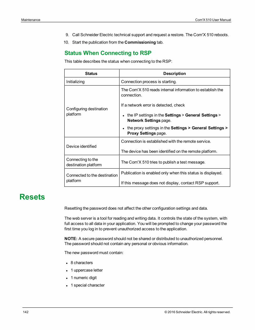
Maintenance Com'X 510 User Manual
142 © 2016 Schneider Electric. All rights reserved.
9. Call Schneider Electric technical support and request a restore. The Com'X 510 reboots.
10. Start the publication from theCommissioning tab.
Status When Connecting to RSPThis table describes the status when connecting to the RSP:
Status Description
Initializing Connection process is starting.
Configuring destinationplatform
The Com'X 510 reads internal information to establish theconnection.
If a network error is detected, check
l the IP settings in theSettings > General Settings >Network Settings page.
l the proxy settings in theSettings > General Settings >Proxy Settings page.
Device identifiedConnection is established with the remote service.
The device has been identified on the remote platform.
Connecting to thedestination platform The Com'X 510 tries to publish a test message.
Connected to the destinationplatform
Publication is enabled only when this status is displayed.
If this message does not display, contact RSP support.
ResetsResetting the password does not affect the other configuration settings and data.
The web server is a tool for reading and writing data. It controls the state of the system, withfull access to all data in your application. You will be prompted to change your password thefirst time you log in to prevent unauthorized access to the application.
NOTE: A secure password should not be shared or distributed to unauthorized personnel.The password should not contain any personal or obvious information.
The new passwordmust contain:
l 8 characters
l 1 uppercase letter
l 1 numeric digit
l 1 special character
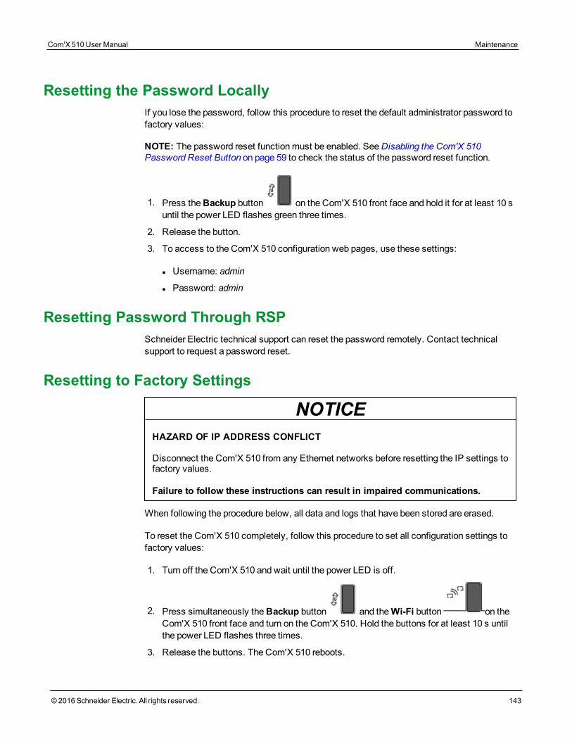
Resetting the Password LocallyIf you lose the password, follow this procedure to reset the default administrator password tofactory values:
NOTE: The password reset functionmust be enabled. SeeDisabling the Com'X 510Password Reset Button on page 59 to check the status of the password reset function.
1. Press theBackup button on the Com'X 510 front face and hold it for at least 10 suntil the power LED flashes green three times.
2. Release the button.
3. To access to the Com'X 510 configuration web pages, use these settings:
l Username: admin
l Password: admin
Resetting Password Through RSPSchneider Electric technical support can reset the password remotely. Contact technicalsupport to request a password reset.
Resetting to Factory Settings
NOTICEHAZARD OF IP ADDRESS CONFLICT
Disconnect the Com'X 510 from any Ethernet networks before resetting the IP settings tofactory values.
Failure to follow these instructions can result in impaired communications.
When following the procedure below, all data and logs that have been stored are erased.
To reset the Com'X 510 completely, follow this procedure to set all configuration settings tofactory values:
1. Turn off the Com'X 510 and wait until the power LED is off.
2. Press simultaneously theBackup button and theWi-Fi button on theCom'X 510 front face and turn on the Com'X 510. Hold the buttons for at least 10 s untilthe power LED flashes three times.
3. Release the buttons. The Com'X 510 reboots.
Com'X 510 User Manual Maintenance
© 2016 Schneider Electric. All rights reserved. 143

Maintenance Com'X 510 User Manual
144 © 2016 Schneider Electric. All rights reserved.
4. Wait for the Com'X 510 to restart completely. The power LED is:
l orange when the Com'X 510 is starting.
l green when the Com'X 510 has been reset to factory settings and is ready to be con-figured.
5. Follow the instructions described inAccess the Com'X 510 User Interface on page 17 toaccess the Com'X 510 web pages.
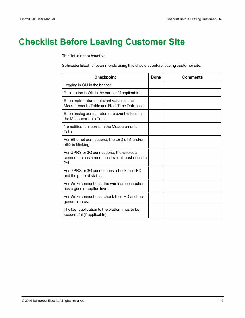
Checklist Before Leaving Customer SiteThis list is not exhaustive.
Schneider Electric recommends using this checklist before leaving customer site.
Checkpoint Done Comments
Logging is ON in the banner.
Publication is ON in the banner (if applicable).
Eachmeter returns relevant values in theMeasurements Table and Real TimeData tabs.
Each analog sensor returns relevant values intheMeasurements Table.
No notification icon is in theMeasurementsTable.
For Ethernet connections, the LED eth1 and/oreth2 is blinking.
For GPRS or 3G connections, the wirelessconnection has a reception level at least equal to2/4.
For GPRS or 3G connections, check the LEDand the general status.
ForWi-Fi connections, the wireless connectionhas a good reception level.
ForWi-Fi connections, check the LED and thegeneral status.
The last publication to the platform has to besuccessful (if applicable).
Com'X 510 User Manual Checklist Before Leaving Customer Site
© 2016 Schneider Electric. All rights reserved. 145

Checklist Before Leaving Customer Site Com'X 510 User Manual
146 © 2016 Schneider Electric. All rights reserved.
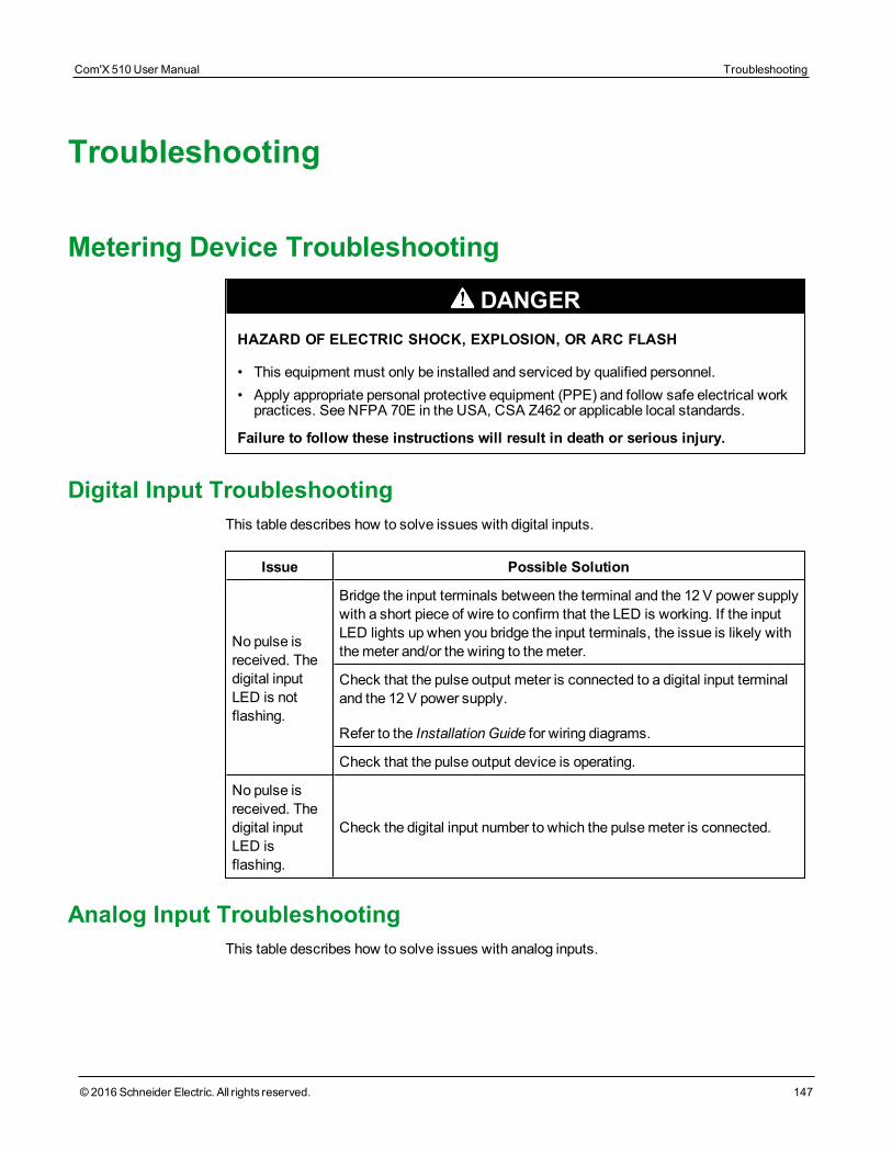
Troubleshooting
Metering Device Troubleshooting
DANGERHAZARD OF ELECTRIC SHOCK, EXPLOSION, OR ARC FLASH
• This equipment must only be installed and serviced by qualified personnel.• Apply appropriate personal protective equipment (PPE) and follow safe electrical workpractices. See NFPA 70E in the USA, CSA Z462 or applicable local standards.
Failure to follow these instructions will result in death or serious injury.
Digital Input TroubleshootingThis table describes how to solve issues with digital inputs.
Issue Possible Solution
No pulse isreceived. Thedigital inputLED is notflashing.
Bridge the input terminals between the terminal and the 12 V power supplywith a short piece of wire to confirm that the LED is working. If the inputLED lights up when you bridge the input terminals, the issue is likely withthemeter and/or the wiring to themeter.
Check that the pulse output meter is connected to a digital input terminaland the 12 V power supply.
Refer to the Installation Guide for wiring diagrams.
Check that the pulse output device is operating.
No pulse isreceived. Thedigital inputLED isflashing.
Check the digital input number to which the pulsemeter is connected.
Analog Input TroubleshootingThis table describes how to solve issues with analog inputs.
Com'X 510 User Manual Troubleshooting
© 2016 Schneider Electric. All rights reserved. 147
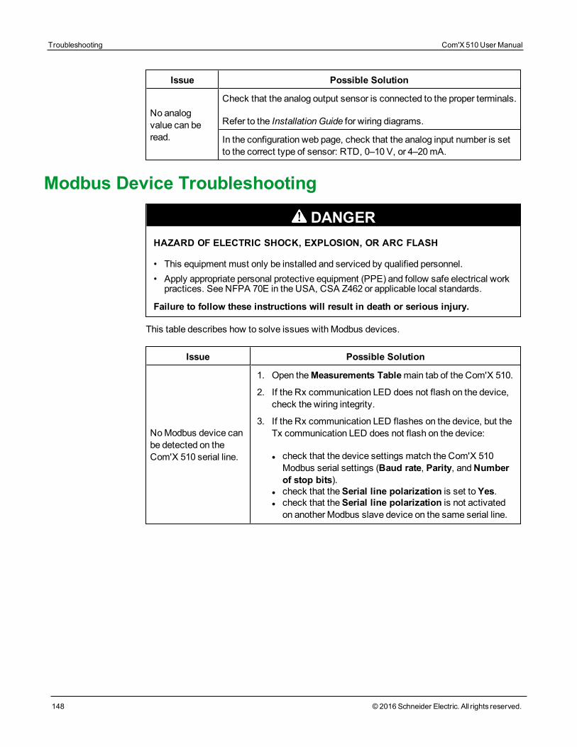
Troubleshooting Com'X 510 User Manual
148 © 2016 Schneider Electric. All rights reserved.
Issue Possible Solution
No analogvalue can beread.
Check that the analog output sensor is connected to the proper terminals.
Refer to the Installation Guide for wiring diagrams.
In the configuration web page, check that the analog input number is setto the correct type of sensor: RTD, 0–10 V, or 4–20 mA.
Modbus Device Troubleshooting
DANGERHAZARD OF ELECTRIC SHOCK, EXPLOSION, OR ARC FLASH
• This equipment must only be installed and serviced by qualified personnel.• Apply appropriate personal protective equipment (PPE) and follow safe electrical workpractices. See NFPA 70E in the USA, CSA Z462 or applicable local standards.
Failure to follow these instructions will result in death or serious injury.
This table describes how to solve issues with Modbus devices.
Issue Possible Solution
NoModbus device canbe detected on theCom'X 510 serial line.
1. Open theMeasurements Tablemain tab of the Com'X 510.
2. If the Rx communication LED does not flash on the device,check the wiring integrity.
3. If the Rx communication LED flashes on the device, but theTx communication LED does not flash on the device:
l check that the device settings match the Com'X 510Modbus serial settings (Baud rate, Parity, andNumberof stop bits).
l check that theSerial line polarization is set toYes.l check that theSerial line polarization is not activatedon another Modbus slave device on the same serial line.
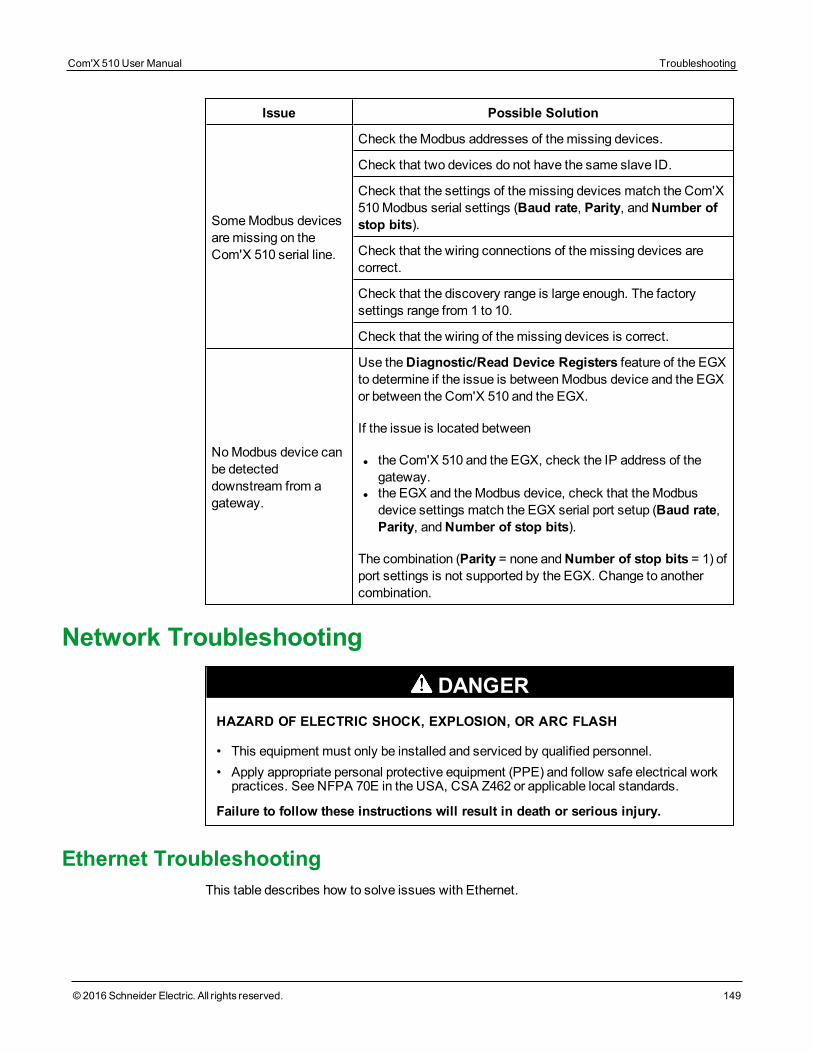
Issue Possible Solution
SomeModbus devicesaremissing on theCom'X 510 serial line.
Check theModbus addresses of themissing devices.
Check that two devices do not have the same slave ID.
Check that the settings of themissing devices match the Com'X510Modbus serial settings (Baud rate, Parity, andNumber ofstop bits).
Check that the wiring connections of themissing devices arecorrect.
Check that the discovery range is large enough. The factorysettings range from 1 to 10.
Check that the wiring of themissing devices is correct.
NoModbus device canbe detecteddownstream from agateway.
Use theDiagnostic/Read Device Registers feature of the EGXto determine if the issue is betweenModbus device and the EGXor between the Com'X 510 and the EGX.
If the issue is located between
l the Com'X 510 and the EGX, check the IP address of thegateway.
l the EGX and theModbus device, check that theModbusdevice settings match the EGX serial port setup (Baud rate,Parity, andNumber of stop bits).
The combination (Parity = none andNumber of stop bits = 1) ofport settings is not supported by the EGX. Change to anothercombination.
Network Troubleshooting
DANGERHAZARD OF ELECTRIC SHOCK, EXPLOSION, OR ARC FLASH
• This equipment must only be installed and serviced by qualified personnel.• Apply appropriate personal protective equipment (PPE) and follow safe electrical workpractices. See NFPA 70E in the USA, CSA Z462 or applicable local standards.
Failure to follow these instructions will result in death or serious injury.
Ethernet TroubleshootingThis table describes how to solve issues with Ethernet.
Com'X 510 User Manual Troubleshooting
© 2016 Schneider Electric. All rights reserved. 149
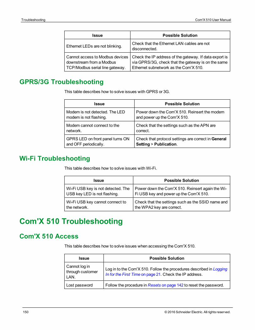
Troubleshooting Com'X 510 User Manual
150 © 2016 Schneider Electric. All rights reserved.
Issue Possible Solution
Ethernet LEDs are not blinking. Check that the Ethernet LAN cables are notdisconnected.
Cannot access toModbus devicesdownstream from aModbusTCP/Modbus serial line gateway.
Check the IP address of the gateway. If data export isvia GPRS/3G, check that the gateway is on the sameEthernet subnetwork as the Com'X 510.
GPRS/3G TroubleshootingThis table describes how to solve issues with GPRS or 3G.
Issue Possible Solution
Modem is not detected. The LEDmodem is not flashing.
Power down the Com'X 510. Reinsert themodemand power up the Com'X 510.
Modem cannot connect to thenetwork.
Check that the settings such as the APN arecorrect.
GPRS LED on front panel turns ONandOFF periodically.
Check that protocol settings are correct inGeneralSetting > Publication.
Wi-Fi TroubleshootingThis table describes how to solve issues withWi-Fi.
Issue Possible Solution
Wi-Fi USB key is not detected. TheUSB key LED is not flashing.
Power down the Com'X 510. Reinsert again theWi-Fi USB key and power up the Com'X 510.
Wi-Fi USB key cannot connect tothe network.
Check that the settings such as the SSID name andtheWPA2 key are correct.
Com'X 510 Troubleshooting
Com'X 510 AccessThis table describes how to solve issues when accessing the Com'X 510.
Issue Possible Solution
Cannot log inthrough customerLAN.
Log in to the Com'X 510. Follow the procedures described in LoggingIn for the First Time on page 21. Check the IP address.
Lost password Follow the procedure inResets on page 142 to reset the password.
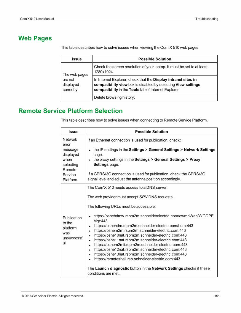
Web PagesThis table describes how to solve issues when viewing the Com'X 510 web pages.
Issue Possible Solution
The web pagesare notdisplayedcorrectly.
Check the screen resolution of your laptop. It must be set to at least1280x1024.
In Internet Explorer, check that theDisplay intranet sites incompatibility view box is disabled by selectingView settingscompatibility in the Tools tab of Internet Explorer.
Delete browsing history.
Remote Service Platform SelectionThis table describes how to solve issues when connecting to Remote Service Platform.
Issue Possible Solution
NetworkerrormessagedisplayedwhenselectingRemoteServicePlatform.
If an Ethernet connection is used for publication, check:
l the IP settings in theSettings > General Settings > Network Settingspage.
l the proxy settings in theSettings > General Settings > ProxySettings page.
If a GPRS/3G connection is used for publication, check the GPRS/3Gsignal level and adjust the antenna position accordingly.
Publicationto theplatformwasunsuccessful.
The Com'X 510 needs access to a DNS server.
The web provider must accept SRV DNS requests.
The following URLs must be accessible:
l https://psnehdmw.rspm2m.schneiderelectric.com/cwmpWeb/WGCPEMgt:443
l https://psnehdm.rspm2m.schneider-electric.com/hdm:443l https://psnem2m.rspm2m.schneider-electric.com:443l https://psne10nat.rspm2m.schneider-electric.com:443l https://psne11nat.rspm2m.schneider-electric.com:443l https://psnem2mii.rspm2m.schneider-electric.com:443l https://psne12nat.rspm2m.schneider-electric.com:443l https://psne13nat.rspm2m.schneider-electric.com:443l https://remoteshell.rsp.schneider-electric.com:443
The Launch diagnostic button in theNetwork Settings checks if theseconditions aremet.
Com'X 510 User Manual Troubleshooting
© 2016 Schneider Electric. All rights reserved. 151
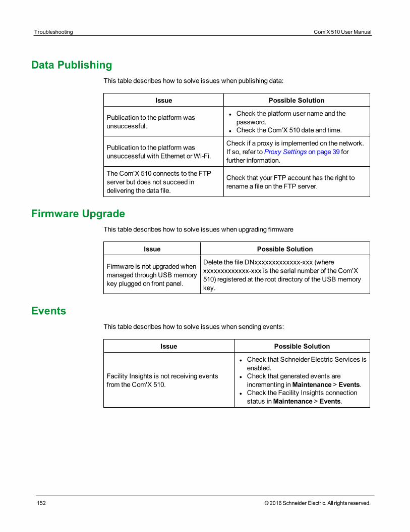
Troubleshooting Com'X 510 User Manual
152 © 2016 Schneider Electric. All rights reserved.
Data PublishingThis table describes how to solve issues when publishing data:
Issue Possible Solution
Publication to the platform wasunsuccessful.
l Check the platform user name and thepassword.
l Check the Com'X 510 date and time.
Publication to the platform wasunsuccessful with Ethernet orWi-Fi.
Check if a proxy is implemented on the network.If so, refer toProxy Settings on page 39 forfurther information.
The Com'X 510 connects to the FTPserver but does not succeed indelivering the data file.
Check that your FTP account has the right torename a file on the FTP server.
Firmware UpgradeThis table describes how to solve issues when upgrading firmware
Issue Possible Solution
Firmware is not upgraded whenmanaged through USB memorykey plugged on front panel.
Delete the file DNxxxxxxxxxxxxx-xxx (wherexxxxxxxxxxxxx-xxx is the serial number of the Com'X510) registered at the root directory of the USB memorykey.
EventsThis table describes how to solve issues when sending events:
Issue Possible Solution
Facility Insights is not receiving eventsfrom the Com'X 510.
l Check that Schneider Electric Services isenabled.
l Check that generated events areincrementing inMaintenance > Events.
l Check the Facility Insights connectionstatus inMaintenance > Events.

Appendices
Com'X 510 User Manual Appendices
© 2016 Schneider Electric. All rights reserved. 153
Appendices Com'X 510 User Manual
154 © 2016 Schneider Electric. All rights reserved.
Appendix A: Publish Data to Energy OperationUse the following chapter as a tutorial for setting up the Com'X 510 for use with EnergyOperation.
WARNINGINACCURATE DATA RESULTS
• Do not incorrectly configure the software, as this can lead to inaccurate reports and/ordata results.
Failure to follow these instructions can result in death, serious injury, equipmentdamage, or permanent loss of data.
Quick Start OverviewThe quick start guide describes the configuration for these simple installations:
l publication to Schneider Electric Energy Operation through Ethernet or GPRS/3G.
l metering devices connected directly to the Com'X 510.
Example: Data Used for PublicationThis table is an example of the fields used for the publication:
Field Data Used
Customer Whale company
Site location name Marseilles office
Country France
Destination platform Energy Operation
SubscriptionOption 1: Ethernet connection
Option 2: Schneider Electric GPRS option
Data LoggerThis table provides information on the Com'X 510:
Device Type IP Address Device Location
Com'X 510 Assigned by DHCP server Main switchboard
Devices Used for Data AcquisitionThis table provides information on digital input devices used for data acquisition:
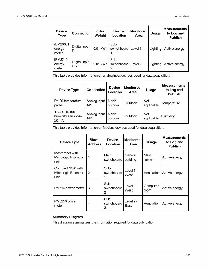
DeviceType Connection Pulse
WeightDeviceLocation
MonitoredArea Usage
Measurementsto Log andPublish
iEM2000Tenergymeter
Digital inputDI1 0.01 kWh
Sub-switchboard1
Level 1 Lighting Active energy
iEM3210energymeter
Digital inputDI2 0.01 kWh
Sub-switchboard2
Level 2 Lighting Active energy
This table provides information on analog input devices used for data acquisition:
Device Type Connection DeviceLocation
MonitoredArea Usage
Measurementsto Log andPublish
Pt100 temperatureprobe
Analog inputAI1
Northoutdoor Outdoor Not
applicable Temperature
TAC SHR100humidity sensor 4–20 mA
Analog inputAI2
Northoutdoor Outdoor Not
applicable Humidity
This table provides information onModbus devices used for data acquisition:
Device Type SlaveAddress
DeviceLocation
MonitoredArea Usage
Measurementsto Log andPublish
Masterpact withMicrologic P controlunit
1 Mainswitchboard
Generalbuilding
Mainmeter Active energy
Compact NSX withMicrologic E controlunit
2Sub-switchboard1
Level 1 -West Ventilation Active energy
PM710 powermeter 3Sub-switchboard2
Level 2 -West
Computerroom Active energy
PM3250 powermeter 4
Sub-switchboard2
Level 2 -East Ventilation Active energy
Summary DiagramThis diagram summarizes the information required for data publication:
Com'X 510 User Manual Appendices
© 2016 Schneider Electric. All rights reserved. 155
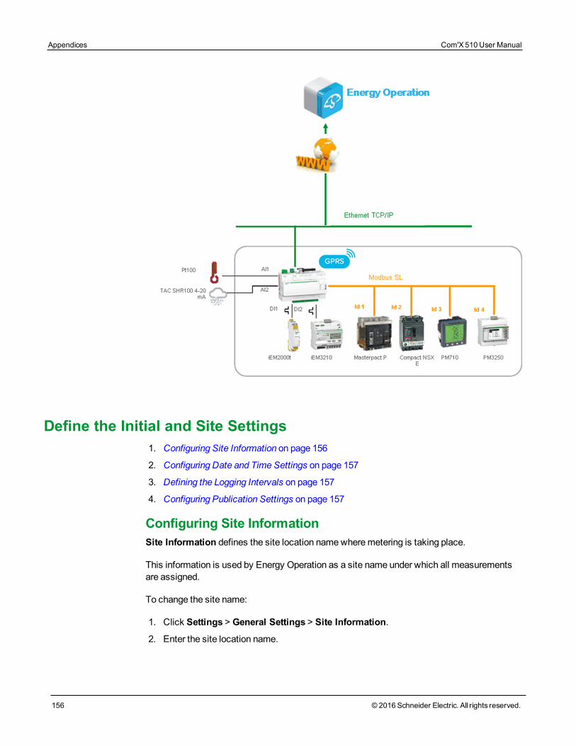
Appendices Com'X 510 User Manual
156 © 2016 Schneider Electric. All rights reserved.
Define the Initial and Site Settings1. Configuring Site Information on page 156
2. Configuring Date and Time Settings on page 157
3. Defining the Logging Intervals on page 157
4. Configuring Publication Settings on page 157
Configuring Site InformationSite Information defines the site location namewheremetering is taking place.
This information is used by Energy Operation as a site name under which all measurementsare assigned.
To change the site name:
1. Click Settings > General Settings > Site Information.
2. Enter the site location name.
NOTE: The site namemust not include any of these characters: ’/:*?<>| or space.
3. Click Save changes.
Configuring Date and Time SettingsTo set the date and time:
1. Click Settings > General Settings > Date/Time Settings.
2. Select the appropriate Timezone in the drop-down list. If the DST time zone is selected,the clock will automatically adjust for Daylight Saving Time.
3. Click Save changes.
4. Click the Today button to set the date and time automatically with the date and time ofyour computer.
NOTE: After selecting RSP publication inSettings > General Settings > Publication, donot change date and time settings until the association is complete.
Defining the Logging IntervalsFollow this procedure to set the logging intervals:
1. Click Settings > Site Settings > Data Logging.
2. Select your country.
NOTE: This will automatically set the logging intervals of data for different commoditiesin the country.
3. Click Save changes.
Configuring Publication SettingsFollow this procedure to set the Energy Operation data publication settings using FTP:
1. Click Settings > General Settings > Publication.
2. Select Energy Operation in theDestination platform drop-down list.
3. Select HTTPS in theProtocol drop-down list.
NOTE: The server and port are preconfigured.
4. Type the username and the password of the HTTPS server. This information is givenwith the Energy Operation subscription contract.Contact the Schneider Electric rep-resentative to provide you with this information.
5. Click Save changes.
NOTE: Refer toDefine the Transfer Protocol on page 42 to use another transfer protocolsuch as HTTP or FTP.
Com'X 510 User Manual Appendices
© 2016 Schneider Electric. All rights reserved. 157
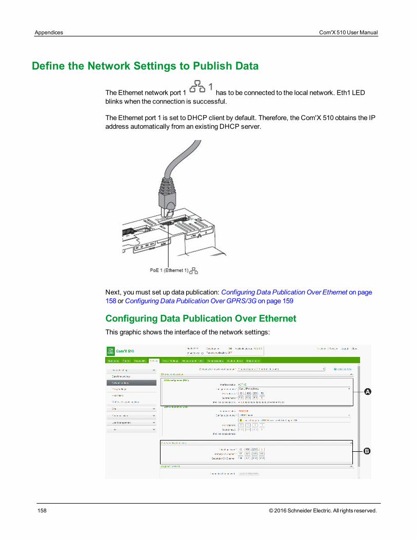
Appendices Com'X 510 User Manual
158 © 2016 Schneider Electric. All rights reserved.
Define the Network Settings to Publish Data
The Ethernet network port 1 has to be connected to the local network. Eth1 LEDblinks when the connection is successful.
The Ethernet port 1 is set to DHCP client by default. Therefore, the Com'X 510 obtains the IPaddress automatically from an existing DHCP server.
Next, youmust set up data publication: Configuring Data Publication Over Ethernet on page158 orConfiguring Data Publication Over GPRS/3G on page 159
Configuring Data Publication Over EthernetThis graphic shows the interface of the network settings:
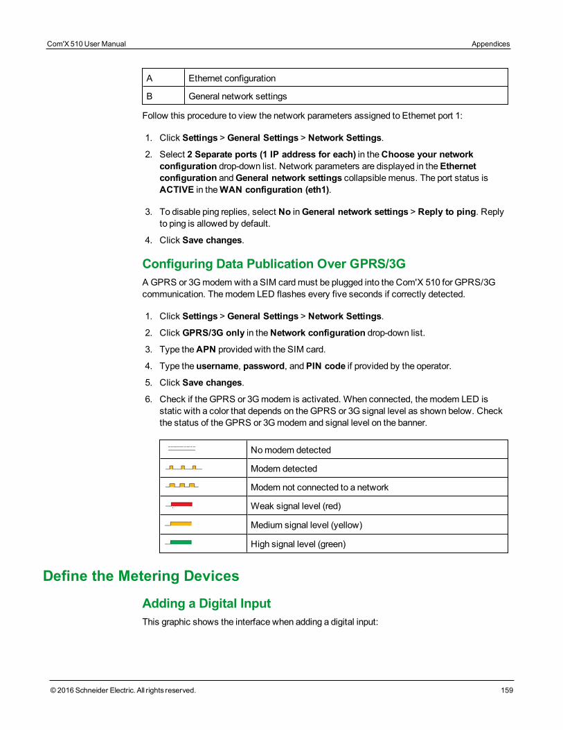
A Ethernet configuration
B General network settings
Follow this procedure to view the network parameters assigned to Ethernet port 1:
1. Click Settings > General Settings > Network Settings.
2. Select 2 Separate ports (1 IP address for each) in theChoose your networkconfiguration drop-down list. Network parameters are displayed in theEthernetconfiguration andGeneral network settings collapsible menus. The port status isACTIVE in theWAN configuration (eth1).
3. To disable ping replies, select No inGeneral network settings > Reply to ping. Replyto ping is allowed by default.
4. Click Save changes.
Configuring Data Publication Over GPRS/3GA GPRS or 3Gmodem with a SIM cardmust be plugged into the Com'X 510 for GPRS/3Gcommunication. Themodem LED flashes every five seconds if correctly detected.
1. Click Settings > General Settings > Network Settings.
2. Click GPRS/3G only in theNetwork configuration drop-down list.
3. Type theAPN provided with the SIM card.
4. Type the username, password, andPIN code if provided by the operator.
5. Click Save changes.
6. Check if the GPRS or 3Gmodem is activated. When connected, themodem LED isstatic with a color that depends on theGPRS or 3G signal level as shown below. Checkthe status of the GPRS or 3Gmodem and signal level on the banner.
Nomodem detected
Modem detected
Modem not connected to a network
Weak signal level (red)
Medium signal level (yellow)
High signal level (green)
Define the Metering Devices
Adding a Digital InputThis graphic shows the interface when adding a digital input:
Com'X 510 User Manual Appendices
© 2016 Schneider Electric. All rights reserved. 159
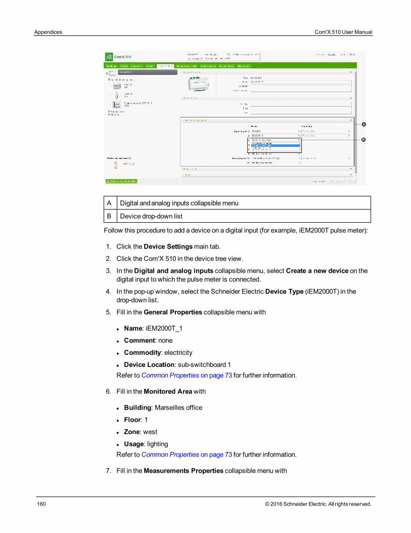
Appendices Com'X 510 User Manual
160 © 2016 Schneider Electric. All rights reserved.
A Digital andanalog inputs collapsible menu
B Device drop-down list
Follow this procedure to add a device on a digital input (for example, iEM2000T pulsemeter):
1. Click theDevice Settingsmain tab.
2. Click the Com'X 510 in the device tree view.
3. In theDigital and analog inputs collapsible menu, select Create a new device on thedigital input to which the pulsemeter is connected.
4. In the pop-up window, select the Schneider Electric Device Type (iEM2000T) in thedrop-down list.
5. Fill in theGeneral Properties collapsible menu with
l Name: iEM2000T_1
l Comment: none
l Commodity: electricity
l Device Location: sub-switchboard 1Refer toCommon Properties on page 73 for further information.
6. Fill in theMonitored Areawith
l Building: Marseilles office
l Floor: 1
l Zone: west
l Usage: lightingRefer toCommon Properties on page 73 for further information.
7. Fill in theMeasurements Properties collapsible menu with
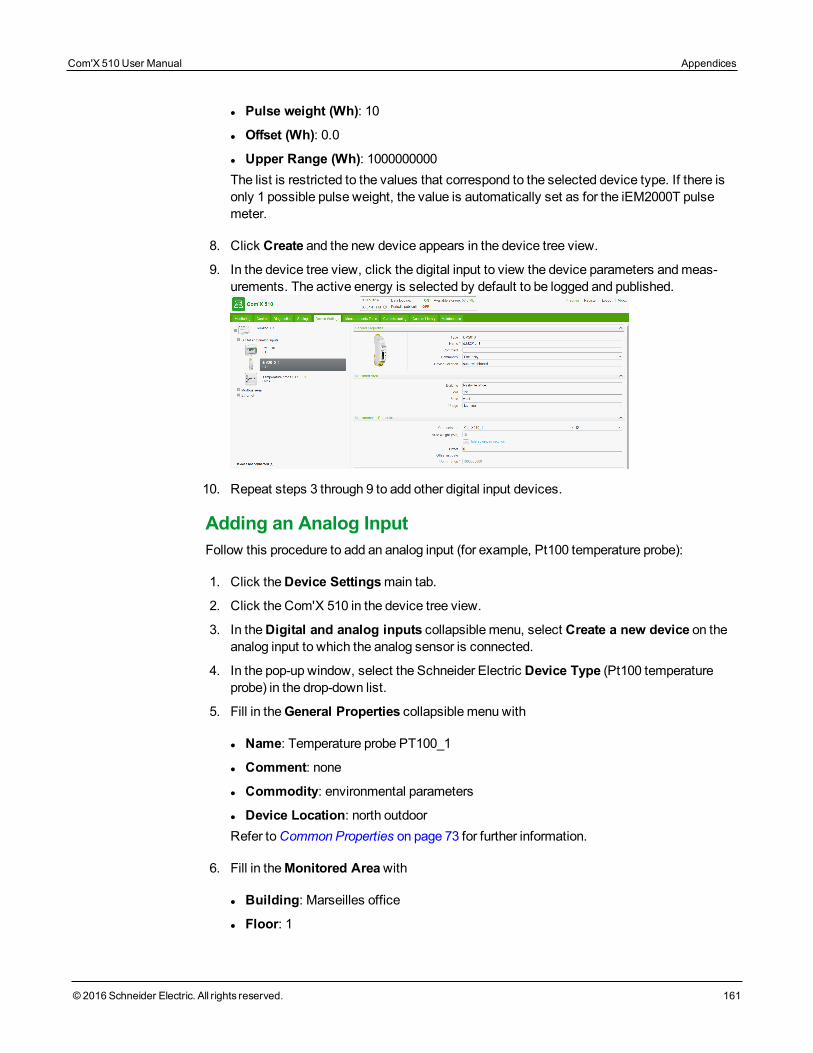
l Pulse weight (Wh): 10
l Offset (Wh): 0.0
l Upper Range (Wh): 1000000000The list is restricted to the values that correspond to the selected device type. If there isonly 1 possible pulse weight, the value is automatically set as for the iEM2000T pulsemeter.
8. Click Create and the new device appears in the device tree view.
9. In the device tree view, click the digital input to view the device parameters andmeas-urements. The active energy is selected by default to be logged and published.
10. Repeat steps 3 through 9 to add other digital input devices.
Adding an Analog InputFollow this procedure to add an analog input (for example, Pt100 temperature probe):
1. Click theDevice Settingsmain tab.
2. Click the Com'X 510 in the device tree view.
3. In theDigital and analog inputs collapsible menu, select Create a new device on theanalog input to which the analog sensor is connected.
4. In the pop-up window, select the Schneider Electric Device Type (Pt100 temperatureprobe) in the drop-down list.
5. Fill in theGeneral Properties collapsible menu with
l Name: Temperature probe PT100_1
l Comment: none
l Commodity: environmental parameters
l Device Location: north outdoorRefer toCommon Properties on page 73 for further information.
6. Fill in theMonitored Areawith
l Building: Marseilles office
l Floor: 1
Com'X 510 User Manual Appendices
© 2016 Schneider Electric. All rights reserved. 161
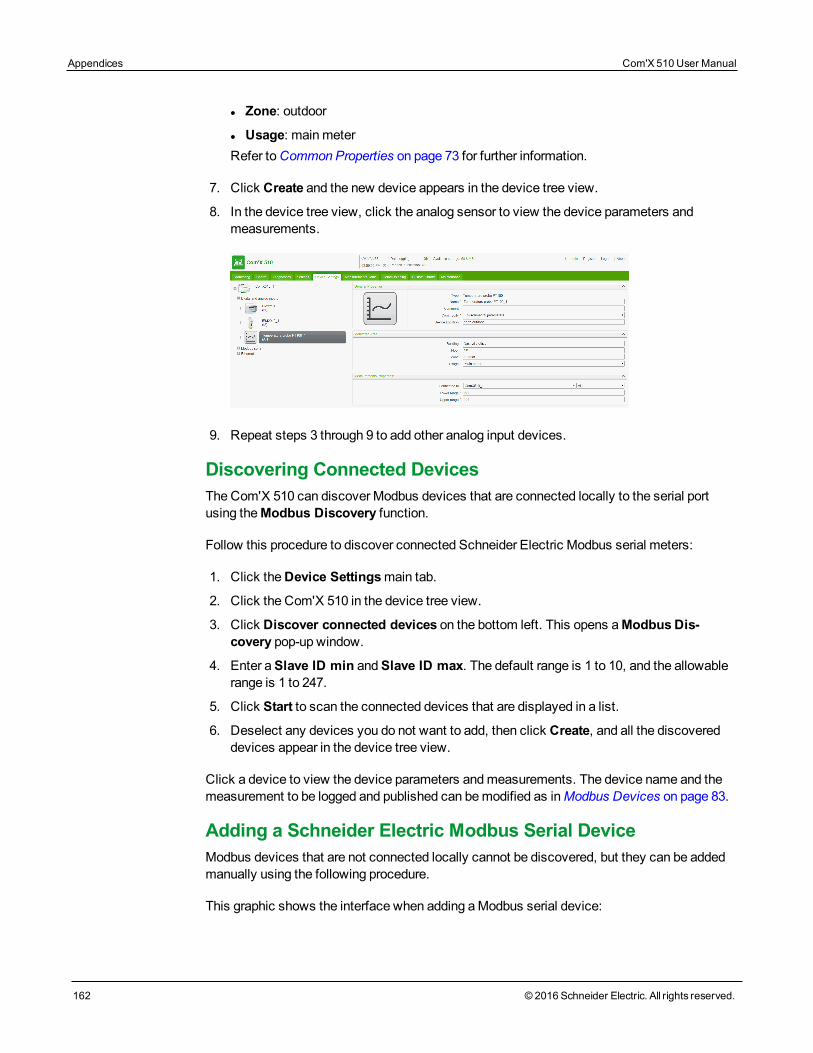
Appendices Com'X 510 User Manual
162 © 2016 Schneider Electric. All rights reserved.
l Zone: outdoor
l Usage: mainmeterRefer toCommon Properties on page 73 for further information.
7. Click Create and the new device appears in the device tree view.
8. In the device tree view, click the analog sensor to view the device parameters andmeasurements.
9. Repeat steps 3 through 9 to add other analog input devices.
Discovering Connected DevicesThe Com'X 510 can discover Modbus devices that are connected locally to the serial portusing theModbus Discovery function.
Follow this procedure to discover connected Schneider Electric Modbus serial meters:
1. Click theDevice Settingsmain tab.
2. Click the Com'X 510 in the device tree view.
3. Click Discover connected devices on the bottom left. This opens aModbusDis-covery pop-up window.
4. Enter aSlave ID min andSlave ID max. The default range is 1 to 10, and the allowablerange is 1 to 247.
5. Click Start to scan the connected devices that are displayed in a list.
6. Deselect any devices you do not want to add, then click Create, and all the discovereddevices appear in the device tree view.
Click a device to view the device parameters andmeasurements. The device name and themeasurement to be logged and published can bemodified as inModbus Devices on page 83.
Adding a Schneider Electric Modbus Serial DeviceModbus devices that are not connected locally cannot be discovered, but they can be addedmanually using the following procedure.
This graphic shows the interface when adding aModbus serial device:
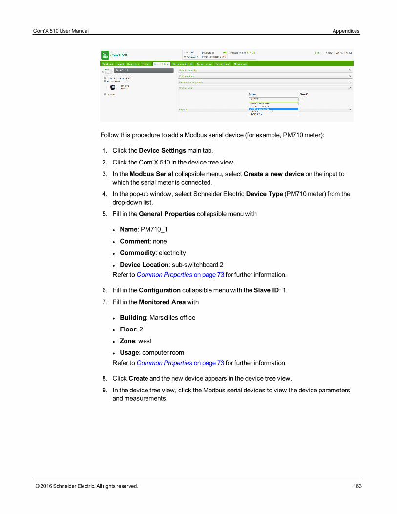
Follow this procedure to add aModbus serial device (for example, PM710meter):
1. Click theDevice Settingsmain tab.
2. Click the Com'X 510 in the device tree view.
3. In theModbus Serial collapsible menu, select Create a new device on the input towhich the serial meter is connected.
4. In the pop-up window, select Schneider Electric Device Type (PM710meter) from thedrop-down list.
5. Fill in theGeneral Properties collapsible menu with
l Name: PM710_1
l Comment: none
l Commodity: electricity
l Device Location: sub-switchboard 2Refer toCommon Properties on page 73 for further information.
6. Fill in theConfiguration collapsible menu with theSlave ID: 1.
7. Fill in theMonitored Areawith
l Building: Marseilles office
l Floor: 2
l Zone: west
l Usage: computer roomRefer toCommon Properties on page 73 for further information.
8. Click Create and the new device appears in the device tree view.
9. In the device tree view, click theModbus serial devices to view the device parametersandmeasurements.
Com'X 510 User Manual Appendices
© 2016 Schneider Electric. All rights reserved. 163
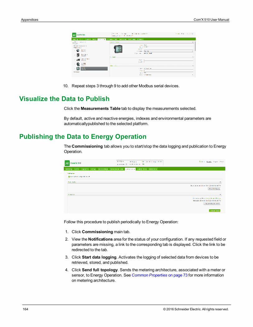
Appendices Com'X 510 User Manual
164 © 2016 Schneider Electric. All rights reserved.
10. Repeat steps 3 through 9 to add other Modbus serial devices.
Visualize the Data to PublishClick theMeasurements Table tab to display themeasurements selected.
By default, active and reactive energies, indexes and environmental parameters areautomaticallypublished to the selected platform.
Publishing the Data to Energy OperationTheCommissioning tab allows you to start/stop the data logging and publication to EnergyOperation.
Follow this procedure to publish periodically to Energy Operation:
1. Click Commissioningmain tab.
2. View theNotifications area for the status of your configuration. If any requested field orparameters aremissing, a link to the corresponding tab is displayed. Click the link to beredirected to the tab.
3. Click Start data logging. Activates the logging of selected data from devices to beretrieved, stored, and published.
4. Click Send full topology. Sends themetering architecture, associated with ameter orsensor, to Energy Operation. SeeCommon Properties on page 73 for more informationonmetering architecture.

NOTE: If the topology is not sent to Energy Operation, a flat list of meters is createdunder a site named Site Newmeters.
5. Click Test publication to send data to Energy Operation.
6. Click Start publication to send data to Energy Operation according to the frequency setinPublication settings (SeeConfiguring Publication Settings on page 157). The nextpublication time is displayed.
Com'X 510 User Manual Appendices
© 2016 Schneider Electric. All rights reserved. 165
Appendices Com'X 510 User Manual
166 © 2016 Schneider Electric. All rights reserved.
Appendix B: Replacing the SD Card
DANGERHAZARD OF ELECTRIC SHOCK, EXPLOSION, OR ARC FLASH
• This equipment must only be installed and serviced by qualified personnel.• Apply appropriate personal protective equipment (PPE) and follow safe electrical workpractices. See NFPA 70E in the USA, CSA Z462 or applicable local standards.
Failure to follow these instructions will result in death or serious injury.
NOTICELOST DATA OR DATA CORRUPTION
Power down the Com'X 510 before inserting or removing the SD card. Otherwise, theCom'X 510 will lose the ability to log and publish data.
Failure to follow these instructions will result in lost or corrupt data.
All data logged by the Com'X 510 is stored on the SD card. Data is lost when you replace theSD card, which affects your ability to view historical data on board. We recommend backingup the data if possible before replacing the SD card. (seePublication on page 41)
Contact Schneider Electric technical support to order the supported replacement SD card.
To replace the SD card:
1. Power down the Com'X 510.
2. Open the front cover and push down to remove the SD card.
3. Insert the new SD card.
4. Close the front cover and power up the Com'X 510.
5. Log in to the Com'X 510 and verify that the available storage in the banner reflects theSD card capacity.

Appendix C: List of Supported DevicesSupported device types are described in the firmware release package. Go towww.myenergyserver.com or www.schneider-electric.com for themost current list ofsupported device types.
Com'X 510 User Manual Appendices
© 2016 Schneider Electric. All rights reserved. 167
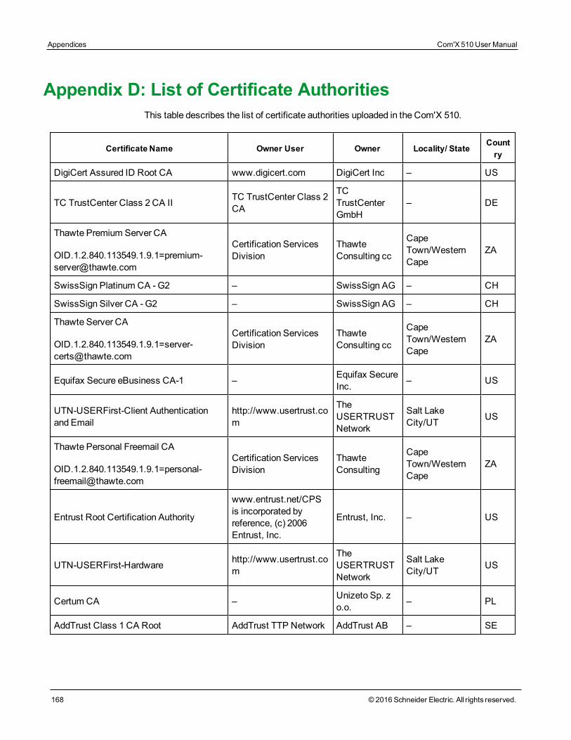
Appendices Com'X 510 User Manual
168 © 2016 Schneider Electric. All rights reserved.
Appendix D: List of Certificate AuthoritiesThis table describes the list of certificate authorities uploaded in the Com'X 510.
Certificate Name Owner User Owner Locality/ StateCountry
DigiCert Assured ID Root CA www.digicert.com DigiCert Inc – US
TC TrustCenter Class 2 CA II TC TrustCenter Class 2CA
TCTrustCenterGmbH
– DE
Thawte Premium Server CA
Certification ServicesDivision
ThawteConsulting cc
CapeTown/WesternCape
ZA
SwissSign Platinum CA -G2 – SwissSign AG – CH
SwissSign Silver CA - G2 – SwissSign AG – CH
Thawte Server CA
Certification ServicesDivision
ThawteConsulting cc
CapeTown/WesternCape
ZA
Equifax Secure eBusiness CA-1 – Equifax SecureInc. – US
UTN-USERFirst-Client Authenticationand Email
http://www.usertrust.com
TheUSERTRUSTNetwork
Salt LakeCity/UT US
Thawte Personal Freemail CA
Certification ServicesDivision
ThawteConsulting
CapeTown/WesternCape
ZA
Entrust Root Certification Authority
www.entrust.net/CPSis incorporated byreference, (c) 2006Entrust, Inc.
Entrust, Inc. – US
UTN-USERFirst-Hardware http://www.usertrust.com
TheUSERTRUSTNetwork
Salt LakeCity/UT US
Certum CA – Unizeto Sp. zo.o. – PL
AddTrust Class 1 CA Root AddTrust TTP Network AddTrust AB – SE
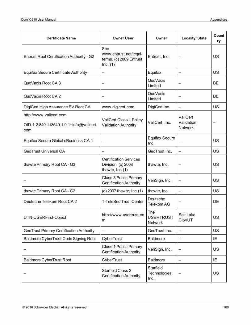
Certificate Name Owner User Owner Locality/ StateCountry
Entrust Root Certification Authority - G2
Seewww.entrust.net/legal-terms, (c) 2009 Entrust,Inc.”(1)
Entrust, Inc. – US
Equifax Secure Certificate Authority – Equifax – US
QuoVadis Root CA 3 – QuoVadisLimited – BE
QuoVadis Root CA 2 – QuoVadisLimited – BE
DigiCert High Assurance EV Root CA www.digicert.com DigiCert Inc – US
http://www.valicert.com
ValiCert Class 1 PolicyValidation Authority ValiCert, Inc.
ValiCertValidationNetwork
–
Equifax Secure Global eBusiness CA-1 – Equifax SecureInc. – US
GeoTrust Universal CA – GeoTrust Inc. – US
thawte Primary Root CA - G3Certification ServicesDivision, (c) 2008thawte, Inc.(1)
thawte, Inc. – US
– Class 3 Public PrimaryCertification Authority VeriSign, Inc. – US
thawte Primary Root CA - G2 (c) 2007 thawte, Inc.(1) thawte, Inc. – US
Deutsche Telekom Root CA 2 T-TeleSec Trust Center DeutscheTelekom AG – DE
UTN-USERFirst-Object http://www.usertrust.com
TheUSERTRUSTNetwork
Salt LakeCity/UT US
GeoTrust Primary Certification Authority – GeoTrust Inc. – US
Baltimore CyberTrust Code Signing Root CyberTrust Baltimore – IE
– Class 1 Public PrimaryCertification Authority VeriSign, Inc. – US
Baltimore CyberTrust Root CyberTrust Baltimore – IE
– Starfield Class 2Certification Authority
StarfieldTechnologies,Inc.
– US
Com'X 510 User Manual Appendices
© 2016 Schneider Electric. All rights reserved. 169
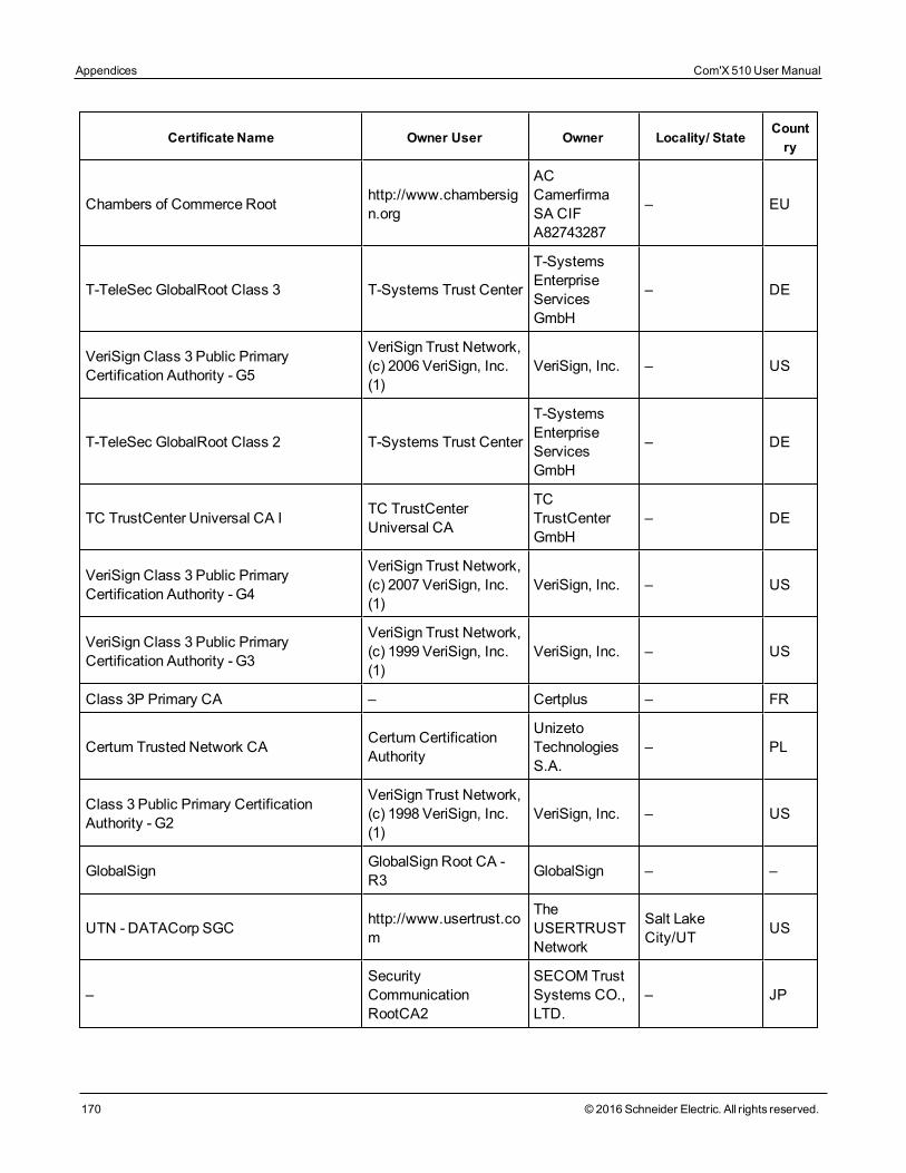
Appendices Com'X 510 User Manual
170 © 2016 Schneider Electric. All rights reserved.
Certificate Name Owner User Owner Locality/ StateCountry
Chambers of Commerce Root http://www.chambersign.org
ACCamerfirmaSA CIFA82743287
– EU
T-TeleSec GlobalRoot Class 3 T-Systems Trust Center
T-SystemsEnterpriseServicesGmbH
– DE
VeriSign Class 3 Public PrimaryCertification Authority - G5
VeriSign Trust Network,(c) 2006 VeriSign, Inc.(1)
VeriSign, Inc. – US
T-TeleSec GlobalRoot Class 2 T-Systems Trust Center
T-SystemsEnterpriseServicesGmbH
– DE
TC TrustCenter Universal CA I TC TrustCenterUniversal CA
TCTrustCenterGmbH
– DE
VeriSign Class 3 Public PrimaryCertification Authority - G4
VeriSign Trust Network,(c) 2007 VeriSign, Inc.(1)
VeriSign, Inc. – US
VeriSign Class 3 Public PrimaryCertification Authority - G3
VeriSign Trust Network,(c) 1999 VeriSign, Inc.(1)
VeriSign, Inc. – US
Class 3P Primary CA – Certplus – FR
Certum Trusted Network CA Certum CertificationAuthority
UnizetoTechnologiesS.A.
– PL
Class 3 Public Primary CertificationAuthority - G2
VeriSign Trust Network,(c) 1998 VeriSign, Inc.(1)
VeriSign, Inc. – US
GlobalSign GlobalSign Root CA -R3 GlobalSign – –
UTN - DATACorp SGC http://www.usertrust.com
TheUSERTRUSTNetwork
Salt LakeCity/UT US
–SecurityCommunicationRootCA2
SECOM TrustSystems CO.,LTD.
– JP
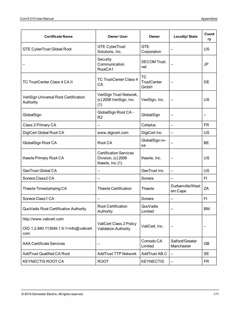
Certificate Name Owner User Owner Locality/ StateCountry
GTE CyberTrust Global Root GTE CyberTrustSolutions, Inc.
GTECorporation – US
–SecurityCommunicationRootCA1
SECOM Trust.net – JP
TC TrustCenter Class 4 CA II TC TrustCenter Class 4CA
TCTrustCenterGmbH
– DE
VeriSign Universal Root CertificationAuthority
VeriSign Trust Network,(c) 2008 VeriSign, Inc.(1)
VeriSign, Inc. – US
GlobalSign GlobalSign Root CA -R2 GlobalSign – –
Class 2 Primary CA – Certplus – FR
DigiCert Global Root CA www.digicert.com DigiCert Inc – US
GlobalSign Root CA Root CA GlobalSign nv-sa – BE
thawte Primary Root CACertification ServicesDivision, (c) 2006thawte, Inc.(1)
thawte, Inc. – US
GeoTrust Global CA – GeoTrust Inc. – US
Sonera Class2 CA – Sonera – FI
Thawte Timestamping CA Thawte Certification Thawte Durbanville/Western Cape ZA
Sonera Class1 CA – Sonera – FI
QuoVadis Root Certification Authority Root CertificationAuthority
QuoVadisLimited – BM
http://www.valicert.com
ValiCert Class 2 PolicyValidation Authority ValiCert, Inc. – –
AAA Certificate Services – Comodo CALimited
Salford/GreaterManchester GB
AddTrust Qualified CA Root AddTrust TTP Network AddTrust AB,C – SE
KEYNECTIS ROOT CA ROOT KEYNECTIS – FR
Com'X 510 User Manual Appendices
© 2016 Schneider Electric. All rights reserved. 171
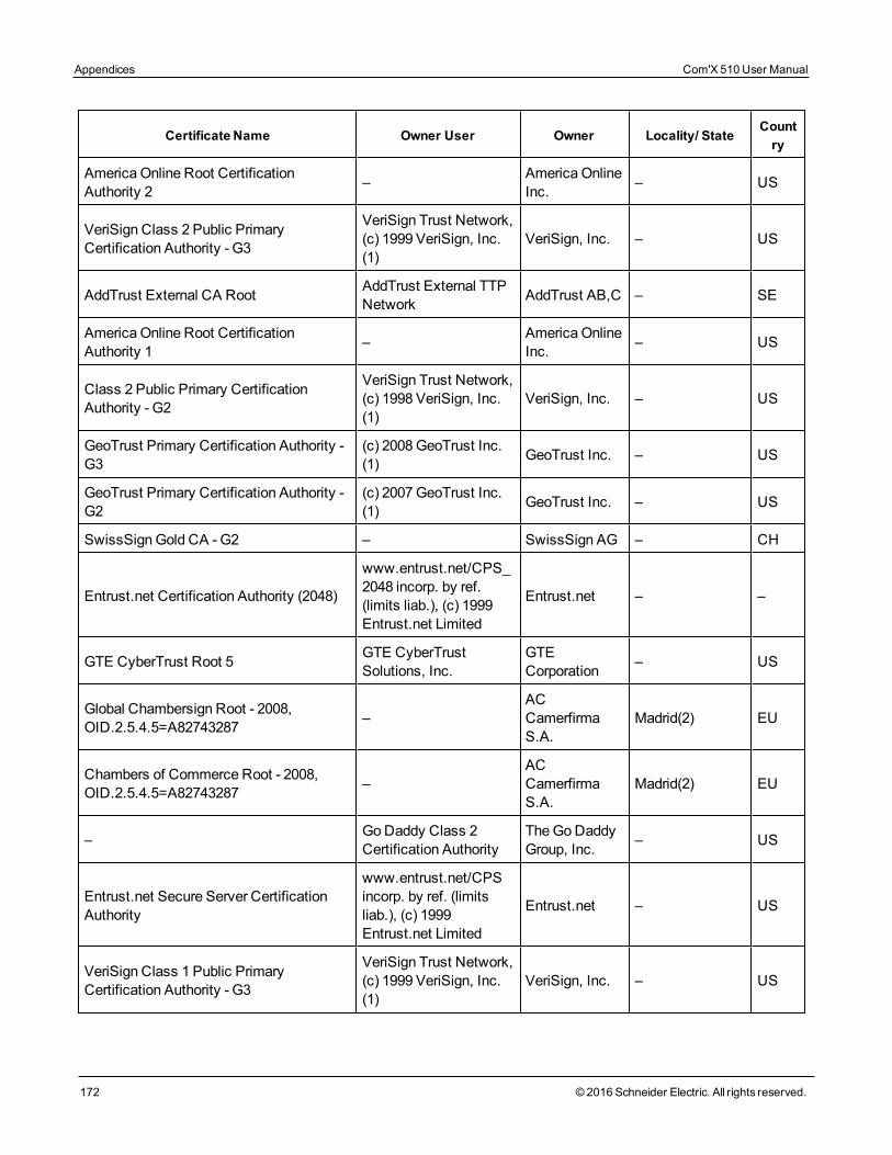
Appendices Com'X 510 User Manual
172 © 2016 Schneider Electric. All rights reserved.
Certificate Name Owner User Owner Locality/ StateCountry
America Online Root CertificationAuthority 2 – America Online
Inc. – US
VeriSign Class 2 Public PrimaryCertification Authority - G3
VeriSign Trust Network,(c) 1999 VeriSign, Inc.(1)
VeriSign, Inc. – US
AddTrust External CA Root AddTrust External TTPNetwork AddTrust AB,C – SE
America Online Root CertificationAuthority 1 – America Online
Inc. – US
Class 2 Public Primary CertificationAuthority - G2
VeriSign Trust Network,(c) 1998 VeriSign, Inc.(1)
VeriSign, Inc. – US
GeoTrust Primary Certification Authority -G3
(c) 2008GeoTrust Inc.(1) GeoTrust Inc. – US
GeoTrust Primary Certification Authority -G2
(c) 2007GeoTrust Inc.(1) GeoTrust Inc. – US
SwissSign Gold CA - G2 – SwissSign AG – CH
Entrust.net Certification Authority (2048)
www.entrust.net/CPS_2048 incorp. by ref.(limits liab.), (c) 1999Entrust.net Limited
Entrust.net – –
GTE CyberTrust Root 5 GTE CyberTrustSolutions, Inc.
GTECorporation – US
Global Chambersign Root - 2008,OID.2.5.4.5=A82743287 –
ACCamerfirmaS.A.
Madrid(2) EU
Chambers of Commerce Root - 2008,OID.2.5.4.5=A82743287 –
ACCamerfirmaS.A.
Madrid(2) EU
– GoDaddy Class 2Certification Authority
TheGoDaddyGroup, Inc. – US
Entrust.net Secure Server CertificationAuthority
www.entrust.net/CPSincorp. by ref. (limitsliab.), (c) 1999Entrust.net Limited
Entrust.net – US
VeriSign Class 1 Public PrimaryCertification Authority - G3
VeriSign Trust Network,(c) 1999 VeriSign, Inc.(1)
VeriSign, Inc. – US
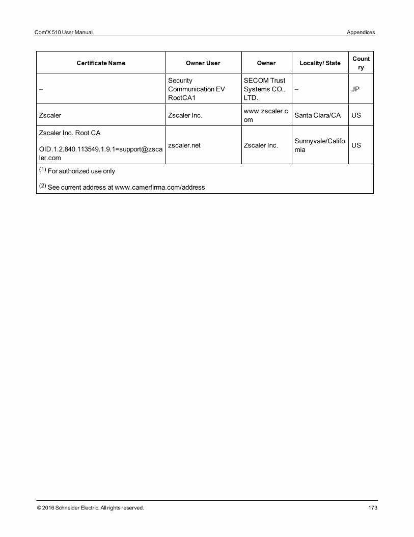
Certificate Name Owner User Owner Locality/ StateCountry
–SecurityCommunication EVRootCA1
SECOM TrustSystems CO.,LTD.
– JP
Zscaler Zscaler Inc. www.zscaler.com Santa Clara/CA US
Zscaler Inc. Root CA
zscaler.net Zscaler Inc. Sunnyvale/California US
(1) For authorized use only
(2) See current address at www.camerfirma.com/address
Com'X 510 User Manual Appendices
© 2016 Schneider Electric. All rights reserved. 173
Appendices Com'X 510 User Manual
174 © 2016 Schneider Electric. All rights reserved.
Appendix E: IPv4 Address SettingsThe Com'X 510 supports three different operatingmodes for assigning the IP address:
l Static IPv4 (seeStatic IP Settings on page 174)
l DHCP client (seeDHCP Client on page 174)
l DHCP server (seeDHCP Server Over Ethernet Port on page 175 orDHCP Server OverWi-Fi on page 175)
Static IP SettingsIn the Com'X 510, you can define the IPv4 addresses of the Ethernet interface, subnetworkmask, and default gateway. These settings must be consistent with the network policy of thesite. The IT administrator of the site should be contacted to provide this information.
DHCP ClientYou can configure the Com'X 510 so that the IPv4 address is automatically set by the DHCPserver facility. The IT administrator of the site can be asked to configure the DHCP server tosystematically assign the same IPv4 address to the Com'X 510.
Follow this procedure to get a fixed IPv4 address with DHCP server:
1. Provide the local IT manager with theMAC address of the Com'X 510 Ethernet port 1.The address can be found on the label on the front face of the device or in theAboutpage.
2. Ask the IT manager to provide a fixed IPv4 address so that the same IP address isalways assigned to the Com'X 510. The IP address is to be given by the IT manager.
3. Write down the IPv4 address:
l on the label sheet provided with the Com'X 510. This sheet can be stuck on the insideof the cover.
l in the space provided in theEthernet configuration collapsible menu inSettings> General Settings > Network Settings (SeeSelecting a Network Configuration onpage 31.)
4. Check that the IT manager has added the Com'X 510 to the DHCP server.NOTE: It is also possible to log in by entering the IP address provided by the IT manager inthe address bar of the browser.
This graphic shows theMAC address on the label of the Com'X 510:
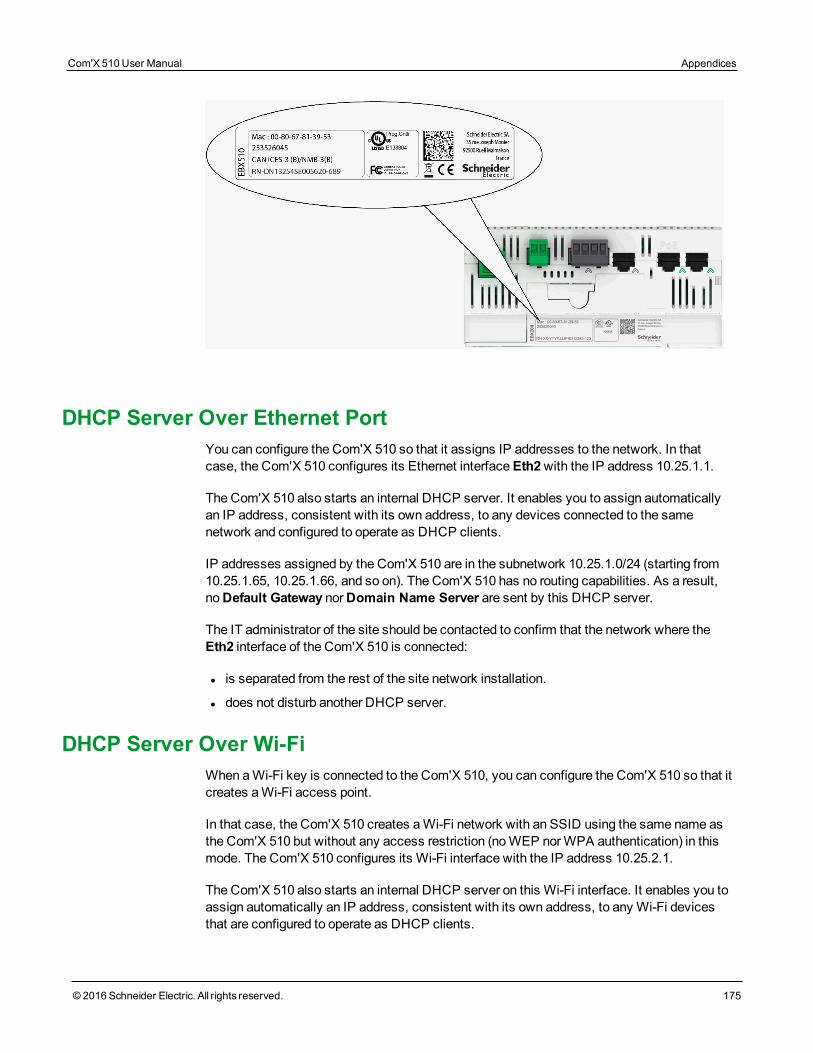
DHCP Server Over Ethernet PortYou can configure the Com'X 510 so that it assigns IP addresses to the network. In thatcase, the Com'X 510 configures its Ethernet interfaceEth2with the IP address 10.25.1.1.
The Com'X 510 also starts an internal DHCP server. It enables you to assign automaticallyan IP address, consistent with its own address, to any devices connected to the samenetwork and configured to operate as DHCP clients.
IP addresses assigned by the Com'X 510 are in the subnetwork 10.25.1.0/24 (starting from10.25.1.65, 10.25.1.66, and so on). The Com'X 510 has no routing capabilities. As a result,noDefault Gateway norDomain Name Server are sent by this DHCP server.
The IT administrator of the site should be contacted to confirm that the network where theEth2 interface of the Com'X 510 is connected:
l is separated from the rest of the site network installation.
l does not disturb another DHCP server.
DHCP Server Over Wi-FiWhen aWi-Fi key is connected to the Com'X 510, you can configure the Com'X 510 so that itcreates aWi-Fi access point.
In that case, the Com'X 510 creates aWi-Fi network with an SSID using the same name asthe Com'X 510 but without any access restriction (noWEP norWPA authentication) in thismode. The Com'X 510 configures its Wi-Fi interface with the IP address 10.25.2.1.
The Com'X 510 also starts an internal DHCP server on this Wi-Fi interface. It enables you toassign automatically an IP address, consistent with its own address, to any Wi-Fi devicesthat are configured to operate as DHCP clients.
Com'X 510 User Manual Appendices
© 2016 Schneider Electric. All rights reserved. 175
Appendices Com'X 510 User Manual
176 © 2016 Schneider Electric. All rights reserved.
IP addresses assigned by the Com'X 510 are in the subnetwork 10.25.2.0/24 (starting from10.25.2.65, 10.25.2.66, and so on). The Com'X 510 has no routing capabilities. As a result,noDefault Gateway norDomain Name Server are sent by this DHCP server.
Remote Access with Windows Operating SystemsYou can remotely access the Com'X 510 by using an IP address underWindows XP. The ITadministrator should be requested to provide a fixed IP address to assign systematically thesame IP address to the Com'X 510.
WithWindows 8, Windows 7, or Vista, the Com'X 510 is accessible underWindows Explorer(seeWithWindows 7/Vista on page 18) when connecting the PC to the same LAN. It is notnecessary to know the IP address.
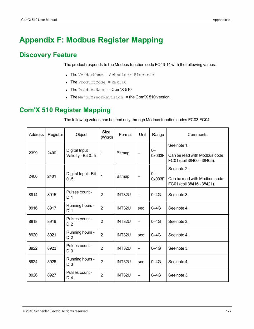
Appendix F: Modbus Register Mapping
Discovery FeatureThe product responds to theModbus function code FC43-14 with the following values:
l The VendorName = Schneider Electric
l The ProductCode = EBX510
l The ProductName = Com'X 510
l The MajorMinorRevision = the Com'X 510 version.
Com'X 510 Register MappingThe following values can be read only throughModbus function codes FC03-FC04.
Address Register Object Size(Word) Format Unit Range Comments
2399 2400 Digital InputValidity - Bit 0..5 1 Bitmap – 0–
0x003F
See note 1.
Can be read with Modbus codeFC01 (coil 38400 - 38405).
2400 2401 Digital Input - Bit0..5 1 Bitmap – 0–
0x003F
See note 2.
Can be read with Modbus codeFC01 (coil 38416 - 38421).
8914 8915 Pulses count -DI1 2 INT32U – 0–4G See note 3.
8916 8917 Running hours -DI1 2 INT32U sec 0–4G See note 4.
8918 8919 Pulses count -DI2 2 INT32U – 0–4G See note 3.
8920 8921 Running hours -DI2 2 INT32U sec 0–4G See note 4.
8922 8923 Pulses count -DI3 2 INT32U – 0–4G See note 3.
8924 8925 Running hours -DI3 2 INT32U sec 0–4G See note 4.
8926 8927 Pulses count -DI4 2 INT32U – 0–4G See note 3.
Com'X 510 User Manual Appendices
© 2016 Schneider Electric. All rights reserved. 177
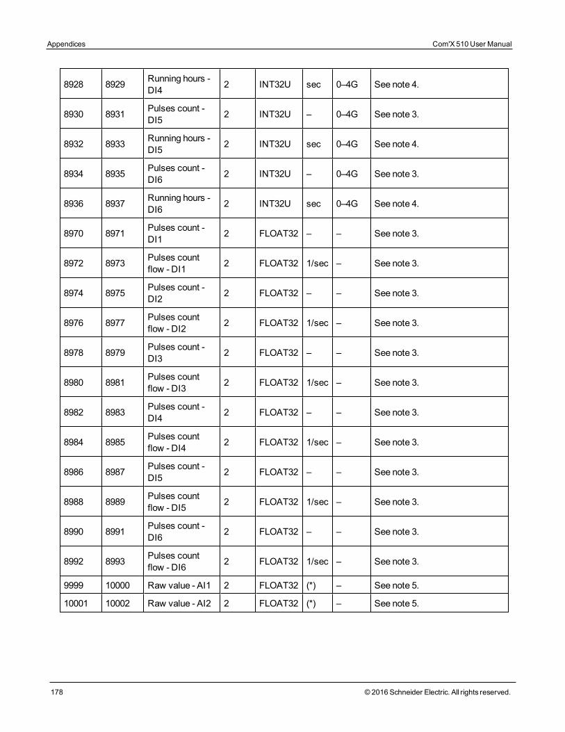
Appendices Com'X 510 User Manual
178 © 2016 Schneider Electric. All rights reserved.
8928 8929 Running hours -DI4 2 INT32U sec 0–4G See note 4.
8930 8931 Pulses count -DI5 2 INT32U – 0–4G See note 3.
8932 8933 Running hours -DI5 2 INT32U sec 0–4G See note 4.
8934 8935 Pulses count -DI6 2 INT32U – 0–4G See note 3.
8936 8937 Running hours -DI6 2 INT32U sec 0–4G See note 4.
8970 8971 Pulses count -DI1 2 FLOAT32 – – See note 3.
8972 8973 Pulses countflow - DI1 2 FLOAT32 1/sec – See note 3.
8974 8975 Pulses count -DI2 2 FLOAT32 – – See note 3.
8976 8977 Pulses countflow - DI2 2 FLOAT32 1/sec – See note 3.
8978 8979 Pulses count -DI3 2 FLOAT32 – – See note 3.
8980 8981 Pulses countflow - DI3 2 FLOAT32 1/sec – See note 3.
8982 8983 Pulses count -DI4 2 FLOAT32 – – See note 3.
8984 8985 Pulses countflow - DI4 2 FLOAT32 1/sec – See note 3.
8986 8987 Pulses count -DI5 2 FLOAT32 – – See note 3.
8988 8989 Pulses countflow - DI5 2 FLOAT32 1/sec – See note 3.
8990 8991 Pulses count -DI6 2 FLOAT32 – – See note 3.
8992 8993 Pulses countflow - DI6 2 FLOAT32 1/sec – See note 3.
9999 10000 Raw value - AI1 2 FLOAT32 (*) – See note 5.
10001 10002 Raw value - AI2 2 FLOAT32 (*) – See note 5.
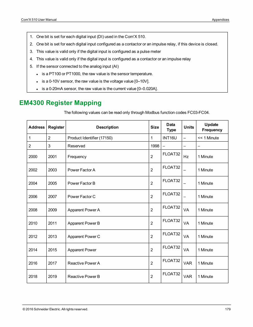
1. One bit is set for each digital input (DI) used in the Com'X 510.
2. One bit is set for each digital input configured as a contactor or an impulse relay, if this device is closed.
3. This value is valid only if the digital input is configured as a pulsemeter
4. This value is valid only if the digital input is configured as a contactor or an impulse relay
5. If the sensor connected to the analog input (AI)
l is a PT100 or PT1000, the raw value is the sensor temperature.
l is a 0-10V sensor, the raw value is the voltage value [0–10V].
l is a 0-20mA sensor, the raw value is the current value [0–0.020A].
EM4300 Register MappingThe following values can be read only throughModbus function codes FC03-FC04.
Address Register Description Size DataType Units Update
Frequency
1 2 Product Identifier (17150) 1 INT16U – << 1Minute
2 3 Reserved 1998 – – –
2000 2001 Frequency 2 FLOAT32 Hz 1Minute
2002 2003 Power Factor A 2 FLOAT32 – 1Minute
2004 2005 Power Factor B 2 FLOAT32 – 1Minute
2006 2007 Power Factor C 2 FLOAT32 – 1Minute
2008 2009 Apparent Power A 2 FLOAT32 VA 1Minute
2010 2011 Apparent Power B 2 FLOAT32 VA 1Minute
2012 2013 Apparent Power C 2 FLOAT32 VA 1Minute
2014 2015 Apparent Power 2 FLOAT32 VA 1Minute
2016 2017 Reactive Power A 2 FLOAT32 VAR 1Minute
2018 2019 Reactive Power B 2 FLOAT32 VAR 1Minute
Com'X 510 User Manual Appendices
© 2016 Schneider Electric. All rights reserved. 179
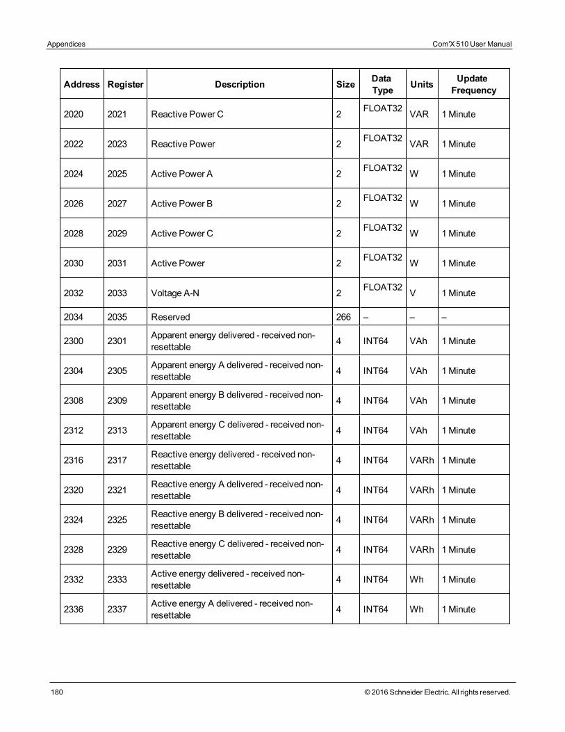
Appendices Com'X 510 User Manual
180 © 2016 Schneider Electric. All rights reserved.
Address Register Description Size DataType Units Update
Frequency
2020 2021 Reactive Power C 2 FLOAT32 VAR 1Minute
2022 2023 Reactive Power 2 FLOAT32 VAR 1Minute
2024 2025 Active Power A 2 FLOAT32 W 1Minute
2026 2027 Active Power B 2 FLOAT32 W 1Minute
2028 2029 Active Power C 2 FLOAT32 W 1Minute
2030 2031 Active Power 2 FLOAT32 W 1Minute
2032 2033 Voltage A-N 2 FLOAT32 V 1Minute
2034 2035 Reserved 266 – – –
2300 2301 Apparent energy delivered - received non-resettable 4 INT64 VAh 1Minute
2304 2305 Apparent energy A delivered - received non-resettable 4 INT64 VAh 1Minute
2308 2309 Apparent energy B delivered - received non-resettable 4 INT64 VAh 1Minute
2312 2313 Apparent energy C delivered - received non-resettable 4 INT64 VAh 1Minute
2316 2317 Reactive energy delivered - received non-resettable 4 INT64 VARh 1Minute
2320 2321 Reactive energy A delivered - received non-resettable 4 INT64 VARh 1Minute
2324 2325 Reactive energy B delivered - received non-resettable 4 INT64 VARh 1Minute
2328 2329 Reactive energy C delivered - received non-resettable 4 INT64 VARh 1Minute
2332 2333 Active energy delivered - received non-resettable 4 INT64 Wh 1Minute
2336 2337 Active energy A delivered - received non-resettable 4 INT64 Wh 1Minute
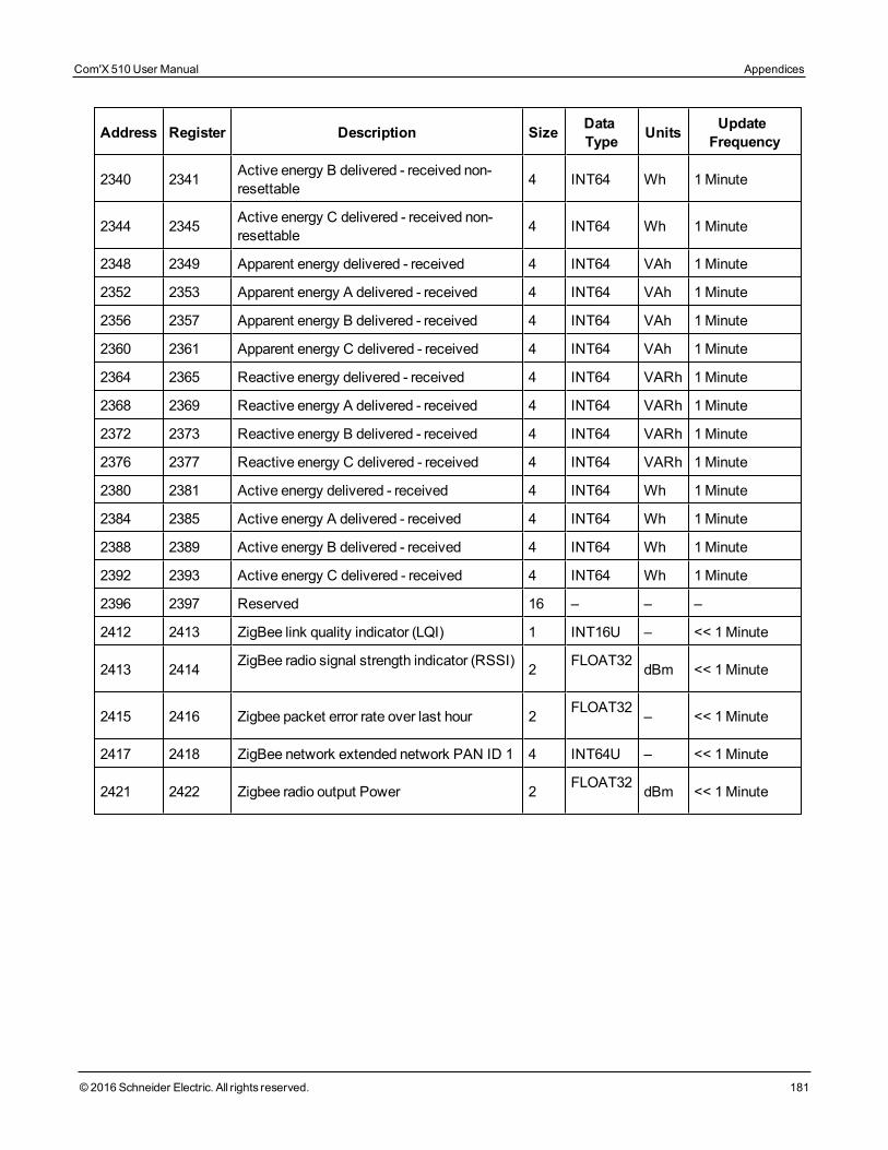
Address Register Description Size DataType Units Update
Frequency
2340 2341 Active energy B delivered - received non-resettable 4 INT64 Wh 1Minute
2344 2345 Active energy C delivered - received non-resettable 4 INT64 Wh 1Minute
2348 2349 Apparent energy delivered - received 4 INT64 VAh 1Minute
2352 2353 Apparent energy A delivered - received 4 INT64 VAh 1Minute
2356 2357 Apparent energy B delivered - received 4 INT64 VAh 1Minute
2360 2361 Apparent energy C delivered - received 4 INT64 VAh 1Minute
2364 2365 Reactive energy delivered - received 4 INT64 VARh 1Minute
2368 2369 Reactive energy A delivered - received 4 INT64 VARh 1Minute
2372 2373 Reactive energy B delivered - received 4 INT64 VARh 1Minute
2376 2377 Reactive energy C delivered - received 4 INT64 VARh 1Minute
2380 2381 Active energy delivered - received 4 INT64 Wh 1Minute
2384 2385 Active energy A delivered - received 4 INT64 Wh 1Minute
2388 2389 Active energy B delivered - received 4 INT64 Wh 1Minute
2392 2393 Active energy C delivered - received 4 INT64 Wh 1Minute
2396 2397 Reserved 16 – – –
2412 2413 ZigBee link quality indicator (LQI) 1 INT16U – << 1Minute
2413 2414 ZigBee radio signal strength indicator (RSSI) 2 FLOAT32 dBm << 1Minute
2415 2416 Zigbee packet error rate over last hour 2 FLOAT32 – << 1Minute
2417 2418 ZigBee network extended network PAN ID 1 4 INT64U – << 1Minute
2421 2422 Zigbee radio output Power 2 FLOAT32 dBm << 1Minute
Com'X 510 User Manual Appendices
© 2016 Schneider Electric. All rights reserved. 181
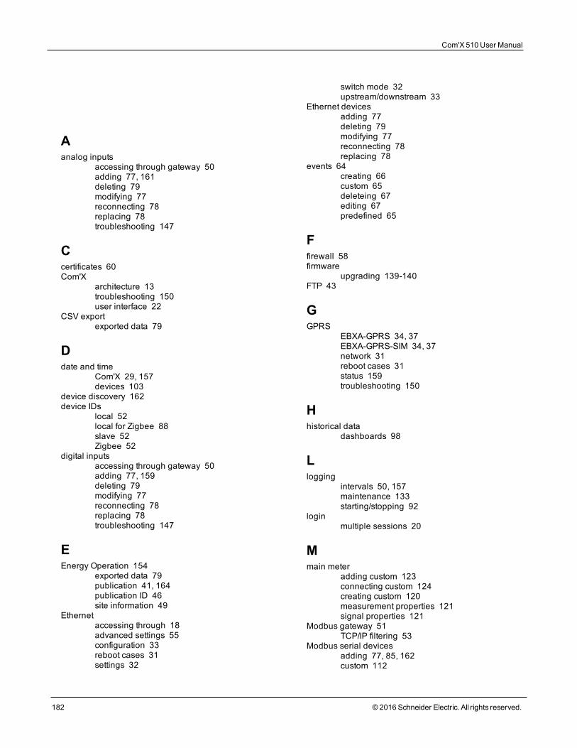
Index
Aanalog inputs
accessing through gateway 50adding 77, 161deleting 79modifying 77reconnecting 78replacing 78troubleshooting 147
Ccertificates 60Com'X
architecture 13troubleshooting 150user interface 22
CSV exportexported data 79
Ddate and time
Com'X 29, 157devices 103
device discovery 162device IDs
local 52local for Zigbee 88slave 52Zigbee 52
digital inputsaccessing through gateway 50adding 77, 159deleting 79modifying 77reconnecting 78replacing 78troubleshooting 147
EEnergy Operation 154
exported data 79publication 41, 164publication ID 46site information 49
Ethernetaccessing through 18advanced settings 55configuration 33reboot cases 31settings 32
switch mode 32upstream/downstream 33
Ethernet devicesadding 77deleting 79modifying 77reconnecting 78replacing 78
events 64creating 66custom 65deleteing 67editing 67predefined 65
Ffirewall 58firmware
upgrading 139-140FTP 43
GGPRS
EBXA-GPRS 34, 37EBXA-GPRS-SIM 34, 37network 31reboot cases 31status 159troubleshooting 150
Hhistorical data
dashboards 98
Llogging
intervals 50, 157maintenance 133starting/stopping 92
loginmultiple sessions 20
Mmain meter
adding custom 123connecting custom 124creating custom 120measurement properties 121signal properties 121
Modbus gateway 51TCP/IP filtering 53
Modbus serial devicesadding 77, 85, 162custom 112
Com'X 510 User Manual
182 © 2016 Schneider Electric. All rights reserved.
deleting 79discovering 83modifying 77reconnecting 78replacing 78troubleshooting 148
Ppassword
changing 21first login 21login 20session timeout 22
proxy 39publication 157
CSV 46Energy Operation 157Ethernet 158FTP 43GPRS 159HTTP 43HTTPS 43publication ID 46RSP connection 47SMTP 45starting 93transfer protocols 42
pulse meters 81
Rreal time data
device summary 96single device 95
Remote Services Platform 15exported data 79firmware upgrade 140publication 47replacing Com'X 141resetting password 143restoring configuration 137saving configuration 135
resistance temperature detectors (RTD) 83measurement properties 83measurement table 83
Sswitch mode 32
Uupstream/downstream mode 33USB
firmware upgrade 140restoring configuration 137saving configuration 136uploading configuration 139
Wweb browser
for PC 17for tablet 17
Wi-Fiaccess point settings 48accessing through 19activating 48deactivating 49troubleshooting 150
ZZigBee
discovery 88Modbus registers 179network configuration 56
Com'X 510 User Manual
© 2016 Schneider Electric. All rights reserved. 183

Com'X 510 Energy ServerUser Manual
Schneider Electric35 rue JosephMonier92500 Rueil-Malmaison, Francewww.schneider-electric.com
DOCA0098EN-03 04/2016Replaces Document DOCA0098EN-00 04/2015© 2016 Schneider Electric. All Rights Reserved.