Embed Size (px)
Citation preview

September, 2017 doc.:11-17-1424-00-00ay Optional MCS12 and 13 Draft Text
IEEE P802.11Wireless LANs
Alternative MCS12 and MCS13 Text
Date: 2017-08-16
Author(s):Name Affiliation Address Phone emailChris Hansen Peraso chris@covariantcorp.
comGary Cheng Peraso [email protected]
Kome Oteri Interdigital [email protected]
Li Hsiang Sun Interdigital LiHsiang.Sun@interd
igital.com
Rui Yang Interdigital [email protected]
Hiroyuki Motozuka Panasonic motozuka.hiroyuki@j
p.panasonic.com
James Wang Mediatek [email protected]
Artyom Lomayev Intel artyom.lomayev@inte
l.com
Submission page 1 C. Hansen, et al
AbstractDraft text to provide support for alternative MCS 12 and 13.

September, 2017 doc.:11-17-1424-00-00ay Optional MCS12 and 13 Draft Text
Instruct the Editor to modify the IEEE 802.11ay draft as shown in this document.
3.
4.
4.1
4.2
4.3
4.3.1 EDMG STAAdd to Section 4.3.1
-- Optional support for alternative SC MCS12 and MCS13 using 8-PSK Modulation
4.3.1.250 EDMG Capabilities element
4.3.1.250.1 GeneralMake the following changes:
The Core Capabilities field is defined in Figure 18.
B0 B6 B7 B18 B19 B210 B221 B23
A-MPDU Parameters
TRN Parameters
Supported MCS
Reserved
Bits: 7 12 32 23
Figure 18 —Core Capabilities field format
The Supported MCS field is defined in Figure 21.
B0 B1 B2NUC TX Supported NUC RX Supported π/2-8-PSK
SupportedBits: 1 1 1
Figure 21 —Supported MCS field format
Add the following text after Figure 21:
Submission page 2 C. Hansen, et al

September, 2017 doc.:11-17-1424-00-00ay Optional MCS12 and 13 Draft Text
The 8-PSK supported sub-field is set to one to indicate that the STA supports SC MCS12 and SC MCS13 using 8-PSK modulation.
Submission page 3 C. Hansen, et al

September, 2017 doc.:11-17-1424-00-00ay Optional MCS12 and 13 Draft Text
5.
6.
7.
8.
9.
10.
11.
12.
13.
14.
15.
16.
17.
18.
19.
20.
Submission page 4 C. Hansen, et al

September, 2017 doc.:11-17-1424-00-00ay Optional MCS12 and 13 Draft Text
21.
22.
23.
24.
25.
26.
27.
28.
29.
30.
30.1
30.1.1 Introduction to the EDMG PHYAdd to Section 30.1.1 An EDMG STA may support the following features:
-- 8-PSK Modulation for SC MCS12 and MCS13
Submission page 5 C. Hansen, et al
September, 2017 doc.:11-17-1424-00-00ay Optional MCS12 and 13 Draft Text
30.2
30.3
30.4
30.4.1
30.4.2
30.4.3
30.4.3.1
30.4.3.2
30.4.3.3
30.4.3.3.1
30.4.3.3.2
30.4.3.3.2.1
30.4.3.3.2.2
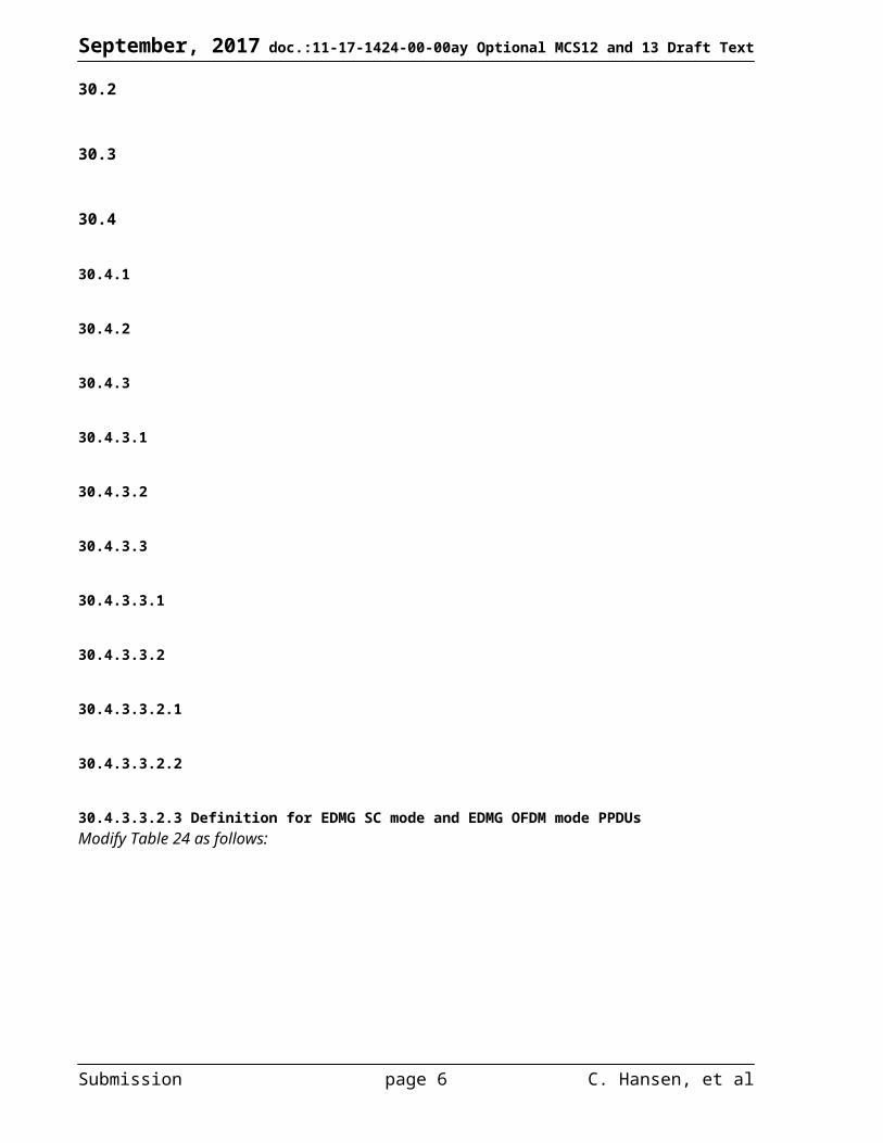
30.4.3.3.2.3 Definition for EDMG SC mode and EDMG OFDM mode PPDUsModify Table 24 as follows:
Submission page 6 C. Hansen, et al
September, 2017 doc.:11-17-1424-00-00ay Optional MCS12 and 13 Draft Text
EDMG-Header-A field structure and definition for a SU PPDUField Number
of bitsStart bit
Description
SU/MU Format 1 0 Indicates whether the PPDU is a SU PPDU or a MU PPDU. Set to 0 to indicate a SU PPDU and set to 1 otherwise.
Channel Aggregation
1 1 Set to 0 to indicate that the BW field specifies a 2.16 GHz, 4.32 GHz, 6.48 GHz or 8.64 GHz channel PPDU. Set to 1 to indicate that the BW field specifies a 2.16+2.16 GHz or 4.32+4.32 GHz PPDU.
BW 8 2 A bitmap constructed from the CH_BANDWIDTH parameter in the TXVECTOR and that indicates the 2.16 GHz channel(s) over which the PPDU is transmitted on. If a bit is set to 1, it indicates that the corresponding channel is used for the PPDU transmission; otherwise if the bit is set to 0, the channel is not used. Bit 0 corresponds to channel 1, bit 1 corresponds to channel 2, and so on.
Primary Channel Number
3 10 Contains the 3 LSBs of the primary channel number of the BSS minus one
Beamformed 1 13 Set to 1 to indicate that channel estimate smoothing is recommended. Set to 0 otherwise.Short/Long LDPC
1 14 Indicates the LDPC codeword length used in the PSDU. Set to 0 for LDPC codeword of length 672. Set to 1 for LDPC codeword of length 1344.
STBC Applied 1 15 If set to 1, indicates that STBC was applied at the transmitter. Otherwise, set to 0.PSDU Length 22 16 Length of the PSDU field in octets.Number of SS 3 38 The value of this field plus one indicates the number of SSs transmitted in the PPDU.EDMG-MCS 21 41 If the number of SSs, as indicated by the Number of SS field, is 4 or less, the EDMG-
MCS field is as defined in Error: Reference source not found. Otherwise, the EDMG-MCS field is as defined in Error: Reference source not found.
DCM SQPSK Applied
1 62 If set to 1, indicates that DCM SQPSK (Error: Reference source not found) was applied at the transmitter. Otherwise, set to 0.
NUC Applied 1 63 If this field is set to 1, NUC is applied at the transmitter for all MCSs indicated within the EDMG-MCS field and that support NUC. If a MCS indicated within the EDMG-MCS field does not support NUC, uniform constellation is applied for this particular MCS.
If set to 0, uniform constellation is applied for all MCSs signalled in EDMG-MCS field.EDMG TRN Length
8 64 Indicates the number of TRN-Units present in the TRN field of the PPDU.
RX TRN-Units per Each TX TRN-Unit
8 72 This field is reserved if the value of the EDMG TRN Length field is 0. Otherwise, the value of this field plus one indicates the number of consecutive TRN-Units in the TRN field for which the transmitter remains with the same transmit AWV (see Error: Reference source not found).
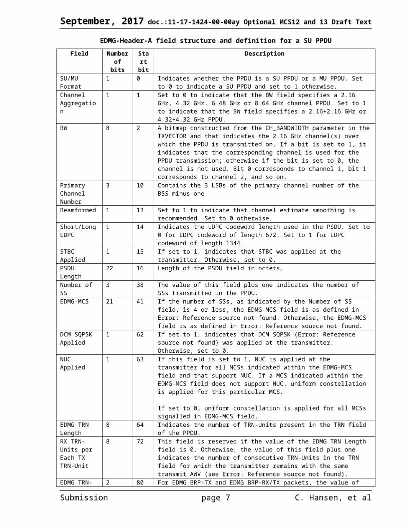
EDMG TRN-Unit P
2 80 For EDMG BRP-TX and EDMG BRP-RX/TX packets, the value of this field describes the number of TRN subfields in a TRN-Unit which are transmitted using the same AWV, which is the same AWV used in the transmission of the preamble and Data field except for the case when the DMG antenna used in the transmission of the packet changes at the beginning of the TRN field, as defined in Error: Reference source not found. Possible values for this field are:
0: indicates zero TRN subfields 1: indicates one TRN subfield 2: indicates two TRN subfields 3: indicates four TRN subfields
For EDMG BRP-RX packets, this field is reserved.EDMG TRN-Unit M
4 82 For EDMG BRP-TX packets, the value of this field plus one indicates the number of TRN subfields in a TRN-Unit in which the transmitter may change AWV at the beginning of each TRN subfield transmission, as defined in Error: Reference source not found. For EDMG BRP-RX/TX packets, the value of this field plus one indicates the number of TRN subfields in a TRN-Unit transmitted with the same AWV following a possible AWV change, as defined in Error: Reference source not found.
For EDMG BRP-RX packets, this field is reserved. For EDMG BRP-TX packets transmitted with EDMG Beam Tracking Request Type field set to 1, this field is reserved.
EDMG TRN-Unit N
2 86 For EDMG BRP-TX packets, the value of this field indicates the number of consecutive TRN subfields within EDMG TRN-Unit M which are transmitted using the same AWV, as defined in Error: Reference source not found. Possible values for this field are:
0: indicates one TRN subfield
Submission page 7 C. Hansen, et al
September, 2017 doc.:11-17-1424-00-00ay Optional MCS12 and 13 Draft Text
1: indicates two TRN subfields 2: indicates three TRN subfields if EDMG TRN-Unit M is equal to 2, 5, 8, 11
or 14; indicates eight TRN subfields if EDMG TRN-Unit M is equal to 7 or 15.
3: indicates four TRN subfields
For EDMG BRP-RX and EDMG BRP-RX/TX packets, this field is reserved. For EDMG BRP-TX packets transmitted with EDMG Beam Tracking Request Type field set to 1, this field is reserved.
TRN Subfield Sequence Length
2 88 This field is reserved if the value of the EDMG TRN Length field is 0. Otherwise, this field indicates the length of the Golay sequence used to transmit the TRN subfields present in the TRN field of the PPDU and is set as follows:
Set to 0 to indicate normal sequence length of 128× NCB
Set to 1 to indicate long sequence length of 256× NCB
Set to 2 to indicate short sequence length of 64× NCB
Value 3 is reservedNCB represents the integer number of contiguous 2.16 GHz channels over which the TRN subfield is transmitted and 1 ≤ NCB ≤ 4.
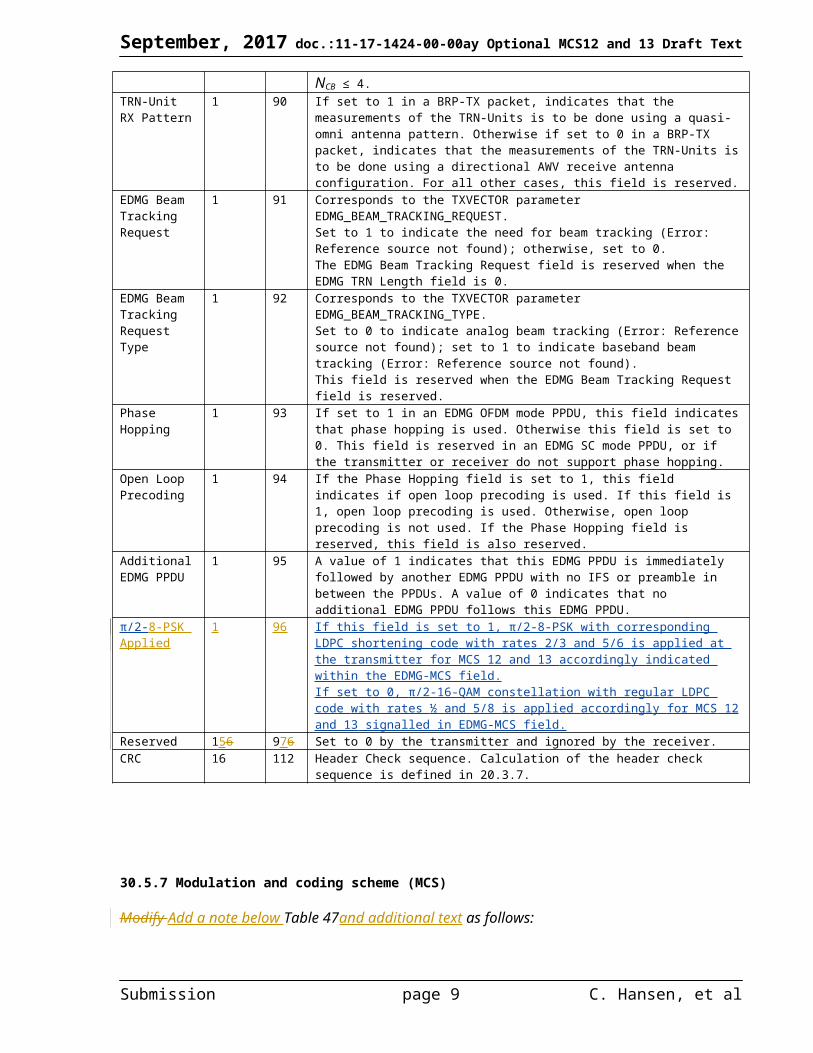
TRN-Unit RX Pattern
1 90 If set to 1 in a BRP-TX packet, indicates that the measurements of the TRN-Units is to be done using a quasi-omni antenna pattern. Otherwise if set to 0 in a BRP-TX packet, indicates that the measurements of the TRN-Units is to be done using a directional AWV receive antenna configuration. For all other cases, this field is reserved.
EDMG Beam Tracking Request
1 91 Corresponds to the TXVECTOR parameter EDMG_BEAM_TRACKING_REQUEST.Set to 1 to indicate the need for beam tracking (Error: Reference source not found); otherwise, set to 0.The EDMG Beam Tracking Request field is reserved when the EDMG TRN Length field is 0.
EDMG Beam Tracking Request Type
1 92 Corresponds to the TXVECTOR parameter EDMG_BEAM_TRACKING_TYPE.Set to 0 to indicate analog beam tracking (Error: Reference source not found); set to 1 to indicate baseband beam tracking (Error: Reference source not found).This field is reserved when the EDMG Beam Tracking Request field is reserved.
Phase Hopping 1 93 If set to 1 in an EDMG OFDM mode PPDU, this field indicates that phase hopping is used. Otherwise this field is set to 0. This field is reserved in an EDMG SC mode PPDU, or if the transmitter or receiver do not support phase hopping.
Open Loop Precoding
1 94 If the Phase Hopping field is set to 1, this field indicates if open loop precoding is used. If this field is 1, open loop precoding is used. Otherwise, open loop precoding is not used. If the Phase Hopping field is reserved, this field is also reserved.
Additional EDMG PPDU
1 95 A value of 1 indicates that this EDMG PPDU is immediately followed by another EDMG PPDU with no IFS or preamble in between the PPDUs. A value of 0 indicates that no additional EDMG PPDU follows this EDMG PPDU.
π/2-8-PSK Applied
1 96 If this field is set to 1, π/2-8-PSK with corresponding LDPC shortening code with rates 2/3 and 5/6 is applied at the transmitter for MCS 12 and 13 accordingly indicated within the EDMG-MCS field.If set to 0, π/2-16-QAM constellation with regular LDPC code with rates ½ and 5/8 is applied accordingly for MCS 12 and 13 signalled in EDMG-MCS field.
Reserved 156 976 Set to 0 by the transmitter and ignored by the receiver.CRC 16 112 Header Check sequence. Calculation of the header check sequence is defined in 20.3.7.
30.5.7 Modulation and coding scheme (MCS)
Modify Add a note below Table 47and additional text as follows:
Submission page 8 C. Hansen, et al
September, 2017 doc.:11-17-1424-00-00ay Optional MCS12 and 13 Draft Text
Table 1—EDMG-MCSs for the EDMG SC mode
EDMG-MCS index Modulation NCBPS Repetition Code Rate Data rate per spatial stream (Mbps)Normal GI Short GI Long GI
1 π/2-BPSK 1 2 1/2 NCB×385.00 NCB×412.50 NCB×330.002 π/2-BPSK 1 1 1/2 NCB×770.00 NCB×825.00 NCB×660.003 π/2-BPSK 1 1 5/8 NCB×962.50 NCB×1031.25 NCB×825.004 π/2-BPSK 1 1 3/4 NCB×1155.00 NCB×1237.50 NCB×990.005 π/2-BPSK 1 1 13/16 NCB×1251.25 NCB×1340.63 NCB×1072.506 π/2-BPSK 1 1 7/8 NCB×1347.50 NCB×1443.75 NCB×1155.007 π/2-QPSK 2 1 1/2 NCB×1540.00 NCB×1650.00 NCB×1320.008 π/2-QPSK 2 1 5/8 NCB×1925.00 NCB×2062.50 NCB×1650.009 π/2-QPSK 2 1 3/4 NCB×2310.00 NCB×2475.00 NCB×1980.00
10 π/2-QPSK 2 1 13/16 NCB×2502.50 NCB×2681.25 NCB×2145.0011 π/2-QPSK 2 1 7/8 NCB×2695.00 NCB×2887.50 NCB×2310.0012 π/2-16QAM 4 1 1/2 NCB×3080.00 NCB×3300.00 NCB×2640.00
13 π/2-16QAM 4 1 5/8 NCB×3850.00 NCB×4125.00 NCB×3300.00
14 π/2-16QAM 4 1 3/4 NCB×4620.00 NCB×4950.00 NCB×3960.0015 π/2-16QAM 4 1 13/16 NCB×5005.00 NCB×5362.50 NCB×4290.0016 π/2-16QAM 4 1 7/8 NCB×5390.00 NCB×5775.00 NCB×4620.0017 π/2-64QAM 6 1 5/8 NCB×5775.00 NCB×6187.50 NCB×4950.0018 π/2-64QAM 6 1 3/4 NCB×6930.00 NCB×7425.00 NCB×5940.0019 π/2-64QAM 6 1 13/16 NCB×7507.50 NCB×8043.75 NCB×6435.0020 π/2-64QAM 6 1 7/8 NCB×8085.00 NCB×8662.50 NCB×6930.00
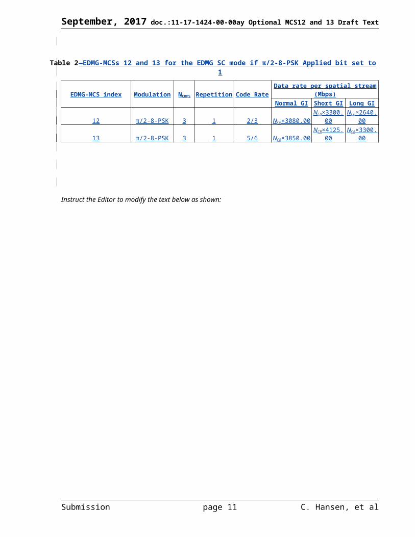
If π/2-8-PSK Applied bit is set to 1, then MCS 12 and 13 shall use π/2-8-PSK modulation with LDPC encoding rates 2/3 and 5/6 accordingly as defined in Table 2.
Table 2—EDMG-MCSs 12 and 13 for the EDMG SC mode if π/2-8-PSK Applied bit set to 1
EDMG-MCS index Modulation NCBPS Repetition Code Rate Data rate per spatial stream (Mbps)Normal GI Short GI Long GI
12 π/2-8-PSK 3 1 2/3 NCB×3080.00 NCB×3300.00 NCB×2640.0013 π/2-8-PSK 3 1 5/6 NCB×3850.00 NCB×4125.00 NCB×3300.00
Instruct the Editor to modify the text below as shown:
Submission page 9 C. Hansen, et al

September, 2017 doc.:11-17-1424-00-00ay Optional MCS12 and 13 Draft Text
30.5
30.5.1
30.5.2
30.5.3
30.5.4
30.5.5
30.5.6
30.5.7
30.5.8
30.5.8.1
30.5.8.2
30.5.8.3
30.5.8.4 Encoding
30.5.8.4.1 GeneralAn EDMG SC mode PSDU is encoded by a systematic LDPC block code. Each data word of L CWD information bits is concatenated with LCWP parity bits to create a codeword of total length LCW = LCWD + LCWP bits. The EDMG LDPC encoding can employ the codeword lengths LCW = 468, 504, 624, 672, 936, 1008, 1248, and 1344 and code rates R = ½, 5/8, 2/3, ¾, 13/16, 5/6, and 7/8. The set of code rates is defined in Error: Reference source not found.
Table 53 —LDPC code ratesCode rate Codeword size (LCW) Number of data bits (LCWD)
Short Long Short Long½ 672 1344 336 672
5/8 672 1344 420 8402/3 504 1008 336 672¾ 672 1344 504 1008
13/16 672 1344 546 10925/6 468 or
504936 or 1008 390 or 420 780 or 840
7/8 624 or 672
1248 or 1344 546 or 588 1092 or 1176
Submission page 10 C. Hansen, et al
September, 2017 doc.:11-17-1424-00-00ay Optional MCS12 and 13 Draft Text
The LDPC encoding with codeword length LCW = 672 and 1344 is performed by solving the linear system of
equations H⋅(c (m ) )T=0 defined by the parity matrix H of size LCWP by LCW, where c(m)=(b (m ) , p(m ) ) defines
the mth LDPC codeword, b (m )=(b1
(m ) , b2(m) , .. . ,bLCWD
(m ) ) defines the mth data word, and p(m)=( p1
(m) , p2(m ) ,. .. , pLCWP
(m ) ) defines parity bits for mth LDPC codeword.
The LDPC encoding with codeword length LCW = 624 and 1248 employs the original matrices H with LCW = 672 and 1344 for code rate R = 13/16, and then applies a puncturing procedure to get to a desired code rate R = 7/8. For L CW
= 624, first 48 parity bits are discarded; for LCW = 1248, first 96 parity bits are discarded.
The LDPC encoding for code rate 2/3 with codeword length LCW = 504 orand 1008 employs the original matrices H with LCW = 672 and 1344 for code rate R = 1/23/4, and then applies a shortening procedure to get to a desired code rate R = 2/3. For LCW = 504, 168 zeros are appended to 336 data bits before encoding; for LCW = 1008, 336 zeros are appended to 672 data bits before encoding. The zero bits are not transmitted.After encoding the zero bits are discareded and not transmitted.
The LDPC encpding for code rate 5/6 with codeword length LCW = 504 and 1008 employs the original matrices H with LCW = 672 and 1344 for code rate R = 7/8. For LCW = 504, 168 zeros are appended to 420 data bits before encoding; for LCW = 1008, 336 zeros are appended to 840 data bits before encoding. After encoding, the zero bits are discareded and not transmitted.
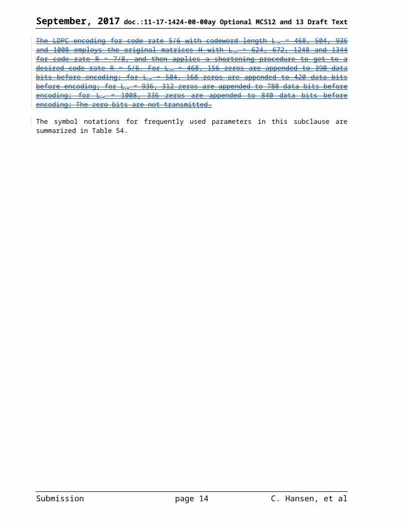
The LDPC encpding for code rate 5/6 with codeword length LCW = 468 and 936 employs the original matrices H with LCW = 672 and 1344 for code rate R = 13/16. For LCW = 468, 156 zeros are appended to 390 data bits before encoding; for LCW = 936, 312 zeros are appended to 780 data bits before encoding. After encoding, the zero bits are discarded; for LCW = 468, first 48 parity bits are discarded (punctured); for LCW = 936, the first 96 parity bits are discarded and not transmitted.
The LDPC encoding for code rate 5/6 with codeword length LCW = 468, 504, 936 and 1008 employs the original matrices H with LCW = 624, 672, 1248 and 1344 for code rate R = 7/8, and then applies a shortening procedure to get to a desired code rate R = 5/6. For LCW = 468, 156 zeros are appended to 390 data bits before encoding; for LCW = 504, 168 zeros are appended to 420 data bits before encoding; for LCW = 936, 312 zeros are appended to 780 data bits before encoding; for LCW = 1008, 336 zeros are appended to 840 data bits before encoding; The zero bits are not transmitted.
The symbol notations for frequently used parameters in this subclause are summarized in Table 54.
Submission page 11 C. Hansen, et al

September, 2017 doc.:11-17-1424-00-00ay Optional MCS12 and 13 Draft Text
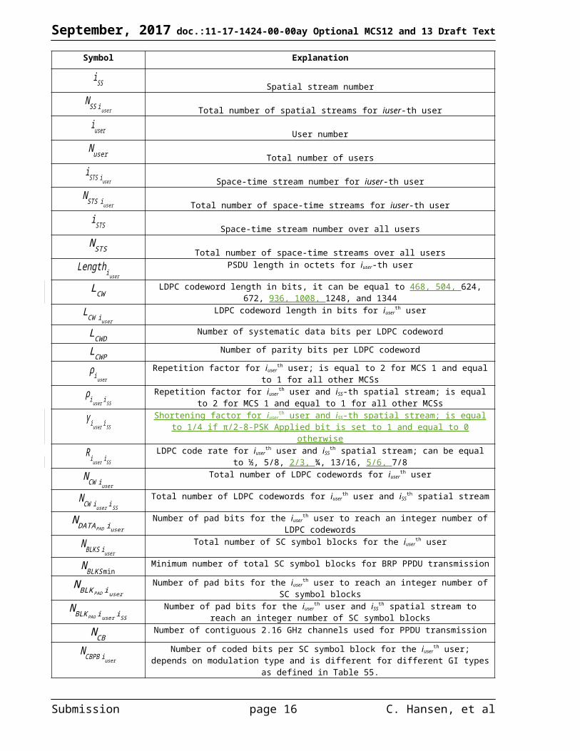
Table 54 —Frequently used parameters
Submission page 12 C. Hansen, et al

September, 2017 doc.:11-17-1424-00-00ay Optional MCS12 and 13 Draft Text
Symbol Explanation
iSS Spatial stream number
N SS iuser Total number of spatial streams for iuser-th user
iuser User number
Nuser Total number of users
iSTS iuser Space-time stream number for iuser-th user
N STS iuser Total number of space-time streams for iuser-th user
iSTS Space-time stream number over all users
N STS Total number of space-time streams over all users
Lengthiuser
PSDU length in octets for iuser-th user
LCWLDPC codeword length in bits, it can be equal to 468, 504, 624, 672, 936, 1008, 1248, and 1344
LCW iuser
LDPC codeword length in bits for iuserth user
LCWDNumber of systematic data bits per LDPC codeword
LCWPNumber of parity bits per LDPC codeword
ρiuser
Repetition factor for iuserth user; is equal to 2 for MCS 1 and equal to 1 for all other MCSs
ρiuser iSS
Repetition factor for iuserth user and iSS-th spatial stream; is equal to 2 for MCS 1 and equal to 1 for
all other MCSs
γiuser iSS
Shortening factor for iuserth user and iSS-th spatial stream; is equal to 1/4 if π/2-8-PSK Applied bit is
set to 1 and equal to 0 otherwise
Riuser iSS
LDPC code rate for iuserth user and iSS
th spatial stream; can be equal to ½, 5/8, 2/3, ¾, 13/16, 5/6, 7/8
NCW iuser
Total number of LDPC codewords for iuserth user
NCW iuser iSS
Total number of LDPC codewords for iuserth user and iSS
th spatial stream
N DATAPAD iuser
Number of pad bits for the iuserth user to reach an integer number of LDPC codewords
N BLKS iuser
Total number of SC symbol blocks for the iuserth user
N BLKSminMinimum number of total SC symbol blocks for BRP PPDU transmission
N BLKPAD iuser
Number of pad bits for the iuserth user to reach an integer number of SC symbol blocks
N BLKPAD iuser iSS
Number of pad bits for the iuserth user and iSS
th spatial stream to reach an integer number of SC symbol blocks
NCBNumber of contiguous 2.16 GHz channels used for PPDU transmission
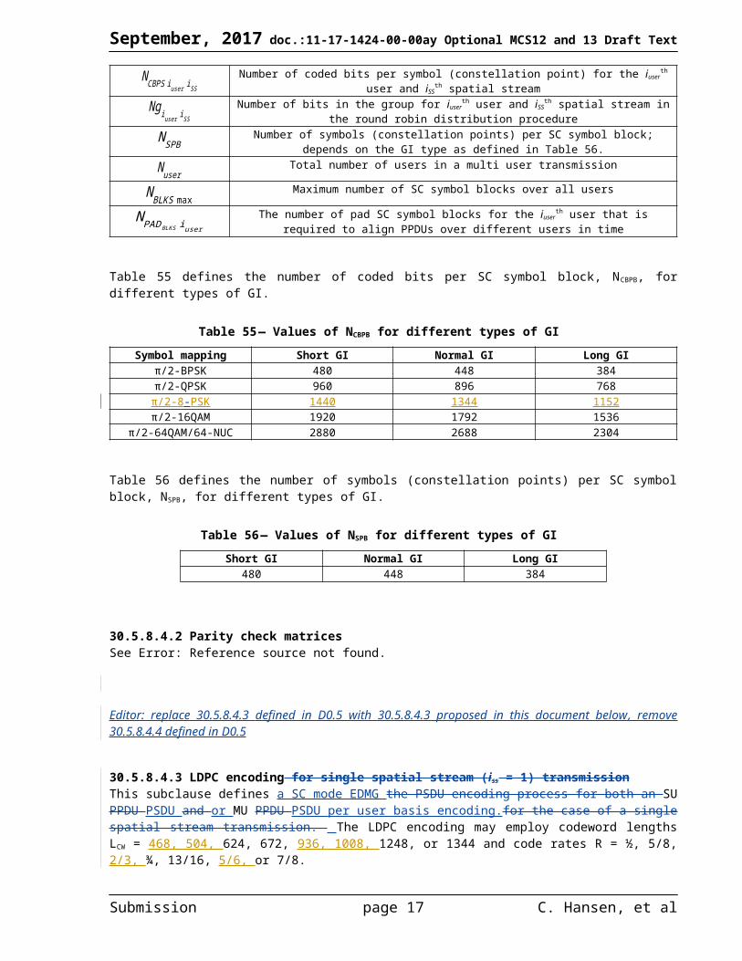
NCBPB iuser
Number of coded bits per SC symbol block for the iuserth user; depends on modulation type and is
different for different GI types as defined in Table 55.
NCBPS iuser iSS
Number of coded bits per symbol (constellation point) for the iuserth user and iSS
th spatial stream
Ngiuser iSS
Number of bits in the group for iuserth user and iSS
th spatial stream in the round robin distribution procedure
N SPBNumber of symbols (constellation points) per SC symbol block; depends on the GI type as defined
in Table 56.
NuserTotal number of users in a multi user transmission
Submission page 13 C. Hansen, et al
September, 2017 doc.:11-17-1424-00-00ay Optional MCS12 and 13 Draft Text
N BLKS maxMaximum number of SC symbol blocks over all users
N PADBLKS iuser
The number of pad SC symbol blocks for the iuserth user that is required to align PPDUs over
different users in time
Table 55 defines the number of coded bits per SC symbol block, NCBPB, for different types of GI.
Table 55 — Values of NCBPB for different types of GISymbol mapping Short GI Normal GI Long GI
π/2-BPSK 480 448 384π/2-QPSK 960 896 768π/2-8-PSK 1440 1344 1152
π/2-16QAM 1920 1792 1536π/2-64QAM/64-NUC 2880 2688 2304
Table 56 defines the number of symbols (constellation points) per SC symbol block, NSPB, for different types of GI.
Table 56 — Values of NSPB for different types of GIShort GI Normal GI Long GI
480 448 384
30.5.8.4.2 Parity check matricesSee Error: Reference source not found.
Editor: replace 30.5.8.4.3 defined in D0.5 with 30.5.8.4.3 proposed in this document below, remove 30.5.8.4.4 defined in D0.5
[30.5.8.4.3] LDPC encoding for single spatial stream (iss = 1) transmissionThis subclause defines a SC mode EDMG the PSDU encoding process for both an SU PPDU PSDU and or MU PPDU PSDU per user basis encoding.for the case of a single spatial stream transmission. The LDPC encoding may employ codeword lengths LCW = 468, 504, 624, 672, 936, 1008, 1248, or 1344 and code rates R = ½, 5/8, 2/3, ¾, 13/16, 5/6, or 7/8.
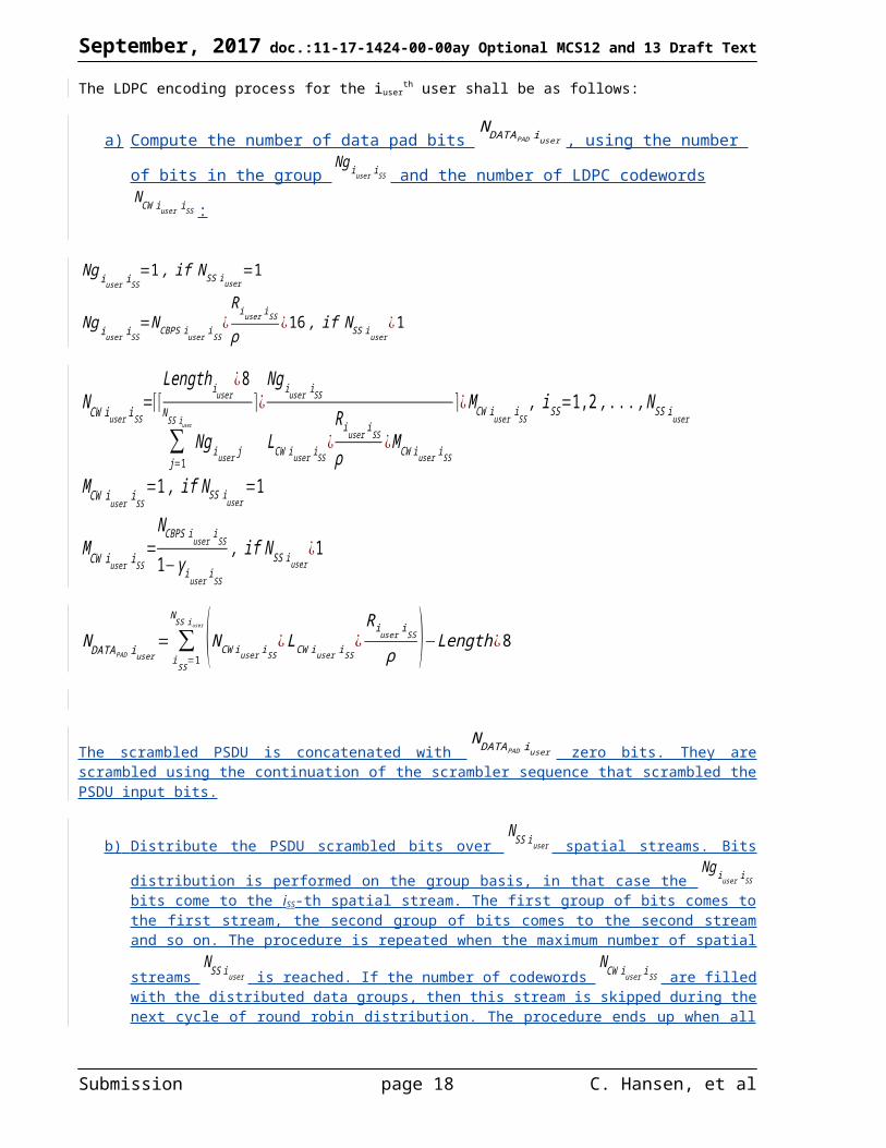
The LDPC encoding process for the iuserth user shall be as follows:
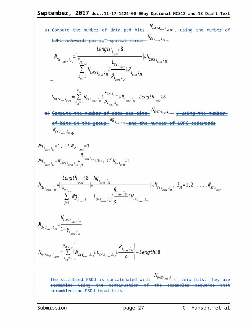
a) Compute the number of data pad bits N DATAPAD iuser , using the number of bits in the group
Ng iuser iSS and the number of LDPC codewords NCW iuser iSS :
Ng iuser iSS=1 , if N SS iuser
=1
Ng iuser iSS=NCBPS iuser iSS
¿Riuser iSS
ρ¿16 , if N SS iuser
¿1
Submission page 14 C. Hansen, et al

September, 2017 doc.:11-17-1424-00-00ay Optional MCS12 and 13 Draft Text
NCW iuser iSS=⌈⌈
Lengthiuser¿8
∑j=1
N SS i user
Ng iuser j
⌉¿Ng iuser iSS
LCW iuser iSS¿
Riuser i SS
ρ¿ MCW iuser iSS
⌉¿M CW iuser iSS, iSS =1,2, . .. , N SS iuser
M CW iuser iSS=1 , if N SS iuser
=1
M CW iuser iSS=
NCBPS iuser iSS
1−γ iuser iSS
, if NSS iuser¿1
N DATAPAD iuser= ∑
iSS=1
N SS iuser (NCW iuser iSS¿ LCW iuser iSS
¿Riuser iSS
ρ )−Length¿8
The scrambled PSDU is concatenated with N DATAPAD iuser zero bits. They are scrambled using the continuation of
the scrambler sequence that scrambled the PSDU input bits.
b) Distribute the PSDU scrambled bits over N SS iuser spatial streams. Bits distribution is performed on the
group basis, in that case the Ng iuser iSS bits come to the iSS-th spatial stream. The first group of bits comes to
the first stream, the second group of bits comes to the second stream and so on. The procedure is repeated
when the maximum number of spatial streams N SS iuser is reached. If the number of codewords
NCW iuser iSS are filled with the distributed data groups, then this stream is skipped during the next cycle of round robin
distribution. The procedure ends up when all PSDU bits including N DATAPAD iuser pad bits are distributed
over the N SS iuser spatial streams.
c) For each spatial stream convert the scrambled PSDU bits to LDPC codewords as follows:
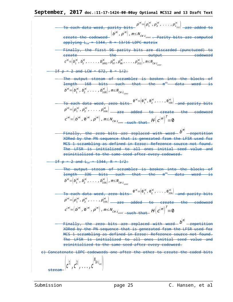
a. If ρ = 1 and LCW = 672, 1344:i. The output stream of scrambler is broken into the blocks of length LCWD = LCW×R bits
such that the m-th data word is b (m )=(b1
(m ) , b2(m) , .. . ,bLCWD
(m ) ) , m≤NCW iuser i SS
ii. To each data word, parity bits p(m)=( p1
(m) , p2(m ) ,. .. , pLCWP
(m ) ) , LCWP = LCW - LCWD, are
added to create the codeword c (m)=(b (m ) , p(m ) ) , m≤NCW iuser iSS such that
H⋅(c (m ) )T=0b. If ρ = 1 and LCW = 624, R = 7/8:
i. The output stream of scrambler is broken into the blocks of length 546 bits such that the
m-th data word is b (m )=(b1
(m ) , b2(m ) ,. .. , b546
(m ) ) ,m≤NCW iuser iSS
Submission page 15 C. Hansen, et al
September, 2017 doc.:11-17-1424-00-00ay Optional MCS12 and 13 Draft Text
ii. To each data word, parity bits p(m)=( p1
(m) , p2(m ) ,. .. , pL126
(m ) ) are added to create the
codeword c (m)=(b (m ) , p(m ) ) , m≤NCW iuser iSS such that H⋅(c (m ) )T=0 , parity bits
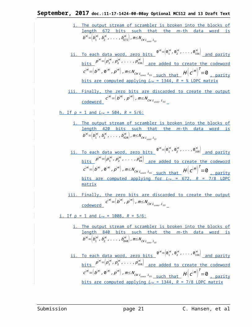
are computed applying LCW = 672, R = 13/16 LDPC matrixiii. Finally, the first 48 parity bits are discarded (punctured) to create the output codeword
c (m)=(b1(m) , b2
(m) , .. . ., b546(m ) , p49
(m ) , p50(m) , .. . , p126
(m ) ) ,m≤NCW iuser iSS
c. If ρ = 1 and LCW = 1248, R = 7/8:i. The output stream of scrambler is broken into the blocks of length 1092 bits such that the
m-th data word is b (m )=(b1
(m ), b2(m ) ,. .. , b1092
(m ) ) ,m≤NCW iuser iSS
ii. To each data word, parity bits p(m)=( p1
(m) , p2(m ) ,. .. , pL252
(m ) ) are added to create the
codeword c (m)=(b (m ) , p(m ) ) , m≤NCW iuser iSS such that H⋅(c (m ) )T=0 , parity bits
are computed applying LCW = 1344, R = 13/16 LDPC matrixiii. Finally, the first 96 parity bits are discarded (punctured) to create the output codeword
c (m)=(b1(m) , b2
(m) , .. . ., b1092(m ) , p97
(m ), p98(m ) , .. . , p252
(m ) ) ,m≤NCW iuser iSS
d. If ρ = 2 and LCW = 672, R = 1/2:i. The output stream of scrambler is broken into the blocks of length 168 bits such that the
m-th data word is b (m )=(b1
(m ) , b2(m ) ,. .. , b168
(m ) ) , m≤NCW iuser iSS
ii. To each data word, zero bits 0(m )=(01
(m) , 02( m ) , . .. ,0168
(m) ) and parity bits p(m)=(p1
(m ) , p2(m ), . .. , p168
(m ) ) are added to create the codeword
c (m)=(b (m ) ,0 (m) , p (m ) ) , m≤NCW iuser iSS such that H⋅(c (m ) )T=0
iii. Finally, the zero bits are replaced with word b(m )
repetition XORed by PN sequence that is generated from the LFSR used for MCS 1 scrambling as defined in 30.5.8.3.2. The LFSR is initialized to all ones initial seed value and reinitialized to the same seed after every codeword.
e. If ρ = 2 and LCW = 1344, R = 1/2:i. The output stream of scrambler is broken into the blocks of length 336 bits such that the
m-th data word is b (m )=(b1
(m ) , b2(m ) ,. .. , b336
(m ) ) , m≤NCW iuser iSS
ii. To each data word, zero bits 0(m )=(01
(m) , 02(m ), . .. , 0336
(m) ) and parity bits p(m)=(p1
(m ) , p2(m ), . .. , p336
(m ) ) are added to create the codeword
c (m)=(b (m ) ,0 (m) , p (m ) ) , m≤NCW iuser iSS such that H⋅(c (m ) )T=0
iii. Finally, the zero bits are replaced with word b(m )
repetition XORed by PN sequence that is generated from the LFSR used for MCS 1 scrambling as defined in 30.5.8.3.2. The LFSR is initialized to all ones initial seed value and reinitialized to the same seed after every codeword.
f. If ρ = 1 and LCW = 504, R = 2/3:
i. The output stream of scrambler is broken into the blocks of length 336 bits such that the
m-th data word is b (m )=(b1
(m ) , b2(m ) ,. .. , b336
(m ) ) , m≤NCW iuser iSS
Submission page 16 C. Hansen, et al
September, 2017 doc.:11-17-1424-00-00ay Optional MCS12 and 13 Draft Text
ii. To each data word, zero bits 0(m )=(01
(m) , 02(m ) , . .. , 0168
(m) ) and parity bits p(m)=(p1
(m ) , p2(m ), . .. , p168
(m ) ) are added to create the codeword
c (m)=(b (m ) ,0 (m) , p (m ) ) ,m≤NCW iuser iSS such that H⋅(c (m ) )T=0 , parity bits are computed applying LCW = 672, R = ¾ LDPC matrix
iii. Finally, the zero bits are discarded to create the output codeword
c (m)=(b (m ) , p(m ) ) , m≤NCW iuser iSS
g. If ρ = 1 and LCW = 1008, R = 2/3:
i. The output stream of scrambler is broken into the blocks of length 672 bits such that the
m-th data word is b (m )=(b1
(m ) , b2(m ) ,. .. , b672
(m ) ) , m≤NCW iuser iSS
ii. To each data word, zero bits 0(m )=(01
(m) , 02(m ), . .. , 0336
(m) ) and parity bits p(m)=(p1
(m ) , p2(m ), . .. , p336
(m ) ) are added to create the codeword
c (m)=(b (m ) ,0 (m) , p (m ) ) ,m≤NCW iuser iSS such that H⋅(c (m ) )T=0 , parity bits are computed applying LCW = 1344, R = ¾ LDPC matrix
iii. Finally, the zero bits are discarded to create the output codeword
c (m)=(b (m ) , p(m ) ) , m≤NCW iuser iSS
h. If ρ = 1 and LCW = 504, R = 5/6:
i. The output stream of scrambler is broken into the blocks of length 420 bits such that the
m-th data word is b (m )=(b1
(m ) , b2(m ) ,. .. , b420
(m ) ) ,m≤NCW iuser iSS
ii. To each data word, zero bits 0(m )=(01
(m) , 02(m ) , . .. , 0168
(m) ) and parity bits p(m)=(p1
(m ) , p2(m ) , . .. , p84
(m ) ) are added to create the codeword
c (m)=(b (m ) ,0 (m) , p (m ) ) ,m≤NCW iuser iSS such that H⋅(c (m ) )T=0 , parity bits are computed applying for LCW = 672, R = 7/8 LDPC matrix
iii. Finally, the zero bits are discarded to create the output codeword
c (m)=(b (m ) , p(m ) ) , m≤NCW iuser iSS
i. If ρ = 1 and LCW = 1008, R = 5/6:
i. The output stream of scrambler is broken into the blocks of length 840 bits such that the
m-th data word is b (m )=(b1
(m ) , b2(m ) ,. .. , b840
(m ) ) ,m≤NCW iuser iSS
Submission page 17 C. Hansen, et al
September, 2017 doc.:11-17-1424-00-00ay Optional MCS12 and 13 Draft Text
ii. To each data word, zero bits 0(m )=(01
(m) , 02(m ), . .. , 0336
(m) ) and parity bits p(m)=(p1
(m ) , p2(m ), . .. , p168
(m ) ) are added to create the codeword
c (m)=(b (m ) ,0 (m) , p (m ) ) , m≤NCW iuser iSS such that H⋅(c (m ) )T=0 , parity bits are computed applying LCW = 1344, R = 7/8 LDPC matrix
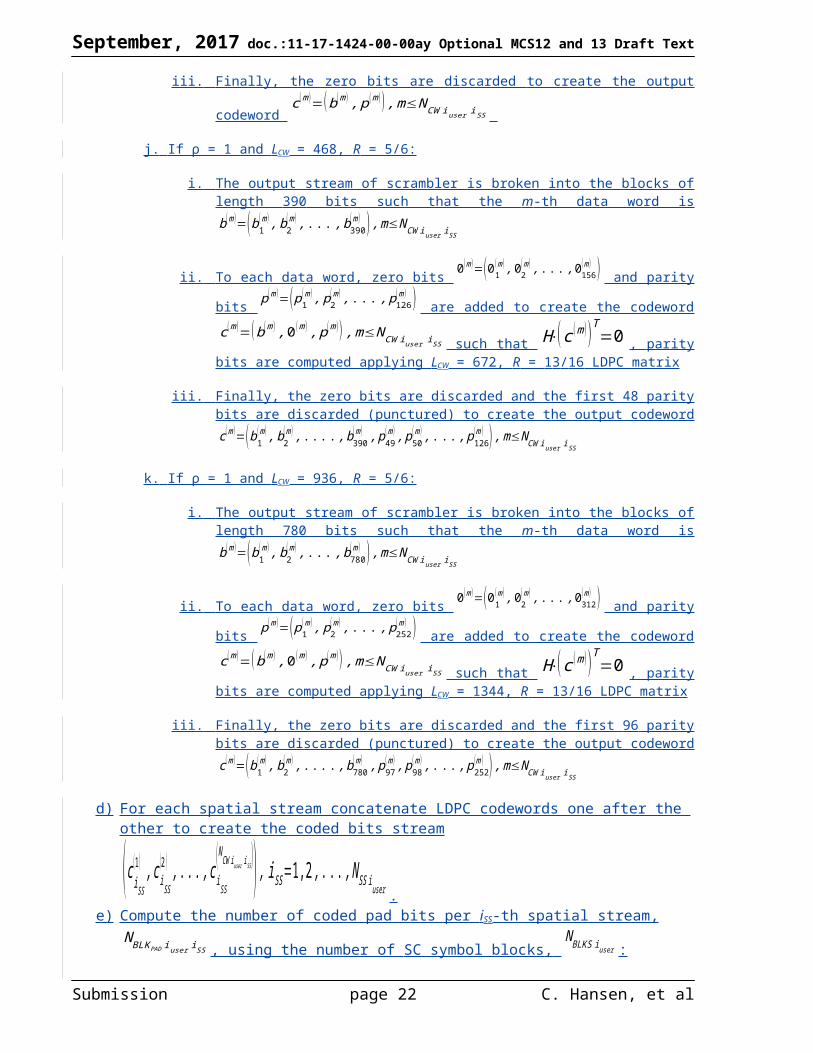
iii. Finally, the zero bits are discarded to create the output codeword
c (m)=(b (m ) , p(m ) ) , m≤NCW iuser iSS
j. If ρ = 1 and LCW = 468, R = 5/6:
i. The output stream of scrambler is broken into the blocks of length 390 bits such that the
m-th data word is b (m )=(b1
(m ) , b2(m ) ,. .. , b390
(m ) ) , m≤NCW iuser iSS
ii. To each data word, zero bits 0(m )=(01
(m) , 02(m ) , . .. , 0156
(m) ) and parity bits p(m)=(p1
(m ) , p2(m ), . .. , p126
(m ) ) are added to create the codeword
c (m)=(b (m ) ,0 (m) , p (m ) ) , m≤NCW iuser iSS such that H⋅(c (m ) )T=0 , parity bits are computed applying LCW = 672, R = 13/16 LDPC matrix
iii. Finally, the zero bits are discarded and the first 48 parity bits are discarded (punctured) to create the output codeword
c (m)=(b1(m) , b2
(m) , .. . ., b390(m ) , p49
(m ) , p50(m) , .. . , p126
(m ) ), m≤NCW iuser iSS
k. If ρ = 1 and LCW = 936, R = 5/6:
i. The output stream of scrambler is broken into the blocks of length 780 bits such that the
m-th data word is b (m )=(b1
(m ) , b2(m ) ,. .. , b780
(m ) ) , m≤NCW iuser iSS
ii. To each data word, zero bits 0(m )=(01
(m) , 02(m ), . .. , 0312
(m) ) and parity bits p(m)=(p1
(m ) , p2(m ) , . .. , p252
(m ) ) are added to create the codeword
c (m)=(b (m ) ,0 (m) , p (m ) ) , m≤NCW iuser iSS such that H⋅(c (m ) )T=0 , parity bits are computed applying LCW = 1344, R = 13/16 LDPC matrix
iii. Finally, the zero bits are discarded and the first 96 parity bits are discarded (punctured) to create the output codeword
c (m)=(b1(m) , b2
(m) , .. . ., b780(m ) , p97
(m ) , p98(m) , .. . , p252
(m ) ) , m≤NCW iuser iSS
d) For each spatial stream concatenate LDPC codewords one after the other to create the coded bits
stream (c iSS
(1 ) , c iSS
(2 ) , . .. , c iSS
( NCW iuser iSS )), iSS=1,2 , .. . , N SS iuser .
Submission page 18 C. Hansen, et al

September, 2017 doc.:11-17-1424-00-00ay Optional MCS12 and 13 Draft Text
e) Compute the number of coded pad bits per iSS-th spatial stream, N BLKPAD iuser iSS , using the number
of SC symbol blocks, N BLKS iuser :
N BLKS iuser=⌈max
i SS( N CW iuser iSS
¿ LCW iuser iSS
NCB ¿N SPB¿NCBPS iuser iSS)⌉ , iSS=1,2 , .. . , N SS iuser
If BRP PPDU and NBLKS iuser¿ NBLKS min , then N BLKS iuser
=N BLKS min
If STBC applied and N BLKS iuseris odd , then N BLKS iuser
=N BLKS iuser+1
N BLKPAD iuser iSS=N BLKS iuser
¿ NCB¿ NSPB ¿ NCBPS iuser iSS−NCW iuser iSS
¿ LCW iuser iSS, iSS=1,2 ,. . ., N SS iuser
f) Concatenate coded bits for iSS-th spatial stream with N BLKPAD iuser iSS zero bits. They are scrambled
using the continuation of the scrambler sequence that scrambled the PSDU input bits and data pad bits at step a). The pad bits of the first spatial stream are scrambled first, the pad bits of the second spatial stream are scrambled second, and so on.
For each user, if STBC coding is applied, then a single spatial stream N SS iuser
=1 is mapped to two space-time
streams N STS iuser
=2 as defined in 30.5.8.5.3. Otherwise, a one-to-one mapping of
N SS iuser spatial streams to N STS iuser space-time streams shall be applied.
NOTE—N BLKSmin is defined on a per user basis in the Requested BRP SC Blocks field within a responder’s EDMG
Capabilities element. If the Requested BRP SC Blocks field is not included in the EDMG Capabilities element, then N BLKSmin
= aBRPminSCblocks.
[a)] Compute the number of data pad bits N DATAPAD iuser , using the number of LDPC codewords
NCW iuser :
NCW iuser=⌈
Lengthiuser¿8
LCW iuser
ρiuser
¿ Riuser
⌉
Submission page 19 C. Hansen, et al

September, 2017 doc.:11-17-1424-00-00ay Optional MCS12 and 13 Draft Text
N DATAPAD iuser=NCW ¿
LCW iuser
ρiuser
¿Riuser−Lengthiuser
¿8
The scrambled PSDU is concatenated with N DATAPAD iuser zero bits. They are scrambled using the
continuation of the scrambler sequence that scrambled the PSDU input bits.
[b)] Convert the scrambled PSDU data bits to LDPC codewords depending on the repetition factor, codeword length, shortening, and code rate:
If ρ = 1 and LCW = 504, 672, 1008, 1344:
The output stream of scrambler is broken into the blocks of length LCWD = LCW×R bits such that
the mth data word is b (m )=(b1
(m ) , b2(m) , .. . ,bLCWD
(m ) ) , m≤NCW iuser
To each data word, parity bits p(m)=( p1
(m) , p2(m ) ,. .. , pLCWP
(m ) ) , LCWP = LCW – LCWD, are added to
create the codeword c (m)=(b (m ) , p(m ) ) , m≤NCW iuser such that H⋅(c (m ) )T=0
If ρ = 1 and LCW = 468 or 624, R = 5/6 or 7/8:
The output stream of scrambler is broken into the blocks of length 546 bits (390 for rate 5/6) such
that the mth data word is b (m )=(b1
(m ) , b2(m ) ,. .. , b546
(m ) ) ,m≤NCW iuser
To each data word, parity bits p(m)=( p1
(m) , p2(m ) ,. .. , pL126
(m ) ) are added to create the codeword (b (m) , p (m ) ) , m≤NCW iuser . Parity bits are computed applying LCW = 672, R = 13/16 LDPC matrix
Finally, the first 48 parity bits are discarded (punctured) to create the output codeword
c (m)=(b1(m) , b2
(m) , .. . ., b546(m ) , p49
(m ) , p50(m) , .. . , p126
(m ) ) , m≤NCW iuser
If ρ = 1 and LCW = 936 or 1248, R = 5/6 or 7/8:
The output stream of scrambler is broken into the blocks of length 1092 bits (780 for rate 5/6)
such that the mth data word is b (m )=(b1
(m ) , b2(m ) ,. .. , b1092
(m ) ), m≤NCW iuser
To each data word, parity bits p(m)=( p1
(m) , p2(m ) ,. .. , pL252
(m ) ) are added to create the codeword (b (m) , p (m ) ) , m≤NCW iuser . Parity bits are computed applying LCW = 1344, R = 13/16 LDPC matrix
Finally, the first 96 parity bits are discarded (punctured) to create the output codeword
c (m)=(b1(m) , b2
(m) , .. . ., b1092(m ) , p97
(m ), p98(m ), .. . , p252
(m ) ) , m≤NCW iuser
If ρ = 2 and LCW = 672, R = 1/2:
The output stream of scrambler is broken into the blocks of length 168 bits such that the m th data
word is b (m )=(b1
(m ) , b2(m ) ,. .. , b168
(m ) ) , m≤NCW iuser
Submission page 20 C. Hansen, et al
September, 2017 doc.:11-17-1424-00-00ay Optional MCS12 and 13 Draft Text
To each data word, zero bits 0(m )=(01
(m) , 02(m ), . .. ,0168
( m) ) and parity bits p(m)=(p1
(m ) , p2(m ), . .. , p168
(m ) ) are added to create the codeword
c (m)=(b (m ) ,0 (m) , p (m ) ) , m≤NCW i user such that H⋅(c (m ) )T=0
Finally, the zero bits are replaced with word b(m )
repetition XORed by the PN sequence that is generated from the LFSR used for MCS 1 scrambling as defined in Error: Reference source notfound. The LFSR is initialized to all ones initial seed value and reinitialized to the same seed after every codeword.
If ρ = 2 and LCW = 1344, R = 1/2:
The output stream of scrambler is broken into the blocks of length 336 bits such that the m th data
word is b (m )=(b1
(m ) , b2(m ) ,. .. , b336
(m ) ) ,m≤NCW iuser
To each data word, zero bits 0(m )=(01
(m) , 02(m ) , . .. ,0336
(m) ) and parity bits p(m)=(p1
(m ) , p2(m ), . .. , p336
(m ) ) are added to create the codeword
c (m)=(b (m ) ,0 (m) , p (m ) ) , m≤NCW i user such that H⋅(c (m ) )T=0
Finally, the zero bits are replaced with word b(m )
repetition XORed by the PN sequence that is generated from the LFSR used for MCS 1 scrambling as defined in Error: Reference source notfound. The LFSR is initialized to all ones initial seed value and reinitialized to the same seed after every codeword.
[c)] Concatenate LDPC codewords one after the other to create the coded bits stream (c (1 ) ,c (2 ) ,. . ., c (NCW i user ))
[d)] Compute the number of coded pad bits, N BLKPAD iuser , using the number of SC symbol blocks,
N BLKS iuser :
N BLKS iuser=⌈
N CW iuser¿ LCW iuser
N CB¿NCBPB iuser
⌉
If BRP PPDU and NBLKS iuser¿ NBLKS min , then N BLKS iuser
=N BLKS min
If STBC applied and N BLKS iuseris odd , then N BLKS iuser
=N BLKS iuser+1
N BLKPAD iuser=N BLKS iuser
¿ NCB¿ NCBPB iuser−NCW iuser
¿ LCW iuser
[e)] Concatenate the coded bit stream with N BLKPAD iuser zero bits. They are scrambled using the continuation
of the scrambler sequence that scrambled the PSDU input bits and data pad bits at step a).
Submission page 21 C. Hansen, et al
September, 2017 doc.:11-17-1424-00-00ay Optional MCS12 and 13 Draft Text
For each user, if STBC coding is applied, then a single spatial stream N SS iuser
=1 is mapped to two space-time
streams N STS iuser
=2 as defined in Error: Reference source not found. Otherwise, a single spatial stream
N SS iuser=1
is mapped to a single space-time stream N STS iuser
=1.
NOTE—N BLKSmin is defined on a per user basis in the Requested BRP SC Blocks field within a responder’s EDMG
Capabilities element. If the Requested BRP SC Blocks field is not included in the EDMG Capabilities element, then N BLKSmin
= aBRPminSCblocks.
[30.5.8.4.4] LDPC encoding for more than one spatial stream (iss > 1) transmissionThis subclause defines the PSDU encoding process for both an SU PPDU and an MU PPDU for the case of more than one spatial stream transmission. The LDPC encoding may employ codeword lengths LCW = 468, 504, 624, 672, 936, 1008, 1248, or 1344 and code rates R = ½, 5/8, 2/3, ¾, 13/16, 5/6, or 7/8.
The LDPC encoding process for the iuserth user shall be as follows: (iuser=1 for SU)
[a)] Compute the number of data pad bits N DATAPAD iuser , using the number of LDPC codewords per iSS
th spatial
stream NCW iuser iSS :
NCW iuser iSS=⌈
Lengthiuser¿8
∑iSS=1
NSS iuser
NCBPS iuser iSS¿
LCW iuser
ρiuser iSS
¿Riuser iSS
⌉¿NCBPS iuser iSS
N DATAPAD iuser=∑
i SS=1
NSS
NCW iuser iSS¿
LCW iuser
ρiuser iSS
¿Riuser i SS−Lengthiuser
¿8
[a)] Compute the number of data pad bits N DATAPAD iuser , using the number of bits in the group
Ng iuser iSS and the number of LDPC codewords NCW iuser iSS :
Ng iuser iSS=1 , if N SS iuser
=1
Ng iuser iSS=NCBPS iuser iSS
¿Riuser iSS
ρ¿16 , if N SS iuser
¿1
Submission page 22 C. Hansen, et al

September, 2017 doc.:11-17-1424-00-00ay Optional MCS12 and 13 Draft Text
NCW iuser i SS=⌈⌈
Lengthiuser¿8
∑j=1
N SS i user
Ng iuser j
⌉¿Ng iuser iSS
LCW iuser iSS¿
Riuser i SS
ρ¿MCW iuser iSS
⌉ ¿M CW iuser iSS, i SS=1,2 , .. . , N SS iuser
MCW iuser iSS=
NCBPS iuser iSS
1−γiuser iSS
N DATAPAD iuser= ∑
iSS=1
N SS iuser (NCW iuser iSS¿ LCW iuser iSS
¿Riuser iSS
ρ )−Length¿8
The scrambled PSDU is concatenated with N DATAPAD iuser zero bits. They are scrambled using the
continuation of the scrambler sequence that scrambled the PSDU input bits.
[b)] Distribute the PSDU scrambled bits over N SS iuser spatial streams. Bits distribution is performed on the
group basis with the number of bits in the group Ngiuser iSS bits come to the iSS-th spatial stream. The first
group of bits comes to the first stream, the second group of bits comes to the second stream and so on. The
procedure is repeated when the maximum number of spatial streams N SS iuser is reached. If the number of
codewords NCW iuser iSS are filled with the distributed data groups, then this stream is skipped during the
next cycle of round robin distribution. The procedure ends up when all PSDU bits including N DATAPAD iuser
pad bits are distributed over the N SS iuser spatial streams.
[c)] For each spatial stream, convert the scrambled PSDU bits to LDPC codewords as described in subclause 30.5.8.4.3, step b).
[d)] For each spatial stream, concatenate LDPC codewords one after the other to create the coded bits stream
(c iSS
(1 ) , c iSS
(2 ) , . .. , c iSS
( NCW iuser iSS )), iSS=1,2 , .. . , N SS iuser .
[e)] Compute the number of coded pad bits per iSSth spatial stream,
N BLKPAD iuser iSS , using the number of SC
symbol blocks, N BLKS iuser :
N BLKS iuser=⌈
NCW iuser iSS¿ LCW iuser
N CB¿ NSPB ¿N CBPS iuser i SS
⌉
If BRP PPDU and NBLKS iuser¿NBLKS min , then N BLKS iuser
=N BLKS min
Submission page 23 C. Hansen, et al

September, 2017 doc.:11-17-1424-00-00ay Optional MCS12 and 13 Draft Text
N BLKPAD iuser iSS=N BLKS iuser
¿NCB¿NSPB ¿NCBPS iuser iSS−NCW iuser iSS
¿ LCW iuser
[f)] Concatenate coded bits for iSSth spatial stream with
N BLKPAD iuser iSS zero bits. They are scrambled using the continuation of the scrambler sequence that scrambled the PSDU input bits and data pad bits at step a). The pad bits of the first spatial stream are scrambled first, the pad bits of the second spatial stream are scrambled second, and so on.
For each user, a one-to-one mapping of N SS iuser spatial streams to
N STS iuser space-time streams shall be applied.
[30.5.8.4.5] MU PPDU padding and space-time streams mappingFor an MU PPDU transmission, all user PPDUs shall be aligned in time. If necessary to achieve this, PSDUs within the MU PPDU shall be padded according to the following steps:
a) Compute the maximum number of SC symbol blocks over all users N BLKSmax=max
iuser( NBLKS iuser )
for iuser
= 1, 2, …, Nuser.
[b)] Update the number of SC symbol blocks at step de) in 30.5.8.4.3 and step e) in 30.5.8.4.4 as N BLKS iuser
=N BLKS max for iuser = 1, 2, …, Nuser. Update the number of pad bits for the iuserth user
accordingly.
b)[c)] The number of pad SC symbol blocks for the MU PPDU transmission for the iuserth user is defined as
N PADBLKS iuser=N BLKS max−N BLKS iuser .
The number of pad blocks N PADBLKS iuser takes into account the MU PPDU padding only and does not include the
regular padding described in 30.5.8.4.3 and in 30.5.8.4.4.
The space-time stream index per user, iSTS iuser , is mapped to the space-time stream index over all users,
iSTS , as follows:
iSTS (iuser ,iSTS iuser )= ∑m=0
iuser−1
Numm+iSTS iuser, 1≤iSTS iuser
¿N STS iuser, 1≤iuser¿Nuser
Numm=N STS m for m> 0 and Numm=0 otherwise
NOTE—iSTS is a function of
iuser and iSTS iuser indices. However, to simplify the notation, this dependence is not indicated
explicitly in other equations.
Modify the following Section:
Submission page 24 C. Hansen, et al
September, 2017 doc.:11-17-1424-00-00ay Optional MCS12 and 13 Draft Text
30.5.8.5 Modulation mapping
30.5.8.5.1 GeneralThe coded and padded bit stream is converted into a stream of complex constellation points, following the rules defined in 20.6.3.2.4 for π/2-BPSK, π/2-QPSK, π/2-16-QAM, and π/2-64-QAM. For π/2-8-PSK, follow the rules defined in 30.5.8.5.2.
Add the following Section:
30.5.8.5.2 π/2-8-PSK modulation
In π/2-8-PSK modulation, the input stream is grouped into sets of 3 bits and mapped according to the following equation:
s~
k=exp ( j π4 (c3 k−3 c3 k+1−c3k+2−2 c3k c3k+1+2 c3 k+1 c3k+2+2c3 k c3 k+2+4 c3k c3k+1 c3 k+2+4 ))
table below where k is the symbol output index, k = 0, 1, …. Each output symbol is then rotated according to the
following equation: sk s̃k e j k 2 = sk=s~
k⋅e j⋅π⋅k /2. The constellation bit encoding for 8-PSK is depicted in
Figure 1 below.
Table XYZ - π/2-8PSK Mapping
Input bit sequence: c3kc3k+1c3k+2 Output symbol: sk
000 -1
001 ej3π/4
010 ejπ/4
011 j
100 ej5π/4
101 -j
110 1
111 ej7π/4
Submission page 25 C. Hansen, et al

September, 2017 doc.:11-17-1424-00-00ay Optional MCS12 and 13 Draft Text
Figure 1: 8-PSK constellation bit encoding
Submission page 26 C. Hansen, et al
September, 2017 doc.:11-17-1424-00-00ay Optional MCS12 and 13 Draft Text
Figure XYZ - 8PSK Constellation Bit Encoding
Submission page 27 C. Hansen, et al