Embed Size (px)
Citation preview
July 2003
MetalinkSlide 1
Doc.: IEEE 11-03-0515-00-htsg
Submission
Time Variable HT MIMO Channel Measurements
Nir Tal
Metalink([email protected])
July 2003
MetalinkSlide 2
Doc.: IEEE 11-03-0515-00-htsg
Submission
Purpose
• Provide a snapshot of real-environment MIMO measurements with time variability
• Derive HT capacity figures and quantify improvement
• Quantify time variability and underlying effects
July 2003
MetalinkSlide 3
Doc.: IEEE 11-03-0515-00-htsg
Submission
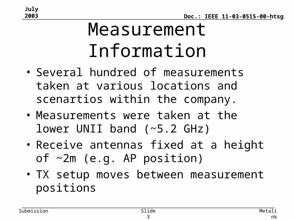
Measurement Information
• Several hundred of measurements taken at various locations and scenartios within the company.
• Measurements were taken at the lower UNII band (~5.2 GHz)
• Receive antennas fixed at a height of ~2m (e.g. AP position)
• TX setup moves between measurement positions
July 2003
MetalinkSlide 4
Doc.: IEEE 11-03-0515-00-htsg
Submission
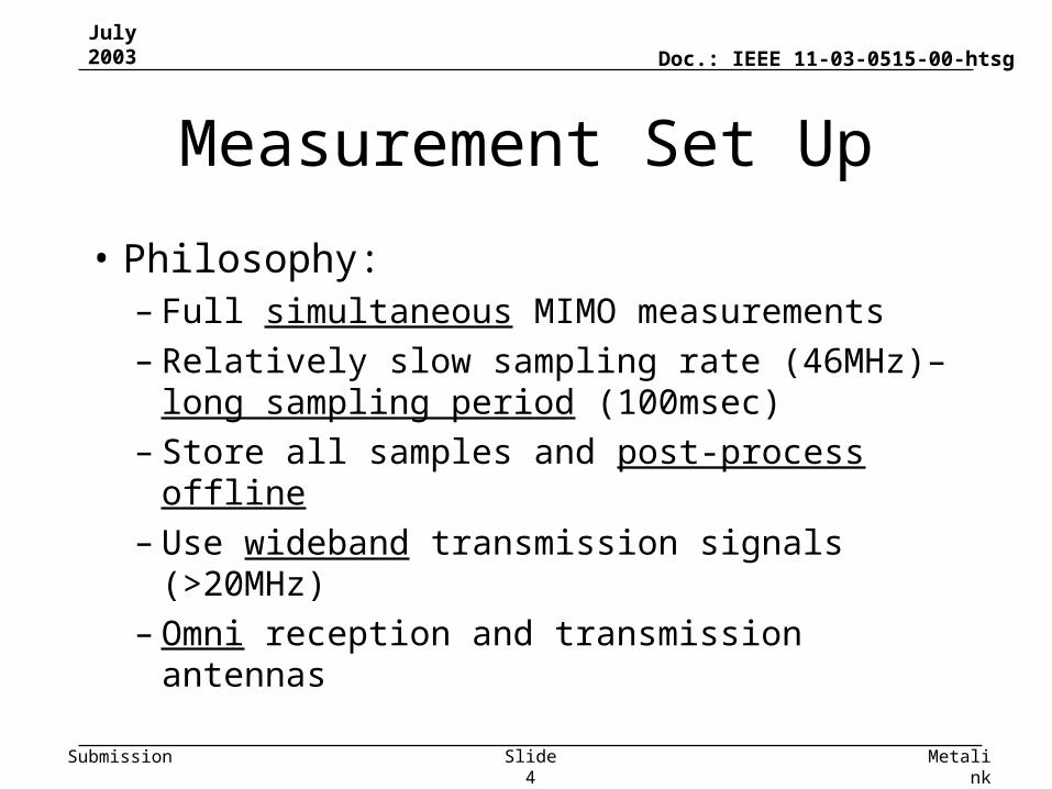
Measurement Set Up
• Philosophy:– Full simultaneous MIMO measurements– Relatively slow sampling rate (46MHz)– long
sampling period (100msec)– Store all samples and post-process offline– Use wideband transmission signals (>20MHz) – Omni reception and transmission antennas
July 2003
MetalinkSlide 5
Doc.: IEEE 11-03-0515-00-htsg
Submission
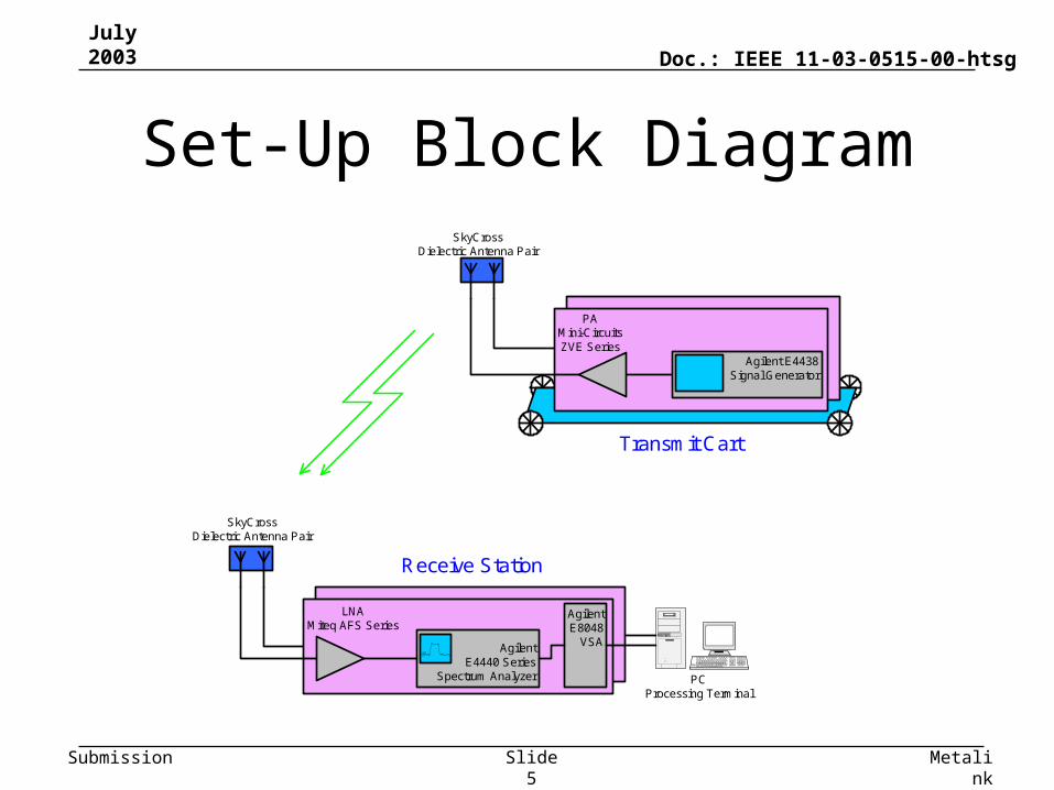
Set-Up Block Diagram
LNAMiteq AFS Series
Agilent E4438Signal Generator
AgilentE4440 Series
Spectrum Analyzer
AgilentE8048
VSA
SkyCrossDielectric Antenna Pair
PCProcessing Terminal
PAMini-CircuitsZVE Series
SkyCrossDielectric Antenna Pair
Transmit Cart
Receive Station
July 2003
MetalinkSlide 6
Doc.: IEEE 11-03-0515-00-htsg
Submission
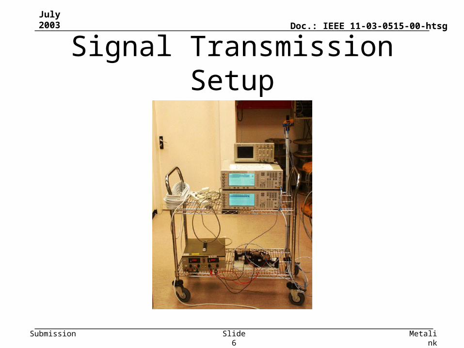
Signal Transmission Setup
July 2003
MetalinkSlide 7
Doc.: IEEE 11-03-0515-00-htsg
Submission
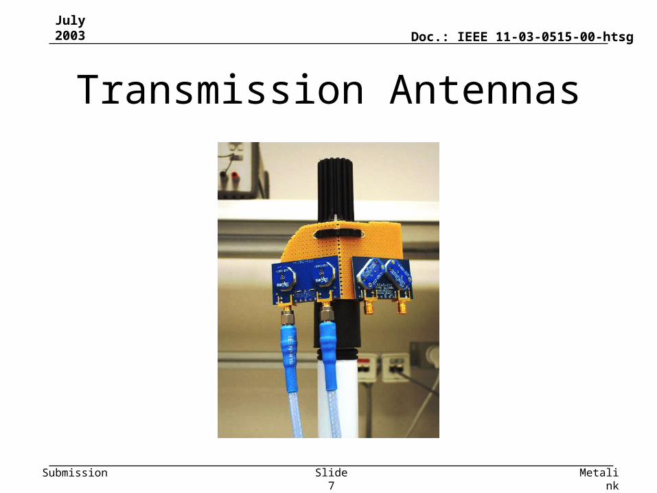
Transmission Antennas
July 2003
MetalinkSlide 8
Doc.: IEEE 11-03-0515-00-htsg
Submission
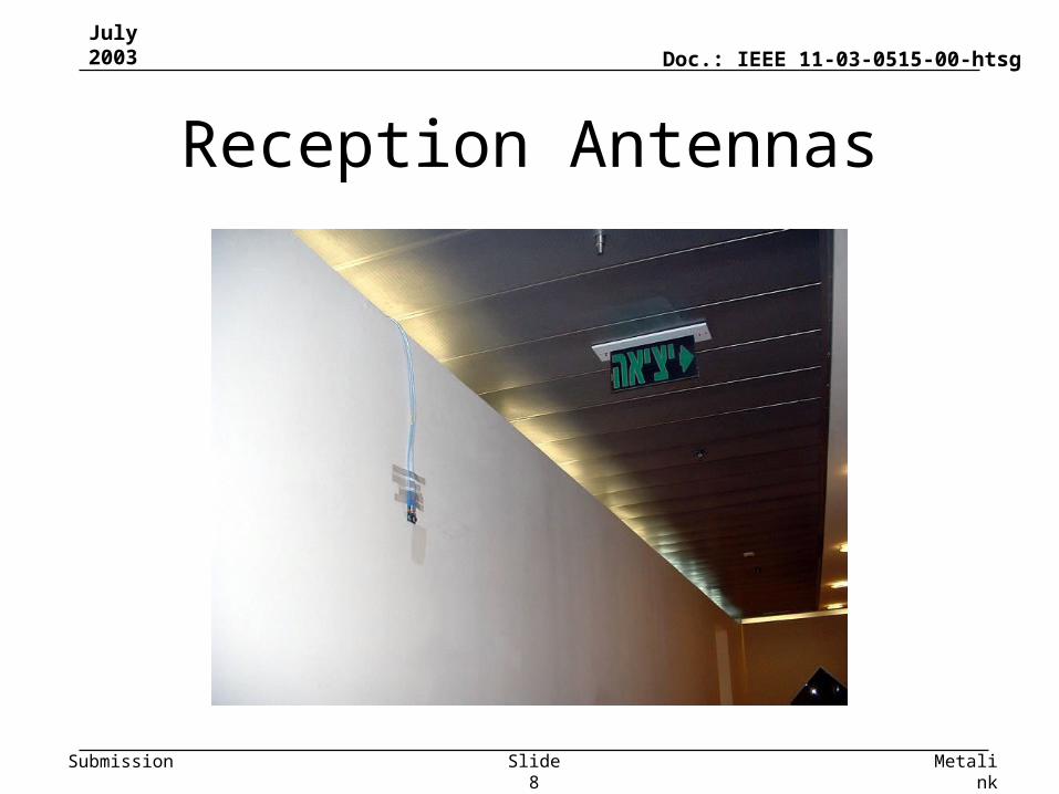
Reception Antennas
July 2003
MetalinkSlide 9
Doc.: IEEE 11-03-0515-00-htsg
Submission
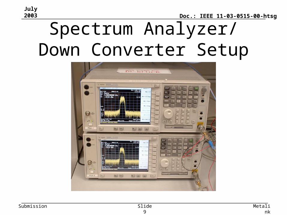
Spectrum Analyzer/ Down Converter Setup
July 2003
MetalinkSlide 10
Doc.: IEEE 11-03-0515-00-htsg
Submission
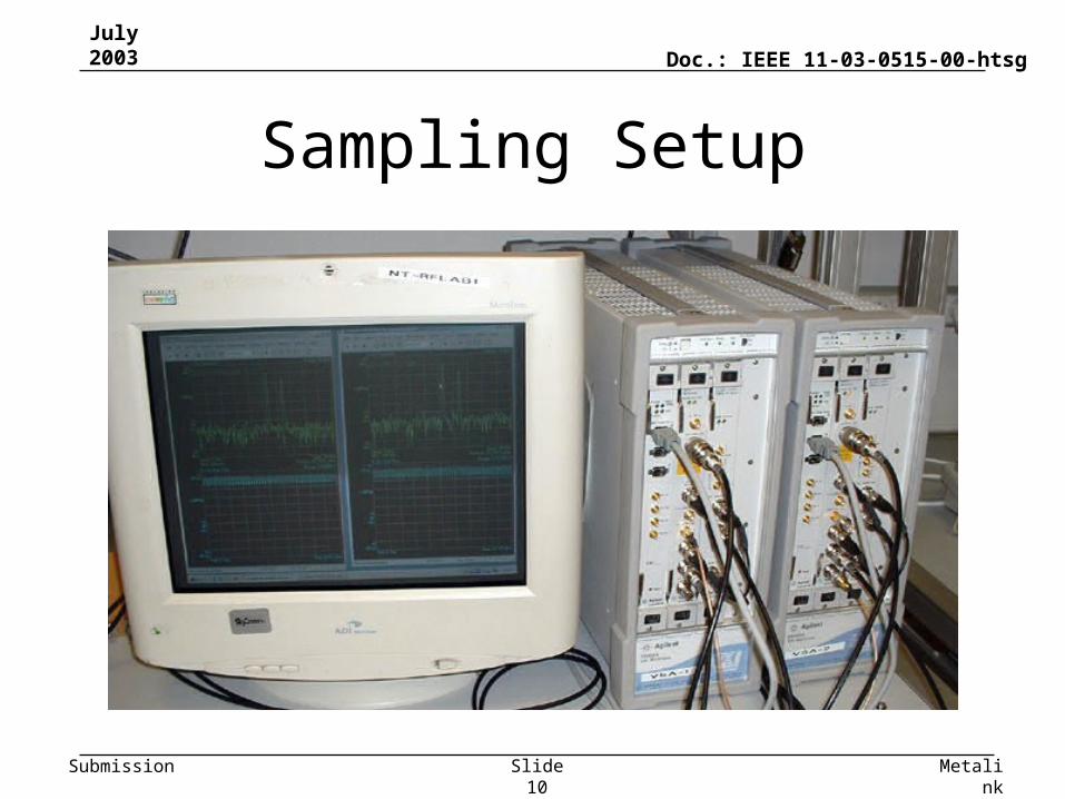
Sampling Setup
July 2003
MetalinkSlide 11
Doc.: IEEE 11-03-0515-00-htsg
Submission
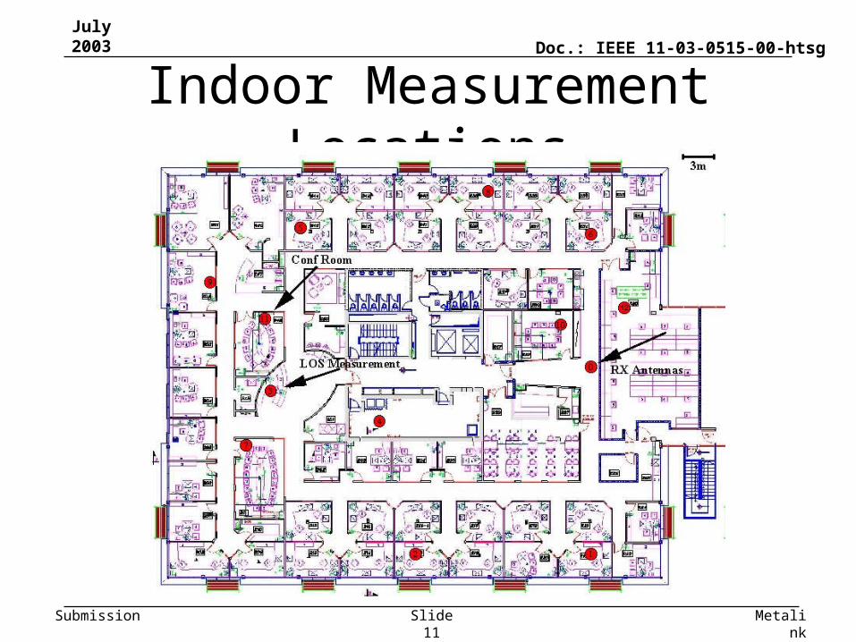
Indoor Measurement Locations

July 2003
MetalinkSlide 12
Doc.: IEEE 11-03-0515-00-htsg
Submission
Result Snapshot
July 2003
MetalinkSlide 13
Doc.: IEEE 11-03-0515-00-htsg
Submission
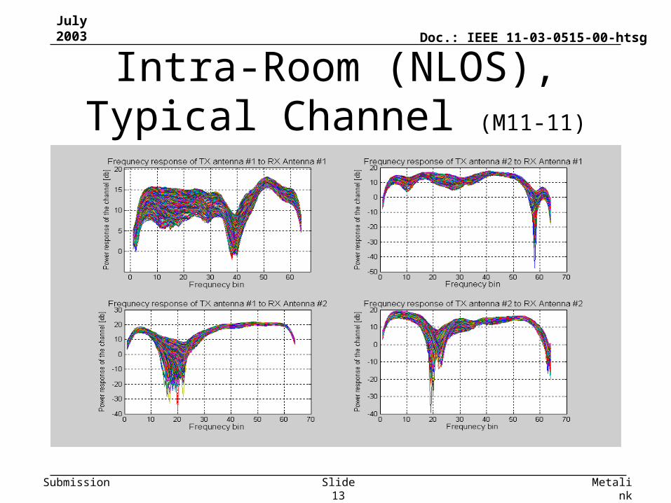
Intra-Room (NLOS), Typical Channel (M11-11)
July 2003
MetalinkSlide 14
Doc.: IEEE 11-03-0515-00-htsg
Submission
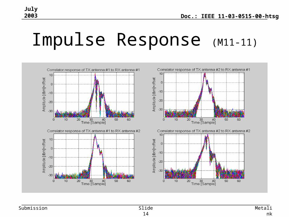
Impulse Response (M11-11)
July 2003
MetalinkSlide 15
Doc.: IEEE 11-03-0515-00-htsg
Submission
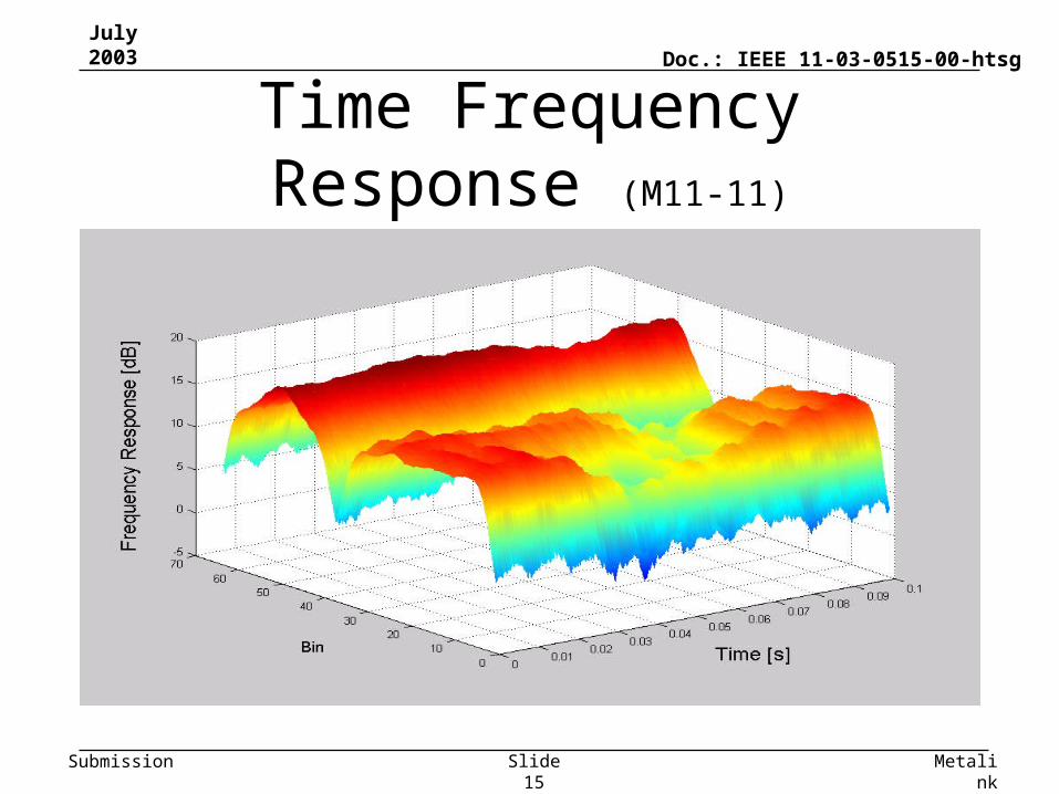
Time Frequency Response (M11-11)
July 2003
MetalinkSlide 16
Doc.: IEEE 11-03-0515-00-htsg
Submission
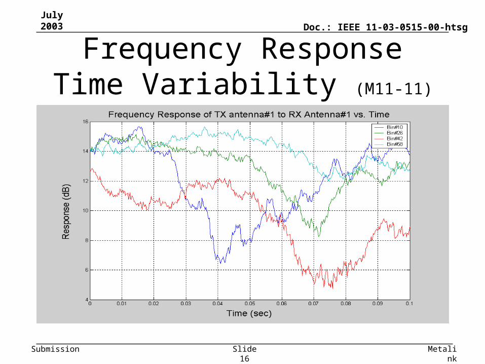
Frequency Response Time Variability (M11-11)
July 2003
MetalinkSlide 17
Doc.: IEEE 11-03-0515-00-htsg
Submission
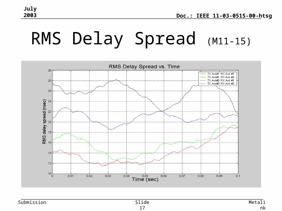
RMS Delay Spread (M11-15)
July 2003
MetalinkSlide 18
Doc.: IEEE 11-03-0515-00-htsg
Submission
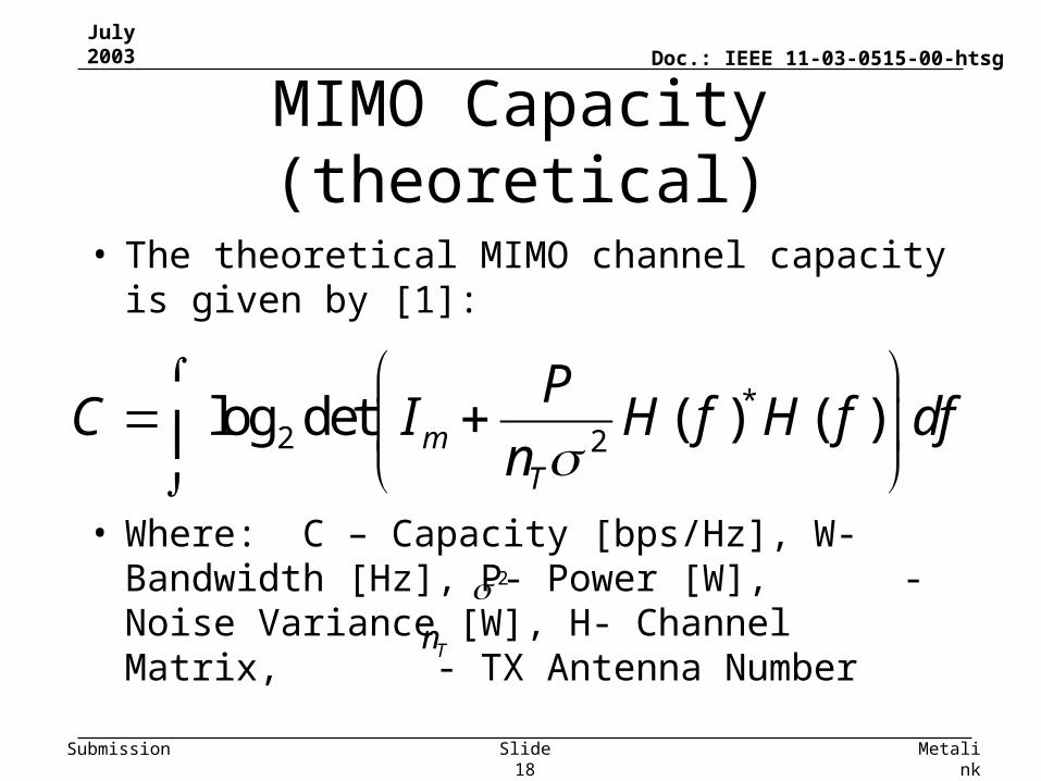
MIMO Capacity (theoretical)
• The theoretical MIMO channel capacity is given by [1]:
• Where: C – Capacity [bps/Hz], W- Bandwidth [Hz], P- Power [W], - Noise Variance [W], H- Channel Matrix, - TX Antenna Number
*2 2
log det ( ) ( )mT
PC I H f H f df
n
2
Tn
July 2003
MetalinkSlide 19
Doc.: IEEE 11-03-0515-00-htsg
Submission
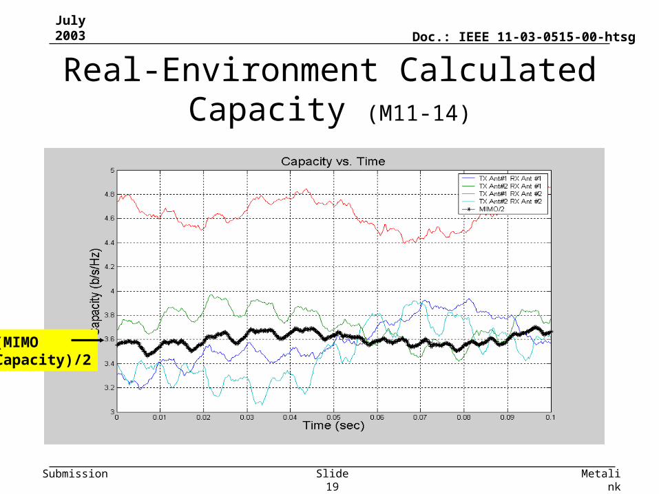
Real-Environment Calculated Capacity (M11-14)
(MIMO Capacity)/2

July 2003
MetalinkSlide 20
Doc.: IEEE 11-03-0515-00-htsg
Submission
Statistical Findings
July 2003
MetalinkSlide 21
Doc.: IEEE 11-03-0515-00-htsg
Submission
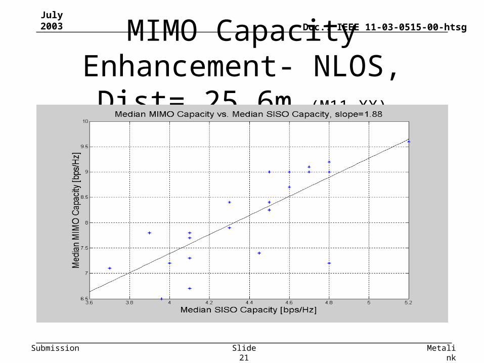
MIMO Capacity Enhancement- NLOS, Dist= 25.6m (M11-XX)
July 2003
MetalinkSlide 22
Doc.: IEEE 11-03-0515-00-htsg
Submission
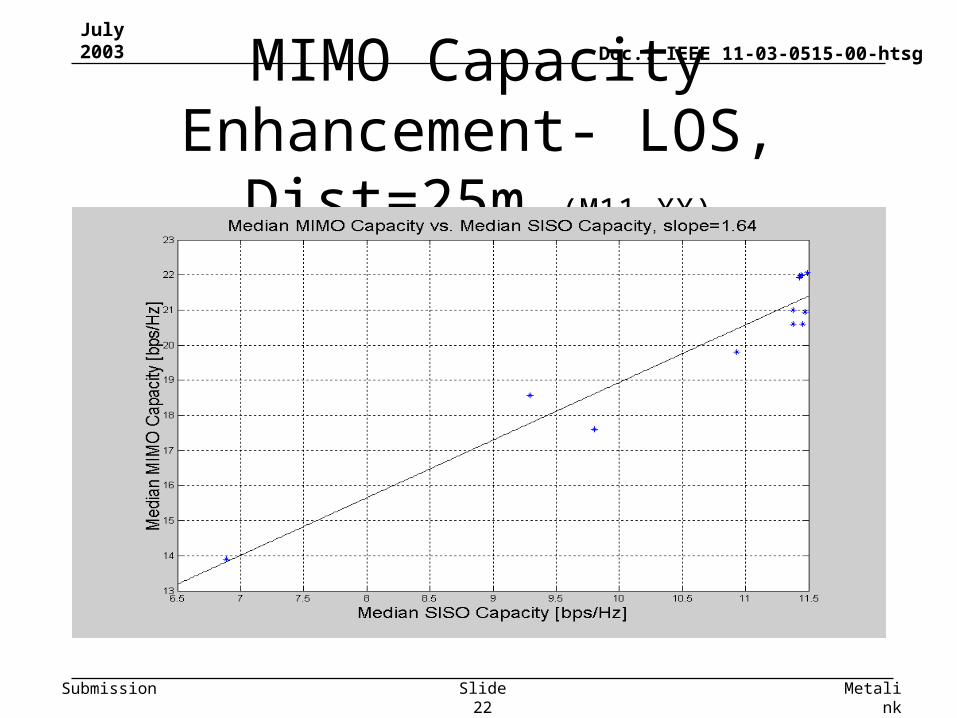
MIMO Capacity Enhancement- LOS, Dist=25m (M11-XX)
July 2003
MetalinkSlide 23
Doc.: IEEE 11-03-0515-00-htsg
Submission
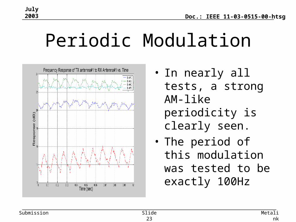
Periodic Modulation
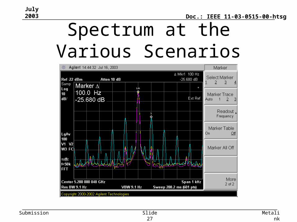
• In nearly all tests, a strong AM-like periodicity is clearly seen.
• The period of this modulation was tested to be exactly 100Hz
July 2003
MetalinkSlide 24
Doc.: IEEE 11-03-0515-00-htsg
Submission
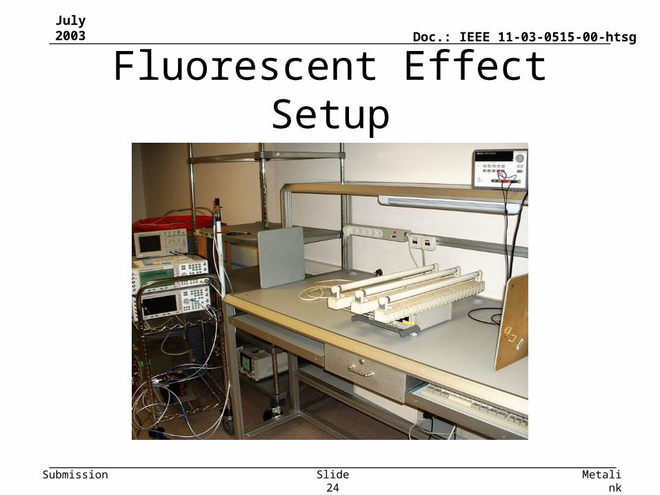
Fluorescent Effect Setup
July 2003
MetalinkSlide 25
Doc.: IEEE 11-03-0515-00-htsg
Submission
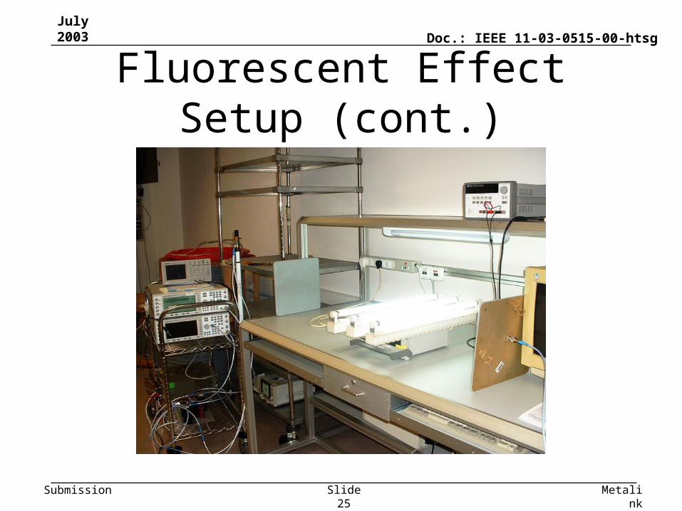
Fluorescent Effect Setup (cont.)
July 2003
MetalinkSlide 26
Doc.: IEEE 11-03-0515-00-htsg
Submission
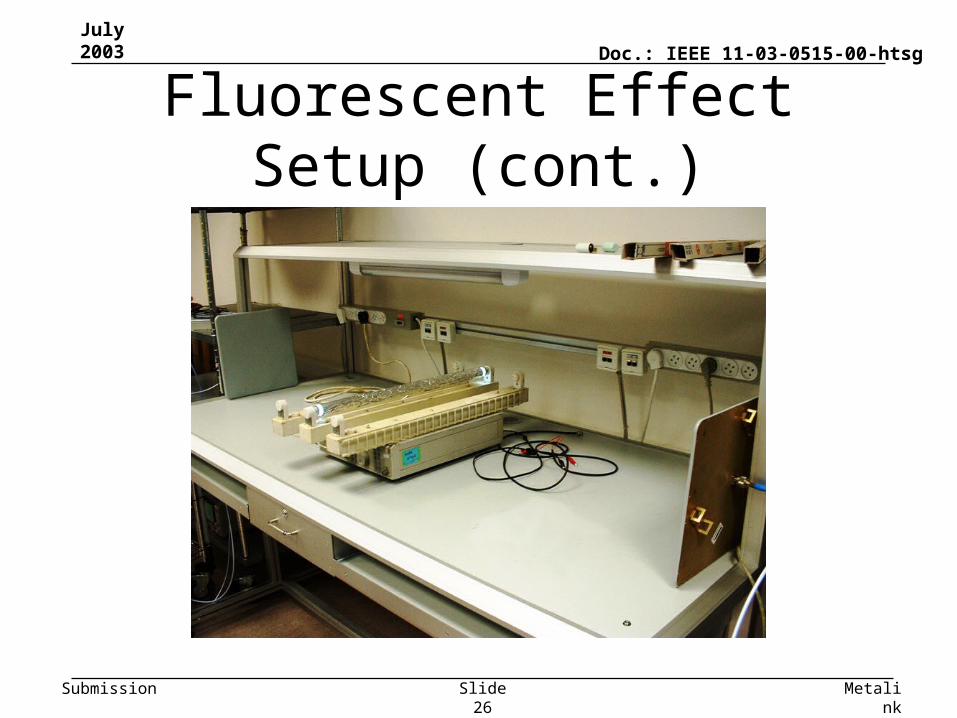
Fluorescent Effect Setup (cont.)
July 2003
MetalinkSlide 27
Doc.: IEEE 11-03-0515-00-htsg
Submission
Spectrum at the Various Scenarios
July 2003
MetalinkSlide 28
Doc.: IEEE 11-03-0515-00-htsg
Submission
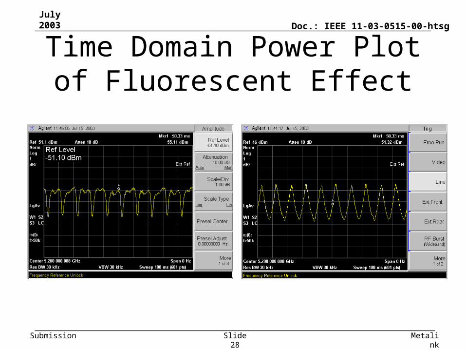
Time Domain Power Plot of Fluorescent Effect
July 2003
MetalinkSlide 29
Doc.: IEEE 11-03-0515-00-htsg
Submission
The Fluorescent Effect
• Fluorescent lights become conductive twice every AC power cycle.
• During that period, the electromagnetic environment (reflections) are changed.
• The channels in such environment exhibit strong AM modulation in all parameters (frequency response, RMS delay spread, capacity, etc.)
• We therefore suggest to incorporate this effect into the MIMO channel models as it is one of the major causes of channel time variability
July 2003
MetalinkSlide 30
Doc.: IEEE 11-03-0515-00-htsg
Submission
Conclusions
• In typical enterprise scenario 2 antenna MIMO enhances the median capacity by 1.5-2x (NLOS and LOS)
• Channels exhibits “slow” variability changes over 100ms (f<10Hz)
• In the vicinity of fluorescence lights the channel is modulated by a strong 100/120Hz AM modulation (up to 5dB)
July 2003
MetalinkSlide 31
Doc.: IEEE 11-03-0515-00-htsg
Submission
Summary
• A snap-shot of channel measurements in office environment has been presented
• Measurements are ongoing and their study shall include topics such as: antenna polarization, channel reciprocity and LOS behavior .
• These results are being integrated into the Channel Modeling Sub-Committee led by Erceg.
July 2003
MetalinkSlide 32
Doc.: IEEE 11-03-0515-00-htsg
Submission
References
• [1] – Branka Vucetic, “Space-Time Coding”, Wiley& Sons, 2003