Embed Size (px)
Citation preview

LIFEPAK 12 Defibrillator/Monitor Series Section 6 Contents
Previous Page Table of Contents Back Index Next Page
1
Doc ID: 3011711, Rev: Y, Pg 1 of 170
Performance Inspection Procedures
The Performance Inspection Procedures (PIP) are a set of manual test procedures used for an operational closed-case evaluation of the LIFEPAK 12 defibrillator/monitor. This section describes the test procedures you will perform to determine if the LIFEPAK 12 defibrillator/monitor is operating within the required specifications. Investigate and correct any malfunctions or out-of-tolerance conditions detected during the PIP.
The PIP comprises safety and performance tests recommended by AHA/ASHE (American Hospital Association/American Society for Hospital Engineering) Maintenance Management for Medical Equipment and International Electrotechnical Commission (IEC) Technical Report 1288-2, Maintenance of Cardiac Defibrillators-Monitors.
Perform the PIP as part of a regularly scheduled preventive maintenance routine. Also, perform the PIP after any repair, replacement, or TCP calibration procedure. The PIP Checklist is provided as an optional tool for recording test results. Also refer to the Operator Checklist for additional items.
PIP – Scope and ApplicabilityPIP – Resource RequirementsPIP – Test Equipment RequirementsPIP – InstructionsPIP – Summary of Leakage Current Specifications
(continued on next page)3011711_Y_PIP-TCP.pdf

Previous Page Table of Contents Section Contents Back Index Next Page
LIFEPAK 12 Defibrillator/Monitor Series Performance Inspection Procedures
2
Doc ID: 3011711, Rev: Y, Pg 2 of 170
Performance Inspection Procedures (continued)
PIP – Modem PC CardPIP – LIFENET BLUEPIP – Voice Recorder AccessoryPIP – LP12 Maintenance Due InstructionPIP – Power AdaptersPIP – Checklist
3011711_Y_PIP-TCP.pdf

Previous Page Table of Contents Section Contents Back Index Next Page
LIFEPAK 12 Defibrillator/Monitor Series Performance Inspection Procedures
3
Doc ID: 3011711, Rev: Y, Pg 3 of 170
PIP – Scope and Applicability
The PIP applies to the LIFEPAK 12 defibrillator/monitor only. To complete the PIP, you perform the manual tests outlined in the PIP – Instructions section of this Service Manual. All required PIP tests applicable to the LIFEPAK 12 defibrillator/monitor configuration under test must be performed.
Refer to the PIP – Resource Requirements for a listing of the necessary qualifications for PIP equipment, test equipment verification, workstation power, and personnel.
Refer to the PIP – Test Equipment Requirements for a listing of test equipment, including specifications, required to complete the PIP.
The PIP Checklist is provided as an optional tool for recording test results.
3011711_Y_PIP-TCP.pdf

Previous Page Table of Contents Section Contents Back Index Next Page
LIFEPAK 12 Defibrillator/Monitor Series Performance Inspection Procedures
4
Doc ID: 3011711, Rev: Y, Pg 4 of 170
PIP – Resource Requirements
This section describes the requirements for PIP equipment, PIP test equipment verification, PIP workstation power, and PIP personnel.
PIP – Equipment To perform the PIP, you must use the equipment listed in the PIP – Test Equipment Requirements table. Although the table lists specific test equipment by manufacturer, test equipment with equivalent specifications may be substituted.
Note: Using test equipment other than that specified in the PIP – Test Equipment Requirements table may provide test results that are different from those specified in this manual. It is the responsibility of the bio-medical personnel who maintain this device to determine test equipment equivalency.
PIP – Test Equipment Verification
All test equipment used to perform the PIP must have a current calibration label, issued by a certified calibration facility.
PIP – Workstation Power
The ac line power to the workstation used must be connected to a grounded power source.
PIP – Personnel Technicians who perform the PIP must be properly qualified and thoroughly familiar with the operation of the LIFEPAK 12 defibrillator/monitor, meeting the requirements described in Service Personnel Qualifications.
3011711_Y_PIP-TCP.pdf

Previous Page Table of Contents Section Contents Back Index Next Page
LIFEPAK 12 Defibrillator/Monitor Series Performance Inspection Procedures
5
Doc ID: 3011711, Rev: Y, Pg 5 of 170
PIP – Test Equipment Requirements Page 1 of 4
The following is a list of test equipment required to conduct the PIP.
Equipment Specifications Manufacturer
Defibrillator Analyzer1
1. Some energy meters are not accurate for biphasic waveforms; contact your defibrillator analyzer’s manufacturer for more information.
Energy range: 0 to 450 J Load resistance: 50 ±1% Accuracy: ±2% +2 JWaveforms: NSR, VF, and Sine Wave
Fluke Biomedical QED-6H™, with test posts accessory (Software Version 2.07, or greater) or equivalent
Patient Simulator2
2. The patient simulator used for blood pressure verification must be accurate to ±2%. The specifications in this procedure may not be met by a simulator with lesser accuracy.
Simultaneous 12-lead outputRates: 30 bpm, 120 bpm @ 1 mvRate accuracy: ±1%, Blood Pressure accuracy ±1% full scale, ±1 MMHg
Fluke Biomedical DNI 215A/217A (with accessory cable [3010-0116] for invasive blood pressure measurement) or equivalent
Safety Analyzer 110 or 220 Vac line voltageCurrent range: 0-1999 ACurrent accuracy: 5% of reading or 1 digit (whichever is greater)
Fluke Biomedical - Dale Model 601 (120 vac line input) or 601E (240 vac line input) or equivalent
Decade Resistance Box 0 to 9 M resistance boxResolution: 1 ; Accuracy: ±1%
IET RS-200 Resistance Substituter or equivalent
3011711_Y_PIP-TCP.pdf

Previous Page Table of Contents Section Contents Back Index Next Page
LIFEPAK 12 Defibrillator/Monitor Series Performance Inspection Procedures
6
Doc ID: 3011711, Rev: Y, Pg 6 of 170
PIP – Test Equipment Requirements(continued) Page 2 of 4
Equipment Specifications Manufacturer
QUIK-COMBO test post adapter Connects to QUIK-COMBO Therapy Cable Physio-Control MIN 3005302
AC Power Adapter Input power: 120/230 vac, 50/60 Hz Physio-Control MIN 3010942
Stop Watch Elapsed timer (minutes, seconds) ACCUSPLIT 705X or equivalent
3-Lead ECG cable Standard accessory with the 3-Lead LIFEPAK 12 defibrillator/monitor
Physio-Control MIN 3006218
12-Lead ECG cable Standard accessory with the 12-Lead LIFEPAK 12 defibrillator/monitor
Physio-Control MIN 805265
General purpose oscilloscope Bandwidth: dc to 2 MHzVertical accuracy: ±3% (5 mv – 5 v/div.)Horizontal Time Base Accuracy: ±5%
Fluke 192B or equivalent
Nellcor SpO2 Oximeter Sensor Adult finger sensor DS100A Physio-Control MIN 3009086-03
Masimo SpO2 Oximeter Sensor Adult finger sensor Physio-Control MIN 3201655-003
LIFEPAK NiCd Battery NiCd battery with fuel gauge Physio-Control MIN 3009376
LIFEPAK SLA Battery Sealed Lead Acid with fuel gauge Physio-Control MIN 3009378-03
FASTPAK Battery NiCd battery Physio-Control MIN 09-10424
FASTPAK 2 Battery NiCd battery with fuel gauge Physio-Control MIN 3009375
3011711_Y_PIP-TCP.pdf

Previous Page Table of Contents Section Contents Back Index Next Page
LIFEPAK 12 Defibrillator/Monitor Series Performance Inspection Procedures
7
Doc ID: 3011711, Rev: Y, Pg 7 of 170
PIP – Test Equipment Requirements(continued) Page 3 of 4
Equipment Specifications Manufacturer
NIBP Calibration Kit w/ Syringe12 ft. Pressure HosePressure/Vacuum Meter
1% Accuracy for pressure and vacuum
Physio-Control MIN 3012432-01Physio-Control MIN 3009167-013Fluke Biomedical - Dale 21 or equivalent
CO2 Calibration KitCalibration GasCO2 FilterLineCO2 Leak Test Fixture
5% CO2, bal. N2XS-04667
Physio-Control MIN 3012430-01Physio-Control MIN 3012556-001Physio-Control MIN 3012176-00Physio-Control MIN 3012430-00
Nellcor SpO2 DB-9 Extender Cable
9-pin D-connector; male/female Physio-Control MIN 3009086-006 or Nellcor DEC-4
Nellcor SpO2 Safety Analyzer Test Lead
ECG Snap Connector to DB-9 Male (pin 3) Fabricate from available parts
Masimo SpO2 Test Cable Assy. ECG Snap Connector to Masimo Connector (pin 1)
Physio-Control MIN 3201832-004, 005 or 006
ECG 12-Lead Switch Box(Optional) [No longer available from Fluke Biomedical]
Provides connections for ECG lead wire snaps, and allows selection of any individual lead or a combination of all leads.
Dale SW 14 Switch Box
Analog ECG Output Cable Connects to the System Connector Physio-Control MIN 3010484
3011711_Y_PIP-TCP.pdf

Previous Page Table of Contents Section Contents Back Index Next Page
LIFEPAK 12 Defibrillator/Monitor Series Performance Inspection Procedures
8
Doc ID: 3011711, Rev: Y, Pg 8 of 170
PIP – Test Equipment Requirements(continued) Page 4 of 4
Equipment Specifications Manufacturer
Modem PC Card USR® 56K, with adapter cable3Com® Megahertz 33.6, with adapter cableMotorola® Montana 33.6, with adapter cable
Physio-Control MIN 3010294-005Physio-Control MIN 3010294-002Physio-Control MIN 3010294-001
Bluetooth Card (LIFEPAK 12)(Laptop PC Card)(USB Connection)
TDK® BLU2i PCMCIA CardTDK® GoBlue PCMCIA PC CardTDK® GoBlue USB Adapter
Physio-Control MIN 3203822-000Physio-Control MIN 3203824-000Physio-Control MIN 3203821-000
QUIK-COMBO Therapy Cable Physio-Control MIN 3006570
Standard Paddles Physio-Control MIN 3006228
LP12 Defibrillator/monitor with voice recorder.LP12 Voice Recorder Software Package Assembly.Running PC host equipped with USB port.
Software version 3011371-095 or later configured for voice recorder.Software version V5.0.2 or later.
Windows 2000, Windows XP
Physio-Control MIN 3011317
Physio-Control MIN 3203824
3011711_Y_PIP-TCP.pdf

Previous Page Table of Contents Section Contents Back Index Next Page
LIFEPAK 12 Defibrillator/Monitor Series Performance Inspection Procedures
9
Doc ID: 3011711, Rev: Y, Pg 9 of 170
PIP – Instructions
PIP – General Instructions
This section lists the general instructions for performing the Performance Inspection Procedure (PIP).
■ All required PIP tests applicable to the LIFEPAK 12 defibrillator/monitor configuration under test must be performed.
■ The PIP Checklist is provided as an optional tool for the recording of test results.
See Troubleshooting to correct failures, then repeat the PIP.
PIP – Exterior Physical Inspection
To perform an exterior physical inspection:
Note: Throughout the body of this PIP, the LIFEPAK 12 defibrillator/monitor is referred to as the Unit Under Test, or UUT.
1. Inspect the UUT exterior for the following:
– Damage– Excessive wear– Improper mechanical function– Damaged connectors
2. Pick up and turn over the UUT and listen for loose or rattling hardware. Locate any loose or rattling hardware and tighten or replace it.
3011711_Y_PIP-TCP.pdf

Previous Page Table of Contents Section Contents Back Index Next Page
LIFEPAK 12 Defibrillator/Monitor Series Performance Inspection Procedures
10
Doc ID: 3011711, Rev: Y, Pg 10 of 170
PIP – Instructions
PIP – Exterior Physical Inspection (continued)
3. Inspect the rubber feet on the underside of the lower enclosure. Reinstall or replace rubber feet as necessary.
4. Inspect the battery connector pins for the following:
– Tighten loose pins.
– Examine each leaf on the connector pins to make sure it is not cracked or broken.
– Replace bent, broken, corroded, worn, or damaged pins using the Battery Pin Replacement procedure.
5. Visual Inspection of the Therapy Connection Interface:
– Inspect Therapy Connector on front of UUT. Check that the Therapy Connector Seal looks to have a symmetrical fit around the Therapy Connector (3006216-004 or greater).
6. Perform a Therapy Cable Fit Check:
Note: Verify locking feature is functional prior to engaging a Therapy Cable into the Therapy Connector.
3011711_Y_PIP-TCP.pdf

Previous Page Table of Contents Section Contents Back Index Next Page
LIFEPAK 12 Defibrillator/Monitor Series Performance Inspection Procedures
11
Doc ID: 3011711, Rev: Y, Pg 11 of 170
PIP – Instructions
PIP – Exterior Physical Inspection (continued)
– Utilizing a Therapy Cable, install the cable to the Therapy Connector. The locking feature must engage (locking feature rotate over) without assistance, accompanied by an audible click.
– If the therapy connection fails the function fit check, a repair action is warranted on the therapy connector interface.
Note: It is not permissible to use lubricants on the seal or mating parts.
7. Inspect the ECG, SpO2*, CO2*, NIBP*, IP*, Power, and System connectors for damage, cracks, or contamination. *(if equipped)
8. Inspect the keypads and overlays for damage, cracks, separations or intermittent keys.
9. Inspect the pins and connector housings of all QUIK-COMBO, Standard Paddles and other therapy cables for damage.
10. Check all other accessory cables, ECG, SpO2 sensors, CO2 tubing, NIBP tubing, and related items for expiration dates, general condition, and suitability for use.
11. Inspect carrying strap and mounts (if the UUT is equipped with them).
12. Record the results on the PIP Checklist.
3011711_Y_PIP-TCP.pdf

Previous Page Table of Contents Section Contents Back Index Next Page
LIFEPAK 12 Defibrillator/Monitor Series Performance Inspection Procedures
12
Doc ID: 3011711, Rev: Y, Pg 12 of 170
PIP – Instructions
PIP – Setup WARNING!Shock hazard. The UUT discharges up to 360 J of electrical energy through the defibrillator cable. You must safely discharge this electrical energy as described in this PIP. Do not attempt to perform this procedure unless you are thoroughly familiar with the operation of the UUT.
Set up the UUT in preparation for the PIP:
1. Insert two fully functional batteries into the UUT. A functional battery is one that does not return a LOW BATTERY message after turning on the device.
2. Verify that each battery clicks into position in the battery wells.
3. Use 50mm or 100mm paper, whichever is appropriate for the UUT.
4. Connect the QUIK-COMBO Therapy Cable (or optional Standard Paddles) to the Therapy Connector.
Note: If the UUT is outfitted with Standard Paddles, follow those PIP tests specific to Standard Paddles instead of the tests specific to QUIK-COMBO.
ALARMS
12-LEAD
TRANSMIT
CODE
ENERG
PAUSEEVENT
OPTIONS
SHOCK
ON
ADVISORY
ANALYZE CHARGE
SYNC
RATE
CURRENT
PACER
HomeECG
Batt ChgService
SPO2
SELECT
Screen
SUMMARY
Battery 2Battery 1
Printer Paper
QUIK-COMBO Therapy
CableStandard Paddles
LEAD SIZE
READY CHARGING FAULTYREADY CHARGING FAULTYPOWER SERVICE
PHYSIO-CONTROLAC POWER ADAPTER
Power Adapter
3011711_Y_PIP-TCP.pdf

Previous Page Table of Contents Section Contents Back Index Next Page
LIFEPAK 12 Defibrillator/Monitor Series Performance Inspection Procedures
13
Doc ID: 3011711, Rev: Y, Pg 13 of 170
PIP – Instructions
PIP – Setup (continued) Set up the UUT for Manual Mode access:
Note: It is most convenient if the UUT is set up for Manual Mode when performing the PIP. Follow the MANUAL ACCESS directions given in the Operating Instructions – Defining Setup Options section to set the UUT to turn on in MANUAL/DIRECT mode. If you do not wish to change the setup for a UUT configured with MANUAL ACCESS restrictions, it may be necessary to use the reserved technician passcode of 5433 to gain access to Manual Mode.
Note: Be sure to restore the UUT to the user selected MANUAL ACCESS mode at the completion of this PIP.
1. Enter the Setup mode.
2. Select the MANUAL MODE… menu option.
3. Select the MANUAL ACCESS option from the MANUAL MODE… sub-menu.
4. Record the user-selected manual access choice (e.g., MANUAL/DIRECT, AED/CONFIRM ONCE, AED/RESTRICTED, etc.) on the PIP Checklist.
5. Turn off the UUT.
6. Continue to the next test.3011711_Y_PIP-TCP.pdf
Previous Page Table of Contents Section Contents Back Index Next Page
LIFEPAK 12 Defibrillator/Monitor Series Performance Inspection Procedures
14
Doc ID: 3011711, Rev: Y, Pg 14 of 170
PIP – Instructions
PIP – Power On/Self-Test
To perform the PIP Power On/Self-Test:
1. Press ON to initiate the UUT nominal 5-second power-on self-test routine.
2. Verify the display lights. The initial display includes the words SELF TESTS IN PROGRESS... and the software version number.
3. Record the software version in the PIP Checklist, e.g., 3011371-099.
4. Verify that all front panel indicators flash on (except the ON indicator, which glows steadily) for approximately 0.5 seconds during the self-test.
5. Verify that the speaker emits a clear, single beep test tone.
6. Verify that the power ON indicator remains lit after self test.
7. Verify that the BATT CHG indicator is off. This indicator is on only when a power adapter is powering the device.
8. Record that the SERVICE indicator is off in the PIP Checklist.
ALARMS
12-LEAD
TRANSMIT
CODE
ENERG
PAUSEEVENT
OPTIONS
SHOCK
ON
ADVISORY
ANALYZE CHARGE
SYNC
RATE
CURRENT
PACER
HomeECG
Batt ChgService
SPO2
SELECT
Screen
SUMMARY
PowerOn
LEAD SIZE
3011711_Y_PIP-TCP.pdf
Previous Page Table of Contents Section Contents Back Index Next Page
LIFEPAK 12 Defibrillator/Monitor Series Performance Inspection Procedures
15
Doc ID: 3011711, Rev: Y, Pg 15 of 170
PIP – Instructions
PIP – Power On/Self-Test (continued)
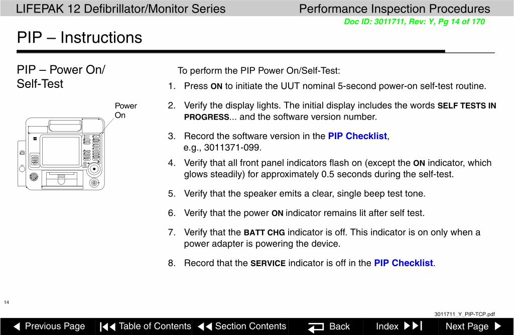
9. Verify the display screen appears similar to that shown below.
Note: (LCD only) To adjust the LCD contrast, press the contrast control , rotate the Selector to the desired contrast, then press the Selector.
10. Turn off the device.
11. Record the results on the PIP Checklist.
ALARMS
12-LEAD
TRANSMIT
CODE
ENERG
PAUSEEVENT
OPTIONS
SHOCK
ON
ADVISORY
ANALYZE CHARGE
SYNC
RATE
CURRENT
PACER
HomeECG
Batt ChgService
SPO2
SELECT
Screen
SUMMARY
display Screen
LEAD SIZE
---x1.0 8:21:35
II
Selected
200J
ECG Size Time
Heart
Battery Status Indicators
EnergySelected
ECG Channel 1
ECG LeadRate
May look different
21
3011711_Y_PIP-TCP.pdf

Previous Page Table of Contents Section Contents Back Index Next Page
LIFEPAK 12 Defibrillator/Monitor Series Performance Inspection Procedures
16
Doc ID: 3011711, Rev: Y, Pg 16 of 170
PIP – Instructions
PIP – Record Operating Data
To record the operating data:
1. Hold down OPTIONS and EVENT controls and turn on the device. Hold the controls until ENTER PASSCODE appears. Enter passcode 5433.
2. Select SERVICE from the SETUP Menu. Enter passcode 5433.
3. Navigate to SERVICE/STATUS/COUNTERS.
4. Record the shocks since last reset (in boxes) and total shocks since the device was built. Select CLEAR ALL to reset box counters (if desired).
5. Select PREVIOUS PAGE.
6. Select DEVICE LOG. Record info from both screens onto PIP Checklist:Power Cycle CountPacing Count (if pacing option installed)Shock CountPower On TimePrinter On TimeSpO2 Operating Time (if SpO2 option installed)CO2 Operating Time (if CO2 option installed)NIBP Inflation Cycles (if NIBP option installed)Defib Storage Cap Value (only for Edmark device)
7. Press the Selector to exit, then the HOME SCREEN key for the SERVICE menu.
8. Continue to the next test while still in SERVICE mode.
Service / Status / Device Log
Serial Number 8244381Dash Number (not used)Manufacturing Date 18 Aug 99Software Revision 3011371-099Fault Messages NoPower Cycle Count 558Pacing Count 4112Shock Count 739Power On Time 74.2Printer On Time 1.4SpO2 Operating Time 10.5CO2 Operating Time 5.1NIBP Inflation Cycles 26Defib Storage Cap Value 50uF
Press Selector knob to exit
Service / Status / Counters
Go back to previous page.
Total Shocks 82360J Shocks 79
225-325J Shocks 32
0-200J Shocks 12
Clear All Previous Page...
6
3
1
3011711_Y_PIP-TCP.pdf

Previous Page Table of Contents Section Contents Back Index Next Page
LIFEPAK 12 Defibrillator/Monitor Series Performance Inspection Procedures
17
Doc ID: 3011711, Rev: Y, Pg 17 of 170
PIP – Instructions
PIP – Keypads To test the keypads:
1. Select TESTS… from the on-screen SERVICE Menu.
2. Select BUTTONS from the SERVICE/TEST Sub-Menu.
3. Press each front panel control when prompted by the flashing control legend (although you may press the controls in any order).
Note: The keypad display may include LEAD and SIZE keys. If these keys are not present on your keypad, disregard these text boxes.
4. Verify with each control pressed that its associated text box is highlighted.
Note: A failure is indicated by a control text box that is not highlighted. It is normal for the controls with up/down arrows to highlight only the arrows.
5. Press the Selector at the end of the test.
6. Record the results on the PIP Checklist.
7. Continue to the next test while still in SERVICE mode.
ALARMS
12-LEAD
TRANSMIT
CODE
ENERG
PAUSEEVENT
OPTIONS
SHOCK
ON
ADVISORY
ANALYZE CHARGE
SYNC
RATE
CURRENT
PACER
HomeECG
Batt ChgService
SPO2
SELECT
Screen
SUMMARY
A09 Small Keypad
A10 Large Keypad
LEAD SIZE
3011711_Y_PIP-TCP.pdf

Previous Page Table of Contents Section Contents Back Index Next Page
LIFEPAK 12 Defibrillator/Monitor Series Performance Inspection Procedures
18
Doc ID: 3011711, Rev: Y, Pg 18 of 170
PIP – Instructions
PIP – Printer To test the 100 mm printer:
1. Select PRINTER… from the on-screen SERVICE menu.
2. Select START to print a test strip.
3. Inspect the test strip for the following attributes:
– The large “X” form is printed without missing dots.
– Seven horizontal lines (one very close to the lower paper margin).
– The character set is printed clearly without broken characters.
– Vertical lines spaced 25 mm ±5% apart. (See TCP – Printer Calibration.)
4. Open the printer door and verify the CHECK PRINTER message appears at the bottom of the screen.
5. Close the printer door.
6. Select PREVIOUS PAGE to return to the SERVICE/TESTS sub-menu.
7. Record the results on the PIP Checklist.
8. Continue to the next test while still in SERVICE mode.
ALARMS
12-LEAD
TRANSMIT
CODE
ENERG
PAUSEEVENT
OPTIONS
SHOCK
ON
ADVISORY
ANALYZE CHARGE
SYNC
RATE
CURRENT
PACER
HomeECG
Batt ChgService
SPO2
SELECT
Screen
SUMMARY
Note: 100 mm printer shown.
LEAD SIZE
3011711_Y_PIP-TCP.pdf

Previous Page Table of Contents Section Contents Back Index Next Page
LIFEPAK 12 Defibrillator/Monitor Series Performance Inspection Procedures
19
Doc ID: 3011711, Rev: Y, Pg 19 of 170
PIP – Instructions
PIP – Audio To test the UUT voice prompts and tones:
1. Select VOICE/TONE… from the SERVICE/TESTS Sub-Menu.
2. Select START. Voice prompts sound in the speaker.
3. When satisfied that the voice prompts are clearly audible and reproduced without distortion, turn off the device.
Note: You may listen to a complete replay of all voice prompts and tones, but it is not required for verification of this function.
4. Record the results on the PIP Checklist.
5. Turn off the UUT.
6. This completes PIP testing using the SERVICE MODE test feature.
7. Continue to next test.
ALARMS
12-LEAD
TRANSMIT
CODE
ENERG
PAUSEEVENT
OPTIONS
SHOCK
ON
ADVISORY
ANALYZE CHARGE
SYNC
RATE
CURRENT
PACER
HomeECG
Batt ChgService
SPO2
SELECT
Screen
SUMMARY
Voice
Tones
LEAD SIZE
3011711_Y_PIP-TCP.pdf

Previous Page Table of Contents Section Contents Back Index Next Page
LIFEPAK 12 Defibrillator/Monitor Series Performance Inspection Procedures
20
Doc ID: 3011711, Rev: Y, Pg 20 of 170
PIP – Instructions
PIP – Biphasic Energy Setting Test
This test checks the lowest available energy level for a standard (domestic) biphasic device and a reduced energy biphasic device.
Note: Complete only if the UUT is a biphasic device. Skip to Next Test
1. Enter the Setup mode. Hold down OPTIONS and EVENT controls and turn on the device. Enter passcode 5433.
2. Select the ADVISORY MODE… menu option.
3. Select the ENERGY PROTOCOL… menu option.
4. Select the ENERGY 1… menu option.
5. Verify the UUT‘s lowest available value for energy 1 is as shown below depending on which UUT type is being tested.
6. Record the results on the PIP checklist.
7. Turn off the UUT. Continue to next test, PIP - User Test.
UUT TYPE Lowest Energy 1 Setting Allowable
Standard (USA) 200J
Reduced Energy 150J
3011711_Y_PIP-TCP.pdf

Previous Page Table of Contents Section Contents Back Index Next Page
LIFEPAK 12 Defibrillator/Monitor Series Performance Inspection Procedures
21
Doc ID: 3011711, Rev: Y, Pg 21 of 170
PIP – Instructions
PIP - User Test To perform User Test:
1. Press ON to turn on the UUT
2. Press OPTIONS to access User Test.
When selected, the User Test automatically performs the following tasks:
■ Performs self-tests■ Charges to 10 J and discharges internally (this energy is not accessible at
the therapy connector)■ Prints a Pass/Fail report
3. Record the results on the PIP Checklist.
4. Continue to the next test, Date and Time.
3011711_Y_PIP-TCP.pdf

Previous Page Table of Contents Section Contents Back Index Next Page
LIFEPAK 12 Defibrillator/Monitor Series Performance Inspection Procedures
22
Doc ID: 3011711, Rev: Y, Pg 22 of 170
PIP – Instructions
PIP – Date and Time To verify the UUT date and time:
1. Press the OPTIONS key.
2. Select DATE/TIME... from the Options menu.
3. Verify that the correct date and time values are displayed on the screen.
Note: If the date and time are incorrect, set the Date and Time as needed.
4. Record the results on the PIP Checklist.
5. Turn off the UUT.
6. Continue to next test, PIP - 12-Lead ECG Characteristics.
ALARMS
12-LEAD
TRANSMIT
CODE
ENERG
PAUSEEVENT
OPTIONS
SHOCK
ON
ADVISORY
ANALYZE CHARGE
SYNC
RATE
CURRENT
PACER
HomeECG
Batt ChgService
SPO2
SELECT
Screen
SUMMARY
PowerOn
LEAD SIZE
OPTIONS Key
3011711_Y_PIP-TCP.pdf

Previous Page Table of Contents Section Contents Back Index Next Page
LIFEPAK 12 Defibrillator/Monitor Series Performance Inspection Procedures
23
Doc ID: 3011711, Rev: Y, Pg 23 of 170
PIP – Instructions
PIP – 12-Lead ECG Characteristics
To test 12-Lead ECG Leads Off detection: (Use Customer’s ECG cable)
Note: If your device does not have a 12-LEAD control on the A09 Small Keypad, perform the PIP – 3-Lead ECG Characteristics test instead.
1. Connect the Main ECG cable, with the Limb Lead and Precordial Lead attachments, and connect all 10 ECG leads to the patient simulator.
2. Program the patient simulator output for a 60 BPM, NSR.
3. Set the UUT lead selection to LEAD II.
4. Remove the LL lead from the patient simulator.
5. Verify the UUT displays a LEADS OFF screen message.
6. Reconnect the LL lead.
7. Repeat steps 4 through 6 for the RA and RL leads.
8. Press the 12-LEAD button, then press the Selector.
9. Verify the UUT display shows ACQUIRING 12-LEAD.
10. Remove the LA lead from the patient simulator.
11. Verify the UUT displays a LEADS OFF screen message. (cont. next page)
ALARMS
12-LEAD
TRANSMIT
CODE
ENERG
PAUSEEVENT
OPTIONS
SHOCK
ON
ADVISORY
ANALYZE CHARGE
SYNC
RATE
CURRENT
PACER
HomeECG
Batt ChgService
SPO2
SELECT
Screen
SUMMARY
RA LA RL LL V1 V2 V3
Dynatech 215A/217A Patient Simulator
LEAD SIZE
3011711_Y_PIP-TCP.pdf

Previous Page Table of Contents Section Contents Back Index Next Page
LIFEPAK 12 Defibrillator/Monitor Series Performance Inspection Procedures
24
Doc ID: 3011711, Rev: Y, Pg 24 of 170
PIP – Instructions Page 1 of 44
PIP – 12-Lead ECG Characteristics (continued)
12. Reconnect the LA lead.
13. Repeat steps 8 through 12 for the V1, V2, V3, V4, V5, and V6 leads.
14. Record the results on the PIP Checklist.
To test 12-Lead ECG gain:
1. Program the patient simulator output for a 1 mv, 10 Hz sine wave.
2. Set the ECG SIZE to 4.0.
3. Set the UUT lead selection to LEAD II.
4. Record 5 seconds of ECG LEAD II and confirm the printed signal amplitude is 36 mm to 44 mm peak-to-peak as shown at the left.
5. Repeat steps 3 and 4 for leads I, V1, V2, V3, V4, V5, and V6, substituting the signal amplitudes given in the table at the left.
6. Record the results on the PIP Checklist.
7. Continue to next test, PIP - Quik-Combo Delivered Energy.
II
36 mmto
44 mm
Lead Printed Peak-to-PeakI 18 mm to 22 mmII 36 mm to 44 mmV1 36 mm to 44 mmV2 36 mm to 44 mmV3 36 mm to 44 mmV4 36 mm to 44 mmV5 36 mm to 44 mmV6 36 mm to 44 mm
3011711_Y_PIP-TCP.pdf
Previous Page Table of Contents Section Contents Back Index Next Page
LIFEPAK 12 Defibrillator/Monitor Series Performance Inspection Procedures
25
Doc ID: 3011711, Rev: Y, Pg 25 of 170
PIP – Instructions
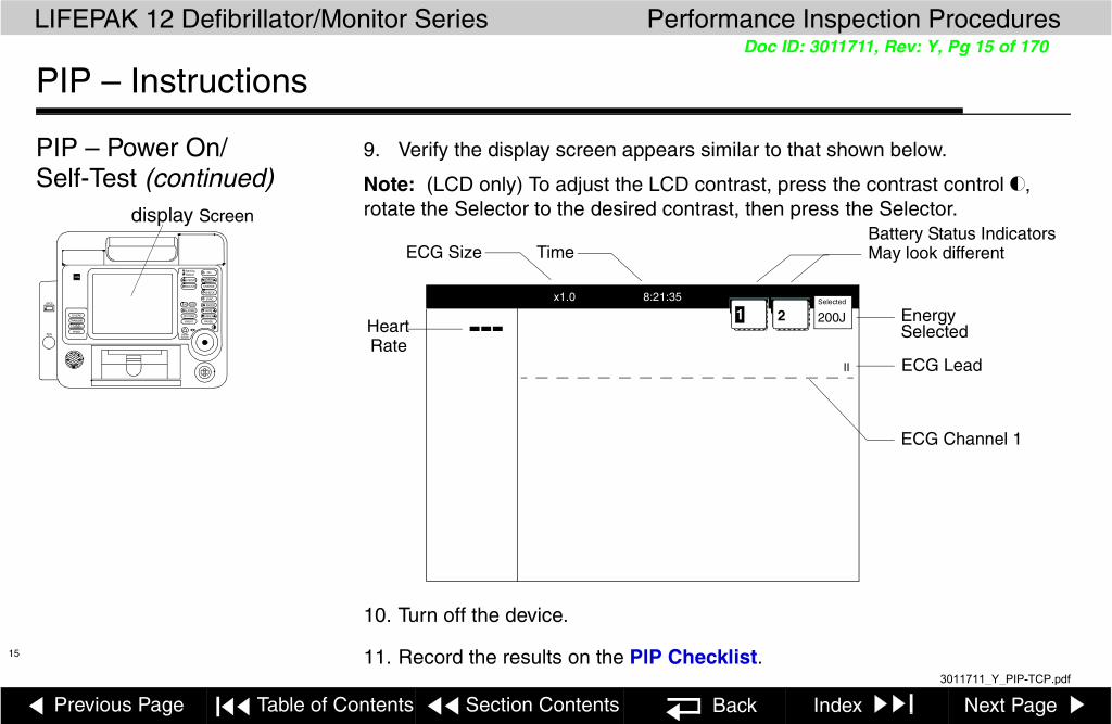
PIP – 3-Lead ECG Characteristics
Note: If 12-Lead ECG Characteristics test was completed, Skip to next test
To test 3-Lead ECG Leads Off detection: (Use Customer’s ECG cable)
Note: If your device has a 12-LEAD control on the A09 Small Keypad, perform the PIP – 12-Lead ECG Characteristics test instead of this test.
1. Connect the 3-Lead ECG Cable between the UUT and patient simulator as shown at the left.
2. Program the patient simulator output for a 60 BPM, NSR.
3. Set the UUT lead selection to LEAD II.
4. Remove the LL lead from the patient simulator.
5. Verify the UUT displays an LL LEADS OFF screen message.
6. Reconnect the LL lead.
7. Repeat steps 4 through 6 for the RA lead.
8. Remove the LA lead from the patient simulator and verify the UUT displays the ECG LEADS OFF screen message.
9. Record the results on the PIP Checklist.
ALARMS
ENERG
EVENT
OPTIONS
SHOCK
ON
ADVISORY
ANALYZE CHARGE
SYNC
Home
Batt ChgService
SELECT
Screen
TRANSMIT
CODE
PRINTECG
SUMMARY
3-Lead ECG Cable
RA LA RL LL V1 V2 V3
Dynatech 215A/217A Patient Simulator
LEAD SIZE
3011711_Y_PIP-TCP.pdf

Previous Page Table of Contents Section Contents Back Index Next Page
LIFEPAK 12 Defibrillator/Monitor Series Performance Inspection Procedures
26
Doc ID: 3011711, Rev: Y, Pg 26 of 170
PIP – Instructions
PIP – 3-Lead ECG Characteristics (continued)
10. Reconnect the LA lead, then continue directly to the next page with this setup in place.
To test 3-Lead ECG gain:
1. Program the patient simulator output for a 1 mv, 10 Hz sine wave.
2. Set the ECG SIZE to 4.0.
3. Set the UUT lead selection to LEAD II.
4. Record 5 seconds of ECG LEAD II and confirm the printed signal amplitude is 36 mm to 44 mm peak-to-peak as shown at the left.
5. Repeat steps 3 and 4 for LEAD I, substituting the signal amplitudes given in the table at the left.
6. Record the results on the PIP Checklist.
7. Continue to next test, PIP - Quik-Combo Delivered Energy.
II
36 mmto
44 mm
Lead Printed Peak-to-Peak
I 18 mm to 22 mm
II 36 mm to 44 mm
3011711_Y_PIP-TCP.pdf
Previous Page Table of Contents Section Contents Back Index Next Page
LIFEPAK 12 Defibrillator/Monitor Series Performance Inspection Procedures
27
Doc ID: 3011711, Rev: Y, Pg 27 of 170
PIP – Instructions
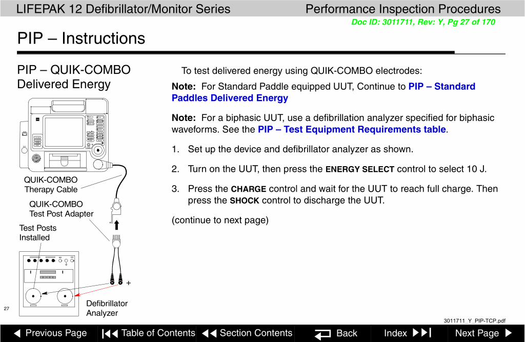
PIP – QUIK-COMBO Delivered Energy
To test delivered energy using QUIK-COMBO electrodes:
Note: For Standard Paddle equipped UUT, Continue to PIP – Standard Paddles Delivered Energy
Note: For a biphasic UUT, use a defibrillation analyzer specified for biphasic waveforms. See the PIP – Test Equipment Requirements table.
1. Set up the device and defibrillator analyzer as shown.
2. Turn on the UUT, then press the ENERGY SELECT control to select 10 J.
3. Press the CHARGE control and wait for the UUT to reach full charge. Then press the SHOCK control to discharge the UUT.
(continue to next page)
ALARMS
12-LEAD
TRANSMIT
CODE
ENERG
PAUSEEVENT
OPTIONS
SHOCK
ON
ADVISORY
ANALYZE CHARGE
SYNC
RATE
CURRENT
PACER
HomeECG
Batt ChgService
SPO2
SELECT
Screen
SUMMARY
+
Defibrillator Analyzer
Test Posts Installed
QUIK-COMBO Therapy Cable
QUIK-COMBO Test Post Adapter
LEAD SIZE
3011711_Y_PIP-TCP.pdf

Previous Page Table of Contents Section Contents Back Index Next Page
LIFEPAK 12 Defibrillator/Monitor Series Performance Inspection Procedures
28
Doc ID: 3011711, Rev: Y, Pg 28 of 170
PIP – Instructions
PIP – QUIK-COMBO Delivered Energy (continued)
4. Verify the defibrillator analyzer indicates the delivered energy is within the acceptable output limits, shown below.
5. Repeat steps 2 through 4 for the remaining energy levels specified in the table.
Note: Perform the TCP – Defibrillator Calibration if the delivered energy falls outside of the acceptable output range.
6. Record the results on the PIP Checklist.
7. Continue to next test, PIP – QUIK-COMBO Synchronous Cardioversion.
Energy Level (J) Acceptable Output (J)
10 9.0 to 11.0
200 186.0 to 214.0
360 334.8 to 385.2
3011711_Y_PIP-TCP.pdf

Previous Page Table of Contents Section Contents Back Index Next Page
LIFEPAK 12 Defibrillator/Monitor Series Performance Inspection Procedures
29
Doc ID: 3011711, Rev: Y, Pg 29 of 170
PIP – Instructions
PIP – QUIK-COMBO Synchronous Cardioversion
To test Synchronous Cardioversion using QUIK-COMBO electrodes:
WARNING!Shock hazard. Electrical energy is discharged during this procedure. Do not allow the electrodes to contact any person or conductive surfaces except as described below.
1. Connect the Main ECG Cable between the UUT and patient simulator2. Set the UUT ECG SIZE to 1.0. Select Lead II. Set the defibrillator analyzer to
measure SYNC.
3. Press the SYNC control on the UUT.
4. Verify the SYNC control LED turns on and R-wave markers appear on the ECG waveform.
5. Charge the UUT to 10 J. Upon reaching full charge, press the SHOCK control to discharge the UUT.
6. Verify the defibrillator analyzer measures a sync delay of 60 ms or less.
7. Record the results on the PIP Checklist.
8. Continue to next test, PIP – QUIK-COMBO ECG Characteristics.
ALARMS
12-LEAD
TRANSMIT
CODE
ENERG
PAUSEEVENT
OPTIONS
SHOCK
ON
ADVISORY
ANALYZE CHARGE
SYNC
RATE
CURRENT
PACER
HomeECG
Batt ChgService
SPO2
SELECT
Screen
SUMMARY
+
LEAD SIZE
3011711_Y_PIP-TCP.pdf

Previous Page Table of Contents Section Contents Back Index Next Page
LIFEPAK 12 Defibrillator/Monitor Series Performance Inspection Procedures
30
Doc ID: 3011711, Rev: Y, Pg 30 of 170
PIP – Instructions
PIP – QUIK-COMBO ECG Characteristics
To test QUIK-COMBO ECG gain:
1. Program the defibrillator analyzer output for a 1 mV, 10 Hz sine wave.
2. Set the UUT ECG SIZE to 4.0.
3. Set the UUT lead selection to PADDLES.
4. Record 10 seconds of PADDLES ECG and confirm the printed signal amplitude is 36 mm to 44 mm peak-to-peak.
Note: The BIO-TEK QED-6 produces a 1.1 mV output; confirm the printed signal amplitude is 38 mm to 50 mm peak-to-peak.
5. Record the results on the PIP Checklist.
6. Continue to the next page with this setup in place.
+
ALARMS
12-LEAD
TRANSMIT
CODE
ENERG
PAUSEEVENT
OPTIONS
SHOCK
ON
ADVISORY
ANALYZE CHARGE
SYNC
RATE
CURRENT
PACER
HomeECG
Batt ChgService
SPO2
SELECT
Screen
SUMMARY
LEAD SIZE
3011711_Y_PIP-TCP.pdf

Previous Page Table of Contents Section Contents Back Index Next Page
LIFEPAK 12 Defibrillator/Monitor Series Performance Inspection Procedures
31
Doc ID: 3011711, Rev: Y, Pg 31 of 170
PIP – Instructions
PIP – QUIK-COMBO ECG Characteristics (continued)
To test QUIK-COMBO ECG fast restore:
1. Program the defibrillator analyzer output for a 30 BPM, NSR.
2. Set the UUT ECG SIZE to 4.0.
3. Charge the UUT to 360 J.
4. Upon reaching full charge, press the PRINT control to begin recording.
5. Discharge the UUT into the defibrillator analyzer.
6. Allow the printer to run until the defibrillation event and associated ECG waveform finishes printing.
7. Press the PRINT control to turn the printer off.
8. Note the Shock # and ENERGY DELIVERED event mark and verify the ECG returns to the baseline in 0.5 seconds (12.5 mm) or less.
9. Record the results on the PIP Checklist.
10. Continue to next test, PIP – Advisory Mode Test.
3011711_Y_PIP-TCP.pdf

Previous Page Table of Contents Section Contents Back Index Next Page
LIFEPAK 12 Defibrillator/Monitor Series Performance Inspection Procedures
32
Doc ID: 3011711, Rev: Y, Pg 32 of 170
PIP – Instructions
PIP – Standard Paddles Delivered Energy
Note: For QUIK-COMBO equipped devices, continue to PIP - QUIK-COMBO Delivered Energy
To test delivered energy using Standard Paddles:
Note: For a biphasic UUT, make sure the defibrillation analyzer is compatible. See the PIP – Test Equipment Requirements table.
1. Set up the device and defibrillator analyzer as shown.
2. Rotate the STERNUM PADDLE ENERGY SELECT dial to select 10 J.
3. Press the Apex paddle CHARGE button and wait for the UUT to reach full charge. Then press the paddles SHOCK switches to discharge the UUT.
ALARMS
12-LEAD
TRANSMIT
CODE
ENERG
PAUSEEVENT
OPTIONS
SHOCK
ON
ADVISORY
ANALYZE CHARGE
SYNC
RATE
CURRENT
PACER
HomeECG
Batt ChgService
SPO2
SELECT
Screen
SUMMARY
Defibrillator Analyzer+
LEAD SIZE
3011711_Y_PIP-TCP.pdf

Previous Page Table of Contents Section Contents Back Index Next Page
LIFEPAK 12 Defibrillator/Monitor Series Performance Inspection Procedures
33
Doc ID: 3011711, Rev: Y, Pg 33 of 170
PIP – Instructions
PIP – Standard Paddles Delivered Energy (continued)
4. Verify the defibrillator analyzer indicates the delivered energy is within the acceptable output limits, shown below.
5. Repeat steps 2 through 4 for the remaining energy levels specified in the table.
Note: Perform the TCP – Defibrillator Calibration if the delivered energy falls outside of the acceptable output range.
6. Record the results on the PIP Checklist.
7. Continue to next test, PIP – Standard Paddles Synchronous Cardioversion.
Energy Level (J) Acceptable Output (J)
10 9.0 to 11.0
200 186.0 to 214.0
360 334.8 to 385.2
3011711_Y_PIP-TCP.pdf

Previous Page Table of Contents Section Contents Back Index Next Page
LIFEPAK 12 Defibrillator/Monitor Series Performance Inspection Procedures
34
Doc ID: 3011711, Rev: Y, Pg 34 of 170
PIP – Instructions
PIP – Standard Paddles Synchronous Cardioversion
To test Synchronous Cardioversion using Standard Paddles:
Note: If the UUT does not have “sync in paddles” feature, skip this test. If using QUIK-COMBO electrodes, see PIP – QUIK-COMBO Synchronous Cardioversion.
WARNING!Shock hazard. Electrical energy is discharged during this procedure. Do not allow the paddles to contact any person or conductive surfaces except as described below.
1. Connect the Main ECG Cable between the UUT and patient simulator.2. Set the UUT ECG SIZE to 1.0. Select Lead II. Set the defibrillator analyzer to
measure SYNC.
3. Press the SYNC control on the UUT. Make sure lead II is selected. Verify the SYNC control LED turns on and R-wave markers appear on the ECG waveform.
4. Charge the UUT to 10 J. Upon reaching full charge, simultaneously press the paddles SHOCK switches to discharge the UUT. Verify the defibrillator analyzer measures a sync delay of 60 ms or less.
5. Record the results on the PIP Checklist.6. Continue to next test, PIP – Standard Paddles ECG Characteristics.
+
ALARMS
12-LEAD
TRANSMIT
CODE
ENERG
PAUSEEVENT
OPTIONS
SHOCK
ON
ADVISORY
ANALYZE CHARGE
SYNC
RATE
CURRENT
PACER
HomeECG
Batt ChgService
SPO2
SELECT
Screen
SUMMARY
LEAD SIZE
Main ECG Cable
3011711_Y_PIP-TCP.pdf
Previous Page Table of Contents Section Contents Back Index Next Page
LIFEPAK 12 Defibrillator/Monitor Series Performance Inspection Procedures
35
Doc ID: 3011711, Rev: Y, Pg 35 of 170
PIP – Instructions
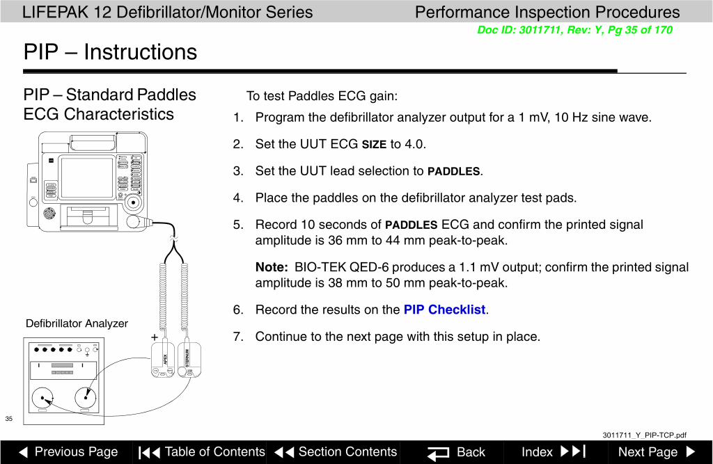
PIP – Standard Paddles ECG Characteristics
To test Paddles ECG gain:
1. Program the defibrillator analyzer output for a 1 mV, 10 Hz sine wave.
2. Set the UUT ECG SIZE to 4.0.
3. Set the UUT lead selection to PADDLES.
4. Place the paddles on the defibrillator analyzer test pads.
5. Record 10 seconds of PADDLES ECG and confirm the printed signal amplitude is 36 mm to 44 mm peak-to-peak.
Note: BIO-TEK QED-6 produces a 1.1 mV output; confirm the printed signal amplitude is 38 mm to 50 mm peak-to-peak.
6. Record the results on the PIP Checklist.
7. Continue to the next page with this setup in place.
ALARMS
12-LEAD
TRANSMIT
CODE
ENERG
PAUSEEVENT
OPTIONS
SHOCK
ON
ADVISORY
ANALYZE CHARGE
SYNC
RATE
CURRENT
PACER
HomeECG
Batt ChgService
SPO2
SELECT
Screen
SUMMARY
Defibrillator Analyzer+
LEAD SIZE
3011711_Y_PIP-TCP.pdf

Previous Page Table of Contents Section Contents Back Index Next Page
LIFEPAK 12 Defibrillator/Monitor Series Performance Inspection Procedures
36
Doc ID: 3011711, Rev: Y, Pg 36 of 170
PIP – Instructions
PIP – Standard Paddles ECG Characteristics (continued)
To test paddles ECG fast restore:
1. Program the defibrillator analyzer output for a 30 BPM, NSR.
2. Set the UUT ECG SIZE to 4.0.
3. Charge the UUT to 360 J.
Note: Maintain contact between the defibrillator paddles and the defibrillator analyzer test load plates throughout this test.
4. Upon reaching full charge, press the PRINT control to begin recording.
5. Discharge the UUT into the defibrillator analyzer.
6. Allow the printer to run until the defibrillation event and associated ECG waveform finish printing.
7. Press the PRINT control to turn the printer off.
8. Note the ENERGY DELIVERED event mark and verify the ECG returns to the baseline in 0.5 seconds (12.5 mm) or less.
9. Record the results on the PIP Checklist.
10. Continue to next test, PIP – Standard Paddles User Test.
3011711_Y_PIP-TCP.pdf

Previous Page Table of Contents Section Contents Back Index Next Page
LIFEPAK 12 Defibrillator/Monitor Series Performance Inspection Procedures
37
Doc ID: 3011711, Rev: Y, Pg 37 of 170
PIP – Instructions
Standard PaddlesUser Test
Note: Complete only if UUT is equipped with the Hard Paddles option.
Optional for QUIK-COMBO device, Skip to PIP - Advisory Mode Test
Note: Use Customer’s Standard Paddles (when available). Remove the paddles and check that the paddle surfaces and paddle wells are clean and dry and free of any debris. Also check therapy connector interface for pin damage.
WARNING!Shock hazard. The Conductive gel (wet or dry) on the paddle handles and in the paddle wells may allow the electrical energy to arc between paddles during discharge. Thoroughly clean and dry the paddles and paddle wells after use and before performing the Standard Paddles User Test.
1. Replace the paddles in the paddle wells.
2. Turn on the UUT.
3. Select 10 J.
4. Press the CHARGE button on the Apex paddle.
5. Confirm the tone indicates full charge within 5 seconds.
ALARMS
12-LEAD
TRANSMIT
CODE
ENERG
PAUSEEVENT
OPTIONS
SHOCK
ON
ADVISORY
ANALYZE CHARGE
SYNC
RATE
CURRENT
PACER
HomeECG
Batt ChgService
SPO2
SELECT
Screen
SUMMARY
+
LEAD SIZE
3011711_Y_PIP-TCP.pdf
Previous Page Table of Contents Section Contents Back Index Next Page
LIFEPAK 12 Defibrillator/Monitor Series Performance Inspection Procedures
38
Doc ID: 3011711, Rev: Y, Pg 38 of 170
PIP – Instructions
PIP – Standard Paddles User Test (continued)
6. Press only the APEX discharge button and confirm that the defibrillator does not discharge. Release the APEX discharge button.
7. Press only the STERNUM discharge button and confirm that the defibrillator does not discharge. Release the STERNUM discharge button.
8. With the paddles still in the paddle wells, press both discharge buttons simultaneously.
9. For an Edmark UUT, confirm ENERGY NOT DELIVERED message appears, indicating energy was removed internally.
For a biphasic UUT, the message ABNORMAL ENERGY DELIVERED is displayed.
10. Record the results on the PIP Checklist.
11. Continue to next test, PIP - Advisory Mode Test.
3011711_Y_PIP-TCP.pdf

Previous Page Table of Contents Section Contents Back Index Next Page
LIFEPAK 12 Defibrillator/Monitor Series Performance Inspection Procedures
39
Doc ID: 3011711, Rev: Y, Pg 39 of 170
PIP – Instructions
PIP – Advisory Mode Test
To test Advisory Mode Test:
Note: Conduct this test only if your device has an ADVISORY key on the A10 Large Keypad. If your device does not have an ADVISORY key, perform the PIP – No Advisory Mode Option Test.
1. Connect UUT to the defibrillator analyzer using the QUIK-COMBO therapy cable and the QUIK-COMBO test post adapter.
2. Select Paddles lead.
3. Press the ADVISORY key on the UUT.
4. Verify the ADVISORY key LED lights and the ADVISORY MODE - MONITORING message appears on the display screen.
5. Press the ADVISORY key on the UUT again to exit advisory mode.
6. Record the results on the PIP Checklist.
7. Depending upon the configuration of the UUT, continue to test,PIP – Pacer Option Characteristics or PIP – No Pacer Option Characteristics.
+
ALARMS
12-LEAD
TRANSMIT
CODE
ENERG
PAUSEEVENT
OPTIONS
SHOCK
ON
ADVISORY
ANALYZE CHARGE
SYNC
RATE
CURRENT
PACER
HomeECG
Batt ChgService
SPO2
SELECT
Screen
SUMMARY
LEAD SIZE
3011711_Y_PIP-TCP.pdf
Previous Page Table of Contents Section Contents Back Index Next Page
LIFEPAK 12 Defibrillator/Monitor Series Performance Inspection Procedures
40
Doc ID: 3011711, Rev: Y, Pg 40 of 170
PIP – Instructions
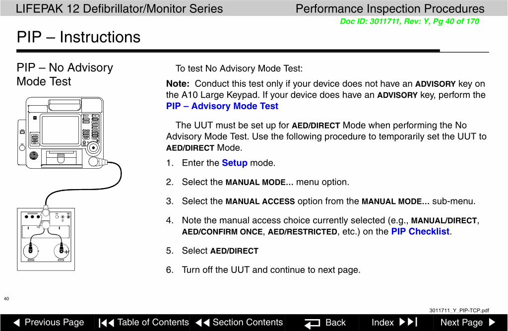
PIP – No Advisory Mode Test
To test No Advisory Mode Test:
Note: Conduct this test only if your device does not have an ADVISORY key on the A10 Large Keypad. If your device does have an ADVISORY key, perform the PIP – Advisory Mode Test
The UUT must be set up for AED/DIRECT Mode when performing the No Advisory Mode Test. Use the following procedure to temporarily set the UUT to AED/DIRECT Mode.
1. Enter the Setup mode.
2. Select the MANUAL MODE… menu option.
3. Select the MANUAL ACCESS option from the MANUAL MODE… sub-menu.
4. Note the manual access choice currently selected (e.g., MANUAL/DIRECT, AED/CONFIRM ONCE, AED/RESTRICTED, etc.) on the PIP Checklist.
5. Select AED/DIRECT
6. Turn off the UUT and continue to next page.
+
ALARMS
12-LEAD
TRANSMIT
CODE
ENERG
PAUSEEVENT
OPTIONS
SHOCK
ON
ADVISORY
ANALYZE CHARGE
SYNC
RATE
CURRENT
PACER
HomeECG
Batt ChgService
SPO2
SELECT
Screen
SUMMARY
LEAD SIZE
+
ALARMS
12-LEAD
TRANSMIT
CODE
ENERG
PAUSEEVENT
OPTIONS
SHOCK
ON
ADVISORY
ANALYZE CHARGE
SYNC
RATE
CURRENT
PACER
HomeECG
Batt ChgService
SPO2
SELECT
Screen
SUMMARY
LEAD SIZE
3011711_Y_PIP-TCP.pdf

Previous Page Table of Contents Section Contents Back Index Next Page
LIFEPAK 12 Defibrillator/Monitor Series Performance Inspection Procedures
41
Doc ID: 3011711, Rev: Y, Pg 41 of 170
PIP – Instructions
PIP – No Advisory Mode Test (continued)
To perform the No Advisory Mode Test:
1. Connect UUT to the defibrillator analyzer using the QUIK-COMBO therapy cable and the QUIK-COMBO test post adapter.
2. Turn on the UUT.
3. Select Paddles lead.
4. Verify the ADVISORY MODE - MONITORING message does NOT appear on the display screen.
5. Record the results on the PIP Checklist.
To restore the UUT Manual Mode access:
1. Enter the Setup mode.
2. Select the MANUAL MODE… menu option.
3. Select the MANUAL ACCESS option from the MANUAL MODE… sub-menu.
4. Select the manual access option recorded on the PIP checklist.
3011711_Y_PIP-TCP.pdf

Previous Page Table of Contents Section Contents Back Index Next Page
LIFEPAK 12 Defibrillator/Monitor Series Performance Inspection Procedures
42
Doc ID: 3011711, Rev: Y, Pg 42 of 170
PIP – Instructions
PIP – No Advisory Mode Test (continued)
5. Cycle power on the UUT. Verify that the UUT powers up in the appropriate mode (Manual or Advisory).
6. Depending upon the configuration of the UUT, continue to test,PIP – Pacer Option Characteristics or PIP – No Pacer Option Characteristics.
3011711_Y_PIP-TCP.pdf

Previous Page Table of Contents Section Contents Back Index Next Page
LIFEPAK 12 Defibrillator/Monitor Series Performance Inspection Procedures
43
Doc ID: 3011711, Rev: Y, Pg 43 of 170
PIP – Instructions
PIP – Pacer Option Characteristics
To test Pacer Leads Off Detection:
Note: Conduct this test only if your device has a PACER control on the A10 Large Keypad. If your device does not have a PACER control, perform the PIP – No Pacer Option Characteristic test.
1. Set the defibrillator analyzer to measure peak current pacing parameters.
2. Press the PACER control on the UUT.
3. Verify the PACER control LED lights and the PACER overlay appears.
4. Disconnect one of the Test Post Adapter snaps from the defibrillator analyzer.
5. Verify the PACING/CONNECT ELECTRODES overlay appears accompanied by an audible alarm.
6. Reconnect the Test Post Adapter snap. Verify the PACING/CONNECT ELECTRODES overlay disappears and the alarm stops.
7. Record the results on the PIP Checklist.
8. Continue to the next page with this setup in place.
ALARMS
12-LEAD
TRANSMIT
CODE
ENERG
PAUSEEVENT
OPTIONS
SHOCK
ON
ADVISORY
ANALYZE CHARGE
SYNC
RATE
CURRENT
PACER
HomeECG
Batt ChgService
SPO2
SELECT
Screen
SUMMARY
Limb Lead Attachment or 3-Lead Cable
+
LEAD SIZE
3011711_Y_PIP-TCP.pdf

Previous Page Table of Contents Section Contents Back Index Next Page
LIFEPAK 12 Defibrillator/Monitor Series Performance Inspection Procedures
44
Doc ID: 3011711, Rev: Y, Pg 44 of 170
PIP – Instructions
PIP – Pacer Option Characteristics (continued)
To test the Pacer Output Current:
1. Press the UUT CURRENT control to select a pacer current of 10 ma.
2. Verify the defibrillator analyzer indicates the pacer output current is within the acceptable output limits, shown below.
3. In this manner, check the peak pacer current for the following settings:
Note: Perform the TCP – Pacing Self Calibration if the peak pacer current falls outside of the acceptable output range.
4. Record the results on the PIP Checklist.
5. Continue to the next page with this setup in place.
Peak Current Level (ma) Acceptable Output (ma)
10 5 to 15
100 95 to 105
200 190 to 210
3011711_Y_PIP-TCP.pdf

Previous Page Table of Contents Section Contents Back Index Next Page
LIFEPAK 12 Defibrillator/Monitor Series Performance Inspection Procedures
45
Doc ID: 3011711, Rev: Y, Pg 45 of 170
PIP – Instructions
PIP – Pacer Option Characteristics (continued)
To test the Pacer Pulse Width:
1. Press the UUT CURRENT control to select a pacer current of 200 ma.
2. Verify the defibrillator analyzer indicates the pacer pulse width is between 19.0 and 21.0 ms.
3. Press the UUT PACER control to terminate pacing.
4. Record the results on the PIP Checklist.
5. Continue to the next test, PIP – Impedance Sense.
3011711_Y_PIP-TCP.pdf
Previous Page Table of Contents Section Contents Back Index Next Page
LIFEPAK 12 Defibrillator/Monitor Series Performance Inspection Procedures
46
Doc ID: 3011711, Rev: Y, Pg 46 of 170
PIP – Instructions
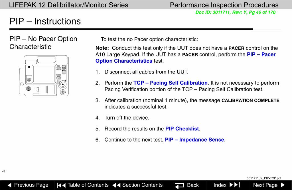
PIP – No Pacer OptionCharacteristic
To test the no Pacer option characteristic:
Note: Conduct this test only if the UUT does not have a PACER control on the A10 Large Keypad. If the UUT has a PACER control, perform the PIP – Pacer Option Characteristics test.
1. Disconnect all cables from the UUT.
2. Perform the TCP – Pacing Self Calibration. It is not necessary to perform Pacing Verification portion of the TCP – Pacing Self Calibration test.
3. After calibration (nominal 1 minute), the message CALIBRATION COMPLETE indicates a successful test.
4. Turn off the device.
5. Record the results on the PIP Checklist.
6. Continue to the next test, PIP – Impedance Sense.
ALARMS
ENERG
EVENT
OPTIONS
SHOCK
ON
ADVISORY
ANALYZE CHARGE
SYNC
Home
Batt ChgService
SELECT
Screen
TRANSMIT
CODE
PRINTECG
SUMMARY
LEAD SIZE
3011711_Y_PIP-TCP.pdf

Previous Page Table of Contents Section Contents Back Index Next Page
LIFEPAK 12 Defibrillator/Monitor Series Performance Inspection Procedures
47
Doc ID: 3011711, Rev: Y, Pg 47 of 170
PIP – Instructions
Impedance Sense To test Impedance Sense circuitry:
1. Connect the QUIK-COMBO Test Post snaps to a decade resistance box, using whatever adapter is appropriate to make connections.
2. Place the UUT into MANUAL mode (ADVISORY off).
3. Set the UUT lead selection to PADDLES.
4. Set the decade resistance box to 370 .
5. Verify the UUT display displays the PADDLES LEADS OFF message.
6. Record the results on the PIP Checklist.
7. Set the decade resistance box to 238 .
8. Verify the PADDLES LEADS OFF message is removed from the UUT display.
9. Record the results on the PIP Checklist.
10. Remove the decade resistance box.
11. Continue to the next test, PIP – ECG Analog Output.
ALARMS
12-LEAD
TRANSMIT
CODE
ENERG
PAUSEEVENT
OPTIONS
SHOCK
ON
ADVISORY
ANALYZE CHARGE
SYNC
RATE
CURRENT
PACER
HomeECG
Batt ChgService
SPO2
SELECT
Screen
SUMMARY
1 2 3 4 5 6 7
Resistance Box
Adapter
LEAD SIZE
3011711_Y_PIP-TCP.pdf

Previous Page Table of Contents Section Contents Back Index Next Page
LIFEPAK 12 Defibrillator/Monitor Series Performance Inspection Procedures
48
Doc ID: 3011711, Rev: Y, Pg 48 of 170
PIP – Instructions
PIP – ECG Analog Output (Optional test)
To test the ECG analog output:
Note: This Test is optional. Perform if this feature is used. Skip to Next Test
1. Establish the test setup as shown at the left.
2. Using the ECG cable supplied with the UUT, input a 1 mV 10 Hz sine wave from the patient simulator.
3. Set the UUT lead selection to LEAD II. (The ECG analog output is in real time at a nominal 1 V/mV and is not affected by the device ECG size setting.)
4. Verify the amplitude of the signal displayed on the oscilloscope is between 0.85 Vp-p and 1.15 Vp-p.
5. Record the results on the PIP Checklist.
6. Disconnect the Analog ECG Output Cable from the UUT and oscilloscope.
7. Continue to the next test, PIP – Spo2 Oximeter test.
12
Brown Lead
Black Lead
VE
General Purpose
Oscilloscope
Analog ECG Output Cable
3011711_Y_PIP-TCP.pdf

Previous Page Table of Contents Section Contents Back Index Next Page
LIFEPAK 12 Defibrillator/Monitor Series Performance Inspection Procedures
49
Doc ID: 3011711, Rev: Y, Pg 49 of 170
PIP – Instructions
PIP – SpO2 Oximeter Note: Complete only if the UUT is equipped with the SpO2 Oximeter option. Skip to Next Test
To test the SpO2 Oximeter:
1. Connect the Oximeter finger probe to the SpO2 connector.
2. Verify the SpO2 parameter region appears on the display.
3. Place your index finger into the SpO2 probe. Allow several seconds for the probe to find your pulse. Confirm the SpO2 reading is between 90% and 100%.
4. Disconnect the SpO2 probe.
5. Turn off the UUT.
6. Record the results on the PIP Checklist.
7. Continue to the next test, PIP – EtCO2 Verification test.
ALARMS
12-LEAD
TRANSMIT
CODE
ENERG
PAUSEEVENT
OPTIONS
SHOCK
ON
ADVISORY
ANALYZE CHARGE
SYNC
RATE
CURRENT
PACER
HomeECG
Batt ChgService
SPO2
SELECT
Screen
SUMMARY
SpO2Parameter
Region
LEAD SIZE
3011711_Y_PIP-TCP.pdf

Previous Page Table of Contents Section Contents Back Index Next Page
LIFEPAK 12 Defibrillator/Monitor Series Performance Inspection Procedures
50
Doc ID: 3011711, Rev: Y, Pg 50 of 170
PIP – Instructions
PIP – EtCO2 Verification
Note: Complete only if the UUT is equipped with the EtCO2 option. Skip to Next Test
To test the EtCO2 Monitor for leaks:
1. Set up the test equipment as shown in the diagram below.
ALARMS
ENERG
EVENT
OPTIONS
SHOCK
ON
ADVISORY
ANALYZE CHARGE
SYNC
Home
Batt ChgService
SELECT
Screen
TRANSMIT
CODE
PRINTECG
SUMMARY
To Back-Panel Gas Outlet
UUT
CO2 Leak Test Kit MIN 3012430-00
VacuumManometer
Syringe Clamp
To Front-Panel CO2 Connector
To Vacuum
Manometer
CO2
LEAD SIZE
3011711_Y_PIP-TCP.pdf

Previous Page Table of Contents Section Contents Back Index Next Page
LIFEPAK 12 Defibrillator/Monitor Series Performance Inspection Procedures
51
Doc ID: 3011711, Rev: Y, Pg 51 of 170
PIP – Instructions
PIP – EtCO2 Verification (continued)
2. Turn the LIFEPAK 12 defibrillator/monitor power OFF. Disconnect the tubing from the front panel CO2 connector.
3. Open the hose clamp and depress the syringe fully.
4. Connect the tubing to the front panel CO2 connector and to the back panel CO2 gas outlet. (Important: Press the fittings that connect to the LIFEPAK 12 firmly on to avoid leakage. All tubing ends should now be connected as shown in the diagram on the previous page.)
5. Pull the syringe plunger out to induce vacuum into the system. When the vacuum manometer indicates approximately –300 mBars (–230 mmHg), close the tubing clamp firmly.
6. Begin timing as the clamp is closed. Verify that after 30 seconds, the change in vacuum reading is less than 20 mBars (15 mmHg).
7. Open the tubing connection to the front panel CO2 connector to release the vacuum.
8. Record the result on the PIP Checklist.
3011711_Y_PIP-TCP.pdf
Previous Page Table of Contents Section Contents Back Index Next Page
LIFEPAK 12 Defibrillator/Monitor Series Performance Inspection Procedures
52
Doc ID: 3011711, Rev: Y, Pg 52 of 170
PIP – Instructions
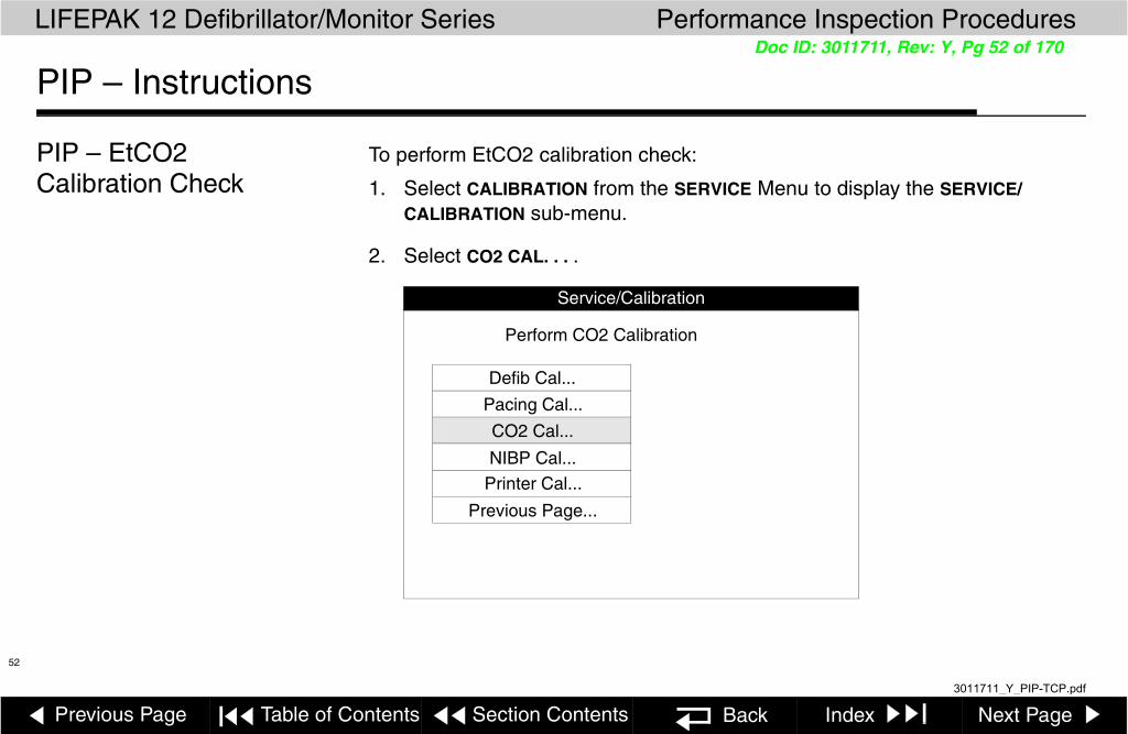
PIP – EtCO2 Calibration Check
To perform EtCO2 calibration check:
1. Select CALIBRATION from the SERVICE Menu to display the SERVICE/CALIBRATION sub-menu.
2. Select CO2 CAL. . . .
Service/Calibration
Defib Cal...
Pacing Cal...
CO2 Cal...
NIBP Cal...
Printer Cal...
Previous Page...
Perform CO2 Calibration
3011711_Y_PIP-TCP.pdf

Previous Page Table of Contents Section Contents Back Index Next Page
LIFEPAK 12 Defibrillator/Monitor Series Performance Inspection Procedures
53
Doc ID: 3011711, Rev: Y, Pg 53 of 170
PIP – Instructions
PIP – EtCO2 Calibration Check (continued)
3. Select CAL CHECK. . . .
Service/Calibration/CO2 Cal
Check CO2 Calibration
Cal Check...
Calibrate...
Previous Page...
3011711_Y_PIP-TCP.pdf

Previous Page Table of Contents Section Contents Back Index Next Page
LIFEPAK 12 Defibrillator/Monitor Series Performance Inspection Procedures
54
Doc ID: 3011711, Rev: Y, Pg 54 of 170
PIP – Instructions
PIP – EtCO2 Calibration Check (continued)
To connect calibration gas:
Connect the calibration gas canister to the front panel CO2 connector using a standard CO2 FilterLine™ and the CO2 calibration kit.
ALARMS
ENERG
EVENT
OPTIONS
SHOCK
ON
ADVISORY
ANALYZE CHARGE
SYNC
Home
Batt ChgService
SELECT
Screen
TRANSMIT
CODE
PRINTECG
SUMMARY
UUT
CO2 Calibration Kit MIN 3012430-01
CO2 FilterLine MIN 3012176
To Front-Panel CO2 Connector
Calibration Gas MIN 3012556
CO2
LEAD SIZE
3011711_Y_PIP-TCP.pdf

Previous Page Table of Contents Section Contents Back Index Next Page
LIFEPAK 12 Defibrillator/Monitor Series Performance Inspection Procedures
55
Doc ID: 3011711, Rev: Y, Pg 55 of 170
PIP – Instructions
PIP – EtCO2 Calibration Check (continued)
To check calibration:
1. Press and hold the spray nozzle to apply the calibration gas. Release the spray nozzle when the device displays a stable value for the measured CO2 content of the calibration gas.
2. Verify that the measured gas concentration reads 5.0% ±0.5%. Record the result on the PIP Checklist.
If the measured value is incorrect, refer to TCP – EtCO2 Calibration.
3. Select PREVIOUS PAGE. . . (twice) to return to the SERVICE/CALIBRATION sub-menu. (continue to next test, PIP - NIBP Verification)
Service/Calibration/CO2 Cal/Cal Check
Go back to previous page
Previous Page...
Connect gas and introduce into sensor
5.0%
3011711_Y_PIP-TCP.pdf

Previous Page Table of Contents Section Contents Back Index Next Page
LIFEPAK 12 Defibrillator/Monitor Series Performance Inspection Procedures
56
Doc ID: 3011711, Rev: Y, Pg 56 of 170
PIP – Instructions
PIP – NIBP Verification Note: Complete only if the UUT is equipped with the NIBP option. Skip to Next Test
To perform NIBP calibration check:
1. Select CALIBRATION from the SERVICE menu to display the SERVICE/CALIBRATION sub-menu.
2. Select NIBP CAL . . . .
Service/Calibration
Perform NIBP Calibration
Defib Cal...
Pacing Cal...
CO2 Cal...
NIBP Cal...
Printer Cal...
Previous Page...
3011711_Y_PIP-TCP.pdf

Previous Page Table of Contents Section Contents Back Index Next Page
LIFEPAK 12 Defibrillator/Monitor Series Performance Inspection Procedures
57
Doc ID: 3011711, Rev: Y, Pg 57 of 170
PIP – Instructions
PIP – NIBP Verification (continued)
To perform static pressure check:
Select PRESSURE . . . from the SERVICE/CALIBRATION/NIBP CAL sub-menu.
Service/Calibration/NIBP Cal
Perform static pressure test
Pressure...
Leakage...
Previous Page...
3011711_Y_PIP-TCP.pdf

Previous Page Table of Contents Section Contents Back Index Next Page
LIFEPAK 12 Defibrillator/Monitor Series Performance Inspection Procedures
58
Doc ID: 3011711, Rev: Y, Pg 58 of 170
PIP – Instructions
PIP – NIBP Verification (continued)
To perform static pressure check:
1. Set up the NIBP calibration kit as shown in the diagram below.
CAUTION!
Possible equipment damage. Pulling out on the syringe plunger applies a vacuum to the NIBP connection and may damage the LIFEPAK 12 defibrillator/monitor. DO NOT pull on the plunger. Only push in on the plunger to inflate the system per the following instructions.
Pressure Meter or MercuryManometer
ALARMS
ENERG
EVENT
OPTIONS
SHOCK
ON
ADVISORY
ANALYZE CHARGE
SYNC
Home
Batt ChgService
SELECT
Screen
TRANSMIT
CODE
PRINTECG
SUMMARY
UUT
NIBP Calibration KitMIN 3012432-01 NIBP
Pressure HoseMIN 3009167-013
Syringe
LEAD SIZE
NIBP
3011711_Y_PIP-TCP.pdf

Previous Page Table of Contents Section Contents Back Index Next Page
LIFEPAK 12 Defibrillator/Monitor Series Performance Inspection Procedures
59
Doc ID: 3011711, Rev: Y, Pg 59 of 170
PIP – Instructions
PIP – NIBP Verification (continued)
2. Adjust the pressure meter if necessary to a zero initial pressure to ensure that the UUT and the pressure meter agree.
3. Using the syringe, inflate the system to each of the following pressures (as indicated on the manometer or pressure meter):
■ 50 mmHg ■ 150 mmHg■ 100 mmHg ■ 200 mmHg
Service/Calibration/NIBP Cal/Pressure
Go back to previous page
Previous Page...
Apply known pressure to NIBP hose
0 mmHg
3011711_Y_PIP-TCP.pdf

Previous Page Table of Contents Section Contents Back Index Next Page
LIFEPAK 12 Defibrillator/Monitor Series Performance Inspection Procedures
60
Doc ID: 3011711, Rev: Y, Pg 60 of 170
PIP – Instructions
PIP – NIBP Verification (continued)
4. Verify that the display of the UUT and the external pressure meter agree within ±3 mmHg. Record the result on the PIP Checklist.
5. Using the syringe, slowly inflate the system until the overpressure switch activates at 285 mmHg ±10 mmHg. Record the result on the PIP Checklist.
6. Verify that the system depressurizes, and that the light on the NIBP key goes out. The pressure reading at which the overpressure fault occurred remains displayed on the UUT.
7. Select PREVIOUS PAGE....
(continue to next page)
3011711_Y_PIP-TCP.pdf

Previous Page Table of Contents Section Contents Back Index Next Page
LIFEPAK 12 Defibrillator/Monitor Series Performance Inspection Procedures
61
Doc ID: 3011711, Rev: Y, Pg 61 of 170
PIP – Instructions
PIP – NIBP Verification (continued)
To check the NIBP Monitor system for leaks:
1. Select LEAKAGE . . . from the SERVICE/CALIBRATION/NIBP CAL sub-menu.
2. Connect a length of NIBP tubing to the NIBP connector.
3. Occlude the distal end of the NIBP tube by plugging it or folding it double and pinching it.
Pressure...
Service/Calibration/NIBP Cal
Perform leakage test
Leakage...
Previous Page...
3011711_Y_PIP-TCP.pdf

Previous Page Table of Contents Section Contents Back Index Next Page
LIFEPAK 12 Defibrillator/Monitor Series Performance Inspection Procedures
62
Doc ID: 3011711, Rev: Y, Pg 62 of 170
PIP – Instructions
PIP – NIBP Verification (continued)
4. Select START..... The UUT pressurizes the tubing to approximately 200 mmHg. Verify that the message LEAKAGE TEST OK appears.
5. Record the results on the PIP Checklist. 6. Turn the UUT off, then on to exit the SERVICE mode.7. Continue to the next test, PIP – Invasive Pressure Verification test.
Service/Calibration/NIBP Cal/Leakage
Start NIBP leakage test
Start...
Previous Page...
Plug the NIBP hose and select Start
0 mmHg
3011711_Y_PIP-TCP.pdf

Previous Page Table of Contents Section Contents Back Index Next Page
LIFEPAK 12 Defibrillator/Monitor Series Performance Inspection Procedures
63
Doc ID: 3011711, Rev: Y, Pg 63 of 170
PIP – Instructions
PIP – Invasive Pressure Verification
Note: Complete only if the UUT is equipped with the Invasive Pressure option. Skip to Next Test
1. Turn the UUT ON.
2. Use the invasive pressure cable to connect the invasive pressure simulator (DNI Nevada 217A or equivalent) to the P1 connector on the parameter bezel.
3. Turn the simulator ON.
4. Set the simulator pressure output to zero.
5. Turn the Selector to highlight CHANNEL 2 in the Wave Form Area of the display.
6. Click the Selector, and click again on WAVEFORM. Select and click P1 to display the pressure waveform.
7. On the CHANNEL 2 overlay, verify that the scale is set to AUTOSCALE. Select and click ZERO to zero the P1 pressure channel.
Record the result on the PIP Checklist
8. Set the invasive pressure simulator to output static pressures.
9. Select 250 mmHg. Verify that the Mean Arterial Pressure (MAP) display and the pressure waveform read 250 ±9 mmHg within a few seconds.
3011711_Y_PIP-TCP.pdf

Previous Page Table of Contents Section Contents Back Index Next Page
LIFEPAK 12 Defibrillator/Monitor Series Performance Inspection Procedures
64
Doc ID: 3011711, Rev: Y, Pg 64 of 170
PIP – Instructions
PIP – Invasive Pressure Verification (continued)
10. Repeat step 9 above, using the following simulated pressures:
– 200 mmHg (±8 mmHg)
– 100 mmHg (±6mmHg)
– 40 mmHg (±5 mmHg)
– 20 mmHg (±4 mmHg) Record the result on the PIP Checklist
11. With a simulated pressure input of 20 mmHg, turn the Selector to highlight CHANNEL 2 in the Waveform Area of the display, and ZERO the P1 pressure channel again. Verify that the pressure waveform and the MAP display return to the zero.
12. Set the simulator pressure output to zero. Highlight CHANNEL 2, select and click AUTOSCALE again. Press the HOME SCREEN key.
13. Verify that the LIFEPAK 12 displays –20 ±4 mmHg within a few seconds. Record the results on the PIP Checklist.
14. Disconnect the invasive pressure cable from the P1 connector and connect it to P2.
15. Select CHANNEL 2, and assign P2 to the display.
16. Repeat steps 5 through 13 above for the P2 Pressure Channel.
17. Continue to the next test, PIP - PC Card.
3011711_Y_PIP-TCP.pdf

Previous Page Table of Contents Section Contents Back Index Next Page
LIFEPAK 12 Defibrillator/Monitor Series Performance Inspection Procedures
65
Doc ID: 3011711, Rev: Y, Pg 65 of 170
PIP – Instructions
PIP – PC Card (Optional test)
This test checks the ability of the internal PC Card to connect with a remote landline modem. This procedure assumes you are using a suggested PC Card modem, MIN 3010294, or equivalent.
Note: Complete only if the UUT is equipped with the a Modem PC Card option. Skip to Next Test
Note: For additional PC Card testing, see Troubleshooting — PC Card Test.
3011711_Y_PIP-TCP.pdf

Previous Page Table of Contents Section Contents Back Index Next Page
LIFEPAK 12 Defibrillator/Monitor Series Performance Inspection Procedures
66
Doc ID: 3011711, Rev: Y, Pg 66 of 170
PIP – Instructions
PIP – PC Card (continued)
To test PC Card communications:
1. Hold down the OPTIONS and EVENT controls and turn on the device. Hold until the PASSCODE overlay appears. Enter the SETUP mode passcode 5433.
2. Rotate the Selector to TRANSMISSION and press.
3. If the UUT has the Fax Option, rotate the Selector to DATA and press.
4. Use the Selector to navigate to PORTS, then INTERNAL, then EDIT STRING 1. Enter the string AT, choosing END as the last character. Press HOME SCREEN.
5. Rotate the Selector to TRANSMISSION and press.
6. If the UUT has the Fax Option, rotate the Selector to DATA and press.
7. Use the Selector to navigate to SITES, SITE 10 (or any unconfigured site). For NAME, enter PIPTEST choosing END as the last character; for PHONE #, enter 11, choosing END as the last character; for OUTPUT PORT, select INTERNAL. Press HOME SCREEN.
8. Turn the device off then on.
9. Press the TRANSMIT control.
10. If the UUT has the Fax Option, rotate the Selector to DATA and press.
ALARMS
12-LEAD
TRANSMIT
CODE
ENERGY
PAUSEEVENT
OPTIONS
SHOCK
ON
ADVISORY
ANALYZE CHARGE
SYNC
RATE
CURRENT
PACER
HomeECG
Batt ChgService
SPO2
SELECT
Screen
SUMMARY
Transmit control
LEAD SIZE
3011711_Y_PIP-TCP.pdf

Previous Page Table of Contents Section Contents Back Index Next Page
LIFEPAK 12 Defibrillator/Monitor Series Performance Inspection Procedures
67
Doc ID: 3011711, Rev: Y, Pg 67 of 170
PIP – Instructions
PIP – PC Card (continued)
11. Use the Selector to select PIPTEST for the SITE, then select SEND and press the Selector.
12. Observe the message area at the bottom of the screen. The message DIALING indicates a successful test.
13. Record the results on the PIP checklist.
To remove the PC Card from the UUT:
1. Turn off the UUT.
2. Press the disengage button just above the PC Card to push the card free of the connector. Remove the PC Card.
3. Reinstall the PC Card cover.
4. Continue to the next test, PIP - Lifenet Blue.
12
PC CardDisengage Button
Removing the PC Card
3011711_Y_PIP-TCP.pdf

Previous Page Table of Contents Section Contents Back Index Next Page
LIFEPAK 12 Defibrillator/Monitor Series Performance Inspection Procedures
68
Doc ID: 3011711, Rev: Y, Pg 68 of 170
PIP – Instructions
PIP -Lifenet Blue Equipment Required:
Note: Complete only if the UUT is equipped with the Lifenet Blue Wireless option. Skip to Next Test
Note:
PC/Laptop with CODESTAT Suite 5.0 (min.) installed (see the CODESTAT Suit installation instructions), and equipped with LIFENET BLUE wireless communications (see the TDK installation instructions).
LP12 equipped with the LIFENET BLUE Wireless option
1. Set up CODESTAT Suite and enable the communications to accept a transmission from the LP12. (See “CONFIGURING THE COMPUTER” in the LIFENET BLUE Reference Guide for details.) Verify that the “Auto Import” is turned on.
2. Setup a wireless data transmission site in the LP12. (See “Configuring the Defibrillator” in the LIFENET BLUE Reference Guide for details.) Pair the LP12 with PC/Laptop. (See “Pairing Wireless Devices” in the LIFENET BLUE Reference Guide for details.) Note: Find the PC/Laptop name by looking in My Bluetooth Places Advanced Configuration selection on the Bluetooth pull-down menu. Look on the general tab.
3011711_Y_PIP-TCP.pdf
Previous Page Table of Contents Section Contents Back Index Next Page
LIFEPAK 12 Defibrillator/Monitor Series Performance Inspection Procedures
69
Doc ID: 3011711, Rev: Y, Pg 69 of 170
PIP – Instructions
PIP -Lifenet Blue (continued)
3. In the LP12, create a new episode and transmit that episode to the wireless site in the PC/Laptop in step 1.
4. Once the LP12 has identified the wireless site and transmitted to it, open up the CODESTAT Reviewer and verify that the episode has been pushed into the CODESTAT Database.
5. Record the results on the LP12 defibrillator/monitor PIP Checklist.
6. Remove the test wireless data transmission site set up in step 2.
7. Record the results on the PIP checklist.
8. Continue to the next test, PIP - Voice Recorder Accessory test.
3011711_Y_PIP-TCP.pdf

Previous Page Table of Contents Section Contents Back Index Next Page
LIFEPAK 12 Defibrillator/Monitor Series Performance Inspection Procedures
70
Doc ID: 3011711, Rev: Y, Pg 70 of 170
PIP – Instructions
PIP- Voice Recorder Accessory
Note: Complete only if the UUT is equipped with the Voice Recorder Accessory option. Skip to Next Test
1. Inspect the voice recorder exterior for damage and loose connections.
2. Verify that the device is firmly attached to the LIFEPAK 12 defibrillator/monitor.
3. Connect the USB cable to the service laptop computer, but DO NOT connect it to the Voice Recorder Module yet.
4. Turn the LIFEPAK 12 defibrillator/monitor ON, and note the time displayed.
5. Wait a minimum of 5 seconds and then speak the following message: “This is a performance test of the voice recorder accessory at (customer site). This test is being performed to verify that the voice recorder is capable of acquiring and storing audio data.”
6. Wait approximately 3 seconds and then turn the LIFEPAK 12 defibrillator/monitor OFF.
3011711_Y_PIP-TCP.pdf

Previous Page Table of Contents Section Contents Back Index Next Page
LIFEPAK 12 Defibrillator/Monitor Series Performance Inspection Procedures
71
Doc ID: 3011711, Rev: Y, Pg 71 of 170
PIP – Instructions
PIP- Voice Recorder Accessory (continued)
7. Connect the USB cable to the Voice Recorder Module. After a few seconds, the Voice Recorder icon in the Voice Recorder Import Manager window will turn green, and the message “Retrieving device directory” will be displayed in the lower-left corner of the window.
8. When the displayed message in the lower-left corner of window changes to “Device directory done”, the “Phaser Device List” window will appear, with a list of files displayed.
9. Select (check the check box) the file with a date and time stamp that is closest to the time you noted during recording of your audio sample. Click “OK”. The file will be downloaded to the Voice Recorder Import Manager screen.
10. Verify that the file downloaded has a date and time stamp that is close to the date and time you noted during recording. For example a file started on November 28, 2000, at 10:30:27 in the morning should have a file name similar to: 2000112810302700xxxx) where “xxxx” corresponds to the serial number of the LIFEPAK 12 defibrillator/monitor.
11. Verify that the most recent file downloaded has the .LAO extension. You may have to resize the window to see the extension.
3011711_Y_PIP-TCP.pdf

Previous Page Table of Contents Section Contents Back Index Next Page
LIFEPAK 12 Defibrillator/Monitor Series Performance Inspection Procedures
72
Doc ID: 3011711, Rev: Y, Pg 72 of 170
PIP – Instructions
PIP- Voice Recorder Accessory (continued)
12. Click the file to select it and then click the “PLAY” button on the right side of the Voice Recorder Import Manager window.
13. Verify that the file replays what you spoke into the Voice Recorder during step 3 of this procedure.
14. Remove the file from the Voice Recorder Import Manager window by selecting it (if not currently selected) and clicking the “TRASH” button in the lower left corner of the Voice Recorder Import Manager window.
15. Disconnect the voice recorder from the service laptop computer and close the “Unsafe Removal of Device” window by clicking OK.
16. Record the results on the LP12 defibrillator/monitor PIP Checklist.
This completes the voice recorder accessory Performance Inspection Procedure.
17. Continue to the next test, PIP - LP12 Maintenance Instruction.
3011711_Y_PIP-TCP.pdf

Previous Page Table of Contents Section Contents Back Index Next Page
LIFEPAK 12 Defibrillator/Monitor Series Performance Inspection Procedures
73
Doc ID: 3011711, Rev: Y, Pg 73 of 170
PIP – Instructions
LP12 Maintenance Instruction
Disabling or Resetting the Maintenance Due Indicator
1. Enter the SERVICE MODE (refer to the Modes of Operation section of this service manual CD).
2. Select the MAINT PROMPT… menu option.
3. Select INTERVAL, and choose OFF to disable the maintenance prompt. If a maintenance prompt is desired, Select INTERVAL, and make the appropriate selection. The maintenance interval timer resets to the selected interval.
4. Turn the UUT off.
5. Record all results on the PIP Checklist.
6. Continue to the next test, PIP - Battery Power Source Management.
3011711_Y_PIP-TCP.pdf

Previous Page Table of Contents Section Contents Back Index Next Page
LIFEPAK 12 Defibrillator/Monitor Series Performance Inspection Procedures
74
Doc ID: 3011711, Rev: Y, Pg 74 of 170
PIP – Instructions
PIP – Battery Power Source Management
Note: The UUT is powered by FASTPAK, FASTPAK2, LIFEPAK NiCD and LIFEPAK SLA batteries. When the LP12 Battery Contact PCB P/N 3006394 is replaced, perform battery switching test with LIFEPAK NiCD P/N 3009376.
To test battery switching:
1. Install two charged batteries. Turn on the UUT.
Note: Battery indications may look slightly different.
2. Notice the two battery icons at the top of the display, with the UUT powered by Battery 1.
3. Remove Battery 1. Verify the Battery 1 icon disappears and the UUT remains powered by Battery 2.
4. Reinsert Battery 1 and remove Battery 2. Verify the Battery 2 icon disappears and the UUT remains powered by Battery 1.
5. Reinsert Battery 2. Verify both battery icons appear.
12
Battery 1Battery 2
21
2
1
21
3011711_Y_PIP-TCP.pdf

Previous Page Table of Contents Section Contents Back Index Next Page
LIFEPAK 12 Defibrillator/Monitor Series Performance Inspection Procedures
75
Doc ID: 3011711, Rev: Y, Pg 75 of 170
PIP – Instructions
PIP – Battery Power Source Management (continued)
6. Record the results on the PIP Checklist.
7. Turn off the UUT. Continue to Leakage Test.
3011711_Y_PIP-TCP.pdf

Previous Page Table of Contents Section Contents Back Index Next Page
LIFEPAK 12 Defibrillator/Monitor Series Performance Inspection Procedures
76
Doc ID: 3011711, Rev: Y, Pg 76 of 170
PIP – Instructions
PIP – Leakage Current Check the leakage current in accordance with the following industry standards:
■ AAMI/ANSI (Association for the Advancement of Medical Instrumentation/American National Standards Institute) DF2-1989, DF39-1993
■ IEC (International Electrotechnical Commission) 601-1 and 601-2-4
WARNING!Shock Hazard. Failure to properly perform these tests could result in a failure to detect excessive leakage current. Make sure you are familiar with your test equipment and these test performance procedures.
Leakage Current flow induced by the application of high voltage to a material or object with high dielectric strength.
Earth Ground Third wire ground
Normal Condition (N.C.) AC voltage is applied in either normal or reversed polarity i.e. measurements made with the POLARITY switch in both NORMAL and REVERSED positions. The earth ground is intact during these measurements (If LIFT GND switch is not pressed.)
Single Fault Condition (S.F.C.) AC voltage is applied in either normal or reversed polarity i.e. measurements made with the POLARITY switch in both NORMAL and REVERSED positions. The earth ground is NOT intact during these measurements (If LIFT GND switch is pressed.)
3011711_Y_PIP-TCP.pdf

Previous Page Table of Contents Section Contents Back Index Next Page
LIFEPAK 12 Defibrillator/Monitor Series Performance Inspection Procedures
77
Doc ID: 3011711, Rev: Y, Pg 77 of 170
PIP – Instructions
PIP – Leakage Current (continued)
Note: Due to the variety of safety analyzers that may be used for these tests, this Service Manual provides only general instructions. For information about configuration and testing methods, refer to your safety analyzer operating instructions.
Each test result applies to a safety analyzer operating from a 120 vac source or 240 vac source, unless indicated otherwise. For exceptions, the test result includes the safety analyzer operating source. For example, 300 µa (120 vac) or 500 µa (240 vac). All test results are summarized in the Leakage Current Specifications Summary Table.
Proceed to the next page.
3011711_Y_PIP-TCP.pdf

Previous Page Table of Contents Section Contents Back Index Next Page
LIFEPAK 12 Defibrillator/Monitor Series Performance Inspection Procedures
78
Doc ID: 3011711, Rev: Y, Pg 78 of 170
PIP – Instructions
UUT Battery or Power Adapter Leakage testing
If UUT normal operation is battery power (no AC power adapter), go to the next section: Battery Operated Device.
Note: If DC-PA is connected, performed battery operated device test.
If the UUT operates with AC Power Adapter, perform tests in section: AC Operated Device
3011711_Y_PIP-TCP.pdf

Previous Page Table of Contents Section Contents Back Index Next Page
LIFEPAK 12 Defibrillator/Monitor Series Performance Inspection Procedures
79
Doc ID: 3011711, Rev: Y, Pg 79 of 170
PIP – Instructions
PIP- Battery Operated Device,Therapy Source Leakage Current Setup, Lead to Lead
Note: If the UUT is configured for use with Standard Paddles, perform alternative Paddles source leakage current setup, shown below.
To test QUIK-COMBO (Paddles) source leakage current, Lead to Lead, set up the safety analyzer, and UUT, as shown below. Continue to the PIP – Source Leakage Current, Lead to Lead Procedure when you complete the setup.
ALARMS
12-LEAD
TRANSMIT
CODE
ENERG
PAUSEEVENT
OPTIONS
SHOCK
ON
ADVISORY
ANALYZE CHARGE
SYNC
RATE
CURRENT
PACER
HomeECG
Batt ChgService
SPO2
SELECT
Screen
SUMMARY
DALE600 SAFETY ANALYZER
NEUTRAL POLARITYCLOSED NORMAL ISO TEST
OPEN REVERSED LIFT GND
LINE VOLTSCURRENTRESISTANCEEARTHCHASSISLEAD - GNDLEAD - LEADLEAD ISOEXTERNAL
000RL RA LA LL C
LEAD
RARL
LALL
C
ALL
RA
LA
+
QUIK-COMBO Therapy Cable
QUIK-COMBO Test Post Adapter
LEAD SIZE
+
Standard Paddles (optional)
3011711_Y_PIP-TCP.pdf

Previous Page Table of Contents Section Contents Back Index Next Page
LIFEPAK 12 Defibrillator/Monitor Series Performance Inspection Procedures
80
Doc ID: 3011711, Rev: Y, Pg 80 of 170
PIP – Instructions
PIP– Battery Operated Device,Therapy Source Leakage Current, Lead to Lead Procedure
To test Source Leakage Current, Lead to Lead:
Note: Install a battery and complete this test on battery power.
1. Establish the PIP – Source Leakage Current, Lead to Lead Setup shown in the figure on the previous page.
2. Turn on the UUT.
3. Set the safety analyzer controls to:
4. Verify the measured current is less than 10 µa.
5. Record all results on the PIP Checklist.
(continued on next page)
Neutral Polarity Mode Lead
Closed Normal Leakage µa Lead – Lead LA
DALE600 SAFETY ANALYZER
NEUTRAL POLARITYCLOSED NORMAL ISO TEST
OPEN REVERSED LIFT GND
LINE VOLTSCURRENTRESISTANCEEARTHCHASSISLEAD - GNDLEAD - LEADLEAD ISOEXTERNAL
000RL RA LA LL C
LEAD
RARL
LALL
C
ALL
QUIK-COMBO setup.
Standard Paddle hookup on next page
3011711_Y_PIP-TCP.pdf
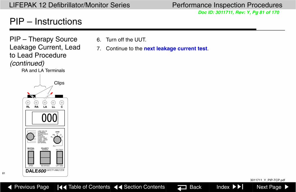
Previous Page Table of Contents Section Contents Back Index Next Page
LIFEPAK 12 Defibrillator/Monitor Series Performance Inspection Procedures
81
Doc ID: 3011711, Rev: Y, Pg 81 of 170
PIP – Instructions
PIP – Therapy Source Leakage Current, Lead to Lead Procedure (continued)
6. Turn off the UUT.
7. Continue to the next leakage current test.
DALE600 SAFETY ANALYZER
NEUTRAL POLARITYCLOSED NORMAL ISO TEST
OPEN REVERSED LIFT GND
LINE VOLTSCURRENTRESISTANCEEARTHCHASSISLEAD - GNDLEAD - LEADLEAD ISOEXTERNAL
000RL RA LA LL C
LEAD
RARL
LALL
C
ALL
RA and LA Terminals
Clips
3011711_Y_PIP-TCP.pdf

Previous Page Table of Contents Section Contents Back Index Next Page
LIFEPAK 12 Defibrillator/Monitor Series Performance Inspection Procedures
82
Doc ID: 3011711, Rev: Y, Pg 82 of 170
PIP – Instructions
PIP– Battery Operated Device, ECG 12-Lead Source Leakage Current Setup
Note: If the device is not configured with a 12-LEAD control, perform the PIP – 3-Lead ECG Leakage Current test instead of this test.
Note: If the Dale SW14 switch box is not available, perform the PIP Alternative ECG 12-Lead Source Leakage Current Test Procedure.
To test the ECG 12-Lead source leakage current, set up the safety analyzer, and UUT as shown below. Continue to the PIP – ECG 12-Lead Source Leakage Current Procedure when you complete the setup.
ALARMS12-LEAD
TRANSMICODE
ENERG
PAUSEEVENT
OPTIONS
SHOC
ON
ADVISOR
ANALYZE CHARGE
SYN
RATE
CURREN
PACE
HomeECG
Batt ChgServic
SPO2
SELEC
Screen
SUMMAR
DALE600 SAFETY ANALYZER
NEUTRAL POLARITYCLOSED NORMAL ISO TEST
OPEN REVERSED LIFT GND
LINE VOLTSCURRENTRESISTANCEEARTHCHASSISLEAD - GNDLEAD - LEADLEAD ISOEXTERNAL
000RL RA LA LL C
LEAD
RARL
LALL
C
ALL
RL C
ECG 12-Lead Main Cable
OUTPUT
DALE TECHNOLOGY CORP.ALL
RL C
LimbLead Set
Precordial Lead Set
CRL
LEA SIZE
Dale SW14 Switch Box
3011711_Y_PIP-TCP.pdf

Previous Page Table of Contents Section Contents Back Index Next Page
LIFEPAK 12 Defibrillator/Monitor Series Performance Inspection Procedures
83
Doc ID: 3011711, Rev: Y, Pg 83 of 170
PIP – Instructions
PIP– Battery Operated Device, ECG 12-Lead Source Leakage Current Lead to Lead
Procedure
To test ECG 12-Lead Source Leakage Current, Lead to Lead:
Note: Install a battery and complete this test on battery power
1. Establish the PIP – ECG 12-Lead Source Leakage Current Setup shown in the figure on the previous page.
2. Turn on the UUT.
3. Set the safety analyzer controls to:
4. Set the Dale SW14 Switch Box control to RL.
5. Verify the measured current is less than 10 µa.
6. Repeat step 5 for each switch setting (RA, LA, LL, V1, V2, V3, V4, V5, and V6) on the Dale SW14 switch box.
7. Record all results on the PIP Checklist.
8. Continue to the PIP Therapy Sink Leakage Current Setup.
Neutral Polarity Mode Lead
Closed Normal Leakage µa Lead – Lead RL
SW14
OUTPUT
DALE TECHNOLOGY CORP.ALL
RL C
3011711_Y_PIP-TCP.pdf

Previous Page Table of Contents Section Contents Back Index Next Page
LIFEPAK 12 Defibrillator/Monitor Series Performance Inspection Procedures
84
Doc ID: 3011711, Rev: Y, Pg 84 of 170
PIP – Instructions
PIP- Battery Operated Device, Alternate ECG 12-Lead Source Leakage Current Setup
If the Dale SW14 Switch Box is not available, use this procedure to test 12-Lead source leakage.
Set up the safety analyzer, and UUT as shown below. Continue to the PIP - Alternate ECG 12–Lead Source Leakage Current Procedure when you complete the setup.
000RL RA LA LL C
ALARMS12-LEAD
TRANSMICODE
ENERG
PAUSEEVENT
OPTIONS
SHOC
ON
ADVISOR
ANALYZE CHARGE
SYN
RATE
CURREN
PACE
HomeECG
Batt ChgServic
SPO2
SELEC
Screen
SUMMAR
ECG 12-Lead Main Cable
Limb Lead Set
Precordial Lead Set
LEA SIZE
DALE600 SAFETY ANALYZER
NEUTRAL POLARITYCLOSED NORMAL ISO TEST
OPEN REVERSED LIFT GND
LINE VOLTSCURRENTRESISTANCEEARTHCHASSISLEAD - GNDLEAD - LEADLEAD ISOEXTERNAL
000RL RA LA LL C
LEAD
RARL
LALL
C
ALL
3011711_Y_PIP-TCP.pdf

Previous Page Table of Contents Section Contents Back Index Next Page
LIFEPAK 12 Defibrillator/Monitor Series Performance Inspection Procedures
85
Doc ID: 3011711, Rev: Y, Pg 85 of 170
PIP – Instructions
PIP - Battery Operated Device, Alternate ECG 12-Lead Source Leakage Current Lead to Lead Procedure
To test ECG 12–Lead Source Leakage Current:
Note: Install a battery and complete this test on battery power
1. Establish the PIP - Alternate ECG 12–Lead Source Leakage Current Setup shown in the figure on the previous page.
2. Turn on the UUT.
3. Connect the V6 lead to the C snap of the safety analyzer.
4. Connect each of the other patient leads individually to the RL snap on the safety analyzer.
5. Set the safety analyzer controls to:
6. Verify that the measured current is less than 10 µA.
7. Repeat steps 4 and 6 for each remaining lead.
8. Record results on the PIP Checklist.
9. Continue to the PIP Therapy Sink Leakage Current Setup.
Neutral Polarity Mode Lead
Closed Normal Leakage µa Lead – Lead RL
3011711_Y_PIP-TCP.pdf

Previous Page Table of Contents Section Contents Back Index Next Page
LIFEPAK 12 Defibrillator/Monitor Series Performance Inspection Procedures
86
Doc ID: 3011711, Rev: Y, Pg 86 of 170
PIP – Instructions
PIP– Battery Operated Device, ECG 3-Lead Source Leakage Current Setup
Note: If the UUT is configured with a 12-LEAD control, perform the PIP – ECG 12-Lead Source Leakage Current test instead of this test.
To test the ECG 3-Lead Source Leakage Current, set up the safety analyzer and UUT as shown below. Continue to the PIP – ECG 3-Lead Source Leakage Current Procedure when you complete the setup.
ALARMS
ENERG
EVENT
OPTIONS
SHOCK
ON
ADVISORY
ANALYZE CHARGE
SYNC
Home
Batt ChgService
SELECT
Screen
TRANSMIT
CODE
PRINTECG
SUMMARY
DALE600 SAFETY ANALYZER
NEUTRAL POLARITYCLOSED NORMAL ISO TEST
OPEN REVERSED LIFT GND
LINE VOLTSCURRENTRESISTANCEEARTHCHASSISLEAD - GNDLEAD - LEADLEAD ISOEXTERNAL
000RL RA LA LL C
LEAD
RARL
LALL
C
ALL
ECG 3-Lead Cable
RA LA LL
LEAD SIZE
3011711_Y_PIP-TCP.pdf

Previous Page Table of Contents Section Contents Back Index Next Page
LIFEPAK 12 Defibrillator/Monitor Series Performance Inspection Procedures
87
Doc ID: 3011711, Rev: Y, Pg 87 of 170
PIP – Instructions
PIP– Battery Operated DeviceECG 3-Lead Source Leakage Current, Lead to Lead Procedure
To test ECG 3-Lead Source Leakage Current:
Note: Install a battery and complete this test on battery power
1. Establish the PIP – ECG 3-Lead Source Leakage Current Setup shown in the figure on the previous page.
2. Turn on the UUT.
3. Set the safety analyzer controls to:.
4. Verify that the measured current is less than 10 µa.
5. Repeat steps 3 & 4 for the remaining LA and LL leads.
6. Record all results on the PIP Checklist.
7. Continue to the PIP Therapy Sink Leakage Current Setup.
Neutral Polarity Mode Lead
Closed Normal Leakage µa Lead – Lead RA
DALE600 SAFETY ANALYZER
NEUTRAL POLARITYCLOSED NORMAL ISO TEST
OPEN REVERSED LIFT GND
LINE VOLTSCURRENTRESISTANCEEARTHCHASSISLEAD - GNDLEAD - LEADLEAD ISOEXTERNAL
000RL RA LA LL C
LEAD
RARL
LALL
C
ALL
RA LA LL
3011711_Y_PIP-TCP.pdf

Previous Page Table of Contents Section Contents Back Index Next Page
LIFEPAK 12 Defibrillator/Monitor Series Performance Inspection Procedures
88
Doc ID: 3011711, Rev: Y, Pg 88 of 170
PIP – Instructions
PIP – Power Source Management
To test auxiliary power switching:
1. Connect the Power Adapter to the power source and the output cable to the Auxiliary Connector at the rear of the device. See the Operating Instructions – AC and DC Power Adapters for more information.
2. Turn on the UUT and verify that the battery icons appear but neither is highlighted.
Note: Battery indications may look slightly different.
3. Unplug the Power Adapter cable from the UUT Auxiliary Connector. One of the UUT battery icons is highlighted.
4. Record the results on the PIP Checklist.
(continue to the next page)
12
AC Power Adapter
AC mains
Battery 1Battery 2
21
21
3011711_Y_PIP-TCP.pdf

Previous Page Table of Contents Section Contents Back Index Next Page
LIFEPAK 12 Defibrillator/Monitor Series Performance Inspection Procedures
89
Doc ID: 3011711, Rev: Y, Pg 89 of 170
PIP – Instructions
PIP – Power Source Management (continued)
To test defibrillator charge current delivery with auxiliary power:
1. Turn off the UUT and remove both batteries.
2. With the Power Adapter connected to the power source and the output cable to the Auxiliary Connector at the rear of the device.
3. Turn on the UUT.
4. Press ENERGY SELECT and choose a level of 360 J.
5. Press CHARGE and note the charging cycle is 10 seconds or less.
6. Record the results on the PIP Checklist.
7. Turn off the UUT.
8. Disconnect the Power Adapter from the UUT and reinstall the two batteries.
9. AC Operated Device, continue to the AC Operated Device Leakage Tests, or for DC Power Adapter operated device, refer to the PIP Checklist.
3011711_Y_PIP-TCP.pdf

Previous Page Table of Contents Section Contents Back Index Next Page
LIFEPAK 12 Defibrillator/Monitor Series Performance Inspection Procedures
90
Doc ID: 3011711, Rev: Y, Pg 90 of 170
PIP – Instructions
PIP – AC Operated Device, Chassis Leakage Current Setup
To test chassis leakage current, set up the safety analyzer, LIFEPAK 12 defibrillator/monitor (UUT), and AC Power Adapter as shown below. Continue to the PIP – Chassis Leakage Current Procedure when you complete the setup.
WARNING RISK OF FIRE. REPLACE FUSES AS MARKED.
12VDC OUTPUT ▼
12
DALE600 SAFETY ANALYZER
NEUTRAL POLARITYCLOSED NORMAL ISO TEST
OPEN REVERSED LIFT GND
LINE VOLTSCURRENTRESISTANCEEARTHCHASSISLEAD - GNDLEAD - LEADLEAD ISOEXTERNAL
000RL RA LA LL C
LEAD
RARL
LA LLC
ALL
AC Power Adapter.
Dale 600 Safety Analyzer with
test clip connected to the
Chassis jack.
Remove batteries for access to battery pins and contact pins.
Connect AC Power Adapter output to the Power Connector.
Connect the Dale 600 Safety Analyzer to line power for all tests.
Connect AC Power Adapter to the Dale 600 Safety Analyzer plug.
3011711_Y_PIP-TCP.pdf

Previous Page Table of Contents Section Contents Back Index Next Page
LIFEPAK 12 Defibrillator/Monitor Series Performance Inspection Procedures
91
Doc ID: 3011711, Rev: Y, Pg 91 of 170
PIP – Instructions
PIP – AC Powered Device, Chassis Leakage Current Procedure
To test Chassis Leakage Current:
1. Establish the PIP – Chassis Leakage Current Setup shown in the figure on the previous page. The UUT is off for this test.
2. Set the safety analyzer controls to:
Note: When operating the Polarity Switch, be sure to pause in the Off (middle) position when switching between Normal and Reversed Polarities.
3. Verify the AC Power Adapter is on.
4. Connect the analyzer clip to the positive (+) battery terminal of Battery Well 1 as shown at the left.
5. Verify measured current is less than 100 µa.
6. Press the LIFT GND button on the safety analyzer.
7. Verify measured current is less than 300 µa (120 vac) or less than 500 µa (240 vac).
Neutral Polarity Mode LeadClosed Normal/Reversed Leakage µa Lead – Chassis All
+
-+
-
12
Battery Pins
Battery Contact Blades
Dale 600 Safety
Analyzer Test clip
3011711_Y_PIP-TCP.pdf

Previous Page Table of Contents Section Contents Back Index Next Page
LIFEPAK 12 Defibrillator/Monitor Series Performance Inspection Procedures
92
Doc ID: 3011711, Rev: Y, Pg 92 of 170
PIP – Instructions
PIP – Chassis Leakage Current Procedure (continued)
8. Release the LIFT GND button on the safety analyzer.
9. Repeat steps 5 through 8 for the three remaining battery pins and all six battery contact blades on the A07 Contact PCB.
10. Record all results on the PIP Checklist.
11. Continue to the next leakage current test.
3011711_Y_PIP-TCP.pdf

Previous Page Table of Contents Section Contents Back Index Next Page
LIFEPAK 12 Defibrillator/Monitor Series Performance Inspection Procedures
93
Doc ID: 3011711, Rev: Y, Pg 93 of 170
PIP – Instructions
PIP – AC Operated Device, Earth Leakage Current Setup
To test earth leakage current, set up the safety analyzer, UUT, and AC Power Adapter as shown below. Continue to the PIP – Earth Leakage Current Procedure when you complete the setup.
WARNING RISK OF FIRE. REPLACE FUSES AS MARKED.
12VDC OUTPUT ▼
DALE600 SAFETY ANALYZER
NEUTRAL POLARITYCLOSED NORMAL ISO TEST
OPEN REVERSED LIFT GND
LINE VOLTSCURRENTRESISTANCEEARTHCHASSISLEAD - GNDLEAD - LEADLEAD ISOEXTERNAL
000RL RA LA LL C
LEAD
RARL
LA LLC
ALL
AC Power Adapter
Connect AC Power Adapter output to the Power Connector.
Connect the Dale 600 Safety Analyzer to line power for all tests.
12
Connect AC Power Adapter to the Dale 600 Safety Analyzer plug.
3011711_Y_PIP-TCP.pdf

Previous Page Table of Contents Section Contents Back Index Next Page
LIFEPAK 12 Defibrillator/Monitor Series Performance Inspection Procedures
94
Doc ID: 3011711, Rev: Y, Pg 94 of 170
PIP – Instructions
PIP – AC Operated Device, Earth Leakage Current Procedure
To test Earth Leakage Current:
1. Establish the PIP – Earth Leakage Current Setup shown in the figure on the previous page.
2. Set the safety analyzer controls to:
3. Verify the AC Power Adapter is on.
4. Verify measured current is less than 2500 µa.
5. Record the results in the PIP Checklist.
6. Set the safety analyzer controls to:
Neutral Polarity Mode Lead
Closed Normal Leakage µa Earth Any
Neutral Polarity Mode Lead
Open Normal Leakage µa Earth Any
3011711_Y_PIP-TCP.pdf

Previous Page Table of Contents Section Contents Back Index Next Page
LIFEPAK 12 Defibrillator/Monitor Series Performance Inspection Procedures
95
Doc ID: 3011711, Rev: Y, Pg 95 of 170
PIP – Instructions
PIP – Earth Leakage Current Procedure (continued)
7. Verify measured current is less than 5000 µa.
8. Record the results in the PIP Checklist.
9. Continue to the next leakage current test.
3011711_Y_PIP-TCP.pdf

Previous Page Table of Contents Section Contents Back Index Next Page
LIFEPAK 12 Defibrillator/Monitor Series Performance Inspection Procedures
96
Doc ID: 3011711, Rev: Y, Pg 96 of 170
PIP – Instructions
PIP – AC Operated Device,Therapy Source Leakage Current Setup, Lead to Gnd
Note: If the UUT is configured for use with Standard Paddles, perform alternative Paddles source leakage current setup, shown below.
To test QUIK-COMBO (Paddles) source leakage current, set up the safety analyzer, UUT, and AC Power Adapter as shown below. Continue to the PIP – Source Leakage Current, Lead to GND Procedure when you complete the setup.
ALARMS
12-LEAD
TRANSMIT
CODE
ENERG
PAUSEEVENT
OPTIONS
SHOCK
ON
ADVISORY
ANALYZE CHARGE
SYNC
RATE
CURRENT
PACER
HomeECG
Batt ChgService
SPO2
SELECT
Screen
SUMMARY
READY CHARGING FAULTYREADY CHARGING FAULTYPOWER SERVICE
PHYSIO-CONTROLAC POWER ADAPTER
DALE600 SAFETY ANALYZER
NEUTRAL POLARITYCLOSED NORMAL ISO TEST
OPEN REVERSED LIFT GND
LINE VOLTSCURRENTRESISTANCEEARTHCHASSISLEAD - GNDLEAD - LEADLEAD ISOEXTERNAL
000RL RA LA LL C
LEAD
RARL
LALL
C
ALL
RA
LA
+
QUIK-COMBO Therapy Cable
QUIK-COMBO Test Post Adapter
LEAD SIZE
+
Standard Paddles (optional)
3011711_Y_PIP-TCP.pdf

Previous Page Table of Contents Section Contents Back Index Next Page
LIFEPAK 12 Defibrillator/Monitor Series Performance Inspection Procedures
97
Doc ID: 3011711, Rev: Y, Pg 97 of 170
PIP – Instructions
PIP – AC Operated Device,Therapy Source Leakage Current, Lead to Gnd Procedure
To test QUIK-COMBO (Paddles) Source Leakage Current, Lead to Gnd:
1. Establish the PIP – Source Leakage Current, Lead to Gnd Setup shown in the figure on the previous page.
2. Verify that the AC Power Adapter is on.
3. Turn on the UUT.
4. Set the safety analyzer controls to:
Note: When operating the Polarity Switch, be sure to pause in the Off (middle) position when switching between Normal and Reversed Polarities
5. Verify the measured current is less than 10 µa.
6. Press the LIFT GND button on the safety analyzer.
7. Verify the measured current is less than 50 µa.Release the LIFT GND button.
8. Record results on the PIP Checklist.
Neutral Polarity Mode LeadClosed Normal/Reversed Leakage µa Lead – Gnd All
DALE600 SAFETY ANALYZER
NEUTRAL POLARITYCLOSED NORMAL ISO TEST
OPEN REVERSED LIFT GND
LINE VOLTSCURRENTRESISTANCEEARTHCHASSISLEAD - GNDLEAD - LEADLEAD ISOEXTERNAL
000RL RA LA LL C
LEAD
RARL
LALL
C
ALL
QUIK-COMBO setup.
Standard Paddle hookup on next page
3011711_Y_PIP-TCP.pdf

Previous Page Table of Contents Section Contents Back Index Next Page
LIFEPAK 12 Defibrillator/Monitor Series Performance Inspection Procedures
98
Doc ID: 3011711, Rev: Y, Pg 98 of 170
PIP – Instructions
PIP – Therapy Source Leakage Current, Lead to Gnd Procedure (continued)
9. Turn off the UUT.
10. Continue to the next leakage current test.
DALE600 SAFETY ANALYZER
NEUTRAL POLARITYCLOSED NORMAL ISO TEST
OPEN REVERSED LIFT GND
LINE VOLTSCURRENTRESISTANCEEARTHCHASSISLEAD - GNDLEAD - LEADLEAD ISOEXTERNAL
000RL RA LA LL C
LEAD
RARL
LALL
C
ALL
RA and LA Terminals
Clips
3011711_Y_PIP-TCP.pdf

Previous Page Table of Contents Section Contents Back Index Next Page
LIFEPAK 12 Defibrillator/Monitor Series Performance Inspection Procedures
99
Doc ID: 3011711, Rev: Y, Pg 99 of 170
PIP – Instructions
PIP – AC Operated Device,Therapy Source Leakage Current Setup, Lead to Lead
Note: If the UUT is configured for use with Standard Paddles, perform alternative Paddles source leakage current setup, shown below.
To test QUIK-COMBO (Paddles) source leakage current, Lead to Lead, set up the safety analyzer, UUT, and AC Power Adapter as shown below. Continue to the PIP – Source Leakage Current, Lead to Lead Procedure when you complete the setup.
ALARMS
12-LEAD
TRANSMIT
CODE
ENERG
PAUSEEVENT
OPTIONS
SHOCK
ON
ADVISORY
ANALYZE CHARGE
SYNC
RATE
CURRENT
PACER
HomeECG
Batt ChgService
SPO2
SELECT
Screen
SUMMARY
READY CHARGING FAULTYREADY CHARGING FAULTYPOWER SERVICE
PHYSIO-CONTROLAC POWER ADAPTER
DALE600 SAFETY ANALYZER
NEUTRAL POLARITYCLOSED NORMAL ISO TEST
OPEN REVERSED LIFT GND
LINE VOLTSCURRENTRESISTANCEEARTHCHASSISLEAD - GNDLEAD - LEADLEAD ISOEXTERNAL
000RL RA LA LL C
LEAD
RARL
LALL
C
ALL
RA
LA
+
QUIK-COMBO Therapy Cable
QUIK-COMBO Test Post Adapter
LEAD SIZE
+
Standard Paddles (optional)
3011711_Y_PIP-TCP.pdf

Previous Page Table of Contents Section Contents Back Index Next Page
LIFEPAK 12 Defibrillator/Monitor Series Performance Inspection Procedures
100
Doc ID: 3011711, Rev: Y, Pg 100 of 170
PIP – Instructions
PIP – Therapy Source Leakage Current, Lead to Lead Procedure
To test Source Leakage Current, Lead to Lead:
1. Establish the PIP – Source Leakage Current, Lead to Lead Setup shown in the figure on the previous page.
2. Verify that the AC Power Adapter is on.
3. Turn on the UUT.
4. Set the safety analyzer controls to:
Note: When operating the Polarity Switch, be sure to pause in the Off (middle) position when switching between Normal and Reversed Polarities
5. Verify the measured current is less than 10 µa.
6. Press the LIFT GND button on the safety analyzer.
7. Verify the measured current is less than 50 µa.
8. Release the LIFT GND button.
Neutral Polarity Mode LeadClosed NormalReversed Leakage µa Lead – Lead LA
DALE600 SAFETY ANALYZER
NEUTRAL POLARITYCLOSED NORMAL ISO TEST
OPEN REVERSED LIFT GND
LINE VOLTSCURRENTRESISTANCEEARTHCHASSISLEAD - GNDLEAD - LEADLEAD ISOEXTERNAL
000RL RA LA LL C
LEAD
RARL
LALL
C
ALL
QUIK-COMBO setup.
Standard Paddle hookup on next page
3011711_Y_PIP-TCP.pdf

Previous Page Table of Contents Section Contents Back Index Next Page
LIFEPAK 12 Defibrillator/Monitor Series Performance Inspection Procedures
101
Doc ID: 3011711, Rev: Y, Pg 101 of 170
PIP – Instructions
PIP – Therapy Source Leakage Current, Lead to Lead Procedure (continued)
9. Record all results on the PIP Checklist.
10. Turn off the UUT.
11. Continue to the next leakage current test.
DALE600 SAFETY ANALYZER
NEUTRAL POLARITYCLOSED NORMAL ISO TEST
OPEN REVERSED LIFT GND
LINE VOLTSCURRENTRESISTANCEEARTHCHASSISLEAD - GNDLEAD - LEADLEAD ISOEXTERNAL
000RL RA LA LL C
LEAD
RARL
LALL
C
ALL
RA and LA Terminals
Clips
3011711_Y_PIP-TCP.pdf

Previous Page Table of Contents Section Contents Back Index Next Page
LIFEPAK 12 Defibrillator/Monitor Series Performance Inspection Procedures
102
Doc ID: 3011711, Rev: Y, Pg 102 of 170
PIP – Instructions
PIP – AC Operated Device, ECG 12-Lead Source Leakage Current Setup
Note: If the device is not configured with a 12-LEAD control, perform the PIP – 3-Lead ECG Leakage Current test instead of this test.
Note: If the Dale SW14 switch box is not available, perform the PIP Alternative ECG 12-Lead Source Leakage Current Test Procedure.
To test the ECG 12-Lead source leakage current, set up the safety analyzer, UUT, and AC Power Adapter as shown below. Continue to the PIP– ECG 12-Lead Source Leakage Current Lead to Gnd Procedure when you complete the setup or PIP- ECG 12-Lead Lead to Lead Procedure.
ALARMS12-LEAD
TRANSMICODE
ENERG
PAUSEEVENT
OPTIONS
SHOC
ON
ADVISOR
ANALYZE CHARGE
SYN
RATE
CURREN
PACE
HomeECG
Batt ChgServic
SPO2
SELEC
Screen
SUMMAR
DALE600 SAFETY ANALYZER
NEUTRAL POLARITYCLOSED NORMAL ISO TEST
OPEN REVERSED LIFT GND
LINE VOLTSCURRENTRESISTANCEEARTHCHASSISLEAD - GNDLEAD - LEADLEAD ISOEXTERNAL
000RL RA LA LL C
LEAD
RARL
LALL
C
ALL
RL C
ECG 12-Lead Main Cable
OUTPUT
DALE TECHNOLOGY CORP.ALL
RL C
LimbLead Set
Precordial Lead Set
CRL
LEA SIZE
Dale SW14 Switch Box
READY CHARGING FAULTYREADY CHARGING FAULTYPOWER SERVICE
PHYSIO-CONTROLAC POWER ADAPTER
3011711_Y_PIP-TCP.pdf
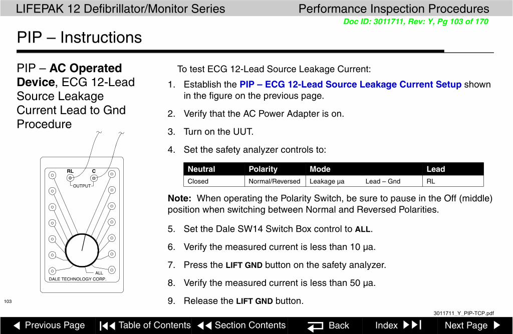
Previous Page Table of Contents Section Contents Back Index Next Page
LIFEPAK 12 Defibrillator/Monitor Series Performance Inspection Procedures
103
Doc ID: 3011711, Rev: Y, Pg 103 of 170
PIP – Instructions
PIP – AC Operated Device, ECG 12-Lead Source Leakage Current Lead to Gnd Procedure
To test ECG 12-Lead Source Leakage Current:
1. Establish the PIP – ECG 12-Lead Source Leakage Current Setup shown in the figure on the previous page.
2. Verify that the AC Power Adapter is on.
3. Turn on the UUT.
4. Set the safety analyzer controls to:
Note: When operating the Polarity Switch, be sure to pause in the Off (middle) position when switching between Normal and Reversed Polarities.
5. Set the Dale SW14 Switch Box control to ALL.
6. Verify the measured current is less than 10 µa.
7. Press the LIFT GND button on the safety analyzer.
8. Verify the measured current is less than 50 µa.
9. Release the LIFT GND button.
Neutral Polarity Mode LeadClosed Normal/Reversed Leakage µa Lead – Gnd RL
SW14
OUTPUT
DALE TECHNOLOGY CORP.ALL
RL C
3011711_Y_PIP-TCP.pdf

Previous Page Table of Contents Section Contents Back Index Next Page
LIFEPAK 12 Defibrillator/Monitor Series Performance Inspection Procedures
104
Doc ID: 3011711, Rev: Y, Pg 104 of 170
PIP – Instructions
PIP – ECG 12-Lead Source Leakage Current, Lead to Gnd Procedure (continued)
10. Record results on the PIP Checklist.
11. Turn off the UUT.
12. Continue to the next leakage current test.
3011711_Y_PIP-TCP.pdf

Previous Page Table of Contents Section Contents Back Index Next Page
LIFEPAK 12 Defibrillator/Monitor Series Performance Inspection Procedures
105
Doc ID: 3011711, Rev: Y, Pg 105 of 170
PIP – Instructions
PIP – AC Operated Device, ECG 12-Lead Source Leakage Current Lead to Lead
Procedure
To test ECG 12-Lead Source Leakage Current, Lead to Lead:
1. Establish the PIP – ECG 12-Lead Source Leakage Current Setup shown in the figure on the previous page.
2. Verify that the AC Power Adapter is on.
3. Turn on the UUT.
4. Set the safety analyzer controls to:
Note: When operating the Polarity Switch, be sure to pause in the Off (middle) position when switching between Normal and Reversed Polarities
5. Set the Dale SW14 Switch Box control to RL.
6. Verify the measured current is less than 10 µa.
7. Press the LIFT GND button on the safety analyzer.
8. Verify the measured current is less than 50 µa.
9. Release the LIFT GND button.
Neutral Polarity Mode LeadClosed Normal/Reversed Leakage µa Lead – Lead RL
SW14
OUTPUT
DALE TECHNOLOGY CORP.ALL
RL C
3011711_Y_PIP-TCP.pdf

Previous Page Table of Contents Section Contents Back Index Next Page
LIFEPAK 12 Defibrillator/Monitor Series Performance Inspection Procedures
106
Doc ID: 3011711, Rev: Y, Pg 106 of 170
PIP – Instructions
PIP – ECG 12-Lead Source Leakage Current Lead to Lead Procedure (continued)
10. Repeat steps 6 through 9 for each switch setting (RA, LA, LL, V1, V2, V3, V4, V5, and V6) on the Dale SW14 switch box. Record all results on the PIP Checklist.
11. Turn off the UUT.
12. Continue to the PIP Therapy Sink Leakage Current Setup.
3011711_Y_PIP-TCP.pdf

Previous Page Table of Contents Section Contents Back Index Next Page
LIFEPAK 12 Defibrillator/Monitor Series Performance Inspection Procedures
107
Doc ID: 3011711, Rev: Y, Pg 107 of 170
PIP – Instructions
PIP - AC Operated, Device, Alternate ECG 12-Lead Source Leakage Current Setup
If the Dale SW14 Switch Box is not available, use this procedure to test 12-Lead source leakage.
Note: If the Dale SW14 switch box is available, perform the PIP ECG 12-Lead Source Leakage Current Test Procedure.
Set up the safety analyzer, UUT, and the AC Power Adapter as shown below. Continue to the PIP - Alternate ECG 12–Lead Source Leakage Current Procedure when you complete the setup.
000RL RA LA LL C
ALARMS12-LEAD
TRANSMICODE
ENERG
PAUSEEVENT
OPTIONS
SHOC
ON
ADVISOR
ANALYZE CHARGE
SYN
RATE
CURREN
PACE
HomeECG
Batt ChgServic
SPO2
SELEC
Screen
SUMMAR
READY CHARGING FAULTYREADY CHARGING FAULTYPOWER SERVICE
PHYSIO-CONTROLAC POWER ADAPTER
ECG 12-Lead Main Cable
Limb Lead Set
Precordial Lead Set
LEA SIZE
DALE600 SAFETY ANALYZER
NEUTRAL POLARITYCLOSED NORMAL ISO TEST
OPEN REVERSED LIFT GND
LINE VOLTSCURRENTRESISTANCEEARTHCHASSISLEAD - GNDLEAD - LEADLEAD ISOEXTERNAL
000RL RA LA LL C
LEAD
RARL
LALL
C
ALL
3011711_Y_PIP-TCP.pdf
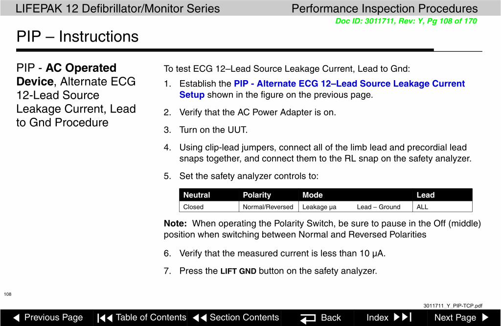
Previous Page Table of Contents Section Contents Back Index Next Page
LIFEPAK 12 Defibrillator/Monitor Series Performance Inspection Procedures
108
Doc ID: 3011711, Rev: Y, Pg 108 of 170
PIP – Instructions
PIP - AC Operated Device, Alternate ECG 12-Lead Source Leakage Current, Lead to Gnd Procedure
To test ECG 12–Lead Source Leakage Current, Lead to Gnd:
1. Establish the PIP - Alternate ECG 12–Lead Source Leakage Current Setup shown in the figure on the previous page.
2. Verify that the AC Power Adapter is on.
3. Turn on the UUT.
4. Using clip-lead jumpers, connect all of the limb lead and precordial lead snaps together, and connect them to the RL snap on the safety analyzer.
5. Set the safety analyzer controls to:
Note: When operating the Polarity Switch, be sure to pause in the Off (middle) position when switching between Normal and Reversed Polarities
6. Verify that the measured current is less than 10 µA.
7. Press the LIFT GND button on the safety analyzer.
Neutral Polarity Mode LeadClosed Normal/Reversed Leakage µa Lead – Ground ALL
3011711_Y_PIP-TCP.pdf

Previous Page Table of Contents Section Contents Back Index Next Page
LIFEPAK 12 Defibrillator/Monitor Series Performance Inspection Procedures
109
Doc ID: 3011711, Rev: Y, Pg 109 of 170
PIP – Instructions
PIP - Alternate ECG 12-Lead Source Leakage Current Lead to Gnd Procedure (continued)
8. Verify that the measured current is less than 50 µA.
9. Release the LIFT GND button.
10. Record all results on the PIP Checklist.
11. Turn off the UUT.
12. Continue to next leakage current test
3011711_Y_PIP-TCP.pdf

Previous Page Table of Contents Section Contents Back Index Next Page
LIFEPAK 12 Defibrillator/Monitor Series Performance Inspection Procedures
110
Doc ID: 3011711, Rev: Y, Pg 110 of 170
PIP – Instructions
PIP - AC Operated Device, Alternate ECG 12-Lead Source Leakage Current Lead to Lead Procedure
To test ECG 12–Lead Source Leakage Current:
1. Establish the PIP - Alternate ECG 12–Lead Source Leakage Current Setup shown in the figure on the previous page.
2. Verify that the AC Power Adapter is on.
3. Turn on the UUT.
4. Connect the V6 lead to the C snap of the safety analyzer.
5. Connect each of the other patient leads individually to the RL snap on the safety analyzer.
6. Set the safety analyzer controls to:
Note: When operating the Polarity Switch, be sure to pause in the Off (middle) position when switching between Normal and Reversed Polarities
7. Verify that the measured current is less than 10 µA.
8. Press the LIFT GND button on the safety analyzer.
Neutral Polarity Mode LeadClosed Normal/Reversed Leakage µa Lead – Lead RL
3011711_Y_PIP-TCP.pdf
Previous Page Table of Contents Section Contents Back Index Next Page
LIFEPAK 12 Defibrillator/Monitor Series Performance Inspection Procedures
111
Doc ID: 3011711, Rev: Y, Pg 111 of 170
PIP – Instructions
PIP - Alternate ECG 12-Lead Source Leakage Current Procedure (continued)
9. Verify that the measured current is less than 50 µA
10. Release the LIFT GND button.
11. Repeat steps 5, 7, 8, 9 and 10 for each remaining lead.
12. Record all results on the PIP Checklist.
13. Turn off the UUT.
14. Continue to the PIP Therapy Sink Leakage Current Setup.
3011711_Y_PIP-TCP.pdf

Previous Page Table of Contents Section Contents Back Index Next Page
LIFEPAK 12 Defibrillator/Monitor Series Performance Inspection Procedures
112
Doc ID: 3011711, Rev: Y, Pg 112 of 170
PIP – Instructions
PIP – AC Operated Device, ECG 3-Lead Source Leakage Current Setup
Note: If the UUT is configured with a 12-LEAD control, perform the PIP – ECG 12-Lead Source Leakage Current test instead of this test.
To test the ECG 3-Lead Source Leakage Current, set up the safety analyzer, UUT, and AC Power Adapter as shown below. Continue to the PIP – ECG 3-Lead Source Leakage Current Procedure when you complete the setup.
ALARMS
ENERG
EVENT
OPTIONS
SHOCK
ON
ADVISORY
ANALYZE CHARGE
SYNC
Home
Batt ChgService
SELECT
Screen
TRANSMIT
CODE
PRINTECG
SUMMARY
READY CHARGING FAULTYREADY CHARGING FAULTYPOWER SERVICE
PHYSIO-CONTROLAC POWER ADAPTER
DALE600 SAFETY ANALYZER
NEUTRAL POLARITYCLOSED NORMAL ISO TEST
OPEN REVERSED LIFT GND
LINE VOLTSCURRENTRESISTANCEEARTHCHASSISLEAD - GNDLEAD - LEADLEAD ISOEXTERNAL
000RL RA LA LL C
LEAD
RARL
LALL
C
ALL
ECG 3-Lead Cable
RA LA LL
LEAD SIZE
3011711_Y_PIP-TCP.pdf

Previous Page Table of Contents Section Contents Back Index Next Page
LIFEPAK 12 Defibrillator/Monitor Series Performance Inspection Procedures
113
Doc ID: 3011711, Rev: Y, Pg 113 of 170
PIP – Instructions
PIP – AC Operated Device, ECG 3-Lead Source Leakage Current, Lead to Gnd Procedure
To test ECG 3-Lead Source Leakage Current:
1. Establish the PIP – ECG 3-Lead Source Leakage Current Setup shown in the figure on the previous page.
2. Verify that the AC Power Adapter is on.
3. Turn on the UUT.
4. Set the safety analyzer controls to:
Note: When operating the Polarity Switch, be sure to pause in the Off (middle) position when switching between Normal and Reversed Polarities.
5. Verify the measured current is less than 10 µA.
6. Press the LIFT GND button on the safety analyzer.
7. Verify the measured current is less than 50 µA.
8. Release the LIFT GND button.
Neutral Polarity Mode LeadClosed Normal/Reversed Leakage µa Lead – Gnd ALL
DALE600 SAFETY ANALYZER
NEUTRAL POLARITYCLOSED NORMAL ISO TEST
OPEN REVERSED LIFT GND
LINE VOLTSCURRENTRESISTANCEEARTHCHASSISLEAD - GNDLEAD - LEADLEAD ISOEXTERNAL
000RL RA LA LL C
LEAD
RARL
LALL
C
ALL
RA LA LL
3011711_Y_PIP-TCP.pdf

Previous Page Table of Contents Section Contents Back Index Next Page
LIFEPAK 12 Defibrillator/Monitor Series Performance Inspection Procedures
114
Doc ID: 3011711, Rev: Y, Pg 114 of 170
PIP – Instructions
PIP – ECG 3-Lead Source Leakage Current, Lead to Gnd Procedure (continued)
9. Record all results on the PIP Checklist.
10. Turn off the UUT.
11. Continue to the next leakage current test.
3011711_Y_PIP-TCP.pdf

Previous Page Table of Contents Section Contents Back Index Next Page
LIFEPAK 12 Defibrillator/Monitor Series Performance Inspection Procedures
115
Doc ID: 3011711, Rev: Y, Pg 115 of 170
PIP – Instructions
PIP – AC Operated Device, ECG 3-Lead Source Leakage Current, Lead to Lead Procedure
To test ECG 3-Lead Source Leakage Current:
1. Establish the PIP – ECG 3-Lead Source Leakage Current Setup shown in the figure on the previous page.
2. Verify that the AC Power Adapter is on.
3. Turn on the UUT.
4. Set the safety analyzer controls to:.
Note: When operating the Polarity Switch, be sure to pause in the Off (middle) position when switching between Normal and Reversed Polarities.
5. Verify that the measured current is less than 10 µa.
6. Press the LIFT GND button on the safety analyzer.
7. Verify that the measured current is less than 50 µa.
8. Release the LIFT GND button.
Neutral Polarity Mode LeadClosed Normal/Reversed Leakage µa Lead – Lead RA
DALE600 SAFETY ANALYZER
NEUTRAL POLARITYCLOSED NORMAL ISO TEST
OPEN REVERSED LIFT GND
LINE VOLTSCURRENTRESISTANCEEARTHCHASSISLEAD - GNDLEAD - LEADLEAD ISOEXTERNAL
000RL RA LA LL C
LEAD
RARL
LALL
C
ALL
RA LA LL
3011711_Y_PIP-TCP.pdf

Previous Page Table of Contents Section Contents Back Index Next Page
LIFEPAK 12 Defibrillator/Monitor Series Performance Inspection Procedures
116
Doc ID: 3011711, Rev: Y, Pg 116 of 170
PIP – Instructions
PIP – ECG 3-Lead Source Leakage Current, Lead to Lead Procedure (continued)
9. Repeat steps 4 through 8 for the remaining LA and LL leads.
10. Record all results on the PIP Checklist.
11. Turn off the UUT.
12. Continue to the PIP Therapy Sink Leakage Current Setup.
3011711_Y_PIP-TCP.pdf
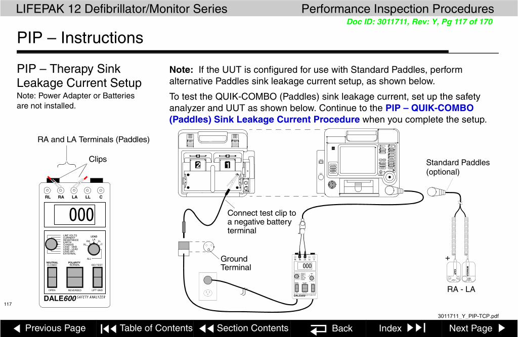
Previous Page Table of Contents Section Contents Back Index Next Page
LIFEPAK 12 Defibrillator/Monitor Series Performance Inspection Procedures
117
Doc ID: 3011711, Rev: Y, Pg 117 of 170
PIP – Instructions
PIP – Therapy Sink Leakage Current Setup Note: Power Adapter or Batteries are not installed.
Note: If the UUT is configured for use with Standard Paddles, perform alternative Paddles sink leakage current setup, as shown below.
To test the QUIK-COMBO (Paddles) sink leakage current, set up the safety analyzer and UUT as shown below. Continue to the PIP – QUIK-COMBO (Paddles) Sink Leakage Current Procedure when you complete the setup.
12 ALARMS
12-LEAD
TRANSMITCODE
ENERG
PAUSEEVENT
OPTIONS
SHOCK
ON
ADVISORY
ANALYZE CHARGE
SYNC
RATE
CURRENT
PACER
HomeECG
Batt ChgServic
SPO2
SELEC
Screen
SUMMARY
Ground
DALE600 SAFETY ANALYZER
NEUTRAL POLARITYCLOSED NORMAL ISO TEST
OPEN REVERSED LIFT GND
LINE VOLTSCURRENTRESISTANCEEARTHCHASSISLEAD - GNDLEAD - LEADLEAD ISOEXTERNAL
000RL RA LA LL C
LEAD
RARL
LA LLC
ALL
Terminal
LEA SIZE
Connect test clip toa negative battery terminal
+
RA - LA
Standard Paddles (optional)
DALE600 SAFETY ANALYZER
NEUTRAL POLARITYCLOSED NORMAL ISO TEST
OPEN REVERSED LIFT GND
LINE VOLTSCURRENTRESISTANCEEARTHCHASSISLEAD - GNDLEAD - LEADLEAD ISOEXTERNAL
000RL RA LA LL C
LEAD
RARL
LALL
C
ALL
RA and LA Terminals (Paddles)
Clips
3011711_Y_PIP-TCP.pdf

Previous Page Table of Contents Section Contents Back Index Next Page
LIFEPAK 12 Defibrillator/Monitor Series Performance Inspection Procedures
118
Doc ID: 3011711, Rev: Y, Pg 118 of 170
PIP – Instructions
PIP – Therapy Sink Leakage Current Procedure
To test QUIK-COMBO (Paddles) Sink Leakage Current:
1. Establish the PIP – QUIK-COMBO (Paddles) Sink Leakage Current Setup shown in the figure on the previous page.
WARNING! Shock hazard. During sink leakage tests high voltage is present on the safety analyzer electrode snaps. Do not touch the analyzer snaps or UUT connections during these tests.
2. Set the safety analyzer controls to:
3. Momentarily press the ISO TEST button on the safety analyzer and observe the measured current reading.
4. Release the ISO TEST button.
5. Verify the following measured currents:
Neutral Polarity Mode Lead
Closed Normal Leakage µa Lead Iso All
120 vac 240 vac
QUIK-COMBO less than 50 µa less than 100 µa
Standard Paddles less than 100 µa less than 500 µa
3011711_Y_PIP-TCP.pdf

Previous Page Table of Contents Section Contents Back Index Next Page
LIFEPAK 12 Defibrillator/Monitor Series Performance Inspection Procedures
119
Doc ID: 3011711, Rev: Y, Pg 119 of 170
PIP – Instructions
PIP – Therapy Sink Leakage Current Procedure (continued)
6. Record the results on the Battery Op. page of PIP Checklist or record the results on the AC-PA page of PIP Checklist.
7. Continue to the next leakage current test.
3011711_Y_PIP-TCP.pdf

Previous Page Table of Contents Section Contents Back Index Next Page
LIFEPAK 12 Defibrillator/Monitor Series Performance Inspection Procedures
120
Doc ID: 3011711, Rev: Y, Pg 120 of 170
PIP – Instructions
PIP – ECG 12-Lead Sink Leakage Current Setup - - - - - - - - - - -Note: Power Adapter or Batteries
are not installed.
If the device is not configured with a 12-LEAD control, perform the PIP – 3-Lead Sink Leakage Current test instead of this test.Note: If the Dale SW14 switch box is not available, perform the PIP Alternative ECG 12-Lead Sink Leakage Current Test Procedure.To test the ECG 12-Lead Sink Leakage Current, set up the safety analyzer and UUT as shown below. Continue to the PIP – ECG 12-Lead Sink Leakage Current Procedure when you complete the setup.
OUTPUT
DALE TECHNOLOGY CORP.ALL
RL C
12ALARMS12-LEAD
TRANSMICODE
ENERG
PAUSEEVENT
OPTIONS
SHOC
ON
ADVISOR
ANALYZE CHARGE
SYN
RATE
CURRENT
PACE
HomeECG
Batt ChgServic
SPO2
SELEC
Screen
SUMMAR
Ground
DALE600 SAFETY ANALYZER
NEUTRAL POLARITYCLOSED NORMAL ISO TEST
OPEN REVERSED LIFT GND
LINE VOLTSCURRENTRESISTANCEEARTHCHASSISLEAD - GNDLEAD - LEADLEAD ISOEXTERNAL
000RL RA LA LL C
LEAD
RARL
LA LLC
ALL
Terminal
LEA SIZE
Connect testclip to negativebattery terminal
3011711_Y_PIP-TCP.pdf

Previous Page Table of Contents Section Contents Back Index Next Page
LIFEPAK 12 Defibrillator/Monitor Series Performance Inspection Procedures
121
Doc ID: 3011711, Rev: Y, Pg 121 of 170
PIP – Instructions
PIP – ECG 12-Lead Sink Leakage Current Procedure
To test ECG 12-Lead Sink Leakage Current:
1. Establish the PIP – ECG 12-Lead Sink Leakage Current Setup shown in the figure on the previous page.
WARNING!Shock hazard. During sink leakage tests high voltage is present on the safety analyzer electrode snaps. Do not touch the analyzer snaps or UUT connections during these tests.
2. Set the safety analyzer controls to:
3. On the Dale SW14 Switch Box set the control to ALL.
4. Momentarily press the ISO TEST button on the analyzer and observe the current reading.
5. Release the ISO TEST button.
6. Verify the measured current is less than 50 µa. Record the results on the Battery Op. page of PIP Checklist or AC-PA PIP Checklist.
7. Continue to next PIP - SpO2 Sink Leakage Current Test.
Neutral Polarity Mode Lead
Closed Normal Leakage µa Lead Iso All
3011711_Y_PIP-TCP.pdf

Previous Page Table of Contents Section Contents Back Index Next Page
LIFEPAK 12 Defibrillator/Monitor Series Performance Inspection Procedures
122
Doc ID: 3011711, Rev: Y, Pg 122 of 170
PIP – Instructions
PIP - Alternate ECG 12-Lead Sink Leakage Current Setup - - - - - Note: Power Adapter or Batteries
are not installed.
If the device is not configured with a 12-LEAD control, perform the PIP – 3-Lead Sink Leakage Current test instead of this test.
Set up the safety analyzer and the UUT as shown below. Continue to the PIP – Alternate ECG 12-Lead Sink Leakage Current Procedure when you complete the setup.
12ALARMS12-LEAD
TRANSMITCODE
ENERG
PAUSEEVENT
OPTIONS
SHOCK
ON
ADVISORY
ANALYZE CHARGE
SYN
RATE
CURRENT
PACER
HomeECG
Batt ChgServic
SPO2
SELEC
Screen
SUMMAR
Ground
DALE600 SAFETY ANALYZER
NEUTRAL POLARITYCLOSED NORMAL ISO TEST
OPEN REVERSED LIFT GND
LINE VOLTSCURRENTRESISTANCEEARTHCHASSISLEAD - GNDLEAD - LEADLEAD ISOEXTERNAL
000RL RA LA LL C
LEAD
RARL
LALL
C
ALL
Terminal
LEA SIZE
000RL RA LA LL C
3011711_Y_PIP-TCP.pdf

Previous Page Table of Contents Section Contents Back Index Next Page
LIFEPAK 12 Defibrillator/Monitor Series Performance Inspection Procedures
123
Doc ID: 3011711, Rev: Y, Pg 123 of 170
PIP – Instructions
PIP - Alternate ECG 12-Lead Sink Leakage Current Procedure
To test ECG 12-Lead Sink Leakage Current:
1. Establish the PIP – ECG 12-Lead Sink Leakage Current Setup shown in the figure on the previous page.
WARNING!Shock hazard. During sink leakage tests high voltage is present on the safety analyzer electrode snaps. Do not touch the analyzer snaps or UUT connections during these tests.
2. Set the safety analyzer controls to:
3. Using clip-lead jumpers, connect all of the limb lead and precordial lead snaps together, and connect them to the RL snap on the safety analyzer.
4. Momentarily press the ISO TEST button on the safety analyzer, and observe the current reading.
5. Release the ISO TEST button.
Neutral Polarity Mode Lead
Closed Normal Leakage µa Lead ISO All
3011711_Y_PIP-TCP.pdf

Previous Page Table of Contents Section Contents Back Index Next Page
LIFEPAK 12 Defibrillator/Monitor Series Performance Inspection Procedures
124
Doc ID: 3011711, Rev: Y, Pg 124 of 170
PIP – Instructions
PIP - Alternate ECG 12-Lead Sink Leakage Current Procedure (continued)
6. Verify that the measured current is less than 50 µA.
7. Record the results on the Battery Op. page of PIP Checklist, or record the results on the AC-PA page of PIP Checklist.
8. Continue to the next PIP - SpO2 Sink Leakage Current Test.
3011711_Y_PIP-TCP.pdf
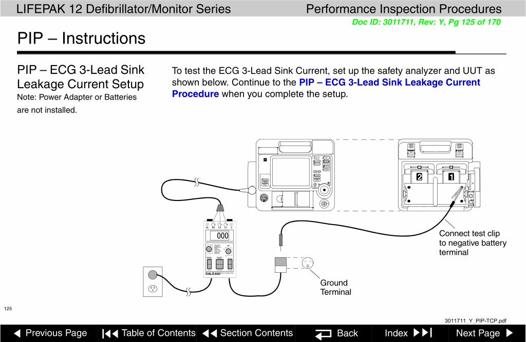
Previous Page Table of Contents Section Contents Back Index Next Page
LIFEPAK 12 Defibrillator/Monitor Series Performance Inspection Procedures
125
Doc ID: 3011711, Rev: Y, Pg 125 of 170
PIP – Instructions
PIP – ECG 3-Lead Sink Leakage Current Setup Note: Power Adapter or Batteries
are not installed.
To test the ECG 3-Lead Sink Current, set up the safety analyzer and UUT as shown below. Continue to the PIP – ECG 3-Lead Sink Leakage Current Procedure when you complete the setup.
12ALARMS
ENERG
EVENT
OPTIONS
SHOCK
ON
ADVISORY
ANALYZE CHARGE
SYNC
Home
Batt ChgService
SELECT
Screen
TRANSMIT
CODE
PRINTECG
SUMMARY
Ground DALE600 SAFETY ANALYZER
NEUTRAL POLARITYCLOSED NORMAL ISO TEST
OPEN REVERSED LIFT GND
LINE VOLTSCURRENTRESISTANCEEARTHCHASSISLEAD - GNDLEAD - LEADLEAD ISOEXTERNAL
000RL RA LA LL C
LEAD
RARL
LALL
C
ALL
Terminal
LEAD SIZE
Connect test clipto negative batteryterminal
3011711_Y_PIP-TCP.pdf

Previous Page Table of Contents Section Contents Back Index Next Page
LIFEPAK 12 Defibrillator/Monitor Series Performance Inspection Procedures
126
Doc ID: 3011711, Rev: Y, Pg 126 of 170
PIP – Instructions
PIP – ECG 3-Lead Sink Leakage Current Procedure
To test ECG 3-Lead Sink Leakage Current:
1. Establish the PIP – ECG 3-Lead Sink Leakage Current Setup shown in the figure on the previous page.
WARNING!Shock hazard. During sink leakage tests high voltage is present on the safety analyzer electrode snaps. Do not touch the analyzer snaps or UUT connections during these tests.
2. Set the safety analyzer controls to:
3. Momentarily press the ISO TEST button on the safety analyzer and observe the current reading.
4. Release the ISO TEST button.
5. Verify that the measured current is less than 50 µa. Record the results on the Battery Op. page of PIP Checklist or AC-PA PIP Checklist.
6. Continue to the next PIP - SpO2 Sink Leakage Current Test.
Neutral Polarity Mode Lead
Closed Normal Leakage µa Lead Iso All
3011711_Y_PIP-TCP.pdf

Previous Page Table of Contents Section Contents Back Index Next Page
LIFEPAK 12 Defibrillator/Monitor Series Performance Inspection Procedures
127
Doc ID: 3011711, Rev: Y, Pg 127 of 170
PIP – Instructions
PIP – SpO2 Sink Leakage Current Setup Note: Power Adapter or Batteries
are not installed.
Note: Complete the following only for UUTs equipped with the SpO2 option, if not, go to the next required test per PIP Checklist.
To test SpO2 Sink Leakage Current, set up the safety analyzer and UUT as shown below. Continue to the PIP – SpO2 Sink Leakage Current Procedure when you complete the setup.
12ALARMS
12-LEAD
TRANSMIT
CODE
ENERG
PAUSEEVENT
OPTIONS
SHOCK
ON
ADVISORY
ANALYZE CHARGE
SYNC
RATE
CURRENT
PACER
HomeECG
Batt ChgService
SPO2
SELECT
Screen
SUMMARY
Ground Terminal
DALE600 SAFETY ANALYZER
NEUTRAL POLARITYCLOSED NORMAL ISO TEST
OPEN REVERSED LIFT GND
LINE VOLTSCURRENTRESISTANCEEARTHCHASSISLEAD - GNDLEAD - LEADLEAD ISOEXTERNAL
000RL RA LA LL C
LEAD
RARL
LALL
C
ALL
Nellcor Safety Analyzer Test Lead — See Test Equipment Requirements
LEAD SIZE
Connect test clipto negative batteryterminal
DB-9 extender cable
ALARMS
12-LEAD
TRANSMIT
CODE
ENERG
PAUSEEVENT
OPTIONS
SHOCK
ON
ADVISORY
ANALYZE CHARGE
SYNC
RATE
CURRENT
PACER
HomeECG
Batt ChgService
SPO2
SELECT
Screen
SUMMARY
NEUTRAL POLARITYCLOSED NORMAL ISO TEST
OPEN REVERSED LIFT GND
LINE VOLTSCURRENTRESISTANCEEARTHCHASSISLEAD - GNDLEAD - LEADLEAD ISOEXTERNAL
000RL RA LA LL C
LEAD
RARL
LALL
C
ALL
NELLCOR SpO2 SetupMasimo SpO2 Setup
Masimo SpO2 Test Cable Assy.
3011711_Y_PIP-TCP.pdf

Previous Page Table of Contents Section Contents Back Index Next Page
LIFEPAK 12 Defibrillator/Monitor Series Performance Inspection Procedures
128
Doc ID: 3011711, Rev: Y, Pg 128 of 170
PIP – Instructions
PIP – SpO2 Sink Leakage Current Procedure
To test SpO2 Sink Leakage Current:
1. Establish the PIP – SpO2 Sink Leakage Current Setup shown in the figure on the previous page.
WARNING! Shock hazard. During sink leakage tests high voltage is present on the safety analyzer electrode snaps. Do not touch the analyzer snaps or UUT connections during these tests.
2. Set the safety analyzer controls to:
3. Momentarily press the ISO TEST button on the safety analyzer and observe the measured current reading.
4. Release the ISO TEST button.
5. Verify that the measured current is less than 100 µa (120 vac) or less than 500 µa (240 vac).
6. Record the results on the Battery Op. page of PIP Checklist or record the results on the AC-PA page of PIP Checklist.
Note: For DC-PA connected devices, also perform Power Source Management test.
Neutral Polarity Mode Lead
Closed Normal Leakage µa Lead Iso C
3011711_Y_PIP-TCP.pdf

Previous Page Table of Contents Section Contents Back Index Next Page
LIFEPAK 12 Defibrillator/Monitor Series Performance Inspection Procedures
129
Doc ID: 3011711, Rev: Y, Pg 129 of 170
PIP – Power Adapter Instructions
PIP – Power Adapter Note: This section of the PIP tests Stand-alone Power Adapters.
1. Connect the Power Adapter under test (UUT) to power source.
2. Verify that the green POWER LED turns on.
Note: When the power adapter is first turned on, it performs a brief self-test. During this test all LEDs turn on for a few seconds. If the test is successful, all the LEDs turn off, with the exception of the green POWER LED.
3. Connect the output cable to the Auxiliary Connector at the rear of a LIFEPAK 12 defibrillator/monitor. See the Operating Instructions – AC/DC Power Adapters for more information.
4. Install two charged batteries into the LIFEPAK 12 defibrillator/monitor.
5. Verify that the CHARGING indicator for either Battery 1 or Battery 2 is backlit.
3011711_Y_PIP-TCP.pdf

Previous Page Table of Contents Section Contents Back Index Next Page
LIFEPAK 12 Defibrillator/Monitor Series Performance Inspection Procedures
130
Doc ID: 3011711, Rev: Y, Pg 130 of 170
PIP – Power Adapter Instructions (continued)
PIP – Power Adapter (continued)
Note: If the batteries are installed in the defibrillator, the power adapter LEDs illuminate as follows:
■ READY (green): battery is fully charged.■ CHARGING (amber): battery is charging■ FAIL (red): discard/ recycle batteries■ SERVICE (red): power adapter needs service immediately. Remove power
adapter from use immediately.6. Turn on the LIFEPAK 12 defibrillator/monitor.
7. Verify that the battery icons appear on the display, but neither is highlighted.
8. Unplug the Power Adapter cable from the LIFEPAK 12 defibrillator/monitor.
9. Verify that one of the battery icons on the monitor display is highlighted.
10. Record the results on the PIP Checklist.
11. Turn off the LIFEPAK 12 defibrillator/monitor and remove both batteries.
1 2
1 2
3011711_Y_PIP-TCP.pdf

Previous Page Table of Contents Section Contents Back Index Next Page
LIFEPAK 12 Defibrillator/Monitor Series Performance Inspection Procedures
131
Doc ID: 3011711, Rev: Y, Pg 131 of 170
PIP – Power Adapter Instructions (continued)
PIP – Power Adapter (continued)
12. Plug the Power Adapter into the LIFEPAK 12 defibrillator/monitor, and turn the LIFEPAK 12 defibrillator/monitor on.
13. Press ENERGY SELECT and choose a level of 360 J.
14. Press CHARGE and note the charging cycle is 10 seconds or less.
15. Record the results on the PIP Checklist.
16. Turn off the LIFEPAK 12 defibrillator/monitor. Continue to the next test.
3011711_Y_PIP-TCP.pdf
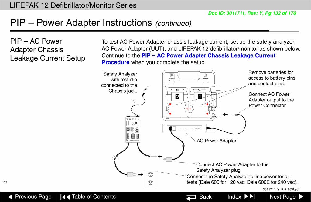
Previous Page Table of Contents Back Index Next Page
LIFEPAK 12 Defibrillator/Monitor Series
132
Doc ID: 3011711, Rev: Y, Pg 132 of 170
PIP – Power Adapter Instructions (continued)
PIP – AC Power Adapter Chassis Leakage Current Setup
To test AC Power Adapter chassis leakage current, set up the safety analyzer, AC Power Adapter (UUT), and LIFEPAK 12 defibrillator/monitor as shown below. Continue to the PIP – AC Power Adapter Chassis Leakage Current Procedure when you complete the setup.
WARNING RISK OF FIRE. REPLACE FUSES AS MARKED.
12VDC OUTPUT ▼
12
DALE600 SAFETY ANALYZER
NEUTRAL POLARITYCLOSED NORMAL ISO TEST
OPEN REVERSED LIFT GND
LINE VOLTSCURRENTRESISTANCEEARTHCHASSISLEAD - GNDLEAD - LEADLEAD ISOEXTERNAL
000RL RA LA LL C
LEAD
RARL
LA LLC
ALL
AC Power Adapter
Safety Analyzer with test clip
connected to the Chassis jack.
Remove batteries for access to battery pins and contact pins.
Connect AC Power Adapter output to the Power Connector.
Connect AC Power Adapter to the Safety Analyzer plug.
Connect the Safety Analyzer to line power for all tests (Dale 600 for 120 vac; Dale 600E for 240 vac).
3011711_Y_PIP-TCP.pdf

Previous Page Table of Contents Section Contents Back Index Next Page
LIFEPAK 12 Defibrillator/Monitor Series Performance Inspection Procedures
133
Doc ID: 3011711, Rev: Y, Pg 133 of 170
PIP – Power Adapter Instructions (continued)
PIP – AC Power Adapter Chassis Leakage Current Procedure
Note: AC Power Adapter Chassis Leakage Current test results are summarized in the Leakage Current Specifications Summary Table.
To test AC Power Adapter Chassis Leakage Current:
1. Establish the PIP – AC Power Adapter Chassis Leakage Current Setup shown in the figure on the previous page. The LIFEPAK 12 is off for this test.
2. Set the safety analyzer controls to:
Note: When operating the Polarity Switch, be sure to pause in the Off (middle) position when switching between Normal and Reversed Polarities
3. Verify the AC Power Adapter (UUT) is on.
4. Connect the analyzer clip to the positive (+) battery terminal of Battery Well 1 as shown at the left.
5. Verify measured current is less than 100 µa.
6. Press the LIFT GND button on the safety analyzer.
Neutral Polarity Mode LeadClosed Normal/Reversed Leakage µa Lead – Chassis All
+
-+
-
12
Battery Pins
Battery Contact Blades
Dale 600/600E
Safety Analyzer Test clip
3011711_Y_PIP-TCP.pdf

Previous Page Table of Contents Section Contents Back Index Next Page
LIFEPAK 12 Defibrillator/Monitor Series Performance Inspection Procedures
134
Doc ID: 3011711, Rev: Y, Pg 134 of 170
PIP – Power Adapter Instructions (continued)
PIP – AC Power Adapter Chassis Leakage Current Procedure (continued)
7. Verify measured current is less than 300 µa (120 vac) or less than 500 µa (240 vac).
8. Release the LIFT GND button
9. Repeat steps 4 through 8 for the three remaining battery pins and all six battery contact blades on the A07 Contact PCB.
10. Record all results on the PIP Checklist.
11. Continue directly to the next leakage current test.
3011711_Y_PIP-TCP.pdf
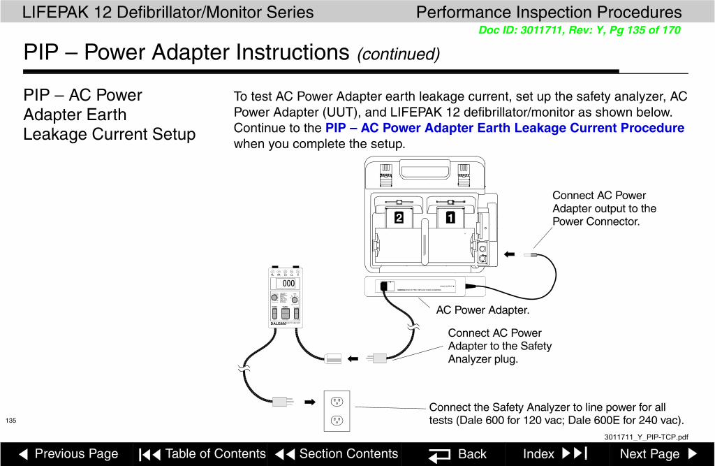
Previous Page Table of Contents Section Contents Back Index Next Page
LIFEPAK 12 Defibrillator/Monitor Series Performance Inspection Procedures
135
Doc ID: 3011711, Rev: Y, Pg 135 of 170
PIP – Power Adapter Instructions (continued)
PIP – AC Power Adapter Earth Leakage Current Setup
To test AC Power Adapter earth leakage current, set up the safety analyzer, AC Power Adapter (UUT), and LIFEPAK 12 defibrillator/monitor as shown below. Continue to the PIP – AC Power Adapter Earth Leakage Current Procedure when you complete the setup.
WARNING RISK OF FIRE. REPLACE FUSES AS MARKED.
12VDC OUTPUT ▼
DALE600 SAFETY ANALYZER
NEUTRAL POLARITYCLOSED NORMAL ISO TEST
OPEN REVERSED LIFT GND
LINE VOLTSCURRENTRESISTANCEEARTHCHASSISLEAD - GNDLEAD - LEADLEAD ISOEXTERNAL
000RL RA LA LL C
LEAD
RARL
LA LLC
ALL
Connect AC Power Adapter output to the Power Connector.12
Connect the Safety Analyzer to line power for all tests (Dale 600 for 120 vac; Dale 600E for 240 vac).
AC Power Adapter.
Connect AC Power Adapter to the Safety Analyzer plug.
3011711_Y_PIP-TCP.pdf
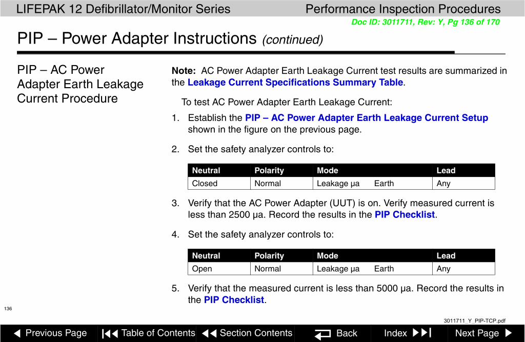
Previous Page Table of Contents Section Contents Back Index Next Page
LIFEPAK 12 Defibrillator/Monitor Series Performance Inspection Procedures
136
Doc ID: 3011711, Rev: Y, Pg 136 of 170
PIP – Power Adapter Instructions (continued)
PIP – AC Power Adapter Earth Leakage Current Procedure
Note: AC Power Adapter Earth Leakage Current test results are summarized in the Leakage Current Specifications Summary Table.
To test AC Power Adapter Earth Leakage Current:
1. Establish the PIP – AC Power Adapter Earth Leakage Current Setup shown in the figure on the previous page.
2. Set the safety analyzer controls to:
3. Verify that the AC Power Adapter (UUT) is on. Verify measured current is less than 2500 µa. Record the results in the PIP Checklist.
4. Set the safety analyzer controls to:
5. Verify that the measured current is less than 5000 µa. Record the results in the PIP Checklist.
Neutral Polarity Mode Lead
Closed Normal Leakage µa Earth Any
Neutral Polarity Mode Lead
Open Normal Leakage µa Earth Any
3011711_Y_PIP-TCP.pdf

Previous Page Table of Contents Section Contents Back Index Next Page
LIFEPAK 12 Defibrillator/Monitor Series Performance Inspection Procedures
137
Doc ID: 3011711, Rev: Y, Pg 137 of 170
PIP – Power Adapter Instructions (continued)
PIP – AC Power Adapter QUIK-COMBO Source Leakage Current Setup
To test AC Power Adapter QUIK-COMBO source leakage current, set up the safety analyzer, AC Power Adapter (UUT), and LIFEPAK 12 defibrillator/monitor as shown below. Continue to the PIP – AC Power Adapter QUIK-COMBO Source Leakage Current Procedure when you complete the setup.
ALARMS
12-LEAD
TRANSMIT
CODE
ENERG
PAUSEEVENT
OPTIONS
SHOCK
ON
ADVISORY
ANALYZE CHARGE
SYNC
RATE
CURRENT
PACER
HomeECG
Batt ChgService
SPO2
SELECT
Screen
SUMMARY
READY CHARGING FAULTYREADY CHARGING FAULTYPOWER SERVICE
PHYSIO-CONTROLAC POWER ADAPTER
DALE600 SAFETY ANALYZER
NEUTRAL POLARITYCLOSED NORMAL ISO TEST
OPEN REVERSED LIFT GND
LINE VOLTSCURRENTRESISTANCEEARTHCHASSISLEAD - GNDLEAD - LEADLEAD ISOEXTERNAL
000RL RA LA LL C
LEAD
RARL
LALL
C
ALL
RA
LA
+
QUIK-COMBO Therapy Cable
QUIK-COMBO Test Post Adapter
LEAD SIZE
3011711_Y_PIP-TCP.pdf

Previous Page Table of Contents Section Contents Back Index Next Page
LIFEPAK 12 Defibrillator/Monitor Series Performance Inspection Procedures
138
Doc ID: 3011711, Rev: Y, Pg 138 of 170
PIP – Power Adapter Instructions (continued)
PIP – AC Power Adapter QUIK-COMBO Source Leakage Current Procedure
Note: AC Power Adapter QUIK-COMBO Source Leakage Current test results are summarized in the Leakage Current Specifications Summary Table.
To test AC Power Adapter QUIK-COMBO Source Leakage Current:
1. Establish the PIP – AC Power Adapter QUIK-COMBO Source Leakage Current Setup shown in the figure on the previous page.
2. Verify that the AC Power Adapter (UUT) is on.
3. Turn on the LIFEPAK 12 defibrillator/monitor.
4. Set the safety analyzer controls to:
Note: When operating the Polarity Switch, be sure to pause in the Off (middle) position when switching between Normal and Reversed Polarities
5. Verify that the measured current is less than 10 µa.
6. Press the LIFT GND button on the safety analyzer.
7. Verify that the measured current is less than 50 µa.
Neutral Polarity Mode Lead
Closed Normal/Reversed Leakage µa Lead – Gnd All
DALE600 SAFETY ANALYZER
NEUTRAL POLARITYCLOSED NORMAL ISO TEST
OPEN REVERSED LIFT GND
LINE VOLTSCURRENTRESISTANCEEARTHCHASSISLEAD - GNDLEAD - LEADLEAD ISOEXTERNAL
000RL RA LA LL C
LEAD
RARL
LALL
C
ALL
3011711_Y_PIP-TCP.pdf

Previous Page Table of Contents Section Contents Back Index Next Page
LIFEPAK 12 Defibrillator/Monitor Series Performance Inspection Procedures
139
Doc ID: 3011711, Rev: Y, Pg 139 of 170
PIP – Power Adapter Instructions (continued)
PIP – AC Power Adapter QUIK-COMBO Source Leakage Current Procedure (continued)
8. Release the LIFT GND button.
9. Set the safety analyzer controls to:
Note: When operating the Polarity Switch, be sure to pause in the Off (middle) position when switching between Normal and Reversed Polarities
10. Repeat steps 5 through 8 for Lead – Lead leakage.
11. Record all results on the PIP Checklist.
12. Turn off the LIFEPAK 12 defibrillator/monitor.
13. Turn off the AC Power Adapter (UUT).
Neutral Polarity Mode Lead
Closed NormalReversed Leakage µa Lead – Lead LA
3011711_Y_PIP-TCP.pdf

Previous Page Table of Contents Section Contents Back Index Next Page
LIFEPAK 12 Defibrillator/Monitor Series Performance Inspection Procedures
140
Doc ID: 3011711, Rev: Y, Pg 140 of 170
PIP – Summary of Leakage Current Specifications Page 1 of 5
The following summarizes leakage current specifications. NC=Normal Condition SFC = Single Fault Condition
Leakage Test Maximum Leakage Current Specifications
Type of Test Lead Test Analyzer @ 120 vac Analyzer @ 240 vac
Chassis Leakage Positive Battery NC: 100 µA NC: 100 µA
Terminal SFC: 300 µA SFC: 500 µA
Negative Battery NC: 100 µA NC: 100 µA
Terminal SFC: 300 µA SFC: 500 µA
Contacts NC: 100 µA NC: 100 µA
SFC: 300 µA SFC: 500 µA
Earth Leakage Closed Neutral 2500 µA 2500 µA
Open Neutral 5000 µA 5000 µA
QUIK-COMBO Source LEAD-GND All–GND NC: 10 µA NC: 10 µA
SFC: 50 µA SFC: 50 µA
QUIK-COMBO Source LEAD-LEAD RA or LA NC: 10 µA NC: 10 µA
SFC: 50 µA SFC: 50 µA
3011711_Y_PIP-TCP.pdf

Previous Page Table of Contents Section Contents Back Index Next Page
LIFEPAK 12 Defibrillator/Monitor Series Performance Inspection Procedures
141
Doc ID: 3011711, Rev: Y, Pg 141 of 170
PIP – Summary of Leakage Current Specifications (continued) Page 2 of 5
Leakage Test Maximum Leakage Current Specifications
Type of Test Lead Test Analyzer @ 120 vac Analyzer @ 240 vac
Paddles Source LEAD-GND All–GND NC: 10 µA NC: 10 µA
SFC: 50 µA SFC: 50 µA
Paddles Source LEAD-LEAD RA or LA NC: 10 µA NC: 10 µA
SFC: 50 µA SFC: 50 µA
12-Lead ECG Source LEAD-GND All-GND NC: 10 µA NC: 10 µA
SFC: 50 µA SFC: 50 µA
3011711_Y_PIP-TCP.pdf

Previous Page Table of Contents Section Contents Back Index Next Page
LIFEPAK 12 Defibrillator/Monitor Series Performance Inspection Procedures
142
Doc ID: 3011711, Rev: Y, Pg 142 of 170
PIP – Summary of Leakage Current Specifications (continued) Page 3 of 5
Leakage Test Maximum Leakage Current Specifications
Type of Test Lead Test Analyzer @ 120 vac Analyzer @ 240 vac
12-Lead ECG Source LEAD-LEAD RA NC: 10 µA NC: 10 µA
SFC: 50 µA SFC: 50 µA
LA NC: 10 µA NC: 10 µA
SFC: 50 µA SFC: 50 µA
RL NC: 10 µA NC: 10 µA
SFC: 50 µA SFC: 50 µA
LL NC: 10 µA NC: 10 µA
SFC: 50 µA SFC: 50 µA
V1 NC: 10 µA NC: 10 µA
SFC: 50 µA SFC: 50 µA
V2 NC: 10 µA NC: 10 µA
SFC: 50 µA SFC: 50 µA
3011711_Y_PIP-TCP.pdf

Previous Page Table of Contents Section Contents Back Index Next Page
LIFEPAK 12 Defibrillator/Monitor Series Performance Inspection Procedures
143
Doc ID: 3011711, Rev: Y, Pg 143 of 170
PIP – Summary of Leakage Current Specifications (continued) Page 4 of 5
Leakage Test Maximum Leakage Current Specifications
Type of Test Lead Test Analyzer@ 120 vac Analyzer @ 240 vac
12-Lead ECG Source LEAD-LEAD V3 NC: 10 µA NC: 10 µA
(continued) SFC: 50 µA SFC: 50 µA
V4 NC: 10 µA NC: 10 µA
SFC: 50 µA SFC: 50 µA
V5 NC: 10 µA NC: 10 µA
SFC: 50 µA SFC: 50 µA
V6 NC: 10 µA NC: 10 µA
SFC: 50 µA SFC: 50 µA
3-Lead ECG Source LEAD-GND All–GND NC: 10 µA NC: 10 µA
SFC: 50 µA SFC: 50 µA
3011711_Y_PIP-TCP.pdf

Previous Page Table of Contents Section Contents Back Index Next Page
LIFEPAK 12 Defibrillator/Monitor Series Performance Inspection Procedures
144
Doc ID: 3011711, Rev: Y, Pg 144 of 170
PIP – Summary of Leakage Current Specifications (continued) Page 5 of 5
Leakage Test Maximum Leakage Current Specifications
Type of Test Lead Test Analyzer @ 120 vac Analyzer @ 240 vac
3-Lead ECG Source LEAD-LEAD RA NC: 10 µA NC: 10 µA
SFC: 50 µA SFC: 50 µA
LA NC: 10 µA NC: 10 µA
SFC: 50 µA SFC: 50 µA
RL NC: 10 µA NC: 10 µA
SFC: 50 µA SFC: 50 µA
QUIK-COMBO Sink Leakage ISO Test 50 µA 100 µA
Paddles Sink Leakage ISO Test 100 µA 500 µA
12-Lead ECG Sink Leakage ISO Test 50 µA 50 µA
3-Lead ECG Sink Leakage ISO Test 50 µA 50 µA
SpO2 Sink Leakage ISO Test 100 µA 500 µA
3011711_Y_PIP-TCP.pdf

LIFEPAK 12 Defibrillator/Monitor Series Section 7 Contents
Previous Page Table of Contents Back Index Next Page
145
Doc ID: 3011711, Rev: Y, Pg 145 of 170
Instrument Calibration
The Instrument Calibration section contains the Test and Calibration Procedures (TCP). Perform the procedures in this section as necessary after replacement of device components or to correct out-of-specification conditions detected during the PIP. The following procedures may be performed in any order.
Note: Anytime the device is calibrated or opened for repair or component replacement, it must successfully pass all portions of the closed-case Performance Inspection Procedures (PIP).
TCP – Scope and ApplicabilityTCP – Resource RequirementsTCP – Test Equipment RequirementsTCP – SetupTCP – Service/Calibration Sub-Menu AccessTCP – Defibrillator CalibrationTCP – Defibrillator Isolation TestTCP – Delivered Energy TestTCP – Biphasic Defibrillator Output Waveform TestTCP – Pacing Self CalibrationTCP – Pacing Verification TestTCP – ECG CalibrationTCP – EtCO2 CalibrationTCP – Printer Calibration
3011711_Y_PIP-TCP.pdf

Previous Page Table of Contents Section Contents Back Index Next Page
LIFEPAK 12 Defibrillator/Monitor Series Instrument Calibration
146
Doc ID: 3011711, Rev: Y, Pg 146 of 170
TCP – Scope and Applicability
This TCP applies to the LIFEPAK 12 defibrillator/monitor exclusively. You may perform the procedures outlined in this section in any order.
Note: Prior to its return to active use, the LIFEPAK 12 defibrillator/monitor must successfully pass all portions of the closed-case Performance Inspection Procedures (PIP) anytime the device is opened for repair, component replacement, or after calibration.
Refer to TCP – Resource Requirements for necessary equipment, test equipment verification, workstation power, and qualifications of the TCP personnel.
Refer to TCP – Test Equipment Requirements for a listing of test equipment, including specifications, required to complete the TCP.
3011711_Y_PIP-TCP.pdf

Previous Page Table of Contents Section Contents Back Index Next Page
LIFEPAK 12 Defibrillator/Monitor Series Instrument Calibration
147
Doc ID: 3011711, Rev: Y, Pg 147 of 170
TCP – Resource Requirements
This section describes the requirements for TCP equipment, TCP test equipment verification, TCP workstation power, and TCP personnel.
TCP – Equipment To perform the TCP, you must use the equipment listed in the TCP – Test Equipment Requirements table. Although the table lists specific test equipment by manufacturer, test equipment with equivalent specifications may be substituted.
Note: Using test equipment other than that specified in the PIP – Test Equipment Requirements table may provide test results that are different from those specified in this manual. It is the responsibility of the bio-medical personnel who maintain this device to determine test equipment equivalency.
TCP – Test Equipment Verification
All test equipment used to perform the TCP must have a current calibration label. The calibration label must be issued by a certified calibration facility.
TCP – Workstation Power
The AC line power to the workstation used must be connected to a grounded power source. The workstation must have Electrostatic Discharge (ESD) protection.
TCP – Personnel Technicians who perform the PIP must be properly qualified and thoroughly familiar with the operation of the LIFEPAK 12 defibrillator/monitor, meeting the requirements described in Service Personnel Qualifications.
3011711_Y_PIP-TCP.pdf

Previous Page Table of Contents Section Contents Back Index Next Page
LIFEPAK 12 Defibrillator/Monitor Series Instrument Calibration
148(Continued on next page)
Doc ID: 3011711, Rev: Y, Pg 148 of 170
TCP – Test Equipment Requirements Page 1 of 2
You need the following test equipment, or equivalent, to conduct the TCP.
Equipment Specifications Manufacturer
Defibrillator Analyzer1
1. Some energy meters are not accurate for biphasic waveforms; contact your defibrillator analyzer’s manufacturer for more information.
Energy range: 0 to 450 J Load resistance: 50 ±1% Accuracy: ±2% +2 JWaveforms: NSR, VF, and Sine Wave
Fluke Biomedical - BIO-TEK® QED-6™, with test posts accessory (software version 2.07, or greater) or equivalent
QUIK-COMBO test post adapter Connects to QUIK-COMBO Therapy Cable Physio-Control MIN 3005302
AC Power Adapter Input power: 120/230 vac, 50/60 Hz Physio-Control MIN 3010942
LIFEPAK NiCd Battery NiCd battery with fuel gauge Physio-Control MIN 3009376
ECG Calibration Cable Physio-Control MIN 3012087-000
3011711_Y_PIP-TCP.pdf

Previous Page Table of Contents Section Contents Back Index Next Page
LIFEPAK 12 Defibrillator/Monitor Series Instrument Calibration
149
Doc ID: 3011711, Rev: Y, Pg 149 of 170
TCP – Test Equipment Requirements (continued) Page 2 of 2
Equipment Specifications Manufacturer
General purpose oscilloscope Bandwidth: dc to 2 MHzVertical accuracy: +3% (5 mV – 5 v/div.)Horizontal Time Base Accuracy: +5%
Fluke 192B or equivalent
CO2 Calibration KitCalibration GasCO2 Filter Line
5% CO2, bal. N2XS-04667
Physio-Control MIN 3012430-01
Physio-Control MIN 3012556
Physio-Control MIN 3012176
QUIK-COMBO Therapy Cable Physio-Control MIN 3006570
Standard Paddles Physio-Control MIN 3006228
Serial Data Cable Physio-Control MIN 3009817
3011711_Y_PIP-TCP.pdf

Previous Page Table of Contents Section Contents Back Index Next Page
LIFEPAK 12 Defibrillator/Monitor Series Instrument Calibration
150
Doc ID: 3011711, Rev: Y, Pg 150 of 170
TCP – Setup
The following describes the LIFEPAK 12 defibrillator/monitor setup for the TCP.
WARNING!Shock hazard. When discharged during this TCP, the device discharges up to 360 J of electrical energy through the defibrillator cable. You must safely discharge this electrical energy as described in this TCP. Do not attempt to perform this procedure unless you are thoroughly familiar with the operation of the device.
To setup the LIFEPAK 12 defibrillator/monitor for the TCP:
1. Insert two fully functional batteries into the UUT. A functional battery is one that does not return a LOW BATTERY message after turning on the device.
2. Verify that each battery clicked into position in the rear panel battery wells.
3. Install a roll of paper into the printer.
Note: If the A12 Printer was replaced, save the piece of paper inside the printer that has the printhead resistance written down.
Note: Do not connect anything to the therapy connector, except as directed during this procedure.
ALARMS
12-LEAD
TRANSMIT
CODE
ENERG
PAUSEEVENT
OPTIONS
SHOCK
ON
ADVISORY
ANALYZE CHARGE
SYNC
RATE
CURRENT
PACER
HomeECG
Batt ChgService
SpO2
SELECT
Screen
SUMMARY
Battery 2Battery 1
PrinterPaper
LEAD SIZE
3011711_Y_PIP-TCP.pdf

Previous Page Table of Contents Section Contents Back Index Next Page
LIFEPAK 12 Defibrillator/Monitor Series Instrument Calibration
151
Doc ID: 3011711, Rev: Y, Pg 151 of 170
TCP – Service/Calibration Sub-Menu Access
To enter the SERVICE/CALIBRATION menu:
1. Conduct the procedure TCP – Setup.
2. Place the unit under test (UUT) in Service Mode.
3. Select CALIBRATION from the on-screen SERVICE menu to display the SERVICE/CALIBRATION sub-menu.
Service / Calibration
Defib Cal...
Pacing Cal...
CO2 Cal...
NIBP Cal...
Perform Defibrillation calibration
Printer Cal...
Previous Page...
3011711_Y_PIP-TCP.pdf

Previous Page Table of Contents Section Contents Back Index Next Page
LIFEPAK 12 Defibrillator/Monitor Series Instrument Calibration
152
Doc ID: 3011711, Rev: Y, Pg 152 of 170
TCP – Defibrillator Calibration
Procedure for Biphasic UUT
Use this procedure for a biphasic UUT.
To perform the defibrillator calibration procedure:
1. Connect the UUT to the defibrillator analyzer. Make sure the QUIK-COMBO (+) terminal is connected to apex (+).
Note: Adapt this procedure to use standard paddles, if desired.
2. Set the defibrillator analyzer to measure energy, with the appropriate scale.
3. Access the Service/Calibration Sub-Menu.
4. Choose DEFIB CAL from the SERVICE/CALIBRATION sub-menu.
5. Select START to initiate the calibration routine.
6. Follow the instructions on the UUT screen.
7. Turn off the UUT.
8. Continue directly to TCP – Defibrillator Isolation Test.
ALARMS
12-LEAD
TRANSMICODE
ENERG
PAUSEEVENT
OPTIONS
SHOC
ON
ADVISOR
ANALYZE CHARGE
SYN
RATE
CURRENT
PACE
HomeECG
Batt ChgServic
SpO2
SELEC
Screen
SUMMAR
+
Defibrillator Analyzer
Test Posts Installed
QUIK-COMBO Therapy Cable
QUIK-COMBO Test Post Adapter
LEAD SIZE
3011711_Y_PIP-TCP.pdf
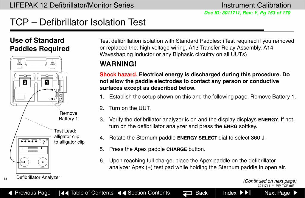
Previous Page Table of Contents Section Contents Back Index Next Page
LIFEPAK 12 Defibrillator/Monitor Series Instrument Calibration
153(Continued on next page)
Doc ID: 3011711, Rev: Y, Pg 153 of 170
TCP – Defibrillator Isolation Test
Use of Standard Paddles Required
Test defibrillation isolation with Standard Paddles: (Test required if you removed or replaced the: high voltage wiring, A13 Transfer Relay Assembly, A14 Waveshaping Inductor or any Biphasic circuitry on all UUTs)
WARNING!Shock hazard. Electrical energy is discharged during this procedure. Do not allow the paddle electrodes to contact any person or conductive surfaces except as described below.
1. Establish the setup shown on this and the following page. Remove Battery 1.
2. Turn on the UUT.
3. Verify the defibrillator analyzer is on and the display displays ENERGY. If not, turn on the defibrillator analyzer and press the ENRG softkey.
4. Rotate the Sternum paddle ENERGY SELECT dial to select 360 J.
5. Press the Apex paddle CHARGE button.
6. Upon reaching full charge, place the Apex paddle on the defibrillator analyzer Apex (+) test pad while holding the Sternum paddle in open air.
12
+
-
Defibrillator Analyzer
Remove Battery 1
Test Lead:alligator clipto alligator clip
3011711_Y_PIP-TCP.pdf

Previous Page Table of Contents Section Contents Back Index Next Page
LIFEPAK 12 Defibrillator/Monitor Series Instrument Calibration
154
Doc ID: 3011711, Rev: Y, Pg 154 of 170
TCP – Defibrillator Isolation Test (continued)
Defibrillator Isolation Test (continued)
7. Simultaneously press the paddles SHOCK switches to discharge the UUT.
8. Verify the defibrillator analyzer indicates a delivered energy of less than 18 J.
9. Change the alligator clip lead to the other defibrillator analyzer test post.
10. Press the Apex paddle CHARGE button.
11. Upon reaching full charge, place the Sternum paddle on the defibrillator analyzer Sternum (-) test pad while holding the Apex paddle in open air.
12. Simultaneously press the paddles SHOCK switches to discharge the UUT.
13. Verify the defibrillator analyzer indicates a delivered energy of less than 18 J.
14. Turn off the device.
15. Remove the test lead and reinstall Battery 1.
16. Continue directly to TCP – Delivered Energy Test.
ALARMS
12-LEAD
TRANSMIT
CODE
ENERG
PAUSEEVENT
OPTIONS
SHOCK
ON
ADVISORY
ANALYZE CHARGE
SYNC
RATE
CURRENT
PACER
HomeECG
Batt ChgService
SPO2
SELECT
Screen
SUMMARY
Defibrillator Analyzer
+
LEAD SIZE
3011711_Y_PIP-TCP.pdf

Previous Page Table of Contents Section Contents Back Index Next Page
LIFEPAK 12 Defibrillator/Monitor Series Instrument Calibration
155(Continued on next page)
Doc ID: 3011711, Rev: Y, Pg 155 of 170
TCP – Delivered Energy Test
WARNING!Shock hazard. Avoid contact with the energy meter. Dangerous voltages will be present on energy meter electrode plates/posts.
To verify the defibrillator delivered energy:
1. Connect the UUT to the defibrillator analyzer. Make sure the QUIK-COMBO (+) terminal is connected to apex (+).
Note: Adapt this procedure to use Standard Paddles, if desired.
2. Set the defibrillator analyzer to measure energy, with the appropriate scale.
3. Turn on the UUT. Verify that the ADVISORY indicator is off. If not, see Entering Manual Mode.
4. Press the ENERGY SELECT control to select 2 J.
5. Press the CHARGE control and wait for the UUT to reach full charge. Press the SHOCK control to discharge the UUT energy.
6. Verify that the defibrillator analyzer shows an energy level between 1.0 and 3.0 J.
Note: All energy levels listed in the Delivered Energy Test table are not available on every UUT.
ALARMS
12-LEAD
TRANSMIT
CODE
ENERG
PAUSEEVENT
OPTIONS
SHOCK
ON
ADVISORY
ANALYZE CHARGE
SYNC
RATE
CURRENT
PACER
HomeECG
Batt ChgService
SpO2
SELECT
Screen
SUMMARY
+
Defibrillator Analyzer
Test Posts Installed
QUIK-COMBO Therapy Cable
QUIK-COMBO Test Post Adapter
LEAD SIZE
3011711_Y_PIP-TCP.pdf

Previous Page Table of Contents Section Contents Back Index Next Page
LIFEPAK 12 Defibrillator/Monitor Series Instrument Calibration
156
Doc ID: 3011711, Rev: Y, Pg 156 of 170
TCP – Delivered Energy Test (continued)
7. Repeat steps 4 through 6 for the remaining available energy levels specified in the Delivered Energy Test table.
Energy Level (J)
Acceptable Output (J)
Energy Level (J)
Acceptable Output (J)
2 1.0 to 3.0 70 66.5 to 73.53 2.0 to 4.0 100 97.5 to 102.54 3.0 to 5.0 125 123.0 to 128.05 4.0 to 6.0 150 146.3 to 158.86 5.0 to 7.0 175 170.62 to 179.387 6.0 to 8.0 200 195.0 to 205.08 7.0 to 9.0 225 219.37 to 230.639 8.0 to 10.0 250 243.75 to 256.2510 9.0 to 11.0 275 268.12 to 281.8815 14.0 to 16.0 300 292.5 to 307.520 19.0 to 21.0 325 316.87 to 333.1330 28.5 to 31.5 360 351.0 to 369.050 47.5 to 52.5
3011711_Y_PIP-TCP.pdf

Previous Page Table of Contents Section Contents Back Index Next Page
LIFEPAK 12 Defibrillator/Monitor Series Instrument Calibration
157(Continued on next page)
Doc ID: 3011711, Rev: Y, Pg 157 of 170
TCP – Biphasic Defibrillator Output Waveform Test
The Defibrillator Output Waveform Test is optional and is intended to aid in troubleshooting the A13 Transfer Relay Assembly or the A15 Energy Storage Capacitor. Use fully charged batteries when you perform this procedure.
1. Connect the UUT to a defibrillator analyzer using the QUIK-COMBO Therapy Cable. Set the defibrillator analyzer to ENERGY, 1000 J scale.
2. Connect the DEFIB and GND terminals on the defibrillator analyzer to an oscilloscope vertical channel input and ground input. Set the oscilloscope to 0.5 V/div, 2 ms/div, + slope, store mode, and single sweep.
Note: 1 V on the oscilloscope = 29 A defibrillator output current using the QED-6 energy meter. When using other energy meters, refer to the manufacturer’s specifications. You may need to slow down the horizontal sweep and/or turn on the triggering high-frequency reject to successfully capture the waveform.
3. Turn on the UUT. Press the ENERGY SELECT control and select 360 J.
4. Press the CHARGE control. After the capacitor charges (the SHOCK indicator is blinking), press the SHOCK control to deliver the energy to the analyzer.
5. Verify that the waveform meets specifications (see next page for biphasic UUT).
6. When testing is complete, turn off the UUT and disconnect the test setup.
ALARMS
12-LEAD
TRANSMIT
CODE
ENERG
PAUSEEVENT
OPTIONS
SHOCK
ON
ADVISORY
ANALYZE CHARGE
SYNC
RATE
CURRENT
PACER
HomeECG
Batt ChgService
SpO2
SELECT
Screen
SUMMARY
+
VERT
LEAD SIZE
3011711_Y_PIP-TCP.pdf

Previous Page Table of Contents Section Contents Back Index Next Page
LIFEPAK 12 Defibrillator/Monitor Series Instrument Calibration
158
Doc ID: 3011711, Rev: Y, Pg 158 of 170
TCP – Biphasic Defibrillator Output Waveform Test (continued)
TPHASE1
TPHASE2
Current
Time
I4
I1
Note 1.Delivered waveform at 360 joules into given resistive load.Note 2.Discharge polarity is APEX positive, STERNUM negative for Phase 1.
Note 3.
Patient Impedance ()
TPHASE1 (ms) TPHASE2 (ms) Tilt
Min Max Min Max Min Max
50 6.8 7.9 4.5 5.3 63.9 71.0
TiltI1 I4–
I1------------------------=
3011711_Y_PIP-TCP.pdf
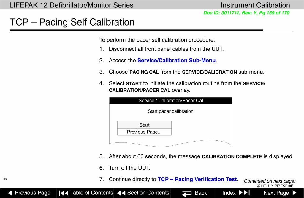
Previous Page Table of Contents Section Contents Back Index Next Page
LIFEPAK 12 Defibrillator/Monitor Series Instrument Calibration
159(Continued on next page)
Doc ID: 3011711, Rev: Y, Pg 159 of 170
TCP – Pacing Self Calibration
To perform the pacer self calibration procedure:
1. Disconnect all front panel cables from the UUT.
2. Access the Service/Calibration Sub-Menu.
3. Choose PACING CAL from the SERVICE/CALIBRATION sub-menu.
4. Select START to initiate the calibration routine from the SERVICE/CALIBRATION/PACER CAL overlay.
5. After about 60 seconds, the message CALIBRATION COMPLETE is displayed.
6. Turn off the UUT.
7. Continue directly to TCP – Pacing Verification Test.
Service / Calibration/Pacer Cal
StartPrevious Page...
Start pacer calibration
3011711_Y_PIP-TCP.pdf

Previous Page Table of Contents Section Contents Back Index Next Page
LIFEPAK 12 Defibrillator/Monitor Series Instrument Calibration
160
Doc ID: 3011711, Rev: Y, Pg 160 of 170
TCP – Pacing Verification Test (continued)
WARNING!Shock hazard. Avoid contact with the energy meter. Potentially dangerous voltages will be present on energy meter electrode plates/posts.
To verify the pacer current levels (for UUTs equipped with pacing):
1. Connect the UUT to the defibrillator analyzer. Make sure the QUIK-COMBO (+) terminal is connected to apex (+).
2. Set the defibrillator analyzer for pacing measurements.
3. Turn on the UUT. Verify the ADVISORY indicator is off. If not, see Entering Manual Mode.
4. Press the PACER control to activate pacing.
5. Press the CURRENT control, then use the Selector to select a current of 10 ma. Verify the measured pacer current is between 5 and 15 ma.
6. Repeat step 5 for the remaining pacer current levels specified in the Pacer Current Test table (next page).
Note: Press the CURRENT control, as required, to maintain the CURRENT overlay on the screen.
ALARMS
12-LEAD
TRANSMIT
CODE
ENERG
PAUSEEVENT
OPTIONS
SHOCK
ON
ADVISORY
ANALYZE CHARGE
SYNC
RATE
CURRENT
PACER
HomeECG
Batt ChgService
SpO2
SELECT
Screen
SUMMARY
+
Defibrillator Analyzer
Test Posts Installed
QUIK-COMBO Therapy Cable
QUIK-COMBO Test Post Adapter
LEAD SIZE
3011711_Y_PIP-TCP.pdf

Previous Page Table of Contents Section Contents Back Index Next Page
LIFEPAK 12 Defibrillator/Monitor Series Instrument Calibration
161
Doc ID: 3011711, Rev: Y, Pg 161 of 170
TCP – Pacing Verification Test (continued)
I
Set Current (ma) Output (ma) Set Current (ma) Output (ma) Set Current (ma) Output (ma)
10 5 to 15 75 70 to 80 140 133.0 to 147.0
15 10 to 20 80 75 to 85 145 137.7 to 152.3
20 15 to 25 85 80 to 90 150 142.5 to 157.5
25 20 to 30 90 85 to 95 155 147.2 to 162.8
30 25 to 35 95 90 to 100 160 152.0 to 168.0
35 30 to 40 100 95 to 105 165 156.7 to 173.3
40 35 to 45 105 99.7 to 110.3 170 161.5 to 178.5
45 40 to 50 110 104.5 to 115.5 175 166.2 to 183.8
50 45 to 55 115 109.2 to 120.8 180 171.0 to 189.0
55 50 to 60 120 114.0 to 126.0 185 175.7 to 194.3
60 55 to 65 125 118.7 to 131.3 190 180.5 to 199.5
65 60 to 70 130 123.5 to 136.5 195 185.2 to 204.8
70 65 to 75 135 128.2 to 141.8 200 190.0 to 210.0
3011711_Y_PIP-TCP.pdf

Previous Page Table of Contents Section Contents Back Index Next Page
LIFEPAK 12 Defibrillator/Monitor Series Instrument Calibration
162(Continued on next page)
Doc ID: 3011711, Rev: Y, Pg 162 of 170
TCP – ECG Calibration
Applicability This procedure applies only to LIFEPAK 12 defibrillator/monitors with operating system software MIN 3011371-022 or above installed. Do not perform ECG calibration on devices equipped with any previous operating system version. If in doubt regarding the software version of your defibrillator/monitor, press the ON button to turn device power off, then press the ON button again, and note the software version displayed on the copyright screen.
Installing the ECG Calibration Software
1. Open the folder on the LIFEPAK 12 defibrillator/monitor Service Manual CD entitled LP12ECG CAL.
2. To install the ECG calibration utility on your personal computer, double click the file SETUP.EXE.
ECG Calibration Procedure
1. Open the LP12EGCCAL application. The application layout shown on the next page appears on your computer display.
2. Click the START button, and follow the instructions on the screen to perform ECG calibration.
3011711_Y_PIP-TCP.pdf

Previous Page Table of Contents Section Contents Back Index Next Page
LIFEPAK 12 Defibrillator/Monitor Series Instrument Calibration
163
Doc ID: 3011711, Rev: Y, Pg 163 of 170
TCP – ECG Calibration (continued)
LIFEPAK 12 defibrillator/monitor series
Start
COM1
COM2
Com Port Select
LP12 ECG Calibration
Continue
Quit
3011711_Y_PIP-TCP.pdf

Previous Page Table of Contents Section Contents Back Index Next Page
LIFEPAK 12 Defibrillator/Monitor Series Instrument Calibration
164(Continued on next page)
Doc ID: 3011711, Rev: Y, Pg 164 of 170
TCP – EtCO2 Calibration
To calibrate the ETCO2 module:
Note: Allow 20 minutes from initial power on for the UUT to warm up before proceeding with the calibration of the EtCO2 module:
1. Access the SERVICE/CALIBRATION sub-menu by selecting CALIBRATION from the SERVICE menu.
2. Select CO2 CAL . . . .
NIBP Cal...
Service/Calibration
Perform CO2 Calibration
Defib Cal...
Pacing Cal...
CO2 Cal...
Printer Cal...
Previous Page...
3011711_Y_PIP-TCP.pdf

Previous Page Table of Contents Section Contents Back Index Next Page
LIFEPAK 12 Defibrillator/Monitor Series Instrument Calibration
165(Continued on next page)
Doc ID: 3011711, Rev: Y, Pg 165 of 170
TCP – EtCO2 Calibration (continued)
To initiate CO2 calibration:
Select CALIBRATE . . . from the SERVICE/CALIBRATION/CO2 CAL sub-menu.
Cal Check...
Service/Calibration/CO2 Cal
Perform CO2 Calibration
Calibrate...
Previous Page...
3011711_Y_PIP-TCP.pdf

Previous Page Table of Contents Section Contents Back Index Next Page
LIFEPAK 12 Defibrillator/Monitor Series Instrument Calibration
166(Continued on next page)
Doc ID: 3011711, Rev: Y, Pg 166 of 170
TCP – EtCO2 Calibration (continued)
Connect the calibration gas canister to the front panel CO2 connector using a standard CO2 Filter Line and the CO2 calibration kit.
ALARMS
ENERG
EVENT
OPTIONS
SHOCK
ON
ADVISORY
ANALYZE CHARGE
SYNC
Home
Batt ChgService
SELECT
Screen
TRANSMIT
CODE
PRINTECG
SUMMARY
UUT
CO2 Calibration Kit MIN 3012430-01 CO2 Filter Line
To Front-Panel CO2 Connector
Calibration Gas5% CO2
CO2
LEAD SIZE
3011711_Y_PIP-TCP.pdf
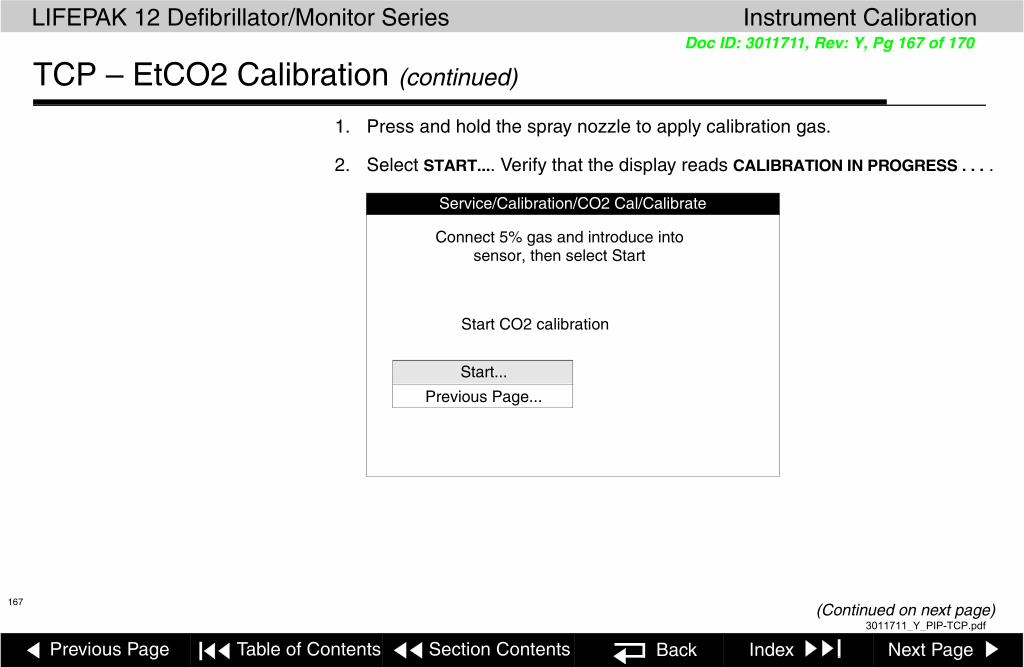
Previous Page Table of Contents Section Contents Back Index Next Page
LIFEPAK 12 Defibrillator/Monitor Series Instrument Calibration
167(Continued on next page)
Doc ID: 3011711, Rev: Y, Pg 167 of 170
TCP – EtCO2 Calibration (continued)
1. Press and hold the spray nozzle to apply calibration gas.
2. Select START.... Verify that the display reads CALIBRATION IN PROGRESS . . . .
Service/Calibration/CO2 Cal/Calibrate
Start CO2 calibration
Start...
Previous Page...
Connect 5% gas and introduce intosensor, then select Start
3011711_Y_PIP-TCP.pdf

Previous Page Table of Contents Section Contents Back Index Next Page
LIFEPAK 12 Defibrillator/Monitor Series Instrument Calibration
168
Doc ID: 3011711, Rev: Y, Pg 168 of 170
TCP – EtCO2 Calibration (continued)
1. Hold the spray nozzle down. When the DISCONNECT GAS prompt appears, release the spray nozzle.
Note: Do not disconnect the filter line until the CALIBRATION OK message appears.
2. Verify that the message CALIBRATION OK appears. If CALIBRATION FAILED is displayed, the LIFEPAK 12 defibrillator/monitor logs a service error code, and the SERVICE indicator illuminates.
Service/Calibration/CO2 Cal/Calibrate
Start...
Previous Page...
Calibration in progress . . .
3011711_Y_PIP-TCP.pdf
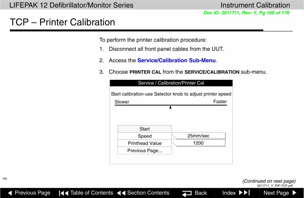
Previous Page Table of Contents Section Contents Back Index Next Page
LIFEPAK 12 Defibrillator/Monitor Series Instrument Calibration
169(Continued on next page)
Doc ID: 3011711, Rev: Y, Pg 169 of 170
TCP – Printer Calibration
To perform the printer calibration procedure:
1. Disconnect all front panel cables from the UUT.
2. Access the Service/Calibration Sub-Menu.
3. Choose PRINTER CAL from the SERVICE/CALIBRATION sub-menu.
1200
Service / Calibration/Printer Cal
Start
Speed
Printhead Value
Previous Page...
Start calibration-use Selector knob to adjust printer speed
Slower Faster
25mm/sec
3011711_Y_PIP-TCP.pdf

Previous Page Table of Contents Section Contents Back Index Next Page
LIFEPAK 12 Defibrillator/Monitor Series Instrument Calibration
170
Doc ID: 3011711, Rev: Y, Pg 170 of 170
TCP – Printer Calibration (continued)
4. If you changed the A12 Printer and are calibrating a new printer, go to step 5. If you are calibrating an existing printer, go to step 6.
5. Select PRINTHEAD VALUE. Rotate the Selector to match the printhead resistance recorded for this printer, then press the Selector.
Note: If you failed to record the printhead resistance value or cannot find the value, see the A12 Printer Replacement procedure to remove the printer, locate the resistance value, and then reinstall the printer.
6. Select START, then push the Selector. The printer runs and prints horizontal tick marks.
7. Notice the spacing of the printed tick marks. The correct interval between marks is 25 mm. Use the Selector to adjust the printer speed SLOWER or FASTER.
8. When the marks are spaced at 25 mm, press the Selector to stop printing.
9. Turn off the UUT.
25 mm 25 mm 25 mm
3011711_Y_PIP-TCP.pdf