Embed Size (px)
Citation preview
Do not delete
Communications Division
NexLog Recorder User Manual
Models NexLog 740 and NexLog 840
NexLog Recorder Software v2.4 or later
[NOTE: Information on title page comes from variables at top of document. Do not directly edit or delete the text produced by these fields. Instead, reveal hidden text & change the variable. ]
[< DO NOT DELETE this draft information paragraph or anything in it, even if it is blank. Set it using the d_DraftInfo variable. To remove for publication, change it to a blank space.]
[DO NOT DELETE THIS ANCHORING PARAGRAPH FOR Title_PNdate FRAME.>]
Part Number: 141214–08
Published: May 8, 2014
ii NexLog Recorder User Manual v2.4
© 2004 – 2014 Eventide Inc. ALL RIGHTS RESERVED.
Every effort has been made to make this guide as complete and accurate as possible, but Eventide Inc. DISCLAIMS ANY WARRANTY OF MERCHANTABILITY OR FITNESS FOR A PARTICULAR PURPOSE. The information provided is on an “as-is” basis and is subject to change without notice or obligation. Eventide Inc. has neither liability nor responsibility to any person or entity with respect to loss or damages arising from the information contained in this guide.
Notice: This computer program and its documentation are protected by copyright law and international treaties. Any unauthorized copying or distribution of this program, its documentation, or any portion thereof may result in severe civil and criminal penalties.
The software installed in accordance with this documentation is copyrighted and licensed by Eventide Inc. under separate license agreement. The software may only be used pursuant to the terms and conditions of such license agreement. Any other use may be a violation of law.
Eventide is a registered trademark of Eventide Inc.
* Other names and brands may be claimed as the property of others.
Publication Date: May 8, 2014
Document Number: 141214-08
Publisher: Eventide Inc., Communications Division, 1 Alsan Way, Little Ferry, NJ 07643, telephone: 201-641-1200
Communications Division Product Information: Visit the Eventide website at: www.eventide.com.
Communications Division Product Service and Technical Support: Users: Contact your local authorized Eventide Dealer. Authorized Dealers: Visit the Eventide website or email [email protected].
NexLog Recorder User Manual v2.4 iii
FCC Part 68 Eventide Larch Analog Recording Card Information
1. This equipment complies with Part 68 of the FCC rules and the requirements adopted by the ACTA. On the bottom side of this
equipment is a label that contains, among other information, a product identifier in the format US:AAAEQ##TXXXX. If requested, this number must be provided to the telephone company.
2. The Eventide Larch Analog Recording Card does not terminate analog telephone lines. Therefore, information about USOC, FIC,
and SOC are not applicable.
3. The REN is used to determine the number of devices that may be connected to a telephone line. Excessive RENs on a telephone line may result in the devices not ringing in response to an incoming call. In most but not all areas, the sum of RENs should not exceed five (5.0). To be certain of the number of devices that may be connected to a line, as determined by the total RENs, contact the local telephone company. For products approved after July 23, 2001, the REN for this product is part of the product identifier that has the format US:AAAEQ##TXXXX. The digits represented by ## are the REN without a decimal point (e.g., 03 is a REN of 0.3). For earlier products, the REN is separately shown on the label.
4. If the Eventide Larch Analog Recording card causes harm to the telephone network, the telephone company will notify you in advance that temporary discontinuance of service may be required. But if advance notice is not practical, the telephone company will notify the customer as soon as possible. Also, you will be advised of your right to file a complaint with the FCC if you believe it is necessary.
5. The telephone company may make changes in its facilities, equipment, operations or procedures that could affect the operation of the equipment. If this happens the telephone company will provide advance notice in order for you to make necessary modifications to maintain uninterrupted service.
6. If trouble is experienced with the equipment Eventide Larch Analog Recording Card, for repairs or warranty information, please contact Eventide Inc, 1 Alsan Way, Little Ferry, NJ 07643, 1-201-641-1200 : www.eventide.com. If the equipment is causing harm to the telephone network, the telephone company may request that you disconnect the equipment until the problem is resolved. The Eventide Larch Analog Recording Card cannot be repaired by the customer (end user). Contact Eventide Inc. for all repairs.
7. Connection to party line service is subject to state tariffs. Contact the state public utility commission, public service commission or corporation commission for information.
8. If your home has specially wired alarm equipment connected to the telephone line, ensure the installation of this Eventide Larch Analog Recording card does not disable your alarm equipment. If you have questions about what will disable alarm
equipment, consult your telephone company or a qualified installer.
iv Contents NexLog Recorder User Manual v2.4
Contents
Tables ........................................................................................................................................... viii
Figures ......................................................................................................................................... viii
Revision History ............................................................................................................................. 1
About This Publication ................................................................................................................... 4
Purpose and Applicability ............................................................................................................ 4 How to Use This Publication ....................................................................................................... 4 Documentation Conventions ....................................................................................................... 5
Important or Critical Information .......................................................................................... 5 Typographical Conventions and Symbols ........................................................................... 5
Related Information ..................................................................................................................... 6
1. Introduction ................................................................................................................................ 7
1.1. Welcome ............................................................................................................................. 7 1.2. Customer Support Information ............................................................................................ 7
Release Numbers ............................................................................................................... 7
2. Recorder Setup .......................................................................................................................... 9
2.1. Unpacking the Recorder ...................................................................................................... 9 2.2. General Specifications ........................................................................................................ 9
2.2.1. NexLog 740 and NexLog 840 ................................................................................... 9 2.2.2. Front Panel Details: NexLog 740 and NexLog 840 .................................................. 11 2.2.3. Rear Panel Details: NexLog 740 ............................................................................ 13 2.2.4. Rear Panel Details: NexLog 840 ............................................................................ 14 2.2.5. NexLog 740 and NexLog 840 Blank Front Panel Units ........................................... 14
2.3. Bench Test ........................................................................................................................ 16 2.3.1. Info screen ............................................................................................................. 17 2.3.2. Replay screen ........................................................................................................ 18 2.3.3. Setup screen .......................................................................................................... 18 2.3.4. Login screen .......................................................................................................... 18
2.4. Installation ......................................................................................................................... 18 2.4.1. General .................................................................................................................. 18 2.4.2. Operating Limits ..................................................................................................... 19 2.4.3. Location Considerations ......................................................................................... 19 2.4.4. Mounting Options ................................................................................................... 20 2.4.5. Other Considerations ............................................................................................. 21 2.4.6. Connecting AC Power and UPS (Uninterruptible Power Supply) ............................ 21 2.4.7. Before You Connect Audio Signals to the Recorder... ............................................ 22 2.4.8. Connecting Telephone, Radio, and Other Analog Audio Signals to the Recorder .. 23
NexLog Recorder User Manual v2.4 Contents v
2.4.9. The Optional Quick Install Kit ................................................................................. 23 2.4.10. Connecting Digital PBX Stations that are to be Tapped ........................................ 25 2.4.11. Connecting to an Ethernet Network ...................................................................... 26 2.4.12. Connecting a Keyboard ........................................................................................ 26 2.4.13. Connecting Headphones ...................................................................................... 26 2.4.14. Connecting Line-Level Equipment ........................................................................ 27
3. The Front Panel User Interface ............................................................................................... 28
3.1 Front Panel Step by Step Quick Guide ................................................................................ 28 3.2 Setup Screen ..................................................................................................................... 36 3.3 Info Screen ......................................................................................................................... 37 3.4 Archiving Controls ............................................................................................................... 38 3.5 Information Bar .................................................................................................................. 40 3.6 Alarm Status ....................................................................................................................... 40 3.7 Replay Screen (Detailed Information) ................................................................................. 41
4. Recorder Configuration and Administration .......................................................................... 49
4.1. The Welcome To NexLog Screen ..................................................................................... 49 4.1.1. MediaWorks Plus ................................................................................................... 50
4.2. SETUP: NexLog Configuration Manager ........................................................................... 50 4.3. SETUP: System ................................................................................................................ 51
4.3.1. System Info ............................................................................................................ 51 4.3.2. Date and Time ....................................................................................................... 53 4.3.3. License Keys .......................................................................................................... 54 4.3.4. Storage Devices ..................................................................................................... 55 4.3.5. Translations ........................................................................................................... 57 4.3.6. Configuration Files ................................................................................................. 58 4.3.7. System Diagnostics ................................................................................................ 59 4.3.8. Power Off ............................................................................................................... 60
4.4. SETUP: Reports ................................................................................................................ 60 4.4.1. Recorder Reports ................................................................................................... 60 4.4.2. Quality Factor Reports ........................................................................................... 62
4.5. SETUP: Networking .......................................................................................................... 63 4.5.1. System Identification .............................................................................................. 63 4.5.2. Network Interfaces ................................................................................................. 63 4.5.3. VNC Settings ......................................................................................................... 66 4.5.4. VPN Settings .......................................................................................................... 66 4.5.5. NexLog Access Bridge ........................................................................................... 66 4.5.6. SNMP Settings ....................................................................................................... 67 4.5.7. Packet Capture ...................................................................................................... 68
4.6. SETUP: Recording ............................................................................................................ 68 4.6.1. Boards and Channels ............................................................................................. 68 4.6.2. Replace Board ....................................................................................................... 84 4.6.3. Retention Settings .................................................................................................. 84 4.6.4. Resource Groups ................................................................................................... 85 4.6.5. Custom Fields ........................................................................................................ 91 4.6.6. Call Suppression .................................................................................................... 96 4.6.7. NG911 ................................................................................................................... 97
4.7. SETUP: Archiving ............................................................................................................. 97 4.7.1. Archives ................................................................................................................. 97 4.7.2. Archive Configuration ........................................................................................... 100
vi Contents NexLog Recorder User Manual v2.4
4.7.3. Media Selection ................................................................................................... 103 4.7.4. Sequential and Parallel Modes ............................................................................. 104 4.7.5. Network Archive Storage Configuration(NAS) ...................................................... 105 4.7.6. Archive Media History .......................................................................................... 106
4.8. SETUP: Alerts and logs ................................................................................................... 107 4.8.1. Active Alarms ....................................................................................................... 107 4.8.2. Alert History ......................................................................................................... 108 4.8.3. Alert Codes .......................................................................................................... 108 4.8.4. Internal Logging ................................................................................................... 109 4.8.5. Email .................................................................................................................... 110 4.8.6. Audit History ......................................................................................................... 110 4.8.7. Client Activity ....................................................................................................... 113
4.9. SETUP: Users and Security ............................................................................................ 114 4.9.1. Users ................................................................................................................... 114 4.9.2. System Security ................................................................................................... 118 4.9.3. SSL ...................................................................................................................... 121 4.9.4. User Groups ......................................................................................................... 121 4.9.5. Permissions ......................................................................................................... 122
4.10. SETUP: Utilities ............................................................................................................. 124 4.10.1. Schedules .......................................................................................................... 124 4.10.2. Upload Recorder Patch ...................................................................................... 127 4.10.3. Re-Order Channels ............................................................................................ 127 4.10.4. Network Utilities ................................................................................................. 127
4.11. SETUP: Quality Factor Software ................................................................................... 128 4.11.1. Agent Mapping ................................................................................................... 128
4.12. SETUP: Change Password ........................................................................................... 128
5. Recorder Operation ............................................................................................................... 129
5.1. Starting and Shutting Down ............................................................................................. 129
6. The Client-Based NexLog Recorder Software ..................................................................... 130
6.1. Introduction ..................................................................................................................... 130 6.1.1. What is the Client-Based NexLog Recorder Software? ........................................ 130 6.1.2. Do You Need to Install the Client Software at all? ................................................ 130
Appendix A: Recorder Software Installation and Upgrade ...................................................... 132
Why Re-installation May Be Necessary .................................................................................. 132 Why Upgrades May Be Necessary or Desirable ...................................................................... 132 The Software Upgrade/Installation Process ............................................................................ 133 Some Details, Especially About Installation ............................................................................. 135 Restoring Archives When Installing New Software .................................................................. 135 Potential Issues ....................................................................................................................... 136
Appendix B: Optional General Purpose Input/Output (GPIO) Boards ..................................... 138
National Instruments PCI-6503 Board (24-Channel) ............................................................... 138
Appendix C: NIST Time Servers ................................................................................................ 140
Appendix D: Channel Wiring for Eventide Analog Input Boards ............................................. 141
Appendix E: Alert Codes ............................................................................................................ 143
Appendix F: Recording VoIP or RoIP Calls ............................................................................... 154
NexLog Recorder User Manual v2.4 Contents vii
Introduction ............................................................................................................................. 154 What is VoIP? ................................................................................................................. 154 The Advantages VoIP Provides ...................................................................................... 154 Technical Considerations ................................................................................................ 155
Network Requirements ............................................................................................................ 156 Local VoIP and RoIP ............................................................................................................... 156 Local VoIP and RTP Templates .............................................................................................. 157 Cisco Local VoIP Template ..................................................................................................... 159 SIP Local VoIP Template ........................................................................................................ 160 Local VoIP and RTP Channel configuration ............................................................................ 160 Advanced Local VoIP Recorder configuration ......................................................................... 163
Device Information .......................................................................................................... 164
Appendix G: Archive Pairing ..................................................................................................... 171
Introduction ............................................................................................................................. 171 Requirements ................................................................................................................. 171 Operation ........................................................................................................................ 171 Pairing Setup .................................................................................................................. 172
Appendix H: SSL Certificate request & application .................................................................. 175
Introduction ............................................................................................................................. 175 Requirements:......................................................................................................................... 175 SSL Settings: .......................................................................................................................... 175 Request procedure: ................................................................................................................ 175 Set New Certificate: ................................................................................................................ 176 Testing: ................................................................................................................................... 176
Limited Warranty ........................................................................................................................ 177
Who is covered under the warranty ......................................................................................... 178 When the warranty becomes effective .................................................................................... 178 Who performs warranty work .................................................................................................. 179 Shipping within the 50 United States ....................................................................................... 179 Shipping outside the 50 United States .................................................................................... 179
Software License ........................................................................................................................ 181
Product License and Usage Agreement .................................................................................. 181 GNU GENERAL PUBLIC LICENSE ................................................................................ 184 Preamble ........................................................................................................................ 184 TERMS AND CONDITIONS FOR COPYING, DISTRIBUTION AND MODIFICATION .... 185 END OF TERMS AND CONDITIONS ............................................................................. 189 How to Apply These Terms to Your New Programs ........................................................ 189
Index ............................................................................................................................................ 192
viii Contents NexLog Recorder User Manual v2.4
Tables Table 1—Specification Summary for NexLog 740 and NexLog 840 with touch-screen Front Panel 10 Table 2—Specification Summary for NexLog 740 and NexLog 840 (Blank Panel) .......................... 14 Table 3—Operating Limits .............................................................................................................. 19 Table 4—INFO Screen Messages .................................................................................................. 37 Table 5—Archive dialog information ............................................................................................... 39 Table 6—Replay Mode information ................................................................................................. 42 Table 7—Sample Net Mask and Subnet Settings ........................................................................... 65 Table 8—Default Security Group Privileges at the Front Panel ..................................................... 114 Table 9—Default Security Group Privileges in NexLog Clients ..................................................... 115 Table 10—Eventide Analog Board Standard Pin-Outs (8-, 16-, and 24-Channel Boards) ............. 142 Table 11—Eventide Analog Board Reverse Pin-Outs (8- and 16-Channel Boards) ...................... 142 Table 12—Alert Severity Levels .................................................................................................... 143 Table 13—Alert Messages ............................................................................................................ 143
Figures Figure 1—NexLog 740 with Touch Screen (Door Closed) ............................................................... 11 Figure 2—NexLog 740 with Touch Screen (Door Open) ................................................................. 11 Figure 3—Touch Screen (Close-Up) ............................................................................................... 12 Figure 4—Typical NexLog 740 Rear Panel ..................................................................................... 13 Figure 5—Typical NexLog 840 Rear Panel ..................................................................................... 14 Figure 6— Front Panel Info Screen ................................................................................................. 16 Figure 7—Front Panel Archives and Drives .................................................................................... 17 Figure 8—Quick Install Kit Components ......................................................................................... 24 Figure 9—Front Panel Info Screen.................................................................................................. 28 Figure 10—Front Panel Replay Screen .......................................................................................... 29 Figure 11—Calendar Mode ............................................................................................................. 30 Figure 12—Replay Transport .......................................................................................................... 31 Figure 13—Incident ........................................................................................................................ 32 Figure 14—Selected Calls in Replay Screen .................................................................................. 33 Figure 15—Working Incident ........................................................................................................... 34 Figure 16—Create Audio CD .......................................................................................................... 35 Figure 17—Setup Screen ............................................................................................................... 36 Figure 18—Info Screen ................................................................................................................... 37 Figure 19—Archives and Drives Display ......................................................................................... 39 Figure 20—Information Bar ............................................................................................................. 40

NexLog Recorder User Manual v2.4 Contents ix
Figure 21—Alarm Status ................................................................................................................. 40 Figure 22—Replay Screen .............................................................................................................. 42 Figure 23—Calendar Mode Search................................................................................................. 43 Figure 24—Calendar ...................................................................................................................... 44 Figure 25—Date Mode .................................................................................................................... 44 Figure 26—Relative Mode .............................................................................................................. 45 Figure 27—Replay Mode Menu ...................................................................................................... 46 Figure 28—Selected Calls in Replay Screen .................................................................................. 47 Figure 29—Front Panel Set-Up top level menus ............................................................................. 49 Figure 30—Web Browser Welcome Page ....................................................................................... 50 Figure 31—Configuration Manager System Info ............................................................................. 51 Figure 32—Example license display with a Primary key and one Add-on license ........................... 55 Figure 33—Software RAID 1 storage devices ................................................................................. 56 Figure 34—Translations .................................................................................................................. 57 Figure 35—Translations Configured ............................................................................................... 58 Figure 36—Configuration files ......................................................................................................... 59 Figure 37—System Diagnostics ...................................................................................................... 60 Figure 38—Example report for Month at a glance ........................................................................... 61 Figure 39—System Identification .................................................................................................... 63 Figure 40—NexLog Access Bridge ................................................................................................. 66 Figure 41—NexLog Access Bridge Add/Edit Page .......................................................................... 67 Figure 42—Packet Capture............................................................................................................. 68 Figure 43—Boards page view by board .......................................................................................... 70 Figure 44—Boards page view by Channels as seen locally on the Front Panel .............................. 72 Figure 45—Boards and Channels Detail level graph as seen in the Chrome browser ..................... 73 Figure 46—Editing the channel name inline .................................................................................... 76 Figure 47—Editing the channel by clicking on the gear ................................................................... 77 Figure 48—Resource groups .......................................................................................................... 86 Figure 49—Resource Group Filters and Resource Filters ............................................................... 87 Figure 50—Resource Group Rules Status ...................................................................................... 87 Figure 51—Resource Group Edit: Permission Group View ............................................................. 88 Figure 52—Resource Group: Empty Group .................................................................................... 88 Figure 53—Resource Groups: Right Mouse Button Menu .............................................................. 89 Figure 54—User Group Edit............................................................................................................ 90 Figure 55—Resource Group Including Resources from Multiple Recorders .................................... 91 Figure 56—Custom fields for NG911 event logging ........................................................................ 92 Figure 57—Image List (Color_Code Example) ................................................................................ 93 Figure 58—Image List in MediaWorks Plus (Color_Code Example)................................................ 94 Figure 59—Calltype Field Configuration ......................................................................................... 95 Figure 60—Archive display in web Configuration Manager ............................................................. 98 Figure 61—Archive Configuration ................................................................................................. 100 Figure 62—NAS configuration ...................................................................................................... 105 Figure 63—User configuration ...................................................................................................... 114 Figure 64—Editing a user ............................................................................................................. 116 Figure 65—User Groups ............................................................................................................... 122 Figure 66—Network Utilities.......................................................................................................... 128 Figure 67—GPIO Board Pin Assignments (NI PCI-6503) .............................................................. 139 Figure 68—Connectors with Standard and Reverse Pin-Outs ....................................................... 141 Figure 69—Adding a Local IP Board, Templates Menu ................................................................. 157 Figure 70—Telex/Vega Console Template Example ..................................................................... 158 Figure 71—Local IP EFJohnson Template Example ..................................................................... 158

x Contents NexLog Recorder User Manual v2.4
Figure 72—Cisco Callmanager “Skinny” Protocol Template.......................................................... 159 Figure 73— SIP Phones Template................................................................................................ 160 Figure 74—Top Half of Local IP Channel RTP Tab ....................................................................... 161 Figure 75—Bottom Half of Local IP Channel RTP Tab .................................................................. 162 Figure 76—Local IP Channel Diagnostics Example ...................................................................... 162 Figure 77—Setting the Archive Time ............................................................................................ 173 Figure 78—Enable Archive Pairing & Define Secondary Recorder ............................................... 173 Figure 79— Enable Auto Start on Secondary Recorder ................................................................ 174
NexLog Recorder User Manual v2.4 1
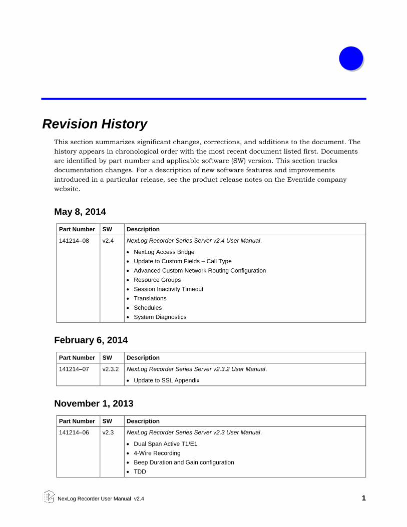
Revision History
This section summarizes significant changes, corrections, and additions to the document. The
history appears in chronological order with the most recent document listed first. Documents
are identified by part number and applicable software (SW) version. This section tracks
documentation changes. For a description of new software features and improvements
introduced in a particular release, see the product release notes on the Eventide company
website.
May 8, 2014
Part Number SW Description
141214–08 v2.4 NexLog Recorder Series Server v2.4 User Manual.
NexLog Access Bridge
Update to Custom Fields – Call Type
Advanced Custom Network Routing Configuration
Resource Groups
Session Inactivity Timeout
Translations
Schedules
System Diagnostics
February 6, 2014
Part Number SW Description
141214–07 v2.3.2 NexLog Recorder Series Server v2.3.2 User Manual.
Update to SSL Appendix
November 1, 2013
Part Number SW Description
141214–06 v2.3 NexLog Recorder Series Server v2.3 User Manual.
Dual Span Active T1/E1
4-Wire Recording
Beep Duration and Gain configuration
TDD
2 NexLog Recorder User Manual v2.4
Part Number SW Description
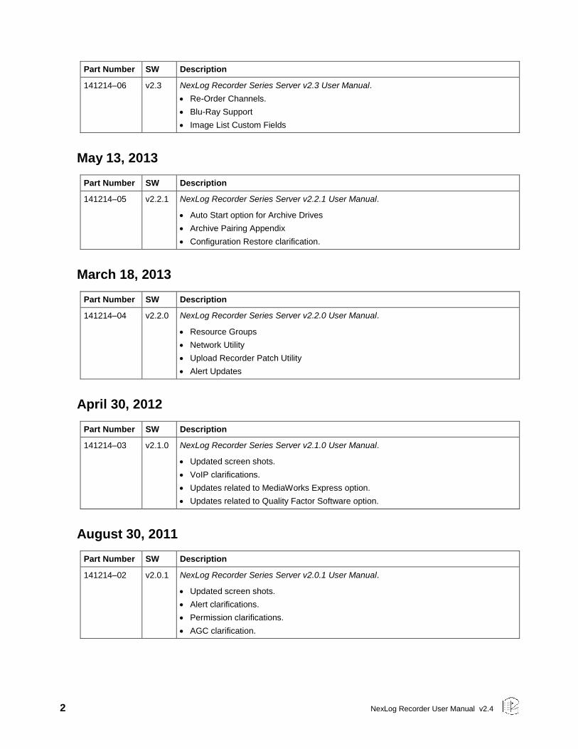
141214–06 v2.3 NexLog Recorder Series Server v2.3 User Manual.
Re-Order Channels.
Blu-Ray Support
Image List Custom Fields
May 13, 2013
Part Number SW Description
141214–05 v2.2.1 NexLog Recorder Series Server v2.2.1 User Manual.
Auto Start option for Archive Drives
Archive Pairing Appendix
Configuration Restore clarification.
March 18, 2013
Part Number SW Description
141214–04 v2.2.0 NexLog Recorder Series Server v2.2.0 User Manual.
Resource Groups
Network Utility
Upload Recorder Patch Utility
Alert Updates
April 30, 2012
Part Number SW Description
141214–03 v2.1.0 NexLog Recorder Series Server v2.1.0 User Manual.
Updated screen shots.
VoIP clarifications.
Updates related to MediaWorks Express option.
Updates related to Quality Factor Software option.
August 30, 2011
Part Number SW Description
141214–02 v2.0.1 NexLog Recorder Series Server v2.0.1 User Manual.
Updated screen shots.
Alert clarifications.
Permission clarifications.
AGC clarification.

NexLog Recorder User Manual v2.4 3
July 10, 2011
Part Number SW Description
141214–01 v2.0.0 NexLog Recorder Series Server v2.0.0 User Manual.
Initial Release, July 28, 2011
4 NexLog Recorder User Manual v2.4
About This Publication
The following topics provide information about this publication:
Purpose and Applicability
How to Use This Publication
Documentation Conventions
Related Information
Purpose and Applicability
This publication provides information for users of the Eventide® NexLog™
Recorders.
This information applies to NexLog Recorder Software 2.4 for the NexLog 740
and NexLog 840 recorders. It may also apply to later versions except when
superseded by a more recent publication.
How to Use This Publication
The content is organized as follows:
About This Publication
Describes the content of this publication and how to use it.
Chapter: 1. Introduction
Provides a brief introduction and customer support information.
Chapter: 2. Recorder Setup
Provides information on unpacking the product, performing a bench test,
installing the product, and a short description of how to use the front panel.
Chapter: 4. Recorder Configuration and Administration
Provides information on configuring the recorder and administrative tasks
using the web-based Setup utility.
Chapter: 5. Recorder Operation
Provides information on basic operating tasks, such as start-up and shutdown,
additional information about locating and playing recordings, archiving
recordings, and live monitoring.
NexLog Recorder User Manual v2.4 5
Chapter: 6. The Client-Based NexLog Recorder Software
Provides introductory information about client software that can be used for
instant recall, incident playback, and more. Note: Detailed information about
the client-based NexLog software is provided in Eventide’s MediaWorks and
MediaAgent manuals.
Appendices
Provide related information.
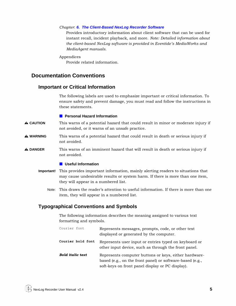
Documentation Conventions
Important or Critical Information
The following labels are used to emphasize important or critical information. To
ensure safety and prevent damage, you must read and follow the instructions in
these statements.
Personal Hazard Information
CAUTION This warns of a potential hazard that could result in minor or moderate injury if
not avoided, or it warns of an unsafe practice.
WARNING This warns of a potential hazard that could result in death or serious injury if
not avoided.
DANGER This warns of an imminent hazard that will result in death or serious injury if
not avoided.
Useful Information
Important! This provides important information, mainly alerting readers to situations that
may cause undesirable results or system harm. If there is more than one item,
they will appear in a numbered list.
Note: This draws the reader’s attention to useful information. If there is more than one
item, they will appear in a numbered list.
Typographical Conventions and Symbols
The following information describes the meaning assigned to various text
formatting and symbols.
Courier font Represents messages, prompts, code, or other text
displayed or generated by the computer.
Courier bold font Represents user input or entries typed on keyboard or
other input device, such as through the front panel.
Bold italic text Represents computer buttons or keys, either hardware-
based (e.g., on the front panel) or software-based (e.g.,
soft-keys on front panel display or PC display).
6 NexLog Recorder User Manual v2.4
Blue text (PDF version only) Represents a hyperlink in the
electronic document. Click on the link in the PDF to jump
to the referenced item. This format is often applied to
cross-references within the document, such as to
chapters, sections, tables, and figures.
Parameter Parameter names are typically given in bold type.
<name> Refers to an item of information of the named type, which
may vary from case to case and so is identified
generically. A user would substitute specific information
if instructed to enter this information.
Related Information
Eventide Documentation
MediaWorks User Manual (part number 141114 version 01 or later)
MediaWorks Plus User Manual (part number 141217 version 01 or later)
MediaAgent User Manual (part number 141115 version 01 or later)
Eventide Quality Factor Software User Manual (part number 141216)
NexLog Screen Recording Guide (part number 142218 version 01 or later)
Note: Although documented in this publication, screen recording features
are not intended for production use and general availability (they are
available only for manufacturer-coordinated customer trials).
Eventide Products and Services
For product information, visit the Eventide website at www.eventide.com.
For technical support, email Eventide at [email protected].
Note: Eventide offers advanced professional services. If you are interested in
obtaining specialized services or Customer Engineering work, contact Eventide
through one of the means listed above.
NexLog Recorder User Manual v2.4 7
1. Introduction
1.1. Welcome
Welcome and congratulations on your purchase of an Eventide® NexLog™
Recorder.
Eventide invented the digital communications recorder in 1989. With thousands
of communications recorders in service in such diverse applications as corporate
call centers, NORAD, nuclear submarines, NASA, maximum security prisons, air
traffic control, and 911 call centers throughout the world, Eventide continues its
tradition of combining unmatched ease-of-use with mission-critical reliability.
This manual will help you maximize the use of your purchase. It includes:
A quick-start bench test, for those who want to quickly familiarize
themselves with some basic operations
Guidance on installing your recorder
Step-by-step instructions on how to set up and operate your recorder
Descriptions of all of the controls and menu items on the front panel user
interface
To help us reach you with information on updates and upcoming new features,
please send us your warranty card. Eventide does not provide your information
to marketers or any other outside organizations.
1.2. Customer Support Information
Eventide is committed to your satisfaction. If, after using this manual, you still
have questions about the operation of your recorder, contact Technical Support
at [email protected] or call (201) 641-1200.
The Eventide web site has additional information that may be helpful. Go to
www.eventide.com.
Release Numbers
You may need to identify the software version and serial number for the
following products/components:
8 NexLog Recorder User Manual v2.4
NexLog Recorder Software: On the touch screen front panel or with a monitor
and mouse attached (while the recorder is running), do the following to
display the version information:
Select the menu icon on the lower left indicated by an “e” icon.
Select Setup.
Select System.
Select the sub menu System Info.
The Recorder Serial Number and Current Firmware Version should
be displayed.
Alternatively, you can get the version and serial number remotely via the Web-
based NexLog Configuration Manager:
Log into the recorder via a web browser and navigate to the recorder’s
address (example: http://192.168.2.100). Note that the default logon
credentials for the recorder (before they are changed by the
administrator) are User Name: Eventide / Password: 12345.
Click Configuration Manager.
In the NexLog Configuration Manager’s navigation menu on the left,
select the System menu.
In the sub navigation menu select System Info.
The Recorder Serial Number and Current Firmware Version should
be displayed.
Eventide MediaWorks or Eventide MediaAgent: On the Help menu, select About
to display the version information.
NexLog Recorder User Manual v2.4 9
2. Recorder Setup
2.1. Unpacking the Recorder
CAUTION Use care and assistance when lifting and handling the recorder. The NexLog 740
weighs approximately 50 pounds (23 kg). The NexLog 840 can weigh as much as
95 pounds (43 kg)!
Check the box for damage. A crushed box, holes, or water damage, for example,
could indicate that the recorder has been damaged. Open the box and inspect
the recorder and associated accessories. If the equipment appears damaged
contact Eventide right away and save the damaged box and packaging!
Check that the unit is delivered with the expected configuration and accessories.
The packing slip states the contents. In addition, the box will include:
A configuration sheet indicating installed audio input boards and other I/O
boards
A warranty registration card
One archive medium per removable archive drive
One power line cord per power supply module
One server software DVD disk labeled “Eventide NexLog Software”
This document
Other accessories may be included, depending on your order. For example, you
may receive client disks and additional documentation for the client software.
2.2. General Specifications
2.2.1. NexLog 740 and NexLog 840
All Eventide NexLog Recorders are based on identical server (recorder) software
and client (PC user) software. The primary differences among different units in
the product line are physical, e.g., size, power, storage configuration, etc. The
following table highlights the differences among the products. This is a
summary only and does not replace the individual unit specifications.
10 NexLog Recorder User Manual v2.4
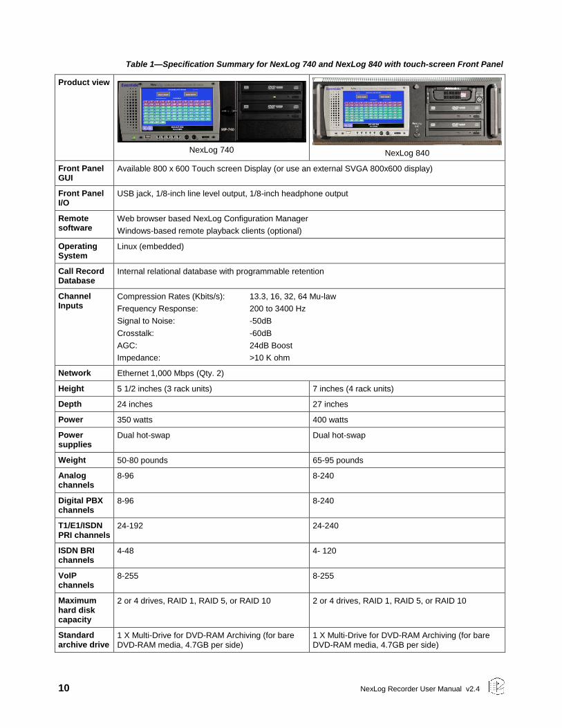
Table 1—Specification Summary for NexLog 740 and NexLog 840 with touch-screen Front Panel
Product view
NexLog 740
NexLog 840
Front Panel GUI
Available 800 x 600 Touch screen Display (or use an external SVGA 800x600 display)
Front Panel I/O
USB jack, 1/8-inch line level output, 1/8-inch headphone output
Remote software
Web browser based NexLog Configuration Manager
Windows-based remote playback clients (optional)
Operating System
Linux (embedded)
Call Record Database
Internal relational database with programmable retention
Channel Inputs
Compression Rates (Kbits/s): 13.3, 16, 32, 64 Mu-law
Frequency Response: 200 to 3400 Hz
Signal to Noise: -50dB
Crosstalk: -60dB
AGC: 24dB Boost
Impedance: >10 K ohm
Network Ethernet 1,000 Mbps (Qty. 2)
Height 5 1/2 inches (3 rack units) 7 inches (4 rack units)
Depth 24 inches 27 inches
Power 350 watts 400 watts
Power supplies
Dual hot-swap Dual hot-swap
Weight 50-80 pounds 65-95 pounds
Analog channels
8-96 8-240
Digital PBX channels
8-96 8-240
T1/E1/ISDN PRI channels
24-192 24-240
ISDN BRI channels
4-48 4- 120
VoIP channels
8-255 8-255
Maximum hard disk capacity
2 or 4 drives, RAID 1, RAID 5, or RAID 10 2 or 4 drives, RAID 1, RAID 5, or RAID 10
Standard archive drive
1 X Multi-Drive for DVD-RAM Archiving (for bare DVD-RAM media, 4.7GB per side)
1 X Multi-Drive for DVD-RAM Archiving (for bare DVD-RAM media, 4.7GB per side)
NexLog Recorder User Manual v2.4 11
Standard hard disk storage
2 X 1 TB fixed-mount, software RAID1 2 X 1 TB fixed-mount, software RAID1
Optional storage
Removable hard drives Removable hard drives
2.2.2. Front Panel Details: NexLog 740 and NexLog 840
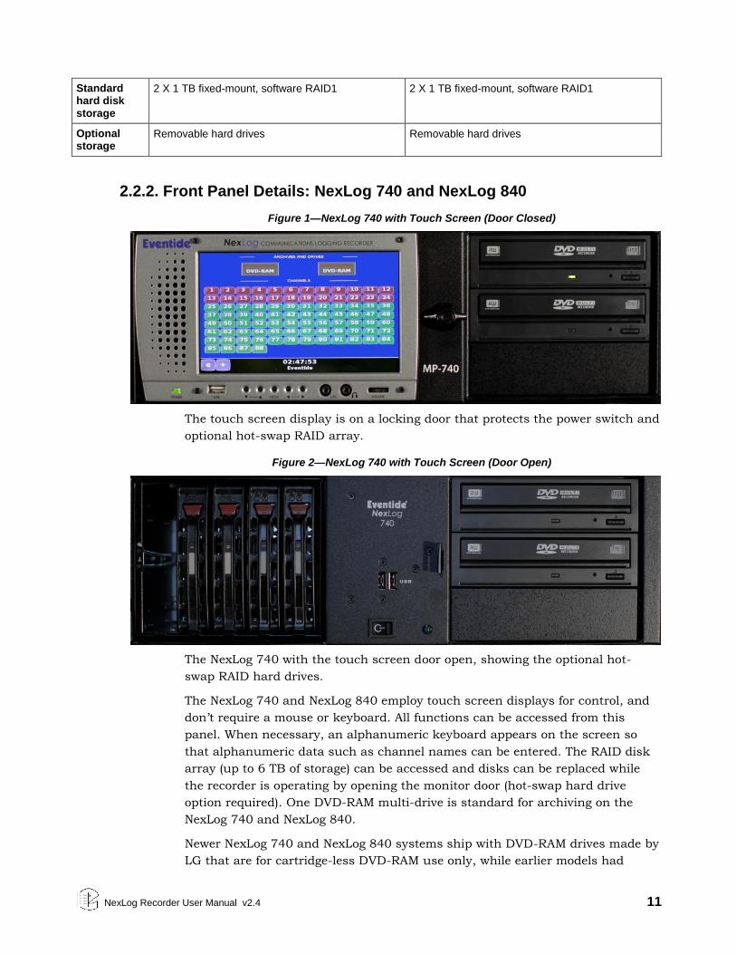
Figure 1—NexLog 740 with Touch Screen (Door Closed)
The touch screen display is on a locking door that protects the power switch and
optional hot-swap RAID array.
Figure 2—NexLog 740 with Touch Screen (Door Open)
The NexLog 740 with the touch screen door open, showing the optional hot-
swap RAID hard drives.
The NexLog 740 and NexLog 840 employ touch screen displays for control, and
don’t require a mouse or keyboard. All functions can be accessed from this
panel. When necessary, an alphanumeric keyboard appears on the screen so
that alphanumeric data such as channel names can be entered. The RAID disk
array (up to 6 TB of storage) can be accessed and disks can be replaced while
the recorder is operating by opening the monitor door (hot-swap hard drive
option required). One DVD-RAM multi-drive is standard for archiving on the
NexLog 740 and NexLog 840.
Newer NexLog 740 and NexLog 840 systems ship with DVD-RAM drives made by
LG that are for cartridge-less DVD-RAM use only, while earlier models had
12 NexLog Recorder User Manual v2.4
cartridge based Panasonic drives, which accepted Type 4 cartridge DVD-RAM
media or cartridge-less DVD-RAM discs.
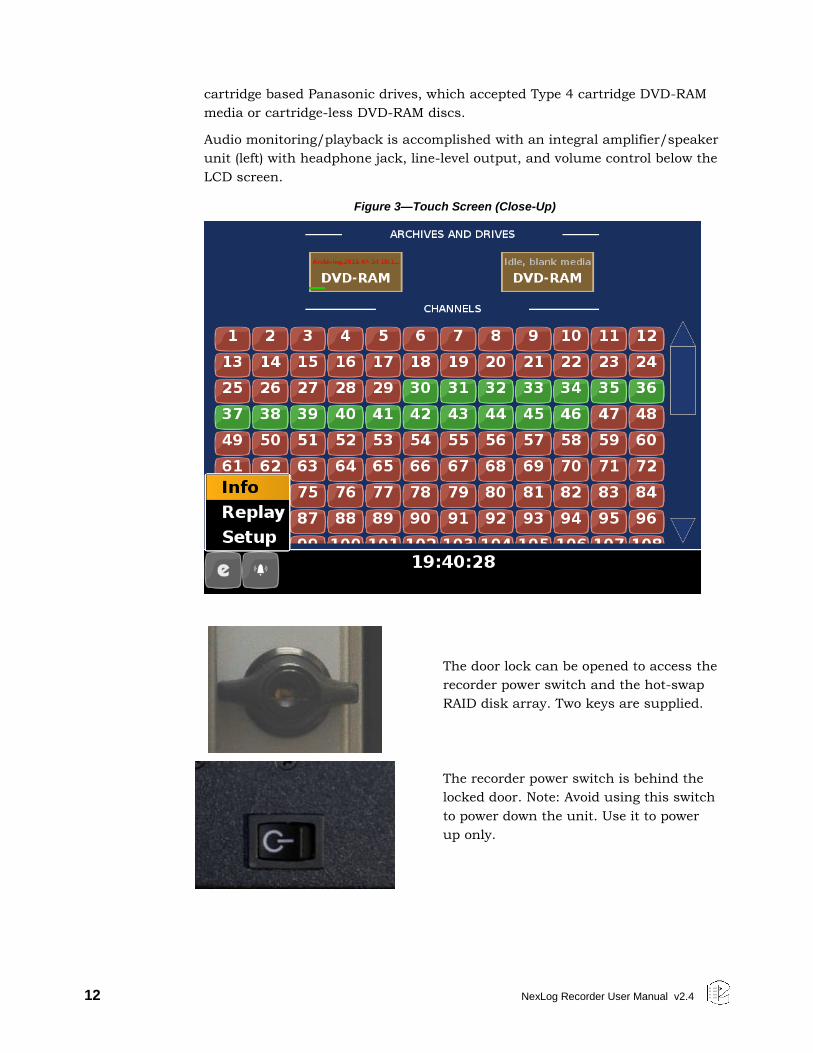
Audio monitoring/playback is accomplished with an integral amplifier/speaker
unit (left) with headphone jack, line-level output, and volume control below the
LCD screen.
Figure 3—Touch Screen (Close-Up)
The door lock can be opened to access the
recorder power switch and the hot-swap
RAID disk array. Two keys are supplied.
The recorder power switch is behind the
locked door. Note: Avoid using this switch
to power down the unit. Use it to power
up only.
NexLog Recorder User Manual v2.4 13
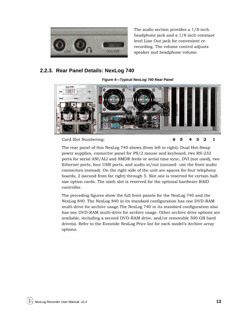
The audio section provides a 1/8-inch
headphone jack and a 1/8 inch constant
level Line Out jack for convenient re-
recording. The volume control adjusts
speaker and headphone volume.
2.2.3. Rear Panel Details: NexLog 740
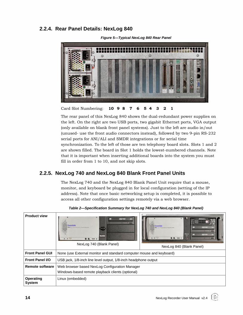
Figure 4—Typical NexLog 740 Rear Panel
Card Slot Numbering: 6 5 4 3 2 1
The rear panel of this NexLog 740 shows (from left to right): Dual Hot-Swap
power supplies, connector panel for PS/2 mouse and keyboard, two RS-232
ports for serial ANI/ALI and SMDR feeds or serial time sync, DVI (not used), two
Ethernet ports, four USB ports, and audio in/out (unused- use the front audio
connectors instead). On the right side of the unit are spaces for four telephony
boards, 2 (second from far right) through 5. Slot one is reserved for certain half-
size option cards. The sixth slot is reserved for the optional hardware RAID
controller.
The preceding figures show the full front panels for the NexLog 740 and the
NexLog 840. The NexLog 840 in its standard configuration has one DVD-RAM
multi-drive for archive usage.The NexLog 740 in its standard configuration also
has one DVD-RAM multi-drive for archive usage. Other archive drive options are
available, including a second DVD-RAM drive, and/or removable 500 GB hard
drive(s). Refer to the Eventide NexLog Price list for each model’s Archive array
options.
14 NexLog Recorder User Manual v2.4
2.2.4. Rear Panel Details: NexLog 840
Figure 5—Typical NexLog 840 Rear Panel
Card Slot Numbering: 10 9 8 7 6 5 4 3 2 1
The rear panel of this NexLog 840 shows the dual-redundant power supplies on
the left. On the right are two USB ports, two gigabit Ethernet ports, VGA output
(only available on blank front panel systems). Just to the left are audio in/out
(unused- use the front audio connectors instead), followed by two 9-pin RS-232
serial ports for ANI/ALI and SMDR integrations or for serial time
synchronization. To the left of those are ten telephony board slots. Slots 1 and 2
are shown filled. The board in Slot 1 holds the lowest-numbered channels. Note
that it is important when inserting additional boards into the system you must
fill in order from 1 to 10, and not skip slots.
2.2.5. NexLog 740 and NexLog 840 Blank Front Panel Units
The NexLog 740 and the NexLog 840 Blank Panel Unit require that a mouse,
monitor, and keyboard be plugged in for local configuration (setting of the IP
address). Note that once basic networking setup is completed, it is possible to
access all other configuration settings remotely via a web browser.
Table 2—Specification Summary for NexLog 740 and NexLog 840 (Blank Panel)
Product view
NexLog 740 (Blank Panel)
NexLog 840 (Blank Panel)
Front Panel GUI None (use External monitor and standard computer mouse and keyboard)
Front Panel I/O USB jack, 1/8-inch line level output, 1/8-inch headphone output
Remote software Web browser based NexLog Configuration Manager
Windows-based remote playback clients (optional)
Operating System
Linux (embedded)
NexLog Recorder User Manual v2.4 15
Call Record Database
Internal relational database with programmable retention
Channel Inputs Compression Rates (Kbits/s): 13.3, 16, 32, 64 Mu-law
Frequency Response: 200 to 3400 Hz
Signal to Noise: -50dB
Crosstalk: -60dB
AGC: 24dB Boost
Impedance: >10 K ohm
Network Ethernet 1,000 Mbps (Qty. 2)
Height 5 1/2 inches (3 rack units) 7 inches (4 rack units)
Depth 24 inches 27 inches
Power 350 watts 400 watts
Power supplies Dual hot-swap Dual hot-swap
Weight 50-80 pounds 65-95 pounds
Analog channels 8-96 8-240
Digital PBX channels
8-96 8-240
T1/E1/ISDN PRI channels
24-192 24-240
ISDN BRI channels
4-48 4-120
VoIP channels 8-255 8-255
Maximum hard disk capacity
2 or 4 drives, RAID 1, RAID 5, or RAID 10 2or 4 drives, RAID 1, RAID 5, or RAID 10
Standard archive drive
1 X 9.4 GB multi-drive for DVD-RAM 1 X 9.4 GB multi-drive for DVD-RAM
Standard hard disk storage
2 X 1 TB fixed-mount, software RAID1 2 X 1 TB fixed-mount, software RAID1
Optional storage Removable hard drive Removable hard drives
16 NexLog Recorder User Manual v2.4
2.3. Bench Test
Before installing the unit, you may want to run a brief bench test, especially if
you are unfamiliar with Eventide NexLog Recorders. The following steps are a
suggested bench test procedure, which you may modify as you wish. If you
change settings, note the defaults first and set them back to the defaults after
you complete the test.
Plug in the provided line cords to the appropriate line voltage.
Unlock the door and press the power switch. The boot process will start and
diagnostic messages will scroll by on the front panel screen or monitor.
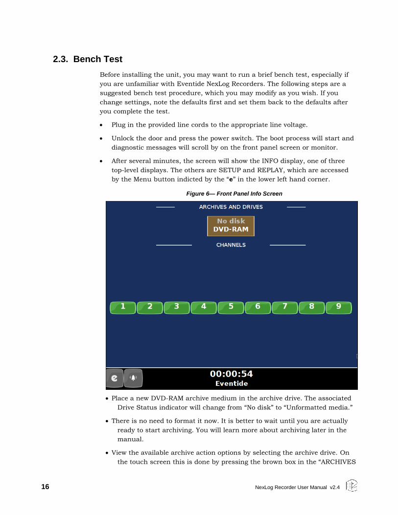
After several minutes, the screen will show the INFO display, one of three
top-level displays. The others are SETUP and REPLAY, which are accessed
by the Menu button indicted by the “e” in the lower left hand corner.
Figure 6— Front Panel Info Screen
Place a new DVD-RAM archive medium in the archive drive. The associated
Drive Status indicator will change from “No disk” to “Unformatted media.”
There is no need to format it now. It is better to wait until you are actually
ready to start archiving. You will learn more about archiving later in the
manual.
View the available archive action options by selecting the archive drive. On
the touch screen this is done by pressing the brown box in the “ARCHIVES
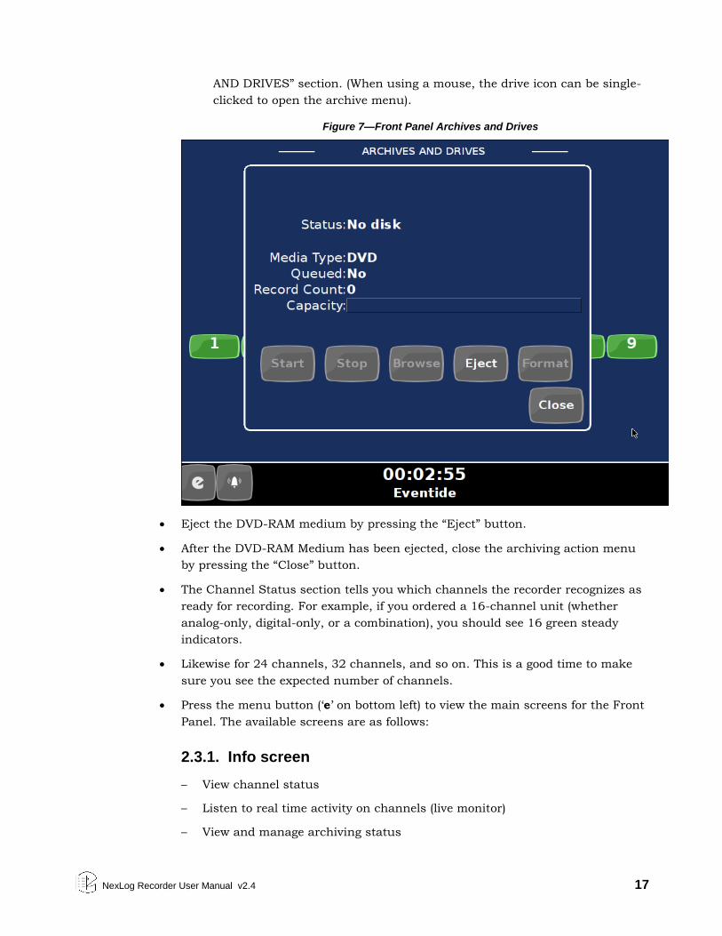
NexLog Recorder User Manual v2.4 17
AND DRIVES” section. (When using a mouse, the drive icon can be single-
clicked to open the archive menu).
Figure 7—Front Panel Archives and Drives
Eject the DVD-RAM medium by pressing the “Eject” button.
After the DVD-RAM Medium has been ejected, close the archiving action menu
by pressing the “Close” button.
The Channel Status section tells you which channels the recorder recognizes as
ready for recording. For example, if you ordered a 16-channel unit (whether
analog-only, digital-only, or a combination), you should see 16 green steady
indicators.
Likewise for 24 channels, 32 channels, and so on. This is a good time to make
sure you see the expected number of channels.
Press the menu button (‘e’ on bottom left) to view the main screens for the Front
Panel. The available screens are as follows:
2.3.1. Info screen
– View channel status
– Listen to real time activity on channels (live monitor)
– View and manage archiving status
18 NexLog Recorder User Manual v2.4
– Access active alarms on the recorder
2.3.2. Replay screen
– Research and play back recordings stored locally and on archives
– Export recordings to removable media.
2.3.3. Setup screen
– Configure the recorder.
2.3.4. Login screen
– This option is only visible and available under certain configurations. This
will be explained later during System Security Settings.
When you have finished viewing each screen, you can shut down the unit as
follows:
Important! Do not force a shutdown by pulling the power plug or using the
power switch. A forced shutdown can result in corrupted files
and loss of data.
1. Go to the SETUP screen.
2. Select System.
3. Select Power Off.
4. Select the Shutdown button.
5. Answer OK to the prompt.
After the recorder completes its controlled shutdown procedures, the unit will
automatically shut down.
2.4. Installation
CAUTION NexLog Recorders can be quite heavy, depending upon the model and options.
Do not attempt to lift or install these units without assistance. Do not attempt to
rack mount any model without either shelf or rack-slide support. Rack slides
are available as an option from Eventide. Do not support these units using only
the mounting ears.
2.4.1. General
NexLog Recorders are computer equipment. They have essentially the same
requirements, both physical and electrical, as standard servers, and similar
attention should be paid to their environment to assure long life and reliable
operation. Site preparation, especially for larger installations, may include
NexLog Recorder User Manual v2.4 19
providing rack cabinets and concentrating communication wiring – phone lines,
radio, etc. – nearby.
2.4.2. Operating Limits
The installation should allow the units to operate within their electrical and
physical operational limits.
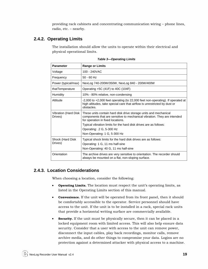
Table 3—Operating Limits
Parameter Range or Limits
Voltage 100 - 240VAC
Frequency 50 - 60 Hz
Power (typical/max) NexLog 740-200W/350W, NexLog 840 - 200W/400W
thatTemperature Operating +5C (41F) to 40C (104F)
Humidity 10% - 80% relative, non-condensing
Altitude -2,000 to +2,000 feet operating (to 22,000 feet non-operating). If operated at high altitudes, take special care that airflow is unrestricted by dust or obstacles.
Vibration (Hard Disk Drives)
These units contain hard disk drive storage units and mechanical components that are sensitive to mechanical vibration. They are intended for operation in fixed locations.
Typical vibration limits for the hard disk drives are as follows:
Operating: .2 G, 5-300 Hz
Non-Operating: 1 G, 5-300 Hz
Shock (Hard Disk Drives)
Typical shock limits for the hard disk drives are as follows:
Operating: 1 G, 11 ms half-sine
Non-Operating: 40 G, 11 ms half-sine
Orientation The archive drives are very sensitive to orientation. The recorder should always be mounted on a flat, non-sloping surface.
2.4.3. Location Considerations
When choosing a location, consider the following:
Operating Limits. The location must respect the unit’s operating limits, as
listed in the Operating Limits section of this manual.
Convenience. If the unit will be operated from its front panel, then it should
be comfortably accessible to the operator. Service personnel should have
access to the unit. If the unit is to be installed in a rack, special rack units
that provide a horizontal writing surface are commercially available.
Security. If the unit must be physically secure, then it can be placed in a
locked equipment room with limited access. This will also help ensure data
security. Consider that a user with access to the unit can remove power,
disconnect the input cables, play back recordings, monitor calls, remove
archive media, and do other things to compromise your data. Logins are no
protection against a determined attacker with physical access to a machine.
20 NexLog Recorder User Manual v2.4
In short, if you are concerned about malicious users making a purposeful
effort to gain unauthorized access to your data, then the only real protection
is to place the unit in a secure location.
Cable lengths. For analog signals, such as POTS lines and radio receiver
outputs, cable lengths are not likely to be an issue. An adequate level can be
obtained hundreds of feet from the signal source. The unit has
programmable adjustments for low or high signal levels. That being said,
shorter cable lengths will create less signal attenuation and pick-up less
noise than longer cable lengths. For tapping digital PBX telephones and
T1/E1 circuits, maximum cable lengths are extremely important, and can be
different for different makes & models of telephone systems. Contact
Eventide technical support for digital-tap cable length information for your
particular digital phone system or T1/E1 circuits.
Particulates. The archive drives and, to a lesser extent, the fans and hard
drives, can be damaged by smoke and dust. If you find dust build up on the
surfaces or the fans being clogged, consider changing the location.
Power dropouts or surges. The unit should be protected from power dropouts
and surges. The chosen location should have line power available that is not
on the same circuit as equipment that draws a large current on start-up,
such as electric motors or compressors or banks of fluorescent lights. Line
voltage fluctuations, brown-outs, and power outages can result in loss of
data and damage to the unit. An Uninterruptible Power Supply is required to
mitigate these problems. For a list of approved UPS units, see Section
2.4.6. Connecting AC Power and UPS (Uninterruptible Power Supply) on page
21.
Spilled liquids. Liquids spilled on the unit can damage it. The location should
not encourage people to place coffee cups on the unit, for instance.
Vibration and Shock. Vibrating or physically shocking the unit while the hard
drives are operating could damage the hard drives. The location should not
be subject to vibration or jolting while the unit is operating.
2.4.4. Mounting Options
As normally provided, the unit can be mounted on any flat, non-sloping surface
that can bear its weight. It can be rack mounted if the rack has a shelf to
support it, and the supplied mounting ears can be attached to the rack with the
rack screws provided, in order to prevent casual removal. The unit must not be
mounted solely with the mounting ears and rack screws!
If no rack shelf is available, a rack-slide rail install kit, which includes slide
rails, rear slide supports, brackets, and mounting hardware, can be ordered:
4-post Rack-Slide Rail Kit for the NexLog 740: Eventide Part# 324430
4-post Rack-Slide Rail Kit for the NexLog 840: Eventide Part# 108112
NexLog Recorder User Manual v2.4 21
Alternatively, a center rack mounting option is also available:
2-post Center Rack Mount Kit for the NexLog 740: Eventide Part# 108109
2-post Center Rack Mount Kit for the NexLog 840: Eventide Part# 108110
2.4.5. Other Considerations
NexLog 740: The recorder is shipped with two keys for locking and unlocking
the front door of the recorder. One key should be kept in a safe place as a
backup spare. You should consider preventing casual access to the other key as
well. The switch behind the front panel should be used to power up the recorder
only and not be used to power down the recorder unless absolutely necessary.
The logger should be shut off using the SETUP/Power Off option. Otherwise,
data corruption could occur. If it is necessary to use the switch to shut down
the recorder, hold it for one second and release. Do not continue holding it until
the recorder shuts down.
NexLog 840: The recorder is shipped with two keys for the power key-switch on
the front panel of the recorder. One key should be kept in a safe place as a
backup spare. You should consider preventing casual access to the other key as
well. The power key-switch should be used to power up the recorder only and
not be used to power down the recorder unless absolutely necessary. The logger
should be shut off using the SETUP/Power Off option. Otherwise, data
corruption could occur. If it is necessary to use the key-switch to shut down the
recorder, insert the key, turn it for one second, and release. Do not keep the key
turned until the recorder shuts down.
2.4.6. Connecting AC Power and UPS (Uninterruptible Power Supply)
The recorders use “universal” power supplies. This means you can plug the
recorder into any line (mains) voltage from 100 volts to 240 volts nominal.
However, to prevent unplanned shutdowns caused by power glitches or
interruptions, Eventide strongly recommends the use of an Uninterruptible
Power Supply (UPS) unit that meets certain minimum characteristics:
The UPS must provide power for a long enough period to allow orderly shutdown
of the recorder in case of power failure.
If your facility has a backup generator, the UPS should provide power long
enough to operate the recorder until the generator becomes operational
following the start of a power failure (typically a minute or less) PLUS a period
long enough to allow orderly shutdown of the recorder in case of generator
failure.
The UPS should be an approved model, i.e., one that can communicate its
status to the recorder. This isn’t strictly necessary if your facility is manned and
personnel are trained to shut down the recorder using the appropriate
procedure in case of power failure before the UPS battery drains. However, an
22 NexLog Recorder User Manual v2.4
approved UPS will keep the recorder running and automatically signal to the
recorder to perform a safe shutdown when its battery power gets low.
Eventide offers commercial-grade, heavy-duty rack-mount UPS units. Eventide
has tested the following units and confirms they work with the recorders.
Manufacturer Rating Rack Height
APC / Tripp-Lite 1500VA, 940W, 120V 2U (3-1/2 inch)
APC / Tripp-Lite 1500VA, 940W, 240V 2U
APC / Tripp-Lite 750VA, 120V 2U
APC / Tripp-Lite 750VA, 240V 2U
APC / Tripp-Lite 3000VA, 2700W, 120V 2U
APC / Tripp-Lite 3000VA, 2700W, 240V 2U
In addition, consumer-grade UPS units may be available locally and are suitable
for more casual installations and shorter run-times. Eventide has tested the
following units and confirms that they work with the recorders.
Manufacturer Model Recommended for
APC Back-UPS ES 500 NexLog 740
APC Back-UPS ES 725 NexLog 740, NexLog 840
To connect your recorder to a UPS, simply plug the UPS into an AC socket, and
plug the recorder into the UPS using the power cords provided. If you use an
approved UPS, also connect the UPS to one of the recorder’s USB connectors on
the rear panel using the cable provided with the UPS. This communication link
will perform a safe shutdown when necessary, and also allow the recorder to
notify you (by display and optionally by email) if there is a power problem. The
NexLog 740 and NexLog 840 recorders are supplied with dual redundant power
supplies. To preserve redundancy, it is acceptable to use a separate UPS with
each power cord from the recorder.
2.4.7. Before You Connect Audio Signals to the Recorder...
Before you connect the telephone lines, radio outputs, or other signals to be
tapped and recorded, set the recorder’s internal clock, date, time zone, and
channel names. If you are installing new software on a currently operating
recorder, disconnect the audio inputs until you have restored the configuration
of the recorder, including channel selection and time zone. The reason for this is
that the recorder will begin recording as soon as it detects an input signal. Calls
with the wrong time, date, and time zone may get recorded and will likely
remain on the recorder for a long time. This might be confusing later when you
search, filter, and archive calls. Refer to Section 3 of this document for
configuration information including Date and Time settings.
NexLog Recorder User Manual v2.4 23
2.4.8. Connecting Telephone, Radio, and Other Analog Audio Signals to the Recorder
This section applies to units equipped with one or more Analog Input Boards. If
you are not sure this board is installed, check the printed back-panel diagram
that was packed with your recorder.
WARNING To reduce the risk of fire, use only 26 AWG or larger telecommunication
wire.
The Analog Input Board handles interfacing to analog audio signals. The
number of channels per board will vary depending on which is ordered. Eventide
sells 8, 16, and 24 channels versions of the Analog Board.
A mating connector is provided for each board unless a Quick Install Kit has
been ordered (see Section 2.4.9. The Optional Quick Install Kit. The connector has
two rows of contacts. One row is numbered 1 through 25, and the other row is
numbered 26 through 50. Numbering is such that pin 1 is opposite 26, and 25
is opposite 50. Each audio input requires two wires, in what is known as a
“balanced” configuration. There is no “ground” connection. The channel and
connector pin correspondence is detailed in Appendix D: Channel Wiring for
Eventide Analog Input Boards.
Eventide offers a Quick Install Kit that, besides pulling together the parts you
will need for a convenient installation, brings Channel 1 to the white-blue pair
(see Section 2.4.9. The Optional Quick Install Kit).
To connect a telephone line to a given channel, simply connect the two wires to
the two pins for that channel. It is not necessary to check or observe polarity.
To connect an audio source such as the line output or recording output of a
radio, connect the “hot” lead to one pin and the ground or shield lead to the
other. Again, there is no distinction between input pins. Either can be connected
to the “hot” lead.
Any audio source may be connected, provided that the audio voltage is
nominally in the .1 - 1 Volt range and remains fairly constant. Differing voltage
levels are compensated for when setting up the board parameters from the
recorder front panel. Not recommended are sources with greatly varying levels,
such as “speaker” outputs. Also unusable are “microphone” signals, whose
levels are too low by far to be usable without pre-amplification.
2.4.9. The Optional Quick Install Kit
For each telephone recording board in the recorder, you will have received either
a mating blue-ribbon connector, or if ordered as an option, a Quick Install Kit.
The connections for the mating blue-ribbon connector are detailed in Appendix
D: Channel Wiring for Eventide Analog Input Boards. The pins are numbered on
the connector itself for reference.
24 NexLog Recorder User Manual v2.4
The Quick Install Kit, Eventide part #109033-003 (3 meter cable) and #109033-
007 (7 meter cable), include the following components:
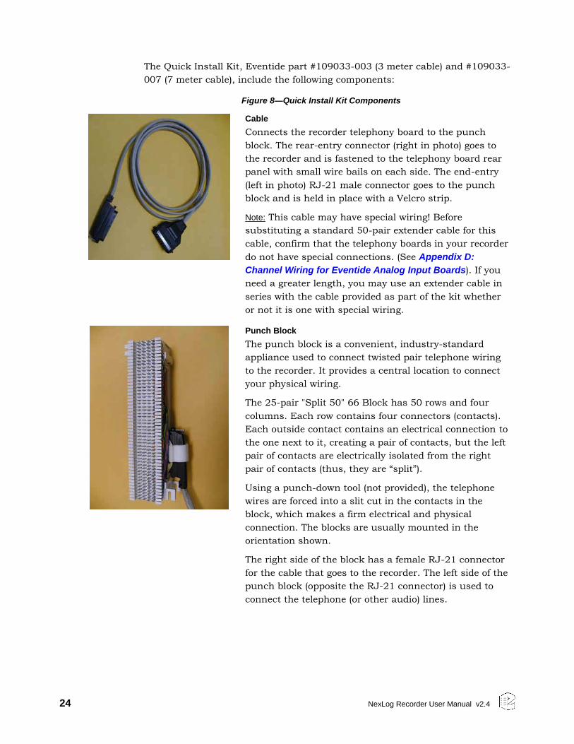
Figure 8—Quick Install Kit Components
Cable
Connects the recorder telephony board to the punch
block. The rear-entry connector (right in photo) goes to
the recorder and is fastened to the telephony board rear
panel with small wire bails on each side. The end-entry
(left in photo) RJ-21 male connector goes to the punch
block and is held in place with a Velcro strip.
Note: This cable may have special wiring! Before
substituting a standard 50-pair extender cable for this
cable, confirm that the telephony boards in your recorder
do not have special connections. (See Appendix D:
Channel Wiring for Eventide Analog Input Boards). If you
need a greater length, you may use an extender cable in
series with the cable provided as part of the kit whether
or not it is one with special wiring.
Punch Block
The punch block is a convenient, industry-standard
appliance used to connect twisted pair telephone wiring
to the recorder. It provides a central location to connect
your physical wiring.
The 25-pair "Split 50" 66 Block has 50 rows and four
columns. Each row contains four connectors (contacts).
Each outside contact contains an electrical connection to
the one next to it, creating a pair of contacts, but the left
pair of contacts are electrically isolated from the right
pair of contacts (thus, they are “split”).
Using a punch-down tool (not provided), the telephone
wires are forced into a slit cut in the contacts in the
block, which makes a firm electrical and physical
connection. The blocks are usually mounted in the
orientation shown.
The right side of the block has a female RJ-21 connector
for the cable that goes to the recorder. The left side of the
punch block (opposite the RJ-21 connector) is used to
connect the telephone (or other audio) lines.
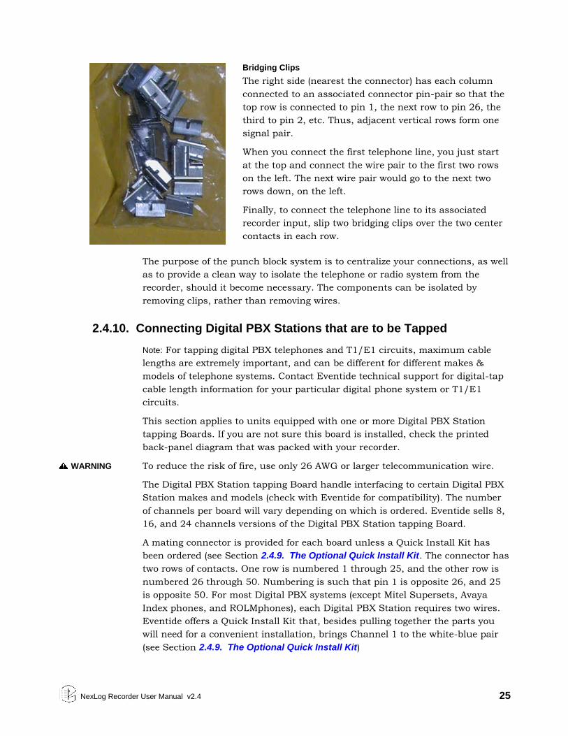
NexLog Recorder User Manual v2.4 25
Bridging Clips
The right side (nearest the connector) has each column
connected to an associated connector pin-pair so that the
top row is connected to pin 1, the next row to pin 26, the
third to pin 2, etc. Thus, adjacent vertical rows form one
signal pair.
When you connect the first telephone line, you just start
at the top and connect the wire pair to the first two rows
on the left. The next wire pair would go to the next two
rows down, on the left.
Finally, to connect the telephone line to its associated
recorder input, slip two bridging clips over the two center
contacts in each row.
The purpose of the punch block system is to centralize your connections, as well
as to provide a clean way to isolate the telephone or radio system from the
recorder, should it become necessary. The components can be isolated by
removing clips, rather than removing wires.
2.4.10. Connecting Digital PBX Stations that are to be Tapped
Note: For tapping digital PBX telephones and T1/E1 circuits, maximum cable
lengths are extremely important, and can be different for different makes &
models of telephone systems. Contact Eventide technical support for digital-tap
cable length information for your particular digital phone system or T1/E1
circuits.
This section applies to units equipped with one or more Digital PBX Station
tapping Boards. If you are not sure this board is installed, check the printed
back-panel diagram that was packed with your recorder.
WARNING To reduce the risk of fire, use only 26 AWG or larger telecommunication wire.
The Digital PBX Station tapping Board handle interfacing to certain Digital PBX
Station makes and models (check with Eventide for compatibility). The number
of channels per board will vary depending on which is ordered. Eventide sells 8,
16, and 24 channels versions of the Digital PBX Station tapping Board.
A mating connector is provided for each board unless a Quick Install Kit has
been ordered (see Section 2.4.9. The Optional Quick Install Kit. The connector has
two rows of contacts. One row is numbered 1 through 25, and the other row is
numbered 26 through 50. Numbering is such that pin 1 is opposite 26, and 25
is opposite 50. For most Digital PBX systems (except Mitel Supersets, Avaya
Index phones, and ROLMphones), each Digital PBX Station requires two wires.
Eventide offers a Quick Install Kit that, besides pulling together the parts you
will need for a convenient installation, brings Channel 1 to the white-blue pair
(see Section 2.4.9. The Optional Quick Install Kit)
26 NexLog Recorder User Manual v2.4
To connect a supported digital PBX telephone line to a given channel, simply
connect the two wires to the two pins for that channel.
2.4.11. Connecting to an Ethernet Network
Connect to an Ethernet network by attaching a network cable between the RJ45
jack on the back of the recorder and your hub, switch or router. The cable
should be CAT5 or equivalent with a male RJ45 plug for the recorder end and
with the connector pin wiring going straight through from end to end.
Alternatively, a crossover cable can be used to isolate the recorder from the
network and connect directly to a PC’s network connection without using a
router or switch. The NexLog 840 and NexLog 740 have two RJ45 jacks and can
be connected to multiple networks simultaneously. On the NexLog 840, the top
most jack is Device 1 in the NETWORK INTERFACE section. The bottom jack is
Device 2. On the NexLog 740, the jack closest to the input boards is Device 1,
and the jack furthest from the input boards is Device 2.
2.4.12. Connecting a Keyboard
A keyboard can be connected to a recorder to allow easier and faster data entry
and interaction than is permitted by the recorder’s optional front panel
interface. This can be useful for performing system administration tasks from
the front panel and for diagnostic work.
Note: The same configuration capabilities that are available on the Front Panel can be
accessed via a web browser from a PC, using the browser-based NexLog
Configuration Manager. Under most circumstances this will allow for a quicker
setup procedure.
The following methods are available for connecting a keyboard to the recorder:
Connect a USB keyboard to any USB connector on the recorder. This may be
done while the recorder is running and does not require a shutdown and
restart of the recorder.
Connect a PS2 keyboard to the PS2 connector on the recorder back panel
(purple on the NexLog 740 only). This should be done while the recorder is
off, so if the recorder is running, it requires a shutdown of the recorder
before it is installed.
2.4.13. Connecting Headphones
Optionally, connect headphones to the 1/8-inch jack labeled “Headphone” on
the front panel. Suitable headphones are available from Eventide (part#
324200). Most headphones with an appropriate plug can be used and adjusted
to a comfortable level with the front panel volume control.

NexLog Recorder User Manual v2.4 27
2.4.14. Connecting Line-Level Equipment
A line-level audio output is available at the 1/8-inch jack labeled “Line Out” on
the front panel, if you wish to connect an external recorder such as a Philips
Cassette recorder to the recorder for excerpting calls to cassette. Most standard
cassette units with record capability can derive an appropriate signal level from
this jack.
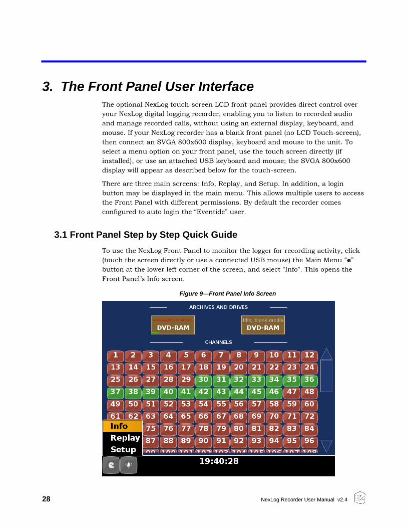
28 NexLog Recorder User Manual v2.4
3. The Front Panel User Interface
The optional NexLog touch-screen LCD front panel provides direct control over
your NexLog digital logging recorder, enabling you to listen to recorded audio
and manage recorded calls, without using an external display, keyboard, and
mouse. If your NexLog recorder has a blank front panel (no LCD Touch-screen),
then connect an SVGA 800x600 display, keyboard and mouse to the unit. To
select a menu option on your front panel, use the touch screen directly (if
installed), or use an attached USB keyboard and mouse; the SVGA 800x600
display will appear as described below for the touch-screen.
There are three main screens: Info, Replay, and Setup. In addition, a login
button may be displayed in the main menu. This allows multiple users to access
the Front Panel with different permissions. By default the recorder comes
configured to auto login the “Eventide” user.
3.1 Front Panel Step by Step Quick Guide
To use the NexLog Front Panel to monitor the logger for recording activity, click
(touch the screen directly or use a connected USB mouse) the Main Menu “e”
button at the lower left corner of the screen, and select "Info". This opens the
Front Panel’s Info screen.
Figure 9—Front Panel Info Screen
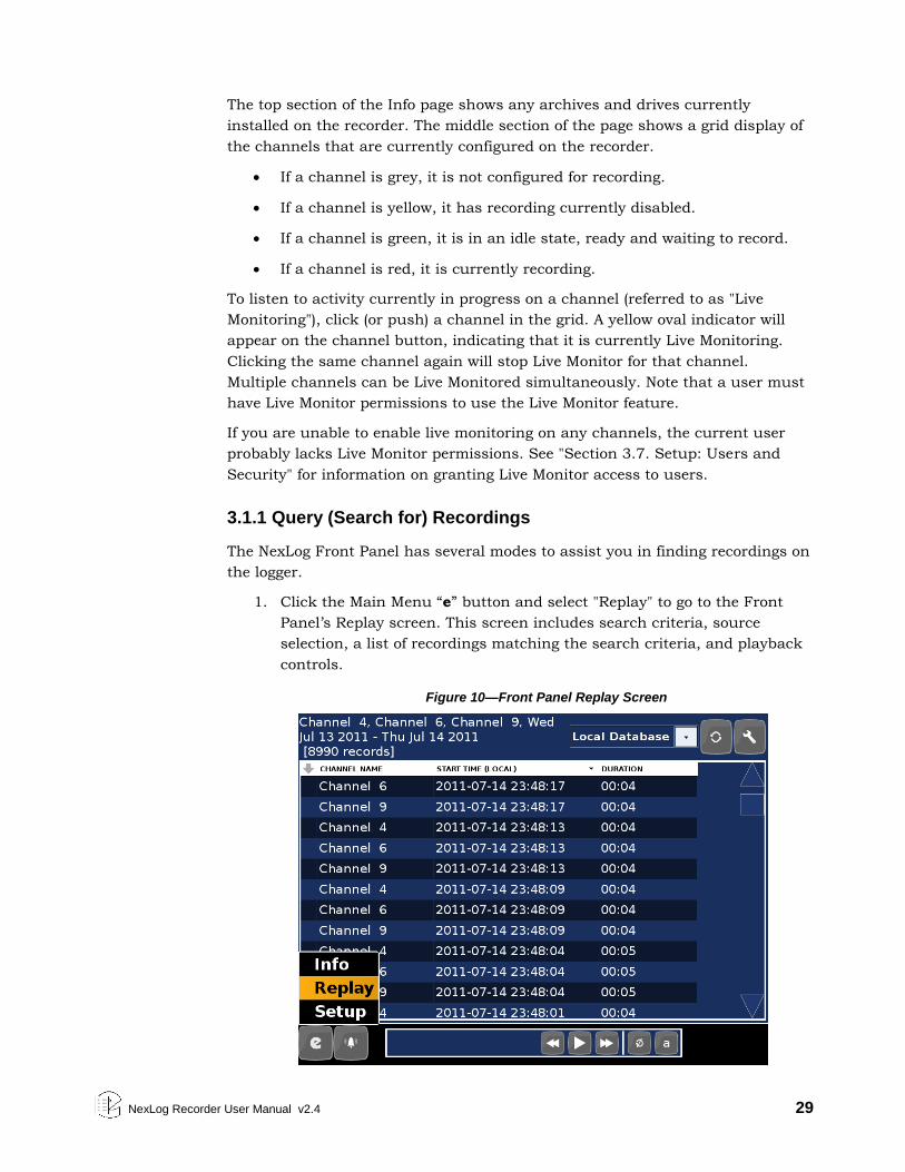
NexLog Recorder User Manual v2.4 29
The top section of the Info page shows any archives and drives currently
installed on the recorder. The middle section of the page shows a grid display of
the channels that are currently configured on the recorder.
If a channel is grey, it is not configured for recording.
If a channel is yellow, it has recording currently disabled.
If a channel is green, it is in an idle state, ready and waiting to record.
If a channel is red, it is currently recording.
To listen to activity currently in progress on a channel (referred to as "Live
Monitoring"), click (or push) a channel in the grid. A yellow oval indicator will
appear on the channel button, indicating that it is currently Live Monitoring.
Clicking the same channel again will stop Live Monitor for that channel.
Multiple channels can be Live Monitored simultaneously. Note that a user must
have Live Monitor permissions to use the Live Monitor feature.
If you are unable to enable live monitoring on any channels, the current user
probably lacks Live Monitor permissions. See "Section 3.7. Setup: Users and
Security" for information on granting Live Monitor access to users.
3.1.1 Query (Search for) Recordings
The NexLog Front Panel has several modes to assist you in finding recordings on
the logger.
1. Click the Main Menu “e” button and select "Replay" to go to the Front
Panel’s Replay screen. This screen includes search criteria, source
selection, a list of recordings matching the search criteria, and playback
controls.
Figure 10—Front Panel Replay Screen
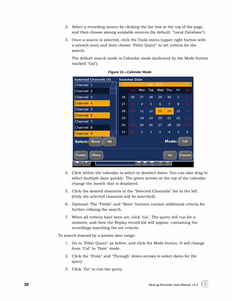
30 NexLog Recorder User Manual v2.4
2. Select a recording source by clicking the list-box at the top of the page,
and then choose among available sources (by default, "Local Database").
3. Once a source is selected, click the Tools menu (upper right button with
a wrench icon) and then choose "Filter Query" to set criteria for the
search.
The default search mode is Calendar mode (indicated by the Mode button
marked "Cal").
Figure 11—Calendar Mode
4. Click within the calendar to select or deselect dates. You can also drag to
select multiple days quickly. The green arrows at the top of the calendar
change the month that is displayed.
5. Click the desired channels in the "Selected Channels" list to the left.
(Only the selected channels will be searched).
6. Optional: The "Fields" and "More" buttons contain additional criteria for
further refining the search.
7. When all criteria have been set, click "Go". The query will run for a
moment, and then the Replay record list will appear, containing the
recordings matching the set criteria.
To search instead by a known date range:
1. Go to "Filter Query" as before, and click the Mode button. It will change
from "Cal" to "Date" mode.
2. Click the "From" and "Through" down-arrows to select dates for the
query.
3. Click "Go" to run the query.
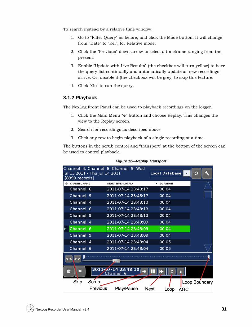
NexLog Recorder User Manual v2.4 31
To search instead by a relative time window:
1. Go to "Filter Query" as before, and click the Mode button. It will change
from "Date" to "Rel", for Relative mode.
2. Click the "Previous" down-arrow to select a timeframe ranging from the
present.
3. Enable "Update with Live Results" (the checkbox will turn yellow) to have
the query list continually and automatically update as new recordings
arrive. Or, disable it (the checkbox will be grey) to skip this feature.
4. Click "Go" to run the query.
3.1.2 Playback
The NexLog Front Panel can be used to playback recordings on the logger.
1. Click the Main Menu “e” button and choose Replay. This changes the
view to the Replay screen.
2. Search for recordings as described above
3. Click any row to begin playback of a single recording at a time.
The buttons in the scrub control and “transport” at the bottom of the screen can
be used to control playback.
Figure 12—Replay Transport
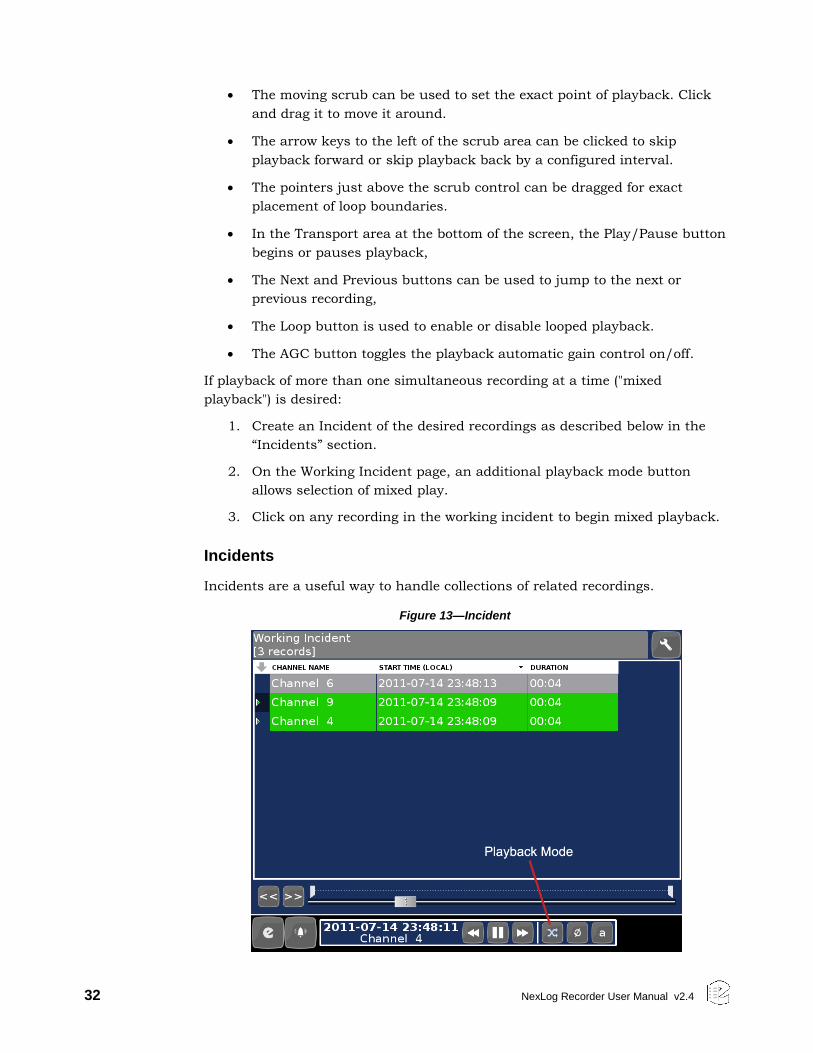
32 NexLog Recorder User Manual v2.4
The moving scrub can be used to set the exact point of playback. Click
and drag it to move it around.
The arrow keys to the left of the scrub area can be clicked to skip
playback forward or skip playback back by a configured interval.
The pointers just above the scrub control can be dragged for exact
placement of loop boundaries.
In the Transport area at the bottom of the screen, the Play/Pause button
begins or pauses playback,
The Next and Previous buttons can be used to jump to the next or
previous recording,
The Loop button is used to enable or disable looped playback.
The AGC button toggles the playback automatic gain control on/off.
If playback of more than one simultaneous recording at a time ("mixed
playback") is desired:
1. Create an Incident of the desired recordings as described below in the
“Incidents” section.
2. On the Working Incident page, an additional playback mode button
allows selection of mixed play.
3. Click on any recording in the working incident to begin mixed playback.
Incidents
Incidents are a useful way to handle collections of related recordings.
Figure 13—Incident
NexLog Recorder User Manual v2.4 33
Creating an Incident
To use the NexLog Front Panel to build an Incident:
1. Query recordings as described in “Query (Search for) Recording”, above.
2. Click the leftmost column (this column is indicated by an arrow pointing
down) beside any recordings you wish to mark for the Incident. A check-
mark will appear next to each selected recording.
Note: recordings that are currently in progress (as shown by red text)
cannot be added to Incidents.
Figure 14—Selected Calls in Replay Screen
3. Click the Tools button (upper right button with the wrench icon) and
choose "Add marked to Incident"
The Front Panel will automatically switch to the Working Incident view, and the
marked recordings will be added to the incident.
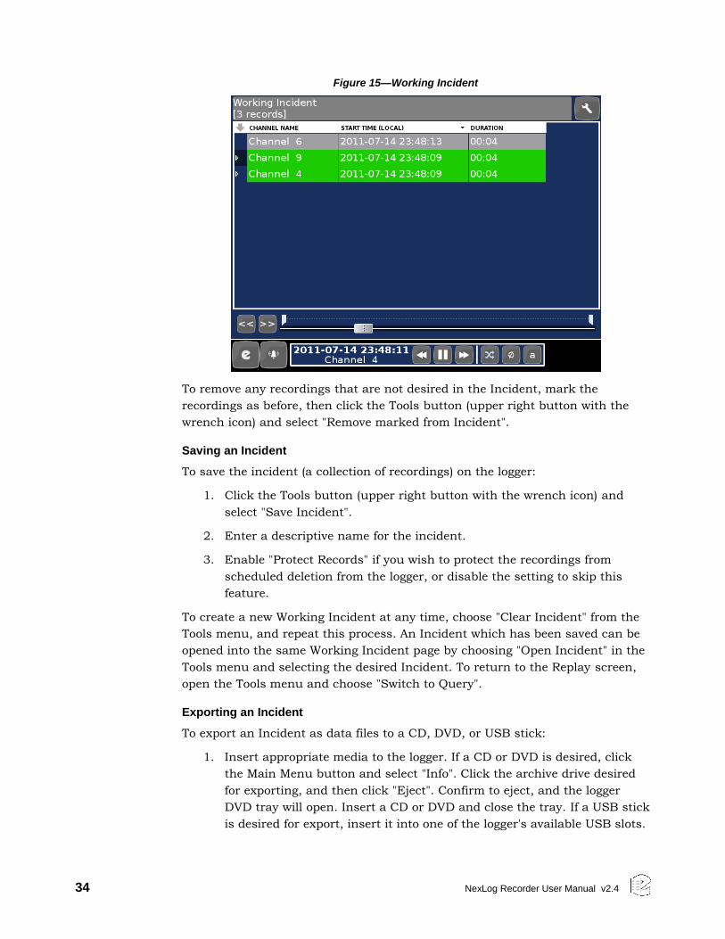
34 NexLog Recorder User Manual v2.4
Figure 15—Working Incident
To remove any recordings that are not desired in the Incident, mark the
recordings as before, then click the Tools button (upper right button with the
wrench icon) and select "Remove marked from Incident".
Saving an Incident
To save the incident (a collection of recordings) on the logger:
1. Click the Tools button (upper right button with the wrench icon) and
select "Save Incident".
2. Enter a descriptive name for the incident.
3. Enable "Protect Records" if you wish to protect the recordings from
scheduled deletion from the logger, or disable the setting to skip this
feature.
To create a new Working Incident at any time, choose "Clear Incident" from the
Tools menu, and repeat this process. An Incident which has been saved can be
opened into the same Working Incident page by choosing "Open Incident" in the
Tools menu and selecting the desired Incident. To return to the Replay screen,
open the Tools menu and choose "Switch to Query".
Exporting an Incident
To export an Incident as data files to a CD, DVD, or USB stick:
1. Insert appropriate media to the logger. If a CD or DVD is desired, click
the Main Menu button and select "Info". Click the archive drive desired
for exporting, and then click "Eject". Confirm to eject, and the logger
DVD tray will open. Insert a CD or DVD and close the tray. If a USB stick
is desired for export, insert it into one of the logger's available USB slots.
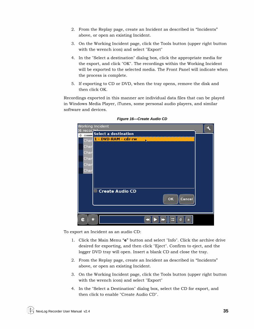
NexLog Recorder User Manual v2.4 35
2. From the Replay page, create an Incident as described in “Incidents”
above, or open an existing Incident.
3. On the Working Incident page, click the Tools button (upper right button
with the wrench icon) and select "Export"
4. In the "Select a destination" dialog box, click the appropriate media for
the export, and click "OK". The recordings within the Working Incident
will be exported to the selected media. The Front Panel will indicate when
the process is complete.
5. If exporting to CD or DVD, when the tray opens, remove the disk and
then click OK.
Recordings exported in this manner are individual data files that can be played
in Windows Media Player, iTunes, some personal audio players, and similar
software and devices.
Figure 16—Create Audio CD
To export an Incident as an audio CD:
1. Click the Main Menu “e” button and select "Info". Click the archive drive
desired for exporting, and then click "Eject". Confirm to eject, and the
logger DVD tray will open. Insert a blank CD and close the tray.
2. From the Replay page, create an Incident as described in “Incidents”
above, or open an existing Incident.
3. On the Working Incident page, click the Tools button (upper right button
with the wrench icon) and select "Export"
4. In the "Select a Destination" dialog box, select the CD for export, and
then click to enable "Create Audio CD".
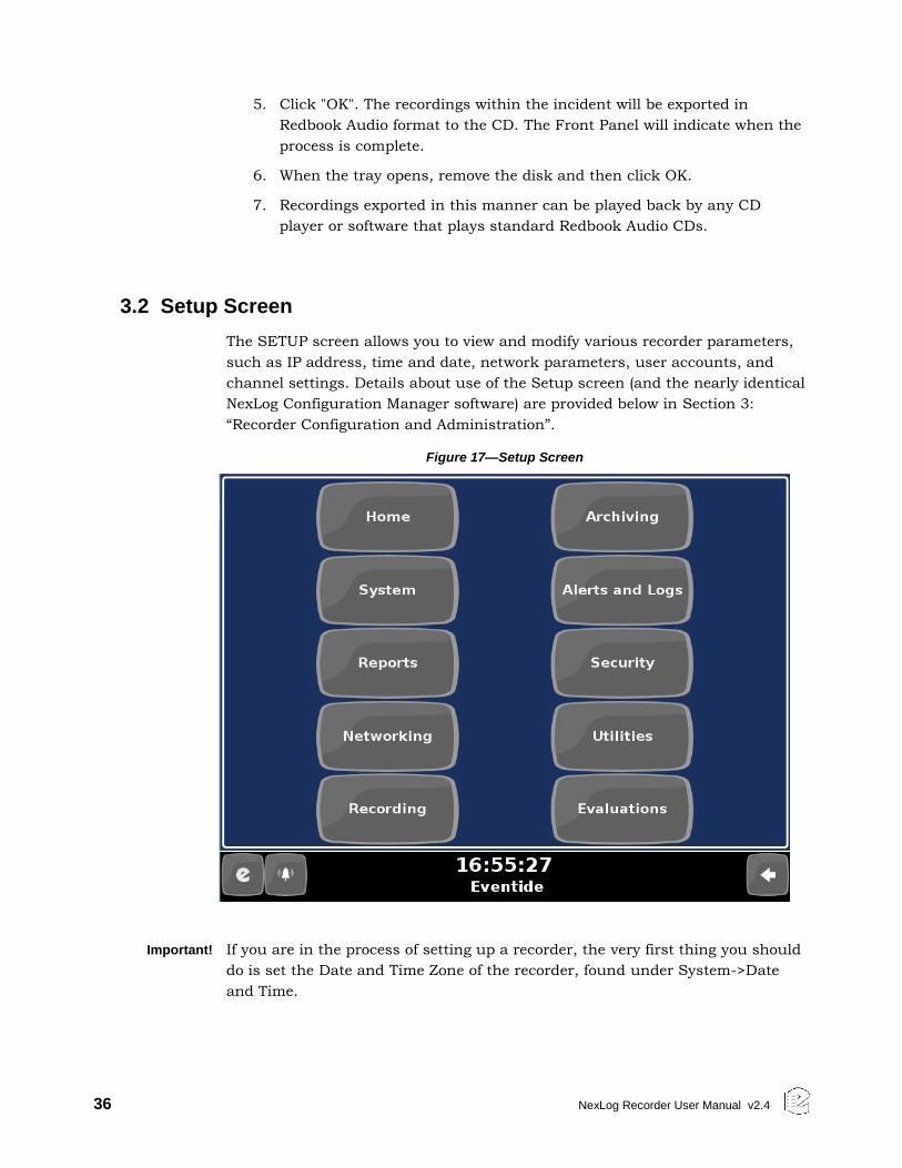
36 NexLog Recorder User Manual v2.4
5. Click "OK". The recordings within the incident will be exported in
Redbook Audio format to the CD. The Front Panel will indicate when the
process is complete.
6. When the tray opens, remove the disk and then click OK.
7. Recordings exported in this manner can be played back by any CD
player or software that plays standard Redbook Audio CDs.
3.2 Setup Screen
The SETUP screen allows you to view and modify various recorder parameters,
such as IP address, time and date, network parameters, user accounts, and
channel settings. Details about use of the Setup screen (and the nearly identical
NexLog Configuration Manager software) are provided below in Section 3:
“Recorder Configuration and Administration”.
Figure 17—Setup Screen
Important! If you are in the process of setting up a recorder, the very first thing you should
do is set the Date and Time Zone of the recorder, found under System->Date
and Time.
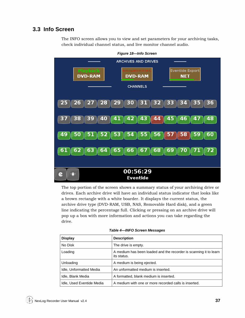
NexLog Recorder User Manual v2.4 37
3.3 Info Screen
The INFO screen allows you to view and set parameters for your archiving tasks,
check individual channel status, and live monitor channel audio.
Figure 18—Info Screen
The top portion of the screen shows a summary status of your archiving drive or
drives. Each archive drive will have an individual status indicator that looks like
a brown rectangle with a white boarder. It displays the current status, the
archive drive type (DVD-RAM, USB, NAS, Removable Hard disk), and a green
line indicating the percentage full. Clicking or pressing on an archive drive will
pop up a box with more information and actions you can take regarding the
drive.
Table 4—INFO Screen Messages
Display Description
No Disk The drive is empty.
Loading A medium has been loaded and the recorder is scanning it to learn its status.
Unloading A medium is being ejected.
Idle, Unformatted Media An unformatted medium is inserted.
Idle, Blank Media A formatted, blank medium is inserted.
Idle, Used Eventide Media A medium with one or more recorded calls is inserted.
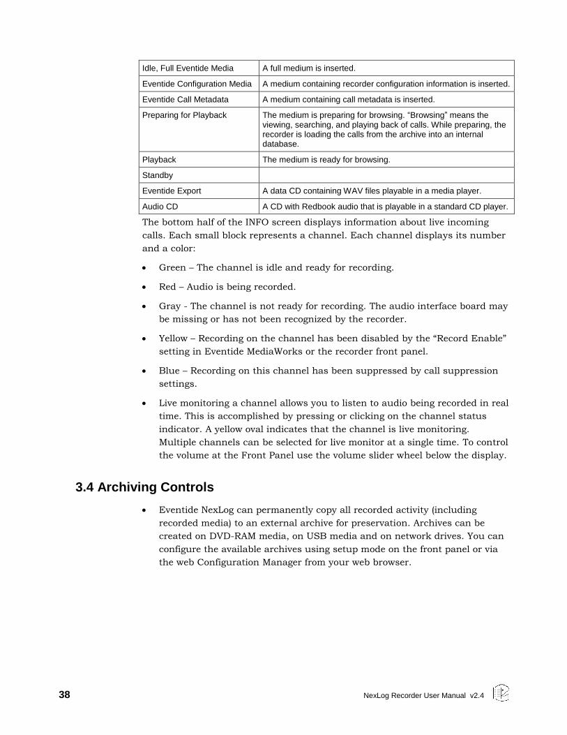
38 NexLog Recorder User Manual v2.4
Idle, Full Eventide Media A full medium is inserted.
Eventide Configuration Media A medium containing recorder configuration information is inserted.
Eventide Call Metadata A medium containing call metadata is inserted.
Preparing for Playback The medium is preparing for browsing. “Browsing” means the viewing, searching, and playing back of calls. While preparing, the recorder is loading the calls from the archive into an internal database.
Playback The medium is ready for browsing.
Standby
Eventide Export A data CD containing WAV files playable in a media player.
Audio CD A CD with Redbook audio that is playable in a standard CD player.
The bottom half of the INFO screen displays information about live incoming
calls. Each small block represents a channel. Each channel displays its number
and a color:
Green – The channel is idle and ready for recording.
Red – Audio is being recorded.
Gray - The channel is not ready for recording. The audio interface board may
be missing or has not been recognized by the recorder.
Yellow – Recording on the channel has been disabled by the “Record Enable”
setting in Eventide MediaWorks or the recorder front panel.
Blue – Recording on this channel has been suppressed by call suppression
settings.
Live monitoring a channel allows you to listen to audio being recorded in real
time. This is accomplished by pressing or clicking on the channel status
indicator. A yellow oval indicates that the channel is live monitoring.
Multiple channels can be selected for live monitor at a single time. To control
the volume at the Front Panel use the volume slider wheel below the display.
3.4 Archiving Controls
Eventide NexLog can permanently copy all recorded activity (including
recorded media) to an external archive for preservation. Archives can be
created on DVD-RAM media, on USB media and on network drives. You can
configure the available archives using setup mode on the front panel or via
the web Configuration Manager from your web browser.
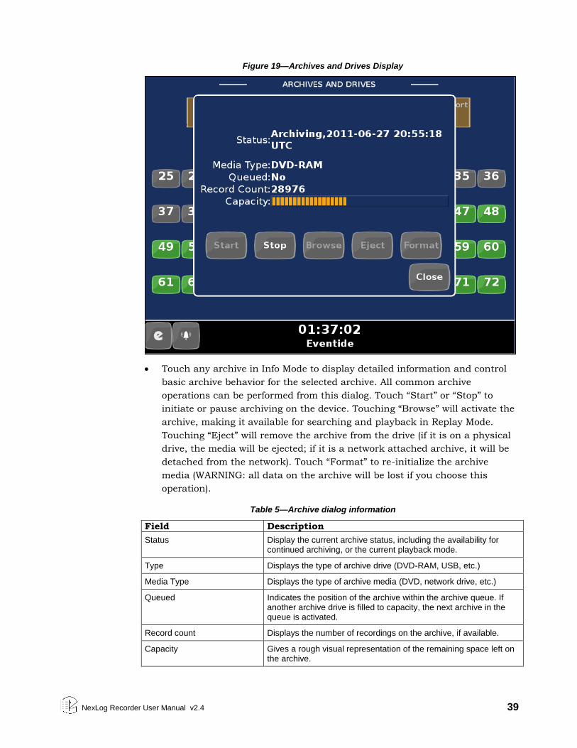
NexLog Recorder User Manual v2.4 39
Figure 19—Archives and Drives Display
Touch any archive in Info Mode to display detailed information and control
basic archive behavior for the selected archive. All common archive
operations can be performed from this dialog. Touch “Start” or “Stop” to
initiate or pause archiving on the device. Touching “Browse” will activate the
archive, making it available for searching and playback in Replay Mode.
Touching “Eject” will remove the archive from the drive (if it is on a physical
drive, the media will be ejected; if it is a network attached archive, it will be
detached from the network). Touch “Format” to re-initialize the archive
media (WARNING: all data on the archive will be lost if you choose this
operation).
Table 5—Archive dialog information
Field Description
Status Display the current archive status, including the availability for continued archiving, or the current playback mode.
Type Displays the type of archive drive (DVD-RAM, USB, etc.)
Media Type Displays the type of archive media (DVD, network drive, etc.)
Queued Indicates the position of the archive within the archive queue. If another archive drive is filled to capacity, the next archive in the queue is activated.
Record count Displays the number of recordings on the archive, if available.
Capacity Gives a rough visual representation of the remaining space left on the archive.
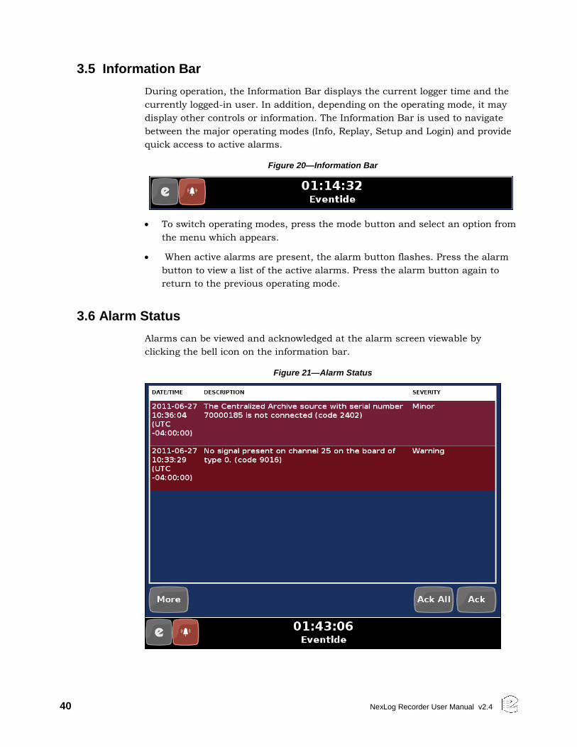
40 NexLog Recorder User Manual v2.4
3.5 Information Bar
During operation, the Information Bar displays the current logger time and the
currently logged-in user. In addition, depending on the operating mode, it may
display other controls or information. The Information Bar is used to navigate
between the major operating modes (Info, Replay, Setup and Login) and provide
quick access to active alarms.
Figure 20—Information Bar
To switch operating modes, press the mode button and select an option from
the menu which appears.
When active alarms are present, the alarm button flashes. Press the alarm
button to view a list of the active alarms. Press the alarm button again to
return to the previous operating mode.
3.6 Alarm Status
Alarms can be viewed and acknowledged at the alarm screen viewable by
clicking the bell icon on the information bar.
Figure 21—Alarm Status
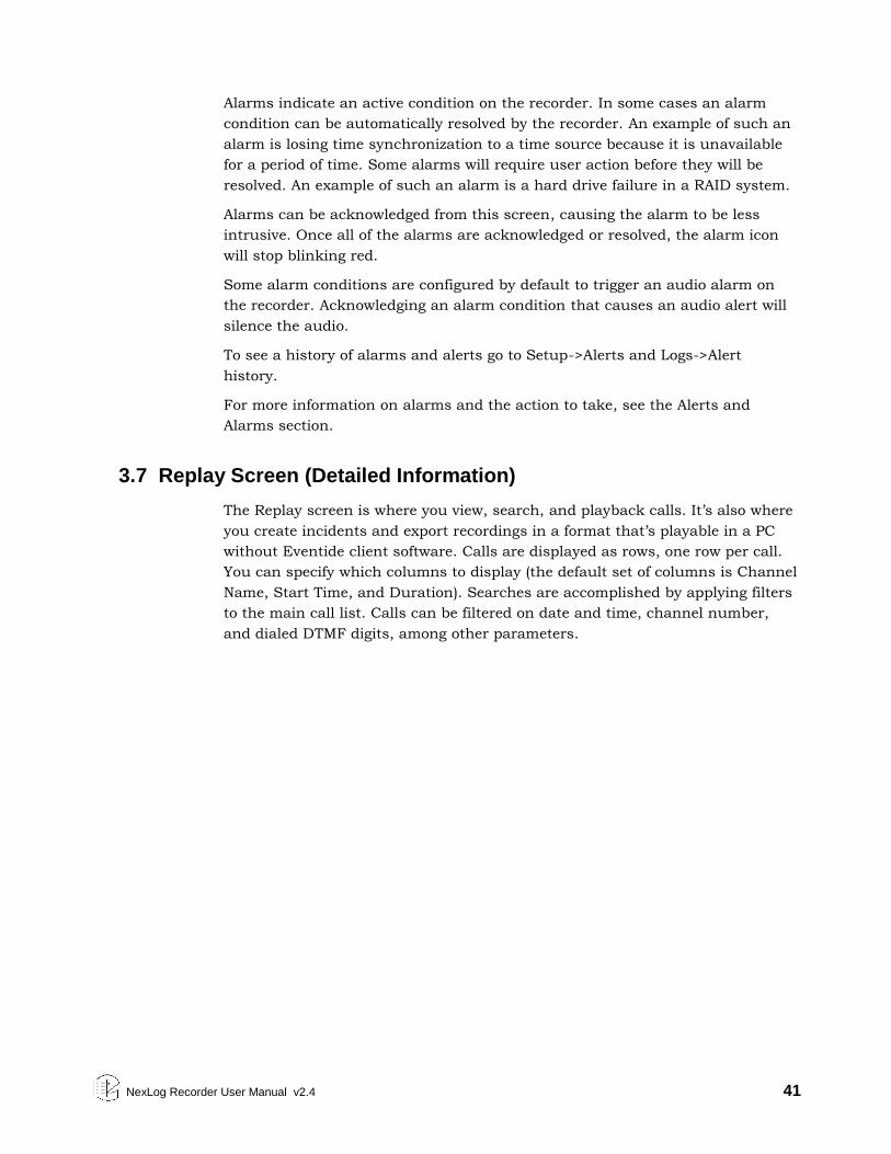
NexLog Recorder User Manual v2.4 41
Alarms indicate an active condition on the recorder. In some cases an alarm
condition can be automatically resolved by the recorder. An example of such an
alarm is losing time synchronization to a time source because it is unavailable
for a period of time. Some alarms will require user action before they will be
resolved. An example of such an alarm is a hard drive failure in a RAID system.
Alarms can be acknowledged from this screen, causing the alarm to be less
intrusive. Once all of the alarms are acknowledged or resolved, the alarm icon
will stop blinking red.
Some alarm conditions are configured by default to trigger an audio alarm on
the recorder. Acknowledging an alarm condition that causes an audio alert will
silence the audio.
To see a history of alarms and alerts go to Setup->Alerts and Logs->Alert
history.
For more information on alarms and the action to take, see the Alerts and
Alarms section.
3.7 Replay Screen (Detailed Information)
The Replay screen is where you view, search, and playback calls. It’s also where
you create incidents and export recordings in a format that’s playable in a PC
without Eventide client software. Calls are displayed as rows, one row per call.
You can specify which columns to display (the default set of columns is Channel
Name, Start Time, and Duration). Searches are accomplished by applying filters
to the main call list. Calls can be filtered on date and time, channel number,
and dialed DTMF digits, among other parameters.
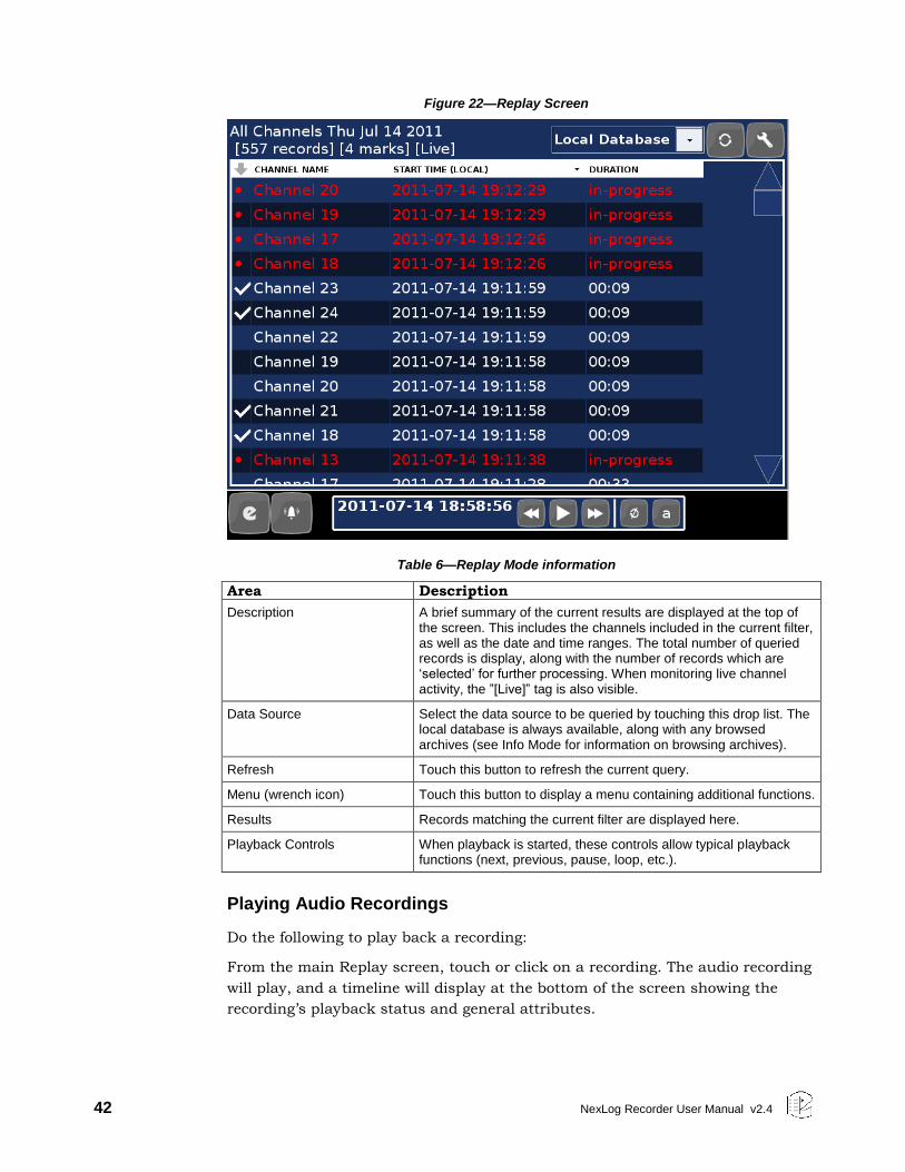
42 NexLog Recorder User Manual v2.4
Figure 22—Replay Screen
Table 6—Replay Mode information
Area Description
Description A brief summary of the current results are displayed at the top of the screen. This includes the channels included in the current filter, as well as the date and time ranges. The total number of queried records is display, along with the number of records which are ‘selected’ for further processing. When monitoring live channel activity, the ”[Live]” tag is also visible.
Data Source Select the data source to be queried by touching this drop list. The local database is always available, along with any browsed archives (see Info Mode for information on browsing archives).
Refresh Touch this button to refresh the current query.
Menu (wrench icon) Touch this button to display a menu containing additional functions.
Results Records matching the current filter are displayed here.
Playback Controls When playback is started, these controls allow typical playback functions (next, previous, pause, loop, etc.).
Playing Audio Recordings
Do the following to play back a recording:
From the main Replay screen, touch or click on a recording. The audio recording
will play, and a timeline will display at the bottom of the screen showing the
recording’s playback status and general attributes.
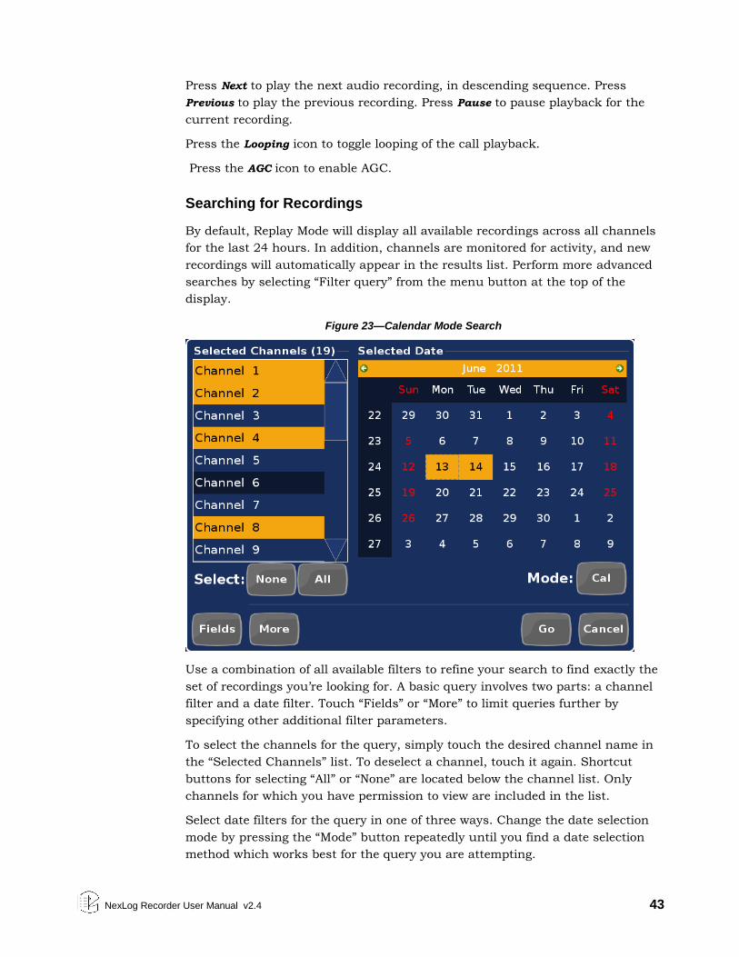
NexLog Recorder User Manual v2.4 43
Press Next to play the next audio recording, in descending sequence. Press
Previous to play the previous recording. Press Pause to pause playback for the
current recording.
Press the Looping icon to toggle looping of the call playback.
Press the AGC icon to enable AGC.
Searching for Recordings
By default, Replay Mode will display all available recordings across all channels
for the last 24 hours. In addition, channels are monitored for activity, and new
recordings will automatically appear in the results list. Perform more advanced
searches by selecting “Filter query” from the menu button at the top of the
display.
Figure 23—Calendar Mode Search
Use a combination of all available filters to refine your search to find exactly the
set of recordings you’re looking for. A basic query involves two parts: a channel
filter and a date filter. Touch “Fields” or “More” to limit queries further by
specifying other additional filter parameters.
To select the channels for the query, simply touch the desired channel name in
the “Selected Channels” list. To deselect a channel, touch it again. Shortcut
buttons for selecting “All” or “None” are located below the channel list. Only
channels for which you have permission to view are included in the list.
Select date filters for the query in one of three ways. Change the date selection
mode by pressing the “Mode” button repeatedly until you find a date selection
method which works best for the query you are attempting.
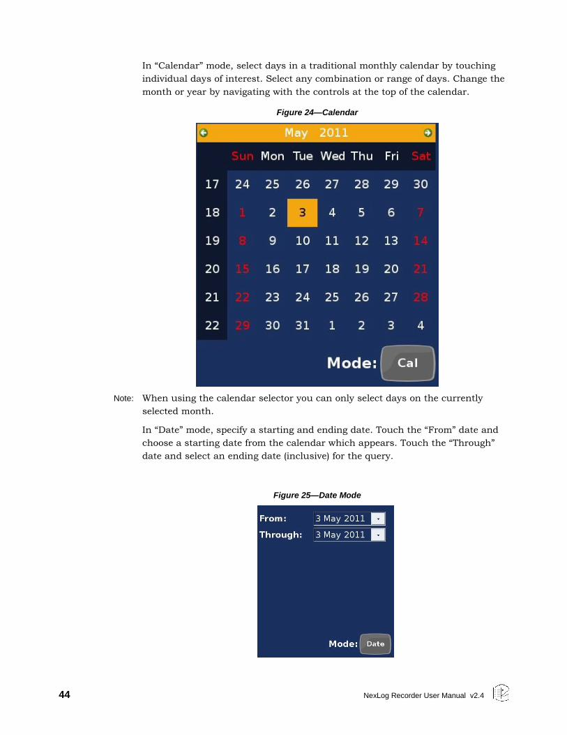
44 NexLog Recorder User Manual v2.4
In “Calendar” mode, select days in a traditional monthly calendar by touching
individual days of interest. Select any combination or range of days. Change the
month or year by navigating with the controls at the top of the calendar.
Figure 24—Calendar
Note: When using the calendar selector you can only select days on the currently
selected month.
In “Date” mode, specify a starting and ending date. Touch the “From” date and
choose a starting date from the calendar which appears. Touch the “Through”
date and select an ending date (inclusive) for the query.
Figure 25—Date Mode
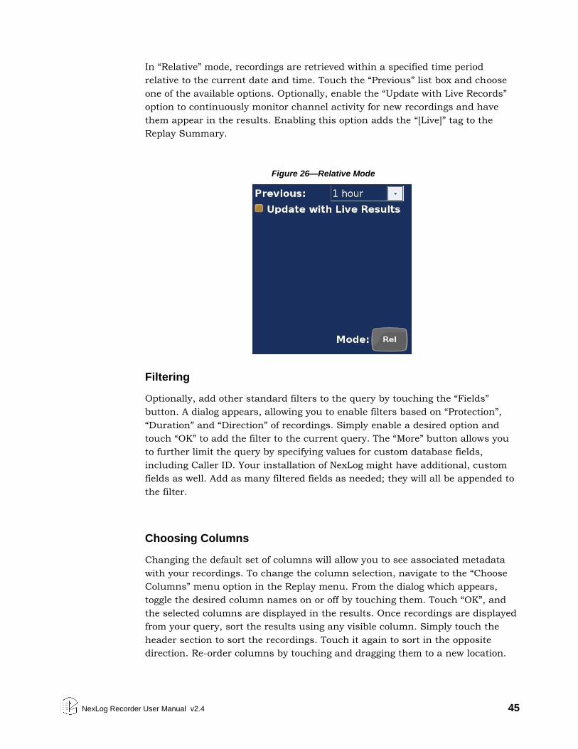
NexLog Recorder User Manual v2.4 45
In “Relative” mode, recordings are retrieved within a specified time period
relative to the current date and time. Touch the “Previous” list box and choose
one of the available options. Optionally, enable the “Update with Live Records”
option to continuously monitor channel activity for new recordings and have
them appear in the results. Enabling this option adds the “[Live]” tag to the
Replay Summary.
Figure 26—Relative Mode
Filtering
Optionally, add other standard filters to the query by touching the “Fields”
button. A dialog appears, allowing you to enable filters based on “Protection”,
“Duration” and “Direction” of recordings. Simply enable a desired option and
touch “OK” to add the filter to the current query. The “More” button allows you
to further limit the query by specifying values for custom database fields,
including Caller ID. Your installation of NexLog might have additional, custom
fields as well. Add as many filtered fields as needed; they will all be appended to
the filter.
Choosing Columns
Changing the default set of columns will allow you to see associated metadata
with your recordings. To change the column selection, navigate to the “Choose
Columns” menu option in the Replay menu. From the dialog which appears,
toggle the desired column names on or off by touching them. Touch “OK”, and
the selected columns are displayed in the results. Once recordings are displayed
from your query, sort the results using any visible column. Simply touch the
header section to sort the recordings. Touch it again to sort in the opposite
direction. Re-order columns by touching and dragging them to a new location.
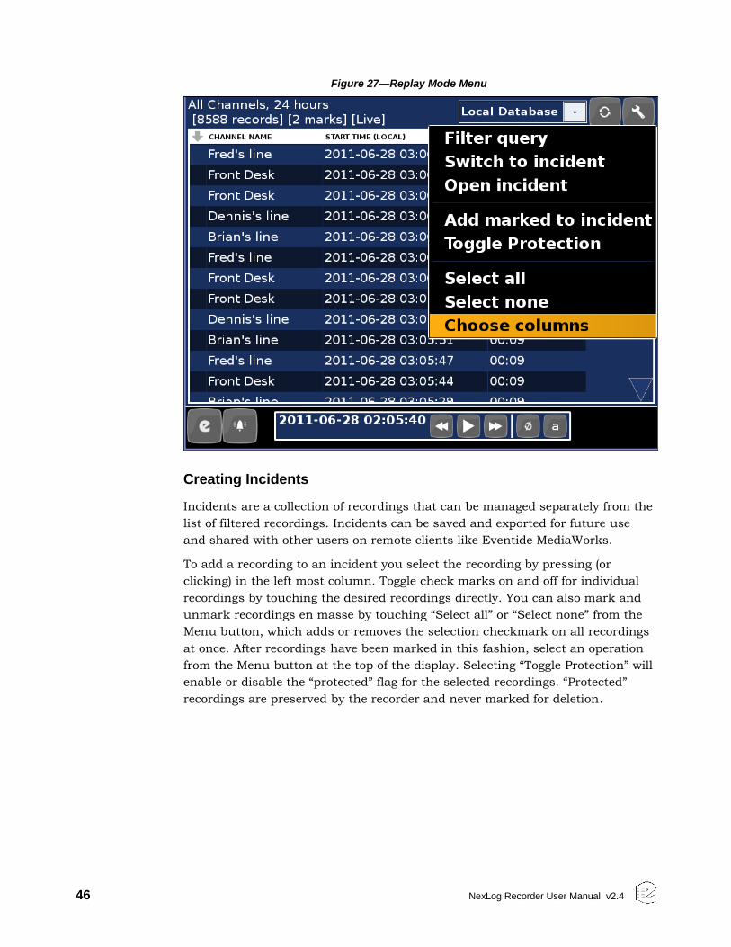
46 NexLog Recorder User Manual v2.4
Figure 27—Replay Mode Menu
Creating Incidents
Incidents are a collection of recordings that can be managed separately from the
list of filtered recordings. Incidents can be saved and exported for future use
and shared with other users on remote clients like Eventide MediaWorks.
To add a recording to an incident you select the recording by pressing (or
clicking) in the left most column. Toggle check marks on and off for individual
recordings by touching the desired recordings directly. You can also mark and
unmark recordings en masse by touching “Select all” or “Select none” from the
Menu button, which adds or removes the selection checkmark on all recordings
at once. After recordings have been marked in this fashion, select an operation
from the Menu button at the top of the display. Selecting “Toggle Protection” will
enable or disable the “protected” flag for the selected recordings. “Protected”
recordings are preserved by the recorder and never marked for deletion.
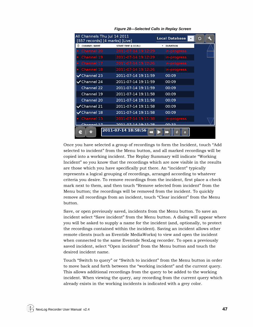
NexLog Recorder User Manual v2.4 47
Figure 28—Selected Calls in Replay Screen
Once you have selected a group of recordings to form the Incident, touch “Add
selected to incident” from the Menu button, and all marked recordings will be
copied into a working incident. The Replay Summary will indicate “Working
Incident” so you know that the recordings which are now visible in the results
are those which you have specifically put there. An “incident” typically
represents a logical grouping of recordings, arranged according to whatever
criteria you desire. To remove recordings from the incident, first place a check
mark next to them, and then touch “Remove selected from incident” from the
Menu button; the recordings will be removed from the incident. To quickly
remove all recordings from an incident, touch “Clear incident” from the Menu
button.
Save, or open previously saved, incidents from the Menu button. To save an
incident select “Save incident” from the Menu button. A dialog will appear where
you will be asked to supply a name for the incident (and, optionally, to protect
the recordings contained within the incident). Saving an incident allows other
remote clients (such as Eventide MediaWorks) to view and open the incident
when connected to the same Eventide NexLog recorder. To open a previously
saved incident, select “Open incident” from the Menu button and touch the
desired incident name.
Touch “Switch to query” or “Switch to incident” from the Menu button in order
to move back and forth between the “working incident” and the current query.
This allows additional recordings from the query to be added to the working
incident. When viewing the query, any recording from the current query which
already exists in the working incidents is indicated with a grey color.

48 NexLog Recorder User Manual v2.4
Export the audio from all recordings collected into an incident by touching
“Export” from the Menu button. Before exporting audio, ensure that an
appropriate export destination is available (for example, insert a blank
recordable CD, or insert a blank, formatted USB thumb drive, into the recorder).
When exporting, all available export destinations will be listed in the dialog
which appears. Select the export destination. For recordable CDs, you will have
the additional option of creating an audio CD, which can be played back in any
CD player. Otherwise, audio data will be copied or burned to the destination
location directly.
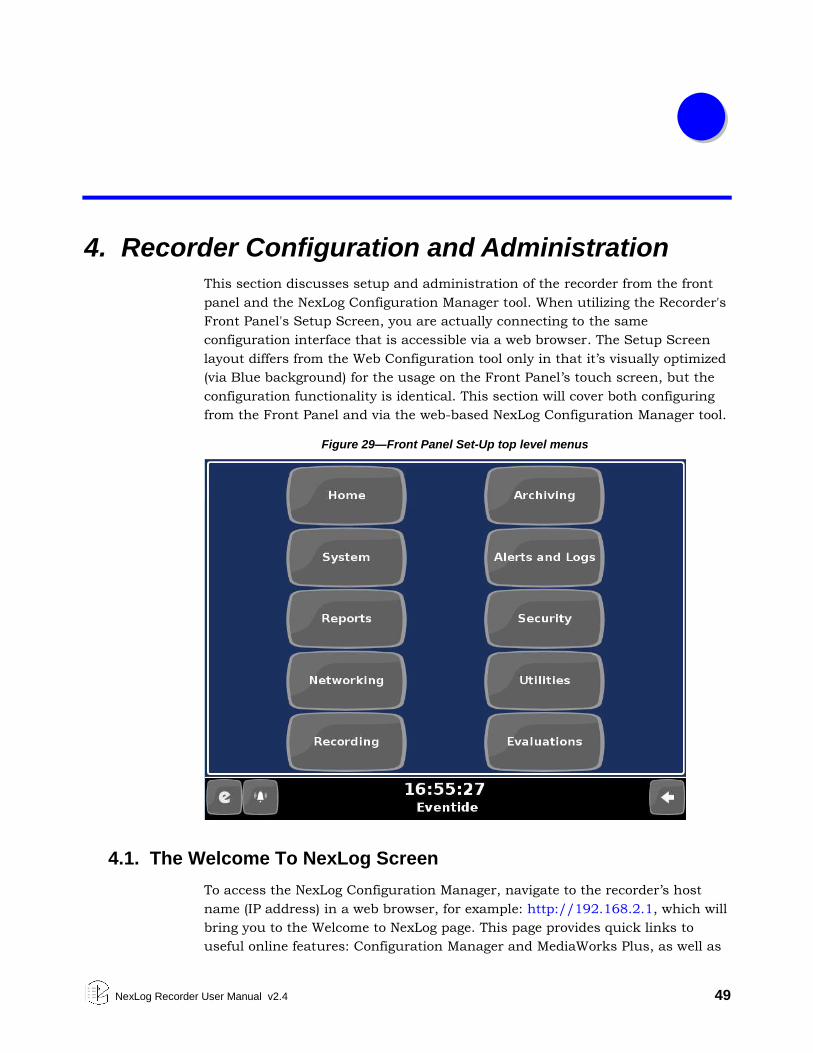
NexLog Recorder User Manual v2.4 49
4. Recorder Configuration and Administration
This section discusses setup and administration of the recorder from the front
panel and the NexLog Configuration Manager tool. When utilizing the Recorder's
Front Panel's Setup Screen, you are actually connecting to the same
configuration interface that is accessible via a web browser. The Setup Screen
layout differs from the Web Configuration tool only in that it’s visually optimized
(via Blue background) for the usage on the Front Panel’s touch screen, but the
configuration functionality is identical. This section will cover both configuring
from the Front Panel and via the web-based NexLog Configuration Manager tool.
Figure 29—Front Panel Set-Up top level menus
4.1. The Welcome To NexLog Screen
To access the NexLog Configuration Manager, navigate to the recorder’s host
name (IP address) in a web browser, for example: http://192.168.2.1, which will
bring you to the Welcome to NexLog page. This page provides quick links to
useful online features: Configuration Manager and MediaWorks Plus, as well as
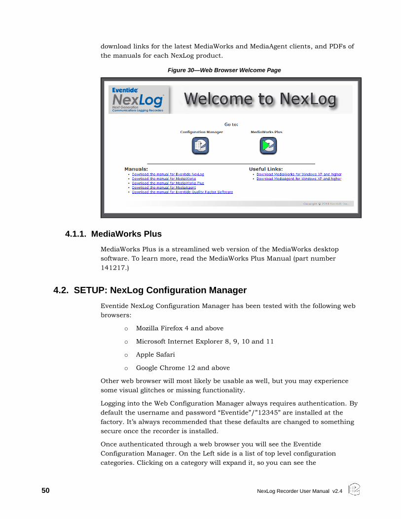
50 NexLog Recorder User Manual v2.4
download links for the latest MediaWorks and MediaAgent clients, and PDFs of
the manuals for each NexLog product.
Figure 30—Web Browser Welcome Page
4.1.1. MediaWorks Plus
MediaWorks Plus is a streamlined web version of the MediaWorks desktop
software. To learn more, read the MediaWorks Plus Manual (part number
141217.)
4.2. SETUP: NexLog Configuration Manager
Eventide NexLog Configuration Manager has been tested with the following web
browsers:
o Mozilla Firefox 4 and above
o Microsoft Internet Explorer 8, 9, 10 and 11
o Apple Safari
o Google Chrome 12 and above
Other web browser will most likely be usable as well, but you may experience
some visual glitches or missing functionality.
Logging into the Web Configuration Manager always requires authentication. By
default the username and password “Eventide”/”12345” are installed at the
factory. It’s always recommended that these defaults are changed to something
secure once the recorder is installed.
Once authenticated through a web browser you will see the Eventide
Configuration Manager. On the Left side is a list of top level configuration
categories. Clicking on a category will expand it, so you can see the
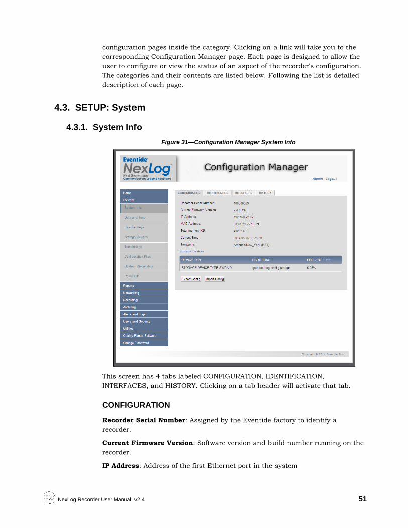
NexLog Recorder User Manual v2.4 51
configuration pages inside the category. Clicking on a link will take you to the
corresponding Configuration Manager page. Each page is designed to allow the
user to configure or view the status of an aspect of the recorder's configuration.
The categories and their contents are listed below. Following the list is detailed
description of each page.
4.3. SETUP: System
4.3.1. System Info
Figure 31—Configuration Manager System Info
This screen has 4 tabs labeled CONFIGURATION, IDENTIFICATION,
INTERFACES, and HISTORY. Clicking on a tab header will activate that tab.
CONFIGURATION
Recorder Serial Number: Assigned by the Eventide factory to identify a
recorder.
Current Firmware Version: Software version and build number running on the
recorder.
IP Address: Address of the first Ethernet port in the system
52 NexLog Recorder User Manual v2.4
MAC Address: Media Access Control address of the first Ethernet port in the
system
Total memory KB: Amount of usable RAM in the system
Current Time: Current local date and time of the recorder
Time zone: Time zone setting of the recorder
Storage Devices: List of the available storage devices in the recorder. (Hard
Drives, RAIDs, SAN, etc.) This list does not include archive devices.
In addition to all the information described above, this page contains two
additional important buttons, 'Import Configuration' and 'Export Configuration'.
Export Configuration allows you to export all of the recorder's configuration
settings for back up and safe keeping. 'Import Configuration' allows these
settings be re-loaded into the recorder. This is designed to allow you to back up
and restore your settings, for example, if you want to reinstall your recorder's
firmware. You can also use this option to Import the configuration from a
different recorder with identical hardware. It is not supported to Import
Configurations across different hardware (models, storage devices, Telephony
Boards), or software versions. For example, if the configuration you want to
import was exported under 2.1.4, you should install 2.1.4 on the recorder,
restore the configuration, and only then upgrade the recorder to the latest. After
performing a Configuration Import, it is important to immediately reboot your
recorder; this will happen automatically.
Identification
Recorder Name: The logger name that will be displayed in remote clients.
Facility Name: The facility name (i.e.: location) that will be stored on archive
media.
Interfaces
This page displays a summary of the recording boards installed in the system.
History
Recorder Run History: Displays a history of system startup and shutdown.
Also note that unplanned shutdowns are noted in this list and usually indicate
a power failure to the recorder. Unplanned Shutdowns can cause severe issues
and should be avoided.
Recorder Upgrade History: Displays a history of the first firmware install on
the recorder and subsequent updates.
NexLog Recorder User Manual v2.4 53
4.3.2. Date and Time
This page allows you to configure your date/time and time sync settings. The
top two items are Time and Time zone. To modify these settings and have them
take effect when you click 'Save', you must first click the 'Edit' checkboxes. This
is to protect you from accidental changes. Time and Time zone are very
important settings on a Recorder. Recordings generated during times when
these are incorrectly set, will be recorded on the wrong dates/times and may be
impossible to find or overlap other properly recorded calls. The configured time
zone is primarily used for displaying timestamps in Setup and on the front
panel. Regardless of the configured time zone, call records are actually stored in
the recorder's database in UTC time zone and converted for display and
querying. The time zone is also used for synchronizing with a time source that
provides Local Time rather than UTC (see below.)
In addition to setting your time and time zone, this page allows you to set your
Time Sync settings. Time sync settings allow you to slave your recorder's
internal clock to an external source to make sure the internal time and all
recording timestamps remain accurate and synchronized across your
organization. Eventide highly recommends the use of Time Sync. When you
select a Time Source via the Time Source Radio buttons, all configuration
settings relevant to that Time Source will appear below. The Available Time
sources are:
None: No Time sync, only the recorder's internal clock will keep time
NTP: Network Time Protocol. You can configure the IPs of up to 4 NTP time
servers. Only one will be used at a time, but others are back ups in case the
recorder cannot reach a primary time source. Normally, the recorder will slowly
“slew” the current time to the time source’s time if they do not match to prevent
large time jumps. The Force Sync option will save the current settings and
immediately set the recorder time. This is useful when first setting up a
recorder.
IRIG-B: Only relevant if you have purchased the optional IRIG-B time code
reader for your recorder. IRIG-B is a time source protocol provided over a coaxial
cable. You can select whether your IRIG-B time source is providing current time
in the UTC Time zone, or in the Local Time zone you have configured under
'Time zone'
RS232: Some Time sources provide time over an RS232 (Serial) Cable plugged
into the recorder. Here you can configure which serial port you have your time
source plugged into and which of the supported formats the time source will be
formatting the timestamps in. You also select serial settings to match your time
source such as Baud Rate, Parity, Number of Data bits and Number of Stop
Bits. Like IRIG-B you can configure whether your time source is sending time
stamps in UTC or Recorder Local Time.
54 NexLog Recorder User Manual v2.4
Wharton: Wharton is a special case of RS232 time sync which does not have
any options about baud rate or format, as this is hard coded as part of the
protocol. In addition, only the first serial port can be used for Wharton.
Regardless of the time source you are attempting to sync to, as a precaution
against the recorder receiving an invalid timestamp from the time source, the
recorder will only take action on a timestamp received if it is within 5 minutes of
the recorder's own clock. Therefore when first syncing to a new time source it
may be necessary to first manually set the recorder's time 'in the ball park' of
the time source's time. In addition, the recorder will not allow large jumps in
time due to a time source input, but will instead slowly 'slew' the recorders time
towards the time source time. The recorder attempts to avoid time ever moving
backwards, as this could cause overlapping recordings.
At the bottom of this page is some diagnostic information about your configured
time source, from which you can see information such as jitter and reach ability
of your time source. This information is useful for troubleshooting problematic
time sources. It includes information about which time sources are configured,
which are reachable, and which, if any, the recorder is currently synchronized
to. You must click the refresh button to see the most recent data. The
formatting of this information is identical to the standard UNIX / Linux
command ‘ntpq –p’. For more information on the data format used search online
for ‘ntpq’.
4.3.3. License Keys
License keys are purchased from Eventide to enable licensed functionality. Your
recorder will ship with one or more license keys installed, and you may also be
sent additional license keys if you upgrade or add new options to your recorder.
License keys are entered on this configuration page. Every recorder has one
primary license key. If this key is not entered, or does not match the hardware,
the system will run normally for 7 days during a grace period, and then certain
functions, such as archiving and call playback will become unavailable until a
valid key is entered. You cannot delete a primary key or add more than one, only
edit your primary key. Each license key is a long number provided by Eventide.
When you add or edit a key, you will see it in the list along with either the text
'Not a Valid License Key for this Recorder' or a description of which features the
license key enables. If the license key itself is valid for your recorder but does
not provide adequate coverage for your installed configuration (for example if
you add in an additional Analog Board beyond your licensed channel count), the
particular field which is not adequate will be marked as “INVALID”. For the
license to function on your recorder, it must be valid for the recorder itself, and
cover the installed features. If your license key does not cover your purchased
features, such as if you purchase an additional Analog Board, you must get a
new license key from Eventide.
In addition to the primary license key which contains information on number
and types of channels, number of client connections, hard drive size, etc. There
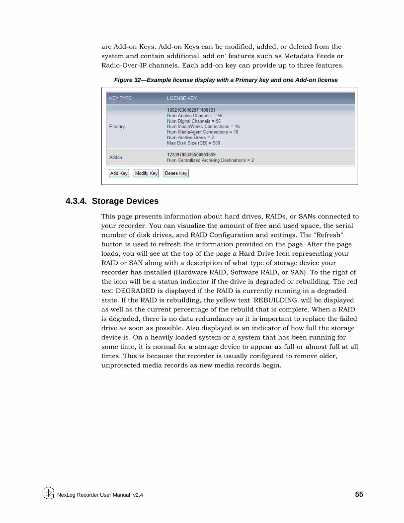
NexLog Recorder User Manual v2.4 55
are Add-on Keys. Add-on Keys can be modified, added, or deleted from the
system and contain additional 'add on' features such as Metadata Feeds or
Radio-Over-IP channels. Each add-on key can provide up to three features.
Figure 32—Example license display with a Primary key and one Add-on license
4.3.4. Storage Devices
This page presents information about hard drives, RAIDs, or SANs connected to
your recorder. You can visualize the amount of free and used space, the serial
number of disk drives, and RAID Configuration and settings. The "Refresh"
button is used to refresh the information provided on the page. After the page
loads, you will see at the top of the page a Hard Drive Icon representing your
RAID or SAN along with a description of what type of storage device your
recorder has installed (Hardware RAID, Software RAID, or SAN). To the right of
the icon will be a status indicator if the drive is degraded or rebuilding. The red
text DEGRADED is displayed if the RAID is currently running in a degraded
state. If the RAID is rebuilding, the yellow text 'REBUILDING' will be displayed
as well as the current percentage of the rebuild that is complete. When a RAID
is degraded, there is no data redundancy so it is important to replace the failed
drive as soon as possible. Also displayed is an indicator of how full the storage
device is. On a heavily loaded system or a system that has been running for
some time, it is normal for a storage device to appear as full or almost full at all
times. This is because the recorder is usually configured to remove older,
unprotected media records as new media records begin.
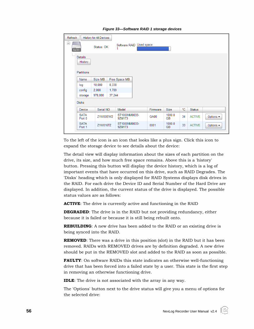
56 NexLog Recorder User Manual v2.4
Figure 33—Software RAID 1 storage devices
To the left of the icon is an icon that looks like a plus sign. Click this icon to
expand the storage device to see details about the device:
The detail view will display information about the sizes of each partition on the
drive, its size, and how much free space remains. Above this is a 'history'
button. Pressing this button will display the device history, which is a log of
important events that have occurred on this drive, such as RAID Degrades. The
'Disks' heading which is only displayed for RAID Systems displays disk drives in
the RAID. For each drive the Device ID and Serial Number of the Hard Drive are
displayed. In addition, the current status of the drive is displayed. The possible
status values are as follows:
ACTIVE: The drive is currently active and functioning in the RAID
DEGRADED: The drive is in the RAID but not providing redundancy, either
because it is failed or because it is still being rebuilt onto.
REBUILDING: A new drive has been added to the RAID or an existing drive is
being synced into the RAID.
REMOVED: There was a drive in this position (slot) in the RAID but it has been
removed. RAIDs with REMOVED drives are by definition degraded. A new drive
should be put in the REMOVED slot and added to the RAID as soon as possible.
FAULTY: On software RAIDs this state indicates an otherwise well-functioning
drive that has been forced into a failed state by a user. This state is the first step
in removing an otherwise functioning drive.
IDLE: The drive is not associated with the array in any way.
The 'Options' button next to the drive status will give you a menu of options for
the selected drive:
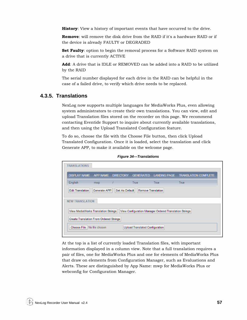
NexLog Recorder User Manual v2.4 57
History: View a history of important events that have occurred to the drive.
Remove: will remove the disk drive from the RAID if it's a hardware RAID or if
the device is already FAULTY or DEGRADED
Set Faulty: option to begin the removal process for a Software RAID system on
a drive that is currently ACTIVE
Add: A drive that is IDLE or REMOVED can be added into a RAID to be utilized
by the RAID
The serial number displayed for each drive in the RAID can be helpful in the
case of a failed drive, to verify which drive needs to be replaced.
4.3.5. Translations
NexLog now supports multiple languages for MediaWorks Plus, even allowing
system administrators to create their own translations. You can view, edit and
upload Translation files stored on the recorder on this page. We recommend
contacting Eventide Support to inquire about currently available translations,
and then using the Upload Translated Configuration feature.
To do so, choose the file with the Choose File button, then click Upload
Translated Configuration. Once it is loaded, select the translation and click
Generate APP, to make it available on the welcome page.
Figure 34—Translations
At the top is a list of currently loaded Translation files, with important
information displayed in a column view. Note that a full translation requires a
pair of files, one for MediaWorks Plus and one for elements of MediaWorks Plus
that draw on elements from Configuration Manager, such as Evaluations and
Alerts. These are distinguished by App Name: mwp for MediaWorks Plus or
webconfig for Configuration Manager.
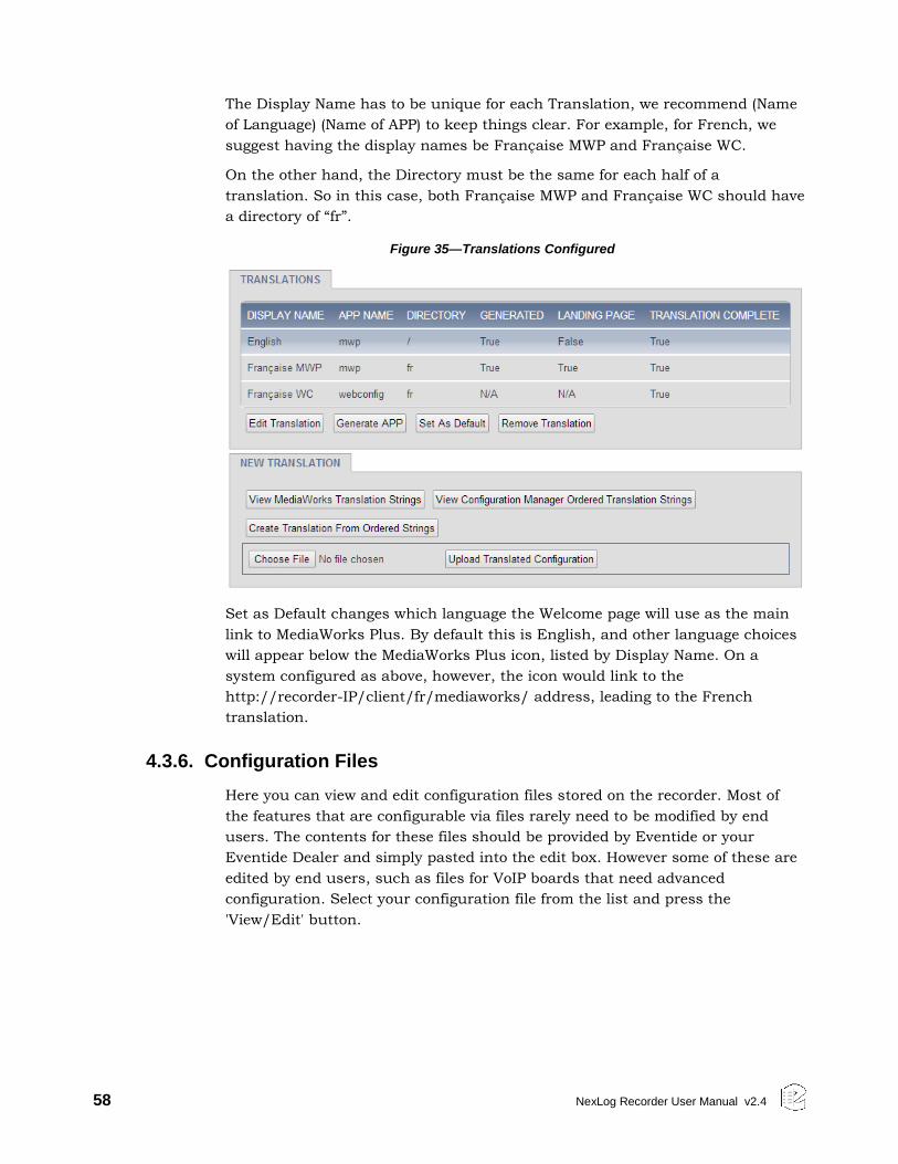
58 NexLog Recorder User Manual v2.4
The Display Name has to be unique for each Translation, we recommend (Name
of Language) (Name of APP) to keep things clear. For example, for French, we
suggest having the display names be Française MWP and Française WC.
On the other hand, the Directory must be the same for each half of a
translation. So in this case, both Française MWP and Française WC should have
a directory of “fr”.
Figure 35—Translations Configured
Set as Default changes which language the Welcome page will use as the main
link to MediaWorks Plus. By default this is English, and other language choices
will appear below the MediaWorks Plus icon, listed by Display Name. On a
system configured as above, however, the icon would link to the
http://recorder-IP/client/fr/mediaworks/ address, leading to the French
translation.
4.3.6. Configuration Files
Here you can view and edit configuration files stored on the recorder. Most of
the features that are configurable via files rarely need to be modified by end
users. The contents for these files should be provided by Eventide or your
Eventide Dealer and simply pasted into the edit box. However some of these are
edited by end users, such as files for VoIP boards that need advanced
configuration. Select your configuration file from the list and press the
'View/Edit' button.
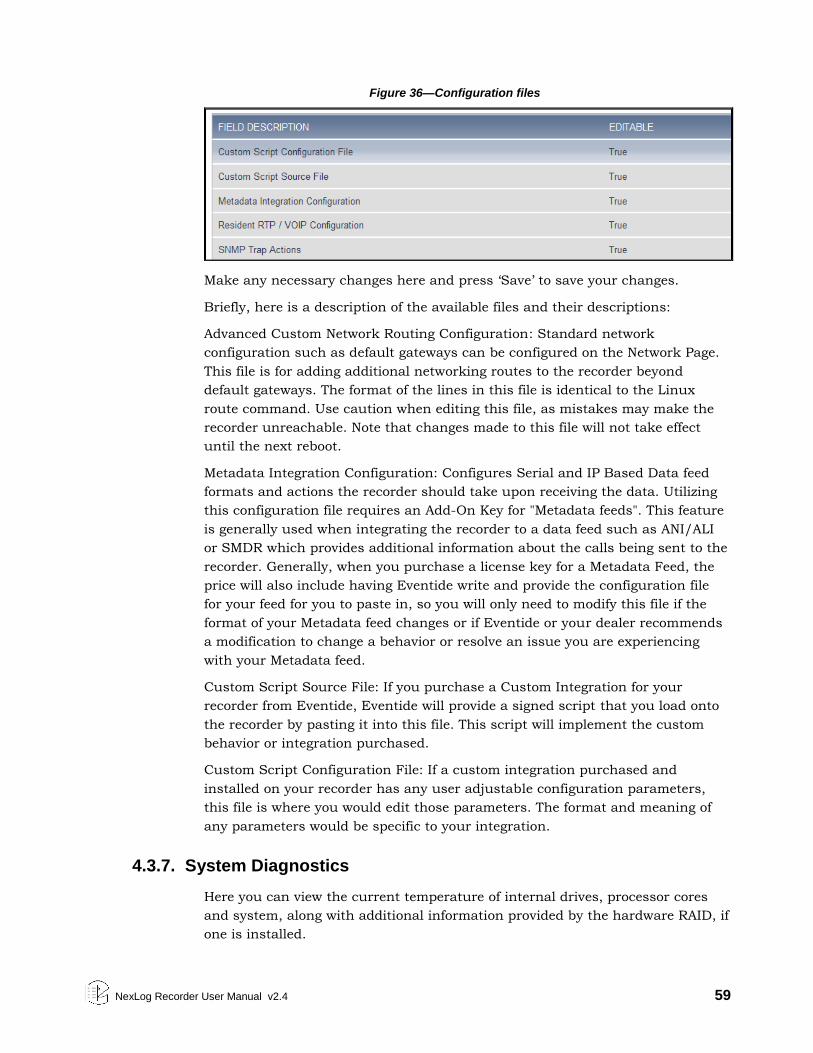
NexLog Recorder User Manual v2.4 59
Figure 36—Configuration files
Make any necessary changes here and press ‘Save’ to save your changes.
Briefly, here is a description of the available files and their descriptions:
Advanced Custom Network Routing Configuration: Standard network
configuration such as default gateways can be configured on the Network Page.
This file is for adding additional networking routes to the recorder beyond
default gateways. The format of the lines in this file is identical to the Linux
route command. Use caution when editing this file, as mistakes may make the
recorder unreachable. Note that changes made to this file will not take effect
until the next reboot.
Metadata Integration Configuration: Configures Serial and IP Based Data feed
formats and actions the recorder should take upon receiving the data. Utilizing
this configuration file requires an Add-On Key for "Metadata feeds". This feature
is generally used when integrating the recorder to a data feed such as ANI/ALI
or SMDR which provides additional information about the calls being sent to the
recorder. Generally, when you purchase a license key for a Metadata Feed, the
price will also include having Eventide write and provide the configuration file
for your feed for you to paste in, so you will only need to modify this file if the
format of your Metadata feed changes or if Eventide or your dealer recommends
a modification to change a behavior or resolve an issue you are experiencing
with your Metadata feed.
Custom Script Source File: If you purchase a Custom Integration for your
recorder from Eventide, Eventide will provide a signed script that you load onto
the recorder by pasting it into this file. This script will implement the custom
behavior or integration purchased.
Custom Script Configuration File: If a custom integration purchased and
installed on your recorder has any user adjustable configuration parameters,
this file is where you would edit those parameters. The format and meaning of
any parameters would be specific to your integration.
4.3.7. System Diagnostics
Here you can view the current temperature of internal drives, processor cores
and system, along with additional information provided by the hardware RAID, if
one is installed.
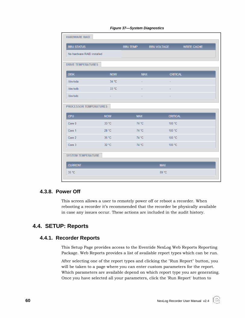
60 NexLog Recorder User Manual v2.4
Figure 37—System Diagnostics
4.3.8. Power Off
This screen allows a user to remotely power off or reboot a recorder. When
rebooting a recorder it’s recommended that the recorder be physically available
in case any issues occur. These actions are included in the audit history.
4.4. SETUP: Reports
4.4.1. Recorder Reports
This Setup Page provides access to the Eventide NexLog Web Reports Reporting
Package. Web Reports provides a list of available report types which can be run.
After selecting one of the report types and clicking the "Run Report" button, you
will be taken to a page where you can enter custom parameters for the report.
Which parameters are available depend on which report type you are generating.
Once you have selected all your parameters, click the 'Run Report' button to
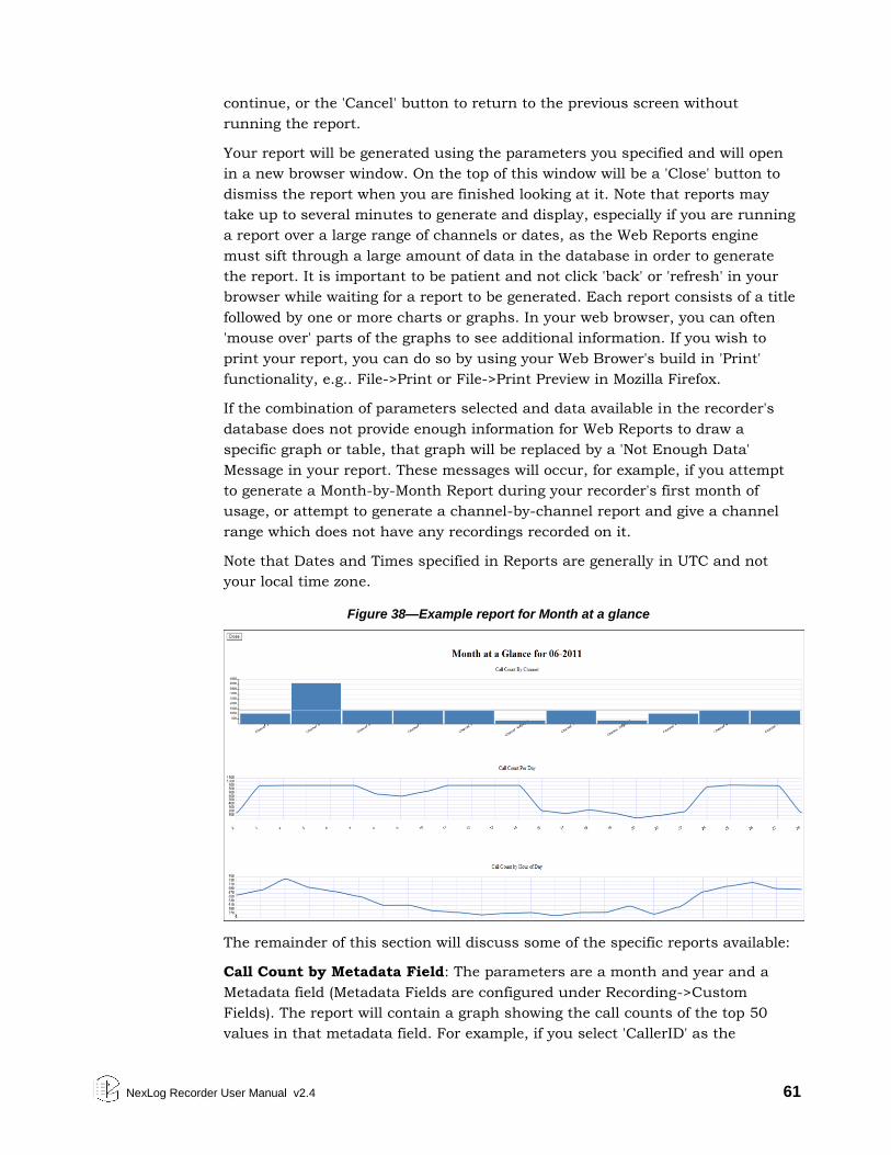
NexLog Recorder User Manual v2.4 61
continue, or the 'Cancel' button to return to the previous screen without
running the report.
Your report will be generated using the parameters you specified and will open
in a new browser window. On the top of this window will be a 'Close' button to
dismiss the report when you are finished looking at it. Note that reports may
take up to several minutes to generate and display, especially if you are running
a report over a large range of channels or dates, as the Web Reports engine
must sift through a large amount of data in the database in order to generate
the report. It is important to be patient and not click 'back' or 'refresh' in your
browser while waiting for a report to be generated. Each report consists of a title
followed by one or more charts or graphs. In your web browser, you can often
'mouse over' parts of the graphs to see additional information. If you wish to
print your report, you can do so by using your Web Brower's build in 'Print'
functionality, e.g.. File->Print or File->Print Preview in Mozilla Firefox.
If the combination of parameters selected and data available in the recorder's
database does not provide enough information for Web Reports to draw a
specific graph or table, that graph will be replaced by a 'Not Enough Data'
Message in your report. These messages will occur, for example, if you attempt
to generate a Month-by-Month Report during your recorder's first month of
usage, or attempt to generate a channel-by-channel report and give a channel
range which does not have any recordings recorded on it.
Note that Dates and Times specified in Reports are generally in UTC and not
your local time zone.
Figure 38—Example report for Month at a glance
The remainder of this section will discuss some of the specific reports available:
Call Count by Metadata Field: The parameters are a month and year and a
Metadata field (Metadata Fields are configured under Recording->Custom
Fields). The report will contain a graph showing the call counts of the top 50
values in that metadata field. For example, if you select 'CallerID' as the
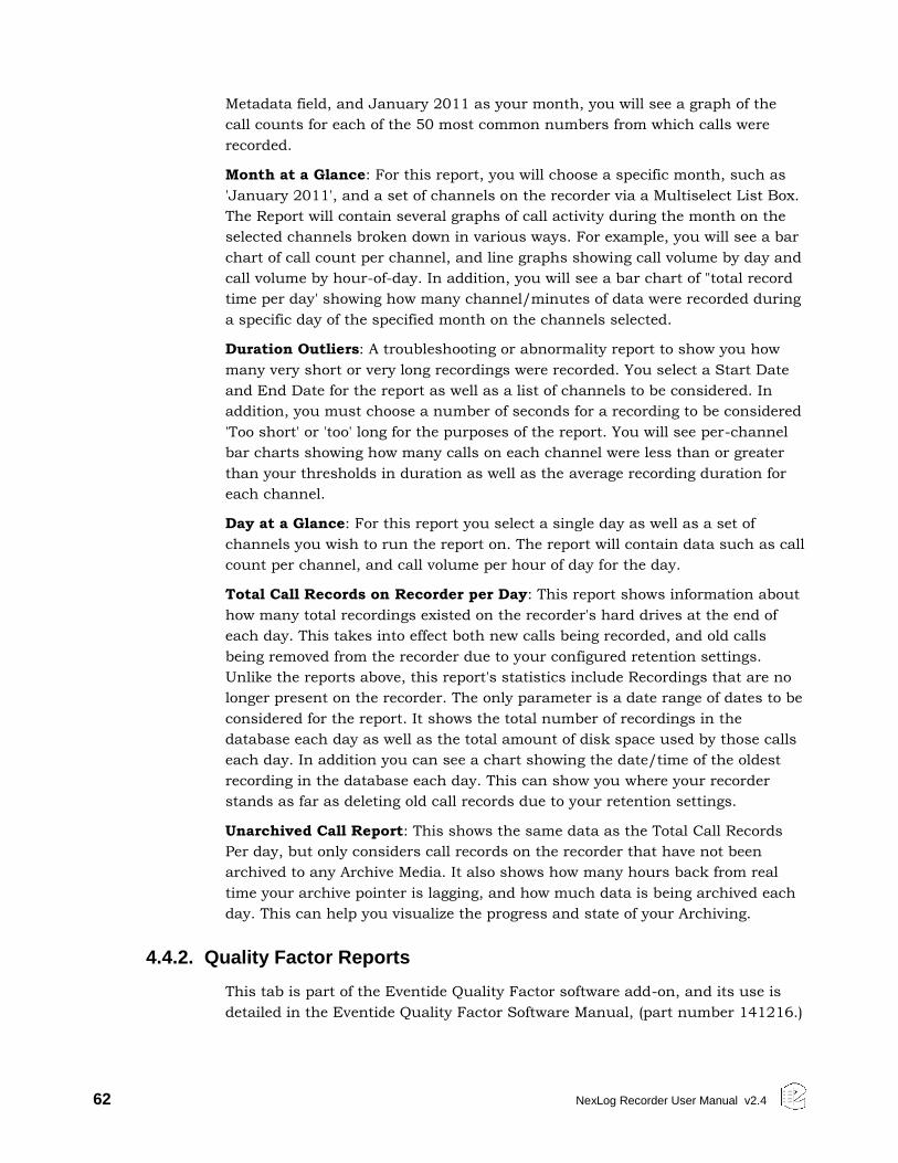
62 NexLog Recorder User Manual v2.4
Metadata field, and January 2011 as your month, you will see a graph of the
call counts for each of the 50 most common numbers from which calls were
recorded.
Month at a Glance: For this report, you will choose a specific month, such as
'January 2011', and a set of channels on the recorder via a Multiselect List Box.
The Report will contain several graphs of call activity during the month on the
selected channels broken down in various ways. For example, you will see a bar
chart of call count per channel, and line graphs showing call volume by day and
call volume by hour-of-day. In addition, you will see a bar chart of "total record
time per day' showing how many channel/minutes of data were recorded during
a specific day of the specified month on the channels selected.
Duration Outliers: A troubleshooting or abnormality report to show you how
many very short or very long recordings were recorded. You select a Start Date
and End Date for the report as well as a list of channels to be considered. In
addition, you must choose a number of seconds for a recording to be considered
'Too short' or 'too' long for the purposes of the report. You will see per-channel
bar charts showing how many calls on each channel were less than or greater
than your thresholds in duration as well as the average recording duration for
each channel.
Day at a Glance: For this report you select a single day as well as a set of
channels you wish to run the report on. The report will contain data such as call
count per channel, and call volume per hour of day for the day.
Total Call Records on Recorder per Day: This report shows information about
how many total recordings existed on the recorder's hard drives at the end of
each day. This takes into effect both new calls being recorded, and old calls
being removed from the recorder due to your configured retention settings.
Unlike the reports above, this report's statistics include Recordings that are no
longer present on the recorder. The only parameter is a date range of dates to be
considered for the report. It shows the total number of recordings in the
database each day as well as the total amount of disk space used by those calls
each day. In addition you can see a chart showing the date/time of the oldest
recording in the database each day. This can show you where your recorder
stands as far as deleting old call records due to your retention settings.
Unarchived Call Report: This shows the same data as the Total Call Records
Per day, but only considers call records on the recorder that have not been
archived to any Archive Media. It also shows how many hours back from real
time your archive pointer is lagging, and how much data is being archived each
day. This can help you visualize the progress and state of your Archiving.
4.4.2. Quality Factor Reports
This tab is part of the Eventide Quality Factor software add-on, and its use is
detailed in the Eventide Quality Factor Software Manual, (part number 141216.)
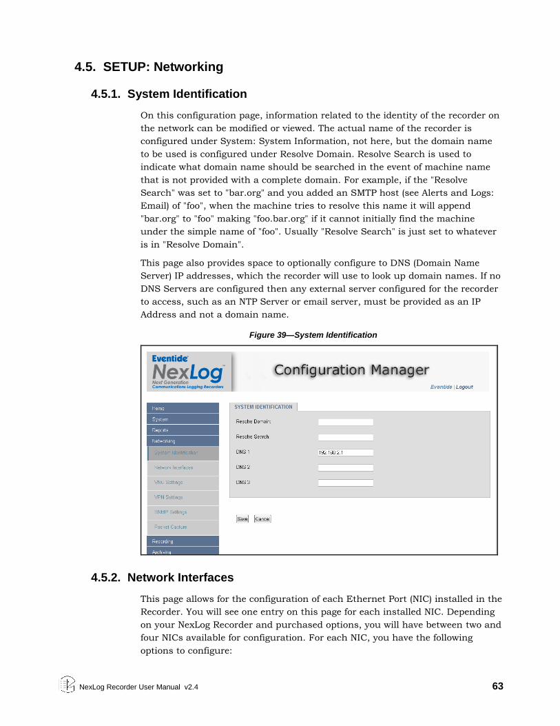
NexLog Recorder User Manual v2.4 63
4.5. SETUP: Networking
4.5.1. System Identification
On this configuration page, information related to the identity of the recorder on
the network can be modified or viewed. The actual name of the recorder is
configured under System: System Information, not here, but the domain name
to be used is configured under Resolve Domain. Resolve Search is used to
indicate what domain name should be searched in the event of machine name
that is not provided with a complete domain. For example, if the "Resolve
Search" was set to "bar.org" and you added an SMTP host (see Alerts and Logs:
Email) of "foo", when the machine tries to resolve this name it will append
"bar.org" to "foo" making "foo.bar.org" if it cannot initially find the machine
under the simple name of "foo". Usually "Resolve Search" is just set to whatever
is in "Resolve Domain".
This page also provides space to optionally configure to DNS (Domain Name
Server) IP addresses, which the recorder will use to look up domain names. If no
DNS Servers are configured then any external server configured for the recorder
to access, such as an NTP Server or email server, must be provided as an IP
Address and not a domain name.
Figure 39—System Identification
4.5.2. Network Interfaces
This page allows for the configuration of each Ethernet Port (NIC) installed in the
Recorder. You will see one entry on this page for each installed NIC. Depending
on your NexLog Recorder and purchased options, you will have between two and
four NICs available for configuration. For each NIC, you have the following
options to configure:
64 NexLog Recorder User Manual v2.4
Type: DHCP, Static, or SPAN: This determines how the recorder will acquire its
Network settings for the specified NIC such as IP address and Net mask.
DHCP: If DHCP is selected, the data will be automatically received from a
DHCP Server on the Network. If No valid DHCP server is configured on your
network, this option will result in no IP address being assigned to the
recorder and it will be inaccessible via the network. Note that since remote
clients such as MediaWorks and MediaAgent, as well as Web Browsers need
to know the IP address of the recorder in order to connect and interact with
it, if DHCP is to be used, it is important to configure your DHCP server to be
aware of the MAC Address of the recorder and to always assign the same
known IP Address to that MAC. If DHCP causes a dynamic IP Address
change, clients will no longer know what address to connect to in order to
reach the recorder and other recorder functionality may not function as
expected.
Static: If the type is set to Static, NexLog Configuration Manager will allow
you to manually enter all the networking settings for this NIC. This
information should be provided by your Network Administrator. The Address
field is the IP Address being assigned to the recorder. Netmask, gateway, and
broadcast should all be configured as well.
SPAN: The third possible option is SPAN. A SPAN port is a port on a network
switch or router that is "transmit only". When a recorder's NIC is connected
to a SPAN port, it cannot send any traffic to that port, only receive any traffic
that has been configured on the router to be forwarded to the SPAN port.
SPAN ports are used for passive monitoring and recording of VoIP or RoIP
traffic.
If at least two NICs are present in your NexLog Recorder, you will also have a
'BIND' option in Type. If BIND is selected on two Ethernet devices, they will be
bound together into a single network link which is configured as a unit, rather
than separately. This feature is sometimes known as "NIC Bonding" or "Link
Aggregation" and is used to provide Network redundancy.
Considerations When Using a Static IP Address
When using static IP addresses, the network parameters must be set manually
from the front panel. There are some things you must consider when setting
these parameters:
The IP address must not be in use by another device. If it is, then the
address may not be accepted, and even if it is accepted, operation will be
unreliable.
If you need the recorder to communicate with other devices on the network,
such as an administration client, an NTP server, or the Internet, then the
devices must either be on the same subnet, or on a different subnet that can
be reached over a gateway. In the latter case, the address of the gateway
must be added to the recorder.
NexLog Recorder User Manual v2.4 65
The subnet is determined by the Net Mask setting. Your subnet is the result
of an AND operation between the 4-octet net mask and the 4-octet IP
address. See Table 7—Sample Net Mask and Subnet Settings for two common
examples of net masks. Your facility’s network administrator should be able
to help you in assigning the proper IP address, net mask, broadcast address,
and if necessary, gateway address for the recorder. If the recorder will be
sending email, one or more DNS servers must be entered.
Table 7—Sample Net Mask and Subnet Settings
Net Mask IP Address Network or Subnet
255.255.0.0 123.45.67.89 123.45.0.0
255.255.255.0 123.45.67.89 123.45.67.0
Dual NICs with Bonding Operation
When configured with NIC bonding, the dual network interface devices provide
failover operation. Because they share the same IP address, if one of the devices
or its connection should fail, the other device will maintain the network
connection.
For NIC bonding operation, you have the same option of using DHCP. Only, in
this case, it is automatically applied to both the primary and secondary network
devices. With DHCP enabled, the other network settings for both network
devices are set automatically by the DHCP server and cannot be changed
manually. The settings remain readable since the information, the IP address in
particular, may be needed to access the recorder remotely.
To configure two network devices with NIC bonding, change the Type to Bind on
each device, then save.
Once you have bound two devices together, they will be presented as a single
device, with an additional menu for Bond Type. This will let you configure the
kind of device bonding used.
Note: After you have configured the network interface devices for NIC bonding
operation, if you change them back to separate operation, you will then have to
shut down and restart the recorder for the changes to take effect.
There are three types of NIC Binding available. Be sure to select the type that
matches the requirements of your network’s configuration.
0 (balance-rr): Round-robin policy: Transmit packets in sequential
order from the first available slave through the last. This mode
provides load balancing and fault tolerance.
1 (active-backup): Active-backup policy: Only one slave in the bond is
active. A different slave becomes active if, and only if, the active slave
fails. The bond's MAC address is externally visible on only one port
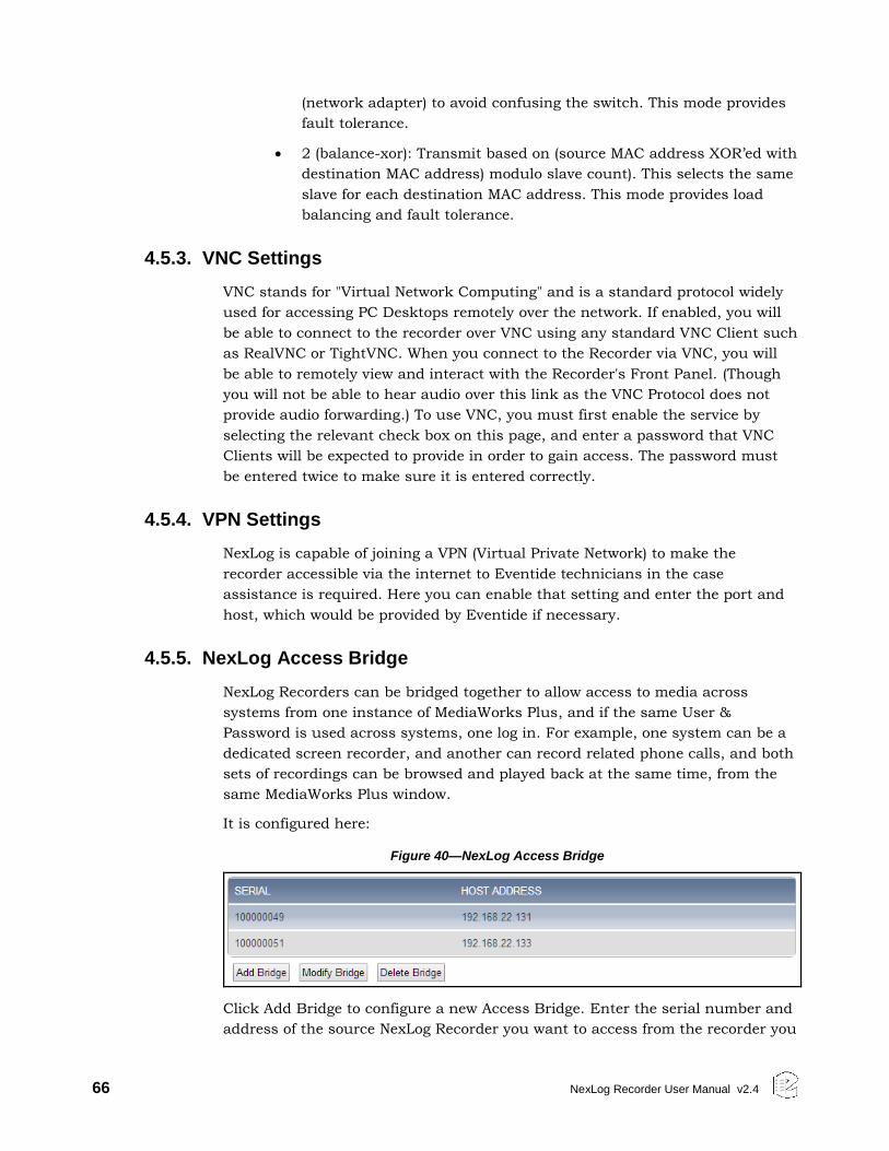
66 NexLog Recorder User Manual v2.4
(network adapter) to avoid confusing the switch. This mode provides
fault tolerance.
2 (balance-xor): Transmit based on (source MAC address XOR’ed with
destination MAC address) modulo slave count). This selects the same
slave for each destination MAC address. This mode provides load
balancing and fault tolerance.
4.5.3. VNC Settings
VNC stands for "Virtual Network Computing" and is a standard protocol widely
used for accessing PC Desktops remotely over the network. If enabled, you will
be able to connect to the recorder over VNC using any standard VNC Client such
as RealVNC or TightVNC. When you connect to the Recorder via VNC, you will
be able to remotely view and interact with the Recorder's Front Panel. (Though
you will not be able to hear audio over this link as the VNC Protocol does not
provide audio forwarding.) To use VNC, you must first enable the service by
selecting the relevant check box on this page, and enter a password that VNC
Clients will be expected to provide in order to gain access. The password must
be entered twice to make sure it is entered correctly.
4.5.4. VPN Settings
NexLog is capable of joining a VPN (Virtual Private Network) to make the
recorder accessible via the internet to Eventide technicians in the case
assistance is required. Here you can enable that setting and enter the port and
host, which would be provided by Eventide if necessary.
4.5.5. NexLog Access Bridge
NexLog Recorders can be bridged together to allow access to media across
systems from one instance of MediaWorks Plus, and if the same User &
Password is used across systems, one log in. For example, one system can be a
dedicated screen recorder, and another can record related phone calls, and both
sets of recordings can be browsed and played back at the same time, from the
same MediaWorks Plus window.
It is configured here:
Figure 40—NexLog Access Bridge
Click Add Bridge to configure a new Access Bridge. Enter the serial number and
address of the source NexLog Recorder you want to access from the recorder you
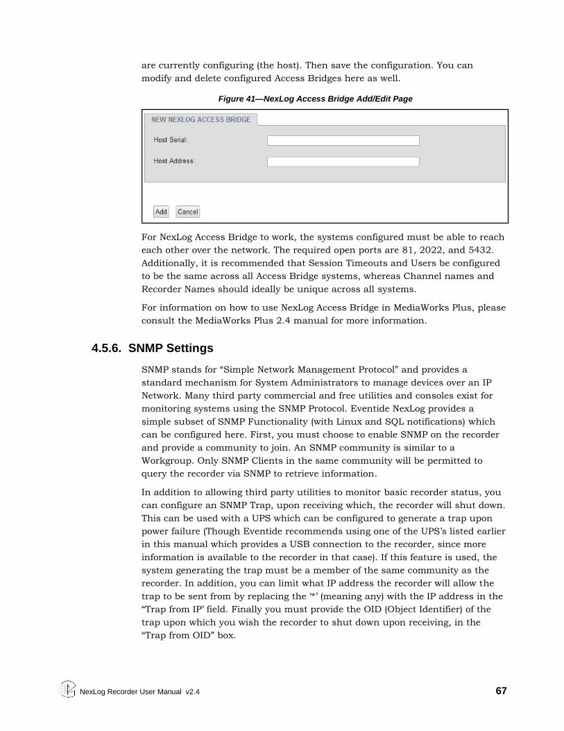
NexLog Recorder User Manual v2.4 67
are currently configuring (the host). Then save the configuration. You can
modify and delete configured Access Bridges here as well.
Figure 41—NexLog Access Bridge Add/Edit Page
For NexLog Access Bridge to work, the systems configured must be able to reach
each other over the network. The required open ports are 81, 2022, and 5432.
Additionally, it is recommended that Session Timeouts and Users be configured
to be the same across all Access Bridge systems, whereas Channel names and
Recorder Names should ideally be unique across all systems.
For information on how to use NexLog Access Bridge in MediaWorks Plus, please
consult the MediaWorks Plus 2.4 manual for more information.
4.5.6. SNMP Settings
SNMP stands for “Simple Network Management Protocol” and provides a
standard mechanism for System Administrators to manage devices over an IP
Network. Many third party commercial and free utilities and consoles exist for
monitoring systems using the SNMP Protocol. Eventide NexLog provides a
simple subset of SNMP Functionality (with Linux and SQL notifications) which
can be configured here. First, you must choose to enable SNMP on the recorder
and provide a community to join. An SNMP community is similar to a
Workgroup. Only SNMP Clients in the same community will be permitted to
query the recorder via SNMP to retrieve information.
In addition to allowing third party utilities to monitor basic recorder status, you
can configure an SNMP Trap, upon receiving which, the recorder will shut down.
This can be used with a UPS which can be configured to generate a trap upon
power failure (Though Eventide recommends using one of the UPS’s listed earlier
in this manual which provides a USB connection to the recorder, since more
information is available to the recorder in that case). If this feature is used, the
system generating the trap must be a member of the same community as the
recorder. In addition, you can limit what IP address the recorder will allow the
trap to be sent from by replacing the ‘*’ (meaning any) with the IP address in the
“Trap from IP’ field. Finally you must provide the OID (Object Identifier) of the
trap upon which you wish the recorder to shut down upon receiving, in the
“Trap from OID” box.
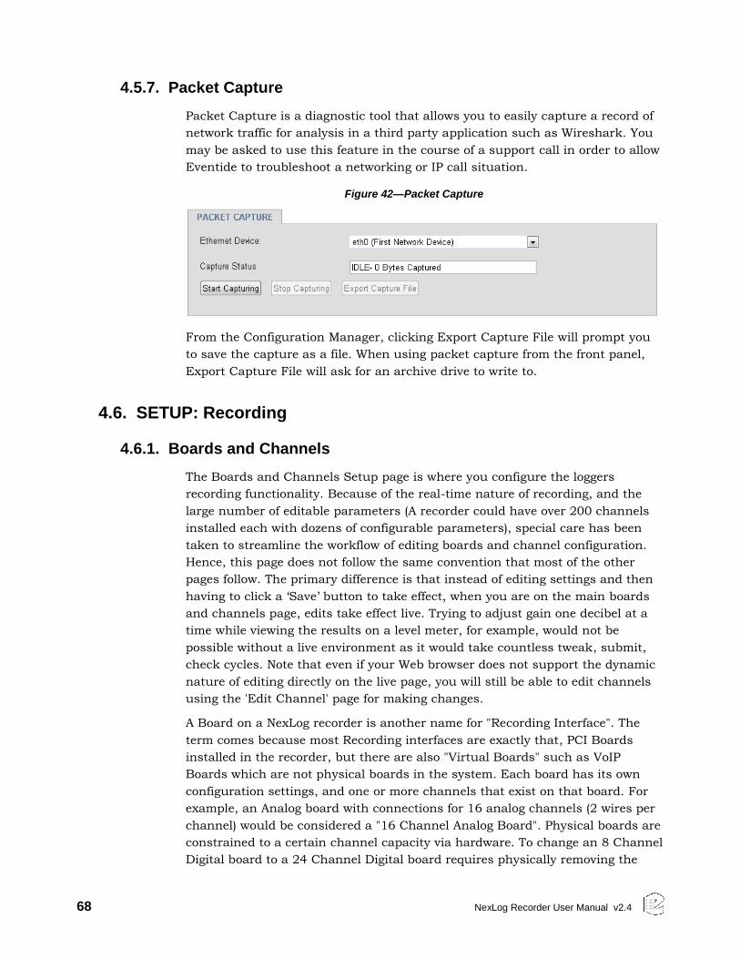
68 NexLog Recorder User Manual v2.4
4.5.7. Packet Capture
Packet Capture is a diagnostic tool that allows you to easily capture a record of
network traffic for analysis in a third party application such as Wireshark. You
may be asked to use this feature in the course of a support call in order to allow
Eventide to troubleshoot a networking or IP call situation.
Figure 42—Packet Capture
From the Configuration Manager, clicking Export Capture File will prompt you
to save the capture as a file. When using packet capture from the front panel,
Export Capture File will ask for an archive drive to write to.
4.6. SETUP: Recording
4.6.1. Boards and Channels
The Boards and Channels Setup page is where you configure the loggers
recording functionality. Because of the real-time nature of recording, and the
large number of editable parameters (A recorder could have over 200 channels
installed each with dozens of configurable parameters), special care has been
taken to streamline the workflow of editing boards and channel configuration.
Hence, this page does not follow the same convention that most of the other
pages follow. The primary difference is that instead of editing settings and then
having to click a ‘Save’ button to take effect, when you are on the main boards
and channels page, edits take effect live. Trying to adjust gain one decibel at a
time while viewing the results on a level meter, for example, would not be
possible without a live environment as it would take countless tweak, submit,
check cycles. Note that even if your Web browser does not support the dynamic
nature of editing directly on the live page, you will still be able to edit channels
using the 'Edit Channel' page for making changes.
A Board on a NexLog recorder is another name for "Recording Interface". The
term comes because most Recording interfaces are exactly that, PCI Boards
installed in the recorder, but there are also "Virtual Boards" such as VoIP
Boards which are not physical boards in the system. Each board has its own
configuration settings, and one or more channels that exist on that board. For
example, an Analog board with connections for 16 analog channels (2 wires per
channel) would be considered a "16 Channel Analog Board". Physical boards are
constrained to a certain channel capacity via hardware. To change an 8 Channel
Digital board to a 24 Channel Digital board requires physically removing the
NexLog Recorder User Manual v2.4 69
board and purchasing and installing a new one. Virtual Boards can often have
their channel capacity expanded simply by purchasing a license and
reconfiguring them, provided the recorder has enough capacity to handle the
additional channel load.
View modes
There are two primary views of the main Boards page, which are toggled via the
"View by Channel" check box at the top of the page. If "View by Channel" is
disabled, the main view shows each board installed. Each board can be
expanded to show the channels within that board. If 'View by Channel' is
checked, the boards are not displayed at all, just all of the channels on the
system in a single list all at once, but there is no way to access the board
settings, only the status settings. Which view you use depends on what task you
are attempting to complete and personal preference. All options are accessible
with View By Channel Disabled, but for some tasks it may be more convenient
to View By Channel and see all the channels not grouped by boards in a tree
view. Note that due to the live nature of this page, some browsers may cause
high CPU load on slower PCs if the ‘View by Channel” option is enabled on high
channel count systems. If this occurs, simply disable the ‘View by Channel”
option.
Browser Support
Note that real time status displays of levels are not available on all browsers.
Internet Explorer 8 and below will not display the level graphs as seen in Figure
23. In addition the detail level display will not update in real time in some
browsers.
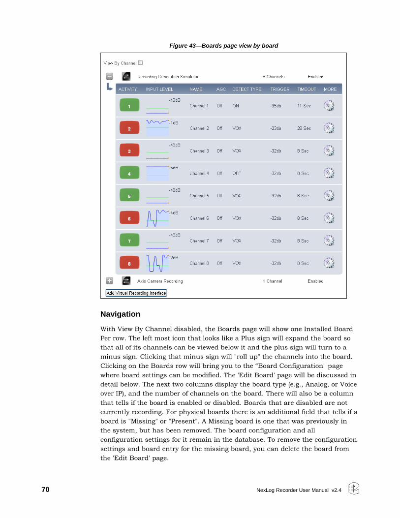
70 NexLog Recorder User Manual v2.4
Figure 43—Boards page view by board
Navigation
With View By Channel disabled, the Boards page will show one Installed Board
Per row. The left most icon that looks like a Plus sign will expand the board so
that all of its channels can be viewed below it and the plus sign will turn to a
minus sign. Clicking that minus sign will "roll up" the channels into the board.
Clicking on the Boards row will bring you to the “Board Configuration" page
where board settings can be modified. The 'Edit Board' page will be discussed in
detail below. The next two columns display the board type (e.g., Analog, or Voice
over IP), and the number of channels on the board. There will also be a column
that tells if the board is enabled or disabled. Boards that are disabled are not
currently recording. For physical boards there is an additional field that tells if a
board is "Missing" or "Present". A Missing board is one that was previously in
the system, but has been removed. The board configuration and all
configuration settings for it remain in the database. To remove the configuration
settings and board entry for the missing board, you can delete the board from
the 'Edit Board' page.
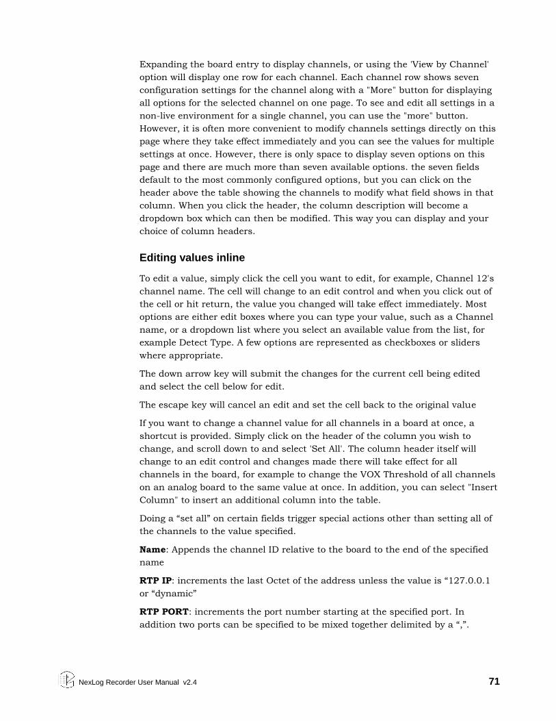
NexLog Recorder User Manual v2.4 71
Expanding the board entry to display channels, or using the 'View by Channel'
option will display one row for each channel. Each channel row shows seven
configuration settings for the channel along with a "More" button for displaying
all options for the selected channel on one page. To see and edit all settings in a
non-live environment for a single channel, you can use the "more" button.
However, it is often more convenient to modify channels settings directly on this
page where they take effect immediately and you can see the values for multiple
settings at once. However, there is only space to display seven options on this
page and there are much more than seven available options. the seven fields
default to the most commonly configured options, but you can click on the
header above the table showing the channels to modify what field shows in that
column. When you click the header, the column description will become a
dropdown box which can then be modified. This way you can display and your
choice of column headers.
Editing values inline
To edit a value, simply click the cell you want to edit, for example, Channel 12's
channel name. The cell will change to an edit control and when you click out of
the cell or hit return, the value you changed will take effect immediately. Most
options are either edit boxes where you can type your value, such as a Channel
name, or a dropdown list where you select an available value from the list, for
example Detect Type. A few options are represented as checkboxes or sliders
where appropriate.
The down arrow key will submit the changes for the current cell being edited
and select the cell below for edit.
The escape key will cancel an edit and set the cell back to the original value
If you want to change a channel value for all channels in a board at once, a
shortcut is provided. Simply click on the header of the column you wish to
change, and scroll down to and select 'Set All'. The column header itself will
change to an edit control and changes made there will take effect for all
channels in the board, for example to change the VOX Threshold of all channels
on an analog board to the same value at once. In addition, you can select "Insert
Column" to insert an additional column into the table.
Doing a “set all” on certain fields trigger special actions other than setting all of
the channels to the value specified.
Name: Appends the channel ID relative to the board to the end of the specified
name
RTP IP: increments the last Octet of the address unless the value is “127.0.0.1
or “dynamic”
RTP PORT: increments the port number starting at the specified port. In
addition two ports can be specified to be mixed together delimited by a “,”.
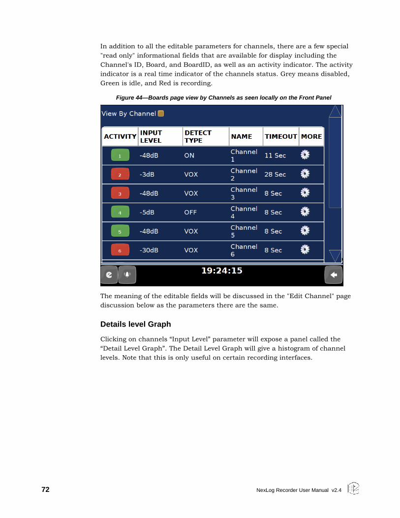
72 NexLog Recorder User Manual v2.4
In addition to all the editable parameters for channels, there are a few special
"read only" informational fields that are available for display including the
Channel's ID, Board, and BoardID, as well as an activity indicator. The activity
indicator is a real time indicator of the channels status. Grey means disabled,
Green is idle, and Red is recording.
Figure 44—Boards page view by Channels as seen locally on the Front Panel
The meaning of the editable fields will be discussed in the "Edit Channel" page
discussion below as the parameters there are the same.
Details level Graph
Clicking on channels “Input Level” parameter will expose a panel called the
“Detail Level Graph”. The Detail Level Graph will give a histogram of channel
levels. Note that this is only useful on certain recording interfaces.
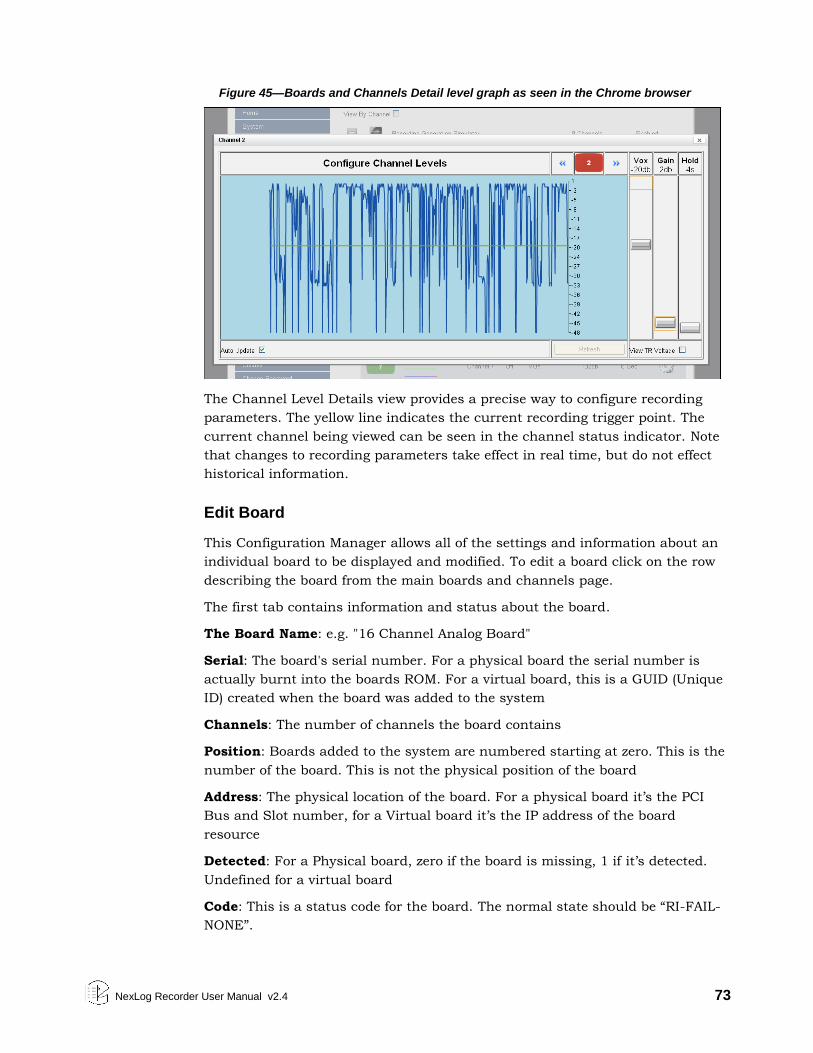
NexLog Recorder User Manual v2.4 73
Figure 45—Boards and Channels Detail level graph as seen in the Chrome browser
The Channel Level Details view provides a precise way to configure recording
parameters. The yellow line indicates the current recording trigger point. The
current channel being viewed can be seen in the channel status indicator. Note
that changes to recording parameters take effect in real time, but do not effect
historical information.
Edit Board
This Configuration Manager allows all of the settings and information about an
individual board to be displayed and modified. To edit a board click on the row
describing the board from the main boards and channels page.
The first tab contains information and status about the board.
The Board Name: e.g. "16 Channel Analog Board"
Serial: The board's serial number. For a physical board the serial number is
actually burnt into the boards ROM. For a virtual board, this is a GUID (Unique
ID) created when the board was added to the system
Channels: The number of channels the board contains
Position: Boards added to the system are numbered starting at zero. This is the
number of the board. This is not the physical position of the board
Address: The physical location of the board. For a physical board it’s the PCI
Bus and Slot number, for a Virtual board it’s the IP address of the board
resource
Detected: For a Physical board, zero if the board is missing, 1 if it’s detected.
Undefined for a virtual board
Code: This is a status code for the board. The normal state should be “RI-FAIL-
NONE”.
74 NexLog Recorder User Manual v2.4
All boards also have an "Enable" checkbox to enable or disable a board. By
default when boards are added to the system they are enabled. Note that if you
disable a board it will not record. It may be necessary to disable a board if you’re
upgrading to a board with a higher channel capacity or if the board is
malfunctioning and needs to be replaced. In some installations it’s a good idea
to disable a board before making settings as to not make recordings before, for
example, naming your channels.
The remainder of the informational and editable fields on the 'Edit Boards" page
are dependent on the board type:
Digital PBX Tapping Board
(Audio codes NGX) 8-channel, 16-channel, and 24 channel versions
Firmware Version: The version of the firmware loaded onto the PBX card, for
diagnostic purposes only.
PBX Type: For a NGX Board to be able to record from a PBX, the PBX Type
configured must be set to the model of the connected PBX. For PBX Model,
version, and phone set compatibility, please contact Eventide.
Telco Encoding: This is the companding used on the digital voice sent between
the PBX and the Phone. This is the format of the voice actually sent across the
wire and is unrelated to any companding or compression codecs used to store
the data on the recorder itself. If this is set incorrectly for your PBX, the
recorded audio will sound scratchy and overdriven. MULAW is generally much
more common than ALAW.
Eventide Analog Boards
8-channel, 16-channel, and 24 channel versions
Encoding: With the Analog board, all channels on the board must be set to the
same Compression format. This setting is configured here. GSM 13Kbps will
produce recordings that use the least amount of disk space, while Mulaw
64kbps will provide the best audio quality at the expense of using approximately
five times as much storage space. Note that Mulaw recording is only supported
on systems with four or less Analog boards. 16kbps and 32kbps ADPCM will
provide intermediate compression options.
Notch Frequency: The Analog Board provides a Notch Filter to Notch out tones
in the input signal. The frequency to notch must be configured on a board wide
basis. In addition, the Notch Filter needs to be enabled for each channel on the
board, so you configure the frequency here, and then which channels on the
board it should be applied to.
Enable MDC1200: If enabled, this board will process MDC1200 Radio tones
which provide RadioID information (who is talking) on some Analog Radio
systems. In addition, an add-on license key must be installed to allow the
NexLog Recorder User Manual v2.4 75
feature to be utilized and a User Defined Field (Recording: User Fields) must be
added to the database to hold the RadioID. The field should be called RADIO_ID
Extended Beep: If enabled, the beep for this board will be 1403.508772 Hz and
387.5 ms, which is within the 1400 Hz ± 1.5% and 400ms ± 75ms specification
for Australian requirements for beep on line recordings.
Beep Gain: Allows you to adjust the volume of the beep from the default
loudness to as much as -30db quieter, in 1db increments.
Audiocodes T1/E1 Board Active and Passive Boards
These boards come in Single Port and Dual Port versions for recording one or
two T1 or E1 Trunks. The Dual Port versions simply provide the same
configuration options separately for each Port. For each port the options are as
follows:
Port Type: Whether the Trunk is a T1 or E1 (must be the same on both ports on
a dual port board)
Protocol: What Protocol is used on the T1/E1. Options are None (Recording is
VOX Only), ISDN, or CAS/RBS
Protocol Variants:
Line Coding: Whether the Line coding on the T1/E1 is AMI, B8Zs or HDB3
Framing Format: Whether the Framing format is SF, ESF, G704, or CRC4
Interface Side: TE or NT. For an active board, this needs to be set to the
opposite of the setting on the equipment terminating the other end of the T1/E1.
For passive boards this can normally be left at the default setting, which is TE.
Dual Span Active T1/E1 board require an add-on license for each board to be
used in a dual configuration; beyond the number licensed, dual span boards will
only use the first span until licensed for a second. Eventide only sells dual span
active T1/E1 boards.
Passive T1/E1 Boards are used for tapping between two T1/E1 endpoints, both
of which terminate their end of the T1/E1 circuit, with the recorder passively
listening in between by use of a 'T-adaptor' wiring tap. These are typically used
for tapping and recording a T1/E1 circuit, for example, between a PBX and the
telephone company, where the recorder is not involved in the communications
and just listening in the middle.
With an active T1/E1 the board will terminate one end of the T1/E1 connection.
If the board is configured for ISDN call control, the recorder will also answer
calls placed over the T1/E1 link and record all the audio sent to it during the
call. The recorder will never place a call to the remote end over the T1/E1.will
also answer calls placed over the T1/E1 link and record all the audio sent to it
during the call. The recorder will never place a call to the remote end over the
T1/E1.
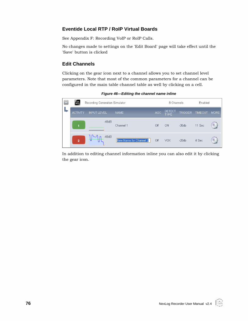
76 NexLog Recorder User Manual v2.4
Eventide Local RTP / RoIP Virtual Boards
See Appendix F: Recording VoIP or RoIP Calls.
No changes made to settings on the 'Edit Board' page will take effect until the
'Save' button is clicked
Edit Channels
Clicking on the gear icon next to a channel allows you to set channel level
parameters. Note that most of the common parameters for a channel can be
configured in the main table channel table as well by clicking on a cell.
Figure 46—Editing the channel name inline
In addition to editing channel information inline you can also edit it by clicking
the gear icon.
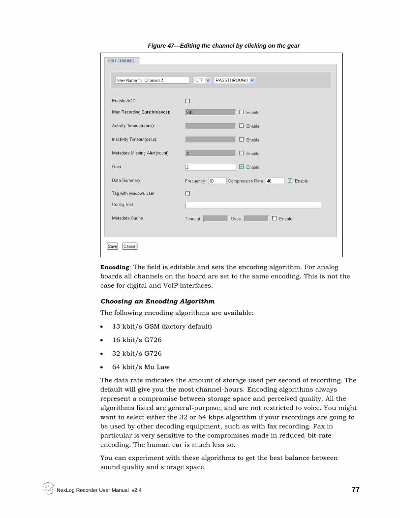
NexLog Recorder User Manual v2.4 77
Figure 47—Editing the channel by clicking on the gear
Encoding: The field is editable and sets the encoding algorithm. For analog
boards all channels on the board are set to the same encoding. This is not the
case for digital and VoIP interfaces.
Choosing an Encoding Algorithm
The following encoding algorithms are available:
13 kbit/s GSM (factory default)
16 kbit/s G726
32 kbit/s G726
64 kbit/s Mu Law
The data rate indicates the amount of storage used per second of recording. The
default will give you the most channel-hours. Encoding algorithms always
represent a compromise between storage space and perceived quality. All the
algorithms listed are general-purpose, and are not restricted to voice. You might
want to select either the 32 or 64 kbps algorithm if your recordings are going to
be used by other decoding equipment, such as with fax recording. Fax in
particular is very sensitive to the compromises made in reduced-bit-rate
encoding. The human ear is much less so.
You can experiment with these algorithms to get the best balance between
sound quality and storage space.
78 NexLog Recorder User Manual v2.4
Name: Editable with an attached or on-screen keyboard.
The channel name can be up to 64 characters. It can identify the signal source
for each input channel. Telephone number, radio station call letters, ATC
frequency and function, or any other free-form data may be entered here. While
up to 64 characters of data may be entered and saved, display constraints
suggest that you choose the first few characters most carefully. There is no
requirement to modify these identifiers. The factory default “Channel 01” ...
“Channel nn” may be serviceable.
AGC: Activates or deactivates Automatic Gain Control for Analog channels.
Automatic Gain Control assures that recordings take advantage of the full
dynamic range of the recording process. If you record at too high a level, the
signal will “clip” and sound very distorted. If you record at too low a level, the
signal will sound very soft and have a poor signal-to-noise ratio. Enabling AGC
gives extra margin when recording telephone calls where the local party may be
much louder than the distant one-it will boost the gain by up to 24dB when the
distant party is speaking. AGC should be enabled in most cases. It can be
disabled in installations where audio levels are well-controlled (e.g., broadcast
radio stations).
BEEP: Enables a “Beep tone” to signify to callers that the call is being recorded.
Activating the beep places a short, distinctive tone on the respective channel of
the input connector. This tone is approximately 65 milliseconds in duration at a
frequency of 1455 Hz. It serves to indicate that the call is being recorded, and is
required by some state laws. Of course, the beep will only be audible to the
callers if the recorder is connected directly to the telephone line in question; if
an amplifier or other device is interposed it will serve no purpose. Beep tones are
only generated on Analog Input Boards, not on Digital PBX or T1/E1 interface
boards.
If extended beep is enabled (at the Board Edit page), the beep will be
1403.508772 Hz and 387.5 ms, which is within the 1400 Hz ± 1.5% and 400ms
± 75ms specification for Australian requirements for beep on line recordings.
DETECT: This parameter determines when an input channel is active and should
be recorded. It establishes the primary recording control for the channel.
The following are valid values for this parameter:
VOX: (default) Starts recording if the voice (vox) or audio input signal is
above the configured Vox threshold setting, and stops recording if the signal
drops below that setting for the configured hold time.
TRUEVOX: [RTP only.] In regular VOX mode for RTP channels, the presence
of data on the line will trigger recording, but some environments will
transmit large durations of data that is actually silence, so this mode will
analyze the contents of the packets and evaluate recording based on the
volume of the contained audio.
NexLog Recorder User Manual v2.4 79
TRV: Starts recording if the DC input voltage is lower than the configured
TRV (Tip-Ring Voltage) threshold, indicating an off-hook condition, and stops
if the voltage rises above the configured setting for a period equal to or
greater than the configured TRV Hold time. Note that TRV detect is only
available for Analog boards and is only useful for audio sources that provide
this DC voltage in addition to the analog signal (such as standard analog
phone lines)
On: Records the channel continuously. For voice, audio, or call recording, it
records regardless of input signal or voltage conditions. (This is useful if
there are periods of silence that need to be recorded, such as dead air on a
broadcast station or long periods of dead silence in a courtroom.) For screen
recordings, the recording includes when the screen saver is on. This setting
is not affected by the Activity Timeout or Inactivity Timeout parameters.
Note: If recording Always, it can be helpful to break the recording into
smaller segments (such as 1-hour segments).
GPIO: Uses an input signal from an optional General Purpose Input/Output
(GPIO) board to trigger recording start and stop. The pin pair that carries the
input signal is specified in GPIO Pin column. Recording starts on a high
signal and stops on a low signal. This allows a variety of external devices to
trigger recording.
Scheduled: Uses Scheduled Recording to start and stop recording.
Script: Records based on start/stop requests from the NexLog Recorder
itself. This is used in conjunction with custom scripts or other specialized
programming created by Eventide Customer Engineering as a contracted
professional service. This setting is not affected by the Activity Timeout or
Inactivity Timeout parameters.
Disable: Disables recording for the channel.
Hook / Audio: These options are used for VoIP and Digital lines. They make
start / stop decisions based on the available signaling from the data source
connected to the channel. The exact behavior is dependent on the source.
For example on an ISDN PRI Channel, this causes the recorder to take cue
based on the ISDN Call Connection messages on the line. On Some PBXs
this will use the actual hookstate of the phone, while others (which do not
provide accurate hookstate), the recorder will use combinations of lights,
button presses, etc.
Note: Channels on T1/E1 boards may display a non-modifiable DETECT value of Data
Channel. When using ISDN Protocol over T1 or E1, one of the channels on the
trunk is reserved as a data channel and does not contain any voice data. The
recorder will automatically set that channel’s detect value to Data Channel and
grey out that channel on the front panel.
80 NexLog Recorder User Manual v2.4
VOX Threshold: This sets the trigger level for recording when Record Enable
Mode is VOX. A value between -48dB and 0dB is typical. The factory default is -
32dB. This setting is only used for Digital PBX, T1/E1, and Analog boards. For
VoIP, VOX detect mode triggers off the presence or absence of RTP traffic, not
the actual levels.
VOX Hold: If Detect is set to VOX, this sets the number of seconds the channel
will continue recording after the signal drops and remains below the threshold.
The factory default is 8 seconds.
Setting this for too long a value will record long periods of silence at the end of
transmissions; too short a value may break a single call into apparent multiple
call records at pauses on the conversation.
TRV Threshold: This sets the DC voltage at which a phone line is assumed to be
in the off-hook state and eligible for recording. On a normal, clean telephone
line, this does not have to be set too finely. On-hook voltages are typically 40-55
volts, off-hook under 10 volts. The factory default of 28 volts will probably be
suitable.
Noisy telephone lines, lines at a great distance from the central office, and lines
that are recorded at one location but answered at another can have unusual
voltage profiles and may require adjustment. This setting is only available on
Analog boards.
TRV Hold: If Detect is set to TRV, this sets the number of seconds the call will
continue to be recorded after the telephone goes on-hook. The factory default is
5 seconds. The on-hook state is then considered to define the end of the
conversation.
With a line that has normal ringing voltage on it ( +/-105V at 20-30 Hz), TRV
will also respond to the ringing voltage. This means that, with a default of less
than four seconds, each ring will appear to be a separate call. By setting TRV
hold to five seconds or more, with a normal ringing cadence only one call will be
logged from the beginning of the ring to completion of the conversation.
If you have set a channel to TRV, a special (non-programmable) feature will
detect and flag a disconnected line if the tip/ring voltage stays below 3 volts for
1 minute. If this happens, it generates a severity 2 (warning) alert indicating
signal loss (Alert #9016). When the voltage equals or exceeds 3 volts, it
generates the corresponding “Resolved” alert for Alert #9016 to indicate the
signal is restored. TRV Hold setting is only available on Analog boards.
Input Gain: Gain (or attenuation) in dB of the input channel - used to set
recording level on analog boards.
Input Level: Real-time display of signal input level - useful for setting channel
gain. This is not an editable item. This information is very useful for diagnosing
recording problems, such as one call being broken up into multiple calls. Note
NexLog Recorder User Manual v2.4 81
that depending on the detect type this can either be TRVolt readings or VOX
readings. Input level is available for Analog boards.
TRV Level: This non-editable item shows you the real-time minimum, maximum,
and current value of the DC voltage at the channel input. The current value will
indicate if the phone is on- or off-hook; the Min and Max will show the highest
(on-hook) and lowest (off-hook) voltages seen by the channel input. If the
current value fluctuates over a wide range when you are not using the
telephone, it probably means that the line is very noisy. This information can
help you set the TRV Thrsh value or diagnose problems such as spurious calls.
This setting is only available for analog channels.
Default Call Type: This is the value that will be entered into the Calltype field of
all calls that come in on this channel, unless altered by a custom integration.
See the discussion of Calltype in the section on Custom Fields below.
Enable 4Wire Mode: Pairs this channel with one adjacent such that the audio
received on this channel and its pair are mixed into a single call record. If
enabled on an odd channel, it will pair with the next channel: Channel 1 will
pair with Channel 2. If enabled on an even channel, it will pair with the previous
channel: Channel 6 will pair with Channel 5.
The settings for each channel are independent so that you can configure them
as needed, but you can live monitor and playback calls as one channel. Audio
and metadata from both channels are recorded if the conditions to record are
met on either channel.
Enable TDD: Calls coming in on this channel with TDD (Telecommunications
Device for the Deaf) text data will be decoded and the TDD text stored in the
RTTsummary custom field. The text feed can then be viewed in MediaWorks
Plus when playing back the call. Nexlog supports decoding of TDD data encoded
using Baudot codes at 45.5 baud utilizing 1 start bit, 5 data bits, and 1.5 stop
bits. This feature requires the TDD Add-on License and an RTTsummary
custom field. Without this feature enabled and licensed, the audio feed of the
TDD will be recorded, but the recorder will not decode the text for display and
search purposes.
Activity Timeout: Timeout value in seconds. When set, alert #3001 (“Channel
was active for more than X seconds”) is issued if a channel is continuously
active for longer than the timeout value. The factory default is to disable this
function. This setting does not affect the actual recording of the call. It simply
issues an alert.
Activity Timeout is useful for calling attention to open or defective telephone
circuits. When a channel is set for TRV detection, a LOW voltage activates it. If
the circuit is open due to a broken wire, the voltage will always be LOW, and the
recorder will issue an alert if this condition persists. If you are going to use this
feature, then you should set this value to one that is longer than any reasonably
expected call or message to avoid nuisance alerts.
82 NexLog Recorder User Manual v2.4
Inactivity Timeout: Timeout value in seconds. When set, alert #3002 (“Channel
was inactive for more than X seconds”) is issued if there is no activity on the
channel for longer than the timeout value. The factory default is to disable this
function.
This setting does not affect the actual recording of the call. It simply issues an
alert.
Inactivity Timeout is useful for alerting you to circuits that should have signals
but do not. If you are monitoring a radio channel and the radio is turned off, the
inactivity timeout will eventually call this to your attention. Likewise, an unused
(but active and paid-for) telephone line can be identified with this feature. Of
course, legitimate inactivity can span weekends and holiday periods. Setting
periods too short can result in nuisance alerts.
GPIO Pin: Specifies a value indicating the input pin on the GPIO board that is
used for triggering recording to start or stop. The channel will record with the
input pin is pulled high by connected to pin 49 and will stop recording with the
pin is pulled low by connecting to ground with any even numbered pin. (This
field is used with the detect GPIO setting.)
For the NI PCI-6503 24-channel GPIO board, values are as follows:
0: specifies pin 47 (PA0) 6: specifies pin 35 (PA6)
1: specifies pin 45 (PA1) 7: specifies pin 33 (PA7)
2: specifies pin 43 (PA2) 8: specifies pin 7 (PC4)
3: specifies pin 41 (PA3) 9: specifies pin 5 (PC5)
4: specifies pin 39 (PA4) 10: specifies pin 3 (PC6)
5: specifies pin 37 (PA5) 11: specifies pin 1 (PC7)
PBX Digital Sync Errors: This column is only important for Digital PBX tapping
boards; it is used for installation and troubleshooting. The data will look like
this: 1.1 / 0.66 [2,1,0]. The first two numbers are signal levels in volts. The first
of the pair is the level of the signal coming from the PBX, and the second is the
signal level coming from the phone set.
The three numbers inside the brackets are the total error counts for the channel
since the last reconfiguration or restart:
Sync errors are more general errors on the channel as a whole.
PBX errors are errors in the signal from the PBX.
Phone errors are in the signal from the phone.
These errors can signify problems and can affect recording: if the errors are
increasing at a steady rate, it indicates that there is a problem with the
telephone line connected to the recorder. However, if the error counts aren’t all
zero but do not increase, it might not be an indication of a serious issue: for
example, someone may have unplugged and then plugged back in a phone.
NexLog Recorder User Manual v2.4 83
Problems can be caused by:
Line issues (bad taps, multiple taps, line lengths, tap lengths, marginal
wiring between the phone and PBX).
Unsupported phone set or line card.
The wrong PBX is set in the board configuration.
Steps for Setting Levels, Thresholds, and Hold Times
It is undesirable for single conversations to be broken up into multiple calls.
There is a lag between each stop and start, so some of the conversation will be
lost. Setting levels and thresholds properly will help you avoid this condition.
This applies to channels set for VOX detect.
If you are seeing this condition, or if you simply want to check how well the
default parameters match your facility, try this procedure:
Disable AGC
Set the Input Gain. It should be set with signals that best match what will
be seen during normal operation. Watch the values and adjust the gain so
that the current value ranges between -6dB and -1dB while a signal is
present.
Enable AGC (if desired). Not recommended for broadcast recording,
recommended for communications or telephone channels.
Using the Input level or the detail levels graph note the VOX Cur value with
no signal present, but with the cabling still connected to account for line
noise. Then note the VOX Cur value with the lowest-level input signal that
you are likely to see during use.
Set the VOX Threshold using the values from the previous step. The
threshold should be higher than noise but lower than your lowest signal.
Another possible cause for conversations recorded on multiple separate calls is
Hold time. This would apply to both VOX Detect and TRV Detect. Conversations
with pauses longer than the Hold setting will generate a stop-recording signal.
When the conversation resumes, a start-recording signal will create a second
call. To determine if this is happening, listen to the last several seconds of a call.
If you hear a pause in the conversation longer than the Hold time, followed by a
second separate call of the same conversation, then the length of the pause
caused the stop-recording signal. If you wish, you can increase the Hold time.
The downside is that longer periods of silence will be recorded at the end of
EVERY call on that particular channel. For example, a 15-second Hold time on
Channel 3 will cause a 15-second period of silence to be recorded on every call
on Channel 3.
84 NexLog Recorder User Manual v2.4
4.6.2. Replace Board
This section allows you to swap boards in your system for similar boards. This is
necessary in the unlikely event of hardware failure (due to a power surge) or to
expand channel count by replacing an 8 channel analog board with a 24
channel board, for example. When selecting the board to be replace it must be
removed from the system. The board that you are going to replace it with must
be physically in the system and disabled. Disable the board by going to the
‘Boards’ setup page and selecting the replacement boards configuration. When
you have a possible replacement candidate the Replace Board setup page will
show a submit button. If you do not a valid replacement configuration the
button will not be present and the text at the top of the page will give an
explanation for why you cannot do a replacement.
The act of replacing a board transfers all settings to the new board. This
includes channel ordering, channel names, and parameters specific to the board
type.
4.6.3. Retention Settings
Eventide NexLog Recorders store call data on their storage devices and provide a
built in database for immediate retrieval and playback of recorded audio. Once
the hard drives fill up with data, the oldest data will begin to be deleted from the
system to make room for new data as new recordings are made. The Retention
settings allow you to customize when this data is deleted.
Note that any Call Record which has been marked as "Protected" in the Front
Panel or MediaWorks will not be deleted to make room for new recordings
regardless of retention settings. If both "Limit retention time" and "Limit
recording count" fields are disabled, then call records will only be deleted if the
hard drives are too full to store new recordings. Enabling and setting "Days to
retain Media Records" will cause all call records older than the configured
number of days to be deleted. For example, if set to 60 days, the recorder hard
drives will contain a rolling history of the past 60 days of recordings (assuming
adequate disk space).
In addition Max Number of Media Records allows a maximum number of
Recordings to be specified, if this number is surpassed, the oldest recordings on
the disk will be deleted to restore this constraint. It is beneficial to keep your
stored recordings under 10 million records to maximize database and recall
performance.
Note that these settings have no effect on Archives. Eventide recommends
Archive settings be properly configured and archive media to be properly
maintained to put in effect a policy of making sure all recordings are archived to
one or more archive media before being deleted due to retention policy.
The Retention Filters tab lists all Resource Groups with Retention Rules
enabled. These groups are configured at the Resource Groups page, and the edit
NexLog Recorder User Manual v2.4 85
Retention Groups button will take you to the Resource Groups page, with the
group filter set to show just Retention Groups.
Clicking the Advanced tab will expose some advanced configuration settings.
You generally would not need to change any of these settings unless
recommended by Eventide or your Eventide Dealer.
Delete parent Media Record: Some Custom Integrations purchased from
Eventide may be designed to break existing media records into multiple records.
When this is done, this setting determines whether the original media record is
also retained or deleted
Use Prefix on Ignore: Used with Some Custom Integrations for Motorola
SmartZone recordings where the same recording will be recorded from two
different towers. This setting will cause the secondary 'backup' recording to have
its channel name prefixed with DUP_ for 'Duplicate'
User Unknown as Channel name: Normally the channel name of a call will be
assigned with the configured name of the channel it is recorded on. This value
can then be overridden by a Metadata Feed or Custom Integration. If no value
comes in from these secondary sources, the name remains the name of the
channel. If this option is checked, and no value comes in via a Metadata feed or
custom integration, then the channel name for the recording will be set to
'Unknown' instead of the name of the channel it was recorded on.
4.6.4. Resource Groups
This page allows you to view and manage Resource Groups. A Resource Group
is a configured set of one or more resources available on the recorder, and the
rules that apply to those resources. Resources are the call sources on a
recorder, and they are identified by channel name, physical channel id, and talk
groups. Leveraging these rules and groups allows you to gracefully administer
your NexLog recorders in more powerful and flexible way than before.
The Resource Groups feature was new to NexLog 2.2.0, and supersedes the
Channel Groups feature present in earlier versions. Resource Groups allows you
to manage all policy for a set of resources, instead of having a separate channel
group for each rule. For example, if you have a group of channels recording Fire
Department calls and another set for Police, you can now have a Resource
Group named Fire that contains all channels with names that start with Fire,
that grants permission to the correct users and follows the legal requirements
for keeping Fire recordings, all in one place.
Resource Group Rules
The rules available are:
Permission: Grant access to these resources to a list of users. The users can
then use these resources when browsing, exporting, searching, live
monitoring, etc., based on the other permissions they are assigned on the
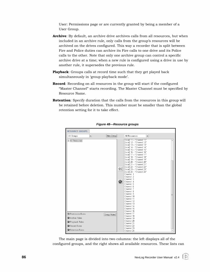
86 NexLog Recorder User Manual v2.4
User: Permissions page or are currently granted by being a member of a
User Group.
Archive: By default, an archive drive archives calls from all resources, but when
included in an archive rule, only calls from the group’s resources will be
archived on the drives configured. This way a recorder that is split between
Fire and Police duties can archive its Fire calls to one drive and its Police
calls to the other. Note that only one archive group can control a specific
archive drive at a time; when a new rule is configured using a drive in use by
another rule, it supersedes the previous rule.
Playback: Groups calls at record time such that they get played back
simultaneously in ‘group playback mode’.
Record: Recording on all resources in the group will start if the configured
“Master Channel” starts recording. The Master Channel must be specified by
Resource Name.
Retention: Specify duration that the calls from the resources in this group will
be retained before deletion. This number must be smaller than the global
retention setting for it to take effect.
Figure 48—Resource groups
The main page is divided into two columns: the left displays all of the
configured groups, and the right shows all available resources. These lists can
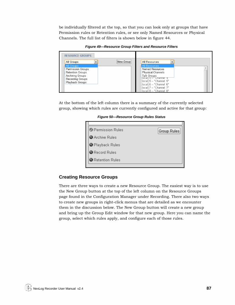
NexLog Recorder User Manual v2.4 87
be individually filtered at the top, so that you can look only at groups that have
Permission rules or Retention rules, or see only Named Resources or Physical
Channels. The full list of filters is shown below in figure 44.
Figure 49—Resource Group Filters and Resource Filters
At the bottom of the left column there is a summary of the currently selected
group, showing which rules are currently configured and active for that group:
Figure 50—Resource Group Rules Status
Creating Resource Groups
There are three ways to create a new Resource Group. The easiest way is to use
the New Group button at the top of the left column on the Resource Groups
page found in the Configuration Manager under Recording. There also two ways
to create new groups in right-click menus that are detailed as we encounter
them in the discussion below. The New Group button will create a new group
and bring up the Group Edit window for that new group. Here you can name the
group, select which rules apply, and configure each of those rules.
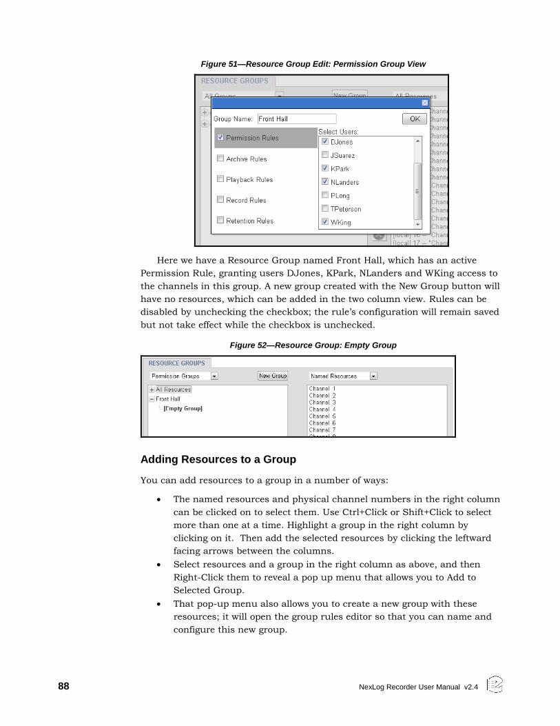
88 NexLog Recorder User Manual v2.4
Figure 51—Resource Group Edit: Permission Group View
Here we have a Resource Group named Front Hall, which has an active
Permission Rule, granting users DJones, KPark, NLanders and WKing access to
the channels in this group. A new group created with the New Group button will
have no resources, which can be added in the two column view. Rules can be
disabled by unchecking the checkbox; the rule’s configuration will remain saved
but not take effect while the checkbox is unchecked.
Figure 52—Resource Group: Empty Group
Adding Resources to a Group
You can add resources to a group in a number of ways:
The named resources and physical channel numbers in the right column
can be clicked on to select them. Use Ctrl+Click or Shift+Click to select
more than one at a time. Highlight a group in the right column by
clicking on it. Then add the selected resources by clicking the leftward
facing arrows between the columns.
Select resources and a group in the right column as above, and then
Right-Click them to reveal a pop up menu that allows you to Add to
Selected Group.
That pop-up menu also allows you to create a new group with these
resources; it will open the group rules editor so that you can name and
configure this new group.
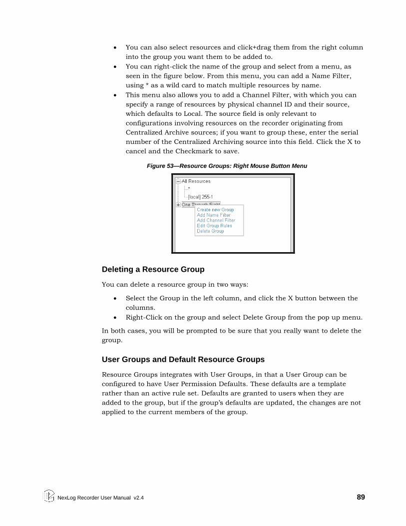
NexLog Recorder User Manual v2.4 89
You can also select resources and click+drag them from the right column
into the group you want them to be added to.
You can right-click the name of the group and select from a menu, as
seen in the figure below. From this menu, you can add a Name Filter,
using * as a wild card to match multiple resources by name.
This menu also allows you to add a Channel Filter, with which you can
specify a range of resources by physical channel ID and their source,
which defaults to Local. The source field is only relevant to
configurations involving resources on the recorder originating from
Centralized Archive sources; if you want to group these, enter the serial
number of the Centralized Archiving source into this field. Click the X to
cancel and the Checkmark to save.
Figure 53—Resource Groups: Right Mouse Button Menu
Deleting a Resource Group
You can delete a resource group in two ways:
Select the Group in the left column, and click the X button between the
columns.
Right-Click on the group and select Delete Group from the pop up menu.
In both cases, you will be prompted to be sure that you really want to delete the
group.
User Groups and Default Resource Groups
Resource Groups integrates with User Groups, in that a User Group can be
configured to have User Permission Defaults. These defaults are a template
rather than an active rule set. Defaults are granted to users when they are
added to the group, but if the group’s defaults are updated, the changes are not
applied to the current members of the group.
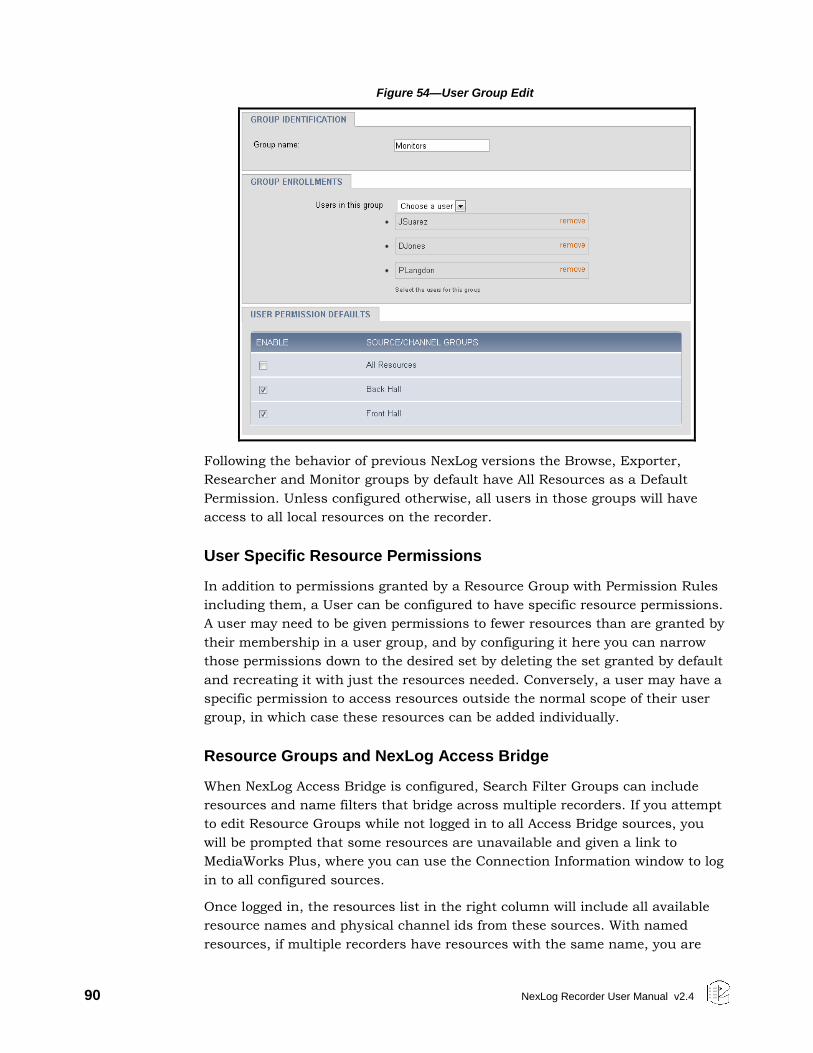
90 NexLog Recorder User Manual v2.4
Figure 54—User Group Edit
Following the behavior of previous NexLog versions the Browse, Exporter,
Researcher and Monitor groups by default have All Resources as a Default
Permission. Unless configured otherwise, all users in those groups will have
access to all local resources on the recorder.
User Specific Resource Permissions
In addition to permissions granted by a Resource Group with Permission Rules
including them, a User can be configured to have specific resource permissions.
A user may need to be given permissions to fewer resources than are granted by
their membership in a user group, and by configuring it here you can narrow
those permissions down to the desired set by deleting the set granted by default
and recreating it with just the resources needed. Conversely, a user may have a
specific permission to access resources outside the normal scope of their user
group, in which case these resources can be added individually.
Resource Groups and NexLog Access Bridge
When NexLog Access Bridge is configured, Search Filter Groups can include
resources and name filters that bridge across multiple recorders. If you attempt
to edit Resource Groups while not logged in to all Access Bridge sources, you
will be prompted that some resources are unavailable and given a link to
MediaWorks Plus, where you can use the Connection Information window to log
in to all configured sources.
Once logged in, the resources list in the right column will include all available
resource names and physical channel ids from these sources. With named
resources, if multiple recorders have resources with the same name, you are
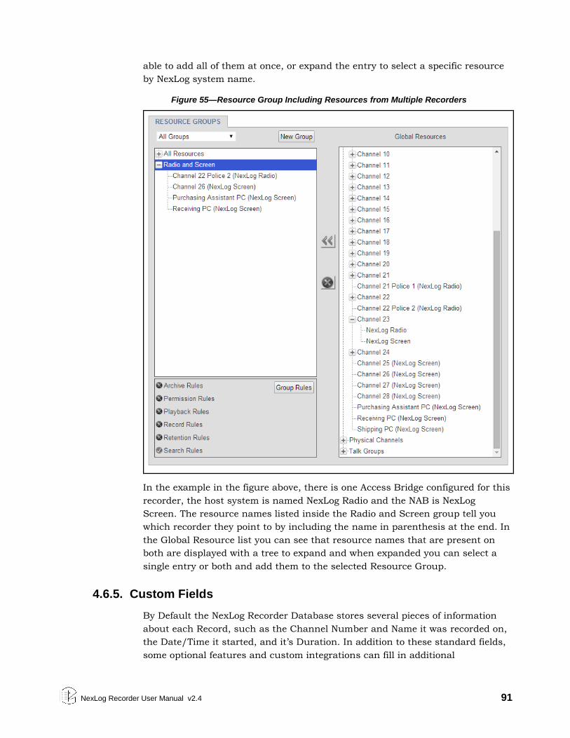
NexLog Recorder User Manual v2.4 91
able to add all of them at once, or expand the entry to select a specific resource
by NexLog system name.
Figure 55—Resource Group Including Resources from Multiple Recorders
In the example in the figure above, there is one Access Bridge configured for this
recorder, the host system is named NexLog Radio and the NAB is NexLog
Screen. The resource names listed inside the Radio and Screen group tell you
which recorder they point to by including the name in parenthesis at the end. In
the Global Resource list you can see that resource names that are present on
both are displayed with a tree to expand and when expanded you can select a
single entry or both and add them to the selected Resource Group.
4.6.5. Custom Fields
By Default the NexLog Recorder Database stores several pieces of information
about each Record, such as the Channel Number and Name it was recorded on,
the Date/Time it started, and it’s Duration. In addition to these standard fields,
some optional features and custom integrations can fill in additional
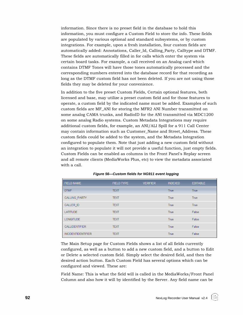
92 NexLog Recorder User Manual v2.4
information. Since there is no preset field in the database to hold this
information, you must configure a Custom Field to store the info. These fields
are populated by various optional and standard subsystems, or by custom
integrations. For example, upon a fresh installation, four custom fields are
automatically added: Annotations, Caller_Id, Calling_Party, Calltype and DTMF.
These fields are automatically filled in for calls which enter the system via
certain board tasks. For example, a call received on an Analog card which
contains DTMF Tones will have those tones automatically processed and the
corresponding numbers entered into the database record for that recording as
long as the DTMF custom field has not been deleted. If you are not using those
fields they may be deleted for your convenience.
In addition to the five preset Custom Fields, Certain optional features, both
licensed and base, may utilize a preset custom field and for those features to
operate, a custom field by the indicated name must be added. Examples of such
custom fields are MF_ANI for storing the MFR2 ANI Number transmitted on
some analog CAMA trunks, and RadioID for the ANI transmitted via MDC1200
on some analog Radio systems. Custom Metadata Integrations may require
additional custom fields, for example, an ANI/ALI Spill for a 911 Call Center
may contain information such as Customer_Name and Street_Address. These
custom fields could be added to the system, and the Metadata Integration
configured to populate them. Note that just adding a new custom field without
an integration to populate it will not provide a useful function, just empty fields.
Custom Fields can be enabled as columns in the Front Panel's Replay screen
and all remote clients (MediaWorks Plus, etc) to view the metadata associated
with a call.
Figure 56—Custom fields for NG911 event logging
The Main Setup page for Custom Fields shows a list of all fields currently
configured, as well as a button to add a new custom field, and a button to Edit
or Delete a selected custom field. Simply select the desired field, and then the
desired action button. Each Custom Field has several options which can be
configured and viewed. These are:
Field Name: This is what the field will is called in the MediaWorks/Front Panel
Column and also how it will by identified by the Server. Any field name can be
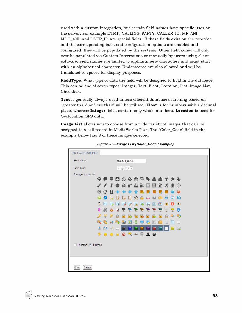
NexLog Recorder User Manual v2.4 93
used with a custom integration, but certain field names have specific uses on
the server. For example DTMF, CALLING_PARTY, CALLER_ID, MF_ANI,
MDC_ANI, and USER_ID are special fields. If these fields exist on the recorder
and the corresponding back end configuration options are enabled and
configured, they will be populated by the systems. Other fieldnames will only
ever be populated via Custom Integrations or manually by users using client
software. Field names are limited to alphanumeric characters and must start
with an alphabetical character. Underscores are also allowed and will be
translated to spaces for display purposes.
FieldType: What type of data the field will be designed to hold in the database.
This can be one of seven types: Integer, Text, Float, Location, List, Image List,
Checkbox.
Text is generally always used unless efficient database searching based on
"greater than" or "less than" will be utilized. Float is for numbers with a decimal
place, whereas Integer fields contain only whole numbers. Location is used for
Geolocation GPS data.
Image List allows you to choose from a wide variety of images that can be
assigned to a call record in MediaWorks Plus. The “Color_Code” field in the
example below has 8 of these images selected:
Figure 57—Image List (Color_Code Example)
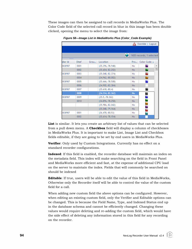
94 NexLog Recorder User Manual v2.4
These images can then be assigned to call records in MediaWorks Plus. The
Color Code field of the selected call record in blue in this image has been double
clicked, opening the menu to select the image from:
Figure 58—Image List in MediaWorks Plus (Color_Code Example)
List is similar. It lets you create an arbitrary list of values that can be selected
from a pull down menu. A Checkbox field will display a column of checkboxes
in MediaWorks Plus. It is important to make List, Image List and Checkbox
fields editable, if they are going to be set by end users in MediaWorks Plus.
Verifier: Only used by Custom Integrations. Currently has no effect on a
standard recorder configurations.
Indexed: If this field is enabled, the recorder database will maintain an index on
the metadata field. This index will make searching on the field in Front Panel
and MediaWorks more efficient and fast, at the expense of additional CPU load
on the server to maintain the index. Fields that will commonly be searched on
should be indexed
Editable: If true, users will be able to edit the value of this field in MediaWorks,
Otherwise only the Recorder itself will be able to control the value of the custom
field for a call.
When adding new custom field the above options can be configured. However,
when editing an existing custom field, only the Verifier and Editable options can
be changed. This is because the Field Name, Type, and Indexed Status end up
in the database schema and cannot be efficiently changed. Changing these
values would require deleting and re-adding the custom field, which would have
the side effect of deleting any information stored in this field for any recording
on the recorder.
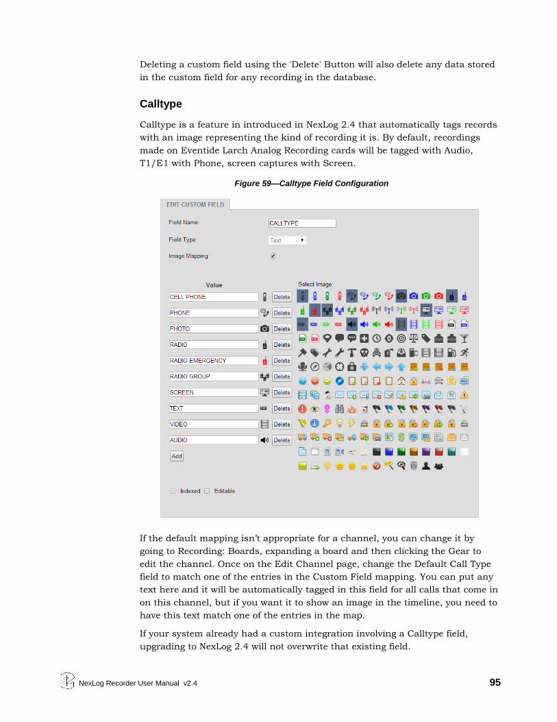
NexLog Recorder User Manual v2.4 95
Deleting a custom field using the 'Delete' Button will also delete any data stored
in the custom field for any recording in the database.
Calltype
Calltype is a feature in introduced in NexLog 2.4 that automatically tags records
with an image representing the kind of recording it is. By default, recordings
made on Eventide Larch Analog Recording cards will be tagged with Audio,
T1/E1 with Phone, screen captures with Screen.
Figure 59—Calltype Field Configuration
If the default mapping isn’t appropriate for a channel, you can change it by
going to Recording: Boards, expanding a board and then clicking the Gear to
edit the channel. Once on the Edit Channel page, change the Default Call Type
field to match one of the entries in the Custom Field mapping. You can put any
text here and it will be automatically tagged in this field for all calls that come in
on this channel, but if you want it to show an image in the timeline, you need to
have this text match one of the entries in the map.
If your system already had a custom integration involving a Calltype field,
upgrading to NexLog 2.4 will not overwrite that existing field.
96 NexLog Recorder User Manual v2.4
4.6.6. Call Suppression
The Call Suppression form provides the means to suppress, or prevent, calls
from recording (audio data will not be recorded, but the recorder retains non-
audio data about the calls). This feature can be used for a variety of purposes,
including implementing a legally mandated attorney-client privilege, or assuring
privacy for undercover officers or high-ranking officials.
Two mutually-exclusive suppression methods are provided:
Suppress on match (Blacklist): Suppresses recording for all calls that match a
telephone number in the list. The recorder discontinues recording a call as
soon as the telephone number is recognized.
Record on match (Whitelist): Suppresses recording for all calls except for
those that match a telephone number in the list.
The suppression method applies to the entire list of telephone numbers rather
than to individual telephone number entries. To select a suppression method,
click on the radio button next to it.
The Suppress DTMF feature applies to all call suppression. When recording is
suppressed for a call and this feature is enabled, the recorder will not store a
record of the telephone keypad dialing tones (Touch-Tones*) that occur during
the call. This can be useful to prevent the storage of sensitive data transmitted
by DTMF during a call, such as social security numbers, passwords, and
personal identification numbers. Click the Suppress DTMF checkbox to enable
this feature.
To suppress recording, you must select a suppression method and create a list
of telephone numbers. Then you must enable record suppression on a channel-
by-channel basis via the boards setup page. The following instructions describe
how to create and manage a list of telephone numbers.
To add a new entry to the list of numbers, click Add Pattern button. This allows
you to enter in Suppression Digits, and a Description.
Enter a full or partial telephone number. A call containing this numeric
sequence within its telephone number will cause a match. For example, if you
enter 800-555-1234, any calls from this number will cause a match, but if you
enter only 555, any calls with this sequence within the number will cause a
match.
A partial number allows you to specify all calls from an area code or exchange.
Whereas the Blacklist method is typically used for very specific telephone
numbers, the Whitelist method is often used with a partial number sequence.
For example, if you want to match on an area code and exchange, you can enter
800-555. (Note that a call from 900-880-0555 will also match this number.)
NexLog Recorder User Manual v2.4 97
Enter a description and click Add. The new should appear in the suppression
list.
Note that Blacklist or Whitelists affect all channels on the recorder and are not
configurable per channel.
4.6.7. NG911
This page allows you to easily configure your recorder to comply with the NG911
recording and event logging specification as published in NENA 03-008. Note
that you must receive licensing from Eventide before enabling the various
NG911 components.
The NG911 components are as follows
Create NG911 SIP Trunk: standard sip trunk with the addition of the ability
to receive geo location information in the form of Longitude and Latitude
coordinates.
Event “logging” interface for NG911 enabled PSAP components.
RTSP server for web based media retrieval.
4.7. SETUP: Archiving
4.7.1. Archives
In addition to the online storage that NexLog provides for recordings on its Hard
Drives (System: Storage Devices), the system also provides for archiving of
recordings. An Archive is a separate medium (DVD-RAM disk, Blu-Ray disk,
USB hard drive, etc.) onto which calls be archived for back up purposes.
Archives also provide a method to retain recordings that are deleted from the
Recorder's Hard Drive due to Retention settings (Recording: Retention) or disk
space availability. The NexLog Archives page allows you to view the status of and
perform actions on your archive drives.
NexLog supports three types of Archive Drives. The first drive type is physically
part of the recorder, such as DVD-RAM multi-Drives. These archive drives are
purchased with and licensed for use with your recorder. Since they are part of
the chassis, these archive drives will always show up in your list of archive
drives, regardless of whether or not media is currently present. Secondly, are
Archive drives that are physically connected and disconnected dynamically to
the recorder, for example, external USB Hard Drives or USB Keychain drives.
These archive drives will only show up on the setup page when they are
physically connected to the recorder. A final class of archive drives are those
which are accessed via the network. Because these are not physically connected
to the recorder, the recorder has no way to auto-detect these. They must be
manually added to the recorder's configuration and configured. These archive
drives include Network Attached Storage Devices and Centralized Archives,
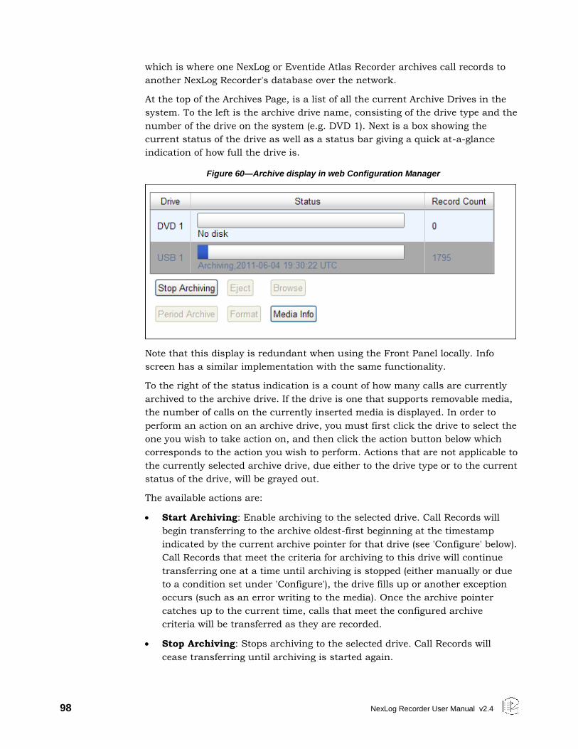
98 NexLog Recorder User Manual v2.4
which is where one NexLog or Eventide Atlas Recorder archives call records to
another NexLog Recorder's database over the network.
At the top of the Archives Page, is a list of all the current Archive Drives in the
system. To the left is the archive drive name, consisting of the drive type and the
number of the drive on the system (e.g. DVD 1). Next is a box showing the
current status of the drive as well as a status bar giving a quick at-a-glance
indication of how full the drive is.
Figure 60—Archive display in web Configuration Manager
Note that this display is redundant when using the Front Panel locally. Info
screen has a similar implementation with the same functionality.
To the right of the status indication is a count of how many calls are currently
archived to the archive drive. If the drive is one that supports removable media,
the number of calls on the currently inserted media is displayed. In order to
perform an action on an archive drive, you must first click the drive to select the
one you wish to take action on, and then click the action button below which
corresponds to the action you wish to perform. Actions that are not applicable to
the currently selected archive drive, due either to the drive type or to the current
status of the drive, will be grayed out.
The available actions are:
Start Archiving: Enable archiving to the selected drive. Call Records will
begin transferring to the archive oldest-first beginning at the timestamp
indicated by the current archive pointer for that drive (see 'Configure' below).
Call Records that meet the criteria for archiving to this drive will continue
transferring one at a time until archiving is stopped (either manually or due
to a condition set under 'Configure'), the drive fills up or another exception
occurs (such as an error writing to the media). Once the archive pointer
catches up to the current time, calls that meet the configured archive
criteria will be transferred as they are recorded.
Stop Archiving: Stops archiving to the selected drive. Call Records will
cease transferring until archiving is started again.
NexLog Recorder User Manual v2.4 99
Eject: For an archive drive with removable media, such as a DVD-RAM, this
button will cause the CD Tray to open so the media can be removed. For
other archive drives, such as a USB Drive, this action will render the drive
safe to be unplugged without the risk of losing or corrupting data on the
drive.
Browse: For Archive device types which do not contain a live database for
call searching and retrieval such as DVD-RAM Drives, this command readies
the current media in the archive drive for playback/retrieval from both the
Front Panel and MediaWorks. It does this by constructing a temporary live
database on the recorder for the call records on the drive so they can be
efficiently searched. When an archive drive is in browse mode, new calls
cannot be archived to it until it is first taken out of browse mode.
Period Archive: Period archive allows you to manually archive a time range
to an archive. It also allows you optionally select only protected media to be
archived. Media must be formatted without any calls on it before period
archiving can be used.
Format: For archive types that can be formatted by the recorder, this action
will perform a format. Formatting the media will delete all existing data
currently stored on the drive, whether it is an existing NexLog Archive, or
data belonging to some other device or operation system. Always double-
check the media before you format it.
Media Info: Displays additional information about the media currently
inserted into the drive.
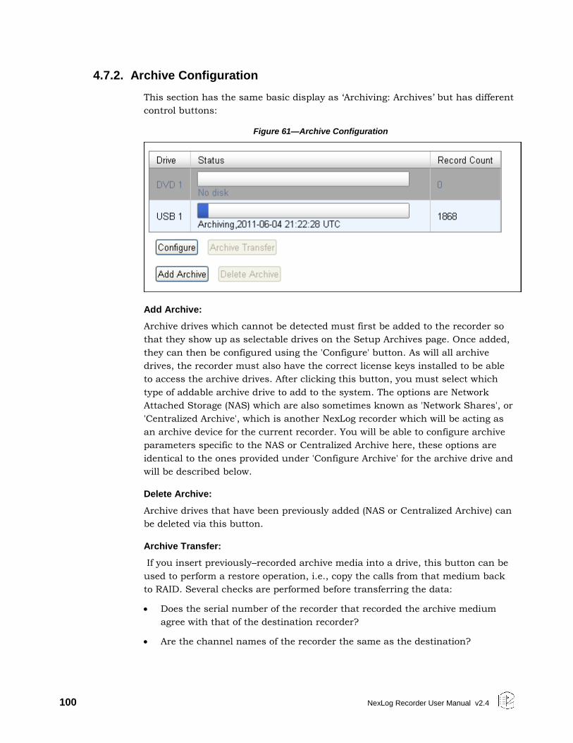
100 NexLog Recorder User Manual v2.4
4.7.2. Archive Configuration
This section has the same basic display as ‘Archiving: Archives’ but has different
control buttons:
Figure 61—Archive Configuration
Add Archive:
Archive drives which cannot be detected must first be added to the recorder so
that they show up as selectable drives on the Setup Archives page. Once added,
they can then be configured using the 'Configure' button. As will all archive
drives, the recorder must also have the correct license keys installed to be able
to access the archive drives. After clicking this button, you must select which
type of addable archive drive to add to the system. The options are Network
Attached Storage (NAS) which are also sometimes known as 'Network Shares', or
'Centralized Archive', which is another NexLog recorder which will be acting as
an archive device for the current recorder. You will be able to configure archive
parameters specific to the NAS or Centralized Archive here, these options are
identical to the ones provided under 'Configure Archive' for the archive drive and
will be described below.
Delete Archive:
Archive drives that have been previously added (NAS or Centralized Archive) can
be deleted via this button.
Archive Transfer:
If you insert previously–recorded archive media into a drive, this button can be
used to perform a restore operation, i.e., copy the calls from that medium back
to RAID. Several checks are performed before transferring the data:
Does the serial number of the recorder that recorded the archive medium
agree with that of the destination recorder?
Are the channel names of the recorder the same as the destination?
NexLog Recorder User Manual v2.4 101
Does the format of the data on the archive conform to that of the
destination?
Is there any problem with or damage to the archive medium to be
transferred?
Are all (or some) of these calls duplicates of calls already on the recorder?
If none of these are appropriate for the medium, or if you indicated that you
wish to proceed, the archive transfer will commence. All drives operate
independently. You can restore archive media in all available drives, or you can
even record archives on one medium while restoring from another.
Important! The restoration process cannot continue once the RAID is full, so unless you
have a special reason for doing otherwise, always restore from the most recent
archive backwards.
If you are restoring archives after a new installation, use the Set Archive Time
facility to make sure that new archives are only recorded from the present
forward. If you don’t set this and begin new archiving after you have restored
your archives from a previous installation, you might find yourself “re-archiving”
the restored archives.
Configure:
This screen allows you to configure your archiving drive. The archiving
parameters are as follows.
Settings
Drive Type: specifies the type of drive.
Data Archived: Specify the amount of data archived since install. This number
is in Bytes.
Archive Mode: Archive drives mounted inside the NexLog recorder are set to
sequential by default. Sequential means that after the current drive finishes
archiving it will start archiving on the next drive in the chain, assuming the
media is inserted and formatted without any data on it.
Auto Resume: A recorder that is turned off while an archive medium is being
recorded will automatically continue recording that archive from where it left off
when the recorder is restarted. If it isn’t enabled, then any archive media in the
recorder when power is applied will appear as they would if they were simply
inserted in the drive. This setting also controls auto resuming on NAS and
Centralized Archive drives after a network disconnect.
Auto Start: An archive drive set to Auto Start will automatically start archiving
anytime the drive is in a state where archiving is available. The only times it will
not start archiving are when there is no media, full (or damaged) media, the
drive is in browse mode, or when the other drive in a sequential pair is already
archiving. You may need to turn this off temporarily to be able to eject or browse
a drive if you want to do so while it is only partially full.
102 NexLog Recorder User Manual v2.4
Auto Eject: Ejects the media after it’s full. This is only applicable for DVD
drives.
Format Protection: Protects the media from being accidently formatted until
the time on the recorder is greater than the oldest call on the media plus the
configured protection seconds. Note that this option only prevents you from
formatting the media on the NexLog recorder, it does not protect against placing
the media in a PC and formatting it there.
Time
Set Archive Time: Allows you to set the current archive pointer.
When you start archiving, the first call to be archived is determined by an
internal archive pointer. This pointer tracks where you left off archiving with the
previous disk, so that the next disk will begin where the previous one left off.
Also, if you are in the middle of a disk and you stop archiving, for whatever
reason, such as the need to browse calls on the disk, you can resume archiving
at the point where you left off. The goal is to ensure that only consecutive calls
are recorded on each disk, making labeling and searching easier. This pointer is
maintained automatically.
However, there are times when you may want to manually set the current
pointer location. For example, you may have misplaced an archive disk and you
want to re-archive calls. Of course, to do so the calls must still be present on the
RAID.
To manually set the current archive time, select a date and time using the
calendar control and save the form. The next time you start archiving, the calls
on your RAID closest to the new archive time setting will be archived first.
When you have completed recording a medium whose starting time you have
selected with the Set Archive Time feature, the time pointer is set to the time of
the end of the medium just recorded. It is NOT set to the end of other data that
may have been archived. Sometimes this is desired behavior, such as when you
want to record more data than will fit on a single medium from the starting time
you set. Sometimes it may not be, such as when you want to continue archiving
from the end of the last medium you recorded in the normal sequence. If the
second is your requirement, you can note the desired time and reset the archive
pointer to this time. If you failed to make a note, you can take the most recent
archive medium, read the “Media info” for that disk, and set the pointer to that
time.
Important! As noted in the display, the Archive time is set in UTC time. If you are setting
the archive time to start at the end of a previously recorded archive medium,
you will probably use the “Media Info” feature to check on the end time of that
medium. The recorder displays “Media Info” in UTC since the archives are
portable and must be compatible over time zones and different playback
hardware. To dovetail the recorded and new archive times, you must convert
your local time to UTC for this setting.
NexLog Recorder User Manual v2.4 103
Archive Delay: how long to archive behind the recorders current time.
Archive Duration: Limit the time period contained on an archive. This is useful
if you only want one day’s worth of recordings on a media, for example.
Groups
Use Channel Group: Set an archive drive to use one of the configured archive
groups.
Tracking
Tracking is an option that prevents calls from being left out of archives. Because
of the inherent nature of the technology involved, NexLog Recorders do not
always receive calls from VoIP, Screen Capture and Centralized Archiving
sources in real-time. They can, under certain conditions, end up receiving calls
hours or even days after they were originally recorded. This can have a
significant impact on archiving. Take the following scenario for example:
A busy NexLog Recorder with both local input board sources and screen
channels.
The archive pointer on a DVD-RAM drive is set to current time.
Calls are currently coming in on the local input channels.
Due to temporary but severe network congestion, a screen capture client has
buffered an hour’s worth of calls, which is just now transferring to the
NexLog Recorder.
Starting to archive calls to this DVD-RAM drive would leave the hour of screen
calls unarchived. Because of this, archive drives can optionally be set to wait for
remote data, which will prevent any archive from writing past the current
archive time of any source that is not currently up-to-date.
In the same scenario as the preceding one, but with Tracking turned on, the
result would be the DVD-RAM drive would pause in archiving mode, idle, until
the screen system caught up to the archive time that had been initially set, at
which point the DVD-RAM would begin to fill with all of the calls, leaving
nothing unarchived.
This feature is optional only because a Call Source may be temporarily offline
and one needs to archive calls anyway. In that case, turn off CST, create the
archive you need, then turn CST back on and reset the archive time.
4.7.3. Media Selection
This section assumes you are using DVD-RAM disks for archiving. Eventide
recommends any of the following configurations of media for DVD-RAM
archiving:
For NexLog recorders equipped with the older Panasonic SW-9576 DVD-RAM
drives, use the following media type:
104 NexLog Recorder User Manual v2.4
PANASONIC 9.4 GB DVD-RAM, double-sided media, inside a Type 2
or Type 4 cassette. The cartridge will need to be flipped to use the
2nd side.
For NexLog recorders equipped with the newer LG Multi-Drives, use the
following media types:
PANASONIC 4.7 GB DVD-RAM, single-sided media, (non-cartridge)
PANASONIC 9.4 GB DVD-RAM, double-sided media, inside a Type 4
cartridge (Note: the disk must be removed from the Type-4 cartridge
prior to use in an LG Multi-drive). The disk will need to be flipped to
use the 2nd side.
Note: Regarding Data Protection: Although the recorder incorporates an archive
protection mechanism, this is only effective when playing the archive in the
recorder itself. When playing the archive in an ordinary PC that accepts the
cassette, it is not protected from being overwritten unless the write protection
tab on the Type 4 cassette is set.
CD-R Media: CD-R and DVD-R/RW/RW+, etc. media are not supported for
archiving. They are supported for exporting media via the Front Panel. If you try
to archive onto a CD-R, it won’t work, and it may not be immediately clear why,
so be sure to confirm that you are using the proper (DVD-RAM) archive medium.
Blu-Ray Media: Blu-Ray media is supported only on systems with Blu-Ray drives.
We recommend 25GB 2x single sided BD-RE discs.
4.7.4. Sequential and Parallel Modes
These modes apply only to recorders with more than one archive drive.
Otherwise, the setting has no effect.
Sequential mode means that archiving will continue automatically to the next
available medium. In the following figure, the top disk is writing calls. When the
disk fills up, archiving will continue on the middle drive, and then on the bottom
drive. The middle and bottom drives must contain formatted, blank media. After
the disks are full, they can be flipped if they are double-sided, and the process
will continue. For example, when the top disk Side A fills up, the middle disk
Side A will begin recording. When that is full, the bottom disk Side A will begin
recording. After Side A is full on any of the disks, you can flip the disk to Side B.
After the bottom disk, Side A, is full, the recording will continue on the top drive
Side B, and so on.
Parallel mode means that archiving will not continue automatically on the next
available drive. Instead, you can begin recording on the top drive and on the
middle drive simultaneously (and the bottom drive if you wish) and all drives will
record the same data. This mode uses more disks but provides redundancy.
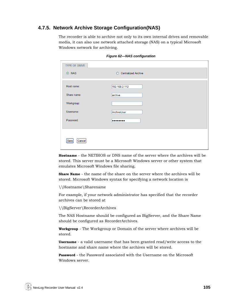
NexLog Recorder User Manual v2.4 105
4.7.5. Network Archive Storage Configuration(NAS)
The recorder is able to archive not only to its own internal drives and removable
media, it can also use network attached storage (NAS) on a typical Microsoft
Windows network for archiving.
Figure 62—NAS configuration
Hostname - the NETBIOS or DNS name of the server where the archives will be
stored. This server must be a Microsoft Windows server or other system that
emulates Microsoft Windows file sharing.
Share Name - the name of the share on the server where the archives will be
stored. Microsoft Windows syntax for specifying a network location is
\\Hostname\Sharename
For example, if your network administrator has specified that the recorder
archives can be stored at
\\BigServer\RecorderArchives
The NAS Hostname should be configured as BigServer, and the Share Name
should be configured as RecorderArchives.
Workgroup - The Workgroup or Domain of the server where archives will be
stored.
Username - a valid username that has been granted read/write access to the
hostname and share name where the archives will be stored.
Password - the Password associated with the Username on the Microsoft
Windows server.
106 NexLog Recorder User Manual v2.4
4.7.6. Archive Media History
The Archive Media History displays a history of all of the different archive media
that have been inserted into the recorder. Archive Media will show up in this list
regardless of whether or not they have actually been written to. Archives which
are inserted into the recorder only for browsing and playback will also show up
in this list. If the list spans multiple pages of output, use the 'Next' and "'Prev'
buttons on the bottom of the page to navigate through the list. Alternatively, you
can alter the page number in the "page" box and press the "Go" button. Note
that if an archive drive in the case of drives without removable media, or a
media disk in the case of drives with removable media will gain a separate entry
in this table for each time they were formatted and used. Therefore if you
archive Jan-Mar on a DVD-RAM disc, then reformat it, and then archive Apr-
Jun, you will have two entries for that disk in the archive media history, one for
the first date range showing that the archive has been deleted, and one for the
new date range.
The fields displayed for each archive media history entry are as follows:
Recorder Serial: The serial number of the recorder on which the archive was
written. This will be zero if created on the recorder you are logged into. It would
only be nonzero in the case of an archive written on a different recorder and
then inserted into this recorder for browsing and playback.
Format Time: The Date and Time upon which the archive drive, or current
archive media, was formatted.
Start Time: The Date and time of the oldest call contained on the archive
media.
End Time: The Date and Time of the latest call contained on the archive media.
Call Count: The number of calls archived to the archive media.
Status: The current status of the archive media. The possibilities are:
DELETED: This media has since been reformatted on the recorder, and this
archive is no longer available. Note that if an archive media is formatted on a
different system or physically destroyed, the calls will also no longer be
available, but this status will not be reflected in the recorder's archive media
history
PARTIAL: Archive was started but not completed.
Drive Type: The type of archive drive (e.g. DVD-RAM, USB Drive, NAS, etc.)
Last Archive Time: The most recent time that archiving was started on this
archive media.
4.7.7. Archive Splitter
Archiving media that has the potential to contain a very large amount of call
data, such as R-HD, NAS and USB drives, can be configured to be split into
NexLog Recorder User Manual v2.4 107
month sized folders, for faster loading times and search results when put into
browse mode. The splitter is configured with the Schedules page found under
Utilities.
4.8. SETUP: Alerts and logs
4.8.1. Active Alarms
An Alert on a NexLog system can either be an event or a state. Alerts that
represent a state are also referred to as 'Active Alerts' or 'Alarms'. All alarms on
a NexLog system are also alerts, but an alert is not necessarily an alert. For
example, Alert Code #8 "Recorder Startup" is an informational alert informing of
an event, but is not an Alarm. Alert Code #6001 "RAID is degraded" is an alarm,
since when the event it is informing of will remain in effect until resolution (by
replacing a drive). Some alerts which are not alarms will raise an alarm if the
alert occurs more frequently than a preset threshold, or will show up as an
Alarm for a few minutes after occurring, but then revert automatically to a non-
alarm alert.
The Active Alarms page allows you to view the Alarms that have triggered on the
system but have not yet been resolved. Therefore these alarm states are actively
in progress and awaiting resolution. Some alarm states will resolve on their own,
for example, an alarm complaining that the networking cable has been
disconnected, will be resolved automatically once the recorder detects that a
network cable has been reattached. Other alarms, such as the degraded RAID
alarm, may require user intervention to resolve.
If there are any currently active alarms to show, you will see a table with one
row per alarm. The columns are as follows:
Time: The date and time the alarm triggered and became active
AlertCode: The Alarm code for the alarm (See Alerts and Logs: Alert Codes)
AlarmText: The user friendly description of what the alarm represents
Times: If the same alarm triggers multiple time, they can be ‘compressed’ down
to a single alarm entry. In that case the “Times” field displays how many
occurrences this single entry represents.
Acknowledge: The word 'Yes' if the Alarm has been acknowledged, otherwise a
button containing the text 'Ack Now' which will acknowledge the alarm
It is impossible to resolve an alarm from the Active Alarms Setup page. For an
alarm to be resolved, the underlying cause must be fixed. Some alarms will
automatically resolve, while others will require user intervention, such as
replacing a disk drive. However, while an alarm cannot be resolved through
Setup, it can be 'Acknowledged'. When an Alarm is acknowledged it remains
active and in effect, but the recorder understands that the user is aware of the
issue and makes less effort to draw the user's attention to the problem. Mainly,
acknowledging an active alarm will prevent the alarm condition from causing
108 NexLog Recorder User Manual v2.4
the Front Panel's alarm indicator to blink red. It will also silence audio alarms
associated with the alarm. In addition, the "Show Acknowledged Alarms'
checkbox on this Configuration Tool page allows the user to determine whether
or not acknowledged alarms should be displayed.
The final checkbox on this page is "Automatically Refresh Page" If checked, the
alarms page will automatically refresh itself with the up to date status from the
recorder approximately once per minute. This saves having to constantly refresh
the page manually to see if any new alarms have arisen.
4.8.2. Alert History
The alert history provides a detailed account of all alerts and alarms on the
recorder. This screen is primarily used for diagnostic purposes. Alerts that are
currently active alarm conditions will appear in bold on this page. For a detailed
description of alerts see appendix I.
The fields displayed for each Alert in the history are:
Time: The Date and Time the Alert or Alarm occurred. This information is
displayed using your time zone information as configured currently.
Alert Code: Every alert occurrence has an Alert Code which can be cross
referenced with the information on the Alert Codes page
Alert Text: This is the corresponding text for the alert code with the specifics
about the alert occurrence substituted in for the place holders in the Alert
Code's text
Severity: The relative severity for this alert code as configured on the Alert
codes Page. Note that for alarms and other active alerts, you will see a separate
entry in the alert history for when the alarm was resolved.
4.8.3. Alert Codes
Every unique alert and alarm the NexLog system is capable of generating has an
alert code. The Alert Codes Setup page allows the user to view all of the possible
Alert Codes and set options for each one, such as whether or not the alert
should generate an email when it occurs. The Alert codes Setup page will
display a table showing one available alert code on each row. At the bottom of
the page are buttons for "Next Page" "Previous Page" and "Edit Alert". The Next
and Previous buttons allow the user to navigate through all the available pages
of alert codes as there are too many to fit on a single page. To edit the settings
for an alert, first highlight the alert code by clicking on it and then click the 'Edit
Alert' button.
Each alert code will display the code number for the alert, followed by its textual
description. In the description you will see placeholders that look like <~1~>.
These are filled in with the details of a specific alert occurrence when the alert
triggers and gets inserted into the alert history table. Finally, the severity is an
indication of how serious of an error the alert represents. These range from
NexLog Recorder User Manual v2.4 109
'INFO' meaning it’s simply an informative alert, to 'SEVERE' meaning that the
alert condition should be addressed immediately. Each alert code is
preconfigured with a reasonable severity for each alert code, but you can use the
'Edit Alert' button to alter the severity of any given alert to better suit your
recording application.
The 'Edit Alert' button will load the 'Edit Alert Code' Page. Here you can view
and modify the settings for the selected alert code. First, the Alert Code and
Display Text are read-only fields showing what alert you are currently editing. If
the alert is an "Active Alert" or Alarm, there will also be a "Resolved Text" field
which is a user visible description of what happens when the alarm is resolved.
This is also read only. After this is an Alert Severity Radio button set which
allows for altering the severity of alert code. This determines the coloration of
the alert in as displayed on the front panel as well as the behavior of certain
features such as GPIO output on alerts which are configured elsewhere.
Repeat Warning Every X Seconds: If enabled, repeats the email notification
every X seconds. (This is only in MediaWorks where alerts pop up as a dialog
box)
Alert Actions: These three checkboxes determine what action the recorder
takes when an alert becomes active
Audio Alarm: Plays an audible alarm from the Front Panel speaker. Option is
only available for alarms.
Send Email: If this box is checked, and email is configured as per Alerts and
Logs: Email, an email will be sent out anytime an alert with this alert code
triggers.
Display in MediaWorks: Whether this alert should be popped up to any
currently logged in MediaWorks clients.
4.8.4. Internal Logging
In addition to the Alert History Your Eventide NexLog recorder maintains some
internal logs which are only useful to Eventide Technicians. For support
reasons, an Eventide Technician may request the logs from your recorder. This
page provides two buttons.
The first button 'Enable/Disable Verbose Logging' turns on and off verbose
logging. When verbose logging is enabled the size of the rolling log file is
increased and certain log events that are not otherwise logged become logged. It
is important to only run your recorder with Verbose Logging enabled at the
request of Eventide or your Eventide Dealer's support personnel and to disable it
when the recorder is in normal operation, as some of the verbose logging may
interfere with normal behavior on busy systems.
The 'Export' logs button will zip up the log files on the recorder and allow you to
download them to your computer to be sent to Eventide or Dealer personnel. If
running from the Front Panel rather than a web browser, then this option will
110 NexLog Recorder User Manual v2.4
give you the option of writing the logs to a plugged in USB Keychain drive or
other archive medium rather than downloading.
4.8.5. Email
Individual Alert codes can be configured to send out an email when they occur.
To enable the sending of email for configured alert codes, first click the 'Enabled'
check box on this page. Then you must configure the parameters for the SMTP
server you wish the recorder to use in order to send the emails.
Setting these parameters is very similar to the normal email setup procedure on
a PC, e.g., the Accounts settings in Microsoft Outlook or Outlook Express. You
will need the same information for these settings as you would for normal email,
and can obtain them from your network administrator (or possibly by looking at
your PC email settings).
All entries requiring IP addresses can either use fully qualified domain names
(FQDN) or numerical addresses. Using a FQDN (e.g., <host.domain.com>) is
recommended since IP addresses frequently change. The recorder does not have
to be restarted for the email settings to take effect.
From Address: What the email alerts’ 'From' field should read: e.g.
ReplyTo address: Where the email alert should request replies be sent to e.g.
Send Error To Address: Option address to send email to if sending to user fails.
SMTP Host: The IP Address of the SMTP server to send the email to
SMTP Login: The username the recorder should use to log in to the SMTP
server
SMTP Password: The password the recorder should use to log in to the SMTP
server
SMTP Localhost Name: Optional name
SMTP Port: The port number the email should be sent to on the SMPT server's
IP address. 25 is standard for SMTP traffic
Finally the "Force TLS" checkbox should be checked if your SMTP server is
configured to only allow emails to be received using TLS.
If email is enabled and properly configured as above, and an Alert Code fires
which is configured to send an email, then an email version of the alert will be
emailed out to any Recorder users who have Administrator rights to the recorder
and have a correct email address in their user record.
4.8.6. Audit History
Your NexLog recorder stores an audit history of important events which have
occurred on the system for security auditing. This Audit history can be viewed
NexLog Recorder User Manual v2.4 111
from the 'Audit History' page. Each row in the table represents one auditable
event, and auditable events are displayed in descending order by time, with
most recent first. If more than one web page is required to display all the audit
history events, you will find an "Older Entries' and "Newer Entries" buttons at
the bottom of the page for navigation purposes.
Each audit history entry shows the following information:
Time: The Date and Time the audited event occurred are displayed using the
currently configured time zone information for the recorder
User: The User Account which performed or attempted to perform the audited
action
Success: Whether or not the attempted Action was successful.
Description: A human readable description of what happened.
Action: This describes the action that was performed. Valid action types
include:
USER-LOGIN: The user account logged into the system. The description will
also specify what client software was used (e.g. MediaWorks, Soap Client,
etc.)
USER-LOGOUT: The user account logged out of the system
SHUTDOWN: A request was made to shut down the recorder
REBOOT: A request was made to reboot the recorder
MONITOR-ON: The user Live Monitored a channel and listened to the audio
MONITOR-OFF: The user ceased live monitor the channel
FORCE-SUPPRESSION-ON: The user turned on call suppression for a
channel
FORCE-SUPPRESSION-OFF: The user turned off call suppression for a
channel
AUDIO-ACCESSED: The user played a media record
ADD-ENTITY: A New entity (e.g. Custom Field, User Account, etc.) was
added to the recorder. The description will tell which entity type was added.
DELETE-ENTITY: An Entity (e.g., Custom Field, User Account, etc.) was
deleted from the recorder. The description will tell which entity type and the
primary key (name, number, etc.) of the entity.
UPDATE-ENTITY: An Entity (e.g., Custom Field, DateTime, etc.) was
modified. The description will tell the Entity Type and if applicable primary
key of the entity.
GET-ENTITY: An Entity (e.g., Custom Field, DateTime, etc.) was retrieved
and viewed. The description will tell the Entity Type and if applicable the
primary key of the entity
112 NexLog Recorder User Manual v2.4
GET-ALL-ENTITY: All Entities (e.g., Custom Field, DateTime, etc.) were
retrieved and viewed. The description will tell the Entity Type
SEARCH-ENTITY: An Entity was searched
START-RECORDING: A user forced recording to start on a channel (this
usually happens from a SOAP integration with the recorder)
STOP-RECORDING: A user forced recording to stop on a channel (this
usually happens from a SOAP integration with the recorder)
ROD-DISABLE: A user forced a channel into a non-recording mode (this
usually happens from a SOAP integration with the recorder)
ROD-ENABLE: A user switched a channel back to its standard recording
mode (this usually happens from a SOAP integration with the recorder)
OPEN-TRAY: A user ejected an archive drive
CLOSE-TRAY: A user injected an archive drive
ACKNOWLEDGE-ALERT: A user acknowledged an alert
SET-CHANNEL-METADATA: A user added metadata to be applied to each
media record on a channel (this usually happens from a SOAP integration
with the recorder)
SET-CALL-METADATA: A user added metadata to a specific call (this
usually happens from a SOAP integration with the recorder)
SET-WORKSTATION-TAG: User set workstation tag for channel. (this
usually happens from a SOAP integration with the recorder).
UNSET-WORKSTATION-TAG: User unset workstation tag for channel. (this
usually happens from a SOAP integration with the recorder).
CHANGE-PASS: A user changed their pass (or someone else’s if they are an
admin)
EXPORT-SYSTEM-INFO: A user took a backup of system information either
to an archive drive or via download to a web browser.
IMPORT-SYSTEM-INFO: A user uploaded or restored system information
OFFLINE-DISK-FROM-RAID: A user marked a drive for removal
ADD-DISK-TO-RAID: A user added a new drive to a RAID
BOND-NICS: A user bonded 2 network interfaces together into 1 interface
(this is advanced behavior for certain logger configurations and is not typical
to see)
START-ARCHIVING: A user started archiving on an archive device
STOP-ARCHIVING: A user stopped archiving
NexLog Recorder User Manual v2.4 113
BROWSE-ARCHIVE: A user put an archive into Browse mode for viewing
with the Front Panel or with client software
UNBROWSE-ARCHIVE: A user took a browsed archive back offline
PERIOD-ARCHIVE: A user initiated a period archive to an archive drive
FORMAT-ARCHIVE: A user initiated a format of an archive drive
SET-ARCHIVE-POINTER: A user moved the archive time pointer on an
archive
START-ARCHIVE-TRANSFER: A user started a transfer of archived data
back to the recorder
STOP-ARCHIVE-TRANSFER: A user stopped the transfer of archived data to
the recorder.
START-PCAP: A user started a network data capture
STOP-PCAP: A user stopped a network data capture
The Audit History is designed to provide an audit trail of configuration changes
as well as audio access to the recorder. There are options available under
Security: System Security that allow for configuration of the level of detail in the
audit history. If full details are enabled, then clicking on a configuration change
audit event (e.g. UPDATE-ENTITY) will display the actual SOAP/XML
configuration request that was sent to the recorder to make the request. A Close
button is provided to dismiss that window.
4.8.7. Client Activity
The Client Activity page will display information about PC Clients which have
recently connected to the recorder using Eventide MediaWorks or Eventide
Media Agent. This information can sometimes be useful for troubleshooting
client licensing issues as the client access is licensed on a per workstation
basis. One client workstation is shown per row along with next/prev/go buttons
for navigation as on other pages.
For each entry in the Client Activity table the following fields are shown:
Workstation: Mac address of the connecting client
User: The Username with which the client was logged into the system
Login Time: The date and time the login occurred
Logout Time: the data and time the client logged out. Blank if still logged in
License In use: Whether or not this client is currently holding a license.
ClientType: Application used to connect to the recorder
Client Address: The MAC address of the workstation from which the client
logged in
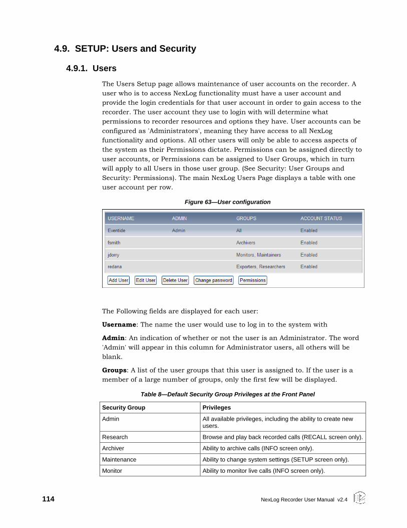
114 NexLog Recorder User Manual v2.4
4.9. SETUP: Users and Security
4.9.1. Users
The Users Setup page allows maintenance of user accounts on the recorder. A
user who is to access NexLog functionality must have a user account and
provide the login credentials for that user account in order to gain access to the
recorder. The user account they use to login with will determine what
permissions to recorder resources and options they have. User accounts can be
configured as 'Administrators', meaning they have access to all NexLog
functionality and options. All other users will only be able to access aspects of
the system as their Permissions dictate. Permissions can be assigned directly to
user accounts, or Permissions can be assigned to User Groups, which in turn
will apply to all Users in those user group. (See Security: User Groups and
Security: Permissions). The main NexLog Users Page displays a table with one
user account per row.
Figure 63—User configuration
The Following fields are displayed for each user:
Username: The name the user would use to log in to the system with
Admin: An indication of whether or not the user is an Administrator. The word
'Admin' will appear in this column for Administrator users, all others will be
blank.
Groups: A list of the user groups that this user is assigned to. If the user is a
member of a large number of groups, only the first few will be displayed.
Table 8—Default Security Group Privileges at the Front Panel
Security Group Privileges
Admin All available privileges, including the ability to create new users.
Research Browse and play back recorded calls (RECALL screen only).
Archiver Ability to archive calls (INFO screen only).
Maintenance Ability to change system settings (SETUP screen only).
Monitor Ability to monitor live calls (INFO screen only).
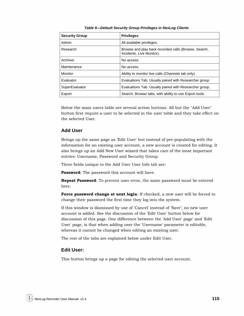
NexLog Recorder User Manual v2.4 115
Table 9—Default Security Group Privileges in NexLog Clients
Security Group Privileges
Admin All available privileges.
Research Browse and play back recorded calls (Browse, Search, Incidents, Live Monitor).
Archiver No access.
Maintenance No access.
Monitor Ability to monitor live calls (Channels tab only).
Evaluator Evaluations Tab. Usually paired with Researcher group.
SuperEvaluator Evaluations Tab. Usually paired with Researcher group.
Export Search, Browse tabs, with ability to use Export tools.
Below the main users table are several action buttons. All but the "Add User"
button first require a user to be selected in the user table and they take effect on
the selected User.
Add User
Brings up the same page as 'Edit User' but instead of pre-populating with the
information for an existing user account, a new account is created for editing. It
also brings up an Add New User wizard that takes care of the most important
entries: Username, Password and Security Group.
Three fields unique to the Add User User Info tab are:
Password: The password this account will have.
Repeat Password: To prevent user error, the same password must be entered
here.
Force password change at next login: If checked, a new user will be forced to
change their password the first time they log into the system.
If this window is dismissed by use of 'Cancel' instead of ‘Save’, no new user
account is added. See the discussion of the 'Edit User' button below for
discussion of this page. One difference between the 'Add User' page' and 'Edit
User' page, is that when adding user the 'Username' parameter is editable,
whereas it cannot be changed when editing an existing user.
The rest of the tabs are explained below under Edit User.
Edit User:
This button brings up a page for editing the selected user account.
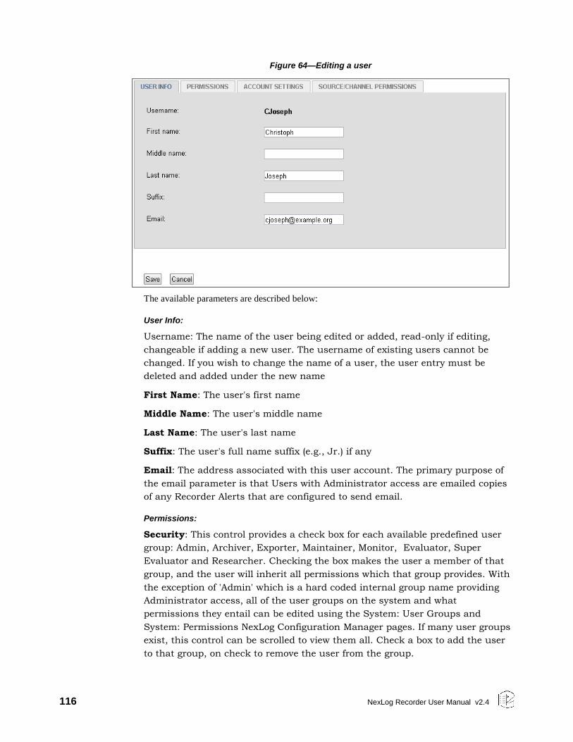
116 NexLog Recorder User Manual v2.4
Figure 64—Editing a user
The available parameters are described below:
User Info:
Username: The name of the user being edited or added, read-only if editing,
changeable if adding a new user. The username of existing users cannot be
changed. If you wish to change the name of a user, the user entry must be
deleted and added under the new name
First Name: The user's first name
Middle Name: The user's middle name
Last Name: The user's last name
Suffix: The user's full name suffix (e.g., Jr.) if any
Email: The address associated with this user account. The primary purpose of
the email parameter is that Users with Administrator access are emailed copies
of any Recorder Alerts that are configured to send email.
Permissions:
Security: This control provides a check box for each available predefined user
group: Admin, Archiver, Exporter, Maintainer, Monitor, Evaluator, Super
Evaluator and Researcher. Checking the box makes the user a member of that
group, and the user will inherit all permissions which that group provides. With
the exception of 'Admin' which is a hard coded internal group name providing
Administrator access, all of the user groups on the system and what
permissions they entail can be edited using the System: User Groups and
System: Permissions NexLog Configuration Manager pages. If many user groups
exist, this control can be scrolled to view them all. Check a box to add the user
to that group, on check to remove the user from the group.
NexLog Recorder User Manual v2.4 117
Archive Drive Access: Drives that a user has access to control.
ROD Channels: This field uses the same formatting as the Channel IDs
parameter above and determines what if any channels the user will be allowed
to perform "Record On Demand" on. If the user has permission, they will be able
to temporarily disable recording on the channels they have this permission on.
No options changed on any of these tabs will take effect until the 'Save' button
at the bottom of the page is clicked.
Instant Recall Interval limit: On the Front Panel and the MediaWorks and
MediaAgent clients, users may have access to an 'Instant Recall' functionality in
which they can view the most recent calls on the recorder. Users are able to
select how far in back they wish their view to contain calls from. The Limit
configured here places an upper bound on how far back the user can set this
limit when performing instant recall.
Restrict to Own Channel: If this checkbox is selected, then when searching
calls in MediaWorks and other clients, users will only be able to view and play
call records which have a metadata field called USER_ID which contains their
username. Obviously, for this setting to have any value, you must also create
the USER_ID column in Recording: Custom Fields and provide some method via
which the USER_ID is filled in with useful data, either by manually placing
User_IDs in individual calls using MediaWorks, by configuring the Workstations
Page for Call Taker tracking, or by a Custom Integration.
Account Settings:
Can Change Password: If this option is checked, the user is able to change their
own password. If disabled, only Administrator users can change this user's
password.
Account Enabled: If checked, the account can be used. If unchecked, the
account cannot be logged into.
Password Never Expires: If checked, the password expiry date has no effect.
Account Expiry Date: The account expiry date. After this date, user will not be
able to log in. He would get "Account expired" message.
Number of days after a password expires until the account is permanently
disabled: If “Password Never Expires” is unchecked, this is the number of days
until the password must be changed.
Session Inactivity Timeout Enabled: By default, users will be logged out from
Configuration Manager and MediaWorks Plus after an hour of inactivity. This
toggles whether that is in effect.
Session Inactivity Timeout (mins): Number of minutes of inactivity before the
user is automatically logged out. If the Session Inactivity Timeout is not enabled,
this value is ignored. The default is 60 minutes.
118 NexLog Recorder User Manual v2.4
Source/Channel Permissions:
These settings control what resources a user can search and playback in
MediaWorks, MediaAgent, and the Front Panel. This feature integrates with the
Resource Groups feature detailed in Section 4.6.4 in this manual. You can add
or delete individual resources or resource groups from the user’s resource
groups here.
4.9.2. System Security
NexLog Recorder provides options to allow recorder administrators to fine tune
the recorder's security policies which are configured from the Security: System
Security NexLog page.
General
Audit Changes: If this option is enabled, then any configuration changes made
via NexLog Configuration Manager, Front Panel, or the SOAP Service will result
in Audit event entries being placed in the audit history table. The audit history
can be viewed by visiting the Alerts and Logs: Audit History Setup page.
Audit Verbose: To have an effect, this option requires "Audit Changes" to also
be enabled. If enabled, then the full SOAP/XML Configuration Change request
message will be stored along with the audit entries in the audit history table.
This information can be viewed by clicking on the audit event on the audit
history page.
Audit non-destructive events: To have an effect, this option requires "Audit
Changes" to also be enabled. This causes audit history entries to be generated
not only for commands which alter the configuration state of the recorder, but
also those which simply view the state. With this option enabled you will be able
to audit any time a configuration entity such as a user record is viewed via
NexLog Configuration Manager or the SOAP Server (Access directly to the
onboard database via ODBC or MediaWorks/MediaAgent are exempt from
auditing). Normally this should be disabled unless for troubleshooting purposes
as a large amount of audit history will be generated; a simple "login and view a
few pages in NexLog Configuration Manager" session could generate dozens or
even hundreds of audit events.
Disable encrypted terminal (ssh): The ssh terminal is only used by Eventide
support personnel to assist with diagnostics. Normally enabled, only disable this
if your organization’s security rules require it.
Authenticate users via SMB service: Can connect to a CIF service that checks
authentication with Active Directory.
Front Panel
Front Panel Login Required: If disabled, the Recorder's Front Panel will be
usable without first logging in. If enabled, users will need to supply login
NexLog Recorder User Manual v2.4 119
credentials in order to view or use the Front Panel. Normally this would only be
disabled if the recorder is physically secured, for example by being in a locked
rack or in a locked room. The Front Panel auto-login user determines which
user account is automatically logged in if "Front Panel login required" is
disabled. When Front Panel Login requires is disabled, there is no way to log in
to the front panel as any user other than the auto-login user other than first
enabling Front Panel Login Required in setup.
Front Panel auto-login user: The user that will be automatically logged on.
Many installations with high security requirements change the auto-login user
to an unprivileged user that can just monitor channel activity.
Auto logout after timeout: If Front Panel Logins are required, this is the
number of seconds of inactivity before the user will be automatically logged out.
This cannot be disabled, but can be set arbitrarily high to achieve the same
effect.
Password Complexity
This section configures restrictions on NexLog passwords. If the "Enable
Password complexity" option is disabled, then the only requirement on user
passwords is that passwords contain at least three characters so trivial
passwords such as 123 are allowed. If this option is enabled, further restrictions
can be applied. Note that password complexity constraints are enforced at
password creation or modification time. Newly configured password constraints
will not have any effect on existing user passwords until the users attempt to
change their password. When enabled, this option enforces basic "no dictionary
words" password complexity constraints. In addition, additional configurable
constraints can be enabled. Password complexity changes the configurable
password restrictions are configured as follows:
Minimum Length: The minimum total number of characters a password must
contain
Minimum Digits: The numerical characters 0-9 are considered digits. If this
setting is greater than zero, then any password must contain at least that many
digit characters to be allowed.
Minimum Lowercase Characters: Any password must contain at least this
number of lowercase characters (a-z)
Minimum Uppercase Characters: Any password must contain at least this
number of uppercase characters (A-Z)
Minimum Special Characters: Special Characters are the non-numeric, non-
alphabetical characters that are available on the keyboard and result in a glyph
being entered. For example !@#$%^&*() are all Special Characters, but the CTRL
key is not since it does not result in the insertion of a glyph when pressed. This
setting indicates the minimum number of special characters that a password is
required to contain.
120 NexLog Recorder User Manual v2.4
Aging
The Password Aging sub header provides configuration options for the "Aging" or
"Time Limiting" of passwords. If this option is enabled via the "Enable Password
Aging" checkbox, users the system will require that users change their password
on a certain configured schedule to continue to access the system. The
configurable options are:
Maximum password age: Once this many days have passed since the user has
last changed the password before they are required to change it again. For
example, if this option were set to 7, users would be required to choose a
different password each week. If a user's password 'expires' and has not yet
been changed, then if the user attempts to log in to NexLog via the web
Configuration Manager or other clients, the only option they will have available
to them is "Change Password". They will not be able to utilize other client
functionality until they successfully complete password modification.
Minimum password age: If this option is set to a value greater than zero, it
configures a time period after which a user changes their password in which
they are prevented from changing their password again.
Warn Before Password Expires: Will warn user this many days before a
password change is required.
Reject Previous Passwords Including Current: Remember historical
passwords and don’t allow them to be re-used. If set to a value greater than
zero, this option will prevent a user from reusing a recent password. For
example, if set to three, a user required to change their password every week
could not simply rotate between 'password1' and 'password2'. Normally this
option would only be used in conjunction with the Minimum Number of Days
feature described immediately above. Otherwise, users could simply change
their password several times quickly to clear out the configured "recent history"
list to get around the security requirements.
Lockout
Clicking the “Lockout Settings" sub header provides configuration settings
allowing user accounts to be temporarily "locked out" upon presentation of an
invalid password. This can be used to prevent unauthorized personnel from
gaining access to the recorder by using automatic scripts to attempt many
passwords very quickly. To enable this option, check the "Enable Account
Lockout" Checkbox and configure the two fields below:
Lock After Failed Attempts: The number of unsuccessful passwords that must
be entered in order for a user's account to enter the locked out state
Lock Duration: The number of seconds a user’s account remains in the lockout
state once the threshold above is met.
None of the settings on this NexLog Configuration Manager page will take effect
until the 'Save' button is pressed.
NexLog Recorder User Manual v2.4 121
4.9.3. SSL
When client software connect to the recorder and transfer data over the
network, this data can be sent in plain text (unencrypted) over the network or
can be encrypted using the SSL (Secure Socket Layer) protocol. The ability to
enable SSL functionality in NexLog recorders with software version 2.3.2 and
later requires an extra-cost Eventide add-on license. (Eventide reserves the right
to limit the availability of this enabler add-on license for export.)
This Setup page determines where encryption is used. For each entry, the
recorder can be configured to accept Unencrypted Connections only, SSL
Connections only or to accept both. When clients connect to the recorder they
must use an enabled form of communication. Encryption provides for data
security at the expense of causing more CPU resources to be utilized on the
recorder. The following connection types can each be configured:
Database Connections: This includes Eventide software such as MediaWorks
which communicate with the recorder's onboard database as well as ODBC
Connections to the recorder's database made by third party applications such as
Crystal Reports (TM).
Web Server Connections: Determines how Web browsers are allowed to
connect to the recorder. Plaintext is used for http:// and Encrypted for https://
Client Service Connections: Controls the live data sent between the Recorder
and MediaWorks/MediaAgent.
Centralized Archive Connections: Controls the connections made between two
NexLog recorders when one acts as an archive destination for another.
No changes made on this page will take effect on the recorder until the recorder
is rebooted.
For details on how to configure SSL, see Appendix H: SSL.
4.9.4. User Groups
The User Groups Setup page allows User Groups to be managed and configured.
A User Group is a collection of permissions and users who will inherit those
permissions. For example, you could create a Group called "Dispatchers" and
give that group permission only to instant recall calls and view alerts, and then
add the user accounts for all of your dispatchers to that group. User Groups are
also sometimes called "Roles" on other systems, the idea is the same. The main
User Groups page displays a table showing all of the user groups configured on
the system, one per row. Each group entry displays the Group Name, and the
Members of the group. If there are a large number of members in the group,
only the first few will be displayed here, and you must navigate to the 'Edit
Group' page for the group to view the full set. Under the User Groups table are a
set of action buttons. With the exception of the 'Add Group' button, all actions
require you to first select the group you wish to perform the action on from the
User Group table by clicking on it in the table.
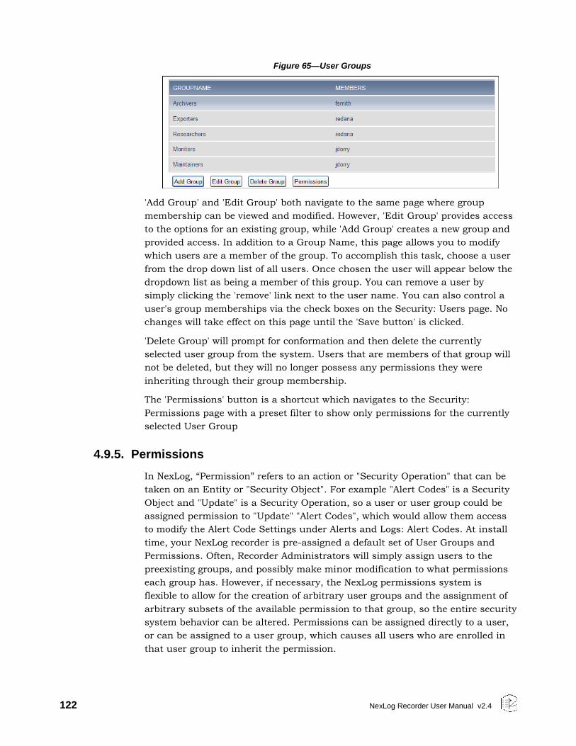
122 NexLog Recorder User Manual v2.4
Figure 65—User Groups
'Add Group' and 'Edit Group' both navigate to the same page where group
membership can be viewed and modified. However, 'Edit Group' provides access
to the options for an existing group, while 'Add Group' creates a new group and
provided access. In addition to a Group Name, this page allows you to modify
which users are a member of the group. To accomplish this task, choose a user
from the drop down list of all users. Once chosen the user will appear below the
dropdown list as being a member of this group. You can remove a user by
simply clicking the 'remove' link next to the user name. You can also control a
user's group memberships via the check boxes on the Security: Users page. No
changes will take effect on this page until the 'Save button' is clicked.
'Delete Group' will prompt for conformation and then delete the currently
selected user group from the system. Users that are members of that group will
not be deleted, but they will no longer possess any permissions they were
inheriting through their group membership.
The 'Permissions' button is a shortcut which navigates to the Security:
Permissions page with a preset filter to show only permissions for the currently
selected User Group
4.9.5. Permissions
In NexLog, “Permission” refers to an action or "Security Operation" that can be
taken on an Entity or "Security Object". For example "Alert Codes" is a Security
Object and "Update" is a Security Operation, so a user or user group could be
assigned permission to "Update" "Alert Codes", which would allow them access
to modify the Alert Code Settings under Alerts and Logs: Alert Codes. At install
time, your NexLog recorder is pre-assigned a default set of User Groups and
Permissions. Often, Recorder Administrators will simply assign users to the
preexisting groups, and possibly make minor modification to what permissions
each group has. However, if necessary, the NexLog permissions system is
flexible to allow for the creation of arbitrary user groups and the assignment of
arbitrary subsets of the available permission to that group, so the entire security
system behavior can be altered. Permissions can be assigned directly to a user,
or can be assigned to a user group, which causes all users who are enrolled in
that user group to inherit the permission.
NexLog Recorder User Manual v2.4 123
The primary element on the Permissions Setup page is a table showing all the
currently assigned permissions. Each row in the table represents one
permission assignment on the system, for example "Group Maintainers can
Update Alert Codes", along with "Next Page" and "Previous Page" buttons for
navigating through the table.
The table contains the following fields:
Security Object: The entity or object which the permission references.
Examples of Security Objects are "Alert Codes" or "Archive Drives".
Security Operation: The action upon the security object that the permission
references. For example, READ, UPDATE, ADD, DELETE. Some Security Objects
have special operations. For example Archive Drives have OPENTRAY and
BROWSEARCHIVE permissions while Alerts have ACKNOWLEDGE permissions.
Because there can be a very large number of permission assignments on the
system, above the table, you will find a mechanism for filtering the list: that is to
show only a targeted subset of the full permissions. There is a User Filter and a
Groups Filter. By default both are set to "All" which causes all of the permission
assignments to be shown. If the User filter is set to a username and Groups
Remains set to 'All', the list will show all permission the selected user is
assigned, either due to direct assignment to the user, or via inheritance through
one of the groups the user is enrolled in. You can determine whether the
permission is a direct assignment or due to a group, by whether the username
or group name field in the permission assignments role is filled in. You can also
use this method to determine which group permission is inherited from. If The
Users filter is set to 'All' and a Group selected via that Group Filter, you will see
all permissions currently assigned to that group. You cannot set both filters at
the same time. Setting one of the filters invalidates the other. Note that the filter
only effects what data is displayed and has no effect on any actions you may
take on that data
If you select a Permission in the table, you may then press the "Delete
Permission" to delete the permission assignment from the system. If the selected
permission assignment is assigned directly to the user, the permission will be
removed from that user. If the permission is assigned to a group, it will be
removed from the group, and hence, all users currently inheriting the
permission from that group will no longer do so. Note that in both cases, users
may still be inheriting the same permission from a different group. To truly take
a permission away from a certain user, you must make sure the permission is
not assigned to the user, nor to any groups the user is enrolled in.
The final button is 'Add Permission', which adds a new permission assignment
to the system. At the top of the 'Add Permission' Page are two list boxes, for
Security Object and Security Operation. First select the security object for which
you want to add a permission assignment. The Security Operation list box will
automatically populate with the security operations which are relevant for that
security object. Next you must select either a User from the User list box or a
User Group from the Group list box which you want to assign the permission to.
124 NexLog Recorder User Manual v2.4
You must choose a user or a group. You cannot select both at the same time. No
change will take place on the system until the Save button at the bottom of the
page is clicked.
4.10. SETUP: Utilities
4.10.1. Schedules
The Schedules Page allows the configuration and maintenance of Recording and
other Schedules. A Schedule is an event that happens either once at a
configured time, or repeatedly at a configured time, such as every Sunday at
2PM. The main Schedules Page shows a table with all configured scheduled
events displayed one row per event. The fields displayed for each event are as
follows:
Action: What action will occur when the schedule triggers:
Start Recording: Begin Recording on the configured channel and record for
the configured duration of the scheduled event.
Disable Recording: Disable a channel for the duration of the scheduled event
Send Notification: Used for integrations and custom scripting.
Calculate Statistics: Runs the Recorder's Daily Statistics Gathering Process
which certain Reports depend on.
Archive: Starts archiving on the drive specified for the duration configured.
This is so that network based archiving such as NAS or Centralized
Archiving can be scheduled for overnight shifts.
NAS Archive Splitter: Controls when and whether NAS drives will be split
into month sized Archives for faster loading when browsing for playback.
R-HD Archive Splitter: Controls when and whether R-HD drives will be split
into month sized Archives for faster loading when browsing for playback.
USB Archive Splitter: Controls when and whether the USB drives will be
split into month sized Archives for faster loading when browsing for
playback.
Backup User Edited Metadata: Archives User Edited Metadata to the archive
drive specified.
Backup Incidents Evaluation Metadata: Archives all Incidents and
Evaluations to the archive drive specified.
Backup Database: Archives the database to the archive drive specified.
Backup Configuration: Archive the current configuration.
NexLog Recorder User Manual v2.4 125
Status Email: Sends an email with a variety of logger status information,
including any current alarms, the last 100 alerts, and call counts per
channel for the last hour.
Description: A user entered description of what this schedule represents, e.g.
"Record 3PM Engineering Meeting"
Start Time: When the schedule will first become active
Expire Time: When the schedule will no longer be active and will no longer
trigger
Enabled: If disabled, schedule events will not fire off when they otherwise
should due to date/time.
Under the main table containing the list of configured scheduled events are
buttons which allow actions to be taken. Except for the 'Add' button, all actions
require a specific scheduled event to first be selected in the table below as they
take effect on the scheduled event.
Delete: Deletes the selected scheduled event after prompting for confirmation
Add and Duplicate: Both of these allow you to create a new scheduled event and
take you to an 'Edit' page for that new schedule. The difference between 'Add'
and 'Duplicate' is that add displays the page with default values, and duplicate
uses the currently selected scheduled event as a Template to set the defaults,
which you can then change. This is useful for creating several schedules that
are all the same except for a couple of parameters, such as channel number.
Edit: The Add and Duplicate Page also take you to a page with the same
parameters as 'Edit', though for a new schedule rather than an existing one, so
the parameters described below are valid for those pages as well. The
configurable parameters for a scheduled event are as follows:
Schedule Heading
Description: A User Friendly Description of what this scheduled event is
Enabled: IF not checked, this schedule is disabled and will not have any effect
until enabled.
Channel: Used for scheduled events where the action is "Start Recording" or
"Disable Recording". This determines the number of the channel upon which
recording will be started or disabled
Scripting Tag: For use with custom scripting and Eventide integrations, it
associates a static piece of data with the notification.
Activation / Expiration Heading
Activate Now: If checked the schedule becomes immediately active. If disabled,
the Start Time becomes option below becomes available for editing. There you
can use the calendar control and hour / minute /second boxes to set a start
126 NexLog Recorder User Manual v2.4
time. Note that all times are configured on this page should be in your currently
configured local time zone (not UTC). The current time zone is listed in the
heading above for convenience
Never expires: If checked, the schedule never expires, otherwise the Expire
Time option below becomes available. It works identically to the Start Time
parameter.
Action Heading
The radio buttons in this section allow you to specify the action that will take
place when the schedule fires. The options are described below:
Start Recording: Recording will start on the channel specified above in the
"Channel" parameter whenever the schedule fires and will continue recording for
the duration configured below, at which time it will stop recording. Note that in
addition to configuring the schedule here, the channel must be configured for
"Scheduled" in the Call Detect Type (configured under Recording: Boards).
Disable Recording: "Record On Demand" For the channel will be disabled when
the schedule fires and re-enabled after the duration. During this time the
channel will not record, at all other times it will record based on its normal call
detect types.
Send Notification: Triggers a notification event for use with custom scripting
and Eventide integrations.
Run Statistics: Schedules the daily statistics to run. This should be run once
daily, you should only ever change the time of day which it is run, to schedule it
for the slowest volume period on your recorder.
Period Heading
These radio buttons determine how often the schedule repeats.
Hourly: Schedule triggers once per hour
Daily: Schedule triggers once per day
Weekly: Schedule triggers once per week Monthly
Monthly: Schedule triggers once per Month
One Time: Schedule triggers only once
Which of these options is selected will dictate what parameters are available
under Period Options as well.
Period Options Heading:
Duration is always the same regardless of the Period set above and is the
Minutes and Seconds time during which the schedule will be occurring (e.g.,
NexLog Recorder User Manual v2.4 127
how long to record for if action is Start Recording). If action is Statistics,
duration has no effect.
For Hourly: Start at X Minutes past the hour, the number of minutes past the
hour the schedule will trigger
For Daily: Start at Hours: Minutes past midnight, the number of hours and
minutes past midnight the schedule will trigger, so if set for 13:30, schedule will
trigger at 1:30PM
For Weekly: Start at Hours: Minutes past Midnight, as above, but also
checkboxes for which days of the week to trigger on are provided
For Monthly: Start at Hours, Minutes past midnight, and also what day of the
month to schedule action for is supplied (e.g., 1 to trigger on 1st of the month),
plus check boxes for which months to trigger on
One Time: Schedule only triggers once at activation time.
Repeat Every: If checked, the how many hours should pass between triggering.
For example for an hourly schedule if Start At is set for 30 and Repeat Every for
3 hours, and the schedule activation time is 1:45, then the schedule will trigger
at 2:30, 5:30, 8:30, 11:30, etc. Repeat every is provided for Hourly and Weekly
schedules
4.10.2. Upload Recorder Patch
The Upload Recorder Patch Utility page allows administrators to apply custom
patches provided by Eventide to update systems in the field. It is only for use
when directed by Eventide support and only works with patches created by
Eventide.
4.10.3. Re-Order Channels
This page allows you system administrators to arrange the channels as if it was
installed with the current configuration. This is useful if the physical boards
have been changed or moved or if virtual boards have been resized. The recorder
will be automatically rebooted after performing this function.
4.10.4. Network Utilities
The Network Utilities page allows administrators to run Ping, Traceroute and
Netcat Unix utilities from the recorder to identify network problems.
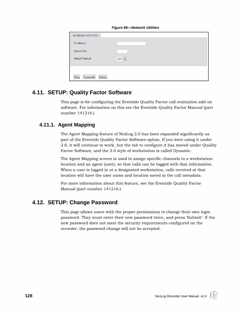
128 NexLog Recorder User Manual v2.4
Figure 66—Network Utilities
4.11. SETUP: Quality Factor Software
This page is for configuring the Eventide Quality Factor call evaluation add-on
software. For information on this see the Eventide Quality Factor Manual (part
number 141216.)
4.11.1. Agent Mapping
The Agent Mapping feature of NexLog 2.0 has been expanded significantly as
part of the Eventide Quality Factor Software option. If you were using it under
2.0, it will continue to work, but the tab to configure it has moved under Quality
Factor Software, and the 2.0 style of workstation is called Dynamic.
The Agent Mapping screen is used to assign specific channels to a workstation
location and an agent (user), so that calls can be tagged with that information.
When a user is logged in at a designated workstation, calls received at that
location will have the user name and location saved in the call metadata.
For more information about this feature, see the Eventide Quality Factor
Manual (part number 141216.)
4.12. SETUP: Change Password
This page allows users with the proper permissions to change their own login
password. They must enter their new password twice, and press ‘Submit’. If the
new password does not meet the security requirements configured on the
recorder, the password change will not be accepted.
NexLog Recorder User Manual v2.4 129
5. Recorder Operation
5.1. Starting and Shutting Down
To start the recorder, use the front panel power switch, the switch is behind the
locked door on which the display is mounted on touch screen units, and behind
the blank front panel door on non-touch screen units. Do not hold the switch for
more than one second.
To shut down the recorder, you can perform a controlled shutdown or a forced
shutdown. In most circumstances, you should only perform a controlled
shutdown. This allows the recorder to close all open files and complete current
database operations before shutdown. A forced shutdown can result in
corrupted files and loss of data. It can also damage any archive media in the
process of being written, and possibly leave either gaps or duplications in your
archives. (In addition, Eventide strongly recommends using the recorder with a
UPS to allow a controlled shutdown in the event of a power failure.)
Important! A forced shutdown can result in corrupted files and loss of data.
To perform a controlled shutdown of the recorder:
Press Setup.
Select Power Off.
Select shutdown and respond “OK” to the prompt.
If for some reason, it is not possible to use this standard method to perform a
shutdown, a controlled shutdown can still be accomplished using the following,
somewhat riskier, alternative.
Use the front panel power switch to initiate a controlled shutdown by pushing
the switch for up to one second.
Eventide does not recommend forcing a shutdown, but if it becomes necessary
follow these steps.
Important! A forced shutdown can result in corrupted files and loss of data.
To perform a forced shutdown of the recorder:
Push and hold the power switch for 10 seconds until it shuts down.
An alternative way to perform a forced shutdown is to turn off the power
supplies from the back panel, or unplug the power supplies.
130 NexLog Recorder User Manual v2.4
6. The Client-Based NexLog Recorder Software
6.1. Introduction
6.1.1. What is the Client-Based NexLog Recorder Software?
Eventide offers optional client software to access NexLog Recorders remotely for
operational tasks. The client software can be installed on PCs running the
Microsoft Windows* Operating System and that are connected to a NexLog
Recorder through a network.
The client software includes the following:
Eventide® MediaAgent™: This application program provides remote access to
recorder data and functions specifically for call-center users. This program
requires an additional software license and is documented in a separate
manual.
Eventide® MediaWorks™: This application program provides remote access to
recorder data and functions specifically for call-center managers. This
program requires an additional software license and is documented in a
separate manual.
6.1.2. Do You Need to Install the Client Software at all?
NexLog Recorders are designed as standalone products, and it is not necessary
to install the clients to use the product. A non-networked recorder controlled
only through the recorder front panel may be adequate for some organizations.
However, the advantages and extra functionality that are provided by the clients
may be important to your needs.
The advantages to using the clients include the following:
Perform tasks at your desk, rather than at the recorder.
Perform tasks more easily, with a full-sized computer monitor and a
keyboard and mouse. This is especially true for certain tasks:
Multiple users can log in and use the recorder simultaneously.
Get extra functionality, including:
View long lists of calls in a tree format

NexLog Recorder User Manual v2.4 131
Play back calls on archives on a PC, without the recorder
Send recording files via email
Audio redaction
More (see the Eventide MediaWorks Manual for a full description of
the MediaWorks software’s capabilities.
132 NexLog Recorder User Manual v2.4
Appendix A: Recorder Software Installation and Upgrade
Just as with any computer, NexLog Recorders require a software operating
system and a number of application programs to be functional and to perform
useful work. The operating system in this case is Linux, and the application
programs are a combination of standard programs and programs written and
maintained by Eventide to work with its custom hardware environment.
As part of the manufacturing process, Eventide installs the recorder software.
Because the recorder software development is an on-going process, Eventide
occasionally creates software upgrades to bring older recorders up to the current
software version. It is sometimes desirable or even necessary to apply these
upgrades to recorders at the customer site, and the purpose of this section is to
explain the process so that customers can confidently perform upgrades (and
even installations) without factory intervention.
Why Re-installation May Be Necessary
The recorders use redundant disks, so a single drive failure should not cause
loss of data or software. However, if multiple disks in an array fail due to a
common cause (e.g., lightning or other power surge), you will have to re-install
the software when they are replaced.
Why Upgrades May Be Necessary or Desirable
There are several reasons why you may need to do an upgrade:
Problems (bugs) are found in the version currently running;
Hardware upgrades or changes require new software;
Valuable features are available in the new release;
Factory support requires a more recent software version
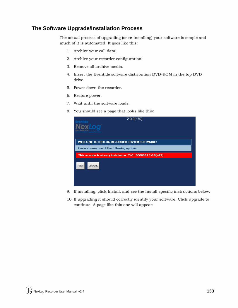
NexLog Recorder User Manual v2.4 133
The Software Upgrade/Installation Process
The actual process of upgrading (or re-installing) your software is simple and
much of it is automated. It goes like this:
1. Archive your call data!
2. Archive your recorder configuration!
3. Remove all archive media.
4. Insert the Eventide software distribution DVD-ROM in the top DVD
drive.
5. Power down the recorder.
6. Restore power.
7. Wait until the software loads.
8. You should see a page that looks like this:
9. If installing, click Install, and see the Install specific instructions below.
10. If upgrading it should correctly identify your software. Click upgrade to
continue. A page like this one will appear:

134 NexLog Recorder User Manual v2.4
11. Click Upgrade and the upgrade will begin.
12. When finished, the DVD-ROM will eject automatically. Remove it from
the tray.
13. Touch the touch screen or hit enter to reboot.
14. Wait until the new software completes its initialization.
Important! You may need to wait 20 minutes or more for an upgrade.
Average wait time is under 10 minutes.
Install Specific Instructions
1. After clicking Install, you will see a page like this:
NexLog Recorder User Manual v2.4 135
2. Unless Eventide Support or your dealer tells you otherwise, click
Automatic Install.
3. The Install will then begin.
4. When finished, the DVD-ROM will eject automatically. Remove it from
the tray.
5. Touch the touch screen or hit enter to reboot.
6. Wait until the new software completes its initialization.
7. Restore your configuration.
8. Restore your archives, beginning with the most recent first.
This completes the procedure.
Some Details, Especially About Installation
The hardest part is to wait for the recorder to complete loading and initializing
the new software. This requires some patience as the second time you are asked
to wait, you may need to wait for an hour or more. The software does a lot of
checking to make sure everything is OK.
If you do a new installation, all your calls will be erased. If you have archived
your calls, you can restore them as described in Restoring Archives When
Installing New Software. An upgrade will theoretically leave your calls in the
same state as they were earlier, and, in fact, it almost always does. But why
take chances? You are probably archiving anyway, so can it hurt to be up to
date?
If you do a new installation, you will have to reconfigure the recorder in
accordance with the Setup instructions. This is greatly simplified by the
Read/Write Configuration to Archive feature. Please read the information in
SETUP carefully before you start the installation!
If you upgrade the recorder, be sure to read the release notes or other
information to see if there are any new SETUP items that must be configured.
Restoring Archives When Installing New Software
In the Archiving section of the SETUP mode there is a menu item “Archive
restore.” If you insert previously–recorded archive media into one or more drives,
it will allow you to select that drive with the knob and perform a restore
operation; i.e., copy the calls from that medium back to RAID. Several checks
are performed before the medium is transferred:
Does the serial number of the recorder that recorded the archive medium
agree with that of the destination recorder?
Are the channel names of the recorder the same as the destination?
136 NexLog Recorder User Manual v2.4
Does the format of the data on the archive conform to that of the
destination?
Is there any problem with or damage to the archive medium data to be
transferred?
Are any of these calls duplicates of calls already on the recorder?
User confirmation: Are you sure you want to go ahead with the transfer?
If none of these apply to the medium, or if you indicated that you wish to
proceed anyway, the archive transfer will commence. All drives operate
independently. You can restore archive media in all available drives, or you can
even record archives on one medium while restoring from another.
Important! The restoration process will delete the oldest calls on the recorder to make
room for the restored calls. In some cases this will be the calls being
restored. Always restore from the most recent archive backwards.
If you are restoring archives after a new installation, set the current archive time
to make sure that new archives are only recorded from the present forward. If you
don’t set this and begin new archiving after you have restored your archives
from a previous installation, you might find yourself “re-archiving” the restored
archives.
Potential Issues
For the most part, the process is automated. At least for an upgrade, beyond
inserting/removing the disk, removing/applying power, and exhibiting patience,
there is little for you to do.
One problem that can occur is failure to recognize the medium in the upgrade
drive (the one in which you place the DVD). If this happens, the recorder just
powers up normally and the DVD never ejects. In such a case, manually eject
the DVD, and again shut down the unit. Next, visually inspect the medium,
confirm it has no scratches, it’s clean, it’s right-side-up, and it’s carefully
centered in the drive tray. Then try again. If the drive persistently refuses to
recognize the DVD, yet works correctly when archiving, you probably have a
defective upgrade DVD, or one that differs enough from the drive’s calibration to
make reading the DVD problematic. You can try copying the DVD-ROM to
another blank one, burning a new one, requesting a replacement, etc.
Much less common: The DVD can’t be read completely, and the upgrade/install
process hangs up and the DVD does not eject. In this case, try the procedure
again from the beginning. For an installation, no damage will be done as long as
the install eventually completes correctly. For an upgrade, there is a possibility
that configuration information will have been lost, in which case it can be
restored manually or from the configuration archive that you made before
starting the upgrade. Do NOT, however, try to resume normal recorder operation
until the upgrade has completed normally.

NexLog Recorder User Manual v2.4 137
Note: Please read the release notes. Software upgrades will normally come with
printed information, and possibly with a README file on the disk. If anything in
the release notes contradicts something you read here, go with the release notes!
138 NexLog Recorder User Manual v2.4
Appendix B: Optional General Purpose Input/Output (GPIO) Boards
Note: The optional GPIO board feature requires an add-on license key from Eventide.
The following uses can be made of a GPIO board:
The start and stop of recording on a channel can be triggered by a GPIO
board input signal. (For more information, see 4.4.1 Boards and Channels.)
The logic of GPIO-triggered recording can be customized using the custom
script feature.
A recorder alert can trigger a GPIO output signal. Alerts of severity 3 or 4
(Error or Severe) will by default trigger a signal on the first output pair of the
board. Further customization is possible via a custom integration script
available from Eventide.
Eventide supports the following optional GPIO board for use with recorders:
National Instruments PCI-6503 Board (24-Channel)
Important! The National Instruments specifications for these GPIO boards describe the
maximum ratings for their input or output signals. Connections that exceed
these maximum ratings can damage the board and the recorder. Neither
Eventide nor National Instruments are liable for any damages resulting from
signal connections that exceed these maximum ratings.
National Instruments PCI-6503 Board (24-Channel)
This board provides a 24-bit parallel, digital I/O interface with:
24 static digital I/O lines (non-isolated 5 V TTL/CMOS) in 8-bit ports, 2.4
mA
50-pin male I/O connector (for ribbon cable with IDC-type connector)
No switches or jumpers
12 Channels are used for Inputs, and 12 for outputs
Note: The I/O ports are not optically isolated.
Eventide has adopted static port assignments on the PCI-6503. See Figure 67—
GPIO Board Pin Assignments (NI PCI-6503) on page 139, which shows the
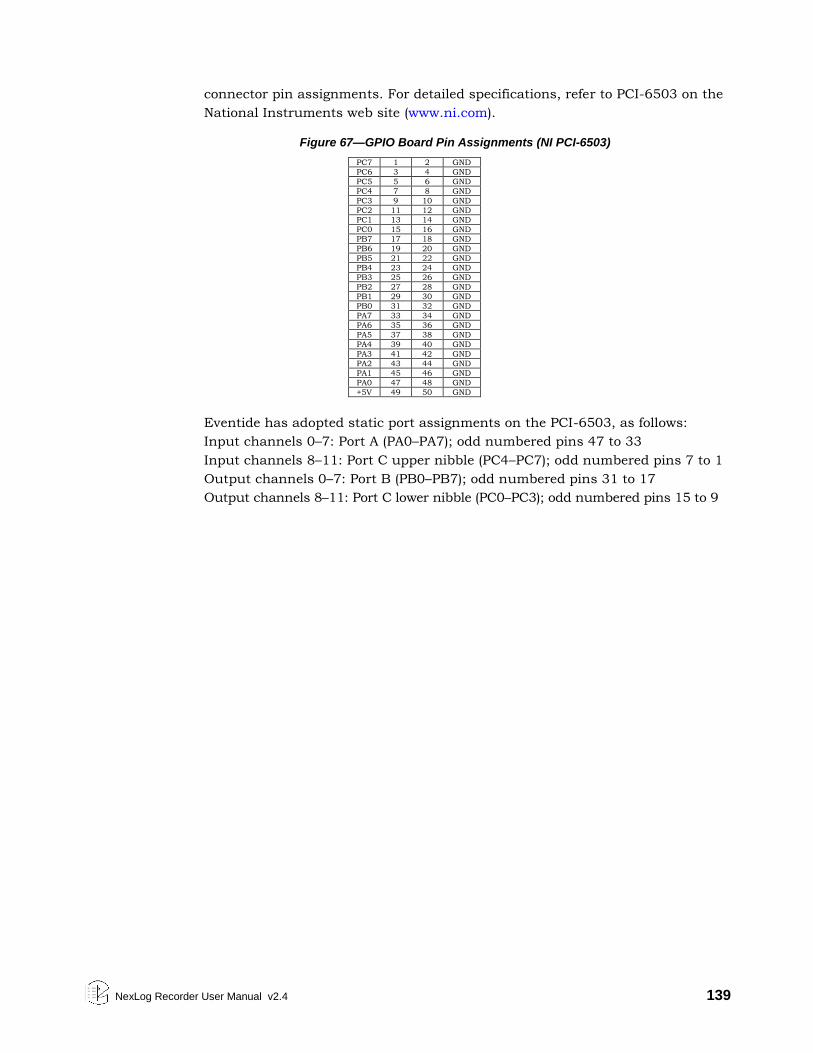
NexLog Recorder User Manual v2.4 139
connector pin assignments. For detailed specifications, refer to PCI-6503 on the
National Instruments web site (www.ni.com).
Figure 67—GPIO Board Pin Assignments (NI PCI-6503)
PC7 1 2 GND
PC6 3 4 GND
PC5 5 6 GND
PC4 7 8 GND
PC3 9 10 GND
PC2 11 12 GND
PC1 13 14 GND
PC0 15 16 GND
PB7 17 18 GND
PB6 19 20 GND
PB5 21 22 GND
PB4 23 24 GND
PB3 25 26 GND
PB2 27 28 GND
PB1 29 30 GND
PB0 31 32 GND
PA7 33 34 GND
PA6 35 36 GND
PA5 37 38 GND
PA4 39 40 GND
PA3 41 42 GND
PA2 43 44 GND
PA1 45 46 GND
PA0 47 48 GND
+5V 49 50 GND
Eventide has adopted static port assignments on the PCI-6503, as follows:
Input channels 0–7: Port A (PA0–PA7); odd numbered pins 47 to 33
Input channels 8–11: Port C upper nibble (PC4–PC7); odd numbered pins 7 to 1
Output channels 0–7: Port B (PB0–PB7); odd numbered pins 31 to 17
Output channels 8–11: Port C lower nibble (PC0–PC3); odd numbered pins 15 to 9
140 NexLog Recorder User Manual v2.4
Appendix C: NIST Time Servers
You can search the web for NIST Time Servers. Historically, a list of National
Institute of Standards and Technology (NIST) internet time servers can be found
on the web at:
www.boulder.nist.gov/timefreq/service/time-servers.html
This list provides each server’s name, IP address, and location. It is probably
best to select one near to your location. If you have difficulty with using a server
name, you can access the server using the IP address instead.
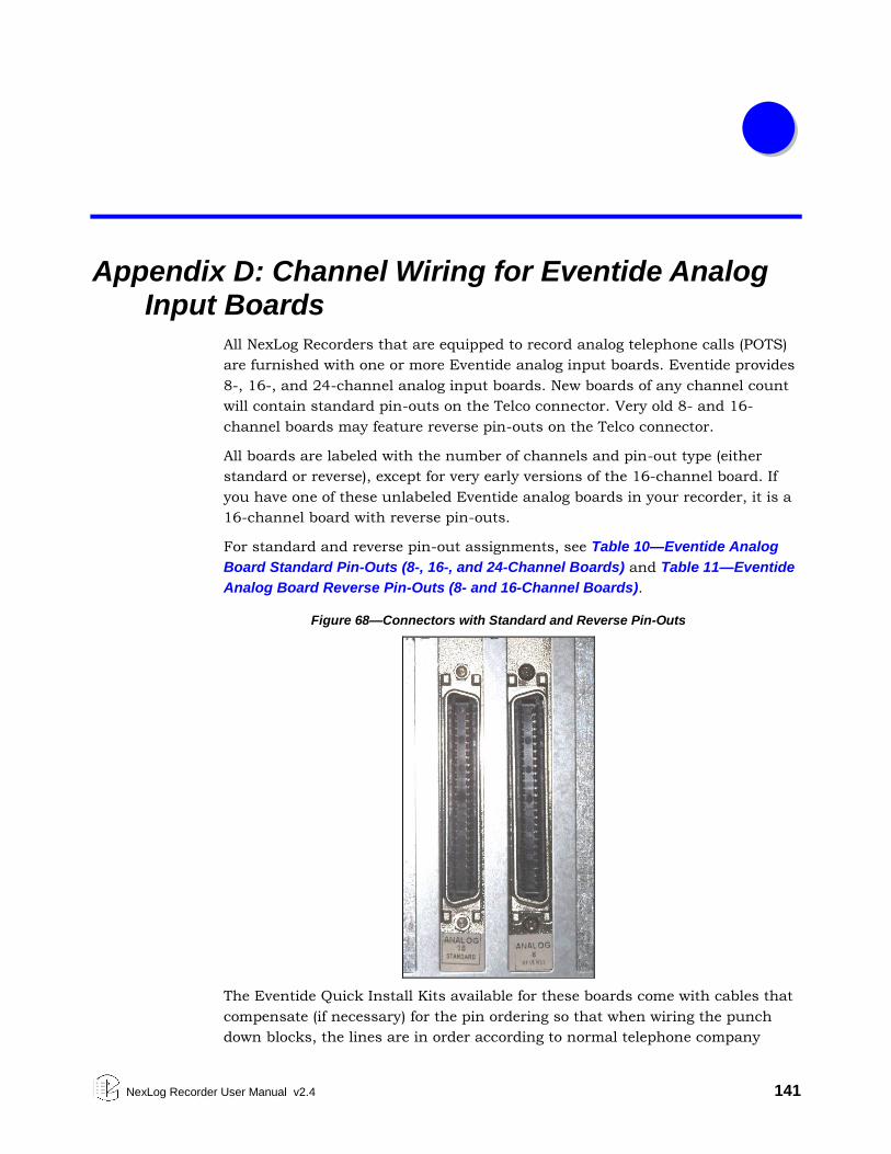
NexLog Recorder User Manual v2.4 141
Appendix D: Channel Wiring for Eventide Analog Input Boards
All NexLog Recorders that are equipped to record analog telephone calls (POTS)
are furnished with one or more Eventide analog input boards. Eventide provides
8-, 16-, and 24-channel analog input boards. New boards of any channel count
will contain standard pin-outs on the Telco connector. Very old 8- and 16-
channel boards may feature reverse pin-outs on the Telco connector.
All boards are labeled with the number of channels and pin-out type (either
standard or reverse), except for very early versions of the 16-channel board. If
you have one of these unlabeled Eventide analog boards in your recorder, it is a
16-channel board with reverse pin-outs.
For standard and reverse pin-out assignments, see Table 10—Eventide Analog
Board Standard Pin-Outs (8-, 16-, and 24-Channel Boards) and Table 11—Eventide
Analog Board Reverse Pin-Outs (8- and 16-Channel Boards).
Figure 68—Connectors with Standard and Reverse Pin-Outs
The Eventide Quick Install Kits available for these boards come with cables that
compensate (if necessary) for the pin ordering so that when wiring the punch
down blocks, the lines are in order according to normal telephone company
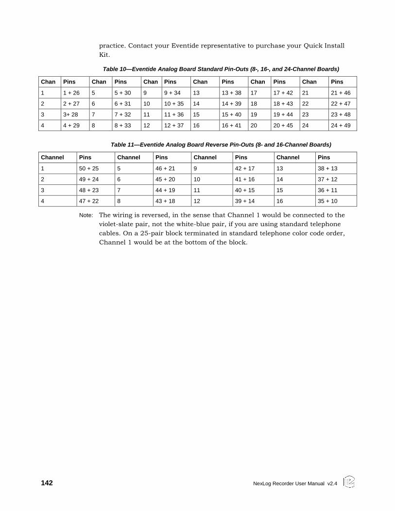
142 NexLog Recorder User Manual v2.4
practice. Contact your Eventide representative to purchase your Quick Install
Kit.
Table 10—Eventide Analog Board Standard Pin-Outs (8-, 16-, and 24-Channel Boards)
Chan Pins Chan Pins Chan Pins Chan Pins Chan Pins Chan Pins
1 1 + 26 5 5 + 30 9 9 + 34 13 13 + 38 17 17 + 42 21 21 + 46
2 2 + 27 6 6 + 31 10 10 + 35 14 14 + 39 18 18 + 43 22 22 + 47
3 3+ 28 7 7 + 32 11 11 + 36 15 15 + 40 19 19 + 44 23 23 + 48
4 4 + 29 8 8 + 33 12 12 + 37 16 16 + 41 20 20 + 45 24 24 + 49
Table 11—Eventide Analog Board Reverse Pin-Outs (8- and 16-Channel Boards)
Channel Pins Channel Pins Channel Pins Channel Pins
1 50 + 25 5 46 + 21 9 42 + 17 13 38 + 13
2 49 + 24 6 45 + 20 10 41 + 16 14 37 + 12
3 48 + 23 7 44 + 19 11 40 + 15 15 36 + 11
4 47 + 22 8 43 + 18 12 39 + 14 16 35 + 10
Note: The wiring is reversed, in the sense that Channel 1 would be connected to the
violet-slate pair, not the white-blue pair, if you are using standard telephone
cables. On a 25-pair block terminated in standard telephone color code order,
Channel 1 would be at the bottom of the block.
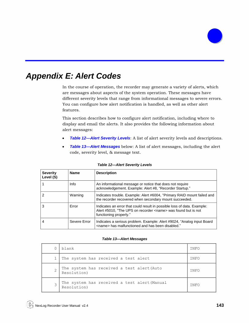
NexLog Recorder User Manual v2.4 143
Appendix E: Alert Codes
In the course of operation, the recorder may generate a variety of alerts, which
are messages about aspects of the system operation. These messages have
different severity levels that range from informational messages to severe errors.
You can configure how alert notification is handled, as well as other alert
features.
This section describes how to configure alert notification, including where to
display and email the alerts. It also provides the following information about
alert messages:
Table 12—Alert Severity Levels: A list of alert severity levels and descriptions.
Table 13—Alert Messages below: A list of alert messages, including the alert
code, severity level, & message text.
Table 12—Alert Severity Levels
Severity Level (S)
Name Description
1 Info An informational message or notice that does not require acknowledgement. Example: Alert #8, “Recorder Startup.”
2 Warning Indicates trouble. Example: Alert #6004, “Primary RAID mount failed and the recorder recovered when secondary mount succeeded.
3 Error Indicates an error that could result in possible loss of data. Example: Alert #5010, “The UPS on recorder <name> was found but is not functioning properly.”
4 Severe Error Indicates a serious problem. Example: Alert #9024, “Analog input Board <name> has malfunctioned and has been disabled.”
Table 13—Alert Messages
0 blank INFO
1 The system has received a test alert INFO
2 The system has received a test alert(Auto
Resolution) INFO
3 The system has received a test alert(Manual
Resolution) INFO
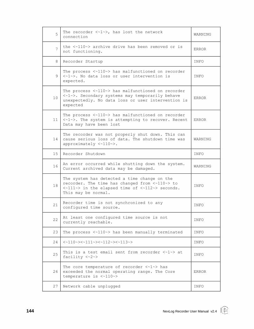
144 NexLog Recorder User Manual v2.4
5 The recorder <~1~>, has lost the network
connection WARNING
7 the <~110~> archive drive has been removed or is
not functioning. ERROR
8 Recorder Startup INFO
9
The process <~110~> has malfunctioned on recorder
<~1~>. No data loss or user intervention is
expected.
INFO
10
The process <~110~> has malfunctioned on recorder
<~1~>. Secondary systems may temporarily behave
unexpectedly. No data loss or user intervention is
expected
ERROR
11
The process <~110~> has malfunctioned on recorder
<~1~>. The system is attempting to recover. Recent
Data may have been lost
ERROR
14
The recorder was not properly shut down. This can
cause serious loss of data. The shutdown time was
approximately <~110~>.
WARNING
15 Recorder Shutdown INFO
16 An error occurred while shutting down the system.
Current archived data may be damaged. WARNING
18
The system has detected a time change on the
recorder. The time has changed from <~110~> to
<~111~> in the elapsed time of <~112~> seconds.
This may be normal.
INFO
21 Recorder time is not synchronized to any
configured time source. INFO
22 At least one configured time source is not
currently reachable. INFO
23 The process <~110~> has been manually terminated INFO
24 <~110~><~111~><~112~><~113~> INFO
25 This is a test email sent from recorder <~1~> at
facility <~2~> INFO
26
The core temperature of recorder <~1~> has
exceeded the normal operating range. The Core
temperature is <~110~>
ERROR
27 Network cable unplugged INFO
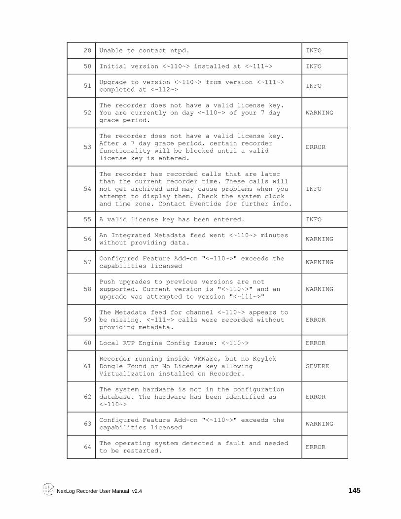
NexLog Recorder User Manual v2.4 145
28 Unable to contact ntpd. INFO
50 Initial version <~110~> installed at <~111~> INFO
51 Upgrade to version <~110~> from version <~111~>
completed at <~112~> INFO
52
The recorder does not have a valid license key.
You are currently on day <~110~> of your 7 day
grace period.
WARNING
53
The recorder does not have a valid license key.
After a 7 day grace period, certain recorder
functionality will be blocked until a valid
license key is entered.
ERROR
54
The recorder has recorded calls that are later
than the current recorder time. These calls will
not get archived and may cause problems when you
attempt to display them. Check the system clock
and time zone. Contact Eventide for further info.
INFO
55 A valid license key has been entered. INFO
56 An Integrated Metadata feed went <~110~> minutes
without providing data. WARNING
57 Configured Feature Add-on "<~110~>" exceeds the
capabilities licensed WARNING
58
Push upgrades to previous versions are not
supported. Current version is "<~110~>" and an
upgrade was attempted to version "<~111~>"
WARNING
59
The Metadata feed for channel <~110~> appears to
be missing. <~111~> calls were recorded without
providing metadata.
ERROR
60 Local RTP Engine Config Issue: <~110~> ERROR
61
Recorder running inside VMWare, but no Keylok
Dongle Found or No License key allowing
Virtualization installed on Recorder.
SEVERE
62
The system hardware is not in the configuration
database. The hardware has been identified as
<~110~>
ERROR
63 Configured Feature Add-on "<~110~>" exceeds the
capabilities licensed WARNING
64 The operating system detected a fault and needed
to be restarted. ERROR
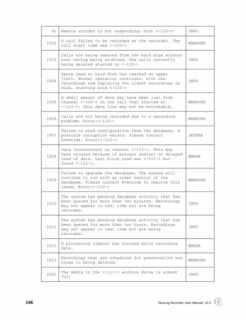
146 NexLog Recorder User Manual v2.4
65 Remote vocoder is not responding: host <~110~>' INFO
1002 A call failed to be recorded on the recorder. The
call start time was <~110~> WARNING
1003
Calls are being removed from the hard disk without
ever having being archived. The calls currently
being deleted started on <~110~>
INFO
1004
Space used on hard disk has reached an upper
limit. Normal operation continues, with new
recordings now replacing the oldest recordings on
disk, starting with <~110~>
INFO
1005
A small amount of data may have been lost from
channel <~110~> on the call that started at
<~111~>. This data loss may not be noticeable.
WARNING
1006 Calls are not being recorded due to a recording
problem. Error:<~110~> WARNING
1007
Failed to read configuration from the database. A
possible corruption exists. Please contact
Eventide. Error:<~110~>
SEVERE
1008
Data inconsistent on channel <~110~>. This may
have occured because of process restart or delayed
read of data. Last block read was <~111~> but
found <~112~>.
ERROR
1009
Failed to upgrade the database. The system will
continue to run with an older version of the
database. Please contact Eventide to resolve this
issue. Error:<~110~>
WARNING
1010
The system has pending database activity that has
been queued for more than two minutes. Recordings
may not appear in real time but are being
recorded.
INFO
1011
The system has pending database activity that has
been queued for more than two hours. Recordings
may not appear in real time but are being
recorded.
INFO
1012 A processing timeout has occured while recording
data. ERROR
1013 Recordings that are scheduled for preservation are
close to being deleted. WARNING
2001 The media in the <~111~> archive drive is almost
full INFO
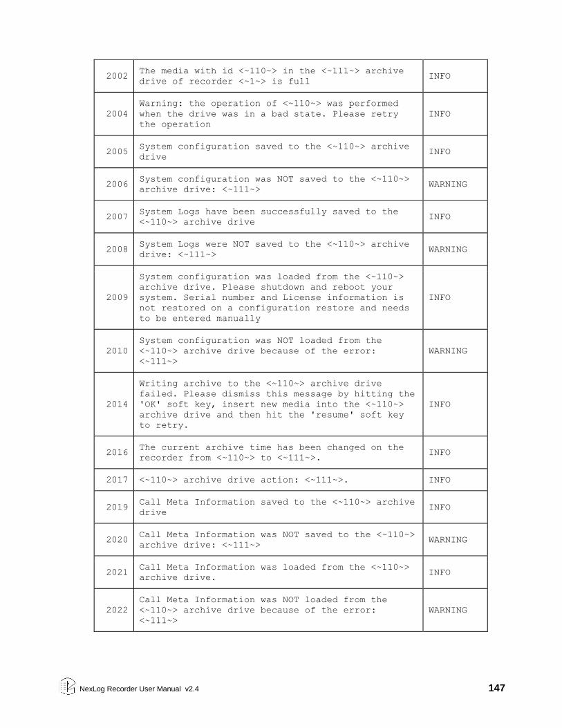
NexLog Recorder User Manual v2.4 147
2002 The media with id <~110~> in the <~111~> archive
drive of recorder <~1~> is full INFO
2004
Warning: the operation of <~110~> was performed
when the drive was in a bad state. Please retry
the operation
INFO
2005 System configuration saved to the <~110~> archive
drive INFO
2006 System configuration was NOT saved to the <~110~>
archive drive: <~111~> WARNING
2007 System Logs have been successfully saved to the
<~110~> archive drive INFO
2008 System Logs were NOT saved to the <~110~> archive
drive: <~111~> WARNING
2009
System configuration was loaded from the <~110~>
archive drive. Please shutdown and reboot your
system. Serial number and License information is
not restored on a configuration restore and needs
to be entered manually
INFO
2010
System configuration was NOT loaded from the
<~110~> archive drive because of the error:
<~111~>
WARNING
2014
Writing archive to the <~110~> archive drive
failed. Please dismiss this message by hitting the
'OK' soft key, insert new media into the <~110~>
archive drive and then hit the 'resume' soft key
to retry.
INFO
2016 The current archive time has been changed on the
recorder from <~110~> to <~111~>. INFO
2017 <~110~> archive drive action: <~111~>. INFO
2019 Call Meta Information saved to the <~110~> archive
drive INFO
2020 Call Meta Information was NOT saved to the <~110~>
archive drive: <~111~> WARNING
2021 Call Meta Information was loaded from the <~110~>
archive drive. INFO
2022
Call Meta Information was NOT loaded from the
<~110~> archive drive because of the error:
<~111~>
WARNING
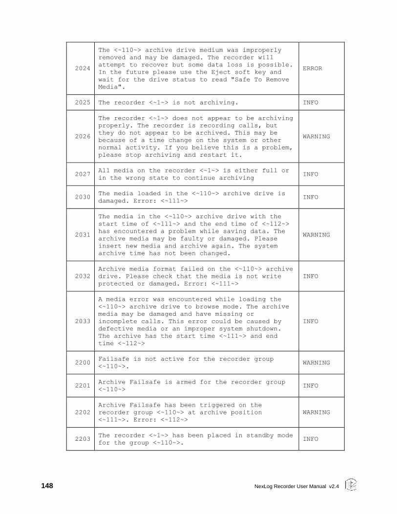
148 NexLog Recorder User Manual v2.4
2024
The <~110~> archive drive medium was improperly
removed and may be damaged. The recorder will
attempt to recover but some data loss is possible.
In the future please use the Eject soft key and
wait for the drive status to read "Safe To Remove
Media".
ERROR
2025 The recorder <~1~> is not archiving. INFO
2026
The recorder <~1~> does not appear to be archiving
properly. The recorder is recording calls, but
they do not appear to be archived. This may be
because of a time change on the system or other
normal activity. If you believe this is a problem,
please stop archiving and restart it.
WARNING
2027 All media on the recorder <~1~> is either full or
in the wrong state to continue archiving INFO
2030 The media loaded in the <~110~> archive drive is
damaged. Error: <~111~> INFO
2031
The media in the <~110~> archive drive with the
start time of <~111~> and the end time of <~112~>
has encountered a problem while saving data. The
archive media may be faulty or damaged. Please
insert new media and archive again. The system
archive time has not been changed.
WARNING
2032
Archive media format failed on the <~110~> archive
drive. Please check that the media is not write
protected or damaged. Error: <~111~>
INFO
2033
A media error was encountered while loading the
<~110~> archive drive to browse mode. The archive
media may be damaged and have missing or
incomplete calls. This error could be caused by
defective media or an improper system shutdown.
The archive has the start time <~111~> and end
time <~112~>
INFO
2200 Failsafe is not active for the recorder group
<~110~>. WARNING
2201 Archive Failsafe is armed for the recorder group
<~110~> INFO
2202
Archive Failsafe has been triggered on the
recorder group <~110~> at archive position
<~111~>. Error: <~112~>
WARNING
2203 The recorder <~1~> has been placed in standby mode
for the group <~110~>. INFO
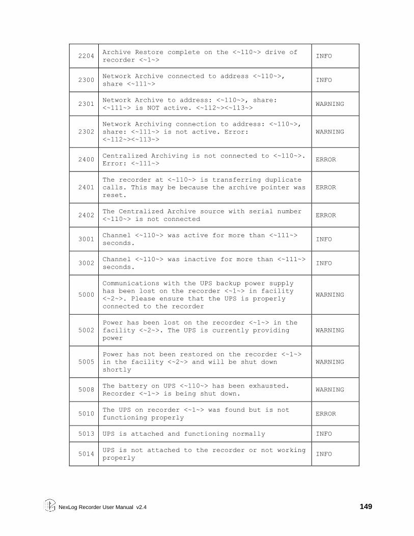
NexLog Recorder User Manual v2.4 149
2204 Archive Restore complete on the <~110~> drive of
recorder <~1~> INFO
2300 Network Archive connected to address <~110~>,
share <~111~> INFO
2301 Network Archive to address: <~110~>, share:
<~111~> is NOT active. <~112~><~113~> WARNING
2302
Network Archiving connection to address: <~110~>,
share: <~111~> is not active. Error:
<~112~><~113~>
WARNING
2400 Centralized Archiving is not connected to <~110~>.
Error: <~111~> ERROR
2401
The recorder at <~110~> is transferring duplicate
calls. This may be because the archive pointer was
reset.
ERROR
2402 The Centralized Archive source with serial number
<~110~> is not connected ERROR
3001 Channel <~110~> was active for more than <~111~>
seconds. INFO
3002 Channel <~110~> was inactive for more than <~111~>
seconds. INFO
5000
Communications with the UPS backup power supply
has been lost on the recorder <~1~> in facility
<~2~>. Please ensure that the UPS is properly
connected to the recorder
WARNING
5002
Power has been lost on the recorder <~1~> in the
facility <~2~>. The UPS is currently providing
power
WARNING
5005
Power has not been restored on the recorder <~1~>
in the facility <~2~> and will be shut down
shortly
WARNING
5008 The battery on UPS <~110~> has been exhausted.
Recorder <~1~> is being shut down. WARNING
5010 The UPS on recorder <~1~> was found but is not
functioning properly ERROR
5013 UPS is attached and functioning normally INFO
5014 UPS is not attached to the recorder or not working
properly INFO
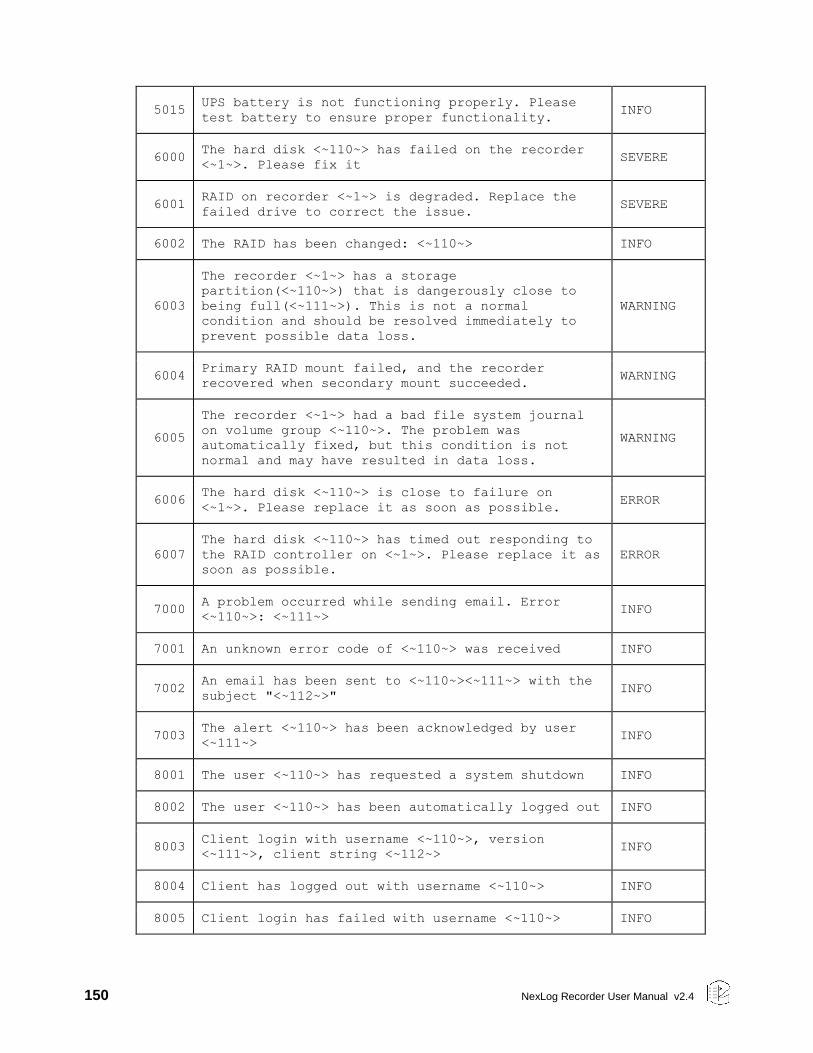
150 NexLog Recorder User Manual v2.4
5015 UPS battery is not functioning properly. Please
test battery to ensure proper functionality. INFO
6000 The hard disk <~110~> has failed on the recorder
<~1~>. Please fix it SEVERE
6001 RAID on recorder <~1~> is degraded. Replace the
failed drive to correct the issue. SEVERE
6002 The RAID has been changed: <~110~> INFO
6003
The recorder <~1~> has a storage
partition(<~110~>) that is dangerously close to
being full(<~111~>). This is not a normal
condition and should be resolved immediately to
prevent possible data loss.
WARNING
6004 Primary RAID mount failed, and the recorder
recovered when secondary mount succeeded. WARNING
6005
The recorder <~1~> had a bad file system journal
on volume group <~110~>. The problem was
automatically fixed, but this condition is not
normal and may have resulted in data loss.
WARNING
6006 The hard disk <~110~> is close to failure on
<~1~>. Please replace it as soon as possible. ERROR
6007
The hard disk <~110~> has timed out responding to
the RAID controller on <~1~>. Please replace it as
soon as possible.
ERROR
7000 A problem occurred while sending email. Error
<~110~>: <~111~> INFO
7001 An unknown error code of <~110~> was received INFO
7002 An email has been sent to <~110~><~111~> with the
subject "<~112~>" INFO
7003 The alert <~110~> has been acknowledged by user
<~111~> INFO
8001 The user <~110~> has requested a system shutdown INFO
8002 The user <~110~> has been automatically logged out INFO
8003 Client login with username <~110~>, version
<~111~>, client string <~112~> INFO
8004 Client has logged out with username <~110~> INFO
8005 Client login has failed with username <~110~> INFO
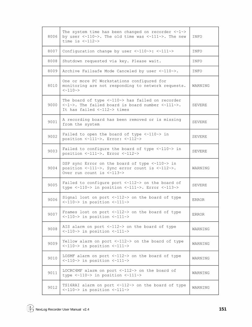
NexLog Recorder User Manual v2.4 151
8006
The system time has been changed on recorder <~1~>
by user <~110~>. The old time was <~111~>. The new
time is <~112~>
INFO
8007 Configuration change by user <~110~>: <~111~> INFO
8008 Shutdown requested via key. Please wait. INFO
8009 Archive Failsafe Mode Canceled by user <~110~>. INFO
8010
One or more PC Workstations configured for
monitoring are not responding to network requests.
<~110~>
WARNING
9000
The board of type <~110~> has failed on recorder
<~1~>. The failed board is board number <~111~>.
It has failed <~112~> times
SEVERE
9001 A recording board has been removed or is missing
from the system SEVERE
9002 Failed to open the board of type <~110~> in
position <~111~>. Error: <~112~> SEVERE
9003 Failed to configure the board of type <~110~> in
position <~111~>. Error <~112~> SEVERE
9004
DSP sync Error on the board of type <~110~> in
position <~111~>. Sync error count is <~112~>.
Over run count is <~113~>
WARNING
9005 Failed to configure port <~112~> on the board of
type <~110~> in position <~111~>. Error <~113~> SEVERE
9006 Signal lost on port <~112~> on the board of type
<~110~> in position <~111~> ERROR
9007 Frames lost on port <~112~> on the board of type
<~110~> in position <~111~> ERROR
9008 AIS alarm on port <~112~> on the board of type
<~110~> in position <~111~> WARNING
9009 Yellow alarm on port <~112~> on the board of type
<~110~> in position <~111~> WARNING
9010 LOSMF alarm on port <~112~> on the board of type
<~110~> in position <~111~> WARNING
9011 LOCRC4MF alarm on port <~112~> on the board of
type <~110~> in position <~111~> WARNING
9012 TS16RAI alarm on port <~112~> on the board of type
<~110~> in position <~111~> WARNING

152 NexLog Recorder User Manual v2.4
9013 Failed to open channel <~111~> on the board of
type <~110~>. Error: <~112~> WARNING
9014 Failed to configure channel <~111~> on the board
of type <~110~>. Error: <~112~> WARNING
9016 No signal present on channel <~111~> on the board
of type <~110~>. WARNING
9017 Recording could not be started on channel <~111~>
on the board of type <~110~>. WARNING
9018 Recording could not be stopped on channel <~111~>
on the board of type <~110~>. WARNING
9019 Read timeout on channel <~111~> on the board of
type <~110~>. ERROR
9020 Read fail on channel <~111~> on the board of type
<~110~>. ERROR
9021 Continuity check error on channel <~110~>. ERROR
9022 The continuity number is not being updated on
channel <~110~>. SEVERE
9023
<~110~>(<~111~>) has not been heard from in
<~112~> seconds. The recorder may not be
recording.
SEVERE
9024 Analog Telephony Board <~110~> has malfunctioned
and has been disabled SEVERE
9025
Recording Interface is configured as disabled and
not recording. Enable the device to begin
recording
SEVERE
9026
One or More Digital PBX Channels are receiving a
large number of line errors. Please check your
wiring and phonesets
WARNING
9100
The recorder is experiencing a connection error
with the remote gateway at address <~110~>. Error:
<~111~>
ERROR
9101 The recorder lost the connection to the remote
gateway at address <~110~>. ERROR
9102
The Remote Gateway at address <~110~> contains a
backlog of data that is <~111~> minutes old. The
data is currently being uploaded
ERROR

NexLog Recorder User Manual v2.4 153
9103
The time on the Remote Gateway at address <~110~>
differs from the recorder time by <~111~> seconds.
Please insure that NTP is running on the Remote
Gateway and recorder
ERROR
9150 Info from CT Gateway: <~110~> INFO
9151 Error from CT Gateway: <~110~> ERROR
9152 Fatal Error from CT Gateway: <~110~> SEVERE
154 NexLog Recorder User Manual v2.4
Appendix F: Recording VoIP or RoIP Calls
Introduction
This topic describes information related to recording Real-time Transport
Protocol (RTP) data.
Voice Over Internet Protocol (VoIP) calls
Radio Over Internet Protocol (RoIP) calls
NexLog Recorders support both VoIP and RoIP, but this topic mainly describes
VoIP. However, because RoIP is similar to VoIP, much of the information applies
equally to both.
Most VoIP recording was previously supported using an Eventide VoIP Gateway
but is now supported via Local VoIP with no additional server hardware
required.
Cisco 7 and 8 are now supported under the Local VoIP/RTP recording.
SIP Endpoints are also now supported by Local VoIP/RTP Recording.
NG9-1-1 “SIP Invite” recording uses the Local VoIP/RTP feature on NexLog
Recorders.
RoIP recording and IP Dispatch Console recording uses the Local VoIP/RTP
feature on NexLog Recorders.
What is VoIP?
VoIP (Voice over Internet Protocol) is a technology that allows telephone calls to
be made over local area networks (LAN) or the Internet. VoIP systems convert
analog voice signals into digital data packets and supports real-time, two-way
transmission of conversations using the Internet Protocol (IP).
The Advantages VoIP Provides
With traditional telephone service, also known as Plain Old Telephone Service
(POTS), a telephone call is made on an analog telephone line through a pair of
copper wires connected between the caller and the called party. This creates a
NexLog Recorder User Manual v2.4 155
physical connection dedicated for a single call, so the conversation is
transmitted using a single, static pathway over the telephone network. It uses
the Public Switched Telephone Network (PSTN), which is a circuit-switched
network, meaning the connection between the endpoints (telephones) is made
through switches that connect the lines together.
On the other hand, VoIP transmits the call using a packet-switched network.
With VoIP, the audio signal of the telephone call is digitized and encapsulated
into data packets that are sent over the network to the other party. The packets
may take one or more paths over the network to reach the called party. At the
other end of the line, the packets are reassembled and converted back into
analog voice signals. This network can be used at the same time by other
communications, which may include other VoIP telephone calls as well as a
variety of packetized information such as data and video.
Because the VoIP network can carry many conversations at the same time and
because it can also transmit other types of information, VoIP is a more efficient
and flexible method for transporting voice. It can also produce a richer
experience for the user if it is combined with other features, such as video. In
addition, it can be cost-effective to implement because you may be able to add
VoIP telephony services to an existing network infrastructure.
VoIP systems can interconnect and co-exist with existing PBX systems as well
the traditional circuit-switched network. Of course, power sources are a
consideration when implementing any VoIP system, because VoIP phones do not
derive power from a PBX or from the telephone company Central Office. So, to
protect against loss of telephone service due to power outages, it is necessary to
install uninterruptible or back-up power supplies for both the LAN equipment
and VoIP telephones.
Technical Considerations
The handling of audio data in VoIP differs significantly from how it is done on a
conventional, circuit-switched network. On the latter, once a connection is
established, it is defined between two fixed points, and both the upstream and
downstream data are handled by the same pair of wires. The digital architecture
of VoIP separates upstream and downstream data, and the transmission path
across the network can vary. Audio is carried through RTP (Real Time Protocol)
packets, which can be routed along different paths. As a result, data packets of
audio data can become unsynchronized and be delivered out of their original
sequence.
To address this, VoIP uses a buffering system that synchronizes delayed
packets. The inherent delay caused by packet buffering should never exceed 500
ms.
Networks are by no means limited to carrying only voice data. As such, a packet
filtering mechanism is used to detect and isolate RTP audio data packets from
other data types carried across the network.
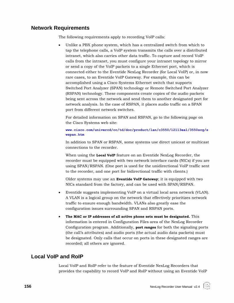
156 NexLog Recorder User Manual v2.4
Network Requirements
The following requirements apply to recording VoIP calls:
Unlike a PBX phone system, which has a centralized switch from which to
tap the telephone calls, a VoIP system transmits the calls over a distributed
intranet, which also carries other data traffic. To capture and record VoIP
calls from the intranet, you must configure your intranet topology to mirror
or send a copy of the VoIP packets to a single Ethernet port, which is
connected either to the Eventide NexLog Recorder (for Local VoIP) or, in now
rare cases, to an Eventide VoIP Gateway. For example, this can be
accomplished using a Cisco Systems Ethernet switch that supports
Switched Port Analyzer (SPAN) technology or Remote Switched Port Analyzer
(RSPAN) technology. These components create copies of the audio packets
being sent across the network and send them to another designated port for
network analysis. In the case of RSPAN, it places audio traffic on a SPAN
port from different network switches.
For detailed information on SPAN and RSPAN, go to the following page on
the Cisco Systems web site:
www.cisco.com/univercd/cc/td/doc/product/lan/c3550/12113ea1/3550scg/s
wspan.htm
In addition to SPAN or RSPAN, some systems use direct unicast or multicast
connections to the recorder.
When using the Local VoIP feature on an Eventide NexLog Recorder, the
recorder must be equipped with two network interface cards (NICs) if you are
using SPAN/RSPAN. (One port is used for the unidirectional VoIP traffic sent
to the recorder, and one port for bidirectional traffic with clients.)
Older systems may use an Eventide VoIP Gateway; it is equipped with two
NICs standard from the factory, and can be used with SPAN/RSPAN.
Eventide suggests implementing VoIP on a virtual local area network (VLAN).
A VLAN is a logical group on the network that effectively prioritizes network
traffic to ensure enough bandwidth. VLANs also greatly ease the
configuration issues surrounding SPAN and RSPAN ports.
The MAC or IP addresses of all active phone sets must be designated. This
information is entered in Configuration Files area of the NexLog Recorder
Configuration program. Additionally, port ranges for both the signaling ports
(the call’s attributes) and audio ports (the actual audio data packets) must
be designated. Only calls that occur on ports in these designated ranges are
recorded; all others are ignored.
Local VoIP and RoIP
Local VoIP and RoIP refer to the feature of Eventide NexLog Recorders that
provides the capability to record VoIP and RoIP without using an Eventide VoIP
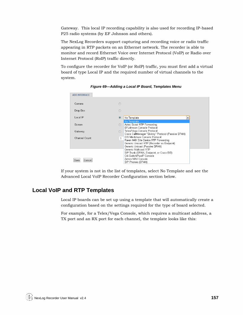
NexLog Recorder User Manual v2.4 157
Gateway. This local IP recording capability is also used for recording IP-based
P25 radio systems (by EF Johnson and others).
The NexLog Recorders support capturing and recording voice or radio traffic
appearing in RTP packets on an Ethernet network. The recorder is able to
monitor and record Ethernet Voice over Internet Protocol (VoIP) or Radio over
Internet Protocol (RoIP) traffic directly.
To configure the recorder for VoIP (or RoIP) traffic, you must first add a virtual
board of type Local IP and the required number of virtual channels to the
system.
Figure 69—Adding a Local IP Board, Templates Menu
If your system is not in the list of templates, select No Template and see the
Advanced Local VoIP Recorder Configuration section below.
Local VoIP and RTP Templates
Local IP boards can be set up using a template that will automatically create a
configuration based on the settings required for the type of board selected.
For example, for a Telex/Vega Console, which requires a multicast address, a
TX port and an RX port for each channel, the template looks like this:
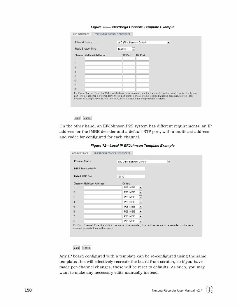
158 NexLog Recorder User Manual v2.4
Figure 70—Telex/Vega Console Template Example
On the other hand, an EFJohnson P25 system has different requirements: an IP
address for the IMBE decoder and a default RTP port, with a multicast address
and codec for configured for each channel.
Figure 71—Local IP EFJohnson Template Example
Any IP board configured with a template can be re-configured using the same
template; this will effectively recreate the board from scratch, so if you have
made per-channel changes, those will be reset to defaults. As such, you may
want to make any necessary edits manually instead.
NexLog Recorder User Manual v2.4 159
The templates included with NexLog 2.4 include:
Aastra MX-ONE H.323 Phones (SPAN), Aastra MX-ONE SIP Phones (SPAN),
Avaya H.323 protocol (SPAN), Avtec Scout RTP Forwarding, C4i SwitchPlusIP
Console, Cisco CallManager "Skinny" Protocol (SPAN), EFJohnson Console
Protocol, Eventide AIS Proxy, Eurocae ED-137b Part 4 RTSP Recording
Interface, Generic Multicast RTP, Generic SIP Phones (SPAN), Generic Unicast
RTP (Recorder as Endpoint), Generic Unicast RTP (SPAN), ICOM IDAS Repeater
(NXDN), IDS Mindshare Console Protocol, Intrado Position (SPAN), Intrado
Trunk (SPAN), NEC Univerge Phone Recording Proprietary SIP (SPAN), Nortel
Unistim Protocol (SPAN), Panasonic MGCP Phones (SPAN), Raven M4X Site
Device RTP Forwarding, Shoretel MGCP Phones (SPAN), SIPREC, SIP Trunk
(SPAN, Endpoint, or Cisco BIB), Tait Radio DMR/MPT Recording Interface,
Telex/Vega Console Protocol, Zetron MAX CallTaking Consoles (SPAN), Zetron
MAX Dispatch
Cisco Local VoIP Template
Figure 72—Cisco Callmanager “Skinny” Protocol Template
To configure Cisco Callmanager with Local VoIP recording, use the Cisco
Callmanager “Skinny” Protocol (Passive SPAN) template. Enter the SCCP and
RTP ports in use, and then enter an IP address (xxx.xxx.xxx.xxx) or MAC
address (xx:xx:xx:xx:xx:xx) for each phone line in the system.
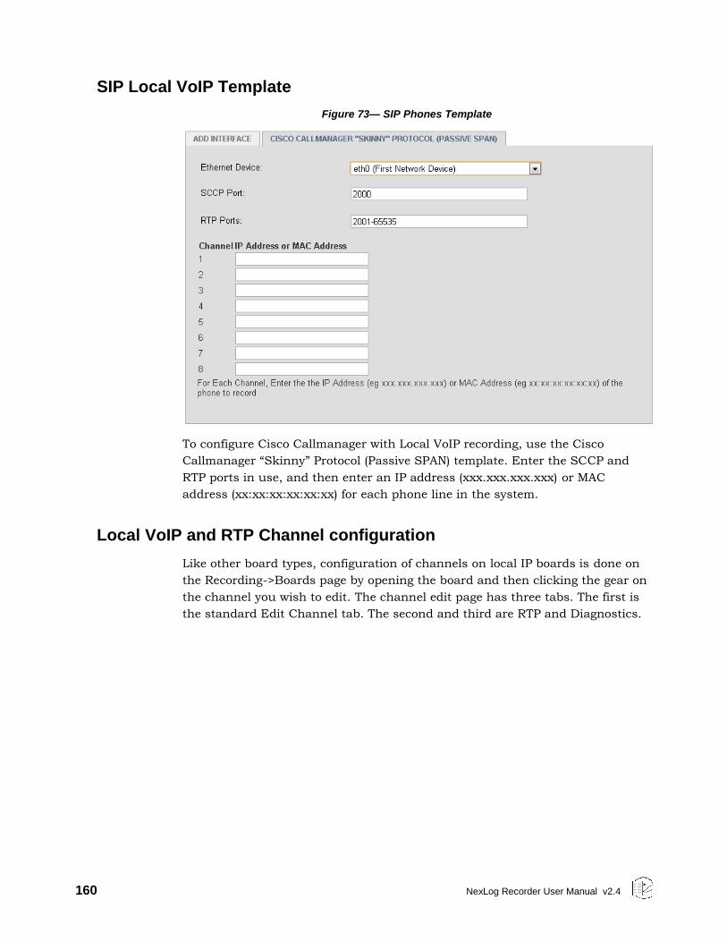
160 NexLog Recorder User Manual v2.4
SIP Local VoIP Template
Figure 73— SIP Phones Template
To configure Cisco Callmanager with Local VoIP recording, use the Cisco
Callmanager “Skinny” Protocol (Passive SPAN) template. Enter the SCCP and
RTP ports in use, and then enter an IP address (xxx.xxx.xxx.xxx) or MAC
address (xx:xx:xx:xx:xx:xx) for each phone line in the system.
Local VoIP and RTP Channel configuration
Like other board types, configuration of channels on local IP boards is done on
the Recording->Boards page by opening the board and then clicking the gear on
the channel you wish to edit. The channel edit page has three tabs. The first is
the standard Edit Channel tab. The second and third are RTP and Diagnostics.
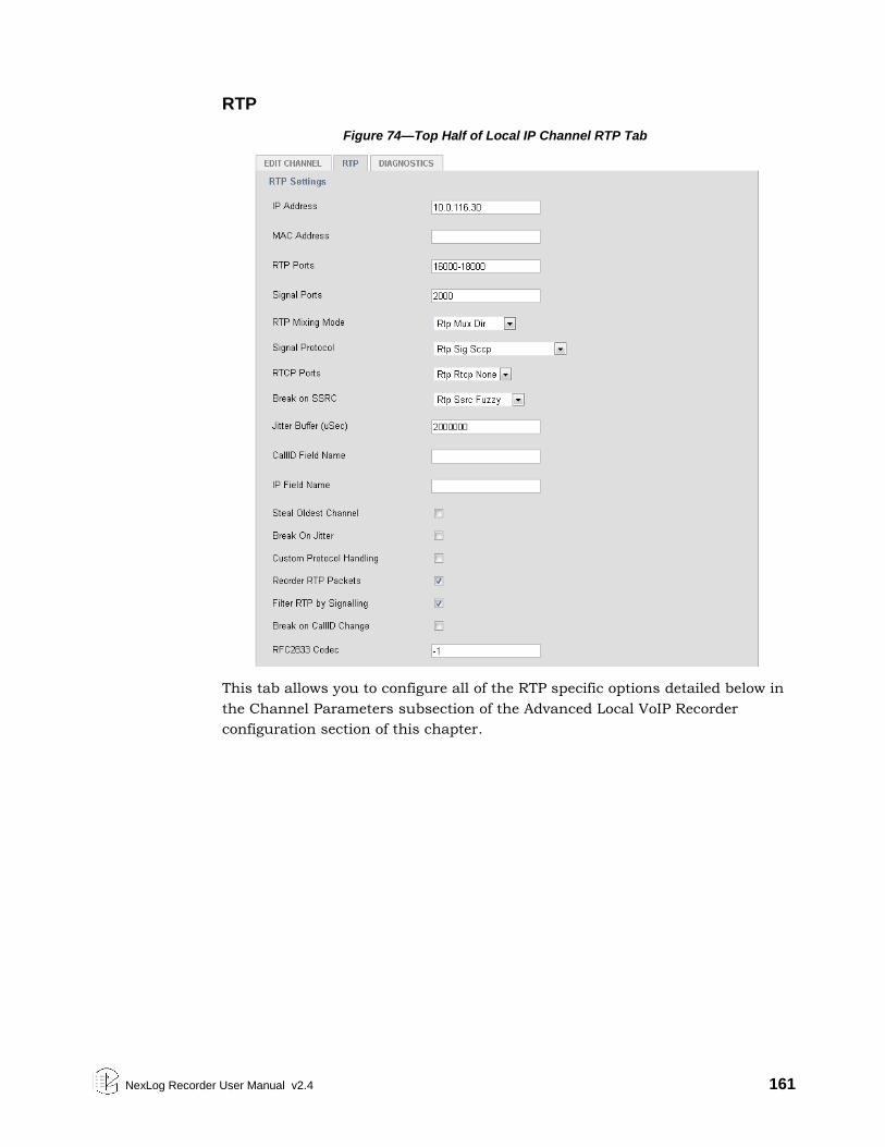
NexLog Recorder User Manual v2.4 161
RTP
Figure 74—Top Half of Local IP Channel RTP Tab
This tab allows you to configure all of the RTP specific options detailed below in
the Channel Parameters subsection of the Advanced Local VoIP Recorder
configuration section of this chapter.
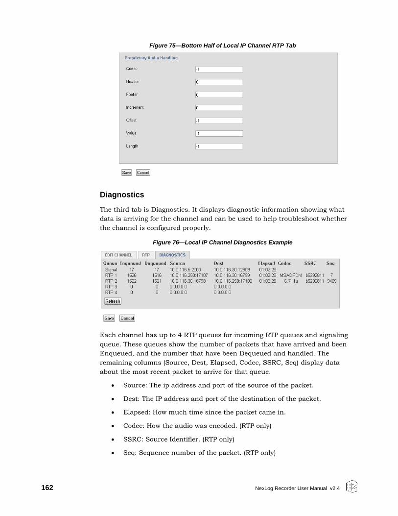
162 NexLog Recorder User Manual v2.4
Figure 75—Bottom Half of Local IP Channel RTP Tab
Diagnostics
The third tab is Diagnostics. It displays diagnostic information showing what
data is arriving for the channel and can be used to help troubleshoot whether
the channel is configured properly.
Figure 76—Local IP Channel Diagnostics Example
Each channel has up to 4 RTP queues for incoming RTP queues and signaling
queue. These queues show the number of packets that have arrived and been
Enqueued, and the number that have been Dequeued and handled. The
remaining columns (Source, Dest, Elapsed, Codec, SSRC, Seq) display data
about the most recent packet to arrive for that queue.
Source: The ip address and port of the source of the packet.
Dest: The IP address and port of the destination of the packet.
Elapsed: How much time since the packet came in.
Codec: How the audio was encoded. (RTP only)
SSRC: Source Identifier. (RTP only)
Seq: Sequence number of the packet. (RTP only)
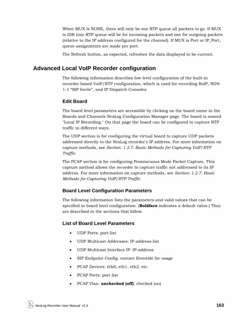
NexLog Recorder User Manual v2.4 163
When MUX is NONE, there will only be one RTP queue all packets to go. If MUX
is DIR (one RTP queue will be for incoming packets and one for outgoing packets
(relative to the IP address configured for the channel). If MUX is Port or IP_Port,
queue assignments are made per port.
The Refresh button, as expected, refreshes the data displayed to be current.
Advanced Local VoIP Recorder configuration
The following information describes low level configuration of the built-in
recorder based VoIP/RTP configuration, which is used for recording RoIP, NG9-
1-1 “SIP Invite”, and IP Dispatch Consoles.
Edit Board
The board level parameters are accessible by clicking on the board name in the
Boards and Channels NexLog Configuration Manager page. The board is named
"Local IP Recording." On that page the board can be configured to capture RTP
traffic in different ways.
The UDP section is for configuring the virtual board to capture UDP packets
addressed directly to the NexLog recorder's IP address. For more information on
capture methods, see Section: 1.2.7. Basic Methods for Capturing VoIP/RTP
Traffic.
The PCAP section is for configuring Promiscuous Mode Packet Capture. This
capture method allows the recorder to capture traffic not addressed to its IP
address. For more information on capture methods, see Section: 1.2.7. Basic
Methods for Capturing VoIP/RTP Traffic
Board Level Configuration Parameters
The following information lists the parameters and valid values that can be
specified in board level configuration. (Boldface indicates a default value.) They
are described in the sections that follow.
List of Board Level Parameters
UDP Ports: port-list
UDP Multicast Addresses: IP-address-list
UDP Multicast Interface IP: IP-address
SIP Endpoint Config: contact Eventide for usage
PCAP Devices: eth0, eth1, eth2, etc.
PCAP Ports: port-list
PCAP Vlan: unchecked (off), checked (on)
164 NexLog Recorder User Manual v2.4
PCAP Defragment: unchecked (off), checked (on)
Packet Filtering: Bpf None, Bpf Port, Bpf Full
Channel Count: number-of-channels-on-virtual-board
Device Information
PCAP Ports and UDP Ports: Specifies a port list (port numbers and/or port
ranges) for ports to record. All ports that are used by all channels must appear
in the list. The ports should also be specified in the channels specific pages.
Valid Range: 1-65535. Format: To specify multiple port numbers, separate them
with commas; for example: 1,2,3,5,9. To specify a port range, separate it with a
hyphen or dash; for example: 1-3. To specify multiple port ranges, separate the
ranges with a comma; for example: 1-3,7-12. To specify multiple port numbers
and port ranges, separate each type with a comma; for example: 1,2,5,9,12-
15,19,22-25,29,30. For readability and maintenance (and to avoid duplications),
it is recommended that you specify port numbers in numerical order.
Note: For PCAP Ports, the smaller the range, the better the performance, so it is
a good practice to identify only those ports that will be used. The ports belong to
VoIP devices such as IP phones, IP softphones, IP PBX ports, or other VoIP
endpoints on the network that you wish to record. Any packet received by the
recorder that uses ports in this list as either destination or source will make it
past the filter and be processed by the recorder.
Important! For UDP Ports, it is very important to specify only the ports that
will be used, because opening these ports will consume resources on the
recorder. For example, specify 3,5 rather than 3-5 if port 4 will not be used.
UDP Multicast Addresses: Specifies one or more IP multicast group addresses
from which to record. [Join or subscribe to.] Format: to specify multiple IP
multicast group addresses, separate them with a comma; for example:
239.1.1.1,239.1.1.9.
UDP Multicast Interface IP: Specifies the IP address of the NexLog Recorder’s
network interface device which will be used to capture the multicast traffic.
SIP Endpoint Config: Specifies a special parameter to configure the NexLog
Recorder as a SIP Trunk endpoint instead of its usual configuration as a "listen
only" device. Contact Eventide support for assistance in configuring this
parameter.
PCAP Devices: Ethernet Device name. Specifies the NexLog Recorder’s network
interface device (NIC) containing the Ethernet port that will be used to record
RTP data. Valid Values: eth0, eth1, etc. Typically, one Ethernet port on the
recorder is used to record the VoIP traffic sent to the recorder and one port is
used for bidirectional traffic with recorder clients, such as a PC with Eventide
MediaWorks that is used for playback or live monitoring.
NexLog Recorder User Manual v2.4 165
PCAP Vlan: Virtual Local Area Network. Enables the Packet Pre-Filtering (BPF)
for use on a VLAN, which is often used with SPAN and RSPAN setups. This
setting is used because the port/IP address information appears in a different
location in packets depending upon whether the traffic is from a VLAN or LAN.
Valid values:
unchecked: Disabled (default), for use on a LAN.
checked: Enabled, for use on a VLAN.
PCAP Defragment: Enables IP defragmentation. When disabled, only the first
fragment is processed and subsequent fragments are ignored. It is usually
unnecessary to enable IP defragmentation, because voice packets are typically
small enough to avoid fragmentation, or if they are sent in multiple fragments,
the necessary data is usually in the first fragment, and the rest can be ignored.
(Fragmentation occurs when the payload results in a data packet size that is
greater than the maximum transmission unit of the sending switch.) Valid
values:
unchecked: Disabled (default). No IP defragmentation is performed.
checked: Enabled. IP defragmentation is performed.
Packet Filtering and Handling
Because networks carry many types of data packets that are bound for different
destinations, the recorder uses a /packet filtering/ mechanism to detect and
isolate the desired RTP audio data packets from other data types forwarded by
the network to the recorder’s Ethernet port.
Packet Filtering: Berkeley Packet Filtering. Specifies a source port pre-filtering
method for capturing RTP packets. Packets are pre-filtered at the NexLog
Recorder network interface. This can reduce the load on the recorder, which is
especially important in saturated high-throughput networks. BPF is a method
used to capture and filter packets from a network interface that is used in
promiscuous mode. When the NexLog Recorder network interface is in
promiscuous mode, it receives a copy of each RTP packet appearing on the port,
which is then run through a filter, so that only packets of interest are passed to
the recording application layer. This pre-filtering can reduce the traffic load on
the recorder CPU (except when no filtering is used).
The following settings can be used:
Full: (default) Accepts traffic from all source ports identified in the
configuration by IP or MAC address or port number.
Port: Accepts traffic from all source ports identified in the configuration
independent of IP or MAC address. This setting is used when the IP
addresses may change.
None: No pre-filtering is performed. Accepts traffic from all source ports.
166 NexLog Recorder User Manual v2.4
Typically, it is either set to FULL or to a list of ports, except when using dynamic
channel mapping, in which case, it should be set to NONE or a list of ports.
Channel Parameters
The channel level configuration is accomplished the same way as other boards.
Click on the plus sign (+) next to the board name to open the list of channels for
a board. From there clicking on the gear icon will show the channel specific
configuration. On the channel page there is an RTP tab where VoIP specific
parameters can be changed. The settings include channel mapping parameters,
which direct RTP packets from a specific IP address, MAC address, or port
number to record on the specified channel (or which specifies dynamic channel
mapping).
When a virtual board is added the virtual channels are added to the recorder
and are assigned recorder channel numbers based on the channel numbering
sequence. The channel numbering sequence starts with hardware based
channels, beginning with installed telephony boards, followed by the channels
on virtual boards in the order they were added via NexLog Configuration
Manager. For example, if the recorder has 8 hardware-based channels, then the
first virtual channel (Channel1 of the virtual board) will be assigned to recorder
channel 9. For an illustration, see Section: 3.5. Set the Recording Control
Parameters.
Channel Configuration Parameters
The following information lists the channel configuration parameters and valid
values that can be specified.
List of Channel Parameters
IP Address: <IP-address>
MAC Address: <MAC-address>
RTP Ports: <port-list>
Signal Ports: <port-list>
RTP Mixing Mode: Rtp Mux None, Rtp Mux Dir, Rtp Mux Port, Rtp Mux
Ip Port, Rtp Mux Ssrc
Signal Protocol: Rtp Sig None, Rtp Sig Sip Trunk, Rtp Sig Zetron Rds,
Rtp Sig Cisco Forked, Rtp Sig Telex Ip223, Rtp Sig Telex Ip223 Trunked,
Rtp Sig Efjohnson
RTCP Ports: Rtp Rtcp None, Rtp Rtcp Odd, Rtp Rtcp Even
Break on SSRC: Rtp Ssrc Nobreak, Rtp Ssrc Break, Rtp Ssrc Fuzzy
Jitter Buffer (uSec): <millionths-of-second>
NexLog Recorder User Manual v2.4 167
CallID Field Name: <SIP-field>
IP Field Name: <optional name of metadata field>
Steal Oldest Channel: *unchecked (off)*, checked (on)
Break On Jitter: *unchecked (off)*, checked (on)
Custom Protocol Handling: *unchecked (off)*, checked (on)
RFC2833 Codec: -1, <codec-number>
Channel Mapping
VoIP calls can be mapped to NexLog Recorder channels using the following
options:
IP Address: Map the IP address of a VoIP device to a recorder channel using
static channel mapping. Mutually exclusive with MAC address. A specific IP
address can be used or Dynamic which can map VoIP calls to a bank of
channels using a dynamic assignment that is controlled by other means, such
as call control or custom programming. Used when the port range or IP address
is variable or floats, such as with VoIP trunking (e.g., SIP trunking, where
negotiation of the SIP phone call includes ports to use), or when using custom
scripts or programming from Eventide. When used with SIP trunking, set
channel 1 to the IP address of the SIP source (for example, the SIP PBX or the
local SIP trunk endpoint), and set the other channels to Dynamic.
MAC Address: Map the MAC address of a VoIP device to a recorder channel
using static channel mapping. Mutually exclusive with IP address.
RTP Ports: Map a set of ports on a device to a recorder channel using static
channel mapping. For valid settings, see Port under Topic: Capture Method
Configuration Parameters.
Signal Ports: Specifies the signaling ports when signaling is used (when Signal
Protocol is set to a value other than Rtp Sig None). Like traditional telephone
calls, VoIP calls offer full-duplex communication, which allows the connected
parties or devices to communicate with each other in both directions at the
same time. However, with VoIP, the full-duplex call is composed of two halves: a
stream of audio packets that are transported from party A to party B and a
stream of audio packets that are transported from party B to party A.
It is typical to record the combined conversation rather than each side
separately. Mixing options allow you to merge both halves of the conversation
into one channel, or to record each party on separate channels.
Each channel is associated with a MAC or IP address (or is dynamically
assigned). Traffic to this address is considered inbound and traffic from it is
considered outbound.
RTP Mixing Mode: Specifies the type of audio stream mixing for the recording.
Valid values include:
168 NexLog Recorder User Manual v2.4
Rtp Mux None: (default) No mixing is performed. The channel must be
set up to receive only a single RTP stream at any given time.
Rtp Mux Dir: Mix inbound and outbound audio streams belonging to a
VoIP device (that is, mix traffic going in both directions). Direction mixing
is typically used with the PCAP method, because the audio streams
could be coming in from any port in the range.
Rtp Mux Port: Mix audio streams from multiple ports, where each port
carries a separate audio stream. Port mixing is typically used with the
UDP method.
Rtp Mux Ip Port: Mix audio streams from a destination IP address and
port. IP Port mixing is used with the UDP method or SIP Trunk signaling.
Rtp Mux Ip Ssrc: Mix audio streams by detecting which stream a packet
belongs to using the RTP packet's SSRC field. Only recommended in case
where IP_PORT cannot be used due to multiple streams received on the
same port
Signal Protocol: Specifies the type of signaling used. See Section: 2.1. Features
for more information on the supported signaling types. Valid values include:
Rtp Sig None:(default) Audio data is recorded without any call metadata
and Start/Stop is based only on RTP Stream presence and SSRCs
Rtp Sig Sip Trunk: SIP Trunk, which is used for trunk-side recording
and not station to station calls.
Rtp Sig Zetron Rds: Zetron RDS RoIP systems recording.
Rtp Sig Cisco Forked: Used for Built-in-Bridge recording from Cisco IP
phones.
Rtp Sig Telex Ip223: Telex /Vega IP radio recording when the Telex is
connected to a Conventional Radio System
Rtp Sig Telex Ip223 Trunked: Telex/Vega IP radio recording when the
Telex is connected to a Trunked Radio System
Rtp Sig Efjohnson: EF Johnson P25 signaling.
RTCP Ports: Specifies the location of RTCP ports when RTP Ports
specifies multiple ports (e.g., a range). This is used to ignore any signals
on the RTCP ports so as to avoid interpreting them as RTP. Valid values
include:
None: (default) None of the ports carry RTCP data (which means that
none of them will be ignored).
Odd: RTCP data appears on odd port numbers. (Typically, RTCP is
transmitted on the next higher odd port number above each RTP port.)
Even: RTCP data appears on even port numbers.
NexLog Recorder User Manual v2.4 169
RTP packets contain information in their headers identifying the sources of the
RTP data stream. This includes the following identifiers:
Synchronization Source (SSRC): A unique numeric ID for a
unidirectional stream of RTP packets. The synchronization source within
the same RTP session is unique.
Contributing Source (CSRC): A unique numeric ID identifying a
contributing source for a mixed stream of RTP packets (a stream that
has been generated from multiple sources). In some situations, it is used
to identify a previous origin of a stream of RTP packets (that is, a
previous SSRC).
These data are used to identify audio streams, and hence, the audio that
belongs to a VoIP call.
In addition, the SSRC is also used to aid in identifying call termination. When
the SSRC changes, it is an indicator that the audio stream from one party has
ended. However, there may be cases where the SSRC changes briefly but does
not indicate a separate call. This can result in a call being broken
inappropriately into two parts or in a spurious call with a very short call length
(e.g., 0 seconds). The following parameter is used to control call breaks for these
different situations.
Break on SSRC: Controls how to handle SSRC changes in determining call
termination. Valid values are as follows:
Rtp Ssrc Nobreak: When the SSRC changes, do not “break” the call.
Rtp Ssrc Break: (default) When the SSRC changes, “break” the call (that is,
treat it as a new call).
Rtp Ssrc Fuzzy: When the SSRC changes, “break” the call. However, if the new
SSRC is numerically close to the current SSRC, do not break the call. This
setting is used with some VoIP implementations that have atypical SSRC
changes, such as with certain configurations of Cisco Call Manager.
Jitter Buffer: Jitter Buffer Size in microseconds. Default: 2000000 (2 seconds).
Range: 0 to 5000000 (5 seconds). The recorder uses a jitter buffer to enable
proper synchronization and a smoother flow of data. The larger the jitter buffer,
the higher the recorder memory usage, as well as the higher the load on the
recorder CPU when jitter is encountered.
CallID Field Name: If this value is set to the name of a text metadata field that
has been added to the recorder's database, and the signaling protocol from the
PBX includes CallID information (a unique identifier assigned to the call by the
PBX), then the CallID for the call will be attached to each call record by placing
the CallID in this field.
RFC2833 Codec: Enables out-of-band digits when signaling is used.
-1: Disabled (default), no out-of-band digits.

170 NexLog Recorder User Manual v2.4
<codec-number>: Enabled to receive out-of-band digits using the specified codec
number used by the particular IP phone system (PBX and phones). Example:
128. The codec number is application-specific and can be obtained by checking
with the manufacturer of the system or by analyzing the signaling data (see
Section: 4.2. Network Diagnostic Programs).
NexLog Recorder User Manual v2.4 171
Appendix G: Archive Pairing
Introduction
Archive Pairing is an archiving scheme, introduced in NexLog software version
2.2.1, created to put a focus on constant archiving to DVD-RAM. It takes
advantage of two recorders to ensure all recorded data is archived. This
appendix explains the requirements for Archive Pairing, how to set it up, and
how it works.
Requirements
Archive Pairing requires two recorders. These recorders should have identical
hardware profiles and software configurations, and must receive the same call
input. Each recorder should have two DVD-RAM drives. The recorders should
also be synced to the same time source, for example NTP, and be in the same
network with the ability to communicate with each other. Additionally, an
appropriate license is required for this functionality but this license is only
needed on the “primary” recorder.
Operation
Archive Pairing enables the end-user to archive their data in a more streamlined
way than traditional archiving with the benefits of system redundancy. With this
feature enabled, recorded information will continue to archive on the next
available DVD-RAM drive when a disc fills, the user manually stops archiving on
a particular DVD-RAM drive, or if some external factor disrupts normal
operation of one of the loggers (such as a power failure). Flow between drives is
automatic. The end-user simply has to flip or change out the media as the
drives fill for constant coverage.
The functionality works by creating a global archive pointer that both recorders
will use to determine what recorded data they should be archiving. The two
recorders are referred to as the “primary” recorder and the “secondary” recorder.
The distinguishing feature between them is that the primary recorder is where
the Archive Pairing license must be entered.
With Archive Pairing enabled, DVD-RAM drives with formatted media will enter
a state called “Standby”. This means the drive is ready to archive as part of the
172 NexLog Recorder User Manual v2.4
Archive Pairing scheme. The first drive of the primary logger will automatically
begin archiving at the point that is set to start at for that drive. This will
establish the starting point for all archiving. The initial archive pointer should
be set before any calls have occurred on the recorder but should also be no
earlier than January 1st, 1989. There is no need to set the archive pointer for
each drive, just the first one.
When a DVD-RAM media fills, it will automatically begin archiving where it left
off on the next drive that is in Standby. Typically the flow is first drive on the
primary recorder, then the second drive on the primary, followed by the first
drive secondary, and finally the second drive secondary. If an archive is
manually stopped, archiving will automatically resume on the next available
Standby archive. In the event that all drives are full, Archive Pairing will wait
until new media is inserted, formatted, and enters Standby.
In the event that maintenance is to be performed on one or both of the
recorders, a recorder can be shut down and worked on while the other recorder
continues archiving from the point that the first recorder is shutdown, and then
once the first recorder is back up and running, the same procedure can be
performed on the other recorder. This method should be employed when
upgrading to future software releases or for any required hardware
maintenance.
Pairing Setup
Prior to setting up the software, the following items are assumed:
Recorders are racked or placed with accordance to site specifications
The software on the recorders are NexLog 2.2.1 or newer.
The software on the recorders is the same version on both.
A valid license has been entered into the recorder
The recorders are networked in the same IP network
The recorders have the same call sources attached to both
Eventide approved DVD-RAM media is available
After the above is satisfied, the recorder should be configured to have the dates
and time synced to the same external clock. The channels for both recorders
should be configured the same and be properly recording. After that has been
setup, insert blank DVD-RAM discs into the drives. Format them if required.
Before enabling Archive Pairing, the archive pointer of the first drive should be
checked to make sure it will catch all calls. To view and set the archive pointer,
in Configuration Manager expand the menu item Archiving and click Archive
Configuration. Select the DVD-RAM 1 device and select the Configure button.
On the resulting screen, select the TIME tab and observe the Archive Time.
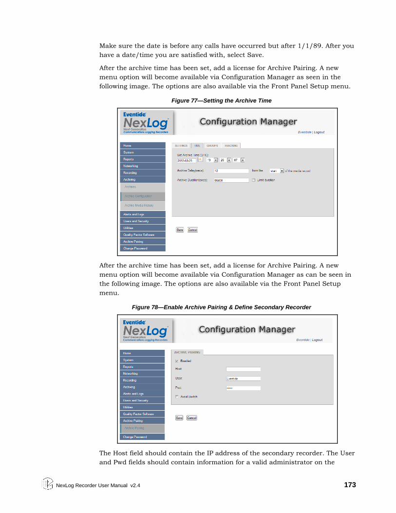
NexLog Recorder User Manual v2.4 173
Make sure the date is before any calls have occurred but after 1/1/89. After you
have a date/time you are satisfied with, select Save.
After the archive time has been set, add a license for Archive Pairing. A new
menu option will become available via Configuration Manager as seen in the
following image. The options are also available via the Front Panel Setup menu.
Figure 77—Setting the Archive Time
After the archive time has been set, add a license for Archive Pairing. A new
menu option will become available via Configuration Manager as can be seen in
the following image. The options are also available via the Front Panel Setup
menu.
Figure 78—Enable Archive Pairing & Define Secondary Recorder
The Host field should contain the IP address of the secondary recorder. The User
and Pwd fields should contain information for a valid administrator on the
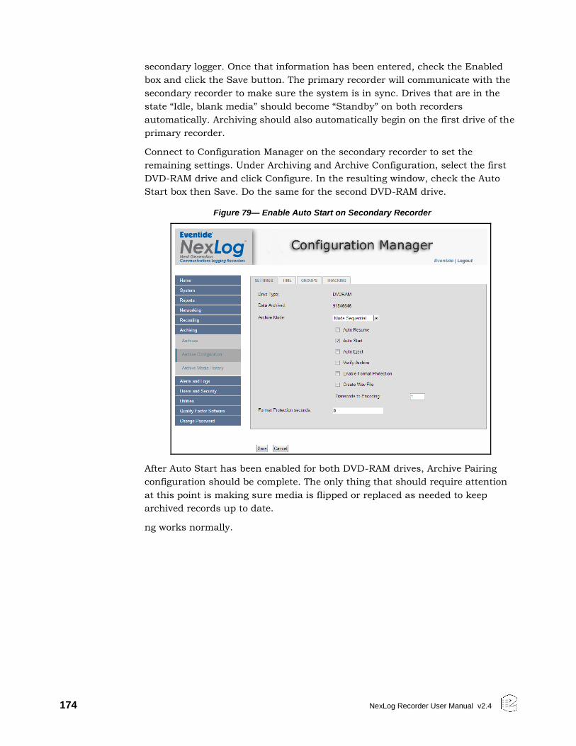
174 NexLog Recorder User Manual v2.4
secondary logger. Once that information has been entered, check the Enabled
box and click the Save button. The primary recorder will communicate with the
secondary recorder to make sure the system is in sync. Drives that are in the
state “Idle, blank media” should become “Standby” on both recorders
automatically. Archiving should also automatically begin on the first drive of the
primary recorder.
Connect to Configuration Manager on the secondary recorder to set the
remaining settings. Under Archiving and Archive Configuration, select the first
DVD-RAM drive and click Configure. In the resulting window, check the Auto
Start box then Save. Do the same for the second DVD-RAM drive.
Figure 79— Enable Auto Start on Secondary Recorder
After Auto Start has been enabled for both DVD-RAM drives, Archive Pairing
configuration should be complete. The only thing that should require attention
at this point is making sure media is flipped or replaced as needed to keep
archived records up to date.
ng works normally.
NexLog Recorder User Manual v2.4 175
Appendix H: SSL Certificate request & application
Introduction
The following applies to systems running Eventide Nexlog software version 2.4.0
and higher. It would allow secure connections, and interactions with an
Eventide system recorder using port 443 using the HTTPS protocol, for which a
valid CSR (Certificate Signing Request) was generated. This procedure does not
go into details of SSL (Secure Socket Layer) or recommendations on providers.
Requirements:
Network Interfaces: primary or secondary network interface must have
accurate, and valid network IP addressing with working Gateway.
System Identification: Valid DNS IP addresses should be available for the
recorder.
Licensing: The ability to enable SSL functionality in NexLog recorders with
software version 2.3.2 and later requires an extra-cost Eventide add-on license.
(Eventide reserves the right to limit the availability of this enabler add-on license
for export.)
SSL Settings:
In Configuration Manager, under Users and Security: SSL: SSL Settings, you
can configure database connections, web server connections, client service
connections to unencrypted only, SSL only, or both.
Request procedure:
First open the Configuration Manager and log in with an Administrator account.
Expand Users and Security, then click SSL.
1. Under the SSL Keys tab: Check the box for generating a new request,
complete the form with the pertinent details
2. Common Name needs to be entered as it would be displayed in the
browser; for example: https://name.domain.com
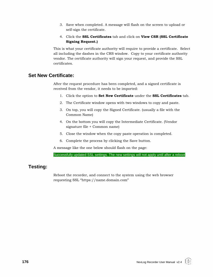
176 NexLog Recorder User Manual v2.4
3. Save when completed. A message will flash on the screen to upload or
self-sign the certificate.
4. Click the SSL Certificates tab and click on View CSR (SSL Certificate
Signing Request.)
This is what your certificate authority will require to provide a certificate. Select
all including the dashes in the CRS window. Copy to your certificate authority
vendor. The certificate authority will sign your request, and provide the SSL
certificates.
Set New Certificate:
After the request procedure has been completed, and a signed certificate is
received from the vendor, it needs to be imported:
1. Click the option to Set New Certificate under the SSL Certificates tab.
2. The Certificate window opens with two windows to copy and paste.
3. On top, you will copy the Signed Certificate. (usually a file with the
Common Name)
4. On the bottom you will copy the Intermediate Certificate. (Vendor
signature file + Common name)
5. Close the window when the copy paste operation is completed.
6. Complete the process by clicking the Save button.
A message like the one below should flash on the page:
Successfully updated SSL settings. The new settings will not apply until after a reboot
Testing:
Reboot the recorder, and connect to the system using the web browser
requesting SSL “https://name.domain.com”
NexLog Recorder User Manual v2.4 177
Limited Warranty
The Eventide® NexLog™ Recorders are built to exacting quality standards and
should give years of trouble-free service. If you are experiencing problems, your
recourse is this warranty.
Eventide Inc. warrants the products unit to be free from defects in workmanship
and material under normal operation and service for a period of one year from
the date of purchase, as detailed in this warranty. At our discretion within the
warranty period, we may elect to repair or replace the defective unit. This means
that if the unit fails under normal operation because of such defect, we will
repair the defective unit at no charge for parts or labor. We also assume a
limited responsibility for shipping charges, as described later in this warranty.
The warranty does not extend beyond repair or replacement as stated herein
and in no event will we be responsible for consequential or incidental damages
caused by any defect, and such damages are specifically excluded from this
warranty. Our sole obligation is to repair or replace the defective unit as
described herein.
The warranty DOES NOT COVER any damage to the unit regardless of the cause
of that damage. The unit is a complex piece of equipment that does not react
well to being dropped, bounced, crushed, soaked or exposed to excessively high
temperatures, voltages, electrostatic or electromagnetic fields. If the unit is
damaged for these or similar causes, and the unit is deemed to be economically
repairable, we will repair it and charge our normal rates.
The warranty DOES NOT COVER shipping damage, either to or from Eventide. If
you receive a new unit from us in damaged condition, notify us and the carrier;
we will arrange to file an insurance claim and either repair or exchange the unit.
If you receive a new unit from a dealer in damaged condition, notify the dealer
and the carrier.
If we receive the unit from you with apparent shipping damage, we will notify
you and the carrier. In this case, you must arrange to collect on any insurance
held by you or your carrier. We will await your instructions as to how to proceed
with the unit, but we will charge you for all repairs on damaged units.
178 NexLog Recorder User Manual v2.4
Who is covered under the warranty
The warranty applies to the original purchaser of a new unit from Eventide or an
Authorized Eventide Dealer. Demo units are also covered by this warranty under
slightly different circumstances (see the following information on “When the
warranty becomes effective.” Units that are used, or have been used as part of a
rental program, are not covered under any circumstances.
It is your responsibility to prove or to be able to prove that you have purchased
the unit under circumstances which affect the warranty. A copy of your
purchase invoice is normally necessary and sufficient for this.
If you have any questions about who is an Authorized Eventide Dealer, call
Eventide at 201-641-1200.
Units with the serial number plate defaced or removed will not be serviced or
covered by this warranty.
When the warranty becomes effective
The one-year warranty period begins on the day the unit is purchased from an
Authorized Eventide Dealer or, if the unit is drop-shipped from Eventide, on the
day shipped, plus a reasonable allowance for shipping delays. This applies
whether or not you return your warranty registration form.
When we receive a unit, this is how we determine whether it is under warranty:
If the unit was shipped from our factory within the past calendar year, we
assume that it is under warranty unless there is evidence to the contrary, such
as its having been sold as used or rented, etc.
If the unit was shipped from our factory more than a calendar year ago, we
assume it is not under warranty unless there is a warranty registration form on
file showing that it has been purchased within the past year under appropriate
conditions or if you send a copy of your purchase invoice indicating warranty
status along with the unit.
If the unit was used as a demo, the warranty runs from the date that it was
received by the dealer. The original purchaser gets the unexpired portion of that
warranty.
When you send a unit for repair, you should indicate whether or not you believe
it to be under warranty. If you do not say the unit is under warranty, we will
charge you for the repair and we will not refund unless the charge was caused
by an error on our part. If you believe the unit to be under warranty and you do
say it is but this disagree, you will not incur any charges until the dispute is
resolved.
Reading the above, you can see that it is to your advantage to send in the
warranty registration form when you purchase the unit. If we know who you are,
NexLog Recorder User Manual v2.4 179
we can send you updates and notifications, and advise you of our new products.
It will also enable you to receive pre-shipment of certain parts.
Who performs warranty work
The only company authorized to perform work under this warranty is Eventide
Inc., Little Ferry, New Jersey. While you are free to give personal authorization
to anyone else (or to work on it yourself), we will not honor claims for payment
for parts or labor from you or from third parties.
However, we and our dealers do try to be helpful in various ways. Our dealers
will assist, usually without charge during the warranty period, in determining
whether there is a problem requiring return to the factory, and alleviating user
error or interconnection problems that may be preventing the unit from
operating to its full capability.
We are available for consultation if the dealer is unable to assist.
If a part is found to be defective during the warranty period and you wish to
replace it yourself, we will normally ship the part immediately at no charge,
provided your warranty registration form is on file. We reserve the right to
request that the defective part be returned to us.
Shipping within the 50 United States
You are responsible for getting the unit to our door at no cost to us. We cannot
accept collect or COD shipments.
We will return the in-warranty unit to you prepaid, at our expense, using a
standard shipping method, normally United Parcel Service. If you are in a hurry
and want us to use a premium shipping method (such as air express, next day
air, etc.), be sure you tell us and agree to pay shipping charges collect. If you
specify a method that does not permit collect or COD charges, remit sufficient
funds to prepay shipping.
Shipping outside the 50 United States
If you purchased the unit from a dealer in your country, consult with the dealer
before returning the unit.
If you wish to return the unit to us, please note the following policies:
The unit must be prepaid to our door. This means that you are responsible
for all shipping charges, including customs brokerage and duties. When a
unit is shipped to us it must be cleared through United States Customs by
an authorized broker. You must make arrangements for this to be done.
Normally, your freight forwarder has a branch in the United States that can
handle this transaction. If you want our assistance in clearing incoming
packages, you must notify us before shipping the unit for repair, giving full
180 NexLog Recorder User Manual v2.4
details of the shipment, and including a minimum of $250.00 in US funds to
cover the administrative and brokerage expenses. Any balance will be
applied to the repair charges or refunded. If a balance is due to us, we will
request a further prepayment.
All shipments will be returned to you collect. If this is impossible because of
shipping regulations or money is due us, we will request prepayment from
you for the appropriate amount.
All funds must be in $US. Payment may be made by check drawn on any
bank in the US, or by telegraphic funds transfer to our bank. If you send US
currency, be sure that it is sent by a method you can trace, such as
registered mail. If you wish to pay by Letter of Credit, be sure that it affords
sufficient time for work to be performed and the L/C negotiated, and that it
is free from restrictive conditions and documentation requirements.
We reserve the right to substitute freight carriers. Although we will attempt
to honor your request for a specific carrier, it is frequently necessary to
select a substitute because of difficulties in communication or scheduling.
This warranty gives you specific legal rights and you may also have other rights
which vary from location to location.
NexLog Recorder User Manual v2.4 181
Software License
The Eventide® NexLog™ Recorder contains proprietary Eventide Firmware and
Software. In addition Eventide MediaWorks and Eventide MediaAgent are
proprietary Eventide Software. The Software License for this software follows:
Product License and Usage Agreement
By installing, copying or otherwise using the Software, you agree to be bound by
the terms of this License Agreement. If you do not agree to the terms of this
License Agreement, do not use or install the Software.
1. License. YOU (either as an individual or an entity) MAY: (a) use this Software
on a single computer; (b) physically transfer the Software from one computer to
another provided that the Software is used on only one computer at a time and
that you remove any copies of the Software from the computer from which the
Software is being transferred; and (c) install a second copy of the Software in the
event that the first Software installation is unusable. In addition, the Eventide
NexLog firmware may only be installed on a purchased and Licensed Eventide
NexLog Recorder.
YOU MAY NOT: (a) distribute copies of the Software or the Documentation to
others; (b) modify or grant sublicenses or other rights to the Software; and (c)
use the Software in a computer service business, network, time-sharing, or
multiple user arrangement without the prior written consent of Eventide.
The License is effective until terminated. You may terminate this License at any
time by destroying the Software together with any copies in any form. This
Agreement, including the license to use the Software, will terminate
automatically if you fail to comply with any term of condition of this Agreement.
2. Ownership. This License is not a sale of the Software or any Firmware
contained in the Product. Eventide and its licensors retain all rights, interest,
title in and ownership of the Software, Firmware and Documentation, including
all intellectual property rights. No title to the intellectual property in the
Software and Firmware is transferred to you. You will not acquire rights to the
Software and Firmware except as expressly set forth above.
3. No Reverse Engineering and Other Restrictions. You agree that you will not
(and if you are a corporation, you will use your best efforts to prevent your
employees and contractors from attempting to) reverse engineer, disassemble,
182 NexLog Recorder User Manual v2.4
compile, modify, translate, investigate or otherwise study the Product (including,
but not limited to any software, firmware, hardware components or circuits) in
whole or in part.
4. Inclusion of free software. In addition to Eventide Proprietary Software, this
distribution contains free software which is distributed in binary form as well as
linked libraries which are licensed under GPL and LGPL licenses respectively.
Usage of this software package binds you to the terms of the GPL and LGPL
software licenses that can be found below this license agreement in your
manual.
5. Compliance with Laws and Indemnification. You agree to use the Product in a
manner that applies to all applicable laws in the jurisdiction in which you use
the Product, including all intellectual property laws. You may not use the
Software or Firmware in conjunction with any device or service designed to
circumvent technological measures employed to control access to, or the rights
in, a content file or other work protected by the copyright laws of any
jurisdiction. You agree to indemnify, defend, and hold harmless Eventide from
and against losses, damages, expenses, (including reasonable attorneys' fees),
fines, or claims arising from or relating to any claim that the Product was used
by you to violate, either directly or indirectly, another party's intellectual
property rights.
6. Limited Warranty on Software. Eventide warrants that the media on which
the Software is furnished will be free from defects in materials and workmanship
under normal use for a period of ninety (90) days from the date of purchase. If a
defect appears during the warranty period, return the diskette/compact disc to
Eventide, and you will receive a free replacement, or at Eventide's option, a
refund, so long as the Software, documentation, accompanying hardware, and
diskettes are returned to Eventide with a copy of your receipts. This Limited
Warranty is void if failure of the Software has resulted from accident, abuse, or
misapplication. Any replacement Software will be warranted for the remainder of
the original warranty period. THIS WARRANTY GIVES YOU SPECIFIC LEGAL
RIGHTS AND YOU MAY ALSO HAVE OTHER RIGHTS WHICH VARY BY
JURISDICITON.
7. No Other Warranties. Eventide AND ITS LICENSOR(s) (hereafter collectively
'Eventide') DO NOT WARRANT THAT THE Eventide SOFTWARE NOR ANY
THIRD-PARTY SOFTWARE EMBEDDED ON THE DISK (collectively
'SOFTWARE') ARE ERROR FREE. YOU EXPRESSLY ACKNOWLEDGE THAT THE
SOFTWARE AND DOCUMENTATION ARE PROVIDED AS IS. EVENTIDE
DISCLAIMS ALL OTHER WARRANTIES, EITHER EXPRESS OR IMPLIED,
INCLUDING BUT NOT LIMITED TO IMPLIED WARRANTIES OF
MERCHANTABILITY, FITNESS FOR A PARTICULAR PURPOSE AND NON-
INFRINGEMENT OF THIRD PARTY RIGHTS WITH RESPECT TO THE
SOFTWARE, THE ACCOMPANYING DOCUMENTATION OR DISKETTES.
8. No Liability for Consequential Damages. IN NO EVENT SHALL EVENTIDE BE
LIABLE TO YOU FOR ANY CONSEQUENTIAL, SPECIAL, INCIDENTAL OR
NexLog Recorder User Manual v2.4 183
INDIRECT DAMAGES OF ANY KIND ARISING OUT OF THE USE OF THE
PRODUCT, EVEN IF Eventide HAS BEEN ADVISED OF THE POSSIBILITY OF
SUCH DAMAGES. EVENTIDE'S LIABILITY FOR ANY CLAIM, LOSSES,
DAMAGES OR INJURY, WHETHER CAUSED BY BREACH OF CONTRACT, TORT
OR ANY OTHER THEORY OF LIABILITY, SHALL NOT EXCEED THE FEE PAID
BY YOU. SOME JURISDICTIONS DO NOT ALLOW THE EXCLUSION OF
IMPLIED WARRANTIES OR INCIDENTAL OR CONSEQUENTIAL DAMAGES, SO
THE ABOVE LIMITATION OR EXCLUSIONS MAY NOT APPLY TO YOU.
9. Export. You acknowledge that the laws and regulations of the United States
restrict the export and re-export of the Software and Documentation. You agree
the Software will not be exported or re-exported without the appropriate U.S. or
foreign government licenses. You also agree not to export the Software (including
over the Internet) into any country subject to U.S. embargo.
10. Governing Law and Arbitration. This Agreement will be governed by the
laws of the State of New Jersey and will be interpreted as if the agreement were
made between New Jersey residents and performed entirely within New Jersey.
All disputes under this Agreement or involving use of the Product shall be
subject to binding arbitration in Little Ferry, NJ in accordance with the
commercial arbitration laws of the American Arbitration Association.
Notwithstanding anything contained in this Paragraph to the contrary, Eventide
shall have the right to institute judicial proceedings against you or anyone
acting by, through, or under you, in order to enforce Eventide's rights hereunder
through reformation of contract, specific performance, injunction or similar
equitable relief.
11. Entire Agreement. This is the entire agreement between you and Eventide
AND supersedes any prior agreement, whether written or oral, relating to the
subject matter of this Agreement. No amendment or modification of this
agreement will be binding unless in writing and signed by a duly authorized
representative of Eventide.
12. Government End Users. U.S. GOVERNMENT RESTRICTED RIGHTS. The
Software and Documentation were developed at private expense, and are
commercial computer software and commercial computer software
documentation. If you are a U.S. Government agency or its contractor, pursuant
to FAR 12.212(a) and/or DFARS -227.7202-1(a) and their successors, as
applicable, use, duplication or disclosure by the Government of the Software
and Documentation is subject to the restrictions set forth in this Agreement.
ALL FEATURES AND SPECIFICATIONS SUBJECT TO CHANGE WITHOUT
NOTICE.
Copyright 2007-2013, Eventide Inc. and its licensors. All rights reserved.
In addition to the proprietary Eventide software, some of the base underlying
substructure of the firmware is provided by the Linux Kernel and the
corresponding Open Source licensed Userspace. These components are not
under the proprietary Eventide License, but under their own software licenses.
184 NexLog Recorder User Manual v2.4
Many of these packages are released under the GNU General Public License or
the GNU Lesser General Public License. Note that none of the Eventide software
that provides the recorder functionality is under this license nor is it linked into
any software under this license. This license only protects the basic underlying
Operating System internally used by the NexLog recorder. The text of the GNU
GPL v2 is provided here for convenience:
GNU GENERAL PUBLIC LICENSE
Version 2, June 1991 Copyright (C) 1989, 1991 Free Software Foundation, Inc.
51 Franklin Street, Fifth Floor, Boston, MA 02110-1301, USA
Everyone is permitted to copy and distribute verbatim copies
of this license document, but changing it is not allowed.
Preamble
The licenses for most software are designed to take away your freedom to share
and change it. By contrast, the GNU General Public License is intended to
guarantee your freedom to share and change free software--to make sure the
software is free for all its users. This General Public License applies to most of
the Free Software Foundation's software and to any other program whose
authors commit to using it. (Some other Free Software Foundation software is
covered by the GNU Lesser General Public License instead.) You can apply it to
your programs, too.
When we speak of free software, we are referring to freedom, not price. Our
General Public Licenses are designed to make sure that you have the freedom to
distribute copies of free software (and charge for this service if you wish), that
you receive source code or can get it if you want it, that you can change the
software or use pieces of it in new free programs; and that you know you can do
these things.
To protect your rights, we need to make restrictions that forbid anyone to deny
you these rights or to ask you to surrender the rights. These restrictions
translate to certain responsibilities for you if you distribute copies of the
software, or if you modify it.
For example, if you distribute copies of such a program, whether gratis or for a
fee, you must give the recipients all the rights that you have. You must make
sure that they, too, receive or can get the source code. And you must show them
these terms so they know their rights.
We protect your rights with two steps: (1) copyright the software, and (2) offer
you this license which gives you legal permission to copy, distribute and/or
modify the software.
NexLog Recorder User Manual v2.4 185
Also, for each author's protection and ours, we want to make certain that
everyone understands that there is no warranty for this free software. If the
software is modified by someone else and passed on, we want its recipients to
know that what they have is not the original, so that any problems introduced
by others will not reflect on the original authors' reputations.
Finally, any free program is threatened constantly by software patents. We wish
to avoid the danger that redistributors of a free program will individually obtain
patent licenses, in effect making the program proprietary. To prevent this, we
have made it clear that any patent must be licensed for everyone's free use or
not licensed at all.
The precise terms and conditions for copying, distribution and modification
follow.
TERMS AND CONDITIONS FOR COPYING, DISTRIBUTION AND MODIFICATION
0. This License applies to any program or other work which contains a notice
placed by the copyright holder saying it may be distributed under the terms of
this General Public License. The "Program", below, refers to any such
program or work, and a "work based on the Program" means either the
Program or any derivative work under copyright law: that is to say, a work
containing the Program or a portion of it, either verbatim or with
modifications and/or translated into another language. (Hereinafter,
translation is included without limitation in the term "modification".) Each
licensee is addressed as "you".
Activities other than copying, distribution and modification are not covered
by this License; they are outside its scope. The act of running the Program is
not restricted, and the output from the Program is covered only if its contents
constitute a work based on the Program (independent of having been made by
running the Program). Whether that is true depends on what the Program
does.
1. You may copy and distribute verbatim copies of the Program's source code
as you receive it, in any medium, provided that you conspicuously and
appropriately publish on each copy an appropriate copyright notice and
disclaimer of warranty; keep intact all the notices that refer to this License and
to the absence of any warranty; and give any other recipients of the Program a
copy of this License along with the Program.
You may charge a fee for the physical act of transferring a copy, and you may
at your option offer warranty protection in exchange for a fee.
2. You may modify your copy or copies of the Program or any portion of it,
thus forming a work based on the Program, and copy and distribute such
modifications or work under the terms of Section 1 above, provided that you
also meet all of these conditions:
186 NexLog Recorder User Manual v2.4
a) You must cause the modified files to carry prominent notices
stating that you changed the files and the date of any change.
b) You must cause any work that you distribute or publish, that in whole or in part contains or is derived from the Program or any part
thereof, to be licensed as a whole at no charge to all third parties
under the terms of this License.
c) If the modified program normally reads commands interactively
when run, you must cause it, when started running for such
interactive use in the most ordinary way, to print or display an announcement including an appropriate copyright notice and a
notice that there is no warranty (or else, saying that you provide a
warranty) and that users may redistribute the program under these
conditions, and telling the user how to view a copy of this License.
(Exception: if the Program itself is interactive but does not normally print such an announcement, your work based on the Program is not
required to print an announcement.)
These requirements apply to the modified work as a whole. If identifiable
sections of that work are not derived from the Program, and can be reasonably
considered independent and separate works in themselves, then this License,
and its terms, do not apply to those sections when you distribute them as
separate works. But when you distribute the same sections as part of a whole
which is a work based on the Program, the distribution of the whole must be
on the terms of this License, whose permissions for other licensees extend to
the entire whole, and thus to each and every part regardless of who wrote it.
Thus, it is not the intent of this section to claim rights or contest your rights to
work written entirely by you; rather, the intent is to exercise the right to
control the distribution of derivative or collective works based on the
Program.
In addition, mere aggregation of another work not based on the Program with
the Program (or with a work based on the Program) on a volume of a storage
or distribution medium does not bring the other work under the scope of this
License.
3. You may copy and distribute the Program (or a work based on it, under
Section 2) in object code or executable form under the terms of Sections 1 and
2 above provided that you also do one of the following: a) Accompany it with the complete corresponding machine-readable
source code, which must be distributed under the terms of Sections
1 and 2 above on a medium customarily used for software interchange; or,
b) Accompany it with a written offer, valid for at least three years, to
give any third party, for a charge no more than your cost of
physically performing source distribution, a complete machine-
readable copy of the corresponding source code, to be distributed under the terms of Sections 1 and 2 above on a medium customarily
used for software interchange; or,
c) Accompany it with the information you received as to the offer to
distribute corresponding source code. (This alternative is allowed
only for noncommercial distribution and only if you received the
program in object code or executable form with such an offer, in accord with Subsection b above.)
NexLog Recorder User Manual v2.4 187
The source code for a work means the preferred form of the work for making
modifications to it. For an executable work, complete source code means all
the source code for all modules it contains, plus any associated interface
definition files, plus the scripts used to control compilation and installation of
the executable. However, as a special exception, the source code distributed
need not include anything that is normally distributed (in either source or
binary form) with the major components (compiler, kernel, and so on) of the
operating system on which the executable runs, unless that component itself
accompanies the executable.
If distribution of executable or object code is made by offering access to copy
from a designated place, then offering equivalent access to copy the source
code from the same place counts as distribution of the source code, even
though third parties are not compelled to copy the source along with the
object code.
4. You may not copy, modify, sublicense, or distribute the Program except as
expressly provided under this License. Any attempt otherwise to copy,
modify, sublicense or distribute the Program is void, and will automatically
terminate your rights under this License. However, parties who have received
copies, or rights, from you under this License will not have their licenses
terminated so long as such parties remain in full compliance.
5. You are not required to accept this License, since you have not signed it.
However, nothing else grants you permission to modify or distribute the
Program or its derivative works. These actions are prohibited by law if you do
not accept this License. Therefore, by modifying or distributing the Program
(or any work based on the Program), you indicate your acceptance of this
License to do so, and all its terms and conditions for copying, distributing or
modifying the Program or works based on it.
6. Each time you redistribute the Program (or any work based on the
Program), the recipient automatically receives a license from the original
licensor to copy, distribute or modify the Program subject to these terms and
conditions. You may not impose any further restrictions on the recipients'
exercise of the rights granted herein. You are not responsible for enforcing
compliance by third parties to this License.
7. If, as a consequence of a court judgment or allegation of patent
infringement or for any other reason (not limited to patent issues), conditions
are imposed on you (whether by court order, agreement or otherwise) that
contradict the conditions of this License, they do not excuse you from the
conditions of this License. If you cannot distribute so as to satisfy
simultaneously your obligations under this License and any other pertinent
obligations, then as a consequence you may not distribute the Program at all.
For example, if a patent license would not permit royalty-free redistribution of
the Program by all those who receive copies directly or indirectly through
188 NexLog Recorder User Manual v2.4
you, then the only way you could satisfy both it and this License would be to
refrain entirely from distribution of the Program.
If any portion of this section is held invalid or unenforceable under any
particular circumstance, the balance of the section is intended to apply and the
section as a whole is intended to apply in other circumstances.
It is not the purpose of this section to induce you to infringe any patents or
other property right claims or to contest validity of any such claims; this
section has the sole purpose of protecting the integrity of the free software
distribution system, which is implemented by public license practices. Many
people have made generous contributions to the wide range of software
distributed through that system in reliance on consistent application of that
system; it is up to the author/donor to decide if he or she is willing to
distribute software through any other system and a licensee cannot impose
that choice.
This section is intended to make thoroughly clear what is believed to be a
consequence of the rest of this License.
8. If the distribution and/or use of the Program is restricted in certain countries
either by patents or by copyrighted interfaces, the original copyright holder
who places the Program under this License may add an explicit geographical
distribution limitation excluding those countries, so that distribution is
permitted only in or among countries not thus excluded. In such case, this
License incorporates the limitation as if written in the body of this License.
9. The Free Software Foundation may publish revised and/or new versions of
the General Public License from time to time. Such new versions will be
similar in spirit to the present version, but may differ in detail to address new
problems or concerns.
Each version is given a distinguishing version number. If the Program
specifies a version number of this License which applies to it and "any later
version", you have the option of following the terms and conditions either of
that version or of any later version published by the Free Software
Foundation. If the Program does not specify a version number of this License,
you may choose any version ever published by the Free Software Foundation.
10. If you wish to incorporate parts of the Program into other free programs
whose distribution conditions are different, write to the author to ask for
permission. For software which is copyrighted by the Free Software
Foundation, write to the Free Software Foundation; we sometimes make
exceptions for this. Our decision will be guided by the two goals of preserving
the free status of all derivatives of our free software and of promoting the
sharing and reuse of software generally.
NO WARRANTY 11. BECAUSE THE PROGRAM IS LICENSED FREE OF CHARGE,
THERE IS NO WARRANTY FOR THE PROGRAM, TO THE EXTENT
PERMITTED BY APPLICABLE LAW. EXCEPT WHEN OTHERWISE
NexLog Recorder User Manual v2.4 189
STATED IN WRITING THE COPYRIGHT HOLDERS AND/OR OTHER
PARTIES PROVIDE THE PROGRAM "AS IS" WITHOUT WARRANTY
OF ANY KIND, EITHER EXPRESSED OR IMPLIED, INCLUDING, BUT
NOT LIMITED TO, THE IMPLIED WARRANTIES OF
MERCHANTABILITY AND FITNESS FOR A PARTICULAR PURPOSE.
THE ENTIRE RISK AS TO THE QUALITY AND PERFORMANCE OF
THE PROGRAM IS WITH YOU. SHOULD THE PROGRAM PROVE
DEFECTIVE, YOU ASSUME THE COST OF ALL NECESSARY
SERVICING, REPAIR OR CORRECTION.
12. IN NO EVENT UNLESS REQUIRED BY APPLICABLE LAW OR
AGREED TO IN WRITING WILL ANY COPYRIGHT HOLDER, OR ANY
OTHER PARTY WHO MAY MODIFY AND/OR REDISTRIBUTE THE
PROGRAM AS PERMITTED ABOVE, BE LIABLE TO YOU FOR
DAMAGES, INCLUDING ANY GENERAL, SPECIAL, INCIDENTAL OR
CONSEQUENTIAL DAMAGES ARISING OUT OF THE USE OR
INABILITY TO USE THE PROGRAM (INCLUDING BUT NOT LIMITED
TO LOSS OF DATA OR DATA BEING RENDERED INACCURATE OR
LOSSES SUSTAINED BY YOU OR THIRD PARTIES OR A FAILURE OF
THE PROGRAM TO OPERATE WITH ANY OTHER PROGRAMS),
EVEN IF SUCH HOLDER OR OTHER PARTY HAS BEEN ADVISED OF
THE POSSIBILITY OF SUCH DAMAGES.
END OF TERMS AND CONDITIONS
How to Apply These Terms to Your New Programs
If you develop a new program, and you want it to be of the greatest possible
use to the public, the best way to achieve this is to make it free software
which everyone can redistribute and change under these terms.
To do so, attach the following notices to the program. It is safest to attach
them to the start of each source file to most effectively convey the exclusion
of warranty; and each file should have at least the "copyright" line and a
pointer to where the full notice is found. one line to give the program's name and an idea of what it
does.
Copyright (C) yyyy name of author
This program is free software; you can redistribute it and/or
modify it under the terms of the GNU General Public License
as published by the Free Software Foundation; either version 2
of the License, or (at your option) any later version.
This program is distributed in the hope that it will be
useful,
but WITHOUT ANY WARRANTY; without even the implied warranty of
MERCHANTABILITY or FITNESS FOR A PARTICULAR PURPOSE. See the
GNU General Public License for more details.
You should have received a copy of the GNU General Public
License
190 NexLog Recorder User Manual v2.4
along with this program; if not, write to the Free Software
Foundation, Inc., 51 Franklin Street, Fifth Floor, Boston, MA
02110-1301, USA.
Also add information on how to contact you by electronic and paper mail.
If the program is interactive, make it output a short notice like this when it
starts in an interactive mode: Gnomovision version 69, Copyright (C) year name of author
Gnomovision comes with ABSOLUTELY NO WARRANTY; for details
type `show w'. This is free software, and you are welcome
to redistribute it under certain conditions; type `show c'
for details.
The hypothetical commands `show w' and `show c' should show the
appropriate parts of the General Public License. Of course, the commands you
use may be called something other than `show w' and`show c'; they
could even be mouse-clicks or menu items--whatever suits your program.
You should also get your employer (if you work as a programmer) or your
school, if any, to sign a "copyright disclaimer" for the program, if necessary.
Here is a sample; alter the names: Yoyodyne, Inc., hereby disclaims all copyright
interest in the program `Gnomovision'
(which makes passes at compilers) written
by James Hacker.
signature of Ty Coon, 1 April 1989
Ty Coon, President of Vice
This General Public License does not permit incorporating your program into
proprietary programs. If your program is a subroutine library, you may
consider it more useful to permit linking proprietary applications with the
library. If this is what you want to do, use the GNU Lesser General Public
License instead of this License
By receiving a copy of these GPL licensed components; this license grants
you a legal right to gain access to the source code to these components. The
Easiest way to get access to the source for the components utilized is to go
to http://debian.org, and download the source code you want. Alternatively,
you may request a copy of these components be sent to you directly from
Eventide. To do so, send a written letter to Eventide at:
Eventide, Inc.
ATTN: NexLog Engineering – GPL Software Request
1 Alsan Way
Little Ferry, NJ 08731
USA
Included with your letter, please provide:
The GPL/LGPL licensed packages you are requesting source to.
Please use the Debian Apt package naming standards to request
packages.

NexLog Recorder User Manual v2.4 191
Enough blank CD-R Media Disks to fit the packages you are
requesting.
A Self Addressed Padded Return Envelope with sufficient space and
postage for your media to be returned to you with the requested data.
A US Postal Money Order or Check drawn on a US Bank made out to
Eventide, Inc. for $10.00 per Media to cover duplication costs.

192 NexLog Recorder User Manual v2.4
Index
A activity timeout, 81 alarm
See Also alerts. alert
configuration, 143 messages, 143 notification, 143 severity, 143
always record, 79 analog input board, 23, 141 archive
labels. See label printer & label printing
media, 103 network archive. See
network archive protection period, 103 restore (software install),
135 sequential or parallel, 104 set time, 103
Atlas initiated recording, 79 Atlas software version, 7 audio segment length, 79 automatic gain control (AGC),
78
B beep tone, 78 bench test, 16 board
analog, 141 bonding, NIC, 65
C channel
name, 107 wiring. See connection
diagram or pin assignments
Cisco Systems Ethernet switch, 156
client software, 130
configuration program, recorder, 130
connection diagram Eventide analog board, 141 NI PCI-6503 GPIO board,
138 customer engineering
services, 6
D detect, 78 documentation
Eventide manuals, 6
E email
alert notification, 143 encoding
algorithm, 77 Ethernet
connection, 26 Eventide
ANI/ALI Integration Guide, 6 MediaAgent, 130 MediaAgent manual, 6 MediaCoach manual, 6 MediaWorks, 130 MediaWorks manual, 6 NexLog Screen Recording
Guide, 6 services and support, 6 web site, 6
F failover, NIC, 65 filters
recall screen, 43 front panel, 28
G GPIO
boards, 138 pin, 82 recording, 79
H headphones, 26 hold times, 83
I inactivity timeout, 82 Info screen, 37 input gain, 80 install
recorder, 18 recorder software, 132
IP address static, 64, 85, 86
K keyboard, 26
L label printer
recorder-based (connection), 14
levels, 83 limited warranty, 177, 181 line out, 27 local RTP/VoIP/RoIP, 154 Local RTP/VoIP/RoIP
configuration, 156, 157
M manuals
Eventide documentation, 6

NexLog Recorder User Manual v2.4 193
N National Instruments GPIO
board, 138 net mask, 65 network
archive, 105 connection, 26 interface card (NIC)
bonding, 65 VoIP requirements, 156
NGX boards, 82 notification
alert, 143
P parallel archive, 104 PBX
NT/TE, 82 pin assignments
Eventide analog board, 141 NI PCI-6503 GPIO board,
138 playback
front panel, 42 printer. See label printer &
label printing professional services, 6
Q quick install kit, 23
cables, 141
R rack mount, 20 Recall screen, 41 record enable, 78
record on match, 96 recorder
configuration program, 130 release number, 7 restore archive
software install, 135 revision history, 1 RoIP
local, 154 local configuration, 156, 157 recording, 154, 171
RSPAN, 156 RTP
local, 154 local configuration, 156, 157 recording, 154, 171
S scheduled recording, 79 segment length, 79 sequential archive, 104 services, Eventide company, 6 Setup screen, 36 severity, alert, 143 shutdown, 129 software install/upgrade, 132 software version, 7 SPAN, 156 startup, 129 subnet, 65 system
startup/shutdown, 129
T technical support, 6 telephone number
record on match, 96
suppress recording, 96 threshholds, 83 time
servers (NIST), 140 tip-ring voltage, 79 troubleshooting
alert configuration, 143 TRV
Hold, 80 min/max/cur, 81 record, 79 Thrsh, 80
U uninterruptible power supply
(UPS), 21 upgrade software, 132
V VoIP
local, 154 local configuration, 156, 157 recording, 154, 171
VoIP gateway, 154 VoIP gateway software
version, 7 VOX
Hold, 80 min/max/cur, 80 record, 78 Thrsh, 80
W warranty, limited, 177, 181 wiring. See connection
diagram or pin assignments