Embed Size (px)
Citation preview
RULES FORCLASSIFICATION OF
SHIPS
SHIPS IN OPERATION
PART 7 CHAPTER 2
PERIODICAL SURVEY REQUIREMENTSJULY 2004
CONTENTS PAGE
Sec. 1 General ....................................................................................................................................... 5Sec. 2 Survey Extent - Main Class........................................................................................................ 6Sec. 3 Survey Extent - Additional Class. Special Service and Type Notations................................. 17Sec. 4 Survey Extent - Additional Class. Special Equipment and Systems Notations ...................... 47
DET NORSKE VERITAS
Veritasveien 1, NO-1322 Høvik, Norway Tel.: +47 67 57 99 00 Fax: +47 67 57 99 11
CHANGES IN THE RULES
General
The present edition of the rules includes additions and amendmentsdecided by the Board as of March and June 2004 and supersedes theJanuary 2004 edition of the same chapter.
The rule changes come into force as described below.
This chapter is valid until superseded by a revised chapter. Supple-ments will not be issued except for an updated list of minor amend-ments and corrections presented in Pt.0 Ch.1 Sec.3. Pt.0 Ch.1 isnormally revised in January and July each year.
Revised chapters will be forwarded to all subscribers to the rules.Buyers of reprints are advised to check the updated list of rule chap-ters printed in Pt.0 Ch.1 Sec.1 to ensure that the chapter is current.
Main changes coming into force 1 January 2005
• Section 2 Survey extent - Main Class
— Sub-section element B500 has been amended to comply withMSC.Circ.850 to include items listed for annual testing of thebreathing air quality for air compressors, hydrostatic test of allfire hoses, etc. The changes cover annual and renewal surveys.
— E400 Table E2 has been amended to identify locations to be se-lected for thickness measurements.
— H200 Table H1 covering extent of survey and tests of propulsionthrusters and dynamic positioning thrusters has been added.
• Section 3 Survey extent - Additional Class.
— Table F1 has been amended with respect to extent of close up ex-amination for renewal survey No.3.
— Table F2 has been amended with respect to requirements forthickness measurements for renewal survey Nos. 2, 3 and 4.
— Item G405 has been amended with respect to survey require-ments for double hull oil tankers, ballast tanks and cargo tanks.
— Table G1 and G3 has been amended with respect to requirementsfor close up examination and thickness measurement respective-ly for renewal survey Nos. 3 and 4.
— Table G3 and G4 has been amended with respect to requirementsfor thickness measurement for renewal survey No.4.
— Table K2 has been amended with respect to requirements forthickness measurement for renewal survey No.4.
• Section 4 Survey extent - Additional Class - Special equip-ment and systems notations
— Sub-section J has been re-written covering annual and renewalsurveys.
— Annual SurveyThe Annual survey aim to verify functional status of naviga-tion equipment as well as log changes of software and/orhardware.
— Renewal surveyThe renewal survey concentrate on inspection and function-al testing of all navigational equipment to verify verifyingperformance.
— A new sub-section element L200 Annual survey has been insert-ed covering requirements for the survey. Previous sub-sectionelement L200 Complete periodical survey has been renumberedto L300 and modified to cover the class notation VCS-3 andVOC plants.
— A new sub-section T covering vibration class has been added.
Corrections and Clarifications
In addition to the above stated rule requirements, a number of correc-tions and clarifications have been made in the existing rule text.
Comments to the rules may be sent by e-mail to [email protected] subscription orders or information about subscription terms, please use [email protected] information about DNV and the Society's services is found at the Web site http://www.dnv.com
© Det Norske VeritasComputer Typesetting (FM+SGML) by Det Norske Veritas Printed in Norway
If any person suffers loss or damage which is proved to have been caused by any negligent act or omission of Det Norske Veritas, then Det Norske Veritas shall pay compensation to such personfor his proved direct loss or damage. However, the compensation shall not exceed an amount equal to ten times the fee charged for the service in question, provided that the maximum compen-sation shall never exceed USD 2 million.In this provision "Det Norske Veritas" shall mean the Foundation Det Norske Veritas as well as all its subsidiaries, directors, officers, employees, agents and any other acting on behalf of DetNorske Veritas.
Rules for Ships, July 2004 Pt.7 Ch.2 Contents – Page 3
CONTENTS
SEC. 1 GENERAL ............................................................ 5
A. Definitions ..............................................................................5A 100 Definitions........................................................................5
B. Extended Survey Scope ........................................................5B 100 General ..............................................................................5
SEC. 2 SURVEY EXTENT - MAIN CLASS.................. 6
A. Hull Survey - General ...........................................................6A 100 Examination of spaces ......................................................6A 200 Thickness measurements...................................................6A 300 Conditions of protective coating.......................................6A 400 Special consideration ........................................................6
B. Annual Survey .......................................................................6B 100 Survey extent, all ships .....................................................6B 200 Hull structures and equipment ..........................................6B 300 Openings and closing appliances ......................................6B 400 Machinery and safety systems ..........................................7B 500 Fire protection arrangement .............................................7B 600 Conventions ships - additional survey requirements ........8
C. Intermediate Survey .............................................................8C 100 Application........................................................................8C 200 Survey extent ....................................................................8C 300 Additional requirements for general dry cargo ships........8
D. Renewal Survey ....................................................................8D 100 Survey extent, all ships .....................................................8D 200 Hull structures and equipment ..........................................8D 300 Openings and closing appliances ....................................10D 400 Machinery .......................................................................11D 500 Electrical installations .....................................................11D 600 Instrumentation and automation .....................................12
E. Hull Surveys for General Dry Cargo Ships ......................12E 100 General ............................................................................12E 200 Annual survey .................................................................12E 300 Intermediate survey.........................................................12E 400 Renewal survey ...............................................................12
F. Bottom Survey .....................................................................14F 100 Survey extent ..................................................................14F 200 Survey details..................................................................15F 300 Bottom survey afloat.......................................................15
G. Tailshaft Survey ..................................................................15G 100 Survey extent ..................................................................15
H. Thrusters for Propulsion and Dynamic Positioning ........15H 100 Definitions.......................................................................15H 200 Survey extent ..................................................................15
I. Boiler and Steam Heated Steam Generator Survey .......16I 100 Survey extent ..................................................................16
J. Thermal Oil Heater Survey................................................16J 100 Survey extent ..................................................................16
SEC. 3 SURVEY EXTENT - ADDITIONAL CLASS. SPECIAL SERVICE AND TYPE NOTATIONS ...................................................... 17
A. Passenger Ships ..................................................................17A 100 Application......................................................................17A 200 Annual survey .................................................................17A 300 Bottom survey.................................................................17
B. Container Ships ...................................................................17B 100 Application......................................................................17B 200 Renewal survey ...............................................................17
C. Car Carriers ........................................................................17C 100 Application......................................................................17C 200 Annual survey .................................................................17
D. Movable Car Decks ........................................................... 17D 100 Application......................................................................17D 200 Annual survey .................................................................17
E. Arrangement for Carriage of Motor Vehicles with Fuel in their Tanks for their own Propulsion.................. 18
E 100 Application......................................................................18E 200 Annual survey .................................................................18
F. Dry Bulk Cargo Ships ....................................................... 18F 100 Application......................................................................18F 200 Annual survey .................................................................18F 300 Intermediate survey.........................................................18F 400 Renewal survey...............................................................18F 500 Additional requirements for single side skin bulk
carriers - transverse bulkheads........................................22F 600 Additional requirements for single skin bulk
carriers – survey of cargo holds ......................................22F 700 Additional requirements for single skin bulk
carriers – side frames .....................................................23
G. Oil Carriers......................................................................... 23G 100 Application......................................................................23G 200 Annual survey (cargo containment) ...............................23G 300 Annual survey (oil pollution prevention)........................24G 400 Intermediate survey (cargo containment) .......................24G 500 Renewal survey (cargo containment)..............................25
H. Inert Gas Plant ................................................................... 34H 100 Application......................................................................34H 200 Survey ............................................................................34
I. Protected Slop Tank .......................................................... 34I 100 Application......................................................................34I 200 Complete periodical survey ............................................34
J. Offshore Bow Loading Arrangements ............................. 34J 100 Application......................................................................34J 200 Complete periodical survey ............................................34
K. Chemical Carriers ............................................................. 34K 100 Application......................................................................34K 200 Annual survey (cargo containment)................................34K 300 Annual survey (IMO Chemical Code)............................35K 400 Intermediate survey (cargo containment) .......................35K 500 Renewal survey (cargo containment)..............................35
L. Liquefied Gas Carriers ..................................................... 40L 100 Application......................................................................40L 200 Annual survey (cargo systems).......................................40L 300 Annual survey (IMO Gas Code) .....................................40L 400 Intermediate survey (cargo systems) ..............................40L 500 Renewal survey (cargo systems).....................................41
M. Fire Fighters ....................................................................... 42M 100 Application......................................................................42M 200 Class notation Fire Fighter I.........................................42M 300 Class notation Fire Fighter II........................................42M 400 Class notation Fire Fighter III.......................................42
N. Well Stimulation Vessels ................................................... 42N 100 Application......................................................................42N 200 Annual survey .................................................................42N 300 Complete periodical survey ............................................43
O. Arrangements for Carriage of Low Flashpoint Liquids ............................................................. 43
O 100 Application......................................................................43O 200 Annual survey .................................................................43O 300 Complete periodical survey ............................................43
P. Reception System for Recovered Oil ................................ 43P 100 Application......................................................................43P 200 Complete periodical survey ............................................43
Q. Pusher and Pusher/Barge Combinations ........................ 43Q 100 Application......................................................................43
DET NORSKE VERITAS
Rules for Ships, July 2004Pt.7 Ch.2 Contents – Page 4
Q 200 Complete periodical survey ............................................43
R. Ships and Plants for Refrigerated Cargoes and Controlled Atmosphere ..................................................... 44
R 100 Application......................................................................44R 200 Annual survey .................................................................44R 300 Complete periodical survey ............................................44R 400 Survey in loading port, upon request ..............................45
S. Dangerous Goods................................................................ 45S 100 Application......................................................................45S 200 Complete periodical survey, compulsory requirements..45
T. Ro/Ro Ships ......................................................................... 45T 100 Application......................................................................45T 200 Annual survey .................................................................45
U. Crane Vessels ...................................................................... 45U 100 Application......................................................................45U 200 Annual survey .................................................................45U 300 Complete periodical survey ............................................45
V. Tanker for Potable Water.................................................. 45V 100 Application......................................................................45V 200 Complete periodical survey ............................................45
W.Cable Laying Vessels .......................................................... 46W 100 Application......................................................................46W 200 Annual survey .................................................................46W 300 Complete periodical survey ............................................46
X. Naval and Naval support vessels ....................................... 46X 100 Application......................................................................46X 200 Annual survey .................................................................46X 300 Complete periodical survey ............................................46X 400 Bottom survey .................................................................46
SEC. 4 SURVEY EXTENT - ADDITIONAL CLASS. SPECIAL EQUIPMENT AND SYSTEMS NOTATIONS....................................................... 47
A. Helicopter Deck .................................................................. 47A 100 Application......................................................................47A 200 Complete periodical survey ............................................47
B. Shipboard Crane................................................................. 47B 100 Application......................................................................47B 200 Annual survey .................................................................47B 300 Complete periodical survey ............................................47
C. Diving Systems .................................................................... 47C 100 Application......................................................................47C 200 Annual survey .................................................................47C 300 Intermediate survey.........................................................47C 400 Complete periodical survey ............................................48
D. De-icing or Anti-icing Systems .......................................... 48D 100 Application......................................................................48D 200 Annual survey .................................................................48
E. Periodically Unattended Machinery Space and Machinery Centralised Operated ......................................................... 48
E 100 Application......................................................................48E 200 Annual survey .................................................................48E 300 Complete periodical survey ............................................48
F. Additional Fire Protection ................................................. 48F 100 Application......................................................................48F 200 All F-class notations........................................................48F 300 Class notation F-A ..........................................................48F 400 Class notation F-M..........................................................49F 500 Class notation F-C ..........................................................49F 600 Class notation F-AM .......................................................49
F 700 Class notation F ..............................................................49
G. Integrated Computer Systems ...........................................49G 100 Application......................................................................49G 200 General ............................................................................49G 300 Complete periodical survey ............................................49
H. Centralised Cargo Control for Liquid Cargoes ................................................................................49
H 100 Application......................................................................49H 200 Complete periodical survey ............................................49
I. Dynamic Positioning System..............................................50I 100 Application......................................................................50I 200 Complete periodical survey ............................................50
J. Nautical Safety ....................................................................50J 100 Application......................................................................50J 200 General ............................................................................50J 300 Annual survey class notation NAUT-OC and
NAUT-AW......................................................................50J 400 Complete survey class notation NAUT-OC ...................50J 500 Complete survey for class notation NAUT-AW.............50J 600 Class notations NAUT-OC-Q and NAUT-AW-Q ........50
K. Hull Monitoring System .....................................................51K 100 Application.....................................................................51K 200 General ............................................................................51K 300 Annual survey .................................................................51
L. Vapour Control Systems ....................................................51L 100 Application......................................................................51L 200 Annual survey .................................................................51L 300 Complete periodical survey ............................................51
M. Redundant Propulsion .......................................................51M 100 Application......................................................................51M 200 Complete periodical survey ............................................51
N. Clean Ships ..........................................................................51N 100 Application......................................................................51N 200 Annual surveys................................................................52
O. Gas Fuelled Engine Installations.......................................52O 100 Application......................................................................52O 200 Annual survey .................................................................52O 300 Intermediate survey.........................................................52O 400 Complete periodical survey ............................................52
P. Tailshaft Monitoring ..........................................................53P 100 Application......................................................................53P 200 General ............................................................................53P 300 Annual survey .................................................................53P 400 Dismantling of propellers................................................53
Q. Fuel Treatment and Condition System.............................53Q 100 Application......................................................................53Q 200 Annual survey .................................................................53Q 300 Complete periodical survey ............................................53
R. Loading Computers for Damage Control.........................53R 100 Application......................................................................53R 200 Annual survey .................................................................53
S. Bridge Design on Seagoing Ships, Bridge Control Console ..................................................................53
S 100 Application......................................................................53S 200 Complete periodical survey ............................................54
T. Vibration Class....................................................................54T 100 Application......................................................................54T 200 General ............................................................................54T 300 Complete surveys............................................................54
DET NORSKE VERITAS
Rules for Ships, July 2004 Pt.7 Ch.2 Sec.1 – Page 5
SECTION 1 GENERAL
A. Definitions
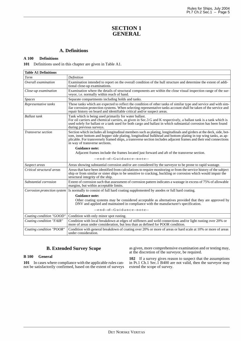
A 100 Definitions101 Definitions used in this chapter are given in Table A1.
B. Extended Survey Scope
B 100 General
101 In cases where compliance with the applicable rules can-not be satisfactorily confirmed, based on the extent of surveys
as given, more comprehensive examination and or testing may,at the discretion of the surveyor, be required.
102 If a survey gives reason to suspect that the assumptionsin Pt.1 Ch.1 Sec.1 B400 are not valid, then the surveyor mayextend the scope of survey.
Table A1 DefinitionsTerm DefinitionOverall examination Examination intended to report on the overall condition of the hull structure and determine the extent of addi-
tional close-up examinations.Close-up examination Examination where the details of structural components are within the close visual inspection range of the sur-
veyor, i.e. normally within reach of hand.Spaces Separate compartments including holds and tanks.Representative tanks Those tanks which are expected to reflect the condition of other tanks of similar type and service and with sim-
ilar corrosion protection systems. When selecting representative tanks account shall be taken of the service and repair history on board and identifiable critical and/or suspect areas.
Ballast tank Tank which is being used primarily for water ballast.For oil carriers and chemical carriers, as given in Sec.3 G and K respectively, a ballast tank is a tank which is used solely for ballast or a tank used for both cargo and ballast in which substantial corrosion has been found during previous surveys.
Transverse section Section which includes all longitudinal members such as plating, longitudinals and girders at the deck, side, bot-tom, inner bottom and hopper side plating, longitudinal bulkhead and bottom plating in top wing tanks, as ap-plicable. For transversely framed ships, a transverse section includes adjacent frames and their end connections in way of transverse sections.
Guidance note:Adjacent frames include the frames located just forward and aft of the transverse section.
---e-n-d---of---G-u-i-d-a-n-c-e---n-o-t-e---
Suspect areas Areas showing substantial corrosion and/or are considered by the surveyor to be prone to rapid wastage.Critical structural areas Areas that have been identified from calculations to require monitoring or from the service history of the subject
ship or from similar or sister ships to be sensitive to cracking, buckling or corrosion which would impair the structural integrity of the ship.
Substantial corrosion Extent of corrosion such that assessment of corrosion pattern indicates a wastage in excess of 75% of allowable margins, but within acceptable limits.
Corrosion protection system Is normally to consist of full hard coating supplemented by anodes or full hard coating.
Guidance note:Other coating systems may be considered acceptable as alternatives provided that they are approved byDNV and applied and maintained in compliance with the manufacturer's specification.
---e-n-d---of---G-u-i-d-a-n-c-e---n-o-t-e---
Coating condition "GOOD" Condition with only minor spot rusting.Coating condition "FAIR" Condition with local breakdown at edges of stiffeners and weld connections and/or light rusting over 20% or
more of areas under consideration, but less than as defined for POOR condition.Coating condition "POOR" Condition with general breakdown of coating over 20% or more of areas or hard scale at 10% or more of areas
under consideration.
DET NORSKE VERITAS
Rules for Ships, July 2004Pt.7 Ch.2 Sec.2 – Page 6
SECTION 2 SURVEY EXTENT - MAIN CLASS
A. Hull Survey - General
A 100 Examination of spaces
101 The examination shall be sufficient to discover substan-tial corrosion, significant deformation, fractures, damage orother structural deterioration.
The examination may be extended taking into account themaintenance of the structures under survey, the condition ofthe corrosion prevention system and also in the following cas-es:
— structural arrangements or details which have suffered de-fects in similar tanks/holds or on similar ships according toavailable information
— in tanks which have structures approved with reducedscantlings due to an approved corrosion control system.
The examination shall be supplemented by thickness measure-ment and testing as deemed necessary, to ensure that the struc-tural condition including related piping are in or placed insatisfactory condition.
A 200 Thickness measurements
201 Thickness measurements shall be carried out to an ex-tent sufficient to determine both general and local corrosionlevels.
Thickness measurements shall be taken on structures subject toclose-up examinations for general assessment and recording ofcorrosion pattern.
Where substantial corrosion, as defined in Sec.1 A, is foundadditional thickness measurements shall be taken to confirmthe extent of substantial corrosion.
Provisions for additional thickness measurements for areaswith substantial corrosion are given in relevant sections of therules. These additional thickness measurements are to be car-ried out before the survey is considered as completed.
A 300 Conditions of protective coating
301 Where provided, the condition of protective coating ofcargo holds, cargo tanks and ballast tanks shall be examined.The condition will be rated GOOD, FAIR or POOR as definedin Sec.1A.
A 400 Special consideration
401 For structures where original protective coatings are inGOOD condition, the extent of close-up examination andthickness measurements may be specially considered. Thisalso applies to tanks of stainless steel.
If not otherwise specified, the same applies for re-coated struc-tures (by epoxy coating or equivalent, alternatively a type ap-proved coating, e.g. semi-hard), provided that the condition ofthe protective coating is in GOOD condition and that docu-mentation is available stating that:
— the scantlings were assessed and found satisfactory by asurveyor prior to re-coating
— the coating was applied according to the manufacturer'srecommendations.
Special consideration as used in this context is taken to mean,as a minimum, that sufficient close-up examination and thick-ness measurements are carried out to confirm the actual aver-age condition of the structure under the protective coating.
B. Annual Survey
B 100 Survey extent, all ships101 The survey is normally to cover hull, machinery systemsand equipment and items as specified in A, and 200 to 600.
B 200 Hull structures and equipment201 The survey shall cover:
— hull plating as far as can be seen— anchoring equipment— watertight bulkheads, including watertight doors and pen-
etrations, if fitted— fittings for timber deck cargoes and permanent supporting
fittings and structures for container stowage and securing,as far as can be seen.
202 Ballast tanks shall be surveyed when required as a con-sequence of no protective coating, soft coating or POOR pro-tective coating condition at previous intermediate survey orrenewal survey.
An overall examination to report on the condition of the hullstructure and corrosion prevention system shall be carried out.
For areas with general breakdown of the protective coating,close-up examination and thickness measurements shall becarried out to an extent sufficient to determine both general andlocal corrosion levels. Where substantial corrosion is found,guidance for extended measurements is given in Table D4.
203 Suspect areas identified at previous intermediate or re-newal surveys shall be overall and close-up examined.
Areas with substantial corrosion shall have thickness measure-ments taken. Table D4 should be used as guidance.
204 If a loading instrument or loading computer system isavailable onboard it shall be verified that the system has a validcertificate.
205 It shall be verified that approved loading and stability in-formation is kept available onboard. See Pt.3 Ch.3 Sec.9.
This information is the same as required when the ship was as-signed class with DNV or at a later conversion of the ship, inaccordance with the rule requirements applicable in each case.
206 Additional requirements given in E apply to general drycargo ships as defined in E101.
B 300 Openings and closing appliances301 The following shall be surveyed or tested:
— hatch covers and hatch coamings on exposed weath-erdecks as described in 302
— doors in ship's bow, sides and stern, as described in 303— openings in superstructures and deck houses— exposed machinery casing and skylights— ventilation ducts for engine and boiler rooms with damp-
ers— ventilator and air pipes with coamings— windows, dead-lights and side scuttles— scuppers, discharges and valves with hull attachments— means of protection of crew, such as guard rails, bulwark,
gangways and lifelines— freeing ports and shutters.
302 Examination and testing of hatch covers and coamingsshall be carried out, as applicable:
a) Where mechanically operated steel covers are fitted:
DET NORSKE VERITAS
Rules for Ships, July 2004 Pt.7 Ch.2 Sec.2 – Page 7
— hatch covers including close-up examination of hatchcover plating
— tightness devices of longitudinal, transverse and inter-mediate cross junctions (gasket, gasket lips, compres-sion bars, drainage channels)
— clamping devices, retaining bars, cleating— chain or rope pulleys— guides— guide rails and track wheels— stoppers etc.— wires, chains, gypsies, tensioning devices— hydraulic system essential to closing and securing— safety locks and retaining devices.
b) Where portable covers, wooden or steel pontoons are fit-ted:
— wooden covers and portable beams, carriers or socketsfor the portable beams, and their securing devices
— steel pontoons, including close-up examination of se-lected hatch cover plating
— tarpaulins— cleats, battens and wedges— hatch securing bars and their securing devices— loading pads or bars and the side plate edge— guide plates and chocks— compression bars, drainage channels and drain pipes.
c) Examination of hatch coaming plating and their stiffenersincluding close-up examination as deemed necessary bythe surveyor.
d) Testing at random of the operation of mechanically oper-ated hatch covers including:
— stowage and securing in open condition— proper fit and efficiency of sealing in closed condition— hydraulic and power components, wires, chains and
link drives.
e) For bulk carriers and general dry cargo ships more than 15years of age, tightness test shall be carried out on all cargohatch covers.
303 For doors in ship's bow (outer and inner), sides andstern, the survey and testing shall include:
— doors, ramps, hinges, packings, cleats, supports and lock-ing arrangement
— surrounding structure— space between outer and inner bow doors— indicators and audible alarms— television surveillance— notice plates— operating and maintenance manual.
In cases where the inspection of doors has been carried out bya company approved by DNV, as given in Ch.1 Sec.5 B300,the extent of survey may be limited at the discretion of the sur-veyor. However, the survey shall, as a minimum, include:
— operating and maintenance manual— notice plates— structural arrangement of doors including surrounding
structures and space between outer and inner bow doors— complete opening and closing operation.
304 Load line marks to be surveyed and confirmed in ac-cordance with valid certificate. If the ship has no load linemark, draft marks shall be checked.
305 The approved stability information shall be verified on-board.
B 400 Machinery and safety systems401 The survey shall cover:
— machinery and boiler spaces with special attention to thefire and explosion hazards
— remote control and quick closing and stop of valves,pumps, fans, etc.
— bilge systems— boilers, pressure vessels and firing or combustion installa-
tions— gas turbines as specified in Ch.8— electrical machinery including emergency power supply— steering gear with special attention to operational condi-
tion of power actuating systems, local and remote steeringgear control systems, alternative power supply as applica-ble and rudder angle indicating systems
— communication systems from bridge to machinery andsteering gear spaces
— cargo systems in ships intended for supply service to off-shore installations
— if arranged, cement and dry mud cargo piping situatedwithin the engine room shall be examined and tightnesstested, particular attention being paid to possible reductionof pipe wall thickness and to tightness of detachable con-nections
— tightness of fixed refrigerating plants— controlled atmosphere (CA) installations shall be sur-
veyed with regard to safety precautions, see Sec.3 S.— waterjets, if applicable see Rules for Classification of HS,
LC and NSC Pt.7 Ch.2 Sec.2 E300 and E400.— that the ship has a maintenance system, in use see Ch.1
Sec.3 C100.
B 500 Fire protection arrangement 501 The following shall be examined and tested as applica-ble:
— fire doors— skylights in machinery spaces— dampers in ventilation duct— emergency escape routes— test of fire pumps, fire mains, hydrants, hoses etc. of water
fire fighting system and international shore connection— non-portable and portable fire extinguishers and portable
foam applicators— firefighters' outfits— fixed fire extinguishing systems and fire protection sys-
tems— fire detection system.
Further, it shall be verified by review of records that the fol-lowing has been carried out within the last year:
— all hydrant operationally tested— all fire hoses hydrostatically pressure tested— anti-freeze systems tested for proper solutions— breathing apparatus air recharging systems, if fitted,
checked for air quality.
502 Inspection and testing of fixed gas and dry powder fireextinguishing systems shall be carried out periodically at thefollowing intervals. Compliance shall be verified at the annualsurvey by review of records:
— air shall be blown through the piping of extinguishing gassystems annually
— biennial inspection shall be carried out by a specialist firmand record from inspection shall be filed onboard
— high pressure CO2/Inergen/Argonite/Nitrogen cylinders infixed fire extinguishing systems shall be subject to period-ical hydrostatic testing at maximum intervals of 10 years.Testing is required for not less than 10% of the cylindersevery 10 years
DET NORSKE VERITAS
Rules for Ships, July 2004Pt.7 Ch.2 Sec.2 – Page 8
— low pressure CO2 bulk containers shall be internally sur-veyed if the content has been released and the container ismore than 5 years old. The annual external inspection ofinsulated containers shall include spot check of the outersurface beneath the insulation. Depending on the result ofthe internal survey, hydrostatic testing may be required atthe surveyor's discretion
— control valves of fixed fire fighting systems shall be inter-nally inspected every 5th year.
503 Survey and testing of fire extinguishers shall be carriedout periodically at the following intervals:
— annual inspection or maintenance by competent person orship's responsible safety officer, in accordance with man-ufacturer's instructions
— every five years examined and refilled by an approvedcompany
— every ten years from date of manufacture overhauled andsubjected to hydrostatic test to 1.35 times maximum work-ing pressure, by manufacturer or approved company.
504 Testing of quality of foam-forming liquids shall be car-ried out periodically not later than 3 years after manufactureand annually thereafter. Testing shall be carried out by themanufacturer or an approved company.
505 Ships carrying motor vehicles with fuel in their tanks inenclosed spaces, and not having the additional class notationPET, shall have the fire and ventilation arrangements for thesespaces surveyed, the extent of the survey being equal to that re-quired for the additional class notation PET, see Sec.3 E.
B 600 Conventions ships - additional survey require-ments
601 For convention ships, requirements as given in 602-604,shall be verified.
602 Means of escape
Stairways and ladders from passenger and crew spaces, shallbe surveyed for ready means of escape to lifeboat embarkationdeck. For restricted spaces, i. e. engine room, boiler room,shaft tunnel, Ro-Ro cargo spaces, two separated means of es-cape shall be verified.
603 The following information shall be verified onboard:
— safety equipment record— fire control plan (posted)— service certificate for inflatable liferafts and hydrostatic
release— certificates for survival craft falls— survival craft launching instructions (posted)— survival craft operating instructions— muster list— change over procedure for steering gear (posted).
The following shall be examined or tested, as deemed neces-sary:
— survival craft, rescue boat and associated launching andrecovery appliances.
604 Safety Management Certificate (SMC)
For ships that shall comply with SOLAS Reg. IX/2, irrespec-tive of the issuing authority for the Safety Management Certif-icate (SMC), the surveyor will complete a list of evidence ofpossible safety management system failures recorded on theoccasion of the annual survey. The list will be submitted withthe annual survey report.
C. Intermediate Survey
C 100 Application101 Intermediate surveys are required carried out for all self-propelled ships.
C 200 Survey extent201 The requirements given in B apply with the additionsgiven in 202 to 205.
202 Ships of more than 5 years, but not exceeding 10 yearsof age:
— An overall examination of representative ballast tanks se-lected by the surveyor shall be carried out.
— For ballast tanks, without protective coating or soft coat-ing or with poor coating, the examination shall be extend-ed to other ballast tanks of the same type, if applicable.
203 For ships of more than 10 years of age:
— An overall examination of all ballast tanks shall be carriedout.
204 In connection with the overall examination of ballasttanks as given in 202 and 203, the following apply:
— where protective coating is found in POOR condition andit is not renewed or soft coating has been applied or a pro-tective coating was not applied from the time of construc-tion, the tanks shall be internally examined at annualintervals. For double bottom ballast tanks, except for oil and chemi-cal tankers with the notation ESP, the internal examinationmay be specially considered. This also applies to ballasttanks of 12 m3 or less with soft coating.
205 For dry cargo ships of more than 15 years of age, otherthan those given in E , and without the notation ESP:
— cargo compartments selected by the surveyor shall be ex-amined in addition to the requirements given in 203.
C 300 Additional requirements for general dry cargo ships301 Additional requirements given in E apply to general drycargo ships as defined in E101.
D. Renewal Survey
D 100 Survey extent, all ships101 The survey is normally to cover hull structures, machin-ery systems and equipment as specified in B and 200 to 600.
D 200 Hull structures and equipment201 A bottom survey as given in F shall be part of the renew-al survey.
202 All spaces shall be internally examined with plating andframing, bulkheads and all decks, casings and superstructures,bilges and drain wells. Internal examination of fuel oil, dieseloil, lub oil and fresh water tanks may be specially consideredas given in 204.
203 The engine room structure shall be examined. Particularattention shall be given to tank tops, shell plating in way oftank tops, brackets connecting side shell frames and tank tops,and engine room bulkheads in way of tank top and bilge wells.
Particular attention shall be given to sea suctions, sea watercooling pipes and overboard discharge valves and their con-nections to shell plating.
Where wastage is evident or suspect, thickness measurements
DET NORSKE VERITAS
Rules for Ships, July 2004 Pt.7 Ch.2 Sec.2 – Page 9
shall be carried out.
204 Fuel oil, lube oil and fresh water tanks shall be internallysurveyed in accordance with Table D1, as far as applicable.
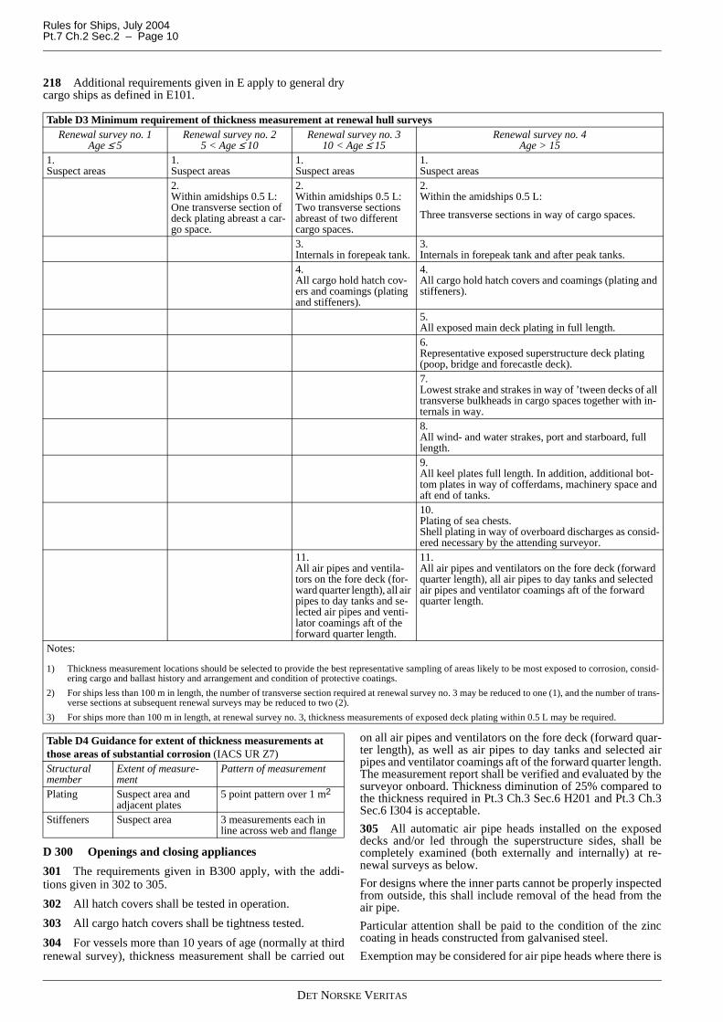
205 The requirements for thickness measurements are givenin Table D3. Transverse sections shall be chosen where thelargest reductions are suspected to occur.
In cases where two or three sections shall be measured, at leastone shall include a ballast tank, as far as applicable.
206 Where substantial corrosion is found, guidance for ex-tended measurements is given in Table D4.
207 Boundaries of all tanks including hold for ballast shallbe tested with a head of liquid to the top of air pipes or to thetop of hatches for ballast/cargo holds. Boundaries of fuel oil,lube oil and fresh water tanks shall be tested with a head of liq-uid to the maximum filling level of the tank. Tank testing offuel oil, lube oil and fresh water tanks may be specially consid-ered based on a satisfactory external examination of the tankboundaries, and a confirmation from the Master stating that thepressure testing has been carried out according to the require-ments with satisfactory results.
208 The survey extent of combined ballast and cargo holdsand tanks shall be evaluated based on the records of ballast his-tory, the extent and condition of the corrosion protection sys-tem provided and the extent of corrosion found.
209 The survey extent of ballast tanks converted to voidspaces should be specially considered in relation to the require-ments for ballast tanks.
210 For ballast tanks where protective coating is found in
POOR condition and it is not renewed, where soft coating hasbeen applied or where a protective coating was not appliedfrom the time of construction, the tanks shall be internally ex-amined at annual intervals.
For double bottom ballast tanks, except for oil and chemicaltankers with the notation ESP, the internal examination may bespecially considered. This also applies to ballast tanks of 12 m3
or less with soft coating.
211 Pipes, valves etc. of piping systems outside the machin-ery spaces shall be examined and tested as indicated in TableD2. For examination of pumps, heat exchangers etc., and pip-ing systems not covered by Table D2, see 401. All sea valves,including scuppers and sanitary discharges, shall be surveyedaccording to 401.
212 If arranged, cement and dry mud pressure tanks shall beexamined internally. Pressure testing to 1.2 times the workingpressure may be required if found necessary by the surveyor.
213 Windlass, including piping system and masts withstanding rigging and foundations shall be examined. The an-chors and chain cables shall be ranged, examined and the re-quired complement and condition verified. The chain lockers,holdfasts, hawse pipes and chain stoppers shall be examinedand drainage arrangement of the chain lockers tested.
214 The existence of required signboards shall be verified.
215 If a loading instrument or loading computer system isavailable onboard, it shall be tested by using the approved testconditions. Functionality and accuracy shall be verified withrespect to strength and stability, whichever is applicable.
216 Special arrangements related to stability such as water-tight closing appliances for openings in internal bulkheads anddecks, cross-flooding, counter-flooding etc., shall be examinedand tested if necessary. The watertight integrity of internalbulkheads and decks shall be verified.
217 For ships more than 5 years of age, the anchors and chaincables shall be ranged for survey and calibrated. Any length ofchain cable found reduced in mean diameter beyond 12% of itsoriginal rule diameter at its most worn part, shall be renewed.
Guidance note:The mean diameter is half the value of the sum of the minimumdiameter found in one cross-section of the link and of the diame-ter measured in a perpendicular direction in the same cross-sec-tion.
---e-n-d---of---G-u-i-d-a-n-c-e---n-o-t-e---
Table D1 Tank Minimum requirements for internal examination of fuel oil, lube oil and fresh water tanks 1), 2)
TankAge of ship, years
0 to 5 5 to 10 10 to 15 above 15Fuel oil/diesel oil 4)
— engine room None None One One
— cargo area None One Two Half, mini-mum two 5)
Lube oil None None None OneFresh water None One All AllPeak 3) All All All All1) Tanks of integral (structural) type.
2) If a selection of tanks are accepted to be examined, then differ-ent tanks shall, as far as practicable, be examined at each re-newal survey, on a rotational basis.
3) Peak tanks (all uses) are subject to internal examination at each renewal survey.
4) Tanks used as bilge water holding tanks, shall be examined as required for sea water tanks.
5) One deep tank shall be included, if fitted.
Guidance note:Independent tanks within machinery spaces (non-integral, self-supporting tanks which do not form part of the ship's hull) arenormally surveyed as part of the machinery surveys, see Pt.7Ch.8 Sec.1 Table A1.
---e-n-d---of---G-u-i-d-a-n-c-e---n-o-t-e---
(IACS UR Z7 Rev.9)
Table D2 Examination and testing of piping, outside machinery spacesSystem Survey methodBilge and ballastSteam with temperature below 450°CCompressed airHydraulicAir and sounding
External examination and performance test shall be carried outOpening up and or pressure testing may be required if found necessary by the sur-veyorLast overhaul shall be verified
Fuel oil
External examination and performance test shall be carried outOpening up and or pressure testing may be required if found necessary by the sur-veyorLast overhaul shall be verifiedFor ships more than 10 years of age, fuel pipes passing through ballast tanks shall be pressure tested
DET NORSKE VERITAS
Rules for Ships, July 2004Pt.7 Ch.2 Sec.2 – Page 10
218 Additional requirements given in E apply to general drycargo ships as defined in E101.
D 300 Openings and closing appliances
301 The requirements given in B300 apply, with the addi-tions given in 302 to 305.
302 All hatch covers shall be tested in operation.
303 All cargo hatch covers shall be tightness tested.
304 For vessels more than 10 years of age (normally at thirdrenewal survey), thickness measurement shall be carried out
on all air pipes and ventilators on the fore deck (forward quar-ter length), as well as air pipes to day tanks and selected airpipes and ventilator coamings aft of the forward quarter length.The measurement report shall be verified and evaluated by thesurveyor onboard. Thickness diminution of 25% compared tothe thickness required in Pt.3 Ch.3 Sec.6 H201 and Pt.3 Ch.3Sec.6 I304 is acceptable.
305 All automatic air pipe heads installed on the exposeddecks and/or led through the superstructure sides, shall becompletely examined (both externally and internally) at re-newal surveys as below.
For designs where the inner parts cannot be properly inspectedfrom outside, this shall include removal of the head from theair pipe.
Particular attention shall be paid to the condition of the zinccoating in heads constructed from galvanised steel.
Exemption may be considered for air pipe heads where there is
Table D3 Minimum requirement of thickness measurement at renewal hull surveysRenewal survey no. 1
Age ≤ 5Renewal survey no. 2
5 < Age ≤ 10Renewal survey no. 3
10 < Age ≤ 15Renewal survey no. 4
Age > 151.Suspect areas
1.Suspect areas
1.Suspect areas
1.Suspect areas
2.Within amidships 0.5 L: One transverse section of deck plating abreast a car-go space.
2.Within amidships 0.5 L: Two transverse sections abreast of two different cargo spaces.
2.Within the amidships 0.5 L:
Three transverse sections in way of cargo spaces.
3.Internals in forepeak tank.
3.Internals in forepeak tank and after peak tanks.
4.All cargo hold hatch cov-ers and coamings (plating and stiffeners).
4.All cargo hold hatch covers and coamings (plating and stiffeners).
5.All exposed main deck plating in full length.6.Representative exposed superstructure deck plating (poop, bridge and forecastle deck).7.Lowest strake and strakes in way of ’tween decks of all transverse bulkheads in cargo spaces together with in-ternals in way.8.All wind- and water strakes, port and starboard, full length.9.All keel plates full length. In addition, additional bot-tom plates in way of cofferdams, machinery space and aft end of tanks.10.Plating of sea chests.Shell plating in way of overboard discharges as consid-ered necessary by the attending surveyor.
11.All air pipes and ventila-tors on the fore deck (for-ward quarter length), all air pipes to day tanks and se-lected air pipes and venti-lator coamings aft of the forward quarter length.
11.All air pipes and ventilators on the fore deck (forward quarter length), all air pipes to day tanks and selected air pipes and ventilator coamings aft of the forward quarter length.
Notes:
1) Thickness measurement locations should be selected to provide the best representative sampling of areas likely to be most exposed to corrosion, consid-ering cargo and ballast history and arrangement and condition of protective coatings.
2) For ships less than 100 m in length, the number of transverse section required at renewal survey no. 3 may be reduced to one (1), and the number of trans-verse sections at subsequent renewal surveys may be reduced to two (2).
3) For ships more than 100 m in length, at renewal survey no. 3, thickness measurements of exposed deck plating within 0.5 L may be required.
Table D4 Guidance for extent of thickness measurements at those areas of substantial corrosion (IACS UR Z7)Structural member
Extent of measure-ment
Pattern of measurement
Plating Suspect area and adjacent plates
5 point pattern over 1 m2
Stiffeners Suspect area 3 measurements each in line across web and flange
DET NORSKE VERITAS
Rules for Ships, July 2004 Pt.7 Ch.2 Sec.2 – Page 11
substantiated evidence of replacement within the previous fiveyears.
At 1st renewal survey, the examination shall comprise:
— Two air pipe heads, one port and one starboard, located onthe exposed decks in the forward 0.25 L, preferably airpipes serving ballast tanks.
— Two air pipe heads, one port and one starboard, on the ex-posed decks and/or superstructure sides, serving spaces aftof 0.25 L, preferably air pipes serving ballast tanks.
— The selection of air pipe heads to be inspected is leftto the attending surveyor.
— According to the results of this inspection, the survey-or may require the inspection of other air pipe heads.
At 2nd renewal survey, the examination shall comprise:
— All air pipe heads located on the exposed decks and/or su-perstructure sides in the forward 0.25 L.
— At least 20% of air pipe heads on the exposed decks and/or superstructure sides serving spaces aft of 0.25 L, pref-erably air pipes serving ballast tanks.
— The selection of air pipe heads to be inspected is leftto the attending surveyor.
— According to the results of this inspection, the survey-or may require the inspection of other heads.
From 3rd renewal survey, the examination shall comprise:
— All air pipe heads located on the exposed decks and/or su-perstructure sides.
(IACS UR Z22)
D 400 Machinery401 Machinery systems and equipment are covered by a sur-vey arrangement if not part of a separate survey. The available
machinery survey arrangements are based on the inventory list(see Ch.8 Sec.1 Table A1) established for the vessel. The con-ditions for:
— obtaining and maintaining the survey arrangement, and— the corresponding survey methods to verify that the ma-
chinery system is in an acceptable condition is differentfor each of the available machinery survey arrangement. Ifa survey arrangement is not specified, Machinery renewalis set as default.
The following survey arrangements are available:
— Machinery renewal, see Ch.8 Sec.1 B— Machinery continuous, see Ch.8 Sec.1 C— Machinery PMS (Planned Maintenance System), see Ch.8
Sec.1 D— Machinery CM (Condition monitoring), see Ch.8 Sec.1 E.
402 Propulsion systems containing components or elementsmay change characteristics during the lifetime and hence influ-ence the torsional behaviour of the system.
Such components may be:
— vibration dampers— elastic couplings— speed governor or quick passing through device.
The mentioned components shall be maintained and inspectedas approved by DNV or as recommended by the manufacturer.
As an alternative to opening up for inspection, measurementsmay be carried out to confirm the correct dynamic conditions.The torsional vibration measurements shall be carried out andreported to DNV. The results shall be compared with the ap-proved limits (torsional vibration calculations).
If an elastic coupling is replaced by another type, new torsionalvibration calculations shall be submitted for approval.
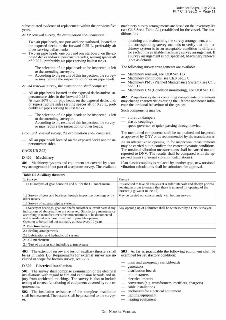
403 The extent of survey and test of auxiliary thrusters shallbe as in Table D5. Requirements for external survey are in-cluded in scope for bottom survey, see F207.
D 500 Electrical installations501 The survey shall comprise examination of the electricalinstallations with regard to fire and explosion hazards and in-jury from accidental touching. The survey is also to includetesting of correct functioning of equipment covered by rule re-quirements.
502 The insulation resistance of the complete installationshall be measured. The results shall be presented to the survey-or.
503 As far as practicable the following equipment shall beexamined for satisfactory condition:
— main and emergency switchboards— generators— distribution boards— motor starters— electrical motors— convertors (e.g. transformers, rectifiers, chargers)— cable installations— enclosures for electrical equipment— lighting equipment— heating equipment
Table D5 Auxiliary thrusters 1. Survey Remark1.1 Oil analysis of gear house oil and oil for the CP mechanism. It is advised to take oil analysis at regular intervals and always prior to
docking in order to ensure that there is no need for opening of the thruster (e.g. water in the oil).
1.2 Survey of gear and bearings through inspection openings or by other means.
May be carried out concurrently with bottom survey.
1.3 Survey of external piping systems.1.4 Survey of bearings, gear and shafts and other relevant parts if any indications of abnormalities are observed. Satisfactory maintenance according to manufacturer’s recommendations to be documented and considered as a base for extent of possible opening.Opening to be carried out normally at least every 10 years
Any opening up of a thruster shall be witnessed by a DNV surveyor.
2. Function testing 2.1 Sealing arrangements2.2 Lubrication and hydraulic oil system2.3 CP mechanism2.4 Test of thruster unit including alarm system
DET NORSKE VERITAS
Rules for Ships, July 2004Pt.7 Ch.2 Sec.2 – Page 12
— battery installations.
504 The following tests shall be carried out to the extentdeemed necessary by the surveyor to ascertain the proper func-tioning of the equipment:
— generator full load test— generator parallel operation— generator protection relays including non-important load
trip (if fitted)— generator remote speed control— generator synchronising equipment— power plant interlocking systems— insulation resistance indicating device— emergency generator including switchboards— battery chargers— mechanical ventilation of battery rooms or lockers— navigation lights, with controllers including alarms.
D 600 Instrumentation and automation601 Correct functioning of the various parts of the followingsystems shall be verified:
— alarm and safety system— fire alarm system— manual control of machinery— remote control of propulsion machinery. It will normally
be required that the following manoeuvres are effected:
— from stop to ahead— from ahead to astern— stop— from stop to astern— stop by operating the emergency device.
602 It shall be verified that the remote control can be trans-ferred to stand-by manual control in the engine room in case ofpower supply failure to the remote control system.
603 When cancelling of automatic load reduction and or au-tomatic stop of engine are provided, these functions shall bedemonstrated to the satisfaction of the surveyor.
E. Hull Surveys for General Dry Cargo Ships
E 100 General101 The requirements apply to all self-propelled general drycargo ships of 500 gross tonnage and above carrying solid car-goes other than:
— dry bulk cargo ships as given in Sec.3 F— dedicated container carriers— ro-ro cargo ships— pure car carriers— general cargo, container, forest product carriers (except
timber or log carriers) designed with double bottom anddouble sides, full width and full length hatches
— refrigerated cargo ships.
102 The requirements apply to surveys of hull structure andpiping systems in way of cargo holds, cofferdams, pipe tunnelsand void spaces within the cargo area and all ballast tanks andare additional to the requirements applicable to the remainderof the ship.
E 200 Annual survey201 The requirements given in A and B apply with the addi-tions given in 202 and 203.
202 Examination and testing of hatch covers and coamingsshall be carried out as given in B302.
Where portable covers, steel pontoons are fitted, close-up ex-
amination of hatch cover plating shall be carried out.
203 Examination of cargo holds
For ships 10 to 15 years of age:
a) Overall examination of one forward and one after cargoholds and their associated ’tween deck spaces.
For ships exceeding 15 years of age:
a) Overall examination of all cargo holds and ‘tween deckspaces.
b) Close-up examination of sufficient extent, minimum 25%of frames, in a forward lower cargo hold and one other se-lected lower cargo hold. This in order to establish the con-dition of the lower region of the shell frames, includingapproximately lower 1/3 length of side frame at side shell,side frame end attachment and the adjacent shell plating.
Where this level of survey reveals need for remedial measures,the survey shall be extended to include a close-up examinationof all shell frames and adjacent shell plating of those cargoholds and associated ’tween deck spaces, as well as close-upexamination of sufficient extent of all remaining cargo holdsand ’tween deck spaces.
c) All piping and penetrations in cargo holds, including over-board piping, shall be examined.
E 300 Intermediate survey301 The requirements given in C200 apply with the addi-tions given in 302 to 305.
302 Where substantial corrosion is found, guidance for ex-tended measurements is given in Table D4.
303 For ships 5 to 10 years of age
Examination of cargo holds:
a) Overall examination of one forward and one after cargohold and their associated ’tween deck spaces.
304 For ships 10 to 15 years of age
Examination of cargo holds:
a) Overall examination of all cargo holds and ’tween deckspaces.
305 For ships exceeding 15 years of age
The requirements of the intermediate survey shall be to thesame extent as the previous renewal survey as required in 402to 406.
However, testing of tanks as given in D207 is not required un-less deemed necessary by the surveyor.
In lieu of the requirements in 402, an in-water survey may beconsidered as equivalent.
E 400 Renewal survey401 The requirements given in relevant items under D applywith the additions given in 402 to 406.
402 An examination of the ship in dry dock shall be a part ofthe renewal survey.
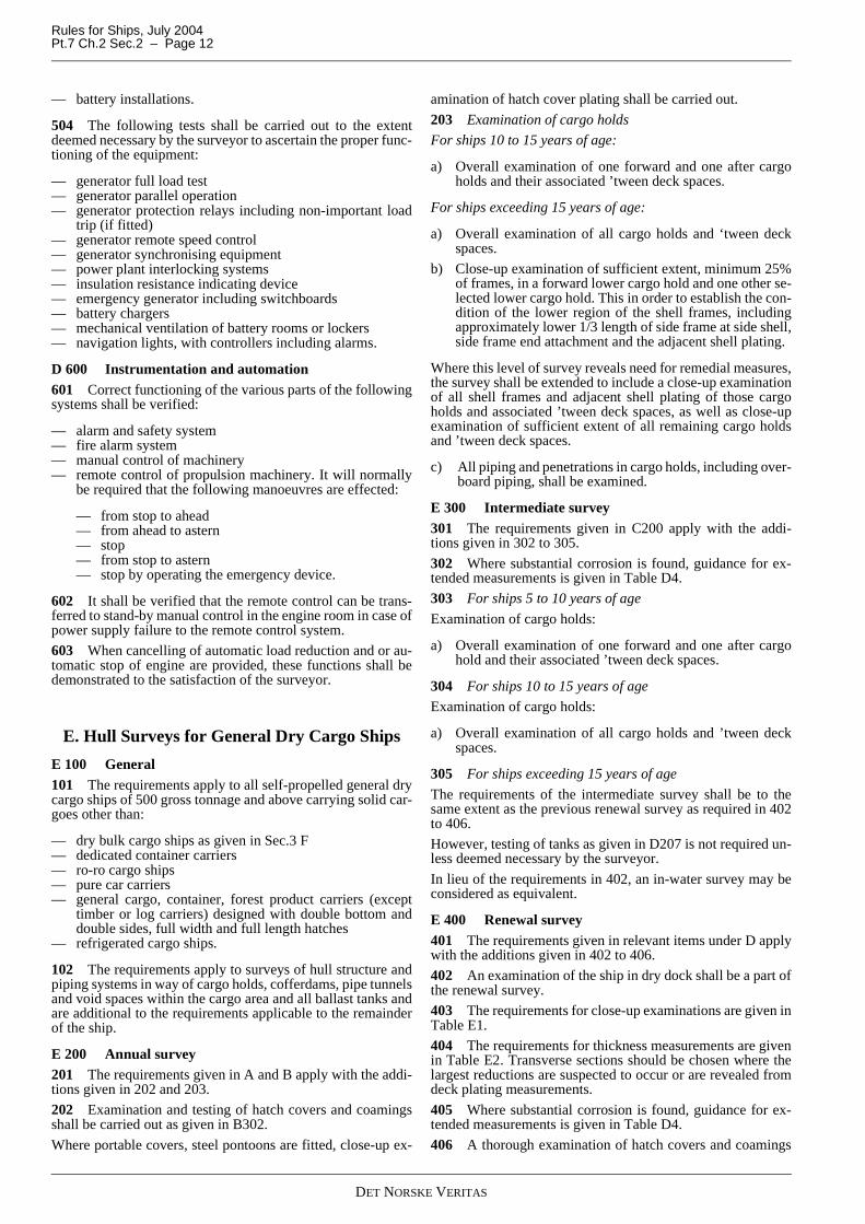
403 The requirements for close-up examinations are given inTable E1.
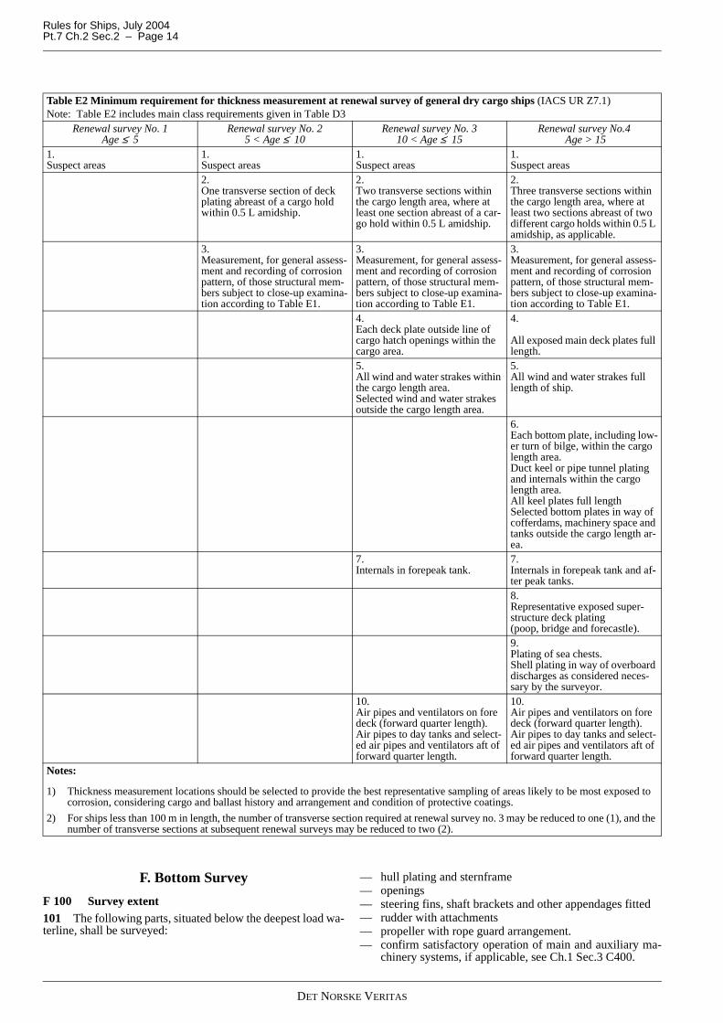
404 The requirements for thickness measurements are givenin Table E2. Transverse sections should be chosen where thelargest reductions are suspected to occur or are revealed fromdeck plating measurements.
405 Where substantial corrosion is found, guidance for ex-tended measurements is given in Table D4.
406 A thorough examination of hatch covers and coamings
DET NORSKE VERITAS
Rules for Ships, July 2004 Pt.7 Ch.2 Sec.2 – Page 13
of items given in B302 shall be carried out including:
a) Testing of the operation of all mechanically operated hatchcovers including:
— stowage and securing in open condition— proper fit and efficiency of sealing in closed condition— hydraulic and power components, wires, chains and
link drives.
b) Testing the effectiveness of sealing arrangement of allhatch covers by hose testing or equivalent.
c) Close-up examination of the hatch cover and coamingplating and stiffeners according to Table E1.
d) Thickness measurement of the hatch cover and coamingplating and stiffeners according to Table E2.
Table E1 Minimum requirement for close-up examination at renewal survey of general dry cargo ships (IACS UR Z7.1)Renewal survey No. 1
Age ≤ 5Renewal survey No. 2
5 < Age ≤ 10Renewal survey No. 3
10 < Age ≤ 15Renewal survey No.4
Age > 151.Selected shell frames in one for-ward and one aft cargo hold and associated ’tween deck spaces
1.Selected shell frames in all cargo holds and ’tween deck spaces
1.All shell frames in the forward lower cargo hold and 25% of shell frames in each of the remaining cargo holds and ’tween deck spaces including upper and lower end attachments and adjacent shell plating
1.All shell frames in all cargo holds and ’tween deck spaces including upper and lower end attachments and adjacent shell plating
2.One selected cargo hold trans-verse bulkheadSee Note
2.One transverse bulkhead in each cargo holdSee Note
2.All cargo hold transverse bulk-headsSee Note
2.All cargo hold transverse bulk-headsSee Note
3.All cargo hold hatch covers and coamings
3.All cargo hold hatch covers and coamings
3.All cargo hold hatch covers and coamings
3.All cargo hold hatch covers and coamings
4.Forward and aft transverse bulk-head in one side ballast tank, in-cluding stiffening system
4.All transverse bulkheads in all ballast tanks, including stiffening system
4.All transverse bulkheads in all ballast tanks, including stiffening system
5.One transverse web with associat-ed plating and framing in two rep-resentative ballast tanks of each type (i.e. topside, hopper side, side tank or double bottom tank. Peak tanks to be included, if ap-plicable)
5.All transverse webs with associat-ed plating and framing in each ballast tank (i.e. topside, hopper side, side tank or double bottom tank. Peak tanks to be included, if applicable)
5.All transverse webs with associat-ed plating and framing in each ballast tank (i.e. topside, hopper side, side tank or double bottom tank. Peak tanks to be included, if applicable)
6.Selected areas of deck plating in-side line of hatch openings be-tween cargo hold hatches
6.All deck plating inside line of hatch openings between cargo hold hatches
6.All deck plating inside line of hatch openings between cargo hold hatches
7.Selected areas of inner bottom plating
7.All areas of inner bottom plating
7.All areas of inner bottom plating
Notes:Close-up examination of cargo hold transverse bulkheads is be carried out at the following levels:
— Immediately above the inner bottom and immediately above the ’tween decks, as applicable.— About mid-height of the bulkheads for holds without ’tween deck.— Immediately below the main deck and immediately below the ’tween deck, as applicable.
DET NORSKE VERITAS
Rules for Ships, July 2004Pt.7 Ch.2 Sec.2 – Page 14
F. Bottom Survey
F 100 Survey extent101 The following parts, situated below the deepest load wa-terline, shall be surveyed:
— hull plating and sternframe— openings— steering fins, shaft brackets and other appendages fitted— rudder with attachments— propeller with rope guard arrangement.— confirm satisfactory operation of main and auxiliary ma-
chinery systems, if applicable, see Ch.1 Sec.3 C400.
Table E2 Minimum requirement for thickness measurement at renewal survey of general dry cargo ships (IACS UR Z7.1)Note: Table E2 includes main class requirements given in Table D3
Renewal survey No. 1Age ≤ 5
Renewal survey No. 25 < Age ≤ 10
Renewal survey No. 310 < Age ≤ 15
Renewal survey No.4 Age > 15
1.Suspect areas
1.Suspect areas
1.Suspect areas
1.Suspect areas
2.One transverse section of deck plating abreast of a cargo hold within 0.5 L amidship.
2.Two transverse sections within the cargo length area, where at least one section abreast of a car-go hold within 0.5 L amidship.
2.Three transverse sections within the cargo length area, where at least two sections abreast of two different cargo holds within 0.5 L amidship, as applicable.
3.Measurement, for general assess-ment and recording of corrosion pattern, of those structural mem-bers subject to close-up examina-tion according to Table E1.
3.Measurement, for general assess-ment and recording of corrosion pattern, of those structural mem-bers subject to close-up examina-tion according to Table E1.
3.Measurement, for general assess-ment and recording of corrosion pattern, of those structural mem-bers subject to close-up examina-tion according to Table E1.
4.Each deck plate outside line of cargo hatch openings within the cargo area.
4.
All exposed main deck plates full length.
5.All wind and water strakes within the cargo length area.Selected wind and water strakes outside the cargo length area.
5.All wind and water strakes full length of ship.
6.Each bottom plate, including low-er turn of bilge, within the cargo length area.Duct keel or pipe tunnel plating and internals within the cargo length area.All keel plates full lengthSelected bottom plates in way of cofferdams, machinery space and tanks outside the cargo length ar-ea.
7.Internals in forepeak tank.
7.Internals in forepeak tank and af-ter peak tanks.8.Representative exposed super-structure deck plating (poop, bridge and forecastle). 9.Plating of sea chests.Shell plating in way of overboard discharges as considered neces-sary by the surveyor.
10.Air pipes and ventilators on fore deck (forward quarter length).Air pipes to day tanks and select-ed air pipes and ventilators aft of forward quarter length.
10.Air pipes and ventilators on fore deck (forward quarter length).Air pipes to day tanks and select-ed air pipes and ventilators aft of forward quarter length.
Notes:
1) Thickness measurement locations should be selected to provide the best representative sampling of areas likely to be most exposed to corrosion, considering cargo and ballast history and arrangement and condition of protective coatings.
2) For ships less than 100 m in length, the number of transverse section required at renewal survey no. 3 may be reduced to one (1), and the number of transverse sections at subsequent renewal surveys may be reduced to two (2).
DET NORSKE VERITAS
Rules for Ships, July 2004 Pt.7 Ch.2 Sec.2 – Page 15
F 200 Survey details
201 The rudder shall be surveyed and the bearing clearancesshall be measured (clearances for forced oil lubricated bear-ings need not be confirmed when the bottom survey is carriedout afloat).
202 As far as practicable and always at surveys carried outwith the ship in dock or on a slipway, securing of nuts to rudderpintles, shafts or stocks and securing of bolts shall be con-firmed to be in order.
Dismantling may be required to the extent found necessary bythe surveyor.
203 For spade rudders the welded connections between therudder side plates and the rudder flange shall be checked by anefficient crack detection method at every docking.
204 For spade rudders with bracket connections in way ofthe rudder flange (i.e. “open construction”), the welded con-nections between the brackets and the rudder flange and therudder top plate shall be checked by an efficient crack detec-tion method at every docking.
205 For spade rudders with cone coupling to rudder stock,the side plating and weld connections in way of access openingto nut, including welds of cover plate, shall be checked by anefficient crack detection method at every docking.
206 The propeller shall be surveyed and shaft sealing ar-rangements checked for tightness. For shafts not running in oil,the clearances shall be measured. For variable pitch propellers,tightness of hub and blade sealings shall be verified and lock-ing arrangements for bolts shall be checked. Dismantling maybe required to the extent found necessary by the surveyor.
207 All thrusters shall be externally surveyed. This compris-es external survey of gear housing, propeller blades, bolt lock-ing and other fastening arrangements. Dismantling may berequired to the extent found necessary by the surveyor.
F 300 Bottom survey afloat
301 For ships with tailshaft survey interval minimum 5 yearsand synthetic or metallic rudder bearing material, bottom sur-veys may be carried out afloat, provided the requirements in302 and 303, and Ch.1 Sec.2 B604 are satisfied.
Special consideration shall be given to ships of 15 years of ageand above before being permitted to have such inspection.
302 The in-water survey shall provide the information nor-mally obtained from a docking survey, as far as practicable.During such surveys the following conditions are normally tobe satisfactorily fulfilled:
— the water conditions at the location of the survey shall besatisfactory with respect to visibility, current, swell, etc
— an approved diving company shall be used in the survey,using pictorial equipment of such quality that the surveyoris fully satisfied with the information relayed to him
— a diving report shall be presented— location of possible damage to be ascertained— the survey shall be witnessed by a DNV surveyor.
303 If the in-water survey reveals damage or deteriorationthat requires early attention, the surveyor may require that theship be dry-docked in order that a detailed survey can be un-dertaken and the necessary repairs carried out.
G. Tailshaft Survey
G 100 Survey extent101 The survey is normally to include complete withdrawalof the tailshaft and examination of the following parts, whererelevant:
— propeller nut and tailshaft threaded end— cone, key and keyway, including examination of the fore
part of the taper and keyway by an approved crack detec-tion method
— tailshaft bearing areas— stern bushes or bearings— shaft sealing arrangement, including lubricating oil sys-
tem.
102 For oil lubricated tailshafts with type approved sealingglands, the survey interval may be extended to 10 years provid-ed an examination of the following parts, if relevant, is carriedout with satisfactory result:
— tightness of sealing arrangements— lubricating oil system including monitoring of oil level,
and oil analysis— shaft couplings— for shaft arrangements where the propeller is secured to
the tailshaft by means of a key, the propeller shall bebacked off and the top of the cone including the forwardpart of the keyway shall be examined by an approvedcrack detection method.
H. Thrusters for Propulsion and Dynamic Posi-tioning
H 100 Definitions101 Thrusters for propulsion are defined as thrusters that areassigned for propulsion or propulsion and steering of the ship.
Guidance note:Thrusters installed to achieve redundant main propulsion sys-tems should be regarded as thrusters for propulsion.
---e-n-d---of---G-u-i-d-a-n-c-e---n-o-t-e---
102 Thrusters for dynamic positioning are thrusters incorpo-rated in systems for dynamic positioning of ships, which havebeen granted the additional class notation DYNPOS-AUTS,DYNPOS-AUT, DYNPOS-AUTR or DYNPOS-AUTRO.
103 Thrusters for other purposes than specified in 101 and102 are defined as auxiliary thrusters.
104 For survey of water jets, see Rules for Classification ofHS, LC and NSC, Pt.7 Ch.2 Sec.2, if applicable.
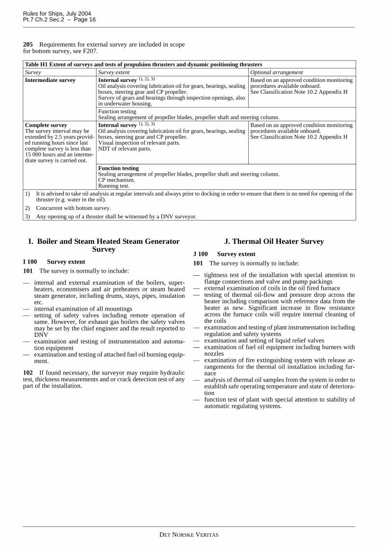
H 200 Survey extent201 Thrusters for propulsion shall be surveyed as given inTable H1, as applicable. Steering gears for azimuth thrusters,providing the main and/or auxiliary steering function, shall besurveyed and tested as part of the annual survey, see B400.
202 Thrusters for dynamic positioning shall be surveyed asper Table H1 as far as applicable.
203 Drive motors and shafting system external to the thrust-ers and pumps and external piping systems shall be surveyedas given in Ch.8 Sec.1 Table A1.
204 Alarm, safety and control systems shall be tested as re-quired for renewal survey of propulsion machinery.
DET NORSKE VERITAS
Rules for Ships, July 2004Pt.7 Ch.2 Sec.2 – Page 16
205 Requirements for external survey are included in scopefor bottom survey, see F207.
I. Boiler and Steam Heated Steam Generator Survey
I 100 Survey extent101 The survey is normally to include:
— internal and external examination of the boilers, super-heaters, economisers and air preheaters or steam heatedsteam generator, including drums, stays, pipes, insulationetc.
— internal examination of all mountings— setting of safety valves including remote operation of
same. However, for exhaust gas boilers the safety valvesmay be set by the chief engineer and the result reported toDNV
— examination and testing of instrumentation and automa-tion equipment
— examination and testing of attached fuel oil burning equip-ment.
102 If found necessary, the surveyor may require hydraulictest, thickness measurements and or crack detection test of anypart of the installation.
J. Thermal Oil Heater Survey
J 100 Survey extent101 The survey is normally to include:
— tightness test of the installation with special attention toflange connections and valve and pump packings
— external examination of coils in the oil fired furnace— testing of thermal oil-flow and pressure drop across the
heater including comparison with reference data from theheater as new. Significant increase in flow resistanceacross the furnace coils will require internal cleaning ofthe coils
— examination and testing of plant instrumentation includingregulation and safety systems
— examination and setting of liquid relief valves— examination of fuel oil equipment including burners with
nozzles— examination of fire extinguishing system with release ar-
rangements for the thermal oil installation including fur-nace
— analysis of thermal oil samples from the system in order toestablish safe operating temperature and state of deteriora-tion
— function test of plant with special attention to stability ofautomatic regulating systems.
Table H1 Extent of surveys and tests of propulsion thrusters and dynamic positioning thrustersSurvey Survey extent Optional arrangementIntermediate survey Internal survey 1), 2), 3)
Oil analysis covering lubrication oil for gears, bearings, sealing boxes, steering gear and CP propeller.Survey of gears and bearings through inspection openings, also in underwater housing.
Based on an approved condition monitoring procedures available onboard.See Classification Note 10.2 Appendix H
Function testingSealing arrangement of propeller blades, propeller shaft and steering column.
Complete surveyThe survey interval may be extended by 2.5 years provid-ed running hours since last complete survey is less than 15 000 hours and an interme-diate survey is carried out.
Internal survey 1), 2), 3)
Oil analysis covering lubrication oil for gears, bearings, sealing boxes, steering gear and CP propeller.Visual inspection of relevant parts.NDT of relevant parts.
Based on an approved condition monitoring procedures available onboard.See Classification Note 10.2 Appendix H
Function testingSealing arrangement of propeller blades, propeller shaft and steering column.CP mechanism.Running test.
1) It is advised to take oil analysis at regular intervals and always prior to docking in order to ensure that there is no need for opening of the thruster (e.g. water in the oil).
2) Concurrent with bottom survey.
3) Any opening up of a thruster shall be witnessed by a DNV surveyor.
DET NORSKE VERITAS
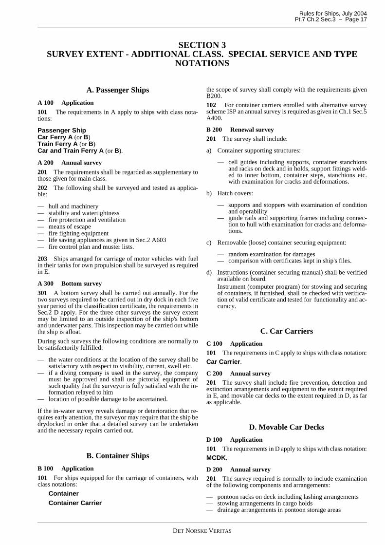
Rules for Ships, July 2004 Pt.7 Ch.2 Sec.3 – Page 17
SECTION 3 SURVEY EXTENT - ADDITIONAL CLASS. SPECIAL SERVICE AND TYPE
NOTATIONS
A. Passenger Ships
A 100 Application
101 The requirements in A apply to ships with class nota-tions:
Passenger ShipCar Ferry A (or B)Train Ferry A (or B)Car and Train Ferry A (or B).
A 200 Annual survey
201 The requirements shall be regarded as supplementary tothose given for main class.
202 The following shall be surveyed and tested as applica-ble:
— hull and machinery— stability and watertightness— fire protection and ventilation— means of escape— fire fighting equipment— life saving appliances as given in Sec.2 A603— fire control plan and muster lists.
203 Ships arranged for carriage of motor vehicles with fuelin their tanks for own propulsion shall be surveyed as requiredin E.
A 300 Bottom survey
301 A bottom survey shall be carried out annually. For thetwo surveys required to be carried out in dry dock in each fiveyear period of the classification certificate, the requirements inSec.2 D apply. For the three other surveys the survey extentmay be limited to an outside inspection of the ship's bottomand underwater parts. This inspection may be carried out whilethe ship is afloat.
During such surveys the following conditions are normally tobe satisfactorily fulfilled:
— the water conditions at the location of the survey shall besatisfactory with respect to visibility, current, swell etc.
— if a diving company is used in the survey, the companymust be approved and shall use pictorial equipment ofsuch quality that the surveyor is fully satisfied with the in-formation relayed to him
— location of possible damage to be ascertained.
If the in-water survey reveals damage or deterioration that re-quires early attention, the surveyor may require that the ship bedrydocked in order that a detailed survey can be undertakenand the necessary repairs carried out.
B. Container Ships
B 100 Application
101 For ships equipped for the carriage of containers, withclass notations:
Container
Container Carrier
the scope of survey shall comply with the requirements givenB200.
102 For container carriers enrolled with alternative surveyscheme ISP an annual survey is required as given in Ch.1 Sec.5A400.
B 200 Renewal survey201 The survey shall include:
a) Container supporting structures:
— cell guides including supports, container stanchionsand racks on deck and in holds, support fittings weld-ed to inner bottom, container steps, stanchions etc.with examination for cracks and deformations.
b) Hatch covers:
— supports and stoppers with examination of conditionand operability
— guide rails and supporting frames including connec-tion to hull with examination for cracks and deforma-tions.
c) Removable (loose) container securing equipment:
— random examination for damages— comparison with certificates kept in ship's files.
d) Instructions (container securing manual) shall be verifiedavailable on board. Instrument (computer program) for stowing and securingof containers, if furnished, shall be checked with verifica-tion of valid certificate and tested for functionality and ac-curacy.
C. Car Carriers
C 100 Application101 The requirements in C apply to ships with class notation:
Car Carrier.
C 200 Annual survey201 The survey shall include fire prevention, detection andextinction arrangements and equipment to the extent requiredin E, and movable car decks to the extent required in D, as faras applicable.
D. Movable Car Decks
D 100 Application101 The requirements in D apply to ships with class notation:
MCDK.
D 200 Annual survey201 The survey required is normally to include examinationof the following components and arrangements:
— pontoon racks on deck including lashing arrangements— stowing arrangements in cargo holds— drainage arrangements in pontoon storage areas
DET NORSKE VERITAS
Rules for Ships, July 2004Pt.7 Ch.2 Sec.3 – Page 18
— pontoon conditions— handling arrangement.
E. Arrangement for Carriage of Motor Vehicles with Fuel in their Tanks for their own Propul-
sion
E 100 Application
101 The requirements in E apply to ships arranged for car-riage of motor vehicles with fuel in their tanks for their ownpropulsion, including ships with class notation: PET.
E 200 Annual survey
201 The survey required is normally to include examinationof the following components and systems:
— automatic fire alarm system in cargo holds— fixed fire extinguishing system in cargo holds— portable fire extinguishers in cargo holds and at cargo hold
entrances— ventilation system in cargo holds including remote indica-
tors on bridge— electrical equipment in cargo holds, if fitted— signboards.
F. Dry Bulk Cargo Ships
F 100 Application
101 The requirements in F apply to self-propelled dry cargoships with class notations:
Bulk Carrier ESPOre Carrier ESP.
102 The requirements apply to surveys of hull structure andpiping systems in way of cargo holds, cofferdams, pipe tunnelsand void spaces within the cargo area and all ballast tanks andare additional to the requirements applicable to the remainderof the ship.
F 200 Annual survey
201 The requirements given in Sec.2 A and B apply with theadditions and amendments given in 202 to 205.
202 Prior to survey, the surveyor shall examine the docu-mentation onboard as specified in Ch.1 Sec.4, and its contentsas a basis for the survey.
203 For areas recorded with substantial corrosion, or wheresubstantial corrosion is found, the extent of thickness measure-ments shall be increased in accordance with Table F3.
204 Examination and testing of hatch covers and coamingsshall be carried out as given in B 302.
Where portable covers, steel pontoons are fitted, close-up ex-amination of hatch cover plating shall be carried out.
205 Examination of cargo holds and piping
For ships over 10 years of age:
a) Overall examination of all cargo holds.
b) Close-up examination of sufficient extent, minimum 25%of frames, in a forward cargo hold. This in order to estab-lish the condition of the lower region of the shell frames,including approximately lower 1/3 length of side frame atside shell, side frame end attachment and the adjacent shellplating.
Where this level of survey reveals need for remedial meas-ures, the survey shall be extended to include a close-up ex-amination of all shell frames and adjacent shell plating ofthe cargo hold, as well as a close-up examination of suffi-cient extent of all remaining cargo holds.
For ships over 15 years of age:
a) Overall examination of all cargo holds.
b) Close-up examination of sufficient extent, minimum 25%of frames, in a forward cargo hold and one other selectedcargo hold. This in order to establish the condition of thelower region of the shell frames, including approximatelylower 1/3 length of side frame at side shell, side frame endattachment and the adjacent shell plating.Where this level of survey reveals need for remedial meas-ures, the survey shall be extended to include a close-up ex-amination of all shell frames and adjacent shell plating ofthat cargo hold, as well as close-up examination of suffi-cient extent of all remaining cargo holds.
c) All piping and penetrations in cargo holds, including over-board piping, shall be examined.
F 300 Intermediate survey
301 The requirements given in Sec.2 C, and 202 and 203, ap-ply with the additions given in 302 to 304 and relevant require-ments for single skin bulk carriers given in F500 to F700.
302 For ships exceeding 5 years of age
Examination of cargo holds:
a) Overall examination of all cargo holds.
b) Close-up examination of sufficient extent, minimum 25%of shell frames, shall be carried out to establish the condi-tion of:
— shell frames including their upper and lower end at-tachments, adjacent shell plating and transverse bulk-heads in the forward cargo hold and one other selectedcargo hold
— where considered necessary by the surveyor as a resultof the overall and close-up examination, the surveyshall be extended to include close-up examination ofall shell frames and adjacent shell plating of that cargohold as well as close-up examination of sufficient ex-tent of all remaining cargo holds.
303 For ships exceeding 10 years of age
The requirements of the intermediate survey shall be to thesame extent as the previous renewal survey as given in 402 to409 and relevant additional requirements for single side skinbulk carriers given in 500 to 700
However, testing of ballast tanks is not required unless deemednecessary by the surveyor.
In lieu of the requirements in 403, an in-water survey may beconsidered as equivalent.
304 For ships exceeding 15 years of age
The requirements of the intermediate survey shall be to thesame extent as the previous renewal survey as given in 402 to409 and relevant requirements for single skin bulk carriers giv-en in 500 to 700.
However, testing of ballast tanks is not required unless deemednecessary by the surveyor.
F 400 Renewal survey
401 The requirements given in Sec.2 D, and 202 and 203, ap-ply with the additions given in 402 to 409 and relevant require-ments for single skin bulk carriers given in F500 to F700.
DET NORSKE VERITAS
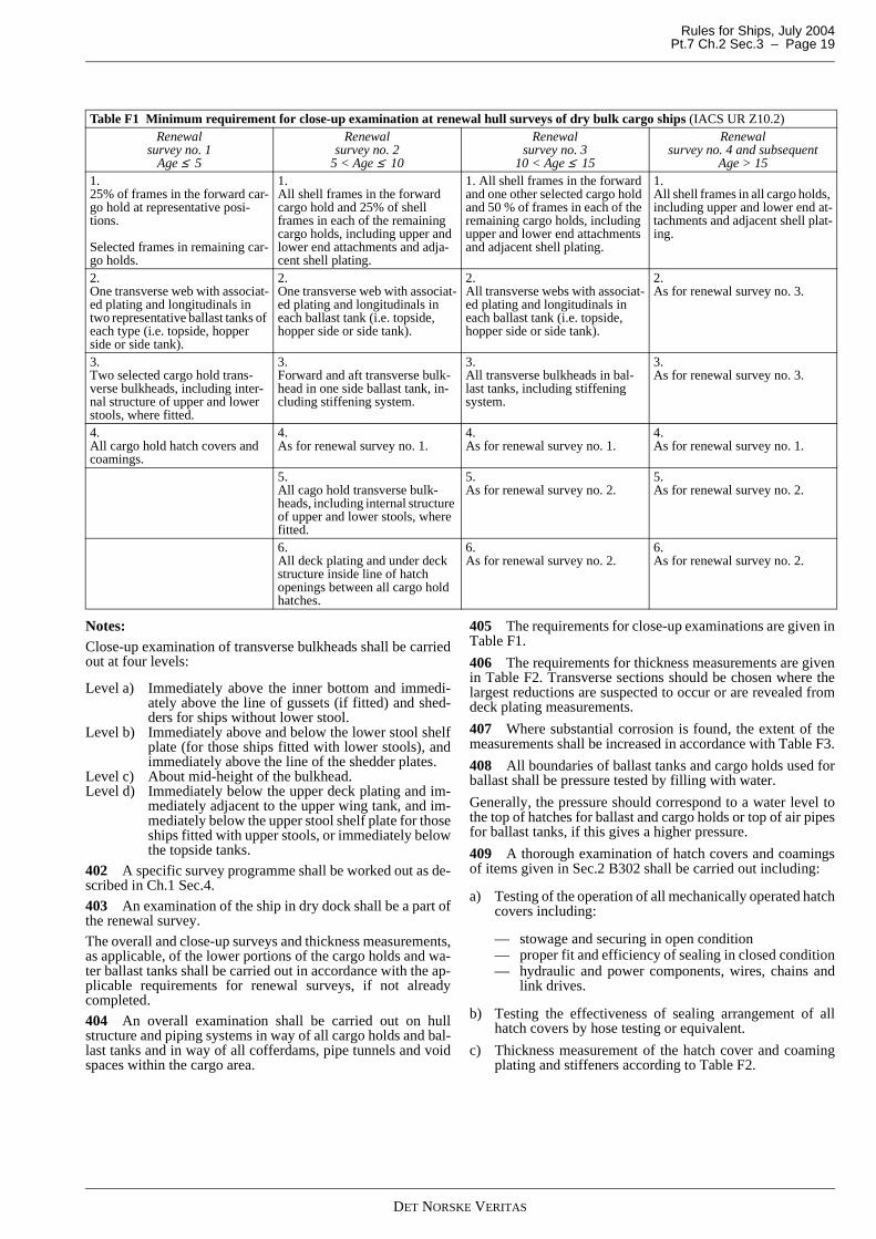
Rules for Ships, July 2004 Pt.7 Ch.2 Sec.3 – Page 19
Notes:Close-up examination of transverse bulkheads shall be carriedout at four levels:
Level a) Immediately above the inner bottom and immedi-ately above the line of gussets (if fitted) and shed-ders for ships without lower stool.
Level b) Immediately above and below the lower stool shelfplate (for those ships fitted with lower stools), andimmediately above the line of the shedder plates.
Level c) About mid-height of the bulkhead.Level d) Immediately below the upper deck plating and im-
mediately adjacent to the upper wing tank, and im-mediately below the upper stool shelf plate for thoseships fitted with upper stools, or immediately belowthe topside tanks.
402 A specific survey programme shall be worked out as de-scribed in Ch.1 Sec.4.
403 An examination of the ship in dry dock shall be a part ofthe renewal survey.
The overall and close-up surveys and thickness measurements,as applicable, of the lower portions of the cargo holds and wa-ter ballast tanks shall be carried out in accordance with the ap-plicable requirements for renewal surveys, if not alreadycompleted.
404 An overall examination shall be carried out on hullstructure and piping systems in way of all cargo holds and bal-last tanks and in way of all cofferdams, pipe tunnels and voidspaces within the cargo area.
405 The requirements for close-up examinations are given inTable F1.
406 The requirements for thickness measurements are givenin Table F2. Transverse sections should be chosen where thelargest reductions are suspected to occur or are revealed fromdeck plating measurements.
407 Where substantial corrosion is found, the extent of themeasurements shall be increased in accordance with Table F3.
408 All boundaries of ballast tanks and cargo holds used forballast shall be pressure tested by filling with water.
Generally, the pressure should correspond to a water level tothe top of hatches for ballast and cargo holds or top of air pipesfor ballast tanks, if this gives a higher pressure.
409 A thorough examination of hatch covers and coamingsof items given in Sec.2 B302 shall be carried out including:
a) Testing of the operation of all mechanically operated hatchcovers including:
— stowage and securing in open condition— proper fit and efficiency of sealing in closed condition— hydraulic and power components, wires, chains and
link drives.
b) Testing the effectiveness of sealing arrangement of allhatch covers by hose testing or equivalent.
c) Thickness measurement of the hatch cover and coamingplating and stiffeners according to Table F2.
Table F1 Minimum requirement for close-up examination at renewal hull surveys of dry bulk cargo ships (IACS UR Z10.2)Renewal
survey no. 1Age ≤ 5
Renewal survey no. 2
5 < Age ≤ 10
Renewal survey no. 3
10 < Age ≤ 15
Renewal survey no. 4 and subsequent
Age > 151. 25% of frames in the forward car-go hold at representative posi-tions. Selected frames in remaining car-go holds.
1. All shell frames in the forward cargo hold and 25% of shell frames in each of the remaining cargo holds, including upper and lower end attachments and adja-cent shell plating.
1. All shell frames in the forward and one other selected cargo hold and 50 % of frames in each of the remaining cargo holds, including upper and lower end attachments and adjacent shell plating.
1. All shell frames in all cargo holds, including upper and lower end at-tachments and adjacent shell plat-ing.
2. One transverse web with associat-ed plating and longitudinals in two representative ballast tanks of each type (i.e. topside, hopper side or side tank).
2. One transverse web with associat-ed plating and longitudinals in each ballast tank (i.e. topside, hopper side or side tank).
2. All transverse webs with associat-ed plating and longitudinals in each ballast tank (i.e. topside, hopper side or side tank).
2. As for renewal survey no. 3.
3. Two selected cargo hold trans-verse bulkheads, including inter-nal structure of upper and lower stools, where fitted.
3. Forward and aft transverse bulk-head in one side ballast tank, in-cluding stiffening system.
3. All transverse bulkheads in bal-last tanks, including stiffening system.
3. As for renewal survey no. 3.
4.All cargo hold hatch covers and coamings.
4. As for renewal survey no. 1.
4. As for renewal survey no. 1.
4. As for renewal survey no. 1.
5.All cago hold transverse bulk-heads, including internal structure of upper and lower stools, where fitted.
5.As for renewal survey no. 2.
5.As for renewal survey no. 2.
6. All deck plating and under deck structure inside line of hatch openings between all cargo hold hatches.
6. As for renewal survey no. 2.
6. As for renewal survey no. 2.
DET NORSKE VERITAS
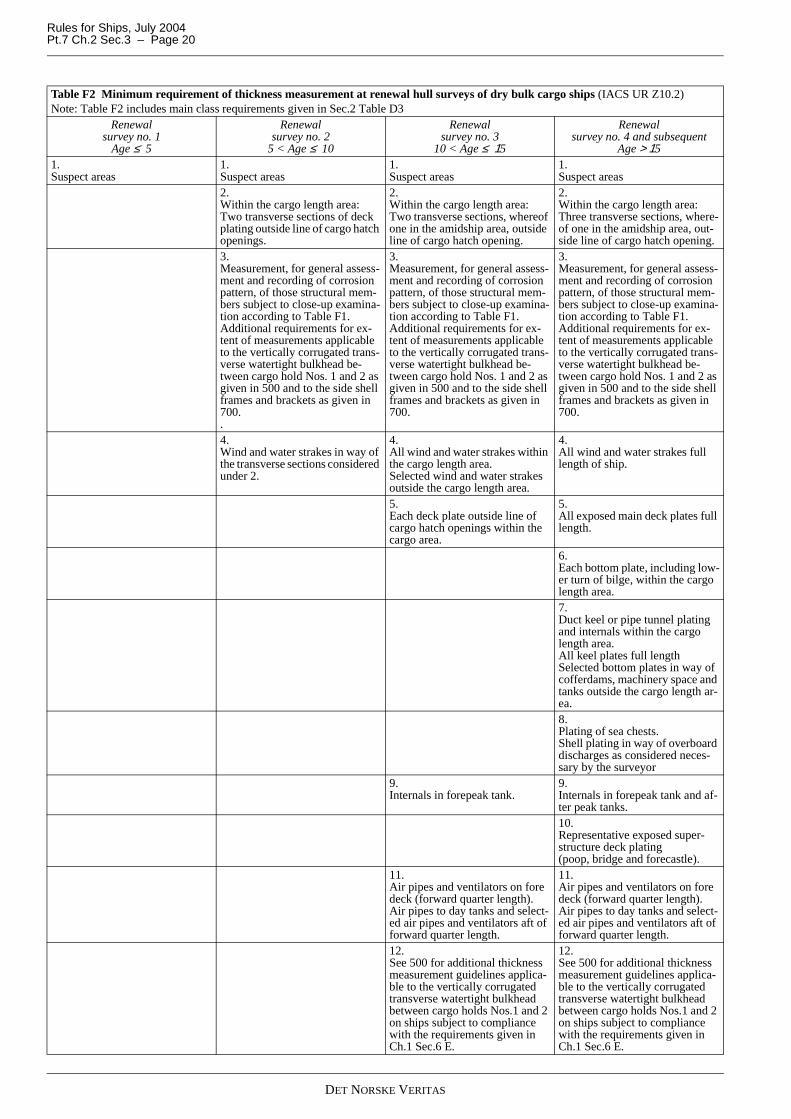
Rules for Ships, July 2004Pt.7 Ch.2 Sec.3 – Page 20
Table F2 Minimum requirement of thickness measurement at renewal hull surveys of dry bulk cargo ships (IACS UR Z10.2)Note: Table F2 includes main class requirements given in Sec.2 Table D3
Renewal survey no. 1
Age ≤ 5
Renewal survey no. 2
5 < Age ≤ 10
Renewal survey no. 3
10 < Age ≤ 15
Renewal survey no. 4 and subsequent
Age > 151.Suspect areas
1.Suspect areas
1.Suspect areas
1.Suspect areas
2.Within the cargo length area: Two transverse sections of deck plating outside line of cargo hatch openings.
2.Within the cargo length area: Two transverse sections, whereof one in the amidship area, outside line of cargo hatch opening.
2.Within the cargo length area: Three transverse sections, where-of one in the amidship area, out-side line of cargo hatch opening.
3.Measurement, for general assess-ment and recording of corrosion pattern, of those structural mem-bers subject to close-up examina-tion according to Table F1.Additional requirements for ex-tent of measurements applicable to the vertically corrugated trans-verse watertight bulkhead be-tween cargo hold Nos. 1 and 2 as given in 500 and to the side shell frames and brackets as given in 700..
3.Measurement, for general assess-ment and recording of corrosion pattern, of those structural mem-bers subject to close-up examina-tion according to Table F1.Additional requirements for ex-tent of measurements applicable to the vertically corrugated trans-verse watertight bulkhead be-tween cargo hold Nos. 1 and 2 as given in 500 and to the side shell frames and brackets as given in 700.
3.Measurement, for general assess-ment and recording of corrosion pattern, of those structural mem-bers subject to close-up examina-tion according to Table F1.Additional requirements for ex-tent of measurements applicable to the vertically corrugated trans-verse watertight bulkhead be-tween cargo hold Nos. 1 and 2 as given in 500 and to the side shell frames and brackets as given in 700.
4.Wind and water strakes in way of the transverse sections considered under 2.
4.All wind and water strakes within the cargo length area.Selected wind and water strakes outside the cargo length area.
4.All wind and water strakes full length of ship.
5.Each deck plate outside line of cargo hatch openings within the cargo area.
5.All exposed main deck plates full length.
6.Each bottom plate, including low-er turn of bilge, within the cargo length area.7.Duct keel or pipe tunnel plating and internals within the cargo length area.All keel plates full lengthSelected bottom plates in way of cofferdams, machinery space and tanks outside the cargo length ar-ea.8.Plating of sea chests.Shell plating in way of overboard discharges as considered neces-sary by the surveyor
9.Internals in forepeak tank.
9.Internals in forepeak tank and af-ter peak tanks.10.Representative exposed super-structure deck plating (poop, bridge and forecastle).
11.Air pipes and ventilators on fore deck (forward quarter length).Air pipes to day tanks and select-ed air pipes and ventilators aft of forward quarter length.
11.Air pipes and ventilators on fore deck (forward quarter length).Air pipes to day tanks and select-ed air pipes and ventilators aft of forward quarter length.
12.See 500 for additional thickness measurement guidelines applica-ble to the vertically corrugated transverse watertight bulkhead between cargo holds Nos.1 and 2 on ships subject to compliance with the requirements given in Ch.1 Sec.6 E.
12.See 500 for additional thickness measurement guidelines applica-ble to the vertically corrugated transverse watertight bulkhead between cargo holds Nos.1 and 2 on ships subject to compliance with the requirements given in Ch.1 Sec.6 E.
DET NORSKE VERITAS
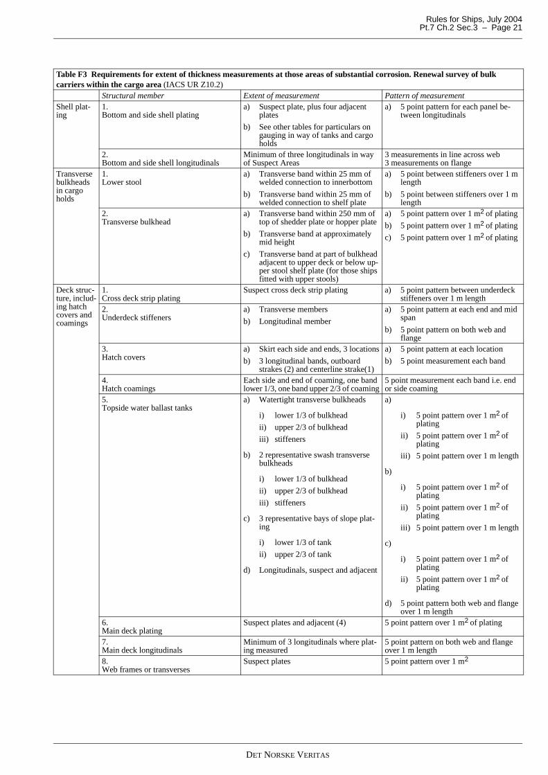
Rules for Ships, July 2004 Pt.7 Ch.2 Sec.3 – Page 21
Table F3 Requirements for extent of thickness measurements at those areas of substantial corrosion. Renewal survey of bulk carriers within the cargo area (IACS UR Z10.2)
Structural member Extent of measurement Pattern of measurementShell plat-ing
1. Bottom and side shell plating
a) Suspect plate, plus four adjacent plates
b) See other tables for particulars on gauging in way of tanks and cargo holds
a) 5 point pattern for each panel be-tween longitudinals
2. Bottom and side shell longitudinals
Minimum of three longitudinals in way of Suspect Areas
3 measurements in line across web 3 measurements on flange
Transverse bulkheads in cargo holds
1. Lower stool
a) Transverse band within 25 mm of welded connection to innerbottom
b) Transverse band within 25 mm of welded connection to shelf plate
a) 5 point between stiffeners over 1 m length
b) 5 point between stiffeners over 1 m length
2. Transverse bulkhead
a) Transverse band within 250 mm of top of shedder plate or hopper plate
b) Transverse band at approximately mid height
c) Transverse band at part of bulkhead adjacent to upper deck or below up-per stool shelf plate (for those ships fitted with upper stools)
a) 5 point pattern over 1 m2 of plating
b) 5 point pattern over 1 m2 of plating
c) 5 point pattern over 1 m2 of plating
Deck struc-ture, includ-ing hatch covers and coamings
1. Cross deck strip plating
Suspect cross deck strip plating a) 5 point pattern between underdeck stiffeners over 1 m length
2. Underdeck stiffeners
a) Transverse members
b) Longitudinal member
a) 5 point pattern at each end and mid span
b) 5 point pattern on both web and flange
3. Hatch covers
a) Skirt each side and ends, 3 locations
b) 3 longitudinal bands, outboard strakes (2) and centerline strake(1)
a) 5 point pattern at each location
b) 5 point measurement each band
4. Hatch coamings
Each side and end of coaming, one band lower 1/3, one band upper 2/3 of coaming
5 point measurement each band i.e. end or side coaming
5. Topside water ballast tanks
a) Watertight transverse bulkheads
i) lower 1/3 of bulkhead
ii) upper 2/3 of bulkhead
iii) stiffeners
b) 2 representative swash transverse bulkheads
i) lower 1/3 of bulkhead
ii) upper 2/3 of bulkhead
iii) stiffeners
c) 3 representative bays of slope plat-ing
i) lower 1/3 of tank
ii) upper 2/3 of tank
d) Longitudinals, suspect and adjacent
a)
i) 5 point pattern over 1 m2 of plating
ii) 5 point pattern over 1 m2 of plating
iii) 5 point pattern over 1 m length
b)
i) 5 point pattern over 1 m2 of plating
ii) 5 point pattern over 1 m2 of plating
iii) 5 point pattern over 1 m length
c)
i) 5 point pattern over 1 m2 of plating
ii) 5 point pattern over 1 m2 of plating
d) 5 point pattern both web and flange over 1 m length
6. Main deck plating
Suspect plates and adjacent (4) 5 point pattern over 1 m2 of plating
7. Main deck longitudinals
Minimum of 3 longitudinals where plat-ing measured
5 point pattern on both web and flange over 1 m length
8. Web frames or transverses
Suspect plates 5 point pattern over 1 m2
DET NORSKE VERITAS
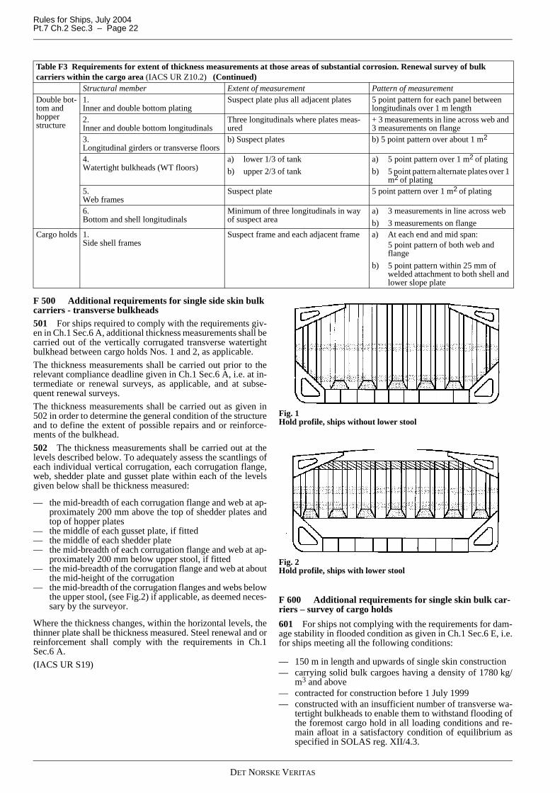
Rules for Ships, July 2004Pt.7 Ch.2 Sec.3 – Page 22
F 500 Additional requirements for single side skin bulk carriers - transverse bulkheads501 For ships required to comply with the requirements giv-en in Ch.1 Sec.6 A, additional thickness measurements shall becarried out of the vertically corrugated transverse watertightbulkhead between cargo holds Nos. 1 and 2, as applicable.
The thickness measurements shall be carried out prior to therelevant compliance deadline given in Ch.1 Sec.6 A, i.e. at in-termediate or renewal surveys, as applicable, and at subse-quent renewal surveys.
The thickness measurements shall be carried out as given in502 in order to determine the general condition of the structureand to define the extent of possible repairs and or reinforce-ments of the bulkhead.
502 The thickness measurements shall be carried out at thelevels described below. To adequately assess the scantlings ofeach individual vertical corrugation, each corrugation flange,web, shedder plate and gusset plate within each of the levelsgiven below shall be thickness measured:
— the mid-breadth of each corrugation flange and web at ap-proximately 200 mm above the top of shedder plates andtop of hopper plates
— the middle of each gusset plate, if fitted— the middle of each shedder plate— the mid-breadth of each corrugation flange and web at ap-
proximately 200 mm below upper stool, if fitted— the mid-breadth of the corrugation flange and web at about
the mid-height of the corrugation— the mid-breadth of the corrugation flanges and webs below
the upper stool, (see Fig.2) if applicable, as deemed neces-sary by the surveyor.
Where the thickness changes, within the horizontal levels, thethinner plate shall be thickness measured. Steel renewal and orreinforcement shall comply with the requirements in Ch.1Sec.6 A.
(IACS UR S19)
Fig. 1Hold profile, ships without lower stool
Fig. 2Hold profile, ships with lower stool
F 600 Additional requirements for single skin bulk car-riers – survey of cargo holds
601 For ships not complying with the requirements for dam-age stability in flooded condition as given in Ch.1 Sec.6 E, i.e.for ships meeting all the following conditions:
— 150 m in length and upwards of single skin construction— carrying solid bulk cargoes having a density of 1780 kg/
m3 and above— contracted for construction before 1 July 1999— constructed with an insufficient number of transverse wa-
tertight bulkheads to enable them to withstand flooding ofthe foremost cargo hold in all loading conditions and re-main afloat in a satisfactory condition of equilibrium asspecified in SOLAS reg. XII/4.3.
Double bot-tom and hopper structure
1. Inner and double bottom plating
Suspect plate plus all adjacent plates 5 point pattern for each panel between longitudinals over 1 m length
2. Inner and double bottom longitudinals
Three longitudinals where plates meas-ured
+ 3 measurements in line across web and 3 measurements on flange
3. Longitudinal girders or transverse floors
b) Suspect plates b) 5 point pattern over about 1 m2
4. Watertight bulkheads (WT floors)
a) lower 1/3 of tank
b) upper 2/3 of tank
a) 5 point pattern over 1 m2 of plating
b) 5 point pattern alternate plates over 1 m2 of plating
5. Web frames
Suspect plate 5 point pattern over 1 m2 of plating
6. Bottom and shell longitudinals
Minimum of three longitudinals in way of suspect area
a) 3 measurements in line across web
b) 3 measurements on flangeCargo holds 1.
Side shell framesSuspect frame and each adjacent frame a) At each end and mid span:
5 point pattern of both web and flange
b) 5 point pattern within 25 mm of welded attachment to both shell and lower slope plate
Table F3 Requirements for extent of thickness measurements at those areas of substantial corrosion. Renewal survey of bulk carriers within the cargo area (IACS UR Z10.2) (Continued)
Structural member Extent of measurement Pattern of measurement
DET NORSKE VERITAS
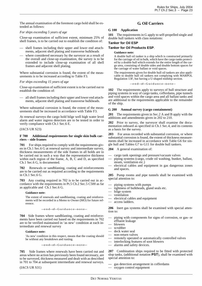
Rules for Ships, July 2004 Pt.7 Ch.2 Sec.3 – Page 23
The annual examination of the foremost cargo hold shall be ex-tended as follows:
For ships exceeding 5 years of age
Close-up examination of sufficient extent, minimum 25% ofshell frames, is to be carried out to establish the condition of:
— shell frames including their upper and lower end attach-ments, adjacent shell plating and transverse bulkheads
— where considered necessary by the surveyor as a result ofthe overall and close-up examination, the survey is to beextended to include close-up examination of all shellframes and adjacent shell plating.
Where substantial corrosion is found, the extent of the meas-urements is to be increased according to Table F3.
For ships exceeding 15 years of age
Close-up examination of sufficient extent is to be carried out toestablish the condition of:
— all shell frames including their upper and lower end attach-ments, adjacent shell plating and transverse bulkheads.
Where substantial corrosion is found, the extent of the meas-urements shall be increased in accordance with Table F3.
At renewal surveys the cargo hold bilge well high water levelalarm and water ingress detectors are to be tested in order toverify compliance with Ch.1 Sec.6 E.
(IACS UR S23)
F 700 Additional requirements for single skin bulk car-riers – side frames
701 For ships required to comply with the requirements giv-en in Ch.1 Sec.6 G at renewal survey and intermediate survey,thickness measurements of the side frames in all holds are tobe carried out in such a way that the representative thicknesswithin each region of the frame, A, B, C and D, as specifiedCh.1 Sec.6 G, is documented.
702 Renewals or sandblasting, coating and reinforcementsare to be carried out as required according to the requirementsin Ch.1 Sec.6 G.
703 Any coating required in 702 is to be carried out in ac-cordance with the requirements in Pt.5 Ch.2 Sec.5 C500 as faras applicable and Ch.1 Sec.6 G.
Guidance note:The extent of renewals and sandblasting, coating and reinforce-ments will be recorded in a Memo to Owner (MO) for future ref-erence.
---e-n-d---of---G-u-i-d-a-n-c-e---n-o-t-e---
704 Side frames where sandblasting, coating and reinforce-ments have been carried out based on the requirements in 702are to be verified maintained in ‘as new’ condition at each in-termediate and renewal survey
Guidance note:'As new' condition in this respect, means that the coating shouldbe without any breakdown and rusting.
---e-n-d---of---G-u-i-d-a-n-c-e---n-o-t-e---
705 Side frames where renewals have been carried out andareas where no action has previously been found necessary, areto be surveyed, thickness measured and dealt with as describedin 701 to 704 at subsequent intermediate and renewal surveys.
(IACS UR S31)
G. Oil Carriers
G 100 Application101 The requirements in G apply to self-propelled single anddouble hull tankers with class notations:
Tanker for Oil ESPTanker for Oil Products ESP.
Guidance note:A double hull oil tanker is a ship which is constructed primarilyfor the carriage of oil in bulk, which have the cargo tanks protect-ed by a double hull which extends for the entire length of the car-go area, consisting of double sides and double bottom spaces forthe carriage of water ballast or void spaces.The requirements given for double hull oil tankers are also appli-cable to double hull oil tankers not complying with MARPOLRegulation 13F, but having a U-shaped midship section.
---e-n-d---of---G-u-i-d-a-n-c-e---n-o-t-e---
102 The requirements apply to surveys of hull structure andpiping systems in way of cargo tanks, cofferdams, pipe tunnelsand void spaces within the cargo area and all ballast tanks andare additional to the requirements applicable to the remainderof the ship.
G 200 Annual survey (cargo containment) 201 The requirements given in Sec.2 A and B apply with theadditions and amendments given in 202 to 210.
202 Prior to survey, the surveyor shall examine the docu-mentation onboard as specified in Ch.1 Sec.4, and its contentsas a basis for the survey.
203 For areas recorded with substantial corrosion, or wheresubstantial corrosion is found, the extent of thickness measure-ments shall be increased in accordance with Table G6 for sin-gle hull and Tables G7 to G11 for double hull tankers.
204 A general examination of:
— cargo tank openings and pressure/vacuum valves— piping systems (cargo, crude oil washing, bunker, ballast,
steam, ventilation etc.)— electrical cables and equipment in gas dangerous zones
and spaces.
205 Pump rooms and pipe tunnels shall be examined withspecial attention to:
— piping systems with pumps— tightness of bulkheads, gland seals etc.— bilge system— ventilation— electrical cables and equipment— access ladders.
206 Inert gas systems shall be examined with special atten-tion to:
— piping with components for signs of corrosion, or gas- oreffluent leakage
— blowers— scrubber— deck water seal— non-return valves— remotely operated or automatically controlled valves— interlocking features of soot blowers— alarms and safety devices.
207 Combination ships required to be fitted with protectedslop tanks, (additional notation PST), shall be examined withspecial attention to:
— gas detection arrangement in cofferdams— oxygen control equipment
DET NORSKE VERITAS
Rules for Ships, July 2004Pt.7 Ch.2 Sec.3 – Page 24
— inert gas arrangement (as specified in 206)— closing arrangement for hatches and other slop tank open-
ings— blanking arrangement for slop tank pipes— required signboards and instruction manuals.
208 Examination of the emergency towing arrangements are,as far as practicable, to be carried out. Aft towing arrangementshall be confirmed as pre-rigged and forward chafing gearshall be confirmed as stowed in such a way that it can be rap-idly connected to the strongpoint. Where light is provided onpick-up gear marker buoy, proper functioning shall be con-firmed.
209 For single hull oil tankers exceeding 15 years of age
All ballast tanks adjacent to (i.e. with a common plane bound-ary) a cargo tank with any means of heating shall be examinedinternally. When considered necessary by the surveyor, thick-ness measurements shall be carried out and if these thicknessmeasurements indicate that substantial corrosion is found, theextent of thickness measurements shall be increased in accord-ance with Table G6.
Tanks or areas where coating was found to be in GOOD con-dition at the previous intermediate or renewal survey may bespecially considered by the Society.
210 For double hull oil tankers exceeding 15 years of age
All ballast tanks adjacent to (i.e. with a common plane bound-ary) a cargo tank with any means of heating shall be examinedinternally. When considered necessary by the surveyor, thick-ness measurements shall be carried out and if the these thick-ness measurements indicate that substantial corrosion is found,the extent of thickness measurements shall be increased in ac-cordance with Table G7 to G11.
Tanks where coating at the previous intermediate or renewalsurvey was found to be in GOOD condition and without areaswithin the tank with substantial corrosion or where coating ofthe common boundary, including adjacent structures wasfound to be in GOOD condition and the remaining parts of thetank where found to be in FAIR condition and without areaswithin the tank with substantial corrosion, may be speciallyconsidered by the Society.
211 For vessels with VOC recovery plants installed on deckthe survey scope for class notation VCS-3 in Sec.4 L shall beused as found relevant, even for vessels without this class no-tation.
G 300 Annual survey (oil pollution prevention)301 The survey requirements given in 302 to 304 are appli-cable to convention ships.
302 Deck foam system shall be examined with attention tophysical and chemical condition of foam concentrate.
303 Segregated ballast tanks
Segregation between cargo and segregated ballast system shallbe confirmed.
304 Retention of oil on board
The oily water interface detector shall be tested as deemed nec-essary.
Oil discharge monitoring and control system and equipmentshall be surveyed externally and tested as deemed necessary.
G 400 Intermediate survey (cargo containment)401 The requirements given in 202 and 203 and in Sec.2 Capply with the additions and amendments given in 402 to 407.
402 For weather decks, an examination as far as applicableof cargo, crude oil washing, bunker, ballast, steam and ventpiping systems as well as vent masts and headers shall be car-ried out. If upon examination there is any doubt as to the con-dition of the piping, the piping may be required to be pressure
tested, thickness measured, or both.
403 For those tanks subject to the survey, special attentionshall be given to:
— cargo piping passing through ballast tanks— bilge and ballast piping passing through cargo tanks— air and sounding piping to ballast tanks passing through
cargo and ballast tanks— fuel pipes passing through ballast tanks.
404 Electrical cables and equipment installed in gas danger-ous zones and spaces shall be insulation resistance measured.The measurements may be omitted provided a record of testingis available showing that measurements have been taken dur-ing the last 12 months and that the results are satisfactory.
Insulation monitors with alarms shall be function tested, if in-stalled.
Guidance note:It should be noted that megger testing in gas dangerous spacesmay involve risk of explosion due to sparks. Therefore appropri-ate procedures for such work should be followed as relevant e.g.,“gas free certificate”.
---e-n-d---of---G-u-i-d-a-n-c-e---n-o-t-e---
405 For single and double hull oil tankers exceeding 10years of age:
— an overall examination of at least two representative cargotanks shall be carried out
— an overall examination of all combined cargo and ballasttanks shall be carried out
— close-up examination shall be carried out to the followingextent:
For single hull oil tankers:
— ballast tanks: to the same extent as previous renewal sur-vey
— cargo tanks: at least two combined cargo and ballast tanks.The extent of survey should be based on the record of theprevious renewal survey, and repair history of the tanks.
For double hull oil tankers:
— ballast tanks:
— all web frames (1) in one complete tank— the knuckle area and the upper part (5 m approximate-
ly) of one web frame in each remaining ballast tank(6)
— one transverse bulkhead (4) in each complete tank
— cargo tanks (or two combined cargo/ballast tanks, wherefitted):
— two tanks, the extent of close-up examination shall bebased on the records of the previous renewal surveyand repair history of the tanks.
Notes:(1), (4) and (6) are areas to be subjected to close-up examination and thickness measurements.(1) Web frame means vertical web in side tank, hopper web
in hopper tank, floor in double bottom tank and deck transverse in double deck tank (where fitted), including adjacent structural members. In fore and aft peak tanks web frame means a complete transverse web frame ring including adjacent structural members.
(4) Transverse bulkhead complete in ballast tanks, includ-ing girder system and adjacent structural members, such as longitudinal bulkheads, girders in double bottom tanks, inner bottom plating, hopper side, inner hull lon-gitudinal bulkhead, connecting brackets.
DET NORSKE VERITAS
Rules for Ships, July 2004 Pt.7 Ch.2 Sec.3 – Page 25
406 For single and double hull tankers exceeding 15 years ofage:
The requirements of the intermediate survey shall be to thesame extent as the previous renewal survey as given in 502 to506, 511, 512 and 518.
However, testing of cargo and ballast tanks is not required un-less deemed necessary by the surveyor.
407 For oil tankers exceeding 15 years of age, ballast tanksadjacent to a cargo tank with any means of heating with condi-tion of coating rated as given in 209 and 210, shall be recordedfor subsequent annual surveys, where applicable.
G 500 Renewal survey (cargo containment)
501 The requirements given in Sec.2 D and 202, 203 and 404apply with the additions given in 502 to 518.
502 A specific survey programme shall be worked out as de-scribed in Ch.1 Sec.4.
503 An examination of the ship in dry dock shall be a part ofthe renewal survey.
The overall and close-up surveys and thickness measurements,as applicable, of the lower portions of the cargo tanks and wa-ter ballast tanks shall be carried out in accordance with the ap-plicable requirements for renewal surveys, if not alreadycompleted.
504 An overall examination shall be carried out on hullstructure and piping systems in way of all cargo and ballasttanks and in way of all pump rooms, cofferdams, pipe tunnelsand void spaces within the cargo area.
505 The requirements for close-up examinations are given inTable G1 and Table G2 for single and double hull oil tankers,respectively.
506 The requirements for thickness measurements are givenin Table G3 and Table G4 for single and double hull oil tank-ers. respectively.
Transverse sections should be chosen where the largest reduc-tions are suspected to occur or are revealed from deck platingmeasurements.
In cases where two or three sections shall be measured, at leastone should include a ballast tank within 0.5 L amidship, alter-natively, within the cargo length area, as applicable.
507 The minimum requirements for tank testing are given inTable G5.
Generally, the pressure should correspond to a water level tothe top of access hatches for cargo tanks, or top of air pipes forballast tanks, if this gives a higher pressure.
508 The surveyor may extend the tank testing as deemednecessary.
509 For ships having inert gas plant the components and sys-tems shall be surveyed as specified in Table G12.
It shall be verified that pipe blanking arrangements, portableO2-analyzers and required signboards and instructions are on
board and in order.
510 For ships having protected slop tanks, (additional nota-tion PST), every survey of these tanks shall be held concur-rently with the inert gas plant survey.
511 Heating coils, tank cleaning apparatus and other equip-ment in cargo tanks, cofferdams and pipe tunnels within thecargo area shall be examined. Heating coils are normally to bepressure tested. Attachments of sacrificial anodes in tanks shallbe examined.
512 Cargo piping on deck, including crude oil washing(COW) piping and cargo and ballast piping within cargo tanks,ballast tanks, including double bottom tanks, pump rooms,pipe tunnels, cofferdams and void spaces bounding cargotanks, decks and outer hull shall be examined and operational-ly tested to working pressure, to the surveyor's satisfaction toensure that tightness and condition remain satisfactory, supple-mented by thickness measurement at random if deemed neces-sary by the surveyor. In addition to requirements given in Sec.2D, special attention shall be given to any ballast piping in cargotanks and any cargo piping in ballast tanks and void spaces andsurveyors shall be advised on all occasions when this piping,including valves and fittings are open during repair periods andcan be internally examined.
513 Cargo pumps, together with the pumps’ prime moversshall be surveyed as specified in Sec.2 D400.
514 Ventilation arrangements, including fans, for cargotanks, pump rooms and other gas dangerous spaces shall besurveyed.
515 If fitted, bow loading and unloading arrangements shallbe surveyed.
516 For ships having boilers burning crude oil or slop, sur-vey and testing of control equipment including monitoring sys-tems and shut down functions related to the following systemsshall be carried out:
— ventilation and gas-tightness, fuel supply line and boilerwith boiler front lagging
— fuel pumps and heating arrangement— drain pipe ducts and automatic closing drain traps— inert and purging systems— manual and automatic quick closing valves and shut-down
systems— boiler hood ventilation system— boiler compartment ventilation— boiler front extinguishing system— pilot burner arrangement— gastight bulkhead penetrations— gas detection system— fuel heater.
517 The emergency towing arrangements shall be examinedand confirmed readily available with aft towing arrangementpre-rigged and forward chafing gear stowed in such a way thatit can be rapidly connected to the strongpoint. The pick-upgear, towing pennant and chafing gear shall be examined overthe full length for deterioration. Where pennant line is storedin a watertight condition confirmed maintained, considerationmay be given to waiving the requirement to examine the pen-nant line over the full length. Strongpoint, fairlead and pedes-tal roller shall be examined including attachment to the ship.
518 For oil tankers exceeding 15 years of age, ballast tanksadjacent to a cargo tank with any means of heating with condi-tion of coating rated as given in 209 and 210, shall be recordedfor subsequent annual surveys, where applicable.
(6) The knuckle area and the upper part (5 metres approxi-mately), including adjacent structural members. Knuck-le area is the area of the web frame around the connections of the slope hopper plating to the inner hull bulkhead and the inner bottom plating, up to 2 metres from the corners both on the bulkhead and the double bottom.
Note: Complete ballast tank: means double bottom tank plus double side tank plus double deck tank, as applicable, even if these tanks are separate.
DET NORSKE VERITAS
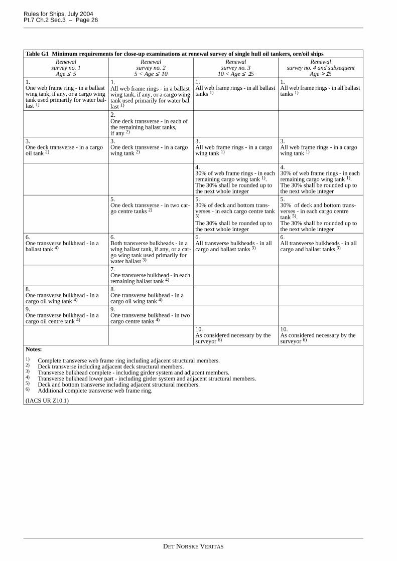
Rules for Ships, July 2004Pt.7 Ch.2 Sec.3 – Page 26
Table G1 Minimum requirements for close-up examinations at renewal survey of single hull oil tankers, ore/oil shipsRenewal
survey no. 1Age ≤ 5
Renewal survey no. 2
5 < Age ≤ 10
Renewal survey no. 3
10 < Age ≤ 15
Renewal survey no. 4 and subsequent
Age > 151.One web frame ring - in a ballast wing tank, if any, or a cargo wing tank used primarily for water bal-last 1)
1.All web frame rings - in a ballast wing tank, if any, or a cargo wing tank used primarily for water bal-last 1)
1.All web frame rings - in all ballast tanks 1)
1.All web frame rings - in all ballast tanks 1)
2.One deck transverse - in each of the remaining ballast tanks, if any 2)
3.One deck transverse - in a cargo oil tank 2)
3.One deck transverse - in a cargo wing tank 2)
3.All web frame rings - in a cargo wing tank 1)
3.All web frame rings - in a cargo wing tank 1)
4.30% of web frame rings - in each remaining cargo wing tank 1). The 30% shall be rounded up to the next whole integer
4.30% of web frame rings - in each remaining cargo wing tank 1).The 30% shall be rounded up to the next whole integer
5.One deck transverse - in two car-go centre tanks 2)
5.30% of deck and bottom trans-verses - in each cargo centre tank 5).
The 30% shall be rounded up to the next whole integer
5.30% of deck and bottom trans-verses - in each cargo centre tank 5).The 30% shall be rounded up to the next whole integer
6.One transverse bulkhead - in a ballast tank 4)
6.Both transverse bulkheads - in a wing ballast tank, if any, or a car-go wing tank used primarily for water ballast 3)
6.All transverse bulkheads - in all cargo and ballast tanks 3)
6.All transverse bulkheads - in all cargo and ballast tanks 3)
7.One transverse bulkhead - in each remaining ballast tank 4)
8.One transverse bulkhead - in a cargo oil wing tank 4)
8.One transverse bulkhead - in a cargo oil wing tank 4)
9.One transverse bulkhead - in a cargo oil centre tank 4)
9.One transverse bulkhead - in two cargo centre tanks 4)
10.As considered necessary by the surveyor 6)
10.As considered necessary by the surveyor 6)
Notes:
1) Complete transverse web frame ring including adjacent structural members.2) Deck transverse including adjacent deck structural members.3) Transverse bulkhead complete - including girder system and adjacent members.4) Transverse bulkhead lower part - including girder system and adjacent structural members.5) Deck and bottom transverse including adjacent structural members.6) Additional complete transverse web frame ring.
(IACS UR Z10.1)
DET NORSKE VERITAS
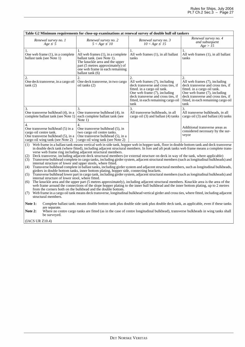
Rules for Ships, July 2004 Pt.7 Ch.2 Sec.3 – Page 27
Table G2 Minimum requirements for close-up examinations at renewal survey of double hull oil tankers
Renewal survey no. 1Age ≤ 5
Renewal survey no. 25 < Age ≤ 10
Renewal survey no. 310 < Age ≤ 15
Renewal survey no. 4 and subsequent
Age > 151.One web frame (1), in a complete ballast tank (see Note 1)
1.All web frames (1), in a complete ballast tank. (see Note 1).The knuckle area and the upper part (5 metres approximately) of one web frame in each remaining ballast tank (6)
1.All web frames (1), in all ballast tanks
1.All web frames (1), in all ballast tanks
2.One deck transverse, in a cargo oil tank (2)
2.One deck transverse, in two cargo oil tanks (2)
2.All web frames (7), including deck transverse and cross ties, if fitted. in a cargo oil tank.One web frame (7), including deck transverse and cross ties, if fitted, in each remaining cargo oil tank
2.All web frames (7), including deck transverse and cross ties, if fitted. in a cargo oil tank.One web frame (7), including deck transverse and cross ties, if fitted, in each remaining cargo oil tank
3.One transverse bulkhead (4), in a complete ballast tank (see Note 1)
3.One transverse bulkhead (4), in each complete ballast tank (see Note 1)
3.All transverse bulkheads, in all cargo oil (3) and ballast (4) tanks
3.All transverse bulkheads, in all cargo oil (3) and ballast (4) tanks
Additional transverse areas as considered necessary by the sur-veyor
4.One transverse bulkhead (5) in a cargo oil centre tank.One transverse bulkhead (5), in a cargo oil wing tank (see Note 2)
4.One transverse bulkhead (5), in two cargo oil centre tanks.One transverse bulkhead (5), in a cargo oil wing tank (see Note 2)
(1) Web frame in a ballast tank means vertical web in side tank, hopper web in hopper tank, floor in double bottom tank and deck transverse in double deck tank (where fitted), including adjacent structural members. In fore and aft peak tanks web frame means a complete trans-verse web frame ring including adjacent structural members.
(2) Deck transverse, including adjacent deck structural members (or external structure on deck in way of the tank, where applicable)(3) Transverse bulkhead complete in cargo tanks, including girder system, adjacent structural members (such as longitudinal bulkheads) and
internal structure of lower and upper stools, where fitted.(4) Transverse bulkhead complete in ballast tanks, including girder system and adjacent structural members, such as longitudinal bulkheads,
girders in double bottom tanks, inner bottom plating, hopper side, connecting brackets.(5) Transverse bulkhead lower part in cargo tank, including girder system, adjacent structural members (such as longitudinal bulkheads) and
internal structure of lower stool, where fitted.(6) The knuckle area and the upper part (5 metres approximately), including adjacent structural members. Knuckle area is the area of the
web frame around the connections of the slope hopper plating to the inner hull bulkhead and the inner bottom plating, up to 2 metres from the corners both on the bulkhead and the double bottom.
(7) Web frame in a cargo oil tank means deck transverse, longitudinal bulkhead vertical girder and cross ties, where fitted, including adjacent structural members.
Note 1: Complete ballast tank: means double bottom tank plus double side tank plus double deck tank, as applicable, even if these tanks are separate.
Note 2: Where no centre cargo tanks are fitted (as in the case of centre longitudinal bulkhead), transverse bulkheads in wing tanks shall be surveyed.
(IACS UR Z10.4)
DET NORSKE VERITAS
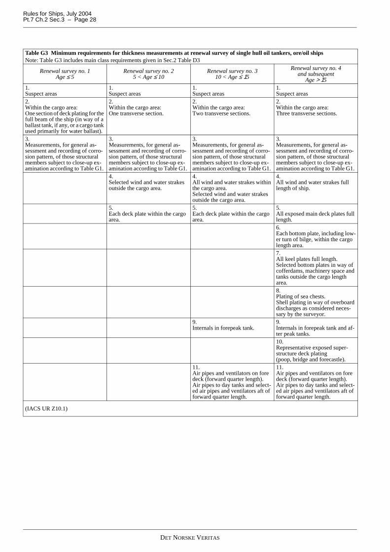
Rules for Ships, July 2004Pt.7 Ch.2 Sec.3 – Page 28
Table G3 Minimum requirements for thickness measurements at renewal survey of single hull oil tankers, ore/oil shipsNote: Table G3 includes main class requirements given in Sec.2 Table D3
Renewal survey no. 1Age ≤ 5
Renewal survey no. 25 < Age ≤ 10
Renewal survey no. 310 < Age ≤ 15
Renewal survey no. 4 and subsequent
Age > 151.Suspect areas
1.Suspect areas
1.Suspect areas
1.Suspect areas
2.Within the cargo area:One section of deck plating for the full beam of the ship (in way of a ballast tank, if any, or a cargo tank used primarily for water ballast).
2.Within the cargo area:One transverse section.
2.Within the cargo area:Two transverse sections.
2.Within the cargo area:Three transverse sections.
3.Measurements, for general as-sessment and recording of corro-sion pattern, of those structural members subject to close-up ex-amination according to Table G1.
3.Measurements, for general as-sessment and recording of corro-sion pattern, of those structural members subject to close-up ex-amination according to Table G1.
3.Measurements, for general as-sessment and recording of corro-sion pattern, of those structural members subject to close-up ex-amination according to Table G1.
3.Measurements, for general as-sessment and recording of corro-sion pattern, of those structural members subject to close-up ex-amination according to Table G1.
4.Selected wind and water strakes outside the cargo area.
4.All wind and water strakes within the cargo area.Selected wind and water strakes outside the cargo area.
4.All wind and water strakes full length of ship.
5.Each deck plate within the cargo area.
5.Each deck plate within the cargo area.
5.All exposed main deck plates full length.6.Each bottom plate, including low-er turn of bilge, within the cargo length area.7.All keel plates full length.Selected bottom plates in way of cofferdams, machinery space and tanks outside the cargo length area.8.Plating of sea chests.Shell plating in way of overboard discharges as considered neces-sary by the surveyor.
9.Internals in forepeak tank.
9.Internals in forepeak tank and af-ter peak tanks.10.Representative exposed super-structure deck plating (poop, bridge and forecastle).
11.Air pipes and ventilators on fore deck (forward quarter length).Air pipes to day tanks and select-ed air pipes and ventilators aft of forward quarter length.
11.Air pipes and ventilators on fore deck (forward quarter length).Air pipes to day tanks and select-ed air pipes and ventilators aft of forward quarter length.
(IACS UR Z10.1)
DET NORSKE VERITAS
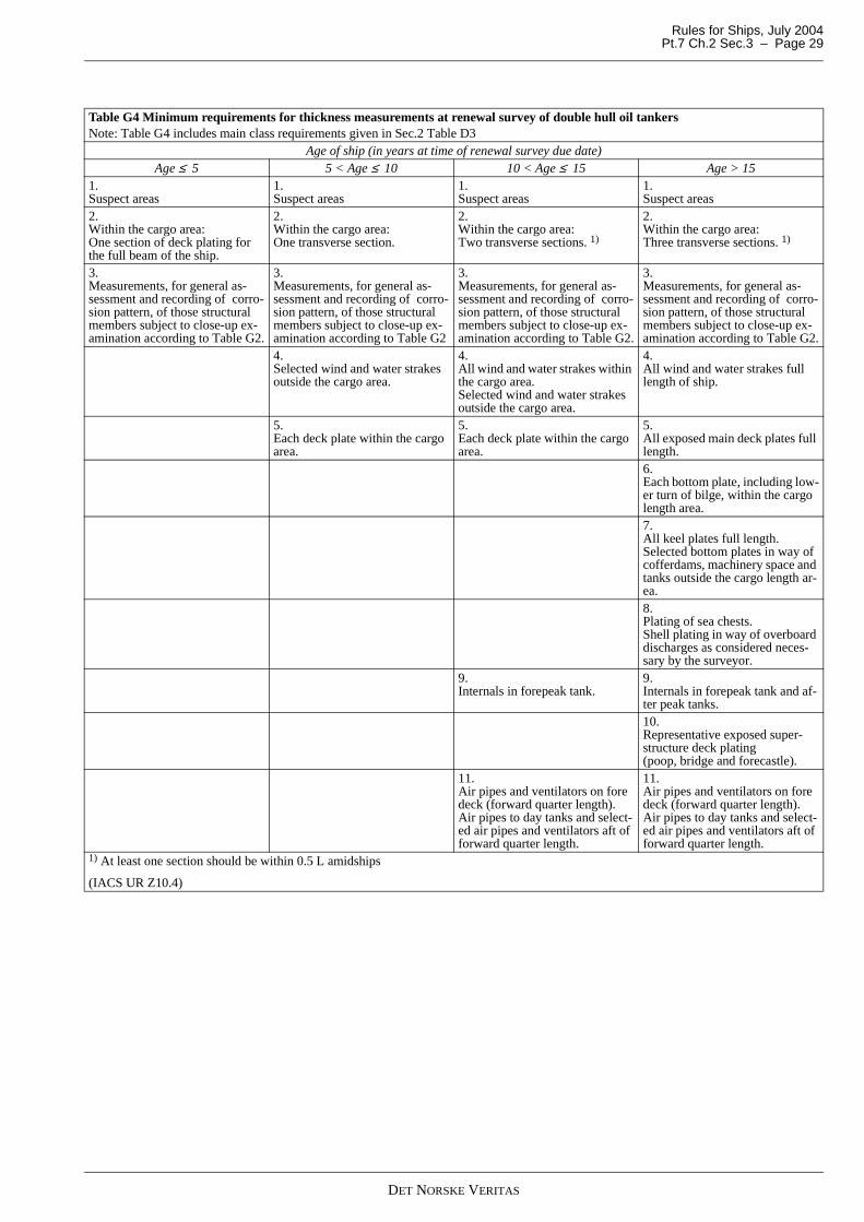
Rules for Ships, July 2004 Pt.7 Ch.2 Sec.3 – Page 29
Table G4 Minimum requirements for thickness measurements at renewal survey of double hull oil tankersNote: Table G4 includes main class requirements given in Sec.2 Table D3
Age of ship (in years at time of renewal survey due date)Age ≤ 5 5 < Age ≤ 10 10 < Age ≤ 15 Age > 15
1.Suspect areas
1.Suspect areas
1.Suspect areas
1.Suspect areas
2.Within the cargo area: One section of deck plating for the full beam of the ship.
2.Within the cargo area: One transverse section.
2.Within the cargo area: Two transverse sections. 1)
2.Within the cargo area: Three transverse sections. 1)
3.Measurements, for general as-sessment and recording of corro-sion pattern, of those structural members subject to close-up ex-amination according to Table G2.
3.Measurements, for general as-sessment and recording of corro-sion pattern, of those structural members subject to close-up ex-amination according to Table G2
3.Measurements, for general as-sessment and recording of corro-sion pattern, of those structural members subject to close-up ex-amination according to Table G2.
3.Measurements, for general as-sessment and recording of corro-sion pattern, of those structural members subject to close-up ex-amination according to Table G2.
4.Selected wind and water strakes outside the cargo area.
4.All wind and water strakes within the cargo area.Selected wind and water strakes outside the cargo area.
4.All wind and water strakes full length of ship.
5.Each deck plate within the cargo area.
5.Each deck plate within the cargo area.
5.All exposed main deck plates full length.6.Each bottom plate, including low-er turn of bilge, within the cargo length area.7.All keel plates full length.Selected bottom plates in way of cofferdams, machinery space and tanks outside the cargo length ar-ea.8.Plating of sea chests.Shell plating in way of overboard discharges as considered neces-sary by the surveyor.
9.Internals in forepeak tank.
9.Internals in forepeak tank and af-ter peak tanks.10.Representative exposed super-structure deck plating (poop, bridge and forecastle).
11.Air pipes and ventilators on fore deck (forward quarter length).Air pipes to day tanks and select-ed air pipes and ventilators aft of forward quarter length.
11.Air pipes and ventilators on fore deck (forward quarter length).Air pipes to day tanks and select-ed air pipes and ventilators aft of forward quarter length.
1) At least one section should be within 0.5 L amidships
(IACS UR Z10.4)
DET NORSKE VERITAS
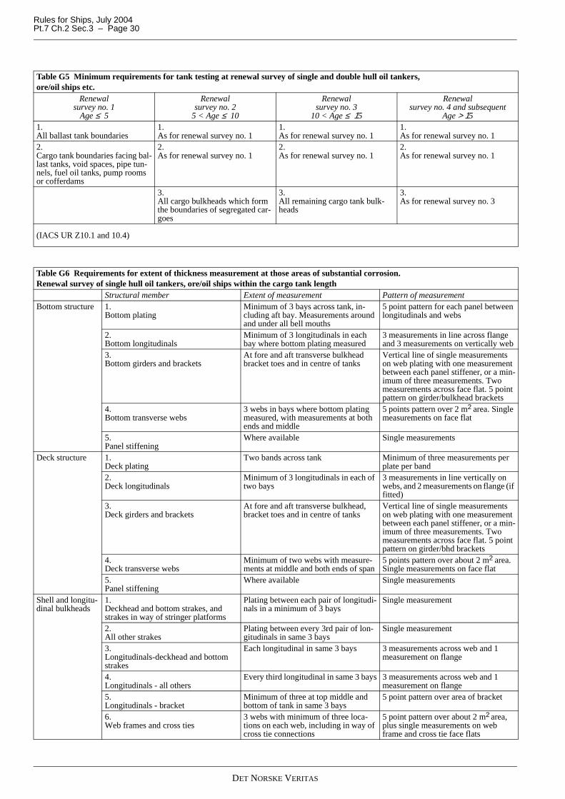
Rules for Ships, July 2004Pt.7 Ch.2 Sec.3 – Page 30
Table G5 Minimum requirements for tank testing at renewal survey of single and double hull oil tankers, ore/oil ships etc.
Renewal survey no. 1
Age ≤ 5
Renewal survey no. 2
5 < Age ≤ 10
Renewal survey no. 3
10 < Age ≤ 15
Renewal survey no. 4 and subsequent
Age > 151. All ballast tank boundaries
1. As for renewal survey no. 1
1. As for renewal survey no. 1
1. As for renewal survey no. 1
2. Cargo tank boundaries facing bal-last tanks, void spaces, pipe tun-nels, fuel oil tanks, pump rooms or cofferdams
2. As for renewal survey no. 1
2. As for renewal survey no. 1
2. As for renewal survey no. 1
3. All cargo bulkheads which form the boundaries of segregated car-goes
3. All remaining cargo tank bulk-heads
3. As for renewal survey no. 3
(IACS UR Z10.1 and 10.4)
Table G6 Requirements for extent of thickness measurement at those areas of substantial corrosion. Renewal survey of single hull oil tankers, ore/oil ships within the cargo tank length
Structural member Extent of measurement Pattern of measurementBottom structure 1.
Bottom platingMinimum of 3 bays across tank, in-cluding aft bay. Measurements around and under all bell mouths
5 point pattern for each panel between longitudinals and webs
2. Bottom longitudinals
Minimum of 3 longitudinals in each bay where bottom plating measured
3 measurements in line across flange and 3 measurements on vertically web
3. Bottom girders and brackets
At fore and aft transverse bulkhead bracket toes and in centre of tanks
Vertical line of single measurements on web plating with one measurement between each panel stiffener, or a min-imum of three measurements. Two measurements across face flat. 5 point pattern on girder/bulkhead brackets
4. Bottom transverse webs
3 webs in bays where bottom plating measured, with measurements at both ends and middle
5 points pattern over 2 m2 area. Single measurements on face flat
5. Panel stiffening
Where available Single measurements
Deck structure 1. Deck plating
Two bands across tank Minimum of three measurements per plate per band
2. Deck longitudinals
Minimum of 3 longitudinals in each of two bays
3 measurements in line vertically on webs, and 2 measurements on flange (if fitted)
3. Deck girders and brackets
At fore and aft transverse bulkhead, bracket toes and in centre of tanks
Vertical line of single measurements on web plating with one measurement between each panel stiffener, or a min-imum of three measurements. Two measurements across face flat. 5 point pattern on girder/bhd brackets
4. Deck transverse webs
Minimum of two webs with measure-ments at middle and both ends of span
5 points pattern over about 2 m2 area. Single measurements on face flat
5. Panel stiffening
Where available Single measurements
Shell and longitu-dinal bulkheads
1. Deckhead and bottom strakes, and strakes in way of stringer platforms
Plating between each pair of longitudi-nals in a minimum of 3 bays
Single measurement
2. All other strakes
Plating between every 3rd pair of lon-gitudinals in same 3 bays
Single measurement
3. Longitudinals-deckhead and bottom strakes
Each longitudinal in same 3 bays 3 measurements across web and 1 measurement on flange
4. Longitudinals - all others
Every third longitudinal in same 3 bays 3 measurements across web and 1 measurement on flange
5. Longitudinals - bracket
Minimum of three at top middle and bottom of tank in same 3 bays
5 point pattern over area of bracket
6. Web frames and cross ties
3 webs with minimum of three loca-tions on each web, including in way of cross tie connections
5 point pattern over about 2 m2 area, plus single measurements on web frame and cross tie face flats
DET NORSKE VERITAS
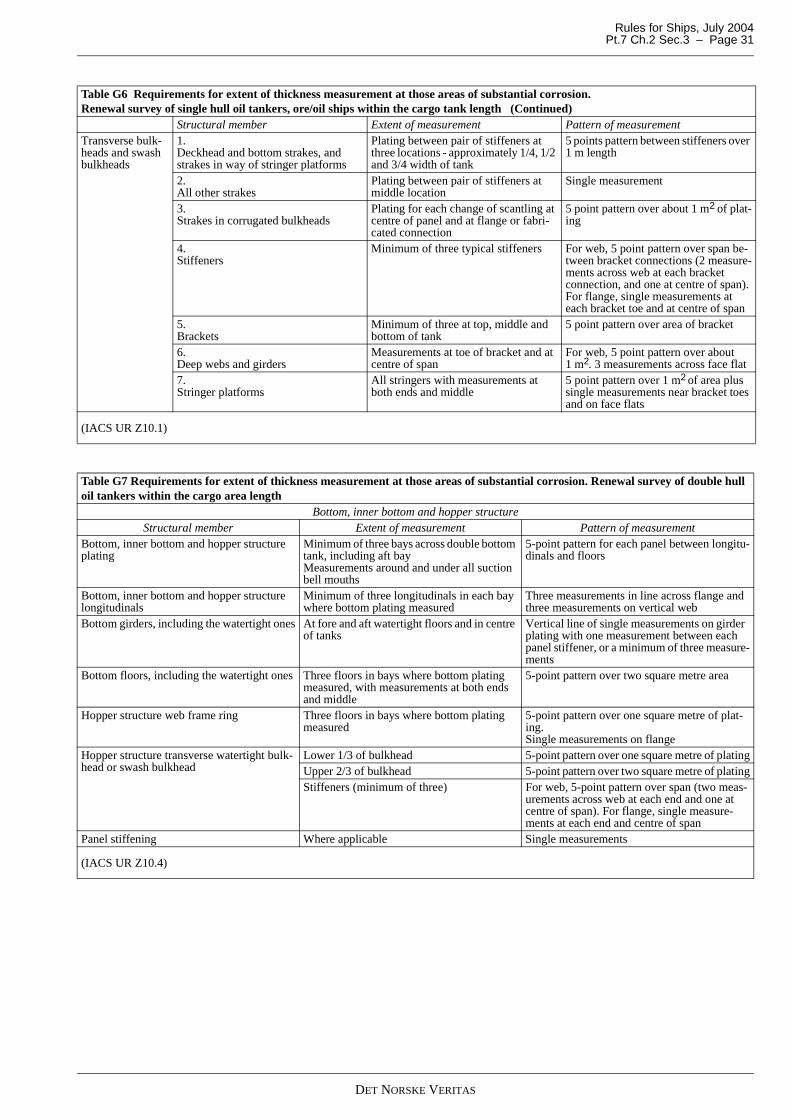
Rules for Ships, July 2004 Pt.7 Ch.2 Sec.3 – Page 31
Transverse bulk-heads and swash bulkheads
1. Deckhead and bottom strakes, and strakes in way of stringer platforms
Plating between pair of stiffeners at three locations - approximately 1/4, 1/2 and 3/4 width of tank
5 points pattern between stiffeners over 1 m length
2. All other strakes
Plating between pair of stiffeners at middle location
Single measurement
3. Strakes in corrugated bulkheads
Plating for each change of scantling at centre of panel and at flange or fabri-cated connection
5 point pattern over about 1 m2 of plat-ing
4. Stiffeners
Minimum of three typical stiffeners For web, 5 point pattern over span be-tween bracket connections (2 measure-ments across web at each bracket connection, and one at centre of span). For flange, single measurements at each bracket toe and at centre of span
5. Brackets
Minimum of three at top, middle and bottom of tank
5 point pattern over area of bracket
6. Deep webs and girders
Measurements at toe of bracket and at centre of span
For web, 5 point pattern over about 1 m2. 3 measurements across face flat
7. Stringer platforms
All stringers with measurements at both ends and middle
5 point pattern over 1 m2 of area plus single measurements near bracket toes and on face flats
(IACS UR Z10.1)
Table G6 Requirements for extent of thickness measurement at those areas of substantial corrosion. Renewal survey of single hull oil tankers, ore/oil ships within the cargo tank length (Continued)
Structural member Extent of measurement Pattern of measurement
Table G7 Requirements for extent of thickness measurement at those areas of substantial corrosion. Renewal survey of double hull oil tankers within the cargo area length
Bottom, inner bottom and hopper structureStructural member Extent of measurement Pattern of measurement
Bottom, inner bottom and hopper structure plating
Minimum of three bays across double bottom tank, including aft bayMeasurements around and under all suction bell mouths
5-point pattern for each panel between longitu-dinals and floors
Bottom, inner bottom and hopper structure longitudinals
Minimum of three longitudinals in each bay where bottom plating measured
Three measurements in line across flange and three measurements on vertical web
Bottom girders, including the watertight ones At fore and aft watertight floors and in centre of tanks
Vertical line of single measurements on girder plating with one measurement between each panel stiffener, or a minimum of three measure-ments
Bottom floors, including the watertight ones Three floors in bays where bottom plating measured, with measurements at both ends and middle
5-point pattern over two square metre area
Hopper structure web frame ring Three floors in bays where bottom plating measured
5-point pattern over one square metre of plat-ing.Single measurements on flange
Hopper structure transverse watertight bulk-head or swash bulkhead
Lower 1/3 of bulkhead 5-point pattern over one square metre of platingUpper 2/3 of bulkhead 5-point pattern over two square metre of platingStiffeners (minimum of three) For web, 5-point pattern over span (two meas-
urements across web at each end and one at centre of span). For flange, single measure-ments at each end and centre of span
Panel stiffening Where applicable Single measurements
(IACS UR Z10.4)
DET NORSKE VERITAS
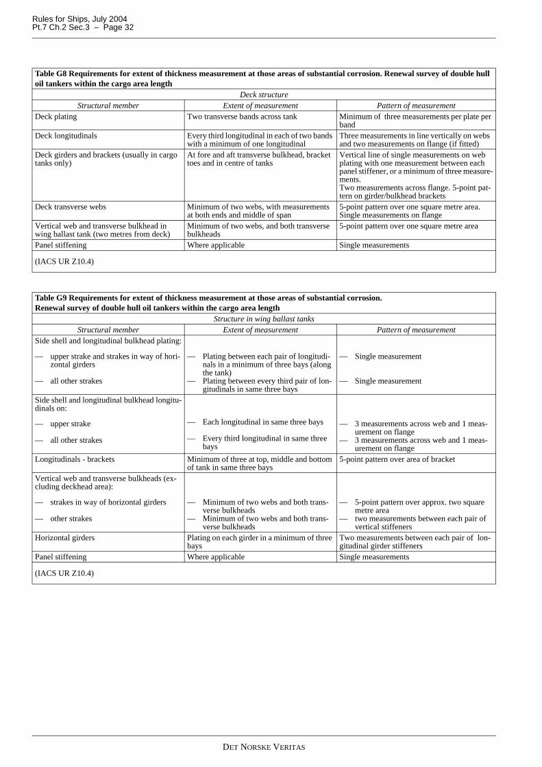
Rules for Ships, July 2004Pt.7 Ch.2 Sec.3 – Page 32
Table G8 Requirements for extent of thickness measurement at those areas of substantial corrosion. Renewal survey of double hull oil tankers within the cargo area length
Deck structureStructural member Extent of measurement Pattern of measurement
Deck plating Two transverse bands across tank Minimum of three measurements per plate per band
Deck longitudinals Every third longitudinal in each of two bands with a minimum of one longitudinal
Three measurements in line vertically on webs and two measurements on flange (if fitted)
Deck girders and brackets (usually in cargo tanks only)
At fore and aft transverse bulkhead, bracket toes and in centre of tanks
Vertical line of single measurements on web plating with one measurement between each panel stiffener, or a minimum of three measure-ments.Two measurements across flange. 5-point pat-tern on girder/bulkhead brackets
Deck transverse webs Minimum of two webs, with measurements at both ends and middle of span
5-point pattern over one square metre area.Single measurements on flange
Vertical web and transverse bulkhead in wing ballast tank (two metres from deck)
Minimum of two webs, and both transverse bulkheads
5-point pattern over one square metre area
Panel stiffening Where applicable Single measurements
(IACS UR Z10.4)
Table G9 Requirements for extent of thickness measurement at those areas of substantial corrosion. Renewal survey of double hull oil tankers within the cargo area length
Structure in wing ballast tanksStructural member Extent of measurement Pattern of measurement
Side shell and longitudinal bulkhead plating:
— upper strake and strakes in way of hori-zontal girders
— all other strakes
— Plating between each pair of longitudi-nals in a minimum of three bays (along the tank)
— Plating between every third pair of lon-gitudinals in same three bays
— Single measurement
— Single measurement
Side shell and longitudinal bulkhead longitu-dinals on:
— upper strake
— all other strakes
— Each longitudinal in same three bays
— Every third longitudinal in same three bays
— 3 measurements across web and 1 meas-urement on flange
— 3 measurements across web and 1 meas-urement on flange
Longitudinals - brackets Minimum of three at top, middle and bottom of tank in same three bays
5-point pattern over area of bracket
Vertical web and transverse bulkheads (ex-cluding deckhead area):
— strakes in way of horizontal girders
— other strakes
— Minimum of two webs and both trans-verse bulkheads
— Minimum of two webs and both trans-verse bulkheads
— 5-point pattern over approx. two square metre area
— two measurements between each pair of vertical stiffeners
Horizontal girders Plating on each girder in a minimum of three bays
Two measurements between each pair of lon-gitudinal girder stiffeners
Panel stiffening Where applicable Single measurements
(IACS UR Z10.4)
DET NORSKE VERITAS
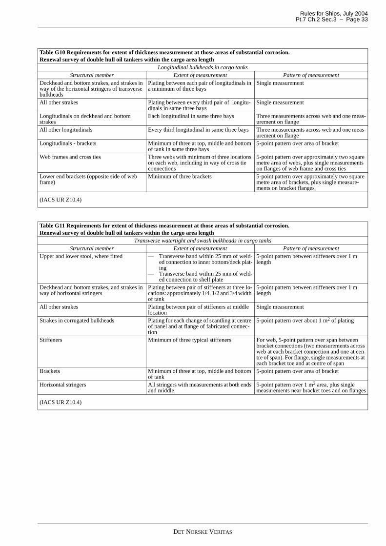
Rules for Ships, July 2004 Pt.7 Ch.2 Sec.3 – Page 33
Table G10 Requirements for extent of thickness measurement at those areas of substantial corrosion. Renewal survey of double hull oil tankers within the cargo area length
Longitudinal bulkheads in cargo tanksStructural member Extent of measurement Pattern of measurement
Deckhead and bottom strakes, and strakes in way of the horizontal stringers of transverse bulkheads
Plating between each pair of longitudinals in a minimum of three bays
Single measurement
All other strakes Plating between every third pair of longitu-dinals in same three bays
Single measurement
Longitudinals on deckhead and bottom strakes
Each longitudinal in same three bays Three measurements across web and one meas-urement on flange
All other longitudinals Every third longitudinal in same three bays Three measurements across web and one meas-urement on flange
Longitudinals - brackets Minimum of three at top, middle and bottom of tank in same three bays
5-point pattern over area of bracket
Web frames and cross ties Three webs with minimum of three locations on each web, including in way of cross tie connections
5-point pattern over approximately two square metre area of webs, plus single measurements on flanges of web frame and cross ties
Lower end brackets (opposite side of web frame)
Minimum of three brackets 5-point pattern over approximately two square metre area of brackets, plus single measure-ments on bracket flanges
(IACS UR Z10.4)
Table G11 Requirements for extent of thickness measurement at those areas of substantial corrosion. Renewal survey of double hull oil tankers within the cargo area length
Transverse watertight and swash bulkheads in cargo tanksStructural member Extent of measurement Pattern of measurement
Upper and lower stool, where fitted — Transverse band within 25 mm of weld-ed connection to inner bottom/deck plat-ing
— Transverse band within 25 mm of weld-ed connection to shelf plate
5-point pattern between stiffeners over 1 m length
Deckhead and bottom strakes, and strakes in way of horizontal stringers
Plating between pair of stiffeners at three lo-cations: approximately 1/4, 1/2 and 3/4 width of tank
5-point pattern between stiffeners over 1 m length
All other strakes Plating between pair of stiffeners at middle location
Single measurement
Strakes in corrugated bulkheads Plating for each change of scantling at centre of panel and at flange of fabricated connec-tion
5-point pattern over about 1 m2 of plating
Stiffeners Minimum of three typical stiffeners For web, 5-point pattern over span between bracket connections (two measurements across web at each bracket connection and one at cen-tre of span). For flange, single measurements at each bracket toe and at centre of span
Brackets Minimum of three at top, middle and bottom of tank
5-point pattern over area of bracket
Horizontal stringers All stringers with measurements at both ends and middle
5-point pattern over 1 m2 area, plus single measurements near bracket toes and on flanges
(IACS UR Z10.4)
DET NORSKE VERITAS
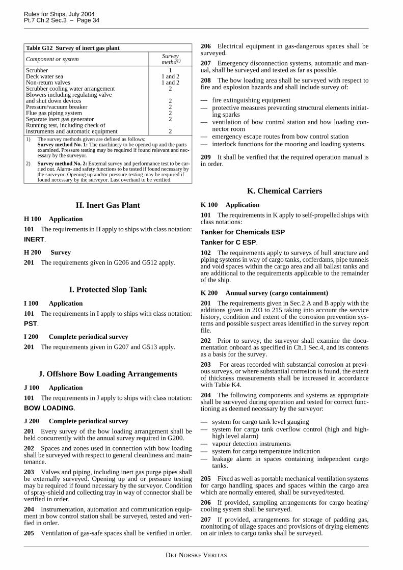
Rules for Ships, July 2004Pt.7 Ch.2 Sec.3 – Page 34
H. Inert Gas Plant
H 100 Application
101 The requirements in H apply to ships with class notation:
INERT.
H 200 Survey
201 The requirements given in G206 and G512 apply.
I. Protected Slop Tank
I 100 Application
101 The requirements in I apply to ships with class notation:
PST.
I 200 Complete periodical survey
201 The requirements given in G207 and G513 apply.
J. Offshore Bow Loading Arrangements
J 100 Application
101 The requirements in J apply to ships with class notation:
BOW LOADING.
J 200 Complete periodical survey
201 Every survey of the bow loading arrangement shall beheld concurrently with the annual survey required in G200.
202 Spaces and zones used in connection with bow loadingshall be surveyed with respect to general cleanliness and main-tenance.
203 Valves and piping, including inert gas purge pipes shallbe externally surveyed. Opening up and or pressure testingmay be required if found necessary by the surveyor. Conditionof spray-shield and collecting tray in way of connector shall beverified in order.
204 Instrumentation, automation and communication equip-ment in bow control station shall be surveyed, tested and veri-fied in order.
205 Ventilation of gas-safe spaces shall be verified in order.
206 Electrical equipment in gas-dangerous spaces shall besurveyed.
207 Emergency disconnection systems, automatic and man-ual, shall be surveyed and tested as far as possible.
208 The bow loading area shall be surveyed with respect tofire and explosion hazards and shall include survey of:
— fire extinguishing equipment— protective measures preventing structural elements initiat-
ing sparks— ventilation of bow control station and bow loading con-
nector room— emergency escape routes from bow control station— interlock functions for the mooring and loading systems.
209 It shall be verified that the required operation manual isin order.
K. Chemical Carriers
K 100 Application
101 The requirements in K apply to self-propelled ships withclass notations:
Tanker for Chemicals ESP
Tanker for C ESP.
102 The requirements apply to surveys of hull structure andpiping systems in way of cargo tanks, cofferdams, pipe tunnelsand void spaces within the cargo area and all ballast tanks andare additional to the requirements applicable to the remainderof the ship.
K 200 Annual survey (cargo containment)
201 The requirements given in Sec.2 A and B apply with theadditions given in 203 to 215 taking into account the servicehistory, condition and extent of the corrosion prevention sys-tems and possible suspect areas identified in the survey reportfile.
202 Prior to survey, the surveyor shall examine the docu-mentation onboard as specified in Ch.1 Sec.4, and its contentsas a basis for the survey.
203 For areas recorded with substantial corrosion at previ-ous surveys, or where substantial corrosion is found, the extentof thickness measurements shall be increased in accordancewith Table K4.
204 The following components and systems as appropriateshall be surveyed during operation and tested for correct func-tioning as deemed necessary by the surveyor:
— system for cargo tank level gauging— system for cargo tank overflow control (high and high-
high level alarm)— vapour detection instruments— system for cargo temperature indication— leakage alarm in spaces containing independent cargo
tanks.
205 Fixed as well as portable mechanical ventilation systemsfor cargo handling spaces and spaces within the cargo areawhich are normally entered, shall be surveyed/tested.
206 If provided, sampling arrangements for cargo heating/cooling system shall be surveyed.
207 If provided, arrangements for storage of padding gas,monitoring of ullage spaces and provisions of drying elementson air inlets to cargo tanks shall be surveyed.
Table G12 Survey of inert gas plant
Component or system Survey methd1)
ScrubberDeck water seaNon-return valves Scrubber cooling water arrangementBlowers including regulating valveand shut down devicesPressure/vacuum breakerFlue gas piping systemSeparate inert gas generatorRunning test, including check of instruments and automatic equipment
11 and 21 and 2
2
2222
21) The survey methods given are defined as follows:
Survey method No. 1: The machinery to be opened up and the parts examined. Pressure testing may be required if found relevant and nec-essary by the surveyor.
2) Survey method No. 2: External survey and performance test to be car-ried out. Alarm- and safety functions to be tested if found necessary by the surveyor. Opening up and/or pressure testing may be required if found necessary by the surveyor. Last overhaul to be verified.
DET NORSKE VERITAS
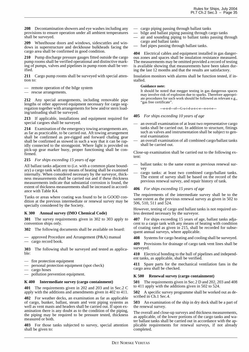
Rules for Ships, July 2004 Pt.7 Ch.2 Sec.3 – Page 35
208 Decontamination showers and eye washes including anyprovisions to ensure operation under all ambient temperaturesshall be surveyed.
209 Wheelhouse doors and windows, sidescuttles and win-dows in superstructure and deckhouse bulkheads facing thecargo area shall be confirmed in good condition.
210 Pump discharge pressure gauges fitted outside the cargopump rooms shall be verified operational and distinctive mark-ing of pumps, valves and pipelines in pump room shall be ver-ified.
211 Cargo pump rooms shall be surveyed with special atten-tion to:
— remote operation of the bilge system— rescue arrangements.
212 Any special arrangements, including removable pipelengths or other approved equipment necessary for cargo seg-regation together with arrangements for bow and/or stern load-ing/unloading shall be surveyed.
213 If applicable, installations and equipment required forspecial cargoes shall be surveyed.
214 Examination of the emergency towing arrangements are,as far as practicable, to be carried out. Aft towing arrangementshall be confirmed as pre-rigged and forward chafing gearshall be confirmed as stowed in such a way that it can be rap-idly connected to the strongpoint. Where light is provided onpick-up gear marker buoy, proper functioning shall be con-firmed.
215 For ships exceeding 15 years of age
All ballast tanks adjacent to (i.e. with a common plane bound-ary) a cargo tank with any means of heating shall be examinedinternally. When considered necessary by the surveyor, thick-ness measurements shall be carried out and if these thicknessmeasurements indicate that substantial corrosion is found, theextent of thickness measurements shall be increased in accord-ance with Table K4.
Tanks or areas where coating was found to be in GOOD con-dition at the previous intermediate or renewal survey may bespecially considered by the Society.
K 300 Annual survey (IMO Chemical Code)
301 The survey requirements given in 302 to 303 apply toconvention ships only.
302 The following documents shall be available on board:
— approved Procedure and Arrangement (P&A) manual— cargo record book.
303 The following shall be surveyed and tested as applica-ble:
— fire protection equipment— personal protection equipment (spot check)— cargo hoses— pollution prevention equipment.
K 400 Intermediate survey (cargo containment)
401 The requirements given in 202 and 203 and in Sec.2 Capply with the additions and amendments given in 402 to 411.
402 For weather decks, an examination as far as applicableof cargo, bunker, ballast, steam and vent piping systems aswell as vent masts and headers shall be carried out. If upon ex-amination there is any doubt as to the condition of the piping,the piping may be required to be pressure tested, thicknessmeasured or both.
403 For those tanks subjected to survey, special attentionshall be given to:
— cargo piping passing through ballast tanks— bilge and ballast piping passing through cargo tanks— air and sounding piping to ballast tanks passing through
cargo and ballast tanks— fuel pipes passing through ballast tanks.
404 Electrical cables and equipment installed in gas danger-ous zones and spaces shall be insulation resistance measured.The measurements may be omitted provided a record of testingis available showing that measurements have been taken dur-ing the last 12 months and that the results are satisfactory.
Insulation monitors with alarms shall be function tested, if in-stalled.
Guidance note:It should be noted that megger testing in gas dangerous spacesmay involve risk of explosion due to sparks. Therefore appropri-ate procedures for such work should be followed as relevant e.g.,“gas free certificate”.
---e-n-d---of---G-u-i-d-a-n-c-e---n-o-t-e---
405 For ships exceeding 10 years of age
— an overall examination of at least two representative cargotanks shall be carried out. In addition to structure, fittingssuch as valves and instrumentation shall be subject to gen-eral examination
— an overall examination of all combined cargo/ballast tanksshall be carried out.
Close-up examination shall be carried out to the following ex-tent:
— ballast tanks: to the same extent as previous renewal sur-vey
— cargo tanks: at least two combined cargo/ballast tanks.The extent of survey shall be based on the record of theprevious renewal survey, and repair history of tank.
406 For ships exceeding 15 years of age
The requirements of the intermediate survey shall be to thesame extent as the previous renewal survey as given in 502 to506, 510, 511 and 524.
However, testing of cargo and ballast tanks is not required un-less deemed necessary by the surveyor.
407 For ships exceeding 15 years of age, ballast tanks adja-cent to a cargo tank with any means of heating with conditionof coating rated as given in 215, shall be recorded for subse-quent annual surveys, where applicable.
408 Systems for cargo heating and cooling shall be surveyed.
409 Provisions for drainage of cargo tank vent lines shall besurveyed.
410 Electrical bonding to the hull of pipelines and independ-ent tanks, as applicable, shall be verified.
411 Spare parts for the mechanical ventilation fans in thecargo area shall be checked.
K 500 Renewal survey (cargo containment)501 The requirements given in Sec.2 D and 202, 203 and 408to 411 apply with the additions given in 502 to 524.
502 A specific survey programme shall be worked out as de-scribed in Ch.1 Sec.4.
503 An examination of the ship in dry dock shall be a part ofthe renewal survey.
The overall and close-up surveys and thickness measurements,as applicable, of the lower portions of the cargo tanks and wa-ter ballast tanks shall be carried out in accordance with the ap-plicable requirements for renewal surveys, if not alreadycompleted.
DET NORSKE VERITAS
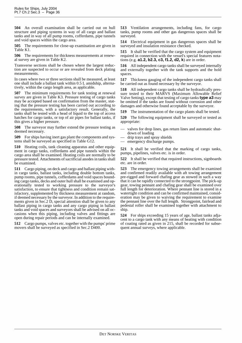
Rules for Ships, July 2004Pt.7 Ch.2 Sec.3 – Page 36
504 An overall examination shall be carried out on hullstructure and piping systems in way of all cargo and ballasttanks and in way of all pump rooms, cofferdams, pipe tunnelsand void spaces within the cargo area.
505 The requirements for close-up examination are given inTable K1.
506 The requirements for thickness measurements at renew-al survey are given in Table K2.
Transverse sections shall be chosen where the largest reduc-tion are suspected to occur or are revealed from deck platingmeasurements.
In cases where two or three sections shall be measured, at leastone shall include a ballast tank within 0.5 L amidship, alterna-tively, within the cargo length area, as applicable.
507 The minimum requirements for tank testing at renewalsurvey are given in Table K3. Pressure testing of cargo tanksmay be accepted based on confirmation from the master, stat-ing that the pressure testing has been carried out according tothe requirements, with a satisfactory result. Generally, thetanks shall be tested with a head of liquid to the top of accesshatches for cargo tanks, or top of air pipes for ballast tanks, ifthis gives a higher pressure.
508 The surveyor may further extend the pressure testing asdeemed necessary.
509 For ships having inert gas plant the components and sys-tems shall be surveyed as specified in Table G12.
510 Heating coils, tank cleaning apparatus and other equip-ment in cargo tanks, cofferdams and pipe tunnels within thecargo area shall be examined. Heating coils are normally to bepressure tested. Attachments of sacrificial anodes in tanks shallbe examined.
511 Cargo piping, on deck and cargo and ballast piping with-in cargo tanks, ballast tanks, including double bottom tanks,pump rooms, pipe tunnels, cofferdams and void spaces bound-ing cargo tanks, decks and outer hull shall be examined and op-erationally tested to working pressure to the surveyor'ssatisfaction, to ensure that tightness and condition remain sat-isfactory, supplemented by thickness measurement at random,if deemed necessary by the surveyor. In addition to the require-ments given in Sec.2 D, special attention shall be given to anyballast piping in cargo tanks and any cargo piping in ballasttanks and void spaces and surveyors shall be advised on all oc-casions when this piping, including valves and fittings areopen during repair periods and can be internally examined.
512 Cargo pumps, valves etc. together with the pumps' primemovers shall be surveyed as specified in Sec.2 D400.
513 Ventilation arrangements, including fans, for cargotanks, pump rooms and other gas dangerous spaces shall besurveyed.
514 Electrical equipment in gas dangerous spaces shall besurveyed and insulation resistance checked.
515 It shall be verified that the cargo system and equipmentrequired in connection with the vessel's special features nota-tions (e.g. a1.2, b2.3, c3, f1.2, d2, k) are in order.
516 All independent cargo tanks shall be surveyed internallyand externally together with the tank supports and the holdspaces.
517 Thickness gauging of the independent cargo tanks shallbe carried out as found necessary by the surveyor.
518 All independent cargo tanks shall be hydraulically pres-sure tested to their MARVS (Maximum Allowable ReliefValve Setting), except that testing of cargo tanks type a3 maybe omitted if the tanks are found without corrosion and otherdamages and otherwise found acceptable by the surveyor.
519 The instrumentation of the cargo plants shall be tested.
520 The following equipment shall be surveyed or tested asappropriate:
— valves for drop lines, gas return lines and automatic shut-down of loading
— drip trays and spray shields— emergency discharge pumps.
521 It shall be verified that the marking of cargo tanks,pumps, pipelines, valves etc. is in order.
522 It shall be verified that required instructions, signboardsetc. are in order.
523 The emergency towing arrangements shall be examinedand confirmed readily available with aft towing arrangementpre-rigged and forward chafing gear as stowed in such a waythat it can be rapidly connected to the strongpoint. The pick-upgear, towing pennant and chafing gear shall be examined overfull length for deterioration. Where pennant line is stored in awatertight condition and can be confirmed maintained, consid-eration may be given to waiving the requirement to examinethe pennant line over the full length. Strongpoint, fairlead andpedestal roller shall be examined together with attachment toship.
524 For ships exceeding 15 years of age, ballast tanks adja-cent to a cargo tank with any means of heating with conditionof coating rated as given in 215, shall be recorded for subse-quent annual surveys, where applicable.
DET NORSKE VERITAS
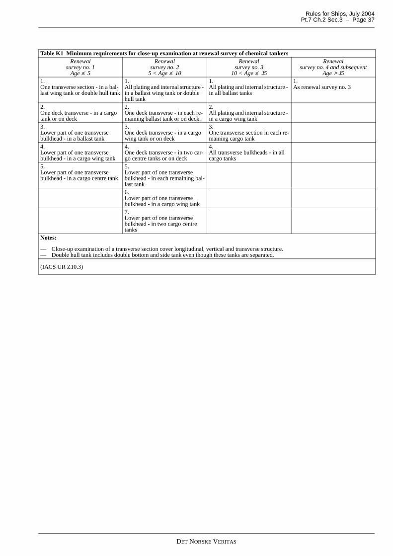
Rules for Ships, July 2004 Pt.7 Ch.2 Sec.3 – Page 37
Table K1 Minimum requirements for close-up examination at renewal survey of chemical tankersRenewal
survey no. 1Age ≤ 5
Renewal survey no. 2
5 < Age ≤ 10
Renewal survey no. 3
10 < Age ≤ 15
Renewal survey no. 4 and subsequent
Age > 151. One transverse section - in a bal-last wing tank or double hull tank
1. All plating and internal structure - in a ballast wing tank or double hull tank
1. All plating and internal structure - in all ballast tanks
1. As renewal survey no. 3
2. One deck transverse - in a cargo tank or on deck
2. One deck transverse - in each re-maining ballast tank or on deck.
2. All plating and internal structure - in a cargo wing tank
3. Lower part of one transverse bulkhead - in a ballast tank
3. One deck transverse - in a cargo wing tank or on deck
3. One transverse section in each re-maining cargo tank
4. Lower part of one transverse bulkhead - in a cargo wing tank
4. One deck transverse - in two car-go centre tanks or on deck
4. All transverse bulkheads - in all cargo tanks
5. Lower part of one transverse bulkhead - in a cargo centre tank.
5. Lower part of one transverse bulkhead - in each remaining bal-last tank6. Lower part of one transverse bulkhead - in a cargo wing tank7. Lower part of one transverse bulkhead - in two cargo centre tanks
Notes:
— Close-up examination of a transverse section cover longitudinal, vertical and transverse structure.— Double hull tank includes double bottom and side tank even though these tanks are separated.
(IACS UR Z10.3)
DET NORSKE VERITAS
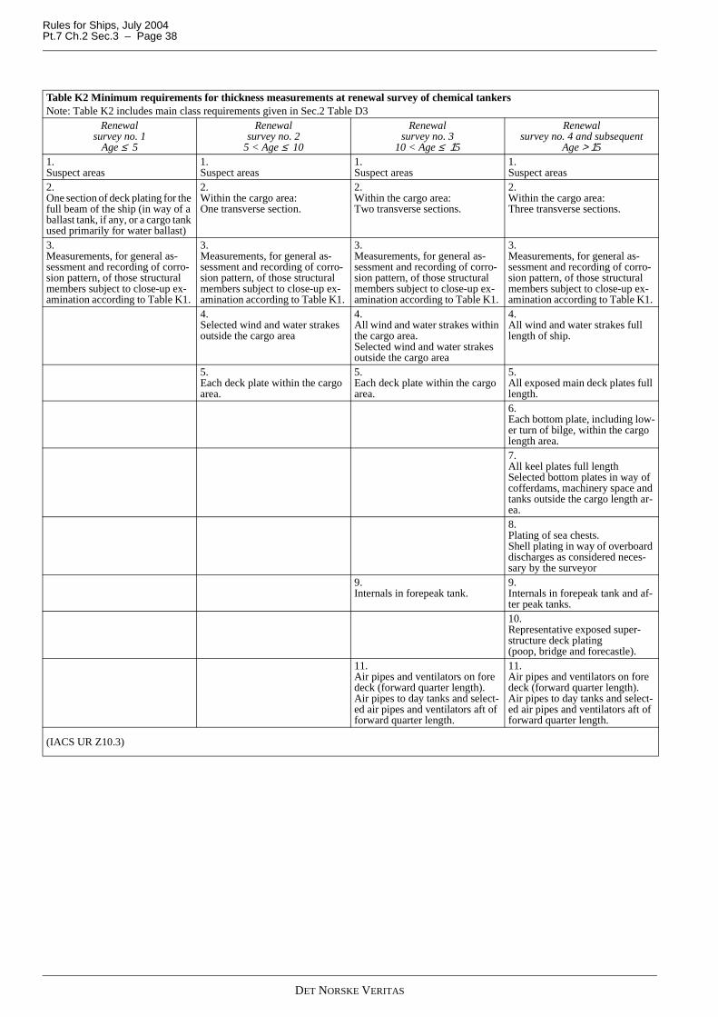
Rules for Ships, July 2004Pt.7 Ch.2 Sec.3 – Page 38
Table K2 Minimum requirements for thickness measurements at renewal survey of chemical tankersNote: Table K2 includes main class requirements given in Sec.2 Table D3
Renewal survey no. 1
Age ≤ 5
Renewal survey no. 2
5 < Age ≤ 10
Renewal survey no. 3
10 < Age ≤ 15
Renewal survey no. 4 and subsequent
Age > 151.Suspect areas
1.Suspect areas
1.Suspect areas
1.Suspect areas
2.One section of deck plating for the full beam of the ship (in way of a ballast tank, if any, or a cargo tank used primarily for water ballast)
2.Within the cargo area: One transverse section.
2.Within the cargo area: Two transverse sections.
2.Within the cargo area: Three transverse sections.
3.Measurements, for general as-sessment and recording of corro-sion pattern, of those structural members subject to close-up ex-amination according to Table K1.
3.Measurements, for general as-sessment and recording of corro-sion pattern, of those structural members subject to close-up ex-amination according to Table K1.
3.Measurements, for general as-sessment and recording of corro-sion pattern, of those structural members subject to close-up ex-amination according to Table K1.
3.Measurements, for general as-sessment and recording of corro-sion pattern, of those structural members subject to close-up ex-amination according to Table K1.
4.Selected wind and water strakes outside the cargo area
4.All wind and water strakes within the cargo area.Selected wind and water strakes outside the cargo area
4.All wind and water strakes full length of ship.
5.Each deck plate within the cargo area.
5.Each deck plate within the cargo area.
5.All exposed main deck plates full length.6.Each bottom plate, including low-er turn of bilge, within the cargo length area.7.All keel plates full lengthSelected bottom plates in way of cofferdams, machinery space and tanks outside the cargo length ar-ea.8.Plating of sea chests.Shell plating in way of overboard discharges as considered neces-sary by the surveyor
9.Internals in forepeak tank.
9.Internals in forepeak tank and af-ter peak tanks.10.Representative exposed super-structure deck plating (poop, bridge and forecastle).
11.Air pipes and ventilators on fore deck (forward quarter length).Air pipes to day tanks and select-ed air pipes and ventilators aft of forward quarter length.
11.Air pipes and ventilators on fore deck (forward quarter length).Air pipes to day tanks and select-ed air pipes and ventilators aft of forward quarter length.
(IACS UR Z10.3)
DET NORSKE VERITAS
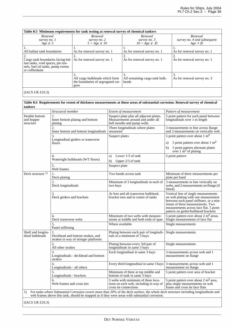
Rules for Ships, July 2004 Pt.7 Ch.2 Sec.3 – Page 39
Table K3 Minimum requirements for tank testing at renewal survey of chemical tankersRenewal
survey no. 1Age ≤ 5
Renewal survey no. 2
5 < Age ≤ 10
Renewal survey no. 3
10 < Age ≤ 15
Renewal survey no. 4 and subsequent
Age > 151. All ballast tank boundaries
1. As for renewal survey no. 1
1. As for renewal survey no. 1
1. As for renewal survey no. 1
2. Cargo tank boundaries facing bal-last tanks, void spaces, pie tun-nels, fuel oil tanks, pump rooms or cofferdams
2. As for renewal survey no. 1
2. As for renewal survey no. 1
2. As for renewal survey no. 1
3. All cargo bulkheads which form the boundaries of segregated car-goes
3. All remaining cargo tank bulk-heads
3. As for renewal survey no. 3
(IACS UR Z10.3)
Table K4 Requirements for extent of thickness measurements at those areas of substantial corrosion. Renewal survey of chemical tankers
Structural member Extent of measurement Pattern of measurementDouble bottom and hopper structure
1. Inner bottom plating and bottom plating
Suspect plate plus all adjacent plates. Measurements around and under all bell mouths and pump wells
5 point pattern for each panel between longitudinals over 1 m length
2. Inner bottom and bottom longitudinals
Three longitudinals where plates measured
3 measurements in line across flange and 3 measurements on vertically web
3. Longitudinal girders or transverse floors
Suspect plates 5 point pattern over about 1 m2
a) 5 point pattern over about 1 m2
b) 5 point pattern alternate plates over 1 m2 of plating
4. Watertight bulkheads (WT floors)
a) Lower 1/3 of tank
b) Upper 2/3 of tank
5 point pattern
5. Web frames
Suspect plate
Deck structure 1) 1. Deck plating
Two bands across tank Minimum of three measurements per plate per band
2. Deck longitudinals
Minimum of 3 longitudinals in each of two bays
3 measurements in line vertically on webs, and 2 measurements on flange (if fitted)
3. Deck girders and brackets
At fore and aft transverse bulkhead, bracket toes and in centre of tanks
Vertical line of single measurements on web plating with one measurement between each panel stiffener, or a min-imum of three measurements. Two measurements across face flat. 5 point pattern on girder/bulkhead brackets
4. Deck transverse webs
Minimum of two webs with measure-ments at middle and both ends of span
5 point pattern over about 2 m2 areas. Single measurements of face flat
5. Panel stiffening
Where available Single measurements
Shell and longitu-dinal bulkheads
1. Deckhead and bottom strakes, and strakes in way of stringer platforms
Plating between each pair of longitudi-nals in a minimum of 3 bays.
Single measurements
2. All other strakes
Plating between every 3rd pair of longitudinals in same 3 bays
Single measurements
3. Longitudinals - deckhead and bottom strakes
Each longitudinal in same 3 bays 3 measurements across web and 1 measurement on flange
4. Longitudinals - all others
Every third longitudinal in same 3 bays 3 measurements across web and 1 measurement on flange
5. Longitudinals - brackets
Minimum of three at top middle and bottom of tank in same 3 bays
5 point pattern over area of bracket
6. Web frames and cross ties
3 webs with minimum of three loca-tions on each web, including in way of cross tie connections
5 point pattern over about 2 m2 area, plus single measurements on web frame and cross tie face flats
1) For tanks where Substantial Corrosion covers more than 20% of the deck surface, the whole deck structure including longitudinals and web frames above this tank, should be mapped as if they were areas with substantial corrosion.
(IACS UR Z10.3)
DET NORSKE VERITAS
Rules for Ships, July 2004Pt.7 Ch.2 Sec.3 – Page 40
L. Liquefied Gas Carriers
L 100 Application101 The requirements in L apply to ships with class notation:
Tanker for Liquefied Gas.
L 200 Annual survey (cargo systems)201 The requirements given in Sec.2 A apply with the addi-tions and amendments given in 202 to 221.
202 The annual survey intends to ensure that the cargo han-dling installations and related safety equipment are in satisfac-tory condition. The annual survey is preferably to be carriedout during a loading or discharging operation. Access to cargotanks or inerted hold spaces, necessitating gas-freeing/aeratingwill normally not be required.
203 The log books shall be examined with regard to the con-dition of the cargo containment and the correct functioning ofthe cargo handling systems. The running hours per day of thereliquefaction plants or the boil-off rate and the inert gas con-sumption shall be considered in order to check that no irregu-larities in performance have occured.
204 Spaces used in connection with cargo handling (e.g. car-go control room, air locks, compressor rooms, electrical motorrooms), shall be surveyed with respect to general condition,e.g. cleanliness and maintenance.
205 Gastight bulkheads with possible shaft sealings shall bevisually examined.
206 The cargo handling piping and machinery, includingcargo process piping, cargo heat exchangers, vapourisers,pumps, compressors shall be visually examined, as far as pos-sible, during operation. Insulation on piping shall be visuallyexamined.
207 Venting systems for the cargo tanks, interbarrier spacesand hold spaces shall be visually examined externally. It shallbe verified that the cargo tank relief valves are sealed and thatthe certificate for the relief valves' opening and closing pres-sures is onboard.
208 The instrumentation of the cargo installations:
— automatic control, alarm and safety systems related to thepressure in cargo tanks, interbarrier spaces and hold spac-es
— systems for cargo tank level gauging, including high levelalarm and high level shut-off
— systems for temperature indication of the cargo, the cargocontainment system, the hull and the cargo piping system
— systems for leakage detection of interbarrier spaces andhold spaces
— automatic control, alarm and safety systems in connectionwith cargo compressors and cargo pumps
shall be verified in good working order by one or more of thefollowing methods:
— visual external examination— comparing of read-outs from different indicators— consideration of read-outs with regard to the actual cargo
and/or actual conditions— examination of maintenance records with reference to the
cargo plant instrumentation maintenance manual.
209 Emergency shut-down valves at shore connections andtanks shall be tested without flow in the pipe lines. It shall beverified that operation of the emergency shut-down systemwill cause the cargo pumps and compressors to stop.
210 The gas detection equipment shall be tested for correctfunctioning, including indicators and alarms.
211 Ventilation systems for all spaces in the cargo area, in-cluding air-locks, cargo pump rooms, cargo compressor
rooms, electrical motor rooms, cargo control rooms, and otherspaces used for cargo handling operations shall be verified asbeing in satisfactory operating condition.
212 In gas dangerous spaces and zones, electrical cables, ca-ble supports and electrical equipment shall be visually exam-ined as far as possible.
213 Inert gas and dry air installations including the means forprevention of backflow of cargo vapour to gas-safe spacesshall be verified as being in satisfactory operating condition.
214 The means for ensuring the gas and vapour tightness ofthe wheelhouse windows and doors, sidescuttles and windowsin way of ends of superstructures and deckhouse facing the car-go area or stern loading and unloading arrangements and clos-ing devices of all air intakes and openings intoaccommodation, service and control spaces shall be examined.
215 The sealing arrangements for tanks or tank domes pene-trating decks or tank covers shall be examined.
216 Portable and or fixed drip trays or insulation for deckprotection in the event of cargo leakage shall be examined.
217 Correct functioning of any arrangements for heating ofstructural hull steel shall be verified. Access to the heated cof-ferdams etc. is normally not required.
218 It shall be verified that the cargo piping systems are elec-trically bonded to the hull.
219 Arrangements for burning methane boil-off shall be vis-ually examined as far as practicable. The instrumentation andsafety systems shall be verified as being in good working orderin accordance with 208.
220 The relevant instruction and information material suchas cargo handling plans, cargo instrumentation maintenancemanual, filling limit information, cooling down proceduresetc. shall be verified as being onboard.
221 Examination of the emergency towing arrangements is,as far as practicable, to be carried out. Aft towing arrangementshall be confirmed as pre-rigged and forward chafing gearshall be confirmed as stowed in such a way that it can be rap-idly connected to the strongpoint. Where light is provided onpick-up gear marker buoy, proper functioning shall be con-firmed.
L 300 Annual survey (IMO Gas Code)301 The survey requirements given in 302 are only applica-ble for convention ships. The survey shall be carried out con-currently with the survey required in 200.
302 The following shall be surveyed and tested as applica-ble:
— fire protection equipment including water spray system— personal protection equipment— cargo hoses— decontamination showers and eyewashes.
L 400 Intermediate survey (cargo systems)401 The requirements given in 200 and in Sec.2 B apply withthe additions and amendments given in 402 to 410.
402 The intermediate survey supplements the annual surveyby testing cargo handling installations with related automaticcontrol, alarm and safety systems for correct functioning. Theintermediate survey is preferably to be carried out with the shipin a gas-free condition. The extent of the testing required forthe intermediate survey will normally be such that the surveycannot be carried out during a loading or discharging opera-tion.
403 Protection screens and flame screens, if provided, in thecargo containment venting systems shall be verified in satis-factory condition. Means for draining the vent system shall beexamined.
DET NORSKE VERITAS
Rules for Ships, July 2004 Pt.7 Ch.2 Sec.3 – Page 41
404 The instrumentation of the cargo installation referred toin 208 shall be visually examined and to be tested by changingthe parameter as applicable and comparing with test instru-ments. Simulated testing may be accepted for sensors whichare not accessible or for sensors located within cargo tanks orinerted hold spaces. The testing shall include testing of alarmand safety functions.
405 For ships having a gas fuel forwarding system, the safetyand control equipment and alarm and shut down functions re-lated to the following systems shall be tested:
— gas heating arrangement— fuel gas compressor and forwarding system— ventilation arrangement— protection and flame screens— gas freeing and purging systems— manual and automatic shut-down system— gas detection system— pilot flame burner or “fuel floor” arrangement, if applica-
ble— governor stability switching from gas fuel to oil, or vice
versa.
406 The piping of the gas detection system shall be visuallyinspected for corrosion and damage as far as practicable. Theintegrity of the suction lines between suction points and ana-lysing units shall be verified as far as possible.
407 The ventilation systems for spaces in the cargo area shallbe surveyed and function tested.
408 Electrical equipment in gas-dangerous spaces and zonesshall be examined as far as practicable with particular respectto the following:
— earthing (spot check)— integrity of certified safe equipment— function testing of pressurised equipment and of associat-
ed alarms— testing of insulation resistance of circuits. Such measure-
ments are only to be made when the ship is in the gas-freeor inerted condition and shall be carried out within an ac-ceptable time period. Where proper records of testing aremaintained consideration may be given to accepting recentreadings (maximum 12 months) by the ship's crew
— insulation monitors with alarms shall be function tested, ifinstalled.
409 For rooms protected by air locks, interlocking with ven-tilation of electrical supply to non-explosion protected equip-ment and de-energising of such equipment in case ofventilation failure shall be examined and function tested as ap-plicable.
410 Confirmation that spares are provided for cargo area me-chanical ventilation fans (not required if double fans provid-ed).
L 500 Renewal survey (cargo systems)501 The renewal survey required for cargo systems of lique-fied gas tankers shall be carried out concurrently with renewalsurveys required for hull and machinery as given in Sec.2 Cand in accordance with the requirements given in 202 to 221and in 402 to 410 with the additions and amendments as givenin 502 to 525.
502 All cargo tanks shall be cleaned and examined internal-ly.
503 As far as practicable the outer surface of non-insulatedcargo tanks or the outer surface of cargo tank insulation togeth-er with any vapour or protective barrier shall be examined.Special attention shall be given to the cargo tank and insulationin way of chocks, supports and keys. Partial removal of insula-tion may be required in order to verify the condition of the tankor the insulation itself if found necessary by the surveyor.
Where the insulation arrangement is such that it cannot be ex-amined, the surrounding structures of wing tanks, double bot-tom tanks and cofferdams shall be examined for cold spotswhen the cargo tanks are in the cold condition (prior to the re-newal survey) unless voyage records together with the instru-mentation give sufficient evidence of the integrity of theinsulation system.
504 Thickness measurements of the cargo tanks may be re-quired if deemed necessary by the surveyor.
505 For integral tanks and independent tanks type A and C,non-destructive testing shall supplement cargo tank inspec-tion, with special attention to be given to the integrity of themain structural members, tank shell and highly stressed parts,including welded connections as deemed necessary by the sur-veyor. The following items are, inter alia, considered to havehighly stressed areas:
— cargo tank supports and anti-rolling or anti-pitching devic-es
— stiffening rings or web frames— Y-connections between tank shell and a longitudinal bulk-
head of bilobe tanks— swash bulkhead boundaries— dome and sump connections to the tank shell— foundations for pumps, towers, ladders etc.— pipe connections.
506 For independent tanks type B, the extent of non-destruc-tive testing shall be as given in a programme specially preparedfor the cargo tank design.
507 The tightness of all cargo tanks shall be verified by anappropriate procedure. Provided that the effectiveness of theship's gas detection equipment has been confirmed, it will beacceptable to utilise this equipment for the tightness test of in-dependent tanks below deck during the first loading of the car-go tanks subsequent to the renewal survey.
508 Where findings of 502 to 507 or an examination of thevoyage records raise doubts as to the structural integrity of acargo tank, a hydraulic or hydropneumatic test shall be carriedout. For integral tanks and for independent tanks type A and B,the test pressure at top of the tank is not to be less than theMARVS (Maximum Allowable Relief Valve Setting). For car-go tanks type B with MARVS higher than 1.0 bar, a test pres-sure higher than MARVS will be specially considered. Forindependent tanks type C the test pressure is not to be less than1.25 times the MARVS.
509 At the second, the fourth, and thereafter at each renewalsurvey all independent cargo tanks type C shall be either:
— hydraulically or hydropneumatically tested to 1.25 timesMARVS and thereafter non-destructively tested in accord-ance with 505, or
— subjected to a thorough, planned non-destructive testing.
This testing shall be carried out in accordance with a pro-gramme specially prepared for the tank design. If a special pro-gramme does not exist, special attention shall be given to thedetection of surface cracks in welded connections in highlystressed areas as listed in 505.
At least 10% of the length of the welded connections in eachof above mentioned areas shall be tested. This testing shall becarried out internally and externally as applicable.
Insulation shall be removed as necessary for the required non-destructive testing.
510 Secondary barriers shall be examined visually for theireffectiveness. For containment systems where access is notpossible, the effectiveness of the secondary barrier may bechecked by means of pressure/vacuum tests or other relevantmethods.
511 For membrane and semi-membrane tank systems in-
DET NORSKE VERITAS
Rules for Ships, July 2004Pt.7 Ch.2 Sec.3 – Page 42
spection and testing shall be carried out in accordance withprogrammes specially prepared in accordance with an ap-proved method for the actual tank system.
512 If installed, systems for heating of hull structures shallbe surveyed and function tested.
513 All pressure relief valves for the cargo tanks shall beopened for examination, adjusted, function tested and sealed.
The allowable tolerance on the set pressure is given in TableL1.
If the cargo tanks are equipped with relief valves with non-me-tallic membranes in the main or pilot valves, such non-metallicmembranes shall be replaced with new ones.
514 Pressure/vacuum relief valves, pressure relief hatchesand rupture discs on interbarrier spaces and hold spaces shallbe examined, if necessary by opening, adjusted and tested de-pending on their design.
515 The cargo, liquid nitrogen and process piping systems,including valves, actuators, compensators etc. shall be openedfor examination as deemed necessary. Insulation shall be re-moved as deemed necessary to ascertain the condition of thepipes. If the visual examination raises doubt as to the integrityof the pipelines, a pressure test at 1.25 times the MARVS forthe pipeline shall be carried out. After reassembly the completepiping system shall be tightness-tested to MARVS.
If the maximum delivery pressure for the piping system is lessthan the design pressure for the piping system, testing to thepumps' delivery pressure may be accepted. In such cases ex-pansion bellows, selected at random, may be required disman-tled for internal survey and pressure tested to their designpressure.
516 The pressure relief valves in the cargo and process pip-ing systems shall be opened, function tested and adjusted to theextent found necessary by the surveyor.
517 The watersides of seawater-cooled heat exchangers, in-cluding those for gas operation of propulsion machinery shallbe opened for survey, and the heat exchangers shall be pressuretested as found necessary.
518 Cargo pumps, compressors and other machinery, includ-ing prime movers, used in connection with cargo handling andgas operation of propulsion machinery shall be surveyed.
519 The following portable equipment shall be surveyed:
— portable gas detectors, oxygen and humidity analysers— hoses and spool pieces used for segregation of piping sys-
tems for cargo, ventilation, inert gas and bilge operation.
520 Water spray systems shall be surveyed and tested forcorrect functioning.
521 Systems for removal of water or cargo from interbarrierspaces and hold spaces shall be examined and tested as deemednecessary.
522 All gas-tight bulkheads shall be inspected. The effec-tiveness of gas-tight shaft sealings shall be verified.
523 It shall be verified that the cargo tanks are electricallybonded to the hull.
524 It shall be verified that required instructions, informa-tion and signboards are in order.
525 The emergency towing arrangements shall be examinedand confirmed readily available with aft towing arrangement
pre- rigged and forward chafing gear as stowed in such a waythat it can be rapidly connected to the strongpoint. The pick-upgear, towing pennant and chafing gear shall be examined overthe full length for deterioration. Where pennant line is storedin a watertight condition and can be confirmed maintained,consideration may be given to waiving the requirement to ex-amine the pennant line over the full length. Strongpoint, fair-lead and pedestal roller shall be examined together withattachment to ship.
M. Fire Fighters
M 100 Application101 The requirements in M apply to ships with class nota-tions:
Fire Fighter IFire Fighter IIFire Fighter III.
M 200 Class notation Fire Fighter I201 Water spray plant for self protection, including pumps,pipes and nozzles, shall be surveyed and tested.
202 Pumps for water monitors including their prime moversshall be surveyed and tested at maximum capacity. Remotecontrol of monitors including valve operation shall be tested.
203 Hoses with their equipment shall be surveyed and tested.
204 Firefighters’ outfits and compressors for charging the airbottles shall be surveyed.
205 Floodlights shall be tested.
206 It shall be verified that the required operation manual isin order.
M 300 Class notation Fire Fighter II301 In addition to the requirements in 202 to 206, the mobilegenerator for foam production with its equipment shall be sur-veyed.
M 400 Class notation Fire Fighter III401 In addition to the requirements given in 300, the fixedfoam monitors with foam production equipment and remotecontrol shall be surveyed.
N. Well Stimulation Vessels
N 100 Application101 The requirements in N apply to ships with class notation:
Well Stimulation Vessel.
N 200 Annual survey201 Spaces and zones used in connection with the well stim-ulation system shall be surveyed with respect to general clean-liness and maintenance.
202 Tanks, pumping and piping and associated equipmentshall be subjected to an external visual inspection. Conditionof protective shielding, insulation and sealing of pressurevalves shall be verified.
203 The flexible high pressure hose including end connec-tors shall be hydraulically pressure tested to 1.25 times itsmaximum working pressure.
204 The following components and systems shall be sur-veyed and tested:
Table L1 Cargo tanks - tolerance on set pressureSet pressure p
(bar) Tolerance
(%) 0.0 ≤ p ≤ 1.5 ±10.01.5 < p < 3.0 ±6.0
3.0 ≤ p ±3.0
DET NORSKE VERITAS
Rules for Ships, July 2004 Pt.7 Ch.2 Sec.3 – Page 43
— emergency remote stop of pumps and shut-off of liquid ni-trogen supply valves
— tank level gauges— tank level alarms and liquid leakage alarms— hydrogen and oxygen detection and alarm system— ventilation system.
205 Decontamination showers and eye washes shall be sur-veyed and tested. Personnel protective equipment shall be ex-amined.
N 300 Complete periodical survey301 The requirements in 200 apply with the additions givenin 302 to 311.
302 Liquid nitrogen tanks shall be inspected internally. Onhighly stressed parts, non-destructive testing may be requiredif considered necessary by the surveyor. The tanks shall be hy-drostatically, hydropneumatically or otherwise pressure testedto their MARVS (Maximum Allowable Relief Valve Setting).
303 Acid tanks shall be examined internally.
304 All pressure relief valves shall be opened for survey, ad-justed, sealed and function tested.
305 Pressure/vacuum relief valves for the acid tanks shall besurveyed and tested for proper function.
306 Spot checking by NDT of the high pressure piping shallbe carried out.
307 The nitrogen vapouriser shall be opened for internal in-spection and hydraulically tested to 1.25 times its maximumworking pressure after reassembly.
308 The high pressure piping shall be hydraulically tested to1,25 times its maximum working pressure.
309 Opening for internal inspection of pumps and valvesmay be required as found necessary by the surveyor.
310 Certified safe electrical equipment shall be examinedand insulation resistance measured.
311 The emergency depressurisation and disconnecting ofthe transfer hose shall be tested.
O. Arrangements for Carriage of Low Flashpoint Liquids
O 100 Application101 The requirements in O apply to ships with class nota-tions:
LFLLFL*.
O 200 Annual survey201 The survey shall include a general examination of:
— tanks— pumping and piping systems (cargo, heating, bilge)— ventilation system— bulkheads with respect to tightness— electrical equipment in gas dangerous zones— inert gas arrangement, if installed.
202 The following components and systems shall be sur-veyed and tested for correct functioning:
— pressure/vacuum relief valves— emergency stop of pumps— quick release of transfer hose— tank high level alarms— portable hydrocarbon gas-measuring apparatus— portable oxygen-measuring apparatus, if applicable
— gas detection system in cofferdams, if applicable.
203 Insulation resistance of electrical cables shall be meas-ured. The measurements may be omitted provided a record oftesting is available showing that measurements have been tak-en during the last 12 months and that the results are satisfacto-ry.
O 300 Complete periodical survey301 The requirements given in 200 apply with the additionsgiven in 302 to 306.
302 All cargo tanks shall be internally examined. The tanksshall be hydrostatically, hydropneumatically or otherwisepressure tested to their MARVS (Maximum Allowable ReliefValve Setting).
303 If fitted, the heating coils, anodes, tank cleaning appara-tus and other equipment in cargo tanks and cofferdams shall besurveyed. Heating coils are normally to be pressure tested.
304 Cargo pumps, pipes, valves, inert gas arrangement, etc.together with the pump's prime movers shall be surveyed asspecified in Sec.2 C400.
305 Electrical equipment in gas-dangerous zones shall besurveyed and insulation resistance checked.
306 It shall be verified that required instruction manuals andsignboards are in order.
P. Reception System for Recovered Oil
P 100 Application101 The requirements in P apply to ships with class notation:
OILREC.
P 200 Complete periodical survey201 The survey is normally to include examination of thefollowing components and arrangements:
— tanks intended for storage of recovered oil if the tanks arenot separated from the engine room by cofferdams
— inert gas arrangement, if installed. For extent of survey,see H
— piping system for oil recovery operations. If recovered oilis led into tanks through hatch openings, the existence ofspecial hatch covers to prevent gas outflow through theopenings shall be verified
— blanking-off arrangements for pipe systems not in use dur-ing oil recovery operations
— disconnecting arrangements of non-certified electricalequipment in spaces adjacent to tanks for recovered oiland on open deck
— dry powder fire extinguishers including hoses— portable hydrocarbon gas-measuring instrument— electrical equipment certified for use in gas dangerous ar-
eas— instruction book for oil recovery operations and sign-
boards.
Q. Pusher and Pusher/Barge Combinations
Q 100 Application101 The requirements in Q apply to ships with class notation:
Pusher and Pusher/Barge Unit.
Q 200 Complete periodical survey201 The survey required is normally to include examinationof the following components and arrangements:
DET NORSKE VERITAS
Rules for Ships, July 2004Pt.7 Ch.2 Sec.3 – Page 44
— connecting points and contact areas with supporting struc-ture
— connecting equipment including locking device if any.
R. Ships and Plants for Refrigerated Cargoes and Controlled Atmosphere
R 100 Application101 The requirements in S apply to ships with class nota-tions:
ReeferRMRM ContainerKMCCACA (port.).
R 200 Annual survey201 For surveys required in 202 to 217, the surveyor may re-quire opening up of machinery and dismantling of insulation tothe extent he finds necessary.
202 The refrigerating plant, with machinery and equipment,shall be surveyed in running condition, preferably without car-go onboard. Temperature- and capacity control systems aswell as alarm and shut-down systems shall be checked.
203 A tightness test shall be carried out of refrigerant sys-tems with odourless refrigerants. Systems with a refrigerantwith distinct odour and brine systems shall be inspected fortightness.
204 The freezing point (density) and acidity (pH value) ofthe brine shall be checked.
205 General safety measures shall be checked including:
— protection of fans and other rotating machinery— alarm and emergency stop buttons— doors, hatches, etc. with regard to escape possibilities and
prevention of personnel being trapped within chambers,air cooler rooms etc.
— emergency escapes— refrigerant leakage detectors.
206 The internal lining of the chambers shall be surveyed. Itshall be checked that the chambers are free from odour.
207 Ducts, walls, gratings, battens, etc. which are installedfor the purpose of air circulation within the chambers shall besurveyed.
208 Hatches and doors with closing appliances shall be sur-veyed.
209 Scuppers, bilges with rose boxes, suction-, sounding-and drain-pipes together with drip pans shall be surveyed to as-certain that they are in good working order.
210 Thermometers and other equipment for measuring tem-perature in holds, chambers, air ducts, RSW tanks, freezingtunnels and plate freezers shall be surveyed and their accuracychecked to the extent found necessary by the surveyor.
211 CO2 detectors, if required installed, shall be checked.
212 The electrical installations including electrical equip-ment such as motors, switchgear and cables shall be examinedand the insulation resistance shall be checked to the extentfound necessary by the surveyor.
213 The safety precautions required for group 2 refrigerants,gas tight machinery room bulkheads, separate ventilation sys-tem, catastrophe ventilation or sprinkler arrangement, escape
arrangements for process areas and continuously manned car-go chambers, etc. shall be examined.
214 Items 215 to 217 apply to ships with class notations:
CA or CA (port.).215 The complete CA installation shall be subject to visualinspection and testing including at least the following:
— check that P/V-valves are operational— inspection of cleats, hinges, catches and locks for hatches
and doors— inspection of seals and gaskets on hatches and doors— spot check of interlocks on inlet valve arrangement— inspection of required ventilation fans during operation— inspection of portable ventilators— spot check of N2 release prealarm— spot check of water seals— inspection of the N2 generating unit during operation— if arranged, inspection of the CO2 scrubber(s) during op-
eration— inspection and spot check of gas analysing and monitoring
equipment, including fixed equipment, portable equip-ment for chamber or space monitoring and portable equip-ment for personal protection. Calibration records andprocedures shall be checked. Use and availability of cer-tified test gases shall be confirmed
— verification of satisfactory maintenance and function test-ing procedures for instrumentation. Spot check of moni-toring, alarm and safety functions
— all signboards on the entrances to rooms adjacent to CAchambers shall be checked. The signboards shall be in ac-cordance with the approved instruction manual
— locks on doors and hatches to be checked. For number andlocation of locks, see approved instruction manual.
216 All CA chambers or gastight groups of chambers shallbe individually tightness tested with air to the design overpres-sure. The pressure drop during 15 minutes shall not exceed30% of the design overpressure. Testing by the vessel's mastercarried out maximum one month prior to the survey may be ac-cepted based on written report by the master and provided thevisual inspection does not cause doubts about the tightness.
217 It shall be verified that the approved instruction manualis onboard, is complete and that the responsible officers are fa-miliar with its content.
R 300 Complete periodical survey301 For surveys required in 302 to 319, the surveyor may re-quire further opening up of machinery, dismantling of insula-tion and testing to the extent he finds necessary.
302 The refrigerating plant with machinery and equipmentshall be tested while cooling down from ambient temperatureto the lowest design temperature for the chambers. The abilityto maintain stable delivery air temperature at all design cham-ber temperatures shall be demonstrated. Satisfactory operationduring defrosting shall be demonstrated.
303 The insulation shall be surveyed for cold spots when thechambers are at the lowest design temperature.
304 The requirements given in 203 to 213 apply with the ad-ditions given in 305 to 319.
305 Sufficient areas of insulation shall be stripped from theholds, air trunkways, pressure vessels, piping and other insu-lated parts in order to assess the condition of the insulated steeland the insulation itself.
306 At the second and all subsequent periodical surveyspressure vessels with R717 shall be surveyed internally withregard to possible ammonia stress corrosion cracking.
307 Reciprocating compressors may be required opened upfor survey, if found necessary by the surveyor. Screw- and tur-bo-type compressors may be examined without opening up,
DET NORSKE VERITAS
Rules for Ships, July 2004 Pt.7 Ch.2 Sec.3 – Page 45
provided they are test-run to the surveyor's satisfaction.
308 Air coolers, freezing tunnels and plate freezers shall beexamined.
309 Condenser cooling water pumps, brine pumps and RSWpumps shall be opened up and surveyed.
310 Brine and RSW piping systems shall be surveyed atworking pressure.
311 Water side of water cooled condensers and brine side ofbrine coolers shall be opened up for survey of tubes, tubeplatesand end covers.
312 Pressure gauges, thermometers and automatic controlsand alarms shall be tested.
313 Pressure relief valves and safety discs shall be examinedexternally and on the outlet side after dismantling of outlet pip-ing and possible external bodies. The tightness over the seatshall be verified. Testing or opening up is required only whenspecially deemed necessary by the surveyor. Discharge pipingshall be examined with regard to integrity and non-obstructedflow.
314 The electrical installations including electrical equip-ment such as motors, switchgear and cables shall be examinedand the insulation resistance shall be checked.
315 Items 316 to 319 apply to ships with class notations:
CA or CA (port.).
316 The complete CA installation shall be subject to com-plete survey and testing. Air compressors, pressure vesselsand other machinery components shall be surveyed in accord-ance with the principles of Sec.2 C400 to C600.
317 All CA chambers or gastight groups of chambers shallbe individually tightness tested with air in the presence of thesurveyor to the design overpressure. The pressure drop during15 minutes shall not exceed 30% of the design overpressure.
318 All entrances to CA chambers, through running pipes,hatches and other connections from CA chamber to adjacentspaces, shall be visually inspected with respect to corrosion,damaged gaskets and other items which may affect the tight-ness between CA chambers and adjacent spaces.
319 Gas separating and adsorbtion units shall be tested withregard to capacity and quality of the produced gas.
R 400 Survey in loading port, upon request
401 The Society may upon request carry out surveys of re-frigerated cargo installations in the loading port for such cargo.Such surveys are not mandatory for retention of class.
The chambers shall be examined in an empty state to ascertainthat they are clean and free from odour, that the dunnage ribsare in good order, and that no damage has been sustained to theaid ducts, facing or insulation.
The surveyor shall ascertain that all pipes for the drainage ofthe chambers and the drip pans are in good working order. Thetemperatures in the chambers shall be recorded, and the condi-tion of the remote thermometers shall be checked. It shall beascertained that the plant is free from leakage.
S. Dangerous Goods
S 100 Application
101 The requirements in T apply to ships with class nota-tions:
DG-P and DG-B.
S 200 Complete periodical survey, compulsory require-ments201 These survey requirements are applicable to all types ofcargo spaces and classes of dangerous goods.
202 It shall be verified that the following documents areavailable onboard:
— International Maritime Dangerous Goods Code (IMDG),IMO Res. A.81(IV), as amended.
— Relevant sections and the related parts of Appendix B ofthe Code of Safe Practice for Solid Bulk Cargoes (BC-Code), IMO Res. A.434(XI), as amended.
— The IMO/WHO/ILO Medical First Aid Guide for Use in-Accidents Involving Dangerous Goods (MFAG), 1982.
203 The following shall be surveyed and tested as applica-ble:
— electrical installation in cargo spaces— ventilation system for cargo spaces— separate bilge pumping system or drainage for cargo spac-
es— personnel protective clothing and breathing apparatus— portable fire extinguishers for cargo spaces— insulation of machinery space boundaries— water spray system on open Ro-Ro cargo spaces.
T. Ro/Ro Ships
T 100 Application
101 The requirements in U apply to ships with class notation:
Ro/Ro.
T 200 Annual survey
201 Ships arranged for carriage of vehicles with fuel in theirtanks shall be surveyed as required in E.
U. Crane Vessels
U 100 Application101 The requirements in V apply to ships with class notation:
Crane Vessel.
U 200 Annual survey
201 The survey requirements are as given in Sec.4 B200.
U 300 Complete periodical survey301 The survey requirements are as given in Sec.4 B300.
V. Tanker for Potable Water
V 100 Application
101 The requirements in W apply to ships with class nota-tion:
Tanker for Potable Water
V 200 Complete periodical survey
201 At complete periodical survey the following shall besurveyed:
— coating in cargo tanks— instruments for pH and conductivity— cargo tank vents.
DET NORSKE VERITAS
Rules for Ships, July 2004Pt.7 Ch.2 Sec.3 – Page 46
W. Cable Laying Vessels
W 100 Application
101 The requirements in X apply to ships with class notation:
Cable Laying Vessel.
W 200 Annual survey
201 An overall survey shall be carried out and shall include:
— support structure— hydraulic systems— function testing.
W 300 Complete periodical survey
301 The requirements given in 200 apply in addition to thosegiven in 302 to 304.
302 Bearings and shafts of revolving equipment shall beopened up for examination.
303 Gear wheel and pinions of cable winch shall be checked.
304 Resistance measurements of electrical systems related tocable laying systems shall be carried out.
X. Naval and Naval support vessels
X 100 Application
101 Naval Surface Craft shall be considered level 4 when de-termining survey extent according to 102 and 201.
102 The requirements for main class given in Sec.2 applywith the addition of examination of systems and parts specifiedin 200 and 300.
X 200 Annual survey
201 The requirements given in Sec.2 A apply with the addi-tion of examination of systems and parts specified in 202.
202 The following shall be surveyed or tested as applicable:
General
— gas tight autonomous zones, divisions (survey)— marking of cables (see Pt.5 Ch.14 Sec.8 G600).
Storage rooms for explosives
— safety arrangement plan (posted)— escape route plan (posted)— no smoking signboards (posted)— supply lines for explosives— temperature and humidity regulation— temperature detectors— water spray system (survey)— water total flooding system (survey)— securing arrangements for explosives.
X 300 Complete periodical survey301 The following shall be surveyed or tested as applicable:
General
— smoke evacuation systems— gas tight autonomous zones, divisions (survey and test)— disabling of control system limitations for machinery sys-
tems— anti-icing systems in air intakes for machinery space.
Storage rooms for explosives
The requirements of 202 apply.
302 Lightweight survey shall be carried out and reported inaccordance with Rules for Classification of High Speed, LightCraft and Naval Surface Craft, Pt.3 Ch.6 Sec.1 A400.
303 A lightweight survey should be carried out to verify anychanges in lightweight displacement and longitudinal centre ofgravity.
The craft should be re-inclined whenever, in comparison withthe approved stability information, a deviation from the light-weight displacement exceeding 2% or a deviation of the longi-tudinal centre of gravity exceeding 1% of L is found oranticipated.
X 400 Bottom survey401 The requirements given in Sec.2 D apply.
DET NORSKE VERITAS
Rules for Ships, July 2004 Pt.7 Ch.2 Sec.4 – Page 47
SECTION 4 SURVEY EXTENT - ADDITIONAL CLASS. SPECIAL EQUIPMENT AND
SYSTEMS NOTATIONS
A. Helicopter Deck
A 100 Application101 The requirements in A apply to ships with class notation:
HELDK.
A 200 Complete periodical survey201 Every survey of the helicopter deck arrangement shallbe held concurrently with the renewal survey of the hull.
202 The survey required is normally to include examinationof the following components and arrangements:
— drainage arrangements— surface protection on wooden decks— safety net— lashing arrangements for the helicopter— arrangement for the prevention of sliding— helicopter deck including support.
B. Shipboard Crane
B 100 Application101 The requirements in B apply to ships with class notation:
CRANE.
B 200 Annual survey201 An overall survey shall be carried out with particularemphasis on structural integrity, including examination of:
— wire ropes and end attachments— blocks and sheaves— hooks with accessories— shackles— bearings of boom heel and eyebolt connections— securing arrangement for crane during passages— support structure.
202 Slewing system (slewing bearing or hook rollers) in-cluding tightness of bolts shall be examined as found necessaryby the surveyor.
203 Examination and functional testing shall be carried outas found necessary by the surveyor for the following:
— correct adjustment of brakes— resistance measurement of electrical systems— leakages in hydraulic system— safety devices— emergency stop function— fire extinguisher.
204 It shall be verified that the load charts, marking andcomponents certificates are available and in order.
B 300 Complete periodical survey301 The requirements given in 200 apply, with the additionsgiven in 302 to 306.
302 Thickness measurements of structural parts shall be car-ried out as far as deemed necessary.
303 The following components shall be dismantled (openedup) and/or checked by MPI (magnetic particle inspection):
— boom heel bearings— fixed sheaves— blocks— axle pin and housing— eyebolt connections— hooks, ring and balls.
304 Slewing ring shall be opened up, and internal fillets,raceway and bolts shall be subjected to MPI.
Alternatively, if a crane has an approved securing device (re-tainer) fitted, opening up is not required, but at least 50% of theholding down bolts shall be drawn and subjected to MPI.
305 Flatness and condition of bearing mounting flanges shallbe checked.
306 A load test, as outlined on Form No. CG 2 in the “Rulesfor Certification of Lifting Appliances”, shall be carried out.
C. Diving Systems
C 100 Application
101 The requirements in C apply to ships with class nota-tions:
DSV-I (SF)
DSV-II (SF)
DSV-III (SF).
C 200 Annual survey
201 The survey is normally to include:
— calibration of essential instrumentation (depth gauges, gasanalysers etc.)
— switching from main to emergency electrical power sup-ply
— emergency systems including bell emergencies (buoyancyif applicable)
— functional and power testing of normal and emergencysystems of the bell handling system shall be carried outwith a load of at least 1,25 times the working weight in themost unfavourable position
— partly dismounting of heat protection and penetrators onthe bell may be required.
Detailed specification of test requirements are given in the rel-evant sections of the “Rules for Certification of Diving Sys-tems”.
C 300 Intermediate survey
301 The requirements given in 200 apply, with the additionsgiven in 302.
302 The following tests shall be carried out:
— gas leak tests— testing of safety valves— functional test of fire detection-, alarm- and extinction sys-
tems— functional tests of life support systems— functional tests of alarm systems— functional tests of mechanical and electrical systems.
DET NORSKE VERITAS
Rules for Ships, July 2004Pt.7 Ch.2 Sec.4 – Page 48
C 400 Complete periodical survey401 The requirements given in 200 and 300 apply with theadditions given in 402 to 406.
402 Bell buoyancy materials, heat protection, penetrators,windows and attached members shall be dismounted for in-spection for possible corrosion and deterioration.
403 Pressure tests and inspections shall be carried out ac-cording to Table C1. Test pressure as stamped on the pressurevessels.
The pressure tests and inspections of gas containers shall becarried out according to an approved test program.
404 The working weight of the bell shall be checked.
405 A test of the bell handling system with a static load equalto the design load shall be carried out.
406 If applicable the bell's releasable ballast system with at-tachments shall be structurally tested with a static load 1,5times the weight of the ballast in air.
407 Viewports with an age of 10 years or more shall bechanged.
D. De-icing or Anti-icing Systems
D 100 Application101 The requirements in D apply to ships with class nota-tions:
DEICEDEICE-C.
D 200 Annual survey201 Visual inspection of anti-icing and de-icing switch-boards and confirm heating load on each circuit according tomarking on the switchboards.
202 Examination of equipment for de-icing and anti-icing in-cluding:
— heaters— covers— equipment for manual de-icing— radar equipment— heating coils— steam tracing lines.
E. Periodically Unattended Machinery Space and Machinery Centralised Operated
E 100 Application101 The requirements in E apply to ships with class nota-tions:
E0ECO.
102 A maintenance and testing program, stamped by the So-
ciety for identification, shall be kept onboard and presented atthe annual and the complete periodical surveys.
E 200 Annual survey
201 It shall be verified that the systematic maintenance andfunctional testing of the instrumentation are performed anddocumented, and that the general condition of the followingshall the satisfaction of the surveyor:
— installation of instrumentation equipment with regard toelectrical and mechanical condition, labels, signboardsetc.
— control panels— local indicating instruments.
202 Correct functioning of the following systems shall beverified:
— alarm systems— safety systems— remote control systems— automatic control systems— emergency lighting systems in engine room— communication systems— fire alarm and fire protection systems.
E 300 Complete periodical survey301 The requirements given in 200 apply, with the additionsand amendments given in 302 to 304.
302 Correct functioning of the various parts of the followingsystems shall be verified to the satisfaction of the surveyor:
— each alarm system— each safety system— each fire detector— automatic control loops— manual control of machinery— remote control of propulsion machinery. It will normally
be required that the following manoeuvres are effected:
— from stop to ahead— from ahead to astern— stop— from stop to astern— stop by operating the emergency device.
303 It shall be verified that the remote control can be trans-ferred to stand-by manual control in the engine room in case ofpower supply failure to the remote control system.
304 When cancelling of automatic load reduction and or au-tomatic stop of engine are provided, these functions shall bedemonstrated to the satisfaction of the surveyor.
F. Additional Fire Protection
F 100 Application
101 The requirements in F apply to ships with class notation:
F-AMC.
F 200 All F-class notations
201 Fire pumps including emergency fire pump and primemovers shall be surveyed and tested.
202 Firefighters' outfits and compressors for charging of airbottles shall be surveyed.
F 300 Class notation F-A301 The requirements in 200 apply with the following addi-tions:
Table C1 Pressure testsComponent Maximum interval between each inspection and
pressure testing (years)Gas containersBell, chambers
5 or 10 1)
5 or 10 2)
1) Interval for hydraulic pressure testing of gas containers may be extend-ed to 10 years if the internal inspection reveals no corrosion.
2) Interval for hydraulic pressure testing of bell and chambers may be ex-tended to 10 years if a pneumatic leakage test to 1,1 times the maximum working pressure is carried out at the complete periodical survey.
DET NORSKE VERITAS
Rules for Ships, July 2004 Pt.7 Ch.2 Sec.4 – Page 49
— fire retarding partitions in the accommodation shall be sur-veyed
— automatic fire-detecting and alarm systems including re-lease arrangement for self-closing doors in passageways,stairways and machinery casings shall be surveyed andtested
— hose stations in the accommodation together with theirequipment shall be surveyed.
F 400 Class notation F-M401 The requirements in 200 apply with the following addi-tions:
— main and local extinguishing systems in engine and boilerrooms including detection and alarm arrangements shallbe surveyed and tested. Quantity of extinguishing mediumshall be checked
— portable dry powder fire extinguishers shall be surveyedand spare charges shall be checked
— hose stations in the engine and boiler rooms together withtheir equipment shall be surveyed.
F 500 Class notation F-C501 The requirements in 200 apply with the following addi-tions:
— smoke detector systems for cargo holds, cargo pumprooms, compressor rooms and other service rooms shall besurveyed and tested
— CO2-systems shall be surveyed and the CO2-quantity ver-ified. Thickness measurements and/or pressure testing ofCO2-bottles may be required if found necessary by the sur-veyor
— foam systems shall be surveyed and the foam quantity ver-ified. Foam forming concentrate shall be analysed everyfive years
— dry chemical powder systems shall be surveyed and thepowder quantity verified
— fire extinguishing systems for deck area shall be tested— portable fire extinguishers for the deck area and cargo
holds shall be surveyed. Spare charges shall be checked— hose stations on deck together with their equipment shall
be surveyed.
F 600 Class notation F-AM601 The requirements in 200, 300, 400 and 500 apply.
F 700 Class notation F701 The requirements in 200, 300, 400 and 500 apply as faras these are applicable.
G. Integrated Computer Systems
G 100 Application101 The requirements in G apply to ships with class notation:
ICS.
G 200 General201 The purpose of the specified survey shall ensure that thequality of the total integrated system is maintained during thelifetime of the ship. In particular, this includes checking thefunctionality and reliability of the data communication linksand that the procedures and operations defined in the operationand maintenance manuals, are being followed.
G 300 Complete periodical survey301 Every survey of integrated computer systems shall beheld concurrently with the survey of instrumentation and auto-mation systems for class notations E0, ECO, NAUT, NAUT-
AW, NAUT-OC, CCO or POSMOOR.
302 The following shall be checked during the survey:
a) Consistency between the software version numbers as pro-vided in the maintenance manual and the software in-stalled on each unit in the total integrated system.
b) If available, logs from network monitoring equipment andor network process control or task manager. The capacityof the net(s) shall be adequate and maintained. Softwareupdates and or integration of additional equipment mayhave changed the network load or the capacity.
c) Consistency between the back-up procedures as describedin the operation manual and the actual back-up proceduresin use.
d) To protect the system and or process net from becomingcontaminated with virus infected floppy drives, a key lockshall be inserted in the floppy drives or the floppy drivesshall be stored in e.g. a locked cupboard.
e) Presence of access limitations on communication throughthe gateway or router from the administrative net to thesystem net shall be verified.
f) Presence of up-dated virus detection software on adminis-trative net shall be verified.
g) That procedures for upgrades of software, hardware, andfirmware are being followed and that system functionalityis verified after each such upgrade.
303 The following shall be tested during the survey:
a) The integrity of the system with respect to unauthorisedaccess.
b) Screen presentation at start-up of the work and or operatorstations connected to the system or process net. Relatedapplication(s) shall start-up automatically with no user in-teraction. No other application shall be accessible. Pagesshall be checked for relevance and compared to the opera-tion manual.
c) Active control and manipulation of a selection of parame-ters shall be demonstrated from two or more workstations.
d) Available self test and or self diagnosis tools supportingthe functions serviced by the net(s) shall be demonstrated.
H. Centralised Cargo Control for Liquid Cargoes
H 100 Application101 The requirements in H apply to ships with class notation:
CCO.
H 200 Complete periodical survey201 Every survey of the centralised cargo control arrange-ment shall be held concurrently with the annual survey re-quired in Sec.3 G200.
202 All remotely controlled operations related to cargo han-dling and ballasting shall be surveyed and tested.
203 Alarms and remote readings according to Pt.6 Ch.6Sec.2 Table C1 shall be checked.
204 In the case of computer based systems the relevant re-quirements in Pt.4 Ch.9 shall be controlled.
205 Arrangement for emergency stop of cargo pumps fromthe cargo manifold area shall be surveyed and tested.
206 Arrangement in cargo control room for emergency clos-ing of valves in cargo lines shall be surveyed and tested.
207 Loading computer shall be tested for the following func-
DET NORSKE VERITAS
Rules for Ships, July 2004Pt.7 Ch.2 Sec.4 – Page 50
tions as applicable:
— damage stability and strength (by simulating loading con-ditions)
— cargo compatibility with tank coating— certificate limitations.
I. Dynamic Positioning System
I 100 Application
101 The requirements in I apply to ships with class notations:
DYNPOS-AUTS, DYNPOS-AUT, DYNPOS-AUTR orDYNPOS-AUTRO.
I 200 Complete periodical survey
201 All sensors, peripheral equipment and reference systemsshall be tested to verify correct operation and adequate accura-cy as compared to previous calibration or specifications.
Failures of sensors shall be simulated to check the alarm sys-tem and the switching logic.
Acoustic reference systems shall be tested with thrusters in op-eration.
Switch-over between reference systems as input to controllershall be carried out to assure that warnings, alarms and infor-mation to operator are satisfactory. Off-location alarm shall bedemonstrated.
202 Each thruster shall be tested with a range of pitches orspeed, and indicating instruments for speed, pitch and azimuthshall be observed for verification of adequate accuracy.
The different modes of thruster control shall be tested for:
— manual control of pitch or speed and azimuth— remote thrust control— controller (automatic) control— transfer of control.
The remote thrust control system shall be tested with the refer-ence system in operation.
The system shall be capable of keeping the vessel in position(not exceeding position boundaries, off-location alarm).
203 The survey of the thruster unit shall be carried out as forthrusters for propulsion, see Ch.1 Sec.2 Table B2 and Sec.2 F.
Guidance note:Survey of the thrusters requires docking of the vessel and shouldbe harmonised with the bottom survey.
---e-n-d---of---G-u-i-d-a-n-c-e---n-o-t-e---
204 Opening of prime movers for thrusters may be requiredif found necessary by the surveyor.
205 The electrical installation serving the dynamic position-ing system shall be examined.
206 Testing of automatic reconnection system for generatorsand consumers connected to the bus-bar system(s) shall be car-ried out (simulated test may be accepted).
Power failure to the different sub-systems shall be simulated toverify the intended functioning.
207 The complete dynamic positioning system is normally tobe tested in all operational modes with simulation of differentfailure conditions to try out switching of modes, back-up sys-tems and the alarm system.
Manual override shall be demonstrated during normal opera-tion and failure conditions.
J. Nautical Safety
J 100 Application101 The requirements in J apply to ships with class nota-tions:
NAUT-OC and W1-OC NAUT-AW and W1NAUT-AW-QNAUT-OC-Q
J 200 General201 Ships with above mentioned class notations are subjectto annual survey and renewal survey every 5 years.
202 The NAUT-AW/OC annual survey to be held concur-rently with the Main class annual survey
203 The NAUT-AW/OC complete survey to be held concur-rently with the Main class renewal survey.
J 300 Annual survey class notation NAUT-OC and NAUT-AW301 The annual survey shall verify the functional status ofthe navigational equipment, including information of anychanges to software and hardware which have been logged.
302 For software and/or hardware changes of the IntegratedNavigation System (e.g. comprising track control system orheading control), a sea trial to verify system performance mayby required.
J 400 Complete survey class notation NAUT-OC401 The following navigation equipment is to be inspectedand tested :
— Course information systems (compasses)— Steering control systems (manual)— Heading control system (autopilot)— Speed log(s)— Echo sounder— Radar / ARPA— Electronic Position Fixing systems— Watch monitoring and alarm transfer system— Internal Communication systems— Automatic Identification System— ECDIS, Electronic Chart Display and — Information System, if installed— ECDIS, Electronic Chart Display and Information— Conning display, if installed— Track control system, if installed
402 The ability of instruments and systems listed in 401 torecover normal operation after black-out shall be tested.
J 500 Complete survey for class notation NAUT-AW501 The complete survey required for class notation NAUT-OC shall be carried out.
502 For software and/or hardware changes of the integratedsystem for Grounding Avoidance (or the Automatic Naviga-tion and Track keeping system), a sea trial to verify system per-formance may be required.
503 The display of required information on the ship's ma-noeuvring characteristics and the contents of the manoeuvringbooklet shall be examined.
J 600 Class notations NAUT-OC-Q and NAUT-AW-Q601 When the class notations NAUT-OC and NAUT-AWare extended with suffix Q, the qualification assurance system,operational procedures and certificates of competence shall beexamined to verify compliance with Pt.6 Ch.8 Sec.9.
DET NORSKE VERITAS
Rules for Ships, July 2004 Pt.7 Ch.2 Sec.4 – Page 51
K. Hull Monitoring System
K 100 Application
101 The requirements in K apply to ships with class notation:
HMON-1 or
HMON-2.
K 200 General201 The purpose of the survey specified in 300 shall ensurethe maintenance of the hull monitoring system as specified forthe class notation.
202 The operation manual shall be available to the attendingsurveyor during periodical surveys. In addition to the manualthe following documents listed in Pt.6 Ch.11 Sec.1 C101 shallbe available:
— arrangement and layout— test program for software— in-service test program— maintenance procedures.
K 300 Annual survey301 The operation of the hull monitoring system shall be ver-ified by a surveyor from the Society:
— to ensure that the value of the stress as defined is compat-ible with the output of the loading instrument for the cur-rent condition
— by examination of the recorded data for compliance withthe requirements.
302 The monitoring system shall be calibrated annually asdefined in Pt.6 Ch.11 Sec.4 A301. The calibration shall be ver-ified by a surveyor from the Society.
303 It shall be verified that the following items are availableand in order:
— calibration certificates and recommendations for all rele-vant components of the monitoring system
— operations manual (in English and in a language appropri-ate for the crew).
L. Vapour Control Systems
L 100 Application
101 The requirements in L apply to ships with the class no-tations:
VCS-1VCS-1BVCS-2VCS-2BVCS-3. 102 The survey intervals for the VCS class notations can befound in Ch.1 Sec.2 Table B4.
L 200 Annual survey
201 The requirements in 200 apply to installations withVCS-3 notation.
202 The VOC module shall be surveyed with respect to gen-eral condition. Gas tight bulkheads, piping systems, pressurevessels with mountings and equipment, regulating valves, decktank safety relief valve sealings, electrical cables and equip-ment as applicable shall be visually examined. Pressure testingand piping thickness measurements are to be performed ifdeemed necessary by the surveyor.
203 The hydrocarbon gas detection system shall be tested.
204 The ventilation system shall be tested.
205 Air locks, if fitted, shall be examined and tested.
206 The calibration of fixed or portable instruments formeasuring oxygen content in the VOC plant shall be checked.
207 An operation manual for the VOC plant shall be verifiedon board, and checked updated if new software has been in-stalled.
208 Alarm and safety systems shall be examined and tested.
L 300 Complete periodical survey
301 Requirements for survey of the additional class nota-tions VCS-1 and VCS-2 are considered covered by the ruleslaid down for vessels with class notations Tanker for Oil andor Tanker for Chemicals.
302 For VCS-1B and VCS-2B the following instrumentsand equipment should be surveyed and tested:
— the means to inert the vapour transfer hose— oxygen analyser with alarms— detonation arrester.
Requirements for survey of the remaining parts of the installa-tion are considered covered by the rules laid down for vesselswith class notations Tanker for Oil and Tanker for Chem-icals.
303 For VCS-3 a VOC plant running test shall be per-formed.
304 If a liquefied gas deck tank is fitted this shall be internal-ly examined including internal piping, valves etc. and includ-ing NDT and thickness measurement as found necessary. Decktanks with foundations shall be externally examined and tight-ness tested. At 2nd, 4th, and thereafter at each complete peri-odical survey deck tanks shall be strength tested as specified inSec.3 L509.
305 Deck tank safety relief valves shall be surveyed afteropening, tested and sealed.
306 Cooling machinery and equipment shall be examinedand tested.
M. Redundant Propulsion
M 100 Application
101 The requirements in M apply to ships with the class no-tations:
RP
RPS.
M 200 Complete periodical survey
201 The requirements for survey of the additional class nota-tions RP and RPS are considered covered by the rules laiddown for main class.
N. Clean Ships
N 100 Application
101 The requirements in N apply to ships with class nota-tions:
CLEANCLEAN DESIGN.
DET NORSKE VERITAS
Rules for Ships, July 2004Pt.7 Ch.2 Sec.4 – Page 52
N 200 Annual surveys201 The basic requirement is that the vessel holds a valid in-ternational pollution prevention certificate.
For the oil pollution prevention certificate, the following shallbe checked onboard during survey:
— certificates for type approved oily water separating or fil-tering equipment, process unit and oil content meters
— oil record book entries— approved SOPEP manual— means of control of sludge— standard discharge connection.
Additionally, the following shall be examined and tested, asapplicable:
— oil filtering equipment (15 ppm) and process unit withalarm
— automatic stopping device (15 ppm) — separation of oil fuel and water ballast system— sludge tank and discharge arrangement externally.
202 In addition the following shall be checked or verified asapplicable:
— all refrigerant consumption figures— consumption figures for fire fighting substances with glo-
bal warming potential (GWP) > 0— garbage record book— oil record books and cargo record book— fuel oil log— NOx emission control equipment log, where applicable— ballast water management log— documentation of antifouling used during dry-dockings
since last review.
O. Gas Fuelled Engine Installations
O 100 Application101 The requirements in O apply to ships with class notation:
GAS FUELLED
O 200 Annual survey201 General cleanliness and maintenance shall be examinedin:
— engine rooms— gas compressor and electric motor rooms, if fitted.
202 The condition of drip trays in the bunkering station shallbe examined.
203 External examination and function test of remote oper-ated valves in the gas piping system shall be carried out. Exter-nal examination of gas pipe ducts shall be carried out.
204 Fire safety
a) Testing of water spray on gas tank if located above deck.
b) Check report for powder extinguishing system in the bun-kering station and in the engine room entrance, if applica-ble. The report shall not be older than 24 months.
205 Reference is made to survey requirements for the classnotation E0 regarding record of systematic maintenance andfunction testing in E201. The survey shall include the gas fuelinstallation.
206 Testing of instrumentation
a) Fixed gas detection unit with alarms.
b) Fixed fire detection system in tank room.
c) Gas tank monitoring: High level alarm, temperature mon-itoring, level indication and temperature sensor in bilgewell in tank room.
d) Gas compressor emergency stop, to be tested from bridge,control room and fire control station.
207 Emergency shutdown system testing shall at least in-clude:
a) Shutdown due to gas detection on two detectors to 20%LEL (with span gas) in either engine room, tank room ordouble pipe outside of the engine room. Shutdown due togas detection on one detector to 60% LEL (with span gas)in double pipe in the engine room. Check that all the cor-rect valves open and close.
b) Testing of automatic disconnection of non-ex proof equip-ment in ESD protected engine rooms at gas detection to20% LEL on two detectors in room.
c) Shutdown due to fire detection in tank room. Check thatall the correct valves open and close.
d) Manual release of emergency shutdown for engine tested.
e) Safety actions at full stop of ventilation in ESD protectedengine tested.
f) Safety actions at full stop of ventilation in duct in intrinsi-cally safe engine room tested.
208 Ventilation system shall be verified functioning in:
— tank room— double pipe— engine room, if ESD protected.
O 300 Intermediate survey301 All alarm and shutdown functions shall be tested for:
— gas compressor— gas engine.
302 Electrical equipment and cables in gas dangerous zonesand areas
a) Examine general condition of cables, cable trays, cablepenetrations or glands, connection boxes and equipment.Check cables, cable pipes and equipment for mechanicaldamage and corrosion that will affect the explosion protec-tion.
b) Insulation resistance tests. For power, heating and lightinginstallation: Testing carried out within the last 12 monthsmay be accepted.
O 400 Complete periodical survey401 Gas tanks shall be examined as follow:
a) Internally, including internal piping, valves etc. and in-cluding NDT and thickness testing, as found necessary.Not required for vacuum insulated tanks.
b) Externally, with foundations, as far as accessible.
c) Insulation.
402 Gas tanks safety relief valves shall be examined and test-ed.
403 Gas tanks high level alarm shall be tested.
404 Tank room or secondary barrier space P/V valves andrelief hatches, if fitted, shall be surveyed and or tested, as rel-evant.
405 Gas handling machinery and equipment shall be exam-ined and tested.
406 Auxiliary systems and equipment for gas installationsshall be examined and tested.
DET NORSKE VERITAS
Rules for Ships, July 2004 Pt.7 Ch.2 Sec.4 – Page 53
407 Portable gas detectors and oxygen analyser shall be ex-amined and tested.
408 Gastight bulkheads with cable and shaft sealing etc.shall be surveyed. Special attention shall be paid to bulkheadsin the electrical motor and or compressor room. Shaft sealingshall be checked for lubrication and possible overheating.
409 Instructions, information manuals and signboards shallbe verified as held on board, and that they are displayed,stowed and or mounted in the appropriate locations.
P. Tailshaft Monitoring
P 100 Application
101 The requirements in P apply to ships with class notation:
Tailshaft monitoring (TMON).
P 200 General
201 For oil lubricated tailshafts that are monitored to ascer-tain the condition of the tailshaft system during operation, andthat fulfils the design requirements in Pt.4 Ch.4 Sec.1 E300,the Society will not require any specific time interval betweencomplete tailshaft surveys.
In such cases a tailshaft condition monitoring survey arrange-ment (class notation TMON ) will be granted.
202 The class notation is applicable to conventional, poddedand thruster propulsion systems. Other arrangements will besubject to special consideration.
203 Ships with more than 3 years since the last tailshaft with-drawal are normally to carry out a complete tailshaft survey asdescribed in Sec.2 E in connection with the initial TMON im-plementation survey.
Guidance note:The requirement for a complete survey at TMON implementa-tion may be waived provided the following:
a) Complete records are presented to the Society containingrelevant measurements concerning TMON for a period cov-ering the last 3 years, showing satisfactory results.
b) Such records shall at least include monthly measurements ofstern tube bearing temperatures with corresponding sea wa-ter temperatures, oil consumption, water content in oil, andin case of roller bearing, recordings of vibration or shock-pulse measurements or trend analysis.
c) Where fluid film bearings are applied, bearing clearancesfrom last dry docking and wear down measurements takensince last shaft withdrawal shall be presented.
---e-n-d---of---G-u-i-d-a-n-c-e---n-o-t-e---
P 300 Annual survey
301 The following conditions for TMON operation must beverified during annual survey:
a) On board oil analysis for checking of water content in thestern tube oil shall be performed monthly and recorded inthe TMON record file by the chief engineer.
b) At least two oil samples per year shall be submitted to arecognised laboratory for analysis testing of water content,iron, chromium, copper, tin, silicon, natrium and magnesi-um.
c) The documentation of the laboratory analysis shall be kepton board, and shall contain a conclusion regarding the con-dition of the oil and its suitability for further use.
d) The report from the oil analysis presented to the surveyorat annual surveys shall be less than three months old.
(IACS UR Z21 2d)
P 400 Dismantling of propellers
401 Dismantling of keyed propellers will be required at in-tervals of maximum 5 years, and keyless propellers every 15years. The following parts shall be surveyed as applicable:
— propeller nut— tailshaft threaded end— key and cone including examination of the keyway and the
fore part of the taper by an approved crack detection meth-od.
Q. Fuel Treatment and Condition System
Q 100 Application
101 The requirements in Q apply to ships with class notation:
FUEL (-cSt, -kg/m3, -°C)
Q 200 Annual survey
201 General examination of fuel oil separation system withfocus on unapproved modifications and cleanliness.
202 Reference is made to survey requirements for the classnotation E0 regarding record of systematic maintenance andfunction testing in E201. The review of maintenance and test-ing records, and additional testing, if necessary, shall also in-clude the fuel class specific items:
— viscosity at engine inlet (high and low)— temperature in service and settling tanks (high and low)— pressure differential areas - fuel filters (high and low), and— level in mixing tank (low).
203 Satisfactory operation of fuel oil separators shall be ver-ified.
204 Portable equipment for testing of density, viscosity andwater content shall be surveyed.
Q 300 Complete periodical survey
301 Complete overhaul of fuel oil separators shall be carriedout.
R. Loading Computers for Damage Control
R 100 Application
101 The requirement in R applies to ships with class nota-tion:
LCS-DC
R 200 Annual survey
201 The survey required in the following shall be carried outconcurrently with the annual survey required in Sec.2.
202 It shall be checked that the approved in-service test pro-gramme for all sensors has been followed.
S. Bridge Design on Seagoing Ships, Bridge Control Console
S 100 Application
101 The requirements in S apply to ships with class notation:
NAV-O
DET NORSKE VERITAS
Rules for Ships, July 2004Pt.7 Ch.2 Sec.4 – Page 54
S 200 Complete periodical survey201 The requirements for survey for the additional class no-tation NAV-O are considered covered by the rules laid downfor main class.
Additionally it shall be checked that the following technicaldocuments are supplied on board:
a) Specification of equipment
b) Operation and maintenance manuals
c) Instructions for function testing on board.
T. Vibration Class
T 100 Application101 The requirements in T apply to ships with the class no-tation:
VIBR
T 200 General201 Before the notation can be issued, vibration measure-ments at the different positions and components, as describedin the Protocol, shall be carried out. The Protocol is a table ofpositions to be measured worked out prior to the measurementsbased on a risk evaluation and experience. If minor excessivevibration levels are found for non-critical components or posi-tions, dispensation may be given, which may also include a re-quirement for new measurements, after a limited period. Thiswill be decided by the Society.
T 300 Complete surveys301 Complete measurements at the different positions, as de-scribed in the Protocol, shall be carried out by or under the su-pervision of a DNV surveyor.
DET NORSKE VERITAS