Embed Size (px)
DESCRIPTION
DNV CN 8
Citation preview
CLASSIFICATION NOTES
The content of thaccepts that it is verification servipursuant to this dconsequences aris
The electronic
No. 8
Conversion of ShipsAPRIL 2013
DET NORSKE VERITAS AS
is service document is the subject of intellectual property rights reserved by Det Norske Veritas AS (DNV). The userprohibited by anyone else but DNV and/or its licensees to offer and/or perform classification, certification and/orces, including the issuance of certificates and/or declarations of conformity, wholly or partly, on the basis of and/orocument whether free of charge or chargeable, without DNV's prior written consent. DNV is not responsible for theing from any use of this document by others.
pdf version of this document found through http://www.dnv.com is the officially binding version

FOREWORD
DNV is a global provider of knowledge for managing risk. Today, safe and responsible business conduct is both a licenseto operate and a competitive advantage. Our core competence is to identify, assess, and advise on risk management. Fromour leading position in certification, classification, verification, and training, we develop and apply standards and bestpractices. This helps our customers safely and responsibly improve their business performance. DNV is an independentorganisation with dedicated risk professionals in more than 100 countries, with the purpose of safeguarding life, propertyand the environment.
Classification NotesClassification Notes are publications that give practical information on classification of ships and other objects. Examplesof design solutions, calculation methods, specifications of test procedures, as well as acceptable repair methods for somecomponents are given as interpretations of the more general rule requirements.
© Det Norske Veritas AS April 2013
Any comments may be sent by e-mail to [email protected]
If any person suffers loss or damage which is proved to have been caused by any negligent act or omission of Det Norske Veritas, then Det Norske Veritas shall pay compensation tosuch person for his proved direct loss or damage. However, the compensation shall not exceed an amount equal to ten times the fee charged for the service in question, provided thatthe maximum compensation shall never exceed USD 2 million.In this provision "Det Norske Veritas" shall mean the Foundation Det Norske Veritas as well as all its subsidiaries, directors, officers, employees, agents and any other acting on behalfof Det Norske Veritas.

Classification Notes - No. 8, April 2013
Changes – Page 3
CHANGES
GeneralThis document supersedes Classification Notes No. 8, February 2004.
Text affected by the main changes in this edition is highlighted in red colour. However, if the changes involvea whole chapter, section or sub-section, normally only the title will be in red colour.
Main Changes
• Sec.1: Introduction: — General restructuring of sec.1, including rephrasing without significantly altering the main objectives from
previous revision. — 1.1.3.2: Modified guidance for applicable rule revision.— 1.2.1: The terms “minor” and “major conversions” have been replaced by “alteration” and “conversions,”
along with slightly modified definitions.
• Sec.2: Conversions and Alterations Structural Strength— 2.2.3: Additional text to give guidance for acceptable levels of thickness deficiency. — 2.5: Table 2-2 has been updated to reflect a more detailed evaluation of when it is required to upgrade
anchor or chain depending on number of equipment letter steps.— 2.7: Text replaced by references to relevant Rules.— 2.8.4.1: Ice belt doubler plate requirements revised to account for combined strength rather than stiffness.— 2.9.1: Additional text to allow use of SPS Sandwich panels.
Additional text to give rule minimum requirements to doubler plates of steel.
• Sec.3: Mobilisation with Temporary Installations— This is a new section regarding class involvement and owners' responsibilities in connection with
temporary installations and conversions.
• Sec.4: Mobilisation for Single Voyage— This is a new section regarding class involvement and owners' responsibilities in connection with single-
voyage mobilisations.
• Sec.5: Stability— Minor editorial changes and update of references to IMO regulations have been done.
• Appendix A — Minor modification to table giving documentation requirements to fire safety and life-saving appliances
has been done.
• Appendix B— “Fee calculation has been removed”.
In addition to the above stated main changes, editorial corrections may have been made.
Editorial Corrections
DET NORSKE VERITAS AS

Classification Notes - No. 8, April 2013
Contents – Page 4
CONTENTS
1. Introduction............................................................................................................................................ 61.1 General......................................................................................................................................................61.2 References.................................................................................................................................................61.3 Structural testing .......................................................................................................................................71.4 Documentation requirements ....................................................................................................................71.5 Certification requirements ........................................................................................................................71.6 Statutory regulations .................................................................................................................................72. Conversions and Alterations Structural Strength .............................................................................. 72.1 Increased draught ......................................................................................................................................72.2 Lengthening of vessels............................................................................................................................112.3 Increased breadth ....................................................................................................................................172.4 Increased depth .......................................................................................................................................192.5 Anchoring equipment..............................................................................................................................192.6 Steering arrangement ..............................................................................................................................212.7 Mounting of bottom equipment ..............................................................................................................222.8 Ice belt.....................................................................................................................................................222.9 Strengthening for increased local loads .................................................................................................242.10 Application of doublers/straps for longitudinal strength ........................................................................262.11 Ladder access by means of cut-outs in ships side...................................................................................272.12 Ballast keels made from slabs.................................................................................................................282.13 Reefer Ships ............................................................................................................................................282.14 Installation of special fixed ballast materials..........................................................................................303. Mobilisation with Temporary Installations....................................................................................... 323.1 General....................................................................................................................................................323.2 Temporary installations subject to class approval ..................................................................................323.3 Plans and documentation ........................................................................................................................333.4 Temporary installation of small deck-mounted equipment and storage units exempted
from class review ....................................................................................................................................333.5 Guidance to structural arrangement, welding and material grades for deck structure subject
to uplift force...........................................................................................................................................353.6 Temporary installations of additional buoyancy units or units being mounted on the outside
of the vessel hull .....................................................................................................................................353.7 Applicable loads for temporary installations ..........................................................................................353.8 Operational limitations ...........................................................................................................................353.9 Fastening arrangement ...........................................................................................................................363.10 Temporary accommodation units and other manned superstructure units .............................................373.11 Temporary deckhouse units being unmanned in heavy weather ...........................................................383.12 Diving support units................................................................................................................................383.13 Class survey and mobilisation period for temporary installation ...........................................................383.14 Temporary installations being in non-compliance with optional class notations .................................383.15 Statutory and non-structural requirements to temporary installations...................................................394. Mobilisation for Single Voyage........................................................................................................... 405. Stability ................................................................................................................................................. 405.1 DNV involvement...................................................................................................................................405.2 Increased draught ....................................................................................................................................405.3 Major conversions...................................................................................................................................415.4 Internal modifications .............................................................................................................................425.5 Change in lightship particulars, additional comments............................................................................435.6 Conversions that may have an effect on stability ...................................................................................435.7 Stability documentation and other formal matters..................................................................................446. Load Line.............................................................................................................................................. 446.1 Increased draught – freeboard deck not redefined..................................................................................446.2 Increased draught – freeboard deck redefined ........................................................................................446.3 Alteration of main dimensions................................................................................................................456.4 Alteration of - or new superstructure ......................................................................................................457. Life-saving Appliances and COLREG and ILO Crew Accommodation........................................ 457.1 Life-saving appliances ............................................................................................................................457.2 COLREG.................................................................................................................................................467.3 ILO Crew accommodation and MLC .....................................................................................................468. Electrical Installation........................................................................................................................... 468.1 Documentation........................................................................................................................................46
DET NORSKE VERITAS AS
Classification Notes - No. 8, April 2013
Contents – Page 5
8.2 New class notations.................................................................................................................................468.3 Certification ............................................................................................................................................468.4 Testing.....................................................................................................................................................469. Fire Safety............................................................................................................................................. 479.1 General....................................................................................................................................................479.2 Documentation requirements ..................................................................................................................479.3 Special arrangement................................................................................................................................4710. Machinery............................................................................................................................................. 4710.1 Documentation........................................................................................................................................4710.2 Certification ............................................................................................................................................4810.3 Testing.....................................................................................................................................................4811. Piping Systems...................................................................................................................................... 4811.1 Documentation........................................................................................................................................4811.2 Application of rules.................................................................................................................................4811.3 Testing.....................................................................................................................................................48Appendix A. Conversion/alteration documentation requirements .................................................................................. 49
DET NORSKE VERITAS AS

Classification Notes - No. 8, April 2013
Sec.1 Introduction – Page 6
1 Introduction
1.1 General
1.1.1 ObjectiveThe objective of this Classification Note is to describe the most common types of conversions and alterationsof ships, and to specify requirements and recommendations related to the classification.
1.1.2 Scope
1.1.2.1 GeneralScope of the Classification Note includes changes to main functions, ship purpose and class notations of thevessel. This includes changes to main dimensions or equipment affecting structural strength, machinery,stability, and safety. Additionally, it covers installation of temporary equipment for multiple or single voyage.
1.1.2.2 VibrationsExtensive conversions/alterations may have adverse effects on the natural frequencies of parts of the vessel.The plan approval does not include consideration of vibrations in the hull structural elements in relation to therequirements for scantling given in the rules.
1.1.2.3 Stability Stability is a very important aspect to clarify when planning a conversion/alteration. In particular, it should benoted that for a dry cargo ship over 80 m in length where no damage stability requirements have previouslybeen in force, new damage stability requirements given by SOLAS may become applicable. It may thus benecessary to submit damage stability index calculations to the Flag State or Class, if delegated, to demonstratethat the level of subdivision is not less than before the conversion/alteration.
1.1.3 Application
1.1.3.1 GeneralThis Classification Note applies to all changes to the ship and its machinery systems or components which arecovered by the scope of class according to the Rules Pt.1 and subject to approval and survey.
Conversions and alterations of offshore installations and conversions of ships into offshore installations are notcovered by this Classification Note.
It is the Owner's responsibility to contact DNV in due time prior to undertaking alterations/conversions in orderto allow for a well-planned approval and survey process.
1.1.3.2 Applicable rulesThe applicable rule edition with which the vessel shall comply is defined in Pt.1 Ch.1 Sec.3 B600.
Note that the current rules will in general be applied when assigning a new class notation to a vessel.
Current rules are taken as the rule edition applicable at the date of signing of the conversion contract betweenclass and client (designer, owner or shipyard), unless otherwise agreed.
Deletion of optional class notations or imposing service restrictions may be accepted where rule requirementscannot otherwise be complied with.
Changes to hull structure, machinery, systems or equipment shall be documented and approved in accordancewith the Rules Pt.1 Ch.1 Sec.2 A400.
1.2 References
1.2.1 Definitions and termsAlteration
Change that does not affect the basic character or structure of the ship to which it is applied.
This is typically a limited change to the ship's structure, equipment or functions, such as change of components,change of local structure, change of draught or change of class notations not affecting ship's purpose/type.
Conversion
Change that substantially alters the main dimensions (L, B, D), watertight subdivision, carrying capacity,engine power or ship type. Increased draught is normally not regarded as a conversion. However, precautionshould be taken if the increase in draught is major. See further information in 2.1.
DET NORSKE VERITAS AS
Classification Notes - No. 8, April 2013
Sec.2 Conversions and Alterations - Structural Strength – Page 7
1.3 Structural testingTesting of new tanks and new equipment will be required. Please refer to relevant Rules for details.
1.4 Documentation requirementsAppendix A contains documentation requirements for typical conversions. For general requirements todocumentation and full definition of the documentation types, reference is made to the Rules Pt.0 Ch.3.
If relevant, information regarding change of Flag Authority in connection with the conversion shall besubmitted to class.
1.5 Certification requirementsRequirements to certification of components and equipment will be the same as for newbuilding.
1.6 Statutory regulationsThis Classification Note neither enforces nor intends to provide complete references to statutory requirementssuch as SOLAS, MARPOL, IBC/BCH codes and IGC code. However, certain sections contain brief referencesto regulations which may have considerable consequences for conversions or alterations.
Note that certain requirements, e.g. SOLAS and MARPOL, may be linked to the contractual signing datebetween shipyard and owner, or the date of conversion commencement or completion.
Furthermore, in case a modification is defined as a "Major Conversion" by SOLAS or MARPOL, new statutoryrequirements may have to be complied with, e.g. requirements to double bottom height, position of fuel oiltanks, life-saving appliance, damage stability, NOx emissions etc. Similarly, conversions which alter thetonnage particulars or deadweight may imply that the ship has to comply with new requirements. It should benoted that lengthening of the vessel may result in new requirements. E.g., increasing the load line length frombelow 85 m to above 85 m will trigger requirements to lifeboats. If clarifications are needed, then the relevantDNV sections should be contacted.
It is important to note that Flag States may have additional requirements to those referenced in thisClassification Note.
2 Conversions and Alterations - Structural Strength
2.1 Increased draught
2.1.1 GeneralThe following items are deemed important to the feasibility of the project and the amount of work required:
1) The current scantling draught of the vessel and earlier approved draughts.2) Will there be any redefinition of the freeboard deck? If yes, may the vertical extent of watertight bulkheads
interrupt the project (ro-ro ships, trawlers, general cargo ships)?3) The freeboard has to be approved according to the load line regulations. Extensive calculations may be
wasted if the questioned draught has to be reduced because it is not according to the load line regulations.4) Global strength.5) Bow height requirement.6) Stern or bow doors and doors in the ship's side.7) Position of side scuttles.8) Position of valves and discharges.9) Bottom of net bin for fishing vessels.
2.1.2 Application of the rulesIncreased draught is normally not regarded as a conversion. This may however depend on the background forthe deeper draught. A major change in load capacity or load type for a bulk carrier or a tanker could for instancebe regarded as a conversion. Draught increase will be evaluated by the society on a case by case basis. Thismay have an influence on the applicable rule edition.
2.1.3 Global strengthThe distribution of still water bending moment (Msw) and shear forces (Qsw) is a function of distribution ofbuoyancy, lightweight, cargo and consumables over the ship's length. The type of vessel and the cargodistribution will therefore have an important impact on how an increase in a ship’s draught will affect thelongitudinal strength.
DET NORSKE VERITAS AS
Classification Notes - No. 8, April 2013
Sec.2 Conversions and Alterations - Structural Strength – Page 8
Wave bending moment and shear forces are very little influenced by the ship's draught. The block-coefficientCB, increases with increasing draught, but this can in most cases be ignored, and design wave bending momentsand shear forces are consequently unchanged.
Still water bending moment (Msw) and shear force (Qsw) for loading conditions with increased draught areoften within values for existing loading conditions. However, Msw and Qsw can be critical, depending on thetype of vessel, e.g. sagging moment amidships and shear force at the collision and forward engine roombulkheads for vessels with a large block coefficient, such as tankers for chemicals and bulk carriers.
The actual distribution of Msw and Qsw is seldom known at the time when an increased draught is requested.The evaluation is therefore normally based on previously approved loading conditions, or previously approvedmaximum still water bending moment and shear forces. In cases where the existing loading conditions areirrelevant, e.g. due to a conversion of the vessel, rule design values or design limits shall be applied.
The loading manual shall be updated and submitted for approval when applicable.
The cargo or loading instrument shall be adjusted accordingly.
2.1.4 Local strength
2.1.4.1 Ship's sides and deckScantlings of structural elements shall be checked based on the new design sea-pressure.
1) Frames, stringers and longitudinals, especially at the ends of the ship.
2) Forecastle structure.
3) Transverse strength of deck and ship side in way of cargo holds for open vessels (e.g. general cargo vesselwith one large cargo hold opening).
4) Main frames for bulk carriers and frames in empty holds.
5) Transverse strength of deck between cargo holds for bulk carriers the buckling capacity shall be appraised.
2.1.4.2 Girder system in bottom and sidesThe girder system shall be checked based on the increased design sea pressure and increased cargo weight intanks, holds or on deck, if relevant.
1) Bottom structure in tankers (floors and longitudinal girders); a limitation on net pressure on the bottom maybe given.
2) Double bottom and bulkheads strength for bulk carriers; double bottom analysis may be required.
2.1.4.3 Deck housesChange of freeboard deck may lead to a substantial increase in the design pressure for deck house frontbulkhead; e.g. 2nd tier becomes 1st tier if a new shelter deck is fitted.
Plating and stiffeners on front bulkheads shall be checked for strength.
Side and end bulkheads are to be checked for strength if the freeboard deck is changed or if the draught increaseis substantial.
2.1.4.4 Bulkheads and decks acting as top/bottom of tanksWatertight bulkheads shall be dimensioned for increased static pressure, due to new damage waterline or newfreeboard deck (bulkhead deck).
Checking of bulkhead scantlings is normally only required if the freeboard deck is changed, since the increasein damaged water line must be considerable before it has any consequence for the bulkhead strength.
Tank bulkheads, bottom and top shall be checked if the height of the air pipes is increased, e.g. when a vessel'sdepth is increased. In such cases DNV shall be informed.
Cargo hold and tank bulkheads are to be checked if the total weight in hold or tank is increased beyond thepreviously approved limits (increased cargo density). In this case drawings showing the modification shall besubmitted for approval.
2.1.4.5 The ice beltThe ice belt shall be especially considered. See 2.8.
2.1.4.6 Bow impactBow impact is only necessary to check for vessels with large flare, when the increase in draught is substantial.
DET NORSKE VERITAS AS
Classification Notes - No. 8, April 2013
Sec.2 Conversions and Alterations - Structural Strength – Page 9
2.1.5 Structural arrangement when the freeboard deck is redefined
2.1.5.1 Collision bulkheadNo openings are accepted below the freeboard deck.
The requirement for the longitudinal position of the bulkhead is normally not influenced. It should however bechecked when the freeboard deck is redefined.
The vertical height of the collision bulkhead shall extend to the next deck above the freeboard deck for shipshaving complete or long forward superstructure. Openings or doors in the existing upper part shall be closed.
Note that steps in the collision bulkhead can be accepted if all parts of the bulkhead are within the rule limits.
2.1.5.2 Fore engine room bulkheadThe bulkhead shall extend watertight to the freeboard deck. Doors in bulkheads acting as fore engine roombulkhead above the tweendeck shall be watertight and fitted with signboards stating that the doors shall be keptclosed at sea. Sill height shall be to the waterline or maximum 600 mm. Scuttles in tween deck bulkheads maybe kept if fitted with deadlights.
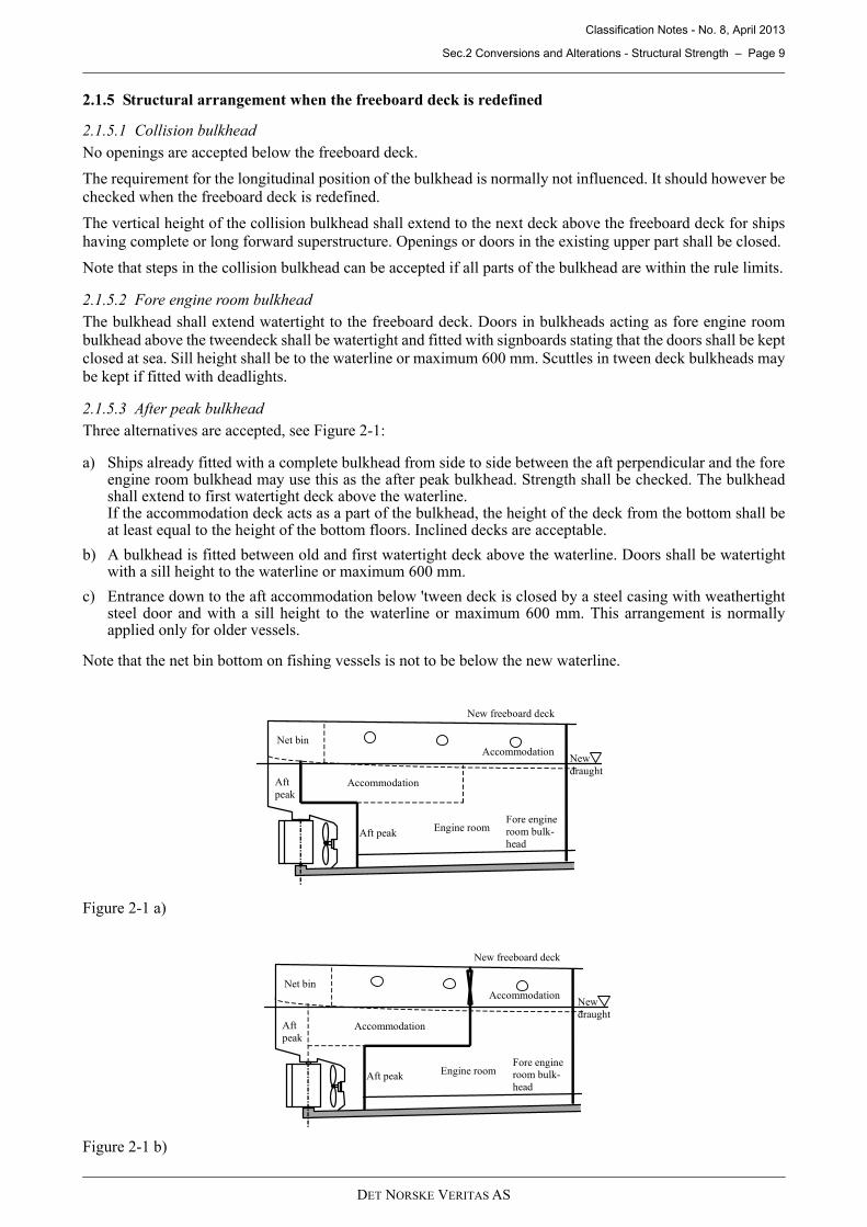
2.1.5.3 After peak bulkheadThree alternatives are accepted, see Figure 2-1:
a) Ships already fitted with a complete bulkhead from side to side between the aft perpendicular and the foreengine room bulkhead may use this as the after peak bulkhead. Strength shall be checked. The bulkheadshall extend to first watertight deck above the waterline. If the accommodation deck acts as a part of the bulkhead, the height of the deck from the bottom shall beat least equal to the height of the bottom floors. Inclined decks are acceptable.
b) A bulkhead is fitted between old and first watertight deck above the waterline. Doors shall be watertightwith a sill height to the waterline or maximum 600 mm.
c) Entrance down to the aft accommodation below 'tween deck is closed by a steel casing with weathertightsteel door and with a sill height to the waterline or maximum 600 mm. This arrangement is normallyapplied only for older vessels.
Note that the net bin bottom on fishing vessels is not to be below the new waterline.
Figure 2-1 a)
Figure 2-1 b)
Engine room
Net bin
Aftpeak
Accommodation
Accommodation
Fore engineroom bulk-head
Aft peak
New freeboard deck
Newdraught
Engine room
Net bin
Aftpeak
Accommodation
Accommodation
Fore engineroom bulk-head
Aft peak
New freeboard deck
Newdraught
DET NORSKE VERITAS AS
Classification Notes - No. 8, April 2013
Sec.2 Conversions and Alterations - Structural Strength – Page 10
Figure 2-1 c)
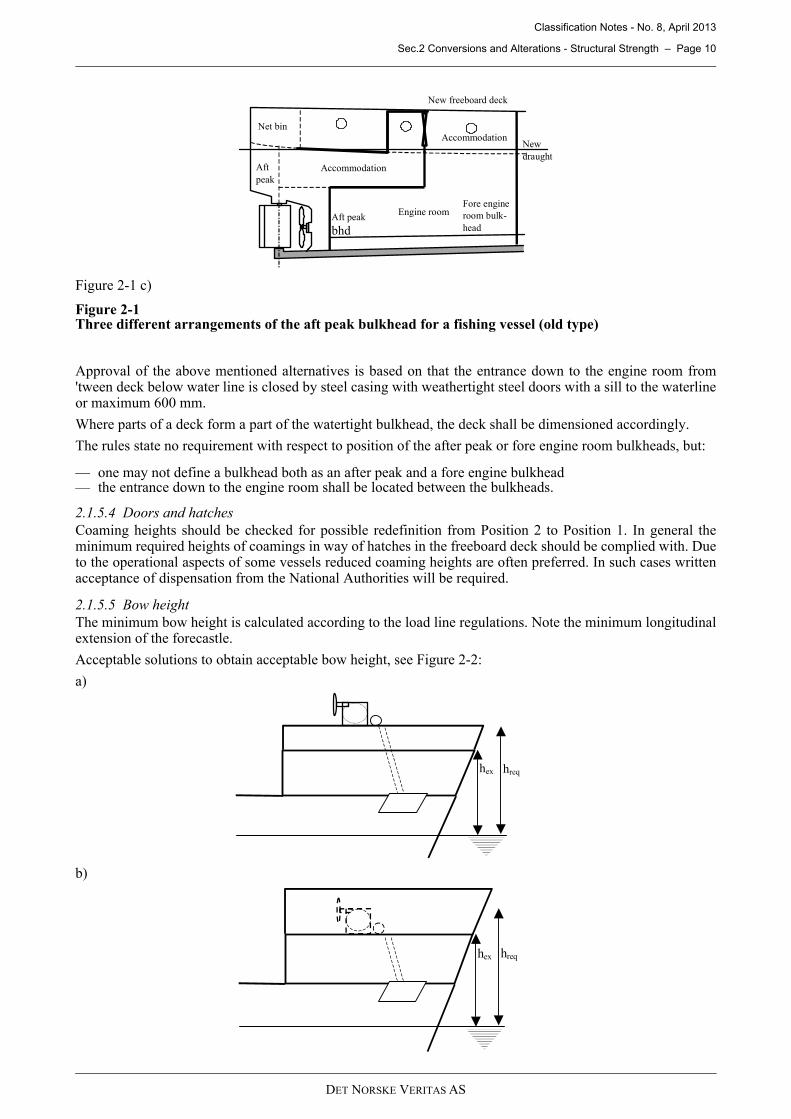
Figure 2-1Three different arrangements of the aft peak bulkhead for a fishing vessel (old type)
Approval of the above mentioned alternatives is based on that the entrance down to the engine room from'tween deck below water line is closed by steel casing with weathertight steel doors with a sill to the waterlineor maximum 600 mm.
Where parts of a deck form a part of the watertight bulkhead, the deck shall be dimensioned accordingly.
The rules state no requirement with respect to position of the after peak or fore engine room bulkheads, but:
— one may not define a bulkhead both as an after peak and a fore engine bulkhead— the entrance down to the engine room shall be located between the bulkheads.
2.1.5.4 Doors and hatchesCoaming heights should be checked for possible redefinition from Position 2 to Position 1. In general theminimum required heights of coamings in way of hatches in the freeboard deck should be complied with. Dueto the operational aspects of some vessels reduced coaming heights are often preferred. In such cases writtenacceptance of dispensation from the National Authorities will be required.
2.1.5.5 Bow heightThe minimum bow height is calculated according to the load line regulations. Note the minimum longitudinalextension of the forecastle.
Acceptable solutions to obtain acceptable bow height, see Figure 2-2:
a)
b)
Engine room
Net bin
Aft peak
Accommodation
Accommodation
Fore engineroom bulk-head
Aft peak
bhd
Newdraught
New freeboard deck
hex hreq
hreqhex
DET NORSKE VERITAS AS

Classification Notes - No. 8, April 2013
Sec.2 Conversions and Alterations - Structural Strength – Page 11
c)
Figure 2-2Examples of ways to increase the bow height
a) A new forecastle deck is built above the existing. Note that the space between the old and the new deckshall be arranged with access using a manhole or similar. This alternative may require that deck equipment(anchoring winches etc.) be removed and refitted on the new deck.
b) A new forecastle deck is built enclosing existing forecastle and the deck equipment. The new part shall bemade watertight and the anchor chain pipes shall be arranged with closing arrangements at the upper end.
c) New forecastle (fulfilling the minimum criteria).
2.1.5.6 Ventilators, air pipes, scuppers and dischargesIf the height of the air pipes is increased then the tanks shall be checked for the new design loads. DNV shallbe informed.
2.1.5.7 Openings when freeboard deck is redefinedOld freeboard deck drains shall be closed. The minimum height between the waterline and the light valves is500 mm.
If the rudder carrier is flooded, an additional sealing box shall be fitted.
2.1.6 Checklist for increased draught
1) watertight bulkheads:
— vertical extent— strength— position of collision bulkhead.
2) minimum bow height3) position of overboard discharges4) position of side scuttles5) doors in the ship's side6) position of rudder carrier7) hatchway coamings and covers8) ice belt:
— strength and vertical extent— min. required engine power for ice class.
9) longitudinal strength (if applicable)10) local strength:
— weather deck— forecastle deck— ship's sides— bottom— deckhouse front and sides.
2.2 Lengthening of vessels
2.2.1 Application of the rulesReference is made to the introduction, for general information.Lengthening of a vessel is always regarded as a conversion with regard to strength. This means that the currentrules apply with respect to local and global strength.
hreq
DET NORSKE VERITAS AS

Classification Notes - No. 8, April 2013
Sec.2 Conversions and Alterations - Structural Strength – Page 12
The design process to determinate the required scantlings for the new section should be similar as for a newbuilding. Scantlings of the new hull section must be in accordance with current rules i.e. the rule requirementsfor minimum thickness and minimum section modulus shall be complied with.
With respect to existing parts of the vessel, the minimum thickness requirements are normally not compliedwith if the vessel is lengthened. Usually, this can be dealt with as follows:
— If the minimum thickness complies with the newbuilding stage rules, no further considerations arenecessary, in this aspect.
— Deletion of class notations, e.g. Fishing Vessel, Supply Vessel or Offshore Service Vessel+, mayreduce the minimum requirements.
— Minor discrepancies are, in general, acceptable, provided the strength is acceptable.
The design still water bending moments and design loads (sea pressure, bow impact, slamming, accelerations)are directly dependent on the length. This means that the complete vessel has to be reassessed for strength.
It should be noted that minor strength discrepancies may be accepted as reduced corrosion margins if requestedby the owner. A Memo for Owner (MO) will be given in such cases.
2.2.2 Documentation requirementsThe following drawings and documentation are required to be submitted for approval or information, inconnection with lengthening of a vessel, see also Appendix I:
1) general arrangement
2) tank plan
3) midship section with material properties (new CB, speed and design draught to be stated on the drawing)
4) shell expansion
5) profile and deck plan
6) new section
7) design loading conditions or loading manual, see the rules
8) reinforcement of existing structure
9) docking plan (L > 100 m)
10) new equipment number calculation and proposal of upgraded anchoring equipment as far as relevant
11) intended class notations.
2.2.3 Longitudinal strengthThe coherence between a vessel’s length and required longitudinal hull girder scantlings, with respect tobending moments and shear forces is discussed here. Lengthening of a vessel will have an influence on bothstill water and wave induced hull girder loads. Global design loads, and acceptance criteria for the hull girder,are given in the Rules for Classification of Ships.
Figure 2-3Stillwater bending moments along the vessel length for L=100 m and L=130 m
The actual still water bending moments and shear forces on a hull girder is dependent on both the vessel’slength and type (hull shape and buoyancy, lightweight distribution and cargo distribution). The design stillwater bending moments, given by the rules, is a function of L3, i.e. an increase in the length will lead to a rapidincrease in the design bending moment, see Figure 2-3.
0
50000
100000
150000
200000
250000
300000
350000
400000
0 0,1 0,2 0,3 0,4 0,5 0,6 0,7 0,8 0,9 1Lengt h
kN m
DET NORSKE VERITAS AS

Classification Notes - No. 8, April 2013
Sec.2 Conversions and Alterations - Structural Strength – Page 13
Still water bending moment less than the rule design still water bending moment can be used provided relevantand realistic loading conditions are submitted for approval. For some types of vessel e.g. cruise vessels, whichoften are pure hogging vessels, zero (0) or the minimum hogging condition as design “sagging condition” canbe accepted.
Wave induced loads on the hull girder are also a function of the ship length. The rule design wave bendingmoments is a function of L3 i.e. increasing the length will imply a rapid increase in the wave bending moment,see Figure 2-4.
Figure 2-4Wave bending moment along the vessel length for L=100 m and L=130 m
From Figures 2-3 and 2-4, it may be seen that a 30% increase in length will lead to approximately 90% increasein both the rule still water and wave bending moment. In other words, the requirement to section modulus willincrease with 90% for a lengthening of 30%. The minimum requirement to the section modulus about thehorizontal neutral axis, which must be fulfilled for all vessels irrespective of loading conditions, will increasesimilarly.
2.2.3.1 Longitudinal strength evaluationScantlings of the new hull section must be in accordance with the current rules.
The existing vessel must be reassessed according to the current rules, based on the new length, and hence thenew design bending and shear forces. Such evaluation should include checking of the relevant cross sections,with respect to fulfilment of the rule requirements for section modulus, buckling control of longitudinalstructural elements and shear strength control. In addition, it shall be checked that the plate thickness isaccording to the rule minimum.
Minimum requirements for thickness are a function of the ship's length, see Table 2-1.
However, deficiencies of up to 10% can be accepted upon application from the Owners. Larger deviations,however thickness not to be taken less than minimum scantlings for steel renewal, may be accepted for limitedareas based on case-by-case consideration of the type of structure and stress level, the corrosive environmentand the applied coating. The steel renewal corrosion margin in the sailing phase will in such cases be reducedcorrespondingly, which will be reflected in a Memo to Owners (MO).
Example of MO:
“As a result of the lengthening of the vessel in 2012, the following structures no longer satisfy minimumthickness requirements, and therefore have a reduced corrosion margin:
— Longitudinal bulkhead 5600 mm from CL in compartment No. XX (rule minimum thickness = 10 mm,actual thickness = 9.5 mm).
— Longitudinal double bottom girder 8200 mm from CL, from #25 to #84 (rule minimum thickness = 11 mm,actual thickness = 10 mm).”
It should be noted that this type of deficiency cannot be accepted for ships covered by CSR Rules or hatch coverstructures covered by IACS Rules. Furthermore, the scantlings of plates or stiffeners shall in no case be lessthan required for compliance with relevant strength requirements. The scantlings of steel which is renewedshould in general be based on rule-required scantlings, in order to obtain a full corrosion margin.
Acceptance of deficiencies in scantlings must be based on performed calculations proving that both thelongitudinal and local strength of the vessel is satisfactory with the actual deficiencies, e.g. buckling control oflongitudinal strength elements such as bottom and strength deck plating. Corrosion addition, tk, according tothe rules, shall be deducted from the plate thickness when carrying out the buckling check.
DET NORSKE VERITAS AS

Classification Notes - No. 8, April 2013
Sec.2 Conversions and Alterations - Structural Strength – Page 14
The allowable stress in longitudinal strength members, when checking for lateral loads, is dependent on thelongitudinal hull girder stress. Members, which were acceptable before the lengthening, may fail to fulfil therule requirements after the lengthening, due to reduced allowable stresses.
2.2.3.2 Shear strengthThe rule wave shear forces will increase when a ship’s length is increased, see Figure 2-5.
Figure 2-5Wave shear force distribution along the vessel length for L=180 m and L=210 m
Evaluation of global shear strength is especially important for vessels with large or many openings in the sideshell, in way of the quarter length fore and aft. It is important to check both vertical and horizontal shear forpassenger and cruise vessels, which have many windows with a small distance between them. The allowableshear stress, shear buckling and secondary bending of shell plating between the windows shall be controlled.
For vessels with a relatively simple longitudinal structure (single skin vessel or vessel with continuouslongitudinal bulkhead(s)), rule values or the Nauticus Hull Section Scantlings shear flow analysis may be used.For more complex vessels, it may be required to carry out FEM analysis in order to achieve a satisfactory shearstress level.
2.2.3.3 Racking analysisFor vessels with large deck areas over several decks, without any transverse bulkhead in the cargo area, suchas ro-ro vessels and seismic research, racking analyses may be required. How the lengthening effects thevessel’s racking capacity has to be considered before racking analysis is required and the extension of such.
2.2.3.4 TorsionFor ships with large deck openings (total width of hatch openings in one transverse section exceeding 65% ofthe ship breadth or length of hatch opening exceeding 75% of hold length) the longitudinal strength includingtorsion may be required to be considered. This is normally only applicable for bulk carriers and containercarriers. Please see the following references:
— Rules for Classification of Ships Pt.5 Ch.2 Sec.6: “Container Carriers”— Classification Note 31.7: “Strength Analysis of Hull Structures in Container Carriers”— Rules for Classification of Ships Pt.5 Ch.2 Sec.5 “Bulk Carriers”— Classification Note 31.1: “Strength Analysis of Hull Structures in Bulk Carriers”.
2.2.3.5 Reinforcement of existing structureFor a newbuilding or a new section, it is normally not a problem e.g. to increase the plate thickness or the sizeof the longitudinals in order to achieve satisfactory section modulus or buckling capacity. Such proposals willin most cases be unrealistic for existing parts of a ship, due to the cost involved in first removing the oldstructure and then inserting a new structure, with the required scantlings.
Table 2-1 Typical minimum thickness requirements for some plates, corrosion addition tk is not included (mm)
Length, L (m) Bottom and sides Keel Strength deck Shell, ICE-C Bottom decks50 7 9.5 6.5 11.5 775 8 10.8 7 14.25 7.5100 9 12 7.5 17 8150 11 14.5 8.5 22.5 9200 12 17 9.5 25 10
DET NORSKE VERITAS AS

Classification Notes - No. 8, April 2013
Sec.2 Conversions and Alterations - Structural Strength – Page 15
Reinforcement of existing ships must therefore be based on what is possible to achieve bearing in mind theconversion cost involved. However, proposed reinforcement shall always comply with the rule requirement. Problems, which frequently occur for the existing structure, are:
1) Section modulus for the existing structure does not fulfil the rule minimum or the required section modulusbased on the new design bending moments and shear forces.
2) Buckling of longitudinal strength elements, such as bottom plating, strength deck plating, side shell platingetc. Transversely stiffened plating shall be especially considered.
3) The rule minimum thickness is not fulfilled for all structural elements.4) Torsion strength of vessel with large deck openings, i.e. a general cargo vessel with one large hatch
opening, open hatch container vessel. The longitudinal strength, including torsion may be required to beconsidered.
5) Shear strength in way of quarter length from AP and FP for vessel with many or large openings in the sideshell, e.g. cruise vessels.
The following reinforcements can be applied:
1) Fitting of doubler plates/straps on bottom, strength deck or at shear strake in order to increase the sectionmodulus, and hence reduce the longitudinal hull girder stress.
2) Increase breadth by fitting of sponsons, in order to increase the section modulus.3) Fitting intermediate stiffeners or longitudinals in order to increase both section modulus and buckling
capacity.4) Fitting buckling stiffeners.5) Doublers/straps on side shell in order to increase shear capacity or closing of windows or openings.
Acceptable ways to increase the section modulus by fitting doublers/straps, are described in 2.10.
2.2.4 Local strength generalThe following areas shall be considered with respect to strength:
— ship's side, especially fore and aft ship— bow impact affected area— slamming affected area— bottom— ice belt— weather decks, especially fore and aft ship— hatches— superstructures, especially front bulkhead.
2.2.5 Local strength - New sectionThe new section shall be checked with respect to requirements stated in the current rules.
2.2.6 Local strength - Existing parts of the ship
2.2.6.1 Structures exposed to sea loadsThe ship length is included in both the minimum sea pressure and the rule sea pressure. Increased length willhowever not result in a major change in the sea pressure.
E.g. given a ship with the particulars:
L = 50 m, B = 12 m, D = 10 m, T = 6 m, CB = 0.6, V = 15,
an increase of the length of 40% will only lead to a sea pressure increase of approximately 15% in way of FPat the base line. The pressure alteration will increase if the draught is less than given above.
Larger ships will generally experience a smaller pressure increase than smaller ships when the length is altered.Considering that CB increases with the length, one may experience that the sea pressure will remain unchangedwhen the ship is lengthened.
The percentage increase of sea pressure should be checked before detailed calculations are carried out. If thesea pressure increases by less than:
— 5%, then frames need not be checked— 10%, then plating need not be checked.
For increased draughts of less than 10% above the scantling draught, frames and plating need normally only bechecked in the fore and the aft ship.
DET NORSKE VERITAS AS

Classification Notes - No. 8, April 2013
Sec.2 Conversions and Alterations - Structural Strength – Page 16
It is however important to take rule changes into consideration. Old ships may have to be checked even forsmall sea pressure alterations, as the current rules are applied for conversions.
2.2.6.2 SuperstructuresThe front bulkhead shall be checked as the length of the vessel has major influence on the design pressure.
The superstructure sides should also be checked on the lower tiers, especially if the draught is increased.
2.2.6.3 Ship sides for bulk carriers or general cargo carriers with large hatch openings in deckThe ship side is carried by deep web frames or stringers or deck strips. If the latter carries the side and the cargospace is altered, these stringers or deck strips shall be checked according to the new span and sea pressure. Themost conservative load case shall be applied i.e. empty hold and maximum sea pressure (if applicable).
When applying a beam element model one should note that the hatch coaming will be the upper deck stripflange.
2.2.6.4 HatchesHatches that previously were located within Position 2 may after the ship lengthening be located withinPosition 1. Thus the requirement for hatch coaming height and strength increases. It is also to be noted that theminimum load on the hatches according to the loadline convention rules increases with the ship length.
2.2.6.5 SlammingThe area affected by slamming is always to be checked when the length is increased. The rule slammingpressure increases rapidly (over proportional) and almost linear with the ship length. The extension of the areaaffected by slamming will also increase, see Figure 2-6.
E.g. for a ship which is lengthened from 80 to 100 m (25%) with a forward minimum ballast draught of 3 m,the slamming pressure will increase by approximately 75%.
Discrepancies may be handled in the following ways:
a) Plating: Intermediate stiffeners are fitted or plating is renewed.
b) Stiffeners: Intermediate stiffeners are fitted or existing stiffeners are strengthened with brackets, additionalflanges or struts.
c) Shear area of bottom floors or girders: Manholes are closed, floors or girders are fitted with doublers,additional floors or girders are fitted.
d) Weight of ballast may be deducted. New load conditions apply.
Figure 2-6Slamming pressure for different ballast conditions as a function of the vessel length
In ships with large holds in the foreship, one may often find a shear area deficiency in bottom floors or girdersaccording to the rule formula. As additional steel in the bottom may become costly for the shipowner, it isimportant to know that it is possible to carry out a direct stress analysis of the bottom structure based on theslamming pressure.
The shear area summation formula is based on the fact that the slamming pressure is very local. The meanallowable shear stress is set to 100 N/mm2 and the slamming pressure is reduced as a function of the affectedarea.
500
700
900
1100
1300
1500
1700
1900
2100
2300
2500
100 103 106 109 112 116 119 123
Vessel lenght
Pre
ssu
re k
N/m
2
Tbf=2,0 m Tbf=3,0 m Tbf=3,5 m Tbf=4,0 m
DET NORSKE VERITAS AS

Classification Notes - No. 8, April 2013
Sec.2 Conversions and Alterations - Structural Strength – Page 17
— for an area (l × b) ≥ (L × B/20) a minimum pressure of p = psl /4 is applied
— (L × B/60) ≤ (l × b) ≤ (L × B/80) => p = psl /2
High bending stresses according to this model may be neglected as the slamming pressure is assumed to bepeaky.
2.2.6.6 Bow impactThe foreship need only be checked according to the bow impact pressure for ships with well-rounded bow linesand/or flare. The bow impact pressure increases significantly less (in %) than the slamming pressure when theship length is increased.
For direct calculations of girder or frame arrangements, the following parameters may be used:
— as the bow impact pressure is peaky, psl /2 is applied on the model— allowable shear stress: τ = 110 N/mm2
— allowable bending stress: σ = 235 N/mm2
— the girders are assumed simply supported at both ends.
2.2.6.7 Ice beltThe ice belt shall be especially considered. See 2.8.
2.2.7 Checklist for lengthening – strength
1) Documentation requirements (See Appendix A)
2) Watertight bulkheads
— number— position— collision bulkhead.
3) Minimum bow height
4) Anchoring equipment
— new equipment number— upgrading.
5) Longitudinal strength (if applicable)
— new midship section, Z0— new midship section, buckling— existing parts amidships, Z0— existing parts, buckling— shear strength— shear strength existing parts.
6) Local Strength
— new midship section— existing ship sides— ice belt— existing bottom— forecastle deck— slamming— bow impact— hatchway coamings and covers— deck house front and sides.
7) Minimum engine power requirements for ice class if applicable.
2.3 Increased breadth
2.3.1 GeneralIncreasing a vessel's breadth is performed by fitting sponsons to the ship's side. It may be carried out to reducedraught or to increase deadweight.
2.3.2 Documentation requirementsThe following documentation shall be submitted for approval, see also Appendix A:
DET NORSKE VERITAS AS

Classification Notes - No. 8, April 2013
Sec.2 Conversions and Alterations - Structural Strength – Page 18
1) new shell expansion and framing plan
2) steel structural details and welding details
3) proposal for new equipment number and updated anchoring equipment
4) new loading manual, if applicable.
For information:
1) general arrangement
2) tank plan.
2.3.3 The following shall be considered
1) Minimum thickness requirement for sponsons sides will be as for side shell. Similar for frames.
2) It is of outmost importance that the sponson framing is aligned with the existing frames, see Figure 2-7.
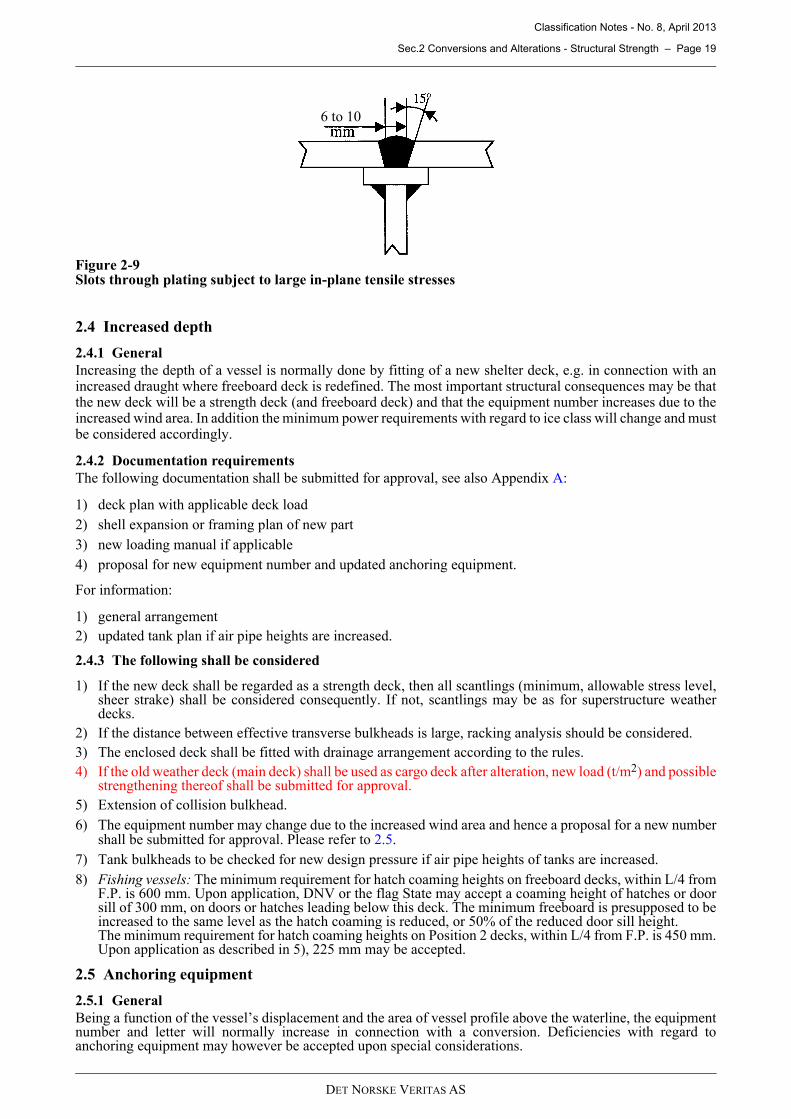
3) When the sponsons are tapered at the ends, slot welding of the shell plating to the frames will be acceptedwhere access is not possible, unless the vessel has assigned ice class notation, see below.The slot weld throat thickness is normally to be 0.6 t, see Figure 2-8 and 2-9. See the rules with regard tothe required arrangement of the slots in the plating.Closed spaces shall be conserved.
4) Ice belt and minimum engine power requirement.Sponsons in the ice belt shall be strengthened according to the assigned ice class notation and the minimumrequirements to engine power shall be checked accordingly. See 2.8.
5) The equipment number may change due to the increased displacement and wind area (factors of the rules’requirement to equipment number), and hence proposal for new number shall be submitted for approval.See 2.5.
Figure 2-7Alignment of sponson framing
Figure 2-8Slot welding of shell plate
0.6t
DET NORSKE VERITAS AS
Classification Notes - No. 8, April 2013
Sec.2 Conversions and Alterations - Structural Strength – Page 19
Figure 2-9Slots through plating subject to large in-plane tensile stresses
2.4 Increased depth
2.4.1 GeneralIncreasing the depth of a vessel is normally done by fitting of a new shelter deck, e.g. in connection with anincreased draught where freeboard deck is redefined. The most important structural consequences may be thatthe new deck will be a strength deck (and freeboard deck) and that the equipment number increases due to theincreased wind area. In addition the minimum power requirements with regard to ice class will change and mustbe considered accordingly.
2.4.2 Documentation requirementsThe following documentation shall be submitted for approval, see also Appendix A:
1) deck plan with applicable deck load2) shell expansion or framing plan of new part3) new loading manual if applicable4) proposal for new equipment number and updated anchoring equipment.
For information:
1) general arrangement2) updated tank plan if air pipe heights are increased.
2.4.3 The following shall be considered
1) If the new deck shall be regarded as a strength deck, then all scantlings (minimum, allowable stress level,sheer strake) shall be considered consequently. If not, scantlings may be as for superstructure weatherdecks.
2) If the distance between effective transverse bulkheads is large, racking analysis should be considered.3) The enclosed deck shall be fitted with drainage arrangement according to the rules. 4) If the old weather deck (main deck) shall be used as cargo deck after alteration, new load (t/m2) and possible
strengthening thereof shall be submitted for approval.5) Extension of collision bulkhead. 6) The equipment number may change due to the increased wind area and hence a proposal for a new number
shall be submitted for approval. Please refer to 2.5.7) Tank bulkheads to be checked for new design pressure if air pipe heights of tanks are increased.8) Fishing vessels: The minimum requirement for hatch coaming heights on freeboard decks, within L/4 from
F.P. is 600 mm. Upon application, DNV or the flag State may accept a coaming height of hatches or doorsill of 300 mm, on doors or hatches leading below this deck. The minimum freeboard is presupposed to beincreased to the same level as the hatch coaming is reduced, or 50% of the reduced door sill height.The minimum requirement for hatch coaming heights on Position 2 decks, within L/4 from F.P. is 450 mm.Upon application as described in 5), 225 mm may be accepted.
2.5 Anchoring equipment
2.5.1 GeneralBeing a function of the vessel’s displacement and the area of vessel profile above the waterline, the equipmentnumber and letter will normally increase in connection with a conversion. Deficiencies with regard toanchoring equipment may however be accepted upon special considerations.
6 to 10
DET NORSKE VERITAS AS
Classification Notes - No. 8, April 2013
Sec.2 Conversions and Alterations - Structural Strength – Page 20
2.5.2 Documentation requirementsNew equipment number calculations shall always be submitted for approval when considering;
— increased length L, breadth B or depth D— additional superstructures or other new structures that considerably increase the wind exposed area.
Note that an increased draught does not normally alter the vessel’s equipment number as the decreased windexposed area compensates for the increased displacement. DNV, therefore, does not normally requirecalculations in these cases.
See also the rule guidance in regard to mooring and towing lines.
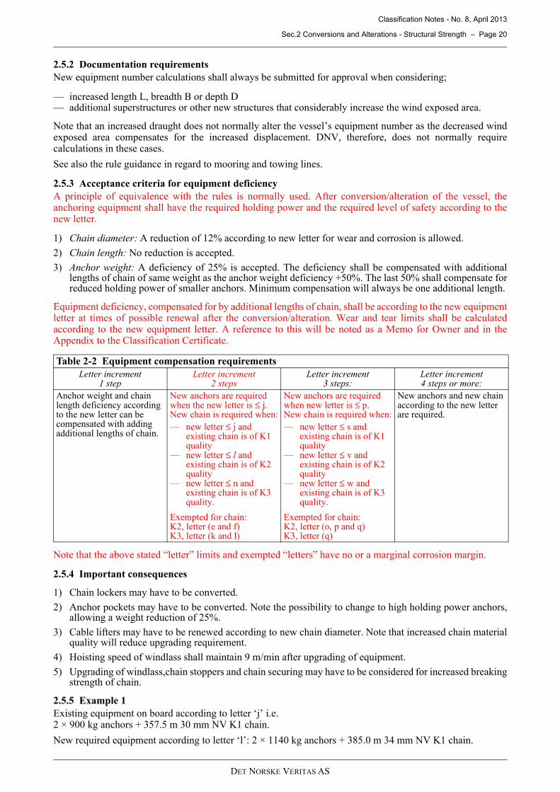
2.5.3 Acceptance criteria for equipment deficiencyA principle of equivalence with the rules is normally used. After conversion/alteration of the vessel, theanchoring equipment shall have the required holding power and the required level of safety according to thenew letter.
1) Chain diameter: A reduction of 12% according to new letter for wear and corrosion is allowed.
2) Chain length: No reduction is accepted.
3) Anchor weight: A deficiency of 25% is accepted. The deficiency shall be compensated with additionallengths of chain of same weight as the anchor weight deficiency +50%. The last 50% shall compensate forreduced holding power of smaller anchors. Minimum compensation will always be one additional length.
Equipment deficiency, compensated for by additional lengths of chain, shall be according to the new equipmentletter at times of possible renewal after the conversion/alteration. Wear and tear limits shall be calculatedaccording to the new equipment letter. A reference to this will be noted as a Memo for Owner and in theAppendix to the Classification Certificate.
Note that the above stated “letter” limits and exempted “letters” have no or a marginal corrosion margin.
2.5.4 Important consequences
1) Chain lockers may have to be converted.
2) Anchor pockets may have to be converted. Note the possibility to change to high holding power anchors,allowing a weight reduction of 25%.
3) Cable lifters may have to be renewed according to new chain diameter. Note that increased chain materialquality will reduce upgrading requirement.
4) Hoisting speed of windlass shall maintain 9 m/min after upgrading of equipment.
5) Upgrading of windlass,chain stoppers and chain securing may have to be considered for increased breakingstrength of chain.
2.5.5 Example 1Existing equipment on board according to letter ‘j’ i.e. 2 × 900 kg anchors + 357.5 m 30 mm NV K1 chain.
New required equipment according to letter ‘l’: 2 × 1140 kg anchors + 385.0 m 34 mm NV K1 chain.
Table 2-2 Equipment compensation requirementsLetter increment
1 stepLetter increment
2 stepsLetter increment
3 steps:Letter increment 4 steps or more:
Anchor weight and chain length deficiency according to the new letter can be compensated with adding additional lengths of chain.
New anchors are required when the new letter is ≤ j.New chain is required when:— new letter ≤ j and
existing chain is of K1 quality
— new letter ≤ l and existing chain is of K2 quality
— new letter ≤ n and existing chain is of K3 quality.
Exempted for chain:K2, letter (e and f)K3, letter (k and l)
New anchors are required when new letter is ≤ p.New chain is required when:— new letter ≤ s and
existing chain is of K1 quality
— new letter ≤ v and existing chain is of K2 quality
— new letter ≤ w and existing chain is of K3 quality.
Exempted for chain:K2, letter (o, p and q)K3, letter (q)
New anchors and new chain according to the new letter are required.
DET NORSKE VERITAS AS
Classification Notes - No. 8, April 2013
Sec.2 Conversions and Alterations - Structural Strength – Page 21
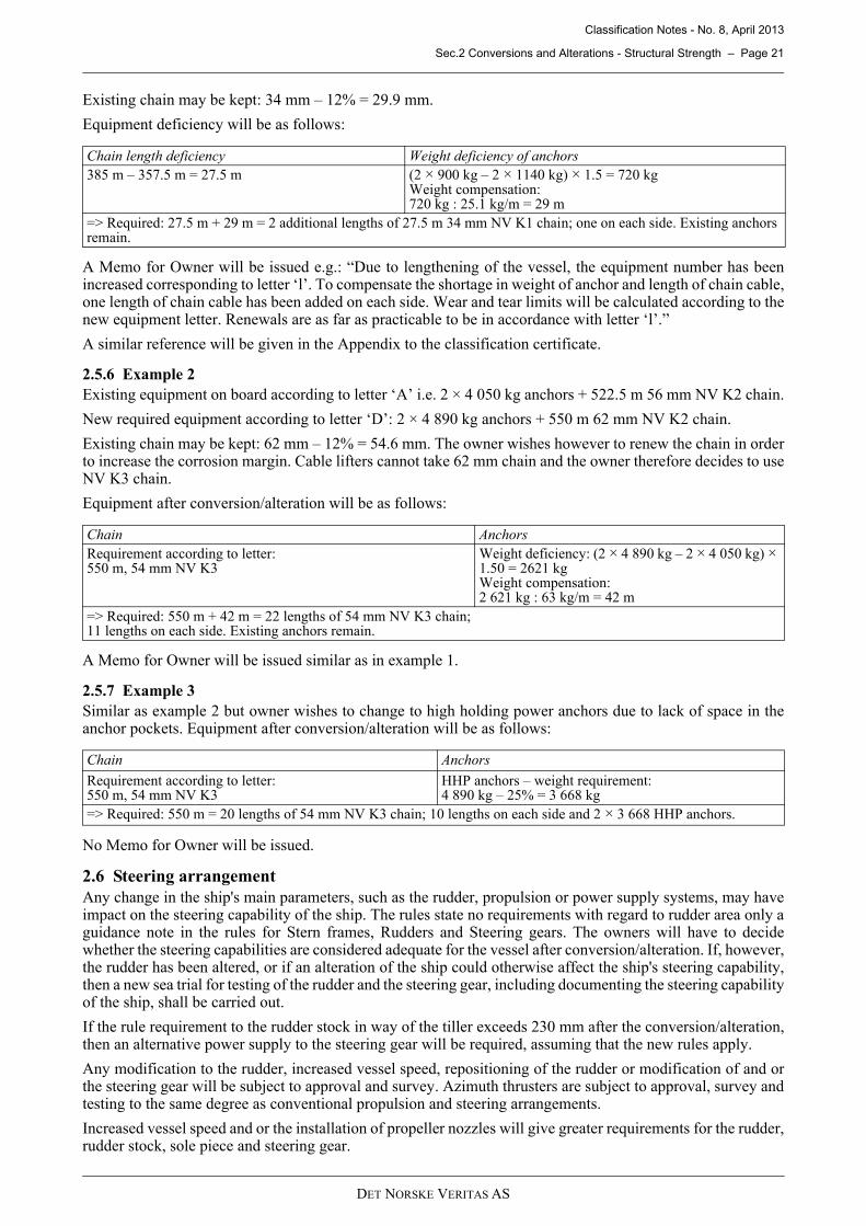
Existing chain may be kept: 34 mm – 12% = 29.9 mm.
Equipment deficiency will be as follows:
A Memo for Owner will be issued e.g.: “Due to lengthening of the vessel, the equipment number has beenincreased corresponding to letter ‘l’. To compensate the shortage in weight of anchor and length of chain cable,one length of chain cable has been added on each side. Wear and tear limits will be calculated according to thenew equipment letter. Renewals are as far as practicable to be in accordance with letter ‘l’.”
A similar reference will be given in the Appendix to the classification certificate.
2.5.6 Example 2Existing equipment on board according to letter ‘A’ i.e. 2 × 4 050 kg anchors + 522.5 m 56 mm NV K2 chain.
New required equipment according to letter ‘D’: 2 × 4 890 kg anchors + 550 m 62 mm NV K2 chain.
Existing chain may be kept: 62 mm – 12% = 54.6 mm. The owner wishes however to renew the chain in orderto increase the corrosion margin. Cable lifters cannot take 62 mm chain and the owner therefore decides to useNV K3 chain.
Equipment after conversion/alteration will be as follows:
A Memo for Owner will be issued similar as in example 1.
2.5.7 Example 3Similar as example 2 but owner wishes to change to high holding power anchors due to lack of space in theanchor pockets. Equipment after conversion/alteration will be as follows:
No Memo for Owner will be issued.
2.6 Steering arrangementAny change in the ship's main parameters, such as the rudder, propulsion or power supply systems, may haveimpact on the steering capability of the ship. The rules state no requirements with regard to rudder area only aguidance note in the rules for Stern frames, Rudders and Steering gears. The owners will have to decidewhether the steering capabilities are considered adequate for the vessel after conversion/alteration. If, however,the rudder has been altered, or if an alteration of the ship could otherwise affect the ship's steering capability,then a new sea trial for testing of the rudder and the steering gear, including documenting the steering capabilityof the ship, shall be carried out.
If the rule requirement to the rudder stock in way of the tiller exceeds 230 mm after the conversion/alteration,then an alternative power supply to the steering gear will be required, assuming that the new rules apply.
Any modification to the rudder, increased vessel speed, repositioning of the rudder or modification of and orthe steering gear will be subject to approval and survey. Azimuth thrusters are subject to approval, survey andtesting to the same degree as conventional propulsion and steering arrangements.
Increased vessel speed and or the installation of propeller nozzles will give greater requirements for the rudder,rudder stock, sole piece and steering gear.
Chain length deficiency Weight deficiency of anchors385 m – 357.5 m = 27.5 m (2 × 900 kg – 2 × 1140 kg) × 1.5 = 720 kg
Weight compensation:720 kg : 25.1 kg/m = 29 m
=> Required: 27.5 m + 29 m = 2 additional lengths of 27.5 m 34 mm NV K1 chain; one on each side. Existing anchors remain.
Chain AnchorsRequirement according to letter:550 m, 54 mm NV K3
Weight deficiency: (2 × 4 890 kg – 2 × 4 050 kg) × 1.50 = 2621 kgWeight compensation:2 621 kg : 63 kg/m = 42 m
=> Required: 550 m + 42 m = 22 lengths of 54 mm NV K3 chain; 11 lengths on each side. Existing anchors remain.
Chain Anchors
Requirement according to letter:550 m, 54 mm NV K3
HHP anchors – weight requirement:4 890 kg – 25% = 3 668 kg
=> Required: 550 m = 20 lengths of 54 mm NV K3 chain; 10 lengths on each side and 2 × 3 668 HHP anchors.
DET NORSKE VERITAS AS
Classification Notes - No. 8, April 2013
Sec.2 Conversions and Alterations - Structural Strength – Page 22
Note that a repositioning of the rudder stock will affect the ships length. DNV Approval Centre and the Flagstate shall be informed accordingly to determine new correct freeboard values.
The following documentation shall be submitted for approval:
1) Updated or new arrangement drawings of rudder, steering gear and steering compartment.
2) Drawings and particulars of all changes to azimuth thrusters, rudder, stock, bearing and steering gearinclusive all relevant piping and control and monitoring. systems. Material data and ratings shall bespecified.
3) Updated operating instructions (posters in wheel house and in steering gear compartment).
All new parts and relevant components shall be delivered with a DNV certificate.
The sea trial of the rudder and steering gear shall be carried out at full speed, i.e. the same conditions that arerequired for a new ship.
2.7 Mounting of bottom equipmentDocumentation, arrangement and strength of foundations for bottom equipment shall satisfy requirementsgiven in the Rules Pt.3 Ch.3 and Pt.4 Ch.5.
Due attention should be paid to the location of docking supports, to avoid damage to bottom equipment and itsfoundations.
2.8 Ice belt
2.8.1 GenerallyLongitudinal extension of forward, midship and aft ice region is dependent upon the vessel's length, its breadthand the given ice class notation. The vertical extension is dependent upon the ice class notation. The extensionand strength of the ice belt is very often utilised with regard to the initial draught. This means that the icestrengthening often fails to meet the requirement given by a possible new draught or a conversion, e.g.lengthening. Changes in displacement or in main dimensions L, B or T will require appraisal of machinerypower, shafting, propeller, in addition to structural strength, etc. Attention shall be paid to the extension of theice belt, in both directions.
DNV accepts that the class notation ICE-C be valid to a maximum specified draught, which is less than the newdraught. If such an arrangement is chosen, a reference to this will be given in the Appendix to the classificationcertificate and as a Memo for Owner. This procedure is not acceptable for the Baltic ice class notations.
2.8.2 ICE-C
1) Plating: The plating rule thickness formula is dependent on the vessel length L.
2) Frames: Dependent on L and the draught T.
3) Engine output: Dependent on displacement.
A deviation of 250 mm with respect to the extension of stiffeners may be accepted if the stiffeners areconnected to a deck or stringer in way of the upper end.
It is important to note that the rule requirements according to ICE-C need not be taken higher than for ICE-1C.This is important to check, if the plate thickness is too low or existing frames are under-dimensioned but haveshort spans (ICE-C framing requirement are not dependent on the frame span).
2.8.3 Baltic ice class notationsThe ice pressure is dependent on the vessel's displacement and its propulsion power. It is important to find thetotal ice pressure increase and consider the amount of checkpoints according to this.
— Ordinary and intermediate frames are generally to be checked if the ice pressure increases more than 5%.— The ice belt plating is generally to be checked if the ice pressure increases with more than 10%.
Design ice-pressure, increase with increasing displacement. In most cases this can be ignored. Only aconsiderable increase in draught will require the adjustment of the ice-pressure.
2.8.4 Strengthening in the ice beltIf the owner does not intend to carry out the required strengthening, the ice class notation will be deleted.
DET NORSKE VERITAS AS

Classification Notes - No. 8, April 2013
Sec.2 Conversions and Alterations - Structural Strength – Page 23
2.8.4.1 Shell platingDoublers/straps are normally accepted in connection with conversions/alterations or increased draught ofvessels, in order to fulfil the ice class requirements with respect to shell thickness. Where doublers/straps areto be used for increasing the shell thickness, the guidance below should be followed:
1) Minimum thickness of doublers is 10.0 mm.2) The breadth of doublers should not exceed 250 mm in the foreship and 325 mm elsewhere. Where slot
welds are accepted, the vertical distance should not exceed 325 mm.3) Adjacent doublers shall be connected with full penetration welding, see Figure 2-11.4) Welds along the doublers sides shall be at least:
a = 0.5 tdb, see Figure 2-11.Slot welds shall not be used in the foreship for ICE-1B and ICE-1C and shall not be used in the fore- andmidship for ice class ICE-1A*F, ICE-1A*, and ICE-1A.Where accepted, slot welds shall be completely filled with welding in the ice belt.
5) Thickness of doublers shall be determined by the following formula:
Figure 2-10Section A-A: Extending the ice belt vertical with doublers. Welding detail
Figure 2-11Section B-B: Welding of doublers to the shell
Figure 2-12Fitting of doublers
tice = required shell thickness for the given ice class (without tc)tex = existing shell thicknesstdb = required thickness of doublertc = increment for abrasion and corrosion (mm), normally 2 mm
= 2 − 2 +
6 to 10 mm
0.5 ×
tex
tice
A
A
B
Btdb
DET NORSKE VERITAS AS

Classification Notes - No. 8, April 2013
Sec.2 Conversions and Alterations - Structural Strength – Page 24
2.8.4.2 Side frames in the ice beltIce frames may be strengthened with additional flanges, new intermediate stiffeners, fitting of brackets orsupported by stringers (must be specially considered). Intermediate framing may have to be extended.
2.9 Strengthening for increased local loadsWhen increased environmental loading due to increased main dimensions or increased draught necessitatesstrengthening of the existing steel structure, some arrangements must be approved which are usually notapproved during a newbuilding phase.
2.9.1 Strengthening of platingIncreased sea pressure will seldom necessitate strengthening of plating. Such are usually required due toincreased:
1) slamming pressure2) bow impact pressure3) design load for decks4) tank loading5) ice belt extension or pressure6) longitudinal stress level.
In the four first cases, fitting of intermediate stiffening is often used. Refitting of plating may be necessary inextreme cases or when increased local loading is combined with increased longitudinal stresses. It may benecessary to strengthen existing stiffeners as well as adding intermediate.
SPS sandwich panels may be used as an alternative strengthening of plate areas, see Classification Note 30.11.The arrangement will be subject to case-by-case acceptance.
For areas where it may be accepted to use doubler plates to strengthen for lateral pressure, the arrangementshould in general comply with the following guidance. The plate thickness for a doubler should not be takenless than:
In regard to the ice belt, see 2.8. With respect to the increased longitudinal stress level, this is usually handledby fitting doublers, see 2.11.
2.9.2 Strengthening of stiffenersThe strengthening of stiffeners due to increased environmental loads or loads from new equipment is usuallyhandled in one of the three following ways:
1) The stiffeners’ end brackets are increased or new larger brackets are fitted. The alignment of supportingstructures shall be specially considered.
2) The stiffeners’ sections are increased by fitting of doublers or additional sections. The thickness of doublersshould not be less than 6.5 mm. The additional flanges shall extend beyond the existing end brackets.Where the sections are considerably increased, new brackets should be fitted.
3) The stiffeners are supported by girders, stringers or struts. Note that when girders are fitted on the outsideof a bulkhead, typical strengthening on the superstructure front connection area shall be applied, withbrackets.
See also Figures 2-13 and 2-14.
tdb = thickness of doubler platetR = rule required thickness tex = existing plate thickness
DET NORSKE VERITAS AS

Classification Notes - No. 8, April 2013
Sec.2 Conversions and Alterations - Structural Strength – Page 25
Figure 2-13Increasing sections of stiffeners
Figure 2-14Reducing stiffener spans
2.9.3 Strengthening of girdersGirders may be strengthened with regard to bending strength and shear strength, see Figures 2-15 to 2-17.
1) When strengthening girders in order to reduce bending stresses, the sections shall be increased in the sameway as for stiffeners. Doublers shall be extended beyond brackets. This may be done by slotting the doublerin way of the bracket or by making the section unsymmetrical. The latter will require additional trippingbrackets.
Figure 2-15Strengthening of girders for bending strength
1) To reduce shear stresses in girders, two solutions are normally acceptable:
a) Increase girder height.
b) Increase shear area by fitting a doubler. The doubler shall be located in way of the shear centre of thegirder. Doublers outside the shear centre will not be accepted.
Newbrackets
DET NORSKE VERITAS AS
Classification Notes - No. 8, April 2013
Sec.2 Conversions and Alterations - Structural Strength – Page 26
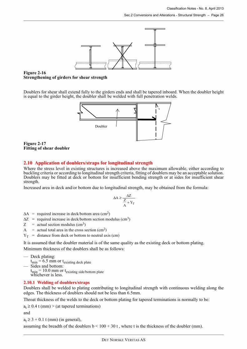
Figure 2-16Strengthening of girders for shear strength
Doublers for shear shall extend fully to the girders ends and shall be tapered inboard. When the doubler heightis equal to the girder height, the doubler shall be welded with full penetration welds.
Figure 2-17Fitting of shear doubler
2.10 Application of doublers/straps for longitudinal strengthWhere the stress level in existing structures is increased above the maximum allowable, either according tobuckling criteria or according to longitudinal strength criteria, fitting of doublers may be an acceptable solution.Doublers may be fitted at deck or bottom for insufficient bending strength or at sides for insufficient shearstrength.Increased area in deck and/or bottom due to longitudinal strength, may be obtained from the formula:
It is assumed that the doubler material is of the same quality as the existing deck or bottom plating.Minimum thickness of the doublers shall be as follows:
— Deck plating: tmin = 6.5 mm or texisting deck plate
— Sides and bottom: tmin = 10.0 mm or texisting side/bottom plate whichever is less.
2.10.1 Welding of doublers/strapsDoublers shall be welded to plating contributing to longitudinal strength with continuous welding along theedges. The thickness of doublers should not be less than 6.5mm.
Throat thickness of the welds to the deck or bottom plating for tapered terminations is normally to be:
at ≥ 0.4 t (mm) > (at tapered terminations)
and
at ≥ 3 + 0.1 t (mm) (in general),
assuming the breadth of the doublers b < 100 + 30 t , where t is the thickness of the doubler (mm).
ΔA = required increase in deck/bottom area (cm2)ΔZ = required increase in deck/bottom section modulus (cm3)Z = actual section modulus (cm3)A = actual total area in the cross section (cm2)YT = distance from deck or bottom to neutral axis (cm)
Doubler
TYAZ
ZA
+
Δ≥Δ
DET NORSKE VERITAS AS

Classification Notes - No. 8, April 2013
Sec.2 Conversions and Alterations - Structural Strength – Page 27
Where doubler plates are tapered within 0.2 L and 0.25 L, fore and aft of amidships, the weld area surroundingthe taper of each doubler should not be less than 1.75 x the doubler area. Where several doublers are terminatedin the same region, the sectional area A* of the strengthened part, see Figure 2-18, should not be less than:
Ai as defined in above formula and shown in Figure 2-18 as A1, A2 and A3 shall be taken as the area of doubler/strap no. i, i.e Ai = bdoubler,i ⋅ tdoubler,i
Figure 2-18Weld area in doubler ends
For doublers plates with breadth, b, exceeding:
b = 100 + 30 t, maximum 850 mm
welding through evenly distributed slots will be required.
2.10.2 Buckling check of doublers/strapsAll doublers/straps are to be checked against relevant buckling criteria in accordance with Rules Pt.3 Ch.1Sec.13, or Ch.2 Sec.12 for ships with L < 100m.
2.11 Ladder access by means of cut-outs in ships sideOccasionally, but mainly on fishing vessels, access ladders are arranged by cutting holes in the ships side. Eventhough longitudinal stresses may be relatively low cracks may arise unless adequate reinforcing is arranged. Asuitable and acceptable method is shown in Figure 2-19.
Figure 2-19Shell insert in way of ladder holes
It is, however, strongly recommended that such openings are positioned outside 0.4 L amidships, if possible.
where A0 is original shell plate area in way of doublers.
+>
=
n
1i
0i AA75.1*A
DET NORSKE VERITAS AS
Classification Notes - No. 8, April 2013
Sec.2 Conversions and Alterations - Structural Strength – Page 28
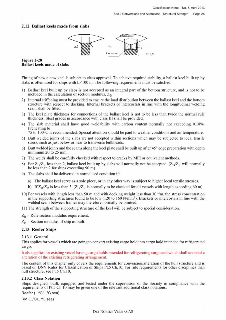
2.12 Ballast keels made from slabs
Figure 2-20Ballast keels made of slabs
Fitting of new a new keel is subject to class approval. To achieve required stability, a ballast keel built up byslabs is often used for ships with L<100 m. The following requirements must be satisfied:
1) Ballast keel built up by slabs is not accepted as an integral part of the bottom structure, and is not to beincluded in the calculation of section modulus, ZB
2) Internal stiffening must be provided to ensure the load distribution between the ballast keel and the bottomstructure with respect to docking. Internal brackets or intercostals in line with the longitudinal weldingseam shall be fitted.
3) The keel plate thickness for connections of the ballast keel is not to be less than twice the normal rulethickness. Steel grades in accordance with class III shall be provided.
4) The slab material shall have good weldability with carbon content normally not exceeding 0.18%.Preheating to 75 to 100oC is recommended. Special attention should be paid to weather conditions and air temperature.
5) Butt welded joints of the slabs are not accepted within sections which may be subjected to local tensilestress, such as just below or near to transverse bulkheads.
6) Butt welded joints and the seams along the keel plate shall be built up after 45° edge preparation with depthminimum 20 to 25 mm.
7) The welds shall be carefully checked with respect to cracks by MPI or equivalent methods.8) For ZB/ZR less than 2, ballast keel built up by slabs will normally not be accepted. (ZB/ZR will normally
be less than 2 for ships exceeding 90 m).9) The slabs shall be delivered in normalised condition if:
a) The ballast keel serve as a sole piece, or in any other way is subject to higher local tensile stresses.b) If ZB/ZR is less than 3. (ZB/ZR is normally to be checked for all vessels with length exceeding 60 m).
10) For vessels with length less than 50 m and with docking weight less than 30 t/m, the stress concentrationin the supporting structures found to be low (120 to 160 N/mm2). Brackets or intercostals in line with thewelded seam between frames may therefore normally be omitted.
11) The strength of the supporting structure of the keel will be subject to special consideration.
ZR = Rule section modulus requirement.
ZB = Section modulus of ship as built.
2.13 Reefer Ships
2.13.1 GeneralThis applies for vessels which are going to convert existing cargo hold into cargo hold intended for refrigeratedcargo.
It also applies for existing vessel having cargo holds intended for refrigerating cargo and which shall undertakealteration of the existing refrigerating arrangement.
The content of this chapter only covers the requirements for conversion/alteration of the hull structure and isbased on DNV Rules for Classification of Ships Pt.5 Ch.10. For rule requirements for other disciplines thanhull structure, see Pt.5 Ch.10.
2.13.2 Class NotationShips designed, built, equipped and tested under the supervision of the Society in compliance with therequirements of Pt.5 Ch.10 may be given one of the relevant additional class notations:Reefer (...ºC/...ºC sea)
RM (...ºC/...ºC sea)
a.) b.
Conserve
t
a= 0,6t
Intercoastals
DET NORSKE VERITAS AS

Classification Notes - No. 8, April 2013
Sec.2 Conversions and Alterations - Structural Strength – Page 29
2.13.3 Documentation requirements for hull structureThe following plans and particulars related to hull structure shall be submitted for approval:
1) Profile and Plan
2) Midship section
3) Framing plan/typical cross section for the freezing chambers
4) Structural details such as welding, material grade etc.
Reference is made to the DNV rules for documentation requirements with respect to the refrigeration plant.
2.13.4 Strength evaluation
2.13.4.1 Material qualityThe material grade is normally to comply with the rule requirements specified in Pt.5 Ch.10 Sec.2 Table A1.
2.13.4.2 Deck PlatingThe existing grade of material of deck plating will normally be accepted except in local areas where the totaltensile stress level is high. This is typical in way of hatch corners, where deck girders are supported by pillarsor where deck girders tie into rigid structures such as bulkheads or deep web frames (Figure 2-21). In such areasnew plating with material grades complying with Pt.5 Ch.10 Sec.2 shall be inserted.
Figure 2-21Strengthening of deck plating exposed to tensile stresses
2.13.4.3 Strengthening of girdersMaterial quality of flanges of deck and side girders exposed to tensile stresses shall be upgraded to comply withthe rule requirements. Alternatively doublers on the girder flanges with correct material grade could beaccepted (Figure 2-22). When calculating the section modulus of the doubler strengthened girders, the materialnot complying with the quality requirements shall be deducted from the calculations. Hence, only the shadedarea shown in Figure 2-22 and Figure 2-23 can be included in the section modulus of the girder.
Figure 2-22Strengthening of girders
If webs of deck and side girders are exposed to shear stress levels higher than 60 N/mm2, the material gradeshall be upgraded. Doubler plates with correct material grade will be accepted provided it is welded with fullpenetration, see Figure 2-25.
Tweendeck
1.5 m
1.5 m1.5 m Hatch
Pillars below
Full penetration welding
DET NORSKE VERITAS AS

Classification Notes - No. 8, April 2013
Sec.2 Conversions and Alterations - Structural Strength – Page 30
Figure 2-23Shear strengthening of girders
2.14 Installation of special fixed ballast materials
2.14.1 GeneralThe following is based on USCG's Circular from 1982:
NAVIGATION AND VESSEL INSPECTION CIRCULAR No. 5-82
When fixed ballast is installed, the following Memo to Owners shall be given:
“Tank(s)........... have been filled with ........ tons (m3) of fixed ballast of the type ........, with a specific gravityof ......... t/m3.
The ballast shall be removed for the survey of the tanks on request from the Society.”
2.14.2 Fixed ballast, generalFixed ballast may be installed to increase stability on new or existing vessels. If fixed ballast is to be usedaboard vessels requiring inclining tests, it should be installed prior to conducting the test. On existing vessels,addition or removal of fixed ballast may require that a new inclining test is performed on the vessel. The massand location of fixed ballast on such vessels should be included in the stability calculations.
The use of high density materials for fixed ballast installations may cause excessive structural loading on avessel. Therefore, the following plans and calculations may be required to be submitted for approval:
1) An arrangement plan showing proposed types, locations and quantities of fixed ballast.
2) A capacity plan showing the original capacity of each space in which fixed ballast will be installed.
3) A structural evaluation of each fixed ballast compartment for the mass and location of the proposed ballastinstallation.
Special arrangements may be necessary to provide proper ventilation and to facilitate the installation andinspection of the ballast material. The following guidance applies to all fixed ballast installations:
1) Each ballast tank should be fitted with vents to the weather deck. Flame screens should be installed iforganic decay is possible.
2) Fixed ballast should not be installed in tanks containing piping systems that require inspection. If fixedballast must be installed in such tanks, a pipe tunnel or other suitable arrangement should be made to permitinspection of the piping.
3) The ballast material should be properly secured to prevent shifting in severe weather.
4) Inspection openings should be provided in each corner of the ballast space for detection of shifting orsettling of the material or seepage of water into the ballast space. Manholes may be provided for thispurpose in double bottom tanks. If concrete caps are used to secure the ballast, ullage pipes at least 200 mmin diameter should be fitted in the concrete to permit inspection of the ballast material.
5) An expansion trunk should be provided which is adequate for the maximum volumetric expansion of liquidballast.
6) Plans showing ventilation of the fixed ballast space, the securing arrangement of the ballast material, andall closure plate installations for openings cut in the vessel structure may be required to be submitted forapproval.
Weather deck
Freezer hold
Freezer hold
Tween deck
DET NORSKE VERITAS AS
Classification Notes - No. 8, April 2013
Sec.2 Conversions and Alterations - Structural Strength – Page 31
Fixed ballast is often installed in compartments or tanks that would normally be examined for deteriorationduring periodic inspections. The following procedures may be followed in lieu of emptying fixed ballast tanksat each inspection period:
1) The atmosphere in each tank should be sampled and analysed by a certified marine chemist who shouldfollow the provisions of NFPA 306 to determine if gas evolution is present.
2) All fixed ballast installations should be accessed through the ullage openings provided. The ballast materialshould be inspected for shifting, settling and excessive moisture. Visible change to the ballast material maybe cause for removal and additional inspection.
3) If a bacteriostatic agent is required, a sample of ballast fluid from the mid-depth of each tank should beremoved for analysis to determine the bacteriostatic agent residual and the presence of any methane gas orgas producing bacterin. If there is evidence that the bacteriostatic agent residual is inadequate to preventbacterin growth, the fluid should be pumped out and supplied with a bacteriostatic agent.
4) If installed, the tank material test pieces should be examined to determine the apparent type and rate ofcorrosion. If there is indication that extensive or accelerated corrosion is taking place the ballast materialshould be pumped out and the tank cleaned for internal examination.
Plans, calculations and procedures for approval of fixed ballast installations should be submitted in one co-ordinated package. DNV's approval of the package should be obtained prior to installation of the ballastmaterial.
2.14.3 Fixed mud ballastSpecial drilling mud type fluids (Baryte) may be used as fixed ballast, under the following provisions:
1) Bacteriostatic agent. A bacteriostatic agent effective against aerobic as well as anaerobic bacteria shouldbe thoroughly mixed with the fluid in accordance with the manufacturer's specifications.
2) Anticorrosivity. The pH factor of the fluid should be adjusted to a value which minimise corrosion for theparticular metals involved. Corrosion inhibitors may be added to the fluid, but they should not interferewith the action of the bacteriostatic agent or affect the physical properties of the fluid such as suspension,viscosity, etc.
3) Settling. Fluids should have sufficient viscosity and gel strength to minimise settling of solids.4) Thermal expansion. Volumetric expansion should not be greater than four tenths of one percent (0.4%) over
a temperature range from -2°C to 30°C. 5) Freezing. The fluid should withstand a low temperature ambient of -2°C without freezing. Unless adjacent
to high temperature spaces, the expected maximum temperature of the ballast should be taken as 30°C.6) Proposed ballast. A sample of proposed ballast fluid should be prepared by the manufacturer and subjected
to at least a thirty day test to insure that all of the above requirements are fulfilled. A report of the test shouldbe made available to the surveyor prior to installation of the fluid.
7) Corrosion test plates. Corrosion test specimens, in the form of two 100 × 500 mm plates 10 mm thick andof the same material as the internal structure of the ballast tanks and welded together to form a plate 200mm wide, should be attached to the underside of the manhole cover on each expansion trunk for the ballasttanks in such a way that the corrosion test specimens hang down to the mid-depth of the ballast tanks. Apermanent record of the date of installation, thickness and weight of each corrosion test specimen shouldbe kept on aboard the vessel. Specimen thickness, weight and date of inspection should be placed in thisrecord after each inspection.
8) Air pockets. When pumping the fluid into the ballast tanks, care should be taken to eliminate all air pockets.Permanently installed ship's pumps or piping should not be used for handling the fluid.
DET NORSKE VERITAS AS

Classification Notes - No. 8, April 2013
Sec.3 Mobilisation with Temporary Installations – Page 32
3 Mobilisation with Temporary Installations
3.1 GeneralThis section covers definitions and class requirements to temporary installations installed on board vessels fora limited time period.
3.2 Temporary installations subject to class approvalThe temporary installations listed below are subject to class approval.
3.2.1 Units/equipment/systems/arrangementsThe following structures and units are subject to class approval:
a) Equipment/systems/arrangements covered by main functions as defined in Pt.1 of the Rules or classnotations
b) Superstructure units manned or operated independent of weather conditions
c) Superstructures units, storage units and offshore service containers containing equipment covered by mainfunctions or class notations
d) Mezzanine decks or other structures being used by the crew as work deck, cargo deck or supporting itemslisted in this subsection
e) Any equipment installed for temporary alteration of the hull girder strength or buoyancy, e.g. additionalbuoyancy elements or similar
f) Mobilisation with special equipment introducing new operational work tasks for the vessel is subject tocase-by-case evaluation if the equipment and foundations are subject to class plan review; e.g. mobilisationwith equipment to operate as well stimulation vessels will introduce class requirements to plan approval.
3.2.2 Foundation for units or equipmentFoundations for the following types of equipment are subject to class approval:
a) Man-riding equipment, such as work boat davits, life boat davits or similar.
b) Diving support systems.
c) Storage units where the local support foundation forces are exceeding the vessel deck capacity.
d) Machinery equipment, winches, lifting equipment as defined in Pt.3 Ch.3 Sec.5 and not exempted in 3.4.
e) All items listed under 3.2.1.
3.2.3 Use of Offshore Service ContainersOffshore Service Containers of type Ship Service Container which have been certified by DNV to our Standardfor Certification No. 2.7-2 “Offshore Service Containers” will normally comply with the classification andstatutory requirements described in this Classification Note, but installation and connections must be approvedin each case. The certificate for the service container will include information on conditions for temporaryinstallation on ships.
It is recommended that also temporarily installed service containers which are not subject to class approval becertified to DNV Standard for Certification No. 2.7-2 “Offshore Service Containers”. This ensures that thecontainers are fit for use on ships, and the certificates provide information on conditions for temporaryinstallation.
3.2.4 Tanks and storage unitsTanks and storage units, including relevant systems and equipment used for carriage of low flashpoint liquids,dangerous goods or chemicals, are subject to class approval.
Tank containers for dangerous goods that are certified according to the IMDG Code are considered to complywith class requirements and can be used as storage tanks, but installation and connections must be approved ineach case.
Foundations for storage units are subject to class review if the local support foundation forces exceed theapproved deck capacity. Uncertified purpose-built tanks and storage units used for carriage of dangerousliquids are subject to class appraisal before being installed.
General notes:
1) Certificates of temporary equipment, life-saving appliances and or man-riding equipment are requested asfor permanent equipment.
DET NORSKE VERITAS AS

Classification Notes - No. 8, April 2013
Sec.3 Mobilisation with Temporary Installations – Page 33
2) Mobilisation with temporary installations covered by the rules shall be carried out by qualified personneland in compliance with applicable rules, with good engineering practice and under the supervision of asurveyor.
3) Independent of the above-mentioned categories, class can be contacted for an evaluation of relevantapplicable requirements of unconventional temporary installations.
3.3 Plans and documentationPlans and documentation of temporary installations covered by 3.2 shall be submitted for approval. Thedocumentation requirements are the same as for permanent installations and are listed in relevant parts of therules.
3.4 Temporary installation of small deck-mounted equipment and storage units exempted from class reviewSections 3.4.1 and 3.4.2 provide terms and conditions upon which foundations for temporary deck equipmentand storage units may be exempted from class approval according to the Rules Pt.3 Ch.3 Sec.5.
3.4.1 General criteriaIn order for a foundation to be exempted from approval, the following general criteria shall be fulfilled.
1) The deck on which the unit is mounted shall be approved for a uniform load of 5 t/m2 or more.2) The SWL and static overturning moment of the equipment must not exceed 6 t and 10 tm, respectively.3) Support brackets and welding of the foundation directly onto deck shall be arranged such that no part of the
foundation is terminated on unsupported deck plating.
3.4.2 Special criteria This subsection provides examples of typical items which may be exempted from class approval, along withassociated special criteria which shall be fulfilled in addition to those given in subsection 2.4.1.
a) Fixed support points in way of pad eyes or similar may be exempted from approval provided that thefoundation of the support point is directly aligned with underlying primary deck structures, such as deepgirders or bulkheads, or supported by at least two secondary structures, such as stiffeners or carlings/brackets.
b) Deck-mounted winches or other pulling accessories, such as that exemplified in Figure 3-1, may beexempted from approval provided that the distance (h) from the foundation base to the acting SWL versusthe horizontal foundation extent (b) does not exceed the figures given in Table 3-1. Linear interpolationmay be used to establish acceptable arrangements for operational design load limits between those listed inthe table. The foundation shall, as a minimum, be securely fastened in four corners.
Table 3-1 Maximum moment arm for SWL of 6t versus size of foundationDeck load (ton/m2)
Maximum moment arm for SWL of 6t versus size of foundation.
5.0 t/m2 h ≤ 0.50·b6.0 t/m2 h ≤ 0.65·b8.0 t/m2 h ≤ 0.85·b10.0 t/m2 h ≤ 1.05·b12.0 t/m2 h ≤ 1.30·b15.0 t/m2 h ≤ 1.60·b20.0 t/m2 h ≤ 2.10·b
DET NORSKE VERITAS AS

Classification Notes - No. 8, April 2013
Sec.3 Mobilisation with Temporary Installations – Page 34
Figure 3-1Foundation for typical pulling appliance
c) Deck stiffener capacity to support single footprint load from pulling accessories and other deck-mountedunits:Table 3-2 gives the minimum deck capacity for a single footprint load, Fc (kN) or (t), supported by onedeck stiffener.
Table 3-2 is based on stiffener minimum span and spacing of 1.8 m and 0.6 m, respectively. I.e., withreference to below formula, the capacity, Fc, will increase for larger span and spacing. Linear interpolation may be used to establish acceptable arrangements for operational design load limitsnot listed in the above table. If the foundation arrangement exceeds the deck capacity as listed in Table 3-2 (or 3-1), then the deckstiffener capacity, Fc, to take a single vertical footprint force per stiffener (incl. dynamic factor) can beestimated as:
FC = 0.50·(g0+0.5av)·pc·s·l(kN)
1) Maximum operational static deck loads as specified in the Appendix to Classification Certificate.2) The design accelerations for deck cargo (g0+0.5av) can be simplified as 1.3·g0 or based on calculations/values from relevant part of the rules.
Footprint loads from winches and other pulling accessories shall be calculated based on SWL timesdynamic amplification factor (DAF), self-weight of the winch and winch geometry. Uneven loading causedby the wire’s extreme positions on the drum can normally be distributed with 80% and 20% of the load ontoeach side of the winch. Footprint loads for pulling accessories and other deck-mounted units shall be based on the loads given insubsection 3.7.
Table 3-2 Deck stiffener capacity, Fc, for single load (dynamic amplification included)Deck load capacity
(ton/m2)Deck capacity to take single load Fc per stiffener versus
deck design load capacity (ton/m2):5.0 t/m2 Fc = 35 kN (or 3.5t)6.0 t/m2 Fc = 40 kN (or 4.2t)8.0 t/m2 Fc = 55 kN (or 5.6t)
10.0 t/m2 Fc = 70 kN (or 7.0t)12.0 t/m2 Fc = 80 kN (or 8.4t)15.0 t/m2 Fc = 100 kN (or 10.5t)20.0 t/m2 Fc = 140 kN (or 14.0t)
pc = design load for deck 1) (t/m2)s = deck stiffener spacing (m)l = deck stiffener span (m)g0 = 9.81 (m/s2)av = vertical accelerations 2) (m/s2)
DET NORSKE VERITAS AS
Classification Notes - No. 8, April 2013
Sec.3 Mobilisation with Temporary Installations – Page 35
Limitations to use of doubler plates:
Doubler plates are normally not accepted as part of the support arrangement for tensile foundation forces. Forequipment delivered with “mounting pads” in way of thick doubler plates; it is required to arrange forunderlying deck structure being aligned with the welding of the “mounting pads”, see 3.5 for all support pointsbeing subject to tensile force. The local support of the foundation pads shall be evaluated for both maximumcompression and tensile forces. However, no mounting pads being subject to uplift forces shall be arrangedwith less than two (2) of the edges being supported. Structural support arrangement of such equipmentincluding doubler plates is subject to class appraisal for case-by-case acceptance.
Shimming plates introduced only to take compression loads may be allowed provided that they are arranged ina way that minimises load transfer from shimming plate corner onto unstiffened plate. I.e. this will normallyrequire a minimum of two supporting structures below the shimming.
If there is any doubt about the fastening arrangement or deck capacity, then class can be contacted for anappraisal of the securing and supporting structure.
3.5 Guidance to structural arrangement, welding and material grades for deck structure subject to uplift force
a) Supporting deck plates thicker than 15 mm shall comply with the Rules Pt.3 Ch.3 Sec.5 A303.
b) Ultrasonic lamination testing shall be carried out if the imposed load results in tensile stress exceeding100 N/mm2, unless the steel is of Z quality.
c) Underlying supporting structures aligned with tensile part of the support foundation shall, as a minimum,have a double continuous welding equivalent to the required welding of the foundation.
d) The foundation’s welding shall be aligned with welding of underlying structure.
3.6 Temporary installations of additional buoyancy units or units being mounted on the outside of the vessel hullAny temporary equipment being mounted onto the shipside or deck equipment extending outside of the vesselhull shall be evaluated for buoyancy, rule sea pressure or slamming pressure acting on the bottom and sides ofthe equipment.
3.7 Applicable loads for temporary installations
a) For pulling accessories, SWL times dynamic amplification factor shall be applied as per the Rules Pt.3 Ch.3Sec.5.
b) Acceleration loads on offshore service containers, stowed heavy equipment or deck cargo shall becalculated according to relevant parts of the rules.
c) Any temporary deckhouse, manned unit or service container which is subject to class approval accordingto 3.2.1 shall be evaluated for a minimum longitudinal acceleration of 0.5go in the forward direction and0.25go in the aft direction, to accommodate for safe securing in case of accidental collision, grounding orsimilar. Allowable bending stresses: 160f1 and shear: 90f1.
d) Temporary superstructure units, including offshore service containers which are subject to class approval,positioned on exposed weather decks shall be evaluated for green-sea pressure according to rules fordeckhouse/superstructure.
e) Units positioned on weather decks shall be evaluated for buoyancy loads when relevant.
f) Temporary deckhouses, storage units and offshore service containers which are protected from green seapressure by way of high cargo rails, bulwarks, protection bulkheads etc. can be evaluated for a reduced rulesea pressure. For the protected area of the units, the sea pressure need not be taken greater than thecalculated sea pressure value at the top of the protection bulkhead. The sea pressure should, however, notbe taken less than 50% of the rule sea pressure for unprotected side/aft bulkhead of the units, to take intoaccount possible washing of trapped sea water on weather deck.
g) For temporary units which are protected from green sea by means of a forward permanent superstructureas well as side protection by means of cargo rails or similar, buoyancy-induced uplift loads need only beevaluated for a water level up to 2.3 m above weather deck or hatch top.
3.8 Operational limitations Ship motion design loads caused by accelerations and sea pressure can be reduced according to the rules forrestricted service area RE, R4, R3, R2 or R1 if the mobilisation with temporary equipment is limited to be usedwithin the restricted service area. Similarly, the design accelerations and sea pressures can be reducedaccording to operational limitations in terms of sea state condition with maximum significant wave height Hs1.The reduced design loads shall then be established by direct sea-keeping analysis of the vessel performance inthe limited sea condition.
DET NORSKE VERITAS AS

Classification Notes - No. 8, April 2013
Sec.3 Mobilisation with Temporary Installations – Page 36
Accommodation units, other manned units and service containers which are subject to class approval accordingto 3.2.1 and without restriction to use in heavy weather shall, however, be evaluated for full rule loadsaccording to the vessel’s class notations, and may only be reduced if the vessel is assigned a service restrictionnotation. The design load values shall, however, not be taken less than the minimum rule value correspondingto a 50% reduction in Cw factor as given for the highest service restriction RE. Please refer to the Rules Pt.3Ch.1 and Pt.3 Ch.2.
Restriction to operational conditions will be issued as a Memo to Owner.
For mobilisations with temporary equipment limited to a maximum of 12 months’ operational period, the localscantlings may be calculated based on measured scantlings or actual corrosion margins, tk. The hull scantlingscondition shall be confirmed by a DNV surveyor if the scantlings evaluations are to be based on reducedcorrosion margins.
For Offshore Service Containers that are certified according to DNV 2.7-2 the allowable loads are specified intheir certificates. Each temporary installation of such containers shall be evaluated based on these allowableloads.1) It is recommended to evaluate the design wave height (Hs) according to Offshore Standard for Marine Operations DNV-OS-H101 depending on theoperational period, the distance to safe harbour and/or possibility to shut down the operation.
3.9 Fastening arrangement
3.9.1 Welded connectionsAll welded connections of temporary equipment subject to class acceptance shall comply with the rulesapplicable to permanent installations. Corrosion margins, tk, can however be neglected (or based on surveyedstatus) if the mobilisation is intended for a restricted mobilisation not exceeding 12 months. Use of single-sidedwelding of temporary equipment in areas exposed to sea water is subject to case-by-case acceptance for a timeperiod normally not exceeding 12 months. Such limitations to corrosion allowance, tk, for a restricted periodwill be reflected in a Memo to Owner (MO) stating that survey shall be carried out to confirm the condition ofthe weld at next annual survey.
3.9.2 TwistlocksAll fastening of temporary equipment subject to class acceptance by means of twistlocks shall comply with thefollowing:
a) The calculated footprint forces acting on the twistlock units shall be kept within the units’ allowable limits.Resulting forces in the twistlock calculated at normal load level (10-4 probability level) shall not exceed thetwistlock’s approved Safe Working Load.
b) Twistlocks shall be certified by DNV or recognised body according to CSS code Annex 13 (IMORequirements to Cargo Stowage and Securing).
c) Only manually operated twistlocks can be used, not semi-automatic or fully automatic twistlocks.
d) The twistlocks shall be secured in locked positions by means of a welded flatbar or equivalent measures.
e) If twistlocks are used as fastening for temporary equipment for a time period exceeding 12 months, thenclass will normally require that the twistlocks be included in the vessel’s annual survey. A Memo to Owner(MO) shall then be issued stating that “Twistlocks used for fastening of temporary equipment (list of units)shall be included in the annual survey. This mobilisation with temporary installations is scheduled to bedemobilised within (date). Any extension of the mobilisation period shall be agreed with class andapplication for extension shall be submitted no later than 3 weeks prior to termination day.”
3.9.3 Bolted connectionsUse of bolted connection is accepted as a means of fastening temporary equipment to the vessel main structure.The capacity of the bolt group connection can be evaluated based upon relevant recognized steel standards. Dueattention shall be paid to load application versus the capacity of the bolted connection. I.e., the capacity of thebolt group shall not be taken less than that of an equivalent welded fastening arrangement independent of theprobability level of the applied loads.
Shear stoppers shall normally be arranged in addition to the bolted connection used to secure temporaryequipment to the vessel main structure.
3.9.4 Padeyes and securing points Padeyes or other permanently fixed securing points may be used as part of the arrangement to fasten temporaryinstallations.
It should be noted that the main pad eyes used for offshore lifting of offshore containers are normally not suitedfor use as securing points.
DET NORSKE VERITAS AS

Classification Notes - No. 8, April 2013
Sec.3 Mobilisation with Temporary Installations – Page 37
3.9.5 Loose securing equipment Loose securing equipment/lashing equipment, such as cables, wires, chains or other lashing equipment, is ingeneral not accepted as primary securing of the equipment listed under 3.2, excluding units used for storageonly.
All loose securing equipment shall have a certificate issued by a recognized classification society.
3.9.6 Use of T-bars to secure temporary installations T-bars located on top of the deck can be used as part of main supporting structure for temporary equipmentprovided that they have been fully documented and surveyed by the classification; i.e. with respect toarrangement, material certification, scantlings and welding. Normally this is not the case as the T-bararrangement is not part of the standard class scope during newbuilding, and then the following restrictionsapply.
Fastening of temporary equipment to T-bars
The use of T-bars to support equipment foundations with compression forces or horizontal forces acting in theparallel direction of the T-bars is found acceptable provide the T-bar scantlings and welding are surveyed byclass.
Use of T-bars to support fastening of equipment with significant tensile foundation forces for temporaryequipment listed in 3.2 will normally require survey and documentation of material quality.
Due attention shall be paid to the limited capacity of the T-bars unless they are directly aligned with under-deckstructure.
3.9.7 Survey scopeDepending on the type and function of temporary installation or offshore service container, the Society willevaluate the need to survey the temporary fastening on case-by-case basis. A Memo to Owner (MO) shall beissued if the temporary securing/fastening arrangements shall be included in the regular class surveys.
3.10 Temporary accommodation units and other manned superstructure units
3.10.1 Application of the RulesAll temporary accommodation units, other manned units and service containers which are subject to classapproval according to 3.2.1 and which are used without weather restrictions shall be in compliance withapplicable rule requirements as if it was a permanent deckhouse on the vessel. Relevant plans showingdocumentation of the unit and its fastening to the vessel hull shall be submitted for class plan approval.
In addition to the above, documentation for compliance with Flag State requirements shall be submitted, see3.15.
3.10.2 Minimum thickness and buckling control of thin-plated structuresAny deviation from rule minimum thickness of plates and stiffeners is subject to case-by-case acceptance, onthe condition that the structural arrangement satisfies rule strength requirements. The minimum thickness shall,however, normally not be taken less than 4 mm.
Special attention should be paid to compliance with rule requirements to buckling control of thin-platedstructures subjected to compression stress in the face plate caused by local bending.
3.10.3 Foundation and fasteningThe fastening and supporting structure of the units shall be evaluated for ship accelerations and sea pressure asspecified in the Rules for Classification of Ships. For additional applicable loads, please refer to 3.7.
The fastening shall be of secured type, i.e. welded to the vessel hull by means of brackets or similar. Iftwistlocks are used as part of the sea fastening solution, then the twistlocks shall be of approved type andsecured in locked position.
3.10.4 Opening and closing appliances Temporary superstructure units which do not have access to openings to under-deck spaces or enclosedsuperstructures may, on case-by-case basis, be exempted from Load Line requirements. Arrangement ofsuperstructure units being exempted from Load Line requirements shall, however, normally comply with thefollowing:
1) All opening and closing appliances in way of doors or hatches shall be of weathertight type and havesufficient strength to comply with the rule sea pressure for deckhouses.
2) All windows glass thickness shall comply with strength requirement according to the Rules Pt.3 Ch.3 Sec.6L.
DET NORSKE VERITAS AS

Classification Notes - No. 8, April 2013
Sec.3 Mobilisation with Temporary Installations – Page 38
3) Arrangement of door sill height and position of ventilation shall as far as practical be in compliance withthe Load Line requirement and arranged to minimise the risk of water ingress to the unit; it is recommendedto arrange the door sill at minimum 380 mm above the weather deck.
4) Any arrangements of windows/side scuttles on first tier superstructure units are subject to case-by-caseacceptance.
3.10.5 LoadsFastening to the vessel main hull and strength of the unit itself shall be evaluated for ship acceleration and seapressure as if it was a permanent deckhouse. Reference is also made to 3.7 for additional applicable loads.
Special attention shall be paid to strength and support of the fastening details for any units which are exposedto direct green sea, or when units are raised above the deck.
The total sea pressure acting simultaneously on the whole superstructure unit (giving maximum reaction in thesea-fastening), may be calculated at the bottom of the unit and tapered off towards zero at the top of the unit.
3.11 Temporary deckhouse units being unmanned in heavy weatherUnder the assumption that the temporary unit in question is not to be manned during heavy weather withpossibilities for large amounts of green sea on deck, DNV may limit the strength review to cover the fasteningonto the deck and the supporting deck structure only. In such cases the unit itself is not subject to class approval.The fastening and supporting structure of the units shall be evaluated in the same manner as for mannedtemporary superstructure units as stated in 3.10. Reduction of rule loads may however be applied according tooperational limitations as described in subsection 3.8.
The limitation of class scope and use shall be stated in a Memo to Owner (MO), e.g.: “The (unit list) is/areapproved for fastening to the hull only and should not be manned in heavy weather with possibility of beingexposed to green sea”.
It is assumed that the owner will take appropriate measures to ensure that the units are unmanned in heavyweather, e.g. by means of signboards, procedures or similar.
Recommendation:
Although class does not require compliance with the rules for temporary units with restricted use, we stillrecommend that the units’ strength be designed according to the guideline for “temporary accommodation unitsand other manned superstructure units” as given in 3.9.7, or that they be certified according to DNV Standardfor Certification 2.7-2 “Offshore Service Containers”.
3.12 Diving support unitsDiving support system (DSS) and their foundations shall be in compliance with DNV rules Pt.5 Ch.16. Specialrequirements to applicable loads and allowable stress levels for DSS are given in Pt.5 Ch.16 Sec.3.
It should be noted that a DSS installed on a DNV vessel is required to hold a class certificate. The DSS does,however, not need be classed by DNV.
3.13 Class survey and mobilisation period for temporary installationA Memo to Owner (MO) stating the date when the temporary installation is intended to be demobilised will beissued for all temporary installations which are subject to class approval according to 3.2.1.
The class is to be contacted no later than 3 weeks prior to the termination of the mobilisation period for a classacceptance and reissuing of an updated MO if the captain intends to extend the accepted period of mobilisationwith temporary equipment.
Temporary equipment being mobilised for more than 12 months is subject to case-by-case evaluation if theinstallation and its foundations shall be included in annual or other regular class surveys.
Class survey of certified offshore service containers:
The suitability and condition of any offshore service containers which are subject to class approval accordingto 3.2.1 shall be assessed before they are installed on a ship. The offshore service container certificate shall beprovided to the DNV surveyor.
3.14 Temporary installations being in non-compliance with optional class notations Temporary installations shall comply with mandatory class notations applicable for the vessel. If temporaryequipment is installed, which results in non-compliance with optional class notations, e.g. Offshore SupportVessels+, a Memo to Owner (MO) will be issued stating the restrictions upon which the acceptance of thetemporary equipment has been based.
DET NORSKE VERITAS AS
Classification Notes - No. 8, April 2013
Sec.3 Mobilisation with Temporary Installations – Page 39
3.15 Statutory and non-structural requirements to temporary installations
3.15.1 Fire Safety
a) Temporary installations shall fully comply with the requirements for fire safety in SOLAS Ch.II-2,alternatively DNV Pt.4 Ch.10 Sec.2 for cargo ships of less than 500 grt. Relevant documentation shall besubmitted to Class and/or Administration for approval, or may upon special agreement with ResponsibleApproval Centre be endorsed by local surveyor.
b) “Fire control and safety plan” for mobilisations with temporary manned units or accommodation unitsshall be updated for the actual situation. The updated plans are subject to be endorsed by local surveyor oralternatively submitted for approval/information.
3.15.2 Internal Communication SystemsTemporary deckhouse units shall be arranged with public address and general alarm systems according to theLSA code as if it was a permanent installation.
3.15.3 Stability
a) It is the master’s responsibility to ensure that the vessel is operated within the approved stability limitswhen mobilising with temporary equipment. If in doubt, the class may be contacted for an evaluation ofwhether a new loading condition is subject to class/administration review.
b) If loading conditions with mobilisation of temporary equipment exceed the assumptions in the approvedstability conditions for the vessel (e.g. amount of deck cargo), an updated trim and stability booklet or anaddendum to the trim and stability booklet shall be submitted for class or administration approval.
3.15.4 Load LineFor mobilisations giving alterations to exposed decks; Relevant plans showing protection of crew according toPt.3 Ch.3 Sec.8 to be submitted for Class and/or Administration appraisal or endorsed by the local surveyor.
3.15.5 SOLASMobilisations with changes to number of crew or non-marine personnel shall be reported to class and/or FlagAdministration for evaluation of compliance with SOLAS.
3.15.6 Electrical Systems
a) Power supply for temporary units connected to the vessels socket outlets are not subject to class acceptance.
b) Power supply for temporary units with low-power consumables connected to the existing electricaldistribution board can be endorsed by the local surveyor.
c) Temporary units with high-power consumables exceeding 10% of the capacity for the existing electricaldistribution board are normally subject to class appraisal including review of load balance and single linediagrams.
d) Arrangement of independent power supply to the temporary units in way of temporary electrical generatorscan be endorsed by the local surveyor.
e) Class requirements to electrical cables:
— Cables for temporary equipment connected by sockets are not subject to class acceptance — All cables used for temporary equipment and terminated in a distribution board shall be of DNV type
approved type or subject to case by case approval. — Cables on skids or installed in container units are not subject to class acceptance.
3.15.7 Piping System
a) Plans showing connection of piping systems to the vessel main systems shall be submitted for classappraisal.
b) Plans showing arrangement of grey water or sewage water piping or connection to the vessel systems shallbe submitted for class appraisal.
3.15.8 Dangerous GoodsInformation regarding units used to carry dangerous goods, chemicals or flammable liquids covered by LFLnotation shall be submitted to class together with an addendum to the PA manual.
3.15.9 MARPOLTemporary installations of machinery or other potential pollution giving installations shall be in compliancewith MARPOL as if it was a permanent installation.
DET NORSKE VERITAS AS

Classification Notes - No. 8, April 2013
Sec.4 Mobilisation for Single Voyage – Page 40
4 Mobilisation for Single VoyageMobilisation for single voyage is normally associated with a specific transportation of cargo or equipment fromone specific area of departure to a specific arrival destination. The voyage may, however, be taken in severalsteps including possible transportation by heavy-lifter or similar. Class is in this respect only covering phasesof the voyage when the vessel is operated in normal sea-going condition with the cargo/equipment securelyfastened to the hull.
Class appraisal of single voyage is normally limited to hull strength requirements. Other requirements will behandled case by case depending on the Flag State.
Design loads such as hull girder wave moment, hull girder wave shear, ship accelerations and sea pressure canbe reduced according to limitation in operational sea state condition with maximum significant wave heightHs1. The reduced wave-induced hull girder design loads can be established through direct sea-keeping analysisof the vessel performance in limited sea condition. The design load values shall, however, not be taken lessthan the minimum rule value equivalent to a 50% reduction in Cw factor (equivalent to RE notation).
Restriction to operational conditions will be issued as Memo to Owner.
For single voyages carried out within 12 months after the mobilisation, the local scantlings may be calculatedbased on measured scantlings or actual corrosion margins tk. The hull scantling condition shall be confirmedby a DNV surveyor if the scantlings evaluations shall be based on reduced corrosion margins. 1) It is recommended to evaluate the design wave height (Hs) according to Offshore Standard for Marine Operations DNV-OS-H101 depending on theoperational period, the distance to safe harbour and/or possibility to shut down the operation.
5 Stability
5.1 DNV involvementDNV handles statutory stability when authorised by the flag Administration.
DNV handles intact stability as a class matter for vessels:
— built after 1991-07-01— having undergone a major conversion after 1991-07-01.
When stability is a class matter, but DNV is not authorised to approve stability on behalf of the flag State, DNVwill base the class approval on the approval by the Administration, if possible. The final stabilitydocumentation carrying the approval stamp of the Administration shall then be submitted for class approvaland for class records together with the Administration’s approval letter. Preliminary documentation need notbe submitted, nor will it be necessary to submit an inclining test/lightweight survey procedure or report or toattend at the test.
Note that some class notations such as Tug, Offshore Service Vessel, SF, Crane Vessel and CRANE containintact or damage stability requirements that may not have been covered by the flag state approval. See TableD1 in the Rules for Classification of Ships Pt.3 Ch.3 Sec.9 for a full list. In these cases it will be necessary forDNV to be involved from the preliminary stage.
5.2 Increased draught
5.2.1 GeneralThis is normally not regarded as a conversion, see 2.1.2. Thus, the converted ship must continue complyingwith the same intact and damage stability requirements, previously applied to the ship at new summer load linedraught (and timber draught, if relevant). Note, however, that for a dry cargo ship over 80 m in length whereno damage stability requirements have previously been in force, it may be necessary to submit damage stabilityindex calculations demonstrating that the level of subdivision is not less than before the conversion. This shallbe decided by the flag Administration.
5.2.2 Documentation requirementsThe following documentation will be required for all ships:
— stability booklet or loading manual including loading conditions, hydrostatic data, cross curves and limitingstability data covering the new maximum draught.
Where damage stability requirements are applicable:
— damage stability calculations covering the loading conditions in the stability booklet or loading manual ordamage KG/GM limiting curves for the full draught range.
DET NORSKE VERITAS AS

Classification Notes - No. 8, April 2013
Sec.5 Stability – Page 41
For passenger ships:
— floodable length calculations.
For dry cargo ships over 80 m in length where no damage stability requirements have previously been in force,when required by the flag Administration:
— calculation of A/R ratio for the ship before and after the conversion as required by MSC.1/Circ.1246.
For ships carrying grain cargo:
— grain stability booklet including loading conditions and maximum allowable heeling moments covering thenew maximum draught.
For ships with a loading instrument approved with respect to stability:
— test loading condition at new maximum draught— stored characteristic data for the increased draught range.
When strengthening and/or other conversion work changes the light ship particulars (see also 5.5):
— inclining test procedure— inclining test report.
In the latter case, preliminary versions of the stability booklet or loading manual and damage stabilitycalculations will also be required.
5.2.3 Survey pointsTo meet damage stability requirements at the increased draught, it may be necessary to increase air pipeheights, install weathertight or watertight doors, etc. In these cases it is very important that the position ofopenings with type of closing appliances assumed in the damage stability calculations, are verified by thesurveyor.
5.3 Major conversions“Major conversions” as used below refers to IMO definitions.
5.3.1 GeneralThis covers change in main dimensions (see also 1.4). The ship shall comply with the rules and statutoryrequirements currently in force for new ships. The exception is existing dry cargo ships over 80 m in lengthwhere no damage stability requirements have previously been in force, where it may be sufficient to prove thatthe level of subdivision is not less than before the conversion. This shall be accepted by the flag Administration.
Change of ship type is regarded as a major conversion according to SOLAS. The ship shall comply with therules and statutory requirements currently in force for new ships (no exceptions). As an example, a cargo shipconverted to a passenger ship shall comply with the regulations in force for new passenger ships regardless ofthe date of construction.
5.3.2 Documentation requirementsThe following will be required for all ships:
— preliminary and final stability booklet or loading manual— inclining test procedure— inclining test report.
Where damage stability requirements are applicable:
— preliminary and final damage stability calculations— internal watertight integrity plan.
For passenger ships:
— floodable length calculations.
For dry cargo ships built from 1992-02-01 and onward and for passenger ships:
— damage control plan— damage control manual.
For change in main dimensions of a dry cargo ship over 80 m in length where no damage stability requirementshave previously been in force:
DET NORSKE VERITAS AS
Classification Notes - No. 8, April 2013
Sec.5 Stability – Page 42
— calculation of A/R ratio for the ship before and after the conversion as required by MSC.1/Circ.1246.
For ships carrying grain cargo:
— preliminary and final grain stability booklet— grain loading plan.
For ships with a loading instrument approved with respect to stability:
— test loading conditions— stored characteristic data.
5.3.3 Survey points
1) Verification onboard of internal watertight integrity plan or damage control plan will be required.
2) Existing cross-flooding valves, spindle extensions and cross-flooding pipes in older ships are susceptibleto corrosion and should be examined and tested in connection with the verification of the damage controlplan.
5.4 Internal modifications
5.4.1 GeneralThe converted ship must continue to comply with the same intact and damage stability requirements, at least to thesame extent as before the modification. Modifications to tanks and cargo spaces may make it necessary to reviseloading conditions and tank or hold data. Similarly, the damage stability may be influenced by internalmodifications and therefore need revision.
Note that for a dry cargo ship over 80 m in length where no damage stability requirements have previously beenin force, it may be necessary to submit damage stability index calculations demonstrating that the level ofsubdivision is not less than before the conversion.
5.4.2 Documentation requirementsThe following will be required for all ships:
— stability booklet or loading manual including updated loading conditions and tank or cargo space data.
Where damage stability requirements are applicable:
— damage stability calculations covering the loading conditions in the stability booklet or loading manual ordamage KG/GM limiting curves.
For passenger ships:
— revised floodable length calculations.
For dry cargo ships over 80 m in length where no damage stability requirements have previously been in force:
— calculation of A/R ratio for the ship before and after the conversion as required by MSC.1/Circ.1246.
For ships carrying grain cargo:
— grain stability booklet including updated loading conditions and cargo hold volumetric heeling moments— revised grain loading plan.
For ships with a loading instrument approved with respect to stability:
— new test loading conditions— revised stored characteristic data.
When the conversion changes the lightship particulars (see also 5.5):
— inclining test procedure— inclining test report.
In the latter case, preliminary versions of the stability booklet or loading manual and damage stabilitycalculations will also be required.
DET NORSKE VERITAS AS

Classification Notes - No. 8, April 2013
Sec.5 Stability – Page 43
5.4.3 Survey points
1) Even a minor modification of a bulkhead between two dry compartments could have an effect on thedamage stability. In such cases DNV should be contacted to determine if new stability documentationwould be required.
2) Modifications to existing cross-flooding arrangements will usually have significant effect on the damagestability. Any modification or discrepancies found in comparison with the damage control plan must bereported to DNV.
5.5 Change in lightship particulars, additional comments
5.5.1 GeneralThe effect of the conversion on the lightship particulars must always be considered. This is not only the casefor extensive conversion work such as a lengthening, but also minor changes such as strengthening of deckstructure or installation or replacement of equipment (cranes, winches, etc.).
5.5.2 Inclining testAs a general guideline, the new lightship particulars shall be found by an inclining test if the estimated changein lightship mass is more than 2%.
5.5.3 Lightship particulars found by calculationSubject to acceptance by DNV, lightship particulars may be found by calculations, provided that the estimatedmass change is less than 2% and that the surveyor is able to verify the mass and position of the changes.Following survey onboard the calculations listing the mass changes shall be endorsed by the surveyor andsubmitted for approval. (See also 5.7.2.) Note that the 2% guideline is not the net change; the total of addedand removed masses as well as their positions shall be considered.
In the case where the lightship particulars have originally been based on the inclining test results of a sister ship,the modification may invalidate previous dispensation from an inclining test.
5.5.4 Documentation requirementsThis will vary depending on the conversion and must be clarified with DNV (although it is assumed that 3.2 to3.4 cover most cases).
5.6 Conversions that may have an effect on stability
5.6.1 Change of tank contentsWhen the types of liquid in tanks are changed, it will normally be necessary to revise the loading conditions aswell as the tank plan or tables and submit an updated stability booklet or loading manual. Typical examples arean increase in fuel capacity by converting fresh water or ballast tanks, conversion of combined fuel or ballasttanks to exclusive fuel tanks, and conversion of tanks in supply vessels to high density cargo tanks.
Where the damage stability calculations are direct calculations based on actual loading conditions, or otherwiseassume a specified tank content in intact condition, revised damage stability calculations may also benecessary.
5.6.2 Increase of load on deckAdditional loading conditions covering the new maximum deck load shall be calculated and submitted as partof a revised stability booklet or loading manual.
5.6.3 Increase in windage areasNew loading conditions including weather criteria calculations may have to be submitted as part of a revisedstability booklet or loading manual. A typical example is increase of stack height on container ships.
5.6.4 Tugs and supply vessels, increase of bollard pullFor vessels with the class notations Tug or Offshore Service Vessel (in the latter case: only if engaged intowing), where the bollard pull is increased, calculations according to the Rules for Classification of Ships Pt.5Ch.7 Sec.12 E shall be submitted for approval.
5.6.5 Fire fighters, increase in monitor heeling momentFor vessels with the class notation Fire Fighter where the monitor heeling moment is increased, calculationsaccording to the Rules for Classification of Ships Pt.5 Ch.7 Sec.7 I shall be submitted for approval.
5.6.6 Crane vessels, modification of crane arrangementFor vessels with the class notation Crane Vessel or CRANE, where the maximum hook load is increased or
DET NORSKE VERITAS AS

Classification Notes - No. 8, April 2013
Sec.6 Load Line – Page 44
other changes are made to the crane arrangement that could adversely affect the stability, calculationsaccording to the Rules for Classification of Ships Pt.5 Ch.7 Sec.17 D shall be submitted for approval.
5.6.7 Upgrade of ice classUpgrade from class notation ICE-xx to POLAR or Icebreaker will require damage stability calculations inaccordance with the Rules for Classification of Ships Pt.5 Ch.1 Sec.4 L.
5.6.8 Increase of number of passengersFor passenger vessels where the number of passengers is increased, it may be necessary to require newfloodable length calculations, new damage stability calculations and a revised stability booklet or loadingmanual.
5.7 Stability documentation and other formal matters
5.7.1 Preliminary stability documentationPreliminary documentation must be submitted for approval at least 6 weeks prior to the completion of theconversion.
5.7.2 Dispensation from an inclining testIn order to allow time for preparations in case a dispensation from an inclining test cannot be granted, theapplication for a dispensation together with lightship particulars found by calculations (see 5.5.3), must besubmitted together with the preliminary stability documentation.
5.7.3 Inclining test procedureThis shall be received for approval at least 1 week prior to the test. This is only required when the use of the“Yard's checklist for planning and execution of lightweight survey and inclining test” is not appropriate. SeeClassification Note CN 20.1 Appendix A.
5.7.4 Inclining test reportThe inclining test report shall be endorsed by the surveyor and submitted for approval.
5.7.5 Departure of converted and inclined shipIn general, preliminary documentation shall be on board in approved order and the inclining test shall beapproved before the ship departs.
6 Load Line
6.1 Increased draught – freeboard deck not redefined
6.1.1 Important aspects with respect to load line conditions of assignment
a) Sanitary discharges The requirements for number of, type and position of closing of valves are determined by the height of thelowest inboard opening for each system above the new summer water line.See the Rules for Classification of Ships Pt.3 Ch.3 Sec.6 K.
b) Side scuttles in the ship’s sides and windowsFor side scuttles in the ship’s sides, the distance from lowest sill of the lowest scuttle to the new summerwater line is not to less than the largest of either 0.025 B or 500 mm.Increased glass thickness for side scuttles and windows may be required.See Rules for Classification of Ships Pt.3 Ch.3 Sec.6 L.
c) Minimum bow heightSee Rules for Classification of Ships Pt.3 Ch.1/Ch.2 Sec.3 A900.
d) Exemption from the load line conventionPossible previous exemption with respect to load line may have been granted for a specific draught.
6.1.2 Required load line documentationForm No. 44.401a, “Initial Load Line Survey” and Freeboard plan shall be updated for possible changes made.
6.2 Increased draught – freeboard deck redefined
6.2.1 Important aspects with respect to load line conditions of assignment
1) Requirements listed under 6.1.1.
DET NORSKE VERITAS AS
Classification Notes - No. 8, April 2013
Sec.7 Life-saving Appliances and COLREG and ILO Crew Accommodation – Page 45
2) Stricter Position 1 requirements, according to ICLL 66, may be required for closing appliances with respectto sills, coamings, scantlings of hatch covers, freeing arrangement etc.
6.2.2 Required load line documentation
1) updated Form No. 44.401a, “Initial Load Line Survey”
2) updated freeboard plan
3) new Form No. 44.402a, “Report on Measurements for Load Line”.
6.3 Alteration of main dimensionsExisting ships with one or more conversions affecting one or more of the main dimensions shall be inaccordance with prevailing load line convention regulations.
6.3.1 Important aspects with respect to load line conditions of assignment and freeboard assignment
1) New freeboard calculation to be carried out based on new Form No. 44.402a, “Report on Measurementsfor Load Line”.Note:
— Lesser draught may be expected for lengthening of vessels that was previously assigned maximumgeometrical draught.
— Minimum bow height requirement increases with increase of L.— Length of forecastle, from F.P., is required to minimum cover 7% of the new L after lengthening in
order to be included in the available bow height.
2) Requirements listed under 6.1.1.
6.3.2 Required load line documentation
1) Updated Form No. 44.401a, “Initial Load Line Survey”.
2) Updated Freeboard plan.
3) New Form No. 44.402a, “Report on Measurements for Load Line”.
6.4 Alteration of - or new superstructure
6.4.1 Important aspects with respect to load line conditions of assignment and freeboard assignment
1) New freeboard calculation shall be carried out.Note:
— Lesser draught may be expected for reduction of superstructure.— For modification of forecastle the mean covered length, from F.P., is required to be minimum 7% of
the new L in order to be included in the available bow height.
6.4.2 Required load line documentation
1) Updated Form No. 44.401a, “Initial Load Line Survey”.
2) Updated Freeboard plan.
3) Updated or new Form No. 44.402a, “Report on Measurements for Load Line”.
7 Life-saving Appliances and COLREG and ILO Crew Accommodation
7.1 Life-saving appliancesIf the life-saving appliances or arrangements are changed due to the conversion, alteration or modification, thendrawings showing the new arrangement shall be submitted to DNV for approval. The following should be notedin this respect:
When life-saving appliances or arrangements of the ship is replaced or the ship undergo repairs, alterations ormodifications of a major character which involve replacement of, or any addition to, their existing life-savingappliances or arrangements, such life-saving appliances or arrangements, in so far as is reasonable andpracticable, shall comply with the requirements which are applicable under chapter III of the SOLASconvention in force.
However, if a survival craft other than an inflatable liferaft is replaced without replacing its launchingappliance, or vice versa, the survival craft or launching appliances may be of the same type as that replaced.
DET NORSKE VERITAS AS

Classification Notes - No. 8, April 2013
Sec.8 Electrical Installation – Page 46
7.2 COLREG(Convention on the International Regulations for Preventing Collision at Sea)
If the conversion, alteration or modification involves that the navigation light arrangements and/or sound signalappliances are changed, then drawings showing the new arrangement shall be submitted to DNV for approval.
7.3 ILO Crew accommodation and MLCIf the superstructure (crew accommodation) is replaced, modified or additional accommodation units areadded, then drawings showing the new arrangement shall be submitted to DNV for approval.
8 Electrical Installation
8.1 Documentation
8.1.1 GeneralAll changes in the electrical system shall be specified and modifications shall be indicated in thedocumentation. This applies to changes to the already existing system, new electrical installations and changesor additions of a class notation.
8.1.2 Documentation requirementsFor changes in the electrical installation the following documentation should be submitted to DNV:
— Description of the extent of the conversion/alteration.— Updated single line diagram.
For changes in generator capacity or installed power (e.g. changes in motor load or installed generator power):
— power consumption balance covering the following operational modes: normal at sea, manoeuvring,special operations and emergency
— discrimination analysis— short circuit calculations (if the short circuit current changes).
For changes in the switchboard or installation of new switchboard:
— drawings of the switchboard.— discrimination analysis (only if the change of breakers affects the selectivity in the system).
For generators powered by the main propulsion system, e.g. power take off (PTO):
— section of shaft generators with bearing arrangement and details of lubrication.
8.2 New class notationsNew rules will apply to the vessel if the following changes are done:
1) If the size of the vessel is changed from below 500 gross tonnage to above 500 gross tonnage there will bea requirement to installation of emergency power according to the Rules for Classification of Ships Pt.4Ch.4.
2) Conversion from a HSLC Passenger A to a HSLC Passenger B vessel, stricter regulations regardingemergency installations will apply according to the Rules for Classification of High Speed, Light Craft andNaval Surface Craft.
8.3 CertificationNew electrical equipment shall be certified according to the Rules for Classification of Ships Pt.4 Ch.8.
8.4 TestingNew electrical equipment shall be tested according to the Rules for Classification of Ships Pt.4 Ch.8.
DET NORSKE VERITAS AS

Classification Notes - No. 8, April 2013
Sec.9 Fire Safety – Page 47
9 Fire Safety
9.1 GeneralThe Rules for Classification of Ships Pt.4 Ch.10 will apply to all ships assigned main class. Note that new Fireand Safety Plans shall be submitted for conversions/alterations in the form of change of ship type. For vesselschanging class notation or obtaining additional class notations after the conversion/alterations, specialrequirements will be applicable as referred to in Pt.4 Ch.6 Sec.1 B200 and for vessels with the followingadditional class notations:
— OILREC, see also Pt.5 Ch.7 Sec.10 B200— LFL, see also Pt.5 Ch.7 Sec.8 F100 to F300— DSV-SURFACE, DSV-SAT, see also Pt.5 Ch.16— DYNPOS-AUTRO, see also Pt.6 Ch.7 — HELDK-S and HELDK-SH see also Pt.6 Ch.1 Sec.2.
9.2 Documentation requirementsRequired drawings are given in Appendix A. See also Rules for Classification of Ships Pt.4 Ch.6 Sec.1 D.
The drawings submitted should show all fire safety details as for newbuildings. Equipment used should be typeapproved when required by the rules. Special attention should be paid to equipment placed on board an EU andEFTA vessel, where equipment mentioned in the Marine Equipment Directive is required to be CE marked(wheel marking).
MSC/Circ.847 “Interpretations of vague expressions and other vague wording in SOLAS Chapter II-2” willapply.
9.3 Special arrangementFor vessels fitted with a helicopter deck the following should be noted:
All helicopter decks shall comply with the Rules for Classification of Ships Pt.4 Ch.6 Sec.13. When additionalclass notations HELDK-S or HELDK-SH, is given, Pt.6 Ch.1 Sec.2 will apply.
For vessels with the class notation Cable Laying Vessel spaces containing cables are regarded as cargo spaces,and should be fitted with a fixed fire extinguishing system approved by DNV.
10 Machinery
10.1 Documentation
10.1.1 GeneralAll changes in the machinery systems, or components, which are covered by the scope of class are subject toapproval and survey. Installation of new equipment, which becomes under ditto scope, e.g. a side thruster, issubject to approval with respect to equipment design and installation on board and shall be delivered with acertificate.
All changes in the machinery systems shall be specified. This applies to changes to the already existing system,new installations and change or addition of class notations.
10.1.2 Documentation requirementsFor changes in the machinery systems and/or components the following documentation shall be submitted:
For changes in the propulsion system:
— updated or new arrangement drawing(s)— drawings and particulars of all changes in shafting system inclusive propeller and gear, main engine and all
relevant piping, control and monitoring systems. Material data and power rating shall be specified— torsional vibration calculations if the mass-elastic system is effected by changes (e.g. new propeller, new
type elastic coupling, new engine type, etc.) and P > 200 kW— calculation of natural frequencies of resiliently mounted engines— shaft alignment calculations, axial vibration calculations upon request.
For changes in installed power, or class notations (e.g. new or higher ice class):
— new power rating and/or class notation.
For change and/or installation of generator set:
— updated or new arrangement drawing
DET NORSKE VERITAS AS
Classification Notes - No. 8, April 2013
Sec.11 Piping Systems – Page 48
— torsional vibration calculations if P > 200 kW— calculation of natural frequencies of resiliently mounted engines— relevant piping, control and monitoring system diagrams.
For change and/or installation of thruster:
— arrangement drawings in thruster room and thruster itself— drawings of connections to the ship's hull— torsional vibration calculations if P > 200 kW— engine mounting (fixing to foundation) arrangement (note that resilient mounting of diesel engine requires
that vibration calculations shall be submitted)— piping systems: lubrication oil, hydraulic oil, cooling, fuel, starting air and exhaust (insulation)— control and monitoring systems.
10.2 CertificationNew machinery equipment shall be certified according to the Rules for Classification of Ships Pt.4 Ch.2.
10.3 TestingFunction and load testing of machinery including verification of any running or load restrictions and settingsafety valves, etc. shall be carried out. Proper function and performance of the propulsion system after anymodification shall be verified at sea trial. Quay test may be accepted for minor changes, provided that functiontesting can be properly carried out. If the alteration may effect the ship's manoeuvrability, a new sea trial fortesting and documenting stopping time and manoeuvrability shall be carried out.
11 Piping Systems
11.1 Documentation
11.1.1 GeneralAll changes in machinery and ship piping systems or components, which are covered by the scope of class, aresubject to approval and survey. All changes in machinery and ship piping systems shall be specified. Thisapplies to changes to the already existing system, new installations and change or addition of class notations.
11.1.2 Documentation requirementsFor changes in the machinery and ship piping systems and/or components the following documentation shallbe submitted:
— updated engine room arrangement (if applicable)— schematic drawings of piping systems with clear identification of modifications. In case of lengthening,
schematic drawings simply showing extension of piping systems need not be submitted for approval, butthe modifications shall be reflected in as carried out drawings
— if a new class notation is assigned, document requirements as specified in the rules shall be submitted.
11.2 Application of rules
11.2.1 GeneralIn case of a new class notation being assigned, the latest edition of the relevant rules shall be applied.
The latest edition of the rules shall be applied on the part of the piping system subject to modification. Newcomponents in a piping system shall be certified in accordance with the requirements in the latest edition of therules.
11.3 TestingFor new and modified piping systems the requirements for manufacture, workmanship, inspection and testingas specified in the latest edition of the rules apply.
DET NORSKE VERITAS AS
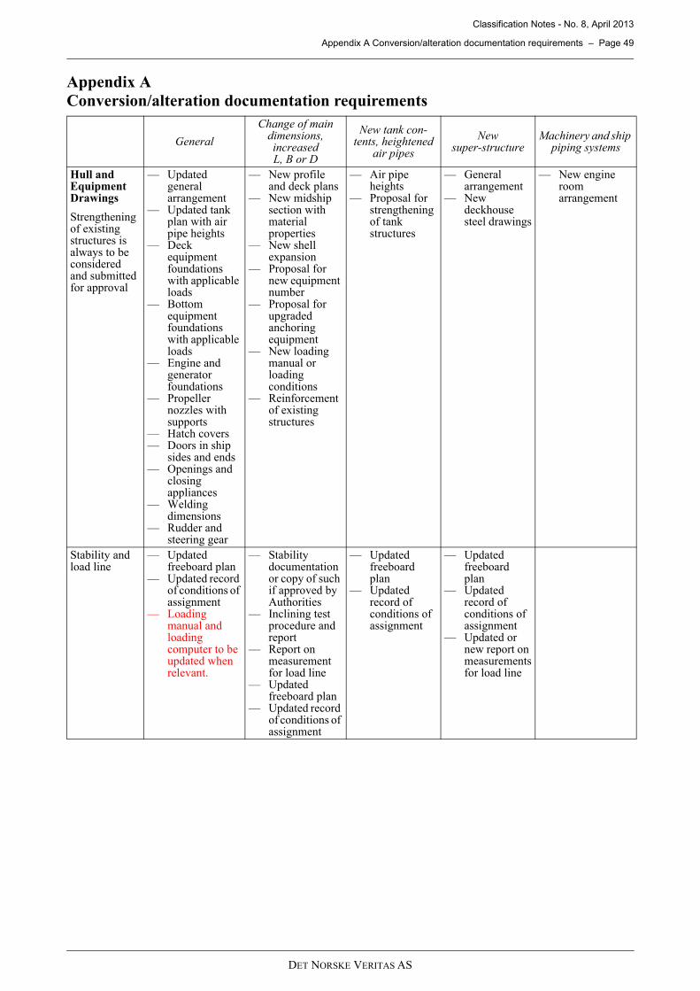
Classification Notes - No. 8, April 2013
Appendix A Conversion/alteration documentation requirements – Page 49
Appendix AConversion/alteration documentation requirements
General
Change of main dimensions, increased L, B or D
New tank con-tents, heightened
air pipes
New super-structure
Machinery and ship piping systems
Hull and Equipment Drawings
Strengthening of existing structures is always to be considered and submitted for approval
— Updated general arrangement
— Updated tank plan with air pipe heights
— Deck equipment foundations with applicable loads
— Bottom equipment foundations with applicable loads
— Engine and generator foundations
— Propeller nozzles with supports
— Hatch covers— Doors in ship
sides and ends— Openings and
closing appliances
— Welding dimensions
— Rudder and steering gear
— New profile and deck plans
— New midship section with material properties
— New shell expansion
— Proposal for new equipment number
— Proposal for upgraded anchoring equipment
— New loading manual or loading conditions
— Reinforcement of existing structures
— Air pipe heights
— Proposal for strengthening of tank structures
— General arrangement
— New deckhouse steel drawings
— New engine room arrangement
Stability and load line
— Updated freeboard plan
— Updated record of conditions of assignment
— Loading manual and loading computer to be updated when relevant.
— Stability documentation or copy of such if approved by Authorities
— Inclining test procedure and report
— Report on measurement for load line
— Updated freeboard plan
— Updated record of conditions of assignment
— Updated freeboard plan
— Updated record of conditions of assignment
— Updated freeboard plan
— Updated record of conditions of assignment
— Updated or new report on measurements for load line
DET NORSKE VERITAS AS

Classification Notes - No. 8, April 2013
Appendix A Conversion/alteration documentation requirements – Page 50
Life-saving and fire safety
Life saving if changed:— Updated safety
plan— Updated
lifeboat or rescue boat arrangement drawing
— Updated liferaft arrangement drawing
— Updated navigation lights arrangement drawing
— Pilot ladder arrangement
Fire safety for al-tered sections:— Fire integrity
plan— Structural fire
protection— Fire detection
and alarm system
— Fire extinguishing system
— Ventilation system
— Fire control plan
— Fire main system
Life-saving and COLREG:— Updated
lifeboat or rescue boat arrangement drawing if relevant
— Updated navigation lights arrangement drawing if relevant
— Pilot ladder arrangement if relevant
Life saving and COLREG:— Updated
lifeboat or rescue boat arrangement drawing if relevant
— Updated navigation lights arrangement drawing if changed
— ILO Crew accommodation arrangement drawings
Electrical in-stallations and instrumenta-tion
— Updated single line diagram
— New load balance
— New selectivity analysis
— New short circuit calculations
— New/updated switchboard drawings
General
Change of main dimensions, increased L, B or D
New tank con-tents, heightened
air pipes
New super-structure
Machinery and ship piping systems
DET NORSKE VERITAS AS
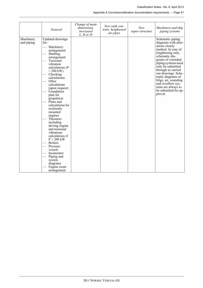
Classification Notes - No. 8, April 2013
Appendix A Conversion/alteration documentation requirements – Page 51
Machinery and piping
Updated drawings for:— Machinery
arrangement — Shafting
arrangement— Torsional
vibration calculations (P > 200 kW)
— Chocking calculations
— Other calculations (upon request)
— Foundation plan for propulsion
— Plans and calculations for resiliently mounted engines
— Thrusters including driving engine and torsional vibrations calculations if P > 200 kW
— Boilers— Pressure
vessels— Incinerator— Piping and
system diagrams
— Engine room arrangement
Schematic piping diagrams with alter-ations clearly marked. In case of lengthening only, schematic dia-grams of extended piping systems need only be submitted through as carried out drawings. Sche-matic diagrams of bilge, air, sounding and overflow sys-tems are always to be submitted for ap-proval.
General
Change of main dimensions, increased L, B or D
New tank con-tents, heightened
air pipes
New super-structure
Machinery and ship piping systems
DET NORSKE VERITAS AS


![DNV CN 8 [Apr'2013] Conversion of Ships](https://img.pdfslide.us/doc/110x75/577cdcf11a28ab9e78abcf0d/dnv-cn-8-apr2013-conversion-of-ships.jpg)