Embed Size (px)
Citation preview
High Productivity Vertical Machining Center
ver. EN 170724 SU
DNM 750 Ⅱ DNM 750L Ⅱ
DNM 750 ⅡDNM 750L Ⅱ
DNM 750Ⅱ
DNM 750Ⅱ
Product Overview
Basic Information
Basic Structure
Cutting
Performance
Detailed
Information
Options
Applications
Diagrams
Specifications
Customer Support
Service
02 /
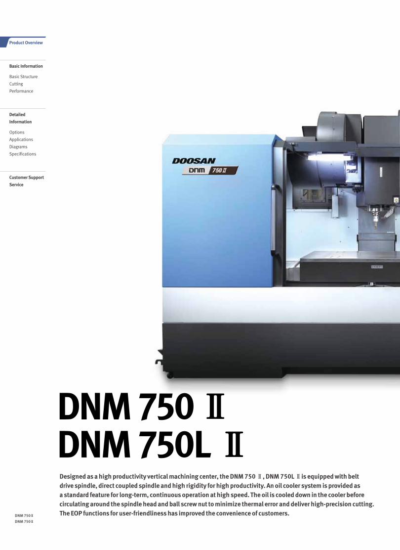
Designed as a high productivity vertical machining center, the DNM 750 Ⅱ, DNM 750L Ⅱis equipped with belt drive spindle, direct coupled spindle and high rigidity for high productivity. An oil cooler system is provided as a standard feature for long-term, continuous operation at high speed. The oil is cooled down in the cooler before circulating around the spindle head and ball screw nut to minimize thermal error and deliver high-precision cutting. The EOP functions for user-friendliness has improved the convenience of customers.
DNM 750 ⅡDNM 750L Ⅱ
03 02 /
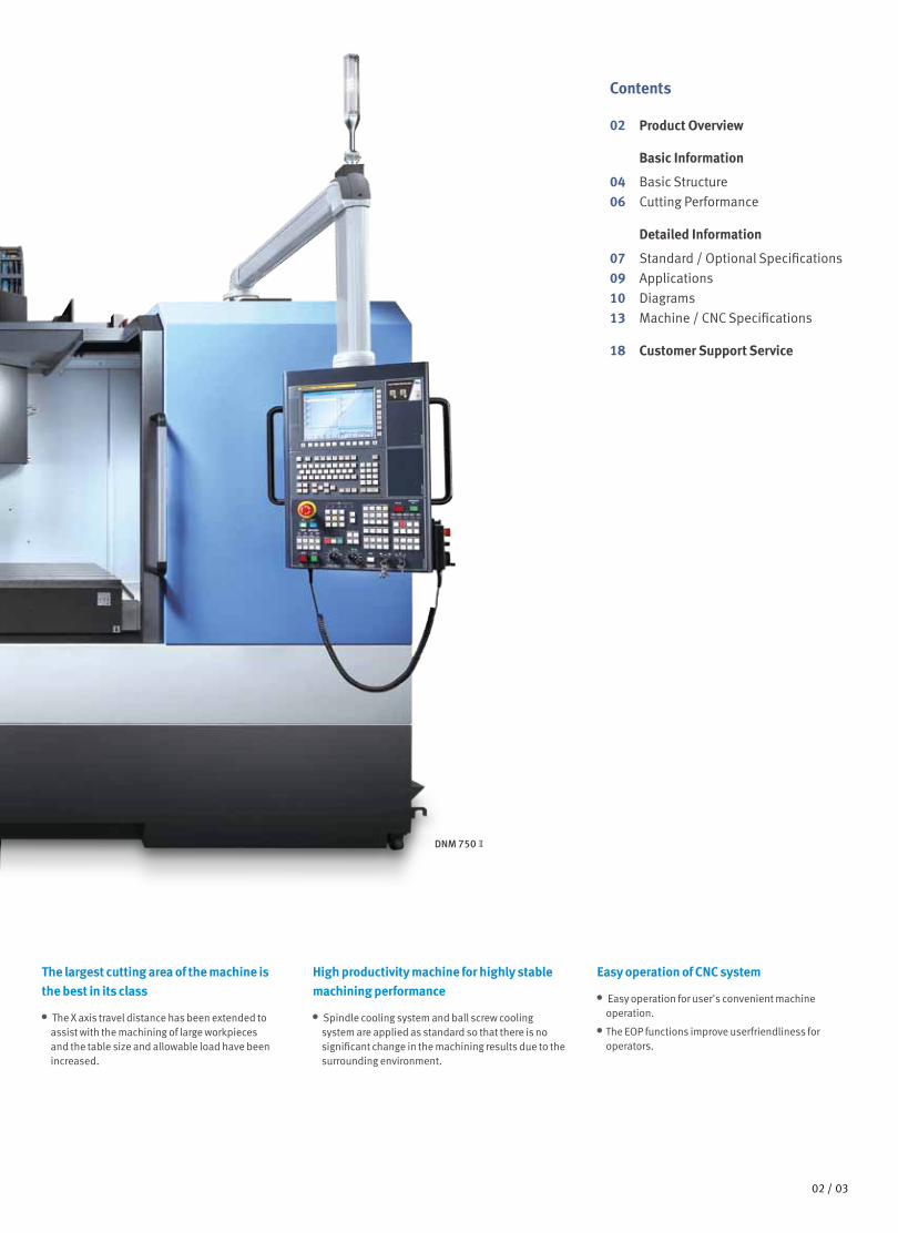
The largest cutting area of the machine is the best in its class
The X axis travel distance has been extended to assist with the machining of large workpieces and the table size and allowable load have been increased.
Easy operation of CNC system
Easy operation for user's convenient machine operation.
The EOP functions improve userfriendliness for operators.
High productivity machine for highly stable machining performance
Spindle cooling system and ball screw cooling system are applied as standard so that there is no significant change in the machining results due to the surrounding environment.
DNM 750Ⅱ
Contents
02 Product Overview
Basic Information
04 Basic Structure
06 Cutting Performance
Detailed Information
07 Standard / Optional Specifications
09 Applications
10 Diagrams
13 Machine / CNC Specifications
18 Customer Support Service
DNM 750Ⅱ
DNM 750Ⅱ
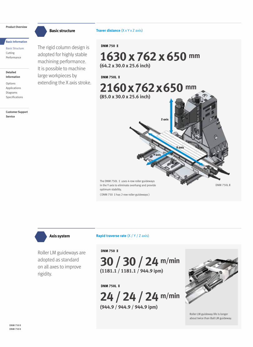
The rigid column design is adopted for highly stable machining performance. It is possible to machine large workpieces by extending the X axis stroke.
Roller LM guideways are adopted as standard on all axes to improve rigidity.
Basic structure
Axis system
DNM 750 Ⅱ
1630 x 762 x 650 mm
DNM 750L Ⅱ
2160 x 762 x 650 mm(85.0 x 30.0 x 25.6 inch)
Roller LM guideway life is longer
about twice than Ball LM guideway.
X-axis
Y-axis
Z-axis
DNM 750LⅡThe DNM 750L Ⅱ uses 4-row roller guideways
in the Y axis to eliminate overhang and provide
optimum stability.
( DNM 750 Ⅱhas 2-row roller guideways )
DNM 750 Ⅱ
DNM 750L Ⅱ
30 / 30 / 24 m/min
24 / 24 / 24 m/min
Product Overview
Basic Information
Basic Structure
Cutting
Performance
Detailed
Information
Options
Applications
Diagrams
Specifications
Customer Support
Service
04 /
Traver distance (X x Y x Z axis)
Rapid traverse rate (X / Y / Z axis)
(64.2 x 30.0 x 25.6 inch)
(1181.1 / 1181.1 / 944.9 ipm)
(944.9 / 944.9 / 944.9 ipm)
05 04 /
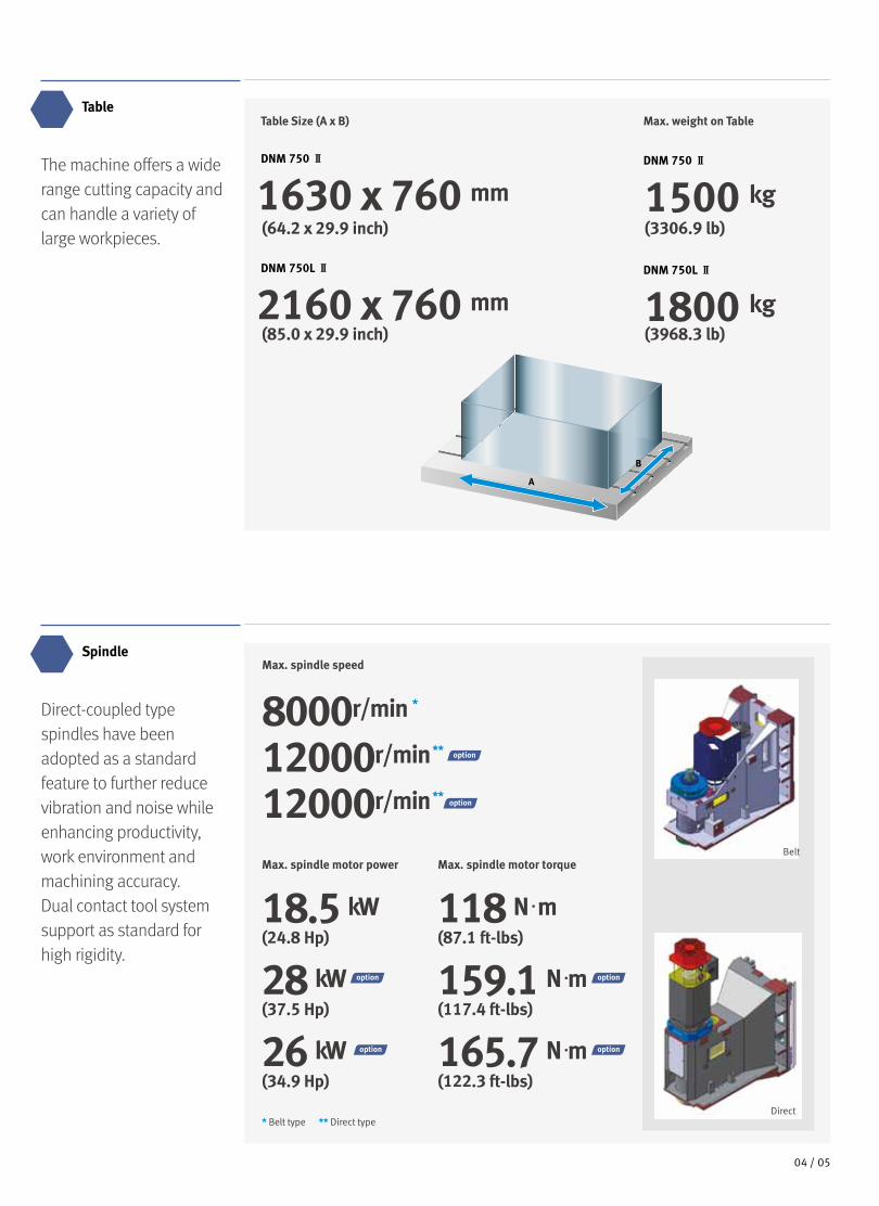
Table Size (A x B)
DNM 750 Ⅱ
1630 x 760 mm
DNM 750L Ⅱ
2160 x 760 mm
Max. weight on Table
DNM 750 Ⅱ
1500 kg
DNM 750L Ⅱ
1800 kg
A
B
The machine offers a wide range cutting capacity and can handle a variety of large workpieces.
Direct-coupled type spindles have been adopted as a standard feature to further reduce vibration and noise while enhancing productivity, work environment and machining accuracy. Dual contact tool system support as standard for high rigidity.
Table
SpindleMax. spindle speed
8000r/min *
12000r/min **
12000r/min **
Max. spindle motor power
18.5 kW
28 kW
26 kW
Max. spindle motor torque
118 N·m
159.1 N·m
165.7 N·m
* Belt type ** Direct type
Belt
Direct
(64.2 x 29.9 inch)
(85.0 x 29.9 inch)
(24.8 Hp) (87.1 ft-lbs)
(37.5 Hp) (117.4 ft-lbs)
(34.9 Hp) (122.3 ft-lbs)
(3306.9 lb)
(3968.3 lb)
DNM 750Ⅱ
DNM 750Ⅱ
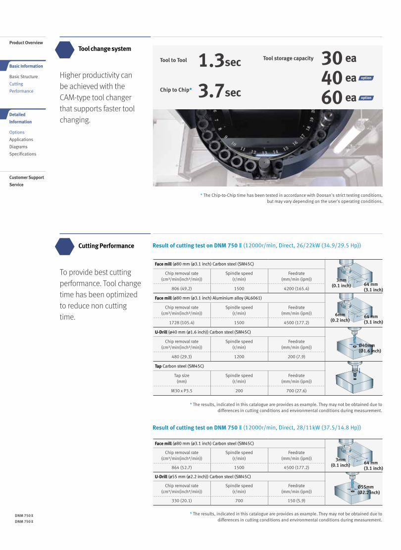
Higher productivity can be achieved with the CAM-type tool changerthat supports faster tool changing.
To provide best cutting performance. Tool change time has been optimized to reduce non cutting time.
Tool change system
Cutting Performance
* The results, indicated in this catalogue are provides as example. They may not be obtained due to differences in cutting conditions and environmental conditions during measurement.
* The results, indicated in this catalogue are provides as example. They may not be obtained due to differences in cutting conditions and environmental conditions during measurement.
Result of cutting test on DNM 750Ⅱ(12000r/min, Direct, 26/22kW (34.9/29.5 Hp))
Result of cutting test on DNM 750Ⅱ(12000r/min, Direct, 28/11kW (37.5/14.8 Hp))
3mm (0.1 inch)
3mm (0.1 inch)
6mm (0.2 inch)
64 mm(3.1 inch)
64 mm(3.1 inch)
64 mm(3.1 inch)
Ø40mm(Ø1.6 inch)
Ø55mm(Ø2.2 inch)
Face mill (ø80 mm (ø3.1 inch) Carbon steel (SM45C)
Chip removal rate (cm³/min(inch³/min))
Spindle speed (r/min)
Feedrate (mm/min (ipm))
806 (49.2) 1500 4200 (165.4)
Face mill (ø80 mm (ø3.1 inch) Aluminium alloy (AL6061)
Chip removal rate (cm³/min(inch³/min))
Spindle speed (r/min)
Feedrate (mm/min (ipm))
1728 (105.4) 1500 4500 (177.2)
U-Drill (ø40 mm (ø1.6 inch)) Carbon steel (SM45C)
Chip removal rate (cm³/min(inch³/min))
Spindle speed (r/min)
Feedrate (mm/min (ipm))
480 (29.3) 1200 200 (7.9)
Tap Carbon steel (SM45C)
Tap size (mm)
Spindle speed (r/min)
Feedrate (mm/min (ipm))
M30 x P3.5 200 700 (27.6)
Face mill (ø80 mm (ø3.1 inch) Carbon steel (SM45C)
Chip removal rate (cm³/min(inch³/min))
Spindle speed (r/min)
Feedrate (mm/min (ipm))
864 (52.7) 1500 4500 (177.2)
U-Drill (ø55 mm (ø2.2 inch)) Carbon steel (SM45C)
Chip removal rate (cm³/min(inch³/min))
Spindle speed (r/min)
Feedrate (mm/min (ipm))
330 (20.1) 700 150 (5.9)
Product Overview
Basic Information
Basic Structure
Cutting
Performance
Detailed
Information
Options
Applications
Diagrams
Specifications
Customer Support
Service
06 /
Tool to Tool 1.3sec Tool storage capacity 30 ea
40 ea
60 eaChip to Chip* 3.7sec
* The Chip-to-Chip time has been tested in accordance with Doosan's strict testing conditions,but may vary depending on the user's operating conditions.
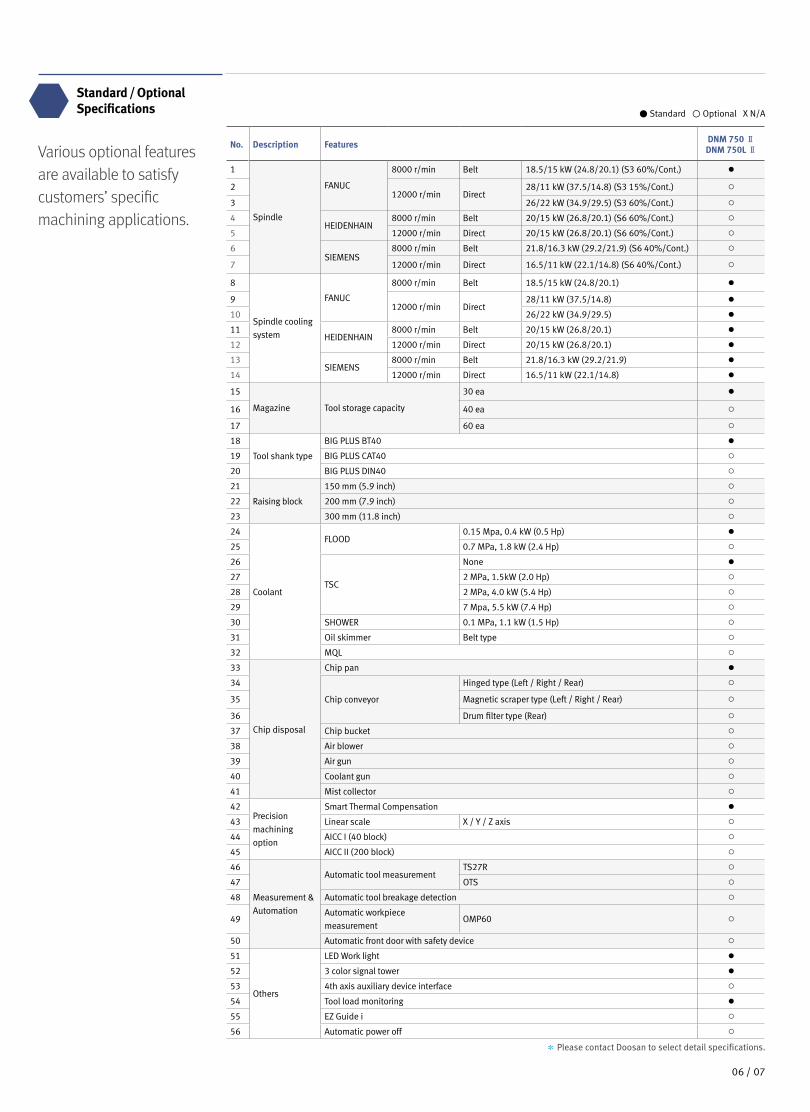
Various optional features are available to satisfy customers’ specific machining applications.
Standard / Optional Specifications
No. Description Features DNM 750 ⅡDNM 750L Ⅱ
1
Spindle
FANUC
8000 r/min Belt 18.5/15 kW (24.8/20.1) (S3 60%/Cont.) ●
212000 r/min Direct
28/11 kW (37.5/14.8) (S3 15%/Cont.) ○
3 26/22 kW (34.9/29.5) (S3 60%/Cont.) ○
4HEIDENHAIN
8000 r/min Belt 20/15 kW (26.8/20.1) (S6 60%/Cont.) ○
5 12000 r/min Direct 20/15 kW (26.8/20.1) (S6 60%/Cont.) ○
6SIEMENS
8000 r/min Belt 21.8/16.3 kW (29.2/21.9) (S6 40%/Cont.) ○
7 12000 r/min Direct 16.5/11 kW (22.1/14.8) (S6 40%/Cont.) ○
8
Spindle cooling
system
FANUC
8000 r/min Belt 18.5/15 kW (24.8/20.1) ●
912000 r/min Direct
28/11 kW (37.5/14.8) ●
10 26/22 kW (34.9/29.5) ●
11HEIDENHAIN
8000 r/min Belt 20/15 kW (26.8/20.1) ●
12 12000 r/min Direct 20/15 kW (26.8/20.1) ●
13SIEMENS
8000 r/min Belt 21.8/16.3 kW (29.2/21.9) ●
14 12000 r/min Direct 16.5/11 kW (22.1/14.8) ●
15
Magazine Tool storage capacity
30 ea ●
16 40 ea ○
17 60 ea ○
18
Tool shank type
BIG PLUS BT40 ●
19 BIG PLUS CAT40 ○
20 BIG PLUS DIN40 ○
21
Raising block
150 mm (5.9 inch) ○
22 200 mm (7.9 inch) ○
23 300 mm (11.8 inch) ○
24
Coolant
FLOOD0.15 Mpa, 0.4 kW (0.5 Hp) ●
25 0.7 MPa, 1.8 kW (2.4 Hp) ○
26
TSC
None ●
27 2 MPa, 1.5kW (2.0 Hp) ○
28 2 MPa, 4.0 kW (5.4 Hp) ○
29 7 Mpa, 5.5 kW (7.4 Hp) ○
30 SHOWER 0.1 MPa, 1.1 kW (1.5 Hp) ○
31 Oil skimmer Belt type ○
32 MQL ○
33
Chip disposal
Chip pan ●
34
Chip conveyor
Hinged type (Left / Right / Rear) ○
35 Magnetic scraper type (Left / Right / Rear) ○
36 Drum filter type (Rear) ○
37 Chip bucket ○
38 Air blower ○
39 Air gun ○
40 Coolant gun ○
41 Mist collector ○
42Precision
machining
option
Smart Thermal Compensation ●
43 Linear scale X / Y / Z axis ○
44 AICC I (40 block) ○
45 AICC II (200 block) ○
46
Measurement &
Automation
Automatic tool measurementTS27R ○
47 OTS ○
48 Automatic tool breakage detection ○
49Automatic workpiece
measurementOMP60 ○
50 Automatic front door with safety device ○
51
Others
LED Work light ●
52 3 color signal tower ●
53 4th axis auxiliary device interface ○
54 Tool load monitoring ●
55 EZ Guide i ○
56 Automatic power off ○
● Standard ◦ Optional X N/A
* Please contact Doosan to select detail specifications.
07 06 /
DNM 750Ⅱ
DNM 750Ⅱ
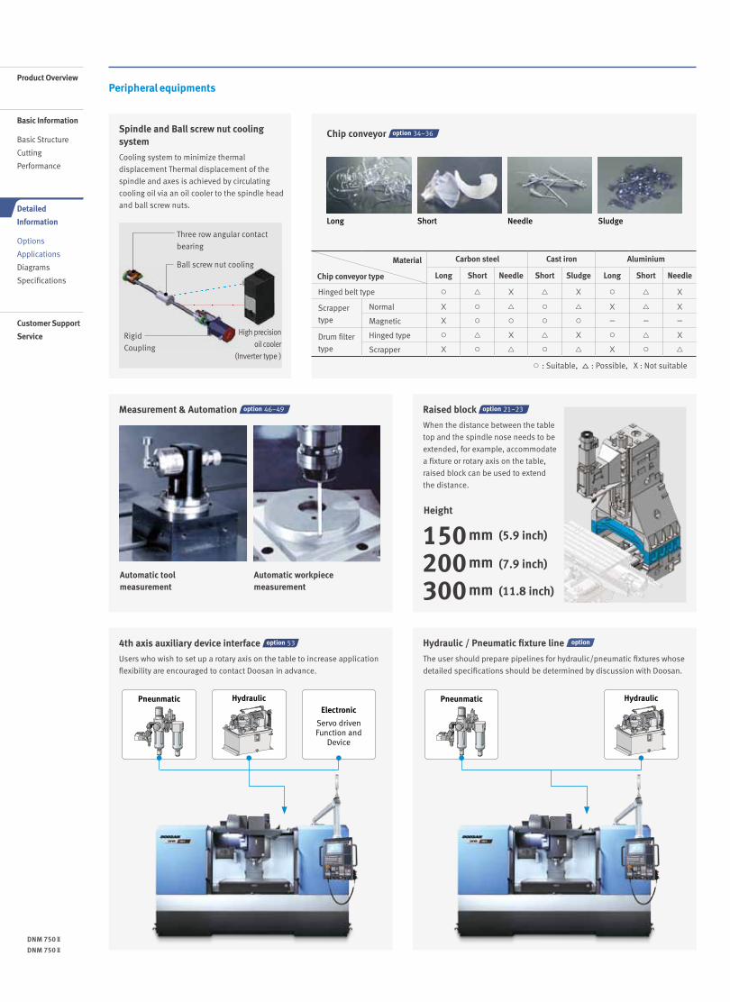
Peripheral equipments
Chip conveyor 34~36
○ : Suitable, △ : Possible, X : Not suitable
Material
Chip conveyor type
Carbon steel Cast iron Aluminium
Long Short Needle Short Sludge Long Short Needle
Hinged belt type ○ △ X △ X ○ △ X
Scrapper
type
Normal X ○ △ ○ △ X △ X
Magnetic X ○ ○ ○ ○ - - -
Drum filter
type
Hinged type ○ △ X △ X ○ △ X
Scrapper X ○ △ ○ △ X ○ △
Long Short Needle Sludge
Spindle and Ball screw nut cooling system
Cooling system to minimize thermal
displacement Thermal displacement of the
spindle and axes is achieved by circulating
cooling oil via an oil cooler to the spindle head
and ball screw nuts.
4th axis auxiliary device interface 53
Users who wish to set up a rotary axis on the table to increase application
flexibility are encouraged to contact Doosan in advance.
Hydraulic / Pneumatic fixture line
The user should prepare pipelines for hydraulic/pneumatic fixtures whose
detailed specifications should be determined by discussion with Doosan.
Pneunmatic PneunmaticHydraulic HydraulicElectronic
Servo drivenFunction and
Device
Measurement & Automation 46~49
Automatic workpiece measurement
Automatic tool measurement
Raised block 21~23
When the distance between the table
top and the spindle nose needs to be
extended, for example, accommodate
a fixture or rotary axis on the table,
raised block can be used to extend
the distance.
Three row angular contact
bearing
High precision
oil cooler
(Inverter type )
Ball screw nut cooling
Rigid
Coupling
Product Overview
Basic Information
Basic Structure
Cutting
Performance
Detailed
Information
Options
Applications
Diagrams
Specifications
Customer Support
Service
Height
150mm
200mm
300mm
(5.9 inch)
(7.9 inch)
(11.8 inch)
08 /
DOOSAN FANUC i
Easy Operation Package
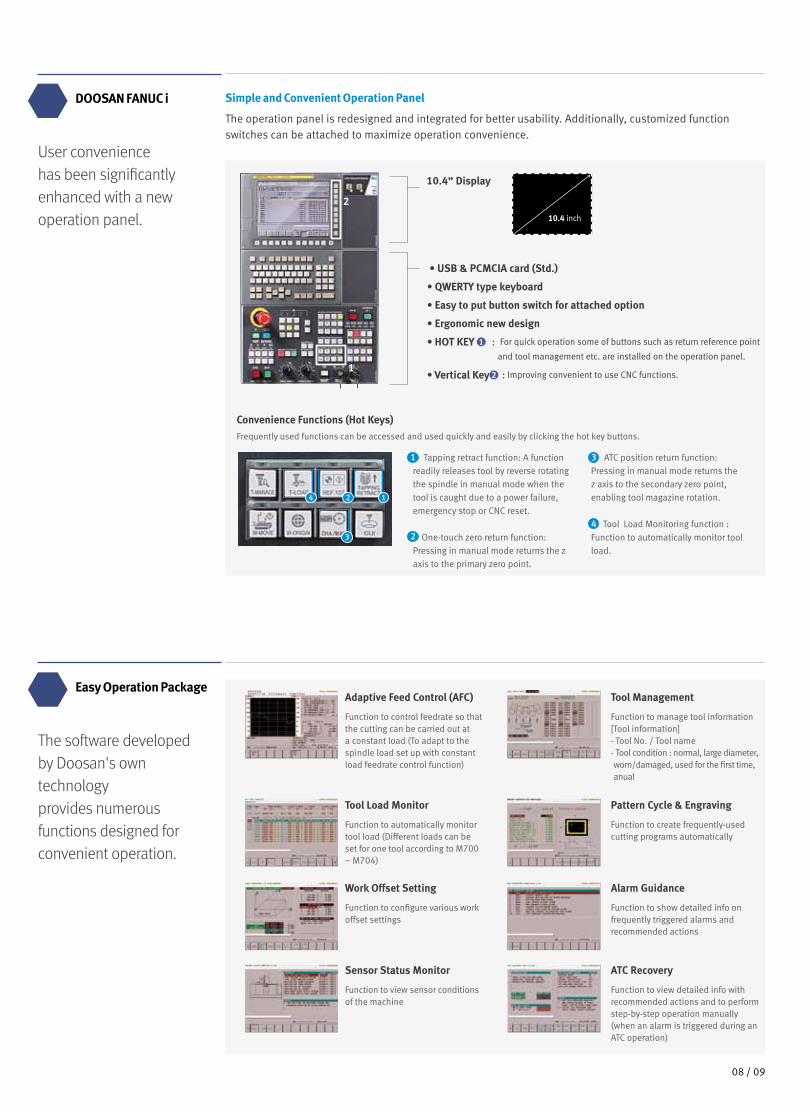
Simple and Convenient Operation Panel
The operation panel is redesigned and integrated for better usability. Additionally, customized function switches can be attached to maximize operation convenience.
User conveniencehas been significantlyenhanced with a newoperation panel.
The software developedby Doosan's owntechnologyprovides numerousfunctions designed forconvenient operation.
10.4 inch
• USB & PCMCIA card (Std.)
• QWERTY type keyboard
• Easy to put button switch for attached option
• Ergonomic new design
• HOT KEY 1 : For quick operation some of buttons such as return reference point
and tool management etc. are installed on the operation panel.
• Vertical Key 2 : Improving convenient to use CNC functions.
10.4” Display
2
1
Convenience Functions (Hot Keys)Frequently used functions can be accessed and used quickly and easily by clicking the hot key buttons.
Tapping retract function: A function readily releases tool by reverse rotating the spindle in manual mode when the tool is caught due to a power failure, emergency stop or CNC reset.
One-touch zero return function: Pressing in manual mode returns the z axis to the primary zero point.
ATC position return function: Pressing in manual mode returns the z axis to the secondary zero point, enabling tool magazine rotation.
Tool Load Monitoring function : Function to automatically monitor tool load.
1
2
3
43
4 2 1
Tool Management
Function to manage tool information[Tool information]- Tool No. / Tool name- Tool condition : normal, large diameter, worn/damaged, used for the first time, anual
Adaptive Feed Control (AFC)
Function to control feedrate so that the cutting can be carried out at a constant load (To adapt to the spindle load set up with constant load feedrate control function)
Pattern Cycle & Engraving
Function to create frequently-used cutting programs automatically
Tool Load Monitor
Function to automatically monitor tool load (Different loads can be set for one tool according to M700 ~ M704)
Alarm Guidance
Function to show detailed info on frequently triggered alarms and recommended actions
Work Offset Setting
Function to configure various work offset settings
ATC Recovery
Function to view detailed info with recommended actions and to perform step-by-step operation manually (when an alarm is triggered during an ATC operation)
Sensor Status Monitor
Function to view sensor conditions of the machine
09 08 /
DNM 750Ⅱ
DNM 750Ⅱ
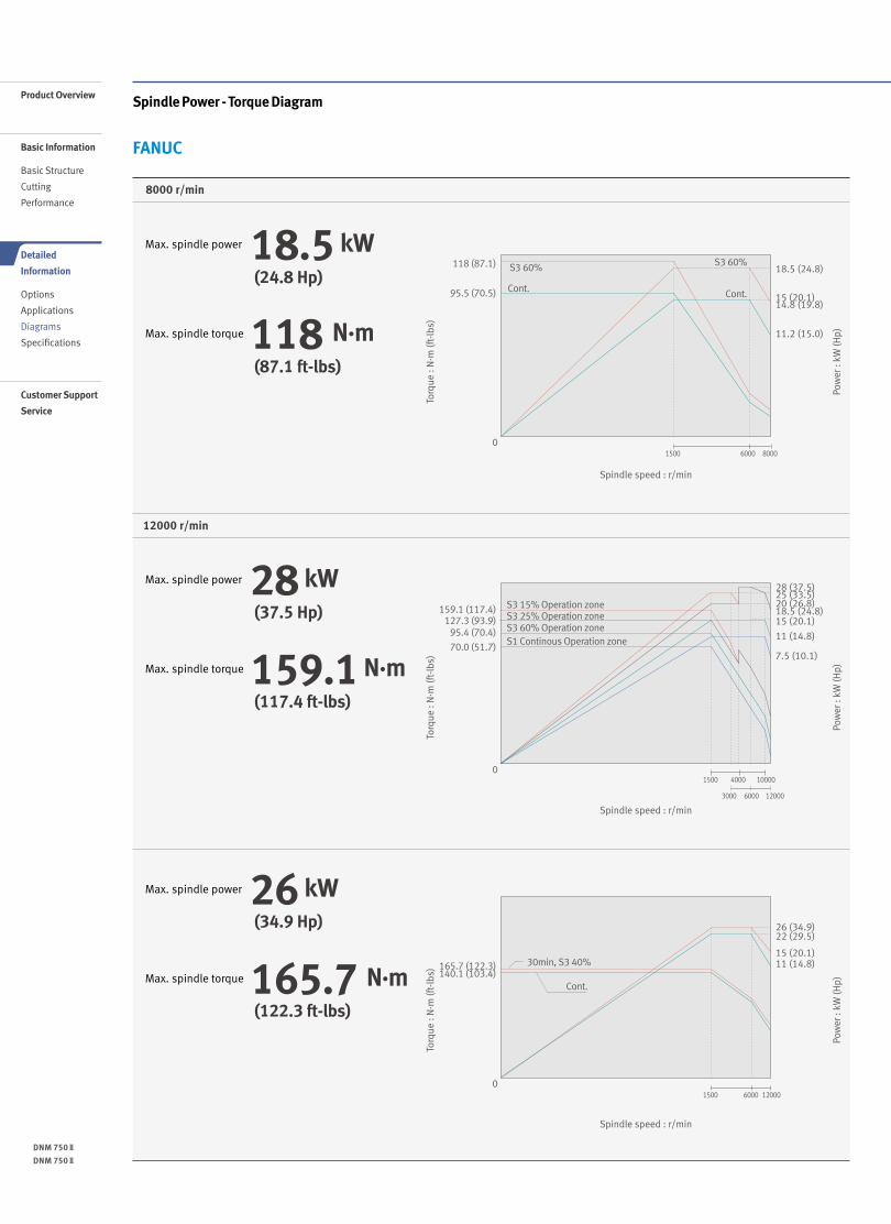
Spindle Power - Torque Diagram
FANUC
8000 r/min
12000 r/min
Max. spindle power 18.5 kW
Max. spindle torque 118 N·m
Product Overview
Basic Information
Basic Structure
Cutting
Performance
Detailed
Information
Options
Applications
Diagrams
Specifications
Customer Support
Service
Spindle speed : r/min
Pow
er :
kW (H
p)
Torq
ue :
N·m
(ft-
lbs)
S3 60% S3 60%
Cont. Cont.
S3 15% Operation zoneS3 25% Operation zoneS3 60% Operation zoneS1 Continous Operation zone
30min, S3 40%
Cont.
11.2 (15.0)
14.8 (19.8)15 (20.1)
18.5 (24.8)
0
95.5 (70.5)
118 (87.1)
11 (14.8)15 (20.1)
22 (29.5)26 (34.9)
0
140.1 (103.4)165.7 (122.3)
11 (14.8)
7.5 (10.1)
15 (20.1)
20 (26.8)25 (33.5)
18.5 (24.8)
28 (37.5)
0
127.3 (93.9)159.1 (117.4)
70.0 (51.7)
95.4 (70.4)
1500 4000 10000
3000 6000 12000
1500 6000 8000
1500 6000 12000
10 /
(24.8 Hp)
(87.1 ft-lbs)
Max. spindle power 28 kW
Max. spindle torque 159.1 N·m
Spindle speed : r/min
Pow
er :
kW (H
p)
Torq
ue :
N·m
(ft-
lbs)
S3 60% S3 60%
Cont. Cont.
S3 15% Operation zoneS3 25% Operation zoneS3 60% Operation zoneS1 Continous Operation zone
30min, S3 40%
Cont.
11.2 (15.0)
14.8 (19.8)15 (20.1)
18.5 (24.8)
0
95.5 (70.5)
118 (87.1)
11 (14.8)15 (20.1)
22 (29.5)26 (34.9)
0
140.1 (103.4)165.7 (122.3)
11 (14.8)
7.5 (10.1)
15 (20.1)
20 (26.8)25 (33.5)
18.5 (24.8)
28 (37.5)
0
127.3 (93.9)159.1 (117.4)
70.0 (51.7)
95.4 (70.4)
1500 4000 10000
3000 6000 12000
1500 6000 8000
1500 6000 12000
(37.5 Hp)
(117.4 ft-lbs)
Max. spindle power 26 kW
Max. spindle torque 165.7 N·m
Spindle speed : r/min
Pow
er :
kW (H
p)
Torq
ue :
N·m
(ft-
lbs)
S3 60% S3 60%
Cont. Cont.
S3 15% Operation zoneS3 25% Operation zoneS3 60% Operation zoneS1 Continous Operation zone
30min, S3 40%
Cont.
11.2 (15.0)
14.8 (19.8)15 (20.1)
18.5 (24.8)
0
95.5 (70.5)
118 (87.1)
11 (14.8)15 (20.1)
22 (29.5)26 (34.9)
0
140.1 (103.4)165.7 (122.3)
11 (14.8)
7.5 (10.1)
15 (20.1)
20 (26.8)25 (33.5)
18.5 (24.8)
28 (37.5)
0
127.3 (93.9)159.1 (117.4)
70.0 (51.7)
95.4 (70.4)
1500 4000 10000
3000 6000 12000
1500 6000 8000
1500 6000 12000
(34.9 Hp)
(122.3 ft-lbs)
11 10 /
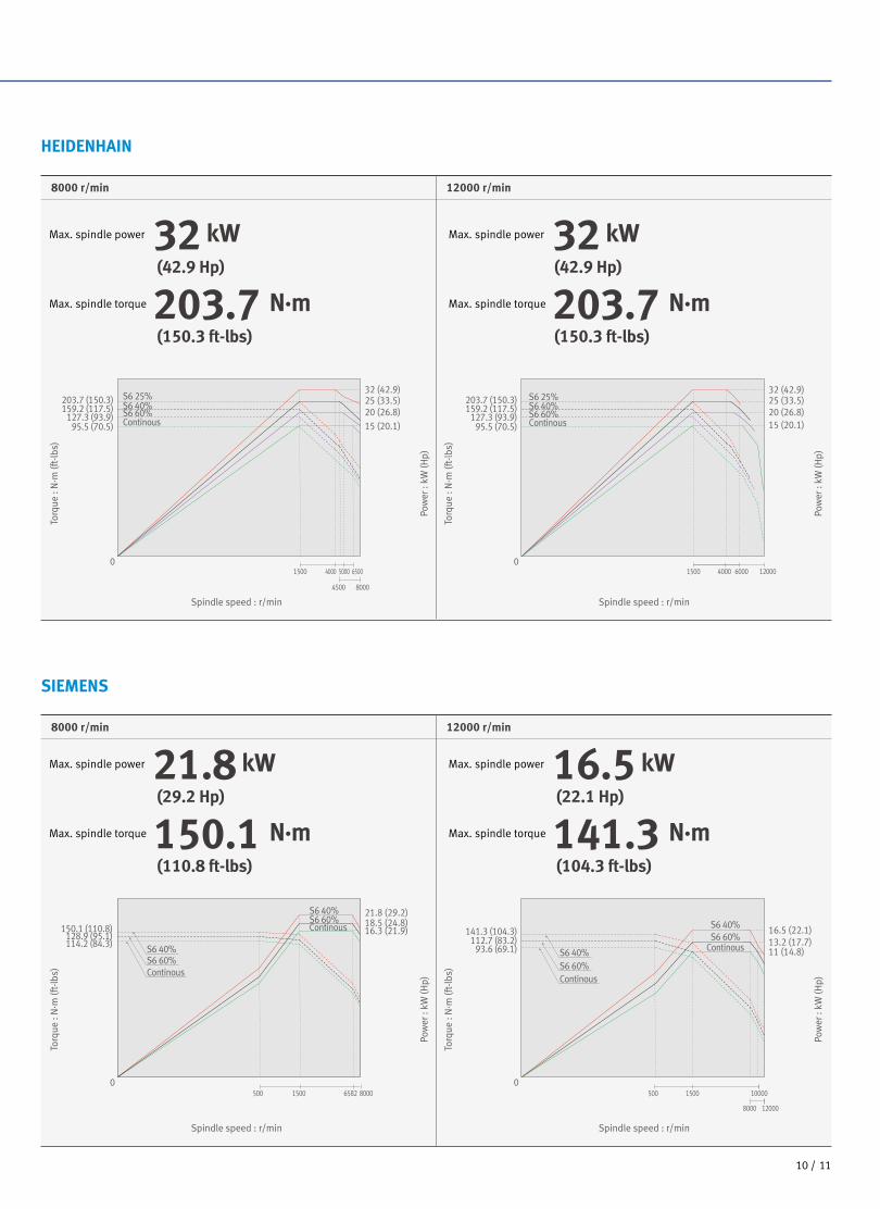
SIEMENS
8000 r/min 12000 r/min
Spindle speed : r/min Spindle speed : r/min
Pow
er :
kW (H
p)
Pow
er :
kW (H
p)
Torq
ue :
N·m
(ft-
lbs)
Torq
ue :
N·m
(ft-
lbs)
Max. spindle power 21.8 kW
Max. spindle torque 150.1 N·m(29.2 Hp)
(110.8 ft-lbs)
Max. spindle power 16.5 kW
Max. spindle torque 141.3 N·m(22.1 Hp)
(104.3 ft-lbs)
HEIDENHAIN
8000 r/min 12000 r/min
Spindle speed : r/min Spindle speed : r/min
Pow
er :
kW (H
p)
Pow
er :
kW (H
p)
Torq
ue :
N·m
(ft-
lbs)
Torq
ue :
N·m
(ft-
lbs)
Max. spindle power 32 kW
Max. spindle torque 203.7 N·m(42.9 Hp)
(150.3 ft-lbs)
Max. spindle power 32 kW
Max. spindle torque 203.7 N·m(42.9 Hp)
(150.3 ft-lbs)
S6 25%S6 40%S6 60%Continous
128.9 (95.1)114.2 (84.3)
150.1 (110.8)
S6 40%
S6 40%S6 60%Continous
S6 60%Continous
S6 40%S6 60%Continous
S6 40%S6 60%
Continous
S6 25%S6 40%S6 60%Continous
16.3 (21.9)
21.8 (29.2)18.5 (24.8)
0
25 (33.5)
15 (20.1)20 (26.8)
32 (42.9)
0
159.2 (117.5)203.7 (150.3)
95.5 (70.5)127.3 (93.9)
1500 4000 6500
4500 8000
5000
500 1500 80006582
16.5 (22.1)13.2 (17.7)11 (14.8)
0
112.7 (83.2)93.6 (69.1)
141.3 (104.3)
32 (42.9)25 (33.5)
15 (20.1)20 (26.8)
01500 4000 6000 12000
500 1500 10000
8000 12000
159.2 (117.5)203.7 (150.3)
95.5 (70.5)127.3 (93.9)
DNM 750Ⅱ
DNM 750Ⅱ
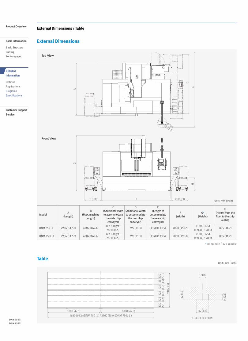
Table
Pront View
Top View
ModelA
(Length)
B (Max. machine
length)
C (Additional width to accommodate
the side chip conveyor)
D (Additional width to accommodate
the rear chip conveyor)
E (Length to
accommodate the rear chip
conveyor)
F(Width)
G*(Height)
H (Height from the floor to the chip
outlet)
DNM 750 Ⅱ 2986 (117.6) 4309 (169.6)Left & Right :953 (37.5)
790 (31.1) 3390 (133.5) 4000 (157.5)3170 / 3251
(124.8 / 128.0)805 (31.7)
DNM 750L Ⅱ 2986 (117.6) 4309 (169.6)Left & Right :953 (37.5)
790 (31.1) 3390 (133.5) 5050 (198.8)3170 / 3251
(124.8 / 128.0)805 (31.7)
Unit: mm (inch)
Unit: mm (inch)
1080 (42.5) 1080 (42.5)
1630 (64.2) (DNM 750 Ⅱ) / 2160 (85.0) (DNM 750LⅡ)
760
(29.
9)
130
(5.1
)12
5(4
.9)
130
(5.1
)12
5(4
.9)
125
(4.9
)12
5(4
.9)
18H8
32 (1
.3)
32 (1.3)
14 (0
.6)
T-SLOT SECTION
* 8k spindle / 12k spindle
AG
Ø 564(Ø 22.2)
D
E
BH
C (Right)C (Left) F
Product Overview
Basic Information
Basic Structure
Cutting
Performance
Detailed
Information
Options
Applications
Diagrams
Specifications
Customer Support
Service
External Dimensions / Table
External Dimensions
12 /
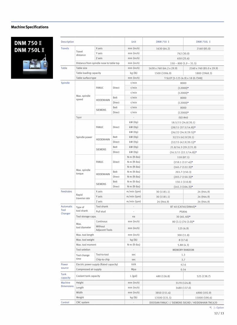
Machine Specifications
DNM 750ⅡDNM 750LⅡ
Description Unit DNM 750 Ⅱ DNM 750L Ⅱ
TravelsTravel distance
X axis mm (inch) 1630 (64.2) 2160 (85.0)
Y axis mm (inch) 762 (30.0)
Z axis mm (inch) 650 (25.6)
Distance from spindle nose to table top mm (inch) 150 ~ 800 (5.9 ~ 31.5)
Table Table size mm (inch) 1630 x 760 (64.2 x 29.9) 2160 x 760 (85.0 x 29.9)
Table loading capacity kg (lb) 1500 (3306.9) 1800 (3968.3)
Table surface type mm (inch) T-SLOT [5-125 (4.9) x 18 (0.7)H8]
Spindle
Max. spindle speed
FANUC Direct
r/min 8000
r/min {12000}*
r/min {12000}*
HEIDENHAINBelt r/min 8000
Direct r/min {12000}*
SIEMENSBelt r/min 8000
Direct r/min {12000}*
Taper - ISO #40
Spindle power
FANUC Direct
kW (Hp) 18.5/15 (24.8/20.1)
kW (Hp) {28/11 (37.5/14.8)}*
kW (Hp) {26/22 (34.9/29.5)}*
HEIDENHAINBelt kW (Hp) 32/15 (42.9/20.1)
Direct kW (Hp) {32/15 (42.9/20.1)}*
SIEMENSBelt kW (Hp) 21.8/16.3 (29.2/21.9)
Direct kW (Hp) {16.5/11 (22.1/14.8)}*
Max. spindle torque
FANUC Direct
N·m (ft-lbs) 118 (87.1)
N·m (ft-lbs) {159.1 (117.4)}*
N·m (ft-lbs) {165.7 (122.3)}*
HEIDENHAINBelt N·m (ft-lbs) 203.7 (150.3)
Direct N·m (ft-lbs) {203.7 (150.3)}*
SIEMENSBelt N·m (ft-lbs) 150.1 (110.8)
Direct N·m (ft-lbs) {141.3 (104.3)}*
FeedratesRapid traverse rate
X axis m/min (ipm) 30 (1181.1) 24 (944.9)
Y axis m/min (ipm) 30 (1181.1) 24 (944.9)
Z axis m/min (ipm) 24 (944.9) 24 (944.9)
Automatic Tool Changer
Type of tool shank
Tool shank - BT 40 {CAT40/DIN40}*
Pull stud - PS806
Tool storage capa. ea 30 {40, 60}*
Max. tool diameter
Continous mm (inch) 80 (3.1) {76 (3.0)}*
Without Adjacent Tools
mm (inch) 125 (4.9)
Max. tool length mm (inch) 300 (11.8)
Max. tool weight kg (lb) 8 (17.6)
Max. tool moment N·m (ft-lbs) 5.88 (4.3)
Tool seletion - MEMORY RANDOM
Tool change time
Tool-to-tool sec 1.3
Chip-to-chip sec 3.7
Power source
Electric power supply (Rated capacity) kVA 42.6
Compressed air supply Mpa 0.54
Tank capacity
Coolant tank capacity L (gal) 480 (126.8) 525 (138.7)
Machine Dimensions
Height mm (inch) 3170 (124.8)
Length mm (inch) 3480 (137.0)
Width mm (inch) 3850 (151.6) 4900 (192.9)
Weight kg (lb) 13500 (531.5) 15000 (590.6)
Control CNC system - DOOSAN FANUC i / SIEMENS S828D / HEIDENHAIN TNC620
*{ } : Option
13 12 /
DNM 750Ⅱ
DNM 750Ⅱ
Product Overview
Basic Information
Basic Structure
Cutting
Performance
Detailed
Information
Options
Applications
Diagrams
Specifications
Customer Support
Service
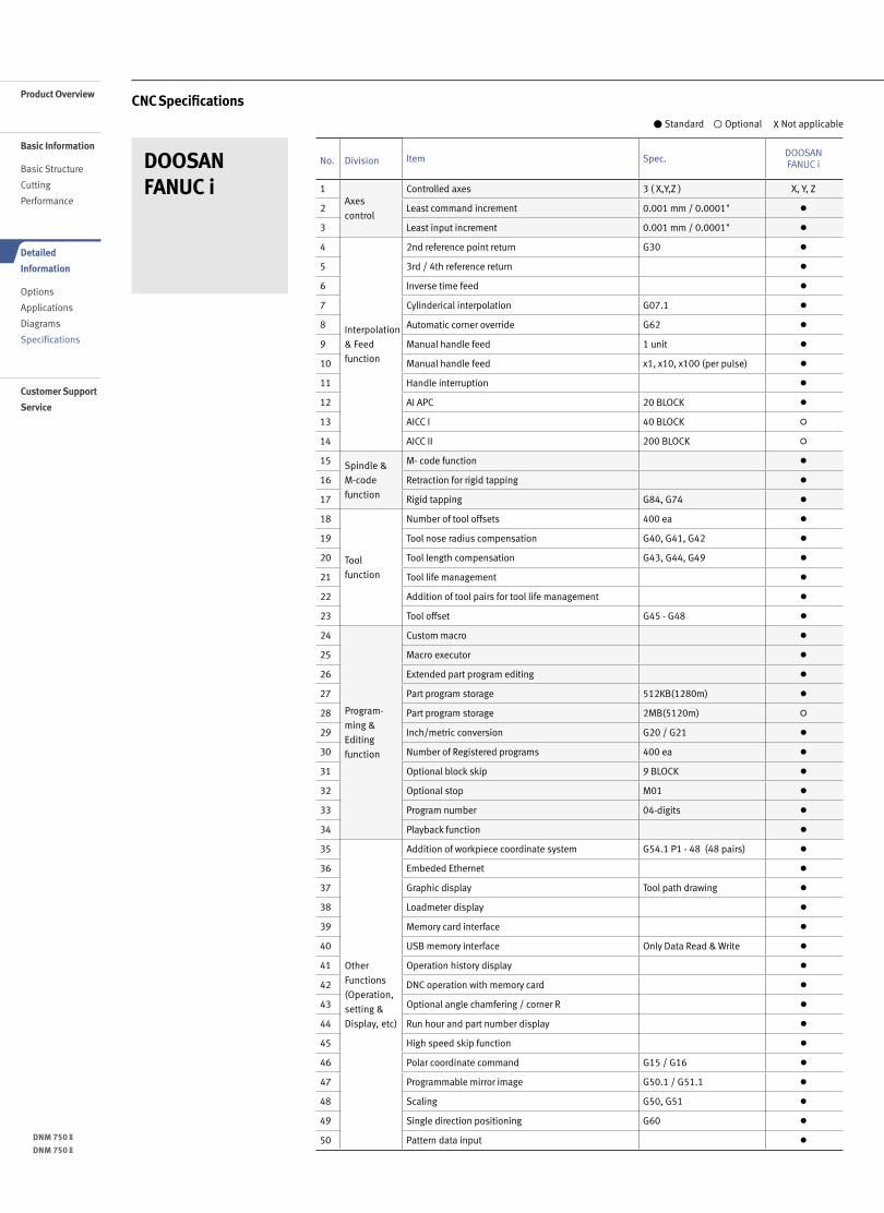
CNC Specifications
No. Division Item Spec.DOOSAN FANUC i
1Axes
control
Controlled axes 3 ( X,Y,Z ) X, Y, Z
2 Least command increment 0.001 mm / 0.0001" ●
3 Least input increment 0.001 mm / 0.0001" ●
4
Interpolation
& Feed
function
2nd reference point return G30 ●
5 3rd / 4th reference return ●
6 Inverse time feed ●
7 Cylinderical interpolation G07.1 ●
8 Automatic corner override G62 ●
9 Manual handle feed 1 unit ●
10 Manual handle feed x1, x10, x100 (per pulse) ●
11 Handle interruption ●
12 AI APC 20 BLOCK ●
13 AICC I 40 BLOCK ◦
14 AICC II 200 BLOCK ◦
15 Spindle &
M-code
function
M- code function ●
16 Retraction for rigid tapping ●
17 Rigid tapping G84, G74 ●
18
Tool
function
Number of tool offsets 400 ea ●
19 Tool nose radius compensation G40, G41, G42 ●
20 Tool length compensation G43, G44, G49 ●
21 Tool life management ●
22 Addition of tool pairs for tool life management ●
23 Tool offset G45 - G48 ●
24
Program-
ming &
Editing
function
Custom macro ●
25 Macro executor ●
26 Extended part program editing ●
27 Part program storage 512KB(1280m) ●
28 Part program storage 2MB(5120m) ◦
29 Inch/metric conversion G20 / G21 ●
30 Number of Registered programs 400 ea ●
31 Optional block skip 9 BLOCK ●
32 Optional stop M01 ●
33 Program number 04-digits ●
34 Playback function ●
35
Other
Functions
(Operation,
setting &
Display, etc)
Addition of workpiece coordinate system G54.1 P1 - 48 (48 pairs) ●
36 Embeded Ethernet ●
37 Graphic display Tool path drawing ●
38 Loadmeter display ●
39 Memory card interface ●
40 USB memory interface Only Data Read & Write ●
41 Operation history display ●
42 DNC operation with memory card ●
43 Optional angle chamfering / corner R ●
44 Run hour and part number display ●
45 High speed skip function ●
46 Polar coordinate command G15 / G16 ●
47 Programmable mirror image G50.1 / G51.1 ●
48 Scaling G50, G51 ●
49 Single direction positioning G60 ●
50 Pattern data input ●
DOOSAN FANUC i
● Standard ◦ Optional X Not applicable
14 /
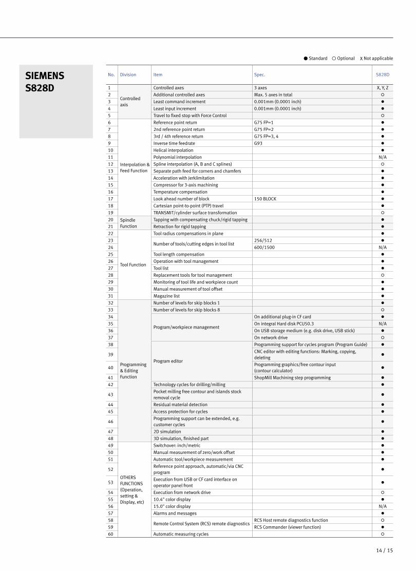
SIEMENSS828D
● Standard ◦ Optional X Not applicable
No. Division Item Spec. S828D
1
Controlled axis
Controlled axes 3 axes X, Y, Z
2 Additional controlled axes Max. 5 axes in total ◦
3 Least command increment 0.001mm (0.0001 inch) ●
4 Least input increment 0.001mm (0.0001 inch) ●
5 Travel to fixed stop with Force Control ◦
6
Interpolation & Feed Function
Reference point return G75 FP=1 ●
7 2nd reference point return G75 FP=2 ●
8 3rd / 4th reference return G75 FP=3, 4 ●
9 Inverse time feedrate G93 ●
10 Helical interpolation ●
11 Polynomial interpolation N/A
12 Spline interpolation (A, B and C splines) ◦
13 Separate path feed for corners and chamfers ●
14 Acceleration with Jerklimitation ●
15 Compressor for 3-axis machining ●
16 Temperature compensation ●
17 Look ahead number of block 150 BLOCK ●
18 Cartesian point-to-point (PTP) travel ●
19 TRANSMIT/cylinder surface transformation ◦
20 Spindle Function
Tapping with compensating chuck/rigid tapping ●
21 Retraction for rigid tapping ●
22
Tool Function
Tool radius compensations in plane ●
23Number of tools/cutting edges in tool list
256/512 ●
24 600/1500 N/A
25 Tool length compensation ●
26 Operation with tool management ●
27 Tool list ●
28 Replacement tools for tool management ◦
29 Monitoring of tool life and workpiece count ●
30 Manual measurement of tool offset ●
31 Magazine list ●
32
Programming & Editing Function
Number of levels for skip blocks 1 ●
33 Number of levels for skip blocks 8 ◦
34
Program/workpiece management
On additional plug-in CF card ●
35 On integral Hard disk PCU50.3 N/A
36 On USB storage medium (e.g. disk drive, USB stick) ●
37 On network drive ◦
38
Program editor
Programming support for cycles program (Program Guide) ●
39CNC editor with editing functions: Marking, copying, deleting
●
40Programming graphics/free contour input (contour calculator)
●
41 ShopMill Machining step programming ●
42 Technology cycles for drilling/milling ●
43Pocket milling free contour and islands stock removal cycle
●
44 Residual material detection ●
45 Access protection for cycles ●
46Programming support can be extended, e.g. customer cycles
●
47 2D simulation ●
48 3D simulation, finished part ●
49
OTHERS FUNCTIONS (Operation, setting & Display, etc)
Switchover: inch/metric ●
50 Manual measurement of zero/work offset ●
51 Automatic tool/workpiece measurement ●
52Reference point approach, automatic/via CNC program
●
53Execution from USB or CF card interface on operator panel front
●
54 Execution from network drive ◦
55 10.4" color display ●
56 15.0" color display N/A
57 Alarms and messages ●
58Remote Control System (RCS) remote diagnostics
RCS Host remote diagnostics function ◦
59 RCS Commander (viewer function) ●
60 Automatic measuring cycles ◦
15 14 /
DNM 750Ⅱ
DNM 750Ⅱ
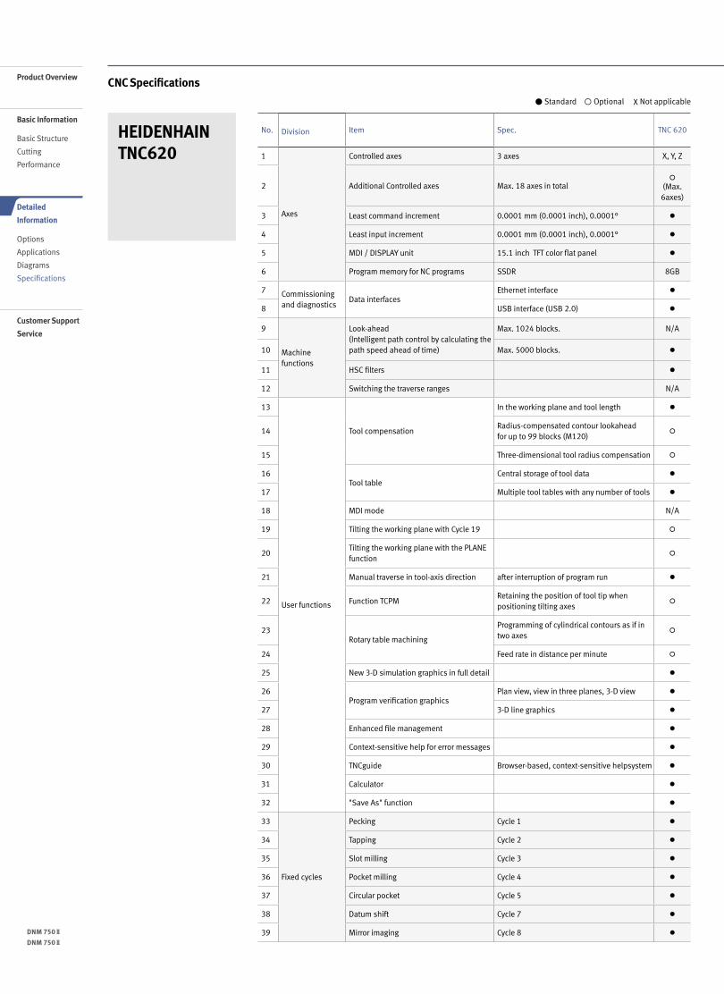
HEIDENHAIN TNC620
No. Division Item Spec. TNC 620
1
Axes
Controlled axes 3 axes X, Y, Z
2 Additional Controlled axes Max. 18 axes in total◦
(Max. 6axes)
3 Least command increment 0.0001 mm (0.0001 inch), 0.0001° ●
4 Least input increment 0.0001 mm (0.0001 inch), 0.0001° ●
5 MDI / DISPLAY unit 15.1 inch TFT color flat panel ●
6 Program memory for NC programs SSDR 8GB
7 Commissioning and diagnostics
Data interfacesEthernet interface ●
8 USB interface (USB 2.0) ●
9
Machine functions
Look-ahead (Intelligent path control by calculating the path speed ahead of time)
Max. 1024 blocks. N/A
10 Max. 5000 blocks. ●
11 HSC filters ●
12 Switching the traverse ranges N/A
13
User functions
Tool compensation
In the working plane and tool length ●
14Radius-compensated contour lookahead for up to 99 blocks (M120)
◦
15 Three-dimensional tool radius compensation ◦
16Tool table
Central storage of tool data ●
17 Multiple tool tables with any number of tools ●
18 MDI mode N/A
19 Tilting the working plane with Cycle 19 ◦
20Tilting the working plane with the PLANE function
◦
21 Manual traverse in tool-axis direction after interruption of program run ●
22 Function TCPMRetaining the position of tool tip when positioning tilting axes
◦
23Rotary table machining
Programming of cylindrical contours as if in two axes
◦
24 Feed rate in distance per minute ◦
25 New 3-D simulation graphics in full detail ●
26Program verification graphics
Plan view, view in three planes, 3-D view ●
27 3-D line graphics ●
28 Enhanced file management ●
29 Context-sensitive help for error messages ●
30 TNCguide Browser-based, context-sensitive helpsystem ●
31 Calculator ●
32 "Save As" function ●
33
Fixed cycles
Pecking Cycle 1 ●
34 Tapping Cycle 2 ●
35 Slot milling Cycle 3 ●
36 Pocket milling Cycle 4 ●
37 Circular pocket Cycle 5 ●
38 Datum shift Cycle 7 ●
39 Mirror imaging Cycle 8 ●
● Standard ◦ Optional X Not applicable
CNC SpecificationsProduct Overview
Basic Information
Basic Structure
Cutting
Performance
Detailed
Information
Options
Applications
Diagrams
Specifications
Customer Support
Service
16 /
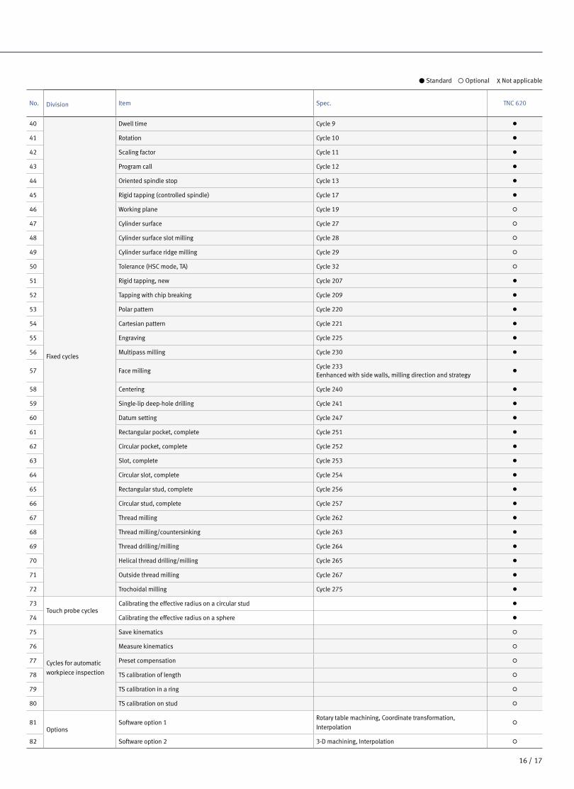
● Standard ◦ Optional X Not applicable
No. Division Item Spec. TNC 620
40
Fixed cycles
Dwell time Cycle 9 ●
41 Rotation Cycle 10 ●
42 Scaling factor Cycle 11 ●
43 Program call Cycle 12 ●
44 Oriented spindle stop Cycle 13 ●
45 Rigid tapping (controlled spindle) Cycle 17 ●
46 Working plane Cycle 19 ◦
47 Cylinder surface Cycle 27 ◦
48 Cylinder surface slot milling Cycle 28 ◦
49 Cylinder surface ridge milling Cycle 29 ◦
50 Tolerance (HSC mode, TA) Cycle 32 ◦
51 Rigid tapping, new Cycle 207 ●
52 Tapping with chip breaking Cycle 209 ●
53 Polar pattern Cycle 220 ●
54 Cartesian pattern Cycle 221 ●
55 Engraving Cycle 225 ●
56 Multipass milling Cycle 230 ●
57 Face millingCycle 233 Eenhanced with side walls, milling direction and strategy
●
58 Centering Cycle 240 ●
59 Single-lip deep-hole drilling Cycle 241 ●
60 Datum setting Cycle 247 ●
61 Rectangular pocket, complete Cycle 251 ●
62 Circular pocket, complete Cycle 252 ●
63 Slot, complete Cycle 253 ●
64 Circular slot, complete Cycle 254 ●
65 Rectangular stud, complete Cycle 256 ●
66 Circular stud, complete Cycle 257 ●
67 Thread milling Cycle 262 ●
68 Thread milling/countersinking Cycle 263 ●
69 Thread drilling/milling Cycle 264 ●
70 Helical thread drilling/milling Cycle 265 ●
71 Outside thread milling Cycle 267 ●
72 Trochoidal milling Cycle 275 ●
73Touch probe cycles
Calibrating the effective radius on a circular stud ●
74 Calibrating the effective radius on a sphere ●
75
Cycles for automatic
workpiece inspection
Save kinematics ◦
76 Measure kinematics ◦
77 Preset compensation ◦
78 TS calibration of length ◦
79 TS calibration in a ring ◦
80 TS calibration on stud ◦
81Options
Software option 1Rotary table machining, Coordinate transformation,
Interpolation◦
82 Software option 2 3-D machining, Interpolation ◦
17 16 /
DNM 750Ⅱ
DNM 750Ⅱ
Product Overview
Basic Information
Basic Structure
Cutting
Performance
Detailed
Information
Options
Applications
Diagrams
Specifications
Customer Support
Service
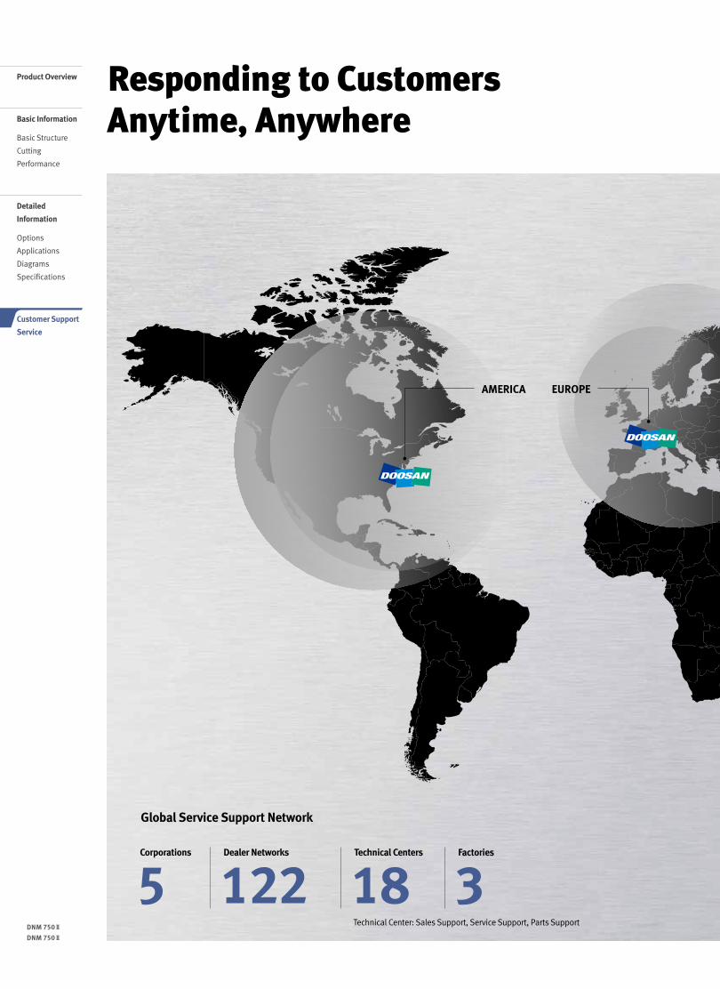
Responding to Customers Anytime, Anywhere
Global Service Support Network
Technical Center: Sales Support, Service Support, Parts Support
5Corporations
3Factories
18Technical Centers
122Dealer Networks
AMERICA EUROPE
18 /
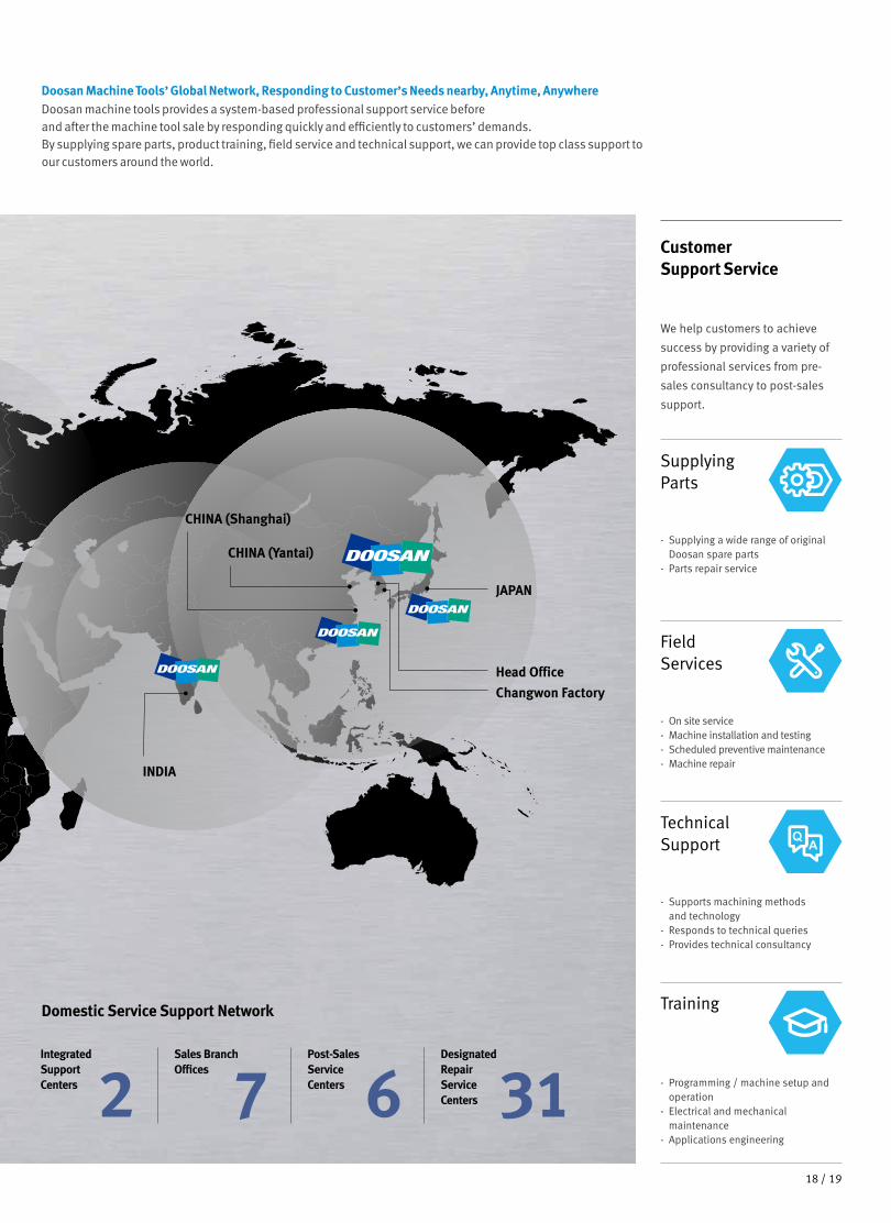
Doosan Machine Tools’ Global Network, Responding to Customer’s Needs nearby, Anytime, AnywhereDoosan machine tools provides a system-based professional support service before and after the machine tool sale by responding quickly and efficiently to customers’ demands.By supplying spare parts, product training, field service and technical support, we can provide top class support to our customers around the world.
We help customers to achieve
success by providing a variety of
professional services from pre-
sales consultancy to post-sales
support.
Customer Support Service
- On site service- Machine installation and testing- Scheduled preventive maintenance- Machine repair
Field Services
- Supports machining methods and technology
- Responds to technical queries- Provides technical consultancy
Technical Support
- Programming / machine setup and operation
- Electrical and mechanical maintenance
- Applications engineering
Training
- Supplying a wide range of original Doosan spare parts
- Parts repair service
Supplying Parts
Domestic Service Support Network
2Integrated Support Centers 7
Sales Branch Offices
6Post-Sales Service Centers 31
Designated Repair Service Centers
CHINA (Yantai)
CHINA (Shanghai)
INDIA
Changwon FactoryHead Office
JAPAN
19 18 /
Head OfficeYeonkang Bldg., 6th FL., 270, Yeonji-dong,
Jongno-gu, Seoul, Korea
Tel +82-2-3670-5345 / 5362
Fax +82-2-3670-5382
Doosan Machine Tools America19A Chapin Rd., Pine Brook, NJ 07058, U.S.A.
Tel +1-973-618-2500
Fax +1-973-618-2501
Doosan Machine Tools ChinaRoom 101,201,301, Building 39 Xinzhuan Highway
No.258 Songjiang District,China Shanghai(201612)
Tel +86-21-5445-1155
Fax +86-21-6405-1472
Doosan Machine Tools EuropeEmdener Strasse 24, D-41540 Dormagen, Germany
Tel +49-2133-5067-100
Fax +49-2133-5067-111
Doosan Machine Tools Japan#2412, Mita Kokusai Bldg. 1-4-28 Mita,
Minato-ku, Tokyo 108-0073, Japan
Tel +81-3-5730-9013
Fax +81-3-5730-9016
Doosan Machine Tools India106 / 10-11-12, Amruthahalli, Byatarayanapura,
Bellary road, Bangalore-560 092, India
Tel +91-80-4266-0122 / 121 / 100
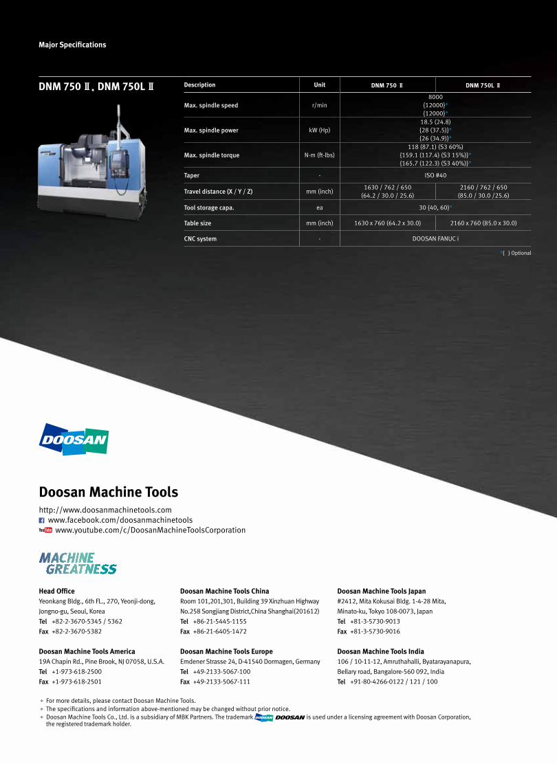
* For more details, please contact Doosan Machine Tools.* The specifications and information above-mentioned may be changed without prior notice.* Doosan Machine Tools Co., Ltd. is a subsidiary of MBK Partners. The trademark is used under a licensing agreement with Doosan Corporation,
the registered trademark holder.
Doosan Machine Toolshttp://www.doosanmachinetools.com
www.facebook.com/doosanmachinetools www.youtube.com/c/DoosanMachineToolsCorporation
Major Specifications
DNM 750 Ⅱ, DNM 750L Ⅱ Description Unit DNM 750 Ⅱ DNM 750L Ⅱ
Max. spindle speed r/min8000
{12000}* {12000}*
Max. spindle power kW (Hp)18.5 (24.8){28 (37.5)}* {26 (34.9)}*
Max. spindle torque N·m (ft-lbs)118 (87.1) (S3 60%)
{159.1 (117.4) (S3 15%)}*{165.7 (122.3) (S3 40%)}*
Taper - ISO #40
Travel distance (X / Y / Z) mm (inch)1630 / 762 / 650
(64.2 / 30.0 / 25.6)2160 / 762 / 650
(85.0 / 30.0 /25.6)
Tool storage capa. ea 30 {40, 60}*
Table size mm (inch) 1630 x 760 (64.2 x 30.0) 2160 x 760 (85.0 x 30.0)
CNC system - DOOSAN FANUC i
*{ } Optional