Embed Size (px)
Citation preview

Klark Teknik Group,Klark Teknik Building,
Walter Nash Road,Kidderminster.Worcestershire.
DY11 7HJ.England.
Tel:+44 (0) 1562 741515Fax:+44 (0) 1562 745371
Email: [email protected]: www.klarkteknik.com
OPERATORS MANUAL
DN9848


DECLARATION OF CONFORMITY
We,
of, Klark Teknik Building, Walter Nash Road, Kidderminster, Worcestershire, DY11 7HJ
Declare that a sample of the following product:-
to which this declaration refers, is in conformity with the following directives and/or standards:-
Signed:............................
Name: David Hoare
Authority: Technical Director, Klark Teknik Group (UK) PLC
Attention!Where applicable, the attention of the specifier, purchaser, installer or user is drawn to special limitations of usewhich must be observed when these products are taken into service to maintain compliance with the abovedirectives. Details of these special measures and limitations to use are available on request and are availablein product manuals.
Klark Teknik Group (UK) PLC
Walter Nash Road, Kidderminster, Worcestershire. DY11 7HJ. England
Tel: (44) (0) 1562 741515. Fax: (44) (0) 1562 745371
Company Registration No: 2414018
��� � ���S I GN A L P R O C E S S I N G B Y D E F I N I T I ON BETTER BY DESIGN DESIGNEDFOR APUREPERFORMANCE
Product Type Number Product Description Nominal Voltage (s) Current Freq
DN9848 115V AC 200mA100mA
50/60Hz230V AC
Directive(s) Test Standard(s)
Generic Standard Using EN55103 Limits and Methods EN50081/2
Class B Conducted Emissions EN55103
Class B Radiated Emissions EN55103
Fast Transient Bursts EN61000-4-4
Static Discharge EN61000-4-2
Date: 1st February, 2000
A Subsidiary of Telex communications, Inc.


Thank you for using a Klark Teknik productAfter you have unpackedIntroductionInstallation and ConnectionRear panel connectorsUser interfaceControlsMain menu structureSave/load routineSystem setup menuInput menu structureOutputTest modeOperational exampleTechnical specification
menu structure
Page 1Page 2Page 3Page 5Page 6Page 7Page 8Page 11Page 12Page 13Page 18Page 20Page 23Page 24Page 26
Contents


.
1
Thank You For Using This Klark Teknik Product
To obtain maximum performance from this precision electronic product, please study theseinstructions carefully. Installation and operating the DN9848 is not complicated, but the flexibilityprovided by its operating features merits familiarisation with its controls and connections. This unithas been prepared to comply with the power supply requirements that exist in your location.
Do not install this unit in a location subjected to excessive heat, dust or mechanical vibration.
Connection is made by means of an IEC standard power socket. The rear panel text indicates thevoltage range required for satisfactory operation of the unit.
Before connecting this unit to the mains supply, ensure the fuse fitted is the correct type and ratingis as indicated on the rear panel, adjacent to the fuse holder.
This unit is fitted with a standard fused IEC mains inlet: For safety reasons the earth lead shouldnever be disconnected.
To prevent shock or fire hazard, do not expose the unit to rain or moisture. To avoid electrical shockdo not remove covers. Refer servicing to qualified personnel only.
This product should only be used with high quality, screened twisted pair audio cables, terminatedwith metal bodied 3-pin XLR connectors. Any other cable type or configuration for the audiosignals may result in degraded performance due to electromagnetic interference.
Should this product be used in an electromagnetic field that is amplitude modulated by an audiofrequency signal (20Hz to 20kHz), the signal to noise ratio may be degraded. Degradation of up to60dB at a frequency corresponding to the modulation signal may be experienced under extremeconditions (3V/m, 90% modulation).
Precautions
Voltage Selection and Power Connection
Safety Warning
Attention!
Cables:
Electric Fields:

After You Have Unpacked The Unit
� ���
This
SideUp
2
Save all the packing materials - they will prove valuable should it become necessary to transport orship this product.
Please inspect this unit carefully for any signs of damage incurred during transportation. It hasundergone stringent quality control inspection and tests prior to packing and left the factory inperfect condition.
If, however, the unit shows any signs of damage, notify the transportation company without delay.Only you, the consignee, may institute a claim against the carrier for damage during transportation.
If necessary, contact your supplier or as a last resort, your Klark Teknik importing agent, who willfully co-operate under such circumstances.

Introduction
The DN9848 is a highly configurable, digital electronic crossover/loudspeaker management systemcomprising of four balanced analogue input channels and eight balanced analogue output channels. Theuser may choose from the following preset routing configurations:
Each output channel may be sourced from the following input channel options :
NoneABCDA+B (channels summed at -3dB with balance control)C+D (channels summed at -3dB with balance control))A+B+C+D (channels summed at -6dB)
Though the DN9848 utilises a fully digital processor, it maintains the operational paradigm, as well asthe sonic integrity, of a high quality analogue unit. In addition to guaranteeing absolutely precise filteroperation, the use of digital technology provides unrivaled flexibility of routing, the ability to programdelays into both the input and output channels, extensive equalisation on both the input and outputchannels, and of course programmability. Each input channel provides eight separately configurable,fully parametric equalisation stages that may be used for room equalisation, up to 1000ms of delay, gaincontrol and compression. Full metering with clip indication is available for all input and outputchannels.
Each output channel provides configurable high and low-pass filters for setting the crossovercharacteristics as well as six further stages of fully parametric equalisation that may be used tocompensate for system or enclosure characteristics. Further delay of up to 300ms is available on eachoutput, mainly used for system time alignment, in addition to gain control, muting and limiting. Dualall-pass phase correction sections are also included, the first of which can be any of the filter orparametric EQ stages and can be adjustable in 5 degree steps.
The crossover filter types available are:
12dB/octave peaking (high-pass filter only)24dB/octave peaking (high-pass filter only)Butterworth (6, 12, 18, 24, 36 and 48dB/octave)Linkwitz-Riley (12 and 24dB/octave)Bessel (12, 18, 24, 36 and 48dB/octave)
All aspects of the unit may be programmed from the front panel via a RS-232 port or via remote controlusing the standard comms port and RS-485 . Parameters may be directly edited via rotary controls andswitches on the front panel with all values being displayed on a 2-line, 24 character backlight LCDdisplay.
The operating system is held in flash ROM, enabling updates to be installed directly from a computerand various levels of safety lockout. This lockout ability may be used for installations or hireapplications where unauthorised user intervention could place the connected loudspeaker systems atrisk. Upto 24 character passwords can be used rather than PIN numbers due to the large display.
3

Six user memories, 32 System memories and 99 Factory Presets are available. The System memoriesare used to store complete setups for custom loudspeaker configurations while the User memories areprovided to allow a small number of patches to be stored or recalled while the main System memoriesare locked to prevent alteration.
A working memory area is used to store the patch currently being used or edited - no changes made tothe working memory will be made permanent until the patch is stored.
The Factory presets will include crossover setups for commonly used EV and third-party loudspeakersystems as itemised in the specifications section of this manual. A blank patch is also provided foroverwriting existing user patches where required. All the memory areas are monitored by an errorchecking system. If an error is diagnosed, the DN9848 will attempt to correct the error and also displaya warning message to alert the user.
As supplied, the user patches are set to unity gain with all processing switched out and no routing.
4

Installation
The DN9848 is housed in a standard, 1U, 19" rack case.Allow adequate ventilation and avoid mountingthe unit directly above power amplifiers or other devices that radiate significant amounts of heat. Wherenecessary, use fan cooled racks.
This device must be grounded and must use an approved mains fuse. The switch mode power supplyautomatically adjusts itself to 50/60Hz mains supplies in the 100 to 240V (+/- 10%)AC range.
The inputs and outputs are electronically balanced on conventionally wired XLRs (pin 1 screen, pin 2hot and pin 3 return) with a nominal operating level of +4dBu. For unbalanced use (input or output), pin3 of the XLR may be grounded by linking it to the screen.
If ground loop problems are encountered, the user must not disconnect the mains earth but instead,disconnect the signal screen at one end of the connecting cables. This can only be done when the unit isbeing used within a balanced system.
5

Rear Panel Connections
CA
UTI
ON
:TO
RED
UC
ERIS
KO
FFIR
E,REPLA
CE
WIT
HSA
ME
TYPE
OF
FUSE.
REPLA
CER
SEULM
EN
TPA
RUN
FUSIB
LED
EM
EM
ETY
PE.
CU
S
IND
INA
INB
INC
IND
OUTP
UT
1O
UTP
UT
2O
UTP
UT
3O
UTP
UT
4O
UTP
UT
5O
UTP
UT
6O
UTP
UT
7O
UTP
UT
8IN
OUT
CO
MM
S
FUSE:
5x20m
m
T0.5
L250V
SUPPLY
VO
LTA
GE
100-2
40V
AC
~5
0-6
0H
z6
0VA
PU
SHPU
SHPU
SHPU
SHPU
SH
Both the input and output channels are accessed via electronically balanced XLRconnectors wired pin 1 ground, pin 2 hot, pin 3 cold. These may be used unbalancedwhere necessary by connecting the ground and cold pins together, though balancedoperation is recommended.
Two further XLR connectors (in/out comms) carry the RS-485 interface and areconnected in parallel to facilitate the linking of multiple units. This interface facilitatesremote control and monitoring.
Mains is fed to the unit via a standard IEC type connector.
6

User Interface
The user interface has been designed to be clear and straightforward with the mainfunctions divided into five menus covering the input channels, output channels, patchloading, patch saving and system setup. Each menu is stepped through linearly withthree rotary controllers being used to edit the displayed parameters directly. For thepurposes of identification, these will be referred to (left to right) as X, Y and Z. A greenLED ring is associated with each of these encoders to indicate that the control iscurrently active as some menu pages do not require all three controls. The signal routingis handled within the output channel menus where combinations of the four inputchannels may be selected as the signal source.
Input channel menus are selected by pressing the corresponding channel Select buttonswhile Output channel menus are selected by pressing the corresponding channel's menuaccess button, each of which is fitted with an integral amber status LED.
7

INPUT MENU BUTTONSEach of the four input channels (A - D) may be accessed and edited independently via channel selectbuttonsA, B, C and D. These correspond directly to rear panel inputsA, B, C and D and each button hasan integral amber LED to indicate which channel is currently being accessed. Depressing any of thesebuttons will provide direct access to the first page of the edit menu. Subsequent presses will stepthrough the five available edit pages after which the display will return to Page 1 and the sequence willstart again. The number of accessible pages is subject to the Lock status of the unit. If the SystemProtection password has been set, the compressor pages will be inaccessible until the unit is unlocked.
Pressing the HOME (SETUP) button at any time during editing will return the user to the main menuHOME page.
Pressing STORE or RECALL will also cause the operating system to leave the current menu andinitiate either the Store or Recall sequence as selected.
Pressing any Input channel select button when an output menu is currently active will quit the currentmenu and go to the first menu page of the input channel selected. Similarly, pressing any Outputchannel select button when an input menu is currently active will quit the current menu and go to thefirst menu page of the output channel selected.
Pressing an Output channel select button when a different output channel menu is currently active willchange the display to the same page of the newly selected output channel. Pressing an Input channelselect button when a different input channel menu is currently active will change the display to the samepage of the newly selected input channel.
Controls
THE INPUT CHANNELSEach input channel comprises an input gain stage followed by an eight-band, fully parametric equaliser,a full-band compressor and a delay. The input metering monitors the output from each processing stageto avoid the possibility of inadvertent clipping within the processing chain.
Input
GainPEQ 1 PEQ 2 PEQ 3 PEQ 4 PEQ 5
PEQ 6 PEQ 7 PEQ 8 Compression Delay
Input
Output
Input
Metering
Feed
Clip Input
Metering
8
Input block diagram:

INPUT BARGRAPH METERSThe input 9-segment bargraph meters can display either level or compressor gain reduction. When theinput signal is below the compressor threshold, the meters display the difference between the currentsignal level and the compressor threshold so as to show the available headroom before compression.When the signal exceeds the compressor threshold, the meters read downward from the 0 dB LED toshow the amount of gain reduction taking place. The top red clip LED will always warn of clipping,regardless of the compressor status.
ROTARYENCODERSThe three rotary controls X,Yand Z associated with the display are continuous encoders and are used toedit parameter values shown in the display window. These controls are used for all front panelparameter editing where each control corresponds to an on-screen parameter. A green LED indicatorring is associated with each of the three controls to indicate when they are active. If there is no parameterassociated with any one of the encoders in the currently accessed screen, the LED ring will notilluminate.
RECALLInitiates the recall of a User, System of Factory setup patch.
SAVEInitiates the save sequence for storing User or System setup patches.
9

Routing DelayPhase
x2
Low
Pass
High
Pass
PEQ 1/
LEQ
Limiter Mute
Inputs
Output
Output
Metering
Feed
Clip Output
Metering
PEQ 2 PEQ 3 PEQ 4 PEQ 5PEQ 6/
HEQ
Gain/
Invert
THE OUTPUT CHANNELS
The output channels are slightly more complex than the input channels insomuch as they areresponsible for the signal routing as well as for further signal processing. At the input of each Outputchannel is a routing block capable of connecting that output to any of the available combinations of thefour Input channels. This provides the user with the flexibility required to construct any crossover typeup to 8-way. This is followed by a Delay, two independent phase correction stages, the crossover lowand high-pass filters, six further stages of fully parametric equalisation and a limiter. All key stages aremonitored by the output meters and each channel can be muted by pressing the output level control pot.
OUTPUT LEVELCONTROLSEach of the eight output channels is fitted with a level control potentiometer that also incorporates apush switch. Pressing the potentiometer knob mutes the channel and causes the red status LED ringaround the control to light.
MENU SELECTION KEYSEach of the eight outputs is fitted with a momentary action output channel selection button. These haveintegral amber status LEDs that light when the channel is selected.
OUTPUT BARGRAPH METERSEach of the eight outputs has an 11-segment bargraph display that shows the true output signal level atall times. The red segment at the top of the meter illuminates when the clip threshold has been reached.
HOME (SETUP) KEYThe function of this key depends on the context in which it is used. One of its main functions is to exitthe current operation and return to the first page of the menu structure. Pressing and holding this key formore than one second calls up the Setup menu.
PC PORTSAn 8-pin mini-DIN connector is provided on the front panel for connection to the RS-232 serial port of aPC or other remote control device conforming to the RS-232 protocol. A standard XLR is provided onthe rear panel for connection to RS-485 for remote control.
POWERThe power switch activates the unit and the Klark Teknik logo on the front panel will illuminate. Thecircuitry is designed so that no audio transients or thumps are generated when powering up or down. Itis also possible to program a 'ramp up time' for the audio output.
10
Input block diagram:

Main Menu Structure
Main menu structure diagram:
11
Acc
ess
topar
amet
ers
isvia
anin
tuit
ive,
hie
rarc
hic
alm
enu
syst
emw
her
eth
eX
,Y
and
Zsc
reen
dat
aen
try
contr
oll
ers
are
use
dto
acce
sson-s
cree
npar
amet
ers
dir
ectl
y.
When
noth
ing
isse
lect
ed,
the
top
level
of
the
men
uis
dis
pla
yed
wher
eth
ecu
rren
tly
load
edpat
chnam
ew
ill
be
show
n.
Fro
mth
ispoin
t,it
isposs
ible
togo
dir
ectl
yto
the
Mem
ory
Rec
all,
Mem
ory
Sto
re,S
etup
Men
u, I
nputM
enu
or
Outp
ut
Men
uvia
the
RE
CA
LL
,S
TO
RE
,H
OM
E(S
ET
UP
)butt
ons
or
by
pre
ssin
gan
yone
of
the
four
Input
Chan
nel
sele
ctbutt
on.
The
Outp
ut
chan
nel
men
us
are
call
edup
by
pre
ssin
gth
eas
soci
ated
Outp
utc
han
nel
sele
ctbutt
on.
RE
CA
LL
RE
CA
LL
STO
RE
STO
RE
HO
ME
(SE
TU
P)
HO
ME
(SE
TU
P)
HO
ME
(SE
TU
P)
HO
ME
(SE
TU
P)
HO
ME
(SE
TU
P)
HO
ME
(SE
TU
P)
HO
ME
(SE
TU
P)

Save/load Routine
RECALLING PATCHESPressing RECALLinitiates the Recall sequence allowing the screen data entry controllers X,Yand Z tobe used to select the memory bank (Preset, System and User). A message instructs that the Recallsequence can be aborted by pressing the HOME (SETUP) key, whereupon the display returns to theHOME page. Note that patch Recall will not be possible if this operation is locked out - see Securitysection.
Pressing RECALLa second time loads the currently selected patch into the working memory unless thepatch selected is identical to the one already loaded. In this case the system is intelligent enough toknow that it doesn't need to load the patch. The three screen data entry controllers access the threememory types: User, System and Preset. The recall sequence may be aborted at any time prior topressing RECALLa second time by pressing the HOME (SETUP) button.
SAVING PATCHESPressing STORE initiates the Store sequence and displays a message asking the user to select thedesired User or System memory bank. As with Recall, the sequence can be aborted at any time prior tosaving by pressing the HOME (SETUP) button, whereupon the display returns to the HOME page.
The X screen data controller may be used to step through the System and User memories unless theSystem memories are locked, in which case these will not be accessible. If empty memory banks areavailable, the first available one will be shown by default. Once all patches are full, the system willautomatically go to the last patch recalled, though the user may step through to any other location.
Pressing STORE a second time calls up a dialogue box requesting the user to enter a name for the storedpatch.
X: Cursor left or right.Y: Scroll characters.Z: Not used.
By default, the name initially displayed will be that of the working memory, ie. the currently selectedpatch.
Once the name has been entered, pressing STORE for a third time will save the patch to memory andreturn the user to the HOME page.
Diagram showing the save and load menu screens:
12
System Setup Menu
The System Setup menu of the DN9848 enables global parameters: LCD contrast, RS-485 channel,System and Panel Lockout status, the delay time units, power-on options on and the working memoryname. Note that if an RS-485 channel (other than Off) is selected, the front panel controls (other than theHOME (SETUP) button)will not function.
If HOME (SETUP) is pressed and held down for at least one second while the first page of a menu isbeing displayed, the system enters the context-sensitive Setup menu. The HOME (SETUP) button isthen used to step through the setup pages. When all the pages have been accessed, the next press of theHOME (SETUP) button will return the user to the HOME page.
Pressing any other button while in Setup mode will exit the Setup menu and take the user to the HOMEpage.
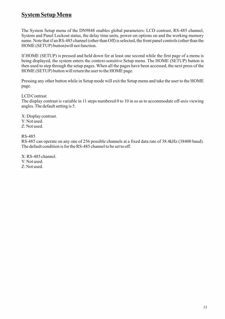
LCD ContrastThe display contrast is variable in 11 steps numbered 0 to 10 in so as to accommodate off-axis viewingangles. The default setting is 5.
X: Display contrast.Y: Not used.Z: Not used.
RS-485RS-485 can operate on any one of 256 possible channels at a fixed data rate of 38.4kHz (38400 baud).The default condition is for the RS-485 channel to be set to off.
X: RS-485 channel.Y: Not used.Z: Not used.
13

SETUP
SETUP
SETUP
SETUP
RS-485
Channel
Set
Front
Panel
Locked
SETUP
SETUP
SETUP
SETUP
SETUP
SETUP
Diagram Showing system setup menu screen:
14

SECURITYA number of lockout modes have been included to prevent tampering with the unit in situations whereunauthorised or unqualified personnel may have physical access.
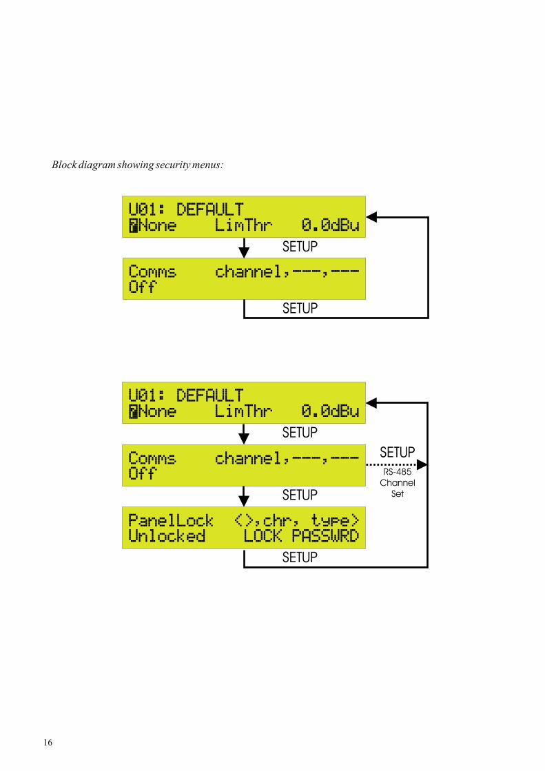
FRONT PANELLOCKOUTThis facility enables the user to set a password of up to 24 characters in order to disable the front panelcontrols. There are three possible lockout options: Unlock, Lock with full recall and Full Lock. WhenFront Panel Lock is enabled, the Setup menu options will be confined to the RS-485 Communicationsand front Panel Lockout pages only. All lock functions are retained after power down. To unlock theunit, the correct password must be entered. Press HOME (SETUP) to access the password page.
SYSTEM PROTECT ENABLE/DISABLEWith a component so central to a sound system as a crossover unit, it is possible that certain parameterchanges could result in loudspeaker damage, so a system is in place to make these parametersinaccessible to unauthorized users. As with the panel lock modes, this function is password protected.The password setup procedure is exactly the same as for the panel lock mode.
When the System Lock is on, the user will be denied access to the input channel compressors and alloutput menu functions. It is also not possible to load factory or system patches while the System Lock ison, though User memories may still be accessed, as may the Password page, input gain, EQ and delayparameters.
As supplied, the password field is blank and the unit is unlocked.
To set password:
X: Character position.Y: Select character.Z: Toggles Lock mode on or off.
To unlock the unit, the correct password must be entered via the HOME (SETUP) page.
To enter a password:
X: Set character position.Y: Select character.Z: Toggles the Lock mode on or off.
15
SETUP
SETUP
SETUP
SETUP
SETUP
RS-485
Channel
Set
SETUP
Block diagram showing security menus:
16

RS-485 LOCALOVERRIDEIn normal use, the RS-485 channel number is set to Off in the Setup menu. If a channel number isselected, the HOME (SETUP) key will still function but all other front panel controls (other than LCDcontrast) will be inoperative (regardless of the Panel Lockout status) as the unit now expects to receivecommands via the RS-485 interface. Pressing the HOME (SETUP) key when in this mode will take theuser directly to the RS-485 Communications page, where changing the Channel number back to Offwill restore normal front panel operation and return the user to the HOME page when the HOME(SETUP) is pressed again.
NAME WORKING MENUThis function allows the user to rename the currently recalled patch (the contents of the workingmemory) without having to go through the Store sequence. Note that factory preset patches cannot berenamed.
X: Character position.Y: Selects character.Z: Not used.
DELAYUNITS/TEMPERATUREThis section allows the user to choose the delay units to read in time or distance based on the speed ofsound. In distance mode, the nominal ambient temperature may be entered to correct the input channeldelay time. The available units are: milliseconds, microseconds, imperial (feet and inches) and metric(metres and millimetres). Note that although the unit has the ability to monitor its own internaltemperature, this will be higher than the nominal venue air temperature, so should not be used for delaytime calculations. The temperature may be entered in the range 0 to 40 degrees C in 1 degreeincrements. Note that the temperature parameter is only relevant when the delay is set in units ofdistance, not as time.
X: Set delay units.Y: Enter temperature.Z: Not used.
POWER ON OPTIONSThe user can opt whether or not the unit should display an animated screen on startup (Logo On/Off). Ifselected, the screen will be displayed until the audio outputs are at their full operating levels. In additionto the power on/off muting, the user may set a ramp time to fade up the crossover output levelsgradually, the maximum ramp time being 30 seconds. The default settings are with the Start-Up screenoff and the ramp time set to 5 seconds.
X: Selects Start-Up screen on or off.Y: Output level ramp time.Z: Not used.
17

Input Menu Structure
Each of the Input channels comprises a gain control, eight fully parametric EQ stages, a compressor anda delay line, monitored by a dual function bargraph meter that shows both signal headroom andcompressor gain reduction.
Input channelmenu block:
18
INPUT
INPUT
INPUT
INPUT
INPUT
INPUT
INPUT
INPUT
INPUT
INPUT
INPUT
INPUT
INPUTSystem
Protect
Password
Pin Set

INPUT GAIN/DELAYNote that the delay units are selected in the Setup menu.
Input Delay/Gain PageX: Not usedY: Input DelayZ: Input Gain.
PARAMETRIC EQUALISEREach of the eight stages is identical, each being accessed via a separate menu page.
Input PEQ Pages 1 - 8X: Frequency.Y: BandwidthZ:Amount of cut or boost.
COMPRESSORThis is a straightforward, variable ratio, compressor with selectable hard or soft knee characteristicsand a bypass function. There are two menu pages for parameter adjustment.
Input Compressor Page 1:X: ThresholdY: RatioZ: Insert On/Off
Input Compressor Page 2:X:AttackY: ReleaseZ: Knee
19

The Output Menu Structure
OUTPUT
OUTPUT
OUTPUT
OUTPUT
OUTPUT
OUTPUT
OUTPUT
OUTPUT
OUTPUT
OUTPUT
OUTPUT
OUTPUT
OUTPUT
Output channelmenu block:
Each of the eight output channels provides configurable high and low-pass filters for setting thecrossover characteristics as well as six further stages of fully parametric equalisation that may be usedto compensate for system or enclosure characteristics. Delay of up to 300ms is available in addition togain control, muting and limiting. Dual all-pass phase correction with channel invert. A number ofpreset input-to-output routing options are available.
The edit menu for any output channel may be accessed by pressing in the corresponding output menuselect button. Only one channel may be active for editing at any time, and after pushing the switch, theOutput menu will be accessed unless it has been password protected.
The menu is always first accessed at its top page where subsequent pushes on the select button willcause the menu to step through the available pages. When all the pages have been presented, the nextpush will return the user to the top of the menu. Pressing the HOME (SETUP), STORE or RECALLkeys will cause the display to jump to the HOME page. Pressing the select button for a different outputchannel will show the same menu page for the newly selected channel.
20

ROUTING/OUTPUT DELAYEach outputs can select one of the following sources as its input:
Delay Units: Time or a choice of imperial or metric distance as selected in the Setup menu. The choiceof delay units applies to both the input and output channels.
Routing/Output Delay PageX: Routing option.Y: Delay.Z: Balance.
OUTPUT PHASE CORRECTION FILTER.
Provides first order correction of phase with phase angle referenced to one of the filters in the output.
X: Phase angle - 0° to 180° in 5° steps. 0° is off..Y:Angle Reference - one of LPF, HPF, LEQ/PEQ1, PEQ2,3,4,5, HEQ/PEQ6.Z: Invert.
OUTPUT ALL-PASS FILTERProvides first and second order correction of phase.X: Frequency.Y: Q - only active for second order filter.
Z: .
The frequency control sets the point at which 90° (first order) or 180° (second order) of phase shift isachieved. Q gives control over the slope of the phase transition for a second order filter.
In all cases the phase changes from 180° / 360° at low frequency to 0° at high frequency.
OUTPUT LOW-PASS FILTERLow-Pass Filter PageX: Frequency.Y: Filter type.Z: Filter slope.
OUTPUT HIGH-PASS FILTERHigh-Pass Filter PageX: Frequency.Y: Filter type.Z: Filter slope/Peaking filter gain.
Enable- one of OFF, 1 or 2st n d
21

22
OUTPUT PARAMETRIC/LOW SHELF FILTERThe upper and lower bands of the six-band output parametric equaliser may be switched betweenbandpass and shelving operation. In other respects, the six bands are identical in range and controlfunctions.
BAND 1Output PEQ/LEQ PageX: Frequency.Y: Bandwidth/Rolloff slope.Z: Level.
BANDS 2 - 5Parametric bands 2 - 5 are identical but without the shelving filter option.
Output PEQ 2 - 5 PageX: Frequency.Y: Bandwidth .Z: Level.
BAND 6Output PEQ/HEQ PageX: Frequency.Y: Bandwidth/Rolloff slope.Z: Level.
OUTPUT LIMITERThe output limiter is a peak reading design, the main function of which is to protect equipment being fedfrom the DN9848 from being driven into clipping. In order to accomplish this, the limiter acts veryquickly and employs an intelligent auto system that adjusts the 'look ahead' time according to therelease time setting. The look ahead time varies between 10 and 24 samples so that transients can beanticipated, but no setup on behalf of the user is required. The limiter threshold is variable so as toaccommodate the level requirements of virtually all professional equipment. Limiter action ismonitored by the second from top red section on each of the output channel meters. The top sectionregisters any clips that may occur.
Limiter PageX: Threshold.Y: Release.Z: Knee.
OUTPUT MUTEEach of the eight outputs is equipped with a noise-free mute switch built into the OUTPUT levelcontrols. This switch is electronically latching and shows a red status LED ring when the channel ismuted. If one of the controls is pressed and held for more than one second, all eight outputs are muted.
METERSAll eight outputs are monitored by independent 11-segment meters, the top section of which registersclips occurring within the output channel EQ stages. The red 0dB segment below this registers limiteraction and is always referenced to the limiter threshold. The remaining green and yellow segmentsindicate the output signal level from -40dB to -3dB. If the limiter threshold is exceeded, the meters flipto reading gain reduction which is shown reading downwards from the 0dB segment.
If the limiter threshold is set to Off, the limit segment will illuminate at the same time as the Clipsegment.

23
Test Mode
If the Setup key is held down while the unit is powered up, the DN9848 automatically enters itsdiagnostic mode, displaying a Test menu. This is for use by service personnel only. If this mode isentered inadvertently, power down the unit, then power up again normally.

24
Operational Example
Quick Start
This section assumes that the DN9848 is not locked and that the user is familiar with the concepts ofcrossovers, compressors, equalisers and limiters.
Each input channel includes eight parametric equalisation stages, up to 1000ms of delay, gain controland compression. Full metering with clip indication is available for all input and output channels.
Each output channel provides configurable high and low-pass crossover filters in addition to six furtherstages of fully parametric equalisation, adjustable delay of up to 300ms, gain control, muting andlimiting. Dual all-pass phase correction sections are also included, each of which is referenced to thecut-off frequency of the low-pass filter and adjustable in 5 degree steps.
To access an Input Channel for editing, press one of the four input channel select buttons. This willdisplay the first page of the Input Channel menu. Further button presses will step through the menupages, eventually returning to the first page.
Changes to on-screen parameters are made via the X,Yand Z rotary controllers that relate directly to theparameters currently displayed on-screen. Each controller has an illuminated status indicator whichwill remain unlit if there is no corresponding parameter (ie. if the current screen contains only one ortwo adjustable parameters).
ToAccess an Output Channel, press one of the eight output channel select buttons. This will display thefirst page of the Output Channel menu. Further control presses will step through the menu pages,eventually returning to the first page. Note that the input-to-output routing options are selected withinthe Output Channel menu.
The crossover filter types available are:
12dB/octave peaking (high-pass only)24 dB/octave peaking (high-pass only)Butterworth (6, 12, 18, 24, 36 and 48dB/octave)Linkwitz-Riley (12 and 24dB/octave)Bessel (12, 18, 24, 36 and 48dB/octave
Changes to on-screen parameters are made via the X,Yand Z rotary controllers that relate directly to theparameters currently displayed on-screen. Each controller has an illuminated status indicator whichwill remain unlit if there is no corresponding parameter (ie. if the current screen contains only one ortwo adjustable parameters).
To load a factory preset or user patch, press RECALL to display the Recall menu. Here it is possible toselect from System, User and Factory patches. Changes to on-screen parameters are made via the X, Yand Z rotary controllers that relate directly to the parameters currently displayed on-screen.
To save a User or System Patch, press SAVE to display the save menu. Here patches may be saved intoeither the System or User locations and named with up to 24 characters. Changes to on-screenparameters are made via the X, Y and Z rotary controllers that relate directly to the parameters currentlydisplayed on-screen.

25
The Security features are located in the Setup menu, accessed by pressing the HOME (SETUP) key andholding it down for a minimum of 2 seconds. Even when the unit is locked, the menu pages relevant topassword entry will always be accessible. There are two types of lockout: Full Panel Lock and SystemLock. In System Lock mode, the User memories are still accessible.
Note that the input meters have a dual function: they display headroom until the compressor or limiterthresholds are reached when they switch to displaying gain reduction, which reads from the top of themeter downwards. The output meters display gain unless limiting occurs, in which case they show gainreduction.

26
Technical Specification
Audio Inputs Four
Audio Outputs Eight
Performance
Input Processing (per channel)
Type Electronically balanced (Pin 2 Hot)
Impedance
Balanced 20k
Unbalanced 10kCommon Mode Rejection >80 dB @ 1 kHzMaximum level + 21 dBu
Type Electronically Balanced (Pin 2 Hot)
Minimum load impedance 56 /20nF
Source impedance 56
Maximum level + 21 dBu into > 2k
Frequency response +/- 0.3 dB with all filters and EQ flat(20 Hz to 20 kHz)Distortion @ +8 dBu <0.02%(20 Hz to 20 kHz)Dynamic range >113 dB(20 Hz to 20 kHz unweighted)
Input gain +12 dB to -40 dB in 0.1 dB steps plus Off
Parametric EQ 1-8 Frequency range: 20 Hz to 20 kHzin 21 steps per octave
Boost/cut: +6/-18 dB in 0.1 dB stepsBandwidth: 3.0 to 0.08
Compressor Threshold: +21 dBu to -10 dBu in 0.1 dB steps
Attack: 40 us to 100ms (20 s steps from 40 s to 1ms.Then 1ms from 1ms to 100ms)
Insert: On/OffRelease: 10 ms to 2000ms in 10ms incrementsRatio: 1:1 to 5:1 in unit incrementsKnee: Hard/Soft
Delay 0 to 1 second (342.25 m or 1122' 10" at 20C)in 20.8 us steps
�
��
�
��
� �

27
Output Processing (per channel)Routing Route from inputs: A, B, C, D, A+B, C+D, A+B+C+D
NoneA ChannelAB Channel BC Channel CD Channel DA+B (channels summed at -3dB with balance control))C+D (channels summed at -3dB with balance control))A+B+C+D (channels summed at -6dB)
Note that sources comprising summed channels will only be aavailable if the input channel delays for the summed channelsare set to the same value.
Controller Z functions as a balance control when the source isA+B or C+D. The balance is adjustable from 0 to 100% in 1%increments.
Delay 0 to 300 ms (102.68 m or 333' 10" at 20°C)in 5.02 us steps
Output phase correction filter Phase angle: - 0° to 180° in 5° steps. 0° is offAngle Reference: - one of LPF, HPF, LEQ/PEQ1, PEQ2,3,4,5,
HEQ/PEQ6Invert: Yes / No
Output all-pass filter Frequency: 20Hz - 20kHz in 21 steps per octaveQ- only active for second order filter: 0.4 to 6.0
Enable: one of OFF, 1 or 2
Low pass filter The following filter configurations are supported:-
i. Butterworth (6 dB/Oct, 12 dB/Oct, 18dB/Oct,24 dB/Oct, 36 dB/Oct, 48 dB/Oct)
ii. Linkwitz-Riley (12 dB/Oct, 24 dB/Oct)iii. Bessel (12 dB/Oct, 18 dB/Oct, 24 dB/Oct, 36
dB/Oct, 48 dB/Oct)iv. Filter bypass
Frequency Range: 20 Hz to 15 kHz in 21 steps/octave
High pass filter The following filter configurations are supported:-
i. 12 dB/Oct Peakingii. 24 dB/Oct Peakingiii. Butterworth (6 dB/Oct, 12 dB/Oct, 18 dB/Oct,
24 dB/Oct, 36 dB/Oct, 48 dB/Oct)iv. Linkwitz-Riley (12 dB/Oct, 24 dB/Oct)v. Bessel (12 dB/Oct, 18 dB/Oct,
24 dB/Oct, 36 dB/Oct, 48 dB/Oct)vi. Filter bypass
Frequency Range: 20 Hz to 15 kHz in 21 steps/octavePeaking Filter Boost: 0 dB to +6 dB in 0.1 dB steps.
st n d

28
Parametric EQ 1/Low shelf filter Frequency range: 20 Hz to 20 kHzin 21 steps per octave
Boost/cut: +12/-12 dB in 0.1 dB stepsParametric EQ Bandwidth: 3.0 to 0.08Shelf slope: 6 dB/Oct and 12 dB/Oct
Parametric EQ 2-5 Frequency range: 20 Hz to 20 kHzin 21 steps per octave
Boost/cut: +12/-12 dB in 0.1 dB stepsBandwidth: 3.0 to 0.08
Parametric EQ 6/High shelf filter Frequency range: 20 Hz to 20 kHzin 21 steps per octave
Boost/cut: +12/-12 dB in 0.1 dB stepsParametric EQ Bandwidth: 3.0 to 0.08Shelf slope: 6 dB/Oct and 12 dB/Oct
Phase invert Normal/invert
Output gain +12 dB to -40 dB in 0.5 dB steps plus Off
Look-ahead limiter Threshold: +21 dBu to 10 dBu in 0.5 dB stepsRelease: 10 ms to 1000 msKnee: Hard/Soft
Mute On/off
Voltage 90 to 250 V a.c @ 50/60 HzConsumption < 75 VAFuse rating T0.5L 250V
Width 483 mm (19 inch)Height 44 mm (1.75 inch)Depth 287 mm (12 inch)
Nett 4kgShipping 6kg
Audio inputs/outputs 3-pin XLRRS-485 inputs/outputs 3-pin XLRRS-232 8-pin Mini-DIN socketPower 3-pin IEC
Power Requirements
Dimensions
Weight
Terminations