Embed Size (px)
Citation preview

DN085-01v06
JYE Tech - 1 - www.jyetech.com
FG085 miniDDS Function Generator
Manual of Operation Applicable Models: 08501, 08501K, 08502K, 08503, 08503K, 08504K Applicable Firmware Version: 1 ) 113-08501-130 or later (for U5)
2 ) 113-08502-050 or later (for U6)
1. Getting Started ...................................................................................................................... 1 2. Front Panel Features ............................................................................................................. 2 3. Connectors ............................................................................................................................ 4 4. FG085 Operations................................................................................................................. 6
Continuous Waveform (CW) Mode............................................................................................................... 6 Frequency .............................................................................................................................................. 7 Amplitude.............................................................................................................................................. 8 DC Offset............................................................................................................................................... 8 Incremental Adjustment......................................................................................................................... 8 Duty Cycle............................................................................................................................................. 8 Trigger Function .................................................................................................................................... 9
Frequency Sweeping Mode ........................................................................................................................... 9 Range and Rate.................................................................................................................................... 11 Sweep Direction .................................................................................................................................. 12 Trigger Function .................................................................................................................................. 12 Sync Pulse Output ............................................................................................................................... 12 Amplitude............................................................................................................................................ 12 DC Offset............................................................................................................................................. 12
Servo Position Mode ................................................................................................................................... 13 Pulse Width and ................................................................................................................................... 14 Pulse Amplitude................................................................................................................................... 14 Increment and ...................................................................................................................................... 14 Servo Signal Settings........................................................................................................................... 15
Servo Run Mode.......................................................................................................................................... 15 States ................................................................................................................................................... 16 Change Settings ................................................................................................................................... 16
Arbitrary Waveform Generation (AWG) ..................................................................................................... 16 How It works ....................................................................................................................................... 16 Define Waveform File ......................................................................................................................... 17 Download Waveform........................................................................................................................... 17 Select User Waveform ......................................................................................................................... 17 Waveform Download........................................................................................................................... 18
5. Firmware Upgrade .............................................................................................................. 18 6. Technical Support ............................................................................................................... 19 7. Specifications...................................................................................................................... 19
Revision History.................................................................................................................................. 20
1. Getting Started
Introduction The FG085 is a low cost versatile function generator capable of producing continuous signal, frequency sweeping signal, servo test signal, and user defined arbitrary signals. It was designed as an easy-to-use tool for electronic hobbyists. The operation of FG085 is extremely straightforward. The following examples will lead you step-by-step through some typical uses.

DN085-01v06
JYE Tech - 2 - www.jyetech.com
Front view of 08501/08502
Data Entry Setting of FG085 signal parameters is done by first pressing one of the parameter keys (F/T, AMP, or OFS). The display of that parameter will be cleared and an underline is shown, indicating place for new value to be typed in. If at the moment you hit a parameter key the cursor is not currently at that parameter just press the key one more time to make the underline shown. Then enter new value using the DIGIT keys. Complete entry by hitting one of the UNITS keys. If an error is made at typing pressing [ESC] key will do backspace to correct it. If no more digits left when [ESC] is pressed it will exit Data Entry and display the original value.
A cursor focused parameter can also be adjusted incrementally by tuning [ADJ] dial.
Examples 1 ) To set output frequency to 5KHz press the following keys:
[F/T] [5] [KHz]
2 ) To change output waveform to square wave press [WF] until “SQR” is shown.
3 ) To set output amplitude to 3V peak-to-peak press the
following keys: [AMP] [3] [V] 4 ) To set DC offset to -2.5V press the following keys [OFS] [+/-] [2] [.] [5] [V]
2. Front Panel Features

DN085-01v06
JYE Tech - 3 - www.jyetech.com
Front view of 08503
1 ) Power Switch The power switch turns the FG085 on and off.
2 ) Parameter Keys The parameter keys select the parameter to be entered. If cursor is not currently at a parameter pressing the parameter key will first move cursor to that parameter.
3 ) Digit Keys The numeric keypad allows for direct entry of the FG085’s parameters. To change a parameter value simply press the parameter key (if cursor is not currently at the parameter press the parameter key twice) and then type a new value. Entries are terminated by the UNITS keys. If an error is made at typing press [ESC] key to correct it (back space). If no more digits left when [ESC] is pressed it will exit Data Entry and display the previous value.
The [+/-] key may be pressed at any time during numeric entry.
4 ) Unit Keys The UNIT keys are used to terminate numeric entries. Note that the unit keys represent different unit at different parameter entry. Under CW mode pressing unit keys without first entering digits will display incremental step sizes. [Hz] key displays frequency step size. [KHz] key displays time step size.
5 ) Waveform Key This key selects output waveform. Repeated pressing of this key will go through all available waveforms.
6 ) ESC key This key backspace typed digits and/or exit current state.
7 ) ADJ Dial By [ADJ] dial users can incrementally adjust a focused parameter up and down. To do this first pressing a parameter key to move cursor the parameter to be changed and then turn the dial.
Under CW or Sweep mode pressing the dial will toggle Trigger function on or off.
At Servo mode pressing the dial will enter Setting Change

DN085-01v06
JYE Tech - 4 - www.jyetech.com
Front view of 08501/08502
Board view of 08503
state
8 ) MODE Key This key selects FG085’s working modes.
9 ) Frequency (Period) Display of current output frequency or period.
10 ) Waveform Display of current waveform type.
11 ) DC Offset Display of current output DC offset.
12 ) Amplitude Display of current output amplitude.
13 ) Cursor Indication of currently focused parameter. Turning [ADJ] dial will incrementally change this parameter. When Trigger Function is on the cursor change to ‘*’.
14)Function Output (J4)
This is the front output connector. Its output impedance is 50Ω.
3. Connectors

DN085-01v06
JYE Tech - 5 - www.jyetech.com
1 ) Power Input (J1) This is the DC power supply input connector. Its center core
should be connected to the positive pole of power supply. FG085 is specified for 14V – 16V DC. The current capacity of power supply should be greater than 200mA average.
2 ) Function Output (J5)
This is the back output connector. Its output impedance is 50Ω.
3 ) USB (J10) This provides a connection to PC for waveform data download and instrument control.
4 ) Alternative USB (J7)
This connector allows wiring the USB connection to socket at enclosure.
5 ) Contrast Adjustment
This is a trimmer for LCD contrast adjustment.
6 ) U5 Programming Port (J8)
This is the programming header for the main controller ATmega168 (U5).
Pin-out Description
Pin# Signal Name I/O Function
1 MOSI I U5 programming 2 +5V PWR 3 NC - No connection 4 - - Reserved 5 nRST I U5 programming 6 - - Reserved 7 SCK I U5 programming 8 GND PWR 9 MISO O U5 programming
10 GND PWR
7 ) U6 Programming Port (J6)
This is the programming header for the DDS core controller ATmega48 (U6)
Pin-out Description
Pin# Signal Name I/O Function
1 MOSI I U6 programming 2 +5V PWR 3 Sync O Sync output (sweeping mode) 4 - - Reserved 5 nRST I U6 programming 6 TrigIn I Trigger input 7 SCK I U6 programming 8 GND PWR 9 MISO O U6 programming
10 GND PWR

DN085-01v06
JYE Tech - 6 - www.jyetech.com
4. FG085 Operations
Power-on Push down the power switch to turn on FG085. It will first display model name. Then manufacturer/vendor name follows. After displaying firmware versions the unit enters normal working state.
Output The output amplitude display is only correct when load is in high impedance (much larger than 50Ω). If load impedance is close to 50Ω the output amplitude will be lower then displayed. If load impedance is 50Ω the output amplitude will half of that displayed.
Mode Selection
FG085 can work in one of four different modes. These four modes are:
1) Continuous Waveforms (CW) mode 2) Frequency Sweeping mode 3) Servo Position mode 4) Servo Run mode
Pressing [Mode] button will display the mode selection menu.
Tuning [ADJ] will scroll through these modes. The number at the lower-right corner indicates menu position. Pressing [MODE] will select the mode displayed. Pressing [ESC] will exit mode selection without change.
Continuous Waveform (CW) Mode In this mode the generator outputs continuous signal of selected waveforms. Signal frequency, amplitude, and DC offset can be independently set by user.
Screen Please refer to Section 2 “Front Panel Features”.
Waveform Selection Waveform selection is done by pressing [WF] key.

DN085-01v06
JYE Tech - 7 - www.jyetech.com
Frequency Frequency is set by first pressing [F/T]. The current display will be erased and an underline is shown, allowing user to enter new value. New value is entered with digit keys and followed by one of the Unit keys. Alternatively, frequency can be changed incrementally by using the [ADJ] dial when it is focused. The incremental step size can be set to any number you want (see below).
Frequency can also be set in period (indicated by letter ‘T’). Press [F/T] key will toggle between frequency and period entry mode.
Frequency Range
In spite of that no limited range is set for frequency entry it should be aware of that there are practical ranges for output frequency due to the low resolution 8-bit DAC and slow sample rate (2.5Msps). Out of these ranges signal quality will degraded as larger distortions and jitters appear. The acceptable ranges depend on actual applications. For FG085 output frequency within the following range is considered reasonably good for most applications.
Function Range Sine Square Triangle Ramp Staircase
0 – 200KHz 0 – 10KHz 0 – 10KHz 0 – 10KHz 0 – 10KHz
Maximum Frequency Error Maximum frequency error depends on sample clock and phase accumulator size. For FG085 the phase accumulator size is 24 bits. Two sampling clocks, 2.5Msps and 10Ksps, are used. Sample clock is automatically selected based on frequency setting as shown in the table below.
Frequency Sampling Clock Maximum Error > 40Hz 2.5Msps 0.1490 Hz ≦ 40Hz 10Ksps 0.0005960 Hz

DN085-01v06
JYE Tech - 8 - www.jyetech.com
Amplitude Amplitude is set by first pressing [AMP] key. The current display will be erased and an underline is shown, allowing user to enter new value. New value is entered with Data Entry keys and followed by one of the Unit keys. Alternatively, amplitude can be changed incrementally by using the rotary encoder when it is focused.
The displayed amplitude value is peak-to-peak value.
The amplitude range is limited by the DC offset setting since |Vac peak| + |Vdc| ≤ 10 V (into High-Z).
D.C. Only
The output of the FG085 can be set to a DC level by entering amplitude of 0V. When the amplitude is set to zero the A.C. waveform will be completely shut off and the FG085 may be used as a DC voltage source.
DC Offset DC offset can be set by first pressing [OFS] key. The current display will be erased and an underline is shown, allowing user to enter new value. New value is entered with Data Entry keys and followed by one of the Unit keys. Alternatively, offset can be changed incrementally by tuning [ADJ] when it is focused.
In general, the DC offset may range between ±5V, but it is limited such that |Vac peak| + |Vdc| ≤ 10 V (into High-Z), or | Vac peak | + |Vdc| ≤ 10 V (into HIGH-Z).
Incremental Adjustment
FG085’s output frequency, amplitude, and DC offset can be changed incrementally up and down by using [ADJ] dial. To do this first move cursor to the parameter you want to change by pressing a parameter key and then turn the rotary encoder clock-wise for increment and counter-clock-wise for decrement.
Tip Incremental step size can be set to any value. To do this directly enter the step size you want and follow by [Hz] or [ms] button. [Hz] button sets step size for frequency adjustment. [ms] button sets step size for time adjustment. Press [Hz] or [ms] without digits will display current frequency or time step size.
Duty Cycle (for square waveform)
Duty cycle can be set to value between 0% and 100%. Pressing [.] (the decimal point key) will display current duty cycle. Press [.] key again the display will be erased and an underline will show, allowing user to enter new value. Pressing any of the unit keys terminates the entry. Pressing [ESC] returns to normal CW mode display.
Note that duty cycle only takes effect for square waveform. The acceptable value range is 0 – 100% with resolution of 1%.

DN085-01v06
JYE Tech - 9 - www.jyetech.com
Trigger Function The trigger function allows user to control the generator output by an external signal. When the external signal is HIGH output signal is stopped. As soon as the trigger signal changes to LOW output signal resumes (see screen capture below).
The external signal must be TTL level compatible and applied to pin 6 of J6.
The trigger function can be turned on/off by pressing [ADJ] dial. When it is on the cursor (normally ‘>’) will change to ‘*’ as indicator.
The initial phase of output signal at each trigger is constant.
Note that the trigger input is pulled to HIGH internally. There will be no output when the terminal is left open. This feature allows using a switch as trigger source.
Trigger waveform
Frequency Sweeping Mode In this mode FG085 generate frequency sweeping signals. The sweeping range and rate as well as signal amplitude and DC offset are all independently set by user.
Screen
Turning [ADJ] or pressing digit buttons [1], [2], [3], and [4] will have Start Freq, Stop Freq, Sweep Time, and Time Step Size displayed respectively.

DN085-01v06
JYE Tech - 10 - www.jyetech.com
Waveform Selection Waveform selection is done by pressing [WF] key.
Normal sweeping
Bi-directional sweeping

DN085-01v06
JYE Tech - 11 - www.jyetech.com
Range and Rate of Sweep
Frequency sweeping is actually frequency stepping. Four parameters determine the frequency change range and rate:
- Start Frequency - Stop Frequency - Sweep Time - Time Step Size
The following drawing illustrates their relationships. Frequency change is linear only. The smallest time step is 1ms.
To change these parameters first turn [ADJ] dial to select the parameter you want to change. Then press [F/T] button to enter values.
Tip
You can also quickly access these parameters by buttons [1], [2], [3], and [4]. Their relationships are:
[1] - Select/change Start Frequency [2] - Select/change Stop Frequency [3] - Select/change Sweep Time [4] - Select/change Time Step Size
Notes:
1. Start and stop frequencies can only be entered in Hz or KHz. The DDS sampling clock selects 2.5Msps as long as sweeping mode is entered. As a result the frequency resolution in this mode is 0.1490Hz (see explanations in CW mode). The allowable frequency range is 0 – 999999 Hz. Keep in mind that when frequency goes beyond certain extend the signal quality degrades significantly.
2. Sweep time can be entered in Sec or mSec. It is always displayed in "mS". The allowable sweep time range is 1 – 999999 mS.
3. Time step size can be entered in Sec or mSec. It is always displayed in "mS". The allowed range is 1 – 65535 mS.
4. When Sweep Time is less than Time Step Size the actual sweep time becomes 2 * (Time Step Size). Frequency sweeping in this case is degraded to outputting start and stop frequency alternatively. This creates an effect of FSK.

DN085-01v06
JYE Tech - 12 - www.jyetech.com
Sweep Direction Normally frequency sweeping is from start frequency (Fstart) to stop frequency (Fstop). This is called Normal Sweeping. For FG085 the sweep can be set to two way sweeping, i.e. it sweeps from Fstart to Fstop, and then from Fstop back to Fstart. This is call Bi-directional sweeping.
To enable bi-directional sweeping press the [+/-] button. A letter ‘B’ will be shown on screen, indicating bi-directional sweep is enabled. Press [+/-] again will turn the function off.
See photos above for normal sweeping and bi-directional sweeping.
For bi-directional sweeping the signal phase is continuous every where.
Trigger Function Trigger function is also available for sweep mode. When this function is enabled the generator only starts sweeping at falling edge of trigger signal.
Press [ADJ] to toggle trigger function on/off. A ‘*’ character will be displayed on screen to indicate trigger function is on.
Unlike the case in CW mode where output stops as soon as trigger signal changes to HIGH, sweeping signal will finish a full sweep even trigger signal has turned HIGH before the end of a started sweep.
Sync Pulse Output For normal sweeping a positive synchronous pulse is generated at pin 3 of J6 between the end of a sweep and the start of next sweep. The pulse width is about 0.5ms. Its amplitude is 5V. See the photo of normal sweeping above.
For bi-directional sweeping the same pin outputs LOW (0V) level when sweeping from Fstart to Fstop and outputs HIGH (+5V) level when sweeping the other way around (i.e. from Fstop to Fstart, see the photo of bi-directional sweeping above).
Amplitude See the explanation of "Amplitude" in CW mode.
DC Offset See the explanation of "DC Offset" in CW mode.

DN085-01v06
JYE Tech - 13 - www.jyetech.com
Servo Position Mode In this mode the generator outputs servo control signal with specific pulse width, amplitude, and cycle. All these parameters can be set independently by user.
Servo Control Signal The drawing below shows a servo control signal.
Typically servo signal takes following parameters:
1) Cycle: 20ms 2) Pulse Width: 1ms – 2ms 3) Pulse Amplitude: 5V
The pulse width determines servo position.
Screens The photo below shows the screens of Servo Position Mode. The first screen shows pulse width in unit of microsecond. The second shows pulse amplitude in unit of volt. Pressing [F/T] will display the pulse width screen and pressing [AMP] will display the amplitude screen.

DN085-01v06
JYE Tech - 14 - www.jyetech.com
Pulse Width and Cycle
At pulse width screen pressing [F/T] will erase current display and show an underline, allowing user to enter new pulse width. New pulse width is entered with Data Entry keys and followed by one of the two Unit keys. The value entered is treated as microsecond if the unit key [Sec] is used, or as millisecond if the unit key [mSec] is used.
Please note that the range of pulse width that user can actually enter is limited by two values, SV.PWmin and SV.PWmax. If the pulse width you input is out of the range defined by SV.PWmin and SV.PWmax then the input will be substituted by the limit numbers. These limiting values can be modified by user (see below). The default values of SV.PWmin and SV.PWmax are 1000 uSec and 2000 uSec respectively.
Servo signal cycle can be changed too. This is done by modifying the setting SV.Cycle in Setting Change state (see below).
Pulse Amplitude At pulse amplitude screen pressing [AMP] will erase current display and show an underline, allowing you to enter new pulse amplitude. Enter new pulse amplitude with Data Entry keys and follow by one of the two Unit keys. The number you entered is treated as volt if the unit key [V] is used, or as mill volt if the unit key [mV] is used.
Like pulse width the maximum of amplitude that user can enter is limited by the value of SV.AMPmax. If the amplitude entered is greater than SV.AMPmax then the input will be substituted by SV.AMPmax. The default value of SV.AMPmax is 5.0V. It can also be changed in “Change Setting” state (see below).
Increment and Decrement
At either pulse width screen or amplitude screen user can turn [ADJ] to incrementally change pulse width or amplitude. The step size of incremental change for pulse width is defined by SV.PWinc, another setting that can be modified by user (see below).

DN085-01v06
JYE Tech - 15 - www.jyetech.com
Servo Signal Settings Servo signal settings are a number of EEPROM stored values that affect the behaviour of servo signal generation. These values are user changeable. In order to change these values pressing [ADJ] to enter Setting Change state. The following screen will be displayed.
The top line shows a setting name. The bottom line shows its value. The number at top-right corner indicates current menu position.
To change a setting first scroll to that setting by turning [ADJ]. Then press [F/T] to enter a new value.
Pressing [ESC] will exit Setting Change state.
Restore factory default
Factory default settings can be restored by scroll to the last item and pressing [WF] key.
The following table lists the details about servo signal settings.
Setting Descriptions Acceptable Range Default
SV.PWmin The minimum pulse width allowed
0 – 26000 uSec 1000
SV.PWmax The maximum pulse width allowed
0 – 26000 uSec 2000
SV.PWmid Pulse width corresponding to servo nurture position
0 – 26000 uSec 1500
SV.PWinc [ADJ] step size in Servo Pos mode
0 – 26000 uSec 100
SV.RunStep Step size of pulse width change in Servo Run mode
0 – 26000 uSec 100
SV.RunRate Duration of one step in Servo Run mode
0 – 6.5 Second 0.1
SV.Cycle Servo signal cycle 0 – 26000 uSec 20000
SV.AMPmax The maximum pulse amplitude allowed
0 – 10.0V 5.0V
When a setting is set to a value out of acceptable range the instrument behaviour is not defined.
Servo Run Mode In this mode the generator outputs servo control signal with changing pulse width. The pulse width change step, rate, and range are user settable.
DN085-01v06
JYE Tech - 16 - www.jyetech.com
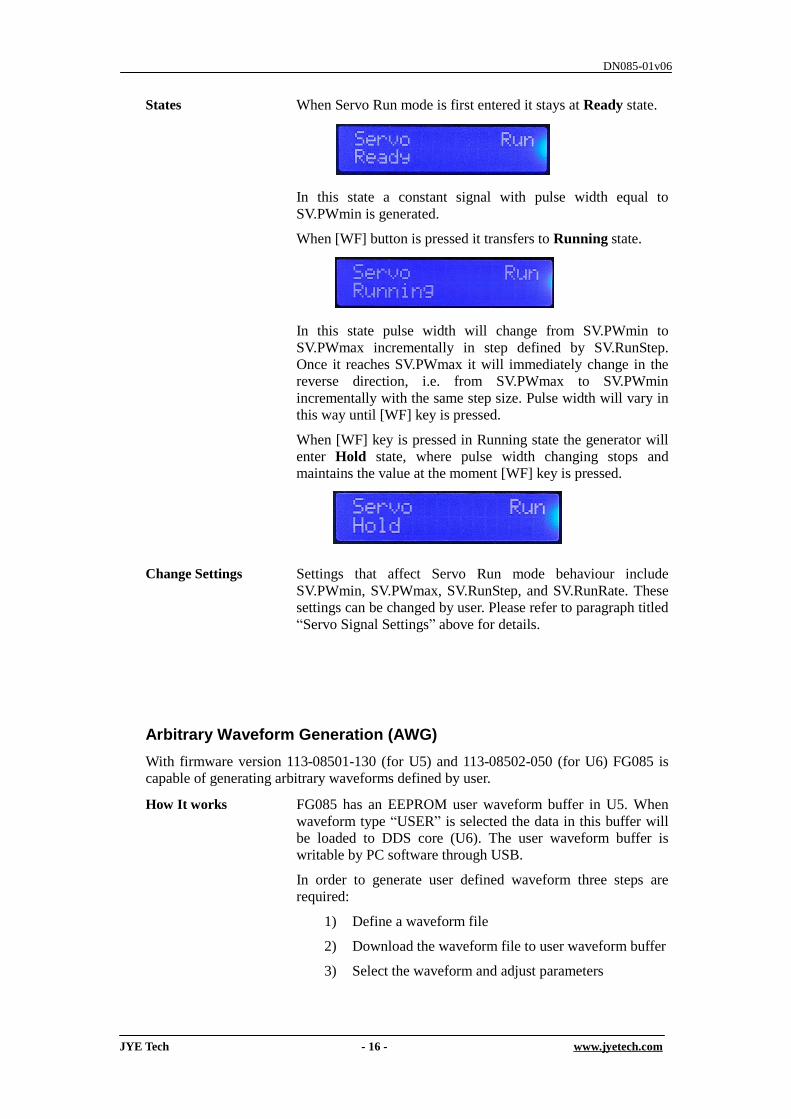
States When Servo Run mode is first entered it stays at Ready state.
In this state a constant signal with pulse width equal to SV.PWmin is generated.
When [WF] button is pressed it transfers to Running state.
In this state pulse width will change from SV.PWmin to SV.PWmax incrementally in step defined by SV.RunStep. Once it reaches SV.PWmax it will immediately change in the reverse direction, i.e. from SV.PWmax to SV.PWmin incrementally with the same step size. Pulse width will vary in this way until [WF] key is pressed.
When [WF] key is pressed in Running state the generator will enter Hold state, where pulse width changing stops and maintains the value at the moment [WF] key is pressed.
Change Settings Settings that affect Servo Run mode behaviour include SV.PWmin, SV.PWmax, SV.RunStep, and SV.RunRate. These settings can be changed by user. Please refer to paragraph titled “Servo Signal Settings” above for details.
Arbitrary Waveform Generation (AWG) With firmware version 113-08501-130 (for U5) and 113-08502-050 (for U6) FG085 is capable of generating arbitrary waveforms defined by user.
How It works FG085 has an EEPROM user waveform buffer in U5. When waveform type “USER” is selected the data in this buffer will be loaded to DDS core (U6). The user waveform buffer is writable by PC software through USB.
In order to generate user defined waveform three steps are required:
1) Define a waveform file
2) Download the waveform file to user waveform buffer
3) Select the waveform and adjust parameters

DN085-01v06
JYE Tech - 17 - www.jyetech.com
Define Waveform File The user waveform buffer consists of 256 samples with each sample being 8 bits. A waveform file defines the value of each sample in the buffer. The waveform file is in general CSV (comma separated value) format, which can be opened and edited by many spreadsheet applications and text editors. A waveform template file has been provided at JYE Tech web site. Based on the template users can use any text editor to create their own waveform files easily and quickly. For detailed descriptions of the internal format of FG085 waveform file please refer to the article “FG085 Waveform File Format”.
Download Waveform To FG085
Waveform is downloaded to FG085 by the jyeLab application (see http://www.jyetech.com/Products/105/e105.php). To do this:
1) Launch jyeLab. Connect FG085 to PC via USB and click the “Connect” button to establish connection. Make sure correct COM port and baudrate are selected.
2) Open the waveform file you have prepared.
3) Select menu “Generator -> Download”.
Please refer to the article “How To Generate User Defined Waveform” (available at http://www.jyetech.com).
Select User Waveform Press [WF] button until “USER” is displayed.

DN085-01v06
JYE Tech - 18 - www.jyetech.com
Waveform Download Protocol
The waveform download follows a simple protocol which is explained below.
1) Serial format Baudrate is fixed at 115200 bps. Data format is 8-N-1. No flow control.
2) Frame structure (multi-byte fields are all little endian)
3) Special value [0xFE] Hexical value 0xFE serves as synchronous character in the waveform download. It must be unique to ensure correct transmission/receiving. So if another 0xFE presents in the fields of frame size, data size, or waveform data a 0x00 byte must be inserted right after it at transmission.
Offset Field Name(size) Value
-1 Sync character (1 byte) 0xFE 0 Command (1 byte)
(write waveform) 0x14
1
Frame Size (2 bytes) Count from the command byte to the end of waveform data.
3 Reserved (1 byte) 0x00 4 Data Size (2 bytes) Number of bytes to
be downloaded to FG085 (usually should be 256. If it is greater than 256 the extra data will be ignored.)
6 Reserved (8 byte) 0x00 14 [waveform data] (as
specified in Data Size field)
Data start
5. Firmware Upgrade
From time to time there may be a need to upgrade firmwares in order to add features or improve performance. FG085 contains two AVR micro-controllers from Atmel:
1) ATmega168PA (U5), which is the main controller of the instrument. 2) ATmega48PA (U6), which is the DDS core.
To upgrade firmware an AVR programmer with compatible programming header is required. For programming header pin-out please refer to tables under section “Connectors”. If the programming header you have has a different pin-out. You need to re-route the signals to make them match. (JYE Tech’s USB AVR Programmer [PN: 07302] is ideal for FG085 programming. Please visit www.jyetech.com for details.) Download updated firmware files from JYE Tech website (www.jyetech.com) and follow

DN085-01v06
JYE Tech - 19 - www.jyetech.com
instructions of the programmer you have to carry out firmware upgrading. About Fuse Bits AVR micro-controllers contain some fuse bits that configure the chip for specific applications. In most cases these fuse bits should not be touched at firmware upgrading. But if somehow these bits are changed they should be restored as follows.
1) ATmega168PA (U5) Extended Fuse Byte: 0b00000111 ( 0x07 ) High Fuse Byte: 0b11010110 ( 0xD6 ) Low Fuse Byte: 0b11100110 ( 0xE6 )
2) ATmega48PA (U6), which is the DDS core. Extended Fuse Byte: 0b00000001 ( 0x01 ) High Fuse Byte: 0b11010110 ( 0xD6 ) Low Fuse Byte: 0b11100000 ( 0xE0 )
6. Technical Support
For any technical issues or questions in using the instrument please contact JYE Tech at [email protected]. Or post your questions at JYE Tech forum at http://forum.jyetech.com.
7. Specifications
Frequency Range 0 – 200KHz (Sine) 0 – 10K (all other waveforms)
Frequency Resolution 1Hz
Period Resolution 1ms
Maximum Frequency Error CW Mode: 0.1490 Hz when frequency > 40 Hz (2.5Msps clock) 0.0005960 Hz when frequency 40Hz (≦ 10Ksps clock)
Sweeping Mode: 0.1490 Hz when frequency > 40 Hz (2.5Msps clock)
Amplitude Range 0 – 10V peak-to-peak (when power supply voltage > 13V)
Amplitude Resolution 0.1V
DC Offset Range -5V – +5V
Offset Resolution 40mV
Sample Rate CW Mode: 2.5Msps when frequency > 40Hz 10Ksps clock when frequency 40Hz≦
Sweeping Mode: 2.5Msps
Waveform Buffer Size 256 bytes
Sample Resolution 8-bits
Trigger Input Level High: 3.5V minimum Low: 1.5V maximum
Output Delay at Trigger 5us maximum (when no panel operation)
Sync Output Level High: 4.5V minimum at 10K resistance load Low: 0.7V maximum at 10mA intake current

DN085-01v06
JYE Tech - 20 - www.jyetech.com
Output Impedance 50 ohm
Power Supply 14V DC (maximum 16V DC)
Current Consumption < 150mA (without loading)
Circuit Board Size 155mm X 55mm
Revision History
Version Date Summary v05 2013.03.19 Updates to reflect new features in firmware 113-08501-130
V06 2013.06.23 Corrected mistake in the description for waveform download frame structure.


![DN085-01v06 FG085 miniDDS Function Generator Manual of ... · as a DC voltage source. DC Offset DC offset can be set by first pressing [OFS] key. The current display will be erased](https://img.pdfslide.us/doc/110x75/5e83e7bfe553261dfb554c6d/dn085-01v06-fg085-minidds-function-generator-manual-of-as-a-dc-voltage-source.jpg)

