Embed Size (px)
DESCRIPTION
5004
Citation preview

03L 11.05.2015 Aq HFO SWe
02I 15.08.2014 Aq SWe RCG
01E 20.06.2014 Aq HFO SWe
Rev. DatePrepared
by
Reviewed
by
Approved
by
Project Tag Numbers:
80EJC0101A, 80JC0101B
As Built
Issued for Review
Issued for Review
Reason for Issue
Package Title:
Ivar Aasen Field Development Project - pdQ
HV TRANSFORMER - AIR PURGING SYSTEM CIRCUIT/WIRING DIAGRAM
EICT Package
Project Document Number:
DN02-S09011-E-XK-5004-01
Supplier Document Number:
51PO-04193.250-K-004-01
Purchase Order No:
S09011
Project No:
C-00011
Copyright © 2013 Siemens AS - Transmittal, reproduction, dissemination and/or editing of this document as well as
utilization of its contents and communication thereof to others without expressed authorization are prohibited.
Area Code: System Code: No. of
Pages
M510 80 8
Rev.
03L
Proj Rev.
03L
Note:It should be noted that any changes on tag nos. after the FATare not implemented in this revision 03L as they are not "AS BUILT"
X
David Stone 26.05.2015
DOCUMENT NO.:
REVISION NO.:
DATE:
PAGE NO.:
Notes
PROJECT NAME: Ivar Aasen Field Development Project - pdQDN02-S09011-E-XK-5004-01
DOCUMENT TITLE:HV TRANSFORMER - AIR PURGING SYSTEM
CIRCUIT/WIRING DIAGRAM
03L
P&ID NO.: 11.05.2015
TAG NO.: 80EJC0101A, 80JC0101B 2
Copyright © 2013 Siemens AS - Transmittal, reproduction, dissemination and/or editing of this document as well as utilization of its contents and
communication thereof to others without expressed authorization are prohibited.
This document has 8 pages in total

DOCUMENT NO.:
REVISION NO.:
DATE:
PAGE NO.:
Table of Contents
Page No.
DN02-S09011-E-XK-5004-01
11.05.2015
3
DOCUMENT TITLE:HV TRANSFORMER - AIR PURGING SYSTEM
CIRCUIT/WIRING DIAGRAM
03L
P&ID NO.:
TAG NO.: 80EJC0101A, 80JC0101B
PROJECT NAME: Ivar Aasen Field Development Project - pdQ
Copyright © 2013 Siemens AS - Transmittal, reproduction, dissemination and/or editing of this document as well as utilization of its contents and
communication thereof to others without expressed authorization are prohibited.
6000 Series Purge and Pressurization System 4
Technical Data 5
Purge System Installation 6
As Built Cable and Piping Connection 7
Circuit/Wiring Diagram - Air Purging System 8
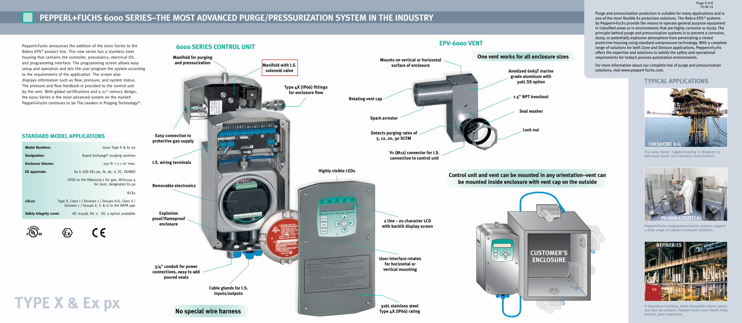
Control unit and vent can be mounted in any orientation–vent canbe mounted inside enclosure with vent cap on the outside
pepperL+FuCHs 6000 series–tHe most aDVanCeD purge/pressuriZation system in tHe inDustry
Pepperl+Fuchs announces the addition of the 6000 Series to the
Bebco EPS® product line. This new series has a stainless steel
housing that contains the controller, pneumatics, electrical I/O,
and programming interface. The programming screen allows easy
setup and operation and lets the user program the system according
to the requirements of the application. The screen also
displays information such as flow, pressure, and system status.
The pressure and flow feedback is provided to the control unit
by the vent. With global certifications and a 21st century design,
the 6000 Series is the most advanced system on the market!
Pepperl+Fuchs continues to be The Leaders in Purging Technology®.
no special wire harness
Customer'senCLosure
type X & ex px
stanDarD moDeL appLiCations
Model Numbers: 6000 Type X & Ex px
Designation: Rapid Exchange® purging systems
Enclosure Volume: 250 ft3 / 7.1 m3 max.
EX approvals: Ex II 2GD EEx px, ib, de, d, IIC, DEMKO
ATEX to the EN60079-2 for gas, IEC61241-4 for dust, designated Ex px
IECEx
cULus: Type X, Class I / Division 1 / Groups A-D, Class II / Division 1 / Groups E, F, & G to the NFPA 496
Safety Integrity Level: IEC 61508, SIL 2. SIL 3 option available
In hazardous locations, where flammable vapors, gases,and dust are present, Pepperl+Fuchs 6000 Series helpsprevent plant explosions.
Pepperl+Fuchs purge/pressurization systems supporta wide range of cabinet enclosure solutions.
The 6000 Series' rugged housing is designed towithstand harsh and corrosive environments.
typiCaL appLiCations
manifold for purgingand pressurization
easy connection toprotective gas supply
3/4" conduit for powerconnections, easy to add
poured seals
Cable glands for i.s.inputs/outputs
316L stainless steeltype 4X (ip66) rating
2 line – 20 character LCDwith backlit display screen
user-interface rotatesfor horizontal orvertical mounting
i.s. wiring terminals
removable electronics
explosionproof/flameproof
enclosure
manifold with i.s.solenoid valve
type 4X (ip66) fittingsfor enclosure flow
6000 series ControL unit
Highly visible LeDs
one vent works for all enclosure sizes
epV-6000 Vent
spark arrestor
mounts on vertical or horizontalsurface of enclosure
V1 (m12) connector for i.s.connection to control unit
1.5" npt knockout
seal washer
Lock nut
anodized 6063t marinegrade aluminum with
316L ss option
rotating vent cap
Detects purging rates of5, 12, 20, 30 sCFm
Purge and pressurization protection is suitable for many applications and isone of the most flexible Ex protection solutions. The Bebco EPS® systemsby Pepperl+Fuchs provide the means to operate general purpose equipmentin classified areas or in environments that are highly corrosive or dusty. Theprinciple behind purge and pressurization systems is to prevent a corrosive,dusty, or potentially explosive atmosphere from penetrating a closedprotective housing using standard overpressure technology. With a completerange of solutions for both Zone and Division applications, Pepperl+Fuchsoffers the expertise and solutions to satisfy the safety and operationalrequirements for today’s process automation environments.
For more information about our complete line of purge and pressurizationsolutions, visit www.pepperl-fuchs.com.
Page 5 of 8
15.08.14

Data for use in conjunction with hazardous areas:
Data for compressed air supply Supply pressure 10 - 16 bar
Output of pressure regulator 0 – 8.2 bar
Recommended regulator setting 4 bar
Enclosure specific features:
Temperature monitoring with preset trip at 60°C to protect the equipment.
For the configuration of the 6000 series pressurization system control unit please refer to the manualand programming worksheet.
TECHNICAL DATA
Supply voltage purge controller Rated voltage 230 Vac
Environmental conditions Ambient temperature range -20 °C to +50 °C
Purged enclosure data Dimensions (WxHxD) 560 x 916 x 389mm


AS BUILTCABLE & PIPING CONNECTION

Date:
Sheet
34
Momentary Pressure Control
1
CSP-0832
0 7 6 8 93
92
&EMA/36
4
35
2 5
Buehl / Baden
CONFIDENTIAL acc. to DIN ISO 16016
Tolerance acc: DIN ISO 2768-cK
Form
at A3
Scale: NTS
Document no.:
of
Rev.
DO NOT SCALEIF IN DOUBT ASK
04.12.2014
Drawn
Checked
Approved
This document contains safety-relevant information. It must not be altered without the authorization of the norm expert!
Only valid as long as released in EDM or with a valid production documentation!
Title:
Rev. Description Date Template: FTM-0331 File: Printed: 07.05.2015
ACS
CCustomer modifications
As built drawing
Customer modifications
07.05.2015
04.12.2014
03.06.2014
C
B
A
CSP-0832
DC.
DC.
DC.
BN
VALV
E
SHIE
LDI.
S. In
terface
board
5 6 7 8 9 10
IS P
WR 2
+
I S P
WR 3
+
IS P
WR 3
-
IS D
ATA 3
A
I S D
ATA 3
B
IS3 S
HLD
INPUT 1
+
I NPUT 1
-
INPUT 2
+
I NPUT 2
-
INPUT 3
+
INPUT 3
-
INPUT 4
+
INPUT 4
-
I NPUT
SHIE
LD
6000 s
eries
controlle
r
SHIE
LD
PW
R 1
+
USER INTERFACE
OUTPUT 1 OUTPUT 2
1 2 3 4
PW
R 1
-
DATA 1
A
DATA 1
B
A2
A1
Y
VALV
E +
VALV
E -
BU
IS P
WR 2
-
WH
IS D
ATA 2
A
BK
IS D
ATA 2
B
IS2 S
HLD
Scr
1B1A1- 1+
1B1A1- 1+
VENT 1EPV-6000
I.S. CONNECTOR M8
240VAC/2A240VAC/2A 240VAC/8
A
240VAC/8
A
EPCU Power supply board
-1B2
BN
BU
WH
BK
Scr
ON 2
AA-03
Ex d
BN
BU
WH
BK
Scr
IS P
WR 1
+
IS P
WR 1
-
IS D
ATA 1
A
IS D
ATA 1
B
IS1 S
HLD
1+ 1A 1- 1B
6000-TEMP-01
+ SIG - NC
-1B1
Power Supply 230VAC
5K1
Purge Controller 80JC0101A
A&B UPS Power SuppliesMain Control Cabinet 80EC0100A
80EC0100A
80EC0100B
BK GN/YE BK
1,0
BK
1,0
BK
Temperature Monitor
mounted in the TAP motion
Purge Controller 80JC0101BA&B UPS Power SuppliesMain Control Cabinet 80EC0100B
Cable No PL800502 (80JC0101A)Cable No PL800503 (80JC0101B)
-A1
1
YELLOW COLORED CABLE
BLUE COLORED CABLE
-A1_L1
/22.8
- A1_L2
/22.8
-A1_PE
/22.8
Phase
GND
NEU
HV TRANSFORMER - AIR PURGING SYSTEM - CIRCUIT/WIRING DIAGRAMS
PNEUMATIC MANIFOLDWITH I.S. SOLENOID
Refer to page 4 for thelocation
Note:For the details of power source andlocation of 5K1,refer to doc.DN02-S09011-E-XK-5003-01HV TRANSFORMER - MAIN CONTROL CABINETCIRCUIT/WIRING DIAGRAMS


![Xk jkX]] leisure opportunities](https://img.pdfslide.us/doc/110x75/6156f5f7a097e25c764f6a56/xk-jkx-leisure-opportunities.jpg)
