Embed Size (px)
Citation preview
Nokia Siemens Networks WCDMA RNC Rel. RN6.0, Site Documentation, Issue 01
Installation Site Requirements for MGW and RNC
DN99575461
Issue 7-4Approval Date 2010-12-23
Confidential
2 DN99575461Issue 7-4
Installation Site Requirements for MGW and RNC
Id:0900d805808219ceConfidential
The information in this document is subject to change without notice and describes only the product defined in the introduction of this documentation. This documentation is intended for the use of Nokia Siemens Networks customers only for the purposes of the agreement under which the document is submitted, and no part of it may be used, reproduced, modified or transmitted in any form or means without the prior written permission of Nokia Siemens Networks. The documentation has been prepared to be used by professional and properly trained personnel, and the customer assumes full responsibility when using it. Nokia Siemens Networks welcomes customer comments as part of the process of continuous development and improvement of the documentation.
The information or statements given in this documentation concerning the suitability, capacity, or performance of the mentioned hardware or software products are given "as is" and all liability arising in connection with such hardware or software products shall be defined conclusively and finally in a separate agreement between Nokia Siemens Networks and the customer. However, Nokia Siemens Networks has made all reasonable efforts to ensure that the instructions contained in the document are adequate and free of material errors and omissions. Nokia Siemens Networks will, if deemed necessary by Nokia Siemens Networks, explain issues which may not be covered by the document.
Nokia Siemens Networks will correct errors in this documentation as soon as possible. IN NO EVENT WILL Nokia Siemens Networks BE LIABLE FOR ERRORS IN THIS DOCUMENTA-TION OR FOR ANY DAMAGES, INCLUDING BUT NOT LIMITED TO SPECIAL, DIRECT, INDI-RECT, INCIDENTAL OR CONSEQUENTIAL OR ANY LOSSES, SUCH AS BUT NOT LIMITED TO LOSS OF PROFIT, REVENUE, BUSINESS INTERRUPTION, BUSINESS OPPORTUNITY OR DATA,THAT MAY ARISE FROM THE USE OF THIS DOCUMENT OR THE INFORMATION IN IT.
This documentation and the product it describes are considered protected by copyrights and other intellectual property rights according to the applicable laws.
The wave logo is a trademark of Nokia Siemens Networks Oy. Nokia is a registered trademark of Nokia Corporation. Siemens is a registered trademark of Siemens AG.
Other product names mentioned in this document may be trademarks of their respective owners, and they are mentioned for identification purposes only.
Copyright © Nokia Siemens Networks 2011. All rights reserved
f Important Notice on Product SafetyThis product may present safety risks due to laser, electricity, heat, and other sources of danger.
Only trained and qualified personnel may install, operate, maintain or otherwise handle this product and only after having carefully read the safety information applicable to this product.
The safety information is provided in the Safety Information section in the “Legal, Safety and Environmental Information” part of this document or documentation set.
The same text in German:
f Wichtiger Hinweis zur Produktsicherheit Von diesem Produkt können Gefahren durch Laser, Elektrizität, Hitzeentwicklung oder andere Gefahrenquellen ausgehen.
Installation, Betrieb, Wartung und sonstige Handhabung des Produktes darf nur durch geschultes und qualifiziertes Personal unter Beachtung der anwendbaren Sicherheits-anforderungen erfolgen.
Die Sicherheitsanforderungen finden Sie unter „Sicherheitshinweise“ im Teil „Legal, Safety and Environmental Information“ dieses Dokuments oder dieses Dokumentations-satzes.

DN99575461 3
Installation Site Requirements for MGW and RNC
Id:0900d805808219ceConfidential
Table of contentsThis document has 51 pages.
Summary of changes . . . . . . . . . . . . . . . . . . . . . . . . . . . . . . . . . . . . . . . . 7
1 Overview of site requirements . . . . . . . . . . . . . . . . . . . . . . . . . . . . . . . . . 9
2 Technical specifications for MGW and RNC . . . . . . . . . . . . . . . . . . . . . 10
3 General hardware platform requirements . . . . . . . . . . . . . . . . . . . . . . . 13
4 Equipment room requirements for MGW and RNC . . . . . . . . . . . . . . . . 164.1 MGW and RNC co-sited with other network elements. . . . . . . . . . . . . . 194.2 Cable support constructions for network elements . . . . . . . . . . . . . . . . 214.3 Lighting in the equipment rooms . . . . . . . . . . . . . . . . . . . . . . . . . . . . . . 224.4 Spare parts and documentation. . . . . . . . . . . . . . . . . . . . . . . . . . . . . . . 22
5 Site power supply . . . . . . . . . . . . . . . . . . . . . . . . . . . . . . . . . . . . . . . . . 235.1 DC power supply . . . . . . . . . . . . . . . . . . . . . . . . . . . . . . . . . . . . . . . . . . 245.1.1 General requirements for DC power supply. . . . . . . . . . . . . . . . . . . . . . 245.1.2 Requirements for the power supply cables (DC) . . . . . . . . . . . . . . . . . . 245.1.3 Central power supply overcurrent protection for the cabinets . . . . . . . . 265.1.4 Batteries. . . . . . . . . . . . . . . . . . . . . . . . . . . . . . . . . . . . . . . . . . . . . . . . . 285.2 AC power supply to auxiliary equipment . . . . . . . . . . . . . . . . . . . . . . . . 29
6 Grounding and bonding . . . . . . . . . . . . . . . . . . . . . . . . . . . . . . . . . . . . . 306.1 Requirements for grounding cables. . . . . . . . . . . . . . . . . . . . . . . . . . . . 306.2 Grounding of EC216 and IC186/-B cabinets . . . . . . . . . . . . . . . . . . . . . 306.3 Site grounding arrangements . . . . . . . . . . . . . . . . . . . . . . . . . . . . . . . . 316.3.1 Overview of site grounding and bonding . . . . . . . . . . . . . . . . . . . . . . . . 316.3.2 Grounding of external interface cables in STAR-IBN. . . . . . . . . . . . . . . 316.3.3 Grounding of external interface cables in MESH-IBN . . . . . . . . . . . . . . 336.3.4 Grounding of external interface cables in MESH-BN. . . . . . . . . . . . . . . 346.3.5 Grounding of external interface cables in CBN . . . . . . . . . . . . . . . . . . . 35
7 Electromagnetic compatibility . . . . . . . . . . . . . . . . . . . . . . . . . . . . . . . . 36
8 Operational environment . . . . . . . . . . . . . . . . . . . . . . . . . . . . . . . . . . . . 378.1 Standards for environmental requirements . . . . . . . . . . . . . . . . . . . . . . 378.1.1 ETSI and IEC standards . . . . . . . . . . . . . . . . . . . . . . . . . . . . . . . . . . . . 378.1.2 NEBS standards . . . . . . . . . . . . . . . . . . . . . . . . . . . . . . . . . . . . . . . . . . 388.2 Conditions during operation . . . . . . . . . . . . . . . . . . . . . . . . . . . . . . . . . . 388.2.1 Climatic conditions. . . . . . . . . . . . . . . . . . . . . . . . . . . . . . . . . . . . . . . . . 388.2.2 Dust . . . . . . . . . . . . . . . . . . . . . . . . . . . . . . . . . . . . . . . . . . . . . . . . . . . . 398.2.3 Chemical impurities . . . . . . . . . . . . . . . . . . . . . . . . . . . . . . . . . . . . . . . . 398.2.4 Acoustic noise . . . . . . . . . . . . . . . . . . . . . . . . . . . . . . . . . . . . . . . . . . . . 418.2.5 Mechanical conditions . . . . . . . . . . . . . . . . . . . . . . . . . . . . . . . . . . . . . . 428.3 Conditions during transportation and storage . . . . . . . . . . . . . . . . . . . . 428.3.1 Climatic conditions. . . . . . . . . . . . . . . . . . . . . . . . . . . . . . . . . . . . . . . . . 428.3.2 Mechanical conditions . . . . . . . . . . . . . . . . . . . . . . . . . . . . . . . . . . . . . . 438.3.3 Moving and mounting the cabinets . . . . . . . . . . . . . . . . . . . . . . . . . . . . 43
4 DN99575461
Installation Site Requirements for MGW and RNC
Id:0900d805808219ceConfidential
9 Ventilation in the equipment rooms. . . . . . . . . . . . . . . . . . . . . . . . . . . . . 44
10 Specifications of interfaces to the environment . . . . . . . . . . . . . . . . . . . 4610.1 PDH TDM interfaces . . . . . . . . . . . . . . . . . . . . . . . . . . . . . . . . . . . . . . . . 4610.2 SDH STM-1 interfaces . . . . . . . . . . . . . . . . . . . . . . . . . . . . . . . . . . . . . . 4710.3 SONET OC-3 interfaces . . . . . . . . . . . . . . . . . . . . . . . . . . . . . . . . . . . . . 4810.4 Ethernet/LAN interfaces . . . . . . . . . . . . . . . . . . . . . . . . . . . . . . . . . . . . . 4810.5 External synchronisation interfaces . . . . . . . . . . . . . . . . . . . . . . . . . . . . 4810.6 External HW alarm interfaces . . . . . . . . . . . . . . . . . . . . . . . . . . . . . . . . . 4910.7 USB connector . . . . . . . . . . . . . . . . . . . . . . . . . . . . . . . . . . . . . . . . . . . . 4910.8 RS232 connector . . . . . . . . . . . . . . . . . . . . . . . . . . . . . . . . . . . . . . . . . . 49
11 Conversion between metric and imperial measures . . . . . . . . . . . . . . . . 50

DN99575461 5
Installation Site Requirements for MGW and RNC
Id:0900d805808219ceConfidential
List of figuresFigure 1 Dimensions of the EC216 and EC213/-A cabinets . . . . . . . . . . . . . . . . 17Figure 2 Dimensions of the IC186/-B and IC183-B cabinets . . . . . . . . . . . . . . . . 18Figure 3 Layout example: common installation site for network elements. . . . . . 20Figure 4 Installations of IPA2800 network elements at the ends of DX 200 DX MSCi
cabinet rows (example) . . . . . . . . . . . . . . . . . . . . . . . . . . . . . . . . . . . . . 21Figure 5 General power distribution principle for the network elements . . . . . . . 23Figure 6 Release curves of 30-A circuit breakers of CPD120-A . . . . . . . . . . . . . 27Figure 7 Release curves of 20-A circuit breakers of CPD80-B / CPD80-A / CPD80
27Figure 8 Ventilation in the equipment room . . . . . . . . . . . . . . . . . . . . . . . . . . . . . 44Figure 9 Ventilation in the equipment room, with raised floor . . . . . . . . . . . . . . . 45

6 DN99575461
Installation Site Requirements for MGW and RNC
Id:0900d805808219ceConfidential
List of tablesTable 1 Rated power consumption for MGW and RNC . . . . . . . . . . . . . . . . . . . 11Table 2 Examples of maximum operating power consumption for MGW . . . . . . 11Table 3 Examples of maximum operating power consumption for RNC . . . . . . 11Table 4 Examples for maximum cable lengths . . . . . . . . . . . . . . . . . . . . . . . . . . 25Table 5 Maximum load per supply cable size . . . . . . . . . . . . . . . . . . . . . . . . . . . 28Table 6 Power consumption of peripheral devices . . . . . . . . . . . . . . . . . . . . . . . 29Table 7 ETSI standards defining the environmental requirements for the network
elements . . . . . . . . . . . . . . . . . . . . . . . . . . . . . . . . . . . . . . . . . . . . . . . . 37Table 8 IEC standards defining the environmental requirements for the network
elements . . . . . . . . . . . . . . . . . . . . . . . . . . . . . . . . . . . . . . . . . . . . . . . . 37Table 9 Limits for temperature and humidity during operation . . . . . . . . . . . . . . 38Table 10 Chemically active substances . . . . . . . . . . . . . . . . . . . . . . . . . . . . . . . . 40Table 11 Mechanical conditions allowed during operation . . . . . . . . . . . . . . . . . . 42Table 12 Limits for temperature during transportation and storage . . . . . . . . . . . 42Table 13 Mechanical stress allowed during transportation . . . . . . . . . . . . . . . . . . 43Table 14 Dimensions of shipping crates for IPA2800 cabinets . . . . . . . . . . . . . . . 43Table 15 TDM E1 balanced/unbalanced interface specifications . . . . . . . . . . . . . 46Table 16 TDM T1 interface specifications . . . . . . . . . . . . . . . . . . . . . . . . . . . . . . . 46Table 17 TDM JT1 interface specifications . . . . . . . . . . . . . . . . . . . . . . . . . . . . . . 47Table 18 SDH STM-1 interface specifications . . . . . . . . . . . . . . . . . . . . . . . . . . . 47Table 19 SONET OC-3 interface specifications . . . . . . . . . . . . . . . . . . . . . . . . . . 48Table 20 LAN interface specifications . . . . . . . . . . . . . . . . . . . . . . . . . . . . . . . . . . 48Table 21 External synchronisation interface specifications . . . . . . . . . . . . . . . . . 48Table 22 External alarm panel interfaces . . . . . . . . . . . . . . . . . . . . . . . . . . . . . . . 49Table 23 USB connector . . . . . . . . . . . . . . . . . . . . . . . . . . . . . . . . . . . . . . . . . . . . 49Table 24 Pin order of the RS232 connector . . . . . . . . . . . . . . . . . . . . . . . . . . . . . 49Table 25 Conversion factors from metric to imperial measurement units . . . . . . . 50Table 26 Conversion factors from imperial to metric length measurement units . 50

DN99575461 7
Installation Site Requirements for MGW and RNC Summary of changes
Id:0900d80580821ac3Confidential
Summary of changesChanges between document issues are cumulative. Therefore, the latest document issue contains all changes made to previous issues.
Changes in issue 7-4RNC power consumption figures in chapter Technical specifications for MGW and RNC have been updated to include RN6.0.
Information in chapter Conditions during operation updated.
Changes in issue 7-3Documentation changes: MGW power consumption figures and minimum fuse ratings in chapter Technical specifications for MGW and RNC have been updated.
Changes in issue 7-2Chapters 2 Technical specifications for MGW and RNC, 3 General hardware platform requirements, 5 Site power supply, 6 Grounding and bonding, 7 Electromagnetic com-patibility, 8 Operational environment have been updated to reflect the latest standards and requirements.
Changes in issue 7-1Documentation changes:Power consumption figures in chapter Technical specifications for MGW and RNC have been updated.
Changes in issue 7-0U4.2 changes: Added new cabling cabinet variant EC213-A.
Documentation changes:Power consumption figures in chapter Technical specifications for MGW and RNC have been updated.
Changes in issue 6-2Updated a standard. Minor editorial corrections.
Changes in issue 6-1Added information on U4 operating power consumption for MGW. Made some correc-tions and further clarified the difference between the rated and operating power con-sumptions.
Removed "Nokia" and replaced it with Nokia Siemens Networks where necessary.
Changes in issue 6-0Rated power consumption was clarified to be a theoretical value and not a representa-tion of an actual maximum configuration.
Ventilation in the equipment rooms was clarified to include only the ventilation graphics for IPA2800 cabinets: ventilation in the equipment room and ventilation in the equipment room, with raised floor.
In NEBS environment, only DC/I is allowed.
Changes in issue 5-2Technical specifications for MGW and RNC has been updated with rated and opera-tional power consumption values for MGW and RNC.

8 DN99575461
Installation Site Requirements for MGW and RNC
Id:0900d80580821ac3Confidential
Summary of changes
Corrected the cable length for the 1000Base-LX single-mode cable from 220 m to 5000 m in table LAN interface specifications.
Changes in issue 5-1Editorial changes.
Changes in issue 5-0Changed the document name to Installation Site Requirements for MGW and RNC, from Installation Site Requirements for IPA2800 Network Elements.
The main change in content is the addition of the new cabinets EC216 and EC213, affecting the chapters:
• Technical specifications for MGW and RNC • Equipment room requirements • Site power supply • Grounding and bonding • Operational environment
Added also USB connectors to the chapter Specifications of interfaces to the environ-ment.
Changes in issue 4-1Added a new chapter, Technical specifications for MGW and RNC, after the Overview of site requirements.
Added a statement about the Restrictions on Hazardous Substances (RoHS) to the end of the chapter General hardware platform requirements.
Chapter Operational environment, section Conditions during transportation and storage: updated the temperatures in the table Limits for temperature during transportation and storage.
Added a table for SONET OC-3 interfaces to the chapter Interfaces to the environment.
Changes in issue 4-0Editorial and structural corrections were made to improve the usability of the document. Main changes were:
• Chapter Environmental requirements was renamed to Operational environment. The contents of section Electrical environment of chapter Environmental require-ments were moved to a new chapter Electromagnetic compatibility.
• Imperial measures were removed throughout the document, and a new chapter Conversion between metric and imperial measures was added at the end of the doc-ument.
• Chapter Specifications of interfaces to the environment was added. • Detailed information on the grounding of the cabinets was moved to document
Installing the MGW and RNC.

DN99575461 9
Installation Site Requirements for MGW and RNC Overview of site requirements
Id:0900d80580577046Confidential
1 Overview of site requirementsThe Installation Site Requirements for MGW and RNC provides installation site informa-tion needed for the installation planning for the IPA2800 network elements, Radio Network Controller (RNC) and Multimedia Gateway (MGW). The subjects covered do not, however, include the installation planning instructions for the site power supply equipment or for the PCM and alarm distribution frames.
Cabinet typesMGW and RNC use cabinet types EC216, EC213/-A (MGW only), IC186/-B and IC183-B. In MGW the 2100 mm high cabinets EC216 and EC213/-A can be installed alongside the 1800 mm high cabinets IC186/-B and IC183. For installation details, see Installing the MGW and RNC.
The hardware of the Radio Network Controller and the Multimedia Gateway are dis-cussed in the network-element-specific sections in Engineering for Radio Network Con-troller (RNC) and Engineering for Multimedia Gateway (MGW).

10 DN99575461
Installation Site Requirements for MGW and RNC
Id:0900d80580821ac7Confidential
Technical specifications for MGW and RNC
2 Technical specifications for MGW and RNCCabinet dimensions
Weight
Environment
Power consumption
Rated power consumptionRated power consumption values are nominal values that have been calculated on the basis of the theoretical maximum power consumption of the cabinet type. These values do not represent the network element power consumption in normal operation, but they can be used for planning site power feed (fuses and cables).
The table below presents the rated power consumption for EC216 and IC186/-B.
EC216 EC213/-A
Dimensions (H x W x D) 2100 x 600 x 600 mm 2100 x 300 x 600 mm
Foot adjustment –25 mm to +40 mm –25 mm to +40 mm
IC186/-B IC183-B
Dimensions (H x W x D) 1800 x 600 x 600 mm 1800 x 300 x 600 mm
Foot adjustment –25 mm to +40 mm –25 mm to +40 mm
EC216 EC213/-A
Cabinet maximum weight, fully equipped
350 kg 100 kg
IC186/-B IC183-B
Cabinet maximum weight, fully equipped
230 kg 80 – 90 kg
Safety EN 60950-1, UL 60950-1
Earthquake resistance Telcordia GR-63-CORE, Zone 4
Environmental requirements ETS 300 019-1-1, ETS 300 019-1-2, ETS 300 019-1-3, Telcordia GR-63-CORE
EMC emission EN 300 386, Telcordia GR-1089-CORE
EMC immunity EN 300 386, Telcordia GR-1089-CORE

DN99575461 11
Installation Site Requirements for MGW and RNC Technical specifications for MGW and RNC
Id:0900d80580821ac7Confidential
Operating power consumptionOperating power consumption values are based on measurements with application SW installed and running in the network element. Maximum operating power consumption values are based on maximum traffic. These values are useful for estimating heat dissi-pation, site cooling planning, battery back-up planning, rectifier planning, and dimen-sioning. The maximum operating power consumption values listed below are examples. For example, the type of traffic in the network element can affect the measurement result.
1) Values for RN6.0 release level are calculated estimates.
Power consumption in IDLE state is approximately 5 % lower than the maximum oper-ating power consumption.
Power supply
Cabinet Maximum per cabinet
EC216 4800 W
IC186/-B 3600 W
Table 1 Rated power consumption for MGW and RNC
Cabinet CAMA CAMB CAMC Network element used for measurement
EC216 3130 W 3580 W 2100 W U5.0
EC216 2500 W 3580 W 2000 W U4.2
EC216 2300 W 3580 W 2100 W U4.0 / U4.1
EC216 2070 W 3580 W 2340 W U3C
IC186/-B 1780 W 3580 W 2030 W U3A
Table 2 Examples of maximum operating power consumption for MGW
Cabinet RNAC RNBC Network element used for mea-surement
EC216 4379 W 4772 W RN6.0 1)
EC216 3900 W 4198 W RN5.0
EC216 2600 W 2800 W RN4.0
EC216 2500 W 2800 W RN2.2
IC186/-B 1950 W 2300 W RN2.1
Table 3 Examples of maximum operating power consumption for RNC
Cabinet Nominal voltage DC Min. fuse rating
EC216 –48 V 125 A

12 DN99575461
Installation Site Requirements for MGW and RNC
Id:0900d80580821ac7Confidential
Technical specifications for MGW and RNC
IC186/-B –48 V 125 A
Cabinet Nominal voltage DC Min. fuse rating

DN99575461 13
Installation Site Requirements for MGW and RNC General hardware platform requirements
Id:0900d8058079e7b3Confidential
3 General hardware platform requirementsListed below are the international specifications and recommendations which form the basis for the requirements for the hardware.
GeneralTelcordia SR-3580, issue 3, June 2007 Network Equipment-Building System
(NEBSTM) Criteria Levels
Equipment safetyIEC 60950-1, Second Edition, 2005 Information technology equipment - Safety - Part
1: General requirements
EN 60950-1, 2006 Information technology equipment - Safety - Part 1: General Requirements
UL 60950-1 First Edition, 2007 Information technology equipment - Safety - Part 1: General requirements
Telcordia GR-1089-CORE, issue 4, June 2006 Electromagnetic Compatibility and Electrical Safety – Generic Criteria for Network Telecommunications Equipment
NFPA 70, 2008 Edition National Electrical Code
EMCETSI EN 300 386, V1.3.3., (2005-04) Electromagnetic compatibility and Radio
spectrum Matters (ERM); Telecommunication network equipment Elec-troMagnetic Compatibility (EMC) requirements
CFR 47 Code of Federal Regulations, Federal Communications Commission (FCC) Title 47 Revised October 2008, Part 15, Radio Frequency Devices
Telcordia GR-1089-CORE, issue 4 Electromagnetic Compatibility and Electrical Safety – Generic Criteria for Network Telecommunications Equipment
IEC 61000-4-5, second edition, 2005-11 Electromagnetic compatibility (EMC); Part 4-5: Testing and measurement techniques - Surge immunity test
CISPR22, Ed.6, 2008 Information technology equipment - Radio disturbance charac-teristics- Limits and methods of measurement
CISPR24, 1997 + A1:2001 + A2:2002 Information technology equipment - Immunity characteristics - Limits and methods of measurement
ITU-T Recommendation K.20, 04/2008 Resistibility of telecommunication equipment installed in a telecommunications centre to overvoltages and overcur-rents
Power feedETSI EN 300 132-2, V2.2.2, (2007-10) Equipment Engineering (EE); Power supply-
interface at the input to telecommunications equipment; Part 2: Operated by direct current (dc)
ANSI T1.315, May 2nd, 2001 Voltage Levels for DC-powered Equipment Used in the Telecommunications Environment

14 DN99575461
Installation Site Requirements for MGW and RNC
Id:0900d8058079e7b3Confidential
General hardware platform requirements
Earthing (grounding) and bondingETSI EN 300 253, V2.1.1, (2002-04) Equipment Engineering (EE); Earthing and
bonding of telecommunications equipment in telecommunication centres
ITU-T K.27, 05/96 Protection against Interference. Bonding Configurations and Earthing inside a Telecommunication Building
Telcordia GR-1089-CORE, issue 4, June 2006 Electromagnetic Compatibility and Electrical Safety – Generic Criteria for Network Telecommunications Equipment
Environmental enduranceETSI EN 300 019-1-1, V2.1.4, (2003-04) Equipment Engineering (EE); Environmen-
tal conditions and environmental tests for telecommunications equip-ment Part 1-1: Storage
ETSI EN 300 019-1-2, V2.1.4, (2003-04) Equipment Engineering Environmental con-ditions and environmental tests for telecommunications equipment Part 1-2: Transportation
ETSI EN 300 019-1-3, V2.2.2, (2004-07) Equipment Engineering (EE); Environmen-tal conditions and environmental tests for telecommunications equip-ment Part 1-3: Stationary use at weather protected locations
Telcordia GR-63-CORE, issue 3, March 2006 NEBSTM Requirements: Physical Pro-tection
ETSI EN 300 753, V1.2.1, (2009-03) Equipment engineering (EE); Acoustic noise emitted by telecommunications equipment
EarthquakeTelcordia GR-63-CORE, Issue 3, March 2006, Zone 4 NEBSTM Requirements:
Physical Protection
InterfacesPDH/TDM (E1/T1/J1) requirements:
ITU-T Recommendation G.703, 11/2001 Physical/electrical characteristics of hierar-chical digital interfaces
STM-1/OC-3 requirements:
ITU-T Recommendation G.957, 03/2006 Optical interfaces for equipments and systems relating to the synchronous digital hierarchy
ITU T Recommendation G.825 (03/2000) The control of jitter and wander within digital networks which are based on the synchronous digital hierarchy (SDH)
ITU T Recommendation I.432.2 (02/1999) B-ISDN user-network interface – Physical layer specification: 155 520 kbit/s and 622 080 kbit/s operation
ANSI T1.105.06, 1996 Telecommunications - Synchronous Optical Network (SONET) - Physical Layer Specifications
LAN requirements:
DN99575461 15
Installation Site Requirements for MGW and RNC General hardware platform requirements
Id:0900d8058079e7b3Confidential
IEEE 802.3, 2008 Standard for Information technology -specific requirements - Part 3: Carrier sense multiple access with collision detection (CSMA/CD) access method and physical layer specifications
ANSI X3.263, 1995 Fibre Distributed Data Interface (FDDI) - Token Ring Twisted Pair Physical Layer Medium Dependent (TP-PMD)
Synchronization requirements:
ITU-T Recommendation G.703, 11/2001 Physical/electrical characteristics of hierar-chical digital interfaces
Telecommunication siteIEC 62305-1, First edition 2006-01 Protection against lightning - Part 1: General prin-
ciples
IEC 62305-2, First edition 2006-01 Protection against lightning - Part 2: Risk manage-ment
IEC 62305-3, First edition 2006-01 Protection against lightning - Part 3: Physical damage to structures and life hazard
IEC 62305-4, First edition 2006-01 Protection against lightning - Part 4: Electrical and electronic systems within structures
RoHSNokia Siemens Networks MGW and WCDMA RNC comply with the European Union RoHS Directive 2002/95/EC on the restriction of the use of certain hazardous sub-stances in electrical and electronic equipment. The directive applies to the use of lead, mercury, cadmium, hexavalent chromium, polybrominated biphenyls (PBB), and poly-brominated diphenyl ethers (PBDE) in electrical and electronic equipment put on the market after 1 July 2006.
WEEENokia Siemens Networks MGW and WCDMA RNC comply with the European Union WEEE (Waste Electrical & Electronic Equipment) Directive 2002/96/EC; the product shall bear the marking indicating producer of the product, with the crossed-out wheeled bin symbol indicating separate collection of electrical and electronic equipment and the date of placing on the market.

16 DN99575461
Installation Site Requirements for MGW and RNC
Id:0900d80580577049Confidential
Equipment room requirements for MGW and RNC
4 Equipment room requirements for MGW and RNCThe MGW and RNC can be installed on a raised floor or concrete floor. We recommend the use of a raised floor in the equipment room, with all the site cables placed under the floor. Check with local construction engineers and battery manufacturers to determine floor load requirements. The ceiling height of the equipment room must allow for the extra height required by the taller EC216 cabinet (minimum 300 mm free space).
The site floor load capacity must be sufficient to carry the installed equipment. The maximum weight of a fully-equipped EC216 equipment cabinet is about 240-300 kg, and of a fully-equipped cabling cabinet about 100 kg. The maximum weight of a fully-equipped IC186/-B equipment cabinet is about 230 kg and of a fully-equipped IC183-B cabling cabinet about 90 kg.
For earthquake resistance, the cabinets must be installed on floor rails. If a raised floor is used, the cabinets must be installed in such a manner as to be as stable as on floor rails.
Cabinet dimensions and free space requirementsEach cabinet should be located in the equipment room with a free space of at least 700 mm both in front and behind the cabinet. The EC216, EC213/-A, IC186/-B and IC183-B cabinets are dimensioned according to ETSI recommendations and they are suitable for, but not limited to, raised-floor installations with standard 600 mm × 600 mm modules.
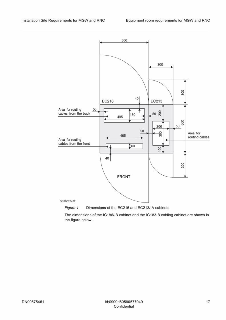
The dimensions of the EC216 cabinet and the EC213/-A cabling cabinet are shown in the figure below.
DN99575461 17
Installation Site Requirements for MGW and RNC Equipment room requirements for MGW and RNC
Id:0900d80580577049Confidential
Figure 1 Dimensions of the EC216 and EC213/-A cabinets
The dimensions of the IC186/-B cabinet and the IC183-B cabling cabinet are shown in the figure below.

18 DN99575461
Installation Site Requirements for MGW and RNC
Id:0900d80580577049Confidential
Equipment room requirements for MGW and RNC
Figure 2 Dimensions of the IC186/-B and IC183-B cabinets
Equipment room layoutIn layout planning, the following aspects should be considered.
• For installation without a raised floor, separate cable structures are needed for the external cables.
• Maintenance passages are needed at the site, for example, for expansion material and service devices.
• The cabinets must be lined up side by side in a single row with a free space of at least 700 mm at the front and back.
• MGW or RNC and FlexiServer cabinet rows must be installed back to back. For more information, see the chapter Ventilation in the equipment rooms.
• No pillars or other support structures are allowed within the free area around the cabinets.
• If planning a NEBS-compliant site arrangement, calculate the average heat release per floor area according to NEBS GR63-CORE.
fElectrostatic discharge (ESD) may damage components in the plug-in units or other units. Before handling the units, check that the site is an ESD-protected area (EPA). If the area is not ESD-protected, create a temporary EPA.
300
600
300
600
DN02133818
300
50200
200
300
100
FRONT
180
100
70
500
50
50
50
50
50
Primary areafor routing cables
Secondary areafor routing cables
Secondary areafor routing cables
Area forrouting cables
IC186 IC183

DN99575461 19
Installation Site Requirements for MGW and RNC Equipment room requirements for MGW and RNC
Id:0900d80580577049Confidential
4.1 MGW and RNC co-sited with other network elementsWhen the equipment room houses several different network elements installed in several cabinet rows (which is normally the case with MGW installations), it must have maintenance passages (for example, for expansion material and service devices) with a minimum width of 1200 mm. As for the cabinet rows, their recommended minimum distance from one another is the following:
• 700 mm between MGW or RNC cabinet rows • 800 mm between MGW or RNC cabinet rows and DX 200 network element cabi-
net/rack rows (for information on equipment by other manufacturers, refer to the documentation of the product concerned).
• MGW or RNC and FlexiServer cabinet rows must be installed back to back. For more information, see the chapter Ventilation in the equipment rooms.
The figure below shows an example of the equipment room layout for a site housing network elements.

20 DN99575461
Installation Site Requirements for MGW and RNC
Id:0900d80580577049Confidential
Equipment room requirements for MGW and RNC
Figure 3 Layout example: common installation site for network elements
The MGW and RNC can be installed in the same rows with other equipment if the latter allow this. When adding MGW or RNC cabinets to an existing site, leave sufficient space between the cabinets already on the site and future expansion cabinets. A further 150 mm space must be left between DX200 and IPA2800 cabinets, as they cannot be bolted together. An example of this kind of layout, with both the RNC and the MGW installed at the ends of DX 200 DX MSCi cabinet rows, is shown in the figure below.
MOMC VLRC VLRC VLRC VLRC
GSWC ETC IWCETCGSWC ETC
IWCETC ETC IWC
SRRi spaceSGSN (GPRS)
HLGC HLRC HLRC HLRC HLRC HLRC HLRC
19"Rack
19"Rack
PoC
Re
g.
FlexiServer
Voice Email
DDF IMR CPS
IMS
FlexiServer
MGW2MGW1RNC2RNC1
DDFODF
Floor tile, 600 x 600 mmExpansion cabinet/rackDN0494652
MSCi PoC
HLRi
RNAC CAMARNAC RNBC CAMB CAMA CAMCCAMB
SGAC SOMC SCECSGBC
CIS
CO
Sw
itch
SRSC SRSC SRSC SRSC
PoCPC
PoCPC
PoCPC
RNBC

DN99575461 21
Installation Site Requirements for MGW and RNC Equipment room requirements for MGW and RNC
Id:0900d80580577049Confidential
Figure 4 Installations of IPA2800 network elements at the ends of DX 200 DX MSCi cabinet rows (example)
Normally, the cabinets are installed in order from left to right (seen from the front), but for example in premises where there is unoccupied space to the right of the existing equipment, the cabinets can be installed according to the 'mirror-image' layout (from right to left). This is especially useful when the initial configuration is small enough to fit into one cabinet. Then, the network element can be installed at the far right in an existing cabinet row, and when the network element is expanded later on, the expansion cabinet can be installed to the right of the previous cabinet.
For details of installation procedures, see the document Installing the MGW and RNC.
4.2 Cable support constructions for network elementsThe MGW and RNC require some cable constructions at the site which are not part of the network element's system construction. These contain the cable shelves (for non-raised-floor installations only) and the distribution frames. The distribution frames are not system-specific and they are therefore not covered in this manual. The requirements for the cable shelves are described in the following section.
Cable shelvesIn installations without a raised floor, the site cables must be routed above the cabinet rows on separate cable shelves. The cable shelves should be attached to the ceiling or a wall, with a separate branch running above each cabinet row to enable easy cable routing.
In a star topology grounding arrangement, to prevent galvanic connection between the cabinets and the steel construction or the concrete reinforcement of the network element building, the cable shelves must be isolated from the network element frame. Lamps for the cabinet row can be mounted on the shelves to avoid direct contact with the network element frame.
Aluminium cable racks, (for example, XYHA type 500 or 600 mm) can be used as the cable shelves. The shelves can be mounted to the walls or to the ceiling.
g The support constructions for the external cables are not included in the network element delivery. The support constructions must be decided upon in the individual site arrangements.
Expansion cabinet
MSCiCABINETS
ETC IWCETC ETC
GSWC GSWC IWCETC IWC
VLRCMOMC VLRC VLRC VLRC
MGW
CAMBCAMA
RNC
RNAC RNBC
DN02180128
CAMC
>1200 mm
> 500 mm
ETC
150mm
150mm

22 DN99575461
Installation Site Requirements for MGW and RNC
Id:0900d80580577049Confidential
Equipment room requirements for MGW and RNC
Optical distribution frameOptical cabling normally exploits optical distribution frame (ODF) for purposes such as:
• making the connection between high-fibre count external cables and individual fibre or fibre pairs
• ease of making modifications to cable interconnections between cabinets, as well as cabinets and other equipment
• hiding extra lengths of cable
Various types of ODF cabinets can be used in IPA2800 installations. High-fibre count cables are not intended to be connected to the IPA2800 cabinets directly; an ODF is used in between. Rather than connecting IPA2800 network elements and the co-sited LAN switch or Router directly with LAN cables, an ODF cabinet is strongly recom-mended.
4.3 Lighting in the equipment roomsThe recommended lighting near a cabinet is 300 lx at 1 m. The most suitable lights are encapsulated fluorescent tubes. In an installation without a raised floor, the lamps for the cabinets can be mounted on the cable shelves above the cabinet rows to avoid galvanic contact with the network element frame.
4.4 Spare parts and documentationSpare parts should be stored in a separate room that fulfils the requirements set for storage (see the section Conditions during transportation and storage in the chapter Operational environment). Spare plug-in units should be stored in their original packages on shelves or in a cabinet.
The documentation needed for the operation of the network element should be located in a room near the equipment room, where it is easily accessible.

DN99575461 23
Installation Site Requirements for MGW and RNC Site power supply
Id:0900d805808309d0Confidential
5 Site power supplyThis chapter describes the requirements for the external site power supply system and the power feed cables to the cabinets, which are not included in the IPA2800 network element delivery. It also describes the requirements for the AC power supply to auxiliary equipment.
fLeaving the power on during installation may damage the equipment. Before installing the power supply cables, ensure that the site power is off and all the power switches on the front panel of each cabinet power distribution unit are off.
To ensure 2n redundancy for the power distribution lines, the cabinets of the MGW and RNC network elements are provided with two mutually redundant feeding inputs. The feed cables from the power system to the cabinets must also be duplicated.
Each cabinet must have supply cables of its own. The power distribution diagram for a cabinet is shown in the figure below. The internal power distribution system of the MGW and RNC is described in more detail in Engineering for Multimedia Gateway (MGW) and Engineering for Radio Network Controller (RNC).
For simplicity, only the negative lead is drawn from the rectifiers to the cabinets in the illustrations of the power supply system in this chapter.
Figure 5 General power distribution principle for the network elements
g Because of their high power requirements, do not chain the supply leads of the cabinets. Chaining is not allowed even with cabinets that belong to the same network element.
Rectifier stack Cabinet
Feed 0
Feed 1
DN0456387
24 DN99575461
Installation Site Requirements for MGW and RNC
Id:0900d805808309d0Confidential
Site power supply
5.1 DC power supplyThe following sections describe the general requirements for the external site power supply system and the main cables feeding the MGW and RNC.
5.1.1 General requirements for DC power supplyThe MGW and RNC require a redundant power feed system in which the voltage is gen-erated by rectifiers and lead-acid batteries are used as a back-up energy source. The supply voltage must meet the following requirements:
• nominal voltage -48 VDC • voltage tolerance -40 VDC to -57 VDC
The requirements for noise returned by the MGW and RNC (conducted emissions at interface A) meet the requirements of the ETS EN 300 132–2, Section 4.9, and ANSI T1.315 standards.
Even for partially equipped configurations, the site power supply system must be dimen-sioned to have enough capacity to feed a fully equipped network element. Alternatively, a supply system expandable to the capacity required by a fully equipped network element must be used.
If the -48 VDC power supply serves other equipment besides the IPA2800 network element, please note that the impedance between the batteries and the main busbar must be sufficiently low or additional busbar capacitors must be used to avoid interfer-ence in failure situations (between devices connected in parallel).
5.1.2 Requirements for the power supply cables (DC)Each cabinet should be fed via two independent supply groups (cable pairs) from the site DC power. The cables must meet local requirements (such as the UL60950 standard and the National Electrical Code ANSI/NFPA No. 70 in North America). The cables are not included in the network element delivery.
The cabinet power entry connectors accept cable sizes up to 70 mm2 (AWG00). In order to ensure proper operation of the equipment during the entire intended period when the back-up system is needed, the following factors must be considered when choosing the dimensions of the supply cables:
• The maximum allowed voltage drop in the supply cables between the main distribu-tion bus and the terminal block is 1.5 V.
• The maximum allowed voltage drop between the batteries and the main distribution bar is 1.0 V.
• The minimum allowed discharge voltage per cell is 1.80 V (if not otherwise stated in the battery manufacturer's specifications), which equals 43.2 V for a 24-cell battery set.
The required cable dimensions (cross-section) are dependent on:
• the maximum load current and the cable length ( ≈ ohmic resistance), i.e. the maximum resistance allowed to keep the voltage drop from the battery terminals to the NE terminals within 1,5 V + 1,0 V at maximum discharge current, as specified in ETSI EN 300 132-2;
• the maximum allowed temperature rise of the cable type;

DN99575461 25
Installation Site Requirements for MGW and RNC Site power supply
Id:0900d805808309d0Confidential
• the selected primary protector (fuse or circuit breaker) rating, i.e. the maximum potential fault current.
Specifying the maximum currentThe network elements use switch-mode internal power supplies that draw a steady amount of power [watts], regardless of the feed voltage.
Thus the load current is highest when the feed voltage is the lowest (i.e. at -40,5 VDC). This occurs when the mains or the rectifiers are down and at the end of the battery back-up time when the battery back-up power is drained. However each NE has two, mutually redundant (independent) power feed connections. When both feeds are functioning the load current is shared.
In the case of failure of one power feed, the rectifiers are functioning so the supply voltage on the other is in the range of -44…54VDC.
For power consumption values, see Technical Specifications for MGW and RNC.
The power consumption of an individual cabinet/particular product release may be con-siderably less than the maximum capacity of a cabinet's power supply circuit. The spare capacity is reserved for future increase in power consumption, which may follow the introduction of new increased capacity hardware (plug-in units) and/or software.
Calculating cable resistance
The specific resistance, ρ , for copper at +20°C is 17.2 × 10⁻⁹ Ωm.
The resistance, R, of a conductor is:
where l = length, A = area (cross-section), ρ = specific resistance, and R = resistance.
Example:
R for a conductor of 1 m length and 16 mm2 cross-section is:
The following table shows examples of maximum cable lengths.
R =A
x l
R =17.2 x 10 -9 m x 1 m
16 x 10-6 m21.075 x 10-3=
Load power
Current at -40,5 VDC
Max. resis-tance at (1.5 V drop)
Max. cable length / cross-section*)
6 mm210 mm2 16 mm2 25 mm2 35 mm2
50 mm2 70 mm2
W A mΩ m m m m m m m
500 12.3 122 42 70 113
700 17.3 87 30 50 80
1000 24.7 61 21 35 56 88
1500 37.0 41 23 37 58 82
2000 49.4 30 28 44 61 88
2500 61.7 24 35 49 70 97
3000 74.1 20 29 41 58 81
Table 4 Examples for maximum cable lengths

26 DN99575461
Installation Site Requirements for MGW and RNC
Id:0900d805808309d0Confidential
Site power supply
Simplified formula to determine the necessary conductor cross-sectionTo get the minimum allowed cross-section in square millimetres, insert the distance (cabling length), b, in metres and cabinet power, a, in watts, in the following equation:
Then choose a suitable standard cross-section.
The maximum voltage drop from the battery terminals to the element may not be more than 1.5 V + 1.0 V at maximum discharge current (ETSI EN 300 132-2). If the voltage drop from the battery terminals to the cabinet is more than 1.5 V + 1.0 V at maximum discharge current, the minimum allowed discharge voltage per cell must be set accord-ingly higher.
True lengthWhen the power feed consists of two conductors, live and return, it would suggest that the actual cabling distance would be only half of that indicated. But since there are always two supply pairs, this compensates the effect, so the cabling distance can be as described above.
Failure scenariosThe power feed redundancy is based on the requirement that no single fault may cause the system to fall outside the specifications. There are three possible conditions (faults) that have an effect on the power feed:
1. When the power is drawn from the backup batteries, both supply groups are opera-tional, and the ambient temperature is nominal (that is, the ohmic loss in the cables is within limits).
2. When one supply group is down, the rectifiers are operational (that is, the supply voltage is high enough to allow twice as high a loss in the supply cables), and the ambient temperature is nominal.
3. When the ambient temperature is exceptional (extremely high), the rectifiers are operational (that is, the supply voltage is high enough to compensate for higher loss in the supply cables), and both supply groups are also operational.
5.1.3 Central power supply overcurrent protection for the cabinetsThe fuses or circuit breakers protecting the distribution lines to the cabinets are located in the power distribution centre of the equipment room. Each distribution cable must be
3500 86.4 17 35 50 69
4000 98.8 15 Illegal area 44 61
4500 111.1 14 39 56
5000 123.5 12 48
*) Cabling length is valid for two pairs in parallel. One pair consists of power and return lines.
Load power
Current at -40,5 VDC
Max. resis-tance at (1.5 V drop)
Max. cable length / cross-section*)
6 mm210 mm2 16 mm2 25 mm2 35 mm2
50 mm2 70 mm2
Table 4 Examples for maximum cable lengths (Cont.)
2) =17.2 x 10⁻³
60 V2
m x b m x a WA(mm

DN99575461 27
Installation Site Requirements for MGW and RNC Site power supply
Id:0900d805808309d0Confidential
protected using a fuse or circuit breaker with a rating sufficiently higher than the sum of the ratings for the circuit breakers which protect the distribution lines from the CPD120-A / CPD80-B / CPD80-A / CPD80 to the subracks. The recommended rating is 100A or 125A.
The release curves for the 30-A circuit breakers of the CPD120-A, and those for the 20-A circuit breakers of the CPD80-B / CPD80-A / CPD80 are shown in the figures below. The area between the two curves represents the range of the current (in relation to the length of the impulse), which will trigger off the circuit breaker.
Figure 6 Release curves of 30-A circuit breakers of CPD120-A
Figure 7 Release curves of 20-A circuit breakers of CPD80-B / CPD80-A / CPD80
DN069206
0,001
0,01
0,1
1
10
100
1000
10000
0 30 60 90 120 150 180 210 240 270 300
Current / Ampere
Time /Seconds
May trip
30A AirpaxIEG Delay 53
Low curveHigh curve
0,001
0,01
0,1
1
10
100
1000
10000
0 20 60 100 140 180 200
Current / Ampere
Time /Seconds
May trip
Low curveHigh curve
20A AirpaxIEG Delay 51
DN99633057
Airpax

28 DN99575461
Installation Site Requirements for MGW and RNC
Id:0900d805808309d0Confidential
Site power supply
The network elements have internal overcurrent protective devices in the power entry or distribution circuits. However, each supply branch must be equipped with an overcurrent protective device. Fuses or circuit breakers are typical.
The DC-return (neutral or +) conductor may not be equipped with an over current pro-tector.
The overcurrent protection system shall be selective to minimize the effect of a fault. The selectivity shall be such that a fault triggers only the first protector upstream (towards the power source).
Selectivity for the protection system can be easiest determined by comparing the trip time curves of the whole sequence of security devices. The protection of the second stage (in the network element) must be below the curve of the first stage (branch pro-tector).
To ensure reliable long-term current supply during nominal conditions and proper func-tioning of the over current protection system, the branch protector rating shall be a factor higher (derated) that the NE breaker rating and/or the max load current at nominal -48VDC. The factor is 1.4 for fuse type protectors and 1.25 for circuit breaker type pro-tectors. In other words the maximum load current is 80% of the rating for circuit breakers and 70% for fuses.
The fuse/CB rating shall be ≥ derated current drain at -48V.
The fuse/CB rating shall be ≥ un-derated current drain at -40V.
5.1.4 Batteries
fDanger of physical injury! The batteries contain highly corrosive acid, and they may emit flammable hydrogen gas. The batteries should be mounted over a basin or precautions should be taken to control any spilled acid. The battery compartment (room) must be well ventilated to remove any flammable gas. Observe local regulations as well as battery manufacturers' cautions and warnings.
Cross-section
Current capacity (ampacity)
Max. CB / Fuse
Max. current CB (80%)
Max. load at 48VDC with CB
Max. current Fuse (70%)
Max. load at 48VDC with fuse
6 mm2 43A 32A 25.6A 1228W 22.4A 1075W
10 mm2 60A 50A 40.0A 1920W 35.0A 1680W
16 mm2 80A 63A 50.4A 2419W 44.1A 2117W
25 mm2 102A 80A 64.0A 3072W 56.0A 2688W
35 mm2 126A 100A 80.0A 3840W 70.0A 3360W
50 mm2 153A 125A 100.0A 4800W 87.5A 4200W
70 mm2 195A 160A 128.0A 6144W 112.0A 5376W
Table 5 Maximum load per supply cable size

DN99575461 29
Installation Site Requirements for MGW and RNC Site power supply
Id:0900d805808309d0Confidential
The batteries serve as a back-up power source for the network element if the power supply from the rectifiers is interrupted. For ease and safety of battery maintenance, the use of two or more separate battery groups (strings) is recommended.
The battery capacity should be selected according to the time each battery string must be able to supply the network element. The discharge time depends on local conditions. In designing the battery system, note that its capacity reduces to a certain degree due to aging.
The summed resistance of the battery, connectors and cables must be low enough in order to ensure that in the case of a short circuit in one cabinet, the power supply to the other cabinets will not be disturbed.
If the battery feeds other equipment besides an MGW or RNC, the resistance of the battery and its cables must be as low as possible. This is to ensure that in case of a power supply failure, the disturbance does not spread from one system to another. Therefore, we recommend the use of additional capacitors in the power distribution busbar.
5.2 AC power supply to auxiliary equipmentIf peripheral devices (terminals or printers) are connected to a network element, the required AC supply can be taken from either the mains supply or a UPS (Uninterrupted Power Supply). The mains supply network must be designed in accordance with local regulations concerning electrical safety. We recommend the use of a redundant AC supply, since terminals and printers are indispensable in locating failures.
Isolating the AC power supplyWhen equipment powered by the AC mains supply are connected to the network element, the AC supply ground must be isolated from the network element ground. This is to avoid disturbance in the equipment due to grounding loops. Two options exist for isolating the AC network, depending on the grounding scheme chosen for the site (see the section Site grounding arrangements in the chapter Grounding and bonding:
• all AC power sockets in the vicinity of the network element cabinets are isolated using a permanent isolating transformer
• all equipment fed by the AC network and connected to the network element are isolated using separate isolating transformers
Typical power consumption values for peripheral devicesA typical power consumption of peripheral devices is shown in the table below.
Peripheral device Power consumption
Printer 120 W
VDU 50 W
Table 6 Power consumption of peripheral devices

30 DN99575461
Installation Site Requirements for MGW and RNC
Id:0900d8058079fde2Confidential
Grounding and bonding
6 Grounding and bondingGrounding and bonding ensure that the MGW and RNC function reliably. They minimise the risk of electric shock for personnel, protect equipment from damage in case of elec-trical faults, provide EMC shielding as well as protection against electromagnetic inter-ference, and provide an electrically robust environment where signal integrity is kept as high as possible.
Specifications for both grounding arrangements are presented in the ITU-T Recommen-dation K.27 (05/96) and ETS 300 253 (April 2002). For detailed instructions on the grounding of the cabinets, see the document Installing the MGW and RNC.
6.1 Requirements for grounding cablesThe grounding cables must meet all local requirements, for example in North America, the UL 1459 standard and the National Electrical Code NFPA No.70. The cables are not included in the network element delivery.
The cross-section of the cables can vary from 25 mm2 (AWG3) to 70 mm2 (AWG00). When the grounding is arranged according to the DC/C principle, the same dimensions apply to the cable which connects the grounding level of the network element to its power return (BOV) connector.
6.2 Grounding of EC216 and IC186/-B cabinetsThe bonding network is formed by two vertical busbars connected to one another by four horizontal busbars. The ground potentials of the subracks and the 0-terminals of the DC/DC converters connect to the vertical busbars by means of four grounding flanges, two per busbar. The bonding network of the cabinet is connected to the common bonding network from a connector in one of the busbars according to two alternative principles:
• a DC/I (or '3-wire system'), where the current return function and the grounding of the equipment are separated, and each cabinet has a separate protective earth (PE) cable along with the B0V and -UB cables. The PE cable itself is not included in the network element delivery. This connection supports the grounding arrangement known as 'Star topology'.
• a DC/C (or '2-wire system'), where the DC power return connectors (B0V) in the CPD are connected to the Common Bonding Network (the system does not have a separate PE cable) by means of a cable which runs between a connector in the CPD and a terminal in either vertical grounding busbar inside the cabinet. The cable is included in the network element delivery. This connection supports the grounding arrangement known as 'MESH topology'.
Specifications for both grounding arrangements are presented in the ITU-T Recommen-dation K.27 (05/96) and ETS 300 253 (April 2002). For more information on the ground-ing of the IPA2800 network elements in the various grounding arrangements, see section Grounding of external interface cables.
To be noted at NEBS sites:
• The network element equipment is NEBS-compliant only when the DC/I supply is implemented in a Common Bonding Network (CBN) environment, that is, when

DN99575461 31
Installation Site Requirements for MGW and RNC Grounding and bonding
Id:0900d8058079fde2Confidential
grounded according to the CBN/mesh-BN principle. In particular, the signal cables with metallic shields must be grounded at both ends.
• NEBS-compliant installations must be connected to the grounding cables using a two-hole compression lug (a NEBS-compliant lug).
To be noted at sites in North America (USA and Canada):
• When grounding the equipment, follow strictly the instructions given in the user manuals in order to protect the equipment against damaging over-voltages, and the installation and maintenance personnel against hazardous energy levels.
6.3 Site grounding arrangements
6.3.1 Overview of site grounding and bonding The IPA2800 equipment can be used on customer sites in which grounding has been arranged in accordance with the following grounding schemes, as described in ITU-T K.27:
• STAR-IBN (Isolated Bonding Network, Star topology) - Recommended by Nokia Siemens Networks for new sites
• MESH-IBN (Isolated Bonding Network, Mesh topology) • MESH-BN (Bonding Network, Mesh topology) • CBN (Common Bonding Network) - Used in NEBS-compliant sites.
6.3.2 Grounding of external interface cables in STAR-IBNThe main feature of star topology grounding is the use of a single grounding point per network element. The various structures and network elements of the site are isolated from each other.
A minimum isolation of 100 kΩ between IBN and CBN must be maintained.
Grounding of network elementsA cabinet row forming a network element forms one branch of the STAR-IBN grounding. Each cabinet is connected to the common grounding point of the cabinet row, which is connected to the STAR-IBN grounding bar or SPCW (Single Point Connection Window).
If the network element is composed of several rows of cabinets, the same principle is applied as with single-row network elements. The network element must be connected to the grounding bar at a single point.
If a single cabinet row contains cabinets with AC power feed or cabinets from other vendors, the network element and these cabinets must have 100 kΩ minimum isolation.
If, however, AC power is obtained from DC power through an inverter, which makes the needed isolation from CBN, then the AC powered cabinet(s) can be part of the 'Nokia Siemens Networks branch'.
Grounding of external cablesThe grounding of all external cables (with group sheaths or pair-sheaths) must follow the general STAR-IBN grounding principles and avoid forming grounding loops.
Telecommunication cablesThese include:
32 DN99575461
Installation Site Requirements for MGW and RNC
Id:0900d8058079fde2Confidential
Grounding and bonding
• PDH (PCM): E1, T1, JT1 • SDH: STM-1 • SONET: OC-3 • LAN: Ethernet 10/100Mbit, 1G, X25
Telecommunication interface cables shall be grounded (from the group sheath) only at the network element end.
Cables running between two network elements on the same site must be routed through the DDF, where the group sheaths are isolated from the ground and from each other (that is, the galvanic connection between network elements and from the ground is sep-arated in the DDF).
If the DDF is located inside the same Single Point Connection Window (SPCW) as the network elements, it is not necessary to separate the sheaths.
The asymmetrical (coaxial) PDH/PCM interface does not support IBN grounding princi-ples because the sheath of the cable has a galvanic connection to the frame (that is, the ground loop is not avoidable).
The floor rail installation does not unconditionally support IBN grounding principles. Concrete anchors may be in galvanic contact in CBN; therefore, special care must be taken to isolate the rails from CBN. It is also possible that the isolation deteriorates due to earthquakes.
Grounding both ends of the pair or group sheath of a telecommunications cable is per-mitted if:
• Both grounding points are located in the same cabinet row and share a common grounding branch.
• The grounding points are located in separate cabinet rows, but use the same grounding branch. The area of the grounding loop formed must not exceed 3 m².
Except for ITU-T G.703 compliant PDH/SDH connections, where the pair sheath is grounded (galvanically or capacitatively) in the transmission direction, the receiving direction is left ungrounded or is grounded capacitatively if possible.
Network elements with AC power feed or from other vendors can be isolated from the IPA2800 network elements without using DDF by separating the group sheaths at their end (for example a special construction of S-FTP-LAN cable where the RJ-45 connector at the other end is replaced with UTP type connector).
This construction is allowed only if unshielded cable is permitted in vendor interfaces.
Cutting a grounding loop while retaining the EMC shielding of both ends is possible if capacitative grounding at the DDF ends. In this case the capacitance must be chosen in a way to ensure the minimum 100 kΩ impedance required at 50/60Hz.
Peripheral devicesThe cables connecting to peripheral devices (for example RS232/MMI interface) must be grounded only at the network element end. In practice, this means either isolating the peripherals such as desktop PC, using a protective transformer or using special cables in which the peripheral end of the sheath is isolated (as mentioned above).

DN99575461 33
Installation Site Requirements for MGW and RNC Grounding and bonding
Id:0900d8058079fde2Confidential
6.3.3 Grounding of external interface cables in MESH-IBNMESH-IBN follows the same principles as STAR-IBN. In large systems, the use of MESH-IBN is recommended, as the area of the grounding loop is practically the same as the area of a MESH loop.
Grounding of network elementsA cabinet row forming a network element forms one branch of the MESH-IBN grounding. Each cabinet is connected to the common grounding point of the cabinet row, which is connected to the MESH-IBN grounding bar or SPCW (Single Point Connection Window).
If the network element is composed of several rows of cabinets, the cabinet rows must be connected to each other in a manner to minimize the size of the grounding loop. The grounding system (MESH) formed by the network element must be connected to the MESH-IBN grounding bar (SPCW) at a single point.
Network elements with AC power feed or from other vendors must not be connected to the same MESH-IBN branch as the IPA2800 network elements.
If, however, AC power is obtained from DC power through an inverter, which makes the needed isolation from CBN, then the AC powered cabinet(s) can be part of the 'Nokia Siemens Networks branch'.
Grounding of external cablesThe grounding of all external cables (with group sheaths or pair-sheaths) must follow the general MESH-IBN grounding principles and avoid forming grounding loops.
Telecommunication cablesThese include:
• PDH (PCM): E1, T1, JT1 • SDH: STM-1 • SONET: OC-3 • LAN: Ethernet 10/100Mbit, 1G, X25
Telecommunication interface cables shall be grounded (from the group sheath) only at the network element end.
Cables running between two network elements on the same site must be routed through the DDF, where the group sheaths are isolated from the ground and from each other (that is, the galvanic connection between network elements and from the ground is sep-arated in the DDF).
However, if the DDF is located inside the same Single Point Connection Window (SPCW) or under the same MESH as the network elements, it is not necessary to separate the sheaths. This arrangement increases the EMI shielding.
The asymmetrical (coaxial) PDH/PCM interface does not unconditionally support MESH-IBN grounding principles because the sheath of the cable has a galvanic connec-tion to the frame (that is, the ground loop is not avoidable). However, if the DDF is under the same MESH as the network elements, the loop is not relevant.
The floor rail installation does not unconditionally support MESH-IBN grounding princi-ples. Concrete anchors may be in galvanic contact in CBN; therefore, special care must be taken to isolate the rails from CBN. It is also possible that the isolation deteriorates due to earthquakes.

34 DN99575461
Installation Site Requirements for MGW and RNC
Id:0900d8058079fde2Confidential
Grounding and bonding
Grounding both ends of the pair or group sheath of a telecommunication cable is per-mitted if:
• both grounding points are located in the same cabinet row and share a common grounding branch.
• the grounding points are located in separate cabinet rows, but use the same ground-ing branch. The area of the grounding loop formed must not exceed 3 m².
Except for ITU-T G.703 compliant PDH/SDH connections, where the pair sheath is grounded (galvanically or capacitatively) in the transmission direction, the receiving direction is left ungrounded or is grounded capacitatively if possible.
IPA2800 network elements not in the same grounding branch must be separated in the DDF. In practice, this means removing the pair or group sheath. If the DDF is located inside the SPCW and is grounded, it is not necessary to remove the sheaths. This arrangement minimises the grounding loop and the differences in potential.
Network elements with AC power feed or from other vendors can be isolated from the IPA2800 network elements without using DDF by separating the group sheaths at their end (for example a special construction of S-FTP-LAN cable where the RJ-45 connector at the other end is replaced with UTP type connector).
This construction is allowed only if unshielded cable is permitted in vendor interfaces.
Cutting a grounding loop while retaining the EMC shielding of both ends is possible if capacitative grounding at the DDF ends. In this case the capacitance must be chosen in a way to ensure the minimum 100 kΩ impedance required at 50/60Hz.
Peripheral devicesThe cables connecting to peripheral devices (for example RS232/MMI interface) must be grounded only at the network element end. In practice, this means either isolating the peripherals such as desktop PC, using a protective transformer or using special cables in which the peripheral end of the sheath is isolated (as mentioned above).
6.3.4 Grounding of external interface cables in MESH-BNMESH-BN is an ETS 300 253 and ITU-T K.27 compliant grounding system, often simply called ETSI grounding.
The distinguishing feature of MESH-BN is the use of multiple grounding points attached to CBN.
MESH-BN forms a Faraday cage in which the maximum potential difference between any two points shall be less than 1V.
Grounding of network elementsA cabinet row, or multiple cabinet rows forming a network element are attached to the MESH-BN at as many points as possible. Each cabinet must be connected at least from its positive power terminal (B0V) and all its grounding points.
If used, the floor rails shall be in galvanic contact with MESH-BN (that is, part of the MESH).
Network elements with AC power feed or from other vendors can be connected to the same MESH-BN as IPA2800 network elements.
DN99575461 35
Installation Site Requirements for MGW and RNC Grounding and bonding
Id:0900d8058079fde2Confidential
Grounding of external cablesAll external cables (including telecommunication cables and cables to peripheral devices) must be grounded at least from both ends. It is recommended that group sheaths be grounded from several points to minimize differences in potential and low-frequency RF disturbances.
6.3.5 Grounding of external interface cables in CBNIn CBN, all conductive parts must be interconnected. The aim is to achieve a three-dimensional mesh by using multiple interconnections (as in MESH-BN above).
For NEBS compliance, the CBN grounding scheme must be used.
Grounding of network elementsA cabinet row, or multiple cabinet rows forming a network element are attached to the MESH-BN at as many points as possible. Each cabinet must be connected at least from its positive power terminal (B0V) and all its grounding points.
If used, the floor rails shall be in galvanic contact with MESH-BN (that is, part of the MESH).
Network elements with AC power feed or from other vendors can be connected to the same CBN as the IPA2800 network elements.
Grounding of external cablesAll external cables (including telecommunication cables and cables to peripheral devices) must be grounded at least from both ends. It is recommended that group sheaths be grounded from several points to minimize differences in potential and low-frequency RF disturbances.

36 DN99575461
Installation Site Requirements for MGW and RNC
Id:0900d8058079fe32Confidential
Electromagnetic compatibility
7 Electromagnetic compatibilityThe Nokia Siemens Networks network elements are compliant with EMC directives 89/336/EEC and 2004/108/EC, and they are tested to meet the requirements of ETSI EN 300 386 (harmonised product family standard) and GR-1089-CORE (NEBS stan-dard). They are also tested to meet the requirements set in FCC rule CFR 47, Part 15, Subpart B, Radio Frequency Devices. The network elements are designed to withstand electromagnetic interference occurring in a telecommunication center environment.
Emission performanceThe emission of electromagnetic interference does not exceed the A-limit of ETSI EN 300 386, FCC rules and GR-1089-CORE. The IPA2800 network elements may be deployed in commercial, industrial or business environments, but not in commercial office, light industry or residential areas outside special purpose premises (such as Central Office or Telecommunication Center).
EMC enclosureAs a general principle, each Nokia Siemens Networks network element makes up an independent EMC-shielded unit. The cabinet doors, the cabinet frame and the sheet steel covers at the ends of the cabinet rows form the EMC enclosure. All metallic signal wire, intermediate and external cabling needs to be electromagnetically shielded.
In IPA2800 network elements each subrack equipped with plug-in units and/or cover plates forms an independent EMC enclosure. To maintain this shield all metallic signal wire, intermediate and external cabling needs to be electromagnetically shielded.
The DC power feed-through is via a DC line filter. All signal feed-throughs are via con-nector panels or grounding comb panels.
g The EMC shield works only when the cabinet doors are closed and the feed-throughs are implemented properly.
Electrostatic discharge (ESD)When the doors of all cabinets are closed, the equipment meets the appropriate require-ments for electrostatic discharge under normal operation.
fElectrostatic discharge can damage circuits or shorten their lifetime. Before touching integrated circuits, ensure that you are working in an electrostatic-free environment. Wear an ESD wrist strap or use another corresponding method to discharge static.
Use of photographic flashThe equipment as such is not prone to damage by photographic flash, such as could be the case with certain EPROM circuits. However, please pay attention to the possible requirements of this kind as set by other equipment in the same equipment room.

DN99575461 37
Installation Site Requirements for MGW and RNC Operational environment
Id:0900d805808309d8Confidential
8 Operational environmentThe following sections describe the environmental requirements and recommendations for the MGW and RNC network elements, and list the international standards the equip-ment complies with. The sections provide the key parameters for the environmental con-ditions during normal operation, transportation and storage, as stated in these standards.
8.1 Standards for environmental requirements
8.1.1 ETSI and IEC standardsThe MGW and RNC network elements comply with the ETSI standards ETS 300 019-1-1, ETS 300 019-1-2 and ETS 300 019-1-3, as specified in the tables below.
1) as a restriction to ETS 300 019- 1-3, Class 3.1E, power-up not allowed below 0° C
The ETSI standards defining the environmental conditions are based on corresponding IEC standards, which are listed in the table below.
Conditions Standard Class
Normal opera-tion
Mechanical conditions ETS 300 019-1-3 3.2
Other conditions1) ETS 300 019-1-3 3.1 E
Transportation ETS 300 019-1-2 2.3
Storage ETS 300 019-1-1 1.2
Table 7 ETSI standards defining the environmental requirements for the network elements
Conditions Standard Class
Normal Opera-tion
Climatic conditions1) IEC 60721-3-3 K3
Special climatic conditions IEC 60721-3-3 Z2, Z4
Biological conditions IEC 60721-3-3 B1
Chemically active substances IEC 60721-3-3 C2 (C1)
Mechanically active sub-stances
IEC 60721-3-3 S2
Mechanical conditions IEC 60721-3-3 M1
Earthquake resistance2) IEC 60721-2-6 -
Table 8 IEC standards defining the environmental requirements for the network elements

38 DN99575461
Installation Site Requirements for MGW and RNC
Id:0900d805808309d8Confidential
Operational environment
1) as a restriction to IEC 60721-3-3K3, power-up not allowed below 0° C2) in order to achieve earthquake resistance, the cabinets must be installed on floor rails
8.1.2 NEBS standardsThe Network Equipment-Building System (NEBS) is a set of Telcordia (former Bellcore) standards, the purpose of which is to unify hardware requirements and help telephone companies to evaluate the suitability of products for use in their networks. Compliance to NEBS is usually required by Regional Bell Operator Companies (RBOC).
The network element hardware is NEBS Level 3 compliant as specified in SR-3580, covering GR-63-CORE and GR-1089-CORE standards in Central Office or equivalent premises, as applicable for Type 2 equipment specified in appendix B of GR-1089-CORE.
8.2 Conditions during operationThe following sections provide the key parameters for the environmental conditions during normal operation, transportation and storage, as stated in the standards above.
8.2.1 Climatic conditionsThe MGW and RNC network elements are designed to operate in temperature-con-trolled, weather-protected conditions. The climatic conditions required during normal operation are shown in the table below.
Transportation Climatic conditions IEC 60721-3-2 K4
Biological conditions IEC 60721-3-2 B2
Chemically active substances IEC 60721-3-2 C2
Mechanically active sub-stances
IEC 60721-3-2 S2
Mechanical conditions IEC 60721-3-2 M2
Storage Climatic conditions IEC 60721-3-1 K4
Special climatic conditions IEC 60721-3-1 Z2, Z3, Z5
Biological conditions IEC 60721-3-1 B2
Chemically active substances IEC 60721-3-1 C2
Mechanically active sub-stances
IEC 60721-3-1 S3
Mechanical conditions IEC 60721-3-1 M2
Conditions Standard Class
Table 8 IEC standards defining the environmental requirements for the network elements (Cont.)
Exceptional 1) Normal Recommended
temperature range –5°C to +50°C +10°C to +35°C (nominal +23°C) +23°C to +30°C
Table 9 Limits for temperature and humidity during operation

DN99575461 39
Installation Site Requirements for MGW and RNC Operational environment
Id:0900d805808309d8Confidential
1) Exceptional conditions may occur following the failure of the temperature controlling system. The network elements can operate under the exceptional conditions in short term (refers to not more than 96 consecutive hours and a total of not more than 15 days in one year). During the site normal operation the climatic conditions should be within the normal ranges.
g Do not power up the equipment in temperatures below 0°C/32°F.
Temperature and air flow requirements in the equipment roomsThe minimum and maximum operating temperatures for the network elements are –5°C and +50°C respectively. However, it is recommended that temperature is set such that air intake for the network element is between +23°C and +30°C. This helps to ensure that humidity stays below 50% and it also saves energy compared to lower tempera-tures. To keep the temperature in the equipment rooms suitable for the equipment and personnel, heat (thermal energy) must be removed from the premises.
AltitudeThe maximum ambient temperature of +50°C is allowed to an elevation of 1800 m above sea level. With a temperature of +40 °C the maximum intended operational altitude is 4000 m.
8.2.2 DustThe MGW and RNC network element equipment has been designed for use in an urban industrial area where the maximum annual average of dust concentration is 200 µg/m3 (total suspended particles). The equipment is protected against the known harmful effects of dust. However, the physical and chemical properties of dust in the environ-ment vary and may cause problems which are not always perceptible. Therefore, the equipment rooms must be kept clean and appropriate instructions must be followed to ensure operational reliability and maximum life span of the equipment.
Air filteringIf the environment contains large amounts of active dust particles, the use of air filters in the site ventilation system is recommended. Adequate filtering in the equipment rooms is generally achieved with filters that trap 40 to 70% of the dust particles or whose weight-separating capacity is ≥ 90%. The use of electrical or oil filters is not allowed. The filters must be cleaned regularly.
8.2.3 Chemical impuritiesThe MGW and RNC network elements are designed to withstand impurities in quantities found in the air in a normal urban industrial area. Indoor particulate levels are a function of the degree of filtration of the outdoor air and the recirculated air.
Change rate of temperature 0.5°C/min <0.5°C/min (nominal 0.1°C/min)
Relative humidity 5% to 90% nominal 50% Less than 50%
Table 9 Limits for temperature and humidity during operation (Cont.)

40 DN99575461
Installation Site Requirements for MGW and RNC
Id:0900d805808309d8Confidential
Operational environment
Acceptable levels of chemically active substances are according to ETSI EN 300 019-1-3 and according to GR-63-CORE (indoor levels). Lower value of each substance is recommended. To be able to withstand air impurities, the humidity of site should be con-trolled (relative humidity less than 50%). The values are shown in the following table.
Environmental parameter Unit 1) Concentration
ETSIEN 300 019-1-3Class 3.1Mean value 2)
TelcordiaGR-63-COREMean value
a) Salt mist: sea and road salt No 3) No
b) Sulphur dioxide (SO2) ppb 4) 110 50
mg/m3 0.3
cm3/m3 0.11
c) Hydrogen sulphide (H2S) ppb 71 40
mg/m3 0.1
cm3/m3 0.071
d) Chlorine (Cl2) ppb 34 5 (HCl+Cl2)
mg/m3 0.1
cm3/m3 0.034
e) Hydrochloric acid(HCI) ppb 66 5 (HCl+Cl2)
mg/m3 0.1
cm3/m3 0.066
f) Hydrofluoric acid(HF) ppb 12 N/S
mg/m3 0.01
cm3/m3 0.012
g) Ammonia(NH3) ppb 1400 500
mg/m3 1.0
cm3/m3 1.4
h) Ozone(O3) ppb 25 125
mg/m3 0.05
cm3/m3 0.025
i) Nitrogen oxides (NOx) 5) ppb 260 200
mg/m3 0.5
cm3/m3 0.26
Volatile organic compounds (boiling point > 30 °C)
ppb N/S 1200
Table 10 Chemically active substances
DN99575461 41
Installation Site Requirements for MGW and RNC Operational environment
Id:0900d805808309d8Confidential
1) The values given in cm3/m3 have been calculated from the values given in mg/m3 and refer to 20°C. The table uses rounded values.2) Mean values are the average values (long-term values) to be expected.3) Salt mist may be present at sheltered locations of coastal areas and offshore sites.4) Gas concentration X(ppm) = 24 x Y(mg/m3)/Mw when the temperature is 20°C and the air pressure is 760 mm Hg; Mw is the molecular weight in g; ppm = parts per million = 1 x 10-6 = cm3/m3 = 1000 ppb (parts per billion).5) Expressed as the equivalent values of nitrogen dioxide.
Air quality measurementIf the environment is suspected or found to be corrosive, air quality measurements should be performed.
The level of corrosion should be tested with copper and silver coupons ("reactivity mon-itoring") using the specification ISA-71.04-1985 as reference. The silver coupons should be used in addition to copper even though they are not required by the ISA specification.
The levels of specific substances in the air can be also directly measured by using suitable test equipment. Measured gas concentrations should be compared against the acceptable levels of chemically active substances stated by ETSI EN 300 019-1-3.
Nokia Siemens Networks equipment is able to withstand ISA G2 (Moderate) corrosive environment based on gas concentrations specified for that class, except if there is ammonia in the air that exceed the specified limits of 1400 ppb.
Maximum conditions: ISA G2 (Moderately corrosive environment):
– Relative humidity RH less than 50%– Copper reactivity rate of less than 1000 Å/month– Silver reactivity rate of less than 1000 Å/month
8.2.4 Acoustic noiseThe network elements are designed for Attended Telecommunication Equipment Room Class 3.1 according to ETS 300 753, and they are compliant with GR-63-CORE acoustic noise criteria.
Attended Telecommunication Equipment Room Class 3.1 in the ETSI 300 753 calls for a sound power noise emission limit of 7.2 bels [LWAd].
Telcordia GR-63-CORE acoustic noise criteria for attended room call for acoustic noise not exceeding 78 dB [LWAd] at ambient temperature of 27°C.
mg/m3 5
cm3/m3 1.2
Environmental parameter Unit 1) Concentration
ETSIEN 300 019-1-3Class 3.1Mean value 2)
TelcordiaGR-63-COREMean value
Table 10 Chemically active substances (Cont.)

42 DN99575461
Installation Site Requirements for MGW and RNC
Id:0900d805808309d8Confidential
Operational environment
The case when most acoustic noise is produced is with fans running at maximum speed, which typically happens at high ambient temperature.
8.2.5 Mechanical conditionsThis section describes mechanical conditions allowed during operation of MGW and RNC network elements. Mechanical conditions allowed during transport and storage of MGW and RNC network elements are described in the Mechanical conditions section of Conditions during transportation and storage.
Vibration and impactThe mechanical conditions allowed during operation are shown in the table below.
Compliance is valid only when the used floor rail installation and the rails are mounted as described in installation manuals.
In raised floor implementation (for example using concrete bench or steel jig) the same rigidity must be reached.
EarthquakeThe network elements are earthquake durable, compliant to GR-63-CORE (NEBS zone 4) requirements, when the floor rail installation set is used.
8.3 Conditions during transportation and storage
f Risk of equipment damage.
Keep the equipment in its original package during storage and transportation. This reduces the risk of mechanical damage, protects units against electrostatic discharge (ESD), and maintains traceability.
8.3.1 Climatic conditionsSome temperature recommendations are given in the table below.
Vibration: - amplitude 1.5 mm, f = 2 to 9 Hz;
- acceleration 5 m/s2, f = 9 to 200 Hz
Shocks: 40 m/s2, 22 ms2.
Table 11 Mechanical conditions allowed during operation
Temperature
min. max.
Transportation: -40°C +70°C
Short-term storage1): -25°C +55°C
Long-term storage: -5°C +45°C
Table 12 Limits for temperature during transportation and storage
DN99575461 43
Installation Site Requirements for MGW and RNC Operational environment
Id:0900d805808309d8Confidential
Relative humidity during transportation and storage may vary between 5 and 95%. During long-term storage, humidity between 20 and 75% is recommended.
f Risk of equipment damage.
Keep the equipment in its original package during transportation. Minimum air pressure during transportation is 70 kPa (which corresponds to an altitude of 3000 m) to guaran-tee the integrity of the humidity seal. When transported to a location that is above 3000 m, the shipping container may not be exposed to rain, and the equipment shall without delay be placed indoors in an environment that meets the operational conditions.
8.3.2 Mechanical conditionsThe allowed mechanical conditions during transportation are shown in the table below.
8.3.3 Moving and mounting the cabinetsThe IPA2800 cabinets, EC216 and EC213/-A, are shipped in cardboard crates that are mounted on durable plywood pallets. Package dimensions including the pallets are given in the table below.
The cabinets can be permanently mounted free-standing or bolted to installation rails attached to the floor. Further information on the rails and the bolts recommended is provided in Installing the MGW and RNC.
1) Maximum 60 consecutive days
Vibration: - amplitude 3.5 mm, f = 2 to 9 Hz;
- acceleration 10 m/s2, f = 9 to 200 Hz
15 m/s2, f = 200 to 500 Hz
Vibration Random
Acceleration Spectral Density
1 m2/s3, f = 10 to 200 Hz
Shocks: 300 m/s2, 6 ms.
Table 13 Mechanical stress allowed during transportation
Package type Dimensions (H × W × L)
Single EC216 100.5 x 81 x 237 cm
EC216 + EC213/-A 132 x 81 x 237 cm
EC213/-A 55 x 81 x 237
Table 14 Dimensions of shipping crates for IPA2800 cabinets
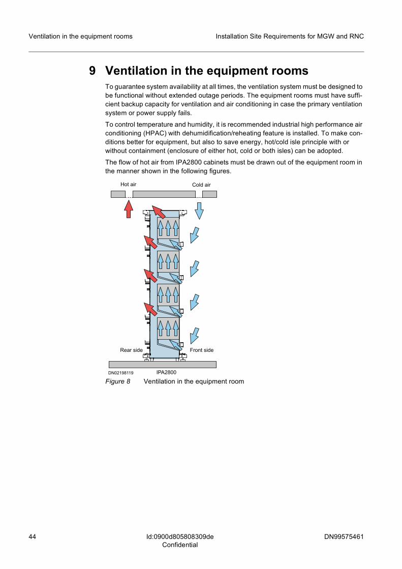
44 DN99575461
Installation Site Requirements for MGW and RNC
Id:0900d805808309deConfidential
Ventilation in the equipment rooms
9 Ventilation in the equipment roomsTo guarantee system availability at all times, the ventilation system must be designed to be functional without extended outage periods. The equipment rooms must have suffi-cient backup capacity for ventilation and air conditioning in case the primary ventilation system or power supply fails.
To control temperature and humidity, it is recommended industrial high performance air conditioning (HPAC) with dehumidification/reheating feature is installed. To make con-ditions better for equipment, but also to save energy, hot/cold isle principle with or without containment (enclosure of either hot, cold or both isles) can be adopted.
The flow of hot air from IPA2800 cabinets must be drawn out of the equipment room in the manner shown in the following figures.
Figure 8 Ventilation in the equipment roomIPA2800
Hot air
Front sideRear side
Cold air
DN02198119

DN99575461 45
Installation Site Requirements for MGW and RNC Ventilation in the equipment rooms
Id:0900d805808309deConfidential
Figure 9 Ventilation in the equipment room, with raised floorIPA2800
Hot air
Front sideRear side
Cold airDN02198107
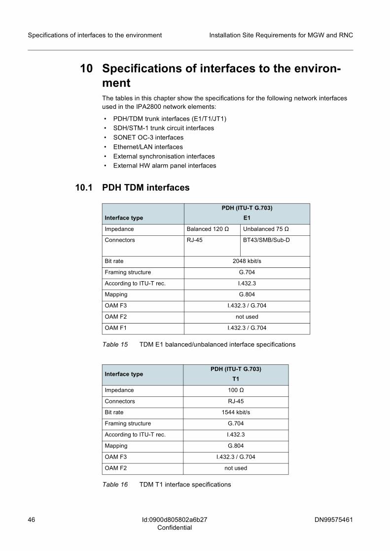
46 DN99575461
Installation Site Requirements for MGW and RNC
Id:0900d805802a6b27Confidential
Specifications of interfaces to the environment
10 Specifications of interfaces to the environ-mentThe tables in this chapter show the specifications for the following network interfaces used in the IPA2800 network elements:
• PDH/TDM trunk interfaces (E1/T1/JT1) • SDH/STM-1 trunk circuit interfaces • SONET OC-3 interfaces • Ethernet/LAN interfaces • External synchronisation interfaces • External HW alarm panel interfaces
10.1 PDH TDM interfaces
Interface typePDH (ITU-T G.703)
E1
Impedance Balanced 120 Ω Unbalanced 75 Ω
Connectors RJ-45 BT43/SMB/Sub-D
Bit rate 2048 kbit/s
Framing structure G.704
According to ITU-T rec. I.432.3
Mapping G.804
OAM F3 I.432.3 / G.704
OAM F2 not used
OAM F1 I.432.3 / G.704
Table 15 TDM E1 balanced/unbalanced interface specifications
Interface typePDH (ITU-T G.703)
T1
Impedance 100 Ω
Connectors RJ-45
Bit rate 1544 kbit/s
Framing structure G.704
According to ITU-T rec. I.432.3
Mapping G.804
OAM F3 I.432.3 / G.704
OAM F2 not used
Table 16 TDM T1 interface specifications

DN99575461 47
Installation Site Requirements for MGW and RNC Specifications of interfaces to the environment
Id:0900d805802a6b27Confidential
10.2 SDH STM-1 interfaces
OAM F1 I.432.3 / G.704
Interface typePDH (ITU-T G.703)
JT1
Impedance 110 Ω
Connectors RJ-45
Bit rate 1544 kbit/s
Framing structure G.704
According to ITU-T rec. -
Mapping G.804
OAM F3
OAM F2 not used
OAM F1
Table 17 TDM JT1 interface specifications
Interface typePDH (ITU-T G.703)
T1
Table 16 TDM T1 interface specifications (Cont.)
Interface typeSTM-1 optical (ITU-T G.957)
S-1.1
Nominal wavelength (nm) 1310
Distance (km) about 15
Medium G.652 optical fibre (SM)
Connectors LC
Bit Rate 155 520 kbit/s
Transmission path VC-4, VC-3
Mapping I.432.2/G.707
OAM F3 I.432.2/G.707 SDH
OAM F2 I.432.2/G.707 SDH
OAM F1 not used
Table 18 SDH STM-1 interface specifications

48 DN99575461
Installation Site Requirements for MGW and RNC
Id:0900d805802a6b27Confidential
Specifications of interfaces to the environment
10.3 SONET OC-3 interfaces
10.4 Ethernet/LAN interfaces
10.5 External synchronisation interfaces
Interface type OC-3 IR-1 (ANSI T1.105.06)
Nominal wavelength (nm) 1310
Distance (km) < 15 km
Medium ITU-T G.652 optical fibre (SM)
Connectors LC
Bit rate 155 520 kbit/s
Transmission path STS-3c SPE/STS-3 SPE (3 x STS-1 SPE) 1)
Specification ANSI T1.646-1995 / ANSI T1.106-1995
Jitter and wander T1.105.03
1) Concatenated synchronous transport level 3 payload envelope/Synchronous transport level 3 payload envelope
Table 19 SONET OC-3 interface specifications
Interface type: IEEE 802.3 (Ethernet)
10Base-T/ 100Base-TX 100Base-T/ 1000Base-TX 1000Base-LX
Max cable length: 100 m 100 m 5000 m
Cable: IEEE 802.3 IEEE 802.3 IEEE 802.3
Connectors: RJ-45 RJ-45 LC duplex (XCVR)
Bit rate: 10/100 Mbit/s 100/1000 Mbit/s 1000 Mbit/s
Table 20 LAN interface specifications
Interface type Synchronisation interface
Input interfaces Output Interface
2.048 Mbit/s 2.048 Mhz 1.544 MHz 64 kHz + 8 kHz 2.048 Mhz
Cable: ( Coaxial 75 Ω/ twisted pair 120 Ω
Coaxial 75 Ω / twisted pair 120 Ω
Coaxial 75 Ω Twisted pair 110 Ω
Coaxial 75 Ω / twisted pair 120 Ω
Connectors BNC / RJ-45 BNC / RJ-45 BNC RJ-45 BNC / RJ-45
Bit rate 2.048 Mbit/s N/A N/A N/A N/A
Framing struc-ture
G.703 N/A N/A N/A N/A
Table 21 External synchronisation interface specifications

DN99575461 49
Installation Site Requirements for MGW and RNC Specifications of interfaces to the environment
Id:0900d805802a6b27Confidential
10.6 External HW alarm interfaces
10.7 USB connector
10.8 RS232 connector
According to ITU-T rec.
G.703 G.703 - G.703 G.703
Interface type Synchronisation interface
Input interfaces Output Interface
2.048 Mbit/s 2.048 Mhz 1.544 MHz 64 kHz + 8 kHz 2.048 Mhz
Table 21 External synchronisation interface specifications (Cont.)
Alarm interface Connector types
External HW alarm interface
General outputs AL0-15, for EXAU/-A panel and cabinet LAMP control
D37
Voltage-controlled HW alarm inputs CAL0-7
D25
Voltage-controlled HW alarm inputs VAL0-31
2 x D37
Table 22 External alarm panel interfaces
Pin Description
Mechanical solder lug Shield ground
1 +5V
2 DATA-
3 DATA+
4 GND
Mechanical solder lug Shield ground
Table 23 USB connector
Pin Signal
2 TxD
3 GND
4 GND
5 RxD
Table 24 Pin order of the RS232 connector

50 DN99575461
Installation Site Requirements for MGW and RNC
Id:0900d8058030d382Confidential
Conversion between metric and imperial measures
11 Conversion between metric and imperial measuresConversion factors and tables
Metric unit Imperial equivalent
Length:
1 mm 0.03937 in
1 cm = 10 mm 0.3937 in
1 m = 100 cm 39.37 in = 3.2808 ft = 1.0936 yd
Area:
1 mm2 0.0016 sq in
1 cm2 = 100 mm2 0.155 sq in
1 m2 = 10,000 cm2 1,550 sq in = 10.764 sq ft = 1.1956 sq yd
Acceleration:
1 m/s2 3.2808 ft/s2 = 1.0936 yd/s2
Mass:
1 g 0.0353 oz
1 kg = 1,000 g 35.2736 oz = 2.2046 lb
Energy:
1 kJ = 1,000 J 0.9479 Btu
Power:
1 W 3.413 Btu/h
Pressure:
1 kPa (= 1,000 Pa) 0.1450 psi
1 bar (= 100 kPa) 14.504 psi
Wire conductor size:
16 mm2 AWG 5
25 mm2 AWG 3
35 mm2 AWG 1
50 mm2 AWG 0
Table 25 Conversion factors from metric to imperial measurement units
Imperial unit Metric equivalent
1 in 25.4 mm
1 ft = 12 in 0.3048 m
Table 26 Conversion factors from imperial to metric length measurement units

DN99575461 51
Installation Site Requirements for MGW and RNC Conversion between metric and imperial measures
Id:0900d8058030d382Confidential
Temperature conversion formulaTo convert temperatures given in degrees Celsius to degrees Fahrenheit, multiply by 9, divide by 5, and add 32:
(F)=
9
5 (C)+ 32tt
![Angle Seat Globe Valve, Metal · 550 3 Kv values [m³/h] DN 6 DN 8 DN 10 DN 15 DN 20 DN 25 DN 32 DN 40 DN 50 DN 65 DN 80 Butt weld spigots, DIN 11850 1.6 1.8 2.4 2.4 - - - - - - -](https://img.pdfslide.us/doc/110x75/5f9509c77c6fed50eb12dcff/angle-seat-globe-valve-metal-550-3-kv-values-mh-dn-6-dn-8-dn-10-dn-15-dn-20.jpg)