Embed Size (px)
Citation preview

Lucent Technologies - ProprietaryThis document contains proprietary information of
Lucent Technologies and is not to be disclosed or used except inaccordance with applicable agreements
Copyright © 2004 Lucent TechnologiesUnpublished and Not for Publication
All Rights Reserved
Metropolis® DMXplore Access Multiplexer
Release 2.0
Installation Manual
365-372-334 R2.0C109536243
Issue 4

Copyright © 2004 Lucent Technologies. All Rights Reserved.
hThis material is protected by the copyright and trade secret laws of the United States and other countries. It may not be reproduced, distributed, or alteredin any fashion by any entity (either internal or external to Lucent Technologies), except in accordance with applicable agreements, contracts, or licensing,without the express written consent of Lucent Technologies and the business management owner of the material.
Notice
Every effort was made to ensure that this information product was complete and accurate at the time of printing. However, information is subject to change.
Mandatory customer information
This equipment is designed to comply with the limits for a Class A digital device, pursuant to Part 15 of the FCC Rules. These limits are designed to providereasonable protection against harmful interference when the equipment is operated in a commercial environment. This equipment generates, uses, and canradiate radio frequency energy and, if not installed and used in accordance with the instructions manual, may cause interference to radio communications.Operation of this equipment in a residence is likely to cause harmful interference, in which case, the user will be required to correct the interference at his ownexpense.
Interference information: Part 15 of FCC rules
NOTE: This equipment has been tested and found to comply within the limits.
Security statement
In rare instances, unauthorized individuals make connections to the telecommunications network. In such an event, applicable tariffs require that the customerpay all network charges for traffic. Lucent Technologies and its predecessors cannot be responsible for such charges and will not make any allowance or giveany credit for charges that result from unauthorized access.
Trademarks
3Com is a registered trademark of 3Com Corporation.
5ESS and Billdats are registered trademarks of Lucent Technologies in the United States and other countries.
Information Mapping is a registered trademark of Information Mapping, Inc.
Adobe and Acrobat are registered trademarks of Adobe Systems, Inc.
CLEI, CLLI, CLCI, and CLFI are trademarks of Telcordia Technologies, Inc.
COMMON LANGUAGE is a registered trademark of Telcordia Technologies, Inc.
CSA is a registered trademark of Canadian Standards Association.
IBM is a registered trademark of International Business Machines Corporation.
Intel and Pentium are registered trademarks of Intel Corporation.
Reader (Adobe Acrobat Reader) is a trademark of Adobe Systems, Inc.
UL is a registered trademark of Underwriters Laboratories Inc.
WaveStar and Metropolis are registered trademarks of Lucent Technologies, Inc.
Windows, Windows NT, Windows 2000, Windows XP, MS-DOS, and Microsoft are registered trademarks of Microsoft Corporation.
Limited warranty
For terms and conditions of sale contact your Lucent Technologies Account Team.
Ordering information
The ordering number for this document is 365-372-334 R2.0. To order this document, call 1-888-582-3688 (USA), 1-317-322-6616 (Canada, Asia, the PacificRegion, China, Caribbean, Latin America, Europe, the Middle East, and Africa), or 1-317-322-6416 (all others). RBOC/BOC customers should processdocument orders or standing order requests through their Company Documentation Coordinator. For more ordering information, refer to the “OrderingInformation” section in the “About This Information Product” section.
Support
Technical support
Lucent Technologies Customer Assistance Request Entry System (CARES) provides a technical assistance telephone number that is monitored 24 hours a day.Technical assistance can be obtained by calling 1 866 LUCENT8 (continental U.S.) or +1 630 224 4672 for in-hours and emergency out-of-hours support.
Developed by Lucent Technologies.

C O N T E N T Si i i
365-372-334 R2.0Issue 4, November 2004
...........................................................................................................................................................................................................................................................
Contents
............................................................................................................................................................................................................................................................
About this information product
Safety Information and Instructions xxi
Related Documentation and Training xxviii
Documentation Ordering Information xxxi
Worldwide Services xxxiii
............................................................................................................................................................................................................................................................
Part I: Metropolis® DMXplore Access Multiplexer Physical Installation and Powering
............................................................................................................................................................................................................................................................
1 Equipment and Cable Installation for Metropolis® DMXplore Shelf (Wall-Mount)
Overview 1-1
Planning 1-3
Connector References 1-7
Inspection 1-8
Metropolis® DMXplore Wall-Mount Shelf Installation 1-9
Power Cable Installation 1-18
DS1 Cable Installation 1-23
DS3 Cable Installation 1-27
Ethernet Cable Installation 1-30
Office Alarm Cable Installation 1-33
Miscellaneous (Environmental) Discrete Telemetry Cable Installation 1-37
OC-3/OC12 Main Optical Fiber Cable Installation 1-41
RS-232 Serial CIT Cable Installation 1-43
SYSCTL LAN Cable Installation 1-45
Final Operations 1-491-49
1-45
1-43
1-41
1-37
1-33
1-30
1-27
1-23
1-18
1-9
1-8
1-7
1-3
1-1
xxxiii
xxxi
xxviii
xxi

...........................................................................................................................................................................................................................................................
C O N T E N T Si v
365-372-334 R2.0Issue 4, November 2004
............................................................................................................................................................................................................................................................
2 Equipment and Cable Installation for Metropolis® DMXplore Shelf (Rack-Mount)
Overview 2-1
Planning 2-3
Connector References 2-7
Inspection 2-8
Metropolis® DMXplore Rack-Mount Shelf Installation 2-9
Power Cable Installation 2-13
DS1 Cable Installation 2-18
DS3 Cable Installation 2-22
Ethernet Cable Installation 2-24
Office Alarm Cable Installation 2-26
Miscellaneous (Environmental) Discrete Telemetry Cable Installation 2-30
OC-3/OC12 Main Optical Fiber Cable Installation 2-34
RS-232 Serial CIT Cable Installation 2-37
SYSCTL LAN Cable Installation 2-39
Final Operations 2-43
............................................................................................................................................................................................................................................................
3 Powering and Initial Circuit Pack Installation for Metropolis®
DMXplore Shelf (Wall-Mount)
Overview 3-1
Description 3-2
Powering 3-3
Circuit Pack Compatibility 3-7
Removal of Cover 3-9
Initial Circuit Pack Installation 3-11
............................................................................................................................................................................................................................................................
4 Powering and Initial Circuit Pack Installation for Metropolis®
DMXplore Shelf (Rack-Mount)
Overview 4-1
Description 4-2
Powering 4-3
Circuit Pack Compatibility 4-7
Removal of Cover 4-8
Initial Circuit Pack Installation 4-114-11
4-8
4-7
4-3
4-2
4-1
3-11
3-9
3-7
3-3
3-2
3-1
2-43
2-39
2-37
2-34
2-30
2-26
2-24
2-22
2-18
2-13
2-9
2-8
2-7
2-3
2-1
...........................................................................................................................................................................................................................................................
C O N T E N T Sv
365-372-334 R2.0Issue 4, November 2004
............................................................................................................................................................................................................................................................
Part II: Metropolis® DMXplore Access Multiplexer Stand-Alone Installation Tests
............................................................................................................................................................................................................................................................
5 Software Download and Circuit Pack Installation
Software Installation 5-4
Circuit Pack Installation 5-5
Use of WaveStar® CIT Software 5-8
A Short Tour of the Command Builder 5-14
Circuit Pack Firmware Version Verification 5-18
Metropolis® DMXplore Shelf Initialization 5-20
............................................................................................................................................................................................................................................................
6 Installation Tests
Overview 6-1
LBO Software Settings 6-4
Clearing Alarms 6-7
Local Equipment and Cross-connect Tests 6-9
LED Test 6-16
............................................................................................................................................................................................................................................................
7 Operational Tests
Overview 7-1
Office Alarm Test 7-4
Automatic Protection Switching and Alarm Test 7-9
Manual Switching Tests 7-12
Miscellaneous (Environmental) Discrete Telemetry Test 7-14
Final Operations 7-18
............................................................................................................................................................................................................................................................
Part III: Metropolis® DMXplore Access Multiplexer Ring Setup and Testing
............................................................................................................................................................................................................................................................
8 Ring Setup and Testing: Integration Procedures
Overview 8-1
Fiber Installation 8-4
OC-3/OC12 Optical Transmission Test 8-11
Automatic Protection Switching Test 8-13
Manual Switching Tests 8-158-15
8-13
8-11
8-4
8-1
7-18
7-14
7-12
7-9
7-4
7-1
6-16
6-9
6-7
6-4
6-1
5-20
5-18
5-14
5-8
5-5
5-4

...........................................................................................................................................................................................................................................................
C O N T E N T Sv i
365-372-334 R2.0Issue 4, November 2004
Cover Installation Wall-Mount 8-19
Cover Installation Rack-Mount 8-21
Final Operations 8-23
............................................................................................................................................................................................................................................................
Part IV: Metropolis® DMXplore Access Multiplexer Supplementary Information and Installation Checklist
............................................................................................................................................................................................................................................................
A Laser Safety and Classifications
Overview A-1
Laser Safety A-2
Laser Product Classification A-5
Metropolis® DMXplore Optical Specifications A-7
............................................................................................................................................................................................................................................................
B Fiber Cleaning
Overview B-1
Equipment Requirements and Recommendations B-3
Safety Instructions B-4
Cleaning/Inspecting Optical Connectors B-5
............................................................................................................................................................................................................................................................
C Installing Fiber Connectors and LBOs
Overview C-1
LBOs C-2
Fiber Connections C-5
............................................................................................................................................................................................................................................................
D Backplane Pin Replacement
Overview D-1
Pin and Connector Background D-3
Repair Kits and Tools D-5
Simple Repair Methods D-6
Replacement Methods D-8
............................................................................................................................................................................................................................................................
E Installation Checklist
Overview E-1
............................................................................................................................................................................................................................................................
F Fiber Labeling
Fiber Description F-2F-2
E-1
D-8
D-6
D-5
D-3
D-1
C-5
C-2
C-1
B-5
B-4
B-3
B-1
A-7
A-5
A-2
A-1
8-23
8-21
8-19

...........................................................................................................................................................................................................................................................
C O N T E N T Sv i i
365-372-334 R2.0Issue 4, November 2004
Fiber Labels F-4
............................................................................................................................................................................................................................................................
GL Glossary
Acronyms and Abbreviations GL-1
Terms and Definitions GL-17
F-4
GL-1
GL-17

...........................................................................................................................................................................................................................................................
C O N T E N T Sv i i i
365-372-334 R2.0Issue 4, November 2004

F I G U R E Si x
365-372-334 R2.0Issue 4, November 2004
...........................................................................................................................................................................................................................................................
List of figures
About this information product........................................................................................................................................................................
1 Equipment and Cable Installation for Metropolis® DMXplore Shelf (Wall-Mount)
1-1 Connector Types and Pinouts 1-7
1-2 Metropolis® DMXplore Shelf Wall-Mount (with Cover) 1-10
1-3 Mounting Screw 1-10
1-4 Wall Plate 1-11
1-5 Safety Ground Screw 1-12
1-6 Exploded Bay-Frame (23" Mounting Bracket) 1-14
1-7 Safety Ground Screw 1-15
1-8 Wall-Mount Bay-Frame Mounting Brackets 1-17
1-9 Power Connection 1-20
1-10 DS1 Access Panel Cable Connectors 1-25
1-11 DS1 Cable Routing 1-26
1-12 DS3 Access Panel Cable Connectors. 1-28
1-13 10/100Base-T Cable Installation 1-31
1-14 Office Alarm Cable Connections 1-35
1-15 Alarm Cable Routing 1-35
1-16 Miscellaneous Discrete Cable Connection 1-39
1-17 Miscellaneous Discretes and Office Alarm Cable Routing 1-40
1-18 Optical Fiber Routing 1-421-42
1-40
1-39
1-35
1-35
1-31
1-28
1-26
1-25
1-20
1-17
1-15
1-14
1-12
1-11
1-10
1-10
1-7

...........................................................................................................................................................................................................................................................
F I G U R E Sx
365-372-334 R2.0Issue 4, November 2004
........................................................................................................................................................................2 Equipment and Cable Installation for Metropolis® DMXplore Shelf (Rack-
Mount)
2-1 Connector Types and Pinouts 2-7
2-2 Metropolis® DMXplore Rack-Mount Shelf (with Cover) 2-9
2-3 Mounting bracket position for 19 inch frame 2-10
2-4 Mounting bracket position for 23 inch frame 2-11
2-5 Safety Ground Screw 2-12
2-6 Rack-Mount Metropolis® DMXplore Connector 2-14
2-7 Power Connection 2-15
2-8 DS1 Access Panel Cable Connectors 2-20
2-9 DS3 Access Panel Cable Connectors 2-23
2-10 10/100Base-T Cable Installation 2-24
2-11 Alarm Designations (as shown on inside cover) 2-28
2-12 Office Alarm Cable Connections 2-28
2-13 MDI and MDO Designations (see inside cover) 2-31
2-14 Miscellaneous Discrete Cable Connection 2-32
2-15 Optical Fiber Routing 2-35
........................................................................................................................................................................3 Powering and Initial Circuit Pack Installation for Metropolis® DMXplore Shelf
(Wall-Mount)
3-1 Power Connections on Metropolis® DMXplore Access Panel 3-4
3-2 Wall-Mount Metropolis® DMXplore Shelf 3-8
3-3 Metropolis® DMXplore Shelf with cover 3-9
3-4 Rotated Cover 3-10
3-5 Pivot Pins 3-10
........................................................................................................................................................................4 Powering and Initial Circuit Pack Installation for Metropolis® DMXplore Shelf
(Rack-Mount)
4-1 Power Connections on Rack-Mount Metropolis® DMXplore Access Panel4-4
4-2 Rack-Mount Metropolis® DMXplore Shelf Front View 4-74-7
3-10
3-10
3-9
3-8
3-4
2-35
2-32
2-31
2-28
2-28
2-24
2-23
2-20
2-15
2-14
2-12
2-11
2-10
2-9
2-7

...........................................................................................................................................................................................................................................................
F I G U R E Sx i
365-372-334 R2.0Issue 4, November 2004
4-3 Rack-Mount Metropolis® DMXplore Shelf with cover 4-8
4-4 Cover Removal 4-9
4-5 Rotated Cover 4-9
4-6 Rack-Mount Metropolis® DMXplore shelf - cover down 4-10
........................................................................................................................................................................5 Software Download and Circuit Pack Installation
5-1 WaveStar® CIT Banner 5-9
5-2 WaveStar® CIT Login Prompt 5-9
5-3 WaveStar® CIT Legal Notice 5-10
5-4 WaveStar® CIT Network View 5-10
5-5 TL1 View Type Selection 5-11
5-6 OSI Connection Type Selection 5-12
5-7 Network Element Login Prompt 5-12
5-8 Command Builder and Response Windows: 5-13
5-9 ent-t1 (sb): Screen 1 5-14
5-10 ent-t1 (sb): Screen 2 5-15
5-11 ent-t1 (sb): Screen 3 5-16
5-12 ed-dat: Screen 1 5-17
........................................................................................................................................................................6 Installation Tests
........................................................................................................................................................................7 Operational Tests
7-1 Miscellaneous (Environmental) Discrete Functions 7-14
........................................................................................................................................................................8 Ring Setup and Testing: Integration Procedures
8-1 Pivot Pins 8-19
8-2 Metropolis® DMXplore Shelf w. Cover 8-20
8-3 Rack-Mount Cover Alignment 8-21
8-4 Snapping cover into place 8-228-22
8-21
8-20
8-19
7-14
5-17
5-16
5-15
5-14
5-13
5-12
5-12
5-11
5-10
5-10
5-9
5-9
4-10
4-9
4-9
4-8

...........................................................................................................................................................................................................................................................
F I G U R E Sx i i
365-372-334 R2.0Issue 4, November 2004
........................................................................................................................................................................A Laser Safety and Classifications
........................................................................................................................................................................B Fiber Cleaning
B-1 Cleaning the Ferrule Endface B-6
B-2 CLETOP Cleaner B-7
B-3 Acceptability Criteria for Fiber Cleaning B-10
........................................................................................................................................................................C Installing Fiber Connectors and LBOs
C-1 LC-type Connector Ports on Circuit Pack C-2
C-2 LC-type LBO C-3
C-3 LC-type LBO inserted into LC-type Connector Port C-3
C-4 Removing LC-type LBO from LC-type Connector Port C-4
C-5 LC-type Fiber Connector C-5
C-6 LC-type Fiber Connection C-6
........................................................................................................................................................................D Backplane Pin Replacement
........................................................................................................................................................................E Installation Checklist
........................................................................................................................................................................F Fiber Labeling
Glossary
C-6
C-5
C-4
C-3
C-3
C-2
B-10
B-7
B-6

T A B L E Sx i i i
365-372-334 R2.0Issue 4, Novmeber 2004
...........................................................................................................................................................................................................................................................
List of tables
About this information product1 Metropolis® DMXplore Documentation Set xxviii
2 Metropolis® DMXplore Drawings xxix
3 Ordering Documentation via Phone, Fax, or Email xxxi
4 Ordering Documentation via the Internet xxxi
........................................................................................................................................................................1 Equipment and Cable Installation for Metropolis® DMXplore Shelf (Wall-
Mount)
1-1 Cable Requirements and Options 1-5
1-2 Power Cable Assemblies 1-18
1-3 Power Connections 1-18
1-4 Power Cable Color Coding 1-20
1-5 DS1 Cable Assemblies 1-23
1-6 DS1 Transmission Connections 1-24
1-7 DS3 Cable Assemblies 1-27
1-8 LAN 10/100 BaseT Cable Assemblies for Fast Ethernet 1-32
1-9 Office Alarm Cable Assemblies 1-33
1-10 Office Alarm Connections 1-34
1-11 Miscellaneous Discrete Cable Assemblies 1-37
1-12 Miscellaneous (Environmental) Discrete Telemetry Connections 1-38
1-13 Serial CIT Cable Assembly 1-43
1-14 Standard CIT Cable Connection 1-43
1-15 RJ-45 to DB-9 Connector Connections 1-441-44
1-43
1-43
1-38
1-37
1-34
1-33
1-32
1-27
1-24
1-23
1-20
1-18
1-18
1-5
xxxi
xxxi
xxix
xxviii

...........................................................................................................................................................................................................................................................
T A B L E Sx i v
365-372-334 R2.0Issue 4, Novmeber 2004
1-16 LAN 10BASE-T Cable Assemblies 1-45
1-17 LAN 10BASE-T Cross-over Cable Connections 1-47
1-18 LAN 10BASE-T Straight-through Cable Connections 1-47
........................................................................................................................................................................2 Equipment and Cable Installation for Metropolis® DMXplore Shelf (Rack-
Mount)
2-1 Cable Requirements and Options 2-5
2-2 Power Cable Assemblies 2-13
2-3 Power Connections 2-14
2-4 Power Cable Color Coding 2-15
2-5 DS1 Cable Assemblies 2-18
2-6 DS1 Transmission Connections 2-19
2-7 DS3 Cable Assemblies 2-22
2-8 LAN 10/100 BaseT Cable Assemblies for Fast Ethernet 2-25
2-9 Office Alarm Cable Assemblies 2-26
2-10 Office Alarm Connections 2-27
2-11 Miscellaneous Discrete Cable Assemblies 2-30
2-12 Miscellaneous (Environmental) Discrete Telemetry Connections 2-31
2-13 Serial CIT Cable Assembly 2-37
2-14 Standard CIT Cable Connection 2-37
2-15 RJ-45 to DB-9 Connector Connections 2-38
2-16 LAN 10BASE-T Cable Assemblies 2-39
2-17 LAN 10BASE-T Cross-over Cable Connections 2-41
2-18 LAN 10BASE-T Straight-through Cable Connections 2-41
2-19 2-42
........................................................................................................................................................................3 Powering and Initial Circuit Pack Installation for Metropolis® DMXplore Shelf
(Wall-Mount)
3-1 Metropolis® DMXplore Shelf Power Supply Requirements 3-3
3-2 Release 2.0 Circuit Pack Slot Compatibility 3-73-7
3-3
2-42
2-41
2-41
2-39
2-38
2-37
2-37
2-31
2-30
2-27
2-26
2-25
2-22
2-19
2-18
2-15
2-14
2-13
2-5
1-47
1-47
1-45

...........................................................................................................................................................................................................................................................
T A B L E Sx v
365-372-334 R2.0Issue 4, Novmeber 2004
........................................................................................................................................................................4 Powering and Initial Circuit Pack Installation for Metropolis® DMXplore Shelf
(Rack-Mount)
4-1 Metropolis® DMXplore Shelf Power Supply Requirements 4-3
4-2 Release 2.0 Circuit Pack Slot Compatibility 4-7
........................................................................................................................................................................5 Software Download and Circuit Pack Installation
........................................................................................................................................................................6 Installation Tests
........................................................................................................................................................................7 Operational Tests
7-1 Office Alarm Connections 7-5
7-2 Miscellaneous (Environmental) Discrete Inputs Telemetry Connections 7-15
........................................................................................................................................................................8 Ring Setup and Testing: Integration Procedures
........................................................................................................................................................................A Laser Safety and Classifications
A-1 Laser Classes A-6
A-2 Metropolis® DMXplore Optical Specifications A-7
........................................................................................................................................................................B Fiber Cleaning
B-1 Required and Recommended Equipment and Materials B-3
........................................................................................................................................................................C Installing Fiber Connectors and LBOs
........................................................................................................................................................................D Backplane Pin Replacement
D-1 Backplane Locations of METRAL™ Pins D-4
D-2 Metral™ Pins D-5
........................................................................................................................................................................E Installation Checklist
E-1 Installation Acceptance Checklist E-2
........................................................................................................................................................................F Fiber Labeling
E-2
D-5
D-4
B-3
A-7
A-6
7-5
4-7
4-3

...........................................................................................................................................................................................................................................................
T A B L E Sx v i
365-372-334 R2.0Issue 4, Novmeber 2004
Glossary

x v i i365-372-334 R2.0Issue 4, November 2004
............................................................................................................................................................................................................................................................
About this information product
Purpose This document provides the information and procedures necessary to install, self-test and turn up the Metropolis® DMXplore Access Multiplexer system.
..................................................................................................................
Reason for reissue This document is reissued to include the OC12 OLIU VLNC 25 and VLNC 26 circuit packs as well as the VLNC15 Fast Ethernet circuit pack which provides functionality of 10/100 Base T introduced with software Release 2.0.
..................................................................................................................
Intended Audience This installation manual is intended to provide information and procedures necessary to install, self-test, and turn up the Metropolis®
DMXplore system.
This manual is not a service or operations manual. Refer to 365-372-332, Metropolis® DMXplore Access Multiplexer User Operations Guide for any activities involving circuit turn-up or regular maintenance, and 365-372-333, Metropolis® DMXplore Access Multiplexer Alarm Messaging and Trouble Clearing Guide for trouble analysis.
..................................................................................................................

...........................................................................................................................................................................................................................................................
About this information product
x v i i i 365-372-334 R2.0Issue 4, November 2004
How to use thisinformation product
This manual is divided into the following sections with a brief description of the contents of each major part/chapter/appendix:
• “About This Document” describes the purpose, intended audience, reason for reissue, and organization of this document. This section references related documentation and explains how to order, make comments or recommend changes to this document.
Part I: Metropolis® DMXplore Access Multiplexer Physical Installation and Powering
• Chapter 1, Equipment and Cable Installation for Metropolis®
DMXplore Shelf (Wall-Mount) and Chapter 2, Equipment and Cable Installation for Metropolis® DMXplore Shelf (Rack-Mount) provide the information and procedures for installing and cabling the Metropolis® DMXplore system. This section contains the latest information at the time of issue. For up-to-date information, refer to the SD and ED drawings listed in those chapters.
• Chapter 3, Powering and Initial Circuit Pack Installation for Metropolis® DMXplore Shelf (Wall-Mount) and Chapter 4, Powering and Initial Circuit Pack Installation for Metropolis®
DMXplore Shelf (Rack-Mount) provide information for verifying that the shelf is being supplied with the proper power and provides instructions for circuit pack installation.
Part II: Metropolis® DMXplore Access Multiplexer Stand-Alone Installation Tests
• Chapter 5, Software Download and Circuit Pack Installation covers generic software loading and initial circuit pack installation, that is, placement of circuit packs in their proper locations in the shelf.
• Chapter 6, Installation Tests provides instructions to verify proper transmission cabling installation and functionality.
• Chapter 7, Operational Tests provides instructions to test protection switching and the non-transmission cabling. This section is not intended to replace acceptance test procedures.
Part III: Metropolis® DMXplore Access Multiplexer Ring Setup and Testing
• Chapter 8, Ring Setup and Testing: Integration Procedures provides the tests to verify proper ring fiber cabling and protection switching.

About this information product
...........................................................................................................................................................................................................................................................
x i x365-372-334 R2.0Issue 4, November 2004
Part IV: Metropolis® DMXplore Access Multiplexer Supplementary Information and Installation Checklist
• Appendix A, Laser Safety and Classifications provides lightwave and laser safety information and precautions.
• Appendix B, Fiber Cleaning describes the Lucent recommended method for the cleaning and inspection of optical connectors using specific tools and materials that have been proven to be effective in the assembly and testing of optical transmission equipment.
• Appendix C, Installing Fiber Connectors and LBOs provides procedures for installing and removing the types of Line Build Out units (LBOs) and fiber connectors onto input and output ports found on the Metropolis® DMXplore circuit packs.
• Appendix D, Backplane Pin Replacement provides information and the procedures used when a pin or blade on the Metropolis®
DMXplore backplane has been bent or broken.
• Appendix E, Installation Checklist provides a checklist to ensure that all necessary procedures have been completed. Use of the installation checklist is required to ensure a quality installation, all completed tasks should be checked off and those not completed should be duly noted as to the reason why. This checklist should be turned in as part of your job complete paperwork.
• Glossary provides definitions for telecommunication acronyms and terms.
• Index supplies users with specific subjects and corresponding page numbers to find necessary information.
..................................................................................................................

...........................................................................................................................................................................................................................................................
About this information product
x x 365-372-334 R2.0Issue 4, November 2004
Conventions Used Italic typeface denotes a particular product line or information product.
Helvetica Bold typeface signifies a window, section, command or parameter used with the TL1 Command Builder.
Helvetica typeface indicates a faceplate or Metropolis® DMXplore label designation, as in the ACTIVE LED on a circuit pack.
Courier Bold indicates a TL1 command typed in a terminal window by the user, as in act-user:LT-DMXplore:LUC01:ctag::DMXPLR2.5G;
Courier typeface indicates the system or PC response to a command.
For the remainder of this document, “Metropolis® DMXplore” is used in place of Metropolis® DMXplore Access Multiplexer in most cases.
..................................................................................................................

About this information productSafety Information and Instructions
...........................................................................................................................................................................................................................................................
x x i365-372-334 R2.0Issue 4, November 2004
........................................................................................................................................................................Safety Information and Instructions
Safety Labels This document may contain safety labels in the form of DANGER, WARNING, and CAUTION statements.
These admonishments have the following definitions:
DANGER
...........................................................................................................................................................................
DANGER shows the presence of a hazard that will cause death or severe personal injury if the hazard is not avoided.
WARNING
...........................................................................................................................................................................
WARNING shows the presence of a hazard that can cause death or severe personal injury if the hazard is not avoided.
CAUTION
...........................................................................................................................................................................
CAUTION shows the presence of a hazard that will or can cause minor personal injury or property damage if the hazard is not avoided. Caution is also used for property-damage-only accidents. This includes equipment damage, loss of software, or service interruption.
The alert symbol appears throughout this document to alert the user to these safety labels.
..................................................................................................................
Laser Safety For more detailed information and safety precautions, refer to Appendix A, Laser Safety and Classifications.
..................................................................................................................

...........................................................................................................................................................................................................................................................
About this information productSafety Information and Instructions
x x i i 365-372-334 R2.0Issue 4, November 2004
Electrostatic Discharge(ESD) Considerations
Electrostatic discharge (ESD) (for example, caused by touching with the hand) can destroy semiconductor components. The correct operation of the complete system is then no longer assured.
Electrostatic discharge (ESD) warning
CAUTION
...........................................................................................................................................................................
Destruction of components by electrostatic dischargeElectronic components can be destroyed by electrostatic discharge. Circuit packs must always be kept in antistatic covers. Use the original packaging if possible
Use a static ground wrist strap whenever handling circuit packs or working on the Metropolis ® DMXplore system to prevent electrostatic discharge damage to sensitive components.
All semiconductor components are basically sensitive to electrostatic discharge. The electrostatic discharge can also affect the components indirectly using contacts or conductor tracks.
Circuit pack handling precautions
Industry experience has shown that all integrated circuit packs can be damaged by static electricity that builds up on work surfaces and personnel. The static charges are produced by various charging effects of movement and contact with other objects. Dry air allows greater static charges to accumulate. Higher potentials are measured in areas with low relative humidity, but potentials high enough to cause damage can occur anywhere.
Observe the following precautions when handling circuit packs/units to prevent damage by electrostatic discharge:
• Assume all circuit packs contain solid state electronic components that can be damaged by ESD.
• When handling circuit packs (storing, inserting, removing, etc.) or when working on the backplane, always wear a grounded wrist strap such as the one shown in Figure 1, Static Control Wrist Strap (page -xxiv) or wear a heel strap and stand on a grounded, static dissipating floor mat. If a static dissipating floor mat is used, be sure that it is clean to ensure a good discharge path.

About this information productSafety Information and Instructions
...........................................................................................................................................................................................................................................................
x x i i i365-372-334 R2.0Issue 4, November 2004
• Wear working garment made of 100% cotton to avoid electrostatic discharge.
• Handle all circuit packs by the faceplate or latch and by the top and bottom outermost edges. Never touch the components, conductors, or connector pins.
• Store and ship circuit packs and components in their shipping packing. Circuit packs and components must be packed and unpacked only at workplaces suitably protected against build-up of charge.
• Observe warning labels on bags and cartons. Whenever possible, do not remove circuit packs from antistatic packaging until ready to insert them into slots.
• If possible, open all circuit packs at a static safe work position, using properly grounded wrist straps and static dissipating table mats. If a static dissipating floor mat is used, be sure that it is clean to ensure a good discharge path.
• Always store and transport circuit packs in static safe packaging. Shielding is not required unless specified.
• Keep all static generating materials such as food wrappers, plastics, and styrofoam containers away from all circuit packs. Upon removal from bay, immediately put circuit packs into static safe packages.
• Whenever possible, maintain relative humidity above 20 percent.
To reduce the possibility of ESD damage, assemblies are equipped with grounding jacks to enable personnel to ground themselves using wrist straps (Figure 1, Static Control Wrist Strap (page -xxiv)) while handling circuit packs or working on an assembly. The jacks for connection of wrist straps are located at the upper right-hand corner of each assembly and are labeled. When grounding jacks are not provided, an alligator clip adapter enables connection to bay frame ground.

...........................................................................................................................................................................................................................................................
About this information productSafety Information and Instructions
x x i v 365-372-334 R2.0Issue 4, November 2004
Figure 1 Static Control Wrist Strap
..................................................................................................................
TOGROUNDCONNECTION

........................................................................................................................................................................IMPORTANT SAFETY INSTRUCTIONS
READ AND UNDERSTAND ALL INSTRUCTIONS
The exclamation point within an equilateral triangle is intended to alert the user to the presence of important operating and maintenance (servicing) instructions in the literature accompanying this product.
When installing, operating, or maintaining this equipment, basic safety precautions should always be followed to reduce the risk of fire, electric shock, and injury to persons, including the following:
1. Read and understand all instructions
2. Follow all warnings and instructions marked on this product.
3. This product should be only operated from the type of power sources indicated on the marking label.
4. Connect this product only to the type of power sources recommended by Lucent Technologies. For information on the powering instructions, consult the Installation Manual (DMXplore 365-372-334).
5. For information on proper mounting instructions, consult the Installation Manual (DMXplore 365-372-334).
6. Install only equipment identified in the Installation Manual (DMXplore 365-372-334). Use of other equipment may result in improper connection of circuitry leading to fire or injury to persons.
7. All metallic telecommunication interfaces should not leave the building premises unless connected to telecommunication devices providing primary and secondary protection, as applicable.
8. Do not use this product near water, for example, in a wet basement.
9. Do not place this product on an unstable cart, stand or table. The product may fall, causing serious damage to the product.
10. Use caution when installing or modifying telecommunications lines.
11. Never install telecommunications wiring during a lightning storm.
12. Never install telecommunications connections in wet locations.
13. Never touch uninsulated telecommunications wires or terminals unless the telecommunications line has been disconnected at the network interface.
14. Never touch uninsulated wiring or terminals carrying direct current or ringing current, or leave this wiring exposed. Protect and tape uninsulated wiring and terminals to avoid risk of fire, electric shock, and injury to service personnel.
15. Never push objects of any kind into this product through slots as they may touch dangerous voltage points or short out parts that could result in a risk of fire or electrical shock. Never spill liquids of any kind on the product.
16. Slots and openings in the unit are provided for ventilation, to protect it from overheating, and these openings must not be blocked or covered. This product should not be placed in a built-in installation unless proper ventilation is provided.

...........................................................................................................................................................................................................................................................
About this information productSafety Information and Instructions
x x v i 365-372-334 R2.0Issue 4, November 2004
17. To reduce the risk of an electrical shock, do not disassemble this product. Service should be performed by trained personnel only. Opening or removing covers and/or circuit boards may expose you to dangerous voltages or other risks. Incorrect reassembly can cause electrical shock when the unit is subsequently used.
18. Some of the Metropolis® DMX Family hardware modules contain FDA/CDRH Class I/IEC Class 1 single-mode laser products that are enclosed lightwave transmission systems. Under normal operating conditions, lightwave transmission systems are completely enclosed; nonetheless, the following precautions must be observed because of the potential for eye damage:
• Do not disconnect any lightwave cable or splice and stare into the optical connectors terminating the cables.
• Lightwave/lightguide operations should not be performed by a technician who has not satisfactorily completed an approved training course.
• Do not use optical instruments such as an eye loupe to view a fiber or unterminated connector.
• More information about laser safety can be found in the Installation Manual (DMXplore 365-372-334).
19. For a unit intended to be powered from –48 V DC voltage sources, read and understand the following:
• To be powered only by Safety Extra Low Voltage (SELV) -48 V DC Sources.
• Disconnect up to two (2) power supply connections when removing power from the system.
• This equipment must be provided with a readily accessible disconnect device as part of the building installation.
• Ensure that there is no exposed wire when the input power cables are connected to the unit.
• Installation must include an independent frame ground drop to building ground. Refer to User’s Manual.
• This Equipment is to be Installed Only in Restricted Access Areas on Business and Customer Premises Applications in Accordance with Articles 110-16, 110-17, and 110-18 of the National Electrical Code, ANSI/NFPA No. 70. Other Installations Exempt from the Enforcement of the National Electrical Code May Be Engineered According to the Accepted Practices of the Local Telecommunications Utility.
20. For a unit intended to be powered from 100-120/200-240 V AC voltage sources, read and understand the following:
• Unplug this product from the wall outlet before cleaning. Do not use liquid cleaners or aerosol cleaners. Use a damp cloth for cleaning.
• Do not staple or otherwise attach the power supply cord to the building surfaces.
This symbol is marked on the product, adjacent to the ground (earth) area for the connection of the ground (earth) conduc-tor.

About this information productSafety Information and Instructions
...........................................................................................................................................................................................................................................................
x x v i i365-372-334 R2.0Issue 4, November 2004
• Do not overload wall outlets and extension cords as this can result in the risk of fire or electric shock.
• The socket outlet shall be installed near the equipment and shall be readily accessible.
• This product is equipped with a three-wire grounding type plug, a plug having a third (grounding) pin. This plug is intended to fit only into a grounding type power outlet. This is a safety feature. If you are unable to insert the plug into the outlet, contact your electrician to replace your obsolete outlet. Do not defeat the safety purpose of the grounding type plug. Do not use a 3-to-2-prong adapter at the receptacle. Use of this type adapter may result in risk of electrical shock and/or damage to this product.
• Do not allow anything to rest on the power cord. Do not locate this product where the cord may be abused by persons walking on it.
• Unplug this product from the wall outlet and refer servicing to qualified service personnel under the following conditions:
a. When the powers supply cord or plug is damaged or frayed.
b. If liquid has been spilled into the product.
c. If the product has been exposed to rain or water.
d. If the product does not operate normally by following the operating instructions. Adjust only those controls that are covered by the operating instructions because improper adjustment of other controls may result in damage and will often require extensive work by qualified technician to restore the product to normal operation.
e. If the product has been dropped or the cabinet has been damaged.
f. If the product exhibits a distinct change in performance.
SAVE THESE INSTRUCTIONS

...........................................................................................................................................................................................................................................................
About this information productRelated Documentation and Training
x x v i i i 365-372-334 R2.0Issue 4, November 2004
........................................................................................................................................................................Related Documentation and Training
Metropolis® DMXploreDocumentation Set
Table 1, Metropolis® DMXplore Documentation Set lists the documents that comprise the Metropolis® DMXplore Access Multiplexer documentation set.
Table 1 Metropolis® DMXplore Documentation Set
DocumentNumber
Comcode Document Title Description
365-372-331 Iss.2 109454066 Metropolis® DMXplore Access Multiplexer Applications and Planning Guide (APG)
Created for use by the Lucent Account Team, customer network planners, analysts, and managers. It presents an overview of the system, describes its applications, gives planning requirements, engineering rules, ordering information, and technical specifications.
365-372-332 R2.0 109536227 Metropolis® DMXplore Access Multiplexer User Operations Guide (UOG)
Provides step-by-step information for use in daily system operations and demonstrates how to perform system provisioning, operations, and administrative tasks.
365-372-333 R2.0 109536235 Metropolis® DMXplore Access Multiplexer Alarm Messages and Trouble Clearing Guide (AMTCG)
Provides detailed information on maintenance and trouble clearing, a list of the system’s alarm messages, and procedures for routine maintenance, troubleshooting, diagnostics, and component replacement.
365-372-334 R2.0 109536243 Metropolis® DMXplore Access Multiplexer Installation Manual (IM)
Provides a step-by-step guide to system installation and setup.
N/A 109553073 Metropolis® DMXplore Access Multiplexer Software Release Description (SRD) - (CD-ROM)
Contains status of problems fixed, known problems and software installation procedure. This document is shipped with the software CD and is not orderable from the Customer Information Center (CIC).
N/A 109553032 Metropolis® DMXplore Access Multiplexer Software Release Description (SRD) - (Paper)
Contains status of problems fixed, known problems and software installation procedure.
365-372-335 R2.0 109536250 Metropolis® DMXplore Access Multiplexer TL1 Message Details
Provides a list of TL1 commands and the associated syntax.

About this information productRelated Documentation and Training
...........................................................................................................................................................................................................................................................
x x i x365-372-334 R2.0Issue 4, November 2004
Training This document expects a user to be familiar with the basic functions of the system before performing tasks that could damage the system, affect system operations, or impede communication traffic within the system. Understanding the descriptive material provided in this manual and attending the recommended training courses should allow you to perform the tasks necessary to operate and maintain the Metropolis®
DMXplore Access Multiplexer.
Refer to https://www.lucent-product-training.com for descriptions of the training courses available for the Metropolis® DMXplore Access Multiplexer.
Registering for a course
To review the available courses or to enroll in a training course at one of Lucent’s corporate training centers,
• Within the United States,
– Visit https://www.lucent-product-training.com
– Call 1-888-LUCENT8 (888-582-3688): Prompt 2.
• Outside the continental United States,
– Visit https://www.lucent-product-training.com
– Contact your in-country training representative
– Call: +1-407-767-2798
– Fax: +1-407-767-2677
Table 2 Metropolis® DMXplore Drawings
Drawing Number
Drawing Title
ED8C947-10 Metropolis® DMXplore Access Multiplexer, Engineering and Ordering Information
ED8C947-20 Metropolis® DMXplore Access Multiplexer, Interconnect Circuit Information

...........................................................................................................................................................................................................................................................
About this information productRelated Documentation and Training
x x x 365-372-334 R2.0Issue 4, November 2004
Suitcasing
To arrange for a suitcase session at your facility,
• Within the United States, call 1-888-LUCENT8 (888-582-3688): Prompt 2.
• Outside the continental United States,
– Contact your in-country training representative
– Call: +1-407-767-2798
– Fax: +1-407-767-2677
How to Comment To comment on this information product, go to the Online Comment Form (http://www.lucent-info.com/comments) or email your comments to the Comments Hotline ([email protected]).
..................................................................................................................

About this information productDocumentation Ordering Information
...........................................................................................................................................................................................................................................................
x x x i365-372-334 R2.0Issue 4, November 2004
........................................................................................................................................................................Documentation Ordering Information
Purpose This section describes how to order:
• Additional copies of this document
• Electronic documentation (CD-ROMs)
ILEC/CLEC Customers ILEC/CLEC customers should process orders through your Company Documentation Coordinator.
Commercial Customers Commercial customers may order standard documentation or request placement on the standing order list (for reissues of any document) by mail, telephone, fax, email, or the internet.The postal address for CIC is:Lucent Technologies Attention: Order Entry 2855 N. Franklin Road P.O. Box 19901 Indianapolis, IN 46219
Table 3 Ordering Documentation via Phone, Fax, or Email
Table 4 Ordering Documentation via the Internet
From Country/Region Telephone Numbers
Fax Numbers Email
USA 1-888-LUCENT-8(1-888-582-3688)
1-800-566-9568 [email protected]
Canada, North American Region (NAR)
+1-317-322-6616 +1-317-322-6699 [email protected]
Europe, the Middle East, and Africa (EMEA), Asia, Pacific Region, and China; Caribbean, Latin America (CALA)
+1-317-322-6416 +1-317-322-6699 [email protected]
Customer Web-SIte
Commercial Customers http://www.lucentdocs.com
http://www.lucent8.com
Lucent Associates http://www.cic.lucent.com

...........................................................................................................................................................................................................................................................
About this information productDocumentation Ordering Information
x x x i i 365-372-334 R2.0Issue 4, November 2004
Methods of payment Lucent Associates are billed using an organization number/cost center and location code. Commercial customers may use one of the following methods of payment:
• Check (payable to Lucent Technologies)
• Money order (payable to Lucent Technologies)
• Invoice upon receipt of a purchase order.
(Purchase orders may be faxed or mailed using the information provided above.)
• Credit card:
– Visa
– MasterCard
– American Express
For orders totaling $1000 or less, either a credit card or prepayment by check/money order is required.
..................................................................................................................
About this information productWorldwide Services
...........................................................................................................................................................................................................................................................
x x x i i i365-372-334 R2.0Issue 4, November 2004
........................................................................................................................................................................Worldwide Services
Overview Lucent Worldwide Services provides a full life-cycle of services and
solutions to help you plan, design, implement, and operate your
network in today's rapidly changing and complex environment.
Engineering Services Engineering Services provide information and technical support to customers during the planning, implementation, and placement of equipment into new or existing networks. We determine the best, most economical equipment solution for a customer and help ensure equipment is configured correctly for the customer’s network needs, works as specified, and is ready for installation on delivery. These services consist of the following:
• Equipment engineering
• Software engineering
• Site records
• Engineering consulting
• Additional engineering services (for example, Network Realignment, System Capacity Planning, System Health Assessment
Installation Services Lucent Technologies offers Installation Services focused on providing the technical support and resources customers need to efficiently and cost-effectively install their network equipment. We offer a variety of options that provide extensive support and deliver superior execution to help ensure the system hardware is installed, tested, and functioning as engineered and specified. Installation Services provides a complete flexible solution tailored to meet customers' specific needs. These services consist of the following:
• Equipment installation
• Specialized equipment installation
• Network connectivity services
• Installation support services
..................................................................................................................

...........................................................................................................................................................................................................................................................
About this information productWorldwide Services
x x x i v 365-372-334 R2.0Issue 4, November 2004
Technical Support Lucent Technologies provides the following Technical Support Services:
• Remote Technical Support (RTS) - remote technical support to troubleshoot and resolve system problems.
• On-site Technical Support (OTS) - on-site assistance with operational issues and remedial maintenance.
• Repair and Replacement (R&R) - technical support services for device repair/return or parts replacement.
• Lucent OnLine Customer Support - online access to information and services that can help resolve technical support requests.
Important! Technical Support Services are available 24 hours a day, 7 days a week.
Customers inside the United States and Canada
Technical Support Services can be reached at 1-866-LUCENT8
(866-582-3688): Prompt 1.
Customers outside the United States
Technical Support Services can be reached at +1-630-224-4672:Prompt 2.
Web-Site
For additional information regarding Worldwide Services, refer to the Lucent Technologies’ web-site at http://www.lucent.com/products
1. Click on Browse the catalog
2. Click on Worldwide Services Solutions
3. Select the desired service to display:
• Engineering and Installation
• Technical Support Services
..................................................................................................................

P A R Ti
365-372-334 R2.0Issue 4, November 2004
...........................................................................................................................................................................................................................................................
Part I: Metropolis® DMXplore Access Multiplexer Physical Installation and Powering
........................................................................................................................................................................Overview
Part I covers the physical mounting of the Metropolis® DMXplore Access Multiplexer Wall-Mount and Rack-Mount shelf, the running and connecting of power cables, interconnecting cables, alarm cables, and as required, communication cables. This section also covers initial circuit pack installation (not seated).
Important! The Metropolis® DMXplore Access Multiplexer Wall-Mount shelf does not require the installation of an additional fan unit since it was designed for natural convection cooling. The Metropolis® DMXplore Access Multiplexer Rack-Mount shelf is designed with an integral fan unit which provides cooling.
This section is organized into the following chapters:
• Chapter 1, Equipment and Cable Installation for Metropolis®
DMXplore Shelf (Wall-Mount)
• Chapter 2, Equipment and Cable Installation for Metropolis®
DMXplore Shelf (Rack-Mount)
• Chapter 3, Powering and Initial Circuit Pack Installation for Metropolis® DMXplore Shelf (Wall-Mount)
• Chapter 4, Powering and Initial Circuit Pack Installation for Metropolis® DMXplore Shelf (Rack-Mount)
..................................................................................................................

...........................................................................................................................................................................................................................................................
Metropolis® DMXplore Access Multiplexer PhysicalInstallation and Powering
P A R T I i i
365-372-334 R2.0Issue 4, November 2004

Metropolis® DMXplore Access Multiplexer PhysicalInstallation and Powering
...........................................................................................................................................................................................................................................................
P A R Ti i i
365-372-334 R2.0Issue 4, November 2004
Tools, Test Equipment, and Accessories
Overview This section lists the tools, test equipment and accessories needed to perform all the procedures in this installation manual.
Tools, Test Equipment andAccessories
Listed below are the required tools, test equipment and accessories.
Quantity Description Comments
1 or 2per shelf
AC/DC Wall-Mount Power Converter(408812394)
The AC/DC Wall-Mount converter allows the Metropolis® DMXplore to be powered using a AC voltage supply. The converter requires a standard 110V AC input 3-prong power cord which can be ordered separately. It includes one bracket and the DC cable pigtail connection to the Metropolis® DMXplore.
1 3-prong power cordPower cord is required to power the AC/DC Wall-Mount power converter and is ordered separately.
1
12" Rack Bracket for Wall-Mount DMXplore(848945424)
The 12" mounting brackets must be ordered separately and are required to install the Metropolis® DMXplore in a 12" bay-frame. The 12" mounting bracket supports one Metropolis® DMXplore shelf and an AC/DC converter.
19" Rack Bracket for Wall-Mount DMXplore (848945432)
The 19" mounting brackets must be ordered separately and are required to install the Metropolis® DMXplore in a 19" bay-frame. The 19" mounting bracket supports one Metropolis® DMXplore shelf and an AC/DC converter.
23" Rack Bracket for Wall-Mount DMXplore (848945440)
The 23" mounting bracket must be ordered separately and are required to install the Metropolis® DMXplore in a 23" bayframe. The 23" mounting bracket supports two Metropolis® DMXplore shelves and two AC/DC converters.
1Heat Baffle(848862181)
If the Metropolis® DMXplore Wall-Mount shelf is to be installed above or below existing equipment in a rack that does not have a heat baffle, then a heat baffle must be installed between the shelf and the existing equipment. If there is space left in the bay-frame above the last Metropolis® DMXplore shelf installed, a heat baffle must be installed above the shelf to prevent accidental damage to the power cables at the top of the shelf.
Screwdriver(s) A screwdriver(s) with the appropriate head(s) is (are) required for securing the mounting screws, repositioning the mounting brackets, and installing the interfacing cables.
1 RJ-45 Crimping toolThe crimping tool is required for terminating DS1 blunt-cut cables to a RJ-45 connector.

...........................................................................................................................................................................................................................................................
Metropolis® DMXplore Access Multiplexer PhysicalInstallation and Powering
P A R T I i v
365-372-334 R2.0Issue 4, November 2004
1 Wire-Wrap Gun
R-4496A
The wire-wrap gun is required for terminating DS1 cable and must be able to accommodate 24-gauge wire.
1 ESD Wrist Strap
R-4987C
A wrist strap must be worn when handling circuit packs. Use the electrostatic discharge (ESD) jack provided on the shelf.
1 Torque Wrench
(R-5952)
A torque wrench (50-250 IN-LBS) is used when tightening the Metropolis® DMXplore shelf to the frame. It is also used when reattaching the mounting brackets to the Metropolis® DMXplore shelf.
1 Torque Screwdriver A torque screwdriver is used to attach the 48 Volt wiring to the terminal block.
1 Metric & Inch Series Tool Set
R - 6001
Because some Optical Networking Products (also know as Transport) may have some metric fasteners, please ensure that the proper metric tools are available.
1 Multimeter (Optional)
ITE-6379C
The voltmeter must be capable of measuring DC voltage in the 40 to 60 volt range. The use of the voltmeter is optional since the shelf will alarm or shut down if the proper voltage is not supplied.
1 Ohmmeter
ITE-6379C
An ohmmeter is required to verify that the Metropolis® DMXplore is properly grounded.
1 DS1 Error Rate Test Set
ITE-7113
A DS1 error rate test set is required for testing of DS1 cabling. A T-BERD 2209 or equivalent is recommended.
2 LC-type Optical Fiber Jumper ITE-7169(109462168)
Two optical fiber jumpers with LC type connectors are required to optically loop the Metropolis® DMXplore shelf for test purposes.
1 Noyes OFS 300-200X Optical Fiber Scope
ITE-7129
This equipment may not be necessary at all locations. It is to be used when the ports need to be verified for cleanliness. If care is exercised when cleaning fibers, the optical fiber scope may not be needed.
1 2.5mm Universal adapter cap ITE-7129 D1
For use with the Noyes OFS 300-200X Optical Fiber Scope.
1 1.25mm Universal adapter cap ITE-7129 D2
Quantity Description Comments

Metropolis® DMXplore Access Multiplexer PhysicalInstallation and Powering
...........................................................................................................................................................................................................................................................
P A R Tv
365-372-334 R2.0Issue 4, November 2004
1 Noyes VFS-1 ITE-7187 Video Fiber Scope1
This equipment may not be necessary at all locations. It is to be used when the ports need to be verified for cleanliness. If care is exercised when cleaning fibers, the video scope may not be needed.
varies Individual presaturated alcohol wipes ITE-7136
99% pure isopropyl alcohol
1 CLETOP Cleaning Cassette ITE-7137
Type A Reel
1 CLETOP Cleaning Cassette Replacement Reel
ITE-7137 D1
Type A Reel
1 Luminex Stick port cleaners ITE-7134 & ITE-7135
1.25 mm and 2.5 mm sizes
1 Luminex Cloth R-6033 5.5” x 5.5”
Quantity Description Comments

...........................................................................................................................................................................................................................................................
Metropolis® DMXplore Access Multiplexer PhysicalInstallation and Powering
P A R T I v i
365-372-334 R2.0Issue 4, November 2004
PC and CableRequirements for
WaveStar® CIT
This section lists the required and optional equipment needed to run the WaveStar® CIT software with the Metropolis® DMXplore.
PC Minimum Requirements
• Windows® NT (with SP5 for Y2K compliance), Windows® 2000
or Windows® XP Operating Systems
• 128 MByte of RAM (minimum for 1 system view), 256 MByte recommended (up to 5 system views)
• 139 MByte Virtual Memory (minimum), 267 MByte recommended
• SVGA monitor set to 800x600 resolution or greater, with 256 colors (1024x768, 16 million colors recommended)
• 500 MByte memory available on hard drive (minimum), 550 MByte Recommended
• CD-ROM drive
• 10/100 BaseT LAN interface (network interface card, NIC)
• Pentium 2, 266 MHz Processor (minimum), Pentium III, 500MHz recommended
Important! Minimum requirements are sufficient to run two to three System GUI views, unless otherwise noted. Recommended requirements are intended to be used as a general guideline to optimize WaveStar® CIT performance. As the CIT is used with multiple NE connections and multiple NE types, the processor type
Quantity Required Description Comments
1 Y Personal Computer (PC) See PC Minimum Requirements below.
1 Y
CIT Interface Cable(848748869)
8-ft. long RJ45 to 9-pin D-sub serial cable.
LAN 10BASE-T (Crossover) Allows for direct connection between the PC LAN card and the CTL LAN slot. See Table 1-17, LAN 10BASE-T Cross-over Cable Connections (page 1-47) for Comcode information.
LAN 10BASE-T (Straight-Through)
Allows for connection between the PC NIC card and a HUB. See Table 1-18, LAN 10BASE-T Straight-through Cable Connections (page 1-47) for Comcode information.

Metropolis® DMXplore Access Multiplexer PhysicalInstallation and Powering
...........................................................................................................................................................................................................................................................
P A R Tv i i
365-372-334 R2.0Issue 4, November 2004
and speed as well as the memory size will all factor in to CIT performance.

...........................................................................................................................................................................................................................................................
Metropolis® DMXplore Access Multiplexer PhysicalInstallation and Powering
P A R T I v i i i
365-372-334 R2.0Issue 4, November 2004

1 - 1365-372-334 R2.0Issue 4, November 2004
............................................................................................................................................................................................................................................................
1 Equipment and Cable Installation for Metropolis® DMXplore Shelf (Wall-Mount)
............................................................................................................................................................................................................................................................
Overview
Purpose This section provides installation and cabling instructions for the Metropolis® DMXplore Wall-Mount Shelf.
Mounting options for the Wall-Mount unit are:
1. Wall
2. Bay-frame (using optional equipment)
Contents This chapter provides information on the following topics:
Planning 1-3
Connector References 1-7
Inspection 1-8
Metropolis® DMXplore Wall-Mount Shelf Installation 1-9
Power Cable Installation 1-18
DS1 Cable Installation 1-23
DS3 Cable Installation 1-27
Ethernet Cable Installation 1-30
Miscellaneous (Environmental) Discrete Telemetry Cable Installation
1-371-37
1-30
1-27
1-23
1-18
1-9
1-8
1-7
1-3

...........................................................................................................................................................................................................................................................
Equipment and Cable Installation for Metropolis®
DMXplore Shelf (Wall-Mount)Overview
1 - 2 365-372-334 R2.0Issue 4, November 2004
OC-3/OC12 Main Optical Fiber Cable Installation 1-41
RS-232 Serial CIT Cable Installation 1-43
SYSCTL LAN Cable Installation 1-45
Final Operations 1-491-49
1-45
1-43
1-41

Equipment and Cable Installation for Metropolis®
DMXplore Shelf (Wall-Mount)Planning
...........................................................................................................................................................................................................................................................
1 - 3365-372-334 R2.0Issue 4, November 2004
............................................................................................................................................................................................................................................................
Planning
Description This section provides information about the following:
• tools, test equipment and accessories
• mounting options
• cabling checklist
...........................................................................................................................................................................
Tools, Test Equipment andAccessories
Listed below are the tools, test equipment and accessories necessary to perform the procedures in this section.
Quantity Description Comments
1 or 2per shelf
AC/DC Wall-Mount Power Converter(408812394)
The AC/DC Wall-Mount converter allows the Metropolis® DMXplore to be powered using a AC voltage supply. The acceptable AC input voltage range for the AC/DC power supply is 85 VAC to 264V AC. It includes one bracket and the DC cable pigtail connection to the Metropolis®
DMXplore.
1 3-prong power cordPower cord is required to power the AC/DC Wall-Mount power converter and is ordered separately.
1
12" Rack Bracket for Wall-Mount DMXplore(848945424)
The 12" mounting brackets must be ordered separately and are required to install the Metropolis®
DMXplore in a 12" bay-frame. The 12" mounting bracket supports one Metropolis® DMXplore shelf and an AC/DC converter.
19" Rack Bracket for Wall-Mount DMXplore (848945432)
The 19" mounting brackets must be ordered separately and are required to install the Metropolis®
DMXplore in a 19" bay-frame. The 19" mounting bracket supports one Metropolis® DMXplore shelf and an AC/DC converter.
23" Rack Bracket for Wall-Mount DMXplore (848945440)
The 23" mounting bracket must be ordered separately and are required to install the Metropolis®
DMXplore in a 23" bayframe. The 23" mounting bracket supports two Metropolis® DMXplore shelves and two AC/DC converters.
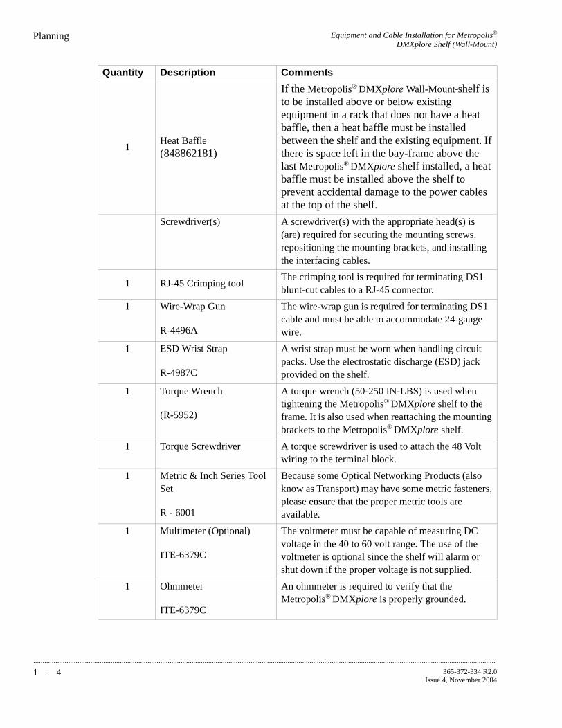
...........................................................................................................................................................................................................................................................
Equipment and Cable Installation for Metropolis®
DMXplore Shelf (Wall-Mount)Planning
1 - 4 365-372-334 R2.0Issue 4, November 2004
1Heat Baffle(848862181)
If the Metropolis® DMXplore Wall-Mount shelf is to be installed above or below existing equipment in a rack that does not have a heat baffle, then a heat baffle must be installed between the shelf and the existing equipment. If there is space left in the bay-frame above the last Metropolis® DMXplore shelf installed, a heat baffle must be installed above the shelf to prevent accidental damage to the power cables at the top of the shelf.
Screwdriver(s) A screwdriver(s) with the appropriate head(s) is (are) required for securing the mounting screws, repositioning the mounting brackets, and installing the interfacing cables.
1 RJ-45 Crimping toolThe crimping tool is required for terminating DS1 blunt-cut cables to a RJ-45 connector.
1 Wire-Wrap Gun
R-4496A
The wire-wrap gun is required for terminating DS1 cable and must be able to accommodate 24-gauge wire.
1 ESD Wrist Strap
R-4987C
A wrist strap must be worn when handling circuit packs. Use the electrostatic discharge (ESD) jack provided on the shelf.
1 Torque Wrench
(R-5952)
A torque wrench (50-250 IN-LBS) is used when tightening the Metropolis® DMXplore shelf to the frame. It is also used when reattaching the mounting brackets to the Metropolis® DMXplore shelf.
1 Torque Screwdriver A torque screwdriver is used to attach the 48 Volt wiring to the terminal block.
1 Metric & Inch Series Tool Set
R - 6001
Because some Optical Networking Products (also know as Transport) may have some metric fasteners, please ensure that the proper metric tools are available.
1 Multimeter (Optional)
ITE-6379C
The voltmeter must be capable of measuring DC voltage in the 40 to 60 volt range. The use of the voltmeter is optional since the shelf will alarm or shut down if the proper voltage is not supplied.
1 Ohmmeter
ITE-6379C
An ohmmeter is required to verify that the Metropolis® DMXplore is properly grounded.
Quantity Description Comments

Equipment and Cable Installation for Metropolis®
DMXplore Shelf (Wall-Mount)Planning
...........................................................................................................................................................................................................................................................
1 - 5365-372-334 R2.0Issue 4, November 2004
Mounting options The Wall-Mount mounting brackets for the Metropolis® DMXplore Access Multiplexer are designed to allow for mounting in the following:
• 12-inch bay-frames
• 19-inch bay-frames
• Standard 23-inch wide network bay-frames
The recommended network bay-frames are the ED-8C500-50 and the ED-8C501-50 (also allows for rear access).
• 23-inch seismic network bay-frame
The ED-8C800-50 and ED-8C801-50 seismic network bay-frames are designed for use in all earthquake zones, and in general, do not require top support at the 7-foot level. These frames meet Pacific Bell Equipment Framework Standard PBS-000-102PT.
• 23-inch wide EIA-Type bay-frames
Cabling checklist This section briefly describes cabling information, including the number of particular cables required. For information regarding available cable lengths and ordering comcodes, refer to the tables in this chapter.
Table 1-1, Cable Requirements and Options lists available cables along with the required number (if any).
Notes:
1. One -48VA and -48VB main power feeder is required per shelf. Each power feed needs to have an external 2A fuse.
2. One CIT Cable Assembly is required for PC serial interface with the
Table 1-1 Cable Requirements and Options
Cable Assembly Description Required See Note
Power Yes 1
CIT
Yes 2LAN 10BASE-T (Cross-over)
LAN 10BASE-T (Straight-Through)
DS1 Optional 3
DS3 Optional 4
Office Alarm Optional 5
Miscellaneous Discrete Optional

...........................................................................................................................................................................................................................................................
Equipment and Cable Installation for Metropolis®
DMXplore Shelf (Wall-Mount)Planning
1 - 6 365-372-334 R2.0Issue 4, November 2004
Metropolis® DMXplore (not included with equipment).
3. One "Single DS1 Cable Assembly" is required for each DS1 supported by the main pack (maximum of 16). Each DS1 Cable Assembly supports 1 pair of 24-gauge RJ45/blunt-cut or RJ45-RJ45 cables. One cable is for input and output signals.
4. One "Single DS3 Cable Assembly" is required for each DS3 supported by the main pack. One code provides 1 DS3 input and 1 DS3 output, 735A coaxial Straight BNC plug to Straight BNC plug.
5. When cabling the Metropolis® DMXplore for office alarm applications, one Office Alarm Cable Assembly is required for each Metropolis®
DMXplore shelf.
6. When accessing the shelf through the LAN (OSI/TCP-IP) connection, either a LAN 10BASE-T cross-over cable or a LAN 10BASE-T straight-through cable is required to access the shelf. The cross-over cable should be used when connecting directly between the shelf from a PC NIC card. The straight-through cable should be used when connecting the shelf to a hub.
...........................................................................................................................................................................

Equipment and Cable Installation for Metropolis®
DMXplore Shelf (Wall-Mount)Connector References
...........................................................................................................................................................................................................................................................
1 - 7365-372-334 R2.0Issue 4, November 2004
............................................................................................................................................................................................................................................................
Connector References
Description Figure 1-1, Connector Types and Pinouts (page 1-7) provides the pinouts of some of the connectors used to interface with the Metropolis® DMXplore.
Figure 1-1 Connector Types and Pinouts
1 2 3
B GROUP
RX
TX
RX
TX
BNCConnector

...........................................................................................................................................................................................................................................................
Equipment and Cable Installation for Metropolis®
DMXplore Shelf (Wall-Mount)Inspection
1 - 8 365-372-334 R2.0Issue 4, November 2004
............................................................................................................................................................................................................................................................
Inspection
Description Perform the following procedure before installing the Metropolis®
DMXplore shelf and cables.
...........................................................................................................................................................................
Procedure
Step 1 Inspect the shelf for visible damage including bent or touching backplane pins.
If any backplane pins are damaged, refer to Appendix D, Backplane Pin Replacement for instructions on repairing the damaged pin(s).
...........................................................................................................................................................................
Step 2 Each Wall-Mount Metropolis® DMXplore shelf comes with a bag containing the following items:
Verify that the bag is available and contains the items listed above.
...........................................................................................................................................................................
Step 3 Check off the appropriate box in Appendix E, Installation Checklist.
End of Steps
...........................................................................................................................................................................
Quantity Description
4 8 X .75" Long Pan Head Wood Screws
1 Safety Insttruction Sheet

Equipment and Cable Installation for Metropolis®
DMXplore Shelf (Wall-Mount)Metropolis® DMXplore Wall-Mount Shelf Installation
...........................................................................................................................................................................................................................................................
1 - 9365-372-334 R2.0Issue 4, November 2004
............................................................................................................................................................................................................................................................
Metropolis® DMXplore Wall-Mount Shelf Installation
Introduction This section provides instructions for mounting the Metropolis®
DMXplore Wall-Mount on a wall and in the supported bay-frames sizes using the appropriate bracket.
Installation Notes:
1. When wall mounting 3" top clearance, 1" bottom clearance, and .5" side clearances are required for natural convection cooling.
2. When mounting the Metropolis® DMXplore unit above power dissipating equipment an appropriate heat baffle is required. Maximum operating temperature is 65° C.
3. When being used in an outdoor cabinet (or other environments allowing for ambient temperatures up to 65° C), the minimum required airflow is 200 fpm.
4. The maximum weight of the Metropolis® DMXplore Wall-Mount shelf, fully equipped is 4.77kg (10.5 lbs).
Wall installation The Metropolis® DMXplore Wall-Mount is a front access design that allows for it to be mounted directly against a flat surface. The following steps describe mounting the shelf on a wall.
Installation Note:
Wall mount mounting hardware is included with the Wall-Mount
Metropolis® DMXplore shelf code.
Procedure
Step 1 Position the Metropolis® DMXplore shelf on a stable work surface.
Important! Front cover is shipped with a clear protective liner over the outside surface of the viewing window of cover. Peel and remove. See Figure 1-2, Metropolis® DMXplore Shelf Wall-Mount (with Cover) (page 1-10).

...........................................................................................................................................................................................................................................................
Equipment and Cable Installation for Metropolis®
DMXplore Shelf (Wall-Mount)Metropolis® DMXplore Wall-Mount Shelf Installation
1 - 1 0 365-372-334 R2.0Issue 4, November 2004
Figure 1-2 Metropolis® DMXplore Shelf Wall-Mount (with Cover)
...........................................................................................................................................................................
Step 2 Remove wall-plate from the rear of the Wall-Mount Metropolis®
DMXplore Shelf by doing the following:
1. Loosen the mounting screw in the top right hand corner of the Access Panel. See Figure 1-2, Metropolis® DMXplore Shelf Wall-Mount (with Cover) (page 1-10).
2. Slide shelf up along wall plate until it clears the mounting tabs. See Figure 1-3, Mounting Screw (page 1-10)
3. Separate shelf from wall plate.
Figure 1-3 Mounting Screw
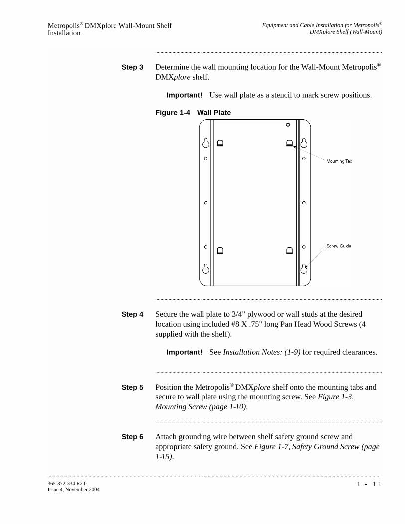
Equipment and Cable Installation for Metropolis®
DMXplore Shelf (Wall-Mount)Metropolis® DMXplore Wall-Mount Shelf Installation
...........................................................................................................................................................................................................................................................
1 - 1 1365-372-334 R2.0Issue 4, November 2004
...........................................................................................................................................................................
Step 3 Determine the wall mounting location for the Wall-Mount Metropolis®
DMXplore shelf.
Important! Use wall plate as a stencil to mark screw positions.
Figure 1-4 Wall Plate
...........................................................................................................................................................................
Step 4 Secure the wall plate to 3/4" plywood or wall studs at the desired location using included #8 X .75" long Pan Head Wood Screws (4 supplied with the shelf).
Important! See Installation Notes: (1-9) for required clearances.
...........................................................................................................................................................................
Step 5 Position the Metropolis® DMXplore shelf onto the mounting tabs and secure to wall plate using the mounting screw. See Figure 1-3, Mounting Screw (page 1-10).
...........................................................................................................................................................................
Step 6 Attach grounding wire between shelf safety ground screw and appropriate safety ground. See Figure 1-7, Safety Ground Screw (page 1-15).

...........................................................................................................................................................................................................................................................
Equipment and Cable Installation for Metropolis®
DMXplore Shelf (Wall-Mount)Metropolis® DMXplore Wall-Mount Shelf Installation
1 - 1 2 365-372-334 R2.0Issue 4, November 2004
Important! Grounding wire must be of the same gauge as the cables used to power the shelf.
Figure 1-5 Safety Ground Screw
...........................................................................................................................................................................
Step 7 Verify with an ohmmeter that the Metropolis® DMXplore shelf is grounded properly. Measure between the Metropolis® DMXplore shelf safety ground screw and the appropriate safety ground.
Requirement: The ohmmeter reads less than 1 ohm.
...........................................................................................................................................................................
Step 8 Verify with an ohmmeter that the ESD jack on the front of the shelf is grounded properly. Measure between the ESD jack stud and the appropriate safety ground.
See Figure 1-2, Metropolis® DMXplore Shelf Wall-Mount (with Cover) (page 1-10)
Requirement: The ohmmeter reads less than 1 ohm.
...........................................................................................................................................................................
Step 9 If using the AC/DC converter (408812394), mount it at least 3" above the DMXplore with its 3’ DC cable towards the DMXplore and its AC connection facing up, away from the DMXplore .
...........................................................................................................................................................................
Step 10 Check off the appropriate box in Appendix E, Installation Checklist.
End of Steps
...........................................................................................................................................................................
Equipment and Cable Installation for Metropolis®
DMXplore Shelf (Wall-Mount)Metropolis® DMXplore Wall-Mount Shelf Installation
...........................................................................................................................................................................................................................................................
1 - 1 3365-372-334 R2.0Issue 4, November 2004
12-inch, 19-inch, and 23-Inch Bay-frame Installation
As an example of the Metropolis® DMXplore shelf installation, the following steps describe mounting a single shelf from the front of a 23-inch bay-frame. Mounting from the rear of a 23-inch bay-frame or from the front/rear of a 12-inch or 19-inch bay-frame is similar with the exception of the type and mounting position of the brackets.
See Figure 1-8, Wall-Mount Bay-Frame Mounting Brackets (page 1-17)
The 23-inch frame supports two Metropolis® DMXplore shelves. To mount a second shelf repeat this procedure for the second shelf at the second mounting position.
Important! This section requires previous bay-frame installation and grounding.
Procedure
Step 1 Position the Metropolis® DMXplore shelf on a stable work surface.
Important! Front cover is shipped with a clear protective liner over the outside surface of the viewing window of cover. Peel and remove. See Figure 1-2, Metropolis® DMXplore Shelf Wall-Mount (with Cover) (page 1-10).
...........................................................................................................................................................................
Step 2 Determine the mounting configuration for the Metropolis® DMXplore shelf:
• type of bay-frame (23-inch, 19-inch or 12-inch wide)
• mounting position (front, rear)
• shelf position for 23-inch frame (right, left)
• position in bay (bottom to top)
Important! The mounting brackets must be ordered separately and are required to install the Metropolis® DMXplore in a bayframe. See Tools, Test Equipment and Accessories (1-3)
Important! If mounting two Metropolis® DMXplore shelves in a 23" rack application cable access is moderately restricted.
Important! A front mounting position results in a 5" protrusion from the front of bay-frame.

...........................................................................................................................................................................................................................................................
Equipment and Cable Installation for Metropolis®
DMXplore Shelf (Wall-Mount)Metropolis® DMXplore Wall-Mount Shelf Installation
1 - 1 4 365-372-334 R2.0Issue 4, November 2004
...........................................................................................................................................................................
Step 3 Remove bay-frame mounting bracket from box, and assemble as indicated in Figure 1-6, Exploded Bay-Frame (23" Mounting Bracket) (page 1-14).
Figure 1-6 Exploded Bay-Frame (23" Mounting Bracket)
Important! Tie-downs are to be positioned to the right of the shelf.
...........................................................................................................................................................................
Step 4 Determine the position that the bay-frame mounting bracket will be mounted. As a general rule, start at the bottom of the bay and add shelves from bottom to top.
Important! If the Metropolis® DMXplore shelf is to be installed above or below existing equipment that does not have a heat baffle, then a heat baffle (C848862181) must be installed between the shelf and the existing equipment.
Important! If there is space left in the bayframe above the last Metropolis® DMXplore bracket assembly installed, a heat baffle

Equipment and Cable Installation for Metropolis®
DMXplore Shelf (Wall-Mount)Metropolis® DMXplore Wall-Mount Shelf Installation
...........................................................................................................................................................................................................................................................
1 - 1 5365-372-334 R2.0Issue 4, November 2004
must be installed above the shelf to prevent accidental damage to the power cables at the top of the shelf.
...........................................................................................................................................................................
Step 5 Position the bay-frame mounting bracket in the frame and secure to the frame using 3 thread-forming screws side (not included). Tighten the screws to 21 in.-lb. (minimum)/30 in.-lb. (maximum)
Important! Grounding wire must be of the same gauge as the cables used to power the shelf.
Important! Be sure to mount the shelf using thread-forming screws to ensure a solid ground connection from the bay to the shelf.
Important! For bays that use powder coat paint e.g. most 19" bays, studies on that type of paint indicate that the material is not always removed cleanly using the thread forming screws and can create a poor ground, thus we recommend a secondary ground be used. The secondary ground would consist of a 12 AWG wire from the UL (Green M5 Screw) safety ground to the bayframe (where the bayframe has been scraped clean of paint and treated with no-ox) See Figure 1-7, Safety Ground Screw (page 1-15).
Figure 1-7 Safety Ground Screw
...........................................................................................................................................................................
Step 6 Remove wall plate from the rear of the Metropolis® DMXplore Shelf by doing the following:
1. Loosen the mounting screw in the top left hand corner of the Access Panel. See Figure 1-3, Mounting Screw (page 1-10).
2. Slide shelf up along wall plate until it clears the mounting tabs. See Figure 1-4, Wall Plate (page 1-11).
3. Separate shelf from wall plate.

...........................................................................................................................................................................................................................................................
Equipment and Cable Installation for Metropolis®
DMXplore Shelf (Wall-Mount)Metropolis® DMXplore Wall-Mount Shelf Installation
1 - 1 6 365-372-334 R2.0Issue 4, November 2004
...........................................................................................................................................................................
Step 7 Loosen plate mounting screws on mounting bracket and position wall-plate onto it.
See Figure 1-6, Exploded Bay-Frame (23" Mounting Bracket) (page 1-14)
...........................................................................................................................................................................
Step 8 Tighten plate mounting screws to firmly attach wall plate to the mounting bracket.
...........................................................................................................................................................................
Step 9 Position shelf onto mounting tabs of the wall plate and tighten mounting screw in the top left hand corner of the access panel.
See Figure 1-3, Mounting Screw (page 1-10)
...........................................................................................................................................................................
Step 10 Verify with an ohmmeter that the Metropolis® DMXplore shelf is grounded to the bay-frame. Measure between the Metropolis®
DMXplore shelf mounting bracket and the safety ground lug on the bay-frame.
Requirement: The ohmmeter reads less than 1 ohm.
...........................................................................................................................................................................
Step 11 Verify with an ohmmeter that the ESD Jack Stud See Figure 1-2, Metropolis® DMXplore Shelf Wall-Mount (with Cover) (page 1-10) is grounded to the bay-frame. Measure between the ESD Jack Stud and the safety ground lug on the bay-frame.
Requirement: The ohmmeter reads less than 1 ohm.
Important! If using the AC/DC converter (408812394), it may be desirable to mount the converter(s) to the rear of the shelf at this time. A single converter can be mounted on the rear of the 12" and 19" mounting brackets, whereas the 23" mounting bracket supports up to two AC/DC converters.
...........................................................................................................................................................................
Step 12 Check off the appropriate box in Appendix E, Installation Checklist.
End of Steps

Equipment and Cable Installation for Metropolis®
DMXplore Shelf (Wall-Mount)Metropolis® DMXplore Wall-Mount Shelf Installation
...........................................................................................................................................................................................................................................................
1 - 1 7365-372-334 R2.0Issue 4, November 2004
Figure 1-8 Wall-Mount Bay-Frame Mounting Brackets
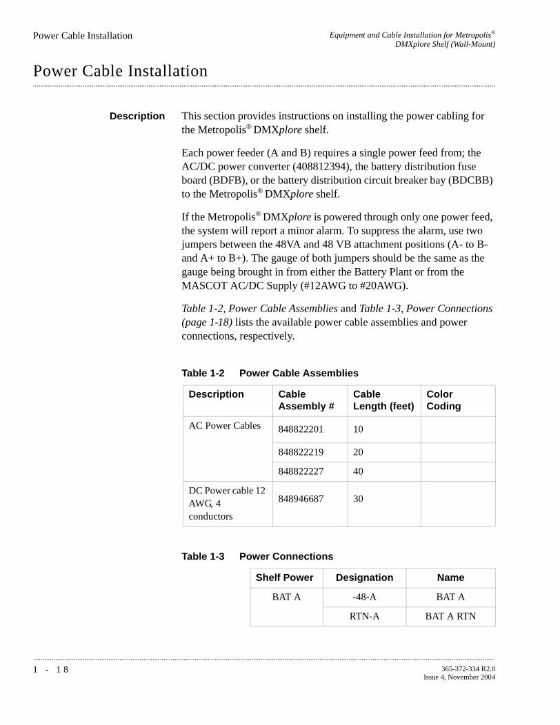
...........................................................................................................................................................................................................................................................
Equipment and Cable Installation for Metropolis®
DMXplore Shelf (Wall-Mount)Power Cable Installation
1 - 1 8 365-372-334 R2.0Issue 4, November 2004
............................................................................................................................................................................................................................................................
Power Cable Installation
Description This section provides instructions on installing the power cabling for the Metropolis® DMXplore shelf.
Each power feeder (A and B) requires a single power feed from; the AC/DC power converter (408812394), the battery distribution fuse board (BDFB), or the battery distribution circuit breaker bay (BDCBB) to the Metropolis® DMXplore shelf.
If the Metropolis® DMXplore is powered through only one power feed, the system will report a minor alarm. To suppress the alarm, use two jumpers between the 48VA and 48 VB attachment positions (A- to B- and A+ to B+). The gauge of both jumpers should be the same as the gauge being brought in from either the Battery Plant or from the MASCOT AC/DC Supply (#12AWG to #20AWG).
Table 1-2, Power Cable Assemblies and Table 1-3, Power Connections (page 1-18) lists the available power cable assemblies and power connections, respectively.
Table 1-2 Power Cable Assemblies
Description Cable Assembly #
Cable Length (feet)
Color Coding
AC Power Cables 848822201 10
848822219 20
848822227 40
DC Power cable 12 AWG, 4 conductors
848946687 30
Table 1-3 Power Connections
Shelf Power Designation Name
BAT A -48-A BAT A
RTN-A BAT A RTN

Equipment and Cable Installation for Metropolis®
DMXplore Shelf (Wall-Mount)Power Cable Installation
...........................................................................................................................................................................................................................................................
1 - 1 9365-372-334 R2.0Issue 4, November 2004
Important! To tie RTN-A and RTN-B together use a MESH Ground Strap to jumper between RTN-COM and GND of the power terminal block.
...........................................................................................................................................................................
CAUTIONVerify that the AC/DC converter is not plugged into the AC power outlet, or that BDCBB breakers are off, or that the BDFB fuses are not installed.
...........................................................................................................................................................................
Procedure
Step 1 Verify the power source is off.
...........................................................................................................................................................................
Step 2 Connect the A and B power cables to the A and B connector pins of the terminal block located on the top right of the access panel. Use a torque screwdriver set to 0.5 Nm (4.4 lb-in) to tighten. See Figure 1-9, Power Connection (page 1-20).
Important! Power cables must be between 12 AWG and 20 AWG and have an 8mm wire strip length for connection to the terminal block.
BAT B -48-B BAT B
RTN-B BAT B RTN
Table 1-3 Power Connections
Shelf Power Designation Name

...........................................................................................................................................................................................................................................................
Equipment and Cable Installation for Metropolis®
DMXplore Shelf (Wall-Mount)Power Cable Installation
1 - 2 0 365-372-334 R2.0Issue 4, November 2004
Figure 1-9 Power Connection
Table 1-4 Power Cable Color Coding
...........................................................................................................................................................................
Step 3 Route the power cables toward the power source (e.g. AC/DC Converter, BDCBB, BDFB etc.)
Important! The Metropolis® DMXplore is powered by -48 V DC.
CAUTIONIf using BBCBB or BDFB, verify that the BDCBB breakers are off or that the BDFB fuses are not installed.
...........................................................................................................................................................................
Step 4 Are you using an AC/DC Converter?
Color Coding Connection
Red -48V-A
Red/Black RTN-A
Blue -48V-B
Blue/Black RTN-B
IF... Then...
Yes Proceed to Step 5
No Proceed to Step 7

Equipment and Cable Installation for Metropolis®
DMXplore Shelf (Wall-Mount)Power Cable Installation
...........................................................................................................................................................................................................................................................
1 - 2 1365-372-334 R2.0Issue 4, November 2004
...........................................................................................................................................................................
Step 5 If not using the orderable AC/DC converter (C), verify that the converter is fuse limited to 2-amperes on each lead.
Important! If the AC/DC converter is not fuse limited to 2-amperes, it will be necessary to add a 2A inline fuse for each power lead.
...........................................................................................................................................................................
Step 6 Proceed to Step 9.
...........................................................................................................................................................................
Step 7 Splice feeders from the BDCBB or BDFB to the Metropolis®
DMXplore power cables. Refer to Table 1-3, Power Connections (page 1-18).
Important! Four wires are spliced to the power cables:
1. BAT A
2. BAT A RTN
3. BAT B
4. BAT B RTN
...........................................................................................................................................................................
Step 8 Label the feeders at the power source as follows:
1. BAT A
2. BAT A RTN
3. BAT B
4. BAT B RTN
Important! Each feeder should be fused for 2-amperes.
...........................................................................................................................................................................
Step 9 Leave the power supply mechanism disconnected at the power source until you are ready to perform the procedures in Chapter 3, Powering and Initial Circuit Pack Installation for Metropolis® DMXplore Shelf (Wall-Mount) of this manual.

...........................................................................................................................................................................................................................................................
Equipment and Cable Installation for Metropolis®
DMXplore Shelf (Wall-Mount)Power Cable Installation
1 - 2 2 365-372-334 R2.0Issue 4, November 2004
Important! The BDFB requires the removal of fuses to inhibit power flow.
...........................................................................................................................................................................
Step 10 Check off the appropriate box in Appendix E, Installation Checklist.
End of Steps
...........................................................................................................................................................................

Equipment and Cable Installation for Metropolis®
DMXplore Shelf (Wall-Mount)DS1 Cable Installation
...........................................................................................................................................................................................................................................................
1 - 2 3365-372-334 R2.0Issue 4, November 2004
............................................................................................................................................................................................................................................................
DS1 Cable Installation
Description This section describes how to connect the DS1 transmission cables to the A/D function group of the shelf. If applicable, route the cables out of the bay and connect the cables to the DSX panel.
Important! When cabling the Metropolis® DMXplore to a DSX, the DSX becomes an extension of the Metropolis® DMXplore access panel connections. Thus the IN on the Metropolis®
DMXplore access panel connects to the IN of the DSX and the OUT of the Metropolis® DMXplore access panel connects to the OUT of the DSX respectively.
The cables are connectorized at the Metropolis® DMXplore end and may be needed to be wire-wrapped at the DSX end if equipped with a blunt connection end. The A function group supports a maximum of 16 DS1 drop capacity.
Important! The A/D function group is a dual purpose slot. In the current release the A/D slot is identified as the A function group. Future releases will add new functionality and refer to the A/D slot as the D function group.
Table 1-5, DS1 Cable Assemblies and Table 1-6, DS1 Transmission Connections (page 1-24) lists the available DS1 cable assemblies and DS1 connections, respectively.
Table 1-5 DS1 Cable Assemblies
Description Cable Length(feet)
Cable Assembly #
Single DS1 Cable, 26-gauge, RJ45-RJ45
8 109468124
20 109142398
50 109142406
100 109142414
150 109142422
250 109142430
350 109142448
550 109142455

...........................................................................................................................................................................................................................................................
Equipment and Cable Installation for Metropolis®
DMXplore Shelf (Wall-Mount)DS1 Cable Installation
1 - 2 4 365-372-334 R2.0Issue 4, November 2004
...........................................................................................................................................................................
Single DS1 Cable, 26-gauge, RJ45 blunt-cut
8 109468132
20 109142323
50 109142331
100 109142349
150 109142356
250 109142364
350 109142372
550 109142380
Bundle of 16 DS1 Cables, 26 gauge, RJ45 blunt-cut
20 109308437
50 109308445
100 109308452
150 109308460
250 109308478
350 109308486
550 109308494
Table 1-5 DS1 Cable Assemblies
Description Cable Length(feet)
Cable Assembly #
Table 1-6 DS1 Transmission Connections
Pin Tip/Ring Designation
Direction Color
1 Ring Out BL-W
2 Tip Out W-BL
4 Ring In O-W
5 Tip In W-O

Equipment and Cable Installation for Metropolis®
DMXplore Shelf (Wall-Mount)DS1 Cable Installation
...........................................................................................................................................................................................................................................................
1 - 2 5365-372-334 R2.0Issue 4, November 2004
Procedure
Step 1 Refer to the engineering job specification. Obtain the DS1 cables per Table 1-5, DS1 Cable Assemblies (page 1-23). Label the cables, indicating bay and shelf, and direction (IN or OUT of the bay) at each end. See Table 1-6, DS1 Transmission Connections (page 1-24) for associated color coding.
Important! Blunt-end cables that are to be wire wrapped will need to be labeled IN or OUT. Cable ends terminated using a RJ-45 connector will not need to be labeled using the IN and OUT designation because both are supported by the connector.
...........................................................................................................................................................................
Step 2 Connect the RJ-45 end of a single cable to the respective RJ-45 Receptacle on the access panel as shown in Figure 1-10, DS1 Access Panel Cable Connectors (page 1-25).
Figure 1-10 DS1 Access Panel Cable Connectors
...........................................................................................................................................................................
Step 3 Route the cables along the access panel and out toward the DSX. See Figure 1-11, DS1 Cable Routing (page 1-26)
ALARM12345678
PWR-A
PWR-B
ON
ON
-48V-A
RTN-COM
-48V-BRTN-B
RTN-A
GRD
41
81818181
2 3
C GROUP
1 2 3
B GROUP
RX
TX
RX
TX
8 1 8 1 8 1 8 1
81818181
321 4
765 8A/D GROUP
8 1 8 1 8 1 8 1
81818181
11109 12
151413 16
12345678
12345678
MDOMDI
8 1 8 1 8 1 8 1
81818181
321 4
765 8A/D GROUP
8 1 8 1 8 1 8 1
81818181
11109 12
151413 16

...........................................................................................................................................................................................................................................................
Equipment and Cable Installation for Metropolis®
DMXplore Shelf (Wall-Mount)DS1 Cable Installation
1 - 2 6 365-372-334 R2.0Issue 4, November 2004
Figure 1-11 DS1 Cable Routing
...........................................................................................................................................................................
Step 4 Route the cables along the cable rack and into the terminating bay or along the wall if mounting on a wall.
...........................................................................................................................................................................
Step 5 Are you terminating the DS1 cables on a DSX?
...........................................................................................................................................................................
Step 6 Remove slack and cut the DS1 cables to the desired length at the DSX.
...........................................................................................................................................................................
Step 7 Referring to Table 1-6, DS1 Transmission Connections (page 1-24), carefully observe color codes and wire-wrap the cables at the DSX.
...........................................................................................................................................................................
Step 8 Check off the appropriate box in Appendix E, Installation Checklist.
End of Steps
...........................................................................................................................................................................
IF... Then...
Yes Go on to Step 6
No Skip to Step 8

Equipment and Cable Installation for Metropolis®
DMXplore Shelf (Wall-Mount)DS3 Cable Installation
...........................................................................................................................................................................................................................................................
1 - 2 7365-372-334 R2.0Issue 4, November 2004
............................................................................................................................................................................................................................................................
DS3 Cable Installation
Description This section describes how to connect the DS3 transmission cables to the B function group of the shelf. If applicable, route the cables out of the bay and connect the cables to the DSX panel.
Important! When cabling the Metropolis® DMXplore to a DSX, the DSX becomes an extension of the Metropolis® DMXplore access panel connections. Thus the IN on the Metropolis®
DMXplore access panel connects to the IN of the DSX and the OUT of the Metropolis® DMXplore access panel connects to the OUT of the DSX, respectively.
The cables are connectorized at the Metropolis® DMXplore end and will need to be connected to the appropriate BNC termination at the other end. The B function group supports a maximum of two DS3 drop capacity.
DS3 cable options are listed in Table 1-7, DS3 Cable Assemblies (page 1-27).
...........................................................................................................................................................................
Table 1-7 DS3 Cable Assemblies
Description Cable Assembly #
Cable Length(feet)
DS3 Cables, 735A coaxial, Straight BNC (terminated) plug to Straight BNC (shipped loose) plug, 26 gauge
109468140 8
108785536 20
108785569 50
108785601 100
108785635 150
108785718 250
Notes:
1. One code provides one DS3 input and one DS3 output cable.

...........................................................................................................................................................................................................................................................
Equipment and Cable Installation for Metropolis®
DMXplore Shelf (Wall-Mount)DS3 Cable Installation
1 - 2 8 365-372-334 R2.0Issue 4, November 2004
Procedure
Step 1 Refer to the engineering job specification. Obtain the DS3 cables per Table 1-7, DS3 Cable Assemblies and note the function group where each cable will be used. Label the cables, indicating bay, shelf, function group (B) and direction (IN or OUT of the bay) at each end.
...........................................................................................................................................................................
Step 2 Connect one end of the cable to the respective Receptacle on the access panel as shown in Figure 1-12, DS3 Access Panel Cable Connectors. (page 1-28).
Figure 1-12 DS3 Access Panel Cable Connectors.
...........................................................................................................................................................................
Step 3 Route the cables along the cable rack and into the terminating bay or along the wall if mounting on a wall.
...........................................................................................................................................................................
Step 4 Connect the cables to their respective positions on the terminating equipment.
A LA R M12345678
P W R -A
P W R -B
ON
ON
-4 8 V -A
R TN -C OM
-4 8 V -BR TN -B
R TN -A
GR D
41
81818181
2 3
C GR O UP
1 2 3
B GR O UP
R X
T X
R X
T X8 1 8 1 8 1 8 1
81818181
321 4
765 8A /D G R O U P
8 1 8 1 8 1 8 1
81818181
11109 12
151413 1 6
12345678
12345678
M D OM D I
1 2 3
B G RO UP
RX
T X
RX
T X

Equipment and Cable Installation for Metropolis®
DMXplore Shelf (Wall-Mount)DS3 Cable Installation
...........................................................................................................................................................................................................................................................
1 - 2 9365-372-334 R2.0Issue 4, November 2004
...........................................................................................................................................................................
Step 5 Check off the appropriate box in Appendix E, Installation Checklist.
End of Steps

...........................................................................................................................................................................................................................................................
Equipment and Cable Installation for Metropolis®
DMXplore Shelf (Wall-Mount)Ethernet Cable Installation
1 - 3 0 365-372-334 R2.0Issue 4, November 2004
............................................................................................................................................................................................................................................................
Ethernet Cable Installation
Overview This section describes how to route the Fast Ethernet (10/100Base T) cables from the Wall-Mount Metropolis® DMXplore shelf to the 10/100BaseT terminating equipment.
If Fast Ethernet Cabling is not available yet, this section may be completed later.
Procedure Refer to Figure 1-13, 10/100Base-T Cable Installation (page 1-31) when performing this procedure.
Step 1 Obtain the 10/100BaseT cables per Table 1-8, LAN 10/100 BaseT Cable Assemblies for Fast Ethernet
...........................................................................................................................................................................
Step 2 Connect one end of the cable to the respective RJ45 connecter on the access panel on the rear of the Rack-Mount Metropolis® DMXplore shelf.
...........................................................................................................................................................................
Step 3 Route the cables along the cable rack and into the terminating bay or along the wall if mounting on a wall.

Equipment and Cable Installation for Metropolis®
DMXplore Shelf (Wall-Mount)Ethernet Cable Installation
...........................................................................................................................................................................................................................................................
1 - 3 1365-372-334 R2.0Issue 4, November 2004
Figure 1-13 10/100Base-T Cable Installation
...........................................................................................................................................................................
Step 4 Label the cables, indicating bay (if required), shelf, pack and position (1 through 4).
...........................................................................................................................................................................
Step 5 Connect the cables onto their respective positions at the 10/100BaseT terminating equipment.
...........................................................................................................................................................................
Step 6 Check off the appropriate box in Appendix E, Installation Checklist.
ALARM1
2
3
4
5
6
7
8
PWR-A
PWR-B
ON
ON
-48V-A
RTN-COM
-48V-B
RTN-B
RTN-A
GRD
41
1818181
2 3
C GROUP
1 2 3
B GROUP
RX
TX
RX
TX
8 1 8 1 8 1 8 1
81818181
321 4
765 8
A/D GROUP
8 1 8 1 8 1 8 1
81818181
11109 12
151413 16
1
2
3
4
5
6
7
8
1
2
3
4
5
6
7
8
MDOMDI
41
1818181
2 3
C GROUP
8

...........................................................................................................................................................................................................................................................
Equipment and Cable Installation for Metropolis®
DMXplore Shelf (Wall-Mount)Ethernet Cable Installation
1 - 3 2 365-372-334 R2.0Issue 4, November 2004
Table 1-8 LAN 10/100 BaseT Cable Assemblies for Fast Ethernet
Description Comcode Cable Length (feet)
Metropolis®
DMXplore Connections
LAN 10BaseT Cross-over cableRJ45 — RJ45
109154476 8
FASTE circuit packPorts 1 - 4
109142513 20
109142521 50
109142539 100
109142547 150
109142554 250
LAN 10BaseT Straight-through cableRJ45 — RJ45
109154468 8
109142463 20
109142471 50
109142489 100
109142497 150
109142505 250

Equipment and Cable Installation for Metropolis®
DMXplore Shelf (Wall-Mount)Office Alarm Cable Installation
...........................................................................................................................................................................................................................................................
1 - 3 3365-372-334 R2.0Issue 4, November 2004
............................................................................................................................................................................................................................................................
Office Alarm Cable Installation
Description Office alarms are the common method used in a central office for maintenance personnel to quickly isolate a failure. Perform this procedure if connection to the office alarm system is required.
Important! The office alarm relay contacts are rated at 50 VA which means that they are capable of switching 1 amp at 50 volts, or 2 amps at 25 volts. Their ability to switch large transient currents means that they can, if necessary, switch up to ten 5-watt aisle pilot lamps.
If transient voltages or currents are above these limits, transient noise-suppressing devices such as diodes or contact protection networks must be used to keep within the voltage and current limits. If these protection devices are not sufficient, an external buffer relay MUST be provided.
In all cases, and as a matter of good practice, suppression devices such as diodes or contact protection networks must be provided across any external relay coil being driven by the Metropolis® DMXplore to limit transient voltages and currents.
Office alarm cable assemblies are listed in Table 1-9, Office Alarm Cable Assemblies (page 1-33) and Office alarm connection are listed in Table 1-10, Office Alarm Connections (page 1-34).
Table 1-9 Office Alarm Cable Assemblies
Description Cable Assembly #
CableLength(feet)
Access Panel Connections
ALARM, 26 AWG, 8 conductors
848946653 30 ALARM
Notes:
1. Miscellaneous Discrete and Alarm cables are identical and thus have the same comcode.

...........................................................................................................................................................................................................................................................
Equipment and Cable Installation for Metropolis®
DMXplore Shelf (Wall-Mount)Office Alarm Cable Installation
1 - 3 4 365-372-334 R2.0Issue 4, November 2004
Procedure
Step 1 Obtain the office alarm cable per Table 1-9, Office Alarm Cable Assemblies (page 1-33). Connect the office alarm cables to the ALARM terminal block in the lower left hand corner of the access panel. See Figure 1-14, Office Alarm Cable Connections (page 1-35)
Important! The recommended wire strip length for cables being connected to the alarm block is 11mm.
Table 1-10 Office Alarm Connections
Pin# Color Name Designation
1
2
BL
BL/W
CR/MJ Visual +
CR/MJ Visual -RYCRMJV1
3
4
O
O/W
CR/MJ Audible +
CR/MJ Audible -RYCRMJA1
5
6
G
G/W
MN/ABN Visual +
MN/ABN Visual -RYMNABNV1
7
8
BR
BR/W
MN/ABN Audible +
MN/ABN Audible -RYMNABNA1
Notes:
1. The SYSCTL circuit pack reports office alarms.
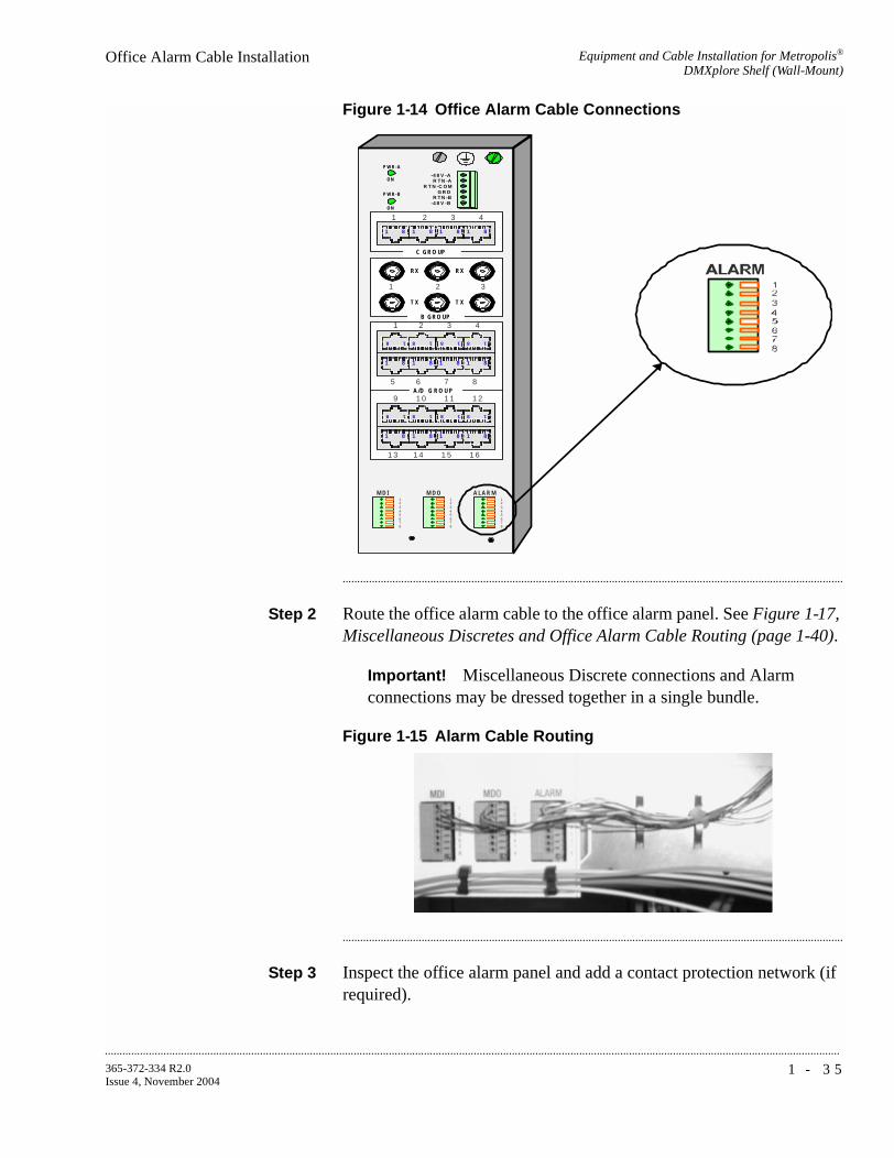
Equipment and Cable Installation for Metropolis®
DMXplore Shelf (Wall-Mount)Office Alarm Cable Installation
...........................................................................................................................................................................................................................................................
1 - 3 5365-372-334 R2.0Issue 4, November 2004
Figure 1-14 Office Alarm Cable Connections
...........................................................................................................................................................................
Step 2 Route the office alarm cable to the office alarm panel. See Figure 1-17, Miscellaneous Discretes and Office Alarm Cable Routing (page 1-40).
Important! Miscellaneous Discrete connections and Alarm connections may be dressed together in a single bundle.
Figure 1-15 Alarm Cable Routing
...........................................................................................................................................................................
Step 3 Inspect the office alarm panel and add a contact protection network (if required).
A LA R M12345678
P W R - A
P W R - B
O N
O N
-4 8 V -A
R T N -C O M
-4 8 V -BR T N -B
R T N -A
G R D
41
81818181
2 3
C G R O UP
1 2 3
B G R O UP
R X
T X
R X
T X
8 1 8 1 8 1 8 1
81818181
321 4
765 8A /D G R O U P
8 1 8 1 8 1 8 1
81818181
1 11 09 1 2
1 51 41 3 1 6
12345678
12345678
M D OM D I

...........................................................................................................................................................................................................................................................
Equipment and Cable Installation for Metropolis®
DMXplore Shelf (Wall-Mount)Office Alarm Cable Installation
1 - 3 6 365-372-334 R2.0Issue 4, November 2004
...........................................................................................................................................................................
Step 4 Cut the office alarm cable to the desired length.
...........................................................................................................................................................................
Step 5 Wire-wrap the loose end of the office alarm cable to the alarm panel, making connections as listed in Table 1-10, Office Alarm Connections (page 1-34).
...........................................................................................................................................................................
Step 6 Check off the appropriate box in Appendix E, Installation Checklist.
End of Steps
...........................................................................................................................................................................

Equipment and Cable Installation for Metropolis®
DMXplore Shelf (Wall-Mount)Miscellaneous (Environmental) Discrete Telemetry Cable Installation
...........................................................................................................................................................................................................................................................
1 - 3 7365-372-334 R2.0Issue 4, November 2004
Miscellaneous (Environmental) Discrete Telemetry Cable
............................................................................................................................................................................................................................................................
Installation
Description The miscellaneous (environmental) discrete telemetry access allows the maintenance center to control and monitor equipment collocated with the Metropolis® DMXplore.
The environmental control feature enables the maintenance center to remotely initiate up to four contact closures at the remote terminal (RT) for equipment operation such as pumps, generators, etc.
The environmental alarm status indications allow up to 4 miscellaneous user-settable alarm status indications (SI) at the remote terminal for transmission toward the central office.
Miscellaneous (environmental) discrete telemetry cable assemblies and connections are listed in Table 1-11, Miscellaneous Discrete Cable Assemblies (page 1-37) and Table 1-12, Miscellaneous (Environmental) Discrete Telemetry Connections (page 1-38), respectively.
Table 1-11 Miscellaneous Discrete Cable Assemblies
Description Cable Assembly #
CableLength(feet)
Access Panel Connections
MDI, 26-gauge, 8 conductors
848946653 30 MDI
MDO, 26-gauge, 8 conductors
848946653 30 MDO
Notes:
1. Miscellaneous Discrete and Alarm cables are identical and thus have the
same comcode.

...........................................................................................................................................................................................................................................................
Equipment and Cable Installation for Metropolis®
DMXplore Shelf (Wall-Mount)Miscellaneous (Environmental) Discrete Telemetry Cable Installation
1 - 3 8 365-372-334 R2.0Issue 4, November 2004
Important! Typically, the MDO (out) of the lowest Metropolis®
DMXplore in a bay is connected to the patch panel and MDI (in) is connected to the next higher Metropolis® DMXplore MDO.
...........................................................................................................................................................................
Procedure This procedure is performed for Metropolis® DMXplore shelves requiring miscellaneous (environmental) discrete telemetry.
Step 1 Connect the miscellaneous discrete telemetry cables to the MDI and MDO terminal blocks on the access panel of the Metropolis®
DMXplore shelf per Figure 1-16, Miscellaneous Discrete Cable Connection (page 1-39).
Table 1-12 Miscellaneous (Environmental) Discrete Telemetry Connections
Pin# Color Designation Name
1
2
3
4
BL
BL/W
O
O/W
Circuit #1 +
Circuit #1 -
Circuit #2 +
Circuit #2 -
Env. Input/Output - #1
Env. Input/Output - #2
Env. Input/Output - #3
Env. Input/Output - #4
5
6
7
8
G
G/W
BR
BR/W
Circuit #3 +
Circuit #3 -
Circuit #4 +
Circuit #4 -
Env. Input/Output - #5
Env. Input/Output - #6
Env. Input/Output - #7
Env. Input/Output - #8

Equipment and Cable Installation for Metropolis®
DMXplore Shelf (Wall-Mount)Miscellaneous (Environmental) Discrete Telemetry Cable Installation
...........................................................................................................................................................................................................................................................
1 - 3 9365-372-334 R2.0Issue 4, November 2004
Figure 1-16 Miscellaneous Discrete Cable Connection
...........................................................................................................................................................................
Step 2 Route the miscellaneous (environmental) discretes cables to the telemetry panel as shown in Figure 1-17, Miscellaneous Discretes and Office Alarm Cable Routing (page 1-40).
Important! Miscellaneous Discrete connections and Alarm connections may be dressed together in a single bundle.
ALARM12345678
PWR-A
PWR-B
ON
ON
-48V-A
RTN-COM
-48V-BRTN-B
RTN-A
GRD
41
81818181
2 3
C GROUP
1 2 3
B GROUP
RX
T X
RX
T X
8 1 8 1 8 1 8 1
81818181
321 4
765 8A/D GRO UP
8 1 8 1 8 1 8 1
81818181
11109 12
151413 16
12345678
12345678
MDOMDI
12345678
12345678
MDOMDI

...........................................................................................................................................................................................................................................................
Equipment and Cable Installation for Metropolis®
DMXplore Shelf (Wall-Mount)Miscellaneous (Environmental) Discrete Telemetry Cable Installation
1 - 4 0 365-372-334 R2.0Issue 4, November 2004
Figure 1-17 Miscellaneous Discretes and Office Alarm Cable Routing
...........................................................................................................................................................................
Step 3 Cut the miscellaneous (environmental) discrete telemetry cable to the desired length at the telemetry panel.
...........................................................................................................................................................................
Step 4 Wire-wrap the loose end of the miscellaneous (environmental) discrete telemetry cable to the wire-wrap terminal strip, making connections per Table 1-12, Miscellaneous (Environmental) Discrete Telemetry Connections (page 1-38).
Important! Each miscellaneous (environmental) discrete telemetry designation is connected to the Metropolis® DMXplore by two leads (wires). For each input, one lead should be connected to input-common and the other lead should be connected to the appropriate alarm indication. For each output, one lead should be connected to output-common and the other lead should be connected to the appropriate alarm indication.
...........................................................................................................................................................................
Step 5 Check off the appropriate box in Appendix E, Installation Checklist.
End of Steps
...........................................................................................................................................................................

Equipment and Cable Installation for Metropolis®
DMXplore Shelf (Wall-Mount)OC-3/OC12 Main Optical Fiber Cable Installation
...........................................................................................................................................................................................................................................................
1 - 4 1365-372-334 R2.0Issue 4, November 2004
............................................................................................................................................................................................................................................................
OC-3/OC12 Main Optical Fiber Cable Installation
Description This section describes how to route the optical fiber cables from the interconnecting equipment (for example, a LGX® optical fiber distributing frame) to the Main OLIUs of the Metropolis® DMXplore. This procedure does not cover routing the optical fiber cable between sites.
The optical fiber cables are connected to the Metropolis® DMXplore after the circuit packs are installed. The Metropolis® DMXplore requires single-mode fiber for the main OLIUs. See ED8C947-10 Common Systems, Metropolis® DMXplore Access Multiplexer, Engineering and Ordering Information for recommended fibers.
Important! The optical fiber cable is fragile and must be protected. The fibers should be placed in a protective tube or channel, such as PVC tubing, or PANDUIT cable channel, when running the cable from the Metropolis® DMXplore to the cable rack. The fibers should be placed in the cable rack in a protective channel with nothing on top of them. Cable ties should NOT be used with the optical fiber cables.
WARNINGUnterminated optical connectors may emit laser radiation. Do not view an unterminated optical connector with optical instruments. Avoid direct exposure of the eyes to the beam.
Important! Prior to connecting the optical fiber cables, the fibers should be examined to ensure that they are clean. See Appendix B, Fiber Cleaning for recommended cleaning procedures.
...........................................................................................................................................................................

...........................................................................................................................................................................................................................................................
Equipment and Cable Installation for Metropolis®
DMXplore Shelf (Wall-Mount)OC-3/OC12 Main Optical Fiber Cable Installation
1 - 4 2 365-372-334 R2.0Issue 4, November 2004
Procedure
Step 1 Route the optical fiber cables from the interconnecting equipment into the left side of the Metropolis® DMXplore. See Figure 1-18, Optical Fiber Routing (page 1-42)
Important! Protective covers must be left on cables.
Figure 1-18 Optical Fiber Routing
...........................................................................................................................................................................
Step 2 Place the optical fiber cables in a protective tube or channel once it has cleared the Metropolis® DMXplore shelf.
...........................................................................................................................................................................
Step 3 Label the optical fiber cables, indicating bay, shelf, pack, and direction (IN or OUT). See Appendix F, Fiber Labeling for more details.
...........................................................................................................................................................................
Step 4 Check off the appropriate box in Appendix E, Installation Checklist.
End of Steps
...........................................................................................................................................................................

Equipment and Cable Installation for Metropolis®
DMXplore Shelf (Wall-Mount)RS-232 Serial CIT Cable Installation
...........................................................................................................................................................................................................................................................
1 - 4 3365-372-334 R2.0Issue 4, November 2004
............................................................................................................................................................................................................................................................
RS-232 Serial CIT Cable Installation
Description This section provides the procedure to connect the CIT cable from the VLNC1 (SYSCTL) to a PC (serial port) to allow communications between the PC and the RS232 port located on the VLNC1.
CIT cable assemblies and the length options are listed in Table 1-13, Serial CIT Cable Assembly (page 1-43). CIT cable connections are listed in Table 1-14, Standard CIT Cable Connection (page 1-43) and Table 1-15, RJ-45 to DB-9 Connector Connections (page 1-44).
Table 1-13 Serial CIT Cable Assembly
Table 1-14 Standard CIT Cable Connection
Description CableAssembly #
CableLength
Metropolis® DMXplore Connections
RS232 CIT Cable
848748869 8 feet CIT/RS-232 jack on System Controller (VLNC1)
Connection RJ45 connector Color 9-Pin D-type connector
Pin# Designation Pin# Designation
CIT cable 1 FRS232N W - O 6 DCE Ready
3 FDTR W - BL 4 DTE Ready
4 Ground W - G 5 Ground
5 FTXD O 2 Receive Data
6 FRXD G 3 Transmit Data
Notes:
1. The connection and the colors shown above are for a standard Lucent-made cable. If you use a RJ-45 to DB-9 connector with a standard straight-through 10BASE-T LAN cable then, refer to Table 1-15, RJ-45 to DB-9 Connector Connections (page 1-44).

...........................................................................................................................................................................................................................................................
Equipment and Cable Installation for Metropolis®
DMXplore Shelf (Wall-Mount)RS-232 Serial CIT Cable Installation
1 - 4 4 365-372-334 R2.0Issue 4, November 2004
...........................................................................................................................................................................
Procedure
Step 1 Connect the RJ-45 end of the CIT cable to the RS232 jack located on the VLNC1 (SYSCTL).
...........................................................................................................................................................................
Step 2 Connect the 9-pin D-type connector to the serial port on the PC.
...........................................................................................................................................................................
Step 3 Check off the appropriate box in Appendix E, Installation Checklist.
End of Steps
...........................................................................................................................................................................
Table 1-15 RJ-45 to DB-9 Connector Connections
From RJ45 connector
To DB-9 Pin D-type connector
Pin# Color Pin#
1 Blue 6
3 Black 4
4 Red 5
5 Green 2
6 Yellow 3
Notes:
1. The connection and the colors shown above are for RJ-45 to DB-9 connector.
2. This connector should be used with a standard straight-through 10BASE-T LAN cable.

Equipment and Cable Installation for Metropolis®
DMXplore Shelf (Wall-Mount)SYSCTL LAN Cable Installation
...........................................................................................................................................................................................................................................................
1 - 4 5365-372-334 R2.0Issue 4, November 2004
............................................................................................................................................................................................................................................................
SYSCTL LAN Cable Installation
Description This section describes how to connect the IAO LAN/TCP-IP (LAN 10BASE-T) cable to the Metropolis® DMXplore shelf and to the interfacing equipment. Perform this procedure if this cabling is required.
Metropolis® DMXplore supports an IntraOffice LAN (IAO LAN) interface for operations data communications to support operations systems such as the Navis Optical EMS (formerly WaveStar SNMS).
Since the IAO LAN can be provisioned as an extension of the SONET DCC, the IAO LAN can also be used to join multiple, otherwise separate subnetworks.
All NE-to-NE OI features that are supported over the DCC are also supported over the IAO LAN.
The IAO LAN/TCP-IP interface cable is available in two configurations (cross-over and straight-through) and is connected to the front of the Metropolis® DMXplore shelf. The following tables provide additional information:
• Table 1-16, LAN 10BASE-T Cable Assemblies (page 1-45)
• Table 1-17, LAN 10BASE-T Cross-over Cable Connections (page 1-47)
• Table 1-18, LAN 10BASE-T Straight-through Cable Connections (page 1-47)
Table 1-16 LAN 10BASE-T Cable Assemblies
Description Cable Assembly #
Cable Length (feet)
LAN 10BASE-T Cross-over (Cable to PC / CIT)
109321810 10
848605028 50
848605036 100
848605051 150
848605064 200
848605077 300

...........................................................................................................................................................................................................................................................
Equipment and Cable Installation for Metropolis®
DMXplore Shelf (Wall-Mount)SYSCTL LAN Cable Installation
1 - 4 6 365-372-334 R2.0Issue 4, November 2004
LAN 10BASE-T Straight-through (Cable to Ethernet Hub / Router)
109321836 20
109321844 30
109321851 40
848604948 50
109321869 60
109321877 70
109321885 80
109321893 90
848604955 100
109321901 110
109321919 120
109321927 130
109321935 140
848604963 150
109321943 160
109321950 180
848604971 200
109321968 220
109321976 240
109321984 260
109321992 280
848604997 300
Table 1-16 LAN 10BASE-T Cable Assemblies
Description Cable Assembly #
Cable Length (feet)

Equipment and Cable Installation for Metropolis®
DMXplore Shelf (Wall-Mount)SYSCTL LAN Cable Installation
...........................................................................................................................................................................................................................................................
1 - 4 7365-372-334 R2.0Issue 4, November 2004
...........................................................................................................................................................................
Procedure
Step 1 Connect the cable to the LAN (RJ45) jack on the SYSCTL circuit pack.
Important! If connecting directly to a PC, use a LAN 10BASE-T Cross-over Cable Assembly (See Table 1-16, LAN 10BASE-T Cable Assemblies).
Important! If connecting to a hub, use a LAN 10BASE-T Straight-through Cable Assembly (See Table 1-16, LAN 10BASE-T Cable Assemblies).
Table 1-17 LAN 10BASE-T Cross-over Cable Connections
SYSCTLConnection
Metropolis®
DMXplore Backplane
Color Other Side Design
LAN 1 BL - W 3 RDTR
2 W - BL 6 RS232N
3 O - W 1 RRXD
6 W - O 2 RTX
Table 1-18 LAN 10BASE-T Straight-through Cable Connections
SYSCTLConnection Backplane Color Other Side
Pin Designation
LAN 1 BL - W 1 XIOLANP
2 W - BL 2 XIOLANN
3 O - W 3 RIOLANP
6 W - O 6 RIOLANN
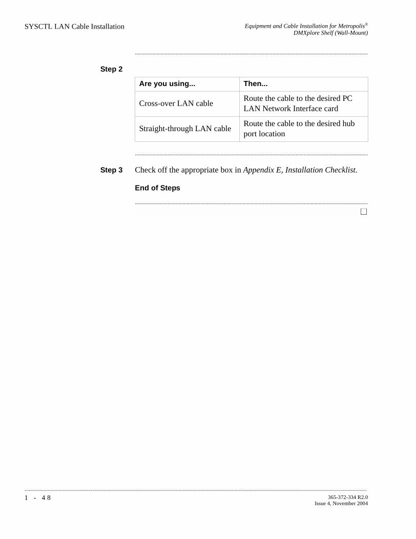
...........................................................................................................................................................................................................................................................
Equipment and Cable Installation for Metropolis®
DMXplore Shelf (Wall-Mount)SYSCTL LAN Cable Installation
1 - 4 8 365-372-334 R2.0Issue 4, November 2004
...........................................................................................................................................................................
Step 2
...........................................................................................................................................................................
Step 3 Check off the appropriate box in Appendix E, Installation Checklist.
End of Steps
...........................................................................................................................................................................
Are you using... Then...
Cross-over LAN cableRoute the cable to the desired PC LAN Network Interface card
Straight-through LAN cableRoute the cable to the desired hub port location

Equipment and Cable Installation for Metropolis®
DMXplore Shelf (Wall-Mount)Final Operations
...........................................................................................................................................................................................................................................................
1 - 4 9365-372-334 R2.0Issue 4, November 2004
............................................................................................................................................................................................................................................................
Final Operations
Description Final check on equipment and cable installation.
...........................................................................................................................................................................
Procedure
Step 1 Verify that all the cables are properly dressed/connected.
...........................................................................................................................................................................
Step 2 Verify that all cables are properly labeled.
...........................................................................................................................................................................
Step 3 Verify that designations where cables were wire-wrapped are properly labeled.
...........................................................................................................................................................................
Step 4 Verify that all the fibers are properly dressed/connected.
...........................................................................................................................................................................
Step 5 Verify that all fibers are properly labeled. See Appendix F, Fiber Labeling
...........................................................................................................................................................................
Step 6 Verify that designations where fibers were terminated are properly labeled.
...........................................................................................................................................................................
Step 7 Check off the appropriate box in Appendix E, Installation Checklist.
End of Steps
...........................................................................................................................................................................

...........................................................................................................................................................................................................................................................
Equipment and Cable Installation for Metropolis®
DMXplore Shelf (Wall-Mount)Final Operations
1 - 5 0 365-372-334 R2.0Issue 4, November 2004

2 - 1365-372-334 R2.0Issue 4, November 2004
............................................................................................................................................................................................................................................................
2 Equipment and Cable Installation for Metropolis® DMXplore Shelf (Rack-Mount)
............................................................................................................................................................................................................................................................
Overview
Purpose This section provides installation and cabling instructions for the Metropolis® DMXplore Rack-Mount Shelf.
Mounting options for the Rack-Mount unit are:
1. Rear-mount with rear access
2. Front-mount with rear access
Important! The Rack-Mount Metropolis® DMXplore has an integrated fan unit, and is stackable, up to 22 units may be installed per 7 foot bay (no baffle is required).
Contents This chapter provides information on the following topics:
Overview 2-1
Planning 2-3
Connector References 2-7
Inspection 2-8
Metropolis® DMXplore Rack-Mount Shelf Installation 2-9
Power Cable Installation 2-13
DS1 Cable Installation 2-182-18
2-13
2-9
2-8
2-7
2-3
2-1
...........................................................................................................................................................................................................................................................
Equipment and Cable Installation for Metropolis®
DMXplore Shelf (Rack-Mount)Overview
2 - 2 365-372-334 R2.0Issue 4, November 2004
DS3 Cable Installation 2-22
Ethernet Cable Installation 2-24
Office Alarm Cable Installation 2-26
Miscellaneous (Environmental) Discrete Telemetry Cable
Installation
2-29
OC-3/OC12 Main Optical Fiber Cable Installation 2-33
RS-232 Serial CIT Cable Installation 2-36
SYSCTL LAN Cable Installation 2-38
Final Operations 2-422-42
2-38
2-36
2-33
2-29
2-26
2-24
2-22

Equipment and Cable Installation for Metropolis®
DMXplore Shelf (Rack-Mount)Planning
...........................................................................................................................................................................................................................................................
2 - 3365-372-334 R2.0Issue 4, November 2004
............................................................................................................................................................................................................................................................
Planning
Description This section provides information about the following:
• tools, test equipment and accessories
• mounting options
• cabling checklist
...........................................................................................................................................................................
Tools, Test Equipment andAccessories
Listed below are the tools, test equipment and accessories necessary to perform the procedures in this section.
Quantity Description Comments
1 or 2per shelf
AC/DC Wall-Mount/Rack Bracket Mount Power Converter(408812394)
The AC/DC Wall-Mount converter allows the Metropolis® DMXplore to be powered using a AC voltage supply. The acceptable AC input voltage range for the AC/DC power supply is 85 VAC to 264V AC. This converter can be used with the Rack-Mount Metropolis® DMXplore but it requires a rack shelf / mounting arrangement (not provided by Lucent).
1 3-prong power cordPower cord is required to power the AC/DC Wall-Mount power converter and is ordered separately.
Screwdriver(s) A screwdriver(s) with the appropriate head(s) is (are) required for securing the mounting screws, repositioning the mounting brackets, and installing the interfacing cables.
1 RJ-45 Crimping toolThe crimping tool is required for terminating DS1 blunt-cut cables to a RJ-45 connector.
1 Wire-Wrap Gun
R-4496A
The wire-wrap gun is required for terminating DS1 cable and must be able to accommodate 24-gauge wire.
1 ESD Wrist Strap
R-4987C
A wrist strap must be worn when handling circuit packs. Use the electrostatic discharge (ESD) jack provided on the shelf.
1 Torque Wrench
(R-5952)
A torque wrench (50-250 IN-LBS) is used when tightening the Metropolis® DMXplore shelf to the frame. It is also used when reattaching the mounting brackets to the Metropolis® DMXplore shelf.
1 Torque Screwdriver A torque screwdriver is used to attach the 48 Volt wiring to the terminal block.

...........................................................................................................................................................................................................................................................
Equipment and Cable Installation for Metropolis®
DMXplore Shelf (Rack-Mount)Planning
2 - 4 365-372-334 R2.0Issue 4, November 2004
1 Metric & Inch Series Tool Set
R - 6001
Because some Optical Networking Products (also know as Transport) may have some metric fasteners, please ensure that the proper metric tools are available.
1 Multimeter (Optional)
ITE-6379C
The voltmeter must be capable of measuring DC voltage in the 40 to 60 volt range. The use of the voltmeter is optional since the shelf will alarm or shut down if the proper voltage is not supplied.
1 Ohmmeter
ITE-6379C
An ohmmeter is required to verify that the Metropolis® DMXplore is properly grounded.
Quantity Description Comments

Equipment and Cable Installation for Metropolis®
DMXplore Shelf (Rack-Mount)Planning
...........................................................................................................................................................................................................................................................
2 - 5365-372-334 R2.0Issue 4, November 2004
Mounting options The Rack-Mount mounting brackets for the Metropolis® DMXplore Access Multiplexer are adjustable and designed to allow for mounting in the following:
• 19-inch bay-frames
• Standard 23-inch wide network bay-frames
The recommended network bay-frames are the ED-8C500-50 and the ED-8C501-50 (also allows for rear access).
• 23-inch seismic network bay-frame
The ED-8C800-50 and ED-8C801-50 seismic network bay-frames are designed for use in all earthquake zones, and in general, do not require top support at the 7-foot level. These frames meet Pacific Bell Equipment Framework Standard PBS-000-102PT.
• 23-inch wide EIA-Type bay-frames
Cabling checklist This section briefly describes cabling information, including the number of particular cables required. For information regarding available cable lengths and ordering comcodes, refer to the tables in this chapter.
Table 2-1, Cable Requirements and Options lists available cables along with the required number (if any).
Table 2-1 Cable Requirements and Options
Notes:
1. One -48VA and -48VB main power feeder is required per shelf. Each power feed needs to have an external 2A fuse.
2. One CIT Cable Assembly is required for PC serial interface with the
Cable Assembly Description Required See Note
Power Yes 1
CIT
Yes 2LAN 10BASE-T (Cross-over)
LAN 10BASE-T (Straight-Through)
DS1 Optional 3
DS3 Optional 4
Office Alarm Optional 5
Miscellaneous Discrete Optional

...........................................................................................................................................................................................................................................................
Equipment and Cable Installation for Metropolis®
DMXplore Shelf (Rack-Mount)Planning
2 - 6 365-372-334 R2.0Issue 4, November 2004
Metropolis® DMXplore (not included with equipment).
3. One "Single DS1 Cable Assembly" is required for each DS1 supported by the main pack (maximum of 16). Each DS1 Cable Assembly supports 1 pair of 24-gauge RJ45/blunt-cut or RJ45-RJ45 cables. One cable is for input and output signals.
4. One "Single DS3 Cable Assembly" is required for each DS3 supported by the main pack. One code provides 1 DS3 input and 1 DS3 output, 735A coaxial Straight BNC plug to Straight BNC plug.
5. When cabling the Metropolis® DMXplore for office alarm applications, one Office Alarm Cable Assembly is required for each Metropolis®
DMXplore shelf.
6. When accessing the shelf through the LAN (OSI/TCP-IP) connection, either a LAN 10BASE-T cross-over cable or a LAN 10BASE-T straight-through cable is required to access the shelf. The cross-over cable should be used when connecting directly between the shelf from a PC NIC card. The straight-through cable should be used when connecting the shelf to a hub.
...........................................................................................................................................................................

Equipment and Cable Installation for Metropolis®
DMXplore Shelf (Rack-Mount)Connector References
...........................................................................................................................................................................................................................................................
2 - 7365-372-334 R2.0Issue 4, November 2004
............................................................................................................................................................................................................................................................
Connector References
Description Figure 2-1, Connector Types and Pinouts (page 2-7) provides the pinouts of some of the connectors used to interface with the Metropolis® DMXplore.
Figure 2-1 Connector Types and Pinouts
1 2 3
B GROUP
RX
TX
RX
TX
BNC Connector

...........................................................................................................................................................................................................................................................
Equipment and Cable Installation for Metropolis®
DMXplore Shelf (Rack-Mount)Inspection
2 - 8 365-372-334 R2.0Issue 4, November 2004
............................................................................................................................................................................................................................................................
Inspection
Description Perform the following procedure before installing the Metropolis®
DMXplore shelf and cables.
...........................................................................................................................................................................
Procedure
Step 1 Inspect the shelf for visible damage including bent or touching backplane pins.
If any backplane pins are damaged, refer to Appendix D, Backplane Pin Replacement for instructions on repairing the damaged pin(s).
...........................................................................................................................................................................
Step 2 Each Rack-Mount Metropolis® DMXplore shelf comes with a bag containing the following items:
Verify that the bag is available and contains the items listed above.
...........................................................................................................................................................................
Step 3 Check off the appropriate box in Appendix E, Installation Checklist.
End of Steps
...........................................................................................................................................................................
Quantity Description
4 Screws for mounting the brackets to the shelf
4 Screws for mounting the shelf to the bay frame
1 Set of adjustable mounting brackets
1 Fiber Management Module
1 Safety Instruction Sheet

Equipment and Cable Installation for Metropolis®
DMXplore Shelf (Rack-Mount)Metropolis® DMXplore Rack-Mount Shelf Installation
...........................................................................................................................................................................................................................................................
2 - 9365-372-334 R2.0Issue 4, November 2004
............................................................................................................................................................................................................................................................
Metropolis® DMXplore Rack-Mount Shelf Installation
Introduction This section provides instructions for mounting the Metropolis®
DMXplore Rack-Mount in the supported bay-frame sizes using the appropriate bracket.
Installation Notes:
1. When being used in an outdoor cabinet (or other environments allowing for ambient temperatures up to 65° C), the minimum required airflow is 200 fpm (no baffle).
2. The Metropolis® DMXplore Rack-Mount is either 17.4" wide, 3.5’’ high, and 13" deep.
3. Metropolis® DMXplore Rack-Mount has an integrated fan unit, and is stackable, up to 22 units may be installed per 7 foot bay (no baffle is required).
4. The maximum weight of the Metropolis® DMXplore Rack-Mount shelf, fully equipped is 4.77kg (10.5 lbs).
Procedure
Step 1 Position the Metropolis® DMXplore Rack-Mount shelf on a stable work surface.
See Figure 2-2, Metropolis® DMXplore Rack-Mount Shelf (with Cover) (page 2-9).
Figure 2-2 Metropolis® DMXplore Rack-Mount Shelf (with Cover)
...........................................................................................................................................................................
Step 2 Supplied in the shipping box with the shelf will be a bag containing the mounting brackets and screws.

...........................................................................................................................................................................................................................................................
Equipment and Cable Installation for Metropolis®
DMXplore Shelf (Rack-Mount)Metropolis® DMXplore Rack-Mount Shelf Installation
2 - 1 0 365-372-334 R2.0Issue 4, November 2004
...........................................................................................................................................................................
Step 3 Determine the mounting configuration for the Rack-Mount Metropolis® DMXplore shelf:
• type of bay frame (23-inch or 19-inch wide)
• mounting position (front or rear)
• postion in bay (bottom to top)
The Rack-Mount Metropolis® DMXplore shelf mounting brackets are adjustable to fit both the 19 inch and 23 inch bay frames.
...........................................................................................................................................................................
Step 4 Attach the mounting brackets to the shelf using the supplied flat head screws see Figure 2-3, Mounting bracket position for 19 inch frame (page 2-10) if attaching to a 19 inch bay frame and Figure 2-4, Mounting bracket position for 23 inch frame (page 2-11) if attaching the shelf to a 23 inch bay frame.
Figure 2-3 Mounting bracket position for 19 inch frame

Equipment and Cable Installation for Metropolis®
DMXplore Shelf (Rack-Mount)Metropolis® DMXplore Rack-Mount Shelf Installation
...........................................................................................................................................................................................................................................................
2 - 1 1365-372-334 R2.0Issue 4, November 2004
Figure 2-4 Mounting bracket position for 23 inch frame
...........................................................................................................................................................................
Step 5 Determine the position that the Rack-Mount Metropolis® DMXplore shelf will be mounted. Start at the bottom of the bay and add shelves from bottom to top.
...........................................................................................................................................................................
Step 6 Position the Rack-Mount Metropolis® DMXplore shelf in the frame and secure the shelf to the frame using the thread-forming screws included with the shelf.
...........................................................................................................................................................................
Step 7 Attach grounding wire between shelf safety ground screw and appropriate safety ground. See Figure 2-5, Safety Ground Screw (page 2-12).
Important! Grounding wire must be of the same gauge as the cables used to power the shelf.

...........................................................................................................................................................................................................................................................
Equipment and Cable Installation for Metropolis®
DMXplore Shelf (Rack-Mount)Metropolis® DMXplore Rack-Mount Shelf Installation
2 - 1 2 365-372-334 R2.0Issue 4, November 2004
Figure 2-5 Safety Ground Screw
...........................................................................................................................................................................
Step 8 Verify with an ohmmeter that the Metropolis® DMXplore shelf is grounded properly. Measure between the Metropolis® DMXplore shelf safety ground screw and the appropriate safety ground.
Requirement: The ohmmeter reads less than 1 ohm.
...........................................................................................................................................................................
Step 9 Verify with an ohmmeter that the ESD jack on the front of the shelf is grounded properly. Measure between the ESD jack stud and the appropriate safety ground.
Requirement: The ohmmeter reads less than 1 ohm.
...........................................................................................................................................................................
Step 10 If using the Lucent Orderable AC/DC converter (408812394), mount it above or below the DMXplore per customer requirements.
...........................................................................................................................................................................
Step 11 Check off the appropriate box in Appendix E, Installation Checklist.
End of Steps
...........................................................................................................................................................................
GroundingScrew

Equipment and Cable Installation for Metropolis®
DMXplore Shelf (Rack-Mount)Power Cable Installation
...........................................................................................................................................................................................................................................................
2 - 1 3365-372-334 R2.0Issue 4, November 2004
............................................................................................................................................................................................................................................................
Power Cable Installation
Description This section provides instructions on installing the power cabling for the Metropolis® DMXplore shelf.
Each power feeder (A and B) requires a single power feed from; the AC/DC power converter (408812394), the battery distribution fuse board (BDFB), or the battery distribution circuit breaker bay (BDCBB) to the Metropolis® DMXplore shelf.
If the Metropolis® DMXplore is powered through only one power feed, the system will report a minor alarm. To suppress the alarm, use two jumpers, one jumper between the -48VA and -48 VB and the second jumper between RTN-A and RTN-B. See Figure 2-7, Power Connection (page 2-15) for location. The gauge of both jumpers should be the same as the gauge being brought in from either the Battery Plant or from the MASCOT AC/DC Supply (#12AWG to #20AWG).
Table 2-2, Power Cable Assemblies and Table 2-3, Power Connections (page 2-14) lists the available power cable assemblies and power connections, respectively.
Table 2-2 Power Cable Assemblies
Description Cable Assembly #
Cable Length (feet)
Color Coding
AC Power Cables 848822201 10
848822219 20
848822227 40
DC Power cable 12 AWG 4 conductors 848946687 30

...........................................................................................................................................................................................................................................................
Equipment and Cable Installation for Metropolis®
DMXplore Shelf (Rack-Mount)Power Cable Installation
2 - 1 4 365-372-334 R2.0Issue 4, November 2004
Figure 2-6 Rack-Mount Metropolis® DMXplore Connector
Important! To tie RTN-A and RTN-B together use a MESH Ground Strap to jumper between RTN-COM and GND of the power terminal block. See Figure 2-7, Power Connection (page 2-15) for location.
...........................................................................................................................................................................
CAUTIONVerify that the AC/DC converter is not plugged into the AC power outlet, or that BDCBB breakers are off, or that the BDFB fuses are not installed.
...........................................................................................................................................................................
Procedure
Step 1 Verify the power source is off.
...........................................................................................................................................................................
Step 2 Connect the A and B power cables to the A and B connector pins of the terminal block located on the lower left rear of the access panel. Use a
Table 2-3 Power Connections
Shelf Power Designation Name
BAT A -48-A BAT A
RTN-A BAT A RTN
BAT B -48-B BAT B
RTN-B BAT B RTN

Equipment and Cable Installation for Metropolis®
DMXplore Shelf (Rack-Mount)Power Cable Installation
...........................................................................................................................................................................................................................................................
2 - 1 5365-372-334 R2.0Issue 4, November 2004
torque screwdriver set to 0.5 Nm (4.4 lb-in) to tighten. See Figure 2-7, Power Connection (page 2-15).
Important! Power cables must be between 12 AWG and 20 AWG and have an 8mm wire strip length for connection to the terminal block. Use the guide located on the inside of the cover on the lower right hand for accurate lengths.
Figure 2-7 Power Connection
Table 2-4 Power Cable Color Coding
...........................................................................................................................................................................
Step 3 Route the power cables toward the power source (e.g. AC/DC Converter, BDCBB, BDFB etc.)
Important! The Metropolis® DMXplore is powered by -48 V DC.
CAUTIONIf using BBCBB or BDFB, verify that the BDCBB breakers are off or that the BDFB fuses are not installed.
Color Coding Connection
Red -48V-A
Red/Black RTN-A
Blue -48V-B
Blue/Black RTN-B

...........................................................................................................................................................................................................................................................
Equipment and Cable Installation for Metropolis®
DMXplore Shelf (Rack-Mount)Power Cable Installation
2 - 1 6 365-372-334 R2.0Issue 4, November 2004
...........................................................................................................................................................................
Step 4 Are you using Lucent orderable AC/DC Converter?
...........................................................................................................................................................................
Step 5 If not using the Lucent orderable AC/DC converter (C), verify that the converter is fuse limited to 2-amperes on each lead.
Important! If the AC/DC converter is not fuse limited to 2-amperes, it will be necessary to add a 2A inline fuse for each power lead.
...........................................................................................................................................................................
Step 6 Proceed to Step 9.
...........................................................................................................................................................................
Step 7 Splice feeders from the BDCBB or BDFB to the Metropolis®
DMXplore power cables. Refer to Table 2-3, Power Connections (page 2-14).
Important! Four wires are spliced to the power cables:
1. BAT A
2. BAT A RTN
3. BAT B
4. BAT B RTN
...........................................................................................................................................................................
Step 8 Label the feeders at the power source as follows:
1. BAT A
2. BAT A RTN
3. BAT B
4. BAT B RTN
IF... Then...
Yes Proceed to Step 5
No Proceed to Step 7

Equipment and Cable Installation for Metropolis®
DMXplore Shelf (Rack-Mount)Power Cable Installation
...........................................................................................................................................................................................................................................................
2 - 1 7365-372-334 R2.0Issue 4, November 2004
Important! Each feeder should be fused for 2-amperes.
...........................................................................................................................................................................
Step 9 Leave the power supply mechanism disconnected at the power source until you are ready to perform the procedures in Chapter 4, Powering and Initial Circuit Pack Installation for Metropolis® DMXplore Shelf (Rack-Mount) of this manual.
Important! The BDFB requires the removal of fuses to inhibit power flow.
...........................................................................................................................................................................
Step 10 Check off the appropriate box in Appendix E, Installation Checklist.
End of Steps
...........................................................................................................................................................................

...........................................................................................................................................................................................................................................................
Equipment and Cable Installation for Metropolis®
DMXplore Shelf (Rack-Mount)DS1 Cable Installation
2 - 1 8 365-372-334 R2.0Issue 4, November 2004
............................................................................................................................................................................................................................................................
DS1 Cable Installation
Description This section describes how to connect the DS1 transmission cables to the A/D function group of the shelf. If applicable, route the cables out of the bay and connect the cables to the DSX panel.
Important! When cabling the Metropolis® DMXplore to a DSX, the DSX becomes an extension of the Metropolis® DMXplore access panel connections. Thus the IN on the Metropolis®
DMXplore access panel connects to the IN of the DSX and the OUT of the Metropolis® DMXplore access panel connects to the OUT of the DSX respectively.
The cables are connectorized at the Metropolis® DMXplore end and may be needed to be wire-wrapped at the DSX end if equipped with a blunt connection end. The A function group supports a maximum of 16 DS1 drop capacity.
Important! The A/D function group is a dual purpose slot. In the current release the A/D slot is identified as the A function group. Future releases will add new functionality and refer to the A/D slot as the D function group.
Table 2-5, DS1 Cable Assemblies and Table 2-6, DS1 Transmission Connections (page 2-19) lists the available DS1 cable assemblies and DS1 connections, respectively.
Table 2-5 DS1 Cable Assemblies
Description Cable Length(feet)
Cable Assembly #
Single DS1 Cable, 26-gauge, RJ45-RJ45
8 109468124
20 109142398
50 109142406
100 109142414
150 109142422
250 109142430
350 109142448
550 109142455

Equipment and Cable Installation for Metropolis®
DMXplore Shelf (Rack-Mount)DS1 Cable Installation
...........................................................................................................................................................................................................................................................
2 - 1 9365-372-334 R2.0Issue 4, November 2004
...........................................................................................................................................................................
Single DS1 Cable, 26-gauge, RJ45 blunt-cut
8 109468132
20 109142323
50 109142331
100 109142349
150 109142356
250 109142364
350 109142372
550 109142380
Bundle of 16 DS1 Cables, 26 gauge, RJ45 blunt-cut
20 109308437
50 109308445
100 109308452
150 109308460
250 109308478
350 109308486
550 109308494
Table 2-5 DS1 Cable Assemblies
Description Cable Length(feet)
Cable Assembly #
Table 2-6 DS1 Transmission Connections
Pin Tip/Ring Designation
Direction Color
1 Ring Out BL-W
2 Tip Out W-BL
4 Ring In O-W
5 Tip In W-O

...........................................................................................................................................................................................................................................................
Equipment and Cable Installation for Metropolis®
DMXplore Shelf (Rack-Mount)DS1 Cable Installation
2 - 2 0 365-372-334 R2.0Issue 4, November 2004
Procedure
Step 1 Refer to the engineering job specification. Obtain the DS1 cables per Table 2-5, DS1 Cable Assemblies (page 2-18). Label the cables, indicating bay and shelf, and direction (IN or OUT of the bay) at each end. See Table 2-6, DS1 Transmission Connections (page 2-19) for associated color coding.
Important! Blunt-end cables that are to be wire wrapped will need to be labeled IN or OUT. Cable ends terminated using a RJ-45 connector will not need to be labeled using the IN and OUT designation because both are supported by the connector.
...........................................................................................................................................................................
Step 2 Connect the RJ-45 end of a single cable to the respective RJ-45 Receptacle on the access panel on the drear of the Rack-Mount Metropolis® DMXplore shelf as shown in Figure 2-8, DS1 Access Panel Cable Connectors (page 2-20).
Figure 2-8 DS1 Access Panel Cable Connectors
...........................................................................................................................................................................
Step 3 Route the cables along the cable rack and into the terminating bay.
...........................................................................................................................................................................
Step 4 Are you terminating the DS1 cables on a DSX?
IF... Then...
Yes Go on to Step 5
No Skip to Step 7

Equipment and Cable Installation for Metropolis®
DMXplore Shelf (Rack-Mount)DS1 Cable Installation
...........................................................................................................................................................................................................................................................
2 - 2 1365-372-334 R2.0Issue 4, November 2004
...........................................................................................................................................................................
Step 5 Remove slack and cut the DS1 cables to the desired length at the DSX.
...........................................................................................................................................................................
Step 6 Referring to Table 2-6, DS1 Transmission Connections (page 2-19), carefully observe color codes and wire-wrap the cables at the DSX.
...........................................................................................................................................................................
Step 7 Check off the appropriate box in Appendix E, Installation Checklist.
End of Steps
...........................................................................................................................................................................

...........................................................................................................................................................................................................................................................
Equipment and Cable Installation for Metropolis®
DMXplore Shelf (Rack-Mount)DS3 Cable Installation
2 - 2 2 365-372-334 R2.0Issue 4, November 2004
............................................................................................................................................................................................................................................................
DS3 Cable Installation
Description This section describes how to connect the DS3 transmission cables to the B function group of the shelf. If applicable, route the cables out of the bay and connect the cables to the DSX panel.
Important! When cabling the Metropolis® DMXplore to a DSX, the DSX becomes an extension of the Metropolis® DMXplore access panel connections. Thus the IN on the Metropolis®
DMXplore access panel connects to the IN of the DSX and the OUT of the Metropolis® DMXplore access panel connects to the OUT of the DSX, respectively.
The cables are connectorized at the Metropolis® DMXplore end and will need to be connected to the appropriate BNC termination at the other end. The B function group supports a maximum of two DS3 drop capacity.
DS3 cable options are listed in Table 2-7, DS3 Cable Assemblies (page 2-22).
...........................................................................................................................................................................
Table 2-7 DS3 Cable Assemblies
Description Cable Assembly #
Cable Length(feet)
DS3 Cables, 735A coaxial, Straight BNC (terminated) plug to Straight BNC (shipped loose) plug, 26 gauge
109468140 8
108785536 20
108785569 50
108785601 100
108785635 150
108785718 250
1. One code provides one DS3 input and one DS3 output cable.

Equipment and Cable Installation for Metropolis®
DMXplore Shelf (Rack-Mount)DS3 Cable Installation
...........................................................................................................................................................................................................................................................
2 - 2 3365-372-334 R2.0Issue 4, November 2004
Procedure
Step 1 Refer to the engineering job specification. Obtain the DS3 cables per Table 2-7, DS3 Cable Assemblies and note the function group where each cable will be used. Label the cables, indicating bay, shelf, function group (B) and direction (IN or OUT of the bay) at each end.
...........................................................................................................................................................................
Step 2 Connect one end of the cable to the respective Receptacle on the access panel on the rear of the Rack-Mount Metropolis® DMXplore shelf as shown in Figure 2-9, DS3 Access Panel Cable Connectors (page 2-23).
Figure 2-9 DS3 Access Panel Cable Connectors
...........................................................................................................................................................................
Step 3 Route the cables along the cable rack and into the terminating bay.
...........................................................................................................................................................................
Step 4 Connect the cables to their respective positions on the terminating equipment.
...........................................................................................................................................................................
Step 5 Check off the appropriate box in Appendix E, Installation Checklist.
End of Steps

...........................................................................................................................................................................................................................................................
Equipment and Cable Installation for Metropolis®
DMXplore Shelf (Rack-Mount)Ethernet Cable Installation
2 - 2 4 365-372-334 R2.0Issue 4, November 2004
............................................................................................................................................................................................................................................................
Ethernet Cable Installation
Overview This section describes how to route the Fast Ethernet (10/100Base T) cables from the Rack-Mount Metropolis® DMXplore shelf to the 10/100BaseT terminating equipment.
If Fast Ethernet Cabling is not available yet, this section may be completed later.
Procedure Refer to Figure 2-10, 10/100Base-T Cable Installation (page 2-24) when performing this procedure.
Step 1 Obtain the 10/100BaseT cables per Table 2-8, LAN 10/100 BaseT Cable Assemblies for Fast Ethernet
...........................................................................................................................................................................
Step 2 Connect one end of the cable to the respective RJ45 connecter on the access panel on the rear of the Rack-Mount Metropolis® DMXplore shelf.
...........................................................................................................................................................................
Step 3 Route the cabling along the rear of the Rack-Mount Metropolis®
DMXplore shelf and out to the 10/100BaseT terminating equipment.
Figure 2-10 10/100Base-T Cable Installation

Equipment and Cable Installation for Metropolis®
DMXplore Shelf (Rack-Mount)Ethernet Cable Installation
...........................................................................................................................................................................................................................................................
2 - 2 5365-372-334 R2.0Issue 4, November 2004
...........................................................................................................................................................................
Step 4 Label the cables, indicating bay (if required), shelf, pack and position (1 through 4).
...........................................................................................................................................................................
Step 5 Connect the cables onto their respective positions at the 10/100BaseT terminating equipment.
...........................................................................................................................................................................
Step 6 Check off the appropriate box in Appendix E, Installation Checklist.
Table 2-8 LAN 10/100 BaseT Cable Assemblies for Fast Ethernet
Description Comcode Cable Length (feet)
Metropolis®
DMXplore Connections
LAN 10BaseT Cross-over cableRJ45 — RJ45
109154476 8
FASTE circuit packPorts 1 - 4
109142513 20
109142521 50
109142539 100
109142547 150
109142554 250
LAN 10BaseT Straight-through cableRJ45 — RJ45
109154468 8
109142463 20
109142471 50
109142489 100
109142497 150
109142505 250

...........................................................................................................................................................................................................................................................
Equipment and Cable Installation for Metropolis®
DMXplore Shelf (Rack-Mount)Office Alarm Cable Installation
2 - 2 6 365-372-334 R2.0Issue 4, November 2004
............................................................................................................................................................................................................................................................
Office Alarm Cable Installation
Description Office alarms are the common method used in a central office for maintenance personnel to quickly isolate a failure. Perform this procedure if connection to the office alarm system is required.
Important! The office alarm relay contacts are rated at 50 VA which means that they are capable of switching 1 amp at 50 volts, or 2 amps at 25 volts. Their ability to switch large transient currents means that they can, if necessary, switch up to ten 5-watt aisle pilot lamps.
If transient voltages or currents are above these limits, transient noise-suppressing devices such as diodes or contact protection networks must be used to keep within the voltage and current limits. If these protection devices are not sufficient, an external buffer relay MUST be provided.
In all cases, and as a matter of good practice, suppression devices such as diodes or contact protection networks must be provided across any external relay coil being driven by the Metropolis® DMXplore to limit transient voltages and currents.
Office alarm cable assemblies are listed in Table 2-9, Office Alarm Cable Assemblies (page 2-26) and Office alarm connection are listed in Table 2-10, Office Alarm Connections (page 2-27).
Table 2-9 Office Alarm Cable Assemblies
Description Cable Assembly #
CableLength(feet)
Access Panel Connections
ALARM, 26 AWG, 8 conductors
848946653 30 ALARM
Notes:
1. Miscellaneous Discrete and Alarm cables are identical and thus have the same comcode.

Equipment and Cable Installation for Metropolis®
DMXplore Shelf (Rack-Mount)Office Alarm Cable Installation
...........................................................................................................................................................................................................................................................
2 - 2 7365-372-334 R2.0Issue 4, November 2004
Procedure
Step 1 Obtain the office alarm cable per Table 2-9, Office Alarm Cable Assemblies (page 2-26). Connect the office alarm cables to the ALARM terminal block in the lower left hand side of the access panel on the rear of the Rack-Mount Metropolis® DMXplore shelf. See Figure 2-12, Office Alarm Cable Connections (page 2-28) and Figure 2-11, Alarm Designations (as shown on inside cover) (page 2-28) for details.
Important! The recommended wire strip length for cables being connected to the alarm block is 11mm. Use the guide located on the inside of the cover on the lower right hand for accurate lengths.
Table 2-10 Office Alarm Connections
Pin# Color Name Designation
1
2
BL
BL/W
CR/MJ Visual
CR/MJ Visual RYCRMJV1
3
4
O
O/W
CR/MJ Audible
CR/MJ Audible RYCRMJA1
5
6
G
G/W
MN/ABN Visual
MN/ABN Visual RYMNABNV1
7
8
BR
BR/W
MN/ABN Audible
MN/ABN Audible RYMNABNA1
Notes:
1. The SYSCTL circuit pack reports office alarms.

...........................................................................................................................................................................................................................................................
Equipment and Cable Installation for Metropolis®
DMXplore Shelf (Rack-Mount)Office Alarm Cable Installation
2 - 2 8 365-372-334 R2.0Issue 4, November 2004
Figure 2-11 Alarm Designations (as shown on inside cover)
Figure 2-12 Office Alarm Cable Connections
...........................................................................................................................................................................
Step 2 Route the office alarm cable to the office alarm panel. Secure to a tie bar for strain relief.
Important! Miscellaneous Discrete connections and Alarm connections may be dressed together in a single bundle.
...........................................................................................................................................................................
Step 3 Inspect the office alarm panel and add a contact protection network (if required).
...........................................................................................................................................................................
Step 4 Cut the office alarm cable to the desired length.

Equipment and Cable Installation for Metropolis®
DMXplore Shelf (Rack-Mount)Office Alarm Cable Installation
...........................................................................................................................................................................................................................................................
2 - 2 9365-372-334 R2.0Issue 4, November 2004
...........................................................................................................................................................................
Step 5 Wire-wrap the loose end of the office alarm cable to the alarm panel, making connections as listed in Table 2-10, Office Alarm Connections (page 2-27).
...........................................................................................................................................................................
Step 6 Check off the appropriate box in Appendix E, Installation Checklist.
End of Steps
...........................................................................................................................................................................

...........................................................................................................................................................................................................................................................
Equipment and Cable Installation for Metropolis®
DMXplore Shelf (Rack-Mount)Miscellaneous (Environmental) Discrete Telemetry Cable Installation
2 - 3 0 365-372-334 R2.0Issue 4, November 2004
Miscellaneous (Environmental) Discrete Telemetry Cable
............................................................................................................................................................................................................................................................
Installation
Description The miscellaneous (environmental) discrete telemetry access allows the maintenance center to control and monitor equipment collocated with the Metropolis® DMXplore.
The environmental control feature enables the maintenance center to remotely initiate up to four contact closures at the remote terminal (RT) for equipment operation such as pumps, generators, etc.
The environmental alarm status indications allow up to 4 miscellaneous user-settable alarm status indications (SI) at the remote terminal for transmission toward the central office.
Miscellaneous (environmental) discrete telemetry cable assemblies and connections are listed in Table 2-11, Miscellaneous Discrete Cable Assemblies (page 2-30) and Table 2-12, Miscellaneous (Environmental) Discrete Telemetry Connections (page 2-31), respectively.
Table 2-11 Miscellaneous Discrete Cable Assemblies
Description Cable Assembly #
CableLength(feet)
Access Panel Connections
MDI, 26-gauge, 8 conductors
848946653 30 MDI
MDO, 26-gauge, 8 conductors
848946653 30 MDO
Notes:
1. Miscellaneous Discrete and Alarm cables are identical and thus have the same
comcode.
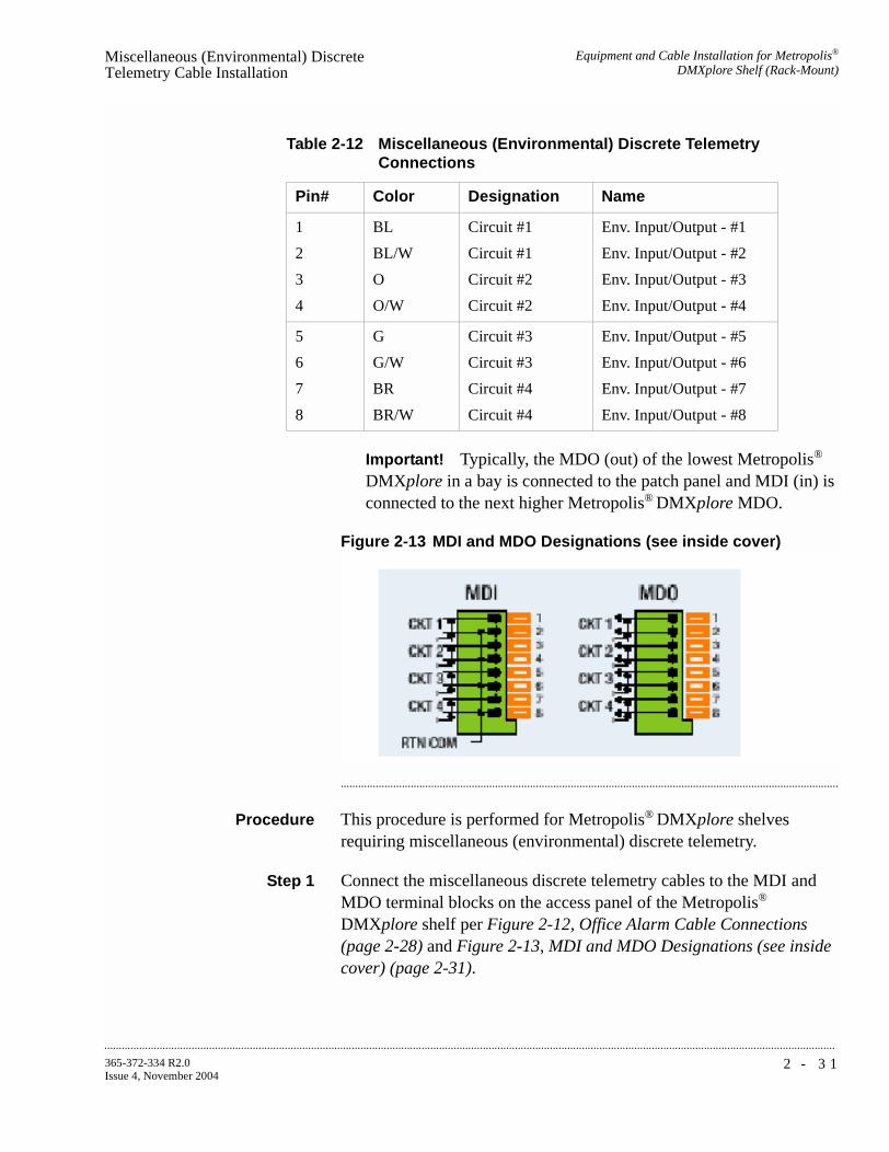
Equipment and Cable Installation for Metropolis®
DMXplore Shelf (Rack-Mount)Miscellaneous (Environmental) Discrete Telemetry Cable Installation
...........................................................................................................................................................................................................................................................
2 - 3 1365-372-334 R2.0Issue 4, November 2004
Important! Typically, the MDO (out) of the lowest Metropolis®
DMXplore in a bay is connected to the patch panel and MDI (in) is connected to the next higher Metropolis® DMXplore MDO.
Figure 2-13 MDI and MDO Designations (see inside cover)
...........................................................................................................................................................................
Procedure This procedure is performed for Metropolis® DMXplore shelves requiring miscellaneous (environmental) discrete telemetry.
Step 1 Connect the miscellaneous discrete telemetry cables to the MDI and MDO terminal blocks on the access panel of the Metropolis®
DMXplore shelf per Figure 2-12, Office Alarm Cable Connections (page 2-28) and Figure 2-13, MDI and MDO Designations (see inside cover) (page 2-31).
Table 2-12 Miscellaneous (Environmental) Discrete Telemetry Connections
Pin# Color Designation Name
1
2
3
4
BL
BL/W
O
O/W
Circuit #1
Circuit #1
Circuit #2
Circuit #2
Env. Input/Output - #1
Env. Input/Output - #2
Env. Input/Output - #3
Env. Input/Output - #4
5
6
7
8
G
G/W
BR
BR/W
Circuit #3
Circuit #3
Circuit #4
Circuit #4
Env. Input/Output - #5
Env. Input/Output - #6
Env. Input/Output - #7
Env. Input/Output - #8

...........................................................................................................................................................................................................................................................
Equipment and Cable Installation for Metropolis®
DMXplore Shelf (Rack-Mount)Miscellaneous (Environmental) Discrete Telemetry Cable Installation
2 - 3 2 365-372-334 R2.0Issue 4, November 2004
Figure 2-14 Miscellaneous Discrete Cable Connection
...........................................................................................................................................................................
Step 2 Route the miscellaneous (environmental) discretes cables to the telemetry . Secure to a tie bar for strain relief
Important! Miscellaneous Discrete connections and Alarm connections may be dressed together in a single bundle.
...........................................................................................................................................................................
Step 3 Cut the miscellaneous (environmental) discrete telemetry cable to the desired length at the telemetry panel.
...........................................................................................................................................................................
Step 4 Wire-wrap the loose end of the miscellaneous (environmental) discrete telemetry cable to the wire-wrap terminal strip, making connections per Table 2-12, Miscellaneous (Environmental) Discrete Telemetry Connections (page 2-31).
Important! Each miscellaneous (environmental) discrete telemetry designation is connected to the Metropolis® DMXplore by two leads (wires). For each input, one lead should be connected to input-common and the other lead should be connected to the appropriate alarm indication. For each output, one lead should be connected to output-common and the other lead should be connected to the appropriate alarm indication.

Equipment and Cable Installation for Metropolis®
DMXplore Shelf (Rack-Mount)Miscellaneous (Environmental) Discrete Telemetry Cable Installation
...........................................................................................................................................................................................................................................................
2 - 3 3365-372-334 R2.0Issue 4, November 2004
...........................................................................................................................................................................
Step 5 Check off the appropriate box in Appendix E, Installation Checklist.
End of Steps
...........................................................................................................................................................................

...........................................................................................................................................................................................................................................................
Equipment and Cable Installation for Metropolis®
DMXplore Shelf (Rack-Mount)OC-3/OC12 Main Optical Fiber Cable Installation
2 - 3 4 365-372-334 R2.0Issue 4, November 2004
............................................................................................................................................................................................................................................................
OC-3/OC12 Main Optical Fiber Cable Installation
Description This section describes how to route the optical fiber cables from the interconnecting equipment (for example, a LGX® optical fiber distributing frame) to the Main OLIUs of the Rack-Mount Metropolis®
DMXplore. This procedure does not cover routing the optical fiber cable between sites.
The optical fiber cables are connected to the Metropolis® DMXplore after the circuit packs are installed. The Metropolis® DMXplore requires single-mode fiber for the main OLIUs. See ED8C947-10 Common Systems, Metropolis® DMXplore Access Multiplexer, Engineering and Ordering Information for recommended fibers.
Important! The optical fiber cable is fragile and must be protected. The fibers should be placed in a protective tube or channel, such as PVC tubing, or PANDUIT cable channel, when running the cable from the Metropolis® DMXplore to the cable rack. The fibers should be placed in the cable rack in a protective channel with nothing on top of them. Cable ties should NOT be used with the optical fiber cables.
WARNINGUnterminated optical connectors may emit laser radiation. Do not view an unterminated optical connector with optical instruments. Avoid direct exposure of the eyes to the beam.
Important! Prior to connecting the optical fiber cables, the fibers should be examined to ensure that they are clean. See Appendix B, Fiber Cleaning for recommended cleaning procedures.
...........................................................................................................................................................................

Equipment and Cable Installation for Metropolis®
DMXplore Shelf (Rack-Mount)OC-3/OC12 Main Optical Fiber Cable Installation
...........................................................................................................................................................................................................................................................
2 - 3 5365-372-334 R2.0Issue 4, November 2004
Procedure
Step 1 Snap the fiber management module into place on the left of the Rack-Mount Metropolis® DMXplore. See Figure 2-15, Optical Fiber Routing (page 2-35)
...........................................................................................................................................................................
Step 2 Route the optical fiber cables from the interconnecting equipment through the fiber management module and into the left side of the Rack-Mount Metropolis® DMXplore. Protective covers must be left on cables.
Figure 2-15 Optical Fiber Routing
...........................................................................................................................................................................
Step 3 Place the optical fiber cables in a protective tube or channel once it has cleared the Metropolis® DMXplore shelf.
...........................................................................................................................................................................
Step 4 Label the optical fiber cables, indicating bay, shelf, pack, and direction (IN or OUT). See Appendix F, Fiber Labeling for more details. The fibers will be inserted into the equipment later, once the circuit packs are installed.

...........................................................................................................................................................................................................................................................
Equipment and Cable Installation for Metropolis®
DMXplore Shelf (Rack-Mount)OC-3/OC12 Main Optical Fiber Cable Installation
2 - 3 6 365-372-334 R2.0Issue 4, November 2004
...........................................................................................................................................................................
Step 5 Check off the appropriate box in Appendix E, Installation Checklist.
End of Steps
...........................................................................................................................................................................

Equipment and Cable Installation for Metropolis®
DMXplore Shelf (Rack-Mount)RS-232 Serial CIT Cable Installation
...........................................................................................................................................................................................................................................................
2 - 3 7365-372-334 R2.0Issue 4, November 2004
............................................................................................................................................................................................................................................................
RS-232 Serial CIT Cable Installation
Description This section provides the procedure to connect the CIT cable from the VLNC1 (SYSCTL) to a PC (serial port) to allow communications between the PC and the RS232 port located on the VLNC1.
CIT cable assemblies and the length options are listed in Table 2-13, Serial CIT Cable Assembly (page 2-37). CIT cable connections are listed in Table 2-14, Standard CIT Cable Connection (page 2-37) and Table 2-15, RJ-45 to DB-9 Connector Connections (page 2-38).
Table 2-13 Serial CIT Cable Assembly
Table 2-14 Standard CIT Cable Connection
Description CableAssembly #
CableLength
Metropolis® DMXplore Connections
RS232 CIT Cable
848748869 8 feet CIT/RS-232 jack on System Controller (VLNC1)
Connection RJ45 connector Color 9-Pin D-type connector
Pin# Designation Pin# Designation
CIT cable 1 FRS232N W - O 6 DCE Ready
3 FDTR W - BL 4 DTE Ready
4 Ground W - G 5 Ground
5 FTXD O 2 Receive Data
6 FRXD G 3 Transmit Data
Notes:
1. The connection and the colors shown above are for a standard Lucent-made cable. If you use a RJ-45 to DB-9 connector with a standard straight-through 10BASE-T LAN cable then, refer to Table 2-15, RJ-45 to DB-9 Connector Connections (page 2-38).

...........................................................................................................................................................................................................................................................
Equipment and Cable Installation for Metropolis®
DMXplore Shelf (Rack-Mount)RS-232 Serial CIT Cable Installation
2 - 3 8 365-372-334 R2.0Issue 4, November 2004
...........................................................................................................................................................................
Procedure
Step 1 Connect the RJ-45 end of the CIT cable to the RS232 jack located on the VLNC1 (SYSCTL).
...........................................................................................................................................................................
Step 2 Connect the 9-pin D-type connector to the serial port on the PC.
...........................................................................................................................................................................
Step 3 Check off the appropriate box in Appendix E, Installation Checklist.
End of Steps
...........................................................................................................................................................................
Table 2-15 RJ-45 to DB-9 Connector Connections
From RJ45 connector
To DB-9 Pin D-type connector
Pin# Color Pin#
1 Blue 6
3 Black 4
4 Red 5
5 Green 2
6 Yellow 3
Notes:
1. The connection and the colors shown above are for RJ-45 to DB-9 connector.
2. This connector should be used with a standard straight-through 10BASE-T LAN cable.
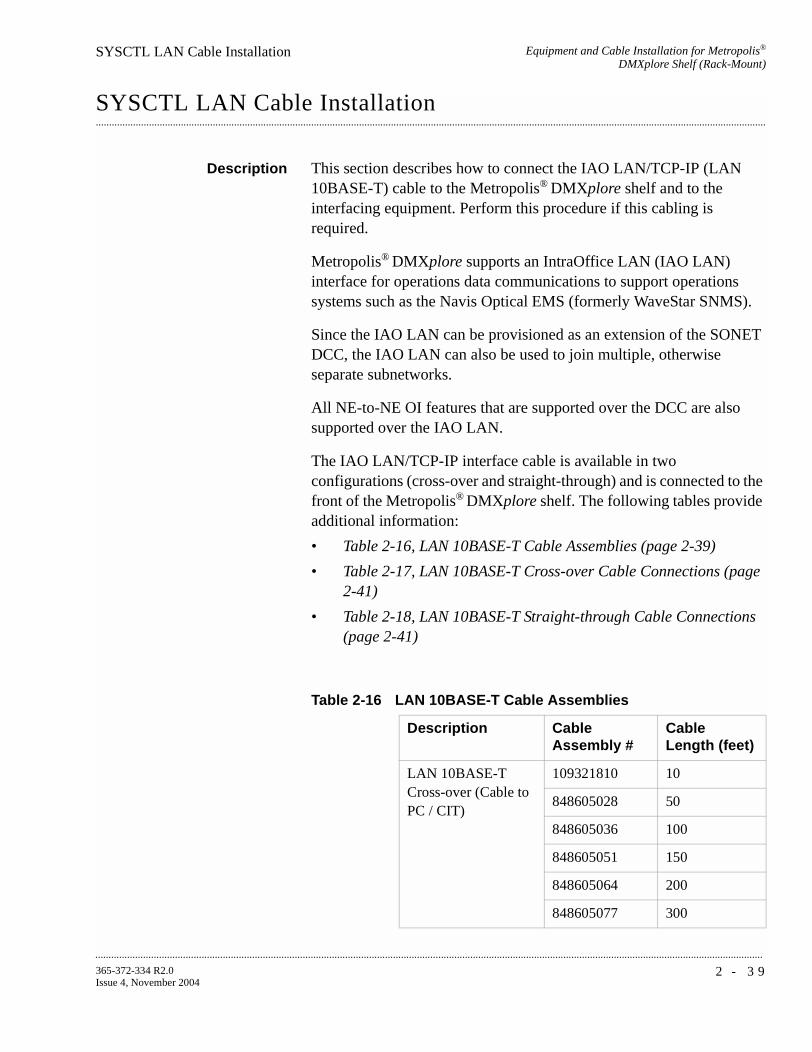
Equipment and Cable Installation for Metropolis®
DMXplore Shelf (Rack-Mount)SYSCTL LAN Cable Installation
...........................................................................................................................................................................................................................................................
2 - 3 9365-372-334 R2.0Issue 4, November 2004
............................................................................................................................................................................................................................................................
SYSCTL LAN Cable Installation
Description This section describes how to connect the IAO LAN/TCP-IP (LAN 10BASE-T) cable to the Metropolis® DMXplore shelf and to the interfacing equipment. Perform this procedure if this cabling is required.
Metropolis® DMXplore supports an IntraOffice LAN (IAO LAN) interface for operations data communications to support operations systems such as the Navis Optical EMS (formerly WaveStar SNMS).
Since the IAO LAN can be provisioned as an extension of the SONET DCC, the IAO LAN can also be used to join multiple, otherwise separate subnetworks.
All NE-to-NE OI features that are supported over the DCC are also supported over the IAO LAN.
The IAO LAN/TCP-IP interface cable is available in two configurations (cross-over and straight-through) and is connected to the front of the Metropolis® DMXplore shelf. The following tables provide additional information:
• Table 2-16, LAN 10BASE-T Cable Assemblies (page 2-39)
• Table 2-17, LAN 10BASE-T Cross-over Cable Connections (page 2-41)
• Table 2-18, LAN 10BASE-T Straight-through Cable Connections (page 2-41)
Table 2-16 LAN 10BASE-T Cable Assemblies
Description Cable Assembly #
Cable Length (feet)
LAN 10BASE-T Cross-over (Cable to PC / CIT)
109321810 10
848605028 50
848605036 100
848605051 150
848605064 200
848605077 300

...........................................................................................................................................................................................................................................................
Equipment and Cable Installation for Metropolis®
DMXplore Shelf (Rack-Mount)SYSCTL LAN Cable Installation
2 - 4 0 365-372-334 R2.0Issue 4, November 2004
LAN 10BASE-T Straight-through (Cable to Ethernet Hub / Router)
109321836 20
109321844 30
109321851 40
848604948 50
109321869 60
109321877 70
109321885 80
109321893 90
848604955 100
109321901 110
109321919 120
109321927 130
109321935 140
848604963 150
109321943 160
109321950 180
848604971 200
109321968 220
109321976 240
109321984 260
109321992 280
848604997 300
Table 2-16 LAN 10BASE-T Cable Assemblies
Description Cable Assembly #
Cable Length (feet)

Equipment and Cable Installation for Metropolis®
DMXplore Shelf (Rack-Mount)SYSCTL LAN Cable Installation
...........................................................................................................................................................................................................................................................
2 - 4 1365-372-334 R2.0Issue 4, November 2004
...........................................................................................................................................................................
Procedure
Step 1 Connect the cable to the LAN (RJ45) jack on the SYSCTL circuit pack.
Important! If connecting directly to a PC, use a LAN 10BASE-T Cross-over Cable Assembly (See Table 2-17, LAN 10BASE-T Cross-over Cable Connections).
Important! If connecting to a hub, use a LAN 10BASE-T Straight-through Cable Assembly (See Table 2-18, LAN 10BASE-T Straight-through Cable Connections).
Table 2-17 LAN 10BASE-T Cross-over Cable Connections
SYSCTLConnection
Metropolis®
DMXplore Backplane
Color Other Side Design
LAN 1 BL - W 3 RDTR
2 W - BL 6 RS232N
3 O - W 1 RRXD
6 W - O 2 RTX
Table 2-18 LAN 10BASE-T Straight-through Cable Connections
SYSCTLConnection Backplane Color Other Side
Pin Designation
LAN 1 BL - W 1 XIOLANP
2 W - BL 2 XIOLANN
3 O - W 3 RIOLANP
6 W - O 6 RIOLANN
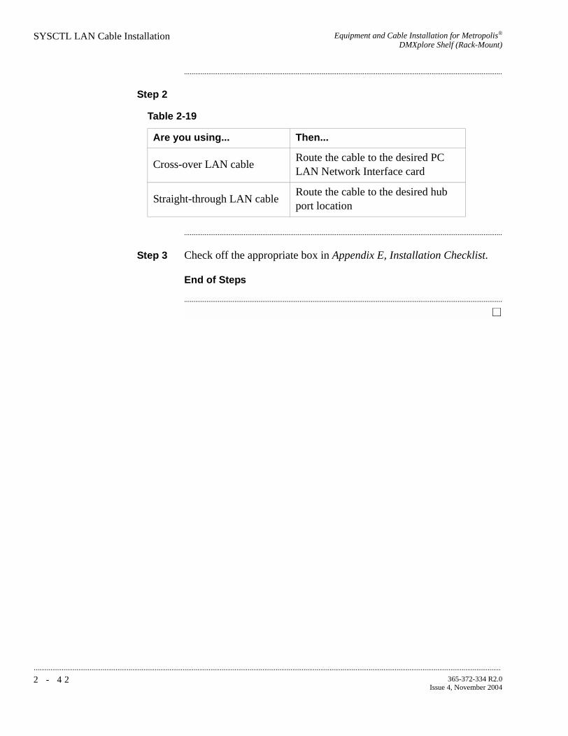
...........................................................................................................................................................................................................................................................
Equipment and Cable Installation for Metropolis®
DMXplore Shelf (Rack-Mount)SYSCTL LAN Cable Installation
2 - 4 2 365-372-334 R2.0Issue 4, November 2004
...........................................................................................................................................................................
Step 2
...........................................................................................................................................................................
Step 3 Check off the appropriate box in Appendix E, Installation Checklist.
End of Steps
...........................................................................................................................................................................
Table 2-19
Are you using... Then...
Cross-over LAN cableRoute the cable to the desired PC LAN Network Interface card
Straight-through LAN cableRoute the cable to the desired hub port location

Equipment and Cable Installation for Metropolis®
DMXplore Shelf (Rack-Mount)Final Operations
...........................................................................................................................................................................................................................................................
2 - 4 3365-372-334 R2.0Issue 4, November 2004
............................................................................................................................................................................................................................................................
Final Operations
Description Final check on equipment and cable installation.
...........................................................................................................................................................................
Procedure
Step 1 Verify that all the cables are properly dressed/connected.
...........................................................................................................................................................................
Step 2 Verify that all cables are properly labeled.
...........................................................................................................................................................................
Step 3 Verify that designations where cables were wire-wrapped are properly labeled.
...........................................................................................................................................................................
Step 4 Verify that all the fibers are properly dressed/connected.
...........................................................................................................................................................................
Step 5 Verify that all fibers are properly labeled. See Appendix F, Fiber Labeling
...........................................................................................................................................................................
Step 6 Verify that designations where fibers were terminated are properly labeled.
...........................................................................................................................................................................
Step 7 Check off the appropriate box in Appendix E, Installation Checklist.
End of Steps
...........................................................................................................................................................................

...........................................................................................................................................................................................................................................................
Equipment and Cable Installation for Metropolis®
DMXplore Shelf (Rack-Mount)Final Operations
2 - 4 4 365-372-334 R2.0Issue 4, November 2004

3 - 1365-372-334 R2.0Issue 4, November 2004
............................................................................................................................................................................................................................................................
3 Powering and Initial Circuit Pack Installation for Metropolis®
DMXplore Shelf (Wall-Mount)
............................................................................................................................................................................................................................................................
Overview
Purpose This section provides information for performing the following:
• shelf powering
• circuit pack installation.
Detailed information on the function of each circuit pack is contained in 365-372-332, Metropolis® DMXplore Access Multiplexer, User Operations Guide.
Contents This chapter provides information on the following topics:
Description 3-2
Powering 3-3
Circuit Pack Compatibility 3-7
Removal of Cover 3-9
Initial Circuit Pack Installation 3-113-11
3-9
3-7
3-3
3-2

...........................................................................................................................................................................................................................................................
Powering and Initial Circuit Pack Installation forMetropolis® DMXplore Shelf (Wall-Mount)
Description
3 - 2 365-372-334 R2.0Issue 4, November 2004
............................................................................................................................................................................................................................................................
Description
Overview This section should be performed on all shelf installations.
Tools, Test Equipment andAccessories
Listed below are the tools, test equipment and accessories necessary to perform the procedures in this section.
Quantity Required Description Comments
Y Screwdriver(s) A screwdriver(s) with the appropriate head(s) is (are) required for securing the mounting screws, repositioning the mounting brackets, and installing the interfacing cables.
1 Y ESD Wrist Strap A wrist strap must be worn when handling circuit packs. Use the electrostatic discharge (ESD) jack provided on the shelf.
1 Y Multimeter (Optional) The voltmeter must be capable of measuring DC voltage in the 40 to 60 volt range. The use of the voltmeter is optional since the shelf will alarm or shut down if the proper voltage is not supplied.
1 Y Personal Computer (PC) Required to run the WaveStar® CIT software. See PC Minimum Requirements (page 5-2).
1 Y
CIT Interface Cable(848748869)
8-ft. long RJ45 to 9-pin D-sub serial cable.
LAN 10BASE-T (Cross-over)
Allows for direct connection between the PC LAN card and the CTL LAN slot. See Table 1-17, LAN 10BASE-T Cross-over Cable Connections (page 1-47) for Comcode information.
LAN 10BASE-T (Straight-Through)
Allows for connection between the PC NIC card and a HUB. See Table 1-18, LAN 10BASE-T Straight-through Cable Connections (page 1-47) for Comcode information.

Powering and Initial Circuit Pack Installation forMetropolis® DMXplore Shelf (Wall-Mount)
Powering
...........................................................................................................................................................................................................................................................
3 - 3365-372-334 R2.0Issue 4, November 2004
............................................................................................................................................................................................................................................................
Powering
Overview The following table lists the requirements for the Metropolis®
DMXplore Shelf.
Table 3-1 Metropolis® DMXplore Shelf Power Supply Requirements
Procedure
Step 1 Verify that the Metropolis® DMXplore shelf is properly grounded.
...........................................................................................................................................................................
Step 2 Verify that the AC/DC converter is not plugged into the AC power outlet or that the battery distribution fuse board (BDFB) has the associated fuses disconnected, or that BDCBB breakers are off.
...........................................................................................................................................................................
Step 3 Disconnect the power cables from the power input terminal block located on the access panel of the Metropolis® DMXplore.
Item Description
Voltage range, all components -40.0V to -60.0V DC
Power Feeders two -48V power feeders PWR A and PWR B
Circuit Breakers (one per feeder) or Fuse (one per feeder)
The power supply has "built-in" current limiting at 2.5A and does not require an external 2A fuse or circuit breaker. If a alternative power supply is used, an external protection device will be needed.

...........................................................................................................................................................................................................................................................
Powering and Initial Circuit Pack Installation forMetropolis® DMXplore Shelf (Wall-Mount)
Powering
3 - 4 365-372-334 R2.0Issue 4, November 2004
Figure 3-1 Power Connections on Metropolis® DMXplore Access Panel
...........................................................................................................................................................................
Step 4 If an AC/DC converter is being used, verify that the power supply is fuse limited to 2-amperes. Otherwise add a 2-ampere in-line fuse for each connection.
OR
If a BDFB or BDCBB is being used, verify that the power feeders going to the Metropolis® DMXplore are current limited to that 2-amperes.
...........................................................................................................................................................................
Step 5 Plug in the AC/DC converter into the AC power outlet or connect the fuses at the BDFB, or turn on the breakers at that BDCBB.
2.75 in.
ALARM12345678
PWR-A
PWR-B
ON
ON
-48V-A
RTN-COM
-48V-BRTN-B
RTN-A
GRD
41
81818181
2 3
C GROUP
1 2 3
B GROUP
RX
TX
RX
TX
8 1 8 1 8 1 8 1
81818181
321 4
765 8A/D GROUP
8 1 8 1 8 1 8 1
81818181
11109 12
151413 16
12345678
12345678
MDOMDI
-48V-A
RTN-COM
-48V-BRTN-B
RTN-A
GRD

Powering and Initial Circuit Pack Installation forMetropolis® DMXplore Shelf (Wall-Mount)
Powering
...........................................................................................................................................................................................................................................................
3 - 5365-372-334 R2.0Issue 4, November 2004
...........................................................................................................................................................................
Step 6 At the Metropolis® DMXplore power cable connector, use a voltmeter and measure the voltage on the power cable between BAT A and BAT A RTN. Then measure the voltage between BAT B and BAT B RTN.
Requirement: The voltage MUST be between -40.00 and -60.0 V DC.
...........................................................................................................................................................................
Step 7 Unplug the AC/DC converter from the AC power outlet or disconnect the fuses at the BDFB, or turn off the breakers at that BDCBB.
...........................................................................................................................................................................
Step 8 Reconnect the “A” and “B” power feed cables to the corresponding power input terminal block connectors (labeled -48A, RTN-A, RTN-B, and -48V-B).
...........................................................................................................................................................................
Step 9 Plug in the AC/DC converter into the AC power outlet or connect the fuses at the BDFB, or turn on the breakers at that BDCBB.
...........................................................................................................................................................................
Step 10 Verify that the PWR-A and PWR-B LEDs are lighted.
...........................................................................................................................................................................
Step 11 Inhibit the power flow to the “B” power feed of the Metropolis®
DMXplore Shelf by either:
• unplugging the corresponding AC/DC converter from the AC power outlet
• disconnecting the corresponding fuse at the BDFB
• turning off the corresponding breaker at that BDCBB.
...........................................................................................................................................................................
Step 12 Verify that only the PWR-A LED on the Metropolis® DMXplore shelf is lit with only the “A” feed powered.

...........................................................................................................................................................................................................................................................
Powering and Initial Circuit Pack Installation forMetropolis® DMXplore Shelf (Wall-Mount)
Powering
3 - 6 365-372-334 R2.0Issue 4, November 2004
...........................................................................................................................................................................
Step 13 Restart the power flow to the “B” power feed of the Metropolis®
DMXplore Shelf by either:
• connecting the corresponding AC/DC converter from the AC power outlet
• connecting the corresponding fuse at the BDFB
• turning on the corresponding breaker at that BDCBB.
...........................................................................................................................................................................
Step 14 Inhibit the power flow to the “A” power feed of the Metropolis®
DMXplore Shelf by either:
• unplugging the corresponding AC/DC converter from the AC power outlet
• disconnecting the corresponding fuse at the BDFB,
• turning off the corresponding breaker at that BDCBB.
...........................................................................................................................................................................
Step 15 Verify the PWR-B LED on the Metropolis® DMXplore shelf is lit with only the “B” feed powered.
...........................................................................................................................................................................
Step 16 Restart the power flow to the “A” power feed of the Metropolis®
DMXplore Shelf by either:
• connecting the corresponding AC/DC converter from the AC power outlet
• connecting the corresponding fuse at the BDFB
• turning on the corresponding breaker at that BDCBB.
...........................................................................................................................................................................
Step 17 Verify that the PWR-A and PWR-B LEDs are lit with both "A" and "B" power feeds powered.
...........................................................................................................................................................................
Step 18 Check off the appropriate box in Appendix E, Installation Checklist.
End of Steps
...........................................................................................................................................................................

Powering and Initial Circuit Pack Installation forMetropolis® DMXplore Shelf (Wall-Mount)
Circuit Pack Compatibility
...........................................................................................................................................................................................................................................................
3 - 7365-372-334 R2.0Issue 4, November 2004
............................................................................................................................................................................................................................................................
Circuit Pack Compatibility
Overview Table 3-2, Release 2.0 Circuit Pack Slot Compatibility lists all the circuit packs that are compatible with Release 2.0 and their respective shelf locations (slots).
See Figure 3-2, Wall-Mount Metropolis® DMXplore Shelf (page 3-8) for slot locations.
Important! Before attempting to remove cover reference Removal of Cover (page 3-9).
Table 3-2 Release 2.0 Circuit Pack Slot Compatibility
Apparatus Code Card Type Physical Slot
VLNC1 Controller CTL
VLNC6 (OC3/16DS1) Main MAIN 1MAIN 2
VLNC5
(OC3/16DS1/2DS3)
Main MAIN1MAIN2
VLNC26
(OC12/16DS1)
Main MAIN 1MAIN 2
VLNC25
(OC12/16DS1/2DS3)
Main MAIN 1MAIN 2
VLNC15 10/100 FE Ethernet C-Group

...........................................................................................................................................................................................................................................................
Powering and Initial Circuit Pack Installation forMetropolis® DMXplore Shelf (Wall-Mount)
Circuit Pack Compatibility
3 - 8 365-372-334 R2.0Issue 4, November 2004
Figure 3-2 Wall-Mount Metropolis® DMXplore Shelf
30 mm.
~ 10 in.
Lucent TechnologiesMetropolis DMXplore®
6RU10.5"
~7.0 in.
2.75 in.4.25 in.
ALARM
FAULT
ACTIVE
VLNC15S1:1
10/100T
Lucent
30mm
12345678
PWR-A
PWR-B
ON
ON
-48V-A
RTN-COM
-48V-BRTN-B
RTN-A
GRD
41
81818181
2 3
C GROUP
1 2 3
B GRO UP
RX
TX
RX
TX
8 1 8 1 8 1 8 1
81818181
321 4
765 8A/D GROUP
8 1 8 1 8 1 8 1
81818181
11109 12
151413 16
12345678
12345678
MDOMDI
FAULT
ACO/TST
UPDATE
LAN
RS232
MN/ABN
CR/MJ
S1:1SYSCTLLucent
VLNC1
FAULT
ACTIVE
VLNC7S1:1OC3
Lucent
35mm
OC3IN OUT
FAULT
ACTIVE
VLNC7S1:1OC3
Lucent
35mm
OC3IN OUT

Powering and Initial Circuit Pack Installation forMetropolis® DMXplore Shelf (Wall-Mount)
Removal of Cover
...........................................................................................................................................................................................................................................................
3 - 9365-372-334 R2.0Issue 4, November 2004
............................................................................................................................................................................................................................................................
Removal of Cover
Introduction Follow this procedure to remove the cover from the Metropolis®
DMXplore shelf.
Important! See Cover Installation Wall-Mount (page 8-19) for instructions for installing the Metropolis® DMXplore cover.
Step 1 Loosen captive screw. See Figure 3-3, Metropolis® DMXplore Shelf with cover (page 3-9).
...........................................................................................................................................................................
Step 2 Carefully pull cover at top flange forward (away from shelf) to overcome resistance with tabs on shelf. See Figure 3-3, Metropolis®
DMXplore Shelf with cover (page 3-9).
Figure 3-3 Metropolis® DMXplore Shelf with cover
...........................................................................................................................................................................
Step 3 Carefully rotate cover on lower pivot pins approximately 30 degrees. See Figure 3-4, Rotated Cover (page 3-10) and Figure 3-5, Pivot Pins (page 3-10).

...........................................................................................................................................................................................................................................................
Powering and Initial Circuit Pack Installation forMetropolis® DMXplore Shelf (Wall-Mount)
Removal of Cover
3 - 1 0 365-372-334 R2.0Issue 4, November 2004
Figure 3-4 Rotated Cover
...........................................................................................................................................................................
Step 4 Lift cover slightly to allow pivot pins to clear slots in the left and right sideplates of shelf.
Figure 3-5 Pivot Pins
Important! Care should be taken to avoid damage to slot details in shelf sideplates.
End of Steps
...........................................................................................................................................................................

Powering and Initial Circuit Pack Installation forMetropolis® DMXplore Shelf (Wall-Mount)
Initial Circuit Pack Installation
...........................................................................................................................................................................................................................................................
3 - 1 1365-372-334 R2.0Issue 4, November 2004
............................................................................................................................................................................................................................................................
Initial Circuit Pack Installation
Description This section provides instructions for installing, BUT NOT fully seating, circuit packs into the Metropolis® DMXplore shelf. After circuit packs have been unpacked, they may be placed in their respective slots in the Metropolis® DMXplore shelf but NOT FULLY ENGAGED IN THE BACKPLANE CONNECTOR. The circuit packs will be fully installed (seated) in the section, Circuit Pack Installation (page 5-5).
Important! If office alarms are connected, it is advisable to disconnect the office alarm cable while performing the procedures in this section to prevent spurious alarms from being reported. Reconnect the office alarm cable after completion of all testing.
CAUTION199M Apparatus Blanks are required in an unequipped Main-2 slot to provide proper air flow for cooling.
199L Apparatus Blanks are required in an unequipped C Function Unit slot to provide proper air flow for cooling.
CAUTIONTo protect against damage due to electrostatic discharge, a properly grounded ESD wrist strap must be worn when handling equipment.
VLNC1 (SYSCTL)Installation
Follow this procedure to install the VLNC1 (SYSCTL) circuit pack into the Metropolis® DMXplore shelf.
Step 1 Remove the SYSCTL circuit pack from the packing material.
...........................................................................................................................................................................
Step 2 Identify the lower left-hand slot on the Metropolis® DMXplore shelf. See Figure 3-2, Wall-Mount Metropolis® DMXplore Shelf (page 3-8).

...........................................................................................................................................................................................................................................................
Powering and Initial Circuit Pack Installation forMetropolis® DMXplore Shelf (Wall-Mount)
Initial Circuit Pack Installation
3 - 1 2 365-372-334 R2.0Issue 4, November 2004
...........................................................................................................................................................................
Step 3 Place the SYSCTL circuit pack into the lower left-hand slot on the Metropolis® DMXplore shelf. Do NOT engage the circuit pack in the backplane connector.
...........................................................................................................................................................................
Step 4 Check off the appropriate box in Appendix E, Installation Checklist.
End of Steps
...........................................................................................................................................................................
Main OLIU Installation Follow this procedure to install the VLNC6 OC-3/16DS1, VLNC5 OC-3/16DS1/2DS3, VLNC26 OC12/16DS1, or the VLNC25 OC12/16DS1/2DS3 Main OLIU circuit pack in the Metropolis®
DMXplore shelf.
Step 1 Remove the first Main OLIU circuit pack from the packing material.
...........................................................................................................................................................................
Step 2 Identify the large, middle slot on the Metropolis® DMXplore shelf. See Figure 3-2, Wall-Mount Metropolis® DMXplore Shelf (page 3-8).
...........................................................................................................................................................................
Step 3 Place the Main OLIU circuit pack into the large, middle slot on the Metropolis® DMXplore shelf. Do NOT engage the circuit pack in the backplane connector.
...........................................................................................................................................................................
Step 4 Are you installing a second main pack?
Important! If the Main 2 slot is to remain unequipped, install a 199M apparatus blank to provide proper air flow for cooling.
...........................................................................................................................................................................
Step 5 Remove the second Main OLIU from the packing material.
If... Then...
Yes Proceed to Step 5
No Proceed to Step 8

Powering and Initial Circuit Pack Installation forMetropolis® DMXplore Shelf (Wall-Mount)
Initial Circuit Pack Installation
...........................................................................................................................................................................................................................................................
3 - 1 3365-372-334 R2.0Issue 4, November 2004
Important! When installing two Main OLIUs, both circuit packs must be the same type, either both VLNC5s or both VLNC6s.
...........................................................................................................................................................................
Step 6 Identify the far right slot on the Metropolis® DMXplore shelf. See Figure 3-2, Wall-Mount Metropolis® DMXplore Shelf (page 3-8).
...........................................................................................................................................................................
Step 7 Place the second Main OLIU circuit pack into the far right slot on the Metropolis® DMXplore shelf. Do NOT engage the circuit pack in the backplane connector.
...........................................................................................................................................................................
Step 8 Check off the appropriate box in Appendix E, Installation Checklist.
End of Steps
10/100 T Fast EthernetInstallation
Follow this procedure if you are installing a VLNC15 10/100 T Fast Ethernet circuit pack.
Step 1 Remove the VLNC15 10/100 BaseT FE circuit pack from the packing material.
...........................................................................................................................................................................
Step 2 Identify the unequipped Function Group-C slot on the upper left-hand side of the shelf. Refer to Figure 3-2, Wall-Mount Metropolis®
DMXplore Shelf (page 3-8) for details.
...........................................................................................................................................................................
Step 3 Place the VLNC15 10/100 BaseT FE circuit pack into the Function Group-C slot on the Metropolis® DMXplore shelf. Do NOT engage the circuit pack in the backplane connector.
...........................................................................................................................................................................
Step 4 Check off the appropriate box in Appendix E, Installation Checklist.
...........................................................................................................................................................................

...........................................................................................................................................................................................................................................................
Powering and Initial Circuit Pack Installation forMetropolis® DMXplore Shelf (Wall-Mount)
Initial Circuit Pack Installation
3 - 1 4 365-372-334 R2.0Issue 4, November 2004
199L Apparatus BlankInstallation
Follow this procedure to install 199L Apparatus Blank into the Wall-Mount Metropolis® DMXplore shelf.
Important! If not installing a VLNC15 FE circuit pack in Function Group-C, an 199L Apparatus Blank is required.
Step 1 Identify the unequipped Function Group-C slot on the upper right-hand side.
...........................................................................................................................................................................
Step 2 Remove the 199L Apparatus Blank from the packing material.
...........................................................................................................................................................................
Step 3 Place the 199L Apparatus Blank into the unequipped C slot on the shelf. Do NOT engage the blank pack in the backplane connector.
...........................................................................................................................................................................
Step 4 Check off the appropriate box in Appendix E, Installation Checklist.
End of Steps
...........................................................................................................................................................................
4 - 1365-372-334 R2.0Issue 4, November 2004
............................................................................................................................................................................................................................................................
4 Powering and Initial Circuit Pack Installation for Metropolis®
DMXplore Shelf (Rack-Mount)
............................................................................................................................................................................................................................................................
Overview
Purpose This section provides information for performing the following:
• shelf powering
• circuit pack installation.
Detailed information on the function of each circuit pack is contained in 365-372-332, Metropolis® DMXplore Access Multiplexer, User Operations Guide.
Contents This chapter provides information on the following topics:
Description 4-2
Powering 4-3
Circuit Pack Compatibility 4-7
Removal of Cover 4-8
Initial Circuit Pack Installation 4-114-11
4-8
4-7
4-3
4-2

...........................................................................................................................................................................................................................................................
Powering and Initial Circuit Pack Installation forMetropolis® DMXplore Shelf (Rack-Mount)
Description
4 - 2 365-372-334 R2.0Issue 4, November 2004
............................................................................................................................................................................................................................................................
Description
Overview This section should be performed on all shelf installations.
Tools, Test Equipment andAccessories
Listed below are the tools, test equipment and accessories necessary to perform the procedures in this section.
Quantity Required Description Comments
Y Screwdriver(s) A screwdriver(s) with the appropriate head(s) is (are) required for securing the mounting screws, repositioning the mounting brackets, and installing the interfacing cables.
1 Y ESD Wrist Strap A wrist strap must be worn when handling circuit packs. Use the electrostatic discharge (ESD) jack provided on the shelf.
1 Y Multimeter (Optional) The voltmeter must be capable of measuring DC voltage in the 40 to 60 volt range. The use of the voltmeter is optional since the shelf will alarm or shut down if the proper voltage is not supplied.
1 Y Personal Computer (PC) Required to run the WaveStar® CIT software. See PC Minimum Requirements (page 5-2).
1 Y
CIT Interface Cable(848748869)
8-ft. long RJ45 to 9-pin D-sub serial cable.
LAN 10BASE-T (Cross-over)
Allows for direct connection between the PC LAN card and the CTL LAN slot. See Table 1-17, LAN 10BASE-T Cross-over Cable Connections (page 1-47) for Comcode information.
LAN 10BASE-T (Straight-Through)
Allows for connection between the PC NIC card and a HUB. See Table 1-18, LAN 10BASE-T Straight-through Cable Connections (page 1-47) for Comcode information.

Powering and Initial Circuit Pack Installation forMetropolis® DMXplore Shelf (Rack-Mount)
Powering
...........................................................................................................................................................................................................................................................
4 - 3365-372-334 R2.0Issue 4, November 2004
............................................................................................................................................................................................................................................................
Powering
Overview The following table lists the requirements for the Metropolis®
DMXplore Shelf.
Table 4-1 Metropolis® DMXplore Shelf Power Supply Requirements
Procedure
Step 1 Verify that the Metropolis® DMXplore shelf is properly grounded.
...........................................................................................................................................................................
Step 2 Verify that the AC/DC converter is not plugged into the AC power outlet or that the battery distribution fuse board (BDFB) has the associated fuses disconnected, or that BDCBB breakers are off.
...........................................................................................................................................................................
Step 3 Disconnect the power cables from the power input terminal block located on the access panel of the Metropolis® DMXplore.
Item Description
Voltage range, all components -40.0V to -60.0V DC
Power Feeders two -48V power feeders PWR A and PWR B
Circuit Breakers (one per feeder) or Fuse (one per feeder)
The power supply has "built-in" current limiting at 2.5A and does not require an external 2A fuse or circuit breaker. If a alternative power supply is used, an external protection device will be needed.

...........................................................................................................................................................................................................................................................
Powering and Initial Circuit Pack Installation forMetropolis® DMXplore Shelf (Rack-Mount)
Powering
4 - 4 365-372-334 R2.0Issue 4, November 2004
Figure 4-1 Power Connections on Rack-Mount Metropolis®
DMXplore Access Panel
...........................................................................................................................................................................
Step 4 If an AC/DC converter is being used, verify that the power supply is fuse limited to 2-amperes. Otherwise add a 2 ampere in-line fuse for each connection.
OR
If a BDFB or BDCBB is being used, verify that the power feeders going to the Metropolis® DMXplore are current limited to 2 amperes.
...........................................................................................................................................................................
Step 5 Plug in the AC/DC converter into the AC power outlet or connect the fuses at the BDFB, or turn on the breakers at that BDCBB.

Powering and Initial Circuit Pack Installation forMetropolis® DMXplore Shelf (Rack-Mount)
Powering
...........................................................................................................................................................................................................................................................
4 - 5365-372-334 R2.0Issue 4, November 2004
..............................................................................................................................................................................
Step 6 At the Metropolis® DMXplore power cable connector, use a voltmeter and measure the voltage on the power cable between BAT A and BAT A RTN. Then measure the voltage between BAT B and BAT B RTN.
Requirement: The voltage MUST be between -40.00 and -60.0 V DC.
..............................................................................................................................................................................
Step 7 Unplug the AC/DC converter from the AC power outlet or disconnect the fuses at the BDFB, or turn off the breakers at that BDCBB.
..............................................................................................................................................................................
Step 8 Reconnect the “A” and “B” power feed cables to the corresponding power input terminal block connectors (labeled -48A, RTN-A, RTN-B, and -48V-B).
..............................................................................................................................................................................
Step 9 Plug in the AC/DC converter into the AC power outlet or connect the fuses at the BDFB, or turn on the breakers at that BDCBB.
..............................................................................................................................................................................
Step 10 Verify that the PWR-A and PWR-B LEDs are lighted.
..............................................................................................................................................................................
Step 11 Inhibit the power flow to the “B” power feed of the Metropolis®
DMXplore Shelf by either:
• unplugging the corresponding AC/DC converter from the AC power outlet
• disconnecting the corresponding fuse at the BDFB
• turning off the corresponding breaker at that BDCBB.
..............................................................................................................................................................................
Step 12 Verify that only the PWR-A LED on the Metropolis® DMXplore shelf is lit with only the “A” feed powered.
..............................................................................................................................................................................
Step 13 Restart the power flow to the “B” power feed of the Metropolis®
DMXplore Shelf by either:

...........................................................................................................................................................................................................................................................
Powering and Initial Circuit Pack Installation forMetropolis® DMXplore Shelf (Rack-Mount)
Powering
4 - 6 365-372-334 R2.0Issue 4, November 2004
• connecting the corresponding AC/DC converter from the AC power outlet
• connecting the corresponding fuse at the BDFB
• turning on the corresponding breaker at that BDCBB.
...........................................................................................................................................................................
Step 14 Inhibit the power flow to the “A” power feed of the Metropolis®
DMXplore Shelf by either:
• unplugging the corresponding AC/DC converter from the AC power outlet
• disconnecting the corresponding fuse at the BDFB,
• turning off the corresponding breaker at that BDCBB.
...........................................................................................................................................................................
Step 15 Verify the PWR-B LED on the Metropolis® DMXplore shelf is lit with only the “B” feed powered.
...........................................................................................................................................................................
Step 16 Restart the power flow to the “A” power feed of the Metropolis®
DMXplore Shelf by either:
• connecting the corresponding AC/DC converter from the AC power outlet
• connecting the corresponding fuse at the BDFB
• turning on the corresponding breaker at that BDCBB.
...........................................................................................................................................................................
Step 17 Verify that the PWR-A and PWR-B LEDs are lit with both "A" and "B" power feeds powered.
...........................................................................................................................................................................
Step 18 Check off the appropriate box in Appendix E, Installation Checklist.
End of Steps
...........................................................................................................................................................................

Powering and Initial Circuit Pack Installation forMetropolis® DMXplore Shelf (Rack-Mount)
Circuit Pack Compatibility
...........................................................................................................................................................................................................................................................
4 - 7365-372-334 R2.0Issue 4, November 2004
............................................................................................................................................................................................................................................................
Circuit Pack Compatibility
Overview Table 4-2, Release 2.0 Circuit Pack Slot Compatibility lists all the circuit packs that are compatible with Release 2.0 and their respective shelf locations (slots).
See Figure 4-2, Rack-Mount Metropolis® DMXplore Shelf Front View (page 4-7) for slot locations.
Important! Before attempting to remove cover reference Removal of Cover (page 4-8).
Figure 4-2 Rack-Mount Metropolis® DMXplore Shelf Front View
Table 4-2 Release 2.0 Circuit Pack Slot Compatibility
Apparatus Code Card Type Physical Slot
VLNC1 Controller CTL
VLNC6 (OC3/16DS1) Main MAIN 1MAIN 2
VLNC5 (OC3/16DS1/2DS3) Main MAIN1MAIN2
VLNC26 (OC12/16DS1) Main MAIN 1MAIN 2
VLNC25 (OC12/16DS1/2DS3)
Main MAIN 1MAIN 2
VLNC15 10/100 BaseT FE Ethernet
C-Group

...........................................................................................................................................................................................................................................................
Powering and Initial Circuit Pack Installation forMetropolis® DMXplore Shelf (Rack-Mount)
Removal of Cover
4 - 8 365-372-334 R2.0Issue 4, November 2004
............................................................................................................................................................................................................................................................
Removal of Cover
Introduction Follow this procedure to remove the cover from the Rack-Mount Metropolis® DMXplore shelf.
Important! See Cover Installation Wall-Mount (page 8-19) for instructions for installing the Metropolis® DMXplore cover.
Step 1 Loosen captive screw. See Figure 4-3, Rack-Mount Metropolis®
DMXplore Shelf with cover (page 4-8).
Figure 4-3 Rack-Mount Metropolis® DMXplore Shelf with cover
...........................................................................................................................................................................
Step 2 Carefully push down on tabs located on the top of the shelf and gently pull cover open. See Figure 4-4, Cover Removal (page 4-9)

Powering and Initial Circuit Pack Installation forMetropolis® DMXplore Shelf (Rack-Mount)
Removal of Cover
...........................................................................................................................................................................................................................................................
4 - 9365-372-334 R2.0Issue 4, November 2004
Figure 4-4 Cover Removal
...........................................................................................................................................................................
Step 3 Carefully rotate cover on lower pivot pins. See Figure 4-5, Rotated Cover (page 4-9).
Figure 4-5 Rotated Cover
...........................................................................................................................................................................
Step 4 Leave cover down or take off completely.
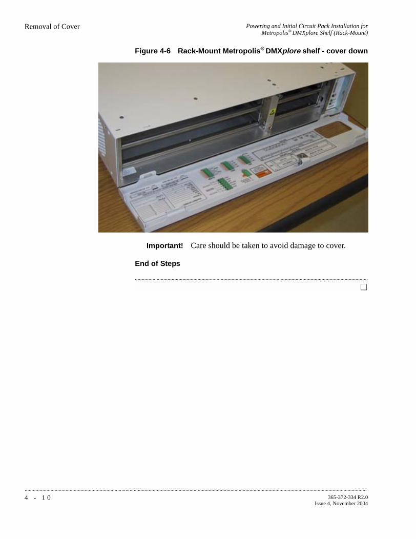
...........................................................................................................................................................................................................................................................
Powering and Initial Circuit Pack Installation forMetropolis® DMXplore Shelf (Rack-Mount)
Removal of Cover
4 - 1 0 365-372-334 R2.0Issue 4, November 2004
Figure 4-6 Rack-Mount Metropolis® DMXplore shelf - cover down
Important! Care should be taken to avoid damage to cover.
End of Steps
...........................................................................................................................................................................

Powering and Initial Circuit Pack Installation forMetropolis® DMXplore Shelf (Rack-Mount)
Initial Circuit Pack Installation
...........................................................................................................................................................................................................................................................
4 - 1 1365-372-334 R2.0Issue 4, November 2004
............................................................................................................................................................................................................................................................
Initial Circuit Pack Installation
Description This section provides instructions for installing, BUT NOT fully seating, circuit packs into the Metropolis® DMXplore shelf. After circuit packs have been unpacked, they may be placed in their respective slots in the Metropolis® DMXplore shelf but NOT FULLY ENGAGED IN THE BACKPLANE CONNECTOR. The circuit packs will be fully installed (seated) in the section, Circuit Pack Installation (page 5-5).
Important! If office alarms are connected, it is advisable to disconnect the office alarm cable while performing the procedures in this section to prevent spurious alarms from being reported. Reconnect the office alarm cable after completion of all testing.
CAUTION199M Apparatus Blanks are required in an unequipped Main-2 slot to provide proper air flow for cooling.
199L Apparatus Blanks are required in an unequipped C Function Unit slot to provide proper air flow for cooling.
CAUTIONTo protect against damage due to electrostatic discharge, a properly grounded ESD wrist strap must be worn when handling equipment.
VLNC1 (SYSCTL)Installation
Follow this procedure to install the VLNC1 (SYSCTL) circuit pack into the Metropolis® DMXplore shelf.
Step 1 Remove the SYSCTL circuit pack from the packing material.
...........................................................................................................................................................................
Step 2 Identify the lower right-hand slot on the Metropolis® DMXplore shelf. See Figure 4-2, Rack-Mount Metropolis® DMXplore Shelf Front View (page 4-7).

...........................................................................................................................................................................................................................................................
Powering and Initial Circuit Pack Installation forMetropolis® DMXplore Shelf (Rack-Mount)
Initial Circuit Pack Installation
4 - 1 2 365-372-334 R2.0Issue 4, November 2004
...........................................................................................................................................................................
Step 3 Holding the SYSCTL upright in your hand, turn the circuit pack 90 degrees to the right and place the SYSCTL circuit pack into the lower right-hand slot on the Metropolis® DMXplore shelf. Do NOT engage the circuit pack in the backplane connector.
...........................................................................................................................................................................
Step 4 Check off the appropriate box in Appendix E, Installation Checklist.
End of Steps
...........................................................................................................................................................................
Main OLIU Installation Follow this procedure to install the VLNC6 OC-3/16DS1, VLNC5 OC-3/16DS1/2DS3, VLNC25 OC12/16DS1/2DS3 and VLNC26 OC12/16DS1 Main OLIU circuit packs in the Metropolis® DMXplore shelf.
Step 1 Remove the first Main OLIU circuit pack from the packing material.
...........................................................................................................................................................................
Step 2 Identify the large, lower left hand slot on the Metropolis® DMXplore shelf. See Figure 4-2, Rack-Mount Metropolis® DMXplore Shelf Front View (page 4-7).
...........................................................................................................................................................................
Step 3 Holding the Main 1 circuit pack upright in your hand, turn the circuit pack 90 degrees to the right and place the Main OLIU circuit pack into the large, lower left hand slot on the Rack-Mount Metropolis®
DMXplore shelf. Do NOT engage the circuit pack in the backplane connector.
...........................................................................................................................................................................
Step 4 Are you installing a second main pack?
Important! If the Main 2 slot is to remain unequipped, install a 199M apparatus blank to provide proper air flow for cooling.
If... Then...
Yes Proceed to Step 5
No Proceed to Step 8

Powering and Initial Circuit Pack Installation forMetropolis® DMXplore Shelf (Rack-Mount)
Initial Circuit Pack Installation
...........................................................................................................................................................................................................................................................
4 - 1 3365-372-334 R2.0Issue 4, November 2004
...........................................................................................................................................................................
Step 5 Remove the second Main OLIU from the packing material.
Important! When installing two Main OLIUs, both circuit packs must be the same type, either both VLNC5s, VLNC6s, VLNC25s or VLNC26s.
...........................................................................................................................................................................
Step 6 Identify the top left slot on the Rack-Mount Metropolis® DMXplore shelf. See Figure 4-2, Rack-Mount Metropolis® DMXplore Shelf Front View (page 4-7).
...........................................................................................................................................................................
Step 7 Holding the Main 2 circuit pack upright in your hand, turn the circuit pack 90 degrees to the right and place the Main OLIU circuit pack into the large, upper left hand slot of the Rack-Mount Metropolis®
DMXplore shelf. Do NOT engage the circuit pack in the backplane connector.
...........................................................................................................................................................................
Step 8 Check off the appropriate box in Appendix E, Installation Checklist.
End of Steps
10/100 T Fast EthernetInstallation
Follow this procedure if you are installing a VLNC15 10/100 T Fast Ethernet circuit pack.
Step 1 Remove the VLNC15 10/100 BaseT FE circuit pack from the packing material.
Step 1 Identify the unequipped Function Group-C slot on the upper right-hand side of the shelf. Refer to Figure 4-2, Rack-Mount Metropolis®
DMXplore Shelf Front View (page 4-7) for details.
...........................................................................................................................................................................
Step 2 Holding the VLNC15 FE circuit pack upright in your hand, turn the circuit pack 90 degrees to the right and place the circuit pack into the Function Group-C slot. Rack-Mount Metropolis® DMXplore shelf. Do NOT engage the circuit pack in the backplane connector.

...........................................................................................................................................................................................................................................................
Powering and Initial Circuit Pack Installation forMetropolis® DMXplore Shelf (Rack-Mount)
Initial Circuit Pack Installation
4 - 1 4 365-372-334 R2.0Issue 4, November 2004
...........................................................................................................................................................................
Step 3 Check off the appropriate box in Appendix E, Installation Checklist.
...........................................................................................................................................................................
199L Apparatus BlankInstallation
Follow this procedure to install 199L Apparatus Blank into the Metropolis® DMXplore shelf.
Important! If not installing a VLNC15 FE circuit pack in Function Group-C, an 199L Apparatus Blank is required.
Step 1 Identify the unequipped Function Group-C slot on the upper right-hand side.
...........................................................................................................................................................................
Step 2 Remove the 199L Apparatus Blank from the packing material.
...........................................................................................................................................................................
Step 3 Place the 199L Apparatus Blank into the unequipped C slot on the shelf. Do NOT engage the blank pack in the backplane connector.
...........................................................................................................................................................................
Step 4 Check off the appropriate box in Appendix E, Installation Checklist.
End of Steps
...........................................................................................................................................................................

P A R Tx v
365-372-334 R2.0Issue 4, November 2004
...........................................................................................................................................................................................................................................................
Part II: Metropolis® DMXplore Access Multiplexer Stand-Alone Installation Tests
........................................................................................................................................................................Overview
Part II covers downloading software to the Metropolis® DMXplore Access Multiplexer and then intallation of circuit packs. This section also covers installation and operational tests.
• Chapter 5, Software Download and Circuit Pack Installation
• Chapter 6, Installation Tests
• Chapter 7, Operational Tests
..................................................................................................................

...........................................................................................................................................................................................................................................................
Metropolis® DMXplore Access Multiplexer Stand-AloneInstallation Tests
P A R T x v i
365-372-334 R2.0Issue 4, November 2004
5 - 1365-372-334 R2.0Issue 4, November 2004
............................................................................................................................................................................................................................................................
5 Software Download and Circuit Pack Installation
Purpose This chapter provides the procedures for initial software download and use of the craft interface terminal (CIT).
...........................................................................................................................................................................
Contents This chapter provides information on the following topics:
Software Installation 5-4
Circuit Pack Installation 5-5
Use of WaveStar® CIT Software 5-8
A Short Tour of the Command Builder 5-14
Circuit Pack Firmware Version Verification 5-18
Metropolis® DMXplore Shelf Initialization 5-205-20
5-18
5-14
5-8
5-5
5-4

...........................................................................................................................................................................................................................................................
Software Download and Circuit Pack Installation
5 - 2 365-372-334 R2.0Issue 4, November 2004
Tools, Test Equipment andAccessories
Listed below are the required tools, test equipment and accessories.
PC Minimum Requirements
• Windows® NT (with SP5 for Y2K compliance), Windows® 2000
or Windows® XP Operating Systems
• 128 MByte of RAM (minimum for 1 system view), 256 MByte recommended (up to 5 system views)
• 139 MByte Virtual Memory (minimum), 267 MByte recommended.
• SVGA monitor set to 800x600 resolution or greater, with 256 colors (1024x768, 16 million colors recommended)
• 250 MByte memory available on hard drive (minimum), 600 MByte Recommended (for all graphical packages).
• CD-ROM drive
• 10/100 BaseT LAN interface (network interface card, NIC)
• Pentium 2, 266 MHz Processor (minimum), Pentium III, 500MHz recommended.
Important! Minimum requirements are sufficient to run two to three System GUI views, unless otherwise noted. Recommended
Quantity Required Description Comments
1 Y Personal Computer (PC) See PC Minimum Requirements below.
1 Y
CIT Interface Cable(848748869)
8-ft. long RJ45 to 9-pin D-sub serial cable.
LAN 10BASE-T (Cross-over)
Allows for direct connection between the PC LAN card and the CTL LAN slot. See Table 1-17, LAN 10BASE-T Cross-over Cable Connections (page 1-47) for Comcode information.
LAN 10BASE-T (Straight-Through)
Allows for connection between the PC NIC card and a HUB. See Table 1-18, LAN 10BASE-T Straight-through Cable Connections (page 1-47) for Comcode information.
1 Y Software CD-ROM Verify latest software version is being used.
1 N Software Release Description (SRD)
Verify latest the issue of the SRD is being used, for the software that is used.

Software Download and Circuit Pack Installation
...........................................................................................................................................................................................................................................................
5 - 3365-372-334 R2.0Issue 4, November 2004
requirements are intended to be used as a general guideline to optimize WaveStar® CIT performance. As the CIT is used with multiple NE connections and multiple NE types, the processor type and speed as well as the memory size will all factor in to CIT performance.

...........................................................................................................................................................................................................................................................
Software Download and Circuit Pack InstallationSoftware Installation
5 - 4 365-372-334 R2.0Issue 4, November 2004
............................................................................................................................................................................................................................................................
Software Installation
Description Installation of the Metropolis® DMXplore software and WaveStar® CIT software is covered in detail in the Metropolis® DMXplore Software Release Description (SRD), which is provided with the software CD. To install the NE and CIT software, please follow the procedures in the "New Installation" section of the Metropolis® DMXplore Access Multiplexer Software Release Description.
Important! When the software installation is complete check off the appropriate box in Appendix E, Installation Checklist.
Software Installation Software installation is accomplished by performing the "New Installation" section in the Software Release Description (SRD) which is shipped with the software CD. Software download requires an MS-DOS*compatible personal computer (PC), and either a CIT interface cable for connecting the PC to the RS232 connector on the faceplate of the SYSCTL (VLNC1) circuit pack or a LAN cross-over cable for connecting the PC to the LAN connector on the faceplate of the SYSCTL.
...........................................................................................................................................................................
* Registered trademark of Microsoft Corporation.

Software Download and Circuit Pack InstallationCircuit Pack Installation
...........................................................................................................................................................................................................................................................
5 - 5365-372-334 R2.0Issue 4, November 2004
............................................................................................................................................................................................................................................................
Circuit Pack Installation
Description This section provides instructions and the recommended order for installing (fully-seating) the circuit packs in the Metropolis®
DMXplore shelf. The procedures in this section assume that the System Controller, VLNC1 is installed and software has been successfully downloaded as described in the "New installation" section of the Metropolis® DMXplore Access Multiplexer Software Release Description.
Locations for circuit packs are shown in Figure 3-2, Wall-Mount Metropolis® DMXplore Shelf (page 3-8) for a Wall-Mount shelf and Figure 4-2, Rack-Mount Metropolis® DMXplore Shelf Front View (page 4-7) for the Rack-Mount shelf.
Important! Circuit packs are keyed to prevent being inserted into the wrong shelf position.
CAUTIONWhen installing the circuit packs, be careful to insert them straight to avoid damaging the backplane pins.
A properly grounded ESD wrist strap MUST be worn when handling circuit packs.
When a circuit pack is installed, its FAULT LED will light for several seconds then extinguish.

...........................................................................................................................................................................................................................................................
Software Download and Circuit Pack InstallationCircuit Pack Installation
5 - 6 365-372-334 R2.0Issue 4, November 2004
Circuit Pack InstallationProcedure
Step 1 If applicable, fully insert the MAIN 1 OLIU circuit pack and then MAIN 2 OLIU circuit pack into the shelf.
Important! If installing two MAIN OLIUs, both circuit packs must be the same type, either both VLNC5s, VLNC6s, VLNC25s or VLNC26s.
Important! Unlatch the circuit pack and using a gentle steady pressure on both ends of the circuit pack, slide the circuit pack into the slot until it is fully seated. Then close the faceplate latch.
...........................................................................................................................................................................
Step 2 If the Main 2 slot is to remain unequipped, fully seat the 199M Apparatus Blank in the slot.
Important! Unlatch the circuit pack and using a gentle steady pressure on both ends of the circuit pack, slide the circuit pack into the slot until it is fully seated. Then close the faceplate latch.
...........................................................................................................................................................................
Step 3 Connect OUT to IN on the MAIN-1 OLIU of the Metropolis®
DMXplore shelf using an optical fiber jumper cable. Refer to Appendix B, Fiber Cleaning for proper fiber cleaning instructions.
Connect OUT to IN on the MAIN-2 OLIU of the Metropolis®
DMXplore shelf using an optical fiber jumper cable.
Result: After a few minutes the flashing FAULT LEDs extinguishes on each OLIU circuit pack. The FAULT and the CR/MJ LEDs light on the SYSCTL due to DCC alarms created by optically looping the OLIUs. These SYSCTL LEDs remain lighted until the DCC is disabled in the section labeled Clearing Alarms (page 6-7).
...........................................................................................................................................................................
Step 4 Fully seat the VLNC15 10/100 Base T FE circuit pack if equipped or the 199L Apparatus Blank in the function group C slot.
Important! Unlatch the circuit pack and using a gentle steady pressure on both ends of the circuit pack, slide the circuit pack into the slot until it is fully seated. Then close the faceplate latch.

Software Download and Circuit Pack InstallationCircuit Pack Installation
...........................................................................................................................................................................................................................................................
5 - 7365-372-334 R2.0Issue 4, November 2004
...........................................................................................................................................................................
Step 5 If there are any FAULT or flashing LEDs on any of the inserted circuit packs other than the SYSCTL, press the UPD/INIT push-button on the SYSCTL circuit pack.
Result: The operation of the UPD/INIT push-button on the SYSCTL circuit pack will update the system and should clear any flashing or FAULT LEDs on any of the low speed circuit packs.
Important! There will still be Solid FAULT and CR/MJ LEDs on the SYSCTL at this time. These alarms will be cleared in Clearing Alarms (page 6-7) of Chapter 6, Installation Tests.
...........................................................................................................................................................................
Step 6 If FAULT LEDs remain lit on any of the inserted circuit packs log into shelf and retrieve alarms using the RTRV-ALM command and refer to the Metropolis® DMXplore Access Multiplexer Alarm Messages and Trouble Clearing Guide for procedures for addressing the problem.
...........................................................................................................................................................................
Step 7 Any other alarms will be cleared later on in Clearing Alarms (page 6-7) of Chapter 6, Installation Tests.
...........................................................................................................................................................................
Step 8 Check off the appropriate box in Appendix E, Installation Checklist.
End of Steps
...........................................................................................................................................................................
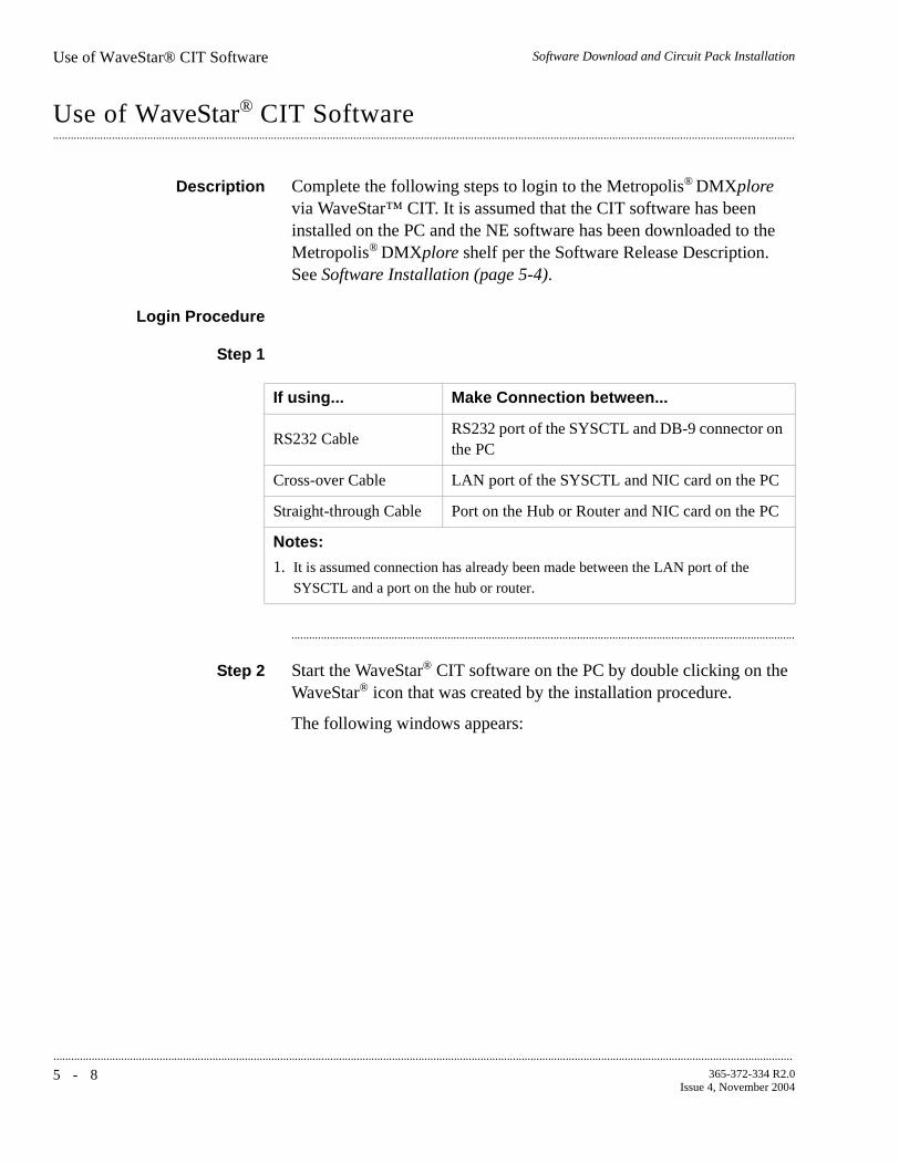
...........................................................................................................................................................................................................................................................
Software Download and Circuit Pack InstallationUse of WaveStar® CIT Software
5 - 8 365-372-334 R2.0Issue 4, November 2004
............................................................................................................................................................................................................................................................
Use of WaveStar® CIT Software
Description Complete the following steps to login to the Metropolis® DMXplore via WaveStar™ CIT. It is assumed that the CIT software has been installed on the PC and the NE software has been downloaded to the Metropolis® DMXplore shelf per the Software Release Description. See Software Installation (page 5-4).
Login Procedure
Step 1
...........................................................................................................................................................................
Step 2 Start the WaveStar® CIT software on the PC by double clicking on the WaveStar® icon that was created by the installation procedure.
The following windows appears:
If using... Make Connection between...
RS232 CableRS232 port of the SYSCTL and DB-9 connector on the PC
Cross-over Cable LAN port of the SYSCTL and NIC card on the PC
Straight-through Cable Port on the Hub or Router and NIC card on the PC
Notes:
1. It is assumed connection has already been made between the LAN port of the
SYSCTL and a port on the hub or router.

Software Download and Circuit Pack InstallationUse of WaveStar® CIT Software
...........................................................................................................................................................................................................................................................
5 - 9365-372-334 R2.0Issue 4, November 2004
Figure 5-1 WaveStar® CIT Banner
Figure 5-2 WaveStar® CIT Login Prompt
...........................................................................................................................................................................
Step 3 Enter the following in the Login window:
User ID: LUC01Password: LUC+01
Note: User ID and password are case sensitive.
The above User ID and Password are the default, if they have been changed, use the current User ID and Password.
If the login bypass functionality was selected during installation the
WaveStar® CIT login prompt will not appear. Continue to the next step.
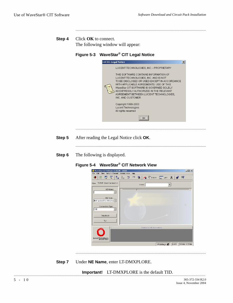
...........................................................................................................................................................................................................................................................
Software Download and Circuit Pack InstallationUse of WaveStar® CIT Software
5 - 1 0 365-372-334 R2.0Issue 4, November 2004
...........................................................................................................................................................................
Step 4 Click OK to connect.The following window will appear:
Figure 5-3 WaveStar® CIT Legal Notice
...........................................................................................................................................................................
Step 5 After reading the Legal Notice click OK.
...........................................................................................................................................................................
Step 6 The following is displayed.
Figure 5-4 WaveStar® CIT Network View
...........................................................................................................................................................................
Step 7 Under NE Name, enter LT-DMXPLORE.
Important! LT-DMXPLORE is the default TID.

Software Download and Circuit Pack InstallationUse of WaveStar® CIT Software
...........................................................................................................................................................................................................................................................
5 - 1 1365-372-334 R2.0Issue 4, November 2004
...........................................................................................................................................................................
Step 8 Under NE Type click on the drop down menu arrow and choose Metropolis (TM) DMXplore from the drop down list.
...........................................................................................................................................................................
Step 9 Under Connection Type, click on the drop down menu arrow and select Serial if physically connected to the RS232 port or OSI if physically connected to the LAN port of the system controller.
...........................................................................................................................................................................
Step 10 Click on the TL1 button. The following screen will appear
Figure 5-5 TL1 View Type Selection
...........................................................................................................................................................................
Step 11 Choose Command Builder.
...........................................................................................................................................................................
Step 12 If connecting using OSI, the following screen will appear. Otherwise skip to Step 14.

...........................................................................................................................................................................................................................................................
Software Download and Circuit Pack InstallationUse of WaveStar® CIT Software
5 - 1 2 365-372-334 R2.0Issue 4, November 2004
Figure 5-6 OSI Connection Type Selection
...........................................................................................................................................................................
Step 13 Select TL1 Maintenance (TL1 Alarms, Events and Command Responses) and click OK.
...........................................................................................................................................................................
Step 14 The following screen appears:
Figure 5-7 Network Element Login Prompt
...........................................................................................................................................................................
Step 15 Enter the Login for the shelf:Default parameters are LUC01 for User ID and DMXPLR2.5G for the password (both are case sensitive). Then select OK. The following screens appears:

Software Download and Circuit Pack InstallationUse of WaveStar® CIT Software
...........................................................................................................................................................................................................................................................
5 - 1 3365-372-334 R2.0Issue 4, November 2004
Figure 5-8 Command Builder and Response Windows:
...........................................................................................................................................................................
Step 16 Check off the appropriate box in Appendix E, Installation Checklist.
...........................................................................................................................................................................
End of Steps

...........................................................................................................................................................................................................................................................
Software Download and Circuit Pack InstallationA Short Tour of the Command Builder
5 - 1 4 365-372-334 R2.0Issue 4, November 2004
............................................................................................................................................................................................................................................................
A Short Tour of the Command Builder
Description This section illustrates to the user the features of the TL1 Command Builder.
The Command Builder window contains two main sections: the Commands section which lists the TL1 commands available; and the Parameters section that contains the parameters available for the command highlighted in the Commands section.
Important! Some commands where parameters are mutually exclusive are listed twice in the Commands section with the parameters divided between the two command listings.
Example: ent-t1(pst) for setting the primary state of the port andent-t1(sb) for setting the spec block parameters of
the port.
Figure 5-9 ent-t1 (sb): Screen 1
The Command Builder window also contains a line showing the command being built and a Send button to send that command to the NE.

Software Download and Circuit Pack InstallationA Short Tour of the Command Builder
...........................................................................................................................................................................................................................................................
5 - 1 5365-372-334 R2.0Issue 4, November 2004
The first parameter displayed in most command’s Parameters section is the aid. This is the access identifier, which is the address of the port, slot, or entity for which the command is intended. See the 365-372-335, Metropolis® DMXplore Access Multiplexer, TL1 Message Details for a complete list and description of aids.
In the Parameters section any item enclosed in brackets {} has an associated drop down menu listing all available options. Double clicking inside the brackets will display the drop down. Selecting an item in the drop down will change the display in the Parameters section to that item and change the command line being built.
Important! The Command Builder shows all available aids, parameters, and options. Some may not be valid due to software load, equipage, or setup of the NE.
Figure 5-10 ent-t1 (sb): Screen 2

...........................................................................................................................................................................................................................................................
Software Download and Circuit Pack InstallationA Short Tour of the Command Builder
5 - 1 6 365-372-334 R2.0Issue 4, November 2004
When the command can set a number of parameters, they can be selected and added to the command line by using the Shift click (holding down the Shift key and right clicking the mouse) or Ctrl click (holding down the Ctrl key and right clicking the mouse) methods.
Important! Make sure all changes to parameter options using drop down menus are made prior to selecting multiple parameters using the above methods.
Figure 5-11 ent-t1 (sb): Screen 3

Software Download and Circuit Pack InstallationA Short Tour of the Command Builder
...........................................................................................................................................................................................................................................................
5 - 1 7365-372-334 R2.0Issue 4, November 2004
Some parameters in the Parameters section are displayed in square brackets [ ]. These must be edited by the user on the command line itself to set the proper values. When editing the parameter the square brackets must be removed from the command line.
Important! All selections in the Parameters section must be made before any editing is done on the command line. If a parameter is selected on the Parameters section after editing the command line the editing will be lost.
Figure 5-12 ed-dat: Screen 1
The command line can be changed using the Windows copy (Ctrl c), paste (Ctrl v), and cut (Ctrl x) keystrokes.
Previous commands sent to the NE can be accessed by clicking in the command line and then using the up and down arrow keys. The command can then be resent by clicking on the send button.

...........................................................................................................................................................................................................................................................
Software Download and Circuit Pack InstallationCircuit Pack Firmware Version Verification
5 - 1 8 365-372-334 R2.0Issue 4, November 2004
............................................................................................................................................................................................................................................................
Circuit Pack Firmware Version Verification
Description This section provides instructions verifying that firmware versions on the circuit packs in the Metropolis® DMXplore shelf. The procedures in this section assume that the SYSCTL is installed and software has been successfully downloaded and the circuit packs have been installed in the shelf as described in the preceding sections.
...........................................................................................................................................................................
Circuit Pack FirmwareVersion Verification
Procedure
Step 1 Log on to the Metropolis® DMXplore shelf using the CIT software as described in the Use of WaveStar® CIT Software (page 5-8).
...........................................................................................................................................................................
Step 2 Use the scroll bar in the Command Builder window to scroll down to the rtrv-eqpt command.
...........................................................................................................................................................................
Step 3 Click on the rtrv-eqpt command.
Result: A command similar to the following example should be displayed in the command window to the left of the Send button.
Example: rtrv-eqpt:LT-DMXPLORE:all:1;
...........................................................................................................................................................................
Step 4 Click Send to issue the command.
Result: The Response Window will display an output similar to the following:
rtrv-eqpt:LT-DMXPLORE:all:1;
LT-DMXPLORE 93-10-26 16:42:11M 1 COMPLD "main-1::TYPE=OC-3/16DS1,APP=VLNC6,CLEI=,ECI=,SLN=,VRSN="1.0.1" "main-2::TYPE=OC-3/16DS1,APP=VLNC6,CLEI=,ECI=,SLN=,VRSN="1.0.1" "sysctl::TYPE=SYSCTL,APP=VLNC1,SSN=S1-1,CLEI=,ECI=,SLN=,VRSN=1.0.0” "shelf::TYPE=DMXplore,APP=,CLEI=,ECI=,SLN=";

Software Download and Circuit Pack InstallationCircuit Pack Firmware Version Verification
...........................................................................................................................................................................................................................................................
5 - 1 9365-372-334 R2.0Issue 4, November 2004
...........................................................................................................................................................................
Step 5 For each circuit pack listed in the Response Window output note the VRSN= number were displayed and compare it to the table of Firmware Versions in Chapter four of the Software Release Description (SRD).
...........................................................................................................................................................................
Step 6 On any circuit pack where the VRSN= number did not match the version number for it in the Firmware Version table in the SRD reseat that circuit pack and wait 15 minutes and perform next step, otherwise proceed to Step 9.
...........................................................................................................................................................................
Step 7 Resend the rtrv-eqpt command.
...........................................................................................................................................................................
Step 8 Compare the VRSN= number again for the circuit pack just re-seated and if it still does not match the table, refer to 365-372-333, Metropolis® DMXplore Access Multiplexer, Alarm Messages and Trouble Clearing Guide for detailed troubleshooting procedures.
...........................................................................................................................................................................
Step 9 Check off the appropriate box in Appendix E, Installation Checklist.
End of Steps
...........................................................................................................................................................................

...........................................................................................................................................................................................................................................................
Software Download and Circuit Pack InstallationMetropolis® DMXplore Shelf Initialization
5 - 2 0 365-372-334 R2.0Issue 4, November 2004
............................................................................................................................................................................................................................................................
Metropolis® DMXplore Shelf Initialization
Description This section provides instructions for initializing the Metropolis®
DMXplore shelf, to insure that all circuit pack databases are correct for the current shelf and software release. The procedures in this section assume that the SYSCTL is installed and software has been successfully downloaded and the circuit packs have all been installed in the shelf as described in the preceding sections.
Shelf InitializationProcedure
Step 1 Log on to the Metropolis® DMXplore shelf using the CIT software as described in the Use of WaveStar® CIT Software (page 5-8).
...........................................................................................................................................................................
Step 2 Use the scroll bar in the Command Builder window to scroll down to the init-sys command.
...........................................................................................................................................................................
Step 3 Click on the init-sys command.
...........................................................................................................................................................................
Step 4 Under the Parameters section, <SYSCTLAID>, click on all[!!! SERVICE AFFECTING !!!].
...........................................................................................................................................................................
Step 5 Under the Parameters section, <PH>.
Double click on {3} and choose the phase value of 9.
Result: A command similar to the following example should be displayed in the command window to the left of the Send button.
Example: init-sys:LT-DMXPLORE:all[!!! SERVICE AFFECTING !!!]:1::9;
...........................................................................................................................................................................
Step 6 In the command window to the left of the Send button highlight and delete the following portion of the command:
[!!! SERVICE AFFECTING !!!]

Software Download and Circuit Pack InstallationMetropolis® DMXplore Shelf Initialization
...........................................................................................................................................................................................................................................................
5 - 2 1365-372-334 R2.0Issue 4, November 2004
Result: A command similar to the following example should be displayed in the command window to the left of the Send button.
Example: init-sys:LT-DMXPLORE:all:1::9;
...........................................................................................................................................................................
Step 7 Click Send to issue the command.
Result: The Response Window will display an output similar to the following:
LT-DMXPLORE 03-09-23 16:10:20A 9 REPT DBCHG "TIME=16-11-27, DATE=03-09-23:INIT-SYS"
;
Result: After a few minutes shelf will reset and end the CIT session. The Response Window will display an output similar to the following:
LT-DMXPLORE 03-09-23 16:10:44M 1 DENYSRSD/* Status Remote Session Dropped (sent by T-TD) */
;
...........................................................................................................................................................................
Step 8 Check off the appropriate box in Appendix E, Installation Checklist.
End of Steps
...........................................................................................................................................................................

...........................................................................................................................................................................................................................................................
Software Download and Circuit Pack InstallationMetropolis® DMXplore Shelf Initialization
5 - 2 2 365-372-334 R2.0Issue 4, November 2004

6 - 1365-372-334 R2.0Issue 4, November 2004
............................................................................................................................................................................................................................................................
6 Installation Tests
............................................................................................................................................................................................................................................................
Overview
Purpose The purpose of this section is to verify proper transmission cabling installation and Release 2 functionality as well as the associated functionality of the Metropolis® DMXplore shelf.
For end-to-end turn-up and testing procedures, refer to 365-372-332, Metropolis® DMXplore Access Multiplexer User Operations Guide (UOG).
Important! Due to the repetitive nature of the following tests, the CIT command builder is used for command generation.
...........................................................................................................................................................................
Contents This chapter provides information on the following topics:
LBO Software Settings 6-4
Clearing Alarms 6-7
Local Equipment and Cross-connect Tests 6-9
LED Test 6-166-16
6-9
6-7
6-4

...........................................................................................................................................................................................................................................................
Installation TestsOverview
6 - 2 365-372-334 R2.0Issue 4, November 2004
Tools, Test Equipment andAccessories
Listed below are the required tools, test equipment and accessories
For complete listing see Part I or Part II.
Quantity Required Description Comments
1 Y Screwdriver(s) A screwdriver(s) with the appropriate head(s) is (are) required for securing the mounting screws, repositioning the mounting brackets, and installing the interfacing cables.
1 Y ESD Wrist Strap A wrist strap must be worn when handling circuit packs. Use the electrostatic discharge (ESD) jack provided on the shelf.
1 Y DS1 Error Rate Test Set A DS1 error rate test set is required for testing of DS1 cabling. A T-BERD 2209 or equivalent is recommended.
1 or 2 LC-type Optical Fiber Jumper (108918269)
Optical fiber jumpers with LC-type connectors are required to optically loop the Metropolis®
DMXplore shelf for test purposes. 1 fiber is needed for main card.
1 Y Personal Computer (PC) See PC Minimum Requirements (page 6-3).
1 Y
CIT Interface Cable(848748869)
8-ft. long RJ45 to 9-pin D-sub serial cable.
LAN 10BASE-T (Cross-over)
Allows for direct connection between the PC LAN card and the CTL LAN slot. See Table 1-17, LAN 10BASE-T Cross-over Cable Connections (page 1-47) for Comcode information.
LAN 10BASE-T (Straight-Through)
Allows for connection between the PC NIC card and a HUB. See Table 1-18, LAN 10BASE-T Straight-through Cable Connections (page 1-47) for Comcode information.

Installation TestsOverview
...........................................................................................................................................................................................................................................................
6 - 3365-372-334 R2.0Issue 4, November 2004
PC Minimum Requirements
Before beginning this procedure check PC Minimum Requirements (page 5-2) to ensure the PC you are using meets the minimum requirements necessary.
...........................................................................................................................................................................

...........................................................................................................................................................................................................................................................
Installation TestsLBO Software Settings
6 - 4 365-372-334 R2.0Issue 4, November 2004
............................................................................................................................................................................................................................................................
LBO Software Settings
Description This section provides instructions for setting the software Line Build Out (LBO) for the DS1 cabling and requires that the SYSCTL and main circuit packs be installed and that software has been downloaded.
...........................................................................................................................................................................
Setting LBO Values Follow this procedure to set the LBOs for DS1 and DS3 interfaces.
Step 1 Log on to the Metropolis® DMXplore shelf using the CIT software as described in the .
...........................................................................................................................................................................
Step 2 Refer to the following table of cable lengths and LBO values. Determine the LBO value corresponding to the DS1 cables installed.
...........................................................................................................................................................................
Step 3 Use the scroll bar in the Command Builder window to scroll down to the ent-t1(sb) command.
...........................................................................................................................................................................
Step 4 Click on the ent-t1(sb) command.
...........................................................................................................................................................................
Step 5 Under the Parameters section, <T1AID>, click on {a}-{1}-{1}.
LBO Value Distance (feet)
Cable Type 1161A
20 0 - 133 (default)
40 133 - 267
60 267 - 420
80 420 - 533
100 533 - 655

Installation TestsLBO Software Settings
...........................................................................................................................................................................................................................................................
6 - 5365-372-334 R2.0Issue 4, November 2004
...........................................................................................................................................................................
Step 6 Under the Parameters section, <T1SB>, click on LBO={20}.
Double click on {20} and choose the LBO value determined in Step 2.
Result: A command similar to the following example will be displayed in the command window to the left of the Send button.
Example: ent-t1:lt-dmxplore:a-1-1:ctag:::LBO=20;
...........................................................................................................................................................................
Step 7 Change aid parameter in the command line from a-1-1 to a-all.
Example: ent-t1:lt-dmxplore:a-all:ctag:::LBO=20;
...........................................................................................................................................................................
Step 8 Click Send to issue the command.
Result: The Response Window will display the command followed by a COMPLD indication.
DS3/EC1
Set DS3 LBO values as follows
...........................................................................................................................................................................
Step 9 Refer to the following table of cable lengths and LBO values. Determine the LBO value corresponding to the DS3 cables installed
...........................................................................................................................................................................
10 Use the scroll bar in the Command Builder window to scroll down to the ent-t3(sb) command.
...........................................................................................................................................................................
11 Click on the ent-t3(sb) command.
LBO Value Distance (Feet)
Cable Type 735A and 734D
IN 0 - 65 (default)
OUT > 65

...........................................................................................................................................................................................................................................................
Installation TestsLBO Software Settings
6 - 6 365-372-334 R2.0Issue 4, November 2004
...........................................................................................................................................................................
12 Under the Parameters section, <T3AID>, click on {b}-{1}.
• Double click on {b} and choose the Function Group B.
• Double click on {1} and choose all.
...........................................................................................................................................................................
13 Under the Parameters section, <T3SB>, click on LBO={IN}.
Double click on {IN} and choose the LBO value determined in Step 9.
Result: A command similar to the following example should be displayed in the command window to the left of the Send button.
Example: ent-t3:lt-dmxtend:b-all:ctag:::LBO=IN;
...........................................................................................................................................................................
14 Click Send to issue the command.
Result: The Response Window should display the command followed by a COMPLD indication.
...........................................................................................................................................................................
15 Check off the appropriate box in Appendix E, Installation Checklist.
End of Steps

Installation TestsClearing Alarms
...........................................................................................................................................................................................................................................................
6 - 7365-372-334 R2.0Issue 4, November 2004
............................................................................................................................................................................................................................................................
Clearing Alarms
Description In order to clear standing alarms the Metropolis® DMXplore synchronization will be provisioned as "Free Running". The DCC will be disabled in order to prevent DCC alarms from being generated due to the optical loopback on the main OLIUs.
Step 1 Use the scroll bar in the Command Builder window to scroll down to the set-syncn(free run) command
...........................................................................................................................................................................
Step 2 Click on the set-syncn(free run) command.
Result: The set-sync:lt-dmxplore:all:ctag::frng; command will be displayed in the command window to the left of the Send button.
...........................................................................................................................................................................
Step 3 Click Send to issue the command.
Result: The Response Window will display the command followed by a COMPLD indication.
...........................................................................................................................................................................
Step 4 Use the scroll bar in the Command Builder window to scroll down to the ent-fecom command.
...........................................................................................................................................................................
Step 5 Click on the ent-fecom command.
...........................................................................................................................................................................
Step 6 Under the Parameters section, <FECOMAID>, click on dcc-m-1.

...........................................................................................................................................................................................................................................................
Installation TestsClearing Alarms
6 - 8 365-372-334 R2.0Issue 4, November 2004
...........................................................................................................................................................................
Step 7 Under the Parameters section, <FECOMSB>, click on COM={ENABLED}.Double click on {ENABLED} and choose DISABLED
Result: A command similar to the following example will be displayed in the command window to the left of the Send button.
Example: ent-fecom:lt-dmxplore:dcc-m-1:ctag:::COM=DISABLED;
...........................................................................................................................................................................
Step 8 Click Send to issue the command.
Result: The Response Window will display the command followed by a COMPLD indication.
...........................................................................................................................................................................
Step 9 If there are any FAULT LEDs on or flashing, press the UPD/INIT push-button on the SYSCTL circuit pack.
...........................................................................................................................................................................
Step 10 If FAULT LEDs remain lit on any of the inserted circuit packs retrieve alarms using the RTRV-ALM command and refer to the Metropolis®
DMXplore Access Multiplexer Alarm Messages and Trouble Clearing Guide for procedures for addressing the problem.
...........................................................................................................................................................................
Step 11 Leave the office alarm cable disconnected until all procedures and testing have been completed.
...........................................................................................................................................................................
Step 12 Check off the appropriate box in Appendix E, Installation Checklist.
End of Steps
...........................................................................................................................................................................

Installation TestsLocal Equipment and Cross-connect Tests
...........................................................................................................................................................................................................................................................
6 - 9365-372-334 R2.0Issue 4, November 2004
............................................................................................................................................................................................................................................................
Local Equipment and Cross-connect Tests
Description The tests in this section verify the proper operation of the circuit packs and the circuit pack positions in the Metropolis® DMXplore shelf. It verifies proper cabling from the Metropolis® DMXplore to the access panel or connecting equipment. The shelf must successfully pass this test before testing any other feature of the Metropolis® DMXplore.
It is assumed that Chapter 3, Powering and Initial Circuit Pack Installation for Metropolis® DMXplore Shelf (Wall-Mount) or Chapter 4, Powering and Initial Circuit Pack Installation for Metropolis®
DMXplore Shelf (Rack-Mount) is complete and the Metropolis®
DMXplore shelf has fiber loopback cables on the Main OLIUs, with far-end communication (see ent-fecom TL1 command) parameter disabled and synchronization set to free-running.
On initial installation/turn-up of Metropolis® DMXplore there are default cross-connects. No cross-connects will need to be entered for these tests.
Important! After completing this test, isolate and correct any incorrect wiring or isolate and replace any failed units. If any cabling is corrected or units replaced, repeat the Local Equipment and cross-connect tests until the units pass without failures.
CAUTION
...........................................................................................................................................................................
A properly grounded ESD wrist strap MUST be worn when handling circuit packs.
WARNINGUnterminated optical connectors may emit laser radiation. Do not view beam with optical instruments.

...........................................................................................................................................................................................................................................................
Installation TestsLocal Equipment and Cross-connect Tests
6 - 1 0 365-372-334 R2.0Issue 4, November 2004
DS1 Testing Procedure Perform the following steps to verify backplane cabling to A/D function slot of the access panel.
Cabling to DS1 connectors located on the access panel are via backplane connections. If a main pack is installed, DS1 cabling will need to be tested.
This procedure requires the use of a DS1 test set.
Important! The access panel requires a RJ-45 connector for DS1 inputs, a cable that will connect from the RJ-45 to the test set is required to complete this testing.
Step 1 Set the DS1 test set to transmit and receive a Quasi-Random Sequence Signal (QRSS) with B8ZS formatting.
...........................................................................................................................................................................
Step 2 Connect a cable from the DS1 test set to the associated DS1 port of the A/D Group on the access panel.
Requirement: The DS1 test set will indicate it is receiving an error free QRSS signal with B8ZS formatting.
Important! By default, DS1 cross connections have already been made.
If an error free signal is not received:
• Verify that the DS1 line coding format is set to B8ZS using the rtrv-t1 command
• Verify that the LBOs are set according to cable length using the rtrv-t1 command (see Setting LBO Values (page 6-4).
• Check DS1 cabling for proper connections.
DS1 Facility LoopbackTesting
Facility Loopback testing allows the installer to verify the electrical cabling to the Metropolis® DMXplore shelf. When the shelf is cabled to other DS1 terminating equipment, it will be necessary to contact the Customer Network Control Center and have a signal established at the port under test, in order to complete the loopback testing.
Step 1 With the DS1 test set still connected to the port under test, establish a loopback with the opr-lpbk-t1:lt-dmxplore:a-1-1-1:ctag::,,,facility; command.

Installation TestsLocal Equipment and Cross-connect Tests
...........................................................................................................................................................................................................................................................
6 - 1 1365-372-334 R2.0Issue 4, November 2004
...........................................................................................................................................................................
Step 2 Click the Send button.
Result: The Response Window should display the command followed by a COMPLD message. A facility loopback will exist on the port issued by the command.
...........................................................................................................................................................................
Step 3 Once the loopback is up, a test signal shall be generated at the DS1 test set which will verify the cabling is correct.
...........................................................................................................................................................................
Step 4 While observing error free transmission, grasp the DS1 cable about 2 inches from the RJ45 connector head and gently tug the cable.
Result: If any errors are detected while performing this "wiggle" test, the RJ45 connector must be cut off and replaced.
If an error free signal is not received:
• Check the LBO settings using the rtrv-t1 command.
• Verify that the pack is provisioned for the framing format being sent from the test set, B8Zs or AMI. (rtrv-t1)
• Check the DS1 cabling for proper connections.
...........................................................................................................................................................................
Step 5 Once the test is complete, remove the loopback. Use the scroll bar in the Command Builder window to scroll down to the rls-lpbk-t1 command.
Result: A command similar to rls-lpbk-t1:lt-dmxplore:a-1-1-1-1:ctag::,,,facility;
...........................................................................................................................................................................
Step 6 Click the Send button.
Result: The Response Window should display the command followed by a COMPLD message. A facility loopback will no longer exist on the port issued by the command.
...........................................................................................................................................................................
Step 7 Remove the test set connections from the associated port on the access panel.

...........................................................................................................................................................................................................................................................
Installation TestsLocal Equipment and Cross-connect Tests
6 - 1 2 365-372-334 R2.0Issue 4, November 2004
...........................................................................................................................................................................
Step 8 Verify that an alarm is present on the port that the test set connections have been removed from. Use the rtrv-alm-all command in the Command Builder window.
...........................................................................................................................................................................
Step 9 Repeat entire procedure on each of the remaining DS1 tributaries of function group B.
...........................................................................................................................................................................
Step 10 Use the scroll bar in the Command Builder window to scroll down to the upd-sys command.
...........................................................................................................................................................................
Step 11 Click on the upd-sys command.
...........................................................................................................................................................................
Step 12 Click Send to issue the command.
Result: This command will remove alarms generated by removing the test signals from the DSX-1.
...........................................................................................................................................................................
Step 13 Check off the appropriate box in Appendix E, Installation Checklist.
End of Steps
DS3 Testing Procedure Perform the following steps to verify backplane cabling to B-Group function slot of the access panel.
Cabling to DS3 connectors located on the access panel are via backplane connections. If a VLNC5 (OC3/16DS1/2DS3) or VLNC25 (OC12/16DS1/2DS3) main pack is installed, DS3 cabling will need to be tested.
Important! This procedure requires the use of a DS3 test set.
Step 1 Set the DS3 test set to transmit and receive a valid signal.
...........................................................................................................................................................................
Step 2 Connect an input and output cable from the DS3 test set to the associated input and output of the DS3 port on the access panel.

Installation TestsLocal Equipment and Cross-connect Tests
...........................................................................................................................................................................................................................................................
6 - 1 3365-372-334 R2.0Issue 4, November 2004
Requirement: The DS3 test set will indicate it is receiving an error free signal.
Important! By default, DS3 cross connections have already been made. If an error free signal is not received, check for cross-connections with the rtrv-crs-sts1 command.
Important! If an error free signal is not received, check DS3 cabling for proper connections.
DS3 Facility LoopbackTesting
Facility Loopback testing allows the installer to verify the electrical cabling to the Metropolis® DMXplore shelf. When the shelf is cabled to other DS3 terminating equipment, it will be necessary to contact the Customer Network Control Center and have a signal established at the port under test, in order to complete the loopback testing.
Step 1 With the DS3 test set still connected to the port under test, establish a loopback with the opr-lpbk-t3:lt-dmxplore:b-1:ctag::,,,facility; command.
...........................................................................................................................................................................
Step 2 Click the Send button.
Result: The Response Window should display the command followed by a COMPLD message. A facility loopback will exist on the port issued by the command.
...........................................................................................................................................................................
Step 3 Once the loopback is up, a test signal shall be generated at the DS3 test set which will verify the cabling is correct.
...........................................................................................................................................................................
Step 4 While observing error free transmission, grasp the DS3 cable about 2 inches from the BNC connector head and gently rotate (twist) the cable in a clockwise and counterclockwise direction about 45 degrees (gently).
Result: If any errors are detected while performing this "wiggle" test, the BNC connector must be cut off and replaced.
If an error free signal is not received:
• Check the LBO settings using the rtrv-t3 command.

...........................................................................................................................................................................................................................................................
Installation TestsLocal Equipment and Cross-connect Tests
6 - 1 4 365-372-334 R2.0Issue 4, November 2004
• Verify that the pack is provisioned for the framing format being sent from the test set, CBIT or M13. (rtrv-t3)
• Check the DS3 cabling for proper connections.
...........................................................................................................................................................................
Step 5 Once the test is complete, remove the loopback. Use the scroll bar in the Command Builder window to scroll down to the rls-lpbk-t3 command.
Result: A command similar to rls-lpbk-t3:lt-dmxplore:b-1:ctag::,,,facility;
...........................................................................................................................................................................
Step 6 Click the Send button.
Result: The Response Window should display the command followed by a COMPLD message. A facility loopback will no longer exist on the port issued by the command.
...........................................................................................................................................................................
Step 7 Remove the test set connections from the associated port on the access panel.
...........................................................................................................................................................................
Step 8 Verify that an alarm is present on the port that the test set connections have been removed from. Use the rtrv-alm-all command in the Command Builder window.
...........................................................................................................................................................................
Step 9 Repeat entire procedure on each of the remaining DS3 tributaries of function group B.
...........................................................................................................................................................................
Step 10 Use the scroll bar in the Command Builder window to scroll down to the upd-sys command.
...........................................................................................................................................................................
Step 11 Click on the upd-sys command.
...........................................................................................................................................................................
Step 12 Click Send to issue the command.

Installation TestsLocal Equipment and Cross-connect Tests
...........................................................................................................................................................................................................................................................
6 - 1 5365-372-334 R2.0Issue 4, November 2004
Result: This command will remove alarms generated by removing the test signals from the DSX.
...........................................................................................................................................................................
Step 13 Check off the appropriate box in Appendix E, Installation Checklist.
End of Steps
...........................................................................................................................................................................

...........................................................................................................................................................................................................................................................
Installation TestsLED Test
6 - 1 6 365-372-334 R2.0Issue 4, November 2004
............................................................................................................................................................................................................................................................
LED Test
Description This test verifies proper operation of all LEDs on the Metropolis®
DMXplore circuit packs. Operation of all the LEDs is necessary to assist in trouble isolation.
Important! If there are any LED failures, determine if the problem is with the circuit pack or shelf and replace the faulty unit.
...........................................................................................................................................................................
Procedure
Step 1 Use the scroll bar in the Command Builder window to scroll down to the test-led command.
...........................................................................................................................................................................
Step 2 Click on the test-led command.
The test-led:lt-dmxplore:all:ctag::1; command will be displayed in the command window to the left of the Send button.
...........................................................................................................................................................................
Step 3 Click Send to issue the command.
Result: The Response Window will display the command followed by a COMPLD indication.
Result: All LEDs on the shelf will light for 10 seconds, then extinguish for 10 seconds, and then the proper LEDs will light to indicate the current status of the shelf.
...........................................................................................................................................................................
Step 4 Check off the appropriate box in Appendix E, Installation Checklist.
End of Steps
...........................................................................................................................................................................

7 - 1365-372-334 R2.0Issue 4, November 2004
............................................................................................................................................................................................................................................................
7 Operational Tests
............................................................................................................................................................................................................................................................
Overview
Purpose This section provides instructions to test protection switching and the non-transmission cabling. This section is not intended to replace acceptance test procedures. If problems are encountered, refer to 365-372-333, Metropolis® DMXplore Access Multiplexer, Alarm Messages and Trouble Clearing Guide for detailed troubleshooting procedures.
...........................................................................................................................................................................
Contents This chapter provides information on the following topics:
Office Alarm Test 7-4
Automatic Protection Switching and Alarm Test 7-9
Manual Switching Tests 7-12
Miscellaneous (Environmental) Discrete Telemetry Test 7-14
Final Operations 7-187-18
7-14
7-12
7-9
7-4

...........................................................................................................................................................................................................................................................
Operational TestsOverview
7 - 2 365-372-334 R2.0Issue 4, November 2004
Tools, Test Equipment andAccessories
Listed below are the tools, test equipment and accessories necessary to perform the procedures in this section.
Quantity Required Description Comments
Y Screwdriver(s) A screwdriver(s) with the appropriate head(s) is (are) required for securing the mounting screws, repositioning the mounting brackets, installing the interfacing cables, and for setting the circuit breakers to the OFF position.
1 Y ESD Wrist Strap A wrist strap must be worn when handling circuit packs. Use the electrostatic discharge (ESD) jack provided on the shelf.
1 N Multimeter (Optional) The voltmeter must be capable of measuring DC voltage in the 40 to 60 volt range. The use of the voltmeter is optional since the shelf will alarm or shut down if the proper voltage is not supplied.
1 Y DS1 Error Rate Test Set A DS1 error rate test set is required for testing of DS1 cabling. A T-BERD 211 or equivalent is recommended.
1 or 2 Y LC-type Optical Fiber Jumper (108918269)
Optical fiber jumpers with LC-type connectors are required to optically loop the Metropolis® DMXplore shelf for test purposes. 1 fiber is needed for main card.
1 Y Personal Computer (PC) See PC Minimum Requirements (page 7-3).
1 Y
CIT Interface Cable(848748869)
8-ft. long RJ45 to 9-pin D-sub serial cable.
LAN 10BASE-T (Cross-over)
Allows for direct connection between the PC LAN card and the CTL LAN slot. See Table 1-17, LAN 10BASE-T Cross-over Cable Connections (page 1-47) for Comcode information.
LAN 10BASE-T (Straight-Through)
Allows for connection between the PC NIC card and a HUB. See Table 1-18, LAN 10BASE-T Straight-through Cable Connections (page 1-47) for Comcode information.

Operational TestsOverview
...........................................................................................................................................................................................................................................................
7 - 3365-372-334 R2.0Issue 4, November 2004
PC Minimum Requirements
Before beginning this procedure check PC Minimum Requirements (page 5-2) to ensure the PC you are using meets the minimum requirements necessary.
Safety Instructions Important! All precautions should be observed when handling fiber.
WARNINGUnterminated optical connectors may emit laser radiation. Do not view beam with optical instruments.
CAUTIONThe operational tests in this section are run only in an out-of-service mode of operation. Office alarms will normally be connected only during the office alarm test to prevent constant alarms throughout this section.

...........................................................................................................................................................................................................................................................
Operational TestsOffice Alarm Test
7 - 4 365-372-334 R2.0Issue 4, November 2004
............................................................................................................................................................................................................................................................
Office Alarm Test
Description This test verifies proper operation and wiring of the office alarms in a network equipment building system (NEBS) environment.
Audible and visual reporting of critical, major, minor alarms will be verified.
Prerequisite The following is a list of items to verify before beginning tests in this section.
• The Metropolis® DMXplore Main OLIUs should be optically looped from the previous section. Verify that the Metropolis®
DMXplore shelf is clear of all alarms (only green LEDs are lighted) prior to and after completing this test.
• The office alarm cable will be temporarily connected during this procedure. Table 7-1, Office Alarm Connections (page 7-5) lists the office alarms connections.
• It is a requirement that alarms on the Metropolis® DMXplore do not affect and are not affected by other equipment via office alarm connections. During this test, the alarm state of other equipment connected to the same office alarms as the Metropolis® DMXplore should be examined after creating or clearing every alarm.
• A properly grounded ESD wrist strap must always be worn while handling circuit packs.
• This test should be performed on all shelves where office alarm reporting is required.
• After completing the office alarm test, the Metropolis®
DMXplore office alarms should be disconnected from the office alarm system for the remainder of the test procedures. This will prevent the office alarms from being activated while performing the other tests in this section.
...........................................................................................................................................................................

Operational TestsOffice Alarm Test
...........................................................................................................................................................................................................................................................
7 - 5365-372-334 R2.0Issue 4, November 2004
Procedure
Step 1 Use the scroll bar in the Command Builder window to scroll down to the ent-rr command.
Important! For DS1 ports, rr is t1 and for DS3 ports, rr is t3.
...........................................................................................................................................................................
Step 2 Click on the ent-rr command.
...........................................................................................................................................................................
Step 3 Under the Parameters section, <rrAID>, click on {x}-{1}-{1} for DS1 parameters and {x}-{1} for DS3 parameters.
Important! For DS1 ports, x is a and for DS3 ports, x is b.
Table 7-1 Office Alarm Connections
Pin# Color Name Designation
1
2
BL
BL-W
CR/MJ Visual
CR/MJ Visual RYCRMJV1
3
4
O
O-W
CR/MJ Audible
CR/MJ Audible RYCRMJA1
5
6
G
G-W
MN/ABN Visual
MN/ABN Visual RYMNABNV1
7
8
BR
BR-W
MN/ABN Audible
MN/ABN Audible RYMNABNA1

...........................................................................................................................................................................................................................................................
Operational TestsOffice Alarm Test
7 - 6 365-372-334 R2.0Issue 4, November 2004
...........................................................................................................................................................................
Step 4 Under the Parameters section, <rrSB>, click on NTFCNCDE={NA}.
Double click on {NA} and choose the MN.
Result: A command similar to the following example will be displayed in the command window to the left of the Send button.
Example: ent-rr:lt-dmxplore:x-1-1:ctag:::NTFCNCDE=MN;
...........................................................................................................................................................................
Step 5 Change aid parameter in the command line from x-1-1 to x-all.
Example: ent-rr:lt-dmxplore:x-all:ctag:::NTFCNCDE=MN;
...........................................................................................................................................................................
Step 6 Click Send to issue the command.
Result: The Response Window will display the command followed by a COMPLD indication.
...........................................................................................................................................................................
Step 7 Connect the office alarm cables to ALARM termination block on the access panel of the Metropolis® DMXplore shelf.
...........................................................................................................................................................................
Step 8 Introduce a valid DS1 or DS3 signal, then remove signal.
Requirement: Activated office alarms: MN/ABN visual, MN/ABN audible.
Important! Alarms will not be activated until the alarm delay time has passed. The default time is 2 seconds.
...........................................................................................................................................................................
Step 9 Press the ACO/TST push-button on the SYSCTL.
Result: Activated office alarm: MN/ABN visual, the MN/ABN audible alarm clears.
...........................................................................................................................................................................
Step 10 Reconnect valid DS1 or DS3 signal, and wait for alarms to clear.

Operational TestsOffice Alarm Test
...........................................................................................................................................................................................................................................................
7 - 7365-372-334 R2.0Issue 4, November 2004
...........................................................................................................................................................................
Step 11 Follow Steps 1 to 5 to provision notification code for all DS1 and/or DS3 ports to MJ
Example: ent-rr:lt-dmxplore:a-all:ctag:::NTFCNCDE=MJ;
Important! Select MJ instead of MN in Step 4.
...........................................................................................................................................................................
Step 12 Click Send to issue the command.
Result: The Response Window will display the command followed by a COMPLD indication.
...........................................................................................................................................................................
Step 13 Remove the valid DS1 or DS3 signal.
Result: Activated office alarms: CR/MJ visual, CR/MJ audible.
...........................................................................................................................................................................
Step 14 Press the ACO push-button on the SYSCTL.
Result: Activated office alarm: CR/MJ visual.The CR/MJ audible alarm clears.
...........................................................................................................................................................................
Step 15 Reconnect valid DS1 or DS3 signal, and wait for alarms to clear.
...........................................................................................................................................................................
Step 16 Follow Steps 1 to 5 to provision notification code for all ports to NA
Example: ent-rr:lt-dmxplore:a-all:ctag:::NTFCNCDE=NA;
Important! Select NA instead of MN in Step 4.
...........................................................................................................................................................................
Step 17 Click Send to issue the command.
Result: The Response Window will display the command followed by a COMPLD indication.

...........................................................................................................................................................................................................................................................
Operational TestsOffice Alarm Test
7 - 8 365-372-334 R2.0Issue 4, November 2004
...........................................................................................................................................................................
Step 18 Remove valid DS1 or DS3 signal, and issue an upd-sys command to clear LOS alarm.
...........................................................................................................................................................................
Step 19 Disconnect the office alarm cable connected in Step 7 for the remainder of the test procedures in this chapter.
...........................................................................................................................................................................
Step 20 Check off the appropriate box in Appendix E, Installation Checklist.
End of Steps
...........................................................................................................................................................................

Operational TestsAutomatic Protection Switching and Alarm Test
...........................................................................................................................................................................................................................................................
7 - 9365-372-334 R2.0Issue 4, November 2004
............................................................................................................................................................................................................................................................
Automatic Protection Switching and Alarm Test
Description This section provides the procedures for verifying the Metropolis®
DMXplore shelf automatic protection switching.
Note the following:
• These tests do NOT simulate circuit pack failures.
• The tests will verify proper alarm reporting and LED indica-tions when circuit packs are removed.
• This test assumes that two OLIU circuit packs have been installed.
• All protected circuit packs will be tested.
• A properly grounded wrist strap must always be worn while handling circuit packs.
• This test is performed with the Metropolis® DMXplore shelf optically looped back on itself (that is, with the OUT of the OLIU Main 1 looped to the IN of the OLIU Main 1, and the OUT of the OLIU Main 2 looped to the IN of the OLIU Main 2).
• Prior to performing each test, the shelf under test must be clear of all alarms (that is, only green LEDs are lit).
CAUTION
...........................................................................................................................................................................
A properly grounded ESD wrist strap MUST be worn when handling circuit packs.
WARNINGUnterminated optical connectors may emit laser radiation. Do not view beam with optical instruments.
...........................................................................................................................................................................

...........................................................................................................................................................................................................................................................
Operational TestsAutomatic Protection Switching and Alarm Test
7 - 1 0 365-372-334 R2.0Issue 4, November 2004
MAIN OLIU Switching Test Use this procedure to test the OC3 VLNC6 and VLNC5 Main OLIU circuit packs (use the OC3 commands) or the OC12 VLNC25 and VLNC26 Main OLIU circuit packs (use the OC12 commands).
Note: It is assumed that the protection scheme on the Main OLIU cir-cuit packs is 1+1, which is the default value.
Step 1 Connect Main-1 OUT to Main-2 IN, and Main-1 IN to Main-2 OUT using optical jumpers.
CAUTION
...........................................................................................................................................................................
LBOs may need to be installed prior to looping optical ports.
...........................................................................................................................................................................
Step 2 Establish a CIT session by following the procedure under Use of WaveStar® CIT Software (page 5-8) in Chapter 5, Software Download and Circuit Pack Installation.
...........................................................................................................................................................................
Step 3 Use the scroll bar in the Command Builder window to scroll down to the rtrv-oc3 or rtrv-oc12 command.
...........................................................................................................................................................................
Step 4 Click on the rtrv-oc3 or rtrv-oc12 command with main-1 for a <OC3AIDRTRV> parameter value.
...........................................................................................................................................................................
Step 5 Click Send to issue the command.
Result: The Response Window will display the command followed by a COMPLD indication as well as indicating whether Main 1 or Main 2 is the active OLIU.
...........................................................................................................................................................................
Step 6 Disconnect the optical fiber connected to the IN port of the OLIU that is the active receiver.
Result: The MN/ABN alarm LED will light on the SYSCTL and the FAULT LED will flash on the OLIU.

Operational TestsAutomatic Protection Switching and Alarm Test
...........................................................................................................................................................................................................................................................
7 - 1 1365-372-334 R2.0Issue 4, November 2004
...........................................................................................................................................................................
Step 7 Click Send to issue a second rtrv-oc3 or rtrv-oc12 command.
Result: The Response Window displays the command followed by a COMPLD indication as well as indicating that the OLIU that was active in the previous step is now "aps-line-fail" and the other OLIU is now "active".
...........................................................................................................................................................................
Step 8 Reconnect the optical fiber to the OLIU.
Result: After a short time, the MN/ABN alarm LEDs on the SYSCTL and the FAULT LED on the OLIU will extinguish.
...........................................................................................................................................................................
Step 9 Repeat Step 4 through Step 8 to verify a switch back to the OLIU that was originally active.
...........................................................................................................................................................................
Step 10 Check off the appropriate box in Appendix E, Installation Checklist.
End of Steps
...........................................................................................................................................................................

...........................................................................................................................................................................................................................................................
Operational TestsManual Switching Tests
7 - 1 2 365-372-334 R2.0Issue 4, November 2004
............................................................................................................................................................................................................................................................
Manual Switching Tests
Description This test will initiate switching commands from the CIT TL1 Command Builder and verify proper switching and LED indications. Use the OC3 commands for the VLNC5 or VLNC6 OLIU circuit packs and the OC12 commands for the VLNC25 or VLNC26 circuit packs.
Main OLIU Switch Test Important! By default VT1.5 cross-connects will exist on the DS1 ports and STS1 cross-connects will exist on the DS3 ports.
Step 1 Use the scroll bar in the Command Builder window to scroll down to the rtrv-oc3 or rtrv-oc12 command.
...........................................................................................................................................................................
Step 2 Click on the rtrv-oc3 or rtrv-oc12 command.
...........................................................................................................................................................................
Step 3 Click Send to issue the command.
Result: The Response Window will display the command followed by a COMPLD indication as well as indicating whether main-1-1 or main-2-1 is the active ring.
...........................................................................................................................................................................
Step 4 Use the scroll bar in the Command Builder window to scroll down to the opr-protnsw-oc3 or opr-protnsw-oc12 command.
...........................................................................................................................................................................
Step 5 Click on the opr-protnsw-oc3 or opr-protnsw-oc12 command.
...........................................................................................................................................................................
Step 6 If the active ring is Ring 2, change the m{1}-1-{1}-{1}-{1} parameter listed under the <VT1PROTN> for DS1 or <STS1PROTN> for DS3, column to m{2}-1-{1}-{1}-{1} by double clicking on 1 between the brackets { } and selecting 2 from the drop down window.
...........................................................................................................................................................................
Step 7 Double click on {LOCKOUT} under <PROTNSWCOCN> and select MAN.
Operational TestsManual Switching Tests
...........................................................................................................................................................................................................................................................
7 - 1 3365-372-334 R2.0Issue 4, November 2004
...........................................................................................................................................................................
Step 8 Click Send to issue the command.
Result: The Response Window will display the command followed by a COMPLD indication.
...........................................................................................................................................................................
Step 9 Use the scroll bar in the Command Builder window to scroll down to the rtrv-oc3 or rtrv-oc12 command.
...........................................................................................................................................................................
Step 10 Click on the rtrv-oc3 or rtrv-oc12 command.
...........................................................................................................................................................................
Step 11 Click Send to issue the command.
Requirement: The Response Window will display the command followed by a COMPLD indication as well as indicating that the OLIU that was active in Step 3 is no longer active and the other OLIU is now active.
...........................................................................................................................................................................
Step 12 Use the scroll bar in the Command Builder window to scroll down to and send the rls-protnsw-oc3 or rls-protnsw-oc12 command.
...........................................................................................................................................................................
Step 13 Repeat Step 4 through Step 11 to verify a switch back to the original OLIU.
...........................................................................................................................................................................
Step 14 Check off the appropriate box in Appendix E, Installation Checklist.
End of Steps
...........................................................................................................................................................................

...........................................................................................................................................................................................................................................................
Operational TestsMiscellaneous (Environmental) Discrete Telemetry Test
7 - 1 4 365-372-334 R2.0Issue 4, November 2004
............................................................................................................................................................................................................................................................
Miscellaneous (Environmental) Discrete Telemetry Test
Description Miscellaneous discrete telemetry access allows the maintenance center to control and monitor equipment co-located with the Metropolis®
DMXplore shelf. See Figure 7-1, Miscellaneous (Environmental) Discrete Functions (page 7-14). Perform this procedure for shelves that are cabled for miscellaneous discrete telemetry.
Figure 7-1 Miscellaneous (Environmental) Discrete Functions

Operational TestsMiscellaneous (Environmental) Discrete Telemetry Test
...........................................................................................................................................................................................................................................................
7 - 1 5365-372-334 R2.0Issue 4, November 2004
...........................................................................................................................................................................
MDI Test Procedure
Step 1 Determine which environmental inputs are to be monitored via the Metropolis® DMXplore shelf.
...........................................................................................................................................................................
Step 2 Verify that the miscellaneous discrete cables are connected to the MDI connector block on the Access Panel. See Figure 1-16, Miscellaneous Discrete Cable Connection (page 1-39)
...........................................................................................................................................................................
Step 3 Refer to Table 7-2, Miscellaneous (Environmental) Discrete Inputs Telemetry Connections (page 7-15) to determine the wire color of the cable lead associated with the environmental input to be tested.
...........................................................................................................................................................................
Step 4 At the far end of the cable, short the associated environmental input lead to the red-slate (R-S) Input Common lead.
...........................................................................................................................................................................
Step 5 Verify that the minor (MN/ABN) alarm lights on the SYSCTL.
Table 7-2 Miscellaneous (Environmental) Discrete Inputs Telemetry Connections
Pin# Color Designation Name
1
2
3
4
BL
BL-W
O
O-W
TLMI1
TLMOC
TLMI2
TLMOC
Env. Input - #1
Output Common
Env. Input - #2
Output Common
5
6
7
8
G
G-W
BR
BR-W
TLMI3
TLMOC
TLMI4
TLMOC
Env. Input - #3
Output Common
Env. Input - #4
Output Common
Note: Output commons are tied together internally. It is necessary only to connect one output common to a ground source.

...........................................................................................................................................................................................................................................................
Operational TestsMiscellaneous (Environmental) Discrete Telemetry Test
7 - 1 6 365-372-334 R2.0Issue 4, November 2004
...........................................................................................................................................................................
Step 6 Use the scroll bar in the Command Builder window to scroll down to the rtrv-alm-env command.
...........................................................................................................................................................................
Step 7 Click on the rtrv-alm-env command.
...........................................................................................................................................................................
Step 8 Click Send to issue the command.
Result: The Response Window will display the command followed by a COMPLD indication as well as indicating the correct environmental alarm has been activated.
...........................................................................................................................................................................
Step 9 Remove the short and verify that the minor (MN/ABN) alarm indication on the SYSCTL clears.
...........................................................................................................................................................................
Step 10 Repeat Step 3 through Step 9 for each environmental input being used.
...........................................................................................................................................................................
Step 11 Check off the appropriate box in Appendix E, Installation Checklist.
End of Steps
...........................................................................................................................................................................
MDO Test Procedure
Step 1 Determine which environmental outputs are to be activated via the Metropolis® DMXplore shelf.
...........................................................................................................................................................................
Step 2 Verify that the miscellaneous discrete cables are connected to the MDO connector block on the Access Panel. See Figure 1-16, Miscellaneous Discrete Cable Connection (page 1-39)
...........................................................................................................................................................................
Step 3 Use the scroll bar in the Command Builder window to scroll down to the opr-ext-cont command.

Operational TestsMiscellaneous (Environmental) Discrete Telemetry Test
...........................................................................................................................................................................................................................................................
7 - 1 7365-372-334 R2.0Issue 4, November 2004
...........................................................................................................................................................................
Step 4 Click on the opr-ext-cont command. Under the <OPREXTAID> double click on {1} and select control output to operate.
...........................................................................................................................................................................
Step 5 Click Send to issue the command.
Result: The Response Window will display the command followed by a COMPLD indication as well as indicating the correct control output has been activated.
...........................................................................................................................................................................
Step 6 Verify the correct control output was operated (e.g. generator, pump, etc.).
...........................................................................................................................................................................
Step 7 Click on the rtrv-ext-cont command. Under the <CONTROLAIDRTRV> double click on {all} and select control output to retrieve.
...........................................................................................................................................................................
Step 8 Click Send to issue the command.
...........................................................................................................................................................................
Step 9 Click on the rls-ext-cont command. Under the <OPREXTAID> double click on {1} and select control output to release.
...........................................................................................................................................................................
Step 10 Click Send to issue the command.
Result: The Response Window will display the command followed by a COMPLD indication as well as indicating the correct control output has been released.
Repeat Step 3 through Step 8 for each environmental input being used.
...........................................................................................................................................................................
Step 11 Check off the appropriate box in Appendix E, Installation Checklist.
End of Steps
...........................................................................................................................................................................

...........................................................................................................................................................................................................................................................
Operational TestsFinal Operations
7 - 1 8 365-372-334 R2.0Issue 4, November 2004
............................................................................................................................................................................................................................................................
Final Operations
Description The following procedure ensures that all test signals have been removed and the Metropolis® DMXplore shelf is alarm free and ready for network connection procedures.
Procedure
Step 1 Verify that no alarm LEDs are lit and no FAULT LED is lit on any circuit pack.
Important! Sending an upd-sys command will update the system database to reflect the current configuration and incoming signals.
If any alarm is present, refer to 365-372-333, Metropolis® DMXplore Access Multiplexer, Alarm Messages and Trouble Clearing Guide.
...........................................................................................................................................................................
Step 2 If desired, reconnect the office alarm cable at this time.
...........................................................................................................................................................................
Step 3 Check off the appropriate box in Appendix E, Installation Checklist.
End of Steps
...........................................................................................................................................................................

P A R Tx i x
365-372-334 R2.0Issue 4, November 2004
...........................................................................................................................................................................................................................................................
Part III: Metropolis® DMXplore Access Multiplexer Ring Setup and Testing
........................................................................................................................................................................Overview
This section starts the process of integrating the Metropolis®
DMXplore into the customer’s network. The section provides the procedures to connect inter-office fibers and verify DCC communications and path switching.
This section is comprised of the following chapters:
• Chapter 8, Ring Setup and Testing: Integration Procedures
..................................................................................................................

...........................................................................................................................................................................................................................................................
Metropolis® DMXplore Access Multiplexer Ring Setup andTesting
P A R T x x
365-372-334 R2.0Issue 4, November 2004

8 - 1365-372-334 R2.0Issue 4, November 2004
............................................................................................................................................................................................................................................................
8 Ring Setup and Testing: Integration Procedures
............................................................................................................................................................................................................................................................
Overview
Purpose This procedure is used to make fiber connections between nodes in a UPSR ring. It is not intended to replace acceptance test procedures. If problems are encountered, refer to 365-372-333, Metropolis®
DMXplore Access Multiplexer, Alarm Messages and Trouble Clearing Guide for detailed troubleshooting procedures.
...........................................................................................................................................................................
Contents This chapter provides information on the following topics:
Fiber Installation 8-4
OC-3/OC12 Optical Transmission Test 8-11
Automatic Protection Switching Test 8-13
Manual Switching Tests 8-15
Cover Installation Wall-Mount 8-19
Final Operations 8-238-23
8-19
8-15
8-13
8-11
8-4

...........................................................................................................................................................................................................................................................
Ring Setup and Testing: Integration ProceduresOverview
8 - 2 365-372-334 R2.0Issue 4, November 2004
Tools, Test Equipment andAccessories
Listed below are the tools, test equipment and accessories necessary to perform the procedures in this section.
Quantity Required Description Comments
1 Y Screwdriver(s) A screwdriver(s) with the appropriate head(s) is (are) required for securing the mounting screws, repositioning the mounting brackets, and installing the interfacing cables.
1 Y ESD Wrist Strap A wrist strap must be worn when handling circuit packs. Use the electrostatic discharge (ESD) jack provided on the shelf.
1 N Multimeter (Optional) The voltmeter must be capable of measuring DC voltage in the 40 to 60 volt range. The use of the voltmeter is optional since the shelf will alarm or shut down if the proper voltage is not supplied.
1 Y DS1 Error Rate Test Set A DS1 error rate test set is required for testing of DS1 cabling. A T-BERD 2209 or equivalent is recommended.
1 Y Personal Computer (PC) See PC Minimum Requirements (page 8-3).
1 Y
CIT Interface Cable(848748869)
8-ft. long RJ45 to 9-pin D-sub serial cable.
LAN 10BASE-T (Cross-over)
Allows for direct connection between the PC LAN card and the CTL LAN slot. See Table 1-17, LAN 10BASE-T Cross-over Cable Connections (page 1-47) for Comcode information.
LAN 10BASE-T (Straight-Through)
Allows for connection between the PC NIC card and a HUB. See Table 1-18, LAN 10BASE-T Straight-through Cable Connections (page 1-47) for Comcode information.

Ring Setup and Testing: Integration ProceduresOverview
...........................................................................................................................................................................................................................................................
8 - 3365-372-334 R2.0Issue 4, November 2004
PC Minimum Requirements
Before beginning this procedure check PC Minimum Requirements (page 5-2) to ensure the PC you are using meets the minimum requirements necessary.
Safety Instructions Important! All precautions should be observed when handling fiber.
WARNINGUnterminated optical connectors may emit laser radiation. Do not view beam with optical instruments.
CAUTIONThe operational tests in this section are run only in an out-of-service mode of operation. Office alarms will normally be connected only during the office alarm test to prevent constant alarms throughout this section.

...........................................................................................................................................................................................................................................................
Ring Setup and Testing: Integration ProceduresFiber Installation
8 - 4 365-372-334 R2.0Issue 4, November 2004
............................................................................................................................................................................................................................................................
Fiber Installation
Description This section is used to verify proper fiber connections between Metropolis® DMXplore nodes.
Prerequisite The following is a list of items to verify before beginning tests in this section.
• Two people are required to perform the end-to-end turn up in this section (one at each adjacent node).
• The Metropolis® DMXplore Main OLIUs should be optically looped from the previous section. Verify that the Metropolis®
DMXplore shelf is clear of all alarms (only green LEDs are lighted) prior to and after completing this test.
• CIT is still connected to the Metropolis® DMXplore and Command Builder is running.
• The office alarm cable will remain disconnected during this procedure.
CAUTION
...........................................................................................................................................................................
A properly grounded ESD wrist strap MUST be worn when handling circuit packs.
WARNINGUnterminated optical connectors may emit laser radiation. Do not view beam with optical instruments.
...........................................................................................................................................................................

Ring Setup and Testing: Integration ProceduresFiber Installation
...........................................................................................................................................................................................................................................................
8 - 5365-372-334 R2.0Issue 4, November 2004
Procedure The following procedures are performed at each end of the optical span being tested.
Step 1 Verify that the office alarm cabling to the ALARM terminal block on the access panel of the Metropolis® DMXplore shelf is disconnected. If the shelf to be tested is part of a multiple shelf bay arrangement, the office alarm cable connects to shelf 1.
...........................................................................................................................................................................
Step 2 At each DMXplore shelf, enter the shelf TID per the customer order or use LT-DMXPLORE-1 and LT-DMXPLORE-2 as defaults using the ENT-SYS command.
...........................................................................................................................................................................
Step 3 Use the scroll bar in the Command Builder window to scroll down to the dlt-crs-zzz command. Select x-1-all under <zzzAIDCRSSRC> and m-1-{1}-all under <zzzAIDCRSDST>.
Result: A command similar to the following example will be displayed in the command window to the left of the Send button.
Example: dlt-crs-vt1:lt-dmxplore:a-1-all,m-1-1-all:1::2WAYPR;
Important! For DS1, zzz is VT1, x is a.
...........................................................................................................................................................................
Step 4 Click Send to issue the command.
Result: All VT1.5 default cross connections on the shelf will be deleted.
...........................................................................................................................................................................
Step 5 If you have a VLNC5 or VLNC25 circuit packs in Main, you must delete the default DS3 cross-connects. Use the scroll bar in the Command Builder window to scroll down to the dlt-crs-zzz command. Select x-all under <zzzAIDCRSSRC> and m-1-all under <zzzAIDCRSDST>.
Result: A command similar to the following example will be displayed in the command window to the left of the Send button.
Example: dlt-crs-sts1:lt-dmxplore:b-all,m-1-all:1::2WAYPR;

...........................................................................................................................................................................................................................................................
Ring Setup and Testing: Integration ProceduresFiber Installation
8 - 6 365-372-334 R2.0Issue 4, November 2004
Important! For DS3, zzz is STS1, and x is b.
...........................................................................................................................................................................
Step 6 Click Send to issue the command.
Result: All STS1 default cross connections on the shelf will be deleted.
...........................................................................................................................................................................
Step 7 Use the scroll bar in the Command Builder window to scroll down to the ent-oc3(sb) or ent-oc12(sb)command.
...........................................................................................................................................................................
Step 8 Click on the ent-oc3(sb) or ent-oc12(sb) command. Under the <OCnSB> select Application={1+1}. Double click on {1+1} and select UPSR.
...........................................................................................................................................................................
Step 9 Click Send to issue the command.
Result: A command similar to the following example will be displayed in the command window to the left of the Send button.
Example: ent-oc3(oc12):lt-dmxplore:main-1:2:::application=UPSR;
...........................................................................................................................................................................
Step 10 Enable the RNESTAT at each node.
For Metropolis® Product family network elements, use the ENT-SYS command and highlight RNESTAT. Double click on {DISABLED} and select ENABLED.
...........................................................................................................................................................................
Step 11 Enable the AGNE on only one of nodes in the network.
If AGNE is a part of the Metropolis® Product family, at the AGNE use the ENT-SYS command and highlight AGNE. Double click on {NO} and select YES, then send the command.
...........................................................................................................................................................................
Step 12 Dress optical cables out of the shelf to the right side of the shelf if the shelf is a Wall-Mount Metropolis® DMXplore. If the shelf is the Rack-

Ring Setup and Testing: Integration ProceduresFiber Installation
...........................................................................................................................................................................................................................................................
8 - 7365-372-334 R2.0Issue 4, November 2004
Mount Metropolis® DMXplore Access Multiplexer, dress the optical cables to the left using the fiber management module.
...........................................................................................................................................................................
Step 13 Route the optical jumpers from the side of the shelf.
...........................................................................................................................................................................
Step 14 Establish verbal communications with the technician at the other end of the optical span.
...........................................................................................................................................................................
Step 15 At both ends of the optical span, remove protective covers from receive and transmit optical jumper cables and clean LC connectors.
Important! The Metropolis® DMXplore OLIUs require single-mode lightguide cable. Single-mode optical fibers connecting this shelf with the far-end shelf should not be connected to the OLIU until at least 45 seconds after an optical loopback is removed. It may take from 15 seconds to 3.5 minutes for the FAULT LEDs to stop flashing after the cables are connected, depending on the setting of the OC-3/OC-12 signal degrade threshold.
...........................................................................................................................................................................
Step 16 At both ends of the optical span, ensure that only the dual LC adapter is installed on the OLIU (no LBO).
Important! For Metropolis® DMXplore OC-3/OC12 UPSR ring configurations, optical fibers extend in two different directions to make up the ring. At each shelf (node) in the ring, the M1 OLIU will connect to the M2 OLIU in one adjacent node, and the M2 OLIU will connect to the M1 OLIU in the other adjacent node.
When the Metropolis® DMXplore is interfacing with other equipment such as a Metropolis® DMX Access Multiplexer at low-speeds (OC-3/OC12) using 1+1 protection, the Main 1 of the DMXplore will connect to the slot 1 of the function Group (e.g. A1, B1, C1, D1, or G1 for the Metropolis® DMX Access Multiplexer). The Main 2 of the DMXplore will connect to the slot 2 of the function Group (e.g. A2, B2, C2, D2, or G2 for the Metropolis® DMX Access Multiplexer).

...........................................................................................................................................................................................................................................................
Ring Setup and Testing: Integration ProceduresFiber Installation
8 - 8 365-372-334 R2.0Issue 4, November 2004
...........................................................................................................................................................................
Step 17 At each end of the optical spans, connect the optical fiber transmit cables to the OLIU OUT connectors.
...........................................................................................................................................................................
Step 18 At each end of the optical span, measure the optical power of the optical fiber receive cables using an optical power meter.
...........................................................................................................................................................................
Step 19 Select the appropriate LBO value required based on the received optical power measurement. Attenuate to the middle of the allowable optical receive power range. Refer to the following table for the DMXplore Main circuit pack receive levels.
...........................................................................................................................................................................
Step 20 Select the proper LBO based on the value required and the comcode as listed below.
...........................................................................................................................................................................
Step 21 Clean LC LBOs and install LBO assemblies in the OLIU IN connector.
...........................................................................................................................................................................
Step 22 At the far end, connect the input optical fiber to the proper OLIU IN connector.
Requirement: The FAULT LED on the OLIU extinguishes after approximately 10 seconds.
Optics Circuit Pack Received Power(dBM)
Long Reach (LR) Optics VLNC6 0 to -34.0
Long Reach (LR) Optics VLNC5 0 to -34.0
Long Reach (LR) Optics VLNC25 -7 to -30.5
Long Reach (LR) Optics VLNC26 -7 to -30.5
Code Comcode Loss (dB)
ABLCS-05.0 108279381 5
ABLCS-10.0 108279431 10
ABLCS-15.0 108279480 15
ABLCS-20.0 108279530 20

Ring Setup and Testing: Integration ProceduresFiber Installation
...........................................................................................................................................................................................................................................................
8 - 9365-372-334 R2.0Issue 4, November 2004
...........................................................................................................................................................................
Step 23 Verify that LBO has been installed at far end.
...........................................................................................................................................................................
Step 24 At the near end, connect the input optical fiber to the proper OLIU IN connector.
Requirement: The FAULT LED on the OLIU extinguishes after approximately 10 seconds.
...........................................................................................................................................................................
Step 25 Disconnect the fiber cable from the OUT connector on the OLIU at one end of the span. At the other end, verify that the associated FAULT LED is flashing, indicating a loss of signal. Reconnect the fiber and repeat the process for the other direction of transmission.
...........................................................................................................................................................................
Step 26 In order to enable communications with the adjacent Metropolis®
DMXplore nodes, execute the ent-fecom command for main 1 and main 2.
Select the following options for Main 1 based on work instructions:dcc-m{1}-1, COM=ENABLED, SIDE={US or NS}
Select the following options for Main 2 based on work instructions:dcc-m{2}-1, COM=ENABLED, SIDE={US or NS}
Important! If inconsistent DCC alarms are raised, US and NS settings may need to be swapped.
...........................................................................................................................................................................
Step 27 Verify proper shelf timing at each node using RTRV-SYNCN. To change timing modes use the SET-SYNCN command.
...........................................................................................................................................................................
Step 28 In order to verify proper communications with the adjacent Metropolis® DMXplore nodes, execute the following command from the Command Builder.
RTRV-MAP-NEIGHBOR
Result: The TIDs and NSAPs of adjacent nodes will be displayed along with the OLIU and port they are connected to.

...........................................................................................................................................................................................................................................................
Ring Setup and Testing: Integration ProceduresFiber Installation
8 - 1 0 365-372-334 R2.0Issue 4, November 2004
...........................................................................................................................................................................
Step 29 In order to verify proper network DCC communications, execute the following command from the Command Builder.
RTRV-MAP-NETWORK
Result: The TIDs and NSAPs of all the nodes in the TARP area will be displayed.
...........................................................................................................................................................................
Step 30 Perform steps in this procedure on all adjacent nodes in the ring.
...........................................................................................................................................................................
Step 31 After all connections and tests have been made, verify optical fiber cables are placed in the fiber slots on the left side of the shelf and properly routed in bay framework.
...........................................................................................................................................................................
Step 32 Check off the appropriate box in Appendix E, Installation Checklist.
End of Steps
...........................................................................................................................................................................

Ring Setup and Testing: Integration ProceduresOC-3/OC12 Optical Transmission Test
...........................................................................................................................................................................................................................................................
8 - 1 1365-372-334 R2.0Issue 4, November 2004
............................................................................................................................................................................................................................................................
OC-3/OC12 Optical Transmission Test
Procedure This procedure should be conducted when the Metropolis® DMXplore Access Multiplexer shelf is set to UPSR and connected end to end and not looped back on itself.
Step 1 Use the scroll bar in the Command Builder window to scroll down to the init-reg-all command.
...........................................................................................................................................................................
Step 2 Click on the init-reg-all command. Select all from the <Default AID> and double click on the 15-min within the <TMPERINIT> and select all.
...........................................................................................................................................................................
Step 3 Click Send to issue the command.
Result: The Response Window should display the command followed by a COMPLD indication.
...........................................................................................................................................................................
Step 4 Wait 15 minutes.
...........................................................................................................................................................................
Step 5 At the test location, enter the following command; replacing TID with that shelf’s TID:rtrv-pm-oc3/oc12:TID:main-1-1:ctag::,1-UP,,,15-MIN,ALL,;
Requirement: The Response Window indicates no transmission errors.
...........................................................................................................................................................................
Step 6 Repeat Step 1 page 11 thorough Step 5 page 11 for all Metropolis®
DMXplore shelves at the test location.
...........................................................................................................................................................................
Step 7 Repeat Step 1 page 11 three Step 5 page 11 for each node in the ring.

...........................................................................................................................................................................................................................................................
Ring Setup and Testing: Integration ProceduresOC-3/OC12 Optical Transmission Test
8 - 1 2 365-372-334 R2.0Issue 4, November 2004
...........................................................................................................................................................................
Step 8 Check off the appropriate box in Appendix E, Installation Checklist.
...........................................................................................................................................................................

Ring Setup and Testing: Integration ProceduresAutomatic Protection Switching Test
...........................................................................................................................................................................................................................................................
8 - 1 3365-372-334 R2.0Issue 4, November 2004
............................................................................................................................................................................................................................................................
Automatic Protection Switching Test
Description This section provides the procedures for verifying the Metropolis®
DMXplore shelf automatic and manual protection switching.
This test may be performed on the VLNC5, VLNC6, VLNC25 and VLNC26 circuit packs. Use the OC 3 commands for the VLNC5 and VLNC6 circuit packs and the OC12 commands for the VLNC25 and VLNC26 circuit packs.
Note the following:
• These tests do NOT simulate circuit pack failures.
• A properly grounded wrist strap must always be worn while handling circuit packs.
• Prior to performing each test, the shelf under test must be clear of all alarms (that is, only green LEDs are lighted).
...........................................................................................................................................................................
MAIN OLIU Switch Test
Step 1 There must be cross-connects present to complete this test. Enter VT1.5 cross connects with the ent-crs-vt1:lt-dmxplore:a-1-1-all,m-1-1-all:1::2WAYPR; command. Enter STS1 cross-connects with the ent-crs-sts1:lt-dmxplore:b-all,m-2-all:1::2WAYPR;
...........................................................................................................................................................................
Step 2 Click Send to issue the command.
Result: All VT1.5 and STS1 cross connections to the shelf will be entered followed with a COMPLD message.
...........................................................................................................................................................................
Step 3 Use the scroll bar in the Command Builder window to scroll down to the rtrv-state-path command.
...........................................................................................................................................................................
Step 4 Click on the rtrv-state-path command. Select m{1}-1-{all} under <STATEAIDRTRV>.
...........................................................................................................................................................................
Step 5 Click Send to issue the command.

...........................................................................................................................................................................................................................................................
Ring Setup and Testing: Integration ProceduresAutomatic Protection Switching Test
8 - 1 4 365-372-334 R2.0Issue 4, November 2004
Result: The Response Window should display the command followed by a COMPLD indication as well as indicating whether Ring 1 or Ring 2 is the active ring for each cross-connection.
Important! MAIN 1 OLIU is associated with Ring 1 and MAIN 2 OLIU is associated with Ring 2.
...........................................................................................................................................................................
Step 6 Disconnect the optical fiber connected to the IN port of the OLIU that is the active receiver.
Result: The NE and then MN/ABN alarm LED will light on the SYSCTL and the FAULT LED will flash on the OLIU.
...........................................................................................................................................................................
Step 7 Click Send to issue a second rtrv-state-path command.
Result: The Response Window will display the command followed by a COMPLD indication as well as indicating that the ring that was active in the previous step is now in signal-failure and the other ring is now active.
...........................................................................................................................................................................
Step 8 Reconnect the optical fiber to the OLIU.
Result: After a short time, the MN/ABN alarm LED on the SYSCTL and the FAULT LED on the OLIU will extinguish.
...........................................................................................................................................................................
Step 9 Repeat Step 4 page 13 through Step 8 page 14 to verify a switch back to the OLIU that was originally active.
...........................................................................................................................................................................
Step 10 Leave the cross-connects in the system to complete the next section Manual Switching Tests (page 8-15).
...........................................................................................................................................................................
Step 11 Check off the appropriate box in Appendix E, Installation Checklist.
End of Steps
...........................................................................................................................................................................
Ring Setup and Testing: Integration ProceduresManual Switching Tests
...........................................................................................................................................................................................................................................................
8 - 1 5365-372-334 R2.0Issue 4, November 2004
............................................................................................................................................................................................................................................................
Manual Switching Tests
Description This test will initiate switching commands from the CIT and verify proper switching and LED indications for a UPSR ring. This test may be performed on the VLNC5, VLNC6, VLNC25 and VLNC26 circuit packs. Use the OC 3 commands for the VLNC5 and VLNC6 circuit packs and the OC12 commands for the VLNC25 and VLNC26 circuit packs.
Main OLIU Switch Test Important! Cross-connects are required in order to perform manual switching tests.
Step 1 Verify the existence of cross-connections to the Main OLIU with the rtrv-crs-all command. If cross connections are not present use the ent-crs-vt1 or ent-crs-sts1 commands. Refer to Step 1 page 13.
...........................................................................................................................................................................
Step 2 Use the scroll bar in the Command Builder window to scroll down to the rtrv-state-path command. There must be a cross-connect present in order for this command to retrieve any information.
...........................................................................................................................................................................
Step 3 Click on the rtrv-state-path command.
...........................................................................................................................................................................
Step 4 Click Send to issue the command.
Result: The Response Window should display the command followed by a COMPLD indication as well as indicating whether Ring 1 or Ring 2 is the active ring for each cross-connection.
MAIN 1 OLIU is associated with Ring 1 and MAIN 2 OLIU is associated with Ring 2.
...........................................................................................................................................................................
Step 5 Use the scroll bar in the Command Builder window to scroll down to the opr-protnsw-rr command.
Important! The rate of the cross-connection is refered to as rr and should be modified to VT1, STS1 or STS3C depending on the application.

...........................................................................................................................................................................................................................................................
Ring Setup and Testing: Integration ProceduresManual Switching Tests
8 - 1 6 365-372-334 R2.0Issue 4, November 2004
...........................................................................................................................................................................
Step 6 Click on the opr-protnsw-rr command. Select m{1}-1-1.
...........................................................................................................................................................................
Step 7 If the active ring is Ring 2, change the m{1} parameter listed under the <rrAIDPROTN> column to m{2} by double clicking on 1 between the brackets { } and selecting 2 from the drop down window. Double click on the { LOCKOUT} under <PROTNSWSC> and select MAN.
Important! Where "rr" refers to the rate of the cross-connect (e.g. VT1.5, or STS1)
...........................................................................................................................................................................
Step 8 Click Send to issue the command.
Result: The Response Window should display the command followed by a COMPLD indication.
...........................................................................................................................................................................
Step 9 Use the scroll bar in the Command Builder window to scroll down to the rls-protnsw-rr command.
...........................................................................................................................................................................
Step 10 Click on the rls-protnsw-rr command. Under <rrAIDPROTN> select the AID pertaining to the ring that has the manual switch request.
...........................................................................................................................................................................
Step 11 Click Send to issue the command.
...........................................................................................................................................................................
Step 12 Use the rtrv-state-path command to verify desired switch state.
Important! The active path should now be different from what it was prior to the manual switch being issued.
...........................................................................................................................................................................
Step 13 Use the scroll bar in the Command Builder window to scroll down to the opr-protnsw-rr command.
Where "rr" refers to the rate of the cross connect (e.g. VT1.5, or STS1)

Ring Setup and Testing: Integration ProceduresManual Switching Tests
...........................................................................................................................................................................................................................................................
8 - 1 7365-372-334 R2.0Issue 4, November 2004
...........................................................................................................................................................................
Step 14 Click on the opr-protnsw-rr command.
...........................................................................................................................................................................
Step 15 If the active ring is Ring 2, change the m{1} parameter listed under the <rrAIDPROTN> column to m{2} by double clicking on 1 between the brackets { } and selecting 2 from the drop down window. Double click on the { LOCKOUT} under <PROTNSWSC> and select MAN.
Important! "rr" in <rrAIDPROTN> refers to the cross connect rate.
...........................................................................................................................................................................
Step 16 Use the scroll bar in the Command Builder window to scroll down to the rls-protnsw-rr command.
...........................................................................................................................................................................
Step 17 Click on the rls-protnsw-rr command. Under <rrAIDPROTN> select the AID pertaining to the ring that has the manual switch request.
...........................................................................................................................................................................
Step 18 Use the rtrv-state-path command to verify desired switch state.
Important! The active path should now be back to the original path prior to performing the two manual switches.
...........................................................................................................................................................................
Step 19 Click Send to issue the command.
...........................................................................................................................................................................
Step 20 Repeat Step 5 page 15 through Step 19 page 17 for every circuit.
...........................................................................................................................................................................
Step 21 Delete any VT1.5 cross connects with the dlt-crs-vt1:lt-dmxplore:a-1-all,m-1-1-all:1::2WAYPR; command. Delete STS1 cross-connects with the dlt-crs-sts1:lt-dmxplore:b-all,m-1-all:1::2WAYPR;
...........................................................................................................................................................................
Step 22 Click Send to issue the command.
Result: All VT1.5 and STS1 cross-connections to the shelf will be deleted followed with a COMPLD message.

...........................................................................................................................................................................................................................................................
Ring Setup and Testing: Integration ProceduresManual Switching Tests
8 - 1 8 365-372-334 R2.0Issue 4, November 2004
...........................................................................................................................................................................
Step 23 Check off the appropriate box in Appendix E, Installation Checklist.
End of Steps
...........................................................................................................................................................................
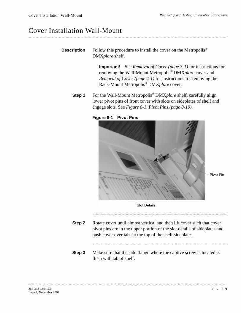
Ring Setup and Testing: Integration ProceduresCover Installation Wall-Mount
...........................................................................................................................................................................................................................................................
8 - 1 9365-372-334 R2.0Issue 4, November 2004
............................................................................................................................................................................................................................................................
Cover Installation Wall-Mount
Description Follow this procedure to install the cover on the Metropolis®
DMXplore shelf.
Important! See Removal of Cover (page 3-1) for instructions for removing the Wall-Mount Metropolis® DMXplore cover and Removal of Cover (page 4-1) for instructions for removing the Rack-Mount Metropolis® DMXplore cover.
Step 1 For the Wall-Mount Metropolis® DMXplore shelf, carefully align lower pivot pins of front cover with slots on sideplates of shelf and engage slots. See Figure 8-1, Pivot Pins (page 8-19).
Figure 8-1 Pivot Pins
...........................................................................................................................................................................
Step 2 Rotate cover until almost vertical and then lift cover such that cover pivot pins are in the upper portion of the slot details of sideplates and push cover over tabs at the top of the shelf sideplates.
...........................................................................................................................................................................
Step 3 Make sure that the side flange where the captive screw is located is flush with tab of shelf.

...........................................................................................................................................................................................................................................................
Ring Setup and Testing: Integration ProceduresCover Installation Wall-Mount
8 - 2 0 365-372-334 R2.0Issue 4, November 2004
...........................................................................................................................................................................
Step 4 Tighten captive screw. See Figure 8-2, Metropolis® DMXplore Shelf w. Cover (page 8-20).
Important! Care should be taken when installing the cover to avoid damage to slots details in shelf sideplates.
Figure 8-2 Metropolis® DMXplore Shelf w. Cover

Ring Setup and Testing: Integration ProceduresCover Installation Rack-Mount
...........................................................................................................................................................................................................................................................
8 - 2 1365-372-334 R2.0Issue 4, November 2004
............................................................................................................................................................................................................................................................
Cover Installation Rack-Mount
...........................................................................................................................................................................
Step 1 For the Rack-Mount Metropolis® DMXplore Access Multiplexer shelf, align the slots of the cover with the flange on the shelf. See Rack-Mount Cover Alignment (page 8-21).
...........................................................................................................................................................................
Step 2 Rotate the cover up and gently push down on tabs on cover to snap cover into place. See Snapping cover into place (page 8-22).
Figure 8-3 Rack-Mount Cover Alignment

...........................................................................................................................................................................................................................................................
Ring Setup and Testing: Integration ProceduresCover Installation Rack-Mount
8 - 2 2 365-372-334 R2.0Issue 4, November 2004
Figure 8-4 Snapping cover into place
Ring Setup and Testing: Integration ProceduresFinal Operations
...........................................................................................................................................................................................................................................................
8 - 2 3365-372-334 R2.0Issue 4, November 2004
............................................................................................................................................................................................................................................................
Final Operations
Description The following procedure ensures that all test signals and cross-connects have been removed and the Metropolis® DMXplore shelf is alarm free and ready for network connection procedures.
Procedure
Step 1 Use the scroll bar in the Command Builder window to scroll down to and Select the upd-sys command.
...........................................................................................................................................................................
Step 2 Click Send to issue the command.
Result: The Response Window should display the command followed by a COMPLD indication.
...........................................................................................................................................................................
Step 3 Verify that no alarm LEDs are lit and no FAULT LED is lit on any circuit pack.
Important! Sending an upd-sys command will update the system database to reflect the current configuration and incoming signals.
...........................................................................................................................................................................
Step 4 If any alarms are present, refer to 365-372-333, Metropolis® DMXplore Access Multiplexer, Alarm Messages and Trouble Clearing Guide.
Clear PM Registers The following steps will clear all the performance monitoring registers:
Step 1 Use the scroll bar in the Command Builder window to scroll down to the init-reg-all command.
...........................................................................................................................................................................
Step 2 Click on the init-reg-all command. Select all from the <DEFAULTAID> and double click on the 15-min under the <TMPERINIT> column and select all.

...........................................................................................................................................................................................................................................................
Ring Setup and Testing: Integration ProceduresFinal Operations
8 - 2 4 365-372-334 R2.0Issue 4, November 2004
...........................................................................................................................................................................
Step 3 Click Send to issue the command.
Result: The Response Window should display the command followed by a COMPLD indication.
...........................................................................................................................................................................
Step 4 If desired, reconnect the office alarm cable at this time.
...........................................................................................................................................................................
Step 5 If desired, bring the system back to default values with the init-sys:lt-dmxplore:sysctl:1::9; command.
Important! Since this will bring the system back to default values, DS1 and DS3 LBO values may need to be re-entered.
...........................................................................................................................................................................
Step 6 Check off the appropriate box in Appendix E, Installation Checklist.
End of Steps
...........................................................................................................................................................................

P A R Tx x v
365-372-334 R2.0Issue 4, November 2004
...........................................................................................................................................................................................................................................................
Part IV: Metropolis® DMXplore Access Multiplexer Supplementary Information and Installation Checklist
........................................................................................................................................................................Overview
This section provides supplementary information that is useful when installing the Metropolis® DMXplore system and using this Installation Manual.
The Installation Checklist is also contained in this part.
This section is comprised of the following appendixes:
• Appendix A, Laser Safety and Classifications
• Appendix B, Fiber Cleaning
• Appendix C, Installing Fiber Connectors and LBOs
• Appendix D, Backplane Pin Replacement
• Appendix E, Installation Checklist
• Appendix F, Fiber Labeling
• Glossary
• Index
..................................................................................................................

...........................................................................................................................................................................................................................................................
Metropolis® DMXplore Access Multiplexer SupplementaryInformation and Installation Checklist
P A R T x x v i
365-372-334 R2.0Issue 4, November 2004

A - 1365-372-334 R2.0Issue 4, November 2004
............................................................................................................................................................................................................................................................
A Laser Safety and Classifications
............................................................................................................................................................................................................................................................
Overview
Purpose This appendix provides laser safety information and precautions.
Contents This appendix provides information on the following topics:
Laser Safety A-2
Laser Product Classification A-5
Metropolis® DMXplore Optical Specifications A-7A-7
A-5
A-2

...........................................................................................................................................................................................................................................................
Laser Safety and ClassificationsLaser Safety
A - 2 365-372-334 R2.0Issue 4, November 2004
............................................................................................................................................................................................................................................................
Laser Safety
System design The Lucent Technologies system complies with FDA/CDRH 21 CFR 1040.10 and 1040.11 as a Class I and with IEC 60825-1 as a Class 1 Optical Fiber Telecommunication laser product. The system has been designed to ensure that the operating personnel is not endangered by laser radiation during normal system operation. The safety measures specified in the Food and Drug Administration’s Center for Devices and Radiological Health (FDA/CDRH) regulations and the international standards IEC-60825 or DIN/EN 60825 are met. Please also refer to Laser Product Classification (page -5).
Potential sources of danger Beware of the following potential sources of danger which will remain despite all safety measures taken:
• Laser radiation can cause damage to the skin and eyes.
• Laser radiation from optical transmission systems is in a wavelength range that is invisible to the human eye.

Laser Safety and ClassificationsLaser Safety
...........................................................................................................................................................................................................................................................
A - 3365-372-334 R2.0Issue 4, November 2004
Laser warning labels The laser warning labels indicate either only the laser class or both the laser class and the maximum output power of laser radiation. The following figure shows different types of laser warning labels and their characteristics.
Laser warning symbol
This laser warning label is affixed on the outside of the front cover
This warning label is affixed to the inside of the subrack.

...........................................................................................................................................................................................................................................................
Laser Safety and ClassificationsLaser Safety
A - 4 365-372-334 R2.0Issue 4, November 2004
Laser safety instructions Observe the following instructions to avoid exposing yourself and others to risk.
• Read the relevant descriptions in the manuals before taking equipment into operation or carrying out any installation and maintenance work on the optical port units, and follow the instructions. Ignoring the instructions can result in exposure to dangerous radiation.
• Do not view directly into the laser beam with optical instruments such as a fiber microscope, because viewing of laser emission in excess of Class 1 limits significantly increases the risk of eye damage.
• Never look into the end of an exposed fiber or an open connector as long as the optical source is still switched on.
• Ensure that the optical source is switched off before disconnecting optical fiber connectors.
• In the event of doubt, check that the optical source is switched off by measuring with an optical power meter.
...........................................................................................................................................................................

Laser Safety and ClassificationsLaser Product Classification
...........................................................................................................................................................................................................................................................
A - 5365-372-334 R2.0Issue 4, November 2004
............................................................................................................................................................................................................................................................
Laser Product Classification
Standards compliance The product complies with both IEC standards and the Food and Drug Administration’s Center for Devices and Radiological Health (FDA/ CDRH) regulations.
FDA/CDRH regulations Laser products are classified in accordance with the FDA/CDRH - 21 CFR 1010 and 1040. The classification scheme is based on the ability of the laser emission to cause injury to eye or skin during normal operating conditions.
In the United States, lasers and laser systems in the infrared wavelength range (greater than 700 nm) are assigned to one of the following classes:
• Class I,
• Class IIIb, or
• Class IV.
Laser classification is dependent upon operating wavelength, output power and fiber modefield diameter (core diameter).
IEC requirements The International Electro-Technical Commission (IEC) establishes standards for the electrical and electronic industries. IEC-60825 has been established for the worldwide safety of laser products.
According to the IEC classification, lasers and laser systems in the infrared wavelength range (greater than 700 nm) are assigned to one of the following classes:
• Class 1,
• Class 3A,
• Class 3B, or
• Class 4.
There are some major differences between the FDA/CDRH regulations and IEC:
1. The Accessible Emission Limits (AEL) are different.
2. Class 3A applies to all wavelengths.
3. Class 3B requires strict engineering controls.
4. Classification is under single fault conditions.

...........................................................................................................................................................................................................................................................
Laser Safety and ClassificationsLaser Product Classification
A - 6 365-372-334 R2.0Issue 4, November 2004
Laser classes The maximum output power of laser radiation depends on the type of laser diode used. The international standards IEC-60825 or DIN/EN 60825 define the maximum output power of laser radiation for each laser class in accordance with the wavelength.
Hazard level assignment Hazard level refers to the potential hazard from laser emission at any location in an end-to-end optical fiber communication system that may be accessible during service or in the event of a failure. The assignment of hazard level uses the AELs for the classes.
Hazard levels for optical transmission equipment are assigned in either of the following two ways:
• actual output power from the connector or fiber cut.
• if automatic power reduction is used, output power at the connector or fiber cut at one second after automatic power reduction takes place provided that maximum output and restart conditions are met.
Classification of opticaltelecommunication
equipment
Optical telecommunication equipment is generally classified as IEC Class 1 or FDA/CDRH Class I, because under normal operating conditions, the transmitter ports terminate on optical fiber connectors. These are covered by a front panel to ensure protection against emissions from any energized, unterminated transmitter. The circuit packs themselves, however, may be IEC Class 1 or 3A or FDA/CDRH Class I or IIIb.
...........................................................................................................................................................................
Table A-1 Laser Classes
Laser class Wavelength Maximum output power of laser radiation
1 1310 nm 8.85 mW
1550 nm 10 mW
3A 1310 nm 24 mW
1550 nm 50 mW
3B 1310 nm 0.5 W
1550 nm 0.5 W
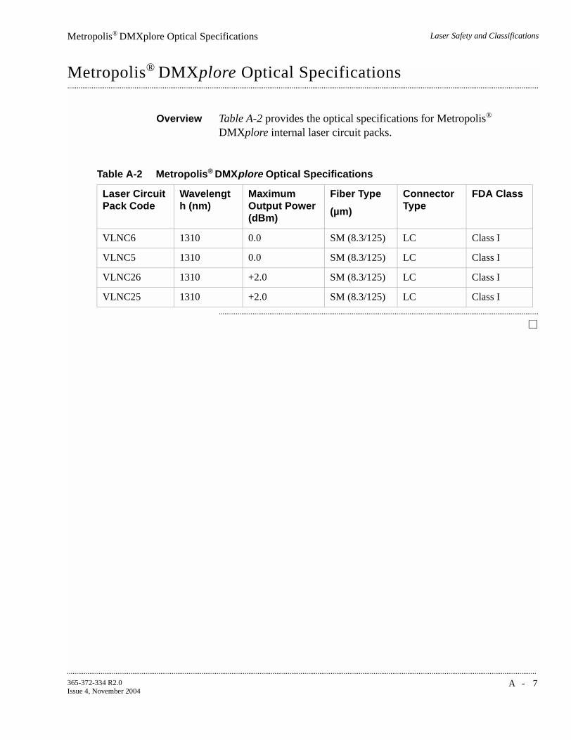
Laser Safety and ClassificationsMetropolis® DMXplore Optical Specifications
...........................................................................................................................................................................................................................................................
A - 7365-372-334 R2.0Issue 4, November 2004
............................................................................................................................................................................................................................................................
Metropolis® DMXplore Optical Specifications
Overview Table A-2 provides the optical specifications for Metropolis®
DMXplore internal laser circuit packs.
...........................................................................................................................................................................
Table A-2 Metropolis® DMXplore Optical Specifications
Laser Circuit Pack Code
Wavelength (nm)
Maximum Output Power (dBm)
Fiber Type
(µm)
Connector Type
FDA Class
VLNC6 1310 0.0 SM (8.3/125) LC Class I
VLNC5 1310 0.0 SM (8.3/125) LC Class I
VLNC26 1310 +2.0 SM (8.3/125) LC Class I
VLNC25 1310 +2.0 SM (8.3/125) LC Class I

...........................................................................................................................................................................................................................................................
Laser Safety and ClassificationsMetropolis® DMXplore Optical Specifications
A - 8 365-372-334 R2.0Issue 4, November 2004

B - 1365-372-334 R2.0Issue 4, November 2004
............................................................................................................................................................................................................................................................
B Fiber Cleaning
............................................................................................................................................................................................................................................................
Overview
Purpose This appendix describes the Lucent recommended method for the cleaning and inspection of optical connectors using specific tools and materials that have been proven to be effective in the assembly and testing of optical transmission equipment. It is critical that connector faces are clean and free from particular contamination to assure proper performance and reliability of lightwave systems. With the modern high speed, high power, and wider bandwidth optical transmission systems, clean connectors along the optical path are essential for successful operation.
Contents This appendix provides information on the following topics:
Objectives This chapter provides information to perform the following:
1. Properly clean an optical connector
2. Inspect an optical connector for cleanliness
...........................................................................................................................................................................
Equipment Requirements and Recommendations B-3
Safety Instructions B-4
Cleaning/Inspecting Optical Connectors B-5B-5
B-4
B-3

...........................................................................................................................................................................................................................................................
Fiber CleaningOverview
B - 2 365-372-334 R2.0Issue 4, November 2004
Related Information A course on connector cleaning and the connector inspection process is now offered through Lucent Technologies Learning and Performance Center, Course Code: LMC200H “Understanding Fiber Optic Cleaning, Inspection and Testing.” To learn more about this course, consult your local Lucent Account Representative.
...........................................................................................................................................................................

Fiber CleaningEquipment Requirements and Recommendations
...........................................................................................................................................................................................................................................................
B - 3365-372-334 R2.0Issue 4, November 2004
............................................................................................................................................................................................................................................................
Equipment Requirements and Recommendations
Description For proper cleaning, the following equipment and materials are recommended:
Important! The equipment and material listed above has been tested and is proven effective when used in conjunction with this procedure. Substitution of equipment or materials is at the discretion of the user and is not recommended.
...........................................................................................................................................................................
Table B-1 Required and Recommended Equipment and Materials
Product Model/Description Comcode ITE # Installation Order #
Optical Fiber Scope Noyes OFS 300-200X 408197028 ITE-7129 33712900
2.5mm Universal adapter cap
For use with the Noyes OFS 300-200X
408197044 ITE-7129D1 33712901
1.25mm Universal adapter cap
For use with the Noyes OFS 300-200X
408197069 ITE-7129D2 33712902
Video Fiber Scope1 Noyes VFS-1 TBD TBD TBD
Individual presaturated alcohol wipes
99% pure isopropyl alcohol
901375147 ITE-7136 33713600
CLETOP Cleaning Cassette
Type A Reel 901375154 ITE-7137 33713700
CLETOP Cleaning Cassette Replacement Reel
Type A Reel 901375014 ITE-7137 D1 33713701
Luminex Stick port cleaners
1.25 mm 901375030 ITE-7134 33713400
Luminex Stick port cleaners
2.5 mm 901375022 ITE-7135 33713500
Luminex Cloth 5.5” x 5.5” 408201226 R6033 23603300
Notes:
1. This equipment may not be necessary at all locations. It is to be used when the ports need to be verified for cleanliness. If care is exercised when cleaning fibers, the video scope may not be needed.

...........................................................................................................................................................................................................................................................
Fiber CleaningSafety Instructions
B - 4 365-372-334 R2.0Issue 4, November 2004
............................................................................................................................................................................................................................................................
Safety Instructions
WARNINGNever view an energized optical cable with the naked eye or with an optical magnifying instrument. Disconnected or separated optical connectors may emit invisible laser radiation and direct exposure can severely injure the eye. If inspecting the endface of a connector with a fiberscope, be absolutely certain that the system is deactivated.
WARNINGAlcohol is flammable and is harmful if swallowed, inhaled or absorbed through the skin. Keep alcohol away from heat, sparks, or flame. Avoid contact with eyes, skin and clothing.
...........................................................................................................................................................................

Fiber CleaningCleaning/Inspecting Optical Connectors
...........................................................................................................................................................................................................................................................
B - 5365-372-334 R2.0Issue 4, November 2004
............................................................................................................................................................................................................................................................
Cleaning/Inspecting Optical Connectors
Introduction The procedure that follows utilizes the “Wet/Dry” method for connector cleaning. This method first applies a “wet” solvent such as high purity alcohol to the connector endface to dissolve/remove any organic particulate or oily films, followed by a “dry” double clean wipe using the CLETOP cleaning cassette.
This procedure is recommended for connector ferrules 2.5 mm and 1.25 mm in diameter associated with ST, SC, FC, and LC connectors. The ferrule of a fiber optic connector consists of a ceramic or stainless steel cylinder with a hole located longitudinally down the center of its axis, allowing enough tolerance for a fiber to pass through.
All optical connectors should be cleaned prior to being connected. Keep the protective ferrule dust cap on the connector until initiating the cleaning process.
...........................................................................................................................................................................
Cleaning Procedure The following cleaning procedure is acceptable for field service/installation activities:
Step 1 Remove the dust cap from the connector ferrule, thus exposing the connector endface.
...........................................................................................................................................................................
Step 2 Open an individual foil packet of pre-saturated isopropyl alcohol (99% pure) wipe.
See Figure B-1, Cleaning the Ferrule Endface (page -6).
Grasp the connector housing and place the connector ferrule endface perpendicular to the alcohol wipe.
Drag it against the wipe three (3) times in a figure eight pattern. This action applies the alcohol solvent to the endface and initially loosens and scrubs away organic/solid contaminates.
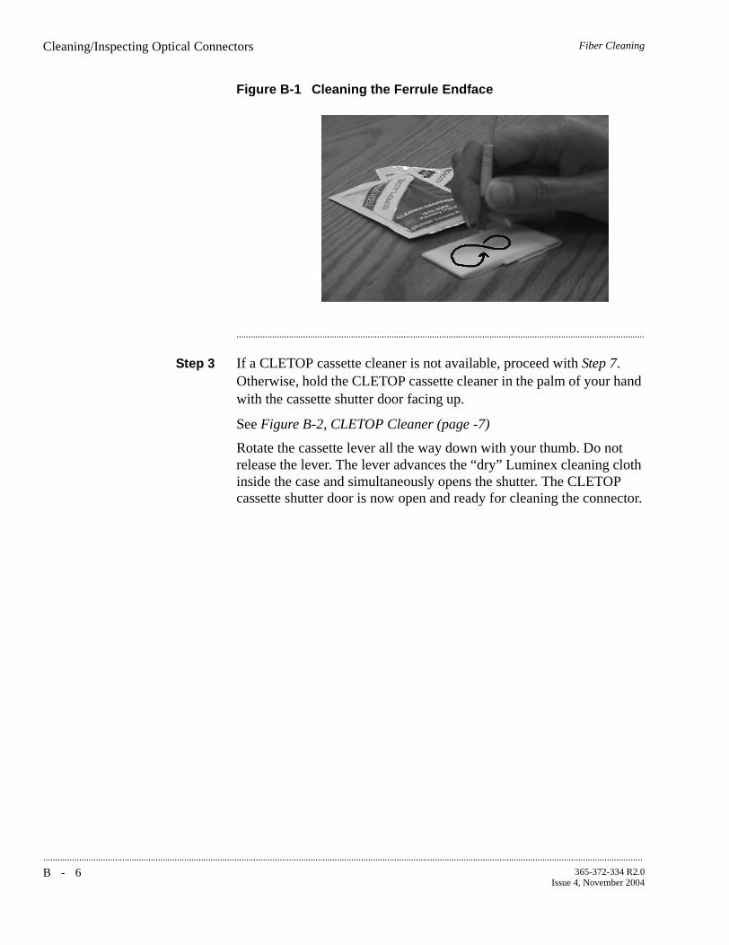
...........................................................................................................................................................................................................................................................
Fiber CleaningCleaning/Inspecting Optical Connectors
B - 6 365-372-334 R2.0Issue 4, November 2004
Figure B-1 Cleaning the Ferrule Endface
...........................................................................................................................................................................
Step 3 If a CLETOP cassette cleaner is not available, proceed with Step 7. Otherwise, hold the CLETOP cassette cleaner in the palm of your hand with the cassette shutter door facing up.
See Figure B-2, CLETOP Cleaner (page -7)
Rotate the cassette lever all the way down with your thumb. Do not release the lever. The lever advances the “dry” Luminex cleaning cloth inside the case and simultaneously opens the shutter. The CLETOP cassette shutter door is now open and ready for cleaning the connector.

Fiber CleaningCleaning/Inspecting Optical Connectors
...........................................................................................................................................................................................................................................................
B - 7365-372-334 R2.0Issue 4, November 2004
Figure B-2 CLETOP Cleaner
...........................................................................................................................................................................
Step 4 Insert and press the connector ferrule endface perpendicular against the cleaning cloth in the first of two slots of the cleaner.
See Figure B-3, Acceptability Criteria for Fiber Cleaning (page -10)
Drag it down (in the direction indicated by the arrows on the cleaner). Make certain not to release the lever of the cassette.
...........................................................................................................................................................................
Step 5 Lift the connector from the first slot and rotate it 90 degrees and repeat the downward motion using the second slot. Be sure the ferrule is pressed snug against the cleaning cloth while dragging the ferrule to assure the proper cleaning action.
...........................................................................................................................................................................
Step 6 Release the cassette lever allowing the shutter door to close to its initial position. Continue with Step 8.
...........................................................................................................................................................................
Step 7 Wrap a Luminex cleaning cloth around the ferrule and rotate the connector housing, cleaning the outside periphery of ferrule.
Follow this by folding an unused portion of the cloth over the end of the ferrule endface and then with light pressure from the thumb, slightly drag the cloth from the center of the ferrule to the edge while rotating the connector 360 degrees. If the Luminex cleaning cloth is not available, a lint free cleanroom optic wipe can be used. The Luminex

...........................................................................................................................................................................................................................................................
Fiber CleaningCleaning/Inspecting Optical Connectors
B - 8 365-372-334 R2.0Issue 4, November 2004
cleaning cloth is washable and can be used multiple times, optic wipes are single use and disposable.
...........................................................................................................................................................................
Step 8 Inspect the connector for cleanliness. If necessary, repeat the cleaning process.
See Connector Inspection (page -9)
End of Steps
...........................................................................................................................................................................

Fiber CleaningCleaning/Inspecting Optical Connectors
...........................................................................................................................................................................................................................................................
B - 9365-372-334 R2.0Issue 4, November 2004
Connector Inspection After cleaning the connector, inspect the ferrule endface to ensure that it is free from any particulate contamination using an optical fiber inspection scope of at least 200X magnification. When using an optical fiber scope (for example, the Noyes OFS 300-200X) exercise extreme caution to assure fiber being examined is de-energized.
WARNINGWhen using an optical power meter to verify the connector and fiber to be clean, take special precaution to make sure that no power is being emitted from the fiber before viewing.
Step 1 Follow the instructions in the manual provided with the Optical Fiber Scope to view the ferrule endface of the fiber under inspection.
...........................................................................................................................................................................
Step 2 The visual area of the ferrule endface (ferrule and fiber) as observed by the inspection system/scope should be free of any contaminates. See Figure B-3, Acceptability Criteria for Fiber Cleaning (page -10)
Repeat the Cleaning Procedure if the fiber endface does not meet the following requirements:
Requirement: No fixed type of contamination (contaminates that remain at the same location after 3 wet-dry cleaning cycles), regardless of size, is allowed in the restricted area of the glass fiber endface.
Requirement: The restricted area is defined as ~66 microns (µm) diameter for both singlemode and multimode fibers.
Requirement: No chips, cracks or scratches are allowed near the core of the glass fiber endface.
Requirement: No large floating (loose) contaminates are allowed on the glass fiber and ceramic ferrule endface.

...........................................................................................................................................................................................................................................................
Fiber CleaningCleaning/Inspecting Optical Connectors
B - 1 0 365-372-334 R2.0Issue 4, November 2004
Figure B-3 Acceptability Criteria for Fiber Cleaning
...........................................................................................................................................................................
Step 3 After the connector has been verified to be cleaned, it should be immediately inserted into the adapter buildout of the optical component. This will assure maximum cleanliness and effectiveness of the connector.
...........................................................................................................................................................................
Step 4 If the cleaned connector can not be immediately connected to a corresponding adapter, the connector ferrule must be protected with a connector dust cap. Before placing the cap on the ferrule, make sure the cap is clean. This can be accomplished by inserting a CLETOP stick cleaner (swab) of the same inside diameter as the cap (either 2.5 or 1.25 mm) and rotating the stick 360 degrees three (3) times. Following this procedure, carefully place the cap over the ferrule. When the cleaned connector is ready for assembly, it should be re-inspected for cleanliness prior to connection.
End of Steps
...........................................................................................................................................................................

Fiber CleaningCleaning/Inspecting Optical Connectors
...........................................................................................................................................................................................................................................................
B - 1 1365-372-334 R2.0Issue 4, November 2004
Fiber Adapters or CircuitPack Connectors
During testing and/or trouble shooting activities it may be necessary to clean the optical buildout adapter or the circuit pack connector. The following procedure is recommended
CAUTIONDo not attempt to clean ports equipped with yellow Light guide BuildOut (LBO) attenuators. Attenuators contain a thin glass lens that is extremely fragile. The LBO will be damaged if cleaned using this method.
Step 1 Using the appropriate CLETOP stick cleaner (2.5 mm for SC, ST, and FC connectors, 1.25 mm for LC connectors) dampen the stick cleaner with Ethyl alcohol using the alcohol wipe. Insert the stick cleaner into the adapter rotating the stick 360 degrees while inserting. Push/rotate stick until the stick cleaner makes contact with the connector. Apply slight pressure upon contact and rotate stick 360 degrees at least three (3) times.
...........................................................................................................................................................................
Step 2 Remove the stick cleaner rotating it upon removal.
...........................................................................................................................................................................
Step 3 Using a dry CLETOP stick cleaner of appropriate diameter, repeat the above cleaning procedure. This procedure will clean the side walls of the adapter and the endface of the circuit pack connector.
...........................................................................................................................................................................
Step 4 Gently insert the Video Fiber Scope probe into the port until the fiber ferrule comes into view.
...........................................................................................................................................................................
Step 5 Verify that the fiber ferrule is clean. Repeat Step 1 through Step 3 if the fiber does not meet the requirements specified in Connector Inspection (page -9).
End of Steps
...........................................................................................................................................................................

...........................................................................................................................................................................................................................................................
Fiber CleaningCleaning/Inspecting Optical Connectors
B - 1 2 365-372-334 R2.0Issue 4, November 2004

C - 1365-372-334 R2.0Issue 4, November 2004
............................................................................................................................................................................................................................................................
C Installing Fiber Connectors and LBOs
............................................................................................................................................................................................................................................................
Overview
Purpose This appendix provides procedures for installing and removing Line Build Out units (LBOs) and fiber connectors onto input and output ports found on the Metropolis® DMXplore optical circuit packs.
...........................................................................................................................................................................
Contents This chapter provides information on the following topics:
Objectives This appendix provides information to perform the following:
• Install and remove LC-type LBOs onto and from LC-type ports.
• Install and remove LC-type fiber connections.
...........................................................................................................................................................................
Fiber Cleaning Refer to Appendix B, Fiber Cleaning for fiber cleaning information. Do not attempt to clean LBOs as they may be damaged by a cleaning attempt. Discard suspect LBOs and replace with a new unit.
...........................................................................................................................................................................
LBOs C-2
Fiber Connections C-5C-5
C-2

...........................................................................................................................................................................................................................................................
Installing Fiber Connectors and LBOsLBOs
C - 2 365-372-334 R2.0Issue 4, November 2004
............................................................................................................................................................................................................................................................
LBOs
General LBOs are fixed-value optical attenuators that mate into mounting blocks and provide a specific connector interface (LC, ST, FC or SC-type) for external fiber connections. The Metropolis® DMXplore optical circuit packs are equipped with LC-type connector ports designed for use with LC-type LBOs and fiber connectors. Dust caps should be applied on all LBOs when not installed in connector ports.
...........................................................................................................................................................................
LC-type Connector Port The LC-type connector port will only accept LC-type LBOs for external fiber connection.
Figure C-1 LC-type Connector Ports on Circuit Pack
...........................................................................................................................................................................

Installing Fiber Connectors and LBOsLBOs
...........................................................................................................................................................................................................................................................
C - 3365-372-334 R2.0Issue 4, November 2004
LC-type LBO Metropolis® DMXplore utilizes Lucent’s state-of-the-art AllWave ADVANTAGE™ Fiber Optic Attenuators. These attenuators reduce optical power from the transmitter that can result in over-saturation of the receiver, have low reflection to meet stringent system requirements, and are backward-compatible with existing transmission systems. Unique to the AllWave ADVANTAGE optical connectivity solution (OCS), the new LC™ optic attenuators are designed to provide flat spectral loss across the full spectrum, allowing the attenuators to be used in the 1300 nm, 1400 nm, and 1500 nm bands.
Figure C-2 LC-type LBO
...........................................................................................................................................................................
Assembly of LC-type LBOinto LC Block
The LC-type LBOs are installed into the LC-type connector by aligning the alignment key with the slot in the connector port and pushing the LBO into the port until it snaps into place.
Figure C-3 LC-type LBO inserted into LC-type Connector Port
...........................................................................................................................................................................
ALIGNMENT KEY
SNAP-ACTION TAB
ALIGNMENTSLOT
15 dB LBO

...........................................................................................................................................................................................................................................................
Installing Fiber Connectors and LBOsLBOs
C - 4 365-372-334 R2.0Issue 4, November 2004
Removal of LC-type LBOfrom LC Block
The LC-type LBOs are removed from the LC-type connector port by depressing the tab to release the LBO and then pulling straight out.
Figure C-4 Removing LC-type LBO from LC-type Connector Port
...........................................................................................................................................................................
DEPRESS TABTO RELEASE LBO
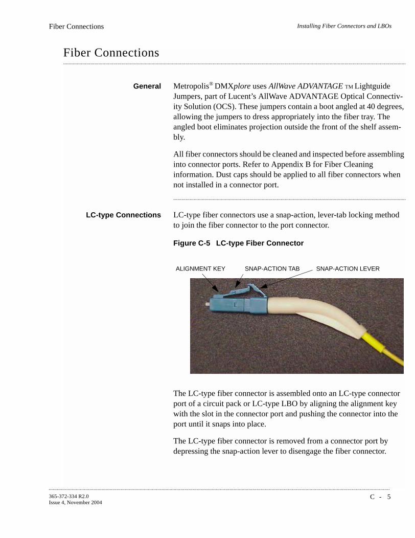
Installing Fiber Connectors and LBOsFiber Connections
...........................................................................................................................................................................................................................................................
C - 5365-372-334 R2.0Issue 4, November 2004
............................................................................................................................................................................................................................................................
Fiber Connections
General Metropolis® DMXplore uses AllWave ADVANTAGE TM Lightguide Jumpers, part of Lucent’s AllWave ADVANTAGE Optical Connectiv-ity Solution (OCS). These jumpers contain a boot angled at 40 degrees, allowing the jumpers to dress appropriately into the fiber tray. The angled boot eliminates projection outside the front of the shelf assem-bly.
All fiber connectors should be cleaned and inspected before assembling into connector ports. Refer to Appendix B for Fiber Cleaning information. Dust caps should be applied to all fiber connectors when not installed in a connector port.
...........................................................................................................................................................................
LC-type Connections LC-type fiber connectors use a snap-action, lever-tab locking method to join the fiber connector to the port connector.
Figure C-5 LC-type Fiber Connector
The LC-type fiber connector is assembled onto an LC-type connector port of a circuit pack or LC-type LBO by aligning the alignment key with the slot in the connector port and pushing the connector into the port until it snaps into place.
The LC-type fiber connector is removed from a connector port by depressing the snap-action lever to disengage the fiber connector.
ALIGNMENT KEY SNAP-ACTION TAB SNAP-ACTION LEVER

...........................................................................................................................................................................................................................................................
Installing Fiber Connectors and LBOsFiber Connections
C - 6 365-372-334 R2.0Issue 4, November 2004
Figure C-6 LC-type Fiber Connection
...........................................................................................................................................................................
ALIGNMENTSLOT
DEPRESS LEVERTO RELEASE THESNAP-ACTION TAB

D - 1365-372-334 R2.0Issue 4, November 2004
............................................................................................................................................................................................................................................................
D Backplane Pin Replacement
............................................................................................................................................................................................................................................................
Overview
Purpose This appendix provides information and the procedures used when a connector and/or pin on the Metropolis® DMXplore backplane has been bent or broken.
...........................................................................................................................................................................
Contents This appendix provides information on the following topics:
Pin and Connector Background D-3
Repair Kits and Tools D-5
Simple Repair Methods D-6
Replacement Methods D-8D-8
D-6
D-5
D-3

...........................................................................................................................................................................................................................................................
Backplane Pin ReplacementOverview
D - 2 365-372-334 R2.0Issue 4, November 2004
Objectives This appendix provides information and procedures to do the following:
• Identify a bent or broken pin
• Determine the correct replacement pin and pin kit
• Straighten bent pin
• Replace broken pins
...........................................................................................................................................................................

Backplane Pin ReplacementPin and Connector Background
...........................................................................................................................................................................................................................................................
D - 3365-372-334 R2.0Issue 4, November 2004
............................................................................................................................................................................................................................................................
Pin and Connector Background
Description This section describes the procedures for the repair/replacement of the press-fit connector pins used on the backplane of the Metropolis®
DMXplore shelf. Trouble clearing procedures may lead you to inspect the backplane for damaged connectors.
Circuit packs are plugged into METRAL™ signal pin connectors which have been press-fit into the backplane. A plastic shroud is included with the connectors to protect the pins. The signal pin press-fit terminals in these connectors my be replaced individually if they have been damaged beyond simple repair methods.
...........................................................................................................................................................................
D-SubminiatureConnectors
Interface cabling to and from the Metropolis® DMXplore shelves is connected through D-Subminiature connectors which have been press-fit into the backplane. Should these connectors be damaged beyond simple repair methods, contact your next level of support for the replacement procedure.
...........................................................................................................................................................................
RJ45 Jacks Interface cabling to and from the Metropolis® DMXplore shelves is connected through RJ45 connectors (jacks) which have been press-fit into the backplane. Should these jacks be damaged beyond simple repair methods, contact your next level of support for the replacement procedure.
...........................................................................................................................................................................
Shelves and Backplanes The Metropolis® DMXplore has its connectors and terminal identifiers stenciled on the back surface for identification of location or position. The stenciling can only be seen when the back cover is removed.
Pins are identified by a column and row position on the backplane. D-Subminiature connectors are identified by their designation and J-number. All the METRAL™ pins used on the Metropolis® DMXplore shelves have the same tail length of 4.30mm (0.169 in.).
Table D-1 show the location and type of METRAL™ pins on the Metropolis® DMXplore backplane.

...........................................................................................................................................................................................................................................................
Backplane Pin ReplacementPin and Connector Background
D - 4 365-372-334 R2.0Issue 4, November 2004
...........................................................................................................................................................................
Table D-1 Backplane Locations of METRAL™ Pins
Slot Row Column Type Mating Length (mm)
Tail Length (mm)
MAIN 001, 103 to 108 a,b,c,d,e Signal Pin 8.00 4.30
SYSCTL 001, 037 to 042 a,b,c,d,e Signal Pin 8.00 4.30
LAN 001, 043 to 048 a,b,c,d,e Signal Pin 8.00 4.30
All others All others Signal Pin 5.75 4.30

Backplane Pin ReplacementRepair Kits and Tools
...........................................................................................................................................................................................................................................................
D - 5365-372-334 R2.0Issue 4, November 2004
............................................................................................................................................................................................................................................................
Repair Kits and Tools
Repair Kits For the repair or replacement of METRAL™ signal pins, use one of the following repair kits:
• Berg Electronic MT370-01 Shelf Level Press-Fit Repair Kit
• IMDARC R-6004 Metral Pin Repair Kit - Comcode 407959881
This kit includes the tools, parts and instructions for repair and replacement of signal pins.
...........................................................................................................................................................................
Replacement Pins Replacement pins are available. These pins are defined by the mating length extending beyond the inside of the plastic shroud and by their tail length for press-fitting into the backplane. The tail length includes a compliant press-fit section needed to achieve a gas-tight connection in four contact areas. All the METRAL™ pins used on the Metropolis®
DMXplore shelves have the same tail length of 4.30 mm (0.169 in.).
Additional replacement signal pins may be ordered in packages of 100 by the part number shown in Table D-2, Metral™ Pins.
...........................................................................................................................................................................
Table D-2 Metral™ Pins
Type Mating Length (mm)
Berg Part #
Ground 5.75 88929-502
Signal Pin 5.75 88929-502
Signal Pin 8.00 88929-519
...........................................................................................................................................................................................................................................................
Backplane Pin ReplacementSimple Repair Methods
D - 6 365-372-334 R2.0Issue 4, November 2004
............................................................................................................................................................................................................................................................
Simple Repair Methods
Precautions
CAUTIONThese procedures should be done with the shelf out of service and powered down to insure no further damage to the equipment or to the person doing the repair. If service cannot be removed or rerouted, contact your next level of support before proceeding.
CAUTIONProper ESD precautions must be followed.
Make sure that you have adequate space to access the backplane area and that you have good light sources so that you can see what you are doing.
...........................................................................................................................................................................
Visual Examination Visually examine the connector pins to determine which pins may have been damaged and the degree of the damage. Pins that have been slightly bent may be carefully restored to their initial straight position. Examine both sides of the backplane to determine if the press-fit termination has been disturbed. These pins depend on an undisturbed interference fit between the terminal body and the plated-through hole in the backplane to create a reliable connection.
If the visual examination suggests that the connector pins are loose or are damaged beyond repair, replace the connector pin.
...........................................................................................................................................................................

Backplane Pin ReplacementSimple Repair Methods
...........................................................................................................................................................................................................................................................
D - 7365-372-334 R2.0Issue 4, November 2004
METRAL™ Backplane Pins
CAUTIONThis is a delicate procedure. Take your time to gently straighten the pin in several small steps. Large movements may damage adjacent pins.
Follow the instructions and use the tools provided in the MT370-01 Shelf Level Press-Fit Repair Kit to straighten METRALTM pins which may have been bent out of position.
...........................................................................................................................................................................
Guide Pins and KeyingPins
If a stainless steel guide pin or keying pin has been bent out of alignment, attempts to straighten it may damage the backplane. The recommended alternative is to replace the bent pin.
...........................................................................................................................................................................
D-Subminiature Pins The D-Subminiature connectors on the Metropolis® DMXplore backplane are all of the receptacle type. These connectors are designated as jacks and not as plugs. The individual connector terminals are protected somewhat by the molded plastic insert inside the connector shell. It is unlikely that these terminals would be bent in the manner that the exposed pin terminals of a plug might be bent. The damage concern for these receptacle terminals is that they may be “crushed” or otherwise distorted out of shape. Attempts to “straighten” these terminals may result in fracturing them. If a receptacle terminal has been damaged to the extent that the mating plug connector cannot be connected, then the recommended alternative is to replace the entire backplane.
...........................................................................................................................................................................
RJ45 Jacks The RJ45 connectors (jacks) are press-fitted into the Metropolis®
DMXplore backplane. Should these jacks be damaged beyond simple repair methods, contact your next level of support for the replacement procedure.
...........................................................................................................................................................................

...........................................................................................................................................................................................................................................................
Backplane Pin ReplacementReplacement Methods
D - 8 365-372-334 R2.0Issue 4, November 2004
............................................................................................................................................................................................................................................................
Replacement Methods
Background Connector pins are designed to withstand a considerable removal force. An impact-type tool is used to generate a controlled removal force. Similarly, proper insertion of a press-fit connector pin is done with an impact-type tool to control the insertion forces and not damage adjacent pins.
...........................................................................................................................................................................
Precautions Read the following Important statements before proceeding:
Important! Any press-fit connector pin may be removed and replaced one time in the Metropolis® DMXplore backplane. A second removal and replacement in the same plated-through hole may not meet the long-term reliability objectives. If a replacement is needed for a previously replaced connector pin, contact your next level of support before proceeding.
Important! Protect the surrounding area from any debris which may be generated during the pin removal and replacement.
...........................................................................................................................................................................
Procedure for METRAL™Pins
Use the procedure below to replace pins when required:
Step 1 Verify that the problem cannot be fixed using a simple repair procedure.
...........................................................................................................................................................................
Step 2 Secure the proper tool kit.
...........................................................................................................................................................................
Step 3 Read the tool kit instructions before beginning.
...........................................................................................................................................................................
Step 4 Plan and write out a “Method of Procedure” specific to your location.
...........................................................................................................................................................................
Step 5 Follow the instructions provided to remove the damaged pin.

Backplane Pin ReplacementReplacement Methods
...........................................................................................................................................................................................................................................................
D - 9365-372-334 R2.0Issue 4, November 2004
...........................................................................................................................................................................
Step 6 Install the replacement pin.
...........................................................................................................................................................................
Step 7 Verify that the new pin is securely in the backplane.
...........................................................................................................................................................................
Step 8 If the replacement is not successful, contact your next level of support.
End of Steps
Guide and Keying PinProcedure
If it becomes necessary to replace Guide or Keying Pins, contact your next level of support for tooling, replacement parts and detailed replacement procedures. The replacements will need to installed with screws and washers.
...........................................................................................................................................................................
D-Subminiature PinProcedure
If it becomes necessary to replace either the D-Subminiature pins or connector, contact your next level of support for detailed replacement procedures.
...........................................................................................................................................................................
RJ45 Jacks If it becomes necessary to replace a RJ45 connector, contact your next level of support for the replacement procedure.
...........................................................................................................................................................................

...........................................................................................................................................................................................................................................................
Backplane Pin ReplacementReplacement Methods
D - 1 0 365-372-334 R2.0Issue 4, November 2004

E - 1365-372-334 R2.0Issue 4, November 2004
............................................................................................................................................................................................................................................................
E Installation Checklist
........................................................................................................................................................................Overview
Purpose This chapter provides the recommended checklist to follow when installing a Metropolis® DMXplore system. Use of the installation checklist is required to ensure a quality installation. All completed tasks should be checked off and those not completed should be duly noted as to the reason why. This checklist should be turned in as part of your job complete paperwork.

...........................................................................................................................................................................................................................................................
Installation ChecklistOverview
E - 2 365-372-334 R2.0Issue 4, November 2004
Table E-1 Installation Acceptance Checklist
Section and Chapter Procedure Required Completed
Yes No
Part I: Metropolis® DMXplore Access Multiplexer Physical Installation and Powering
Chapter 1, Equipment and Cable Installation for Metropolis® DMXplore Shelf (Wall-Mount)
Inspection (page 1-8) Yes
Metropolis® DMXplore Wall-Mount Shelf Installation (page 1-9)
Yes
Power Cable Installation (page 1-18) Yes
DS1 Cable Installation (page 1-23) Yes
DS3 Cable Installation (page 1-27) See Note 1
Ethernet Cable Installation (page 1-30) See Note 1
Miscellaneous (Environmental) Discrete Telemetry Cable Installation (page 1-37)
See Note 1
OC-3/OC12 Main Optical Fiber Cable Installation (page 1-41)
Yes
RS-232 Serial CIT Cable Installation (page 1-43)
See Note 1
SYSCTL LAN Cable Installation (page 1-45) See Note 1
Chapter 2, Equipment and Cable Installation for Metropolis® DMXplore Shelf (Rack-Mount)
Inspection (page 2-8) Yes
Metropolis® DMXplore Rack-Mount Shelf Installation (page 2-9)
Yes
Power Cable Installation (page 2-13) Yes
DS1 Cable Installation (page 2-18) Yes
DS3 Cable Installation (page 2-22) See Note 1
Ethernet Cable Installation (page 2-24) See Note 1
Miscellaneous (Environmental) Discrete Telemetry Cable Installation (page 2-30)
See Note 1
OC-3/OC12 Main Optical Fiber Cable Installation (page 2-34)
Yes
RS-232 Serial CIT Cable Installation (page 2-37)
See Note 1
SYSCTL LAN Cable Installation (page 2-39) See Note 1

Installation ChecklistOverview
...........................................................................................................................................................................................................................................................
E - 3365-372-334 R2.0Issue 4, November 2004
Chapter 3, Powering and Initial Circuit Pack Installation for Metropolis®
DMXplore Shelf (Wall-Mount)
Powering (page 3-3) Yes
VLNC1 (SYSCTL) Installation (page 3-11) Yes
Main OLIU Installation (page 3-12) Yes
Figure , 10/100 T Fast Ethernet Installation (page 3-13)
See Note 1
199L Apparatus Blank Installation (page 3-14) See Note 1
Chapter 4, Powering and Initial Circuit Pack Installation for Metropolis®
DMXplore Shelf (Rack-Mount)
Powering (page 4-3) Yes
VLNC1 (SYSCTL) Installation (page 4-11) Yes
Main OLIU Installation (page 4-12) Yes
Figure , 10/100 T Fast Ethernet Installation (page 4-13)
See Note 1
199L Apparatus Blank Installation (page 4-14) See Note 1
Table E-1 Installation Acceptance Checklist (Continued)
Section and Chapter Procedure Required Completed
Yes No
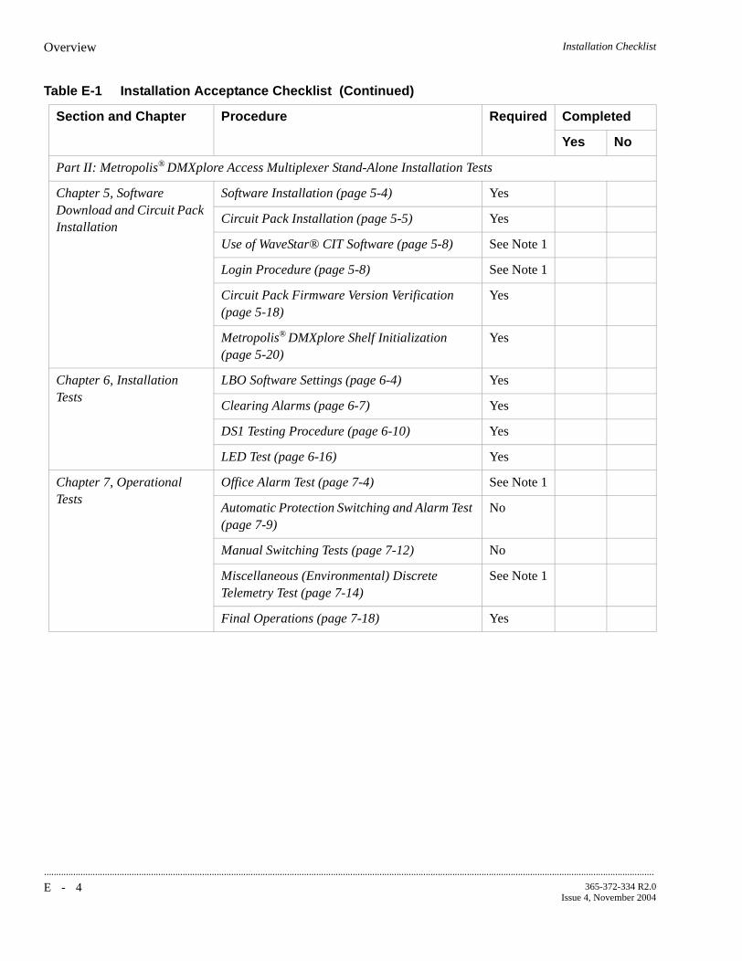
...........................................................................................................................................................................................................................................................
Installation ChecklistOverview
E - 4 365-372-334 R2.0Issue 4, November 2004
Part II: Metropolis® DMXplore Access Multiplexer Stand-Alone Installation Tests
Chapter 5, Software Download and Circuit Pack Installation
Software Installation (page 5-4) Yes
Circuit Pack Installation (page 5-5) Yes
Use of WaveStar® CIT Software (page 5-8) See Note 1
Login Procedure (page 5-8) See Note 1
Circuit Pack Firmware Version Verification (page 5-18)
Yes
Metropolis® DMXplore Shelf Initialization (page 5-20)
Yes
Chapter 6, Installation Tests
LBO Software Settings (page 6-4) Yes
Clearing Alarms (page 6-7) Yes
DS1 Testing Procedure (page 6-10) Yes
LED Test (page 6-16) Yes
Chapter 7, Operational Tests
Office Alarm Test (page 7-4) See Note 1
Automatic Protection Switching and Alarm Test (page 7-9)
No
Manual Switching Tests (page 7-12) No
Miscellaneous (Environmental) Discrete Telemetry Test (page 7-14)
See Note 1
Final Operations (page 7-18) Yes
Table E-1 Installation Acceptance Checklist (Continued)
Section and Chapter Procedure Required Completed
Yes No

Installation ChecklistOverview
...........................................................................................................................................................................................................................................................
E - 5365-372-334 R2.0Issue 4, November 2004
Part III: Metropolis® DMXplore Access Multiplexer Ring Setup and Testing
Chapter 8, Ring Setup and Testing: Integration Procedures
Fiber Installation (page 8-4) Yes
OC-3/OC12 Optical Transmission Test (page 8-11)
No
Automatic Protection Switching Test (page 8-13)
No
Manual Switching Tests (page 8-15) Yes
Final Operations (page 8-23) Yes
Notes:
1. Only required if equipped.
Table E-1 Installation Acceptance Checklist (Continued)
Section and Chapter Procedure Required Completed
Yes No

...........................................................................................................................................................................................................................................................
Installation ChecklistOverview
E - 6 365-372-334 R2.0Issue 4, November 2004
F - 1365-372-334 R2.0Issue 4, November 2004
............................................................................................................................................................................................................................................................
F Fiber Labeling
........................................................................................................................................................................Overview
Purpose This chapter describes the labeling of the fiber.
Contents This chapter contains the following.
Fiber Description F-2
Fiber Labels F-4F-4
F-2

...........................................................................................................................................................................................................................................................
Fiber LabelingFiber Description
F - 2 365-372-334 R2.0Issue 4, November 2004
........................................................................................................................................................................Fiber Description
Fibers There are three different types of single-mode fiber used with the DMXplore system, simplex blue fiber, simplex yellow fiber, and the customer's fiber
Blue Fiber Blue fiber is made up of a single blue colored fiber equipped with LC connectors at both ends. It is referred to as Simplex LC Blue Fiber. The Blue Fibers are custom cut to length for their application. The length is given on the protection boot of the LC connector.
Yellow Fiber Simplex fibers are Yellow in color and come in six different lengths (15, 20, 25, 30, 35 and 50 feet), as well as custom lengths.
Outside Fiber Outside fiber is the fiber connecting the Customer equipment to the DMXplore . Depending on the customers specifications, these fibers may be any combination of SC, FC, or ST connectors. The length of these fibers depends on the system interface setup. This fiber is usually referred to as the Outside Bay or Plant Fiber.
Outside Bay Fiber management should be specified by the customer. It is beyond the scope of this document to specify the route or dressings that the fiber should take once it leaves the equipment bays.
Precautions
CAUTIONFiber is constructed of glass and should be treated with care. It should not be pulled or stretched. This could cause damage to the fiber or the fiber connector.
CAUTIONFiber should not be bent in a radius of less than 1-1/2”.

Fiber LabelingFiber Description
...........................................................................................................................................................................................................................................................
F - 3365-372-334 R2.0Issue 4, November 2004
Single-Mode Fiber TestingRequirements
All fibers shall be tested after they are installed as follows:
• All fibers shall be tested after installation, but prior to turn-up
• Before fibers are tested, they shall be labeled properly and all cable tags shall be removed.
• A 1310nm or 1550nm test source and an ITE# 7116 (or equivalent) optical power meter shall be used to perform all tests.
• The light source shall first be measured for a reference point/baseline.
• No fiber jumper may have a measured loss of more than 2 dB.

...........................................................................................................................................................................................................................................................
Fiber LabelingFiber Labels
F - 4 365-372-334 R2.0Issue 4, November 2004
........................................................................................................................................................................Fiber Labels
Introduction If pre-printed labels are not available, use a label-maker to create labels for each end of each fiber. The label should include:
• rack location
• circuit pack
• port
• direction (IN,OUT)
Labeling the Fibers To apply the labels to the connectors, use the following procedure.
Step 1 Remove the appropriate label from the backing sheet or the label maker.
...........................................................................................................................................................................
Step 2 Apply the label to the strain relief boot, close to the body of the LC connector.
...........................................................................................................................................................................
Step 3 Adhere the end of the label with the printed text first.
...........................................................................................................................................................................
Step 4 The label must be oriented perpendicular to the main axis of the connector.
...........................................................................................................................................................................
Step 5 Wrap the label around the boot so that the second wrap is directly on top of the first wrap. (The label will wrap around the boot approximately two times). The text is printed diagonally on the label so that it can be read when applied the correct way.
Important! Do not apply the label diagonally to the boot. The label must wrap directly on top of itself for the adhesive to work.
End of Steps
..................................................................................................................

G L O S S A R YG L - 1
365-372-334 R2.0Issue 4, November 2004
...........................................................................................................................................................................................................................................................
Glossary
......................................................................................................................................................................................................
....................................................................................................................................Acronyms and Abbreviations
A ABNAbnormal (status condition)
ACOAlarm Cutoff
ACO/SWAlarm Cutoff and Test
ADMAdd/Drop Multiplexer
AGNEAlarm Gateway Network Element
AISAlarm Indication Signal
AMIAlternate Mark Inversion
ANSIAmerican National Standards Institute
APSAutomatic Protection Switch
ARMAccess Resource Manager

...........................................................................................................................................................................................................................................................
G L O S S A R YG L - 2
365-372-334 R2.0Issue 4, November 2004
......................................................................................................................................................................................................
......................................................................................................................................................................................................
AS&CAlarm, Status, and Control
ASCIIAmerican Standard Code for Information Interchange
ASN.1Abstract Syntax Notation 1
ASNEAlarm Server Network Element
ATMAsynchronous Transfer Mode
AutoAutomatic
AUXCTLAuxiliary Control
B B3ZSBipolar 3-Zero Substitution
B8ZSBipolar 8-Zero Substitution
BDFBBattery Distribution and Fuse Bay
BERBit Error Ratio
BIPBit Interleaved Parity
BITSBuilding Integrated Timing Supply
BRIBasic Rate Interface
C CCClear Channel

...........................................................................................................................................................................................................................................................
G L O S S A R YG L - 3
365-372-334 R2.0Issue 4, November 2004
CCITTInternational Telephone and Telegraph Consultative Committee
CEVControlled Environment Vault
CD-ROMCompact Disk, Read-Only Memory
CDTUChannel and Drop Test Unit
CITCraft Interface Terminal
CLFCarrier Line Failure Status
CLKClock
CMISECommon Management Information Service Element
CMOSComplementary Metal Oxide Semiconductor
CMTSCable Modem Termination System
COCentral Office
CPCircuit Pack
CPECustomer Premises Equipment
CRCritical (alarm status)
CSACarrier Serving Area

...........................................................................................................................................................................................................................................................
G L O S S A R YG L - 4
365-372-334 R2.0Issue 4, November 2004
......................................................................................................................................................................................................
CSUChannel Service Unit
CS&OCustomer Support and Operations
CVCoding Violation
CVFECoding Violation Far End
D DCCData Communications Channel
DCEData Communications Equipment
DEMUXDemultiplexer
DLCDigital Loop Carrier
DPLLDigital Phase-Locked Loop
DRIDual Ring Interworking
DS1Digital Signal Level 1
DS3Digital Signal Level 3
DSLAMDigital Subscriber Line Access Multiplexer
DSNEDirectory Services Network Element
DSXDigital Cross-Connect Panel

...........................................................................................................................................................................................................................................................
G L O S S A R YG L - 5
365-372-334 R2.0Issue 4, November 2004
......................................................................................................................................................................................................
DTDistant Terminal
DTEData Terminating Equipment
E EC-1Electrical Carrier Level 1
ECIEquipment Catalog Item
EEPROMElectrically-Erasable Programmable Read-Only Memory
EIAElectronic Industries Association
EMCElectromagnetic Compatibility
EMIElectromagnetic Interference
EOOFExcessive Out of Frame
EPROMErasable Programmable Read-Only Memory
EQEquipped (memory administrative state)
ESErrored Seconds
ESDElectrostatic Discharge
ESFExtended Super Frame
ESTEnvironmental Stress Testing

...........................................................................................................................................................................................................................................................
G L O S S A R YG L - 6
365-372-334 R2.0Issue 4, November 2004
......................................................................................................................................................................................................
......................................................................................................................................................................................................
F FCCFederal Communications Commission
FDDIFiber Distribution Data Interface
FEFar End
FE ACTYFar End Activity
FEBEFar End Block Error
FE IDFar End Identification
FEPROMFlash EPROM
FERFFar End Receive Failure
FE SELFar End Select
G GbEGigabit Ethernet
GNEGateway Network Element
GRTelcordia Technologies General Requirement
GTPGeneral Telemetry Processor
GTSIPGlobal Technical Support Information Platform
GUIGraphical User Interface

...........................................................................................................................................................................................................................................................
G L O S S A R YG L - 7
365-372-334 R2.0Issue 4, November 2004
......................................................................................................................................................................................................
......................................................................................................................................................................................................
H HECIHumans Equipment Catalog Item
I ICInternal Clock
IDIdentifier
IECInternational Electrotechnology Commission
IMFInfant Mortality Factor
INCIncoming Status
I/OInput/Output
IPInternet Protocol
IRIntermediate Reach
ISIn Service
ISCIIntershelf control Interface
ISIIntershelf Interface
ISDNIntegrated Services Digital Network
ISOInternational Standards Organization
ISPInternet Service Provider

...........................................................................................................................................................................................................................................................
G L O S S A R YG L - 8
365-372-334 R2.0Issue 4, November 2004
......................................................................................................................................................................................................
......................................................................................................................................................................................................
IVHSIntelligent Vehicle Highway System
L LANLocal Area Network
LAPDLink Access Procedure "D"
LBOLine Build Out
LCNLocal Communications Network
LECLocal Exchange Carrier
LEDLight-Emitting Diode
LOFLoss of Frame
LOPLoss of Pointer
LOSLoss of Signal
LRLong Reach
LSLow Speed
M MDMediation Device
MJMajor Alarm
MMMultimode

...........................................................................................................................................................................................................................................................
G L O S S A R YG L - 9
365-372-334 R2.0Issue 4, November 2004
......................................................................................................................................................................................................
MMLhuMan-Machine Language
MNMinor Alarm
MPEGMoving Picture Experts Group
MSDTMulti-Services Distant Terminal
MTBFMean Time Between Failures
MTBMAMean Time Between Maintenance Activities
MultMultipling
MUXMultiplex
MXBIUMultiplexer and Backplane Interface Unit
N NENear End
NENetwork Element
NE ACTYNear-End Activity
NEBSNetwork Equipment-Building System
nmNanometer (10-9 meters)
NMANetwork Monitoring and Analysis

...........................................................................................................................................................................................................................................................
G L O S S A R YG L - 1 0
365-372-334 R2.0Issue 4, November 2004
......................................................................................................................................................................................................
NMONNot Monitored (provisioning state)
NRZNonreturn to Zero
NARTACLucent North American Regional Technical Assistance Center call 1-866-LUCENT8 (866-582-3688): Prompt 1
NNINetwork-Network Interface
NSANot Service Affecting
NSAPNetwork Services Access Point
NTFNo Trouble Found
O OAM&POperations, Administration, Maintenance, and Provisioning
OC-1Optical Carrier Level 1 Signal (51.84 Mb/s)
OC-3Optical Carrier Level 3 Signal (155 Mb/s)
OC-12Optical Carrier Level 12 Signal (622 Mb/s)
OC-48Optical Carrier Level 48 Signal
OLIUOptical Line Interface Unit
OOFOut of Frame
OOLOut of Lock

...........................................................................................................................................................................................................................................................
G L O S S A R YG L - 1 1
365-372-334 R2.0Issue 4, November 2004
......................................................................................................................................................................................................
OPS/INEOperations System/Intelligent Network Element
OSOperations System
OSGNEOperations System Gateway Network Element
OSIOpen Systems Interconnection
OSMINEOperations Systems Modifications for the Integration of Network Elements
OSPOutside Plant
P P-bitPerformance Bit
PCPersonal Computer
PCUPower Conversion Unit
PIDProgram Identification
PINFETPositive Intrinsic Negative Field Effect Transistor
PJCPointer Justification Count
PLLPhase-Locked Loop
PMPerformance Monitoring
PMNPower Minor Alarm

...........................................................................................................................................................................................................................................................
G L O S S A R YG L - 1 2
365-372-334 R2.0Issue 4, November 2004
......................................................................................................................................................................................................
......................................................................................................................................................................................................
POHPath Overhead
POPPoints of Presence
POTSPlain Old Telephone Service
PRMPerformance Report Message
PROTNProtection
PRSPrimary Reference Source
PSUPower Supply Unit
PVCPermanent Virtual Circuit
PWRPower
R RAMRandom Access Memory
RPPReliability Prediction Procedure (described in Telcordia Technologies TR-NWT-00032)
RTRemote Terminal
RZReturn to Zero
S SAService Affecting

...........................................................................................................................................................................................................................................................
G L O S S A R YG L - 1 3
365-372-334 R2.0Issue 4, November 2004
SCADASupervisory Control and Data Acquisition
SDSignal Degrade
SDHSynchronous Digital Hierarchy
SEFSSeverely Errored Frame Seconds
SEOSingle-Ended Operations
SESSeverely Errored Seconds
SFSuper Frame (format for DS1 signal)
SIDSystem Identification
SLAService Level Agreements
SLIMSubscriber Loop Interface Module
SMSingle Mode
SONETSynchronous Optical NETwork
SPESynchronous Payload Envelope
SQUSync Quality Unknown
SRDSoftware Release Description

...........................................................................................................................................................................................................................................................
G L O S S A R YG L - 1 4
365-372-334 R2.0Issue 4, November 2004
......................................................................................................................................................................................................
STS, STS-nSynchronous Transport Signal
STMSynchronous Transfer Mode
STS-1 SPESTS-1 Synchronous Payload Envelope
STS-3cSynchronous Transport Level 3 Concatenated Signal
STS-12cSynchronous Transport Level 12 Concatenated Signal
SYSCTLSystem Controller (circuit pack)
T T1X1 and T1M1The ANSI committees responsible for telecommunications standards
TATelcordia Technologies Technical Advisory
TABSTelemetry Asynchronous Byte Serial (Protocol)
TARPTarget ID Address Resolution Protocol
TCAThreshold-Crossing Alert
TCP/IPTransmission Control Protocol/Internet Protocol
TCVCXOTermperature-Compensated Voltage-Controlled Crystal Oscillator
TDMTime Division Multiplexing
TIDTarget Identifier

...........................................................................................................................................................................................................................................................
G L O S S A R YG L - 1 5
365-372-334 R2.0Issue 4, November 2004
......................................................................................................................................................................................................
......................................................................................................................................................................................................
TL1Transaction Language 1
TLBTiming Looped Back
TOPTask Oriented Practice
TRTelcordia Technologies Technical Requirement
TSATime Slot Assignment
TSITime Slot Interchange
TSOTechnical Support Organization
U UASUnavailable Seconds
UNIUser Network Interface
UOCUniversal Optical Connector
UPD/INITUpdate/Intialize
UPSRUnidirectional Path Switched Rings
V VFVoice Frequency
VLANVirtual Local Area Network
VLSIVery Large Scale Integration

...........................................................................................................................................................................................................................................................
G L O S S A R YG L - 1 6
365-372-334 R2.0Issue 4, November 2004
......................................................................................................................................................................................................
VMViolation Monitor
VMRViolation Monitor and Removal
VoIPVoice over Internet Protocol
VONUVirtual Optical Network Unit
VPNVirtual Private Network
VTVirtual Tributary
VT1.5Virtual Tributary 1.5 (1.728 Mb/s)
VT-GVirtual Tributary Group
W WANWide Area Network

...........................................................................................................................................................................................................................................................
G L O S S A R YG L - 1 7
365-372-334 R2.0Issue 4, November 2004
......................................................................................................................................................................................................
......................................................................................................................................................................................................
....................................................................................................................................Terms and Definitions
Numerics 0x1Set up using unswitched cross connections on UPSR Ring Interfaces.
1+1The 1+1 protection switching architecture protects against failures of the optical transmit/receive equipment and their connecting fiber facility. One bidirectional interface (two fibers plus associated OLIUs on each end) is designated "service," and the other is designated "protection." In each direction, identical signals are transmitted on the service and protection lines ("dual-fed"). The receiving equipment monitors the incoming service and protection lines independently, and selects traffic from one line (the "active" line) based on performance criteria and technician/OS control. In 1+1 both service and protection lines could be active at the same time (service in one direction, protection in the other).
A ActiveActive identifies a 1+1 protected OC-N line which is currently selected by the receiver at either end as the payload carrying signal or a 1x1 or 1xN protected circuit pack that is currently carrying service. (See Standby).
AGNE - Alarm Gateway Network ElementA defined NE in an alarm group through which members of the alarm group exchange information.
AIS - Alarm Indication SignalA code transmitted downstream in a digital network that shows that an upstream failure has been detected and alarmed.
AMI - Alternate Mark InversionA line code that employs a ternary signal to convey binary digits, in which successive binary ones are represented by signal elements that are normally of alternating, positive and negative polarity but equal in amplitude, and in which binary zeros are represented by signal elements that have zero amplitude.
ASCII - American Standard Code for Information Interchange A standard 8-bit code used for exchanging information among data processing systems and associated equipment.

...........................................................................................................................................................................................................................................................
G L O S S A R YG L - 1 8
365-372-334 R2.0Issue 4, November 2004
......................................................................................................................................................................................................
......................................................................................................................................................................................................
AutoOne possible state of a service interface port. In this state, the port will automatically be put "in service" if a good incoming signal is detected on the port.
Automatic Protection SwitchA feature that allows another synchronization source to be automatically selected and the synchronization source provisioning to be automatically reconfigured in the event of a synchronization source failure or network synchronization change, for example, a fiber cut.
Available TimeIn performance monitoring, the 1-second intervals.
B B3ZS - Bipolar 3-Zero SubstitutionA line coding method that replaces a string of three zeros with a sequence of symbols having some special characteristic.
B8ZS - Bipolar 8-Zero SubstitutionA line coding method that replaces a string of eight zeros with a sequence of symbols having some special characteristic.
Backbone RingA host ring.
BER - Bit Error RatioThe ratio of bits received in error to the total bits sent.
BIP - Bit Interleaved Parity A method of error monitoring over a specified number of bits, that is BIP-3 or BIP-8.
BITS - Building Integrated Timing Supply A single clock that provides all the DS1 and DS0 synchronization references required by clocks in a building.
BroadbandAny communications channel with greater bandwidth than a voice channel; sometimes used synonomously with wideband. Also refers to signals at the DS3 (44.736 Mb/s) and higher. Wideband refers to lower rates (i.e. DS1, VT1.5, etc.).
C CC - Clear ChannelA provisionable mode for the DS3 output that causes parity violations not to be monitored or corrected before the DS3 signal is encoded.

...........................................................................................................................................................................................................................................................
G L O S S A R YG L - 1 9
365-372-334 R2.0Issue 4, November 2004
......................................................................................................................................................................................................
CCITT - International Telephone and Telegraph Consultative CommitteeAn international advisory committee under United Nations’ sponsorship that has composed and recommended for adoption worldwide standards for international communications. Recently changed to the International Telecommunications Union Telecommunications Standards Sector (ITU-TSS).
ChannelA logical signal within a port. For example, for an EC-1 port, there is one STS-1 channel and sometimes 28 VT1.5 channels. See Port.
Channel State ProvisioningA feature that allows a user to suppress reporting of alarms and events during provisioning by supporting multiple states (automatic, in-service and not monitored) for VT1.5 and STS-1 channels. See Port State Provisioning.
CV - Coding ViolationA performance monitoring parameter.
CVFE - Coding Violation Far-EndAn indication returned to the transmitting terminal that an errored block has been detected at the receiving terminal.
D DACS III-2000Digital Access and Cross-Connect System that provides clear channel switching at either the DS3 or the STS-1 rates, eliminating the need for manual DSXs.
DACS IV-2000Digital Access and Cross-Connect System that provides electronic DS3/STS-1 or DS1/VT1.5 cross-connect capability, eliminating the need for manual DSXs.
DCC - Data Communications ChannelThe embedded overhead communications channel in the SONET line. It is used for end-to-end communications and maintenance. It carries alarm, control, and status information between network elements in a SONET network.
DCE - Data Communications EquipmentIn a data station, the equipment that provides the signal conversion and coding between the data terminal equipment (DTE) and the line. The DCE may be separate equipment or an integral part of the DTE or of intermediate equipment. A DCE may perform other functions usually performed at the network end of the line.
DDM-2000Lucent’s first generation SONET multiplexers that multiplex DS1, DS3, or EC-1 inputs into EC-1, OC-1, OC-3, or OC-12 outputs.

...........................................................................................................................................................................................................................................................
G L O S S A R YG L - 2 0
365-372-334 R2.0Issue 4, November 2004
Default ProvisioningThe parameter values that are preprogrammed as shipped from the factory.
DemultiplexingA process applied to a multiplexed signal for recovering signals combined within it and for restoring the distinct individual channels of these signals.
DEMUX - DemultiplexerThe DEMUX direction is from the fiber toward the DSX.
Digital MultiplexerEquipment that combines time-division multiplexing several digital signals into a single composite digital signal.
DRI - Dual Ring InterworkingTwo ring networks interconnected at two common nodes.
Drop and ContinueA technique that allows redundant signal appearances at two central offices in a DRI network, allowing protection against central office failures.
DS1Digital Signal Level 1 (1.544 Mb/s).
DS3Digital Signal Level 3 (44.736 Mb/s).
DS3/EC-1 Circuit PackThe DS3/EC-1 circuit pack interfaces to the DSX-3 panel.
DSn - Digital Signal Rate nOne of the possible digital signal rates at Metropolis® DMXplore interfaces: DS1 (1.544 Mb/s) or DS3 (44.736 Mb/s).
DSX - Digital Cross-Connect PanelA panel designed to interconnect to equipment that operates at a designated rate. For example, a DSX-3 interconnects equipment operating at the DS3 rate.
DTE - Data Terminating EquipmentThat part of a data station that serves as a data source (originates data for transmission), a data sink (accepts transmitted data), or both.
Dual HomingA network topology in which two Metropolis® shelves serve as hosts supporting up to 8 OC-3 rings or 4 OC-12 rings. Each OC-3 and OC-12 ring is interconnected between the two separate hosts.

...........................................................................................................................................................................................................................................................
G L O S S A R YG L - 2 1
365-372-334 R2.0Issue 4, November 2004
......................................................................................................................................................................................................
......................................................................................................................................................................................................
E EC-1, EC-n - Electrical CarrierThe basic logical building block signal with a rate of 51.840 Mb/s for an EC-1 signal and a rate of n times 51.840 Mb/s for an EC-n signal. An EC-1 signal can be built in two ways: A DS1 can be mapped into a VT1.5 signal and 28 VT1.5 signals multiplexed into an EC-1 (VT1.5 based EC-1), or a DS3 can be mapped directly into an EC-1 (DS3 based EC-1).
ECI - Equipment Catalog ItemThe bar code number on the faceplate of each circuit pack used by some inventory systems.
ES - Errored SecondsA performance monitoring parameter.
ESF - Extended Super FrameThe format for a DS1 signal.
F FE - Far EndAny other network element in a maintenance subnetwork other than the one the user is at or working on. Also called remote.
FE ACTY - Far End ActivityAn LED on the SYSCTL circuit pack faceplate.
FEBE - Far End Block ErrorAn indication returned to the near-end transmitting node that an errored block has been detected at the far end.
FEPROM - Flash EPROMNonvolatile Electrically-erasable Programmable Read-Only Memory.
FERF - Far End Receive FailureAn indication returned to the transmitting terminal that the receiving terminal has detected an incoming section failure.
FE SEL - Far End SelectAn LED on the faceplate of the SYSCTL circuit pack.
FITFailures in 10-9 hours of operation.

...........................................................................................................................................................................................................................................................
G L O S S A R YG L - 2 2
365-372-334 R2.0Issue 4, November 2004
......................................................................................................................................................................................................
......................................................................................................................................................................................................
......................................................................................................................................................................................................
......................................................................................................................................................................................................
Free RunningAn operating condition of a clock in which its local oscillator is not locked to an internal synchronization reference and is using no storage techniques to sustain its accuracy.
FT-2000Lucent’s SONET OC-48 Lightwave System.
Function UnitRefers to any circuit pack that is designated for Function-Group-C of the Metropolis® DMXplore shelf.
G GNE - Gateway Network ElementA network element that has an active X.25 link. Can also be a DSNE.
H Hairpin RoutingA cross-connection within the same function unit (intra-function unit).
HoldoverAn operating condition of a network element in which its local oscillator is not locked to any synchronization reference but is using storage techniques to maintain its accuracy with respect to the last known frequency comparison with a synchronization reference.
I IC - Internal ClockUsed in synchronization messaging.
IDSee shelf ID and site ID.
IR - Intermediate ReachA term used to describe distances of 15 to 40 km between optical transmitter and receiver without regeneration. See long reach.
IS - In ServiceOne possible state of a DS or DS3 port. Other possible states are "auto" (automatic) and "nmon" (not monitored).
J JitterTiming jitter is defined as short-term variations of the significant instants of a digital signal from their ideal positions in time.

...........................................................................................................................................................................................................................................................
G L O S S A R YG L - 2 3
365-372-334 R2.0Issue 4, November 2004
......................................................................................................................................................................................................
......................................................................................................................................................................................................
L LBO - Line Build OutAn equalizer network between the Metropolis® DMXplore and the DSX panel. It guarantees the proper signal level and shape at the DSX panel.
LED - Light Emitting DiodeUsed on a circuit pack faceplate to show failure (red) or service state. It is also used to show the alarm and status condition of the system.
Line TimingThe capability to directly derive clock timing from an incoming OC-N signal while providing theuser the capability to provision whether switching to an alternate OC-N from a different source (as opposed to entering holdover) will occur if the OC-N currently used as the timing reference for that NE becomes unsuitable as a reference. For example, intermediate nodes in a linear network are line timed. See Loop Timing.
LocalSee Near-End.
LOF - Loss of FrameA failure to synchronize to an incoming signal.
Loop TimingLoop timing is a special case of line timing. It applies to NEs that have only one OC-N interface. For example, terminating nodes in a linear network are loop timed. See Line Timing.
LOP - Loss of PointerA failure to extract good data from an STS-1 payload.
LOS - Loss of SignalThe complete absence of an incoming signal.
LR - Long ReachA term used to describe distances of 40 km or more between optical transmitter and reciever without regeneration. See Intermediate Reach.
M MainThe two slots (M-1 and M-2) on the Metropolis® DMXplore shelf in which the OC-3 or OC-12 main OLIU circuit packs are installed.
Midspan MeetThe capability to interface between two lightwave terminals of different vendors. This applies to high-speed optical interfaces.

...........................................................................................................................................................................................................................................................
G L O S S A R YG L - 2 4
365-372-334 R2.0Issue 4, November 2004
......................................................................................................................................................................................................
......................................................................................................................................................................................................
MultiplexingThe process of combining several distinct digital signals into a single composite digital signal.
N NE - Near EndThe network element the user is at or working on. Also called local.
NE - Network ElementThe basic building block of a telecommunications equipment within a telecommunication network that meets SONET standards. Typical internal attributes of a network element include: onr or more high- and low-speed transmission ports, built-in intelligence, synchronization and timing capability, and access interfaces for use by technicians and/or operation systems. In addition, a network element may also include a time slot interchanger.
NMA - Network Monitoring and AnalysisAn operations system designed by Telcordia Technologies which is used to monitor network facilities.
NMON - Not MonitoredA provisioning state for equipment that is not monitored or alarmed.
NodeIn SONET, a node is a line terminating element.
Non-RevertiveA protection switching mode in which, after a protection switch occurs, the equipment remains in its current configuration after any failure conditions that caused a protection switch to occur clear or after any external switch commands are reset. See Revertive.
NSAP - Network Services Access PointAn address that identifies a network element. Used for maintenance subnetwork communication using the OSI protocol.
O OC, OC-n - Optical CarrierThe optical signal that results from an optical inversion of an STS signal; that is, OC-1 from STS-1 and OC-n from STS-n.
OC-1Optical Carrier Level 1 Signal (51.844 Mb/s).
OC-3Optical Carrier Level 3 Signal (155 Mb/s).

...........................................................................................................................................................................................................................................................
G L O S S A R YG L - 2 5
365-372-334 R2.0Issue 4, November 2004
......................................................................................................................................................................................................
OC-3c (STS-3c)Optical Carrier Level 3 Concatenated Signal. Low-speed broadband equivalent to three STS-1s linked together with a single path overhead.
OC-12Optical Carrier Level 12 Signal (622 Mb/s).
OC-12c (STS-12c)Optical Carrier Level 12 Concatenated Signal. High-speed broadband equivalent to twelve STS-1s linked together with a single path overhead.
OC-48Optical Carrier Level 48 Signal.
Operations InterfaceAny interface that provides information on the system performance or control. These include the equipment LEDs, SYSCTL faceplate, and office alarms.
OS - Operations SystemA central computer-based system used to provide operations, administration, and maintenance functions.
OSI - Open Systems InterconnectionReferring to the OSI reference model, a logical structure for network operations standardized by the Internation Standards Organization (ISO).
P Pass ThroughPaths that are cross-connected directly across an intermediate node in a ring network.
Plesiochronous NetworkA network that contains multiple maintenance subnetworks, each internally synchronous and all operating at the same nominal frequency, but whose timing may be slightly different at any particular instant. For example, in SONET networks, each timing traceable to their own Stratum 1 clock are considered plesiochronous with respect to each other.
PM - Performance MonitoringMeasures the quality of service and identifies degrading or marginally operating systems (before an alarm would be generated).
PortThe physical, electrical, or optical interface on a system. For example, DS1, DS3, OC-3, and OC-12. See Channel.

...........................................................................................................................................................................................................................................................
G L O S S A R YG L - 2 6
365-372-334 R2.0Issue 4, November 2004
......................................................................................................................................................................................................
Port State ProvisioningA feature that allows a user to supress alarm reporting and performance monitoring during provisioning by supporting multiple states (automatic, in-service, and not monitored) for low-speed ports. See Channel State Provisioning.
Proactive MaintenanceRefers to the process of detecting degrading conditions not severe enough to initiate protection switching or alarming, but indicative of an impending signal fail or signal degrade defect (for example, performance monitoring).
Protection LineAs defined by the SONET standard, the protection line is the pair of fibers (one transmit and one receive) that carry the SONET APS channel (K1 and K2 bytes in the SONET line overhead). On a Metropolis® DMXplore, a protection line is a pair of fibers that terminate an OLIU circuit pack in the Main-2 or C-2 slots. See Service Line.
Product Family 2000Lucent’s first line of SONET standard network products providing total network solutions.
R Reactive MaintenanceRefers to decting defects/failures and clearing them.
RemoteSee Far-End (FE).
RevertiveA protection switching mode in which, after a protection switch occurs, the equipment returns to the nominal configuration (that is, the service equipment is active, and the protection equipment is standby) after the clearing of any failure conditions that caused a protection switch to occur or after any external switch commands are reset. See Non-Revertive.
RingA configuration of nodes comprised of network elements connected in a circular fashion. Under normal conditions, each node is interconnected with its neighbor and includes capacity for transmission in either direction between adjacent nodes. Path switched rings use a head-end bridge and tail-end switch. Line switched rings actively reroute traffic over a protection line.
RPP - Reliability Prediction ProcedureDescribed in Telcordia Technologies TR-NWT-00032.

...........................................................................................................................................................................................................................................................
G L O S S A R YG L - 2 7
365-372-334 R2.0Issue 4, November 2004
......................................................................................................................................................................................................
RT - Remote TerminalAn unstaffed equipment enclosure that may have a controlled or uncontrolled environment.
S Self-HealingRing architecture in which two or more fibers are used to provide route diversity. Node failures only affect traffic dropped at the failed node.
SEO - Single-Ended OperationsThe maintenance capability that provides remote access to all Metropolis®
DMXplore systems from a single location over the DCC.
Service LineOn a Metropolis® DMXplore system, a service (or "working") line is a pair of fibers (one transmit and one receive) that terminate on an OLIU circuit pack in the Main-1 or C-1 slots. As defined by the SONET standard, the SONET APS channel is not defined on a service line. See Protection Line.
SES - Severely Errored SecondsThis performance monitoring parameter is a second in which a signal fail occurs, or more than a preset amount of coding violations (dependent on the type of signal) occurs.
SF - Super FrameThe format for DS1 signals.
Single HomingA network topoly in which a single Metropolis® DMXplore serves as a DDM-2000 FiberReach, OC-3 Multiplexer, or OC-12 Multiplexer host.
StandbyStandby identifies a 1+1 protected OC-N line which is not currently selected by the receiver at either end as the payload carrying signal, or 1x1 or 1xN protected circuit pack that is not currently carrying service. See Active.
StatusThe indication of a short-term change in the system.
STS, STS-n - Synchronous Transport SignalThe basic building block signal with a rate of 51.840 Mb/s for an STS-1 signal and a rate of n times 51.840 Mb/s for an STS-n signal.
STS-1 SPE - STS-1 Synchronous Payload EnvelopeA 125-microsecond frame structure composed of STS path overhead and the STS-1 payload.

...........................................................................................................................................................................................................................................................
G L O S S A R YG L - 2 8
365-372-334 R2.0Issue 4, November 2004
......................................................................................................................................................................................................
......................................................................................................................................................................................................
SubnetworkGroup of SONET network elements that share a SONET data communications channel.
Synchronization MessagingSONET synchronization messaging is used to communicate the quality of network timing, internal timing status, and timing states throughout a subnetwork.
SYSCTL - System ControllerThe system controller circuit pack that provides overall administrative control of the terminal.
T T1X1 and T1M1The ANSI committees responsible for telecommunications standards.
TCA - Threshold Crossing AlertA condition set when a performance monitoring counter exceeds a user-selected threshold. A TCA does not generate an alarm but is available on demand through the CIT and causes a message to be sent to NMA via the TL1 interface.
TL1 - Transaction Language 1A Telcordia Technologies machine-to-machine communications language that is a subset of ITU-TSS, formerly CCITT’s, human-machine language.
U UAS - Unavailable SecondsIn performance monitoring, the count of seconds in which a signal is declared failed or, in which, 10 consecutively severely errored seconds (SES) occurred, until the time when 10 consecutive non-SES occur.
UnidirectionalA protection switching mode in which the system at each end of an optical span monitors both service and protection lines and independently chooses the best signal (unless overridden by an equipment failure or by an external request, such as a forced switch or lockout). In a system that uses unidirectional line switching, both the service and protection lines may be active simultaneously, with one line carrying traffic in one direction and other line carrying traffic in the other direction. For a 1+1 protection scheme the K1 and K2 bytes in the SONET line overhead are used to convey to the far end which line the near-end receiver has chosen, so that an "active" indication may be made at the far end.
UOC - Univeral Optical ConnectorReceptacles on the faceplate of some OLIUs that accept ST, SC, or FC connectors.

...........................................................................................................................................................................................................................................................
G L O S S A R YG L - 2 9
365-372-334 R2.0Issue 4, November 2004
......................................................................................................................................................................................................
......................................................................................................................................................................................................
UPD/INITA push-button on the SYSCTL faceplate.
V VM - Violation MonitorA mode of the DS3 circuit pack in which it will monitor but not remove P-bit parity violations on the DS3 signal from the received fiber.
VMR - Violation Monitor and RemovalA mode of the DS3 circuit pack in which it will monitor and remove P-bit parity violations on the DS3 signal received from the fiber.
VT - Virtual TributaryA structure designed for transport and switching of a sub-DS3 payload.
VT1.5A 1.728 Mb/s virtual tributary.
VT-G - Virtual Tributary GroupA 9-row by 12-column SONET structure (108 bytes) that carries one or more VTs of the same size. Seven VT groups (756 bytes) are byte-interleaved within the VT-organized STS-1 synchronous payload envelope
Z Zero Code SuppressionA technique used to reduce the number of consecutive zeros in a line-codes signal (B3ZS for DS3 signals and B8ZS for DS1 signals).

...........................................................................................................................................................................................................................................................
G L O S S A R YG L - 3 0
365-372-334 R2.0Issue 4, November 2004
I N D E XI N - 3 1
365-372-334 R2.0Issue 4, January 2004
............................................................................................................................................................................................................................................................
Index
.....................................................................................................................
.....................................................................................................................
A abnormal alarm (ABN), 7-6See "minor/abnormal alarm (MN/ABN)", 1-
34, 2-27
Accessible Emission Limits (AEL), A-5
accessories, iii
alarmpanel, 1-35, 1-36, 2-28, 2-29
reporting, 7-9
Alarm Cut-Off (ACO), 7-6, 7-7
alarm status indicationsuser settable, 1-37, 2-30
alarm(s)critical/major (CR/MJ), 1-34, 2-27, 7-7
default delay time, 7-6
environmental, 1-37, 2-30
LED, 7-9
major (MJ), 7-7
minor (MN), 7-6
minor (MN/ABN), 1-34, 2-27, 7-6
minor/abnormal (MN/ABN), 1-34, 2-27
office, 7-3, 7-6, 8-3
automatic protection switch, 7-9, 8-13
B backplane pins, 1-8, 2-8
battery distributioncircuit breaker bay (BDCBB), 1-18, 2-13
fuse board (BDFB), 1-18, 1-20, 2-13, 2-15
battery distribution fuse board (BDFB), 1-21, 2-16
.....................................................................................................................
bay frame ground, xxiii
C cable(s)CIT, 1-43, 2-37, 5-4
CIT cable connections, 1-43, 2-37
discrete cables, 1-37, 2-30
DS1, 1-23, 1-25, 1-26, 1-27, 1-28, 2-18, 2-20, 2-21, 2-22, 2-23
DS3/EC-1, 1-27, 2-22
environmental, 1-37, 2-30
IAO LAN/TCP-IP, 1-45, 2-39
miscellaneous discrete, 1-37, 2-30
miscellaneous discrete connections, 1-38, 2-31
OC-3, 1-42, 2-35
OC-3 optical fiber, 1-41, 2-34
office alarm, 1-33, 1-34, 1-36, 2-26, 2-27, 2-28, 2-29, 6-8
office alarm connections, 1-33, 1-34, 1-37, 2-26, 2-27, 2-30
optical fiber, 1-42, 2-35
power, 1-18, 1-20, 1-21, 2-13, 2-15, 2-16
power cable, 3-3, 4-3
cablingchecklist, 1-5, 2-5
power, 1-20, 2-15
central office (CO), 1-33, 1-37, 2-26, 2-30
1-21
1-18 1-20 2-13 2-15
1-33 1-37 2-26 2-301-18 2-13
1-20 2-15
1-8 2-8 1-5 2-5
3-3 4-37-9 8-13
1-18 1-20 1-21 2-13 2-15 2-167-3 7-6 8-3
1-42 2-351-34 2-27
2-27 2-301-34 2-27 7-6 1-33 1-34 1-37
7-6 2-29 6-81-33 1-34 1-36 2-26 2-277-7
1-41 2-347-9
1-42 2-351-37 2-30
7-61-381-34 2-27 7-7
1-37 2-30
1-45 2-391-37 2-30
1-37 2-30
7-6 7-7 1-27 2-22
7-9 2-21 2-22 2-231-23 1-25 1-26 1-27 1-28 2-181-35 1-36 2-28 2-29
1-37 2-30
iii 1-43 2-37
A-5 1-43 2-37 5-4
2-27
7-6
xxiii

I N D E XI N - 3 2
365-372-334 R2.0Issue 4, January 2004
.........................................................................................................................................................................................................................................................
.....................................................................................................................
CITcable assembly, 1-43, 2-37
cable connections, 1-43, 2-37
Interface Cable, vi, 3-2, 4-2, 5-2, 5-4, 6-2, 7-2, 8-2
serial port, 1-44, 2-38
software, 5-8
CLETOP cleaning cassette, v, B-3
commands, 7-12, 8-15
connectorsDB-15 pinouts, 1-7, 2-7
DB-9 pinouts, 1-7, 2-7
pinouts, 1-7, 2-7
RJ-45 pinouts, 1-7, 2-7
controller card, 3-7, 4-7
conventions used, xx
critical/major alarm (CR/MJ), 1-34, 2-27, 7-7
cross-connect tests, 6-9
cross-connectsVT1.5, 6-9
D DB-15 connector pinouts, 1-7, 2-7
DB-9 connector pinouts, 1-7, 2-7
discrete, 1-37, 2-30
documentconventions used, xx
how to use, xviii
intended audience, xvii
DocumentationAlarm Messages and Troubleclearing
(AMTC) Guide, xxviii, 5-7, 6-8
Applications, Planning, and Ordering Guide (APOG), xxviii
Installation Manual (IM), xxviii
Software Release Description (SRD), xxviii, 5-4, 5-5
User Operations Guide (UOG), xxviii
documentationrelated, xxviii
.....................................................................................................................
.....................................................................................................................
.....................................................................................................................
.....................................................................................................................
.....................................................................................................................
drawingsrelated, xxix
DS1cable assemblies, 1-23, 1-25, 1-26, 1-27, 1-
28, 2-18, 2-20, 2-21, 2-22, 2-23
DS1 error rate test set, iv, 6-2, 7-2, 8-2
DS3/EC-1cable assemblies, 1-27, 2-22
DSX, 1-23, 1-26, 1-27, 2-18, 2-21, 2-22, 6-9
E EIA-type bay frame, 1-5, 2-5
Electrostatic Discharge (ESD), xxii
environmental discrete, 1-37, 2-30, 7-14
ESDdamage, xxiii
electronic components, xxii
jack, iv, 1-4, 2-3, 3-2, 4-2, 6-2, 7-2, 8-2
wrist strap, xxiii, xxiv, iv, 1-4, 2-3, 3-2, 4-2, 6-2, 7-2, 7-4, 7-9, 8-2, 8-13
external buffer relay, 1-33, 2-26
F FDA/CDRH, A-221 CFR 1040.10 and 1040.11, A-2
FDA/CDRH regulations, A-5
fiber cleaning, B-1acceptable criteria, B-10
G ground, iv, 1-4, 1-12, 1-15, 1-16, 2-4, 2-12bay frame, xxiii
I IAO LAN/TCP-IPcabling, 1-45, 2-39
IEC60825-1, A-2
requirements, A-5
intended audience, xvii
J jumper(s)optical fiber, iv, 6-2, 7-2iv 6-2 7-2
xxviii
xxviii xvii5-4 5-5 A-5
xxviiiA-2
xxviii
xxviii 1-45 2-39
xxviii 5-7 6-8
xxiiiiv 1-4 1-12 1-15 1-16 2-4 2-12xvii
xviii
xx B-10B-1
1-37 2-30 A-51-7 2-7 A-2
1-7 2-7 A-2
6-9 1-33 2-26
6-2 7-2 7-4 7-9 8-2 8-136-9 xxiii xxiv iv 1-4 2-3 3-2 4-2
1-34 2-27 7-7 iv 1-4 2-3 3-2 4-2 6-2 7-2 8-2
xx xxii
3-7 4-7 xxiii
1-7 2-7
1-37 2-30 7-141-7 2-7
xxii1-7 2-7
1-5 2-51-7 2-7
7-12 8-151-23 1-26 1-27 2-18 2-21 2-22 6-9
v B-31-27 2-22
5-8
1-44 2-38 iv 6-2 7-2 8-28-2 2-18 2-20 2-21 2-22 2-23
vi 3-2 4-2 5-2 5-4 6-2 1-23 1-25 1-26 1-271-43 2-37
1-43 2-37 xxix
I N D E XI N - 3 3
365-372-334 R2.0Issue 4, January 2004
...........................................................................................................................................................................................................................................................
.....................................................................................................................
.....................................................................................................................
.....................................................................................................................
L labelslaser safety, A-3
safety, xxi
laserclasses, A-6
optical specifications, A-6
product classifications, A-5
radiation, 1-41, 2-34, 6-9, 7-3, 7-9, 8-3, 8-4
safety, xxi, A-2
laser radiation, B-4
LBO, C-2, C-3, C-4
LC Block, C-3
LC-typeconnector port, C-2
fiber connectors, C-5
LED, 7-9, 8-13
LGX, 1-41, 2-34
local equipment tests, 6-9
Luminex Stick port cleaners, v, B-3
M main card, 3-7, 4-7
major alarm (MJ), 7-7
minor/abnormal alarm (MN/ABN), 1-34, 2-27, 7-6
miscellaneous discrete, 7-14, 7-15connections, 1-38, 2-31
mounting, 1-9bay frame bracket, 1-15
wall plate, 1-10, 1-15
MS-DOS, 5-4
multimeter, iv, 1-4, 2-4, 3-2, 4-2, 7-2, 8-2
N network bay frame, 1-5, 2-5seismic, 1-5, 2-5
Network Equipment Building System (NEBS), 7-4
.....................................................................................................................
.....................................................................................................................
.....................................................................................................................
O OC-3optical fiber cables, 1-41, 1-42, 2-34, 2-35
office alarm, 1-33, 2-26, 7-3, 7-6, 8-3alarm(s)
office, 7-4
cable, 1-33, 1-36, 2-26, 2-28, 2-29, 6-8, 7-4, 8-4
connections, 1-33, 1-34, 1-37, 2-26, 2-27, 2-30, 7-4, 7-5
panel, 1-35, 2-28
relay contacts, 1-33, 2-26
test, 7-4
office alarm panel, 1-36, 2-29
ohmmeter, iv, 1-4, 2-4
optical attenuators, C-2
optical fiber scope, iv, B-3
out-of-service mode, 7-3, 8-3
P Personal Computer (PC), 5-4CIT requirements, vi, 3-2, 4-2, 5-2, 6-2, 7-2,
8-2
pinouts, 1-7, 2-7connectors, 1-7, 2-7
RJ-45 to DB-9 connector, 1-44, 2-38
power cable, 1-20, 1-21, 2-15, 2-16, 3-3, 4-3assemblies, 1-18, 2-13
connections, 1-18, 2-14
installation, 1-18, 2-13
power input terminal block, 1-7, 2-7
protection network, 1-35, 2-28
protection switching, xviii, 7-1automatic, 7-9, 8-13
R remote terminal (RT), 1-37, 2-30
RJ-45 connector pinouts, 1-7, 2-7
RJ-45 to DB-9 connector pinouts, 1-44, 2-381-44 2-38
1-7 2-71-5 2-5
1-37 2-301-5 2-5
7-9 8-13iv 1-4 2-4 3-2 4-2 7-2 8-2xviii 7-1
5-41-35 2-28
1-10 1-151-7 2-7
1-151-18 2-131-91-18 2-141-38 2-31
1-18 2-137-14 7-151-20 1-21 2-15 2-16 3-3 4-37-6
1-44 2-381-34 2-27
1-7 2-77-71-7 2-73-7 4-7
8-2vi 3-2 4-2 5-2 6-2 7-2
5-4v B-3
6-9
1-41 2-34 7-3 8-37-9 8-13 iv B-3
C-5 C-2C-2 iv 1-4 2-4
1-36 2-29C-3
7-4C-2 C-3 C-4
1-33 2-26B-4
1-35 2-28xxi A-2
7-4 7-51-41 2-34 6-9 7-3 7-9 8-3 8-4 1-33 1-34 1-37 2-26 2-27
A-5 8-41-33 1-36 2-26 2-28 2-29 6-8 7-4A-6
7-4A-6
1-33 2-26 7-3 7-6 8-3xxi
1-41 1-42 2-34 2-35A-3

I N D E XI N - 3 4
365-372-334 R2.0Issue 4, January 2004
.........................................................................................................................................................................................................................................................
.....................................................................................................................
.....................................................................................................................
S safetyground screw, 1-11, 2-11
instructions, xxv, B-4
labels, xxi
laser, xxi, A-2
laser instructions, A-4
laser warning labels, A-3
Proper Grounding, 1-12, 2-12
screwdriver(s), iii, 1-4, 2-3, 3-2, 4-2, 6-2, 7-2, 8-2
screwswood screw description, 1-8, 2-8
seismic network bay frame, 1-5, 2-5
serial port, 1-44, 2-38
shelfmounting, 1-9
Wall-Mount, 1-9
single-mode fiber, 1-41, 2-34
slot designations, 3-7, 4-7
standardsPacific Bell Equipment Framework Standard
PBS-000-102PT, 1-5, 2-5
T technical supporttelephone support, xxxiv
telemetry, 1-37, 2-30, 7-14connections, 7-15
panel, 1-40, 2-32
terminal block pins, 1-7, 2-7
test equipmentCIT Interface Cable, 5-4
DS1 error rate test set, iv, 6-2, 7-2, 8-2
multimeter, iv, 1-4, 2-4, 3-2, 4-2, 7-2, 8-2
ohmmeter, iv, 1-4, 2-4
optical fiber jumpers, 7-2
optical fiber scope, iv, B-3
screwdrivers, 3-2, 4-2
video fiber scope, v, B-3
.....................................................................................................................
.....................................................................................................................
toolsCLETOP cleaning cassette, v, B-3
Luminex Stick port cleaners, v, B-3
screwdriver(s), iii, 1-4, 2-3, 7-2, 8-2
screwdrivers, 6-2
torque wrench, iv, 1-4, 2-3
wire-wrap gun, iv, 1-4, 2-3
torque wrench, iv, 1-4, 2-3
transientvoltages, 1-33, 2-26
transient currents, 1-33, 2-26
V video fiber scope, v, B-3
VT1.5cross-connects, 6-9
W wall plate, 1-10, 1-15
wire-wrap gun, iv, 1-4, 2-3
wrist strapESD, xxiii, xxiv, iv, 1-4, 2-3, 3-2, 4-2, 6-2,
7-2, 7-4, 7-9, 8-2, 8-13
v B-3
3-2 4-2
iv B-3
7-2
iv 1-4 2-4
iv 1-4 2-4 3-2 4-2 7-2 8-2
iv 6-2 7-2 8-2
5-4
1-7 2-7
1-40 2-32
7-151-37 2-30 7-14
xxxiv
1-5 2-57-2 7-4 7-9 8-2 8-13
xxiii xxiv iv 1-4 2-3 3-2 4-2 6-2
3-7 4-7iv 1-4 2-31-41 2-34
1-10 1-151-9
1-9
6-91-44 2-38
1-5 2-5 v B-31-8 2-8
1-33 2-26
iii 1-4 2-3 3-2 4-2 6-2 7-2 1-33 2-26
1-12 2-12
iv 1-4 2-3A-3
iv 1-4 2-3A-4
iv 1-4 2-3xxi A-2
6-2xxi
iii 1-4 2-3 7-2 8-2xxv B-4
v B-31-11 2-11
v B-3