Embed Size (px)
Citation preview

DMX512A
AN1659
INTRODUCTIONThis application note presents an overview ofDMX512A. It shows and explains the recommendedelectrical and electronic requirements, then presentshow the protocol was implemented in the MicrochipTechnology DMX512 Library. Included is a discussionon using the back-channel capabilities.
DMX512 is the most common lighting communicationsprotocol used in theatrical lighting, and is often found inarchitectural and other lighting systems. It was createdin 1986 by the United States Institute for TheatricalTechnology (USITT) to be a more reliable replacementfor the 0 to 10V standard, which was commonly used atthe time. In 1998, it was taken over by theEntertainment Services and Technology Association(ESTA). It became DMX512A in 1998, and was revisedin 2008. It has been an ANSI standard since 2004(ANSI E1.11-2008).
Uses of DMX512A include dimming theatrical lights,running color mixing lighting fixtures, robot scannerlighting fixtures, strobe lights, fog machines and more.Some vendors are using DMX512 to controlcommercial or domestic lighting fixtures and even gianthigh definition television displays have been built usingmultiple DMX512 universes. Due to there being noerror checking, there are some restrictions of use.Basically, any use that could potentially harm or kill ahuman or animal is not allowed. This includes, but isnot limited to, moving stages, moving trusses andpyrotechnic control.
DMX512A is a simple, single master serial protocol thatuses the RS-485 Electrical layer at a data rate of 250Kbaud, no error checking and up to 512 bytes of data.A DMX512 Universe is made up of 512 channels ofinformation sent from a single controller. Multipleuniverses can be created by using additionalcontrollers. The electrical requirements are very welldefined in the specification, including what circuitdesigns to use and the exact type of cable andconnectors that are allowed. Despite this, there aremany manufacturers that do not follow the specificationand use invalid circuit layout and incorrect connectors,which can cause issues with compatibility andreliability.
The data packet is retransmitted continuously, whichhelps correct any data glitches. If no packet has beentransmitted within one second, then most receivers willswitch to a default setting or to an Off mode. Themaximum refresh rate for 512 channels is 44 updatesper second, which allows for nice dimming with little orno visible flicker on incandescent bulbs. LEDs mayrequire smart control to smooth out fading.
DMX512 TERMINOLOGY- Controller: This is the device transmitting the
DMX512 data- Receiver: This is the device that receives
and processes the DMX512 data- Universe: Group of up to 512 channels run
from a single controller- Terminator: 120 resistor at the end of the
data bus between D+ and D- - Packet: A BREAK, Mark After Break (MAB),
START, and the following 512 data slots- Back Channel: Special mode where a
receiver sends data back to the controller.- Data Link: The physical wires the data is
transmitted across.
ELECTRICAL REQUIREMENTSThe electrical requirements are based on the RS-485standard, with slight variation. It uses RS-485differential transceivers, maximum transmission linelength of 1200m (3900 feet), and up to 32 receivers perRS-485 transmitter. The driver output range is +/- 1.5Vto +/- 6V and receiver sensitivity of +/-200 mV.
For DMX512A, it is required that the receivers areisolated, which helps avoid earth loop and potentiallylethal voltage differences. Many low-cost receivers,often used by DJs and for party lighting, are stillnon-isolated and can cause communication issues, orbe a safety hazard, especially if used in a largernetwork of lights.
Cable requirements are specified as a cable withnominal characteristic impedance of 120 with a shieldand two twisted pairs. Only one of the pairs is generallyused, as the second pair is set aside for a secondarychannel that is not commonly used. Because of this,many DMX512 cables use a single pair. Due to thesespecific requirements and hard wearing environment ofstage lighting, there are a number of cable
Author: Michael PearceMicrochip Technology Inc.
2014 Microchip Technology Inc. DS00001659A-page 1

AN1659
manufacturers that make DMX512 specific data cablethat is flexible, very heavy duty and have DMX,DMX512 or DMX512A printed on the cable itself. TheDMX512A specification introduced the use of CAT5Ecable and RJ45 connectors strictly for use inpermanent installation, where the cable is not beingmoved, and the connectors are only used on occasion.This is more cost-effective, but would not last in anon-permanent setting.
The standard only specifies the use of 5-pin XLR typeconnectors for DMX512 communication, andDMX512A added the use of RJ45 connectors forpermanent installation. For the XLR connectors, theplug is used for the DMX IN, and the socket is used forDMX OUT. The pinouts for the 5-pin XLR and RJ45 areshown in Table 1.
FIGURE 1: DMX512A CONNECTORS – RJ45 AND 5-PIN XLR
Despite the standard specifying the connectors, manylow-cost manufacturers used 3-pin XLR connectorscommonly used for professional microphones. Thisintroduced a number of issues from different pinouts,and the common mistake of using microphone cableinstead of DMX data cable, and accidental plugging ofDMX and audio equipment together. It is highlyrecommended that the user comply with the DMX512Aspecified cables and connectors to avoid these issues,and to ensure DMX512A compliance.
CIRCUITRYFor the controller, the transceiver is usually aground-referenced transmitter, although it is possible tohave it isolated. The recommended circuit from theDMX512A specification (Figure 2) shows how toconnect the signal and chassis (earth) grounds usingresistors. Even though the resistors are optional, theycan possibly reduce earth loop issues if they areincluded in the design. More details are found in thespecification (ANSI E1.11-2008).
FIGURE 2: CONTROLLER TRANSMITTER CIRCUIT
TABLE 1: CONNECTOR PINOUTSPin # 5-Pin XLR RJ45
1 Signal Common Data 1+2 Data 1- (Primary Data Link) Data 1- 3 Data 1+ (Primary Data Link) Data 2+ 4 Data 2- (Optional secondary link) Not Assigned5 Data 2+ (Optional secondary Link) Not Assigned6 Data 2- 7 Signal Common for Data 18 Signal Common for Data 2
+V
TXTXEN
OV<100Ω
<20Ω
DS00001659A-page 2 2014 Microchip Technology Inc.

AN1659
The receiver is isolated, as shown in Figure 3. Theresistance from any pin on the DMX connector tochassis ground must be greater than 22 M at 42V. Anoptional capacitor may be fitted between the data linkcommon and the chassis ground for radio frequencybypass.
FIGURE 3: RECEIVER CIRCUIT
CONNECTION TOPOLOGYDMX512 uses a daisy chain connection topology. Up to32 receivers can be daisy-chained from a single driverwith a 120 termination resistor at the far end of thechain. To achieve this, there are two connectors oneach receiver, often labeled “DMX IN” and “DMX OUT”.These two connectors have the data and ground linesconnected between them, so it electrically passes thedata along the chain. Figure 4 demonstrates the daisychain principle.
FIGURE 4: DMX512 DAISY CHAIN
To connect more than 32 receivers to a singlecontroller, then DMX splitters are required. These canbe as simple as an isolated RS-485 receiver that feedsto multiple RS-485 transmitters or a more elaboratesystem that uses microcontrollers to capture andretransmit data with the possibility of limited backchannel capability. Because of this, receivers with backchannel capability should be connected directly to thecontroller’s bus to avoid potential problems.
+S
RX
RXEN<100Ω
>20MΩΩ
+ISO
OV ISO
Isolation
2014 Microchip Technology Inc. DS00001659A-page 3

AN1659
THE DATA PACKETThe data packet consists of a BREAK, MAB (Mark AfterBreak), a START code, then 512 bytes of data at a rateof 250 Kbits/second. A data byte is a Start bit, eightdata bits and two Stop bits with LSB sent first, whichhappens to match standard UART transmissioncapabilities and makes it easier for us. The BREAKoccurs when the data is held low for greater than 92 us.The MAB is when the data is held high for more than 12us, but less than one second. The START code is abyte of data that determines the type of data that will besent, the most common is dimmer data, which is avalue of 0x00.
FIGURE 5: THE DMX512 DATA PACKET
Each receiver has a manually-programmed baseaddress, often set by DIP or rotational switches, andmore recently, by a display and buttons. This addressis used to select where the receiver starts reading datafrom. After a BREAK, MAB and a valid START code, areceiver counts the bytes until the count matches thepreset base address. The receiver reads the number ofbytes it requires, then discards anything else until thenext break. This makes addressing very simple andallows multiple units to use the same base address,which is very useful in theatrical and architecturallighting.
BIDIRECTIONAL COMMUNICATIONThe DMX512 standard does allow for bidirectionalcommunication, and is covered in ANSI E1.11-2008Annex B – Enhanced DMX512. Communication canoperate in Full or Half-Duplex modes using just theprimary data link, or using both primary and secondarydata links. The data protocols and any timingrequirements are not specified in the standard.
The most common use of the bidirectionalcommunication is known as “Remote DeviceManagement (RDM)”, and is defined in ANSI E1.20 –2010. RDM uses the primary data link in Half-Duplexmode and has special START codes that are used.There are other uses of bidirectional communicationthat are not covered by the specification.
To achieve bidirectional communication, all thetransceivers must be bidirectional and controlled usingan additional I/O pin. In normal operation, the controllershould be configured for Transmit mode and thereceiver for Receive mode. The controller will initiate adata request using the same BREAK, MAB, then aspecial START code followed by appropriateaddressing and control data. The controller switches toReceive mode, the receiver switches to Transmitmode, and then data can be transmitted back to thecontroller. The data returned is normal bytes of data
with one Start byte, eight bits of data and two Stop bits.The communications shall follow the normal timing fora DMX512 packet, so that other receivers are keptalive.
Additional termination may be required to achievereliable communications. This may be as simple asusing resistors at both ends of the data link, or theremay be requirements to do specific biasing of the datalines, or other methods to ensure data integrity. Theseadditional termination methods are beyond the scopeof the DMX512A standard. Figure 6 is an example oftermination with biasing implemented at the DMXController. (See ANSI E1.20-2010, Section 2.5,Command Port Reference Circuit for details).
DS00001659A-page 4 2014 Microchip Technology Inc.

AN1659
FIGURE 6: TYPICAL BIDIRECTIONAL CONTROLLER WITH BIASED TERMINATION
The DMX512A Remote Device Management is definedin ANSI E1.20 – 2010 and uses the bidirectionalcommunications, as mentioned in ANSI E1.11-2008,Annex B and Annex E. There are specific terminationrequirements and use bidirectional half-duplexoperation over the primary data link. Timingrequirements for BREAK and MAB are more stringent,and include additional inter-slot and other timingrequirements.
The RDM protocol is much more complicated thangeneral DMX512 communications, as it has a specificdata format and command set to be able to auto-finddevices using a binary search tree, configure devices,report faults and more. Implementation of an RDMresponder (DMX receiver that has RDM capability) canbe done in a microcontroller, as the minimum commandset that needs to be implemented is small. An RDMcontroller is more complicated and usually requiresnotably more processing power and data storage.
Details on how to implement RDM are beyond thescope of this application note, but the user needs to beaware that it exists and the importance of ignoringnon-valid START codes. This allows your receiverproduct to operate correctly when used on a DMXuniverse that has RDM communications.
IMPLEMENTING THE DMX512 RECEIVERUsing the EUSART found on many PIC® devices, theBREAK can easily be detected using the framing errorinterrupt. The data rate of 250 Kbaud is a clean dividedown from common oscillator frequencies, such as 4, 8or 32 MHz, which results in a theoretical 0% data rateerror. These features make implementing DMX512 arelatively simple task.
562Ω
+5
RX
RXEN
TX
TXEN
+5
PIC® MCU
562Ω
133Ω
2014 Microchip Technology Inc. DS00001659A-page 5
AN1659
According to the DMX512A specification, the receivershould be isolated. There are a number of isolatedRS-485 transceivers that can be used for this task,each with their own pros and cons and often not verycost-effective. The most cost-effective parts are usuallyan isolated transceiver with an external-isolated powersupply. The least cost-effective parts combine theisolated transceiver and the isolated power supply intoone package with little or no additional components.
The flow of the receiver is as follows:
1. Wait for a BREAK2. Receive a valid START code3. Read and discard data until the appropriate
addressing is matched.
Anytime a BREAK occurs the process starts over. If theSTART code is not valid, then all data is discarded untilthe next BREAK. This is shown in the state diagrambelow (Figure 7).
FIGURE 7: STATE DIAGRAM FOR THE RECEIVER INTERRUPT
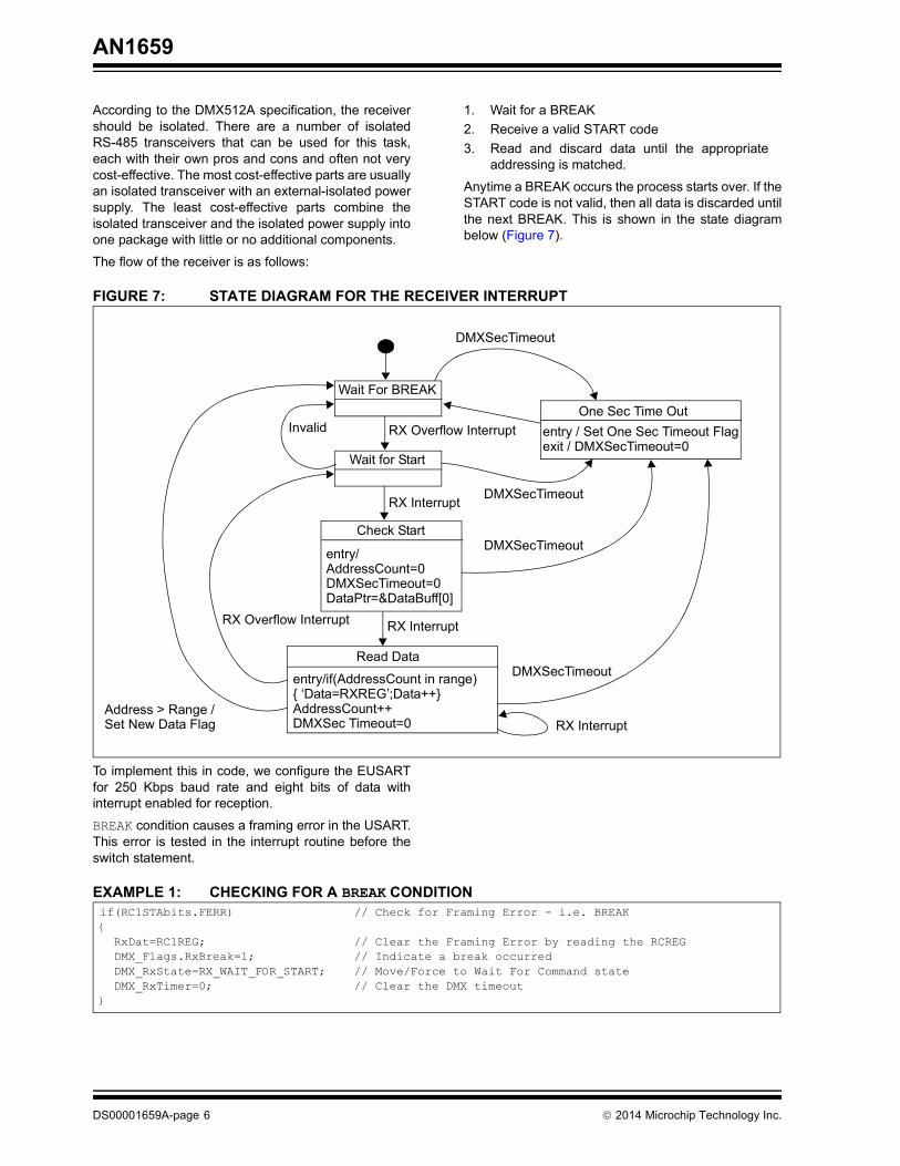
To implement this in code, we configure the EUSARTfor 250 Kbps baud rate and eight bits of data withinterrupt enabled for reception.
BREAK condition causes a framing error in the USART.This error is tested in the interrupt routine before theswitch statement.
EXAMPLE 1: CHECKING FOR A BREAK CONDITION
Wait For BREAK
Wait for Start
Check Start
entry/AddressCount=0DMXSecTimeout=0DataPtr=&DataBuff[0]
Read Data
entry/if(AddressCount in range) ‘Data=RXREG’;Data++AddressCount++DMXSec Timeout=0
One Sec Time Outentry / Set One Sec Timeout Flagexit / DMXSecTimeout=0
DMXSecTimeout
RX Overflow Interrupt
DMXSecTimeout
DMXSecTimeout
DMXSecTimeout
RX Interrupt
Invalid
RX Interrupt
RX InterruptRX Overflow Interrupt
Address > Range / Set New Data Flag
if(RC1STAbits.FERR) // Check for Framing Error - i.e. BREAK
RxDat=RC1REG; // Clear the Framing Error by reading the RCREG
DMX_Flags.RxBreak=1; // Indicate a break occurred
DMX_RxState=RX_WAIT_FOR_START; // Move/Force to Wait For Command state
DMX_RxTimer=0; // Clear the DMX timeout
DS00001659A-page 6 2014 Microchip Technology Inc.

AN1659
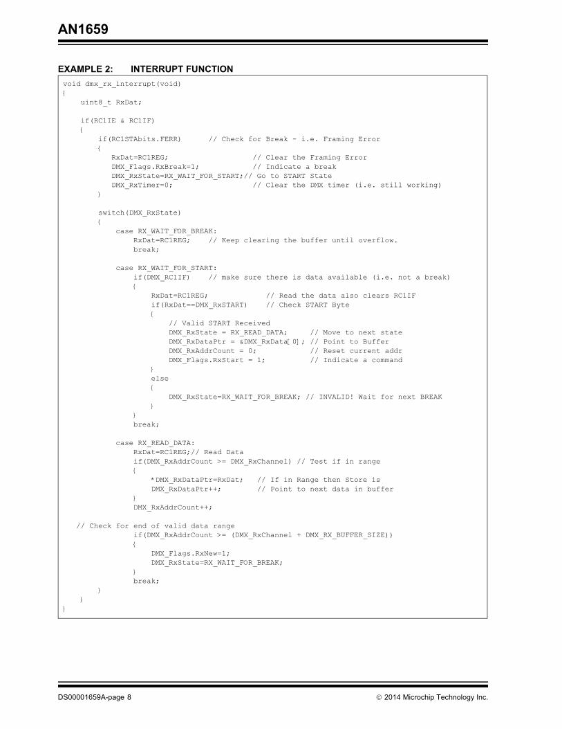
The next byte read is the start byte. If the start isnot valid, then the code moves back to waiting for aBREAK. When a valid start is read, the addresscounter, data pointers, etc., are reset and the statemachine moves to waiting for data.
On each data read the address is incremented. Whena match occurs, the data is stored in the local buffer. Ifit does not match, then the data is discarded. Once allthe valid data has been read, then the state machinegoes back to waiting for a BREAK.
The following example shows the interrupt functionused on a PIC16F1947 (see Example 2).
2014 Microchip Technology Inc. DS00001659A-page 7
AN1659
EXAMPLE 2: INTERRUPT FUNCTIONvoid dmx_rx_interrupt(void)
uint8_t RxDat;
if(RC1IE & RC1IF)
if(RC1STAbits.FERR) // Check for Break - i.e. Framing Error
RxDat=RC1REG; // Clear the Framing Error
DMX_Flags.RxBreak=1; // Indicate a break
DMX_RxState=RX_WAIT_FOR_START;// Go to START State
DMX_RxTimer=0; // Clear the DMX timer (i.e. still working)
switch(DMX_RxState)
case RX_WAIT_FOR_BREAK:
RxDat=RC1REG; // Keep clearing the buffer until overflow.
break;
case RX_WAIT_FOR_START:
if(DMX_RC1IF) // make sure there is data available (i.e. not a break)
RxDat=RC1REG; // Read the data also clears RC1IF
if(RxDat==DMX_RxSTART) // Check START Byte
// Valid START Received
DMX_RxState = RX_READ_DATA; // Move to next state
DMX_RxDataPtr = &DMX_RxData[0]; // Point to Buffer
DMX_RxAddrCount = 0; // Reset current addr
DMX_Flags.RxStart = 1; // Indicate a command
else
DMX_RxState=RX_WAIT_FOR_BREAK; // INVALID! Wait for next BREAK
break;
case RX_READ_DATA:
RxDat=RC1REG;// Read Data
if(DMX_RxAddrCount >= DMX_RxChannel) // Test if in range
*DMX_RxDataPtr=RxDat; // If in Range then Store is
DMX_RxDataPtr++; // Point to next data in buffer
DMX_RxAddrCount++;
// Check for end of valid data range
if(DMX_RxAddrCount >= (DMX_RxChannel + DMX_RX_BUFFER_SIZE))
DMX_Flags.RxNew=1;
DMX_RxState=RX_WAIT_FOR_BREAK;
break;
DS00001659A-page 8 2014 Microchip Technology Inc.

AN1659
IMPLEMENTING THE DMX512 CONTROLLERSending data out is simple to do. The tricky part of theprocess is configuring the hardware to generate theBREAK. More recent EUSARTS allow individualcontrol of the TX and RX I/O pins, and with these partsit is possible to disable only the TX pin. This allows aBREAK to be manually be generated using the sameI/O pin. On the parts without this feature, it is easier touse a second I/O pin and a resistor, as shown inFigure 8. Setting the secondary pin low, then clearingthe TRIS bit, overrides the normal TX pin operation.Setting the TRIS bit for that pin, then ends the breakand passes control back to the USART.
FIGURE 8: CONTROLLER SCHEMATIC – WITH AND WITHOUT RESISTOR
The BREAK and MAB timing requirements are wide.This gives the option of using a soft-timed BREAK andMAB. Alternately, a timer can be used to accuratelygenerate the BREAK and MAB, as well as providing a1 ms tick and millisecond, minute and hour timeinformation for general purpose use. Using the timeralso makes it possible to run the entire transmit code inan interrupt.
IMPLEMENTING DMX512 HALF-DUPLEX COMMUNICATIONHalf-duplex communication requires hardware that canbe dynamically configured as receive or transmit. Italso has active termination at the controller to correctlybias the data lines when the output is tri-stated. Typicalcontroller and receiver circuits are shown below inFigure 9 and Figure 10.
FIGURE 9: HALF-DUPLEX CONTROLLER SCHEMATIC
TX TX
I/O PORT
INDIVIDUAL PIN CONTROL EUSART OLDER EUSART OR UART
562Ω
+5
RX
RXEN
TX
TXEN
+5
PIC® MCU
562Ω
133Ω
2014 Microchip Technology Inc. DS00001659A-page 9

AN1659
FIGURE 10: HALF-DUPLEX RECEIVER SCHEMATIC
Initiating a read from a receiver requires an alternateSTART code and possibly a Manufacturer ID. Theseare issued by the standards committee. START codes0xF0 to 0xF7 are allowed for experimental use whilewaiting for a registered START code to be assigned.Products cannot be shipped using these codes. Also, aSTART code of 0x91 is followed by a 2-byteManufacturer ID that is issued by the standardscommittee and allows for more custom options.
Once the START code and/or Manufacturer ID havebeen sent, the protocol is completely open for theremainder of the frame. At some point, you may wantto read from a receiver. To achieve this, you send acustom sequence or receiver address, change the
direction of the transceiver on the controller, smalldelay, change direction on the receiver hardware, thensend bytes from the receiver to the controller. Once thedata has been sent, the controller and receiver switchthe hardware back to normal operation. These framesmust be interleaved with standard DMX512 frames tokeep everything else on the bus running.
Implementing the half-duplex communication requiresthe addition of a simple USART receiver on thecontroller hardware and a USART transmitter on thereceiver hardware. Detection of the alternate STARTcode and appropriate Manufacture ID needs to beadded so that the custom communications can begin.
FIGURE 11: EXAMPLE OF HALF-DUPLEX COMMUNICATION
+5
RX
RXEN
TX
TXEN
+5
PIC® MCU
+5 ISO
ISO GND
ISO GND
ISOLATION BARRIER
ISOLATED RS-485/422 TRANSCEIVER
BREAK 0x91 IDMSB
ID REQLSB
BREAK 0x91 IDMSB
ID REQLSB DATADATA
DATADATA CH
AN
GE
DIR
EC
TIO
N
CH
AN
GE
DIR
EC
TIO
N
CONTROLLEROUTPUT
RECEIVEROUTPUT
DMXBUS
START MANUFACTURE ID REQUEST RETURNED DATA
DS00001659A-page 10 2014 Microchip Technology Inc.

AN1659
Because the implementation is custom to eachindividual application, we will not go into any moredetail here. The required functions to enablehalf-duplex communication may be found in a futurerelease of the DMX512 library.
THE DMX512 LIBRARYThe library is completely interrupt-driven and requiresthe use of a EUSART and an one timer. The timergenerates the BREAK and the MAB timing for thecontroller and the data time out for the receiver. Thetimer also generates millisecond, minute and hour ticksand counts that can be accessed for general use.
The library currently implements a DMX controller,receiver, or both, depending on how it is configured. Afuture version may add half-duplex communicationcapability and possibly a basic implementation of RDM.
Currently, the DMX512 Library is targeted at theMicrochip Technology 8-bit microcontroller family with aEUSART, but can be easily ported to the 16-bit and32-bit families and some non-EUSART parts.
Files:
• dmxconfig.h• dmx.h• dmx.c
dmxconfig.h is used to configure the various optionsthat are available including the mode of operation,buffer sizes and some default values. Please copy thetemplate to your own project and modify accordingly.
dmx.h is the common header file for the library API thatis included in your C project files
dmx.c is the combined controller and receiver libraryyou need to include in your project.
2014 Microchip Technology Inc. DS00001659A-page 11

AN1659
EXAMPLE CONTROLLER CODEThis is an example of a basic lighting console formanually controlling RGBW LEDs. The following codesimply samples four sliding potentiometers and outputsit to the DMX512 bus.
EXAMPLE 3: SIMPLE DMX CONTROLLER SOURCE CODE#include <xc.h>
#include “dmx.h”
#include “board.h”
void main(void)
uint8_t R,G,B,W;
OSCCON= 0b11110000; // 4xPLL, 8MHz(32MHz), Config bits source
board_init(); // Initialise the boards hardware, ADC etc
dmx_init(); // Initialise DMX512
GIE=1; // Enable the Interrupts
while(1)
if(dmx_timer_ms()) // Use the DMX ms timer to update the reading
R=read_slider(CH_RED);
G=read_slider(CH_GREEN);
B=read_slider(CH_BLUE);
W=read_slider(CH_WHITE);
dmx_write_byte(0,R);
dmx_write_byte(1,G);
dmx_write_byte(2,B);
dmx_write_byte(3,W);
void interrupt isr(void)
dmx_interrupt(); // Process the DMX512 interrupts
DS00001659A-page 12 2014 Microchip Technology Inc.

AN1659
EXAMPLE RECEIVER CODEThe following code demonstrates how a RGBW fixturecan be set up using the DMX512 Library. The addressis set by a 9-bit switch (zero to 511) spread betweenPORTA and PORTB, and is only updated on Reset.The data received is in the order: Red, Green, Blue,White and output to the four PWMs.
EXAMPLE 4: SIMPLE DMX RECEIVER SOURCE CODE
As shown above, the DMX512 library is easy to use.
For full code samples based on the LightingCommunications Kit, please download the library fromhttp://www.microchip.com/.
DMX512 DEVELOPMENT TOOLS• Lighting Communications Motherboard
(DM160214)• Lighting Communications Prototyping Board
(AC160214)• DMX512 Adapter (AC160214-2)• USB to DMX512 Adapter (DM160214)
#include <xc.h>
#include "dmx.h"
#include “board.h”
uint8_t RGBW[4];
void main(void)
uint16_t Address;
OSCCON= 0b11110000;
board_init();
dmx_init();
Address = ((PORTB & 0x01)<<8) | PORTA; // Read the 9bit switch
dmx_set_address(Address);
GIE=1;
while(1)
if(dmx_new_data())
LED_DataToggle(); // Toggle LED to show data RX
dmx_read(0,RGBW,4); // Read the data
led_set_rgbw(RGBW[0],RGBW[1],RGBW[2],RGBW[3]); // Set the PWMs
void interrupt isr(void)
dmx_interrupt();
2014 Microchip Technology Inc. DS00001659A-page 13

AN1659
APPENDIX A: DMX512A LIBRARY FUNCTIONS
EXAMPLE A-1: COMMON FUNCTIONS
Software License AgreementThe software supplied herewith by Microchip Technology Incorporated (the “Company”) is intended and supplied to you, theCompany’s customer, for use solely and exclusively with products manufactured by the Company.The software is owned by the Company and/or its supplier, and is protected under applicable copyright laws. All rights are reserved.Any use in violation of the foregoing restrictions may subject the user to criminal sanctions under applicable laws, as well as to civilliability for the breach of the terms and conditions of this license.THIS SOFTWARE IS PROVIDED IN AN “AS IS” CONDITION. NO WARRANTIES, WHETHER EXPRESS, IMPLIED OR STATU-TORY, INCLUDING, BUT NOT LIMITED TO, IMPLIED WARRANTIES OF MERCHANTABILITY AND FITNESS FOR A PARTICU-LAR PURPOSE APPLY TO THIS SOFTWARE. THE COMPANY SHALL NOT, IN ANY CIRCUMSTANCES, BE LIABLE FORSPECIAL, INCIDENTAL OR CONSEQUENTIAL DAMAGES, FOR ANY REASON WHATSOEVER.
void dmx_init(void)
Initializes the DMX512A Library
Please add near the beginning of you main() function before your main loop
void dmx_interrupt(void)
This processes all the DMX512 related Interrupts.
Please add this to your interrupt function.
void dmx_set_start(uint8_t start)
This selects the DMX512A start code.
For DMX_CONTROLLER this is the start code that is transmitted.
For DMX_RECEIVER this is the start code that will be responded to.
The dmx_init() function defaults this value to '0' which is the most
common start code that is used.
Parameters:
cmd - uint8_t - Sets the start code to use.
DS00001659A-page 14 2014 Microchip Technology Inc.

AN1659
EXAMPLE A-2: DMX512A CONTROLLER FUNCTIONSvoid dmx_tx_interrupt(void)
DMX Transmit interrupt.
This is called as part of dmx_interrupt() but it can call seperately for optimization.
Do not use this unless you really have to.
void dmx_tx_set_start(uint8_t cmd)
This selects the DMX512A start code for the controller
The dmx_init() function defaults this value to '0' which is the most common start code that is
used. This is needed if you are using custom start codes.
Parameter:
uint8_t cmd - Sets the start code to use.
uint8_t dmx_tx_get_start(void)
Returns the DMX512A start code in use
void dmx_write_byte(uint16_t addr, uint8_t data)
This writes a single byte to the specific address in the TX buffer.
Parameters:
uint16_t addr - range 1 to DMX_TX_BUFFER_SIZE. 0 is invalid.
uint8_t data - data to insert in the buffer at location addr
uint8_t dmx_tx_read_byte(uint16_t addr)
This Reads a byte from the tx buffer and is useful for manipulation of data.
Paramter:
uint16_t addr - Selects the address in the buffer to read from.
Range 1 to DMX_TX_BUFFER_SIZE. 0 in invalid.
Returns byte from the buffer at the address selected.
uint8_t dmx_tx_done(void)
Indicates when a packet has been sent and starting a new one. Self clears.
Returns 1 if new data sent or 0 if not.
void dmx_tx_enable(uint8_t enable)
Enables or disable the transmission sequence. i.e. Turns output on/off
Parameter:
uint8_t enable - 1 = turn TX on, 0 = turn TX Off
2014 Microchip Technology Inc. DS00001659A-page 15

AN1659
EXAMPLE A-3: DMX512 CONTROLLER FUNCTIONS
EXAMPLE A-4: DMX512 RECEIVER FUNCTIONS
uint8_t dmx_tx_get_enable(void)
Returns 1 if tx is enabled, 0 if disabled
void dmx_write( uint16_t addr, uint8_t *data, uint8_t num)
Copies an array of data to the output buffer.
This buffer write is performed autonomously - i.e. interrupts disabled
Parameters:
uint16_t addr - address in th ebuffer to start writing to
uint8_t *data - pointer to the data to copy to the buffer
uint8_t num - number of bytes to copy to the buffer. Limited range.
void dmx_rx_interrupt(void)
DMX Receive interrupt.
Called as part of dmx_interrupt() but can call separately for optimization.
Do not call this function unless you really need it.
void dmx_rx_set_start(uint8_t cmd)
This selects the DMX512A start code for the receiver.
The dmx_init() function defaults this value to '0' which is the most common start code that is
used.
Parameter:
uint8_t cmd - Sets the start code to use.
uint8_t dmx_rx_get_start(void)
Returns the DMX512A start code in use
void dmx_set_address(uint16_t base)
Sets the base address to start reading data from.
Valid address range for DMX512 is 1 to 512 (But will work beyond the DMX range for custom
protocol)
An address of "0" will not respond to DMX data causing the DMX 1.2 second timeout to occur
effectively disabling DMX.
Parameter
uint16_t base - The base address to use 1 to 512. 0 to disable RX.
uint16_t dmx_get_address(void)
Returns the base address that is in use.
DS00001659A-page 16 2014 Microchip Technology Inc.

AN1659
EXAMPLE A-5: DMX512 RECEIVER FUNCTIONSuint8_t dmx_new_data(void)
Indicates if new data has been received. Self clears.
Returns 0 for no new data, or the number of bytes of new data received.
uint8_t dmx_read_byte(uint8_t offset)
Reads a byte of the received data from the buffer.
Parameter:
uint8_t offset - sets the offset into the RX buffer to read from
Range 0 to DMX_RX_BUFFER_SIZE-1
Returns the byte read from the RX Buffer at the offset address
uint8_t dmx_read( uint8_t offset, uint8_t *data, uint8_t num)
Reads a block of data from the receive buffer.
Parameters
uint8_t offset - sets the offset into the RX buffer to read from
uint8_t *data - Pointer to where to copy the data to
uint8_t num - Number of bytes to copy. Limited to buffer range.
Returns Number of Bytes copied.
uint8_t dmx_rx_timeout(void)
Indicates if a data timeout has occurred.
Default trigger is 1200ms of no DMX data received which indicates an error, or a DMX512 system
shut down.
Changing the DMX_RX_TIMEOUT_MS changes the timeout limit (ms counter)
Returns 1 if timeout in effect, 0 if everything is still running
2014 Microchip Technology Inc. DS00001659A-page 17

AN1659
EXAMPLE A-6: TIMER FUNCTIONSvoid dmx_timer_interrupt(void)
DMX Timer interrupt.
Called as part of dmx_interrupt() but can call separately for optimization.
Do not use this call unless you really need to.
uint8_t dmx_timer_ms(void)
DMX Timer millisecond tick.
Returns ‘0’ if tick has not occurred.
Returns ‘1’ is tick occurred since last time this function was called.
uint16_t dmx_ms_count(void)
Returns current ms count 0 to 999
void dmx_ms_clear(void)
Clears the current ms count
uint8_t dmx_timer_sec(void)
One second tick.
Returns 0 if a one second tick has not occurred.
Returns 1 if a one second tick has occurred.
uint8_t dmx_sec_count(void)
Returns the current second count 0 to 59
void dmx_sec_clear(void)
Clears the second count.
DS00001659A-page 18 2014 Microchip Technology Inc.

AN1659
EXAMPLE A-7: DMX CONFIGURATION TITLE
EXAMPLE A-8: CONTROLLER SPECIFIC OPTIONS
EXAMPLE A-9: RECEIVER SPECIFIC OPTIONS
Please copy and rename dmxconfig_template.h from the dmx library directory to dmxconfig.h in
your project directory then set the parameters as required.
Following are the definitions and parameters available in the dmxconfig.h file with a brief
description of what they do. Please note these may change in future versions of the library so
check the information in the header file for any updates.
#define DMX // Shows the DMX library is being used, must be uncommented.
Uncomment the modes of operation that you require.
It is possible to have both controller and receiver running at the same time.
//#define DMX_CONTROLLER // Enables the controller functions
//#define DMX_RECEIVER // Enables the receiver function
//#define DMX_BACKCHANNEL // Not used in this version of the library
DMX_TIMER
This enables the timer interrupt features. If you disable this function you MUST write your own
function to provide the appropriate timing flags required by the DMX library.
The best option is to leave it as is unless you really need to use the timer for something else!
In that case, please ensure you include what is required to keep the DMX running!
i.e. copy then modify the existing timer interrupt section.
#define DMX_TIMER
DMX_TX_BUFFER_SIZE
Select the size of the transmit buffer.
This is the Maximum number of channels that will be sent.
DMX512A requires a minimum of 20 and a maximum of 512.
This depends on how much RAM your PIC has available.
#define DMX_TX_BUFFER_SIZE 128
DMX_RX_BUFFER_SIZE
Select the size of the receive buffer.
This is the number of DMX512 Channels you will receive.
For example a RGBW fixture may use 4 channels where a scanner may need 10.
#define DMX_RX_BUFFER_SIZE 8
DMX_RX_TIMEOUT_MS
Selects the ms between breaks that sets the timeout flag.
This is usually just over 1 second and is common for DMX Fixtures
to go into a blackout or default mode if this occurs (i.e. signal lost)
#define DMX_RX_TIMEOUT_MS 1200
2014 Microchip Technology Inc. DS00001659A-page 19

AN1659
EXAMPLE A-10: HARDWARE SETTINGSDirection pin is used on the demo board so that both Transmit and receive can be demonstrated
using a single SN75176 transceiver.
#define DMX_USE_DIR_PIN // Define if using a direction pin
#define DMX_DIR_PIN LATA1 // LAT for the direction pin
#define DMX_DIR_TRIS TRISA1 // TRIS for the direction pin
#define DMX_DIR_RX 0 // Pin setting for RX mode (Based on SN75176)
#define DMX_DIR_TX 1 // Pin Setting for TX mode (Based on SN75176)
Define the TX and RX pins that we are using.
#define DMX_RX_PIN LATB7 // RX pin used
#define DMX_RX_TRIS TRISB7
#define DMX_TX_PIN LATB6 // TX pin used
#define DMX_TX_TRIS TRISB6
Select the EUSART that will be used by redefining the USART registers and individual bits to DMX
USART registers. Some parts with different style USARTS may need changes here and in the dmx.c
code.
#define DMX_BAUDCON BAUD1CON
#define DMX_RCSTA RC1STA
#define DMX_FERR RC1STAbits.FERR
#define DMX_OERR RC1STAbits.OERR
#define DMX_TXSTA TX1STA
#define DMX_TXEN TX1STAbits.TXEN // TX Enable Bit
#define DMX_TRMT TX1STAbits.TRMT // TX Shift reg status bit
#define DMX_RCREG RC1REG // RX Data register
#define DMX_SPBRGL SP1BRGL
#define DMX_SPBRGH SP1BRGH
#define DMX_TXREG TX1REG // TX data register
#define DMX_RCIE RCIE
#define DMX_RCIF RCIF
#define DMX_TXIE TXIE
#define DMX_TXIF TXIF
Calculate the Preload values for the EUSART Configuration
Using BRG16=1 & BRGH=0
BRGH:BRGL = (FOSC / BAUD / 16) - 1
= (FOSC / 250000 / 16) -1
For 32MHZ = (32M / 250K / 16) -1 = 7 = 0x0007
This needs to be automated but at the moment is manually calculated so if you use a different
frequency please recalculate these values.
#define DMX_SPBRGH_LOAD 0
#define DMX_SPBRGL_LOAD 7
#define DMX_BRG16 1 // BRG16=1 & BRGH=0 = Fosc/16 - 16bit H:L
#define DMX_BRGH 0 // BRG16=1 & BRGH=1 = Fosc/4 - 16bit H:L
DS00001659A-page 20 2014 Microchip Technology Inc.

AN1659
EXAMPLE A-11: HARDWARE SETTINGS#define DMX_BAUDCON_LOAD 0b00000000 | (DMX_BRG16<<3)
// Use 9 bit mode to give the 2 stop bits required - set bit 9 to '1'
#define DMX_STA_LOAD 0b01000001 | (DMX_USE_TX <<5) | (DMX_BRGH << 2 )
#define DMX_RCSTA_LOAD 0b10000000 | (DMX_USE_RX <<4)
Timer hardware options and load values. If you use a different timer then you will have to change
this and possibly the dmx.c source code.
#define DMX_TMRIE TMR1IE
#define DMX_TMRIF TMR1IF
#define DMX_TMR TMR1
#define DMX_TCON T1CON
#define DMX_TCON_LOAD 0b00110001 // Fosc/4, 1:8 pre
Reload values for the timer to generate 1ms, Break and MAB timing.
If you use a different frequency or BREAK/MAB timing then you will have to recalculate these.
32MHz / 4 / 8 = 1MHz 1/1MHz = 1us
1ms = 0xFFFF - 1000 = 0xFc17
#define DMX_TMR_LOAD_1MS 0xFc17 // Load value for 1ms
20us = 0xFFFF - 20 = 0xFFEB
#define DMX_TMR_LOAD_MAB 0xFFEB // Load value for MAB ( 20us)
a180us = 0xFFFF - 180 = 0xFF4B#define DMX_TMR_LOAD_BREAK 0xFF4B // Load Value for BREAK (180us)
800us = 0xFFFF - 800 = 0xFCDF - Adjust to fine tune the 1ms total
#define DMX_TMR_LOAD_FILL 0xFCDF // Load value to total 1ms (800us)
2014 Microchip Technology Inc. DS00001659A-page 21

AN1659
NOTES:
DS00001659A-page 22 2014 Microchip Technology Inc.

Note the following details of the code protection feature on Microchip devices:• Microchip products meet the specification contained in their particular Microchip Data Sheet.
• Microchip believes that its family of products is one of the most secure families of its kind on the market today, when used in the intended manner and under normal conditions.
• There are dishonest and possibly illegal methods used to breach the code protection feature. All of these methods, to our knowledge, require using the Microchip products in a manner outside the operating specifications contained in Microchip’s Data Sheets. Most likely, the person doing so is engaged in theft of intellectual property.
• Microchip is willing to work with the customer who is concerned about the integrity of their code.
• Neither Microchip nor any other semiconductor manufacturer can guarantee the security of their code. Code protection does not mean that we are guaranteeing the product as “unbreakable.”
Code protection is constantly evolving. We at Microchip are committed to continuously improving the code protection features of ourproducts. Attempts to break Microchip’s code protection feature may be a violation of the Digital Millennium Copyright Act. If such actsallow unauthorized access to your software or other copyrighted work, you may have a right to sue for relief under that Act.
Information contained in this publication regarding deviceapplications and the like is provided only for your convenienceand may be superseded by updates. It is your responsibility toensure that your application meets with your specifications.MICROCHIP MAKES NO REPRESENTATIONS ORWARRANTIES OF ANY KIND WHETHER EXPRESS ORIMPLIED, WRITTEN OR ORAL, STATUTORY OROTHERWISE, RELATED TO THE INFORMATION,INCLUDING BUT NOT LIMITED TO ITS CONDITION,QUALITY, PERFORMANCE, MERCHANTABILITY ORFITNESS FOR PURPOSE. Microchip disclaims all liabilityarising from this information and its use. Use of Microchipdevices in life support and/or safety applications is entirely atthe buyer’s risk, and the buyer agrees to defend, indemnify andhold harmless Microchip from any and all damages, claims,suits, or expenses resulting from such use. No licenses areconveyed, implicitly or otherwise, under any Microchipintellectual property rights.
2014 Microchip Technology Inc.
QUALITY MANAGEMENT SYSTEM CERTIFIED BY DNV
== ISO/TS 16949 ==
Trademarks
The Microchip name and logo, the Microchip logo, dsPIC, FlashFlex, KEELOQ, KEELOQ logo, MPLAB, PIC, PICmicro, PICSTART, PIC32 logo, rfPIC, SST, SST Logo, SuperFlash and UNI/O are registered trademarks of Microchip Technology Incorporated in the U.S.A. and other countries.
FilterLab, Hampshire, HI-TECH C, Linear Active Thermistor, MTP, SEEVAL and The Embedded Control Solutions Company are registered trademarks of Microchip Technology Incorporated in the U.S.A.
Silicon Storage Technology is a registered trademark of Microchip Technology Inc. in other countries.
Analog-for-the-Digital Age, Application Maestro, BodyCom, chipKIT, chipKIT logo, CodeGuard, dsPICDEM, dsPICDEM.net, dsPICworks, dsSPEAK, ECAN, ECONOMONITOR, FanSense, HI-TIDE, In-Circuit Serial Programming, ICSP, Mindi, MiWi, MPASM, MPF, MPLAB Certified logo, MPLIB, MPLINK, mTouch, Omniscient Code Generation, PICC, PICC-18, PICDEM, PICDEM.net, PICkit, PICtail, REAL ICE, rfLAB, Select Mode, SQI, Serial Quad I/O, Total Endurance, TSHARC, UniWinDriver, WiperLock, ZENA and Z-Scale are trademarks of Microchip Technology Incorporated in the U.S.A. and other countries.
SQTP is a service mark of Microchip Technology Incorporated in the U.S.A.
GestIC and ULPP are registered trademarks of Microchip Technology Germany II GmbH & Co. KG, a subsidiary of Microchip Technology Inc., in other countries.
All other trademarks mentioned herein are property of their respective companies.
© 2014, Microchip Technology Incorporated, Printed in the U.S.A., All Rights Reserved.
Printed on recycled paper.
ISBN: 978-1-63276-245-0
Microchip received ISO/TS-16949:2009 certification for its worldwide
DS00001659A-page 23
headquarters, design and wafer fabrication facilities in Chandler and Tempe, Arizona; Gresham, Oregon and design centers in California and India. The Company’s quality system processes and procedures are for its PIC® MCUs and dsPIC® DSCs, KEELOQ® code hopping devices, Serial EEPROMs, microperipherals, nonvolatile memory and analog products. In addition, Microchip’s quality system for the design and manufacture of development systems is ISO 9001:2000 certified.
DS00001659A-page 24 2014 Microchip Technology Inc.
AMERICASCorporate Office2355 West Chandler Blvd.Chandler, AZ 85224-6199Tel: 480-792-7200 Fax: 480-792-7277Technical Support: http://www.microchip.com/supportWeb Address: www.microchip.comAtlantaDuluth, GA Tel: 678-957-9614 Fax: 678-957-1455Austin, TXTel: 512-257-3370 BostonWestborough, MA Tel: 774-760-0087 Fax: 774-760-0088ChicagoItasca, IL Tel: 630-285-0071 Fax: 630-285-0075ClevelandIndependence, OH Tel: 216-447-0464 Fax: 216-447-0643DallasAddison, TX Tel: 972-818-7423 Fax: 972-818-2924DetroitNovi, MI Tel: 248-848-4000Houston, TX Tel: 281-894-5983IndianapolisNoblesville, IN Tel: 317-773-8323Fax: 317-773-5453Los AngelesMission Viejo, CA Tel: 949-462-9523 Fax: 949-462-9608New York, NY Tel: 631-435-6000San Jose, CA Tel: 408-735-9110Canada - TorontoTel: 905-673-0699 Fax: 905-673-6509
ASIA/PACIFICAsia Pacific OfficeSuites 3707-14, 37th FloorTower 6, The GatewayHarbour City, KowloonHong KongTel: 852-2943-5100Fax: 852-2401-3431Australia - SydneyTel: 61-2-9868-6733Fax: 61-2-9868-6755China - BeijingTel: 86-10-8569-7000 Fax: 86-10-8528-2104China - ChengduTel: 86-28-8665-5511Fax: 86-28-8665-7889China - ChongqingTel: 86-23-8980-9588Fax: 86-23-8980-9500China - HangzhouTel: 86-571-8792-8115 Fax: 86-571-8792-8116China - Hong Kong SARTel: 852-2943-5100 Fax: 852-2401-3431China - NanjingTel: 86-25-8473-2460Fax: 86-25-8473-2470China - QingdaoTel: 86-532-8502-7355Fax: 86-532-8502-7205China - ShanghaiTel: 86-21-5407-5533 Fax: 86-21-5407-5066China - ShenyangTel: 86-24-2334-2829Fax: 86-24-2334-2393China - ShenzhenTel: 86-755-8864-2200 Fax: 86-755-8203-1760China - WuhanTel: 86-27-5980-5300Fax: 86-27-5980-5118China - XianTel: 86-29-8833-7252Fax: 86-29-8833-7256China - XiamenTel: 86-592-2388138 Fax: 86-592-2388130China - ZhuhaiTel: 86-756-3210040 Fax: 86-756-3210049
ASIA/PACIFICIndia - BangaloreTel: 91-80-3090-4444 Fax: 91-80-3090-4123India - New DelhiTel: 91-11-4160-8631Fax: 91-11-4160-8632India - PuneTel: 91-20-3019-1500Japan - OsakaTel: 81-6-6152-7160 Fax: 81-6-6152-9310Japan - TokyoTel: 81-3-6880- 3770 Fax: 81-3-6880-3771Korea - DaeguTel: 82-53-744-4301Fax: 82-53-744-4302Korea - SeoulTel: 82-2-554-7200Fax: 82-2-558-5932 or 82-2-558-5934Malaysia - Kuala LumpurTel: 60-3-6201-9857Fax: 60-3-6201-9859Malaysia - PenangTel: 60-4-227-8870Fax: 60-4-227-4068Philippines - ManilaTel: 63-2-634-9065Fax: 63-2-634-9069SingaporeTel: 65-6334-8870Fax: 65-6334-8850Taiwan - Hsin ChuTel: 886-3-5778-366Fax: 886-3-5770-955Taiwan - KaohsiungTel: 886-7-213-7830Taiwan - TaipeiTel: 886-2-2508-8600 Fax: 886-2-2508-0102Thailand - BangkokTel: 66-2-694-1351Fax: 66-2-694-1350
EUROPEAustria - WelsTel: 43-7242-2244-39Fax: 43-7242-2244-393Denmark - CopenhagenTel: 45-4450-2828 Fax: 45-4485-2829France - ParisTel: 33-1-69-53-63-20 Fax: 33-1-69-30-90-79Germany - DusseldorfTel: 49-2129-3766400Germany - MunichTel: 49-89-627-144-0 Fax: 49-89-627-144-44Germany - PforzheimTel: 49-7231-424750Italy - Milan Tel: 39-0331-742611 Fax: 39-0331-466781Italy - VeniceTel: 39-049-7625286 Netherlands - DrunenTel: 31-416-690399 Fax: 31-416-690340Poland - WarsawTel: 48-22-3325737 Spain - MadridTel: 34-91-708-08-90Fax: 34-91-708-08-91Sweden - StockholmTel: 46-8-5090-4654UK - WokinghamTel: 44-118-921-5800Fax: 44-118-921-5820
Worldwide Sales and Service
03/25/14