Embed Size (px)
Citation preview
Freescale SemiconductorApplication Note
Document Number: AN3315Rev. 0, 09/2006
ContentsOverview . . . . . . . . . . . . . . . . . . . . . . . . . . . . . . . . . . . . . 1DMX512 Protocol Overview . . . . . . . . . . . . . . . . . . . . . . 2
2.1 Physical Layer . . . . . . . . . . . . . . . . . . . . . . . . . . . . . 22.2 Data Protocol. . . . . . . . . . . . . . . . . . . . . . . . . . . . . . 2Software Flowchart . . . . . . . . . . . . . . . . . . . . . . . . . . . . . 5
3.1 Software Implementation. . . . . . . . . . . . . . . . . . . . . 63.2 Code Description. . . . . . . . . . . . . . . . . . . . . . . . . . . 63.3 Advantages and Disadvantages of Using Interrupt or
Non-Interrupt Methods. . . . . . . . . . . . . . . . . . . . . 73.4 Interrupt and Non-Interrupt Based Code: . . . . . . . . 83.5 DMX512 Frame-Detection Code . . . . . . . . . . . . . . . 8DMX512 Implementation Constrains . . . . . . . . . . . . . . . 9DMX512 Hardware Implementation . . . . . . . . . . . . . . . . 9Considerations . . . . . . . . . . . . . . . . . . . . . . . . . . . . . . . 10 Conclusion . . . . . . . . . . . . . . . . . . . . . . . . . . . . . . . . . . 10
DMX512 Protocol Implementation Using MC9S08GT60 8-Bit MCUby: Oscar Luna
Daniel TorresRTAC Americas
1 Overview This application note details the implementation of the DMX512 using the MC9S08GT60 microcontroller.
Illumination entertainment markets have adopted DMX512 protocol due to its simplicity and characteristics and the necessity to unify a single illumination standard. It has been adapted in the high-brightness LED (HBLED) lighting industry for light sources in microscopes and even fixtures in ships and submarines. This market attracts new players as low-end MCUs enable new applications. In many cases, these new applications will be controlled by a central control unit requiring a connectivity interface. In the lighting market today, connectivity is dominated by two protocols: DMX512 and DALI.
The newly-enabled applications using HBLEDs and low-end MCUs include automotive signage, mobile appliances, and illumination. Other novel uses for LEDs range from water purification modules to automated
12
3
4567
© Freescale Semiconductor, Inc., 2006. All rights reserved.
DMX512 Protocol Overview
systems for cultivating vegetables through the combined use of RGB LEDs.
2 DMX512 Protocol OverviewThe DMX512 protocol is simple because it is an asynchronous 8-bit serial protocol and works in an unidirectional line generated by a master device (or console). The protocol can handle up to 512 devices in a DMX network and communicates at 250 kbps baud rate. Each bit in the frame is generated every 4us.
Every slave in the network is addressed using one specific byte in the frame. Each byte in the frame describes 256 possible dimming levels on each slave. The media is driven using ANSI/TIA/EIA-485-A-1998 balanced data-transmission techniques. Physical connection between devices is via 5-pin XRL connectors or by hard-wiring the terminals.
2.1 Physical LayerThe EIA-485 are the protocol’s electrical specifications. The EIA-485-A standard does not point any advice related to isolation issues but DMX512 standard does. Any suitable isolation method such as optical isolation, transformer isolation, or other means may be used to avoid the undesirable propagation of voltages exceeding limits based on the EIA-485-A standard.
The data link is compounded by a single, active differential-line driver, a terminated transmission line, and one or more differential-line receivers. A DMX512 connection point has five assigned end-points: data 1-, data1+, data2-, data2+ and a common reference. In some cases, data2- and data 2+ are not used or they simply carry the same signals of the first differential line (data1- and data1+). In both cases, there should be a low impedance connection between data link and common pin or contact of the DMX512 port.
The data link must have a terminator to eliminate ringing issues or signal reflection. The terminator must be a 120 Ohms +5%/-10% impedance placed between data+ and data-.
Female connectors are used on controllers and other transmitting devices. Male connectors are used on receiving devices. The required connector is a 5-pin XLR; pins are assigned as: common reference (1), data1- (2), data1+ (3), data2- (4), data2+ (5).
2.2 Data ProtocolDMX512 data is transmitted sequentially in asynchronous serial format, starting with slot 0 and ending with slot 512. Prior to the first data slot being transmitted, there is a reset sequence consisting of a BREAK followed by a MARK AFTER BREAK and a START code. Valid data values under a NULL START code are between 0 and 255.
(Figure 1 shows detailed information about the DMX512 frame’s compounding elements.)
The data transmission format is compounded as follows:• Bit 1 start bit, low or space• Bit 2-9 data bits (least significant bit to most significant bit)• Bit 10,11 stop bits, high or MARK
DMX512 Protocol Implementation Using MC9S08GT60 8-Bit MCU, Rev. 0
Freescale Semiconductor2
DMX512 Protocol Overview
The data frame is compounded by these time slots:• BREAK
Indicates the start of a new packet, typical value is 176 μsec.• MARK AFTER BREAK
Separates the break and start code time slots. Values can be between 8 μsec and 1 second.• START CODE
The first slot (slot 0) following a MARK AFTER BREAK. Identifies the function of subsequent data bytes in the packet. For dimming commands the star code value is 0x00; therefore, it is also known as a NULL START CODE. Alternate start codes may be used (refer to the USSIT-DMX512-A protocol specification, annex D).
• DATA SLOTS Subsequent data bytes where the dimming levels for each receiving device are placed. The number of data slots is 512; DMX512 data packets with fewer data packets should not be transmitted. Time between any two data packets may vary from 0 up to 1 sec. This time is known as MARK TIME BETWEEN DATA SLOTS.
• MARK BEFORE BREAK Time between the second stop bit of the last data slot of a given data packet and the falling edge of the beginning of the BREAK for the next data packet. This time may vary from 0 up to 1 sec. Every data packet transmitted over the data link starts with a BREAK, MARK AFTER BREAK, and a START CODE sequence defined as a RESET sequence.
• BREAK-TO-BREAK. The period between the falling edge at the start code of any one BREAK and the falling edge at the start of the next BREAK. May vary from 1196 μsec up to 1.25 sec.
DMX512 Protocol Implementation Using MC9S08GT60 8-Bit MCU, Rev. 0
Freescale Semiconductor 3
DMX512 Protocol Overview
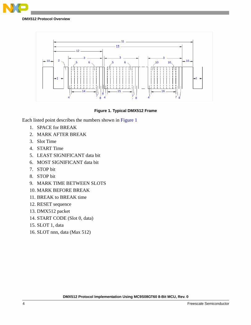
Figure 1. Typical DMX512 Frame
Each listed point describes the numbers shown in Figure 11. SPACE for BREAK2. MARK AFTER BREAK3. Slot Time4. START Time5. LEAST SIGNIFICANT data bit6. MOST SIGNIFICANT data bit7. STOP bit8. STOP bit9. MARK TIME BETWEEN SLOTS10. MARK BEFORE BREAK11. BREAK to BREAK time12. RESET sequence13. DMX512 packet14. START CODE (Slot 0, data)15. SLOT 1, data16. SLOT nnn, data (Max 512)
10
1
3333
12
1213
11
10
1
4
14
7 88889
994
15
7 8 4
16
7 8
210
1213
11
10
1
3335 6 10 10
4
16
7 887
15
49
87
14
4
1
5 6
DMX512 Protocol Implementation Using MC9S08GT60 8-Bit MCU, Rev. 0
Freescale Semiconductor4
Software Flowchart
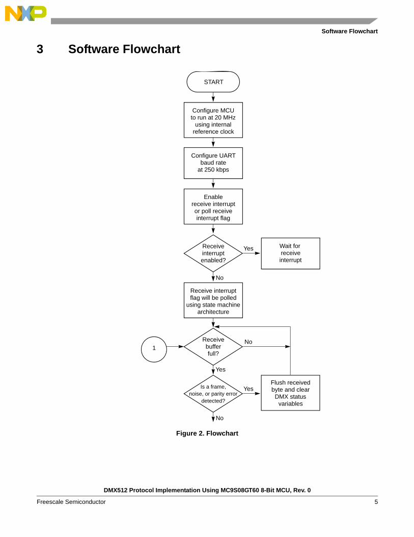
3 Software Flowchart
Figure 2. Flowchart
START
Configure MCUto run at 20 MHz
using internalreference clock
Configure UARTbaud rate
at 250 kbps
Enablereceive interruptor poll receiveinterrupt flag
Receiveinterruptenabled?
Wait for receiveinterrupt
Yes
No
Receive interruptflag will be polled
using state machinearchitecture
Receivebufferfull?
No
Yes
Is a frame,noise, or parity error
detected?
Yes
No
Flush receivedbyte and clearDMX status
variables
1
DMX512 Protocol Implementation Using MC9S08GT60 8-Bit MCU, Rev. 0
Freescale Semiconductor 5
Software Flowchart
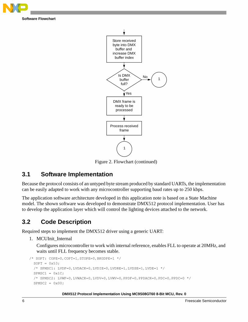
Figure 2. Flowchart (continued)
3.1 Software ImplementationBecause the protocol consists of an untyped byte stream produced by standard UARTs, the implementation can be easily adapted to work with any microcontroller supporting baud rates up to 250 kbps.
The application software architecture developed in this application note is based on a State Machine model. The shown software was developed to demonstrate DMX512 protocol implementation. User has to develop the application layer which will control the lighting devices attached to the network.
3.2 Code DescriptionRequired steps to implement the DMX512 driver using a generic UART:
1. MCUInit_InternalConfigures microcontroller to work with internal reference, enables FLL to operate at 20MHz, and waits until FLL frequency becomes stable.
/* SOPT: COPE=0,COPT=1,STOPE=0,BKGDPE=1 */ SOPT = 0x53; /* SPMSC1: LVDF=0,LVDACK=0,LVDIE=0,LVDRE=1,LVDSE=1,LVDE=1 */ SPMSC1 = 0x1C; /* SPMSC2: LVWF=0,LVWACK=0,LVDV=0,LVWV=0,PPDF=0,PPDACK=0,PDC=0,PPDC=0 */ SPMSC2 = 0x00;
Store receivedbyte into DMX
buffer and increase DMX
buffer index
Is DMXbufferfull?
No
Yes
1
DMX frame isready to beprocessed
Process receivedframe
1
DMX512 Protocol Implementation Using MC9S08GT60 8-Bit MCU, Rev. 0
Freescale Semiconductor6
Software Flowchart
/* ICGC1: RANGE=1,REFS=0,CLKS1=0,CLKS0=1,OSCSTEN=1 */ ICGC1 = 0x4C; /* ICGC2: LOLRE=0,MFD2=1,MFD1=1,MFD0=1,LOCRE=0,RFD2=0,RFD1=0,RFD0=0 */ ICGC2 = 0x70; ICGTRM = *(unsigned char*far)0xFFBE; /* Initialize ICGTRM register from a non volatilememory */ while(!ICGS1_LOCK) { /* Wait FLL be stable */2. vfnDMX512Init
Configures SCI module to work with a baud rate of 250 kbps, enables RX interrupt, clears all RX flags, and initializes DMX control variables. /** Variable used to clear the SCI flags */UINT8 uInt8ClearFlags = 0;
DMX512BDH = 0x00;
DMX512BDL = BAUD_RATE_250K; /* Configure Baud Rate at 250Kbps*/DMX512C1 = DMX512_RESET_VALUE;
/* Disable Rx interrupt. Data arrived will be polled */
DMX512C2 = CONFIG_DMX512_RX_POLL; /*
Clear any Flag that could be set */ uInt8ClearFlags = DMX512S1; uInt8ClearFlags = DMX512S2; DMX512C3 = DMX512_RESET_VALUE; uInt8ClearFlags = DMX512Data; /* Reading the DMX512_RX Data Register */ /*Set the program flow control flags*/ DMX512Comm.RxOffset = 0;
DMX512Comm.RxFlags = 0;DMX512Comm.StartRxFlag = 0 ;
DMX512Comm.RxStatus = DMX512_READY ; 3. vfnDMX512Driver:
There are two methods to detect a valid DMX512 frame. The first method uses the SCI receiver interrupt. The second method polls the SCI receiver interrupt flag. (See sections 3.1 and 3.2 for code.)
3.3 Advantages and Disadvantages of Using Interrupt or Non-Interrupt Methods
Developer must choose which method better suits the application. Both alternatives are presented in the source code.
• Interrupt-Method Advantage:Byte reception is assured because MCU services the UART receiver interrupt routine every time a byte is received. Therefore, data reception is independent of program flow. This task is always serviced.
• Interrupt-Method Disadvantage:
DMX512 Protocol Implementation Using MC9S08GT60 8-Bit MCU, Rev. 0
Freescale Semiconductor 7
Software Flowchart
Because the DMX512 console sends every time the DMX frame completes (512 data bytes + 1 command byte), the MCU will constantly service the SCI receiver interrupt, consuming most of the MCU processing time. The application tasks must be completed during the remaining time. Time to complete these tasks could be longer than using polling method. Developer must be aware the interrupt-service routine will have higher priority than program flow.
• Non-Interrupt Method Advantage:Program flow time could be prioritized in order to attend the incoming DMX frame and continue with normal program flow.
• Non-Interrupt Method Disadvantage:DMX512 frames could be lost if the DMX512 receiving task is not called on time during the normal program flow.
3.4 Interrupt and Non-Interrupt Based Code:The frame-detection method is the same in both solutions. The main difference between methods resides in the state-machine model. In the non-interrupt method, the state machine is always polling the receiver interrupt flag (see code for more details). If non-interrupt method is not used then developer should change the following line code in the DMX initialization routine (vfnDMX512Init): DMX512C2 = CONFIG_DMX512_RX_POLL;
If developer decides to use the interrupt-base method, the following line in the DMX initialization routine must be declared instead of the above code: DMX512C2 = CONFIG_DMX512_RX_ISR_EN;
3.5 DMX512 Frame-Detection CodeThe following code is used to detect the DMX512 data frames. Two local variables are declared, u8Status is used to capture and clear the SCI status register flags. The u8Dummy is a temporal variable where the data byte retrieved from the SCI Rx data register is stored. After declaring these variables, the next step is to check if the receiver buffer is full. That does not mean the received data is valid. To verify data, the framing, noise, and parity flags must be checked. If one flag is set, data is flushed and the DMX512 driver status flags are cleared. The driver will wait for the next DMX512 frame to sync.
When a valid data is received, it is stored in the DMX512 buffer until the 1 command + 512 data bytes have been received. If buffer is full, the DMX512 driver tells the main program a complete DMX512 frame has been received. It will set the RxStatus flag to DMX512_RX_PROC_MSG state and initialize the DMX512 buffer index.
The RxStatus and the StartRx flags must be cleared in the main program flow once the DMX512 data buffer has been read, then the buffer can be used again. See AN3315SW software files for details. /** Variable used to capture the SCI status register */ UINT8 u8Status = 0; /** Variable used to store the Data register content */ UINT8 u8Dummy = 0; u8Status = DMX512S1;
DMX512 Protocol Implementation Using MC9S08GT60 8-Bit MCU, Rev. 0
Freescale Semiconductor8
DMX512 Implementation Constrains
u8Dummy = DMX512Data; if((u8Status & 0x20) !=0) /* Rx data buffer is full ?*/ { if ((u8Status & 0x07) != 0) /* Check for Errors (Framing, Noise, Parity) */ { u8Dummy = DMX512Data; DMX512Comm.RxOffset = 0; DMX512Comm.StartRxFlag = 0; DMX512Comm.RxStatus = DMX512_RX_DATA; return; }
DMX512Comm.RxBuffer1[DMX512Comm.RxOffset++] = u8Dummy ;
if( DMX512Comm.RxOffset >= DMX_RX_BUFFER_SIZE ) { DMX512Comm.RxOffset = 0; DMX512Comm.StartRxFlag = 1; DMX512Comm.RxStatus = DMX512_RX_PROC_MSG; }
}
4 DMX512 Implementation Constrains To implement the DMX512 protocol in an 8-bit microcontroller, it is important to keep in mind the following considerations:
• MCU UART must support a baud rate of 250 kbps. • MCU UART must support a data frame compounded by 1 start bit, 8 data bits, 1 stop bit in a NRZ
format.• 513 bytes in RAM are needed to store the complete DMX512 frame. MCU must have at least 1Kb
of RAM.
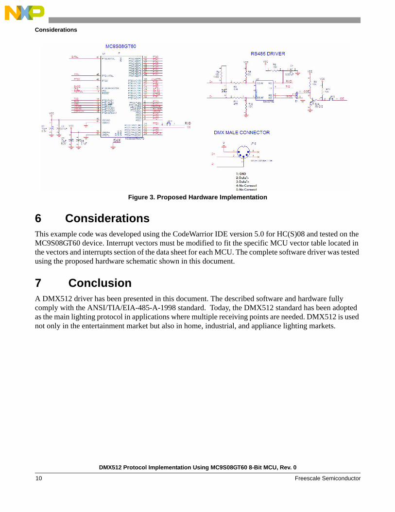
5 DMX512 Hardware ImplementationFigure 3 shows the recommended hardware that should be implemented using the referenced code in this document. Listed below are considerations to keep in mind when the proposed HW becomes implemented:
• Jumper JP9 must be set in case the device becomes the last in the DMX bus.• Pins 4 & 5 in the male connector are not used. • The developer is allowed to Enable/Disable the RE signal in the transceiver by software or
hardware. The DMX512 driver in this document does not control the RE signal.
DMX512 Protocol Implementation Using MC9S08GT60 8-Bit MCU, Rev. 0
Freescale Semiconductor 9
Considerations
Figure 3. Proposed Hardware Implementation
6 Considerations This example code was developed using the CodeWarrior IDE version 5.0 for HC(S)08 and tested on the MC9S08GT60 device. Interrupt vectors must be modified to fit the specific MCU vector table located in the vectors and interrupts section of the data sheet for each MCU. The complete software driver was tested using the proposed hardware schematic shown in this document.
7 ConclusionA DMX512 driver has been presented in this document. The described software and hardware fully comply with the ANSI/TIA/EIA-485-A-1998 standard. Today, the DMX512 standard has been adopted as the main lighting protocol in applications where multiple receiving points are needed. DMX512 is used not only in the entertainment market but also in home, industrial, and appliance lighting markets.
DMX512 Protocol Implementation Using MC9S08GT60 8-Bit MCU, Rev. 0
Freescale Semiconductor10

THIS PAGE IS INTENTIONALLY BLANK
DMX512 Protocol Implementation Using MC9S08GT60 8-Bit MCU, Rev. 0
Freescale Semiconductor 11

Document Number: AN3315Rev. 009/2006
How to Reach Us:
Home Page:www.freescale.com
E-mail:[email protected]
USA/Europe or Locations Not Listed:Freescale SemiconductorTechnical Information Center, CH3701300 N. Alma School RoadChandler, Arizona 85224+1-800-521-6274 or [email protected]
Europe, Middle East, and Africa:Freescale Halbleiter Deutschland GmbHTechnical Information CenterSchatzbogen 781829 Muenchen, Germany+44 1296 380 456 (English)+46 8 52200080 (English)+49 89 92103 559 (German)+33 1 69 35 48 48 (French)[email protected]
Japan:Freescale Semiconductor Japan Ltd.HeadquartersARCO Tower 15F1-8-1, Shimo-Meguro, Meguro-ku,Tokyo 153-0064Japan0120 191014 or +81 3 5437 [email protected]
Asia/Pacific:Freescale Semiconductor Hong Kong Ltd.Technical Information Center2 Dai King StreetTai Po Industrial EstateTai Po, N.T., Hong Kong+800 2666 [email protected]
For Literature Requests Only:Freescale Semiconductor Literature Distribution CenterP.O. Box 5405Denver, Colorado 802171-800-441-2447 or 303-675-2140Fax: [email protected]
Information in this document is provided solely to enable system and software implementers to use Freescale Semiconductor products. There are no express or implied copyright licenses granted hereunder to design or fabricate any integrated circuits or integrated circuits based on the information in this document.
Freescale Semiconductor reserves the right to make changes without further notice to any products herein. Freescale Semiconductor makes no warranty, representation or guarantee regarding the suitability of its products for any particular purpose, nor does Freescale Semiconductor assume any liability arising out of the application or use of any product or circuit, and specifically disclaims any and all liability, including without limitation consequential or incidental damages. “Typical” parameters that may be provided in Freescale Semiconductor data sheets and/or specifications can and do vary in different applications and actual performance may vary over time. All operating parameters, including “Typicals”, must be validated for each customer application by customer’s technical experts. Freescale Semiconductor does not convey any license under its patent rights nor the rights of others. Freescale Semiconductor products are not designed, intended, or authorized for use as components in systems intended for surgical implant into the body, or other applications intended to support or sustain life, or for any other application in which the failure of the Freescale Semiconductor product could create a situation where personal injury or death may occur. Should Buyer purchase or use Freescale Semiconductor products for any such unintended or unauthorized application, Buyer shall indemnify and hold Freescale Semiconductor and its officers, employees, subsidiaries, affiliates, and distributors harmless against all claims, costs, damages, and expenses, and reasonable attorney fees arising out of, directly or indirectly, any claim of personal injury or death associated with such unintended or unauthorized use, even if such claim alleges that Freescale Semiconductor was negligent regarding the design or manufacture of the part.
Freescale™ and the Freescale logo are trademarks of Freescale Semiconductor, Inc. All other product or service names are the property of their respective owners.
© Freescale Semiconductor, Inc. 2006. All rights reserved.
RoHS-compliant and/or Pb-free versions of Freescale products have the functionality and electrical characteristics as their non-RoHS-compliant and/or non-Pb-free counterparts. For further information, see http://www.freescale.com or contact your Freescale sales representative.For information on Freescale’s Environmental Products program, go to http://www.freescale.com/epp.


![j IV. UnionÐFind D I, II, III,wayne/kleinberg... · 11/13/2019 · Goal. Increment a k-bit binary counter (mod 2 k). Representation. A[j] = jth least significant bit of counter](https://img.pdfslide.us/doc/110x75/5f4b5af7e6d90971493f3793/j-iv-unionfind-d-i-ii-iii-waynekleinberg-11132019-goal-increment.jpg)

![DIGITAL-TO-ANALOG CONVERTER · D13A is most significant data bit (MSB) D0A is least significant data bit (MSB) D[13..0]B 2, 4, 6, 8, 10, 12, 14, 24, 26, 28, 30, 32, 34, 36 I LVDS](https://img.pdfslide.us/doc/110x75/5ba227a909d3f210318b6a42/digital-to-analog-converter-d13a-is-most-significant-data-bit-msb-d0a-is-least.jpg)