Embed Size (px)
Citation preview
DMX-Master I,DMX-Master MK II ENC
DMX controller
user manual
Musikhaus Thomann
Thomann GmbH
Hans-Thomann-Straße 1
96138 Burgebrach
Germany
Telephone: +49 (0) 9546 9223-0
E-mail: [email protected]
Internet: www.thomann.de
05.08.2016, ID: 168962, 236071 | SW B3.0V3.3
Table of contents
1 General information................................................................................................................................. 51.1 Further information........................................................................................................................... 61.2 Notational conventions.................................................................................................................... 71.3 Symbols and signal words............................................................................................................... 9
2 Safety instructions.................................................................................................................................. 10
3 Features....................................................................................................................................................... 14
4 Installation.................................................................................................................................................. 16
5 Setup.............................................................................................................................................................. 18
6 Connections and controls................................................................................................................... 19
7 Basics............................................................................................................................................................. 31
8 Operating.................................................................................................................................................... 348.1 Introduction....................................................................................................................................... 348.2 Enabling programming mode..................................................................................................... 348.3 Programming scenes...................................................................................................................... 358.4 Programming chase........................................................................................................................ 42
Table of contents
DMX-Master I, DMX-Master MK II ENC
3
8.5 Assigning / reversing DMX channels........................................................................................ 478.6 Calling up scenes.............................................................................................................................. 558.7 Calling chases.................................................................................................................................... 578.8 The MIDI functions........................................................................................................................... 598.9 Sending data...................................................................................................................................... 628.10 Receiving data................................................................................................................................ 63
9 Technical specifications....................................................................................................................... 64
10 Plug and connection assignment.................................................................................................... 65
11 Protecting the environment.............................................................................................................. 66
Table of contents
DMX controller
4
1 General information
This manual contains important instructions for the safe operation of the unit. Read and followthe safety instructions and all other instructions. Keep the manual for future reference. Makesure that it is available to all those using the device. If you sell the unit please make sure thatthe buyer also receives this manual.
Our products are subject to a process of continuous development. Thus, they are subject tochange.
General information
DMX-Master I, DMX-Master MK II ENC
5
1.1 Further information
On our website (www.thomann.de) you will find lots of further information and details on thefollowing points:
Download This manual is also available as PDF file for you to download.
Keyword search Use the search function in the electronic version to find the topics ofinterest for you quickly.
Online guides Our online guides provide detailed information on technical basicsand terms.
Personal consultation For personal consultation please contact our technical hotline.
Service If you have any problems with the device the customer service willgladly assist you.
General information
DMX controller
6
1.2 Notational conventions
This manual uses the following notational conventions:
The letterings for connectors and controls are marked by square brackets and italics.
Examples: [VOLUME] control, [Mono] button.
Texts and values displayed on the device are marked by quotation marks and italics.
Examples: ‘24ch’ , ‘OFF’ .
Letterings
Displays
General information
DMX-Master I, DMX-Master MK II ENC
7
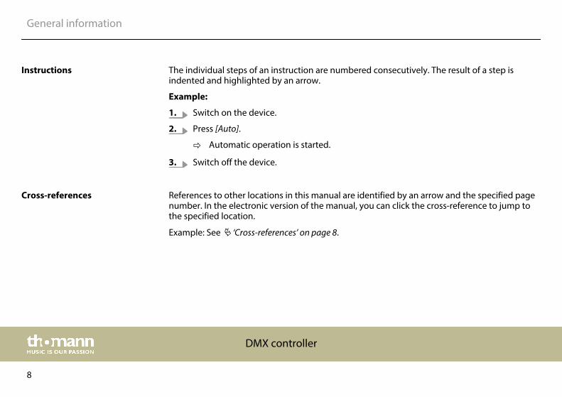
The individual steps of an instruction are numbered consecutively. The result of a step isindented and highlighted by an arrow.
Example:
1. Switch on the device.
2. Press [Auto].
ð Automatic operation is started.
3. Switch off the device.
References to other locations in this manual are identified by an arrow and the specified pagenumber. In the electronic version of the manual, you can click the cross-reference to jump tothe specified location.
Example: See Ä ‘Cross-references’ on page 8.
Instructions
Cross-references
General information
DMX controller
8
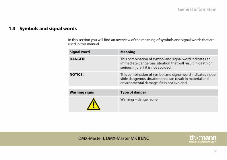
1.3 Symbols and signal words
In this section you will find an overview of the meaning of symbols and signal words that areused in this manual.
Signal word Meaning
DANGER! This combination of symbol and signal word indicates animmediate dangerous situation that will result in death orserious injury if it is not avoided.
NOTICE! This combination of symbol and signal word indicates a pos‐sible dangerous situation that can result in material andenvironmental damage if it is not avoided.
Warning signs Type of danger
Warning – danger zone.
General information
DMX-Master I, DMX-Master MK II ENC
9
2 Safety instructions
This device is used to control spotlights, dimmers, lighting effects equipment, Moving Headsor other DMX-controlled devices. The device is designed for professional use and is not suit‐able for use in households. Use the device only as described in this user manual. Any other useor use under other operating conditions is considered to be improper and may result in per‐sonal injury or property damage. No liability will be assumed for damages resulting fromimproper use.
This device may be used only by persons with sufficient physical, sensorial, and intellectualabilities and having corresponding knowledge and experience. Other persons may use thisdevice only if they are supervised or instructed by a person who is responsible for their safety.
Intended use
Safety instructions
DMX controller
10
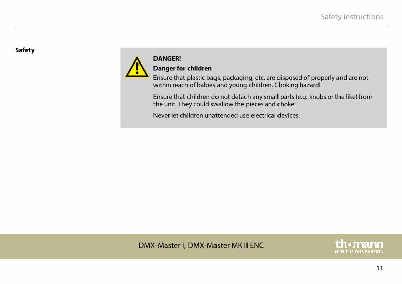
DANGER!Danger for childrenEnsure that plastic bags, packaging, etc. are disposed of properly and are notwithin reach of babies and young children. Choking hazard!
Ensure that children do not detach any small parts (e.g. knobs or the like) fromthe unit. They could swallow the pieces and choke!
Never let children unattended use electrical devices.
Safety
Safety instructions
DMX-Master I, DMX-Master MK II ENC
11
NOTICE!External power supplyThe device is powered by an external power supply. Before connecting theexternal power supply, ensure that the input voltage (AC outlet) matches thevoltage rating of the device and that the AC outlet is protected by a residual cur‐rent circuit breaker. Failure to do so could result in damage to the device and pos‐sibly the user.
Unplug the external power supply before electrical storms occur and when thedevice is unused for long periods of time to reduce the risk of electric shock orfire.
NOTICE!Risk of fireDo not cover the device nor any ventilation slots. Do not place the device nearany direct heat source. Keep the device away from naked flames.
Safety instructions
DMX controller
12
NOTICE!Operating conditionsThis device has been designed for indoor use only. To prevent damage, neverexpose the device to any liquid or moisture. Avoid direct sunlight, heavy dirt, andstrong vibrations.
NOTICE!Possible stainingThe plasticiser contained in the rubber feet of this product may possibly reactwith the coating of your parquet, linoleum, laminate or PVC floor and after sometime cause permanent dark stains.
In case of doubt, do not put the rubber feet directly on the floor, but use felt-padfloor protectors or a carpet.
Safety instructions
DMX-Master I, DMX-Master MK II ENC
13
3 Features
Special features of the device:
n 192 DMX channelsn 12 units with up to 16 DMX channels operablen 30 banks with 8 freely programmable scenesn Six Chase programmes with up to 240 scenes from 30 banksn Eight faders for manual controln All data interchangeable between two unitsn Auto programmes (scenes and chases), controlled by Wait Time knob (or Tap Sync) and
Fade Time knobn Stepless fade time setting (0-30 seconds)n Two encoder wheels for precise adjustment of PAN and TILT (DMX Master MK-II ENC)n Fine tuning for PAN and TILTn Inverted DMX channels allow reverse output control for the slidersn Assigned or reversed DMX channel previewn 8 / 16 channel mode for assigned or reversed DMX channelsn Blackout mastern Stand-alone mode
Features
DMX controller
14
n Manual overriding of scenes in chasesn Sound controln MIDI control for banks, chases and blackoutn LCDn DMX polarity adjustablen Memory retention on power failuren Auto addressing
Features
DMX-Master I, DMX-Master MK II ENC
15
4 Installation
NOTICE!Possible stainingThe plasticiser contained in the rubber feet of this product may possibly reactwith the coating of your parquet, linoleum, laminate or PVC floor and after sometime cause permanent dark stains.
In case of doubt, do not put the rubber feet directly on the floor, but use felt-padfloor protectors or a carpet.
Unpack and carefully check that there is no transportation damage before using the unit. Keepthe equipment packaging. To fully protect the device against vibration, dust and moistureduring transportation or storage use the original packaging or your own packaging materialsuitable for transport or storage, respectively.
Installation
DMX controller
16
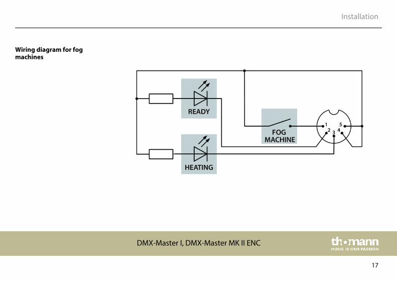
Wiring diagram for fogmachines
Installation
DMX-Master I, DMX-Master MK II ENC
17
5 Setup
Create all connections while the device is off. Use the shortest possible high-quality cables forall connections. Take care when running the cables to prevent tripping hazards.
Connect the included power adapter to the 9V connector of the unit and then plug the poweradapter into a wall outlet.
Turn on the device using the main switch on the rear panel. Turn on the device using the mainswitch at the back side. After turning the device on the displays shows the software versionand the operation mode for a short time. The related display LEDs light up.
Connecting the power supply
Turning the unit on
Setup
DMX controller
18
6 Connections and controls
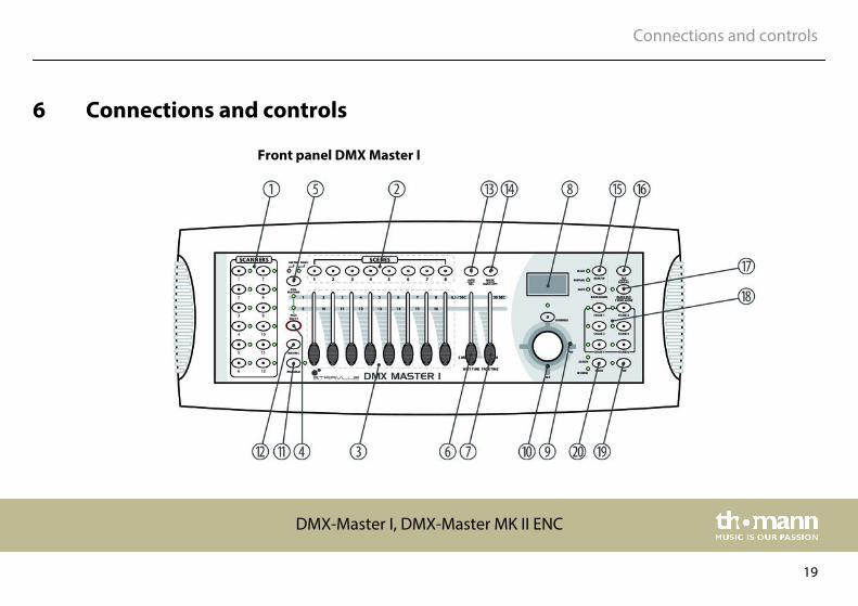
Front panel DMX Master I
Connections and controls
DMX-Master I, DMX-Master MK II ENC
19
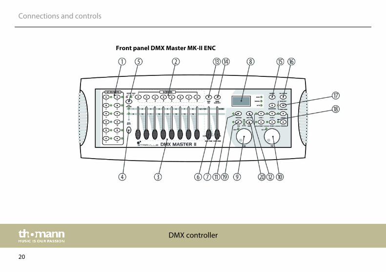
Front panel DMX Master MK-II ENC
Connections and controls
DMX controller
20
1 [SCANNERS]
12 scanners with 16 DMX channels and fader control.
Press one of the scanner buttons to turn on the manual fader control. Press the scanner button again to turn it off.The LED next to the button lights up or goes out to indicate your selection. For channel assignment, see table below.
2 [SCENES]
Scene buttons.
Press one of the Scene buttons to load or save scenes. A maximum of 240 scenes can be saved.
3 Fader.
Use these knobs to control the intensity of channels 1-8 or 9-16, depending on which Page is selected.
4 [PAGE SELECT]
Page select button.
To select the desired page A (1-8) or page B (9-16).
Connections and controls
DMX-Master I, DMX-Master MK II ENC
21
5 [FOG MACHINE]
Activates the fog machine.
The control LEDS indicate the current operation status of the fog machine.
n [HEATING]: Fog machine is heating up.n [READY]: Fog machine is operational.
6 [WAIT TIME]
Time control.
For setting the Chase-Wait time of 0.1 s to 5 min.
7 [FADE TIME]
Time control.
For setting the Fade time. The Fade time is the time it takes for a scanner to move from one position to another, or fora dimmer from Fade In to Fade Out.
Connections and controls
DMX controller
22
8 Display
Shows the current activity of the device or the status of programming ( Ä ‘Information in the display’ on page 30).
The control LEDs show the current operating mode of the controller:
n [MUSIC]: Sound control.n [MANUAL]: Manual operation.n [AUTO]: Automatic run.
9 [PAN]
Pan wheel.
This wheel controls the Pan movement of the scanner or is used for programming.
10 [TILT]
Tilt wheel.
This wheel controls the Tilt movement of the scanner or is used for programming.
11 [PROGRAM]
Enables the Programme mode.
Connections and controls
DMX-Master I, DMX-Master MK II ENC
23
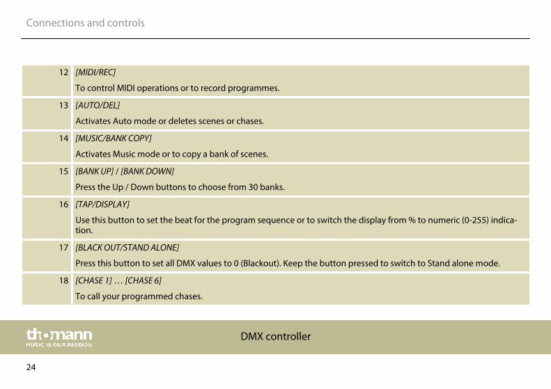
12 [MIDI/REC]
To control MIDI operations or to record programmes.
13 [AUTO/DEL]
Activates Auto mode or deletes scenes or chases.
14 [MUSIC/BANK COPY]
Activates Music mode or to copy a bank of scenes.
15 [BANK UP] / [BANK DOWN]
Press the Up / Down buttons to choose from 30 banks.
16 [TAP/DISPLAY]
Use this button to set the beat for the program sequence or to switch the display from % to numeric (0-255) indica‐tion.
17 [BLACK OUT/STAND ALONE]
Press this button to set all DMX values to 0 (Blackout). Keep the button pressed to switch to Stand alone mode.
18 [CHASE 1] … [CHASE 6]
To call your programmed chases.
Connections and controls
DMX controller
24
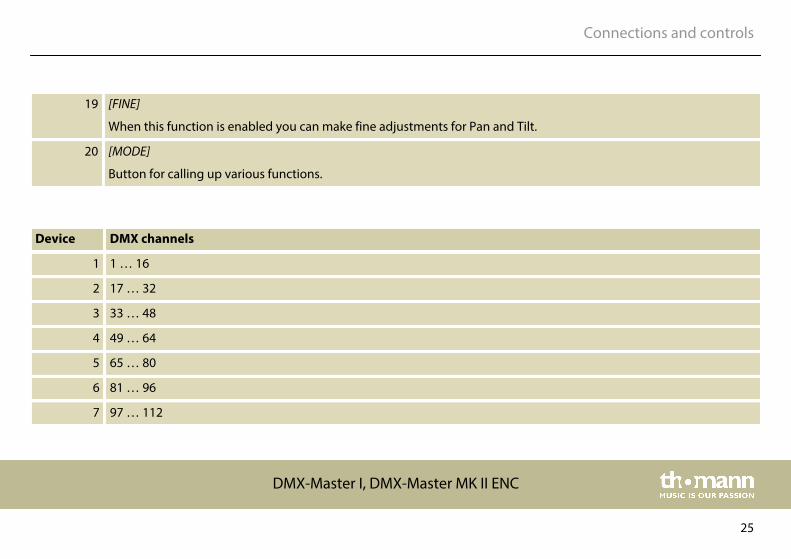
19 [FINE]
When this function is enabled you can make fine adjustments for Pan and Tilt.
20 [MODE]
Button for calling up various functions.
Device DMX channels
1 1 … 16
2 17 … 32
3 33 … 48
4 49 … 64
5 65 … 80
6 81 … 96
7 97 … 112
Connections and controls
DMX-Master I, DMX-Master MK II ENC
25
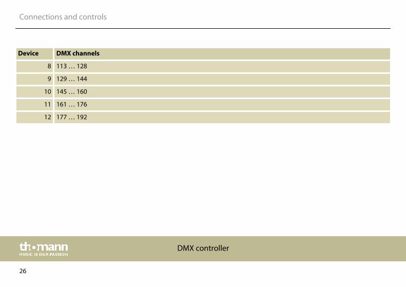
Device DMX channels
8 113 … 128
9 129 … 144
10 145 … 160
11 161 … 176
12 177 … 192
Connections and controls
DMX controller
26
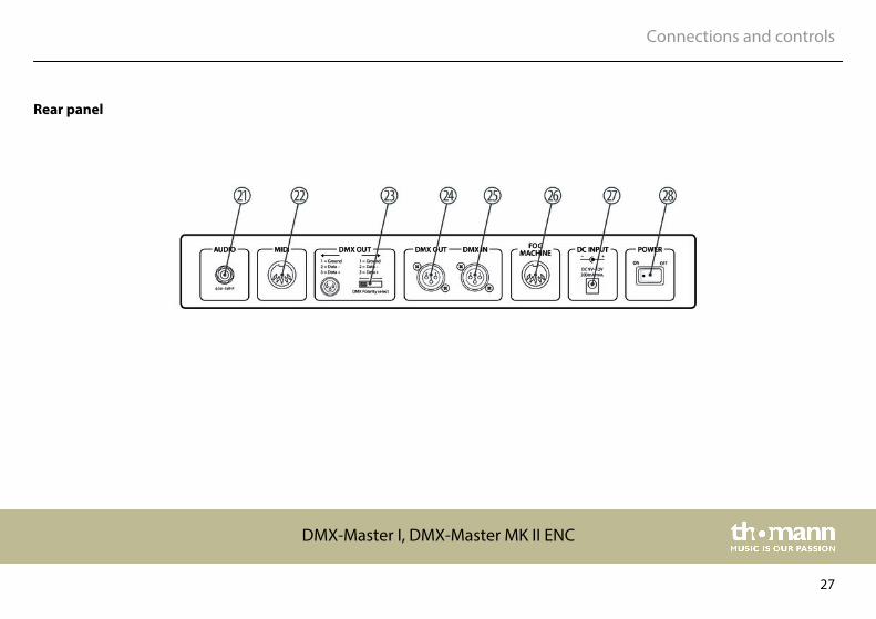
Rear panel
Connections and controls
DMX-Master I, DMX-Master MK II ENC
27
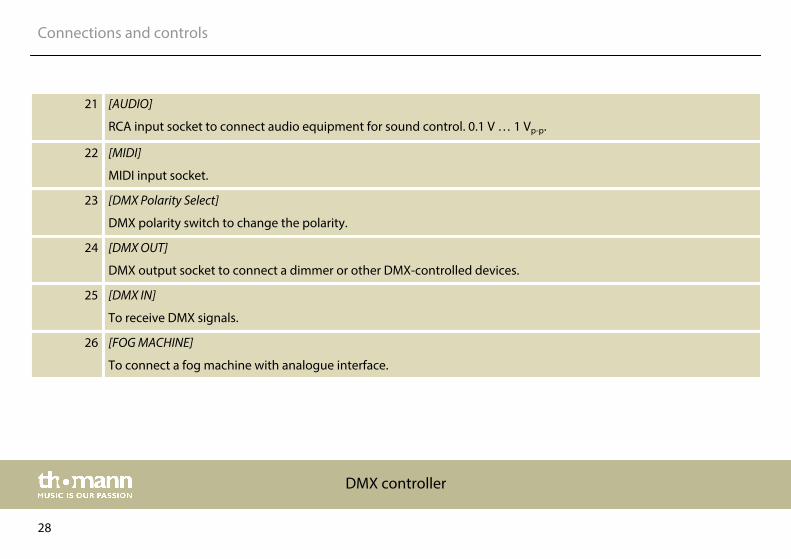
21 [AUDIO]
RCA input socket to connect audio equipment for sound control. 0.1 V … 1 Vp-p.
22 [MIDI]
MIDI input socket.
23 [DMX Polarity Select]
DMX polarity switch to change the polarity.
24 [DMX OUT]
DMX output socket to connect a dimmer or other DMX-controlled devices.
25 [DMX IN]
To receive DMX signals.
26 [FOG MACHINE]
To connect a fog machine with analogue interface.
Connections and controls
DMX controller
28
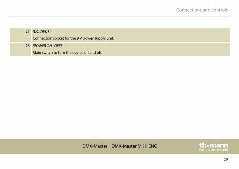
27 [DC INPUT]
Connection socket for the 9 V power supply unit.
28 [POWER ON | OFF]
Main switch to turn the device on and off.
Connections and controls
DMX-Master I, DMX-Master MK II ENC
29
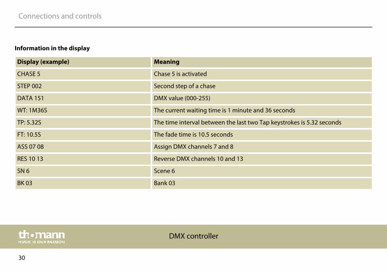
Display (example) Meaning
CHASE 5 Chase 5 is activated
STEP 002 Second step of a chase
DATA 151 DMX value (000-255)
WT: 1M36S The current waiting time is 1 minute and 36 seconds
TP: 5.32S The time interval between the last two Tap keystrokes is 5.32 seconds
FT: 10.5S The fade time is 10.5 seconds
ASS 07 08 Assign DMX channels 7 and 8
RES 10 13 Reverse DMX channels 10 and 13
SN 6 Scene 6
BK 03 Bank 03
Information in the display
Connections and controls
DMX controller
30
7 Basics
This chapter provides basic information about the data transmission using the DMX protocol.
DMX signals are generated by a DMX controller. The signals are transferred over a DMX cableto the connected devices. Each connection can transmit up to 512 channels. For each channel,a value between 0 and 255 is being transmitted. The 512 channels form a so-called ‘DMX uni‐verse’.
DMX devices are connected serially, that means the sending device transmits signals to all con‐nected receivers (daisy chain). The order of the receivers in the daisy chain does not mattersince all devices filter and process the relevant data independently from each other.
To create the daisy chain, the DMX input of the first receiver is connected to the DMX output ofthe controller or another DMX master. The output of the first receiver is connected to the inputof the second one, and so on. The output of the last receiver in the DMX chain must be termi‐nated using a resistor (110 Ω, ¼ W).
Signal transmission
Cabling
Basics
DMX-Master I, DMX-Master MK II ENC
31
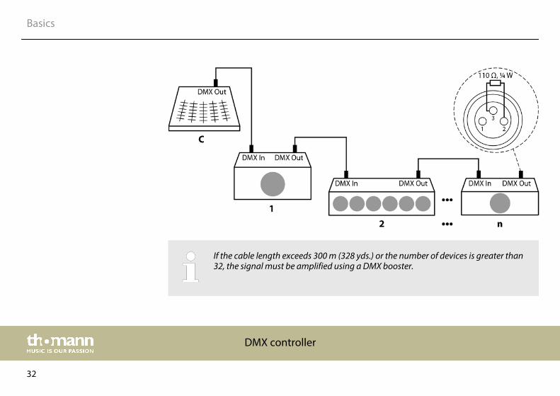
If the cable length exceeds 300 m (328 yds.) or the number of devices is greater than32, the signal must be amplified using a DMX booster.
Basics
DMX controller
32
Each DMX devices operates on a specific number of channels to transfer the incoming controlsignals into movements, changing of light intensity or colour, and so on. Since all receiversthat are part of a DMX daisy chain receive all signals, a start address must be assigned to eachDMX device. Starting from this address (a value between 0 and 512) the incoming signals arebeing evaluated and transferred into the functions of the receiver (internal channel assign‐ment).
It is no problem to use a start address more than once in a DMX chain. In that case, the relevantreceivers operate synchronously (identical movement, light intensity, colour, and so on).
When setting the DMX address, the counting method of the device determines the firstchannel. Depending on the device, the channel numbers may start from 0 or from 1. Theaddress range may therefore reach from 0 to 511 or from 1 to 512.
Signal processing
Addressing
Basics
DMX-Master I, DMX-Master MK II ENC
33
8 Operating
8.1 Introduction
With the DMX Master I or the DMX Master MK II ENC you can control up to twelve devices withup to 16 DMX channels per device. 30 banks with each eight programmable scenes are avail‐able as program memory. You can programme six chases, each with up to 240 programmedscenes. Control is done via eight faders and further function buttons. With DMX Master MK IIENC, you can very easily control pan and tilt of a scanner using two encoder wheels. To createyour very special light effect, you can assign or also invert DMX channels. In addition, twodevices can communicate with each other so that they can exchange files.
8.2 Enabling programming mode
As soon as you turn the unit on, the manual mode will be automatically activated. To enter theprogramming mode, press [PROGRAM] for three seconds. The LED will start flashing, indicatingthat you are now in programming mode.
Operating
DMX controller
34
8.3 Programming scenes
1. Enabling programming mode.
2. Press one of the [SCANNERS] buttons to turn on the Fader control for the correspondingscanner. The lighting LED indicates this. You can select several scanners at the same timeby pressing their [SCANNERS] buttons. So you can set several scanners at once.
3. If using a dimmer, use the faders to set the desired dimmer intensity. With the DMXMaster MK-II ENC, you can also use the two encoder wheels to control the Pan or Tiltmovements of the scanners.
4. If desired, you can use [PAGE SELECT] to switch to the second level to programme chan‐nels 9 - 16.
5. Once all settings are done press [MIDI/REC] to save the scene.
6. Use the buttons [BANK UP/DOWN] to select the desired bank in which you want to savethe scene. 30 banks with each eight memory locations are available.
7. To save the scene to the desired location, press the corresponding [SCENES] button (1 -8). All LEDs and the display will flash three times, indicating that the scene has beensaved. Then the display shows Bank and Scene.
Operating
DMX-Master I, DMX-Master MK II ENC
35
8. Repeat steps 3 - 7 until all desired scenes have been saved. Press the [SCANNERS] buttonagain to turn off its fader control. To select another scanner, press the corresponding[SCANNERS] button to turn on its fader control. Then you can begin programming again.
9. Once the programming is completed, press [PROGRAM] for three seconds. The LED[PROGRAM] goes out and indicates that you have quit the programming mode.
Operating
DMX controller
36
Example: Programme scanner 1 with eight scenes in which channels 1 - 8 are successively setto 100 %. Save the scenes in bank 3.
1. Enabling programming mode.
2. Press [SCANNERS] 1 to turn on its fader control.
3. Press [PAGE SELECT] to select page A.
4. Slide fader 1 all the way up.
5. Press [MIDI/REC].
6. Select bank 3 using the [BANK UP/DOWN] buttons.
7. Press [SCENES] 1.
8. Repeat steps 4 - 7 until all eight scenes are stored in bank 3.
9. Press [SCANNERS] 1 again to disable the scanner again.
10. Press [PROGRAM] for three seconds to quit programming mode.
Operating
DMX-Master I, DMX-Master MK II ENC
37
1. Enabling programming mode.
2. Use [BANK UP/DOWN] to select the bank with the scene you want to alter.
3. Use the [SCENES] buttons to select the desired scene.
4. Make the desired changes using the faders and / or joystick or the encoder wheels.
5. Press [MIDI/REC] to save the changes.
6. Press the corresponding [SCENES] button again to overwrite the former scene.
Make sure that you select the same scene in steps 3 and 6 to avoid accidentally over‐writing the wrong scene!
Altering scenes
Operating
DMX controller
38
With this function you can copy the settings of a device to another.
1. Press and hold the button on the scanner to be copied.
2. While holding this button, additionally press the button of the scanner that you want tocopy the settings to.
1. Enabling programming mode.
2. Use [BANK UP/DOWN] to select the bank with the scene you want to copy.
3. Use the [SCENES] buttons to select the desired scene.
4. Use [BANK UP/DOWN] to select the bank to which the scene is to be copied.
5. Press [MIDI/REC].
6. Select the desired memory location for the scene to be copied using the [SCENES] but‐tons.
Copying scanners
Copying scene
Operating
DMX-Master I, DMX-Master MK II ENC
39
1. Use the buttons [SCENES] to select the scene you want to delete.
2. Keep [AUTO/DEL] pressed. Now additionally press the [SCENES] button of the scene youwant to delete.
This function clears all stored scenes and sets the DMX channels to ‘0’.
1. While the device is switched off, simultaneously press [BANK DOWN] and [PROGRAM].
2. While pressing the buttons, turn on the device. All scenes should now be deleted.
Deleting a scene
Deleting all scenes
Operating
DMX controller
40
1. Enabling programming mode.
2. Use [BANK UP/DOWN] to select the bank to be copied.
3. Press [MIDI/REC].
4. Use [BANK UP/DOWN] to select the bank to be copied to.
5. Press [MUSIC/BANK COPY]. All LEDs will flash three times and thus confirm the copying ofthe Bank.
6. Press [PROGRAM] for three seconds to quit programming mode.
Copying bank
Operating
DMX-Master I, DMX-Master MK II ENC
41
8.4 Programming chase
In order to programme chases, scenes must have been previously programmed. Each Chasecan contain up to 240 scenes.
1. Enabling programming mode.
2. Select the Chase to be programmed via the [CHASE] buttons. Only one Chase can beselected in each case.
3. Select the desired scene from a bank that contains scenes (see also Ä Chapter 8.3 ‘Pro‐gramming scenes’ on page 35).
4. Press [MIDI/REC].
5. Repeat steps 3 and 4 until all desired scenes are stored in the chase.
Operating
DMX controller
42
1. Enabling programming mode.
2. Select a chase with the [CHASE] buttons 1 - 6.
3. Use [BANK UP/DOWN] to select the bank with the scenes to be copied.
4. Press [MUSIC/BANK COPY].
5. Press [MIDI/REC]. All LEDs will flash three times and thus indicate that the scenes werecopied into the Chase.
Storing an entire bank to achase
Operating
DMX-Master I, DMX-Master MK II ENC
43
1. Enabling programming mode.
2. Select the Chase, you want to add a step to.
3. Press [TAP/DISPLAY] , the display shows the current step.
4. Use [BANK UP/DOWN] to select the step after which you want to add a step.
5. Press [MIDI/REC] , then the display shows the number of steps increased by one. If you,e.g., want to insert a step between steps 3 and 4, and you scroll to step 3, the displayshows ‘STEP 004’ when you press the button [MIDI/REC] .
6. Press [TAP/DISPLAY] again, then the display shows the current chase, scene and bank.Create the desired scene and record it as a new step. Or select a programmed scenewhich you want to add to this chase.
You can press [TAP/DISPLAY] to switch the display mode ‘STEP’ and ‘BANK’.
7. Press [MIDI/REC] again, then all LEDs will flash three times briefly indicating that the newstep has been inserted into this chase.
Adding step
Operating
DMX controller
44
1. Enabling programming mode.
2. Select the chase containing the step to be deleted.
3. Press [TAP/DISPLAY], the display shows the current step.
4. Use [BANK UP/DOWN] to select the step you want to delete.
5. Press [AUTO/DEL] to delete the step. All LEDs will flash three times briefly, thus indicatingthat the step has been deleted.
1. Select the chase you want to delete.
2. Hold down [AUTO/DEL] while you press [CHASE] again. All LEDs will flash three timesbriefly, thus indicating that the chase has been deleted.
Deleting step
Deleting chase
Operating
DMX-Master I, DMX-Master MK II ENC
45
1. While the device is switched off, simultaneously keep [AUTO/DEL] and [BANK DOWN]pressed.
2. Switch on the device.
Deleting chases
Operating
DMX controller
46
8.5 Assigning / reversing DMX channels.
1. Enabling programming mode.
2. Press [FINE] and [MODE] twice simultaneously. Then the LED [ASSIGN] lights up and indi‐cates that the ASSIGN mode is active.
3. With [BANK UP/DOWN] you can switch between Pan and Tilt. The corresponding LEDindicates your selection.
4. Press [TAP/DISPLAY] to switch between 8-channel and 16-channel mode. The displayshows either ‘ASSXX XX | X/Y 08CH’ or ‘ASSXX XX | X/Y 16CH’ .
5. Select the desired scanner.
6. If necessary, you can use [PAGE SELECT] to switch between levels Page A and Page B.
7. While keeping [MODE] pressed, press [SCENES]. All LEDs should flash briefly and thusindicating that the DMX channel has been assigned. The button [SCENES] 1 stands forDMX channel 1, [SCENES] 2 for DMX channel 2 and so on.
8. Repeat steps 3 - 7.
8-channel mode: You can assign the PAN / TILT movement for 24 scanners. In 8-channelmode, you can save PAN / TILT for page A and page B.
Assigning DMX channel
Operating
DMX-Master I, DMX-Master MK II ENC
47
16-channel mode: You can assign the PAN / TILT movement for 12 scanners. In 16-channel mode, you can save PAN / TILT only for page A or page B.
Operating
DMX controller
48
1. Enabling programming mode.
2. Simultaneously press [FINE] and [MODE]. The LED [REVERSE] lights up and thus indicatesthat the device is in Reverse mode.
3. With [BANK UP/DOWN] you can switch between Pan and Tilt.
4. Press [TAP/DISPLAY] to switch between 8-channel and 16-channel mode.
5. Use one of the [SCANNERS] buttons to select the desired scanner.
6. If necessary, you can use [PAGE SELECT] to switch between levels Page A and Page B.
7. While you keep [MODE] pressed, press the [SCENES]button. All LEDs should flash brieflyand thus indicating that the DMX channel has been reversed. The button [SCENES] 1stands for DMX channel 1, [SCENES] 2 for DMX channel 2 and so on.
8. Repeat steps 3 - 7.
8-channel mode: You can assign the PAN / TILT movement for 24 scanners. In 8-channelmode, you can save PAN / TILT for page A and page B.
16-channel mode: You can assign the PAN / TILT movement for 12 scanners. In 16-channel mode, you can save PAN / TILT only for page A or page B.
Reversing channels
Operating
DMX-Master I, DMX-Master MK II ENC
49
1. While the device is switched off, press the two buttons [TAP/DISPLAY] and [MODE] andkeep them pressed.
2. Switch the device on again. Press [TAP/DISPLAY] to switch between ‘Fade Time’ and‘Assign Fade Time’. The display either shows ‘ALL CH| FD TIME’ or ‘ONLY X/Y|FD TIME’ .
3. Simultaneously press [TAP/DISPLAY] and [MODE] to save the settings. If you don't want tosave press [BLACKOUT] to exit the mode.
1. Activate the Assign or Reverse mode (see Ä ‘Assigning DMX channel’ on page 47 andÄ ‘Reversing channels’ on page 49).
2. Use one of the [SCANNERS] buttons to select the scanner you want to delete.
3. Simultaneously press [AUTO/DEL] and [MODE]. All LEDs will flash briefly to confirm thedeleting.
Assigning Fade time
Deleting DMX settings of ascanner
Operating
DMX controller
50
1. Switch off the device.
2. Simultaneously press [AUTO/DEL] and [MODE] and keep these buttons pressed.
3. Keep the buttons pressed and turn the device on again. All LEDs will flash briefly to con‐firm the deleting. All assigned or reversed channels are reset.
1. Simultaneously press [MODE] and [FINE], the LED [ASSIGN] is lit.
2. If you press both buttons again the LED [ASSIGN] goes out and the LED [REVERSE] lightsup.
3. By pressing the [SCANNERS] buttons you can let the display indicate the Pan and Tiltchannels of the respective scanner.
Resetting all DMX channels
Indicating DMX channels
Operating
DMX-Master I, DMX-Master MK II ENC
51
1. Switch off the device.
2. Keep the [SCANNERS] buttons 6 and 12 simultaneously pressed while turning the deviceon again. Then release the buttons.
3. Press [SCANNERS] buttons 6 or 12 to move the cursor to the left or right.
4. Repeat steps 3 - 4. You can enter up to 16 characters in two rows.
5. Simultaneously press the [SCANNERS] buttons 6 and 12 to save the new characters. AllLEDs will flash briefly, thus indicating the success of the procedure. If you don't want tosave press [BLACKOUT] to end this function.
Setting up a new logo
Operating
DMX controller
52
1. Keep [BLACKOUT / STAND ALONE] pressed for three seconds to enable the Stand Alonemode
2. Keep the [SCANNERS] button 1 pressed and press additionally[BLACKOUT / STAND ALONE]. The Pan and Tilt movements of all devices now stop at thecentre position. The bezel and LED of the first device opens up / flashes and thus indi‐cate that the device is active and ready to be assigned with a new position (= number inthe chain).
3. With [BANK UP/DOWN] you select the next or last device.
4. With the [SCANNERS] buttons 1 - 12 you set the DMX address.
5. Keep [PAGE] pressed, then press [SCANNERS] 1 - 12 to increase the address by eight.
6. Press [BLACKOUT / STAND ALONE] again to return to the Programme mode.
Auto addressing
Operating
DMX-Master I, DMX-Master MK II ENC
53
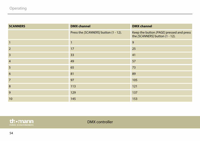
SCANNERS DMX channel DMX channel
Press the [SCANNERS] button (1 - 12). Keep the button [PAGE] pressed and pressthe [SCANNERS] button (1 - 12).
1 1 9
2 17 25
3 33 41
4 49 57
5 65 73
6 81 89
7 97 105
8 113 121
9 129 137
10 145 153
Operating
DMX controller
54
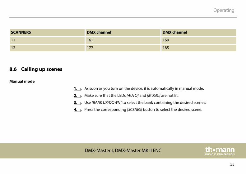
SCANNERS DMX channel DMX channel
11 161 169
12 177 185
8.6 Calling up scenes
1. As soon as you turn on the device, it is automatically in manual mode.
2. Make sure that the LEDs [AUTO] and [MUSIC] are not lit.
3. Use [BANK UP/DOWN] to select the bank containing the desired scenes.
4. Press the corresponding [SCENES] button to select the desired scene.
Manual mode
Operating
DMX-Master I, DMX-Master MK II ENC
55
With this function, you can run a bank of scenes in an endless loop.
1. Press [AUTO/DEL] to enable the Auto mode. The LED [AUTO] lights up and indicates theactivation.
2. Use [BANK UP/DOWN] to select a bank with scenes for the run.
3. After selecting the bank whose scenes are intended to run you can use the controls[WAIT TIME] (or the button [TAP SYNC/DISPLAY]) and [FADE TIME] to adjust the scenes asdesired.
Repeatedly press [TAP SYNC] to set the speed. The interval of the last tworespective keystrokes defines the speed with a maximum of 5 minutes. Whenusing this function, all settings made with the [WAIT TIME] fader are beingignored, as long as you don't move it.
4. Press [AUTO/DEL] again to exit the mode.
Auto mode
Operating
DMX controller
56
1. Press [MUSIC/BANK COPY] to enable the sound control. The LED [MUSIC] lights then.
2. Select the bank using [BANK UP/DOWN] . The scenes are now running in an endless loopaccording to the rhythm of the music which the device perceives via the built-in micro‐phone.
3. Press [MUSIC/BANK COPY] to exit the mode.
8.7 Calling chases
First, you have to programme scenes before you can run chases!
Sound control
Operating
DMX-Master I, DMX-Master MK II ENC
57
1. When you turn on the device, it is automatically in manual mode.
2. Press one of the six [CHASE] buttons to select the desired chase. If you press the buttonagain, you disable this function.
3. Use the [FADE TIME] control to set the fading time of the current scene.
4. With [BANK UP/DOWN] you can call the steps of the chase one by one.
1. Press [AUTO/DEL] to enable the Auto mode. The LED [AUTO] then indicates that themode is active.
2. Press one of the six [CHASE] buttons to select the desired chase. If you press the buttonagain, you disable this function.
3. Use the [WAIT TIME] control (or the button [TAP SYNC]) and the [FADE TIME] control toadjust the chase as desired.
You can select several chases at a time. The chases run in the sequence in which youselect them.
Manual mode
Auto mode
Operating
DMX controller
58
1. Press [MUSIC/BANK COPY] to enable the sound control. The LED [MUSIC] then indicatesthat the mode is active.
2. Press one of the six [CHASE] buttons to select the desired chase. The chase is then con‐trolled by the rhythm of the music. You can select several chases at a time.
8.8 The MIDI functions
1. Keep [MIDI/REC] pressed for three seconds. The display shows the last set MIDI channel.
2. With [BANK UP/DOWN] you can select a DMX channel 01 - 16 that you assign as MIDIchannel.
3. Press [MIDI/REC] again for three seconds to save the setting and to deactivate the MIDIsettings. If you do not want to save the setting, press any key (except [BANK UP/DOWN])to exit the MIDI mode.
Sound control
MIDI channel setting
Operating
DMX-Master I, DMX-Master MK II ENC
59
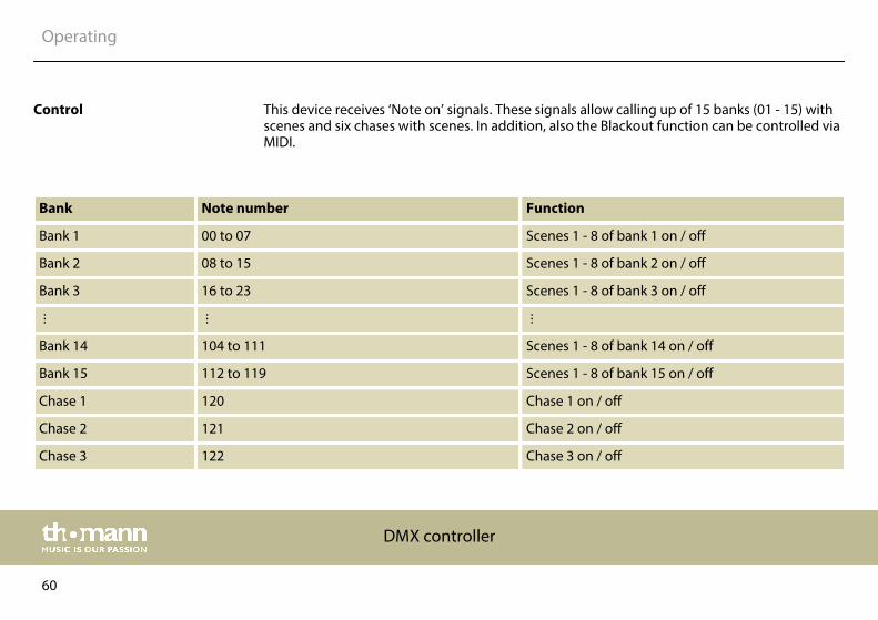
This device receives ‘Note on’ signals. These signals allow calling up of 15 banks (01 - 15) withscenes and six chases with scenes. In addition, also the Blackout function can be controlled viaMIDI.
Bank Note number Function
Bank 1 00 to 07 Scenes 1 - 8 of bank 1 on / off
Bank 2 08 to 15 Scenes 1 - 8 of bank 2 on / off
Bank 3 16 to 23 Scenes 1 - 8 of bank 3 on / off
Bank 14 104 to 111 Scenes 1 - 8 of bank 14 on / off
Bank 15 112 to 119 Scenes 1 - 8 of bank 15 on / off
Chase 1 120 Chase 1 on / off
Chase 2 121 Chase 2 on / off
Chase 3 122 Chase 3 on / off
Control
Operating
DMX controller
60
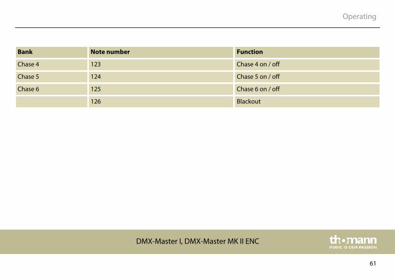
Bank Note number Function
Chase 4 123 Chase 4 on / off
Chase 5 124 Chase 5 on / off
Chase 6 125 Chase 6 on / off
126 Blackout
Operating
DMX-Master I, DMX-Master MK II ENC
61
8.9 Sending data
You have to establish a DMX connection between the two controllers before you cantransfer data.
1. While the device is switched off, simultaneously press [SCANNERS] 2 [SCANNERS] 3 and[SCENES] 1.
2. Keep the buttons pressed and turn the device on again. The display shows ‘TRANSMIT’ .The controller is now ready for transmission.
3. To start the transmission process, simultaneously press [SCENES] 7 and [SCENES] 8.
Operating
DMX controller
62
8.10 Receiving data
1. While the device is switched off, simultaneously press [SCANNERS] 8 [SCANNERS] 9 and[SCENES] 2.
2. Keep the buttons pressed and turn the device on again. The display shows ‘RECEIVE’ .The controller now receives the data.
3. As soon as the transmission process is complete, the device automatically returns to thenormal status.
Operating
DMX-Master I, DMX-Master MK II ENC
63
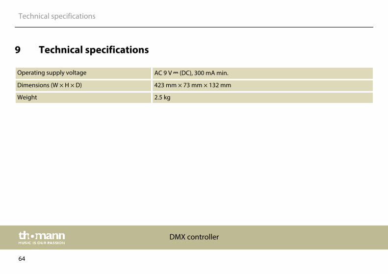
9 Technical specifications
Operating supply voltage AC 9 V (DC), 300 mA min.
Dimensions (W × H × D) 423 mm × 73 mm × 132 mm
Weight 2.5 kg
Technical specifications
DMX controller
64
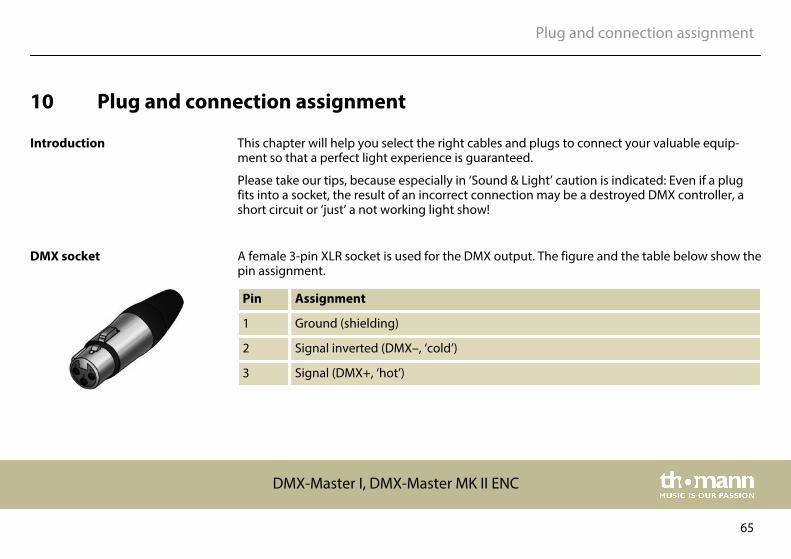
10 Plug and connection assignment
This chapter will help you select the right cables and plugs to connect your valuable equip‐ment so that a perfect light experience is guaranteed.
Please take our tips, because especially in ‘Sound & Light’ caution is indicated: Even if a plugfits into a socket, the result of an incorrect connection may be a destroyed DMX controller, ashort circuit or ‘just’ a not working light show!
A female 3-pin XLR socket is used for the DMX output. The figure and the table below show thepin assignment.
Pin Assignment
1 Ground (shielding)
2 Signal inverted (DMX–, ‘cold’)
3 Signal (DMX+, ‘hot’)
Introduction
DMX socket
Plug and connection assignment
DMX-Master I, DMX-Master MK II ENC
65
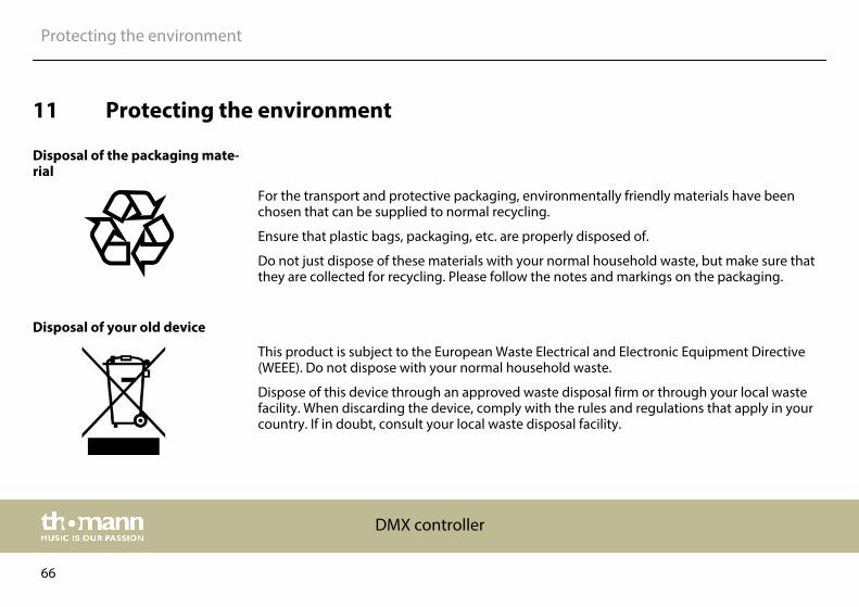
11 Protecting the environment
For the transport and protective packaging, environmentally friendly materials have beenchosen that can be supplied to normal recycling.
Ensure that plastic bags, packaging, etc. are properly disposed of.
Do not just dispose of these materials with your normal household waste, but make sure thatthey are collected for recycling. Please follow the notes and markings on the packaging.
This product is subject to the European Waste Electrical and Electronic Equipment Directive(WEEE). Do not dispose with your normal household waste.
Dispose of this device through an approved waste disposal firm or through your local wastefacility. When discarding the device, comply with the rules and regulations that apply in yourcountry. If in doubt, consult your local waste disposal facility.
Disposal of the packaging mate‐rial
Disposal of your old device
Protecting the environment
DMX controller
66


Musikhaus Thomann · Hans-Thomann-Straße 1 · 96138 Burgebrach · Germany · www.thomann.de


![DMX-Master MK II ENC DMX-Master I, DMX controller€¦ · DMX-Master I, DMX-Master MK II ENC 23. 12 [MIDI/REC] To control MIDI operations or to record programmes. 13 [AUTO/DEL] Activates](https://img.pdfslide.us/doc/110x75/6024d4b709488a62466819ea/dmx-master-mk-ii-enc-dmx-master-i-dmx-controller-dmx-master-i-dmx-master-mk-ii.jpg)