Embed Size (px)
Citation preview
ELECTRONICS FOR SPECIALISTS ELECTRONICS FOR SPECIALISTS ELECTRONICS FOR SPECIALISTS ELECTRONICS FOR SPECIALISTS
BEDIENUNGSANLEITUNG
INSTRUCTION MANUAL
MODE D’EMPLOI
ISTRUZIONI PER L’USO
MANUAL DE INSTRUCCIONES
INSTRUKCJA OBSŁUGI
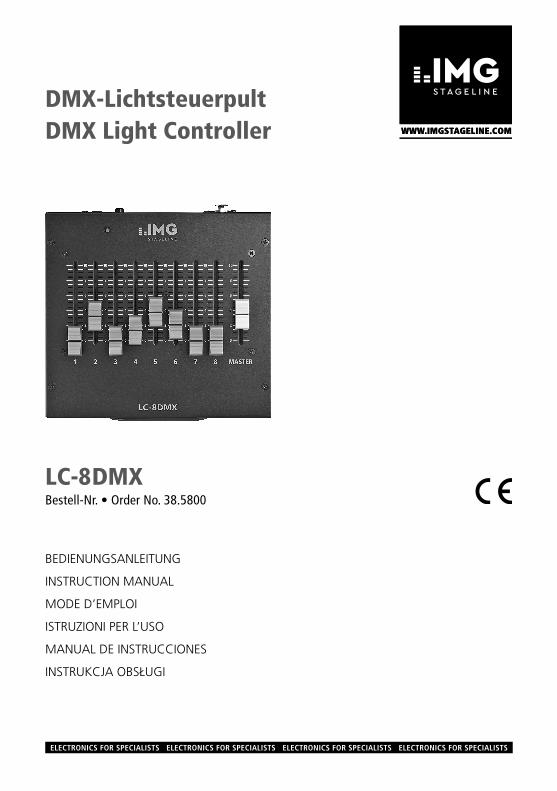
LC-8 DMXBestell-Nr. • Order No. 38.5800
DMX-LichtsteuerpultDMX Light Controller

3
ELECTRONICS FOR SPECIALISTS ELECTRONICS FOR SPECIALISTS ELECTRONICS FOR SPECIALISTS ELECTRONICS FOR SPECIALISTS
Deutsch . . . . . . . . . . Seite 4
English . . . . . . . . . . . Page 6
Français . . . . . . . . . . Page 8
Italiano . . . . . . . . . . . Pagina 10
Nederlands . . . . . . . Pagina 12
Polski . . . . . . . . . . . . Strona 14
4
Deu
tsch
EnglishEnglish Page
FrançaisFrançais Page
ItalianoItaliano Pagina
EspañolEspañol Página
NederlandsNederlands Pagina
PolskiPolski Strona
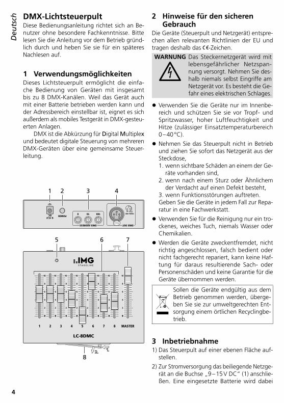
DMX-LichtsteuerpultDiese Bedienungsanleitung richtet sich an Be-nutzer ohne besondere Fachkenntnisse . Bitte lesen Sie die Anleitung vor dem Betrieb gründ-lich durch und heben Sie sie für ein späteres Nachlesen auf .
1 VerwendungsmöglichkeitenDieses Lichtsteuerpult ermöglicht die einfa-che Bedienung von Geräten mit insgesamt bis zu 8 DMX-Kanälen . Weil das Gerät auch mit einer Batterie betrieben werden kann und der Adressbereich einstellbar ist, eignet es sich außerdem als mobiles Testgerät in DMX-gesteu-erten Anlagen .
DMX ist die Abkürzung für Digital Multiplex und bedeutet digitale Steuerung von mehreren DMX-Geräten über eine gemeinsame Steuer-leitung .
09
87 6 54
321 09
87 6 54
321 09
87 6 54
321
213
PUSH
1 23
DMX ADDRESS
POWER
DMX OUT
9-15VDC 100100 SIGNAL GND
654321 7 8 MASTER
LC-8DMC
00
2
4
6
8
10
00
2
4
6
8
10
00
2
4
6
8
10
00
2
4
6
8
10
00
2
4
6
8
10
00
2
4
6
8
10
00
2
4
6
8
10
00
2
4
6
8
10
1
8
2
5 6 7
43
DeutschDeutsch Seite
2 Hinweise für den sicheren Gebrauch
Die Geräte (Steuerpult und Netzgerät) entspre-chen allen relevanten Richtlinien der EU und tragen deshalb das -Zeichen .
WARNUNG Das Steckernetzgerät wird mit lebensgefährlicher Netzspan-nung versorgt . Nehmen Sie des-halb niemals selbst Eingriffe am Netzgerät vor . Es besteht die Ge-fahr eines elektrischen Schlages .
• Verwenden Sie die Geräte nur im Innenbe-reich und schützen Sie sie vor Tropf- und Spritzwasser, hoher Luftfeuchtigkeit und Hitze (zulässiger Einsatztemperaturbereich 0 – 40 °C) .
• Nehmen Sie das Steuerpult nicht in Betrieb und ziehen Sie sofort das Netzgerät aus der Steckdose,1 . wenn sichtbare Schäden an einem der Ge-
räte vorhanden sind,2 . wenn nach einem Sturz oder Ähnlichem
der Verdacht auf einen Defekt besteht,3 . wenn Funktionsstörungen auftreten .Geben Sie die Geräte in jedem Fall zur Repa-ratur in eine Fachwerkstatt .
• Verwenden Sie für die Reinigung nur ein tro-ckenes, weiches Tuch, niemals Wasser oder Chemikalien .
• Werden die Geräte zweckentfremdet, nicht richtig angeschlossen, falsch bedient oder nicht fachgerecht repariert, kann keine Haf-tung für daraus resultierende Sach- oder Personenschäden und keine Garantie für die Geräte übernommen werden .
Sollen die Geräte endgültig aus dem Betrieb genommen werden, überge-ben Sie sie zur umweltgerechten Ent-sorgung einem örtlichen Recyclingbe-trieb .
3 Inbetriebnahme1) Das Steuerpult auf einer ebenen Fläche auf-
stellen .
2) Zur Stromversorgung das beiliegende Netzge-rät an die Buchse „9 – 15 V DC“ (1) anschlie-ßen . Eine eingesetzte Batterie wird dabei
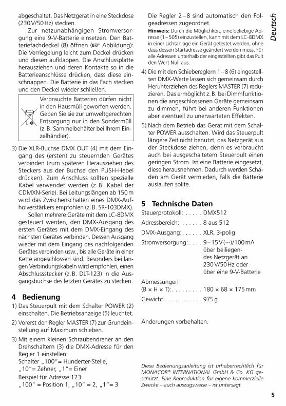
5
Deu
tschabgeschaltet . Das Netzgerät in eine Steckdose
(230 V/ 50 Hz) stecken .Zur netzunabhängigen Stromversor-
gung eine 9-V-Batterie einsetzen . Den Bat-teriefachdeckel (8) öffnen (☞ Abbildung): Die Verriegelung leicht zum Deckel drücken und diesen aufklappen . Die Anschlussplatte herausziehen und deren Kontakte so in die Batterieanschlüsse drücken, dass diese ein-schnappen . Die Batterie in das Fach stecken und den Deckel wieder schließen .
Verbrauchte Batterien dürfen nicht in den Hausmüll geworfen werden . Geben Sie sie zur umweltgerechten Entsorgung nur in den Sondermüll (z . B . Sammelbehälter bei Ihrem Ein-zelhändler) .
3) Die XLR-Buchse DMX OUT (4) mit dem Ein-gang des (ersten) zu steuernden Gerätes verbinden (zum späteren Herausziehen des Steckers aus der Buchse den PUSH-Hebel drücken) . Zum Anschluss sollten spezielle Kabel verwendet werden (z . B . Kabel der CDMXN-Serie) . Bei Leitungslängen ab 150 m wird das Zwischenschalten eines DMX-Auf-holverstärkers empfohlen (z . B . SR-103DMX) .
Sollen mehrere Geräte mit dem LC-8DMX gesteuert werden, den DMX-Ausgang des ersten Gerätes mit dem DMX-Eingang des nächsten Gerätes verbinden . Dessen Ausgang wieder mit dem Eingang des nachfolgenden Gerätes verbinden usw ., bis alle Geräte in einer Kette angeschlossen sind . Besonders bei lan-gen Verbindungskabeln wird empfohlen, einen Abschlussstecker (z . B . DLT-123) in die Aus-gangsbuchse des letzten Gerätes zu stecken .
4 Bedienung1) Das Steuerpult mit dem Schalter POWER (2)
einschalten . Die Betriebsanzeige (5) leuchtet .
2) Vorerst den Regler MASTER (7) zur Grundein-stellung auf Maximum schieben .
3) Mit einem kleinen Schraubendreher an den Drehschaltern (3) die DMX-Adresse für den Regler 1 einstellen: Schalter „100“= Hunderter-Stelle, „10“= Zehner, „1“= EinerBeispiel für Adresse 123: „100“ = Position 1, „10“ = 2, „1“= 3
Die Regler 2 – 8 sind automatisch den Fol-geadressen zugeordnet .
Hinweis: Durch die Möglichkeit, eine beliebige Ad-resse (1 – 505) einzustellen, kann mit dem LC-8DMX in einer Lichtanlage ein Gerät getestet werden, ohne dass dessen Startadresse geändert werden muss . Für alle Adressen unterhalb der eingestellten gibt das Pult den Wert Null aus .
4) Die mit den Schiebereglern 1 – 8 (6) eingestell-ten DMX-Werte lassen sich gemeinsam durch Herunterziehen des Reglers MASTER (7) redu-zieren . Das ermöglicht z . B . bei Dimmfunktio-nen die angeschlossenen Geräte gemeinsam zu dimmen, führt bei anderen Funktionen aber eventuell zu unerwarteten Effekten .
5) Nach dem Betrieb das Gerät mit dem Schal-ter POWER ausschalten . Wird das Steuerpult längere Zeit nicht benutzt, das Netzgerät aus der Steckdose ziehen, denn es verbraucht auch bei ausgeschaltetem Steuerpult einen geringen Strom . Ist eine Batterie eingesetzt, diese herausnehmen . Dadurch werden Schä-den am Gerät vermieden, falls die Batterie auslaufen sollte .
5 Technische DatenSteuerprotokoll: . . . . . DMX512
Adressbereich: . . . . . . 8 aus 512
DMX-Ausgang: . . . . . . XLR, 3-polig
Stromversorgung: . . . . 9 – 15 V (⎓) / 100 mA über beiliegen-des Netzgerät an 230 V/ 50 Hz oder über eine 9-V-Batterie
Abmessungen(B × H × T): . . . . . . . . . 180 × 68 × 175 mm
Gewicht: . . . . . . . . . . . 975 g
Änderungen vorbehalten .
Diese Bedienungsanleitung ist urheberrechtlich für MONACOR ® INTERNATIONAL GmbH & Co. KG ge-schützt. Eine Reproduktion für eigene kommerzielle Zwecke – auch auszugsweise – ist untersagt.
6
EnglishDeutsch
Deutsch Seite
FrançaisFrançais Page
ItalianoItaliano Pagina
EspañolEspañol Página
NederlandsNederlands Pagina
PolskiPolski Strona
DMX Light ControllerThese instructions are intended for users without any specific technical knowledge . Please read these instructions carefully prior to operating the unit and keep them for later reference .
1 ApplicationsThis light controller allows easy operation of units with a maximum of 8 DMX channels al-together . As the unit may also be operated via battery and the address range can be adjusted, it is also suited as a mobile test unit in DMX-con-trolled systems .
DMX stands for Digital Multiplex and means digital control of multiple DMX units via a com-mon control line .
09
87 6 54
321 09
87 6 54
321 09
87 6 54
321
213
PUSH
1 23
DMX ADDRESS
POWER
DMX OUT
9-15VDC 100100 SIGNAL GND
654321 7 8 MASTER
LC-8DMC
00
2
4
6
8
10
00
2
4
6
8
10
00
2
4
6
8
10
00
2
4
6
8
10
00
2
4
6
8
10
00
2
4
6
8
10
00
2
4
6
8
10
00
2
4
6
8
10
1
8
2
5 6 7
43
2 Safety NotesThe units (controller and power supply unit) cor-respond to all relevant directives of the EU and are therefore marked with .
WARNING The plug-in power supply unit uses dangerous mains voltage . Leave servicing to skilled person-nel only . Inexpert handling or modification of the power supply unit may result in electric shock .
• The units are suitable for indoor use only . Pro-tect them against dripping water and splash water, high air humidity and heat (admissible ambient temperature range 0 – 40 °C) .
• Do not operate the controller and immedi-ately disconnect the power supply unit from the socket 1 . if one of the units is visibly damaged, 2 . if a defect might have occurred after a unit
was dropped or suffered a similar accident,3 . if malfunctions occur .In any case the units must be repaired by skilled personnel .
• For cleaning only use a dry, soft cloth; never use water or chemicals .
• No guarantee claims for the units and no li-ability for any resulting personal damage or material damage will be accepted if the units are used for other purposes than originally intended, if they are not correctly connected or operated, or if they are not repaired in an expert way .
If the units are to be put out of oper-ation definitively, take them to a local recycling plant for a disposal which is not harmful to the environment .
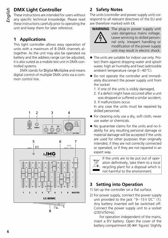
3 Setting into Operation1) Set up the controller on a flat surface .
2) For power supply, connect the power supply unit provided to the jack “9 – 15 V DC” (1) . Any battery inserted will be switched off . Connect the power supply unit to a socket (230 V/ 50 Hz) .
For operation independent of the mains, insert a 9 V battery . Open the cover of the battery compartment (8) (☞ figure): Slightly
EnglishEnglish Page
7
Englishpush the latching towards the cover and open
the cover . Remove the connection plate and push its contacts into the battery connections so that the battery connections snap in . Place the battery into the compartment and close the cover .
Used batteries must not be placed in the household waste; always take them to a special waste dis-posal, e . g . collection container at your retailer .
3) Connect the XLR jack DMX OUT (4) to the input of the (first) unit to be controlled (for later removal of the plug from the jack, press the PUSH lever) . For connection, special ca-bles are recommended (e . g . cables of the CDMXN series) . For cable lengths exceeding 150 m, it is recommended to insert a DMX level matching amplifier (e . g . SR-103DMX) .
To control several units via the LC-8DMX, connect the DMX output of the first unit to the DMX input of the next unit; connect its output again to the input of the following unit, etc . until all units have been connected in a chain . Especially for long connection cables it is recommended to connect a termi-nating plug (e . g . DLT-123) to the output jack of the last unit .
4 Operation1) Switch on the controller with the POWER
switch (2) . The POWER LED (5) will light up .
2) For basic setting, first set the control MASTER (7) to maximum .
3) Use a small screwdriver to adjust the DMX address for the control 1 at the rotary switches (3): Switch “100” = hundreds digit, “10” = tens digit, “1” = units digit .
Example for address 123: “100” = position 1, “10” = 2, “1” = 3
The controls 2 – 8 are automatically assigned to the following addresses .
Note: As it is possible to adjust any desired address (1 – 505), the LC-8DMX allows to test a unit in a lighting system without changing its start address . For any address lower than the one adjusted, the controller will issue the value zero .
4) When sliding down the control MASTER (7), it will be possible to reduce the DMX values adjusted with the sliding controls 1 – 8 (6) all at once . This allows e . g . for dimming func-tions to dim the units connected at the same time, but for other functions this may lead to unexpected effects .
5) After operation, switch off the unit with the POWER switch . If the controller is not in use for a longer period of time, disconnect the power supply unit from the mains socket; even with the controller switched off, the power supply unit will have a low power consumption . If a battery has been inserted, remove it to prevent damage to the unit in case of battery leakage .
5 SpecificationsControl protocol: . . . . DMX512
Address range: . . . . . . 8 from 512
DMX output: . . . . . . . XLR, 3-pole
Power supply: . . . . . . . 9 – 15 V (⎓) / 100 mA via power supply unit provided and con-nected to 230 V/ 50 Hz or via a 9 V battery
Dimensions(W × H × D): . . . . . . . . 180 × 68 × 175 mm
Weight: . . . . . . . . . . . 975 g
Subject to technical modification .
All rights reserved by MONACOR ® INTERNATIONAL GmbH & Co. KG. No part of this instruction manual may be reproduced in any form or by any means for any commercial use.
8
Fran
çaisDeutsch
Deutsch Seite
EnglishEnglish Page
ItalianoItaliano Pagina
EspañolEspañol Página
NederlandsNederlands Pagina
PolskiPolski Strona
Contrôleur de lumière DMXCette notice s‘adresse aux utilisateurs sans connaissances techniques particulières . Veuillez lire la présente notice avant le fonctionnement et conservez-la pour pouvoir vous y reporter ultérieurement .
1 Possibilités d’utilisationCe contrôleur permet une utilisation simple d’appareils avec en tout 8 canaux DMX . Dans la mesure où l’appareil peut également fonc-tionner avec une batterie et la plage d’adresses est réglable, il est également adapté comme appareil mobile de test dans des installations gérées par DMX .
DMX est l’abréviation de Digital Multiplex et signifie transmission digitale de plusieurs appa-reils DMX via un câble commun de commande .
2 Conseils importants d’utilisationLes appareils (contrôleur et bloc secteur) répondent à toutes les directives nécessaires de l’Union européenne et portent donc le sym- bole .
AVERTISSEMENT Le bloc secteur est alimenté par une tension secteur dan-gereuse . Ne touchez jamais l’intérieur de l’appareil, en cas de mauvaise manipula-tion, vous pourriez subir une décharge électrique .
• Les appareils ne sont conçus que pour une utilisation en intérieur . Protégez-les de tout type de projections d’eau, des éclaboussures, d’une humidité élevée d’air et de la chaleur (plage de température de fonctionnement autorisée : 0 – 40 °C) .
• Ne faites pas fonctionner le contrôleur et dé-branchez immédiatement le bloc secteur de la prise lorsque :1 . des dommages visibles apparaissent sur
un des appareils,2 . après une chute ou un cas similaire, vous
avez un doute sur l’état de l’appareil,3 . des dysfonctionnements apparaissent .Dans tous les cas, les dommages doivent être réparés par un technicien spécialisé .
• Pour le nettoyage, utilisez un chiffon sec et doux, en aucun cas de produits chimiques ou d’eau .
• Nous déclinons toute responsabilité en cas de dommages matériels ou corporels résultants si les appareils sont utilisés dans un but autre que celui pour lequel ils ont été conçus, s’ils ne sont pas correctement branchés ou utilisés ou s’ils ne sont pas réparés par une personne habilitée ; en outre, la garantie deviendrait caduque .
Lorsque les appareils sont définitive-ment retirés du service, vous devez les déposer dans une usine de recyclage adaptée pour contribuer à leur élimi-nation non polluante .
CARTONS ET EMBALLAGE PAPIER À TRIER
FrançaisFrançais Page
09
87 6 54
321 09
87 6 54
321 09
87 6 54
321
213
PUSH
1 23
DMX ADDRESS
POWER
DMX OUT
9-15VDC 100100 SIGNAL GND
654321 7 8 MASTER
LC-8DMC
00
2
4
6
8
10
00
2
4
6
8
10
00
2
4
6
8
10
00
2
4
6
8
10
00
2
4
6
8
10
00
2
4
6
8
10
00
2
4
6
8
10
00
2
4
6
8
10
1
8
2
5 6 7
43
9
Fran
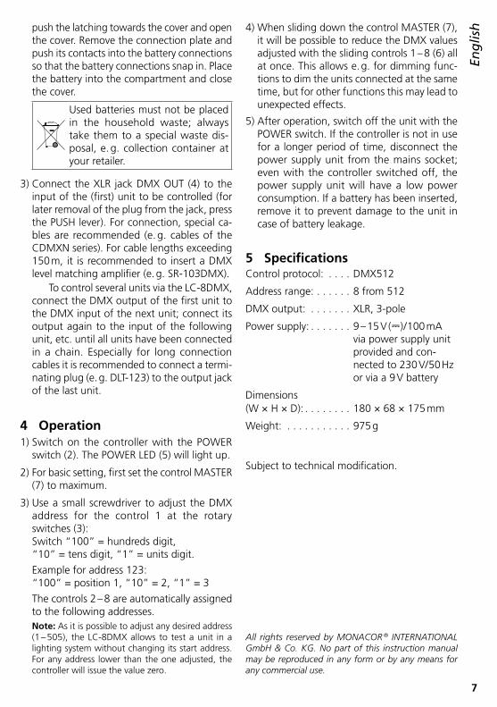
çais3 Fonctionnement
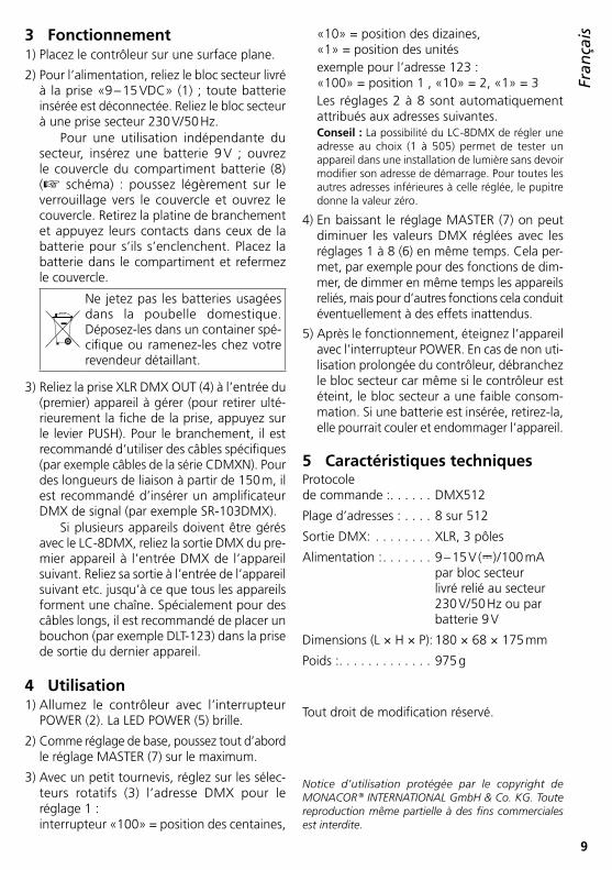
1) Placez le contrôleur sur une surface plane .
2) Pour l’alimentation, reliez le bloc secteur livré à la prise «9 – 15 VDC» (1) ; toute batterie insérée est déconnectée . Reliez le bloc secteur à une prise secteur 230 V/ 50 Hz .
Pour une utilisation indépendante du secteur, insérez une batterie 9 V ; ouvrez le couvercle du compartiment batterie (8) (☞ schéma) : poussez légèrement sur le verrouillage vers le couvercle et ouvrez le couvercle . Retirez la platine de branchement et appuyez leurs contacts dans ceux de la batterie pour s’ils s’enclenchent . Placez la batterie dans le compartiment et refermez le couvercle .
Ne jetez pas les batteries usagées dans la poubelle domestique . Déposez-les dans un container spé-cifique ou ramenez-les chez votre revendeur détaillant .
3) Reliez la prise XLR DMX OUT (4) à l’entrée du (premier) appareil à gérer (pour retirer ulté-rieurement la fiche de la prise, appuyez sur le levier PUSH) . Pour le branchement, il est recommandé d‘utiliser des câbles spécifiques (par exemple câbles de la série CDMXN) . Pour des longueurs de liaison à partir de 150 m, il est recommandé d’insérer un amplificateur DMX de signal (par exemple SR-103DMX) .
Si plusieurs appareils doivent être gérés avec le LC-8DMX, reliez la sortie DMX du pre-mier appareil à l’entrée DMX de l’appareil suivant . Reliez sa sortie à l’entrée de l’appareil suivant etc . jusqu’à ce que tous les appareils forment une chaîne . Spécialement pour des câbles longs, il est recommandé de placer un bouchon (par exemple DLT-123) dans la prise de sortie du dernier appareil .
4 Utilisation1) Allumez le contrôleur avec l’interrupteur
POWER (2) . La LED POWER (5) brille .
2) Comme réglage de base, poussez tout d’abord le réglage MASTER (7) sur le maximum .
3) Avec un petit tournevis, réglez sur les sélec- teurs rotatifs (3) l’adresse DMX pour le réglage 1 : interrupteur «100» = position des centaines,
«10» = position des dizaines, «1» = position des unitésexemple pour l’adresse 123 : «100» = position 1 , «10» = 2, «1» = 3Les réglages 2 à 8 sont automatiquement attribués aux adresses suivantes .
Conseil : La possibilité du LC-8DMX de régler une adresse au choix (1 à 505) permet de tester un appareil dans une installation de lumière sans devoir modifier son adresse de démarrage . Pour toutes les autres adresses inférieures à celle réglée, le pupitre donne la valeur zéro .
4) En baissant le réglage MASTER (7) on peut diminuer les valeurs DMX réglées avec les réglages 1 à 8 (6) en même temps . Cela per-met, par exemple pour des fonctions de dim-mer, de dimmer en même temps les appareils reliés, mais pour d’autres fonctions cela conduit éventuellement à des effets inattendus .
5) Après le fonctionnement, éteignez l’appareil avec l’interrupteur POWER . En cas de non uti-lisation prolongée du contrôleur, débranchez le bloc secteur car même si le contrôleur est éteint, le bloc secteur a une faible consom-mation . Si une batterie est insérée, retirez-la, elle pourrait couler et endommager l’appareil .
5 Caractéristiques techniquesProtocole de commande : . . . . . . DMX512
Plage d’adresses : . . . . 8 sur 512
Sortie DMX: . . . . . . . . XLR, 3 pôles
Alimentation : . . . . . . . 9 – 15 V (⎓) / 100 mA par bloc secteur livré relié au secteur 230 V/ 50 Hz ou par batterie 9 V
Dimensions (L × H × P): 180 × 68 × 175 mm
Poids : . . . . . . . . . . . . . 975 g
Tout droit de modification réservé .
Notice d’utilisation protégée par le copyright de MONACOR ® INTERNATIONAL GmbH & Co. KG. Toute reproduction même partielle à des fins commerciales est interdite.
10
ItalianoDeutsch
Deutsch Seite
EnglishEnglish Page
FrançaisFrançais Page
EspañolEspañol Página
NederlandsNederlands Pagina
PolskiPolski Strona
Unità DMX di comando luceQueste istruzioni sono rivolte all‘utente senza conoscenze tecniche specifiche . Vi preghiamo di leggerle attentamente prima della messa in funzione e di conservarle per un uso futuro .
1 Possibilità d‘impiegoQuesta unità di comando luce permette l’uso semplice di apparecchi con un totale di 8 canali DMX . Dato che l‘unità può funzionare anche con una batteria e avendo l’indirizzo imposta-bile, è adatta inoltre come dispositivo mobile di test in impianti con comando DMX .
DMX è l’abbreviazione di Digital Multiplex e significa comando digitale di più apparec-chi DMX per mezzo di una linea comune di comando .
2 Avvertenze di sicurezzaGli apparecchi (unità di comando e alimentatore) sono conformi a tutte le direttive rilevanti dell’UE e pertanto portano la sigla .
AVVERTIMENTO L’alimentatore a spina fun-ziona con pericolosa tensione di rete . Non intervenire mai personalmente al suo interno . Esiste il pericolo di una scarica elettrica .
• Usare gli apparecchi solo all’interno di locali e proteggerli dall’acqua gocciolante e dagli spruzzi d’acqua, da alta umidità dell’aria e dal calore (temperatura d’impiego ammessa fra 0 e 40 °C) .
• Non mettere in funzione l’unità di comando e staccare subito l’alimentatore dalla presa di rete se:1 . uno degli apparecchi presenta dei danni
visibili;2 . dopo una caduta o dopo eventi simili sus-
siste il sospetto di un difetto;3 . gli apparecchi non funzionano corretta-
mente .Per la riparazione rivolgersi sempre ad un’of-ficina competente .
• Per la pulizia usare solo un panno morbido, asciutto; non impiegare in nessun caso acqua o prodotti chimici .
• Nel caso d’uso improprio, di collegamenti sbagliati, d’impiego scorretto o di riparazione non a regola d’arte degli apparecchi, non si assume nessuna responsabilità per eventuali danni consequenziali a persone o a cose e non si assume nessuna garanzia per gli ap-parecchi .
Se si desidera eliminare gli apparecchi definitivamente, consegnarli per lo smaltimento ad un’istituzione locale per il riciclaggio .
3 Messa in funzione1) Posizionare l’unità di comando su una su-
perficie piana .
2) Per l’alimentazione collegare l’alimentatore in dotazione con la presa “9 – 15 V DC” (1) . Una batteria eventualmente inserita sarà
ItalianoItaliano Pagina
09
87 6 54
321 09
87 6 54
321 09
87 6 54
321
213
PUSH
1 23
DMX ADDRESS
POWER
DMX OUT
9-15VDC 100100 SIGNAL GND
654321 7 8 MASTER
LC-8DMC
00
2
4
6
8
10
00
2
4
6
8
10
00
2
4
6
8
10
00
2
4
6
8
10
00
2
4
6
8
10
00
2
4
6
8
10
00
2
4
6
8
10
00
2
4
6
8
10
1
8
2
5 6 7
43
11
Italianodisattivata in questo caso . Inserire l’alimen-
tatore in una presa di rete (230 V/ 50 Hz) .Per un’alimentazione indipendente dalla
rete, inserire una batteria di 9 V . Aprire il coperchio del vano batteria (8) (☞ illustra-zione): Premere il bloccaggio leggermente contro il coperchio e aprire il coperchio . Sfilare la piastra di connessione e spingere i suoi con-tatti sui contatti della batteria fino allo scatto . Sistemare la batteria nel vano e richiudere il coperchio .
Non gettare le batterie scariche o difettose nelle immondizie di casa bensì negli appositi contenitori (p . es . presso il vostro rivenditore) .
3) Collegare la presa XLR DMX OUT (4) con l’in-gresso del (primo) apparecchio da comandare (per sfilare successivamente il connettore dalla sua presa, premere sulla levetta PUSH) . Per il collegamento si dovrebbero usare cavi speciali per la trasmissione di segnali DMX (p . es . cavi della serie CDMXN) . Nel caso di lunghezze oltre i 150 m si consiglia l’impiego di un am-plificatore DMX (p . es . SR-103DMX) .
Se si devono comandare più apparec-chi con la LC-8DMX, collegare l’uscita DMX del primo apparecchio con l’ingresso DMX dell’apparecchio a valle e l’uscita di quest’ul-timo con l’ingresso dell’apparecchio succes-sivo ecc . finché tutti gli apparecchi sono col-legati formando una catena . Per cavi lunghi di collegamento conviene inserire un termi-natore (p . es . DLT-123) nella presa d’uscita dell’ultimo apparecchio .
4 Funzionamento1) Accendere l’unità di comando con l’interrut-
tore POWER (2) . Si accende la spia di funzio-namento (5) .
2) Per il momento, per l’impostazione base, spo-stare il regolatore MASTER (7) sul massimo .
3) Con un piccolo cacciavite, ai selettori (3) im-postare l’indirizzo DMX per il regolatore 1: Selettore “100”= centinaia, “10”= decine, “1”= unità
Esempio per l’indirizzo 123: “100” = posizione 1, “10” = 2, “1”= 3
I regolatori 2 – 8 sono assegnati automatica-mente agli indirizzi successivi .
Nota: Grazie alla possibilità di impostare un indirizzo a scelta (1 – 505), con la LC-8DMX si può testare un apparecchio in un impianto di luci, senza dovere modificare il suo indirizzo di start . Per tutti gli indirizzi inferiori all’indirizzo impostato, l’unità segna il valore zero .
4) I valori DMX impostati con i cursori 1 – 8 (6) possono essere ridotti insieme abbassando il regolatore MASTER (7) . In questo modo è possibile, per esempio, se è attiva al funzione di dimming, eseguire il dimming comune per tutti gli apparecchi collegati; in caso di altre funzioni, tale azione può provocare tuttavia degli effetti inaspettati .
5) Dopo l’uso spegnere l’apparecchio con l’in-terruttore POWER . Se l’unità di comando non viene usata per un certo periodo conviene staccare l’alimentatore dalla presa di rete perché consuma un po’ di corrente anche con l’unità spenta . Se è inserita una batteria, toglierla per escludere danni all’apparecchio se la batteria dovesse perdere .
5 Dati tecniciProtocollo di comando: . . . . . . . . DMX512
Range d’indirizzi: . . . . 8 fra 512
Uscita DMX: . . . . . . . . XLR, 3 poli
Alimentazione: . . . . . . 9 – 15 V (⎓) / 100 mA tramite alimentatore in dotazione con 230 V/ 50 Hz oppure tramite batteria 9 V
Dimensioni(l × h × p): . . . . . . . . . 180 × 68 × 175 mm,
Peso: . . . . . . . . . . . . . . 975 g
Con riserva di modifiche tecniche .
La MONACOR ® INTERNATIONAL GmbH & Co. KG si riserva ogni diritto di elaborazione in qualsiasi forma delle presenti istruzioni per l’uso. La riproduzione – anche parziale – per propri scopi commerciali è vietata.
12
Españ
olDeutsch
Deutsch Seite
EnglishEnglish Page
FrançaisFrançais Page
ItalianoItaliano Pagina
PolskiPolski Strona
EspañolEspañol Página
Controlador DMXEstas instrucciones van dirigidas a usuarios sin ningún conocimiento técnico específico . Lea atentamente estas instrucciones antes de utili-zar el aparato y guárdelas para usos posteriores .
1 AplicacionesEste controlador permite el funcionamiento sen-cillo de aparatos con un máximo de 8 canales DMX en total . Puesto que el aparato también se puede utilizar mediante una batería y puede ajustarse el rango de direcciones, está adecuado también como comprobador móvil de sistemas controlados por DMX .
DMX es la abreviatura de Digital Multiplex y significa control digital de varios aparatos DMX mediante una línea de control común .
2 Notas de SeguridadLos aparatos (controlador y alimentador) cum-plen con todas las directivas relevantes de la UE y por lo tanto están marcados con el símbolo .
ADVERTENCIA El alimentador utiliza un vol-taje peligroso . Deje el mante-nimiento en manos del personal cualificado . El manejo inexperto o la modificación del alimenta-dor puede provocar una des-carga .
• Los aparatos están adecuados para su aplica-ción sólo en interiores . Protéjalos de goteos y salpicaduras, elevada humedad del aire y calor (temperatura ambiente admisible: 0 – 40 ºC) .
• No utilice el controlador y desconecte inmedia-tamente el alimentador del enchufe si:1 . Uno de los aparatos está visiblemente
dañado .2 . El aparato ha sufrido daños después de
una caída o accidente similar .3 . No funciona correctamente .Sólo el personal cualificado puede reparar los aparatos bajo cualquier circunstancia .
• Utilice sólo un paño suave y seco para la lim-pieza; no utilice nunca ni agua ni productos químicos .
• No podrá reclamarse garantía o responsabi-lidad alguna por cualquier daño personal o material resultante si los aparatos se utilizan para otros fines diferentes a los originalmente concebidos, si no se conectan correctamente, no se utilizan adecuadamente o no se reparan por expertos .
Si va a poner los aparatos fuera de servicio definitivamente, llévelos a la planta de reciclaje más cercana para que su eliminación no sea perjudicial para el medioambiente .
3 Puesta en Marcha1) Coloque el controlador en una superficie
plana .
2) Para la alimentación, conecte el alimentador entregado a la toma “9 – 15 V DC” (1) . Se desconectará la batería insertada . Conecte el alimentador a un enchufe (230 V/ 50 Hz) .
09
87 6 54
321 09
87 6 54
321 09
87 6 54
321
213
PUSH
1 23
DMX ADDRESS
POWER
DMX OUT
9-15VDC 100100 SIGNAL GND
654321 7 8 MASTER
LC-8DMC
00
2
4
6
8
10
00
2
4
6
8
10
00
2
4
6
8
10
00
2
4
6
8
10
00
2
4
6
8
10
00
2
4
6
8
10
00
2
4
6
8
10
00
2
4
6
8
10
1
8
2
5 6 7
43
13
Españ
olPara un funcionamiento independiente
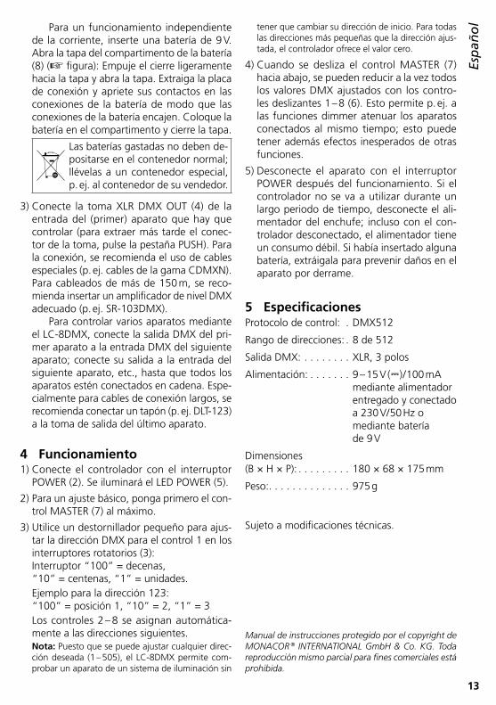
de la corriente, inserte una batería de 9 V . Abra la tapa del compartimento de la batería (8) (☞ figura): Empuje el cierre ligeramente hacia la tapa y abra la tapa . Extraiga la placa de conexión y apriete sus contactos en las conexiones de la batería de modo que las conexiones de la batería encajen . Coloque la batería en el compartimento y cierre la tapa .
Las baterías gastadas no deben de-positarse en el contenedor normal; llévelas a un contenedor especial, p . ej . al contenedor de su vendedor .
3) Conecte la toma XLR DMX OUT (4) de la entrada del (primer) aparato que hay que controlar (para extraer más tarde el conec-tor de la toma, pulse la pestaña PUSH) . Para la conexión, se recomienda el uso de cables especiales (p . ej . cables de la gama CDMXN) . Para cableados de más de 150 m, se reco-mienda insertar un amplificador de nivel DMX adecuado (p . ej . SR-103DMX) .
Para controlar varios aparatos mediante el LC-8DMX, conecte la salida DMX del pri-mer aparato a la entrada DMX del siguiente aparato; conecte su salida a la entrada del siguiente aparato, etc ., hasta que todos los aparatos estén conectados en cadena . Espe-cialmente para cables de conexión largos, se recomienda conectar un tapón (p . ej . DLT-123) a la toma de salida del último aparato .
4 Funcionamiento1) Conecte el controlador con el interruptor
POWER (2) . Se iluminará el LED POWER (5) .
2) Para un ajuste básico, ponga primero el con-trol MASTER (7) al máximo .
3) Utilice un destornillador pequeño para ajus-tar la dirección DMX para el control 1 en los interruptores rotatorios (3): Interruptor “100” = decenas, “10” = centenas, “1” = unidades .Ejemplo para la dirección 123: “100” = posición 1, “10” = 2, “1” = 3Los controles 2 – 8 se asignan automática-mente a las direcciones siguientes .
Nota: Puesto que se puede ajustar cualquier direc-ción deseada (1 – 505), el LC-8DMX permite com-probar un aparato de un sistema de iluminación sin
tener que cambiar su dirección de inicio . Para todas las direcciones más pequeñas que la dirección ajus-tada, el controlador ofrece el valor cero .
4) Cuando se desliza el control MASTER (7) hacia abajo, se pueden reducir a la vez todos los valores DMX ajustados con los contro-les deslizantes 1 – 8 (6) . Esto permite p . ej . a las funciones dimmer atenuar los aparatos conectados al mismo tiempo; esto puede tener además efectos inesperados de otras funciones .
5) Desconecte el aparato con el interruptor POWER después del funcionamiento . Si el controlador no se va a utilizar durante un largo periodo de tiempo, desconecte el ali-mentador del enchufe; incluso con el con-trolador desconectado, el alimentador tiene un consumo débil . Si había insertado alguna batería, extráigala para prevenir daños en el aparato por derrame .
5 EspecificacionesProtocolo de control: . DMX512
Rango de direcciones: . 8 de 512
Salida DMX: . . . . . . . . XLR, 3 polos
Alimentación: . . . . . . . 9 – 15 V (⎓) / 100 mA mediante alimentador entregado y conectado a 230 V/ 50 Hz o mediante batería de 9 V
Dimensiones(B × H × P): . . . . . . . . . 180 × 68 × 175 mm
Peso: . . . . . . . . . . . . . . 975 g
Sujeto a modificaciones técnicas .
Manual de instrucciones protegido por el copyright de MONACOR ® INTERNATIONAL GmbH & Co. KG. Toda reproducción mismo parcial para fines comerciales está prohibida.
14
PolskiDeutsch
Deutsch Seite
EnglishEnglish Page
FrançaisFrançais Page
ItalianoItaliano Pagina
EspañolEspañol Página
NederlandsNederlands Pagina
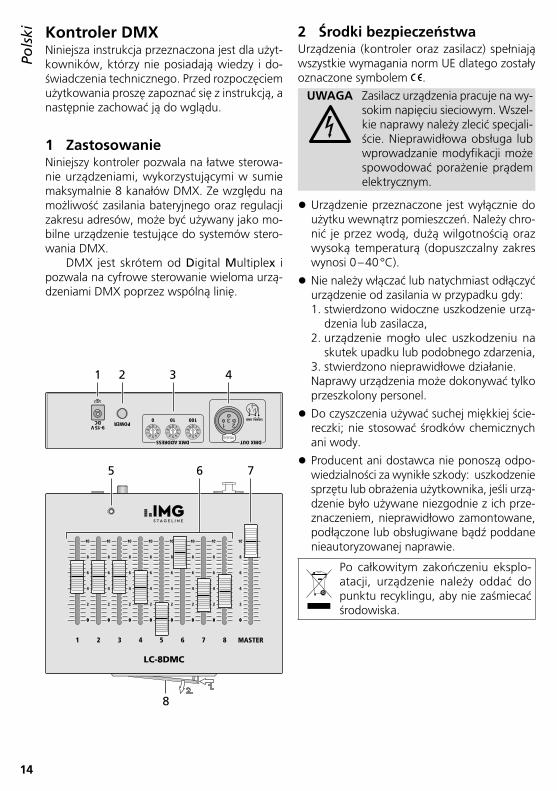
Kontroler DMXNiniejsza instrukcja przeznaczona jest dla użyt-kowników, którzy nie posiadają wiedzy i do-świadczenia technicznego . Przed rozpoczęciem użytkowania proszę zapoznać się z instrukcją, a następnie zachować ją do wglądu .
1 ZastosowanieNiniejszy kontroler pozwala na łatwe sterowa-nie urządzeniami, wykorzystującymi w sumie maksymalnie 8 kanałów DMX . Ze względu na możliwość zasilania bateryjnego oraz regulacji zakresu adresów, może być używany jako mo-bilne urządzenie testujące do systemów stero-wania DMX .
DMX jest skrótem od Digital Multiplex i pozwala na cyfrowe sterowanie wieloma urzą-dzeniami DMX poprzez wspólną linię .
2 Środki bezpieczeństwaUrządzenia (kontroler oraz zasilacz) spełniają wszystkie wymagania norm UE dlatego zostały oznaczone symbolem .
UWAGA Zasilacz urządzenia pracuje na wy-sokim napięciu sieciowym . Wszel-kie naprawy należy zlecić specjali-ście . Nieprawidłowa obsługa lub wprowadzanie modyfikacji może spowodować porażenie prądem elektrycznym .
• Urządzenie przeznaczone jest wyłącznie do użytku wewnątrz pomieszczeń . Należy chro-nić je przez wodą, dużą wilgotnością oraz wysoką temperaturą (dopuszczalny zakres wynosi 0 – 40 °C) .
• Nie należy włączać lub natychmiast odłączyć urządzenie od zasilania w przypadku gdy: 1 . stwierdzono widoczne uszkodzenie urzą-
dzenia lub zasilacza,2 . urządzenie mogło ulec uszkodzeniu na
skutek upadku lub podobnego zdarzenia,3 . stwierdzono nieprawidłowe działanie .Naprawy urządzenia może dokonywać tylko przeszkolony personel .
• Do czyszczenia używać suchej miękkiej ście-reczki; nie stosować środków chemicznych ani wody .
• Producent ani dostawca nie ponoszą odpo-wiedzialności za wynikłe szkody: uszkodzenie sprzętu lub obrażenia użytkownika, jeśli urzą-dzenie było używane niezgodnie z ich prze-znaczeniem, nieprawidłowo zamontowane, podłączone lub obsługiwane bądź poddane nieautoryzowanej naprawie .
Po całkowitym zakończeniu eksplo-atacji, urządzenie należy oddać do punktu recyklingu, aby nie zaśmiecać środowiska .
PolskiPolski Strona
09
87 6 54
321 09
87 6 54
321 09
87 6 54
321
213
PUSH
1 23
DMX ADDRESS
POWER
DMX OUT
9-15VDC 100100 SIGNAL GND
654321 7 8 MASTER
LC-8DMC
00
2
4
6
8
10
00
2
4
6
8
10
00
2
4
6
8
10
00
2
4
6
8
10
00
2
4
6
8
10
00
2
4
6
8
10
00
2
4
6
8
10
00
2
4
6
8
10
1
8
2
5 6 7
43
15
Polski3 Przygotowanie do pracy
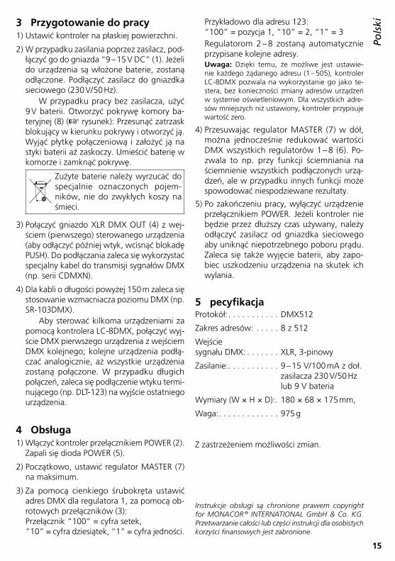
1) Ustawić kontroler na płaskiej powierzchni .
2) W przypadku zasilania poprzez zasilacz, pod-łączyć go do gniazda “9 – 15 V DC” (1) . Jeżeli do urządzenia są włożone baterie, zostaną odłączone . Podłączyć zasilacz do gniazdka sieciowego (230 V/ 50 Hz) .
W przypadku pracy bez zasilacza, użyć 9 V baterii . Otworzyć pokrywę komory ba-teryjnej (8) (☞ rysunek): Przesunąć zatrzask blokujący w kierunku pokrywy i otworzyć ją . Wyjąć płytkę połączeniową i założyć ją na styki baterii aż zaskoczy . Umieścić baterię w komorze i zamknąć pokrywę .
Zużyte baterie należy wyrzucać do specjalnie oznaczonych pojem-ników, nie do zwykłych koszy na śmieci .
3) Połączyć gniazdo XLR DMX OUT (4) z wej-ściem (pierwszego) sterowanego urządzenia (aby odłączyć później wtyk, wcisnąć blokadę PUSH) . Do podłączania zaleca się wykorzystać specjalny kabel do transmisji sygnałów DMX (np . serii CDMXN) .
4) Dla kabli o długości powyżej 150 m zaleca się stosowanie wzmacniacza poziomu DMX (np . SR-103DMX) .
Aby sterować kilkoma urządzeniami za pomocą kontrolera LC-8DMX, połączyć wyj-ście DMX pierwszego urządzenia z wejściem DMX kolejnego; kolejne urządzenia podłą-czać analogicznie, aż wszystkie urządzenia zostaną połączone . W przypadku długich połączeń, zaleca się podłączenie wtyku termi-nującego (np . DLT-123) na wyjście ostatniego urządzenia .
4 Obsługa1) Włączyć kontroler przełącznikiem POWER (2) .
Zapali się dioda POWER (5) .
2) Początkowo, ustawić regulator MASTER (7) na maksimum .
3) Za pomocą cienkiego śrubokręta ustawić adres DMX dla regulatora 1, za pomocą ob-rotowych przełączników (3): Przełącznik “100” = cyfra setek, “10” = cyfra dziesiątek, “1” = cyfra jedności .
Przykładowo dla adresu 123: “100” = pozycja 1, “10” = 2, “1” = 3Regulatorom 2 – 8 zostaną automatycznie przypisane kolejne adresy .
Uwaga: Dzięki temu, że możliwe jest ustawie-nie każdego żądanego adresu (1 – 505), kontroler LC-8DMX pozwala na wykorzystanie go jako te-stera, bez konieczności zmiany adresów urządzeń w systemie oświetleniowym . Dla wszystkich adre-sów mniejszych niż ustawiony, kontroler przypisuje wartość zero .
4) Przesuwając regulator MASTER (7) w dół, można jednocześnie redukować wartości DMX wszystkich regulatorów 1 – 8 (6) . Po-zwala to np . przy funkcji ściemniania na ściemnienie wszystkich podłączonych urzą-dzeń, ale w przypadku innych funkcji może spowodować niespodziewane rezultaty .
5) Po zakończeniu pracy, wyłączyć urządzenie przełącznikiem POWER . Jeżeli kontroler nie będzie przez dłuższy czas używany, należy odłączyć zasilacz od gniazdka sieciowego aby uniknąć niepotrzebnego poboru prądu . Zaleca się także wyjęcie baterii, aby zapo-biec uszkodzeniu urządzenia na skutek ich wylania .
5 pecyfikacjaProtokół: . . . . . . . . . . . DMX512
Zakres adresów: . . . . . 8 z 512
Wejście sygnału DMX: . . . . . . . XLR, 3-pinowy
Zasilanie: . . . . . . . . . . . 9 – 15 V/ 100 mA z doł . zasilacza 230 V/ 50 Hz lub 9 V bateria
Wymiary (W × H × D): . 180 × 68 × 175 mm,
Waga: . . . . . . . . . . . . . 975 g
Z zastrzeżeniem możliwości zmian .
Instrukcje obsługi są chronione prawem copyright for MONACOR ® INTERNATIONAL GmbH & Co. KG. Przetwarzanie całości lub części instrukcji dla osobistych korzyści finansowych jest zabronione.

MONACOR INTERNATIONAL GmbH & Co. KG • Zum Falsch 36 • 28307 Bremen • Germany Copyright © by MONACOR INTERNATIONAL. All rights reserved. A-1318.99.02.08.2017