Embed Size (px)
Citation preview
February 2005
DESIGN MANUAL FOR ROADS AND BRIDGES
VOLUME 5 ASSESSMENT ANDPREPARATION OF ROADSCHEMES
SECTION 2 PREPARATION ANDIMFORMATION
PART 4
TA 91/05
PROVISION FOR NON-MOTORISEDUSERS
SUMMARY
This Advice Note provides guidance in relation toprovision for non-motorised users, through the designand implementation of both on- and off- carriagewayprovision including crossings, junctions and generaldesign considerations.
INSTRUCTIONS FOR USE
This is a new document to be inserted into the manual.
1. Remove Contents pages from Volume 5.
2. Insert new Contents page for Volume 5 datedFebruary 2005.
3. Insert TA 91/05 into Volume 5, Section 2.
4. Please archive this sheet as appropriate.
Note: A quarterly index with a full set of VolumeContents Pages is available separately from TheStationery Office Ltd.
TA 91/05
Provision forNon-Motorised Users
Summary: This Advice Note provides guidance in relation to provision for non-motorisedusers, through the design and implementation of both on- and off- carriagewayprovision including crossings, junctions and general design considerations.
DESIGN MANUAL FOR ROADS AND BRIDGES
THE HIGHWAYS AGENCY
SCOTTISH EXECUTIVE
WELSH ASSEMBLY GOVERNMENTLLYWODRAETH CYNULLIAD CYMRU
THE DEPARTMENT FOR REGIONAL DEVELOPMENTNORTHERN IRELAND

Volume 5 Section 2Part 4 TA 91/05
February 2005
REGISTRATION OF AMENDMENTS
Amend Page No Signature & Date of Amend Page No Signature & Date ofNo incorporation of No incorporation of
amendments amendments
Registration of Amendments

Volume 5 Section 2Part 4 TA 91/05
February 2005
REGISTRATION OF AMENDMENTS
Amend Page No Signature & Date of Amend Page No Signature & Date ofNo incorporation of No incorporation of
amendments amendments
Registration of Amendments
VOLUME 5 ASSESSMENT ANDPREPARATION OF ROADSCHEMES
SECTION 2 PREPARATION ANDIMFORMATION
PART 4
TA 91/05
PROVISION FOR NON-MOTORISEDUSERS
Contents
Chapter
1. Introduction
2. NMU Requirements
3. Scheme Development and Assessment
4. NMU Off-Carriageway Routes (OCRs)
5. On-Carriageway Cycling Facilities
6. Crossings
7. Junctions
8. General Considerations
9. References and Bibliography
10. Detailed Contents and Index
11. Enquiries
Annex 1 Legal Framework (England and WalesOnly)
Annex 2 OCR Types
Annex 3 On-Carriageway Cycling Facilities
Annex 4 NMU Crossing: Site Assessment RecordSheet
DESIGN MANUAL FOR ROADS AND BRIDGES
February 2005
Volume 5 Section 2Part 4 TA 91/05
Chapter 1Introduction
1. INTRODUCTION
General
1.1 The purpose of this Advice Note is to highlightthe needs of Non-Motorised Users (NMUs) on trunkroads, and provide guidance on provision of bothOff-Carriageway Routes (OCRs) and on-carriagewayfacilities, including crossings and junctions. OCRs areNMU routes which may be either inside or outside thehighway boundary, but do not form part of thecarriageway.
1.2 NMUs are considered to be pedestrians, cyclistsand equestrians. Particular consideration should begiven to the needs of disabled people, who may use anyof these modes or other equipment such as wheelchairs.
1.3 For the purpose of this Advice Note users ofelectrically assisted pedal cycles or poweredwheelchairs and invalid carriages, that conform withcurrent Department for Transport regulations and maylegally be used on pedestrian or cycle facilities, are alsoconsidered as NMUs.
1.4 This Advice Note should be read in conjunctionwith TA 90 (DMRB 6.3.5), HD 42 (DMRB 5.2.5) andTA 68 (DMRB 8.5.1). Other documents within theDesign Manual for Roads and Bridges (DMRB) alsoprovide information in relation to NMUs; these areidentified where relevant within this Advice Note.
1.5 This Advice Note and those identified inparagraph 1.4 wholly supersede TA 67 (DMRB 5.2.4)and replace Chapters 8 and 11 of TA 57 (DMRB 6.3.3).
Advice Note Objectives
1.6 All NMUs have a legal right to use the publichighway, unless specifically prohibited.
1.7 Encouraging modal shift, particularly to walkingand cycling, has a very important role to play increating a more integrated and sustainable transportsystem.
1.8 All purpose trunk roads typically carry highflows of fast moving traffic and are generallyunattractive for NMUs to travel along or across.However, trunk roads often provide important links orroutes for NMUs, representing the quickest, most directroute between key destinations, and are often used
February 2005
because of the lack of more convenient alternatives. Assuch there is a need to ensure that scheme designs takefull account of NMU requirements, and thatopportunities are taken to encourage safer and moreattractive provision wherever possible.
1.9 This Advice Note considers facilities for NMUsas part of trunk road schemes. Other national, regionaland user group guidance is also available and mayprovide additional or more suitable advice in othersituations.
1.10 This Advice Note contains information on legalissues in relation to NMUs within England and Wales(Annex 1). However, legal advice should always besought before proposals are finalised because of thepossibility of changes to legislation and case law.
Implementation
1.11 This Advice Note should be used forthwith forthe planning and design of trunk roads and motorwayimprovement schemes, currently being prepared,provided that in the opinion of the OverseeingOrganisation this would not result in unreasonableexpense or delay to the progress of the scheme. DesignOrganisations should confirm its application toparticular schemes with the Overseeing Organisation.
1.12 This Advice Note does not apply in Scotland.
Research and Consultation
1.13 This guidance draws from a range of documentsfrom governmental and non-governmentalorganisations. A range of user groups and otherorganisations have also been consulted in thedevelopment of this Advice Note.
Definitions
1.14 Overseeing Organisation: The highwayauthority responsible for the scheme.
1.15 Design Organisation: The organisation(s)commissioned to undertake scheme preparation.
1/1
Volume 5 Section 2Part 4 TA 91/05
Chapter 2NMU Requirements
2. NMU REQUIREMENTS
General
2.1 This chapter identifies the characteristics ofdifferent NMUs and their general requirements.
Pedestrians
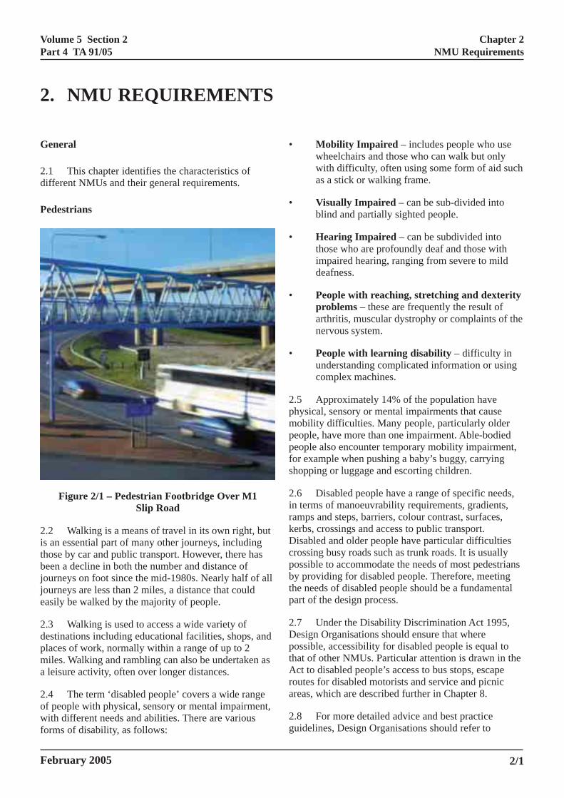
Figure 2/1 – Pedestrian Footbridge Over M1Slip Road
2.2 Walking is a means of travel in its own right, butis an essential part of many other journeys, includingthose by car and public transport. However, there hasbeen a decline in both the number and distance ofjourneys on foot since the mid-1980s. Nearly half of alljourneys are less than 2 miles, a distance that couldeasily be walked by the majority of people.
2.3 Walking is used to access a wide variety ofdestinations including educational facilities, shops, andplaces of work, normally within a range of up to 2miles. Walking and rambling can also be undertaken asa leisure activity, often over longer distances.
2.4 The term ‘disabled people’ covers a wide rangeof people with physical, sensory or mental impairment,with different needs and abilities. There are variousforms of disability, as follows:
February 2005
• Mobility Impaired – includes people who usewheelchairs and those who can walk but onlywith difficulty, often using some form of aid suchas a stick or walking frame.
• Visually Impaired – can be sub-divided intoblind and partially sighted people.
• Hearing Impaired – can be subdivided intothose who are profoundly deaf and those withimpaired hearing, ranging from severe to milddeafness.
• People with reaching, stretching and dexterityproblems – these are frequently the result ofarthritis, muscular dystrophy or complaints of thenervous system.
• People with learning disability – difficulty inunderstanding complicated information or usingcomplex machines.
2.5 Approximately 14% of the population havephysical, sensory or mental impairments that causemobility difficulties. Many people, particularly olderpeople, have more than one impairment. Able-bodiedpeople also encounter temporary mobility impairment,for example when pushing a baby’s buggy, carryingshopping or luggage and escorting children.
2.6 Disabled people have a range of specific needs,in terms of manoeuvrability requirements, gradients,ramps and steps, barriers, colour contrast, surfaces,kerbs, crossings and access to public transport.Disabled and older people have particular difficultiescrossing busy roads such as trunk roads. It is usuallypossible to accommodate the needs of most pedestriansby providing for disabled people. Therefore, meetingthe needs of disabled people should be a fundamentalpart of the design process.
2.7 Under the Disability Discrimination Act 1995,Design Organisations should ensure that wherepossible, accessibility for disabled people is equal tothat of other NMUs. Particular attention is drawn in theAct to disabled people’s access to bus stops, escaperoutes for disabled motorists and service and picnicareas, which are described further in Chapter 8.
2.8 For more detailed advice and best practiceguidelines, Design Organisations should refer to
2/1
Volume 5 Section 2Part 4 TA 91/05
Chapter 2NMU Requirements
Inclusive Mobility: a Guide to Best Practice on Accessto Pedestrian and Transport Infrastructure (DfT, 2002)and Guidance on the Use of Tactile Paving Surfaces(DfT, 1999).
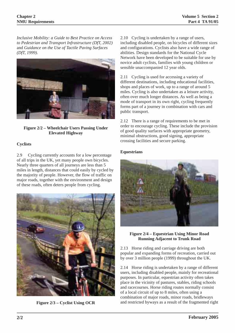
Figure 2/2 – Wheelchair Users Passing UnderElevated Highway
Cyclists
2.9 Cycling currently accounts for a low percentageof all trips in the UK, yet many people own bicycles.Nearly three quarters of all journeys are less than 5miles in length, distances that could easily by cycled bythe majority of people. However, the flow of traffic onmajor roads, together with the environment and designof these roads, often deters people from cycling.
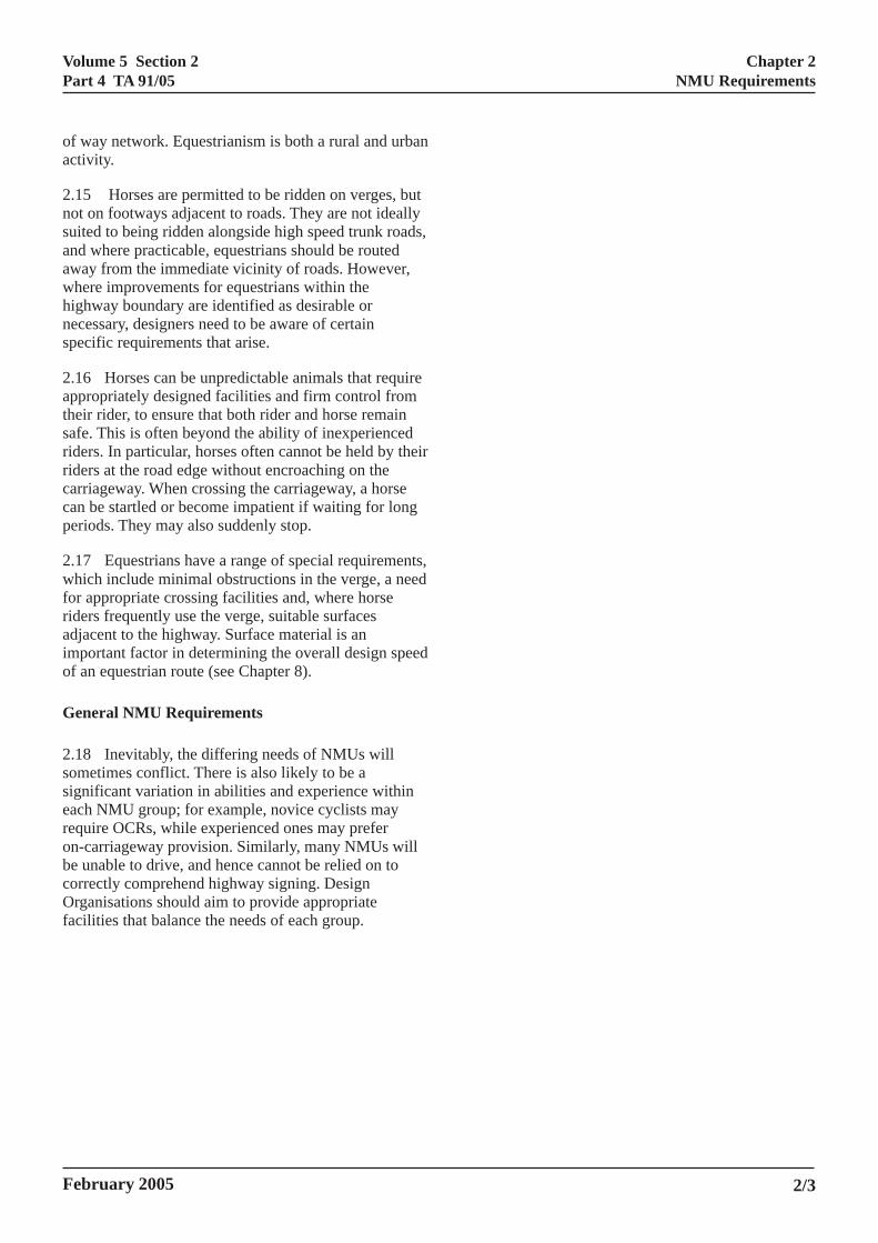
Figure 2/3 – Cyclist Using OCR
2iaaNns
2dsmomfp
2oomc
E
2pb
2uppaoca
2/2
.10 Cycling is undertaken by a range of users,ncluding disabled people, on bicycles of different sizesnd configurations. Cyclists also have a wide range ofbilities. Design standards for the National Cycleetwork have been developed to be suitable for use byovice adult cyclists, families with young children orensible unaccompanied 12 year olds.
.11 Cycling is used for accessing a variety ofifferent destinations, including educational facilities,hops and places of work, up to a range of around 5iles. Cycling is also undertaken as a leisure activity,
ften over much longer distances. As well as being aode of transport in its own right, cycling frequently
orms part of a journey in combination with cars andublic transport.
.12 There is a range of requirements to be met inrder to encourage cycling. These include the provisionf good quality surfaces with appropriate geometry,inimal obstructions, good signing, appropriate
rossing facilities and secure parking.
questrians
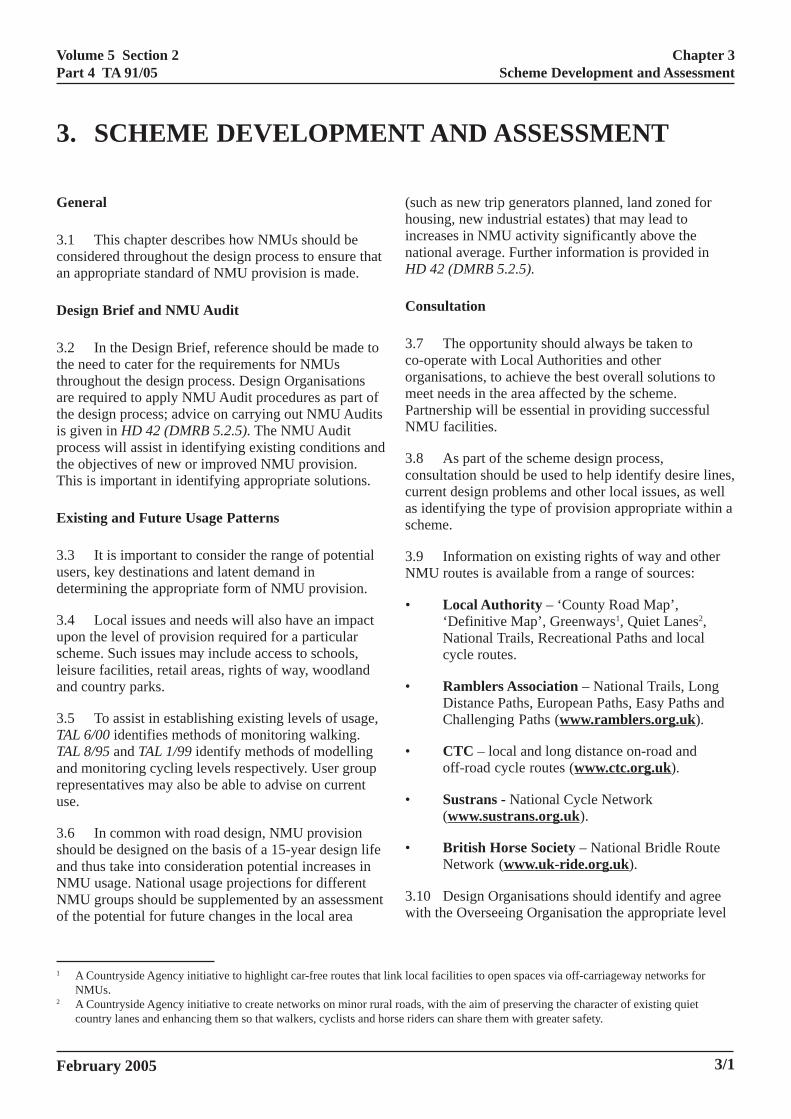
Figure 2/4 – Equestrian Using Minor RoadRunning Adjacent to Trunk Road
.13 Horse riding and carriage driving are bothopular and expanding forms of recreation, carried outy over 3 million people (1999) throughout the UK.
.14 Horse riding is undertaken by a range of differentsers, including disabled people, mainly for recreationalurposes. In particular, equestrian activity often takeslace in the vicinity of pastures, stables, riding schoolsnd racecourses. Horse riding routes normally consistf a local circuit of up to 8 miles, often using aombination of major roads, minor roads, bridlewaysnd restricted byways as a result of the fragmented right
February 2005
Volume 5 Section 2Part 4 TA 91/05
Chapter 2NMU Requirements
of way network. Equestrianism is both a rural and urbanactivity.
2.15 Horses are permitted to be ridden on verges, butnot on footways adjacent to roads. They are not ideallysuited to being ridden alongside high speed trunk roads,and where practicable, equestrians should be routedaway from the immediate vicinity of roads. However,where improvements for equestrians within thehighway boundary are identified as desirable ornecessary, designers need to be aware of certainspecific requirements that arise.
2.16 Horses can be unpredictable animals that requireappropriately designed facilities and firm control fromtheir rider, to ensure that both rider and horse remainsafe. This is often beyond the ability of inexperiencedriders. In particular, horses often cannot be held by theirriders at the road edge without encroaching on thecarriageway. When crossing the carriageway, a horsecan be startled or become impatient if waiting for longperiods. They may also suddenly stop.
2.17 Equestrians have a range of special requirements,which include minimal obstructions in the verge, a needfor appropriate crossing facilities and, where horseriders frequently use the verge, suitable surfacesadjacent to the highway. Surface material is animportant factor in determining the overall design speedof an equestrian route (see Chapter 8).
General NMU Requirements
2.18 Inevitably, the differing needs of NMUs willsometimes conflict. There is also likely to be asignificant variation in abilities and experience withineach NMU group; for example, novice cyclists mayrequire OCRs, while experienced ones may preferon-carriageway provision. Similarly, many NMUs willbe unable to drive, and hence cannot be relied on tocorrectly comprehend highway signing. DesignOrganisations should aim to provide appropriatefacilities that balance the needs of each group.
February 2005 2/3
Volume 5 Section 2Part 4 TA 91/05
Chapter 3Scheme Development and Assessment
AND ASSESSMENT
3. SCHEME DEVELOPMENTGeneral
3.1 This chapter describes how NMUs should beconsidered throughout the design process to ensure thatan appropriate standard of NMU provision is made.
Design Brief and NMU Audit
3.2 In the Design Brief, reference should be made tothe need to cater for the requirements for NMUsthroughout the design process. Design Organisationsare required to apply NMU Audit procedures as part ofthe design process; advice on carrying out NMU Auditsis given in HD 42 (DMRB 5.2.5). The NMU Auditprocess will assist in identifying existing conditions andthe objectives of new or improved NMU provision.This is important in identifying appropriate solutions.
Existing and Future Usage Patterns
3.3 It is important to consider the range of potentialusers, key destinations and latent demand indetermining the appropriate form of NMU provision.
3.4 Local issues and needs will also have an impactupon the level of provision required for a particularscheme. Such issues may include access to schools,leisure facilities, retail areas, rights of way, woodlandand country parks.
3.5 To assist in establishing existing levels of usage,TAL 6/00 identifies methods of monitoring walking.TAL 8/95 and TAL 1/99 identify methods of modellingand monitoring cycling levels respectively. User grouprepresentatives may also be able to advise on currentuse.
3.6 In common with road design, NMU provisionshould be designed on the basis of a 15-year design lifeand thus take into consideration potential increases inNMU usage. National usage projections for differentNMU groups should be supplemented by an assessmentof the potential for future changes in the local area
(hinnH
C
3comPN
3ccas
3N
•
•
•
•
•
3w
February 2005
1 A Countryside Agency initiative to highlight car-free routes that liNMUs.
2 A Countryside Agency initiative to create networks on minor ruracountry lanes and enhancing them so that walkers, cyclists and ho
such as new trip generators planned, land zoned forousing, new industrial estates) that may lead tocreases in NMU activity significantly above the
ational average. Further information is provided inD 42 (DMRB 5.2.5).
onsultation
.7 The opportunity should always be taken too-operate with Local Authorities and otherrganisations, to achieve the best overall solutions toeet needs in the area affected by the scheme.artnership will be essential in providing successfulMU facilities.
.8 As part of the scheme design process,onsultation should be used to help identify desire lines,urrent design problems and other local issues, as wells identifying the type of provision appropriate within acheme.
.9 Information on existing rights of way and otherMU routes is available from a range of sources:
Local Authority – ‘County Road Map’,‘Definitive Map’, Greenways1, Quiet Lanes2,National Trails, Recreational Paths and localcycle routes.
Ramblers Association – National Trails, LongDistance Paths, European Paths, Easy Paths andChallenging Paths (www.ramblers.org.uk).
CTC – local and long distance on-road andoff-road cycle routes (www.ctc.org.uk).
Sustrans - National Cycle Network(www.sustrans.org.uk).
British Horse Society – National Bridle RouteNetwork (www.uk-ride.org.uk).
.10 Design Organisations should identify and agreeith the Overseeing Organisation the appropriate level
nk local facilities to open spaces via off-carriageway networks for
3/1
l roads, with the aim of preserving the character of existing quietrse riders can share them with greater safety.
Volume 5 Section 2Part 4 TA 91/05
Chapter 3Scheme Development and Assessment
of consultation required. However, consultation shouldnormally be carried out with the Local Authority,Regional Road User Committee and local user grouprepresentatives, during the feasibility and preliminarydesign stage.
3.11 Public meetings and exhibitions should be wellpublicised throughout a radius of around 5 miles andheld in an accessible location where all local people canattend. It is essential that the building in which theseevents are held can be accessed by disabled people andthat events cover a combination of periods, includingtimes inside and outside normal working hours, toensure as many local users as possible can attend.
3.12 Insufficient consultation and consideration ofNMU needs is likely to result in a greater number ofobjections from local people and user groups, oftenleading to Public Inquiries. Good consultation can beexpensive, but should allay local fears and help toensure that appropriate NMU provision is made earlyon, without the need for additional mitigation at a laterstage.
General Design Principles
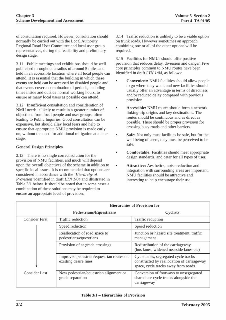
3.13 There is no single correct solution for theprovision of NMU facilities, and much will dependupon the overall objectives of the scheme in addition tospecific local issues. It is recommended that options areconsidered in accordance with the ‘Hierarchy ofProvision’ identified in draft LTN 1/04 and illustrated inTable 3/1 below. It should be noted that in some cases acombination of these solutions may be required toensure an appropriate level of provision.
3/2
3.14 Traffic reduction is unlikely to be a viable optionon trunk roads. However sometimes an approachcombining one or all of the other options will berequired.
3.15 Facilities for NMUs should offer positiveprovision that reduces delay, diversion and danger. Fivecore principles common to NMU routes have beenidentified in draft LTN 1/04, as follows:
• Convenient: NMU facilities should allow peopleto go where they want, and new facilities shouldusually offer an advantage in terms of directnessand/or reduced delay compared with previousprovision.
• Accessible: NMU routes should form a networklinking trip origins and key destinations. Theroutes should be continuous and as direct aspossible. There should be proper provision forcrossing busy roads and other barriers.
• Safe: Not only must facilities be safe, but for thewell being of users, they must be perceived to besafe.
• Comfortable: Facilities should meet appropriatedesign standards, and cater for all types of user.
• Attractive: Aesthetics, noise reduction andintegration with surrounding areas are important.NMU facilities should be attractive andinteresting to help encourage their use.
Hierarchies of Provision for
Pedestrians/Equestrians Cyclists
Consider First Traffic reduction Traffic reduction
Speed reduction Speed reduction
Reallocation of road space to Junction or hazard site treatment, trafficpedestrians/equestrians management
Provision of at-grade crossings Redistribution of the carriageway(bus lanes, widened nearside lanes etc)
Improved pedestrian/equestrian routes on Cycle lanes, segregated cycle tracksexisting desire lines constructed by reallocation of carriageway
space, cycle tracks away from roads
Consider Last New pedestrian/equestrian alignment or Conversion of footways to unsegregatedgrade separation shared use cycle tracks alongside the
carriageway
Table 3/1 – Hierarchies of Provision
➤
February 2005
Volume 5 Section 2Part 4 TA 91/05
Chapter 3Scheme Development and Assessment
3.16 A basic principle in scheme design is that theexisting rights of way network should be preserved asfar as possible, even where usage levels are low. A lowlevel of usage may be as a result of severance and coulddisguise the fact that a particular path is an essentiallink for certain local journeys. Preserving the networkshould save considerable resources, as any diversionwill require legal orders, which are normally opposedby user groups. In extreme cases, such a proposeddiversion could threaten the delivery of the wholescheme.
3.17 Where rights of way diversions are necessary, itis recommended that they should not normally result inadditional journey lengths for NMUs of more than10%, unless agreed with the Overseeing Organisation.For situations where high numbers of work, school orother non-recreational NMU journeys are likely to bemade, diversions should be kept to levels lower thanthis. It will often be more appropriate for diversions tofollow a new route through land adjacent to thehighway boundary, rather than run alongside thecarriageway.
Choice of Facility
3.18 NMU facilities should always be designed andconstructed to appropriate standards. Although it isaccepted that lower standards will need to be used in
February 2005
certain circumstances, clear justification for the use ofthese lower standards should always be made as part ofthe design process. Further information is given in draftLTN 1/04 and TA 90 (DMRB 6.3.5).
3.19 Provision of adequate pedestrian facilities shouldbe considered within every scheme. This may includefootpaths (pedestrian rights of way) or footwaysincluding appropriate surfaces, kerbs, signing andcrossing facilities. The level of provision should also beappropriate to the expected number of users.
3.20 Footways should normally be provided within thehighway boundary or in another location in the form ofan OCR. In urban situations, footways should normallybe provided on both sides of the carriageway, while inrural situations footways should normally be providedon at least one side of the carriageway, to connect tomost key destinations.
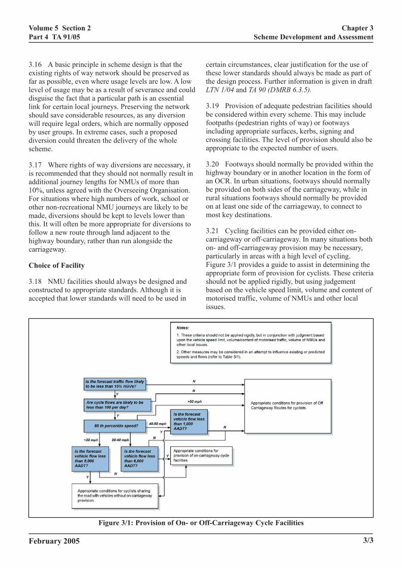
3.21 Cycling facilities can be provided either on-carriageway or off-carriageway. In many situations bothon- and off-carriageway provision may be necessary,particularly in areas with a high level of cycling.Figure 3/1 provides a guide to assist in determining theappropriate form of provision for cyclists. These criteriashould not be applied rigidly, but using judgementbased on the vehicle speed limit, volume and content ofmotorised traffic, volume of NMUs and other localissues.
Figure 3/1: Provision of On- or Off-Carriageway Cycle Facilities
3/3
Volume 5 Section 2Part 4 TA 91/05
Chapter 3Scheme Development and Assessment
3.22 Where off-carriageway facilities are proposed, itis recommended that they are provided on both sides ofthe road. Where space is limited, it may be acceptableto provide a two way facility on one side of the road.However, in unlit areas, cyclists with headlights maycause confusion when heading directly towardsmotorists. It is therefore recommended that whereroutes are provided on one side of the road only, a highdegree of separation between the carriageway and cycleroute should be provided, or street lighting at anappropriate level as agreed with the OverseeingOrganisation. Where lighting is required, considerationshould be given to light intrusion.
3.23 Since horses can be better controlled when riddenrather than led, the design of equestrian routes shouldminimise or eliminate the need to lead horses. As such,there should be a ‘whole route’ strategy for equestrianroutes to enable continuous ridden use as far aspracticable. New facilities should help link togetherexisting routes, including bridleways, byways andminor roads, wherever possible.
3.24 Schemes should normally include provision ofoff-carriageway equestrian facilities in the followingcircumstances:
• where highway verges accommodate frequentequestrian movements;
• in close proximity to riding schools, stables,racecourses or pastures;
• where the route acts as a link to bridleways, orfeeds bridleways to crossings or other equestrianfacilities.
3.25 Equestrian facilities can normally be used byother types of NMUs, even if the facility providesspecific features for equestrian use. On this basis,consideration of requirements of other NMUs will beessential when designing equestrian facilities along thesame route.
3.26 In exceptional circumstances, it may beacceptable not to provide NMU facilities, for examplehighways adjacent to tunnels or other route sectionsthat have or will have an NMU prohibition. In suchcases Design Organisations should provide explicitjustification, with agreement from the OverseeingOrganisation, for not providing NMU facilities.
3.27 Where no provision for NMUs is made as part ofa scheme, it will be important to ensure that appropriatealternative NMU routes and suitable linkages areprovided and signed.
S
3daafisup
3inss
3ap
•
•
•
•
S
3juNEI
3reasca
3/4
hared NMU Provision
.28 Shared use is an important consideration inesigning for NMUs. It will often be beneficial toccommodate equestrians separately from pedestriansnd cyclists. There may also be some value in providingor pedestrians and cyclists separately, although inolated areas adjacent or shared facilities can givesers a greater sense of security due to the number ofeople using the facility.
.29 However, it should be noted that disabled people particular are often very cautious about the use of
hared NMU facilities without adequate physicalegregation between users.
.30 The draft LTN 2/04 provides further guidancend highlights the following issues that requirearticular consideration:
Consultation and publicity – any proposal toallow cyclists to use pedestrian facilities mustinvolve extensive consultation and publicity.
Segregated or unsegregated – combined NMUflows in excess of 200 per hour require specificmeasures such as kerbs, railings, verge, linemarking or different surface textures to denotesegregation.
Signing and markings (and tactile surfaceswhere appropriate) – These are important forthe proper operation of shared use routes.
Geometric Dimensions – Different geometriclayouts and dimensions are appropriate indifferent situations. These are identified withindraft LTN 2/04 and TA 90 (DMRB 6.3.5).
cheme Assessment
.31 As with all highway schemes, assessment andstification will be required for schemes includingMU facilities. The assessment will covernvironment, Safety, Economy, Accessibility and
ntegration.
.32 The provision of NMU facilities, including newoutes and crossings, should be regarded as an integrallement of the overall cost of a scheme and not as andditional item that needs to be separately justified. Asuch, provision of measures for NMUs should beonsidered in the same way as other ‘soft’ features suchs landscaping.
February 2005
Volume 5 Section 2Part 4 TA 91/05
Chapter 4NMU Off-Carriageway Routes (OCRs)
Y ROUTES (OCRs)
4. NMU OFF-CARRIAGEWAGeneral
4.1 In many circumstances, it may be decided thatthe most appropriate form of NMU provision is anOCR. This chapter identifies the range of issues thatneed to be addressed in developing OCRs for NMUs.For information on geometric design aspects, refer toHD 39 (DMRB 7.2.5) and TA 90 (DMRB 6.3.5).
4.2 OCRs may be designed specifically for use byNMUs, or through the adoption or conversion of rightsof way in partnership with Local Authorities or privatelandowners.
4.3 OCRs may be developed as an improvementscheme in their own right, or as an integral part of newall-purpose road improvements.
4.4 In order to provide NMUs with a more effectiveand attractive route than trunk roads, OCRs should aimto provide better connectivity. To achieve this, routesshould normally aim to connect to the followinglocations:
• Key destinations – residential areas, healthfacilities, retail outlets, educational facilities,places of worship, recreational and socialfacilities and civic buildings.
• Public transport – railway and light railstations, bus stations, bus stops and park & ridesites.
• NMU routes – National Cycle Network,Greenways, Quiet Lanes, National Bridle RouteNetwork and other rights of way.
4.5 All OCR types can be financed, designed andimplemented by the Overseeing Organisation as long asthey are included as part of published statutory ordersand receive the appropriate statutory approvals.However, wherever possible the OverseeingOrganisation should aim to provide a scheme that linksinto local networks.
OCR Types
4.6 In the development of an OCR, various optionswill be available to the Design Organisation. Given thetypical length of trunk roads, it is likely that a single
OlFt
•
•
•
•
•
•
•
4Ait
RW
4toifitbowdrla
4haC
February 2005
CR will need to use a variety of route types along itsength, in order to respond to different local constraints.or the purposes of this guidance, the following route
ypes have been identified:
Route Type A – Within trunk road verge;
Route Type B – Land outside, but adjacent to thehighway boundary;
Route Type C – Distant from trunk road;
Route Type D – Existing rights of way;
Route Type E – Redundant or bypassed road;
Route Type F – Minor highway;
Route Type G – Other locations such as forestrytracks, canal towpaths, abandoned railway linesand farm tracks. These may be in public orprivate ownership.
.7 The route types are described in turn below.nnex 2 provides detailed information on construction
ssues and the advantages and disadvantages of eachype.
oute Type Aithin Trunk Road Verge
.8 An OCR may be created immediately adjacent tohe trunk road within the existing highway on landwned by the Overseeing Organisation. This route types often the most appropriate solution in operational,inancial and legal terms. In many instances, a footways already in existence, which should be re-used withinhe OCR. Many trunk roads have a reasonable vergeetween the carriageway and the highway boundary orther property boundary. In some instances, the vergeill be wide enough to accommodate the minimumimensions of an OCR; however, where the verge is tooestricted, consideration could be given to purchasingand adjacent to the highway boundary to accommodaten OCR (see Route Type B).
.9 Where verge width is restricted, the physicalazards of proximity to the trunk road are considerablend other route types may be more appropriate.rossing facilities often require a considerable amount
4/1
Volume 5 Section 2Part 4 TA 91/05
Chapter 4NMU Off-Carriageway Routes (OCRs)
of space and as a result may prove to be an overridingconstraint.
Route Type BLand Outside, But Adjacent To The HighwayBoundary
4.10 An OCR may be created adjacent to the trunkroad by extending the highway to encompass landdirectly adjacent to the highway boundary. This routetype exploits most of the advantages of Route Type A,but will require purchase of additional land. Forsections of trunk road where individual propertiesintrude into the verge, the OCR may comprise sectionsof both Route Types A and B, while still providingfrontage access. With Route Type B there are likely tobe fewer signposts, lighting columns and otherobstructions than in Route Type A, where such featureswould require removal or cause a minor obstruction onroute.
4.11 Route Type B provides similar advantages toRoute Type A, but with less width restriction and a safedistance from high speed traffic. However, there aremore complicated issues regarding the purchase andcreation of the route.
Route Type CDistant From Trunk Road
4.12 An OCR may be created distant from the trunkroad, perhaps at a second or third plot boundary fromthe road, if necessary in partnership with the LocalAuthority. The desired outcome is a separate routerunning broadly parallel to the trunk road. There shouldbe few existing services in this area.
4.13 This route type may involve disruption toexisting habitats. Because the line of the route isflexible, it can be directed along appropriate gradientsand connected to key destinations. Connections back tothe trunk road (e.g. for access to bus stops) or tofrontages may be required, and where these need to befrequent, this route type will be less appropriate.
4.14 Route Type C should provide a pleasantalternative route where trunk roads pass through bothdeveloped and undeveloped areas. The likely absenceof width restrictions, and flexible alignment, offerpotential for mixed use at a safe distance from highspeed traffic. However, this route type involves thecreation of a new right of way and there will thereforebe associated legal and practical issues.
RE
4mbtawo
4ctrthlidsimLnr
RR
4raaAthhroisff
4sc
RM
4Ob
4lera
4/2
oute Type Dxisting Rights of Way
.15 An OCR may be developed by adopting orodifying existing rights of way such as footpaths,
ridleways or restricted byways. Route Type D seeks toke advantage of the existing legal status of rights ofay and existing patterns of use. It is an attractiveption where existing width permits.
.16 However, existing rights of way are unlikely toonnect fully to trunk roads, key destinations oransport links. To achieve OCR integration mayerefore require development of new rights of waynks. It may position the OCR at a considerableistance from the road, and to achieve full OCRtandards may create issues of visual and environmental
pact. A change of legal status, in partnership with theocal Authority or private landowners, may beecessary and negotiation of private rights may beequired.
oute Type Eedundant or Bypassed Road
.17 Following the re-alignment of a trunk road,edundant stretches of road sometimes remain. Thesere often used as lay-bys, bus-stops or short sections ofccess road running broadly parallel to the trunk road.n OCR may be created by adopting and modifyingese stretches of road. In cases where the ownership
as passed to private hands, it would be necessary toe-establish a right of way as well as negotiate purchaser adoption, in partnership with the Local Authority. It likely that these roads will be wider than necessary
or an OCR, and may already possess appropriateoundations and wearing course.
.18 Route Type E can often provide a practical shorttretch of OCR at relatively low cost which will linkonveniently to both Route Type A and B.
oute Type Finor Highway
.19 An existing minor highway may be adopted as anCR and modified as required to meet OCR standards,y agreement with the Local Authority.
.20 This route type takes advantage of the existinggal status, patterns of use and connections to trunk
oads. However, NMUs may encounter motorised users,nd there may be a lack of protection for NMUs unless
appropriate facilities (such as footways or cycle lanes)
February 2005
Volume 5 Section 2Part 4 TA 91/05
Chapter 4NMU Off-Carriageway Routes (OCRs)
are provided. This route type will not normally involvethe purchase of land, thus reducing the legal andpractical problems involved. Traffic Regulation Ordersmay be required to slow or restrict certain types ofmotorised traffic. Badging will be important to ensurethat the new OCR status is acknowledged by bothmotor vehicles and NMUs (see paragraph 4.33).
4.21 Route Type F is a useful option, if the problemsof combined use by motorised and non-motorised userscan be overcome.
Route Type GOther Locations
4.22 Included in this category are farm access roads,private roads, farm access tracks, disused airfields,former MOD tracks, private footpaths with space forwidening, footpaths within urban or country parks,forestry tracks, canal towpaths, and abandoned railwaylines. OCRs can also be purpose built in newdevelopments to provide greater accessibility.
4.23 This route type allows for a considerable range ofpossibilities for OCRs, particularly in response to localcircumstances. It will normally require either apartnership with the Local Authority to re-designateaccess, an agreement to permissive access, or landpurchase from the private landowners in order to permitNMU use.
4.24 Technical features of this route type will vary, butgradients and widths may already conform to OCRstandards, and some access for construction is likely toexist.
4.25 This range of possible route types should addinteresting variety to the route experience and provideeconomies through the use of existing infrastructure.
Choice of Route Type
4.26 In order to assess which of the route types is mostappropriate in any one location, the following should beconsidered:
• general design principles, as identified inChapter 3;
• likely levels and type of demand (existing andlatent) for the route;
• the need to achieve links with key destinations;
•
•
L
4ptsssoat
•
•
•
•
4eTcdtlpatgrtc
4oct
•
February 2005
landscape and ecological impacts;
construction and technical issues.
ocal Distinctiveness
.27 Achieving local distinctiveness is important inroviding high quality design for OCRs. Recognisinghe elements within the landscape that make each placepecial and ‘distinctive’ allows for the moreympathetic introduction of a new OCR. Designshould aim to retain and extend the local distinctivenessf an area and respond in a way that is both sensitivend skilful. These issues may be addressed as part ofhe design process, by considering the following:
identify the context – consider the widerlandscape pattern and type;
identify local features – consider the specificlocal elements that form the landscape patternand type;
identify the history and culture of the landscape;
use elements and features in the design of anOCR that reflect local distinctiveness.
.28 Identifying the context of the OCR is crucial innsuring it will sit appropriately within the landscape.he OCR may extend for some distance and thereforeross through areas of landscape with distinctlyifferent character, such as upland to lowland or scarpo vale. The patterns of the landscape, influenced byand use (such as different agricultural type andractices, forestry, etc) will strongly affect the routelignment and identity. This should be borne in mindhroughout the design of the route. It may be decided toive an OCR a strong identity throughout the wholeoute, or to vary the character of the route as it passeshrough different contexts. What is important isonsistency of approach.
.29 Identifying local features provides the next levelf detail required to ensure the OCR reflects the localharacter. The local features to consider may includehe following:
Topography, vegetation and structures – Theshape and size of fields, land uses at a more locallevel, landform and natural landscape features,construction materials, types of structures and thedensity and type of planting all have a significanteffect on the landscape character.
4/3
Volume 5 Section 2Part 4 TA 91/05
Chapter 4NMU Off-Carriageway Routes (OCRs)
• Traditional routes – It is important to be awareof the traditional way that routes wereconstructed and why. The main features are thelevel of the route in relation to the surroundingland and the elements that enclose the route, suchas hedgerow, wall or bank.
• Geology – This has a major influence on therange of materials and architectural detail in agiven locality. It generates materials of differentcolours, shapes and patterns (e.g. clay, granite,and limestone).
• Local crafts and building traditions – Thesewill set a precedent for the type of fencing andrailings, types of brickwork, building stone, typesof walls and access points used along the OCR,responding fully to the local distinctiveness ofthe area.
• Design guidance – There is also a need toconsider any local design guidance from parishcouncils, Local Authorities or other bodies.
4.30 Understanding the historic and culturalassociations of a place is an important element inidentifying local distinctiveness. For example, the OCRmay run along a traditional route from one place to thenext. This may only be recognised locally, but havecultural significance to the local community.Understanding these cultural links and makingreference to them in the design will enhance the identityof the OCR.
4.31 Interpreting the local distinctiveness for an OCRwill help decide how best to reflect the localcharacteristics. The following principles guide thisprocess:
• Creating new field patterns – This is probablythe most important element in influencing thecharacter and alignment of the OCR. The routealignment is fundamental in minimising visualimpact. It will normally be better to adopt analignment of existing enclosing elements (such ashedges and walls). Alignments that cross opencountryside should be avoided, unlessspecifically considered appropriate or necessary.
• Designing new enclosing elements – In someinstances, enclosing elements may not berequired. However, where they are new, theyshould not be visually intrusive. This is becausethe view from a distance is considered to be moreimportant than conformity in the detail of
•
•
4.thenm
B
4.th‘bdeof
4.
•
•
•
•
•
4.Aof
4/4
material or construction. To limit impacts, newenclosing elements should match existingelements, using local materials and constructionwhere possible. Where this is not possible, acontemporary style boundary feature should beprovided rather than a poor replica.
Responding to local topography – In most ruralsituations, an OCR should generally followcontour lines. This makes for easier travel, and inmost cases will conform to local character.
Creating new surfaces – Surfaces will have tobe well compacted and level in situations whereintensive use by small-wheeled vehicles isanticipated. To reflect the local geology and torespond to local traditions, local stone may beappropriate (see Chapter 8). Where conflictcannot be resolved, functional performanceshould take priority over local distinctiveness.
32 While designs should aim to retain and extende local distinctiveness of an area, it is essential tosure that adequate provision for disabled people isade.
adging
33 In the development of OCRs, it is important thate route is well identified to NMUs. The termadging’ has been used to describe the range of visualvices that could be used in order to denote the status the OCR both to its users and to others.
34 Badging is useful for the following purposes:
to help provide an identifiable route through itscharacter;
to provide general information to current andpotential users of the OCR;
to confirm the legal status of the path with regardto its use, particularly in terms of the welfare,safety and convenience of other users;
to inform users of the extent of the route and itsprincipal destinations;
to provide information about features of interestsuch as wildlife, landscape or archaeology.
35 Design Organisations should work with Localuthorities to try to ensure that badging reflects issues local distinctiveness. In addition to the standard signs
February 2005
Volume 5 Section 2Part 4 TA 91/05
Chapter 4NMU Off-Carriageway Routes (OCRs)
in the Traffic Signs Regulations and General Directions(TSRGD), the following devices can also be used toprovide character and badge the OCR:
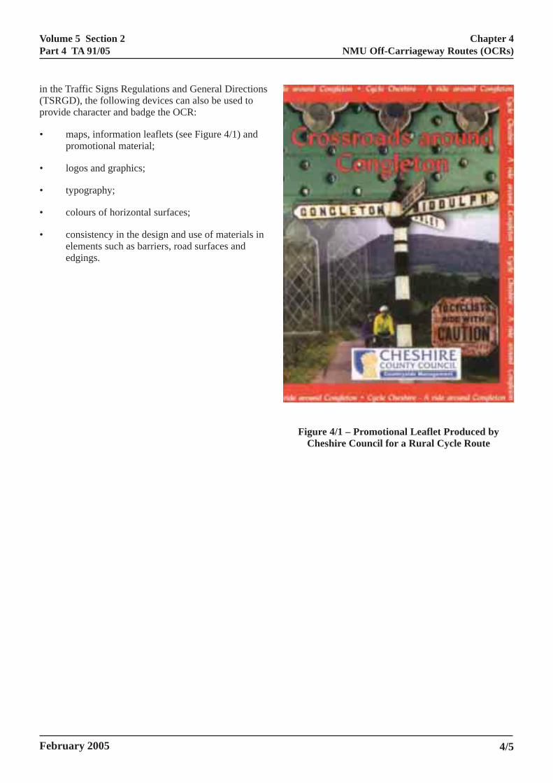
• maps, information leaflets (see Figure 4/1) andpromotional material;
• logos and graphics;
• typography;
• colours of horizontal surfaces;
• consistency in the design and use of materials inelements such as barriers, road surfaces andedgings.
February 2005
Figure 4/1 – Promotional Leaflet Produced byCheshire Council for a Rural Cycle Route
4/5
Volume 5 Section 2Part 4 TA 91/05
CLING FACILITIES
Chapter 5On-Carriageway Cycling Facilities
5. ON-CARRIAGEWAY CY
General
5.1 In some cases, as identified in Chapter 3,on-carriageway provision for cyclists may be the mostappropriate solution. This chapter identifies the rangeof options available. Further advice is available in otherdocuments, including
• Traffic Signs Manual, Chapter 5 (DfT, 2003);
• Cycle-Friendly Infrastructure – Guidelines forPlanning and Design (IHT/DfT, 1996);
• Cycling by Design – A Consultation Paper(Scottish Executive, 1999);
• The National Cycle Network – Guidelines andPractical Details (Sustrans, 1997).
5.2 TD 27 (DMRB 6.1.2) provides details of thedesign standards for cross-section and headroom for allpurpose trunk roads. Any variation in cross-section willrequire ‘Departure from Standard’ approval from theOverseeing Organisation.
5.3 Approaches that may be used in the provision ofon-carriageway routes include:
• wide nearside lanes;
• with-flow cycle lanes (advisory/mandatory);
• contra-flow cycle lanes;
• with-flow and contra-flow bus/cycle lanes.
5.4 Annex 3 provides information on theconstruction issues, advantages and disadvantages ofeach measure. Detailed guidance on layout andimplementation is provided in the Traffic Signs Manual,Chapter 5 (DfT, 2003).
Wide Nearside Lanes
5.5 The provision of a wide nearside lane can be arelatively simple and cost effective way of improvingsafety for cyclists on the carriageway, while alsoreducing vehicle delay and frustration. They may beprovided by adjusting the road markings to establishnarrower offside lanes (on dual carriageways).
February 2005
‘Departure from Standard’ approval is required fromTD 27 (DMRB 6.1.2).
With-flow Cycle Lanes (Advisory/Mandatory)
5.6 Cycle lanes are provided to allocate anddemarcate space for cyclists within the carriageway andcan help to ensure a safe separation between motorvehicles and cyclists. Cycle lanes are a low costmeasure in comparison with the development of OCRs,and are most useful on urban/suburban roads. It shouldbe noted that cyclists are permitted to travel outsidecycle lanes and their use is not compulsory.
5.7 Cycle lanes may be mandatory or advisory,although mandatory cycle lanes are often preferable.Mandatory cycle lanes may only be used by cyclists,with all other vehicles prohibited from entry. Advisorycycle lanes may be entered by motor vehicles whenencroachment is unavoidable. Both types requireeffective parking and loading restrictions to preventabuse by motor vehicles and help ensure successfuloperation.
Contra-Flow Cycle Lanes
5.8 One-way traffic systems can be inconvenient forcyclists. To prevent long diversions for cyclists acontra-flow cycle lane may be provided. These allowcyclists to travel against the flow of motorised traffic.Signing and markings highlight the need for motoriststo anticipate cyclists in the contra-flow direction. It isclearly essential that the ‘one-way’ Traffic RegulationOrder (TRO) excludes cyclists from the restrictions.
5.9 Further information can be found in TAL 6/98and the Traffic Signs Manual, Chapter 5 (DfT, 2003).
With-Flow and Contra-Flow Bus/Cycle Lanes
5.10 The use of with-flow and contra-flow bus lanesto form shared use bus/cycle lanes can improve bothsafety and convenience for cyclists, particularly inurban areas. Further information can be found inLTN 1/97 Keeping Buses Moving.
5/1

Volume 5 Section 2Part 4 TA 91/05
Chapter 5On-Carriageway Cycling Facilities
Other Considerations for On-Carriageway CycleProvision
5.11 Road narrowings are sometimes used on majorroads as traffic calming measures and/or environmentalfeatures. Cyclists require special consideration at roadnarrowings to ensure their safety and protection.Further information can be found in TAL 1/97.
5.12 Cyclists also require special consideration at roadworks to ensure their safety and protection. Furtherinformation can be found in TAL 15/99.
February 20055/2
Volume 5 Section 2Part 4 TA 91/05
Chapter 6Crossings
6. CROSSINGS
General
6.1 Careful design at crossings is a key aspect ofproviding safe and attractive NMU routes. This chapterprovides information on NMU crossing selection andassessment criteria, and a summary of crossing types.
6.2 Reference should also be made to TA 90 (DMRB6.3.5) for geometric parameters associated withcrossing provision, TA 68 (DMRB 8.5.1) for advice onassessment of at-grade pedestrian crossings and theTraffic Signs Manual, Chapter 4 (DfT, 2004) for adviceon warning signs.
Crossing and Junction Assessment and Selection
6.3 Selecting the most appropriate form of crossingfor a particular location requires careful assessment.Where possible the needs of NMUs should beincorporated into the design without a detrimentalimpact upon other road users.
6.4 From an NMU perspective, crossing facilitiesshould aim to have the following characteristics (basedon principles developed in Providing for Journeys onFoot (IHT, 2000):
• Safety and Comfort – users should feel safe andshould not feel intimidated by motorised traffic.The speed of approaching vehicles should betaken into account.
• Location – where safety considerations permit,crossing points should also coincide with desirelines. This is particularly important onidentifiable local routes such as school routes oraccess to country parks.
• Convenience – there should be appropriateopportunity to cross quickly and efficiently atdesignated crossing points without NMUs beingrequired to wait for long periods. In addition,long stretches of enclosing guardrails at crossingsshould be avoided.
February 2005
• Capacity – crossings should be wide enough toaccommodate peak demand and, in particular,signalled crossings should respond quickly andsafely to demand.
• Opportunity – crossings should respond quicklyand safely to demand from NMUs.
Rights of Way Crossings
6.5 For many trunk road schemes, a key issue will bewhether to provide an at-grade or grade separatedfacility at existing rights of way crossings. At informalat-grade crossings, where NMUs are expected to crosswithout special provision, the difficulty of crossingdepends primarily on the width of road to be crossedand the availability of gaps in traffic. As traffic flowsincrease, the availability of adequate gaps decreasessharply. If delays between gaps become too high, usersare likely to either take risks or be discouraged fromusing the crossing at all.
6.6 Informal at-grade NMU crossings should not beprovided on dual carriageways of 3 or more lanes percarriageway. In addition, informal at-grade equestriancrossings are not recommended on roads with 120kphdesign speed, or on wide single carriageways.
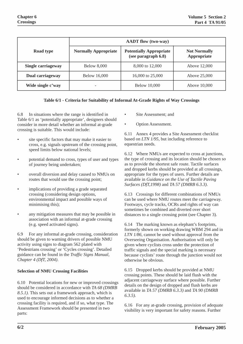
6.7 Table 6/1 provides additional criteria to assist indetermining whether informal at-grade crossingfacilities are appropriate, based upon Average AnnualDaily Traffic flows (AADT). However, these criteriashould be seen as a general guide and local factors willalso influence the decision.
6/1
Volume 5 Section 2Part 4 TA 91/05
Chapter 6Crossings
AADT flow (two-way)
Potentially Appropriate Not Normally(see paragraph 6.8) Appropriate
8,000 to 12,000 Above 12,000
16,000 to 25,000 Above 25,000
Road type Normally Appropriate
Single carriageway Below 8,000
Dual carriageway Below 16,000
Wide single c’way -
Table 6/1 - Criteria for Suitability of Info
6.8 In situations where the range is identified inTable 6/1 as ‘potentially appropriate’, designers shouldconsider in more detail whether an informal at-gradecrossing is suitable. This would include:
• site specific factors that may make it easier tocross, e.g. signals upstream of the crossing point,speed limits below national levels;
• potential demand to cross, types of user and typesof journey being undertaken;
• overall diversion and delay caused to NMUs onroutes that would use the crossing point;
• implications of providing a grade separatedcrossing (considering design options,environmental impact and possible ways ofminimising this);
• any mitigation measures that may be possible inassociation with an informal at-grade crossing(e.g. speed activated signs).
6.9 For any informal at-grade crossing, considerationshould be given to warning drivers of possible NMUactivity using signs to diagram 562 plated with‘Pedestrians crossing’ or ‘Cycles crossing’. Detailedguidance can be found in the Traffic Signs Manual,Chapter 4 (DfT, 2004).
Selection of NMU Crossing Facilities
6.10 Potential locations for new or improved crossingsshould be considered in accordance with TA 68 (DMRB8.5.1). This sets out a framework approach, which isused to encourage informed decisions as to whether acrossing facility is required, and if so, what type. TheAssessment Framework should be presented in two
6/2
parts:
Below 10,000 Above 10,000
rmal At-Grade Rights of Way Crossings
• Site Assessment; and
• Option Assessment.
6.11 Annex 4 provides a Site Assessment checklistbased on LTN 1/95, but including reference toequestrian needs.
6.12 Where NMUs are expected to cross at junctions,the type of crossing and its location should be chosen soas to provide the shortest safe route. Tactile surfacesand dropped kerbs should be provided at all crossings,appropriate for the types of users. Further details areavailable in Guidance on the Use of Tactile PavingSurfaces (DfT,1998) and TA 57 (DMRB 6.3.3).
6.13 Crossings for different combinations of NMUscan be used where NMU routes meet the carriageway.Footways, cycle tracks, OCRs and rights of way cansometimes be combined and diverted over shortdistances to a single crossing point (see Chapter 3).
6.14 The marking known as elephant’s footprints,formerly shown on working drawing WBM 294 and inLTN 1/86, cannot be used without approval from theOverseeing Organisation. Authorisation will only begiven where cyclists cross under the protection oftraffic signals and the special marking is necessarybecause cyclists’ route through the junction would nototherwise be obvious.
6.15 Dropped kerbs should be provided at NMUcrossing points. These should be laid flush with theadjacent carriageway surface where possible. Furtherdetails on the design of dropped and flush kerbs areavailable in TA 57 (DMRB 6.3.3) and TA 90 (DMRB6.3.5).
6.16 For any at-grade crossing, provision of adequatevisibility is very important for safety reasons. Further
February 2005
Volume 5 Section 2Part 4 TA 91/05
Chapter 6Crossings
details on visibility may be found in TA 90 (DMRB6.3.5).
6.17 Table 6/2 illustrates the range of NMU crossingfacilities available. The following sections provide abrief summary of each type of crossing and providereference to other guidance for further information.While some of the suggested crossing facilities areunlikely to be appropriate in most trunk road situations,Design Organisations should consider all optionsavailable.
Informal Pedestrian and Cycle Crossings
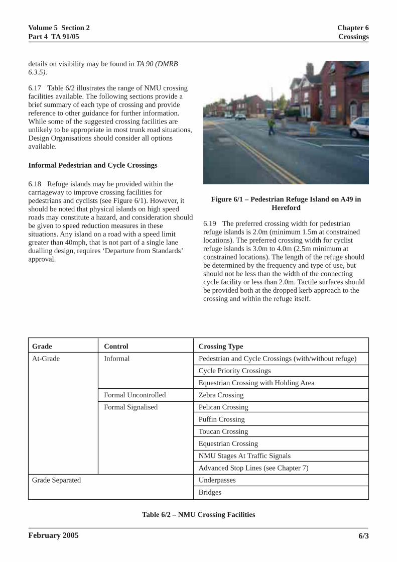
6.18 Refuge islands may be provided within thecarriageway to improve crossing facilities forpedestrians and cyclists (see Figure 6/1). However, itshould be noted that physical islands on high speedroads may constitute a hazard, and consideration shouldbe given to speed reduction measures in thesesituations. Any island on a road with a speed limitgreater than 40mph, that is not part of a single lanedualling design, requires ‘Departure from Standards’approval.
February 2005
Figure 6/1 – Pedestrian Refuge Island on A49 inHereford
6.19 The preferred crossing width for pedestrianrefuge islands is 2.0m (minimum 1.5m at constrainedlocations). The preferred crossing width for cyclistrefuge islands is 3.0m to 4.0m (2.5m minimum atconstrained locations). The length of the refuge shouldbe determined by the frequency and type of use, butshould not be less than the width of the connectingcycle facility or less than 2.0m. Tactile surfaces shouldbe provided both at the dropped kerb approach to thecrossing and within the refuge itself.
Grade Control Crossing Type
At-Grade Informal Pedestrian and Cycle Crossings (with/without refuge)
Cycle Priority Crossings
Equestrian Crossing with Holding Area
Formal Uncontrolled Zebra Crossing
Formal Signalised Pelican Crossing
Puffin Crossing
Toucan Crossing
Equestrian Crossing
NMU Stages At Traffic Signals
Advanced Stop Lines (see Chapter 7)
Grade Separated Underpasses
Bridges
Table 6/2 – NMU Crossing Facilities
6/3
Volume 5 Section 2Part 4 TA 91/05
Chapter 6Crossings
6.20 Traffic calming features such as pinch points,build outs and refuge islands reduce the carriagewaywidth for vehicles and cyclists alike. Often this leads to‘squeezing’ of the cyclist which makes them morevulnerable. These features should therefore beaccompanied by a cycle by-pass wherever possible.
6.21 A staggered crossing may be considered on litroads only and the length of stagger between crossingmovements should be kept to a minimum. Staggeredcrossings should, where possible, be aligned as left/right manoeuvres rather than right/left so that NMUsturn to face oncoming traffic.
6.22 Possible layouts for cycle crossings include asimple cycle track with refuge island, offset crossing atunsignalised junction and staggered cycle track crossingof dual carriageway.
6.23 Further details on pedestrian refuge islands areavailable in TA 68 (DMRB 8.5.1). Further details onGive Way Cycle Crossings are available in LTN 1/86.
Cycle Priority Crossings
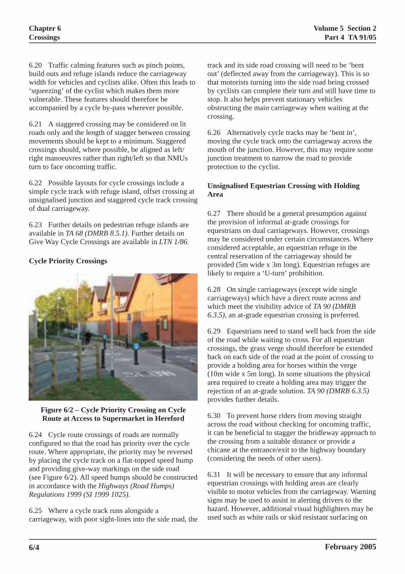
Figure 6/2 – Cycle Priority Crossing on CycleRoute at Access to Supermarket in Hereford
6.24 Cycle route crossings of roads are normallyconfigured so that the road has priority over the cycleroute. Where appropriate, the priority may be reversedby placing the cycle track on a flat-topped speed humpand providing give-way markings on the side road(see Figure 6/2). All speed humps should be constructedin accordance with the Highways (Road Humps)Regulations 1999 (SI 1999 1025).
6.25 Where a cycle track runs alongside acarriageway, with poor sight-lines into the side road, the
trothbsoc
6mmjup
UA
6themccpli
6cw6
6ocbp(arp
6aitthc(
6evshu
6/4
ack and its side road crossing will need to be ‘bentut’ (deflected away from the carriageway). This is soat motorists turning into the side road being crossed
y cyclists can complete their turn and still have time totop. It also helps prevent stationary vehiclesbstructing the main carriageway when waiting at therossing.
.26 Alternatively cycle tracks may be ‘bent in’,oving the cycle track onto the carriageway across theouth of the junction. However, this may require somenction treatment to narrow the road to provide
rotection to the cyclist.
nsignalised Equestrian Crossing with Holdingrea
.27 There should be a general presumption againste provision of informal at-grade crossings for
questrians on dual carriageways. However, crossingsay be considered under certain circumstances. Where
onsidered acceptable, an equestrian refuge in theentral reservation of the carriageway should berovided (5m wide x 3m long). Equestrian refuges arekely to require a ‘U-turn’ prohibition.
.28 On single carriageways (except wide singlearriageways) which have a direct route across andhich meet the visibility advice of TA 90 (DMRB.3.5), an at-grade equestrian crossing is preferred.
.29 Equestrians need to stand well back from the sidef the road while waiting to cross. For all equestrianrossings, the grass verge should therefore be extendedack on each side of the road at the point of crossing torovide a holding area for horses within the verge10m wide x 5m long). In some situations the physicalrea required to create a holding area may trigger theejection of an at-grade solution. TA 90 (DMRB 6.3.5)rovides further details.
.30 To prevent horse riders from moving straightcross the road without checking for oncoming traffic, can be beneficial to stagger the bridleway approach toe crossing from a suitable distance or provide a
hicane at the entrance/exit to the highway boundaryconsidering the needs of other users).
.31 It will be necessary to ensure that any informalquestrian crossings with holding areas are clearlyisible to motor vehicles from the carriageway. Warningigns may be used to assist in alerting drivers to theazard. However, additional visual highlighters may besed such as white rails or skid resistant surfacing on
February 2005
Volume 5 Section 2Part 4 TA 91/05
Chapter 6Crossings
the approach to the crossing as identified in HD 28(DMRB 7.3.1) and HD 36 (DMRB 7.5.1).
‘Zebra’ Crossings
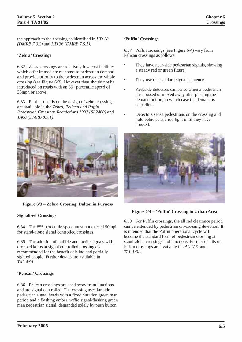
6.32 Zebra crossings are relatively low cost facilitieswhich offer immediate response to pedestrian demandand provide priority to the pedestrian across the wholecrossing (see Figure 6/3). However they should not beintroduced on roads with an 85th percentile speed of35mph or above.
6.33 Further details on the design of zebra crossingsare available in the Zebra, Pelican and PuffinPedestrian Crossings Regulations 1997 (SI 2400) andTA68 (DMRB 8.5.1).
Figure 6/3 – Zebra Crossing, Dalton in Furness
Signalised Crossings
6.34 The 85th percentile speed must not exceed 50mphfor stand-alone signal controlled crossings.
6.35 The addition of audible and tactile signals withdropped kerbs at signal controlled crossings isrecommended for the benefit of blind and partiallysighted people. Further details are available inTAL 4/91.
‘Pelican’ Crossings
6.36 Pelican crossings are used away from junctionsand are signal controlled. The crossing uses far sidepedestrian signal heads with a fixed duration green manperiod and a flashing amber traffic signal/flashing greenman pedestrian signal, demanded solely by push button.
‘P
6.Pe
•
•
•
•
6.caisbestPuTA
February 2005
uffin’ Crossings
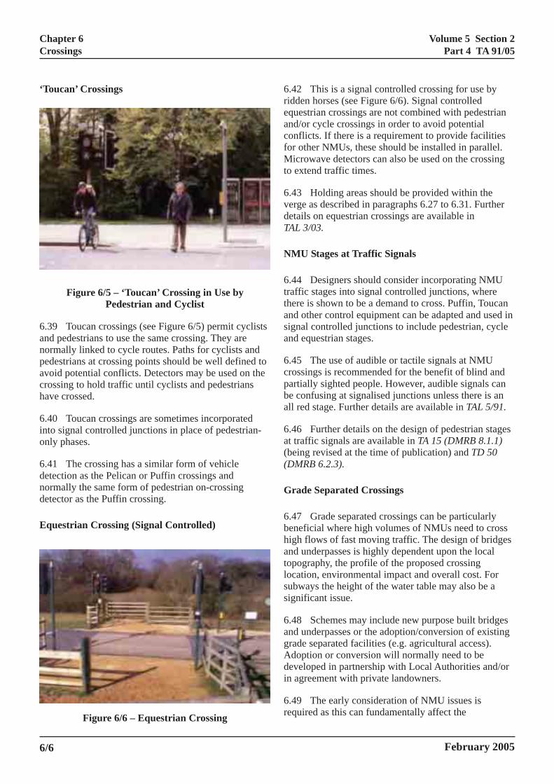
37 Puffin crossings (see Figure 6/4) vary fromlican crossings as follows:
They have near-side pedestrian signals, showinga steady red or green figure.
They use the standard signal sequence.
Kerbside detectors can sense when a pedestrianhas crossed or moved away after pushing thedemand button, in which case the demand iscancelled.
Detectors sense pedestrians on the crossing andhold vehicles at a red light until they havecrossed.
Figure 6/4 – ‘Puffin’ Crossing in Urban Area
38 For Puffin crossings, the all red clearance periodn be extended by pedestrian on–crossing detection. It intended that the Puffin operational cycle willcome the standard form of pedestrian crossing at
and-alone crossings and junctions. Further details onffin crossings are available in TAL 1/01 andL 1/02.
6/5
Volume 5 Section 2Part 4 TA 91/05
Chapter 6Crossings
‘Toucan’ Crossings
Figure 6/5 – ‘Toucan’ Crossing in Use byPedestrian and Cyclist
6.39 Toucan crossings (see Figure 6/5) permit cyclistsand pedestrians to use the same crossing. They arenormally linked to cycle routes. Paths for cyclists andpedestrians at crossing points should be well defined toavoid potential conflicts. Detectors may be used on thecrossing to hold traffic until cyclists and pedestrianshave crossed.
6.40 Toucan crossings are sometimes incorporatedinto signal controlled junctions in place of pedestrian-only phases.
6.41 The crossing has a similar form of vehicledetection as the Pelican or Puffin crossings andnormally the same form of pedestrian on-crossingdetector as the Puffin crossing.
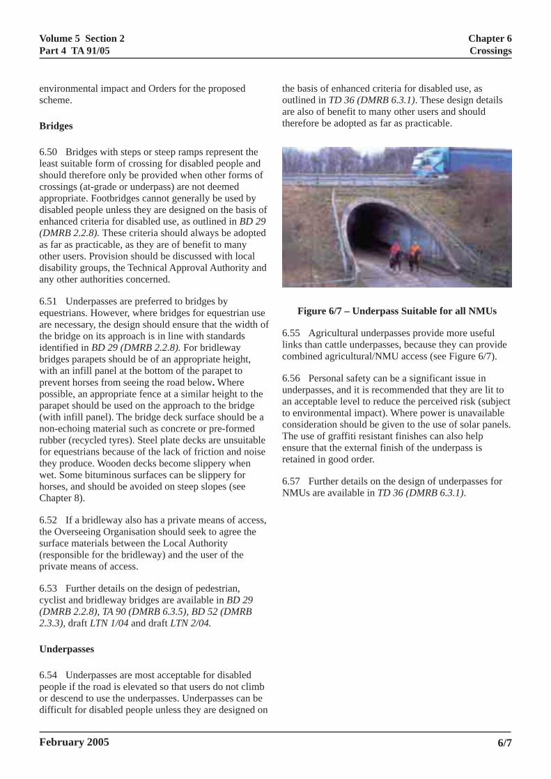
Equestrian Crossing (Signal Controlled)
Figure 6/6 – Equestrian Crossing
6reacfMt
6vdT
N
6ttasa
6cpba
6a((
G
6bhatlss
6agAdi
6r
6/6
.42 This is a signal controlled crossing for use byidden horses (see Figure 6/6). Signal controlledquestrian crossings are not combined with pedestriannd/or cycle crossings in order to avoid potentialonflicts. If there is a requirement to provide facilitiesor other NMUs, these should be installed in parallel.
icrowave detectors can also be used on the crossingo extend traffic times.
.43 Holding areas should be provided within theerge as described in paragraphs 6.27 to 6.31. Furtheretails on equestrian crossings are available inAL 3/03.
MU Stages at Traffic Signals
.44 Designers should consider incorporating NMUraffic stages into signal controlled junctions, wherehere is shown to be a demand to cross. Puffin, Toucannd other control equipment can be adapted and used inignal controlled junctions to include pedestrian, cyclend equestrian stages.
.45 The use of audible or tactile signals at NMUrossings is recommended for the benefit of blind andartially sighted people. However, audible signals cane confusing at signalised junctions unless there is anll red stage. Further details are available in TAL 5/91.
.46 Further details on the design of pedestrian stagest traffic signals are available in TA 15 (DMRB 8.1.1)being revised at the time of publication) and TD 50DMRB 6.2.3).
rade Separated Crossings
.47 Grade separated crossings can be particularlyeneficial where high volumes of NMUs need to crossigh flows of fast moving traffic. The design of bridgesnd underpasses is highly dependent upon the localopography, the profile of the proposed crossingocation, environmental impact and overall cost. Forubways the height of the water table may also be aignificant issue.
.48 Schemes may include new purpose built bridgesnd underpasses or the adoption/conversion of existingrade separated facilities (e.g. agricultural access).doption or conversion will normally need to beeveloped in partnership with Local Authorities and/orn agreement with private landowners.
.49 The early consideration of NMU issues isequired as this can fundamentally affect the
February 2005
Volume 5 Section 2Part 4 TA 91/05
Chapter 6Crossings
environmental impact and Orders for the proposedscheme.
Bridges
6.50 Bridges with steps or steep ramps represent theleast suitable form of crossing for disabled people andshould therefore only be provided when other forms ofcrossings (at-grade or underpass) are not deemedappropriate. Footbridges cannot generally be used bydisabled people unless they are designed on the basis ofenhanced criteria for disabled use, as outlined in BD 29(DMRB 2.2.8). These criteria should always be adoptedas far as practicable, as they are of benefit to manyother users. Provision should be discussed with localdisability groups, the Technical Approval Authority andany other authorities concerned.
6.51 Underpasses are preferred to bridges byequestrians. However, where bridges for equestrian useare necessary, the design should ensure that the width ofthe bridge on its approach is in line with standardsidentified in BD 29 (DMRB 2.2.8). For bridlewaybridges parapets should be of an appropriate height,with an infill panel at the bottom of the parapet toprevent horses from seeing the road below. Wherepossible, an appropriate fence at a similar height to theparapet should be used on the approach to the bridge(with infill panel). The bridge deck surface should be anon-echoing material such as concrete or pre-formedrubber (recycled tyres). Steel plate decks are unsuitablefor equestrians because of the lack of friction and noisethey produce. Wooden decks become slippery whenwet. Some bituminous surfaces can be slippery forhorses, and should be avoided on steep slopes (seeChapter 8).
6.52 If a bridleway also has a private means of access,the Overseeing Organisation should seek to agree thesurface materials between the Local Authority(responsible for the bridleway) and the user of theprivate means of access.
6.53 Further details on the design of pedestrian,cyclist and bridleway bridges are available in BD 29(DMRB 2.2.8), TA 90 (DMRB 6.3.5), BD 52 (DMRB2.3.3), draft LTN 1/04 and draft LTN 2/04.
Underpasses
6.54 Underpasses are most acceptable for disabledpeople if the road is elevated so that users do not climbor descend to use the underpasses. Underpasses can bedifficult for disabled people unless they are designed on
the boutliare athere
F
6.55linkscom
6.56undean acto enconsThe ensuretai
6.57NMU
February 2005
asis of enhanced criteria for disabled use, asned in TD 36 (DMRB 6.3.1). These design detailslso of benefit to many other users and shouldfore be adopted as far as practicable.
igure 6/7 – Underpass Suitable for all NMUs
Agricultural underpasses provide more useful than cattle underpasses, because they can providebined agricultural/NMU access (see Figure 6/7).
Personal safety can be a significant issue inrpasses, and it is recommended that they are lit toceptable level to reduce the perceived risk (subjectvironmental impact). Where power is unavailableideration should be given to the use of solar panels.use of graffiti resistant finishes can also helpre that the external finish of the underpass isned in good order.
Further details on the design of underpasses fors are available in TD 36 (DMRB 6.3.1).
6/7
Volume 5 Section 2Part 4 TA 91/05
Chapter 7Junctions
7. JUNCTIONS
General
7.1 Volume 6 of DMRB provides advice on issues ofjunction design of relevance to NMUs. This chapterdeals with issues not covered elsewhere in DMRB andprovides information on advanced stop lines, NMUs atroundabouts, and cyclists at grade separated crossings.Further advice is available in other documents,including
• Traffic Signs Manual, Chapter 5 (DfT, 2003);
• Cycle-Friendly Infrastructure – Guidelines forPlanning and Design (IHT/DfT, 1996);
• Cycling by Design – A Consultation Paper(Scottish Executive, 1999);
• The National Cycle Network – Guidelines andPractical Details (Sustrans, 1997).
Advanced Stop Lines (ASLs)
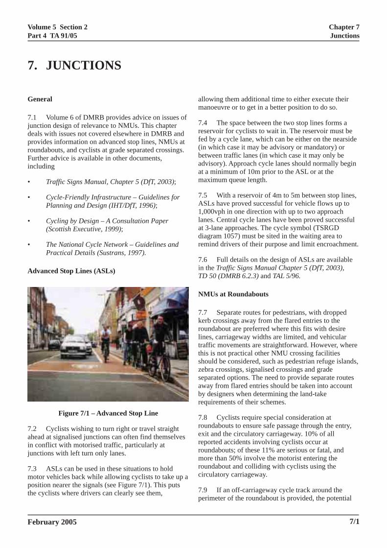
Figure 7/1 – Advanced Stop Line
7.2 Cyclists wishing to turn right or travel straightahead at signalised junctions can often find themselvesin conflict with motorised traffic, particularly atjunctions with left turn only lanes.
7.3 ASLs can be used in these situations to holdmotor vehicles back while allowing cyclists to take up aposition nearer the signals (see Figure 7/1). This putsthe cyclists where drivers can clearly see them,
am
7rf(baam
7A1ladr
7iT
N
7krlttszsabr
7rerrmrc
7p
February 2005
llowing them additional time to either execute theiranoeuvre or to get in a better position to do so.
.4 The space between the two stop lines forms aeservoir for cyclists to wait in. The reservoir must beed by a cycle lane, which can be either on the nearsidein which case it may be advisory or mandatory) oretween traffic lanes (in which case it may only bedvisory). Approach cycle lanes should normally begint a minimum of 10m prior to the ASL or at theaximum queue length.
.5 With a reservoir of 4m to 5m between stop lines,SLs have proved successful for vehicle flows up to,000vph in one direction with up to two approachanes. Central cycle lanes have been proved successfult 3-lane approaches. The cycle symbol (TSRGDiagram 1057) must be sited in the waiting area toemind drivers of their purpose and limit encroachment.
.6 Full details on the design of ASLs are availablen the Traffic Signs Manual Chapter 5 (DfT, 2003),D 50 (DMRB 6.2.3) and TAL 5/96.
MUs at Roundabouts
.7 Separate routes for pedestrians, with droppederb crossings away from the flared entries to theoundabout are preferred where this fits with desireines, carriageway widths are limited, and vehicularraffic movements are straightforward. However, wherehis is not practical other NMU crossing facilitieshould be considered, such as pedestrian refuge islands,ebra crossings, signalised crossings and gradeeparated options. The need to provide separate routesway from flared entries should be taken into accounty designers when determining the land-takeequirements of their schemes.
.8 Cyclists require special consideration atoundabouts to ensure safe passage through the entry,xit and the circulatory carriageway. 10% of alleported accidents involving cyclists occur atoundabouts; of these 11% are serious or fatal, andore than 50% involve the motorist entering the
oundabout and colliding with cyclists using theirculatory carriageway.
.9 If an off-carriageway cycle track around theerimeter of the roundabout is provided, the potential
7/1
Volume 5 Section 2Part 4 TA 91/05
Chapter 7Junctions
for use of these routes by pedestrians and equestriansshould also be considered, particularly whenintersecting with routes such as bridleways and in closeproximity to riding schools, stables and racecourses.
7.10 Different levels of treatment for cyclists arerequired at different forms of roundabout. These areconsidered in the following sections.
Mini Roundabouts
7.11 Well designed mini roundabouts generally reducetraffic speeds, and with the short distances involved it isrecommended that cyclists use the carriageway withoutany special cycle facilities.
Normal Roundabouts
7.12 Traffic speeds generally increase with the size ofroundabouts and larger entry flares:
• Roundabouts with an inscribed circle diameter of28m to 36m are unlikely to present major safetyproblems to cyclists, unless they have wide flareson entry. In these situations consideration shouldbe give to providing an off-carriageway cycletrack around the perimeter of the roundabout.
• Roundabouts with an inscribed circle diameter of36m to 50m are likely to have higher speeds andthe risk to cyclists is greater. Cyclists shouldnormally use the circulatory carriageway for totalflows up to 8,000vpd. Where traffic flows are inexcess of this, consideration should be given toproviding an off-carriageway cycle track aroundthe perimeter of the roundabout, or provision oftraffic signals to control the flow of traffic inconjunction with ASLs.
• Roundabouts with an inscribed circle diameter ofover 50m and/or dual carriageway entriesgenerally have significantly higher speeds onentry, exit and on the circulatory carriageway,and are of greatest risk to cyclists. In these casesit is recommended that cyclists are provided withan alternative route such as an off-carriagewaycycle track around the perimeter of theroundabout, with signal controlled crossing ofentry and exit arms, or the provision of a gradeseparated facility.
Co
7.1singthaimpbe ‘DeOv
7.1avaTAL
CySlip
7.1sepensmolikebetacrwis
7.1junTAL
7.1junA a(DM
7/2
ntinental Roundabouts
3 ‘Continental’ roundabouts are often designed forle lane entry with restricted capacity and geometry
t is more suited to the needs of cyclists. This has anact upon the capacity of the roundabout. It should
noted that continental roundabouts requireparture from Standard’ approval from the
erseeing Organisation.
4 Further details on NMUs at roundabouts areilable in TD 16 (DMRB 6.2.3), LTN 1/86 and 9/97.
clists at Grade Separated Junctions and Other Road Junctions
5 Cyclists require special facilities at gradearated junctions and other slip road junctions toure safe integration with merging traffic. Speeds oftor vehicles joining or leaving the carriageway arely to be in excess of 50mph, and conflicts can occur
ween relatively slow moving cyclists continuingoss the main carriageway and motor vehicleshing to leave or join the main carriageway.
6 Further details on cyclists at grade separatedctions are available in TD 22 (DMRB 6.2.1) and 1/88.
7 Cycling provision suitable for grade separatedctions should also be considered acceptable at Typend Type A modified lay-bys as described in TA 69
RB 6.3.3).
February 2005
Volume 5 Section 2Part 4 TA 91/05
IONS
Chapter 8General Considerations
8. GENERAL CONSIDERAT
General
8.1 This chapter identifies a range of generalconsiderations that need to be taken into account whenplanning and designing NMU routes.
Surfaces
8.2 The choice of materials and constructionspecifications are critical to the long-term integrity andaesthetic appeal of NMU facilities. NMUs require agood quality surface with an even profile and a smoothmacro texture to provide a comfortable surface to travelon, but a harsh micro texture to provide sufficient skidresistance when wet.
8.3 The following issues should be considered whenselecting an appropriate surface:
• type of use (volume and combination of NMUsand vehicles);
• skid resistance;
• strength and durability, from the anticipatedloading;
• construction: rigid or flexible, pre-formed orin situ – often dependent upon the above and easeof construction;
• visual appearance – often dependent upon thelocal context and character;
• capital and routine maintenance costs.
8.4 Longitudinal and transverse defects on surfacescan cause serious trip hazards for pedestrians and lossof control for cyclists. In particular, cyclists are lesslikely to use the OCR surface if it is inferior to that ofthe carriageway. Surfaces should be machine laid wherepractical.
8.5 A range of appropriate surfaces for footways orcycle routes are identified in HD 39 (DMRB 7.2.5).However, the development of an OCR will require theconsideration of the potential combinations of NMUsthat may use the OCR. Although HD 39 (DMRB 7.2.5)does not identify the use of unbound surfaces, in ruralareas with lower NMU flows, unbound surfacingmaterials can be used to good effect. They are,
February 2005
however, not suitable for use by wheelchairs andpushchairs. Table 8/1 outlines a range of bound andunbound surfaces, which includes an adequacy scorerelating to their appropriateness for use by differentNMUs. Surface selection should be made on a case-by-case basis and agreed with the appropriate user groupsand the Overseeing Organisation.
8.6 It should be noted that equestrian routes havetraditionally been ‘beaten earth’ (dirt tracks) orredundant/little used macadam or bituminouscarriageways. Bituminous surfaces can polish undernormal wear and tear, which may provide anunsatisfactory surface for horses. Where routes have ahigh frequency of use, a formal sub-base and wearingcourse may be required.
8.7 The selection of equestrian surfacing also has adirect impact upon the speed at which the equestriancan ride. Short grass or woodchip surfaces lendthemselves to a fast trot/canter by horses, whereasmacadam surfaces are only suitable for walking or aslow trot.
Signing and Markings
8.8 Consistent and good quality signing will assistNMUs with identifying routes and advertise thepresence of NMUs to other highway users. This isparticularly important when identifying alternatives toon-carriageway facilities.
8.9 NMU destination signs should normally includeboth the next destination and the nearest majordestination. Where possible, links with NMU routessuch as National Cycle Network, ‘Greenways’, ‘QuietLanes’ and National Bridle Route Network should alsobe identified, including destination and route numberwhere appropriate. OCRs may also be identified onplans in display cabinets.
8.10 Signing should be sited so as not to cause anobstruction to NMUs. Where possible, signs should notbe placed within an OCR. However, where this isunavoidable, signs should be placed so that all theexpected users can easily pass under or around them.Adjacent to OCRs, it is desirable that signs are sitedback from the edge of the route to maintain an effectivewidth. For more information refer to TA 90 (DMRB6.3.5).
8/1
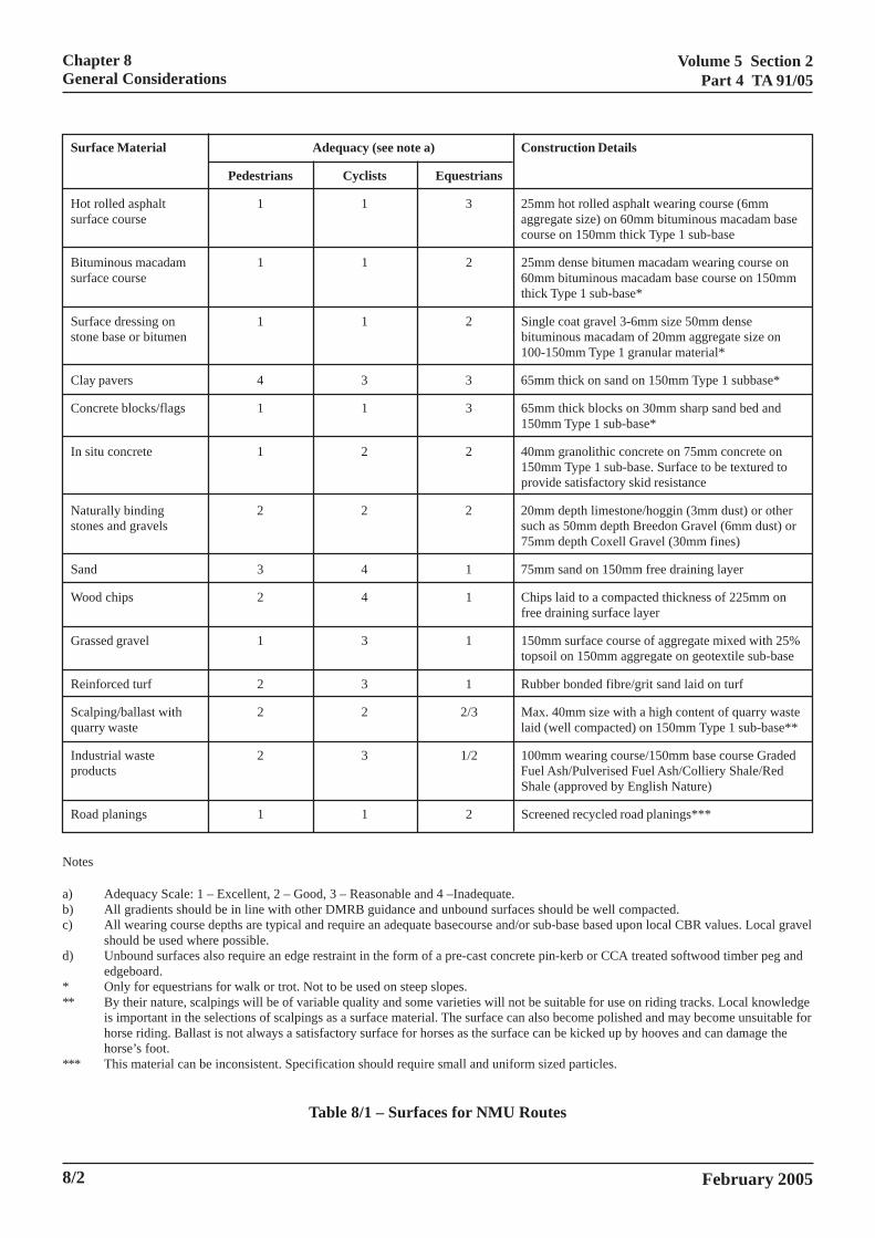
Volume 5 Section 2Part 4 TA 91/05
Chapter 8General Considerations
Surface Material Adequacy (see note a) Construction Details
Pedestrians Cyclists Equestrians
Hot rolled asphalt 1 1 3 25mm hot rolled asphalt wearing course (6mmsurface course aggregate size) on 60mm bituminous macadam base
course on 150mm thick Type 1 sub-base
Bituminous macadam 1 1 2 25mm dense bitumen macadam wearing course onsurface course 60mm bituminous macadam base course on 150mm
thick Type 1 sub-base*
Surface dressing on 1 1 2 Single coat gravel 3-6mm size 50mm densestone base or bitumen bituminous macadam of 20mm aggregate size on
100-150mm Type 1 granular material*
Clay pavers 4 3 3 65mm thick on sand on 150mm Type 1 subbase*
Concrete blocks/flags 1 1 3 65mm thick blocks on 30mm sharp sand bed and150mm Type 1 sub-base*
In situ concrete 1 2 2 40mm granolithic concrete on 75mm concrete on150mm Type 1 sub-base. Surface to be textured toprovide satisfactory skid resistance
Naturally binding 2 2 2 20mm depth limestone/hoggin (3mm dust) or otherstones and gravels such as 50mm depth Breedon Gravel (6mm dust) or
75mm depth Coxell Gravel (30mm fines)
Sand 3 4 1 75mm sand on 150mm free draining layer
Wood chips 2 4 1 Chips laid to a compacted thickness of 225mm onfree draining surface layer
Grassed gravel 1 3 1 150mm surface course of aggregate mixed with 25%topsoil on 150mm aggregate on geotextile sub-base
Reinforced turf 2 3 1 Rubber bonded fibre/grit sand laid on turf
Scalping/ballast with 2 2 2/3 Max. 40mm size with a high content of quarry wastequarry waste laid (well compacted) on 150mm Type 1 sub-base**
Industrial waste 2 3 1/2 100mm wearing course/150mm base course Gradedproducts Fuel Ash/Pulverised Fuel Ash/Colliery Shale/Red
Shale (approved by English Nature)
Road planings 1 1 2 Screened recycled road planings***
Notes
a) Adequacy Scale: 1 – Excellent, 2 – Good, 3 – Reasonable and 4 –Inadequate.b) All gradients should be in line with other DMRB guidance and unbound surfaces should be well compacted.c) All wearing course depths are typical and require an adequate basecourse and/or sub-base based upon local CBR values. Local gravel
should be used where possible.d) Unbound surfaces also require an edge restraint in the form of a pre-cast concrete pin-kerb or CCA treated softwood timber peg and
edgeboard.* Only for equestrians for walk or trot. Not to be used on steep slopes.** By their nature, scalpings will be of variable quality and some varieties will not be suitable for use on riding tracks. Local knowledge
is important in the selections of scalpings as a surface material. The surface can also become polished and may become unsuitable forhorse riding. Ballast is not always a satisfactory surface for horses as the surface can be kicked up by hooves and can damage thehorse’s foot.
*** This material can be inconsistent. Specification should require small and uniform sized particles.
Table 8/1 – Surfaces for NMU Routes
February 20058/2
Volume 5 Section 2Part 4 TA 91/05
Chapter 8General Considerations
8.11 Good road markings tend to assist cyclists as theychannel traffic in clearly defined paths; however, roadmarkings can be hazardous to NMUs if they:
• stand excessively proud of the surface;
• become slippery when wet;
• are used to excess, which adds to visual impactand future maintenance requirements, and candistract horses.
Lighting
8.12 NMU routes within or adjacent to the highwayverge will often benefit from lighting spillage fromcarriageway lighting. However, other OCRs may besome distance from the carriageway and may requiretheir own lighting provision. Lighting of OCRs adjacentto an otherwise unlit highway can cause problems forhighway users, and is not recommended.
8.13 The provision of lighting for NMUs shouldlargely be based upon local circumstances. In urbanareas, it is recommended that where appropriate andfeasible, routes should be lit, particularly at crossingpoints. Consultation may be required to assessappropriateness. It should be noted that commuterjourneys during winter months are likely to take placein dusk or dark conditions in both directions.
8.14 NMU routes in rural areas should not normallyinclude lighting unless there are specific requirements,which include:
• high flows of NMUs, particularly on adjacentand shared use NMU facilities;
• routes with intersections with rights of way andboth minor and major roads falling belowgeometry standards (lighting used at a specificpoint to highlight danger);
• routes which form part of an identified schoolroute, commuter route or other route;
• through any underpass (subject to environmentalimpact).
8.15 Where rural OCRs require lighting it should becontinuous along the NMU route. It is also desirablethat the lighting has a low environmental impact, andcare should be taken at transition points from lit to unlitareas.
8.1NMligthe
8.1sitOC
8.1the
8.1Reby
Dr
8.2effPoprbicheroofsaororMsu
8.2shro
8.2disseprovavshNMlea
8.2slieqprroreq
8.2eq
February 2005
6 At surface level crossings on lit roads after dark,Us should always be seen in silhouette, i.e. the
hting source should be close to, but downstream of, crossing.
7 Any lighting columns or bollard lights should beed a minimum of 0.5m back from the edge of theR, so as not to cause an obstruction to NMUs.
8 Where locations have no existing power supply, use of solar powered lighting may be considered.
9 Further information is provided in ‘Technicalport Number 23: Lighting of Cycle Tracks’ produced the Institution of Lighting Engineers and BS 5489.
ainage and Manholes
0 On-carriageway drainage should be outside theective carriageway area (including the hardstrip).sitive drainage in the form of gullies can causeoblems for NMUs. For cyclists, the front wheel of aycle can be trapped by drainage grate slots, and
nce where grates are unavoidably within the cycleute they should normally be outside the usable width the cycle route. They should also be modern cycle-fe and hydraulically efficient models, such as “vane” “honeycomb” grates. Drainage slots should beiented perpendicular to the direction of travel.anholes should be installed fully flush with therrounding surface and outside any equestrian route.
1 Filter drains and french drains within the vergeould generally be avoided on verges used as NMUutes, because of the difficulty they cause to horses.
2 On NMU routes, rainwater will normallyperse to the verges. However at dips and on kerbed
ctions, positive drainage should be provided toevent ponding. Ditches and gullies hidden inergrown verges are a hazard, and should generally beoided. However, where these are necessary, theyould be a minimum of 0.5m back from the edge of the
U route to avoid hazards if NMUs accidentallyve the route. Regular maintenance is essential.
3 Drainage grates and utility covers can also causepping problems for equestrians. The drainage ofuestrian routes may rely on run-off to adjacent landovided this is within the boundary of the facility orad; otherwise, gullies and pipe systems may beuired.
4 Where an extruded kerb segregates a cycle oruestrian route, drainage should take place through
8/3
Volume 5 Section 2Part 4 TA 91/05
Chapter 8General Considerations
300mm wide gaps in the extruded kerb. The frequencyof the gaps will be influenced by the drainage designfor the route.
Street Furniture
8.25 Cycle theft can be a major problem. Theprovision of carefully planned, secure and convenientparking facilities can reduce this problem and help topromote cycling. In addition, it is recommended thatparking is located in well used public areas and isappropriately lit.
8.26 TAL 5/02 identifies suitable types of andlocations for cycle parking. This includes use ofSheffield stands (for short/medium stay parking) andcycle lockers (long stay parking).
8.27 Access barriers may be used to preventunauthorised access by motorised vehicles onto rightsof way and OCRs. However, these should be avoidedwherever possible and only installed if there is eitherhigh likelihood of, or existing evidence of, misuse.Metal or timber bollards can be used successfully asaccess barriers as long as they are designed to allowwheelchair access (refer to Inclusive Mobility (DfT,2002) for further details). Alternatively, motorcyclebarriers may be used; Sustrans have developed a designwhich is suitable for cycle routes. However, these areunsuitable for routes with equestrian use, for whichbarriers developed by the British Horse Society wouldbe acceptable.
8.28 Cycle chicanes can be used both as accessbarriers and traffic calming measures for cyclists onOCRs. However, these should again be designed toensure that wheelchair users and equestrians retain fullaccess. Further details of cycle chicanes can be found inCycle-Friendly Infrastructure - Guidelines for Planningand Design (IHT/DfT, 1996).
8.29 Street furniture, such as seating and bins, shouldbe included at intervals along OCRs to provide restingand amenity facilities for NMUs, particularly for thosewith mobility impairments. In commonly usedpedestrian areas, seats should be provided at intervalsof no more than 50m. This is particularly important inclose proximity to hospitals, residential areas andnursing homes. Design Organisations should liaise withLocal Authorities about the provision and managementof these facilities.
8.30 The use of pedestrian guardrails in bothon-carriageway and off-carriageway design is outlined
inOHmap
P
8swasc
8spinainPinstha
8aSsmvtohliaththf
M
8sph
8Lmo
8/4
TA 57 (DMRB 6.3.3) and the Overseeingrganisation standard for road restraint systems.owever, the use of guardrails should be kept to theinimum necessary, and where used, designs should
void obstructing inter-visibility between drivers andedestrians.
ersonal Safety and Security
.31 Designers need to take account of personalecurity issues when designing an NMU route. OCRsithin or adjacent to the highway verge will bring about
degree of perceived and actual personal safety if aufficient visual and physical connection with thearriageway can be maintained.
.32 Where this is not possible, the design of the OCRhould take into account the perceived and actualersonal security of NMUs by providing good accessto adjacent areas, sightlines, lighting (where
ppropriate) and the provision of a spacious andviting environment where the NMU can feel at ease.opular and well used routes will generate their ownformal surveillance that will help to provide personal
ecurity. Opportunities for assailants to concealemselves may be avoided by good design, such as
voiding use of sudden changes in fence lines.
.33 Consideration needs to be given to the need for,nd level of, landscaping in the vicinity of NMU routes.uch landscaping should be sympathetic to the requiredecurity of the route. Additionally, routes that are notaintained can cause security problems if the
egetation is not regularly cut back. Vegetation adjacent the OCR should be maintained to an appropriate
eight to minimise the number of hiding places; this iskely to be of particular concern in urban/suburbanreas. The maintenance requirements of schemes shoulderefore be carefully considered in design, includinge health and safety aspects for operatives involved in
uture maintenance.
aintenance and Monitoring
.34 NMU routes, both on- and off-carriageway,hould be maintained to an appropriate standard. Inarticular, debris should be removed regularly and aigh standard of surface provided.
.35 Where OCRs are developed in partnership withocal Authorities, the standard and funding of futureaintenance will need to be agreed to the satisfaction
f the Overseeing Organisation.
February 2005
Volume 5 Section 2Part 4 TA 91/05
Chapter 8General Considerations
8.36 Scheme designs should ensure that access will beavailable for plant and machinery to undertakemaintenance on OCRs.
8.37 It should be noted that legal action can bebrought in respect of loss, injury or damage resultingfrom neglect or failure to maintain a highway (or cycletrack).
8.38 All on-carriageway facilities and OCRs should bemonitored to identify whether additional maintenanceprovision is required.
Other Issues
8.39 Bus stops: Because of the volume of traffic ontrunk roads, it is common practice to provide a lay-byfor a bus stop. The progressive introduction oflow-floor buses and the desire to raise kerbs at busstops to reduce the step into the bus, require a stop thatthe bus can approach parallel to the kerb. In lay-bys,standard kerb heights for bus stops range from 125mmto 140mm. Above this it is recommended thatspecialised bus stop kerbs should be used which giveheights up to 220mm. Where bus stops are provided atthe immediate side of high speed roads without lay-bys,the limits for kerb heights within TA 57 (DMRB 6.3.3)should be adhered to. The stop should be connected tothe local pedestrian network of footways and footpaths,with dropped kerbs and tactile surfaces where roads arecrossed. This network should be as direct as possiblebetween the stop and local principal destinations.
8.40 Escape routes for disabled motorists: Anumber of sections of road, including tunnels andbridges, are provided with emergency escape routes.These should be designed so that they can be used bydisabled people. Further details are given in BD 78(DMRB 2.2.9), TD 27 (DMRB 6.1.2), and InclusiveMobility (DfT, 2002).
8.41 Service and Picnic Areas: Toilets and otherfacilities at service and picnic areas should beaccessible to disabled people. Parking for disabledtravellers should be provided close to the toilets. Thegeometry of car parking spaces for disabled people isspecified in TAL 5/95. The Building Regulations 2000 –Part M: Access and Facilities for Disabled Peopleincludes regulations for access of disabled people tobuildings, including ramps, steps and locations oftactile paving.
February 2005 8/5
Volume 5 Section 2Part 4 TA 91/05
OGRAPHY
Chapter 9References and Bibliography
9. REFERENCES AND BIBLI
Design Manual for Roads and Bridges (DMRB):
1. TA 90 (DMRB 6.3.5) The Geometric Design ofPedestrian, Cycle and Equestrian Routes
2. HD 42 (DMRB 5.2.5) Non-Motorised UserAudits
3. TA 57 (DMRB 6.3.3) Roadside Features
4. TA 68 (DMRB 8.5.1) The Assessment andDesign of Pedestrian Crossings
5. HD 39 (DMRB 7.2.5) Footway Design
6. TD 27 (DMRB 6.1.2) Cross-Sections andHeadrooms
7. HD 28 (DMRB 7.3.1) Skidding Resistance
8. HD 36 (DMRB 7.5.1) Surfacing Materials forNew and Maintenance Construction
9. TA 15 (DMRB 8.1.1) Pedestrian Facilities atTraffic Signal Installations
10. TD 50 (DMRB 6.2.3) The Geometric Layout ofSignal-Controlled Junctions and SignalisedRoundabouts
11. BD 29 (DMRB 2.2.8) Design Criteria forFootbridges
12. BD 52 (DMRB 2.3.3) The Design of HighwayBridge Parapets
13. TD 36 (DMRB 6.3.1) Subways for Pedestriansand Pedal Cyclists. Layout and Dimensions
14. TD 16 (DMRB 6.2.3) The Geometric Design ofRoundabouts
15. TD 22 (DMRB 6.2.1) Layout of Grade SeparatedJunctions
16. TA 69 (DMRB 6.3.3) The Location and Layoutof Lay-bys
17. BD 78 (DMRB 2.2.9) Design of Road Tunnels
Df
18
19
20
21
22
23
24
25
26
27
28
29
30
31
32
33
Df
34
35
February 2005
T Traffic Advisory Leaflets (TALs):
. TAL 6/00 Monitoring Walking
. TAL 8/95 Traffic Models for Cycling
. TAL 1/99 Monitoring Local Cycle Use
. TAL 6/98 Contraflow Cycling
. TAL 1/97 Cyclists at Road Narrowings
. TAL 15/99 Cyclists at Road Works
. TAL 4/91 Audible and Tactile Signals at PelicanCrossings
. TAL 1/01 Puffin Pedestrian Crossing
. TAL 1/02 The Installation of Puffin PedestrianCrossings
. TAL 3/03 Equestrian Crossings
. TAL 5/91 Audible and Tactile Signals at SignalControlled Junctions
. TAL 5/96 Further Development of AdvancedStop Lines
. TAL 9/97 Cycling at Roundabouts, ContinentalDesign Geometry
. TAL 1/88 Provision for Cyclists at GradeSeparated Junctions
. TAL 5/02 Key Elements of Cycle ParkingProvision
. TAL 5/95 Parking for disabled people
T Local Transport Notes (LTNs):
. LTN 1/04 Policy, Planning and Design forWalking and Cycling (Consultation Draft, 2004)
. LTN 2/04 Adjacent And Shared Use FacilitiesFor Pedestrians And Cyclists (Consultation Draft,2004)
9/1
Volume 5 Section 2Part 4 TA 91/05
Chapter 9References and Bibliography
36. LTN 1/97 Keeping Buses Moving
37. LTN 1/86 Cyclists at Road Crossings andJunctions
Other Documents:
38. Inclusive Mobility – A Guide to Best Practice onAccess to Pedestrian and Transport Infrastructure(DfT, 2002)
39. Guidance on the Use of Tactile Paving Surfaces(DfT, 1998)
40. The Traffic Signs Manual, Chapter 5: RoadMarkings (DfT, 2003)
41. Cycle-Friendly Infrastructure: Guidelines forPlanning and Design (IHT/Bicycle Association/CTC/DfT, 1996)
42. The National Cycle Network: Guidelines &Practical Details (Sustrans, 1997)
43. Cycling By Design – A Consultation Paper(Scottish Executive, 1999), in use in Scotland
44. Guidelines for Providing for Journeys on Foot(IHT, 2000)
45. The Traffic Signs Manual, Chapter 4: WarningSigns (DfT, 2004)
46. The Highways (Road Humps) Regulations 1999:SI 1999 1025
47. The Zebra, Pelican and Puffin PedestrianCrossings Regulations 1997: SI 1997 2400
48. Technical Report 23: Lighting of Cycle Tracks(Institution of Lighting Engineers, 1998)
49. BS 5489: Code of Practice for the Design ofRoad Lighting (BSi, 2003)
50. The Building Regulations 2000, Part M: Accessand Facilities for Disabled People
February 20059/2
Volume 5 Section 2Part 4 TA 91/05
February 2005
Chapter 10Detailed Contents and Index
10/1
10. DETAILED CONTENTS AND INDEX
1. Introduction 1/1General 1/1Advice Note Objectives 1/1Implementation 1/1Research and Consultation 1/1Definitions 1/1
2. NMU Requirements 2/1General 2/1Pedestrians 2/1Cyclists 2/2Equestrians 2/2General NMU Requirements 2/3
3. Scheme Development and Assessment 3/1General 3/1Design Brief and NMU Audit 3/1Existing and Future Usage Patterns 3/1Consultation 3/1General Design Principles 3/2Choice of Facility 3/3Shared NMU Provision 3/4Scheme Assessment 3/4
4. NMU Off-Carriageway Routes (OCRs) 4/1General 4/1OCR Types 4/1Route Type A: Within Truck Road Verge 4/1Route Type B: Land Outside, But Adjacent to The Highway Boundary 4/2Route Type C: Distant From Trunk Road 4/2Route Type D: Existing Rights of Way 4/2Route Type E: Redundant or Bypassed Road 4/2Route Type F: Minor Highway 4/2Route Type G: Other Locations 4/3Choice of Route Type 4/3Local Distinctiveness 4/3Badging 4/4
5. On-Carriageway Cycling Facilities 5/1General 5/1Wide Nearside Lane 5/1With-Flow Cycle Lanes (Advisory/Mandatory) 5/1Contra-Flow Cycle Lanes 5/1With-Flow & Contra-Flow Bus/Cycle Lanes 5/1Other Considerations for On-Carriageway Cycle Provision 5/2
Volume 5 Section 2Part 4 TA 91/05
February 200510/2
Chapter 10Detailed Contents and Index
6. Crossings 6/1General 6/1Crossings and Junction Assessment and Selection 6/1Rights of Way Crossings 6/1Selection of NMU Crossing Facilities 6/2Informal Pedestrian and Cycle Crossings 6/3Cycle Priority Crossings 6/4Unsignalised Equestrian Crossing with Holding Area 6/4‘Zebra’ Crossings 6/5Signalised Crossings 6/5‘Pelican’ Crossings 6/5‘Puffin’ Crossings 6/5‘Toucan’ Crossings 6/6Equestrian Crossings (Signal Controlled) 6/6NMU Stages at Traffic Signals 6/6Grade Separated Crossings 6/6Bridges 6/7Underpasses 6/7
7. Junctions 7/1General 7/1Advanced Stop Lines (ASLs) 7/1NMUs at Roundabouts 7/1Mini Roundabouts 7/2Normal Roundabouts 7/2Continental Roundabouts 7/2Cyclists at Grade Separated Junctions and Other Slip Road Junctions 7/2
8. General Considerations 8/1General 8/1Surfaces 8/1Signing and Markings 8/1Lighting 8/3Drainage and Manholes 8/3Street Furniture 8/4Personal Safety and Security 8/4Maintenance and Monitoring 8/4Other Issues 8/5
9. References and Bibliography 9/1
10. Detailed Contents and Index 10/1
11. Enquiries 11/1
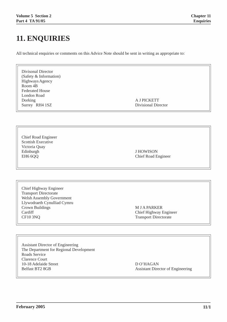
Volume 5 Section 2Part 4 TA 91/05
February 2005 11/1
11. ENQUIRIES
All technical enquiries or comments on this Advice Note should be sent in writing as appropriate to:
Divisonal Director(Safety & Information)Highways AgencyRoom 4BFederated HouseLondon RoadDorking A J PICKETTSurrey RH4 1SZ Divisional Director
Chief Road EngineerScottish ExecutiveVictoria QuayEdinburgh J HOWISONEH6 6QQ Chief Road Engineer
Chief Highway EngineerTransport DirectorateWelsh Assembly GovernmentLlywodraeth Cynulliad CymruCrown Buildings M J A PARKERCardiff Chief Highway EngineerCF10 3NQ Transport Directorate
Assistant Director of EngineeringThe Department for Regional DevelopmentRoads ServiceClarence Court10-18 Adelaide Street D O’HAGANBelfast BT2 8GB Assistant Director of Engineering
Chapter 11Enquiries
Volume 5 Section 2Part 4 TA 91/05
ORK (ENGLAND AND
Annex 1Legal Framework (England and Wales Only)
ANNEX 1 LEGAL FRAMEWWALES ONLY)
General
A1.1 This annex is included for information andprovides a summary of existing definitions, usage rightsand responsibilities of different bodies, followed byissues relating to improving NMU facilities. Legaladvice should always be sought during thedevelopment of proposals to ensure that changes inlegislation and case law have been taken intoaccount.
A1.2 Changes to public rights of way can befinanced, designed and implemented by the OverseeingOrganisation as long as they are included as part ofpublished statutory orders and receive the appropriatestatutory approvals.
Public Rights of Way
A1.3 Public Rights of Way comprise Footpaths,Bridleways, Restricted Byways and Byways Open toAll Traffic. All Public Rights of Way are highways, andare shown on ‘Definitive Maps’ held by highwayauthorities.
• Footpaths – are highways over which the publichave a right of way on foot only, not being afootway [Section 329(1) Highways Act 1980].
• Bridleways – provide a right of way onhorseback, foot and bicycle. The Countryside Act1968 gave cyclists the right to use bridleways butthey must give way to other users. The right forcyclists to use a bridleway can be subject to anorder or bylaw prohibiting cycling on particularparts of it.
• Restricted Byways – were created by theCountryside and Rights of Way Act 2000. Theyare generally open only to pedestrians, cyclists,horse-riders and horse-drawn vehicles andreplace the former category of ‘Roads Used asPublic Paths’ (RUPPs).
• Byways Open to All Traffic – (BOATs) havefull public rights, including for vehicles, butrarely have a sealed surface and are generallyused in a similar way to bridleways. Thedefinition was created under the Wildlife and
A1higwaonareare
A1TrafooBetheconrem
A1lanaccunperowandThhavtheThconrec
A1rigprianyhavto rou
A1seasea1:2“OhigUnRe‘Lishoon(PM
February 2005
Countryside Act 1981.
.4 A Footway means a way comprised in ahway, which also comprises a carriageway, being ay over which the public has a right of way on footly [Section 329(1) Highways Act 1980]. Footways the pedestrian paths alongside a carriageway, and often referred to as a pavement.
.5 Cycle Tracks are created under the Cyclecks Act 1984 through the upgrade of footpaths andtways to provide a right of way by bicycle and foot.cause cycle tracks are not a category of right of way,y are not shown on any Definitive Maps, and theversion of a footpath to a cycle track requires itsoval from the Definitive Map.
.6 Permissive rights routes exist wheredowners have agreed with the highway authority foress to be available to particular categories of user
der certain conditions. There are examples ofmissive routes for pedestrians and cyclists on landned by British Waterways, the Forestry Commission the National Trust, as well as private landowners.
ey are for agreed periods. Some highway authoritiese granted themselves permissive rights for paths onir own land instead of using the Cycle Tracks Act.is is not recommended. If there is no alternative toverting a route in this way, consultation is stronglyommended even though it is not a legal requirement.
.7 No right of way is established under permissivehts, and the landowner can still use the land for itsmary purpose. The permission may be withdrawn at time, either temporarily or permanently. This cane implications for highway authorities if they wish
invest money to improve or maintain permissivetes that cross land that they do not own.
.8 Unclassified Roads may or may not have aled surface. Where unclassified roads without aled surface are depicted on Ordnance Survey5 000 and 1:50 000 scale maps they appear as eitherther road, drive or track” or “Path”, but their publichway status should be confirmed by reference to theclassified Road map held by all highway authorities.ference can also be made to the highway authority’sst of Streets’, which identifies all adopted roads. Ituld be noted that the majority of ‘other roads’ shown
Ordnance Survey maps are private means of accessAs). The most recent Ordnance Survey maps show
A1/1
Volume 5 Section 2Part 4 TA 91/05
Annex 1Legal Framework (England and Wales Only)
most unsealed unclassified roads as “Other Routes withpublic access”.
Use of Footways and Cycle Tracks
A1.9 A footway is a right of way on foot, on a part ofa highway that also comprises a carriageway. Section66 of the Highways Act 1980 places a duty on thehighway authority to construct a footway alongside thecarriageway if considered necessary or desirable.
A1.10 Driving a vehicle (including cycles) or a horseon a footway is an offence under the Highways Act1835. Therefore, footways cannot be used as linkingsections on routes for cyclists or horse-riders. It shouldbe noted that powered scooters and electric pavementvehicles can be legally used on the footway, up to aspeed of 4mph.
A1.11 A cycle track alongside a carriageway cannot beused by horses. However, Section 71 of the HighwaysAct 1980 places a duty on the highway authority toprovide an adequate grass verge for the safety andaccommodation of ridden horses and driven livestock,where this is considered necessary or desirable. There isalso a duty not to obstruct verges with signs orconstructions which would prevent the safe passage ofusers.
Creation of New Off-Carriageway Routes
A1.12 The Overseeing Organisation has powers tocreate new footpaths, bridleways or all-purposehighways within an existing trunk road boundary or byextending the highway boundary into land alongside anexisting trunk road owned by the OverseeingOrganisation. Powers do not exist to create a routeseparated from the rest of the trunk road by interveningland. In these cases the Overseeing Organisation shouldwork in partnership with the highway authority.
A1.13 Highway authorities have powers to create newhighways (including cycle tracks) as well as footpathsand bridleways under the Highways Act 1980.
A1.14 New footpaths or bridleways can be createdunder Section 25 or 26 of the Highways Act 1980 bythe Local Authority through agreement (public pathcreation agreement) or compulsory powers (public pathcreation order). Creation of a footpath or bridleway willrequire consultation with other highway authorities.Although there is no statutory requirement to consultwith user groups, or parish or community councils, it isrecommended.
A1/2
A1.15 Both an agreement under Section 25 of theHighways Act 1980 and compulsory powers underSection 26 of the Highways Act 1980 would normallylead to compensation for loss caused by the creation ofa public path.
A1.16 The creation of a new off-carriageway routemay be classed as ‘development’, and therefore mayrequire planning approval from the highway authority.However in some cases (e.g. where a new route isconstructed as an extension to an existing highway, oran unadopted road is adopted and resurfaced) the routemay be considered ‘permitted development’, and assuch would not require planning approval.
A1.17 In general, a highway authority is entitled togrant itself ‘deemed planning permission’ for statutoryworks undertaken by the authority. However, it mayjudge that the processes of partnership and publicinvolvement achieved through the conventionalplanning process achieve other worthwhile benefits.
Footpath Conversion to Cycle Track
A1.18 To convert all or part of a footpath to a cycletrack, a footpath conversion order must be madeapplying to the appropriate width of the footpath.Footpath conversion orders are made under Section 3 ofthe Cycle Tracks Act 1984 and the Cycle TracksRegulations 1984 (SI 1984/1431).
A1.19 Having obtained the necessary consents wherethe footpath crosses agricultural land, and havingundertaken the required consultation process, a footpathconversion order is made by the highway authority. Ifthere are unwithdrawn objections, the order has to beconfirmed by the Secretary of State, if necessary after apublic inquiry.
A1.20 If there are no objections, or all objections arewithdrawn, the order can be confirmed by the highwayauthority. Section 2 of the Cycle Tracks Act 1984applies and the adjacent or shared track should beclearly signed.
Footway Conversion to Cycle Track
A1.21 To convert all, or part, of a footway to a cycletrack, all, or the appropriate part of the footway must be‘removed’ under the powers in Section 66(4) of theHighways Act 1980, and a cycle track ‘constructed’under Section 65(1). The process need not necessarilyinvolve physical construction work, but there needs tobe clear evidence that the highway authority has
February 2005
Volume 5 Section 2Part 4 TA 91/05
Annex 1Legal Framework (England and Wales Only)
exercised its powers. This can be provided by aresolution of the appropriate committee. By virtue ofSection 21 of the Road Traffic Act 1988, it is an offenceto use a motor vehicle on a cycle track, and the makingof a Traffic Regulation Order is therefore no longerrequired to control such use. The adjacent cycle track orshared surface should be clearly signed.
Cycle Track Conversion to Bridleway
A1.22 Under subsection 65(2) of the Highways Act1980, it is possible to ‘alter’ the use of the cycle trackand extend it to equestrian use.
Maintenance
A1.23 All rights of way are public highways and theirsurface is owned and maintained by the highwayauthority. Stiles and gates, including those on orforming the highway boundary, are owned andmaintained by the adjoining landowner; they must bemaintained in good condition or the highway authoritycan serve notice to repair, or repair and counter-charge.Stiles and gates should be designed for use by disabledpeople.
A1.24 Links and accesses to rights of way within thetrunk road boundary are the responsibility of theOverseeing Organisation, not the highways authority,for maintenance.
Rights of Way Improvement Plans
A1.25 The Countryside and Rights of Way Act 2000(England and Wales) requires all highway authorities toprepare a Rights of Way Improvement Plan by January2006. The Plans need to illustrate the extent to whichthe rights of way meet the present and future needs ofthe public, offer opportunities for exercise andrecreation, and are accessible to blind and partiallysighted people and people with mobility problems.
Disability Discrimination Act
A1.26 The Disability Discrimination Act 1995 (DDA)brought in a range of requirements upon serviceproviders to prevent discrimination against disabledpeople. Although highway authorities (includingOverseeing Organisations) are not recognised as serviceproviders at present, they should aim to comply withPart III of the DDA until such time as a legal precedent
isbeseprta
ADPSewPa
February 2005
has been set to confirm their status. Part III of the DDA
based on the principle that disabled people should not discriminated against (through non-provision ofrvices or a different level of provision) by serviceoviders when accessing everyday services that otherske for granted.
1.27 Design Organisations should refer to theisability Rights Commission (DRC) ‘Code ofractice – Rights of Access, Goods, Facilities,rvices and Premises’ (available on-line at
ww.drc-gb.org/drc/InformationAndLegislation/ge331a.asp).
A1/3
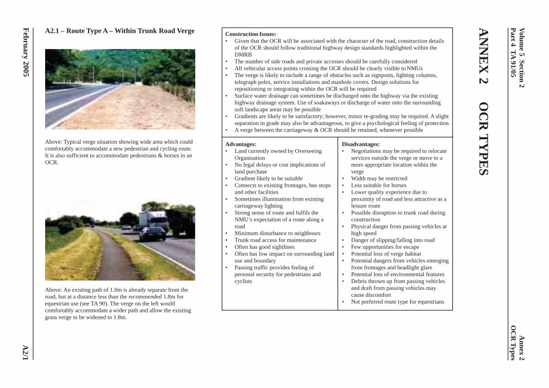
Volume 5 Section 2
Part 4 TA 91/05
February 2005
AN
NE
X 2
OC
R T
YPE
S
A2.1 – Route Type A – Within Trunk Road Verge
Above: Typical verge situation showing wide area which couldcomfortably accommodate a new pedestrian and cycling route.It is also sufficient to accommodate pedestrians & horses in anOCR.
Above: An existing path of 1.0m is already separate from theroad, but at a distance less than the recommended 1.8m forequestrian use (see TA 90). The verge on the left wouldcomfortably accommodate a wider path and allow the existinggrass verge to be widened to 1.8m.
Construction Issues:·• Given that the OCR will be associated with the character of the road, construction details
of the OCR should follow traditional highway design standards highlighted within theDMRB
• The number of side roads and private accesses should be carefully considered• All vehicular access points crossing the OCR should be clearly visible to NMUs• The verge is likely to include a range of obstacles such as signposts, lighting columns,
telegraph poles, service installations and manhole covers. Design solutions forrepositioning or integrating within the OCR will be required
• Surface water drainage can sometimes be discharged onto the highway via the existinghighway drainage system. Use of soakaways or discharge of water onto the surroundingsoft landscape areas may be possible
• Gradients are likely to be satisfactory; however, minor re-grading may be required. A slightseparation in grade may also be advantageous, to give a psychological feeling of protection
• A verge between the carriageway & OCR should be retained, whenever possible
Advantages: Disadvantages:• Land currently owned by Overseeing • Negotiations may be required to relocate
Organisation services outside the verge or move to a• No legal delays or cost implications of more appropriate location within the
land purchase verge• Gradient likely to be suitable • Width may be restricted• Connects to existing frontages, bus stops • Less suitable for horses
and other facilities • Lower quality experience due to• Sometimes illumination from existing proximity of road and less attractive as a
carriageway lighting leisure route• Strong sense of route and fulfils the • Possible disruption to trunk road during
NMU’s expectation of a route along a constructionroad • Physical danger from passing vehicles at
• Minimum disturbance to neighbours high speed• Trunk road access for maintenance • Danger of slipping/falling into road• Often has good sightlines • Few opportunities for escape• Often has low impact on surrounding land • Potential loss of verge habitat
use and boundary • Potential dangers from vehicles emerging• Passing traffic provides feeling of from frontages and headlight glare
personal security for pedestrians and • Potential loss of environmental featurescyclists • Debris thrown up from passing vehicles
and draft from passing vehicles maycause discomfort
• Not preferred route type for equestrians
A2/1
Annex 2
OC
R Types
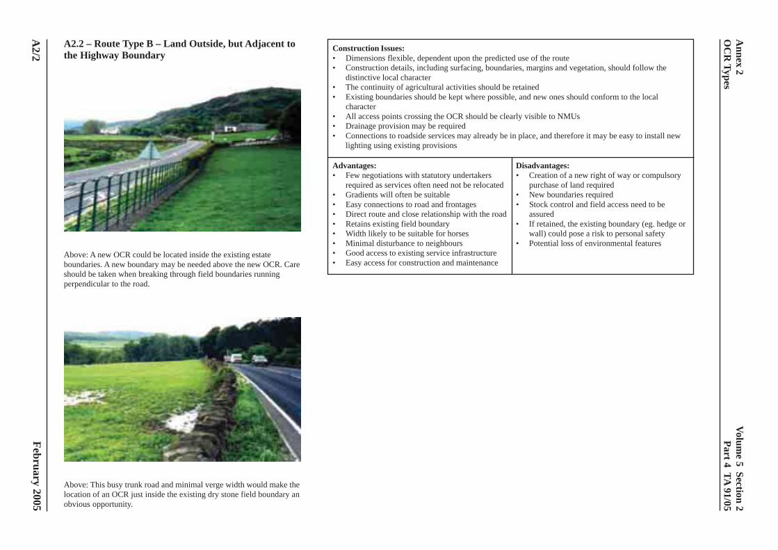
Volume 5 Section 2
Part 4 TA 91/05
February 2005
A2.2 – Route Type B – Land Outside, but Adjacent tothe Highway Boundary
Above: A new OCR could be located inside the existing estateboundaries. A new boundary may be needed above the new OCR. Careshould be taken when breaking through field boundaries runningperpendicular to the road.
Above: This busy trunk road and minimal verge width would make thelocation of an OCR just inside the existing dry stone field boundary anobvious opportunity.
Construction Issues:• Dimensions flexible, dependent upon the predicted use of the route• Construction details, including surfacing, boundaries, margins and vegetation, should follow the
distinctive local character• The continuity of agricultural activities should be retained• Existing boundaries should be kept where possible, and new ones should conform to the local
character• All access points crossing the OCR should be clearly visible to NMUs• Drainage provision may be required• Connections to roadside services may already be in place, and therefore it may be easy to install new
lighting using existing provisions
Advantages: Disadvantages:• Few negotiations with statutory undertakers • Creation of a new right of way or compulsory
required as services often need not be relocated purchase of land required• Gradients will often be suitable • New boundaries required• Easy connections to road and frontages • Stock control and field access need to be• Direct route and close relationship with the road assured• Retains existing field boundary • If retained, the existing boundary (eg. hedge or• Width likely to be suitable for horses wall) could pose a risk to personal safety• Minimal disturbance to neighbours • Potential loss of environmental features• Good access to existing service infrastructure• Easy access for construction and maintenance
A2/2
Annex 2
OC
R Types
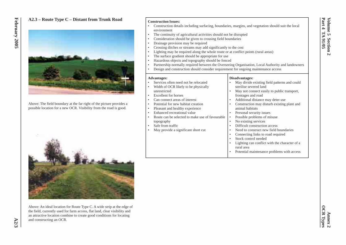
Volume 5 Section 2
Part 4 TA 91/05
February 2005
A2.3 – Route Type C – Distant from Trunk Road
Above: The field boundary at the far right of the picture provides apossible location for a new OCR. Visibility from the road is good.
Above: An ideal location for Route Type C. A wide strip at the edge ofthe field, currently used for farm access, flat land, clear visibility andan attractive location combine to create good conditions for locatingand constructing an OCR.
Construction Issues:• Construction details including surfacing, boundaries, margins, and vegetation should suit the local
environment• The continuity of agricultural activities should not be disrupted• Consideration should be given to crossing field boundaries• Drainage provision may be required• Crossing ditches or streams may add significantly to the cost• Lighting may be required along the whole route or at conflict points (rural areas)• The surface gradient should be appropriate for use• Hazardous objects and topography should be fenced• Partnership normally required between the Overseeing Organisation, Local Authority and landowners• Design and construction should consider requirement for ongoing maintenance access
Advantages: Disadvantages:• Services often need not be relocated • May divide existing field patterns and could• Width of OCR likely to be physically sterilise severed land
unrestricted • May not connect easily to public transport,• Excellent for horses frontages and road• Can connect areas of interest • Additional distance may deter use• Potential for new habitat creation • Construction may disturb existing plant and• Pleasant and healthy experience animal habitats• Enhanced recreational value • Personal security issues• Route can be selected to make use of favourable • Possible problems of misuse
topography • No existing services• Safe from traffic • Difficult construction access• May provide a significant short cut • Need to construct new field boundaries
• Connecting links to road required• Stock control needed• Lighting can conflict with the character of a
rural area• Potential maintenance problems with access
A2/3
Annex 2
OC
R Types
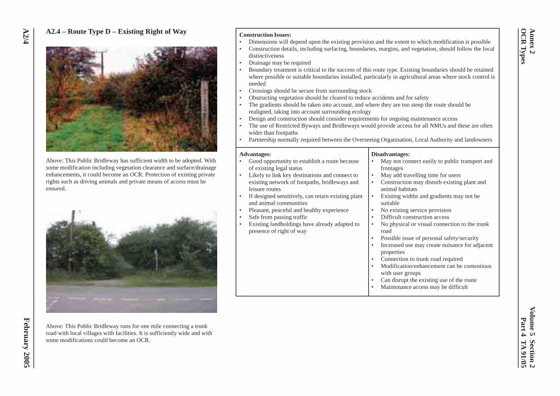
Volume 5 Section 2
Part 4 TA 91/05
February 2005
A2.4 – Route Type D – Existing Right of Way
Above: This Public Bridleway has sufficient width to be adopted. Withsome modification including vegetation clearance and surface/drainageenhancements, it could become an OCR. Protection of existing privaterights such as driving animals and private means of access must beensured.
Above: This Public Bridleway runs for one mile connecting a trunkroad with local villages with facilities. It is sufficiently wide and withsome modifications could become an OCR.
Construction Issues:• Dimensions will depend upon the existing provision and the extent to which modification is possible• Construction details, including surfacing, boundaries, margins, and vegetation, should follow the local
distinctiveness• Drainage may be required• Boundary treatment is critical to the success of this route type. Existing boundaries should be retained
where possible or suitable boundaries installed, particularly in agricultural areas where stock control isneeded
• Crossings should be secure from surrounding stock• Obstructing vegetation should be cleared to reduce accidents and for safety• The gradients should be taken into account, and where they are too steep the route should be
realigned, taking into account surrounding ecology• Design and construction should consider requirements for ongoing maintenance access• The use of Restricted Byways and Bridleways would provide access for all NMUs and these are often
wider than footpaths• Partnership normally required between the Overseeing Organisation, Local Authority and landowners
Advantages: Disadvantages:• Good opportunity to establish a route because • May not connect easily to public transport and
of existing legal status frontages• Likely to link key destinations and connect to • May add travelling time for users
existing network of footpaths, bridleways and • Construction may disturb existing plant andleisure routes animal habitats
• If designed sensitively, can retain existing plant • Existing widths and gradients may not beand animal communities suitable
• Pleasant, peaceful and healthy experience • No existing service provision• Safe from passing traffic • Difficult construction access• Existing landholdings have already adapted to • No physical or visual connection to the trunk
presence of right of way road• Possible issue of personal safety/security• Increased use may create nuisance for adjacent
properties• Connection to trunk road required• Modification/enhancement can be contentious
with user groups• Can disrupt the existing use of the route• Maintenance access may be difficult
A2/4
Annex 2
OC
R Types
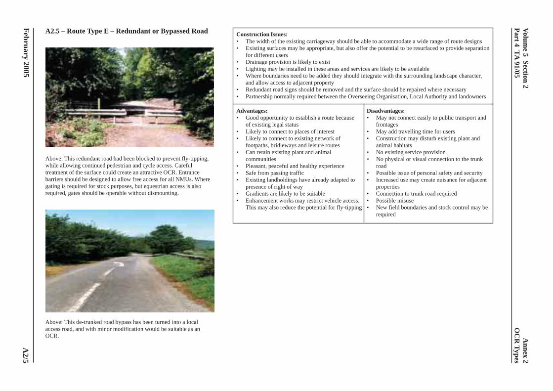
Volume 5 Section 2
Part 4 TA 91/05
February 2005
A2.5 – Route Type E – Redundant or Bypassed Road
Above: This redundant road had been blocked to prevent fly-tipping,while allowing continued pedestrian and cycle access. Carefultreatment of the surface could create an attractive OCR. Entrancebarriers should be designed to allow free access for all NMUs. Wheregating is required for stock purposes, but equestrian access is alsorequired, gates should be operable without dismounting.
Above: This de-trunked road bypass has been turned into a localaccess road, and with minor modification would be suitable as anOCR.
Construction Issues:• The width of the existing carriageway should be able to accommodate a wide range of route designs• Existing surfaces may be appropriate, but also offer the potential to be resurfaced to provide separation
for different users• Drainage provision is likely to exist• Lighting may be installed in these areas and services are likely to be available• Where boundaries need to be added they should integrate with the surrounding landscape character,
and allow access to adjacent property• Redundant road signs should be removed and the surface should be repaired where necessary• Partnership normally required between the Overseeing Organisation, Local Authority and landowners
Advantages: Disadvantages:• Good opportunity to establish a route because • May not connect easily to public transport and
of existing legal status frontages• Likely to connect to places of interest • May add travelling time for users• Likely to connect to existing network of • Construction may disturb existing plant and
footpaths, bridleways and leisure routes animal habitats• Can retain existing plant and animal • No existing service provision
communities • No physical or visual connection to the trunk• Pleasant, peaceful and healthy experience road• Safe from passing traffic • Possible issue of personal safety and security• Existing landholdings have already adapted to • Increased use may create nuisance for adjacent
presence of right of way properties• Gradients are likely to be suitable • Connection to trunk road required• Enhancement works may restrict vehicle access. • Possible misuse
This may also reduce the potential for fly-tipping • New field boundaries and stock control may berequired
A2/5
Annex 2
OC
R Types
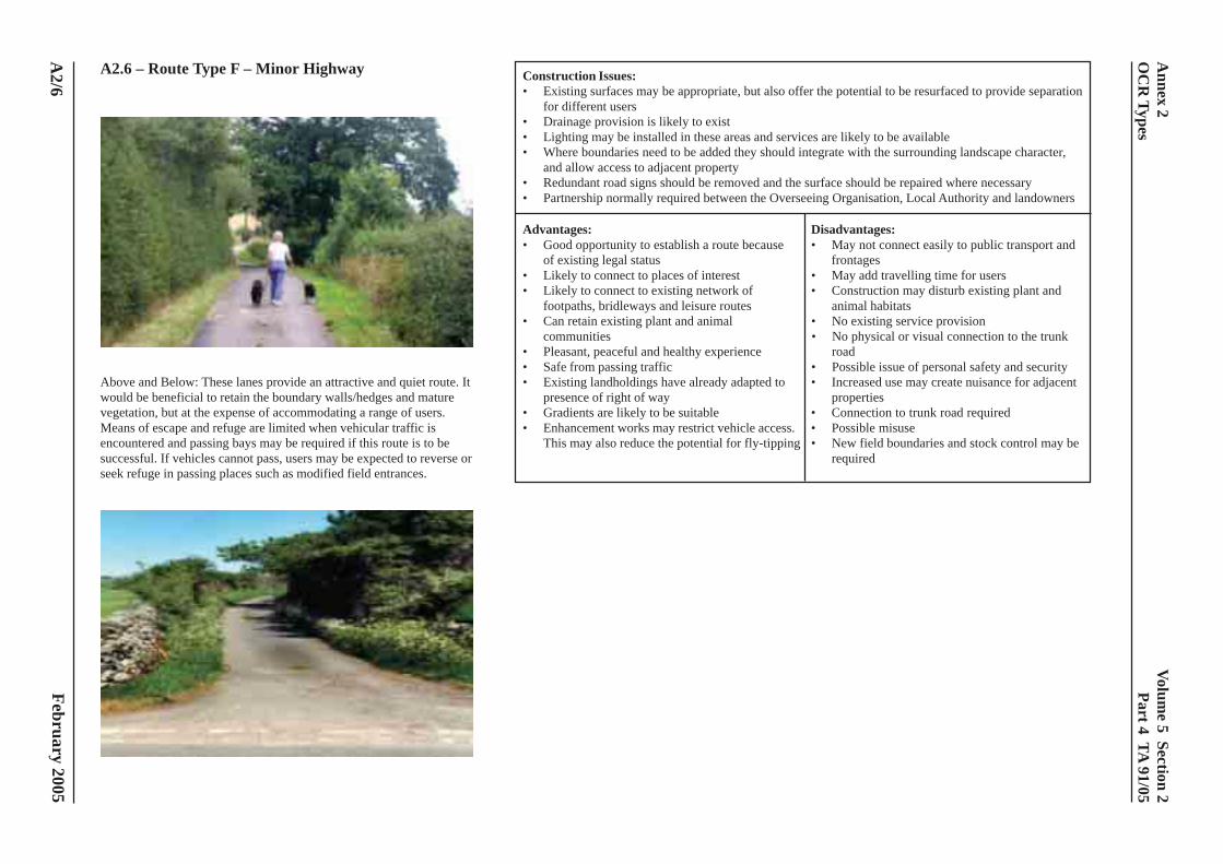
Volume 5 Section 2
Part 4 TA 91/05
February 2005
A2.6 – Route Type F – Minor Highway
Above and Below: These lanes provide an attractive and quiet route. Itwould be beneficial to retain the boundary walls/hedges and maturevegetation, but at the expense of accommodating a range of users.Means of escape and refuge are limited when vehicular traffic isencountered and passing bays may be required if this route is to besuccessful. If vehicles cannot pass, users may be expected to reverse orseek refuge in passing places such as modified field entrances.
Construction Issues:• Existing surfaces may be appropriate, but also offer the potential to be resurfaced to provide separation
for different users• Drainage provision is likely to exist• Lighting may be installed in these areas and services are likely to be available• Where boundaries need to be added they should integrate with the surrounding landscape character,
and allow access to adjacent property• Redundant road signs should be removed and the surface should be repaired where necessary• Partnership normally required between the Overseeing Organisation, Local Authority and landowners
Advantages: Disadvantages:• Good opportunity to establish a route because • May not connect easily to public transport and
of existing legal status frontages• Likely to connect to places of interest • May add travelling time for users• Likely to connect to existing network of • Construction may disturb existing plant and
footpaths, bridleways and leisure routes animal habitats• Can retain existing plant and animal • No existing service provision
communities • No physical or visual connection to the trunk• Pleasant, peaceful and healthy experience road• Safe from passing traffic • Possible issue of personal safety and security• Existing landholdings have already adapted to • Increased use may create nuisance for adjacent
presence of right of way properties• Gradients are likely to be suitable • Connection to trunk road required• Enhancement works may restrict vehicle access. • Possible misuse
This may also reduce the potential for fly-tipping • New field boundaries and stock control may berequired
A2/6
Annex 2
OC
R Types
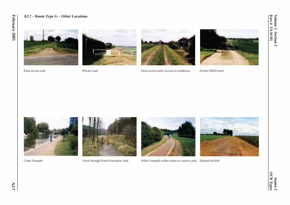
Volume 5 Section 2
Part 4 TA 91/05
February 2005
A2.7 – Route Type G – Other Locations
Farm access road Private road Farm access track: Access to residences Former MOD track
Canal Towpath Track through Forest Enterprise land Public footpath within urban or country park Disused airfield
A2/7
Annex 2
OC
R Types
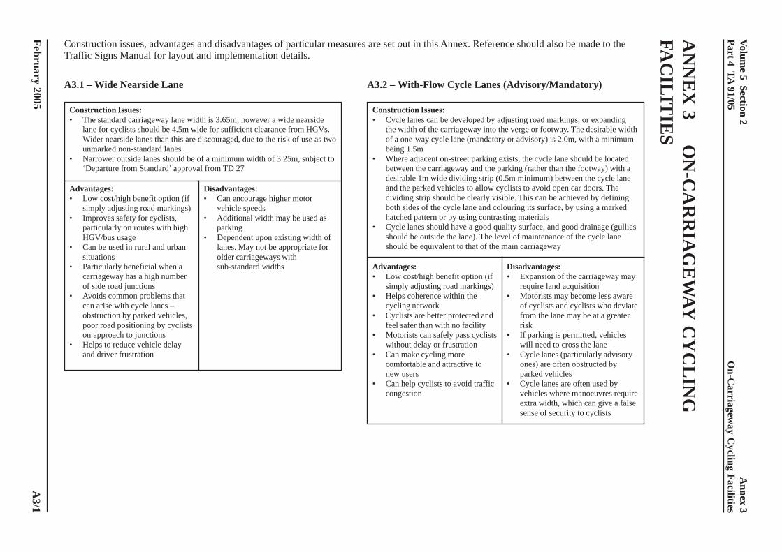
Volume 5 Section 2
Part 4 TA 91/05
February 2005
AN
NE
X 3
ON
-CA
RR
IAG
EW
AY C
YC
LIN
GFA
CIL
ITIE
S
A3.1 – Wide Nearside Lane
Construction Issues:• The standard carriageway lane width is 3.65m; however a wide nearside
lane for cyclists should be 4.5m wide for sufficient clearance from HGVs.Wider nearside lanes than this are discouraged, due to the risk of use as twounmarked non-standard lanes
• Narrower outside lanes should be of a minimum width of 3.25m, subject to‘Departure from Standard’ approval from TD 27
Advantages: Disadvantages:• Low cost/high benefit option (if • Can encourage higher motor
simply adjusting road markings) vehicle speeds• Improves safety for cyclists, • Additional width may be used as
particularly on routes with high parkingHGV/bus usage • Dependent upon existing width of
• Can be used in rural and urban lanes. May not be appropriate forsituations older carriageways with
• Particularly beneficial when a sub-standard widthscarriageway has a high numberof side road junctions
• Avoids common problems thatcan arise with cycle lanes –obstruction by parked vehicles,poor road positioning by cyclistson approach to junctions
• Helps to reduce vehicle delayand driver frustration
Construction issues, advantages and disadvantages of particular measures are set out in this Annex. Reference should also be made to theTraffic Signs Manual for layout and implementation details.
A3.2 – With-Flow Cycle Lanes (Advisory/Mandatory)
Construction Issues:• Cycle lanes can be developed by adjusting road markings, or expanding
the width of the carriageway into the verge or footway. The desirable widthof a one-way cycle lane (mandatory or advisory) is 2.0m, with a minimumbeing 1.5m
• Where adjacent on-street parking exists, the cycle lane should be locatedbetween the carriageway and the parking (rather than the footway) with adesirable 1m wide dividing strip (0.5m minimum) between the cycle laneand the parked vehicles to allow cyclists to avoid open car doors. Thedividing strip should be clearly visible. This can be achieved by definingboth sides of the cycle lane and colouring its surface, by using a markedhatched pattern or by using contrasting materials
• Cycle lanes should have a good quality surface, and good drainage (gulliesshould be outside the lane). The level of maintenance of the cycle laneshould be equivalent to that of the main carriageway
Advantages: Disadvantages:• Low cost/high benefit option (if • Expansion of the carriageway may
simply adjusting road markings) require land acquisition• Helps coherence within the • Motorists may become less aware
cycling network of cyclists and cyclists who deviate• Cyclists are better protected and from the lane may be at a greater
feel safer than with no facility risk• Motorists can safely pass cyclists • If parking is permitted, vehicles
without delay or frustration will need to cross the lane• Can make cycling more • Cycle lanes (particularly advisory
comfortable and attractive to ones) are often obstructed bynew users parked vehicles
• Can help cyclists to avoid traffic • Cycle lanes are often used bycongestion vehicles where manoeuvres require
extra width, which can give a falsesense of security to cyclists
A3/1
Annex 3
On-C
arriageway C
ycling Facilities
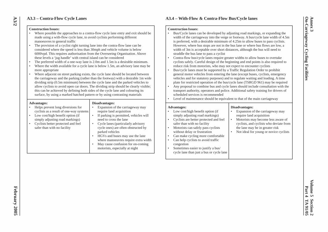
Volume 5 Section 2
Part 4 TA 91/05
February 2005
A3.3 – Contra-Flow Cycle Lanes
Construction Issues:• Where possible the approaches to a contra-flow cycle lane entry and exit should be
made using a with-flow cycle lane, to avoid cyclists performing differentmanoeuvres to general traffic
• The provision of a cyclist right turning lane into the contra-flow lane can beconsidered where the speed is less than 30mph and vehicle volume is below6000vpd. This requires authorisation from the Overseeing Organisation. Abovethese levels a ‘jug handle’ with central island can be considered
• The preferred width of a one-way lane is 2.0m and 1.5m is a desirable minimum.• Where the width available for a cycle lane is below 1.5m, an advisory lane may be
more appropriate• Where adjacent on street parking exists, the cycle lane should be located between
the carriageway and the parking (rather than the footway) with a desirable 1m widedividing strip (0.5m minimum) between the cycle lane and the parked vehicles toallow cyclists to avoid open car doors. The dividing strip should be clearly visible;this can be achieved by defining both sides of the cycle lane and colouring itssurface, by using a marked hatched pattern or by using contrasting materials
Advantages: Disadvantages:• Helps prevent long diversions for • Expansion of the carriageway may
cyclists as a result of one-way systems require land acquisition• Low cost/high benefit option (if • If parking is permitted, vehicles will
simply adjusting road markings) need to cross the lane• Cyclists better protected and feel • Cycle lanes (particularly advisory
safer than with no facility cycle ones) are often obstructed byparked vehicles
• HGVs and buses may use the lanewhere manoeuvres require extra width
• May cause confusion for on-comingmotorists, especially at night
A3.4 – With-Flow & Contra-Flow Bus/Cycle lanes
Construction Issues:• Bus/Cycle lanes can be developed by adjusting road markings, or expanding the
width of the carriageway into the verge or footway. A bus/cycle lane width of 4.5mis preferred, with a desirable minimum of 4.25m to allow buses to pass cyclists.However, where bus stops are not in the bus lane or where bus flows are low, awidth of 3m is acceptable over short distances, although the bus will need tostraddle the bus lane to pass a cyclist
• Contra-flow bus/cycle lanes require greater widths to allow buses to overtakecyclists safely. Careful design of the beginning and end points is also required toreduce risk from motorists, who may not expect to encounter cyclists
• Bus/cycle lanes must be supported by a Traffic Regulation Order to prohibitgeneral motor vehicles from entering the lane (except buses, cyclists, emergencyvehicles and for statutory purposes) and to regulate waiting and loading. A timeplate for restricted operation of the bus/cycle lane (TSRGD 961) may be required
• Any proposal to combine bus and cycle lanes should include consultation with thetransport authority, operators and police. Additional safety training for drivers ofscheduled services is recommended
• Level of maintenance should be equivalent to that of the main carriageway
Advantages: Disadvantages:• Low cost/high benefit option (if • Expansion of the carriageway may
simply adjusting road markings) require land acquisition• Cyclists are better protected and feel • Motorists may become less aware of
safer than with no facility cyclists, and cyclists who deviate from• Motorists can safely pass cyclists the lane may be in greater risk
without delay or frustration • Not ideal for young or novice cyclists• Can make cycling more comfortable• Can help cyclists to avoid traffic
congestion• Sometimes easier to justify a bus/
cycle lane than just a bus or cycle lane
A3/2
Annex 3
On-C
arriageway C
ycling Facilities
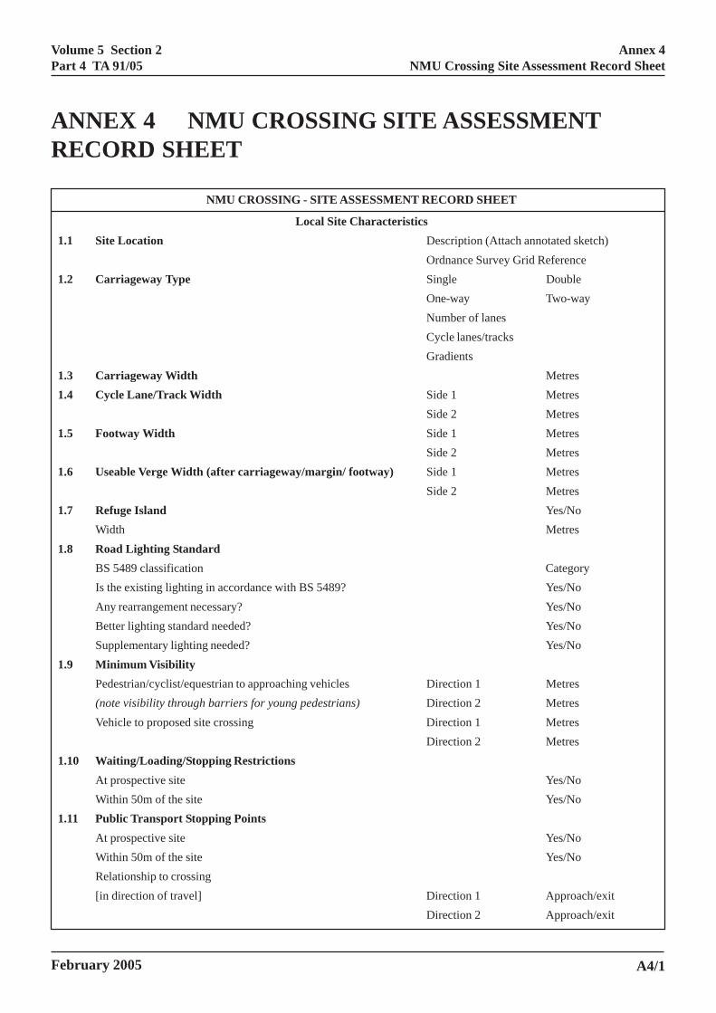
Volume 5 Section 2Part 4 TA 91/05
February 2005
ANNEX 4 NMU CROSSING SITE ASSESSMENTRECORD SHEET
NMU CROSSING - SITE ASSESSMENT RECORD SHEET
Local Site Characteristics1.1 Site Location Description (Attach annotated sketch)
Ordnance Survey Grid Reference1.2 Carriageway Type Single Double
One-way Two-wayNumber of lanesCycle lanes/tracksGradients
1.3 Carriageway Width Metres1.4 Cycle Lane/Track Width Side 1 Metres
Side 2 Metres1.5 Footway Width Side 1 Metres
Side 2 Metres1.6 Useable Verge Width (after carriageway/margin/ footway) Side 1 Metres
Side 2 Metres1.7 Refuge Island Yes/No
Width Metres1.8 Road Lighting Standard
BS 5489 classification CategoryIs the existing lighting in accordance with BS 5489? Yes/NoAny rearrangement necessary? Yes/NoBetter lighting standard needed? Yes/NoSupplementary lighting needed? Yes/No
1.9 Minimum VisibilityPedestrian/cyclist/equestrian to approaching vehicles Direction 1 Metres(note visibility through barriers for young pedestrians) Direction 2 MetresVehicle to proposed site crossing Direction 1 Metres
Direction 2 Metres1.10 Waiting/Loading/Stopping Restrictions
At prospective site Yes/NoWithin 50m of the site Yes/No
1.11 Public Transport Stopping PointsAt prospective site Yes/NoWithin 50m of the site Yes/NoRelationship to crossing[in direction of travel] Direction 1 Approach/exit
Direction 2 Approach/exit
A4/1
Annex 4NMU Crossing Site Assessment Record Sheet
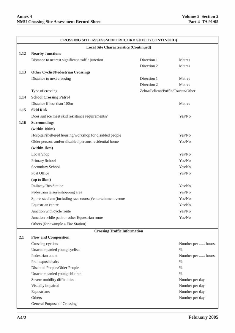
Volume 5 Section 2Part 4 TA 91/05
February 2005
CROSSING SITE ASSESSMENT RECORD SHEET (CONTINUED)
Local Site Characteristics (Continued)1.12 Nearby Junctions
Distance to nearest significant traffic junction Direction 1 MetresDirection 2 Metres
1.13 Other Cyclist/Pedestrian CrossingsDistance to next crossing Direction 1 Metres
Direction 2 MetresType of crossing Zebra/Pelican/Puffin/Toucan/Other
1.14 School Crossing PatrolDistance if less than 100m Metres
1.15 Skid RiskDoes surface meet skid resistance requirements? Yes/No
1.16 Surroundings(within 100m)Hospital/sheltered housing/workshop for disabled people Yes/NoOlder persons and/or disabled persons residential home Yes/No(within 1km)Local Shop Yes/NoPrimary School Yes/NoSecondary School Yes/NoPost Office Yes/No(up to 8km)Railway/Bus Station Yes/NoPedestrian leisure/shopping area Yes/NoSports stadium (including race course)/entertainment venue Yes/NoEquestrian centre Yes/NoJunction with cycle route Yes/NoJunction bridle path or other Equestrian route Yes/NoOthers (for example a Fire Station)
Crossing Traffic Information2.1 Flow and Composition
Crossing cyclists Number per ...... hoursUnaccompanied young cyclists %Pedestrian count Number per ...... hoursPrams/pushchairs %Disabled People/Older People %Unaccompanied young children %Severe mobility difficulties Number per dayVisually impaired Number per dayEquestrians Number per dayOthers Number per dayGeneral Purpose of Crossing
A4/2
Annex 4NMU Crossing Site Assessment Record Sheet
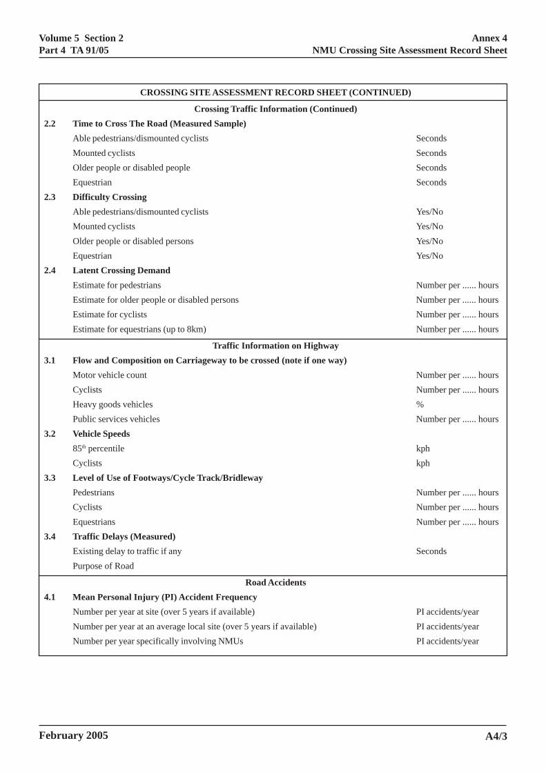
Volume 5 Section 2Part 4 TA 91/05
February 2005
CROSSING SITE ASSESSMENT RECORD SHEET (CONTINUED)
Crossing Traffic Information (Continued)2.2 Time to Cross The Road (Measured Sample)
Able pedestrians/dismounted cyclists SecondsMounted cyclists SecondsOlder people or disabled people SecondsEquestrian Seconds
2.3 Difficulty CrossingAble pedestrians/dismounted cyclists Yes/NoMounted cyclists Yes/NoOlder people or disabled persons Yes/NoEquestrian Yes/No
2.4 Latent Crossing DemandEstimate for pedestrians Number per ...... hoursEstimate for older people or disabled persons Number per ...... hoursEstimate for cyclists Number per ...... hoursEstimate for equestrians (up to 8km) Number per ...... hours
Traffic Information on Highway3.1 Flow and Composition on Carriageway to be crossed (note if one way)
Motor vehicle count Number per ...... hoursCyclists Number per ...... hoursHeavy goods vehicles %Public services vehicles Number per ...... hours
3.2 Vehicle Speeds85th percentile kphCyclists kph
3.3 Level of Use of Footways/Cycle Track/BridlewayPedestrians Number per ...... hoursCyclists Number per ...... hoursEquestrians Number per ...... hours
3.4 Traffic Delays (Measured)Existing delay to traffic if any SecondsPurpose of Road
Road Accidents4.1 Mean Personal Injury (PI) Accident Frequency
Number per year at site (over 5 years if available) PI accidents/yearNumber per year at an average local site (over 5 years if available) PI accidents/yearNumber per year specifically involving NMUs PI accidents/year
A4/3
Annex 4NMU Crossing Site Assessment Record Sheet