Embed Size (px)
Citation preview

USER MANUAL
axeltechnology.com
DML (Rev. 2.1 ENG)

2 INTRODUCTION TO DML SYSTEM |
Table of Contents
1 INTRODUCTION TO DML SYSTEM ................................................................................................................................................................................................................. 4 2 MINIMUM SYSTEM REQUIREMENTS .............................................................................................................................................................................................................. 6 3 EXAMPLE OF DML SYSTEMS ......................................................................................................................................................................................................................... 7 4 DML RECORDER ............................................................................................................................................................................................................................................ 10
4.1 DML RECORDER SETUP ...................................................................................................................................................................................................................... 11 4.1.1 FIRST DML CONFIGURATION – DML CONFIGURATION ..................................................................................................................................................................................... 16 4.1.2 DESCRIPTION OF BASIC FUNCTIONS .................................................................................................................................................................................................................... 42 4.1.3 DESCRIPTION OF MAIN WINDOW CONTROLS ...................................................................................................................................................................................................... 43 4.1.4 DML RECORDER - NAME FILE DESCRIPTION....................................................................................................................................................................................................... 44
4.2 STATISTICS ( ‘STATS’ WINDOW) ......................................................................................................................................................................................................... 45 4.3 ALARMS ( ‘ALARM’ WINDOW) ............................................................................................................................................................................................................... 49 4.4 ‘CONFIG’ WINDOW ................................................................................................................................................................................................................................ 52
4.4.1 EZ SETUP WIZARD ..................................................................................................................................................................................................................................................... 55 4.4.2 INPUT DEVICES ......................................................................................................................................................................................................................................................... 57 4.4.3 CROSSBAR................................................................................................................................................................................................................................................................... 67 4.4.4 TUNER ......................................................................................................................................................................................................................................................................... 68 4.4.5 VIDEO SIZE ................................................................................................................................................................................................................................................................. 69 4.4.6 VIDEO SETTINGS ....................................................................................................................................................................................................................................................... 71 4.4.7 AUDIO SETTINGS ....................................................................................................................................................................................................................................................... 75 4.4.8 ALARMS SETTINGS .................................................................................................................................................................................................................................................... 78 4.4.9 CALCULATOR ............................................................................................................................................................................................................................................................. 79 4.4.10 LOAD CONFIGURATION ........................................................................................................................................................................................................................................... 81 4.4.11 SAVE CONFIGURATION ............................................................................................................................................................................................................................................ 81
4.5 RECORDINGS SCHEDULER ................................................................................................................................................................................................................. 83 4.5.1 ADD / MODIFY A SCHEDULER ELEMENT .............................................................................................................................................................................................................. 83
5 DML PLAYER .................................................................................................................................................................................................................................................. 85 5.1 DML PLAYER SETUP ............................................................................................................................................................................................................................ 85 5.2 DIVX CODEC SETUP (FREE) ................................................................................................................................................................................................................ 87 5.3 DML PLAYER ......................................................................................................................................................................................................................................... 92 5.4 OPEN A SINGLE DML FILE .................................................................................................................................................................................................................... 93 5.5 OPEN A DML ARCHIVE ......................................................................................................................................................................................................................... 93 5.6 SHORTCUT FOR DML CHANNEL ......................................................................................................................................................................................................... 96 5.7 PLAYING FUNCTIONS .......................................................................................................................................................................................................................... 97
5.7.1 PLAY, PAUSE AND STOP .......................................................................................................................................................................................................................................... 97 5.7.2 PLAYING SPEED......................................................................................................................................................................................................................................................... 97 5.7.3 HOT KEYS ................................................................................................................................................................................................................................................................... 98
5.8 VOLUME AND BALANCE AUDIO SETTINGS ...................................................................................................................................................................................... 100 5.9 RECORDING POINT FAST FINDER .................................................................................................................................................................................................... 101
5.9.1 LOAD MARKIN AND MARKOUT POINTS IN TEXT FORMAT ............................................................................................................................................................................... 101 5.10 FILE INFORMATION ............................................................................................................................................................................................................................ 103 5.11 DATE AND TIME OVERLAY ................................................................................................................................................................................................................. 103 5.12 MARK-IN/OUT POINTS AND SEQUENCE EXPORT ........................................................................................................................................................................... 104
5.12.1 MARK-IN AND MARK-OUT POINT ......................................................................................................................................................................................................................... 104 5.12.2 MEDIA EXPORTER AND CONVERTER ................................................................................................................................................................................................................... 105

| INTRODUCTION TO DML SYSTEM 3
5.12.3 EXTRACT ................................................................................................................................................................................................................................................................... 106 5.12.4 EXPORT SINGLE FRAME TO BMP ........................................................................................................................................................................................................................ 107 5.12.5 EXTRACT XMAM....................................................................................................................................................................................................................................................... 107
5.13 RECORDING PLAYOUT IN EXTERN MONITOR ................................................................................................................................................................................. 109 6 DML COPY .................................................................................................................................................................................................................................................... 109
6.1 DML COPY INSTALLATION ................................................................................................................................................................................................................. 110 6.2 DML COPY USAGE .............................................................................................................................................................................................................................. 114
7 DML MONITOR WEB .................................................................................................................................................................................................................................... 120 7.1 INTRODUCTION TO DML MONITOR WEB ......................................................................................................................................................................................... 120 7.2 DML MONITOR WEB INSTALLATION ................................................................................................................................................................................................. 121 7.3 DML MONITOR WEB USAGE .............................................................................................................................................................................................................. 121
7.3.1 TO OPEN THE DML MONITOR WEB ...................................................................................................................................................................................................................... 121 7.3.2 DML MONITOR WEB - CHANNEL LOG VIEWER .................................................................................................................................................................................................. 124 7.3.3 DML MONITOR WEB – FOLDER NAVIGATION: NOT ALLOWED ....................................................................................................................................................................... 125 7.3.4 DML MONITOR WEB – FOLDER NAVIGATION: ALLOWED ................................................................................................................................................................................ 127 7.3.5 DML MONITOR WEB – HOW TO CHANGE THE LOCAL PORT ........................................................................................................................................................................... 131 7.3.6 DML MONITOR WEB– HOW TO CHANGE FOLDERS PATHS .............................................................................................................................................................................. 132
8 DML SYSTEMS - OPTIONAL ELEMENTS ................................................................................................................................................................................................... 133 8.1 SAT TIME SYNCHRONIZER’ (GPS) RECEIVER ................................................................................................................................................................................. 134 8.2 CONTROL PANEL ................................................................................................................................................................................................................................ 134 8.3 SAT TIME SYNCHRONIZER AND CONTROL PANEL CONNECTIONS .............................................................................................................................................. 134
9 FINAL CONSIDERATIONS & AXEL TECHNOLOGY CONTACTS .............................................................................................................................................................. 136

4 INTRODUCTION TO DML SYSTEM |
1 INTRODUCTION TO DML SYSTEM What is DML?
DML is a 24/7 media logger featuring non stop AV recording both for high and low quality video, and IP streaming over internet. Who needs DML?
TV stations and multimedia companies for: • TV broadcasting law obligations • Customer advertisement certification • Real time monitoring of TV programs • Video & audio quality surveillance • A/V streaming over Internet • Competitor surveillance Tech info:
> Typical capture card features composite and S-VHS video inputs along with TV tuner on board. Digital SDI input is available with broadcast quality video cards. > DML can be configured for simultaneous capture of several channels on a single recoding unit. > Thanks to their efficiency, popularity and portability, we suggest DIVX video and MP3 Audio codecs, allowing direct CD/DVD burning and playback on home DVD players and
non Windows platforms as well (Linux, Mac, PDA). > DML creates regular multimedia files and assures non stop uninterrupted recordings, with no dropped frames between consecutive files. > Date and time information of recordings are synchronized with GPS satellites, and may be stamped on to video, displayed by DML Player during playback or as subtitles on
home DVD players. > Alarms management and Email and SMS notification are included in DML Recorder. > Simultaneous internet streaming on IP in Windows Media Format is supported. Included software utility:
Software package includes also DML Player and DML Monitor freeware tools which may be installed on any LAN connected PC. DML Player allows instant browsing and playback of recorded contents, and their conversion/export in other media formats. DML Monitor allows real time monitoring of operating status of recorders through the LAN. Versions:
DML is available as turnkey system and as EZ-DML kit which includes softwares and capture card to be installed on any PC.
| INTRODUCTION TO DML SYSTEM 5
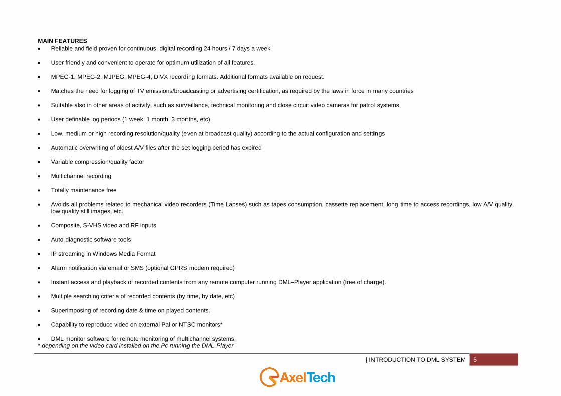
MAIN FEATURES
Reliable and field proven for continuous, digital recording 24 hours / 7 days a week
User friendly and convenient to operate for optimum utilization of all features.
MPEG-1, MPEG-2, MJPEG, MPEG-4, DIVX recording formats. Additional formats available on request.
Matches the need for logging of TV emissions/broadcasting or advertising certification, as required by the laws in force in many countries
Suitable also in other areas of activity, such as surveillance, technical monitoring and close circuit video cameras for patrol systems
User definable log periods (1 week, 1 month, 3 months, etc)
Low, medium or high recording resolution/quality (even at broadcast quality) according to the actual configuration and settings
Automatic overwriting of oldest A/V files after the set logging period has expired
Variable compression/quality factor
Multichannel recording
Totally maintenance free
Avoids all problems related to mechanical video recorders (Time Lapses) such as tapes consumption, cassette replacement, long time to access recordings, low A/V quality, low quality still images, etc.
Composite, S-VHS video and RF inputs
Auto-diagnostic software tools
IP streaming in Windows Media Format
Alarm notification via email or SMS (optional GPRS modem required)
Instant access and playback of recorded contents from any remote computer running DML–Player application (free of charge).
Multiple searching criteria of recorded contents (by time, by date, etc)
Superimposing of recording date & time on played contents.
Capability to reproduce video on external Pal or NTSC monitors*
DML monitor software for remote monitoring of multichannel systems. * depending on the video card installed on the Pc running the DML-Player
6 MINIMUM SYSTEM REQUIREMENTS |
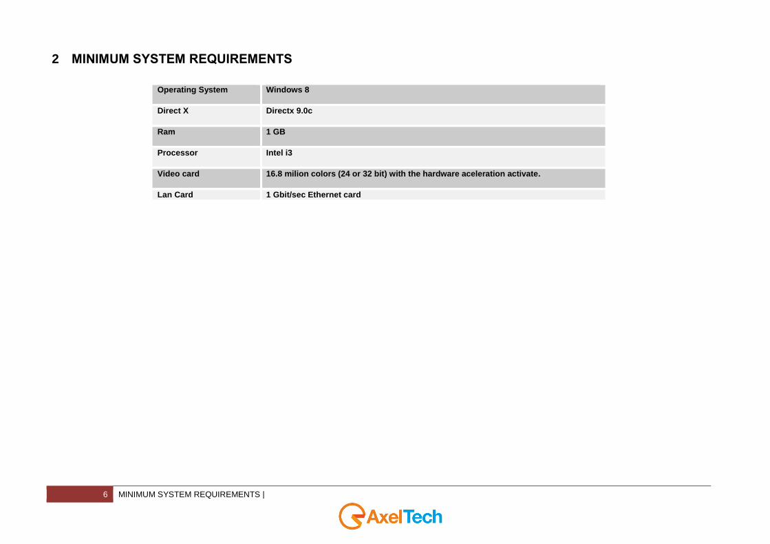
2 MINIMUM SYSTEM REQUIREMENTS
Operating System Windows 8
Direct X Directx 9.0c
Ram 1 GB
Processor Intel i3
Video card 16.8 milion colors (24 or 32 bit) with the hardware aceleration activate.
Lan Card 1 Gbit/sec Ethernet card
| EXAMPLE OF DML SYSTEMS 7
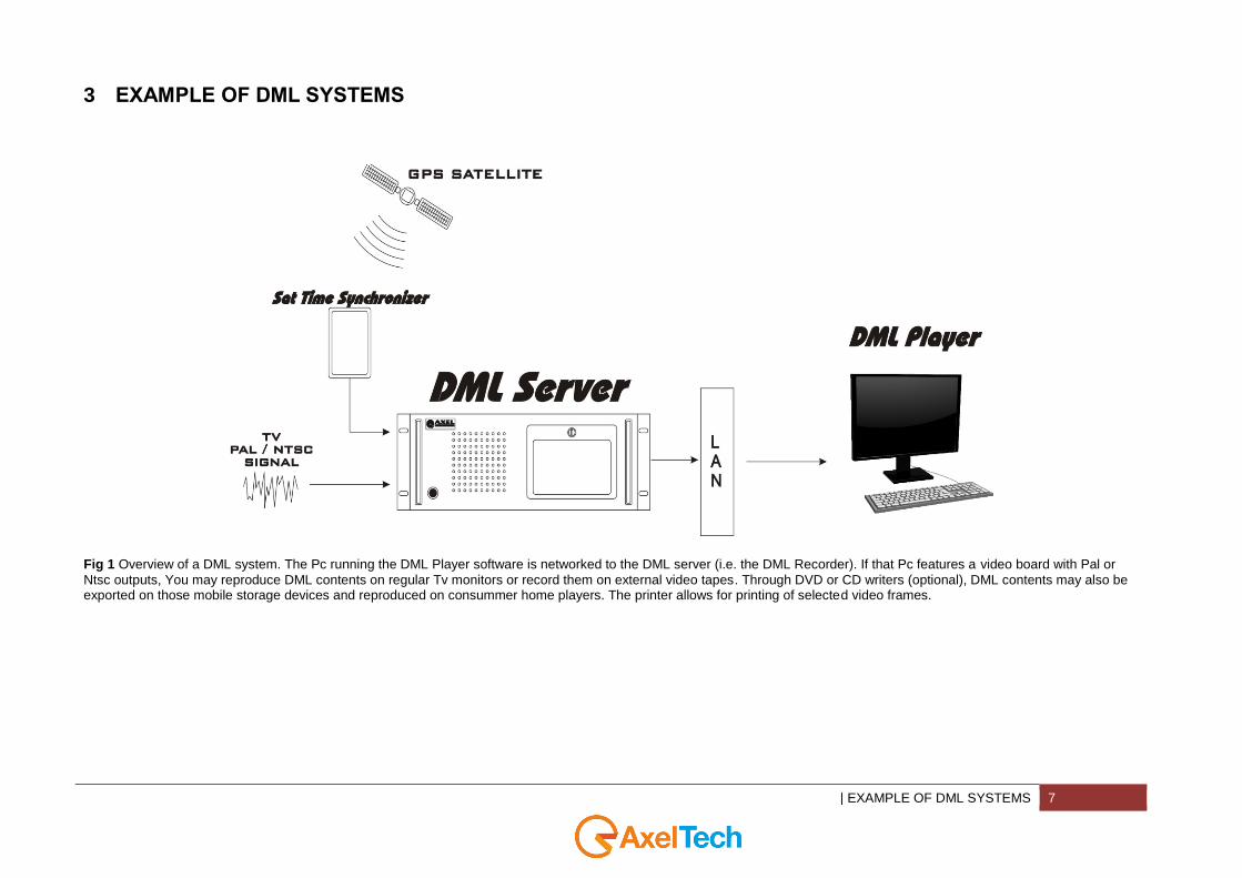
3 EXAMPLE OF DML SYSTEMS
Fig 1 Overview of a DML system. The Pc running the DML Player software is networked to the DML server (i.e. the DML Recorder). If that Pc features a video board with Pal or
Ntsc outputs, You may reproduce DML contents on regular Tv monitors or record them on external video tapes. Through DVD or CD writers (optional), DML contents may also be exported on those mobile storage devices and reproduced on consummer home players. The printer allows for printing of selected video frames.
8 EXAMPLE OF DML SYSTEMS |
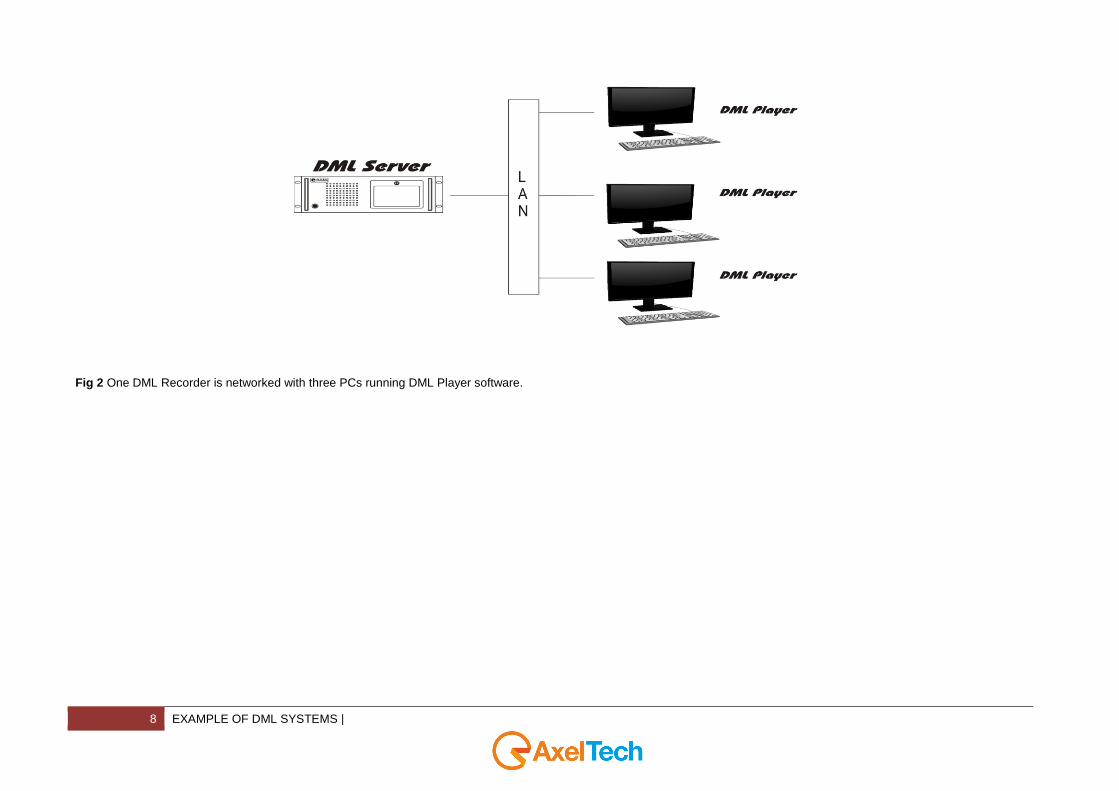
Fig 2 One DML Recorder is networked with three PCs running DML Player software.
| EXAMPLE OF DML SYSTEMS 9
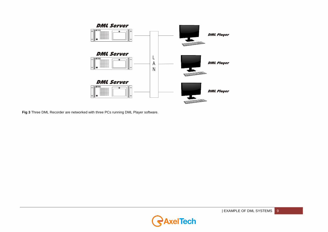
Fig 3 Three DML Recorder are networked with three PCs running DML Player software.
10 DML RECORDER |
4 DML RECORDER DML is a 24/7 non stop AV recorder. You can use DML to record audio or video files. DML is useful for TV Stations to record their Audio and Video, for Radio Stations is useful to record only Audio Files. Recordings are segmented into 1 hour files (usually), until hard disk is full, and then oldest files are automatically replaced by new ones. Common configuration implement DivX codec for video and MP3 codec for Audio, producing industry standard files, which can be distributed to many electronic devices such as home DVD players, handheld devices, ecc. DML works on Windows 8, and is optimized for non assisted, automatic operation. A special Mux switching technology assures that no video or audio frames are lost between consecutive files. The amount of recording days (i.e. the target recording duration, as required by the customer) is entered in the alarm parameters window, but essentially depends only on codec settings (datarate) and available disk space A separate disk partition, different from OS partition, is suggested, since DML will fill up almost completely the media target disk(s). During the capture process, Dml automatically monitors the average Data Rate (A+V) and calculates the projected recording time on the basis of Hard Disk capacity* (i.e. Archive capacity). In the event the number of minimum or maximum recording days cannot be satisfied at the present datarate, an error message will inform the operator about parameter mismatch. All alarms may also be notified by email or SMS (optional GPRS modem is required.)
| DML RECORDER 11
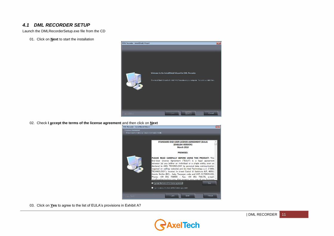
4.1 DML RECORDER SETUP
Launch the DMLRecorderSetup.exe file from the CD
01. Click on Next to start the installation
02. Check I accept the terms of the license agreement and then click on Next
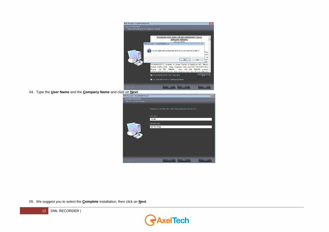
03. Click on Yes to agree to the list of EULA’s provisions in Exhibit A?
12 DML RECORDER |
04. Type the User Name and the Company Name and click on Next
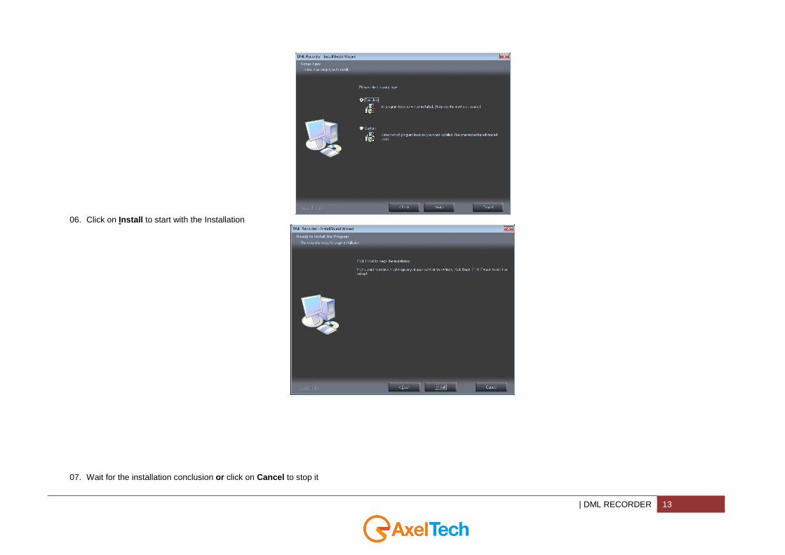
05. We suggest you to select the Complete installation, then click on Next
| DML RECORDER 13
06. Click on Install to start with the Installation
07. Wait for the installation conclusion or click on Cancel to stop it

14 DML RECORDER |
08. Click on Finish to exit the wizard
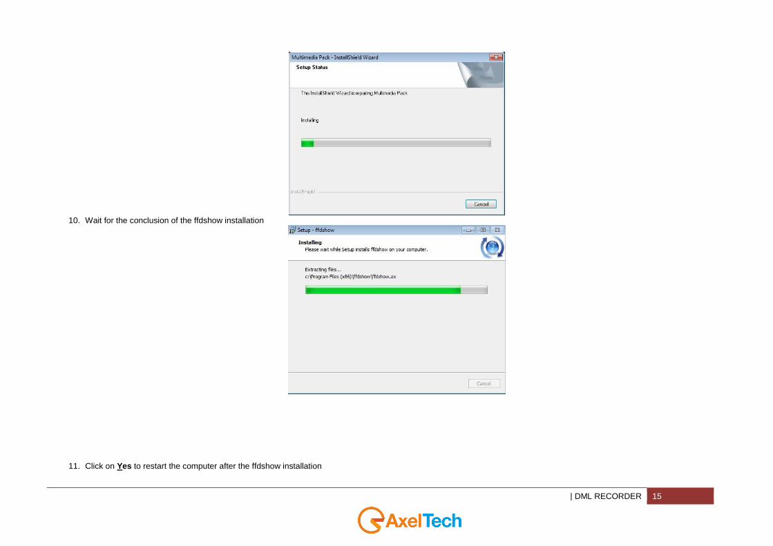
09. Wait for the conclusion of the Multimedia Pack Installation/Reparation
| DML RECORDER 15
10. Wait for the conclusion of the ffdshow installation
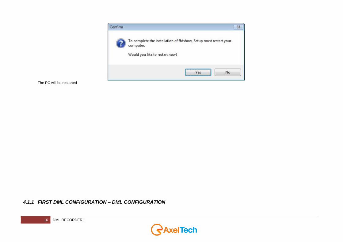
11. Click on Yes to restart the computer after the ffdshow installation
16 DML RECORDER |
The PC will be restarted
4.1.1 FIRST DML CONFIGURATION – DML CONFIGURATION
| DML RECORDER 17
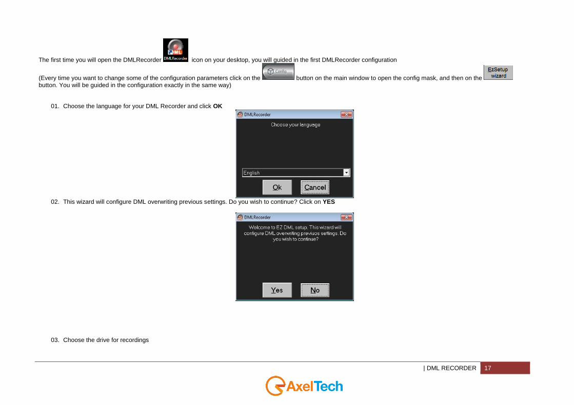
The first time you will open the DMLRecorder icon on your desktop, you will guided in the first DMLRecorder configuration
(Every time you want to change some of the configuration parameters click on the button on the main window to open the config mask, and then on the button. You will be guided in the configuration exactly in the same way)
01. Choose the language for your DML Recorder and click OK
02. This wizard will configure DML overwriting previous settings. Do you wish to continue? Click on YES
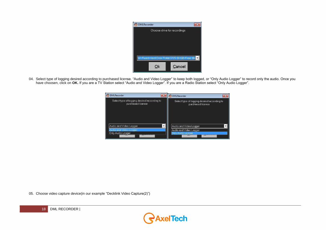
03. Choose the drive for recordings
18 DML RECORDER |
04. Select type of logging desired according to purchased license. “Audio and Video Logger” to keep both logged, or “Only Audio Logger” to record only the audio. Once you have choosen, click on OK. If you are a TV Station select “Audio and Video Logger”. If you are a Radio Station select “Only Audio Logger”.
05. Choose video capture device(in our example “Decklink Video Capture(2)”)

| DML RECORDER 19
06. Choose audio capture device(in our example “Decklink Audio Capture(2)”)
07. See from the Input devices panel if all is ok, else, if you chose something wrong change it and click on OK.

20 DML RECORDER |
08. To confirm the capture device settings click on OK

| DML RECORDER 21
09. Select desired number of days of record, (in our example 90 days)
10. Do you want to install applications? click on Yes to continue, No to stop it, Cancel to exit from the installshield
22 DML RECORDER |
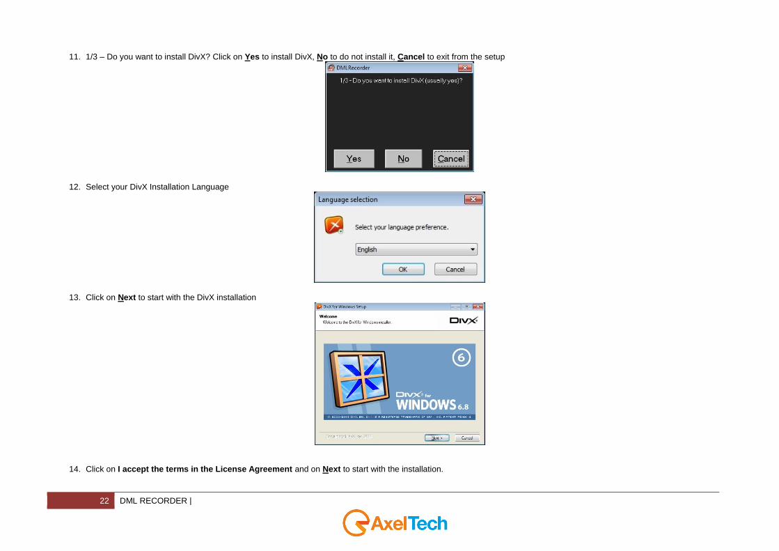
11. 1/3 – Do you want to install DivX? Click on Yes to install DivX, No to do not install it, Cancel to exit from the setup
12. Select your DivX Installation Language
13. Click on Next to start with the DivX installation
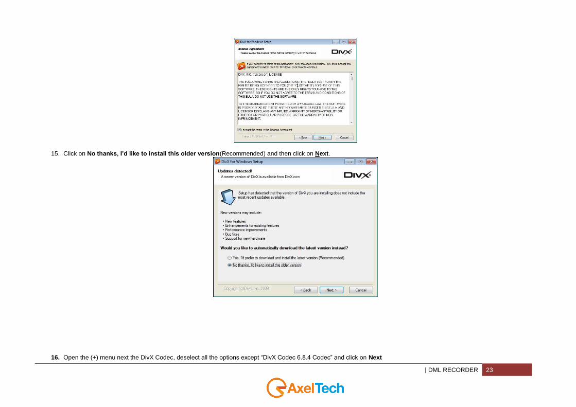
14. Click on I accept the terms in the License Agreement and on Next to start with the installation.
| DML RECORDER 23
15. Click on No thanks, I’d like to install this older version(Recommended) and then click on Next.
16. Open the (+) menu next the DivX Codec, deselect all the options except “DivX Codec 6.8.4 Codec” and click on Next

24 DML RECORDER |
17. Type the DivX Destination Folder or browse for it and click on Next
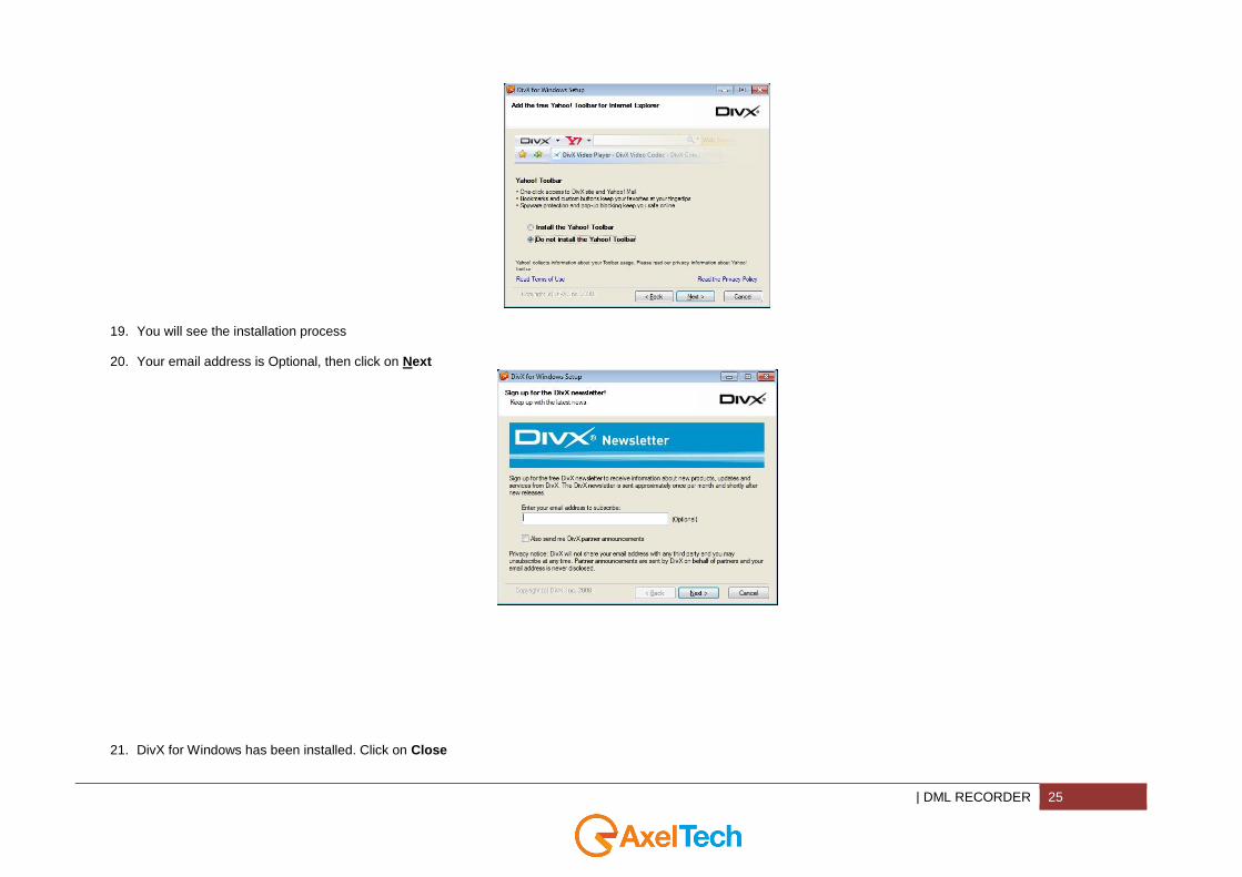
18. Select Do not install the Yahoo! Toolbar and click on Next
| DML RECORDER 25
19. You will see the installation process
20. Your email address is Optional, then click on Next
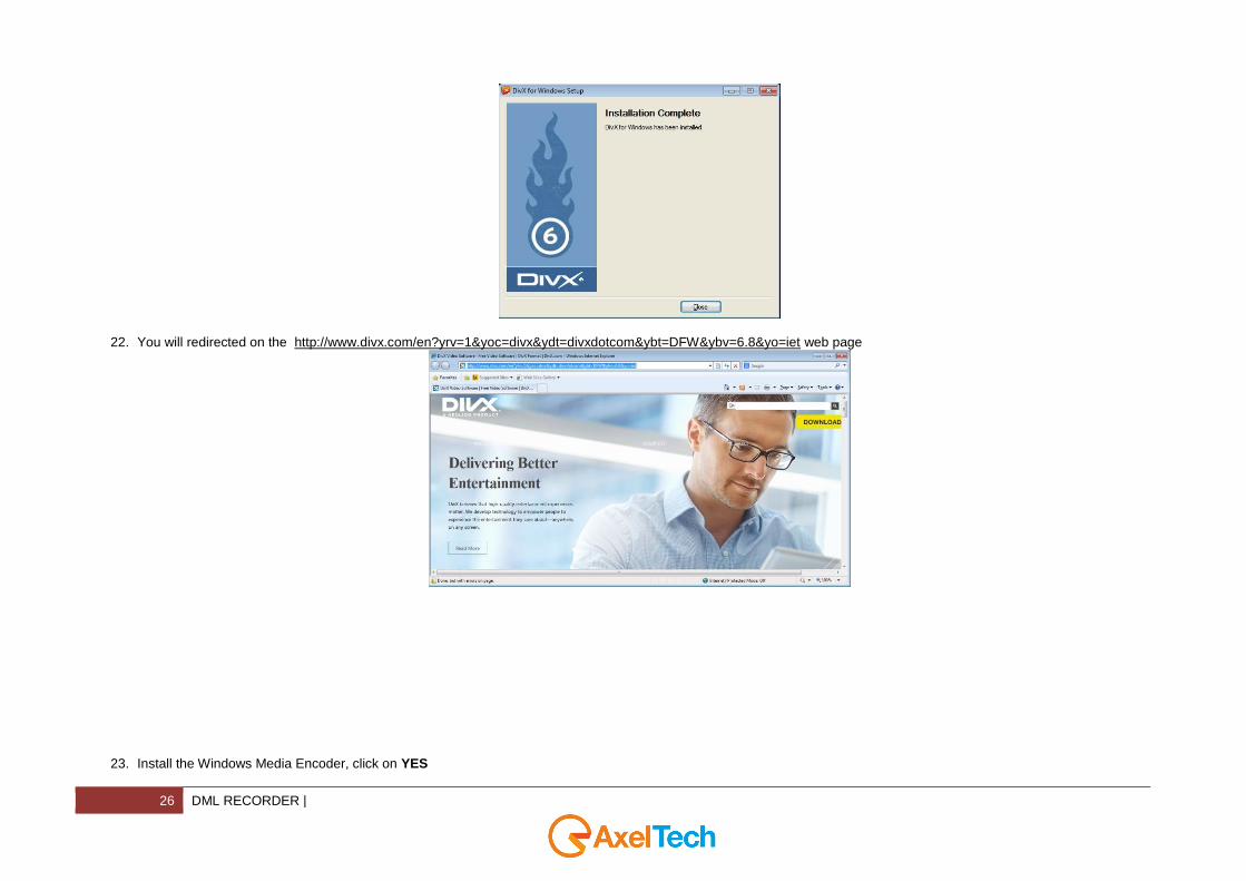
21. DivX for Windows has been installed. Click on Close
26 DML RECORDER |
22. You will redirected on the http://www.divx.com/en?yrv=1&yoc=divx&ydt=divxdotcom&ybt=DFW&ybv=6.8&yo=iet web page
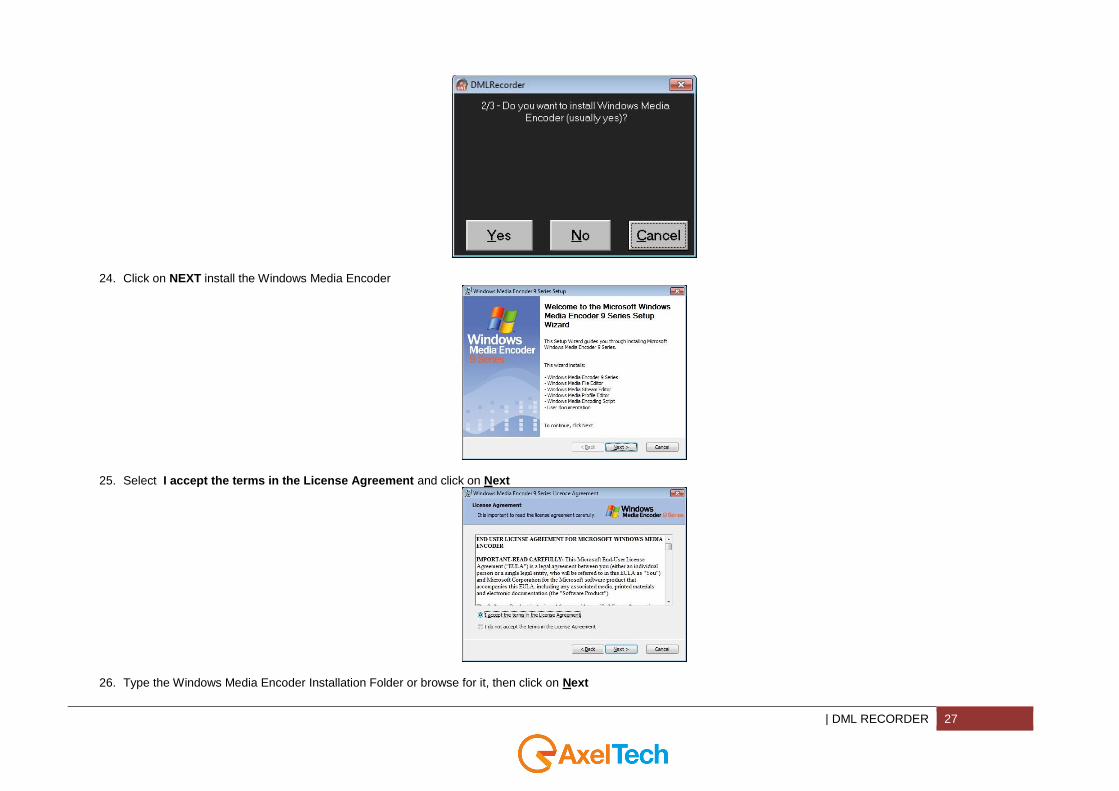
23. Install the Windows Media Encoder, click on YES
| DML RECORDER 27
24. Click on NEXT install the Windows Media Encoder
25. Select I accept the terms in the License Agreement and click on Next
26. Type the Windows Media Encoder Installation Folder or browse for it, then click on Next
28 DML RECORDER |
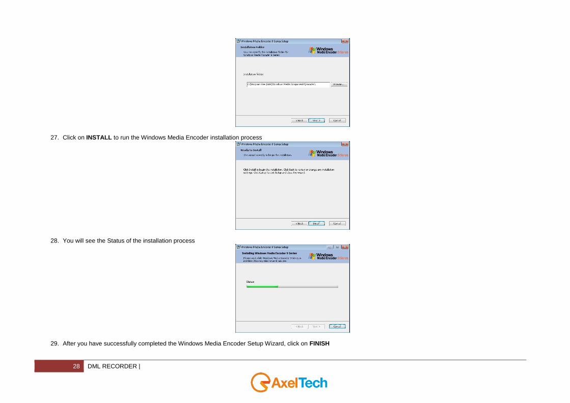
27. Click on INSTALL to run the Windows Media Encoder installation process
28. You will see the Status of the installation process
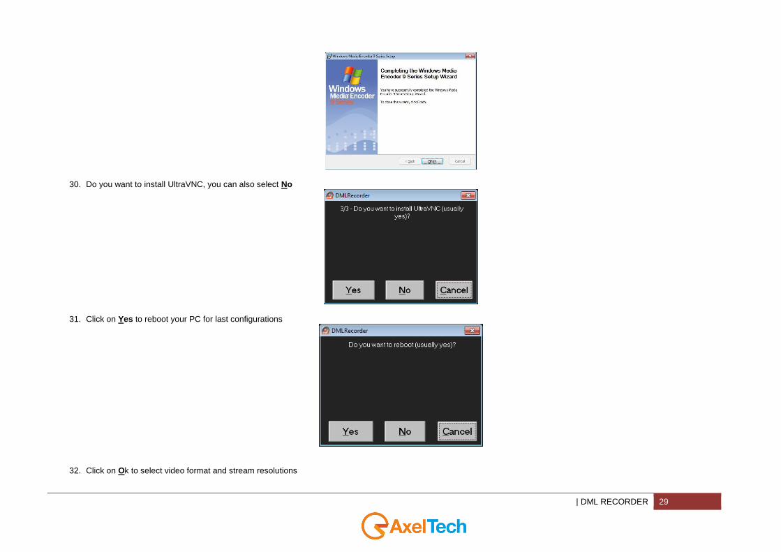
29. After you have successfully completed the Windows Media Encoder Setup Wizard, click on FINISH
| DML RECORDER 29
30. Do you want to install UltraVNC, you can also select No
31. Click on Yes to reboot your PC for last configurations
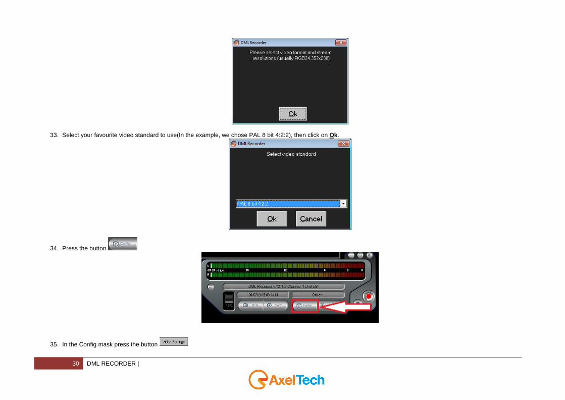
32. Click on Ok to select video format and stream resolutions
30 DML RECORDER |
33. Select your favourite video standard to use(In the example, we chose PAL 8 bit 4:2:2), then click on Ok.
34. Press the button
35. In the Config mask press the button

| DML RECORDER 31
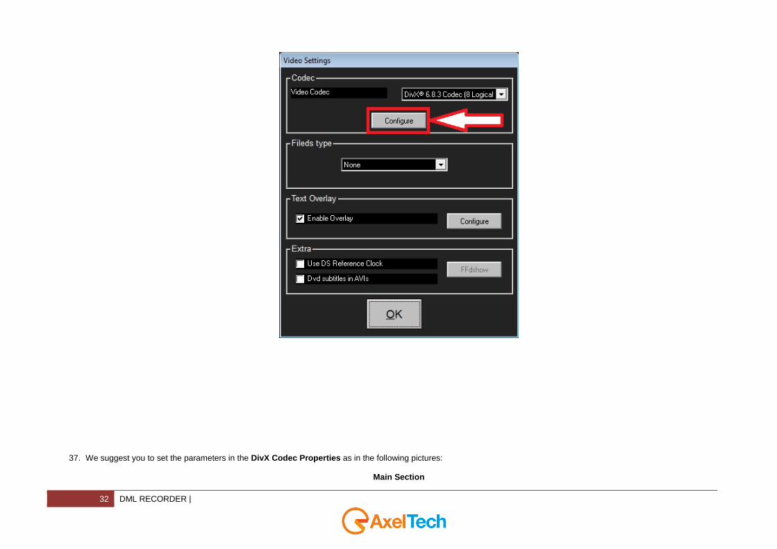
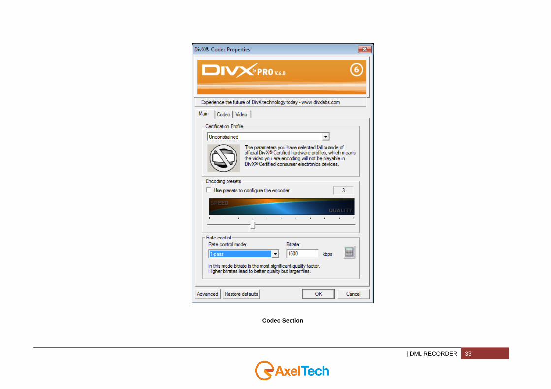
36. In the top section of Video Settings(Codec) press the button to open the DivX Codec Properties
32 DML RECORDER |
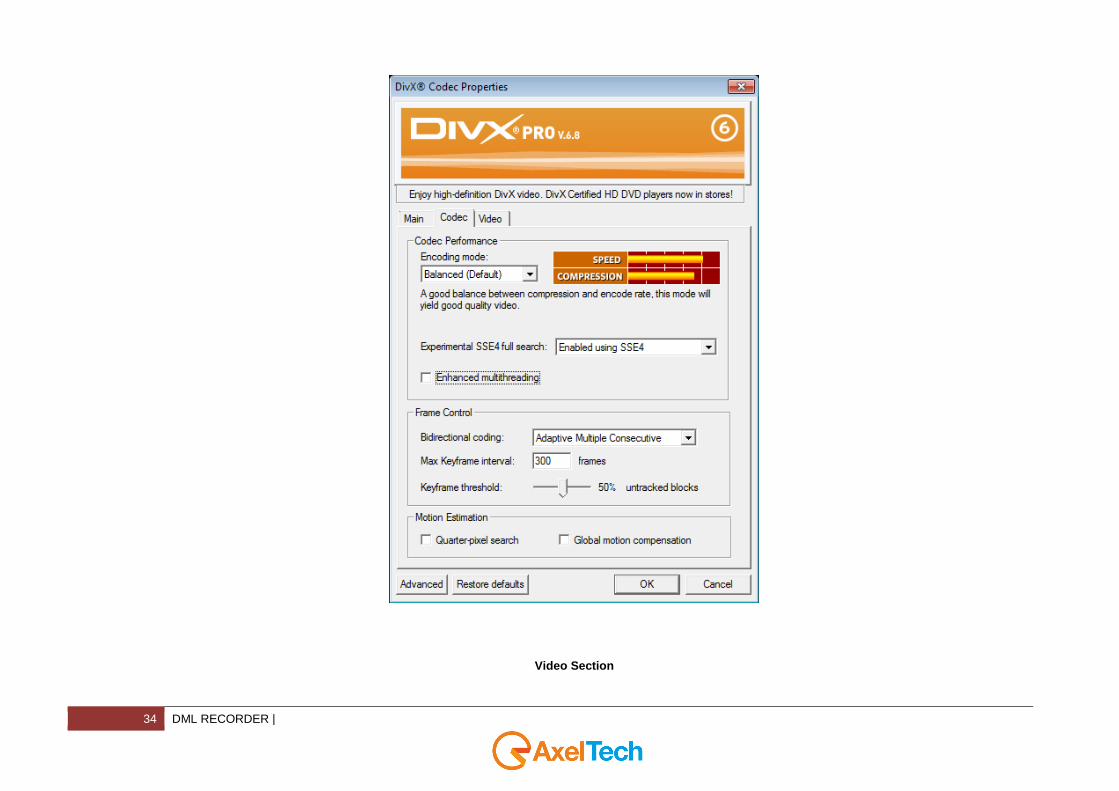
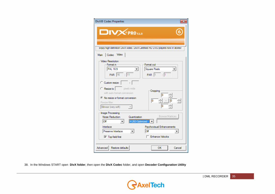
37. We suggest you to set the parameters in the DivX Codec Properties as in the following pictures:
Main Section
| DML RECORDER 33
Codec Section
34 DML RECORDER |
Video Section
| DML RECORDER 35
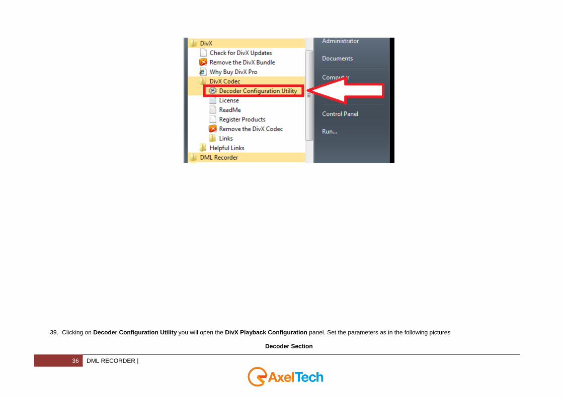
38. In the Windows START open DivX folder, then open the DivX Codec folder, and open Decoder Configuration Utility
36 DML RECORDER |
39. Clicking on Decoder Configuration Utility you will open the DivX Playback Configuration panel. Set the parameters as in the following pictures
Decoder Section
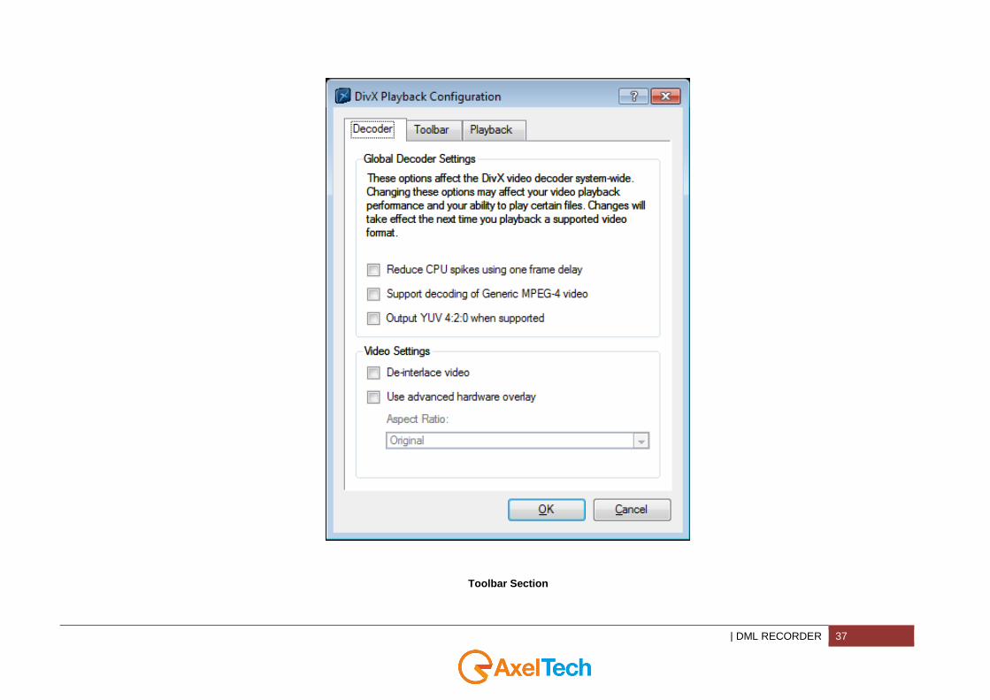
| DML RECORDER 37
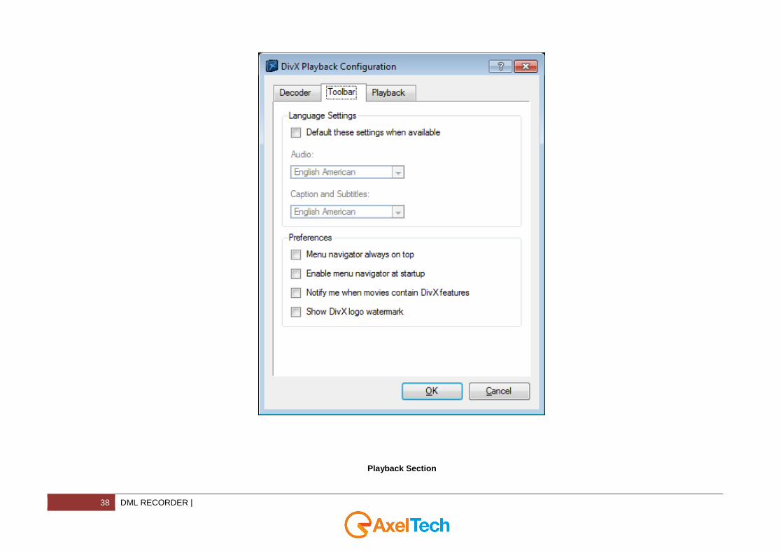
Toolbar Section
38 DML RECORDER |
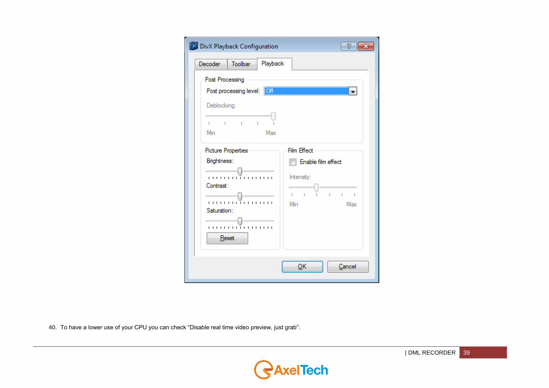
Playback Section
| DML RECORDER 39
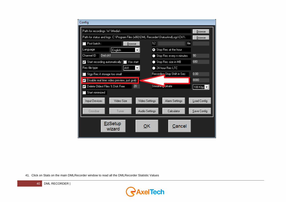
40. To have a lower use of your CPU you can check “Disable real time video preview, just grab”:
40 DML RECORDER |
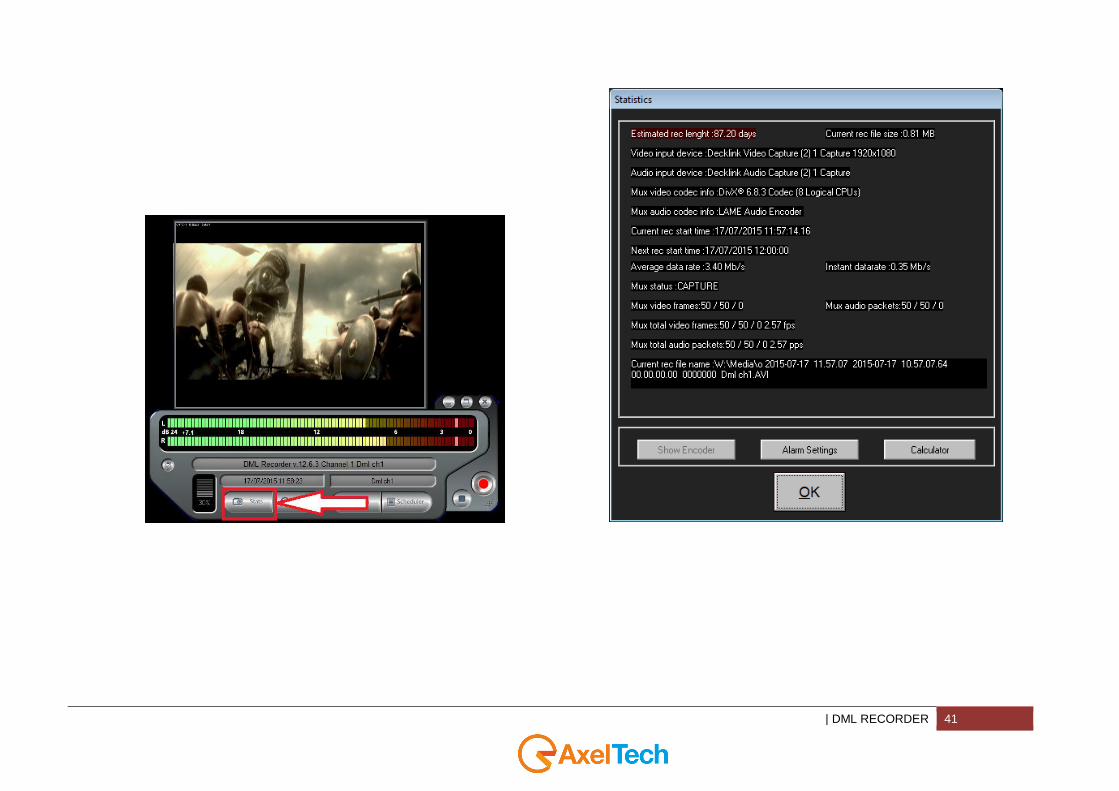
41. Click on Stats on the main DMLRecorder window to read all the DMLRecorder Statistic Values
| DML RECORDER 41
42 DML RECORDER |
4.1.2 DESCRIPTION OF BASIC FUNCTIONS
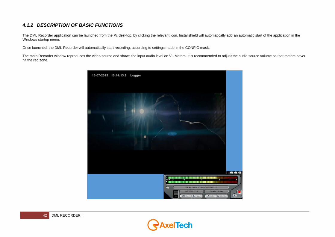
The DML Recorder application can be launched from the Pc desktop, by clicking the relevant icon. Installshield will automatically add an automatic start of the application in the Windows startup menu. Once launched, the DML Recorder will automatically start recording, according to settings made in the CONFIG mask. The main Recorder window reproduces the video source and shows the input audio level on Vu Meters. It is recommended to adjust the audio source volume so that meters never hit the red zone.
| DML RECORDER 43
At the bottom, three fields display main data related to recording: - The first filed (at the top) is active when lunching the DML Recorder application and notify about loading of filters and
software components for DML Recorder operation. It also displays error messages in the event of malfunctioning. Double clicking this field opens the LOG window.
- The second field show current time and date. Time information is derived from Pc clock, which is kept updated from the
GPS time signal. - The third field (on the right side) displays the target recording days (as set by the user) and the real recording duration
(switched), as calculated, second by second, on the basis of the actual compressed video bit rate. Real recording duration will be equal or longer than the target duration.
4.1.3 DESCRIPTION OF MAIN WINDOW CONTROLS
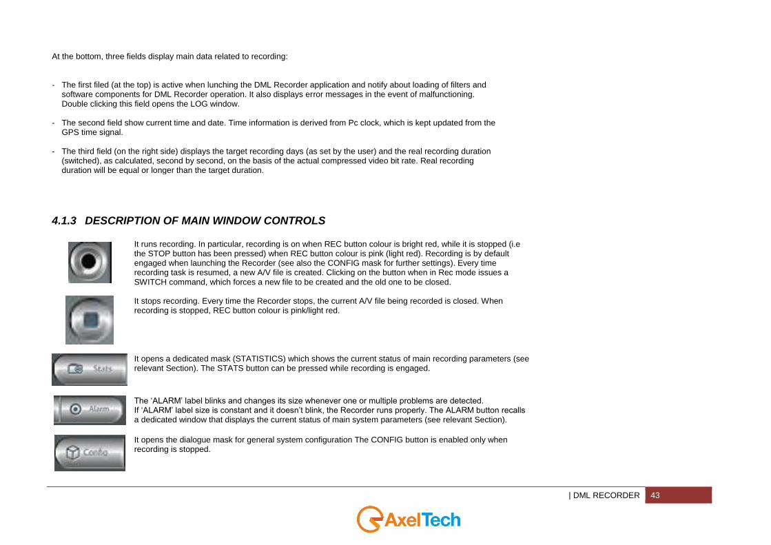
It runs recording. In particular, recording is on when REC button colour is bright red, while it is stopped (i.e the STOP button has been pressed) when REC button colour is pink (light red). Recording is by default engaged when launching the Recorder (see also the CONFIG mask for further settings). Every time recording task is resumed, a new A/V file is created. Clicking on the button when in Rec mode issues a SWITCH command, which forces a new file to be created and the old one to be closed.
It stops recording. Every time the Recorder stops, the current A/V file being recorded is closed. When recording is stopped, REC button colour is pink/light red.
It opens a dedicated mask (STATISTICS) which shows the current status of main recording parameters (see relevant Section). The STATS button can be pressed while recording is engaged.
The ‘ALARM’ label blinks and changes its size whenever one or multiple problems are detected. If ‘ALARM’ label size is constant and it doesn’t blink, the Recorder runs properly. The ALARM button recalls a dedicated window that displays the current status of main system parameters (see relevant Section).
It opens the dialogue mask for general system configuration The CONFIG button is enabled only when recording is stopped.
44 DML RECORDER |
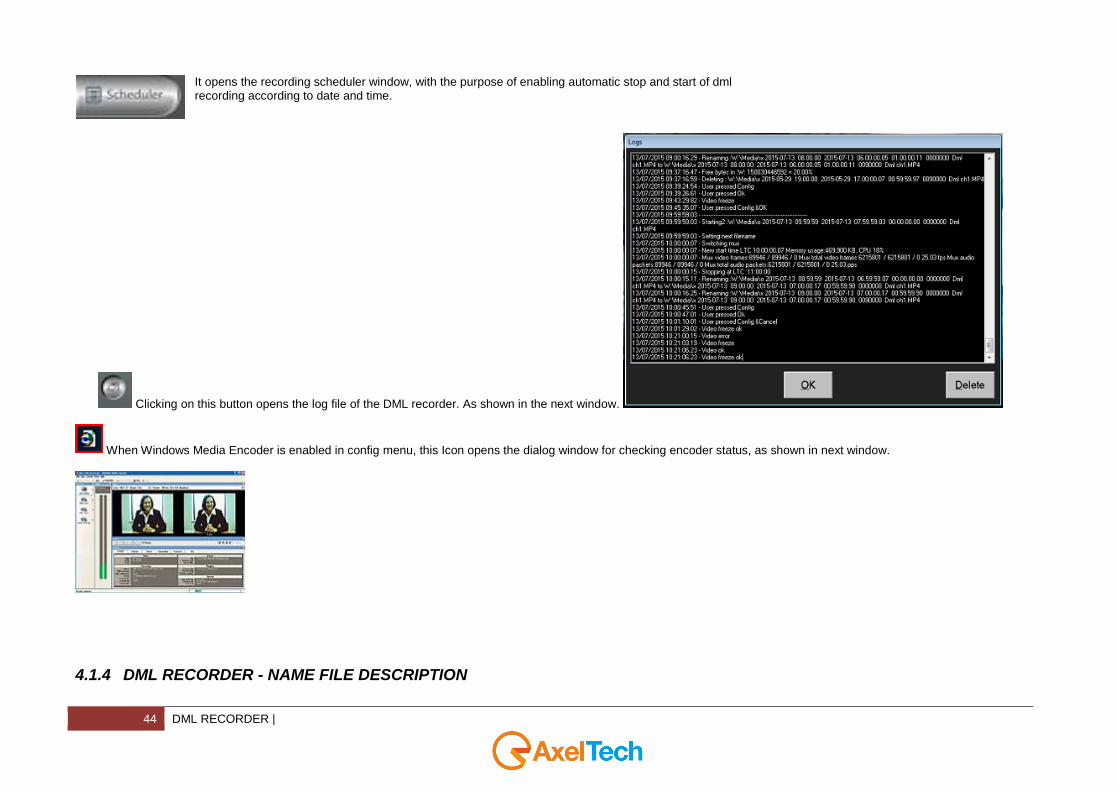
It opens the recording scheduler window, with the purpose of enabling automatic stop and start of dml recording according to date and time.
Clicking on this button opens the log file of the DML recorder. As shown in the next window.
When Windows Media Encoder is enabled in config menu, this Icon opens the dialog window for checking encoder status, as shown in next window.
4.1.4 DML RECORDER - NAME FILE DESCRIPTION
| DML RECORDER 45
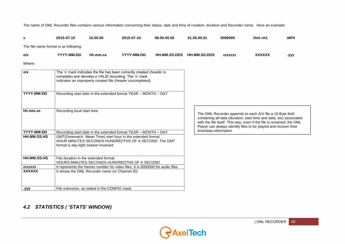
The name of DML Recorder files contains various information concerning their status, date and time of creation, duration and Recorder name. Here an example: x
2015-07-10
10.00.00
2015-07-10
08.00.00.05
01.00.00.01
0090000
Dml ch1
.MP4
The file name format is as following: o/x YYYY-MM-DD hh.mm.ss YYYY-MM-DD HH.MM.SS.DDS HH.MM.SS.DDS zzzzzzz XXXXXX .yyy
Where:
o/x The ‘x’ mark indicates the file has been correctly created (header is
complete) and denotes a VALID recording. The ‘o’ mark indicates an improperly created file (header uncompleted).
YYYY-MM-DD Recording start date in the extended format YEAR – MONTH – DAY
hh.mm.ss Recording local start time
YYYY-MM-DD Recording start date in the extended format YEAR – MONTH – DAY
HH.MM.SS.HS GMT(Greenwich Mean Time) start hour in the extended format HOUR.MINUTES.SECONDS.HUNDREDTHS OF A SECOND. The GMT format is day-light season invariant
HH.MM.SS.HS File duration in the extended format HOURS.MINUTES.SECONDS.HUNDREDTHS OF A SECOND
zzzzzzz It represents the frames number for video files. It is 0000000 for audio files
XXXXXX It shows the DML Recorder name (or Channel ID)
.yyy File extension, as stated in the CONFIG mask
4.2 STATISTICS ( ‘STATS’ WINDOW)
The DML Recorder appends to each A/V file a 19 Byte field containing all data (duration, start time and data, etc) associated with the file itself. This way, even if the file is renamed, the DML Player can always identify files to be played and recover their time/data information

46 DML RECORDER |
The STATS button opens the STATISTICS window, showing all main recording parameters. The window is refreshed every second.
ESTIMATED REC LENGHT It shows the actual recording days. This value is calculated at every second on the
basis of Average Data Rate. If the value is lower or higher than user preset in the alarm settings, DML generates an alarm. Normally, under optimal operating conditions and VBR compression formats, the estimated (projected) recording duration may be slightly longer than the target one.
CURRENT REC FILE SIZE It shows the actual size of A/V file being recorded.
| DML RECORDER 47
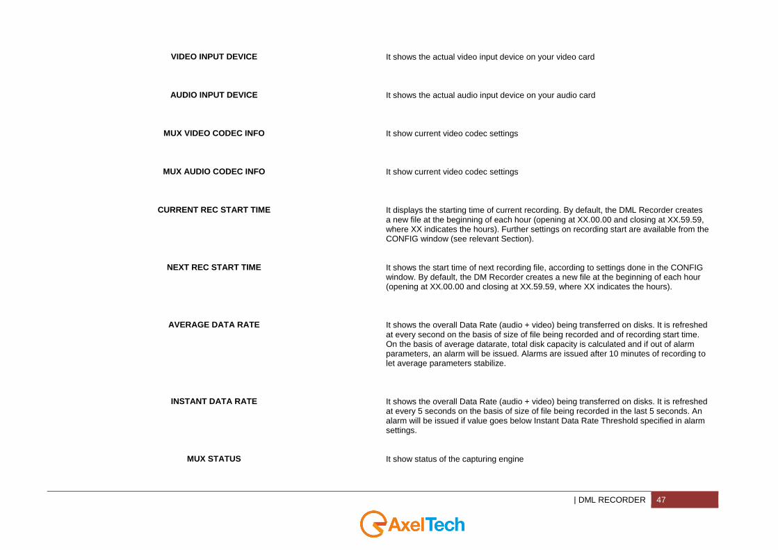
VIDEO INPUT DEVICE It shows the actual video input device on your video card
AUDIO INPUT DEVICE It shows the actual audio input device on your audio card
MUX VIDEO CODEC INFO It show current video codec settings
MUX AUDIO CODEC INFO It show current video codec settings
CURRENT REC START TIME It displays the starting time of current recording. By default, the DML Recorder creates a new file at the beginning of each hour (opening at XX.00.00 and closing at XX.59.59, where XX indicates the hours). Further settings on recording start are available from the CONFIG window (see relevant Section).
NEXT REC START TIME It shows the start time of next recording file, according to settings done in the CONFIG window. By default, the DM Recorder creates a new file at the beginning of each hour (opening at XX.00.00 and closing at XX.59.59, where XX indicates the hours).
AVERAGE DATA RATE It shows the overall Data Rate (audio + video) being transferred on disks. It is refreshed at every second on the basis of size of file being recorded and of recording start time. On the basis of average datarate, total disk capacity is calculated and if out of alarm parameters, an alarm will be issued. Alarms are issued after 10 minutes of recording to let average parameters stabilize.
INSTANT DATA RATE It shows the overall Data Rate (audio + video) being transferred on disks. It is refreshed at every 5 seconds on the basis of size of file being recorded in the last 5 seconds. An alarm will be issued if value goes below Instant Data Rate Threshold specified in alarm settings.
MUX STATUS It show status of the capturing engine

48 DML RECORDER |
CURRENT REC FILE NAME It shows the complete name and path of file being recorded. It is the same name shown in the archive (see next Paragraph).
MUX VIDEO FRAMES It shows the current count for the video frames passed to the encoder of the current file. It shows passed/rejected/dropped frames. Rejected and dropped frames are symptom of unhealthy system or configuration.
MUX AUDIO PACKETS It shows the current count for the audio packets passed to the encoder of the current file. It shows passed/rejected/dropped frames. Rejected and dropped frames are symptom of unhealthy system or configuration.
MUX TOTAL VIDEO FRAMES It shows the current count for all the video frames passed to the encoder since the last input device reset. It shows passed/rejected/dropped frames. Rejected and dropped frames are symptom of unhealthy system or configuration.
MUX TOTAL AUDIO PACKETS It shows the current count for all audio packets passed to the encoder since the last input device reset. It shows passed/rejected/dropped frames. Rejected and dropped frames are symptom of unhealthy system or configuration.
SHOW ENCODER When Windows Media Encoder is enabled in config menu, this button opens the dialog window for checking encoder status.
ALARM SETTINGS This button opens the DML Recorder Alarm Settings panel.
| DML RECORDER 49
CALCULATOR This button opens the DML recorder calculator window, as described in dedicated
section.
4.3 ALARMS ( ‘ALARM’ WINDOW)

50 DML RECORDER |
The ALARM window (which is displayed when pressing the ALARM button on the main screen) shows the status (OK or ERROR) of basic DML Recorder operating elements, according to following table, which also serves as simple ‘troubleshooting’ guide. For every alarm you have, you can decide if you want to receive an Email, an SMS, and if you want to reboot it.
GPS SIGNAL When OK, the GPS signal recovered by Sat Time Synchronizer receiver is strong enough to get a valid time reference. The ERROR condition corresponds to having Red and Yellow lights on traffic-light Icon on Sat Time Synchronizer control software
VIDEO INPUT When OK, the video signal at the DML input is Valid. The DML Recorder checks Luminance level of one pixel out of eight on the image at the input every 5 seconds. If all Pixel luma value stays under the specified threshold and for the specified time as in set in the alarm
| DML RECORDER 51
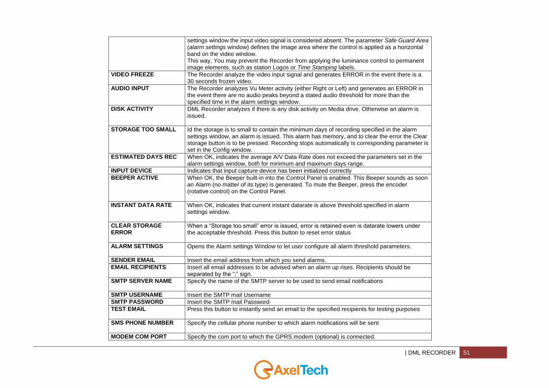
settings window the input video signal is considered absent. The parameter Safe Guard Area (alarm settings window) defines the image area where the control is applied as a horizontal band on the video window. This way, You may prevent the Recorder from applying the luminance control to permanent image elements, such as station Logos or Time Stamping labels.
VIDEO FREEZE The Recorder analyze the video input signal and generates ERROR in the event there is a 30 seconds frozen video.
AUDIO INPUT The Recorder analyzes Vu Meter activity (either Right or Left) and generates an ERROR in the event there are no audio peaks beyond a stated audio threshold for more than the specified time in the alarm settings window.
DISK ACTIVITY DML Recorder analyzes if there is any disk activity on Media drive. Otherwise an alarm is issued.
STORAGE TOO SMALL Id the storage is to small to contain the minimum days of recording specified in the alarm settings window, an alarm is issued. This alarm has memory, and to clear the error the Clear storage button is to be pressed. Recording stops automatically is corresponding parameter is set in the Config window.
ESTIMATED DAYS REC When OK, indicates the average A/V Data Rate does not exceed the parameters set in the alarm settings window, both for minimum and maximum days range.
INPUT DEVICE Indicates that input capture device has been initialized correctly
BEEPER ACTIVE When OK, the Beeper built-in into the Control Panel is enabled. This Beeper sounds as soon an Alarm (no matter of its type) is generated. To mute the Beeper, press the encoder (rotative control) on the Control Panel.
INSTANT DATA RATE When OK, indicates that current instant datarate is above threshold specified in alarm settings window.
CLEAR STORAGE ERROR
When a “Storage too small” error is issued, error is retained even is datarate lowers under the acceptable threshold. Press this button to reset error status
ALARM SETTINGS Opens the Alarm settings Window to let user configure all alarm threshold parameters.
SENDER EMAIL Insert the email address from which you send alarms.
EMAIL RECIPIENTS Insert all email addresses to be advised when an alarm up rises. Recipients should be separated by the “;” sign.
SMTP SERVER NAME Specify the name of the SMTP server to be used to send email notifications
SMTP USERNAME Insert the SMTP mail Username
SMTP PASSWORD Insert the SMTP mail Password
TEST EMAIL Press this button to instantly send an email to the specified recipients for testing purposes
SMS PHONE NUMBER Specify the cellular phone number to which alarm notifications will be sent
MODEM COM PORT Specify the com port to which the GPRS modem (optional) is connected.
52 DML RECORDER |
TEST SMS Press this button to instantly send a SMS to the specified phone number for testing purposes
4.4 ‘CONFIG’ WINDOW

| DML RECORDER 53
PATH FOR RECORDINGS Specifies the folder where all media files are captured. To view files from LAN this folder must be in a shared drive. DML player must point to this folder.
PATH FOR STATUS AND
LOGS Specifies where DML stores log files, current image, current status file. To view status with DML monitor application, this filder must be in a shared drive. DML monitor must point to this folder.
In order to guarantee best DML Recorder operation, it is highly recommended to save A/V files in Partitions or Volumes distinct from the Operating System ones.
POST BATCH
BROWSE
Enable/Disable to open a batch file after the recording creation Browse your folders to point your batch file
%2 Batch file second parameter. The %1 parameter is filled in by the same batch file with
54 DML RECORDER |
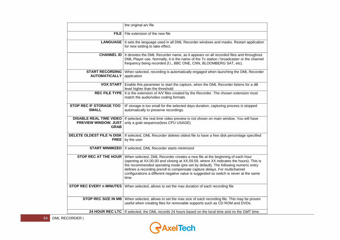
the original a/v file
FILE File extension of the new file
LANGUAGE It sets the language used in all DML Recorder windows and masks. Restart application for new setting to take effect.
CHANNEL ID It denotes the DML Recorder name, as it appears on all recorded files and throughout DML Player use. Normally, it is the name of the Tv station / broadcaster or the channel frequency being recorded (f.i., BBC ONE, CNN, BLOOMBERG SAT, etc).
START RECORDING AUTOMATICALLY
When selected, recording is automatically engaged when launching the DML Recorder application
VOX START Enable this parameter to start the capture, when the DML Recorder listens for a dB level higher than the threshold
REC FILE TYPE It is the extension of A/V files created by the Recorder. The chosen extension must match the audio/video coding formats.
STOP REC IF STORAGE TOO SMALL
IF storage is too small for the selected days duration, capturing process is stopped automatically to preserve recordings.
DISABLE REAL TIME VIDEO PREVIEW WINDOW. JUST
GRAB
If selected, the real time video preview is not shown on main window. You will have only a grab sequence(less CPU USAGE)
DELETE OLDEST FILE % DISK FREE
If selected, DML Recorder deletes oldest file to have a free disk percentage specified by the user
START MINIMIZED If selected, DML Recorder starts minimized
STOP REC AT THE HOUR When selected, DML Recorder creates a new file at the beginning of each hour (opening at XX.00.00 and closing at XX.59.59, where XX indicates the hours). This is the recommended operating mode (pre-set by default). The following numeric entry defines a recording preroll to compensate capture delays. For multichannel configurations a different negative value is suggested so switch is never at the same time.
STOP REC EVERY n MINUTES When selected, allows to set the max duration of each recording file
STOP REC SIZE IN MB When selected, allows to set the max size of each recording file. This may be proven useful when creating files for removable supports such as CD ROM and DVDs.
24 HOUR REC LTC If selected, the DML records 24 hours based on the local time and no the GMT time.
| DML RECORDER 55
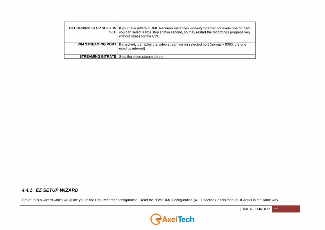
RECORDING STOP SHIFT IN SEC
If you have different DML Recorder instances working together, for every one of them you can select a little stop shift in second, so they restart the recordings progressively without stress for the CPU.
WM STREAMING PORT If checked, it enables the video streaming on selected port (normally 8080, the one used by internet)
STREAMING BITRATE Sets the video stream bitrate.
4.4.1 EZ SETUP WIZARD
EZSetup is a wizard which will guide you to the DMLRecorder configuration. Read the “First DML Configuration”(4.1.1 section) in this manual. It works in the same way.

56 DML RECORDER |
Remember that at the end of the wizard the system will reboot.

| DML RECORDER 57
4.4.2 INPUT DEVICES
VIDEO Video device type Set if you want to capture an Analog signal or a Digital signal
58 DML RECORDER |
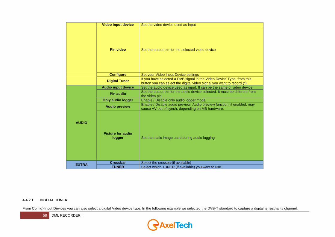
Video input device Set the video device used as input
Pin video
Set the output pin for the selected video device
Configure Set your Video Input Device settings
Digital Tuner If you have selected a DVB signal in the Video Device Type, from this button you can select the digital video signal you want to record.(*)
AUDIO
Audio input device Set the audio device used as input. It can be the same of video device
Pin audio Set the output pin for the audio device selected. It must be different from the video pin
Only audio logger Enable / Disable only audio logger mode
Audio preview Enable / Disable audio preview. Audio preview function, if enabled, may cause AV out of synch, depending on MB hardware.
Picture for audio logger
Set the static image used during audio logging
EXTRA Crossbar Select the crossbar(if available)
TUNER Select which TUNER (if available) you want to use
4.4.2.1 DIGITAL TUNER
From Config>Input Devices you can also select a digital Video device type. In the following example we selected the DVB-T standard to capture a digital terrestrial tv channel.

| DML RECORDER 59
.
By clicking on Digital Tuner you can set all channel parameters.

60 DML RECORDER |
By clicking on DVB Scanner you can scan all available digital terrestrial televisions.
| DML RECORDER 61
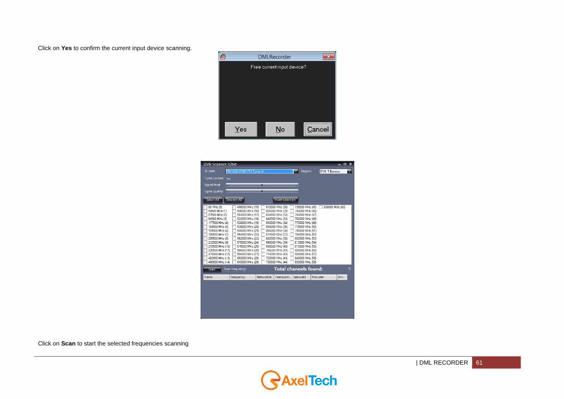
Click on Yes to confirm the current input device scanning.
Click on Scan to start the selected frequencies scanning
62 DML RECORDER |
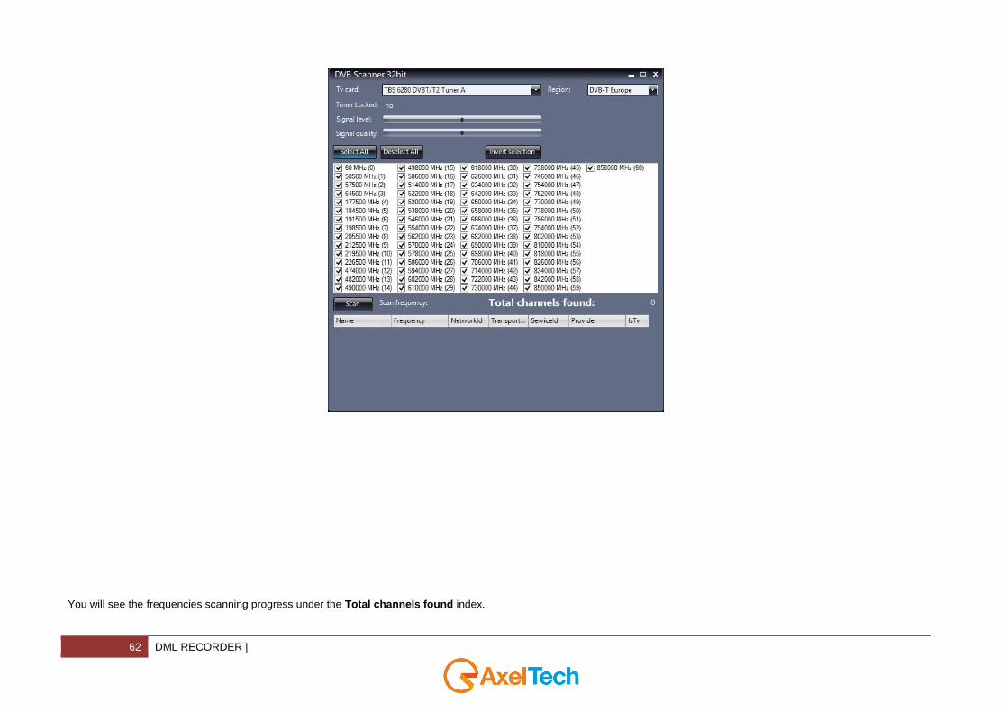
You will see the frequencies scanning progress under the Total channels found index.
| DML RECORDER 63
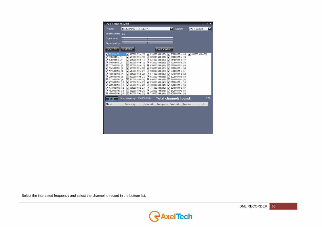
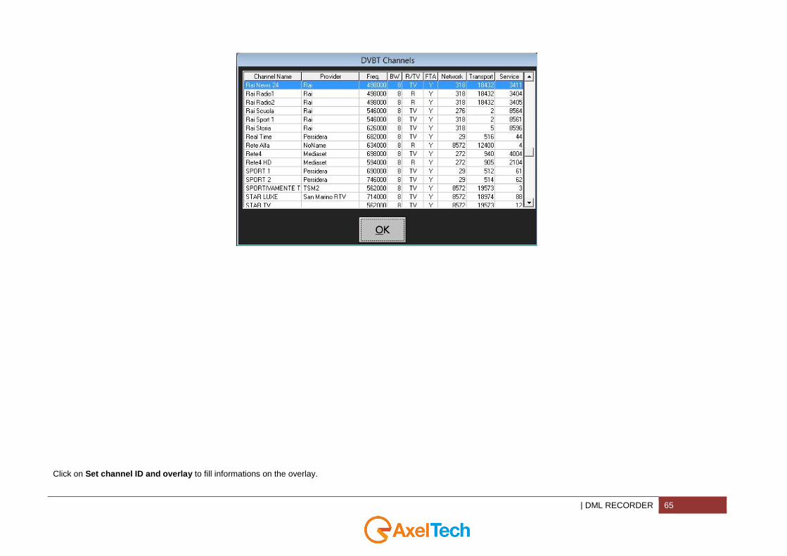
Select the interested frequency and select the channel to record in the bottom list.
64 DML RECORDER |
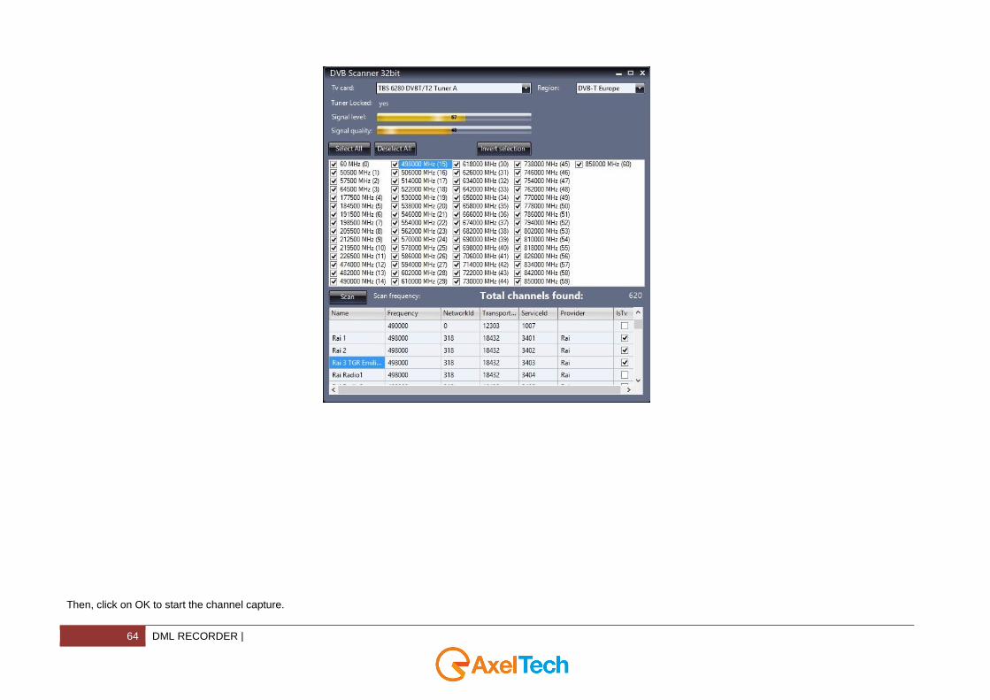
Then, click on OK to start the channel capture.
| DML RECORDER 65
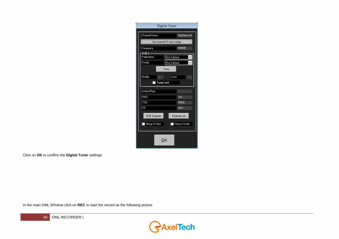
Click on Set channel ID and overlay to fill informations on the overlay.
66 DML RECORDER |
Click on OK to confirm the Digital Tuner settings
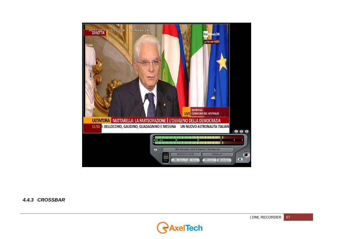
In the main DML Window click on REC to start the record as the following picture
| DML RECORDER 67
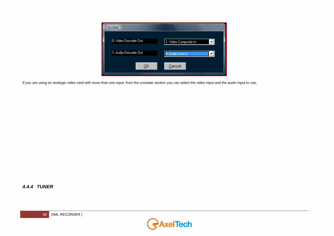
4.4.3 CROSSBAR
68 DML RECORDER |
If you are using an analogic video card with more than one input, from the crossbar section you can select the video input and the audio input to use.
4.4.4 TUNER
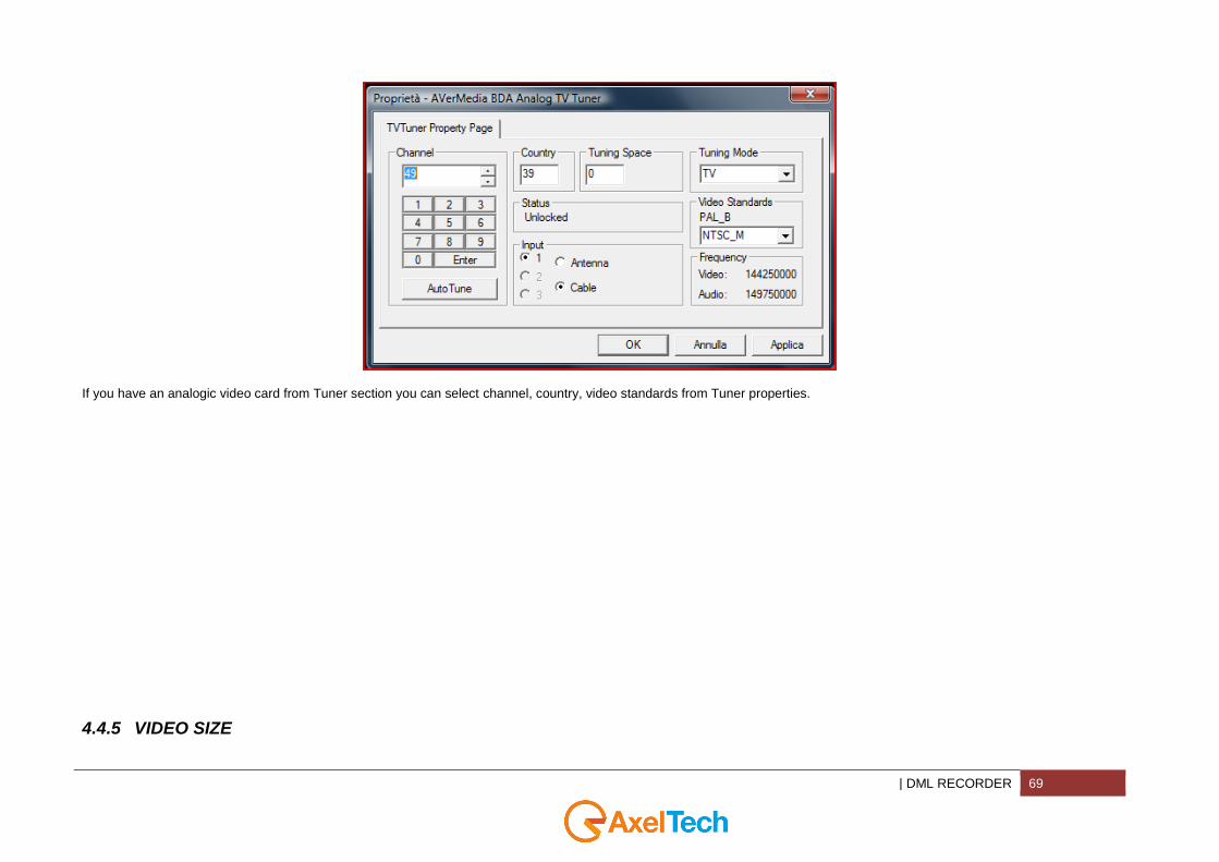
| DML RECORDER 69
If you have an analogic video card from Tuner section you can select channel, country, video standards from Tuner properties.
4.4.5 VIDEO SIZE

70 DML RECORDER |
This button will initialize video input device to specified Video Standard
Select the video standard of your capture
| DML RECORDER 71
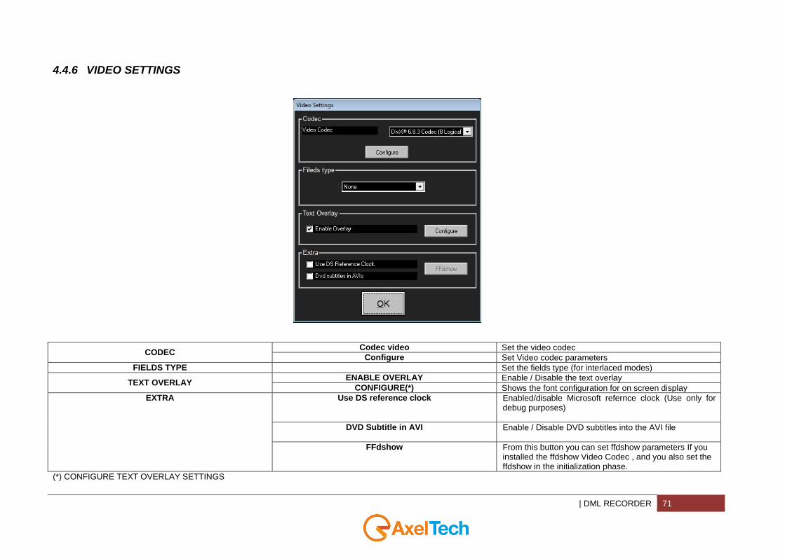
4.4.6 VIDEO SETTINGS
CODEC Codec video Set the video codec
Configure Set Video codec parameters
FIELDS TYPE Set the fields type (for interlaced modes)
TEXT OVERLAY ENABLE OVERLAY Enable / Disable the text overlay
CONFIGURE(*) Shows the font configuration for on screen display
EXTRA Use DS reference clock Enabled/disable Microsoft refernce clock (Use only for debug purposes)
DVD Subtitle in AVI Enable / Disable DVD subtitles into the AVI file
FFdshow From this button you can set ffdshow parameters If you installed the ffdshow Video Codec , and you also set the ffdshow in the initialization phase.
(*) CONFIGURE TEXT OVERLAY SETTINGS

72 DML RECORDER |
LOGO
IMAGE
Decide if you want to enable/disable the logo
BROWSE
Browse your PC or your network for the right logo image. Visible only if you check the IMAGE checkbox
X
Logo top left x-coordinate
Y
Logo top left y-coordinate
OPACITY It rules the logo opacity level: opacity = 0(invisible) opacity = 100(fully visible)
DATE ENABLE Enable date displaying
| DML RECORDER 73
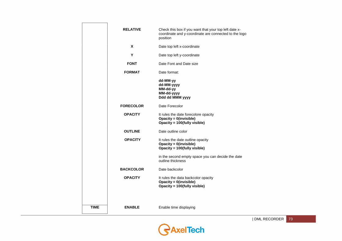
RELATIVE Check this box if you want that your top left date x-coordinate and y-coordinate are connected to the logo position
X Date top left x-coordinate
Y Date top left y-coordinate
FONT Date Font and Date size
FORMAT Date format: dd-MM-yy dd-MM-yyyy MM-dd-yy MM-dd-yyyy Ddd dd MMM yyyy
FORECOLOR
OPACITY
Date Forecolor It rules the date forecolore opacity Opacity = 0(invisible) Opacity = 100(fully visible)
OUTLINE
OPACITY
Date outline color It rules the date outline opacity Opacity = 0(invisible) Opacity = 100(fully visible)
in the second empty space you can decide the date outline thickness
BACKCOLOR
OPACITY
Date backcolor It rules the data backcolor opacity Opacity = 0(invisible) Opacity = 100(fully visible)
TIME ENABLE Enable time displaying
74 DML RECORDER |
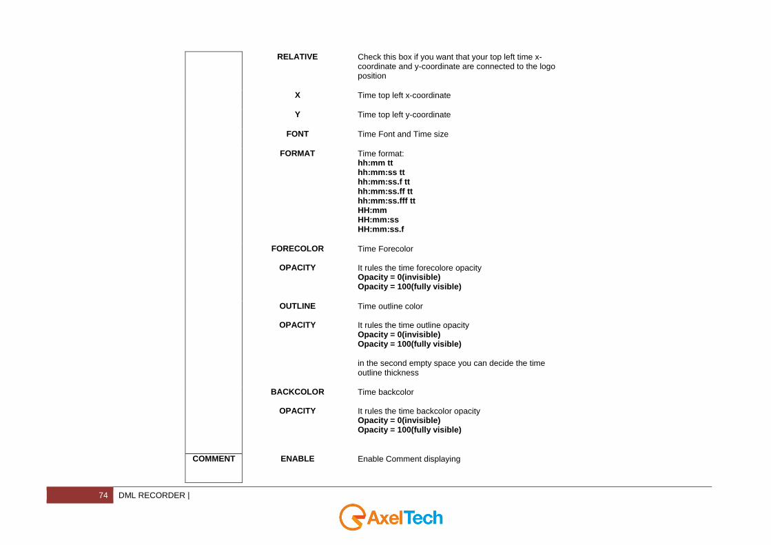
RELATIVE Check this box if you want that your top left time x-coordinate and y-coordinate are connected to the logo position
X Time top left x-coordinate
Y Time top left y-coordinate
FONT Time Font and Time size
FORMAT Time format: hh:mm tt hh:mm:ss tt hh:mm:ss.f tt hh:mm:ss.ff tt hh:mm:ss.fff tt HH:mm HH:mm:ss HH:mm:ss.f
FORECOLOR
OPACITY
Time Forecolor It rules the time forecolore opacity Opacity = 0(invisible) Opacity = 100(fully visible)
OUTLINE
OPACITY
Time outline color It rules the time outline opacity Opacity = 0(invisible) Opacity = 100(fully visible)
in the second empty space you can decide the time outline thickness
BACKCOLOR
OPACITY
Time backcolor It rules the time backcolor opacity Opacity = 0(invisible) Opacity = 100(fully visible)
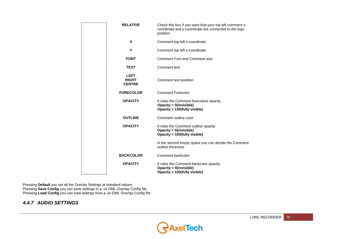
COMMENT ENABLE Enable Comment displaying
| DML RECORDER 75
RELATIVE Check this box if you want that your top left comment x-coordinate and y-coordinate are connected to the logo position
X Comment top left x-coordinate
Y Comment top left y-coordinate
FONT Comment Font and Comment size
TEXT Comment text
LEFT RIGHT
CENTRE
Comment text position
FORECOLOR
OPACITY
Comment Forecolor It rules the Comment forecolore opacity Opacity = 0(invisible) Opacity = 100(fully visible)
OUTLINE
OPACITY
Comment outline color It rules the Comment outline opacity Opacity = 0(invisible) Opacity = 100(fully visible)
in the second empty space you can decide the Comment outline thickness
BACKCOLOR
OPACITY
Comment backcolor It rules the Comment backcolor opacity Opacity = 0(invisible) Opacity = 100(fully visible)
Pressing Default you set all the Overlay Settings at standard values. Pressing Save Config you can save settings in a .ini DML Overlay Config file. Pressing Load Config you can load settings from a .ini DML Overlay Config file.
4.4.7 AUDIO SETTINGS

76 DML RECORDER |
AUDIO CODEC Codec Audio Set the audio codec
Configure Set your audio codec parameters
| DML RECORDER 77
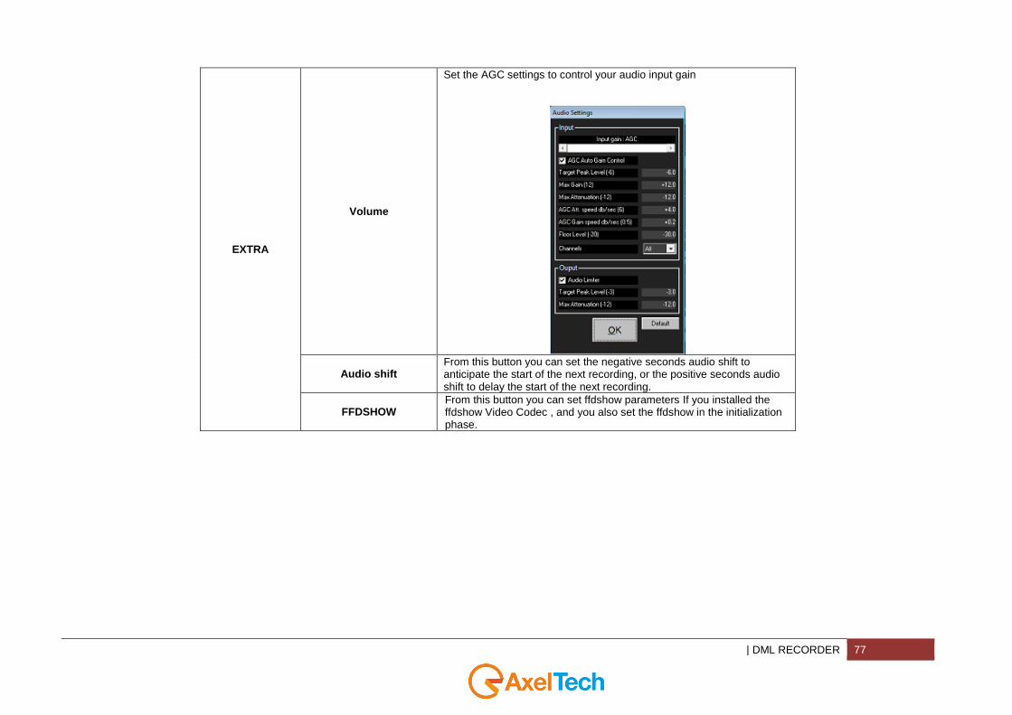
EXTRA
Volume
Set the AGC settings to control your audio input gain
Audio shift From this button you can set the negative seconds audio shift to anticipate the start of the next recording, or the positive seconds audio shift to delay the start of the next recording.
FFDSHOW From this button you can set ffdshow parameters If you installed the ffdshow Video Codec , and you also set the ffdshow in the initialization phase.
78 DML RECORDER |
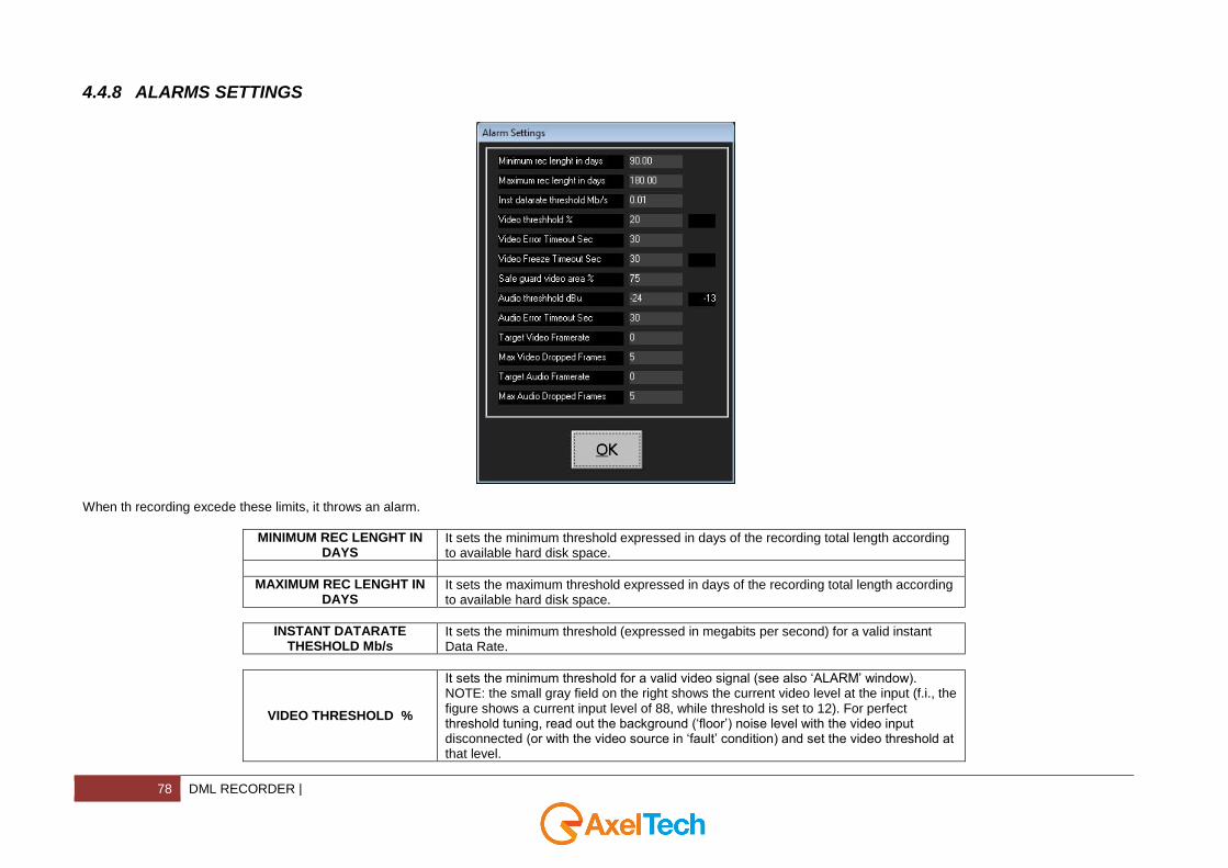
4.4.8 ALARMS SETTINGS
When th recording excede these limits, it throws an alarm.
MINIMUM REC LENGHT IN DAYS
It sets the minimum threshold expressed in days of the recording total length according to available hard disk space.
MAXIMUM REC LENGHT IN DAYS
It sets the maximum threshold expressed in days of the recording total length according to available hard disk space.
INSTANT DATARATE THESHOLD Mb/s
It sets the minimum threshold (expressed in megabits per second) for a valid instant Data Rate.
VIDEO THRESHOLD %
It sets the minimum threshold for a valid video signal (see also ‘ALARM’ window). NOTE: the small gray field on the right shows the current video level at the input (f.i., the figure shows a current input level of 88, while threshold is set to 12). For perfect threshold tuning, read out the background (‘floor’) noise level with the video input disconnected (or with the video source in ‘fault’ condition) and set the video threshold at that level.
| DML RECORDER 79
VIDEO ERROR TIMEOUT SEC
It sets the timeout for Video presence alarm. After the specified number of seconds, if video level is always below threshold, an alarm will be issued.
VIDEO FREEZE TIMEOUT SEC
It sets the timeout for Video presence alarm. After the specified number of seconds, if video is freezed, an alarm will be issued.
SAFE GUARD VIDEO AREA %
It defines, on each frame, the image area where the Luminance control is applied. See also ‘ALARM’ window – Video Input item.
AUDIO THRESHOLD dBu
It sets the minimum threshold for a valid audio signal (see also ‘ALARM’ window). NOTE: the small gray field on the right shows the current video level at the input (f.i., the figure shows a current input level of 90, while threshold is set to 80). For perfect threshold tuning, read out the background (‘floor’) noise level with the audio input disconnected (or with the audio source in ‘fault’ condition) and set the audio threshold at that level.
AUDIO ERROR TIMEOUT SEC
It sets the timeout for audio presence alarm. After the specified number of seconds, if audio level is always below threshold, an alarm will be issued.
TARGET VIDEO FRAMERATE
Desired video framerate for your target
MAX VIDEO DROPPED FRAMES
Max dropped video frames before the alarm starts
TARGET AUDIO FRAMERATE
Desired Audio packet-rate for your target
MAX AUDIO DROPPED FRAMES
Max dropped audio packets before the alarm starts
4.4.9 CALCULATOR
80 DML RECORDER |
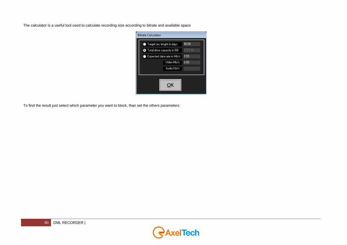
The calculator is a useful tool used to calculate recording size according to bitrate and available space
To find the result just select which parameter you want to block, than set the others parameters
| DML RECORDER 81
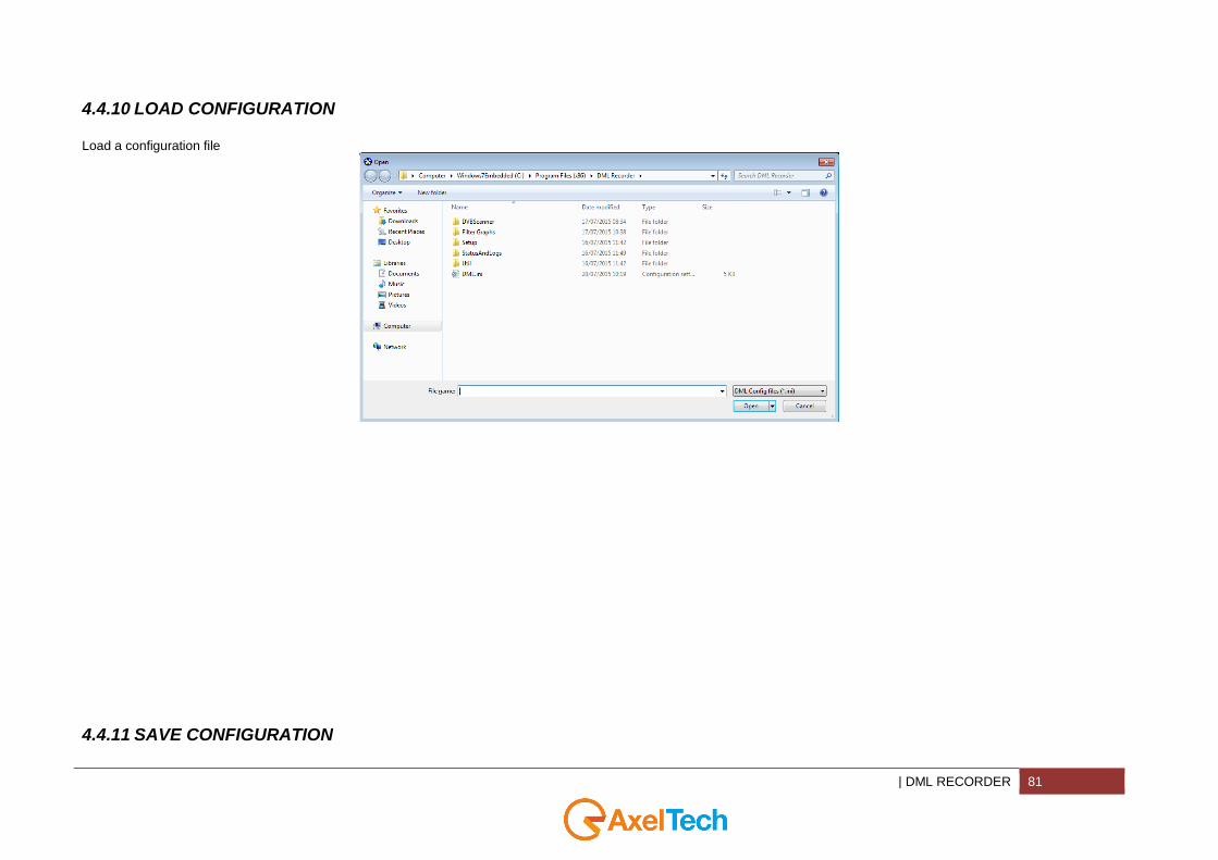
4.4.10 LOAD CONFIGURATION
Load a configuration file
4.4.11 SAVE CONFIGURATION

82 DML RECORDER |
Save the current configuration in a config file
| DML RECORDER 83
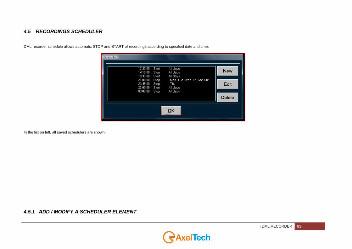
4.5 RECORDINGS SCHEDULER
DML recorder schedule allows automatic STOP and START of recordings according to specified date and time.
In the list on left, all saved schedulers are shown.
4.5.1 ADD / MODIFY A SCHEDULER ELEMENT
84 DML RECORDER |
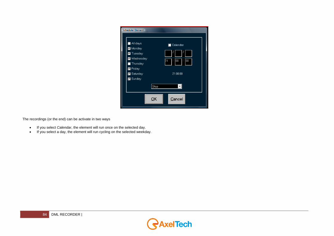
The recordings (or the end) can be activate in two ways
If you select Calendar, the element will run once on the selected day.
If you select a day, the element will run cycling on the selected weekday.
| DML PLAYER 85
5 DML PLAYER
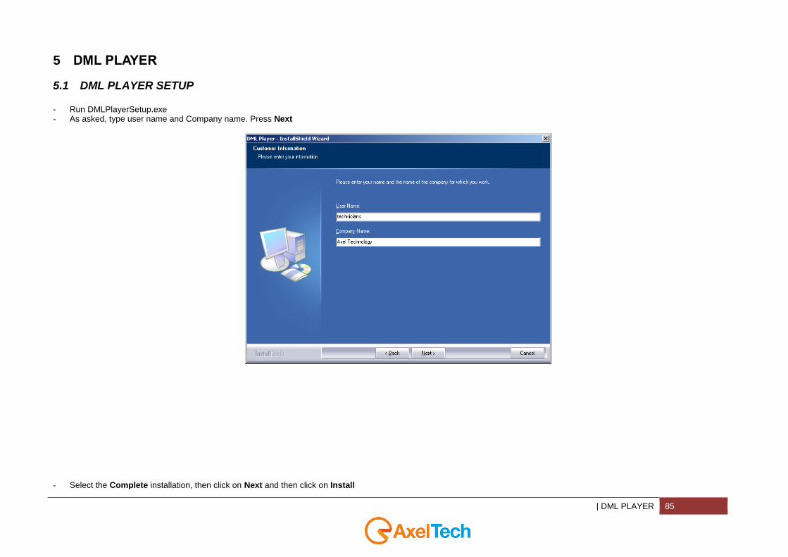
5.1 DML PLAYER SETUP
- Run DMLPlayerSetup.exe - As asked, type user name and Company name. Press Next
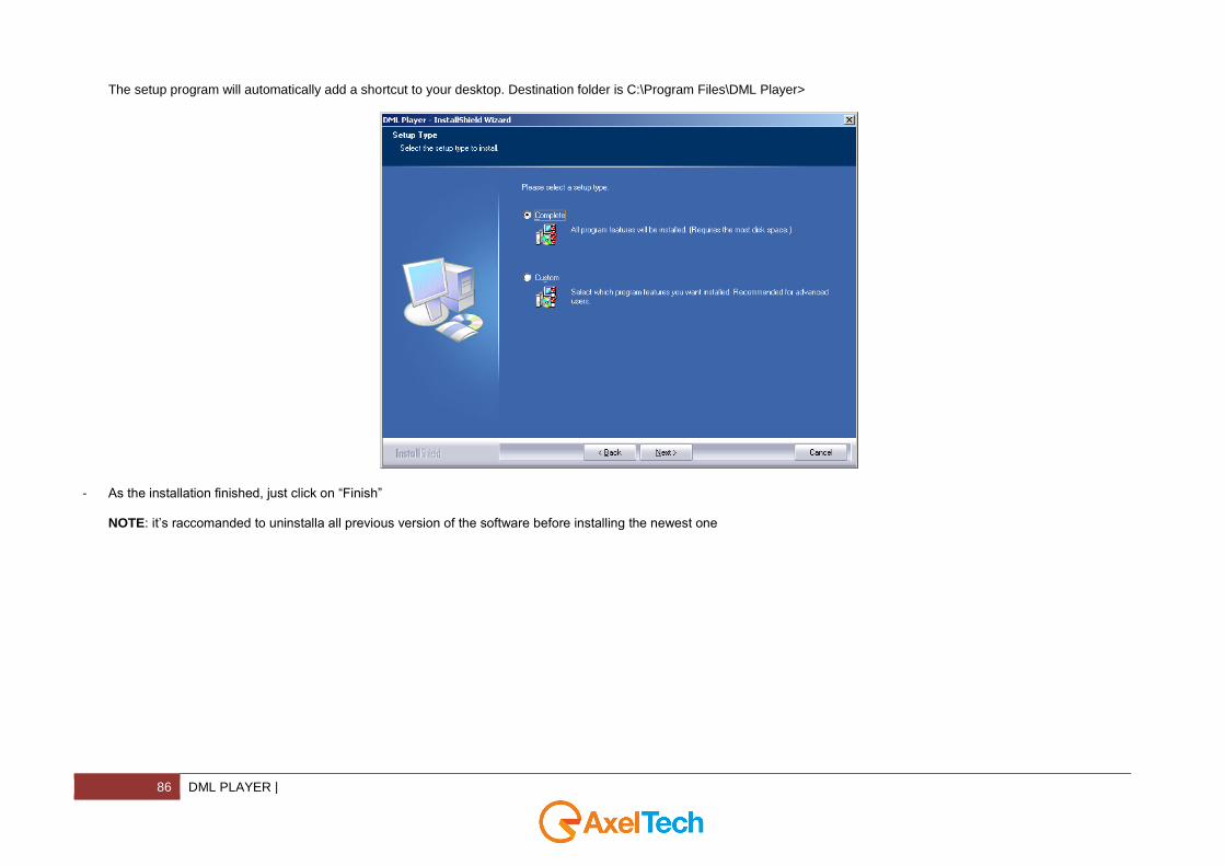
- Select the Complete installation, then click on Next and then click on Install
86 DML PLAYER |
The setup program will automatically add a shortcut to your desktop. Destination folder is C:\Program Files\DML Player>
- As the installation finished, just click on “Finish”
NOTE: it’s raccomanded to uninstalla all previous version of the software before installing the newest one
| DML PLAYER 87
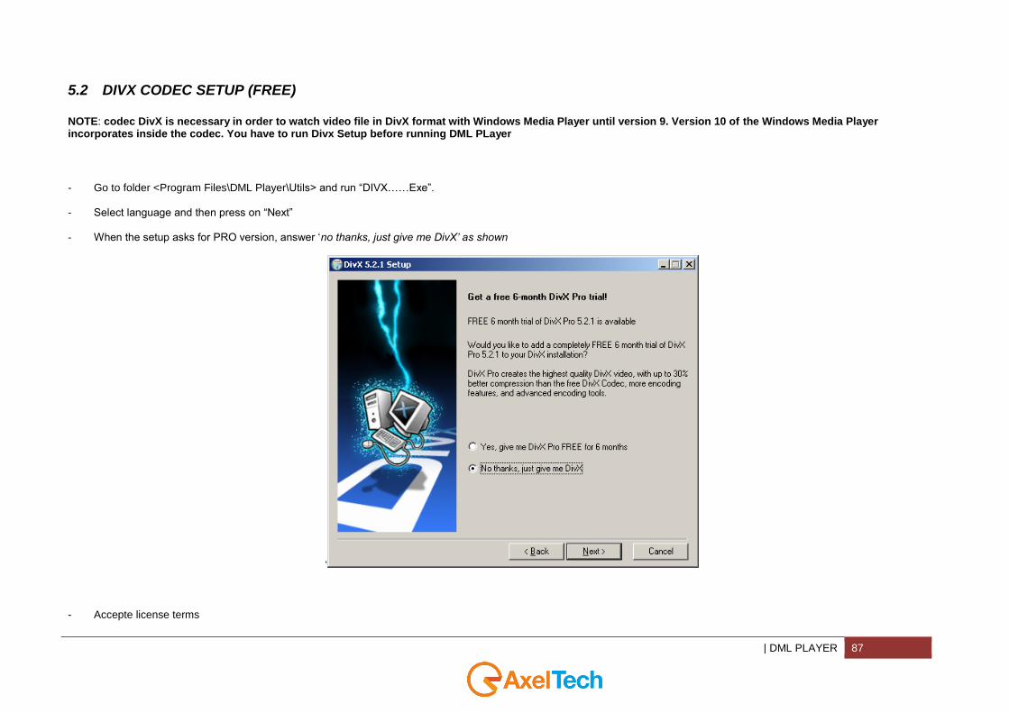
5.2 DIVX CODEC SETUP (FREE)
NOTE: codec DivX is necessary in order to watch video file in DivX format with Windows Media Player until version 9. Version 10 of the Windows Media Player incorporates inside the codec. You have to run Divx Setup before running DML PLayer
- -
Go to folder <Program Files\DML Player\Utils> and run “DIVX……Exe”. Select language and then press on “Next”
- When the setup asks for PRO version, answer ‘no thanks, just give me DivX’ as shown
‘
- Accepte license terms

88 DML PLAYER |
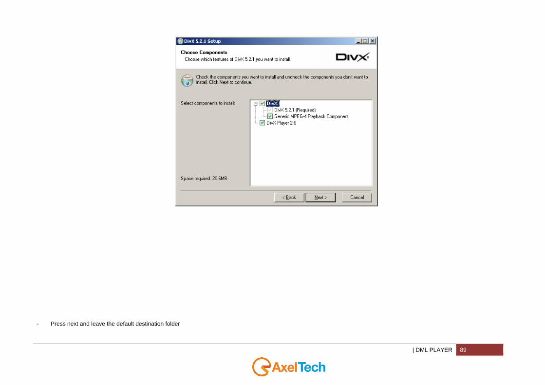
- Press next and leave all settings as shown
| DML PLAYER 89
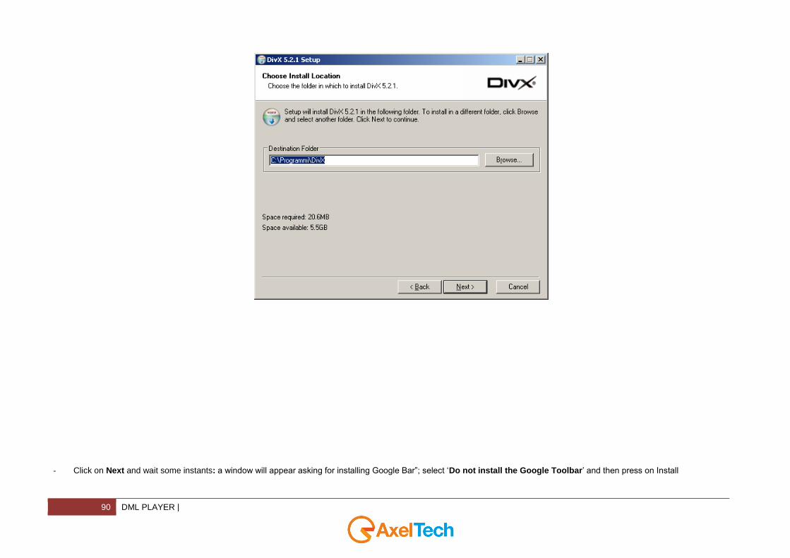
- Press next and leave the default destination folder
90 DML PLAYER |
-
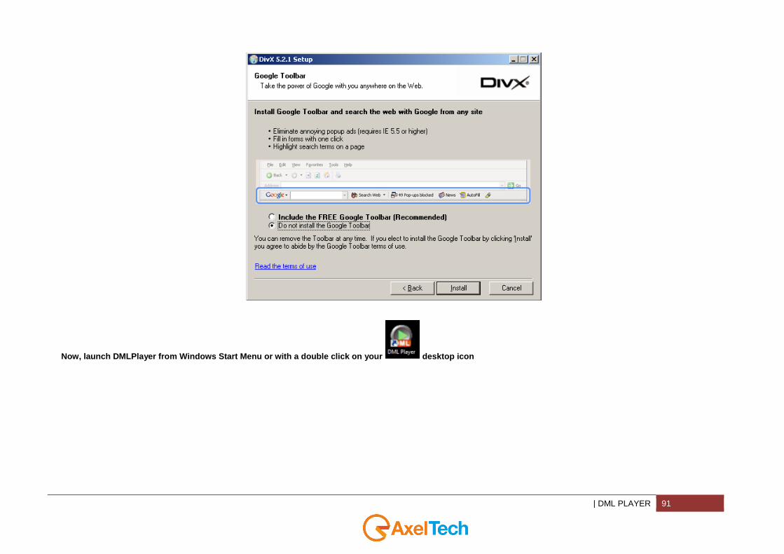
Click on Next and wait some instants: a window will appear asking for installing Google Bar”; select ‘Do not install the Google Toolbar’ and then press on Install
| DML PLAYER 91
Now, launch DMLPlayer from Windows Start Menu or with a double click on your desktop icon

92 DML PLAYER |
5.3 DML PLAYER
Run DML Player double clicking on the desktop shortcut icon
You can select application language, selecting it in the menu “Languages” When it start the window will appear black
| DML PLAYER 93
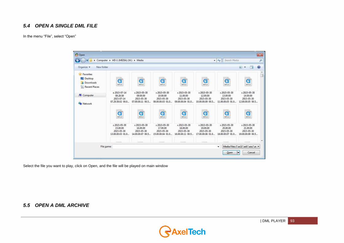
5.4 OPEN A SINGLE DML FILE
In the menu “File”, select “Open”
Select the file you want to play, click on Open, and the file will be played on main window
5.5 OPEN A DML ARCHIVE

94 DML PLAYER |
In the menu “File”, select “Browse DML” or select the button . In the browser window select the Dml MEDIA folder
When you click on “Ok”, DML Player will automatically scan the folder searching for media files. At the end (the duration depends on net settings and on file number inside the folder), a calendar will be shown

| DML PLAYER 95
At the beginning the calendar will show current year and month. To scroll them, just use the arrow on the window top. For each month, all days are shown, with different colors. The green ones rapresents a day in which at least one file is present. On the contrary the red ones rapresents days without recording associated
Select the day you want to watch: the corresponding box will be colored in yellow (for exemplae 19 october is selected in the image on the left)
Now you have to select which hour of the day you want to watch. As before, where a video file is presente, the box will appear green
In the image on the left, for example, you see that in day 19 there are three recordings.
When you click the time, the correspending video file willb be played in the main window
96 DML PLAYER |
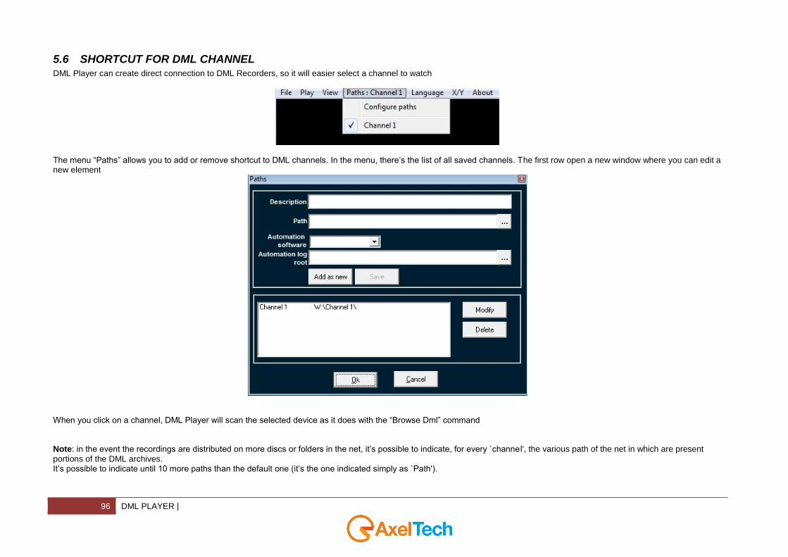
5.6 SHORTCUT FOR DML CHANNEL
DML Player can create direct connection to DML Recorders, so it will easier select a channel to watch
The menu “Paths” allows you to add or remove shortcut to DML channels. In the menu, there’s the list of all saved channels. The first row open a new window where you can edit a new element
When you click on a channel, DML Player will scan the selected device as it does with the “Browse Dml” command Note: in the event the recordings are distributed on more discs or folders in the net, it’s possible to indicate, for every `channel', the various path of the net in which are present
portions of the DML archives. It’s possible to indicate until 10 more paths than the default one (it’s the one indicated simply as `Path').
| DML PLAYER 97
5.7 PLAYING FUNCTIONS
5.7.1 PLAY, PAUSE AND STOP
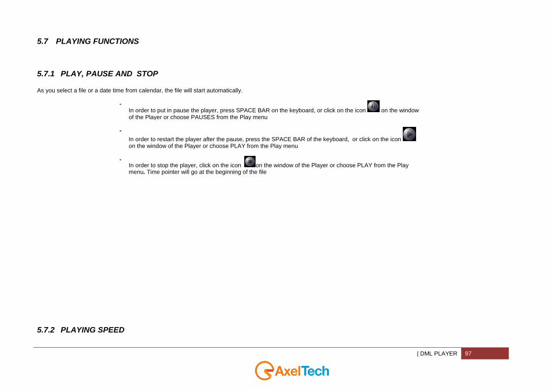
As you select a file or a date time from calendar, the file will start automatically.
- In order to put in pause the player, press SPACE BAR on the keyboard, or click on the icon on the window of the Player or choose PAUSES from the Play menu
-
In order to restart the player after the pause, press the SPACE BAR of the keyboard, or click on the icon on the window of the Player or choose PLAY from the Play menu
-
In order to stop the player, click on the icon on the window of the Player or choose PLAY from the Play menu. Time pointer will go at the beginning of the file
5.7.2 PLAYING SPEED
98 DML PLAYER |
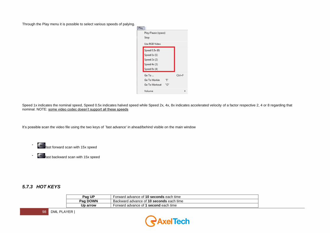
Through the Play menu it is possible to select various speeds of palying.
Speed 1x indicates the nominal speed, Speed 0.5x indicates halved speed while Speed 2x, 4x, 8x indicates accelerated velocity of a factor respective 2, 4 or 8 regarding that nominal. NOTE: some video codec doesn’t support all these speeds
It’s possible scan the video file using the two keys of `fast advance' in ahead/behind visible on the main window
-
fast forward scan with 15x speed -
fast backward scan with 15x speed
5.7.3 HOT KEYS
Pag UP Forward advance of 10 seconds each time
Pag DOWN Backward advance of 10 seconds each time
Up arrow Forward advance of 1 second each time
| DML PLAYER 99
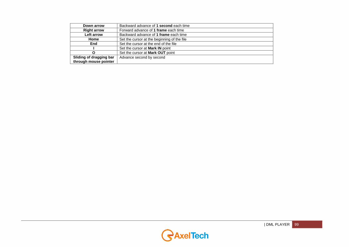
Down arrow Backward advance of 1 second each time
Right arrow Forward advance of 1 frame each time
Left arrow Backward advance of 1 frame each time
Home Set the cursor at the beginning of the file
End Set the cursor at the end of the file
I Set the cursor at Mark IN point
O Set the cursor at Mark OUT point
Sliding of dragging bar through mouse pointer
Advance second by second
100 DML PLAYER |
5.8 VOLUME AND BALANCE AUDIO SETTINGS
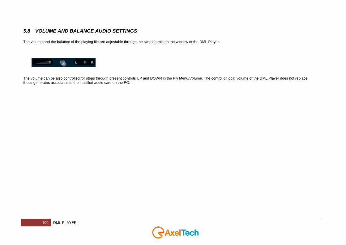
The volume and the balance of the playing file are adjustable through the two controls on the window of the DML Player.
The volume can be also controlled for steps through present controls UP and DOWN in the Ply Menu/Volume. The control of local volume of the DML Player does not replace those generates associates to the installed audio card on the PC.
| DML PLAYER 101
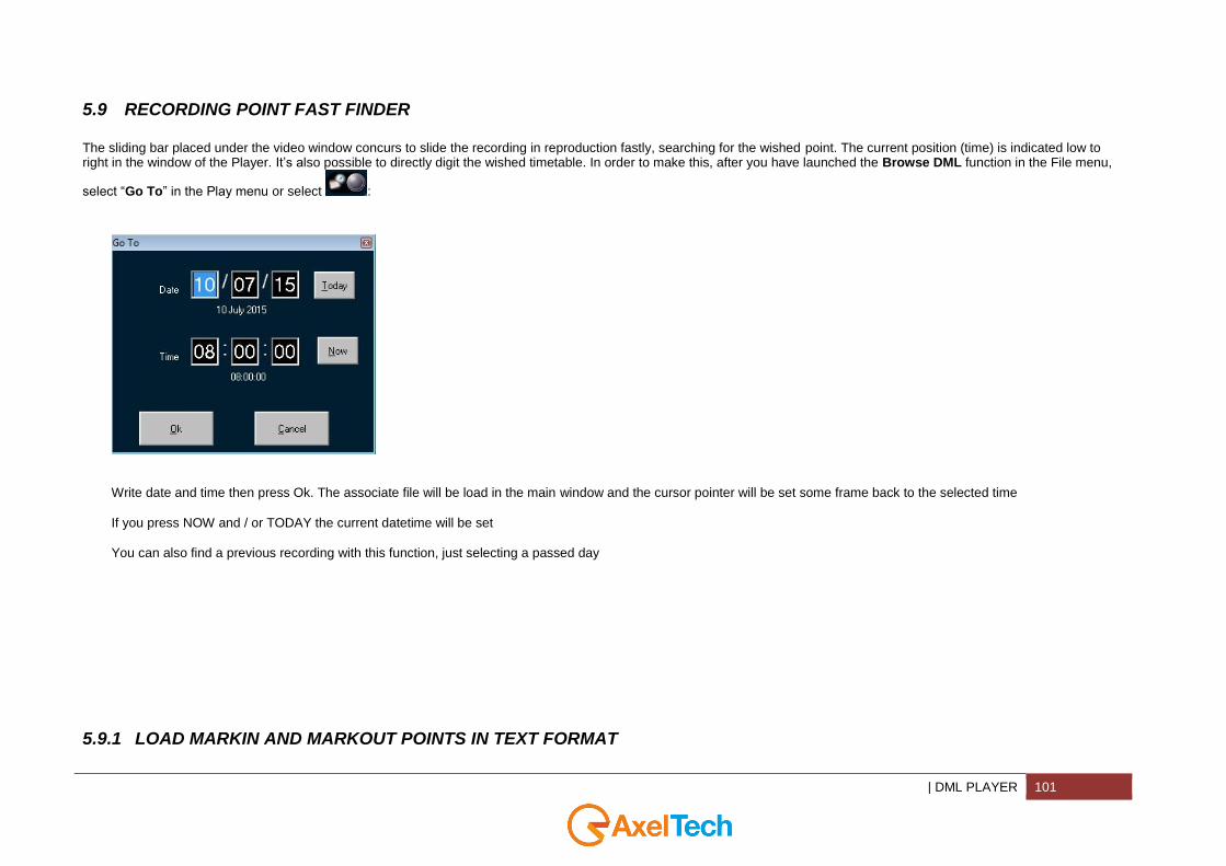
5.9 RECORDING POINT FAST FINDER
The sliding bar placed under the video window concurs to slide the recording in reproduction fastly, searching for the wished point. The current position (time) is indicated low to right in the window of the Player. It’s also possible to directly digit the wished timetable. In order to make this, after you have launched the Browse DML function in the File menu,
select “Go To” in the Play menu or select :
Write date and time then press Ok. The associate file will be load in the main window and the cursor pointer will be set some frame back to the selected time If you press NOW and / or TODAY the current datetime will be set You can also find a previous recording with this function, just selecting a passed day
5.9.1 LOAD MARKIN AND MARKOUT POINTS IN TEXT FORMAT
102 DML PLAYER |
Select the function “LOAD TEXT” from the File menu. It’s a function that concurs to apply to the opened file in the DML PLayer one list of marks specified in a text file with generic formats. Such text file can be found in any net folder. Marks will be visibel in the dedicated window “Marks”. That window can be also opened with the menu View/Marks
As you see, the file opened trough “Loaded Text” function will be applied to the current video file without making any checks. It will be the user that will check if marks are appropriate for the file
DML Player has a second function for loading external marks. At the moment in which the operator it selects a determined day on the calendar DML Player search for a text file with “Playlist_yyyy_mm_dd*.txt” syntax, which must be in the same folder of A/V media files. Iin this way the correpondence between text files asnd television net is automatically assured
For example, if you have an automation TV system which is able to generate the transmissions register with txt format, DML Player is able to marks in the right point the beginning of single programs or spot in the selected days. Marks pointing is sure and precise, because it’s calculated with filtering of the relative datas, not only on the current day, but also on the next and on the previous one. In this way midnight jump is correct.
| DML PLAYER 103
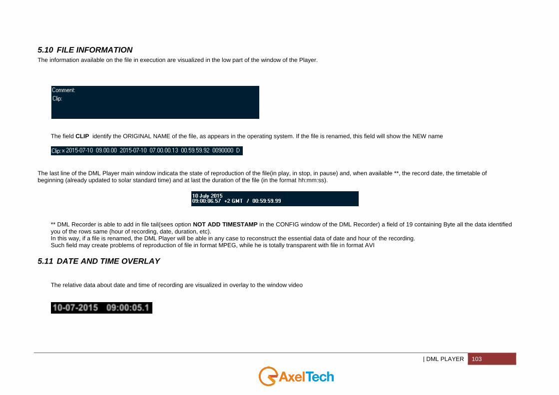
5.10 FILE INFORMATION
The information available on the file in execution are visualized in the low part of the window of the Player.
The field CLIP identify the ORIGINAL NAME of the file, as appears in the operating system. If the file is renamed, this field will show the NEW name
The last line of the DML Player main window indicata the state of reproduction of the file(in play, in stop, in pause) and, when available **, the record date, the timetable of beginning (already updated to solar standard time) and at last the duration of the file (in the format hh:mm:ss).
** DML Recorder is able to add in file tail(sees option NOT ADD TIMESTAMP in the CONFIG window of the DML Recorder) a field of 19 containing Byte all the data identified
you of the rows same (hour of recording, date, duration, etc). In this way, if a file is renamed, the DML Player will be able in any case to reconstruct the essential data of date and hour of the recording. Such field may create problems of reproduction of file in format MPEG, while he is totally transparent with file in format AVI
5.11 DATE AND TIME OVERLAY
The relative data about date and time of recording are visualized in overlay to the window video
104 DML PLAYER |
5.12 MARK-IN/OUT POINTS AND SEQUENCE EXPORT
5.12.1 MARK-IN AND MARK-OUT POINT
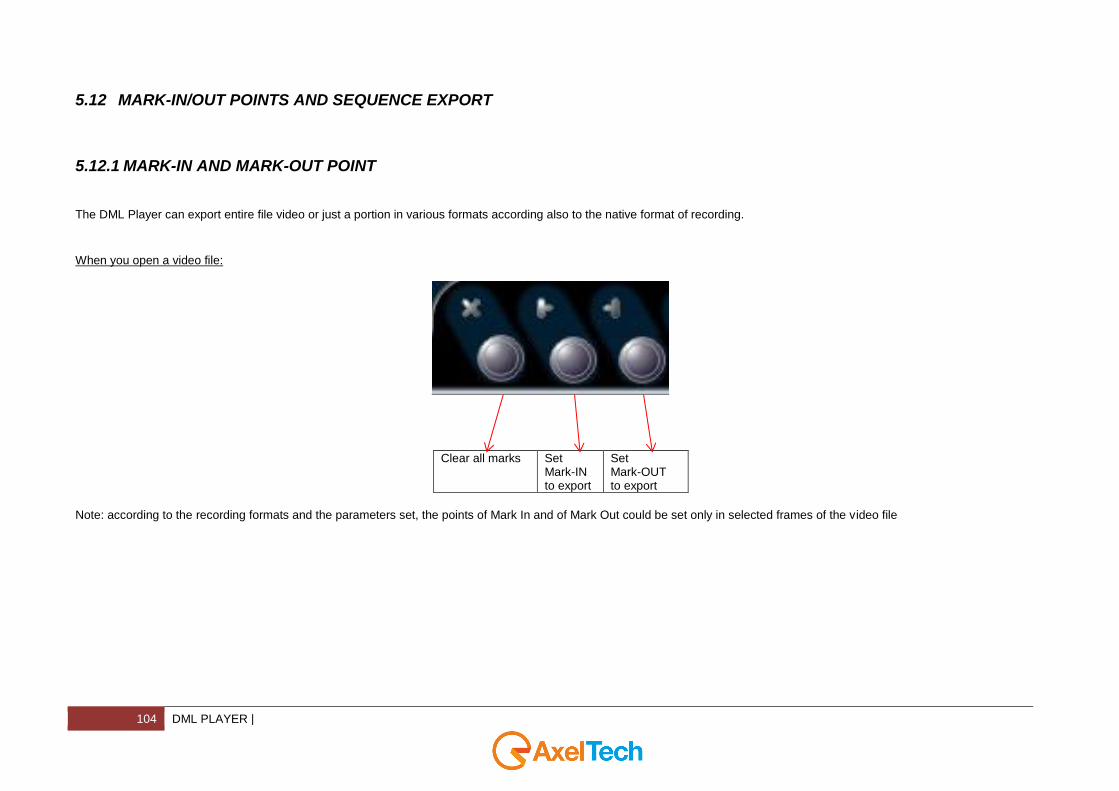
The DML Player can export entire file video or just a portion in various formats according also to the native format of recording.
When you open a video file:
Clear all marks Set Mark-IN to export
Set Mark-OUT to export
Note: according to the recording formats and the parameters set, the points of Mark In and of Mark Out could be set only in selected frames of the video file

| DML PLAYER 105
5.12.2 MEDIA EXPORTER AND CONVERTER
When you set Mark IN and mark OUT, the command (Ctrl+P) extracts and converts the selected portion to the selected folder. In the window, you can set folder and name of the file:
If you type the File Name and after you type ‘.format’ the file will be created in the format you choosed: for example if you type export.wmv, the file will be converted to .wmv(Windows Media Video) format.
The progress bar shows you the status of the convertion
The convertion process has been completed. Click ok
106 DML PLAYER |
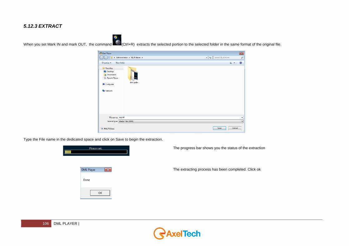
5.12.3 EXTRACT
When you set Mark IN and mark OUT, the command (Ctrl+R) extracts the selected portion to the selected folder in the same format of the original file.
Type the File name in the dedicated space and click on Save to begin the extraction.
The progress bar shows you the status of the extraction
The extracting process has been completed. Click ok
| DML PLAYER 107
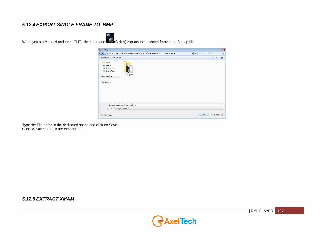
5.12.4 EXPORT SINGLE FRAME TO BMP
When you set Mark IN and mark OUT, the command (Ctrl+A) exports the selected frame as a Bitmap file
Type the File name in the dedicated space and click on Save Click on Save to begin the exportation.
5.12.5 EXTRACT XMAM

108 DML PLAYER |
When you set Mark IN and Mark OUT, the command exports the selected portion of the file in the original video format and also it exports an .xml file with different tags, to the XMAM folder. Type the folder path for the storage or browse for it. Write a Title, a Caption, and Keywords for your XMAM tags.
Click on Extract you start with - the extraction of the selected portion of the video file - with the creation of an .xml file with tags(Title, Caption, Keywords) of the preview image.
The progress bar shows you the status of the export
The extracting process has been completed. Click ok
| DML COPY 109
5.13 RECORDING PLAYOUT IN EXTERN MONITOR
If the PC where DML Player is installed has a video card with Pal/Ntsc output, you can watch the file played with DML Player on an extern monitor * For more information, please see the video card documentation for the right settings *some video formats compressor may not be played on the Pal/Ntsc output.. If in doubt, please contact Axel Technology. The Pal/Ntsc output can be used to put all video data to videotape or others recording supports If enabled, the Datestamp overlay is shown also in the Pal/Ntsc output
6 DML COPY
110 DML COPY |
DML Copy is an interesting tool that allows you to copy automatically DML Recorder files in a server folder. In other words, DML Copy monitors the DML Recorder folder and every time it finds new files, it provides for the copy in the server folder path you set.
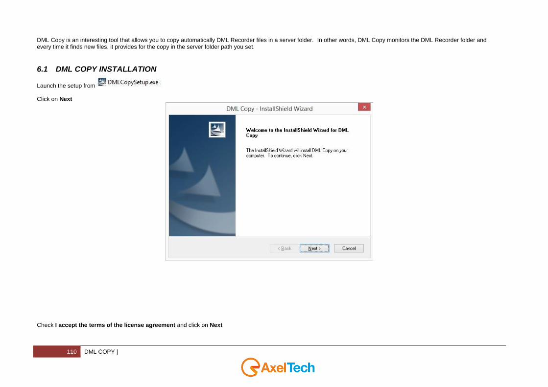
6.1 DML COPY INSTALLATION
Launch the setup from Click on Next
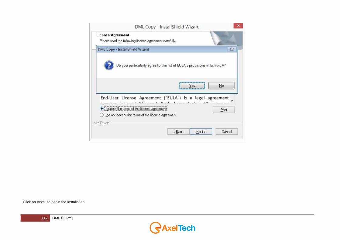
Check I accept the terms of the license agreement and click on Next

| DML COPY 111
Click on Yes to agree to the list of EULA’s provisions in Exhibit A
112 DML COPY |
Click on Install to begin the installation

| DML COPY 113
After the installation progress you will see the following window. Click on Finish to end the installation.

114 DML COPY |
6.2 DML COPY USAGE

| DML COPY 115
Click on the following icon
To start the copy you have to create a new job for every DML Channel. Click on Add Job
116 DML COPY |
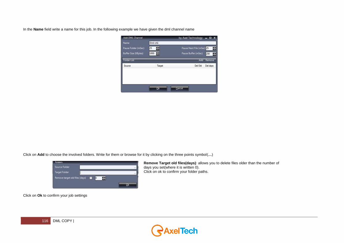
In the Name field write a name for this job. In the following example we have given the dml channel name
Click on Add to choose the involved folders. Write for them or browse for it by clicking on the three points symbol(…)
Remove Target old files(days): allows you to delete files older than the number of
days you set(where it is written 0). Click on ok to confirm your folder paths.
Click on Ok to confirm your job settings

| DML COPY 117
Click on start to start with the copy
118 DML COPY |
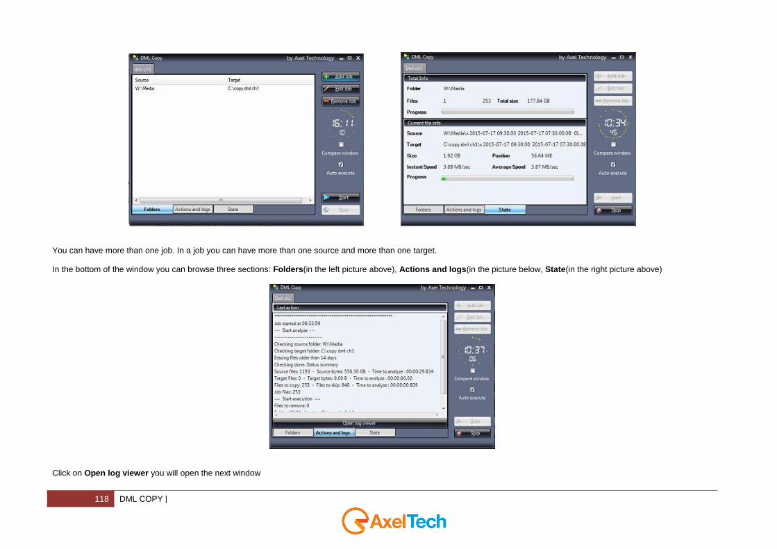
You can have more than one job. In a job you can have more than one source and more than one target. In the bottom of the window you can browse three sections: Folders(in the left picture above), Actions and logs(in the picture below, State(in the right picture above)
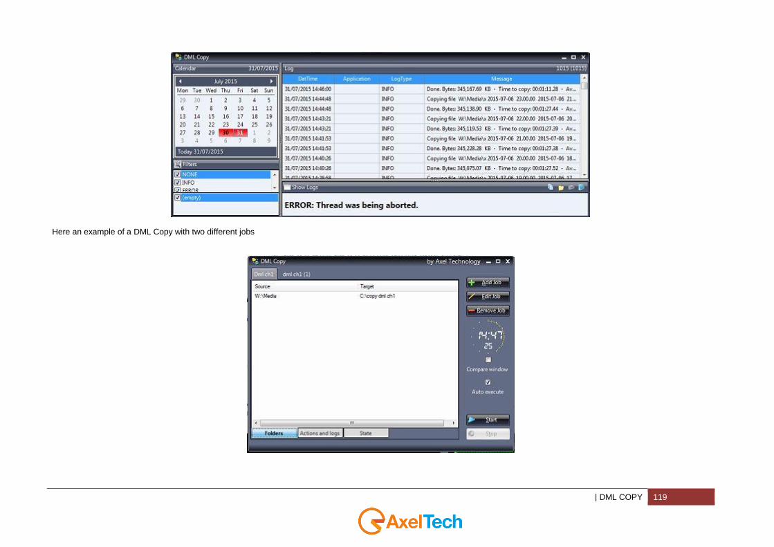
Click on Open log viewer you will open the next window
| DML COPY 119
Here an example of a DML Copy with two different jobs

120 DML MONITOR WEB |
7 DML MONITOR WEB
7.1 INTRODUCTION TO DML MONITOR WEB
DML Monitor is a powerful web page for the remote monitoring in real time through LAN or Internet of one or more DML unit. For each connected unit, the software shows a reference frame of the video in phase of recording (continuously updated) and the presence of eventual alarms or parameters outside range. It is also possible to have continuously under control video signal and the state of the recorder.
The installation and the configuration of the DML Monitor Web are extremely simple.
| DML MONITOR WEB 121
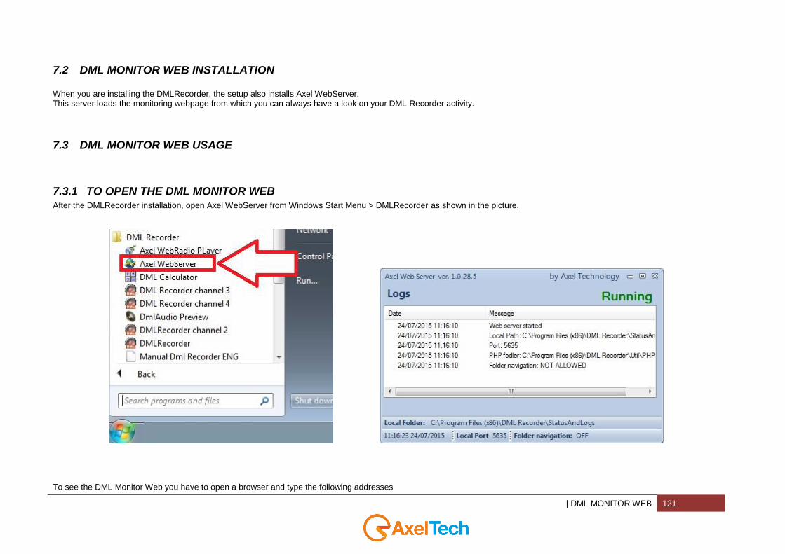
7.2 DML MONITOR WEB INSTALLATION
When you are installing the DMLRecorder, the setup also installs Axel WebServer. This server loads the monitoring webpage from which you can always have a look on your DML Recorder activity.
7.3 DML MONITOR WEB USAGE
7.3.1 TO OPEN THE DML MONITOR WEB
After the DMLRecorder installation, open Axel WebServer from Windows Start Menu > DMLRecorder as shown in the picture.
To see the DML Monitor Web you have to open a browser and type the following addresses

122 DML MONITOR WEB |
localhost:5635/dmlmonitorweb, if you are in the same DMLRecorder PC or privateipaddress:5635/dmlmonitorweb, if you are not in the same DMLRecorder PC but you are in a PC included in the same Private Network. publicipaddress:5635/dmlmonitorweb, if you are not in the same DMLRecorder PC and if you are in a PC out from the DMLRecorder PC Network. in both cases you will see a page like the next one:
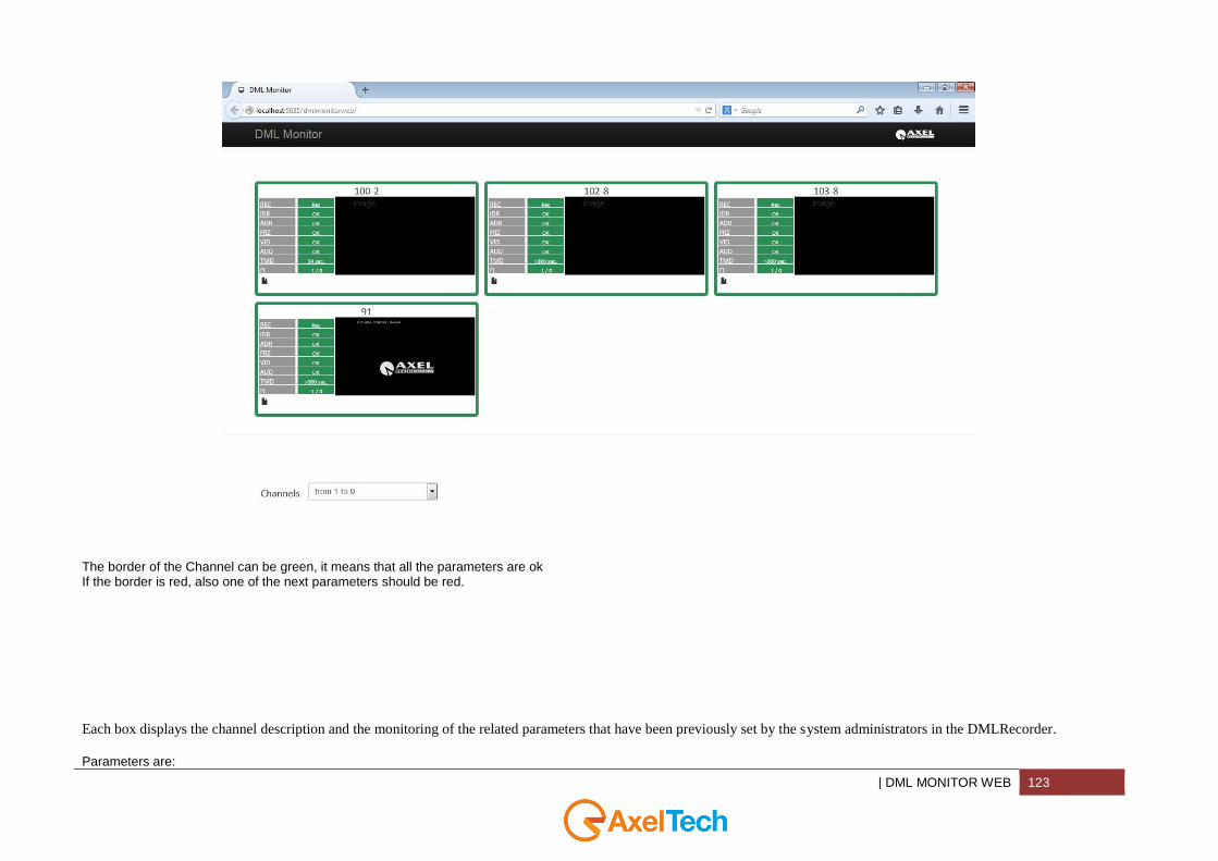
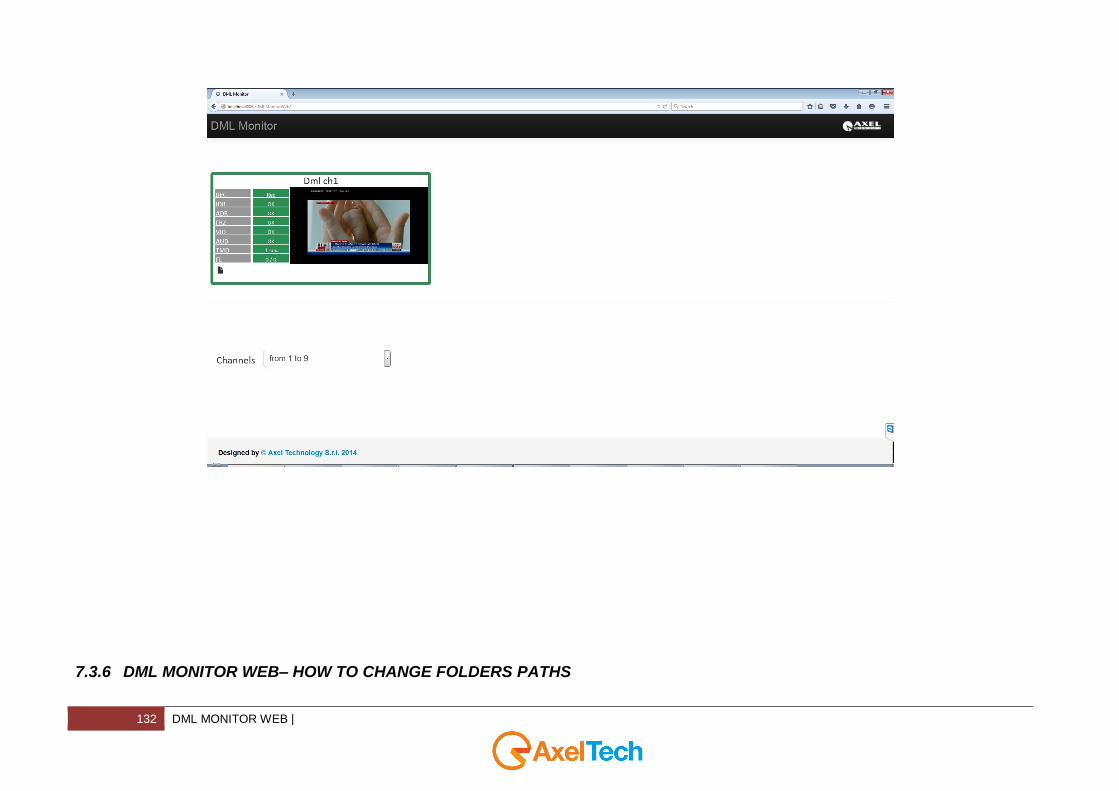
If you are monitoring more than a channel you will see a page like the next one:
| DML MONITOR WEB 123
The border of the Channel can be green, it means that all the parameters are ok If the border is red, also one of the next parameters should be red.
Each box displays the channel description and the monitoring of the related parameters that have been previously set by the system administrators in the DMLRecorder.
Parameters are:

124 DML MONITOR WEB |
REC Shows the recording status of the channel. If the recording is in progress, the REC value is present, highlighted in green. If the recording is stopped, the STOP value appears highlighted in red.
IDR Instant Data Rate. It refers to the recording in progress and is detected after 1 minute from the start of recording,
its value turns red when the data rate drops below the set threshold, or when the recording is losing more audio (or video) frames than the ones set in the threshold, or when one of the streams coming from the card is interrupted.
ADR Average Data Rate. It is detected 10 minutes after the start of each recording, it warns if the recording is coming
out of the range of minimum amount and maximum amount of days to record. It depends on the average recording bitrate set and on the available disk space.
FRZ Video freezed (only for video recordings). It warns when the video image is freezed for a time longer than the
timeout set.
VID No video (only for video recordings). It warns when the video image is darker than the set threshold for a time
longer than the set timeout. If a safeguard area is set, the image will be analyzed only in the horizontal strip in the middle of the screen (used to ignore the station logo).
AUD No Audio. It shows the state regarding the presence or absence of audio level in the channel. It warns when the
audio level is under the set threshold for a period longer than the timeout set.
TMD Time Difference. It indicates the time difference between the system clock of the recording workstation and the
system clock of the workstation you are logged in.
FL Frames Loss. It indicates the number of audio and video frames lost in the current recording.
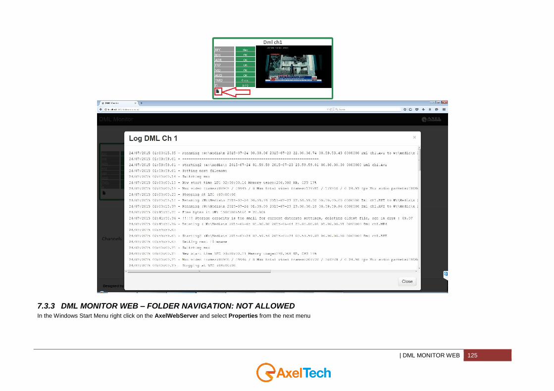
7.3.2 DML MONITOR WEB - CHANNEL LOG VIEWER
If you press the red squared link you will be redirected to the DML Channel Log file, as shown in the next picture
| DML MONITOR WEB 125
7.3.3 DML MONITOR WEB – FOLDER NAVIGATION: NOT ALLOWED In the Windows Start Menu right click on the AxelWebServer and select Properties from the next menu
126 DML MONITOR WEB |
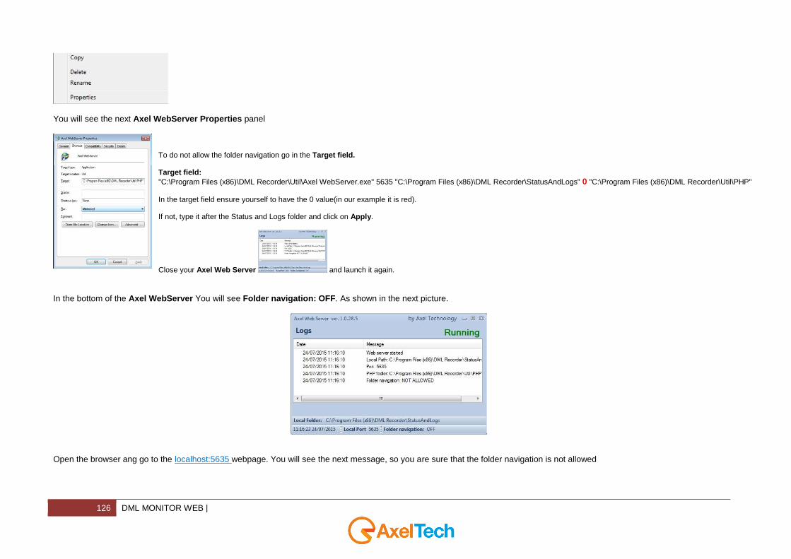
You will see the next Axel WebServer Properties panel
To do not allow the folder navigation go in the Target field. Target field:
"C:\Program Files (x86)\DML Recorder\Util\Axel WebServer.exe" 5635 "C:\Program Files (x86)\DML Recorder\StatusAndLogs" 0 "C:\Program Files (x86)\DML Recorder\Util\PHP"
In the target field ensure yourself to have the 0 value(in our example it is red). If not, type it after the Status and Logs folder and click on Apply.
Close your Axel Web Server and launch it again.
In the bottom of the Axel WebServer You will see Folder navigation: OFF. As shown in the next picture.
Open the browser ang go to the localhost:5635 webpage. You will see the next message, so you are sure that the folder navigation is not allowed
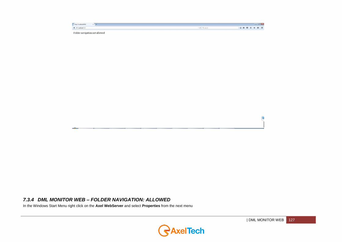
| DML MONITOR WEB 127
7.3.4 DML MONITOR WEB – FOLDER NAVIGATION: ALLOWED In the Windows Start Menu right click on the Axel WebServer and select Properties from the next menu

128 DML MONITOR WEB |
You will see the next Axel WebServer Properties panel
To allow the folder navigation go in the Target field. Target field:
"C:\Program Files (x86)\DML Recorder\Util\Axel WebServer.exe" 5635 "C:\Program Files (x86)\DML Recorder\StatusAndLogs" 1 "C:\Program Files (x86)\DML Recorder\Util\PHP"
In the target field ensure yourself to have the 1 value(in our example is red 1 value). If not, type it after the Status and Logs folder and click on Apply.
Close your Axel Web Server and launch it again.
In the bottom of the Axel WebServer You will see Folder navigation: ON. As shown in the next picture.
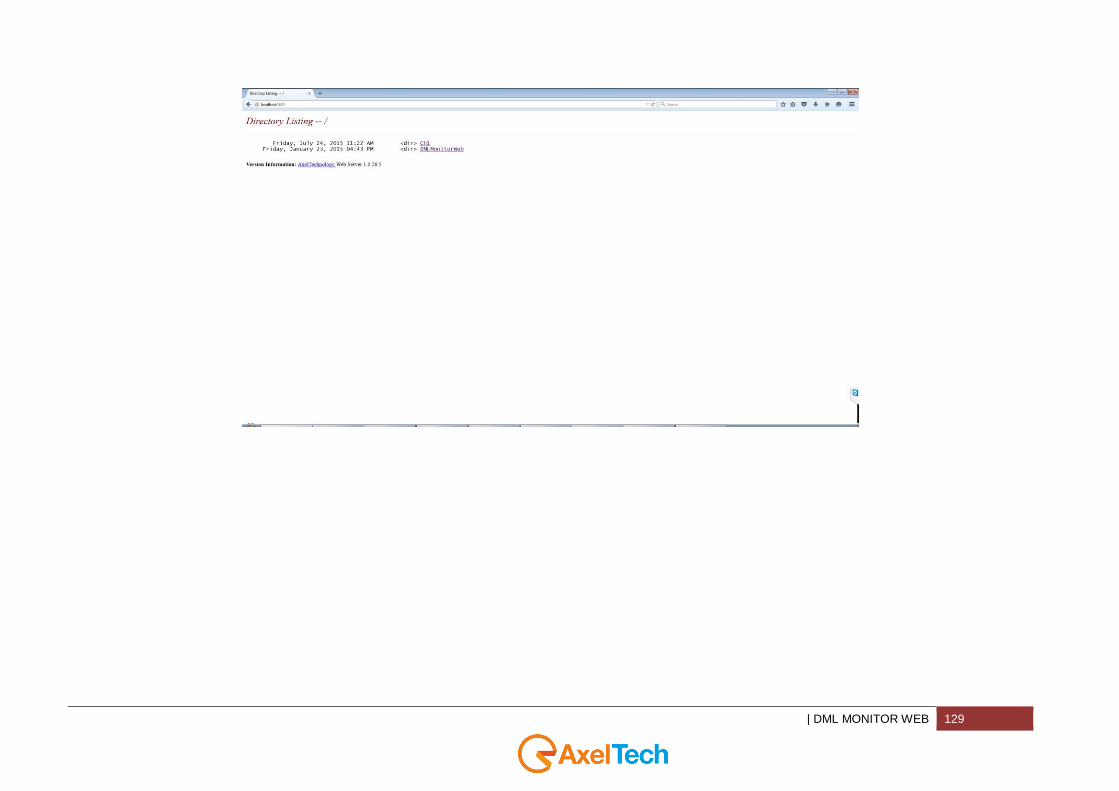
Open the browser and go to the localhost:5635 webpage. You will see a webpage with the list of your DML channels folders and with a DMLMonitorWeb link, so you are sure that
the folder navigation is allowed.
| DML MONITOR WEB 129
130 DML MONITOR WEB |
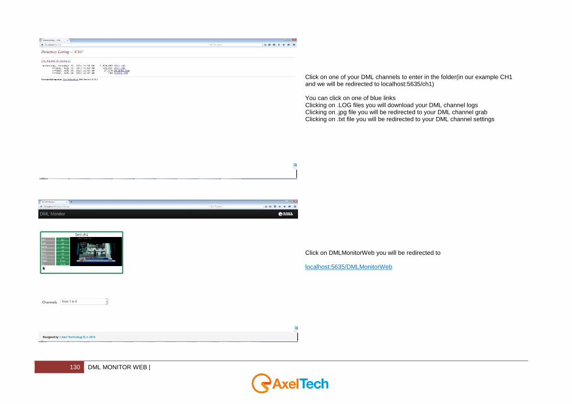
Click on one of your DML channels to enter in the folder(in our example CH1 and we will be redirected to localhost:5635/ch1) You can click on one of blue links Clicking on .LOG files you will download your DML channel logs Clicking on .jpg file you will be redirected to your DML channel grab Clicking on .txt file you will be redirected to your DML channel settings
Click on DMLMonitorWeb you will be redirected to localhost:5635/DMLMonitorWeb
| DML MONITOR WEB 131
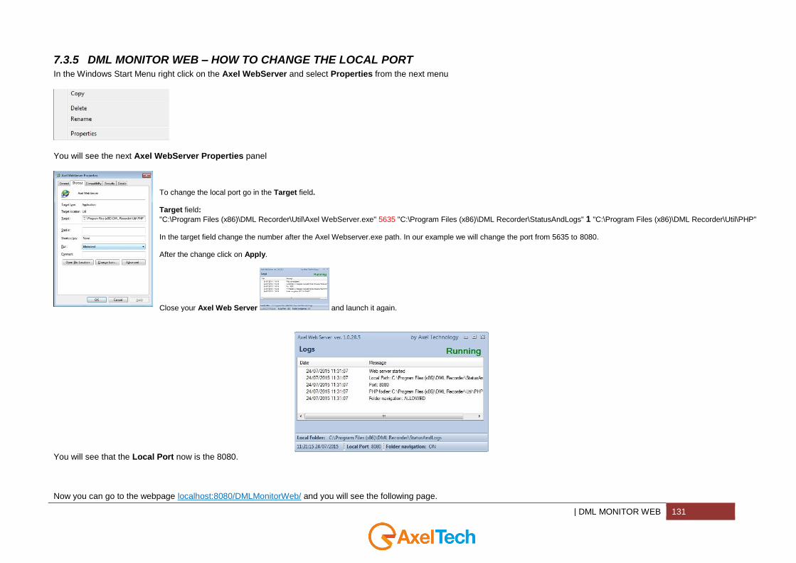
7.3.5 DML MONITOR WEB – HOW TO CHANGE THE LOCAL PORT In the Windows Start Menu right click on the Axel WebServer and select Properties from the next menu
You will see the next Axel WebServer Properties panel
To change the local port go in the Target field. Target field:
"C:\Program Files (x86)\DML Recorder\Util\Axel WebServer.exe" 5635 "C:\Program Files (x86)\DML Recorder\StatusAndLogs" 1 "C:\Program Files (x86)\DML Recorder\Util\PHP"
In the target field change the number after the Axel Webserver.exe path. In our example we will change the port from 5635 to 8080. After the change click on Apply.
Close your Axel Web Server and launch it again.
You will see that the Local Port now is the 8080.
Now you can go to the webpage localhost:8080/DMLMonitorWeb/ and you will see the following page.
132 DML MONITOR WEB |
7.3.6 DML MONITOR WEB– HOW TO CHANGE FOLDERS PATHS
| DML SYSTEMS - OPTIONAL ELEMENTS 133
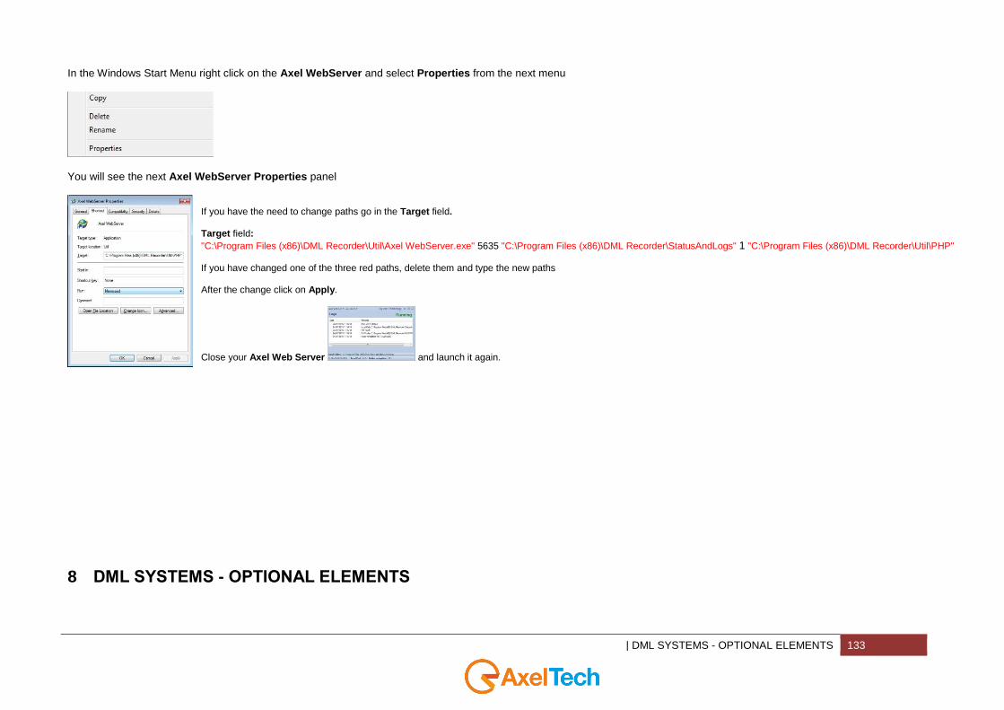
In the Windows Start Menu right click on the Axel WebServer and select Properties from the next menu
You will see the next Axel WebServer Properties panel
If you have the need to change paths go in the Target field. Target field:
"C:\Program Files (x86)\DML Recorder\Util\Axel WebServer.exe" 5635 "C:\Program Files (x86)\DML Recorder\StatusAndLogs" 1 "C:\Program Files (x86)\DML Recorder\Util\PHP" If you have changed one of the three red paths, delete them and type the new paths After the change click on Apply.
Close your Axel Web Server and launch it again.
8 DML SYSTEMS - OPTIONAL ELEMENTS
134 DML SYSTEMS - OPTIONAL ELEMENTS |
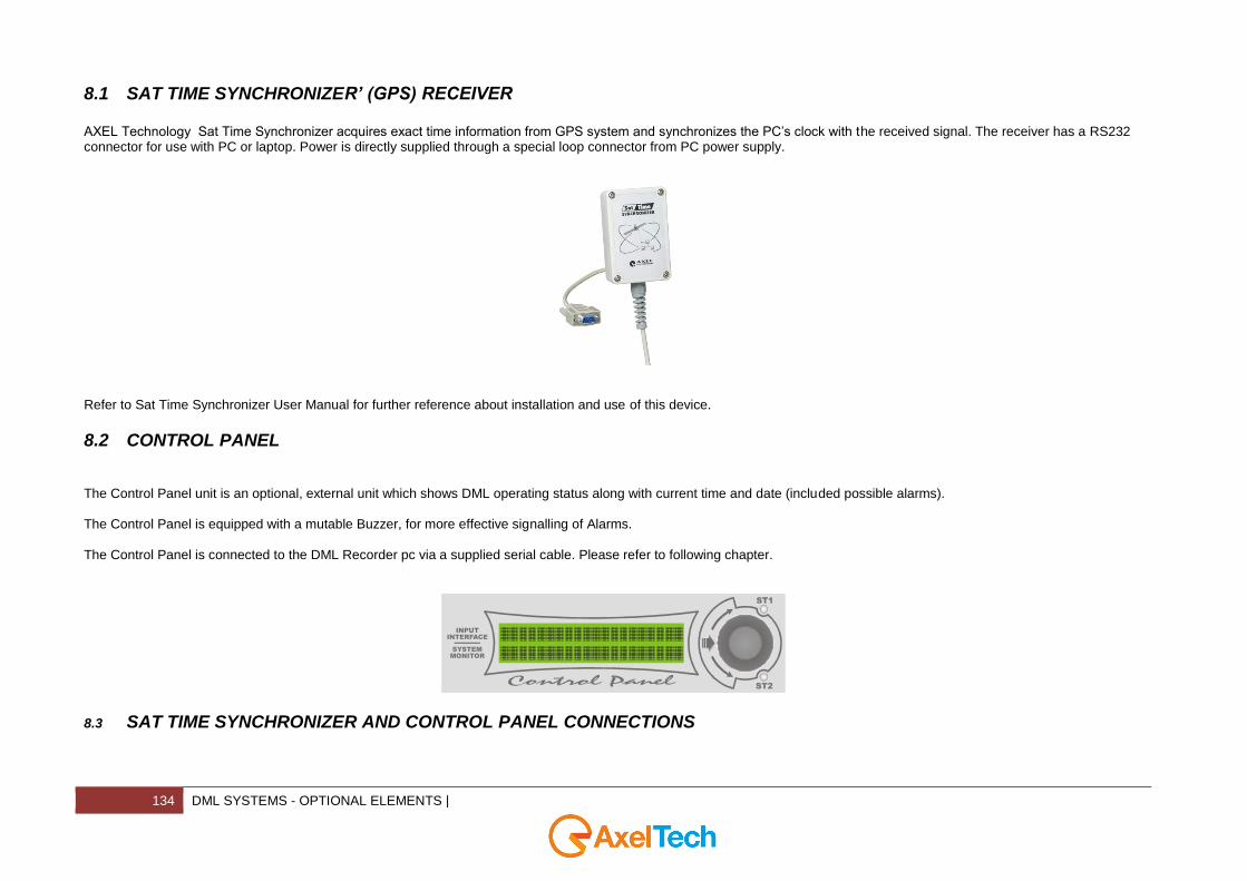
8.1 SAT TIME SYNCHRONIZER’ (GPS) RECEIVER
AXEL Technology Sat Time Synchronizer acquires exact time information from GPS system and synchronizes the PC’s clock with the received signal. The receiver has a RS232 connector for use with PC or laptop. Power is directly supplied through a special loop connector from PC power supply.
Refer to Sat Time Synchronizer User Manual for further reference about installation and use of this device.
8.2 CONTROL PANEL
The Control Panel unit is an optional, external unit which shows DML operating status along with current time and date (included possible alarms). The Control Panel is equipped with a mutable Buzzer, for more effective signalling of Alarms. The Control Panel is connected to the DML Recorder pc via a supplied serial cable. Please refer to following chapter.
ST1
ST2
SYSTEMMONITOR
INPUTINTERFACE
8.3 SAT TIME SYNCHRONIZER AND CONTROL PANEL CONNECTIONS
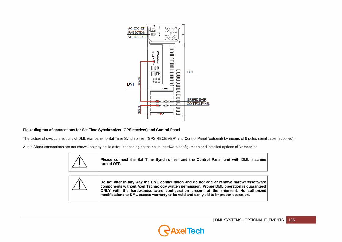
| DML SYSTEMS - OPTIONAL ELEMENTS 135
Fig 4: diagram of connections for Sat Time Synchronizer (GPS receiver) and Control Panel
The picture shows connections of DML rear panel to Sat Time Synchronizer (GPS RECEIVER) and Control Panel (optional) by means of 9 poles serial cable (supplied). Audio /video connections are not shown, as they could differ, depending on the actual hardware configuration and installed options of Yr machine.
Please connect the Sat Time Synchronizer and the Control Panel unit with DML machine turned OFF.
Do not alter in any way the DML configuration and do not add or remove hardware/software components without Axel Technology written permission. Proper DML operation is guaranteed ONLY with the hardware/software configuration present at the shipment. No authorized modifications to DML causes warranty to be void and can yield to improper operation.
136 |
9 FINAL CONSIDERATIONS & AXEL TECHNOLOGY CONTACTS __________________________________________________________________________________________________________________________________________________________________________________________________________________________________________________________________________________________________________________________________________________________________________________________________________________________________________ ____________________________________________________________________________________________________________________________________________________________________________________________________________________________________________________________________________________________________________________________________________________________________________________________________________________________________________________________________________________________________________________________________________________________________________________________________________________________________________________________________________________________________________________________________________________________________________________________________________________________________________________________________________________________________________________________________________________________________________________________________________________________________________________________________________________________________________________________________________________________________________________________________________________________________________________________________________________________________________________________________________________________________________________________________________________________________________________________________________________________________________________________________________________________________________________________________________________________________________________________________________________________________________________________________________________________________________________________________________________________________________________________________________________________________________________________________________________________________________________________________________________________________________________________________________________________________________________________________________________________________________________________________________________________________________________________________________________________________________________________________________________________________________________________________________________________________________________________________________________________________________________________________________________________________________________________________________________________________________________________
Main Office BOLOGNA: Via Caduti Di Sabbiuno 6/F 40011 Anzola Emilia - Bologna – Italy
Tel. +39 051 736555 - Fax. +39 051 736170
For Technical information or support: [email protected]
For General information and Sales dept: [email protected]
www.axeltechnology.com


![[Investec] India C&S TV Broadcasting - SR2PIN_112750](https://img.pdfslide.us/doc/110x75/577c785d1a28abe0548fc4bb/investec-india-cs-tv-broadcasting-sr2pin112750.jpg)