Embed Size (px)
Citation preview

GMV SPA
FLUID DYNAMICS EQUIPMENTS AND COMPONENTS FOR LIFTS
UNI EN ISO 9001 Certified Company
ENG
English
DLV VALVE
DLV-A3 VALVE MANUA L
INSTALLATION AND USE
1 0991 486 EN
AVAILABLE WITH VALVE TYPE
3010 ¾”,1 1/4”, 1 ½”, 2”, NGV ¾”

ENG
1 0991 486 EN - 29.09.2016
2 / 11
DLV VALVE MANUAL INSTALLATION , USE AND MAINTENANCE
INDEX
0 GENERAL SECTION 3
0.1 INTRODUCTION 3
0.2 INSTALLATION RELATED DOCUMENTS 3
0.3 SAFETY PRECAUTION DURING INSTALLATION 3
0.4 GENERAL ORDERS 4
0.5 LIABILITY AND WARRANTY 4
1 FEATURES AND REQUIREMENTS 4
1.1 DLV A3 VALVE 4
1.2 DELIVERY PACKAGING 5
1.3 IDENTIFICATION PLATE 5
1.4 THE FLUID 5
1.5 CLEANING AND SAFETY PROTECTIONS 6
2 DLV A3 WORKING DESCRIPTION 6
2.1 DESCRIPTION 6
2.2 HYDRAULIC SCHEME 7
2.1 SEMPLIFIED HYDRAULIC SCHEME 7
3 INSTALLATION 8
3.1 HYDRAULIC CONNECTION SAMPLES 8
3.2 DIMENSIONS 9
4 ELETTRICAL CONNECTIONS 9
4.1 ELECTRICAL GETTING STARTED :ICONS 10
5 TEST AND ADJUSTMENTS 10
5.1 MONITORING SYSTEM CHECK 10
6 CERTIFICATES 11
1 0991 486 EN - 29.09.2016
ENG DLV VALVE MANUAL
INSTALLATION , USE AND MAINTENANCE 3 / 11
0 GENERAL SECTION
0.1 INTRODUCTION Assembling,installation,start-up and hydraulic lift maintenance should be performed by experienced
personnel.Before starting any work on the hydraulic components,personnel showld carefully read these instructions,particularly referring to 0.3 chap. “Safety precautions”. This “Instruction Manual” in an integral part of the lift and should be protected and accessible. DLV is a non return electrically-controlled valve,working in series with the main valve to stop the lift during an unintended car movement from the floor. DLV valve prevent only the downward unintended car movement. The purpose of the valve is to work together with the main valve according to the Lift European Standards EN 81.2:1998 + A3:2009 which states that “in case of use of two electro-valves working in series, the self control implies the separate verification of the opening and closing of each single valve when the car is empty. If a fault is detected, the subsequent movement of the lift must be avoided”
0.2 INSTALLATION RELATED DOCUMENTS The documents to use for the installation are those required by the EN81-2:1998 and by the rules in force,
particularly the following: THIS INSTALLATION MANUAL WIRING AND HYDRAULIC DIAGRAMS (EN81-2:1998 16.2 A) 6 AND 7).
All the documentation for a correct and safe installation, must be stored by the installation responsible. Please remember that this documentation is considered part of the plant and must be complete, well stored and unabridged in every part. In order to maintain the readability, the documentation shouldn’t be damaged and shouldn’t have missing parts. Moreover, do not tear or deteriorate sheets during consulting.
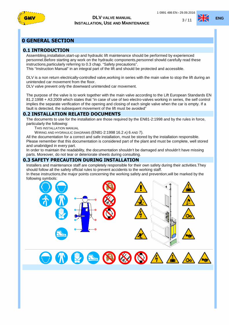
0.3 SAFETY PRECAUTION DURING INSTALLATION Installers and maintenance staff are completely responsible for their own safety during their activities.They
should follow all the safety official rules to prevent accidents to the working staff. In these instructions,the major points concerning the working safety and prevention,will be marked by the following symbols:

ENG
1 0991 486 EN - 29.09.2016
4 / 11
DLV VALVE MANUAL INSTALLATION , USE AND MAINTENANCE
0.4 GENERAL ORDERS The valves shall be maintained in good working order in accordance with the European Standards. To this effect, regular maintenance of the installation shall be carried out, to ensure, in particular, the safety of the installation. The safety of an installation shall take into account the ability to be maintained without causing injury or damage to health. Regular maintenance of the installation shall be carried out to ensure the reliability of the installation. The access and the associated environment shall be maintained in good working order. The competence of the maintenance person within the maintenance organization shall be continuously updated.
0.5 LIABILITY AND WARRANTY These instructions are intended for people with experience in installation, adjustment and maintenance of
hydraulic lifts. GMV disclaims any liability for damage caused by improper or different use from what described in these instructions or inexperience or carelessness of those responsible to assemble, adjust or repair hydraulic components. GMV's warranty is voided if you install any components or parts not original, if you make unauthorized changes or modifications or made by unauthorized or unqualified personnel. Unless otherwise indicated, the following situations are forbidden for safety reasons:
- Any product modification; The installation of the product for purposes other than those described; Damage to the joints; Carrying out maintenance or inspections improper or inadequate; The use of improper accessories and not original spare parts or materials from GMV.
NOTES Indicates information which contents must be seriously taken in consideration.
WARNING Indicates that the described operation may cause, damages to the system or physical damages if performed without complying with the safety standards.
To install or replace system components,we should pay attention to the following measures:
- Make the car lift rest on the buffers - make sure the lift shouln’t be unintentionally powered,locking the main switch - bring to zero the pressure before opening the hydraulic circuit,removing cups,unscrewing fittings - In case of welding,be care the slags do not get in touch with the fluid,the jask and the gaskets - Remove the fluid in excess,the leakages,keep clean the system to find out and consequently remove the
leakages
WARNING Before starting all kind of installation operation: ALWAYS verify that all the safety devices, mechanical or electrical, are active and working properly
1 FEATURES AND REQUIREMENTS
1.1 DLV A3 VALVE
The DLV A3 is a pilot-operated non-return valve that must be mounted between the cylinder and the 3010 control valve or any other control valve for lifts,traditional or electronic.
The valve should be installed as close as possible to the main hydraulic block but in special cases can be installed also close to the cylinder without compromising its function.
During the upward phase it works as a normal non-return valve . So the pressure of the oil sent from the pump can control the opening degree.
In down direction however, when energized, the valve allows the passage of oil from the cylinder to the main block and then into the tank.When de-energized, the solenoid valve immediately closes and stops the car.

1 0991 486 EN - 29.09.2016
ENG DLV VALVE MANUAL
INSTALLATION , USE AND MAINTENANCE 5 / 11
DLV are manifactured in different sizes and can be used for the following range(see the tab. 1).
Type Max interv.flow
Nominal flow
Working press.
Working temp. Viscosity Tens.DLV Power Emerg.
Pw. l/min bar °C cSt Vdc Vac W Vdc
DLV A3 – ¾” 45 8 - 45
12 - 45 5 - 70
14-290
(ISO VG 46 I≈120)
24-12 48-12 80-12 90-12
110-12 180-12/24
110 220 230
30
12 24 DLV A3 - 1” ¼ 210 15 - 210 30 DLV A3 - 1” ½ 430 25 - 430 30
DLV A3 - 2” 600 30 - 600 45
Tab. 1
1.2 DELIVERY PACKAGING Upon picking up the material,before signing the delivery,be care the goods match the packing list and the order list.
The packing list should includes: - Installation use and maintenance manual - DLV device (factory assembled) - Connection fittings - Cartboard box
1.3 IDENTIFICATION PLATE
The indentification plate with the main factory data (see picture below), is directly placed on DLV.
The plate should include: - Type of DLV device - Serial number - Year manifacturing - Flow range - Max static pressure
1.4 THE FLUID The hydraulic fluid is very important for an hydraulic lift
Especially in systems with medium or intensive traffic,choosing a good fluid increases the temperature range of comfortable working and enhances the service life of the components.
When we choose the fluid we must take into account both the characteristics of the elevator (temperature , power unit ventilation room, amount of trafic) and the characteristics of the fluid (temperature-viscosity).In case of replacement,follow the local pollution.Waste should be placed in a proper box to protect the environment.
ENG
1 0991 486 EN - 29.09.2016
6 / 11
DLV VALVE MANUAL INSTALLATION , USE AND MAINTENANCE
GMV use and recommend an hydraulic fluid ISO VG 46 that : • Thanks to classification as category HEES, as rule ISO-UNI 6743-4 and its
biodegradability index > 90%, according to standard CEC L33-A-93, is acceptable from an environmental point of view.
• Thanks to the synthetic base (ISO VG 46 ) and its viscosity index (>140), higher than the traditional mineral oil, allowing greater stability, ensuring better performance against wear and aging on systems as lifts for persons and goods, in accordance with the environmental directive 2006/118/EC.
• Thanks to a flash point above 220°C compared to the 140°C of the traditional mineral oil it is safer and reduces the risk of fire.
1.5 CLEANING AND SAFETY PROTECTIONS Ensure there is no dirty inside.The impurities could damage the sealing of the piston and of the valve block and can cause failures.All the components to remove for control and repair,should be clean before the re-installation.
Any leakage of fluid should be adsorbed with rags during the maintenance to avoid any release.
2 DLV A3 WORKING DESCRIPTION
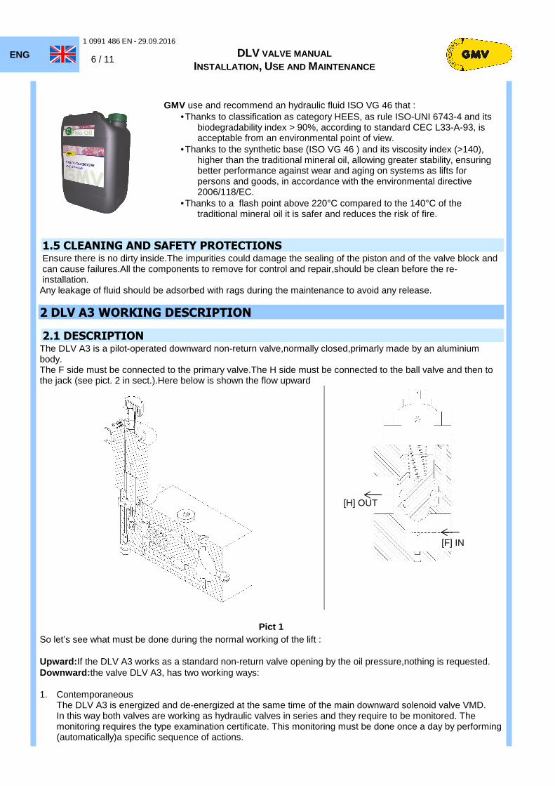
2.1 DESCRIPTION The DLV A3 is a pilot-operated downward non-return valve,normally closed,primarly made by an aluminium body. The F side must be connected to the primary valve.The H side must be connected to the ball valve and then to the jack (see pict. 2 in sect.).Here below is shown the flow upward
Pict 1
So let’s see what must be done during the normal working of the lift : Upward: If the DLV A3 works as a standard non-return valve opening by the oil pressure,nothing is requested. Downward: the valve DLV A3, has two working ways: 1. Contemporaneous
The DLV A3 is energized and de-energized at the same time of the main downward solenoid valve VMD. In this way both valves are working as hydraulic valves in series and they require to be monitored. The monitoring requires the type examination certificate. This monitoring must be done once a day by performing (automatically)a specific sequence of actions.
[F] IN
[H] OUT

1 0991 486 EN - 29.09.2016
ENG DLV VALVE MANUAL
INSTALLATION , USE AND MAINTENANCE 7 / 11
2. Timed
The DLV A3, respect to the main downward solenoid valve VMD, is energized about 1 second before and de-energized almost 2 seconds after the arrival at landing. In this way the DLV A3 is not an element working to control the lift and consequently does not require any kind of monitoring. Its correct working can be verified during the standard maintenance operations every 6 months.
A3 intervention state of DLV In the shaft must be present a system (ex. two contacts/switches) able to detect the unintended movement of the car with open doors in up or down direction.
During an unintended movement in down direction , when the unintended movement is detected, the system de-energize the DLV A3 valve to let it close and stop the lift.
During an unintended movement in up direction the system must switch off the motor/pump to stop this movement. Consequently the valve will stop the car.In every case,after this phase,the system should go out of service and it should be restored only by an authorized and properly trained person. The system which detects the unintended movement and energizes the stopping device can be the existing one just used to define the opening doors zone. The intervention zone, according to the EN 81-2, must be at maximum ± 200 mm from the landing
2.2 HYDRAULIC SCHEME Here below (pict.3) follows the DLV hydraulic scheme to show the placing of DLV,between the main valve and the jack. Legend
Pict. 1
PT Pressure trasducer DLV Non return pilot-operated valve R/S Shut off valve/Silencer VC Check valve ISP Inspection pressure gauge fitting MAN Pressure gauge Pmax Maximum pressure switch Pmin Minimum pressure switch OLD Overload pressure switch J Jack [F] DLV connection main valve side [H] DLV connection main jack side
2.1 SEMPLIFIED HYDRAULIC SCHEME DLV A3 Non return pilot valve
VAL Main valve J Jack
VAL
DLV A3
J
[H]
[F]

ENG
1 0991 486 EN - 29.09.2016
8 / 11
DLV VALVE MANUAL INSTALLATION , USE AND MAINTENANCE
3 INSTALLATION
ATTENZIONE During the installation:nvere exclude safety devices and never power-on the motor pump.
3.1 HYDRAULIC CONNECTION SAMPLES
DLV A3 - 3010 – MR with cabinet up to 150 lt DLV A3 - 3010 – MR no cabinet from 180 to 210 lt
DLV A3 - 3010 - MRL MC with cabinet up to 150 lt DLV A3 - 3010 - MRL MC no cabinet 180/210 lt
1 0991 486 EN - 29.09.2016
ENG DLV VALVE MANUAL
INSTALLATION , USE AND MAINTENANCE 9 / 11
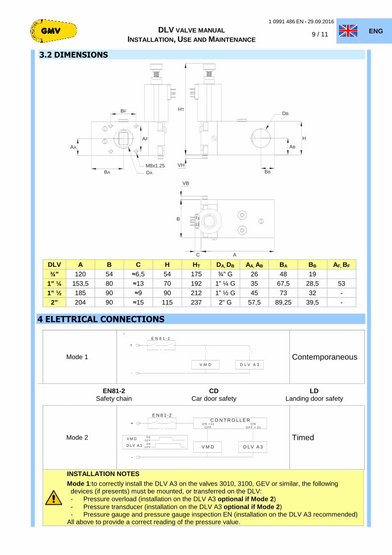
3.2 DIMENSIONS
HT
B
A
H
VHBB
AB
DB
BA
AA
AF
BF
M8x1.25DA
C
VB
DLV A B C H HT DA, DB AA, AB BA BB AF, BF
¾” 120 54 ≈6,5 54 175 ¾” G 26 48 19
1” ¼ 153,5 80 ≈13 70 192 1” ¼ G 35 67,5 28,5 53
1” ½ 185 90 ≈9 90 212 1” ½ G 45 73 32 -
2” 204 90 ≈15 115 237 2” G 57,5 89,25 39,5 -
4 ELETTRICAL CONNECTIONS
Mode 1
E N 8 1 - 2
V M D D L V A 3
+
-
2
Contemporaneous
EN81-2 CD LD Safety chain Car door safety Landing door safety
Mode 2
E N 8 1 -2
V M D D LV A 3
O N + 1 sO F F
O NO F F + 2 s
-
+
3C O N T R O L LE R
D L V A 3
V M DO N
O F FO N
O F F
Timed
INSTALLATION NOTES
Mode 1 :to correctly install the DLV A3 on the valves 3010, 3100, GEV or similar, the following devices (if presents) must be mounted, or transferred on the DLV: - Pressure overload (installation on the DLV A3 optional if Mode 2 ) - Pressure transducer (installation on the DLV A3 optional if Mode 2 ) - Pressure gauge and pressure gauge inspection EN (installation on the DLV A3 recommended)
All above to provide a correct reading of the pressure value.

ENG
1 0991 486 EN - 29.09.2016
10 / 11
DLV VALVE MANUAL INSTALLATION , USE AND MAINTENANCE
4.1 ELECTRICAL GETTING STARTED:ICONS
0 - OFF
0 - OFF
+
5 TEST AND ADJUSTMENTS
5.1 MONITORING SYSTEM CHECK
To assure the correct working of the monitoring system of the DLV A3 the control panel should perform a check operation behind closed doors, at least once a day.
The control panel, during the test, must:
1. To move the car to the lower floor
2. To close the doors 3. Wait that the system turns
into the “Free” status 4. Start the test following the
scheme -> 5. At the end of the test, if the
system is not in the “Out of service” status, turn the system in normal use.
If the control panel receives a command from a push-button panel during the test, stop the test, execute the command (order / call) and at the end, restart from point 1
]x[ = Close ]↕[ = Open � = NO
� = YES R _↑ = Relevelling L --►-- = Return at landing
With the car stopped at landing,energize only the DLV A3 valve,holding the main valve VMD de-energized.If all the components work correctly,the car must stop at landing position.A timed check starts for two sec.to verify a car movement.In case of movement detection without landing,the system must go into alarm and put the lift out of service.In case of back-landing,another 2 seconds timed check starts,energizing the the DLV.If the relevelling does not start,the system is ok.Otherwise,a VMD failure is confirmed (DLV de-energized).

1 0991 486 EN - 29.09.2016
ENG DLV VALVE MANUAL
INSTALLATION , USE AND MAINTENANCE 11 / 11
In the same way,is energized only the main valve VMD,holding the DLV A3 valve de-energized.If all the components work correctly,the car must stop at landing position.A timed check starts for two sec.to verify a car movement.In case of movement detection without landing,the system must go into alarm and put the lift out of service.In case of back-landing,another 2 seconds timed check starts,energizing the VMD.If the relevelling does not start,the system is ok.Otherwise,a DLV failure is confirmed (VMD de-energized).
6 CERTIFICATES

Doc
. n°
1 09
91 4
86 E
N R
ev. 0
.0 -
29.
09.2
016
File
: DLV
A3-
02-1
0991
486E
N.d
oc -
(J3
0)
FLUID DYNAMICS EQUIPMENTS
AND COMPONENTS FOR LIFTS
All rights reserved. Any kind of exploitation in any form and by any means is forbidden without a written permission of GMV Spa. GMV Spa, within technical or manufacturing progress, reserves the right to modify parts or this manual without notice. Drawings, descriptions and data included in this manual are indicatives. For all the data not included in this manual refer to the documents of any single part. To guarantee the products security, do not use spare parts not genuine or not approved by GMV Spa. GMV Spa will not assume any responsibility if the instructions included in this manual are not observed.
Information and support:
GMV SPA
VIA DON GNOCCHI, 10 - 20016 PERO – MILANO (ITALY)
TEL. +39 02 33930.1 - FAX +39 02 3390379
HTTP://WWW.GMV.IT - E-MAIL: [email protected]
UNI EN ISO 9001
CERTIFIED COMPANY