Embed Size (px)
Citation preview
1
DLR MASCOT on HAYABUSA-II, A Mission That May Change Your Idea of Life!
– AIV Challenges in a Fast Paced and High Performance Deep Space Project –
By Christian Grimm1)
, Jeffrey Hendrikse2)
, Caroline Lange1)
, Jan-Thimo Grundmann1)
, Christian Ziach1)
, Ross Findlay1)
,
Tra-Mi Ho1)
, Tim van Zoest1)
1)Institute of Space Systems, German Aerospace Center, Bremen, Germany; 2)EADS Astrium, Friedrichshafen, Germany;
MASCOT, a small 10kg Asteroid landing package on-board Hayabusa-2 is currently finalizing Phase-C of its
development and after official go-ahead during the Critical Design Review it will undergo a final verification program at
DLR before send to JAXA to be integrated into the mother spacecraft. Its last stages during the Assembly, Integration and
Verification (AIV) process show that by applying a unique mix of conventional and tailored Model Philosophies it is
possible to dynamical adapt the test program, limited by a fixed launch date, to accomplish for the shortest planning and a
suitable weighing of costs and risks. In addition, this paper introduces the term Concurrent AIV to express the many
simultaneous running test and verification activities.
Key Words: MASCOT, Hayabusa-2, Asteroid Lander, Concurrent AIV, Dynamic Model Philosophy
1. Introduction
About the size of a shoe box and weighing roughly 10
kilograms, the Mobile Asteroid Surface Scout (MASCOT) is a
small landing package aboard the Japanese space probe
Hayabusa-2, scheduled for launch in late 2014. MASCOT is
currently being developed at the German Aerospace Center
(DLR) in close collaboration with the French space agency
(CNES) and the Japanese Aerospace Exploration Agency
(JAXA). The 5-year sample return mission HY-2 targets the
carbonaceous Near-Earth Asteroid 1999 JU3, an object
belonging to the most abundant type of space rock in our solar
system which is thought to contain water and therefore may
have provided the building blocks for seeding life on Earth [1].
The fully autonomous robot MASCOT will carry a full set of
scientific payloads to study the temperature, chemical
composition, surface texture and magnetic properties of this
asteroid.
Originally investigated in the framework of the European
Marco Polo study, MASCOT has undergone several concept
iterations converging into a system which is very compact in
design but still achieving a high ratio of payload mass to total
system mass. Following an invitation from JAXA to join in
the follow-up mission of the first asteroid sampler Hayabusa,
MASCOT was selected at a time where its final conceptual
design, including its scientific payloads, had not yet been fully
defined. The tight schedule, tightly defined envelope, and
strict margins policy are challenges during development at all
levels. Science payloads, bus subsystem units and overall
system design had to be derived from what was available off
the shelf at the project partners’ in very heterogeneous
maturity levels ranging from concept study to flight heritage
hardware. In essence, MASCOT was in the beginning behind
the main spacecraft schedule, but due to the early delivery
date of the FM the project development cycle needed to be
shortened compared to the master schedule. In other words,
the MASCOT development is required to constantly catch up
with the master timeline and finally overtake it [2].
Fig. 1. MASCOT Project Timeline with major milestones [2] and
MASCOT STM on display at the ILA Berlin Air Show 2012.
MASCOT entered the realm of hardware with the first unit
breadboarding start on June, 6th, 2011, over half a year before
formal go-ahead. It passed Hayabusa-2 subsystem CDR in
December 2011, and an internal system PDR in July 2012.
2
The project is currently in Phase C, with testing activities
on-going. After a series of subsystem midterm reviews, the
internal system CDR takes place on April 22nd, 2013.
According to current planning, the MASCOT flight model has
to be delivered in February 2014 for launch in December 2014.
The tight schedule, due to a launch date fixed by celestial
mechanics, is one of the major challenges during the
MASCOT development and specifically in its Verification and
Validation Program.
2. The MASCOT Mission
2.1 Asteroids – Cradle of Life or Source of Hazard?
The search for the origins of life and increasing the Earths
safety against possible meteor impacts are two corner stones
in the international space exploration endeavor. Asteroids,
which are the residual population of planetesimals, have
formed during the accretion process of the solar system some
4.5 billion years ago. Since this time, they have changed only
little preserving the original content of material from which
the planets, including the Earth, have been formed. It is
assumed that especially the carbonaceous asteroids (C-type),
which are with almost 75% of all known asteroids the most
common type, contain organics and perhaps water as well.
Analyses of meteorite fragments, like the one of the Tagish
lake, Canada, contained comparatively much organic matter
including traces of amino acids [3], the building blocks of
proteins, essential for forming life. These could have been
carried by asteroids to Earth when raining down on it during
its early development stages. The question is whether it was a
lucky coincidence, that the analyzed meteorite samples
contained organic matter, or whether it can be expected in
general, that many asteroids carry the essence of life with
them. The assumption, that asteroids could contain water, is
derived from spectral analyses of infrared pictures of for
example 24 Themis. These observations revealed that the
surface of this object is covered to a big part by water ice as
well as include potential traces of organic matter [4].
In order to verify this theory, it is required to gather in-situ
information of such objects. The Hayabusa-2 mission targets
therefore the carbonaceous asteroid 1999 JU3 to collect
primitive unaltered material samples. This Near-Earth Object
is also an Earth-crossing body, which in general pose a
potential threat when on an impacting course. Even small
objects can have severe consequences. Like the Tunguska
Event in 1908, a similar recent incident in Russia of the
Chelyabinsk meteor made this very clear. This asteroid had an
estimated size of only 17 to 20 meters, weighting between
10,000 to 18,000 tons, and it burst in a height of
approximately 23 km causing a shock wave which shattered
windows and did further damage to buildings. More than 1000
people were hurt, mainly by broken glass [5]. Depending on
the size and composition of such an object, events like this can
be confined to the closer vicinity of its impact location only or,
in worst case, have a devastating global effect which could
even extinct all life on earth. Missions to investigate asteroids
will help to know better about this type of space objects and
hence to identify and establish the most effective prevention
measures. Once it comes to the need for deflection, the
response of the surface and the immediate environment of the
asteroid to any method of impulse transfer need to be
understood. For kinetic deflection, the mechanical properties
resulting from surface mineral composition, porosity and
possible volatiles influence the factor by which impact energy
is converted to impulse. Deflection methods employing
radiative ablation, whether by continuous illumination or
pulse irradiation, require understanding of the surface
composition, porosity, thermo-optical properties and heat
capacity. Many of the parameters related to orbit
determination would require decades of observation from the
ground to be constrained to sufficient precision. MASCOT
with its dedicated set of instruments has the capability to
quickly constrain many surface and environment parameters
relevant to precise orbit determination and deflection [6].
2.2 MASCOT – Targeting for the Context!
Hayabusa-2 (HY-2) will launch from Tanegashima Space
Center and arrive at 1999 JU3 in June 2018. After arrival,
HY-2 will first perform a global mapping in order to
characterize the asteroid. With the landing site selected based
on local geology and thermal constraints, MASCOT will be
released to the surface, either during a dedicated descent or
during one of the sampling dress rehearsal maneuvers. The
mothership will descend to the separation altitude of 100
meter, at which point MASCOT will be ejected via a spring
mechanism with a controlled low velocity in the order of cm/s.
MASCOT will fall to the asteroid surface under the effects of
the weak gravitational field, before landing in an unknown
orientation. In order to start the investigation, MASCOT must
be orientated to its primary surface side. This is performed by
an up-righting manoeuver using an internal mobility
mechanism. A full complement of scientific activities will be
performed, involving approximately one asteroid day, before
MASCOT can be relocated to another site by initiating an
uncontrolled hop of up to 200 meters across the surface.
Further scientific activities will take place, and then, power
depending, a second hop is considered. The expected lifetime
of MASCOT is in the order of 12-16 hours. MASCOT takes
up a key role in the HY-2 mission aiming to conduct the first
ever in-situ measurements on an asteroid providing ground
truth information, since rocks nature (i.e. volatiles within
rocks) can change during return flight. MASCOT’s suite of
science instruments is designed for the study of the target
asteroid with a focus on surface properties and the close-in
space environment that it experiences during descent and
landing. The design goal is to provide supporting information
to the process of sampling site selection. MASCOT acts
therefore as scouting vehicle in favor of the mother spacecraft,
but in addition its measurements are on different length scales.
The returned samples by Hayabusa-2 will be in the micro- to
millimeter scale, whereas the orbiter will map the asteroid
from several meters to a few centimeters scale. MASCOT’s
measurements will complete this picture with measurements
in ranges from micrometers to several centimeters scale and
hence, providing the context of any collected samples.
3
3. The AIV Program
The Assembly, Integration and Verification (AIV), a.k.a.
Assembly, Integration and Test (AIT) is the final stage in
producing a spacecraft and readying it for launch. It includes
the simulation and test of the expected space environment and
flight operation to verify and demonstrate the overall
performance and reliability of the flight system. Choosing the
right philosophy or approach of the Verification and
Validation (V&V) process is crucial and driven by risk
tolerance. Less verification implies but does not necessarily
create more risk. More verification implies but does not
guarantee less risk [7].
3.1. Model Philosophy – Dynamic and Flexible
In European and American space industry there are
currently two main model philosophies in use to conduct the
verification of a space system. These two philosophies are
known as the Prototype Approach, sometimes also called the
Traditional or Classical Approach, and the Protoflight
Approach [8, 9]. The basic difference is reflected in the
number and types of models being built and tested. In the
Classical Approach the design verification evolves in a mostly
sequential and also successive fashion from a Dummy Model,
a Structural or Structural-Thermal Model (STM), an
Engineering/Electrical Model (EM), a Qualification Model
(QM), to the final Flight Model (FM), which may also have a
sister model used as Flight Spare (FS) in case of launch failure
or otherwise as Ground Reference Model (GRM). The
Protoflight Approach qualifies the design of a single flight
model by replacing critical subsystems during the integration
process. The Protoflight Model (PFM) is subject to a full
qualification process and is refurbished before launch. It is
generally faster and cheaper and applied to projects with no
technology critical design accepting a medium risk.
The classical approach would be of course the most reliable
method to choose as it gives the highest confidence that the
final product performs well in all aspects of the mission.
However, due to the tight schedule in the MASCOT project,
the extensive and time consuming method of this approach
could not be applied. On the other hand, the Protoflight
Approach is also not applicable, since the chosen payloads
and the system itself have very heterogeneous maturity levels,
which prevent the system from being tested as a consistent
entity at each stage. Hence, the test philosophy of MASCOT
applies a Hybrid Approach with a mixture of conventional and
tailored model strategies. This approach is common practice in
scientific robotic missions [7] but the specific MASCOT
model philosophy goes even further. The project started with a
baseline on the Classical Approach (STM, QM and FM) to
ensure a minimum number of physical models required to
achieve confidence in the product verification with the
shortest planning and a suitable weighing of costs and risks.
But the approach was adapted on a case by case scenario,
where the model philosophy evolved along the verification
and test process depending on the particular system and
subsystem readiness. According to this dynamical process, the
decision which model to test and what to test with it was often
made simply on the subsystems availability. This included test
models reorganization, refurbishing and re-assigning previous
models for other verification tasks if appropriate, skipping test
cases, parallel testing of similar or equal models and for some
components allowing the qualification on MASCOT system
level. The verification approach is focused around the systems
main structure which comprises the MASCOT Landing
Module (LM) the Mechanical and Electronic Support System
(MESS), which is the main interface to HY-2 remaining at the
spacecraft after separation, and the common electronic box
(Ebox), which is an integral part of the LM structure serving
also as interface for other subsystems like the mobility unit,
the battery and the communication modules. The development
status of these three elements defines the overall maturity of
each MASCOT model.
3.3. Concurrent AIV – Dealing with Projects Risks
As mentioned before, MASCOT was granted only a limited
time which could not hold a classical sequential approach
regarding development, test and verification phases or even
allowing margins for risks such as coping with delays due to
non-conformances on systems, units, parts and facilities. The
heterogeneous maturity levels have let us to tailor a mixed
model philosophy of the subunits into an adaptable overall
MASCOT strategy to maintain reduced programmatic risks.
Due to the highly compact and lightweight nature of this
system almost all elements are custom made for the specific
mission scenario. The risk assessment showed that a high
chance for schedule delays can occur due to test repetition of
unit failures and late delivery. Keeping this course, the
complete path would have taken us approximately 48 month.
However, when your ride has minimal options to wait for you
defining a time limit less than 24 month and none of the
subunits are replaceable by off-the-shelf equipment, how do
you proceed?
To catch up with the HY-2 development schedule and
maintain enough margins to incorporate risk, the MASCOT
project incorporated parallelization of testing activities using
identical copies and flexibility in its model philosophy. This in
turn created independent unique test threads only joining their
dependencies at key points where optional other roads could
be chosen. E.g. If a structure was damaged by one test, or in
use longer by another, a copy was shortly available to redo the
test if applicable, knowing that a new structure manufacturing
process would have taken otherwise 4 months or more. Like
Concurrent Engineering, a methodology based on the
parallelization of engineering tasks nowadays used for
optimizing and shorten design cycles in early project phases,
we introduce here the term Concurrent AIV to express the
many simultaneous running test and verification activities. In
effect, the development, test and verification track of Software
Development, Functional Testing, Mechanical AIV and
Thermal AIV got their own independent routes sharing their
verification processes. Meaning that basically almost all
environmental tests on STM and functional test with
subsystems will have been performed before MASCOT QM
4
and FM are fully assembled reducing the potential delays. In
addition, both these final threads (QM/FM – performed in
near parallel activities) are sharing as well their verification
processes were the QM will endure all environmental
qualification tests at DLR herewith validating parts of the FM
which in turn does its final acceptance on HY-2 system level,
hereby reducing again required project timeline. Knowing the
advantages of this novel approach, the challenges in creating
parallel development, test and verification tracks are found in
team and facility resources if these are not readily and
on-demand available. In addition, this philosophy is more
complex as it requires the overview of the development
process of the mother spacecraft, the ongoing progress on
system level as well as the insight in all payloads and
subsystems. This was handled by splitting the tasks on more
Systems Engineering and AIV responsible personnel and
performing regular consolidation gatherings between these
key player including also the Project Management and
Product Assurance, in order to keep the project sorted and on
course.
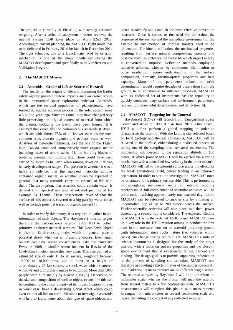
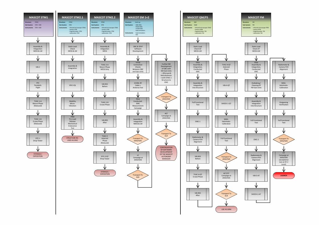
4. Dual-Track Test Campaigns
The applied approach is dynamic and evolves while the
project progresses. Figure 8 shows the current (as of the time
of writing) top level model and test philosophy of the
MASCOT system, not including separate model strategies of
payloads or other subsystems. What complicated the
development process even further, for the verification of the
main spacecraft MASCOT had to take part in certain
verification activities on HY-2 system level. As these tasks
run also in parallel to the own MASCOT development this
introduced a Dual-Track test scenario. To cope this situation,
again depending purely on subsystem availability, the already
tested models of MASCOT, when not needed for any other
purpose in its own development process, where used to take
part in HY-2 system verification test. Otherwise, additional
duplicate or reduced models where built as “built to purpose
and schedule”. Nevertheless, this was used as an advantage to
shorten the verification process on MASCOT system level by
skipping some tests which will be performed on HY-2 system
level and focusing mainly on the requirements implied to be
verified for launch. The self-given set of requirements, which
focusses more on the scientific outcome of the integrated
payloads, where handled similar but with a slightly lower
priority.
4.1 MASCOT Track - Engineering Thoughts face Reality!
The first model built was a breadboard (BB) model
consisting of the aforementioned three elements LM, MESS
and Ebox, including mass dummies of the single heaviest
subsystems, namely the payloads, the battery and the mobility
unit. This model was used to initially demonstrate structural
integrity on reduced vibration levels (VIB-1). After this test,
the MESS and Ebox where refurbished and advanced to an
STM, whereas the LM was re-used as demonstration model
for the mobility subsystem including pendulum test and
parabolic flight. The MASCOT STM1 then featured the
previous BB MESS and Ebox as well as a new LM structure.
The model, including also the previous S/S mass dummies,
was intended to qualify the structural design (VIB-2), but after
failing the test structural damage was severe and it was
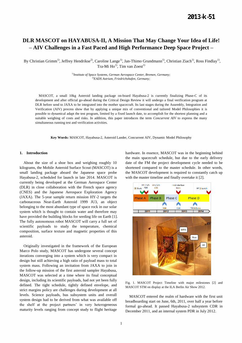
decided to build yet another structure (STM2). The STM1,
however, was refurbished and re-used as demonstration
platform for the systems separation mechanism needed later
in-orbit operation to push out the landing module out of the
MESS and HY-2. These tests have been performed in
parabolic flight (PFC) as well as in drop tower (DTC)
experiments.
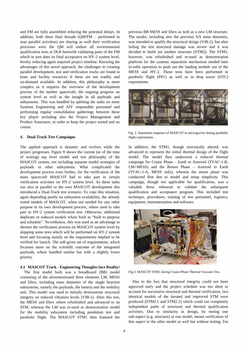
Fig. 2. Separation sequence of MASCOT in microgravity during parabolic
flight experiments.
In addition, the STM1, though structurally altered, was
advanced to represent the initial thermal design of the flight
model. The model then underwent a reduced thermal
campaign for Cruise Phase – Earth to Asteroid (TVAC-1-B,
LM+MESS) and the Return Phase – Asteroid to Earth
(TVAC-1-A, MESS only), whereas the return phase was
conducted first due to model and setup simplicity. This
campaign, though not applicable for qualification, was a
valuable dress rehearsal to validate the subsequent
qualification and acceptance program. This included test
technique, procedures, training of test personnel, logistics,
equipment, instrumentation and software.
Fig.3. MASCOT STM1 during Cruise-Phase Thermal Vacuum Test.
Due to the fact that structural integrity could not been
approved early and the project schedule was too short to
account for successive structural and thermal verification, two
identical models of the iterated and improved STM were
produced (STM2.1 and STM2.2) which could run completely
independent paths of structural and thermal qualification
activities. Due to similarity in design, by testing one
sub-aspect (e.g. structure) at one model, meant verification of
this aspect in the other model as well but without testing. For

5
the next vibration campaign (VIB-3-QL) with qualification
levels, which verified also the frequency response and load
levels of all subunits, the STM2.1 was integrated with the now
available P/L, battery and communication STM subunits as
well as an EM mobility unit. To shorten subunit test schedules,
this test gave also the first possibility for subsystems
electronics, if ready, to be integrated into the Ebox to qualify
for structural integrity on system level.
Fig.4. MASCOT STM2.1 during Random Vibration Test to full
Qualification Level.
While the STM2.1 underwent the structural verification
path, the STM2.2 is awaiting currently thermal verification of
the Return and Cruise Phase (TVAC-2-A/B). After vibration,
P/L’s and other subunits are re-used for the thermal test but
are improved again to be thermally representative, including
dummy heat pipes, main and sub radiator, optical face sheets,
multi-layer insulation as well as controlled heaters. In order to
prevent over-testing and to confirm that no structural
alteration during thermal cycling has been induced by thermal
stresses we incorporate vibrational resonance checks with low
level sine-sweeps (VIB-Res) before and after each thermal
environment test. After successful test of the return and cruise
phase configuration the setup is changed to the third and final
On-Asteroid Phase (TVAC-3), whereas this test is again a
reduced dress rehearsal for the later QM test (TVAC-4) which
will include full functional subsystems and payloads. Both
STM2 after completion of the structural and thermal patch
will be used afterwards as qualification test bed of other
critical system elements (e.g. separation, preload release,
umbilical connector, Mobility microvibration as well as P/L
FOV alignment tests).
In addition to the physical MASCOT models a Software
Development and Verification Facility (SDVF) was created to
establish a general test bed for Mascot onboard software
development and functional system tests. This device builds
the electrical interface for the system electronic boards
including backplane, P/L boards, onboard computer (OBC)
and power control and distribution unit (PCDU). The OBC
can be connected to the SDVF simulating the other system
elements, which could be added piece vise when the hardware
electronic becomes available but also the other way around
where the OBC remains simulated by the SDVF In a final step
the real OBC board could be integrated running real EM
boards and verifying MASCOT’s functional performance.
These functional tests run continuously until functional
performance of all real hardware electronic boards is approved
and the cards can be implemented into the MASCOT QM.
Fig.5. MASCOT SDVF during conducted EMC tests including OBC,
PCDU and all Payload Electronic boards.
4.2 Hayabusa-2 Track – Bringing it on the Road!
As mentioned above the MASCOT system tries to catch up
with the development progress of the mother spacecraft
Hayabusa-2, whose final test sequence is split into sequential
test campaigns starting with an environmental campaign with
qualification test and the Initial Integration Test (IIT), where
subunits are integrated for the first time and end-to-end
communication to the main spacecraft is tested. This is then
followed by an Acceptance Environmental Test (AET) and the
Final Integration Test (FIT) leading all the way up to the
launch campaign. Each test campaign is required to see a
MASCOT model in order to verify the HY-2 system
performance. However, as the MASCOT system only reaches
proper maturity at the end of this year, which will be just in
time to take part in the FIT, reduced models and mock-ups of
MASCOT build to schedule and purpose had to be produced.
In order to receive appropriate vibration qualification levels
at the final integration place of MASCOT, a dedicated mass
dummy (MD) was created resembling the overall MASCOT
system in mass, CoG and mechanical interfaces to HY-2. This
MD was send to the JAXA/ISAS test center to take part in the
first environmental test of the mother spacecraft.
Fig.6. MASCOT MD during integration and test for the first HY-2
Environmental Test Campaign.
For the IIT a separate EM was built with a mock-up structure
resembling MASCOT in form and fit as well as having EM
functional communications equipment includeding OBC,
6
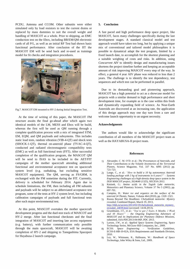
PCDU, Antenna and CCOM. Other subunits were either
simulated only by load resistors to test the current drains or
replaced by mass dummies to suit the overall weight and
handling of MASCOT as a whole. Prior to shipping, an EMC
conduction test on the Ebox, including BB/EM/QM electronic
cards of all P/L, as well as an initial RF Test had shown basic
functional performance. After conclusion of the IIT the
MASCOT EM will be send back and re-used as trainings
model for fit checks and integration procedures.
Fig.7. MASCOT EM mounted to HY-2 during Initial Integration Test.
At the time of writing of this paper, the MASCOT FM
structure awaits the final go-ahead after which again two
identical models of the LM, MESS and Ebox will be build,
whereas the first will be used as QM running through a
complete qualification process with a mix of integrated STM,
EM, EQM, and QM payloads and subsystems. This includes
static load tests, random vibration (VIB-4-QT) and shock tests
(SHOCK-1-QT), thermal on-asteroid phase (TVAC-4-QT),
conducted and radiated electromagnetic compatibility tests
(EMC) as well as full functional tests (FFT). After successful
completion of the qualification program, the MASCOT QM
will be send to ISAS to be included in the AET/FIT
campaigns of the mother spacecraft attending additional
functional and environmental acceptance test on spacecraft
system level (e.g. outbaking, but excluding sensitive
MASCOT equipment). The QM, serving as FS/GRM, is
exchanged with the FM sometime during the FIT. Currently,
delivery is scheduled for February 2014. Again due to
schedule limitations, the FM, then including all FM subunits
and payloads will be subject to an abbreviated acceptance test
program, some of the tests at HY-2 system level, but including
calibration campaigns of payloads and full functional tests
after each major environmental test.
At this point, MASCOT overtakes the mother spacecraft
development progress and the duel-test track of MASCOT and
HY-2 merge. After last functional checkouts and the final
integration of MASCOT and inserting late access equipment
(e.g. battery), with further communication only possible
through the main spacecraft, MASCOT will be awaiting
completion of HY-2 and shipping to Tanegashima Spaceport
for Hayabusa-2 launch campaign.
5. Conclusion
A fast paced and high performance deep space project, like
MASCOT, faces many challenges specifically during the last
development stages. A standard classical model and test
approach would have taken too long, but by applying a unique
mix of conventional and tailored model philosophies it is
possible to dynamical adapt the test program, limited by a
fixed launch date, to accomplish for the shortest planning and
a suitable weighing of costs and risks. In addition, using
Concurrent AIV to identify design and manufacturing issues
shortens the project timeline further and keeping an acceptable
amount of risk improving MASCOT every step of the way. In
effect, a general 4 year AIV phase was reduced to less than 2
years. The challenge is to identify the test dependency, test
sequences and which test can be performed in parallel.
Due to its demanding goal and pioneering approach,
MASCOT has a high potential to act as a showcase model for
projects with a similar demand in high performance and short
development time, for example as is the case within this fresh
and dynamically expanding field of science. As Near-Earth
Asteroids are discovered at an increasing rate, the application
of this design approach may one day turn from a rare and
welcome launch opportunity to an urgent necessity.
Acknowledgments
The authors would like to acknowledge the significant
contribution of all members of the MASCOT project team as
well as the HAYABUSA-II project team.
References
1) Alexander, C. M. O’D. et al.: The Provenances of Asteroids, and Their Contributions to the Volatile Inventories of the Terrestrial
Planets, Science Magazine, Vol. 337 No. 6095 (2012) pp.
721-723.
2) Lange, C., et al.: “How to build a 10 kg autonomous Asteroid
landing package with 3 kg of instruments in 6 years?” – Systems
Engineering challenges of a high-density deep space system in the DLR MASCOT project, 2624640 (1325), SECESA 2012.
3) Kminek, G.: Amino acids in the Tagish Lake meteorite,
Meteoritics and Planetary Science, Volume 37 No 5 (2002), pp. 697-701.
4) Campins, H.: Water ice and organics on the surface of the
asteroid 24 Themis, Nature, Volume 464 (2010), pp. 1320–1321.
5) Russia Beyond The Headlines: Chelyabinsk meteorite: Mystery
revealed, Combined Report, March 19, 2013,
http://rbth.ru/society/2013/03/19/chelyabinsk_meteorite_mystery_
revealed_24039.html (accessed: 14.04.2013).
6) Grundmann, J.T., et al.: “You’ve got 2 Years, 6 Months, 1 Week
and 48 Hours!” – the Ongoing Engineering Adventure of MASCOT and its Implications for Planetary Defence Missions,
submitted, IAA-PDC2013-04-06P, PDC 2013.
7) Larson, J.W., et al.: Applied Space Systems Engineering, Space Technology Series, McGraw-Hill Companies, Inc., 2009.
8) ECSS: Space Engineering – Verification Guidelines,
ECSS-E-HB-10-02A, ESA Requirements and Standards Division, 2010.
9) Ley, W., Wittmann, K., Hallmann, W.: Handbook of Space
Technology, John Wiley & Sons, Ltd., 2009.
MASCOT STM2.2
Structure:
Sub-System:
Instruments:
STM2
STM
∙ infrared microscope STM1
∙ camera STM
∙ magnetometer STM
∙ radiometer STM
Assembly &
Integration
MESS
TVAC-2-A
Return Phase
MESS Only
VIB-RES
Before
TVAC-2-B
Cruise Phase
VIB-RES
After
TVAC-3
Asteroid
Phase
(Reduced)
STORAGE /
EXPOSITION
DTC-2-QT
Drop Tower
MASCOT QM/FS
Structure:
Sub-System:
Instruments:
QM
EQM
∙ infrared microscope STM2
∙ camera EQM
∙ magnetometer FM
∙ radiometer FM
Static Load
Check QT
MESS+LM
Ebox
Assembly &
Integration,
Conducted
EMC
Assembly &
Integration
Into Structure
Full Functional
Test
EMC-1
Radiometer &
Camera FOV
Alignment
VIB-RES
Before
TVAC-4-QT
Cruise Phase
VIB-RES
After
TVAC-4-QT
Asteroid
Phase
VIB-4-QT
SHOCK-1-QT
MAG-
Helmholtz-
Calibration
Full Functional
Test
Transport To
JAXA/ISAS
Transport To
DLR
AET/FIT
Campaign at
JAXA/ISAS
USE AS GRM
Static Load
Check
MESS & LM
Assembly &
Integration
VIB-3-QL
Mobility
Micro-
Vibration
PRM
Pre-Load
Release
Mechanical
Endurance
Test
STRUCTURE RE-
USED AS EM2
MASCOT STM2.1
Structure:
Sub-System:
Instruments:
STM2
STM
∙ infrared microscope STM1
∙ camera STM
∙ magnetometer STM
∙ radiometer STM
OBC & SDVF
Software
Development
Initial
Connection
Checks
Between OBC
and Sub-Units
CCOM, RF
Cable +
Antenna Test
Ebox
Conducted-
EMC
Measurement
Campaign
Assembly &
Integration
MESS & LM
Further SW
Development
of OBC with
EM Sub-Units
– Afterwards
Refurbishmen
t with STM2.1
Structure to
EM2
CONTINUATION
OF SOFTWARE
DEVELOPMENT
OF THE MASCOT
AUTONOMY
MANAGER
IIT
Campaign at
JAXA/ISAS
Transport To
JAXA/ISAS
Transport To
DLR
Transport To
JAXA/ISAS
Transport To
DLR
AET
Campaign at
JAXA/ISAS
MASCOT EM 1+2
∙ load simulators
∙ MD
∙ OBC-EM1
∙ PCDU-EM2
∙ CCOM-EM1
∙ load simulators
Structure:
Sub-System:
Instruments:
mock-up
Assembly &
Integration
MESS & LM
VIB-2
PFC
Parabolic
Flight
TVAC-1-A
Return Phase
(Reduced)
TVAC-1-B
Cruise Phase
(Reduced)
DTC-1
Drop Tower
STORAGE /
EXPOSITION
MASCOT STM1
Structure:
Sub-System:
Instruments:
STM1
STM + MD
STM + MD
Static Load
Check AT
MESS+LM
Ebox
Assembly &
Integration,
Conducted
EMC
Outbaking /
Cleaning Of
FM Sub-Units
Assembly &
Integration
Into Structure
Full Functional
Test
EMC-2
Radiometer &
Camera FOV
Alignment
VIB-5-AT
SHOCK-2-AT
Radiometer &
Camera FOV
Alignment
Outgassing
Verification
Transport To
JAXA/ISAS
FIT
Campaign at
JAXA/ISAS
(acceptance
test at HY-2
Level)
MAG-
Helmholtz-
Calibration
Full Functional
Test
LAUNCH
MASCOT FM
Structure:
Sub-System:
Instruments:
FM
FM
∙ infrared microscope PFM
∙ camera PFM
∙ magnetometer FM
∙ radiometer FM