Embed Size (px)
Citation preview
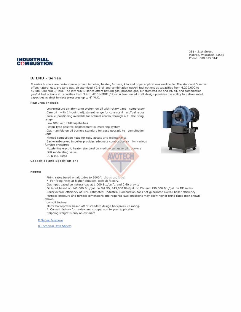
D/LND - Series
Features Include:
Capacities and Specifications
Notes:

D SERIES4.2 TO 42.0 MM BTU/HR
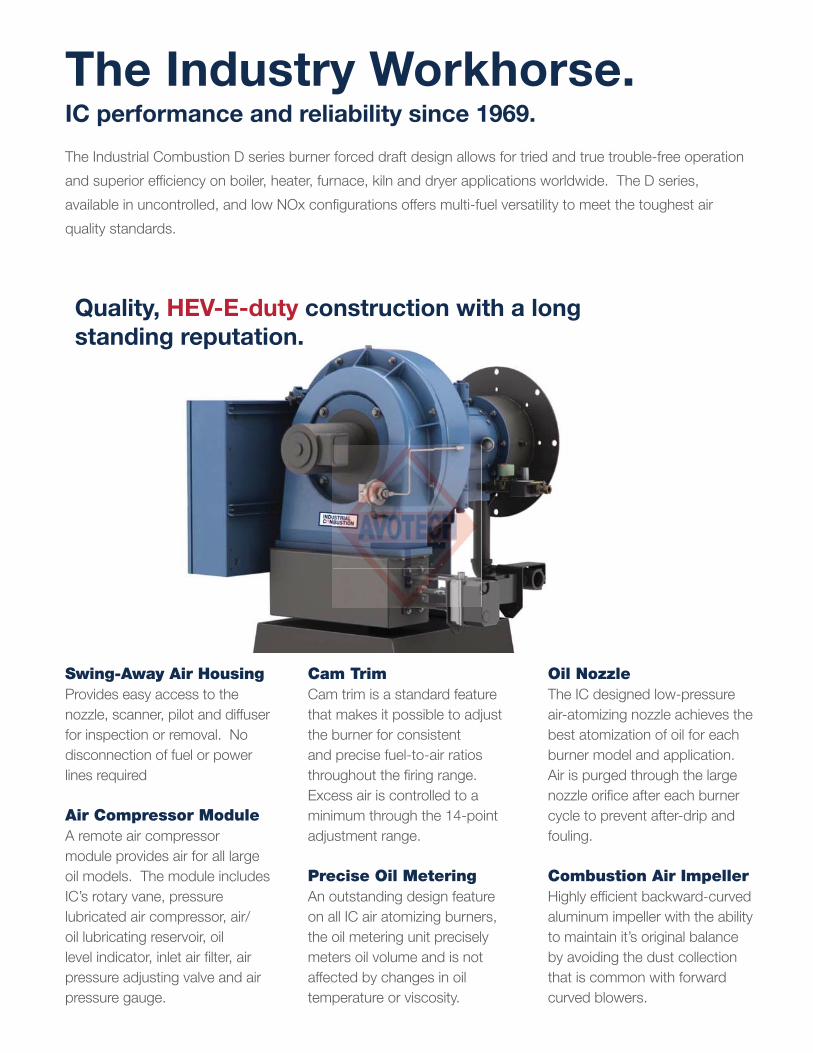
The Industry Workhorse.
The Industrial Combustion D series burner forced draft design allows for tried and true trouble-free operation
and superior effi ciency on boiler, heater, furnace, kiln and dryer applications worldwide. The D series,
available in uncontrolled, and low NOx confi gurations offers multi-fuel versatility to meet the toughest air
quality standards.
IC performance and reliability since 1969.
Swing-Away Air HousingProvides easy access to the
nozzle, scanner, pilot and diffuser
for inspection or removal. No
disconnection of fuel or power
lines required
Air Compressor ModuleA remote air compressor
module provides air for all large
oil models. The module includes
IC’s rotary vane, pressure
lubricated air compressor, air/
oil lubricating reservoir, oil
level indicator, inlet air fi lter, air
pressure adjusting valve and air
pressure gauge.
Oil NozzleThe IC designed low-pressure
air-atomizing nozzle achieves the
best atomization of oil for each
burner model and application.
Air is purged through the large
nozzle orifi ce after each burner
cycle to prevent after-drip and
fouling.
Combustion Air ImpellerHighly effi cient backward-curved
aluminum impeller with the ability
to maintain it’s original balance
by avoiding the dust collection
that is common with forward
curved blowers.
Cam TrimCam trim is a standard feature
that makes it possible to adjust
the burner for consistent
and precise fuel-to-air ratios
throughout the fi ring range.
Excess air is controlled to a
minimum through the 14-point
adjustment range.
Precise Oil MeteringAn outstanding design feature
on all IC air atomizing burners,
the oil metering unit precisely
meters oil volume and is not
affected by changes in oil
temperature or viscosity.
Quality, HEV-E-duty construction with a long
standing reputation.

The D series burner offers: natural gas, propane gas, air atomized #2-6 oil and combination gas and oil fuel options
from 4.2 to 42.0 MM BTU per hour. The LND burner, capable of <30 PPM NOx emissions offers: natural gas, propane
gas, air atomized #2 oil and combination gas and oil fuel options from 3.4 to 42.0 MM BTU per hour. Full modulation
operation and cam trim are standard for greater effi ciency and cost savings. The D burner is an excellent choice when
fi ring alternative fuels such as digester, waste oil, and biodiesel.
Low-pressure air atomizing system on
oil with rotary vane compressor
Piston-type positive displacement oil metering
system for precise oil control
Cam Trim 14-point adjustment range
Parallel Positioning available for
optimal control throughout the fi ring range
Nozzle Line Electric Heater standard on
medium to heavy oil burners
Rotary Air Damper for precise fuel-to-air ratios
Hinged Air Housing for easy access to
internal components
Gas Manifold on oil burners standard for easy
upgrade to combination units
Backward-Curved Impeller provides
adequate combustion air for various furnace
pressures and high altitude applications
Induced FGR FGR modulating valve and
shutoff valve (LND)
No. 2 Oil capability for back-up fuel (LND)
UL & cUL listed
Emissions FrameModel
RangeBoiler HP
Capacities Mode of
OperationFuel
Parallel
PositioningMBH GPH
Uncontrolled Size 1 - 8 42 - 420 100 - 1,000 4,200 - 42,000 30 - 300Full
ModulationGas, Oil, Comb.
Optional
<30 PPM Size 1 - 8 34 - 420 80 - 1,000 3,360 - 42,000 24 - 300Full
ModulationGas & Comb. Optional
The D Burner Explained:
D/ LND Burner
Ro
H
int
GaGGGGG
up
Ba
ad
pr
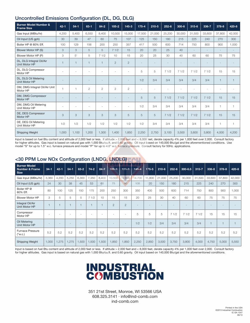
Input is based on fuel Btu content and altitude of 2,000 feet or less. If altitude > 2,000 feet and < 8,000 feet, derate capacity 4% per 1,000 feet over 2,000. Consult factory for higher altitudes. Gas input is based on natural gas with 1,000 Btu/cu.ft. and 0.60 gravity. Oil input based on 140,000 Btu/gal and the aforementioned conditions.
Burner Model Number &
Frame Size42-1 54-1 63-1 84-2 105-2 145-3 175-4 210-5 252-6 300-6 315-6 336-7 378-8 420-8
Gas Input (MBtu/hr) 4,200 5,400 6,550 8,400 10,500 15,000 17,500 21,000 25,200 30,000 31,500 33,600 37,800 42,000
Oil Input (US gph) 30 39 47 60 75 107 125 150 180 215 225 240 270 300
Boiler HP @ 80% Eff. 100 129 156 200 250 357 417 500 600 714 750 800 900 1,000
Blower Motor HP (S) 3 3 5 5 7 1/2 15 20 20 25 40 - - - -
Blower Motor HP (P) 3 51 5 7 1/2 10 15 20 25 30 40 60 60 75 75
DL, DLG Integral Oil/Air Unit Motor HP
1 1 1 1 2 2 - - - - - - - -
DL, DLG Compressor Motor HP
- - - - - - 5 5 7 1/2 7 1/2 7 1/2 7 1/2 15 15
DL, DLG Oil Metering Unit Motor HP
- - - - - - 1/2 3/4 3/4 3/4 3/4 3/4 1 1
DM, DMG Integral Oil/Air Unit Motor HP
1 1 2 2 2 2 - - - - - - - -
DM, DMG Compressor Motor HP
- - - - - - 5 5 7 1/2 7 1/2 7 1/2 7 1/2 15 15
DM, DMG Oil Metering Unit Motor HP
- - - - - - 1/2 3/4 3/4 3/4 3/4 3/4 1 1
DE, DEG Compressor Motor HP
3 3 3 3 3 5 5 5 7 1/2 7 1/2 7 1/2 7 1/2 15 15
DE, DEG Oil Metering Unit Motor HP
1/2 1/2 1/2 1/2 1/2 1/2 1/2 3/4 3/4 3/4 3/4 3/4 1 1
Shipping Weight 1,000 1,100 1,200 1,300 1,400 1,850 2,250 2,750 3,100 3,500 3,600 3,800 4,000 4,200
Uncontrolled Emissions Confi guration (DL, DG, DLG)
Burner Model
Number & Frame
Size
34-1 42-1 54-1 63-2 74-2 84-2 105-3 125-3 145-4 175-5 210-6 252-6 300-6.5 315-7 336-8 378-8 420-8
Gas Input (MBtu/hr) 3,360 4,200 5,250 6,300 7,350 8,400 10,500 12,600 14,700 16,800 21,000 25,200 30,000 31,500 33,600 37,800 42,000
Oil Input (US gph) 24 30 38 45 53 60 75 90 105 120 150 180 215 225 240 270 300
Boiler HP @ 80% Eff.
80 100 125 150 175 200 250 300 350 400 500 600 714 750 800 900 1,000
Blower Motor HP 3 5 5 5 7 1/2 10 15 15 20 25 30 40 60 60 75 75 75
Integral Oil/Air Unit Motor HP
1 1 1 1 1 1 2 2 - - - - - - - - -
Compressor Motor HP
- - - - - - - - 5 5 5 7 1/2 7 1/2 7 1/2 15 15 15
Oil Metering Unit Motor HP
- - - - - - - - 1/2 1/2 3/4 3/4 3/4 3/4 1 1 1
Furnace Pressure (“w.c.)
5.2 5.2 5.2 5.2 5.2 5.2 5.2 5.2 5.2 5.2 5.2 5.2 5.2 5.2 5.2 5.2 5.2
Shipping Weight 1,000 1,275 1,275 1,500 1,500 1,500 1,850 1,850 2,250 2,850 3,500 3,750 3,800 4,000 4,750 5,000 5,550
<30 PPM Low NOx Confi guration (LNDG, LNDLG)
Printed in the USA©2013 Industrial Combustion
IC-SA-154706/13
351 21st Street, Monroe, WI 53566 USA608.325.3141 · [email protected]
ind-comb.com
Input is based on fuel Btu content and altitude of 2,000 feet or less. If altitude > 2,000 feet and < 8,000 feet, derate capacity 4% per 1,000 feet over 2,000. Consult factory for higher altitudes. Gas input is based on natural gas with 1,000 Btu/cu.ft. and 0.60 gravity. Oil input based on 140,000 Btu/gal and the aforementioned conditions. Use model “S” for up to 1.5” w.c. furnace pressure and model “P” for up to 4.0” w.c. furnace pressure. Consult factory for 50Hz. applications.
4-2 1051010555105105555105551055 3 13 1-3 1-3 1-- 25-2525-25-25-5 3 1443 1443 143 1444444555-45-45-45-45-45-45-4 17
400 10,500 10 10 10 1110 10 112,62,62,6,6622 0000 10000 100000 4,700 16
0 75 99999990 1000000 5 1
DG,GG,GG,G,G,G,G LLLLLLLLNDNDNDNDNDNDNDNDNDNDDN LGLGLGLGLLLGLGLGLGLG))))))
If altitude > 2,0000000000000 f0 f0 f0 f0 f0 f0 feeteeeeeeeeee and < 8,000 fu/cu.ft. and 000.60.60.60.60.60.60.60 grggrggrgrgraviaviaviaviaviaviaviaaa tyty.tytytytyty Oil input bato 4.0” w.c.c..c.. furfurfufufurfururrrrnnacnn e ppppppresresresesresrese surssssss e. Cons

D SERIESTECHNICAL DATA INFORMATION PACKET

Table of Contents
D Series Uncontrolled Emissions DG, DL, DLG Technical Data Sheet ...................................................... 3 Ratings Table ................................................................... 4 Dimension Table .............................................................. 5
D SeriesUncontrolled Emissions DM, DMG Technical Data Sheet ...................................................... 6 Ratings Table ................................................................... 7 Dimension Table .............................................................. 8
D SeriesUncontrolled Emissions DE, DEG Technical Data Sheet ...................................................... 9 Ratings Table ................................................................. 10 Dimension Table ............................................................ 11
D Series<30 PPM Low NOx LNDG, LNDLG Technical Data Sheet .................................................... 12 Ratings Table ................................................................. 13 Dimension Table ...................................................... 14-15
ed Emisssssssssssssssssssions DESheet .................................................................... ..... ......................... .............
e .............. ...................................... ...
ow NNNNNNNOOOOOOOOOOOOOOOxxxxxxxxxxxx LLLLLLLLLLLLNNNNNNNNNNNNNNDDDDDDDG, LSheet ................ ......... ...................
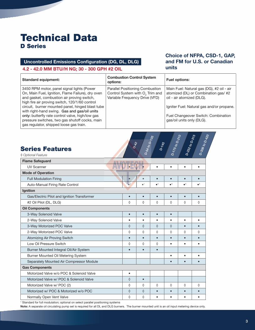
Standard equipment:Combustion Control System
options:Fuel options:
3450 RPM motor, panel signal lights (Power On, Main Fuel, Ignition, Flame Failure), dry oven and gasket, combustion air proving switch, high fi re air proving switch, 120/1/60 control circuit, burner mounted panel, hinged blast tube with right-hand swing. Gas and gas/oil units only: butterfl y rate control valve, high/low gas pressure switches, two gas shutoff cocks, main gas regulator, shipped loose gas train.
Parallel Positioning Combustion Control System with O2 Trim and Variable Frequency Drive (VFD)
Main Fuel: Natural gas (DG), #2 oil - air atomized (DL) or Combination gas/ #2 oil - air atomized (DLG).
Igniter Fuel: Natural gas and/or propane.
Fuel Changeover Switch: Combination gas/oil units only (DLG).
Choice of NFPA, CSD-1, GAP,
and FM for U.S. or Canadian
units
Uncontrolled Emissions Confi guration (DG, DL, DLG)
4.2 - 42.0 MM BTU/H NG; 30 - 300 GPH #2 OIL
Technical DataD Series
3
D-4
2
D-5
4 to
D-1
05
D-1
45
D-1
75 to
D-2
10
D-2
52 to
D-3
15
D-3
36 to
D-4
20
Flame Safeguard
UV Scanner • • • • • •
Mode of Operation
Full Modulation Firing • • • • • •
Auto-Manual Firing Rate Control •1 •1 •1 •1 •1 •1
Ignition
Gas/Electric Pilot and Ignition Transformer • • • • • •
#2 Oil Pilot (DL, DLG) ◊ ◊ ◊ ◊ ◊ ◊
Oil Components
3-Way Solenoid Valve • • • •
2-Way Solenoid Valve • • • • • •
3-Way Motorized POC Valve ◊ ◊ ◊ ◊ • •
2-Way Motorized POC Valve ◊ ◊ ◊ ◊ ◊ ◊
Atomizing Air Proving Switch • • • • • •
Low Oil Pressure Switch ◊ ◊ ◊ • • •
Burner Mounted Integral Oil/Air System • • •
Burner Mounted Oil Metering System • • •
Separately Mounted Air Compressor Module • • •
Gas Components
Motorized Valve w/o POC & Solenoid Valve •
Motorized Valve w/ POC & Solenoid Valve ◊ •
Motorized Valve w/ POC (2) ◊ ◊ ◊ ◊ ◊ ◊
Motorized w/ POC & Motorized w/o POC ◊ ◊ • • • •
Normally Open Vent Valve ◊ ◊ • • • •
Series Features◊ Optional Feature
1 Standard for full modulation; optional on select parallel positioning systemsNote: A separate oil circulating pump set is required for all DL and DLG burners. The burner mounted unit is an oil input metering device only.
D-4
D-
DDDD-
D-
2
D-5
4 to
D-1
•• ••••
••• •
••••••••111111 •1

Standard RatingsD Series
DG - DL - DLG: Gas, #2 Oil, Gas/Oil Confi guration
4
1 Use model "S" up to 1.5" w.c. furnace pressure 2 Use model "P" up to 4.0" w.c. furnace pressureConsult the factory for higher furnace pressures
Input is based on fuel BTU content, listed furnace pressure and altitude of 2,000 feet or less. If altitude > 2,000 feet and < 8,000 feet, derate capacity 4% per 1,000 feet over 2,000. Consult factory for higher altitudes. If furnace pressure exceeds listed value, derate capacity 5% for every 0.5" w.c. of pressure in excess of stated. Consult factory if derate exceeds 20%. Gas input is based on natural gas with 1,000 BTU/cu.ft. and 0.60 gravity. For total pressure at manifold, add furnace pressure. Oil input based on 140,000 BTU/gal and the aforementioned conditions. Consult factory for 50 Hz. applications.
Gas Input MBH
#2 Oil Input GPH
BHP @ 80% Eff.
BlowerMotor
HP "S"1
BlowerMotor
HP "P"2
Integral Oil/Air
System Motor HP 3 Phase
Separate Compressor
Module Motor HP 3 Phase
Oil Metering System
Motor HP 3 Phase
StandardGas TrainPipe Size
(in.)
Gas Pressure Required
("w.c.)
Model No. & Frame Size
D-42-1 4,200 30 100 3 3 1 - - 2 9.2
208 / 230 / 460 / 3
D-54-1 5,400 39 129 3 5 1 - - 2 15.3
D-63-1 6,550 47 156 5 5 1 - - 2 21.6
D-84-2 8,400 60 200 5 7 1/2 1 - - 2 1/2 18.0
D-105-2 10,500 75 250 7 1/2 10 2 - - 3 16.0
D-145-3 15,000 107 357 15 15 2 - - 3 2 PSI
D-175-4 17,500 125 417 20 20 - 5 1/2 3 5 PSI
D-210-5 21,000 150 500 20 25 - 5 3/4 3 5 PSI
230 / 460 / 3D-252-6 25,200 180 600 25 30 - 7 1/2 3/4 3 5 PSI
D-300-6 30,000 215 714 40 40 - 7 1/2 3/4 3 10 PSI
460 / 3
D-315-6 31,500 225 750 - 60 - 7 1/2 3/4 3 10 PSI
D-336-7 33,600 240 800 - 60 - 7 1/2 3/4 3 10 PSI
D-378-8 37,800 270 900 - 75 - 15 1 4 10 PSI
D-420-8 42,000 300 1,000 - 75 - 15 1 4 10 PSI
7 1/////2 1222222
2 111000 222
151515151515515151515 22222222222
20200200000 -

Standard DimensionsD Series
DG - DL - DLG: Gas, #2 Oil, Gas/Oil Confi guration
5
Burner Frame Size & Model Number
Boiler HP
DIM
Size 1 Size 2 Size 3 Size 4 Size 5 Size 6 Size 7 Size 8
42-63 84 105 145 175 210 252-300 315 336 378-420
Length in inches
Overall length E 45 3/4 44 5/8 45 5/8 56 7/8 60 64 3/4 66 3/8 69 3/8 68 1/2 73 7/8
Width in inches
Center line to right side I 21 5/8 23 7/8 23 7/8 24 3/4 25 1/4 32 3/8 32 3/8 32 3/8 32 3/8 36 7/8
Center line to left side J 17 7/8 17 5/8 17 5/8 21 22 23 3/4 23 3/4 23 3/4 23 3/4 28
Height in inches
Center line to top F 13 15 15 15 15 21 21 21 21 23
Center line to bottom G 23 3/4 25 3/8 25 3/8 30 1/8 31 7/8 35 7/8 37 3/8 37 3/8 38 7/8 39 7/8
Dry oven dimensions in inches
Diameter of dry oven A 15 7/8 19 19 22 27 1/2 27 1/2 31 1/2 31 1/2 34 5/8 34 5/8
Depth of dry oven C 9 10 10 12 12 12 15 15 18 18
Mounting fl ange dimensions in inches
Diameter B 22 24 24 27 32 1/2 32 1/2 37 37 40 42
Flange to hinge D 18 18 18 21 1/2 21 1/2 21 1/2 22 22 22 24
Diameter of bolt circle L 20 1/2 22 22 25 30 1/2 30 1/2 35 35 38 40
Number of mounting holes K 8 12 12 12 12 12 12 12 12 12
Hinge swing dimensions in inches
Center line to outer hinge clearance M 32 3/4 35 3/8 36 3/8 45 50 5/8 54 3/8 56 7/8 59 7/8 60 5/8 69 1/8
Hinge swing radius N 27 3/8 29 30 37 3/8 41 1/4 46 47 1/2 50 1/4 50 1/4 55 5/8
Oil inlet dimensions in inches
Diameter of oil inlet Q 3/4 1 1/4 1 1/4 1 1/4 1 1/4 1 1/4 1 1/4 1 1/4 1 1/4 1 1/4
Mounting fl ange to oil inlet P 17 7/8 27 27 30 1/2 30 1/2 30 1/2 31 31 30 7/5 33 3/4
Gas inlet dimensions in inches
Diameter of gas inlet R 2 2 1/2 2 1/2 3 3 3 4 4 4 4
Mounting fl ange to gas inlet H 3 5/8 3 5/8 3 5/8 4 1/8 4 1/8 4 1/8 4 5/8 4 5/8 4 5/8 3 7/8
Accompanying dimensions, while suffi ciently accurate for layout purposes, must be confi rmed for construction.
Burner
Sizzzzzze 2e 2e 2e 2e 2e 2e 222 Size 3
84 105 145
44 54 554 5554 55/8 4/8 4/8 4/8 4/8 4/8 4/8 4/8 48/8 45 5 55 55 55 55 55 55 888 55/8/8 5/8 5/8 5/8 5 7666666 7/8/8/8/8/8/88
23333333 7/7/7/7/7///7//7/8 28 233888 7/8 24242424242424 3/4
17 5///88888 117788 5/5//88 21888888
15 11111115 15

UL listed with choice of
NFPA, CSD-1, GAP, and FM
for U.S. or Canadian units
Uncontrolled Emissions Confi guration (DM, DMG)
4.2 - 42.0 MM BTU/H NG; 29 - 290 GPH #2-5 OIL
Technical DataD Series
Standard equipment:Combustion Control System
options:Fuel options:
3450 RPM motor, panel signal lights (Power On, Main Fuel, Ignition, Flame Failure), dry oven and gasket, combustion air proving switch, high fi re air proving switch, 120/1/60 control circuit, burner mounted panel, hinged blast tube with right-hand swing. Gas and gas/oil units only: butterfl y rate control valve, high/low gas pressure switches, two gas shutoff cocks, main gas regulator, shipped loose gas train.
Parallel Positioning Combustion Control System with O2 Trim and Variable Frequency Drive (VFD)
Main Fuel: #2-5 oil - Air atomized (DM) or Combination natural gas/ #2-5 oil - air atomized (DMG).
Igniter Fuel: Natural gas and/or propane.
Fuel Changeover Switch: Combination gas/oil units only (DMG).
D-4
2 to
D-1
05
D-1
45
D-1
75
D-2
10
D-2
52 to
D-3
15
D-3
36 to
D-4
20
Flame Safeguard
IR Scanner • • • • • •
Mode of Operation
Full Modulation Firing • • • • • •
Auto-Manual Firing Rate Control •1 •1 •1 •1 •1 •1
Ignition
Gas/Electric Pilot and Ignition Transformer • • • • • •
#2 Oil Pilot ◊ ◊ ◊ ◊ ◊ ◊
Oil Components
3-Way Oil Solenoid Valve • • • •
2-Way Oil Solenoid Valve • • • • • •
3-Way Motorized POC Valve ◊ ◊ ◊ ◊ • •
2-Way Motorized POC Valve ◊ ◊ ◊ ◊ ◊ ◊
Atomizing Air Proving Switch • • • • • •
Low Oil Pressure Switch ◊ ◊ • • • •
Burner Mounted Integral Oil/Air System • •
Burner Mounted Oil Metering System • • • •
Separately Mounted Air Compressor Module • • • •
Nozzle Line Heater with Cold Oil Lockout • • • • • •
Gas Components
Motorized Valve w/o POC & Solenoid Valve •
Motorized Valve w/ POC & Solenoid Valve ◊ •
Motorized Valve w/ POC (2) ◊ ◊ ◊ ◊ ◊ ◊
Motorized w/ POC & Motorized w/o POC ◊ ◊ • • • •
Normally Open Vent Valve ◊ • • • • •
Series Features◊ Optional Feature
1 Standard for full modulation; optional on select parallel positioning systemsNote: A separate oil circulating pump set is required for all DM and DMG burners. The burner mounted unit is an oil input metering device only.
6
D-4
DD2
tttt2
tto Do D
o D
o D
oD
o D
oD
oo-1
05
D-1
45
• •••••• ••••
••• ••
•••••1111111 •1

Standard RatingsD Series
DM - DMG: #2-5 Oil, Gas/Oil Confi guration
1 Use model "S" up to 1.5" w.c. furnace pressure, consult the factory for higher pressures 2 Use model "P" up to 4.0" w.c. furnace pressure, consult the factory for higher pressures3 Standard gas pressures only, consult the factory for lower gas pressures
Input is based on fuel BTU content, listed furnace pressure and altitude of 2,000 feet or less. If altitude > 2,000 feet and < 8,000 feet, derate capacity 4% per 1,000 feet over 2,000. Consult factory for higher altitudes. If furnace pressure exceeds listed value, derate capacity 5% for every 0.5" w.c. of pressure in excess of stated. Consult factory if derate exceeds 20%. Gas input is based on natural gas with 1,000 BTU/cu.ft. and 0.60 gravity. For total pressure at manifold, add furnace pressure. Oil input based on 145,000 BTU/gal and the aforementioned conditions. Consult factory for 50 Hz. applications.
Gas Input MBH
#2-5 Oil Input GPH
BHP @ 80% Eff.
BlowerMotor
HP "S"1
BlowerMotor
HP "P"2
Integral Oil/Air
System Motor HP 3 Phase
Separate Compressor
Module Motor HP 3 Phase
Oil Metering System
Motor HP 3 Phase
StandardGas TrainPipe Size
(in.)
Gas Pressure Required ("w.c.)3
Nozzle Line
Heater (kw)
Model No. & Frame Size
D-42-1 4,200 29 100 3 3 1 - - 2 9.2 3
208 / 230 / 460 / 3
D-54-1 5,400 38 129 3 5 1 - - 2 15.3 3
D-63-1 6,550 45 156 5 5 2 - - 2 21.6 3
D-84-2 8,400 58 200 5 7 1/2 2 - - 2 1/2 18.0 5
D-105-2 10,500 73 250 7 1/2 10 2 - - 3 16.0 5
D-145-3 15,000 104 357 15 15 2 - - 3 2 PSI 5
D-175-4 17,500 121 417 20 20 - 5 1/2 3 5 PSI 5
D-210-5 21,000 145 500 20 25 - 5 3/4 3 5 PSI 7
230 / 460 / 3D-252-6 25,200 174 600 25 30 - 7 1/2 3/4 3 5 PSI 10
D-300-6 30,000 207 714 40 40 - 7 1/2 3/4 3 10 PSI 10
460 / 3
D-315-6 31,500 217 750 - 60 - 7 1/2 3/4 3 10 PSI 10
D-336-7 33,600 232 800 - 60 - 7 1/2 3/4 3 10 PSI 10
D-378-8 37,800 261 900 - 75 - 15 1 4 10 PSI 10
D-420-8 42,000 290 1,000 - 75 - 15 1 4 10 PSI 10
7
7 1/2 22 22 22 22222 22
111111110 20 20 20 20 200 20 2
15555 25155 2155 2515 25 211515
20 -------

Standard DimensionsD Series
DM - DMG: #2-5 Oil, Gas/Oil Confi guration
8
Combination Gas/Oil
Models 175 - 420
Combination Gas/Oil
Models 42 - 145
Burner Frame Size & Model Number
Boiler HP
DIM
Size 1 Size 2 Size 3 Size 4 Size 5 Size 6 Size 7 Size 8
42-63 84 105 145 175 210 252-300 315 336 378-420
Length in inches
Overall length E 45 3/4 44 5/8 45 5/8 56 7/8 60 64 3/4 66 3/8 69 3/8 68 1/2 73 7/8
Width in inches
Center line to right side I 21 5/8 23 7/8 23 7/8 24 3/4 25 1/4 32 3/8 32 3/8 32 3/8 32 3/8 36 7/8
Center line to left side J 17 7/8 17 5/8 17 5/8 21 22 23 3/4 23 3/4 23 3/4 23 3/4 28
Height in inches
Center line to top F 13 15 15 15 15 21 21 21 21 23
Center line to bottom G 23 3/4 25 3/8 25 3/8 30 1/8 31 7/8 35 7/8 37 3/8 37 3/8 38 7/8 39 7/8
Dry oven dimensions in inches
Diameter of dry oven A 15 7/8 19 19 22 27 1/2 27 1/2 31 1/2 31 1/2 34 5/8 34 5/8
Depth of dry oven C 9 10 10 12 12 12 15 15 18 18
Mounting fl ange dimensions in inches
Diameter B 22 24 24 27 32 1/2 32 1/2 37 37 40 42
Flange to hinge D 18 18 18 21 1/2 21 1/2 21 1/2 22 22 22 24
Diameter of bolt circle L 20 1/2 22 22 25 30 1/2 30 1/2 35 35 38 40
Number of mounting holes K 8 12 12 12 12 12 12 12 12 12
Hinge swing dimensions in inches
Center line to outer hinge clearance M 32 3/4 35 3/8 36 3/8 45 50 5/8 54 3/8 56 7/8 59 7/8 60 5/8 69 1/8
Hinge swing radius N 27 3/8 29 30 37 3/8 41 1/4 46 47 1/2 50 1/4 50 1/4 55 5/8
Oil inlet dimensions in inches
Diameter of oil inlet Q 3/4 1 1/4 1 1/4 1 1/4 1 1/4 1 1/4 1 1/4 1 1/4 1 1/4 1 1/4
Mounting fl ange to oil inlet P 17 7/8 27 27 30 1/2 30 1/2 30 1/2 31 31 30 7/8 33 3/4
Gas inlet dimensions in inches
Diameter of gas inlet R 2 2 1/2 2 1/2 3 3 3 4 4 4 4
Mounting fl ange to gas inlet H 3 5/8 3 5/8 3 5/8 4 1/8 4 1/8 4 1/8 4 5/8 4 5/8 4 5/8 3 7/8
Accompanying dimensions, while suffi ciently accurate for layout purposes, must be confi rmed for construction.
84 105 14555555 5 1
44 5/8 444444444555 5555 /8 56 77776 776 6 6 6 /88/8 6/8/8/88
23333333 7/8 2323232323232323232 7/77/7/7/7/777/8 248 248 248 248 248 248 28 2428 3333/3/33333 44444 222524 2224444
17 5///////8888 1788 17178 17171 5/5/5/5/5/8 218 218 218 218 218 21 2
15 11111115 1555 155 15 155 1 1
25 3/8 25 3//////888 308888 1/8 31

UL listed with choice of
NFPA, CSD-1, GAP, and FM
for U.S. or Canadian units
Uncontrolled Emissions Confi guration (DE, DEG)
4.2 - 42.0 MM BTU/H NG; 28 - 280 GPH #2-6 OIL
Technical DataD Series
Standard equipment:Combustion Control System
options:Fuel options:
3450 RPM motor, panel signal lights (Power On, Main Fuel, Ignition, Flame Failure), dry oven and gasket, combustion air proving switch, high fi re air proving switch, 120/1/60 control circuit, burner mounted panel, hinged blast tube with right-hand swing. Gas and gas/oil units only: butterfl y rate control valve, high/low gas pressure switches, two gas shutoff cocks, main gas regulator, shipped loose gas train.
Parallel Positioning Combustion Control System with O2 Trim and Variable Frequency Drive (VFD)
Main Fuel: #2-5 oil - Air atomized (DM) or Combination natural gas/ #2-5 oil - air atomized (DMG).
Igniter Fuel: Natural gas and/or propane.
Fuel Changeover Switch: Combination gas/oil units only (DMG).
9
D-4
2 to
D-1
05
D-1
45
D-1
75
D-2
10
D-2
52 to
D-3
15
D-3
36 to
D-4
20
Flame Safeguard
IR Scanner • • • • • •
Mode of Operation
Full Modulation Firing • • • • • •
Auto-Manual Firing Rate Control •1 •1 •1 •1 •1 •1
Ignition
Gas/Electric Pilot and Ignition Transformer • • • • • •
#2 Oil Pilot ◊ ◊ ◊ ◊ ◊ ◊
Oil Components
3-Way Oil Solenoid Valve • • • •
2-Way Oil Solenoid Valve • • • • • •
3-Way Motorized POC Valve ◊ ◊ ◊ ◊ • •
2-Way Motorized POC Valve ◊ ◊ ◊ ◊ ◊ ◊
Atomizing Air Proving Switch • • • • • •
Low Oil Pressure Switch • • • • • •
Burner Mounted Oil Metering System • • • • • •
Separately Mounted Air Compressor Module • • • • • •
Nozzle Line Heater with Cold Oil Lockout • • • • • •
Gas Components
Motorized Valve w/o POC & Solenoid Valve •
Motorized Valve w/ POC & Solenoid Valve ◊ •
Motorized Valve w/ POC (2) ◊ ◊ ◊ ◊ ◊ ◊
Motorized w/ POC & Motorized w/o POC ◊ ◊ • • • •
Normally Open Vent Valve ◊ • • • • •
Series Features◊ Optional Feature
1 Standard for full modulation; optional on select parallel positioning systemsNote: A separate oil circulating pump set is required for all DE and DEG burners. The burner mounted unit is an oil input metering device only.
D-4
D-444
D-444444
D2
t2
t2
t2
t2
t2
t2
to D
-1
D-1
45
• •••••
• •
••••••111111 •1
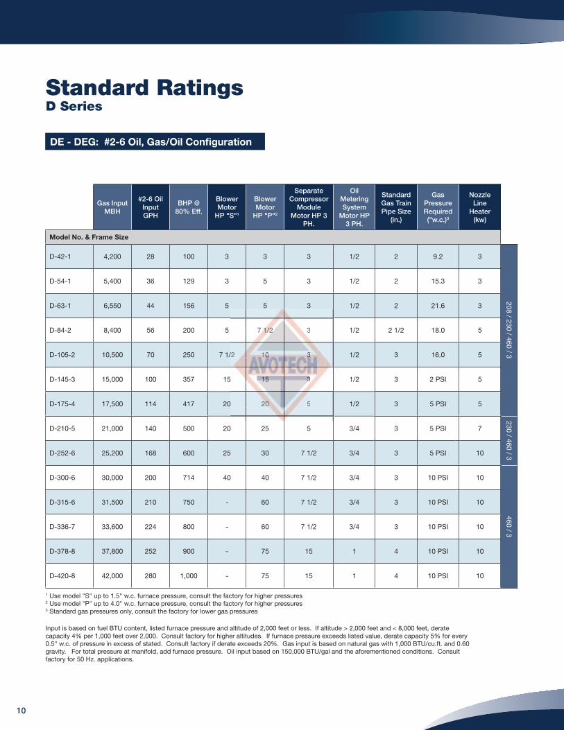
Standard RatingsD Series
DE - DEG: #2-6 Oil, Gas/Oil Confi guration
Input is based on fuel BTU content, listed furnace pressure and altitude of 2,000 feet or less. If altitude > 2,000 feet and < 8,000 feet, derate capacity 4% per 1,000 feet over 2,000. Consult factory for higher altitudes. If furnace pressure exceeds listed value, derate capacity 5% for every 0.5" w.c. of pressure in excess of stated. Consult factory if derate exceeds 20%. Gas input is based on natural gas with 1,000 BTU/cu.ft. and 0.60 gravity. For total pressure at manifold, add furnace pressure. Oil input based on 150,000 BTU/gal and the aforementioned conditions. Consult factory for 50 Hz. applications.
1 Use model "S" up to 1.5" w.c. furnace pressure, consult the factory for higher pressures 2 Use model "P" up to 4.0" w.c. furnace pressure, consult the factory for higher pressures3 Standard gas pressures only, consult the factory for lower gas pressures
Gas Input MBH
#2-6 Oil Input GPH
BHP @ 80% Eff.
BlowerMotor
HP "S"1
BlowerMotor
HP "P"2
Separate Compressor
Module Motor HP 3
PH.
Oil Metering System
Motor HP 3 PH.
StandardGas TrainPipe Size
(in.)
Gas Pressure Required ("w.c.)3
Nozzle Line
Heater (kw)
Model No. & Frame Size
D-42-1 4,200 28 100 3 3 3 1/2 2 9.2 3
208 / 230 / 460 / 3
D-54-1 5,400 36 129 3 5 3 1/2 2 15.3 3
D-63-1 6,550 44 156 5 5 3 1/2 2 21.6 3
D-84-2 8,400 56 200 5 7 1/2 3 1/2 2 1/2 18.0 5
D-105-2 10,500 70 250 7 1/2 10 3 1/2 3 16.0 5
D-145-3 15,000 100 357 15 15 3 1/2 3 2 PSI 5
D-175-4 17,500 114 417 20 20 5 1/2 3 5 PSI 5
D-210-5 21,000 140 500 20 25 5 3/4 3 5 PSI 7
230 / 460 / 3D-252-6 25,200 168 600 25 30 7 1/2 3/4 3 5 PSI 10
D-300-6 30,000 200 714 40 40 7 1/2 3/4 3 10 PSI 10
460 / 3
D-315-6 31,500 210 750 - 60 7 1/2 3/4 3 10 PSI 10
D-336-7 33,600 224 800 - 60 7 1/2 3/4 3 10 PSI 10
D-378-8 37,800 252 900 - 75 15 1 4 10 PSI 10
D-420-8 42,000 280 1,000 - 75 15 1 4 10 PSI 10
10
7 1/1/1/1/1/1//2222 3222222
/2 111000000 333333333
5 1515151515 33333333333333
0 2020000000 5

Standard DimensionsD Series
DE - DEG: #2-6 Oil, Gas/Oil Confi guration
Burner Frame Size & Model Number
Boiler HP
DIM
Size 1 Size 2 Size 3 Size 4 Size 5 Size 6 Size 7 Size 8
42-63 84 105 145 175 210 252-300 315 336 378-420
Length in inches
Overall length E 45 3/4 44 5/8 45 5/8 56 7/8 60 64 3/4 66 3/8 69 3/8 68 1/2 73 7/8
Width in inches
Center line to right side I 21 5/8 23 7/8 23 7/8 24 3/4 25 1/4 32 3/8 32 3/8 32 3/8 32 3/8 36 7/8
Center line to left side J 17 7/8 17 5/8 17 5/8 21 22 23 3/4 23 3/4 23 3/4 23 3/4 28
Height in inches
Center line to top F 13 15 15 15 15 21 21 21 21 23
Center line to bottom G 23 3/4 25 3/8 25 3/8 30 1/8 31 7/8 35 7/8 37 3/8 37 3/8 38 7/8 39 7/8
Dry oven dimensions in inches
Diameter of dry oven A 15 7/8 19 19 22 27 1/2 27 1/2 31 1/2 31 1/2 34 5/8 34 5/8
Depth of dry oven C 9 10 10 12 12 12 15 15 18 18
Mounting fl ange dimensions in inches
Diameter B 22 24 24 27 32 1/2 32 1/2 37 37 40 42
Flange to hinge D 18 18 18 21 1/2 21 1/2 21 1/2 22 22 22 24
Diameter of bolt circle L 20 1/2 22 22 25 30 1/2 30 1/2 35 35 38 40
Number of mounting holes K 8 12 12 12 12 12 12 12 12 12
Hinge swing dimensions in inches
Center line to outer hinge clearance M 32 3/4 35 3/8 36 3/8 45 50 5/8 54 3/8 56 7/8 59 7/8 60 5/8 69 1/8
Hinge swing radius N 27 3/8 29 30 37 3/8 41 1/4 46 47 1/2 50 1/4 50 1/4 55 5/8
Oil inlet dimensions in inches
Diameter of oil inlet Q 3/4 1 1/4 1 1/4 1 1/4 1 1/4 1 1/4 1 1/4 1 1/4 1 1/4 1 1/4
Mounting fl ange to oil inlet P 17 7/8 27 27 30 1/2 30 1/2 30 1/2 31 31 30 7/8 33 3/4
Gas inlet dimensions in inches
Diameter of gas inlet R 2 2 1/2 2 1/2 3 3 3 4 4 4 4
Mounting fl ange to gas inlet H 3 5/8 3 5/8 3 5/5 4 1/8 4 1/8 4 1/8 4 5/8 4 5/8 4 5/8 3 7/8
Accompanying dimensions, while suffi ciently accurate for layout purposes, must be confi rmed for construction.
11
Size 2222222 Size 3
84 111010555 145 5
44444444 54 54 54 54 54 54 5/8 48 48 4/8 4/8 4/8 4/8 5 55 55 5/8 5/8 5/8 55/8 5/8 5/8 5/8 56 76 76 76 76 76 76 7/8//////
23232323232323 /7/7/7//7 8 238 2388 2388 238 //7/7/7/7/ 248 248 248 2228 22444224 3/3/3/3/3//3/4
17 5/5/5/5/55//8888 17177788 55555/8 21
15 111115 15555555
UL listed with choice of
NFPA, CSD-1, GAP, and FM
for U.S. or Canadian units
Technical DataD Series
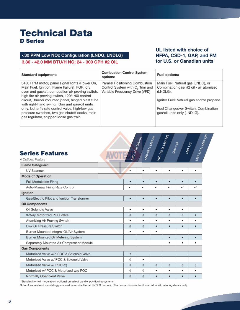
<30 PPM Low NOx Confi guration (LNDG, LNDLG)
3.36 - 42.0 MM BTU/H NG; 24 - 300 GPH #2 OIL
Standard equipment:Combustion Control System
options:Fuel options:
3450 RPM motor, panel signal lights (Power On, Main Fuel, Ignition, Flame Failure), FGR, dry oven and gasket, combustion air proving switch, high fi re air proving switch, 120/1/60 control circuit, burner mounted panel, hinged blast tube with right-hand swing. Gas and gas/oil units only: butterfl y rate control valve, high/low gas pressure switches, two gas shutoff cocks, main gas regulator, shipped loose gas train.
Parallel Positioning Combustion Control System with O2 Trim and Variable Frequency Drive (VFD)
Main Fuel: Natural gas (LNDG), or Combination gas/ #2 oil - air atomized (LNDLG).
Igniter Fuel: Natural gas and/or propane.
Fuel Changeover Switch: Combination gas/oil units only (LNDLG).
LND
-34
to L
ND
-54
LND
-63
to L
ND
-84
LND
-105
to L
ND
-125
LND
-145
LND
-175
LND
-210
to L
ND
-420
Flame Safeguard
UV Scanner • • • • • •
Mode of Operation
Full Modulation Firing • • • • • •
Auto-Manual Firing Rate Control •1 •1 •1 •1 •1 •1
Ignition
Gas/Electric Pilot and Ignition Transformer • • • • • •
Oil Components
Oil Solenoid Valve • • • • •
3-Way Motorized POC Valve ◊ ◊ ◊ ◊ ◊ •
Atomizing Air Proving Switch • • • • • •
Low Oil Pressure Switch ◊ ◊ • • • •
Burner Mounted Integral Oil/Air System • • •
Burner Mounted Oil Metering System • • •
Separately Mounted Air Compressor Module • • •
Gas Components
Motorized Valve w/o POC & Solenoid Valve •
Motorized Valve w/ POC & Solenoid Valve ◊ •
Motorized Valve w/ POC (2) ◊ ◊ ◊ ◊ ◊ ◊
Motorized w/ POC & Motorized w/o POC ◊ ◊ • • • •
Normally Open Vent Valve ◊ ◊ • • • •
Series Features◊ Optional Feature
1 Standard for full modulation; optional on select parallel positioning systemsNote: A separate oil circulating pump set is required for all LNDLG burners. The burner mounted unit is an oil input metering device only.
12
LND
LND
LND
LND
LND
LND
LND
LND
LLL44
-34444
-344
-34
-34
-34
tototottotot L
ND
-54
•

Standard RatingsD Series
LNDG - LNDLG: Gas, Gas/Oil Confi guration
Input is based on fuel BTU content, listed furnace pressure and altitude of 2,000 feet or less. If altitude > 2,000 feet and < 8,000 feet, derate capacity 4% per 1,000 feet over 2,000. Consult factory for higher altitudes. If furnace pressure exceeds listed value, derate capacity 5% for every 0.5" w.c. of pressure in excess of stated. Consult factory if derate exceeds 20%. Gas input is based on natural gas with 1,000 BTU/cu.ft. and 0.60 gravity. For total pressure at manifold, add furnace pressure. Oil input based on 140,000 BTU/gal and the aforementioned conditions. Consult factory for 50 Hz. applications.
1 Standard gas pressures only, consult the factory for lower gas pressures
Gas Input MBH
#2 Oil Input GPH
BHP @ 80% Eff.
BlowerMotor
HP
Integral Oil/Air
System Motor HP 3 Phase
Separate Compressor
Module Motor HP 3 Phase
OilMetering System
Motor HP 3 Phase
StandardGas TrainPipe Size
(in.)
Gas Pressure Required ("w.c.)1
Furnace Pressure
("w.c.)
FGR Line
Piping (in.)
Model No. & Frame Size
LND-34-1 3,360 24 80 3 1 - - 1 1/2 19.86 5.2 6
208 / 230 / 460 / 3
LND-42-1 4,200 30 100 5 1 - - 2 15.82 5.2 6
LND-54-1 5,250 38 125 5 1 - - 2 2 PSI 5.2 6
LND-63-2 6,300 45 150 5 1 - - 2 1/2 14.87 5.2 6
LND-74-2 7,350 53 175 7 1/2 1 - - 2 1/2 20.71 5.2 6
LND-84-2 8,400 60 200 10 1 - - 3 2 PSI 5.2 6
LND-105-3 10,500 75 250 15 2 - - 3 19.56 5.2 6
LND-125-3 12,600 90 300 15 2 - - 3 2 PSI 5.2 8
LND-145-4 14,700 105 350 20 - 5 1/2 3 2 PSI 5.2 8
LND-175-5 16,800 120 400 25 - 5 1/2 3 3 PSI 5.2 8
230 / 460 / 3LND-210-6 21,000 150 500 30 - 5 3/4 3 3 PSI 5.2 8
LND-252-6 25,200 180 600 40 - 7 1/2 3/4 3 10 PSI 5.2 10
460 / 3
LND-300-6.5 30,000 215 714 60 - 7 1/2 3/4 3 10 PSI 5.2 10
LND-315-7 31,500 225 750 60 - 7 1/2 3/4 3 10 PSI 5.2 10
LND-336-8 33,600 240 800 75 - 15 1 3 10 PSI 5.2 10
LND-378-8 37,800 270 900 75 - 15 1 4 10 PSI 5.2 10
LND-420-8 42,000 300 1,000 75 - 15 1 4 10 PSI 5.2 10
13
1 -- -
1 - -
2 - -
2 - -
- 555555 1/

Standard DimensionsD Series
LNDG - LNDLG: Gas, Gas/Oil Size 1 - 4 Confi guration
11
Accompanying dimensions, while suffi ciently accurate for layout purposes, must be confi rmed for construction.
Burner Frame Size & Model Number
Boiler HP
DIM
Size 1 Size 2 Size 3 Size 4
34 42 54 63 - 84 105 - 125 145
Length in inches
Overall length E 46 5/8 46 5/8 46 5/8 48 1/4 56 7/8 60
Width in inches
Center line to right side I 21 5/8 21 5/8 21 5/8 23 7/8 24 3/4 25 1/4
Center line to left side J 17 7/8 17 7/8 17 7/8 17 7/8 20 5/8 21 5/8
Height in inches
Center line to top F 13 5/8 13 5/8 13 5/8 15 15 15
Center line to bottom G 24 5/8 24 5/8 24 5/8 25 3/8 30 1/8 31 7/8
Dry oven dimensions in inches
Diameter of dry oven A 15 7/8 15 7/8 15 7/8 19 22 27 1/2
Depth of dry oven C 9 9 9 10 12 12
Mounting fl ange dimensions in inches
Diameter B 22 22 22 24 27 32 1/2
Flange to hinge D 18 18 18 18 21 1/2 21 1/2
Diameter of bolt circle L 20 1/2 20 1/2 20 1/2 22 25 30 1/2
Number of mounting holes K 8 8 8 12 12 12
Hinge swing dimensions in inches
Center line to outer hinge clearance M 36 1/8 36 1/8 36 1/8 38 5/8 45 50 5/8
Hinge swing radius N 36 7/8 36 7/8 36 7/8 39 1/4 47 3/8 49 5/8
Oil inlet dimensions in inches
Diameter of oil inlet Q 3/4 3/4 3/4 1 1/4 1 1/4 1 1/4
Mounting fl ange to oil inlet P 17 7/8 17 7/8 17 7/8 27 30 1/2 30 1/2
Gas inlet dimensions in inches
Diameter of gas inlet R 2 2 2 2 1/2 3 3
Mounting fl ange to gas inlet H 3 7/8 3 7/8 3 7/8 3 5/8 4 1/8 4 1/8
Flue gas recirculation (FGR) in inches
Center line of FGR to mounting fl ange S 41 1/2 41 1/2 41 1/2 42 3/4 47 7/8 50
Number of mounting holes T 16 16 16 16 16 16
Bolt hole diameter U 3/4 3/4 7/8 7/8 7/8 7/8
Bolt circle diameter V 7 1/2 7 1/2 9 1/2 9 1/2 9 1/2 11 3/4
14
34 42 5
46 5555555/8/8/8/888 4/88/8 6 56 555556 55555/8/8/8 4/8/8/8/8 6
22212121221122 5/55/5/5/5/5/5/5//8 218 218 2188 218 218 218 218 2 5/5/5/5/5/5/5/5/5/5/88 2888888 2218 2222
17117171717117171711711 7//7/7/7/7/7/7/7/7/7/8 178 188 18 18 178 178 188 178 17 7/7/7/7/7/7/7/7/7/7/7/888888888 178
13 5/5/5/5/5///8 138 1313131331388 1313 5/5/5/5/5/5//888 138
24 5/8 24242424242424 5/8 24
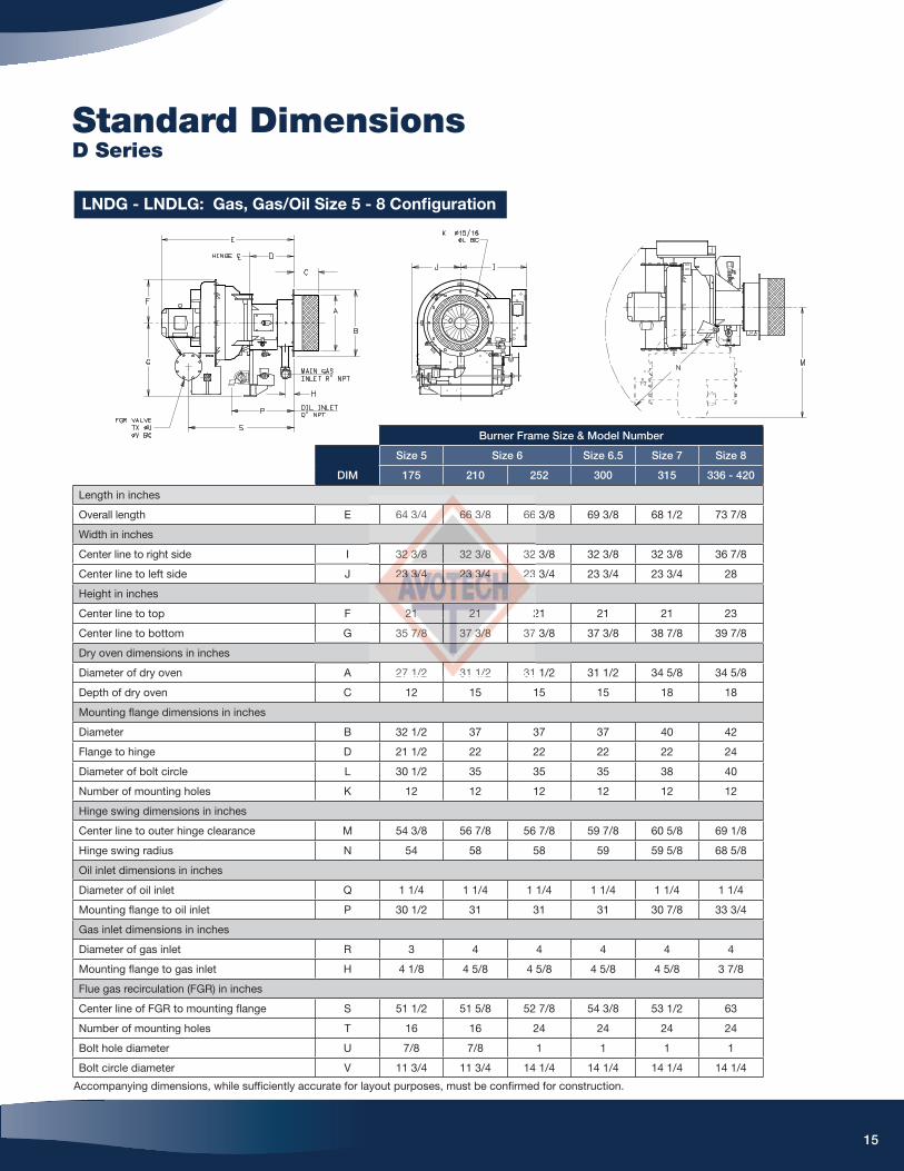
Standard DimensionsD Series
11
LNDG - LNDLG: Gas, Gas/Oil Size 5 - 8 Confi guration
Burner Frame Size & Model Number
Boiler HP
DIM
Size 5 Size 6 Size 6.5 Size 7 Size 8
175 210 252 300 315 336 - 420
Length in inches
Overall length E 64 3/4 66 3/8 66 3/8 69 3/8 68 1/2 73 7/8
Width in inches
Center line to right side I 32 3/8 32 3/8 32 3/8 32 3/8 32 3/8 36 7/8
Center line to left side J 23 3/4 23 3/4 23 3/4 23 3/4 23 3/4 28
Height in inches
Center line to top F 21 21 21 21 21 23
Center line to bottom G 35 7/8 37 3/8 37 3/8 37 3/8 38 7/8 39 7/8
Dry oven dimensions in inches
Diameter of dry oven A 27 1/2 31 1/2 31 1/2 31 1/2 34 5/8 34 5/8
Depth of dry oven C 12 15 15 15 18 18
Mounting fl ange dimensions in inches
Diameter B 32 1/2 37 37 37 40 42
Flange to hinge D 21 1/2 22 22 22 22 24
Diameter of bolt circle L 30 1/2 35 35 35 38 40
Number of mounting holes K 12 12 12 12 12 12
Hinge swing dimensions in inches
Center line to outer hinge clearance M 54 3/8 56 7/8 56 7/8 59 7/8 60 5/8 69 1/8
Hinge swing radius N 54 58 58 59 59 5/8 68 5/8
Oil inlet dimensions in inches
Diameter of oil inlet Q 1 1/4 1 1/4 1 1/4 1 1/4 1 1/4 1 1/4
Mounting fl ange to oil inlet P 30 1/2 31 31 31 30 7/8 33 3/4
Gas inlet dimensions in inches
Diameter of gas inlet R 3 4 4 4 4 4
Mounting fl ange to gas inlet H 4 1/8 4 5/8 4 5/8 4 5/8 4 5/8 3 7/8
Flue gas recirculation (FGR) in inches
Center line of FGR to mounting fl ange S 51 1/2 51 5/8 52 7/8 54 3/8 53 1/2 63
Number of mounting holes T 16 16 24 24 24 24
Bolt hole diameter U 7/8 7/8 1 1 1 1
Bolt circle diameter V 11 3/4 11 3/4 14 1/4 14 1/4 14 1/4 14 1/4
Accompanying dimensions, while suffi ciently accurate for layout purposes, must be confi rmed for construction.
15
64 3/4 66666666 3666 666 /8 66
32323232323232 333/33/33/3/33//888 32 3////8 3288888
232322333333333 /3/3/3/3/3/3/3//3/4 234 234 2324 24 24 234 24 2 /3/3/3/3/3/3/3/3/3//4 24 22344444444
212222121111211 21 2212121
35 7/7/7/7/7/77/888 37378888 37 3333//3/3/3/3/3/8888 37888
27 1/2 313 1/2 31

Printed in the USA©2013 Industrial Combustion
IC-SA-157306/13
351 21st Street, Monroe, WI 53566 USA608.325.3141 · [email protected]
ind-comb.com