Embed Size (px)
Citation preview
LIGHT GAGE STEEL FOLDED PLATES
by
Daryl Armen trout
Thesis submitted to the Graduate Faculty of the
Virginia Polytechnic Institute
in partial fulfillment for the degree of
MASTER OF SCIENCE
in
Structural Engineering
I APPROVED:
Dr. H. M. Morris Dr. R. M. Barker
DL? G. W •7 Swif j(
June, 1968
Blacksburg, Virginia
I.
II.
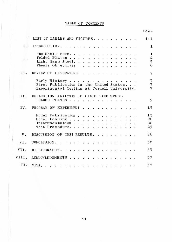
TABLE OF CONTENTS
LIST OF TABLES AND FIGURES.
INTRODUCTION. • • . . . . . . . . The She 11 Form. . Folded Plates . . . . • • . • . Light Gage Steel. • • • . . •. Thesis Objectives . •
REVIEW OF LITERATURE. • •
Page
iii
1
1 2 5 6
7
Early History . • . . • • . • . • • • • • . 7 First Publication in the United States. 7 Experimental Testing at Cornell University. 7
III. DEFLECTION ANALYSIS OF LIGHT GAGE STEEL FOLDED PLATES • • • • • • • • •
IV. PROGRAM OF EXPERIMENT •
v. VI.
VII.
Model Fa brication Model Loading . Instrumentation . . • • Test Procedure ...
DISCUSSION OF TEST RESULTS.
CONCLUSION.
BIBLIOGRAPHY.
VIII. ACKNOWLEDGMENTS •
I X. VITA. • • • • •
ii
9
15 15 20 20 25 26
32
35
3 7
38
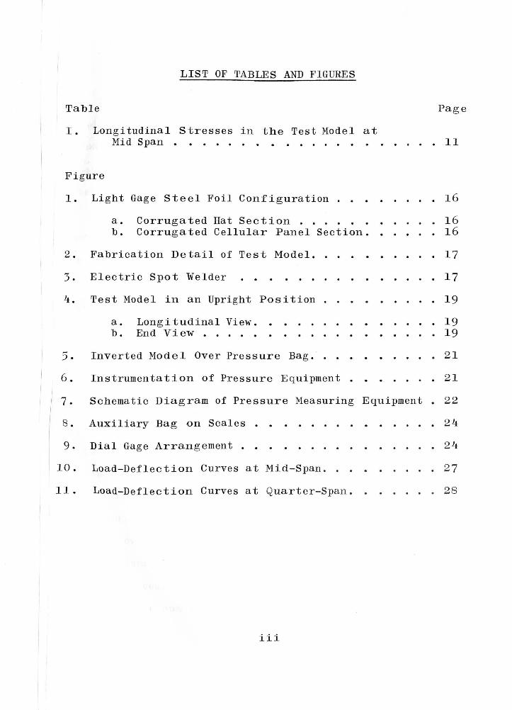
LIST OF TABLES AND FIGURES
Table Page
I. Longitudinal Stresses in the Test Model at Mid Span • • • • • . . • . . • 11
Figure
1. Light Gage Steel Foil Configuration ..
a. b.
Corrugated Hat Section ..•.• Corrugated Cellular Panel Section.
2. Fabrication De tail of Test Model. •
3. Electric Spot Welder
4.
5.
6.
Test Model in an Upright Position
a. Longitudinal View. b. End View ••
Inverted Model Over Pressure Bag ••
Instrumentation of Pressure E quipment .
. .
. .
.
.
. .
. . . .
. .
. .
.
. .
.
.
. 16
. 16
. 16
. 17
. 17
19
. 19 . 19
. 21
. 21
17. Schematic Diagram of Pressure Measuring Equipment • 22
8. Auxiliary Bag on Scales . . . . . . . . . . . . . 24
9. Dial Gage Arrangement . . . . . . . 24
10. Load-Deflection Curves at Mid-Span . . . . . . 27
11. Load-Deflection Curves at Quarter-Span. . . . . . 28
iii
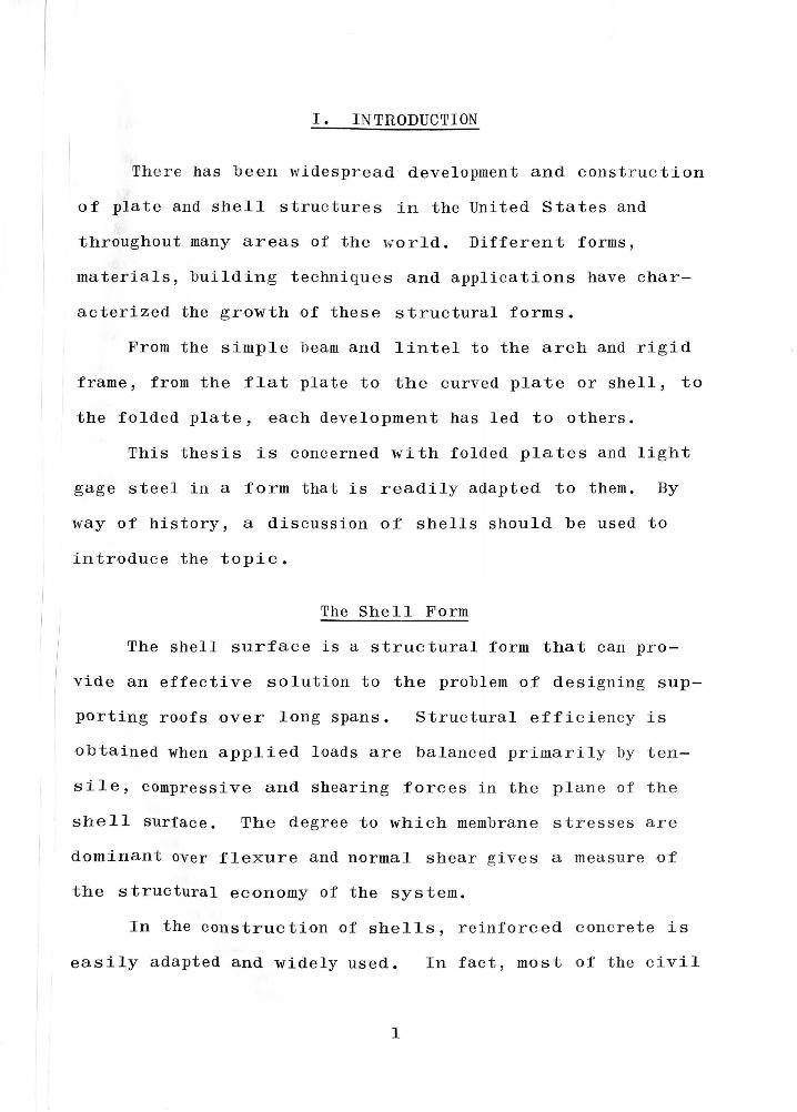
I. INTRODUCTION
There has b een widespread development and construction
of plate and shell structures in the United States and
throughout many areas of the world. Different forms,
materials, building techni ques and appli cations have char-
acterized the growth of these structural forms.
From the simple b eam and lintel to the arch and rigid
frame, from the flat plate to the curved plate or shell, to
the folded plate, each development has led to others.
This thesis is concerned with folded plates and light
gage steel in a form that is readily adapted to them. By
way of history, a dis cussion of shells should be used to
introduce the topic.
The Shell Form
The shell surface is a structural form that can pro-
vide an effective solution to the problem of designing sup-
porting roofs over long spans. Struc tural efficiency is
o b tained when applied loads are balanced primarily by ten-
s i 1 e, compressive and shearing forces in the plane of the
shell surface. The degree to which membrane stresses are
dominant over flex ure and normal shear gives a measure of
the structural economy of the sys tern.
In the construction of shells, reinforc ed concrete is
easily adapted and widely used. In fact, most of the civi l
1
2
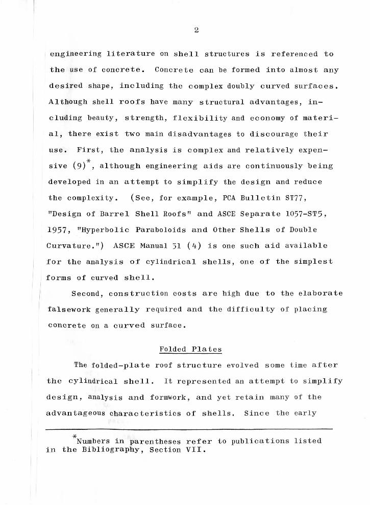
engineering literature on shell structures is referenced to
the use of concrete. Concrete can be formed in to almost any
desired shape, including the complex doubly curved surfaces.
Al though shell roofs have many structural advantages, in-
eluding beauty, strength, flexibility and economy of ma teri-
al, there exist two main disadvantages to discourage their
use. First, the analysis is complex and relatively expen-
* sive (9) , although engineering aids are continuously being
developed in an attempt to simplify the design and reduce
the complexity. (See, for example, PCA Bulletin ST77,
"Design of Barrel Shell Roofs 11 and ASCE Separate 1057-ST5,
1957, "Hyperbolic Paraboloids and Other Shells of Double
Curvature.") ASCE Manual 31 (4) is one such aid available
for the analysis of cylindrical shells, one of the simplest
forms of curved shell.
/ Second, construction costs are high due to the elaborate
falsework generally required and the difficulty of placing
concrete on a curved surface.
Folded Plates
The folded-plate roof structure evolved some time after
the cylindrical shell. It represented an attempt to simplify
design, analysis and formwork, and yet retain many of the
advantageous characteristics of shells. Since the early
* Numbers in parentheses refer to publications listed in the Bibliography, Section VII.
3
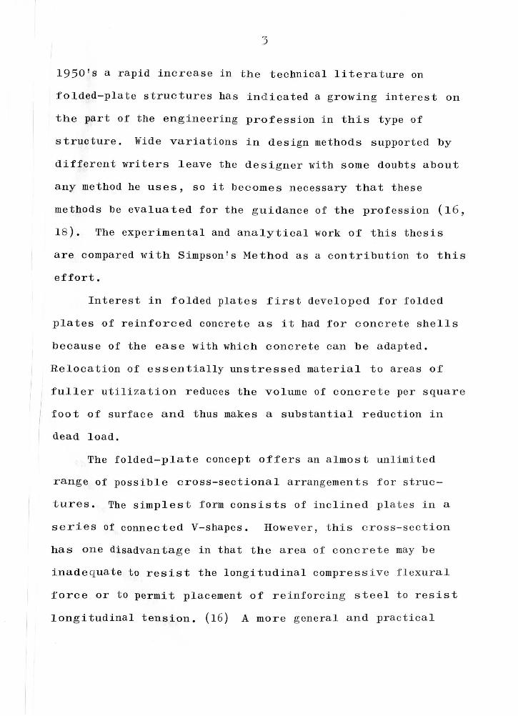
1950's a rapid increase in the technical literature on
folded-plate structures has ind icated a growing intere st on
the part of the engineering profession in this type of
structure. Wide variations in design methods supported by
different writers leave the d e signer with some doubts about
any method he uses, so it becomes necessary that these
methods be evaluated for the guidance of the profession ( 16,
1 8 ). The experimental and analytical work of this thesis
are compared with Simpson ' s Me thod as a contribution to this
effort.
Interest in folded plates first developed for folded
plates of reinforced concrete as it had for concrete shells
because of the ease with which concrete can be adapted.
Relocation of essentially unstressed material to areas of
fuller utili zation reduces the volume of concrete per square
foot of surface and thus makes a substantial reduction in
dead load.
The folded-plate concept offers a n almo st unl i mite d
range of possible cross-sectional arrangements for stru c -
tures. The simplest form consists of i nc l ined plates in a
series of connected V-shapes. Howev e r , t hi s cross-section
has one disadvantage in that the a rea of concrete may be
inade q uate to resist the longitudin al compressive flexura l
force or to permit placement of r e inforc i ng steel to res ist
longitudinal tension. (16) A more g enera l and practical
4
cross-section can be developed by adding horizontal plates
at the top and bottom junctions of the inclined plates, form-
ing what is called "hipped plate" construction. This form
enables more convenient placing of the the reinforcing steel
at the fold lines, reduces the angle change between plates
and leads to better economy of steel and concrete. Other
cross-sectional arrangements include tapered or triangular
plates and the unsymmetrical Z-shape which is used in north-
light roofs. ( 8, 20)
For all concrete folded plates, the slope angle is
usually 45° or less in order to facilitate the placing of
the concrete without top forms. ( 16) In general, the thick-
ness of individual plates should be kept at the minimum as
governed by the criteria for steel reinforcement protection.
In turn, this wi 11 affect the width of the plate, which is
gene rally not over 10 to 12 feet wide.
Al though reinforced concrete has been used extensively
in the development of folded-plates, other materials such
as timber and metal have ad van tag es to off er. Plywood is
shown to be readily adaptable to large flat plate areas and
has been used in some folded-plate construction. ( 16) The
economical advantages are not yet clearly defined for metal
folded plates, except perhaps in the construction of bins
and bunkers. In folded plate roof structures however,
sheet metal employed as shear diaphragms gives high
5
resistance to roof loads. The ideal shear diaphragm is a
thin plane sheet or membrane with a stiffening structure
attached to it. If the membrane is prevented from buckling,
it can resist shear forces through a diagonal tension field
action. (10)
Light Gage Steel
Light-gage steel roof, wall, and floor systems may be
used effectively to transfer in-plane shear forces from one
part of a framed structure to another, leading to reduced
loads in parts of the main load carrying frame. (1) Since
the action of folded-plates involves transferring in-plane
shear forces from one plate to another, light-gage steel
diaphragms show favorable possibilities. Because of the
large number of variable parameters, it is difficult at
this stage in the state of the art to predict diaphragm
behavior from a purely analytical approach; test evidence
must be drawn upon in large measure. (10) Most experimental
studies have been limited to diaphragms made from open
fluted and standard corrugated panels. Very little data is
available on cellular panel diaphragms, which appear to be
most favorable for folded-plate construction.
Some of the variables that influence the action of
light-gage steel diaphragms include panel configuration,
length, width, diaphragm size, fastener type and
6
arrangement, perimeter member stiffeners, type of loading,
material thickness and material properties. ( 1, 2, 10) Some
basic testing has been done at Cornell University (10) in an
attempt to study trends of the influence of these variables,
but much more experimental study is needed.
In lieu of expensive formwork re quired for concrete,
the use of light-gage steel cellular panels for folded-plate
structures offers favorable possibilities. These panels can
form a very stiff structure when a series of them are joined
together along successive fold lines in any one of a wide
variety of patterns. The light weight of the panels coupled
with the ease of construction are favorable aspects of this
type of structural system. It was reported in 1965 that
about 90 light-gage steel folded-plate structures had been
built in the United States. (11)
Thesis Objectives
The purpose of this thesis is two-fold. One obj ect ive
is to determine the rigidity of a V-shaped f o lded- pla t e
structure made of light-gage steel cellula r p ane l s. A
model scaled approximately 1 to 20 is tested under a uni -
formly applied load, and deflections are me a s ured using
dial gages.
A second objective is to compare experiment a l r esults
with values obtained from a rational analysis .
II. REVIEW OF LITERATURE
Early History
The first known application of folded plates was in
large coal bunkers erected in Germany in 1925 and the first
papers on the corresponding design theory were published in
Germany by G. Ehlers and H. Craemer (5, 6, 7) in 19 30. The
folded-plate structure was widely used in Europe and Russia
before it was introduced into the United States. (21)
First Publication in the United States
The first technical publication on folded plates in the
United States was written by Winter and Pei ( 21) in 1947.
Since the early 1950 1 s, there have been numerous papers
published dealing with the analysis, design and construction
of folded plates. Included among these are the well known
papers by Simpson and Parme. ( 19, 13)
Few papers have been written about light-gage steel
folded plates. The AISI has been the prime mover in pro-
moting research in this area for many years and sponsored
studies are currently being conducted at Cornell, Arizona ,
West Virginia and other universities.
Experimental Testing at Cornell University
In 1961 Arthur H. Nilson, Professor of Civil Engineer-
ing at Cornell University, published an experimental study
( 12) in which a full-sized, light-gage steel folded plate
7
8
unit, forty-six and one-half feet long, was fabricated and
tested in the structural laboratory. The cross-section of
the test structure was trapezoidal.
The test structure was full size and difficult to load
with distributed surface design loads, Vertical loads were
applied by jacks along the fold lines to simulate end
reactions from uniformly loaded transverse slab segments.
The observed vertical deflections of a lower fold line
coincided very closely with the predicted values . Deflection
contributions from flexure, shear, and seam slip were about
85%, 11%, and 4% of the total deflection, respectively.
Proportionate con tri but ions for other cases depend largely
on the ratio of span length to width of the inclined plate
and on the conf igura ti on of the structure.
Nilson analyzed the test structure by considering the
plates as separated along the fold lines and calculating
the in-plane deflection of each plate due to flexure, shear,
and seam slip. The plates were considered to b e d eep beams
with each flange area e qual to one-half of the cro ss-s ec tional
area of the connecting fold line members. The to t al deflec-
tion was determined by the geometry of small a ng l e s.
Extensive study has also been made of shear diaphragm
action and some theoretical technique s have b een d eve loped
for the proper evaluation of the action and load capacity
of light-gage folded-plate steel welded diaphragms (11).
III. DEFLECTION ANALYSIS OF LIGHT GAGE STEEL FOLDED PLATES
The action of light gage steel folded plates differs
from the action of reinforced concrete folded plates in that
the fold lines of the steel structure provide no continuity
of transverse bending moment. The plates may rotate with
respect to each other with re la ti vely insignificant
resistance.
In order to analyze them, the action of folded-plate
structures when subjected to surface loading can be con-
sidered in two parts. First, with the plates acting as flat
slabs supported along the fold lines and subjected to the
normal component of loading, this is called 11 slab action."
Second, with the plates acting as deep beams supported at
each end and subjected to the in-plane component of loading
(plus the resolved components of fold line forces), this is
called "beam action." When these separate analyses are
completed, compatibility at the fold lines must b e
established.
There may be several ways in which the plates of a
light gage steel structure could be treat e d for the purpose
of analysis. Methods presented in the literature (12, 1 6 ,
19, 22) suggest that the plates may be divided arbi t rari ly
at the fold lines. Usually this means along some pl ane of
symmetry wherein the fold line member (the connecting a n g le
9
10
in the light gage steel structure) is divided in half and
each half acts as a flange of the deep beam to which it is
attached. To assure continuity and compatibility along the
edges of adjoining plates, the longitudinal shearing stresses
and the longitudinal axial strains at the edges of separation
of each half of the fold line member must be the same. If
continuity does not exist, these longitudinal stresses may
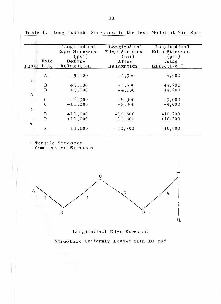
be corrected by a relaxation process (19). Table I shows
the longitudinal stresses in the test model at mid span
before and after relaxation.
In lieu of correcting these longitudinal stresses in a
stepwise manner after each application of adjusted loading,
a modified method is used to determine directly the longi-
tudinal stresses that will be compatible along the separated
edges. When each plate is separated longitudinally along
its fold lines, the fold line members are proportioned so
that the plates are considered to be deep beams with flange
areas e qual to one-half of the cross-sectiona l area of the
fold line members. The moment of inertia of each plate
acting as a deep beam is calculated and the strains induc ed
in the extreme edge fibers of the plates by the in-plane
load on the structure are determined. The differences in
edge strains are then re-evaluated. The cross-sectional
area of the fold line member connecting the adjacent plates
is reapportioned so that the common edge stresses of the
11
Table I. Longitudinal Stresses in the Test Model at Mid SEan
Longitudinal Longitudinal Longitudinal Edge Stresses Edge Stresses Edge Stresses
(psi) (psi) (psi) Fold Before After Using
Plate Line Relaxation Relaxation Effective I
A -5' 100 -4,900 -4 ,900 1
B + 5' 100 +4' 800 +4, 700 B +3 '800 +4' 800 +4, 700
2 c -6,900 -8,900 -9,000 c -11,000 -8,900 -9,000
3 D +11, 000 +10' 600 +10,700 D +11, 000 +10,600 +10,700
4 E -11, 000 -10' 800 -10,900
+ Tensile Stresses - Compressive Stresses
c E
B D .
Longitudinal Edge Stresses
Structure Uniformly L-0aded with 10 psf
12
two plates become e qual. This new division of flange areas
generally results in shifting the neutral a x is of the plates
and changing the moments of inertia. New values for moments
of inertia can be referred to as effective moments of inertia.
The process of reapportioning the cross-sectional area of the
fold line members is continued until the effective moment of
inertia of each plate in the structure converges to a value .
which gives compatibility of longitudinal strains between
every pair of adjacent plates. The convergence is rapid;
in the test structure, convergence occurred after two cycles
of adjustment. Calculated values of longitudinal stress for
the test model are also shown in Table I for comparison.
After an effective moment of inertia has been deter-
mined for each plate, compatibility along the fold lines is
assured for any other proportional values of loading applied
on the structure.
Certain limitations may have to be imposed on t h is
modified procedure, particularly when l arge differences in
applied loading exist on adjacent plate s . Further study is
needed before a broader application of this method can be
used.
With continuity assured between adjacent plates, the
deflections of each plate acting as a deep beam in flexure
can be calculated. The total defl ec tion is composed of
contributions due to flexure, shear and seam slip. Since
13
the cellular panels of the test model are continuous for the
full length of the structure, seam slip transverse across
the panels cannot occur. The shear along the fold line is
small compared to the tran sverse shear; thus, the amount of
seam slip developed along the fold lines is small and has
been neglected. In the analysis of this test model, only
deflections due to flexure and shear are considered to con-
tribute to the total deflection.
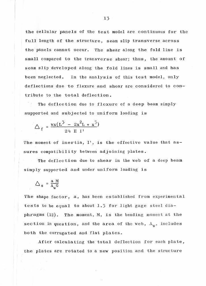
The deflection due to flexure of a deep beam simply
supported and subjected to uniform loading is
= wx(L3 - 2x2L + x 3 ) 24 E 1 1
The moment of inertia, I 1 , is the effective value that as-
sures compatibility between adjoining plates.
The deflection due to shear in the web of a deep beam
simply supported and under uniform loading is
a M 6s =AG w
The shape factor, a, has been establ i shed from experimental
tests to be e qual to about 1. 3 for l ight gage steel dia-
phragms (12). The moment, M, is the bend i ng moment at t he
section in question, and the area of the web, A , include s w
both the corrugated and flat plates.
After cal cu la ting the total deflection for each p late,
the plates are rotated to a new position and the struc t u re

14
is joined together in its new position to give the total
deflected structure. Geometry of small angle changes is
used to determine the total deflections of the structure.
IV. PROGRAM OF EXPERIMENT
Model Fa brica ti on
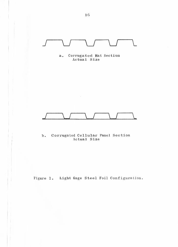
In order to make up the 6 11 x 67" plate elements of the
test model, light gage .002 inch stainless steel foil was
corrugated into the hat section shape shown in Figure la and
spot welded to a :flat steel plate of the same thickness to
form the cellular panel assemblage shown in Figure lb. The
spot welds were placed between every third hat corrugation
with seven welding spots spaced one inch apart parallel to
the corrugation o:f the plate. Six cellular panel assem-
blages, each 6 11 x 67", were fastened together along their
common longitudinal edges with galvanized steel angles,
.15" x .15" x .018'', to form a V-shaped roof as shown in
Figure 2. The angles were fastened to the panels by spot
welding between every hat section along the longitudinal
length of the plates. The spacing of these welds was about
one inch, center to center.
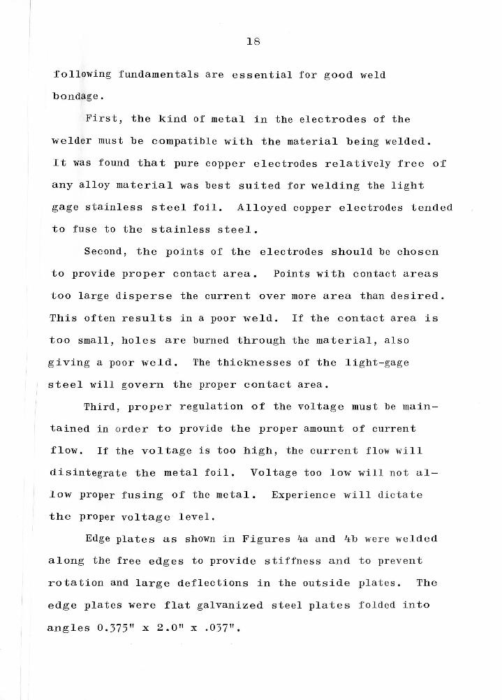
Special attention had to be given to the we lding pro-
cess . Spot welding is probably the most important means of
shop fabrication of light gage steel. A spot welder as
shown in Figure 3 was used to fabricate this test model.
Extreme precaution had to be exercised in order to obtain
adequate welding bond without burning the material. Ex-
perience gained from building this model showed that the
15
J
16
a. Corrugated Hat Section Actual Size
\ I \ I \ I
b. Corrugated Cellular Panel Section Actual Size
Figure 1. Light Gag e Steel Foil Configuration.
17
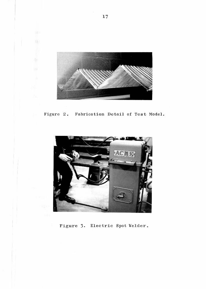
Figure 2. Fabrication Detail of Test Model.
Fig ure 3. El e ctric Spot We l der.
18
:following fundamentals are essential for good weld
bondage.
First, the kind of metal in the electrodes of the
welder must be compatible with the material being welded.
It was found that pure copper electrodes relatively free o:f
any alloy material was best suited for welding the light
gage stainless steel foil. Alloyed copper electrodes tended
to fuse to the stainless steel.
Second, the points of the electrodes should be chosen
to provide proper contact area. Points with contact areas
too large disperse the current over more area than desired.
This often results in a poor weld. If the con tact area is
too small, holes are burned through the material, also
giving a poor weld. The thicknesses of the light-gage
steel will govern the proper con tact area.
Third, prop e r regulation o:f the voltage must b e ma in-
tained in o rder to provide the proper amount of current
flow. If the voltage is too high , the curr e n t flow will
disintegrat e the metal foil. Voltage too l o w will not a l-
low proper fusing of the metal. Exper ien c e will dictat e
the proper voltage level.
Edge plates as shown in Fig u res 4a and 4b were weld e d
along the free e d g es to provide stiffness and to prevent
rotation and large deflections in the outside plat es. The
edge plate s were :flat galvanized stee l plates f o lded into
ang 1 e s 0. 3 7 5" x 2 • O" x . 0 3 7" •
19
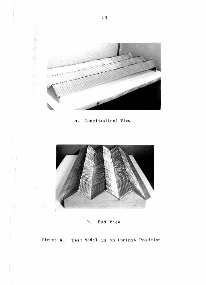
a. Longitudinal View
b. End View
Figure 4. Test Model in an Upright Position.
20
The model was simply supported on two solid wooden
diaphragms spaced 67 11 apart. The overall dimensions of the
model were 32.0" wide by 67.0" long by 3.6 11 high, Figures
4a and 4b.
A plastic bag (made with vinyl 4 mils thick) was fabri-
cated to extend over the entire surface of the model. The
plastic bag was placed on a firm table and the model was
anchored by the supports to the table in an inverted position
over the plastic bag, Figure 5. By inflating the plastic
bag, the model was loaded with a uniform upward pressure
while it was held down by the end supports.
Model Loading
The manner in which the model was loaded did not pro-
duce the exact equivalent of gravity loading. The applied
pressure was normal to the surfaces and did not have the
in-plane force components that gravity loading would have
produced. However, the plastic bag was convenient, simple,
dependable and quickly inflated; and the result i n g forces
could be resolved in the same manner as gra vity l oads to
determine deflections.
Instrumentation
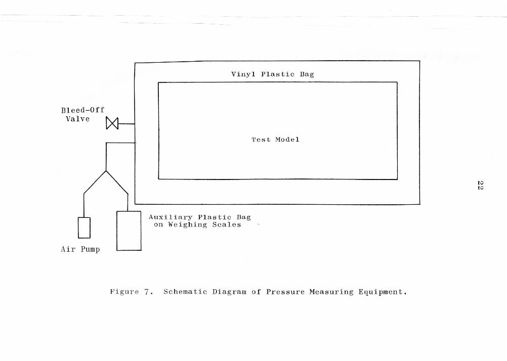
Pressure Equipment. A schematic diagram of t he in-
strumentation used to measure the applied lo a d s on the model
is shown in Figure 7. A small auxiliary pl as tic bag,
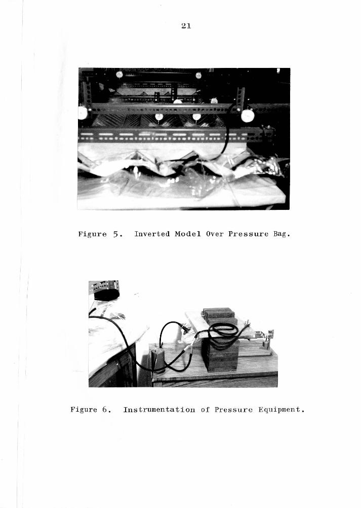
21
Figure 5. Inverted Model Over Pressure Bag.
Figure 6. Instrumentation of Pres s u re Equ i pment .
Bleed-Off Valve
Air Pump
Vinyl Plastic Bag
Auxiliary Plastic Bag on Weighing Scales
Test Model
Figu re 7. Schemat ic Diagram of Pressure Measuring Equipment.
[\J N
23
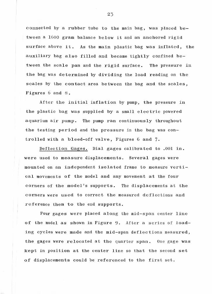
connected by a rubber tube to the main bag, was placed be-
tween a 1600 gram balance below it and an anchored rigid
surface above it. As the main plastic bag was inflated, the
auxiliary bag also filled and became tightly confined be-
tween the scale pan and the rigid surface. The pressure in
the bag was determined by dividing the load reading on the
scales by the contact area between the bag and the scales,
Figures 6 and 8.
After the initial inflation by pump, the pressure in
the plastic bag was supplied by a small electric powered
a quarium air pump. The pump ran continuously throughout
the testing period and the pressure in the bag was con-
trolled with a bleed-off valve, Figures 6 and 7.
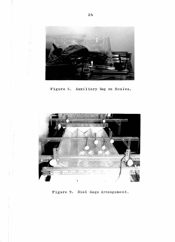
Deflection Gages. Dial gages calibrated to .001 in.
were used to measure displacements. Several gages were
mounted on an independent isolated frame to measure verti-
cal movements o:f the model and any movement at the four
corners of the model's supports. The displacements at the
corners were used to correct the measured deflections and
reference them to the end supports.
Four gages were placed along the mid-span center line
of the model as shown in Figure 9. After a series of load-
ing cycles were made and the mid-span deflections measured,
the gages were relocated at the quarter span. One gage was
kept in position at the center line so that the second set
o:f displacements could be referenced to the first set.
24
Figure 8 . Auxiliary Bag on Scales.
Figure 9. Dial Gage Arrangement.
25
Test Procedure
An initial setting of the scales was made to g ive an
effective pressure of 3 psf (less dead weight) over the
surface of the model. The weight of the auxiliary bag was
accounted for in the initial load. The pressure was then
increased by 1 psf increments to 10 psf and decreased in
1 ike manner to 3 psf again. Dial gage readings were recorded
at each level of load. The time required for each cy cle of
loading was a bout four hours. Sinc e the pre ssure instru-
mentation lacked the sensi ti vi ty of the dial gages, extreme
assiduity was exercised to obtain an e quilibrium condition
after apply i ng each load increment.
The results of the tests are presented in Section V.
V. DISCUSS ION OF TEST RESULTS
The measured deflections of the test model agree close-
1 with the calculated values obtained by the analysis out-
1 ined in Section III. The results of these tests, compared
' ·th the theoretical analysis, are shown in Figures 10 and
1. Both flexure and shear in the planes of the deep-beam
iaphragms were considered in calculating the total deflec-
i on of the test model; the contributions of each were about
5% and 5% respectively. Torsion, seam slip and normal
ongi tudinal bending and shear were neglected.
After minor adjustments, the model was loaded and un-
oaded through a couple of cycles using a four foot sloping
water manometer to measure loading pressure. Since it was
desirable to measure the pressure in one psf increments, it
was found that the manometer lacked the sensitivity and pre-
ision necessary to be consistent with the dial gage read-
ings. It became necessary to devise a better scheme for
measuring pressure, so a weighing system was invented using
a n auxiliary plastic bag and another trial run was made.
At this point most of the defects appeared to have
been worked out of the system, so three test runs were made
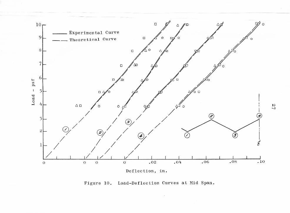
and the data recorded for mid-span deflections (Points 1, 2,
3 and 4). The results are plotted in Figure 10. The indi-
idual loading cycles can be identified by the different
symbols. The next loading cycle was made with the gages
26
10
9
8
7
ct--! 6 [/) p..
I 5 'O (1j 0 ~ 4
3
2
1
Experimental Curve
---- The oretical Curve 0
D
(o / o/O
o/M o/tn
/.
;~ 0
0
)~o
,,/~
10~ ) /; ) ~ ~ Experimental Curve f J ) 9L -- Theoretical Curve J / j j j
Bl-I j j' I j 7~ oJ
'H 6 ~ Jo Jo rn j I ~ j I 5 j 'd
I I Cd 0 j ...:l 4 I Kl
II I 00
@I I 31- I l @/ 0/ 0 ® 21- I ~ I
U- I I I ~ ~ I I @ 0 I I I I t
0 0 0 0 .02 .04 .06 .OB Deflection, in.
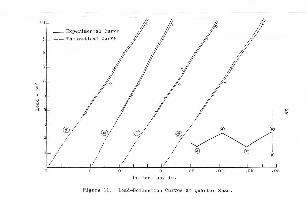
Figure 11. Load-Deflection Curves at Quarter Span.
29
located at the q uarter-span and the data was r e corded and
plotted i n Fig ure 11 (Points 5, 6, 7 and 8 ).
In eve ry test cycle, the data for loading and unloading
agreed very closely; average values were plotted. A
straight line curve was fitted approximately to each set of
data and extended to the margin as shown, along with an
analytical prediction . The figures show that the theoreti-
cal predictions agree very closely with the experimental
data. The largest variation occurred at the edge (Fold Line
1 in Figure 10). This variation could be due to the neglect
of torsion in the analysis or due to the boundary conditions
of the pressure bag, since the pressure bag was only slightly
wider than the test model. In subse quent testing programs,
if a pressur e bag is used, it is suggest e d that it be made
to extend some distance beyond the outer edges of the model.
This experiment was carried out within the elastic
range of the materials. The test model was designed to
carry a working load of 20 ps:f under which the longitudinal
stress at the center fold line would no t exceed 20, 000 psi.
The structure was intentionally d e signed to be flexib le so
that the model would deflect with s ens i ti vi ty to the li g hter
loads. Little is known about how the diaphragm material
acts under yield loads and less is known about the act ion
o f' a folded plate structure mad e of such d iaphragm segments.
It was expected that the light gag e stee l :fo i 1 mo del would
30
perform in a similar manner to a prototype, but there was
no assurance of that before the tests. With concern that
several test runs might induce some fatigue, it was decided
not to overload the model beyond about 50 percent of its
allowable working loads. In addition, the strength and
reliability of the welds were not assured before testing.
The model was not tested to failure; the applied loads never
exceeded 10 psf. The model performed well under about eight
repeated cycles of loading with only slight local buckling
around the welded points along the fold lines. Surface
irregularities were developed during fabrication, probably
due to uneven heating from the spot welder. They appeared
to increase slightly in magnitude during the first loading
cycle, but they did not appear to change during subsequent
loading cycles. No quantitative measurements were made.
This apparent buckling could contribute to the diaphragm
action known as "seam slip" al though it would be a small
contribution compared to that caused by shearing or tearing
o:f the spot welds. An analytical evaluation of the effect
o:f seam slip along the fold lines on the total deflect ion
would be similar to the evaluation of shear strains when
balancing edge :forces between plates. However, because the
magnitude of these deformations were hardly perceptible
a:f ter the initial loading cycle, they were not conside red
in the analysis. All welding points remained intact and
no breaks or cracks appeared.
31
The only unusual reactions observed during testing were
occasional sudden "jumps 11 of the deflection dial during
loading as though the apparatus had been jarred slightly.
These were accompanied by a sound like the 11 snap-through 11
of a flat warped surface. Some of these produced deflection
offsets on the plotted curves but apparently did not affect
the load-deflection ratios. Actually there was only one
offset during the fifth loading cycle that was large enough
to show an irregularity; this was removed by adjusting the
axis when the data were plotted. The other offsets were
very small and no adjustments were made in plotting. This
phenomenon can not be quantitatively explained except as
representing points of unstable stress concentrations within
the system. When subjected to additional stress, there
could have been a very rapid relaxing of stress at some
other point and a redistribution of stress within the
structure, thus causing a sudden change in deflection.
The maximum deflection of the test model occurred along
the center "fold line. 11 At mid span, the deflection under
the uniform load of 10 psf was .095 inches giving a 6/L
ratio of 1/700.

VI. CONCLUSION
About 40 percent of all steel produced in the United
States is light-gage, cold formed steel ( 11). Most of the
design and analysis of light-gage steel structures is based
on empirical formulas developed from experimental or in-
s ervice testing. During the past 20 years, the use and
development of light-gage steel construction in the United
States have been accelerated by the issuance of the "Light
Gage Cold-Formed Steel Design Manual ." ( 3 ) This manual is
based primarily on a long-time research project sponsored
by AISI at Cornell University (1). Much research is still
needed in order to fully understand the action of light-
gage steel structures subjected to various loading condi-
tions. Load-deflection testing of light-gage folded plate
structures is only part of the total research needed in
thi s area. Nevertheless, it provides a very significant
contribution to the establishment of a fuller understanding
of light-gage steel structures.
The use o:f small-scale test models fabricated from
light-gage steel foil offers a reasonably convenient method
:for studying folded plate structures , al though the fabrica-
tion of the model is tedious and exacting. Variations in
shape and form of structure might also b e test ed in t he
same manner as the model tested for this thesis.
32
33
The test model was a V-shaped folded plate structure
made of light gage steel cellular panels o It was approxi-
mately one-twentieth scale model size and tested under uni-
form pressure loading to determine stiffness and compare de-
flections with analytical predictions.
The results of the tests agreed closely with the calcu-
lated values of the theoretical analyses. Both flexure and
shear in the planes of the deep-beam diaphragms were con-
sidered in calculating the total deflection of the test
model; the con tri but ions of each were about 95 per cent and
5 per cent, respectively. Torsion, seam slip and normal
longitudinal bending and shear were neglected.
The tests were carried out within the elastic range
with loads up to 50 per cent of design working loads. The
test model appeared to perform in a similar manner to a
prototype; there was no sign of fatigue and no evidence of
weld failure. The model performed well under about eight
repeated cycles of loading with only slight local buckling
around the we lde d points along the f old lines. Surface ir-
regularities were developed during fabrication, probably
due to uneven heating from the spot welder o They appeared
to increase slightly in magnitude during the first loading
eye l e , but they did not appear to change during subsequent
1 oading cycles. No quanti ta ti ve measurements were made.
34
A few sudden jumps of the deflection dials accompanied
by sounds like the snap through of a flat warped surface
were noticed during testing, but apparently had no effect
on the results. The maximum deflection ·Of the test model
occurred a long the center "folded line." At mid span, the
deflection under the uniform load of 10 psf was .095 inches
giving a b / L ratio of 1/ 700.
VII. BIBLIOGRAPHY
l. AISI Committee on Building Research and Technology, "Design of Light Gage Steel Diaphragms," First Edition, 1967.
2. AISI Committee on Building Technology, "Sectional Properties of Corrugated Steel Sheets," 1964.
3. American Iron and Steel Institute, Light Gage Cold-Formed Steel Design Manual, Third Edition, New York, 1962.
4. ASCE Manual No. 31, "Design of Cylindrical Concrete Shell Roofs, 11 October, 1951.
5. Craemer, H., "Design of Prismatic Shells," ACI Journal, February, 1953, Proc. V. 49, pp. 549-563.
6. Craemer, H., "Theorie der Faltwerke, 11 Beton und Eisen, v. 29, 19 30.
7. Ehlers, G. , "Ein neues Kons truktion prinzip, 11 Bauingen-ieur, V. 9, 1930.
8. Ketchum, M. S., "Design and Construction of a Folded Plate Roof Structure," ACI Journal, Feb., 1955, Proc. v. 51, pp. 449-455.
9. Kirkland, W. G., "Shell Structures of Light Gage Steel Roof Panels," Southern Building Magazine, March, 1963 .
10. Luttrell, L. D., "Strength and Behavior of Light-Gage Steel Shear Diaphragms," Cornell Engineering Research Bulletin, No. 67-1, July, 1967.
11. Luttrell, L. D., Lecture Notes, AISI Conference at West Virginia University, 1966.
12. Nilson, A. H. , "Folded Plate Structures of Light Gage Steel," Journal of the Structural Divis i on, ASCE, V. 87, No. ST 7, Proc. Paper 2970, October, 1961, pp. 215-237.
13. Parme, A., "Direct Solution of Folded Plate Roofs, " PCA Bulletin, No. 3, 1960.
35
36
14. Pion , R., "Light-Gage Steel Folded Plates," Interim Report, Structural Conference, West Virginia Uni ver-si ty, 1966.
15. Progress Report of the Committee on Research of the Structural Division, "Survey of Current Structural Resea rch," Journal of the Structural Division, ASCE, V · 91 , No. ST 1, Proc. Paper 4233, February, 1965, pp. 28 and 46.
16. Report of the Task Committee on Folded Plate Construc-tion, Com.mi ttee on Masonry and Reinforced Concrete, "Phase I Report on Folded Plate Construction," Journal of the Structural Division, ASCE, V. 89, No. ST 6, Proc. Paper 3741, December, 1963 , pp. 365-406.
17. Report by the Committee on Research, Structural Division, "Research Needs in Structural Engineering for the Decade 1966-1975," Journal of the Structural Division, ASCE, V. 92, No. ST 5, Proc. Paper 4946, October, 1966, pp. 287-311.
1 8 . Scordelis, A. C., Croy, E. L., Stubbs, I. R., "Experi-mental and Analytical Study of a Folded Plate," Journal of the Structural Division, ASCE, V. 87, No. ST 8, Proc. Paper 3023, December, 1961, pp. 139-159.
19. Simpson, H., "Design of Folded .Plate Roofs," Journal of the Structural Division, ASCE, V. 84, No. ST 1, Proc. Paper 1508, January, 1958, pp. 1-21.
20. Whitney, C. S., Anderson, B. G., Birnbaum, H., "Rein-forced Concrete Folded Plate Construction," Journal of the Structural Division, ASCE, Vol. 85 , No. ST 8 , Proc. Paper 2219, October, 1959 , pp. 15-43.
21. Winter, G. and Pei, M., "Hipped Plate Construction , 11
ACI Journal, January, 1947, Proc. Vol. 43 , pp. 505-531.
22. Yu, Wei-Wen, "Design of Light Gage Cold-Formed Steel Structures," Engineering Experiment Station, West Virginia University, 1965.
VIII. ACKNOWLEDGMENTS
The author wishes to thank his major professor,
Dr. G. A. Gray, for his encouraging remarks and friendly
criticism and for his direction and guidance throughout
this study. Acknowledgment is also extended to the author's
committee and many members of the Civil Engineering Faculty
at V.P.I. , especially Professors J. H. Hammer and R. C.
Heterick, for their assistance.
The author wishes to thank for doing
the photog raphy included in this thesis.
37

The vita has been removed from the scanned document
LIGHT GAGE STEEL FOLDED PLATES
by
Daryl Armen trout
Abstract
A light gage steel folded plate model structure was
:fabricated and t ested under a uniform pressure to determine
the relat i ve s ti :ffness of this type of s true ture. Def l e e tions
at mid a n d quarter spans were measured and compared with
values d e termined by a rational method of analysis.
A di ff erent approach to the a nalysis was i n troduced in
which valu es o:f e quivalent moment of inertia were determined
f'or each p l a te cross-section so that compatability along
adjoining long itudinal edges would be assured. The experi-
mental and theoretical results were in good agreement.