Embed Size (px)
Citation preview
diyAudio™ Soft Start Board Build GuidePrepared, written and compiled by “JojoD818”
Build Guide revision 1.0 for use with diyAudio Soft Start PCBs version 2.0
Introduction:
Power amplifier builders more often than not use capacitor filter banks in their power supplies. These capacitor banks are like power reserves that are ready to supply the power amplifier with extra power during transient passages. When our power amplifiers are switched on, the initial current drawn from the AC mains is several times that of normal power. This phenomenon is commonly known as “inrush current”. Such sudden and high current draw is stressful to a number of components in your power amplifier:
• Capacitors – Most DIY power amplifiers contain tremendous amounts of capacitance, When fully discharged these capacitors are like a short circuit for a brief moment at start-up, causing the inrush current, which can damage them and other components. This only normalizes once the filter capacitors have enough charge that their AC impedance starts to rise.
• Power Transformer – The primary windings of the power transformer are burdened by the sudden draw of current during power on.
• Rectifiers – Diodes are heavily stressed as they are between the power transformer and the capacitors, so are also exposed to the inrush current.
• Power Switch – Pitting caused by arcing in the contacts degrades the performance of the switch. Contact bonding/welding can occur in severe cases.
• Mains Fuse – Slow blow fuses are usually employed, but a blown fuse due to inrush current is not uncommon if no other means are used to control it.
The circuit presented in here was chosen to limit the inrush current to a fairly safe value through the introduction of a small resistance in series with the power transformer’s primary winding. This small resistance is effectively shorted by a relay after a brief moment thereby connecting the power transformer’s primary winding directly to the mains. This brief moment (often less than a second) is
© diyAudioTM 2012
enough to charge up the filter capacitors to a level where their internal resistance has already increased, drawing less current to the whole power supply system.
The project is easy to construct but mains wiring is involved and so it is imperative that you follow the wiring guide properly. The safety aspect of this project cannot be stressed enough to the builder - practice Safety First!!!
About the circuit:
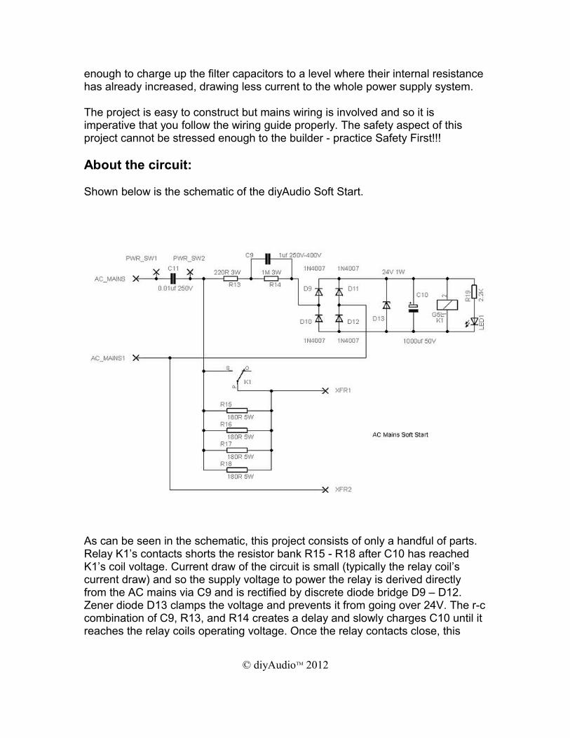
Shown below is the schematic of the diyAudio Soft Start.
As can be seen in the schematic, this project consists of only a handful of parts. Relay K1’s contacts shorts the resistor bank R15 - R18 after C10 has reached K1’s coil voltage. Current draw of the circuit is small (typically the relay coil’s current draw) and so the supply voltage to power the relay is derived directly from the AC mains via C9 and is rectified by discrete diode bridge D9 – D12. Zener diode D13 clamps the voltage and prevents it from going over 24V. The r-c combination of C9, R13, and R14 creates a delay and slowly charges C10 until it reaches the relay coils operating voltage. Once the relay contacts close, this
© diyAudioTM 2012
effectively shorts R15 – R18 and so the primary of the power transformer is effectively connected directly to the AC mains.
The length of time for the relay coil to engage can be changed by varying the value of C9, please see Ideas and Alternatives section for details.
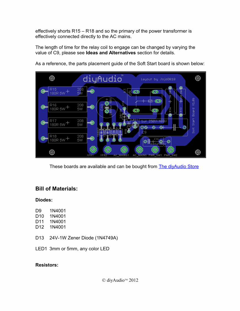
As a reference, the parts placement guide of the Soft Start board is shown below:
These boards are available and can be bought from The diyAudio Store
Bill of Materials:
Diodes:
D9 1N4001D10 1N4001D11 1N4001D12 1N4001
D13 24V-1W Zener Diode (1N4749A)
LED1 3mm or 5mm, any color LED
Resistors:
© diyAudioTM 2012
R13 220R 3W Flame-proof recommendedR14 1M 3W Flame-proof recommendedR15 150R-180R 5W Wire-wound (See Ideas and Alternatives)R16 150R-180R 5W Wire-wound (See Ideas and Alternatives)R17 150R-180R 5W Wire-wound (See Ideas and Alternatives)R18 150R-180R 5W Wire-wound (See Ideas and Alternatives)R19 2.2K 1/4W
Capacitors:
C9 0.33uf – 1uf 250V~ See Ideas and AlternativesC10 1,000uf 50V Electrolytic CapacitorC11 0.001-0.01uf 250V~ Y-Class Capacitor
Other Component:
K1 24V Coil Relay SPDT Standard 5-Pin
Tools Required:
Screwdrivers - Phillips and Flat
Miniature Screwdrivers - Phillips and Flat
Small Diagonal Cutters
Insulation Strippers
Needle-nose Pliers
Solder 60/40 Rosin cored or better
Soldering iron about 30 - 40 Watts
Digital Multi Meter
© diyAudioTM 2012
Other Useful Tools: Electric Hand Drill
Assorted Files
Solder Sucker
Solder Remover Braid (Solder Wick)
Extra Flux
Lacquer Thinner
Ideas and Alternatives:
Choosing R15, R16, R17, and R18
The values given for R15 to R18 (150 ohms to 180 ohms) were chosen after several experiments to allow, at the very least, about 40% initial charge in the power supply capacitors before K1’s contacts close. A total parallel resistance of R15 to R18 of about 45 to 50 ohms for 220VAC to 240VAC mains or 30 to 35 ohms for 100VAC to 120VAC mains operation is a pretty good overall compromise and works well even with high VA transformers.
R15 to R18 will have a temperature rise depending on the size of the power transformer and the amount of total capacitance in the power supply capacitors. The higher the total parallel resistance, the higher the temperature for the same time K1’s contacts are delayed. The recommended values are the best compromise for delay time and initial charge without R15 to R18 overheating.
Choosing C9
Varying the value of C9 changes the amount of time it takes for K1’s contacts to close. Using a lower value increases the delay time. Values between 0.22uf up to 1uf were tested and with 1uf being the shortest time delay. Sometimes it may not be enough, especially with large capacitor banks, so the goal is to have at least about 40% initial voltage charge in the capacitors before K1’s contacts close. Recommended values between 0.22uf to 1uf should work well. Choose which is more suited to maximize your soft start. For lower total capacitance in the power supply use 1uf, but for total capacitance in the 100Kuf range, 0.22uf to 0.33uf values should work better.
© diyAudioTM 2012
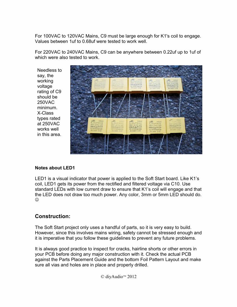
For 100VAC to 120VAC Mains, C9 must be large enough for K1's coil to engage. Values between 1uf to 0.68uf were tested to work well.
For 220VAC to 240VAC Mains, C9 can be anywhere between 0.22uf up to 1uf of which were also tested to work.
Notes about LED1
LED1 is a visual indicator that power is applied to the Soft Start board. Like K1’s coil, LED1 gets its power from the rectified and filtered voltage via C10. Use standard LEDs with low current draw to ensure that K1’s coil will engage and that the LED does not draw too much power. Any color, 3mm or 5mm LED should do.
Construction:
The Soft Start project only uses a handful of parts, so it is very easy to build. However, since this involves mains wiring, safety cannot be stressed enough and it is imperative that you follow these guidelines to prevent any future problems.
It is always good practice to inspect for cracks, hairline shorts or other errors in your PCB before doing any major construction with it. Check the actual PCB against the Parts Placement Guide and the bottom Foil Pattern Layout and make sure all vias and holes are in place and properly drilled.
© diyAudioTM 2012
Needless to say, the working voltage rating of C9 should be 250VAC minimum. X-Class types rated at 250VAC works well in this area.
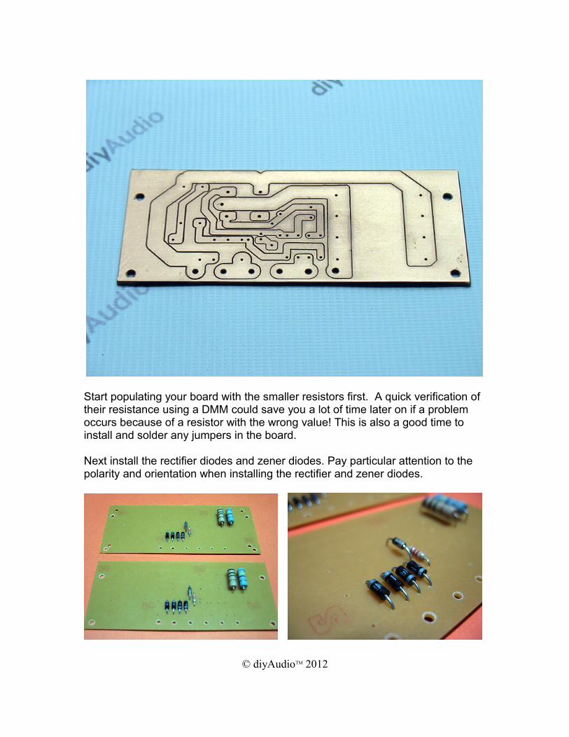
Start populating your board with the smaller resistors first. A quick verification of their resistance using a DMM could save you a lot of time later on if a problem occurs because of a resistor with the wrong value! This is also a good time to install and solder any jumpers in the board.
Next install the rectifier diodes and zener diodes. Pay particular attention to the polarity and orientation when installing the rectifier and zener diodes.
© diyAudioTM 2012
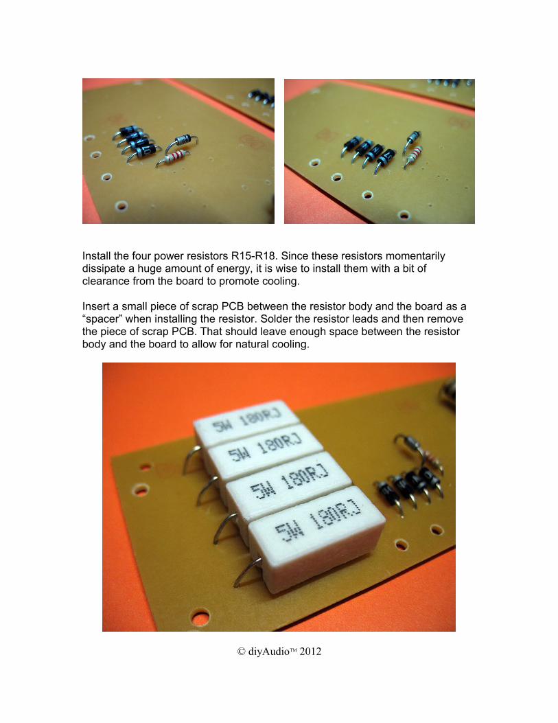
Install the four power resistors R15-R18. Since these resistors momentarily dissipate a huge amount of energy, it is wise to install them with a bit of clearance from the board to promote cooling.
Insert a small piece of scrap PCB between the resistor body and the board as a “spacer” when installing the resistor. Solder the resistor leads and then remove the piece of scrap PCB. That should leave enough space between the resistor body and the board to allow for natural cooling.
© diyAudioTM 2012
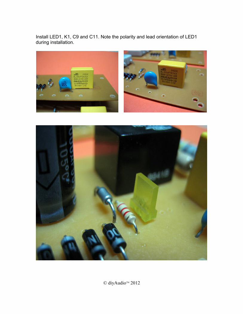
Install LED1, K1, C9 and C11. Note the polarity and lead orientation of LED1 during installation.
© diyAudioTM 2012
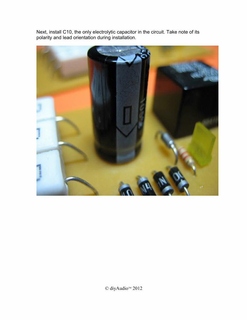
Next, install C10, the only electrolytic capacitor in the circuit. Take note of its polarity and lead orientation during installation.
© diyAudioTM 2012
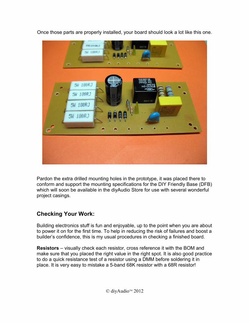
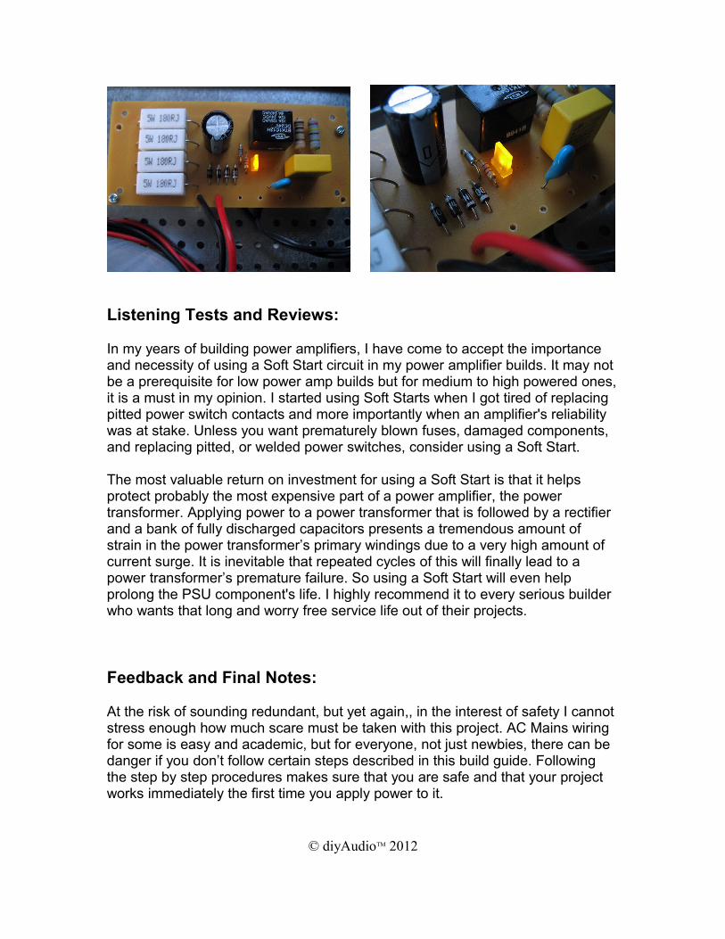
Once those parts are properly installed, your board should look a lot like this one.
Pardon the extra drilled mounting holes in the prototype, it was placed there to conform and support the mounting specifications for the DIY Friendly Base (DFB) which will soon be available in the diyAudio Store for use with several wonderful project casings.
Checking Your Work:
Building electronics stuff is fun and enjoyable, up to the point when you are about to power it on for the first time. To help in reducing the risk of failures and boost a builder’s confidence, this is my usual procedures in checking a finished board.
Resistors – visually check each resistor, cross reference it with the BOM and make sure that you placed the right value in the right spot. It is also good practice to do a quick resistance test of a resistor using a DMM before soldering it in place. It is very easy to mistake a 5-band 68K resistor with a 68R resistor!
© diyAudioTM 2012
Capacitors – electrolytic capacitors are polarized so check and pay careful attention to their pin orientation. Make sure the markings on the capacitor matches the polarity marked on the board.
Diodes – it is so easy to overlook the lead orientation of diodes especially those small signal types and zener types. Check and make sure that their polarity matches the assigned polarity markings on the board.
Testing and Calibration:Things you’ll need:
Digital Multi-Meter (DMM).1. Several AWG #18 hook-up wires.2. Power Transformer.3. A power supply assembly like the diyAudio PSU Cap Diode Board (P-
PSU-1V20)
© diyAudioTM 2012
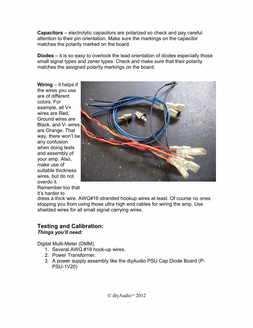
Wiring – it helps if the wires you use are of different colors. For example, all V+ wires are Red, Ground wires are Black, and V- wires are Orange. That way, there won’t be any confusion when doing tests and assembly of your amp. Also, make use of suitable thickness wires, but do not overdo it. Remember too that it’s harder to dress a thick wire. AWG#16 stranded hookup wires at least. Of course no ones stopping you from using those ultra high end cables for wiring the amp. Use shielded wires for all small signal carrying wires.
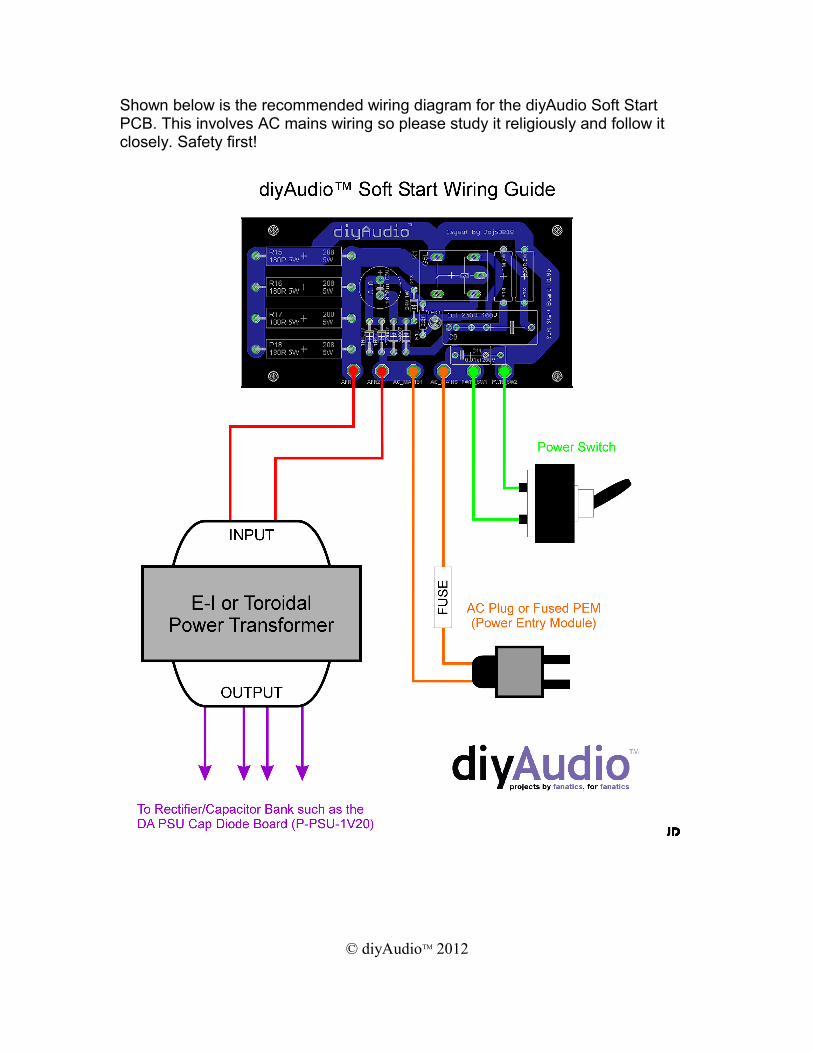
Shown below is the recommended wiring diagram for the diyAudio Soft Start PCB. This involves AC mains wiring so please study it religiously and follow it closely. Safety first!
© diyAudioTM 2012
There are only 6 solder points in the Soft Start board, these are:
• XFR1 & XFR2 – Connects to the Primary winding of your power transformer.
• AC_MAINS1 & AC_MAINS2 – Connects to your AC Mains via a fused PEM (Power Entry Module) or fused AC Plug.
• PWR_SW1 & PWR_SW2 – Connects to your main Power Switch. In cases where there is a primary switch situated at the back or built-in on the PEM and a secondary switch on the front, these terminals (PWR_SW1 & PWR_SW2) must be wired to your secondary switch, which is used to power up the main power supply.
Power ON Procedures:
1. To test the populated board, simply wire the Soft Start board as seen in the Wiring Guide while closely noting the proper connections.
2. Connect your DMM to the output of your power supply assembly like the diyAudio PSU Cap Diode Board (P-PSU-1V20).
3. Plug in your AC plug to your AC Mains socket or if using a PEM, connect a suitable AC power cord.
4. Switch your Power Switch to ON and you’ll see in your DMM that the voltage output of your power supply is slowly rising.
5. After a few milliseconds (depends on the value of C9), K1 should engage and you should be able to measure the rated output of your power supply assembly with your DMM.
6. Power down and wait until your power supply capacitors are completely discharged and then repeat steps 4 & 5.
7. It is normal for R15 - R18 to heat up, all other components should be room temperature. (NOTE: DON’T TOUCH ANY COMPONENTS WHILE THE BOARD IS PLUGGED TO THE AC MAINS!)
8. If everything is satisfactory, it is now time to install your Soft Start to your power amplifier. Please follow the wiring guide religiously and double check everything before powering up again.
© diyAudioTM 2012
Listening Tests and Reviews:
In my years of building power amplifiers, I have come to accept the importance and necessity of using a Soft Start circuit in my power amplifier builds. It may not be a prerequisite for low power amp builds but for medium to high powered ones, it is a must in my opinion. I started using Soft Starts when I got tired of replacing pitted power switch contacts and more importantly when an amplifier's reliability was at stake. Unless you want prematurely blown fuses, damaged components, and replacing pitted, or welded power switches, consider using a Soft Start.
The most valuable return on investment for using a Soft Start is that it helps protect probably the most expensive part of a power amplifier, the power transformer. Applying power to a power transformer that is followed by a rectifier and a bank of fully discharged capacitors presents a tremendous amount of strain in the power transformer’s primary windings due to a very high amount of current surge. It is inevitable that repeated cycles of this will finally lead to a power transformer’s premature failure. So using a Soft Start will even help prolong the PSU component's life. I highly recommend it to every serious builder who wants that long and worry free service life out of their projects.
Feedback and Final Notes:
At the risk of sounding redundant, but yet again,, in the interest of safety I cannot stress enough how much scare must be taken with this project. AC Mains wiring for some is easy and academic, but for everyone, not just newbies, there can be danger if you don’t follow certain steps described in this build guide. Following the step by step procedures makes sure that you are safe and that your project works immediately the first time you apply power to it.
© diyAudioTM 2012
I encourage everyone to build this project for their power amplifiers but please work slowly, be patient, and don’t let the excitement get the better part of you before you have double checked your work.
Enjoy!
JD
© diyAudioTM 2012