Embed Size (px)
Citation preview
DIY Build Instructions – KOSMODROM CHAOS DIVIDER [v 1.4 PCB SET]
First of, thank you for your purchase of the Tsyklon Labs KOSMODROM CHAOS DIVIDER DIY Kit [details below]. If you are a DIY SynthVeteran [or, as we like to say at Tsyklon Labs - “Hero of Synthesizer DIY”], then this kit will be a fun build. If you are a DIY Synth Novice, youhave selected a build that will certainly strengthen your skills – but, follow the directions and take your time with this build. It is notexceptionally complicated, but there are a lot of steps. During the build, you will put together many types of circuits – power, digital logic,analog signal manipulation, high voltage DC [160V], and cold cathode tubes. If you are into coding, you'll even have the option of creatingyour own alternate frmware for the Chaos Divider HV. Also, if you are not familiar with component naming, please check out page 37.
First, let's make sure that you have everything on hand before we heat up the iron. The tools you will need are as follows:- Soldering Iron [if you have both a fne point and a chisel point, that will work well] and Solder- Wire Cutters- Needle Nose Pliers- Fine Point Tweezers [ESD safe is preferred]- 2.5mm Allen Wrench or Small Phillips Screw Driver for tightening M3 screws on PCB Standofs- 10mm Deep Well Socket for tightening Potentiometer nuts and 7mm for Toggle Switch nuts- Knurled Nut Tool [Xicon 382-0006] or 8mm Socket for tightening Jack nuts- Insulated Trimmer Resistor adjustment tool- Voltmeter w/ clip leads for trimming On Board Voltage Regulators [10VDC and 160VDC]- Two pieces of electrical tape, both 2.5” [64mm] long
The following parts have been included in your kit:
Qty Part Description
1 Kosmodrom Chaos Divider Front Panel [WHITE Aluminum Panel with BLUE, BLACK, and RED screen printing]
1 Kosmodrom Chaos Divider Power/Logic Printed Circuit Board v1.4 [RED Solder Mask with BLACK screen printing]
1 Kosmodrom Chaos Divider Signal Printed Circuit Board v1.4 [BLUE Solder Mask, with WHITE screen printing]
1 Kosmodrom Chaos Divider Control Printed Circuit Board v1.4 [WHITE Solder Mask with BLACK screen printing]
9 Orange Water-clear 3mm Orange LEDs [2 pin]
1 Common Cathode 3mm Red/Blue LED [3 pin]
1 ИН-17 [IN-17] 10 Digit Nixie Cold Cathode, Common Anode Vacuum Tube
1 КМ155ИД1 [KM155ID1] Ceramic Nixie Driver IC [16 pin DIP IC]
1 Microchip PIC18F4520 Microcontroller Chaos Engine with Chaos Divider v1.4.x frmware [40 pin DIP IC] with 40 Pin Socket
DIY Build DOC/BOM KOSMODROM CHAOS DIVIDER V 1.4 Page 1
PART I – Unpacking the kit
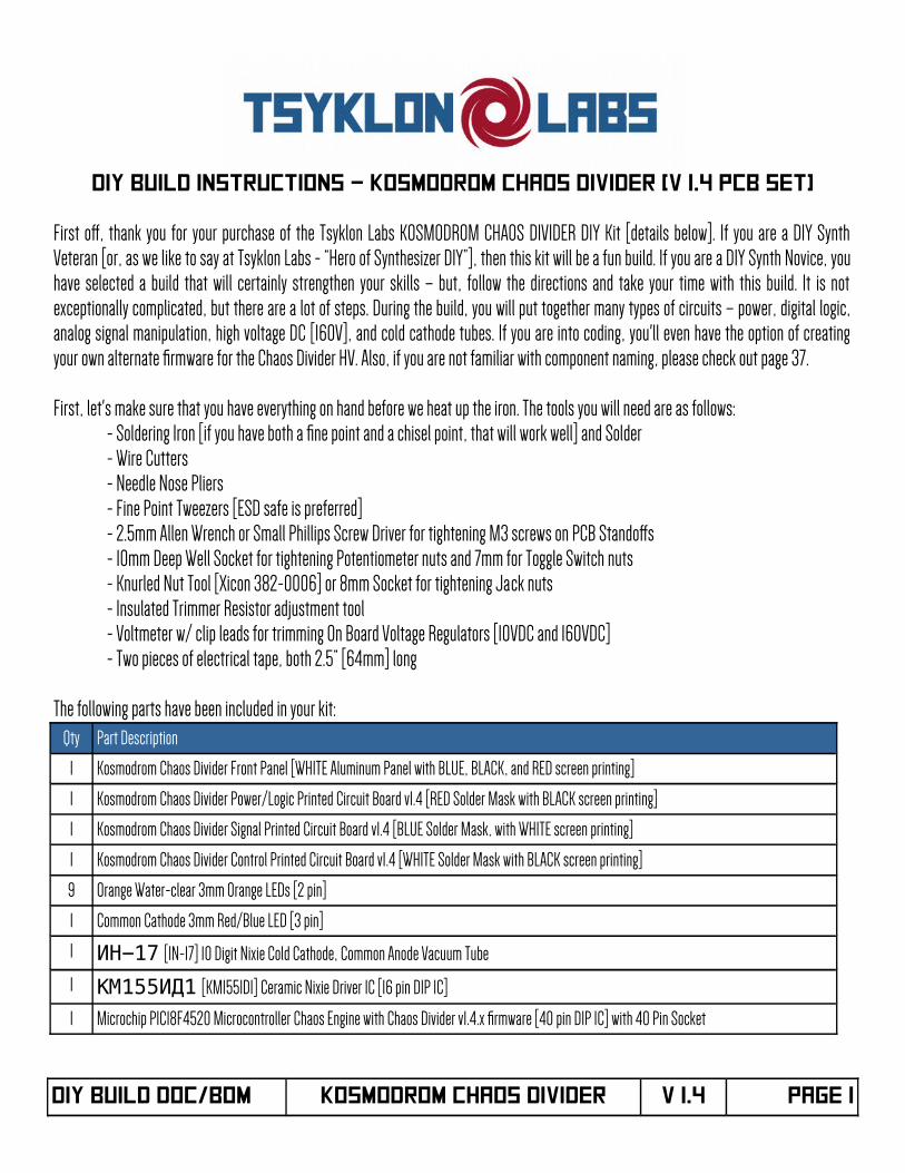
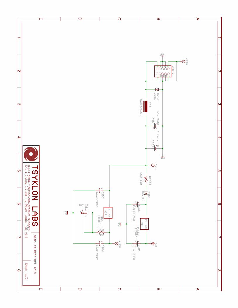
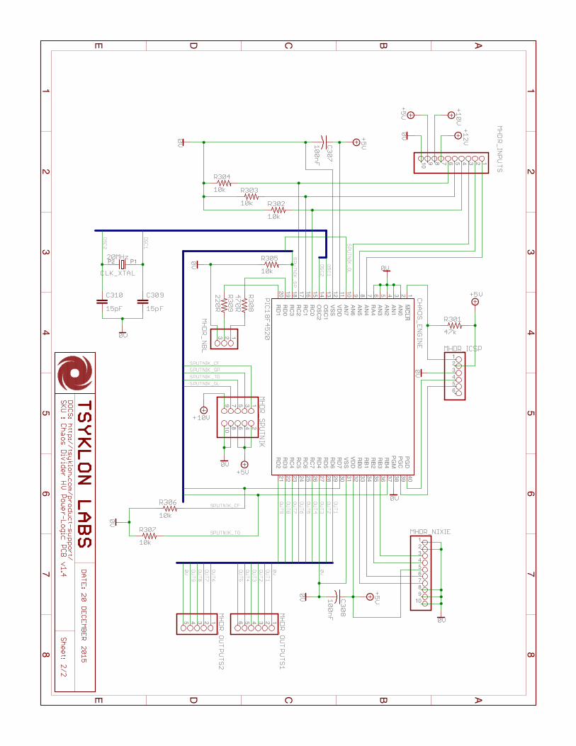
1-1) Let us begin by inspecting the components that came with the kit. First is the RED Power/Logic Printed Circuit Board [PCB]. It is calledthat because it hosts the power supply circuitry as well as the logic interfaces for the Microcontroller [front and back sides are shown]:
1-2) Next, take a look at the BLUE Signal PCB. It contains all of the circuitry for the Nixie Tube and its voltage boost power supply as well asall of the circuitry that translates all of the real world, Eurorack system signals to those that work with [and more importantly, will notdamage] the PIC18 8-bit Microcontroller. Take note of the “Do Not Touch” screen printing images on the back of the PCB. That is thelocation of the Voltage Boost circuitry for the Nixie tube – so, take heed and do not touch. And especially, do not lick the Nixie circuit either.In fact, it is not safe to lick any side of any circuit board of any of your modules, the Chaos Divider included. Especially the Chaos Divider.Seriously, stop thinking about it. [front and back sides are shown]:
DIY Build DOC/BOM KOSMODROM CHAOS DIVIDER V 1.4 Page 2
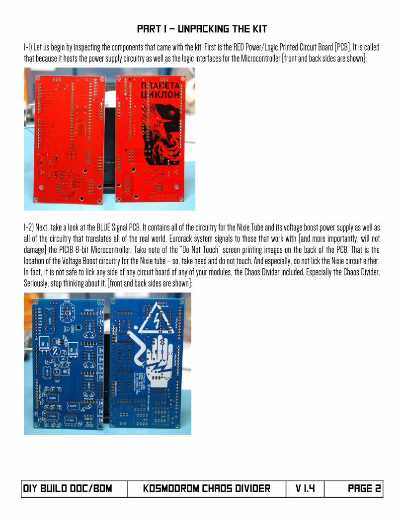
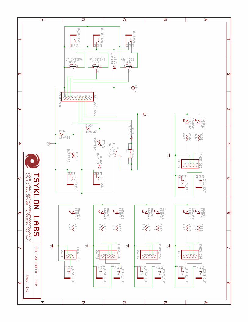
1-3) The third item that we will check is the WHITE Control PCB. All of the user IO and Control devices for the Chaos Divider are on this PCB[front and back sides are shown]:
1-4) Next, we will inspect the Chaos Divider Front Panel. Check for chips or fakes in the powder coated panel as well as any issues with the screen printing. It should look like this:
NOTE: The Chaos Divider's front panels are printed with solvent based inks. Do not use solvents such as Naphtha, VM&P, Isopropyl Alcohol [or any other solvent or solvent based cleaners not listed] to clean the front panel. There is a really good chance that you will remove the printing from the panel.
ALSO OF NOTE: There are four Mouser carts for this build. One for each of the PCBs and one for miscellaneous hardware such as fasteners and stand-ofs. Be sure to get ALL of them.
DIY Build DOC/BOM KOSMODROM CHAOS DIVIDER V 1.4 Page 3
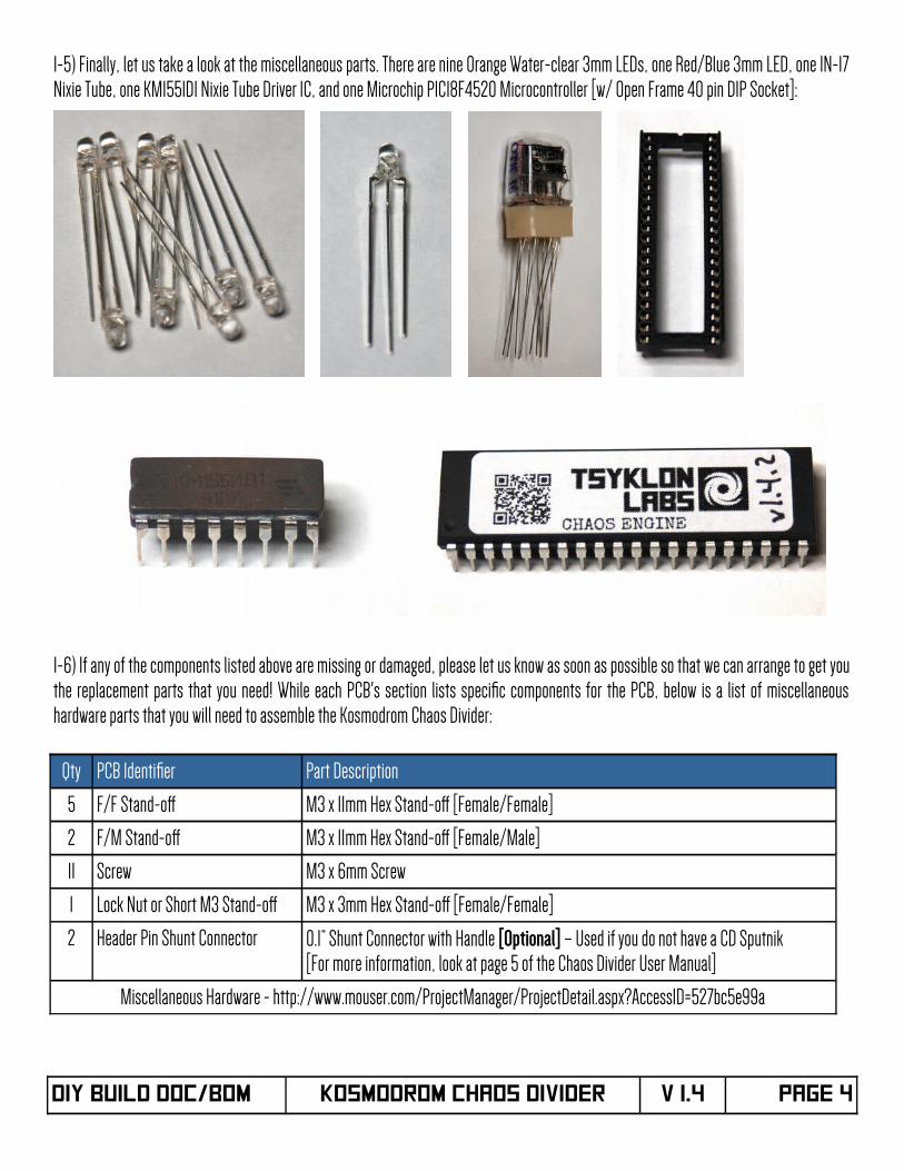
1-5) Finally, let us take a look at the miscellaneous parts. There are nine Orange Water-clear 3mm LEDs, one Red/Blue 3mm LED, one IN-17Nixie Tube, one KM155ID1 Nixie Tube Driver IC, and one Microchip PIC18F4520 Microcontroller [w/ Open Frame 40 pin DIP Socket]:
1-6) If any of the components listed above are missing or damaged, please let us know as soon as possible so that we can arrange to get youthe replacement parts that you need! While each PCB's section lists specifc components for the PCB, below is a list of miscellaneoushardware parts that you will need to assemble the Kosmodrom Chaos Divider:
Qty PCB Identifer Part Description
5 F/F Stand-of M3 x 11mm Hex Stand-of [Female/Female]
2 F/M Stand-of M3 x 11mm Hex Stand-of [Female/Male]
11 Screw M3 x 6mm Screw
1 Lock Nut or Short M3 Stand-of M3 x 3mm Hex Stand-of [Female/Female]
2 Header Pin Shunt Connector 0.1” Shunt Connector with Handle [Optional] – Used if you do not have a CD Sputnik[For more information, look at page 5 of the Chaos Divider User Manual]
Miscellaneous Hardware - http://www.mouser.com/ProjectManager/ProjectDetail.aspx?AccessID=527bc5e99a
DIY Build DOC/BOM KOSMODROM CHAOS DIVIDER V 1.4 Page 4
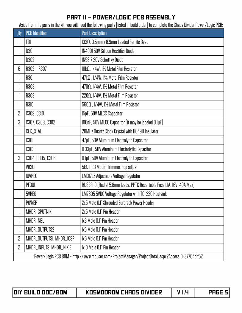
PART II – Power/Logic PCB Assembly
Aside from the parts in the kit, you will need the following parts [listed in build order] to complete the Chaos Divider Power/Logic PCB:
Qty PCB Identifer Part Description
1 FB1 133Ω, 3.5mm x 8.9mm Leaded Ferrite Bead
1 D301 1N4001 50V Silicon Rectifer Diode
1 D302 1N5817 20V Schottky Diode
6 R302 – R307 10kΩ, 1/4W, 1% Metal Film Resistor
1 R301 47kΩ , 1/4W, 1% Metal Film Resistor
1 R308 470Ω, 1/4W, 1% Metal Film Resistor
1 R309 220Ω, 1/4W, 1% Metal Film Resistor
1 R310 560Ω , 1/4W, 1% Metal Film Resistor
2 C309, C310 15pF, 50V MLCC Capacitor
3 C307, C308, C302 100nF, 50V MLCC Capacitor [it may be labeled 0.1µF]
1 CLK_XTAL 20MHz Quartz Clock Crystal with HC49U Insulator
1 C301 47µF, 50V Aluminum Electrolytic Capacitor
1 C303 0.33µF, 50V Aluminum Electrolytic Capacitor
3 C304, C305, C306 0.1µF, 50V Aluminum Electrolytic Capacitor
1 VR301 5kΩ PCB Mount Trimmer, top adjust
1 10VREG LM317LZ Adjustable Voltage Regulator
1 PF301 RUSBF110 [Radial 5.8mm leads, PPTC Resettable Fuse 1.1A, 16V, 40A Max]
1 5VREG LM7805 5VDC Voltage Regulator with TO-220 Heatsink
1 POWER 2x5 Male 0.1” Shrouded Eurorack Power Header
1 MHDR_SPUTNIK 2x5 Male 0.1” Pin Header
1 MHDR_NBL 1x3 Male 0.1” Pin Header
1 MHDR_OUTPUTS2 1x5 Male 0.1” Pin Header
2 MHDR_OUTPUTS1, MHDR_ICSP 1x6 Male 0.1” Pin Header
2 MHDR_INPUTS, MHDR_NIXIE 1x10 Male 0.1” Pin Header
Power/Logic PCB BOM - http://www.mouser.com/ProjectManager/ProjectDetail.aspx?AccessID=37764c1f52
DIY Build DOC/BOM KOSMODROM CHAOS DIVIDER V 1.4 Page 5
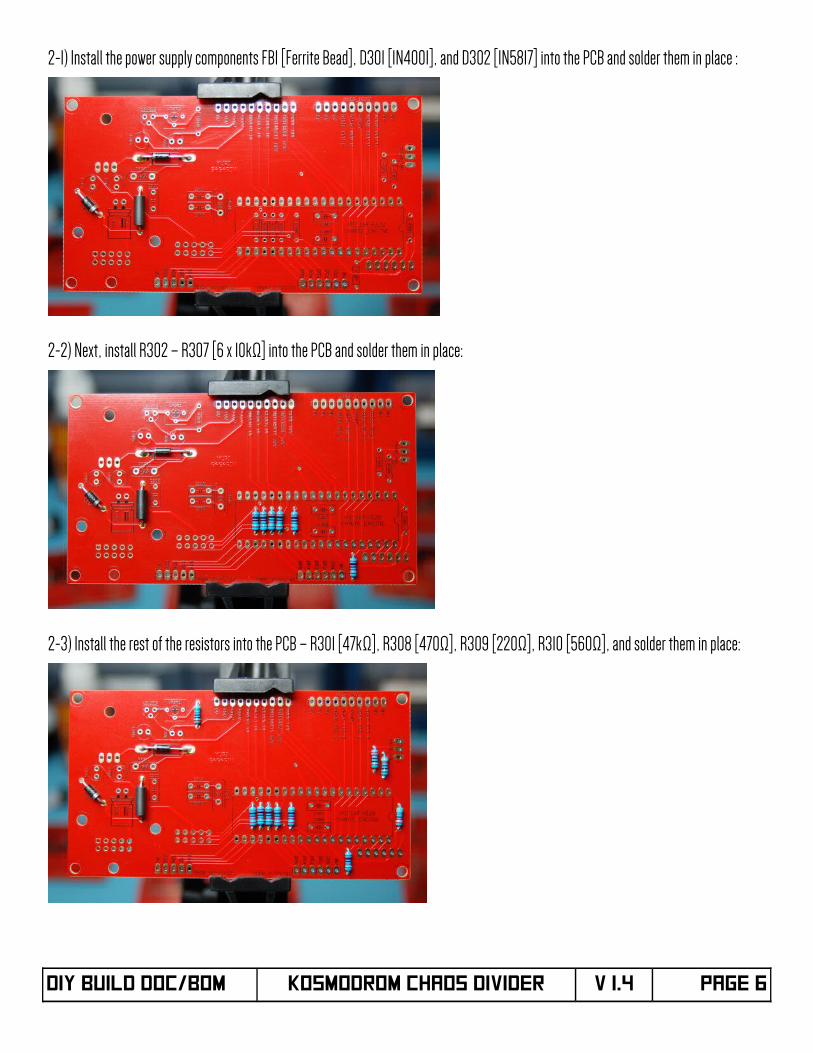
2-1) Install the power supply components FB1 [Ferrite Bead], D301 [1N4001], and D302 [1N5817] into the PCB and solder them in place :
2-2) Next, install R302 – R307 [6 x 10kΩ] into the PCB and solder them in place:
2-3) Install the rest of the resistors into the PCB – R301 [47kΩ], R308 [470Ω], R309 [220Ω], R310 [560Ω], and solder them in place:
DIY Build DOC/BOM KOSMODROM CHAOS DIVIDER V 1.4 Page 6
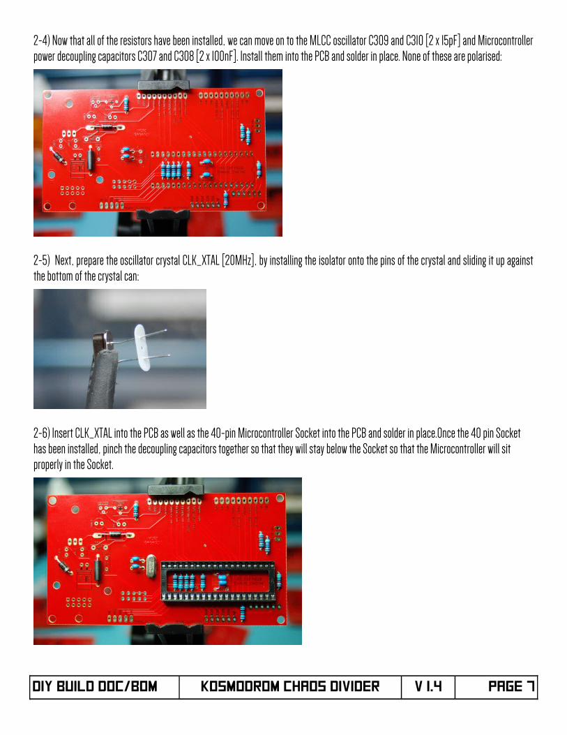
2-4) Now that all of the resistors have been installed, we can move on to the MLCC oscillator C309 and C310 [2 x 15pF] and Microcontrollerpower decoupling capacitors C307 and C308 [2 x 100nF]. Install them into the PCB and solder in place. None of these are polarised:
2-5) Next, prepare the oscillator crystal CLK_XTAL [20MHz], by installing the isolator onto the pins of the crystal and sliding it up againstthe bottom of the crystal can:
2-6) Insert CLK_XTAL into the PCB as well as the 40-pin Microcontroller Socket into the PCB and solder in place.Once the 40 pin Socket has been installed, pinch the decoupling capacitors together so that they will stay below the Socket so that the Microcontroller will sit properly in the Socket.
DIY Build DOC/BOM KOSMODROM CHAOS DIVIDER V 1.4 Page 7
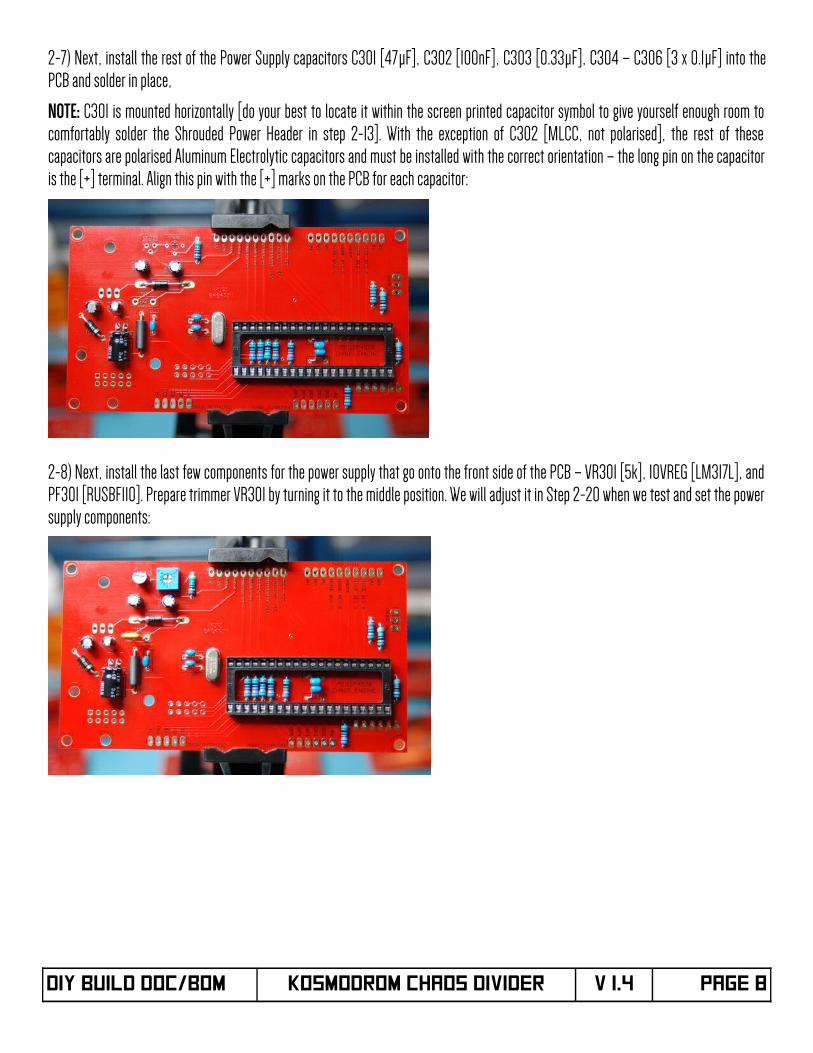
2-7) Next, install the rest of the Power Supply capacitors C301 [47µF], C302 [100nF], C303 [0.33µF], C304 – C306 [3 x 0.1µF] into thePCB and solder in place,
NOTE: C301 is mounted horizontally [do your best to locate it within the screen printed capacitor symbol to give yourself enough room tocomfortably solder the Shrouded Power Header in step 2-13]. With the exception of C302 [MLCC, not polarised], the rest of thesecapacitors are polarised Aluminum Electrolytic capacitors and must be installed with the correct orientation – the long pin on the capacitoris the [+] terminal. Align this pin with the [+] marks on the PCB for each capacitor:
2-8) Next, install the last few components for the power supply that go onto the front side of the PCB – VR301 [5k], 10VREG [LM317L], andPF301 [RUSBF110]. Prepare trimmer VR301 by turning it to the middle position. We will adjust it in Step 2-20 when we test and set the powersupply components:
DIY Build DOC/BOM KOSMODROM CHAOS DIVIDER V 1.4 Page 8
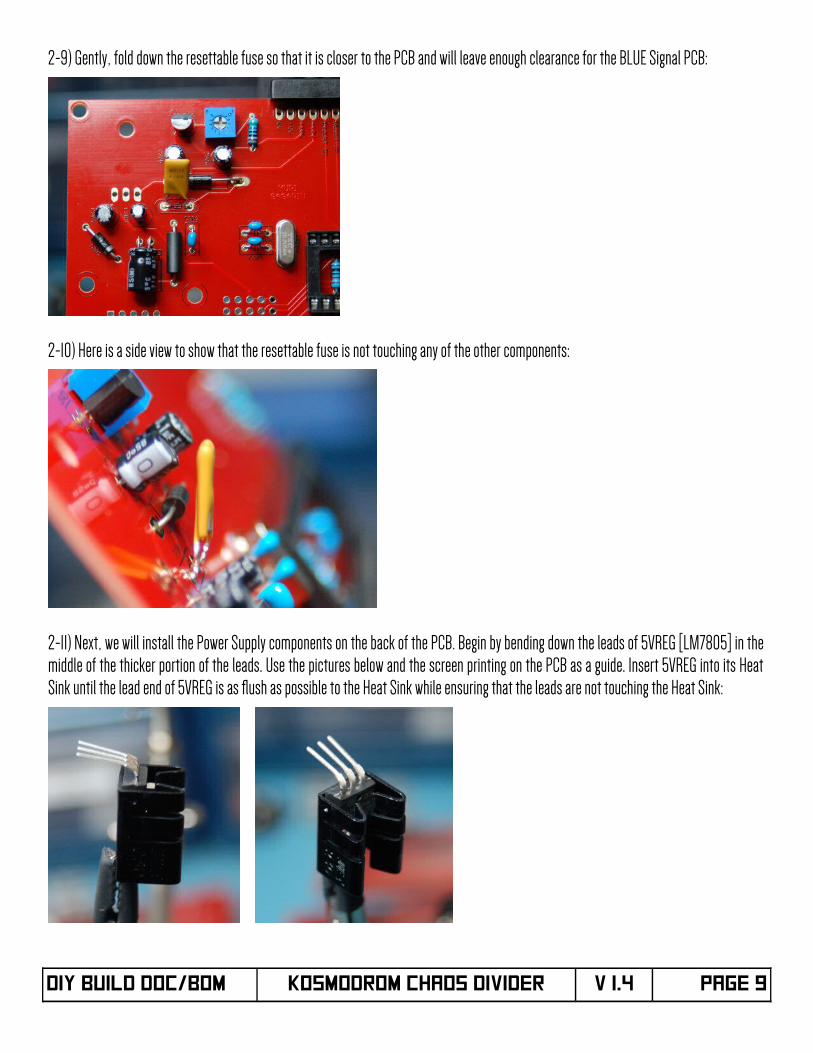
2-9) Gently, fold down the resettable fuse so that it is closer to the PCB and will leave enough clearance for the BLUE Signal PCB:
2-10) Here is a side view to show that the resettable fuse is not touching any of the other components:
2-11) Next, we will install the Power Supply components on the back of the PCB. Begin by bending down the leads of 5VREG [LM7805] in themiddle of the thicker portion of the leads. Use the pictures below and the screen printing on the PCB as a guide. Insert 5VREG into its HeatSink until the lead end of 5VREG is as fush as possible to the Heat Sink while ensuring that the leads are not touching the Heat Sink:
DIY Build DOC/BOM KOSMODROM CHAOS DIVIDER V 1.4 Page 9
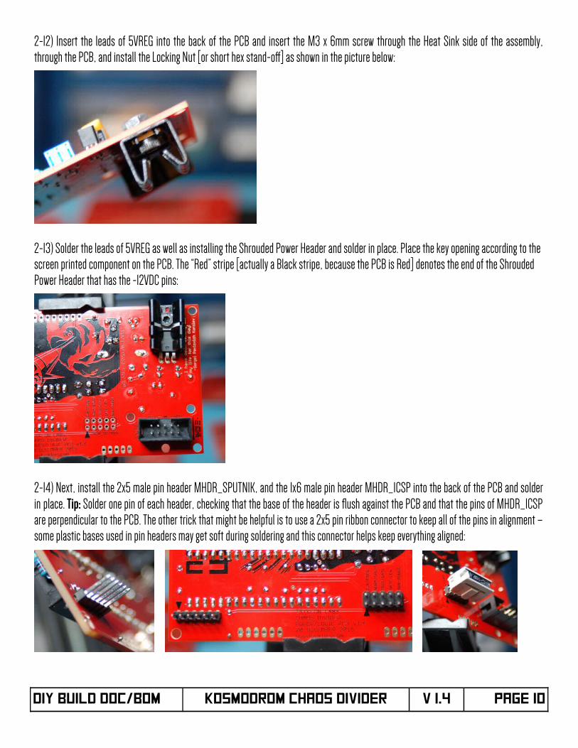
2-12) Insert the leads of 5VREG into the back of the PCB and insert the M3 x 6mm screw through the Heat Sink side of the assembly,through the PCB, and install the Locking Nut [or short hex stand-of] as shown in the picture below:
2-13) Solder the leads of 5VREG as well as installing the Shrouded Power Header and solder in place. Place the key opening according to the screen printed component on the PCB. The “Red” stripe [actually a Black stripe, because the PCB is Red] denotes the end of the Shrouded Power Header that has the -12VDC pins:
2-14) Next, install the 2x5 male pin header MHDR_SPUTNIK, and the 1x6 male pin header MHDR_ICSP into the back of the PCB and solderin place. Tip: Solder one pin of each header, checking that the base of the header is fush against the PCB and that the pins of MHDR_ICSPare perpendicular to the PCB. The other trick that might be helpful is to use a 2x5 pin ribbon connector to keep all of the pins in alignment –some plastic bases used in pin headers may get soft during soldering and this connector helps keep everything aligned:
DIY Build DOC/BOM KOSMODROM CHAOS DIVIDER V 1.4 Page 10
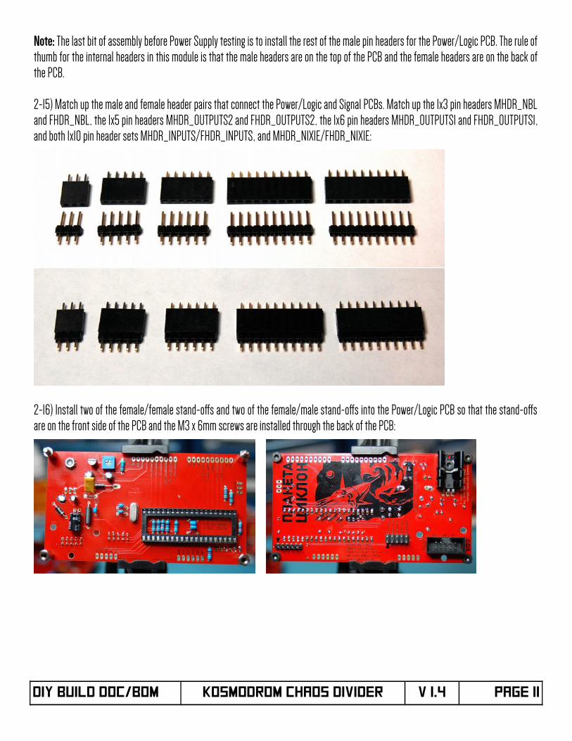
Note: The last bit of assembly before Power Supply testing is to install the rest of the male pin headers for the Power/Logic PCB. The rule ofthumb for the internal headers in this module is that the male headers are on the top of the PCB and the female headers are on the back ofthe PCB.
2-15) Match up the male and female header pairs that connect the Power/Logic and Signal PCBs. Match up the 1x3 pin headers MHDR_NBLand FHDR_NBL, the 1x5 pin headers MHDR_OUTPUTS2 and FHDR_OUTPUTS2, the 1x6 pin headers MHDR_OUTPUTS1 and FHDR_OUTPUTS1,and both 1x10 pin header sets MHDR_INPUTS/FHDR_INPUTS, and MHDR_NIXIE/FHDR_NIXIE:
2-16) Install two of the female/female stand-ofs and two of the female/male stand-ofs into the Power/Logic PCB so that the stand-ofsare on the front side of the PCB and the M3 x 6mm screws are installed through the back of the PCB:
DIY Build DOC/BOM KOSMODROM CHAOS DIVIDER V 1.4 Page 11
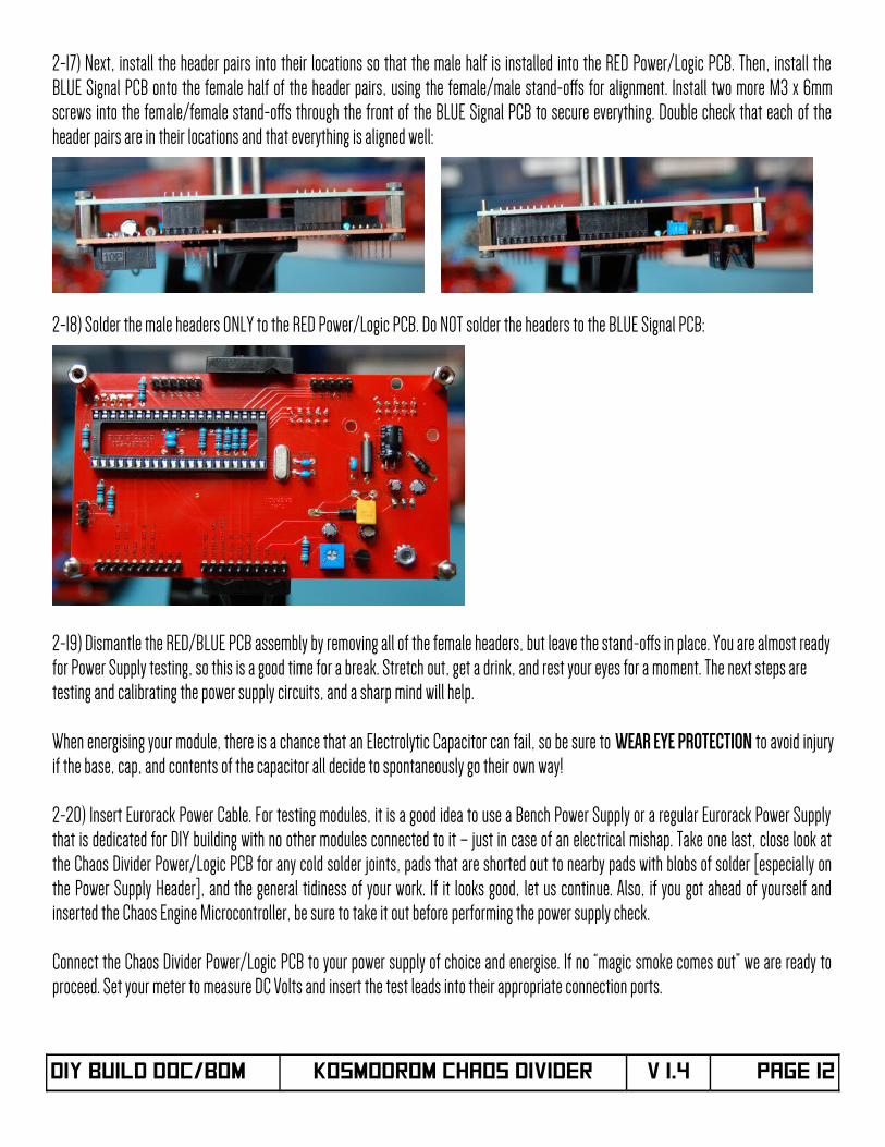
2-17) Next, install the header pairs into their locations so that the male half is installed into the RED Power/Logic PCB. Then, install theBLUE Signal PCB onto the female half of the header pairs, using the female/male stand-ofs for alignment. Install two more M3 x 6mmscrews into the female/female stand-ofs through the front of the BLUE Signal PCB to secure everything. Double check that each of theheader pairs are in their locations and that everything is aligned well:
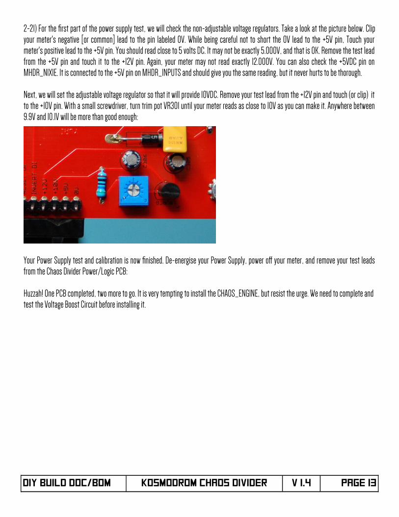
2-18) Solder the male headers ONLY to the RED Power/Logic PCB. Do NOT solder the headers to the BLUE Signal PCB:
2-19) Dismantle the RED/BLUE PCB assembly by removing all of the female headers, but leave the stand-ofs in place. You are almost readyfor Power Supply testing, so this is a good time for a break. Stretch out, get a drink, and rest your eyes for a moment. The next steps are testing and calibrating the power supply circuits, and a sharp mind will help.
When energising your module, there is a chance that an Electrolytic Capacitor can fail, so be sure to WEAR EYE PROTECTION to avoid injuryif the base, cap, and contents of the capacitor all decide to spontaneously go their own way!
2-20) Insert Eurorack Power Cable. For testing modules, it is a good idea to use a Bench Power Supply or a regular Eurorack Power Supplythat is dedicated for DIY building with no other modules connected to it – just in case of an electrical mishap. Take one last, close look atthe Chaos Divider Power/Logic PCB for any cold solder joints, pads that are shorted out to nearby pads with blobs of solder [especially onthe Power Supply Header], and the general tidiness of your work. If it looks good, let us continue. Also, if you got ahead of yourself andinserted the Chaos Engine Microcontroller, be sure to take it out before performing the power supply check.
Connect the Chaos Divider Power/Logic PCB to your power supply of choice and energise. If no “magic smoke comes out” we are ready toproceed. Set your meter to measure DC Volts and insert the test leads into their appropriate connection ports.
DIY Build DOC/BOM KOSMODROM CHAOS DIVIDER V 1.4 Page 12
2-21) For the frst part of the power supply test, we will check the non-adjustable voltage regulators. Take a look at the picture below. Clipyour meter's negative [or common] lead to the pin labeled 0V. While being careful not to short the 0V lead to the +5V pin, Touch yourmeter's positive lead to the +5V pin. You should read close to 5 volts DC. It may not be exactly 5.000V, and that is OK. Remove the test leadfrom the +5V pin and touch it to the +12V pin. Again, your meter may not read exactly 12.000V. You can also check the +5VDC pin onMHDR_NIXIE. It is connected to the +5V pin on MHDR_INPUTS and should give you the same reading, but it never hurts to be thorough.
Next, we will set the adjustable voltage regulator so that it will provide 10VDC. Remove your test lead from the +12V pin and touch (or clip) itto the +10V pin. With a small screwdriver, turn trim pot VR301 until your meter reads as close to 10V as you can make it. Anywhere between9.9V and 10.1V will be more than good enough:
Your Power Supply test and calibration is now fnished. De-energise your Power Supply, power of your meter, and remove your test leadsfrom the Chaos Divider Power/Logic PCB:
Huzzah! One PCB completed, two more to go. It is very tempting to install the CHAOS_ENGINE, but resist the urge. We need to complete and test the Voltage Boost Circuit before installing it.
DIY Build DOC/BOM KOSMODROM CHAOS DIVIDER V 1.4 Page 13
PART III – Signal PCB Assembly
Aside from the parts in the kit, you will need the following parts [listed in build order] to complete the Chaos Divider Signal PCB:
Qty PCB Identifer Part Description
7 C201, C202, C209, C212, C234, C256, C278 100nF, 50V MLCC [0805 SMD] Capacitor [may be labeled 0.1µF]
1 Q212 KSP42TA 300V BJT NPN Transistor
1 Q213 IRFD320 Power MOSFET N-Chan 400V 0.49A
1 D200 UF4004 High Speed, High Voltage Silicon Rectifer Diode
1 C216 2.2nF, 100V MLCC Capacitor [may be labeled 2200pF]
1 R242 6.8kΩ , 1/4W, 1% Metal Film Resistor
1 VR_HV 1kΩ PCB Mount Trimmer, top adjust
1 R215 56kΩ , 1/4W, 1% Metal Film Resistor
1 R216 10kΩ , 1/4W, 1% Metal Film Resistor
1 R217 1kΩ , 1/4W, 1% Metal Film Resistor
1 R218 2.2kΩ , 1/4W, 1% Metal Film Resistor
1 R219 470Ω , 1/4W, 1% Metal Film Resistor
1 R220 220kΩ , 1/4W, 1% Metal Film Resistor
1 L200 100µH Fixed Inductor
1 C215 330µF, 25V Aluminum Electrolytic Capacitor
1 C217 100pF, 2kV Ceramic Capacitor [may be labeled 0.1nF]
1 C218 2.2µF, 400V Aluminum Electrolytic Capacitor
1 IC200 NE555 Timer IC and 8 pin DIP Socket
7 IC201, IC202, IC209, IC212, IC234, IC256, IC278 TLV2372 Rail to Rail Op-Amp and 8 pin DIP Socket
9 R221 – R229 27kΩ , 1/4W, 1% Metal Film Resistor
6 R231, R232, R235, R236, R239, R240 24kΩ , 1/4W, 1% Metal Film Resistor
6 R230, R233, R234, R237, R238, R241 47kΩ , 1/4W, 1% Metal Film Resistor
3 D201, D202, D203 1N4733 5.1V, 1W Zener Diode
9 VR201 – VR209 50kΩ PCB Mount Trimmer, side adjust
1 IC203 KM155ID1 and 16 pin DIP Socket
DIY Build DOC/BOM KOSMODROM CHAOS DIVIDER V 1.4 Page 14
[Chaos Divider Signal PCB BOM Continued]
Qty PCB Identifer Part Description
1 MHDR_O9 1x3 Male 0.1” Pin Header
4 MHDR_O12, MHDR_O34, MHDR_O56, MHDR_O78 1x5 Male 0.1” Pin Header
1 MHDR_CONTROLS 1x10 Male 0.1” Pin Header
1 FHDR_NBL 1x3 Female 0.1” Pin Header
1 FHDR_OUTPUTS2 1x5 Female 0.1” Pin Header
1 FHDR_OUTPUTS1 1x6 Female 0.1” Pin Header
2 FHDR_INPUTS, FHDR_NIXIE 1x10 Female 0.1” Pin Header
Signal PCB BOM - http://www.mouser.com/ProjectManager/ProjectDetail.aspx?AccessID=a7c17e4863
If you don't have a lot of experience with SMD soldering, do yourself a favour and watch this video from Adafruit. Seriously, watch it:
https://www.youtube.com/watch?v=QzoPxvIM2qE
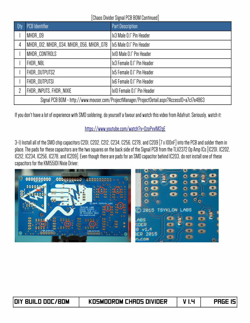
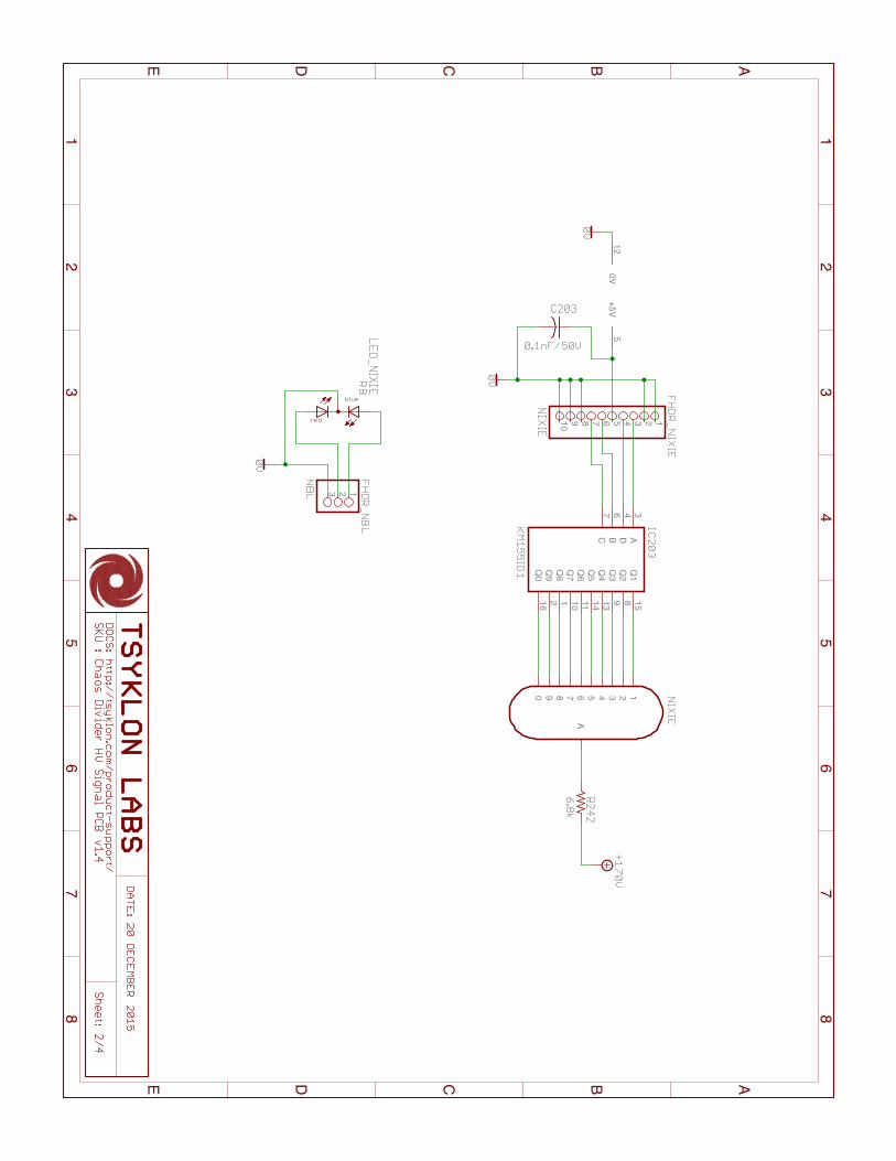
3-1) Install all of the SMD chip capacitors C201, C202, C212, C234, C256, C278, and C209 [7 x 100nF] into the PCB and solder them in place. The pads for these capacitors are the two squares on the back side of the Signal PCB from the TLV2372 Op Amp ICs [IC201, IC202, IC212, IC234, IC256, IC278, and IC209]. Even though there are pads for an SMD capacitor behind IC203, do not install one of these capacitors for the KM155ID1 Nixie Driver:
DIY Build DOC/BOM KOSMODROM CHAOS DIVIDER V 1.4 Page 15
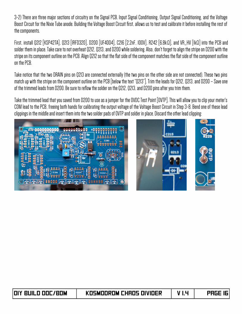
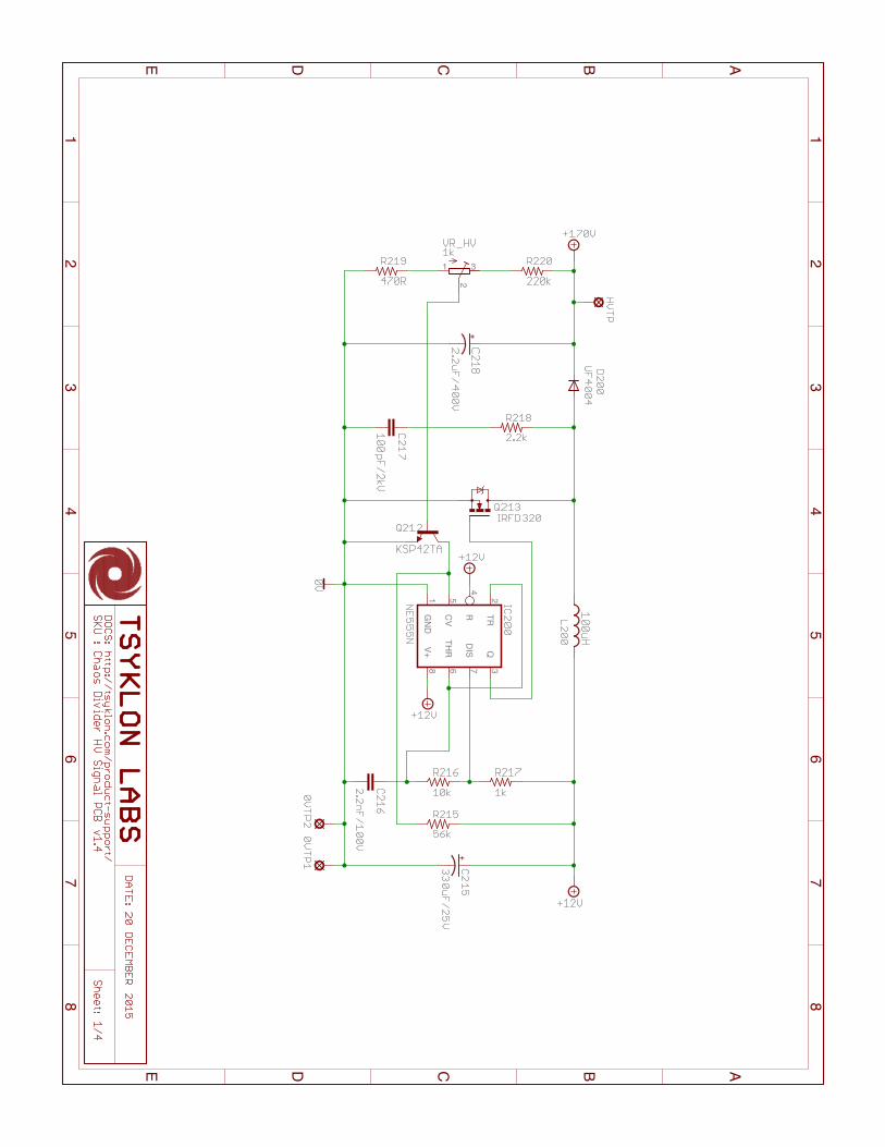
3-2) There are three major sections of circuitry on the Signal PCB. Input Signal Conditioning, Output Signal Conditioning, and the VoltageBoost Circuit for the Nixie Tube anode. Building the Voltage Boost Circuit frst, allows us to test and calibrate it before installing the rest ofthe components.
First, install Q212 [KSP42TA], Q213 [IRFD320], D200 [UF4004], C216 [2.2nF, 100V], R242 [6.8k Ω], and VR_HV [1kΩ] into the PCB andsolder them in place. Take care to not overheat Q212, Q213, and D200 while soldering. Also, don't forget to align the stripe on D200 with thestripe on its component outline on the PCB. Align Q212 so that the fat side of the component matches the fat side of the component outlineon the PCB.
Take notice that the two DRAIN pins on Q213 are connected externally (the two pins on the other side are not connected). These two pinsmatch up with the stripe on the component outline on the PCB [below the text “Q213”]. Trim the leads for Q212, Q213, and D200 – Save oneof the trimmed leads from D200. Be sure to refow the solder on the Q212, Q213, and D200 pins after you trim them.
Take the trimmed lead that you saved from D200 to use as a jumper for the 0VDC Test Point [0VTP]. This will allow you to clip your meter'sCOM lead to the PCB, freeing both hands for calibrating the output voltage of the Voltage Boost Circuit in Step 3-8. Bend one of these leadclippings in the middle and insert them into the two solder pads of 0VTP and solder in place. Discard the other lead clipping:
DIY Build DOC/BOM KOSMODROM CHAOS DIVIDER V 1.4 Page 16
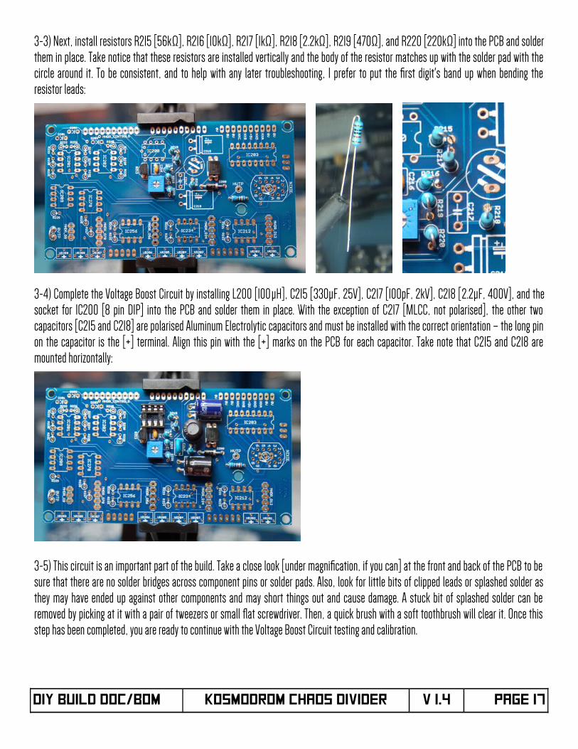
3-3) Next, install resistors R215 [56kΩ], R216 [10kΩ], R217 [1kΩ], R218 [2.2kΩ], R219 [470Ω], and R220 [220kΩ] into the PCB and solderthem in place. Take notice that these resistors are installed vertically and the body of the resistor matches up with the solder pad with thecircle around it. To be consistent, and to help with any later troubleshooting, I prefer to put the frst digit's band up when bending theresistor leads:
3-4) Complete the Voltage Boost Circuit by installing L200 [100µH], C215 [330µF, 25V], C217 [100pF, 2kV], C218 [2.2µF, 400V], and thesocket for IC200 [8 pin DIP] into the PCB and solder them in place. With the exception of C217 [MLCC, not polarised], the other twocapacitors [C215 and C218] are polarised Aluminum Electrolytic capacitors and must be installed with the correct orientation – the long pinon the capacitor is the [+] terminal. Align this pin with the [+] marks on the PCB for each capacitor. Take note that C215 and C218 aremounted horizontally:
3-5) This circuit is an important part of the build. Take a close look [under magnifcation, if you can] at the front and back of the PCB to besure that there are no solder bridges across component pins or solder pads. Also, look for little bits of clipped leads or splashed solder asthey may have ended up against other components and may short things out and cause damage. A stuck bit of splashed solder can beremoved by picking at it with a pair of tweezers or small fat screwdriver. Then, a quick brush with a soft toothbrush will clear it. Once thisstep has been completed, you are ready to continue with the Voltage Boost Circuit testing and calibration.
DIY Build DOC/BOM KOSMODROM CHAOS DIVIDER V 1.4 Page 17
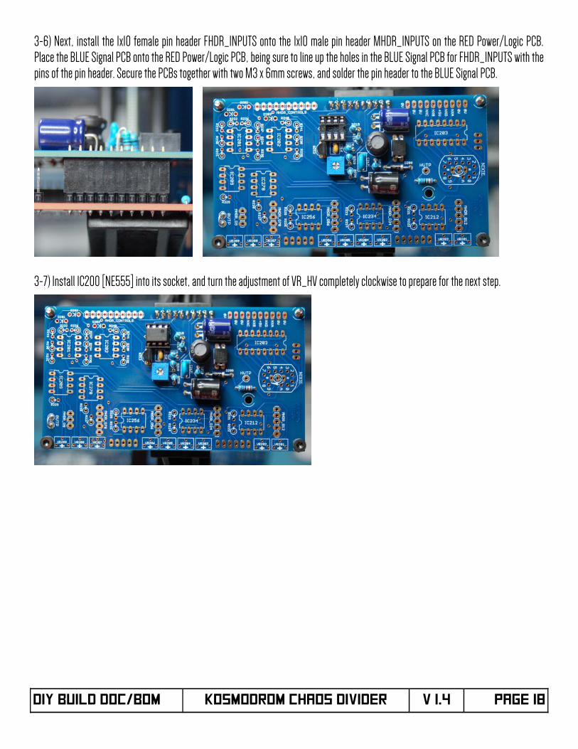
3-6) Next, install the 1x10 female pin header FHDR_INPUTS onto the 1x10 male pin header MHDR_INPUTS on the RED Power/Logic PCB.Place the BLUE Signal PCB onto the RED Power/Logic PCB, being sure to line up the holes in the BLUE Signal PCB for FHDR_INPUTS with thepins of the pin header. Secure the PCBs together with two M3 x 6mm screws, and solder the pin header to the BLUE Signal PCB.
3-7) Install IC200 [NE555] into its socket, and turn the adjustment of VR_HV completely clockwise to prepare for the next step.
DIY Build DOC/BOM KOSMODROM CHAOS DIVIDER V 1.4 Page 18
THE NEXT STEP EXPOSES YOU TO HAZARDOUS VOLTAGES.
Take care to not touch any of the components in the Voltage BoostCircuit with your body while calibrating the Voltage Boost Circuit.
WEAR EYE PROTECTION!
[seriously, we're not messing around]
DIY Build DOC/BOM KOSMODROM CHAOS DIVIDER V 1.4 Page 19
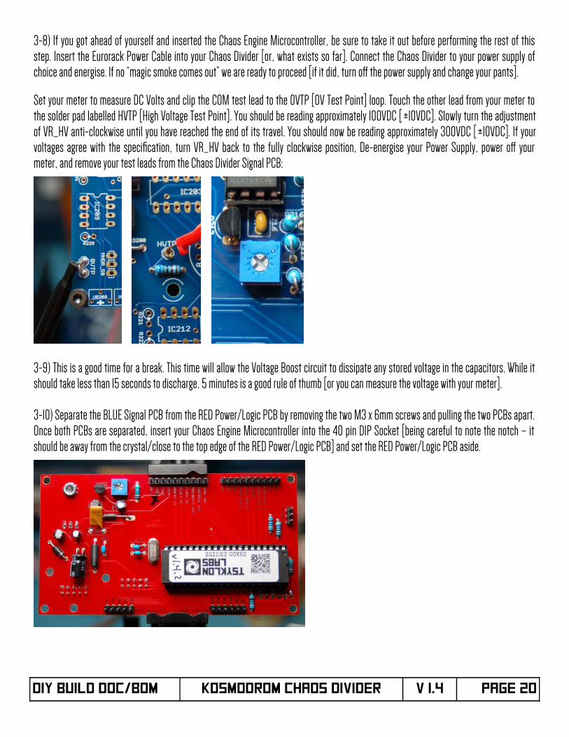
3-8) If you got ahead of yourself and inserted the Chaos Engine Microcontroller, be sure to take it out before performing the rest of thisstep. Insert the Eurorack Power Cable into your Chaos Divider [or, what exists so far]. Connect the Chaos Divider to your power supply ofchoice and energise. If no “magic smoke comes out” we are ready to proceed [if it did, turn of the power supply and change your pants].
Set your meter to measure DC Volts and clip the COM test lead to the 0VTP [0V Test Point] loop. Touch the other lead from your meter tothe solder pad labelled HVTP [High Voltage Test Point]. You should be reading approximately 100VDC [ ±10VDC]. Slowly turn the adjustmentof VR_HV anti-clockwise until you have reached the end of its travel. You should now be reading approximately 300VDC [ ±10VDC]. If yourvoltages agree with the specifcation, turn VR_HV back to the fully clockwise position, De-energise your Power Supply, power of yourmeter, and remove your test leads from the Chaos Divider Signal PCB:
3-9) This is a good time for a break. This time will allow the Voltage Boost circuit to dissipate any stored voltage in the capacitors. While itshould take less than 15 seconds to discharge, 5 minutes is a good rule of thumb [or you can measure the voltage with your meter].
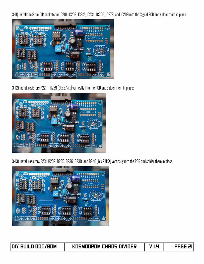
3-10) Separate the BLUE Signal PCB from the RED Power/Logic PCB by removing the two M3 x 6mm screws and pulling the two PCBs apart.Once both PCBs are separated, insert your Chaos Engine Microcontroller into the 40 pin DIP Socket [being careful to note the notch – itshould be away from the crystal/close to the top edge of the RED Power/Logic PCB] and set the RED Power/Logic PCB aside.
DIY Build DOC/BOM KOSMODROM CHAOS DIVIDER V 1.4 Page 20
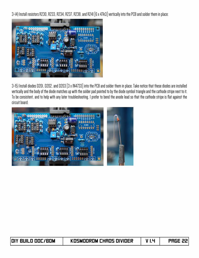
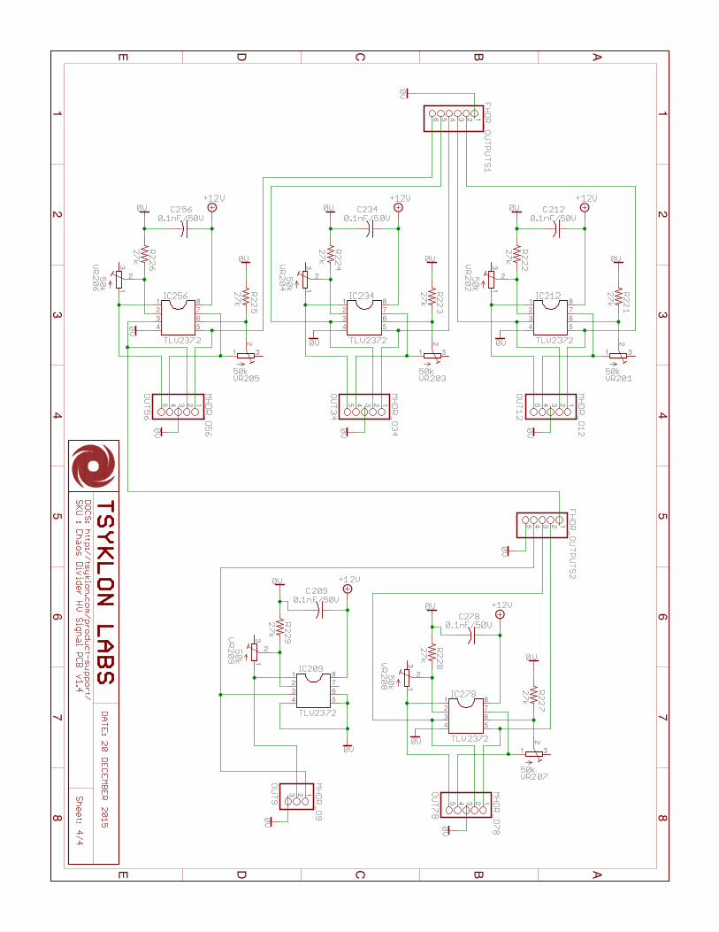
3-11) Install the 8 pin DIP sockets for IC201, IC202, IC212, IC234, IC256, IC278, and IC209 into the Signal PCB and solder them in place:
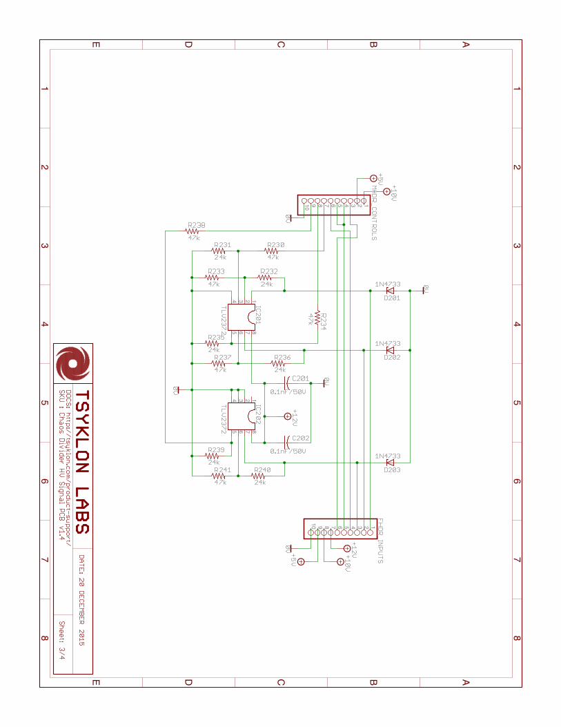
3-12) Install resistors R221 – R229 [9 x 27kΩ] vertically into the PCB and solder them in place:
3-13) Install resistors R231, R232, R235, R236, R239, and R240 [6 x 24kΩ] vertically into the PCB and solder them in place:
DIY Build DOC/BOM KOSMODROM CHAOS DIVIDER V 1.4 Page 21
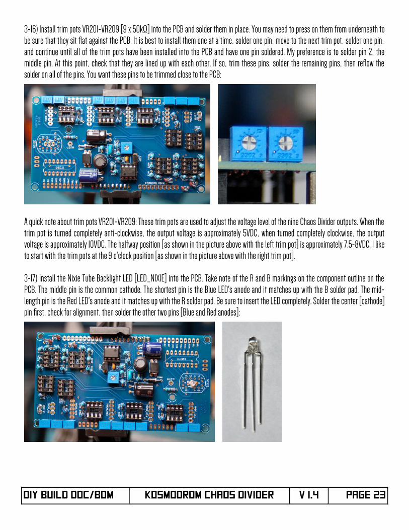
3-14) Install resistors R230, R233, R234, R237, R238, and R241 [6 x 47kΩ] vertically into the PCB and solder them in place:
3-15) Install diodes D201, D202, and D203 [3 x 1N4733] into the PCB and solder them in place. Take notice that these diodes are installedvertically and the body of the diode matches up with the solder pad pointed to by the diode symbol triangle and the cathode stripe next to it.To be consistent, and to help with any later troubleshooting, I prefer to bend the anode lead so that the cathode stripe is fat against thecircuit board:
DIY Build DOC/BOM KOSMODROM CHAOS DIVIDER V 1.4 Page 22
3-16) Install trim pots VR201-VR209 [9 x 50kΩ] into the PCB and solder them in place. You may need to press on them from underneath tobe sure that they sit fat against the PCB. It is best to install them one at a time, solder one pin, move to the next trim pot, solder one pin,and continue until all of the trim pots have been installed into the PCB and have one pin soldered. My preference is to solder pin 2, themiddle pin. At this point, check that they are lined up with each other. If so, trim these pins, solder the remaining pins, then refow thesolder on all of the pins. You want these pins to be trimmed close to the PCB:
A quick note about trim pots VR201-VR209: These trim pots are used to adjust the voltage level of the nine Chaos Divider outputs. When thetrim pot is turned completely anti-clockwise, the output voltage is approximately 5VDC, when turned completely clockwise, the outputvoltage is approximately 10VDC. The halfway position [as shown in the picture above with the left trim pot] is approximately 7.5-8VDC. I liketo start with the trim pots at the 9 o'clock position [as shown in the picture above with the right trim pot].
3-17) Install the Nixie Tube Backlight LED [LED_NIXIE] into the PCB. Take note of the R and B markings on the component outline on thePCB. The middle pin is the common cathode. The shortest pin is the Blue LED's anode and it matches up with the B solder pad. The mid-length pin is the Red LED's anode and it matches up with the R solder pad. Be sure to insert the LED completely. Solder the center [cathode]pin frst, check for alignment, then solder the other two pins [Blue and Red anodes]:
DIY Build DOC/BOM KOSMODROM CHAOS DIVIDER V 1.4 Page 23
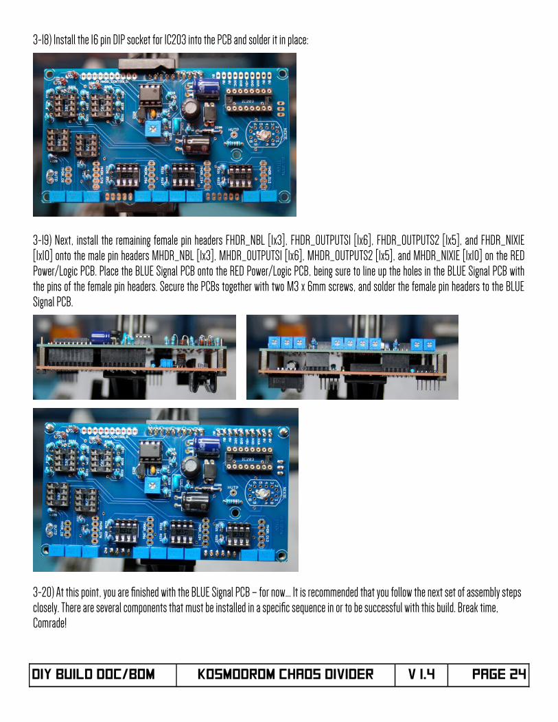
3-18) Install the 16 pin DIP socket for IC203 into the PCB and solder it in place:
3-19) Next, install the remaining female pin headers FHDR_NBL [1x3], FHDR_OUTPUTS1 [1x6], FHDR_OUTPUTS2 [1x5], and FHDR_NIXIE[1x10] onto the male pin headers MHDR_NBL [1x3], MHDR_OUTPUTS1 [1x6], MHDR_OUTPUTS2 [1x5], and MHDR_NIXIE [1x10] on the REDPower/Logic PCB. Place the BLUE Signal PCB onto the RED Power/Logic PCB, being sure to line up the holes in the BLUE Signal PCB withthe pins of the female pin headers. Secure the PCBs together with two M3 x 6mm screws, and solder the female pin headers to the BLUESignal PCB.
3-20) At this point, you are fnished with the BLUE Signal PCB – for now... It is recommended that you follow the next set of assembly steps closely. There are several components that must be installed in a specifc sequence in or to be successful with this build. Break time, Comrade!
DIY Build DOC/BOM KOSMODROM CHAOS DIVIDER V 1.4 Page 24
PART IV – CONTROL PCB Assembly
Aside from the parts in the kit, you will need the following parts [listed in build order] to complete the Chaos Divider Control PCB:
Qty PCB Identifer Part Description
3 D101, D102, D105 1N4148 Silicon Small Signal Diode
2 D103, D104 1N4733 5.1V Zener Diode
2 PF101, PF102 RXEF005 [Radial 5.8mm leads, PPTC Resettable Fuse 1.1A, 16V, 40A Max]
9 R101 – R109 3.3kΩ , 1/4W, 1% Metal Film Resistor
1 SW_INVERT SPDT PCB Mount Mini-Toggle Switch
1 PB_RESET Normally Open PCB Mount Pushbutton with Black Cap
9 LED1 – LED9 Orange Water Clear 3mm LED
1 FHDR_O9 1x3 Female 0.1” Pin Header
4 FHDR_O12, FHDR_O34,FHDR_O56, FHDR_O78
1x5 Female 0.1” Pin Header
1 FHDR_CONTROLS 1x10 Female 0.1” Pin Header
Control PCB - http://www.mouser.com/ProjectManager/ProjectDetail.aspx?AccessID=977138c2a7
You will also need the following parts [Available from Modular Addict, Thonk, or Erthenvar]:
Qty PCB Identifer Part Description
14 CLK, ITV, ITN,MOD, RST,OUT1 – OUT9
Inline 3.5mm Jacks with Nutshttp://modularaddict.com/parts/synth-diy-parts/pj301m12-jacks [includes nuts]https://www.thonk.co.uk/shop/3-5mm-jacks [includes nuts]http://shop.erthenvar.com/collections/9mm-potentiometers/products/smooth-shaft-vertical-pot http://shop.erthenvar.com/collections/accessories/products/3-5mm-knurled-nuts
3 VR_MODE,VR_INTENS,VR_INTERV
100kΩ, Linear 9mm PCB Mount Potentiometer [100kB]https://www.thonk.co.uk/shop/alpha-9mm-potshttp://shop.erthenvar.com/products/smooth-shaft-vertical-pot
If you want to use the same Black Anodized Knobs that we use, you can fnd them here:
Qty PCB Identifer Part Description
3 VR_MODE, VR_INTENS, VR_INTERV
13mm x 16mm black aluminum knurled knobhttp://www.mammothelectronics.com/4SKA-13X16KBK-p/700-1901.htm
DIY Build DOC/BOM KOSMODROM CHAOS DIVIDER V 1.4 Page 25
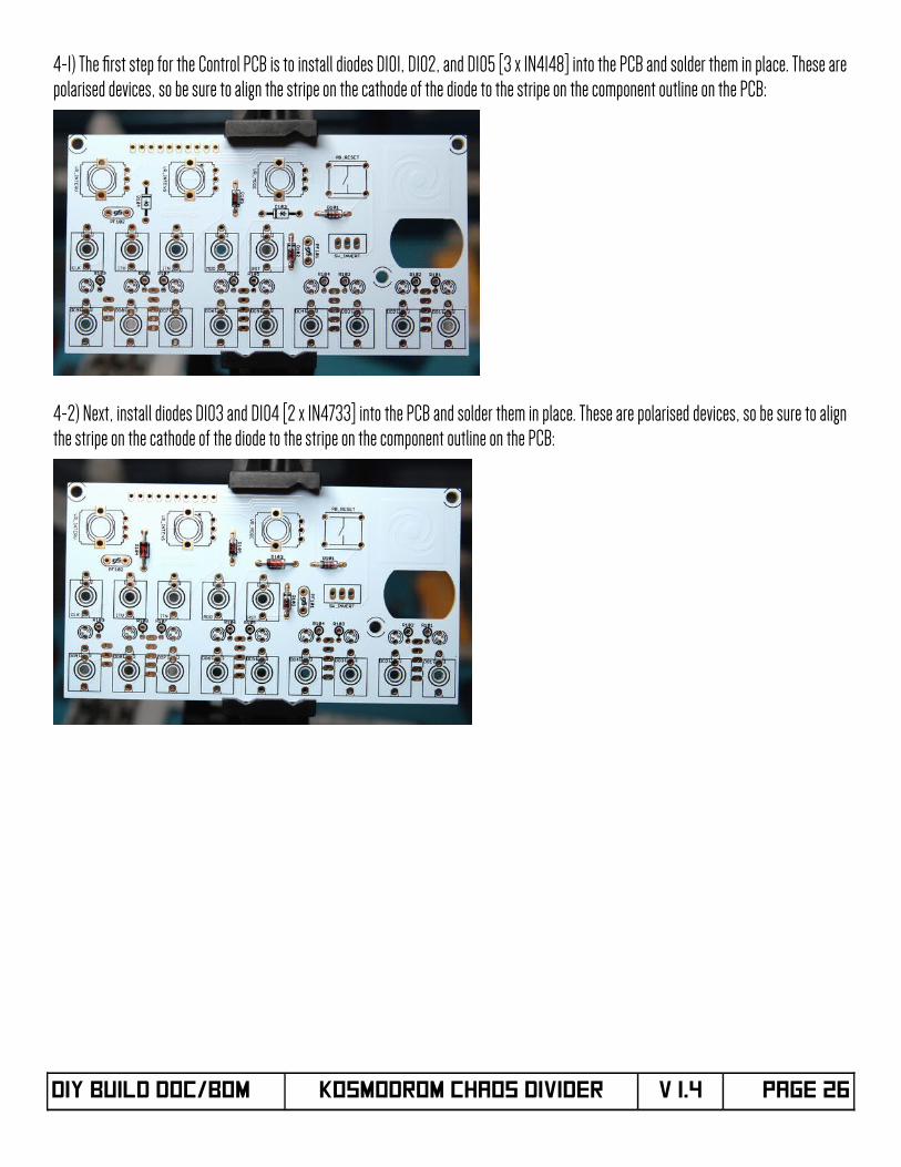
4-1) The frst step for the Control PCB is to install diodes D101, D102, and D105 [3 x 1N4148] into the PCB and solder them in place. These arepolarised devices, so be sure to align the stripe on the cathode of the diode to the stripe on the component outline on the PCB:
4-2) Next, install diodes D103 and D104 [2 x 1N4733] into the PCB and solder them in place. These are polarised devices, so be sure to alignthe stripe on the cathode of the diode to the stripe on the component outline on the PCB:
DIY Build DOC/BOM KOSMODROM CHAOS DIVIDER V 1.4 Page 26
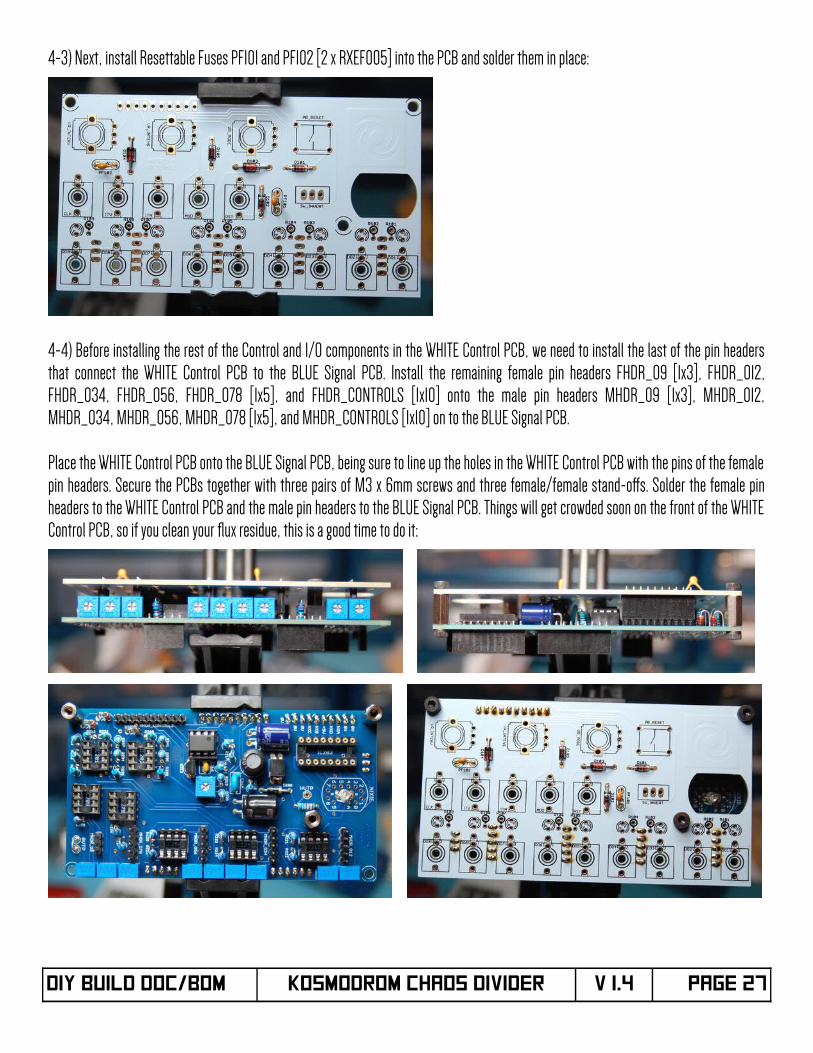
4-3) Next, install Resettable Fuses PF101 and PF102 [2 x RXEF005] into the PCB and solder them in place:
4-4) Before installing the rest of the Control and I/O components in the WHITE Control PCB, we need to install the last of the pin headersthat connect the WHITE Control PCB to the BLUE Signal PCB. Install the remaining female pin headers FHDR_O9 [1x3], FHDR_O12,FHDR_O34, FHDR_O56, FHDR_O78 [1x5], and FHDR_CONTROLS [1x10] onto the male pin headers MHDR_O9 [1x3], MHDR_O12,MHDR_O34, MHDR_O56, MHDR_O78 [1x5], and MHDR_CONTROLS [1x10] on to the BLUE Signal PCB.
Place the WHITE Control PCB onto the BLUE Signal PCB, being sure to line up the holes in the WHITE Control PCB with the pins of the femalepin headers. Secure the PCBs together with three pairs of M3 x 6mm screws and three female/female stand-ofs. Solder the female pinheaders to the WHITE Control PCB and the male pin headers to the BLUE Signal PCB. Things will get crowded soon on the front of the WHITEControl PCB, so if you clean your fux residue, this is a good time to do it:
DIY Build DOC/BOM KOSMODROM CHAOS DIVIDER V 1.4 Page 27
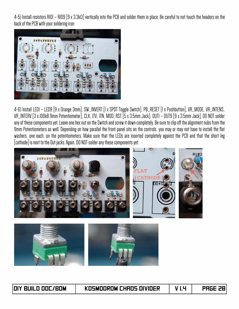
4-5) Install resistors R101 – R109 [9 x 3.3kΩ] vertically into the PCB and solder them in place. Be careful to not touch the headers on theback of the PCB with your soldering iron:
4-6) Install LED1 – LED9 [9 x Orange 3mm], SW_INVERT [1 x SPDT Toggle Switch], PB_RESET [1 x Pushbutton], VR_MODE, VR_INTENS,VR_INTERV [3 x 100kB 9mm Potentiometer], CLK, ITV, ITN, MOD, RST [5 x 3.5mm Jack], OUT1 – OUT9 [9 x 3.5mm Jack]. DO NOT solderany of these components yet. Leave one hex nut on the Switch and screw it down completely. Be sure to clip of the alignment nubs from the9mm Potentiometers as well. Depending on how parallel the front panel sits on the controls, you may or may not have to install the fatwashers, one each, on the potentiometers. Make sure that the LEDs are inserted completely against the PCB and that the short leg[cathode] is next to the Out jacks. Again, DO NOT solder any these components yet:
DIY Build DOC/BOM KOSMODROM CHAOS DIVIDER V 1.4 Page 28
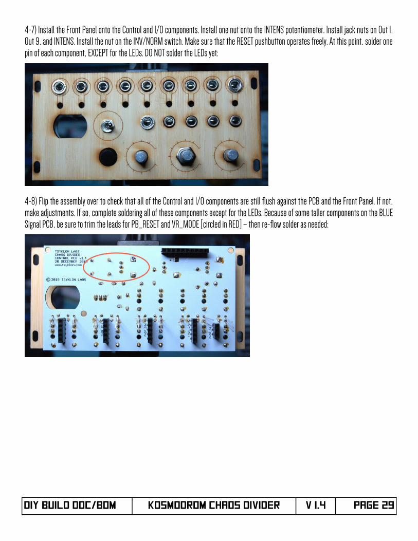
4-7) Install the Front Panel onto the Control and I/O components. Install one nut onto the INTENS potentiometer. Install jack nuts on Out 1,Out 9, and INTENS. Install the nut on the INV/NORM switch. Make sure that the RESET pushbutton operates freely. At this point, solder onepin of each component, EXCEPT for the LEDs. DO NOT solder the LEDs yet:
4-8) Flip the assembly over to check that all of the Control and I/O components are still fush against the PCB and the Front Panel. If not,make adjustments. If so, complete soldering all of these components except for the LEDs. Because of some taller components on the BLUESignal PCB, be sure to trim the leads for PB_RESET and VR_MODE [circled in RED] – then re-fow solder as needed:
DIY Build DOC/BOM KOSMODROM CHAOS DIVIDER V 1.4 Page 29
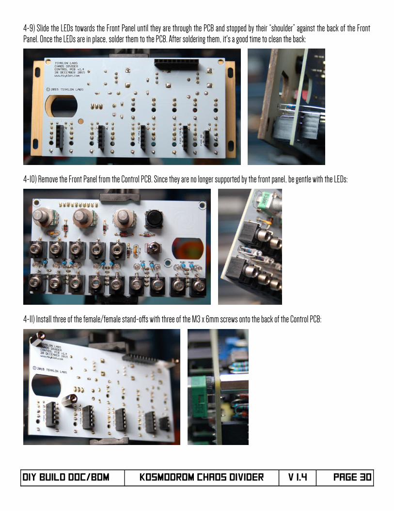
4-9) Slide the LEDs towards the Front Panel until they are through the PCB and stopped by their “shoulder” against the back of the FrontPanel. Once the LEDs are in place, solder them to the PCB. After soldering them, it's a good time to clean the back:
4-10) Remove the Front Panel from the Control PCB. Since they are no longer supported by the front panel, be gentle with the LEDs:
4-11) Install three of the female/female stand-ofs with three of the M3 x 6mm screws onto the back of the Control PCB:
DIY Build DOC/BOM KOSMODROM CHAOS DIVIDER V 1.4 Page 30
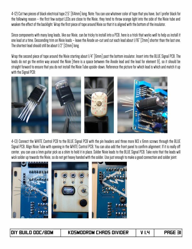
4-12) Cut two pieces of black electrical tape 2.5” [64mm] long. Note: You can use whatever color of tape that you have, but I prefer black forthe following reason – the frst few output LEDs are close to the Nixie, they tend to throw orange light into the side of the Nixie tube andweaken the efect of the backlight. Wrap the frst piece of tape around Nixie so that it is aligned with the bottom of the insulator.
Since components with many long leads, like our Nixie, can be tricky to install into a PCB, here is a trick that works well to help us install itone lead at a time. Descending trim on Nixie leads – leave the Anode un-cut and cut each lead about 1/16” [2mm] shorter than the last one.The shortest lead should still be about 1/2” [12mm] long.
Wrap the second piece of tape around the Nixie starting about 1/4” [6mm] past the bottom insulator. Insert into the BLUE Signal PCB. Theleads do not go the entire way around the Nixie [there is a space between the Anode lead and the lead for element 9], so it should bestraight forward to ensure that you do not install the Nixie Tube upside-down. Reference the picture for which lead is which and match it upwith the Signal PCB:
4-13) Connect the WHITE Control PCB to the BLUE Signal PCB with the pin headers and three more M3 x 6mm screws through the BLUESignal PCB. Align Nixie Tube with opening in the WHITE Control PCB. You can also add the front panel to confrm alignment. If it is really ofcenter, you can use a 1mm guitar pick as a shim to hold it in place. Solder Nixie leads to the BLUE Signal PCB. Take note that the leads willwick solder up towards the Nixie, so do not get heavy handed with the solder. Use just enough to make a good connection and solder joint:
DIY Build DOC/BOM KOSMODROM CHAOS DIVIDER V 1.4 Page 31
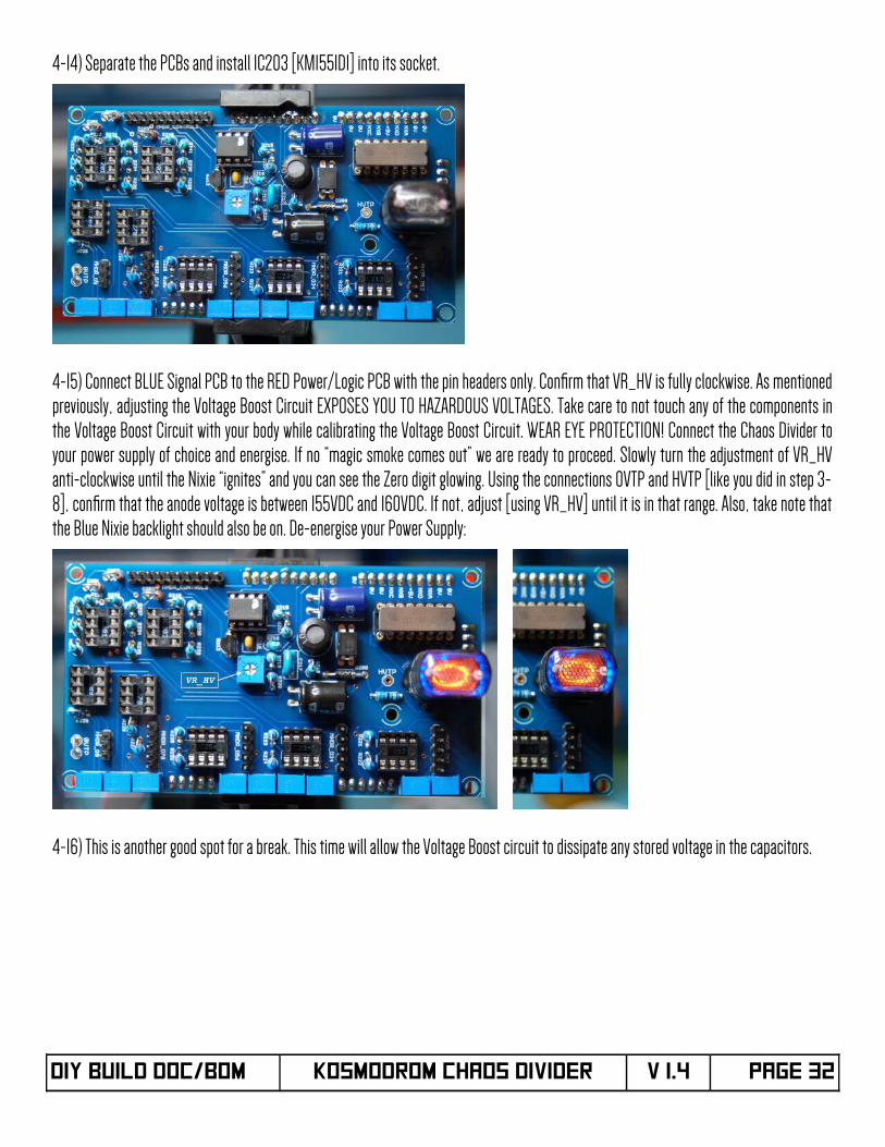
4-14) Separate the PCBs and install IC203 [KM155ID1] into its socket.
4-15) Connect BLUE Signal PCB to the RED Power/Logic PCB with the pin headers only. Confrm that VR_HV is fully clockwise. As mentionedpreviously, adjusting the Voltage Boost Circuit EXPOSES YOU TO HAZARDOUS VOLTAGES. Take care to not touch any of the components inthe Voltage Boost Circuit with your body while calibrating the Voltage Boost Circuit. WEAR EYE PROTECTION! Connect the Chaos Divider toyour power supply of choice and energise. If no “magic smoke comes out” we are ready to proceed. Slowly turn the adjustment of VR_HVanti-clockwise until the Nixie “ignites” and you can see the Zero digit glowing. Using the connections 0VTP and HVTP [like you did in step 3-8], confrm that the anode voltage is between 155VDC and 160VDC. If not, adjust [using VR_HV] until it is in that range. Also, take note thatthe Blue Nixie backlight should also be on. De-energise your Power Supply:
4-16) This is another good spot for a break. This time will allow the Voltage Boost circuit to dissipate any stored voltage in the capacitors.
DIY Build DOC/BOM KOSMODROM CHAOS DIVIDER V 1.4 Page 32
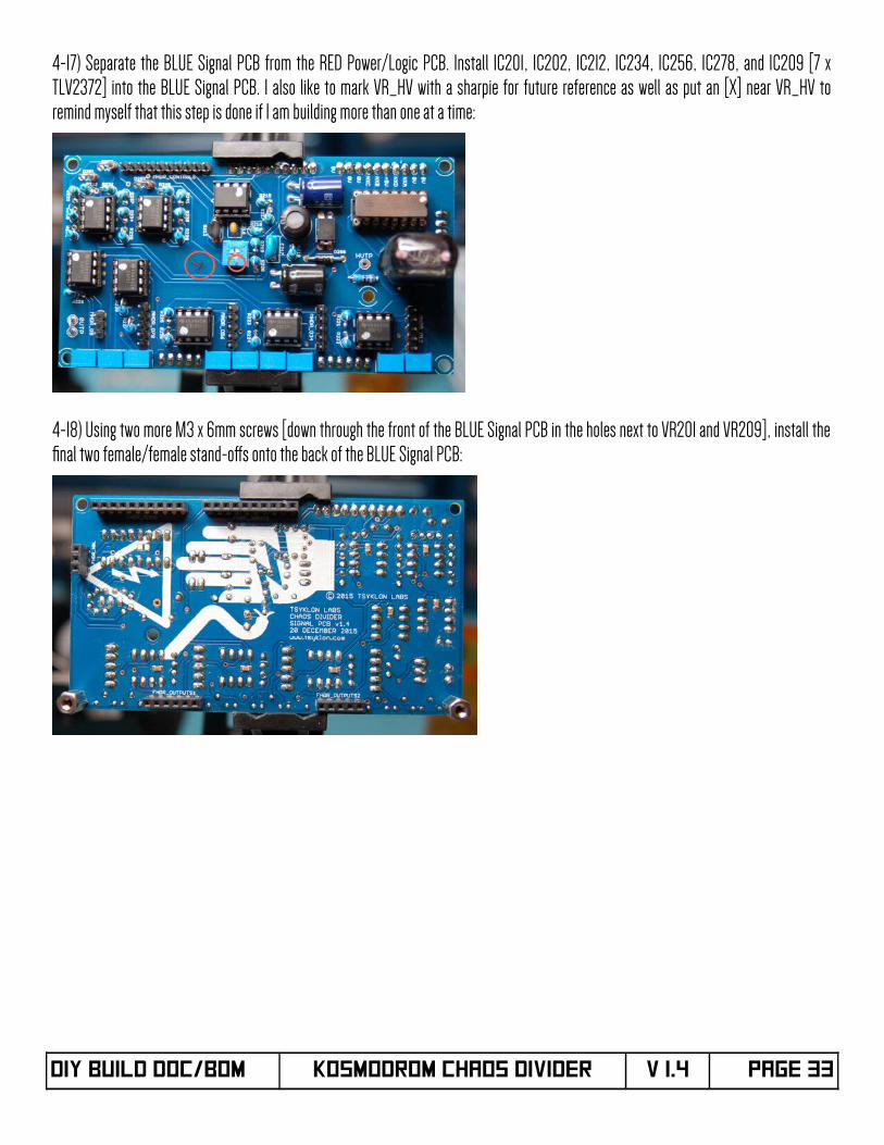
4-17) Separate the BLUE Signal PCB from the RED Power/Logic PCB. Install IC201, IC202, IC212, IC234, IC256, IC278, and IC209 [7 xTLV2372] into the BLUE Signal PCB. I also like to mark VR_HV with a sharpie for future reference as well as put an [X] near VR_HV toremind myself that this step is done if I am building more than one at a time:
4-18) Using two more M3 x 6mm screws [down through the front of the BLUE Signal PCB in the holes next to VR201 and VR209], install thefnal two female/female stand-ofs onto the back of the BLUE Signal PCB:
DIY Build DOC/BOM KOSMODROM CHAOS DIVIDER V 1.4 Page 33
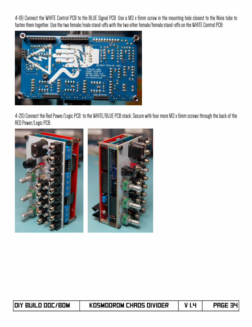
4-19) Connect the WHITE Control PCB to the BLUE Signal PCB. Use a M3 x 6mm screw in the mounting hole closest to the Nixie tube tofasten them together. Use the two female/male stand-ofs with the two other female/female stand-ofs on the WHITE Control PCB:
4-20) Connect the Red Power/Logic PCB to the WHITE/BLUE PCB stack. Secure with four more M3 x 6mm screws through the back of theRED Power/Logic PCB:
DIY Build DOC/BOM KOSMODROM CHAOS DIVIDER V 1.4 Page 34
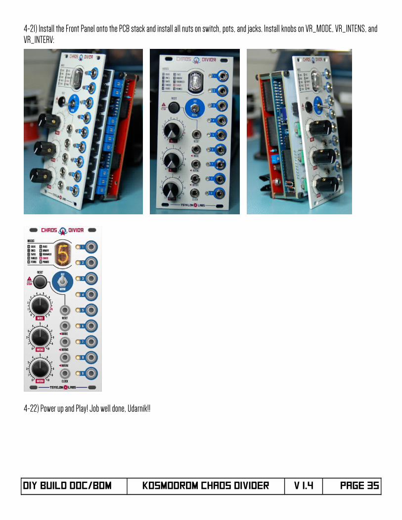
4-21) Install the Front Panel onto the PCB stack and install all nuts on switch, pots, and jacks. Install knobs on VR_MODE, VR_INTENS, andVR_INTERV:
4-22) Power up and Play! Job well done, Udarnik!!
DIY Build DOC/BOM KOSMODROM CHAOS DIVIDER V 1.4 Page 35
Expressions of GratitudeA Siberian Sized Spasibo to Kylee and Cory for testing the prototype Chaos Divider and CD Sputnik. Your feedback and suggestions regardingeverything from packaging and component selection, to the modules themselves has been invaluable in making this module a lot of fun touse and durable as a tank.
Massivnyy thanks to Kylee, James, and Brendon for assembling the Chaos Divider and CD Sputnik kits to proof the DIY Build Documents.Your feedback has been invaluable in ensuring the quality and accuracy of these instructions.
Ursa Major [like giant Russian Circus Bear sized] thanks to Hannes Pasqualini at Papernoise for taking the disjointed thoughts, suggestions,and ramblings of my childhood love of all things Cosmonaut and turning them into the FREAKING AWESOME visual language that would be athome in a space station 250 miles [402 km] high traveling at 17,000 mph [27,359 kph].
Support and Contact Information:If you should have any issues or questions about the assembly of your Kosmodrom Chaos Divider, you can reach us at:
[email protected] will make every efort to reply to you as soon as we possibly can.
If you would like to sign up for our mailing list [one monthly email max, and occasional re-stock notifcations], please fll out the form here:http://tsyklon.com/contact/
If you prefer not to sign up for the email list, but still want to stay up to date, please keep an eye on this page:http://tsyklon.com/updates/
User Manuals, DIY Build Documents and Schematics, Microcontroller source code, and Firmware upgrade fles can be found here:http://tsyklon.com/product-support/
Please note that compiled frmware upgrade fles will be freely available, and instructions will be part of the documentation for that. If youaren't interested in downloading and performing your own frmware upgrades, pre-loaded Microcontrollers will also be available for sale.
Document Published: 5 NOVEMBER 2016
DIY Build DOC/BOM KOSMODROM CHAOS DIVIDER V 1.4 Page 36
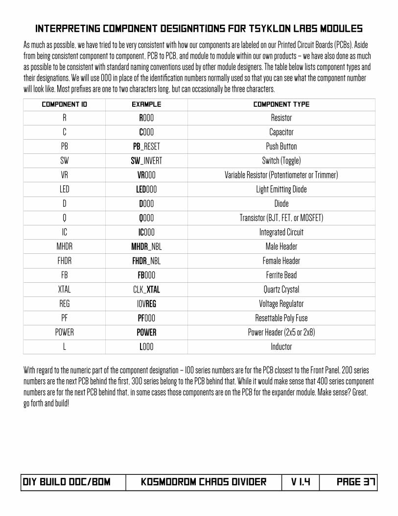
INTERPRETING COMPONENT DESIGNATIONS FOR TSYKLON LABS MODULES
As much as possible, we have tried to be very consistent with how our components are labeled on our Printed Circuit Boards (PCBs). Aside from being consistent component to component, PCB to PCB, and module to module within our own products – we have also done as much as possible to be consistent with standard naming conventions used by other module designers. The table below lists component types and their designations. We will use 000 in place of the identifcation numbers normally used so that you can see what the component number will look like. Most prefxes are one to two characters long, but can occasionally be three characters.
Component ID EXAMPLE COMPoNENT TYPE
R R000 Resistor
C C000 Capacitor
PB PB_RESET Push Button
SW SW_INVERT Switch (Toggle)
VR VR000 Variable Resistor (Potentiometer or Trimmer)
LED LED000 Light Emitting Diode
D D000 Diode
Q Q000 Transistor (BJT, FET, or MOSFET)
IC IC000 Integrated Circuit
MHDR MHDR_NBL Male Header
FHDR FHDR_NBL Female Header
FB FB000 Ferrite Bead
XTAL CLK_XTAL Quartz Crystal
REG 10VREG Voltage Regulator
PF PF000 Resettable Poly Fuse
POWER POWER Power Header (2x5 or 2x8)
L L000 Inductor
With regard to the numeric part of the component designation – 100 series numbers are for the PCB closest to the Front Panel. 200 series numbers are the next PCB behind the frst, 300 series belong to the PCB behind that. While it would make sense that 400 series componentnumbers are for the next PCB behind that, in some cases those components are on the PCB for the expander module. Make sense? Great, go forth and build!
DIY Build DOC/BOM KOSMODROM CHAOS DIVIDER V 1.4 Page 37
12
34
56
78
910
13
2
ABCDE
12
34
56
78
ABCDE
12
34
56
78
12
34
56
78
910
RC726
RD427
RD528
RD629
RD730
VSS12
VDD11
RB033
RB134
RB235
RB336
RB437
PGM
38PG
C39
PGD
40MCLR
1AN0
2AN1
3AN2
4AN3
5RA4
6AN4
7AN5
8AN6
9AN7
10VDD
32VSS
31
OSC1
13OSC2
14RC0
15RC1
16RC2
17RC3
18RD0
19RD1
20RD2
21RD3
22RC4
23RC5
24RC6
25
123456
P2 P1
12345678910
123
12345678910
12345612345
ABCDE
12
34
56
78
ABCDE
12
34
56
78
TR2
Q3
R4
CV
5TH
R6
DIS
7
V+8
GND
1
1 3
2
ABCDE
12
34
56
78
ABCDE
12
34
56
78
12345678910
1234567890
A
123
Q0
16
Q1
15
Q2
8
Q3
9
Q4
13
Q5
14
Q6
11
Q7
10
A3
Q8
1
Q9
2
B6
C7
D4
+5V5
0V12
ABCDE
12
34
56
78
ABCDE
12
34
56
78
12345678910
12345678910
12345 6 7 8
12345 6 7 8
ABCDE
12
34
56
78
ABCDE
12
34
56
78
1234512345
12345
12345
123
1234 5
6781
234 5
678
13
2
1 3
2
13
2
1 3
2
1234 5
678
1234 5
678
13
2
1 3
2
13
2
1 3
2
1234 5
678
13
2
12345
123456
ABCDE
12
34
56
78
ABCDE
12
34
56
78
1 3
2
P1 P3P2
1 3
2
1 3
2P1 P3P2
P1 P3P2P1 P3P2 P1 P3P2
P1 P3P2P1 P3P2
P1 P3P2P1 P3P2P1 P3P2P1 P3P2P1 P3P2P1 P3P2P1 P3P2
12345678910
231
123451234512345
12345
123
ABCDE
12
34
56
78
ABCDE
12
34
56
78