Embed Size (px)
Citation preview

2018 Standard Specifications M 41-10 Page 8-1
Division 8 Miscellaneous Construction
8-01 Erosion Control and Water Pollution Control8-01.1 Description
This Work consists of furnishing, installing, maintaining, removing and disposing of high visibility fence, and water pollution and erosion control items in accordance with these Specifications and as shown in the Plans or as designated by the Engineer.
8-01.2 MaterialsMaterials shall meet the requirements of the following sections: Corrugated Polyethylene Drain Pipe 9-05.1(6)
Quarry Spalls 9-13 Seed 9-14.2 Fertilizer 9-14.3 Mulch and Amendments 9-14.4 Tackifiers 9-14.4(7) Erosion Control Devices 9-14.5 High Visibility Fence 9-14.5 Construction Geotextile 9-33
For all seed the Contractor shall furnish the Engineer with the following documentation:1. The state or provincial seed dealer license and endorsements.2. Copies of Washington State Department of Agriculture (WSDA) test results on each lot
of seed. Test results must be within six months prior to the date of application.Recycled concrete, in any form, shall not be used for any Work defined in Section 8-01.
8-01.3 Construction Requirements
8-01.3(1) GeneralThe Contractor shall install a high visibility fence along the site preservation lines shown in
the Plans or as instructed by the Engineer.Throughout the life of the project, the Contractor shall preserve and protect the delineated
area, acting immediately to repair or restore any fencing damaged or removed.Controlling pollution, erosion, runoff, and related damage requires the Contractor
to perform temporary Work items including but not limited to:1. Providing ditches, berms, culverts, and other measures to control surface water.2. Building dams, settling basins, energy dissipaters, and other measures, to control
downstream flows.3. Controlling underground water found during construction.4. Covering or otherwise protecting slopes until permanent erosion-control measures
are working.To the degree possible, the Contractor shall coordinate this temporary Work with
permanent drainage and erosion control Work the Contract requires.The Engineer may require additional temporary control measures if it appears pollution
or erosion may result from weather, the nature of the materials, or progress on the Work.When natural elements rut or erode the slope, the Contractor shall restore and repair the
damage with the eroded material where possible, and remove and dispose of any remaining material found in ditches and culverts. When the Engineer orders replacement with additional or other materials, unit Contract prices will cover the quantities needed.
Page 8-2 2018 Standard Specifications M 41-10
8-01 Erosion Control and Water Pollution Control
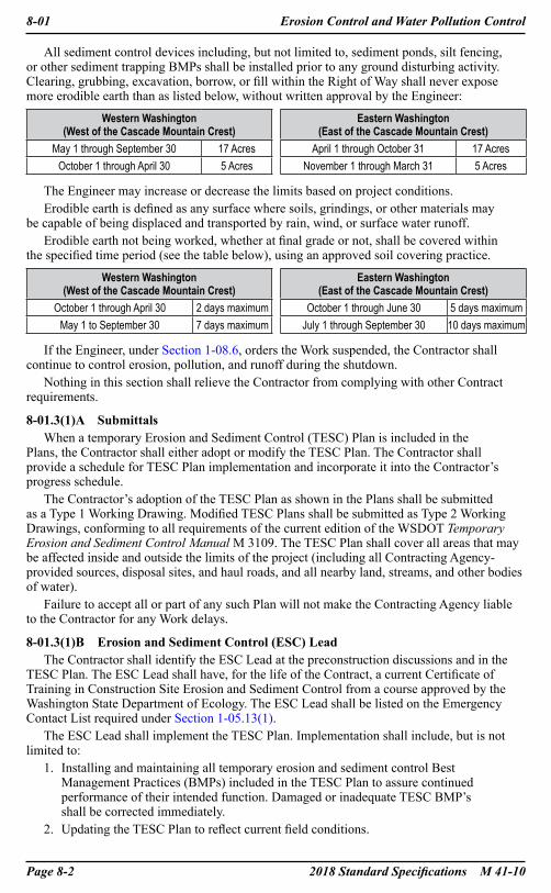
All sediment control devices including, but not limited to, sediment ponds, silt fencing, or other sediment trapping BMPs shall be installed prior to any ground disturbing activity. Clearing, grubbing, excavation, borrow, or fill within the Right of Way shall never expose more erodible earth than as listed below, without written approval by the Engineer:
Western Washington (West of the Cascade Mountain Crest)
Eastern Washington (East of the Cascade Mountain Crest)
May 1 through September 30 17 Acres April 1 through October 31 17 AcresOctober 1 through April 30 5 Acres November 1 through March 31 5 Acres
The Engineer may increase or decrease the limits based on project conditions.Erodible earth is defined as any surface where soils, grindings, or other materials may
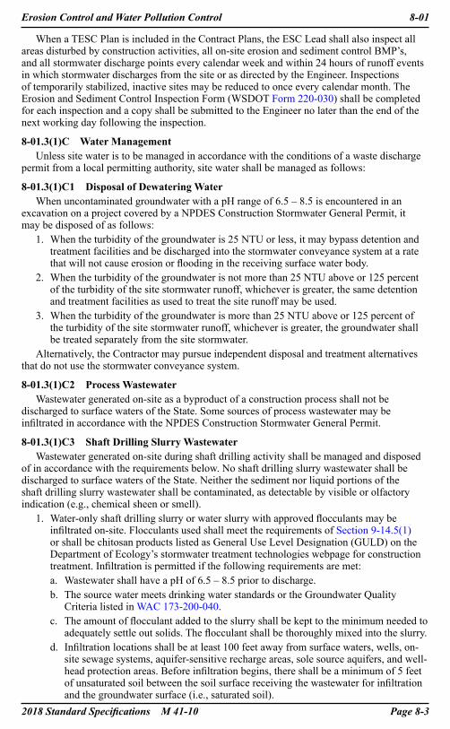
be capable of being displaced and transported by rain, wind, or surface water runoff.Erodible earth not being worked, whether at final grade or not, shall be covered within
the specified time period (see the table below), using an approved soil covering practice.
Western Washington (West of the Cascade Mountain Crest)
Eastern Washington (East of the Cascade Mountain Crest)
October 1 through April 30 2 days maximum October 1 through June 30 5 days maximumMay 1 to September 30 7 days maximum July 1 through September 30 10 days maximum
If the Engineer, under Section 1-08.6, orders the Work suspended, the Contractor shall continue to control erosion, pollution, and runoff during the shutdown.
Nothing in this section shall relieve the Contractor from complying with other Contract requirements.
8-01.3(1)A SubmittalsWhen a temporary Erosion and Sediment Control (TESC) Plan is included in the
Plans, the Contractor shall either adopt or modify the TESC Plan. The Contractor shall provide a schedule for TESC Plan implementation and incorporate it into the Contractor’s progress schedule.
The Contractor’s adoption of the TESC Plan as shown in the Plans shall be submitted as a Type 1 Working Drawing. Modified TESC Plans shall be submitted as Type 2 Working Drawings, conforming to all requirements of the current edition of the WSDOT Temporary Erosion and Sediment Control Manual M 3109. The TESC Plan shall cover all areas that may be affected inside and outside the limits of the project (including all Contracting Agency-provided sources, disposal sites, and haul roads, and all nearby land, streams, and other bodies of water).
Failure to accept all or part of any such Plan will not make the Contracting Agency liable to the Contractor for any Work delays.
8-01.3(1)B Erosion and Sediment Control (ESC) LeadThe Contractor shall identify the ESC Lead at the preconstruction discussions and in the
TESC Plan. The ESC Lead shall have, for the life of the Contract, a current Certificate of Training in Construction Site Erosion and Sediment Control from a course approved by the Washington State Department of Ecology. The ESC Lead shall be listed on the Emergency Contact List required under Section 1-05.13(1).
The ESC Lead shall implement the TESC Plan. Implementation shall include, but is not limited to:
1. Installing and maintaining all temporary erosion and sediment control Best Management Practices (BMPs) included in the TESC Plan to assure continued performance of their intended function. Damaged or inadequate TESC BMP’s shall be corrected immediately.
2. Updating the TESC Plan to reflect current field conditions.
2018 Standard Specifications M 41-10 Page 8-3
Erosion Control and Water Pollution Control 8-01
When a TESC Plan is included in the Contract Plans, the ESC Lead shall also inspect all areas disturbed by construction activities, all on-site erosion and sediment control BMP’s, and all stormwater discharge points every calendar week and within 24 hours of runoff events in which stormwater discharges from the site or as directed by the Engineer. Inspections of temporarily stabilized, inactive sites may be reduced to once every calendar month. The Erosion and Sediment Control Inspection Form (WSDOT Form 220-030) shall be completed for each inspection and a copy shall be submitted to the Engineer no later than the end of the next working day following the inspection.
8-01.3(1)C Water ManagementUnless site water is to be managed in accordance with the conditions of a waste discharge
permit from a local permitting authority, site water shall be managed as follows:
8-01.3(1)C1 Disposal of Dewatering WaterWhen uncontaminated groundwater with a pH range of 6.5 – 8.5 is encountered in an
excavation on a project covered by a NPDES Construction Stormwater General Permit, it may be disposed of as follows:
1. When the turbidity of the groundwater is 25 NTU or less, it may bypass detention and treatment facilities and be discharged into the stormwater conveyance system at a rate that will not cause erosion or flooding in the receiving surface water body.
2. When the turbidity of the groundwater is not more than 25 NTU above or 125 percent of the turbidity of the site stormwater runoff, whichever is greater, the same detention and treatment facilities as used to treat the site runoff may be used.
3. When the turbidity of the groundwater is more than 25 NTU above or 125 percent of the turbidity of the site stormwater runoff, whichever is greater, the groundwater shall be treated separately from the site stormwater.
Alternatively, the Contractor may pursue independent disposal and treatment alternatives that do not use the stormwater conveyance system.
8-01.3(1)C2 Process WastewaterWastewater generated on-site as a byproduct of a construction process shall not be
discharged to surface waters of the State. Some sources of process wastewater may be infiltrated in accordance with the NPDES Construction Stormwater General Permit.
8-01.3(1)C3 Shaft Drilling Slurry WastewaterWastewater generated on-site during shaft drilling activity shall be managed and disposed
of in accordance with the requirements below. No shaft drilling slurry wastewater shall be discharged to surface waters of the State. Neither the sediment nor liquid portions of the shaft drilling slurry wastewater shall be contaminated, as detectable by visible or olfactory indication (e.g., chemical sheen or smell).
1. Water-only shaft drilling slurry or water slurry with approved flocculants may be infiltrated on-site. Flocculants used shall meet the requirements of Section 9-14.5(1) or shall be chitosan products listed as General Use Level Designation (GULD) on the Department of Ecology’s stormwater treatment technologies webpage for construction treatment. Infiltration is permitted if the following requirements are met:a. Wastewater shall have a pH of 6.5 – 8.5 prior to discharge.b. The source water meets drinking water standards or the Groundwater Quality
Criteria listed in WAC 173-200-040.c. The amount of flocculant added to the slurry shall be kept to the minimum needed to
adequately settle out solids. The flocculant shall be thoroughly mixed into the slurry.d. Infiltration locations shall be at least 100 feet away from surface waters, wells, on-
site sewage systems, aquifer-sensitive recharge areas, sole source aquifers, and well-head protection areas. Before infiltration begins, there shall be a minimum of 5 feet of unsaturated soil between the soil surface receiving the wastewater for infiltration and the groundwater surface (i.e., saturated soil).

Page 8-4 2018 Standard Specifications M 41-10
8-01 Erosion Control and Water Pollution Control
e. The slurry removed from the shaft shall be contained in a leak proof cell or tank for a minimum of 3 hours.
f. Within a 24 hour period, a maximum of 21,000 gallons of slurry wastewater may be infiltrated in an infiltration location. The infiltration rate shall be reduced if needed to prevent wastewater from leaving the infiltration location. The infiltration site shall be monitored regularly during infiltration activity. All wastewater discharged to the ground must fully infiltrate and discharges must stop before the end of each work day.
g. After infiltration activity is complete, loose sediment in the infiltration location that may have resulted from the infiltration activity or the removal of BMPs used to manage infiltration activity shall be stabilized to prevent mobilization by stormwater runoff.
h. Drilling spoils and settled sediments remaining in the containment cell or tank shall be disposed of in accordance with Section 6-19.3(4)F.
i. Infiltration locations shall be marked on the on-site temporary erosion and sediment control (TESC) plan sheets before the infiltration activity begins.
j. Prior to infiltrating water-only shaft drilling slurry or water slurry with approved flocculants, the Contractor shall submit a Shaft Drilling Slurry Wastewater Manage-ment and Infiltration Plan as a Type 2 Working Drawing. This Plan shall be kept on-site, adapted if needed to meet the construction requirements, and updated to reflect what is being done in the field. The Working Drawing shall include, at a minimum, the following information:i. Plan sheet showing the proposed infiltration location and all surface waters,
wells, on-site sewage systems, aquifer-sensitive recharge areas, sole source aquifers, and well-head protection areas within 150 feet.
ii. The proposed elevation of soil surface receiving the wastewater for infiltration and the anticipated phreatic surface (i.e., saturated soil).
iii. The source of the water used to produce the slurry.iv. The estimated total volume of wastewater to be infiltrated.v. The approved flocculant to be used (if any).vi. The controls or methods (e.g., trenches, traps, berms, silt fence, dispersion,
or discharge metering devices) that will be used to prevent surface wastewater runoff from leaving the infiltration location. The Working Drawing shall in-clude all pertinent design details (e.g., sizing of trenches or traps, placement or height of berms, application techniques) needed to demonstrate the proposed controls or methods are adequate to prevent surface wastewater runoff from leaving the infiltration location.
vii. The strategy for removing slurry wastewater from the shaft and containing the slurry wastewater once it has been removed from the shaft.
viii. The strategy for monitoring infiltration activity and adapting methods to ensure compliance.
ix. A contingency plan that can be implemented immediately if it becomes evident that the controls in place or methods being used are not adequate.
x. The strategy for cleaning up the infiltration location after the infiltration activity is done. Cleanup shall include stabilizing any loose sediment on the surface within the infiltration area generated as a byproduct of suspended solids in the infiltrated wastewater or soil disturbance associated with BMP placement and removal.
k. An infiltration event log of containing details of the infiltration activity shall be kept on-site and updated during infiltration. The log shall record the date of infiltration, approximate time of initiation and completion of infiltration, pH of the wastewater prior to infiltration, approximate volume infiltrated, and the name of the individual responsible for the infiltration.
2018 Standard Specifications M 41-10 Page 8-5
Erosion Control and Water Pollution Control 8-01
2. Shaft drilling mineral slurry, synthetic slurry, or slurry with polymer additives not approved for infiltration shall be contained and disposed of by the Contractor at an approved disposal facility in accordance with Section 2-03.3(7)C. Spoils that have come into contact with mineral slurry shall be disposed of in accordance with Section 6-19.3(4)F.
8-01.3(1)C4 Management of Off-Site WaterPrior to disruption of the normal watercourse, the Contractor shall intercept the off-site
surface water and pipe it either through or around the project site to prevent it from coming into contact with construction activity or mixing with construction stormwater. It shall be discharged at its preconstruction outfall point in such a manner that there is no increase in erosion downstream of the site. The Contractor shall submit a Type 2 Working Drawing consisting of the method for performing this Work.
8-01.3(1)D Dispersion/InfiltrationWater shall be conveyed only to dispersion or infiltration areas designated in the TESC
Plan or to sites approved by the Engineer. Water shall be conveyed to designated dispersion areas at a rate such that, when runoff leaves the area and enters waters of the State, turbidity standards are achieved. Water shall be conveyed to designated infiltration areas at a rate that does not produce surface runoff.
8-01.3(1)E Detention/Retention Pond ConstructionWhether permanent or temporary, ponds shall be constructed before beginning other
grading and excavation Work in the area that drains into that pond. Temporary conveyances shall be installed concurrently with grading in accordance with the TESC Plan so that newly graded areas drain to the pond as they are exposed.
8-01.3(2) Seeding, Fertilizing, and Mulching
8-01.3(2)A Preparation for Application
8-01.3(2)A1 SeedingAreas to be cultivated are shown in the Plans or specified in the Special Provisions.
The areas shall be cultivated to the depths specified to provide a reasonably firm but friable seedbed. Cultivation shall take place no sooner than 2 weeks prior to seeding.
All areas to be seeded, including excavated slopes shall be compacted and prepared unless otherwise specified or ordered by the Engineer. A cleated roller, crawler tractor, or similar equipment that forms longitudinal depressions at least 2 inches deep shall be used for compaction and preparation of the surface to be seeded.
The entire area shall be uniformly covered with longitudinal depressions formed perpendicular to the natural flow of water on the slope. The soil shall be conditioned with sufficient water so the longitudinal depressions remain in the soil surface until completion of the seeding.
Prior to seeding, the finished grade of the soil shall be 1 inch below the top of all curbs, junction and valve boxes, walks, driveways, and other Structures. The soil shall be in a weed free and bare condition.
All bags of seed shall be brought to the site in sealed bags and shall have seed labels attached showing the seed meets the Specifications. Seed which has become wet, moldy, or otherwise damaged in transit or storage will not be accepted.
8-01.3(2)A2 Temporary SeedingA cleated roller, crawler tractor, or similar equipment, that forms longitudinal depressions
at least 2 inches deep shall be used for compaction and preparation of the surface to be seeded. The entire area shall be uniformly covered with longitudinal depressions formed perpendicular to the natural flow of water on the slope. The soil shall be conditioned with sufficient water so the longitudinal depressions remain in the soil surface until completion of the seeding.
Page 8-6 2018 Standard Specifications M 41-10
8-01 Erosion Control and Water Pollution Control
8-01.3(2)B Seeding and FertilizingSeed or seed and fertilizer shall be placed at the rate, mix and analysis specified in the
Special Provisions or as designated by the Engineer. The Contractor shall notify the Engineer not less than 24 hours in advance of any seeding operation and shall not begin the Work until areas prepared or designated for seeding have been approved. Following the Engineer’s approval, seeding of the approved slopes shall begin immediately.
Seeding shall not be done during windy weather or when the ground is frozen, excessively wet, or otherwise untillable. Seed or seed and fertilizer may be sown by one of the following methods:
1. A hydro seeder that utilizes water as the carrying agent, and maintains continuous agitation through paddle blades. It shall have an operating capacity sufficient to agitate, suspend, and mix into a homogeneous slurry the specified amount of seed and water or other material. Distribution and discharge lines shall be large enough to prevent stoppage and shall be equipped with a set of hydraulic discharge spray nozzles that will provide a uniform distribution of the slurry.
2. Blower equipment with an adjustable disseminating device capable of maintaining a constant, measured rate of material discharge that will ensure an even distribution of seed at the rates specified.
3. Helicopters properly equipped for aerial seeding.4. Power-drawn drills or seeders.5. Areas in which the above methods are impractical may be seeded by hand methods.When seeding by hand, the seed shall be incorporated into the top ¼ inch of soil by
hand raking or other method that is approved by the Engineer.Seed applied using a hydroseeder shall have a tracer added to visibly aid uniform
application. This tracer shall not be harmful to plant, aquatic, or and animal life. If Short-Term Mulch is used as a tracer, the application rate shall not exceed 250 pounds per acre.
Seed and fertilizer may be applied in one application provided that the fertilizer is placed in the hydroseeder tank no more than 1 hour prior to application.
8-01.3(2)C Vacant
8-01.3(2)D MulchingMulch of the type specified in the Special Provisions shall be furnished, hauled, and evenly
applied at the rates indicated and shall be spread on seeded areas within 48 hours after seeding unless otherwise specified.
Distribution of straw mulch material shall be by means that utilizes forced air to blow mulch material on seeded areas. Wood strand mulch shall be applied by hand or by straw blower on seeded areas.
Mulch may be applied with seed and fertilizer West of the summit of the Cascade Range. East of the summit of the Cascade Range, seed and fertilizer shall be applied in a single application followed by the application of mulch. Mulch shall be suitable for application with a hydroseeder as specified in Section 8-01.3(2)B.
Temporary seed applied outside the application windows established in Section 8-01.3(2)F, shall be covered with a mulch containing either Moderate-Term Mulch or Long-Term Mulch, as designated by the Engineer.
Short Term Mulch shall be hydraulically applied at the rate of 2500 pounds per acre and may be applied in one lift.
Moderate Term Mulch and Long Term Mulch shall be hydraulically applied at the rate of 3500 pounds per acre with no more than 2000 pounds applied in any single lift.
Mulch sprayed on signs or sign Structures shall be removed the same day.Areas not accessible by mulching equipment shall be mulched by approved hand methods.
2018 Standard Specifications M 41-10 Page 8-7
Erosion Control and Water Pollution Control 8-01
8-01.3(2)E TackifiersTackifiers applied using a hydroseeder shall have a mulch tracer added to visibly aid
uniform application. This tracer shall not be harmful to plant, aquatic, or animal life. A minimum of 125 pounds per acre and a maximum of 250 pounds per acre of Short-Term Mulch shall be used as a tracer. Tackifier shall be mixed and applied in accordance with the manufacturer’s recommendations.
Soil Binding Using Polyacrylamide (PAM) – The PAM shall be applied on bare soil completely dissolved and mixed in water or applied as a dry powder. Dissolved PAM shall be applied at a rate of not more than ⅔ pound per 1,000 gallons of water per acre. A minimum of 200 pounds per acre of Short-Term Mulch shall be applied with the dissolved PAM. Dry powder applications may be at a rate of 5 pounds per acre using a hand-held fertilizer spreader or a tractor-mounted spreader.
PAM shall be applied only to areas that drain to completed sedimentation control BMPs in accordance with the TESC Plan. PAM may be reapplied on actively worked areas after a 48-hour period.
PAM shall not be applied during rainfall or to saturated soils.
8-01.3(2)F Dates for Application of Final Seed, Fertilizer, and MulchUnless otherwise approved by the Engineer, the final application of seeding, fertilizing,
and mulching of slopes shall be performed during the following periods:
Western Washington1 (West of the Cascade Mountain Crest)
Eastern Washington (East of the Cascade Mountain Crest)
March 1 through May 15September 1 through October 1
October 1 through November 15 only
1 Where Contract timing is appropriate, seeding, fertilizing, and mulching shall be accomplished during the fall period listed above.
All Roadway excavation and embankment slopes, including excavation and embankment slopes that are partially completed to grade, shall be prepared and seeded during the first available seeding window. When environmental conditions are not conducive to satisfactory results, the Engineer may suspend Work until such time that the desired results are likely to be obtained.
Temporary seeding may be performed at any time approved by the Engineer.
8-01.3(2)G Protection and Care of Seeded AreasThe Contractor shall be responsible to ensure a healthy stand of grass. The Contractor shall
restore eroded areas, clean up and properly dispose of eroded materials, and reapply the seed, fertilizer, and mulch at no additional cost to the Contracting Agency.
In addition to the requirements of Section 1-07.13(1), the Contractor shall be responsible for performing the following duties:
1. At the Contractor’s expense, seed, fertilizer, and mulch shall be reapplied in areas that have been damaged through any cause prior to final inspection, and reapplied to areas that failed to receive a uniform application at the specified rate.
2. Seeded areas within the planting area shall be considered part of the planting area. Weeds within the seeded areas shall be controlled in accordance with Section 8-02.3(3).
8-01.3(2)H InspectionInspection of seeded areas will be made upon completion of seeding, temporary seeding,
fertilizing, and mulching. The Work in any area will not be measured for payment until a uniform distribution of the materials is accomplished at the specified rate. Areas that have not received a uniform application of seed, fertilizer, or mulch at the specified rate, as determined by the Engineer, shall be reseeded, refertilized, or remulched at the Contractor’s expense prior to payment.

Page 8-8 2018 Standard Specifications M 41-10
8-01 Erosion Control and Water Pollution Control
8-01.3(2)I MowingWhen the Proposal contains the Bid item “Mowing” or mowing areas are defined, the
Contractor shall mow all grass growing areas and slopes 2.5 (H) to 1 (V) or flatter except for naturally wooded and undergrowth areas. Trimming around traffic facilities, Structures, planting areas, or other features extending above ground shall be accomplished preceding or simultaneously with each mowing.
Each mowing shall be considered as one coverage of all grass areas to be mowed within a defined area. Prospective Bidders shall verify the estimated acreage, the topography, irregularity of the area, slopes involved, and access limitations to determine the appropriate equipment to use for mowing. Equipment and tools shall be provided such as, but not limited to, tractor operated rotary or flail-type grass cutting machines and tools or other approved equipment. Power driven equipment shall not cause ruts or deformation of improved areas. Sickle type grass cutters will be permitted only on slopes of drainage ditches, berms, or other rough areas. The equipment and tools shall be in good repair and maintained so that a clean, sharp cut of the grass will result at all times. The Engineer will determine the actual number of mowings. The height of mowing will be 4 to 6 inches or as designated in the Plans or in the Special Provisions.
Mowing equipment shall be operated and equipped with suitable guards to prevent throwing rocks or debris onto the Traveled Way or off the Right of Way. Equipment, which pulls or rips the grass or damages the turf in any manner will not be permitted. The Engineer will be the sole judge of the adequacy of the equipment, safeguards, and methods of use. The Contractor will not be required to collect or remove clippings from the project except on the Traveled Way, Shoulder, walkway, or other areas designated by the Engineer.
8-01.3(3) Placing Biodegradable Erosion Control BlanketBiodegradable Erosion Control Blankets are used as an erosion prevention device and to
enhance the establishment of vegetation. Erosion control blankets shall be installed according to the manufacturer’s recommendations.
Seeding and fertilizing shall be done prior to blanket installation.Select erosion control blanket material for an area based on the intended function: slope
or ditch stabilization, and site specific factors including soil, slope gradient, rainfall, and flow exposure. Erosion Control Blankets shall not be used on slopes or in ditches that exceed the manufacturer’s recommendations.
8-01.3(4) Placing Compost BlanketCompost blanket shall be placed to a depth of 3 inches over bare soil. Compost blanket
shall be placed prior to seeding or other planting. An organic tackifier shall be placed over the entire composted area when dry or windy conditions are present or expected before the final application of mulch or erosion control blanket. The tackifier shall be applied immediately after the application of compost to prevent compost from leaving the composted area.
Compost shall be Medium Compost.
8-01.3(5) Plastic CoveringErosion Control – Plastic coverings used to temporarily cover stockpiled materials, slopes
or bare soils shall be installed and maintained in a way that prevents water from intruding under the plastic and prevents the plastic cover from blowing open in the wind. Plastic coverings shall be placed with at least a 12-inch overlap of all seams and be a minimum of 6 mils thick.
Containment – Plastic coverings used to line concrete washout areas, contain wastewaters, or used in secondary containment to prevent spills, shall be seamless to prevent infiltration and be a minimum of 10 mils thick.
Vegetation Management – Plastic covering shall be clear when placed over areas that have been seeded, and shall be black when placed over areas where vegetation growth is to be inhibited. Plastic covering for vegetation management shall be a minimum of 4 mils thick.

2018 Standard Specifications M 41-10 Page 8-9
Erosion Control and Water Pollution Control 8-01
8-01.3(6) Check DamsCheck dams are used as an erosion and sediment control device in channels or conveyance
areas. Check dams shall be installed as soon as construction will allow, or when directed by the Engineer. The Contractor may substitute a different check dam material, in lieu of what is specified in the contract, with approval of the Engineer. Check dam materials shall meet the requirements in Section 9-14.5(4). Straw bales shall not be used as check dams. The check dam is a temporary or permanent structure, built across a minor channel placed perpendicular to the flow of water. Water shall not flow freely through the check dam structure. Check dams shall be constructed in a manner that creates a ponding area upstream of the dam to allow pollutants to settle, with water from increased flows channeled over a spillway in the check dam. The check dam shall be constructed to prevent erosion in the area below the spillway. The outer edges shall extend up the sides of the conveyance to prevent water from going around the check dam. Check dams shall be of sufficient height to maximize detention, without causing water to leave the ditch.
Wattles, coir logs and compost sock used as check dams shall not be trenched in and shall be installed as shown in the Standard Plans.
When wattles, coir logs, and compost socks are used as check dams they shall be measured and paid as check dam in accordance with Section 8-01.4 and 8-01.5.
8-01.3(6)A Coir LogCoir logs are used as erosion and sediment control or bank stabilizing device. Coir logs
shall be laid out, spaced, staked, and installed in accordance with the Standard Plans.Live stakes in accordance with Section 9-14.6(1) can be used in addition to, but not as
a replacement for, wooden stakes.
8-01.3(7) Stabilized Construction EntranceTemporary stabilized construction entrance shall be constructed in accordance with the
Standard Plans, prior to beginning any clearing, grubbing, embankment or excavation. Material used for stabilized construction entrance shall be free of extraneous materials that may cause or contribute to track out.
When the stabilized entrance no longer prevents track out of sediment or debris, the Contractor shall either rehabilitate the existing entrance to original condition, or construct a new entrance.
When the Contract requires a tire wash in conjunction with the stabilized entrance, the Contractor shall include details for the tire wash and the method for containing and treating the sediment-laden runoff as part of the TESC Plan. All vehicles leaving the site shall stop and wash sediment from their tires.
8-01.3(8) Street CleaningSelf-propelled pickup street sweepers shall be used to remove and collect sediment and
other debris from the Roadway, whenever required by the Engineer. The street sweeper shall effectively collect these materials and prevent them from being washed or blown off the Roadway or into waters of the State. Street sweepers shall not generate fugitive dust and shall be designed and operated in compliance with applicable air quality standards.
Material collected by the street sweeper shall be disposed of in accordance with Section 2-03.3(7)C.
Street washing with water will require the concurrence of the Engineer.
8-01.3(9) Sediment Control BarriersSediment control barriers shall be installed in accordance with TESC Plan or
manufacturer’s recommendations in the areas of clearing, grubbing, earthwork or drainage prior to starting those activities.
The sediment control barriers shall be maintained until the soils are stabilized.

Page 8-10 2018 Standard Specifications M 41-10
8-01 Erosion Control and Water Pollution Control
8-01.3(9)A Fencing
8-01.3(9)A1 High Visibility FencingHigh visibility fencing (HVF) shall be orange in color and installed along the site
preservation lines shown in the Plans or as specified by the Engineer. Post spacing and attachment of the fencing material to the posts shall be as shown in the Standard Plans and in accordance with Section 9-14.5(8). The HVF shall not be fastened to trees.
8-01.3(9)A2 Silt FenceSilt fence shall be black in color and used as a sediment control device to prevent sediment
laden water from leaving project boundaries, to manage stormwater within the site, or to create small detention areas. Silt fence shall be installed at locations shown in the Plans. The geotextile shall be securely attached to the posts and support system. Post spacing and attachments shall be as shown in the Standard Plans.
Geotextile material shall meet the requirements of Section 9-33.2(1), Table 6 and be sewn together at the point of manufacture, or at a location approved by the Engineer, to form geotextile lengths as required. All sewn seams and overlaps shall be located at a support post.
Posts shall be either wood or steel. Wood posts shall have minimum dimensions of 1¼ by 1¼ inches by the minimum length shown in the Plans.
When sediment deposits reach approximately ⅓ the height of the silt fence, the deposits shall be removed and stabilized in accordance with Section 8-01.3(15).
If trenching is not feasible due to rocky soils or not advisable due to proximity to a downslope sensitive area, a different sediment control device that does not require trenching shall be used in place of silt fence.
Silt Fence with Backup SupportBackup support is needed for silt fence in areas where extra strength may be required, such
as the toe of steep cut or fill slopes or areas where equipment may push excessive soils toward the fence. When backup support is used, wire shall have a maximum mesh spacing of 2 inches, and the plastic mesh shall be as resistant to ultraviolet radiation as the geotextile it supports. The strength of the wire or plastic mesh shall be equivalent to or greater than as required in Section 9-33.2(1), Table 6, for unsupported geotextile (i.e., 180 lbs. grab tensile strength in the machine direction). Post spacing and attachments shall be as shown in the Standard Plans.
8-01.3(9)A3 High Visibility Silt Fence High visibility silt fence (HVSF) shall be orange in color and only be used for the dual
purpose of demarcating site preservation lines and a sediment control device in a location where high visibility mesh fence and black silt fence would otherwise be used together at same location. If use of HVSF is allowed the geotextile material shall meet the material requirements of Section 9-33.2(1), Table 6. Post spacing and attachments shall be as shown in the Standard Plans.
High Visibility Silt Fence with Backup SupportBackup support is needed for high visibility silt fence (HVSF) in areas where extra strength
may be required, such as the toe of steep cut or fill slopes or areas where equipment may push excessive soils toward the sensitive or protected areas. When backup support is used, wire shall have a maximum mesh spacing of 2 inches, and the plastic mesh shall be as resistant to ultraviolet radiation as the geotextile it supports. The strength of the wire or plastic mesh shall be equivalent to or greater than as required in Section 9-33.2(1), Table 6, for unsupported geotextile (i.e., 180 lbs. grab tensile strength in the machine direction). Post spacing shall be as shown in the Standard Plans.
When sediment deposits reach approximately ⅓ the height of the silt fence, or 8 inches whichever is lower the deposits shall be removed and stabilized in accordance with Section 8-01.3(15).
2018 Standard Specifications M 41-10 Page 8-11
Erosion Control and Water Pollution Control 8-01
8-01.3(9)B Gravel Filter, Wood Chip, or Compost BermFilter berms shall retain sediment and direct flows. The gravel filter berm shall be a
minimum of 1 foot in height and shall be maintained at this height for the entire time they are in use. Rock material used for filter berms shall meet the grading requirements in Section 9-03.9(2), but shall not include any recycled materials as outlined in Section 9-03.21.
The wood chip berm shall be a minimum of 2 feet in height and shall be maintained at this height for the entire time they are in use.
The Compost Berm shall be constructed in accordance with the detail in the Plans. Compost shall be Medium Compost.
8-01.3(9)C Vacant
8-01.3(9)D Inlet ProtectionInlet protection shall be installed below or above, or as a prefabricated cover at each inlet
grate, as shown in the Plans. Inlet protection devices shall be installed prior to beginning clearing, grubbing, or earthwork activities.
Geotextile fabric in all prefabricated inlet protection devices shall meet or exceed the requirements of Section 9-33.2, Table 1, for Moderate Survivability, and the minimum filtration properties of Table 2.
When the depth of accumulated sediment and debris reaches approximately ½ the height of an internal device or ⅓ the height of the external device (or less when so specified by the manufacturers), or as designated by the Engineer, the deposits shall be removed and stabilized on-site in accordance with Section 8-01.3(16).
Below Inlet GrateBelow Inlet Grate devices shall be prefabricated units specifically designed for inlet
protection and shall remain securely attached to the drainage Structure when fully loaded with sediment and debris, or at the maximum level of sediment and debris specified by the manufacturer.
Above Inlet GrateAbove Inlet Grate devices may be silt fence, sandbags, or prefabricated units specifically
designed for inlet protection.The device shall remain securely in place around the drainage Structure under
all conditions.Inlet Grate CoverInlet Grate Cover devices shall be prefabricated units specifically designed for inlet
protection and have the following features:1. Be a sewn geotextile fabric unit fitted to the individual grate and completely enclosing
the grate.2. Have built-in lifting devices to allow manual access of the stormwater system.3. Utilize an orange monofilament geotextile fabric.Check dams or functionally equivalent devices may be used as inlet protection devices
with the approval of the Engineer.
8-01.3(10) WattlesWattles are used as a flow control and sediment control device. Wattles shall be installed
as soon as construction will allow or when designated by the Engineer. Wattle installation and trenching shall begin from the base of the slope and work uphill prior to any topsoil or compost placement. Excavated material from trenching shall be spread evenly along the uphill slope and be compacted using hand tamping or other method approved by the Engineer. On gradually sloped or clay-type soils trenches shall be 2 to 3 inches deep. On loose soils, in high rainfall areas, or on steep slopes, trenches shall be 3 to 5 inches deep, or half the thickness of the wattle, whichever is greater.
Page 8-12 2018 Standard Specifications M 41-10
8-01 Erosion Control and Water Pollution Control
Wattles shall be laid out, spaced, and staked in accordance with the Standard Plans. Live stakes in accordance with Section 9-14.6(1) can be used in addition to, but not as a replacement for, wooden stakes. If trenching and staking is not possible due to rocky soils, compost socks shall be used instead of wattles.
The Contractor shall exercise care when installing wattles to ensure the method of installation minimizes the disturbance of waterways and prevents sediment or pollutant discharge into water bodies.
8-01.3(11) Outlet ProtectionOutlet protection shall prevent scour at the outlets of ponds, pipes, ditches or other
conveyances. All quarry spall material used for outlet protection shall be free of extraneous material and meet the gradation requirements in Section 9-13.1(5).
8-01.3(12) Compost SockCompost socks are used as a flow control and sediment control device. Compost socks
shall be installed as soon as construction will allow or when specified by the Engineer. Compost socks shall be installed prior to any mulching or compost placement. Compost socks shall be laced together end-to-end with coir rope or ends shall be securely overlapped to create a continuous length. Terminal ends of the continuous length shall be curved 2 to 4 feet upward into the slope to prevent concentrated flows from going around the terminal ends. Finished grades shall be of a natural appearance with smooth transitions. Compost for compost socks shall be Medium Compost.
Compost socks shall be laid out, spaced and staked in accordance with the Standard Plans. Live stakes in accordance with Section 9-14.6(1) can be used in addition to, but not as a replacement for, wooden stakes. If staking is not possible or if the compost sock is being used on concrete, heavy blocks or an equivalent item shall be used to weigh down and secure the sock.
The Contractor shall exercise care when installing compost socks to ensure that the method of installation minimizes disturbance of waterways and prevents sediment or pollutant discharge into water bodies. Stakes shall be removed to minimize soil disturbance.
8-01.3(13) Temporary CurbTemporary curbs shall divert or redirect water around erodible soils.Temporary curbs shall be installed along pavement edges to prevent runoff from flowing
onto erodible slopes. Water shall be directed to areas where erosion can be controlled. The temporary curbs shall be a minimum of 4 inches in height. Ponding shall not be in roadways.
8-01.3(14) Temporary Pipe Slope DrainTemporary pipe slope drain shall be Corrugated Polyethylene Drain Pipe and shall be
constructed in accordance with the Plans.Water interceptor dikes or temporary curbs shall be used to direct water into pipe slope
drain. The entrance to the drain may consist of a prefabricated funnel device specifically designed for application, rock, sand bags, or as approved by the Engineer.
Pipe shall be securely fastened together and have gasketed watertight fittings, and secured to the slope with metal “T” posts, wood stakes, sand bags, or as approved by the Engineer.
The water shall be discharged to a stabilized conveyance, sediment trap, stormwater pond, rock splash pad, vegetated strip, or as approved by the Engineer.
Placement of outflow of the pipe shall not pond water on road surface.
8-01.3(15) MaintenanceErosion and sediment control BMP’s shall be maintained so they properly perform their
function until the Engineer determines they are no longer needed.The BMP’s shall be inspected on the schedule outlined in Section 8-01.3(1)B for damage
and sediment deposits. Damage to or undercutting of BMP’s shall be repaired immediately.

2018 Standard Specifications M 41-10 Page 8-13
Erosion Control and Water Pollution Control 8-01
In areas where the Contractor’s activities have compromised the erosion control functions of the existing grasses, the Contractor shall overseed at no additional cost to the Contracting Agency.
Unless otherwise specified, when the depth of accumulated sediment and debris reaches approximately ⅓ the height of the BMP the deposits shall be removed. Debris or contaminated sediment shall be disposed of in accordance with Section 2-03.3(7)C. Clean sediments may be stabilized on-site using BMPs as approved by the Engineer.
Erosion and sediment control BMP’s that have been damaged shall be repaired or replaced immediately by the Contractor, in accordance with Section 1-07.13(4).
8-01.3(16) RemovalWhen the Engineer determines that an erosion control BMP is no longer required,
the Contractor shall remove the BMP and all associated hardware from the project limits. When the materials are biodegradable the Engineer may approve leaving the temporary BMP in place.
The Contractor shall remove BMPs and associated hardware in a way that minimizes soil disturbance. The Contractor shall permanently stabilize all bare and disturbed soil after removal of BMP’s. If the installation and use of the erosion control BMP’s have compacted or otherwise rendered the soil inhospitable to plant growth, such as construction entrances, the Contractor shall take measures to rehabilitate the soil to facilitate plant growth. This may include, but is not limited to, ripping the soil, incorporating soil amendments, or seeding with the specified seed.
8-01.4 MeasurementESC lead will be measured per day for each day that an inspection is made and a report
is filed.Compost blanket, erosion control blanket and plastic covering will be measured by the
square yard along the ground slope line of surface area covered and accepted.Check dams will be measured per linear foot one time only along the completed check
dam. No additional measurement will be made for check dams that are required to be rehabilitated or replaced due to wear.
Stabilized construction entrance will be measured by the square yard for each entrance constructed.
Tire wash facilities will be measured per each for each wash installed.Street cleaning will be measured by the hour for the actual time spent cleaning pavement,
as authorized by the Engineer. Time to move the equipment to or from the area on which street cleaning is required will not be measured.
Inlet protection will be measured per each for each initial installation at a drainage Structure.
Silt fence, gravel filter, compost berms, and wood chip berms will be measured by the linear foot along the ground line of completed barrier.
Wattle and compost sock will be measured by the linear foot.Temporary curb will be measured by the linear foot.Temporary pipe slope drain will be measured by the linear foot.Seeding, fertilizing, liming, mulching, mowing, and tackifier will be measured by the acre
by ground slope measurement or through the use of design data.Seeding and fertilizing by hand will be measured by the square yard. No adjustment
in area size will be made for the vegetation free zone around each plant.Coir log will be measured by the linear foot along the ground line of the completed
installation.Fencing will be measured by the linear foot along the ground line of the completed fence.Outlet Protection will be measured per each initial installation at an outlet location.

Page 8-14 2018 Standard Specifications M 41-10
8-01 Erosion Control and Water Pollution Control
8-01.5 PaymentPayment will be made for each of the following Bid items that are included in the Proposal:“ESC Lead”, per day.“Biodegradable Erosion Control Blanket”, per square yard.The unit Contract price per square yard for “Biodegradable Erosion Control Blanket”, shall
be full pay for all costs to complete the specified Work.“Compost Blanket”, per square yard.“Plastic Covering”, per square yard.The unit Contract price per square yard for “Plastic Covering” shall be full payment to
perform the Work as specified in Section 8-01.3(5) and as shown in the Plans, including removal and disposal at an approved disposal site.
“Check Dam”, per linear foot.“Inlet Protection”, per each.“Gravel Filter Berm”, per linear foot.The unit Contract price per linear foot for “Check Dam” and “Gravel Filter Berm” and
per each for “Inlet Protection” shall be full pay for all equipment, labor, and materials to perform the Work as specified, including installation, removal, and disposal at an approved disposal site.
“Stabilized Construction Entrance”, per square yard.“Tire Wash”, per each.The unit Contract price per each for tire wash shall include all costs associated with
constructing, operating, maintaining, and removing the tire wash.“Street Cleaning”, per hour.“Silt Fence”, per linear foot.“High Visibility Silt Fence”, per linear foot.“Wood Chip Berm”, per linear foot.“Compost Berm”, per linear foot.“Wattle”, per linear foot.“Compost Sock”, per linear foot.The unit Contract price for “Compost Sock” shall include removal and disposal of the
compost sock fabric if photodegradable fabric is used.“Coir Log”, per linear foot.“Erosion/Water Pollution Control”, by force account as provided in Section 1-09.6.Maintenance and removal of erosion and water pollution control devices including removal
and disposal of sediment, stabilization and rehabilitation of soil disturbed by these activities, and any additional Work deemed necessary by the Engineer to control erosion and water pollution will be paid by force account in accordance with Section 1-09.6.
To provide a common Proposal for all Bidders, the Contracting Agency has entered an amount in the Proposal to become a part of the Contractor’s total Bid.
“Temporary Curb”, per linear foot.The unit Contract price per linear foot for “Temporary Curb” shall include all costs to
install, maintain, remove, and dispose of the temporary curb. “Temporary Pipe Slope Drain”, per linear foot.The unit Contract price per linear foot shall be full pay for all Work to complete and
remove the installation of the pipe slope drain as shown in the Plans. All materials shall become the property of the Contractor after removal.
“Mulching”, per acre“Mulching with PAM”, per acre
2018 Standard Specifications M 41-10 Page 8-15
Erosion Control and Water Pollution Control 8-01
“Mulching with Short-Term Mulch”, per acre.“Mulching with Moderate-Term Mulch”, per acre.“Mulching with Long-Term Mulch”, per acre.“Temporary Seeding”, per acre.“Seeding, Fertilizing and Mulching”, per acre.“Seeding and Fertilizing”, per acre.“Seeding and Fertilizing by Hand”, per square yard.“Second Application of Fertilizer”, per acre.“Liming”, per acre.“Mowing”, per acre.“Seeding and Mulching”, per acre.“Tackifier”, per acreThe unit Contract price per acre for “Tackifier” shall be full payment for all costs incurred
to complete the Work.“High Visibility Fence”, per linear foot.The unit contract price per linear foot for “High Visibility Fence” shall be full pay for all
costs to obtain, install, maintain, and remove the fence as specified. Once removed, the fencing shall remain the property of the Contractor.
“Outlet Protection”, per each.The unit Contract price per each for “Outlet Protection” shall be full payment for all costs
incurred to complete the Work.
Page 8-16 2018 Standard Specifications M 41-10
8-02 Roadside Restoration
8-02 Roadside Restoration8-02.1 Description
This Work consists of furnishing and placing topsoil, compost, and soil amendments,and furnishing and planting bare root plants, container plants, balled and burlapped plants, cuttings, fascines, live stakes, live poles, rhizomes, tubers, lawn installation, controlling weeds, performing plant establishment activities, and soil bioengineering in accordance with these Specifications and as shown in the Plans or as designated by the Engineer.
Trees, whips, shrubs, ground covers, cuttings, live stakes, live poles, rhizomes, tubers, rootstock, and seedlings will hereinafter be referred to collectively as “plants” or “plant material”.
8-02.2 MaterialsMaterials shall meet the requirements of the following sections: Soil 9-14.1
Fertilizer 9-14.3 Mulch and Amendments 9-14.4 Erosion Control Blanket 9-14.5 Plant Materials 9-14.6 Stakes, Guys, and Wrapping 9-14.7 Irrigation Water 9-25.2
Botanical identification and nomenclature of plant materials shall be based on descriptions by Hitchcock and Cronquist in “Flora of the Pacific Northwest”. Botanical identification and nomenclature of plant material not found in "Flora" shall be based on Bailey in “Hortus Third” or superseding editions and amendments or as referenced in the Plans.
8-02.3 Construction Requirements
8-02.3(1) Responsibility During ConstructionThe Contractor shall ensure adequate and proper care of all plant material and Work done
on this project until all plant establishment periods required by the Contract are complete or until Physical Completion of the project, whichever is last. Existing vegetation shall not be disturbed unless required by the Contract or approved by the Engineer.
Adequate and proper care shall include, but is not limited to, keeping all plant material in a healthy, growing condition by watering, cultivating, pruning, and spraying. Plant material crowns, runners, and branches shall be kept free of mulch at all times. This Work shall include keeping the planted and seeded areas free from insect infestation, weeds or unwanted vegetation, litter, and other debris along with retaining the finished grades and mulch in a neat uniform condition.
The Contractor shall have sole responsibility for the maintenance and appearance of the roadside restoration.
8-02.3(2) Work Plans
8-02.3(2)A Roadside Work PlanBefore starting any Work that disturbs the earth and as described in Sections 8-01, 8-02
and 8-03, the Contractor shall submit a roadside work plan. The roadside work plan shall be submitted as a Type 1 Working Drawing and shall define the Work necessary to provide all Contract requirements, including: wetland excavation, soil preparation, habitat structure placement, planting area preparation, seeding area preparation, bark mulch and compost placement, seeding, planting, plant replacement, irrigation, and weed control in narrative form.
The Roadside Work Plan shall also include a copy of the approved progress schedule.
2018 Standard Specifications M 41-10 Page 8-17
Roadside Restoration 8-02
8-02.3(2)B Weed and Pest Control PlanThe Weed and Pest Control Plan shall be submitted as a Type 1 Working Drawing. The
weed and pest control plan shall include scheduling and methods of all control measures required under the Contract or proposed by the Contractor including soil preparation methods to meet the required soil surface conditions in the planting, bark mulch, and wetland areas. The weed control plan shall show general weed control including hand, mechanical and chemical methods, timing, application of herbicides including type, rate, use and timing, mowing, and noxious weed control. Target weeds and unwanted vegetation to be removed shall be identified and listed in the weed control plan.
The plan shall be prepared and signed by a licensed Commercial Pest Control Operator or Consultant when chemical pesticides are proposed. The plan shall include methods of weed control; dates of weed control operations; and the name, application rate, and Material Safety Data Sheets of all proposed herbicides. In addition, the Contractor shall furnish the Engineer with a copy of the current product label for each pesticide and spray adjuvant to be used. These product labels shall be submitted with the weed control plan for approval.
8-02.3(2)C Plant Establishment PlanThe Plant Establishment Plan shall be prepared in accordance with the requirements of
Section 8-02.3(13) and submitted as a Type 1 Working Drawing. The Plan shall show the proposed scheduling of activities, materials, equipment to be utilized for the first-year plant establishment, and an emergency contact person. The Plan shall include the management of the irrigation system, when applicable. Should the plan become unworkable at any time during the first-year plant establishment, the Contractor shall submit a revised plan prior to proceeding with further Work.
8-02.3(3) Weed and Pest ControlThe Contractor shall control weed and pest species within the project area using integrated
pest management principles consisting of mechanical, biological, and chemical controls that are outlined in the Weed and Pest Control Plan or as designated by the Engineer.
Those weeds specified as noxious by the Washington State Department of Agriculture, the local Weed District, or the County Noxious Weed Control Board and other species identified by the Contracting Agency shall be controlled on the project in accordance with the weed and pest control plan.
The Contractor shall control weeds not otherwise covered in accordance with Section 8-02.3(3)A, Planting Area Weed Control, in all areas within the project limits, including erosion control seeding areas and vegetation preservation areas, as designated by the Engineer.
Grass, including grass applied in accordance with Section 8-01, growing within the mulch ring of a plant shall be considered a weed and be controlled on the project in accordance with the weed and pest control plan.
8-02.3(3)A Planting Area Weed ControlAll planting areas shall be prepared so that they are weed and debris free at the time of
planting and until completion of the project. The planting areas shall include the entire ground surface, regardless of cover, all planting beds, areas around plants, and those areas shown in the Plans.
All applications of post-emergent herbicides shall be made while green and growing tissue is present. Should unwanted vegetation reach the seed stage, in violation of these Specifications, the Contractor shall physically remove and bag the seed heads. All physically removed vegetation and seed heads shall be disposed of off-site at no cost to the Contracting Agency.
Weed barrier mats shall be installed as shown in the Plans. Mats shall be 3 feet square and shall be secured by a minimum of five staples per mat. Mats and staples shall be installed according to the manufacturer’s recommendations.

Page 8-18 2018 Standard Specifications M 41-10
8-02 Roadside Restoration
8-02.3(3)B Chemical PesticidesApplication of chemical pesticides shall be in accordance with the label recommendations,
the Washington State Department of Ecology, local sensitive area ordinances, and Washington State Department of Agriculture laws and regulations. Only those herbicides listed in the table Herbicides Approved for Use on WSDOT Rights of Way may be used (www.wsdot.wa.gov/maintenance/roadside/herbicide_use.htm).
The applicator shall be licensed by the state of Washington as a Commercial Applicator or Commercial Operator, with additional endorsements as required by the Special Provisions or the proposed weed control plan. The Contractor shall furnish the Engineer evidence that all operators are licensed with appropriate endorsements, and that the pesticide used is registered for use by the Washington State Department of Agriculture. All chemicals shall be delivered to the job site in the original containers. The licensed applicator or operator shall complete a Commercial Pesticide Application Record (WSDOT Form 540-509) each day the pesticide is applied and furnish a copy to the Engineer by the following business day.
The Contractor shall ensure confinement of the chemicals within the designated areas. The use of spray chemical pesticides shall require the use of anti-drift and activating agents and a spray pattern indicator unless otherwise allowed by the Engineer.
The Contractor shall assume all responsibility for rendering any area unsatisfactory for planting by reason of chemical application. Damage to adjacent areas, either on or off the Highway Right of Way, shall be repaired to the satisfaction of the Engineer or the property owner, and the cost of such repair shall be borne by the Contractor.
8-02.3(4) TopsoilTopsoil shall be evenly spread over the specified areas to the depth shown in the Plans or
as otherwise ordered by the Engineer. The soil shall be cultivated to a depth of 1 foot or as specified in the Special Provisions or the Plans. After the topsoil has been spread, all large clods, hard lumps, and rocks 2 inches in diameter and larger, and litter shall be raked up, removed, and disposed of by the Contractor.
Topsoil stockpiled for project use shall be protected to prevent erosion and weed growth. Weed growth on topsoil stockpile sites shall be immediately eliminated in accordance with the approved Weed and Pest Control Plan.
Topsoil shall not be placed when the ground or topsoil is frozen, excessively wet, or in the opinion of the Engineer, in a condition detrimental to the Work.
8-02.3(4)A Topsoil Type ATopsoil Type A shall be as specified in the Special Provisions.
8-02.3(4)B Topsoil Type BTopsoil Type B shall be native topsoil taken from within the project limits and shall meet
the requirements of Section 9-14.1(2).Topsoil Type B shall be taken from areas designated by the Engineer to the designated
depth and stockpiled at locations that will not interfere with the construction of the project, as approved by the Engineer. Areas beyond the slope stakes shall be disturbed as little as possible in the above operations.
When Topsoil Type B is specified, it shall be the Contractor’s responsibility to perform the excavation operations in such a manner that sufficient material is set aside to satisfy the needs of the project.
Upon Physical Completion of the Work, Topsoil Type B remaining and not required for use on the project shall be disposed of by the Contractor at no expense to the Contracting Agency in accordance with Section 2-03.3(7)C.
Should a shortage of Topsoil Type B occur, and the Contractor has wasted or otherwise disposed of topsoil material, the Contractor shall furnish Topsoil Type C at no expense to the Contracting Agency.

2018 Standard Specifications M 41-10 Page 8-19
Roadside Restoration 8-02
Topsoil Type B will not be considered as selected material, as defined in Section 2-03.3(10), and the conditions of said section shall not apply.
Materials taken from Roadway excavation, borrow, stripping, or other excavation items, and utilized for topsoil, will not be deducted from the pay quantities for the respective items.
8-02.3(4)C Topsoil Type CTopsoil Type C shall be native topsoil obtained from a source provided by the Contractor
outside of the Contracting Agency-owned Right of Way. Topsoil Type C shall meet the requirements of Sections 8-02.3(4), 8-02.3(4)B, and 9-14.1(3).
8-02.3(5) Planting Area PreparationThe Work involved in preparing planting areas shall be conducted so the flow lines in
drainage channels are maintained. Material displaced by the Contractor’s operations that interferes with drainage, shall be removed from the channel and disposed of as approved by the Engineer.
Before planting and final grading takes place, the area shall be cultivated when specified in the Plans or the Special Provisions.
The areas shall be brought to a uniform finished grade, 1 inch, or the specified depth of mulch plus 1 inch, below walks, curbs, junction and valve boxes, catch basins, and driveways, unless otherwise specified. All excess material and debris, stumps, and rocks larger than 3 inches, shall be removed and disposed of off the project site or as approved by the Engineer.
8-02.3(6) Soil AmendmentsSoil amendments of the type, quality, and quantities specified shall be applied where shown
in the Plans or as specified in the Special Provisions. Areas receiving soil amendments shall be bare soil or vegetation free prior to application. Compost used for soil amendments shall be Fine Compost. All soil amendments shall be installed as shown in the Plans within 30 calendar days after delivery to the project site.
8-02.3(7) Layout of PlantingThe Contractor shall stake the location of all trees larger than 1-inch caliper and the
perimeter of all planting areas for approval by the Engineer prior to any installation activities.All trees to be planted in mowable grass areas shall be located a minimum of 10 feet
from the edge of planting beds, other trees, fence lines, and bottom of ditches unless otherwise specified.
Tree locations shown in the Plans shall be considered approximate unless shown with stationing and offset distance. In irrigated areas, trees shall be located so their trunk is a minimum of ⅓ of the spray radius away from the nearest sprinkler head.
Unless otherwise shown, planting beds located adjacent to Roadways shall begin at the Shoulder Subgrade.
8-02.3(8) PlantingNo plant material shall be planted until it has been inspected and approved for planting
by the Engineer. Rejected material shall be removed from the project site immediately. All plants for the project or a sufficient quantity to plant 1-acre of the site, whichever is less, shall be received on site prior to the Engineer beginning inspection of the plants.
Under no circumstances will planting be permitted during unsuitable soil or weather conditions as determined by the Engineer. Unsuitable conditions may include frozen soil, freezing weather, saturated soil, standing water, high winds, heavy rains, and high water levels. All planting shall be accomplished during the following periods:
1. Non-Irrigated Plant Material West of the summit of the Cascade Range – October 1 to March 1.
East of the summit of the Cascade Range – October 1 to November 15.2. Irrigated Plant Material
Page 8-20 2018 Standard Specifications M 41-10
8-02 Roadside Restoration
In irrigated areas, plant material shall not be installed until the irrigation system is fully operational. Trees and shrubs may be planted in irrigated areas during the non-irrigated planting window before the irrigation system is functional with the written approval of the Engineer only if the irrigation system is guaranteed to be operational prior to the end of the non-irrigated planting window.
Plants shall not be placed below the finished grade.Planting hole sizes for plant material shall be in accordance with the details shown in the
Plans. Any glazed surface of the planting hole shall be roughened prior to planting.Plant material supplied in containers shall not be removed from the containers until the
time of planting at the planting location. Roots of bare root stock shall not be bunched, curled, twisted, or unreasonably bent when placed in the planting hole. Root balls shall be loosened prior to planting. All bare root plant material shall be dormant at the time of planting.
All cuttings shall be planted immediately if buds begin to swell.All burlap, baskets, string, wire and other such materials shall be removed from the hole
when planting balled and burlapped plants. The plant material shall be handled in such a manner that the root systems are kept covered and damp at all times. The root systems of all bare root plant material shall be dipped in a slurry as specified in the Special Provisions immediately prior to planting. The root systems of container plant material shall be moist at the time of planting. In their final position, all plants shall have their top true root (not adventitious root) no more than 1 inch below the soil surface, no matter where that root was located in the original root ball or container. The backfill material and root ball shall be thoroughly watered on the same day that planting occurs regardless of season.
8-02.3(9) Pruning, Staking, Guying, and WrappingPlants shall be pruned at the time of planting, only to remove minor broken or damaged
twigs, branches or roots. Pruning shall be done with a sharp tool and shall be done in such a manner as to retain or to encourage natural growth characteristics of the plants. All other pruning shall be performed only after the plants have been in the ground at least 1 year and when plants are dormant.
Trees shall only be staked when so noted in the Plans. Each tree shall be staked or guyed before completion of the backfilling in accordance with the details shown in the Plans.
All staking and guying shall be completely removed at the end of the first year of plant establishment, unless otherwise approved by the Engineer.
8-02.3(10) FertilizersFertilizers shall be applied in the form specified in the Special Provisions. Application
procedures shall be in accordance with the manufacturer’s recommendations or as specified in the Special Provisions. The Contractor shall submit for approval a guaranteed fertilizer analysis label for the selected product.
8-02.3(11) Bark or Wood Chip MulchBark or wood chip mulch of the type and depth specified shall be applied where shown
in the Plans or as specified in the Special Provisions. Any contamination of the mulch due to the Contractor’s operations shall be corrected to its former condition at the Contractor’s expense. Mulch shall be feathered to the base of the plant and 1 inch below the top of junction and valve boxes, curbs, and pavement edges. All plant crowns shall be free of mulch. Mulch placed to a thickness greater than specified shall be at no additional cost to the Contracting Agency.
Areas receiving bark mulch shall be bare soil or vegetation free before application.
8-02.3(12) Completion of Initial PlantingUpon completion of the initial planting within a designated area, the Engineer will make
an inspection of all plant material and notify the Contractor, in writing, of any replacements
2018 Standard Specifications M 41-10 Page 8-21
Roadside Restoration 8-02
or corrective action necessary to meet the Contract Provisions. The Contractor shall replace all materials rejected or missing and correct unsatisfactory conditions.
Completion of the initial planting within a designated area includes the following:1. 100 percent of each of the plant material categories shall be installed as shown in the
Contract Plans. 2. Planting Area cleanup.3. Repairs completed for the entire project, including but not limited to full operation of
the irrigation system, complete mulch coverage, and all weeds controlled.
8-02.3(13) Plant EstablishmentPlant establishment shall consist of caring for all plants planted on the project and caring
for the planting areas within the project limits. The provisions of Sections 1-07.13(2) and 1-07.13(3) do not apply to this Section.
The first year of plant establishment shall begin immediately upon written notification from the Engineer of the completion of initial planting for the project. The first-year plant establishment period shall be a minimum of 1 calendar year. The 1 calendar year shall be extended an amount equal to any periods where the Contractor does not comply with the plant establishment plan.
During the first-year plant establishment period, the Contractor shall perform all Work necessary to ensure the resumption and continued growth of the transplanted material. This care shall include, but not be limited to, labor and materials necessary for removal of foreign, dead, or rejected plant material, maintaining a weed-free condition, and the replacement of all unsatisfactory plant material planted under the Contract. If plants are stolen or damaged by the acts of others, the Contracting Agency will pay invoice cost only for the replacement plants with no mark-up and the Contractor will be responsible for the labor to install the replacement plants.
During the first year of plant establishment under psiPE (Plant Selection Including Plant Establishment), the Contractor shall meet monthly with the Engineer for the purpose of joint inspection of the planting material on a mutually agreed upon schedule. The Contractor shall correct all conditions unsatisfactory to the Engineer within a 10-day period immediately following the inspection. If plant replacement is required, the Contractor shall, within the 10-day period, submit a plan and schedule for the plant replacement to occur immediately at the beginning of the planting period as designated in Section 8-02.3(8). Failure to comply with corrective steps as outlined by the Engineer shall constitute justification for the Contracting Agency to take corrective steps and to deduct all costs thereof from any monies due the Contractor. At the end of the plant establishment period, plants that do not show normal growth shall be replaced.
All automatic irrigation systems shall be operated fully automatic during the plant establishment period and until final acceptance of the Contract. Payment for water used to water in plants, or hand watering of plant material or lawn areas unless otherwise specified, is the responsibility of the Contractor during the first-year plant establishment period.
8-02.3(14) Plant ReplacementThe Contractor shall be responsible for growing or providing enough plants for
replacement of all plant material rejected through first-year plant establishment. All replacement plant material shall be inspected and approved by the Engineer prior to installation. All rejected plant material shall be replaced at dates approved by the Engineer.
All replacement plants shall be of the same species and quality as the plants they replace. Plants may vary in size reflecting one season of growth should the Contractor elect to hold plant material under nursery conditions for an additional year to serve as replacement plants. Replacement plant material larger than specified in the Plans shall meet the applicable section requirements of the ASNS for container class, ball size, spread, and branching characteristics.
Page 8-22 2018 Standard Specifications M 41-10
8-02 Roadside Restoration
8-02.3(15) Live FascinesLive fascines are constructed of live and dead cuttings bundled together with a minimum
diameter of 8 inches. Live cuttings shall be as shown in the Plans. Dead branches may be cuttings from any woody, non-invasive plant, native to the project area. Dead branches may be placed within the live fascine and on the side exposed to the air. Live branches shall be placed in contact with the soil along their entire length. Each live fascine must contain a minimum of eight live branches. Dead branches shall constitute no more than 40 percent of the total fascine content.
The total length of each live fascine shall be a minimum of 5 feet. Branches shall be bound with biodegradable twine spaced at 1-foot intervals along the entire length of the live fascine. Live fascines shall be installed in a trench whose depth shall be ½ the diameter of the live fascine. Secure the live fascine with live stakes 3 feet in length and ¾ inch in diameter placed at 18-inch intervals. A minimum of three live stakes shall be used per fascine. The live stakes shall be driven through the live fascine vertically into the slope. The ends of live fascines shall be woven together so that no gap remains between the two sections of the live fascine.
8-02.3(16) Lawn Installation
8-02.3(16)A Lawn InstallationIn irrigated areas, lawn installation shall not begin until the irrigation system
is fully operational.Seed mix and rate of application shall be as specified in the Special Provisions.Unless otherwise approved by the Engineer, seeded lawn installation shall be performed
during the following time periods at the location shown:
Western Washington (West of the Cascade Mountain Crest)
Eastern Washington (East of the Cascade Mountain Crest)
March 1 through May 15 September 1 through October 1
October 1 through November 15
The Contractor shall have the option of sodding in lieu of seeding for lawn installation at no additional expense to the Contracting Agency. Seeding in lieu of sodding will not be allowed.
Topsoil for seeded or sodded lawns shall be placed at the depth and locations as shown in the Plans. The topsoil shall be cultivated to the specified depth, raked to a smooth even grade without low areas that trap water and compacted, all as approved by the Engineer.
Sod strips shall be placed within 48 hours of being cut. Placement shall be without voids and have the end joints staggered. Following placement, the sod shall be rolled with a smooth roller to establish contact with the soil.
Barriers shall be erected, with warning signs where necessary, to preclude pedestrian traffic access to the newly placed lawn during the establishment period.
8-02.3(16)B Lawn EstablishmentLawn establishment shall consist of caring for all new lawn areas within the limits of
the project.The lawn establishment period shall begin immediately after the lawn planting has been
accepted by the Engineer and shall extend to the end of four mowings or 20 working days which ever is longer. The mowings shall be done in accordance with Section 8-02.3(16)C.
During the lawn establishment period, it shall be the Contractor’s responsibility to ensure the continuing healthy growth of the turf. This care shall include labor and materials necessary to keep the project in a presentable condition, including but not limited to, removal of litter, mowing, trimming, removal of grass clippings, edging, fertilization, insecticide and fungicide applications, weed control, watering, repairing the irrigation system, and repair and reseeding any and all damaged areas. Lawn mowing shall be performed once each week, or as ordered by the Engineer, during the lawn establishment period with no additional compensation.

2018 Standard Specifications M 41-10 Page 8-23
Roadside Restoration 8-02
Temporary barriers shall be removed only on written permission from the Engineer.All Work performed under lawn establishment shall comply with established turf
management practices.Acceptance of lawn planting as specified shall be based on a uniform stand of grass and
a uniform grade at the time of final inspection. Areas that are bare or have a poor stand of grass, and areas not having a uniform grade through any cause before final inspection, shall be recultivated, regraded, reseeded, or resodded and refertilized as specified at no additional cost to the Contracting Agency.
8-02.3(16)C Lawn MowingLawn mowing shall begin immediately after the lawn establishment period has been
accepted by the Engineer and shall extend to the end of the Contract or the first-year plant establishment, whichever is last.
The Contractor shall accomplish the following minimum requirements:1. Mowing, trimming, and edging shall be done as often as conditions dictate. Maximum
height of lawn shall not exceed 3 inches. The cutting height shall be 2 inches. Cuttings, trimmings, and edgings shall be disposed of off the project site. When the Engineer approves the use of a mulching mower, trimmings may be left in place.
2. Watering shall be as often as conditions dictate depending on weather and soil conditions.
3. Provide fertilizer, weed control, and other measures as necessary to maintain a healthy stand of grass.
8-02.4 MeasurementTopsoil, mulch and soil amendments will be measured by the acre along the grade and
slope of the area covered immediately after application.Brush layer will be measured by the linear foot along the ground slope line.Live pole will be measured per each.Live stake row will be measured by the linear foot along the ground slope line.Fascine will be measured by the linear foot along the ground slope line.Live brush mattress will be measured by the surface square yard along the ground
slope line.Compost will be measured by the acre along the grade and slope of the area covered
immediately after application.The quantity of topsoil Type B used on the project will not be deducted from the total
quantity of Roadway excavation, borrow, strippings, or other excavation for which haul is being paid.
The pay quantities for plant materials will be determined by count of the number of satisfactory plants in each category accepted by the Engineer.
Weed barrier mat will be measured per each.Fertilizer will be measured in pounds.Water will be measured in accordance with Section 2-07.4. Measurement will be made of
only that water hauled in tank trucks or similar equipment.Seeded lawn, sod installations, and lawn mowing will be measured along the ground slope
and computed in square yards of actual lawn completed, established, and accepted.Plant selection will be measured per each.PSIPE __ (Plant Selection Including Plant Establishment) will be measured per each.

Page 8-24 2018 Standard Specifications M 41-10
8-02 Roadside Restoration
8-02.5 PaymentPayment will be made for each of the following listed Bid items that are included in the
Proposal:“Topsoil Type ____”, per acre.The unit Contract price per acre for “Topsoil Type ____” shall be full payment for all costs
for the specified Work.“Plant Selection ___”, per each.“PSIPE ___”, per each. The unit Contract price for “Plant Selection ___”, per each, and “PSIPE ___”, per each,
shall be full pay for all Work necessary for weed control within the planting area, planting area preparation, fine grading, planting, cultivating, plant storage and protection, fertilizer and root dip, staking, cleanup, and water necessary to complete planting operations as specified to the end of first year plant establishment.
As the plants that include plant establishment are obtained, propagated, and grown, partial payments shall be made as follows after inspection by the Engineer:
Payment of 5 percent of the unit Contract price, per each, when the plant materials have been contracted, propagated, and are growing under nursery conditions. The Contractor shall provide the Engineer with certification that the plant material has been procured or contracted for delivery to the project for planting within the time limits of the project. The certification shall state the location, quantity, and size of all material.
Payment shall be increased to 15 percent of the unit Contract price, per each, upon completion of the initial weed control Work.
Payment shall be increased to 60 percent of the unit Contract price per each for the contracted plant material in a designated unit area when planted.
Payment shall be increased to 70 percent of the unit Contract price per each for contracted plant material at the completion of the initial planting.
Payment shall be increased to the appropriate percentage upon reaching the following plant establishment milestones:
June 30th 80 percent September 30th 90 percent Completion of first-year plant establishment or after all 100 percent replacement plants have been installed, whichever is later
Plant establishment milestones are achieved when plants meet conditions described in Section 8-02.3(13).
As the plants that do not include plant establishment are obtained, propagated, and grown, partial payments shall be made as follows:
Payment of 15 percent of the unit Contract price per each when the plant materials have been contracted, propagated, and are growing under nursery conditions. The Contractor shall provide the Engineer with certification that the plant material has been procured or contracted for delivery to the project for planting within the time limits of the project. The certification shall state the location, quantity, and size of all material.
Payment shall be increased to 90 percent of the unit Contract price per each for contracted plant material at the completion of the initial planting.
Payment shall be increased to 100 percent at the Physical Completion of the Contract.All partial payments shall be limited to the actual number of healthy vigorous plants that
meet the stage requirements, limited to plan quantity. Previous partial payments made for materials rejected or missing will be deducted from future payments due the Contractor.
“Live Pole”, per each.“Live Stake Row”, per linear foot.“Live Brush Mattress”, per square yard.
2018 Standard Specifications M 41-10 Page 8-25
Roadside Restoration 8-02
“Brush Layer”, per linear foot.“Fascines”, per linear foot.“Weed Barrier Mat”, per each.The unit Contract price per each for “Weed Barrier Mat” shall be full pay to provide and
install the weed barrier mat as specified, to maintain the mat in place throughout the plant establishment period, and to remove the mat when ordered by the Engineer.
“Fine Compost ”, per acre.“Medium Compost”, per acre.“Coarse Compost”, per acre.The unit Contract price per acre for “Fine Compost”, “Medium Compost” or “Coarse
Compost” shall be full pay for furnishing and spreading the compost onto the existing soil.“Fertilizer”, per pound.The unit Contract price per pound for “Fertilizer” shall be full pay for furnishing and
applying the fertilizer.“Weed and Pest Control” shall be paid in accordance with Section 1-09.6. For the purpose of providing a common Proposal for all Bidders, the Contracting Agency
entered an amount for “Plant Establishment - ___ Year” and “Weed and Pest Control” in the Proposal to become a part of the total Bid by the Contractor.
“Soil Amendment”, per acre.The unit Contract price per acre for “Soil Amendment” shall be full pay for furnishing and
incorporating the soil amendment into the existing soil.“Bark or Wood Chip Mulch”, per acre.The unit Contract price per acre for “Bark or Wood Chip Mulch” shall be full pay
for furnishing and spreading the mulch onto the existing soil.“Water”, per M Gal.“Seeded Lawn Installation”, per square yard.“Sod Installation”, per square yard.“Lawn Mowing”, per square yard.The unit Contract price per square yard for “Seeded Lawn Installation” or “Sod
Installation” shall be full pay for all costs necessary for weed control within the seeding or sodding area, to prepare the area, plant or sod the lawn, erect barriers, and establish lawn areas and for furnishing all labor, tools, equipment, and materials necessary to complete the Work as specified and shall be paid in the following sequence for healthy, vigorous lawn:
Completion of Lawn Planting 60 percent of individual areasMid Lawn Establishment (after two mowings) 85 percent of individual areasCompletion of Lawn Establishment 100 percent of individual areas
(after four mowings)
Page 8-26 2018 Standard Specifications M 41-10
8-03 Irrigation Systems
8-03 Irrigation Systems8-03.1 Description
This Work consists of installing an irrigation system in accordance with these Specifications and the details shown in the Plans or as approved by the Engineer.
8-03.2 MaterialsMaterials shall meet the requirements of Sections 9-15 and 9-29.
8-03.3 Construction RequirementsLocation of pipe, tubing, sprinkler heads, emitters, valves, and other equipment shall be
as shown in the Plans and shall be of the size and type indicated. No changes shall be made except as approved by the Engineer.
Potable water supplies shall be protected against cross connections in accordance with applicable Washington State Department of Health rules and regulations and approval by the local health authority.
Construction of electrical systems shall conform to applicable portions of Sections 8-20 and 9-29.
8-03.3(1) Layout of Irrigation SystemThe Contractor shall stake the irrigation system following the schematic design shown in
the Plans. Approval must be obtained from the Engineer. Alterations and changes in the layout may be expected in order to conform to ground conditions and to obtain full and adequate coverage of plant material with water. However, no changes in the system as planned shall be made without prior authorization by the Engineer.
8-03.3(1)A Locating Irrigation SleevesExisting underground irrigation sleeve ends shall be located by potholing. Irrigation sleeves
placed during general construction prior to installation of the irrigation system shall be marked at both ends with a 2 by 4 by 24 inch wood stake extending 6 inches out of the soil and painted blue on the exposed end.
8-03.3(2) ExcavationPipe trenches shall be no wider at any point than is necessary to lay the pipe or install
equipment. The top 6 inches of topsoil, when such exists, shall be kept separate from subsoil and shall be replaced as the top layer when backfill is made. Trench bottoms shall be relatively smooth and consist of sand or other suitable material free from rocks, stones, or any material that might damage the pipe. Trenches through rock or other material unsuitable for trench bottoms and sides shall be excavated 6 inches below the required depth and shall be backfilled to the top of the pipe with sand or other suitable material free from rocks or stones. Backfill material shall not contain rocks 2 inches or greater in diameter or other materials that can damage pipe.
The Contractor shall exercise care when excavating pipe trenches near existing trees to minimize damage to tree roots. Where roots are 1½ inches or greater in diameter, the trench shall be hand excavated and tunneled under the roots. When large roots are exposed, they shall be wrapped with heavy, moist material, such as burlap or canvas, for protection and to prevent excessive drying. The material must be kept moist until the trench is backfilled. Trenches dug by machines adjacent to trees with roots less than 1½ inches in diameter shall have severed roots cleanly cut. Trenches with exposed tree roots shall be backfilled within 24 hours unless adequately protected by moist material as approved by the Engineer. All material and fastenings used to cover the roots shall be removed before backfilling.
Detectable marking tape shall be placed in all trenches 6 inches directly above, parallel to, and along the entire length of all nonmetallic water pipes and all nonmetallic and aluminum sleeves, conduits, and casing pipes. The width of the tape and installation depth shall be as recommended by the manufacturer for the depth of installation or as shown in the Plans.
2018 Standard Specifications M 41-10 Page 8-27
Irrigation Systems 8-03
8-03.3(3) PipingAll water lines shall be a minimum of 18 inches below finished grade measured from the
top of the pipe or as shown in the Plans. All live water mains to be constructed under existing pavement shall be placed in steel casing jacked under pavement as shown in the Plans. All PVC or polyethylene pipe installed under areas to be paved shall be placed in irrigation sleeves. Irrigation sleeves shall extend a minimum of 2 feet beyond the limits of pavement. All jacking operations shall be performed in accordance with an approved jacking plan. Where possible, mains and laterals or section piping shall be placed in the same trench. All lines shall be placed a minimum of 3 feet from the edge of concrete sidewalks, curbs, guardrails, walls, fences, and traffic barriers. Pipe pulling will not be allowed for installation and placement of irrigation pipe.
Main lines and lateral lines shall be defined as follows:Main Lines – All supply pipe and fittings between the water meter and the irrigation
control valves.Lateral Lines – All supply pipe and fittings between the irrigation control valves and
the connections to the irrigation heads. Swing joints, thick-walled PVC or polyethylene pipe, flexible risers, rigid pipe risers, and associated fittings are not considered part of the lateral line but incidental components of the irrigation heads.
8-03.3(4) JointingDuring construction, pipe ends shall be plugged or capped to prevent entry of dirt, rocks,
or other debris.All galvanized steel pipe shall have sound, clean cut, standard pipe threads well fitted.
All pipes shall be reamed to the full diameter and burrs removed before assembly. Threaded galvanized steel joints shall be constructed using either a nonhardening, nonseizing multipurpose sealant or Teflon® tape or paste as recommended by the pipe manufacturer or as shown in the Plans. Threaded galvanized steel joints shall be constructed using either a nonhardening, nonseizing multipurpose sealant or Teflon tape or paste as recommended by the pipe manufacturer. All threaded joints shall be made tight with wrenches without the use of handle extensions. Joints that leak shall be cleaned and remade with new material. Caulking or thread cement to make joints tight shall not be permitted.
PVC pipe, couplings, and fittings shall be handled and installed in accordance with the manufacturer’s recommendation. The outside of the PVC pipe shall be chamfered to a minimum of ¹⁄16 inch at approximately 22 degrees. Pipe and fittings shall be joined by solvent welding. Solvents used must penetrate the surface at both pipe and fitting, which shall result in complete fusion at the joint. Use solvent and cement only as recommended by the pipe manufacturer.
Threaded PVC joints shall be assembled using Teflon tape as recommended by the pipe manufacturer.
On PVC or polyethylene-to-metal connections, work the metal connection first. Use a nonhardening compound on threaded connections. Connections between metal and PVC or polyethylene are to be threaded using female threaded PVC adapters with threaded Schedule 80 PVC nipples only.
Polyethylene pipe and fittings shall be installed in accordance with the manufacturer’s recommendations. The ends of the polyethylene pipe shall be cut square, reamed smooth inside and out, and inserted to the full depth of the fitting. Clamps for insert fittings shall be stainless steel.
8-03.3(5) InstallationGalvanized pipe shall be used from the water meter or service connection through the cross
connection control device. Final position of turf heads shall be between ½ and 1 inch above finished grade measured
from the top of the sprinkler. All sprinklers adjacent to walks, curbs, and pavement shall be placed as shown in the Plans.

Page 8-28 2018 Standard Specifications M 41-10
8-03 Irrigation Systems
Shrub heads, unless otherwise specified, shall be placed on risers approximately 12 inches above finished grade.
All automatic control valves, flow control valves, and pressure reducing valves shall be installed in appropriately sized valve boxes. Manual control valves shall be installed in an appropriately sized valve box and, where appropriate, upstream of the automatic control valves. Manual and automatic valves installed together shall be in an appropriately sized box with 3 inches of clearance on all sides.
Final position of valve boxes, capped sleeves, and quick coupler valves shall be between ½ and 1 inch above finished grade or mulch, or as shown in the Plans.
Quick coupler valves and hose bibs shall be installed in valve boxes, either separately or within a control valve assembly box upstream of the control valves. Valves, quick couplers, and hose bibs shall have 3 inches of clearance on all sides within the valve box.
Drip irrigation emitters shall be installed in accordance with the manufacturer’s recommendations. Install drain valves at the lowest point of each zone in a minimum 8-inch diameter round valve box over 3 cubic feet of washed gravel.
Automatic controller pedestals or container cabinets shall be installed on a concrete base as shown in the Plans or in accordance with the manufacturer’s recommendations. Provide three 1-inch diameter galvanized metal or PVC electrical wire conduits through the base and 3 inches minimum beyond the edge or side of the base, both inside and outside of the pedestal.
8-03.3(6) Electrical Wire InstallationAll electrical work shall conform to the National Electric Code, NEMA Specifications,
and in accordance with Section 8-20. Electrical wiring between the automatic controller and automatic valves shall be direct burial and may share a common neutral. Separate control conductors shall be run from the automatic controller to each valve. When more than one automatic controller is required, a separate common neutral shall be provided for each controller and the automatic valves it controls. Electrical wire shall be installed in the trench adjacent to or above the irrigation pipe, but no less than 12 inches deep. Plastic tape or nylon tie wraps shall be used to bundle wires together at 10-foot intervals. If it is necessary to run electrical wire in a separate trench from the irrigation pipe, the wire shall be placed at a minimum depth of 18 inches and “snaked” from side to side in the trench. Each circuit shall be identified at both ends and at all splices with a permanent marker identifying zone and/or station.
Wiring placed under pavement and walls, or through walls, shall be placed in an electrical conduit or within an irrigation sleeve. Electrical conduit shall not be less than 1 inch in diameter and shall meet conduit specifications for PVC conduit as required in Section 9-29.1.
Splices will be permitted only in approved electrical junction boxes, valve boxes, pole bases, or within control equipment boxes or pedestals. A minimum of 18 inches of excess conductor shall be left at all splices, terminals, and control valves to facilitate inspection and future splicing. The excess wire shall be neatly coiled to fit easily into the boxes.
All 120-volt electrical conductors and conduit shall be installed by a certified electrician, including all wire splices and wire terminations.
All wiring shall be tested in accordance with Section 8-20.3(11).Continuity ground and functionality testing shall be performed for all 24-volt direct burial
circuits. The Megger test, confirming insulation resistance of not less than 2 megohms to ground in accordance with Section 8-20.3(11), is required.
8-03.3(7) Flushing and TestingAll gauges used in the testing of water pressures shall be certified as accurate by an
independent testing laboratory immediately prior to use on the project. Gauges shall be retested when required by the Engineer.
Automatic controllers shall be tested by actual operation for a period of 2 weeks under normal operating conditions. Should adjustments be required, the Contractor shall do so according to the manufacturer’s direction and test until operation is satisfactory.
2018 Standard Specifications M 41-10 Page 8-29
Irrigation Systems 8-03
Main Line Flushing – All main supply lines shall receive two fully open flushings to remove debris that may have entered the line during construction: the first before placement of valves and the second after placement of valves and prior to testing.
Main Line Testing – All main supply lines shall be purged of air and tested with a minimum static water pressure of 150 psi for 60 minutes without the introduction of additional service or pumping pressure. Testing shall be done with one pressure gauge installed on the line, in the location required by the Engineer. For systems using a pump, an additional pressure gauge shall be installed at the pump when required by the Engineer. Lines that show loss of pressure exceeding 5 psi at the ends of specified test periods will be rejected.
Lateral Line Flushing – All lateral lines shall receive one fully open flushing prior to placement of sprinkler heads, emitters, and drain valves. The flushing shall be of sufficient duration to remove all dirt or debris that has entered the lateral lines during construction.
Lateral Line Testing – All lateral lines shall be purged of air and tested in place at operating line pressure with a pressure gauge and with all fittings capped or plugged. The operating line pressure shall be maintained for 30 minutes with valves closed and without the introduction of additional service or pumping pressure. Lines that show leaks or loss of pressure exceeding 5 psi at the end of specified test periods will be rejected.
The Contractor shall correct and retest lateral line installations that have been rejected. Throughout the life of the Contract, the Contractor shall repair, flush, and test, all main and lateral lines that have sustained a break or disruption of service. Upon restoration of the water service, the affected lines shall be brought up to operating pressure. The Contractor shall then conduct a thorough inspection of all sprinkler heads, emitters, etc., located downstream of the break or disruption of service, and make all needed repairs to ensure the entire irrigation system is operating properly.
8-03.3(8) Adjusting SystemBefore final inspection, the Contractor shall adjust and balance all sprinklers to provide
adequate and uniform coverage. Spray patterns shall be balanced by adjusting individual sprinkler heads with the adjustment screws or replacing nozzles to produce a uniform pattern. Unless otherwise specified, sprinkler spray patterns will not be permitted to apply water to pavement, walks, or Structures.
8-03.3(9) BackfillBackfill shall not be started until all piping has been inspected, tested, and approved by the
Engineer, after which backfilling shall be completed as soon as possible. All backfill material placed within 6 inches of the pipe shall be sand or other suitable material free of rocks, roots, or other objectionable material that might cut or otherwise damage the pipe. Backfill from the bottom of the trench to approximately 6 inches above the pipe shall be by continuous compacting in a manner that will not damage pipe or wiring and shall proceed evenly on both sides of the pipe. The remainder of the backfill shall be thoroughly compacted, except that heavy equipment shall not be used within 18 inches of any pipe. The top 6 inches of the backfill shall be of topsoil material or the first 6 inches of material removed in the excavation.
8-03.3(10) As Built PlansUpon Physical Completion of the Work, the Contractor shall submit As Built Plans
consisting of corrected shop drawings, schematic circuit diagrams, or other details necessary to show the Work as constructed including the actual installed locations of the irrigation system(s) equipment including, but not limited to, water meters, cross connection control devices, electrical services, pipe and wire runs, splice boxes, controllers, valves, heads, and other equipment. These drawings shall be on sheets conforming in size to the provisions of Section 1-05.3. All drawings must be complete and legible.
Any corrections and additions ordered by the Engineer shall be made by the Contractor prior to acceptance. The Contractor shall provide the Engineer with 3 copies of parts lists, catalog cuts, and service manuals for all equipment installed on the project.
Page 8-30 2018 Standard Specifications M 41-10
8-03 Irrigation Systems
8-03.3(11) System OperationThe irrigation system shall be completely installed, tested, and automatically operable
prior to planting in a unit area except where otherwise specified in the Plans or approved by the Engineer. The Contractor shall be fully responsible for all maintenance, repair, testing, inspecting, and automatic operation of the entire system until all Work is considered complete as determined by the final inspection specified in Section 1-05.11. The final inspection of the irrigation system will coincide with the end of the Contract or the end of first-year plant establishment, whichever is later.
This responsibility shall include, but not be limited to, draining the system prior to winter and reactivating the system in the spring and at other times as required by the Engineer.
For the life of the Contract, the Contractor shall be responsible for having annual inspections and tests performed on all cross connection control devices as required and specified by the Washington State Department of Health. Inspections and tests shall be conducted at the time of initial activation and each spring prior to reactivating the irrigation system. Potable water shall not flow through the cross-connection control device to any downstream component until tested and approved for use by the local health authority in accordance with Section 8-03.3(12).
In the spring, when the drip irrigation system is in full operation, the Contractor shall make a full inspection of all emitters and irrigation heads. This shall involve visual inspection of each emitter and irrigation head under operating conditions. All adjustments, flushing, or replacements to the system shall be made at this time to ensure the proper operation of all emitters and irrigation heads.
8-03.3(12) Cross Connection Control Device InstallationCross connection control devices shall be installed, inspected, and tested by the local health
authority or designee in accordance with applicable portions of WAC 246-290-490 and other applicable regulations as set forth by the Washington State Department of Health and WSDOT.
During the life of the Contract, these devices shall be inspected and tested annually, or more often if successive inspections indicate repeated failures. Inspections and tests shall be conducted at the time of initial installation, after repairs, and each spring prior to reactivation of the irrigation system. These inspections and tests shall be completed and the results recorded by a licensed Backflow Assembly Device Tester (BADT) Operator or by a Contracting Agency Certified Water Works Operator with a CCS 1 or CCS 2 Classification and shall document that the devices are in good operating condition prior to flushing and testing of any downstream water lines. Devices that are defective shall be repaired or replaced.
Inspection and test results shall be recorded on WSDOT Form 540-020 and other forms as may be required by the serving utility. The completed forms shall be submitted to the appropriate health authority and to the serving utility when applicable.
8-03.3(13) Irrigation Water ServiceAll water meter(s) shall be installed by the serving utility. The Contracting Agency shall
arrange for water meter installation(s) for the irrigation system at the locations and sizes as shown in the Plans at no cost to the Contractor. It shall be the Contractor’s responsibility to contact the Engineer to schedule the water meter installation. The Contractor shall provide a minimum of 60 calendar days notice to the Engineer prior to the desired water meter installation date.
Construction activities for irrigation water service connections shall be in accordance with the serving utility’s Service Agreement. A copy of the Service Agreement may be obtained from the Engineer.

2018 Standard Specifications M 41-10 Page 8-31
Irrigation Systems 8-03
8-03.3(14) Irrigation Electrical ServiceThe Contracting Agency shall arrange for electrical service connection(s) for operation of
the automatic electrical controller(s) at the locations shown in the Plans. The Contractor shall splice and run conduit and wire from the electrical service connection(s) or service cabinet to the automatic electrical controller, and connect the conductors to the circuit(s) per the controller manufacturer’s diagrams or recommendations.
The installation of conduits and wire for the electrical power service shall be in accordance with the serving utility’s Service Agreement and these Specifications. A copy of the Service Agreement may be obtained from the Engineer.
8-03.4 Vacant
8-03.5 PaymentPayment will be made for the following Bid items when included in the Proposal:“Irrigation System”, lump sum.All costs for furnishing and installing irrigation system equipment and components where
indicated and as detailed in the Plans, all costs of initial and annual inspections and tests performed on cross connection control devices and electrical wire testing during the life of the Contract and As Built Plans shall be included in the lump sum price for the complete irrigation system as shown in the Plans or as otherwise approved by the Engineer.
The Contracting Agency will, at no cost to the Contractor, provide water and electrical services needed for installation and operation of the irrigation system for the life of the Contract.
As the irrigation system is installed, the payment schedule will be as follows:Payment will be made in proportion to the amount of Work performed up to 90 percent of
the unit Contract price for irrigation system when the irrigation system is completed, tested, inspected, and fully operational.
Payment shall be increased to 95 percent of the unit Contract price for irrigation system upon completion and acceptance of initial planting and submittal of As Built Plans.
Payment shall be increased to 100 percent of the unit Contract price for irrigation system upon completion and acceptance of the first-year plant establishment. When there is no first-year plant establishment or when the Contract is completed, payment will be increased to 100 percent of the unit Contract price for irrigation system upon completion of As Built Plans.

Page 8-32 2018 Standard Specifications M 41-10
8-04 Curbs, Gutters, and Spillways
8-04 Curbs, Gutters, and Spillways8-04.1 Description
This Work consists of the construction of cement concrete curbs, curbs and gutters, gutters, spillways, hot mix asphalt curbs, gutters, spillways, and metal spillways, of the kind and design specified, at the locations shown in the Plans or where designated by the Engineer in accordance with these Specifications and in conformity to the lines and grades as staked.
8-04.2 MaterialsMaterials shall meet the requirements of the following sections: Portland Cement 9-01
Aggregates 9-03 Premolded Joint Filler 9-04.1 Drain Pipe 9-05.1 Steel Culvert Pipe and Pipe Arch 9-05.4 Aluminum Culvert Pipe 9-05.5 Structural Steel and Related Materials 9-06 Reinforcing Steel 9-07 Hand Placed Riprap 9-13.1(4)
Hot Mix Asphalt (HMA) curbs, gutters, and spillways shall be constructed of an HMA mix that will have a dense, uniform surface and will fully retain its shape, grade, and line after placement. The mix components shall meet applicable requirements for asphalt concrete specified in Section 5-04 and shall be approved by the Engineer.
8-04.3 Construction Requirements
8-04.3(1) Cement Concrete Curbs, Gutters, and SpillwaysCement concrete curb, curb and gutter, gutter, and spillway shall be constructed with
air entrained concrete Class 3000 conforming to the requirement of Section 6-02 except at driveway entrances. Cement concrete curb or curb and gutter along the full width of a driveway entrance shall be constructed with air entrained concrete Class 4000 conforming to the requirements of Section 6-02.
The foundation for curbs, gutters, and spillways shall be thoroughly compacted and required side forms shall rest throughout their length on firm ground. Side forms for straight sections shall be full depth of the curb. They shall be either metal of suitable gage for the Work or surfaced “construction” grade lumber not less than 2 inches (commercial) in thickness. Forms used more than one time shall be thoroughly cleaned and any forms that have become worn, splintered, or warped shall not be used again.
The foundation shall be watered thoroughly before the concrete is placed, and the concrete shall be well tamped and spaded or vibrated in the forms. The exposed surfaces shall be finished full width with a trowel and edger. Within 24 hours after the concrete is placed, the forms of the Roadway face of curbs shall be removed, and the concrete treated with a float finish. The top and face of the curb shall receive a light brush finish, and the top of the gutter shall receive a broom finish.
Expansion joints in the curb or curb and gutter shall be spaced as shown in the Plans, and placed at the beginning and ends of curb returns, drainage Structures, bridges, and cold joints with existing curbs and gutters. The expansion joint shall be filled to full cross-section with ⅜-inch premolded joint filler. When curb or curb and gutter is placed adjacent to portland cement concrete pavement, a ⅜-inch thick, 6 inch deep premolded joint filler shall be installed between the two vertical surfaces to prevent cracking. When noted in the Plans, the Contractor shall install the catch basin gutter pan at drainage Structures abutting the curb and gutter.
The concrete shall be cured for 72 hours by one of the methods specified for cement concrete pavement in Section 5-05.
2018 Standard Specifications M 41-10 Page 8-33
Curbs, Gutters, and Spillways 8-04
At the option of the Contractor, the curb and gutter may be constructed using approved slip-form equipment. The curb and gutter shall be constructed to the same requirements as the cast-in-place curb and gutter.
A water-reducing admixture conforming to the requirements of Section 9-26 may be used provided the finished curb and gutter shall retain its line and shape.
8-04.3(1)A Extruded Cement Concrete CurbExtruded cement concrete curb shall be placed, shaped, and compacted true to line and
grade with an approved extrusion machine. The extrusion machine shall be capable of shaping and thoroughly compacting the concrete to the required cross section.
The pavement shall be dry and cleaned of loose and deleterious material prior to curb placement. Cement concrete curbs shall be anchored to the existing pavement by placing steel reinforcing bars 1 foot on each side of every joint.
Steel reinforcing bars shall meet the dimensions shown in the Standard Plans.Joints in the curb shall be spaced at 10-foot intervals. Joints shall be cut vertically and to
the depth shown in the Standard Plans.All other requirements for cement curb and cement concrete curb and gutter shall apply to
extruded cement concrete curb.The Contractor may substitute extruded cement concrete curb for extruded HMA concrete
curb upon receiving written permission from the Engineer. There will be no change in unit Contract price if this substitution is allowed.
8-04.3(1)B Roundabout Cement Concrete Curb and GutterRoundabout cement concrete curb and gutter and roundabout splitter island nosing curb
shall be shaped and finished to match the shape of the adjoining curb as shown in the Plans. All other requirements for cement concrete curb and cement concrete curb and gutter shall apply to roundabout cement concrete curb and gutter.
8-04.3(2) Extruded Asphalt Concrete Curbs and GuttersAsphalt concrete curbs, gutters, and spillways shall be constructed of Commercial HMA
as specified in Section 5-04. The HMA will have a dense, uniform surface and will fully retain its shape, grade, and line after placement. Just prior to placing the curb, a tack coat of asphalt shall be applied to the existing pavement surface at the rate ordered by the Engineer.
Set forms will not be required for forming gutter if slip-form equipment of a type approved by the Engineer is used. Gutter shall be shaped and compacted to the required line, grade, and cross section. Connections to any type of outlet shall be constructed so as to form a watertight joint.
8-04.3(3) Vacant
8-04.3(4) Metal SpillwaysRound metal spillways shall be plain metal drain pipe 8-inch diameter and when specified
in the Contract, the joints shall be sealed with rubber gaskets conforming to the requirements of Section 9-04.4(4). Half round metal spillways shall be half round metal culvert pipe of the size, kind, and thickness shown in the Plans.
In the construction of metal spillways, sufficient bands, elbows, and joints shall be furnished and placed by the Contractor to permit the construction and connection of the spillways as indicated in the Plans so as to carry the drainage from gutters to the inlets and spillways without percolation of the water under and around the Structure.
Spillway pipe shall be laid in a trench in the embankment slope and shall not be placed until after the embankment slopes have been completed and dressed to the lines prescribed by the Engineer. The lower end of the pipe spillway shall be adequately protected and supported by hand placed riprap, concrete, or by other means as may be shown in the Plans. After the spillway pipe has been placed and connected, the trench shall be backfilled, thoroughly compacted, and the embankment slopes restored to their original condition.
Page 8-34 2018 Standard Specifications M 41-10
8-04 Curbs, Gutters, and Spillways
8-04.3(5) Spillways at Bridge EndsWhere spillways are required to be constructed at bridge ends, they shall be constructed in
the embankment slopes as described above and arranged so that they will connect to the bridge drains. The pipe shall be plain metal drain pipe 8-inch diameter and the joints shall be sealed with rubber gaskets conforming to the requirements of Section 9-04.4(4).
8-04.4 MeasurementAll curbs, gutters, and spillways will be measured by the linear foot along the line and
slope of the completed curbs, gutters, or spillways, including bends. Measurement of cement concrete curb and cement concrete curb and gutter, when constructed across driveways or sidewalk ramps, will include the width of the driveway or sidewalk ramp.
Roundabout splitter island nosing curb will be measured per each.Except for metal spillways, excavation for these Structures shall be incidental to the
items involved. Structure excavation required for the installation of metal spillways will be measured in accordance with the provisions of Section 2-09.
Hand placed riprap will be measured in accordance with Section 8-15.4.
8-04.5 PaymentPayment will be made for each of the following Bid items that are included in the Proposal:“Cement Conc. Traffic Curb and Gutter”, per linear foot.“Cement Conc. Traffic Curb”, per linear foot.“Mountable Cement Conc. Traffic Curb”, per linear foot.“Dual-Faced Cement Conc. Traffic Curb and Gutter”, per linear foot.“Dual-Faced Cement Conc. Traffic Curb”, per linear foot.“Cement Conc. Pedestrian Curb”, per linear foot.“Roundabout Central Island Cement Concrete Curb”, per linear foot.“Roundabout Truck Apron Cem. Conc. Curb and Gutter”, per linear foot.“Roundabout Cement Concrete Curb and Gutter”, per linear foot.The unit Contract price per linear foot for “Roundabout Cement Concrete Curb and
Gutter” shall be full payment for all costs for the specified Work including transitioning the roundabout cement concrete curb and gutter to the adjoining curb shape.
“Roundabout Splitter Island Nosing Curb”, per each.The unit Contract price per each for “Roundabout Splitter Island Nosing Curb” shall be
full payment for all costs for the specified Work including transitioning the roundabout splitter island nosing curb to the adjoining curb shape.
“Extruded Curb”, per linear foot.“Cement Conc. Gutter”, per linear foot.“Cement Conc. Spillway”, per linear foot.“Asphalt Conc. Gutter”, per linear foot.“Asphalt Conc. Spillway”, per linear foot.“Drain Pipe ___ In. Diam.”, per linear foot.“Half Round Plain St. Culv. Pipe ___ In. Th. ___ In. Diam.”, per linear foot.“Half Round Tr. 1 St. Culv. Pipe ___ In. Th. ___ In. Diam.”, per linear foot.“Half Round Plain Al. Culv. Pipe ___ In. Th. ___ In. Diam.”, per linear foot.“Half Round Tr. 1 Al. Culv. Pipe ___ In. Th. ___ In. Diam.”, per linear foot.“Hand Placed Riprap”, per cubic yard.Hand placed riprap will be paid for as provided in Section 8-15.5.When catch basin gutter pans are required in the Plans, all costs for providing the widened
area of gutter pan shall be included in the curb and gutter Bid item.
2018 Standard Specifications M 41-10 Page 8-35
Vacant 8-05
8-05 Vacant

Page 8-36 2018 Standard Specifications M 41-10
8-06 Cement Concrete Driveway Entrances8-06.1 Description
This Work shall consist of constructing the types of cement concrete driveway entrances shown in the Plans and in accordance with these Specifications and the Standard Plans. The widths of the entrances shall be as noted in the Plans. When no width is noted in the Plans, the entrance shall be constructed to the minimum dimensions shown in the Standard Plans.
8-06.2 MaterialsMaterials shall meet the requirements of the following sections: Portland Cement 9-01
Aggregates 9-03 Premolded Joint Filler 9-04.1
8-06.3 Construction RequirementsCement concrete driveway approaches shall be constructed with air entrained concrete
Class 4000 conforming to the requirements of Section 6-02 or Portland Cement Concrete Pavement conforming to the requirements of Section 5-05.
Driveway entrance concrete may be placed, compacted, and finished using hand methods. The tools required for these operations shall be approved by the Engineer. After troweling and before edging, the surface of the driveway entrance shall be brushed in a transverse direction with a stiff bristled broom. Curing of the concrete shall be in accordance with Section 5-05.3(13). The driveway entrances may be opened to traffic in accordance with Section 5-05.3(17).
When noted in the Plans, the Contractor shall construct the driveway entrance in two or more segments to permit access to an existing driveway. At these locations, the Contractor shall provide a well-graded and drained temporary approach suitable for vehicular traffic from the abutting Roadway to the existing driveway and a firm surface for pedestrians crossing the approach. When the concrete in this segment of the entrance has reached the desired compressive strength, the Contractor shall route traffic over it, remove the temporary approach, and construct the remaining driveway entrance segment or segments. The joints between segments shall be filled to full cross-section with ⅜-inch premolded joint filler.
8-06.4 MeasurementCement concrete driveway entrances will be measured by the square yard of finished surface.
8-06.5 PaymentPayment will be made for the following Bid item when it is included in the Proposal:“Cement Conc. Driveway Entrance Type ___”, per square yard.All costs in constructing the driveway entrance in segments and installing and removing
the temporary approach shall be included.
8-06 Cement Concrete Driveway Entrances
2018 Standard Specifications M 41-10 Page 8-37
Precast Traffic Curb 8-07
8-07 PrecastTrafficCurb8-07.1 Description
This Work consists of furnishing and installing precast traffic sloped mountable curb, or dual faced sloped mountable curb of the design and type specified in the Plans in accordance with these Specifications and the Standard Plans in the locations indicated in the Plans or as staked by the Engineer.
8-07.2 MaterialsMaterials shall meet the requirements of the following sections: Precast Traffic Curb 9-18.1
Water Repellent Compound 9-18.4 Sodium Metasilicate 9-18.5 Mortar 9-20.4 Paint 9-34.2
8-07.3 Construction Requirements
8-07.3(1) Installing CurbsThe curb shall be firmly bedded for its entire length and breadth on a mortar bed
conforming to Section 9-20.4(3) composed of one part Portland cement and two parts of concrete sand. The anchor grooves in the bottom of the curb shall be entirely filled with the mortar.
Before the cement mortar bed is laid, all dirt shall be cleaned from the pavement surface by washing.
All old pavements and any portion of new pavements constructed under this Contract, which are covered with oil or grease within the curb limits, shall be further cleaned as follows:
1. The pavement shall be flushed with water.2. While the pavement is still wet, sodium metasilicate, complying with the requirements
as specified elsewhere herein, shall be evenly distributed over the pavement surface at a rate of 1 to 2 pounds per 100 square feet of pavement surface.
3. The sodium metasilicate shall remain on the pavement for at least 15 minutes. Where patches of oil, tar, or grease occur, these areas shall be scrubbed with a brush or broom.
4. The pavement surface shall then be thoroughly rinsed.All joints between adjacent pieces of curb except joints for expansion and/or drainage as
designated by the Engineer shall be filled with mortar composed of one part Portland cement and two parts sand.
The alignment and the top surface of adjoining sections of curb shall be true and even with a maximum tolerance of ¹⁄16 inch.
For sloped mountable curb installed in curves, the units shall be either curved blocks precast to the radii shown in the Plans or tangent blocks sawn to the dimensions shown in the Standard Plans to conform to the specified radii.
8-07.3(2) Painting of CurbsConcrete curbing shall be painted with two full coats of paint conforming to
Section 9-34.2, as shown in the Plans or as designated by the Engineer. The paint can be applied by brush or spray. The second coat shall have glass traffic paint beads sprinkled in the wet paint at the rate of 12 pounds per 100 linear feet of curbing. The beads shall conform to the requirements of Section 9-34.4.
8-07.4 MeasurementSloped mountable curb will be measured by the linear foot along the front face of the curb.
Dual faced sloped mountable curb will be measured by the linear foot of tapered block and nosing block installed. Only one face of dual faced curb will be measured.

Page 8-38 2018 Standard Specifications M 41-10
8-07 Precast Traffic Curb
8-07.5 PaymentPayment will be made for each of the following Bid items that are included in the Proposal:“Precast Sloped Mountable Curb”, per linear foot.“Precast Dual Faced Sloped Mountable Curb”, per linear foot.
2018 Standard Specifications M 41-10 Page 8-39
Rumble Strips 8-08
8-08 Rumble Strips8-08.1 Description
This Work consists of constructing centerline and shoulder rumble strips by grinding hot mix asphalt. The Work shall include cleanup and disposal of cuttings and other resultant debris. The Standard Plans show the patterns and construction details for the centerline rumble strip and the four types of shoulder rumble strips.
8-08.2 Vacant
8-08.3 Construction RequirementsThe equipment shall have a rotary type cutting head or series of cutting heads capable
of grinding one or more recesses in the hot mix asphalt as detailed in the Standard Plans. The difference in the surface texture between the high and low surfaces from the grinding shall not exceed ⅛ inch.
Rumble strips shall not be constructed on bridge decks, bridge approach slabs, or cement concrete surfaces. In areas where monuments, drainage structures, induction loop lead-ins, pavement markings or other features will not allow the rumble strips to be constructed as detailed, the rumble strips shall be eliminated or relocated as approved by the Project Engineer.
The traveled lanes shall be kept free of cuttings and other construction debris at all times. All cuttings, grinding debris, dust, and other loose materials shall become the property of the Contractor and, upon completion of rumble strip grinding, shall be immediately removed and disposed of outside the project limits. Cuttings and other debris shall not be allowed to enter any waterways.
When shown in the Plans, the rumble strips shall be fog sealed in accordance with the requirements of Section 5-02, following the completion of the shoulder rumble strip. All pavement markings, junction boxes, drainage structures, and similar objects shall not be fog sealed.
The accumulative error in the longitudinal spacing of the rumble strips and the gaps, when required, shall not exceed plus or minus 5 percent.
8-08.4 MeasurementCenterline and shoulder rumble strips will be measured to the nearest 0.01 mile along
the mainline roadway for centerline or each shoulder. No deductions will be made for required gaps shown on the Standard Plans or for the elimination of rumble strips across bridge decks, bridge approach slabs, cement concrete areas, or other areas approved by the Engineer.
Fog sealing, when shown in the Plans, will be measured as asphalt for fog seal in accordance with Section 5-02.4.
8-08.5 Payment“Shoulder Rumble Strip Type __”, per mile.“Centerline Rumble Strip”, per mile.Layout of the rumble strip pattern on the centerline or shoulders for grinding purposes is
the responsibility of the Contractor. All costs involved in this Work shall be included in the appropriate Bid item.
Payment for fog sealing the shoulder, when shown in the Plans, shall be paid as asphalt for fog seal in accordance with Section 5-02.5.
Page 8-40 2018 Standard Specifications M 41-10
8-09 Raised Pavement Markers
8-09 Raised Pavement Markers8-09.1 Description
This Work shall consist of furnishing and installing pavement markers of the type specified in the Plans, in accordance with these Specifications, and at the locations indicated in the Plans or where designated by the Engineer. This Work also includes cleanup and disposal of cuttings and other resultant debris. The color of pavement markers shall conform to the color of the marking for which they supplement, substitute for, or serve as a positioning guide for.
8-09.2 MaterialsRaised pavement marker (RPM) shall meet the requirements of the following sections: RPM Type 1 9-21.1
RPM Type 2 9-21.2 RPM Type 3 9-21.3 Adhesive 9-02.1(8), 9-26.2
8-09.3 Construction Requirements
8-09.3(1) Preliminary SpottingThe Engineer will provide necessary control points at intervals agreed upon with the
Contractor to assist in preliminary spotting of the lines before marker placement begins. The Contractor shall be responsible for preliminary spotting of the lines to be marked. The color of the material used for spotting shall match the color of the raised pavement markers. Approval by the Engineer is required before marking begins.
Markers shall not be placed over longitudinal or transverse joints in the pavement surface.
8-09.3(2) Surface PreparationAll sand, dirt, and loose extraneous material shall be swept or blown away from the marker
location and the cleaned surface prepared by one of the following procedures:When deemed necessary by the Engineer all surface dirt within areas to receive markers
shall be removed. Large areas of tar, grease, or foreign materials may require sandblasting, steam cleaning, or power brooming to accomplish complete removal.
When markers are placed on new cement concrete pavement, any curing compound shall be removed in accordance with the requirements of this Section. All liquid membrane-forming compounds shall be removed from the portland cement concrete pavement to which Raised Pavement Markers are to be bonded. Curing compound removal shall not be started until the pavement has attained sufficient flexural strength before opening to traffic. The Contractor shall submit a Type 2 Working Drawing consisting of the proposed removal method.
The pavement shall be surface dry. When applying Epoxy Adhesives in cool weather the pavement surface shall be heated by intense radiant heat (not direct flame) for a sufficient length of time to warm the pavement areas of marker application to a minimum of 70ºF.
Application of markers shall not proceed until final authorization is received from the Engineer.
8-09.3(3) Marker PreparationType 2 markers may be warmed prior to setting by heating to a maximum temperature of
120°F for a maximum of 10 minutes.
8-09.3(4) Adhesive PreparationEpoxy adhesive shall be maintained at a temperature of 60ºF to 85ºF before use and
during application.Component A shall be added to component B just before use and mixed to a smooth
uniform blend. The unused mixed adhesive shall be discarded when polymerization has caused stiffening and reduction of workability.

2018 Standard Specifications M 41-10 Page 8-41
Raised Pavement Markers 8-09
Flexible bituminous pavement marker adhesive shall be indirectly heated in an applicator with continuous agitation or recurring circulation. Adhesive temperature shall not exceed the maximum safe heating temperature stated by the manufacturer. The Contractor shall provide the Engineer with manufacturers written instruction for application temperature and maximum safe heating temperature.
8-09.3(5) Application Procedure
8-09.3(5)A Epoxy AdhesivesEpoxy adhesive shall conform to the requirements of Section 9-26.2.The marker shall be affixed to the prepared pavement area with sufficient adhesive so as to
squeeze out a small bead of adhesive around the entire periphery of the marker.The sequence of operations shall be as rapid as possible. Adhesive shall be in place and the
marker seated in not more than 30 seconds after the removal of the pavement preheat or warm air blast. The marker shall not have cooled more than 1 minute before seating.
The length of the pavement preheat or warming shall be adjusted so as to ensure bonding of the marker in not more than 15 minutes. Bonding will be considered satisfactory when adhesive develops a minimum bond strength in tension of not less than 800 grams per square inch or a total tensile strength of 25 pounds.
On Roadway sections which are not open to public traffic, the preheating of the markers by dry heating before setting will not be required provided the adhesive develops the required bond strength of 800 grams per square inch in less than 3 hours. If the Roadway section is carrying public traffic during the installation of the markers, the 15 minute set-to-traffic provision will be enforced, and necessary flagging and traffic control will be required.
8-09.3(5)B Flexible Bituminous Pavement Marker AdhesivesThe flexible bituminous pavement marker adhesive shall conform to the requirements of
Section 9-02.1(8).The adhesive shall be applied at temperatures recommended by the manufacturer.The marker shall be affixed to the prepared pavement area with sufficient adhesive so as to
squeeze out a small bead of adhesive around the entire periphery of the marker. Markers shall be placed immediately after application of the adhesive.
8-09.3(6) Recessed Pavement MarkerThe Contractor shall construct recesses for pavement markers by grinding the pavement in
accordance with the dimensions shown in the Standard Plans. The Contractor shall ensure that grinding of the pavement does not result in any damage, (e.g. chipping, spalling or raveling) to the pavement to remain. The Contractor shall prepare the surface in accordance with Section 8-09.3(2), and install Type 2 markers in the recess in accordance with the Standard Plans and Section 8-09.3(4).
Recessed pavement markers shall not be constructed on bridge decks or on bridge approach slabs.
8-09.3(7) Tolerances for Pavement MarkersMarkers shall be spaced and aligned as shown in the Standard Plans and as specified by
the Engineer. A displacement of not more than ½ inch left or right of the established guideline will be permitted. The Contractor shall remove and replace all improperly placed markers at no expense to the Contracting Agency.
8-09.4 MeasurementMeasurement of markers will be by units of 100 for each type of marker furnished and
set in place.
Page 8-42 2018 Standard Specifications M 41-10
8-09 Raised Pavement Markers
8-09.5 PaymentPayment will be made for each of the following Bid items that are included in the Proposal:“Raised Pavement Marker Type 1”, per hundred.“Raised Pavement Marker Type 2”, per hundred.“Raised Pavement Marker Type 3-______ In.”, per hundred.“Recessed Pavement Marker”, per hundred.The unit Contract price per hundred for “Raised Pavement Marker Type 1”,
“Raised Pavement Marker Type 2”, “Raised Pavement Marker Type 3______ In.”, and “Recessed Pavement Marker” shall be full pay for furnishing and installing the markers in accordance with these Specifications including all cost involved with traffic control except for reimbursement for other traffic control labor, and for flaggers in accordance with Section 1-10.5.
2018 Standard Specifications M 41-10 Page 8-43
Guide Posts 8-10
8-10 Guide Posts8-10.1 Description
This Work shall consist of furnishing and placing flexible guide posts of the type specified in the Plans in accordance with these Specifications and the Standard Plans, at the locations indicated in the Plans or where designated by the Engineer.
8-10.2 MaterialsFlexible guide posts and reflective sheeting shall be selected from approved materials
listed in the Special Provisions or the Qualified Products List. Flexible guide posts shall be preapproved in accordance with Section 9-17 prior to use on a project. If a producer lacks access to a regularly conducted State Materials Laboratory test, the producer may submit for consideration, performance data gained from independent testing attested by a registered Engineer. Acceptance of independent data or repetition of selected or total tests, shall be the prerogative of the State Materials Laboratory.
Adhesives for surface mounted guide posts shall meet the requirements of Sections 9-02.1(8) or 9-26.2. Other bonding agents may be approved by the Engineer.
8-10.3 Construction RequirementsFlexible guide posts shall be installed as shown in the Standard Plans or as specified by
the Engineer. The posts shall be installed plumb, plus or minus 1½ degrees.Guide posts shall be of such length as to provide a height of 48 inches, plus or minus
3 inches, above the nearest edge of traveled pavement surface. Surface mounted guide posts shall be bonded to the pavement surface.
Flexible guide posts shall be installed according to the manufacturer’s recommendations. The Contractor shall submit a Type 1 Working Drawing consisting of the manufacturer’s recommended installation procedures. Only one type of ground mount or guardrail mount flexible guide post shall be used on each project. When a guide post is placed on new cement concrete pavement, any curing compound shall be removed. All liquid membrane-forming compounds shall be removed from the portland cement concrete pavement to which guide posts are to be bonded. Curing compound removal shall not be started until the pavement has attained sufficient flexural strength before opening to traffic. The Contractor shall submit a Type 2 Working Drawing consisting of the proposed removal method.
The final guide posts lengths will be determined or verified by the Engineer at the request of the Contractor.
If the ground adjacent to the posts is disturbed in any manner, it shall be backfilled to the level of the existing surface and thoroughly compacted. The surface of the ground adjacent to the post shall be replaced with like materials, including bituminous treatment if previously existent.
8-10.4 MeasurementFlexible guide posts will be measured by the unit for each post furnished and installed.
8-10.5 PaymentPayment will be made for the following Bid item when included in the Proposal:“Flexible Guide Post”, per each.

Page 8-44 2018 Standard Specifications M 41-10
8-11 Guardrail
8-11 Guardrail8-11.1 Description
This Work consists of constructing, modifying, removing, and resetting guardrail and anchors of the kind and type specified in accordance with the Plans, these Specifications, and the Standard Plans in conformity with the lines and grades as staked.
8-11.2 MaterialsMaterials shall meet the requirements of the following sections: Beam Guardrail 9-16.3
Rail Element 9-16.3(1) Posts and Blocks 9-16.3(2) Galvanizing 9-16.3(3) Hardware 9-16.3(4) Anchors 9-16.3(5)
8-11.3 Construction Requirements
8-11.3(1) Beam Guardrail
8-11.3(1)A Erection of PostsPosts shall be set to the true line and grade of the Highway. If the ends of a section of
guardrail are curved outward or downward, the posts shall be set to accommodate the curve. The length of posts and post spacing shall be as shown in the Plans.
Posts may be placed in dug or drilled holes. Ramming or driving will be permitted only if approved by the Engineer and if no damage to the pavement, Shoulders, and adjacent slopes results there from.
In broken rock embankments, the pre-punching of holes will be permitted only prior to final Shoulder or median compaction, surfacing, and paving.
The posts shall be protected from traffic at all times by attaching the rail elements or by a method approved by the Engineer.
8-11.3(1)B Erection of RailAll metal work shall be fabricated in the shop. No punching, cutting, or welding shall be
done in the field, except that holes necessary when additional posts are required or for special details in exceptional cases may be drilled in the field when approved by the Engineer. The rail shall be erected so that the bolts at expansion joints will be located at the centers of the slotted holes. All holes shall be painted with two coats of paint conforming to Section 9-08.1(2)B.
Rail plates shall be assembled with the splice joints lapping in the direction of the traffic.When nested W-beam or thrie beam is specified, two sections of guardrail, one set inside
of the other shall be installed. The inside and outside rail elements shall not be staggered.Galvanized steel rail plates shall be fastened to the posts with galvanized bolts, washers,
and nuts of the size and kind shown in the Plans.All bolts, except where otherwise required at expansion joints, shall be drawn tight.
Bolts through expansion joints shall be drawn up as tight as possible without being tight enough to prevent the rail elements from sliding past one another longitudinally. Bolts shall be sufficiently long to extend at least ¼ inch beyond the nuts. Except where required for adjustments, bolts shall not extend more than ½ inch beyond the nuts.
8-11.3(1)C Terminal and Anchor InstallationAll excavation and backfilling required for installation of anchors shall be performed in
accordance with Section 2-09, except that the costs thereof shall be incidental to and included in the unit Contract price for the type of anchor installed.
2018 Standard Specifications M 41-10 Page 8-45
Guardrail 8-11
Bolts shall be tightened to the tension specified. The anchor cable shall be tightened sufficiently to eliminate all slack. When tightening, the anchor cable shall be restrained to prevent twisting of the cable.
When foundation tubes used with the Wood Breakaway Post are driven, they shall be driven prior to installing the wood post.
Type 2 concrete anchors may either be precast or cast-in-place at the option of the Contractor.
Assembly and installation of Beam Guardrail Flared Terminals and Beam Guardrail Non-flared Terminals shall be supervised at all times by a manufacturer’s representative, or an installer who has been trained and certified by the manufacturer. A copy of the installer’s certification shall be provided to the Engineer prior to installation. Assembly and installation shall be in accordance with the manufacturer’s recommendations.
Beam Guardrail Non-flared Terminals for Type 1 guardrail shall meet the crash test and evaluation criteria of NCHRP 350 or the Manual for Assessing Safety Hardware (MASH). Beam Guardrail Non-flared Terminals for Type 31 guardrail shall meet the crash test and evaluation criteria of MASH.
8-11.3(1)D Removing Guardrail and Guardrail AnchorRemoval of the various types of guardrail shall include removal of the rail, cable elements,
hardware, and posts, including transition sections, expansion sections, terminal sections and the rail element of anchor assemblies. Removal of the various types of guardrail anchors shall include removal of the anchor assembly including concrete bases, rebar, steel tubes, and any other appurtenances in the anchor assembly. All holes resulting from the removal of the guardrail posts and anchors shall be backfilled with granular material in layers no more than 6 inches thick and compacted to a density similar to that of the adjacent material. The removed guardrail items shall become the property of the Contractor.
The embedded anchors attaching guardrail posts and guardrail terminal sections specified for removal to existing concrete Structures shall be removed to a minimum of 1 inch beneath the existing concrete surface. The void left by removal of the embedded anchors shall be coated with epoxy bonding agent and filled with mortar conforming to Section 9-20.4(2). The epoxy bonding agent shall be Type II, conforming to Section 9-26.1, with the grade and class as recommended by the epoxy bonding agent manufacturer and as approved by the Engineer.
8-11.3(1)E Raising GuardrailFor raising guardrail anchors and raising guardrail terminals, the existing guardrail posts
shall be raised to attain the guardrail height shown in the Plans, measured from the top of the rail to the finished Shoulder surface. The material around each post shall be tamped to prevent settlement of the raised post.
For raising all other guardrail, the existing guardrail posts shall not be raised to attain the new mounting height. The existing rail elements and blocks shall be removed from the guardrail post. The Contractor shall field drill new ¾-inch diameter holes in the existing posts to accommodate the ⅝-inch diameter button head bolts. When existing guardrail posts are galvanized steel, the new drill holes shall be painted with two coats of paint, conforming to Section 9-08.1(2)B. The Contractor shall then reinstall the guardrail block and rail element at the new mounting height shown in the Plans, measured from the top of the rail to the finished Shoulder surface. The new position of the top of the block shall not be more than 4 inches above the top of the guardrail post.
The Contractor shall remove and replace any existing guardrail posts and blocks that are not suited for re-use, as staked by the Engineer. The void caused by removal of the post shall be backfilled and compacted. The Contractor shall then furnish and install a new guardrail post to provide the necessary mounting height.
Page 8-46 2018 Standard Specifications M 41-10
8-11 Guardrail
8-11.3(1)F Removing and Resetting Beam GuardrailThe Contractor shall remove and reset existing guardrail posts, rail element, hardware and
blocks to the location shown in the Plans. The mounting height of reset rail element shall be at the height shown in the Plans.
The Contractor shall remove and replace any existing guardrail posts and blocks that are not suited for re-use, as staked by the Engineer. The void caused by the removal of the post shall be backfilled and compacted. The Contractor shall then furnish and install a new guardrail post to provide the necessary mounting height.
8-11.3(1)G PlansThe Contractor shall submit Type 2 Working Drawings of such additional detailed plans
and shop drawings of rail punching, fittings, and assemblies as may be required by the Engineer.
8-11.3(1)H GuardrailConstructionExposedtoTrafficAny section of beam guardrail that is removed for modification shall be back in place
within 5 calendar days of the date the guardrail is removed.The Contractor’s operations shall be conducted in such a manner that fixed objects and
beam guardrail posts shall be protected from traffic at all times by attachment of the rail elements and all associated hardware or by a method approved by the Engineer.
At the end of each day, guardrail sections having an exposed end toward oncoming traffic shall have a Type G terminal end section bolted securely in place.
8-11.4 MeasurementMeasurement of beam guardrail and beam guardrail with long posts will be by the linear
foot measured along the line of the completed guardrail, including expansion section, and will also include the end section for F connections.
Measurement of beam guardrail transition sections will be per each for the type of transition section installed. End sections, except for F connections, will be considered part of the transition section and will be included in the measurement of the transition section.
Measurement of beam guardrail _____ terminal and beam guardrail buried terminal Type 1 will be per each for the completed terminal.
Measurement of beam guardrail buried terminal Type 2 will be per linear foot for the completed terminal.
Measurement of beam guardrail placement-25-foot span will be per each for the completed span.
Measurement of beam guardrail anchors of the type specified will be per each for the completed anchor, including the attachment of the anchor to the guardrail.
Measurement of removal of guardrail will be by the linear foot measured along the line of guardrail removed including transition sections, expansion sections, guardrail anchor rail elements and terminal sections.
Measurement of removal of guardrail anchors will be per each.Measurement of raising beam guardrail and removing and resetting beam guardrail will be
by the linear foot measured along the line of guardrail actually raised or removed and reset. This will include transition sections, expansion sections, anchors, and terminal sections.
Measurement of beam guardrail post used for raising beam guardrail will be per each.Measurement of beam guardrail blocks used for raising beam guardrail will be per each.
8-11.5 PaymentPayment will be made for each of the following Bid items that are included in the Proposal:“Beam Guardrail Type ____”, per linear foot.“Beam Guardrail Type 1- ____ Ft. Long Post”, per linear foot.
2018 Standard Specifications M 41-10 Page 8-47
Guardrail 8-11
“Beam Guardrail Type 31-____ Ft. Long Post”, per linear foot.The unit Contract price per linear foot for “Beam Guardrail Type____”, “Beam Guardrail Type 1-____ Ft. Long Post”, and “Beam Guardrail Type 31-____ Ft. Long Post”, shall be
full payment for all costs to obtain and provide materials and perform the Work as described in Sections 8-11.3(1)A and 8-11.3(1)B, including costs for additional rail elements when nested rail is required, and when connections to concrete masonry Structures are required.
“Beam Guardrail Transition Section Type ____”, per each.The unit Contract price per each for “Beam Guardrail Transition Section Type ____”
shall be full payment for all costs to obtain and provide materials and perform the Work as described in Sections 8-11.3(1)A and 8-11.3(1)B, including costs for additional rail elements when nested rail is required and when connections to concrete masonry Structures are required.
“Beam Guardrail Anchor Type ____”, per each.“Beam Guardrail ____ Terminal”, per each.“Beam Guardrail Buried Terminal Type 1”, per each.The unit Contract price per each for “Beam Guardrail Anchor Type ____”, “Beam
Guardrail ___ Terminal”, and “Beam Guardrail Buried Terminal Type 1” shall be full payment for all costs to obtain and provide materials and perform the Work as described in Section 8-11.3(1)C.
“Beam Guardrail Buried Terminal Type 2”, per linear foot.The unit Contract price per linear foot for “Beam Guardrail Buried Terminal Type 2”
shall be full payment for all costs to obtain and provide materials and perform the Work as described in Section 8-11.3(1)C.
“Beam Guardrail Placement - 25’ Span”, per each.The unit Contract price per each for “Beam Guardrail Placement - 25’ Span” shall be full
payment for all costs to perform the Work as shown in the Plans and as described in Sections 8-11.3(1)A and 8-11.3(1)B, including all costs for CRT posts, blocks, and nested W-beam rail elements.
“Removing and Resetting Beam Guardrail”, per linear foot.The unit Contract price per linear foot for “Removing and Resetting Beam Guardrail”
shall be full payment for all costs to perform the Work as described in Section 8-11.3(1)F, except for replacement posts and blocks.
“Raising Existing Beam Guardrail”, per linear foot.The unit Contract price per linear foot for “Raising Existing Beam Guardrail” shall be
full payment for all costs to perform the Work as described in Section 8-11.3(1)E, except for replacement posts and blocks.
“Removing Guardrail”, per linear foot.The unit Contract price per linear foot for “Removing Guardrail” shall be full payment
for all costs to perform the Work as described in Section 8-11.3(1)D.“Removing Guardrail Anchor”, per each.The unit Contract price per each for “Removing Guardrail Anchor” shall be full payment
for all costs to perform the Work as described in Section 8-11.3(1)D, including rail removal, if there isn’t a Bid item for Removing Guardrail in the run of guardrail connecting to the anchor.
“Beam Guardrail Post”, per each.“Beam Guardrail Block”, per each.The unit Contract price per each for “Beam Guardrail Post” and “Beam Guardrail Block”
shall be full payment for all costs for furnishing and installing new posts and blocks, removal and disposal of the existing posts and blocks, and backfilling and compacting the void created by post removal when new posts or blocks are required for the Work described in Sections 8-11.3(1)E and 8-11.3(1)F.

Page 8-48 2018 Standard Specifications M 41-10
8-11 Guardrail
2018 Standard Specifications M 41-10 Page 8-49
Chain Link Fence and Wire Fence 8-12
8-12 Chain Link Fence and Wire Fence8-12.1 Description
This Work consists of furnishing and constructing chain link fence and wire fence of the types specified in accordance with the Plans, these Specifications, and the Standard Plans at the locations shown in the Plans and in conformity with the lines as staked.
Chain link fence shall be of diamond woven wire mesh mounted on steel posts.Wire fence shall be of barbed wire or barbed wire combined with wire mesh fastened to
posts. Steel posts and steel braces, or wood posts and wood braces may be used, provided only one type shall be selected for use in any Contract.
Gates shall consist of a steel frame or frames covered with chain link or wire mesh.
8-12.2 MaterialsMaterials shall meet the requirements of the following sections: Concrete 6-02
Paint 9-08.1(2)B Chain Link Fence and Gates 9-16.1 Wire Fence and Gates 9-16.2 Grout 9-20.3
8-12.3 Construction RequirementsClearing of the fence line will be required. Clearing shall consist of the removal and
disposal of all trees, brush, logs, upturned stumps, roots of down trees, rubbish, and debris.For chain link type fences, the clearing width shall be approximately 10 feet. For wire type
fences, the clearing width shall be approximately 3 feet. Grubbing will not be required except where short and abrupt changes in the ground contour will necessitate removal of stumps in order to properly grade the fence line. All stumps within the clearing limits shall be removed or close cut.
Grading of the fence line sufficient to prevent short and abrupt breaks in the ground contour that will improve the aesthetic appearance of the top of the fencing when installed shall be required. It is expected that in the performance of this Work, machine operations will be required for chain link fencing, and handwork will be required for wire fencing except where sufficient width exists for machine work.
The fence shall be constructed close to and inside the Right of Way line unless otherwise directed by the Engineer or shown in the Plans. Deviations in alignment to miss obstacles will be permitted only when approved by the Engineer and only when such deviation will not be visible to the traveling public or adjacent property owners.
8-12.3(1) Chain Link Fence and Gates
8-12.3(1)A PostsPosts shall be placed in a vertical position and, except where otherwise directed by the
Engineer, shall be spaced at 10-foot centers. Spacing will be measured parallel to the slope of the ground.
All posts, except line posts, shall be set in concrete to the dimensions shown in the Plans. All concrete footings shall be crowned so as to shed water. Line posts fences shall be set in undisturbed earth either by driving or drilling, except as specified. Driving shall be accomplished in such a manner as not to damage the post. Voids around the post shall be backfilled with suitable material and thoroughly tamped.
Concrete footings shall be constructed to embed the line posts at grade depressions where the tension on the fence will tend to pull the post from the ground.
Where solid rock is encountered without an overburden of soil, line posts shall be set a minimum depth of 14 inches, and end, corner, gate, brace, and pull posts a minimum of 20 inches into the solid rock. The holes shall have a minimum width 1 inch greater than the
Page 8-50 2018 Standard Specifications M 41-10
8-12 Chain Link Fence and Wire Fence
largest dimension of the post section to be set. The posts shall be cut before installation to lengths that will give the required length of post above ground, or if the Contractor so elects, an even length of post set at a greater depth into the solid rock may be used.
After the post is set and plumbed, the hole shall be filled with Grout Type 4. The grout shall be thoroughly worked into the hole so as to leave no voids. The grout shall be crowned to carry water from the post.
Where solid rock is covered by an overburden of soil or loose rock, the posts shall be set to the full depth shown in the Plans unless penetration into solid rock reaches the minimum depths specified above, in which case the depth of penetration may be terminated. Concrete footings shall be constructed from the solid rock to the top of the ground. After the post is set and plumbed, the hole in the portion of the post in solid rock shall be filled with Grout Type 4. The grout shall be thoroughly worked into the hole so as to leave no voids.
Gate and pull posts shall be braced to the adjacent brace, end, or corner post(s) in the manner shown in the Plans. Changes in line amounting to 2-foot tangent offset or more between posts shall be considered as corners for all types of fence.
Steep slopes or abrupt topography may require changes in various elements of the fence. It shall be the responsibility of the Contractor to provide all posts of sufficient length to accommodate the chain link fabric.
All round posts shall have approved top caps fastened securely to the posts. The base of the top cap fitting for round posts shall feature an apron around the outside of the posts.
8-12.3(1)B Vacant
8-12.3(1)C Tension WireTension Wires shall be attached to the posts as detailed in the Plans or as approved
by the Engineer.
8-12.3(1)D Chain Link FabricChain link fabric shall be attached after the cables and wires have been properly tensioned.Chain link fabric shall be placed on the face of the post away from the Highway, except
on horizontal curves where it shall be placed on the face on the outside of the curve unless otherwise directed by the Engineer.
Chain link fabric shall be placed approximately 1 inch above the ground and on a straight grade between posts by excavating high points of ground. Filling of depressions will be permitted only upon approval of the Engineer.
The fabric shall be stretched taut and securely fastened to the posts. Fastening to end, gate, corner, and pull posts shall be with stretcher bars and fabric bands spaced at intervals of 15 inches or less or by weaving the fabric into the fastening loops of roll formed posts. Fastening to posts shall be with tie wire, metal bands, or other approved method attached at 14-inch intervals. The top and bottom edge of the fabric shall be fastened with hog rings to the top and bottom tension wires as may be applicable, spaced at 24-inch intervals.
Rolls of wire fabric shall be joined by weaving a single strand into the ends of the rolls to form a continuous mesh.
8-12.3(1)E Chain Link GatesChain link fabric shall be fastened to the end bars of the gate frame by stretcher bars and
fabric bands and to the top and bottom bars of the gate frames by tie wires in the same manner as specified for the chain link fence fabric, or by other standard methods if approved by the Engineer.
Welded connections on gate frames where the galvanized coating has been burned shall be thoroughly cleaned by wire brushing and all traces of the welding flux and loose or cracked galvanizing removed. The clean areas shall then be painted with two coats of paint, conforming to Section 9-08.1(2)B.

2018 Standard Specifications M 41-10 Page 8-51
Chain Link Fence and Wire Fence 8-12
8-12.3(2) Wire Fence and Gates
8-12.3(2)A PostsLine posts shall be spaced at intervals not to exceed 14 feet. All intervals shall be measured
center to center of posts. In general, in determining the spacing of posts, measurements will be made parallel to the slope of the existing ground, and all posts shall be placed in a vertical position except where otherwise directed by the Engineer.
Line posts may be driven in place provided the method of driving does not damage the post. Steel corner, gate, and pull posts shall be set in concrete footings to the dimensions shown in the Plans and crowned at the top to shed water.
Concrete footings shall be constructed to embed the lower part of steel line posts, and wood anchors shall be placed on wood posts at grade depressions wherever the tension on the line wires will tend to pull the post from the ground. The concrete footings shall be 3 feet deep by 12 inches in diameter and crowned at the top.
Where solid rock is encountered without an overburden of soil, line posts shall be set a minimum depth of 14 inches and end, corner, gate, and pull posts a minimum depth of 20 inches into the solid rock. The hole shall have a minimum dimension 1 inch greater than the largest dimension of the post section to be set. The posts shall be cut before installation to lengths that will give 4½ feet of post above ground, or if the Contractor so elects, 6-foot posts set 18 inches into the solid rock may be used.
After the post is set and plumbed, the hole shall be filled with Grout Type 4. The grout shall be thoroughly worked into the hole so as to leave no voids. The grout shall be crowned to carry water away from the post. Where posts are set in the above manner, anchor plates and concrete footings will not be required.
Where solid rock is covered by an overburden of soil or loose rock, the posts shall be set to the full depth of 2½ feet unless the penetration into solid rock reaches the minimum depths specified above, in which case the depth of penetration may be terminated. When the depth of the overburden is greater than 12 inches, anchor plates will be required on the steel line posts, and concrete footings shall be constructed from the solid rock to the top of the ground on steel end, gate, corner, and pull posts. When the depth of overburden is 12 inches or less, anchor plates and concrete footings will not be required. After the post is set and plumbed, the hole in the portion of the post in solid rock shall be filled with Grout Type 4. The grout shall be thoroughly worked into the hole so as to leave no voids.
Steel braces shall be anchored to soil or loose rock with a commercial concrete footing not less than 18 inches on any one side and set in solid rock to a minimum depth of 10 inches in the same manner as specified above for posts. The braces shall be set on the diagonal as shown in the Plans and connected to the post with an approved connection.
Wood braces shall be dapped ¼ inch into the posts and shall be fastened to each post with three 20d galvanized nails.
Wire braces shall consist of a 9-gage wire passed around the wood posts to form a double wire. The wire shall be fastened to each post with two staples and fastened together to form a continuous wire. The wires shall then be twisted together until the wire is in tension.
Where the new fence joins an existing fence, the two shall be attached in a manner satisfactory to the Engineer, and end or corner posts shall be set as necessary.
Changes in alignment of 30 degrees or more shall be considered as corners, and corner posts shall be installed. Where it is deemed by the Engineer that a change in alignment of less than 30 degrees will materially lessen the strength of the fence, the line post at the angle shall be supported by the addition of braces or wires in a manner satisfactory to the Engineer.
Page 8-52 2018 Standard Specifications M 41-10
8-12 Chain Link Fence and Wire Fence
8-12.3(2)B Barbed Wire and Wire MeshAfter the pull posts have been placed and securely braced, the barbed wire and mesh shall
be pulled taut to the satisfaction of the Engineer, and each longitudinal wire shall be cut and securely fastened to the pull post with devices customarily used for the purpose. Wire or mesh shall not be carried past a pull post, but shall be cut and fastened to the pull post independently for the adjacent spans.
After the tensioning of the wire or mesh between two pull posts, all longitudinal wires shall be properly fastened at proper height to each intervening line post.
Wire mesh and barbed wire shall be placed on the face of the post which is away from the highway, except that on horizontal curves, the mesh and wires shall be fastened to the face on the outside of the curve unless otherwise directed by the Engineer.
Where unusual ground depressions occur between posts, the fence shall be guyed to the ground by means of a 9-gage galvanized wire attached to a deadman of approximately 100 pounds buried 2 feet in the ground. The guy wire shall be securely attached to each strand of barbed wire and to the top and bottom wires of the wire mesh fabric in a manner to maintain the entire fence in its normal shape. If necessary to guy the fence in solid rock, the guy wire shall be grouted in a hole 2 inches in diameter and 10 inches deep. The operation of guying shall leave the fence snug with the ground.
8-12.3(2)C Vertical Cinch StaysVertical cinch stays shall be installed midway between posts on both types of fence.
The wire shall be twisted in such a manner as to permit weaving into the horizontal fence wires to provide rigid spacing. All barbed wires and the top, middle, and bottom wire of the wire mesh shall be woven into the stay.
8-12.3(2)D Wire GatesThe wire mesh fabric shall be taut and securely tied to the frame and stays in accordance
with recognized standard practice for wire gate construction.Welded connections on gate frames shall be treated as specified for chain link fence gates.The drop bar locking device for double wire gates shall be provided with a footing of
commercial concrete 12 inches in diameter and 12 inches deep, crowned on top and provided with a hole to receive the locking bar. The diameter and depth of the hole in the footing shall be as specified by the manufacturer of the locking device.
8-12.3(2)E Access Control GateAccess control gates shall be placed to line and grade as shown in the Plans or as staked.
After the posts have been set, the holes shall be backfilled. The postholes shall be of sufficient dimension to allow placement and thorough compaction of selected backfill material completely around the post. Selected backfill material shall consist of earth or fine sandy gravel, free from organic matter, with no individual particles exceeding 1½ inches in diameter.
8-12.4 MeasurementChain link fence and wire fence will be measured by the linear foot of completed fence,
along the ground line, exclusive of openings.End, gate, corner, and pull posts for chain link fence will be measured per each for the
posts furnished and installed complete in place.Gates will be measured by the unit for each type of gate furnished and installed.Access control gates will be measured per each.
2018 Standard Specifications M 41-10 Page 8-53
Chain Link Fence and Wire Fence 8-12
8-12.5 PaymentPayment will be made for each of the following Bid items that are included in the Proposal:“Chain Link Fence Type ____”, per linear foot.The unit Contract price per linear foot for “Chain Link Fence Type ___” shall be full
payment for all costs for the specified Work including brace post installation and all other requirements of Section 8-12 for Chain Link Fence, unless covered in a separate Bid Item in this section.
Payment for clearing of fence line for “Chain Link Fence Type ____” shall be in accordance with Section 2-01.5.
“End, Gate, Corner, and Pull Post for Chain Link Fence”, per each.The unit Contract price per each for “End, Gate, Corner, and Pull Post for Chain Link
Fence” shall be full payment for all costs for the specified Work.“Double 14 Ft. Chain Link Gate”, per each.“Double 20 Ft. Chain Link Gate”, per each.“Single 6 Ft. Chain Link Gate”, per each.The unit Contract price per each for “Double 14 Ft. Chain Link Gate”, “Double 20 Ft.
Chain Link Gate”, and “Single 6 Ft. Chain Link Gate”, shall be full payment for all costs for the specified Work.
“Wire Fence Type ____”, per linear foot.The unit Contract price per each for “Wire Fence Type ____” shall be full payment for
all costs for the specified Work including payment for clearing of the fence line.“Single Wire Gate 14 Ft. Wide”, per each.“Double Wire Gate 20 Ft. Wide”, per each.The unit contract price per each for “Single Wire Gate 14 Ft. Wide” and “Double Wire
Gate 20 Ft. Wide” shall be full payment for all costs for the specified Work.“Access Control Gate”, per each.The unit contract price per each for “Access Control Gate” shall be full payment for all
costs to perform the specified work.
Page 8-54 2018 Standard Specifications M 41-10
8-13 Monument Cases
8-13 Monument Cases8-13.1 Description
This Work consists of furnishing and placing monument cases and covers, in accordance with the Standard Plans and these Specifications, in conformity with the lines and locations shown in the Plans or as staked.
8-13.2 MaterialsMaterials shall meet the requirements of the following sections: Concrete 6-02
Monument Cases and Covers 9-22.1
8-13.3 Construction RequirementsThe concrete base shall be placed on a well compacted foundation. The placing of the
monument case and base shall be performed in a manner that will not disturb the monument.The monument case shall be installed by the Contractor after the final course of surfacing
has been placed. After the monument case has been in place for a minimum of 3 days, the Roadway surface shall be patched in a workmanlike manner.
When the monument case and cover are placed in cement concrete pavement, the concrete base will not be required.
The monument will be furnished and set by the Engineer.
8-13.4 MeasurementMeasurement of monument case and cover will be by the unit for each monument case and
cover furnished and set.
8-13.5 PaymentPayment will be made for the following Bid item when included in the Proposal:“Monument Case and Cover”, per each.
2018 Standard Specifications M 41-10 Page 8-55
Cement Concrete Sidewalks 8-14
8-14 Cement Concrete Sidewalks8-14.1 Description
This Work consists of constructing cement concrete sidewalks in accordance with details shown in the Plans and these Specifications and in conformity to lines and grades shown in the Plans or as established by the Engineer.
8-14.2 MaterialsMaterials shall meet the requirements of the following sections: Portland Cement 9-01
Aggregates 9-03 Premolded Joint Filler 9-04.1 Concrete Curing Materials and Admixtures 9-23
The Contractor shall use one of the detectable warning surface products listed in the Qualified Products List or seek approval through the WSDOT Request for Approval of Material process. The detectable warning surface shall have the truncated dome shape shown in the Plans. The minimum 2-foot-wide detectable warning surface area shall be yellow and shall match Federal Standard 595, color number 33538. When painting a detectable warning surface is required, such as on a steel detectable warning surface, the yellow paint shall conform to Section 9-08.1(8) and shall match Federal Standard 595, color number 33538.
8-14.3 Construction RequirementsThe concrete in the sidewalks and curb ramps shall be air entrained concrete Class 3000
in accordance with the requirements of Section 6-02.
8-14.3(1) ExcavationExcavation shall be made to the required depth and to a width that will permit the
installation and bracing of the forms. The foundation shall be shaped and compacted to a firm even surface conforming to the section shown in the Plans. All soft and yielding material shall be removed and replaced with acceptable material.
8-14.3(2) FormsForms shall be of wood or metal and shall extend for the full depth of the concrete. All
forms shall be straight, free from warp, and of sufficient strength to resist the pressure of the concrete without springing. Bracing and staking of forms shall be such that the forms remain in both horizontal and vertical alignment until their removal. After the forms have been set to line and grade, the foundation shall be brought to the grade required and thoroughly wetted approximately 12 hours before placing the concrete.
8-14.3(3) Placing and Finishing ConcreteThe concrete shall be placed in the forms and struck off with an approved straightedge.
As soon as the surface can be worked, it shall be troweled smooth with a steel trowel.After troweling and before installing the contraction joints or perimeter edging, the walking
surfaces of the sidewalk and curb ramps shall be brushed in a transverse direction with a stiff bristled broom as shown in the Plans.
Expansion and contraction joints shall be constructed as shown in the Plans. When the sidewalk abuts a cement concrete curb or curb and gutter, the expansion joints in the sidewalk shall have the same spacing as the curb. The expansion joint shall be filled to full cross-section of the sidewalk with ⅜ inch premolded joint filler.
Curb ramps shall be of the type specified in the Plans and shall include the detectable warning surface.

Page 8-56 2018 Standard Specifications M 41-10
8-14 Cement Concrete Sidewalks
8-14.3(4) CuringConcrete sidewalks shall be cured for at least 72 hours. Curing shall be by means of moist
burlap or quilted blankets or other approved methods. During the curing period, all traffic, both pedestrian and vehicular, shall be excluded. Vehicular traffic shall be excluded for such additional time as the Engineer may specify.
8-14.3(5) Detectable Warning SurfaceThe detectable warning surface shall be located as shown in the Plans. Placement of the
detectable warning surface shall be in accordance with the manufacturer’s recommendation for placement in fresh concrete, before the concrete has reached initial set, or on a hardened cement concrete surface or asphalt pavement surface.
Vertical edges of the detectable warning surface shall be flush with the adjoining surface to the extent possible (not more than ¼ inch above the surface of the pavement) after installation.
Embossing or stamping the wet concrete to achieve the truncated dome pattern or using a mold into which a catalyst-hardened material is applied shall not be allowed.
8-14.4 MeasurementCement concrete sidewalks will be measured by the square yard of finished surface and
will not include the surface area of the curb ramps. Cement concrete curb ramp type ______ will be measured per each for the complete curb
ramp type installed and includes the installation of the detectable warning surface.Detectable warning surfaces will be measured by the square foot of detectable warning
surface material installed as shown in the Plans.
8-14.5 PaymentPayment will be made for the following Bid items when included in the Proposal:“Cement Conc. Sidewalk”, per square yard.“Cement Conc. Sidewalk with Raised Edge”, per square yard.“Monolithic Cement Conc. Curb and Sidewalk”, per square yard.“Cement Conc. Curb Ramp Type ___”, per eachThe unit Contract price per each for “Cement Conc. Curb Ramp Type____” shall be
full pay for installing the curb ramp as specified, including the “Detectable Warning Surface”.Payment for excavation of material not related to the construction of the sidewalk but
necessary before the sidewalk can be placed, when and if shown in the Plans, will be made in accordance with the provisions of Section 2-03. Otherwise, the Contractor shall make all excavations including haul and disposal, regardless of the depth required for constructing the sidewalk and curb ramps to the lines and grades shown, and shall include all costs thereof in the unit Contract price per square yard for “Cement Conc. Sidewalk”, “Cement Conc. Sidewalk with Raised Edge”, “Monolithic Cement Conc. Curb and Sidewalk”, or the unit contract price per each for “Cement Conc. Curb Ramp Type ___”.
“Detectable Warning Surface”, per square foot.

2018 Standard Specifications M 41-10 Page 8-57
Riprap 8-15
8-15 Riprap8-15.1 Description
This Work consists of furnishing and placing riprap protection of the type specified at the locations and in conformity with the lines and dimensions shown in the Plans or established by the Engineer.
Riprap will be classified as heavy loose riprap, light loose riprap, and hand placed riprap.
8-15.2 MaterialsMaterials shall meet the requirements of the following sections: Filter Blanket ____ (shall meet the gradation
requirements for Permeable Ballast) 9-03.9(2) Gravel Backfill for Drains 9-03.12(4) Heavy Loose Riprap 9-13 Light Loose Riprap 9-13 Hand Placed Riprap 9-13 Quarry Spalls 9-13
8-15.3 Construction Requirements
8-15.3(1) Excavation for RiprapThe foundation for riprap shall be excavated below probable scour or to the elevation
shown in the Plans, and no stone shall be laid or concrete placed until the footing is approved by the Engineer. Excavation below the level of the intersection of the slope to be protected and the adjacent original ground or the channel floor or slope shall be classified, measured, and paid for as channel excavation or ditch excavation in accordance with Section 2-03. All excavation or backfill above the level of the above described intersection and all dressing of the slope to be protected shall be included in the Contract price for the class of riprap to be placed. Before placing riprap, the slopes shall be dressed to the lines and grades as staked.
8-15.3(2) Loose RiprapLoose riprap shall be placed in such a manner that all relatively large stones shall be
essentially in contact with each other, and all voids filled with the finer materials to provide a well graded compact mass. The stone shall be dumped on the slope in a manner that will ensure the riprap attains its specified thickness in one operation. When dumping or placing, care shall be used to avoid disturbing the underlying material. Placing in layers parallel to the slope will not be permitted. A 12-inch tolerance for loose riprap will be allowed from slope plane and grade line in the finished surface.
8-15.3(3) Hand Placed RiprapThe stones shall be laid by hand on prepared slopes to such thickness as may be ordered
by the Engineer. The riprap shall be started at the toe of the embankment by digging a trench and placing a course of the largest stones therein. Each stone shall be placed so that it shall rest on the slope of the embankment and not wholly on the stone below, and it shall be thoroughly tamped or driven into place. The exposed face of all hand placed riprap shall be made as smooth as the shape and size of the stones will permit and shall not vary more than 3 inches from a plane surface on the required slope.
8-15.3(4) Vacant
8-15.3(5) Vacant
8-15.3(6) Quarry SpallsQuarry spalls shall be placed in ditches and on slopes to be protected, in accordance with
the Plans or as staked by the Engineer. After placement, the quarry spalls shall be compacted to be uniformly dense and unyielding.
Page 8-58 2018 Standard Specifications M 41-10
8-15 Riprap
8-15.3(7) Filter BlanketWhen required, a filter blanket shall be placed on the prepared slope or area to the full
thickness specified in the Plans using methods which will not cause segregation of particle sizes within the bedding. The surface of the finished layer shall be even and free from mounds or windrows. Additional layers of filter material, when required, shall be placed using methods that will not cause mixing of the materials in the different layers.
8-15.4 MeasurementLoose riprap will be measured by the ton or per cubic yard of riprap actually placed.Hand placed riprap will be measured by the cubic yard of riprap actually placed.Filter blanket will be measured by the ton or cubic yard of filter blanket actually placed.Quarry spalls will be measured by the ton or per cubic yard of spalls actually placed.Channel excavation will be measured by the cubic yard as specified in Section 2-03.Ditch excavation will be measured by the cubic yard as specified in Section 2-03.Excavation for toe walls and trenches will be measured by the cubic yard as ditch
excavation in accordance with the provisions of Section 2-03.
8-15.5 PaymentPayment will be made for each of the following Bid items that are included in the Proposal:“Heavy Loose Riprap”, per ton or per cubic yard.“Light Loose Riprap”, per ton or per cubic yard.“Hand Placed Riprap”, per cubic yard.The unit Contract price per ton or per cubic yard for the class or kind of riprap specified
above shall be full pay for furnishing all labor, tools, equipment, and materials required to construct the riprap protection, except for excavation. When it is necessary to dump and sort individual loads, payment will be made only for that portion accepted by the Engineer.
“Quarry Spalls”, per ton or per cubic yard.The unit Contract price per ton or per cubic yard for “Quarry Spalls” shall be full pay for
all costs in furnishing, placing, and compacting spalls.“Ditch Excavation”, per cubic yard.“Filter Blanket”, per cubic yard or per ton.The unit price for “Filter Blanket” shall be full payment for all costs incurred to perform
the work in Section 8-15.3(7).“Channel Excavation”, per cubic yard.“Channel Excavation Incl. Haul”, per cubic yard.“Ditch Excavation Incl. Haul”, per cubic yard.Payment for “Channel Excavation”, “Channel Excavation Incl. Haul”, “Ditch Excavation”
and “Ditch Excavation Incl. Haul” is described in Section 2-03.5.

2018 Standard Specifications M 41-10 Page 8-59
Concrete Slope Protection 8-16
8-16 Concrete Slope Protection8-16.1 Description
This Work consists of constructing concrete slope protection, in accordance with these Specifications and the details shown in the Plans, at the locations and in conformity with the lines, grades, and dimensions as staked.
Concrete slope protection shall consist of reinforced cement concrete poured or pneumatically placed upon the slope with a rustication joint pattern or semi-open concrete masonry units placed upon the slope closely adjoining each other.
8-16.2 MaterialsMaterials shall meet the requirements of the following sections: Commercial Concrete 6-02.3(2)B
Concrete Slope Protection 9-13.5 Semi-Open Concrete Masonry Units Slope Protection 9-13.5(1) Poured Portland Cement Concrete Slope Protection 9-13.5(2) Pneumatically Placed Portland Cement Concrete Slope Protection 9-13.5(3)
8-16.3 Construction Requirements
8-16.3(1) Footing and Preparation of SlopeThe footing for the slope protection shall be constructed in accordance with Sections 2-09
and 6-02.The construction of the footing will be incidental to the slope protection, and no separate
measurement or payment will be made.The surface on which application is to be made shall be thoroughly compacted and neatly
trimmed to line and grade as necessary to conform to the detail in the Plans.
8-16.3(2) Placing Semi-Open Concrete Masonry UnitsThe concrete masonry units shall be placed in a uniform plane and in such a manner that
they rest firmly and evenly against the slope with no rocking. The concrete masonry units shall be placed in horizontal parallel courses, and successive courses shall break joints with the preceding course to form a running bond.
8-16.3(3) Poured in Place Cement ConcreteThe wire mesh shall lap a minimum of one mesh spacing, and laps shall be securely
fastened at the ends. During the placement of the concrete, the reinforcement shall be held so as to provide a minimum of 1¼ inch of cover.
Where commercial concrete is to be placed upon the slope, the method of depositing and compacting shall result in a compact, dense, and impervious concrete which will show a uniform plane surface.
The newly constructed concrete shall be finished by means of a wood float and shall be striated with a rustication joint as shown in the Plans.
Curing shall be performed in accordance with Section 5-05.3(13).
8-16.3(4) Pneumatically Placed ConcreteWorkers – Only workers experienced in pneumatically placed concrete shall be
employed; and satisfactory evidence of such experience shall be furnished when requested by the Engineer.
Equipment – The Contractor shall furnish the Engineer with two copies of the manufacturer’s Specifications and operating instructions for the equipment used. Before placement of any portion of the slope protection, the type of equipment and method of operation shall be approved by the Engineer.
Page 8-60 2018 Standard Specifications M 41-10
8-16 Concrete Slope Protection
Proportions of Materials – The sand/cement ratio shall be 4½ parts sand to one part cement based on loose dry volume.
Water shall be maintained at a constant pressure that shall be at least 15 psi above atmospheric pressure at the nozzle. For lengths of hose up to 100 feet, pneumatic pressure at the gun shall be 45 psi or greater. Pressure shall be increased 5 psi for each additional 5 feet of hose required. A steady pressure shall be maintained.
Method of Application – Portland cement and sand shall be mixed dry, passed through a cement gun and conveyed by air through a flexible tube, hydrated at a nozzle at the end of the flexible tube, and deposited in place by air pressure.
All surfaces are to be wetted, but application shall not be made on any surface on which free water exists.
Reinforcement – The wire mesh shall lap a minimum of one mesh spacing, and laps shall be securely fastened at the ends. During the placement of the concrete, the reinforcement shall be held so as to provide a minimum of 1¾ inch of cover at the recess.
Finishing – The newly constructed concrete shall be finished by means of a wood float and shall be striated with a rustication joint as shown in the Plans.
Curing – Curing shall be in accordance with Section 5-05.3(13).Protection of Facilities – During the construction, the Contractor shall protect all retaining
walls, columns and Structures from concrete splash or overspray. Suitable covering shall be provided if such protection is deemed necessary by the Engineer.
Test Cylinders – Two test cylinders shall be made for each full day’s operation. The Contractor shall furnish cylinders 6 inches in diameter and 12 inches high made of ¾-inch mesh hardware cloth. The test cylinder shall be filled with concrete by utilizing the same pneumatic application described above.
The cylinders shall develop a minimum compressive strength of 3,000 psi at the age of 28 days.
8-16.4 MeasurementMeasurement for concrete slope protection will be by the square yard and will include the
actual area of the slope covered excluding the footings. The area will be computed on the basis of slope measurements.
8-16.5 PaymentPayment will be made for the following Bid item when included in the Proposal:“Conc. Slope Protection”, per square yard.

2018 Standard Specifications M 41-10 Page 8-61
Impact Attenuator Systems 8-178-17 Impact Attenuator Systems8-17.1 Description
This Work consists of furnishing, constructing, repairing, and removing permanent and temporary impact attenuator systems selected from the approved list shown in the Plans.8-17.2 Materials
Sand for inertial barrier systems shall not contain more than 5 percent water by weight. Commercial grade urea shall be thoroughly mixed with the sand in an amount equal to 5 percent, by weight, of the sand.
Undamaged sand barrel impact attenuators that have been previously utilized may be utilized in a temporary impact attenuator array only, if inspected and approved by the Engineer prior to use.8-17.3 Construction Requirements
The assembly and installation of all attenuator systems, except those utilizing sand barrels, shall be supervised at all times by either a manufacturer’s representative or an installer who has been trained and certified by the manufacturer of the system. If the supervision is provided by a trained installer, a copy of the installer certification shall be provided to the Engineer prior to installation.
Assembly and installation shall be in accordance with the manufacturer’s recommendations. This Work shall include the connection to a concrete barrier, bridge abutment or a transition section identified in the Plans, construction of a steel reinforced concrete pad or concrete backup, and anchorage to the pavement, if required by the manufacturer’s assembly and installation procedures.
The Contractor shall have a complete set of replacement parts on the jobsite for each type of temporary impact attenuator in use on the project and shall repair all damaged impact attenuators immediately.
When the Engineer determines that a temporary impact attenuator is no longer needed, then the Contractor shall remove that attenuator from the project. The removed equipment shall remain the property of the Contractor.8-17.4 Measurement
Temporary and permanent impact attenuators will be measured per each for each installation. Only the maximum number of temporary impact attenuators installed at any one time within the project limits will be measured for payment.
Resetting impact attenuators will be measured per each for each installation that is adjusted or reset to a new location on the project. The Contracting Agency will not measure resetting impact attenuators when it is for the benefit of the Contractor’s operations.8-17.5 Payment
Payment will be made for the following Bid items when they are included in the Proposal:“Temporary Impact Attenuator”, per each.The unit Contract price for “Temporary Impact Attenuator” shall be full pay for all Work
associated with the installation, maintenance, and the final removal of the temporary impact attenuator.
“Permanent Impact Attenuator”, per each.The unit Contract price for “Permanent Impact Attenuator” shall be full pay for all Work
associated with furnishing, installing and all other costs involved with installing the impact attenuator in accordance with the manufacturer’s recommendations.
“Resetting Impact Attenuator”, per each.The unit Contract price for “Resetting Impact Attenuator” shall be full pay for all Work
associated with the removing, transporting, and resetting an impact attenuator.If an impact attenuator is damaged by a third party, repairs shall be made in accordance
with Section 1-07.13(4) under the Bid item “Reimbursement For Third Party Damage”. No payment will be made for repair of impact attenuators damaged by the Contractor’s operations.
Page 8-62 2018 Standard Specifications M 41-10
8-18 Mailbox Support8-18.1 Description
This Work consists of removing, maintaining in temporary locations during construction, and reinstalling in permanent locations, all mailboxes affected by Construction work in accordance with the Plans, these Specifications, and the Standard Plans.
8-18.2 MaterialsMaterials shall meet the requirements of the following sections: Steel Posts 9-32.1
Bracket, Platform, and Anti-Twist Plate 9-32.2 Type 2 Mailbox Support 9-32.7 Timber Sign Posts 9-28.14(1) Fasteners 9-32.5 Snow Guard 9-32.6 Concrete Base 9-32.8 Steel Pipe 9-32.9 U-Channel Post 9-32.10Mailboxes will be furnished by others.
8-18.3 Construction RequirementsDuring construction the mailboxes shall be moved to a temporary location where their
usefulness will not be impaired. The boxes shall be reinstalled at the original location or at locations determined by the Engineer in accordance with the Standard Plans.
The existing mailboxes shall be reinstalled on new mailbox supports, in accordance with the Standard Plans, within 24 hours of being removed. The existing mailbox posts shall be removed and disposed of off the project site.
Excavation for new mailbox supports shall be backfilled with adjacent native material and compacted to the satisfaction of the Engineer.
When a newspaper tube is attached to an existing mailbox installation, it shall be removed and attached under the mailbox on the new support, to the satisfaction of the Engineer.
8-18.3(1) Type 3 Mailbox SupportThe concrete base shall be constructed using commercial concrete, with the pipe set to
the dimensions shown in the Standard Plans. The base shall be crowned so as to shed water. The concrete may be mixed on the jobsite as specified in Section 6-02.3(4)B.
The U-channel post may be driven in place provided the method of driving does not damage the post.
With the Engineer’s consent, a Type 3 Mailbox Support design, made of steel or other durable material, that meets the NCHRP 350 or the Manual for Assessing Safety Hardware (MASH) crash test criteria may be used in place of the design shown in the Standard Plans. In which case, the manufacturer’s recommendations concerning installation shall be followed; however, the mailbox itself shall be positioned on the Roadway according to the dimensions shown in the Standard Plans.
8-18.4 MeasurementMailbox supports will be measured by the unit for each kind of mailbox support furnished
and installed in its permanent location.
8-18.5 PaymentPayment will be made for the following Bid item when it is included in the Proposal:“Mailbox Support, Type ____”, per each.All costs for the snow guard shall be included in the unit Contract price per mailbox
support involved.
8-18 Mailbox Support

2018 Standard Specifications M 41-10 Page 8-63
8-19 Vacant
Vacant 8-19

Page 8-64 2018 Standard Specifications M 41-10
8-20 Illumination, Traffic Signal Systems, Intelligent Transportation Systems, and Electrical
8-20 Illumination,TrafficSignalSystems,IntelligentTransportationSystems, and Electrical8-20.1 Description
This Work consists of furnishing, installing and field testing all materials and equipment necessary to complete in place, fully functional system(s) of any or all of the following types including modifications to an existing system all in accordance with approved methods, the Plans, the Special Provisions, and these Specifications:
1. Traffic Signal System2. Illumination System3. Intelligent Transportation Systems (ITS)Unless otherwise noted, the location of signals, controllers, standards, and appurtenances
shown in the Plans are approximate; and the exact location will be established by the Engineer in the field.
8-20.1(1) Regulations and CodeAll electrical equipment shall conform to the standards of the National Electrical
Manufacturers Association (NEMA), Electric Utility Service Equipment Requirements Committee (EUSERC), and California Department of Transportation document entitled Transportation Electrical Equipment Specifications (TEES). Traffic signal control equipment shall conform to the Contract and these Standard Specifications: EIA Electronic Industries Alliance, IEEE Institute of Electrical and Electronics Engineers, the American Society for Testing and Materials (ASTM), the American Association of State Highway and Transportation Officials (AASHTO), the American National Standards Institute (ANSI), whichever is applicable, and to other codes listed herein. In addition to the requirements of these Specifications, the Plans, and the Special Provisions, all material and Work shall conform to the requirements of the National Electrical Code, hereinafter referred to as the Code, and any WACs and local ordinances, which may apply.
Wherever reference is made in these Specifications or in the Special Provisions to the Code, the rules, or the standards mentioned above, the reference shall be construed to mean the code, rule, or standard that is in effect on the Bid advertisement date.
In accordance with RCW 39.06.010, the Contractor need not be registered or licensed if the Contractor has been prequalified as required by RCW 47.28.070.
Safe wiring labels normally required by the Department of Labor and Industries will not be required on electrical Work within the Rights-of-Way of Contracting Agency Highways as allowed in RCW 19.28.141.
Persons performing electrical Work shall be certified in accordance with RCW 19.28.161. Proof of certification shall be supplied to the Engineer prior to the performance of the Work.
8-20.1(2) Industry Codes and StandardsThe following electrical industry codes and standard procedures are listed for reference
purposes:Air Movement and Control Association (AMCA), 30 West University Drive, Arlington
Heights, IL 60004.American Association of State Highway and Transportation Officials (AASHTO),
444 North Capitol Street NW, Suite 225, Washington, D.C. 20001.American National Standards Institute (ANSI), 70 East 45th Street, New York, NY. American Society for Testing and Materials (ASTM), 1916 Race Street, Philadelphia, PA.American Wood Protection Association (AWPA), 836 Seventeenth Street,
Washington, D.C.Bell Company Research and Evaluation (Bellcore) 31220 La Baya DR, Westlake Village,
CA 91362.
2018 Standard Specifications M 41-10 Page 8-65
Illumination, Traffic Signal Systems, Intelligent Transportation Systems, and Electrical 8-20
Edison Electric Institute (EEI), 420 Lexington Avenue, New York, NY. Electronics Industries Alliance (EIA), 101 Pennsylvania Avenue, Washington, D.C. Electric Utility Service Equipment Requirements Committee (EUSERC).Federal Communications Commission (FCC), 445 12th SW, Washington, D.C. 20554.International Municipal Signal Association (IMSA), PO Box 539, 1115 North Main Street,
Newark, NY 14513.Institute of Electrical and Electronics Engineers (IEEE), 17th Floor, New York, NY 10016International Telephony Communications Union (ITU) Place des Nations CH 1211 Geneva
20 Switzerland.Institute of Transportation Engineers (ITE), 2029 K Street, Washington, D.C. 20005.Insulated Power Cable Engineers’ Association (IPCEA), 283 Valley Road, Montclair, NJ.National Electrical Manufacturers’ Association (NEMA), 155 East 44th Street,
New York, NY.National Fire Protection Association – National Electrical Code (NEC), 470 Atlantic
Avenue, Boston, MA.National Television Standards Committee (NTSC), 445 12th SW, Washington, D.C. 20554.National Transportation Communications for ITS Protocol (NTCIP). Rural Utilities Service (RUS), 1400 Independence Avenue, Washington, D.C.Underwriters’ Laboratories (UL), 207 East Ohio Street, Chicago, IL.
8-20.1(3) Permitting and InspectionsElectrical installations are subject to electrical inspection in accordance with
RCW 19.28.101. Electrical inspections may only be performed by an electrical inspector meeting the requirements of RCW 19.28.321. Electrical installations will not be accepted until they have been inspected and approved by an electrical inspector as required by this Section. This inspection is required even if there is no new electrical service or new electrical meter being installed in the Contract.
Installations within WSDOT right of way are subject to a minimum of a final inspection by a WSDOT certified electrical inspector as allowed by RCW 19.28.141. A separate permit is not required for electrical installations within WSDOT right of way. Additional inspections may be required at the discretion of the Engineer.
Installations outside of WSDOT right of way are subject to permitting and inspection by the Washington State Department of Labor and Industries (L&I) or a local jurisdiction approved for that location by L&I. Approved local jurisdictions and their contacts can be found on the L&I website at www.lni.wa.gov/TradesLicensing/Electrical/FeePermInsp/CityInspectors.
8-20.2 MaterialsMaterials shall meet the requirements of Section 9-29. Unless otherwise indicated in the
Plans or specified in the Special Provisions, all materials shall be new.Where existing systems are to be modified, the existing material shall be incorporated
in the revised system, salvaged, or abandoned as specified in the Contract documents, or as ordered by the Engineer.
8-20.2(2) Equipment List and DrawingsWithin 20 days following execution of the Contract, the Contractor shall submit to
the Engineer a completed “Request for Approval of Material” that describes the material proposed for use to fulfill the Plans and Specifications.
If required to do so, the Contractor shall submit Type 2 Working Drawings consisting of supplemental data, sample articles, or both, of the material proposed for use. Supplemental data includes such items as catalog cuts, product Specifications, shop drawings, wiring diagrams, etc.
Page 8-66 2018 Standard Specifications M 41-10
8-20 Illumination, Traffic Signal Systems, Intelligent Transportation Systems, and Electrical
If the luminaires are not listed in the Qualified Products List, the Contractor shall submit Type 2 Working Drawings consisting of the following information for each different type of luminaire required on the Contract:
1. Isocandela diagrams showing vertical light distribution, vertical control limits, and lateral light distribution classification.
2. Details showing the lamp socket positions with respect to lamp and refractor for each light distribution type. This requires that the Contracting Agency know what the light pattern available are and the light distribution.
The Contractor shall submit for approval Type 3E Working Drawings in accordance with Section 1-05.3 for each of the following types of standards called for on this project:
1. Light standards without preapproved plans.2. Signal standards with or without preapproved plans.The Contractor will not be required to submit shop drawings for approval for light
standards and traffic signal standards conforming to the preapproved plans listed in the Special Provisions. The Contractor may use preapproved plans posted on the WSDOT website with a more current revision date than stamped in the Special Provisions.
The Engineer’s acceptance of any submitted documentation shall in no way relieve the Contractor from compliance with the safety and performance requirements as specified herein.
Submittals required shall include but not be limited to the following:1. A Type 2 Working Drawing consisting of a material staging plan, should the Contractor
propose Contracting Agency-owned property for staging areas.2. A Type 2 Working Drawing consisting of a cable vault installation plan showing the
exact proposed installation location by Roadway station, offset and the scheduled sequence for each cable vault installation.
3. A Type 2E Working Drawing consisting of a pit plan, for each boring pit, depicting the protection of traffic and pedestrians, pit dimensions, shoring, bracing, struts, walers, sheet piles, conduit skids, and means of attachment, casing type, and casing size.
4. A Type 2E Working Drawing consisting of a boring plan depicting the boring system and entire support system.
8-20.3 Construction Requirements
8-20.3(1) GeneralAll workmanship shall be complete and in accordance with the latest accepted standards
of the industry.Existing electrical systems, traffic signal or illumination, or approved temporary
replacements, shall be kept in effective operation during the progress of the Work, except when shutdown is permitted to allow for alterations or final removal of the system.
If a portion of an existing communication conduit system is damaged due to the Contractor’s activities, the affected system shall be restored to original condition. Conduit shall be repaired. Communication cables shall be replaced and the communication system shall be made fully operational within 24 hours of being damaged.
Damaged communication cable shall be replaced between existing termination or splice points. No additional termination or splice points will be allowed. An existing termination or splice point is defined as a location where all existing fiber strands or twisted pair wires are terminated or spliced at one point. Communication cable shall be defined as either copper twisted pair or fiber optic cables. The Contractor may use temporary splices to restore WSDOT communication systems until the permanent communication cable system is restored.
When damage to an existing communication system has occurred, the Contractor shall perform the following in addition to other restoration requirements:
1. Inspect the communication raceway system including locate wire or tape to determine the extent of damage.
2018 Standard Specifications M 41-10 Page 8-67
Illumination, Traffic Signal Systems, Intelligent Transportation Systems, and Electrical 8-20
2. Contact the Engineer for Fiber Optic Cable and Twisted Pair (TWP) Copper Cable acceptance testing requirements and communication system restoration requirements.
3. Initially perform the acceptance tests to determine the extent of damage and also perform the acceptance tests after repairs are completed. Provide written certification that the communication cable system, including the locate wire or tape, is restored to test standard requirements.
Communication cables shall be restored by Contractor personnel that are WSDOT prequalified for communication installation work. Restoration shall be considered electrical work when the path of the communication system interfaces with electrical systems. Electrical work of this nature shall be performed by Contractor personnel that are WSDOT prequalified for work on both electrical and communication systems.
If the Contractor or Subcontractors are unable or unqualified to complete the restoration work, the Engineer may have the communication or electrical systems restored by other means and subtract the cost from the money that will be or is due the Contractor.
When field repair of existing conduit, innerduct or outerduct is required, the repair kits shall be installed per manufacturer’s recommendations. Repair kits and each connection point between the repair kit and the existing raceway system shall be sealed to prevent air leakage during future cable installation.
Illumination system shutdowns shall not interfere with the regular lighting schedule, unless permitted by the Engineer. The Contractor shall notify the Engineer prior to performing any Work on existing systems.
Work shall be so scheduled that each electrical system is operational prior to opening the corresponding section of Roadway to traffic.
Traffic signals shall not be placed in operation for use by the public until all required channelization, pavement markings, illumination, signs, and sign lights are substantially complete and operational unless otherwise allowed by the Engineer.
The embedded anchors attaching existing electrical, illumination, and traffic signal systems specified for removal to existing concrete Structures shall be removed a minimum of 1 inch beneath the existing concrete surface. The void left by removal of the embedded anchors shall be coated with epoxy bonding agent and filled with mortar conforming to Section 9-20.4(2). The epoxy bonding agent shall be Type II, conforming to Section 9-26.1, with the grade and class as recommended by the epoxy bonding agent manufacturer and as approved by the Engineer. The mortar shall consist of cement and fine aggregate mixed in the proportions to match the color of the existing concrete surface as near as practicable.
All costs incurred by the Contractor for providing effective operation of existing electrical systems shall be included in the associated electrical Bid items.
8-20.3(2) ExcavatingandBackfillingThe excavations required for the installation of conduit, foundations, poles and other-
accessories shall be performed in a manner that prevents damage to the streets, sidewalks, and other improvements. The trenches shall not be excavated wider than necessary for the proper installation of the electrical accessories and foundations. Excavating shall not be performed until immediately before installation of conduit and other accessories. The material from the excavation shall be placed where the least interference to vehicular and pedestrian traffic, and to surface drainage, will occur.
All surplus excavated material shall be removed and disposed of by the Contractor in accordance with Section 2-03, or as ordered by the Engineer in accordance with Section 1-04.4.
The excavations shall be backfilled in conformance with the requirements of Section 2-09.3(1)E, Structure Excavation.
At the end of each day’s Work and at all other times when construction operations are suspended, all equipment and other obstructions shall be removed from that portion of the Roadway open for use by public traffic.
Page 8-68 2018 Standard Specifications M 41-10
8-20 Illumination, Traffic Signal Systems, Intelligent Transportation Systems, and Electrical
Excavations in the street or Highway shall be performed in such a manner that not more than one traffic lane is restricted in either direction at any time unless otherwise approved by the Engineer.
8-20.3(3) Removing and Replacing ImprovementsImprovements such as sidewalks, curbs, gutters, Portland cement concrete and hot mix
asphalt pavement, bituminous surfacing, base material, and any other improvements removed, broken, or damaged by the Contractor, shall be replaced or reconstructed with the same kind of materials as found on the Work or with other materials satisfactory to the Engineer.
Whenever a part of a square, slab, or section of existing concrete sidewalk, curb, gutter or driveway is broken or damaged, the entire square, slab or section, curb, gutter, driveway shall be removed and the concrete reconstructed as specified above.
The outline of all areas to be removed in Portland cement concrete sidewalks and pavements and hot mix asphalt pavements shall be cut to a minimum depth of 3 inches with a saw prior to removing the sidewalk, driveway, slabs and pavement material. The cut for the remainder of the required depth may be made by a method satisfactory to the Engineer. Cuts shall be neat and true with no shatter outside the removal area.
8-20.3(4) FoundationsFoundation concrete shall conform to the requirements for the specified class, be cast-in-
place concrete and be constructed in accordance with Sections 6-02.2 and 6-02.3. Concrete for Type II, III, IV, V, and CCTV signal standards and light standard foundations shall be Class 4000P. Concrete for pedestals and cabinets, Type PPB, PS, I, FB, and RM signal standards and other foundations shall be Class 3000. Concrete placed into an excavation where water is present shall be placed using an approved tremie. If water is not present, the concrete shall be placed such that the free-fall is vertical down the center of the shaft without hitting the sides, the steel reinforcing bars, or the steel reinforcing bar cage bracing. The Section 6-02.3(6) restriction for 5-feet maximum free-fall shall not apply to placement of Class 4000P concrete into a shaft. Steel reinforcing bars for foundations shall conform to Section 9-07.
The bottom of concrete foundations shall rest on firm ground. If the portion of the foundation beneath the existing ground line is formed or cased instead of being cast against the existing soil forming the sides of the excavation, then all gaps between the existing soil and the completed foundation shall be backfilled and compacted in accordance with Section 2-09.3(1)E.
Foundations shall be cast in one operation where practicable. The exposed portions shall be formed to present a neat appearance.
The top edges of the luminaire foundation, traffic signal standard foundations, electrical service foundations, traffic signal controller cabinets, Transformer cabinets, ITS Standards, and ITS cabinets shall have a ¾-inch chamfer on the top edge of the foundation. Where one or more of the above foundations directly abut each other, no chamfer shall be permitted.
Where soil conditions are poor, the Engineer may order the Contractor to extend the foundations shown in the Plans to provide additional depth. Such additional Work will be paid for according to Section 1-04.4.
When slip bases are installed the conduit, anchor bolts, and other obstructions shall terminate at a height below the elevation of the top of the bottom slip plate. The galvanized surfaces of the slip plates, the keeper plate and the luminaire base plate shall be smooth, without irregularities, to reduce friction and to prevent slacking of bolt tension due to flattening of the irregularities. Slip base luminaire foundations shall have a maximum conduit size of 1-inch.
Forms shall be true to line and grade. Tops of foundations for posts and standards, except special foundations, shall be finished to ground line or sidewalk grade, unless otherwise noted in the Plans.

2018 Standard Specifications M 41-10 Page 8-69
Illumination, Traffic Signal Systems, Intelligent Transportation Systems, and Electrical 8-20
Forms shall be rigid and securely braced in place. Conduit ends and anchor bolts shall be plumbed and rigidly placed in proper position and to proper height prior to placing concrete and shall be held in place by means of a template until the forms are removed.
Anchor bolts shall be installed so that two full threads extend above the top of the top heavy-hex nut, except that slip base anchor bolt extensions shall conform to the specified slip base clearance requirements. Anchor bolts shall be installed plumb, plus or minus 1 degree.
See Section 8-20.3(9) for additional grounding requirements.Plumbing of standards shall be accomplished by adjusting leveling nuts. Shims or other
similar devices for plumbing or raking will not be permitted except on power installed hot dipped galvanized steel luminaire foundations.
The top heavy-hex nuts of light standards and signal standards shall be tightened in accordance with Section 6-03.3(33), and as follows:
1. The top heavy-hex nuts for all clamping bolts of slip base light standards and Type RM and FB signal standards, shall be tightened using a torque wrench to the torque specified in Sections 8-20.3(13)A and 8-20.3(14)E, respectively.
2. The top heavy-hex nuts for type ASTM F1554 grade 105 anchor bolts shall be tightened by the Turn-of-Nut Tightening Method to a minimum rotation of ¼ turn (90 degrees) and a maximum rotation of ⅓ turn (120 degrees) past snug tight. Permanent marks shall be set on the base plate and nuts to indicate nut rotation past snug tight.
3. The top hex nuts for type ASTM F1554 grade 55 anchor bolts shall be tightened by the Turn-of-Nut Tightening Method to a minimum rotation of ⅛ turn (45 degrees) and a maximum rotation of 1/6 turn (60 degrees) past snug tight. Permanent marks shall be set on the base plate and nuts to indicate nut rotation past snug tight.
Both forms and ground which will be in contact with the concrete shall be thoroughly moistened before placing concrete; however, excess water in the foundation excavation will not be permitted. Foundations shall have set at least 72 hours prior to the removal of the forms. All forms shall be removed, except when the Plans or Special Provisions specifically allow or require the forms or casing to remain.
Class 2 surface finish shall be applied to exposed surfaces of concrete in accordance with the requirements of Section 6-02.3(14)B.
Where obstructions prevent construction of planned foundations, the Contractor shall construct an effective foundation satisfactory to the Engineer.
The combined height of the light standard concrete foundation plus the anchor bolt stub height shall not exceed 4-inches above the ground line.
8-20.3(5) Conduit
8-20.3(5)A GeneralThe ends of all conduit, metallic and nonmetallic, shall be reamed to remove burrs and
rough edges. Field cuts shall be made square and true. The ends of unused conduits shall be capped. When conduit caps are removed, the threaded ends of metal conduit shall be provided with approved conduit bushings and non-metal conduit shall be provided with end bells.
Reducing couplings will not be permitted.Existing conduit in place scheduled for installation of new conductor(s) shall first have any
existing conductor(s) removed and a cleaning mandrel shall be pulled through. The existing conduit shall then be prepared subject to the same requirements outlined in this paragraph, for new conduit and innerduct, unless otherwise indicated in the Plans. All new conduit and all innerduct shall be blown clean with compressed air. Then in the presence of the Engineer, an 80 percent sizing mandrel, correctly sized for the raceway, shall be pulled through to ensure that the raceway has not been deformed. This shall be done prior to pulling wire or fiber optic cable and after final assembly is in place. Existing conductor(s) shall be reinstalled unless otherwise indicated in the Plans.
Page 8-70 2018 Standard Specifications M 41-10
8-20 Illumination, Traffic Signal Systems, Intelligent Transportation Systems, and Electrical
Immediately after the sizing mandrel has been pulled through, install an equipment grounding conductor if applicable (see Section 8-20.3(9)) and any new or existing wire or cable as specified in the Plans. Where conduit is installed for future use, install a 200-pound minimum tensile strength pull string with the equipment grounding conductor. The pull string shall be attached to duct plugs or caps at both ends of the conduit.
8-20.3(5)A1 Fiber Optic ConduitWhere conduit to contain fiber optic cable or conduit identified to contain future fiber optic
cable is installed by open trenching, Detectable Underground Warning Tape shall be placed 12-inches above the conduit unless otherwise detailed in the Plans. Detectable Underground Warning Tape shall extend 2-feet into boxes or vaults. Splicing of the tape shall be per the tape manufacturer’s recommended materials and procedures.
8-20.3(5)A2 ITS and Cabinet Outer and Inner Duct ConduitITS conduit and both ends of conduit runs entering cabinets, with the exception of the
½-inch grounding conduit, shall be sealed with self expanding water proof foam or mechanical plugs; unless otherwise required. At other locations conduit shall be sealed with Duct Seal.
Outer-duct conduit with non factory assembled innerduct shall be sealed around the innerduct with self-expanding waterproof foam. Outer-duct conduit with factory assembled innerduct shall be sealed around the innerduct with a multiplex expansion plug. Innerduct containing one cable shall be plugged using an expandable split plug. Innerduct with multiple cables shall be sealed with self-expanding waterproof foam. Duct plugs shall be installed in all unused inner-ducts (those that are specified as empty) at the time of conduit installation. Duct plugs shall be installed in all used inner-ducts (as specified in the Plans), at the time of conduit installation, unless cable pulling for those inner-ducts will commence within 48-hours. Installation shall conform to the manufacturer’s recommendations.
Foam sealant shall be installed with the following additional requirements:1. Penetration of the sealant into the conduit or duct shall be limited using a high
temperature backer rod material or rag.2. Penetration of the sealant into the conduit shall be limited to 1-inch.3. The foam sealant shall not project outside the end of the conduit or duct.Where open trenching is allowed and conduit with innerduct is installed, a maximum
of 1000-feet of continuous open trench will be allowed unless otherwise approved by the Engineer.
8-20.3(5)B Conduit TypeConduit shall be rigid polyvinyl chloride (PVC), high density polyethylene (HDPE), rigid
metal or flexible metal depending on the application.Rigid metal conduit shall be installed at the following locations:1. Within railroad right of way.2. All surface-mounted conduit, with the exception of pole risers.3. All runs within slip form placed concrete.Unless otherwise required by the owning utility:1. Service lateral runs shall be Schedule 80 PVC or Schedule 80 HDPE.2. Pole risers shall be Schedule 80 PVC.PVC and HDPE conduits shall be Schedule 80 unless installed as innerduct.Flexible metal conduit is allowed only at locations called for in the Plans.Except as described under Non-Metallic Conduit, unless otherwise indicated in the Plans
or Standard Plans, the same type of conduit shall be used for the entire length of the run, from outlet to outlet.
Innerduct shall have a smooth wall non ribbed interior surface, with factory pre-lubricated coating.

2018 Standard Specifications M 41-10 Page 8-71
Illumination, Traffic Signal Systems, Intelligent Transportation Systems, and Electrical 8-20
Innerduct within the Traveled Way or Shoulders and innerduct which is not factory installed shall be Schedule 40 HDPE. The innerduct shall be continuous with no splices. Innerduct which is pulled into the outer duct in the field shall be installed with an extra 2 feet of conduit beyond each end of the outer-duct and shall be allowed to finish contracting for 21 calendar days before it is terminated. Innerduct shall be terminated with end bells flush to ¼-inch out of the outer-duct and the space between the outer-duct and innerduct shall be sealed with rodent and moisture resistant foam designed for this application and installed per manufacturer’s recommendations.
8-20.3(5)B1 Rigid Metal ConduitSlip joints or running threads will not be permitted for coupling metallic conduit; however,
running threads will be permitted in traffic signal head spiders and rigid metal conduit (RMC) outer-duct. When installing rigid metal conduit (RMC), if a standard coupling cannot be used, an approved three-piece coupling shall be used. Conduit bodies, fittings and couplings for rigid metal conduit (RMC) shall be cleaned first and then painted with one coat of paint conforming to Section 9-08.1(2)B. The paint shall have a minimum wet film thickness of 3-mils. The painted coating shall cover the entire coupling or fitting. The threads on all metal conduit shall be rust-free, clean, and painted with colloidal copper suspended in a petroleum vehicle before couplings are made. All metallic couplings shall be tightened so that a good electrical connection will be made throughout the entire length of the conduit run. If the conduit has been moved after assembly, it shall be given a final tightening from the ends prior to backfilling.
Rigid metal conduit (RMC) ends shall be terminated with grounded end bushings. Rigid metal conduit (RMC) entering cable vaults or pull boxes shall extend 2-inches beyond the inside wall face. (for the installation of grounded end bushing and bonding.)
Rigid metal conduit (RMC) entering concrete shall be wrapped in 2-inch-wide pipe wrap tape with a minimum 1-inch overlap for 12-inches on each side of the concrete face. Pipe wrap tape shall be installed per the manufacturer’s recommendations.
Rigid metal conduit (RMC) bends shall have a radius consistent with the requirements of Code Article 344.24 and other articles of the Code. Where factory bends are not used, conduit shall be bent, using an approved conduit bending tool employing correctly sized dies, without crimping or flattening, using the longest radius practicable.
Where the coating on galvanized conduit has been damaged in handling or installing, such damaged areas shall be thoroughly painted with paint conforming to Section 9-08.1(2)B.
Metal conduit ends shall be threaded and protected with a snug fitting plastic cap that covers the threads until wiring is started.
8-20.3(5)B2 Non-Metallic ConduitWhere non-metallic conduit is installed, care shall be used in excavating, installing, and
backfilling, so that no rocks, wood, or other foreign material will be left in a position to cause possible damage.
PVC conduit ends shall be terminated with end bell bushings. PVC or HDPE conduit entering cable vaults and pull boxes shall terminate with the end bell flush with the inside walls of the Structure.
Non-metallic conduit bends, where allowed, shall conform to Article 352.24 of the Code. Eighteen-inch radius elbows shall be used for PVC conduit of 2-inch nominal diameter or less. Standard sweep elbows shall be used for PVC conduit with greater than 2-inch nominal diameter unless otherwise specified in the Plans. In nonmetallic conduit less than 2-inch nominal diameter, pull ropes or flat tapes for wire installation shall be not less than ¼-inch diameter or width. In nonmetallic conduit of 2-inch nominal diameter or larger, pull ropes or flat tapes for wire installation shall be not less than ½-inch diameter or width. When HDPE conduit is used for directional boring, it shall be continuous, with no joints, for the full length of the bore. The conduit run shall be extended to the associated outlets with the same schedule HDPE or PVC conduit. Entry into associated junction box outlets shall be with the same
Page 8-72 2018 Standard Specifications M 41-10
8-20 Illumination, Traffic Signal Systems, Intelligent Transportation Systems, and Electrical
schedule PVC conduit and elbows. The same requirements apply for extension of an existing HDPE conduit crossing.
PVC conduit and elbows shall be connected to HDPE conduit with an approved mechanical coupling. The connection shall have minimum pullout strength of 700-pounds. Prior to installation of a mechanical coupling, the HDPE conduit shall first be prepared with a clean, straight edge. A water-based pulling lubricant may be applied to the threaded end of the mechanical coupling before installation. Solvent cement or epoxy shall not be used on the threaded joint when connecting the HDPE conduit to the mechanical coupling. The mechanical coupling shall be rotated until the HDPE conduit seats approximately ¾ of the distance into the threaded coupling depth.
For PVC installation through a directional bore, the PVC shall be in rigid sections assembled to form a watertight bell and spigot-type mechanical joint with a solid retaining ring around the entire circumference of the conduit installed per the manufacturer’s recommendations. The conduit run shall be extended beyond the length of the bore, to the associated outlets with the same mechanical coupled PVC or with standard PVC conduit of the same schedule. The same requirements apply for extension of an existing PVC conduit Roadway crossing.
PVC conduit shall be assembled using the solvent cement specified in Section 9-29.1.Conduit ends shall be protected with a snug fitting plastic cap until wiring is started.Conduit caps, end bells and the section of PVC between the coupling and end bell bushing
in cabinet foundations shall be installed without glue.
8-20.3(5)C Conduit SizeThe size of conduit used shall be as shown in the Plans. Conduits smaller than 1-inch
electrical trade size shall not be used unless otherwise specified, except that grounding conductors at service points may be enclosed in ½-inch-diameter conduit.
Conduit between light standards, PPB, PS, or Type 1 poles and the nearest junction box shall be the diameter specified in the Plans. Larger size conduit is not allowed at these locations. At other locations it shall be the option of the Contractor, at no expense to the Contracting Agency, to use larger size conduit if desired, provided that junction box or vault capacity is not exceeded. Where larger size conduit is used, it shall be for the entire length of the run from outlet to outlet.
Conduit runs with innerduct, shall have 4-inch outer-duct and shall be installed with four 1-inch innerduct unless otherwise indicated in the Plans.
8-20.3(5)D Conduit PlacementConduit shall be laid so that the top of the conduit is a minimum depth of:1. 24-inches below the bottom of curb in the sidewalk area.2. 24-inches below the top of the untreated surfacing on a Roadbed.3. 48-inches below the bottom of ties under railroad tracks unless otherwise specified by
the railroad company.4. 36-inches below finish grade when installed using conduit plowing method.5. 24-inches below the finish grade in all other areas.Conduit entering through the bottom of a junction box shall be located near the end walls
to leave the major portion of the box clear. At all outlets, conduit shall enter from the direction of the run, terminating 6 to 8-inches below the junction box lid and within 3-inches of the box wall nearest its entry location.
Conduit runs shown in the Plans are for Bidding purposes only and may be relocated with approval of the Engineer, to avoid obstructions.
2018 Standard Specifications M 41-10 Page 8-73
Illumination, Traffic Signal Systems, Intelligent Transportation Systems, and Electrical 8-20
8-20.3(5)D1 Surface MountingWhere surface mounting of conduit is required, supports shall consist of channel with
clamps sized for the conduit. Support spacing shall comply with the Code, with the exception that spacing of channel supports for conduit shall not exceed 5-feet.
The minimum distance between adjacent clamps and between the clamp and the end of the channel supports shall be 1-inch. Channel supports shall be installed with stops, to prevent clamps from sliding out of the ends.
8-20.3(5)D2 StructuresAll conduits attached to or routed within bridges, retaining walls, and other structures
shall be equipped with approved expansion, deflection, and/or combination expansion/deflection fittings at all expansion joints and at all other joints where structure movement is anticipated, including locations where the Contractor, due to construction method, installs expansion and/or construction joints with movement. All conduit fittings shall have movement capacity appropriate for the anticipated movement of the Structure at the joint. Approved deflection fittings shall also be installed at the joint between the bridge end and the retaining wall end, and the transition from bridge, wall, or other structure to the underground section of conduit pipe.
8-20.3(5)E Method of Conduit InstallationConduit shall be placed under existing pavement by approved directional boring, jacking,
or drilling methods at locations approved by the Engineer. The pavement shall not be disturbed unless allowed in the Plans or with the approval of the Engineer in the event obstructions or impenetrable soils are encountered. High density polyethylene (HDPE) conduit runs, which enter the traveled way or shoulders, shall be installed using the directional boring method.
8-20.3(5)E1 Open TrenchingWhen open trenching is allowed, trench construction shall conform to the following:1. The pavement shall be saw-cut a minimum of 3-inches deep. The cuts shall be parallel
to each other and extend 2-feet beyond the edge of the trench.2. Pavement shall be removed in an approved manner.3. Trench depth shall provide a minimum cover for conduit of 24-inches below the top
of the roadway base.4. Trench width shall be 8-inches or the conduit diameter plus 2-inches, whichever
is larger.5. Trenches located within paved Roadway areas shall be backfilled with Controlled
density fill (CDF) meeting the requirements of Section 2-09.3(1)E. The controlled density fill shall be placed level to, and at the bottom of, the existing pavement. The pavement shall be replaced with paving material that matches the existing pavement.
6. On new construction, conduit shall be placed prior to placement of base course pavement.
8-20.3(5)E2 Conduit PlowingAll conduit plowing shall be supervised by a licensed electrical Contractor.The starting point shall be anchored or held such that conduit movement at the start of the
plowing operation is kept to a minimum. The conduit reel shall be mounted on the vehicle such that conduit movement is kept to a minimum once it is in the ground. Use of a stationary reel is not allowed. The feed shoe shall have rollers which conform to the conduit at a radius of not less than 15 times the diameter of the conduit. The conduit will not be permitted to pass over stationary guides nor over rollers or sheaves, which will permit a bend radius of less than 15 times conduit diameter. The width of the tooth and feed shoe shall not exceed the conduit diameter by more than two-inches.
The conduit shall be installed using a continuous reel, with no joints, for the full length of the conduit run, unless conduit splicing is allowed as indicated below.

Page 8-74 2018 Standard Specifications M 41-10
8-20 Illumination, Traffic Signal Systems, Intelligent Transportation Systems, and Electrical
If an obstruction is encountered that cannot be plowed through, the following remedies shall be attempted in order:
1. Contractor shall stop the plowing operation and attempt to remove the obstruction. If the obstruction is removed, plowing operations shall continue along the approved path.
2. Deviations of up to one foot from the projected path may be authorized by the Engineer, provided the new route does not result in total conduit run bends exceeding NEC requirements. Deviations in excess of one foot from the projected path are not allowed and the maximum taper rate is 1-inch per linear foot of conduit.
3. The Contractor may request approval to intercept the installed conduit and route another section of HDPE to avoid the obstruction, provided the new route does not result in total conduit run bends exceeding NEC requirements. Connection between the sections shall be accomplished using an approved fusion splicing method, which is compatible with the conduit manufacturer’s recommendations.
4. Where none of the above remedies are successful, all conduit installed so far in that run shall be removed and a new plow path established to avoid the obstruction.
In the event of a breakage, all conduit installed in that run shall be removed.The conduit run shall be extended to the associated outlets, subject to the same
requirements indicated when HDPE is installed using the directional boring method.The depth of installation shall be continually adjusted as necessary to compensate for
changes in terrain.Plowed conduit shall be laid so that the top of the conduit is a minimum depth of 36-inches
below the finish grade with the exception that the conduit shall be swept up to enter the knock outs of associated pull boxes or cable vaults.
The plow placing the conduit shall be marked at a proper distance above the plow’s conduit exit point to indicate when the minimum installation depth is not met. The mark shall be visible from a safe distance from the plowing operation when it is exposed above ground. While plowing this mark must remain below ground level at all times, with the exception of the entry and exit points at the end of the run, in order to ensure that minimum burial depth of the conduit is achieved.
If the depth mark on the plow comes above ground, the Contractor shall stop the plowing operation and attempt to correct the placement depth. If the conduit depth can be verified to meet the minimum burial requirements at the location where the depth mark came above ground, the plowing operation shall resume subject to the Engineers approval.
The compacted surface shall be firm, non-yielding, and result in a finished surface that matches the lines and grades of the terrain prior to plowing.
8-20.3(5)E3 BoringBore pits shall be backfilled and compacted in accordance with Section 2-09.3(1)E.
Directional boring, jacking or drilling pits shall be a minimum of 2-feet from the edge of any type of pavement, unless otherwise approved by the Engineer. Excessive use of water that might undermine the pavement or soften the Subgrade will not be permitted.
When approved by the Engineer, small test holes may be cut in the pavement to locate obstructions. When the Contractor encounters obstructions or is unable to install conduit because of soil conditions, as determined by the Engineer, additional Work to place the conduit will be paid in accordance with Section 1-04.4.
8-20.3(5)E4 Directional BoringDirectional boring for electrical installations shall be supervised by a licensed electrical
contractor in accordance with Section 8-20.1(1). Where directional boring is called for, conduit shall be installed using a surface-launched, steerable drilling tool. Drilling shall be accomplished using a high-pressure fluid jet tool-head. The drilling fluid shall be used to maintain the stability of the tunnel, reduce drag on the conduit, and provide backfill between the conduit and tunnel. A guidance system that measures the depth, lateral position, and

2018 Standard Specifications M 41-10 Page 8-75
Illumination, Traffic Signal Systems, Intelligent Transportation Systems, and Electrical 8-20
roll shall be used to guide the tool-head when creating the pilot hole. Once the pilot hole is established, a reamer and swivel shall be used to install the conduit. Reaming diameter shall not exceed 1.5 times the diameter of the conduits being installed. Conduit that is being pulled into the boring shall be installed in such a manner that the conduit is not damaged during installation. The pullback force on the conduit shall be controlled to prevent damage to the conduit. A vacuum spoils extraction system shall be used to remove any excess spoils generated during the installation. Excess drilling fluid and spoils shall be disposed of. The method and location used for disposal of excess drilling fluid and spoils shall be subject to the Engineer’s approval. Drilling fluid returns (caused by fracturing of formations) at locations other than the entry and exit points shall be minimized. Any drilling fluid that surfaces through fracturing shall be cleaned up immediately. Mobile spoils-removal equipment capable of quickly removing spoils from entry or exit pits and areas with returns caused by fracturing shall be used as necessary during drilling operations.
8-20.3(5)E5 Boring with CasingWhere boring with casing is called for, the casing shall be placed using an auger inside
the casing to remove the soil as the casing is jacked forward. The auger head shall proceed no more than 4-inches ahead of the pipe being jacked. Boring operations shall be conducted to prevent caving ahead of the pipe. Installed casing pipe shall be free from grease, dirt, rust, moisture, and any other deleterious contaminants.
The space between the conduit and casing shall be plugged with sandbags and a grout seal 12-inches thick at each end of the casing. Casing abandoned due to an encountered obstruction shall be grout sealed in the same manner. Grout shall conform to Section 9-20.3(4).
In lieu of sandbags and grout, unopened prepackaged concrete and grout may be used to seal the casing.
Material shall not be removed from the boring pit by washing or sluicing.All joints shall be welded by a Washington State certified welder. Welding shall conform to
AWS D 1.1-80 Structural Welding Code, Section 3, Workmanship.
8-20.3(6) Junction Boxes, Cable Vaults, and Pull boxesStandard Duty and Heavy-Duty junction boxes, pull boxes, and cable vaults shall be
installed at the locations shown in the Plans. The Contractor may install, at no expense to the Contracting Agency, such additional boxes as may be desired to facilitate the Work. Junction box installation shall conform to details in the Standard Plans.
Cable vaults and pull boxes shall be installed in accordance with the following:1. Excavation shall be performed in accordance with Section 2-09.2. Cable vaults and pull boxes shall be installed on 6-inches of crushed surfacing,
in accordance with Section 9-03.9(3), placed on a compacted or undisturbed level foundation.
3. All openings around conduits shall be sealed and filled with grout in accordance with Sections 6-02.3(20), and 9-20.3(4) to prevent water and debris from entering the vaults or pull boxes.
4. Backfilling around the Work shall not be allowed until the concrete or mortar has set.5. Pull boxes shall be installed in accordance with Plans and details.6. Pull boxes shall be configured such that the tensile and bending limitations of the
fiber optic and other cables are not compromised. Pull boxes shall be configured to mechanically protect the fiber optic and other cables against installation force as well as inert forces after cable pulling operations.
7. Upon acceptance of Work, cable vaults, and pull boxes shall be free of debris and ready for cable installation. All grounding requirements shall be met prior to cable installation.
8. Where installed near steel casings, the pull boxes and cable vaults shall be offset 3 feet, minimum, from the centerline of the casing. Factory bends shall be used to route the conduits to the cable vault or pull box.

Page 8-76 2018 Standard Specifications M 41-10
8-20 Illumination, Traffic Signal Systems, Intelligent Transportation Systems, and Electrical
Adjustments involving raising or lowering the junction boxes shall require conduit modification if the resultant clearance between the top of the conduit and the junction box lid becomes less than 6 inches or more than 10 inches in accordance with the Plans.
Cable vaults and pull boxes shall be adjusted to final grade using risers or rings manufactured by the cable vault and pull box manufacturer. Cable vaults and pull boxes with traffic bearing lids shall be raised to final grade using ring risers to raise the cover only. All voids resulting from the adjustment shall be backfilled with materials matching adjacent surfacing material and compacted in accordance with Section 2-09.3(1)E.
Damage to the junction boxes, pull boxes, cable vaults and the associated conduit system, or wiring resulting from the Contractor’s operations, shall be repaired to the Engineer’s satisfaction at no additional cost to the Contracting Agency.
Both existing and new junction boxes, pull boxes, and cable vaults shall be adjusted to be flush with the finished grade as well as with the grade during the various construction stages proposed in the Contract.
Where conduit and junction boxes are placed in barrier, the Prime Contractor shall coordinate the Work of the Contractor constructing the barrier and the electrical Contractor so that each junction box placed in the barrier is placed in correct alignment with respect to the barrier, with the face of the box flush or uniformly chamfered within ⅛ inch of the barrier surface. If any point on the surface of the junction box placed in barrier is recessed more than ⅛ inch from the surface of the barrier, the Contractor shall install a box extension meeting the Engineer’s approval and grout around the extension or remove and replace the entire section of barrier.
Standard Duty pull boxes, cable vaults, and concrete junction boxes installed in sidewalks, walkways, and shared-use paths shall have slip-resistant surfaces, be flush with the surface, and match the grade of the sidewalk, walkway, and shared-use path. The boxes, vaults, and junction boxes shall not be placed in curb ramps, curb ramp landings, or the gutter areas associated with the curb ramps. Standard Duty nonconcrete junction boxes shall not be installed in sidewalks, walkways, or shared-use paths.
8-20.3(7) Messenger Cable, FittingsMessenger cable shall be secured to steel strain poles by means of pole bands, and to
timber poles by means of single strand guy eye bolts. Pole bands and eyebolts shall be installed as detailed in the Plans.
Messenger cable shall be secured to eye bolts or strain clamps at poles by the use of approved self-locking cable clamp type dead-ending devices. Messenger cable shall be secured to bull rings and anchors by two approved U-bolt connectors and guy thimbles.
Traffic signal control cable shall be secured to the messenger cable by cable ties. The ties shall be black nylon with ultraviolet protection and rated at 120-pound minimum unlocking strength.
Down guy assemblies shall be installed as detailed in the Standard Plans.
8-20.3(8) WiringAll underground wiring shall be installed in conduit unless specifically noted otherwise
in the Contract. All wiring in conduit shall be installed with a lubricant recommended by cable/conductor manufacturer.
With the exception of induction loop circuits, magnetometer circuits and illumination circuits, all wiring shall run continuously, without splices, from a terminal located in a cabinet, compartment, pedestrian push button assembly, or signal head to a similarly located terminal. Illumination circuit terminals and traffic circuit signal terminals located below grade will not be allowed. Video detection systems cable installation shall follow manufacturer’s Specification, except no below grade terminals will be allowed.

2018 Standard Specifications M 41-10 Page 8-77
Illumination, Traffic Signal Systems, Intelligent Transportation Systems, and Electrical 8-20
All splices in underground illumination circuits, induction loops circuits, and magnetometer circuits shall be installed in junction boxes. The only splice allowed in induction loop circuits and magnetometer circuits shall be the splice connecting the induction loop lead in conductors or magnetometer lead in conductors to the shielded lead in cable. Splices for induction loop circuits and magnetometer circuits shall be: heat shrink type with moisture blocking, material sized for conductors, epoxy filled clear rigid mold splice kits or rigid re-enterable type splice kits. Conductors for rigid mold kits shall be centered in the splice mold prior to installation of the encapsulation material. Magnetometer and induction loop splices shall be soldered. All connections with #10 and smaller wire shall use copper crimped connectors installed with a positive action (ratchet) tool, except where setscrew connections are allowed for quick disconnects as described in Section 9-29.7. The non-insulated die shall be an indent type and insulated die shall be of a smooth shape capable of crimping pre-insulated terminals and connectors. The tool shall be compound lever type with a ratchet mechanism to ensure positive closure for full crimping cycle. The tool shall be field adjustable to proper calibration with common tools and materials. All connectors installed in splices shall be wrapped with two layers of electrical tape. All epoxy splice kits shall be physically separated from other splices and wiring within the junction box to avoid damage from heat during the casting process.
All termination for traffic signal control systems shall follow the conductor sequence color code as shown in the following table.
Conductor Number Color Code Color Trace Use1 R Red Red or Don’t Walk2 O Orange Yellow or Spare3 G Green Green or Walk4 W White Neutral5 B Black Ped Call or Spare6 Wb White/Black Neutral or Spare7 Bl Blue Ped Call or Spare8 Rb Red/Black Red or Don’t Walk9 Ob Orange/Black Yellow or Spare10 Gb Green/Black Green or Walk
Splices and taps on underground circuits shall be made with solderless crimp connectors meeting the requirements of Section 9-29.12.
Only one conductor or one multiconductor cable per wire entrance will be allowed in any rigid mold splice.
Aerial illumination splices shall employ vice or crimp type pressure connectors. Splice insulation may be epoxy, heat shrink, or tape. Tape splice insulation, where allowed, shall consist of thermoplastic electrical insulating tape equivalent to the original wire insulation rating. It shall be well lapped over the original insulation, and there shall be a coating of moisture resistant varnish applied and allowed to dry. Two layers of friction tape will then be applied, and the splice shall be finished with a second complete coating of moisture resistant varnish.
Quick disconnect connectors shall be installed in the base of all poles supporting a luminaire. Every conductor above ground potential shall be served by a fused quick disconnect kit. Every conductor at ground potential shall be served by an unfused quick disconnect kit.
Pole and bracket cable meeting the requirements of Section 9-29.3(2)D shall be installed between the quick disconnects and the luminaire and between the sign light hand hole and the isolation switch. In addition, the conductors from the isolation switch and the sign light shall be minimum AWG 14, meeting the requirements of Section 9-29.3(2)A or 9-29.3(2)B. Pole and bracket cable jacket shall be removed from the quick disconnect to within 2 inches below the support bracket clamp.

Page 8-78 2018 Standard Specifications M 41-10
8-20 Illumination, Traffic Signal Systems, Intelligent Transportation Systems, and Electrical
Sufficient slack wire shall be installed at each junction box to allow any conductor, cable, or splice within the junction box to be raised a minimum of 18 inches outside of the box.
Insulated neutral conductors shall be identified in accordance with the NEC requirements. Every conductor at every wire termination, connector, or device shall have an approved wire marking sleeve bearing as its legend, the circuit number indicated in the Contract. All terminal strips shall also bear the circuit number consistent with the Contract.
At all illumination circuit splices, each wire entering the splice shall have an approved wire marking sleeve bearing as its legend the circuit number indicated in the Contract.
All wiring, exclusive of the previously mentioned illumination circuits, at junction boxes and at the controller cabinet shall have an approved tag with legends as follows:
1. Individual conductors – the circuit number indicated in the Contract.2. Multiconductor cable – the numbers of the signal heads and/or pedestrian push
buttons served.3. Loop lead-in cable – the numbers of the loops served.4. Magnetometer cable – the numbers of the magnetometers served.5. Video detection camera lead-in cable – the numbers of the phases the camera served.6. ITS cameras – the number of the camera indicated in the Contract and the number
of the associated cabinet as indicated in the Plans.7. Communication cable – labeled as Comm.Drip loops shall be provided on all aerial conductors where they enter poles, signal heads,
or weather heads.When conductors, either cable or single, are being installed, the Contractor shall not exceed
the tension limitations recommended by the manufacturer. Conductors may be pulled directly by hand or with mechanical assistance. If conductors are pulled by any mechanical means, a dynamometer with drop-needle hand shall be used on every mechanically assisted pull.
On mechanically assisted pulls, insulation shall be stripped off the individual conductor and the conductor formed into a pulling eye and firmly attached to the pulling rope/tape, or a cable grip shall be used. The Contractor shall determine the maximum allowable pulling tension, taking into account the direction of the pull, type of raceway, cable geometry, weight of the cable, the coefficient of friction, and side wall pressure, using the information from the cable manufacturer. If there are bends in the raceway or sheaves are used for the cable pull, the contractor shall use the cable manufacture’s side wall pressure limits to determine the maximum pulling tension. The maximum pulling force applied directly to the conductor when pulling eyes are used or when the conductor is formed into a loop, shall be limited to that shown in the following table for copper conductor. When a cable grip is applied over nonmetallic sheathed cables, the maximum pulling force shall be limited to 1,000 pounds provided this is not in excess of the force as determined above.
Conductor Pounds8 1326 2104 3343 4212 5311 669
1/0 8452/0 1,0653/0 1,3424/0 1,693
250 Kcmil 2,000500 Kcmil 4,000

2018 Standard Specifications M 41-10 Page 8-79
Illumination, Traffic Signal Systems, Intelligent Transportation Systems, and Electrical 8-20
Adequate lubrication of the proper type to reduce friction in conduit and duct pulls shall be utilized. The grease and oil-type lubricants used on lead sheathed cables shall not be used on nonmetallic sheathed cables.
When wiring is noted for future connection, the ends of each wire or cable shall be sealed with an approved heat shrink end cap.
If loop lead splices are not installed immediately after the installation of the loop leads into the adjacent junction box, the ends of the two conductor “home run” cable shall be sealed with heat shrink end caps to prevent entry of moisture into the two conductor cable. All coaxial cables shall have heat shrink end caps installed prior to aerial or underground installation of the cables to prevent moisture entry into the cable.
Multiconductor cable for signal displays shall be installed entirely through the mounting fitting to a point a minimum of 1 inch inside the signal display housing before the outer insulation is stripped back for the connection of individual conductors to the terminal block.
Installation of coaxial or coaxial/Siamese cable or data cables with a 600 VAC rating will be allowed in the same raceway with 480 VAC illumination cable.
8-20.3(9) Bonding, GroundingAll metallic appurtenances containing electrical conductors (luminaires, light standards,
cabinets, metallic conduit, etc.) shall be made mechanically and electrically secure to form continuous systems that shall be effectively grounded.
Install an equipment grounding conductor in all new conduit, whether or not the equipment grounding conductor is called for in the wire schedule.
For each new conduit with innerduct install an equipment grounding conductor in only one of the innerducts unless otherwise required by the NEC or the plans.
Bonding jumpers and equipment grounding conductors meeting the requirements of Section 9-29.3(2)A3 shall be minimum #8 AWG, installed in accordance with the NEC. Where existing conduits are used for the installation of new circuits, an equipment grounding conductor shall be installed unless an existing equipment ground conductor, which is appropriate for the largest circuit, is already present in the existing raceway. The equipment ground conductor between the isolation switch and the sign lighter fixtures shall be minimum #14 AWG stranded copper conductor. Where parallel circuits are enclosed in a common conduit, the equipment-grounding conductor shall be sized by the largest overcurrent device serving any circuit contained within the conduit.
Junction boxes with metallic lids shall have one 4-foot long tinned braided copper equipment bonding strap with full circle connector lugs installed from each metallic junction box lid(s) to the junction box frame. A non-insulated stranded copper conductor, minimum #8 AWG, with a full circle crimp on connector (crimped with a manufacturer recommended crimper) shall be connected to the junction box frame or frame bonding stud, the other end shall be crimped to the equipment bonding conductor, using a “C” type crimp connector. The equipment ground conductor shall not be cut or spliced except at junction boxes.
Supplemental grounding shall be provided at light standards, signal standards, cantilever and sign bridge Structures. Steel sign posts which support signs with sign lighting or flashing beacons shall also have supplemental grounding. The supplemental ground conductor shall be connected to the foundation rebar (all rebar crossings shall be wire tied) by means of a grounding connector listed for use in concrete, and lead up directly adjacent to a conduit installed within the foundation. The free end of the conductor shall be terminated to the ground terminal, with an approved clamp, within the pole. If no ground terminal is provided, bond to standard or post. Three-feet of slack shall be provided inside the standard. Where a concrete and rebar foundation is not used the supplemental ground shall be a grounding electrode placed in the hole next to the post prior to back fill. For light standards, signal standards, cantilever and sign bridge Structures the supplemental grounding conductor shall be #4 AWG non-insulated stranded copper conductor. For steel sign posts which support signs with sign lighting or flashing beacons the supplemental grounding conductor shall be #6 AWG non-insulated stranded copper conductor.
Page 8-80 2018 Standard Specifications M 41-10
8-20 Illumination, Traffic Signal Systems, Intelligent Transportation Systems, and Electrical
All connectors between bonding jumpers and equipment grounding conductors shall be installed in accordance with the NEC. Identification of the equipment grounding conductor shall conform to all code requirements.
Bonding of the equipment grounding system and neutral at the service point shall be accomplished as required under the NEC. Grounding of the neutral shall be accomplished only at the service or at a separately derived system.
Install a two grounding electrode system at each service entrance point, at each electrical service installation and at each separately derived power source. The service entrance grounding electrode system shall conform to the “Service Ground” detail in the Standard Plans. If soil conditions make vertical grounding electrode installation impossible an alternate installation procedure as described in the NEC may be used. Maintain a minimum of 6 feet of separation between any two grounding electrodes within the grounding system. Grounding electrodes shall be bonded copper, ferrous core materials and shall be solid rods not less than 10 feet in length if they are ½ inch in diameter or not less than 8 feet in length if they are ⅝ inch or larger in diameter.
The connection of the grounding electrode conductor to the grounding electrode shall be made with two approved ground clamps.
Messenger cable shall be bonded to steel strain poles by means of a bond strap connected between an approved U-bolt connector and a bonding lug on the pole.
At points where shields or shielded conductors are grounded, the shields shall be neatly wired and terminated on grounding terminal strip.
8-20.3(10) Service, Transformer, and Intelligent Transportation System (ITS) Cabinets Power sources shown in the Plans are approximate only; exact location will be determined
in the field.Aerial fed transformer cabinets and type A, type B, or type C service cabinets shall include
a timber pole, as specified in Section 9-29.6(3), a meter base, installed in accordance with serving utility requirements, a 2- or 3-wire service breaker of size noted in the Plans, the necessary conduit risers and ground assembly as noted in the Standard Plans. The timber pole shall be set at a depth of 10 percent of the total pole length plus 2 feet. Modified type B, type D and type E services shall be installed per Contract Plan, and service description in Standard Plans. Pad mounted transformer cabinets shall be installed per Contract Plans.
The service breaker shall be a standard thermal circuit breaker encased in a raintight housing that can be padlocked.
Upon request of the Contractor, the Engineer will make the necessary arrangements with the serving utility to complete the service connections. Electrical energy used prior to Completion of the Contract will be charged to the Contractor, except that the cost of energy used for public benefit, when the Engineer orders such operation, will be borne by the Contracting Agency.
The service, transformer and ITS cabinets shall be marked with the service agreement letters and numbers as noted in the Plans. The markings shall be installed on the outside cabinet door near the top of the cabinet. The markings shall be series C using stencils and black enamel alkyd gloss paint conforming to Federal Specification TT-E-489F.
8-20.3(11) TestingThe Contractor shall conduct the following tests on all electrical circuits with nominal
operating voltage between 115-volts and 600-volts, in the presence of the Engineer:1. Test the continuity of each circuit.2. Test for grounds in each circuit, which shall consist of the physical examination of the
installation to ensure that all required ground jumpers, devices, and appurtenances do exist and are mechanically firm.
2018 Standard Specifications M 41-10 Page 8-81
Illumination, Traffic Signal Systems, Intelligent Transportation Systems, and Electrical 8-20
3. Using a megohm meter, a 500-volt test on each new circuit between the conductor and ground with all switch boards, panel boards, fuse holders, switches, receptacles, and overcurrent devices in place. All readings shall be recorded. The Contractor shall furnish the Engineer with three copies of the test results identifying observed readings with their respective circuits.
The insulation resistance shall not be less than 50 megohms between the conductor and ground on new circuits with a total single conductor length of 2,500 feet and over, nor less than 50 megohms on new circuits with single conductor length of less than 2,500 feet.
Any change in the above stated minimum readings must be approved in writing by the Engineer. Only those factors based on dialectric properties of conductor insulations, splicing insulations, terminal strip castings, etc., will be cause for consideration of a variance.
4. A functional test in which it is demonstrated that each and every part of the system functions as specified.
For those new circuits below 115-volts nominal, except induction loop circuits and test direct burial circuits, the circuits shall be tested with a 500-volt megger for continuity, ground, and a test to demonstrate the circuit functions as specified. The megger test shall show an insulation resistance of not less than 8-megohms to ground.
Any fault in any material or in any part of the installation revealed by these tests shall be replaced or repaired by the Contractor in a manner approved by the Engineer, and the same test shall be repeated until no fault appears.
When the project includes a traffic signal system, the Contractor shall conduct tests noted in Section 8-20.3(14)D. The Contractor shall provide the Engineer a minimum of 5 days advance written notice of the proposed traffic signal turn-on date and time. The traffic signal turn-on procedure shall not begin until all required channelization, pavement markings, illumination, signs, and sign lights are substantially complete and operational unless otherwise allowed by the Engineer. The Contractor shall provide traffic control to stop all traffic from entering the intersection. The Contracting Agency electronics technician will program the controller and enter the timing data, then turn the traffic signal system to its flash mode to verify proper flash indications. The Contracting Agency electronics technician will then conduct functional tests to demonstrate that each part of the traffic signal system, illumination system, or other electrical system, functions as specified. These demonstrations shall be conducted in the presence of a Contracting Agency electronic technician, the Contracting Agency electrical Inspector, and Regional Traffic Engineer or his/her designee. The Contracting Agency electronics technician will then turn the traffic signal to stop and go operation for no less than one full cycle. Based on the results of the turn-on, the Engineer will direct the Contracting Agency electronics technician to either turn the traffic signal on to normal stop and go operation, to turn the signal to flash mode for a period not to exceed 5 calendar days, or to turn the signal off and require the Contractor to cover all signal displays and correct all deficiencies.
If the Contractor is directed to turn off the traffic signal, the Contractor shall schedule a new turn-on date with the Engineer in accordance with the previously mentioned procedures.
Unless approved by the Engineer no change to signal stop and go operation will be allowed between 6:00 a.m. to 10:00 a.m. and 2:00 p.m. to 7:00 p.m. on Monday through Thursday, nor will signal operation changes be allowed on Friday, weekends, holidays, or the day preceding a holiday.
8-20.3(12) PaintingAll painting required shall be done in conformance with applicable portions of
Section 6-07.

Page 8-82 2018 Standard Specifications M 41-10
8-20 Illumination, Traffic Signal Systems, Intelligent Transportation Systems, and Electrical
8-20.3(13) Illumination Systems
8-20.3(13)A Light StandardsLight standards shall be handled when loading, unloading, and erecting in such a manner
that they will not be damaged. Any parts that are damaged due to the Contractor’s operations shall be repaired or replaced at the Contractor’s expense.
Light standards shall not be erected on concrete foundations until foundations have set at least 72 hours or attained a compressive strength of 2,400 psi, and shall be raked sufficiently to be plumb after all load has been placed.
Slip base installation shall conform to the following:1. The slip plane shall be free of obstructions such as protruding conduit or anchor bolts.
The anchor bolts, and other obstructions shall terminate at a height below the elevation of the top of the slip plate. Conduit shall extend a maximum of 1 inch above the top of the foundation, including grounding end bushing or end bell bushing.
2. Washers in the slip plane shall be placed between the slip plate and the keeper plate.3. Anchor bolts shall extend through the top heavy-hex nut two full threads to the extent
possible while conforming to the specified slip base clearance requirements. Anchor bolts shall be tightened by the Turn-of-Nut Tightening Method in accordance with Sections 6-03.3(33) and 8-20.3(4).
4. Clamping bolts shall be tightened in accordance with Sections 6-03.3(33) and 8-20.3(4). The clamping bolts shall be tightened to the specified torque, plus or minus 2 percent, in two stages using an accurately calibrated torque wrench before erecting the light standard. Except as otherwise specified, the Contractor shall install 1-inch diameter clamping bolts in all slip bases to a torque of 95 foot-pounds.
5. The galvanized surfaces of the slip plates, the keeper plate and the luminaire base plate shall be smooth, without irregularities, to reduce friction and to prevent slackening of bolt tension due to flattening of the irregularities.
6. Anchor bolts damaged after the foundation concrete is placed shall not be repaired by bending or welding. The Contractor’s repair procedure is to be submitted to the Engineer for approval prior to making any repairs. The procedure is to include removing the damaged portion of the anchor bolt, cutting threads on the undamaged portion to remain, the installation of an approved threaded sleeve nut and stud, and repairing the foundation with epoxy concrete. Epoxy concrete shall meet the requirements of Section 9-26.3(1)B.
7. The grout pad shall not extend above the elevation of the bottom of the anchor plate.8. Wiring for slip base installation shall conform to details in the Standard Plans.Breakaway coupling installation shall conform to the following:1. At existing foundations, the anchor nuts, pole, grout pad, and leveling nuts shall be
removed. Conduits shall be cut to a maximum height of 2 inches above the foundation including grounding end bushing or end bell bushing. Paint, conforming to Section 9-08.1(2)B, shall be applied to the cut conduit that has been threaded. Anchor bolts that are damaged shall be repaired with approved sleeve nuts as noted under slip base installation procedures.
2. All existing anchor bolts shall be cut off 2½ to 3 inches above the foundation. At new foundations, the anchor bolts shall be installed with top of bolt 2½ to 3 inches above the foundation.
3. Couplings shall be installed to within ⅛ to ⅜ inch of the foundation. Couplings shall then be leveled.
4. The pole shall be set and plumbed; and washers, nuts, and skirt installed per manufacturer’s recommendations.
5. The conduit installed in a luminaire foundation shall not exceed 1 inch, trade size.
2018 Standard Specifications M 41-10 Page 8-83
Illumination, Traffic Signal Systems, Intelligent Transportation Systems, and Electrical 8-20
Slip base insert installations shall conform to details in the Standard Plans, and shall conform to items 1 through 8 above for slip base installation, except that the specified torque for the ⅞-inch diameter clamping bolts shall be 50 foot-pounds.
Prior to installation all relocated metal light standards shall have existing painted identification markings removed. Manufactures Identification tag shall not be removed. Damaged surfaces and coatings shall be repaired with material matching the existing coating.
All new light standards shall have an approved metal tag riveted to the pole above the handhole. The information provided on the tag shall be as noted on the preapproved drawings.
All new and relocated metal light standards shall be numbered for identification using painted 4 inch block gothic letters (similar to series C highway lettering) and numbers installed 3 feet above the base facing the Traveled Way. Paint shall be black enamel alkyd gloss conforming to Federal Specification TT-E-489. The following information shall be provided as shown in the Plans:
NNCC-SSSS
VVVWhere:
NN = Is the pole number as identified in the Plans. May be one or more characters.
CC = Is the circuit letter as identified in the Plans. May be one or more characters.
SSSS = Is the service cabinet number as identified in the Plans. Do not include the two or three letter prefix. Up to four digits - do not include leading zeros.
VVV = Is the operating voltage of the luminaire. Always three digits.
In setting timber poles, the Contractor shall provide a minimum burial of 10 percent of the total pole length plus 2 feet and shall rake the poles as shown in the Plans.
8-20.3(13)B Vacant
8-20.3(13)C LuminairesThe Contractor shall mark the installation date on the inside of the luminaire ballast
or driver housing using a permanent marking pen.All luminaires shall be mounted level, both transverse and longitudinally, as measured
across points specified by the manufacturer. Leveling and orientation shall be accomplished after pole plumbing.
8-20.3(13)D Sign LightingSign illumination equipment shall include fixtures, brackets, conduit, electrical wire, and
other material required to make the sign lighting system operable. Sign illumination fixtures shall be fused according to the table in Section 9-29.7.
8-20.3(13)E Sign Lighting LuminairesThe sign lighting luminaire shall be supported by a lighting bracket assembly as detailed
in the Plans. If the sign Structure includes a maintenance walkway, the luminaire fixture mounting plate shall be bolted to the walkway grating.
An isolation switch shall be provided in the line side conductors, mounted over the Shoulder to de-energize all luminaires for maintenance purposes. The switch shall be single pole, single throw, or double-pole, single throw as necessary to open all conductors to the luminaires other than neutral and ground conductors. The switch shall contain 600-volt terminal strips on the load side with solderless box lugs as required plus 4 spare lugs per strip. The switch enclosure shall be rated NEMA 3R.

Page 8-84 2018 Standard Specifications M 41-10
8-20 Illumination, Traffic Signal Systems, Intelligent Transportation Systems, and Electrical
8-20.3(14) Signal Systems
8-20.3(14)A Signal ControllersAll control cabinets and control equipment shall be factory wired ready for operation.
Field work will be limited to placing cabinets and equipment and connecting the field wiring to field terminal strips. All controller cabinets shall be installed on a silicone seal pad.
Controllers for portable traffic signal systems shall conform to the requirements of Section 9-29.13(7).
8-20.3(14)B Signal HeadsUnless ordered otherwise by the Engineer, signal heads shall not be installed at any
intersection until all other signal equipment is installed and the controller is in place, inspected, and ready for operation at that intersection, except that the signal heads may be mounted if the faces are covered to clearly indicate the signal is not in operation.
Three section displays mounted on type M mounts shall have the plumbizer between the top and second display. Four and five section vertical displays mounted on type M mounts shall have the plumbizer between the second and third display.
8-20.3(14)C Induction Loop Vehicle DetectorsInduction loops shall be constructed as detailed in the Contract and the following:1. Loop wire shall conform to Section 9-29.3.2. When Type 2 or 6 foot round (R) loops are grouped at the stop line, the front edge of the
first loop shall be 1 foot behind the stop line. Each additional loop installed in the lane shall be on 15-foot centers.
3. Lead-in cable shall conform to Section 9-29.3.4. All loops shall be installed after grinding or prior to paving the final lift of asphalt
designated in the Contract. Loop conductors shall be held at the bottom of the saw cut by high temperature backer rod (sized to fit snugly in the saw cut). Two-inch-long pieces of the backer rod shall be installed on 24-inch centers along the entire loop and home run(s) and at the entrance and exit of all turns greater than 45 degrees. If new loops are installed over existing the old loops shall be removed by grinding and the grinding shall be deep enough to destroy any existing operational loop conductors. If not listed as incidental to another item or paid for under another Bid item the additional Work to remove the existing loops shall be paid in accordance with Section 1-04.4.
5. Each loop shall be the size and number of turns indicated in the Plans. 6. No loop installation will be done in rainy weather or when the pavement is wet.7. All sawcuts shall be cleaned with a high-pressure washer and dried with 100 psi
minimum air pressure, to the satisfaction of the Engineer. If traffic is allowed over the sawcut prior to wire installation, the sawcuts shall be cleaned again.
8. Wiring shall be installed with a blunt-nosed wooden wedge.9. Prior to the installation of the high temperature backer rod all slack shall be removed
from the wiring. Kinks in wiring or folding back of excess wiring will not be allowed.10. High temperature backer rod, sized for snug fit shall be installed in the saw cut on
2-foot centers and at all sharp turns. 11. Install sealant as per Contract or as approved by the Engineer.12. Sealant shall be applied such that air bubbles or foam will not be trapped in the sawcut.
8-20.3(14)D Test for Induction Loops and Lead-In CableAll tests shall be performed by the Contractor in the presence of the Engineer for each
loop. The tests shall be performed at the amplifier location after complete installation of the loop. All costs associated with testing shall be included in the unit Contract prices of the respective Bid items.

2018 Standard Specifications M 41-10 Page 8-85
Illumination, Traffic Signal Systems, Intelligent Transportation Systems, and Electrical 8-20
Test A – The DC resistance between the two lead-in cable wires will be measured by a volt ohmmeter. The resistance shall not exceed 10 ohms.
Test B – A megohm meter test at 500 volts DC shall be made between the lead-in cable shield and grounding, prior to connection to grounding. The resistance shall equal or exceed 100 megohms.
Test C – A megger test shall be made between the loop circuit and grounding. The resistance shall equal or exceed 100-megohms.
Test D – An inductance test to determine the inductance level of each inductance loop. The Contractor shall record the inductance level of each inductance loop installed on the project and shall furnish the findings to the Engineer. An inductance level below 150 microhenries is considered a failure for a Type 1 loop, any one round loop and an inductance level below 75 microhenries is considered a failure for a Type 2 loop.If any of the installations fails to pass all tests, the loop installation or lead-in cable
shall be repaired and replaced and then retested.
8-20.3(14)E Signal StandardsTraffic signal standards shall be furnished and installed in accordance with the methods
and materials noted in the Contract and the following:1. All dimensions and orientations will be field verified by the Engineer prior to
fabrication.2. The signal standard component identification shall conform to details in the Plans.3. Disconnect connectors complete with pole and bracket cable shall be installed in any
signal standard supporting a luminaire. Illumination wiring installation shall conform to details in the Plans for slip base wiring.
4. No field drilling will be allowed on signal mast arms except for the installation of any required pre-empt indicators, pre-empt detectors, microwave detector, or type “N” signal mountings. The maximum diameter shall be 1 inch.
5. All pole entrances required for pole-mounted signal heads, cabinets, signs, pedestrian push button assemblies, etc., shall be field drilled.
6. Damage to the galvanized pole surface resulting from field drilling shall be repaired with approved zinc rich paint.
7. Field welding will not be allowed, except as shown in the Plans. 8. All tenons shall be factory installed.9. All welding shall be completed prior to galvanizing.10. Foundations shall be constructed to provide the pole orientation noted in the Plans.
Anchor bolts shall be tightened in accordance with Sections 6-03.3(33) and 8-20.3(4).11. Slip base installation for Type RM and FB signal standards shall conform to the
slip base installation requirements specified in Section 8-20.3(13)A, except that the specified torque for the ¾-inch diameter clamping bolts shall be 50 foot-pounds.
12. The pole shall be plumbed after signal heads are installed.13. The space between the bottom base plate and the top of foundation shall be filled with
grout with a ⅜-inch plastic drain tube.Signal standards shall not be erected on concrete foundations until the foundations have
attained 2,400 psi or 14 days after concrete placement. Signal standards without mast arms may be erected after 72 hours. Type IV and V strain pole standards may be erected but the messenger cable (span wire) shall not be placed until the foundation has attained 2400 psi or 14 days after concrete placement.
Signal supports used with portable traffic signal systems shall provide a minimum of two signal displays, spaced a minimum of 8 feet apart.
Page 8-86 2018 Standard Specifications M 41-10
8-20 Illumination, Traffic Signal Systems, Intelligent Transportation Systems, and Electrical
When portable traffic signals are used to provide alternating one-way control, a minimum of one of the signal displays shall be suspended over the Traveled Way. The minimum vertical clearance to the Traveled Way for this signal display is 16′ 6″.
Timber strain poles shall be set a burial depth of 10 percent of the total length plus 2 feet and shall be raked as noted in the Plans.
8-20.3(15) GroutGrout shall conform to the requirements of Section 6-02.3(20) and 9-20.3(4).
8-20.3(16) Reinstalling Salvaged Material When the Contract requires salvaged electrical equipment to be reinstalled, the Contractor
shall furnish and install all necessary materials and equipment, including anchor bolts, nuts, washers, concrete, etc., required to install the salvaged equipment.
8-20.3(17) “As Built” PlansUpon Physical Completion of the Work, the Contractor shall submit corrected shop
drawings, schematic circuit diagrams, or other drawings necessary for the Engineer to prepare corrected Plans to show the Work as constructed.
These drawings shall be on sheets conforming in size to the provisions of Section 1-05.3.
8-20.4 MeasurementConduit of the kind and diameter specified will be measured, through the junction boxes,
by the linear foot of conduit placed, unless the conduit is included in an illumination system, signal system, intelligent transportation system, or other type of electrical system lump sum Bid item.
Casing will be measured by the linear foot for the actual length of casing placed, unless the casing is included in an illumination, signal, or other electrical system lump sum Bid item.
Directional boring will be measured by the linear foot for the length of the boring tunnel.
8-20.5 PaymentPayment will be made for each of the following Bid items that are included in the Proposal:“Illumination System ____”, lump sum.“Traffic Signal System ____”, lump sum.“ITS ____”, lump sum.The lump sum Contract price for “Illumination System, ____”, “Traffic Signal System
____”, or “ITS _____” shall be full pay for the construction of the complete electrical system, modifying existing systems, or both, including sign lighting systems, as described above and as shown in the Plans, and herein specified, including excavation, backfilling, concrete foundations, conduit, wiring, restoring facilities destroyed or damaged during construction, salvaging existing materials, and for making all required tests. All additional materials and labor, not shown in the Plans or called for herein and which are required to complete the electrical system, shall be included in the lump sum Contract price.
“Conduit Pipe ____ In. Diam.”, per linear foot. The unit Contract price per linear foot for “Conduit Pipe____ In. Diam.” shall be full pay
for furnishing all pipe, pipe connections, elbows, bends, caps, reducers, conduits, unions, junction boxes, and fittings; for placing the pipe in accordance with the above provisions, including all excavation, jacking, or drilling required, backfilling of any voids around casing, conduits, pits, or trenches; restoration of native vegetation disturbed by the operation, chipping of pavement, and bedding of the pipe; and all other Work necessary for the construction of the conduit, except that when conduit is included on any project as an integral part of an illumination, traffic signal, or ITS system, and the conduit is not shown as a pay item, it shall be included in the lump sum price for the system shown.

2018 Standard Specifications M 41-10 Page 8-87
Illumination, Traffic Signal Systems, Intelligent Transportation Systems, and Electrical 8-20
All costs for installing conduit containing both signal and illumination wiring shall be included in the Contract prices for the signal system.
All costs for installing junction boxes containing both illumination and signal wiring shall be included in the Contract prices for the signal system.
“Casing”, per linear foot. The unit Contract price per linear feet for “casing” shall be full payment for boring, jacking
or drilling for installing casing, and backfilling any voids around the casing and pits or back filling of the trenches required to install the casing. This cost will also include any restoration of native vegetation disturbed by the operation.
“Directional Boring”, per linear footThe unit Contract price per linear foot for “Directional Boring”, shall be full pay for
furnishing all labor, materials, equipment and electrical supervision associated with the directional boring.
Page 8-88 2018 Standard Specifications M 41-10
8-21 Permanent Signing
8-21 Permanent Signing8-21.1 Description
This Work consists of furnishing and installing permanent signing, sign removal, sign relocation, and refacing existing signs in accordance with the Plans, these Specifications, and at the locations shown in the Plans or where designated by the Engineer.
8-21.2 MaterialsMaterials shall meet the requirements of the following sections: Roadside Sign Structures 9-06.16
Permanent Signs 9-28 Sign Support Structures 9-28.14
The Contractor shall submit a Manufacturer’s Certificate of Compliance for all permanent signs in accordance with Section 1-06.3; a copy of the Manufacturer’s Certificate of Compliance shall be available at the fabricator’s plant. Permanent signs will be inspected at the fabricator’s plant prior to shipment to the project unless otherwise accepted by the Engineer. Signs without an approved decal will not be installed on the project with the exception of double-faced signs which do not receive decals or fabricator’s stickers.
8-21.3 Construction Requirements
8-21.3(1) Location of SignsSigns are located in the Plans by station numbers. These are tentative locations subject to
change by the Engineer. The post lengths specified in the Plans are estimated for Bid purposes only. Final lengths of timber posts will be determined or verified by the Engineer at the request of the Contractor prior to fabrication. Final lengths of steel posts will be determined by the Engineer prior to fabrication.
8-21.3(2) Placement of SignsAll reflectorized signs located less than 30 feet from the edge of the lane should be turned
out approximately 3 degrees from the pavement edge of oncoming traffic lanes, and those located 30 feet or more from the edge of the lane should be turned in approximately 3 degrees from the pavement edge of oncoming traffic lanes. All sign posts shall be plumb and signs level. The signs shall be inspected at night by the Engineer and, if specular glare occurs from failure to install at 3 degrees as stipulated, the Contractor shall reinstall the signs at no expense to the Contracting Agency. The post holes shall be of sufficient dimensions to allow placement and thorough compaction of selected backfill material completely around the post. Selected backfill material shall consist of earth or fine sandy gravel free from organic matter with no individual particles exceeding 1½ inches in diameter.
8-21.3(3) Sign CoveringWhen notified by the Engineer, the Contractor shall cover or uncover certain signs
to facilitate and control the operation of the project. The covering shall consist of 4 mils minimum thickness black polyethylene sheeting of sufficient size to entirely cover the sign, unless otherwise approved by the Engineer, and shall extend over the edges of the sign and fastened on the back. The Contractor shall not use any type of adhesive tape on the face of the signs. Other methods of covering may be considered if approved by the Engineer.
8-21.3(4) Sign RemovalWhere shown in the Plans or ordered by the Engineer, the existing signs and,
if so indicated, the sign Structures shall be removed by the Contractor. Sign Structures shall include sign bridges, cantilever sign Structures, bridge-mounted
sign brackets, and any other sign-mounting Structure shown in the Plans to be removed by the Contractor.

2018 Standard Specifications M 41-10 Page 8-89
Permanent Signing 8-21
The embedded anchors attaching signs and sign Structures specified for removal to existing concrete Structures shall be removed a minimum of 1 inch beneath the existing concrete surface. The void left by removal of the embedded anchors shall be coated with epoxy bonding agent and filled with mortar conforming to Section 9-20.4(2). The epoxy bonding agent shall be Type II, conforming to Section 9-26.1, with the grade and class as recommended by the epoxy bonding agent manufacturer and as approved by the Engineer. The mortar shall consist of cement and fine aggregate mixed in the proportions to match the color of the existing concrete surface as near as practicable.
Where indicated, the Contractor shall remove concrete pedestals to a minimum of 2 feet below Subgrade or finished ground elevation and backfill the hole to the satisfaction of the Engineer. Where an existing sign post is located within a sidewalk area, the Contractor shall remove the post and finish the area so as to make the sidewalk continuous. Where signs are removed from existing overhead sign Structures, the existing vertical sign support braces shall also be removed. The removed aluminum signs, wood signs, wood sign posts, wood structures, metal sign posts, wind beams, and other metal structural members and all the existing fastening hardware connecting such members shall become the property of the Contractor and shall be removed from the project. Salvage value of the removed signs and sign Structure members shall be reflected in the Contractor’s Bid price for other items of Work.
8-21.3(5) Sign RelocationWhere shown in the Plans, the existing signs and, if so indicated, the sign Structures shall
be relocated by the Contractor to the location noted. Where the existing sign Structure is mounted on concrete pedestals, the Contractor shall remove the pedestal to a minimum of 12 inches below finished grade and backfill the remaining hole with material similar to that surrounding the hole. Where the existing Structure is to be relocated, the Contractor shall provide necessary materials, labor, and hardware, and if so indicated, electrical conduit, conductors, etc., electrical services, and connections so as to erect and provide an operable unit to the satisfaction of the Engineer. All materials damaged by the Contractor shall be replaced at no cost to the Contracting Agency. Unless otherwise allowed, relocation of each existing sign and Structure shall be accomplished during the day in which it was removed. Relocation of overhead signs and Structures shall be accomplished during the hours between 12 midnight and 4:00 a.m. or as approved by the Engineer.
8-21.3(6) Sign RefacingWhere indicated in the Plans or in the Special Provisions, the Contractor shall reface
existing signs with sheet aluminum overlay panels. Unless otherwise indicated in the Plans or allowed by the Engineer, all Work shall be accomplished while the existing sign is in place. Modifications to each sign shall be completed during the same day in which the Work is commenced.
Prior to the installation of overlay panels, the existing legend (message and border) shall be removed. The aluminum overlay panels shall be butt jointed. Aluminum or stainless steel screws, a minimum of ½ inch in length, shall be used to attach overlay panels to existing plywood signs. In addition to the screws, two ¼-inch diameter by 1-inch-long aluminum or stainless steel bolts shall be installed through the top of each panel and the plywood sign. Aluminum blind rivets shall be used to attach overlay panels to existing aluminum signs. Screws or rivets shall be installed at 24-inch centers. Unless otherwise noted, sign background material shall be in accordance with Section 9-28.
After installation of overlay panels, the existing legend shall be reinstalled or, where indicated in the Plans, new legend or portions thereof shall be furnished and installed by the Contractor. Direct applied legend shall be applied to the new face prior to resurfacing. Layout and letter spacing shall be in accordance with Contracting Agency standards unless otherwise approved by the Engineer. New legend components shall be of the same type and size as the existing materials, and it shall be the Contractor’s responsibility to verify material type and size. Materials damaged by the Contractor shall be replaced at no expense to the Contracting Agency.
Page 8-90 2018 Standard Specifications M 41-10
8-21 Permanent Signing
8-21.3(7) Sign Message RevisionWhere indicated in the Plans or in the Special Provisions, the Contractor shall revise
existing sign messages or layouts. The Contractor shall remove and reinstall portions of or all of the existing message or furnish and install new message components as necessary to provide the revised message as indicated. Prior to installing the revised message, the Contractor shall thoroughly clean the sign face and plug all existing rivet holes with aluminum blind rivets painted the same color as the sign background. Plugging screw holes in plywood signs will not be required. Modifications to the sign shall be completed during the same day in which Work is commenced and while the sign is in place. All new materials necessary to accomplish this Work shall be the same type and size as the existing components, and it shall be the Contractor’s responsibility to verify such component type and size. Materials damaged by the Contractor shall be replaced at no expense to the Contracting Agency. Existing materials not reinstalled shall become the property of the Contractor and shall be removed from the project.
8-21.3(8) Sign CleaningSigns shall be cleaned after relocation or installation to the satisfaction of the Engineer.
The Contractor shall not use cleaning solvents that would be harmful to the sign finish.
8-21.3(9) Sign Structures
8-21.3(9)A Fabrication of Steel StructuresFabrication shall conform to the applicable requirements of Sections 6-03 and 9-06.
All welded connections of sign bridge and cantilever sign Structure posts, arms, and beams, including base and connection plates, shall be cleaned prior to welding to remove all mill scale from within 2 inches of the weld. As an alternative to the blast cleaning requirements of Section 6-03.3(13), the Contractor may perform the cleaning using power hand tools as approved by the Engineer. Unless otherwise specified in the Plans or Special Provisions, metal surfaces shall not be painted.
All fabrication, including repairs, adjustments or modifications of previously fabricated sign structure members and connection elements, shall be performed in the shop, under a Working Drawing prepared and submitted by the Contractor for the original fabrication or the specific repair, adjustment or modification. Sign structure fabrication repair, adjustment or modification of any kind in the field is not permitted. If fabrication repair, adjustment or modification occurs after a sign structure member or connection element has been galvanized, the entire member or element shall be re-galvanized in accordance with AASHTO M 111.
8-21.3(9)B Erection of Steel StructuresErection shall conform to the applicable requirements of Sections 6-03 and 8-21.3(9)F.
Section 8-21.3(9)F notwithstanding, the Contractor may erect a sign bridge prior to completion of the shaft cap portion of one foundation for one post provided the following conditions are satisfied:
1. The Contractor shall submit a Type 2E Working Drawing consisting of design calculations and details of the temporary supports and falsework supporting the sign bridge near the location of the incomplete foundation. The submittal shall include the method of releasing and removing the temporary supports and falsework without inducing loads and stress into the sign bridge.
2. The Contractor shall submit a Type 2 Working Drawing consisting of the method used to secure the anchor bolt array in proper position with the sign bridge while casting the shaft cap concrete to complete the foundation.
3. The Contractor shall erect the sign bridge and temporary supports and falsework, complete the remaining portion of the incomplete foundation, and remove the temporary supports and falsework, in accordance with the accepted Working Drawings.
2018 Standard Specifications M 41-10 Page 8-91
Permanent Signing 8-21
8-21.3(9)C Timber PostsTimber sign posts shall conform to the requirements of Section 9-28.14(1).
8-21.3(9)D Aluminum StructuresWelding of aluminum shall be in accordance with Section 9-28.14(3).
8-21.3(9)E Bridge Mounted Sign BracketsThe Contractor shall fabricate and install sign supports for mounting signs on bridge
Structures at the locations and as shown in the Plans, including inserts and anchor bolts. Fabrication and installation shall be in accordance with applicable requirements of Sections 6-03 and 9-06. Metal surfaces shall not be painted.
The quantity of structural carbon steel shown in the Contract is listed only for the convenience of the Contractor in determining the volume of Work involved and is not guaranteed to be accurate. The prospective Bidders shall verify this quantity before submitting a Bid. No adjustments other than for approved changes will be made in the lump sum Contract price for the bridge mounted sign brackets, even though the actual quantity of structural carbon steel required may deviate from that listed.
8-21.3(9)F FoundationsThe excavation and backfill shall conform to the requirements of Section 2-09.3. Where
obstructions prevent construction of planned foundations, the Contractor shall construct an effective foundation satisfactory to the Engineer.
The bottom of concrete foundations shall rest on firm ground. If the portion of the foundation beneath the existing ground line is formed or cased instead of being cast against the existing soil forming the sides of the excavation, then all gaps between the existing soil and the completed foundation shall be backfilled and compacted in accordance with Section 2-09.3(1)E.
Concrete placed into an excavation where water is present shall be placed using an approved tremie. If water is not present, the concrete shall be placed such that the free-fall is vertical down the center of the shaft without hitting the sides, the steel reinforcing bars, or the steel reinforcing bar cage bracing. The Section 6-02.3(6) restriction for 5-feet maximum free-fall shall not apply to placement of Class 4000P concrete into a shaft.
Foundations shall be cast in one operation where practicable. The exposed portions shall be formed to present a neat appearance. Class 2 surface finish shall be applied to exposed surfaces of concrete in accordance with the requirements of Section 6-02.3(14)B.
Where soil conditions are poor, the Engineer may order the Contractor to extend the foundations shown in the Plans to provide additional depth. Such additional work shall be paid for according to Section 1-04.4.
Forms shall be true to line and grade. Tops of foundations for roadside sign structures shall be finished to ground line unless otherwise shown in the Plans or directed by the Engineer. Tops of foundations for sign bridges and cantilever sign structures shall be finished to the elevation shown in the Plans.
Both forms and ground that will be in contact with the concrete shall be thoroughly moistened before placing concrete; however, excess water in the foundation excavation will not be permitted. Forms shall not be removed until the concrete has set at least 3 days. All forms shall be removed, except when the Plans or Special Provisions specifically allow or require the forms or casing to remain.
Foundation concrete shall conform to the requirements for the specified class, be cast-in-place concrete, and be constructed in accordance with Sections 6-02.2 and 6-02.3.
After construction of concrete foundations for sign bridge and cantilever sign structures, the Contractor shall survey the foundation locations and elevations, the anchor bolt array locations and lengths of exposed threads. The Contractor shall confirm that the survey conforms to the sign structure post, beam, span and foundation design geometry shown in the
Page 8-92 2018 Standard Specifications M 41-10
8-21 Permanent Signing
Plans prior to completion of the sign structure foundation, and shall identify any deviations from the design geometry shown in the Plans. When deviations are identified, the Contractor shall notify the Engineer and submit a Type 2 Working Drawing consisting of the Contractor’s proposed method(s) of addressing the deviations.
Sign structures shall not be erected on concrete foundations until the Contractor confirms that the foundations and the fabricated sign structures are either compatible with each other and the design geometry shown in the Plans, or have been modified in accordance with this section and as approved by the Engineer to be compatible with each other, and the foundations have attained a compressive strength of 2,400-psi.
In addition to the basic requirements, sign bridges and cantilever sign structures shall be installed in accordance with the following:
1. Foundation excavations shall conform to the requirements of Section 2-09.3(3).2. Tops of foundations for sign bridges and cantilever sign structures shall be finished
to the elevation shown in the Plans.3. Steel reinforcing bars shall conform to Section 9-07.4. Concrete shall be Class 4000P, except as otherwise specified. The concrete for the shaft
cap (the portion containing the anchor bolt array assemblies above the construction joint at the top of the shaft) shall be Class 4000.
5. All bolts and anchor bolts shall be installed so that two full threads extend beyond the top of the top heavy-hex nut. Anchor bolts shall be installed plumb, plus or minus 1 degree.
6. Plumbing of sign bridges and cantilever sign structures shall be accomplished by adjusting leveling nuts. Shims or other similar devices for plumbing or raking will not be permitted.
7. The top heavy-hex nuts of sign bridges and cantilever sign structures shall be tightened in accordance with Section 6-03.3(33), and by the Turn-of-Nut Method to a minimum rotation of ¼ turn and a maximum of ⅓ turn past snug tight. Permanent marks shall be set on the base plate and nuts to indicate nut rotation past snug tight.
In addition to the basic requirements, roadside sign structures shall be installed in accordance with the following:
1. Tops of foundations shall be finished to final ground line unless otherwise shown in the Plans or staked by the Engineer.
2. Steel reinforcement, including spiral reinforcing, shall conform to Section 9-07.2.3. Unless otherwise shown in the Plans, concrete shall be Class 4000P.4. The assembly and installation of all Type TP-A or Type TP-B bases for roadside sign
structures shall be supervised at all times by either a manufacturer’s representative or an installer who has been trained and certified by the manufacturer of the system. If the supervision is provided by a trained installer, a copy of the installer’s certification shall be provided to the Engineer prior to installation.
5. For all Type TP-A or TP-B bases, the Contractor shall attach four female anchors to a flat rigid template following the manufacturer’s recommendations. The Contractor shall lower the anchor assembly into fresh concrete foundation and vibrate into position such that the tops of the anchor washers are flush with the finished top surface of the foundation. The Contractor shall support the template such that all anchors are level and in their proper position.
Slip base and hinge connection nuts of roadside sign structures shall be tightened using a torque wrench to the torque, following the procedure specified in the Plans.
2018 Standard Specifications M 41-10 Page 8-93
Permanent Signing 8-21
8-21.3(9)G Sign Structure IdentificationInformationWhenever existing bridge-mounted sign brackets, cantilever sign structures, or sign bridge
structures are removed from their anchorage, whether temporary or permanent, the Contractor shall provide the sign structure identification information, attached to the sign structures, to the Engineer. The identification information may be in the form of a riveted plate, sticker, or other means.
8-21.3(10) Sign AttachmentSign panels consisting of sheet aluminum or fiberglass reinforced plastic shall be attached
or mounted to signposts or sign structures as shown in the Plans.Signs not conforming to the above, including all variable message sign (VMS) assemblies
and other message boardtype assemblies, shall be attached or mounted to signposts or sign structures by means of positive connections—defined as through-bolted connections. The use of clips or clamps to accomplish the attachment or mounting of such signs and assemblies is prohibited.
8-21.3(11) Multiple Panel SignsAfter installation of multiple panel signs, the Contractor shall furnish and install an
approved reinforced aluminized tape on the reverse side of the sign to prevent visible light through the seam. The tape shall be pressure sensitive and a minimum of 2 inches wide and 2 mils thick. In lieu of tape, the Contractor may use 1-inch-wide aluminum sheeting riveted to the sign back. The aluminum shall be a minimum of 0.032 inch thick. Rivet heads shall match the sign face color.
8-21.3(12) Steel Sign PostsFor roadside sign structures on Type TP-A or Type TP-B bases, the Contractor shall use the
following procedures and manufacturer’s recommendations:1. The couplings, special bolts, bracket bolts, and hinge connection nuts on all Type TP-A
or Type TP-B bases shall be tightened using the Turn-of-Nut Tightening Method to a maximum rotation of ½ turn past snug tight.
2. The Contractor shall shim as necessary to plumb the steel signposts.For roadside sign structures on all Type PL and SB slip bases, the Contractor shall use the
following procedures:1. The Contractor shall assemble the steel signpost to stub post with bolts and flat washers
as shown in the Plans.2. Each bolt shall be tightened using a torque wrench to the torque, following the
procedures specified in the Plans.For roadside sign structures on SB-1, SB-2, or SB-3 slip bases, the Contractor shall use the
following procedures and manufacturer’s recommendations:1. The Contractor shall attach the perforated square steel post or solid square steel post to
the upper slip plate with bolts, nuts, and washers as shown in the Plans.2. The three bolts connecting the upper and lower slip plates shall be tightened to torque,
using a torque wrench, following the procedures in the Plans.For roadside structures on ST-2 and ST-4 sign supports, the Contractor shall use the
following procedures:1. The Contractor shall attach the perforated square steel post to the lower sign post
support with bolts, nuts, and washers as shown in the Plans.
8-21.4 MeasurementSign covering will be measured in square feet of the area of the sign covered.

Page 8-94 2018 Standard Specifications M 41-10
8-21 Permanent Signing
8-21.5 PaymentPayment will be made for each of the following Bid items that are included in the Proposal:“Permanent Signing”, lump sum.“Sign Bridge No. ____”, lump sum.“Cantilever Sign Structure No. ____”, lump sum.All costs in connection with surveying completed concrete foundations for sign bridges
and cantilever sign structures shall be included in the lump sum contract price for “Structure Surveying”, except that when no Bid item is included in the Proposal for “Structure Surveying” then such costs shall be included in the lump sum contract price(s) for “Sign Bridge No. ___” and “Cantilever Sign Structure No. ___”.
“Bridge Mounted Sign Bracket No. ____”, lump sum.“Sign Covering”, per square foot.
2018 Standard Specifications M 41-10 Page 8-95
Pavement Marking 8-22
8-22 Pavement Marking8-22.1 Description
This Work consists of furnishing, installing, and removing pavement markings upon the Roadway surface in accordance with the Plans, Standard Plans, the FHWA publication Standard Alphabet for Highway Signs and Pavement Markings and these Specifications, at locations shown in the Contract or as ordered by the Engineer in accordance with Section 1-04.4.
Pavement Markings may be either Longitudinal (long) Line Markings or Transverse Markings. Longitudinal line markings are generally placed parallel and adjacent to the flow of traffic. Transverse markings are generally placed perpendicular and across the flow of traffic. Word and symbol markings are classified as transverse markings. Traffic letters used in word messages shall be sized as shown in the Plans.
8-22.2 MaterialsMaterial for pavement marking shall be paint or plastic as noted in the Bid item meeting
the requirements of Section 9-34. Glass beads for paint shall meet the requirements of Section 9-34.4. Glass beads for plastic shall be as recommended by the material manufacturer.
8-22.3 Construction Requirements
8-22.3(1) Preliminary SpottingThe Engineer will provide necessary control points at intervals agreed upon with the
Contractor to assist in preliminary spotting of the lines before marking begins. The Contractor shall be responsible for preliminary spotting of the lines to be marked. Approval by the Engineer is required before marking begins. Preliminary spotting to guide the striping machine is required for all longitudinal lines except where a clearly visible separation is present. Preliminary spotting shall be provided at a spacing of 100 feet maximum on tangents and 25-feet maximum on curves. The color of the material used for spotting shall match the color of the permanent marking.
8-22.3(2) Preparation of Roadway SurfacesAll surfaces shall be dry, free of any loose debris, and within the proper temperature
range prior to striping. When required by the pavement marking manufacturer’s installation instructions, remove pavement markings from pavement surfaces that will adversely affect the bond of new pavement marking material to the roadway surface according to Section 8-22.3(6).
Remove all other contaminants from pavement surfaces that may adversely affect the installation of new pavement markings by sandblasting, shot-blasting, or sweeping. Air blast the pavement with a high-pressure system to remove extraneous or loose material.
Apply materials to new HMA that is sufficiently cured according to the manufacturer’s recommendations. Typically, Type D material applied to new HMA pavement requires a pavement cure period of 21 days. This cure period may be reduced if the manufacturer performs a successful bond test and approves the reduction of the pavement cure period.
For new Portland cement concrete surfaces, remove curing compounds and laitance by an approved mechanical means. Air blast the pavement with a high-pressure system to remove extraneous or loose material. Apply materials to concrete that has reached a minimum compressive strength of 2,500 psi and that is sufficiently cured according to the manufacturer’s recommendations. Typically, Type D material applied to Portland cement concrete pavement requires a pavement cure period of 28 days. This cure period may be reduced if the manufacturer performs a successful bond test and approves the reduction of the pavement cure period.

Page 8-96 2018 Standard Specifications M 41-10
8-22 Pavement Marking
After the pavement surface is clean and dry, apply primer as recommended by the manufacturer to the area receiving the pavement markings. Apply the primer in a continuous, solid film according to the recommendations of the primer manufacturer and the pavement markings manufacturer.
8-22.3(3) Marking Application
8-22.3(3)A Marking ColorsLane line and right edge line shall be white in color. Centerline and left edge line shall
be yellow in color. Transverse markings shall be white, except as otherwise noted in the Standard Plans.
8-22.3(3)B Line PatternsSolid Line – A continuous line without gaps.Broken Line – A line consisting of solid line segments separated by gaps.Dotted Line – A broken line with noticeably shorter line segments separated by noticeably
shorter gaps.
8-22.3(3)C Line SurfacesFlat Lines – Pavement marking lines with a flat surface.ProfiledMarking – A profiled pavement marking is a marking that consists of a base line
thickness and a profiled thickness, which is a portion of the pavement marking line that is applied at a greater thickness than the base line thickness. Profiles shall be applied using the extruded method in the same application as the base line. The profiles may be slightly rounded provided the minimum profile thickness is the same throughout the length of the profile. See the Plans for the construction details.
Embossed Plastic Line – Embossed plastic lines consist of a flat line with transverse grooves. An embossed plastic line may also have profiles. See the Plans for the construction details.
8-22.3(3)D Line ApplicationsSurface Line – A line constructed by applying pavement marking material directly to the
pavement surface or existing pavement marking.Grooved Line – A line constructed by grinding or saw cutting a groove into the pavement
surface and spraying, extruding, or gluing pavement marking material into the groove. Groove depth is measured vertically from the bottom of a 2 foot or longer straightedge placed on the roadway surface to the ground surface. The groove depth is dependent upon the material used, the pavement surface, and the location. See these Standard Specifications, the project Plans, and Special Provisions. Grooved line pavement marking shall not be constructed on bridge decks or on bridge approach slabs.
8-22.3(3)E InstallationApply pavement marking materials to clean, dry pavement surfaces and according to
the following:1. Place material according to the manufacture’s recommendations,2. Place parallel double lines in one pass,3. The top of pavement marking shall be smooth and uniform,4. Line ends shall be square and clean,5. Place pavement marking lines parallel and true to line, and6. Place markings in proper alignment with existing markings.When applying paint, Type A or Type C material, ensure that both the pavement
surface and the air temperature at the time of application are not less than 50°F and rising. When applying Type B or Type D material, ensure that both the pavement surface and the air temperature at the time of application are not less than 40°F and rising.
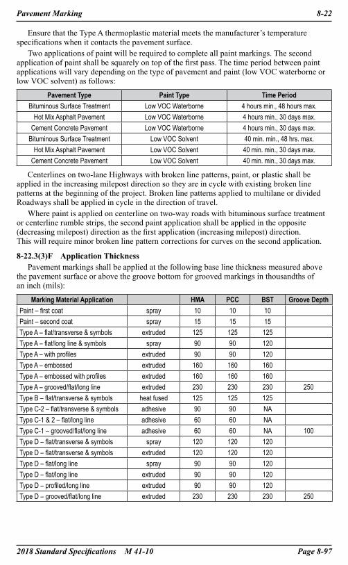
2018 Standard Specifications M 41-10 Page 8-97
Pavement Marking 8-22
Ensure that the Type A thermoplastic material meets the manufacturer’s temperature specifications when it contacts the pavement surface.
Two applications of paint will be required to complete all paint markings. The second application of paint shall be squarely on top of the first pass. The time period between paint applications will vary depending on the type of pavement and paint (low VOC waterborne or low VOC solvent) as follows:
Pavement Type Paint Type Time PeriodBituminous Surface Treatment Low VOC Waterborne 4 hours min., 48 hours max.
Hot Mix Asphalt Pavement Low VOC Waterborne 4 hours min., 30 days max.Cement Concrete Pavement Low VOC Waterborne 4 hours min., 30 days max.
Bituminous Surface Treatment Low VOC Solvent 40 min. min., 48 hrs. max.Hot Mix Asphalt Pavement Low VOC Solvent 40 min. min., 30 days max.
Cement Concrete Pavement Low VOC Solvent 40 min. min., 30 days max.
Centerlines on two-lane Highways with broken line patterns, paint, or plastic shall be applied in the increasing milepost direction so they are in cycle with existing broken line patterns at the beginning of the project. Broken line patterns applied to multilane or divided Roadways shall be applied in cycle in the direction of travel.
Where paint is applied on centerline on two-way roads with bituminous surface treatment or centerline rumble strips, the second paint application shall be applied in the opposite (decreasing milepost) direction as the first application (increasing milepost) direction. This will require minor broken line pattern corrections for curves on the second application.
8-22.3(3)F Application ThicknessPavement markings shall be applied at the following base line thickness measured above
the pavement surface or above the groove bottom for grooved markings in thousandths of an inch (mils):
Marking Material Application HMA PCC BST Groove DepthPaint – first coat spray 10 10 10Paint – second coat spray 15 15 15Type A – flat/transverse & symbols extruded 125 125 125Type A – flat/long line & symbols spray 90 90 120Type A – with profiles extruded 90 90 120Type A – embossed extruded 160 160 160Type A – embossed with profiles extruded 160 160 160Type A – grooved/flat/long line extruded 230 230 230 250Type B – flat/transverse & symbols heat fused 125 125 125Type C-2 – flat/transverse & symbols adhesive 90 90 NAType C-1 & 2 – flat/long line adhesive 60 60 NAType C-1 – grooved/flat/long line adhesive 60 60 NA 100Type D – flat/transverse & symbols spray 120 120 120Type D – flat/transverse & symbols extruded 120 120 120Type D – flat/long line spray 90 90 120Type D – flat/long line extruded 90 90 120Type D – profiled/long line extruded 90 90 120Type D – grooved/flat/long line extruded 230 230 230 250

Page 8-98 2018 Standard Specifications M 41-10
8-22 Pavement Marking
Liquid pavement marking material yield per gallon depending on thickness shall not exceed the following:
Mils thickness Feet of 4″ line/gallon Square feet/gallon10 483 16115 322 10818 268 8920 242 8022 220 7324 202 6730 161 5440 122 4145 107 3660 81 2790 54 18
90 with profiles 30 10120 40 13
120 with profiles 26 9230 21 7
Solid pavement marking material (Type A) yield per 50-pound bag shall not exceed the following:
Mils thickness Feet of 4″ line/50# bag Square feet/50# bag30 – flat 358 12045 – flat 240 8060 – flat 179 6090 – flat 120 40
90 – flat with profiles 67 23120 – flat 90 30
120 – flat with profiles 58 20125 – embossed 86 29
125 – embossed with profiles 58 20230 – flat grooved 47 15
All grooved lines shall be applied into a groove cut or ground into the pavement. For Type A or Type D material, the groove shall be cut or ground with equipment to produce a smooth square groove 4 inches wide. For Type C-1 material, the groove shall be cut with equipment to produce a smooth bottom square groove with a width in accordance with the material manufacturer’s recommendation. After grinding, clean the groove by shot-blasting or a method approved by Engineer. Immediately before placing the marking material, clean the groove with high-pressure air.
8-22.3(3)G Glass beadsTop dress glass beads shall be applied to all spray and extruded pavement marking
material. Glass beads shall be applied by a bead dispenser immediately following the pavement marking material application. Glass bead dispensers shall apply the glass beads in a manner such that the beads appear uniform on the entire pavement marking surface with 50 to 60 percent embedment. Hand casting of beads will not be allowed.
2018 Standard Specifications M 41-10 Page 8-99
Pavement Marking 8-22
Glass beads shall be applied to 10 or 15 mil thick paint at a minimum application rate of 7 pounds per gallon of paint. For plastic pavement markings, glass bead type and application rate shall be as recommended by the marking material manufacturer.
When two or more spray applications are required to meet thickness requirements for Type A and Type D materials, top dressing with glass beads is only allowed on the last application. The cure period between successive applications shall be in accordance with the manufacturer’s recommendations. Any loose beads, dirt or other debris shall be swept or blown off the line prior to application of each successive application. Successive applications shall be applied squarely on top of the preceding application.
8-22.3(4) Tolerances for LinesAllowable tolerances for lines are as follows:Length of Line – The longitudinal accumulative error within a 40 foot length of broken
line shall not exceed plus or minus 1 inch. The broken line segment shall not be less than 10 feet.
Width of Line – The width of the line shall not be less than the specified line width or greater than the specified line width plus ¼ inch.
Lane Width – The lane width, which is defined as the lateral width from the edge of pavement to the center of the lane line or between the centers of successive lane lines, shall not vary from the widths shown in the Contract by more than plus or minus 4 inches.
Thickness – A thickness tolerance not exceeding plus 10 percent will be allowed for thickness or yield in paint and plastic material application.
Parallel Lines – The gap tolerance between parallel lines is plus or minus ½ inch.
8-22.3(5) Installation InstructionsInstallation instructions for plastic markings shall be provided for the Engineer. The
instructions shall include equipment requirements, approved work methods and procedures, material application temperature range, air and pavement surface temperature requirements, weather limitations, precautions, and all other requirements for successful application and material performance. Do not use materials with incomplete or missing instructions. All materials including glass beads shall be installed according to the manufacturer’s recommendations. A manufacturer’s technical representative shall be present at the initial installation of plastic material to approve the installation procedure or the material manufacturer shall certify that the Contractor will install the plastic material in accordance with their recommended procedure.
8-22.3(6) Removal of Pavement MarkingsPavement markings to be removed shall be obliterated until all blemishes caused by
the pavement marking removal conform to the coloration of the adjacent pavement. Grinding to remove pavement markings in their entirety is allowed in areas designated
for applications of either Hot Mix Asphalt (HMA) or Bituminous Surface Treatment (BST). Pavement marking removal shall be performed from April 1st through September 30th and only in those areas that shall be paved within the same time window as the grinding, unless otherwise allowed by the Engineer in writing.
For all cement concrete pavement and areas that will not be overlaid with hot mix asphalt or BST, grinding is allowed to a depth just above the pavement surface and then Water blasting or shot blasting shall be required to remove the remaining pavement markings.
If in the opinion of the Engineer, the pavement is materially damaged by pavement marking removal, such damage shall be repaired by the Contractor in accordance with Section 1-07.13(1). Sand or other material deposited on the pavement as a result of removing lines and markings shall be removed as the Work progresses to avoid hazardous conditions. Accumulation of sand or other material which might interfere with drainage will not be permitted.
Page 8-100 2018 Standard Specifications M 41-10
8-22 Pavement Marking
8-22.4 MeasurementCenter line, center line with no pass line, double center line, double lane line, edge line,
solid lane line, dotted extension line, lane line, reversible lane line, and two-way left-turn center line will be measured by the completed linear foot as “Paint Line”, “Plastic Line”, “Embossed Plastic Line”, “Profiled Plastic Line”, “Profiled Embossed Plastic Line” or Grooved Plastic Line”.
The measurement for “Paint Line” will be based on a marking system capable of simultaneous application of three 4-inch lines with two 4-inch spaces. No deduction will be made for the unmarked area when the marking includes a broken line such as center line, dotted extension line, center line with no-pass line, lane line, reversible lane line, or two-way left-turn center line. No additional measurement will be made when more than one line can be installed on a single pass such as center line with no-pass line, double center line, double lane line, reversible lane line, or two-way left-turn center line.
The measurement for “Plastic Line”, “Embossed Plastic Line”, “Profiled Plastic Line”, “Profiled Embossed Plastic Line”, or “Grooved Plastic Line” will be based on the total length of each 4 inch wide plastic line installed. No deduction will be made for the unmarked area when the marking includes a broken line such as, center line, dotted extension line, center line with no-pass line, lane line, reversible lane line, or two-way left-turn center line.
The measurement for “Painted Wide Lane Line”, “Plastic Wide Lane Line”, “Profiled Plastic Wide Lane Line”, “Painted Barrier Center Line”, “Plastic Barrier Center Line”, “Painted Stop Line”, “Plastic Stop Line”, “Painted Wide Dotted Entry Line”, or “Plastic Wide Dotted Entry Line” will be based on the total length of each painted, plastic or profiled plastic line installed. No deduction will be made for the unmarked area when the marking includes a broken line such as, wide broken lane line, drop lane line, wide dotted lane line or wide dotted entry line. The measurement for double wide lane line will be based on the total length of each wide lane line installed.
No additional measurement for payment will be made for the required second application of paint. No additional measurement for payment will be made for additional applications required to meet thickness requirements for plastic markings.
Diagonal lines used to delineate parking stalls that are constructed of painted or plastic 4-inch lines will be measured as “Paint Line” or “Plastic Line” by the linear foot of line installed. Crosswalk line will be measured by the square foot of marking installed.
Crosshatch markings used to delineate median and gore areas will be measured by the completed linear foot as “Painted Crosshatch Marking” or “Plastic Crosshatch Marking”.
The measurement for “Painted Crosshatch Marking” and for “Plastic Crosshatch Marking” will be based on the total length of each 8-inch or 12-inch wide line installed.
Traffic arrows, traffic letters, access parking space symbols, HOV symbols, railroad crossing symbols, drainage markings, junction box markings, bicycle lane symbols, aerial surveillance full, and ½ markers, yield line symbols, yield ahead symbols, and speed bump symbols will be measured per each. Type 1 through 6 traffic arrows will be measured as one unit each, regardless of the number of arrow heads.
Removal of lines, 4, 8, 18, and 20 inches in width will be measured by the linear foot, with no deduction being made for the unmarked area when the marking includes a gap.
Removal of traffic arrows, traffic letters, access parking space symbol, HOV lane symbol, railroad crossing symbol, bicycle lane symbols, drainage markings, aerial surveillance full and ½ markers, yield line symbol, yield ahead symbol, and speed bump symbol will be measured per each. Removal of crosswalk lines will be measured by the square foot of lines removed.
2018 Standard Specifications M 41-10 Page 8-101
Pavement Marking 8-22
8-22.5 PaymentPayment will be made for each of the following Bid items that are included in the Proposal:“Paint Line”, per linear foot.“Plastic Line”, per linear foot.“Embossed Plastic Line”, per linear foot.“Profiled Plastic Line”, per linear foot.“Profiled Embossed Plastic Line”, per linear foot.“Grooved Plastic Line”, per linear foot.“Painted Wide Lane Line”, per linear foot.“Plastic Wide Lane Line”, per linear foot.“Profiled Plastic Wide Lane Line”, per linear foot.“Painted Barrier Center Line”, per linear foot.“Plastic Barrier Center Line”, per linear foot.“Painted Stop Line”, per linear foot.“Plastic Stop Line”, per linear foot.“Painted Crosswalk Line”, per square foot.“Plastic Crosswalk Line”, per square foot.“Painted Crosshatch Marking”, per linear foot.“Plastic Crosshatch Marking”, per linear foot.“Painted Wide Dotted Entry Line”, per linear foot.“Plastic Wide Dotted Entry Line”, per linear foot.“Painted Traffic Arrow”, per each.“Plastic Traffic Arrow”, per each.“Painted Traffic Letter”, per each.“Plastic Traffic Letter”, per each.“Painted Access Parking Space Symbol”, per each.“Plastic Access Parking Space Symbol”, per each.“Painted Railroad Crossing Symbol”, per each.“Plastic Railroad Crossing Symbol”, per each.“Painted Bicycle Lane Symbol”, per each.“Plastic Bicycle Lane Symbol”, per each.“Painted Drainage Marking”, per each.“Plastic Drainage Marking”, per each.“Painted Junction Box Marking”, per each.“Plastic Junction Box Marking”, per each.“Painted Aerial Surveillance Full Marker”, per each.“Plastic Aerial Surveillance Full Marker”, per each.“Painted Aerial Surveillance ½ Marker”, per each.“Plastic Aerial Surveillance ½ Marker”, per each.“Painted Access Parking Space Symbol with Background”, per each.“Plastic Access Parking Space Symbol with Background”, per each.“Painted HOV Lane Symbol”, per each.“Plastic HOV Lane Symbol”, per each.“Painted Yield Line Symbol”, per each.“Plastic Yield Line Symbol”, per each.
Page 8-102 2018 Standard Specifications M 41-10
8-22 Pavement Marking
“Painted Yield Ahead Symbol”, per each.“Plastic Yield Ahead Symbol”, per each.“Painted Speed Bump Symbol”, per each.“Plastic Speed Bump Symbol”, per each.“Removing Paint Line”, per linear foot.“Removing Plastic Line”, per linear foot.“Removing Painted Crosswalk Line”, per square foot.“Removing Plastic Crosswalk Line”, per square foot.“Removing Painted Traffic Marking”, per each.“Removing Plastic Traffic Marking”, per each.The unit Contract price for the aforementioned Bid items shall be full payment for all costs
to perform the Work as described in Section 8-22.

2018 Standard Specifications M 41-10 Page 8-103
Temporary Pavement Markings 8-23
8-23 Temporary Pavement Markings8-23.1 Description
The Work consists of furnishing and installing temporary pavement markings. Temporary pavement markings shall be provided where noted in the Plans and for all lane shifts and detours resulting from construction activities; or when permanent markings are removed because of construction operations.
8-23.2 MaterialsMaterials for temporary markings shall be paint, plastic, tape, raised pavement markers
or flexible raised pavement markers. Materials for pavement markings shall meet the following requirements:
Raised Pavement Marker 9-21 Temporary Marking Paint 9-34.2(6) Plastic 9-34.3 Glass Beads for Pavement Marking Materials 9-34.4 Temporary Pavement Marking Tape 9-34.5 Temporary Flexible Raised Pavement Markers 9-34.6
8-23.3 Construction Requirements
8-23.3(1) GeneralThe Contractor shall select the type of pavement marking material in accordance with
the Contract.
8-23.3(2) Preliminary SpottingAll preliminary layout and marking in preparation for application and the application
and removal of temporary pavement markings shall be the responsibility of the Contractor.
8-23.3(3) Preparation of Roadway SurfaceSurface preparation for temporary pavement markings shall be in accordance with the
manufacturer’s recommendations.
8-23.3(4) Pavement Marking Application
8-23.3(4)A Temporary Pavement Markings – Short DurationTemporary pavement markings – short duration shall meet the following requirements: Temporary Center Line – A BROKEN line used to delineate adjacent lanes of traffic
moving in opposite directions. The broken pattern shall be based on a 40-foot unit, consisting of a 4-foot line with a 36-foot gap if paint or tape is used. If temporary raised pavement markers are used, the pattern shall be based on a 40-foot unit, consisting of a grouping of three temporary raised pavement markers, each spaced 3 feet apart, with a 34 foot gap.
Temporary Edge Line – A SOLID line used on the edges of Traveled Way. The line shall be continuous if paint or tape is used. If temporary raised pavement markers are used, the line shall consist of markers installed continuously at 5-foot spacings.
Temporary Lane Line – A BROKEN line used to delineate adjacent lanes with traffic traveling in the same direction. The broken pattern shall be based on a 40-foot unit, consisting of a 4-foot line with a 36-foot gap, if paint or tape is used. If temporary raised pavement markers are used, the pattern shall be based on a 40-foot unit, consisting of a grouping of three temporary raised pavement markers, each spaced 3 feet apart, with a 34 foot gap.
Lane line and right edge line shall be white in color. Center line and left edge line shall be yellow in color. Edge Lines shall be installed only if specifically required in the Contract. All temporary pavement markings shall be retroreflective.
Page 8-104 2018 Standard Specifications M 41-10
8-23 Temporary Pavement Markings
8-23.3(4)A1 Temporary Pavement Marking PaintPaint used for short duration temporary pavement markings shall be applied in one
application at a thickness of 15 mils or 108 square feet per gallon. Glass beads shall be in accordance with Section 8-22.3(3)G.
8-23.3(4)A2 Temporary Pavement Marking TapeApplication of temporary pavement marking tape shall be in conformance with the
manufacturer’s recommendations.Black mask pavement marking tape shall mask the existing line in its entirety.
8-23.3(4)A3 Temporary Raised Pavement MarkersTemporary raised pavement markers are not allowed on bituminous surface treatments.
8-23.3(4)A4 Temporary Flexible Raised Pavement MarkersFlexible raised pavement markers are required for new applications of bituminous surface
treatments. Flexible raised pavement markers are not allowed on other pavement types unless otherwise specified or approved by the Engineer. Flexible raised pavement markers shall be installed with the protective cover in place. The cover shall be removed immediately after spraying asphaltic material.
8-23.3(4)B Temporary Pavement Markings – Long DurationApplication of paint, pavement marking tape and plastic for long duration pavement
markings shall meet the requirements of Section 8-22.3(3); application of raised pavement markers shall meet the requirements of Section 8-09.3; and application of flexible pavement markings shall be in conformance with the manufacturer’s recommendations.
8-23.3(4)C Tolerance for LinesTolerance for lines shall conform to Section 8-22.3(4).
8-23.3(4)D Maintenance of Pavement MarkingsTemporary pavement markings shall be maintained in serviceable condition throughout
the project until permanent pavement markings are installed. As directed by the Engineer; temporary pavement markings that are damaged, including normal wear by traffic, shall be repaired or replaced immediately. Repaired and replaced pavement markings shall meet the requirements for the original pavement marking.
8-23.3(4)E Removal of Pavement MarkingsRemoval of temporary paint is not required prior to paving; all other temporary pavement
markings shall be removed.All temporary pavement markings that are required on the wearing course prior to
construction of permanent pavement markings and are not a part of the permanent markings shall be completely removed concurrent with or immediately subsequent to the construction of the permanent pavement markings. Temporary flexible raised pavement markers on bituminous surface treatment pavements shall be cut off flush with the surface if their location conflicts with the alignment of the permanent pavement markings. All other temporary pavement markings shall be removed in accordance with Section 8-22.3(6).
All damage to the permanent Work caused by removing temporary pavement markings shall be repaired by the Contractor at no additional cost to the Contracting Agency.
8-23.4 MeasurementTemporary pavement markings will be measured by the linear foot of each installed line
or grouping of markers, with no deduction for gaps in the line or markers and no additional measurement for the second application of paint required for long duration paint lines. Short duration and long duration temporary pavement markings will be measured for the initial installation only.
2018 Standard Specifications M 41-10 Page 8-105
Temporary Pavement Markings 8-23
8-23.5 PaymentPayment will be made for each of the following Bid items that are included in the Proposal:“Temporary Pavement Marking – Short Duration”, per linear foot.“Temporary Pavement Marking – Long Duration”, per linear foot.The unit Contract price per linear foot for “Temporary Pavement Marking – Short
Duration” and “Temporary Pavement Marking – Long Duration” shall be full pay for all Work.
Page 8-106 2018 Standard Specifications M 41-10
8-24 Rock and Gravity Block Wall and Gabion Cribbing
8-24 Rock and Gravity Block Wall and Gabion Cribbing8-24.1 Description
This Work consists of constructing rock and gravity block wall(s), and gabion cribbing in accordance with the Plans, Special Provisions, these Specifications, or as designated by the Engineer.
8-24.2 MaterialsMaterials shall meet the requirements of the following Sections: Rock for Rock Wall and Chinking Material 9-13.7(1)
Backfill for Rock Wall 9-13.7(2) Gabion Cribbing 9-27.3 Wire Mesh Fabric 9-27.3(1) PVC Coating for Welded Wire Mesh Fabric 9-27.3(2) Gabion Basket Fasteners 9-27.3(4) Stone 9-27.3(6) Construction Geotextile 9-33
Materials for gravity block walls shall be as specified in the Special Provisions.
8-24.3 Construction Requirements
8-24.3(1) Rock Wall
8-24.3(1)A Geometric TolerancesThe completed wall shall meet the following tolerances:1. Wall batter shall be 6:1 or flatter as specified in the Plans.2. The exterior slope plane and grade in the finished surface of the wall shall be plus
or minus 6 inches.3. The maximum void between adjacent rocks shall be 6 inches as measured at the
smallest dimensions of the void within the thickness of the wall.
8-24.3(1)B ExcavationExcavation shall conform to Section 2-09.3(4), and to the limits and construction stages
shown in the Plans.The Contractor shall restrict the excavation limits to the length of rock wall that can be
constructed in 1 day’s Work, except as otherwise noted. The Engineer may permit excavation beyond the limits that can be completed in 1 day’s Work provided the Contractor either demonstrates that the excavation will remain stable until the rock wall is completed, or shores the excavation in accordance with Section 2-09.3(4).
Slope above the rock wall shall be established prior to excavating for the wall.
8-24.3(1)C Foundation PreparationThe foundation for the wall shall be graded as shown in the Plans.Prior to rock placement, the foundation, if not in rock, shall be compacted as approved
by the Engineer. Any foundation soils found to be unsuitable shall be removed and replaced in accordance with Section 2-09.3(1)C.
Base course rocks shall have full contact with the foundation soils. If necessary, the excavation shall be shaped to fit the rocks. Rocks may be dropped to shape the ground provided the rocks do not crack. Cracked rocks shall be replaced and the foundation regraded to fit the replacement rock.
8-24.3(1)D Construction GeotextileConstruction geotextile shall be of the type, and shall be placed, as shown in the Plans.

2018 Standard Specifications M 41-10 Page 8-107
Rock and Gravity Block Wall and Gabion Cribbing 8-24
8-24.3(1)E RockPlacementandBackfillRocks shall be placed so there are no continuous joint planes in either the vertical or
lateral direction.Where possible, rocks shall be placed so that the rock shall bear on at least two rocks
below it. Rocks shall be oriented so that flat surface contact points between adjacent rocks are maximized. Point-to-point contact between adjacent rocks shall be minimized. Each rock in a course shall be arranged so that the natural irregularities in the rocks key the rocks together and so that the courses are keyed together.
Rocks shall increase in size from the top of the wall to the bottom at a uniform rate. The minimum rock sizes, as referenced from the top of the wall, shall be as follows:
Depth From Top of Wall (feet)
Minimum Rock Size at Depth From Top of Wall
6 Three Man9 Four Man
12 Five Man
Rocks at the top of the wall shall be Two Man or larger.Where voids larger than 6 inches are present, chinking rock shall be keyed between the
rocks to fill the void.Backfill for the rock wall shall be placed behind each course and tamped to provide a
stable condition prior to placing rocks for the next successive course.For rock walls constructed in fills, the fill shall be overbuilt and cut back to construct
the wall.
8-24.3(2) Gravity Block WallExcavation shall conform to Section 2-09.3(4), and to the limits and construction stages
shown in the Plans. Foundation soils found to be unsuitable shall be removed and replaced in accordance with Section 2-09.3(1)C. Slope above the gravity block wall shall be established prior to beginning any excavation for the wall.
Gravity block walls are defined as a wall of modular blocks acting as a gravity wall to retain soil. The modular blocks may have features designed to interlock the blocks together. However there shall be no reinforcement of the retained soil nor any reinforcement connection between the modular blocks and the retained soil.
Gravity block walls shall be constructed as specified in the Special Provisions and as shown in the Plans.
8-24.3(3) Gabion Cribbing
8-24.3(3)A FoundationsBefore placing any gabion cribbing, the Contractor shall excavate the foundation or bed
to the specified grade in accordance with Section 2-09.3(4). Foundation soils found to be unsuitable shall be removed and replaced in accordance with Section 2-09.3(1)C.
8-24.3(3)B BasketsBaskets may be fabricated from either woven or welded steel wire; however, a gabion
Structure shall not include both. Baskets may be assembled with either lacing wire or clip fasteners; however, a perimeter or diaphragm edge shall not include both.
8-24.3(3)C DimensionsThe Contractor shall supply gabion baskets in the lengths and heights the Plans require.
Each length shall be a multiple (double, triple, or greater) of horizontal width. Horizontal width shall be 36 inches. All baskets from the same manufacturer shall be the same width and shall be within a tolerance of 5 percent of the manufacturer’s stated sizes.

Page 8-108 2018 Standard Specifications M 41-10
8-24 Rock and Gravity Block Wall and Gabion Cribbing
8-24.3(3)D Fabrication of BasketsGabions shall be made so that the sides, ends, lid, and diaphragms can be assembled into
rectangular baskets of the required sizes at the construction site. Common-wall construction may be used in gabion Structures up to 12 feet high. Common-wall construction includes any basket where its top serves as the bottom of the one above it, or where one wall also serves an adjacent basket. When gabion Structures are more than 12 feet high, the baskets shall have independent sides, ends, top, and bottom.
Each gabion shall be divided by diaphragms into cells the same length as horizontal basket width. Diaphragms shall be made of the same mesh and gage as the basket body.
All perimeter and diaphragm edges shall be laced or clipped together so that joints are at least as strong as the body of the mesh itself. The ends of the lacing shall be anchored by three tight turns around the selvage wire.
8-24.3(3)E Filling BasketsBaskets shall be filled with stone. The stone shall be placed and compacted to meet the
unit weight requirements of Section 8-24.3(3)F.The stone shall be placed in compacted layers not more than 14 inches deep. If cross-
connecting wires are required, the Contractor shall adjust the number and depth of layers so that wires occur between the compacted layers of stone.
8-24.3(3)F Unit Weight Requirements and TestThe unit weight of the filled gabion basket shall be at least 100 pounds per cubic foot.
Should the unit weight be less than 100 pounds per cubic foot, the gabion will be rejected and the Engineer will require the Contractor to conduct and pass additional unit weight tests before completing other gabions.
The Contractor shall conduct either of the following unit weight tests to prove the density of completed gabions:
1. A filled gabion basket shall be selected from the completed Structure and weighed.2. A gabion basket shall be filled with stone from a loaded truck that has been weighed.
After filling, the truck and unused stone shall be weighed again. The difference between the two weights shall be used to determine the weight per cubic foot of the stone in the gabion.
The Contractor shall conduct one unit weight test for each 500 cubic yards of gabions placed. The Engineer may reduce the specified frequency of these tests provided the specified minimum unit weight has been consistently achieved.
In conducting unit weight test 1 or 2, the Contractor shall provide and use scales conforming to Section 1-09.2.
8-24.3(3)G Gabion Cribbing ErectionEach row or tier of baskets shall be reasonably straight and shall conform to alignment
and grade. Hexagonal mesh baskets shall be stretched endwise before filling. The stone shall be carefully placed in layers, then tamped or vibrated. The last layer of stones shall fill each basket completely so that the secured lid will rest upon the stones. Each basket shall be laced securely to all adjacent baskets and its lid then laced or clipped to the sides, ends, and diaphragms.
All selvage wires of ends of adjacent baskets shall be laced together. The bottom selvage of the basket being constructed on a previously constructed basket shall be laced to the top of that basket.
Backfilling behind or around gabions shall conform to Section 2-09.3(1)E.
2018 Standard Specifications M 41-10 Page 8-109
Rock and Gravity Block Wall and Gabion Cribbing 8-24
8-24.4 MeasurementRock for rock walls and backfill for rock walls will be measured by the ton of rock
actually placed.Gabion cribbing will be measured by the calculated neat line volume of gabion baskets
in place, using the manufacturer’s stated dimensions.Gravity block wall will be measured by the square foot of completed wall in place.
The vertical limits for measurement are from the bottom of the bottom layer of blocks to the top of the top layer of blocks. The horizontal limits for measurement are from the end of wall to the end of wall.
Construction geotextile will be measured by the square yard for the surface area actually covered.
Structure excavation Class B, Structure excavation Class B including haul, and shoring or extra excavation Class B, will be measured in accordance with Section 2-09.4.
8-24.5 PaymentPayment will be made for each of the following Bid items that are included in the Proposal:“Rock for Rock Wall”, per ton.The unit Contract price per ton for “Rock for Rock Wall” shall also include furnishing and
installing chinking materials.“Backfill for Rock Wall”, per ton.“Gabion Cribbing”, per cubic yard.“Gravity Block Wall”, per square foot.“Construction Geotextile”, per square yard.“Structure Excavation Class B”, per cubic yard.“Structure Excavation Class B Incl. Haul”, per cubic yard.“Shoring or Extra Excavation Class B”, per square foot.
Page 8-110 2018 Standard Specifications M 41-10
8-25 Glare Screen
8-25 Glare Screen8-25.1 Description
This Work consists of furnishing and constructing glare screen of the types specified, in accordance with the Plans, these Specifications, the Standard Plans, and as ordered by the Engineer in accordance with Section 1-04.4.
Glare screen consists of diamond woven wire mesh fence of aluminum, galvanized or aluminum coated steel wire, fabricated and placed to reduce glare from headlights of opposing traffic or other adjacent light sources.
8-25.2 MaterialsMaterials shall meet the requirements of Section 9-16.6.
8-25.3 Construction Requirements
8-25.3(1) Glare Screen FabricGlare screen fabric shall be placed on the face of the posts designated by the Engineer.
On curves, the fabric shall be placed on the face of the post that is on the outside of the curve.The fabric shall be stretched taut and securely fastened to the posts. Fastening to end,
corner, and pull posts shall be with stretcher bars and fabric bands spaced at 1-foot intervals. The fabric shall be cut and each span attached independently at all pull and corner posts. Fabric shall be securely fastened to line and brace posts with tie wires, metal bands, or other approved methods, attached at 14-inch intervals. The top and bottom of the fabric shall be fastened to the tension wire with hog rings spaced at 24-inch intervals.
Rolls of wire fabric shall be joined by weaving a single strand into the end of the rolls to form a continuous mesh.
8-25.3(2) SlatsThe slats shall be fastened into the weave by using staples, screws, or other methods as
approved by the Engineer. Allowing the tension of the mesh to hold the slats in place will not be permitted.
Slats broken or split during construction shall be removed and replaced by the Contractor at no expense to the Contracting Agency.
8-25.3(3) PostsPosts shall be constructed in accordance with the Standard Plans and applicable provisions
of Section 8-12.3(1)A.Posts for Type 1 Design A shall be bolted to the beam guardrail posts as detailed in the
Standard Plans. Drilling of the guardrail posts shall be done in such a manner to ensure that the glare screen posts are set plumb and centered over the guardrail posts unless otherwise directed.
All round posts for Type 1 Design B and Type 2 glare screen shall be fitted with a watertight top securely fastened to the post. Line posts shall have tops designed to carry the top tension wire.
8-25.3(4) Tension WireTension wires shall be attached to the posts as detailed in the Standard Plans or as
approved by the Engineer.
8-25.4 MeasurementMeasurement of glare screen will be by the linear foot of completed glare screen for the
particular type and design specified.
8-25.5 PaymentPayment will be made for each of the following Bid items that are included in the Proposal:“Glare Screen Type 1 Design ____”, per linear foot.“Glare Screen Type 2”, per linear foot.

2018 Standard Specifications M 41-10 Page 8-111
Vacant 8-26
8-26 Vacant
Page 8-112 2018 Standard Specifications M 41-10
8-27 Vacant
8-27 Vacant

2018 Standard Specifications M 41-10 Page 8-113
Vacant 8-28
8-28 Vacant
Page 8-114 2018 Standard Specifications M 41-10
8-29 Wire Mesh Slope Protection
8-29 Wire Mesh Slope Protection8-29.1 Description
This Work consists of furnishing and installing the anchors and the wire mesh slope protection in accordance with these Specifications and the details shown in the Plans and in conformity with the lines and dimensions shown in the Plans or specified by the Engineer.
8-29.2 MaterialsMaterials shall meet the requirements of Section 9-16.4.
8-29.3 Construction Requirements
8-29.3(1) SubmittalsThe Contractor shall submit a Type 2 Working Drawing consisting of a wire mesh slope
protection plan. The wire mesh slope protection plan shall include the following:1. Plan sheets for anchor layout and installation, and the equipment and process used to
confirm the capacity of the constructed anchors including the calibration data for the stressing devices used to proof test the anchors, as completed by an independent testing laboratory within 60 calendar days of the wire mesh slope work.
2. Working drawings for the temporary yoke or load frame to be used for anchor proof testing in accordance with Section 6-01.9.
3. Plans and details for assembling wire mesh and erecting the assembled mesh on the slope.
All the costs for the Work required for Submittals shall be included in the unit Bid price detailed in Section 8-29.5.
8-29.3(2) AnchorsThe Contractor shall install anchors of the type shown in the Plans and in conformance
with the layout shown in the wire mesh protection plan. The spacing and number of the anchors and wire ropes as shown in the Plans are approximate only, and upon review of the wire mesh slope protection plan, the Engineer may arrange the spacing to better hold the wire mesh against the slope. Backfill material shall be thoroughly compacted with a mechanical compactor.
The Contractor shall proof test up to 25 percent of the anchors in vertical pullout to the minimum allowable anchor capacity specified in the Plans. Proof testing of anchors shall be performed against a temporary yoke or load frame. No part of the temporary yoke or load frame shall bear within three feet of the anchor being tested. For vertical pullout proof testing, an anchor is acceptable if it sustains the specified capacity for 10 minutes with no loss of load. Anchors that fail this criterion shall be replaced and retested. If more than three anchors fail, the Contractor shall proof test all anchors.
8-29.3(3) Wire RopeAll wire rope loops shall include a thimble. No wire rope splicing will be allowed.
8-29.3(4) Wire MeshThe wire mesh shall be fastened to the completed wire rope assembly as shown in the
Plans. High tensile steel fasteners on the vertical seams shall be staggered across width of the seam. Horizontal splices joining 2 rolls of mesh shall be made by overlapping the mesh approximately 3 feet and either weaving 3 rows of lacing wires through every mesh opening or using 4 rows of high tensile steel fasteners placed on approximately 3-inch spacing. All top and bottom laps shall be made by folding the mesh to the outside, away from the slope, to avoid the possibility of falling material hanging up in the folds. The bottom of the mesh shall be located as shown in the Plans. The ends of all lacing wires shall be secured to the mesh with a minimum of 1½-turns.
2018 Standard Specifications M 41-10 Page 8-115
Wire Mesh Slope Protection 8-29
The wire mesh shall not be tensioned in any direction, but is to remain loose so as to increase its dampening effect on rolling rocks. The Contractor shall use care in the handling and installing of the wire mesh and wire rope. Any mesh or wire rope damaged due to the Contractor’s operations shall be replaced by the Contractor at no expense to the Contracting Agency.
8-29.4 MeasurementMeasurement of anchors will be per each for the completed anchor. Anchor types will not
be differentiated.Wire mesh slope protection will be measured by the square foot of wire mesh erected on
the slope. There will be no deduction made for overlapping the wire mesh material as required for splices or for coverage due to variations in the slope or ground conditions.
8-29.5 PaymentPayment will be made for each of the following Bid items that are included in the Proposal:“Wire Mesh Slope Protection Anchor”, per each.The unit Contract price per each for “Wire Mesh Slope Protection Anchor” shall be full
payment for all costs for the Work described in Sections 8-29.3(1) and 8-29.3(2).“Wire Mesh Slope Protection”, per square foot.The unit Contract price per square foot for “Wire Mesh Slope Protection” shall be full
payment for all costs for the Work described in Sections 8-29.3(3) and 8-29.3(4).

![Statute Law (Miscellaneous Provisions) Bill (No 2) 2017 · PDF fileStatute Law (Miscellaneous Provisions) Bill (No 2) ... Division 1 Animals [14] Schedule 3, Part 1 ... Statute Law](https://img.pdfslide.us/doc/110x75/5ab2ba547f8b9aea528d9ca7/statute-law-miscellaneous-provisions-bill-no-2-2017-law-miscellaneous-provisions.jpg)