Embed Size (px)
Citation preview
1
DIVISION 3 Concrete
Work to include but not be limited to: 03010 Concrete Work 03150 Concrete Accessories RELATED DOCUMENTS Drawings and general provisions of contract, including General and Supplementary Conditions and DIVISION 1 Specification sections, apply to work of this section. SECTION 03010 -- CONCRETE WORK PART 1 - GENERAL 1.01 Description A. All poured-in-place concrete work shown on the drawings is governed by this section.
Concrete strength, not otherwise designated, shall be 3,000 psi, as determined by the use of ASTM C31 and C39. All precast concrete shall be 4,000 psi.
1.02 Quality Assurance A. Codes and Standards: Comply with the provisions of the latest editions of the following
codes, specifications and standards, except as otherwise shown or specified. Where provisions of these codes and standards are in conflict with the building codes in force for this project, the building code shall govern.
1. ACI 301, “Specifications for Structural Concrete for Buildings”. 2. ACI 318, “Building Code Requirements for Reinforced Concrete”. 3. ACI 304, “Recommended Practice for Measuring, Mixing, Transporting and Placing
Concrete”. 4. ACI 311, “Recommended Practice for Concrete Inspection”. 5. ACI 347, “Recommended Practice for Concrete Formwork”. 6. Concrete Reinforcing Steel Institute (CRSI) “Manual of Standard Practice”. B. Workmanship: The contractor is responsible for correction of concrete work which does not
conform to the specified requirements, including strength, tolerances and finishes. Correct deficient concrete as directed by the Architect/Engineer. Should cylinders and cores indicate unacceptable concrete, load testing or removal and replacement of the concrete may be required at no cost to the Owner.
2
C. Concrete Testing Service: 1. The contractor shall employ, at his own expense, a testing laboratory experienced in
design and testing of concrete materials and mixes to perform material evaluation tests, to design concrete mixes, and to perform strength tests associated with form removal. Testing agency shall meet the requirements of ASTM C1077 and ASTM E329.
2. The contractor shall employ, at his own expense, an independent testing laboratory to perform the testing of the concrete during the process of the work. Allow free access to material stockpiles and facilities at all times. Tests, not specifically indicated to be done at the Owner’s expense, including the retesting of rejected materials and installed work, shall be done at the contractor’s expense. The independent testing agency shall be qualified according to ASTM C1077 and ASTM E329.
D. Welding of reinforcing steel shall be limited to welders whose competency has been treated
according to standards of Structural Welding Code of American Welding Society. 1.03 Definitions A. Cementitious Materials: Portland Cement alone or in combination with one or more of the
following: fly ash, other possolans, ground granulated blast-furnace slag and silica fume; subject to compliance with requirements.
1.04 Submittals A. Shop Drawings-Concrete Reinforcement: Submit shop drawings for fabrication, bending
and placement of concrete reinforcement. Comply with ACI Manual 315, “Manual of Standard Practice for Detailing Reinforced Concrete Structures”, showing bar schedules, stirrup spacing, diagrams of bent bars, and arrangement of reinforcement. Show location of construction joints planned.
B. Product Data: Submit manufacturer’s product data, specifications with application and
installation instructions for proprietary materials and items, including admixtures, bonding agents, joint systems, curing compounds, water stops, chemical floor hardeners, and others as requested by the Architect/Engineer.
C. Test reports specified in Paragraphs Proportioning and Design of Mixes, Field Quality
Control, and Evaluation of Quality Control Tests. PART 2 - PRODUCTS 2.01 Form Materials A. Forms for Exposed Finish Concrete:
3
1. Unless otherwise indicated, construct formwork for exposed concrete surfaces with
plywood, metal, metal-framed plywood faced or other acceptable panel-type materials, to provide continuous, straight, smooth, exposed surfaces. Furnish in largest practicable sizes to minimize number of joints and to conform to joint system shown on drawings. Provide form material with sufficient thickness to withstand pressure of newly-placed concrete without bow or deflection.
B. Use overlaid plywood complying with U.S. Product Standards PS-1 “A-C or B-B High Density
Overlaid Concrete Form”, Class I. C. Use plywood complying with U.S. Product Standard PS-1 “B-B (Concrete Form) Plywood”,
Class I, Exterior Grade or better, mill-oiled and edge-sealed, with each piece bearing legible inspection trademark.
D. Forms for Unexposed Finish Concrete: Form concrete surfaces which will be unexposed in
finished structure with plywood, lumber, metal or other acceptable material. Provide lumber dressed on at least 2-edges and one side for tight fit.
E. Form Coatings: Provide commercial formulation form-coating compounds that will not
bond with, stain nor adversely affect concrete surfaces, and will not impair subsequent treatments of concrete surfaces to be cured with water or curing compound.
2.02 Reinforcing Materials A. Reinforcing Bar: ASTM A615, grade 60, deformed. B. Welded Wire Fabric: ASTM A185, welded steel wire fabric, fabricated from as-drawn steel
wire into flat sheets. C. Supports for Reinforcement: Provide supports for reinforcement including bolsters, chairs,
spacers and other devices for spacing, supporting and fastening reinforcing bars and welded wire fabric in place. Use wire bar type supports complying with CRSI “Manual of Standard Practice”, unless otherwise indicated. Wood, brick and other devices will not be acceptable.
D. Slab-On-Grade: Use supports or horizontal runners where wetted base material will not
support chair legs. E. Exposed-To-View Concrete Surfaces: Where legs of supports are in contact with forms,
provide supports with legs which are hot-dip galvanized or plastic protected or stainless steel protected.
F. Fabricate steel reinforcing in accordance with CRSI’s “Manual of Standard Practice”.
4
2.03 Concrete Materials: See Structural Notes on engineering drawings for concrete materials. 2.04 Related Materials A. Water stops: Provide flange, dumbbell type or center bulb type water stops at construction
joints and other joints as shown. Size to suit joints. 1. Rubber or PVC water stops, at contractor’s option, with rubber units complying with
Corps of Engineers CRD-C513 and PVC units complying with CRD-C572. 2. Vertical surfaces (greater than 3% slope) ASTM C920. B. Performed Expansion Joint Fillers: Fiber type conforming to ASTM D1751 or Cork, ASTM
D1752, type II. C. Joint Sealing Compound: 1. Horizontal Surfaces (maximum 3% slope). a. Inside building - ASTM D1190 or ASTM D1850 b. Outside building - ASTM D1190. 2. Vertical surfaces (greater than 3% slope) ASTM C920. D. Chemical Hardener: Colorless aqueous solution containing a blend of magnesium
fluosilicate and zinc fluosilicate combined with a wetting agent, containing not less than 2 lbs. of fluosilicates per gallon.
E. Curing Materials: 1. Absorptive Cover: Burlap cloth made from jute or kenaf, weighing approximately 9
oz. per sq. yard, complying with AASHTO M182, class 3. 2. Moisture-Retaining Cover: One of the following, complying with ASTM C171. a. Waterproof paper. b. Polyethylene film. c. Polyethylene-coated burlap. 3. Membrane-Forming Curing Compound: ASTM C309, type I. F. Non-Shrink Grout: Conform to CRD-C621, factory pre-mixed grout; use non-metallic,
“Masterflow 713" by Master Builders; “Sonogrout”, by Sonnoborn-Contech, or equal. G. Vapor Barrier: ASTM D4397 polyethylene sheeting, minimum 6 mil thickness. H. Non-Slip Aggregate Finish: Provide fused aluminum oxide grits, or crushed emery, as
abrasive aggregate for non-slip finish with emery aggregate containing not less than 40% aluminum oxide and not less than 25% ferric oxide. Use material that is factory-graded, packaged, rust-proof and non-glazing, and is unaffected by freezing, moisture and cleaning materials.
5
I. Epoxy Adhesive: ASTM C881, two component material suitable for use on dry or damp
surfaces. Provide material “Type”, “Grade” and “Class” to suit project requirements. 1. Products: Subject to compliance with requirements, provide one of the following: “Eppoxtite”; A.C. Horn. “Edoco 2118 Epoxy Adhesive”; Edoco Technical Prod. “Sikadur 35, Hi-Med, LV”; Sika Chemical Corp. “Euco Epoxy 463 or 615"; Euclid Chemical Co. “Patch and Bond Epoxy”; The Burke Co. “Sure-Poxy”; Kaufman Products Inc. 2.05 Repair Materials A. Repair Underlayment: Cement-based, polymer-modified, self-leveling product that can be
applied in thicknesses from 1/8 inch (3.2 mm) and that can be feathered at edges to match adjacent floor elevations.
1. Cement Binder: ASTM C150, Portland Cement or hydraulic or blended hydraulic
cement, as defined in ASTM C219. 2. Primer: Product of underlayment manufacturer recommended for substrate,
conditions, and application. 3. Aggregate: Well-graded, washed gravel, 1/8 to 1/4 inch (3.2 to 6mm) or coarse
sand, as recommended by underlayment manufacturer. 4. Compressive Strength: Not less than 4,100 psi (29 MPa) at 28 days when tested
according to ASTM C109/C109M. B. Repair Overlayment: Cement-based, polymer-modified, self-leveling product that can be
applied in thickness from 1/4 inch (6.4 mm) and that can be filled in over a scarified surface to match adjacent floor elevations.
1. Cement Binder: ASTM C150, Portland Cement or hydraulic or blended hydraulic
cement, as defined in ASTM C219. 2. Primer: Product of topping manufacturer recommended for substrate, conditions and
application. 3. Aggregate: Well-graded, washed gravel, 1/8 to 1/4 inch (3.2 to 6 mm) or coarse
sand, as recommended by topping manufacturer. 4. Compressive Strength: Not less than 5,000 psi (34.5 MPs) at 28 days when tested
according to ASTM C109/C109M. 2.06 Proportioning and Design of Mixes A. General: 1. All concrete shall contain a minimum of 5-sacks of cement per cubic yard. Tremie
6
concrete, where required; use minimum of 7-sacks of cement per cubic yard. 2. All concrete not specifically designated shall be proportioned for a strength of 3,000
lbs. per square inch at 28 days of age. B. Slump Limits: Slump in Inches Type of Construction Maximum Minimum Reinforced foundation walls and footings 5 2 Slabs and beams 5 3 Reinforced columns and pilasters 5 3 Masonry Grout 10 5 C. Proportion design mixes for each type and strength of concrete by either laboratory trail
batch or field experience methods, using materials to be employed on the project for each class of concrete required, complying with ACI 211.1 for normal weight concrete and ACI 211.2 for structural lightweight concrete.
1. Field Experience Method: When field experience method is used to select concrete
proportions, establish procedures as specified in ACI 301 and ACI 318. When proportioning by field experience method furnish mix design and independent testing facility proof of standard deviation using materials, mix and production facility proposed.
2. Laboratory Trial Method: When laboratory trail batches are used to select concrete proportions, prepare test specimens in accordance with ASTM C192 and conduct strength test in accordance with ASTM C39, as specified in ACI 301.
a. When proportioning by the trial batch method, furnish compressive strength developed at 7-days and 28-days, from not less than 2 test cylinders cast for each 7 and 28 day test, and for each design mix.
b. Establish a curve showing relationship between water-cement ratio (or cement content) and compressive strength, with at least 3 points representing batches which product strengths above and below that required. Use not less than 2 specimens tested at 28 days, or an earlier age when acceptable to the Architect/Engineer, to establish each point on the curve.
D. Lightweight Concrete: Proportion mix as herein specified. Design mix to product strength
and modulus of elasticity as noted on drawings, with a split-cylinder strength factor (Fct) of not less than 5.5 and a dry weight of not less than 95 lbs. or more than 110 lbs. after 28 days. Limit shrinkage to 0.03% at 28 days.
E. Submit Testing Service reports to the Architect/Engineer of each proposed mix for each type
7
of concrete at least 15 days prior to start of work. Do not begin concrete production until mix data have been reviewed by the Architect/Engineer.
F. Admixtures: 1. Use air-entraining admixture in all concrete, unless otherwise indicated. Add
air-entraining admixture at the manufacturer’s prescribed rate to result in concrete at the point of placement having 4-1/2 percent entrained air with tolerance in either direction from this optimum of 1-1/2 percent.
2. Use amounts of admixtures as recommended by the manufacturer for climatic conditions prevailing at the time of placing. Adjust quantities and types of admixtures as required to maintain quality control.
3. Contractor may use fly ash as part of the cement content of the foundation concrete; fly ash shall be a maximum of 25 percent of the cement content (cement and fly ash). All other concrete shall have a cement content of a blend of Portland Cement and a maximum of 50 percent of the cement content of blast-furnace slag.
G. Adjustment to Concrete Mixes: Mix design adjustments may be requested by the contractor
when characteristics of material, job conditions, weather, test results or other circumstances warrant; at no additional cost to the Owner and as accepted by the Architect/Engineer. Laboratory test data for revised mix designs and strength results must be submitted to and accepted by the Architect/Engineer before using in the work.
PART 3 - EXECUTION 3.01 Forms A. Design of formwork for structural stability and sufficiency is the contractor’s responsibility.
Conform to ACI 301, within tolerance limits of ACI 114. B. Design, erect, support, brace and maintain formwork to support vertical and lateral loads
that might be applied until such loads can be supported by the concrete structure. Construct formwork so that concrete members and structures are of correct size, shape, alignment, elevation and position.
C. Construct forms complying with ACI 347, to sizes, shapes, lines and dimensions shown, and
to obtain accurate alignment, location, grades, level and plumb work in finished structures. Provide for openings, offsets, keyways, recesses, moldings, rustications, reglets, chamfers, blocking, screeds, bulkheads, anchorages and inserts, and other features required in work. Use selected materials to obtain required finishes. Solidly butt joints and provide back-up joints to prevent leakage of cement paste.
D. Fabricate forms for easy removal without hammering or prying against the concrete
surfaces. Provide crush plates or wrecking plates where stripping may damage cast concrete surfaces. Provide top forms for inclined surfaces where slope is too steep to place
8
concrete with bottom forms only. Kerf wood inserts for forming keyways, reglets, and recesses to prevent swelling and for easy removal.
E. Provide temporary openings where interior area of formwork is inaccessible for clean out, for
inspection before concrete placement, and for placement of concrete. Securely brace temporary openings and set tightly to forms to prevent loss of concrete mortar. Locate temporary openings on forms at inconspicuous locations.
F. Chamfer exposed corners and edges 3/4 inches, unless otherwise noted, using wood,
metal, PVC or rubber chamfer strips fabricated to produce uniform smooth lines and tight edge joints.
G. Form Ties: Factory-fabricated, adjustable-length, removable or snap off metal form ties,
designed to prevent form deflection and to prevent spalling concrete surfaces upon removal. 1. Unless otherwise shown, provide ties so portion remaining within concrete after
removal is at least 1-1/2" inside concrete. 2. Unless otherwise shown, provide form ties which will not leave holes larger than 1"
diameter in concrete surface. H. Provisions for Other Trades: Provide openings in concrete formwork to accommodate work
of other trades. Determine size and location of openings, recesses and chases from trades providing such items. Accurately place and securely support items built into forms.
I. Cleaning and Tightening: Thoroughly clean forms and adjacent surfaces to receive
concrete. Remove chips, wood, sawdust, dirt or other debris just before concrete is placed. Retighten forms after concrete placement if required to eliminate mortar leaks.
3.02 Placing Reinforcement A. Comply with specified codes and standards, and Concrete Reinforcing Steel Institute’s
“Manual of Standard Practice”, for details and methods of reinforcement placement and supports, and as herein specified.
B. Clean reinforcement of loose rust and mill scale, earth, ice and other materials which reduce
or destroy bond with concrete. C. Accurately position, support and secure reinforcement against displacement by formwork,
construction or concrete placement operations. Locate and support reinforcing by metal chairs, runners, bolsters, spacers, and hangers, as required.
D. Place reinforcement to obtain at least the minimum coverages for concrete protection.
Arrange, space and securely tie bars and bar supports to hold reinforcement in position during concrete placement operations. Set wire ties so ends are directed into concrete, not toward exposed concrete surfaces. Do not place reinforcing bars more than 2" beyond the
9
last leg of continuous bar support. Do not use supports as bases for runways for concrete conveying equipment and similar construction loads.
E. Install welded wire fabric in as long lengths as practicable. Lap adjoining pieces at least
one full mesh and lace splices with wire. Offset end laps in adjacent widths to prevent continuous laps in either direction.
F. Splices: Provide standard reinforcing splices by lapping ends per ACI 318, 2005 Edition. 3.03 Joints A. Construction Joints: Locate and install construction joints, which are not shown on the
drawings, so as not to impair the strength and appearance of the structure, as acceptable to the Architect/Engineer.
B. Provide keyways at least 1-1/2" deep in all construction joints in walls, slabs and between
walls and footings; accepted bulkheads designed for this purpose may be used for slabs. C. Place construction joints perpendicular to the main reinforcement. Continue all
reinforcement across construction joints, unless shown or noted otherwise. D. Control Joints in Slabs-on-Ground: Construct control joints in slabs-on-ground to form
panels of patterns as shown. Use inserts 1/4" wide by 1/5 to 1/4 of the slab depth, unless otherwise shown. Form control joints by inserting a pre-molded hardboard or fiberboard strip into the fresh concrete until the top surface of the strip is flush with the slab surface. After the concrete has cured, remove inserts and clean groove and loose debris. Fill with joint sealant material continuous. Sawn joints are not permitted.
E. Waterstops: Provide waterstops in construction joints as indicated. Install waterstops to
form continuous diaphragm in each joint. Make provisions to support and protect exposed waterstops during progress of work. Fabricate field joints in waterstops in accordance with manufacture’s printed instructions.
F. Isolation Joints in Slabs-on-Ground: Construct isolation joints in slabs-on-ground at points
of contact between slabs-on-ground and vertical surfaces, such as column pedestals, foundation walls, grade beams and elsewhere as indicated.
3.04 Installation of Embedded Items A. General: Set and build into the work anchorage devices and other embedded items required
for other work that is attached to, or supported by, cast-in-place concrete. Use setting drawings, diagrams, instructions and directions provided by suppliers of the items to be attached.
B. Edge Forms and Screed Strips for Slabs: Set edge forms or bulkheads and intermediate
10
screed strips for slabs to obtain the required elevations and contours in the finished slab surface. Provide and secure units sufficiently strong to support the types of screed strips by the use of strike-off templates or accepted compacting type screeds.
3.05 Preparation of Form Surfaces A. Coat the contact surfaces of forms with a form-coating compound before reinforcement is
placed. B. Thin form-coating compounds only with thinning agent of type, and in amount and under
conditions of the form-coating compound manufacturer’s directions. Do not allow excess form-coating material to accumulate in the forms or to come into contact with concrete surfaces against which fresh concrete will be placed. Apply in compliance with manufacturer’s instructions.
C. Coat steel forms with a non-staining, rust-preventative form oil or otherwise protect against
rusting. Rust-stained steel formwork is not acceptable. 3.06 Concrete Mixing A. Ready-Mix Concrete: All concrete shall be ready-mix concrete. Comply with the
requirements of ASTM C94, and herein specified. 1. During hot weather, or under conditions contributing to rapid setting of concrete, a
shorter mixing time than specified in ASTM C94 may be required. When the air temperature is between 85 degrees F and 90 degrees F, reduce the mixing and delivery time from 1-1/2 hours to 75 minutes, and when the air temperature is above 90 degrees F, reduce the mixing and delivery time to 60 minutes.
2. No additional water shall be added to concrete without the approval of the Architect/Engineer. Should additional water be required to obtain a slump as specified in this section for the type of concrete, the contractor shall perform slump tests in accordance with ASTM C143 to determine the actual slump of the concrete in the mixer. The contractor may then add water, but in no case shall the additional water exceed 3 percent of the mix design water content, nor shall the slump of the mix exceed the maximum slump specified for the type concrete. Slump tests and the addition of water to the mixer shall be completed within 15 minutes of the arrival of the mixer at the site. Additional water shall not be added to the mix after the mixer has been on the site longer than 15 minutes.
3. A delivery ticket showing truck number, date and time that mixing was started shall be given to the contractor’s superintendent at the job site before placing the concrete from the truck mixer. At the job site the contractor’s superintendent shall note on the delivery ticket the time of completion of the concrete placement from the truck and the general area of the structure in which the concrete was placed. A complete file of all delivery tickets shall be maintained and kept available at the job site until completion of the project.
11
3.07 Concrete Placement A. General: Comply with ACI 304, and as herein specified. B. Pre-placement Inspection: Before placing concrete, inspect and complete the formwork
installation, reinforcing steel, and items to be embedded or cast-in. Thoroughly wet wood forms immediately before placing concrete where form coatings are not used. Coordinate the installation of joint materials and moisture barriers with placement of forms and reinforcing steel.
C. Deposit concrete continuously or in layers of such thickness that no concrete will be placed
on concrete which has hardened sufficiently to cause the formation of seams or planes of weakness within the section. If a section cannot be placed continuously, provide construction joints as herein specified. Deposit concrete as nearly as practicable to its final location to avoid segregation due to re-handling or flowing. Maintain reinforcing in the proper position during concrete placement operation.
D. Placing Concrete in Forms: Deposit concrete in forms in horizontal layers not deeper than
24" and in a manner to avoid inclined construction joints. Where placement consists of several layers, place each layer while preceding layer is still plastic to avoid cold joints.
E. Consolidate placed concrete by mechanical vibrating equipment supplemented by
hand-spading, rodding or tamping. Use equipment and procedures for consolidation of concrete in accordance with the recommended practices of ACI 309, to suit the type of concrete and project conditions.
1. Do not use vibrators to transport concrete inside of forms. Insert and withdraw
vibrators vertically at uniformly spaced locations not farther than the visible effectiveness of the machine. Place vibrators to rapidly penetrate the placed layer of concrete and at least 6" into the preceding layer. At each insertion limit the duration of vibration to the time necessary to consolidate the concrete and complete embedment of reinforcement and other embedded items without causing segregation of the mix.
F. Placing Concrete Slabs: Deposit and consolidate concrete slabs in a continuous operation,
within the limits of construction joints, until the placing of a panel or section is completed. G. Bring slab surfaces to the correct level with a straightedge and strike off. Use bull floats or
darbies to smooth the surface, leaving it free of humps or hollows. Do not sprinkle water on the plastic surface. Do not disturb the slab surfaces prior to beginning finishing operations.
H. Do not place concrete in an inundated excavation. I. Cold Weather Placing:
12
1. Protect concrete work from physical damage or reduced strength which could be caused by frost, freezing actions, or low temperatures, in compliance with ACI 306 and as herein specified. When air temperature has fallen to or is expected to fall below 40 degrees F, uniformly heat all water and aggregates before mixing as required to obtain a concrete mixture temperature of 50 degrees F and not more than 80 degrees F at point of placement.
2. Use water -reducing retarding admixture (Type D) when required by high temperatures, low humidity, or other adverse placing conditions.
J. Hot Weather Placement: Comply with ACI 301 and as follows: 1. Maintain concrete temperature below 90 degrees F at time of placement. Chilled
mixing water or chopped ice may be used to lower temperature provided water equivalent of ice is to total amount of mixing water.
2. Fog-spray forms, steel reinforcing and subgrade just before placing concrete. Keep subgrade uniformly moist without standing water, soft spots or dry areas.
3.08 Finish of Formed Surfaces A. Rough Form Finish: For formed concrete surfaces not exposed-to-view in the finish work or
by other construction, unless otherwise indicated. This is the concrete surface having texture imparted by form facing material used, with tie holes and defective areas repaired and patched and fins and other projections exceeding 1/4" in height rubbed down or chipped off.
B. Smooth Form Finish: For formed concrete surfaces exposed-to-view, or that are to be
covered with a coating material applied directly to concrete, or a covering material applied directly to concrete, such as waterproofing, damp proofing, painting or other similar system. This is as-cast concrete surface obtained with selected form facing material, arranged orderly and symmetrically with a minimum of seams. Repair and patch defective areas. Fins or other projections are to be completely removed and smoothed.
C. Smooth Rubbed Finish: Provide smooth rubbed finish to scheduled concrete surfaces, which
have received smooth form finish treatment, not later than one day after form removal. 1. Moisten concrete surfaces and rub with carborundum brick or other abrasive until a
uniform color and texture is produced. Do not apply cement grout other than that created by the rubbing process.
D. Related Uniformed Surfaces: At tops of walls, horizontal offsets surfaces occurring adjacent
to formed surfaces, strike-off smooth and finish with a texture matching adjacent formed surfaces. Continue final surface treatment of formed surfaces uniformly across adjacent unformed surfaces, unless otherwise indicated.
3.09 Finishing Floors and Slabs
13
A. Scratch Finish: Apply scratch finish to monolithic slab surfaces that are to receive mortar setting beds for tile, Portland Cement terrazzo, and other bonded applied cementitious finish flooring material, and as otherwise indicated.
1. After placing slabs, plane the surface so that depressions between high spots do not
exceed ½" under a 10' straightedge. Slope surfaces uniformly to drains where required. After leveling, roughen surface before final set, with stiff brushes, brooms or rakes.
B. Float Finish: Apply float finish to monolithic slab surfaces to receive trowel finish and other
finishes hereinafter specified. 1. After screeding, consolidating, and leveling concrete slabs, do not work surface until
ready for floating. Begin floating when surface water has disappeared or when concrete has stiffened sufficiently to permit operation of power-driven floats, or both. Consolidate surface with power-driven floats, or by hand-floating if area is small or inaccessible to power units. Check level surface plane to a tolerance not exceeding 1/4" in 10' when tested with a 10' straightedge. Cut down high spots and fill low spots. Uniformly slope surfaces to drains. Immediately after leveling, refloat surface to a uniform, smooth, granular texture.
C. Trowel Finish: Apply trowel finish to monolithic slab surfaces to be exposed-to-view, and slab
surfaces to be covered with resilient flooring, paint or other thin film finish coating system. 1. After floating, begin first trowel finish operation using a power-driven trowel. Begin
final troweling when surface produces a ringing sound as trowel is moved over surface. Consolidate concrete surface by final hand-troweling operation, free of trowel marks, uniform in texture and appearance, and with a surface plane tolerance not exceeding 1/8" in 10' when tested with a 10' straightedge. Grind smooth any surface defects which would telegraph through applied floor covering system.
D. Trowel and Fine Broom Finish: Where ceramic or quarry tile is to be installed with thin-set
mortar, apply trowel finish as specified, then immediately follow with slightly scarifying surface by fine brooming.
E. Non-Slip Broom Finish: Apply non-slip broom finish to exterior concrete platforms, steps and
ramps and elsewhere as indicated. 1. Immediately after trowel finishing, slightly roughen concrete surface by brooming
with fiber bristle broom perpendicular to main traffic route. Coordinate required final finish with Architect before application.
F. Chemical-Hardener Finish: Apply chemical-hardener finish to interior concrete floors
exposed to view and where indicated. Apply liquid chemical-hardener after complete curing and drying of the concrete surface. Dilute liquid hardener with water, apply in
14
3-coats; first coat, 1/3 strength. Evenly apply each coat, and allow 24 hours for drying between coats.
1. Apply proprietary chemical hardeners, in accordance with manufacturer’s printed
instructions. 2. After final coat of chemical-hardener solution is applied and dried, remove surplus
hardener by scrubbing and mopping with water. 3.10 Miscellaneous Concrete Items A. Filling In: Fill in holes and openings left in concrete structures after work of other trades is in
place, unless otherwise indicated. Mix, place and cure concrete, as specified to blend with in-place construction. Provide other miscellaneous concrete filling indicated or required to complete the Work.
B. Equipment Bases and Foundations: Provide machine and equipment bases and foundations
as shown on the drawings. Set anchor bolts for machines and equipment at correct elevations, complying with diagrams or templates from manufacturer furnishing machines and equipment.
C. Steel Pan Stairs: Provide concrete fill for steel pan stair treads, landings and associated
items. Cast-in inserts and accessories as shown on the drawings. Screed, tamp and trowel finish concrete surfaces.
3.11 Concrete Protecting and Curing A. General: Protect freshly placed concrete from premature drying and excessive cold or hot
temperatures. Comply with ACI 306.1 for cold-weather protection and ACI 301 for hot-weather protection during curing.
B. Evaporation Retarder: Apply evaporation retarder to unformed concrete surfaces if hot, dry
or windy conditions cause moisture loss approaching 0.2 lb./sq ft x h (1kg/sq m x h) before and during finishing operations. Apply according to manufacturer’s written instructions after placing, screeding and bull floating or darbying concrete, but before float finishing.
C. Formed Surfaces: Cure formed concrete surfaces, including underside of beams, supported
slabs and other similar surfaces. If forms remain during curing period, moist cure after loosening forms. If removing forms before end of curing period, continue curing for the remainder of the curing period.
D. Uniformed Surfaces: Begin curing immediately after finishing concrete. Cure unformed
surfaces, including floors and slabs, concrete floor toppings and other surfaces. E. Cure concrete according to ACI 308.1, by one or a combination of the following methods:

15
1. Moisture Curing: Keep surfaces continuously moist for not less than seven (7) days with the following materials:
a. Water. b. Continuous water-fog spray. c. Absorptive cover, water saturated, and kept continuously wet. Cover
concrete surfaces and edges with 12 inch (300 mm) lap over adjacent absorptive covers.
2. Moisture-Retaining Cover Curing: Cover concrete surfaces with moisture-retaining cover for curing concrete, placed in widest practicable width, with sides and ends lapped at least 12 inches (300 mm), and sealed by waterproof tape or adhesive. Cure for not less than seven (7) days. Immediately repair any holes or tears during curing period using cover material and waterproof tape.
a. Moisture cure or use moisture-retaining covers to cure concrete surfaces to receive floor coverings.
b. Moisture cure or use moisture-retaining covers to cure concrete surfaces to receive penetrating liquid floor treatments.
c. Cure concrete surfaces to receive floor coverings with either a moisture retaining cover or a curing compound that the manufacturer certifies will not interfere with bonding of floor covering used on Project.
3. Curing Compound: Apply uniformly in continuous operation by power spray or roller according to manufacturer’s written instructions. Recoat areas subjected to heavy rainfall within three (3) hours after initial application. Maintain continuity of coating and repair damage during curing period.
a. Removal: After curing period has elapsed, remove curing compound without damaging concrete surfaces by method recommended by curing compound manufacturer, unless manufacturer certifies curing compound will not interfere with bonding of floor covering used on Project.
4. Curing and Sealing Compound: Apply uniformly to floors and slabs indicated in a continuous operation by power spray or roller according to manufacturer’s written instructions. Recoat areas subjected to heavy rainfall within three (3) hours after initial application. Repeat process 24 hours later and apply a second coat. Maintain continuity of coating and repair damage during curing period.
3.12 Removal of Forms A. Formwork not supporting weight of concrete, such as sides of beams, walls, columns, and
similar parts of the work, maybe removed after cumulatively curing at not less than 50 degrees F (10 degrees C) for 24 hours after placing concrete, provided concrete is sufficiently hard to not be damaged by form removal operations, and provided curing and protection are maintained.
B. Formwork supporting weight of concrete, such as beam soffits, joints, slabs and other
structural elements, may not be removed in less than 14 days and until concrete has attained design minimum compressive strength at 28 days. Determine potential compressive strength of in place concrete by testing field-cured specimens representative of concrete
16
location of members. C. Form facing material may be removed four (4) days after placement, only if shores and other
vertical supports have been arranged to permit removal of form facing material without loosening or disturbing shores and supports.
3.13 Re-Use of Forms A. Clean and repair surfaces for forms to be re-used in work. Split, frayed, delaminated or
otherwise damaged form facing material will not be acceptable for exposed surfaces. Apply new form coating compound as specified for new formwork.
B. When forms are extended for successive concrete placement, thoroughly clean surfaces,
remove fins and laitance, and tighten forms to close joints. Align and secure joint to avoid offsets. Do not use “patched” forms for exposed concrete surfaces, except as acceptable to Architect.
3.14 Concrete Surface Repairs A. Defective Concrete: Repair and patch defective areas when approved by Architect.
Remove and replace concrete that cannot be repaired and patched to Architect’s approval. B. Patching Mortar: Mix dry-pack patching mortar, consisting of one part Portland Cement to
two and one half parts fine aggregate passing a No.16 (1.18 mm) sieve, using only enough water for handling and placing.
C. Repairing Formed Surfaces: Surface defects include color and texture irregularities, cracks,
spalls, air bubbles, honeycombs, rock pockets, fins and other projections on the surface and stains and other discolorations that cannot be removed by cleaning.
1. Immediately after form removal, cut out honeycombs, rock pockets and voids more
than ½ inch (13 mm) in any dimension to solid concrete. Limit cut depth to 3/4 inch (19 mm). Make edges of cuts perpendicular to concrete surface. Clean, dampen with water and brush-coat holes and voids with bonding agent. Fill and compact with patching mortar before bonding agent has dried. Fill form-tie voids with patching mortar or cone plugs secured in place with bonding agent.
2. Repair defects on surfaces exposed to view by blending white Portland Cement and standard Portland Cement so that, when dry, patching mortar will match surrounding color. Patch a test area at inconspicuous locations to verify mixture and color match before proceeding with patching. Compact mortar in place and strike off slightly higher than surrounding surface.
3. Repair defects on concealed formed surfaces that affect concrete’s durability and structural performance as determined by Architect.
D. Repairing Unformed Surfaces: Test unformed surfaces, such as floors and slabs, for finish
17
and verify surface tolerances specified for each surface. Correct low and high areas. Test surfaces sloped to drain for trueness of slope and smoothness; use a sloped template.
1. Repair finished surfaces containing defects. Surface defects include spalls, pop-outs, honeycombs, rock pockets, crazing and cracks in excess of 0.01 inch (0.25 mm) wide or that penetrate to reinforcement or completely through unreinforced sections regardless of width, and other objectionable conditions.
2. After concrete has cured at least 14 days, correct high areas by grinding. 3. Correct localized low areas during or immediately after completing surface finishing
operations by cutting out low areas and replacing with patching mortar. Finish repaired areas to blend into adjacent concrete.
4. Correct other low areas scheduled to receive floor coverings with a repair underlayment. Prepare, mix and apply repair underlayment and primer according to manufacturer’s written instructions to produce a smooth, uniform, plane and level surface. Feather edges to match adjacent floor elevations.
5. Correct other low areas scheduled to remain exposed with a repair topping. Cut out low areas to ensure a minimum repair topping depth of 1/4 inch (6 mm) to match adjacent floor elevations. Prepare, mix and apply repair topping and primer according to manufacturer’s written instructions to product a smooth, uniform, plane and level surface.
6. Repair defective areas, except random cracks and single holes 1 inch (25 mm) or less in diameter, by cutting out and replacing with fresh concrete. Remove defective areas with clean, square cuts and expose steel reinforcement with at least a 3/4 inch (19 mm) clearance all around. Dampen concrete surfaces in contact with patching concrete and apply bonding agent. Mix patching concrete of same materials and mixture as original concrete except without coarse aggregate. Place, compact and finish to blend with adjacent finished concrete. Cure in same manner as adjacent concrete.
7. Repair random cracks and single holes 1 inch (25 mm) or less in diameter with patching mortar. Groove top of cracks and cut out holes to sound concrete and clean off dust, dirt and loose particles. Dampen cleaned concrete surfaces and apply bonding agent. Place patching mortar before bonding agent has dried. Compact patching mortar and finish to match adjacent concrete. Keep patched area continuously moist for at least 72 hours.
E. Perform structural repairs of concrete, subject to Architect’s approval, using epoxy adhesive
and patching mortar. F. Repair materials and installation not specified above may be substituted, subject to
Architect’s approval. 3.15 Joint Filling A. Prepare, clean and install joint filler according to manufacturer’s written instructions.
18
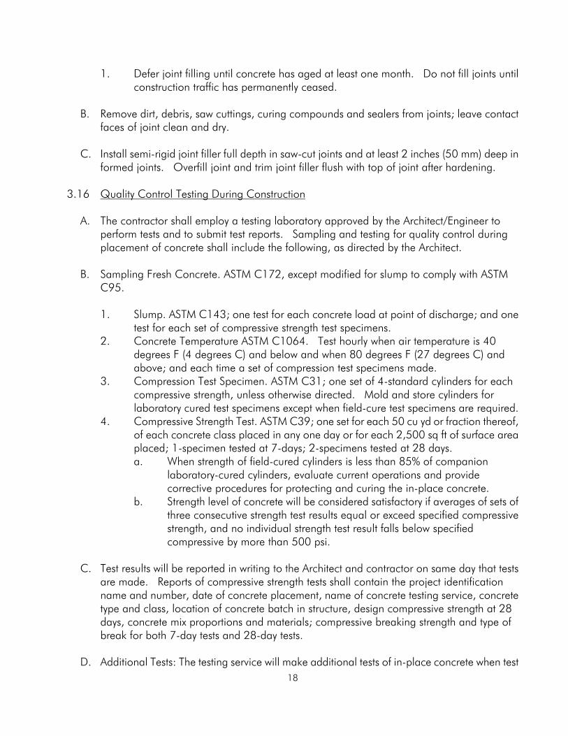
1. Defer joint filling until concrete has aged at least one month. Do not fill joints until construction traffic has permanently ceased.
B. Remove dirt, debris, saw cuttings, curing compounds and sealers from joints; leave contact
faces of joint clean and dry. C. Install semi-rigid joint filler full depth in saw-cut joints and at least 2 inches (50 mm) deep in
formed joints. Overfill joint and trim joint filler flush with top of joint after hardening. 3.16 Quality Control Testing During Construction A. The contractor shall employ a testing laboratory approved by the Architect/Engineer to
perform tests and to submit test reports. Sampling and testing for quality control during placement of concrete shall include the following, as directed by the Architect.
B. Sampling Fresh Concrete. ASTM C172, except modified for slump to comply with ASTM
C95. 1. Slump. ASTM C143; one test for each concrete load at point of discharge; and one
test for each set of compressive strength test specimens. 2. Concrete Temperature ASTM C1064. Test hourly when air temperature is 40
degrees F (4 degrees C) and below and when 80 degrees F (27 degrees C) and above; and each time a set of compression test specimens made.
3. Compression Test Specimen. ASTM C31; one set of 4-standard cylinders for each compressive strength, unless otherwise directed. Mold and store cylinders for laboratory cured test specimens except when field-cure test specimens are required.
4. Compressive Strength Test. ASTM C39; one set for each 50 cu yd or fraction thereof, of each concrete class placed in any one day or for each 2,500 sq ft of surface area placed; 1-specimen tested at 7-days; 2-specimens tested at 28 days.
a. When strength of field-cured cylinders is less than 85% of companion laboratory-cured cylinders, evaluate current operations and provide corrective procedures for protecting and curing the in-place concrete.
b. Strength level of concrete will be considered satisfactory if averages of sets of three consecutive strength test results equal or exceed specified compressive strength, and no individual strength test result falls below specified compressive by more than 500 psi.
C. Test results will be reported in writing to the Architect and contractor on same day that tests
are made. Reports of compressive strength tests shall contain the project identification name and number, date of concrete placement, name of concrete testing service, concrete type and class, location of concrete batch in structure, design compressive strength at 28 days, concrete mix proportions and materials; compressive breaking strength and type of break for both 7-day tests and 28-day tests.
D. Additional Tests: The testing service will make additional tests of in-place concrete when test

19
results indicate specified concrete strengths and other characteristics have not been attained in the structure, as directed by Architect/Engineer. Testing service may conduct tests to determine adequacy of concrete by cored cylinders complying with ASTM C42, or by other methods as directed. Contractor shall pay for such tests conducted, and any other additional testing as may be required, when unacceptable concrete is verified.
SECTION 03150 -- CONCRETE ACCESSORIES PART 1 - GENERAL 1.01 Work Summary
A. Furnish and install expanding bentonite/butyl waterstop as specified herein, illustrated on project drawings, or as required to complete the work.
1.02 Related Sections
A. Division 3 - Concrete 1.03 Quality Assurance
A. Verification of details: Contractor to notify the Architect immediately of any detail, note, or specification which does not comply with current manufacturer=s installation requirements.
B. Adhesive: Volclay WB-Adhesive is specially formulated to secure Waterstop-RX. No other
adhesive should be used.
C. Installation Instructions: components and installation procedures shall be in accordance with current manufacturer=s printed specifications and recommendations. Verify technical data submittals are the most current with manufacturer- (847)392-5800.
D. Expansion Joints: WATERSTOP-RX is not designed, nor intended for waterproofing or
sealing expansion joints. Responsibility of waterproofing expansion joints is of others.
E. Concrete: Concrete to receive waterstop shall be sound structural grade (minimum 3000 psi tensile strength) with a smooth finish, free of debris, oil, grease, or other foreign material.
1.04 Submittals
A. Material Certificate: submit certificate signed by manufacturer certifying waterstop consists of 75% sodium bentonite and 25% butyl rubber compound.
1.05 Material Delivery, Handling and Storage
A. Deliver materials as factory packaged, sealed and labeled. Handle and protect as
20
necessary to prevent damage or deterioration during shipment and handling. Store materials in a dry location secure from weather and construction operations. Remove damaged materials from the site and dispose of in accordance with applicable regulations.
PART 2 - PRODUCTS 2.01 Manufacturer
A. Materials and accessories specified herein are products of Colloid Environmental Technologies Company (CETCO). WATERSTOP-RX is manufactured in the United States by CETCO and is the basis for both the design and standard of quality.
2.02 Materials
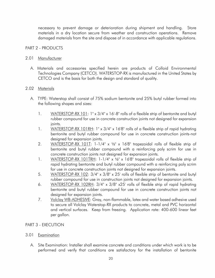
A. TYPE: Waterstop shall consist of 75% sodium bentonite and 25% butyl rubber formed into the following shapes and sizes:
1. WATERSTOP-RX 101
1.
: 1" x 3/4" x 16'-8" rolls of a flexible strip of bentonite and butyl rubber compound for use in concrete construction joints not designed for expansion joints. WATERSTOP-RX 101RH
2.
: 1" x 3/4" x 16'8" rolls of a flexible strip of rapid hydrating bentonite and butyl rubber compound for use in concrete construction joints-not designed for expansion joints. WATERSTOP-RX 101T
1.
: 1-1/4" x 2" x 16'8" trapezoidal rolls of flexible strip of bentonite and butyl rubber compound with a reinforcing poly scrim for use in concrete construction joints not designed for expansion joints. WATERSTOP-RX 101TRH
5.
: 1-1/4" x 2" x 16'8" trapezoidal rolls of flexible strip of rapid hydrating bentonite and butyl rubber compound with a reinforcing poly scrim for use in concrete construction joints not designed for expansion joints. WATERSTOP-RX 102
6.
: 3/4" x 3/8" x 25' rolls of flexible strip of bentonite and butyl rubber compound for use in construction joints not designed for expansion joints. WATERSTOP-RX 102RH
7.
: 3/4" x 3/8" x25' rolls of flexible strip of rapid hydrating bentonite and butyl rubber compound for use in concrete construction joints not designed for expansion joints. Volclay WB-ADHESIVE
: Gray, non-flammable, latex and water based adhesive used to secure all Volclay Waterstop-RX products to concrete, metal and PVC horizontal and vertical surfaces. Keep from freezing. Application rate: 400-600 linear feet per gallon.
PART 3 - EXECUTION 3.01 Examination A. Site Examination: Installer shall examine concrete and conditions under which work is to be
performed and verify that conditions are satisfactory for the installation of bentonite
21
waterstop. Installer shall notify the Architect, in writing, of circumstances detrimental to proper completion of work. Do not proceed with work until unsatisfactory conditions are corrected.
3.02 Weather Conditions
A. Installation shall not proceed when work areas are flooded to the extent that would cause bentonite waterstop to hydrate; nor when precipitation can be reasonably anticipated before bentonite waterstop can be properly installed or protected. Consult with manufacturer=s representative as necessary to ensure adequate protection of bentonite waterstop.
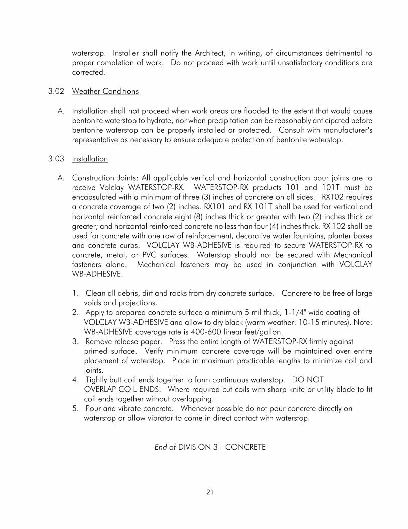
3.03 Installation A. Construction Joints: All applicable vertical and horizontal construction pour joints are to
receive Volclay WATERSTOP-RX. WATERSTOP-RX products 101 and 101T must be encapsulated with a minimum of three (3) inches of concrete on all sides. RX102 requires a concrete coverage of two (2) inches. RX101 and RX 101T shall be used for vertical and horizontal reinforced concrete eight (8) inches thick or greater with two (2) inches thick or greater; and horizontal reinforced concrete no less than four (4) inches thick. RX 102 shall be used for concrete with one row of reinforcement, decorative water fountains, planter boxes and concrete curbs. VOLCLAY WB-ADHESIVE is required to secure WATERSTOP-RX to concrete, metal, or PVC surfaces. Waterstop should not be secured with Mechanical fasteners alone. Mechanical fasteners may be used in conjunction with VOLCLAY WB-ADHESIVE.
1. Clean all debris, dirt and rocks from dry concrete surface. Concrete to be free of large voids and projections.
2. Apply to prepared concrete surface a minimum 5 mil thick, 1-1/4" wide coating of VOLCLAY WB-ADHESIVE and allow to dry black (warm weather: 10-15 minutes). Note: WB-ADHESIVE coverage rate is 400-600 linear feet/gallon. 3. Remove release paper. Press the entire length of WATERSTOP-RX firmly against
primed surface. Verify minimum concrete coverage will be maintained over entire placement of waterstop. Place in maximum practicable lengths to minimize coil and joints.
4. Tightly butt coil ends together to form continuous waterstop. DO NOT OVERLAP COIL ENDS. Where required cut coils with sharp knife or utility blade to fit coil ends together without overlapping.
5. Pour and vibrate concrete. Whenever possible do not pour concrete directly on waterstop or allow vibrator to come in direct contact with waterstop.
End of DIVISION 3 - CONCRETE


![Welcome []€¦ · Welcome Christopher R. Paolini, P.E., Sr. Vice President CME Associates, Inc. 6035 Corporate Drive East Syracuse, New York 13057 ... ASTM C1077-14, Under Section](https://img.pdfslide.us/doc/110x75/5ac995ff7f8b9a42358d4e5f/welcome-welcome-christopher-r-paolini-pe-sr-vice-president-cme-associates.jpg)