Embed Size (px)
Citation preview

Oregon State University September 7, 2012
Division 27: Global Communications Specification Document
1
Division 27 Master Specification for
Information Transport Systems and Spaces
Oregon State University September 7, 2012
Division 27: Global Communications Specification Document
2
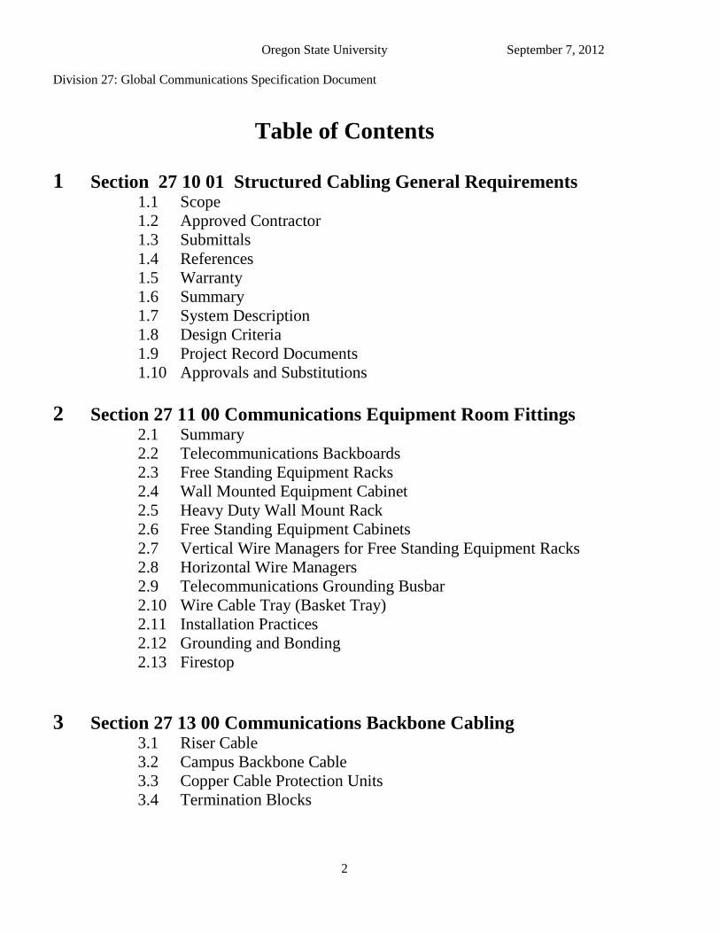
Table of Contents
1 Section 27 10 01 Structured Cabling General Requirements 1.1 Scope
1.2 Approved Contractor
1.3 Submittals
1.4 References
1.5 Warranty
1.6 Summary
1.7 System Description
1.8 Design Criteria
1.9 Project Record Documents
1.10 Approvals and Substitutions
2 Section 27 11 00 Communications Equipment Room Fittings 2.1 Summary
2.2 Telecommunications Backboards
2.3 Free Standing Equipment Racks
2.4 Wall Mounted Equipment Cabinet
2.5 Heavy Duty Wall Mount Rack
2.6 Free Standing Equipment Cabinets
2.7 Vertical Wire Managers for Free Standing Equipment Racks
2.8 Horizontal Wire Managers
2.9 Telecommunications Grounding Busbar
2.10 Wire Cable Tray (Basket Tray)
2.11 Installation Practices
2.12 Grounding and Bonding
2.13 Firestop
3 Section 27 13 00 Communications Backbone Cabling 3.1 Riser Cable
3.2 Campus Backbone Cable
3.3 Copper Cable Protection Units
3.4 Termination Blocks
Oregon State University September 7, 2012
Division 27: Global Communications Specification Document
3
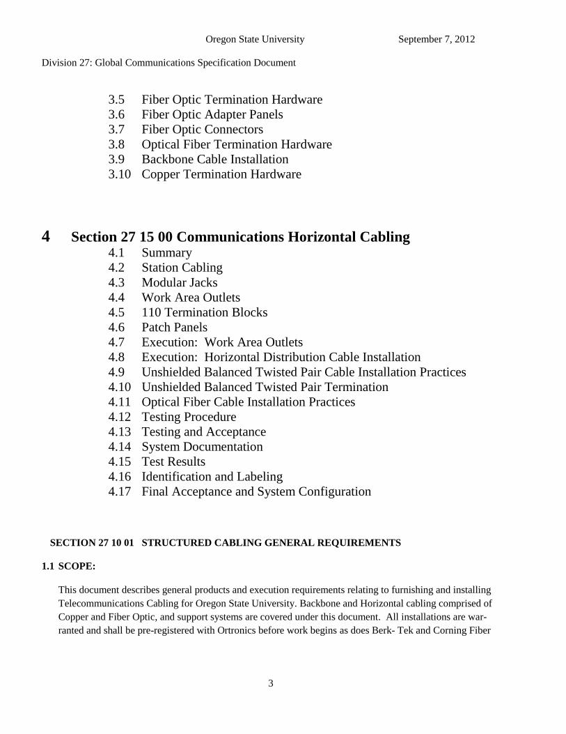
3.5 Fiber Optic Termination Hardware
3.6 Fiber Optic Adapter Panels
3.7 Fiber Optic Connectors
3.8 Optical Fiber Termination Hardware
3.9 Backbone Cable Installation
3.10 Copper Termination Hardware
4 Section 27 15 00 Communications Horizontal Cabling 4.1 Summary
4.2 Station Cabling
4.3 Modular Jacks
4.4 Work Area Outlets
4.5 110 Termination Blocks
4.6 Patch Panels
4.7 Execution: Work Area Outlets
4.8 Execution: Horizontal Distribution Cable Installation
4.9 Unshielded Balanced Twisted Pair Cable Installation Practices
4.10 Unshielded Balanced Twisted Pair Termination
4.11 Optical Fiber Cable Installation Practices
4.12 Testing Procedure
4.13 Testing and Acceptance
4.14 System Documentation
4.15 Test Results
4.16 Identification and Labeling
4.17 Final Acceptance and System Configuration
SECTION 27 10 01 STRUCTURED CABLING GENERAL REQUIREMENTS
1.1 SCOPE:
This document describes general products and execution requirements relating to furnishing and installing
Telecommunications Cabling for Oregon State University. Backbone and Horizontal cabling comprised of
Copper and Fiber Optic, and support systems are covered under this document. All installations are war-
ranted and shall be pre-registered with Ortronics before work begins as does Berk- Tek and Corning Fiber
Oregon State University September 7, 2012
Division 27: Global Communications Specification Document
4
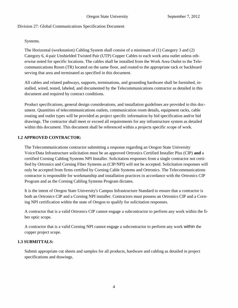
Systems.
The Horizontal (workstation) Cabling System shall consist of a minimum of (1) Category 3 and (2)
Category 6, 4-pair Unshielded Twisted Pair (UTP) Copper Cables to each work area outlet unless oth-
erwise noted for specific locations. The cables shall be installed from the Work Area Outlet to the Tele-
communications Room (TR) located on the same floor, and routed to the appropriate rack or backboard
serving that area and terminated as specified in this document.
All cables and related pathways, supports, terminations, and grounding hardware shall be furnished, in-
stalled, wired, tested, labeled, and documented by the Telecommunications contractor as detailed in this
document and required by contract conditions.
Product specifications, general design considerations, and installation guidelines are provided in this doc-
ument. Quantities of telecommunications outlets, communication room details, equipment racks, cable
routing and outlet types will be provided as project specific information by bid specification and/or bid
drawings. The contractor shall meet or exceed all requirements for any infrastructure system as detailed
within this document. This document shall be referenced within a projects specific scope of work.
1.2 APPROVED CONTRACTOR:
The Telecommunications contractor submitting a response regarding an Oregon State University
Voice/Data Infrastructure solicitation must be an approved Ortronics Certified Installer Plus (CIP) and a
certified Corning Cabling Systems NPI Installer. Solicitation responses from a single contractor not certi-
fied by Ortronics and Corning Fiber Systems as (CIP/NPI) will not be accepted. Solicitation responses will
only be accepted from firms certified by Corning Cable Systems and Ortronics. The Telecommunications
contractor is responsible for workmanship and installation practices in accordance with the Ortronics CIP
Program and as the Corning Cabling Systems Program dictates.
It is the intent of Oregon State University's Campus Infrastructure Standard to ensure that a contractor is
both an Ortronics CIP and a Corning NPI installer. Contractors must possess an Ortronics CIP and a Corn-
ing NPI certification within the state of Oregon to qualify for solicitation responses.
A contractor that is a valid Ortronics CIP cannot engage a subcontractor to perform any work within the fi-
ber optic scope.
A contractor that is a valid Corning NPI cannot engage a subcontractor to perform any work within the
copper project scope.
1.3 SUBMITTALS:
Submit appropriate cut sheets and samples for all products, hardware and cabling as detailed in project
specifications and drawings.
Oregon State University September 7, 2012
Division 27: Global Communications Specification Document
5
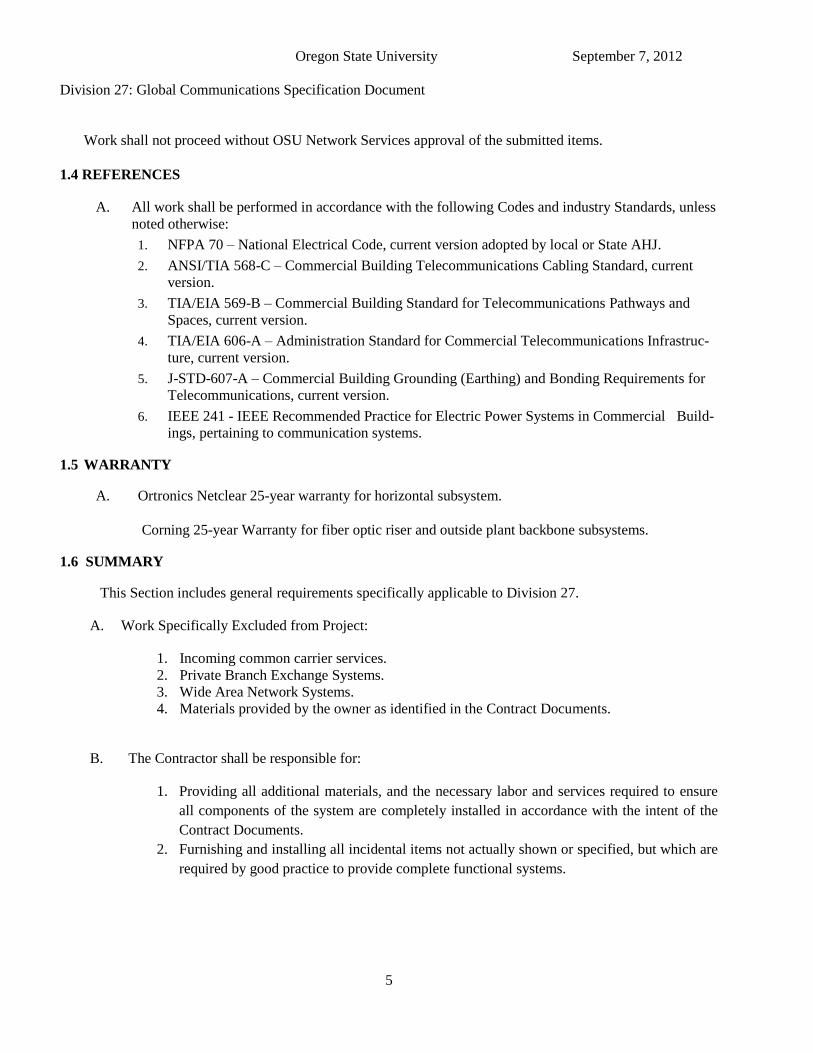
Work shall not proceed without OSU Network Services approval of the submitted items.
1.4 REFERENCES
A. All work shall be performed in accordance with the following Codes and industry Standards, unless
noted otherwise:
1. NFPA 70 – National Electrical Code, current version adopted by local or State AHJ.
2. ANSI/TIA 568-C – Commercial Building Telecommunications Cabling Standard, current
version.
3. TIA/EIA 569-B – Commercial Building Standard for Telecommunications Pathways and
Spaces, current version.
4. TIA/EIA 606-A – Administration Standard for Commercial Telecommunications Infrastruc-
ture, current version.
5. J-STD-607-A – Commercial Building Grounding (Earthing) and Bonding Requirements for
Telecommunications, current version.
6. IEEE 241 - IEEE Recommended Practice for Electric Power Systems in Commercial Build-
ings, pertaining to communication systems.
1.5 WARRANTY
A. Ortronics Netclear 25-year warranty for horizontal subsystem.
Corning 25-year Warranty for fiber optic riser and outside plant backbone subsystems.
1.6 SUMMARY
This Section includes general requirements specifically applicable to Division 27.
A. Work Specifically Excluded from Project:
1. Incoming common carrier services.
2. Private Branch Exchange Systems.
3. Wide Area Network Systems.
4. Materials provided by the owner as identified in the Contract Documents.
B. The Contractor shall be responsible for:
1. Providing all additional materials, and the necessary labor and services required to ensure
all components of the system are completely installed in accordance with the intent of the
Contract Documents.
2. Furnishing and installing all incidental items not actually shown or specified, but which are
required by good practice to provide complete functional systems.
Oregon State University September 7, 2012
Division 27: Global Communications Specification Document
6
3. Coordinating the details of facility equipment and construction for all specification
divisions that affect the work covered under this Division.
Coordinating all activities with the overall construction schedule.
4. Developing bill of materials, perform material management and efficient use of the
materials whether they are issued by the Contractor, the owner or purchased by the
Contractor.
5. Ensure materials in excess of those required to complete the project are kept in their
original condition and packaging for restocking.
Ensure project is properly registered for a NetClear warranty.
C. Intent of Drawings:
1. Communications plan drawings show only general locations of equipment, devices,
raceways, cable trays, boxes, etc. All dimensioned locations and elevations are
approximate. The contractor is responsible for the field coordination of communications
work with the other trades prior to beginning work.
2. The contractor shall be responsible for the proper placement and routing of equipment,
cable, raceways, cable tray, and related components; according to the Contract Documents
and subject to prior review by contractor.
3. Refer all conflicts between Contract Documents to owner for resolution.
1.7 SYSTEM DESCRIPTION
A. The owner will implement a comprehensive integrated communications distribution system, as
described in paragraph B below, to provide wiring infrastructure which may be used to support
one or more of the following services and systems:
1. Data telecommunications.
2. Wireless systems.
3. Facilities management systems.
B. The communications distribution system consists of the following major subsystems, as specified
elsewhere:
1. Interbuilding Backbone: The interbuilding subsystem refers to all twisted-pair and fiber
optic backbone communications cabling connecting the Main Building Entrance Facility
Room (BEF) to each building Main Distribution Frame room (MDF) in all buildings on the
campus. Note: typically outside plant cables.
2. Intrabuilding Backbone: The intrabuilding subsystem refers to all twisted-pair and fiber
optic backbone communications cabling connecting the Main Distribution Frame room
(MDF) to each Intermediate Distribution Frame Room (IDF) in the buildings.
Oregon State University September 7, 2012
Division 27: Global Communications Specification Document
7
3. Communication Rooms: Main Distribution Frame (MDF) and Intermediate Distribution
Frame (IDF).
4. Horizontal Distribution: The horizontal distribution subsystem refers to all intra-building
twisted-pair and fiber optic communications cabling connecting telecommunication rooms
(IDF’s) to telecommunication outlets (TOs) located at individual work areas.
5. Work Area Distribution Subsystem: Patch cords, adapters, and devices located between the
TO and station equipment.
C. The communications distribution system is based on a combination of the following
communications transmission technologies as defined by specific project specifications:
1. 100-ohm 4-pair unshielded twisted-pair cable. (Cat 6, Cat 6a)
2. 100-ohm multi-pair unshielded twisted-pair cable. (Cat 3). Note: NetClear warranty does
not apply to 100- ohm multi-pair cables.
3. OM3 and OM4 multimode fiber optic cable.
4. 850 nm Laser Optimized 50/125-micron multimode fiber optic cable.
5. 8.3/125-micron singlemode fiber optic cable.
6. 8-position telecommunications jacks.
7. 8-position telecommunications patch panels
8. Insulation displacement connector (IDC) type field terminated wiring blocks
9. Factory Terminated copper patch cords
10. Rack mount fiber optic hardware
11. Wall mounted fiber optic hardware
12. Fiber optic connectors.
13. Factory terminated fiber optic patch cords
D. The work locations and limits of work are shown on the drawings.
1.8 DESIGN CRITERIA
A. BICSI RCDD Certification is required for anyone performing infrastructure design
specifications and/or drawings for solicitation and construction. All drawings issued for
construction shall have valid RCDD stamp.
B. Compliance by the contractor with the provisions of this specification does not relieve contractor
of the responsibilities of furnishing materials and equipment of proper design, mechanically and
electrically suited to meet operating guarantees at the specified service conditions.
C. The following are incorporated into the design:
1. Minimum communication room size for EF room shall be no less than 14’x12’.
2. Minimum communication room size for MDF room shall be no less than 14’ x 12’.
3. Minimum communication room size for an IDF room shall be no less than 10’ x 12’.
Oregon State University September 7, 2012
Division 27: Global Communications Specification Document
8
4. All pathways, conduits, cable trays, slots and sleeves shall have no less than 50% future fill
capacity when project is completed.
5. All pathways, conduits, cable trays, slots and sleeves shall not have other cabling (fire
alarm, Audio Visual, security etc.) routed within or attached to them.
6. The location of communication rooms is intended to restrict the maximum horizontal
subsystem wiring length (defined as a channel between a telecommunications room cross-
connect termination field and a served TO) to 295 feet (90 meters).
7. All communication rooms shall have cooling calculated at 7KW of power consumption for
each open frame communications rack. 12KW of power for each Communication cabinet.
8. It is the intent of this specification to ensure security of communication rooms and sensitive
information. Electrical panels, fire alarm panels, and security systems are not to be
incorporated into communication room space, racks, cabinets or walls.
1.9 PROJECT RECORD DOCUMENTS
A. Provide detailed project record documentation within 30 days of substantial completion of the
work.
1. Maintain separate sets of red-lined record drawings for the communications work
which show the exact placement and identification of as-built system components.
2. Provide communication pathway record drawings which indicate exact placement and
routing for all components, e.g., maintenance holes, handholes, conduit, wireway, cable
tray, pull boxes, enclosures, telecommunications outlet boxes, etc.
3. Provide communication room record drawings which indicate exact placement for all
components; e.g., conduit, wireway, cable tray, backboards, equipment cabinets,
equipment racks, cross-connect equipment, etc.
4. Provide communication wiring and cabling record “As-Builds’” drawings and
schedules which indicate exact placement, routing, and connection details for all
components, e.g., twisted-pair and fiber optic cables, splices, cable cross-connect
termination locations, enclosures, telecommunications outlets, cross-connect jumpers,
patch cords, etc.
5. Provide network schematics when appropriate.
1.10 APPROVALS AND SUBSTITUTIONS
A. Substitutions are not authorized without written approval from owners authorized
representative through addendum.
Oregon State University September 7, 2012
Division 27: Global Communications Specification Document
9
PART 2 SECTION 27 11 00 COMMUNICATIONS EQUIPMENT ROOM FITTINGS
2.1 SUMMARY
A. The telecommunications spaces will be referred as Building Entrance Facilty (BEF),
Equipment Room (ER), Telecommunications Room (TR), Telecommunications Enclosure
(TE), and Data Center (DC) in this document is intended to house racks, cabinets and
equipment necessary for the support of the communications cabling infrastructure.
2.2 TELECOMMUNICATIONS BACKBOARDS
A. Wall mounted termination block fields shall be mounted on A/C 4' x 8' x .75" void free
plywood. The plywood shall be mounted vertically 12" above the finished floor. The ply-
wood shall be painted with a minimum two coats of white fire retardant paint on all (6)
sides. Mounting hardware shall also be painted white for cosmetic purposes.
2.3 FREE STANDING EQUIPMENT RACKS
A. All racks and wire management shall be Ortronics and/or Chattsworth, as specified in project
specifications and drawings. The equipment rack shall provide vertical and horizontal cable
management and support for patch cords and protection for the horizontal cables inside the
legs of the rack. Waterfall cable management shall be provided at the top of the rack for patch
cords and for horizontal cables entering the rack channels for protection and to maintain proper
bend radius and cable support. Wire management shall also be mounted above each patch pan-
el and/or piece of equipment on the rack. The rack shall include mounting brackets for cable
tray ladder rack to mount to the top of the rack. Rack shall be black in color.
Equipment Rack as detailed by project specifications and drawings Approved manufacturers are Ortronics Mighty MO & Mighty MO 6, and misc. CPI as
project specified by OSU Network Services.
B. Racks shall be securely attached to the concrete floor using minimum 3/8" hardware or as re-
quired by local codes. Earthquake restrictions, requirements, and zoning codes shall be strict-
ly followed.
Racks shall be placed with a minimum of 36-inch clearance from the walls on all sides of the
rack. When mounted in a row, maintain a minimum of 36 inches from the wall behind and in
front of the row of racks and from the wall at each end of the row.
All racks shall be grounded to the telecommunications ground bus bar in accordance with Sec-
tion 2.9 of this document.
Oregon State University September 7, 2012
Division 27: Global Communications Specification Document
10
Rack mount screws not used for installing patch panels and other hardware shall be bagged and
left with the rack
C.. 7 foot high, 19 inches wide, 10.5 inch channel depth, EIA free-standing rack, UL listed, black
finish.
1. Ortronics Mighty Mo 6 OR-MM6710
D. 7 foot high, 19 inches wide, rail-to-rail depth adjustable from 6 to 32 inches, EIA four post
equipment rack, UL listed, with universal 5/8 inch x 5/8 inch x ½ inch hole pattern with EIA
square hole rails, #12-24 cage nuts and screws, black finish.
1. Ortronics Mighty Mo Server Rack OR-MM107SVR
Refer to Ortronics catalog for additional part numbers and accessories.
2.4 WALL MOUNTED EQUIPMENT CABINET
1. Ortronics Mighty Mo Wall Mount Cabinet OR-MMW192426P-B; 26”deep 200 lb
capacity
2. Fan Kit OR-MMCFAN-4-50
Refer to Ortronics catalog for additional part numbers and accessories.
2.5 HEAVY DUTY WALL MOUNT RACK
A. Heavy Duty Wall Mount EQ Rack Chatsworth CPI-15321-724
2.6 FREE STANDING EQUIPMENT CABINETS
A. Modular Freestanding Server Cabinet, 7 foot tall, 42 RUs, 32 inches wide, 42 inches deep,
frame configured with cable opening at rear, frame levelers, two pairs of RU labeled mounting
rails with 3/8” square holes, full profile mesh front door, split flat rear mesh rear door, two “L”
shaped finger managers on rear rails, vertical PDU mount and lacing bar, divider or side
panels, solid top panel in front, cable entry top panel in rear, #12-24 cage nuts (50), #12-24
mounting screws (100), additional adhesive rack unit labels.
B. Modular Freestanding Network Cabinet, 7 foot tall, 32 inches wide, 34 inches deep, frame
configured with cable opening at bottom front, frame levelers, two pairs of RU labeled
mounting rails, with #12-24 tapped holes, full profile plexiglass front door, full flat sold rear
door, two “L” shaped finger managers on front rails, right and left locking side panels, fan top
panel in front, cable entry top panel in rear, #12-24 mounting screws (50).
1. Ortronics Mighty Mo Network Cabinet OR-MMC423234-00001I
Oregon State University September 7, 2012
Division 27: Global Communications Specification Document
11
Refer to Ortronics catalog for additional part numbers and accessories.
2.7 VERTICAL WIRE MANAGERS FOR FREE STANDING EQUIPMENT RACKS
A. 7 foot high, 10 inches wide, 13 inches deep with dual-hinged door and integral one rack unit
high horizontal management, black finish.
1. Ortronics Mighty Mo 6 OR-MM6VMD710
B. 7 foot high, 6 inches wide, 8 inches deep with dual-hinged door and integral one rack unit high
horizontal management, black finish.
1. Ortronics Mighty Mo 6 OR-MM6VMD706
Refer to Ortronics catalog for additional part numbers and accessories.
2.8 HORIZONTAL WIRE MANAGERS
A. At the top and bottom of every rack or cabinet, install the following:
1. OR-60400098
B. 19 inches wide, two rack units high with cover.
1. Ortronics Mighty Mo OR-808004818
C. 19 inches wide, one rack unit high with cover.
1. Ortronics Mighty Mo OR-808004759
Refer to Ortronics catalog for additional part numbers and accessories.
2.9 TELECOMMUNICATIONS GROUNDING BUSBAR
A. The TBB shall be designed and/or approved by a qualified PE, licensed in the state that the
work is to be performed. The TBB shall adhere to the recommendations of the TIAIEIA-607
standard, and shall be installed in accordance with best industry practice. A licensed electrical
contractor shall perform installation and termination of the main bonding conductor to the
building service entrance ground
B. Solid copper busbar kit, 12.0 inches long x 4.0 inches wide, wall-mounted, with standoffs.
1. Telecommunications Main Ground Busbar Kit OR-GB4X12TGBKIT
Oregon State University September 7, 2012
Division 27: Global Communications Specification Document
12
Refer to Ortronics catalog for additional part numbers and accessories.
2.10 WIRE CABLE TRAY (BASKET TRAY)
A. 24 inches wide, 4 inches deep, black, 10 foot lengths, steel construction.
1. Cablofil P/N 105/600BL
B. 12 inches wide, 4 inches deep, black, 10 foot lengths, steel construction.
1. Cablofil P/N 105/300BL
C. Cable exit manager.
1. Cablofil P/N CABLEXIT
D. Cable tray to wall termination angle.
1. Cablofil P/N HB2
E. Cable tray to wall mounting bracket.
1. Cablofil P/N CPR400
F. Cable tray splice kit
1. Cablofil P/N EDRN
G. Ground lug
H. Black cable tray shall be required in all communication rooms and shall not have a liner. Cable
tray installed buildings will have a color determined by A/E to match building paint schemes
and tray liners will be required.
I. All tray will be grounded per local Electric Code requirements.
J. All tray must be cut using the Cablofil tray cutter: COUPFIL or CUTYFIL. All cut cable tray
will be filed to remove burrs and painted to match color. All cutting, filing, and painting will
be done outside of building.
Refer to Cablofil catalog for additional part numbers and accessories.
2.11 INSTALLATION PRACTICES
A. All materials shall be installed as per the manufacturers’ instructions, unless noted otherwise.
B. Furnish and install telecommunication backboards on wall of communication equipment
rooms as indicated. The bottom of the backboards shall be placed approximately twelve
Oregon State University September 7, 2012
Division 27: Global Communications Specification Document
13
inches above finished floor (AFF), and must extend to a minimum height AFF of eight feet.
Mount backboards with the smooth side facing away from the wall, and paint the backboard
with two coats of fire resistant white paint prior to mounting. A minimum of six appropriate
fasteners shall be used for every sixteen square feet of backboard.
C. Free-standing equipment racks shall be fastened to the communications room floor using a
minimum of four 3/8 inch concrete anchors.
D. Equipment racks shall be positioned according to drawings with a minimum of 3 feet
clearance in front and back. The contractor shall field verify the dimensions of the room prior
to installation of racks and report any discrepancies to the owner or owners representative.
E. Vertical wire managers for free-standing racks shall be bolted to the side or front of the rack
using the manufacturers recommended hardware.
F. All equipment racks, cabinets, enclosures, cable tray, conduits, and patch panels shall be
bonded to the Telecommunications Grounding Busbar (TMG) (one per Telecommunications
Room), which shall be bonded to the Telecommunications Main Grounding Busbar (TMGB),
which shall be grounded to the main electrical ground in the main electrical room. Coordinate
with electrical contractor. Coordinate exact routing and connection points with the electrical
work. All surfaces that are used as a bond shall be filed to bare metal before completing
connections.
G. Install cable tray as shown in drawing package. The locations shown may need to be adjusted
slightly in the field to assure proper placement. Note: Drawings may be in Division 16
Electrical.
H. All tray sections shall be field cut to length as required with a minimum number of splice
points. All field cuts shall be made using the manufacturers recommended equipment.
I. All wire basket cable tray’s shall be supported from the building structure using threaded rod
and FAS type supports and shall be bonded to ground.
2.12 GROUNDING AND BONDING
A. The facility shall be equipped with a Telecommunications Bonding Backbone (TBB). This
backbone shall be used to ground all telecommunications cable shields, equipment, racks,
cabinets, raceways, and other associated hardware that has the potential to act as a current
carrying conductor. The TBB shall be installed independent of the building's electrical and
building ground and shall be designed in accordance with the recommendations contained in
the ANSI/TIA/EIA-607 Telecommunications Bonding and Grounding Standard.
B. The main entrance facility/equipment room in each building shall be equipped with a
Oregon State University September 7, 2012
Division 27: Global Communications Specification Document
14
telecommunications main grounding bus bar (TMGB). Each telecommunications
room shall be provided with a telecommunications ground bus bar (TGB). The
TMGB shall be connected to the building electrical entrance grounding facility. The
intent of this system is to provide a grounding system that is equal in potential to the
building electrical ground system. Therefore, ground loop current potential is mini-
mized between telecommunications equipment and the electrical system to which it
is attached.
C. All racks, metallic backboards, cable sheaths, metallic strength members, splice cases, cable
trays, etc. Entering or residing in the TR or ER shall be grounded to the respective TGB or
TMGB using a minimum #6 AWG green stranded copper bonding conductor and compres-
sion connectors.
D. All wires used for telecommunications grounding purposes shall be identified with a green
insulation. Non-insulated wires shall be identified at each termination point with a wrap of
green tape. All cables and busbars shall be identified and labeled in accordance with the Sys-
tem Documentation Section of this specification.
2.13 FIRESTOP
A. All Penetrations through fire-rated building structures (walls and floors) shall be sealed with
an approved fire stop system approved by the local fire code. This requirement applies to
through penetrations (complete penetration) and membrane penetrations (through one side of a
hollow fire-rated structure). Any penetration item, i.e., riser slots and sleeves, cables, conduit,
cable tray, and raceways, etc. shall be properly fire stopped.
PART 3 SECTION 27 13 00 COMMUNICATIONS BACKBONE CABLING
3.1 RISER CABLE
A. Voice and Data riser cable shall be plenum rated as detailed within project specifications and
drawings. Pair counts shall also be project specific.
B. Voice riser cable shall be category 3, 24AWG and manufactured by Berk-Tek, General, or Es-
sex.
C. Data riser cable shall be Corning plenum rated duplex LC, MTP-MTP, method A, factory pre-
terminated fiber optic cable:
1. Berk-Tek, OM4, colored aqua for Multimode and project specific
2. Corning singlemode, colored yellow for singlemode.
Oregon State University September 7, 2012
Division 27: Global Communications Specification Document
15
D. Fiber optic riser cable shall be routed in plenum, white Interduct, labeled every 20 feet with
"Caution Fiber Optics" warning label permanently attached to Interduct.
E. Interduct shall have fixed machine-labeled, yellow fiber optic ID tags, with labeling infor-
mation specified by OSU Network Services.
3.2 CAMPUS BACKBONE CABLE
A. UTP cable shall be category 3, Pic-Filled, Black jacketed cable with overall sheath. PE-89. Ap
proved manufacturers are General, Essex, and Commscope.
B. Fiber Cable shall be graded index single mode fiber, non-conductive and be of loose tube con-
struction. Strand counts shall also be project specific. Approved product is Corning ALTOS.
C. Corning duplex LC connectorized pre-polished· pigtail assemblies will be fusion spliced onto
all singlemode fiber optic cable. Field terminated LC connectors shall not be permitted.
D. Fusion splice all cables that requiring splicing as detailed in project specifications and draw-
ings. Mechanical splices are not acceptable anywhere within the physical system.
E. Cable Jacket shall have a permanently attached label that identifies OSU cable number, strand
count and destination at ever termination and/or splice as the cabling enters and/or leaves a
splice enclosure, vault, hand hole, building, building floor, and patch panels. The tag shall be
engraved with black lettering on yellow background with information provided by OSU Net-
work Services.
1. Example: SM16,1-36 TUNNEL ENTRANCE "D"
2. Example: SM04, 1-6 Plageman Hall
3.3 COPPER CABLE PROTECTION UNITS:
A. All copper circuits shall be provided with protection between each building with an entrance
cable protector panel. All building-to-building circuits shall be routed through this protector.
The protector shall be connected with a #6 AWG green copper bonding conductor between the
protector ground lug and the TC ground point.
3.4 TERMINATION BLOCKS
Oregon State University September 7, 2012
Division 27: Global Communications Specification Document
16
A. Cat 3, 110-Style Blocks
1. Ortronics OR-30200007
B. Wiring troughs
1. Vertical backbone managers wall mount 300 pair.
a. Ortronics OR-806003194
C. 110 block labels
1. Clear plastic holder for 110 blocks with paper inserts, for blocks with legs
a. Ortronics P/N OR-70400646
Note: Refer to Ortronics catalog for more complete 110 termination block kits.
3.5 FIBER OPTIC TERMINATION HARDWARE
A. Fiber Optic Termination Hardware
1. Corning Pretium Series
a. PCH-01U
b. PCH-04U
Refer to Corning catalog for additional part numbers and accessories.
3.6 FIBER OPTIC ADAPTER PANELS
A. Corning adapter panels
1. OM3/OM4 – CCH-CP12-E14, Duplex LC
2. Singlemode – CCH-CP12-A9, Duplex LC
B. Corning Pre-terminated Modules
1. Corning Universal Play LC Module, shuttered LC to MTP
Refer to Corning catalog for additional part numbers and accessories.
3.7 FIBER OPTIC CONNECTORS
A. Corning fiber option connectors
1. OM3/OM4 95-050-99-X
2. Singlemode 95-200-99
3.8 OPTICAL FIBER TERMINATION HARDWARE:
A. All Optical fiber cables shall be fanned out when terminating with Corning fan-out kits (Ris-
Oregon State University September 7, 2012
Division 27: Global Communications Specification Document
17
er/Horizontal), and Corning Spider Fan -out Kits (Campus Backbone).
B. Fiber slack shall be neatly coiled within the fiber splice tray or enclosure. No slack loops shall
be allowed external to the fiber panel.
C. Each cable shall be individually attached to the respective splice enclosure by mechanical
means. The cables strength member shall be securely attached the cable strain relief bracket in
the enclosure.
D. Each fiber bundle shall be stripped upon entering the splice tray and the individual fibers
routed in the splice tray.
E. Each cable shall be clearly labeled at the entrance to the splice enclosure. Cables labeled
within the bundle shall not be acceptable.
3.9 BACKBONE CABLE INSTALLATION
A. Backbone cables shall be installed separately from horizontal distribution cables.
B. A pull cord (nylon; 1/8" minimum) shall be co-installed with all cable installed in any conduit.
C. Where cables are housed in conduits, the backbone and horizontal cables shall be installed in
separate conduits.
D. Where backbone cables and distribution cables are installed in a cable tray or wireway, back-
bone cables shall be installed first and bundled separately from the horizontal distribution ca-
bles.
E. All backbone cables shall be securely fastened to the sidewall of the TR on each floor.
F. Backbone cables spanning more than three floors shall be securely attached at the top of the
cable run with a wire mesh grip and on alternating floors or as required by local codes.
G. Vertical runs of cable shall be supported to messenger strand, cable ladder, or other method to
provide proper support for the weight of the cable.
H. Large bundles of cables and/or heavy cables shall be attached using metal clamps and/or metal
banding to support the cables.
3.10 COPPER TERMINATION HARDWARE
A. Cables shall be dressed and terminated in accordance with the recommendations made in the
TIA/EIA568-B (B.1, B.2, B.3) document, manufacturer's recommendations and best industry
Oregon State University September 7, 2012
Division 27: Global Communications Specification Document
18
practices.
B. Copper riser shall be terminated on 110 IDC block separate from OSP protection units.
C. Pair untwist at the termination shall not exceed 12 mm (one-half inch).
D. Bend radius of the cable in the termination area shall not exceed 4 times the outside diam-
eter of the cable.
E. Cables shall be neatly bundled and dressed to their respective panels or blocks. Each pan-
elblock shall be fed by an individual bundle separated and dressed back to the point of cable
entrance into the rack or frame.
F. The cable jacket shall be maintained to within 25 mm (one inch) of the termination point.
G. Each cable shall be clearly labeled on the cable jacket behind the patch panel at a location
that can be viewed without removing the bundle support ties. Cables labeled within the bun-
dle, where the label is obscured from view shall not be acceptable.
PART 4 SECTION 27 15 00 COMMUNICATIONS HORIZONTAL CABLING
4.1 SUMMARY
A. The horizontal distribution subsystem refers to all intra-building twisted-pair and fiber optic
communications cabling connecting Telecommunication Rooms (TR’s) to telecommunication
outlets (TO’s) located at individual work areas.
B. Horizontal cabling may consist of a combination of the following types of cable from the TR to
the TO:
1. Enhanced Category 6, (100 Ohm, 4-pair, unshielded twisted pair) cables from the TR’s to
the TO’s.) Port 1 or Port 2
2. Laser Optimized OM4, optical fiber cable.
C. The Horizontal System includes cables, jacks, patch panels, connecting blocks, fiber connectors
as well as the necessary support systems, such as cable managers and faceplates.
D. Telecommunications contractor shall furnish and install all materials necessary for a complete
system per project documents.
4.2 STATION CABLING
A. Voice - BerkTek LAN grade Grey Cat 3 Plenum
Oregon State University September 7, 2012
Division 27: Global Communications Specification Document
19
B. Data - BerkTek LM 1000 Cat 6 Green Plenum
C. Fiber Optic – BerkTek Gigalite OM4 Aqua Plenum
4.3 MODULAR JACKS
A. Work area outlet jack
1. Ortronics voice – OR-6373003, 8 POS, Fog White T568B
2. Ortronics data – OR TJ600-25, 8 POS, Green T568B
B. Multimode fiber modular adapter
1. 2-strand fiber optic TracJack modular adapter, Duplex LC type connectors, ceramic
alignment sleeves with 180-degree exit
a. Ortronics OR-63700075
2. 2-strand fiber optic TracJack modular adapter, Duplex LC type connectors, ceramic
alignment sleeves with 45-degree exit
a. Ortronics OR-63700080
4.4 WORK AREA OUTLETS
A. Flush mounted faceplates
1. One port TracJack faceplate with mounting lugs for wall phone, constructed from stainless
steel, mounts within a single gang wall box.
a. Ortronics OR-403STJ1WP.
2. Six port TracJack faceplate, constructed from high impact thermo-plastic, with recessed
label fields, mounts within a single gang wall box.
a. Ortronics OR-40300545, fog white.
B. Dust covers
1. Single port dust cover for modular openings, color to match faceplate.
a. Ortronics OR-42100002, fog white.
Oregon State University September 7, 2012
Division 27: Global Communications Specification Document
20
4.5 110 TERMINATION BLOCKS
A. Wiring Troughs
1. Horizontal trough for routing of patch cords and cross-connect wire, with mounting legs.
a. Ortronics OR-30200140.
B. 110 block labels (Cat 3)
1. Clear plastic holder for 110 blocks with paper inserts, for blocks with legs
a. Ortronics OR-70400646.
b. Ortronics OR-70400680.
4.6 PATCH PANELS
A. Category 6 modular patch panels
1. 48 port, 8P8C modular jack panel, high density, 6 port modules, Category 6, IDC terminals,
T568A/B wiring scheme. Angled or standard patch panels per specific project specification
determined by OSU Network Services.
a. Ortronics OR-PHD66U48.
b. Ortronics Angled OR-PHA66U48
4.7 EXECUTION: WORK AREA OUTLETS
A. The cable jacket shall be maintained to within 25mm (one inch) of the termination point.
B. Data jacks, unless otherwise noted in drawings, shall be located in the right side posi
tion(s) of each faceplate.
C. Voice jacks shall occupy the left position(s) on the faceplate.
4.8 EXECUTION: HORIZONTAL DISTRIBUTION CABLE INSTALLATION:
A. Cable shall be installed in accordance with manufacturer's recommendations and best industry
practices.
B. A pull cord (nylon; 1/8" minimum) shall be co-installed with all cable installed in any conduit.
Cable raceways shall not be filled greater than the TIA/EIA-569-B maximum fill for the particu-
lar raceway type or 40% (Initial Installations).
C. Cables shall be installed in continuous lengths from origin to destination (no splices) except for
transition points, or consolidation points.
Oregon State University September 7, 2012
Division 27: Global Communications Specification Document
21
D. Where transition points, or consolidation points are allowed, they shall be located in accessible
locations and housed in an enclosure intended and suitable for the purpose.
E. The cable's minimum bend radius and maximum pulling tension shall not be exceeded.
F. If a J-hook or trapeze system is used to support cable bundles all horizontal cables shall be sup-
ported at a maximum of 48-inch (1.2 meter) intervals. At no point shall cabld(s) rest on light
fixtures, acoustic ceiling grids, panels, conduits, sprinkler pipe, water pipe, and/or HVAC sys-
tem ducting.
G. Horizontal distribution cables shall be bundles in groups of no more than 50 cables when being
supported by J-Hook or trapeze systems. Cable bundle quantities in excess of 50 cables may
cause deformation of the bottom cables within the bundle and degrade cable performance. An
exception to this rule is when cable is installed in cable tray systems.
H. Cable shall be installed above fire-sprinkler systems and shall not be attached to the system or
any ancillary equipment or hardware. The cable system and support hardware shall be installed
so that it does not obscure any valves, fire alarm conduit, boxes, or other control devices.
I. Cables shall not be attached to ceiling grid or lighting fixture wires. Where support for horizon-
tal cable is required, the contractor shall install appropriate carriers to support the cabling.
J. Any cable damaged or exceeding recommended installation parameters during installation shall
be replaced by the contractor prior to final acceptance at no cost to the Owner.
K. Cables shall be identified by a self-adhesive machine label in accordance with the System
L. Documentation Section of this specification and ANSI/TIA/EIA-606. The cable label shall be
applied to the cable behind the faceplate on a section of cable that can be accessed by removing
the cover plate.
M. Unshielded twisted pair cable shall be installed so that there are no bends smaller than four
times the cable outside diameter at any point in the run and at the termination field.
N. Pulling tension on 4-pair UTP cables shall not exceed 25-lbf for a four-pair UTP cable.
4.9 UNSHIELDED BALANCED TWISTED PAIR CABLE INSTALLATION PRACTICES
A. Cable shall be installed in accordance with Ortronics and Berk-Tek recommendations and best
industry practices.
B. Cables shall be installed in continuous lengths from origin to destination (no splices) except for
transition points, or consolidation points.
C. Where transition points or consolidation points are allowed, they shall be located in accessible
locations and housed in an enclosure intended and suitable for the purpose.
D. The cable’s minimum bend radius and maximum pulling tension shall not be exceeded Bend
radius for UTP = 4 x Cable OD, FTP = 4 x Cable OD.
Oregon State University September 7, 2012
Division 27: Global Communications Specification Document
22
E. Unshielded twisted pair cable shall be installed so that there are no bends smaller than four
times the cable outside diameter at any point in the run and at the termination field.
F. Pulling tension on 4-pair UTP cables shall not exceed 25-lbf for a four-pair UTP cable.
G. Separation from Power Lines:
1. Provide the following minimum separation distances between pathways for copper
communications cables and power wiring of 480 volts or less:
a. Open or Nonmetal Communications Pathways:
1) 12 inches from electric motors, fluorescent light fixtures, and
unshielded power lines carrying up to 3 kVA.
2) 36 inches from electrical equipment and unshielded power lines
carrying more than 5 kVA.
3) 48 inches from large electrical motors or transformers.
b. Grounded Metal Conduit Communications Pathways:
1) 2 1/2 inches from electrical equipment and unshielded power lines
carrying up to 2 kVA.
2) 6 inches from electrical equipment and unshielded power lines carrying
from 2 kVA to 5 kVA.
3) 12 inches from electrical equipment and unshielded power lines
carrying more than 5 kVA.
4) 3 inches from power lines enclosed in a grounded metal conduit (or
equivalent shielding) carrying from 2 kVA to 5 kVA.
5) 6 inches from power lines enclosed in a grounded metal conduit (or
equivalent shielding) carrying more than 5 kVA.
4.10 UNSHIELDED BALANCED TWISTED PAIR TERMINATION
A. Cables shall be dressed and terminated in accordance with the recommendations made in the
ANSI/TIA-568-C.0 document, manufacturer's recommendations and best industry practices.
B. All 4 pair cables shall be terminated on the jack and patch panels using T568-B wiring scheme.
C. Pair untwist at the termination shall not exceed 12 mm (one-half inch).
Oregon State University September 7, 2012
Division 27: Global Communications Specification Document
23
D. Bend radius of the horizontal cable shall not be less than 4 times the outside diameter of the UTP
cable and 4 times for FTP cables.
E. The cable jacket shall be maintained to within 25mm (one inch) of the termination point.
a. Pair untwist at the termination shall not exceed 13 mm (0.5 inch).
b. Cables shall be neatly bundled and dressed to their respective panels or blocks. Each panel or
block shall be fed by an individual bundle separated and dressed back to the point of cable
entrance into the rack or frame.
c. The cable jacket shall be maintained as close as possible to the termination point. Cable shall
not have more than 1.0” removed.
4.11 OPTICAL FIBER CABLE INSTALLATION PRACTICES
A. Place fiber optic cable so as to maintain the minimum cable bend radius limits specified by the
manufacturer or ten times the cable diameter, whichever is larger.
d. Use care when handling fiber optic cable. Carefully monitor pulling tension so as not to exceed
the limits specified by the manufacturer.
e. There shall be no splicing of Horizontal fiber optic cable.
4.12 TESTING PROCEDURES
A. All cables and termination hardware shall be 100% tested for defects in installation and to
verify cabling system performance under installed conditions according to the requirements of
ANSI/TIA-568-C. All pairs of each installed cable shall be verified prior to system acceptance.
Any defect in the cabling system installation including but not limited to cable, connectors,
patch panels, and connector blocks shall be repaired or replaced in order to ensure 100%
useable conductors in all cables installed.
f. All cables shall be tested in accordance with this document, the ANSI/TIA standards, the
Ortronics procedures and best industry practice. If any of these are in conflict, the Contractor
shall bring any discrepancies to the attention of the project team for clarification and resolution.
g. Cables, jacks, connecting blocks, and patch panels shall be in there final position with the
building energized.
h. All Unshielded Balanced Twisted Pair cables shall be tested as follows:
1. All twisted-pair copper cable links shall be tested for continuity, pair reversals, shorts,
opens and performance as indicated below. Additional testing is required to verify
Oregon State University September 7, 2012
Division 27: Global Communications Specification Document
24
Category performance. Horizontal cabling shall be tested using an approved Ortronics
certification tester (Fluke or Agilent) for category 6a, category 6, and category 5e
performance compliance as specified in ANSI/TIA-568-C.
2. Follow the Standards requirements established in ANSI/TIA-568-C.
3. Testing shall be accomplished with an approved Ortronics certification tester (Fluke)
4. The basic tests required are:
1. Wire Map
2. Length (feet)
3. Insertion Loss (dB) (Formerly Attenuation)
4. NEXT (Near end crosstalk) (dB)
5. Return Loss (dB)
6. ELFEXT (dB)
7. Propagation Delay (ns)
8. Delay skew (ns)
9. PSNEXT (Power sum near-end crosstalk loss) (dB)
10. PSELFEXT (Power sum equal level far-end crosstalk loss) (dB)
Cat 6 Ortronics NetClear GT2 shall be tested to a Cat 6 auto test to 250 MHz.
5. All test results shall be provided in the approved certification testers original software
format on a CD, with the following minimum information per cable:
11. Circuit ID
12. All information from 1.2A.4 above.
13. Test result, “Pass” or “Fail”
14. Date and Time of test
15. Project Name
16. NVP
17. Version of software
Note: No asterisk * will be accepted by Ortronics. These results shall be retested and
submitted after a PASS is received.
6. A software copy of the test results, in the original tester software format, shall be
provided to the Owner and Ortronics.
7. Contractor shall provide a fully functional version of the tester software for use by the
Owner in reviewing the test results.
8. Any failed test results that cannot be remedied through re-termination (as in the case
of reversed or split pairs), must be reported in writing to the Owner immediately,
along with a copy of the test results.
Oregon State University September 7, 2012
Division 27: Global Communications Specification Document
25
i. All Optical Fiber shall be tested as follows:
9. Testing procedures shall be in accordance with the following:
1. ANSI/TIA/EIA-568-A
2. ANSI/TIA/EIA-568-B.1
3. ANSI/TIA-568-C.0
4. ANSI/TIA/EIA-526-7
5. ANSI/TIA/EIA-526-14, Method B
6. Proposed TSB-140 Tier one Fiber Certification, C
10. Test Equipment
7. Certification tester (Fluke).
11. Testing
8. All optical fibers shall be tested at both the 850 nm and 1300 nm wavelengths for
multimode, 1310nm and 1550nm wavelengths for Singlemode, end-to-end
insertion loss. Telecommunications Room (TR) to Telecommunications outlet
(TO).Telecommunications outlet (TO) to Telecommunications Room (TR).
Maximum insertion loss for all horizontal fiber optic cables with out a
consolidation point shall not exceed 2.0 dB.
NOTE: Horizontal fiber runs TR to TO, TO to TR, shall be tested at the wavelength of
operation to the desk top applications.
4.13 TESTING AND ACCEPTANCE
GENERAL:
A. All cables and termination hardware shall be 100% tested for defects in installation and to
verify cabling system performance under installed conditions according to the requirements
of ANSI/TIA/EIA-568-B.1, B.2. All pairs of each installed cable shall be verified prior to
system acceptance. Any defect in the cabling system installation including but not limited to
cable, connect ors, feed through couplers, patch panels, and connector blocks shall be
repaired or replaced in order to ensure 100% useable conductors in all cables installed.
B. All cables shall be tested in accordance with this document, the ANSI-TIA/EIA standards, the
Ortronics, Berk-Tek and Corning Certification Program Information Manuals and best Indus-
try practice. If any of these are in conflict, the Contractor shall bring any discrepancies to the
attention of the owners authorized representative for clarification and resolution.
COPPER CHANNEL TESTING:
A. All twisted-pair copper cable links shall be tested for continuity, pair reversals, shorts,
opens and performance as indicated below. Additional testing is required to verify
Oregon State University September 7, 2012
Division 27: Global Communications Specification Document
26
Category performance. Horizontal cabling shall be tested using a level IIe or level III test
unit for category 5e or category 6, performance compliance, respectively.
B. Continuity - Each pair of each installed cable shall be tested using a test unit that shows opens,
shorts, polarity and pair-reversals. crossed pairs and split pairs. Shielded/screened cables shall
be tested with a device that verifies shield continuity in addition to the above stated tests. The
test shall be recorded as pass/fail as indicated by the test unit in accordance with the manufac-
turers' recommended procedures, and referenced to the appropriate cable identification number
and circuit or pair number. Any faults in the wiring shall be corrected and the cable re-tested
prior to final acceptance.
C. Length - Each installed cable link shall be tested for installed length using a TDR type
device. The cables shall be tested from patch panel to patch panel, block to block, patch panel
to outlet or block to outlet as appropriate. The cable length shall conform to the maximum
distances set forth in the ANSI-TIA/EIA-568-B Standard. Cable lengths shall be recorded,
referencing the cable identification number and circuit or pair number. For multi-pair cables,
the shortest pair length shall be recorded as the length for the cable.
D. Category 6 and 6E:
1. Follow the Standard requirements established in ANSI/TIA/EIA-568-B.1, B.2:
2. A level III test unit is required to verify category 6 performance and must be updated to include the requirements of ANSI/TIA/EIA-568-B.1.
3. The primary field-test parameters leading to Pass/Fail criteria used to verify installed hori- zontal cabling are listed below. These parameters are defined in ANSI/EIA/TIA-568-B.1.
Wire Map
Length
Insertion Loss
Near-end cross talk (NEXT) loss
Power sum near-eand cross talk (PSNEXT) loss
Equal-Ievel-far-end cross talk (ELFEXT)
Power sum equal-level-far-end cross talk (PSELFEXT)
Return Loss
Propagation Delay
Delay Skew
Approved test unit manufacturer is Fluke DSP. Other test units are unacceptable. The Fluke DSP shall have the latest software version installed at time of project testing.
Oregon State University September 7, 2012
Division 27: Global Communications Specification Document
27
FIBER TESTING:
A. For horizontal and riser cabling system using multimode optical fiber, attenuation shall be
measured bi-directionally at both 850.nanometer (nm) and 1300 nm operating windows using
an LED light source and power meter.
B. For horizontal and riser cabling system using single mode optical fiber, attenuation shall be
measured bi-directionally at both 1310 nanometer (nm) and 1550 nm operating windows, using
an LASER light source and power meter.
C. Campus Backbone multimode fiber cabling shall be tested with OTDR at both 850 nm and
1300 nm bi-directionally.
D. Campus Backbone single mode fiber cabling shall be tested with OTDR at both 1310 nm and
1550 nm bi-directionally.
E. Test set-up and performance shall be conducted in accordance with ANSI/TIA/EIA-526-
14A, Method B Standard.
F. Where links are combined to complete a circuit between devices, the Contractor shall test each
link from end to end to ensure the performance of the system. ONLY BASIC LINK TEST IS
REQUIRED. The contractor can optionally install patch cords to complete the circuit and then
test the entire channel. The test method shall be the same used for the test described above. The
values for calculating loss shall be those defined in the ANSI/TIA/EIA Standard.
G. Attenuation testing shall be performed with a stable launch condition using two-meter jum-
pers to attach the test equipment to the cable plant. The light source shall be left in place after
calibration and the power meter moved to the far end to take measurements.
4.14 SYSTEM DOCUMENTATION
A. Per project contract documents.
4.15 TEST RESULTS:
A. Submit completed test results with close out documentation on CD-ROM. Hard copy printed
results are also required to be submitted via 3 ring binder(s), tabbed by EF/MC/IC/TC/ER/TR
Binder shall be labeled with Oregon State University Project name and project number. This
applies to all Horizontal copper and all fiber optic test results.
B. Horizontal Cat. 3, Cat. 6, and Cat 6E cabling shall be tested with Fluke DTX 1800 Level III
Oregon State University September 7, 2012
Division 27: Global Communications Specification Document
28
tester. Test results produced by other testers WILL NOT be accepted. A summary report will
accompany the individual graph format test results. Test results shall have the Technicians
names, correct date and time. Test results without the correct information and not in colored
graph format shall not be accepted.
4.16 IDENTIFICAITON AND LABELING:
A. OSP copper labels shall be engraved. OSP copper labels shall be white letters on black
background.
B. OSP Singlemode fiber optic labels shall be engraved, black letters on yellow background.
C. Outlet, patch panel and wiring block labels shall be installed on, or in, the space provided on
the device. Specific labeling information shall be project specific and the information will be
given to the contractor by OSU Network Services.
D. All horizontal cables are to be labeled using a machine printed label at each end of the cable
approximately 6 inches of the termination point. Handwritten labels shall not be used.
E. All patch panel ports and TO ports shall be labeled with the cable, network, TR room #, and
port identifier.
F. All inside building cabling, termination, hardware, protection units, patch panels, and work area
outlets shall comply with ANSI/TIA/EIA 606 labeling standard color codes.
G. Labeling scheme information and format to be provided by OSU Network Services.
1. Note all labeling information on the as-built drawings.
4.17 FINAL ACCEPTANCE & SYSTEM CERTIFICATION:
A. Completion of the installation, in-progress inspections, receipt of the test and as-built docu-
mentation, and successful performance of the cabling system will constitute completion of the
system. Upon successful completion of the installation and subsequent inspection, Oregon
State University shall be provided with a numbered certificate, from Ortronics or Berk-Tek
and/or Corning if applicable, registering the installation.